It's Vintage Darling! An exploration of vintage fashion retailing
Upload
khangminh22Category
view
1download
0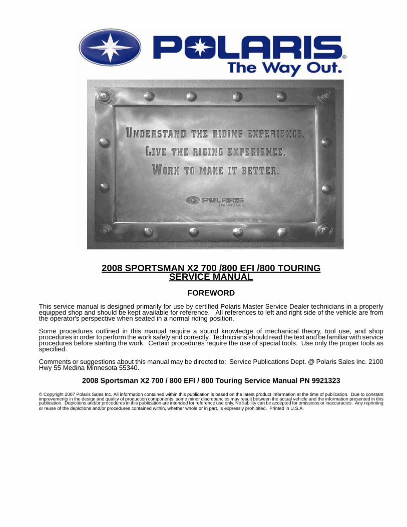
2008 SPORTSMAN X2 700 /800 EFI /800 TOURINGSERVICE MANUAL
FOREWORDThis service manual is designed primarily for use by certified Polaris Master Service Dealer technicians in a properlyequipped shop and should be kept available for reference. All references to left and right side of the vehicle are fromthe operator's perspective when seated in a normal riding position.
Some procedures outlined in this manual require a sound knowledge of mechanical theory, tool use, and shopprocedures in order to perform the work safely and correctly. Technicians should read the text and be familiar with serviceprocedures before starting the work. Certain procedures require the use of special tools. Use only the proper tools asspecified.
Comments or suggestions about this manual may be directed to: Service Publications Dept. @ Polaris Sales Inc. 2100Hwy 55 Medina Minnesota 55340.
2008 Sportsman X2 700 / 800 EFI / 800 Touring Service Manual PN 9921323
© Copyright 2007 Polaris Sales Inc. All information contained within this publication is based on the latest product information at the time of publication. Due to constantimprovements in the design and quality of production components, some minor discrepancies may result between the actual vehicle and the information presented in thispublication. Depictions and/or procedures in this publication are intended for reference use only. No liability can be accepted for omissions or inaccuracies. Any reprintingor reuse of the depictions and/or procedures contained within, whether whole or in part, is expressly prohibited. Printed in U.S.A.

UNDERSTANDING MANUAL SAFETY LABELS AND DIRECTIONSThroughout this manual, important information is brought to your attention by the following symbols:
SAFETY ALERT WARNING indicates a potential hazard that may result in severe injury or death to the operator, bystander orperson(s) inspecting or servicing the vehicle.
SAFETY ALERT CAUTION indicates a potential hazard that may result in minor personal injury or damage to the vehicle.
CAUTION indicates special precautions that must be taken to avoid vehicle damage or property damage.
NOTE:
NOTE provides key information by clarifying instructions.
IMPORTANT:
IMPORTANT provides key reminders during disassembly, assembly and inspection of components.
TRADEMARKSPOLARIS ACKNOWLEDGES THE FOLLOWING PRODUCTS MENTIONED IN THIS MANUAL:
Loctite, Registered Trademark of the Loctite Corporation
Nyogel, Trademark of Wm. F. Nye Co.
Fluke, Registered Trademark of John Fluke Mfg. Co.
Mity-Vac, Registered Trademark of Neward Enterprises, Inc.
Torx, Registered Trademark of Textron
Hilliard, Trademark of the Hilliard Corporation
Warn, Trademark of Warn Industries
Some Polaris factory publications can be downloaded from www.polarisindustires.com, purchased from www.purepolaris.com orby contacting the nearest Polaris dealer.
WARNING
CAUTION
CAUTION

1GENERAL
2MAINTENANCE
3ENGINE
4FUEL SYSTEM
5BODY / SUSPENSION
6CLUTCH
7TRANSMISSION
8FINAL DRIVE
9BRAKES
10ELECTRICAL
11INTERNATIONAL

NOTES

GENERAL INFORMATION
CHAPTER 1GENERAL INFORMATION 1
MODEL INFORMATION . . . . . . . . . . . . . . . . . . . . . . . . . . . . . . . . . . . . . . . . . . . . . . . . . . 1.2MODEL NUMBER. . . . . . . . . . . . . . . . . . . . . . . . . . . . . . . . . . . . . . . . . . . . . . . . . . . . . . . 1.2ENGINE DESIGNATION NUMBERS . . . . . . . . . . . . . . . . . . . . . . . . . . . . . . . . . . . . . . . . 1.2VIN IDENTIFICATION . . . . . . . . . . . . . . . . . . . . . . . . . . . . . . . . . . . . . . . . . . . . . . . . . . . 1.2TRANSMISSION I.D. LOCATION. . . . . . . . . . . . . . . . . . . . . . . . . . . . . . . . . . . . . . . . . . . 1.2ENGINE AND MACHINE SERIAL NUMBERS . . . . . . . . . . . . . . . . . . . . . . . . . . . . . . . . . 1.2PUBLICATIONS . . . . . . . . . . . . . . . . . . . . . . . . . . . . . . . . . . . . . . . . . . . . . . . . . . . . . . . . 1.3PAINT CODES . . . . . . . . . . . . . . . . . . . . . . . . . . . . . . . . . . . . . . . . . . . . . . . . . . . . . . . . . 1.3REPLACEMENT KEYS . . . . . . . . . . . . . . . . . . . . . . . . . . . . . . . . . . . . . . . . . . . . . . . . . . 1.3
2008 SPORTSMAN 800 EFI . . . . . . . . . . . . . . . . . . . . . . . . . . . . . . . . . . . . . . . . . . . . . . . 1.4MODEL NUMBER: A08MN76AF, AL, AQ, AS, AX . . . . . . . . . . . . . . . . . . . . . . . . . . . . . 1.4
2008 SPORTSMAN X2 700 EFI . . . . . . . . . . . . . . . . . . . . . . . . . . . . . . . . . . . . . . . . . . . . 1.6MODEL NUMBER: A08TN68AZ, AX. . . . . . . . . . . . . . . . . . . . . . . . . . . . . . . . . . . . . . . . 1.6
2008 SPORTSMAN TOURING 800 EFI . . . . . . . . . . . . . . . . . . . . . . . . . . . . . . . . . . . . . . 1.8MODEL NUMBER: A08DN76AF, AG, AH, AL, AL, AS / A08DN76FC, FH . . . . . . . . . . . 1.8
MISC. NUMBERS/CHARTS . . . . . . . . . . . . . . . . . . . . . . . . . . . . . . . . . . . . . . . . . . . . . . 1.10STANDARD TORQUE SPECIFICATIONS. . . . . . . . . . . . . . . . . . . . . . . . . . . . . . . . . . . 1.10SPECIAL TOOLS . . . . . . . . . . . . . . . . . . . . . . . . . . . . . . . . . . . . . . . . . . . . . . . . . . . . . . 1.10SAE TAP DRILL SIZES . . . . . . . . . . . . . . . . . . . . . . . . . . . . . . . . . . . . . . . . . . . . . . . . . 1.11METRIC TAP DRILL SIZES . . . . . . . . . . . . . . . . . . . . . . . . . . . . . . . . . . . . . . . . . . . . . . 1.11DECIMAL EQUIVALENTS . . . . . . . . . . . . . . . . . . . . . . . . . . . . . . . . . . . . . . . . . . . . . . . 1.11CONVERSION TABLE . . . . . . . . . . . . . . . . . . . . . . . . . . . . . . . . . . . . . . . . . . . . . . . . . . 1.12GLOSSARY OF TERMS. . . . . . . . . . . . . . . . . . . . . . . . . . . . . . . . . . . . . . . . . . . . . . . . . 1.13
1.1
GENERAL INFORMATION
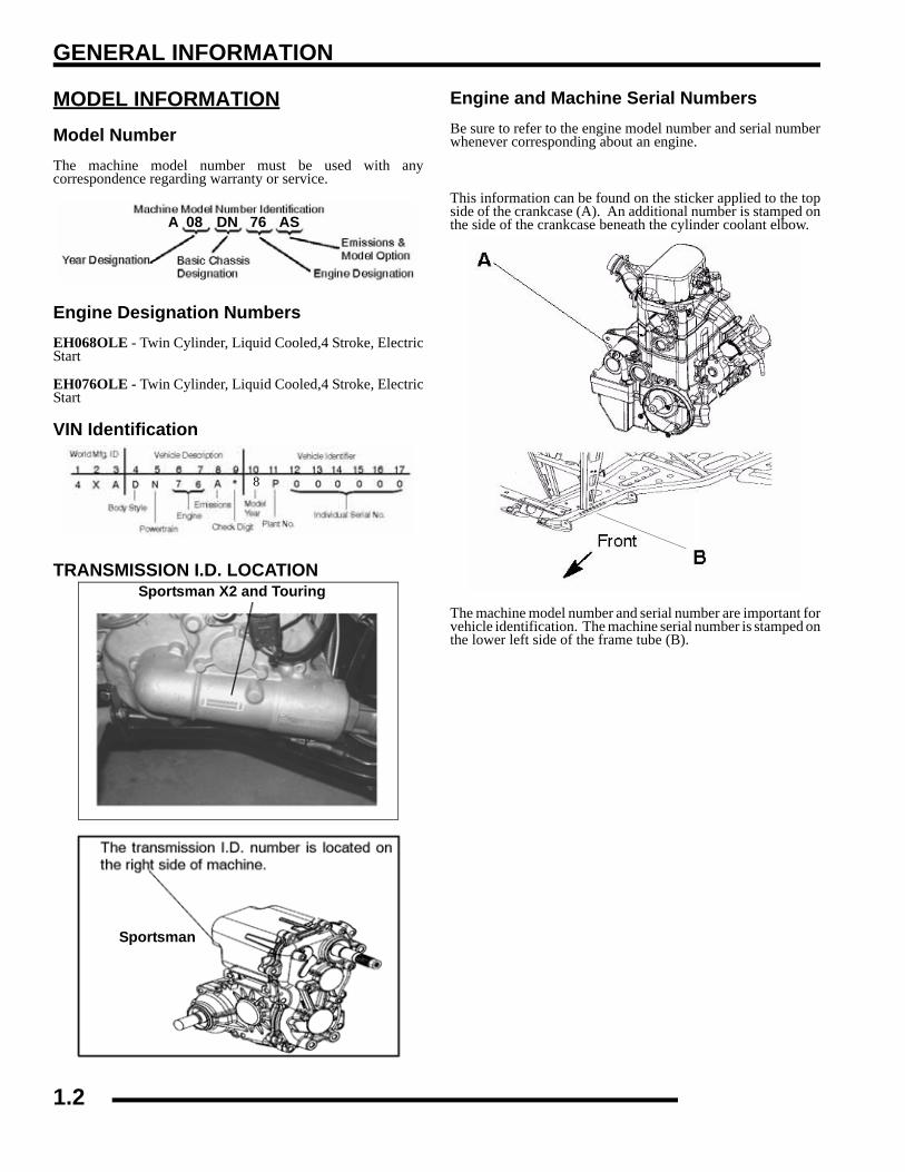
MODEL INFORMATIONModel NumberThe machine model number must be used with anycorrespondence regarding warranty or service.
Engine Designation NumbersEH068OLE - Twin Cylinder, Liquid Cooled,4 Stroke, ElectricStart
EH076OLE - Twin Cylinder, Liquid Cooled,4 Stroke, ElectricStart
VIN Identification
TRANSMISSION I.D. LOCATION
Engine and Machine Serial NumbersBe sure to refer to the engine model number and serial numberwhenever corresponding about an engine.
This information can be found on the sticker applied to the topside of the crankcase (A). An additional number is stamped onthe side of the crankcase beneath the cylinder coolant elbow.
The machine model number and serial number are important forvehicle identification. The machine serial number is stamped onthe lower left side of the frame tube (B).
A 08 DN 76 AS
8
Sportsman X2 and Touring
Sportsman
xxxxxxxx
1.2

GENERAL INFORMATION
1
PUBLICATIONSPAINT CODES
REPLACEMENT KEYSReplacement keys can be made from the original key. To identify which series the key is, take the first two digits on the originalkey and refer to the chart to the right for the proper part number. Should both keys become lost, ignition switch replacement isrequired.
Table 1-1: Publications
Year Model Model No. Owner's Manual PN
Parts Manual PN
2008 Sportsman 800 EFI A08MN76A 9921169 9921349
2008 Sportsman X2 700 EFI A08TN68A 9921356 9921357
2008 Sportsman Touring 800 EFIInternational
A08DN76AA08DN76F 9921356 9921359
Table 1-2: Paint Codes
PAINTED PART COLOR DESCRIPTION
DITZLER NUMBER
POLARIS NUMBER
Sportsman 700/800 EFI Frame Black 9440 P-067
Table 1-3: Key NumbersSeries # Part Number
20 401027821 401027822 401032123 401032127 401032128 401032131 411014132 411014867 401027868 4010278
Key BootPN 5433534
1.3

GENERAL INFORMATION
2008 SPORTSMAN 800 EFIMODEL NUMBER: A08MN76AF, AL, AQ, AS, AX
ENGINE MODEL: EH076OLE
Table 1-4: Sportsman 800 EFI General Specifications
Category Dimension / CapacityLength 83 in./205.74 cmWidth 48 in./116.8 cmHeight 48 in./119.4 cmSeat Height 34 in./86.4 cmWheel Base 50.75 in./128.9 cmDry Weight 770 lbs./326.6 kgGross Vehicle Weight 1220 lbs. / 553 kgFront Rack Capacity 100 lbs./45.4 kgRear Rack Capacity 200 lbs./90.7 kgTowing Capacity 1500 lbs./680 kgBody Style SpiritHitch Tongue Capacity 150 lbs./68 kg
Combination of rear rack weight and tongue weight not
to exceed 200 lbs. (91kg)
1.4

GENERAL INFORMATION
1
Table 1-5: 2008 800 EFI SpecificationsENGINE
Platform Polaris Twin Cylinder
Engine Model Number EH076OLE
Engine Displacement 760cc
Number of Cylinders 2
Bore & Stroke (mm) 80 x 76.5 mm
Compression Ratio 11:1
Compression Pressure 150-200 psi
Engine Idle Speed 1150 ± 100 RPM
Engine Max Operating Rpm 6600 Rpm ± 200 Rpm
Cooling System / Capacity Liquid - 3.6 qt/ 3.4 ltr.
Overheat Warning HOT on Instrument Cluster
Lubrication Pressurized Wet Sump
Oil Requirements / Capacity Polaris 2W-50 2 qt. / 1.9 liters
Exhaust System Dual Pipe / Silencer
Fuel SystemFuel System Electronic Fuel Injection
Fuel Pump 25L per hour at 39 PSI
Fuel Filter(s) 30 micron in Tank - (unserviceable)
Fuel Injector(s) Bosch
EFI Controller Bosch MSE 1.1B
Fuel Capacity / Requirement 4.13 gal US / 15.6 liters 87 Octane (minimum) or 89 Oxygenated
ElectricalAlternator Output 500 w @ 6000 RPM
Lights : Pod 50 watts
Grill Two x 37 watts
Brake 8.26 watts
Tail 26.9 watts
Worklights (If equipped) 2 x 13 watts
Ignition System DC/CDI Ignition
Ignition Timing 13°BTDC @ 1200 RPM
Spark plug / Gap RC7YC/ .035 in. / 0.9 mm
Battery / Amp Hr Lead Acid / 30 Amp Hr
Circuit Breakers Fan 20 amp / Harness 20 amp / ECU 15 amp / Inst. Cluster /
Voltage Regulator 6 amp
Starting Electric
Instrument Cluster Analog Speedo w/ LCD
Table 1-6: 2007 800 EFI SpecificationsDrivetrainTransmission Type Drumshift - H/L/N/Rev/Park Transmission Capacity 15 oz. / 450ml
Front Gearcase Capacity- CH 8.97 / 265 ml
Rear Gearcase Capacity 5 oz. / 150ml
Gear Ratio : Low Rev High Front Drive Rear Drive
7.49:15.11:12.88:13.82:13.10:1
Clutch Type PVT w/ EBS
Belt 3211113
Steering / SuspensionFront Suspension / Shock A-arm / MacPherson Strut
Front Travel 8.2 in. / 21 cm
Rear Suspension / Shock Progressive Rate Independent - Coil - over shock
Rear Travel 9.5 in. / 24.13 cm
Ground Clearance 11.25 in. / 28.6 cm
Shock Preload AdjustmentFront / Rear
Front -Non Adjustable.Rear - Ratchet Style- Std.
Turning Radius 76 in. / 193 cm
Toe Out 0 - 1/16 in / .0 - .159 mm
Wheels / BrakesWheel Size / Pattern - Front 26 x 8 - 12 / 4-156
Wheel Size / Pattern - Rear 26 x 11 - 12 / 4-156
Front Tire Size 26 x 8 - 12
Rear Tire Size 26 x 11 - 12
Recommended Air Pressure Front - 5 psi & Rear - 5 psi
Brake - Front Dual Hydraulic Disc
Brake - Rear Dual Hydraulic Disc
Table 1-7: A08MN76A ClutchingAltitude
Shift Weight
Drive Clutch Spring
Driven Clutch Type(Non-Adjustable)Meters
(Feet)
0-1800(0-6000) A08MN76
21-74 w/EBS
Red/Wht7043349 w/EBS
EBS - 1322751
1800-3700(6000-12000) A08MN76
21-72 w/EBS
Red/Wht7043349 w/EBS
EBS - 1322751
1.5

GENERAL INFORMATION
2008 SPORTSMAN X2 700 EFIMODEL NUMBER: A08TN68AZ, AX
ENGINE MODEL: EH068OLE
Table 1-8: Sportsman X2 700 EFI General Specifications
Category Dimension / CapacityLength 93 in./236 cmWidth 48 in./116.8 cmHeight 48 in./119.4 cmSeat Height 34 in./86.4 cmWheel Base 57 in./144.7 cmDry Weight 830 lbs./376.5 kgGross Vehicle Weight 1500 lbs./680.3 kgFront Rack/ Box Capacity 90 lbs./40.8 kgRear Box Capacity 400 lbs./181.4 kgTowing Capacity 1500 lbs./680 kgBody Style SpiritHitch Tongue Capacity 150 lbs./68 kg
Combination of rear rack weight and tongue weight not to exceed 400 lbs. (181.5 kg)
1.6

GENERAL INFORMATION
1
Table 1-9: 2008 X2 700 EFI SpecificationsENGINE
Platform Polaris Twin Cylinder
Engine Model Number EH068OLE
Engine Displacement 680cc
Number of Cylinders 2
Bore & Stroke (mm) 80 x 68 mm
Compression Ratio 9.78:1
Compression Pressure 150-200 psi
Engine Idle Speed 1150 ± 100 RPM
Engine Max Operating Rpm 6500 Rpm ± 200 Rpm
Cooling System / Capacity Liquid - 3.4 qt/ 3.2 ltr.
Overheat Warning HOT on Instrument Cluster
Lubrication Pressurized Wet Sump
Oil Requirements / Capacity Polaris 2W-50 2 qt. / 1.9 liters
Exhaust System Single Pipe / Silencer
Fuel SystemFuel System Electronic Fuel Injection
Fuel Pump 25L per hour at 39 PSI
Fuel Filter(s) 30 micron in Tank - (unserviceable)
Fuel Injector(s) Bosch
EFI Controller Bosch
Fuel Capacity / Requirement 6.0 gal US / 22.7 liters 87 Octane (minimum) or 89 Oxygenated
ElectricalAlternator Output 500 w @ 6000 RPM
Lights : Pod 50 watts
Grill Two x 37 watts
Tail 2 x 26.9 watts
Brake 2 x 8.26 watts
Worklights (Deluxe Only) 2 x 13 watts
Indicator Panel 1 watt
Ignition System DC/CDI Ignition
Ignition Timing Variable - ECU controlled
Spark plug / Gap RC7YC/ .035 in. / 0.9 mm
Battery / Amp Hr Lead Acid / 30 Amp Hr
Fuses Fan 20 amp / Harness 20 amp / ECU 15 amp / Inst. Cluster /
Voltage Regulator 5 amp
Starting Electric
Instrument Cluster Analog Speedo w/ LCD
Table 1-10: 2008 X2 700 EFI SpecificationsDrivetrainTransmission Type Drumshift - H/L/N/Rev/Park Transmission Capacity 32 oz. / 946.3ml
Front Gearcase Capacity- ADC 9.3 / 275 ml
Gear Ratio : Low Rev High Front Drive
23.91:121.74:18.28:13.82:1
Clutch Type PVT w/ EBS
Belt 3211113
Steering / SuspensionFront Suspension / Shock A-arm / MacPherson Strut
Front Travel 8.2 in. / 21 cm
Rear Suspension / Shock Progressive Rate Independent - Coil - over shock
Rear Travel 8.75 in. / 22.22 cm
Ground Clearance 11.25 in. / 28.6 cm
Shock Preload AdjustmentFront / Rear
Front -Non Adjustable.Rear - Ratchet Style- Std.
Turning Radius 82 in. / 208.2 cm
Toe Out 0 - 1/16 in / .0 - .159 mm
Wheels / BrakesWheel Size / Pattern - Front 25 x 8 - 12 / 4-156
Wheel Size / Pattern - Rear 25 x 11 - 12 / 4-156
Front Tire Size 25 x 8 - 12
Rear Tire Size 25 x 11 - 12
Recommended Air Pressure Front - 5 psi & Rear - 5 psi
Brake - Front Dual Hydraulic Disc
Brake - Rear Dual Hydraulic Disc
Table 1-11: A08TN76A EFI ClutchingAltitude
Shift Weight
Drive Clutch Spring
Driven Clutch Type(Non-Adjustable)Meters
(Feet)
0-1800(0-6000) A08TN68A
20-62 w/EBS
Grn/Blu 7041157w/EBS
EBS - 1322550
1800-3700(6000-12000) A08TN68A
20-58 w/EBS
Grn/Blu 7041157w/EBS
EBS - 1322550
1.7
GENERAL INFORMATION
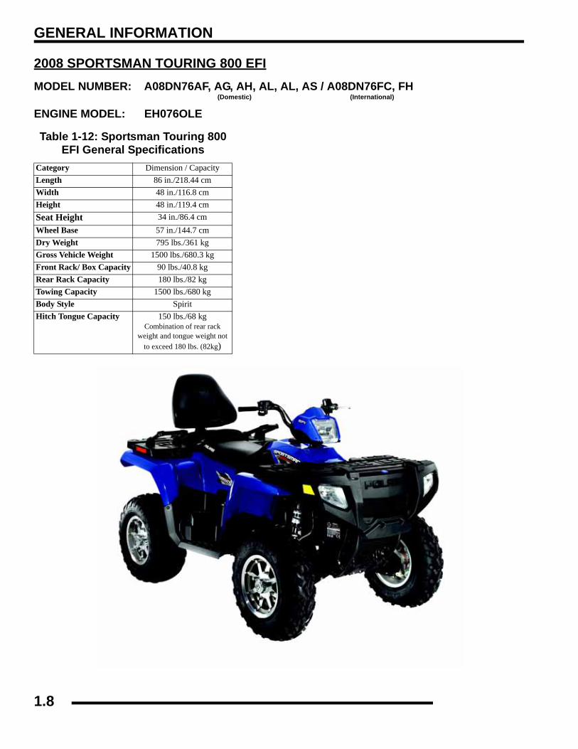
2008 SPORTSMAN TOURING 800 EFIMODEL NUMBER: A08DN76AF, AG, AH, AL, AL, AS / A08DN76FC, FH
(Domestic) (International)
ENGINE MODEL: EH076OLE
Table 1-12: Sportsman Touring 800 EFI General Specifications
Category Dimension / CapacityLength 86 in./218.44 cmWidth 48 in./116.8 cmHeight 48 in./119.4 cmSeat Height 34 in./86.4 cmWheel Base 57 in./144.7 cmDry Weight 795 lbs./361 kgGross Vehicle Weight 1500 lbs./680.3 kgFront Rack/ Box Capacity 90 lbs./40.8 kgRear Rack Capacity 180 lbs./82 kgTowing Capacity 1500 lbs./680 kgBody Style SpiritHitch Tongue Capacity 150 lbs./68 kg
Combination of rear rack weight and tongue weight not
to exceed 180 lbs. (82kg)
1.8

GENERAL INFORMATION
1
Table 1-13: 2008 Touring 800 EFISpecifications
ENGINE
Platform Polaris Twin Cylinder
Engine Model Number EH076OLE
Engine Displacement 760cc
Number of Cylinders 2
Bore & Stroke (mm) 80 x 76.5 mm
Compression Ratio 11:1
Compression Pressure 150-200 psi
Engine Idle Speed 1150 ± 100 RPM
Engine Max Operating Rpm 6600 Rpm ± 200 Rpm
Cooling System / Capacity Liquid - 3.4 qt/ 3.2 ltr.
Overheat Warning HOT on Instrument Cluster
Lubrication Pressurized Wet Sump
Oil Requirements / Capacity Polaris 2W-50 2 qt. / 1.9 liters
Exhaust System Single Pipe / Silencer
Fuel SystemFuel System Electronic Fuel Injection
Fuel Pump 25L per hour at 39 PSI
Fuel Filter(s) 30 micron in Tank - (unserviceable)
Fuel Injector(s) Bosch
EFI Controller Bosch
Fuel Capacity / Requirement 6.0 gal US / 22.7 liters 87 Octane (minimum) or 89 Oxygenated
ElectricalAlternator Output 500 w @ 6000 RPM
Lights : Pod 50 watts
Grill Two x 37 watts
Tail 2 x 26.9 watts
Brake 2 x 8.26 watts
Worklights (Deluxe Only) 2 x 13 watts
Indicator Panel 1 watt
Ignition System DC/CDI Ignition
Ignition Timing Variable - ECU controlled
Spark plug / Gap RC7YC/ .035 in. / 0.9 mm
Battery / Amp Hr Lead Acid / 30 Amp Hr
Fuses Fan 20 amp / Harness 20 amp / ECU 15 amp / Inst. Cluster /
Voltage Regulator 5 amp
Starting Electric
Instrument Cluster Analog Speedo w/ LCD
Table 1-14: 2008 Touring 800 EFI Specifications
DrivetrainTransmission Type Drumshift - H/L/N/Rev/Park Transmission Capacity 32 oz. / 946.3ml
Front Gearcase Capacity- ADC 9.3 / 275 ml
Gear Ratio : Low Rev High Front Drive
23.91:121.74:18.28:13.82:1
Clutch Type PVT w/ EBS (Standard and Deluxe)
Belt 3211113
Steering / SuspensionFront Suspension / Shock A-arm / MacPherson Strut
Front Travel 8.2 in. / 21 cm
Rear Suspension / Shock Progressive Rate Independent - Coil - over shock
Rear Travel 8.75 in. / 22.22 cm
Ground Clearance 11.25 in. / 28.6 cm
Shock Preload AdjustmentFront / Rear
Front -Non Adjustable.Rear - Ratchet Style- Std.
Turning Radius 82 in. / 208.2 cm
Toe Out 0 - 1/16 in / .0 - .159 mm
Wheels / BrakesWheel Size / Pattern - Front 25 x 8 - 12 / 4-156
Wheel Size / Pattern - Rear 25 x 11 - 12 / 4-156
Front Tire Size 25 x 8 - 12
Rear Tire Size 25 x 11 - 12
Recommended Air Pressure Front - 5 psi & Rear - 5 psi
Brake - Front Dual Hydraulic Disc
Brake - Rear Dual Hydraulic Disc
Table 1-15: A08DN76A ClutchingAltitude
Shift Weight
Drive Clutch Spring
Driven Clutch Type(Non-Adjustable)Meters
(Feet)
0-1800(0-6000) A08DN76A
20-62 w/EBS
Grn/Blu 7041157w/EBS
EBS - 1322550
1800-3700(6000-12000) A08DN76A
20-58 w/EBS
Grn/Blu 7041157w/EBS
EBS - 1322550
1.9
GENERAL INFORMATION
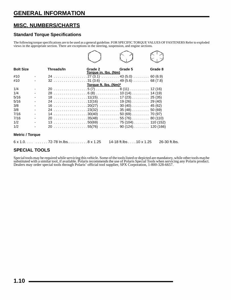
MISC. NUMBERS/CHARTSStandard Torque SpecificationsThe following torque specifications are to be used as a general guideline. FOR SPECIFIC TORQUE VALUES OF FASTENERS Refer to explodedviews in the appropriate section. There are exceptions in the steering, suspension, and engine sections.
Bolt Size Threads/In Grade 2 Grade 5 Grade 8 Torque in. lbs. (Nm)
#10 - 24 . . . . . . . . . . . . . . . . . 27 (3.1) . . . . . . . . . 43 (5.0) . . . . . . . . 60 (6.9)#10 - 32 . . . . . . . . . . . . . . . . . 31 (3.6) . . . . . . . . . 49 (5.6) . . . . . . . . 68 (7.8)
Torque ft. lbs. (Nm)*1/4 - 20 . . . . . . . . . . . . . . . . . 5 (7) . . . . . . . . . . . . 8 (11) . . . . . . . . . . 12 (16) 1/4 - 28 . . . . . . . . . . . . . . . . . 6 (8) . . . . . . . . . . . . 10 (14) . . . . . . . . . 14 (19) 5/16 - 18 . . . . . . . . . . . . . . . . . 11(15). . . . . . . . . . . 17 (23) . . . . . . . . . 25 (35) 5/16 - 24 . . . . . . . . . . . . . . . . . 12(16) . . . . . . . . . . 19 (26) . . . . . . . . . 29 (40) 3/8 - 16 . . . . . . . . . . . . . . . . . 20(27) . . . . . . . . . . 30 (40) . . . . . . . . . 45 (62) 3/8 - 24 . . . . . . . . . . . . . . . . . 23(32) . . . . . . . . . . 35 (48) . . . . . . . . . 50 (69) 7/16 - 14 . . . . . . . . . . . . . . . . . 30(40) . . . . . . . . . . 50 (69) . . . . . . . . . 70 (97) 7/16 - 20 . . . . . . . . . . . . . . . . . 35(48) . . . . . . . . . . 55 (76) . . . . . . . . . 80 (110)1/2 - 13 . . . . . . . . . . . . . . . . . 50(69) . . . . . . . . . . 75 (104) . . . . . . . . 110 (152) 1/2 - 20 . . . . . . . . . . . . . . . . . 55(76) . . . . . . . . . . 90 (124) . . . . . . . . 120 (166)
Metric / Torque
6 x 1.0. . . . . . . . . . 72-78 In.lbs. . . . . . . . . .8 x 1.25 14-18 ft.lbs . . . . 10 x 1.25 26-30 ft.lbs.
SPECIAL TOOLSSpecial tools may be required while servicing this vehicle. Some of the tools listed or depicted are mandatory, while other tools maybesubstituted with a similar tool, if available. Polaris recommends the use of Polaris Special Tools when servicing any Polaris product.Dealers may order special tools through Polaris’ official tool supplier, SPX Corporation, 1-800-328-6657.
1.10

GENERAL INFORMATION
1
SAE Tap Drill SizesMetric Tap Drill Sizes
Decimal Equivalents1/64 . . . . . . . . . . .. . . . . . . .0156
1/32 . . . . . . .. . . . . . . .0312 . . 1 mm= .0394"3/64 . . . . . . . . . . .. . . . . . . .0469
1/16 . . . . . . .. . . . . . . .06255/64 . . . . . . . . . . .. . . . . . . .0781 . . 2 mm = .0787"
3/32 . . . . . . .. . . . . . . .09387/64 . . . . . . . . . . .. . . . . . . .1094 . . 3 mm =.1181"
1/8 . . . . . . . . .12509/64 . . . . . . . . . . .. . . . . . . .1406
5/32 . . . . . . .. . . . . . . .1563 . . 4 mm = .1575"11/64 . . . . . . . . . . .. . . . . . . .1719
3/16 . . . . . . .. . . . . . . .1875 . . 5mm= .1969"13/64 . . . . . . . . . . .. . . . . . . .2031
7/32 . . . . . . .. . . . . . . .218815/64 . . . . . . . . . . .. . . . . . . .2344 . . 6 mm = .2362"
1/4 . . . . . . . . .2517/64 . . . . . . . . . . .. . . . . . . .2656 . . 7 mm = .2756"
9/32 . . . . . . .. . . . . . . .281319/64 . . . . . . . . . . .. . . . . . . .2969
5/16 . . . . . . .. . . . . . . .3125 . . 8mm= .3150"21/64 . . . . . . . . . . .. . . . . . . .3281
11/32 . . . . . .. . . . . . . .3438 . . 9 mm = .3543"23/64 . . . . . . . . . . .. . . . . . . .3594
3/8 . . . . . . . . .37525/64 . . . . . . . . . . .. . . . . . . .3906 . . 10 mm = .3937"
13/32 . . . . . .. . . . . . . .406327/64 . . . . . . . . . . .. . . . . . . .4219 . . 11 mm =.4331"
7/16 . . . . . . .. . . . . . . .437529/64 . . . . . . . . . . .. . . . . . . .4531
15/32 . . . . . .. . . . . . . .4688 . . 12 mm = .4724"31/64 . . . . . . . . . . .. . . . . . . .4844
1/2 . . . . . . . . .5 . . . . . . . . . . . 13mm = .5118"33/64 . . . . . . . . . . .. . . . . . . .5156
17/32 . . . . . .. . . . . . . .531335/64 . . . . . . . . . . .. . . . . . . .5469 . . 14 mm = .5512"
9/16 . . . . . . .. . . . . . . .562537/64 . . . . . . . . . . .. . . . . . . .5781 . . 15 mm = .5906"
19/32 . . . . . .. . . . . . . .593839/64 . . . . . . . . . . .. . . . . . . .6094
5/8 . . . . . . . . .625 . . . . . . . . . 16mm=. 6299"41/64 . . . . . . . . . . .. . . . . . . .6406
21/32 . . . . . .. . . . . . . .6563 . . 17 mm =.6693"43/64 . . . . . . . . . . .. . . . . . . .6719
11/16 . . . . . .. . . . . . . .687545/64 . . . . . . . . . . .. . . . . . . .7031 . . 18 mm = .7087"
23/32 . . . . . .. . . . . . . .718847/64 . . . . . . . . . . .. . . . . . . .7344 . . 19 mm = .7480"
3/4 . . . . . . . . .7549/64 . . . . . . . . . . .. . . . . . . .7656
25/32 . . . . . .. . . . . . . .7813 . . 20 mm = .7874"51/64 . . . . . . . . . . .. . . . . . . .7969
13/16 . . . . . .. . . . . . . .8125 . . 21 mm =.8268"53/64 . . . . . . . . . . .. . . . . . . .8281
27/32 . . . . . .. . . . . . . .843855/64 . . . . . . . . . . .. . . . . . . .8594 . . 22 mm = .8661"
7/8 . . . . . . . . .87557/64 . . . . . . . . . . .. . . . . . . .8906 . . 23 mm = .9055"
29/32 . . . . . .. . . . . . . .906359/64 . . . . . . . . . . .. . . . . . . .9219
15/16 . . . . . .. . . . . . . .9375 . . 24 mm = .9449"61/64 . . . . . . . . . . .. . . . . . . .9531
31/32 . . . . . .. . . . . . . .9688 . . 25 mm = .9843"63/64 . . . . . . . . . . .. . . . . . . .9844
1. . . . . . . . . . 1.0
Thread Size/ Drill Size Thread Size / Drill Size#0-80 3/64 1/2-13 27/64#1-64 53 1/2-20 29/64#1-72 53 9/16-12 31/64#2-56 51 9/16-18 33/64#2-64 50 5/8-11 17/32#3-48 5/64 5/8-18 37/64#3-56 45 3/4-10 21/32#4-40 43 3/4-16 11/16#4-48 42 7/8-9 49/64#5-40 38 7/8-14 13/16#5-44 37 1-8 7/8#6-32 36 1-12 59/64#6-40 33 1 1/8-7 63/64#8-32 29 1 1/8-12 1 3/64#8-36 29 1 1/4-7 1 7/64#10-24 24 1 1/4-12 1 11/64#10-32 21 1 1/2-6 1 11/32#12-24 17 1 1/2-12 1 27/64#12-28 4.6mm 1 3/4-5 1 9/161/4-20 7 1 3/4-12 1 43/641/4-28 3 2-4 1/2 1 25/325/16-18 F 2-12 1 59/645/16-24 I 2 1/4-4 1/2 2 1/323/8-16 O 2 1/2-4 2 1/43/8-24 Q 2 3/4-4 2 1/27/16-14 U 3-4 2 3/47/16-20 25/64
Tap Size Drill Size DecimalEquivalent
NearestFraction
3x.50 #39 0.0995 3/323x.60 3/32 0.0937 3/324x.70 #30 0.1285 1/84x.75 1/8 0.125 1/85x.80 #19 0.166 11/645x.90 #20 0.161 5/326x1.00 #9 0.196 13/647x1.00 16/64 0.234 15/648x1.00 J 0.277 9/328x1.25 17/64 0.265 17/649x1.00 5/16 0.3125 5/169x1.25 5/16 0.3125 5/1610x1.25 11/32 0.3437 11/3210x1.50 R 0.339 11/3211x1.50 3/8 0.375 3/812x1.50 13/32 0.406 13/3212x1.75 13/32 0.406 13/32
1.11

GENERAL INFORMATION
Conversion Table
°C to °F: 9 (°C + 40) ÷ 5 - 40 = °F °F to °C: 5 (°F + 40) ÷ 9 - 40 = °C
Unit of Measure Multiplied by Converts toft. lbs. x 12 = in. lbs.in. lbs. x .0833 = ft. lbs.ft. lbs. x 1.356 = Nmin. lbs. x .0115 = kg-mNm x .7376 = ft. lbs.kg-m x 7.233 = ft. lbs.kg-m x 86.796 = in. lbs.kg-m x 10 = Nmin. x 25.4 =mmmm x .03937 = in.in. x 2.54 = cmmile (mi.) x 1.6 = kmkm x .6214 = mile (mi.)Ounces (oz.) x 28.35 = Grams (g)Fluid Ounces (fl. oz.) x 29.57 = Cubic Centimeters (cc)Cubic Centimeters (cc) x .03381 = Fluid Ounces (fl. oz.)Grams (g) x 0.035 = Ounces (oz.)lb. x .454 = kgkg x 2.2046 = lb.Cubic inches (cu. in) x 16.387 = Cubic centimeters (cc)Cubic centimeters (cc) x 0.061 = Cubic inches (cu. in)Imperial pints (Imp pt.) x 0.568 = Liters (l)Liters (l) x 1.76 = Imperial pints (Imp pt.)Imperial quarts (Imp qt.) x 1.137 = Liters (l)Liters (l) x 0.88 = Imperial quarts (Imp qt.)Imperial quarts (Imp qt.) x 1.201 = US quarts (US qt.)US quarts (US qt.) x 0.833 = Imperial quarts (Imp qt.)US quarts (US qt.) x 0.946 = Liters (l)Liters (l) x 1.057 = US quarts (US qt.)US gallons (US gal) x 3.785 =Liters (l)Liters (l) x 0.264 = US gallons (US gal)Pounds - force per square inch (psi) x 6.895 = Kilopascals (kPa)Kilopascals (kPa) x 0.145 = Pounds - force per square inch (psi)Kilopascals (kPa) x 0.01 = Kilograms - force per square cmKilograms - force per square cm x 98.1 = Kilopascals (kPa)π(3.14)xR2x H (height) = Cylinder Volume
1.12

GENERAL INFORMATION
1
Glossary Of TermsABDC: After bottom dead center.ACV: Alternating current voltage.ADC: Active Descent Control. Engages front wheels for 4-wheel EBS.Alternator: Electrical generator producing voltage alternating current.ATDC: After top dead center.BBDC: Before bottom dead center.BDC: Bottom dead center.BTDC: Before top dead center.CC: Cubic centimeters.Center Distance: Distance between center of crankshaft and center of driven clutch shaft.Chain Pitch: Distance between chain link pins (No. 35 = 3/8" or 1 cm). Polaris measures chain length in number of pitches.CI: Cubic inches.Clutch Buttons: Plastic bushings which aid rotation of the movable sheave in the drive and driven clutch.Clutch Offset: Drive and driven clutches are offset so that drive belt will stay nearly straight as it moves along the clutch face.Clutch Weights: Three levers in the drive clutch which relative to their weight, profile and engine RPM cause the drive clutch to close andgrip the drive belt.Crankshaft Run-Out: Run-out or "bend" of crankshaft measured with a dial indicator while crankshaft is supported between centers on Vblocks or resting in crankcase. Measure at various points especially at PTO.CVT: Centrifugal Variable Transmission (Drive Clutch System)DCV: Direct current voltage.Dial Bore Gauge: A cylinder measuring instrument which uses a dial indicator. Good for showing taper and out-of-round in the cylinder bore.EBS: Engine Braking System. Uses engine compression to slow the ATV without the use of hydraulic brakes.Electrical Open: Open circuit. An electrical circuit which isn't complete.Electrical Short: Short circuit. An electrical circuit which is completed before the current reaches the intended load. (i.e. a bare wire touchingthe chassis).End Seals: Rubber seals at each end of the crankshaft.Engagement RPM: Engine RPM at which the drive clutch engages to make contact with the drive belt.ft.: Foot/feet.Foot Pound: Ft. lb. A force of one pound at the end of a lever one foot in length, applied in a rotational direction.g: Gram. Unit of weight in the metric system.gal.: Gallon.ID: Inside diameter.in.: Inch/inches.Inch Pound: In. lb. 12 in. lbs. = 1 ft. lb.kg/cm2: Kilograms per square centimeter.kg-m: Kilogram meters.Kilogram/meter: A force of one kilogram at the end of a lever one meter in length, applied in a rotational direction.l or ltr: Liter.lbs/in2: Pounds per square inch.Left or Right Side: Always referred to based on normal operating position of the driver.m: Meter/meters.Mag: Magneto.Magnetic Induction: As a conductor (coil) is moved through a magnetic field, a voltage will be generated in the windings. Mechanical energyis converted to electrical energy in the stator.mi.: Mile/miles.mm: Millimeter. Unit of length in the metric system. 1 mm = approximately .040".Nm: Newton meters.OD: Outside diameter.Ohm: The unit of electrical resistance opposing current flow.oz.: Ounce/ounces.Piston Clearance: Total distance between piston and cylinder wall.psi.: Pounds per square inch.PTO: Power take off.qt.: Quart/quarts.Regulator: Voltage regulator. Regulates battery charging system output at approximately 14.5 DCV as engine RPM increases.Reservoir Tank: The fill tank in the liquid cooling system.Resistance: In the mechanical sense, friction or load. In the electrical sense, ohms, resulting in energy conversion to heat.RPM: Revolutions per minute.Seized Piston: Galling of the sides of a piston. Usually there is a transfer of aluminum from the piston onto the cylinder wall.Possible causes: 1) improper lubrication; 2) excessive temperatures; 3) insufficient piston clearance; 4) stuck piston rings.Stator Plate: The plate mounted under the flywheel supporting the battery charging coils.TDC: Top dead center. Piston's most outward travel from crankshaft.Volt: The unit of measure for electrical pressure of electromotive force. Measured by a voltmeter in parallel with the circuit.Watt: Unit of electrical power. Watts = amperes x volts.WOT: Wide open throttle.1.13

GENERAL INFORMATION
NOTES
1.14

MAINTENANCE
CHAPTER 2MAINTENANCE
2
MAINTENANCE. . . . . . . . . . . . . . . . . . . . . . . . . . . . . . . . . . . . . . . . . . . . . . . . . . . . . . . . . 2.3OVERVIEW. . . . . . . . . . . . . . . . . . . . . . . . . . . . . . . . . . . . . . . . . . . . . . . . . . . . . . . . . . . . 2.3PERIODIC MAINTENANCE CHART . . . . . . . . . . . . . . . . . . . . . . . . . . . . . . . . . . . . . . . . 2.4LUBRICATION / FLUIDS. . . . . . . . . . . . . . . . . . . . . . . . . . . . . . . . . . . . . . . . . . . . . . . . . . 2.7SPORTSMAN COMPONENT LOCATIONS. . . . . . . . . . . . . . . . . . . . . . . . . . . . . . . . . . . 2.7SPORTSMAN X2-TOURING COMPONENT LOCATIONS . . . . . . . . . . . . . . . . . . . . . . . 2.8POLARIS LUBRICANTS, MAINTENANCE AND SERVICE PRODUCTS . . . . . . . . . . . . 2.9POLARIS LUBRICANT SYMBOL IDENTIFICATION . . . . . . . . . . . . . . . . . . . . . . . . . . . 2.10PRE-RIDE / DAILY INSPECTION . . . . . . . . . . . . . . . . . . . . . . . . . . . . . . . . . . . . . . . . . 2.10LUBRICATION / GREASE POINTS . . . . . . . . . . . . . . . . . . . . . . . . . . . . . . . . . . . . . . . . 2.11FRONT GEARCASE LUBRICATION . . . . . . . . . . . . . . . . . . . . . . . . . . . . . . . . . . . . . . . 2.12REAR GEARCASE LUBRICATION - 800 EFI . . . . . . . . . . . . . . . . . . . . . . . . . . . . . . . . 2.13TRANSMISSION LUBRICATION . . . . . . . . . . . . . . . . . . . . . . . . . . . . . . . . . . . . . . . . . . 2.14ADC DIFFERENTIAL HYDRAULIC CIRCUIT FLUID CHANGE. . . . . . . . . . . . . . . . . . . 2.15
VEHICLE INSPECTION. . . . . . . . . . . . . . . . . . . . . . . . . . . . . . . . . . . . . . . . . . . . . . . . . . 2.15SHIFT LINK ROD INSPECTION. . . . . . . . . . . . . . . . . . . . . . . . . . . . . . . . . . . . . . . . . . . 2.15THROTTLE INSPECTION . . . . . . . . . . . . . . . . . . . . . . . . . . . . . . . . . . . . . . . . . . . . . . . 2.16THROTTLE CABLE / ELECTRONIC THROTTLE CONTROL ADJUSTMENT . . . . . . . 2.16FUEL SYSTEM. . . . . . . . . . . . . . . . . . . . . . . . . . . . . . . . . . . . . . . . . . . . . . . . . . . . . . . . 2.17VENT LINES. . . . . . . . . . . . . . . . . . . . . . . . . . . . . . . . . . . . . . . . . . . . . . . . . . . . . . . . . . 2.17COMPRESSION TEST. . . . . . . . . . . . . . . . . . . . . . . . . . . . . . . . . . . . . . . . . . . . . . . . . . 2.17ENGINE MOUNTS . . . . . . . . . . . . . . . . . . . . . . . . . . . . . . . . . . . . . . . . . . . . . . . . . . . . . 2.18SPARK PLUG. . . . . . . . . . . . . . . . . . . . . . . . . . . . . . . . . . . . . . . . . . . . . . . . . . . . . . . . . 2.18ACTIVE DESCENT CONTROL (ADC) RESERVOIR LEVEL. . . . . . . . . . . . . . . . . . . . . 2.18BATTERY MAINTENANCE . . . . . . . . . . . . . . . . . . . . . . . . . . . . . . . . . . . . . . . . . . . . . . 2.19COOLING SYSTEM. . . . . . . . . . . . . . . . . . . . . . . . . . . . . . . . . . . . . . . . . . . . . . . . . . . . 2.19COOLANT STRENGTH / TYPE . . . . . . . . . . . . . . . . . . . . . . . . . . . . . . . . . . . . . . . . . . . 2.20COOLING HOSES . . . . . . . . . . . . . . . . . . . . . . . . . . . . . . . . . . . . . . . . . . . . . . . . . . . . . 2.20RADIATOR . . . . . . . . . . . . . . . . . . . . . . . . . . . . . . . . . . . . . . . . . . . . . . . . . . . . . . . . . . . 2.20COOLING SYSTEM PRESSURE TEST. . . . . . . . . . . . . . . . . . . . . . . . . . . . . . . . . . . . . 2.20RESERVOIR LEVEL INSPECTION . . . . . . . . . . . . . . . . . . . . . . . . . . . . . . . . . . . . . . . . 2.20RADIATOR COOLANT LEVEL. . . . . . . . . . . . . . . . . . . . . . . . . . . . . . . . . . . . . . . . . . . . 2.21AIR FILTER SERVICE . . . . . . . . . . . . . . . . . . . . . . . . . . . . . . . . . . . . . . . . . . . . . . . . . . 2.21AIR BOX SEDIMENT TUBE . . . . . . . . . . . . . . . . . . . . . . . . . . . . . . . . . . . . . . . . . . . . . . 2.22ENGINE BREATHER HOSE . . . . . . . . . . . . . . . . . . . . . . . . . . . . . . . . . . . . . . . . . . . . . 2.22PVT INSPECTION / DRYING PROCEDURE. . . . . . . . . . . . . . . . . . . . . . . . . . . . . . . . . 2.23ENGINE GROUND . . . . . . . . . . . . . . . . . . . . . . . . . . . . . . . . . . . . . . . . . . . . . . . . . . . . . 2.23ENGINE OIL LEVEL . . . . . . . . . . . . . . . . . . . . . . . . . . . . . . . . . . . . . . . . . . . . . . . . . . . . 2.23OIL/FILTER CHANGE . . . . . . . . . . . . . . . . . . . . . . . . . . . . . . . . . . . . . . . . . . . . . . . . . . 2.24STEERING INSPECTION. . . . . . . . . . . . . . . . . . . . . . . . . . . . . . . . . . . . . . . . . . . . . . . . 2.25TIE ROD / STEERING . . . . . . . . . . . . . . . . . . . . . . . . . . . . . . . . . . . . . . . . . . . . . . . . . . 2.25CAMBER/CASTER. . . . . . . . . . . . . . . . . . . . . . . . . . . . . . . . . . . . . . . . . . . . . . . . . . . . . 2.25WHEEL ALIGNMENT . . . . . . . . . . . . . . . . . . . . . . . . . . . . . . . . . . . . . . . . . . . . . . . . . . . 2.26TOE ALIGNMENT. . . . . . . . . . . . . . . . . . . . . . . . . . . . . . . . . . . . . . . . . . . . . . . . . . . . . . 2.26EXHAUST PIPE . . . . . . . . . . . . . . . . . . . . . . . . . . . . . . . . . . . . . . . . . . . . . . . . . . . . . . . 2.27BRAKE SYSTEM INSPECTION. . . . . . . . . . . . . . . . . . . . . . . . . . . . . . . . . . . . . . . . . . . 2.27BRAKE PADS. . . . . . . . . . . . . . . . . . . . . . . . . . . . . . . . . . . . . . . . . . . . . . . . . . . . . . . . . 2.28BRAKE HOSE INSPECTION . . . . . . . . . . . . . . . . . . . . . . . . . . . . . . . . . . . . . . . . . . . . . 2.28AUXILIARY (REAR) BRAKE TEST . . . . . . . . . . . . . . . . . . . . . . . . . . . . . . . . . . . . . . . . 2.28AUXILIARY BRAKE ADJUSTMENT. . . . . . . . . . . . . . . . . . . . . . . . . . . . . . . . . . . . . . . . 2.29SUSPENSION: SPRING PRELOAD ADJUSTMENT . . . . . . . . . . . . . . . . . . . . . . . . . . . 2.29FRONT SUSPENSION. . . . . . . . . . . . . . . . . . . . . . . . . . . . . . . . . . . . . . . . . . . . . . . . . . 2.29REAR SUSPENSION . . . . . . . . . . . . . . . . . . . . . . . . . . . . . . . . . . . . . . . . . . . . . . . . . . . 2.29CV SHAFT BOOT INSPECTION . . . . . . . . . . . . . . . . . . . . . . . . . . . . . . . . . . . . . . . . . . 2.29
2.1

MAINTENANCE
ATV CONTROLS . . . . . . . . . . . . . . . . . . . . . . . . . . . . . . . . . . . . . . . . . . . . . . . . . . . . . . 2.30WHEEL INSPECTION . . . . . . . . . . . . . . . . . . . . . . . . . . . . . . . . . . . . . . . . . . . . . . . . . . 2.30WHEEL REMOVAL: FRONT OR REAR . . . . . . . . . . . . . . . . . . . . . . . . . . . . . . . . . . . . 2.30WHEEL INSTALLATION . . . . . . . . . . . . . . . . . . . . . . . . . . . . . . . . . . . . . . . . . . . . . . . . 2.30TIRE PRESSURE. . . . . . . . . . . . . . . . . . . . . . . . . . . . . . . . . . . . . . . . . . . . . . . . . . . . . . 2.31TIRE INSPECTION. . . . . . . . . . . . . . . . . . . . . . . . . . . . . . . . . . . . . . . . . . . . . . . . . . . . . 2.31FRAME, NUTS, BOLTS, FASTENERS . . . . . . . . . . . . . . . . . . . . . . . . . . . . . . . . . . . . . 2.31FRONT / REAR STORAGE COMPARTMENTS . . . . . . . . . . . . . . . . . . . . . . . . . . . . . . 2.31WINCH OPERATION (IF EQUIPPED) . . . . . . . . . . . . . . . . . . . . . . . . . . . . . . . . . . . . . . 2.32CLEANING AND STORAGE OF ATV . . . . . . . . . . . . . . . . . . . . . . . . . . . . . . . . . . . . . . 2.34MAINTENANCE SCHEDULE. . . . . . . . . . . . . . . . . . . . . . . . . . . . . . . . . . . . . . . . . . . . . 2.37MAINTENANCE SCHEDULE. . . . . . . . . . . . . . . . . . . . . . . . . . . . . . . . . . . . . . . . . . . . . 2.38
2.2
MAINTENANCE
2
MAINTENANCEOverviewCareful periodic maintenance will help keep your vehicle in the safest, most reliable condition. Inspection, adjustment andlubrication of important components are explained in the periodic maintenance chart.
Inspect, clean, lubricate, adjust and replace parts as necessary. When inspection reveals the need for replacement parts, use genuinePolaris parts available from your Polaris dealer.
NOTE: Service and adjustments are critical. If you're not familiar with safe service and adjustment procedures, have a qualifieddealer perform these operations.
Maintenance intervals in the following chart are based upon average riding conditions and an average vehicle speed of approximately10 miles per hour. Vehicles subjected to severe use must be inspected and serviced more frequently.
• Frequent immersion in mud, water or sand
• Racing or race-style high RPM use
• Prolonged low speed, heavy load operation
• Extended idle
• Short trip cold weather operation
Pay special attention to the oil level. A rise in oil level during cold weather can indicate contaminants collecting in the oil sump orcrankcase. Change oil immediately if the oil level begins to rise. Monitor the oil level, and if it continues to rise, discontinue useand determine the cause.
Maintenance Chart KeyThe following symbols denote potential items to be aware of during maintenance:
= CAUTION: Due to the nature of these adjustments, it is recommended this service be performed by an authorizedPolaris dealer.
= SEVERE USE ITEM --If vehicle is subjected to severe use, decrease interval by 50% (Severe Use is defined as frequentvehicle immersion in mud, water or sand, racing or race-style high rpm use, prolonged low speed - heavy load operation orextended idle. More preventative maintenance is required under these conditions. Fluid changes, cable, chain and chassislubrication are required more frequently. For engine oil, short trip cold weather riding also constitutes severe use. Payspecial attention to oil level. A rising oil level in cold weather can indicate contaminants collecting in the oil sump orcrankcase. Change oil immediately and monitor level. If oil level begins to rise, discontinue use and determine cause.)
E = Emission Control System Service (California).
NOTE: Inspection may reveal the need for replacement parts. Always use genuine Polaris parts.
WARNING: Improperly performing the procedures marked with a could result in component failure and lead to serious injuryor death. Have an authorized Polaris dealer perform these services.
2.3

MAINTENANCE
Periodic Maintenance Chart
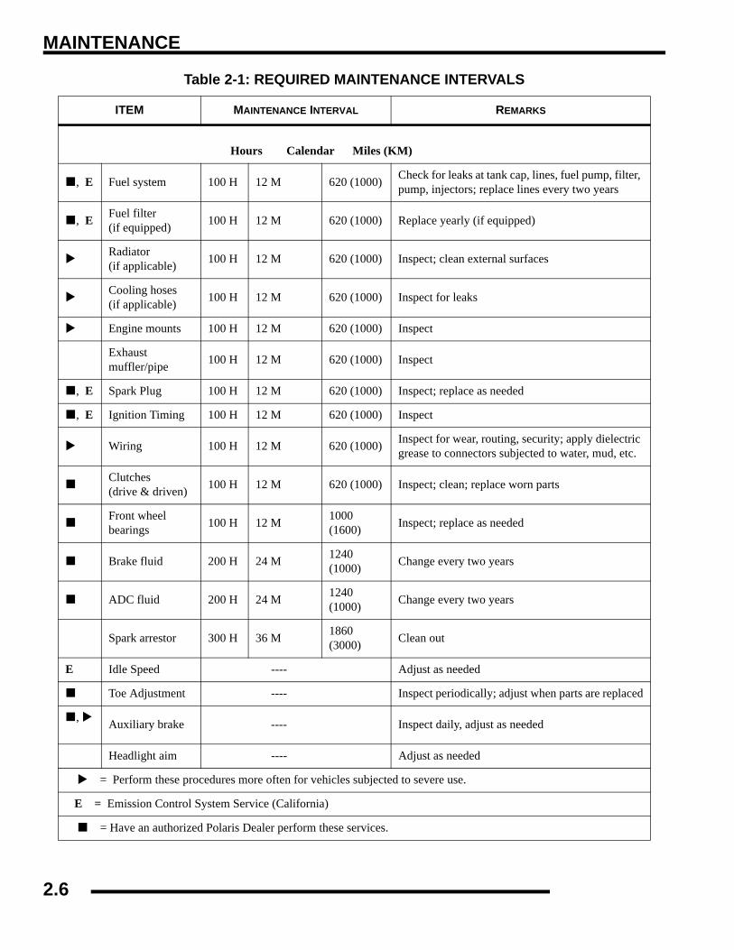
Table 2-1: REQUIRED MAINTENANCE INTERVALS
ITEM MAINTENANCE INTERVAL REMARKS
Hours Calendar Miles (KM)
Steering -- Pre-Ride --
Make adjustments as needed.
Front Suspension -- Pre-Ride --
Rear Suspension -- Pre-Ride --
Tires -- Pre-Ride --
ADC Fluid Level -- Pre-Ride --
Brake Fluid Level -- Pre-Ride --
Brake Lever Travel -- Pre-Ride --
Brake Systems -- Pre-Ride --
Wheels/Fasteners -- Pre-Ride --
Frame Fasteners -- Pre-Ride --
, E Engine Oil Level -- Pre-Ride --
, E Air filter, pre-filter -- Daily -- Inspect; clean often
, E Air Box Sediment Tube -- Daily -- Drain deposits when visible
Coolant (if applicable) -- Daily -- Check level daily, change coolant every 2 years
Head lamp/tail lamp -- Daily -- Check operation; apply dielectric grease if replacing
, E Air filter, main element -- Weekly -- Inspect; replace as needed
Recoil housing (if applicable) -- Weekly -- Drain water as needed, check often if operating in
wet conditions
, E Brake Pad Wear 10 H Monthly 60 (100) Inspect periodically
Battery 20 H Monthly 125 (200) Check terminals; clean; test
= Perform these procedures more often for vehicles subjected to severe use.
E = Emission Control System Service (California)
= Have an authorized Polaris Dealer perform these services.
2.4

MAINTENANCE
2
Hours Calendar Miles (KM)Front gearcase oil (if equipped) 25 H Monthly 155 (250) Inspect level; change yearly
Middle gearcase oil (if equipped) 25 H Monthly 155 (250) Inspect level; change yearly
Rear gearcase oil (if equipped) 25 H Monthly 155 (250) Inspect level; change yearly
Transmission Oil 25 H Monthly 155 (250) Inspect level; change yearly
, EEngine breather filter (if equipped)
25 H Monthly 155 (250) Inspect; replace if necessary
, E Engine oil change (break-in) 25 H 1 M 155 (250) Perform a break-in oil change at one month
General lubrication 50 H 3 M 310 (500) Lubricate all fittings, pivots, cables, etc.
Shift Linkage 50 H 6 M 310 (500) Inspect, lubricate, adjust
Steering 50 H 6 M 310 (500) Lubricate
Front Suspension 50 H 6 M 310 (500) Lubricate
Rear Suspension 50 H 6 M 310 (500) Lubricate
, E Throttle Cable/ETC Switch 50 H 6 M 310 (500) Inspect; adjust; lubricate; replace if necessary
E Air intake ducts 50 H 6 M 310 (500) Inspect ducts for proper sealing/air leaks
Drive belt 50 H 6 M 310 (500) Inspect; adjust; replace as needed
Cooling system (if applicable) 50 H 6 M 310 (500) Inspect coolant strength seasonally; pressure test
system yearly
, E Engine Oil Change 100 H 6 M 620 (1000) Perform a break-in oil change at 25 hours/one month
, E Oil filter change 100 H 6 M 620 (1000) Replace with oil change
, E Oil tank vent hose (if applicable) 100 H 12 M 620 (1000) Inspect routing, condition
, E Valve Clearance 100 H 12 M 620 (1000) Inspect;
= Perform these procedures more often for vehicles subjected to severe use.
E = Emission Control System Service (California)
= Have an authorized Polaris Dealer perform these services.
Table 2-1: REQUIRED MAINTENANCE INTERVALS
ITEM MAINTENANCE INTERVAL REMARKS
2.5
MAINTENANCE
Hours Calendar Miles (KM)
, E Fuel system 100 H 12 M 620 (1000) Check for leaks at tank cap, lines, fuel pump, filter, pump, injectors; replace lines every two years
, E Fuel filter (if equipped) 100 H 12 M 620 (1000) Replace yearly (if equipped)
Radiator (if applicable) 100 H 12 M 620 (1000) Inspect; clean external surfaces
Cooling hoses (if applicable) 100 H 12 M 620 (1000) Inspect for leaks
Engine mounts 100 H 12 M 620 (1000) Inspect
Exhaust muffler/pipe 100 H 12 M 620 (1000) Inspect
, E Spark Plug 100 H 12 M 620 (1000) Inspect; replace as needed
, E Ignition Timing 100 H 12 M 620 (1000) Inspect
Wiring 100 H 12 M 620 (1000) Inspect for wear, routing, security; apply dielectric grease to connectors subjected to water, mud, etc.
Clutches (drive & driven) 100 H 12 M 620 (1000) Inspect; clean; replace worn parts
Front wheel bearings 100 H 12 M 1000
(1600) Inspect; replace as needed
Brake fluid 200 H 24 M 1240 (1000) Change every two years
ADC fluid 200 H 24 M 1240 (1000) Change every two years
Spark arrestor 300 H 36 M 1860 (3000) Clean out
E Idle Speed ---- Adjust as needed
Toe Adjustment ---- Inspect periodically; adjust when parts are replaced
,
Auxiliary brake ---- Inspect daily, adjust as needed
Headlight aim ---- Adjust as needed
= Perform these procedures more often for vehicles subjected to severe use.
E = Emission Control System Service (California)
= Have an authorized Polaris Dealer perform these services.
Table 2-1: REQUIRED MAINTENANCE INTERVALS
ITEM MAINTENANCE INTERVAL REMARKS
2.6

MAINTENANCE
2
LUBRICATION / FLUIDSSPORTSMAN Component Locations
(Sportsman Only)
(Deluxe)
2.7

MAINTENANCE
SPORTSMAN X2-Touring Component LocationsAWD/ADC Switch
Throttle
Ignition/Key
Instrument ClusterWorklight
Diagnostic
Reverse
Brake Fluid Reservoir
Brake Lever
Light Control& Run Switch
(Speedometer)
Override
X2 Rear Dump Box / Passenger Area
PVT Cover
Oil Dipstick
Front Demand
(Behind Radiator)
Front Storage Compartment& Rack
Gas CapGear Shifter
Front Drive CV Shafts
Front Prop Shaft(Between Transmissionand Front Gearcase)
TransmissionMuffler
Right Side View
Auxiliary Brake
Port (under access panel)
Drive Unit
Battery (Under Tank)
Rear Drive CV Shafts
(Sportsman X2 Shown)
Differential Switch
2.8

MAINTENANCE
2
Polaris Lubricants, Maintenance and Service Products
Table 2-2: PART
NUMBER DESCRIPTION
Engine Lubricant2870791 Fogging Oil (12 oz. Aerosol)
2876244 Engine Oil (Quart) Premium Synthetic 2W-50 (4-cycle) (12 count)
2876245 Engine Oil (Gallon) Premium Synthetic 2W-50 (4-cycle) (4 count)
Gearcase / Transmission Lubricants2876251 Demand Drive LT Premium Hub Fluid 3234438 Polaris ADC Hydraulic Fluid
2873602 Premium Synthetic AGL Gearcase Lube (12 oz. bottle) (12 count)
2873603 Premium Synthetic AGL Gearcase Lube (1 Gal. bottle) (4 count)
2876160 Premium ATV Angle Drive Fluid (32 oz.) (12 count)
2872276 Premium ATV Angle Drive Fluid (2.5 Gal.) (2 count)
2870465 Oil Pump for 1 Gallon JugGrease / Specialized Lubricants
2871322 Premium All Season Grease (3 oz. cartridge) (24 count)
2871423 Premium All Season Grease (14 oz. cartridge) (10 count)
2871460 Starter Drive Grease (12 count)
2871515 Premium U-Joint Lube (3 oz.) (24 Count)
2871551 Premium U-Joint Lube (14 oz.) (10 count)
2871312 Grease Gun Kit2871329 Dielectric Grease (Nyogel™)
Coolant2871323 60/40 Coolant (Gallon) (6 count)2871534 60/40 Coolant (Quart) (12 count)
Additives / Sealants / Thread Locking Agents / Misc.2874275 Loctite™ Primer N, Aerosol
2871956 Loctite™ Thread Sealant 565 (50 ml.) (6 count)
2871950 Loctite™ Threadlock 242 (6 ml.) (12 count)
2871951 Loctite™ Threadlock 262 (50 ml.) (10 count)
2871953 Loctite™ Threadlock 271 (6 ml.) (12 count)
2871557 3-Bond 1215 Sealant(5 oz.)
2871326 Premium Carbon Clean (12 oz.) (12 count)
2870652 Fuel Stabilizer (16 oz.) (12 count)
2871957 Black RTV Silicone Sealer (3 oz. tube ) (12 count)
2871958 Black RTV Silicone Sealer (11 oz. cartridge) (12 count)
2872189 DOT 4 Brake Fluid (12 count)2871557 Crankcase Sealant, 3 Bond 1215 (5 oz.)
Table 2-2: PART
NUMBER DESCRIPTION
2.9

MAINTENANCE
Polaris Lubricant Symbol IdentificationNOTE: The symbols used are for quick reference in identifyingwhich lubricant/grease to use on each component.
Pre-Ride / Daily InspectionPerform the following pre-ride inspection daily, and whenservicing the vehicle at each scheduled maintenance.
• Tires - check tire condition and air pressures
• Fuel and oil - fill both to their proper level; Do notoverfill
• All brakes - check operation and adjustment (includesauxiliary brake)
• Throttle -check for free operation
• Headlight/Taillight/Brakelight - check operation of allindicator lights and switches
• Engine stop switch - check for proper function
• Wheels - check for loose wheel nuts and axle nuts;check to be sure axle nuts are secured by cotter pins
• Air cleaner element - check for dirt or water; clean orreplace
• Steering - check for free operation, noting any unusuallooseness in any area
• Loose parts - visually inspect vehicle for any damagedor loose nuts, bolts or fasteners
• Engine coolant - check for proper level at the recoverybottle
• ADC Fluid Level - check for proper level
Polaris DOT 4 Brake Fluid Polaris Synthetic AGL
Gearcase Lube
Polaris Synthetic Polaris 60/40
Demand Drive LT Premium Hub Fluid
Polaris U-Joint Lube Polaris All Season Grease
Polaris ATV Angle Drive Fluid
2W/50 Coolant
Polaris ADCHydraulic Fluid
2.10

MAINTENANCE
2
Lubrication / Grease Points
* Perform more often under severe use, such as operation in water and under severe loads.
Semi-annually or 50 hours of operation 9refer to Maintenance Schedule for additional information). More often under severeconditions (operating in water or hauling heavy loads.
Annually or 100 hours of operation (refer to Maintenance Schedule for additional information). More often under severeconditions (operating in water or hauling heavy loads.
Grease conforming to NLGI No. 2, such as Polaris Premium All Season Grease, Conoco Superlube M, or Mobilgrease Special
# ITEM LUBE METHOD FREQUENCY*
1. Engine Oil Polaris 2W/50 Check dipstick and add to proper level.
Change after 1st month, 6 months, or 100 hours thereafter; Change more often (25-50 hours) in extremely dirty conditions, or short
trip cold weather operation.
2. Transmission Polaris AGL Synthetic Gearcase Lube Add lube to bottom fill hole. Change annually
3A.3B.
Front GearcaseADC Fluid
Demand Drive LT Premium Hub Fluid
Polaris ADC Hydraulic
Drain as directed.Add specified quantity.
Gearcase - Change annually ADC - Change fluid every 2 years
4. Rear Gearcase ATV Angle Drive Fluid Drain completely. Add lube to specified quantity. Change annually
5. Brake Fluid Polaris DOT 4 Brake Fluid Fill master cylinder reservoir to indicated level As required, change fluid every 2 years
6. Front A-Arm Polaris All Season Grease Locate fitting and grease. Semi-annually
7. Rear A-Arm Polaris All Season Grease Locate fitting and grease Semi-annually
5. Front Propshaft Polaris U-Joint Grease Locate fitting and grease. Semi-annually
1. Engine Oil 2. Transmission Fluid 4. Rear Gearcase
3. Front Gearcase
5. Brake Fluid
6. Front A-Arm
7. Rear A-Arm8. Front Propshaft
2.11

MAINTENANCE
Front Gearcase LubricationThe front gearcase lubricant level should be checked andchanged in accordance with the maintenance schedule.
• Be sure vehicle is level before proceeding and in PARK• Check vent hose to be sure it is routed properly and
unobstructed
• The correct front gearcase lubricant to use is Polaris Premium Demand Hub Fluid.
To Check the Lubricant Level:
The front gearcase lubricant level cannot be checked with adipstick. The gearcase must be drained and re-filled with theproper amount of lubricant or be filled to the bottom of the fillplug hole threads. Refer to procedures.
To Change Gearcase Lubricant:
1. Remove gearcase drain plug (A) located on the bottom ofthe gearcase and drain oil. (The drain plug is accessiblethrough the skid plate.) Catch and discard used oilproperly.
2. Clean and reinstall drain plug (A) using a new sealingwasher (B). Torque to specification.
3. Remove fill plug. Inspect the O-ring.4. Fill with the recommended fluid amount or to the bottom
of the fill plug hole threads. (See Illustration below).
5. Install / torque fill plug and check for leaks.
=
Specified Lubricant: Demand Drive LT Premium Hub Fluid
ADC Gearcase Capacity: 9.3 oz. (275 ml.)
= T
Fill Plug Torque: 8-10 ft.lbs. (11-14 Nm)
Drain Plug Torque: 11 ft.lbs. (15 Nm)
FRONT GEARCASE
Fill Plug8-10 ft.lbs.(11-14 Nm)
Drain Plug 11 ft.lbs. (15 Nm)
Drain Plug
Left Side View
Fill Plug
Front Gearcase
Fill - Premium
Hub Fluid Demand Drive
2.12

MAINTENANCE
2
Rear Gearcase Lubrication - 800 EFIThe rear gearcase lubricant level should be checked andchanged in accordance with the maintenance schedule.
• Be sure vehicle is level before proceeding and in PARK• Check vent hose to be sure it is routed properly and
unobstructed
To Check the Lubricant Level:
The rear gearcase lubricant level cannot be checked with adipstick. The gearcase must be drained and re-filled with theproper amount of lubricant or be filled to the bottom of the fillplug hole threads. Refer to procedures.
To Change Gearcase Lubricant:
1. Remove gearcase drain plug (A) located on the bottom ofthe gearcase and drain oil. (The drain plug is accessiblethrough the skid plate.) Catch and discard used oilproperly.
2. Clean and reinstall drain plug (A) using a new sealingwasher (B). Torque to specification.
3. Remove fill plug. Inspect the o-ring and replace ifnecessary.
4. Fill with the recommended fluid amount or to the bottomof the fill plug hole threads. (See Illustration below).
5. Install / torque fill plug and check for leaks.
=
Specified Lubricant: Premium Synthetic AGL Gearcase Fluid
Gearcase Capacity: 5.0 oz. (150 ml.)
= T
Fill Plug Torque: 8-10 ft.lbs. (11-14 Nm)
Drain Plug Torque: 11 ft.lbs. (15 Nm)
Drain Plug
Fill Plug
Drain Plug
2.13
MAINTENANCE
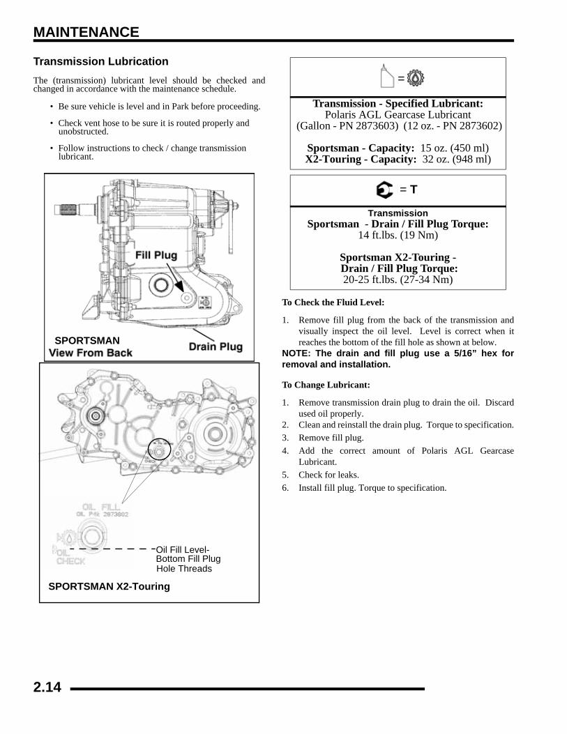
Transmission Lubrication The (transmission) lubricant level should be checked andchanged in accordance with the maintenance schedule.
• Be sure vehicle is level and in Park before proceeding.
• Check vent hose to be sure it is routed properly and unobstructed.
• Follow instructions to check / change transmission lubricant.
To Check the Fluid Level:
1. Remove fill plug from the back of the transmission andvisually inspect the oil level. Level is correct when itreaches the bottom of the fill hole as shown at below.
NOTE: The drain and fill plug use a 5/16” hex forremoval and installation.
To Change Lubricant:
1. Remove transmission drain plug to drain the oil. Discardused oil properly.
2. Clean and reinstall the drain plug. Torque to specification.3. Remove fill plug.4. Add the correct amount of Polaris AGL Gearcase
Lubricant.5. Check for leaks.6. Install fill plug. Torque to specification.
SPORTSMAN
Oil Fill Plug
Oil Fill Level-Bottom Fill PlugHole Threads
SPORTSMAN X2-Touring
=
Transmission - Specified Lubricant:Polaris AGL Gearcase Lubricant
(Gallon - PN 2873603) (12 oz. - PN 2873602)
Sportsman - Capacity: 15 oz. (450 ml)X2-Touring - Capacity: 32 oz. (948 ml)
= T
TransmissionSportsman - Drain / Fill Plug Torque:
14 ft.lbs. (19 Nm)
Sportsman X2-Touring - Drain / Fill Plug Torque: 20-25 ft.lbs. (27-34 Nm)
2.14

MAINTENANCE
2
ADC Differential Hydraulic Circuit Fluid Change1. Make sure vehicle is parked on flat ground and allowed to
sit at least 30 minutes prior to bleeding hydraulic circuit.2. Thoroughly clean area around and on remote reservoir and
bleeder valves.3. Remove reservoir cap and diaphragm assembly.4. Make sure hydraulic oil inside reservoir is free of debris.
If any debris is found, use clean rag or suction device toremove from the reservoir.
NOTE: Debris in reservoir may block porting andproduce inadequate bleeding of the system.Decreased performance may be encountered withinadequate bleed of the hydraulic circuit.
5. Begin the bleeding process by filling reservoir to ‘MAX’line with clean Polaris ADC hydraulic fluid.
6. Locate bleeder valves found on either side of differentialand remove the protective caps.
7. Turn bleeder valves counter-clockwise to loosen. Loosenbleeder screw slowly, allowing oil and any trapped air toflow out of fitting.
IMPORTANT: Do not allow hydraulic fluid in reservoirto drain below minimum fill line. Close bleeder valvebefore oil level falls below minimum fill line. Refillingempty reservoir will result in air pockets becomingtrapped.
NOTE: If empty reservoir is encountered, filling offluid is still possible. Verify air is not trapped beforeproceeding with step 7.
8. Continue steps 6-8 on both sides in sequence until cleanfluid is seen when bleeding occurs.
9. Re-torque both bleeder valves to specification and reinstallcover caps.
10. Fill reservoir with to a level midway between ‘MAX’ and‘MIN’ fill lines. Verify no debris is found in reservoir oil.
11. Replace reservoir cap securely and wipe clean any residue.
VEHICLE INSPECTIONShift Link Rod InspectionNOTE: Shift rod is preset at time of manufacturer.
1. Inspect shift link tie rod ends and replace if worn ordamaged. Lubricate pivot points with a light aerosollubricant or grease if desired.
= T
Bleeder Valve Torque:80 in. lbs. (9 Nm)
Shift Mount
Shifter
Shift Link Rod
2.15

MAINTENANCE
Throttle InspectionCheck for smooth throttle opening and closing in all handlebarpositions. Throttle lever operation should be smooth and levermust return freely without binding.
1. Place the gear selector in neutral.2. Place shift selector in neutral and set parking brake.3. Loosen lock nut on in-line cable adjuster (Ill. 1).4. Turn handlebars from full right to full left. If idle speed
increases at any point in the turning range, inspect throttlecable routing and condition. Adjust cable tension as neededuntil lock-to-lock turning can be accomplished with no risein engine rpm.
5. Replace the throttle cable if worn, kinked, or damaged.
To Remove ETC Cover:
1. Use a medium flat blade screwdriver and insert blade intothe pocket of the cover starting on the #1 position.
2. Twist screwdriver slightly while lifting on the cover torelease snap.
3. Repeat procedure at the other five locations as shown.NOTE: Do not attempt to remove cover until all latchpoints are released.
Throttle Cable / Electronic Throttle Control (ETC Switch) Adjustment1. Slide boot off throttle cable adjuster and jam nut.2. Place shift selector in neutral and set parking brake.3. Loosen lock nut on in-line cable adjuster (Ill. 1).
4. Turn adjuster until specified freeplay is achieved at thumblever. (see illustration). After making adjustments, quicklyactuate the thumb lever several times and reverify freeplay.
5. Tighten lock nut securely and slide boot completely inplace to ensure a water-resistant seal.
6. Turn handlebars from left to right through the entire turningrange. If idle speed increases, check for proper cablerouting. If cable is routed properly and in good condition,repeat adjustment procedure
ETC CoverRemoval Sequence
= In. / mm.
Throttle Freeplay:.0625 - .1250" (1.58 - 3.17mm)
BootAdjuster Sleeve Lock Nut
Boot
Direction of Travel
1/16-1/8” Freeplay
2.16

MAINTENANCE
2
Fuel System
NOTE: Only Touring and X2 models have aserviceable external fuel filter.
Touring and X2 Only - The fuel filter (1) should be replaced inaccordance with the Periodic Maintenance Chart. To replace thefilter:
1. Disconnect negative battery cable.2. Relieve the pressure on the fuel rail. (See Ch. 4)3. Remove line locks at both ends of the filter.
4. Remove fuel lines from filter, use shop towels to catch anyleaking fuel.
5. Install new filter in line with arrow pointed in direction offuel flow.
6. Install line locks on fuel lines and verify locks are seated.7. Start engine and inspect for leaks.
Vent LinesCheck fuel tank, oil tank, battery and transmission vent lines forsigns of wear, deterioration, damage or leakage. Replace Besure vent lines are routed properly and secured with cable ties.
Compression TestNOTE: This engine does NOT have decompressioncomponents. Compression readings will vary inproportion to cranking speed during the test.Average compression (measured) is about 150-200psi during a compression test.
A smooth idle generally indicates good compression. Lowengine compression is rarely a factor in running conditionproblems above idle speed. Abnormally high compression canbe caused by carbon deposits in the combustion chamber orworn, damaged exhaust cam lobes. Inspect camshaft andcombustion chamber if compression is abnormally high.
A cylinder leakdown test is the best indication of enginecondition. Follow manufacturer's instructions to perform acylinder leakage test. (Never use high pressure leakage testers,as crankshaft seals may dislodge and leak).
WARNING
* Gasoline is extremely flammable and explosiveunder certain conditions. * EFI components are under high pressure. Verifysystem pressure has been relieved beforedisassembly. * Never drain the fuel system when the engine ishot. Severe burns may result * Do not overfill the tank. The tank is at full capacitywhen the fuel reaches the bottom of the filler neck.Leave room for expansion of fuel. * Never start the engine or let it run in an enclosedarea. Gasoline powered engine exhaust fumes arepoisonous and can cause loss of consciousnessand death in a short time. * Do not smoke or allow open flames or sparks inor near the area where refueling is performed orwhere gasoline is stored. * If you get gasoline in your eyes or if you shouldswallow gasoline, seek medical attentionimmediately. * If you spill gasoline on your skin or clothing,immediately wash with soap and water and changeclothing. * Always stop the engine and refuel outdoors or ina well ventilated area.Keep away from open flamesand electrical components when removing fuelfilter.
(1)EFI Example
CAUTION
Verify vent lines are not kinked or damaged
Cylinder CompressionStandard: 150-200 PSI
Cylinder LeakdownService Limit 15%
(Inspect for cause if test exceeds 15%)
2.17

MAINTENANCE
Engine MountsInspect rubber engine mounts (A) for cracks or damage.Check engine fasteners and mounts, ensure they are tight.
Spark Plug 1. Clean plug area so no dirt and debris can fall into engine
when plug is removed. Remove spark plug high tensionlead.
2. Remove spark plug.3. Inspect electrodes for wear and carbon buildup. Look for
a sharp outer edge with no rounding or erosion of theelectrodes.
4. Clean with electrical contact cleaner or a glass bead sparkplug cleaner only.
5. Measure gap with a wire gauge. Refer to specifications forproper spark plug type and gap. Adjust gap if necessary bybending the side electrode carefully.
6. If necessary, replace spark plug with proper type.
7. Apply a small amount of anti-seize compound to the sparkplug threads.
8. Install spark plug and torque to specification.
Active Descent Control (ADC) Reservoir LevelThe Active Descent Control reservoir is located by the radiatorfill cap. Check the level and verify it is between the ‘MAX’ and‘MIN’ lines. Add only Polaris ADC fluid when required.
CAUTION
A wire brush or coated abrasive should not be used for cleaning sparkplugs.
CAUTION
Severe engine damage may occur if the incorrect spark plug is used.
= T
Recommended Spark PlugRefer to the Specifications page in
Chapter 1 for spark plug type.Spark Plug Torque: 18 ft.lbs. (24 Nm)
Spark Plug Gap
.036 (0.9 mm)
2.18

MAINTENANCE
2
Battery MaintenanceComplete battery servicing information for both conventionaland sealed batteries can be found in Chapter 10 of thismanual.
NOTE: Expected battery shelf life is 6-8 monthsdepending on storage conditions. As a general rulebefore placing the battery into service, check thebattery condition and charge accordingly.NOTE: New Batteries: Batteries must be fullycharged before use or battery life will be reduced by10-30% of full potential. Charge battery for 3-5 hoursat a current equivalent of 1/10 of the battery's ratedamp/hour capacity. Do not use the alternator tocharge a new battery. (Refer to battery video PN9917987).
(Conventional Battery Only) Inspect the battery fluid level.When the electrolyte nears the lower level, remove the batteryand add distilled water only to the upper level line .
To Remove the Battery:
1. Disconnect holder strap and remove cover.2. Disconnect battery negative (-) (black) cable first, followed
by the positive (+) (red) cable.
3. Disconnect the vent hose.4. Remove the battery.5. (Conventional Battery Only) Remove the filler caps and
add distilled water only as needed to bring each cell to theproper level. Do not overfill the battery.
IMPORTANT: Use only distilled water. Tap watercontains minerals which are harmful to a battery.
IMPORTANT: Do not allow cleaning solution or tapwater to enter a battery, as it will shorten the life of thebattery.
6. Fully recharge the battery.7. Reinstall battery caps (Conventional Battery Only).8. Clean battery cables and terminals with a stiff wire brush.
Corrosion can be removed using a solution of one cup waterand one tablespoon baking soda. Rinse well with cleanwater and dry thoroughly.
9. Reinstall battery, attaching positive (+) (red) cable first andthen the negative (-) (black) cable.
10. Reattach vent hose making sure it is properly routed and notkinked or pinched.
11. Coat terminals and bolt threads with Dielectric Grease (PN2871329).
12. Reinstall battery cover and holder strap.
Cooling SystemThe engine coolant level is controlled or maintained by therecovery system. The recovery system components are therecovery bottle, radiator filler neck, radiator pressure cap andconnecting hose.
As coolant operating temperature increases, the expanding(heated) excess coolant is forced out of the radiator past thepressure cap and into the recovery bottle. As engine coolanttemperature decreases the contracting (cooled) coolant is drawnback up from the tank past the pressure cap and into the radiator.
• Some coolant level drop on new machines is normal as the system is purging itself of trapped air. Observe coolant levels often during the break-in period.
• Overheating of engine could occur if air is not fully purged from system.
• Polaris Premium 60/40 anti-freeze is premixed and ready to use. Do not dilute with water.
WARNING
Battery electrolyte is poisonous. It contains sulfuric acid. Serious burns can result from contact with
skin, eyes or clothing. Antidote:
External: Flush with water.
Internal: Drink large quantities of water or milk. Follow with milk of magnesia, beaten egg, or
vegetable oil. Call physician immediately.
Eyes: Flush with water for 15 minutes and get prompt medical attention.
Batteries produce explosive gases. Keep sparks, flame, cigarettes, etc. away. Ventilate when
charging or using in an enclosed space. Always shield eyes when working near batteries. KEEP OUT OF REACH OF CHILDREN.
Maintain between
level marksupper and lower
CAUTION
To reduce the chance of sparks: Whenever removing the battery, disconnect the negative
(black) cable first. When reinstalling the battery, install the negative cable last.
2.19
MAINTENANCE
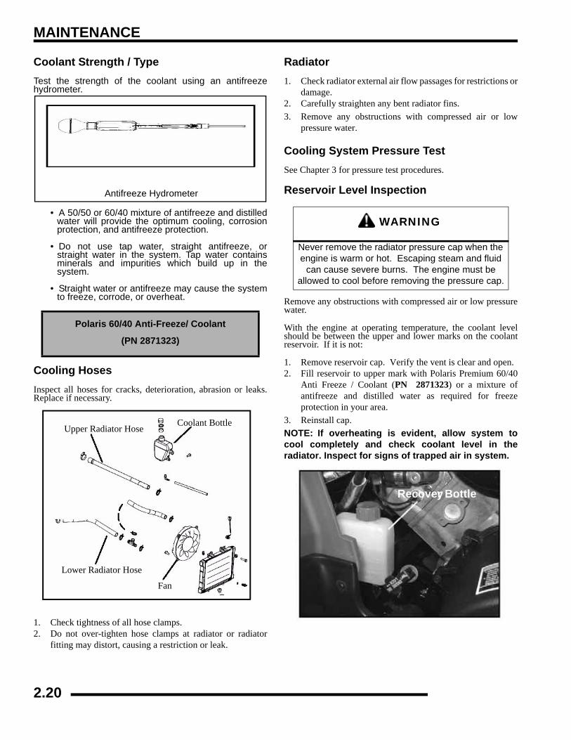
Coolant Strength / TypeTest the strength of the coolant using an antifreezehydrometer.
• A 50/50 or 60/40 mixture of antifreeze and distilledwater will provide the optimum cooling, corrosionprotection, and antifreeze protection.
• Do not use tap water, straight antifreeze, orstraight water in the system. Tap water containsminerals and impurities which build up in thesystem.
• Straight water or antifreeze may cause the systemto freeze, corrode, or overheat.
Cooling HosesInspect all hoses for cracks, deterioration, abrasion or leaks.Replace if necessary.
1. Check tightness of all hose clamps.2. Do not over-tighten hose clamps at radiator or radiator
fitting may distort, causing a restriction or leak.
Radiator1. Check radiator external air flow passages for restrictions or
damage.2. Carefully straighten any bent radiator fins.3. Remove any obstructions with compressed air or low
pressure water.
Cooling System Pressure TestSee Chapter 3 for pressure test procedures.
Reservoir Level Inspection
Remove any obstructions with compressed air or low pressurewater.
With the engine at operating temperature, the coolant levelshould be between the upper and lower marks on the coolantreservoir. If it is not:
1. Remove reservoir cap. Verify the vent is clear and open.2. Fill reservoir to upper mark with Polaris Premium 60/40
Anti Freeze / Coolant (PN 2871323) or a mixture ofantifreeze and distilled water as required for freezeprotection in your area.
3. Reinstall cap.NOTE: If overheating is evident, allow system tocool completely and check coolant level in theradiator. Inspect for signs of trapped air in system.
Polaris 60/40 Anti-Freeze/ Coolant
(PN 2871323)
Antifreeze Hydrometer
Fan
Lower Radiator Hose
Upper Radiator HoseCoolant Bottle
WARNING
Never remove the radiator pressure cap when the engine is warm or hot. Escaping steam and fluid
can cause severe burns. The engine must be allowed to cool before removing the pressure cap.
Recover Bottley
2.20

MAINTENANCE
2
Radiator Coolant Level
NOTE: This procedure is only required if the coolingsystem has been drained for maintenance and/orrepair. However, if the recovery bottle has run dry,or if overheating is evident, the level in the radiatorshould be inspected via the radiator cap first andcoolant added if necessary.
NOTE: Use of a non-standard pressure cap will notallow the recovery system to function properly.
To Access the Radiator Pressure Cap:
Lift the front cargo cover. Remove access cover (A) by placingyour fingers under the front of the cover and pulling upward.The radiator cap (B) is now accessible.
Air Filter ServiceIt is recommended that the air filter and pre filter be replacedannually. When riding in extremely dusty conditions,replacement is required more often.
The pre filter should be inspected before each ride, and ifrequired, cleaned using the following procedure:
1. Lift up on the rear of the seat.2. Pull the seat back and free of the tabs.NOTE: When reinstalling seat, make sure the slotsin the seat engage the tabs in the fuel tank.
3. Remove clips (A) from air box cover and remove cover.Inspect the gasket. It should adhere tightly to the cover andseal all the way around.
4. Loosen clamp and remove air filter assembly.
Cleaning:
5. Slip the pre-filter element off of main element. Clean thepre filter with hot soapy water.
6. Rinse and dry thoroughly.7. Inspect element for tears or damage.8. Inspect main filter and replace if necessary. If the filter has
been soaked with fuel or oil it must be replaced.
Installation:
9. Reinstall pre-filter element over main filter. Be sure theelement covers entire surface of main filter without folds,creases, or gaps.
10. Reinstall filter on main filter mount. Place filter clamp overthe assembly and tighten.
WARNING
Never remove the radiator pressure cap when the engine is warm or hot. Escaping steam and fluid
can cause severe burns. The engine must be allowed to cool before removing the pressure cap.
A
B
Cover
Seal
Main Element
Pre-filter
2.21

MAINTENANCE
NOTE: Apply a small amount of general purposegrease to the sealing edges of the filter beforereinstalling.
NOTE: The air filter should rest on the filter support.Proper placement of the air filter is important toprevent rattles and air leaks.
11. Install air box cover and secure with clips.
Air Box Sediment TubePeriodically check the air box drain tube located toward the rearof the machine. Drain whenever deposits are visible in the cleartube.
1. Remove drain plug (A) from end of sediment tube (B).2. Drain tube.3. Reinstall drain plug.
NOTE: The sediment tube will require more frequentservice if the vehicle is operated in wet conditions orat high throttle openings for extended periods.
Engine Breather HoseFour-cycle ATV engines are equipped with a engine breatherhose. The breather line is located on top of the cylinder headcover, below the gas tank. Be sure breather line is routedproperly and secured in place. Make sure the line is not kinkedor pinched.
A
Main Filter
Filter Support
Air Box
Front of ATV
Proper Filter Placement
AB
BreatherHose
To Cylinder Head Cover
2.22

MAINTENANCE
2
PVT Inspection / Drying ProcedureNOTE: If operating the ATV in or through water, besure to check the PVT cover and other componentsfor water ingestion. The ATV should be checkedimmediately.
1. To release any water that maybe trapped in the PVT cover,simply remove the PVT drain plug and O-ring (A) locatedon the bottom of the PVT cover and let the water drain out.The PVT drain plug is shown below.
2. To further expel water from the cover and to dry out thePVT system, shift the transmission to neutral and revengine slightly to expel the moisture and air-dry the belt andclutches. Allow engine RPM to settle to idle speed, shifttransmission to lowest available range and test for beltslippage. Operate ATV in lowest available range for a shortperiod of time until PVT system is dry.
Engine GroundInspect engine-to-frame ground cable connection. Be sure theconnection clean and tight.
Engine Oil LevelThe twin engine is a wet-sump engine, meaning the oil iscontained in the bottom of the crankcase. To check the oil level:
1. Set machine on a level surface.2. Be sure the machine has sat for awhile before removing the
dipstick. Do not run the engine and then check the oil level,as this will result in an incorrect reading.
3. Unlock the lever lock (A). Remove dipstick (B) and wipedry with a clean cloth.
A
Typical Ground Cable
Dipstick
A
AB
2.23

MAINTENANCE
4. Reinstall dipstick and push it into place. Do not lock thedipstick.
NOTE: Make certain the dipstick is inserted all theway into the filler tube to keep the angle and depth ofstick consistent. When reinstalling the dipstick,make certain to seat the lever lock.
5. Remove dipstick and check to see that the oil level is in thenormal range. Add oil as indicated by the level on thedipstick. Do not overfill. (See NOTE below!)
NOTE: Due to the dipstick entry angle into thecrankcase, the oil level will read higher on thebottom side of the dipstick. Proper level indicationis determined on the upper side of the dipstick as itis being removed, regardless of the level marksbeing on top or on bottom. (See illustration)
NOTE: A rising oil level between checks in coolweather driving can indicate contaminants such asgas or moisture collecting in the crankcase. If the oillevel is over the full mark, change the oilimmediately.
Oil/filter Change1. Place vehicle on a level surface.2. Run engine two to three minutes until warm. Stop engine.3. Clean area around drain plug at bottom of engine.4. Place a drain pan beneath crankcase and remove drain plug.
5. Allow oil to drain completely.6. Replace the sealing washer on drain plug.NOTE: The sealing surfaces on drain plug and oiltank should be clean and free of burrs, nicks orscratches.
7. Reinstall drain plug and torque to specification.
8. Place shop towels beneath oil filter. Using Oil FilterWrench PV-43527, turn filter counterclockwise to remove.
9. Using a clean dry cloth, clean filter sealing surface oncrankcase.
10. Lubricate O-ring on new filter with a film of fresh engineoil. Check to make sure the O-ring is in good condition.
11. Install new filter and turn by hand until filter gasket contactsthe sealing surface, then turn an additional 1/2 turn.
12. Remove dipstick and fill sump with 2 quarts (1.9 l) ofPolaris PS 4 Plus Synthetic Oil.
13. Place gear selector in park and set the parking brake.
Dipstick
Always read top side of dipstick toproperly check oil level in crankcase.
CAUTION
Do not allow hot oil to come into contact with your skin, as serious burns may result.
= T
Drain Plug Torque: 15 ± 2 ft.lbs. (21.7 ± 2.7 Nm)
Oil Filter
2.24
MAINTENANCE
2
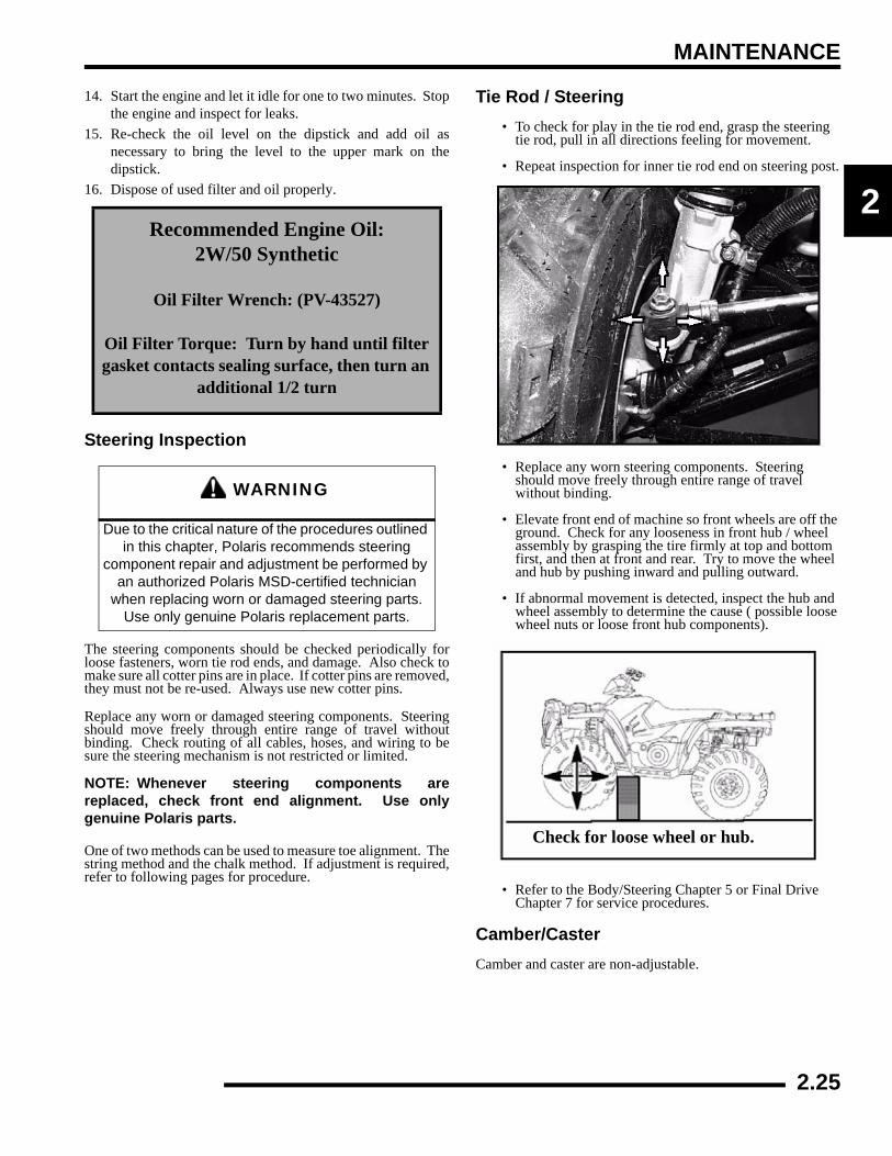
14. Start the engine and let it idle for one to two minutes. Stopthe engine and inspect for leaks.
15. Re-check the oil level on the dipstick and add oil asnecessary to bring the level to the upper mark on thedipstick.
16. Dispose of used filter and oil properly.
Steering Inspection
The steering components should be checked periodically forloose fasteners, worn tie rod ends, and damage. Also check tomake sure all cotter pins are in place. If cotter pins are removed,they must not be re-used. Always use new cotter pins.
Replace any worn or damaged steering components. Steeringshould move freely through entire range of travel withoutbinding. Check routing of all cables, hoses, and wiring to besure the steering mechanism is not restricted or limited.
NOTE: Whenever steering components arereplaced, check front end alignment. Use onlygenuine Polaris parts.
One of two methods can be used to measure toe alignment. Thestring method and the chalk method. If adjustment is required,refer to following pages for procedure.
Tie Rod / Steering• To check for play in the tie rod end, grasp the steering
tie rod, pull in all directions feeling for movement.
• Repeat inspection for inner tie rod end on steering post.
• Replace any worn steering components. Steering should move freely through entire range of travel without binding.
• Elevate front end of machine so front wheels are off the ground. Check for any looseness in front hub / wheel assembly by grasping the tire firmly at top and bottom first, and then at front and rear. Try to move the wheel and hub by pushing inward and pulling outward.
• If abnormal movement is detected, inspect the hub and wheel assembly to determine the cause ( possible loose wheel nuts or loose front hub components).
• Refer to the Body/Steering Chapter 5 or Final Drive Chapter 7 for service procedures.
Camber/CasterCamber and caster are non-adjustable.
Recommended Engine Oil:2W/50 Synthetic
Oil Filter Wrench: (PV-43527)
Oil Filter Torque: Turn by hand until filter gasket contacts sealing surface, then turn an
additional 1/2 turn
WARNING
Due to the critical nature of the procedures outlined in this chapter, Polaris recommends steering
component repair and adjustment be performed by an authorized Polaris MSD-certified technician
when replacing worn or damaged steering parts. Use only genuine Polaris replacement parts.
Check for loose wheel or hub.
2.25

MAINTENANCE
Wheel Alignment1. Place machine on a smooth level surface.2. Set handlebars in a straight ahead position and secure
handlebars in this position.3. Place a chalk mark on the center line of the front tires
approximately 10" (25.4 cm) from the floor or as close tothe hub/axle center line as possible.
NOTE: It is important that the height of both marksbe equally positioned in order to get an accuratemeasurement.
4. Measure the distance between the marks and record themeasurement. Call this measurement “A”.
5. Rotate the tires 180° by moving vehicle forward orbackward. Position chalk marks facing rearward, even withthe hub/axle centerline.
6. Again measure the distance between the marks and record.Call this measurement “B”. Subtract measurement “B”from measurement “A”. The difference betweenmeasurements “A” and “B” is the vehicle toe alignment.The recommended vehicle toe tolerance is 1/8" to 1/4" (.3to .6 cm) toe out. This means the measurement at the frontof the tire (A) is 1/8" to 1/4" (.3 to .6 cm) wider than themeasurement at the rear (B).
Toe AlignmentIf toe alignment is incorrect, measure the distance betweenvehicle center and each wheel. This will tell you which tie rodneeds adjusting.
NOTE: Be sure handlebars are straight ahead beforedetermining which tie rod(s) need adjustment.
To Adjust Toe Alignment:
• Hold tie rod end to keep it from rotating.
• Loosen jam nuts at both end of the tie rod.
• Shorten or lengthen the tie rod until alignment is as required to achieve the proper toe setting as specified.
• IMPORTANT: When tightening the tie rod end jam nuts, the rod ends must be held parallel to prevent rod end damage and premature wear. Damage may not be immediately apparent if done incorrectly. See illustration.
• After alignment is complete, torque jam nuts to specification.
= In. / mm.
Wheel Toe-Out:(A) - (B) = 1/8 - 1/4" (.3 to .6 cm)
Measurement “B”Chalk Line Measurement “A”
CAUTION
During tie rod adjustment, it is very important that the following precautions be taken when tightening tie rod end jam nuts. If the rod end is positioned
incorrectly it will not pivot, and may break.
= T
Tie Rod Jam Nut Torque:12-14 ft. lbs. (16-19 Nm)
Hold RodEnd
CorrectlyTightenedJam Nut
IncorrectlyTightened JamNut
2.26

MAINTENANCE
2
Exhaust PipeThe exhaust pipe must be periodically purged of accumulatedcarbon as follows:
1. Remove the clean out plugs located on the bottom of themuffler as shown
2. Place the transmission in neutral and start the engine. Purgeaccumulated carbon from the system by momentarilyrevving the engine several times.
3. If some carbon is expelled, cover the exhaust outlet and rapon the pipe around the clean out plugs while revving theengine several more times.
4. If particles are still suspected to be in the muffler, back themachine onto an incline so the rear of the machine is onefoot higher than the front. Set the hand brake and block thewheels. Make sure the machine is in neutral and repeatSteps 2 and 3. See WARNING in this section.
5. If particles are still suspected to be in the muffler, drive themachine onto the incline so the front of the machine is onefoot higher than the rear. Set the hand brake and block thewheels. Make sure the machine is in neutral and repeatSteps 2 and 3. SEE WARNING in this section.
6. Repeat Steps 2 through 5 until no more particles areexpelled when the engine is revved.
7. Stop the engine and allow the arrestor to cool.8. Reinstall the clean out plugs.
Brake System InspectionThe following checks are recommended to keep the brakesystem in good operating condition. Service life of brake systemcomponents depends on operating conditions. Inspect brakes inaccordance with the maintenance schedule and before each ride.
• Keep fluid level in the master cylinder reservoir to the indicated level inside reservoir (See Chapter 9)
• Use Polaris DOT-approved Brake Fluid.
• Check brake system for fluid leaks, look for dust build up on lines and connections that may indicate a fluid leak
• Check brake for excessive travel or spongy feel
• Check friction pads for wear, damage or looseness (see Chapter 9)
• Check surface condition of the disc (see Chapter 9)
Clean Out Plug
1 ft. (30.5 cm)
WARNING
* Do not perform clean-out immediately after theengine has been run, as the exhaust systembecomes very hot. Serious burns could result fromcontact with hot exhaust components. * To reduce fire hazard, make sure that there are nocombustible materials in the area when purging thespark arrestor. * Wear eye protection. * Do not stand behind or in front of the vehicle whilepurging the carbon from the spark arrestor.Neverrun the engine in an enclosed area. * Exhaust contains poisonous carbon monoxidegas. * Do not go under the machine while it is inclined.Set the hand brake and block the wheels to preventroll back. Failure to heed these warnings could result inserious personal injury or death.
2.27

MAINTENANCE
• Inspect thickness of brake pad friction material (see Chapter 9)
Brake PadsPads should be changed when the friction material is wornbeyond the service limit.
Brake Hose InspectionCheck brake system hoses and fittings for cracks, deterioration,abrasion, and leaks. Tighten any loose fittings and replace anyworn or damaged parts.
Auxiliary (Rear) Brake TestThe auxiliary brake (A) should be checked for proper function.
1. Support the rear wheels off the ground.= In. / mm.
Brake Pad Service Limit:.180" (4.6 mm)
Sight Glass
Parking Lock Brake
Measure ThicknessBrake Pad
A
2.28

MAINTENANCE
2
2. While turning the rear wheels by hand, apply the auxiliaryfoot brake. This brake should not stop the wheels fromturning until the lever is half way between its rest positionand bottoming on the footrest.
Auxiliary Brake AdjustmentUse the following procedure to inspect the hydraulic auxiliary(foot) brake system and adjust or bleed if necessary:
First, check foot brake effectiveness by applying 50 lb. (approx.)downward force on the pedal. The top of the pedal should be atleast 1 inch, (25.4mm) above the surface of the footrest.
If less than one inch, two things must be examined:
Free Play:
If free play is excessive, inspect pedal, linkage, and mastercylinder for wear or damage and replace any parts as needed.
Bleeding:
If free play is correct and brake pedal travel is still excessive, airmay be trapped somewhere in the system. Bleed the hydraulicauxiliary brake system in a conventional manner, following theprocedure outlined in Brake Chapter 9.
Suspension: Spring Preload AdjustmentOperator weight and vehicle loading affect suspension springpreload requirements. Adjust as necessary. Use Shock SpannerWrench (PN 2870872) to adjust the rear springs.
Front Suspension
• Compress and release front suspension. Dampening should be smooth throughout the range of travel.
• Check all front suspension components for wear or damage.
• Inspect front strut cartridges for leakage.
Rear Suspension
• Compress and release rear suspension. Dampening should be smooth throughout the range of travel.
• Check all rear suspension components for wear or damage.
• Inspect shock for leakage.
CV Shaft Boot InspectionInspect the CV shaft boots in the front and rear of the ATV fordamage, tears, wear, or leaking grease. If the rubber bootexhibits any of these symptoms, replace the boot. Refer toChapter 7 for CV boot replacement, or have your Polaris dealerreplace the boot.
= In. / mm.
Foot Brake Freeplay:1/8 - 1/4 inch (3.2 - 6.35 mm)
Auxiliary Foot Brake
Pedal - Full HeightFull Engagement
Floor Board Surface
1/8 to 1/4 inchFree Play
1 inch or greater
Floorboard
INSPECT BOOTS
2.29
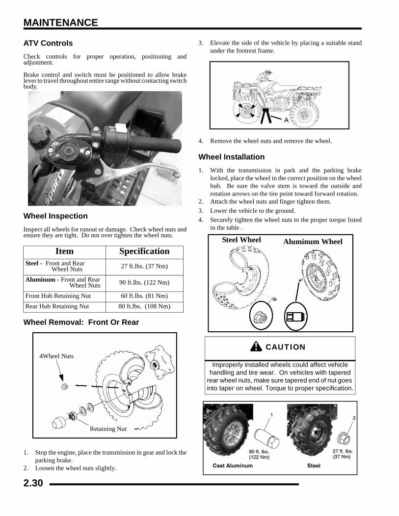
MAINTENANCE
ATV ControlsCheck controls for proper operation, positioning andadjustment.
Brake control and switch must be positioned to allow brakelever to travel throughout entire range without contacting switchbody.
Wheel InspectionInspect all wheels for runout or damage. Check wheel nuts andensure they are tight. Do not over tighten the wheel nuts.
Wheel Removal: Front Or Rear
1. Stop the engine, place the transmission in gear and lock theparking brake.
2. Loosen the wheel nuts slightly.
3. Elevate the side of the vehicle by placing a suitable standunder the footrest frame.
4. Remove the wheel nuts and remove the wheel.
Wheel Installation1. With the transmission in park and the parking brake
locked, place the wheel in the correct position on the wheelhub. Be sure the valve stem is toward the outside androtation arrows on the tire point toward forward rotation.
2. Attach the wheel nuts and finger tighten them.3. Lower the vehicle to the ground.4. Securely tighten the wheel nuts to the proper torque listed
in the table .
Item SpecificationSteel - Front and Rear Wheel Nuts 27 ft.lbs. (37 Nm)
Aluminum - Front and Rear Wheel Nuts 90 ft.lbs. (122 Nm)
Front Hub Retaining Nut 60 ft.lbs. (81 Nm)Rear Hub Retaining Nut 80 ft.lbs. (108 Nm)
4Wheel Nuts
Retaining Nut
CAUTION
Improperly installed wheels could affect vehicle handling and tire wear. On vehicles with tapered
rear wheel nuts, make sure tapered end of nut goes into taper on wheel. Torque to proper specification.
Steel Wheel Aluminum Wheel
2.30

MAINTENANCE
2
Tire Pressure
Tire Inspection• Improper tire inflation may affect ATV
maneuverability.
• When replacing a tire always use original equipment size and type.
• The use of non-standard size or type tires may affect ATV handling.
Tire Tread Depth
Always replace tires when tread depth is worn to 1/8, (3 mm) orless.
Frame, Nuts, Bolts, FastenersPeriodically inspect the torque of all fasteners in accordancewith the maintenance schedule. Check that all cotter pins are inplace. Refer to specific fastener torques listed in each chapter.
Front / Rear Storage CompartmentsThe front and rear storage (Sportsman Only) compartments areeasily accessible. To open the front compartment turn the latchhandle to the horizontal position on both sides. To close thestorage compartment turn the latch handles to the verticalposition.
CAUTION
Maintain proper tire pressure. Refer to the warning tire pressure decal applied to the vehicle.
Table 2-1:
TIRE PRESSURE INSPECTION (PSI - COLD)
Front Rear
5 5
WARNING
Operating an ATV with worn tires will increase the possibility of the vehicle skidding and possible loss
of control.Worn tires can cause an accident.
Always replace tires when the tread depth measures 1/8inch (.3 cm) or less.
Tread Depth - 1/8” (3 mm)
Front Storage - Unlatched
Front Storage - Latched
Sportsman Rear Storage -
2.31

MAINTENANCE
Winch Operation (If Equipped)This information is for Sportsman models equipped with awinch in the front.
Winch Handlebar Controls
The winch is located in the front bumper area.
The mini-rocker (IN/OUT) control controls the direction of thecable for the winch. IN pulls the cable into the winch and OUTfeeds the cable out of the winch.
Winch Control
The winch control located on the side of the winch gives theoperator easy access to switch between ENGAGED andFREESPOOL.
When the winch is ENGAGED, the winch only allows the cableto be pulled IN or released OUT via the mini-rocker switch onthe handlebar.
When the winch is FREESPOOL, the winch allows the cable tobe pulled out freely.
NOTE: The switch on the handlebar does not have to be inthe OUT position.
FREESPOOLL
ENGAGE
2.32

MAINTENANCE
2
Winch Wire Locations
The winch wires can be located under the front cab area. Locatethe wires, remove the cap and hook up to winch the Blue andYellow (6 Ga.) wires to the winch. Refer to the installationinstructions for more details.
Locate the Red wire (6 Ga.) with the yellow crimp cover islocated in the rear fender area. The red wire connects to thebattery.
The Orange/White wires are located under the front cover(under headlight pod). The Orange/White wires supply thecontrol power to the winch.
Winch Connector
Splash Guard for Contactor mount Winch Connecting
Harness
Right Side Front Fender
Winch Connecting Wire
2.33

MAINTENANCE
Cleaning And Storage Of ATVCleaning the ATV
Keeping your ATV clean will not only improve its appearancebut it can also extend the life of various components. With a fewprecautions, your ATV can be cleaned much like an automobile.
Washing the ATV
The best and safest way to clean your ATV is with a garden hoseand a pail of mild soap and water. Use a professional typewashing mitten, cleaning the upper body first and the lower partslast. Rinse with water frequently and dry with a chamois toprevent water spots.
NOTE: If warning and safety labels are damaged, contactyour a Polaris dealer for free replacement.
Polaris does not recommend the use of a high pressure type carwash system for washing the ATV. If a high pressure system isused, exercise extreme care to avoid water damage to the wheelbearings, transmission seals, body panels, brakes and warninglabels.
NOTE: Grease all zerk fittings immediately afterwashing, and allow the vehicle to run for a while toevaporate any water that may have entered theengine or exhaust system.
Waxing the ATV
ATVs can be waxed with any non-abrasive automotive pastewax. Avoid the use of harsh cleaners since they can scratch thebody finish. Spray-on furniture polish is an acceptablealternative. Do not use old cloths or pads which may contain dirtparticles that can scratch the finish. Polaris offers a detailing kitfor ATVs.
Storage Tips
See the beginning of the chapter for Pure Polaris storageproducts.
Clean the Exterior
Make necessary repairs and then clean the ATV thoroughly withmild soap and warm water to remove all dirt and grime. Don'tuse harsh detergents or high pressure washers. Some detergentsdeteriorate rubber parts. Use dish soap type cleaners only. Highpressure washers may force water past seals.
Stabilize the Fuel
Fill the fuel tank. Add Polaris Carbon Clean Fuel Treatment orPolaris Fuel Stabilizer. Follow the instructions on the containerfor the recommended amount. (Carbon clean will also reducethe possibility of bacterial growth in the fuel system.) Allow 15-20 minutes of operation for the stabilizer to disperse through thefuel in the tank and the fuel system.
Oil and Filter
Warm the engine and change the oil and filter. Follow theprocedure in this chapter for proper oil change.
Air Filter / Air Box
Inspect and clean or replace the pre-cleaner and air filter. Cleanthe air box and drain the sediment tube.
Breather Filter
Inspect and clean or replace the breather filter.
Fluid Levels
Inspect the following fluid levels and change if necessary: frontgearcase; transmission; brake fluid (change every two years oras required if fluid looks dark or contaminated).
Drain and Recoil Housing (If Applicable)
Remove the recoil housing drain plug and drain any moisture.
Fog the Engine
Use Polaris Fogging Oil, following the instructions as directed.
If you choose not to use Polaris Fogging Oil, perform thefollowing procedure.
1. Treat the fuel system with Polaris Carbon Clean. If Polarisfuel system additive is not used, the fuel tank and fuel linesshould be completely drained of gasoline.
2. To access the plug hole, use a section of clear 1/4" hose anda small plastic squeeze bottle filled with the pre-measuredamount of oil.
3. Remove the spark plug(s). Rotate the piston to BDC andpour approximately two ounces of Polaris oil into thecylinder.
NOTE: Do this carefully! If you miss the plug hole,oil will drain from the spark plug cavity into the holeat the front of the cylinder head and appear to be anoil leak.
4. Apply dielectric grease to the inside of the spark plug capand install the cap onto the plug.
5. Turn the engine over several times to ensure coverage ofpiston rings, cylinder walls and crankshaft bearings.
CAUTION
Certain products, including insect repellents and chemicals, will damage plastic surfaces.
Use caution when using these products near plastic surfaces.
CAUTION
Starting the engine during the storage period will disturb the protective film created
by fogging. Damage could occur. Never start the engine during the storage period
2.34
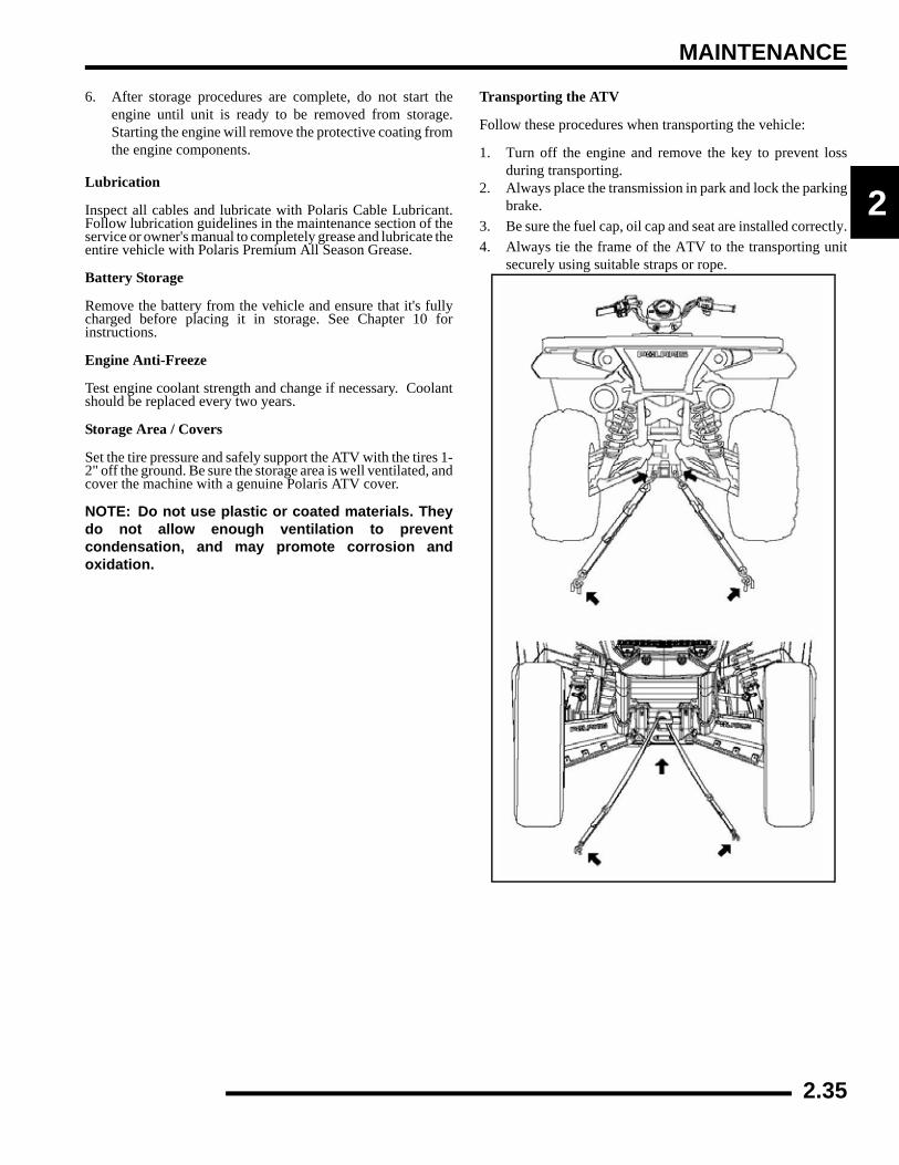
MAINTENANCE
2
6. After storage procedures are complete, do not start theengine until unit is ready to be removed from storage.Starting the engine will remove the protective coating fromthe engine components.
Lubrication
Inspect all cables and lubricate with Polaris Cable Lubricant.Follow lubrication guidelines in the maintenance section of theservice or owner's manual to completely grease and lubricate theentire vehicle with Polaris Premium All Season Grease.
Battery Storage
Remove the battery from the vehicle and ensure that it's fullycharged before placing it in storage. See Chapter 10 forinstructions.
Engine Anti-Freeze
Test engine coolant strength and change if necessary. Coolantshould be replaced every two years.
Storage Area / Covers
Set the tire pressure and safely support the ATV with the tires 1-2" off the ground. Be sure the storage area is well ventilated, andcover the machine with a genuine Polaris ATV cover.
NOTE: Do not use plastic or coated materials. Theydo not allow enough ventilation to preventcondensation, and may promote corrosion andoxidation.
Transporting the ATV
Follow these procedures when transporting the vehicle:
1. Turn off the engine and remove the key to prevent lossduring transporting.
2. Always place the transmission in park and lock the parkingbrake.
3. Be sure the fuel cap, oil cap and seat are installed correctly.4. Always tie the frame of the ATV to the transporting unit
securely using suitable straps or rope.
2.35

MAINTENANCE
800 EFI Dual Exhaust Canister Maintenance (Sportsman Only)
The canisters on dual-exhaust Polaris Sportsman 800 EFIs (X2-Touring not applicable) are powder coated. To maintain the finish andprevent corrosion, periodic maintenance is required.
1. Wash any accumulated mud or debris from the canisters with a soft brush and soapy water.2. Use a non-caustic cleaner to clean away any remaining grime, salts or oils.3. Polish canisters if desired usind
Repeat this procedure as often as desired to maintain the finish.
CAUTION
DO NOT use caustic chemicals to clean, as they may damage the finish.
800 EFI Dual Exhaust System(X2-Touring not applicable)
2.36
MAINTENANCE
2
Maintenance Schedule
Service Date Hours / Miles Service Performed Serviced By:
2.37
MAINTENANCE
Maintenance Schedule
Service Date Hours / Miles Service Performed Serviced By:
2.38

3.1
CHAPTER 3ENGINE
3
ENGINE
SPECIFICATIONS. . . . . . . . . . . . . . . . . . . . . . . . . . . . . . . . . . . . . . . . . . . . . . . . . . . . . . . 3.2CRANKCASE EXPLODED VIEWS . . . . . . . . . . . . . . . . . . . . . . . . . . . . . . . . . . . . . . . . . 3.2ENGINE FASTENER TORQUE PATTERNS . . . . . . . . . . . . . . . . . . . . . . . . . . . . . . . . . . 3.9TORQUE SPECIFICATIONS . . . . . . . . . . . . . . . . . . . . . . . . . . . . . . . . . . . . . . . . . . . . . 3.10700/800 EFI ENGINE SERVICE SPECIFICATIONS . . . . . . . . . . . . . . . . . . . . . . . . . . . 3.11SPECIAL TOOLS . . . . . . . . . . . . . . . . . . . . . . . . . . . . . . . . . . . . . . . . . . . . . . . . . . . . . . 3.13
GENERAL ENGINE SERVICE . . . . . . . . . . . . . . . . . . . . . . . . . . . . . . . . . . . . . . . . . . . . 3.14ACCESSIBLE COMPONENTS. . . . . . . . . . . . . . . . . . . . . . . . . . . . . . . . . . . . . . . . . . . . 3.14PISTON IDENTIFICATION. . . . . . . . . . . . . . . . . . . . . . . . . . . . . . . . . . . . . . . . . . . . . . . 3.14COOLING SYSTEM SPECIFICATIONS. . . . . . . . . . . . . . . . . . . . . . . . . . . . . . . . . . . . . 3.14COOLING SYSTEM PRESSURE TEST. . . . . . . . . . . . . . . . . . . . . . . . . . . . . . . . . . . . . 3.15FOUR STROKE - COOLANT AIR BLEEDING PROCEDURE . . . . . . . . . . . . . . . . . . . . 3.15ENGINE REMOVAL (TYPICAL) . . . . . . . . . . . . . . . . . . . . . . . . . . . . . . . . . . . . . . . . . . . 3.16ENGINE INSTALLATION NOTES . . . . . . . . . . . . . . . . . . . . . . . . . . . . . . . . . . . . . . . . . 3.18CYLINDER HONE SELECTION AND HONING PROCEDURE. . . . . . . . . . . . . . . . . . . 3.18HONING TO DEGLAZE . . . . . . . . . . . . . . . . . . . . . . . . . . . . . . . . . . . . . . . . . . . . . . . . . 3.19CLEANING THE CYLINDER AFTER HONING . . . . . . . . . . . . . . . . . . . . . . . . . . . . . . . 3.19OIL FLOW CHART . . . . . . . . . . . . . . . . . . . . . . . . . . . . . . . . . . . . . . . . . . . . . . . . . . . . . 3.20ENGINE LUBRICATION SPECIFICATIONS . . . . . . . . . . . . . . . . . . . . . . . . . . . . . . . . . 3.20OIL PRESSURE TEST . . . . . . . . . . . . . . . . . . . . . . . . . . . . . . . . . . . . . . . . . . . . . . . . . . 3.20
ENGINE DISASSEMBLY AND INSPECTION . . . . . . . . . . . . . . . . . . . . . . . . . . . . . . . . . 3.21CYLINDER HEAD ASSEMBLY EXPLODED VIEW . . . . . . . . . . . . . . . . . . . . . . . . . . . . 3.21ROCKER ARMS . . . . . . . . . . . . . . . . . . . . . . . . . . . . . . . . . . . . . . . . . . . . . . . . . . . . . . . 3.22PUSH RODS. . . . . . . . . . . . . . . . . . . . . . . . . . . . . . . . . . . . . . . . . . . . . . . . . . . . . . . . . . 3.22CYLINDER HEAD REMOVAL . . . . . . . . . . . . . . . . . . . . . . . . . . . . . . . . . . . . . . . . . . . . 3.22CYLINDER HEAD INSPECTION . . . . . . . . . . . . . . . . . . . . . . . . . . . . . . . . . . . . . . . . . . 3.23CYLINDER HEAD WARP. . . . . . . . . . . . . . . . . . . . . . . . . . . . . . . . . . . . . . . . . . . . . . . . 3.23VALVE SEAL/SPRING SERVICE (ON ENGINE) . . . . . . . . . . . . . . . . . . . . . . . . . . . . . . 3.23CYLINDER HEAD DISASSEMBLY . . . . . . . . . . . . . . . . . . . . . . . . . . . . . . . . . . . . . . . . 3.24VALVE INSPECTION . . . . . . . . . . . . . . . . . . . . . . . . . . . . . . . . . . . . . . . . . . . . . . . . . . . 3.25COMBUSTION CHAMBER. . . . . . . . . . . . . . . . . . . . . . . . . . . . . . . . . . . . . . . . . . . . . . . 3.26VALVE SEAT RECONDITIONING . . . . . . . . . . . . . . . . . . . . . . . . . . . . . . . . . . . . . . . . . 3.26CYLINDER HEAD REASSEMBLY . . . . . . . . . . . . . . . . . . . . . . . . . . . . . . . . . . . . . . . . . 3.28VALVE SEALING TEST . . . . . . . . . . . . . . . . . . . . . . . . . . . . . . . . . . . . . . . . . . . . . . . . . 3.29CYLINDER REMOVAL . . . . . . . . . . . . . . . . . . . . . . . . . . . . . . . . . . . . . . . . . . . . . . . . . . 3.29VALVE LIFTER REMOVAL/INSPECTION . . . . . . . . . . . . . . . . . . . . . . . . . . . . . . . . . . . 3.29PISTON REMOVAL . . . . . . . . . . . . . . . . . . . . . . . . . . . . . . . . . . . . . . . . . . . . . . . . . . . . 3.30CYLINDER INSPECTION. . . . . . . . . . . . . . . . . . . . . . . . . . . . . . . . . . . . . . . . . . . . . . . . 3.31PISTON-TO-CYLINDER CLEARANCE . . . . . . . . . . . . . . . . . . . . . . . . . . . . . . . . . . . . . 3.32PISTON/ROD INSPECTION. . . . . . . . . . . . . . . . . . . . . . . . . . . . . . . . . . . . . . . . . . . . . . 3.32PISTON RING INSTALLED GAP . . . . . . . . . . . . . . . . . . . . . . . . . . . . . . . . . . . . . . . . . . 3.33STARTER DRIVE/BENDIX REMOVAL INSPECTION . . . . . . . . . . . . . . . . . . . . . . . . . . 3.33FLYWHEEL / STATOR REMOVAL / INSPECTION . . . . . . . . . . . . . . . . . . . . . . . . . . . . 3.34ENGINE CRANKCASE DISASSEMBLY / INSPECTION . . . . . . . . . . . . . . . . . . . . . . . . 3.35CAMSHAFT INSPECTION . . . . . . . . . . . . . . . . . . . . . . . . . . . . . . . . . . . . . . . . . . . . . . . 3.42
ENGINE REASSEMBLY . . . . . . . . . . . . . . . . . . . . . . . . . . . . . . . . . . . . . . . . . . . . . . . . . 3.43CRANKCASE REASSEMBLY . . . . . . . . . . . . . . . . . . . . . . . . . . . . . . . . . . . . . . . . . . . . 3.43FLYWHEEL / STATOR INSTALLATION . . . . . . . . . . . . . . . . . . . . . . . . . . . . . . . . . . . . 3.54CYLINDER HEAD REASSEMBLY . . . . . . . . . . . . . . . . . . . . . . . . . . . . . . . . . . . . . . . . . 3.55
TROUBLESHOOTING. . . . . . . . . . . . . . . . . . . . . . . . . . . . . . . . . . . . . . . . . . . . . . . . . . . 3.57ENGINE . . . . . . . . . . . . . . . . . . . . . . . . . . . . . . . . . . . . . . . . . . . . . . . . . . . . . . . . . . . . . 3.57COOLING SYSTEM . . . . . . . . . . . . . . . . . . . . . . . . . . . . . . . . . . . . . . . . . . . . . . . . . . . . 3.58
800 EFI EXHAUST SYSTEM . . . . . . . . . . . . . . . . . . . . . . . . . . . . . . . . . . . . . . . . . . . . . 3.59DUAL EXHAUST LAYOUT. . . . . . . . . . . . . . . . . . . . . . . . . . . . . . . . . . . . . . . . . . . . . . . 3.59

ENGINE
SPECIFICATIONSCrankcase Exploded Views
A
B
C
D
EF
G
H IJ
K
L
I
M
N
OApply Loctite™242 tobolt threads.
Apply White LithiumGrease
Apply MolyLube Grease.
60 ± 6 in.lbs.(6.8 ± .68 Nm)
192 ± 24 in.lbs(21.7 ± 2.7 Nm)
115 ± 12 in.l(13 ± 1.35 Nm)
60 ± 6 in.l(6.8 .68 Nm)
NOTE: If needed, heatthe oil baffle bolts with aheat gun to remove.
22 ± 2 ft.lbs. (30 ± 3 Nm)
A. JournalBearings B. CamshaftC. Thrust Plate D. Balance Shaft E. Woodruff Key F. Flange Seal G. Crankshaft H. Oil Pickup I. Journal Bearings J. Baffle K. Oil Plug L. Washer M. O-ring N. Crankcase O. Crankcase Bolts
3.2

ENGINE
3
Oil / Water Pump and Timing Cover Exploded ViewA. Split GearB. Washer C. Bolt D. Oil Rotor E. Oil Pump F. Mag Gasket Cover G. Impeller H. Washer I. Nut J. Counterbalance Gear K. Washer L. Bolt M. Oil Pump Bolts N. Gear/Stator cover O. Wire Hold down P. Stator Housing Bolts
AB
C
DE
F
GH
I
JK
L
M
N
OP
22 ± 2 ft.lbs. (30 ± 3 Nm)
84 ± 8 in.lbs. (9.5 ± .90 Nm)
Apply corrosion resistantgrease to stator grommet area.
96 ± 3 in.lbs. (10.85 ± 0.35 Nm)
108 ±12 in.lbs.(6.8 ± .68 Nm)
Oil Pump Bolt Tighten Sequence
Apply White LithiumGrease
Apply Polaris OW-40oil to component
Mag Cover Bolt Tighten Sequence
No Grease on thisPortion of the Gasket!
3.3

ENGINE
Starter / Flywheel / Water Pump Exploded View
A. Bolts B. Starter C. Washer D. Nut E. Positive Cable F. Negative Cable G. Gasket H. Clamp I. Bolts J. Gasket K. Water Pump Cover L. Bolts M. Crank Nut/Washer N. Flywheel O. Bendix
Apply Polaris Starter Grease
Apply Polaris 0W-40oil to sealLoctite™ Pipe Sealant(PN 2871956)
A
1
2
Tighten Top Bolt First
84 ± 8 ft.lbs. (9.5 ± 0.9 Nm)No Grease or Oil
B
CDE
F
G
H
I
JK
L
MN
O108 ± 12 ft.lbs.(12 ± 1.35 Nm)
96 ± 12 in.lbs.(10.85± 1.35 Nm)
65 ± 7 ft.lbs.(88 ± 9.5 Nm)
96 ± 12 in.lbs.(10.85 ± 1.35 Nm)
Water Pump Cover Bolt Tighten Sequence
Stator Cover BoltTighten Sequence
3.4

ENGINE
3
Oil System / Level Assembly Exploded ViewA. Clamp B. Oil Fill Tube C. Dipstick D. O-ring E. Hex Plug F. Oil Filter Nipple G. Oil FilterH. Dowel I. Galley Plug J. Nut/washer K. Spring
A BC
D
E
F
G
HI
J
50 ± 5 in. lbs.(5.65 0.56 Nm)
35 ± 4 ft.lbs.(47.5 ± 5.4 Nm)
18 ± 2 ft.lbs. (24.4 ± 2.71 Nm)
22 ± 2 ft.lbs.(30 ± 3 Nm)
50 ± 5 in.lbs. (5.64± 0.56 Nm)
K
3.5

ENGINE
Cylinder / Cylinder Head Exploded View
Lubricate threads & between washers and underside of bolt heads with engine oil. Torque in sequence provided.
Apply Moly Lube grease to valve tips. Gasket free of oil. Verify tabs are visible.
Apply thin film of 0W-40 to 25-55 mm of cylinder bore.
Apply 0W-40 to piston pin or pin bore.
Apply 0W-40 to lifters.
A. Head Bolts B. Rocker Arms C. Head Assembly D. Gasket E. Pushrods F. Bushing G. Expansion Plug H. Cylinder I. Piston Assembly J. Circlip K. Gasket L. Hydraulic Lifter
AB
C
D
EF
G
HI
J
KL
(Apply each Bolt Threads)
1
2
3
44
5
6
3
Circlip UP for Install
Do Not install expansion plug more than 1.5 mm inward.
Apply Polaris 0W--40 Oil
Apply Moly Lube Grease
Side View
Initial: 35 ± 4 ft. lbs (47.5 ± 5.5 Nm) in sequence. Finalize sequence by tightening an additional 90° (1/4 turn)
Head Bolt Tighten Sequence
22 ± 2 ft.lbs.(30 ± 3 Nm)
1.5 mm
3.6

ENGINE
3
Engine Sensors & Misc. Exploded View
84 ± 4 in.lbs.(9.5 ± 0.9 Nm)
20 ± 5 in.lbs. (2.5 ± 0.55 Nm)
18 ± 2 ft.lbs. (24.5 ± 2.7 Nm)
20 ± 5 in.lbs. (2.5 ± 0.55 Nm)
84 ± 4 in.lbs.(9.5 ± 0.9 Nm)
25 ± 3 ft.lbs. (34 ± 0.14 Nm)
84 ± 4 in.lbs.(9.5 ± 0.9 Nm)
18 ± 2 ft.lbs. (24.5 ± 2.7 Nm)
A. Screws B. Rocker Cover C. Breather D. O-ring Seal E. Breather Bolts F. Spark Plugs G. Carburetor Boot H. Bolts I. Boot Clamp J. Throttle Body K. Crank Position Sensor L. Thermistor M. O-ring N. Thermostat Housing O. Bolts P. Gasket Q. Exhaust Manifold R. Bolts S. Thermostat
AB
E
C
D
F(Apply Dielectric Greaseto threads of Spark Plug)
GH
I
JApply CorrosionResistant Grease
K
L
MN O
PQ
18 ± 2 ft.lbs. (24.5 ± 2.7 Nm)R
3.7

ENGINE
EFI Harness Exploded View
A. Fuel InjectorB. Fuel Rail C. EFI Harness
AB
C
18 ± 2 ft.lbs.(24.5 ± 2.7 Nm)
NOTE: See Chapter 4 for more information on the EFI system.
3.8

ENGINE
3
Engine Fastener Torque Patterns
22 ± 2 ft.lbs. (30 ± 3 Nm)
Crankcase Bolt Tighten Sequence
Lubricate threads and between washer and underside of bolt with engine oil.Torque in sequence to spec provided, allow the gasket to set for 1 minute, thentighten in sequence 90° (1/4 turn).
35 ± 4 ft.lbs.(47.5 ± 5.5 Nm) + 90° (1/4 turn)
3.9

ENGINE
Torque Specifications
NOTE: * See exploded views for notes or torque sequences.
Table 3-1: Engine Torque Specifications
FASTENER SIZE IN.LBS. (NM) FT.LBS. (NM)Camshaft Gear 8 mm 22 ± 2 (30 ± 3)
Camshaft Thrust Plate 6 mm 115 ± 12 (13 ± 1.35) 9.5 ± 1 (13 ± 1.35)
Carburetor Adaptor Bolts 8 mm 216 ± 24 (24.5-± 2.7) 18 ± 2 (24.5 ± 2.7)
Counterbalance Gear 8 mm 22 ± 2 (30 ± 3)
Crankcase Bolts 8 mm * 22 ± 2 (30 ± 3)
Crankcase Breather 5 mm 20 ± 5 (2.5 ± 0.55) -
Cylinder Head Bolts 11 mm * 35 ± 4 (47.5 ± 5.5)
Exhaust Manifold 8 mm 216 ± 24 (24.5 ± 2.70) 18 ± 2 (24.5 ± 2.7)
Flywheel 14 mm 65 ± 7 (88 ± 9.50)
Injector Rail 8 mm 216 ± 24 (24.5 ± 2.70) 18 ± 2 (24.5 ± 2.7)
Magneto Cover 6 mm * 96 ± 3 (10.85 ± 0.35) -
Oil Baffle Weldment 5 mm 60 ± 6 (6.8 ± 0.68) -
Oil Drain Bolt (Crankcase) 12 mm 192 ± 24 (21.7 ± 2.7) 16 ± (21.7)
Oil Fill Tube Bolt 5 mm 50 ± 5 (5.64 ± 0.56) -
Oil Filter Pipe Fitting 20 mm 35 ± 4 (47.5 ± 5.4)
Oil Pick Up 5 mm 60 ± 6 (6.8 ± 0.68) -
Oil Pressure Relief Plug 10 mm 22 ± 2 (30 ± 3) -
Oil Pump Housing Screw 6 mm * 84 ± 8 (9.50 ± 0.90) -
Rocker Arm 8 mm * 22 ± 2 (30 ± 3)
Rocker Cover 6 mm * 84 ± 8 (9.5 ± 0.9) -
Spark Plug 14 mm 216 ± 24 (24.5 ± 2.7) 18 ± 2 (24.5 ± 2.7)
Starter Motor 6 mm * 84 ± 8 (9.5 ± 0.9) -
Stator Assembly 6 mm 96 ± 3 (10.85 ± 0.35) -
Stator Housing 6 mm * 96 ± 3 (10.85 ± 0.35) -
Temperature Switch 3/8 NPT 25 ± 3 (34 ± 4)
Thermostat Housing 6 mm 84 ± 8 (9.5 ± 0.9) -
Timing Plug 3/4-16 7-9 (10-12 Nm)
Trigger Coil/Stator Wire Holddown 5 mm * 96 ± 3 (10.85 ± 0.35) -
Water Pump Housing Cover 6 mm * 96 ± 3 (10.85 ± 0.35) -
Water Pump Impeller Nut 8 mm 108 ± 3 (12 ± 0.35) -
3.10

ENGINE
3
700/800 EFI Engine Service Specifications
Table 3-1: Engine Specifications
MAIN COMPONENT: CYLINDER HEAD EH068OLE / EH076OLE
Camshaft
Cam Lobe Height - Intake / Exhaust 1.3334" (33.8674 mm)
Camshaft Journal Outer Diameter - Mag 1.654" ± 0.00039" (42 ± 0.010 mm)
Camshaft Journal Outer Diameter - Center 1.634"± 0.00039" (41.50 ± 0.010 mm)
Camshaft Journal Outer Diameter - PTO 1.614" ± 0.00039" (41 ± 0.010 mm)
Camshaft Journal Bore Inner Diameter - Mag 1.656" ± 0.00039" (42.07 ± 0.010 mm)
Camshaft Journal Bore Inner Diameter - Center 1.637" ± 0.00039" (41.58 ± 0.010 mm)
Camshaft Journal Bore Inner Diameter - PTO 1.617" ± 0.00039" (41.07 ± 0.010 mm)
Camshaft Oil Clearance 0.00276" ± 0.00079" (0.07 ± 0.02 mm)
Camshaft End Play 0.0167" ± 0.0098" (0.425 ± 0.25 mm)
Counter Balance Counter Balance End Play 0.005" (0.127 mm)
Cylinder HeadCylinder Head - Surface warp limit 0.00394" (0.1 mm)
Cylinder Head - Standard height 3.478" (88.35 mm)
Valve Seat
Valve Seat - Contacting Width - Intake 0.0472" ± 0.00787" - 0.0039"(1.20 ± 0.20 - 0.10mm)
Valve Seat - Contacting Width - Exhaust 0.0591" ± 0.00787" - 0.0039"(1.50 ± 0.20 - 0.10 mm)
Valve Seat Angle 45.5° ± 0.255°
Valve GuideValve Guide Inner diameter 0.2367" ± 0.00029" (6.012 ± 0.007 mm)
Valve Guide Protrusion Above Head 0.807" ± 0.0039" (20.50 ± 0.01 mm)
Valve
Valve Margin Thickness - Intake Standard: 0.79" (20.06 mm) Max- 0.98" (24.89 mm) Min- 0.59" (14.98 mm)
Valve Margin Thickness - Exhaust Standard: 0.80" (20.32 mm) Max- 1.0" (25.4 mm) Min- 0.60" (15.24 mm)
Valve Stem Diameter - Intake 0.2356" ± 0.00039" (5.985 ± 0.01 mm)
Valve Stem Diameter - Exhaust 0.2351" ± 0.00039" (5.972 ± 0.01 mm)
Valve Stem Oil Clearance - Intake 0.00228" ± 0.00098" (0.058 ± 0.025 mm)
Valve Stem Oil Clearance - Exhaust 0.00275" ± 0.00098" (0.0870 ± 0.025mm)
Valve Stem Overall Length - Intake 4.51" ± 0.01476" (114.5550 ± 0.375 mm)
Valve Stem Overall Length - Exhaust 4.5453" ± .01496" (115.45 ± 0.38 mm)
Valve SpringValve Spring Overall Length - Free Length 1.735" (46.069 mm)
Valve Spring Overall Length - Installed Height Intake - 1.4638" (37.18 mm) Exhaust - 1.4736" (37.43 mm)
3.11

ENGINE
Table 3-2: Engine Specifications
MAIN COMPONENTS: CYLINDER/PISTON/ CONNECTING ROD
EH068OLE EH076OLE
Cylinder
Cylinder - Surface warp limit (mating with cylinder head) 0.004" (0.10 mm) 0.004" (0.10 mm)
Cylinder Bore - Standard 3.1495" (80 mm) 3.1495" (80 mm)
Cylinder Taper Limit 0.00031" (0.008 mm) 0.00031" (0.008 mm)
Cylinder Out of Round Limit 0.00030" (0.0075 mm) 0.00030" (0.0075 mm)
Cylinder to Piston Clearance .0015" ± .00059" (.040 ± .015mm)
.0015" ± .00059" (.040 ± .015mm)
Lifter
Lifter Outer Diameter Standard
0.84245" ± 0.00025" (21.39 8 ± 0.00635 mm)
0.84245" ± 0.00025" (21.39 8 ± 0.00635 mm)
Lifter Block Bore 0.8438" ± 0.00062"(21.4322 ± 0.0157 mm)
0.8438" ± 0.00062"(21.4322 ± 0.0157 mm)
PistonPiston - Standard 3.1477" ± .000121"
(79.954 ± .003mm)3.14803" + .00028" (79.960 + .007 mm)
Piston Standard Inner Diameter of Piston Pin Bore
0.78789" ± .00009" (20.0125 ± 0.003 mm)
0.70902" ± .00012" (18.009 ± 0.003 mm)
Piston Pin
Piston Pin Outer Diameter 0.7874" - 0.7872" (20 - 19.995 mm)
0.70866" - 0.70846" (18 - 17.995 mm)
Piston Pin - Standard Clearance - Piston Pin to Pin
0.00059" ± 0.0002" (0.015 ± 0.005 mm)
0.00047" ± 0.00024" (0.012 ± 0.006 mm)
Piston Pin - Degree of Fit Piston pin must be a push fit (by hand) at 68° F (20° C)
Piston pin must be a push fit (by hand) at 68° F (20° C)
3.12
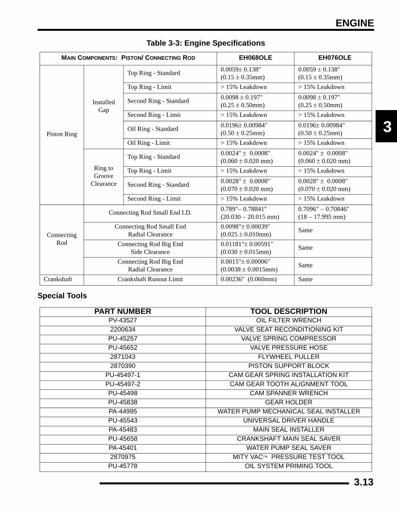
ENGINE
3
Special Tools
Table 3-3: Engine Specifications
MAIN COMPONENTS: PISTON/ CONNECTING ROD EH068OLE EH076OLE
Piston Ring
InstalledGap
Top Ring - Standard 0.0059± 0.138"(0.15 ± 0.35mm)
0.0059 ± 0.138"(0.15 ± 0.35mm)
Top Ring - Limit > 15% Leakdown > 15% Leakdown
Second Ring - Standard 0.0098 ± 0.197"(0.25 ± 0.50mm)
0.0098 ± 0.197"(0.25 ± 0.50mm)
Second Ring - Limit > 15% Leakdown > 15% Leakdown
Oil Ring - Standard 0.0196± 0.00984"(0.50 ± 0.25mm)
0.0196± 0.00984"(0.50 ± 0.25mm)
Oil Ring - Limit > 15% Leakdown > 15% Leakdown
Ring to Groove
Clearance
Top Ring - Standard 0.0024" ± 0.0008" (0.060 ± 0.020 mm)
0.0024" ± 0.0008" (0.060 ± 0.020 mm)
Top Ring - Limit > 15% Leakdown > 15% Leakdown
Second Ring - Standard 0.0028" ± 0.0008" (0.070 ± 0.020 mm)
0.0028" ± 0.0008" (0.070 ± 0.020 mm)
Second Ring - Limit > 15% Leakdown > 15% Leakdown
Connecting Rod
Connecting Rod Small End I.D. 0.789"− 0.78841" (20.030 − 20.015 mm)
0.7096" − 0.70846" (18 − 17.995 mm)
Connecting Rod Small End Radial Clearance
0.0098"± 0.00039" (0.025 ± 0.010mm)
Same
Connecting Rod Big End Side Clearance
0.01181"± 0.00591" (0.030 ± 0.015mm)
Same
Connecting Rod Big End Radial Clearance
0.0015"± 0.00006" (0.0038 ± 0.0015mm)
Same
Crankshaft Crankshaft Runout Limit 0.00236" (0.060mm) Same
PART NUMBER TOOL DESCRIPTIONPV-43527 OIL FILTER WRENCH2200634 VALVE SEAT RECONDITIONING KIT
PU-45257 VALVE SPRING COMPRESSORPU-45652 VALVE PRESSURE HOSE2871043 FLYWHEEL PULLER2870390 PISTON SUPPORT BLOCK
PU-45497-1 CAM GEAR SPRING INSTALLATION KITPU-45497-2 CAM GEAR TOOTH ALIGNMENT TOOLPU-45498 CAM SPANNER WRENCHPU-45838 GEAR HOLDERPA-44995 WATER PUMP MECHANICAL SEAL INSTALLERPU-45543 UNIVERSAL DRIVER HANDLEPA-45483 MAIN SEAL INSTALLERPU-45658 CRANKSHAFT MAIN SEAL SAVERPA-45401 WATER PUMP SEAL SAVER2870975 MITY VAC™ PRESSURE TEST TOOL
PU-45778 OIL SYSTEM PRIMING TOOL
3.13

ENGINE
GENERAL ENGINE SERVICEAccessible ComponentsFollowing Components can be serviced or removed with theengine installed:
• Flywheel
• Alternator (Stator)
• Starter Motor/Drive
• Cylinder Head
• Cylinder
• Piston/Rings
• Camshaft
• Rocker Arms
• Oil pump/Water Pump/Oil Pump Drive Gear
• Gear Train Components
Following Components Require Engine Removal for service:
• Counterbalance Shaft or Bearings
• Connecting Rod
• Crankshaft
• Crankshaft Main Bearings
• Crankcase
Piston IdentificationFour stroke engine rings have a rectangular profile. See“PISTON RING INSTALLED GAP” for ring installation. Usethe information below to identify pistons and rings.
Cooling System Specifications
Recommended Coolant
Use only high quality antifreeze/coolant mixed with distilledwater in a 50/50 or 60/40 ratio, depending on freeze protectionrequired in your area. CAUTION: Using tap water in thecooling system will lead to a buildup of deposits which mayrestrict coolant flow and reduce heat dissipation, resulting inpossible engine damage. Polaris Premium 60/40 Antifreeze/Coolant is recommended for use in all cooling systems andcomes pre-mixed, ready to use.
Table 3-1:
ENGINE MODEL PISTON DIAMETER
EH068OLEEH076OLE 80 mm
Table 3-2:
CONDITIONAPPROX.
READING (MIN.-MAX)
TEMPERATURE
Hot light ON 178Ω - 190Ω 215° F (108° C)
Fan Off 296Ω - 316Ω 180° F (82° C)
Fan On 236Ω - 251Ω 195° F (91° C)
System Capacity Refer To Chapter 1 Specifications
Radiator Cap Pressure Relief 13 PSI
Radiator
Thermostat
Cylinder Head
Water Pump
Cylinder
3.14

ENGINE
3
Cooling System Pressure Test
1. Remove front cover.2. Remove recovery bottle hose from coolant filler neck.3. Connect a commerically available pressure tester to the
filler neck and pressurize system to 10 psi. The system mustretain 10 psi for five minutes or longer. If pressure loss isevident within five minutes, check the radiator, hoses,clamps and water pump seals for leakage.
Radiator Cap Pressure Test
1. Remove radiator cap and test cap using a commerciallyavailable cap tester.
2. The radiator cap relief pressure is 13 psi. Replace cap if itdoes not meet this specification.
Four Stroke - Coolant Air Bleeding Procedure
Use this procedure when a unit overheats and no apparent leaksin the cooling system are found.
NOTE: If the coolant level is LOW in the radiator, or if thereare leaks in the system, the coolant system will not drawcoolant from the reservoir tank.
1. Park machine on a flat surface. Remove radiator cap andtop off coolant. Leave the cap off of the radiator. Start andidle machine for 5-10 minutes until steam is visible in theradiator cap area.
2. Stop the engine and let cool for a few minutes or until anair bubble is seen at the filler neck, or there is a droppingof the coolant level indicating that coolant has been pulledinto the system.
NOTE: Slowly squeezing the hose after the bendbelow the filler neck will aid in purging the system ofair. Pump the hose using your hand several times asshown in the diagram. Elevating the rear of the ATVwith a floor jack (rear tires 4-6, off the ground) alsoaids the purging of air from the system.
3. Always add coolant to the radiator first, filling to the top ofthe neck to replace air that has been purged from the system.Fill the reservoir only after you have completely filled thecooling system at the radiator filler neck.
4. Repeat Steps 1 and 2 four or five times or until no morecoolant is pulled into the system.
5. In some instances, Steps 1 and 2 may have to be performedwith the radiator cap on to prevent coolant loss.
6. To test, install the radiator cap and idle machine until fancomes on. Make sure the fan comes on before the hot light.
WARNING
Never remove radiator cap when engine is warm or hot. The cooling system is under pressure and serious burns may result. Allow the engine and
cooling system to cool before servicing.
Upper Engine Hose
Surge Tank
Fan Assembly
Lower Engine Hose Radiator
Hose
Pump Hose ByHand to HelpPurge System
Squeeze HoseHere to HelpPurge Air FromSystem
Polaris PremiumAntifreeze 2871534 - Quart2871323 - Gallon
3.15

ENGINE
Engine Removal (Typical)
1. Clean work area.2. Thoroughly clean ATV engine and chassis.3. Disconnect battery (-) negative cable.4. Remove the following parts as required:
• Seat
• Left and right side covers (refer to Chapter 5)
• Fuel tank covers
• Fuel tank (refer to Chapter 4)
• Springs from exhaust pipe and remove pipe.
5. Drain coolant and engine oil.6. Remove air pre-cleaner and duct.7. Remove airbox.8. Disconnect the throttle body sensor (C) and T-BAP sensor
(D). Remove throttle body (A). Insert a shop towel intothe engine intake to prevent dirt from entering the ports.
9. Relieve the fuel pressure in the fuel rail (refer to Chapter 4,FUEL INJECTION") for proper procedure. Carefullyremove the fuel rail (B) and injectors.
10. Disconnect spark plug high tension leads.11. Remove the crank position sensor (E) located on the mag
cover.
12. Remove the air breather line .13. Disconnect the coolant hoses. Properly dispose of any
antifreeze from the engine or hoses.
WARNING
Always wear safety glasses and proper shop clothing when performing the procedures in this
manual. Failing to do so may lead to possible injury or death.
B
A
C
D
E
3.16

ENGINE
3
14. Refer to PVT System Chapter 6 to remove outer clutchcover, drive belt, drive clutch, driven clutch, and innercover (F).
15. When removing starter cables, note and mark ground cableand positive (+) cable mounting angle and locations.Remove cables.
16. Remove transmission linkage rod from gear selector andsecure out of the way.
17. Disconnect coolant temperature sensor wire located on thecylinder.
18. Remove engine to chassis ground cable.
19. Remove all engine mount nuts and / or engine mount plates.Remove the frame brace (G) from the front left side of theframe.
20. Remove the engine from the left side of the frame.
NOTE: Use caution when lifting the engine out offrame. Use an engine lift or other means if theengine is too heavy to be lifted manually.
21. For engine installation, reverse procedures.
F G
3.17

ENGINE
Engine Installation NotesAfter the engine is installed in the frame, review this checklistand perform all steps that apply:
General Items
1. Install previously removed components using new gaskets,seals, and fasteners where applicable.
2. Perform regular checks on fluid levels, controls, and allimportant areas on the vehicle as outlined in the daily pre-ride inspection checklist (refer to Chapter 2 or the Owner'sManual).
PVT System
1. Adjust center distance of drive and driven clutch. (Chapter6)
2. Adjust clutch offset, alignment, and belt deflection.(Chapter 6)
3. Clean clutch sheaves thoroughly and inspect inlet andoutlet ducts for proper routing and sealing. (Chapter 6)
Transmission
1. Inspect transmission operation and adjust linkage ifnecessary. Refer to Chapter 2 and Chapter 8.
Exhaust
1. Replace exhaust gaskets. Seal connections with high tempsilicone sealant.
2. Check to be sure all springs are in good condition.
Bleed Cooling System
NOTE: This cooling system contains vent lines tohelp purge trapped air during filling. Bleedinggenerally should not be necessary.
1. Remove radiator cap and slowly add coolant to the bottomof filler neck.
2. Fill coolant reservoir tank to full mark.3. Install radiator cap and gently squeeze coolant hoses to
force any trapped air out of system.4. Again, remove radiator cap and slowly add coolant to the
bottom of fill neck if needed.5. Start engine and observe coolant level in the radiator.
Allow air to purge and top off as necessary. Reinstallradiator cap and bring engine to operating temperature.After engine is cool, check level in reservoir tank and addcoolant if necessary.
NOTE: Should the reservoir tank become empty, itwill be necessary to refill at the radiator and repeatthe bleeding procedure.
Engine Break-In Period
The break-in period for a Polaris ATV engine is defined as thefirst ten hours of operation, or the time it takes to use two fulltanks of gasoline. No single action on your part is as importantas a proper break-in period. Careful treatment of a new enginewill result in more efficient performance and longer life for theengine. Perform the following procedures carefully.
1. Fill fuel tank with unleaded or leaded fuel which has aminimum pump octane number of 87= (R+ M)/2.
2. Check oil reservoir level indicated on dipstick. Add oil ifnecessary (Refer to Chapter 2, “Engine Oil Level” ).
3. Drive slowly at first to gradually bring engine up tooperating temperature.
4. Vary throttle positions. Do not operate at sustained idle orsustained high speed.
5. Perform regular checks on fluid levels, controls and allimportant bolt torques. Pull only light loads during initialbreak in.
6. Pull only light loads during initial break-in.7. Change break in oil and filter at 20 hours or 200 miles.
Cylinder Hone Selection And Honing Procedure
Cylinders may be wet or dry honed depending upon the honemanufacturer’s recommendations. Wet honing removes morematerial faster and leaves a more distinct pattern in the bore.
CAUTION
Use only Polaris PS4 Plus 2W/50 synthetic oil or equivalent.
Never substitute or mix oil brands. Serious engine damage and voiding of warranty can result.
Do not operate at full throttle or high speeds for extended periods during the first three hours of use. Excessive heat can build up and cause damage to
close fitted engine parts.
CAUTION
A hone which will straighten as well as remove material from the cylinder is very important. Using a common spring loaded glaze breaker for honing is
not advised for nicasil cylinders. Polaris recommends using a rigid hone or arbor honing machine. Cylinders may be wet or dry
honed depending upon the hone manufacturer's recommendations.
Wet honing removes more material faster and leaves a more distinct pattern in the bore.
3.18

ENGINE
3
Honing To DeglazeA finished cylinder should have a cross-hatch pattern to ensurepiston ring seating and to aid in the retention of the fuel/oilmixture during initial break in. Hone cylinder according to honemanufacturer's instructions, or these guidelines:
• Honing should be done with a diamond hone. Cylinder could be damaged if the hone is not hard enough to scratch the nicasil lining.
• Use a motor speed of approximately 300-500 RPM, run the hone in and out of the cylinder rapidly until cutting tension decreases. Remember to keep the hone drive shaft centered (or cylinder centered on arbor) and to bring the stones approximately 1/2, (1.3 cm) above and below the bore at the end of each stroke.
• Release the hone at regular intervals and inspect the bore to determine if it has been sufficiently de-glazed, and to check for correct cross-hatch. NOTE: Do not allow cylinder to heat up during honing.
• After honing has been completed, inspect cylinder for thinning or peeling.
If cylinder wear or damage is excessive, it will be necessary toreplace the cylinder. The cylinders are lined with a nicasilcoating and are not repairable. Hone only enough to de-glazethe outer layer of the cylinder bore.
IMPORTANT: Clean the cylinder after honing
If cylinder wear or damage is excessive, it will be necessary toreplace the cylinder. The cylinders are lined with a nicasilcoating and are not repairable. Hone only enough to de-glazethe outer layer of the cylinder bore.
Cleaning the Cylinder After HoningIt is very important that the cylinder be thoroughly cleaned afterhoning to remove all grit material. Wash the cylinder in asolvent, then in hot, soapy water. Pay close attention to areaswhere the cylinder sleeve meets the aluminum casting (transferport area). Use electrical contact cleaner if necessary to cleanthese areas. Rinse thoroughly, dry with compressed air, and oilthe bore immediately with Polaris Lubricant.
Example of Cross Hatch Pattern
3.19

ENGINE
Oil Flow ChartThis chart describes the flow of oil through the 700/800 engine. Beginning in the crankcase sump, the oil is drawn through an oilgalley to the feed side of the oil pump. The oil is then pumped through the oil filter. If the oil filter is obstructed, a bypass valvecontained in the filter allows oil to bypass the filter element. At this point, the oil is supplied to the main oil galley through a crankcasepassage. Oil is then diverted three ways from the main oil galley, with the first path entering the camshaft bores, onto the rear balanceshaft journal and then draining back into the crankcase sump. The second oil path from the main oil galley feeds the lifter bores andthen drains back to the crankcase sump. The third oil path flows through a crankcase galley to the MAG side crankshaft journal andalso to the front balance shaft journal and onto the crankcase sump. The oil pressure switch is fed off the main oil galley.
Engine Lubrication Specifications OIL PRESSURE TEST1. Remove blind plug/sender from left side of crankcase.2. Insert a 1/8 NPT oil pressure gauge adaptor into the
crankcase and attach the gauge.3. Start engine and allow it to reach operating temperature,
monitoring gauge indicator.NOTE: Use only Polaris PS4 Plus 2W/50 SyntheticEngine Lubricant.
=
Capacity - Approximately 2 U.S. Quarts (1.9 l)Oil Type - Polaris PS4 Plus 2W/50 Synthetic
Filter Wrench - PV-43527 or equivalent- Oil Pressure Specification -
35-39 PSI @ 5500 RPM, Polaris 2W/50 Synthetic , Engine at operating temperature. Oil Pressure at 5500 RPM (Engine Hot):
Standard: 39 PSIMinimum: 35 PSI
3.20

ENGINE
3
ENGINE DISASSEMBLY AND INSPECTIONCylinder Head Assembly Exploded View
Rocker Arms
Spring Retainers
Retainer Locks (keepers)
Springs
Valve Seals
Cylinder Head
Valves
Hydraulic Lifters
:Push Rods
3.21
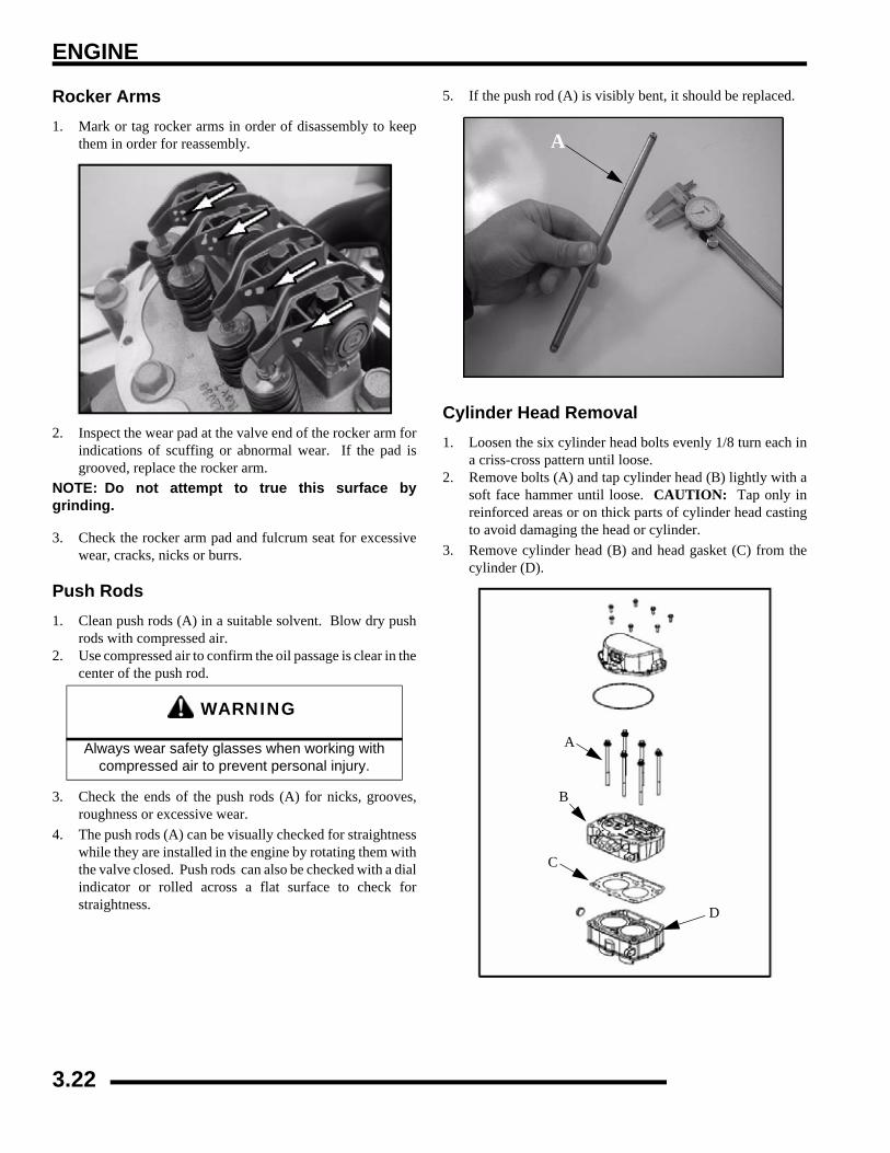
ENGINE
Rocker Arms1. Mark or tag rocker arms in order of disassembly to keep
them in order for reassembly.
2. Inspect the wear pad at the valve end of the rocker arm forindications of scuffing or abnormal wear. If the pad isgrooved, replace the rocker arm.
NOTE: Do not attempt to true this surface bygrinding.
3. Check the rocker arm pad and fulcrum seat for excessivewear, cracks, nicks or burrs.
Push Rods1. Clean push rods (A) in a suitable solvent. Blow dry push
rods with compressed air.2. Use compressed air to confirm the oil passage is clear in the
center of the push rod.
3. Check the ends of the push rods (A) for nicks, grooves,roughness or excessive wear.
4. The push rods (A) can be visually checked for straightnesswhile they are installed in the engine by rotating them withthe valve closed. Push rods can also be checked with a dialindicator or rolled across a flat surface to check forstraightness.
5. If the push rod (A) is visibly bent, it should be replaced.
Cylinder Head Removal1. Loosen the six cylinder head bolts evenly 1/8 turn each in
a criss-cross pattern until loose.2. Remove bolts (A) and tap cylinder head (B) lightly with a
soft face hammer until loose. CAUTION: Tap only inreinforced areas or on thick parts of cylinder head castingto avoid damaging the head or cylinder.
3. Remove cylinder head (B) and head gasket (C) from thecylinder (D).
WARNING
Always wear safety glasses when working with compressed air to prevent personal injury.
A
A
B
C
D
3.22

ENGINE
3
Cylinder Head InspectionThoroughly clean cylinder head surface to remove all traces ofgasket material and carbon.
Cylinder Head Warp1. Lay a straight edge (A) across the surface of the cylinder
head (B) at several different points and measure warp byinserting a feeler gauge between the straight edge and thecylinder head surface. If warp exceeds the service limit,replace the cylinder head.
Valve Seal/Spring Service (On Engine)NOTE: The following procedure is only for servicingthe top end of the valve train when replacing valvesprings or replacing valve seals.
In some cases the valve train can be serviced while the cylinderhead is still on the engine. Keep all parts in order with respectto their location in the cylinder head.
1. Having already removed the valve cover, rocker arms andpushrods, align the cylinder to be worked on at top deadcenter (TDC). Install the Valve Pressure Hose (PU-45652) into the spark plug hole. Hook the hose to an aircompressor and supply 50 to 100 psi to the hose. This willseat the valves during valve spring removal. Do notremove air from the hose at anytime until reassembly iscompleted.
2. Using the Valve Spring Compressor (PU-45257),compress the valve spring and remove the valve keepers.NOTE: A small parts magnet (A) can aid in the removalof the retainers (B).
NOTE: To prevent damage to the valve seals, do notcompress the valve spring more than is needed toremove the valve keepers.
3. Remove spring retainer and spring.4. The valve seals are now serviceable.
CAUTION
Use care not to damage sealing surface.
= In. / mm.
Cylinder Head Warp Limit: .004" (.1016 mm) max
A
B
Measure at differentpoints on the surface.
WARNING
Wear eye protection or a face shield during cylinder head disassembly and reassembly.
A
B
PU-45257
3.23

ENGINE
Cylinder Head Disassembly1. Carefully remove the cylinder components. Place the
hydraulic lifters (C), pushrods (D), and rocker arms (E) ina safe, clean area.
2. Measure free length of spring with a Vernier caliper.Compare to specifications. Replace spring if measurementis out of specification.
3. Remove valve guide seals.IMPORTANT: It is recommended to replace sealswhenever the cylinder head is disassembled.Hardened, cracked or worn valve seals will causeexcessive oil consumption and carbon buildup.
4. Mark the valves with a white pen. Remove the valves fromthe cylinder head. This will ensure that the valves areproperly placed during engine reassembly.
= In. / mm.
Valve Spring Free Length: Std: 1.735" (44.069 mm)
DC
E
Valve SpringFree Length
Mark the Valves
3.24
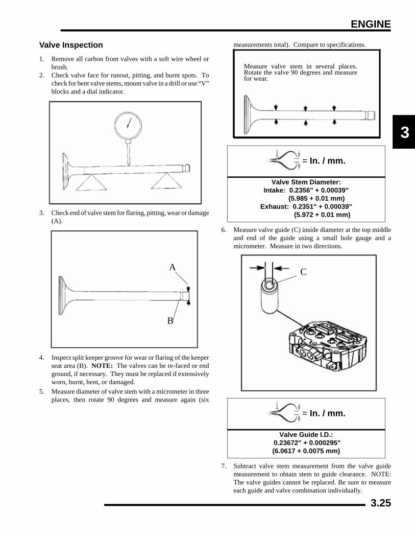
ENGINE
3
Valve Inspection1. Remove all carbon from valves with a soft wire wheel or
brush.2. Check valve face for runout, pitting, and burnt spots. To
check for bent valve stems, mount valve in a drill or use “V”blocks and a dial indicator.
3. Check end of valve stem for flaring, pitting, wear or damage(A).
4. Inspect split keeper groove for wear or flaring of the keeperseat area (B). NOTE: The valves can be re-faced or endground, if necessary. They must be replaced if extensivelyworn, burnt, bent, or damaged.
5. Measure diameter of valve stem with a micrometer in threeplaces, then rotate 90 degrees and measure again (six
measurements total). Compare to specifications.
6. Measure valve guide (C) inside diameter at the top middleand end of the guide using a small hole gauge and amicrometer. Measure in two directions.
7. Subtract valve stem measurement from the valve guidemeasurement to obtain stem to guide clearance. NOTE:The valve guides cannot be replaced. Be sure to measureeach guide and valve combination individually.
A
B
= In. / mm.
Valve Stem Diameter: Intake: 0.2356" + 0.00039"
(5.985 + 0.01 mm) Exhaust: 0.2351" + 0.00039" (5.972 + 0.01 mm)
= In. / mm.
Valve Guide I.D.: 0.23672" + 0.000295"(6.0617 + 0.0075 mm)
Measure valve stem in several places.Rotate the valve 90 degrees and measurefor wear.
C
3.25

ENGINE
Combustion Chamber1. Clean all accumulated carbon deposits from combustion
chamber and valve seat area with carbon cleaner and a softplastic scraper.
IMPORTANT: Do not use a wire brush, metal scraper,or abrasive cleaners to clean the bottom of thecylinder head. Extensive damage to the cylinder headmay result. Wear safety glasses during cleaning.
Valve Seat ReconditioningNOTE: Polaris recommends that the work be doneby a local machine shop that specializes in this area.
NOTE: The cylinder head valve guides cannot bereplaced.
Valve Seat InspectionInspect valve seat in cylinder head for pitting, burnt spots,roughness, and uneven surface. If any of the above conditionsexist, the valve seat must be reconditioned. If the valve seat iscracked the cylinder head must be replaced.
Follow the manufacturers instructions provided with the valveseat cutters in the Cylinder Head Reconditioning Kit (PN2200634). Abrasive stone seat reconditioning equipment canalso be used. Keep all valves in order with their respective seat.
NOTE: Valve seat width and point of contact on thevalve face is very important for proper sealing. Thevalve must contact the valve seat over the entirecircumference of the seat, and the seat must be theproper width all the way around. If the seat isuneven, compression leakage will result. If the seatis too wide, seat pressure is reduced, causingcarbon accumulation and possible compressionloss. If the seat is too narrow, heat transfer fromvalve to seat is reduced. The valve may overheatand warp, resulting in burnt valves.
1. Install pilot into valve guide.
2. Apply cutting oil to valve seat and cutter.3. Place 46° cutter on the pilot and make a light cut.
WARNING
Wear eye protection or a face shield during cylinder head disassembly and reassembly.
Combustion Area
3.26
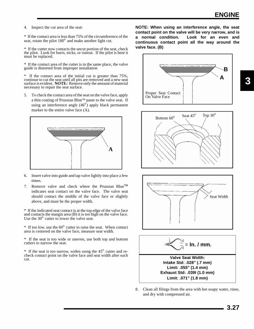
ENGINE
3
4. Inspect the cut area of the seat:
* If the contact area is less than 75% of the circumference of theseat, rotate the pilot 180° and make another light cut.
* If the cutter now contacts the uncut portion of the seat, checkthe pilot. Look for burrs, nicks, or runout. If the pilot is bent itmust be replaced.
* If the contact area of the cutter is in the same place, the valveguide is distorted from improper installation
* If the contact area of the initial cut is greater than 75%,continue to cut the seat until all pits are removed and a new seatsurface is evident. NOTE: Remove only the amount of materialnecessary to repair the seat surface.
5. To check the contact area of the seat on the valve face, applya thin coating of Prussian Blue™ paste to the valve seat. Ifusing an interference angle (46°) apply black permanentmarker to the entire valve face (A).
6. Insert valve into guide and tap valve lightly into place a fewtimes.
7. Remove valve and check where the Prussian Blue™indicates seat contact on the valve face. The valve seatshould contact the middle of the valve face or slightlyabove, and must be the proper width.
* If the indicated seat contact is at the top edge of the valve faceand contacts the margin area (B) it is too high on the valve face.Use the 30° cutter to lower the valve seat.
* If too low, use the 60° cutter to raise the seat. When contactarea is centered on the valve face, measure seat width.
* If the seat is too wide or uneven, use both top and bottomcutters to narrow the seat.
* If the seat is too narrow, widen using the 45° cutter and re-check contact point on the valve face and seat width after eachcut.
NOTE: When using an interference angle, the seatcontact point on the valve will be very narrow, and isa normal condition. Look for an even andcontinuous contact point all the way around thevalve face. (B)
8. Clean all filings from the area with hot soapy water, rinse,and dry with compressed air.
A
= In. / mm.
Valve Seat Width:Intake Std: .028" (.7 mm)
Limit: .055" (1.4 mm)Exhaust Std: .039I (1.0 mm)
Limit: .071" (1.8 mm)
BA
Proper Seat ContactOn Valve Face
Bottom 60° Seat 45° Top 30°
Seat Width
3.27
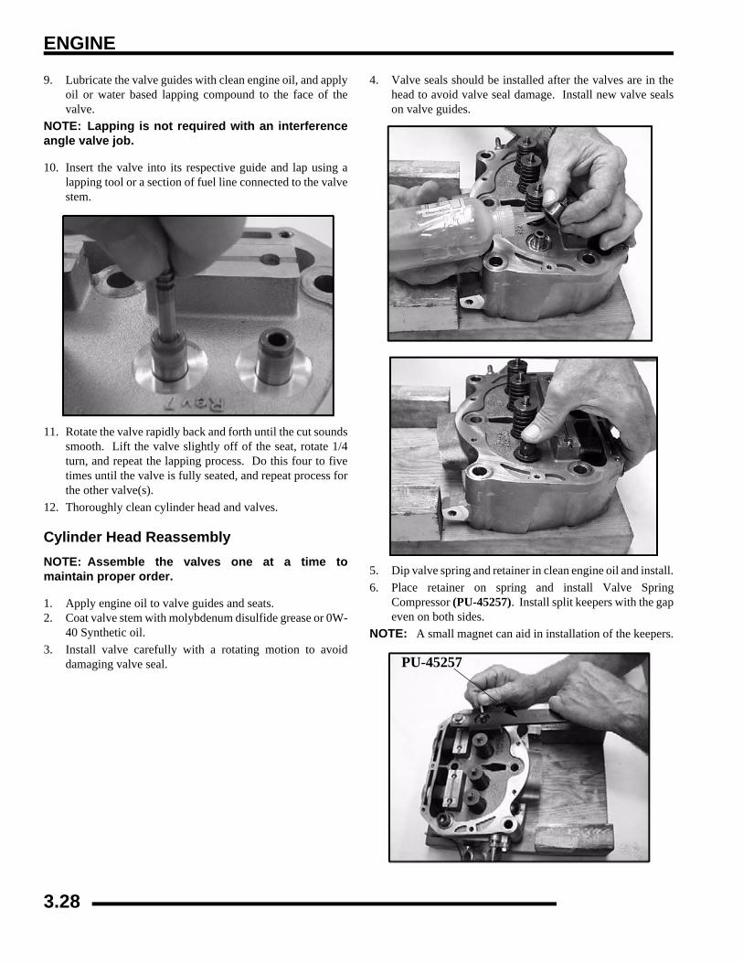
ENGINE
9. Lubricate the valve guides with clean engine oil, and applyoil or water based lapping compound to the face of thevalve.
NOTE: Lapping is not required with an interferenceangle valve job.
10. Insert the valve into its respective guide and lap using alapping tool or a section of fuel line connected to the valvestem.
11. Rotate the valve rapidly back and forth until the cut soundssmooth. Lift the valve slightly off of the seat, rotate 1/4turn, and repeat the lapping process. Do this four to fivetimes until the valve is fully seated, and repeat process forthe other valve(s).
12. Thoroughly clean cylinder head and valves.
Cylinder Head ReassemblyNOTE: Assemble the valves one at a time tomaintain proper order.
1. Apply engine oil to valve guides and seats.2. Coat valve stem with molybdenum disulfide grease or 0W-
40 Synthetic oil.3. Install valve carefully with a rotating motion to avoid
damaging valve seal.
4. Valve seals should be installed after the valves are in thehead to avoid valve seal damage. Install new valve sealson valve guides.
5. Dip valve spring and retainer in clean engine oil and install.6. Place retainer on spring and install Valve Spring
Compressor (PU-45257). Install split keepers with the gapeven on both sides.
NOTE: A small magnet can aid in installation of the keepers.
PU-45257
3.28
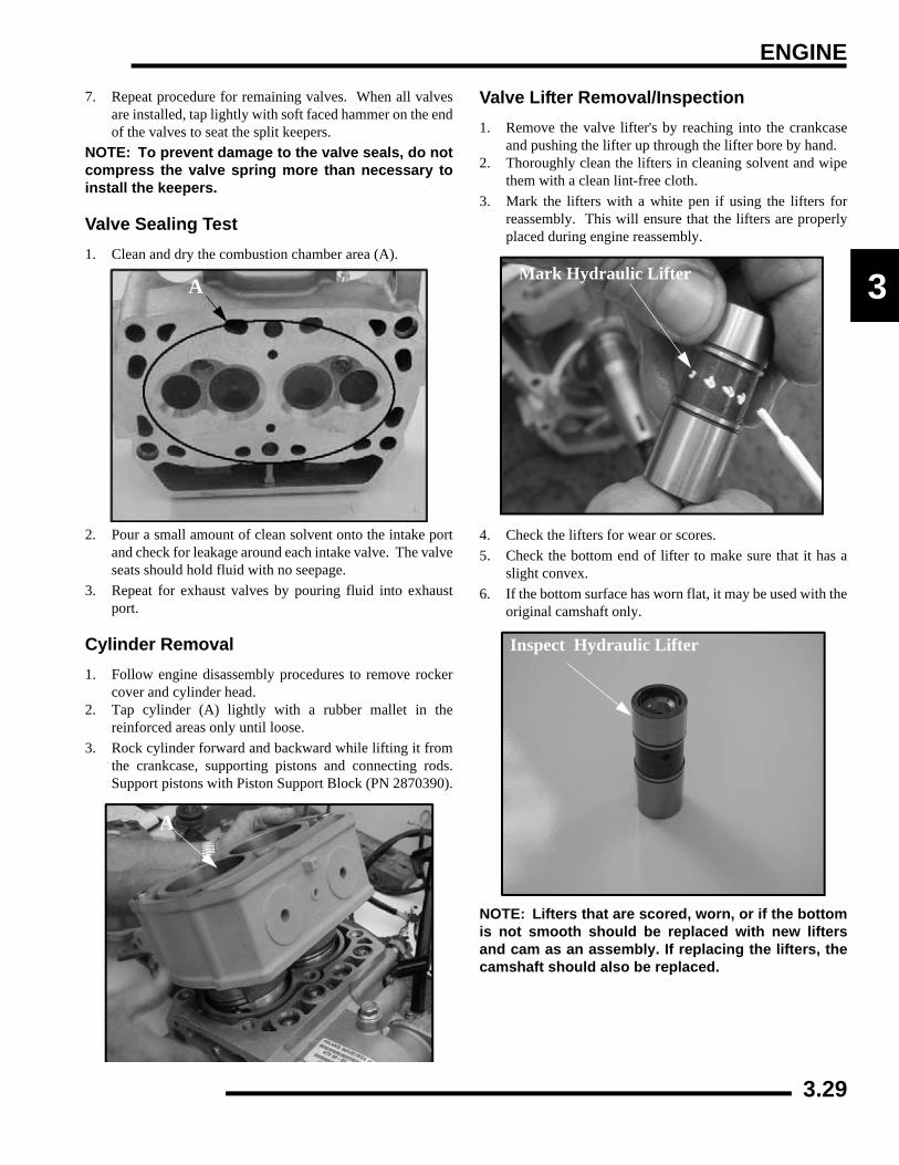
ENGINE
3
7. Repeat procedure for remaining valves. When all valvesare installed, tap lightly with soft faced hammer on the endof the valves to seat the split keepers.
NOTE: To prevent damage to the valve seals, do notcompress the valve spring more than necessary toinstall the keepers.
Valve Sealing Test1. Clean and dry the combustion chamber area (A).
2. Pour a small amount of clean solvent onto the intake portand check for leakage around each intake valve. The valveseats should hold fluid with no seepage.
3. Repeat for exhaust valves by pouring fluid into exhaustport.
Cylinder Removal1. Follow engine disassembly procedures to remove rocker
cover and cylinder head.2. Tap cylinder (A) lightly with a rubber mallet in the
reinforced areas only until loose.3. Rock cylinder forward and backward while lifting it from
the crankcase, supporting pistons and connecting rods.Support pistons with Piston Support Block (PN 2870390).
Valve Lifter Removal/Inspection1. Remove the valve lifter's by reaching into the crankcase
and pushing the lifter up through the lifter bore by hand.2. Thoroughly clean the lifters in cleaning solvent and wipe
them with a clean lint-free cloth.3. Mark the lifters with a white pen if using the lifters for
reassembly. This will ensure that the lifters are properlyplaced during engine reassembly.
4. Check the lifters for wear or scores.5. Check the bottom end of lifter to make sure that it has a
slight convex.6. If the bottom surface has worn flat, it may be used with the
original camshaft only.
NOTE: Lifters that are scored, worn, or if the bottomis not smooth should be replaced with new liftersand cam as an assembly. If replacing the lifters, thecamshaft should also be replaced.
A
A
Mark Hydraulic Lifter
Inspect Hydraulic Lifter
3.29

ENGINE
Piston Removal1. Remove circlip (A). Mark the piston with a white pen to
ensure proper orientation (if reused) during assembly.
NOTE: If the pistons are to be reused, reassemblethe pistons in the same cylinder and direction fromwhich they were removed.
NOTE: New pistons are non-directional and can beplaced in either cylinder.
2. Remove piston circlip and push piston pin out of piston. Ifnecessary, heat the crown of the piston slightly with apropane torch. CAUTION: Do not apply heat to the pistonrings. The ring may lose radial tension.
3. Remove top compression ring:
*Using a piston ring pliers: Carefully expand ring and lift it offthe piston. CAUTION: Do not expand the ring more than theamount necessary to remove it from the piston, or the ring maybreak.
*By hand: Placing both thumbs as shown, spread the ring openand push up on the opposite side. Do not scratch the ring lands.
4. Repeat procedure for second ring.5. Remove the oil control ring.
The oil control ring is a three piece design consisting of a top andbottom steel rail and a center expander section. The top rail hasa locating tab on the end which fits into a notch (B) in the upperoil ring land of the piston.
To Remove:
A) Remove the top rail first followed by the bottom rail.
B) Remove the expander.
CompressionRings
Oil Ring
B
3.30
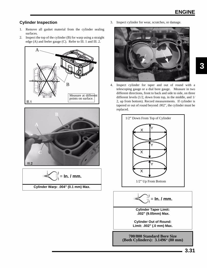
ENGINE
3
Cylinder Inspection1. Remove all gasket material from the cylinder sealing
surfaces.2. Inspect the top of the cylinder (B) for warp using a straight
edge (A) and feeler gauge (C). Refer to Ill. 1 and Ill. 2.
3. Inspect cylinder for wear, scratches, or damage.
4. Inspect cylinder for taper and out of round with atelescoping gauge or a dial bore gauge. Measure in twodifferent directions, front to back and side to side, on threedifferent levels (1/2, down from top, in the middle, and 1/2, up from bottom). Record measurements. If cylinder istapered or out of round beyond .002", the cylinder must bereplaced.
= In. / mm.
Cylinder Warp: .004" (0.1 mm) Max.
Measure at differentpoints on surface.
A
B
A
B
C
= In. / mm.
Cylinder Taper Limit: .002" (9.05mm) Max.
Cylinder Out of Round:
Limit: .002" (.0 mm) Max.
700/800 Standard Bore Size (Both Cylinders): 3.1496" (80 mm)
1/2” Down From Top of Cylinder
1/2” Up From Bottom
3.31

ENGINE
Piston-To-Cylinder ClearanceMeasure piston outside diameter at a point 5 mm up from thebottom of the piston at a right angle to the direction of the pistonpin.
Subtract this measurement from the maximum cylindermeasurement obtained in Step 5.
Piston/rod Inspection1. Measure piston pin bore.
2. Measure piston pin O.D. Replace piston and/or piston pinif out of tolerance.
3. Measure connecting rod small end ID.
Piston to Cylinder Clearance: See “700/800 EFI Engine Service
Specifications” on page 3.11
Piston O.D.: See “700/800 EFI Engine Service
Specifications” on page 3.11
Piston Pin Bore: See “700/800 EFI Engine Service
Specifications” on page 3.11
5 mm
Piston
Piston Pin
Piston Pin O.D.: See “700/800 EFI Engine Service
Specifications” on page 3.11
Connecting Rod Small End I.D.: See “700/800 EFI Engine Service
Specifications” on page 3.11
Piston Pin Measurement Locations
3.32
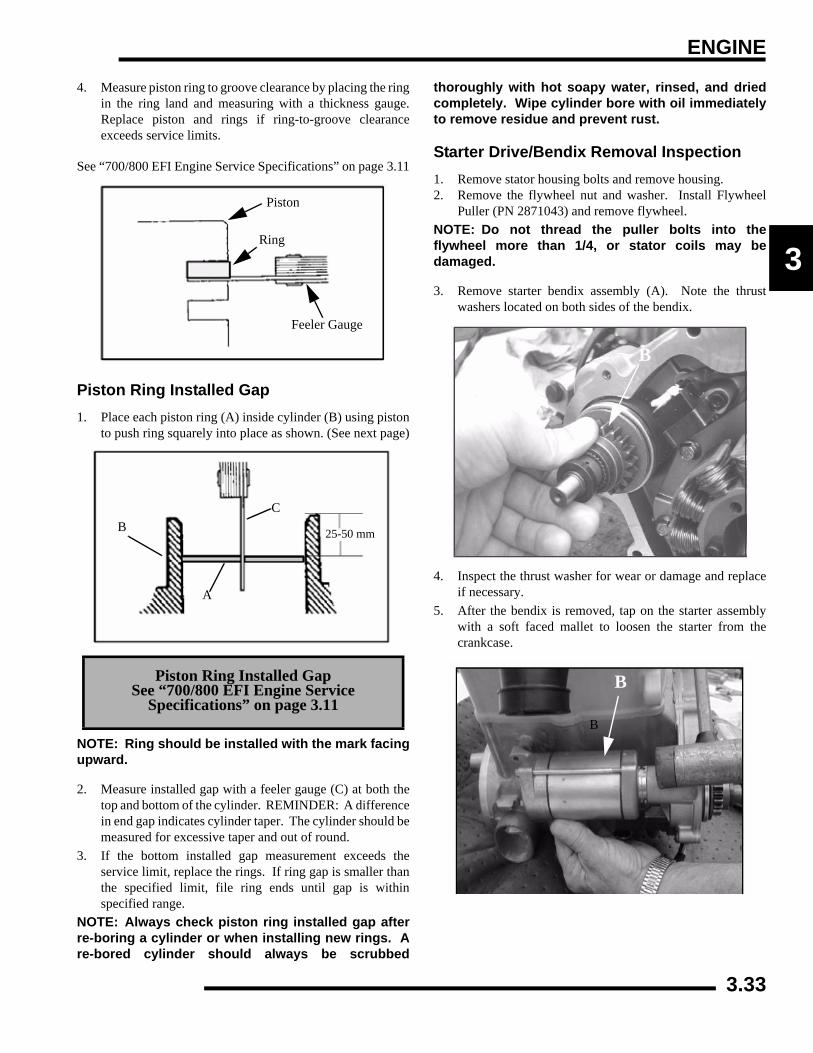
ENGINE
3
4. Measure piston ring to groove clearance by placing the ringin the ring land and measuring with a thickness gauge.Replace piston and rings if ring-to-groove clearanceexceeds service limits.
See “700/800 EFI Engine Service Specifications” on page 3.11
Piston Ring Installed Gap1. Place each piston ring (A) inside cylinder (B) using piston
to push ring squarely into place as shown. (See next page)
NOTE: Ring should be installed with the mark facingupward.
2. Measure installed gap with a feeler gauge (C) at both thetop and bottom of the cylinder. REMINDER: A differencein end gap indicates cylinder taper. The cylinder should bemeasured for excessive taper and out of round.
3. If the bottom installed gap measurement exceeds theservice limit, replace the rings. If ring gap is smaller thanthe specified limit, file ring ends until gap is withinspecified range.
NOTE: Always check piston ring installed gap afterre-boring a cylinder or when installing new rings. Are-bored cylinder should always be scrubbed
thoroughly with hot soapy water, rinsed, and driedcompletely. Wipe cylinder bore with oil immediatelyto remove residue and prevent rust.
Starter Drive/Bendix Removal Inspection1. Remove stator housing bolts and remove housing.2. Remove the flywheel nut and washer. Install Flywheel
Puller (PN 2871043) and remove flywheel.NOTE: Do not thread the puller bolts into theflywheel more than 1/4, or stator coils may bedamaged.
3. Remove starter bendix assembly (A). Note the thrustwashers located on both sides of the bendix.
4. Inspect the thrust washer for wear or damage and replaceif necessary.
5. After the bendix is removed, tap on the starter assemblywith a soft faced mallet to loosen the starter from thecrankcase.
Piston Ring Installed Gap See “700/800 EFI Engine Service
Specifications” on page 3.11
Piston
Ring
Feeler Gauge
A
BC
25-50 mm
B
B
B
3.33

ENGINE
6. Inspect gear teeth on starter drive (B). Replace starter driveif gear teeth are cracked, worn, or broken.
7. Inspect the bendix bushing (C) in the mag cover for wear.Replace as needed.
Flywheel / Stator Removal / Inspection1. Remove stator housing bolts and remove housing.
2. Remove flywheel nut and washer.
3. Install Flywheel Puller (PN 2871043) and removeflywheel (A). CAUTION: Do not thread the puller boltsinto the flywheel more than 1/4, or stator coils may bedamaged.
4. Use caution when removing the wire holddown (B), triggercoil (C), and the stator assembly (D). Do not tap or bumpthe gear /stator housing cover or the stator. This couldcause the seal around the gear/stator housing cover and thecrankcase to break, causing a leak.
5. Remove the bendix (E) if necessary.
C
Remove StatorCover
A2871043
E
CB
D
3.34

ENGINE
3
Engine Crankcase Disassembly / Inspection1. Remove the stator cover (A) and water pump cover (B).
2. Remove the nylok nut (C), washer (D), and water pumpimpeller (E). Remove part of the water pump seal behindthe impeller.
3. Remove flywheel nut and washer.
4. Install Flywheel Puller (PN 2871043) and remove flywheel(F). CAUTION: Do not thread the puller bolts into theflywheel more than 1/4, or stator coils may be damaged.
5. Remove the starter bendix (G), wire holddown plate (H),and the woodruff key (I) from the crankshaft. The statordoes not have to be removed at this point.
6. Remove the gear/stator housing bolts and remove the gear/stator housing cover (J) and gasket from the crankcase. Besure to catch the excess oil from the crankcase.
A
B
E
CD
F
G
HI
J
3.35

ENGINE
7. Note the positions of the gears in the photo.
8. Use a white pen to accent the timing marks on the followinggears: camshaft gear (K), crankshaft gear (M), orcounterbalance gear (N) This will ensure proper gearalignment and timing during reassembly of the gears.
NOTE: If replacing one of the gears, it isrecommended that all of the gears be replaced. Agear kit is available in the parts book.
9. Use the Cam Gear Tooth Alignment Tool (PU-45497-2)(O) to align the cam split gear assembly. With the split gearaligned, remove the bolt and cam gear assembly.
NOTE: Install the Cam Gear Tooth Alignment Tool(PU-45497-2) into the assembly hole counterclockwise from the timing mark as shown.
10. Inspect the cam gear teeth and check to make sure there isspring tension offsetting the teeth between the two gears.If there is no tension, check the springs inside of the camgear assembly.
11. The cam gear assembly contains three loaded springs. Toopen the cam gear assembly:
* Place the cam gear on a flat surface with the timing mark sidefacing up.
* While holding both gears together, lightly work a smallflathead screwdriver between the two gears.
* Remove the top gear. The springs should stay in place.
12. Remove all three springs using one of the tapered pins fromthe Tapered Pins (PU-45497-1).
Camshaft Gear
Counterbalance GearCrank Gear
MN
K
Timing Marks
Water Pump Gear
CAUTION
Wear safety glasses at all times. Use caution when working with the top gear. The springs could cause
injury or become lost should they pop out.
3 Loaded Springs
3.36

ENGINE
3
13. With a white marking pen, accent the timing mark on thegear that contains the springs.
14. Inspect the gear teeth and the three tabs on the gears forwear.
15. Install the new springs into the grooves of the cam gear.
16. Insert the pointed dowels from the Tapered Pins (PU-45497-1) into the cam gear.
To Assemble:
* Hold the spring with one finger.* Start the pointed end of the tapered pin into the cam gear holeand slowly push the dowel through the hole until the end of thedowel is almost flush with the spring.* Perform this procedure with all three tapered pins.* Do not push the pins too far through or the springs will popout.NOTE: Do not remove the tapered pins at this time.
17. Note in the photograph that the Tapered Pins (PU-45497-1) are below flush with end of the springs. This helps toalign the three gear tabs during the next step.
Accent Timing Marks
Inspect Teeth & Tabs
Replace 3 Springs
Install Springs
Cam Gear Spring Installation Tool Kit: (PU-45497)
Tapered Pins: (PU-45497-1)Cam Gear Tooth Align Tool: (PU-45497-2)
PU-45497-1
PU-45497-1
3.37

ENGINE
18. Line up the two gears using the timing marks and the threegear tabs that were referenced earlier. Push the gears backtogether, using both hands and hold securely.
19. Once the gears are pressed together, firmly hold the gearstogether with one hand. Carefully remove the Tapered Pins(PU-45497-1) by pulling them out one at a time with theother hand.
20. After the tapered pins are removed, be sure the cam gearassembly is held together tightly. Place the cam gearassembly on a flat surface. Use the Cam Gear ToothAlignment Tool (PU-45497-2) to align the teeth of the camgears, as shown in the picture.
NOTE: Install the Cam Gear Alignment Tool (PU-45497-2) into one assembly hole counter clockwisefrom the timing mark.
NOTE: For ease of installing the Cam GearAlignment Tool (PU-45497-2) (R), use a twistingmotion when pushing down on the tool.
21. To remove the balance shaft gear, the flat side of thecamshaft (P) must face the balance shaft gear. To rotate thecamshaft, use the Cam Spanner Wrench (PU-45498) torotate the camshaft so the flat side of the camshaft faces thebalance shaft gear.
NOTE: This Cam Spanner Wrench (PU-45498) isonly needed to rotate the camshaft when the entirevalve train is assembled. If the rocker arms areremoved, the cam-shaft can be turned by hand.
Align Timing Marks
PU--45497-2
PU-45498
P
3.38

ENGINE
3
22. Remove the bolt and nut from the balance shaft gear. Tryto remove the balance shaft gear. If the gear does not comeoff manually, use the Flywheel Puller (PN 2871043) toremove the balance shaft gear.
23. Inspect the crankshaft gear (Q) for broken or worn teeth. Ifthe crankshaft gear does not need to be replaced, it does notneed to be removed. If the crankshaft gear is damaged,remove the crankshaft gear with the Flywheel Puller (PN2871043).
24. Install the two puller bolts (R). Tighten the puller bolts upso that the bolts are at equal length.
25. Install the Flywheel Puller (PN 2871043) and remove thecrankshaft gear, if needed.
26. Rotate the water/oil pump gear (S), so that all four bolts arevisible though the gear. Remove the four bolts with a hexwrench. Pull out the pump.
27. Inspect the oil pump rotors for wear. Mark the rotors witha white pen to ensure upon reassembly that the correct sidesof the rotors are installed and mesh with the same edges aspreviously installed.
NOTE: If replacing the old rotors, new replacementrotors will fit into the old oil/water pump housing.
2871043
Q
R
2871043
S
3.39

ENGINE
28. Use a feeler gauge to measure the clearance between thetwo rotors. Measure the gap between the two rotor tips asshown below. The clearance should not exceed 0.006"(0.15 mm).
29. Remove the oil pressure relief. The oil pressure reliefconsists of a bolt, washer, spring, and valve (dowel).Inspect the valve (dowel) for signs of possible obstructions.Use compressed air to blow out any debris.
30. Reinstall the valve (dowel chamfered end first). Install thespring, washer, and bolt. Torque to specification .
NOTE: Be sure to place the tapered end of the valve(dowel) in first. If the valve is installed incorrectly,oil pressure and oil priming problems will occur.
31. Carefully press the gear off the assembly while supportingthe housing assembly.
32. Remove the snap ring from the assembly. Place the housingin a support and press out the bearing/shaft assembly.
= T
22 ± 2 ft. lbs. (30 ± 3 Nm)
0.006” (0.15 mm)Max Tip Clearance
22 22 ± 2 ft. lbs.(30 ± 3 Nm).
ChamferEnd First
CAUTION
Wear appropriate safety gear during this procedure. Protective gloves, clothing and eyewear are
required.
Press Off Gear
Press Out shaftand bearingassembly.
Bearing
Retaining Ring
3.40

ENGINE
3
33. Place the shaft in a press to remove the bearing.
34. Press shaft into the new bearing..
35. Press the bearing/shaft assembly using the bearing's outerrace. Do not use the shaft to press the assembly into thehousing, as bearing damage may result. Install retainingring.
36. Press gear onto shaft while supporting the housing.
37. Remove thrust plate (U).
38. Remove PTO end engine mount Remove crankcase bolts.Tap on the reinforced areas on the cases using soft hammer.Carefully separate the two crankcase halves.
Bearing
New Bearing
Press Bearing/ShaftAssembly usingouter race only
U
SeparateCrankcase Halves
3.41

ENGINE
NOTE: Only remove the oil baffle if the baffle isdamaged. When removing the oil baffle bolts, use aheat gun to heat the bolts and loosen the Loctite™.This will prevent any possible damage to the bolts orto the crankcase casting.
39. Remove and clean oil pick up (V) and oil baffle weldment(W).
40. Remove balance shaft and crankshaft.
41. Remove and inspect crankshaft main journal bearings forabnormal wear. It is recommended to replace thebearings anytime the engine is disassembled.
NOTE: Plain bearing clearances may be checkedusing a commercially available plasti-gaugematerial.
Camshaft Inspection1. Thoroughly clean the cam shaft.2. Visually inspect each cam lobe for wear, chafing or
damage.3. Measure height of each cam lobe using a micrometer.
Compare to specification.
W
V
= In. / mm.
Cam Lobe Height (Intake & Exhaust):
Std: 1.3334" (33.8674 mm)
Cam Lobe Height
3.42

ENGINE
3
4. Measure camshaft journal outside diameters (O.D.).
5. Measure ID of camshaft journal bores.
6. Calculate oil clearance by subtracting journal O.D.'s fromjournal bore I.D.'s. Compare to specification.
NOTE: Replace camshaft if damaged or if any part isworn past the service limit.
NOTE: Replace engine block if camshaft journalbores are damaged or worn excessively.
ENGINE REASSEMBLYCRANKCASE REASSEMBLY
NOTE: Before assembly, clean the bolts and boltholes with Primer N (PN 2870585) to remove anydebris. This will ensure proper sealing wheninstalling bolts.
1. Install oil pick up (A), if removed. Torque to specification.
2. Install oil baffle weldment (B). Torque bolts tospecification.
3. Install the balance shaft. Inspect balance shaft clearance(C) in both gearcase halves. Rotate balance shaft to ensurethat there is clearance between it and oil baffle weldment.
= In. / mm.
Camshaft Journal O.D. :A. (Mag): 1.654" ± .00039" (42 ± .010 mm)
B. (Ctr.): 1.634" ± .00039" (41.50 ± .010 mm)C. (PTO): 1.614" ± .00039" (41 ± .010 mm)
= In. / mm.
Camshaft Journal Bore I.D.: (Mag): 1.656" ± 0.00039" (42.07± 0.010 mm) (Ctr.) 1.637" ± 0.00039" (41.58 ± 0.010 mm) (PTO) 1.617" ± 0.00039" (41.07 ± 0.010 mm)
= In. / mm.
Calculated Camshaft Oil Clearance: Std: 0.0027" (.070mm)Limit: .0039" (.10 mm)
AB
C
CAUTION
After any reassembly or rebuild, the engine must be primed using the Oil Priming Adapter (PU-45778) and a 3/4-full oil filter before initial start-up. Follow Steps 45-46 of this section to prime the engine and
to help aid proper break-in.
= T
Oil Baffle Weldment & Oil Pick Up Bolt Torque:
60 ± 6 in. lbs. (6.8 ± 0.68 Nm)
A
B
3.43

ENGINE
NOTE: Always install new balance shaft bearings.
4. Apply assembly lube to cam journals and balance shaftbearing surfaces of the MAG case halve. Install cam andbalance shafts.
5. Install crankshaft assembly and apply engine oil to crankpins and rods (D). Apply assembly lube to the mainjournals and bearings.
6. Apply Crankcase Sealant (PN 2871557) to the top gearcasehalve.
NOTE: Do not apply sealant to cam relief hole (E).
7. Assemble the crankcase halves. Apply LocTite™ 242 (PN2871949) to the threads and pipe sealant to the bolt flanges.Torque bolts to specification following torque pattern atbeginning of this chapter.
8. Lubricate cam lobes and valve lifters with Moly LubeGrease.
C
D
= T
Crankcase Bolt Torque:22 + 2 ft. lbs. (30 + 3 Nm)
Torque in sequence
E
Apply Moly Lube Cam Lobes
Lifters
3.44

ENGINE
3
9. Lubricate lifters with engine oil and install in the originalorder as removed in disassembly. Apply Lubriplate orMoly Lube to the ends of the lifters.
NOTE: Always replace the camshaft and lifters as aset.
10. Lubricate connecting rods with 0W-40 engine oil.
11. Install new cylinder gasket on crankcase. Align gasket onthe dowel pins for proper gasket alignment.
12. Orientate the piston rings on the piston before installationinto the cylinders. Set the gaps of the rings evenly 120°apart. (see illustration)
13. Install piston assemblies into cylinder aligning the pistonpin holes, to ensure proper alignment of the pistons to theconnecting rods upon assembly. Partially install the pistonpins into the pistons.
NOTE: To help align the pistons, slide a rod that isclose to the same diameter as the wrist pin holes toproperly align them in the cylinder.
Piston RingOrientation
1. Top Ring 2. Second Ring
3. Oil Ring
1
2
3
3.45

ENGINE
14. Position cylinder and piston assemblies onto the connectingrods and push the piston pins through the piston andconnecting rods.
15. Install the piston pin circlips (F). The circlip ends shouldbe installed at the 12 O'clock position.
NOTE: While installing in piston pins, cover allengine passages. The clip could fall into the engineduring installation.
16. Install camshaft thrust plate (G) with new bolts. Torquebolts to specification.
NOTE: New bolts have patch lock on the threadsand do not require Loctite™.
17. Assemble rotors as marked when disassembled. Use acleaner to remove the marks previously made on the rotors.
18. Apply assembly lube or oil to the rotors on the oil pumpshaft.
Push In Piston Pins
Piston Pin Cirlcip (F) in12 O’clock position
= T
Thrust Plate Screw Torque: 115 ± 12 in.lbs. (13 ± 1.35 Nm)
G
Line Up Marks
3.46

ENGINE
3
NOTE: The application of lubrication aids in primingthe oil pump during initial engine start up.
19. Align the bolt holes and install oil pump assembly intocrankcase. Rotate the rotors in the housing duringinstallation, as this checks for binding if new rotors areused.
NOTE: For assembly of the gears, the cam gear andthe crankshaft gear are stamped with “This SideOut." This indicates the side of the gear that facesoutward or away from the case.
NOTE: Before assembly, clean the bolts and boltholes with Primer N (PN 2870585) to remove anydebris. This will ensure proper sealing wheninstalling bolts and new Loctite™.
20. Install oil pump housing bolts (H). The new bolts containpatch lock, so Loctite™ is not needed on the new bolts.Torque bolts to specification and follow the torquesequence at beginning of the chapter.
NOTE: Occasionally spin the oil pump wheninstalling bolts to check for binding of the rotors.
21. Apply Loctite™ 242 (PN 2871949) to the crankshaft.
Lubricate Rotors
= T
Oil Pump Bolt Torque: 84 ± 8 in.lbs. (9.50 ± 0.90 Nm)
* Torque in Sequence
H
3.47

ENGINE
22. Before installing the crankshaft gear (I), heat the crankshaftgear to 250° F (121°C) on a hot plate (J).
23. Use extreme caution when removing the crankshaft gearfrom the hot plate. Use a pair of pliers and leather gloveswhen handling the crankshaft gear.
24. Install the crankshaft gear (I) onto the crankshaft.NOTE: For assembly of the gears, the cam gear andthe crankshaft gear are stamped with This Side Out."This indicates the side of the gear that faces outwardor away from the case.
25. Install counter balance shaft gear (J) with new key, aligningtiming marks with crankshaft gear (I). Install washer andbolt. Use the Gear Holder (PU-45838). Torque tospecification.
26. Use the Cam Gear Alignment Tool (PU-45497-2) to alignthe teeth of the cam gear (M). Install the cam gear (M) (withthe Cam Gear Alignment Tool still in place) onto thecamshaft. The timing marks on the camshaft gear shouldalign with the keyway on the balance shaft gear.
NOTE: If the timing mark on the camshaft gear doesnot align properly, remove the camshaft gear andtool. Use the Cam Spanner Wrench (PU-45498) torotate the cam to the proper position.
CAUTION
The crankshaft gear is extremely hot! Severe burns or injury can occur if the gear is not handled with extreme care and caution. Follow the procedure
below to help ensure safety.
I J
I
= T
Balance Shaft Gear Bolt Torque: 22 ± 2 ft. lbs. (30 ± 3 Nm)
PU-45497-2
M
3.48

ENGINE
3
NOTE: Cam Spanner Wrench (PU-45498) is onlyneeded to rotate the camshaft when the entire valvetrain is assembled.
27. Reinstall the camshaft gear; so the timing marks areproperly aligned. Install the washer and bolt. Torque tospecification.
NOTE: Be sure all of the timing marks are properlyaligned.
Before installing the gear/stator housing, replace the seals in the
cover. Install a new water pump seal (N) into the gear/statorhousing (O). Use the Water Pump Mechanical Seal Installer(PA-44995) to properly install the seal to the correct depth in thecover.
Due to seal design and construction, seals MUST be
installed DRY (no lubricant) during assembly. Use oflubricants (oil, soapy water, etc.) will not allow the sealto wear-in and seal properly. Do not touch sealsurface or allow seal surface to come in contact withcontaminates during installation. Thoroughly cleanparts, tools and hands before installation.
NOTE: To remove the water pump seal, the gear/stator housing must be removed. The water pumpseal cannot be removed or installed with the gear/stator housing attached to the engine. Shaft damagewill occur.
NOTE: Install the water pump seal (N) with the seallip facing out (towards the crankcase). Use of ahydraulic press is recommended for this procedure.
PU-45498
Timing Marks
MN
KWater Pump Gear
= T
Counterbalance Gear and Camshaft Gear Bolt Torque:
22 ± 2 ft. lbs. (30 ± 3 Nm)
Timing Marks
PA-44995
O
N
PA-44995
3.49

ENGINE
28. Install a new crankshaft seal (P) into the gear/stator housingcover (O). Use the Universal Driver Handle (PU-45543)and the Main Seal Installer (PA-45483) to seat thecrankshaft seal into place.
NOTE: Install the crankshaft seal (P) with the seal lipfacing out (towards the crankcase).
29. Once the crankshaft seal is installed into the gear/statorhousing cover, set the direction of the paper lip by slidingthe Main Crankshaft Seal Saver (PA-45658) into thecrankshaft seal from the rubber lipped side to the paper lipside.(Back to Front) Remove the tool.
30. Carefully install the tapered end of the Crankshaft SealProtection Tool (PA-45658) through the paper side of thecrankshaft seal. (Back to Front) Leave the seal protectorinstalled in the crankshaft seal. Check the crankshaft seallips to verify they have not been rolled or damaged.
31. Before installing the gear/stator housing cover, install theWater Pump Seal Saver (PA-45401) onto the water pumpshaft.
32. Install a NEW gasket to the gear/stator housing cover andcrankcase. With the tools installed, carefully place thegear/stator housing cover over the protection tools.
PU-45543
PA-45483
P
Seal lip goes towards the crankcase.
IMPORTANT: Set the directionof the paper lip seal.
PA-54658
PA-45401
3.50

ENGINE
3
33. Apply Crankcase Sealant (PN 2871557) to the outsideedges of the crankcase halves (See arrows), where thecrankcases mate. (See photos below.) This helps to preventcoolant leakage.
34. Install the gear/stator housing gasket onto he crankcase.
35. Secure the gear/stator housing cover (O) to the crankcasewith the cover bolts. Torque bolts in proper sequence tospecification. Remove seal protectors from the shaft endsonce secure.
NOTE: Before assembly, clean the bolts and boltholes with Primer N (PN 2870585) to remove anydebris. This will ensure proper sealing wheninstalling bolts.
36. Install shaft seal with ceramic surface facing inward.
Gear/Stator Housing Gasket
= T
Gear/Stator Housing Bolt Torque:96 ± 3 in. lbs. (10.85 ± 0.35 Nm)
*Torque in proper sequence
OPA-45658
PA-45401
3.51

ENGINE
37. Install water pump impeller (P). Secure the impeller withthe washer and a new nylok nut (Q). Torque the nut tospecification.
38. Install water pump cover (R) with new O-ring seal. Torquebolts to specification in proper sequence (See front of thischapter).
39. Sparingly apply Starter Drive Grease (PN 2871423) to thestarter drive. Install the starter bendix.
NOTE: There are thrust washers on both sides ofstarter drive.
40. Install stator assembly (S) and bolts. Torque bolts tospecification.
41. Install the wire hold down bracket (T). Install two new wirehold down bolts. New bolts contain patch-lock. Torquebolts to specification, following the proper bolt torquesequence. Coat the stator wire grommet (U) with Nyogel™ Grease (PN 2871329).
NOTE: Verify stator wires are routed properly underthe wire hold down bracket.
= T
Water Pump Impeller Nut Torque: 108 ± 6 in. lbs. (6.8 ± 0.68 Nm)
= T
Water Pump Housing Bolt Torque: 96 ± 3 in. lbs. (10.85 ± 0.35 Nm)
*Torque in proper sequence
Q
P
Install the O-ring dry, no lubricants
R
96 ± 3 in. lbs. (10.85 ± 1.35 Nm)
= T
Stator Assembly Bolt Torque: 96 ± 3 in.lbs. (10.85 ± 0.35 Nm)
Replace 2 bolts with new bolts.
T
U
S
3.52

ENGINE
3
42. Install the flywheel, washer, nut, and key. Torque flywheelnut to specification.
43. Install stator housing with new o-rings. Torque the bolts tospecification and follow proper bolt torque sequence at thebeginning of this chapter.
44. After the engine is completely assembled and ready forinstallation, the engine must be properly primed withPolaris 0W-40 Synthetic Oil (PN 2871281). Fill the oilfilter three-quarters full with Polaris 0W-40 Synthetic Oil(PN 2871281). Let the oil soak into the filter for 8-10
minutes. Install the filter onto the engine.
45. Remove primer plug from the engine. Install Oil SystemPriming Adapter (PU-45778) into the oil plug hole. Push3-5 oz. (approx.) of Polaris 0W-40 into the adapter or untilresistance is felt. Remove the adapter. Apply sealant to theplug threads. Install the plug and torque to specification.
= T
Flywheel Nut Torque65 ± 7 ft.lbs. (88 ± 9.50 Nm)
= T
Stator Housing Bolt Torque: 96 ± 3 in. lbs. (10.85 ± 0.35 Nm)
65 ± 7 ft.lbs. (88 ± 9.50 Nm)
96 ± 3 in.lbs. (10.85 ± 0.35 Nm)
= T
Primer Plug Torque18 ± 2 ft.lbs. (24.4 ± 2.71 Nm)
CAUTION
After any reassembly or rebuild, the engine must be primed using the Oil Priming Adapter (PU-45778) and a 3/4-full oil filter before initial start-up. Follow the steps in this section to properly prime the engine and aid proper engine break in. Failure to perform this procedure may cause internal engine damage
on initial start-up.
PU-45778
3.53

ENGINE
Flywheel / Stator InstallationNOTE: Before assembly, clean the bolts and boltholes with Primer N (PN 2870585) to remove anydebris. This will ensure proper sealing wheninstalling bolts.
1. Carefully install the stator and trigger coil to the gear/statorhousing cover. Do not tap on the stator or the gearstator housing cover. This may cause a leak in betweenthe gear/stator housing cover and the crankcase.
2. Properly place the stator wires under the wire holddownand install the bolts. Inspect the bolts, if new bolts areneeded, replace them with new bolts. New bolts containpatch lock, so Loctite™ is not needed. Torque bolts tospecification.
3. Install the starter bendix if removed.4. Install woodruff key. Install the flywheel. Install the
flywheel washer and nut. Torque the flywheel nut tospecification.
5. Inspect the mating surface around the gear/stator housingcover and the crankcase for oil seepage. If there is seepagebetween the mating surfaces, then the gear/stator housingcover must be resealed. Clean the gearcase surfaces andreseal with a new gasket. Refer to the Lower EngineDisassembly section and the Lower Engine Assemblysection for details. lnspect the areas pointed out in theillustration for possible oil seepage.
6. Install stator housing with new O-rings. Torque the boltsto specification. Follow bolt torque sequence on found atthe beginning of this chapter.
= T
Flywheel Nut Torque: 65 ± 7 ft.lbs. (88 ± 9.5 Nm)
= T
Stator Housing Bolt Torque:96 ± 3 in.lbs. (1.85 ± 0.35 Nm)
*Torque in Sequence
96 ± 3 in.lbs.(1.85 ± 0.35 Nm)
3.54

ENGINE
3
Cylinder Head ReassemblyNOTE: Before reassembly, clean the bolts and boltholes with Primer N (PN 2870585) to remove anydebris. This will ensure proper sealing wheninstalling bolts.
1. Install the head gasket (A) on the cylinder (B).
2. Install cylinder head on cylinder.3. Lubricate threads and top of washers underside of bolt head
with engine oil. Install head bolts (C) and torque tospecification.
4. Lubricate push rods (D) and install into lifters.
5. Lubricate rockers (E) with engine oil.
6. Verify pushrods are engaged in lifters.7. Install rockers. Be sure that tab of fulcrum (F) is seated in
head stand-off. Torque bolts to specification.
= T
Cylinder Head Bolt Torque: Initial setting: 35± 4 ft. lbs. (47.5 ± 5.5 Nm)
Allow to set for 1 minute, then turn additional 90° (1/4 turn)
*Torque Bolts In Sequence
A
B
C
= T
Rocker Arm Bolt Torque22 + 2 ft. lbs. (30 ± 3 Nm)
D
E
E
3.55

ENGINE
8. Install breather reed (G) into rocker cover (H). Lightlyapply black RTV sealant to the outer edges of the breatherreed. The reed has a tab and will assemble one-way only.Torque the breather bolts to specification.
NOTE: When applying RTV, do not get any RTVinside the reed assembly.
9. Place a new seal (I) into the bottom of the cover. Be surethe seal is seated into the cover properly.
IMPORTANT: Before assembly, clean the bolts andbolt holes with Primer N (PN 2870585) to remove anydebris. This will ensure proper sealing wheninstalling bolts.
10. Install rocker cover. Torque bolts to specification.
11. Install thermostat (J), new O-ring, and thermostat housing.Torque to specification.
12. Install temperature sender (K) and torque to specification.
= T
Breather Bolt Toque:20 ± 5 in. lbs. (2.5± 0.55 Nm)
= T
Rocker Cover Bolt Torque: 84 ± 8 in.lbs. (9.5 ± 0.9 Nm)
Torque in Sequence
20 ± 5 in.lbs.(2.5 ± .55 Nm)
G
H
I
= T
Thermostat Housing Bolt Torque: 84 ± 8 in. lbs. (9.5± 0.9 Nm)
= T
Temperature Sender Torque:25 ± 3 ft.lbs. (34 ± 4 Nm)
84 ± 8 in.lbs.(9.5 ± 0.9 Nm)
25 ± 3 ft.lbs. (34 ± 4 Nm)
K
K
3.56

ENGINE
3
TROUBLESHOOTINGEngine
Spark Plug Fouling• Spark plug cap loose or faulty
• Incorrect spark plug heat range or gap
• PVT system calibrated incorrectly/ components worn or mis-adjusted
• Fuel quality poor (old) or octane too high
• Low compression
• Restricted exhaust
• Weak ignition (loose coil ground, faulty coil, stator, or ETC switch)
• ETC switch mis-adjusted
• Restricted air filter (main or pre-cleaner) or breather system
• Improperly assembled air intake system
• Restricted engine breather system
• Oil contaminated with fuel
Engine Turns Over But Fails To Start• No fuel
• Dirt in fuel line or filter
• Fuel will not pass through fuel valve
• Fuel pump inoperative/restricted
• Tank vent plugged or pinched
• Engine flooded
• Low compression (high cylinder leakage)
• No spark (Spark plug fouled) ignition component failure
Engine Does Not Turn Over• Dead battery
• Starter motor does not turn
• Engine seized, rusted, or mechanical failure
Engine Runs But Will Not Idle• Restricted carburetor pilot system
• Low compression
• Crankcase breather restricted
Engine Idles But Will Not Accelerate
• Spark plug fouled/weak spark
• Broken throttle cable
• Obstruction in air intake
• Air box removed (reinstall all intake components)
• Incorrect or restricted carburetor jetting
• ETC switch limiting speed
• Reverse speed limiter limiting speed
• Incorrect ignition timing
• Restricted exhaust system
• Cam worn excessively
Engine Has Low Power• Spark plug fouled
• Cylinder, piston, ring, or valve wear or damage (check compression)
• PVT not operating properly
• Restricted exhaust muffler
• Cam worn excessively
Piston Failure - Scoring• Lack of lubrication
• Dirt entering engine through cracks in air filter or ducts
• Engine oil dirty or contaminated
Excessive Smoke and Carbon Buildup• Excessive piston-to-cylinder clearance
• Wet sumping (Oil Level Too Full)
• Worn rings, piston, or cylinder
• Worn valve guides or seals
• Restricted breather
• Air filter dirty or contaminated
Piston Failure - Scoring
• Lack of lubrication
• Dirt entering engine through cracks in air filter or ducts
• Engine oil dirty or contaminated
3.57

ENGINE
Excessive Smoke and Carbon Buildup
• Excessive piston-to-cylinder clearance
• Wet sumping due to over-full crankcase
• Worn rings, piston, or cylinder
• Worn valve guides or seals
• Restricted breather
• Air filter dirty or contaminated
Low Compression• Cylinder head gasket leak
• No valve clearance ( cam wear )
• Cylinder or piston worn
• Piston rings worn, leaking, broken, or sticking
• Bent valve or stuck valve
• Valve spring broken or weak
• Valve not seating properly (bent or carbon accumulated on sealing surface)
• Rocker arm sticking
Backfiring• ETC or speed limiter system malfunction
• Fouled spark plug or incorrect plug or plug gap
• Exhaust system air leaks
• Exhaust system air leaks
• Ignition system faulty: Spark plug cap cracked/broken, Ignition coil faulty, Ignition or kill switch circuit faulty, Ignition poor connections in ignition system
• n timing incorrect, Sheared flywheel key
• Valve sticking
Cooling System
Overheating
• Low coolant level
• Air in cooling system
• Wrong type/mix of coolant
• Faulty pressure cap or system leaks
• Restricted system (mud or debris in radiator fins causing restriction to air flow, passages blocked in radiator, lines, pump, or water jacket, accident damage)
• Lean mixture (restricted jets, vents, fuel pump or fuel valve)
• Fuel pump output weak
• Electrical malfunction
• Water pump failure/ Loose impeller
• Thermistor failure
• Cooling fan inoperative or turning too slowly (perform current draw test)
• Ignition timing mis-adjusted
• Low oil level
• Spark plug incorrect heat range
• Faulty hot light circuit
• Thermostat stuck closed or not opening completely
• Possible diverter plate loose or missing inside radiator
Temperature Too Low• Thermostat stuck open
Leak at Water Pump Weep Hole
• Faulty water pump mechanical seal (coolant leak)
• Faulty pump shaft oil seal (oil leak)
3.58

ENGINE
3
800 EFI EXHAUST SYSTEMDual Exhaust LayoutThe dual exhaust canisters on select Polaris 800 EFIs are powdercoated. To maintain the finish and prevent corrosion, periodicmaintenance is required. DO NOT use caustic chemicals toclean, as they may damage the finish.
1. Wash any accumulated mud or debris from the canisterswith a soft brush and soapy water.
2. Use a non-caustic cleaner to clean away any remaininggrime, salts or oils.
3. Polish if desired using a soft cloth.4. Repeat this procedure as often as desired to maintain the
canister's finish.NOTE: Silencer removal requires replacement of thesilencer grommets, item G, as they becomedamaged during removal.
A. Mounting Hardware B. Clean Out Plug C. Exhaust Seal/Clamp D. Dual Exhaust Pipe E. Exhaust Gasket F. Exhaust Silencers G. Silencer Grommets A.
B
C
E
F
D
F
G
3.59

ENGINE
NOTES
3.60

FUEL INJECTION
CHAPTER 4FUEL INJECTION
4
GENERAL INFORMATION . . . . . . . . . . . . . . . . . . . . . . . . . . . . . . . . . . . . . . . . . . . . . . . . 4.2SPECIAL TOOLS . . . . . . . . . . . . . . . . . . . . . . . . . . . . . . . . . . . . . . . . . . . . . . . . . . . . . . . 4.2SERVICE NOTES. . . . . . . . . . . . . . . . . . . . . . . . . . . . . . . . . . . . . . . . . . . . . . . . . . . . . . . 4.4EFI SYSTEM EXPLODED VIEW . . . . . . . . . . . . . . . . . . . . . . . . . . . . . . . . . . . . . . . . . . . 4.5EFI SYSTEM COMPONENT LOCATIONS . . . . . . . . . . . . . . . . . . . . . . . . . . . . . . . . . . . 4.6FUEL TANK ASSEMBLY . . . . . . . . . . . . . . . . . . . . . . . . . . . . . . . . . . . . . . . . . . . . . . . . . 4.7FUEL LINES - QUICK CONNECT . . . . . . . . . . . . . . . . . . . . . . . . . . . . . . . . . . . . . . . . . . 4.7
ELECTRONIC FUEL INJECTION . . . . . . . . . . . . . . . . . . . . . . . . . . . . . . . . . . . . . . . . . . . 4.8PRINCIPAL COMPONENTS . . . . . . . . . . . . . . . . . . . . . . . . . . . . . . . . . . . . . . . . . . . . . . 4.8EFI OPERATION OVERVIEW . . . . . . . . . . . . . . . . . . . . . . . . . . . . . . . . . . . . . . . . . . . . . 4.8INITIAL PRIMING / STARTING PROCEDURE . . . . . . . . . . . . . . . . . . . . . . . . . . . . . . . . 4.8
ELECTRONIC CONTROL UNIT (ECU). . . . . . . . . . . . . . . . . . . . . . . . . . . . . . . . . . . . . . . 4.9OPERATION OVERVIEW . . . . . . . . . . . . . . . . . . . . . . . . . . . . . . . . . . . . . . . . . . . . . . . . 4.9ECU SERVICE . . . . . . . . . . . . . . . . . . . . . . . . . . . . . . . . . . . . . . . . . . . . . . . . . . . . . . . . . 4.9ECU REPLACEMENT . . . . . . . . . . . . . . . . . . . . . . . . . . . . . . . . . . . . . . . . . . . . . . . . . . . 4.9
FUEL PUMP . . . . . . . . . . . . . . . . . . . . . . . . . . . . . . . . . . . . . . . . . . . . . . . . . . . . . . . . . . 4.10OPERATION OVERVIEW . . . . . . . . . . . . . . . . . . . . . . . . . . . . . . . . . . . . . . . . . . . . . . . 4.10FUEL PUMP TEST . . . . . . . . . . . . . . . . . . . . . . . . . . . . . . . . . . . . . . . . . . . . . . . . . . . . . 4.10FUEL PUMP / TANK ASSEMBLY REPLACEMENT . . . . . . . . . . . . . . . . . . . . . . . . . . . 4.11
FUEL PRESSURE REGULATOR . . . . . . . . . . . . . . . . . . . . . . . . . . . . . . . . . . . . . . . . . . 4.12OPERATION OVERVIEW . . . . . . . . . . . . . . . . . . . . . . . . . . . . . . . . . . . . . . . . . . . . . . . 4.12FUEL PRESSURE REGULATOR TEST . . . . . . . . . . . . . . . . . . . . . . . . . . . . . . . . . . . . 4.12FUEL PRESSURE REGULATOR REPLACEMENT. . . . . . . . . . . . . . . . . . . . . . . . . . . . 4.12
FUEL FILTER . . . . . . . . . . . . . . . . . . . . . . . . . . . . . . . . . . . . . . . . . . . . . . . . . . . . . . . . . 4.12GENERAL INFORMATION. . . . . . . . . . . . . . . . . . . . . . . . . . . . . . . . . . . . . . . . . . . . . . . 4.12FUEL FILTER SERVICE. . . . . . . . . . . . . . . . . . . . . . . . . . . . . . . . . . . . . . . . . . . . . . . . . 4.12FUEL FILTER REPLACEMENT . . . . . . . . . . . . . . . . . . . . . . . . . . . . . . . . . . . . . . . . . . . 4.12
FUEL INJECTORS . . . . . . . . . . . . . . . . . . . . . . . . . . . . . . . . . . . . . . . . . . . . . . . . . . . . . 4.13OPERATION OVERVIEW . . . . . . . . . . . . . . . . . . . . . . . . . . . . . . . . . . . . . . . . . . . . . . . 4.13FUEL INJECTOR SERVICE. . . . . . . . . . . . . . . . . . . . . . . . . . . . . . . . . . . . . . . . . . . . . . 4.13FUEL INJECTOR REPLACEMENT . . . . . . . . . . . . . . . . . . . . . . . . . . . . . . . . . . . . . . . . 4.13
CRANKSHAFT POSITION SENSOR (CPS) . . . . . . . . . . . . . . . . . . . . . . . . . . . . . . . . . . 4.14OPERATION OVERVIEW . . . . . . . . . . . . . . . . . . . . . . . . . . . . . . . . . . . . . . . . . . . . . . . 4.14CRANKSHAFT POSITION SENSOR TEST. . . . . . . . . . . . . . . . . . . . . . . . . . . . . . . . . . 4.14CRANKSHAFT POSITION SENSOR (CPS) REPLACEMENT . . . . . . . . . . . . . . . . . . . 4.14
TEMPERATURE / BAROMETRIC AIR PRESSURE SENSOR (T-BAP). . . . . . . . . . . . . 4.15OPERATION OVERVIEW . . . . . . . . . . . . . . . . . . . . . . . . . . . . . . . . . . . . . . . . . . . . . . . 4.15TEMPERATURE AND BAROMETRIC AIR PRESSURE SENSOR TEST. . . . . . . . . . . 4.15TEMPERATURE AND BAROMETRIC AIR PRESSURE SENSOR REPLACEMENT . . 4.15
THROTTLE POSITION SENSOR (TPS) . . . . . . . . . . . . . . . . . . . . . . . . . . . . . . . . . . . . . 4.15OPERATION OVERVIEW . . . . . . . . . . . . . . . . . . . . . . . . . . . . . . . . . . . . . . . . . . . . . . . 4.15THROTTLE POSITION SENSOR REPLACEMENT. . . . . . . . . . . . . . . . . . . . . . . . . . . . 4.15THROTTLE POSITION SENSOR TEST . . . . . . . . . . . . . . . . . . . . . . . . . . . . . . . . . . . . 4.16THROTTLE POSITION SENSOR INITIALIZATION . . . . . . . . . . . . . . . . . . . . . . . . . . . . 4.16
ENGINE TEMPERATURE SENSOR. . . . . . . . . . . . . . . . . . . . . . . . . . . . . . . . . . . . . . . . 4.18OPERATION OVERVIEW . . . . . . . . . . . . . . . . . . . . . . . . . . . . . . . . . . . . . . . . . . . . . . . 4.18ENGINE TEMPERATURE SENSOR TEST . . . . . . . . . . . . . . . . . . . . . . . . . . . . . . . . . . 4.18ENGINE TEMPERATURE SENSOR REPLACEMENT . . . . . . . . . . . . . . . . . . . . . . . . . 4.18
TROUBLESHOOTING. . . . . . . . . . . . . . . . . . . . . . . . . . . . . . . . . . . . . . . . . . . . . . . . . . . 4.19DIAGNOSTICS USING “BLINK CODES” . . . . . . . . . . . . . . . . . . . . . . . . . . . . . . . . . . . . 4.19EFI TROUBLESHOOTING . . . . . . . . . . . . . . . . . . . . . . . . . . . . . . . . . . . . . . . . . . . . . . . 4.20EFI CIRCUIT - POWER ON . . . . . . . . . . . . . . . . . . . . . . . . . . . . . . . . . . . . . . . . . . . . . . 4.21EFI CIRCUIT - CRANK POSITION SENSOR. . . . . . . . . . . . . . . . . . . . . . . . . . . . . . . . . 4.21EFI CIRCUIT - FUEL PUMP. . . . . . . . . . . . . . . . . . . . . . . . . . . . . . . . . . . . . . . . . . . . . . 4.22EFI CIRCUIT - THROTTLE POSITION SENSOR . . . . . . . . . . . . . . . . . . . . . . . . . . . . . 4.22EFI CIRCUIT - TEMPERATURE - BAROMETRIC AIR PRESSURE SENSOR . . . . . . . 4.23EFI CIRCUIT - ENGINE TEMPERATURE . . . . . . . . . . . . . . . . . . . . . . . . . . . . . . . . . . . 4.23EFI CIRCUIT - MALFUNCTION INDICATOR LIGHT . . . . . . . . . . . . . . . . . . . . . . . . . . . 4.24
4.1
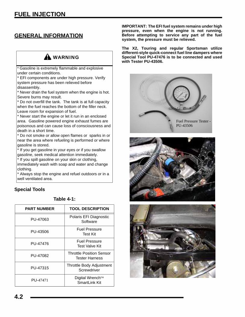
FUEL INJECTION
GENERAL INFORMATION
Special Tools
IMPORTANT: The EFI fuel system remains under highpressure, even when the engine is not running.Before attempting to service any part of the fuelsystem, the pressure must be relieved.
The X2, Touring and regular Sportsman utilizedifferent-style quick-connect fuel line dampers whereSpecial Tool PU-47476 is to be connected and usedwith Tester PU-43506.
WARNING
* Gasoline is extremely flammable and explosive under certain conditions.* EFI components are under high pressure. Verify system pressure has been relieved before disassembly.* Never drain the fuel system when the engine is hot. Severe burns may result.* Do not overfill the tank. The tank is at full capacity when the fuel reaches the bottom of the filler neck. Leave room for expansion of fuel.* Never start the engine or let it run in an enclosed area. Gasoline powered engine exhaust fumes are poisonous and can cause loss of consciousness and death in a short time.* Do not smoke or allow open flames or sparks in or near the area where refueling is performed or where gasoline is stored. * If you get gasoline in your eyes or if you swallow gasoline, seek medical attention immediately. * If you spill gasoline on your skin or clothing, immediately wash with soap and water and change clothing. * Always stop the engine and refuel outdoors or in a well ventilated area.
Table 4-1:
PART NUMBER TOOL DESCRIPTION
PU-47063 Polaris EFI Diagnostic Software
PU-43506 Fuel PressureTest Kit
PU-47476 Fuel PressureTest Valve Kit
PU-47082 Throttle Position Sensor Tester Harness
PU-47315 Throttle Body Adjustment Screwdriver
PU-47471 Digital Wrench™ SmartLink Kit
Fuel Pressure Tester -PU-43506
Test Valve
X2 fuel rail stopper
Test Valve
Sportsman and Touring Fuel Rail Damper
4.2
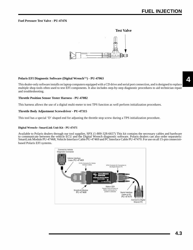
FUEL INJECTION
4
Fuel Pressure Test Valve - PU-47476
Polaris EFI Diagnostic Software (Digital Wrench™) - PU-47063
This dealer-only software installs on laptop computers equipped with a CD drive and serial port connection, and is designed to replacemultiple shop tools often used to test EFI components. It also includes step-by-step diagnostic procedures to aid technician repairand troubleshooting.
Throttle Position Sensor Tester Harness - PU-47082
This harness allows the use of a digital multi-meter to test TPS function as well perform initialization procedures.
Throttle Body Adjustment Screwdriver - PU-47315
This tool has a special ‘D’ shaped end for adjusting the throttle stop screw during a TPS initialization procedure.
Digital Wrench™ SmartLink Unit Kit - PU-47471
Available to Polaris dealers through our tool supplier, SPX (1-800-328-6657) This kit contains the necessary cables and hardwareto communicate between the vehicle ECU and the Digital Wrench diagnostic software. Polaris dealers can also order separately:SmartLink Module PU-47468, Vehicle Interface Cable PU-47469 and PC Interface Cable PU-47470. For use on all 15-pin connector-based Polaris EFI systems.
Test Valve
PU-47468
PU-47469
PU-47470
4.3

FUEL INJECTION
Service Notes• For more convenient and accurate testing of EFI components, it is recommended dealers utilize the Polaris Diagnostic
Software (dealer only), or testing may be done manually using the procedures provided.
• 80% of all EFI problems are caused by wiring harness connections.
• For the purpose of troubleshooting difficult running issues, a known-good ECU from another Polaris ATV EFI of the same model may be used without damaging system or engine components.
• Never attempt to service any fuel system component while engine is running or ignition switch is "on."
• Cleanliness is essential and must be maintained at all times when servicing or working on the EFI system. Dirt, even in small quantities, can cause significant problems.
• Do not use compressed air if the system is open. Cover any parts removed and wrap any open joints with plastic if they will remain open for any length of time. New parts should be removed from their protective packaging just prior to installation.
• Clean any connector before opening to prevent dirt from entering the system.
• Although every precaution has been taken to prevent water intrusion failure, avoid direct water or spray contact with system components.
• Do not disconnect or reconnect the wiring harness connector to the control unit or any individual components with the ignition "on." This can send a damaging voltage spike through the ECU.
• Do not allow the battery cables to touch opposing terminals. When connecting battery cables attach the positive (+) cable to positive (+) battery terminal first, followed by negative (-) cable to negative (-) battery terminal.
• Never start the engine when the cables are loose or poorly connected to the battery terminals.
• Never disconnect battery while engine is running.
• Never use a battery boost-pack to start the engine.
• Do not charge battery with key switch "on."
• Always disconnect negative (-) battery cable lead before charging battery.
• Always unplug ECU from the wire harness before performing any welding on the ATV.
4.4

FUEL INJECTION
4
EFI System Exploded View1. Electronic Control Unit (ECU) 2. Intake Air Temperature/Barometric Air Pressure Sensor (T-BAP) 3. Crankshaft Position Sensor (CPS) 4. Fuel Injectors 5. Fuel Filter (if equipped - not shown) 6. Fuel Pump/Tank Assy. 7 Fuel Rail 8. Engine Coolant Sensor (ECT) 9. Throttle Position Sensor (TPS) 10.Throttle Body
1
2
3
4
6
7
8
9
10
4
4.5

FUEL INJECTION
EFI System Component Locations1. Electronic Control Unit (ECU)
2. Intake Air Temperature and Barometric Air PressureSensor (T-BAP)
3. Crankshaft Position Sensor (CPS)4. Fuel Injectors5. 2 Fuel Filters (1 located in tank, 1 under front cab cover not
pictured)6. Fuel Pump / Regulator / Gauge Sender Assembly (located
In tank as an assembly7. Fuel Rail8. Throttle Position Sensor (TPS)9. Throttle Body10. Wire Harness Assembly
11. Engine Coolant Temperature Sensor (ECT)
1
10
4 & 72
8 & 9
3
11
4.6

FUEL INJECTION
4
Fuel Tank Assembly Fuel Lines - Quick ConnectSportsman 700/800 EFI models use quick connect fuel lines.Refer to the steps below for fuel line removal.
1. Place a shop towel around the fuel line to catch anydripping fuel. Squeeze the connector tabs together andpush the locking slide back.
2. Pull on the fuel line for removal.3. To install the line, verify the connector and fuel tank nipple
are clean and free of debris.4. Snap the fuel line back over the nipple and slide the locking
mechanism back into place. Verify the connector tabs snapback into place.
1. Cap 2. Tank Vent 3. Tank Mount 4. Fuel Pump/Tank Assembly 5. Fuel Lines
1 2
3
45
* Fuel Filter (30 micron)
Fuel Tank
* Fuel Pump / Pressure Regulator Unit
Fuel Supply Rail Injectors
Fuel Flow
* component located in fuel tank and is non-serviceable
Squeeze Connector Tabs
4.7

FUEL INJECTION
ELECTRONIC FUEL INJECTIONPrincipal ComponentsThe Electronic Fuel Injection (EFI) system is a complete enginefuel and ignition management design. This system includes thefollowing principal components:
• Fuel Pump
• Fuel Rail
• Fuel Line(s)
• Fuel Filter(s)
• Fuel Injectors
• Pressure Regulator
• Throttle Body / lntake Manifold
• Engine Control Unit (ECU)
• Ignition Coils
• Coolant Temperature Sensor
• Throttle Position Sensor (TPS)
• Crankshaft Position Sensor (CPS)
• Intake Air Temperature and Barometric Air Pressure Sensor (T-BAP)
• Wire Harness Assembly
• Check Engine Light (MIL)
EFI Operation OverviewThe EFI system is designed to provide peak engine performancewith optimum fuel efficiency and lowest possible emissions.The ignition and injection functions are electronicallycontrolled, monitored and continually corrected duringoperation to maintain peak performance.
The central component of the system is the Bosch EngineControl Unit (ECU) which manages system operation,determining the best combination of fuel mixture and ignitiontiming for the current operating conditions.
An in-tank electric fuel pump is used to move fuel from the tankthrough the fuel line. The in-tank fuel pressure regulatormaintains a system operating pressure of 39 psi and returns anyexcess fuel to the tank. At the engine, fuel is fed through the fuelrail and into the injectors, which inject into the intake ports. TheECU controls the amount of fuel by varying the length of timethat the injectors are "on". This can range from 1.5-8.0milliseconds depending on fuel requirements. The controlledinjection of the fuel occurs each crankshaft revolution, or twicefor each 4-stroke cycle. One-half the total amount of fuel neededfor one firing of a cylinder is injected during each injection.
When the intake valve opens, the fuel/air mixture is drawn intothe combustion chamber, ignited. and burned.
The ECU controls the amount of fuel being injected and theignition timing by monitoring the primary sensor signals for airtemperature, barometric air pressure, engine temperature, speed(RPM), and throttle position (load). These primary signals arecompared to the programming in the ECU computer chip, andthe ECU adjusts the fuel delivery and ignition timing to matchthe values.
During operation the ECU has the ability to re-adjusttemporarily, providing compensation for changes in overallengine condition and operating environment, so it will be ableto maintain the ideal air/fuel ratio.
During certain operating periods such as cold starts, warm up,acceleration, etc., a richer air/fuel ratio is automaticallycalculated by the ECU.
Initial Priming / Starting ProcedureNOTE: The Injection system must be purged of allair prior to the initial start up, and/or any time thesystem has been disassembled.
If the EFI system is completely empty of fuel or has beendisassembled and repaired:
1. Cycle the key switch from “OFF” to “ON” 6 times,waiting for approximately 3 seconds at each “ON” cycle toallow the fuel pump to cycle and shut down.
2. Once step 1 is completed, turn the key switch to “START”until the engine starts or 5 seconds has passed.
3. If the engine failed to start, repeat step 1 for 2 more cyclesand attempt to start the engine.
If the engine fails to start, a problem may still exist, and shouldbe diagnosed.
NOTE: Accurate testing of EFI components isrecommended utilizing the Polaris DiagnosticSoftware (dealer only).
4.8

FUEL INJECTION
4
ELECTRONIC CONTROL UNIT (ECU)Operation OverviewThe ECU is the brain or central processing computer of theentire EFI fuel/ignition management system. During operation,sensors continuously gather data which is relayed through thewiring harness to input circuits within the ECU. Signals to theECU include: ignition (on/off), crankshaft position and speed(RPM), throttle position, engine coolant temperature, airtemperature, intake manifold air pressure and battery voltage.The ECU compares the input signals to the programmed mapsin its memory and determines the appropriate fuel and sparkrequirements for the immediate operating conditions. The ECUthen sends output signals to set the injector duration and ignitiontiming.
During operation, the ECU continually performs a diagnosticcheck of itself, each of the sensors, and system performance. Ifa fault is detected, the ECU turns on the Malfunction IndicatorLight (MIL) (Check Engine Light) on the speedometer andstores the fault code in its fault memory. Depending on thesignificance or severity of the fault, normal operation maycontinue, or "Fail-Safe" operation (slowed speed, richerrunning) may be initiated. A technician can access the storedfault code using a “blink code” diagnosis flashed out through theInstrument cluster. The ECU requires a minimum of 7.0 volts tooperate. The memory in the ECU is operational the moment thebattery cables are connected.
To prevent engine over-speed and possible failure, a rev-limiting feature is programmed into the ECU. If the maximumRPM limit (6500) is exceeded, the ECU suppresses the injectionsignals, cutting off the fuel flow. This process repeats it self inrapid succession, limiting operation to the preset maximum.
Sportsman 700 / 800 EFI RPM Limit:
Hard Limit - Injector suppression occurs
• High: 6500 (6600 - H.O engine - all gears)• Low: 6500 • Neutral: 6500 • Reverse: 6500 • Park: 6500
Soft Limit - Timing suppression occurs
• High: None• Low: 6300 (6400 - H.O engine - L/N/R/P)• Neutral: 6300• Reverse: 6300• Park: 6300
ECU ServiceNever attempt to disassemble the ECU. It is sealed to preventdamage to internal components. Warranty is void if the case isopened or tampered with in any way.
All operating and control functions within the ECU are pre-set.No internal servicing or readjustment may be performed. If aproblem is encountered, and you determine the ECU to befaulty, contact the Polaris Service Department for specifichandling instructions. Do not replace the ECU without factoryauthorization.
The relationship between the ECU and the throttle positionsensor (TPS) is very critical to proper system operation. If theTPS is faulty, or the mounting position of the TPS to the throttlebody is altered, the TPS must be re-initialized.
For the purpose of troubleshooting, a known-good ECU fromanother Polaris ATV EFI of the same model may be usedwithout system or engine component damage.
ECU Replacement1. Remove the retaining screws (2) holding the ECU.2. With the Ignition turned off, disconnect the wire harness
from the ECU.3. To install, reverse the procedures, reapply a small amount
of dielectric grease to the connector if desired. Tightenscrews to specification.
= T
ECU Retaining Screws10 in. lbs. (1.1 Nm)
4.9

FUEL INJECTION
FUEL PUMPOperation OverviewNOTE: All EFI units utilize quick connect lines. FuelTank / Pump Assembly is a non-serviceable item andmust be replaced if determined to be at fault.
An electric fuel pump assembly is used to transfer fuel to the EFIsystem from inside the fuel tank. This assembly includes the fuelpump, regulator and fuel gauge sender. The pump is rated for aminimum output of 25 liters per hour at 39 psi and has a non-serviceable internal 30-micron filter.
When the key switch is turned to "ON", the ECU activates thefuel pump, which pressurizes the system for start-up.
The ECU switches off the pump preventing the continueddelivery of fuel in these instances:
• If the key switch is not promptly turned to the "start" position.
• If the engine fails to start, or
• If the engine is stopped with the key switch "on" (as in the case of an accident)
In these situations, the “check engine” light will go on, but willturn off after 4 cranking revolutions if system function is OK.Once the engine is running, the fuel pump remains on.
Fuel Pump TestNOTE: FUEL GAUGE SENDER TEST - To test fuelgauge sender function, refer to Chapter 10.
The fuel pump/tank assembly is non-serviceable and must bereplaced if determined to be faulty. If a fuel delivery problem issuspected, make certain the filter is not plugged, that the pumpis being activated through the ECU, all electrical connectionsare properly secured, the fuses are good, and a minimum of 7.0volts is being supplied. If during starting the battery voltagedrops below 7.0 volts, the ECU will fail to operate the system.
1. Remove the fuel rail end cap (damper). 2. Connect the fuel rail end cap (damper) onto adapter PU-
47476 and install on the fuel rail.3. Attach Polaris pressure tester PU-43506. Route the tester
clear hose into a portable gasoline container or theequipment fuel tank.
4. Turn on the key switch to activate the pump and check thesystem pressure on the gauge. If system pressure of 39 psi± 3 is observed, the ignition switch, ECU, fuel pump, andpressure regulator are working properly. Turn the keyswitch off and depress the valve button on the tester torelieve the system pressure.
NOTE: If the pressure is too high or too low, replacethe fuel tank assembly.
Example Shown. Fuel pump not replaceable. For reference only.
Regulator
Fuel Pump
Internal 30 MicronStrainer (Bottom)
Fuel Gauge Sender
WARNING
Check the fuel test valve for any possible fuel seepage after performing any tests or procedures. Fuel is extremely flammable and may cause severe burns, injury, or death. Do not use any device that
produces a flame or electrical devices that may spark around fuel or fuel vapors.
Normal Fuel Pressure: 39 psi. ± 3
4.10

FUEL INJECTION
4
5. If the pump did not activate (Step 2), disconnect the plugfrom the fuel pump. Connect a DC voltmeter acrossterminals “A” and “C” in the plug, turn on the key switchand observe if a minimum of 7 volts is present. If voltageis between 7 and 14, turn key switch off and connect anohmmeter between the terminals “A” and “C”' on the pumpto check for continuity.
NOTE: If there was no continuity between the pumpterminals, replace the fuel tank assembly.
NOTE: If the voltage was below 7Vdc, test thebattery, ignition switch, wiring harness and ECU.
6. If voltage at the plug was good, and there was continuityacross the pump terminals, reconnect the plug to the pump,making sure you have good, clean connections. Turn on thekey switch and listen for the pump to activate.
NOTE: If the pump starts, repeat steps 1 and 2 toverify correct pressure.
NOTE: If the pump still does not operate, check forcorrect ECU operation by plugging in a known-goodECU of the same model.
NOTE: If the pump still does not operate, replace thepump/tank assembly.
Fuel Pump / Tank Assembly ReplacementNOTE: All EFIs utilize quick connect fuel lines.
NOTE: The fuel pump cannot be replaced as anindividual part, the entire fuel pump and fuel tank isreplaced as an assembly. Refer to your parts bookfor the proper part number.
1. Disconnect the negative battery cable.2. Remove the side panels and front cab assembly. Refer to
“COVER PANEL REMOVAL" in Chapter 5 for details.
3. Remove the clamps on the PVT intake duct and remove thePVT duct.
4. Remove the gas tank cover vent hose. Be sure to properlyroute the vent hose upon reassembly.
5. With all the body panels removed from the front of the ATVand the gas tank exposed, disconnect the pump wiringharness.
6. Relieve the fuel pressure at the fuel test valve.7. Loosen the fuel tank hose and pull the fuel line from
the tank. NOTE: A small amount of fuel may comeout of the fuel line or tank. Plug the fuel line and tankinlet or use a shop towel during removal.
WARNING
Always wear safety equipment when working with high pressure or flammable fluids. Failure to do so
could result in serious injury or complications.WARNING
Wear safety equipment while performing this procedure, failure to do so could result in serious
injuries.
4.11

FUEL INJECTION
NOTE: A small amount of fuel may come out of thefuel line or tank. Plug the fuel line and tank inlet oruse a shop towel during removal.
8. Remove the air box cover and remove the two gas tankmounting bolts at the rear of the gas tank.
9. Carefully pull the fuel tank out of the frame. Keep the fueltank horizontal during removal, this will keep the fuel in thetank from spilling out the top inlet.
FUEL PUMP TANK INSTALLATION
1. Reinstall the pump/tank assembly.2. Reconnect the sender wiring harness and route the harness
properly. Install the fuel line and secure the fuel lineclamps.
3. Reinstall the two fuel tank mounting bolts at back of tank.Tighten sufficiently.
4. Reinstall the PVT intake duct, gas tank vent line, front cabassembly, and side panels.
NOTE: Properly route the gas tank vent line, usetape to secure the vent line in place. (See Pg. 4.10).
5. Reconnect the negative battery cable. Test the sender forproper operation.
FUEL PRESSURE REGULATOROperation OverviewThe fuel pressure regulator maintains the required operatingsystem pressure of 39 psi + 3psi. A rubber-fiber diaphragmdivides the regulator into two separate sections-, the fuelchamber and the pressure regulating chamber. The pressureregulating spring presses against the valve holder (part of thediaphragm), pressing the valve against the valve seat. Thecombination of atmospheric pressure and regulating springtension equals the desired operating pressure. Any time the fuelpressure against the bottom of the diaphragm exceeds thedesired (top) pressure, the valve opens, relieving the excesspressure, returning the excess fuel back to the tank.
Fuel Pressure Regulator TestRefer to the “FUEL PUMP TEST” procedure.
See “Fuel Pump Test” on page 4.10.
Fuel Pressure Regulator ReplacementThe regulator is a sealed, non-serviceable assembly. If it isfaulty, the pump assembly must be replaced. Refer to the FuelPump/Tank Assembly Replacement procedure.
FUEL FILTERGeneral InformationAll EFI Engines use a non-serviceable, high-volume, high-pressure, 30-micron internal fuel pump filter. The filter islocated inside the tank as part of the fuel pump assembly.
Fuel Filter ServiceThe in-tank filter is non-serviceable. Tank flushing to removesediments may temporarily restore fuel flow, but is not arecommended service procedure.
Fuel Filter Replacement
NOTE: Tank replacement is required.
WARNING
Check the fuel rail for any possible fuel seepage after performing any tests or procedures. Fuel is
extremely flammable and may cause severe burns, injury, or death. Do not use any device that
produces a flame or electrical devices that may spark around fuel or fuel vapors.
4.12

FUEL INJECTION
4
FUEL INJECTORSOperation OverviewNOTE: All EFI units utilize quick connect fuel lines.
The fuel injectors mount into the intake manifold, and the fuelrail attaches to them at the top end. Replaceable O-Rings on bothends of the injector prevent external fuel leaks and also insulateit from heat and vibration.
When the key switch is on, the fuel rail is pressurized, andvoltage is present at the injector. At the proper instant, the ECUcompletes the ground circuit, energizing the injector. The valveneedle in the injector is opened electromagnetically, and thepressure in the fuel rail forces fuel down through the inside. The“director plate” at the tip of the injector (see inset) contains aseries of calibrated openings which directs the fuel into theintake port in a cone-shaped spray pattern.
The injector is opened and closed once for each crankshaftrevolution, however only one-half the total amount of fuelneeded for one firing is injected during each opening. Theamount of fuel injected is controlled by the ECU and determinedby the length of time the valve needle is held open, also referredto as the “injection duration” or “pulse width”. It may vary inlength from 1.5-8 milliseconds depending on the speed and loadrequirements of the engine.
Fuel Injector ServiceInjector problems typically fall into three general categories-electrical, dirty/clogged, or leakage. An electrical problemusually causes one or both of the injectors to stop functioning.Several methods may be used to check if the injectors areoperating.
• With the engine running at idle, feel for operational vibration, indicating that they are opening and closing.
• When temperatures prohibit touching, listen for a buzzing or clicking sound with a screwdriver or mechanic's stethoscope.
• Disconnect the electrical connector from an injector and listen for a change in idle performance (only running on one cylinder) or a change in injector noise or vibration.
NOTE: Do not apply voltage directly to the fuelinjector(s). Excessive voltage will burn out theinjector(s). Do not ground the injector(s) with theignition "on". lnjector(s) will open/turn on if relay isenergized.
If an injector is not operating, it can indicate either a bad injector,or a wiring/electrical connection problem. Check as follows:
Injector leakage is very unlikely, but in rare instances it can beinternal (past the tip of the valve needle), or external (weepingaround the injector body). The loss of system pressure from theleakage can cause hot restart problems and longer crankingtimes.
Injector problems due to dirt or clogging are unlikely due to thedesign of the injectors, the high fuel pressure, the use of filtersand the detergent additives in the gasoline. Symptoms that couldbe caused by dirty/clogged injectors include rough idle,hesitation/stumble during acceleration, or triggering of faultcodes related to fuel delivery. Injector clogging is usually causedby a buildup of deposits on the director plate, restricting the flowof fuel, resulting in a poor spray pattern. Some contributingfactors to injector clogging include; dirty air filters, higher thannormal operating temperatures, short operating intervals anddirty, incorrect, or poor quality fuel. Cleaning of cloggedinjectors is not recommended; they should be replaced.Additives and higher grades of fuel can be used as a preventativemeasure if clogging has been a problem.
Fuel Injector Replacement1. Engine must be cool. Depressurize fuel system through
test valve in fuel rail.2. Remove the front fender assembly and fuel tank.3. Thoroughly clean the area around and including the throttle
body/manifold and the injectors.4. Disconnect the fuel injector harness(s) at the ECU.5. Remove the fuel rail mounting screw and carefully loosen
/ pull the rail away from the injectors.6. Reverse the procedures to install the new injector(s) and
reassemble. Use new O-rings any time an injector isremoved (new replacement injectors include new O-rings).Lubricate O-rings lightly with oil to aid installation. Torquethe fuel rail mounting screw to specification.
Injector
= T
Fuel Rail Mount Screws16-20 ft. lbs. (22.6-27 Nm)
4.13

FUEL INJECTION
CRANKSHAFT POSITION SENSOR (CPS)Operation OverviewThe engine speed sensor is essential to engine operation,constantly monitoring the rotational speed (RPM) and positionof the crankshaft.
A ferromagnetic 60-tooth ring gear with two consecutive teethmissing is mounted on the flywheel. The inductive speed sensoris mounted 1.0 ± 0.26 mm (0.059 ± 0.010 in.) away from thering gear. During rotation, an AC pulse is created within thesensor for each passing tooth. The ECU calculates engine speedfrom the time interval between the consecutive pulses. The two-tooth gap creates an “interrupt” input signal, corresponding tospecific crankshaft position for PTO cylinder. This signal servesas a reference for the control of ignition timing by the ECU.Synchronization of the CPS and crankshaft position takes placeduring the first two revolutions each time the engine is started.This sensor must be properly connected at all times. If the sensorfails or becomes disconnected for any reason, the engine willquit running.
Crankshaft Position Sensor TestThe crankshaft position sensor is a sealed, non-serviceableassembly. If fault code diagnosis indicates a problem within thisarea, test and correct as follows:
1. Disconnect main harness connector from ECU.2. Connect an ohmmeter between the pin terminals. A
resistance value of 560Ω ± 10% at room temperature (20°C, 68° F) should be obtained. If resistance is correct, checkthe mounting, air gap, toothed ring gear (damage, runout,etc.), and flywheel key.
3. Disconnect speed sensor connector from wiring harness.(the connector with one heavy black lead) Viewing theconnector with dual aligning rails on top, test resistancebetween the terminals. A reading of 560Ω ± 10% shouldagain be obtained.
NOTE: If the resistance is incorrect, remove thescrew securing the sensor to the mounting bracketand replace the sensor. If the resistance in step 2was incorrect, but the resistance of the sensor alonewas correct, test the main harness circuit betweenthe sensor connector terminals and thecorresponding pin terminals in the main connector.Correct any observed problem, reconnect thesensor, and perform step 2 again.
Crankshaft Position Sensor (CPS) Replacement1. Disconnect sensor harness connector.
2. Using a 6 mm hex wrench, remove the retaining bolt andreplace the sensor, using a light coating of oil on the o-ringto aid installation.
3. Torque the retaining bolt to specification.
Crankshaft Position Sensor:560Ω ± 10% (20° C, 68° F)
Crank Sensor
= T
CPS Retaining Bolt Torque:25 in. lbs. (2.8 Nm)
4.14
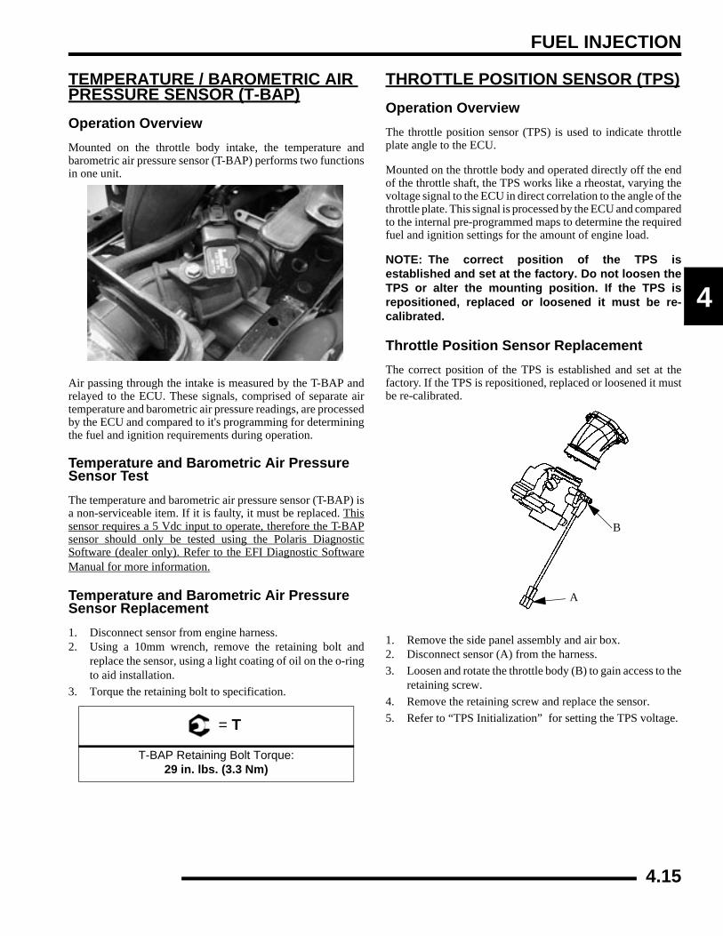
FUEL INJECTION
4
TEMPERATURE / BAROMETRIC AIR PRESSURE SENSOR (T-BAP)Operation OverviewMounted on the throttle body intake, the temperature andbarometric air pressure sensor (T-BAP) performs two functionsin one unit.
Air passing through the intake is measured by the T-BAP andrelayed to the ECU. These signals, comprised of separate airtemperature and barometric air pressure readings, are processedby the ECU and compared to it's programming for determiningthe fuel and ignition requirements during operation.
Temperature and Barometric Air Pressure Sensor TestThe temperature and barometric air pressure sensor (T-BAP) isa non-serviceable item. If it is faulty, it must be replaced. Thissensor requires a 5 Vdc input to operate, therefore the T-BAPsensor should only be tested using the Polaris DiagnosticSoftware (dealer only). Refer to the EFI Diagnostic SoftwareManual for more information.
Temperature and Barometric Air Pressure Sensor Replacement1. Disconnect sensor from engine harness.2. Using a 10mm wrench, remove the retaining bolt and
replace the sensor, using a light coating of oil on the o-ringto aid installation.
3. Torque the retaining bolt to specification.
THROTTLE POSITION SENSOR (TPS)Operation OverviewThe throttle position sensor (TPS) is used to indicate throttleplate angle to the ECU.
Mounted on the throttle body and operated directly off the endof the throttle shaft, the TPS works like a rheostat, varying thevoltage signal to the ECU in direct correlation to the angle of thethrottle plate. This signal is processed by the ECU and comparedto the internal pre-programmed maps to determine the requiredfuel and ignition settings for the amount of engine load.
NOTE: The correct position of the TPS isestablished and set at the factory. Do not loosen theTPS or alter the mounting position. If the TPS isrepositioned, replaced or loosened it must be re-calibrated.
Throttle Position Sensor ReplacementThe correct position of the TPS is established and set at thefactory. If the TPS is repositioned, replaced or loosened it mustbe re-calibrated.
1. Remove the side panel assembly and air box.2. Disconnect sensor (A) from the harness.3. Loosen and rotate the throttle body (B) to gain access to the
retaining screw.4. Remove the retaining screw and replace the sensor.5. Refer to “TPS Initialization” for setting the TPS voltage.= T
T-BAP Retaining Bolt Torque:29 in. lbs. (3.3 Nm)
A
B
4.15

FUEL INJECTION
Throttle Position Sensor TestThe throttle position sensor (TPS) is a non-serviceable item. Ifit is faulty, it must be replaced. It can be tested using thefollowing method:
• Set up the TPS Test Adapter Harness (PU-47082), according to the instructions. Make sure that the 9 volt battery is new. Figure 2.
• With the test leads connected and the meter set, move the throttle open and closed slowly while reading the display. The voltage should increase smoothly with no “jumps” or decreases when the throttle is applied.
• If the sensor does not function correctly, replace it.
CORRECT REFERENCE VOLTAGE
A 5 volt reference voltage from the harness is required for theTPS test to be accurate. Refer to the instructions provided withthe TPS Test Adapter Harness (PU-47082) or follow the stepsbelow to check reference voltage.
• Harness Test: Insert black voltmeter probe into the “Bk” test port.
• Connect the red meter probe into the “R” port and verify the voltage is 4.99-5.01 Vdc. If this reading is
low, verify the 9 volt battery is good or try a new 9 volt battery.
Throttle Position Sensor InitializationNOTE: The correct position of the TPS isestablished and set at the factory. Use thisprocedure only if the TPS was repositioned,replaced or loosened.
STEP 1
Establishing zero offset voltage: This step is crucial as it setsthe TPS position using a fixed physical stop. This will insurethat the correct offset voltage is reached once the correct throttlebody flow is set.
PU-47082 TPS TestAdapter Harness Use NEW
9V battery
PU-47082 Harness No “Jumps” in read out
Throttle PlateMust Be Closed
4.16

FUEL INJECTION
4
• Remove cover and disconnect throttle cable from throttle cam.
• With engine off, back out air flow screw until it no longer is in contact with throttle plate cam. The throttle plate should seal off throttle bore completely.
• Open and close throttle plate a couple of times to ensure full throttle closing. Do not snap closed, as this could cause unnecessary throttle plate to throttle body interference and/or damage.
• Set up the TPS Test Adapter Harness (PU-47082) according to the instructions. Verify that the 9 volt battery is new. Figure 2.
• Using a voltmeter attached to the TPS Tester Harness (PU-47082), check the voltage output of the TPS. It should read .528 ± .01 volts.
• If it does not read .528 ± .01 volts, loosen the screw holding the TPS to the throttle body. Rotate TPS until voltmeter reads .528 ± .01 volts.
• Retighten TPS mounting screw, and verify the voltage did not change. If changed, repeat the previous steps.
STEP 2
Establishing correct flow: Now that the zero offset voltage hasbeen set, you can now set the throttle body to the correct air flowvalue.
• With voltmeter still attached to the TPS Test Adapter Harness (PU-47082), turn the air flow adjustment screw until the voltmeter reads .710 ± .01 volts. The throttle body is now adjusted to the correct flow value Figure 3.
• Reconnect the TPS harness lead
• Reinstall throttle cable on throttle cam and install cover. Adjust cable freeplay.
Back Air Flow Screw Out Until NoContact is Made
TPS Tester AdapterHarness- PU-47082
Fig. 2
.528
Should Read: .528 V
Turn Air Flow Screw In
TPS Tester AdapterHarness- PU-47082 Should Read: .710 V
.710
4.17
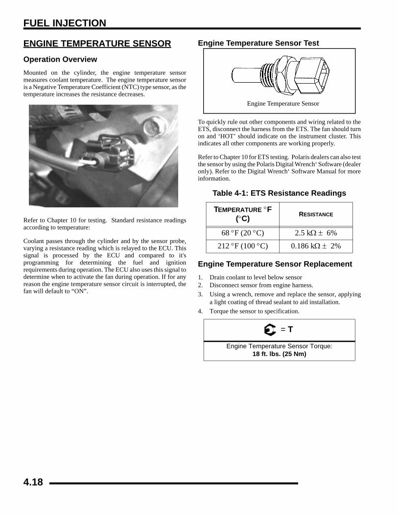
FUEL INJECTION
ENGINE TEMPERATURE SENSOROperation OverviewMounted on the cylinder, the engine temperature sensormeasures coolant temperature. The engine temperature sensoris a Negative Temperature Coefficient (NTC) type sensor, as thetemperature increases the resistance decreases.
Refer to Chapter 10 for testing. Standard resistance readingsaccording to temperature:
Coolant passes through the cylinder and by the sensor probe,varying a resistance reading which is relayed to the ECU. Thissignal is processed by the ECU and compared to it'sprogramming for determining the fuel and ignitionrequirements during operation. The ECU also uses this signal todetermine when to activate the fan during operation. If for anyreason the engine temperature sensor circuit is interrupted, thefan will default to “ON”.
Engine Temperature Sensor Test
To quickly rule out other components and wiring related to theETS, disconnect the harness from the ETS. The fan should turnon and ‘HOT’ should indicate on the instrument cluster. Thisindicates all other components are working properly.
Refer to Chapter 10 for ETS testing. Polaris dealers can also testthe sensor by using the Polaris Digital Wrench‘ Software (dealeronly). Refer to the Digital Wrench‘ Software Manual for moreinformation.
Engine Temperature Sensor Replacement1. Drain coolant to level below sensor2. Disconnect sensor from engine harness.3. Using a wrench, remove and replace the sensor, applying
a light coating of thread sealant to aid installation.4. Torque the sensor to specification.
Table 4-1: ETS Resistance Readings
TEMPERATURE °F (°C) RESISTANCE
68 °F (20 °C) 2.5 kΩ ± 6%
212 °F (100 °C) 0.186 kΩ ± 2%
= T
Engine Temperature Sensor Torque:18 ft. lbs. (25 Nm)
Engine Temperature Sensor
4.18

FUEL INJECTION
4
TROUBLESHOOTINGDiagnostics Using “Blink Codes”To enable the blink codes, turn the ignition from “OFF” to “ON”3 times, leaving it 'on' the 3rd time, within 5 seconds.
Any “blink codes” stored in the ECU will display a numerical“blink code”, one at a time, in numerical order, on the instrumentcluster LCD. The word ‘END’ will display after all codes havebeen transmitted.
NOTE: To clear codes manually, disconnect thepositive battery lead for 20 seconds.
ON
Table 4-1: DIAGNOSTIC “BLINK CODES” CHART
SAE CODE
BLINK CODE
NAME MIL LIGHT
P0335 21 Loss of Synchronization YesP0122 22 TPS Circuit: Open and Short To Ground YesP0123 22 TPS Circuit: Short To Battery YesP0601 23 RAM Error: Defective ECU YesP0914 25 Transmission Input - Invalid Gear YesP0500 26 Vehicle Speed Sensor - Implausible YesP0113 41 Air Temp Sensor: Open or Short Circuit to Sensor Voltage (ECU) YesP0112 41 Air Temp Sensor: Short Circuit to Ground YesP0117 42 Engine Temperature Sensor Circuit: Short To Ground YesP0118 42 Engine Temperature Sensor Circuit: Open or Short to Battery YesP0107 45 Barometric Pressure Sensor: Circuit Low Input YesP0108 46 Barometric Pressure Sensor: Circuit High Input YesP1260 51 Injector 1: Open Load YesP0261 51 Injector 1: Short Circuit to Ground YesP0262 51 Injector 1: Short Circuit to Battery YesP1263 52 Injector 2: Open Load YesP0264 52 Injector 2: Short Circuit to Ground YesP0265 52 Injector 2: Short Circuit to Battery YesP0655 54 Engine Temperature Lamp: Open Load YesP1657 54 Engine Temperature Lamp: Short Circuit to Ground YesP1658 54 Engine Temperature Lamp: Short Circuit to Battery YesP1651 55 Diagnostic Lamp: Open Load YesP1652 55 Diagnostic Lamp: Short Circuit to Ground YesP1653 55 Diagnostic Lamp: Short Circuit To Battery YesP1231 56 Pump Relay Open Load YesP1232 56 Pump Relay Short Circuit to Ground YesP1233 56 Pump Relay Short Circuit to Battery YesP1480 58 Cooling Fan: Open Load YesP1481 58 Cooling Fan: Short Circuit to Ground YesP1482 58 Cooling Fan: Short Circuit to Battery Yes
-- 61 End of Diagnostic Check --
4.19

FUEL INJECTION
EFI TroubleshootingFuel Starvation / Lean Mixture
Symptoms: Hard start or no start, bog, backfire, poppingthrough intake / exhaust, hesitation, detonation, low power,spark plug erosion, engine runs hot, surging, high idle, idlespeed erratic.
• No fuel in tank
• Restricted tank vent, or routed improperly
• Fuel lines or fuel injectors restricted
• Fuel filter plugged
• Fuel pump inoperative
• Air leak in system
• Intake air leak (throttle shaft, intake ducts, airbox or air cleaner cover)
• Incorrect throttle stop screw adjustment
Rich Mixture
Symptoms: Fouls spark plugs, black, sooty exhaust smoke,rough idle, poor fuel economy, engine runs rough/ misses, poorperformance, bog, engine loads up, backfire.
• Air intake restricted (inspect intake duct)
• Air filter dirty/plugged
• Poor fuel quality (old fuel)
• Fouled spark plug
• TPS setting incorrect
• Injector failure
Poor Idle
Symptom: Idle Too High (If greater than 1300 RPM whenengine is warm)
• Throttle stop screw set incorrect
• Throttle cable sticking, improperly adjusted, routed incorrectly
Symptom: Idle Too Low (if less than 900 RPM when engine iswarm)
• Plugged air filter
• Leaking injector (rich condition)
• Belt dragging
• Throttle stop screw tampering
Symptom: Erratic Idle
• Throttle cable incorrectly adjusted
• Air Leaks, dirty injector
• TPS damaged or adjusted
• Tight valves
• Ignition timing incorrect
• Belt dragging
• Dirty air cleaner
• Engine worn
• Spark Plug fouled
• Throttle stop screw set incorrectly (out of sync with ECU)
4.20

FUEL INJECTION
4
EFI CIRCUIT - Power On
EFI CIRCUIT - Crank Position Sensor
4.21

FUEL INJECTION
EFI CIRCUIT - Fuel Pump
EFI CIRCUIT - Throttle Position Sensor
4.22

FUEL INJECTION
4
EFI CIRCUIT - Temperature - Barometric Air Pressure Sensor
EFI CIRCUIT - Engine Temperature
4.23

FUEL INJECTION
EFI CIRCUIT - Malfunction Indicator Light
4.24

BODY / STEERING / SUSPENSION
CHAPTER 5BODY / STEERING / SUSPENSION
5
GENERAL INFORMATION . . . . . . . . . . . . . . . . . . . . . . . . . . . . . . . . . . . . . . . . . . . . . . . . 5.2TORQUE SPECIFICATIONS . . . . . . . . . . . . . . . . . . . . . . . . . . . . . . . . . . . . . . . . . . . . . . 5.2SPECIAL TOOLS . . . . . . . . . . . . . . . . . . . . . . . . . . . . . . . . . . . . . . . . . . . . . . . . . . . . . . . 5.2DECAL REPLACEMENT . . . . . . . . . . . . . . . . . . . . . . . . . . . . . . . . . . . . . . . . . . . . . . . . . 5.2PLASTIC INSERT REMOVAL / INSTALLATION . . . . . . . . . . . . . . . . . . . . . . . . . . . . . . . 5.3
BODY. . . . . . . . . . . . . . . . . . . . . . . . . . . . . . . . . . . . . . . . . . . . . . . . . . . . . . . . . . . . . . . . . 5.4SIDE PANEL REMOVAL . . . . . . . . . . . . . . . . . . . . . . . . . . . . . . . . . . . . . . . . . . . . . . . . . 5.4FRONT COVER REMOVAL / INSTALLATION. . . . . . . . . . . . . . . . . . . . . . . . . . . . . . . . . 5.4FOOT WELL REMOVAL / INSTALLATION . . . . . . . . . . . . . . . . . . . . . . . . . . . . . . . . . . . 5.5X2-TOURING FOOT WELL REMOVAL / INSTALLATION. . . . . . . . . . . . . . . . . . . . . . . . 5.5FRONT STORAGE REMOVAL . . . . . . . . . . . . . . . . . . . . . . . . . . . . . . . . . . . . . . . . . . . . 5.6FRONT STORAGE INSTALLATION . . . . . . . . . . . . . . . . . . . . . . . . . . . . . . . . . . . . . . . . 5.8SPORTSMAN REAR RACK REMOVAL / INSTALLATION . . . . . . . . . . . . . . . . . . . . . . . 5.8FRONT CAB/FENDER REMOVAL/INSTALLATION . . . . . . . . . . . . . . . . . . . . . . . . . . . . 5.9SPORTSMAN REAR CAB / FENDER REMOVAL / INSTALLATION. . . . . . . . . . . . . . . 5.10X2 REAR QUARTER PANEL REMOVAL / INSTALLATION . . . . . . . . . . . . . . . . . . . . . 5.10SPORTSMAN REAR STORAGE REMOVAL / INSTALLATION . . . . . . . . . . . . . . . . . . 5.11RADIATOR SCREEN REMOVAL. . . . . . . . . . . . . . . . . . . . . . . . . . . . . . . . . . . . . . . . . . 5.11SPORTSMAN BODY ASSEMBLY EXPLODED VIEW. . . . . . . . . . . . . . . . . . . . . . . . . . 5.12X2- TOURING BODY ASSEMBLY EXPLODED VIEW . . . . . . . . . . . . . . . . . . . . . . . . . 5.13TOURING BODY/RACK ASSEMBLY EXPLODED VIEW . . . . . . . . . . . . . . . . . . . . . . . 5.14BODY / RACK EXPLODED VIEWS . . . . . . . . . . . . . . . . . . . . . . . . . . . . . . . . . . . . . . . . 5.15TOURING BODY/SEAT ASSEMBLY EXPLODED VIEW. . . . . . . . . . . . . . . . . . . . . . . . 5.16HEADLIGHT POD EXPLODED VIEW . . . . . . . . . . . . . . . . . . . . . . . . . . . . . . . . . . . . . . 5.17
STEERING . . . . . . . . . . . . . . . . . . . . . . . . . . . . . . . . . . . . . . . . . . . . . . . . . . . . . . . . . . . 5.18HANDLEBAR BLOCK INSTALLATION PROCEDURE . . . . . . . . . . . . . . . . . . . . . . . . . 5.18STEERING / A-ARM EXPLODED VIEW . . . . . . . . . . . . . . . . . . . . . . . . . . . . . . . . . . . . 5.19A-ARM REPLACEMENT . . . . . . . . . . . . . . . . . . . . . . . . . . . . . . . . . . . . . . . . . . . . . . . . 5.20BALL JOINT REPLACEMENT . . . . . . . . . . . . . . . . . . . . . . . . . . . . . . . . . . . . . . . . . . . . 5.21STEERING POST REMOVAL . . . . . . . . . . . . . . . . . . . . . . . . . . . . . . . . . . . . . . . . . . . . 5.22STEERING POST ASSEMBLY . . . . . . . . . . . . . . . . . . . . . . . . . . . . . . . . . . . . . . . . . . . 5.22
SUSPENSION . . . . . . . . . . . . . . . . . . . . . . . . . . . . . . . . . . . . . . . . . . . . . . . . . . . . . . . . . 5.22FRONT STRUT CARTRIDGE REPLACEMENT . . . . . . . . . . . . . . . . . . . . . . . . . . . . . . 5.22STRUT ASSEMBLY . . . . . . . . . . . . . . . . . . . . . . . . . . . . . . . . . . . . . . . . . . . . . . . . . . . . 5.23SPORTSMAN REAR SUSPENSION ASSEMBLY . . . . . . . . . . . . . . . . . . . . . . . . . . . . . 5.24X2- TOURING REAR SUSPENSION EXPLODED VIEW . . . . . . . . . . . . . . . . . . . . . . . 5.25X2 TORSION BAR EXPLODED VIEW. . . . . . . . . . . . . . . . . . . . . . . . . . . . . . . . . . . . . . 5.26
X2 CARGO BOX . . . . . . . . . . . . . . . . . . . . . . . . . . . . . . . . . . . . . . . . . . . . . . . . . . . . . . . 5.27EXPLODED VIEW . . . . . . . . . . . . . . . . . . . . . . . . . . . . . . . . . . . . . . . . . . . . . . . . . . . . . 5.27REMOVAL / INSTALLATION . . . . . . . . . . . . . . . . . . . . . . . . . . . . . . . . . . . . . . . . . . . . . 5.28
X2 SEAT ASSEMBLY . . . . . . . . . . . . . . . . . . . . . . . . . . . . . . . . . . . . . . . . . . . . . . . . . . . 5.30EXPLODED VIEWS . . . . . . . . . . . . . . . . . . . . . . . . . . . . . . . . . . . . . . . . . . . . . . . . . . . . 5.30X2 SEAT OPERATION - CONFIGURING CARGO BOX FOR PASSENGER RIDING . 5.31X2 DRIVER SEAT BACKREST REMOVAL / INSTALLATION. . . . . . . . . . . . . . . . . . . . 5.32X2 PASSENGER SEAT BACKREST REMOVAL / INSTALLATION . . . . . . . . . . . . . . . 5.32
5.1

BODY / STEERING / SUSPENSION
GENERAL INFORMATIONTorque Specifications
NOTE: Refer to exploded views throughout thischapter for identification and location ofcomponents.
Special Tools
Decal ReplacementFlame Treating Decal AreaPlastic polyethylene material must be “flame treated" prior toinstalling a decal to ensure good adhesion. The flame treatingprocedure can often be used to reduce or eliminate the whitishstress marks that are sometimes left after a fender or cab is bent,flexed, or damaged.
1. Pass the flame of a propane torch back and forth quicklyover the area where the decal is to be applied until thesurface appears slightly glossy. This should occur afterjust a few seconds of flame treating. Do not hold the torchtoo close to the surface. Keep the torch moving to preventdamage.
2. Apply the decal.
Table 5-1:
COMPONENTFT.LBS. (IN.LBS.) NM
Front Hub Nut 60 81
Front A-Arm Attaching Bolt 37 50
Front A-Arm Ball Joint Stud Nut 30 41
Handlebar Adjuster Block 14 19
Master Cylinder Clamp Bolt (45-55) 5.2-6.3
Rear Wheel Hub Nut 80 108
Upper Stabilizer Support Nuts 17 27
Upper Control Arm Mounting Bolt 37 50
Lower Wheel Bearing Carrier Bolt 37 50
Strut Rod Retaining Nut (Top) 17 23
Strut Casting Pinch Bolt 17 23
Tie Rod End Jam Nut 12 17
Tie Rod End Castle Nut 43 58
Tie Rod End Attaching Bolt 24 33
Upper Rear Shock Bolt 37 50
Lower Rear Shock Bolt 37 50
Table 5-2:
PART NUMBER DESCRIPTION
2870871 Ball Joint Replacement Tool
2870872 Shock Spanner Wrench
2870623 Shock Absorber Spring Compression Tool
2871572 Strut Rod Wrench
2871573 LH Strut Spring Compressor
2871574 RH Strut Spring Compressor
WARNING
The following procedure involves the use of an open flame. Wear the appropriate safety equipment
at all times. Perform this procedure in a well ventilated area, away from gasoline or other
flammable materials. Verify the area to be flame treated is clean and free of gasoline or flammable
residue.
5.2

BODY / STEERING / SUSPENSION
5
Plastic Insert Removal / InstallationSome Polaris ATVs use a two piece plastic insert in place of ametal screw. The plastic inserts are simple to remove and install.
1. Use a pair of diagonal side cutters to lift the plastic insert(A) until you feel some slight pressure or lift the insertapproximately 1/4" (6.35 mm). Apply just enoughpressure on the side cutters to lift up on the insert. DONOT apply too much pressure on the side cutters, ordamage to the insert will occur.
2. Next, use the diagonal side cutters under outside insert (B)to completely remove the assembly. NOTE: The insideinsert (A) will still be installed in the outside insert (B).
NOTE: The inside insert (A) will still be installed inthe outside insert (B).
3. To install the inserts, press outside insert (B) into the hole.Press inside insert (A) until it snaps into place.
NOTE: The outside insert (B) should be flushsurface after installation.
The inside insert (A) should be flush with the top of the outsideinsert (B).
A
B
A
B
5.3

BODY / STEERING / SUSPENSION
BODYSide Panel RemovalSide panel removal is quick and easy, use the followinginstructions for removal and installation.
1. Remove seat by releasing the latch (if equipped) and liftingup on the seat. (X2 seats do not have a latch system.)
2. Grasp the rear of the side panel near the rear cab. With afirm motion, pull the panel outward to disengage the sidepanel from the grommet. Pull the panel downward andrearward to remove it from the ATV.
3. Reinstall the side panel by reversing the removal procedure.
Front Cover Removal / Installation1. Open the front storage compartment2. Pull up and outward on the front cover to remove the cover.
3. To install the front cover, insert the tabs of the front coverinto the inserts of the cab. Make sure the tabs are alignedwith the slots. Then press the rear tabs into the slots.
Step 1
Step 2
Step 3
5.4

BODY / STEERING / SUSPENSION
5
Foot Well Removal / Installation1. Remove the four plastic inserts (A) that secure the wheel
well to the front and rear cabs. (See “PLASTIC INSERTREMOVAL / INSTALLATION” for help).
2. Remove the four screws (B) from the bottom of the footwell. Remove the footwell.
3. Reverse the removal procedures to install the foot well. Besure to properly align the cab ends into the foot wells uponreassembly.
X2-Touring Foot Well Removal / Installation1. Remove the four plastic inserts (A) that secure the wheel
well to the front and rear cabs. (See “PLASTIC INSERTREMOVAL / INSTALLATION” for help).
2. Remove the six screws (B) from the bottom of the foot well.Remove the footwell.
3. Reverse the removal procedures to install the foot well. Besure to properly align the cab ends into the foot wells uponreassembly.
A
B
A
18 in.lbs. (
A
B
A
5.5

BODY / STEERING / SUSPENSION
Front Storage Removal
1. Remove the front radiator cap cover (A) by lifting upwardon the cover.
2. Remove the four bolts that secure the storage rack to theframe.
3. Remove the two (T25) screws that secure the storage boxto the front fender well areas (each side).
4. Remove the two (T25) screws that secure the outside of thestorage box to the front fenders (each side).
Front Storage
T-25 Screws
A
Remove Bolts
Remove Bolts
T-25 Screws
5.6

BODY / STEERING / SUSPENSION
5
Winch Installation Area
5. Remove the front cover piece by lifting up on sides of thetwo locking tabs as shown. Pull the tabs out of the notchesand lift up on the cover piece.
To install the front cover place top lip of the cover into and liftup to remove.
6. Remove the front headlights (C) or simply disconnect theelectric connector (D) before removing the front plasticbumper.
7. Remove the remaining bolts and screws that secure thefront bumper section to the frame.
Pull Out to Remove
1. Place Lip In GrooveGroove
Lip
2. Press in Tabs
CD
5.7

BODY / STEERING / SUSPENSION
Front Storage Installation
1. Place the front storage rack onto the frame.2. Install the four bolts (A) into the inside of the compartment
hand tight.3. Install the four screws and washers (B) (T-25) under the
fender area (2 each side).4. Install the four screws (C) (T-25) into the front fender area
of the storage box (2 each side).5. Install the two screws (D) into the rear area of the cab (if
removed).6. Install the two plastic inserts (E) into the front cab (if
removed).7. Torque all bolts and screws according to the illustration.
8. Install the front radiator cap cover (E).
Sportsman Rear Rack Removal / Installation
1. Remove the six (A) T27 screws and two bolts (B) thatsecure the rear rack to the rear cab and frame.
2. Lift the rear rack from the ATV. Remove the two rackspacers (C).
Front StorageA
BC
CB
D
Einserts
T-25 Screw
A. 14 ft.lbs. (19 Nm)B. 10 in.lbs. (1.13 Nm)
C. 10 in.lbs. (1.13 Nm)D. 24 in.lbs (2.7 Nm)
E
F
T-27 Screw
A. 36 in.lbs. (4 Nm) B. 18 in.lbs. ( 2 Nm)
A
A
A
A B
B
C
C
5.8

BODY / STEERING / SUSPENSION
5
3. Place spacers on frame.
4. Install rear rack onto rear frame and cab.5. Install the two bolts (B) and six (A) T-27 screws. Torque
the bolts (A) to 18 in.lbs. (2 Nm) and six T-27 screws to 36in.lbs. (4 Nm). Refer to the illustration for torque values.
Front Cab/Fender Removal/Installation1. Follow the “FRONT RACK / BUMPER REMOVAL”
section to begin removal of the front cab, rack, andbumper.
2. Remove the plastic inserts (A) that secure the front cab tothe upper strut support.
3. Remove the two screws (B) that secure the front cab to theframe in the fuel tank mount area.
4. Remove the side panels (D), refer to the “SIDE PANELREMOVAL” section.
5. Remove the plastic inserts (E) that secure the front of thefoot wells to the front cab.
6. Remove the fuel cap and place a clean lint free shop towelinto the tank neck to keep any debris from falling into thetank.
7. The front cab should now slide back over the fuel tank andfuel tank neck.
NOTE: When removing the front cab use caution sothe plastic cab does not scratch or get caught onother components.
8. Reverse the removal steps for installation. Torque twofront cab to frame screws to specification.
A
= T
Cab to Frame Screws24 in.lbs. (2.7 Nm)
B
B
A
D
E
5.9

BODY / STEERING / SUSPENSION
Sportsman Rear Cab / Fender Removal / Installation1. Follow the “REAR RACK REMOVAL” procedure to
remove the rear rack.2. Remove the plastic inserts that secure the rear cab to the
frame and plastic.
3. Disconnect the rear lights by pulling the locks on each sideand removing the connectors. Lift the rear cab from theframe.
4. Reverse the removal steps for installation.
X2 Rear Quarter Panel Removal / Installation1. Remove the seat.2. Remove the plastic inserts (circled) that secure the quarter
panel to the rear footwell. (See “PLASTIC INSERTREMOVAL / INSTALLATION” for information).
3. Reverse the removal procedures to install the quarterpanels. Verify panels are properly aligned to the footwellend upon reassembly.
Remove plastic dart inserts.
Remove Connectors
Lock
5.10

BODY / STEERING / SUSPENSION
5
Sportsman Rear Storage Removal / Installation1. Follow the “REAR RACK REMOVAL” and “REAR
CAB REMOVAL” procedure to remove the rear storagecompartment. After the rear cab is removed the storagecompartment comes out.
2. Remove the two plastic inserts that hold the rear storagecompartment in place.
3. For installation, reverse the removal steps.
Radiator Screen Removal1. Pull out slightly on the top of the radiator screen.2. With the top free, pull out on the bottom of the screen to
remove the screen.3. To install the screen, simply press the tabs on the screen
back into the mounting grommets. Be sure the screen issecurely in place.
5.11
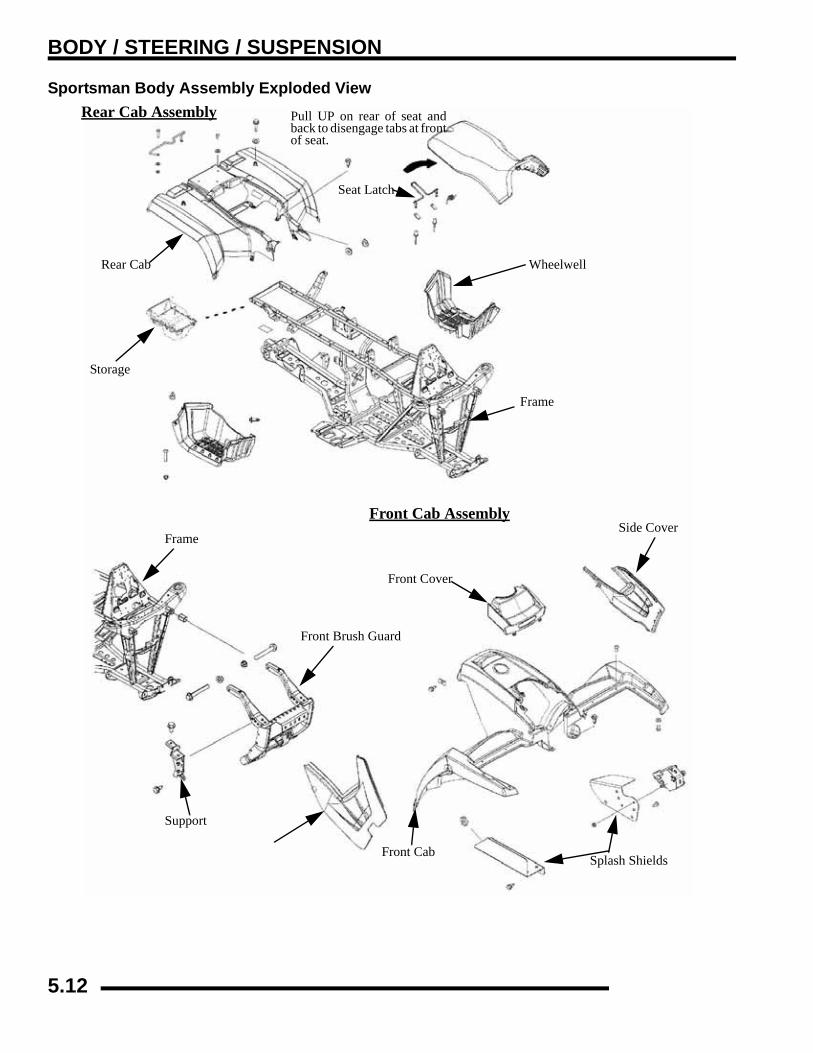
BODY / STEERING / SUSPENSION
Sportsman Body Assembly Exploded ViewRear Cab Assembly Pull UP on rear of seat and
back to disengage tabs at frontof seat.
Seat Latch
Rear Cab
Storage
Frame
Wheelwell
Frame
Front Brush Guard
Support
Side Cover
Splash ShieldsFront Cab
Front Cover
Front Cab Assembly
5.12

BODY / STEERING / SUSPENSION
5
X2- Touring Body Assembly Exploded ViewRear Cab Assembly
Frame
Front Brush Guard
Support
Side Cover
Splash ShieldsFront Cab
Front Cover
Front Cab Assembly
Footwell
Frame
RH Rear Cab
Footwell Support
5.13

BODY / STEERING / SUSPENSION
Touring Body/Rack Assembly Exploded View
Footwell and AuxiliaryFoot Rests
Rear Rack
Rear Rack Support
Hand Rails
5.14

BODY / STEERING / SUSPENSION
5
Body / Rack Exploded Views
Rack Rails
Rear Rack
Rear Rack Support
Frame
Front Brush Guard
Radiator Shield
Radiator Screen
Grill
Front Bumper
Panel
Rack Rails
Box Assembly
Cover
Sportsman Only
5.15

BODY / STEERING / SUSPENSION
Touring Body/Seat Assembly Exploded View
Upper Support
Rear Seat Support
Upper Seat
Base and Pin Latch
Latch Assembly
Lower Seat
5.16
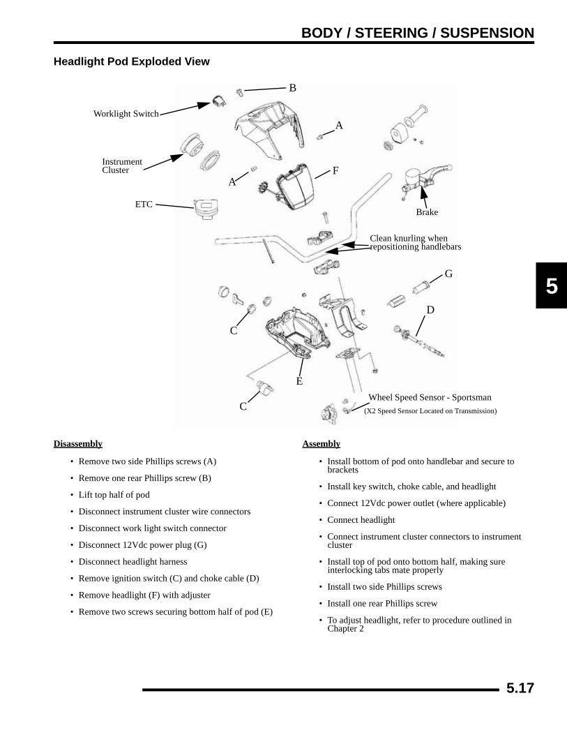
BODY / STEERING / SUSPENSION
5
Headlight Pod Exploded View
Disassembly
• Remove two side Phillips screws (A)
• Remove one rear Phillips screw (B)
• Lift top half of pod
• Disconnect instrument cluster wire connectors
• Disconnect work light switch connector
• Disconnect 12Vdc power plug (G)
• Disconnect headlight harness
• Remove ignition switch (C) and choke cable (D)
• Remove headlight (F) with adjuster
• Remove two screws securing bottom half of pod (E)
Assembly
• Install bottom of pod onto handlebar and secure to brackets
• Install key switch, choke cable, and headlight
• Connect 12Vdc power outlet (where applicable)
• Connect headlight
• Connect instrument cluster connectors to instrument cluster
• Install top of pod onto bottom half, making sure interlocking tabs mate properly
• Install two side Phillips screws
• Install one rear Phillips screw
• To adjust headlight, refer to procedure outlined in Chapter 2
Worklight Switch
InstrumentCluster
A
A
F
B
C
C
E
D
Brake
Clean knurling when repositioning handlebars
Wheel Speed Sensor - Sportsman
G
ETC
(X2 Speed Sensor Located on Transmission)
5.17

BODY / STEERING / SUSPENSION
STEERINGHandlebar Block Installation Procedure
1. The pin (A) on the bottom side of the top handlebar block faces down and to the front of the ATV.
2. The bottom handle bar block has a side with 3 holes, the side with 3 holes faces up and to the front of the ATV.
3. Align the pin (A) in the top block with the middle hole (B) in the bottom block for proper installation. The pin (A) and middlehole (B) should face the front of the ATV.
4. Install the pin side bolts first and evenly tighten the bolts down. Evenly torque the 2 front bolts to specification.
5. Install the rear bolts and tighten evenly. Evenly torque the 2 rear bolts to specification.
NOTE: There will be a slight gap on the backside of the blocks after the procedure is performed.
= T
Handle Bar Bolt Torque14 ft.lbs.(19 Nm)
A
Clean knurling whenrepositioning handlebarsB
5.18
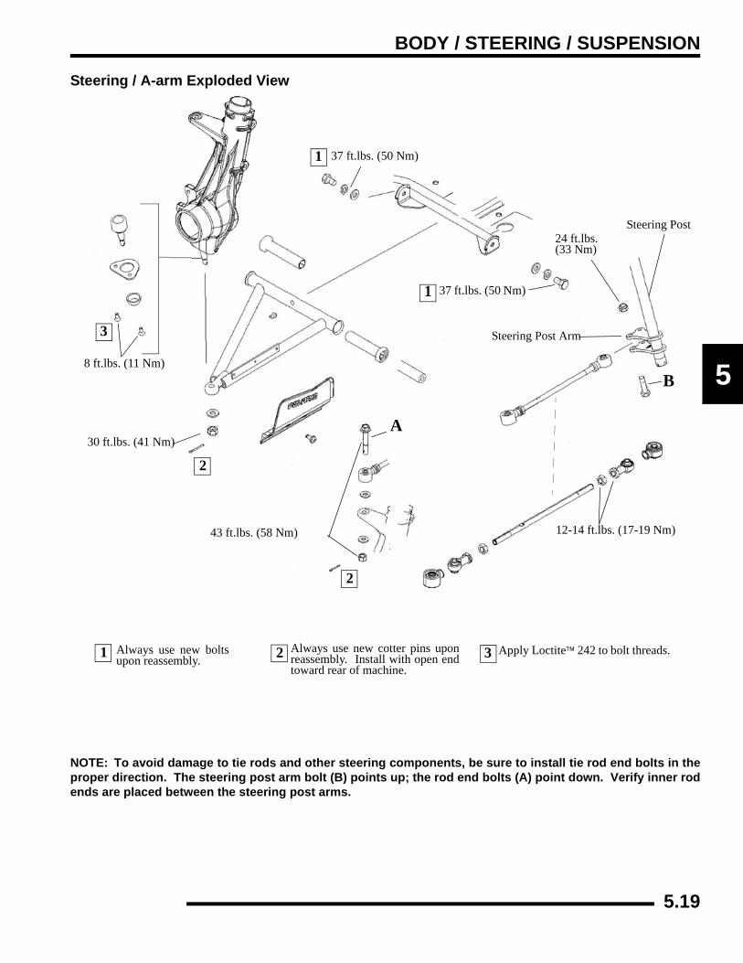
BODY / STEERING / SUSPENSION
5
Steering / A-arm Exploded View
NOTE: To avoid damage to tie rods and other steering components, be sure to install tie rod end bolts in theproper direction. The steering post arm bolt (B) points up; the rod end bolts (A) point down. Verify inner rodends are placed between the steering post arms.
Apply Loctite™ 242 to bolt threads.
8 ft.lbs. (11 Nm)
30 ft.lbs. (41 Nm)
2
2
2
Always use new cotter pins uponreassembly. Install with open endtoward rear of machine.
1 Always use new boltsupon reassembly.
1
1
24 ft.lbs. (33 Nm)
Steering Post
Steering Post Arm
12-14 ft.lbs. (17-19 Nm)
A
37 ft.lbs. (50 Nm)
43 ft.lbs. (58 Nm)
37 ft.lbs. (50 Nm)
3
3
B
5.19

BODY / STEERING / SUSPENSION
A-Arm Replacement
1. Elevate and safely support vehicle with weight removed from front wheel(s).2. Remove cotter pin from ball joint stud at wheel end of A-arm and loosen nut until it is flush with end of stud.3. Using a soft face hammer, tap nut to loosen A-arm from bolt. Remove nut and A-arm from hub strut assembly.4. Loosen two bolts on A-arm tube by alternating each about 1/3 of the way until A-arm can be removed.5. Examine A-arm shaft. Replace if worn. Discard hardware.6. Insert A-arm shaft into new A-arm. 7. Install CV joint shields.8. Install new A-arm assembly onto vehicle frame. Torque new bolts to specification.
9. Attach A-arm to hub strut assembly. Tighten ball joint nut to specification. If cotter pin holes are not aligned, tighten nutslightly to align. Install a new cotter pin with open ends toward rear of machine. Bend both ends in opposite directions around nut
= T
A-Arm to Frame Bolt Torque: 37 ft. lbs. (50 Nm)
WARNING
The locking features on the existing bolts were destroyed during removal. DO NOT reuse old
bolts. Serious injury or death could result if fasteners come loose during operation.
= T
A-Arm to Strut Bolt Torque: 30 ft. lbs. (41 Nm)
WARNING
Upon A-arm installation completion, test vehicle at low speeds before putting into regular service.
37 ft.lbs. (50 Nm)A-arm Shaft
Apply Loctite™ 242to the bolt threads.
Vehicle Frame Bolt - 37 ft.lbs. (50 Nm)
Bushing Ball Joint Stud
8 ft.lbs. (11 Nm)
Cotter Pin - (Install New)30 ft.lbs. (41 Nm)
A-Arm Tube
5.20
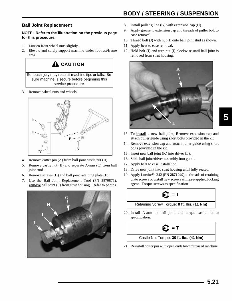
BODY / STEERING / SUSPENSION
5
Ball Joint ReplacementNOTE: Refer to the illustration on the previous pagefor this procedure.
1. Loosen front wheel nuts slightly.2. Elevate and safely support machine under footrest/frame
area.
3. Remove wheel nuts and wheels.
4. Remove cotter pin (A) from ball joint castle nut (B).5. Remove castle nut (B) and separate A-arm (C) from ball
joint stud.6. Remove screws (D) and ball joint retaining plate (E).7. Use the Ball Joint Replacement Tool (PN 2870871),
remove ball joint (F) from strut housing. Refer to photos.
8. Install puller guide (G) with extension cap (H).9. Apply grease to extension cap and threads of puller bolt to
ease removal.10. Thread bolt (J) with nut (I) onto ball joint stud as shown.11. Apply heat to ease removal.12. Hold bolt (J) and turn nut (I) clockwise until ball joint is
removed from strut housing.
13. To install a new ball joint, Remove extension cap andattach puller guide using short bolts provided in the kit.
14. Remove extension cap and attach puller guide using shortbolts provided in the kit.
15. Insert new ball joint (K) into driver (L).16. Slide ball joint/driver assembly into guide.17. Apply heat to ease installation.18. Drive new joint into strut housing until fully seated.19. Apply Loctite™ 242 (PN 2871949) to threads of retaining
plate screws or install new screws with pre-applied lockingagent. Torque screws to specification.
20. Install A-arm on ball joint and torque castle nut tospecification.
21. Reinstall cotter pin with open ends toward rear of machine.
CAUTION
Serious injury may result if machine tips or falls. Be sure machine is secure before beginning this
service procedure.
F
E
DA
B
GH
I
J
= T
Retaining Screw Torque: 8 ft. lbs. (11 Nm)
= T
Castle Nut Torque: 30 ft. lbs. (41 Nm)
K
L
5.21

BODY / STEERING / SUSPENSION
Steering Post Removal1. Remove the front cab. 2. Remove the handle bar pod. 3. Remove the handle bar. 4. Remove the fuel tank bracket assembly.5. Remove the steering tie rod ends from the steering bracket.
Note the orientation of the fasteners and bracket on thesteering assembly.
6. Remove the steering post nut (A) at the mount plate.7. Remove the top steering bracket.8. Remove the steering post.
Steering Post Assembly
1. Hand tighten steering post slotted nut (A).2. Align the cotter pin hole on the steering post slotted nut (A).3. Install the cotter pin (B). Bend both ends of the cotter pin
around the slotted nut (A) in opposite directions.4. Check the steering, the handle bars must move freely and
easily from full left to full right without binding.
SUSPENSIONFront Strut Cartridge ReplacementNOTE: Refer to illustration on following page.
1. Hold strut rod and remove top nut.2. Remove upper strut pivot assembly.
3. Compress spring using any commercially available springcompressor tool and remove the spacer nut.
4. Remove coil spring and collapse strut cartridge.5. Remove two pinch bolts from strut casting.6. Remove strut cartridge.7. Install cartridge until bottomed in strut casting.8. Install pinch bolts with wire clamp(s). Torque pinch bolts
to specification.
9. Reassemble spring and top pivot assembly. Be sure allparts are installed properly and seated fully.
10. Torque strut rod nut to specification. Do not over torquethe nut.
17 ft.lbs. (23 Nm)
NOTE: Steering post bearing is shown in explodedview form. This bearing is attached to the post usinga radial riveting method and is a non-serviceable item.Steering post replacement is required in the event of abearing failure.
Strut Rod Wrench: (PN 2871572)
Strut Spring Compressor Tools: (PN 2871573) and (PN 2871574)
= T
Pinch Bolt Torque:17 ft. lbs. (23 Nm)
= T
Strut Rod Nut Torque:15 ft. lbs. (21 Nm)
5.22

BODY / STEERING / SUSPENSION
5
Strut Assembly
Nut - 15 ft.lbs. (21 Nm)
Washer
Spacer Rubber
Upper Pivot Ball
Spacer Nut
Lower Pivot Ball
Spring Retainer
Spring
Strut Bumper
Strut
Washer
Bolts
Hubstrut BearingRetaining Ring
Brake Caliper
17 ft.lbs. (23 Nm)
Clamp
17 ft.lbs. (23 Nm)
5.23
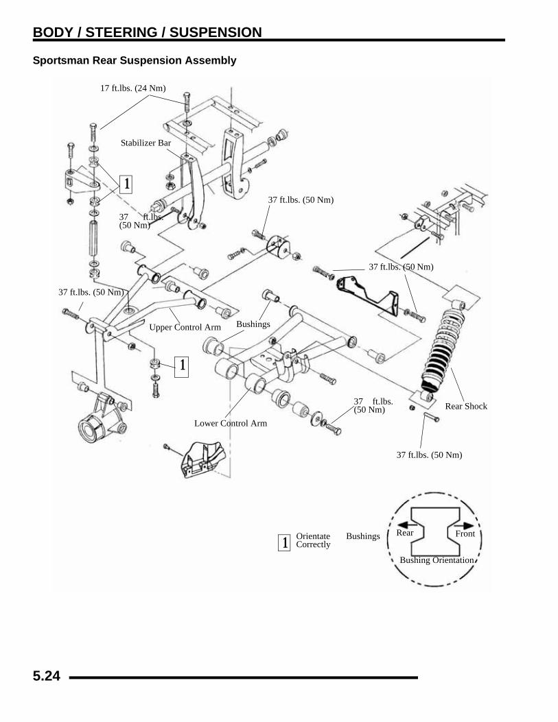
BODY / STEERING / SUSPENSION
Sportsman Rear Suspension Assembly
17 ft.lbs. (24 Nm)
Stabilizer Bar
37 ft.lbs. (50 Nm)
37 ft.lbs. (50 Nm)
Rear Shock
Lower Control Arm
Bushings
37 ft.lbs. (50 Nm)
Upper Control Arm
37 ft.lbs. (50 Nm)
Rear Front1 Orientate Bushings
Correctly
1
1
37 ft.lbs.(50 Nm)
Bushing Orientation
37 ft.lbs.(50 Nm)
5.24

BODY / STEERING / SUSPENSION
5
X2- Touring Rear Suspension Exploded View
Upper Control Arm
Lower Control Arm
Rear ShockBushings
Rear Compression Spring
Preload Adjustment Cam
A-Arm Shaft
Wheel Bearing Carrier
Grease Zerk
Boot Shield (if equipped)
Control Arm Pivot Bracket
5.25

BODY / STEERING / SUSPENSION
X2 Torsion Bar Exploded View
Linkage Bushing Stabilizer Bar
Torsion Mount
Linkage Assy.
Bushing
Stabilizer Bushing
5.26

BODY / STEERING / SUSPENSION
5
X2 CARGO BOXExploded View
5.27
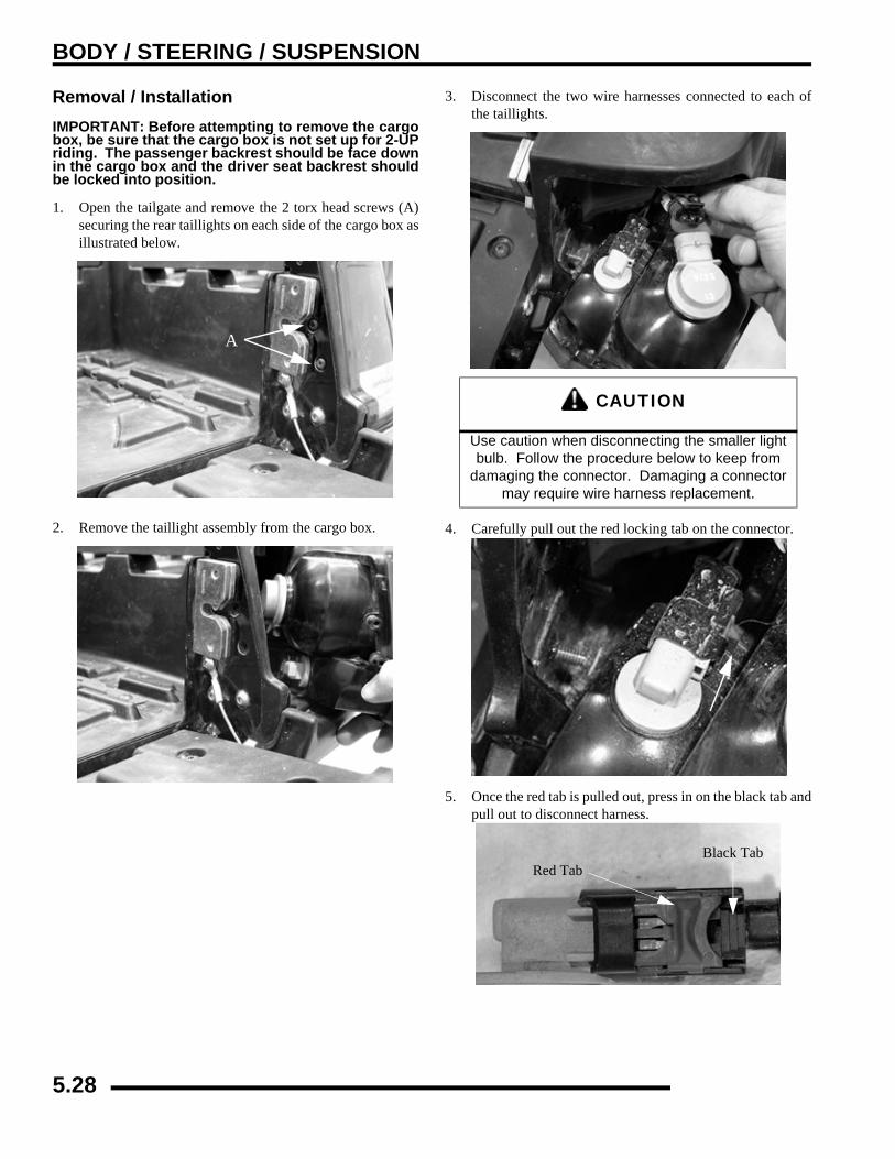
BODY / STEERING / SUSPENSION
Removal / InstallationIMPORTANT: Before attempting to remove the cargobox, be sure that the cargo box is not set up for 2-UPriding. The passenger backrest should be face downin the cargo box and the driver seat backrest shouldbe locked into position.
1. Open the tailgate and remove the 2 torx head screws (A)securing the rear taillights on each side of the cargo box asillustrated below.
2. Remove the taillight assembly from the cargo box.
3. Disconnect the two wire harnesses connected to each ofthe taillights.
4. Carefully pull out the red locking tab on the connector.
5. Once the red tab is pulled out, press in on the black tab andpull out to disconnect harness.
A
CAUTION
Use caution when disconnecting the smaller light bulb. Follow the procedure below to keep from
damaging the connector. Damaging a connector may require wire harness replacement.
Black TabRed Tab
5.28

BODY / STEERING / SUSPENSION
5
6. Lift up firmly in the cargo box release lever on either sideof the ATV.
7. Remove the four bolts attaching the rear of the cargo boxto the frame. There are two on each side.
8. Support the cargo box and remove the clip and pin holdingthe gas shock to the cargo box.
9. Carefully remove the cargo box from the ATV.
10. Reverse the removal steps to reinstall the cargo box. Referto the standard fastener torque values in Chapter 1 duringassembly.
See “Standard Torque Specifications” on page 1.10.
Clip Pin
5.29

BODY / STEERING / SUSPENSION
X2 SEAT ASSEMBLYExploded Views
5.30

BODY / STEERING / SUSPENSION
5
X2 Seat Operation - Configuring Cargo Box For Passenger Riding1. Unlatch the driver seat backrest by turning the engagement
knobs on each side in the directions shown below.
2. While pulling the backrest towards the front of the ATV,lift up on the passenger backrest loop that is face down inthe cargo box.
3. Lift the passenger backrest up and into place, then lay thedriver seat backrest down into place
4. Fold the driver seat backrest down into place to serve as thepassenger seat bottom.
5. Lift the latch on the passenger backrest to set the properbackrest height desired by the passenger.
A
B
Passenger Backrest
Driver Seat Backrest
A
B
Passenger Backrest
Driver Seat Backrest / Passenger Seat Bottom
5.31

BODY / STEERING / SUSPENSION
X2 Driver Seat Backrest Removal / Installation1. Configure the seating for 2-UP riding. With the passenger
seat bottom in place, remove the two screws retaining theseat bottom.
2. Remove the two pivot pins holding the seat bottom to theframe and then lift up on the seat bottom to remove.
3. For installation, reverse the removal steps.
X2 Passenger Seat Backrest Removal / Installation1. Configure the seating for 2-UP riding. Lift up on the latch
for the passenger backrest and lift the backrest to the fullup position.
2. Lift up on the latch for the passenger seat bottom and lockit in the upright position as shown below.
5.32

BODY / STEERING / SUSPENSION
5
3. Remove the two screws retaining the passenger backrest.
4. Remove the two pivot pins holding the backrest to theframe.
5. Lift up on the backrest latch and tilt the backrest in towardsthe cargo box and lift up to remove it.
6. For installation, reverse the removal steps.
5.33

BODY / STEERING / SUSPENSION
NOTES
5.34
CLUTCH SYSTEM
CHAPTER 6CLUTCH SYSTEM
6
SPECIAL TOOLS AND SPECIFICATIONS. . . . . . . . . . . . . . . . . . . . . . . . . . . . . . . . . . . . 6.2SPECIAL TOOLS . . . . . . . . . . . . . . . . . . . . . . . . . . . . . . . . . . . . . . . . . . . . . . . . . . . . . . . 6.2COMPONENT FASTENER TORQUES . . . . . . . . . . . . . . . . . . . . . . . . . . . . . . . . . . . . . . 6.2
PVT EXPLODED VIEWS. . . . . . . . . . . . . . . . . . . . . . . . . . . . . . . . . . . . . . . . . . . . . . . . . . 6.3PVT SEALING AND DUCTING COMPONENTS . . . . . . . . . . . . . . . . . . . . . . . . . . . . . . . 6.3DRIVE CLUTCH EXPLODED VIEWS (EBS VS. NON-EBS) . . . . . . . . . . . . . . . . . . . . . . 6.3DRIVEN CLUTCH EXPLODED VIEWS . . . . . . . . . . . . . . . . . . . . . . . . . . . . . . . . . . . . . . 6.4ENGINE BRAKING SYSTEM (EBS) EXPLODED VIEW . . . . . . . . . . . . . . . . . . . . . . . . . 6.5
PVT SYSTEM . . . . . . . . . . . . . . . . . . . . . . . . . . . . . . . . . . . . . . . . . . . . . . . . . . . . . . . . . . 6.6PVT OPERATION OVERVIEW . . . . . . . . . . . . . . . . . . . . . . . . . . . . . . . . . . . . . . . . . . . . 6.6DRIVE CLUTCH OPERATION . . . . . . . . . . . . . . . . . . . . . . . . . . . . . . . . . . . . . . . . . . . . . 6.6DRIVEN CLUTCH OPERATION. . . . . . . . . . . . . . . . . . . . . . . . . . . . . . . . . . . . . . . . . . . . 6.6EBS CLUTCH OPERATION. . . . . . . . . . . . . . . . . . . . . . . . . . . . . . . . . . . . . . . . . . . . . . . 6.7PVT MAINTENANCE / INSPECTION. . . . . . . . . . . . . . . . . . . . . . . . . . . . . . . . . . . . . . . . 6.7DRIVE CLUTCH SPRING. . . . . . . . . . . . . . . . . . . . . . . . . . . . . . . . . . . . . . . . . . . . . . . . . 6.8OPTIONAL SHIFT WEIGHTS. . . . . . . . . . . . . . . . . . . . . . . . . . . . . . . . . . . . . . . . . . . . . . 6.9PVT DRYING . . . . . . . . . . . . . . . . . . . . . . . . . . . . . . . . . . . . . . . . . . . . . . . . . . . . . . . . . 6.10PVT DISASSEMBLY. . . . . . . . . . . . . . . . . . . . . . . . . . . . . . . . . . . . . . . . . . . . . . . . . . . . 6.10PVT INSTALLATION . . . . . . . . . . . . . . . . . . . . . . . . . . . . . . . . . . . . . . . . . . . . . . . . . . . 6.11DRIVE BELT REMOVAL / INSPECTION . . . . . . . . . . . . . . . . . . . . . . . . . . . . . . . . . . . . 6.12DRIVE BELT INSTALLATION . . . . . . . . . . . . . . . . . . . . . . . . . . . . . . . . . . . . . . . . . . . . 6.13CLUTCH ALIGNMENT . . . . . . . . . . . . . . . . . . . . . . . . . . . . . . . . . . . . . . . . . . . . . . . . . . 6.14CLUTCH OFFSET . . . . . . . . . . . . . . . . . . . . . . . . . . . . . . . . . . . . . . . . . . . . . . . . . . . . . 6.14
EBS DRIVE CLUTCH SERVICE . . . . . . . . . . . . . . . . . . . . . . . . . . . . . . . . . . . . . . . . . . . 6.15DRIVE CLUTCH DISASSEMBLY. . . . . . . . . . . . . . . . . . . . . . . . . . . . . . . . . . . . . . . . . . 6.15SPIDER REMOVAL . . . . . . . . . . . . . . . . . . . . . . . . . . . . . . . . . . . . . . . . . . . . . . . . . . . . 6.15BUTTON TO TOWER CLEARANCE INSPECTION. . . . . . . . . . . . . . . . . . . . . . . . . . . . 6.17SHIFT WEIGHT INSPECTION . . . . . . . . . . . . . . . . . . . . . . . . . . . . . . . . . . . . . . . . . . . . 6.17DRIVE CLUTCH INSPECTION . . . . . . . . . . . . . . . . . . . . . . . . . . . . . . . . . . . . . . . . . . . 6.17MOVEABLE SHEAVE BUSHING INSPECTION . . . . . . . . . . . . . . . . . . . . . . . . . . . . . . 6.18DRIVE CLUTCH BUSHING SERVICE . . . . . . . . . . . . . . . . . . . . . . . . . . . . . . . . . . . . . . 6.18ONE-WAY CLUTCH INSPECTION (DRIVE CLUTCH) . . . . . . . . . . . . . . . . . . . . . . . . . 6.20DRIVE CLUTCH REASSEMBLY . . . . . . . . . . . . . . . . . . . . . . . . . . . . . . . . . . . . . . . . . . 6.20
EBS DRIVEN CLUTCH SERVICE. . . . . . . . . . . . . . . . . . . . . . . . . . . . . . . . . . . . . . . . . . 6.22DRIVEN CLUTCH DISASSEMBLY . . . . . . . . . . . . . . . . . . . . . . . . . . . . . . . . . . . . . . . . 6.22DRIVEN CLUTCH BUSHING REMOVAL/INSTALLATION . . . . . . . . . . . . . . . . . . . . . . 6.24EBS DRIVEN CLUTCH REASSEMBLY . . . . . . . . . . . . . . . . . . . . . . . . . . . . . . . . . . . . . 6.25
PVT TROUBLESHOOTING. . . . . . . . . . . . . . . . . . . . . . . . . . . . . . . . . . . . . . . . . . . . . . . 6.29OVERHEATING . . . . . . . . . . . . . . . . . . . . . . . . . . . . . . . . . . . . . . . . . . . . . . . . . . . . . . . 6.29PROBLEM, CAUSE AND REMEDY CHART . . . . . . . . . . . . . . . . . . . . . . . . . . . . . . . . . 6.30
6.1
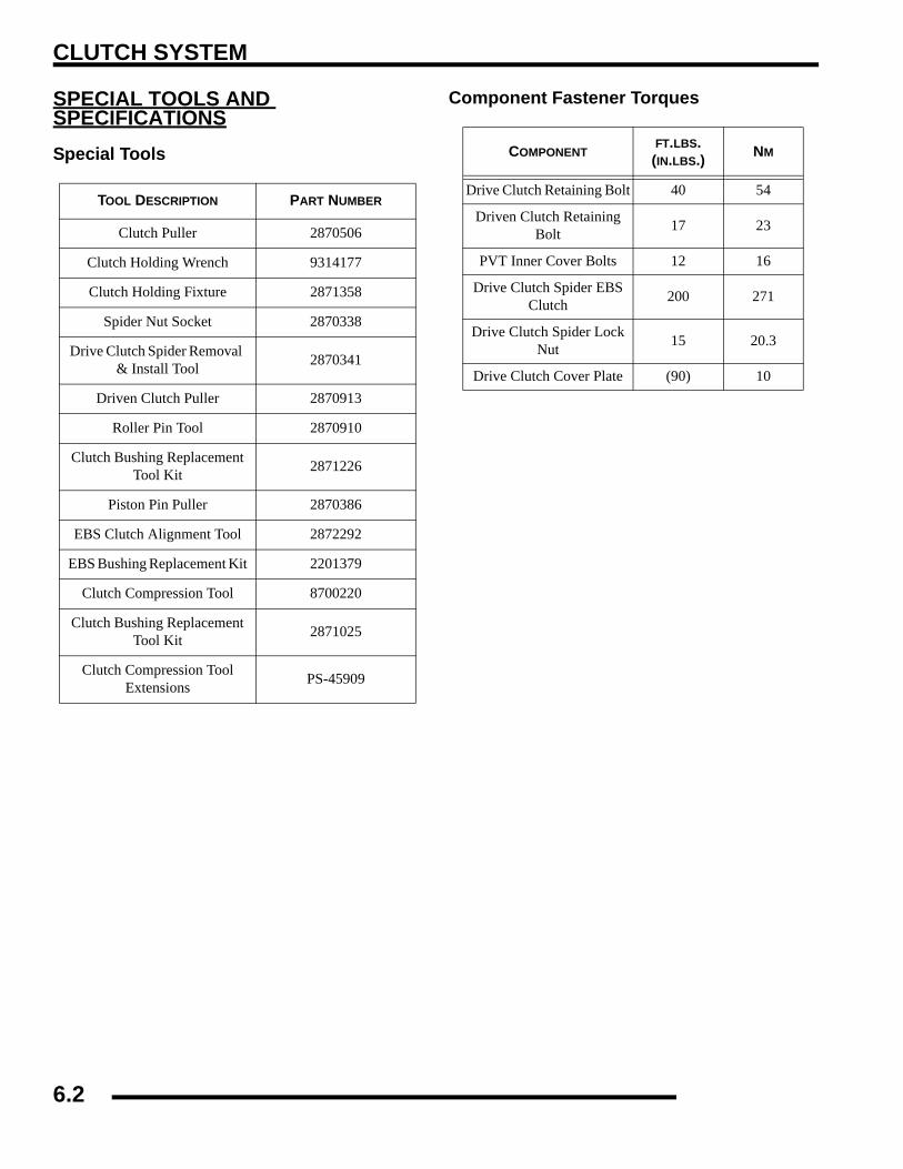
CLUTCH SYSTEM
SPECIAL TOOLS AND SPECIFICATIONSSpecial Tools
Component Fastener Torques
TOOL DESCRIPTION PART NUMBER
Clutch Puller 2870506
Clutch Holding Wrench 9314177
Clutch Holding Fixture 2871358
Spider Nut Socket 2870338
Drive Clutch Spider Removal & Install Tool 2870341
Driven Clutch Puller 2870913
Roller Pin Tool 2870910
Clutch Bushing Replacement Tool Kit 2871226
Piston Pin Puller 2870386
EBS Clutch Alignment Tool 2872292
EBS Bushing Replacement Kit 2201379
Clutch Compression Tool 8700220
Clutch Bushing Replacement Tool Kit 2871025
Clutch Compression ToolExtensions PS-45909
COMPONENTFT.LBS. (IN.LBS.) NM
Drive Clutch Retaining Bolt 40 54
Driven Clutch Retaining Bolt 17 23
PVT Inner Cover Bolts 12 16
Drive Clutch Spider EBS Clutch 200 271
Drive Clutch Spider Lock Nut 15 20.3
Drive Clutch Cover Plate (90) 10
6.2

CLUTCH SYSTEM
6
PVT EXPLODED VIEWSPVT Sealing And Ducting Components
Drive Clutch Exploded Views (EBS vs. Non-EBS)
Clutch Inlet Duct
ClampsBoot Duct
Clutch Cover
Clutch Cover Seal
Seal Retainer Bracket
Inner Seal Cover
Inner Clutch Cover
Transmission Cover Seal
NON-EBS
One Way ClutchEBS
6.3
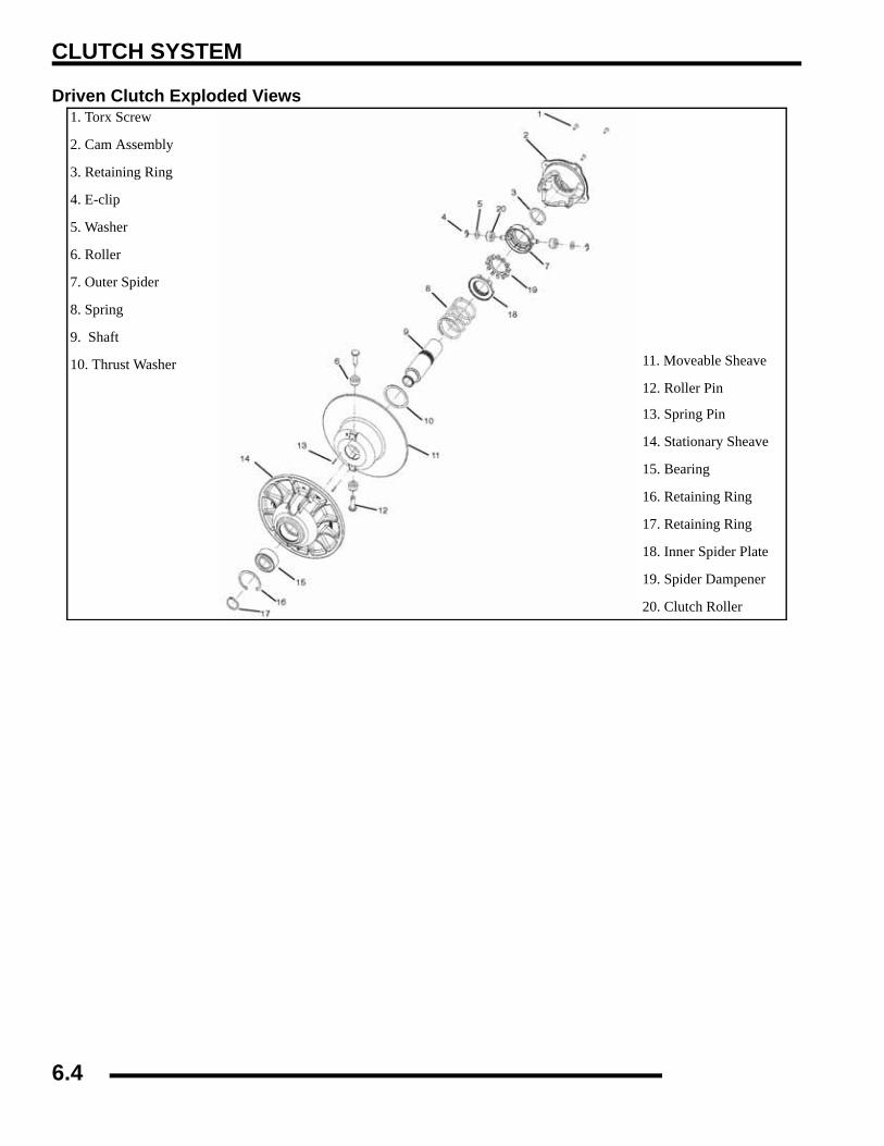
CLUTCH SYSTEM
Driven Clutch Exploded Views1. Torx Screw
2. Cam Assembly
3. Retaining Ring
4. E-clip
5. Washer
6. Roller
7. Outer Spider
8. Spring
9. Shaft
10. Thrust Washer 11. Moveable Sheave
12. Roller Pin
13. Spring Pin
14. Stationary Sheave
15. Bearing
16. Retaining Ring
17. Retaining Ring
18. Inner Spider Plate
19. Spider Dampener
20. Clutch Roller
6.4

CLUTCH SYSTEM
6
Engine Braking System (EBS) Exploded View
WasherOne Way Clutch Drive
Washer
Spacer
Shift Weights
Roller/BushingAssembly - Torque200 ft.lbs.
Spider Lock Nut
Coil Spring
Bushing Cover
Drive Belt
Cam AssemblyRetaining Ring
Spider Assembly
Compression Spring
Clutch Shaft
Spacer Washer
Sheaves
Clutch Rollers
Bearing
Retaining Rings
6.5
CLUTCH SYSTEM
PVT SYSTEMPVT Operation Overview
The Polaris Variable Transmission (PVT) consists of threemajor assemblies: 1) The Drive Clutch; 2) The Driven Clutch;and 3) The Drive Belt. The internal components of the driveclutch and driven clutch control engagement (initial vehiclemovement), clutch upshift and backshift. During thedevelopment of a Polaris ATV, the PVT system is matched firstto the engine power curve; then to average riding conditions andthe vehicle's intended usage. Therefore, modifications orvariations of components at random are never recommended.Proper clutch setup and careful inspection of existingcomponents must be the primary objective whentroubleshooting and tuning.
Drive Clutch OperationDrive clutches primarily sense engine RPM. The two majorcomponents which control its shifting function are the shiftweights and the coil spring. Whenever engine RPM isincreased, centrifugal force is created, causing the shift weightsto push against rollers on the moveable sheave, which is heldopen by coil spring preload. When this force becomes higherthan the preload in the spring, the outer sheave moves inwardand contacts the drive belt. This motion pinches the drive beltbetween the spinning sheaves and causes it to rotate, which inturn rotates the driven clutch.
At lower RPM, the drive belt rotates low in the drive clutchsheaves. As engine RPM increases, centrifugal force causes thedrive belt to be forced upward on drive clutch sheaves.
Driven Clutch OperationDriven clutches primarily sense torque, opening and closingaccording to the forces applied to it from the drive belt and thetransmission input shaft. If the torque resistance at thetransmission input shaft is greater than the load from the drivebelt, the drive belt is kept at the outer diameter of the drivenclutch sheaves.
As engine RPM and horsepower increase, the load from thedrive belt increases, resulting in the belt rotating up toward theouter diameter of the drive clutch sheaves and downward intothe sheaves of the driven clutch. This action, which increasesthe driven clutch speed, is called upshifting.
Should the throttle setting remain the same and the vehicle issubjected to a heavier load, the drive belt rotates back up towardthe outer diameter of the driven clutch and downward into thesheaves of the drive clutch. This action, which decreases thedriven clutch speed, is called backshifting.
In situations where loads vary (such as uphill and downhill) andthrottle settings are constant, the drive and driven clutches arecontinually shifting to maintain optimum engine RPM. At fullthrottle a perfectly matched PVT system should hold engineRPM at the peak of the power curve. This RPM should bemaintained during clutch upshift and backshift. In this respect,the PVT system is similar to a power governor. Rather than varythrottle position, as a conventional governor does, the PVTsystem changes engine load requirements by either upshifting orbackshifting.
WARNING
All PVT maintenance or repairs should be performed only by a certified Polaris Master Service
Dealer (MSD) technician who has received the proper training and understands the procedures outlined in this manual. Because of the critical
nature and precision balance incorporated into the PVT components, it is absolutely essential that no
disassembly or repair be made without factory authorized special tools and service procedures.
6.6

CLUTCH SYSTEM
6
EBS Clutch OperationThis EBS driven clutch provides the same engine brakingabilities as the EBS drive clutch.
When the ATV is moving the drivetrain turns in the direction ofengine rotation as the clutches, belt, and one-way clutches at thesame speed. When the drivetrain rotational speed exceeds theone-way clutch rotation (see exploded view of drive clutch) , theone-way clutch locks to the clutch shaft and engine brakingoccurs. Essentially, the driven clutch has become the drivingclutch. The spider assembly with the two rollers, fixed to thetransmission shaft, rotates in the pockets of the sheave, allowingthe stationary sheave to rotate with the moveable sheave as therollers move to the other side of the ramp, providing instantEBS. Engine braking (EBS) continues until the drive clutchspeed exceeds the one-way clutch speed, or until the throttle isapplied and the engine reaches clutch engagement speed.
PVT Maintenance / InspectionUnder normal operation the PVT system will provide years oftrouble free operation. Periodic inspection and maintenance isrequired to keep the system operating at peak performance. Thefollowing list of items should be inspected and maintained toensure maximum performance and service life of PVTcomponents. Refer to the troubleshooting checklist at the end ofthis chapter for more information.
1. Drive to Driven Clutch Offset, Belt Width.
See “Clutch Alignment” on page 6.14.
2. Drive and Driven Clutch Rollers and Bushings, DriveClutch Shift Weights and Pins, Drive Clutch Spider Rollersand Roller Pins, Drive and Driven Clutch Springs.
See “Drive Clutch Inspection” on page 6.17.
3. Sheave Faces. Clean and inspect for wear.4. PVT System Sealing. Refer to appropriate illustrations and
photos. The PVT system is air cooled by fins on the driveclutch stationary sheave. The fins create a low pressurearea in the crankcase casting, drawing air into the systemthrough an intake duct. The opening for this intake duct islocated at a high point on the vehicle (location varies bymodel). The intake duct draws fresh air through a ventedcover. All connecting air ducts, as well as the inner andouter covers, must be properly sealed to ensure clean air isbeing used for cooling the PVT system. This also willprevent water and other contaminants from entering thePVT area. A sealed PVT is especially critical on unitssubjected to frequent water forging.
CAUTION
Driven clutches must be disassembled from the helix end to reduce spring pressure. Review all
information below before proceeding.
One-Way Clutch
Drive ClutchAssembly
Downhill BeltRotation
Driven
Drive
6.7
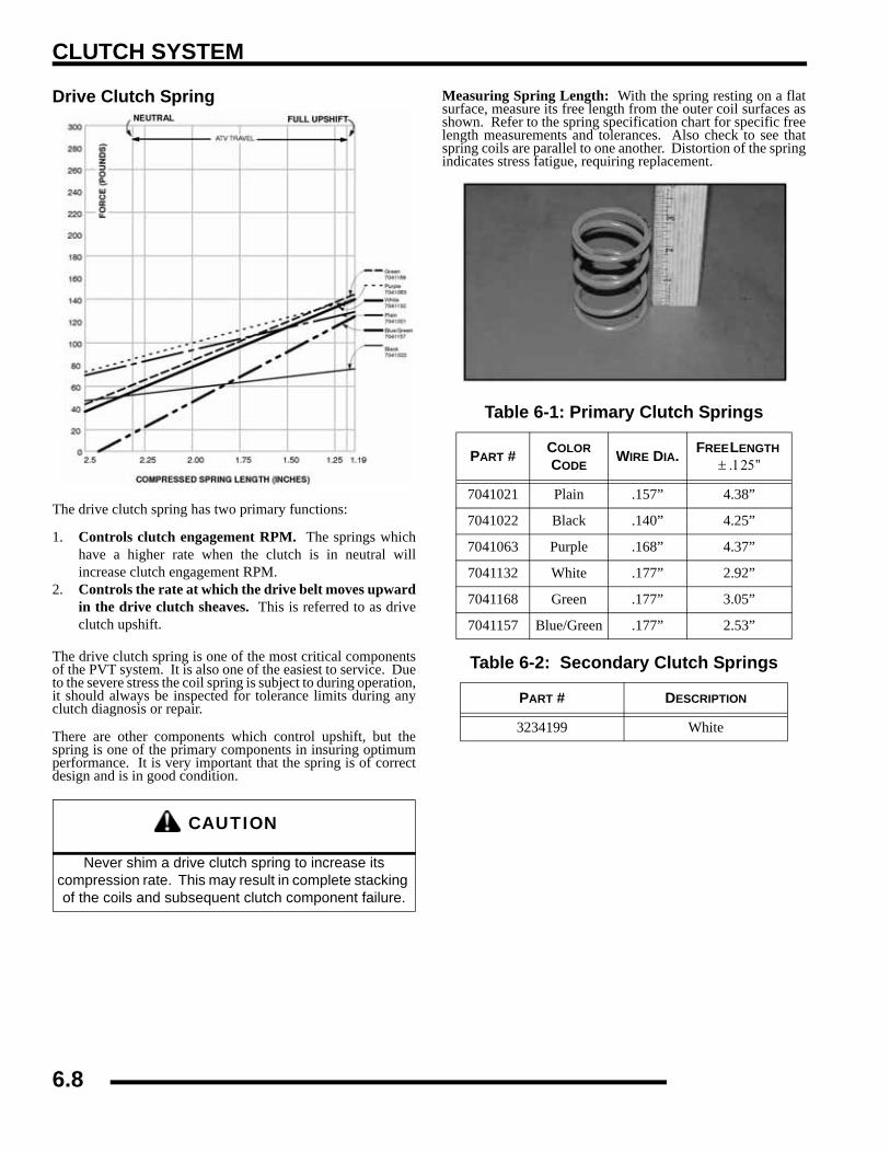
CLUTCH SYSTEM
Drive Clutch Spring
The drive clutch spring has two primary functions:
1. Controls clutch engagement RPM. The springs whichhave a higher rate when the clutch is in neutral willincrease clutch engagement RPM.
2. Controls the rate at which the drive belt moves upwardin the drive clutch sheaves. This is referred to as driveclutch upshift.
The drive clutch spring is one of the most critical componentsof the PVT system. It is also one of the easiest to service. Dueto the severe stress the coil spring is subject to during operation,it should always be inspected for tolerance limits during anyclutch diagnosis or repair.
There are other components which control upshift, but thespring is one of the primary components in insuring optimumperformance. It is very important that the spring is of correctdesign and is in good condition.
Measuring Spring Length: With the spring resting on a flatsurface, measure its free length from the outer coil surfaces asshown. Refer to the spring specification chart for specific freelength measurements and tolerances. Also check to see thatspring coils are parallel to one another. Distortion of the springindicates stress fatigue, requiring replacement.
CAUTION
Never shim a drive clutch spring to increase its compression rate. This may result in complete stacking of the coils and subsequent clutch component failure.
Table 6-1: Primary Clutch Springs
PART # COLOR CODE
WIRE DIA. FREE LENGTH ± .125”
7041021 Plain .157” 4.38”
7041022 Black .140” 4.25”
7041063 Purple .168” 4.37”
7041132 White .177” 2.92”
7041168 Green .177” 3.05”
7041157 Blue/Green .177” 2.53”
Table 6-2: Secondary Clutch Springs
PART # DESCRIPTION
3234199 White
6.8

CLUTCH SYSTEM
6
Optional Shift WeightsShown below are optional shift weights which can be used in a PVT system. These shift weights have many different factors designedinto them for controlling engagement RPM and shifting patterns. Shift weights should not be changed or altered without first havinga thorough understanding the effects they have on belt to sheave clearance, clutch balance, engagement and shifting characteristics.
- NLA -- NLA -
698
6.9

CLUTCH SYSTEM
PVT DryingIMPORTANT: If operating the ATV through water, besure to check the PVT cover and other ATVcomponents for water ingestion. The ATV should bechecked immediately. Refer to Owner's Manual forSafe Riding Tips.
To drain any water that may be trapped inside the PVT cover,simply remove the PVT drain plug and O-ring located on thebottom of the PVT cover and let the water drain out. The PVTdrain plug is shown below.
To further expel water in the PVT cover and to dry out the PVTsystem, shift the transmission to neutral and rev engine slightlyto expel the moisture. This will also air-dry the belt and clutches.Allow engine RPM to settle to idle speed, shift transmission tolowest available range and test for belt slippage. Repeat asneeded. Operate ATV in lowest available range for a shortperiod of time until PVT system is dry.
PVT DisassemblyNOTE: Some fasteners and procedures will vary.Refer to the appropriate parts manual for properfasteners and fastener placement.
1. Remove seat.2. Remove or loosen cab and footwell fasteners as necessary
to gain access to PVT outer cover.3. Remove PVT air outlet duct hose.4. Remove outer PVT cover screws. 5. Mark the drive belt direction of rotation and remove drive
belt. See the “DRIVE BELT REMOVAL” procedure laterin this chapter.
6. Remove drive clutch retaining bolt and remove drive clutchusing puller.
7. Remove driven clutch retaining bolt and driven clutch. Usepuller if necessary.
PVT Drain Plug
PVT Drain Plug & O-Ring
Drive Clutch Puller: (PN 2870506)Clutch Holding Wrench: (PN 9314177)
Driven Clutch Puller: (PN 2870913)
6.10

CLUTCH SYSTEM
6
8. Remove driven clutch offset spacers from the transmissioninput shaft. NOTE: Remember to keep spacers in order forproper clutch offset on reassembly.
9. Remove cover screws and retainer plate.
10. Remove inner cover retaining bolts at rear of cover.11. Remove cover along with foam seal on back of cover or
shaft.
PVT Installation1. Inspect PVT inner cover-to-engine seal. Replace if
cracked or damaged. Align the alignment mark on thecover with the mark on the engine seal.
2. Place a new seal on transmission input shaft.3. Apply RTV silicone sealant to outside edge of inner cover-
to-engine seal, to ensure a water tight fit between the sealand the cover on engine side. Surfaces must be clean toensure adhesion of silicone sealant.
4. Reinstall cover and tighten rear cover bolts just enough tohold it in place.
5. Fit lip of inner cover seal (A) to engine. Install seal retainerplate and tighten screws securely.
6. Torque rear inner cover bolts (B) to specification.
Offset Spacer
Inner Cover
Retainer Seal
Foam Seal
= T
Inner Cover Bolt Torque (B):12 ft. lbs. (16.6 Nm)
Seal This Edge To Cover On Engine
B
C
Seal Outer Edge To Coverw/ RTV silicone sealant
A
6.11

CLUTCH SYSTEM
7. Install clutch offset spacer(s) on transmission input shaft.
8. Clean splines inside driven clutch and on the transmissioninput shaft.
9. Apply a light film of grease to the splines on the shaft.10. Install the driven clutch, washer, lock washer, and retaining
bolt. Torque to specification.
11. Clean end of taper on crankshaft and the taper bore insidedrive clutch.
12. Install drive clutch and torque retaining bolt tospecification.
13. Reinstall drive belt noting direction of rotation. If a newbelt is installed, install so numbers can be easily read.
14. Only replace PVT outer cover rubber gasket if it isdamaged. Place the gasket with the narrow side out (C).
15. Reinstall PVT outer cover and secure with screws. Torqueto specification.
16. Reinstall cab/footwell assembly, panel and seat.
Drive Belt Removal / Inspection1. Remove outer PVT cover as described in PVT
Disassembly.2. Mark drive belt direction of rotation so that it can be
installed in the same direction. The belt is normallypositioned so part numbers are easily read.
3. To remove drive belt, place transmission in gear, applybrake, pull upward and rearward on belt while turning theback (moveable) driven sheave clockwise to open drivenclutch sheaves. Pull out and down on belt to slip over thedriven clutch outer sheave.
4. Measure belt width and replace if worn. Generally, beltsshould be replaced if clutches can no longer be adjusted toprovide proper belt deflection.
NOTE: If the top edges are trimmed on some drivebelts, it will be necessary to project the side profilesin order to measure from corner-to-corner.
5. Place a straight edge on each side of the drive belt. Placeanother straight edge on top of belt.
= T
Driven Clutch Retaining Bolt Torque:17 ft. lbs. (23.5 Nm)
= T
Drive Clutch Retaining Bolt Torque:40 ft. lbs. (55 Nm)
Offset Spacer
PVT Cover Gasket
Towards Outside Cover
6.12

CLUTCH SYSTEM
6
6. Measure the distance where the side straight edges intersectthe top, as shown in the illustration.
7. Inspect belt for loose cords, missing cogs, cracks,abrasions, thin spots, or excessive wear. Replace ifnecessary.
8. Inspect belt for hour glassing (extreme circular wear in atleast one spot and on both sides of the belt). Hour glassingoccurs when the drive train does not move and the driveclutch engages the belt continuously in one spot.
9. Measure belt length with a tape measure around the outercircumference of the belt. Belts which measure longer thannominal length may require driven shimming or engineadjustment for a longer center distance to obtain proper beltdeflection. Belts which measure shorter than nominallength may require driven shimming or a shorter centerdistance. Remember, proper belt deflection is the desiredgoal - not a specific center distance.
10. Replace belt if worn past the service limit. Belts with thinspots, burn marks, etc., should be replaced to eliminatenoise, vibration, or erratic PVT operation. SeeTroubleshooting Chart at the end of this chapter forpossible causes.
DRIVE BELT INSTALLATIONNOTE: Be sure to position belt so part number is easilyread. Verify new belt is seated properly in the clutchesbefore operating the ATV.
1. Loop belt over drive and over top of driven sheave.2. While pushing down on top of belt, turn the back or
moveable driven sheave clockwise.
3. The belt then should be able to be pushed down into andbetween the sheaves.
4. Install clutch cover temporarily. Verify engine is in PARK.Start engine and raise engine RPM enough to engage theclutch, rotating the belt and seating it in the clutches.Remove clutch cover and verify belt is seated properlybefore final cover installation.
Belt Width:Wear Limit 1.125" (2.86 cm)
Clutch Center Distance: 10.05 ± .05" (254 ± 2.51mm)
Projected Belt Width
Center Distance
6.13

CLUTCH SYSTEM
Clutch Alignment1. Remove belt and install the Clutch Offset Alignment Tool
as shown.
2. With tool touching rear of driven clutch inner sheave, thedistance at point “A” should be 1/8”.
NOTE: If the distance is greater than 1/8, or lessthan 1/16,, clutch alignment must be adjusted asfollows:
3. Remove drive and driven clutch. See “PVTDIASSEMBLY” at the beginning of the chapter.
4. Remove PVT inner cover.5. Loosen all engine mounts. Move front of engine to the right
or left slightly until alignment is correct.6. Tighten engine mounts and verify alignment is correct.
7. Measure belt deflection and measure offset both above andbelow shaft centerlines. Adjust if necessary.
NOTE: On some models, minor adjustments can bemade by adding shims between the frame and frontlower left engine mount to increase the distance atpoint “A”. If a shim is present, it can be removed todecrease the distance at point “A”.
Clutch OffsetIMPORTANT: Inspect clutch alignment and centerdistance before adjusting offset.
Offset is correct when rear of tool contacts rear of inner sheavewith driven clutch pushed completely inward, spacers installed(if required) on shaft and bolt torqued to specification.
1. Install alignment tool as shown. Remember to measureabove and below the shaft centerlines.
2. Adjust offset by adding or removing spacer washersbetween back of driven clutch and spacer.
B
A 1/8” + 0 / -1/16 (3.2mm + 0 / - 1.6)
Offset AlignmentTool
Shim Kit (PN 2200126)
Spacer Washer (PN 7556401)
Center Line
Measure Above and Below Centerline
6.14

CLUTCH SYSTEM
6
EBS DRIVE CLUTCH SERVICEDrive Clutch Disassembly1. Using a permanent marker, mark the cover, spider, and
moveable and stationary sheaves for reference, as the cast-in X's may not have been in alignment before disassembly.
2. Remove cover bolts evenly in a cross pattern and removecover plate.
3. Inspect cover bushing (A). The outer cover bushing ismanufactured with a Teflon™ coating. Wear is determinedby the amount of Teflon™ remaining on the bushing.
4. Inspect area on shaft where bushing rides for wear, galling,nicks, or scratches. Replace clutch assembly if worn ordamaged.
5. Remove and inspect spring. See “Drive Clutch SpringSpecifications” for spring inspection.
Spider Removal1. Remove the limiter nut using the Clutch Spider Nut Socket
(PN 2870338). Install clutch in holding fixture and loosenthe spider (counterclockwise) using Clutch Spider InstallTool (PN 2870341).
Cover Bushing Inspection:Replace the cover bushing if more brass than Teflon™ is visible on the bushing. Refer to bushing replacement in this chapter.
A
Clutch Holding Fixture: (PN 2871358) Spider Removal Tool: (PN 2870341)
Inspect Shaft
6.15

CLUTCH SYSTEM
NOTE: It is important that the same number andthickness of washers are reinstalled beneath thespider during assembly. Be sure to note the numberand thickness of these washers.
2. Inspect the Teflon™ coating on the moveable sheavebushing.
3. Inspect all rollers, bushings and roller pins by pulling a flatmetal rod across the roller. Turn roller with your finger. Ifyou notice resistance, galling, or flat spots, replace rollers,pins and thrust washers in sets of three. Also inspect to seeif roller and bushing are separating. Bushing must fittightly in roller. Use the Roller Pin Tool (PN 2870910) toreplace rollers and pins. Take care not to damage rollerbushing or bearing surface of the new pin duringinstallation.
4. Rubber-backed buttons can and should be used in all ATVclutches if the hollow roller pin is changed to a solid rollerpin.
NOTE: Rubber side of the button is positionedtoward the solid roller pin. It is recommended toswitch all buttons to the rubber version duringservice (if needed).
Moveable Sheave Bushing Inspection: Replace the cover bushing if more
brass than Teflon™ is visible on the bushing. Refer to bushing
replacement in this chapter.
To maintain proper clutch balance and belt-to-sheaveclearance, be sure to reinstall original quantity andthickness washers
6.16

CLUTCH SYSTEM
6
Button To Tower Clearance Inspection1. Inspect for any clearance between spider button to tower.
If clearance exists, replace all buttons and inspect surfaceof towers. See “Spider Removal” procedure.
2. Inspect sheave surfaces. Replace the entire clutch as anassembly if worn, damaged or cracked.
Shift Weight Inspection1. If clutch is not disassembled, inspect as shown, using a
clutch holding tool to compress the moveable sheave. Thecontact surface of the weight should be smooth and free ofdents or gall marks. Remove shift weight bolts andweights.
2. Inspect the weight pivot bore and pivot bolts for wear orgalling. If weights or bolts are worn or broken, replace insets of three with new bolts.
NOTE: A damaged shift weight is usually caused bya damaged or stuck roller in the spider assembly.See roller inspection, see “Roller, Pin, and ThrustWasher Inspection”.
Drive Clutch InspectionNOTE: Remove cover, spring, and spider followinginstructions for drive clutch removal, then proceedas follows:
1. Remove moveable sheave spacer sleeve (1) and the thrustwasher (2). Visually inspect the washer for damage.Measure the thickness and compare to specification.Replace if worn or damaged.
Button to Tower Clearance: .000-.001
WARNING
The clutch assembly is a precisely balanced unit. Never replace parts with used parts from another clutch assembly!All PVT maintenance or repairs should beperformed only by a certified Polaris Master ServiceDealer (MSD) technician who has received theproper training and understands the proceduresoutlined in this manual. Because of the critical nature and precisionbalance incorporated into the PVT system, it isabsolutely essential that no attempt atdisassembly or repair be made without factoryauthorized special tools and serviceprocedures.
Thrust Washer ThicknessStandard: .030, (.76mm)
Service Limit: .025, (.64mm)
1
2
6.17

CLUTCH SYSTEM
2. Lift one-way clutch (3) and thrustwasher (4) off shaft.Replace as an assembly if worn, damaged, or if problemswere noted.
3. Inspect surface of shaft for pitting, grooves, or damage.Measure the outside diameter and compare tospecifications. Replace the drive clutch assembly if shaftis worn or damaged.
4. Visually inspect PTFE thrustwasher for damage. Measurethe thickness and compare to specification. Replace ifworn or damaged
Moveable Sheave Bushing InspectionInspect the Teflon™ coating (arrow) on the moveable sheavebushing. Inspect BOTH sheaves for signs of wear, grooving orcracking. De-glaze surfaces with a 3M™ pad if needed.
Drive Clutch Bushing ServiceNOTE: Special Tool Required: EBS CLUTCHBUSHING REMOVAL AND INSTALLATION
= In. / mm.
Shaft Diameter:Standard: 1.3745 - 1.375 (
Service Limit: 1.3730”
= In. / mm.
PTFE Washer ThicknessStandard: .030” (.76mm)
Service Limit: .025” (.64mm)
Moveable Sheave Bushing Inspection:Replace the cover bushing if more brass than
Teflon™ is visible on the bushing. Refer to bushing replacement in this chapter.
Table 6-1: Special Tools
ITEM QTY PART DESCRIPTION PART #
A, B 1 EBS Puller Tool 5132027
C 1 EBS Puller Nut 5132501
D 1 EBS Main Adapter 5132029
E 1 EBS Bushing Removal 5132028
-- 1 Bushing Replacement Kit 2871226
-- 1 Piston Pin Puller 2870386
-- 1 Instructions 9915111
6.18

CLUTCH SYSTEM
6
NOTE: Bushings are installed at the factory usingLoctite™ 609. In order to remove bushings it will benecessary to apply heat evenly to the area aroundeach bushing. Clean all residual Loctite™ frombushing bore prior to installing new bushing.
Drive Clutch Bushing Removal
1. Remove clutch as outlined previously in this chapter.2. Install handle end of Piston Pin Puller (PN 2870386)
securely into bench vise and lightly grease puller threads.3. Remove nut from puller rod and set aside.4. Install puller adapter (Item 10 from kit PN 2871226).5. Install main adapter (Item D) onto puller.
6. With towers pointing toward the vise, slide sheave ontopuller rod.
7. Install removal tool (Item A/B) into center of sheave withA side" toward sheave. NOTE: Smooth One-way Clutch- Use Bushing Tool PA-47336.
8. Install nut (C) onto end of puller rod and hand tighten. Turnpuller barrel to increase tension on sheave if needed. Usinga hand held propane torch, apply heat around outside ofbushing until tiny smoke tailings appear.
9. Turn sheave counterclockwise on puller rod until it comesfree. Lift sheave off puller.
10. Remove nut from puller rod and set aside.11. Pull bushing removal tool and adapter from puller rod.
Remove bushing from tool and discard.
Drive Clutch Bushing Installation
1. Place main adapter (Item 8) on puller.
2. Apply Loctite™ 609 evenly to bushing bore insidemoveable sheave.
3. Set bushing in place on sheave.4. Insert installation puller tool (Item A/B) with “A” side
down, into center of bushing. NOTE: 800 EFI Clutch -Use Bushing Tool PA-47336.
5. With towers pointing upward, slide sheave, bushing andtool onto puller rod.
6. Install nut on puller rod and hand tighten. Turn barrel toapply additional tension if needed.
7. Turn sheave counterclockwise, making sure bushing isdrawn straight into bore. Continue until bushing is seated.
8. Remove nut from puller rod and set aside.9. Remove sheave from puller.10. Remove installation tool.
CAUTION
Clutch components will be hot! In order to avoid serious burns, wear insulated gloves during the
removal process.
Puller Tool (A,B)Side “A” towardsheave
Nut (C)
MainAdapter (D)
PullerAdapter (10)
Piston PinPuller
Puller Tool (A,B) Side“A” toward sheave Nut (C)
Bushing
Main Adapter (8)
Piston Pin Puller
6.19

CLUTCH SYSTEM
Cover Bushing Removal
1. Install main adapter (Item 8) on puller.
2. Install adapter reducer (Item 9).3. From outside of clutch cover, insert removal tool (Item 3)
into cover bushing.4. With inside of cover toward vise, slide cover onto puller.5. Install nut onto puller rod and hand tighten. Turn puller
barrel to increase tension as needed.6. Turn clutch cover counterclockwise on puller rod until
bushing is removed and cover comes free.7. Remove nut from puller rod and set aside. 8. Remove bushing and bushing removal tool from puller.
Discard bushing.
Cover Bushing Installation
1. Apply Loctite™ 609 evenly to bushing bore in cover.2. Working from inside of cover, insert new bushing and
bushing installation tool into center of clutch cover.3. With main adapter on puller, insert cover onto puller rod,
placing outside of cover toward vise.4. Install nut on rod and hand tighten. Turn puller barrel to
apply more tension if needed.5. Turn clutch cover counterclockwise on puller rod until
bushing is seated.6. Remove nut from puller rod. Take installation tool and
clutch cover off rod.
One-Way Clutch Inspection (Drive Clutch)1. Rotate one-way clutch clockwise (as viewed from the
cover plate side). The clutch should rotate on the shaftwith only slight amount of drag. Verify there is no bindingor rough spots. When rotated counterclockwise, the clutchshould lock to the shaft without slipping. If problems arenoted in either direction, continue with disassembly.
Drive Clutch ReassemblyNOTE: It is important that the same number andthickness of washers are reinstalled beneath thespider during assembly. The Teflon bushings areself-lubricating.
1. Reassemble drive clutch in the following sequence. Besure the “X”, or the marks that were made earlier, arealigned during each phase of assembly.
A) “X”, or the marks that were made earlier on cover
B) “X” on spider, making sure spacer washers are installedunderneath spider and positioned properly in recess
Removal Tool (3)Nut (C)
Adapter Reducer (9)
Piston Pin PulleMain Adapter (8)
CAUTION
Do not apply oil or grease to the bushings.
6.20

CLUTCH SYSTEM
6
C) “X”, or the marks that were made earlier under weight
2. Install moveable sheave onto fixed sheave.3. Install spider spacers. Use same quantity and thickness as
were removed.4. Compress spider buttons for each tower and install spider,
making sure that “X”, or the marks that were made earlier,on spider aligns with “X”, or the marks that were madeearlier on the moveable sheave.
5. Torque spider to specification using the holding fixture andspider tool. Torque with smooth motion to avoid damageto the stationary sheave.
6. Install limiter nut on top of spider using the Clutch SpiderNut Socket (PN 2870338). Torque to specification.Reinstall shift weights using new lock nuts on the bolts.
7. Reinstall clutch spring.
8. Reinstall cover, aligning bosses on the tower and cover.Torque cover bolts evenly to specification.
CAUTION
Verify spider spacer washers are fully seated in the recessed area of the spider. Any misalignment will alter clutch balance.
Inverting the clutch while initially tightening the spider will help position the washers.
= T
Spider Torque:200 ft. lbs. (271 Nm)
Spacer Washers
= T
Spider Nut Torque:15 ft. lbs. (20 Nm)
= T
Cover Screw Torque:90 in. lbs. (10.4 Nm)
EngineRotation
Nut on trailing side
6.21

CLUTCH SYSTEM
EBS DRIVEN CLUTCH SERVICEDriven Clutch Disassembly 1. Remove driven clutch from the transmission input shaft.
Do not attempt disassembly of the driven clutch from theoutside snap ring. The driven clutch must be disassembledfrom the helix side.
2. It is important to mark the position of the shaft, cam cover,and sheave before disassembly or use the “X’s” on thecomponents for reference. This will aid in reassembly andhelps to maintain clutch balance after reassembly.
3. Remove the four torx screws that secure the cam assembly(helix) using a T25 torx.
4. Place the clutch into Clutch Compression Tool PN8700220. Using Compression Extensions PN PS-45909,Press down on top of the spider assembly, compressing thespider onto the shaft. Remove snap ring (A) and slowlyrelease the assembly.
5. Remove the spider assembly, spring (B), and spacer washer(C). NOTE: Spring is compression only and has notorsional wind
Do not disassemble from this side
Press down on spider
B
C
6.22

CLUTCH SYSTEM
6
6. Remove the inside spider plate (D) and spider dampener(E). Inspect the spider dampener (E) for wear and replacedif needed.
7. Remove the E-clip (F), washer (G), and the clutch rollers(H). Inspect the rollers for wear replace if worn.
8. Remove the clutch assembly from the holding tool.Remove the large outer retaining ring (I) and the innerretaining ring (J).
9. Press out the spring pins (K) in the inner sheave.
10. Pull out the clutch roller pins (L) and rollers (M).
11. Press the shaft and bearing out of the outer sheave using apress.
ED
H G F
I
J
K
K
M L
Press Shaft & Bearing Out
Inspect Bearing
6.23

CLUTCH SYSTEM
12. Inspect the bearing for wear. Spin the bearing, if thebearing does not spin smoothly replace as needed. Toremove the bearing, simply press the bearing from the shaft.
13. Inspect the bearing for wear. Spin the bearing, if thebearing does not spin smoothly replace as needed. Toremove the bearing, simply press the bearing from the shaft.
14. Inspect the cam assembly (helix) bushing for wear. If thebushing is worn or the shaft does not fit snug into thebushing, replace the cam assembly (cover).
DRIVEN CLUTCH BUSHING REMOVAL/INSTALLATIONNOTE: Special Tool Required: EBS CLUTCHBUSHING REMOVAL AND INSTALLATION
NOTE: Bushings are installed at the factory usingLoctite™ 609. In order to remove bushings it will benecessary to apply heat evenly to the area aroundeach bushing. Clean all residual Loctite™ frombushing bore prior to installing new bushing.
Driven Clutch Bushing Removal1. Install main puller adapter (Item 8) onto puller.2. Install adapter reducer (Item 9).3. Using a hand held propane torch, apply heat around outside
of bushing until tiny smoke tailings appear.4. Flip sheave over so bushing faces downward and install
onto puller.5. Install bushing tool (Item 2).
Inspect Sheave Surface
Inspect Bushing
Table 6-1:
ITEM QTY PART DESCRIPTION PART #
A, B 1 EBS Puller Tool 5132027
C 1 EBS Puller Nut 5132501
D 1 EBS Main Adapter 5132029
E 1 EBS Bushing Removal Tool Instructions 5132028
-- 1 Bushing Replacement Kit 2871226
-- 1 Piston Pin Puller 2870386
-- 1 Instructions 9915111
6.24

CLUTCH SYSTEM
6
6. Install left hand nut (C) and spacer onto puller rod andtighten by hand. Turn puller barrel for further tension ifneeded.
7. Turn clutch sheave counterclockwise until bushing isremoved and sheave comes free.
8. Remove nut (C) (left hand thread) from puller rod and setaside.
9. Remove adapters from puller.10. Remove bushing and removal tool from adapters. Discard
bushing.
Driven Clutch Bushing Installation1. Install puller adapter (Item 10) onto puller.2. Install adapter (Item 9) onto puller.
3. Apply Loctite™ 609 evenly to bushing bore insidemoveable sheave.
4. Install sheave face down on puller.5. Install new bushing on installation tool (Item 2) and install
assembly into sheave.6. Install left hand thread nut (C) onto puller rod and hand
tighten against installation tool. 7. Turn clutch sheave counterclockwise, making sure bushing
is drawn straight into bore. Continue until bushing isseated.
8. Remove nut (C) from puller rod and set aside.9. Remove installation tool and clutch sheave from puller.
EBS DRIVEN CLUTCH REASSEMBLY1. Press a new bearing onto the output shaft using a press.
2. Install the shaft/bearing into the outer sheave.
6.25

CLUTCH SYSTEM
3. Install the small and large retaining rings into the outersheave above the bearing.
4. Line up the “X” on the moveable sheave with the “X” onthe stationary sheave or use the marks previously used. Putthe sheaves together.
5. Install the roller (A) onto the roller pin (B). (Both Sides).
6. Install the roller pin into the sheave assembly. (Both sides).The flat side of the roller pin faces downward when theshaft side is laying flat on the bench.
7. Install the spring pins (C) to secure the roller pins. Installuntil flush with sheave surface.
Align X’s
A
B
Flat Side Down
C
6.26

CLUTCH SYSTEM
6
8. Install the spacer washer.
9. Install the spring over the shaft (arrow).
10. Install the clutch rollers (D) onto each side of the outsidespider. Install the washers (E) and E-clips (F) to secure therollers. Spin the roller, the rollers should spin freely.
11. Install the spider dampener (G) inside the outer spider andinstall the inside spider plate (H).
12. Install the spider assembly onto the shaft with the retainingring on top of the spider. NOTE: Use the marks previouslymade to align the skip tooth spider, or use the “X” on topof the spider and align it with the skip tooth on the shaft.
13. Place the clutch into Clutch Compression Tool PN8700220. Using Compression Extensions PN PS-45909,Press down on the top of the spider assembly, pushing thespider onto the shaft.
14. Slowly compress the spider into place. If the spider appearsto bind while compressing, stop and make sure the skiptooth on the shaft and the spider are aligned. Once thespider passes the retaining ring notch on the shaft, installthe retaining ring (A).
Install Spacer Washer
Outer Spider
H
G
D E F
Align Marks
Press Down on Spider
A
6.27

CLUTCH SYSTEM
15. Install the cam assembly (helix) over the shaft. Line up the“X” on the cam, “X” on spider, and “X” on the stationarysheave or use the marks previously made beforedisassembly. NOTE: If the cam assembly (helix) isdifficult to install, be sure the sheaves are aligned. To alignthe sheaves place the clutch assembly on a flat surface withthe cam assembly (helix) side down. Press down on themoveable sheave belt face with both hands and the helixwill release.
16. Use a T25 torx to install the four torx screws and torque tospecification.
= T
T25 Torx:42-52 in. lbs. (4.75 - 5.88 Nm)
Press Down to Loosen Helix
6.28

CLUTCH SYSTEM
6
PVT TROUBLESHOOTINGOverheatingIMPORTANT: During routine maintenance orwhenever PVT system overheating is evident, it'simportant to check the inlet and outlet ducting forobstructions. Obstructions to air flow through theducts will significantly increase PVT systemoperating temperatures. The ATV should be operatedin low range when pulling or plowing heavy loads, orif extended low speed operation is anticipated.
General Range Operation GuidelinesLOW RANGE: Heavy pulling, basic operational speeds lessthan 7 MPH, riding through rough terrain (swamps, mountains,etc..), low ground speeds.
HIGH RANGE: High ground speeds, speeds above 7 MPH.
Table 6-1: Cause and Remedy
DIAGNOSIS OF CLUTCH DRIVE BELT & COVER RELATED ISSUES:
POSSIBLE CAUSES SOLUTIONS/WHAT TO DO
Loading the ATV into a pickup or tall trailer when in high range. Shift transmission to low range during loading of the ATV to prevent belt burning.
Starting out going up a steep incline.
When starting out on an incline, use low range, or dismount the ATV after first applying the park brake and perform the “K” turn.
Driving at low RPM or low ground speed (at approximately 3-7 MPH).
Drive at higher speed or use Low Range. The use of Low Range is highly recommended for cooler PVT operating temperatures and longer component life.
Insufficient warm-up of ATVs exposed to low ambient temperatures.
Warm engine at least 5 min., then with transmission in neutral, advance throttle to approx. 1/8 throttle in short bursts, 5 to 7 times. The belt will become more flexible and prevent belt burning.
Slow and easy clutch engagement.
Fast, effective use of the throttle for efficient engagement. Continuous operation at the point of engagement (initial vehicle movement) increases PVT temperatures and component wear.
Towing/Pushing at low RPM/low ground speed. Use Low Range only.
Plowing snow, dirt, etc./utility use. Use Low Range only.
Stuck in mud or snow. Shift the transmission to Low Range, carefully use fast, aggressive throttle application to engage clutch. Warning: Excessive throttle may cause loss of control and vehicle overturn.
Climbing over large objects from a stopped position.
Shift the transmission to Low Range, carefully use fast, aggressive, throttle application to engage clutch. Warning: Excessive throttle may cause loss of control and vehicle overturn.
Belt slippage from water or snow ingestion into the PVT system.
Shift the transmission to neutral. Using the throttle, vary the engine rpm from idle to 3/4 throttle. Engage transmission in the lowest possible range and test for belt slippage Repeat several times as required. During this procedure, the throttle should not be held at the full position for more than 10 seconds. PVT seals should be inspected for damage if repeated leaking occurs.
Clutch malfunction. Inspection/repair of clutch components should be performed by a certified Polaris MSD technician.
6.29

CLUTCH SYSTEM
Problem, Cause and Remedy Chart
Table 6-2: Problem, Cause and Remedy
SITUATION POSSIBLE CAUSE REMEDY
Engine RPM below specified operating range although engine is properly tuned.
-Wrong or broken drive clutch spring. -Replace with recommended spring.
-Drive clutch shift weight too heavy. -Install correct shift weight kit to match engine application.
-Driven clutch spring broken or installed wrong . -Replace spring; refer to proper installation location
Erratic engine operating RPM during acceleration or load variations.
-Drive clutch binding.a. Disassemble drive clutch; inspect shift weights for wear and free operation.
-Belt worn unevenly - thin/burnt spots Replace belt
-Driven clutch malfunction.a. Replace ramp buttons. b. Inspect movable sheave for excessive bushing
-Sheave face grooved. -Replace the clutch.
Engine RPM above specified operating range.
-Incorrect drive clutch spring (too high spring rate). -Install correct recommended spring.
-Drive clutch shift weights incorrect for application (too light) -Install correct recommended shift weights.
-Drive clutch binding.-Disassemble and clean clutch, inspecting shift weights and rollers. Reassemble without the spring
-Driven clutch binding.-Disassemble, clean, and inspect driven clutch, noting worn sheave bushing and ramp buttons and helix
-Converter sheaves greasy; belt slippage. -Clean sheaves with denatured alcohol or brake cleaner, install new belt.
Harsh drive clutch engagement.
-Drive belt worn too narrow. -Replace belt.
-Excessive belt/sheave clearance with new belt. -Perform belt/sheave clearance adjustment with shim washers beneath spider.
Drive belt turns over-Wrong belt for application. -Replace with correct belt.-Clutch alignment out of spec. -Adjust alignment offset.-Engine mount broken or loose -Inspect/adjust or replace.
PVT cover overheating (melting)
-Plugged air intake or outlet -Clear obstruction.-Belt slippage due to water, oil, grease, etc., rubbing on cover
-Inspect system. Clean , repair or replace as necessary. Seal PVT system ducts.
-Clutches or weight being applied to cover while in operation Remove weight. Inform operator.
-Use of High vs. low range-Instruct operator on guidelines for operation in wet terrain as outlined in Owner's Safety and Maintenance
Water Ingestion-Cover seals or ducts leaking -Find leak and repair as necessary.
-Operator error-Instruct operator on guidelines for operation in wet terrain as outlined in Owner's Safety and Maintenance
Belt Slipping-Belt worn out -Replace belt.-Water ingestion -Inspect and seal PVT system.-Belt contaminated with oil or grease -Inspect and clean.
6.30

CLUTCH SYSTEM
6
Belt burnt, thin spots
-Abuse (continued throttle application when vehicle is stationary, excess load)
-Caution operator to operate machine within guidelines.
-Dragging brake -Vehicle operated with park brake on. Inspect brake system.
-Slow, easy clutch engagement -Instruct firm, effective use of throttle for efficient engagement.
PVT noise
-Belt worn or separated, thin spots, loosebelt -Replace belt.
-Broken or worn clutch components, cover hitting clutches -Inspect and repair as necessary.
Engagementerratic or “jerks”
-Thin spots on belt, worn belt -Replace belt. Refer to belt burnt troubleshooting and instruct operator.
-Drive clutch bushings stick -Inspect and repair clutches.
Table 6-2: Problem, Cause and Remedy
SITUATION POSSIBLE CAUSE REMEDY
6.31

CLUTCH SYSTEM
NOTES
6.32

FINAL DRIVE
7.1
CHAPTER 7FINAL DRIVE
7
SPECIFICATIONS. . . . . . . . . . . . . . . . . . . . . . . . . . . . . . . . . . . . . . . . . . . . . . . . . . . . . . . 7.2TORQUE TABLE . . . . . . . . . . . . . . . . . . . . . . . . . . . . . . . . . . . . . . . . . . . . . . . . . . . . . . . 7.2SPECIAL TOOLS . . . . . . . . . . . . . . . . . . . . . . . . . . . . . . . . . . . . . . . . . . . . . . . . . . . . . . . 7.2GEARCASE FLUID / CAPACITY . . . . . . . . . . . . . . . . . . . . . . . . . . . . . . . . . . . . . . . . . . . 7.2
FRONT HUB . . . . . . . . . . . . . . . . . . . . . . . . . . . . . . . . . . . . . . . . . . . . . . . . . . . . . . . . . . . 7.2DISASSEMBLY. . . . . . . . . . . . . . . . . . . . . . . . . . . . . . . . . . . . . . . . . . . . . . . . . . . . . . . . . 7.2ASSEMBLY . . . . . . . . . . . . . . . . . . . . . . . . . . . . . . . . . . . . . . . . . . . . . . . . . . . . . . . . . . . 7.3
FRONT DRIVE SHAFT (CV) SERVICE. . . . . . . . . . . . . . . . . . . . . . . . . . . . . . . . . . . . . . . 7.3REMOVAL . . . . . . . . . . . . . . . . . . . . . . . . . . . . . . . . . . . . . . . . . . . . . . . . . . . . . . . . . . . . 7.3INSTALLATION . . . . . . . . . . . . . . . . . . . . . . . . . . . . . . . . . . . . . . . . . . . . . . . . . . . . . . . . 7.4INSPECTION . . . . . . . . . . . . . . . . . . . . . . . . . . . . . . . . . . . . . . . . . . . . . . . . . . . . . . . . . . 7.5CV JOINT/BOOT REPLACEMENT . . . . . . . . . . . . . . . . . . . . . . . . . . . . . . . . . . . . . . . . . 7.5
PROP SHAFT - FRONT OR REAR. . . . . . . . . . . . . . . . . . . . . . . . . . . . . . . . . . . . . . . . . . 7.7REMOVAL AND INSTALLATION . . . . . . . . . . . . . . . . . . . . . . . . . . . . . . . . . . . . . . . . . . . 7.7
U-JOINT. . . . . . . . . . . . . . . . . . . . . . . . . . . . . . . . . . . . . . . . . . . . . . . . . . . . . . . . . . . . . . . 7.7DISASSEMBLY. . . . . . . . . . . . . . . . . . . . . . . . . . . . . . . . . . . . . . . . . . . . . . . . . . . . . . . . . 7.7ASSEMBLY . . . . . . . . . . . . . . . . . . . . . . . . . . . . . . . . . . . . . . . . . . . . . . . . . . . . . . . . . . . 7.8
DRIVE AXLE EXPLODED VIEWS. . . . . . . . . . . . . . . . . . . . . . . . . . . . . . . . . . . . . . . . . . 7.10DRIVE SHAFTS AND PROPSHAFTS . . . . . . . . . . . . . . . . . . . . . . . . . . . . . . . . . . . . . . 7.10
FRONT GEARCASE - CENTRALIZED HILLIARD W/ ACTIVE DESCENT CONTROL . 7.11OPERATION. . . . . . . . . . . . . . . . . . . . . . . . . . . . . . . . . . . . . . . . . . . . . . . . . . . . . . . . . . 7.11ADC GEARCASE EXPLODED VIEW. . . . . . . . . . . . . . . . . . . . . . . . . . . . . . . . . . . . . . . 7.12ADC OPERATION . . . . . . . . . . . . . . . . . . . . . . . . . . . . . . . . . . . . . . . . . . . . . . . . . . . . . 7.13FRONT GEARCASE DIAGNOSIS . . . . . . . . . . . . . . . . . . . . . . . . . . . . . . . . . . . . . . . . . 7.14GEARCASE REMOVAL . . . . . . . . . . . . . . . . . . . . . . . . . . . . . . . . . . . . . . . . . . . . . . . . . 7.15GEARCASE INSTALLATION . . . . . . . . . . . . . . . . . . . . . . . . . . . . . . . . . . . . . . . . . . . . . 7.16COIL TESTING. . . . . . . . . . . . . . . . . . . . . . . . . . . . . . . . . . . . . . . . . . . . . . . . . . . . . . . . 7.17ADC DIFFERENTIAL HYDRAULIC CIRCUIT BLEEDING . . . . . . . . . . . . . . . . . . . . . . . 7.17DISASSEMBLY / INSPECTION . . . . . . . . . . . . . . . . . . . . . . . . . . . . . . . . . . . . . . . . . . . 7.17ADC GEARCASE PISTON REPLACEMENT PROCEDURE. . . . . . . . . . . . . . . . . . . . . 7.21ASSEMBLY . . . . . . . . . . . . . . . . . . . . . . . . . . . . . . . . . . . . . . . . . . . . . . . . . . . . . . . . . . 7.23SETTING RING GEAR BACKLASH. . . . . . . . . . . . . . . . . . . . . . . . . . . . . . . . . . . . . . . . 7.26
REAR HUB . . . . . . . . . . . . . . . . . . . . . . . . . . . . . . . . . . . . . . . . . . . . . . . . . . . . . . . . . . . 7.27REMOVAL . . . . . . . . . . . . . . . . . . . . . . . . . . . . . . . . . . . . . . . . . . . . . . . . . . . . . . . . . . . 7.27DISASSEMBLY. . . . . . . . . . . . . . . . . . . . . . . . . . . . . . . . . . . . . . . . . . . . . . . . . . . . . . . . 7.28ASSEMBLY . . . . . . . . . . . . . . . . . . . . . . . . . . . . . . . . . . . . . . . . . . . . . . . . . . . . . . . . . . 7.29INSTALLATION . . . . . . . . . . . . . . . . . . . . . . . . . . . . . . . . . . . . . . . . . . . . . . . . . . . . . . . 7.29
REAR DRIVE (CV) SHAFT . . . . . . . . . . . . . . . . . . . . . . . . . . . . . . . . . . . . . . . . . . . . . . . 7.30REMOVAL . . . . . . . . . . . . . . . . . . . . . . . . . . . . . . . . . . . . . . . . . . . . . . . . . . . . . . . . . . . 7.30SERVICE . . . . . . . . . . . . . . . . . . . . . . . . . . . . . . . . . . . . . . . . . . . . . . . . . . . . . . . . . . . . 7.31CV BOOT REPLACEMENT . . . . . . . . . . . . . . . . . . . . . . . . . . . . . . . . . . . . . . . . . . . . . . 7.32INSTALLATION . . . . . . . . . . . . . . . . . . . . . . . . . . . . . . . . . . . . . . . . . . . . . . . . . . . . . . . 7.33DRIVE SHAFT AND CV JOINT HANDLING TIPS . . . . . . . . . . . . . . . . . . . . . . . . . . . . . 7.33
REAR GEARCASE . . . . . . . . . . . . . . . . . . . . . . . . . . . . . . . . . . . . . . . . . . . . . . . . . . . . . 7.34REMOVAL . . . . . . . . . . . . . . . . . . . . . . . . . . . . . . . . . . . . . . . . . . . . . . . . . . . . . . . . . . . 7.34DISASSEMBLY AND INSPECTION. . . . . . . . . . . . . . . . . . . . . . . . . . . . . . . . . . . . . . . . 7.34REASSEMBLY . . . . . . . . . . . . . . . . . . . . . . . . . . . . . . . . . . . . . . . . . . . . . . . . . . . . . . . . 7.35INSTALLATION . . . . . . . . . . . . . . . . . . . . . . . . . . . . . . . . . . . . . . . . . . . . . . . . . . . . . . . 7.36REAR GEARCASE EXPLODED VIEW . . . . . . . . . . . . . . . . . . . . . . . . . . . . . . . . . . . . . 7.38

FINAL DRIVE
SPECIFICATIONSTorque Table
IMPORTANT: Verify which type of wheel ATV isequipped with (aluminum or steel) when torquingwheel nuts.
Special Tools
Gearcase Fluid / Capacity
FRONT HUBDisassemblyNOTE: Follow steps 1-10 for wheel/hub removal in‘Front Drive Shaft (CV) Service / Removal’1. Remove outer snap ring.
COMPONENTFT.LBS. (IN.LBS.) NM
F/R Steel Wheel Nuts 30 41
F/R Aluminum Wheel Nuts 90 122
Front Hub Nut 60 81
Rear Hub Nut 80 108
Front Gearcase Mount Bolts 30 41
Standard Gearcase Screws 14 19
Rear Gearcase Mount Bolts 30 41
Rear Gearcase Bolts 25 34
Lower Hub Carrier Bolts 37 50
Upper Hub Carrier Bolts 37 50
ADC Pump Screws (17-23) 1.9 - 2.5
ADC Cover Screws 7 - 11 9.4 - 14.9
ADC Bleed Valves (80) 9
PART NUMBER TOOL DESCRIPTION
2872608 Roller Pin Removal Tool
8700226 CV Boot Clamp Pliers
2870772 1 3/4” Straight Wrench
PA-48542 ADC Gearcase PistonInstallation Tool
GEARCASE DESCRIPTION
Centralized Hilliard Demand Drive LT Premium Hub Fluid
8.97 oz. (265 ml)
Centralized Hilliard w/ ADC
Demand Drive LTPremium Hub Fluid
9.3 oz. (275 ml)
ADC GearcasePump Reservoir
Polaris ADC Hydraulic Fluid
Rear Gearcase AGL Synthetic or ADF 5.0 oz. (150 ml)
7.2
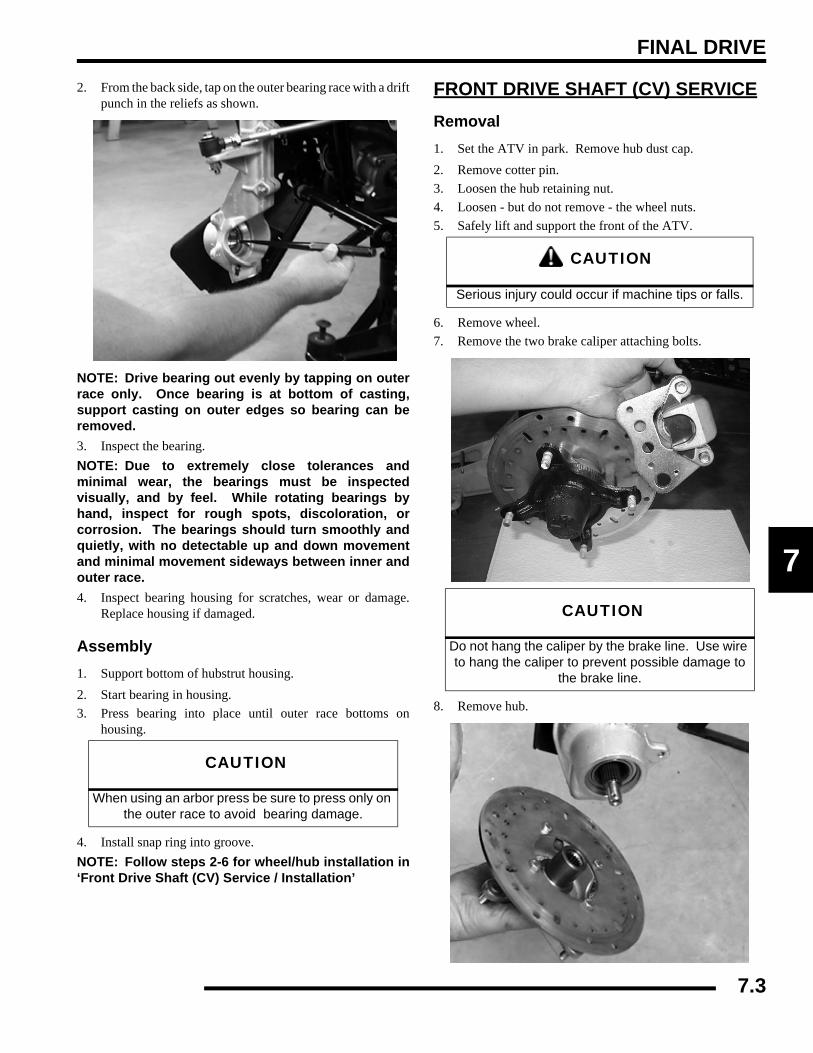
FINAL DRIVE
7
2. From the back side, tap on the outer bearing race with a driftpunch in the reliefs as shown.
NOTE: Drive bearing out evenly by tapping on outerrace only. Once bearing is at bottom of casting,support casting on outer edges so bearing can beremoved.3. Inspect the bearing.NOTE: Due to extremely close tolerances andminimal wear, the bearings must be inspectedvisually, and by feel. While rotating bearings byhand, inspect for rough spots, discoloration, orcorrosion. The bearings should turn smoothly andquietly, with no detectable up and down movementand minimal movement sideways between inner andouter race.4. Inspect bearing housing for scratches, wear or damage.
Replace housing if damaged.
Assembly1. Support bottom of hubstrut housing.2. Start bearing in housing.3. Press bearing into place until outer race bottoms on
housing.
4. Install snap ring into groove.NOTE: Follow steps 2-6 for wheel/hub installation in‘Front Drive Shaft (CV) Service / Installation’
FRONT DRIVE SHAFT (CV) SERVICERemoval1. Set the ATV in park. Remove hub dust cap.2. Remove cotter pin.3. Loosen the hub retaining nut.4. Loosen - but do not remove - the wheel nuts.5. Safely lift and support the front of the ATV.
6. Remove wheel.7. Remove the two brake caliper attaching bolts.
8. Remove hub.
CAUTION
When using an arbor press be sure to press only on the outer race to avoid bearing damage.
CAUTION
Serious injury could occur if machine tips or falls.
CAUTION
Do not hang the caliper by the brake line. Use wire to hang the caliper to prevent possible damage to
the brake line.
7.3

FINAL DRIVE
9. Remove cotter pin and nut from lower A-arm ball joint.Remove lower A-arm from ball joint.
10. Pull strut assembly out while pivoting front drive shaftdownward until it clears strut assembly.
11. Pull strut assembly out while pivoting front drive shaftdownward until it clears strut assembly.
Installation1. Install new compression ring on drive shaft. Apply an
anti-seize compound to splines. Align splines of driveshaft with front gearcase and install by lightly tapping ondrive shaft with rubber faced hammer.
2. Install drive shaft in strut.3. Install lower ball joint, torque nut to specification and
install new cotter pin.
4. Install hub and tighten hub nut to specification.
5. Install brake caliper and tighten bolts to specification. Referto Chapter 9.
6. Install wheel.
= T
Ball Joint Retaining Nut Torque:30 ft. lbs. (41 Nm)
= T
Front Hub Retaining Nut Torque:60 ft. lbs. (91 Nm)
7.4
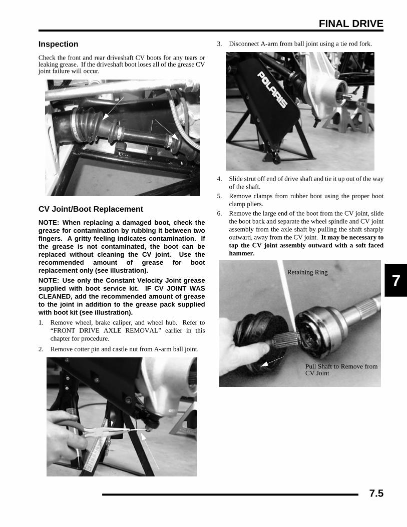
FINAL DRIVE
7
InspectionCheck the front and rear driveshaft CV boots for any tears orleaking grease. If the driveshaft boot loses all of the grease CVjoint failure will occur.
CV Joint/Boot ReplacementNOTE: When replacing a damaged boot, check thegrease for contamination by rubbing it between twofingers. A gritty feeling indicates contamination. Ifthe grease is not contaminated, the boot can bereplaced without cleaning the CV joint. Use therecommended amount of grease for bootreplacement only (see illustration).NOTE: Use only the Constant Velocity Joint greasesupplied with boot service kit. IF CV JOINT WASCLEANED, add the recommended amount of greaseto the joint in addition to the grease pack suppliedwith boot kit (see illustration).1. Remove wheel, brake caliper, and wheel hub. Refer to
“FRONT DRIVE AXLE REMOVAL” earlier in thischapter for procedure.
2. Remove cotter pin and castle nut from A-arm ball joint.
3. Disconnect A-arm from ball joint using a tie rod fork.
4. Slide strut off end of drive shaft and tie it up out of the wayof the shaft.
5. Remove clamps from rubber boot using the proper bootclamp pliers.
6. Remove the large end of the boot from the CV joint, slidethe boot back and separate the wheel spindle and CV jointassembly from the axle shaft by pulling the shaft sharplyoutward, away from the CV joint. It may be necessary totap the CV joint assembly outward with a soft facedhammer.
Retaining Ring
Pull Shaft to Remove fromCV Joint
7.5

FINAL DRIVE
7. Remove small clamp and boot from driveshaft.NOTE: If the ATV has been operated with a damagedboot, the CV joint grease may be contaminated.Inspect the grease carefully for contamination, andclean the joint thoroughly if necessary. Front driveaxle CV boot replacement requires 3.5 oz. of grease.
8. Before installing the new boot, remove all grease from theboot area and shaft.
NOTE: It is very important to use the correct typeand quantity of grease. Use only the greasecontained in the boot kit. DO NOT use a substitutegrease and DO NOT overfill or under fill the CV joint.9. Slide the new clamp and boot (small end first) over the
splined shaft, then slide (tap) the CV joint into the splinesof the axle.
10. Add grease through large end of boot.11. Install a new boot onto the axle shaft and fill the CV joint
and boot with the correct type and amount of grease.12. While pulling out on the CV shaft, fully extend the CV joint
and slide a straight O-ring pick or a small slotted screwdriver between the small end of the boot and the shaft. Thiswill allow the air pressure to equalize in the CV boot in theposition that the joint will spend most of its life. Before youremove your instrument, be sure the small end of the bootis in its correct location on the axle. CARE MUST BETAKEN TO AVOID DAMAGE TO THE NEWLYINSTALLED BOOT.
13. Install the small clamp on the boot.
CV Joint Grease -3.5 oz. (Refer to parts manual for boot kit)
CV Boot Clamp Pliers:Earless Type: (PN 8700226)
Boot replacement with complete CV joint cleaning requires the entire 3.5 oz. of grease.
Front Shaft
7.6

FINAL DRIVE
7
PROP SHAFT - FRONT OR REARRemoval and Installation1. Using Roll Pin Removal Tool (PN 2872608), remove the
roll pin from prop shaft at rear of housing (front only) ortransmission output shaft (rear only). Slide prop shaft backand away from housing, then pull sharply forward toremove from transmission shaft.
2. For installation, reverse the removal procedure.
NOTE: If removing rear propshaft, loosening and/orremoval of rear gearcase mounting bolts may berequired to gain necessary clearance for propshaftremoval.
see “REAR GEARCASE” on page 7.34
U-JOINTDisassembly
1. Remove internal or external snap ring from all bearingcaps.
NOTE: If yoke or bearing is removed, cross bearingmust be replaced. Note orientation of grease fitting(if equipped) and mark inner and outer yoke forcorrect re-positioning during installation.2. Support inner yoke as shown and drive outer yoke down
(bearing cap out) with a soft face hammer.
CAUTION
Always wear eye protection when working with spring-tensioned components
7.7

FINAL DRIVE
3. Support U-joint in vise as shown and drive inner yoke downto remove remaining bearing ca
4. Force U-joint cross to one side and lift out of inner yoke.
Assembly1. Install new bearing caps in yoke by hand. Carefully install
U-joint cross with grease fitting properly positionedinward toward center of shaft. Take care not to dislodgeneedle bearings upon installation of cross joint. Tightenvise to force bearing caps in.
2. Using a suitable arbor, fully seat bearing cap in one side.Continually check for free movement of bearing cross asbearing caps using a suitable arbor, fully seat bearing capin one side. Continually check for free movement ofbearing cross as bearing caps are assembled. are assembled.
3. Install snap ring to contain bearing cap just installed.Repeat procedure for other side.
7.8

FINAL DRIVE
7
4. Install snap ring to contain bearing cap just installed.Repeat procedure for other side.
5. Install snap ring to contain bearing cap just installed.Repeat procedure for other side.
6. Seat all bearing caps against snap rings by supporting crossshaft and tapping on each corner as shown.
7. When installation is complete, yokes must pivot freely inall directions without binding. If the joint is stiff or binding,tap the yoke lightly to center the joint until it pivots freelyin all directions.
7.9

FINAL DRIVE
DRIVE AXLE EXPLODED VIEWSDrive Shafts and PropshaftsNOTE: Refer to your parts manual for the proper replacement parts.
CompressionInner CV Joint
Inner BootOuter Boot Outer CV Joint
Drive Axle Components
Drive Boot Replacement Kits
Prop Shaft Components
Clamps
Outer Clamp
BootClamp 3.5 oz. grease
Propshaft Assy.
Cross & Bearing KitProp Shaft
O-Ring
Yoke, Prop to TransmissionYoke, Front Gearcase
Yoke, Rear Gearcase Prop ShaftYoke, Prop to Transmission
Ring
CompressionRing
CompressionRing
7.10

FINAL DRIVE
7
FRONT GEARCASE - CENTRALIZED HILLIARD W/ ACTIVE DESCENT CONTROL
OperationEngaging front gearcase: The AWD switch may be turned onor off while the vehicle is moving. AWD will not enable untilthe engine rpm is below 3100 RPM. Once enabled, the AWDremains engaged while the front gearcase is moving and will notdisengage until the rear wheels regain traction.
Engage the AWD switch before getting into conditions wherethe front wheel drive may be needed. If the rear wheels arespinning, release the throttle before switching to AWD.
With the AWD switch off the vehicle drives only the rear wheels(2 wheel drive). When the AWD switch is activated it engagesthe hilliard, locking both front axles into all wheel drive whenthere is a loss of rear wheel traction.
4x4 Engagement: When the AWD switch is activated, a 12Vdc current charges the central coil, creating a magnetic field.This magnetic field attracts an armature plate keyed to a rollercage that contains rollers and roller cam. The difference in rpmbetween the input shaft and front axles forces the rollers up theexternal cam. The rollers engage, or “wedge” themselvesbetween the pinion gear and output hubs that link both frontaxles, resulting in true all wheel drive.
Disengagement: As the front and rear wheels gain equaltraction, rotating very close to the same speed, the transmissionshaft “overdrives” the front gearcase input. The rollers areforced outward, disengaging the AWD. The vehicle is now backto rear wheel drive until the next loss of rear wheel traction.
CAUTION
Switching to AWD while the rear wheels are spinning may cause severe drive shaft and
gearcase damage. Always switch to AWD while the rear wheels have traction or are at rest.
Armature PlateRoll Cage Output Hubs
Ring Gear Magnetic Coil
CAUTION
If the rear wheels are spinning, release the throttle before turning the AWD switch on. If AWD is
engaged while the wheels are spinning, severe drive shaft and clutch damage could result.
Ring Gear
Rollers
Roll Cage
7.11
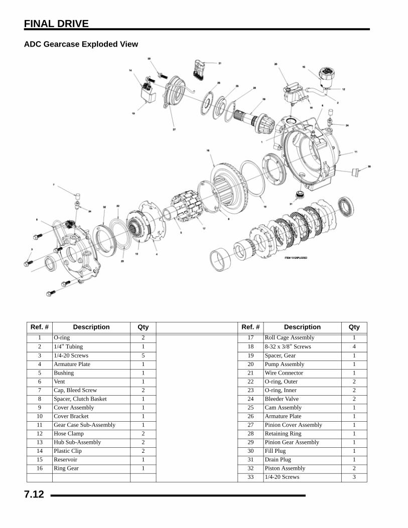
FINAL DRIVE
ADC Gearcase Exploded View
Ref. # Description Qty Ref. # Description Qty1 O-ring 2 17 Roll Cage Assembly 12 1/4" Tubing 1 18 8-32 x 3/8" Screws 43 1/4-20 Screws 5 19 Spacer, Gear 14 Armature Plate 1 20 Pump Assembly 15 Bushing 1 21 Wire Connector 16 Vent 1 22 O-ring, Outer 27 Cap, Bleed Screw 2 23 O-ring, Inner 28 Spacer, Clutch Basket 1 24 Bleeder Valve 29 Cover Assembly 1 25 Cam Assembly 1
10 Cover Bracket 1 26 Armature Plate 111 Gear Case Sub-Assembly 1 27 Pinion Cover Assembly 112 Hose Clamp 2 28 Retaining Ring 113 Hub Sub-Assembly 2 29 Pinion Gear Assembly 114 Plastic Clip 2 30 Fill Plug 115 Reservoir 1 31 Drain Plug 116 Ring Gear 1 32 Piston Assembly 2
33 1/4-20 Screws 3
7.12
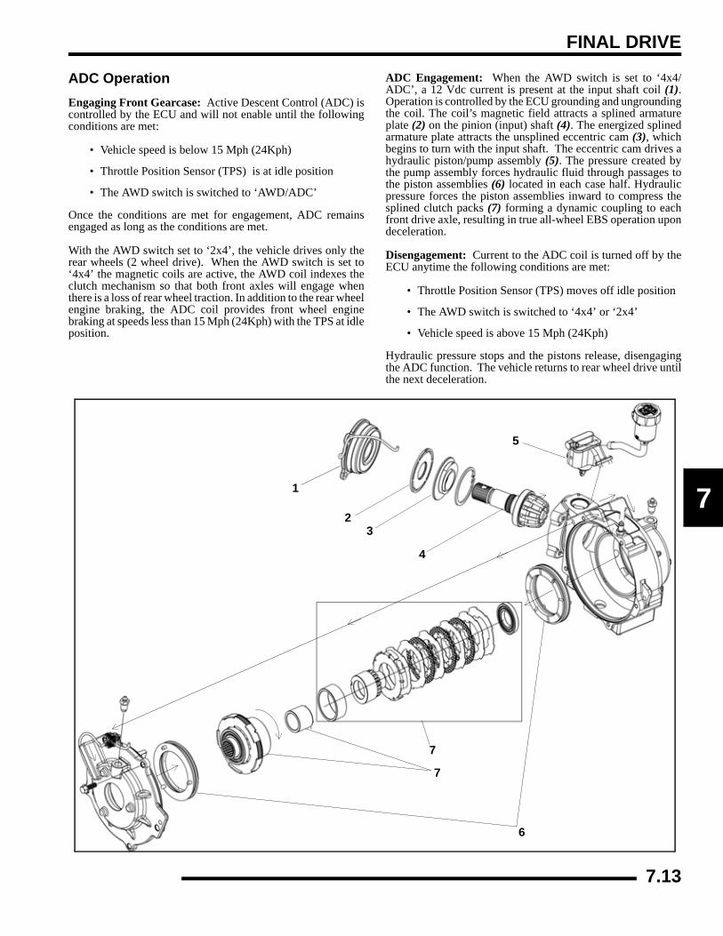
FINAL DRIVE
7
ADC OperationEngaging Front Gearcase: Active Descent Control (ADC) iscontrolled by the ECU and will not enable until the followingconditions are met:
• Vehicle speed is below 15 Mph (24Kph)
• Throttle Position Sensor (TPS) is at idle position
• The AWD switch is switched to ‘AWD/ADC’
Once the conditions are met for engagement, ADC remainsengaged as long as the conditions are met.
With the AWD switch set to ‘2x4’, the vehicle drives only therear wheels (2 wheel drive). When the AWD switch is set to‘4x4’ the magnetic coils are active, the AWD coil indexes theclutch mechanism so that both front axles will engage whenthere is a loss of rear wheel traction. In addition to the rear wheelengine braking, the ADC coil provides front wheel enginebraking at speeds less than 15 Mph (24Kph) with the TPS at idleposition.
ADC Engagement: When the AWD switch is set to ‘4x4/ADC’, a 12 Vdc current is present at the input shaft coil (1).Operation is controlled by the ECU grounding and ungroundingthe coil. The coil’s magnetic field attracts a splined armatureplate (2) on the pinion (input) shaft (4). The energized splinedarmature plate attracts the unsplined eccentric cam (3), whichbegins to turn with the input shaft. The eccentric cam drives ahydraulic piston/pump assembly (5). The pressure created bythe pump assembly forces hydraulic fluid through passages tothe piston assemblies (6) located in each case half. Hydraulicpressure forces the piston assemblies inward to compress thesplined clutch packs (7) forming a dynamic coupling to eachfront drive axle, resulting in true all-wheel EBS operation upondeceleration.
Disengagement: Current to the ADC coil is turned off by theECU anytime the following conditions are met:
• Throttle Position Sensor (TPS) moves off idle position
• The AWD switch is switched to ‘4x4’ or ‘2x4’
• Vehicle speed is above 15 Mph (24Kph)
Hydraulic pressure stops and the pistons release, disengagingthe ADC function. The vehicle returns to rear wheel drive untilthe next deceleration.
1
23
4
5
6
7
7
7.13

FINAL DRIVE
Front Gearcase Diagnosis
• Symptom: AWD Will Not Engage1. Check the gearcase coil resistance. To test the gearcase
coil resistance, use the coil harness (Grey & Brown/White).
NOTE: To test the gearcase coil resistance, use theAWD coil harness. The gearcase coil shouldmeasure between 22.8 ohms and 25.2 ohms.
2. Check the minimum battery voltage at the Grey & Brown/White wires that feed the hub coil wires. There should bea minimum of 11.80-12.0 Volts present for properoperation.
3. Inspect the armature plate for a consistent wear pattern.There should be two distinct wear bands (one band insidethe other). If only one band of wear is present (or if thereis wear between the two bands, inspect the coil area asindicated in Step 4. A band with an interrupted wear markmay indicate a warped plate, which may cause intermittentoperation.
4. Check to make sure the coil is seated in the U-shaped insertthat is pressed into the gearcase cover. The top of the coilshould be seated below the U-shaped insert. The U-shapedinsert controls the pole gap. If the top of the coil is abovethe surface of the U-shaped insert it raises the armatureplate, thereby increasing pole gap. If the pole gapincreases the coil will not be strong enough to engage theAWD system. If this is the cause order a new Cover PlateAssembly.
Front Gearcase Coil Resistance: 24 Ω ±10%
AWD Coil Applied Battery Voltage:11.80-12.0 Vdc
Armature Plate
Check for Wear Bands
U-Shaped Insert
Coil
Cutaway View of Gearcase Cover
7.14

FINAL DRIVE
7
5. Inspect the rollers for nicks, scratches, and flat spots. Alsoinspect the roll cage for cracks and ensure the rollers areable to slide up and down and in and out freely within theroll cage sliding surfaces.
Gearcase Removal1. Stop engine, place machine in Park and set parking brake.
2. Loosen left front wheel nuts slightly.
3. Elevate the machine until the front wheels are off theground and support machine under footrest/frame area.
4. Remove left wheel nuts and wheel.5. Remove cotter pin, lower ball joint nut and A-arm from
ball joint.
6. Pull the hub and strut assembly out and pull the drive-shaftout of the hub.
Rollers
CAUTION
Serious injury may result if machine tips or falls. Be sure machine is secure before beginning this
service procedure. Wear eye protection when removing and installing bearings and seals.
7.15
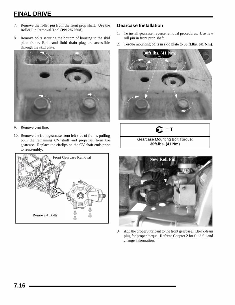
FINAL DRIVE
7. Remove the roller pin from the front prop shaft. Use theRoller Pin Removal Tool (PN 2872608).
8. Remove bolts securing the bottom of housing to the skidplate frame. Bolts and fluid drain plug are accessiblethrough the skid plate.
9. Remove vent line.
10. Remove the front gearcase from left side of frame, pullingboth the remaining CV shaft and propshaft from thegearcase. Replace the circlips on the CV shaft ends priorto reassembly.
Gearcase Installation1. To install gearcase, reverse removal procedures. Use new
roll pin in front prop shaft.2. Torque mounting bolts in skid plate to 30 ft.lbs. (41 Nm).
3. Add the proper lubricant to the front gearcase. Check drainplug for proper torque. Refer to Chapter 2 for fluid fill andchange information.
Front Gearcase Removal
Remove 4 Bolts
= T
Gearcase Mounting Bolt Torque:30ft.lbs. (41 Nm)
30ft.lbs. (41 Nm)
New Roll Pin
7.16

FINAL DRIVE
7
Coil TestingRefer to the following tests in Chapter 10:
see “ACTIVE DESCENT CONTROL (ADC) COIL” onpage 10.15
see “ALL WHEEL DRIVE (AWD) COIL” on page 10.15
ADC Differential Hydraulic Circuit Bleeding1. Make sure vehicle is parked on flat ground and allowed to
sit at least 30 minutes prior to bleeding hydraulic circuit.2. Thoroughly clean area around and on remote reservoir and
hydraulic bleeders.3. Remove reservoir cap and diaphragm assembly.4. Make sure hydraulic oil inside reservoir is free of debris.
If any debris is found, use clean rag or suction device toremove from the reservoir.
NOTE: Debris in reservoir may block porting andproduce inadequate bleeding of the system.Decreased performance may be encountered withinadequate bleed of the hydraulic circuit.5. Begin the bleeding process by filling reservoir to ‘MAX’
line with clean Polaris ADC oil.6. Locate bleeder valves found on either side of differential
and remove the protective caps.7. Turn bleeder valves counter-clockwise to loosen. Loosen
bleeder screw slowly, allowing oil and any trapped air toflow out of fitting.
IMPORTANT: Do not allow hydraulic fluid in reservoirto drain below minimum fill line. Close bleeder valvebefore oil level falls below minimum fill line. Refillingempty reservoir will result in air pockets becomingtrapped.
NOTE: If empty reservoir is encountered, filling offluid is still possible. Verify air is not trapped beforeproceeding with step 7.8. Continue steps 6-8 on both sides in sequence until no air
bubbles are seen when bleeding occurs. 9. Re-torque both bleeder valves to specification and reinstall
cover caps.
10. Fill reservoir with to a level midway between ‘MAX’ and‘MIN’ fill lines. Verify no debris is found in reservoir oil.
11. Replace reservoir cap securely and wipe clean any residue.
Disassembly / InspectionNOTE: see “Gearcase Removal” on page 7.151. Drain and properly dispose of used oil. Remove any metal
particles from the drain plug magnet.2. Remove the piston pump assembly from the gearcase.
NOTE: Piston pump assembly is a non-serviceableitem and should not be disassembled. Replace as anassembly if found to be damaged or non-working.3. Remove bolts (arrows) retaining the outer cover plate
assembly.
= T
Bleeder Valve Torque:80 in. lbs. (9 Nm)
7.17

FINAL DRIVE
4. Remove the outer cover plate assembly. Remove andinspect the cover o-ring (1). Inspect thrust bearing (2) forwear. Replace items as required.
NOTE: Thrust bearing (2) located between the twooutput assemblies is pressed into the clutch packand is not removable.5. Remove the output clutch assemblies. Inspect the bearings,
contact surfaces and splines of the output clutch for signsof wear or damage. Visually inspect the clutch plate area.If plates are steel-on-steel, or if the friction material is worn,the assembly should be replaced.
NOTE: Excessive debris in the oil and/or noisecoming from the front drive on deceleration are keyindicators of clutch pack failure. Replace clutch asan assembly if found to be worn or damaged. NOTE: Locating pins / holes (circle) aid installation.Note for reassembly.
6. Remove the armature plate. Inspect the armature plate forwear, distortion or other damage. Replace component asrequired.
7. Remove the spacer. Inspect for signs of wear or damage.Replace component as required.
NOTE: locating pins (arrow) are for spacerinstallation. Note for reassembly.
2
1
7.18
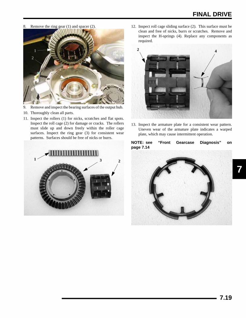
FINAL DRIVE
7
8. Remove the ring gear (1) and spacer (2).
9. Remove and inspect the bearing surfaces of the output hub. 10. Thoroughly clean all parts.11. Inspect the rollers (1) for nicks, scratches and flat spots.
Inspect the roll cage (2) for damage or cracks. The rollersmust slide up and down freely within the roller cagesurfaces. Inspect the ring gear (3) for consistent wearpatterns. Surfaces should be free of nicks or burrs.
12. Inspect roll cage sliding surface (2). This surface must beclean and free of nicks, burrs or scratches. Remove andinspect the H-springs (4). Replace any components asrequired.
13. Inspect the armature plate for a consistent wear pattern.Uneven wear of the armature plate indicates a warpedplate, which may cause intermittent operation.
NOTE: see “Front Gearcase Diagnosis” onpage 7.14
1
2
3 21
2 4
7.19

FINAL DRIVE
14. Inspect the magnetic coil (1) in the outer cover plateassembly. Inspect the backlash pad (2) for excessive wear.
NOTE: See “FRONT GEARCASE DIAGNOSIS” in thischapter.NOTE: Ring gear backlash (2) is set at the factory.No adjustment is required, unless the front cover isreplaced or the back lash pad screw is removed.See the “FRONT GEARCASE ASSEMBLY” in thischapter for details on backlash setting.
15. Remove the bolts retaining the input shaft cover and piniongear assembly.
16. Inspect the magnetic coil (1) and bushing in the input coverplate assembly. Replace the input cover seal.
17. Remove the splined armature plate (1).
18. Remove the eccentric cam assembly. Inspect the cam (1)and bushing (2) for wear or damage. Replace componentas required.
1 2
1
1
1
2
7.20

FINAL DRIVE
7
19. Remove the snap ring retaining the input shaft assembly.
20. Remove the input shaft assembly. Inspect the pinion gear(1) for chipped, broken, or missing teeth. Inspect the inputshaft bearing (2) for signs of wear. Replace the input shaftcover O-ring (3) prior to reassembly.
21. Inspect the input shaft bushing. Replace case if worn.
ADC Gearcase Piston Replacement Procedure
1. Place ADC Piston Tool PA-48542 on top of the piston.Using moderate hand pressure, hold the tool on top of thepiston while using compressed air at the gearcase passage(circled) to force piston up and out of the case. (See photo)
2. Repeat procedure for the other piston. (See photo)
3. Remove and discard the inner and outer o-rings from thepiston assembly.
NOTE: Never re-use o-rings. Always replace withnew.
12
3
CAUTION
This repair procedure involves the use of compressed air. Safety glasses
or a face shield are required.
AIR
ADC Piston Tool PA-48542
PA-48542AIR
7.21

FINAL DRIVE
4. Coat new piston and o-rings with a moderate amount ofwhite lithium grease or assembly lube. Coat the edges of thepiston cavities. Install the inner and outer piston o-rings.
5. Place the piston in the piston cavity, aligning the pins withthe pin bosses. Using the casting and piston marks as aguide as shown will aid pin alignment.
6. Place ADC Piston Tool PA-48542 on top of the piston andverify alignment of the sight hole (circled) and piston markwith the casting marks. Support the case and press thepiston down evenly. The piston is fully seated and locatedin the pin bosses when the piston surface is just below thecavity edge.
7. Repeat procedure for the other gearcase half.NOTE: Verify that the o-rings are seated properlyand that no o-ring shavings exist outside of thepiston area, which is an indication of damage duringinstallation.
Inner
Outer
Tool PA-48542
7.22

FINAL DRIVE
7
Assembly1. Thoroughly clean the gearcase components before
beginning reassembly. 2. Install a new seal in the main gearcase halve.
3. Install the input shaft assembly. Install the pinion gear/bearing assembly (1). Install a new seal and o-ring theinput shaft cover (2) prior to reassembly.
4. Install the snap ring retaining the input shaft assembly.
5. Install the eccentric cam assembly (1).
6. Install the splined armature plate (1).
7. Install the input shaft cover assembly, bolts and bracket.Torque to specification.
12
= T
Input Cover Bolt Torque:7-11 ft. lbs. (9.4-14.9 Nm)
1
1
7.23
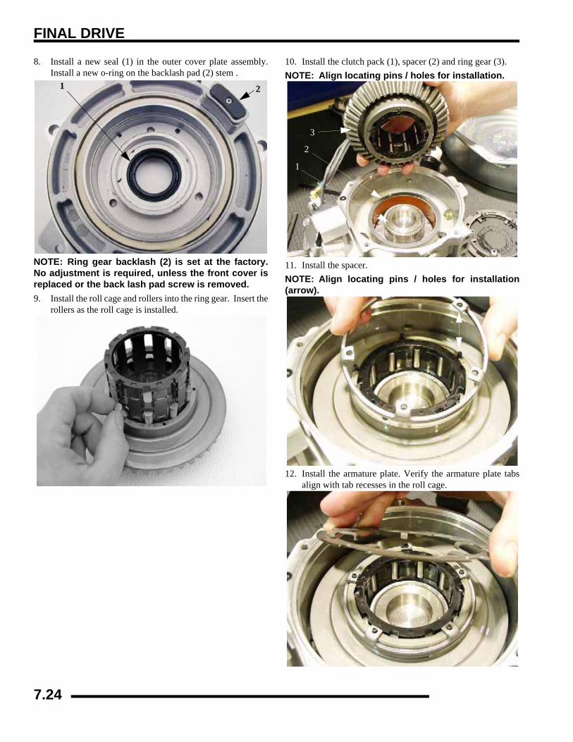
FINAL DRIVE
8. Install a new seal (1) in the outer cover plate assembly.Install a new o-ring on the backlash pad (2) stem .
NOTE: Ring gear backlash (2) is set at the factory.No adjustment is required, unless the front cover isreplaced or the back lash pad screw is removed.9. Install the roll cage and rollers into the ring gear. Insert the
rollers as the roll cage is installed.
10. Install the clutch pack (1), spacer (2) and ring gear (3).NOTE: Align locating pins / holes for installation.
11. Install the spacer.NOTE: Align locating pins / holes for installation(arrow).
12. Install the armature plate. Verify the armature plate tabsalign with tab recesses in the roll cage.
1 2
3
2
1
7.24

FINAL DRIVE
7
13. Install new cover o-ring (1) on the cover plate assemblyand a new passage o-ring (2) on the gear case.
14. Install the remaining output clutch assembly. NOTE: Align locating pins / holes for installation.
15. Place cover assembly on Install bolts (arrows) retaining theouter cover plate assembly and torque to specification.
16. Install a new passage o-ring (dotted circle) on the gearcaseand install the piston pump assembly. Torque the screws tospecification.
NOTE: see “Gearcase Installation” on page 7.16
1
2
= T
Input Cover Bolt Torque:7-11 ft. lbs. (9.4-14.9 Nm)
= T
Pump Assembly Screw Torque:17-23 in. lbs. (1.9-2.5 Nm)
7.25

FINAL DRIVE
Setting Ring Gear BacklashNOTE: Ring gear backlash is set at the factory. Noadjustment is required, unless the front cover isreplaced or the back lash pad screw is removed. 1. The backlash screw has locking agent that holds it into
place. Use a heat gun to lightly heat up the locking agenton the screw.
2. Using a 3/32 hex wrench, turn the back-lash screw out 3-4turns. Re-apply Loctite 262™ onto the bottom screwthreads.
3. Turn the screw in until it is lightly seated, then turn thescrew out 1/4 turn.
4. Set the gearcase upright. Rotate the input shaft at least 4times. This ensures the ring gear completes one fullrotation.
5. If a tight spot is felt during rotation, loosen the backlashscrew another 1/8 turn. Perform the step 16 again. Repeatthis procedure until the pinion shaft rotates smoothly 4times (1 revolution of ring gear).
7.26

FINAL DRIVE
7
REAR HUBRemoval1. Place the ATV in Park and lock the parking brake.
Remove rear hub cap.
2. Remove cotter pin (A).3. Loosen the hub retaining nut (B).4. Loosen the wheel nuts (C).5. Safely support the rear of the ATV.6. Remove wheel nuts and wheel.7. Remove the rear brake caliper and safely suspend the
caliper from the frame with a piece of wire.
8. Remove hub nut, domed washer and flat washer.
9. Remove hub.
10. Remove upper control arm bolt as shown.
A
B C
7.27
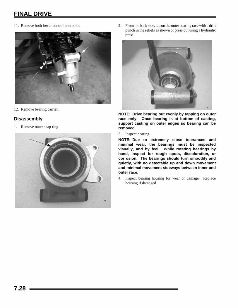
FINAL DRIVE
11. Remove both lower control arm bolts.
12. Remove bearing carrier.
Disassembly1. Remove outer snap ring.
2. From the back side, tap on the outer bearing race with a driftpunch in the reliefs as shown or press out using a hydraulicpress.
NOTE: Drive bearing out evenly by tapping on outerrace only. Once bearing is at bottom of casting,support casting on outer edges so bearing can beremoved.3. Inspect bearing.NOTE: Due to extremely close tolerances andminimal wear, the bearings must be inspectedvisually, and by feel. While rotating bearings byhand, inspect for rough spots, discoloration, orcorrosion. The bearings should turn smoothly andquietly, with no detectable up and down movementand minimal movement sideways between inner andouter race.4. Inspect bearing housing for wear or damage. Replace
housing if damaged.
7.28
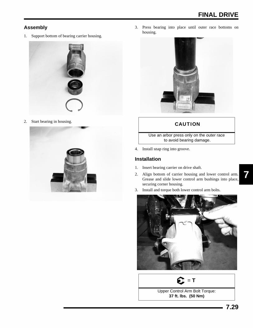
FINAL DRIVE
7
Assembly1. Support bottom of bearing carrier housing.
2. Start bearing in housing.
3. Press bearing into place until outer race bottoms onhousing.
4. Install snap ring into groove.
Installation1. Insert bearing carrier on drive shaft.2. Align bottom of carrier housing and lower control arm.
Grease and slide lower control arm bushings into place,securing corner housing.
3. Install and torque both lower control arm bolts.
CAUTION
Use an arbor press only on the outer race to avoid bearing damage.
= T
Upper Control Arm Bolt Torque: 37 ft. lbs. (50 Nm)
7.29

FINAL DRIVE
4. Lift bearing carrier until top aligns with upper control arm.Install and torque upper control arm bolt and torque tospecification.
5. Pull drive shaft outward and install hub onto driveshaftsplines.
6. Install cone washers with domed side facing outward.7. Install retainer nut, wheel and wheel nuts.8. Remove jackstand and torque axle nut and wheel nuts to
specification.
9. Install a new cotter pin. Tighten nut slightly to align holesif required.
REAR DRIVE (CV) SHAFTRemoval1. Remove rear hub, see “REAR HUB REMOVAL”.2. Remove upper carrier bolt. Tip hub outward and remove
shaft from carrier.
3. Pull sharply outward to remove shaft from transmission.Install a new compression ring upon assembly.
= T
Lower Control Arm Bolt Torque: 37 ft. lbs. (50 Nm)
= T
Wheel Nut Torque: see “Torque Table” on page 7.2
= T
Rear Hub Nut Torque: 80 ft. lbs. (109 Nm)
Pull outward sharply to removefrom transmission
Compression Ring
7.30

FINAL DRIVE
7
ServiceNOTE: The following procedure applies to BOTHinner and outer CV joints.1. Remove clamps from rubber boot(s) using a CV Boot
Clamp Pliers (A) and slide back boot.
2. Tap CV housing off shaft with a soft-faced hammer.
3. Place a new compression ring in the groove of the CV shaft.
4. Refit CV joint on interconnecting shaft by tapping with asoft-faced hammer on the joint housing. Take care not todamage threads on the outboard CV joint. The joint is fullyassembled when the compression ring is seated in thegroove on the CV joint.
5. Remove excess grease from the CV joint's external surfacesand position the large boot joint over the CV housing,making sure boot is seated in groove. Position clamp overboot end and make sure clamp tabs are located in slots.
6. Install and tighten large boot clamp with boot clamp pliers.7. Remove excess grease from the CV shaft’s external
surfaces and position the small boot joint over the CV shaft,making sure boot is seated in the shaft groove. Whilepulling out on the CV shaft, fully extend the CV joint andslide a straight O-ring pick or a small slotted screw driverbetween the small end of the boot and the shaft. This willallow the air pressure to equalize in the CV boot in theposition that the joint will spend most of its life. Positionthe small clamp over boot end and make sure clamp tabsare located in slots.
NOTE: Release any air pressure which may havebuilt up inside the boot has been released. The airshould be released after the joint has been centeredproperly. 8. Tighten small boot clamp using boot clamp pliers.
A
Tap CV housing off shaft
Tap joint onto shaft
7.31

FINAL DRIVE
CV Boot Replacement1. Remove CV joint from end of shaft.2. Remove boot from shaft.NOTE: When replacing a damaged boot, check thegrease for contamination by rubbing it between twofingers. A gritty feeling indicates contamination. Ifthe grease is not contaminated, the boot can bereplaced without cleaning the CV joint. Use therecommended amount of grease for bootreplacement only (see illustration). Proceed to step#5.NOTE: Use only the Constant Velocity Joint greasesupplied with boot service kit. IF CV JOINT WASCLEANED, add the recommended amount of greaseto the joint in addition to the grease pack suppliedwith boot kit.3. Thoroughly clean and dry the CV joint and inspect ball
tracks and cages for wear, cracks or other damage.NOTE: Shiny areas in ball tracks and on the cagespheres are normal. Do not replace CV jointsbecause parts have polished surfaces. Replace CVjoint only if components are cracked, broken, wornor otherwise unserviceable.
4. Add the recommended amount of grease for CV jointcleaning to the joint. Be sure grease penetrates all parts ofthe joint.
5. Slide a new CV boot onto the shaft. Do not install the bootclamps at this time.
6. Refit CV joint on the interconnecting shaft by tapping witha soft-faced hammer on the joint housing. Take care not todamage threads on the outboard CV joint. The joint is fullyassembled when the compression ring is seated in thegroove on the CV joint.
7. Add remaining grease through large end of boot.
8. Remove excess grease from the CV joint's external surfacesand position the large boot joint over the CV housing,making sure boot is seated in groove. Position clamp overboot end and make sure clamp tabs are located in slots.
9. Install and tighten large boot clamp with boot clamp pliers.10. Remove excess grease from the CV shaft’s external
surfaces and position the small boot joint over the CV shaft,making sure boot is seated in the shaft groove. Whilepulling out on the CV shaft, fully extend the CV joint andslide a straight O-ring pick or a small slotted screw driverbetween the small end of the boot and the shaft. This willallow the air pressure to equalize in the CV boot in theposition that the joint will spend most of its life. Positionthe small clamp over boot end and make sure clamp tabsare located in slots.
11. Install the small clamp on the boot.NOTE: CV Joint Grease Capacity:
Outboard Joint - 30g if boot is replaced only. Another 50g (80total) if joint is cleaned.
Inboard Joint - 50g if boot is replaced only. Another 50g (100total) if joint is cleaned.
CV Joint Grease: 30g PN 1350046 50g PN 1350047
Joint Capacity -50 grams
Boot Capacity -30 Grams
Outboard - 80g Total
Joint Capacity - 50grams
Boot Capacity - 50grams
Inboard - 100g Total
7.32
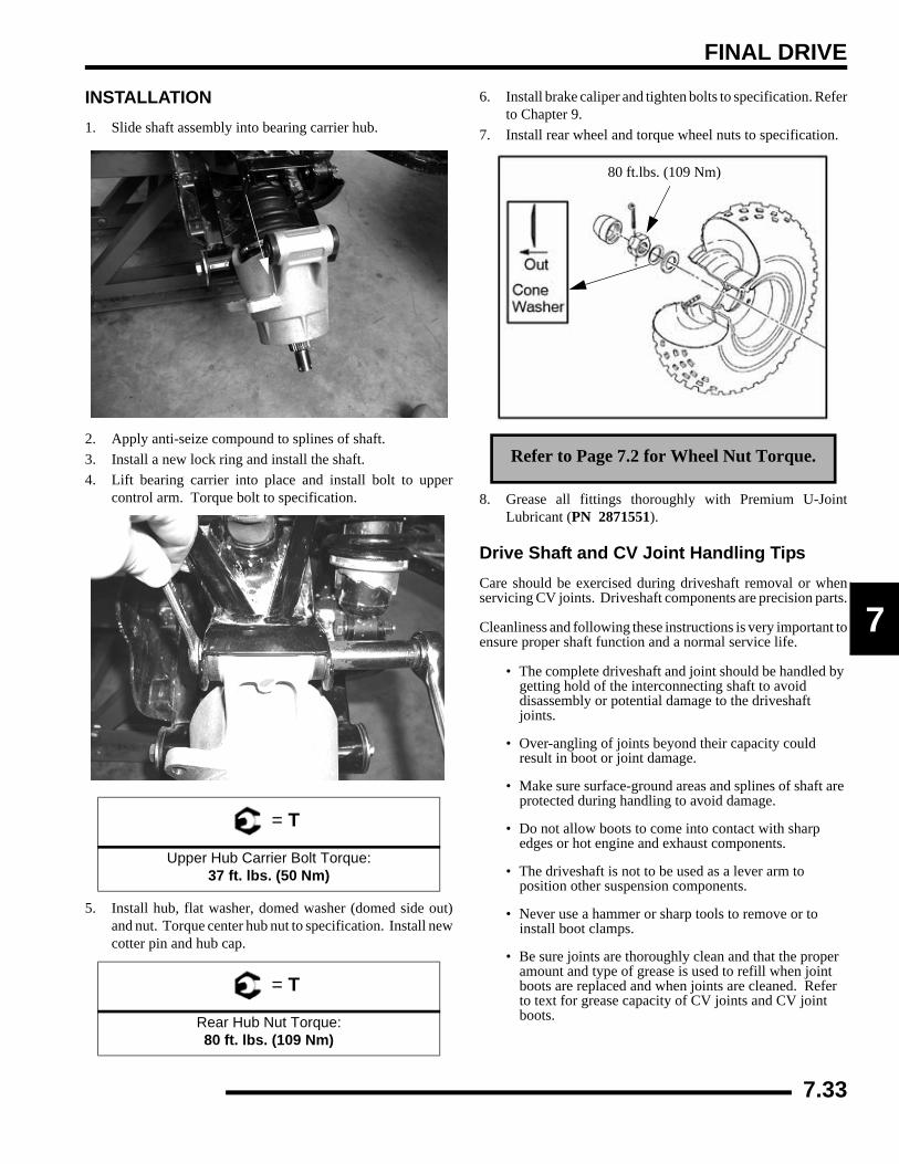
FINAL DRIVE
7
INSTALLATION1. Slide shaft assembly into bearing carrier hub.
2. Apply anti-seize compound to splines of shaft.3. Install a new lock ring and install the shaft.4. Lift bearing carrier into place and install bolt to upper
control arm. Torque bolt to specification.
5. Install hub, flat washer, domed washer (domed side out)and nut. Torque center hub nut to specification. Install newcotter pin and hub cap.
6. Install brake caliper and tighten bolts to specification. Referto Chapter 9.
7. Install rear wheel and torque wheel nuts to specification.
8. Grease all fittings thoroughly with Premium U-JointLubricant (PN 2871551).
Drive Shaft and CV Joint Handling TipsCare should be exercised during driveshaft removal or whenservicing CV joints. Driveshaft components are precision parts.
Cleanliness and following these instructions is very important toensure proper shaft function and a normal service life.
• The complete driveshaft and joint should be handled by getting hold of the interconnecting shaft to avoid disassembly or potential damage to the driveshaft joints.
• Over-angling of joints beyond their capacity could result in boot or joint damage.
• Make sure surface-ground areas and splines of shaft are protected during handling to avoid damage.
• Do not allow boots to come into contact with sharp edges or hot engine and exhaust components.
• The driveshaft is not to be used as a lever arm to position other suspension components.
• Never use a hammer or sharp tools to remove or to install boot clamps.
• Be sure joints are thoroughly clean and that the proper amount and type of grease is used to refill when joint boots are replaced and when joints are cleaned. Refer to text for grease capacity of CV joints and CV joint boots.
= T
Upper Hub Carrier Bolt Torque:37 ft. lbs. (50 Nm)
= T
Rear Hub Nut Torque:80 ft. lbs. (109 Nm)
Refer to Page 7.2 for Wheel Nut Torque.
80 ft.lbs. (109 Nm)
7.33

FINAL DRIVE
REAR GEARCASERemoval1. Place ATV on a level surface and place transmission in
‘PARK’.2. Loosen both rear wheel nuts.3. Loosen both rear center hub nuts.4. Lift and safely support rear of ATV so that the rear wheels
are off the ground.5. Remove the roll pin from the rear transmission yoke and
pull vent line off the gearcase.6. Remove both rear wheels and center hub nuts. NOTE: Hub removal is not required to remove CVshafts.7. Remove both upper hub carrier bolts. Tilt hubs outward and
remove both CV shafts.8. Remove the upper and lower bolts from the gearcase
mounts.9. Pull gearcase out the rear of the vehicle. Some prying and
tapping with a soft-face hammer may be required. Use carenot to damage other components.
Disassembly and Inspection1. Drain and properly dispose of used oil.2. Remove the gearcase housing cover bolts and the gearcase
housing cover.
3. Remove the shim, thrust button, and thrust button shimfrom the gearcase.
4. Remove rear bevel gear from the gearcase housing. cover.
Thrust Button
Shims
7.34

FINAL DRIVE
7
5. Inspect the ring gear for abnormal wear, broken, or chippedteeth. Spin the bearing to check the ball bearings forsmoothness. Replace the bearing if needed.
6. Remove the input shaft cover and the pinion shaft from thegearcase housing. See next page.
7. Inspect the ring gear for abnormal wear, broken, or chippedteeth. Spin the bearing to check the ball bearings forsmoothness. Replace the bearing if needed.
Reassembly1. Inspect the pinion shaft bushing for wear.
2. Replace all O-rings, seals, and worn components.
3. Install the pinion shaft into the gearcase housing. Install thepinion shaft cover and torque the cover bolts tospecification.
7.35
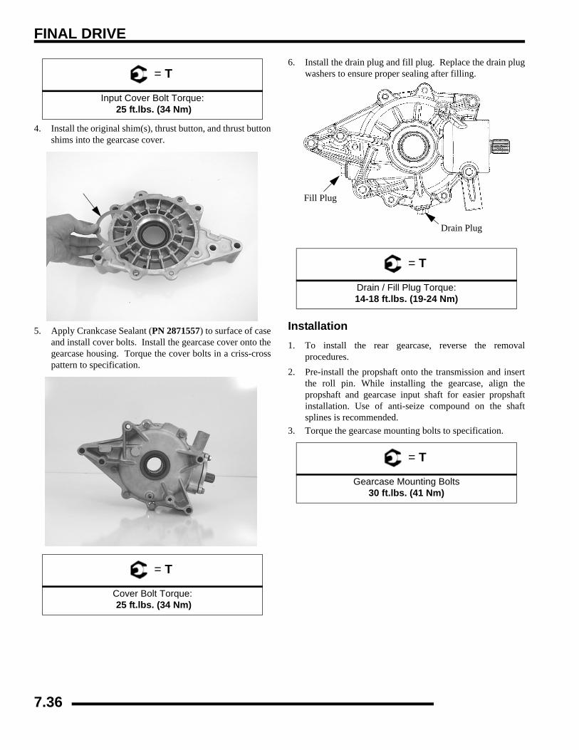
FINAL DRIVE
4. Install the original shim(s), thrust button, and thrust buttonshims into the gearcase cover.
5. Apply Crankcase Sealant (PN 2871557) to surface of caseand install cover bolts. Install the gearcase cover onto thegearcase housing. Torque the cover bolts in a criss-crosspattern to specification.
6. Install the drain plug and fill plug. Replace the drain plugwashers to ensure proper sealing after filling.
Installation1. To install the rear gearcase, reverse the removal
procedures.2. Pre-install the propshaft onto the transmission and insert
the roll pin. While installing the gearcase, align thepropshaft and gearcase input shaft for easier propshaftinstallation. Use of anti-seize compound on the shaftsplines is recommended.
3. Torque the gearcase mounting bolts to specification.
= T
Input Cover Bolt Torque: 25 ft.lbs. (34 Nm)
= T
Cover Bolt Torque: 25 ft.lbs. (34 Nm)
= T
Drain / Fill Plug Torque:14-18 ft.lbs. (19-24 Nm)
= T
Gearcase Mounting Bolts30 ft.lbs. (41 Nm)
Fill Plug
Drain Plug
7.36

FINAL DRIVE
7
4. Re-install CV shafts, hubs, carrier bolts, etc. and torque tospecifications.
5. Re-install gearcase vent line.6. Refill the rear gearcase with Polaris Premium Gearcase
Lubricant (PN 2871653). Refer to the “REARGEARCASE LUBRICATION” procedure in Chapter 2.
= T
Lower Control Arm Bolt Torque: 37 ft. lbs. (50 Nm)
= T
Upper Control Arm Bolt Torque: 37 ft. lbs. (50 Nm)
= T
Rear Hub Nut Torque: 80 ft. lbs. (109 Nm)
= T
Wheel Nut Torque: see “Torque Table” on page 7.2
7.37

FINAL DRIVE
Rear Gearcase Exploded View
7.38
TRANSMISSION
CHAPTER 8TRANSMISSION
8
SPORTSMAN. . . . . . . . . . . . . . . . . . . . . . . . . . . . . . . . . . . . . . . . . . . . . . . . 8.3-8.18
SPORTSMAN X2 . . . . . . . . . . . . . . . . . . . . . . . . . . . . . . . . . . . . . . . . . . . . 8.19-8.38
8.1

TRANSMISSION
NOTES
8.2
SPORTSMAN TRANSMISSION
CHAPTER 8SPORTSMAN TRANSMISSION
8
TRANSMISSION EXPLODED VIEW. . . . . . . . . . . . . . . . . . . . . . . . . . . . . . . . . . . . . . . . . 8.4SPORTSMAN TRANSMISSION. . . . . . . . . . . . . . . . . . . . . . . . . . . . . . . . . . . . . . . . . . . . 8.4
SPECIFICIATONS. . . . . . . . . . . . . . . . . . . . . . . . . . . . . . . . . . . . . . . . . . . . . . . . . . . . . . . 8.6TORQUE SPECIFICATIONS . . . . . . . . . . . . . . . . . . . . . . . . . . . . . . . . . . . . . . . . . . . . . . 8.6LUBRICANT / CAPACITY. . . . . . . . . . . . . . . . . . . . . . . . . . . . . . . . . . . . . . . . . . . . . . . . . 8.6
TRANSMISSION SERVICE. . . . . . . . . . . . . . . . . . . . . . . . . . . . . . . . . . . . . . . . . . . . . . . . 8.6TRANSMISSION REMOVAL . . . . . . . . . . . . . . . . . . . . . . . . . . . . . . . . . . . . . . . . . . . . . . 8.6DISASSEMBLY. . . . . . . . . . . . . . . . . . . . . . . . . . . . . . . . . . . . . . . . . . . . . . . . . . . . . . . . . 8.7ASSEMBLY . . . . . . . . . . . . . . . . . . . . . . . . . . . . . . . . . . . . . . . . . . . . . . . . . . . . . . . . . . 8.12TRANSMISSION INSTALLATION . . . . . . . . . . . . . . . . . . . . . . . . . . . . . . . . . . . . . . . . . 8.17TROUBLESHOOTING . . . . . . . . . . . . . . . . . . . . . . . . . . . . . . . . . . . . . . . . . . . . . . . . . . 8.18
8.3
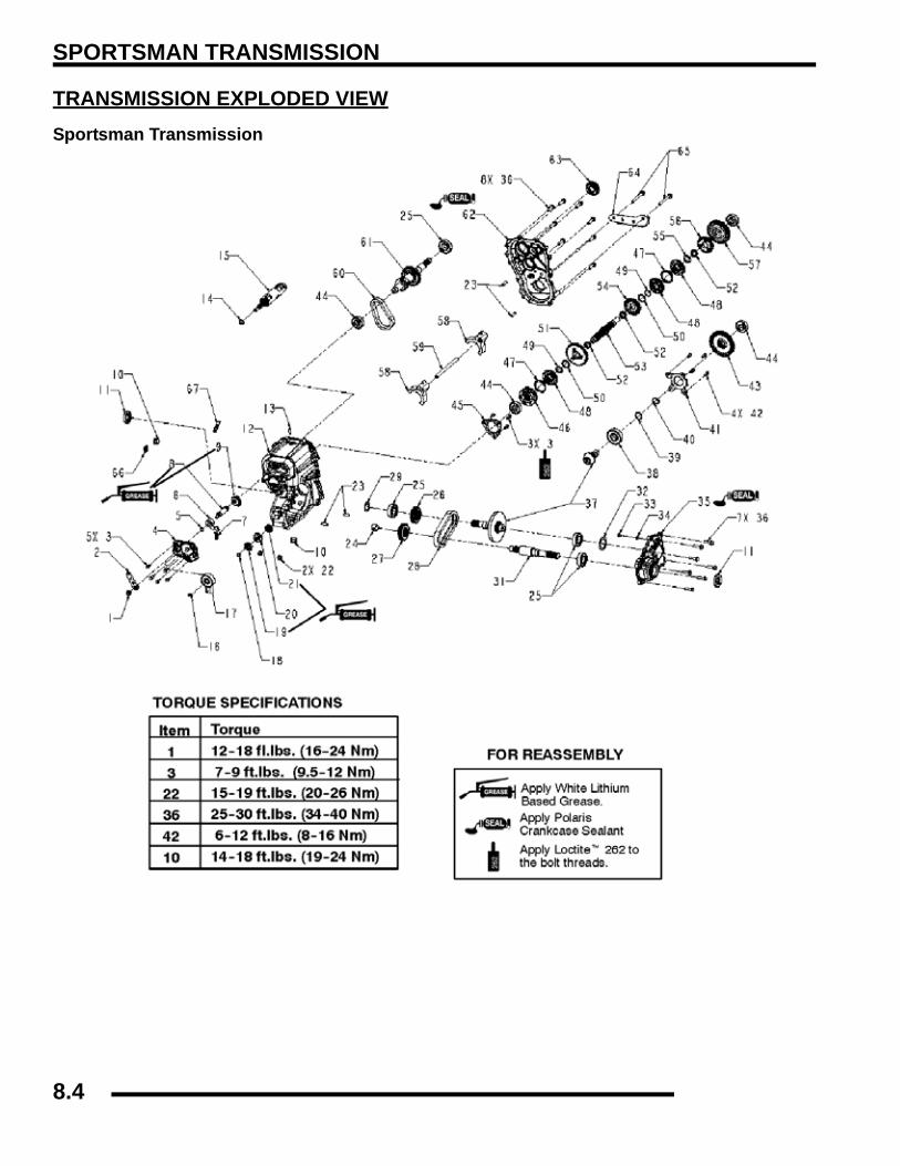
SPORTSMAN TRANSMISSION
TRANSMISSION EXPLODED VIEWSportsman Transmission
8.4
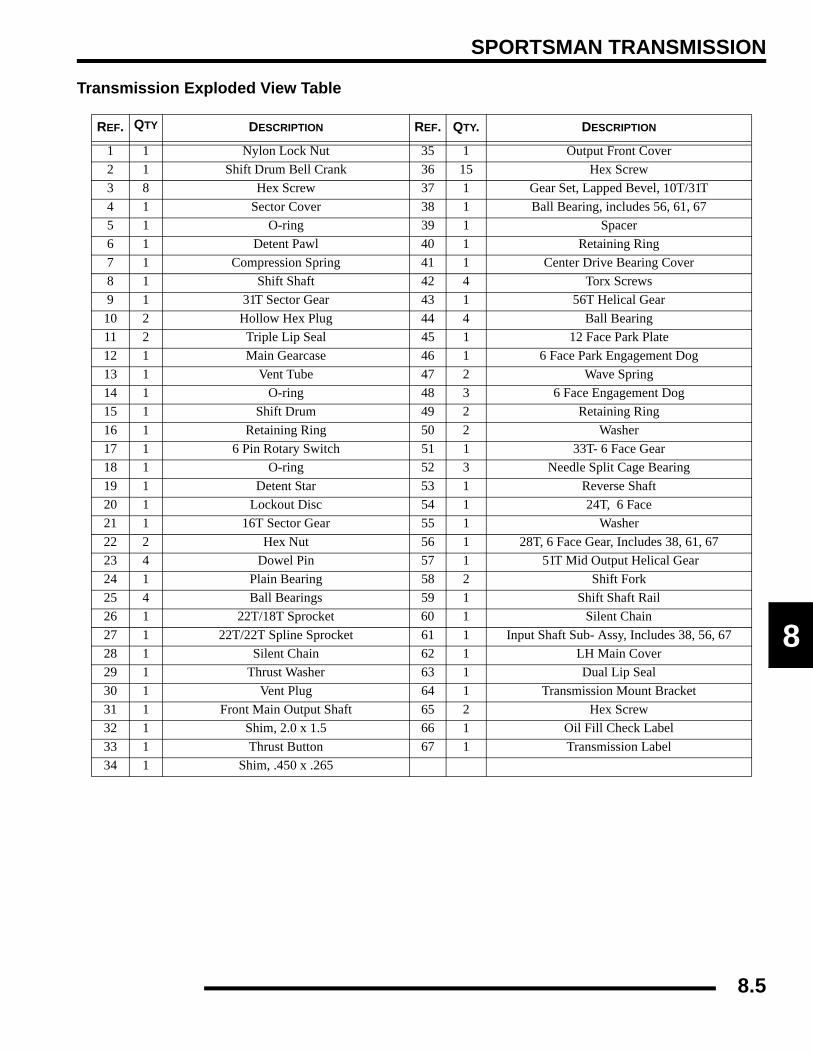
SPORTSMAN TRANSMISSION
8
Transmission Exploded View Table
REF. QTY DESCRIPTION REF. QTY. DESCRIPTION
1 1 Nylon Lock Nut 35 1 Output Front Cover2 1 Shift Drum Bell Crank 36 15 Hex Screw3 8 Hex Screw 37 1 Gear Set, Lapped Bevel, 10T/31T4 1 Sector Cover 38 1 Ball Bearing, includes 56, 61, 675 1 O-ring 39 1 Spacer6 1 Detent Pawl 40 1 Retaining Ring7 1 Compression Spring 41 1 Center Drive Bearing Cover8 1 Shift Shaft 42 4 Torx Screws9 1 31T Sector Gear 43 1 56T Helical Gear10 2 Hollow Hex Plug 44 4 Ball Bearing11 2 Triple Lip Seal 45 1 12 Face Park Plate12 1 Main Gearcase 46 1 6 Face Park Engagement Dog13 1 Vent Tube 47 2 Wave Spring14 1 O-ring 48 3 6 Face Engagement Dog15 1 Shift Drum 49 2 Retaining Ring16 1 Retaining Ring 50 2 Washer17 1 6 Pin Rotary Switch 51 1 33T- 6 Face Gear18 1 O-ring 52 3 Needle Split Cage Bearing19 1 Detent Star 53 1 Reverse Shaft 20 1 Lockout Disc 54 1 24T, 6 Face21 1 16T Sector Gear 55 1 Washer22 2 Hex Nut 56 1 28T, 6 Face Gear, Includes 38, 61, 6723 4 Dowel Pin 57 1 51T Mid Output Helical Gear24 1 Plain Bearing 58 2 Shift Fork25 4 Ball Bearings 59 1 Shift Shaft Rail26 1 22T/18T Sprocket 60 1 Silent Chain27 1 22T/22T Spline Sprocket 61 1 Input Shaft Sub- Assy, Includes 38, 56, 6728 1 Silent Chain 62 1 LH Main Cover29 1 Thrust Washer 63 1 Dual Lip Seal30 1 Vent Plug 64 1 Transmission Mount Bracket31 1 Front Main Output Shaft 65 2 Hex Screw32 1 Shim, 2.0 x 1.5 66 1 Oil Fill Check Label33 1 Thrust Button 67 1 Transmission Label34 1 Shim, .450 x .265
8.5

SPORTSMAN TRANSMISSION
SPECIFICIATONSTorque Specifications
NOTE: TRANSMISSION ILLUSTRATIONS DEPICTEDWITH PARK LOCK. PARK LOCK IS REMOVED FOR2007.
Lubricant / CapacityUse only Polaris recommended products if possible.
TRANSMISSION SERVICETransmission Removal1. Disconnect linkage rod from gear selector handle.2. Remove two bolts attaching gear selector mount to machine
frame.3. Lift gear selector out of mounting bracket and away from
frame.NOTE: TRANSMISSION ILLUSTRATIONS DEPICTEDWITH PARK LOCK. PARK LOCK IS REMOVED FOR2007.
4. Remove seat, rear rack, rear cab, air box, exhaust system,and right footwell (as required for access).
5. Disconnect transmission vent line.6. Drain transmission lubricant.7. Disconnect shift linkage rod end from transmission
bellcrank.
8. Disconnect gear position switch harness.
9. Remove auxiliary brake mounting bracket from frame andsecure out of way for transmission removal.
10. Remove PVT outer cover, both drive and driven clutch, andinner PVT cover (refer to Clutch Chapter 6).
Table 8-1: Torque Specifications
COMPONENTFT.LBS. (IN.LBS.) NM
Transmission Case Bolts 27-34 37-46
Oil Deflector Screws (16-30) 2-3.3
Shift Cover Bolt 6-12 8-16
Bell Crank Nut 12-18 16-24
Trans. Drain/Fill Plug 14 19
Trans. Mounting Bolts 25 34.5
Snorkel Lock Screw 8-12 11-16
=
Specified Lubricant:Polaris AGL Gearcase Lubricant
(Gallon - PN 2873603) (12 oz. - PN 2873602)
Capacity: 15 oz. (450 ml)
= T
Fill Plug Torque: 14 ft.lbs. (19 Nm)
Drain Plug Torque: 14 ft.lbs. (19 Nm)
TransmissionSwitch
Linkage Rod
8.6

SPORTSMAN TRANSMISSION
8
11. Use the Roll Pin Removal Tool (PN 2872608) to removethe roll pins from the front prop shaft and the rear prop shaft.Remove the front propshaft.
12. To remove the rear propshaft, loosen or remove the boltsthat secure the rear gearcase. Move the rear gearcase backjust enough to slide the rear propshaft from the transmissionshaft.
13. Remove left side transmission bracket, rear bracket, andlower right bracket bolt.
14. Remove front transmission-to-engine mount bolts. Seeillustration.
15. Remove transmission from right side of frame.
Disassembly1. Place the bellcrank in neutral position.
2. Remove the nut, and washer that secure the bell crank.Remove the bellcrank.
3. Remove the e-clip and then remove the transmission switch(A).
Remove Roll Pin
Remove or loosen RearGearcase Bolts
Shift Shaft
Cover
Bellcrank Detent Pawl Case
A
8.7

SPORTSMAN TRANSMISSION
4. Remove the five bolts that secure the cover. Remove thedetent spring (B).
5. Mark the detent gear (C) with a white pen. Remove thedetent gear from the case.
NOTE: It may be helpful to place a mark just abovethe keyed spline. Note the raised edge on the detentgear for reassembly.
6. Mark the shift lockout disc, this will indicate which side ofthe disc faces outward during assembly. Remove the shiftlockout disc.
NOTE: It may be helpful to place a mark just abovethe keyed spline. Note the raised edge on the detentgear for reassembly.
7. Remove the shift shaft and detent lever.
8. Note the timing marks on the shift gears. Remove the shiftgears from the case.
NOTE: You may have to tap the shift drum from thebackside of the case to aid in removal.
B
C
8.8

SPORTSMAN TRANSMISSION
8
9. Remove the upper gear cluster and shift forks. You mayneed to move the assembly back and forth to aid in removal.
10. Set the upper gear cluster on a flat surface and inspect thecomponents.
11. Remove the shift forks from the assembly. Note the correctposition of each fork.
12. Remove the bearing from the reverse shaft using a puller.
13. Remove the park lock engagement dog. Remove the wavespring and reverse engagement dog.
14. Remove the bearing from the input shaft with a puller.
Engagement Dogs
8.9
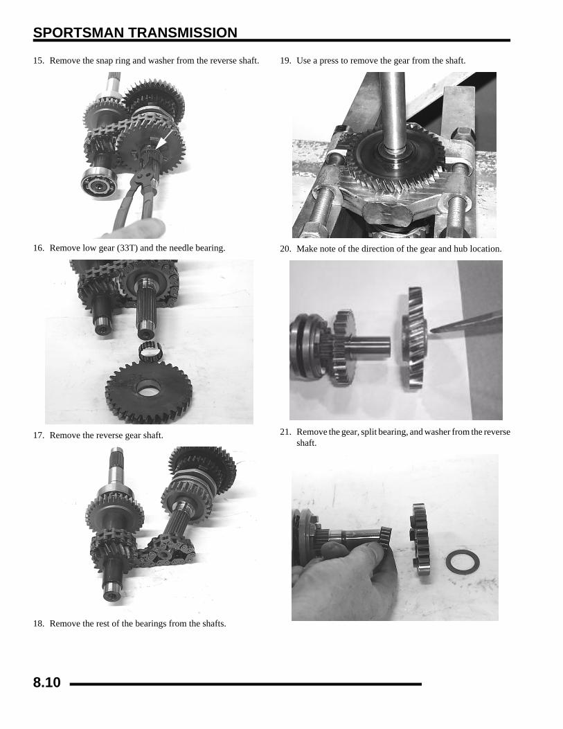
SPORTSMAN TRANSMISSION
15. Remove the snap ring and washer from the reverse shaft.
16. Remove low gear (33T) and the needle bearing.
17. Remove the reverse gear shaft.
18. Remove the rest of the bearings from the shafts.
19. Use a press to remove the gear from the shaft.
20. Make note of the direction of the gear and hub location.
21. Remove the gear, split bearing, and washer from the reverseshaft.
8.10

SPORTSMAN TRANSMISSION
8
22. Slide off the shift dogs and wave springs.
23. Remove the snap ring, washer, gear, and split bearing.
24. Remove bearing and the helical gear.
25. Remove the pinion shaft retainer plate and the pinion shaft.
26. Remove the front housing cover screws.
27. Remove the front housing cover, shim, thrust button, andthrust button shim.
8.11

SPORTSMAN TRANSMISSION
28. Remove the shafts as an assembly.
29. Remove the silent chain from the assembly for shaftinspection.
30. Clean all components in a parts washer and inspect forwear.
31. Inspect engagement dogs of gears and replace if edges arerounded.
32. Inspect gear teeth for wear, cracks, chips or broken teeth.Note the location of the hubs on the gear.
33. Remove seals from transmission case.IMPORTANT: New seals should be installed after thetransmission is completely assembled.
34. Inspect bearings for smooth operation. Check for excessiveplay between inner and outer race.
Assembly1. Reinstall the chain onto the front output shaft and rear
output shaft.
2. Install front and rear output shafts into the case.
3. Before installing the cover make sure the sealing surfacesare clean and dry, and shafts are fully seated in thetransmission case. Apply Crankcase Sealant (PN 2871557)to the mating surfaces.
Note location of hubs
Apply Crankcase Sealant to mating surfaces.
8.12

SPORTSMAN TRANSMISSION
8
4. Reinstall the thrust button shim, thrust button, and othershims into the cover. Reinstall cover and torque bolts in acriss-cross pattern in 3 steps to specification.
NOTE: Verify case locating pins (knock pipes) are inplace.
5. Install new front and rear output shaft seals. Apply greaseto the seal lips. Cover the splines of the shaft to protect theseal lips during installation.
6. Install pinion shaft with bearing.7. Install retainer plate with flat side toward bearing.
8. Apply Loctite™ 262 (Red) (PN 2871951) to screw threadsand torque screws to specification.
9. Install the a new needle bearing, the 24T reverse sprocket,washer, and a new snap ring. Install the shift dogs and wavespring. Install the washer, a new needle bearing and thehigh gear. Install the press fit gear and ball bearing.
NOTE: Install a new snap ring at this time. Wheninstalling the new snap ring, open the snap ring justfar enough to go over the shaft, to avoid stressingthe snap ring. If the snap ring is over-stressed, itcould come off the shaft and cause internal damageto the transmission.
= T
Cover Bolt Torque: 27-34 ft.lbs. (36.5-46 Nm)
Torque in Sequence
= T
Pinion Retainer Plate Bolt Torque: 6-12 ft.lbs. (8-16 Nm)
8.13

SPORTSMAN TRANSMISSION
10. Slide the reverse shaft assembly through the silent chain.
11. Install a new needle bearing, the low gear, the thrustwasherand the snap ring. A new snap ring is recommended.
12. Install the engagement dogs, wave springs, and bearing.
13. Install the ball bearing onto the end of the input shaft.
14. As the engagement dogs are installed onto the shaft, placethe wave springs into the spring groove. Keep the springin place while the fork is being installed on the shaft andwhile placing the shafts into the case.
NOTE: Use caution when installing the fork, as thespring can easily fall out.
NOTE: Installing the shift rail will aid in keeping theshift forks, shift dogs, and the springs in place.
15. Carefully install the shaft assembly and gear cluster as aunit into their respective bearing case recesses. Tap with asoft face hammer to seat shaft assemblies.
8.14
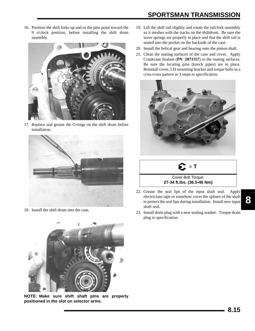
SPORTSMAN TRANSMISSION
8
16. Position the shift forks up and so the pins point toward the9 o'clock position, before installing the shift drumassembly.
17. Replace and grease the O-rings on the shift drum beforeinstallation.
18. Install the shift drum into the case.
NOTE: Make sure shift shaft pins are properlypositioned in the slot on selector arms.
19. Lift the shift rail slightly and rotate the rail/fork assemblyso it meshes with the tracks on the shiftdrum. Be sure thewave springs are properly in place and that the shift rail isseated into the pocket on the backside of the case.
20. Install the helical gear and bearing onto the pinion shaft.21. Clean the mating surfaces of the case and cover. Apply
Crankcase Sealant (PN 2871557) to the mating surfaces.Be sure the locating pins (knock pipes) are in place.Reinstall cover, LH mounting bracket and torque bolts in acriss-cross pattern in 3 steps to specification.
22. Grease the seal lips of the input shaft seal. Applyelectricians tape or somehow cover the splines of the shaftto protect the seal lips during installation. Install new inputshaft seal.
23. Install drain plug with a new sealing washer. Torque drainplug to specification.
= T
Cover Bolt Torque:27-34 ft.lbs. (36.5-46 Nm)
8.15
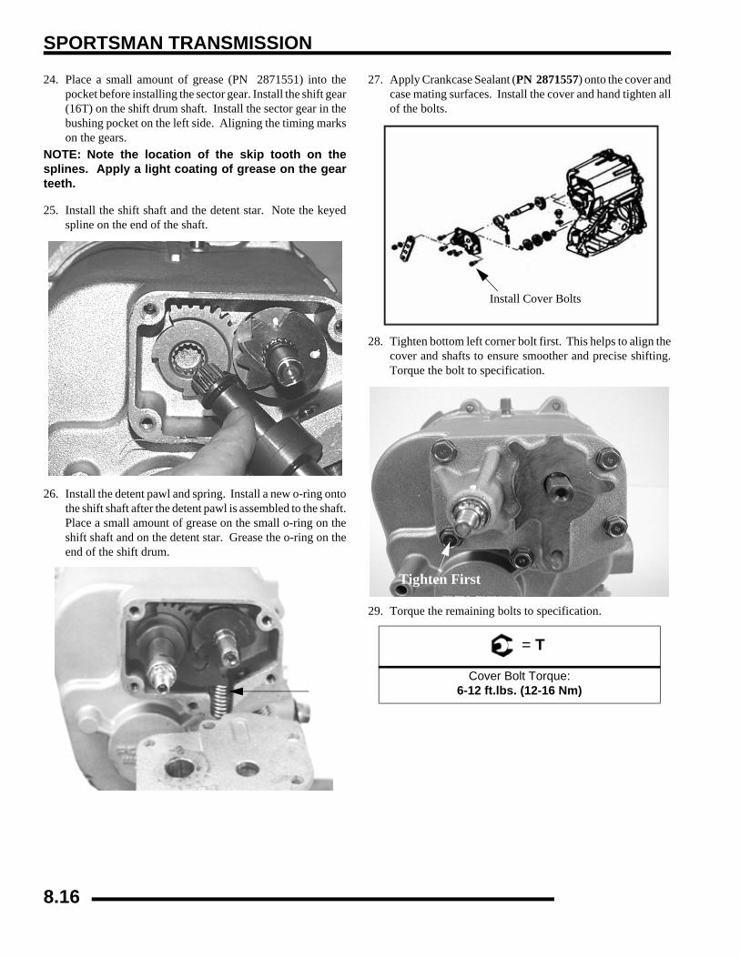
SPORTSMAN TRANSMISSION
24. Place a small amount of grease (PN 2871551) into thepocket before installing the sector gear. Install the shift gear(16T) on the shift drum shaft. Install the sector gear in thebushing pocket on the left side. Aligning the timing markson the gears.
NOTE: Note the location of the skip tooth on thesplines. Apply a light coating of grease on the gearteeth.
25. Install the shift shaft and the detent star. Note the keyedspline on the end of the shaft.
26. Install the detent pawl and spring. Install a new o-ring ontothe shift shaft after the detent pawl is assembled to the shaft.Place a small amount of grease on the small o-ring on theshift shaft and on the detent star. Grease the o-ring on theend of the shift drum.
27. Apply Crankcase Sealant (PN 2871557) onto the cover andcase mating surfaces. Install the cover and hand tighten allof the bolts.
28. Tighten bottom left corner bolt first. This helps to align thecover and shafts to ensure smoother and precise shifting.Torque the bolt to specification.
29. Torque the remaining bolts to specification.
= T
Cover Bolt Torque: 6-12 ft.lbs. (12-16 Nm)
Install Cover Bolts
Tighten First
8.16

SPORTSMAN TRANSMISSION
8
30. Install a new bellcrank onto the shift shaft. Note the keyedspline on the bellcrank and shaft. Install the washer and nut.Torque the bellcrank nut to specification.
31. Install the shift switch. Install the retaining clip. Hook upthe switch harness and reconnect the lockout plungerspring.
NOTE: Rotate the bellcrank to line the flat side of theswitch up to the flat side of the shaft.
32. Install transmission and add Polaris AGL GearcaseLubricant (PN 2873602) in the recommended amount.Refer to Maintenance Chapter 2 for more information.
Transmission Installation1. Install transmission from right side of vehicle.2. Align output shafts to propshaft yokes and roll pin holes.3. Slide output shafts into propshaft yokes and insert roll pins.4. Position transmission in frame.5. Loosely install left side and rear mounting brackets.6. Loosely install lower right bracket bolt.7. Loosely install front mounting bolts.8. Install PVT back cover, bolts and driven clutch and torque
to specification.IMPORTANT: Align clutches as outlined in Chapter 6
9. Tighten mounting fasteners in order A-F as shown.
10. Tighten rear gearcase fasteners to specification.11. Install shift switch and shift rod.12. Install remaining body panels and fasteners as required.
= T
Torque Bellcrank Nut: 12-18 ft.lbs. (16-24 Nm)
= T
Transmission Mounting Bolt Torque:25 ft.lbs. (34.5 Nm)
A
B
CD
E
Tighten Bolts in Sequence
8.17

SPORTSMAN TRANSMISSION
TroubleshootingCheck the following items when shifting difficulty isencountered.
• Idle speed adjustment
• PVT alignment
• Transmission oil type/quality
• Transmission torque stop adjustment (where applicable)
• Engine torque stop adjustment (where applicable)
• Drive belt deflection
• Loose fasteners on rod ends
• Loose fasteners on selector box
• Worn rod ends, clevis pins, or pivot arm bushings
• Linkage rod adjustment and rod end positioning
• Shift selector rail travel
• *Worn, broken or damaged internal transmission components
NOTE: To determine if shifting difficulty or problemis caused by an internal transmission problem,isolate the transmission by disconnecting linkagerod from transmission bellcrank. Manually selecteach gear range at the transmission bellcrank, andtest ride vehicle. If it functions properly, the problemis outside the transmission. If transmission problemremains, disassemble transmission and inspect allgear dogs for wear (rounding), damage. Inspect allbearings, circlips, thrust washers and shafts forwear.
8.18

X2 / Touring Transmission
CHAPTER 8X2 / Touring Transmission
8
TRANSMISSION EXPLODED VIEWS . . . . . . . . . . . . . . . . . . . . . . . . . . . . . . . . . . . . . . 8.20TRANSMISSION EXPLODED VIEW . . . . . . . . . . . . . . . . . . . . . . . . . . . . . . . . . . . . . . . 8.20MOUNTING EXPLODED VIEW . . . . . . . . . . . . . . . . . . . . . . . . . . . . . . . . . . . . . . . . . . . 8.22
SPECIFICATIONS. . . . . . . . . . . . . . . . . . . . . . . . . . . . . . . . . . . . . . . . . . . . . . . . . . . . . . 8.23TORQUE SPECIFICATIONS . . . . . . . . . . . . . . . . . . . . . . . . . . . . . . . . . . . . . . . . . . . . . 8.23SPECIAL TOOLS . . . . . . . . . . . . . . . . . . . . . . . . . . . . . . . . . . . . . . . . . . . . . . . . . . . . . . 8.23LUBRICATION . . . . . . . . . . . . . . . . . . . . . . . . . . . . . . . . . . . . . . . . . . . . . . . . . . . . . . . . 8.23
TRANSMISSION SERVICE. . . . . . . . . . . . . . . . . . . . . . . . . . . . . . . . . . . . . . . . . . . . . . . 8.23GEAR SELECTOR REMOVAL. . . . . . . . . . . . . . . . . . . . . . . . . . . . . . . . . . . . . . . . . . . . 8.23TRANSMISSION REMOVAL . . . . . . . . . . . . . . . . . . . . . . . . . . . . . . . . . . . . . . . . . . . . . 8.23TRANSMISSION INSTALLATION . . . . . . . . . . . . . . . . . . . . . . . . . . . . . . . . . . . . . . . . . 8.25TROUBLESHOOTING CHECKLIST. . . . . . . . . . . . . . . . . . . . . . . . . . . . . . . . . . . . . . . . 8.26TRANSMISSION DISASSEMBLY . . . . . . . . . . . . . . . . . . . . . . . . . . . . . . . . . . . . . . . . . 8.27TRANSMISSION ASSEMBLY . . . . . . . . . . . . . . . . . . . . . . . . . . . . . . . . . . . . . . . . . . . . 8.32TRANSMISSION FRONT OUTPUT SHAFT BACKLASH PROCEDURE . . . . . . . . . . . 8.33
8.19

X2 / Touring Transmission
TRANSMISSION EXPLODED VIEWSTransmission Exploded View
262
242
= THREAD LOCKING AGENT FOR ALL ‘FT. LBS.’ FASTENERS
= THREAD LOCKING AGENT FOR ‘INCH LBS. ‘ FASTENERS
8.20
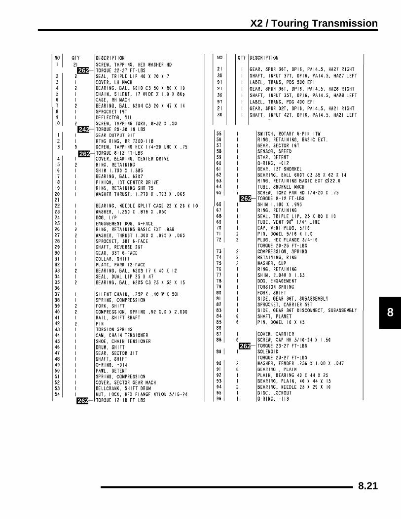
X2 / Touring Transmission
8
242
262
262
262
262
262
8.21

X2 / Touring Transmission
Mounting Exploded View
x2x3
x4
x4
x2
x1
x1
x1
8.22

X2 / Touring Transmission
8
SPECIFICATIONSTorque Specifications
Special Tools
Lubrication
Refer to Chapter 2 for transmission lubricant service.
TRANSMISSION SERVICEGear Selector Removal1. Disconnect linkage rod from gear selector handle.2. Remove two bolts attaching gear selector mount to machine
frame.3. Lift gear selector out of mounting bracket and away from
frame.
Transmission Removal1. Place vehicle in “park”. Raise and securely support rear of
ATV at the frame. Remove both rear wheels.2. Drain transmission lubricant (if required).3. Remove seat, both side panels, both rear cab quarter panels
and both footwells. See Chapter 5.4. Disconnect the differential, speed sensor and gear selection
switch connectors from the transmission.5. Disconnect transmission vent line (A).
6. Disconnect shift linkage rod end (B) from transmissionbellcrank (C).
7. Remove PVT outer cover, drive and driven clutches, andthe inner PVT cover. (refer to Chapter 6).
COMPONENT FT. LBS. (IN.LBS.)
NM
Transmission Case Bolts 25-30 36-43
Bell Crank Nut 12-18 17-26
Transmission Fill/Drain Plug 20-25 29-36
Trans. Mounting Bolts 40 57
Gear Sector Cover 8-12 11-17
Oil Deflector Screws (20-30) 2-3.6
Snorkel Torx Screw 8-12 11-17
Bearing Cover 8-12 11-17
Carrier Cover 23-27 33-39
Shift Fort Retainer Screws 8-12 11-17
Park Plate 8-12 11-17
Differential Solenoid 23-27 33-39
Speed Sensor 8-12 11-17
PART NUMBER TOOL DESCRIPTION
2871695 (Part of 2871702 Kit) Backlash Setting Tool
2871698 (Part of 2871702 Kit) Rear Output Seal Driver
2871699 (Part of 2871702 Kit) Rear Driveshaft Seal Guide
2871282 Bearing Seal Driver (50 mm)
=
Specified Lubricant Polaris AGL FluidGearcase Capacity
Approx. 32 oz. (948ml)
A
CB
8.23

X2 / Touring Transmission
8. Remove both rear drive shafts. Brake caliper removal isrequired. Do not let calipers hang by the brake line. (SeeChapters 7 and 9)
9. Remove both upper shock absorber mounting bolts andswing shocks away from the transmission.
10. Remove the torsion bar mountings from the control arms.11. Remove all fasteners (X) attaching the torsion mount, and
completely remove the mount (Z) from the ATV.
12. Remove both upper control arms (I). Refer to Chapter 7 formore details.
13. Remove all lower transmission mounting fasteners (J) fromeach side.
14. Remove the middle transmission support bracket (K)completely from the ATV.
15. Remove the rear transmission support brackets (L)completely from the ATV.
16. Lift and remove transmission out right side of frame whilepulling the output shaft from the propshaft yoke.
X
X
X
X
Z
H
I
J
J
J
K
L
8.24

X2 / Touring Transmission
8
Transmission Installation1. Apply Polaris Premium All Season Grease (PN 2871423)
to splines of front output shaft ,install new O–ring in propshaft.
2. With the help of an assistant, rotate transmission into placefrom the right side of the frame, aligning the forwardtransmission bracket into the rear engine mounting holeswhile ensuring that the output shaft and propshaft align andslide together.
3. Loosely install lower transmission mounting fasteners andforward engine mounting nuts.
4. Install the rear support bracket, middle support bracket andtorsion bar support bracket. Torque all lower bracket boltsto specification. Torque all upper rear and middle supportbracket bolts (circled) to specification.
5. Install the upper control arms. Refer to Chapter 5 forprocedures and torque specifications.
6. Reconnect the torsion bar to both lower control arms.Torque to specification.
7. Install both upper shock absorber mounts and torque tospecification.
8. Apply anti-seize to splines of rear drive shafts and insertdrive shafts into carriers and transmission. Install rearcarriers and hubs. Torque lower carrier bolts to specification. Torque all othercontrol arm bolts and remaining carrier bolts tospecification.
= T
Transmission Bracket Bolt Torque: Lower - 40 ft.lbs. (57Nm)
Upper Rear / Middle Bolts - 17 ft.lbs. (24 Nm)
= T
Lower Torsion Bar Bolt Torque: 17 ft.lbs. (24 Nm)
= T
Shock Bolt Torque: 30 ft.lbs. (43 Nm)
= T
Upper Carrier Bolt Torque: 50 ft.lbs. (71 Nm)
All Other Carrier Bolts: 35 ft.lbs. (50 Nm)
Apply anti-seize to splines
8.25

X2 / Touring Transmission
9. Install the rear hubs, rear brake disc and brake caliper. Referto Chapters 5 and 9 for procedures and torquespecifications.
10. Install PVT system. Refer to Chapter 6 PVT section forprocedures and torque specifications.
11. Once the PVT system is installed. Tighten all remainingtransmission mounting bolts to specification. See page 8.2for transmission bolt placement.
12. Install transmission vent line. Be sure vent line is not kinkedor pinched.
13. Install seat, both side panels, both rear cab quarter panelsand both footwells. See Chapter 5.
14. Reconnect the differential, speed sensor and gear selectionswitch connectors to the transmission.
15. Reconnect the shift rod. Torque to standard specification.
16. Install the rear wheel nuts and torque to specification.
17. With the ATV on level ground, add Polaris AGL GearcaseLubricant to the proper level. See Chapter 2 for proper fillprocedures and Torque Specifications.
Troubleshooting ChecklistCheck the following items when shifting difficulty isencountered.
• Idle speed adjustment
• Transmission oil type/quality
• Drive belt deflection
• *Worn, broken or damaged internal transmission components
= T
Transmission Mount Bolt Torque:40 ft.lbs. (57Nm)
Rear Wheel Nut Torque
Refer to Chapter 2
Polaris AGL Gearcase Lubricant
(PN 2873602) (12 oz.)(PN 2873603) (Gallon)
8.26

X2 / Touring Transmission
8
Transmission Disassembly1. Place the transmission in the Neutral gear before
disassembly.2. Drain and properly dispose of transmission oil. See Chapter
2.3. Remove the bellcrank nut (1) and remove the bellcrank (2).4. Remove the c-clip (3) that holds the gear selector switch (4)
onto the shaft and remove the selector switch.
5. Remove the sector cover bolts (5) and remove the sectorcover (6). Removal can be aided by using your thumbs topress down on the shafts and pulling up the cover with yourfingers.
6. Remove the compression spring (7).
7. Remove the detent star (8). Note how the detent star fitsonto the splined shaft and the raised edge facing outwardfor reassembly.
8. Remove the lockout disc (9). Note the raised edge facingoutward for reassembly.
9. Remove the shift shaft (10) and the shift gears (11,12).NOTE: Note the timing marks on the shift gears (12,13)for reassembly.
1
2 3 4
65
7
89
10
11
127 13
8.27
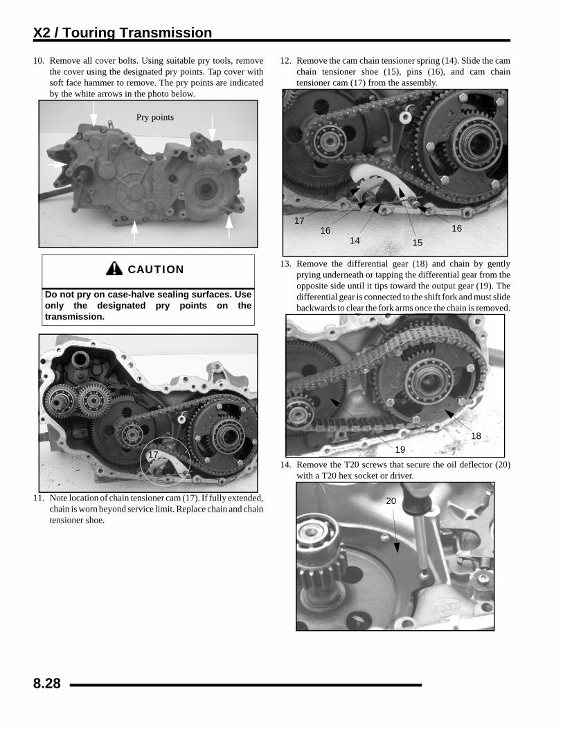
X2 / Touring Transmission
10. Remove all cover bolts. Using suitable pry tools, removethe cover using the designated pry points. Tap cover withsoft face hammer to remove. The pry points are indicatedby the white arrows in the photo below.
11. Note location of chain tensioner cam (17). If fully extended,chain is worn beyond service limit. Replace chain and chaintensioner shoe.
12. Remove the cam chain tensioner spring (14). Slide the camchain tensioner shoe (15), pins (16), and cam chaintensioner cam (17) from the assembly.
13. Remove the differential gear (18) and chain by gentlyprying underneath or tapping the differential gear from theopposite side until it tips toward the output gear (19). Thedifferential gear is connected to the shift fork and must slidebackwards to clear the fork arms once the chain is removed.
14. Remove the T20 screws that secure the oil deflector (20)with a T20 hex socket or driver.
CAUTION
Do not pry on case-halve sealing surfaces. Useonly the designated pry points on thetransmission.
Pry points
17
161514
1617
1819
20
8.28
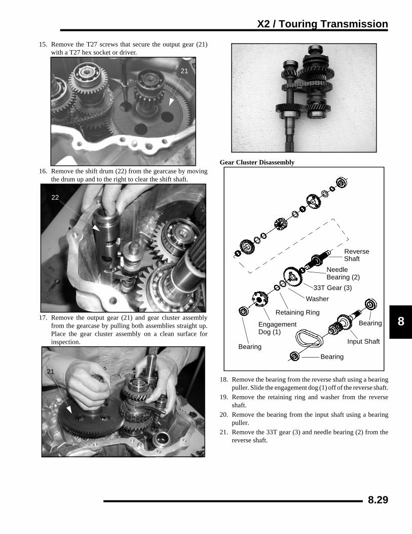
X2 / Touring Transmission
8
15. Remove the T27 screws that secure the output gear (21)with a T27 hex socket or driver.
16. Remove the shift drum (22) from the gearcase by movingthe drum up and to the right to clear the shift shaft.
17. Remove the output gear (21) and gear cluster assemblyfrom the gearcase by pulling both assemblies straight up.Place the gear cluster assembly on a clean surface forinspection.
Gear Cluster Disassembly
18. Remove the bearing from the reverse shaft using a bearingpuller. Slide the engagement dog (1) off of the reverse shaft.
19. Remove the retaining ring and washer from the reverseshaft.
20. Remove the bearing from the input shaft using a bearingpuller.
21. Remove the 33T gear (3) and needle bearing (2) from thereverse shaft.
21
22
21
Bearing
Input Shaft
Bearing
Reverse
Needle
33T Gear (3)Washer
Retaining Ring
Bearing (2)
EngagementDog (1)
Bearing
Shaft
8.29

8.3
X2 / Touring Transmission
22.
23.24.
25.
The reverse shaft should slide out of the silent chain (4) toseparate the assembly.
Remove the rest of the bearings from the shafts.Remove the engagement dog (5) from the reverse shaft.
Remove the retaining ring (6) and then washer (7), gear (8),and split bearing (9) from the reverse shaft.
26. To disassemble the shift fork rail remove the snap ring (10)from the end of the shift rail on either side.
Transmission Snorkel Shaft Removal
27. Remove the snorkel lock screw located inside the gearcase.Use a T27 hex socket or driver.
28. Mark the snorkel tube and case with a white pen or marker.This is used to ease reassembly of the gearcase.
4
REVERSE SHAFT
Towards Insideof Case
5
6 78
9
CAUTIONUse caution when disassembling the shift rail. Thecompressed springs on the shift rail may pop off causingeye or face injury.
10
10
0

X2 / Touring Transmission
8
kel
the
on
e a
29. Use a 2 3/8” wrench to loosen and remove the front driveshaft snorkel tube (11).
30. If needed, remove the seal from the front of the snortube. Remove the snap ring (12).
31. Remove the second snap ring (13) and spacer (14) from snorkel shaft.
NOTE: Shim may or may not be present. Depending input shaft tolerance.
32. To remove the snorkel shaft from the snorkel tube, uspress to press the snorkel shaft out.
11
Front Drive Snorkel Assembly
A. O-ringB. SealC. Retaining RingD. Retaining RingE. SpacerF. Ball BearingG. Snorkel tubeH. Retaining RingI. Ball BearingJ. Snorkel Shaft
A
AB E
DC
I
H
G
F
J
12
13
14
8.31

8.3
X2 / Touring Transmission
33.
Tra1.
2.
To remove the remaining bearing on the snorkel shaft (15),remove the retaining ring and press the bearing off.
nsmission assemblyInstall all new seals in the gearcases. Use the Rear OutputSeal Driver (PN 2871698) and Rear Driveshaft Seal Guide(PN 2871699) to install the seals into the gearcases. Seeillustration 1 to identify seals for replacement.
Reverse the disassembly procedure for the assembly of thesnorkel shaft assembly.
3. Inspect the output gear assembly (1), replace bearings ifneeded. Inspect the 91T gear for damage, chips, orabnormal worn teeth.
4. Install 2 new O-rings onto the snorkel tube. Apply a whitelithium grease onto the O-rings and threads of the snorkeltube.
5. Install the snorkel shaft assembly into the gearcase. Installthe snorkel shaft assembly in until the second O-ring iscontacting the gearcase, but is still visible.
15
28716982871699
LH GearcaseCover Seals
Gearcase Seal
1
2

X2 / Touring Transmission
8
e th
6. Install the output gear assembly. Be sure to properly meshthe snorkel shaft bevel gear with the output bevel gear.Install the 4 torx screws (2) to secure the output gearassembly into place. Torque screws to .NOTICE! : It is important to set zero lash between theoutput gear and the snorkel shaft gear. If there is binding orexcess lash, tighten or loosen the snorkel shaft until thereis zero lash.
Transmission front output shaft backlash procedure1. The following steps must be performed to obtain proper
front output gear backlash adjustment:
• Upon completion of Step 6, make sure the snorkel gear and output bevel gear are lightly seated or meshing so there is ‘zero’ lash. Do not overtighten. Gears should rotate freely without binding.
• Before turning the snorkel tube, look down into the gearcase at the snorkel lock screw hole opening (Photo 2) to reference your starting point. Next, slowly rotate the snorkel tube counterclockwise (Photo 3), counting the number of notches passing through the thread hole as you rotate the tube. Rotate the snorkel tube to the 7th notch from ‘seated’ position (Photo 1 & 2) using a 2 3/8” wrench.
• Check the output shaft gear backlash again by feel. Ifthe output shaft lash appears to be too tight, rotate thsnorkel shaft counterclockwise to the next notch or 8notch.
= T
Output Gear Retaining Screw Torque:8-12 ft.lbs. (11-17 Nm)
2
Notches
1
Count 7 notches of snorkel tube throughlock screw hole.
2
Rotate snorkel counterclockwise 7 notches
3
8.33

8.3
X2 / Touring Transmission
2.
3.
Once the gear backlash is found, to install the snorkel lockscrew, you may have to rotate the snorkel tube clockwiseor counterclockwise slightly. This will allow the lock screwto thread itself into one of the slots of the snorkel tube (Seeillustration below) to secure the snorkel tube.
With the snorkel shaft assembly in place, remove the 4 Torxscrews from the output shaft assembly. Remove the outputshaft assembly.
4. Assemble the input shaft assembly if previouslydisassembled.
5. Assemble the reverse shaft assembly if previouslydisassembled.
Screw Fits in Slots of Snorkel Tube
8-12 ft.-lbs. (11-17) Nm
Input Shaft AssemblyA. Ball BearingB. Input ShaftC. Silent Chain
A
AB
C
REVERSE SHAFT
Towards Insideof Case
A. Ball BearingB. Engagement DogC. Retaining RingD. WasherE. GearF. Needle BearingG. Reverse ShaftH. Needle BearingI. Sprocket
J. WasherK. retaining RingL. Engagement DogM. WasherN. Needle BearingO. GearP. WasherQ. Retaining RingR. Ball bearing
A
BC
D
EFG
H
I JK
L
RQP
ON
M
4

X2 / Touring Transmission
8
ldng
tertall
6. Inspect the shift drum for any damage or wear. Inspect thesplines of the shift drum. Replace the O-rings on the end ofthe shift drum and lubricate them before assembly.
7. Stretch the silent chain on a flat surface and measure thelength of 8 pitches in a minimum of three places on thechain. Replace the chain if the measurement is longer thanthe service limit.
8. The shift drum (C), reverse shaft (D), input shaft (E), andoutput gear assembly must be installed at the same time toproperly align all components.
NOTE: To ease assembly use a plastic tie strap to hothe shift forks (D) and the shift drum (C) together duriassembly.
9. With the gearcase on it’s side, hold the gear clusassembly and output assembly together. Carefully inseach shaft into their respective recess in the gearcase.
= In. / mm.
Silent Chain Service Limit (8 pitch):3.0904” (7.8496 cm)
D
E
C
8.35
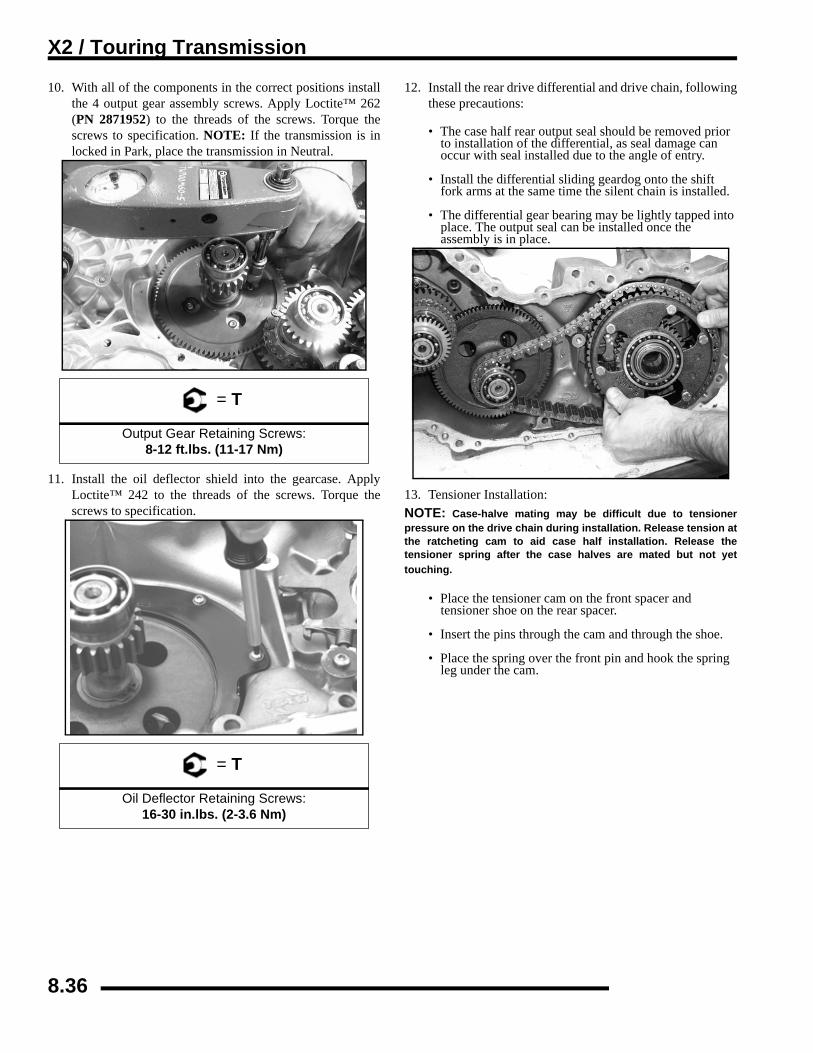
8.3
X2 / Touring Transmission
10.
11.
With all of the components in the correct positions installthe 4 output gear assembly screws. Apply Loctite™ 262(PN 2871952) to the threads of the screws. Torque thescrews to specification. NOTE: If the transmission is inlocked in Park, place the transmission in Neutral.
Install the oil deflector shield into the gearcase. ApplyLoctite™ 242 to the threads of the screws. Torque thescrews to specification.
12. Install the rear drive differential and drive chain, followingthese precautions:
• The case half rear output seal should be removed prior to installation of the differential, as seal damage can occur with seal installed due to the angle of entry.
• Install the differential sliding geardog onto the shift fork arms at the same time the silent chain is installed.
• The differential gear bearing may be lightly tapped into place. The output seal can be installed once the assembly is in place.
13. Tensioner Installation:NOTE: Case-halve mating may be difficult due to tensionerpressure on the drive chain during installation. Release tension atthe ratcheting cam to aid case half installation. Release thetensioner spring after the case halves are mated but not yettouching.
• Place the tensioner cam on the front spacer and tensioner shoe on the rear spacer.
• Insert the pins through the cam and through the shoe.
• Place the spring over the front pin and hook the spring leg under the cam.
= T
Output Gear Retaining Screws: 8-12 ft.lbs. (11-17 Nm)
= T
Oil Deflector Retaining Screws: 16-30 in.lbs. (2-3.6 Nm)
6
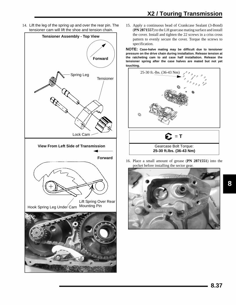
X2 / Touring Transmission
8
d)talloss to
ner at
theyet
the
14. Lift the leg of the spring up and over the rear pin. Thetensioner cam will lift the shoe and tension chain.
15. Apply a continuous bead of Crankcase Sealant (3-Bon(PN 2871557) to the LH gearcase mating surface and insthe cover. Install and tighten the 22 screws in a criss crpattern to evenly secure the cover. Torque the screwsspecification.
NOTE: Case-halve mating may be difficult due to tensiopressure on the drive chain during installation. Release tensionthe ratcheting cam to aid case half installation. Release tensioner spring after the case halves are mated but not touching.
16. Place a small amount of grease (PN 2871551) into pocket before installing the sector gear.
Tensioner Assembly - Top View
Forward
Spring LegTensioner
Lock Cam
View From Left Side of Transmission
Forward
Hook Spring Leg Under CamLift Spring Over RearMounting Pin
= T
Gearcase Bolt Torque:25-30 ft.lbs. (36-43 Nm)
25-30 ft.-lbs. (36-43 Nm)
8.37
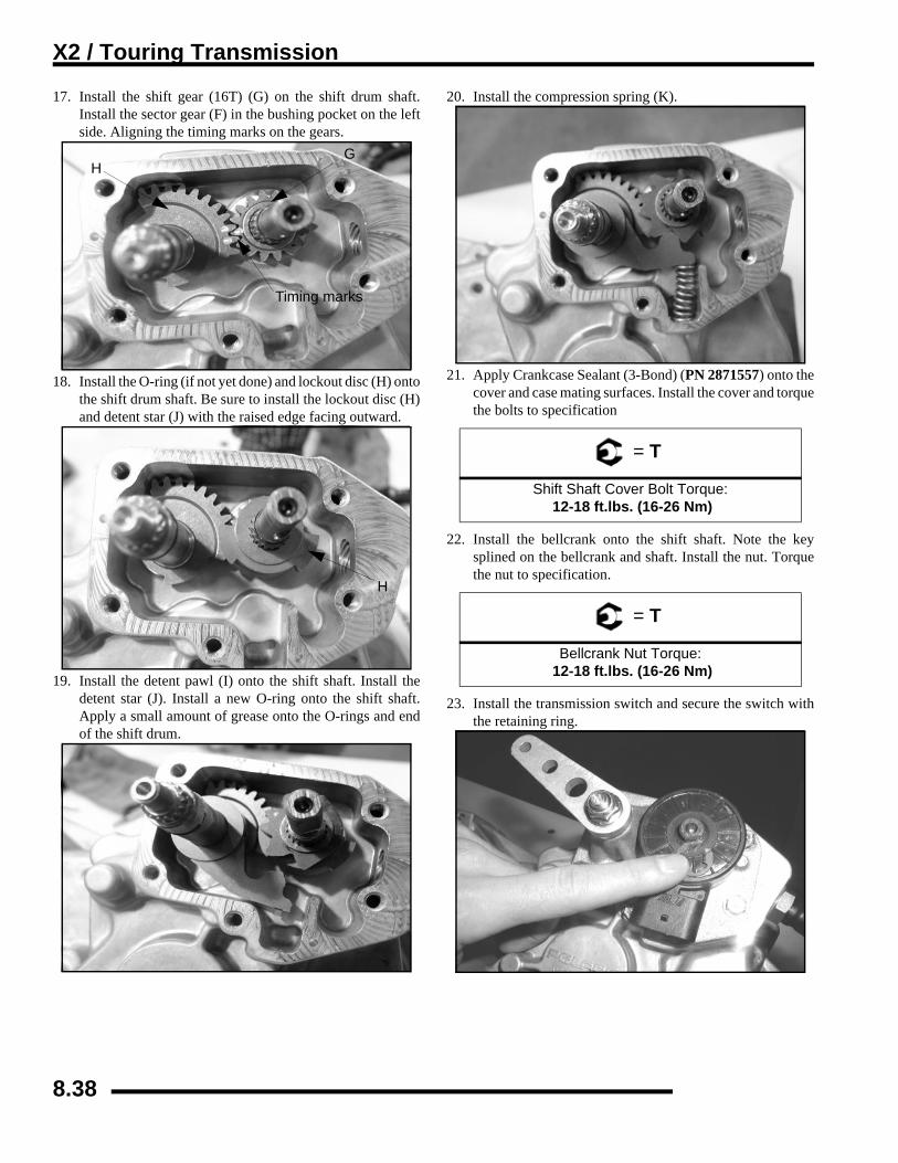
X2 / Touring Transmission
17. Install the shift gear (16T) (G) on the shift drum shaft.Install the sector gear (F) in the bushing pocket on the leftside. Aligning the timing marks on the gears.
18. Install the O-ring (if not yet done) and lockout disc (H) ontothe shift drum shaft. Be sure to install the lockout disc (H)and detent star (J) with the raised edge facing outward.
19. Install the detent pawl (I) onto the shift shaft. Install thedetent star (J). Install a new O-ring onto the shift shaft.Apply a small amount of grease onto the O-rings and endof the shift drum.
20. Install the compression spring (K).
21. Apply Crankcase Sealant (3-Bond) (PN 2871557) onto thecover and case mating surfaces. Install the cover and torquethe bolts to specification
22. Install the bellcrank onto the shift shaft. Note the keysplined on the bellcrank and shaft. Install the nut. Torquethe nut to specification.
23. Install the transmission switch and secure the switch withthe retaining ring.
GH
Timing marks
H
= T
Shift Shaft Cover Bolt Torque: 12-18 ft.lbs. (16-26 Nm)
= T
Bellcrank Nut Torque: 12-18 ft.lbs. (16-26 Nm)
8.38

BRAKES
9.1
CHAPTER 9BRAKES
9
SPECIFICATIONS. . . . . . . . . . . . . . . . . . . . . . . . . . . . . . . . . . . . . . . . . . . . . . . . . . . . . . . 9.2TORQUE TABLE . . . . . . . . . . . . . . . . . . . . . . . . . . . . . . . . . . . . . . . . . . . . . . . . . . . . . . . 9.2COMPONENT SERVICE LIMITS . . . . . . . . . . . . . . . . . . . . . . . . . . . . . . . . . . . . . . . . . . . 9.2
BRAKE SYSTEM EXPLODED VIEWS . . . . . . . . . . . . . . . . . . . . . . . . . . . . . . . . . . . . . . . 9.3X2, TOURING SYSTEM COMPONENT EXPLODED VIEW . . . . . . . . . . . . . . . . . . . . . . 9.3SPORTSMAN SYSTEM COMPONENT EXPLODED VIEW . . . . . . . . . . . . . . . . . . . . . . 9.4
BRAKE CALIPER EXPLODED VIEWS . . . . . . . . . . . . . . . . . . . . . . . . . . . . . . . . . . . . . . . 9.5SPORTSMAN AND X2, TOURING FRONT CALIPER ASSEMBLY . . . . . . . . . . . . . . . . 9.5X2, TOURING REAR CALIPER ASSEMBLY . . . . . . . . . . . . . . . . . . . . . . . . . . . . . . . . . . 9.5SPORTSMAN REAR CALIPER ASSEMBLY . . . . . . . . . . . . . . . . . . . . . . . . . . . . . . . . . . 9.6
HYDRAULIC BRAKE SYSTEM . . . . . . . . . . . . . . . . . . . . . . . . . . . . . . . . . . . . . . . . . . . . . 9.6OPERATION OVERVIEW . . . . . . . . . . . . . . . . . . . . . . . . . . . . . . . . . . . . . . . . . . . . . . . . 9.6BRAKE NOISE TROUBLESHOOTING . . . . . . . . . . . . . . . . . . . . . . . . . . . . . . . . . . . . . . 9.7BRAKE BLEEDING / FLUID CHANGE. . . . . . . . . . . . . . . . . . . . . . . . . . . . . . . . . . . . . . . 9.7
FRONT MASTER CYLINDER . . . . . . . . . . . . . . . . . . . . . . . . . . . . . . . . . . . . . . . . . . . . . . 9.9REMOVAL . . . . . . . . . . . . . . . . . . . . . . . . . . . . . . . . . . . . . . . . . . . . . . . . . . . . . . . . . . . . 9.9INSTALLATION . . . . . . . . . . . . . . . . . . . . . . . . . . . . . . . . . . . . . . . . . . . . . . . . . . . . . . . . 9.9
FRONT BRAKES. . . . . . . . . . . . . . . . . . . . . . . . . . . . . . . . . . . . . . . . . . . . . . . . . . . . . . . 9.10PAD REMOVAL . . . . . . . . . . . . . . . . . . . . . . . . . . . . . . . . . . . . . . . . . . . . . . . . . . . . . . . 9.10ASSEMBLY . . . . . . . . . . . . . . . . . . . . . . . . . . . . . . . . . . . . . . . . . . . . . . . . . . . . . . . . . . 9.11BRAKE BURNISHING PROCEDURE . . . . . . . . . . . . . . . . . . . . . . . . . . . . . . . . . . . . . . 9.12
FRONT BRAKE DISC . . . . . . . . . . . . . . . . . . . . . . . . . . . . . . . . . . . . . . . . . . . . . . . . . . . 9.12INSPECTION . . . . . . . . . . . . . . . . . . . . . . . . . . . . . . . . . . . . . . . . . . . . . . . . . . . . . . . . . 9.12REMOVAL / REPLACEMENT . . . . . . . . . . . . . . . . . . . . . . . . . . . . . . . . . . . . . . . . . . . . 9.13
FRONT CALIPER . . . . . . . . . . . . . . . . . . . . . . . . . . . . . . . . . . . . . . . . . . . . . . . . . . . . . . 9.14REMOVAL . . . . . . . . . . . . . . . . . . . . . . . . . . . . . . . . . . . . . . . . . . . . . . . . . . . . . . . . . . . 9.14INSPECTION . . . . . . . . . . . . . . . . . . . . . . . . . . . . . . . . . . . . . . . . . . . . . . . . . . . . . . . . . 9.15REASSEMBLY . . . . . . . . . . . . . . . . . . . . . . . . . . . . . . . . . . . . . . . . . . . . . . . . . . . . . . . . 9.15INSTALLATION . . . . . . . . . . . . . . . . . . . . . . . . . . . . . . . . . . . . . . . . . . . . . . . . . . . . . . . 9.16
REAR BRAKE PAD . . . . . . . . . . . . . . . . . . . . . . . . . . . . . . . . . . . . . . . . . . . . . . . . . . . . . 9.17X2, TOURING PAD REMOVAL . . . . . . . . . . . . . . . . . . . . . . . . . . . . . . . . . . . . . . . . . . . 9.17X2, TOURING PAD INSTALLATION . . . . . . . . . . . . . . . . . . . . . . . . . . . . . . . . . . . . . . . 9.18SPORTSMAN REAR PAD REMOVAL . . . . . . . . . . . . . . . . . . . . . . . . . . . . . . . . . . . . . . 9.19SPORTSMAN REAR PAD INSTALLATION . . . . . . . . . . . . . . . . . . . . . . . . . . . . . . . . . . 9.20BRAKE BURNISHING PROCEDURE . . . . . . . . . . . . . . . . . . . . . . . . . . . . . . . . . . . . . . 9.20
X2, TOURING REAR CALIPER. . . . . . . . . . . . . . . . . . . . . . . . . . . . . . . . . . . . . . . . . . . . 9.21REMOVAL . . . . . . . . . . . . . . . . . . . . . . . . . . . . . . . . . . . . . . . . . . . . . . . . . . . . . . . . . . . 9.21INSPECTION . . . . . . . . . . . . . . . . . . . . . . . . . . . . . . . . . . . . . . . . . . . . . . . . . . . . . . . . . 9.22REASSEMBLY . . . . . . . . . . . . . . . . . . . . . . . . . . . . . . . . . . . . . . . . . . . . . . . . . . . . . . . . 9.22
SPORTSMAN REAR CALIPER. . . . . . . . . . . . . . . . . . . . . . . . . . . . . . . . . . . . . . . . . . . . 9.23REMOVAL AND INSPECTION. . . . . . . . . . . . . . . . . . . . . . . . . . . . . . . . . . . . . . . . . . . . 9.23ASSEMBLY . . . . . . . . . . . . . . . . . . . . . . . . . . . . . . . . . . . . . . . . . . . . . . . . . . . . . . . . . . 9.24
REAR BRAKE DISC . . . . . . . . . . . . . . . . . . . . . . . . . . . . . . . . . . . . . . . . . . . . . . . . . . . . 9.25INSPECTION . . . . . . . . . . . . . . . . . . . . . . . . . . . . . . . . . . . . . . . . . . . . . . . . . . . . . . . . . 9.25
REAR MASTER CYLINDER . . . . . . . . . . . . . . . . . . . . . . . . . . . . . . . . . . . . . . . . . . . . . . 9.26X2, TOURING EXPLODED VIEW . . . . . . . . . . . . . . . . . . . . . . . . . . . . . . . . . . . . . . . . . 9.26OVERVIEW. . . . . . . . . . . . . . . . . . . . . . . . . . . . . . . . . . . . . . . . . . . . . . . . . . . . . . . . . . . 9.27X2, TOURING REAR MASTER CYLINDER REMOVAL AND INSTALLATION. . . . . . . 9.27SPORTSMAN REAR MASTER CYLINDER REMOVAL / INSTALLATION . . . . . . . . . . 9.28PEDAL REMOVAL AND INSTALLATION . . . . . . . . . . . . . . . . . . . . . . . . . . . . . . . . . . . 9.29
TROUBLESHOOTING. . . . . . . . . . . . . . . . . . . . . . . . . . . . . . . . . . . . . . . . . . . . . . . . . . . 9.29

BRAKES
SPECIFICATIONSTorque Table
NOTE: Refer to tightening procedures in this chapter. Some special procedures are used when torquingcertain bolts and fasteners.
Component Service Limits
TORQUE SPECIFICATIONS (Sportsman and X2, Touring)
ITEM TORQUE FT.LBS. (IN.LBS.) TORQUE NM
Front / Rear Caliper Mounting Bolts 18 24Handlebar Master Cylinder Clamp Bolts (25 in.lbs.) 3.0
Hand Master Cylinder Reservoir Cover Screws (7 in.lbs.) 0.79Brake Line Banjo Bolt 15.0 21
Brake Line Flared Fittings 12-15 16-21
Brake Disc Bolts Front / Rear 18.0 Front27.0 Rear
2436
Brake Switch 12-15 16-21Caliper Mounting Bolts 18.0 24
Sportsman Caliper Slide Pins 30-35 41-48Rear Master Cylinder-to-Frame Bolts 8 11
FRONT BRAKE CALIPER (Sportsman and X2, Touring)
ITEM STANDARD SERVICE LIMIT
Brake Pad Thickness .298” / 7.6 mm .180” / 4.6 mmBrake Disc Thickness .150-.165” / 3.81-4.19 mm .140” / 3.556 mm
Brake Disc Thickness Variance -- .002” / .051 mmBrake Disc Runout -- .010 / .254 mm
REAR BRAKE CALIPER (X2, Touring ONLY)
ITEM STANDARD SERVICE LIMIT
Brake Pad Thickness .298” / 7.6 mm .180” / 4.6 mmBrake Disc Thickness .180-.195” / 4.57-4.95 mm .170” / 4.318 mm
Brake Disc Thickness Variance -- .002” / .051 mmBrake Disc Runout -- .010” / .254 mm
REAR BRAKE CALIPER (Sportsman ONLY)
ITEM STANDARD SERVICE LIMIT
Brake Pad Thickness .318” / 7.6 mm .180” / 4.6 mmBrake Disc Thickness .180-.195” / 4.57-4.95 mm .170” / 4.318 mm
Brake Disc Thickness Variance -- .002” / .051 mmBrake Disc Runout -- .010” / .254 mm
9.2

BRAKES
9
BRAKE SYSTEM EXPLODED VIEWSX2, Touring System Component Exploded View
1) Master Cylinder Cover Screws: 7 in.lbs. (0.79 Nm)2) Banjo Style Fitting: 15 ft.lbs. (21 Nm)3) Flare Style Fittings: 12-15 ft.lbs. (16-21 Nm)4) Brake Switch: 12-15 ft.lbs. (16-21 Nm) *Apply Pipe Sealant to Threads
2
2
1
2
2
3
3
2
2
34
*All Bleed Screws: 25-30 in.lbs. (2.80-3.40 Nm)
5) Dual Input Master Cylinder and Bleed Screw: 25-30 in. lbs. (2.8-3.4 Nm)6) Front and Rear Caliper Bleed Screws: 36-60 in. lbs. (4.07-6.78 Nm)
6
5
9.3

BRAKES
Sportsman System Component Exploded View
All
Ban
jo S
tyle
Fi
tting
s: 1
5 ft.
lbs.
(21
Nm
)
All
Flar
e St
yle
Fitti
ngs:
12-
15 ft
.lbs.
(16-
21 N
m)
All
Ble
ed S
crew
s: 2
5-30
in
.lbs.
(2.8
0-3.
40 N
m)
App
ly P
ipe S
eala
nt
To T
hrea
ds
2 Sc
rew
s - 7
in.lb
s. (0
.79
m)
9.4
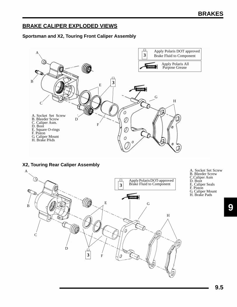
BRAKES
9
BRAKE CALIPER EXPLODED VIEWS
Sportsman and X2, Touring Front Caliper Assembly
X2, Touring Rear Caliper Assembly
A. Socket Set ScrewB. Bleeder Screw C. Caliper Asm. D. Boot E. Square O-rings F. Piston G. Caliper Mount H. Brake PAds
A
B
C
D
E
F
GH
Apply Polaris All Purpose Grease
3
3Apply Polaris DOT approved Brake Fluid to Component
A. Socket Set ScrewB. Bleeder Screw C.Caliper Asm D. Boot E. Caliper Seals F. Piston G. Caliper Mount H. Brake Pads
A
B
C
D
E
F
G
H
Apply Polaris DOT-approved Brake Fluid to Component3
3
9.5

BRAKES
Sportsman Rear Caliper Assembly
HYDRAULIC BRAKE SYSTEMOperation Overview
The Polaris disc brake system consists of the followingcomponents or assemblies: brake lever; master cylinder;hydraulic hose; brake calipers (slave cylinder); brake pads; andbrake discs, which are secured to the drive line.
When the hand activated brake lever (A) is applied it contactspiston (B) within the master cylinder. As the master cylinderpiston moves inward it closes a small opening (compensatingport C) within the cylinder and starts to build pressure within thebrake system. As the pressure within the system is increased,the piston (D) located in the brake caliper moves outward andapplies pressure to the brake pad. This pad contacts the brakedisc and moves the caliper in its floating bracket, pulling thestationary side pad into the brake disc. The resulting frictionreduces brake disc and vehicle speed. As the lever pressure isincreased, the braking affect is also increased.
The friction applied to the brake pads will cause the pads towear. As these pads wear, the piston within the caliper movesfurther outward and becomes self adjusting. Fluid from thereservoir fills the additional area created when the caliper pistonmoves outward.
Brake fluid level is critical to proper system operation. Too littlefluid will allow air to enter the system and cause the brakes tofeel spongy. Too much fluid could cause brakes to drag due tofluid expansion.
Located within the master cylinder is the compensating port (C)which is opened and closed by the master cylinder pistonassembly. The port is open when the lever is released and themaster cylinder piston is outward. As the temperature within thehydraulic system changes, this port compensates for fluidexpansion (heated fluid) or contraction (cooled fluid). Duringsystem service, be sure this port is open. Due to the hightemperatures created within the system during heavy braking, itis very important that the master cylinder reservoir has adequatespace to allow for fluid expansion. Never overfill thereservoir! Fill to 1/4, - 5/16, (.64 - .80 cm) from top of thecylinder.
A. Anvil Bolts B. Bleed Screws C. Washers D. O-rings E. Rear Housing F. Seals G. Piston H. Slide Pins I. Bushings J. Seal K. Bracket L. Pad M.Front Housing N. Retaining Clips
3Apply Polaris DOT approved Brake fluidto component.
A
B
CD
E
F
GH
I
J
K
L
M
N
3
330-35 ft.lbs. (41-48 Nm) 25-30 in lbs.
(2.80-3.40 Nm)
16-18 ft.lbs. (22-24 Nm)
A B
C
D
E
F
Must be clear to allow proper diaphragm movement
Compensating port compensates for temperature changes by allowing fluid back to master cylinder
Move Brake Pad
9.6

BRAKES
9
This system also incorporates a diaphragm (E) as part of thecover gasket; and a vent port (F) located between the gasket andthe cover. The combination diaphragm and vent allow for the airabove the fluid to equalize pressure as the fluid expands orcontracts. Make sure the vent is open and allowed to function.If the reservoir is over filled or the diaphragm vent is plugged theexpanding fluid may build pressure in the brake system leadingto brake fail
When servicing Polaris ATV brake systems, use only PolarisDOT-approved brake fluid.
Brake Noise TroubleshootingDirt or dust buildup on the brake pads and disc is the mostcommon cause of brake noise (squeal caused by vibration). Ifcleaning does not reduce the occurrence of brake noise, aproduct such as Permatex™ Disc Brake Quiet can be applied tothe back of the pads. Follow directions on the package. This willkeep pads in contact with caliper piston(s) to reduce the chanceof squeaks caused by dirt or dust.
Brake Bleeding / Fluid ChangeNOTE: When bleeding the brakes or replacing thefluid, always start with the caliper farthest from themaster cylinder.
NOTE: Do not remove brake lever when reservoirfluid level is low.
This procedure should be used to change fluid or bleed brakesduring regular maintenance.
1. Clean reservoir cover thoroughly.
2. Remove screws, cover and diaphragm (C) from reservoir.
WARNING
Once a bottle is opened, use what is necessary and discard the rest in accordance with local laws. Do not store or use a partial bottle of brake fluid. Brake
fluid is hygroscopic, meaning it rapidly absorbs moisture. This causes the boiling temperature of
the brake fluid to drop, which can lead to brake fade and the possible loss of control.
BRAKE NOISE TROUBLESHOOTING
POSSIBLE CAUSE REMEDY
Dirt, dust, or imbedded material on pads or disc
Spray disc and pads with CRC Brake Kleen™ or equivalent non-flammable aerosol brake cleaner. Remove pads and/or disc hub to clean imbedded material from disc or pads.
Pad(s) dragging on disc (noise or premature pad wear) Adjust pad stop
Insufficient lever or pedal clearance Set to proper level
Master cylinder reservoir overfilled
Check brake fluid level, adjust as needed
Master cylinder compensating port restricted, Master cylinder piston not returning completely, Caliper piston(s) not returning
Clean piston(s) seal
Operator error (riding the brake / park brake applied)
Educate operator
Loose wheel hub or bearings Tighten wheel, hub nuts or replace bearings if worn
Brake disc warped or excessively worn Replace disc
Brake disc misaligned or loose
Inspect and repair as necessary
Noise is from other source (chain, axle, hub, disc or wheel)
If noise does not change when brake is applied check other sources. Inspect and repair as necessary
Wrong pad for conditions
Change to a softer or harder pad (if available)
CAUTION
Always wear safety glasses during these procedures. Brake fluid will damage finished
surfaces. Do not allow brake fluid to come in contact with finished surfaces.
BRAKE NOISE TROUBLESHOOTING
POSSIBLE CAUSE REMEDY
9.7

BRAKES
3. Inspect vent slots (A) in cover and remove any debris orblockage.
4. If changing fluid, remove old fluid from reservoir with aMity Vac™ pump (PN 2870975) or similar tool.
5. Begin bleeding procedure with the caliper that is farthestfrom the master cylinder. Install a box end wrench oncaliper bleeder screw. Attach a clean, clear hose to fittingand place the other end in a clean container. Be sure thehose fits tightly on fitting.
NOTE: Fluid may be forced from supply port (B)when brake lever is pumped. Place diaphragm (C) inreservoir to prevent spills. Do not install cover. SeeIllustration above.
6. Slowly pump the brake lever until pressure builds andholds.
7. While maintaining lever pressure, open bleeder screw.Close bleeder screw and release brake lever.
NOTE: Do not release lever before bleeder screw istight or air may be drawn into caliper.
8. Repeat procedure until clean fluid appears in bleeder hoseand all air has been purged. Add fluid as necessary tomaintain level in reservoir.
9. Tighten bleeder screw securely and remove bleeder hose.Torque the bleeder screw to specification.
10. Repeat procedure Steps 5-9 for the remaining caliper(s).
11. Add Polaris DOT-approved Brake Fluid to MAX levelinside reservoir.
A
D
C
B
Sight Glass
Fill Line
Bleeder Screw
CAUTION
Maintain at least 1/2", (1.27 cm) of brake fluid in the reservoir to prevent air from
entering the master cylinder.
= T
Bleeder Screw Torque: 25-30 in.lbs. (2.80-3.40 Nm)
9.8

BRAKES
9
12. Install diaphragm, sight glass, cap and screws.
13. Wiggle and press down on the cap to be sure it fits evenlyand snug.
14. Torque the screw to specification .
15. Field test machine at low speed before putting into service.Check for proper braking action and lever reserve. Withlever firmly applied, lever reserve should be no less than 1/2”, (1.3 cm) from handlebar.
16. Check brake system for fluid leaks and inspect all hoses andlines for wear or abrasion. Replace hose if wear or abrasionis found.
FRONT MASTER CYLINDERRemoval1. Clean master cylinder and reservoir assembly. Make sure
you have a clean work area to disassemble brakecomponents.
2. Remove master cylinder from handlebars.
3. While holding upright, continue to remove master cylinder.Cover the brake line to avoid spillage when removing thebrake line banjo bolt.
Installation1. Install master cylinder on handlebars. Torque mounting
bolts to specification. Torque the inner bolt first asindicated in the illustration below.
= T
Master Cylinder Cover Screw Torque:7 in.lbs. (0.79 Nm)
Sight Glass
Master Cylinder Cap
Diaphragm
Cap Screws
Cap Must be Even
Torque Inner Bolt First
7 in.lbs. (0.79 Nm)
CAUTION
Brake fluid will damage finished surfaces. Do not allow brake fluid to come in
contact with finished surfaces.
= T
Master Cylinder Mount Bolt Torque:25 in. lbs. (3 Nm)
Torque Inner Bolt First
7 in.lbs. (.79 Nm)
Torque inner Bolt First
25 in.lbs. (3 Nm)
9.9

BRAKES
2. Place new sealing washers on each side of banjo fitting onthe brake line and torque banjo bolt to specification.
3. Fill reservoir with DOT-approved brake fluid.
NOTE: To speed up the brake bleeding procedure,the master cylinder can be purged of air beforebrake line is attached. Fill with DOT-approved brakefluid and pump lever slowly two to three times withfinger over the outlet end to purge master cylinder ofair.
4. Follow proper bleeding procedures. Check all connectionsfor leaks and repair if necessary.
FRONT BRAKESPad Removal1. Elevate and support the of the ATV.
2. Remove the wheel. 3. Loosen pad adjuster screw 2-3 turns.
4. Remove caliper from mounting bracket.
= T
Banjo Bolt Torque:15 ft.lbs. (21 Nm)
Torque to 15 ft.lbs. (21 Nm)
Banjo Bolt
Sealing Washer
Brake Line
CAUTION
Use care when supporting vehicle so that it does not tip or fall. Severe injury may occur.
9.10

BRAKES
9
5. Push caliper piston into caliper bore slowly using a C-clamp or locking pliers with pads installed.
NOTE: Brake fluid will be forced throughcompensating port into master cylinder fluidreservoir when piston is pushed back into caliper.Remove excess fluid from reservoir as required.
6. Push mounting bracket inward and slip outer brake pad pastedge. Remove inner pad.
7. Measure the thickness of the pad material. Replace pads ifworn beyond the service limit.
Assembly1. Lubricate mounting bracket pins with a light film of
Polaris Premium All Season Grease (PN 2871423), andinstall rubber dust boots.
= In. / mm.
Front Brake Pad Thickness Service Limit: .180” / 4.6 mm
Measure Pad
9.11

BRAKES
2. Compress mounting bracket and make sure dust boots arefully seated. Install pads with friction material facing eachother.
3. Install caliper on hub strut, and torque mounting bolts.
4. Slowly pump the brake lever until pressure has been builtup. Maintain at least 1/2, (12.7 mm) of brake fluid in thereservoir to prevent air from entering the brake system.
5. Install the adjuster screw and turn clockwise untilstationary pad contacts disc, then back off 1/2 turn(counterclockwise).
6. Verify fluid level in reservoir is up to MAX line insidereservoir and install reservoir cap.
7. Install wheels and torque wheel nuts. It is required that aburnishing procedure be performed after installation of newbrake pads to extend service life and reduce noise.
NOTE: Front Wheel Nut Torque: Refer to Chapter 2.
Brake Burnishing ProcedureStart machine and slowly increase speed to 30 mph. Graduallyapply brakes to stop machine. Allow pads and disc to coolsufficiently during the procedure. Do not allow pads or disc tobecome hot or warping may result. Repeat this procedure 10times.
FRONT BRAKE DISCInspection1. Visually inspect the brake disc for nicks, scratches, or
damage.
WARNING
If pads are contaminated with grease, oil, or liquid soaked do not use the pads. Use only new clean pads.
18 ft.lbs.(25 Nm)
9.12

BRAKES
9
2. Measure the disc thickness at eight different points aroundthe pad contact surface. Replace disc if worn beyondservice limit.
3. Mount dial indicator as shown to measure disc runout.Slowly rotate the disc and read total runout on the dialindicator. Replace the disc if runout exceeds specifications.
Removal / ReplacementNOTE: To reduce the possibility of warping, tryremoving the brake disc mounting bolts beforeapplying heat to the bolts.
1. Apply heat to the hub in the area of the brake discmounting bolts to soften the bolt locking agent.
2. Remove bolts and disc.
3. Clean mating surface of disc and hub.
4. Install disc on hub.
5. Install new bolts and tighten to specification.
= In. / mm.
Brake Disc Thickness: Service Limit: .140” / 3.556 mm
= In. / mm.
Brake Disc Thickness Variance Service Limit: .002” (.051 mm) between measurements.
= In. / mm.
Brake Disc Runout Service Limit: .010” / .254 mm
= T
Brake Disc Bolt Torque:18 ft.lbs. (24 Nm) Front27 ft.lbs. (36 Nm) Rear
CAUTION
Always use new brake disc mounting bolts. The bolts have a pre-applied locking agent which is
destroyed upon removal.
9.13
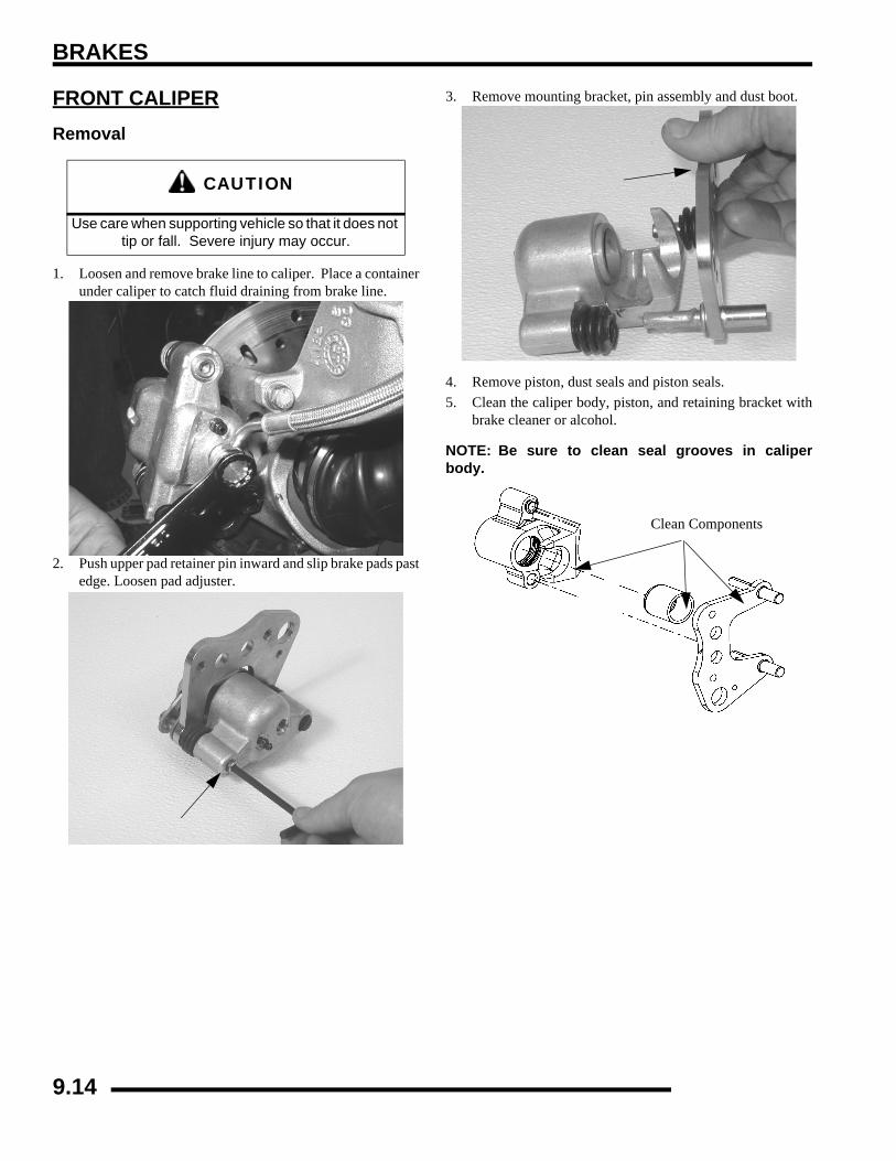
BRAKES
FRONT CALIPERRemoval
1. Loosen and remove brake line to caliper. Place a containerunder caliper to catch fluid draining from brake line.
2. Push upper pad retainer pin inward and slip brake pads pastedge. Loosen pad adjuster.
3. Remove mounting bracket, pin assembly and dust boot.
4. Remove piston, dust seals and piston seals.5. Clean the caliper body, piston, and retaining bracket with
brake cleaner or alcohol.
NOTE: Be sure to clean seal grooves in caliperbody.
CAUTION
Use care when supporting vehicle so that it does not tip or fall. Severe injury may occur.
Clean Components
9.14

BRAKES
9
Inspection1. Inspect caliper body for nicks, scratches or wear. Measure
bore size and compare to specifications. Replace if damageis evident or if worn beyond service limit.
2. Inspect piston for nicks, scratches, wear or damage.Measure diameter and replace if damaged or worn beyondservice limit.
3. Inspect the brake disc and pads as outlined for brake padreplacement in this section. See “BRAKE PADINSPECTION” earlier in this chapter.
Reassembly1. Install new caliper seals (A) in the caliper body (B). Be
sure groove is clean and free of residue or brakes may dragupon assembly.
2. Coat piston with clean Polaris DOT-approved Brake Fluid(C). Install piston (D) with a twisting motion while pushinginward. Piston should slide in and out of bore smoothly,with light resistance.
3. Lubricate the mounting bracket pins with Polaris PremiumAll Season Grease (PN 2871423), and install the rubberdust seal boots.
= In. / mm.
Front Caliper Piston Bore I.D.:Service Limit: 1.193” (30.30 mm)
A
BC
D
9.15
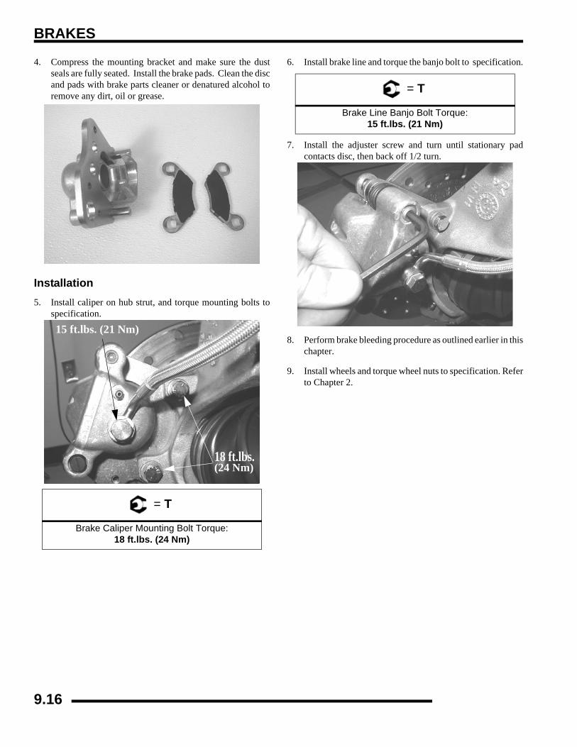
BRAKES
4. Compress the mounting bracket and make sure the dustseals are fully seated. Install the brake pads. Clean the discand pads with brake parts cleaner or denatured alcohol toremove any dirt, oil or grease.
Installation5. Install caliper on hub strut, and torque mounting bolts to
specification.
6. Install brake line and torque the banjo bolt to specification.
7. Install the adjuster screw and turn until stationary padcontacts disc, then back off 1/2 turn.
8. Perform brake bleeding procedure as outlined earlier in thischapter.
9. Install wheels and torque wheel nuts to specification. Referto Chapter 2.
= T
Brake Caliper Mounting Bolt Torque:18 ft.lbs. (24 Nm)
15 ft.lbs. (21 Nm)
18 ft.lbs.(24 Nm)
= T
Brake Line Banjo Bolt Torque:15 ft.lbs. (21 Nm)
9.16

BRAKES
9
REAR BRAKE PADX2, Touring Pad Removal1. Elevate and support the rear of the ATV.
2. Remove the rear wheel
3. Loosen pad adjuster screw 2-3 turns.
4. Remove the two caliper mounting bolts and lift caliper offthe brake disc.
NOTE: When removing caliper, be careful not todamage brake line. Support caliper so as not to kinkor bend brake line.
5. Push caliper piston into the caliper bore slowly using a C-clamp or locking pliers with pads installed.
NOTE: Brake fluid will be forced throughcompensating port into master cylinder fluidreservoir when piston is pushed back into caliper.Remove excess fluid from reservoir as required.
6. Push caliper mounting bracket inward and slip outer brakepad past the edge to remove.
7. Remove the inner brake pad.
8. Clean the caliper with brake cleaner or alcohol.
9.17
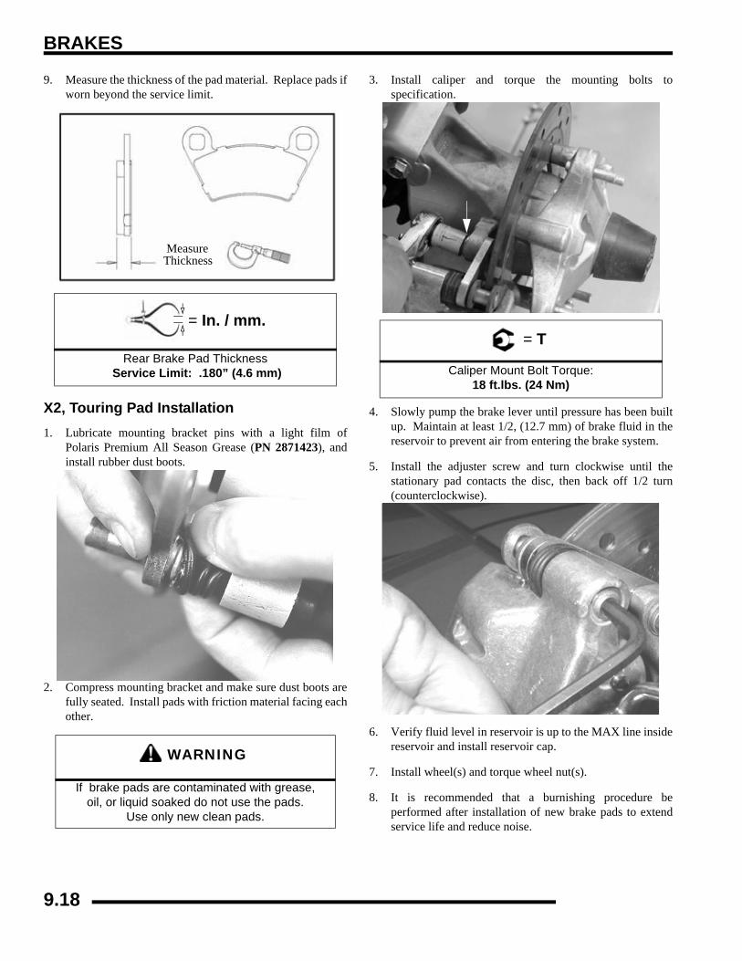
BRAKES
9. Measure the thickness of the pad material. Replace pads ifworn beyond the service limit.
X2, Touring Pad Installation1. Lubricate mounting bracket pins with a light film of
Polaris Premium All Season Grease (PN 2871423), andinstall rubber dust boots.
2. Compress mounting bracket and make sure dust boots arefully seated. Install pads with friction material facing eachother.
3. Install caliper and torque the mounting bolts tospecification.
4. Slowly pump the brake lever until pressure has been builtup. Maintain at least 1/2, (12.7 mm) of brake fluid in thereservoir to prevent air from entering the brake system.
5. Install the adjuster screw and turn clockwise until thestationary pad contacts the disc, then back off 1/2 turn(counterclockwise).
6. Verify fluid level in reservoir is up to the MAX line insidereservoir and install reservoir cap.
7. Install wheel(s) and torque wheel nut(s).
8. It is recommended that a burnishing procedure beperformed after installation of new brake pads to extendservice life and reduce noise.
= In. / mm.
Rear Brake Pad Thickness Service Limit: .180” (4.6 mm)
WARNING
If brake pads are contaminated with grease, oil, or liquid soaked do not use the pads.
Use only new clean pads.
MeasureThickness
= T
Caliper Mount Bolt Torque:18 ft.lbs. (24 Nm)
9.18

BRAKES
9
Sportsman Rear Pad Removal1. Support the machine. Remove the rear tire.2. Remove the slide pin clips from the slide bolt.
3. Loosen the slide pins with a hex wrench.
4. Remove caliper mounting bolts and lift caliper off of disc.
NOTE: When removing caliper, be careful not todamage brake line. Support caliper so as not to kinkor bend brake line.
5. Push caliper pistons into caliper bore slowly with padsinstalled.
6. Remove the caliper slide pins and remove the brake padsfrom the caliper.
7. Clean the caliper with brake cleaner or alcohol.8. Measure the thickness of the pad material. Replace pads if
worn beyond the service limit.
= In. / mm.
Rear Brake Pad Thickness Service Limit: .180” (4.6 mm)
Remove Rear Pads
MeasureThickness
9.19

BRAKES
Sportsman Rear Pad Installation1. Install new brake pads in caliper body.
2. Install and tighten the slide pin with a hex wrench.3. Install caliper and torque the mounting bolts to
specification.
4. Install the slide bolt snap ring. Torque the slide pin tospecification.
5. Slowly pump the brake lever until pressure has been builtup. Maintain at least 1/2, (12.7 mm) of brake fluid in thereservoir to prevent air from entering the master cylinder.
6. It is recommended that a burnishing procedure beperformed after installation of new brake pads to extendservice life and reduce noise.
Brake Burnishing ProcedureStart machine and slowly increase speed to 30 mph. Graduallyapply brakes to stop machine. Allow pads and disc to coolsufficiently during the procedure. Do not allow pads or disc tobecome hot or warping may result. Repeat this procedure 10times.
WARNING
If the brake pads are contaminated with grease, oil, or liquid soaked do not use the pads,
use only new clean pads.
= T
Caliper Mount Bolt Torque:18 ft.lbs. (24 Nm)
Install Pads
18 ft.lbs. (24 Nm)
= T
Caliper Slide Bolt Torque:30-35 ft.lbs. (41-48Nm)
30-35 ft.lbs.(41-48 Nm)
9.20

BRAKES
9
X2, TOURING REAR CALIPERRemoval
1. Clean caliper area before removal.
2. Place a container below the caliper to catch brake fluid thatwill drain from the brake line. Remove brake line fromcaliper
3. Remove the two caliper mounting bolts and the caliper.
4. Loosen the adjuster screw and remove the brake pads.5. Remove mounting bracket, pin assembly and dust boot.
6. Remove piston, dust seals and piston seals.
7. Clean the caliper body, piston, and retaining bracket withbrake cleaner or alcohol.
NOTE: Be sure to clean seal grooves in caliperbody.
CAUTION
Use care when supporting vehicle so that it does not tip or fall. Severe injury may occur.
Clean Components
9.21

BRAKES
Inspection1. Inspect caliper body for nicks, scratches or wear. Measure
bore size and compare to specifications. Replace if damageis evident or if worn beyond service limit.
2. Inspect piston for nicks, scratches, wear or damage.Measure diameter and replace if damaged or worn beyondservice limit.
3. Inspect the brake disc and pads as outlined for brake padreplacement in this section. See “BRAKE PADINSPECTION” earlier in this chapter.
Reassembly1. Install new caliper seals (A) in the caliper body (B). Be
sure groove is clean and free of residue or brakes may dragupon assembly.
2. Coat piston with clean Polaris DOT-approved BrakeFluid (C). Install piston (D) with a twisting motion whilepushing inward. Piston should slide in and out of boresmoothly, with light resistance.
3. Lubricate the mounting bracket pins with Polaris PremiumAll Season Grease (PN 2871423), and install the rubberdust seal boots.
= In. / mm.
Rear Caliper Piston Bore I.D.Service Limit: 1.193” (30.30 mm)
A
BC
D
9.22
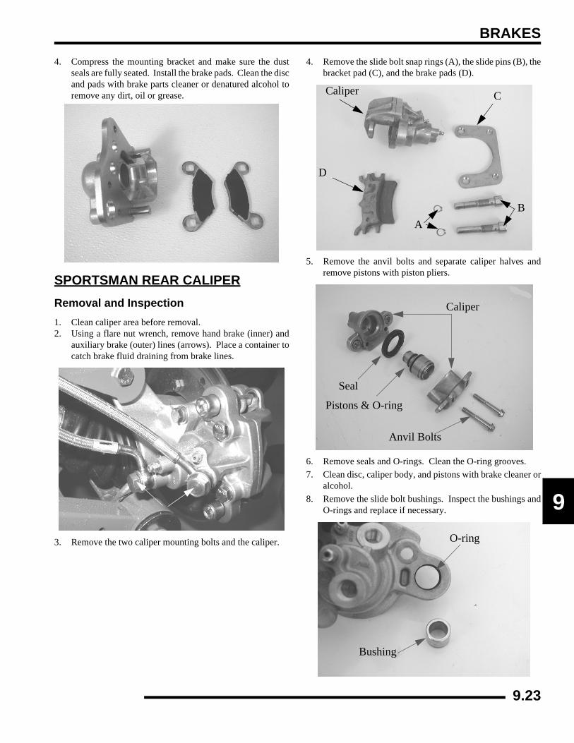
BRAKES
9
4. Compress the mounting bracket and make sure the dustseals are fully seated. Install the brake pads. Clean the discand pads with brake parts cleaner or denatured alcohol toremove any dirt, oil or grease.
SPORTSMAN REAR CALIPERRemoval and Inspection1. Clean caliper area before removal.2. Using a flare nut wrench, remove hand brake (inner) and
auxiliary brake (outer) lines (arrows). Place a container tocatch brake fluid draining from brake lines.
3. Remove the two caliper mounting bolts and the caliper.
4. Remove the slide bolt snap rings (A), the slide pins (B), thebracket pad (C), and the brake pads (D).
5. Remove the anvil bolts and separate caliper halves andremove pistons with piston pliers.
6. Remove seals and O-rings. Clean the O-ring grooves.7. Clean disc, caliper body, and pistons with brake cleaner or
alcohol.8. Remove the slide bolt bushings. Inspect the bushings and
O-rings and replace if necessary.
Caliper C
B
D
A
Caliper
Seal
Pistons & O-ring
Anvil Bolts
O-ring
Bushing
9.23

BRAKES
9. Measure the inside diameter of the rear caliper. The caliperbody is a 2-step piston. The rear step is measured as wellas the outside step.
10. Inspect caliper piston bore for scratches, severe corrosion,or galling and replace if necessary.
11. Inspect surface of caliper piston for nicks, scratches, ordamage and replace if necessary.
Assembly1. Install new O-rings in the slide bolt bushing holes. Be sure
O-ring and seal grooves are thoroughly cleaned of allresidue, or piston may bind in bore. Apply brake fluid topiston seals and install carefully with a twisting motion toease assembly until fully seated.
2. Carefully assemble caliper body, making sure O-rings areproperly positioned in groove. Tighten the caliper anvilbolts and then torque the anvil bolts evenly to specification.
3. Install brake pads in caliper body with friction materialfacing each other. Install the slide pins and the slide pinretaining rings. Torque the slide pins to specification.
= In. / mm.
Rear Caliper Piston Bore I.D.Inner Bore Service Limit: .94” (23.88 mm)Outer Bore Service Limit: 1.5” (38.1 mm)
.94in. (23.88) mm)
1.5 in. (38.1 mm)
Inspect
= T
Caliper Anvil Bolt Torque:16-18 ft.lbs. (22-24 Nm)
Seals
16-18 ft.lbs. (22-24
9.24

BRAKES
9
NOTE: The slide pins should be torqued wheninstalled on caliper mount.
4. Install caliper and torque mounting bolts to specification.
5. Install brake line and tighten securely with a line wrench.Torque the brake lines to the proper torque specification.
6. Follow bleeding procedure outlined in the “BLEEDINGPROCEDURE” in this chapter.
7. Field test unit for proper braking action before putting intoservice. Inspect for fluid leaks and firm brakes. Make surethe brake is not dragging when lever is released. If the brakedrags, re-check assembly and installation.
REAR BRAKE DISCInspection1. Visually inspect disc for scoring, scratches, or gouges.
Replace the disc if any deep scratches are evident.
2. Use a micrometer and measure disc thickness at 8 differentpoints around perimeter of disc. Replace disc if wornbeyond service limit.
3. Mount dial indicator and measure disc runout. Replace thedisc if runout exceeds specifications.
= T
Slide Pin Torque:30-35 ft.lbs. (41-48 Nm)
= T
Caliper Mounting Bolt Torque:17 ft.lbs. (23 Nm)
18 ft.lbs.(24 Nm)
30-35 ft.lbs.(41-48 Nm)
= In. / mm.
Brake Disc Thickness: Service Limit: .170” (4.318 mm)
= In. / mm.
Brake Disc Thickness Variance: Service Limit: .002” (.051 mm)
Between Measurements
= In. / mm.
Brake Disc Runout Service Limit: .010” / .254 mm
Disc Thickness
9.25

BRAKES
REAR MASTER CYLINDERX2, Touring Exploded View
A
B
D
EF
G
I
H
C
D
E
J
A. Master Cylinder BoltsB. Rear Brake Line C. Rear Master CylinderD. Bushing(s) E. Washer(s) F. Cotter Pin G. Foot Pedal H. Spring I. Front Brake Line J. Banjo Fitting
9.26

BRAKES
9
OverviewPolaris disc brake systems are light weight, low maintenanceand perform well in the conditions ATV’s routinely encounter.However, there are a few things to remember when replacingdisc brake pads or performing brake system service to ensureproper system function and maximum pad service life.
• Perform a brake burnishing procedure after installing new pads to maximize service life.
• Optional pads are available to suit conditions in your area. Select a pad to fit riding style and environment.
• Do not over-fill the master cylinder fluid reservoir.
• Make sure the brake lever and pedal returns freely and completely.
• Adjust stop pin on caliper (if applicable) after pad service.
• Check and adjust master cylinder reservoir fluid level after pad service.
• Make sure atmospheric vent on reservoir is unobstructed.
• Test for brake drag after any brake system service and investigate cause if brake drag is evident.
• Make sure caliper moves freely on guide pins (where applicable).
• Inspect caliper piston seals for foreign material that could prevent caliper pistons from returning freely.
X2, Touring Rear Master Cylinder Removal and Installation
1. Remove the RH footwell to gain access to the rear mastercylinder.
2. If required, remove the rear brake line from the mastercylinder. Use a suitable container to catch the brake fluid.Dispose of brake fluid properly.
3. Remove the two bolts that secure the rear master cylinderto the frame. Replace parts as needed.
4. To install the rear master cylinder, mount the mastercylinder to the frame and torque bolts to specification.
5. Reinstall the brake line and torque the banjo bolt tospecification.
6. Perform brake bleeding procedures as outlined in thischapter.
CAUTION
Use only DOT-approved brake fluid as an assembly aid for all procedures described in this chapter to
prevent brake system contamination. DO NOT USE LUBRICANTS OF ANY KIND FOR
ASSEMBLY, AS THEIR USE CAN CAUSE RUBBER COMPONENTS TO SWELL.
= T
Master Cylinder to Frame Bolt Torque: 8 ft.lbs. (11 Nm)
= T
Banjo Bolt Torque:15 ft.lbs. (21 Nm)
Frame
Brake Fluid Reservoir
Brake Lever
Front Brake Line
Brake Mount
Rear Brake Line
Spring
Rear Brake MC
9.27

BRAKES
Sportsman Rear Master Cylinder Removal / Installation1. Remove the RH footwell to gain access to the rear master
cylinder.2. Remove the rear brake lines from the master cylinder. Use
a suitable container to catch the brake fluid. Dispose ofbrake fluid properly.
3. Remove the two bolts that secure the rear master cylinderto the brake mount plate. Replace parts as needed.
4. To install the rear brake master cylinder, mount the mastercylinder to the mount plate and torque bolts to specification.
5. Reinstall the brake line and torque the banjo bolt tospecification depending on the style of fitting.
6. Perform brake bleeding procedures as outlined in thischapter.
= T
Master Cylinder to Frame Bolt Torque: 8 ft.lbs. (11 Nm)
= T
Banjo Bolt Torque:15 ft.lbs. (21 Nm)
= T
Flare Stye Brake Line Torque:12-15 ft.lbs. (16-20 Nm)
15 ft.lbs.(21 Nm)
A. Brake Reservoir B. Rear Foot Brake LineC. Rear Master CylinderD. Master Cylinder BoltsE. Bushing F. Washer G. Cotter Pin H. Foot Pedal I. Mount Plate Bolts J. Mount Plate K. Spring
A
B
C
D
E
F
G H
I
J
K
SPORTSMAN
9.28
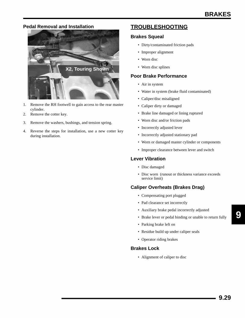
BRAKES
9
Pedal Removal and Installation
1. Remove the RH footwell to gain access to the rear mastercylinder.
2. Remove the cotter key.
3. Remove the washers, bushings, and tension spring.
4. Reverse the steps for installation, use a new cotter keyduring installation.
TROUBLESHOOTINGBrakes Squeal
• Dirty/contaminated friction pads
• Improper alignment
• Worn disc
• Worn disc splines
Poor Brake Performance• Air in system
• Water in system (brake fluid contaminated)
• Caliper/disc misaligned
• Caliper dirty or damaged
• Brake line damaged or lining ruptured
• Worn disc and/or friction pads
• Incorrectly adjusted lever
• Incorrectly adjusted stationary pad
• Worn or damaged master cylinder or components
• Improper clearance between lever and switch
Lever Vibration• Disc damaged
• Disc worn (runout or thickness variance exceeds service limit)
Caliper Overheats (Brakes Drag)• Compensating port plugged
• Pad clearance set incorrectly
• Auxiliary brake pedal incorrectly adjusted
• Brake lever or pedal binding or unable to return fully
• Parking brake left on
• Residue build up under caliper seals
• Operator riding brakes
Brakes Lock
• Alignment of caliper to disc
X2, Touring Shown
9.29

BRAKES
NOTES
9.30
ELECTRICAL
CHAPTER 10ELECTRICAL
10
INSTRUMENT CLUSTER . . . . . . . . . . . . . . . . . . . . . . . . . . . . . . . . . . . . . . . . . . . . . . . . 10.3OVERVIEW. . . . . . . . . . . . . . . . . . . . . . . . . . . . . . . . . . . . . . . . . . . . . . . . . . . . . . . . . . . 10.3INSTRUMENT CLUSTER DIAGNOSTIC MODE . . . . . . . . . . . . . . . . . . . . . . . . . . . . . . 10.4SETTING A NEW SERVICE INTERVAL . . . . . . . . . . . . . . . . . . . . . . . . . . . . . . . . . . . . 10.6EFI DIAGNOSTIC MODE . . . . . . . . . . . . . . . . . . . . . . . . . . . . . . . . . . . . . . . . . . . . . . . . 10.7SPEEDOMETER REMOVAL . . . . . . . . . . . . . . . . . . . . . . . . . . . . . . . . . . . . . . . . . . . . . 10.8SPEEDOMETER INSTALLATION . . . . . . . . . . . . . . . . . . . . . . . . . . . . . . . . . . . . . . . . . 10.9
SPEEDOMETER TROUBLESHOOTING . . . . . . . . . . . . . . . . . . . . . . . . . . . . . . . . . . . 10.10TEST 1 - NO ALL WHEEL DRIVE . . . . . . . . . . . . . . . . . . . . . . . . . . . . . . . . . . . . . . . . 10.10TEST 2 - NO DISPLAY / TEST 3 - NO REVERSE SPEED LIMIT. . . . . . . . . . . . . . . . 10.11TEST 4 - NO AWD HUB SAFETY LIMITER. . . . . . . . . . . . . . . . . . . . . . . . . . . . . . . . . 10.12TEST 5 - REVERSE SPEED LIMITER / TEST 6 - SPEED SENSOR . . . . . . . . . . . . . 10.13TEST 7 - NO FUEL GAUGE / TEST 8 - TRANSMISSION SWITCH . . . . . . . . . . . . . . 10.14
ACTIVE DESCENT CONTROL (ADC) COIL. . . . . . . . . . . . . . . . . . . . . . . . . . . . . . . . . 10.15OPERATION OVERVIEW . . . . . . . . . . . . . . . . . . . . . . . . . . . . . . . . . . . . . . . . . . . . . . 10.15DIAGNOSING SYSTEM FAILURES. . . . . . . . . . . . . . . . . . . . . . . . . . . . . . . . . . . . . . . 10.15
ALL WHEEL DRIVE (AWD) COIL . . . . . . . . . . . . . . . . . . . . . . . . . . . . . . . . . . . . . . . . . 10.15OPERATION OVERVIEW . . . . . . . . . . . . . . . . . . . . . . . . . . . . . . . . . . . . . . . . . . . . . . 10.15DIAGNOSING SYSTEM FAILURES. . . . . . . . . . . . . . . . . . . . . . . . . . . . . . . . . . . . . . . 10.15
COOLING SYSTEM COMPONENTS . . . . . . . . . . . . . . . . . . . . . . . . . . . . . . . . . . . . . . 10.16FAN CONTROL CIRCUIT OPERATION / TESTING . . . . . . . . . . . . . . . . . . . . . . . . . . 10.16FAN CONTROL CIRCUIT BYPASS TEST. . . . . . . . . . . . . . . . . . . . . . . . . . . . . . . . . . 10.16COOLANT TEMPERATURE SENSOR . . . . . . . . . . . . . . . . . . . . . . . . . . . . . . . . . . . . 10.16FAN MOTOR CURRENT DRAW . . . . . . . . . . . . . . . . . . . . . . . . . . . . . . . . . . . . . . . . . 10.17
GEAR POSITION INDICATOR SWITCH. . . . . . . . . . . . . . . . . . . . . . . . . . . . . . . . . . . . 10.17TEST DIAGRAM. . . . . . . . . . . . . . . . . . . . . . . . . . . . . . . . . . . . . . . . . . . . . . . . . . . . . . 10.17
ELECTRONIC THROTTLE CONTROL (ETC) SWITCH . . . . . . . . . . . . . . . . . . . . . . . . 10.18ETC SWITCH OPERATION . . . . . . . . . . . . . . . . . . . . . . . . . . . . . . . . . . . . . . . . . . . . . 10.18ETC OPERATION TEST . . . . . . . . . . . . . . . . . . . . . . . . . . . . . . . . . . . . . . . . . . . . . . . 10.18
IGNITION SYSTEM . . . . . . . . . . . . . . . . . . . . . . . . . . . . . . . . . . . . . . . . . . . . . . . . . . . . 10.19FLYWHEEL IDENTIFICATION. . . . . . . . . . . . . . . . . . . . . . . . . . . . . . . . . . . . . . . . . . . 10.19EFI - DC/CDI IGNITION OVERVIEW . . . . . . . . . . . . . . . . . . . . . . . . . . . . . . . . . . . . . . 10.19ALTERNATOR/IGNITION COMPONENTS - 700/800 EFI . . . . . . . . . . . . . . . . . . . . . . 10.20CRANKSHAFT POSITION SENSOR GAP. . . . . . . . . . . . . . . . . . . . . . . . . . . . . . . . . . 10.21IGNITION SYSTEM TROUBLESHOOTING. . . . . . . . . . . . . . . . . . . . . . . . . . . . . . . . . 10.21
CHARGING SYSTEM . . . . . . . . . . . . . . . . . . . . . . . . . . . . . . . . . . . . . . . . . . . . . . . . . . 10.21CURRENT DRAW - KEY OFF . . . . . . . . . . . . . . . . . . . . . . . . . . . . . . . . . . . . . . . . . . . 10.21CHARGING SYSTEM “BREAK EVEN” TEST . . . . . . . . . . . . . . . . . . . . . . . . . . . . . . . 10.22ALTERNATOR OUTPUT TEST . . . . . . . . . . . . . . . . . . . . . . . . . . . . . . . . . . . . . . . . . . 10.22CHARGING SYSTEM TESTING FLOW CHART . . . . . . . . . . . . . . . . . . . . . . . . . . . . . 10.24
RELAYS. . . . . . . . . . . . . . . . . . . . . . . . . . . . . . . . . . . . . . . . . . . . . . . . . . . . . . . . . . . . . 10.25OPERATION. . . . . . . . . . . . . . . . . . . . . . . . . . . . . . . . . . . . . . . . . . . . . . . . . . . . . . . . . 10.25
FUSES/CIRCUIT BREAKER . . . . . . . . . . . . . . . . . . . . . . . . . . . . . . . . . . . . . . . . . . . . . 10.26OPERATION. . . . . . . . . . . . . . . . . . . . . . . . . . . . . . . . . . . . . . . . . . . . . . . . . . . . . . . . . 10.26
LIGHTING . . . . . . . . . . . . . . . . . . . . . . . . . . . . . . . . . . . . . . . . . . . . . . . . . . . . . . . . . . . 10.26HIGH BEAM HEADLIGHT BULB REPLACEMENT . . . . . . . . . . . . . . . . . . . . . . . . . . . 10.26HEADLIGHT HOUSING REPLACEMENT . . . . . . . . . . . . . . . . . . . . . . . . . . . . . . . . . . 10.27HIGH BEAM HEADLIGHT ADJUSTMENT. . . . . . . . . . . . . . . . . . . . . . . . . . . . . . . . . . 10.28LOWER HEADLAMP REMOVAL / INSTALLATION. . . . . . . . . . . . . . . . . . . . . . . . . . . 10.28LOW BEAM HEADLIGHT ADJUSTMENT . . . . . . . . . . . . . . . . . . . . . . . . . . . . . . . . . . 10.29HEADLAMP SWITCH TEST. . . . . . . . . . . . . . . . . . . . . . . . . . . . . . . . . . . . . . . . . . . . . 10.29WORK LIGHT / DIFFERENTIAL SWITCH . . . . . . . . . . . . . . . . . . . . . . . . . . . . . . . . . . 10.30SPORTSMAN / TOURING BRAKE LIGHT / WORK LIGHT REPLACEMENT. . . . . . . 10.30X2 BRAKE LIGHT / WORK LIGHT REPLACEMENT. . . . . . . . . . . . . . . . . . . . . . . . . . 10.31BRAKE LIGHT SWITCH. . . . . . . . . . . . . . . . . . . . . . . . . . . . . . . . . . . . . . . . . . . . . . . . 10.32
10.1

ELECTRICAL
FUEL SENDER . . . . . . . . . . . . . . . . . . . . . . . . . . . . . . . . . . . . . . . . . . . . . . . . . . . . . . . 10.33TESTING . . . . . . . . . . . . . . . . . . . . . . . . . . . . . . . . . . . . . . . . . . . . . . . . . . . . . . . . . . . 10.33
X2 / TOURING DIFFERENTIAL SYSTEM . . . . . . . . . . . . . . . . . . . . . . . . . . . . . . . . . . 10.33SOLENOID TESTING. . . . . . . . . . . . . . . . . . . . . . . . . . . . . . . . . . . . . . . . . . . . . . . . . . 10.33SOLENOID REPLACEMENT . . . . . . . . . . . . . . . . . . . . . . . . . . . . . . . . . . . . . . . . . . . . 10.33DIFFERENTIAL RELAY OPERATION . . . . . . . . . . . . . . . . . . . . . . . . . . . . . . . . . . . . . 10.34DIFFERENTIAL RELAY TESTING. . . . . . . . . . . . . . . . . . . . . . . . . . . . . . . . . . . . . . . . 10.34
X2 / TOURING SPEED SENSOR . . . . . . . . . . . . . . . . . . . . . . . . . . . . . . . . . . . . . . . . . 10.34TESTING . . . . . . . . . . . . . . . . . . . . . . . . . . . . . . . . . . . . . . . . . . . . . . . . . . . . . . . . . . . 10.34REPLACEMENT. . . . . . . . . . . . . . . . . . . . . . . . . . . . . . . . . . . . . . . . . . . . . . . . . . . . . . 10.34
ACCESSORY POWER . . . . . . . . . . . . . . . . . . . . . . . . . . . . . . . . . . . . . . . . . . . . . . . . . 10.35WIRE CONNECTIONS. . . . . . . . . . . . . . . . . . . . . . . . . . . . . . . . . . . . . . . . . . . . . . . . . 10.35
STARTER SYSTEM . . . . . . . . . . . . . . . . . . . . . . . . . . . . . . . . . . . . . . . . . . . . . . . . . . . 10.36SPORTSMAN STARTER LOCKOUT OVERVIEW AND DIAGNOSTIC . . . . . . . . . . . 10.36X2 /TOURING STARTER LOCKOUT OVERVIEW AND DIAGNOSTIC . . . . . . . . . . . 10.37TROUBLESHOOTING . . . . . . . . . . . . . . . . . . . . . . . . . . . . . . . . . . . . . . . . . . . . . . . . . 10.38VOLTAGE DROP TEST . . . . . . . . . . . . . . . . . . . . . . . . . . . . . . . . . . . . . . . . . . . . . . . . 10.38STARTER MOTOR REMOVAL / DISASSEMBLY . . . . . . . . . . . . . . . . . . . . . . . . . . . . 10.38BRUSH INSPECTION / REPLACEMENT . . . . . . . . . . . . . . . . . . . . . . . . . . . . . . . . . . 10.39ARMATURE TESTING. . . . . . . . . . . . . . . . . . . . . . . . . . . . . . . . . . . . . . . . . . . . . . . . . 10.40STARTER REASSEMBLY / INSTALLATION. . . . . . . . . . . . . . . . . . . . . . . . . . . . . . . . 10.41STARTER SOLENOID BENCH TEST . . . . . . . . . . . . . . . . . . . . . . . . . . . . . . . . . . . . . 10.41STARTER DRIVE. . . . . . . . . . . . . . . . . . . . . . . . . . . . . . . . . . . . . . . . . . . . . . . . . . . . . 10.42STARTER EXPLODED VIEW . . . . . . . . . . . . . . . . . . . . . . . . . . . . . . . . . . . . . . . . . . . 10.43
STARTER SYSTEM TESTING FLOW CHART. . . . . . . . . . . . . . . . . . . . . . . . . . . . . . . 10.44BASIC WINCH WIRING- PRE-WIRED MODELS . . . . . . . . . . . . . . . . . . . . . . . . . . . . . 10.45BATTERY . . . . . . . . . . . . . . . . . . . . . . . . . . . . . . . . . . . . . . . . . . . . . . . . . . . . . . . . . . . 10.46
BATTERY IDENTIFICATION . . . . . . . . . . . . . . . . . . . . . . . . . . . . . . . . . . . . . . . . . . . . 10.46BATTERY ACTIVATION (CONVENTIONAL). . . . . . . . . . . . . . . . . . . . . . . . . . . . . . . . 10.46BATTERY TERMINALS/BOLTS. . . . . . . . . . . . . . . . . . . . . . . . . . . . . . . . . . . . . . . . . . 10.47CONVENTIONAL BATTERY INSPECTION / REMOVAL . . . . . . . . . . . . . . . . . . . . . . 10.47CONVENTIONAL BATTERY INSTALLATION . . . . . . . . . . . . . . . . . . . . . . . . . . . . . . . 10.47CONVENTIONAL BATTERY TESTING . . . . . . . . . . . . . . . . . . . . . . . . . . . . . . . . . . . . 10.48CONVENTIONAL BATTERY OCV - OPEN CIRCUIT VOLTAGE TEST . . . . . . . . . . . 10.48CONVENTIONAL BATTERY SPECIFIC GRAVITY TEST . . . . . . . . . . . . . . . . . . . . . . 10.48BATTERY LOAD TEST . . . . . . . . . . . . . . . . . . . . . . . . . . . . . . . . . . . . . . . . . . . . . . . . 10.49OFF SEASON STORAGE . . . . . . . . . . . . . . . . . . . . . . . . . . . . . . . . . . . . . . . . . . . . . . 10.49CHARGING PROCEDURE . . . . . . . . . . . . . . . . . . . . . . . . . . . . . . . . . . . . . . . . . . . . . 10.49LOW MAINTENANCE BATTERY. . . . . . . . . . . . . . . . . . . . . . . . . . . . . . . . . . . . . . . . . 10.50LOW MAINTENANCE BATTERY CHARGING . . . . . . . . . . . . . . . . . . . . . . . . . . . . . . 10.50LOW MAINTENANCE BATTERY INSPECTION / REMOVAL . . . . . . . . . . . . . . . . . . . 10.51LOW MAINTENANCE BATTERY INSTALLATION . . . . . . . . . . . . . . . . . . . . . . . . . . . 10.51LOW MAINTENANCE BATTERY - OCV- OPEN CIRCUIT VOLTAGE TEST . . . . . . . 10.52LOW MAINTENANCE BATTERY LOAD TEST . . . . . . . . . . . . . . . . . . . . . . . . . . . . . . 10.52LOW MAINTENANCE BATTERY OFF-SEASON STORAGE . . . . . . . . . . . . . . . . . . . 10.53LOW MAINTENANCE BATTERY CHARGING PROCEDURE . . . . . . . . . . . . . . . . . . 10.53
TROUBLESHOOTING DIAGRAMS . . . . . . . . . . . . . . . . . . . . . . . . . . . . . . . . . . . . . . . 10.54OVERVIEW . . . . . . . . . . . . . . . . . . . . . . . . . . . . . . . . . . . . . . . . . . . . . . . . . . . . . . . . . 10.54ALL WHEEL DRIVE - EFI. . . . . . . . . . . . . . . . . . . . . . . . . . . . . . . . . . . . . . . . . . . . . . . 10.54CHARGING CIRCUIT - EFI . . . . . . . . . . . . . . . . . . . . . . . . . . . . . . . . . . . . . . . . . . . . . 10.54COOLING FAN - EFI . . . . . . . . . . . . . . . . . . . . . . . . . . . . . . . . . . . . . . . . . . . . . . . . . . 10.55FUEL PUMP - EFI . . . . . . . . . . . . . . . . . . . . . . . . . . . . . . . . . . . . . . . . . . . . . . . . . . . . 10.55GEAR SWITCH - EFI . . . . . . . . . . . . . . . . . . . . . . . . . . . . . . . . . . . . . . . . . . . . . . . . . . 10.56POWER CIRCUIT - EFI . . . . . . . . . . . . . . . . . . . . . . . . . . . . . . . . . . . . . . . . . . . . . . . . 10.56 REVERSE OVERRIDE - EFI . . . . . . . . . . . . . . . . . . . . . . . . . . . . . . . . . . . . . . . . . . . . 10.57FAN CONTROL - EFI . . . . . . . . . . . . . . . . . . . . . . . . . . . . . . . . . . . . . . . . . . . . . . . . . . 10.57START CIRCUIT - EFI . . . . . . . . . . . . . . . . . . . . . . . . . . . . . . . . . . . . . . . . . . . . . . . . . 10.58START ENABLE - EFI . . . . . . . . . . . . . . . . . . . . . . . . . . . . . . . . . . . . . . . . . . . . . . . . . 10.58
10.2

ELECTRICAL
0
1INSTRUMENT CLUSTER Overview
Introduction
Refer To Illustration 1:
The Polaris ATV Instrument Cluster is powered by batteryvoltage (12 VDC) and requires inputs from the engine RPM,transmission gear, and speed sensor for proper operation. Twoharnesses plug into the cluster head; one from the speed sensor,and one from the vehicle main harness. A non-serviceableinternal memory battery maintains odometer and hour meterdata when the machine is not running. The illumination lampinside the gauge is non-serviceable and is designed to last for thelife of the unit. (A) The speedometer needle indicates speedfrom an electronic speed sensor. The needle also flashes duringa warning condition. The speedometer needle indicates speed inMPH and KPH. NOTE: A flashing needle could indicate a hotengine, low battery warning, or the No. 10 Pin could begrounded. (B) The speedometer face features numbers in MilePer Hour (MPH) and Kilometers Per Hour (KPH). (C) TheRider Information Center performs a number of functions (SeeIllustration 2):
1. Odometer / Tachometer / Trip meter / Hour Meter / Clock
• Odometer records the miles traveled by the ATV.
• Tachometer displays engine RPM. This feature will also display with the vehicle in motion NOTE: Small RPM fluctuations from day to day are normal because of changes in humidity, temperature, and elevation
• Trip meter records the miles traveled by the ATV if reset before each trip or total miles to 999. To reset the trip meter, select the trip meter mode. Press and hold the mode button (override button) until the total changes to 0. NOTE: In the Rider Information Center, the trip meter display contains a decimal point, but the odometer displays without a decimal point.
• Hour meter logs the total hours the engine has been in operation.
• Clock - displays hours and minutes.
2. Programmable Service Interval / Diagnostic Mode
• Service Interval - The purpose of the programmable service interval is to provide the consumer and the dealer with a convenient way to schedule routine maintenance. When the ATV leaves the factory, this feature is set at “50 hours". When the first 50 hours of engine operation are finished the wrench icon will flash for 10 seconds each time the ATV is started as a reminder that ATV maintenance is due. NOTE: To reset the Service Interval, follow the directions for “SETTING NEW SERVICE INTERVAL” later in this chapter.
3. Check Engine Warning Indicator
• The word HOT will display alpha numerically when the engine is overheating. Do not continue to operate the ATV if this warning appears. Refer to Chapter 3 “COOLING SYSTEM TROUBLESHOOTING” for help with diagnosis of overheating.
(A) Speedometer Needle (flashes during warning condition)
(B) Speedometerin MPH/KPH
(C) Rider Information Center ILL. 1
1425
6
7 8
3
9
9
ILL. 2
10.3

ELECTRICAL
4. High/Low Battery Voltage
• This warning usually indicates that the ATV is being operated at an RPM too low to keep the battery charged. A low battery warning may also occur under normal operation if the machine is at idle and high electrical load (lights, cooling fan, accessories) is applied. Driving at a higher RPM or connecting a battery charger will usually clear the warning. This indicator may also turn in the event of an overcharging situation, such as a faulty voltage regulator.
5. Engine Hour Display Indicator
• Displays number of hours of engine operation.
6. AWD Indicator
• Illuminates when the electrical portion of the AWD system is enabled.
7. Gear Indicator
• Specifies what position the shift lever and transmission are in. This area is blank if a fault occurs.
8. Mode Indicator
• Indicates which modes are being utilized.
9. Fuel Gauge
• The segments of the fuel gauge indicate the level of fuel in the fuel tank. When the last segment clears, a low fuel warning is activated. All related icons will flash, “FUEL” will display in the LCD, and the speedometer needle will blink. If riding, be sure to refuel immediately.
Instrument Cluster Diagnostic ModeNOTE: This gauge features auto shut-off protectionif the voltage on the DC bus is excessive. This isusually the result of an open battery condition, andthe gauge is designed to survive such an event.
NOTE: If the gauge will not indicate what gear it is inand will not allow AWD operation, AWD can still beenabled by holding in the mode/override button.
1. Turn the key switch off and wait 10 seconds.2. Set the park brake and shift the transmission to neutral.3. Hold the mode/reverse override button as you turn the key
switch on.4. Release the switch as soon as the display is activated.
Use the mode/reverse override button to toggle through thediagnostic screens.
NOTE: The initial screen display refers to thesoftware version installed on your ATV. Thisinformation is only displayed briefly.
Screen 1 - Clock: This screen allows for setting the time of day.To reset the clock:
1. Enter the diagnostic mode.2. Toggle to the clock screen. 3. Press and hold the mode button until the hour display
flashes. Release the button. 4. Press and release the mode button once to advance the
setting by one hour. Press and hold the mode button toadvance the hours quickly.
5. When the desired hour is displayed, wait approximatelyfour seconds, until the minute display flashes.
6. When the display stops flashing, the mode has been set.7. Use the same procedure to reset the minutes.
Screen 2 - Battery: This screen indicates battery voltage. Referto Ill. 2.
Blink When Low On Fuel
Ill. 2
10.4

ELECTRICAL
0
1Screen 3 - Tachometer: (Ill. 3) indicates engine RPM.
Screen 4 - AWD Diagnostic Screen: This screen indicateswhether or not current is flowing through the AWD coil onmodels with AWD.
Screen 5 - Gear Circuit Diagnostic:
This screen displays the resistance value (in ohms) being read atthe gear switch input of the gauge.
NOTE: 10--20% Variance from these reading is withinnormal parameters.
Ill.3
AWD Off
AWD On
23 Ohms in Park
158 Ohms in Neutral
75 Ohms in Reverse
10.5

ELECTRICAL
Screen 6 - Programmable Service Interval:
The purpose of the programmable service interval is to providethe consumer and dealer with a convenient reminder for routinemaintenance. When the ATV leaves the factory, this feature isset at 50 hours.
Once the service interval mode is set with the hours whenservice is due, the hours of actual engine operation aresubtracted from the set hours until 0 is reached. When thecounter reaches 0, the wrench icon will flash quickly for 10seconds each time the vehicle is started as a reminder that theperiodic maintenance is due.
Setting A New Service Interval1. While in the service interval mode, press and hold the
mode/override button until the wrench icon flashes. Whenit begins to flash, release the button.
2. The setting will increase by one hour each time the buttonis pressed. Pressing and holding the button will allow thenumbers to escalate much faster.
3. When the desired time increment is displayed, release thebutton and wait for the wrench to stop flashing. When thewrench stops blinking, your service hours are set.
NOTE: If you scroll past the intended number, holdthe button down until the count turns over to 0. Youcan then reset the number.
Turn Service Interval OFF:
1. If the service interval is enabled (functioning) on yourATV and you wish to turn it off, toggle to the serviceinterval mode.
2. Press and hold the mode button for approximately 7seconds until the word OFF appears in the RiderInformation Center. The service interval is now OFF. Toenable (turn on) the service interval mode, repeat the stepsabove in “Setting Service Interval After Countdown”.
Change Service Interval Time
If you would like to change the service interval time, (example:change the interval from 50 hrs. to 55 hrs.). Follow the stepsbelow:
1. While in the service interval mode, press and hold themode button for approximately 7 seconds until the wordOFF appears in the Rider Information Center.
2. Wait 5 seconds and then press the mode button in until thewrench icon flashes. Press the mode button again to set thedesired service increment. Release the button and wait forthe wrench icon to stop flashing. The new service intervalis now set.
297 Ohms in Low
628 Ohms in High
Set at 50 hours from factory.
10.6

ELECTRICAL
0
1Screen 6 - Miles/Kilometers: toggle, The display in the tripmeter and odometer can be changed to display either kilometersor miles. The current display mode will be shown as “KM” or“MP”. To change, hold in the mode button until the letters flash,then press and release the button once. When the display stopsflashing, the mode has been set.
NOTE: As long as you are in the diagnostic mode,the wrench icon will remain lit.
NOTE: To leave the diagnostic mode, turn the keyswitch off and on.
NOTE: Any movement of the tires will trigger thespeedometer out of the diagnostic mode and intostandard display mode.
EFI Diagnostic ModeNOTE: The EFI diagnostic mode is intended toquickly view fault codes stored in the EFI module.Polaris dealers are equipped with the properdiagnostic tools to further diagnose the blink code.
To download blink codes (failure codes) from you EFI module:
1. Be sure the ATV key switch is off and with the shifter is inPark.
2. Turn the key switch ON and OFF 3 times within 5 seconds,leaving the key switch in the ‘ON’ position on the third turn.
3. The word “Wait” will appear, the EFI module is nowsearching for blink codes. If any blink codes are stored theywill display in numerical order on the instrument cluster.
NOTE: The check engine icon will flash during thismode.
4. The word “End” will display after all of the codes have beendisplayed.
MP = Miles
KM = Kilometers
ON
Example of how a failure code will appear.
10.7

ELECTRICAL
Speedometer Removal1. Remove the three screws that secure the headlight pod
cover and disconnect the wire connectors from theinstrument cluster.
2. Push the instrument cluster out from the backside of thepod, while securely holding the pod.
NOTE: Do not remove the rubber grommet in thepod. Only remove the rubber grommet if necessary.The bezel is a snap-on assembly and is a serviceablepart.
EFI CODE FAILURE DESCRIPTION
No RPM Signal
21 Loss of Synchronization
22 TPS: Open or Short Circuit to Ground
22 TPS: Short Circuit to Battery
23 RAM Error: Defective ECU
25 Transmission Input - Invalid Gear
26 Vehicle Speed Sensor - Implausible
41 Intake Air Temp Sensor: Open or Short Circuit to +Sensor Voltage
41 Intake Air Temp Sensor: Short Circuit to Ground
42 Engine Temp Sensor Circuit: Short to Ground
42 Engine Temp Sensor Circuit: Open or Short to Battery
45 Barometric Pressure Sensor: Circuit Low Input
46 Barometric Pressure Sensor: Circuit High Input
51 Injector 1: Open Load
51 Injector 1: Short Circuit to Ground
51 Injector 1: Short Circuit to Battery
52 Injector 2: Open Load
52 Injector 2: Short Circuit to Ground
52 Injector 2: Short Circuit to Battery
54 Engine Temp Lamp: Open Load
54 Engine Temp Lamp: Short Circuit to Ground
54 Engine Temp Lamp: Short Circuit to Battery
55 Diag Lamp: Open Load
55 Diag Lamp: Short Circuit to Ground
55 Diag Lamp: Short Circuit to Battery
56 Pump Relay: Open Load
56 Pump Relay: Short Circuit to Ground
56 Pump Relay: Short Circuit to Battery
58 Cooling Fan: Open Load
58 Cooling Fan: Short Circuit to Ground
58 Cooling Fan: Short Circuit to Battery
61 END of Check
Pod
Rubber Mount
Instrument BezelBezel
Push Instrument Cluster Outward
10.8

ELECTRICAL
0
1Speedometer Installation1. Spray a soap and water mixture onto the outer surface area
of the instrument cluster. This will help the instrumentcluster slide into the pod assembly more easily.
2. Be sure the rubber grommet inside the pod is fully installedand that the indexing key is in the headlight pod keyway.
3. Hold the pod assembly securely and insert the instrumentcluster into the pod assembly. Twist the instrument clustergently in a clockwise motion to properly seat the instrumentcluster into the pod assembly. Apply pressure on the bezelwhile pressing down on the instrument cluster.
NOTE: Do not allow alcohol or petroleum productsto come in contact with the instrument cluster lens.
Align Index
10.9

ELECTRICAL
SPEEDOMETER TROUBLESHOOTINGTest 1 - No All Wheel Drive
10.10

ELECTRICAL
0
1TEST 2 - No Display / TEST 3 - No Reverse Speed Limit
10.11

ELECTRICAL
TEST 4 - No AWD Hub Safety Limiter
10.12

ELECTRICAL
0
1TEST 5 - Reverse Speed Limiter / TEST 6 - Speed Sensor
10.13
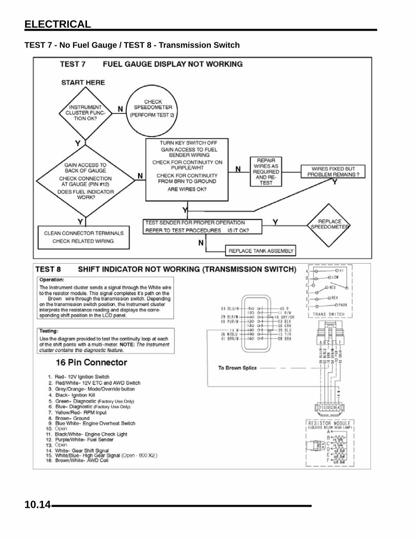
ELECTRICAL
TEST 7 - No Fuel Gauge / TEST 8 - Transmission Switch
10.14

ELECTRICAL
0
1ACTIVE DESCENT CONTROL (ADC) COILOperation Overview
• AWD switch must be ‘ON’. 12Vdc power is present at the ADC hub coil.
• ECU pin #11 controls the grounding of the ADC hub coil for operation.
• ECU Pin #20 senses the gear signal indicating the transmission is engaged and is not in Park or Neutral.
• ECU pin #27 senses the speed sensor signal for determining if vehicle speed is below 15 Mph.
• ECU senses the TPS position and will cancel ADC operation if TPS moves off ‘idle’ position.
• System must be grounded to operate.
Diagnosing System Failures• Verify the AWD switch is functional.
• Verify the ADC hub coil is functional. Test the ADC hub coil using an ohm meter.
• Verify the TPS is functioning correctly. Test using Digital Wrench Diagnostic Software. (Dealer Only)
• Verify the wiring harness, wiring, connectors, connector pins, grounds and ECU pin locations are undamaged, clean and connect properly.
• Verify continuity of wire connections with a known good volt/ohm meter.
IMPORTANT: Verify all wires and wiring connectionshave been tested properly with a known good volt/ohm meter before suspecting a component failure.80% of all electrical issues are caused by bad/failedconnections and grounds.
NOTE: Refer to the ADC subsystem diagram locatedin ‘Wire Diagrams’ at the end of this chapter.
ALL WHEEL DRIVE (AWD) COILOperation Overview
• AWD switch must be ‘ON’. 12Vdc power is present at the ADC hub coil.
• The instrument cluster senses grounding at pin #16. AWD icon should turn on at the instrument cluster.
• System must be grounded to operate.
Diagnosing System Failures• Verify the AWD switch is functional.
• Verify the AWD hub coil is functional. Test the AWD hub coil using an ohm meter.
• Verify the wiring harness, wiring, connectors, connector pins and grounds are undamaged, clean and connect properly.
• Verify continuity of wire connections with a known good volt/ohm meter.
IMPORTANT: Verify all wires and wiring connectionshave been tested properly with a known good volt/ohm meter before suspecting a component failure.80% of all electrical issues are caused by bad/failedconnections and grounds.
ADC Hub Coil Resistance:12 Ω ± 5%
AWD Hub Coil Resistance:24 Ω ± 5%
10.15

ELECTRICAL
COOLING SYSTEM COMPONENTSFan Control Circuit Operation / TestingPower is supplied to the fan via the Orange/Black wire when therelay is ON. The ground path for the fan motor is through theBrown harness wire. Refer to “RELAYS” later in this chapterfor more information on fan functions.
NOTE: The fan may not function or operation maybe delayed if coolant level is low or if air is trapped inthe cooling system. Be sure cooling system is fulland purged of air. Refer to Maintenance Chapter 2for cooling system information.
Fan Control Circuit Bypass Test1. Disconnect harness from coolant temperature sensor on
engine.2. With the ATV in “Park” and with the parking brake on, turn
the ignition key (and engine stop switch) “ON”. The fanshould start running.
3. If the fan does not run or runs slowly, check the fan motorwiring, ground, motor condition and mechanical relay forproper operation (refer to “FAN MOTOR CURRENTDRAW” in this section). Repair or replace as necessary.If the fan runs with the sensor harness disconnected, butwill not turn on when the engine is hot, check the coolanttemperature sensor and connector terminals.
Coolant Temperature SensorThe coolant temperature sensor can be tested using an ohmmeteror voltmeter.
1. With the engine and temperature sensor at roomtemperature (68°F = 20°C), disconnect the harnessconnector.
2. With the meter in the ohms mode, place the meter leadsonto the sensor contacts.
3. Use the table Temperature / Resistance table to determineif the sensor needs to be replaced.
NOTE: If the coolant temperature sensor or circuitmalfunctions the radiator fan will default to 'ON'.
NOTE: The fan may not function or operation maybe delayed if coolant level is low or if air is trapped inthe cooling system. Be sure cooling system is fulland purged of air. Refer to Maintenance Chapter 2for cooling system information.
CAUTION
Keep hands away from fan blades during operation. Serious personal injury could result.
TEMPERATURE °F (°C) RESISTANCE
68 °F (20 °C) 2.5 k Ω ± 6%
212 °F (100 °C) 0.186 Ω ± 2%
10.16
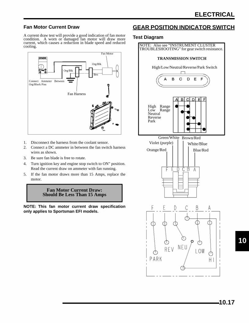
ELECTRICAL
0
1Fan Motor Current DrawA current draw test will provide a good indication of fan motorcondition. A worn or damaged fan motor will draw morecurrent, which causes a reduction in blade speed and reducedcooling.
1. Disconnect the harness from the coolant sensor.2. Connect a DC ammeter in between the fan switch harness
wires as shown.3. Be sure fan blade is free to rotate.4. Turn ignition key and engine stop switch to ON" position.
Read the current draw on ammeter with fan running.5. If the fan motor draws more than 15 Amps, replace the
motor.
NOTE: This fan motor current draw specificationonly applies to Sportsman EFI models.
GEAR POSITION INDICATOR SWITCHTest Diagram
Fan Motor Current Draw:Should Be Less Than 15 Amps
Connect Ammeter BetweenOrg/Black Pins
Org/Blk
Fan Motor
Brn
Org/Blk
Fan Harness
NOTE: Also see “INSTRUMENT CLUSTER TROUBLESHOOTING” for gear switch resistance.
TRANSMISSION SWITCH
High/Low/Neutral/Reverse/Park Switch
High RangeLow RangeNeutralReversePark
Orange/Red
Violet (purple)Green/White Brown/Red
White/BlueBlue/Red
10.17
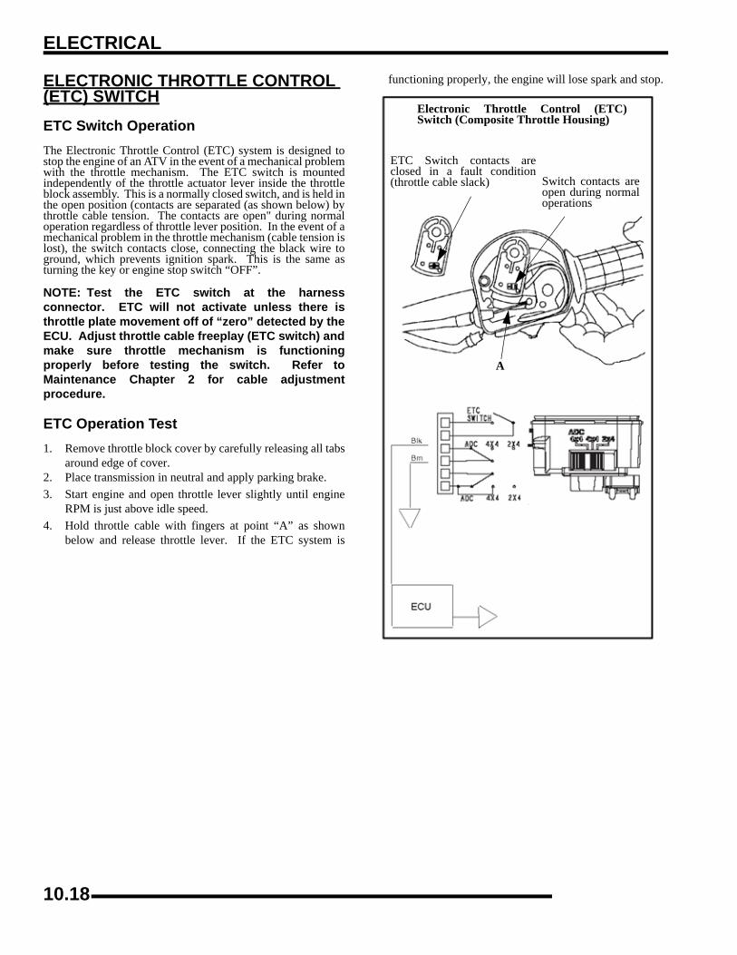
ELECTRICAL
ELECTRONIC THROTTLE CONTROL (ETC) SWITCHETC Switch OperationThe Electronic Throttle Control (ETC) system is designed tostop the engine of an ATV in the event of a mechanical problemwith the throttle mechanism. The ETC switch is mountedindependently of the throttle actuator lever inside the throttleblock assembly. This is a normally closed switch, and is held inthe open position (contacts are separated (as shown below) bythrottle cable tension. The contacts are open" during normaloperation regardless of throttle lever position. In the event of amechanical problem in the throttle mechanism (cable tension islost), the switch contacts close, connecting the black wire toground, which prevents ignition spark. This is the same asturning the key or engine stop switch “OFF”.
NOTE: Test the ETC switch at the harnessconnector. ETC will not activate unless there isthrottle plate movement off of “zero” detected by theECU. Adjust throttle cable freeplay (ETC switch) andmake sure throttle mechanism is functioningproperly before testing the switch. Refer toMaintenance Chapter 2 for cable adjustmentprocedure.
ETC Operation Test1. Remove throttle block cover by carefully releasing all tabs
around edge of cover.2. Place transmission in neutral and apply parking brake.3. Start engine and open throttle lever slightly until engine
RPM is just above idle speed.4. Hold throttle cable with fingers at point “A” as shown
below and release throttle lever. If the ETC system is
functioning properly, the engine will lose spark and stop.
Electronic Throttle Control (ETC)Switch (Composite Throttle Housing)
ETC Switch contacts areclosed in a fault condition(throttle cable slack) Switch contacts are
open during normaloperations
A
10.18
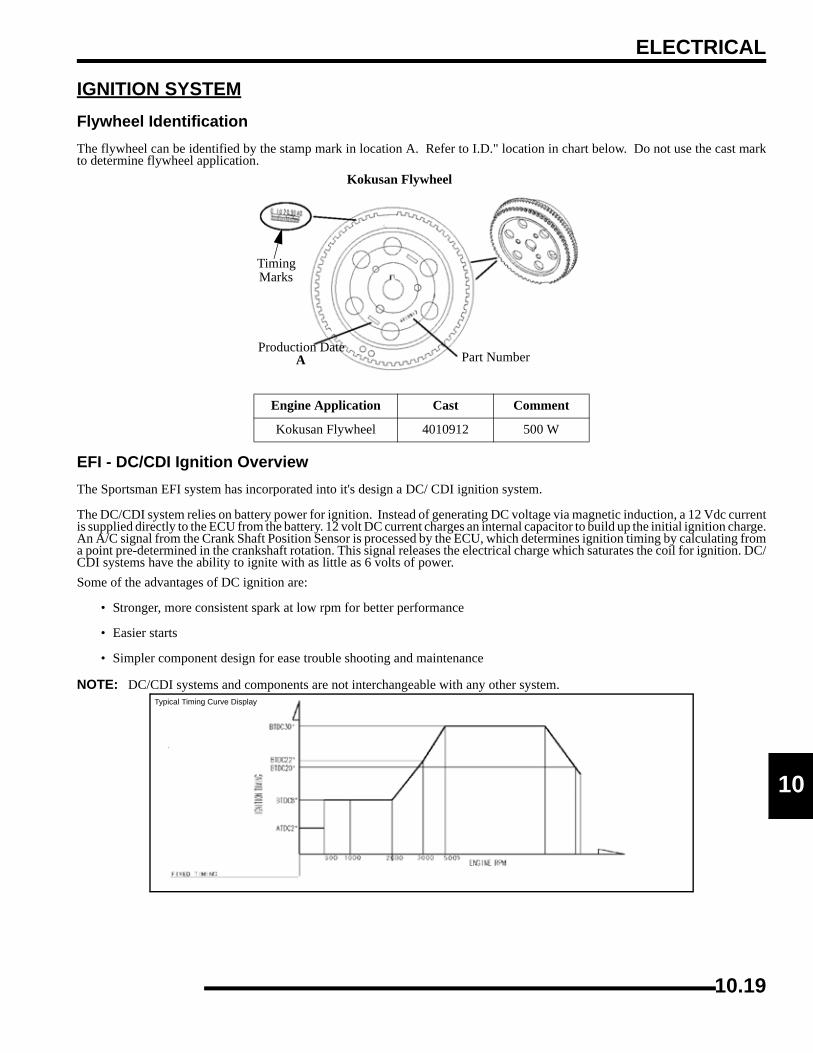
ELECTRICAL
0
1IGNITION SYSTEMFlywheel IdentificationThe flywheel can be identified by the stamp mark in location A. Refer to I.D." location in chart below. Do not use the cast markto determine flywheel application.
EFI - DC/CDI Ignition OverviewThe Sportsman EFI system has incorporated into it's design a DC/ CDI ignition system.
The DC/CDI system relies on battery power for ignition. Instead of generating DC voltage via magnetic induction, a 12 Vdc currentis supplied directly to the ECU from the battery. 12 volt DC current charges an internal capacitor to build up the initial ignition charge.An A/C signal from the Crank Shaft Position Sensor is processed by the ECU, which determines ignition timing by calculating froma point pre-determined in the crankshaft rotation. This signal releases the electrical charge which saturates the coil for ignition. DC/CDI systems have the ability to ignite with as little as 6 volts of power.Some of the advantages of DC ignition are:
• Stronger, more consistent spark at low rpm for better performance
• Easier starts
• Simpler component design for ease trouble shooting and maintenance
NOTE: DC/CDI systems and components are not interchangeable with any other system.
Engine Application Cast Comment
Kokusan Flywheel 4010912 500 W
Kokusan Flywheel
Timing Marks
Part NumberProduction Date
A
Typical Timing Curve Display
10.19

ELECTRICAL
Alternator/Ignition Components - 700/800 EFI
Battery to Solenoid CableIgnition Coils
Solenoid Switch (starter)
Coil Wires
Control Module
FusesSpark Plugs
Voltage Regulator
Crank Position Sensor
FlywheelStator Assembly
Pre-Wire Winch Cables
Negative Battery Cable
Relays
Starter Solenoid Cable
30 Amp/hr. Battery
10.20

ELECTRICAL
0
1Crankshaft Position Sensor GapMeasure trigger coil gap with a feeler gauge. The gap should be.059 inch (1.0 mm).
Ignition System TroubleshootingNo Spark, Weak, or Intermittent Spark
• Spark plug gap incorrect
• Fouled spark plug
• Faulty spark plug cap or poor connection to high tension lead
• Related wiring loose, disconnected, shorted, or corroded
• Engine Stop switch or ignition switch faulty
• ETC switch mis-adjusted or faulty
• Wire harness or connections wet, corroded
• Poor ignition coil ground (e.g. coil mount loose or corroded)
• Incorrect wiring (inspect color coding in connectors etc.)
• Faulty ignition coil winding (measure resistance of primary and secondary)
• Sheared flywheel key
• Flywheel loose or damaged
• Faulty ECU
CHARGING SYSTEMCurrent Draw - Key Off
Connect an ammeter in series with the negative battery cable.Check for current draw with the key off. If the draw is excessive,loads should be disconnected from the system one by one untilthe draw is eliminated. Check component wiring as well as thecomponent for partial shorts to ground to eliminate the draw.
Crankshaft Position Sensor Gap: .059" ± .010 inch
(1.0 ± .26 mm)
CAUTION
Do not connect or disconnect the battery cable or ammeter with the engine running. Damage will
occur to electrical components.
YB30L-B
Current Draw Inspection (key off)
Current Draw - Key Off:Maximum of .01 DCA (10 mA)
10.21
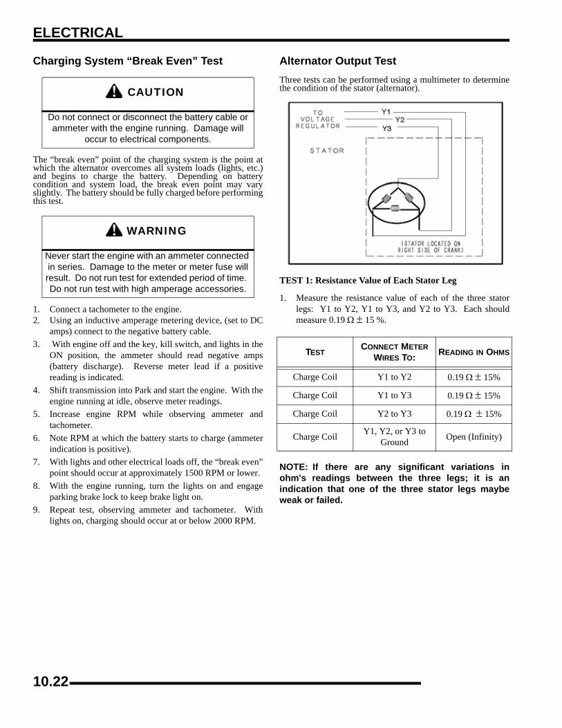
ELECTRICAL
Charging System “Break Even” Test
The “break even” point of the charging system is the point atwhich the alternator overcomes all system loads (lights, etc.)and begins to charge the battery. Depending on batterycondition and system load, the break even point may varyslightly. The battery should be fully charged before performingthis test.
1. Connect a tachometer to the engine.2. Using an inductive amperage metering device, (set to DC
amps) connect to the negative battery cable.3. With engine off and the key, kill switch, and lights in the
ON position, the ammeter should read negative amps(battery discharge). Reverse meter lead if a positivereading is indicated.
4. Shift transmission into Park and start the engine. With theengine running at idle, observe meter readings.
5. Increase engine RPM while observing ammeter andtachometer.
6. Note RPM at which the battery starts to charge (ammeterindication is positive).
7. With lights and other electrical loads off, the “break even”point should occur at approximately 1500 RPM or lower.
8. With the engine running, turn the lights on and engageparking brake lock to keep brake light on.
9. Repeat test, observing ammeter and tachometer. Withlights on, charging should occur at or below 2000 RPM.
Alternator Output TestThree tests can be performed using a multimeter to determinethe condition of the stator (alternator).
TEST 1: Resistance Value of Each Stator Leg
1. Measure the resistance value of each of the three statorlegs: Y1 to Y2, Y1 to Y3, and Y2 to Y3. Each shouldmeasure 0.19 Ω ± 15 %.
NOTE: If there are any significant variations inohm's readings between the three legs; it is anindication that one of the three stator legs maybeweak or failed.
CAUTION
Do not connect or disconnect the battery cable or ammeter with the engine running. Damage will
occur to electrical components.
WARNING
Never start the engine with an ammeter connected in series. Damage to the meter or meter fuse will result. Do not run test for extended period of time. Do not run test with high amperage accessories.
TESTCONNECT METER
WIRES TO: READING IN OHMS
Charge Coil Y1 to Y2 0.19 Ω ± 15%
Charge Coil Y1 to Y3 0.19 Ω ± 15%
Charge Coil Y2 to Y3 0.19 Ω ± 15%
Charge Coil Y1, Y2, or Y3 to Ground Open (Infinity)
10.22

ELECTRICAL
0
1TEST 2: Resistance Value of Stator Leg to Ground
1. Measure the resistance value of each of the stator legs toground: Y1 to Ground, Y2 to Ground, Y3 to Ground.
NOTE: Any measurement other than Infinity (open)will indicate a failed or shorted stator leg.
TEST 3: Measure AC Voltage Output of Each Stator Leg atCharging RPM
1. Set the selector dial to measure AC Voltage.2. Start the engine and let it idle.3. While holding the ATV at a specified RPM, separately
measure the voltage across each “leg” of the stator byconnecting the meter leads to the wires leading from thealternator (Y1 to Y2, Y1 to Y3, Y2 to Y3).
4. Refer to the table below for approximate Voltage ACreadings according to RPM. Test each leg at the specifiedRPM in the table. Example: The alternator voltage outputreading should be approximately 18 Vac at 1300 RPMbetween each 'leg'.
NOTE: If one or more of the stator leg output ACvoltage varies significantly from the specified value,the stator may need to be replaced.
ATV RPM READINGAC VOLTAGE (VAC )
READING
1300 18 Vac ± 25%
3000 42 Vac ± 25%
5000 64 Vac ± 25%
10.23

ELECTRICAL
Charging System Testing Flow ChartWhenever charging system problems are suspected, proceed with the following system check after verifying that all wires are in goodcondition, connected and not kinked or pinched.
Using a multitester set on D.C. volts, measure thebattery open circuit voltage (See earlier test). Itshould be 12.4 volts or more. Is it?
With the transmission in Park, start the engine andincrease RPM to between 3000 and 4000. Readbattery voltage with the multitester. Readingsshould increase to between 13 and 14.6 VDC. Are they?
Perform system Break Even Amperage Test"
Does charging occur as specified?
Meter Setting DC Amps
Meter Setting DC Volts
Ohm stator wires If bad, replace stator. If good,continue with alternator output test.
Disconnect the wires from the regulator/rectifier.Using a multitester, perform an Alternator Output(AC amp) test. See test procedure on Page 10.20for procedure. Is output above 7 amps?
Meter Setting AC Amps
Reconnect the alternator wires. Note: Red wiremust be connected to harness. Battery voltage mustbe present on red wire terminal on harness side ofvoltage regulator connector. Is it?
Meter Setting: DC Volts
If all of the previous tests indicate a goodcondition, but the charging voltage does not riseabove battery voltage at the connector or wireharness, replace the voltage regulator.
Yes
Yes
Yes
No
No
Remove the battery and properly service.Reinstall the fully charged battery or a fullycharged shop battery.No
Yes
Yes
No
No
Check Key Off Current Draw
Check for owner modification, anddiscuss operating habits. The batterywill continually discharge if operatedbelow the “Break Even” RPM.Continued problems would call forbattery inspection.
Inspect the wiring harness between thepanel and the stator for damage. If nodamage is found, remove the recoil andflywheel. Inspect the flywheel magnets,stator coils and stator wire harness fordamage. Repair or replace any damagedcomponents.
Check regulator/rectifier connections andground, battery connections, circuitbreaker and connecting wires. Repair orreplace faulty wiring or components.
10.24

ELECTRICAL
0
1RELAYSOperationThe relays, located next to the ECU, assist with componentoperation such as the fan, fuel pump, etc.
The fan relay, controlled by the ECU, operates the fan.
The power relay, controlled by the ECU, turns on power forcomponents such as the fuel pump, injectors, etc.
The differential relay, controlled by the AWD switch and ECU,operates the differential solenoid.
NOTE: See “Differential Relay Testing” onpage 10.34.
FAN RELAY
COLOR FUNCTION
Red Fused 20-amp, unswitched FAN power supply.
Yellow /Black Fan 'ON' Command. Ground is supplied by the ECU, closing the relay to turn on the fan.
Red / WhiteKEY-ON Battery power supply, switched on by the key and LH control switches, enables power to relay.
Orange / BlackKEY-ON Battery power supply, switched on by the key and LH control switches, enables power to relay.
POWER RELAY
COLOR FUNCTION
Red/White
KEY-ON Battery power supply, switched on by the key and LH control switches, enables power to relay. Tied to Fan Relay terminal.
Gray/WhiteRelay “ON” command. The ECU supplies a ground which closes the relay, supplying power to run the fuel pump, injectors, etc.
Orange Fused 15-amp, unswitched battery power IN supply for EFI component operation.
Red/Black
EFI power output. 'ON' when ECU sends a signal on the GRY/W wire, closing the relay. Supplies 15-amp power for ECU-controlled operation of EFI components.
10.25

ELECTRICAL
FUSES/CIRCUIT BREAKEROperationThe fuse panel, located next to the ECU, assists with componentprotection such as the Instrument Cluster/ECU, EFI system,Chassis Power and Accessories.
A 20-amp circuit breaker protects the fan circuit.
LIGHTINGHigh Beam Headlight Bulb Replacement
1. Remove three Phillips screws on the headlight pod.2. Lift pod cover up.3. Disconnect instrument cluster harness (A) and work light
switch (B).
CAUTION
Do not service while headlight is hot. Serious burns may result. Protect lamp during install.
Remove 3 Screws
A B
10.26

ELECTRICAL
0
14. Turn the headlight lamp socket counter-clockwise andremove.
5. Carefully remove headlamp bulb from housing.6. Remove the headlamp and replace with a new headlamp.NOTE: Do not touch the lamp with bare fingers.Hold the plastic part (1) of the lamp. Oil from yourskin leaves a residue, causing a hot spot that willshorten the life of the lamp.
7. Install the new headlamp and harness assembly into theheadlight assembly. Turn the headlight harness clockwiseto secure the headlamp into place.
Headlight Housing Replacement1. Remove three Phillips screws on the headlight pod.2. Disconnect instrument cluster harness (A) and work light
switch (B).
3. Unplug headlamp harness (C).
4. Remove O-Ring (D) from headlight pivot pins. (BothSides)
5. Pull the headlight housing up to release from the lockingtabs.
6. Lift the adjusting knob up to remove from the locking tabs.7. Carefully pull the assembly up and out of pod.
Turn Harness Assembly
TightenLoosen
A B
C
D
l
Pull Upward
10.27

ELECTRICAL
8. Reverse the steps to install the new housing and reassemblethe pod.
NOTE: The distance from the headlamp parting lineto the end of the adjustment knob stop is 5 1/8”, (13cm). See illustration.
9. Adjust the headlight aim by turning the adjusting knob.
High Beam Headlight AdjustmentThe headlight beam can be adjusted to any position desired byturning the adjusting knob located on the bottom right side of theheadlight pod.
Raise Headlight - Turn knob counter- counterclockwise
Lower Headlight - Turn knob clockwise
1. Place the vehicle on a level surface with the headlightapproximately 25' (7.6 m) from a wall.
2. Measure the distance from the floor to the center of theheadlight and make a mark on the wall at the same height.
3. Start the engine and turn the headlight switch to high beam.4. Observe headlight aim. The most intense part of the
headlight beam should be aimed 2” (5.1 cm) below themark placed on the wall in Step 2.
NOTE: Rider weight must be included on the seat.On machines with separate low beam lights, thedrop should be 8, (20.3 cm) in 25' from the center ofthe low beam lamp.
5. Adjust beam to desired position.
Lower Headlamp Removal / Installation
1. Turn the back of the headllamp harness in a counter-clockwise direction to loosen.
5 1/8” (13 cm)
25’ (7.6 m)
2” (5.1 cm)
Lamp Center Height
Loosen Tighten
Turn Harness Assembly
10.28

ELECTRICAL
0
12. Pull the harness assembly out from the headlight assembly.
3. Remove the lamp and replace with a new headlamp.NOTE: Do not touch the new lamp with bare fingers.Hold the plastic part (1) of the lamp. Oil from yourskin leaves a residue, causing a hot spot that willshorten the life of the lamp.
4. Install the harness assembly into the headlight assembly.Turn the headlight harness clockwise to secure theheadlamp into place.
Lower Headlamp Housing Removal (if required)
5. Remove the screw that secures the lower headlamp.
6. Pull the headlamp out of the locking tab.
Low Beam Headlight Adjustment1. The low beam can be adjusted slightly upward or
downward.
2. Loosen the phillips screw located at the rear of theheadlamp.
3. Tilt the headlamp upward or downward.4. Tighten the screw.
Headlamp Switch Test1. Remove the headlight pod cover.2. Set meter to DC Volts and probe the headlamp plug wires
(Brown and Yellow) at back of connector for 12 Volts.3. Turn ignition and headlight on. If there is no power,
continue with checks to the harness and fuses.
Remove Screw
Loosen Screw
Brown
Yellow
Upper Headlamp Plug Wires
Brown
Green
10.29
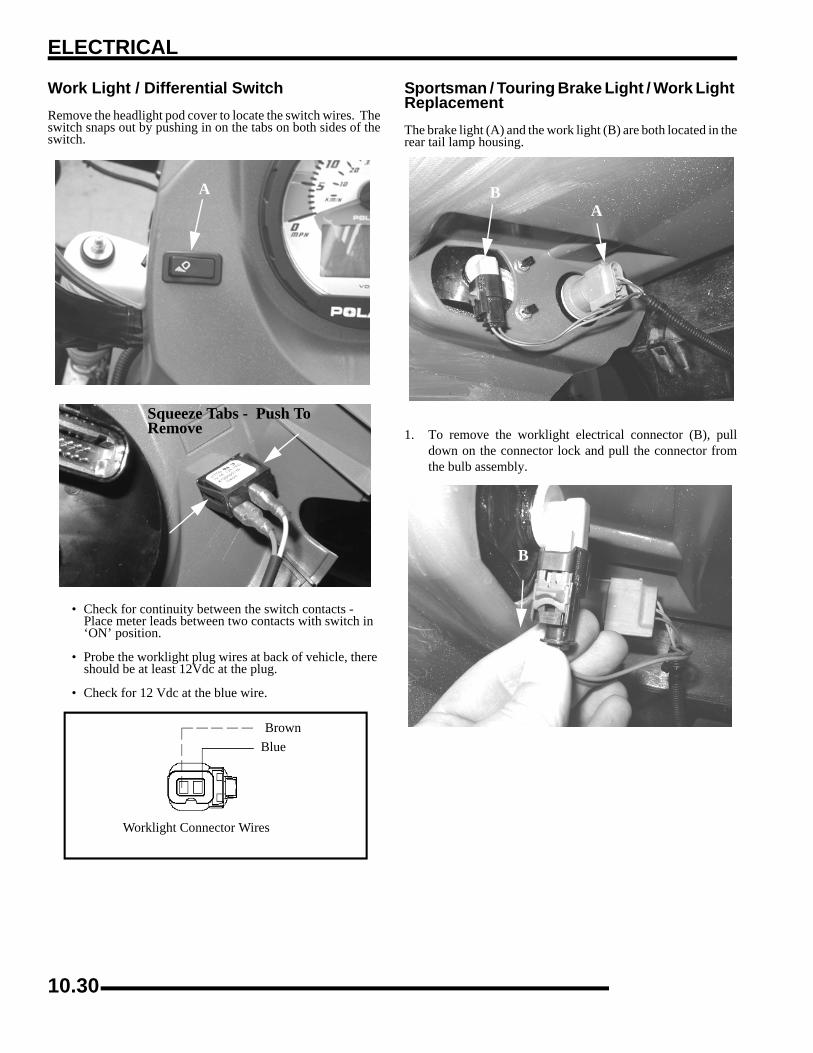
ELECTRICAL
Work Light / Differential SwitchRemove the headlight pod cover to locate the switch wires. Theswitch snaps out by pushing in on the tabs on both sides of theswitch.
• Check for continuity between the switch contacts - Place meter leads between two contacts with switch in ‘ON’ position.
• Probe the worklight plug wires at back of vehicle, there should be at least 12Vdc at the plug.
• Check for 12 Vdc at the blue wire.
Sportsman / Touring Brake Light / Work Light ReplacementThe brake light (A) and the work light (B) are both located in therear tail lamp housing.
1. To remove the worklight electrical connector (B), pulldown on the connector lock and pull the connector fromthe bulb assembly.
A
Squeeze Tabs - Push To Remove
BrownBlue
Worklight Connector Wires
BA
B
10.30

ELECTRICAL
0
12. To remove the brake light electrical connector (B), press inon the tab on the connector to unlock the connector and pullthe connector from the bulb assembly.
3. To remove either of the bulbs, turn the holder assemblycounter-clockwise to remove and pull out. Turn the holderassembly clockwise to install. Refer to the parts manual forthe correct bulb part number.
X2 BRAKE LIGHT / WORK LIGHT REPLACEMENTThe brake light (A) and the work light (B) are both located in therear tail lamp housing.
1. X2 only - Open the tailgate and remove the 2 torx headscrews (A) securing the rear taillights on each side of thecargo box as illustrated below.
2. X2 only - Remove the taillight assembly from the cargobox.
A
CAUTION
Use caution when disconnecting smaller light bulbs. Follow the procedures to avoid damaging the
connector. Damaging connectors may require wire harness replacement.
A
10.31

ELECTRICAL
3. X2 and Touring - Carefully pull out the red locking tab onthe connector.
4. X2 and Touring - Once the red tab is pulled out, press inon the black tab and pull out to disconnect harness.
5. X2 and Touring - Disconnect the two wire harnessesconnected to each of the taillights. Twist bulb housing toremove from lamp assembly.
Brake Light Switch1. Remove the front cover.
2. Disconnect wire harness from switch.3. Connect an ohmmeter across switch contacts. Reading
should be infinite (∞).4. Apply brake at handlebar lever and check for continuity
between switch contacts. Replace switch if there is nocontinuity or greater than .5 ohms resistance when the brakeis applied with slight pressure.
Black TabRed Tab
RemoveInstall
Brake Lamp Switch
Brake Switch Location
10.32

ELECTRICAL
0
1FUEL SENDERTesting1. Drain the fuel tank and remove it from the atv.2. Set the fuel tank on a flat surface.3. Hook up an ohm meter to the fuel sender harness Violet/
White wire (B) and Brown wire (C).4. With the sender float in the empty position and compare
to specification.
5. Slowly tilt invert the tank so that gravity moves the senderfloat to the full position and compare to specification.
6. If the readings are not to specification, or if the reading iserratic or LCD display “sticks”, check the following beforereplacing the fuel pump assembly.
• Loose float
• Float contact with tank
• Bent Float Rod
If none of the conditions exists, the sender assembly is faulty.Fuel pump assembly replacement is required.
X2 / TOURING DIFFERENTIAL SYSTEMSolenoid TestingDisconnect from the wire harness. Using a digital ohmmeter,test the solenoid at the connector leads and compare to thespecification. Replacement of solenoid is required as it is notserviceable.
Solenoid Replacement1. Remove the solenoid using a suitable tool. 2. Coat threads of new solenoid with anti-seize compound or
sealant.3. Thread new solenoid into gearcase housing. Tighten to
specification.
Fuel Sender - Empty: 5 Ω ± 5%
Fuel Sender - Full: 90 Ω ± 5%
Fuel Sender
Empty: 5 Ω ± 5%Half: 57 Ω ± 5%Full: 90 Ω ± 5%
Differential Solenoid Resistance:1.45 Ω ± 5 %
= T
Differential Solenoid Torque23-27 ft. lbs. (31-37 Nm)
10.33

ELECTRICAL
Differential Relay Operation• The AWD switch must be turned to ‘TURF’ mode.
• Speed must be below 15mph and transmission must not be in ‘Park’.
• 12Vdc is constant at the differential relay.
• ECU senses grounding on pin #26 from the AWD switch.
• ECU grounds pin #13, activating the relay.
• Relay powers the differential solenoid.
• System must be grounded to operate.
Differential Relay Testing• Test for 12Vdc constant at the relay with the AWD
switch turned to ‘TURF’ mode.
• Test for continuity to ground at pin #26 of the ECU connector from the AWD switch.
• Test for continuity to ground at ECU pin #13.
• Test for continuity at ECU connector pin #13 to the solenoid.
• Test the AWD/TURF switch for proper function.
IMPORTANT: Verify all wires and wiring connectionshave been tested properly with a known good volt/ohm meter before suspecting an ECU failure. 80% ofall electrical issues are caused by bad/failedconnections and grounds.
X2 / TOURING SPEED SENSORTestingUsing the special tools listed, test the speed sensor according tothe tester instructions. Remove sensor and inspect the o-ringseal for damage or wear and replace as required. Replacementof sensor is required as it is not serviceable.
Replacement1. Remove the sensor retaining using a suitable tool. 2. Coat o-ring of new sensor with anti-seize compound or
sealant.3. Push new sensor into gearcase housing. Install bolt and
tighten to specification.
Speed Sensor Special Tools:
Static Timing Light Harness PN 2871745
Hall Sensor Probe HarnessPN 2460761
= T
Speed Sensor Bolt Torque8-12 ft. lbs. (11-17 Nm)
10.34

ELECTRICAL
0
1ACCESSORY POWERWire ConnectionsWinch Installation
The Sportsman models have the main winch cables routed andinstalled from the factory. This enables quick installation.
Refer to Chapter 2 for more information on winch installationand operation.
Accessory Power Wires
The accessory power leads for all accessories are located underthe front cover. The wires are 12 Volt wires and are Orange /White in color. To locate the wires, remove the front cover. Thewires will be located in the main wire loom on the right side.
If you have trouble locating the Orange / White wires removethe left side panel and search under the front fender area.
NOTE: Refer to the accessory instructions foraccessory hook-up and installation.
Orange/White Wires Located In This Area
Orange/White Wires
Accessory Wires
Power Point
Acc #1 (Located Below Head Lamps)
Acc. 2
10.35

ELECTRICAL
STARTER SYSTEMSportsman Starter Lockout Overview and DiagnosticThe Sportsman starter lockout is controlled by the ECU. Pin #20 senses the transmission signal and determines if the switch is inNeutral or Park. Pin #24 senses when the brake is applied. When the conditions are met, the ECU will activate Pin #16 to groundthe starter solenoid. Note the ground for the transmission switch runs to the wire harness splice. The ECU will allow starting inNeutral or Park without the brake applied. Applying the brake overrides this system and allows starting regardless of transmissionshift position.
Items to check when diagnosing a no-start condition are:
• Transmission switch for proper function
• Starter solenoid for proper function
• Brake switch for proper function
• Wire harness, loose connections/pins (including the ECU) leading to and from these components
• Proper ground to frame
Should all these items be found in working order, the ECU may be at fault.
10.36

ELECTRICAL
0
1X2 /TOURING Starter Lockout Overview and DiagnosticThe Sportsman X2 and Touring starter lockout is controlled by the ECU. Pin #20 senses the transmission signal and determines ifthe switch is in Neutral or Park. Pin #24 senses when the brake is applied. When the conditions are met, the ECU will activate Pin#16 to ground the starter solenoid. Note the ground for the transmission switch runs to the wire harness splice. The ECU will allowstarting in Neutral or Park without the brake applied. Applying the brake overrides this system and allows starting regardless oftransmission shift position.
Items to check when diagnosing a no-start condition are:
• Transmission switch for proper function
• Starter solenoid for proper function
• Brake switch for proper function
• Wire harness, loose connections/pins (including the ECU) leading to and from these components
• Proper ground to frame
Should all these items be found in working order, the ECU may be at fault.
10.37
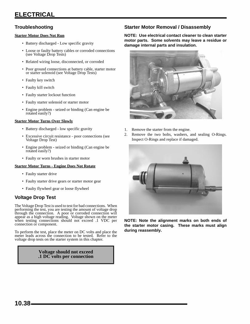
ELECTRICAL
TroubleshootingStarter Motor Does Not Run
• Battery discharged - Low specific gravity
• Loose or faulty battery cables or corroded connections (see Voltage Drop Tests)
• Related wiring loose, disconnected, or corroded
• Poor ground connections at battery cable, starter motor or starter solenoid (see Voltage Drop Tests)
• Faulty key switch
• Faulty kill switch
• Faulty starter lockout function
• Faulty starter solenoid or starter motor
• Engine problem - seized or binding (Can engine be rotated easily?)
Starter Motor Turns Over Slowly
• Battery discharged - low specific gravity
• Excessive circuit resistance - poor connections (see Voltage Drop Test)
• Engine problem - seized or binding (Can engine be rotated easily?)
• Faulty or worn brushes in starter motor
Starter Motor Turns - Engine Does Not Rotate
• Faulty starter drive
• Faulty starter drive gears or starter motor gear
• Faulty flywheel gear or loose flywheel
Voltage Drop TestThe Voltage Drop Test is used to test for bad connections. Whenperforming the test, you are testing the amount of voltage dropthrough the connection. A poor or corroded connection willappear as a high voltage reading. Voltage shown on the meterwhen testing connections should not exceed .1 VDC perconnection or component.
To perform the test, place the meter on DC volts and place themeter leads across the connection to be tested. Refer to thevoltage drop tests on the starter system in this chapter.
Starter Motor Removal / DisassemblyNOTE: Use electrical contact cleaner to clean startermotor parts. Some solvents may leave a residue ordamage internal parts and insulation.
1. Remove the starter from the engine.2. Remove the two bolts, washers, and sealing O-Rings.
Inspect O-Rings and replace if damaged.
NOTE: Note the alignment marks on both ends ofthe starter motor casing. These marks must alignduring reassembly.
Voltage should not exceed.1 DC volts per connection
10.38
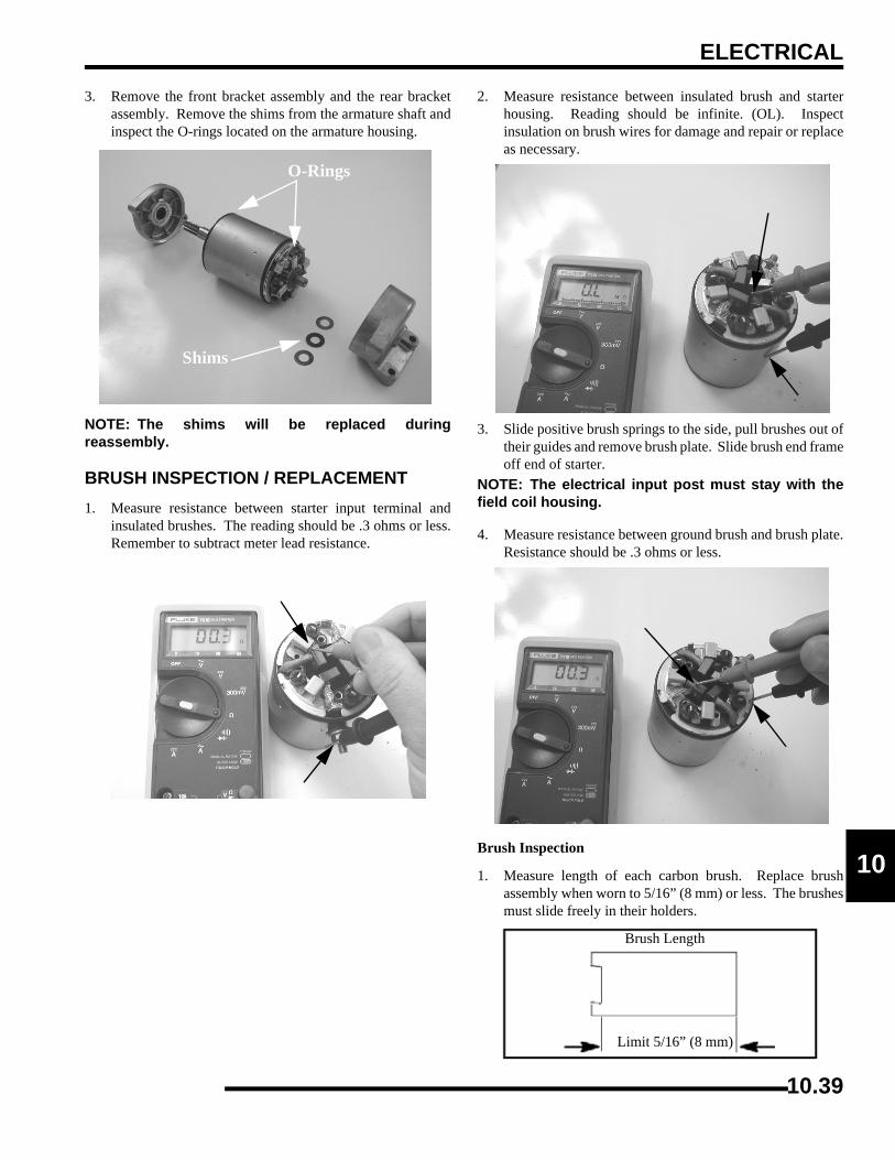
ELECTRICAL
0
13. Remove the front bracket assembly and the rear bracketassembly. Remove the shims from the armature shaft andinspect the O-rings located on the armature housing.
NOTE: The shims will be replaced duringreassembly.
BRUSH INSPECTION / REPLACEMENT1. Measure resistance between starter input terminal and
insulated brushes. The reading should be .3 ohms or less.Remember to subtract meter lead resistance.
2. Measure resistance between insulated brush and starterhousing. Reading should be infinite. (OL). Inspectinsulation on brush wires for damage and repair or replaceas necessary.
3. Slide positive brush springs to the side, pull brushes out oftheir guides and remove brush plate. Slide brush end frameoff end of starter.
NOTE: The electrical input post must stay with thefield coil housing.
4. Measure resistance between ground brush and brush plate.Resistance should be .3 ohms or less.
Brush Inspection
1. Measure length of each carbon brush. Replace brushassembly when worn to 5/16” (8 mm) or less. The brushesmust slide freely in their holders.
O-Rings
Shims
Limit 5/16” (8 mm)
Brush Length
10.39

ELECTRICAL
Brush Replacement
1. Remove terminal nut with lock washer, flat washer, largephenolic washer, the small phenolic spacers, and sealingO-ring. Inspect O-ring and replace if damaged.
2. Slide positive brush springs to the side, pull brushes out oftheir guides and remove brush plate.
Armature Testing1. Remove armature from starter casing. Note order of shims
on drive end for reassembly.
2. Inspect surface of commutator. Replace if excessivelyworn or damaged.
3. Using a digital multitester, measure the resistance betweeneach of the commutator segments. The reading should be.3 ohms or less.
4. Measure the resistance between each commutator segmentand the armature shaft. The reading should be infinite (nocontinuity).
5. Check commutator bars for discoloration. Bars discoloredin pairs indicate shorted coils, requiring replacement of thestarter motor.
6. Place armature in a growler. Turn growler on and positiona hacksaw blade or feeler gauge lengthwise 1/8” (.3 cm)above armature coil laminates. Rotate armature 360°. Ifhacksaw blade is drawn to armature on any pole, thearmature is shorted and must be replaced.
CAUTION
Some cleaning solvents may damage the insulation in the starter. Care should be exercised when
selecting an appropriate solvent. If the commutator needs cleaning use only electrical contact cleaner.
CAUTION
Use care when handling starter housing. Do not drop or strike the housing as magnet damage is
possible. If magnets are damaged, starter must be replaced.
10.40
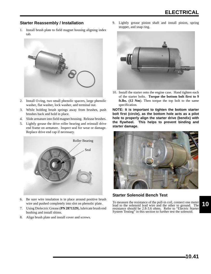
ELECTRICAL
0
1Starter Reassembly / Installation1. Install brush plate to field magnet housing aligning index
tab.
2. Install O-ring, two small phenolic spacers, large phenolicwasher, flat washer, lock washer, and terminal nut.
3. While holding brush springs away from brushes, pushbrushes back and hold in place.
4. Slide armature into field magnet housing. Release brushes.5. Lightly grease the drive roller bearing and reinstall drive
end frame on armature. Inspect seal for wear or damage.Replace drive end cap if necessary.
6. Be sure wire insulation is in place around positive brushwire and pushed completely into slot on phenolic plate.
7. Using Dielectric Grease (PN 2871329), lubricate brush endbushing and install shims.
8. Align brush plate and install cover and screws.
9. Lightly grease pinion shaft and install pinion, springstopper, and snap ring.
10. Install the starter onto the engine case. Hand tighten eachof the starter bolts. Torque the bottom bolt first to 9ft.lbs. (12 Nm). Then torque the top bolt to the samespecification.
NOTE: It is important to tighten the bottom starterbolt first (circle), as the bottom hole acts as a pilothole to properly align the starter drive (bendix) withthe flywheel. This helps to prevent binding andstarter damage.
Starter Solenoid Bench TestTo measure the resistance of the pull-in coil, connect one meterlead to the solenoid lead wire and the other to ground. Theresistance should be 2.8-3.6 ohms. Refer to “Electric StarterSystem Testing” in this section to further test the solenoid.
Roller Bearing
Seal
10.41

ELECTRICAL
Starter Drive
Pinion Gear - Anti-kick Out Shoe, Garter Spring ReplacementIf the garter spring is damaged, the overrun clutch may fail to return properly. Use either of the following methods to remove andinstall a new garter spring:
1. Screw the overrun clutch out to the engaged position on the pinion shaft assembly. Use a small piece of wire with the end bentin a hook and pick the old spring out of its channel. Slide it off the end of the shaft. Slide the new spring over the overrunclutch and into the spring groove. Make sure that the spring is positioned between the shoe alignment pins and the back flangeof the anti kick-out shoes.
2. Remove the retaining ring, thrust washer, spring retainers and clutch return spring. Screw the overrun clutch off the end of thepinion shaft. Remove the old spring and install a new one. Lightly grease the pinion shaft and reinstall the clutch, spring,retainers, end washer and lock ring in the reverse order. Make sure the end washer is positioned properly so that it will holdthe lock ring in its groove.
A. Gear Assembly B. Thrust Washer C. Busing D. Retaining Ring E. Thrust Washer F. Stopper G. Cover H. Spring
A
B
C
D
E
FG
H
10.42
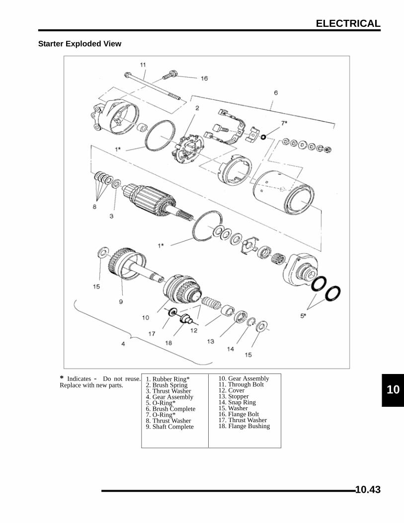
ELECTRICAL
0
1Starter Exploded View
1. Rubber Ring* 2. Brush Spring 3. Thrust Washer 4. Gear Assembly 5. O-Ring* 6. Brush Complete 7. O-Ring* 8. Thrust Washer 9. Shaft Complete
10. Gear Assembly 11. Through Bolt 12. Cover 13. Stopper 14. Snap Ring 15. Washer 16. Flange Bolt 17. Thrust Washer 18. Flange Bushing
* Indicates - Do not reuse.Replace with new parts.
10.43

ELECTRICAL
STARTER SYSTEM TESTING FLOW CHARTCondition: Starter fails to turn motor. NOTE: Make sure engine crankshaft is free to turn before proceeding with dynamic testing of starter system. A digital multitester must be used for this test
With the tester on the VDC position, place thetester's black lead on the battery negative and thered lead on the battery positive. Reading shouldbe 12.4 V D. C. or greater.
Remove battery and properly service. Installfully charged shop battery to continue test.
Disconnect coil engagement wire from the startersolenoid. Connect tester black wire to batteryground. Connect red tester lead to harness wire atsolenoid. Turn on ignition switch and depress thestarter button. Tester should read battery voltage.
Check voltage on both sides of circuitbreaker, ignition switch/engine stop switchand starter button. The voltage on both sidesshould be the same. NOTE: The ignitionswitch and engine stop switch must be on andthe starter button depressed. Replacecomponent if failed .
Test starter solenoid coil by connecting an ohmmeter between the solenoidwire and the solenoid mounting plate. Resistance should be 3.4°Ω. Checksolenoid ground path by measuring resistance between mounting plate andbattery negative terminal (-).
Reconnect the solenoid. Connect the tester blacklead to the battery positive and the red lead to thesolenoid end of the battery-to-solenoid wire.Depress starter button. Reading should be lessthan .1 V D.C.
Clean the battery-to-solenoid cable endsor replace the cable.
Connect the black tester lead to solenoid end ofbattery-to-solenoid cable. Connect red tester leadto solenoid end of solenoid-to-starter cable.Depress starter button. Reading should be less than.1 V D.C.
Replace the starter solenoid.
Connect the black tester lead to the solenoid end ofthe solenoid-to-starter cable. Connect the redtester lead to the starter end of the same cable.Depress the starter button. The reading should beless than .1 V D.C.
Clean the solenoid-to-starter cable ends orreplace the cable.
If all of these indicate a good condition, yet the starter still fails toturn, the starter must be removed for static testing and inspection.
Yes
Yes
Yes
Yes
No
No
No
Yes
No
No
Voltage DropTesting
10.44
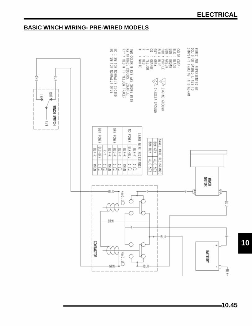
ELECTRICAL
0
1BASIC WINCH WIRING- PRE-WIRED MODELS
10.45
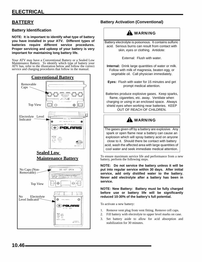
ELECTRICAL
BATTERYBattery IdentificationNOTE: It is important to identify what type of batteryyou have installed in your ATV. Different types ofbatteries require different service procedures.Proper servicing and upkeep of your battery is veryimportant for maintaining long battery life.
Your ATV may have a Conventional Battery or a Sealed LowMaintenance Battery. To identify which type of battery yourATV has, refer to the illustration below and follow the correctservice and charging procedures that follow in the manual.
Battery Activation (Conventional)
To ensure maximum service life and performance from a newbattery, perform the following steps.
NOTE: Do not service the battery unless it will beput into regular service within 30 days. After initialservice, add only distilled water to the battery.Never add electrolyte after a battery has been inservice.
NOTE: New Battery: Battery must be fully chargedbefore use or battery life will be significantlyreduced 10-30% of the battery's full potential.
To activate a new battery:
1. Remove vent plug from vent fitting. Remove cell caps.2. Fill battery with electrolyte to upper level marks on case.3. Set battery aside to allow for acid absorption and
stabilization for 30 minutes.
RemovableCaps
Top View
Electrolyte LevelIndicator
No Caps (Non-Removable)
Top View
No ElectrolyteLevel Indicator
Sealed Low Maintenance Battery
Conventional Battery
WARNING
Battery electrolyte is poisonous. It contains sulfuric acid. Serious burns can result from contact with
skin, eyes or clothing. Antidote:
External: Flush with water.
Internal: Drink large quantities of water or milk. Follow with milk of magnesia, beaten egg, or
vegetable oil. Call physician immediately.
Eyes: Flush with water for 15 minutes and get prompt medical attention.
Batteries produce explosive gases. Keep sparks, flame, cigarettes, etc. away. Ventilate when
charging or using in an enclosed space. Always shield eyes when working near batteries. KEEP
OUT OF REACH OF CHILDREN.
WARNING
The gases given off by a battery are explosive. Any spark or open flame near a battery can cause an explosion which will spray battery acid on anyone close to it. Should there be contact with battery
acid, wash the affected area with large quantities of cool water and seek immediate medical attention.
10.46

ELECTRICAL
0
14. Add electrolyte to bring level back to upper level mark oncase.
NOTE: This is the last time that electrolyte shouldbe added. If the level becomes low after this point,add only distilled water.
5. Charge battery at 1/10 of its amp/hour rating. Examples:1/10 of 9 amp battery = .9 amp; 1/10 of 14 amp battery =1.4 amp; 1/10 of 18 amp battery = 1.8 amp (recommendedcharging rates).
6. Check specific gravity of each cell with a hydrometer toassure each has a reading of 1.270 or higher.
Battery Terminals/BoltsTerminal Preparation
Use Polaris corrosion resistant Nyogel™ grease (PN 2871329)on battery bolts and terminals when installing a battery. Thiswill help to prevent corrosion and maintain good electricalconnection. See “BATTERY INSTALLATION”.
Conventional Battery Inspection / RemovalThe battery is located under the seat on Sportsman models.
The X2 and Touring battery is located under fuel tank and canbe accessed by removing the right hand side panel.
Inspect the battery fluid level. When the battery fluid nears thelower level, remove the battery and fill with distilled water onlyto the upper level line. To remove the battery:
1. Disconnect holder strap and remove covers.2. Disconnect battery negative (-) (black) cable first, followed
by the positive (+) (red) cable.
3. Remove the battery.4. Remove the filler caps and add distilled water only as
needed to bring each cell to the proper level. Do not overfillthe battery.
NOTE: Refill using only distilled water. Tap watercontains minerals which are harmful to a battery.
NOTE: Do not allow cleaning solution or tap waterinside the battery. Battery life may be reduced.
5. Reinstall the battery caps.
Conventional Battery Installation1. lean battery cables and terminals with a stiff wire brush.
Corrosion can be removed using a solution of one cupwater and one tablespoon baking soda. Rinse well withclean water and dry thoroughly.
2. Route the cables correctly.3. Reinstall battery, attaching positive (+) (red) cable first and
then the negative (-) (black) cable. Coat terminals and boltthreads with Nyogel™ Grease (PN 2871329).BATTERY
CAUTION
Whenever removing or reinstalling the battery, disconnect the negative (black) cable first and
reinstall the negative cable last!
Maintain between upper and lower level marks
10.47

ELECTRICAL
4. Install clear battery vent tube from vehicle to battery vent.
5. Reinstall the holder strap.
Conventional Battery TestingWhenever a service complaint is related to either the starting orcharging systems, the battery should be checked first.
Following are three tests which can easily be made on a batteryto determine its condition: OCV Test, Specific Gravity Test andLoad Test.
Conventional Battery OCV - Open Circuit Voltage TestBattery voltage should be checked with a digital multitester.Readings of 12.6 volts or less require further battery testing andcharging. See charts and Load Test below.
NOTE: Lead-acid batteries should be kept at or neara full charge as possible. Electrolyte level should bekept between the low and full marks. If the battery isstored or used in a partially charged condition, orwith low electrolyte levels, hard crystal sulfation willform on the plates, reducing the efficiency andservice life of the battery.
Conventional Battery Specific Gravity TestA tool such as a Battery Hydrometer (PN 2870836) can be usedto measure electrolyte strength or specific gravity. As thebattery goes through the charge/discharge cycle, the electrolytegoes from a heavy (more acidic) state at full charge to a light(more water) state when discharged. The hydrometer canmeasure state of charge and differences between cells in a multi-cell battery. Readings of 1.270 or greater should be observed ina fully charged battery. Differences of more than .025 betweenthe lowest and highest cell readings indicate a need to replacethe battery.
* Measurement at 80° F
NOTE: Subtract .01 from the specific gravity readingat 40° F
WARNING
Vent tube must be free from obstructions and kinks and securely installed. If not, battery gases could accumulate and cause an explosion. The vent tube should be routed away from frame and body to prevent contact with Route
the cables correctly.
OPEN CIRCUIT VOLTAGE
STATE OF CHARGE
CONVENTIONAL LEAD - ACID
LOW MAINTENANCE
100% 12.60V 12.70V
Charged 12.40V 12.50V
75% Charged 12.10V 12.20V
50% Charged 11.90V 12.0V
25% Charged less than 11.80V Less than 11.90V
0% Charged -- --
SPECIFIC GRAVITY
STATE OF CHARGE*
CONVENTIONAL LEAD - ACID
LOW MAINTENANCE
100% 1.265 1.275
Charged 1.210 1.225
75% Charged 1.160 1.175
50% Charged 1.120 1.135
25% Charged less than 1.100 Less than 1.115
0% Charged -- --
Battery Hydrometer (PN 2870836)
10.48

ELECTRICAL
0
1Battery Load Test
NOTE: This test can only be performed on machineswith electric starters. This test cannot be performedwith an engine or starting system that is not workingproperly.
A battery may indicate a full charge condition in the OCV testand the specific gravity test, but still may not have the storagecapacity necessary to properly function in the electrical system.For this reason, a battery capacity or load test should beconducted whenever poor battery performance is encountered.To perform this test, hook a multitester to the battery in the samemanner as was done in the OCV test. The reading should be 12.6volts or greater. Engage the starter and observe the batteryvoltage while cranking the engine. Continue the test for 15seconds. During cranking the observed voltage should not dropbelow 9.5 volts. If the beginning voltage is 12.6 volts or higherand the cranking voltage drops below 9.5 volts during the test,replace the battery.
Off Season StorageTo prevent battery damage during extended periods of non-use,the following basic battery maintenance items must beperformed:
• Remove the battery from the machine and wash the case and battery tray with a mild solution of baking soda and water. Rinse with lots of fresh water after cleaning. NOTE: Do not get any of the baking soda into the battery or the acid will be neutralized.
• Using a wire brush or knife, remove any corrosion from the cables and terminals.
• Make sure that the electrolyte is at the proper level. Add distilled water if necessary.
• Charge at a rate no greater than 1/10 of the battery's amp/hr capacity until the electrolyte's specific gravity reaches 1.270 or greater.
• Store the battery either in the machine with the cables disconnected, or store in a cool place.
NOTE: Recharge to full capacity every 30 to 60 daysduring a non-use period. If the battery is storedduring the winter months, electrolyte will freeze athigher temperatures as the battery discharges. Thechart below indicates freezing points by specificgravity.
Charging Procedure1. Remove the battery from the ATV to prevent damage from
leaking or spilled acid during charging.2. Charge the battery with a charging output no larger than 1/
10 of the battery's amp/hr rating. Charge as needed to raisethe specific gravity to 1.270 or greater.
3. Install battery in vehicle with positive terminal toward thefront. Coat threads of battery bolt with a corrosion resistantdielectric grease (PN 2871329).
4. Connect battery cables.
5. After connecting the battery cables, install the cover on thebattery and attach the hold down strap.
CAUTION
To prevent shock or component damage, remove spark plug high tension leads and connect securely
to engine ground before proceeding. ELECTROLYTE FREEZING POINTS
SPECIFIC GRAVITY OF ELECTROLYTE
FREEZING POINT
1.265 -75° F
1.225 -35° F
1.200 -17° F
1.150 +5° F
1.100 +18° F
1.050 +27° F
WARNING
To avoid the possibility of explosion, connect positive (red) cable first and negative (black) cable
last.
10.49

ELECTRICAL
6. Install clear battery vent tube from vehicle to battery vent.
7. Route cables so they are tucked away in front and behindbattery.
Low Maintenance BatteryBattery Check:
NOTE: All Low Maintenance batteries are fullycharged and tested at the factory before installation.Expected shelf life varies on storage conditions. Asa general rule before placing the battery into service,check the battery condition and charge accordingly.
1. Check the date label on the side of the battery to calculatewhen to check voltage. The battery should be checkedevery 3 months.
2. Check the voltage with a voltmeter or multimeter. A fullycharged battery should be 12.8 V or higher.
3. If the voltage is below 12.8 V, the battery will need to berecharged.
NEW BATTERIES: Batteries must be fully charged beforeuse or battery life can be reduced by 10-30% of full potential.Charge battery for 3-5 hours using a variable rate charger. Donot use the alternator to charge a new battery. A high rate batterycharger can cause battery damage.
Low Maintenance batteries are permanently sealed at the time ofmanufacture. The use of lead-calcium and AGM technologyinstead of lead-antimony allows the battery acid to be fullyabsorbed. For this reason, a Low Maintenance battery case isdark and the cell caps are not removable, since there is no needto check electrolyte level.
NEVER attempt to add electrolyte or water to a LowMaintenance battery. Doing so will damage the case and shortenthe life of the battery. Refer to the Battery Activation andMaintenance Video (PN 9917987) for proper instruction onservicing Low Maintenance batteries.
NOTE: New Batteries: Batteries must be fullycharged before use or battery life will be reduced by10-30% of full potential. Charge battery for 3-5 hoursat a current equivalent of 1/10 of the battery's ratedamp/hour capacity. Do not use the alternator tocharge a new battery. (Refer to Battery Activationand Maintenance video PN 9917987)
NEVER attempt to add electrolyte or water to a LowMaintenance battery. Doing so will damage the case and shortenthe life of the battery. Refer to the Battery Maintenance Video(PN 9917987) for proper instruction on servicing LowMaintenance batteries.
TO SERVICE A LOW MAINTENANCE BATTERY:
1. Remove battery from the vehicle.2. Test battery with a voltage meter or load tester to determine
battery condition. This will determine the length of timerequired to charge the battery to full capacity. Refer tocapacity table.
3. Charge battery using a variable rate charger.
Low Maintenance Battery ChargingIf battery voltage is 12.8 V or less, the battery may needrecharging. When using an automatic charger, refer to thecharger manufacturer's instructions for recharging. When usinga constant current charger, use the following guidelines forrecharging.
NOTE: Always verify battery condition before and 1-2 hours after the end of charging.
WARNING
Vent tube must be free from obstructions and kinks and securely installed. If not, battery gases could accumulate and cause an explosion. Vent should be routed away from frame and body to prevent contact with electrolyte. Avoid skin contact with
electrolyte, as severe burns could result. If electrolyte contacts the vehicle frame,
corrosion will occur.
WARNING
An overheated battery could explode, causing severe injury or death. Always watch charging
times carefully. Stop charging if the battery becomes very warm to the touch. Allow it to cool
before resuming charging.
10.50

ELECTRICAL
0
1Low Maintenance Battery Inspection / RemovalThe battery is located under the seat on Sportsman models.
The X2 and Touring battery is located under fuel tank and canbe accessed by removing the right hand side panel.
1. Remove the seat and Disconnect holder strap.2. Disconnect battery negative (-) (black) cable first, followed
by the positive (+) (red) cable.
3. Remove the battery.
Low Maintenance Battery Installation1. Clean battery cables and terminals with a stiff wire brush.
Corrosion can be removed using a solution of one cupwater and one tablespoon baking soda. Rinse well withclean water and dry thoroughly.
2. Route the cables correctly.3. Reinstall battery, attaching positive (+) (red) cable first and
then the negative (-) (black) cable. Coat terminals and boltthreads with Nyogel™ Grease (PN 2871329).
4. Reinstall the holder strap.
BATTERY CHARGING REFERENCE TABLE
STATE OF CHARGE
VOLTAGE ACTIONCHARGE
TIME
100% 12.8-13 V
None, check voltage at 3 mos. after manufacture
date
None Required
75-100% 12.5-12.8 V May need slight charge 3-6 Hours
50-75% 12.0-12.5 V Needs Charge 5-11 Hours
25-50% 11.5-12.0 V Needs Charge
At least 13 hours, verify
state of charge
0-25% 11.5 V or less Needs Charge At least 20
hours
CAUTION
Whenever removing or reinstalling the battery, disconnect the negative (black) cable first and
reinstall the negative cable last!
BATTERY
10.51

ELECTRICAL
Low Maintenance Battery - OCV- Open Circuit Voltage TestBattery voltage should be checked with a digital multitester.Readings of 12.8 volts or less require further battery testing andcharging. See charts and Load Test.
NOTE: Lead-acid batteries should be kept at or neara full charge as possible. If the battery is stored orused in a partially charged condition, or with lowelectrolyte levels, hard crystal sulfation will form onthe plates, reducing the efficiency and service life ofthe battery.
NOTE: Use a voltmeter or multimeter to test batteryvoltage.
* Measurement at 80° F
NOTE: Subtract .01 from the specific gravity readingat 40° F.
Low Maintenance Battery Load Test
NOTE: This test can only be performed on machineswith electric starters. This test cannot be performedwith an engine or starting system that is not workingproperly.
A battery may indicate a full charge condition in the OCV testand the specific gravity test, but still may not have the storagecapacity necessary to properly function in the electrical system.For this reason, a battery capacity or load test should beconducted whenever poor battery performance is encountered.To perform this test:
1. Hook a multitester to the battery in the same manner as wasdone in the OCV test. The reading should be 12.8 volts orgreater.
2. Engage the starter and observe the battery voltage whilecranking the engine. Continue the test for 15 seconds.
3. During cranking the observed voltage should not dropbelow 9.5 volts.
4. If the beginning voltage is 12.8 volts or higher and thecranking voltage drops below 9.5 volts during the test,replace the battery.
OPEN CIRCUIT VOLTAGE
STATE OF CHARGE
LOW MAINTENANCE BATTERY
CONVENTIONAL BATTERY
100 % 13.0V 12.70V
75% Charged 12.80V 12.50V
50% 12.50V 12.20V
25% 12.20V 12.0V
0% Charged less than 12.0V less than 11.9V
CAUTION
To prevent shock or component damage, remove spark plug high tension leads and connect securely
to engine ground before proceeding.
10.52

ELECTRICAL
0
1Low Maintenance Battery Off-season StorageBattery voltage should be checked with a digital multitester.Readings of 12.8 volts or less require further battery testing andcharging. See charts and Load Test.
• Remove the battery from the machine and wash the case and battery tray with a mild solution of baking soda and water. Rinse with lots of fresh water after cleaning.
• Using a wire brush or knife, remove any corrosion from the cables and terminals.
• Make sure that the electrolyte is at the proper level.
• Charge at a rate no greater than 1/10 of the battery's amp/hr capacity until the electrolyte's specific gravity reaches 1.270 or greater.
• Store the battery either in the machine with the cables disconnected, or store in a cool place.
NOTE: Stored batteries lose their charge at the rateof 1% per day. Recharge to full capacity every 30 to60 days during a non-use period. If the battery isstored during the winter months, electrolyte willfreeze at higher temperatures as the batterydischarges. The chart below indicates freezingpoints by specific gravity.
Low Maintenance Battery Charging Procedure1. Remove the battery from the ATV to prevent damage from
leaking or spilled acid during charging.2. Charge the battery with a variable rate charging output.
Charge as needed to raise the specific gravity to 1.270 orgreater.
3. Install battery in vehicle with positive terminal toward thefront. Coat threads of battery bolt with a corrosion resistantNyogel™ Grease (PN 2871329).
4. Route cables so they are tucked away in front and behindbattery.
5. Connect battery cables.
6. After connecting the battery cables, install the cover on thebattery and attach the hold down strap.
ELECTROLYTE FREEZING POINTS
SPECIFIC GRAVITY OF ELECTROLYTE
FREEZING POINT
1.265 -75° F
1.225 -35° F
1.200 -17° F
1.150 +5° F
1.100 +18° F
1.050 +27° F
WARNING
To avoid the possibility of sparks and explosion, connect positive (red) cable first and negative
(black) cable last.
10.53

ELECTRICAL
TROUBLESHOOTING DIAGRAMSOverviewIMPORTANT: Illustrations are representative and may not apply to all models. Refer to the wire diagrams for thecorrect wire circuit and technical information (if applicable).
All Wheel Drive - EFI
Charging Circuit - EFI
10.54

ELECTRICAL
0
1Cooling Fan - EFI
Fuel Pump - EFI
10.55

ELECTRICAL
Gear Switch - EFI
Power Circuit - EFI
10.56

ELECTRICAL
0
1Reverse Override - EFI
Fan Control - EFI
10.57

ELECTRICAL
Start Circuit - EFI
Start Enable - EFI
10.58
800 TOURING EFI INTERNATIONAL
CHAPTER 11800 TOURING EFI INTERNATIONAL
11
800 TOURING EFI INTERNATIONAL BRAKE SYSTEM . . . . . . . . . . . . . . . . . . . . . . . . 11.2OVERVIEW. . . . . . . . . . . . . . . . . . . . . . . . . . . . . . . . . . . . . . . . . . . . . . . . . . . . . . . . . . . 11.2EXPLODED VIEW . . . . . . . . . . . . . . . . . . . . . . . . . . . . . . . . . . . . . . . . . . . . . . . . . . . . . 11.3
800 TOURING EFI INTERNATIONAL STEERING POST AND LOCK ASSEMBLY. . . . 11.4STEERING ASSEMBLY EXPLODED VIEW . . . . . . . . . . . . . . . . . . . . . . . . . . . . . . . . . 11.4
800 TOURING EFI INTERNATIONAL ELECTRICAL . . . . . . . . . . . . . . . . . . . . . . . . . . . 11.5TURN / HAZARD SIGNAL DIAGRAM . . . . . . . . . . . . . . . . . . . . . . . . . . . . . . . . . . . . . . 11.5
NOTE: This chapter illustrates components that are unique to the Sportsman 800 Touring EFI International. Except where noted, any servicing of these components or other components
on the ATV can be done using this service manual’s procedures and illustrations.
11.1

800 TOURING EFI INTERNATIONAL
800 TOURING EFI INTERNATIONAL BRAKE SYSTEMOverviewThe Sportsman Touring International brake system consists of a complete hydraulic brake system. All-wheel braking is integratedinto the foot brake and hand brake systems and allows 4 wheel braking from either control separately, or at the same time.
When the foot brake is applied, all brake calipers are active, as braking pressure is routed from the foot brake master cylinder throughthe proportioning valve and distribution block, exiting one line to the front calipers, while the other line exits the proportioning valveand feeds the outer line to the rear calipers.
When the hand brake is applied, all brake calipers are active, as braking pressure is routed from the hand brake master cylinderthrough the distribution block, exiting one line to the front calipers, while the other line feeds the inner line to the rear calipers.
11.2
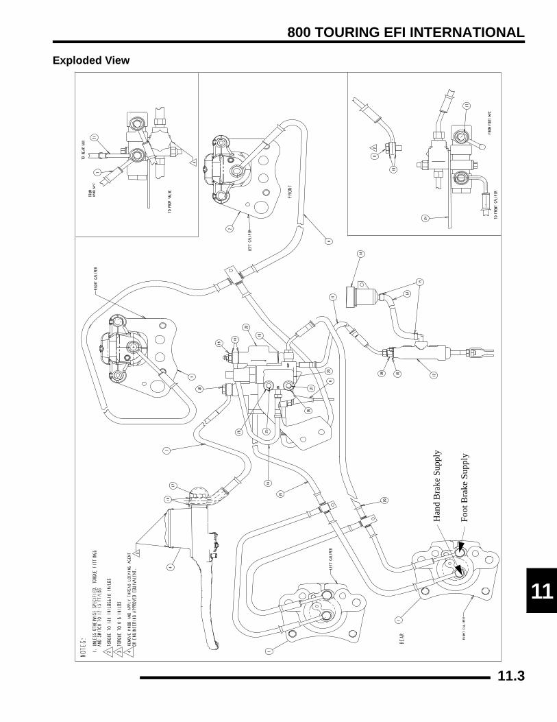
800 TOURING EFI INTERNATIONAL
1
1Exploded View
Foot
Bra
ke S
uppl
y
Han
d B
rake
Sup
ply
11.3

800 TOURING EFI INTERNATIONAL
800 TOURING EFI INTERNATIONAL STEERING POST AND LOCK ASSEMBLYSteering Assembly Exploded ViewThe 800 Touring EFI International Sportsman is equipped with a locking mechanism to prevent theft or unauthorized use. Steeringpost removal may be required for lock service or repair.
Lock System Item Number / Description:
11. Lock Collar
12. Lock Set
13. Bolt, Lock Set
14. Bolt(s), Lock Collar
15. Nut(s), Lock Collar
11.4

800 TOURING EFI INTERNATIONAL
1
1800 TOURING EFI INTERNATIONAL ELECTRICALTurn / Hazard Signal Diagram
11.5

800 TOURING EFI INTERNATIONAL
NOTES
11.6
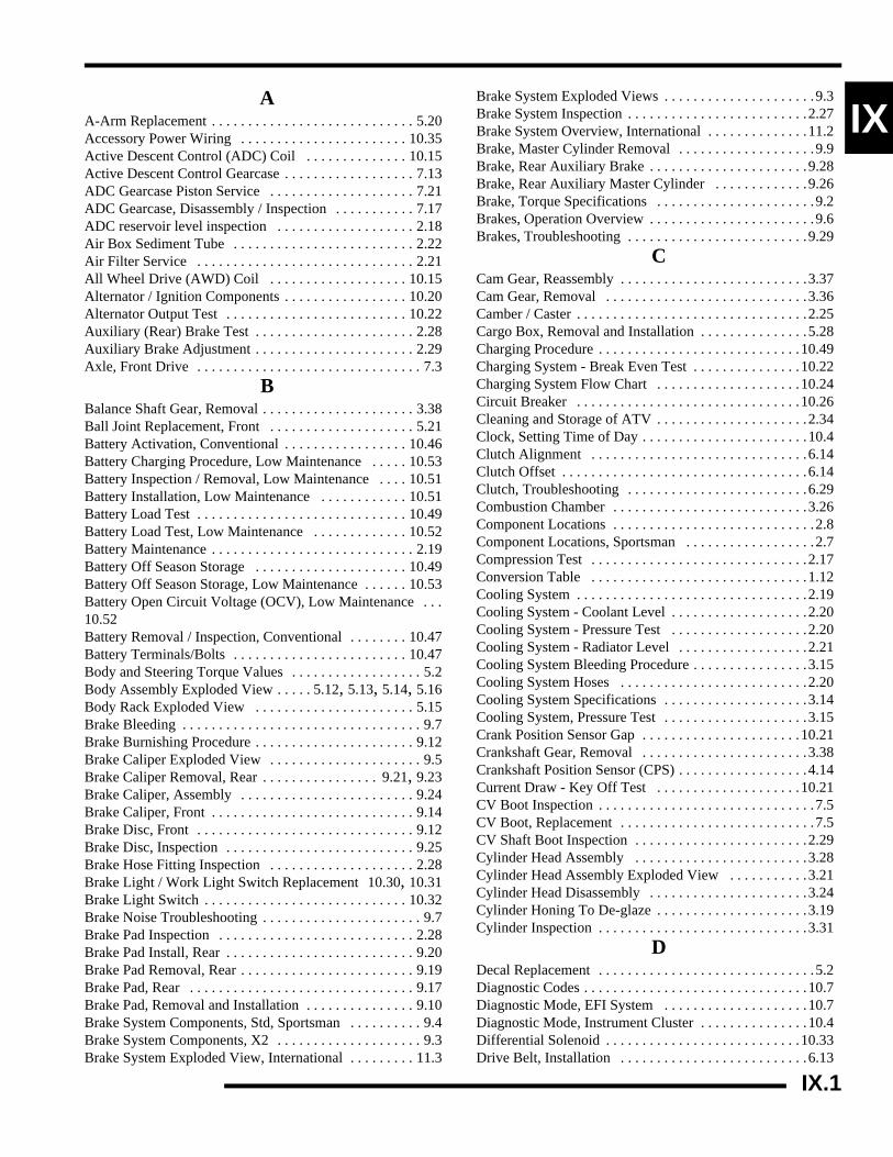
X
IAA-Arm Replacement . . . . . . . . . . . . . . . . . . . . . . . . . . . . 5.20Accessory Power Wiring . . . . . . . . . . . . . . . . . . . . . . . 10.35Active Descent Control (ADC) Coil . . . . . . . . . . . . . . 10.15Active Descent Control Gearcase . . . . . . . . . . . . . . . . . . 7.13ADC Gearcase Piston Service . . . . . . . . . . . . . . . . . . . . 7.21ADC Gearcase, Disassembly / Inspection . . . . . . . . . . . 7.17ADC reservoir level inspection . . . . . . . . . . . . . . . . . . . 2.18Air Box Sediment Tube . . . . . . . . . . . . . . . . . . . . . . . . . 2.22Air Filter Service . . . . . . . . . . . . . . . . . . . . . . . . . . . . . . 2.21All Wheel Drive (AWD) Coil . . . . . . . . . . . . . . . . . . . 10.15Alternator / Ignition Components . . . . . . . . . . . . . . . . . 10.20Alternator Output Test . . . . . . . . . . . . . . . . . . . . . . . . . 10.22Auxiliary (Rear) Brake Test . . . . . . . . . . . . . . . . . . . . . . 2.28Auxiliary Brake Adjustment . . . . . . . . . . . . . . . . . . . . . . 2.29Axle, Front Drive . . . . . . . . . . . . . . . . . . . . . . . . . . . . . . . 7.3BBalance Shaft Gear, Removal . . . . . . . . . . . . . . . . . . . . . 3.38Ball Joint Replacement, Front . . . . . . . . . . . . . . . . . . . . 5.21Battery Activation, Conventional . . . . . . . . . . . . . . . . . 10.46Battery Charging Procedure, Low Maintenance . . . . . 10.53Battery Inspection / Removal, Low Maintenance . . . . 10.51Battery Installation, Low Maintenance . . . . . . . . . . . . 10.51Battery Load Test . . . . . . . . . . . . . . . . . . . . . . . . . . . . . 10.49Battery Load Test, Low Maintenance . . . . . . . . . . . . . 10.52Battery Maintenance . . . . . . . . . . . . . . . . . . . . . . . . . . . . 2.19Battery Off Season Storage . . . . . . . . . . . . . . . . . . . . . 10.49Battery Off Season Storage, Low Maintenance . . . . . . 10.53Battery Open Circuit Voltage (OCV), Low Maintenance . . .10.52Battery Removal / Inspection, Conventional . . . . . . . . 10.47Battery Terminals/Bolts . . . . . . . . . . . . . . . . . . . . . . . . 10.47Body and Steering Torque Values . . . . . . . . . . . . . . . . . . 5.2Body Assembly Exploded View . . . . . 5.12, 5.13, 5.14, 5.16Body Rack Exploded View . . . . . . . . . . . . . . . . . . . . . . 5.15Brake Bleeding . . . . . . . . . . . . . . . . . . . . . . . . . . . . . . . . . 9.7Brake Burnishing Procedure . . . . . . . . . . . . . . . . . . . . . . 9.12Brake Caliper Exploded View . . . . . . . . . . . . . . . . . . . . . 9.5Brake Caliper Removal, Rear . . . . . . . . . . . . . . . . 9.21, 9.23Brake Caliper, Assembly . . . . . . . . . . . . . . . . . . . . . . . . 9.24Brake Caliper, Front . . . . . . . . . . . . . . . . . . . . . . . . . . . . 9.14Brake Disc, Front . . . . . . . . . . . . . . . . . . . . . . . . . . . . . . 9.12Brake Disc, Inspection . . . . . . . . . . . . . . . . . . . . . . . . . . 9.25Brake Hose Fitting Inspection . . . . . . . . . . . . . . . . . . . . 2.28Brake Light / Work Light Switch Replacement 10.30, 10.31Brake Light Switch . . . . . . . . . . . . . . . . . . . . . . . . . . . . 10.32Brake Noise Troubleshooting . . . . . . . . . . . . . . . . . . . . . . 9.7Brake Pad Inspection . . . . . . . . . . . . . . . . . . . . . . . . . . . 2.28Brake Pad Install, Rear . . . . . . . . . . . . . . . . . . . . . . . . . . 9.20Brake Pad Removal, Rear . . . . . . . . . . . . . . . . . . . . . . . . 9.19Brake Pad, Rear . . . . . . . . . . . . . . . . . . . . . . . . . . . . . . . 9.17Brake Pad, Removal and Installation . . . . . . . . . . . . . . . 9.10Brake System Components, Std, Sportsman . . . . . . . . . . 9.4Brake System Components, X2 . . . . . . . . . . . . . . . . . . . . 9.3Brake System Exploded View, International . . . . . . . . . 11.3
Brake System Exploded Views . . . . . . . . . . . . . . . . . . . . .9.3Brake System Inspection . . . . . . . . . . . . . . . . . . . . . . . . .2.27Brake System Overview, International . . . . . . . . . . . . . .11.2Brake, Master Cylinder Removal . . . . . . . . . . . . . . . . . . .9.9Brake, Rear Auxiliary Brake . . . . . . . . . . . . . . . . . . . . . .9.28Brake, Rear Auxiliary Master Cylinder . . . . . . . . . . . . .9.26Brake, Torque Specifications . . . . . . . . . . . . . . . . . . . . . .9.2Brakes, Operation Overview . . . . . . . . . . . . . . . . . . . . . . .9.6Brakes, Troubleshooting . . . . . . . . . . . . . . . . . . . . . . . . .9.29
CCam Gear, Reassembly . . . . . . . . . . . . . . . . . . . . . . . . . .3.37Cam Gear, Removal . . . . . . . . . . . . . . . . . . . . . . . . . . . .3.36Camber / Caster . . . . . . . . . . . . . . . . . . . . . . . . . . . . . . . .2.25Cargo Box, Removal and Installation . . . . . . . . . . . . . . .5.28Charging Procedure . . . . . . . . . . . . . . . . . . . . . . . . . . . .10.49Charging System - Break Even Test . . . . . . . . . . . . . . .10.22Charging System Flow Chart . . . . . . . . . . . . . . . . . . . .10.24Circuit Breaker . . . . . . . . . . . . . . . . . . . . . . . . . . . . . . .10.26Cleaning and Storage of ATV . . . . . . . . . . . . . . . . . . . . .2.34Clock, Setting Time of Day . . . . . . . . . . . . . . . . . . . . . . .10.4Clutch Alignment . . . . . . . . . . . . . . . . . . . . . . . . . . . . . .6.14Clutch Offset . . . . . . . . . . . . . . . . . . . . . . . . . . . . . . . . . .6.14Clutch, Troubleshooting . . . . . . . . . . . . . . . . . . . . . . . . .6.29Combustion Chamber . . . . . . . . . . . . . . . . . . . . . . . . . . .3.26Component Locations . . . . . . . . . . . . . . . . . . . . . . . . . . . .2.8Component Locations, Sportsman . . . . . . . . . . . . . . . . . .2.7Compression Test . . . . . . . . . . . . . . . . . . . . . . . . . . . . . .2.17Conversion Table . . . . . . . . . . . . . . . . . . . . . . . . . . . . . .1.12Cooling System . . . . . . . . . . . . . . . . . . . . . . . . . . . . . . . .2.19Cooling System - Coolant Level . . . . . . . . . . . . . . . . . . .2.20Cooling System - Pressure Test . . . . . . . . . . . . . . . . . . .2.20Cooling System - Radiator Level . . . . . . . . . . . . . . . . . .2.21Cooling System Bleeding Procedure . . . . . . . . . . . . . . . .3.15Cooling System Hoses . . . . . . . . . . . . . . . . . . . . . . . . . .2.20Cooling System Specifications . . . . . . . . . . . . . . . . . . . .3.14Cooling System, Pressure Test . . . . . . . . . . . . . . . . . . . .3.15Crank Position Sensor Gap . . . . . . . . . . . . . . . . . . . . . .10.21Crankshaft Gear, Removal . . . . . . . . . . . . . . . . . . . . . . .3.38Crankshaft Position Sensor (CPS) . . . . . . . . . . . . . . . . . .4.14Current Draw - Key Off Test . . . . . . . . . . . . . . . . . . . .10.21CV Boot Inspection . . . . . . . . . . . . . . . . . . . . . . . . . . . . . .7.5CV Boot, Replacement . . . . . . . . . . . . . . . . . . . . . . . . . . .7.5CV Shaft Boot Inspection . . . . . . . . . . . . . . . . . . . . . . . .2.29Cylinder Head Assembly . . . . . . . . . . . . . . . . . . . . . . . .3.28Cylinder Head Assembly Exploded View . . . . . . . . . . .3.21Cylinder Head Disassembly . . . . . . . . . . . . . . . . . . . . . .3.24Cylinder Honing To De-glaze . . . . . . . . . . . . . . . . . . . . .3.19Cylinder Inspection . . . . . . . . . . . . . . . . . . . . . . . . . . . . .3.31
DDecal Replacement . . . . . . . . . . . . . . . . . . . . . . . . . . . . . .5.2Diagnostic Codes . . . . . . . . . . . . . . . . . . . . . . . . . . . . . . .10.7Diagnostic Mode, EFI System . . . . . . . . . . . . . . . . . . . .10.7Diagnostic Mode, Instrument Cluster . . . . . . . . . . . . . . .10.4Differential Solenoid . . . . . . . . . . . . . . . . . . . . . . . . . . .10.33Drive Belt, Installation . . . . . . . . . . . . . . . . . . . . . . . . . .6.13
IX.1
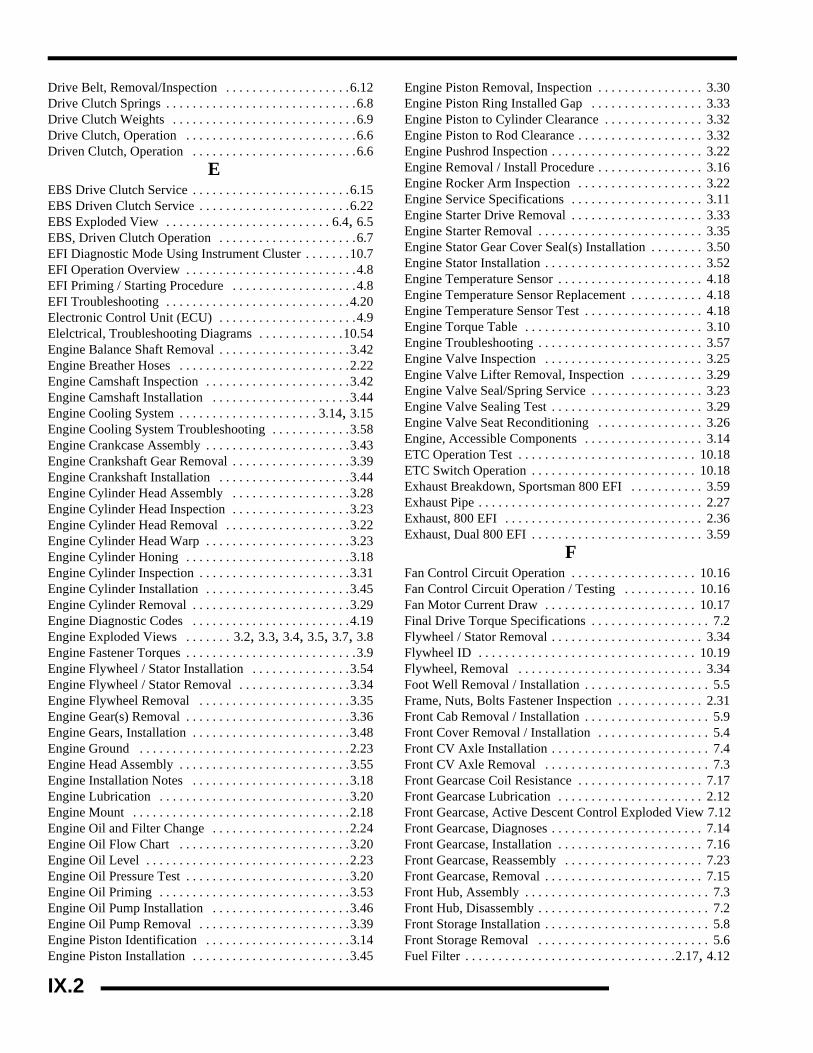
Drive Belt, Removal/Inspection . . . . . . . . . . . . . . . . . . .6.12Drive Clutch Springs . . . . . . . . . . . . . . . . . . . . . . . . . . . . .6.8Drive Clutch Weights . . . . . . . . . . . . . . . . . . . . . . . . . . . .6.9Drive Clutch, Operation . . . . . . . . . . . . . . . . . . . . . . . . . .6.6Driven Clutch, Operation . . . . . . . . . . . . . . . . . . . . . . . . .6.6
EEBS Drive Clutch Service . . . . . . . . . . . . . . . . . . . . . . . .6.15EBS Driven Clutch Service . . . . . . . . . . . . . . . . . . . . . . .6.22EBS Exploded View . . . . . . . . . . . . . . . . . . . . . . . . . 6.4, 6.5EBS, Driven Clutch Operation . . . . . . . . . . . . . . . . . . . . .6.7EFI Diagnostic Mode Using Instrument Cluster . . . . . . .10.7EFI Operation Overview . . . . . . . . . . . . . . . . . . . . . . . . . .4.8EFI Priming / Starting Procedure . . . . . . . . . . . . . . . . . . .4.8EFI Troubleshooting . . . . . . . . . . . . . . . . . . . . . . . . . . . .4.20Electronic Control Unit (ECU) . . . . . . . . . . . . . . . . . . . . .4.9Elelctrical, Troubleshooting Diagrams . . . . . . . . . . . . .10.54Engine Balance Shaft Removal . . . . . . . . . . . . . . . . . . . .3.42Engine Breather Hoses . . . . . . . . . . . . . . . . . . . . . . . . . .2.22Engine Camshaft Inspection . . . . . . . . . . . . . . . . . . . . . .3.42Engine Camshaft Installation . . . . . . . . . . . . . . . . . . . . .3.44Engine Cooling System . . . . . . . . . . . . . . . . . . . . . 3.14, 3.15Engine Cooling System Troubleshooting . . . . . . . . . . . .3.58Engine Crankcase Assembly . . . . . . . . . . . . . . . . . . . . . .3.43Engine Crankshaft Gear Removal . . . . . . . . . . . . . . . . . .3.39Engine Crankshaft Installation . . . . . . . . . . . . . . . . . . . .3.44Engine Cylinder Head Assembly . . . . . . . . . . . . . . . . . .3.28Engine Cylinder Head Inspection . . . . . . . . . . . . . . . . . .3.23Engine Cylinder Head Removal . . . . . . . . . . . . . . . . . . .3.22Engine Cylinder Head Warp . . . . . . . . . . . . . . . . . . . . . .3.23Engine Cylinder Honing . . . . . . . . . . . . . . . . . . . . . . . . .3.18Engine Cylinder Inspection . . . . . . . . . . . . . . . . . . . . . . .3.31Engine Cylinder Installation . . . . . . . . . . . . . . . . . . . . . .3.45Engine Cylinder Removal . . . . . . . . . . . . . . . . . . . . . . . .3.29Engine Diagnostic Codes . . . . . . . . . . . . . . . . . . . . . . . .4.19Engine Exploded Views . . . . . . . 3.2, 3.3, 3.4, 3.5, 3.7, 3.8Engine Fastener Torques . . . . . . . . . . . . . . . . . . . . . . . . . .3.9Engine Flywheel / Stator Installation . . . . . . . . . . . . . . .3.54Engine Flywheel / Stator Removal . . . . . . . . . . . . . . . . .3.34Engine Flywheel Removal . . . . . . . . . . . . . . . . . . . . . . .3.35Engine Gear(s) Removal . . . . . . . . . . . . . . . . . . . . . . . . .3.36Engine Gears, Installation . . . . . . . . . . . . . . . . . . . . . . . .3.48Engine Ground . . . . . . . . . . . . . . . . . . . . . . . . . . . . . . . .2.23Engine Head Assembly . . . . . . . . . . . . . . . . . . . . . . . . . .3.55Engine Installation Notes . . . . . . . . . . . . . . . . . . . . . . . .3.18Engine Lubrication . . . . . . . . . . . . . . . . . . . . . . . . . . . . .3.20Engine Mount . . . . . . . . . . . . . . . . . . . . . . . . . . . . . . . . .2.18Engine Oil and Filter Change . . . . . . . . . . . . . . . . . . . . .2.24Engine Oil Flow Chart . . . . . . . . . . . . . . . . . . . . . . . . . .3.20Engine Oil Level . . . . . . . . . . . . . . . . . . . . . . . . . . . . . . .2.23Engine Oil Pressure Test . . . . . . . . . . . . . . . . . . . . . . . . .3.20Engine Oil Priming . . . . . . . . . . . . . . . . . . . . . . . . . . . . .3.53Engine Oil Pump Installation . . . . . . . . . . . . . . . . . . . . .3.46Engine Oil Pump Removal . . . . . . . . . . . . . . . . . . . . . . .3.39Engine Piston Identification . . . . . . . . . . . . . . . . . . . . . .3.14Engine Piston Installation . . . . . . . . . . . . . . . . . . . . . . . .3.45
Engine Piston Removal, Inspection . . . . . . . . . . . . . . . . 3.30Engine Piston Ring Installed Gap . . . . . . . . . . . . . . . . . 3.33Engine Piston to Cylinder Clearance . . . . . . . . . . . . . . . 3.32Engine Piston to Rod Clearance . . . . . . . . . . . . . . . . . . . 3.32Engine Pushrod Inspection . . . . . . . . . . . . . . . . . . . . . . . 3.22Engine Removal / Install Procedure . . . . . . . . . . . . . . . . 3.16Engine Rocker Arm Inspection . . . . . . . . . . . . . . . . . . . 3.22Engine Service Specifications . . . . . . . . . . . . . . . . . . . . 3.11Engine Starter Drive Removal . . . . . . . . . . . . . . . . . . . . 3.33Engine Starter Removal . . . . . . . . . . . . . . . . . . . . . . . . . 3.35Engine Stator Gear Cover Seal(s) Installation . . . . . . . . 3.50Engine Stator Installation . . . . . . . . . . . . . . . . . . . . . . . . 3.52Engine Temperature Sensor . . . . . . . . . . . . . . . . . . . . . . 4.18Engine Temperature Sensor Replacement . . . . . . . . . . . 4.18Engine Temperature Sensor Test . . . . . . . . . . . . . . . . . . 4.18Engine Torque Table . . . . . . . . . . . . . . . . . . . . . . . . . . . 3.10Engine Troubleshooting . . . . . . . . . . . . . . . . . . . . . . . . . 3.57Engine Valve Inspection . . . . . . . . . . . . . . . . . . . . . . . . 3.25Engine Valve Lifter Removal, Inspection . . . . . . . . . . . 3.29Engine Valve Seal/Spring Service . . . . . . . . . . . . . . . . . 3.23Engine Valve Sealing Test . . . . . . . . . . . . . . . . . . . . . . . 3.29Engine Valve Seat Reconditioning . . . . . . . . . . . . . . . . 3.26Engine, Accessible Components . . . . . . . . . . . . . . . . . . 3.14ETC Operation Test . . . . . . . . . . . . . . . . . . . . . . . . . . . 10.18ETC Switch Operation . . . . . . . . . . . . . . . . . . . . . . . . . 10.18Exhaust Breakdown, Sportsman 800 EFI . . . . . . . . . . . 3.59Exhaust Pipe . . . . . . . . . . . . . . . . . . . . . . . . . . . . . . . . . . 2.27Exhaust, 800 EFI . . . . . . . . . . . . . . . . . . . . . . . . . . . . . . 2.36Exhaust, Dual 800 EFI . . . . . . . . . . . . . . . . . . . . . . . . . . 3.59
FFan Control Circuit Operation . . . . . . . . . . . . . . . . . . . 10.16Fan Control Circuit Operation / Testing . . . . . . . . . . . 10.16Fan Motor Current Draw . . . . . . . . . . . . . . . . . . . . . . . 10.17Final Drive Torque Specifications . . . . . . . . . . . . . . . . . . 7.2Flywheel / Stator Removal . . . . . . . . . . . . . . . . . . . . . . . 3.34Flywheel ID . . . . . . . . . . . . . . . . . . . . . . . . . . . . . . . . . 10.19Flywheel, Removal . . . . . . . . . . . . . . . . . . . . . . . . . . . . 3.34Foot Well Removal / Installation . . . . . . . . . . . . . . . . . . . 5.5Frame, Nuts, Bolts Fastener Inspection . . . . . . . . . . . . . 2.31Front Cab Removal / Installation . . . . . . . . . . . . . . . . . . . 5.9Front Cover Removal / Installation . . . . . . . . . . . . . . . . . 5.4Front CV Axle Installation . . . . . . . . . . . . . . . . . . . . . . . . 7.4Front CV Axle Removal . . . . . . . . . . . . . . . . . . . . . . . . . 7.3Front Gearcase Coil Resistance . . . . . . . . . . . . . . . . . . . 7.17Front Gearcase Lubrication . . . . . . . . . . . . . . . . . . . . . . 2.12Front Gearcase, Active Descent Control Exploded View 7.12Front Gearcase, Diagnoses . . . . . . . . . . . . . . . . . . . . . . . 7.14Front Gearcase, Installation . . . . . . . . . . . . . . . . . . . . . . 7.16Front Gearcase, Reassembly . . . . . . . . . . . . . . . . . . . . . 7.23Front Gearcase, Removal . . . . . . . . . . . . . . . . . . . . . . . . 7.15Front Hub, Assembly . . . . . . . . . . . . . . . . . . . . . . . . . . . . 7.3Front Hub, Disassembly . . . . . . . . . . . . . . . . . . . . . . . . . . 7.2Front Storage Installation . . . . . . . . . . . . . . . . . . . . . . . . . 5.8Front Storage Removal . . . . . . . . . . . . . . . . . . . . . . . . . . 5.6Fuel Filter . . . . . . . . . . . . . . . . . . . . . . . . . . . . . . . .2.17, 4.12
IX.2

X
IFuel Injection, Component Locations . . . . . . . . . . . . . . . 4.6Fuel Injection, Exploded View . . . . . . . . . . . . . . . . . . . . . 4.5Fuel Injection, Service Notes . . . . . . . . . . . . . . . . . . . . . . 4.4Fuel Injection, Special Tools . . . . . . . . . . . . . . . . . . . . . . 4.2Fuel Injector . . . . . . . . . . . . . . . . . . . . . . . . . . . . . . . . . . 4.13Fuel Pressure Regulator . . . . . . . . . . . . . . . . . . . . . . . . . 4.12Fuel Pump / Tank Assembly . . . . . . . . . . . . . . . . . . . . . 4.10Fuel Sender Test . . . . . . . . . . . . . . . . . . . . . . . . . . . . . . 10.33Fuel System, EFI Circuit Diagrams . . . . . . . . . . . . . . . . 4.21Fuel Tank Location . . . . . . . . . . . . . . . . . . . . . . . . . . . . . . 4.7Fuses . . . . . . . . . . . . . . . . . . . . . . . . . . . . . . . . . . . . . . . 10.26GGear / Stator Housing Seal Replacement . . . . . . . . . . . . 3.49Gear Position Indicator Switch Test . . . . . . . . . . . . . . . 10.17Gearcase, ADC Hydraulic Fluid Change . . . . . . . . . . . . 2.15Gearcase, Front Capacity and Fluid Type . . . . . . . . . . . . 7.2Glossary of Terms . . . . . . . . . . . . . . . . . . . . . . . . . . . . . 1.13
HHandlebar Block Installation Procedure . . . . . . . . . . . . . 5.18Headlamp Switch Test . . . . . . . . . . . . . . . . . . . . . . . . . 10.29Headlight Housing Replacement . . . . . . . . . . . . . . . . . 10.27Headlight Pod Exploded View . . . . . . . . . . . . . . . . . . . . 5.17High Beam Bulb Replacement . . . . . . . . . . . . . . . . . . . 10.26High Beam Headlight Adjustment . . . . . . . . . . . . . . . . 10.28Hydraulic Brake System Operation Overview . . . . . . . . . 9.6
IIgnition Curve . . . . . . . . . . . . . . . . . . . . . . . . . . . . . . . . 10.19Ignition System Troubleshooting . . . . . . . . . . . . . . . . . 10.21Instrument Cluster (Speedometer) Overview . . . . . . . . . 10.3Instrument Cluster, Setting New Service Interval . . . . . 10.6Interlock, Starter, 700/800 EFI . . . . . . . . . . . . . . . . . . . 10.36Interlock, Starter, 800 X2 EFI . . . . . . . . . . . . . . . . . . . 10.37
KKeys, Replacement . . . . . . . . . . . . . . . . . . . . . . . . . . . . . . 1.3
LLow Beam Headlight Adjustment . . . . . . . . . . . . . . . . 10.29Low Maintenance Battery Charging . . . . . . . . . . . . . . . 10.50Low Maintenance Battery Info . . . . . . . . . . . . . . . . . . . 10.50Lower Headlamp Housing Removal . . . . . . . . . . . . . . 10.29Lower Headlamp Removal . . . . . . . . . . . . . . . . . . . . . . 10.28Lubricants/Fluids, Polaris Brand Part Numbers . . . . . . . . 2.9Lubricants/Fluids, Polaris Brand Symbol Identification Chart 2.10Lubrication / Grease Points . . . . . . . . . . . . . . . . . . . . . . 2.11
MMaintenance Chart, Periodic . . . . . . . . . . . . . . . . . . . . . . 2.3Maintenance Schedule . . . . . . . . . . . . . . . . . . . . . 2.37, 2.38Misc. Tables . . . . . . . . . . . . . . . . . . . . . . . . . . . . . . . . . . 1.10Model . . . . . . . . . . . . . . . . . . . . . . . . . . . . . . . . . . . . . . . . 1.2Model Number/VIN Identification . . . . . . . . . . . . . . . . . . 1.2
OOil Pump, Disassembly . . . . . . . . . . . . . . . . . . . . . . . . . 3.39
Oil Pump, Reassembly . . . . . . . . . . . . . . . . . . . . . . . . . .3.40Oil Pump, Removal . . . . . . . . . . . . . . . . . . . . . . . . . . . . .3.39
PPaint Codes . . . . . . . . . . . . . . . . . . . . . . . . . . . . . . . . . . . .1.3Passenger Seat, Operation . . . . . . . . . . . . . . . . . . . . . . . .5.31Piston Ring Installed Gap . . . . . . . . . . . . . . . . . . . . . . . .3.33Piston to Cylinder Clearance . . . . . . . . . . . . . . . . . . . . . .3.32Piston to Rod Inspection . . . . . . . . . . . . . . . . . . . . . . . . .3.32Plastic Inserts . . . . . . . . . . . . . . . . . . . . . . . . . . . . . . . . . . .5.3Pre-ride Checklist . . . . . . . . . . . . . . . . . . . . . . . . . . . . . .2.10Propshaft, Removal . . . . . . . . . . . . . . . . . . . . . . . . . . . . . .7.7Publication Numbers . . . . . . . . . . . . . . . . . . . . . . . . . . . . .1.3PVT Assembly . . . . . . . . . . . . . . . . . . . . . . . . . . . . . . . .6.11PVT Disassembly . . . . . . . . . . . . . . . . . . . . . . . . . . . . . .6.10PVT Drive Clutch Operation . . . . . . . . . . . . . . . . . . . . . . .6.6PVT Drive Clutch Shift Weights . . . . . . . . . . . . . . . . . . .6.9PVT Drive Clutch Specifications . . . . . . . . . . . . . . . . . . .6.8PVT Driven Clutch Operation . . . . . . . . . . . . . . . . . . . . . .6.6PVT Drying . . . . . . . . . . . . . . . . . . . . . . . . . . . . . . 2.23, 6.10PVT Ducting . . . . . . . . . . . . . . . . . . . . . . . . . . . . . . . . . . .6.3PVT Maintenance / Inspection . . . . . . . . . . . . . . . . . . . . .6.7PVT Operation . . . . . . . . . . . . . . . . . . . . . . . . . . . . . . . . .6.6PVT Overheating Chart . . . . . . . . . . . . . . . . . . . . . . . . . .6.29PVT Special Tools . . . . . . . . . . . . . . . . . . . . . . . . . . . . . .6.2PVT Torque Specs . . . . . . . . . . . . . . . . . . . . . . . . . . . . . .6.2PVT Troubleshooting Chart . . . . . . . . . . . . . . . . . . . . . .6.30PVT, Button to Tower Clearance . . . . . . . . . . . . . . . . . .6.17PVT, Clutch Alignment . . . . . . . . . . . . . . . . . . . . . . . . . .6.14PVT, Clutch Offset . . . . . . . . . . . . . . . . . . . . . . . . . . . . .6.14PVT, Drive Belt Installation . . . . . . . . . . . . . . . . . . . . . .6.13PVT, Drive Belt Removal/Inspection . . . . . . . . . . . . . . .6.12PVT, Drive Clutch Disassembly . . . . . . . . . . . . . . . . . . .6.15PVT, Drive Clutch Exploded View . . . . . . . . . . . . . . . . . .6.3PVT, Drive Clutch Reassembly . . . . . . . . . . . . . . . . . . .6.20PVT, Drive Clutch Spider Removal . . . . . . . . . . . . . . . .6.15PVT, Driven Clutch Bushing Service . . . . . . . . . . . . . . .6.24PVT, Driven Clutch Disassembly . . . . . . . . . . . . . . . . . .6.22PVT, Driven Clutch Reassembly . . . . . . . . . . . . . . . . . .6.25PVT, EBS Clutch Operation . . . . . . . . . . . . . . . . . . . . . . .6.7PVT, EBS Drive Clutch Bushing Service . . . . . . . . . . . .6.18PVT, EBS Drive Clutch Cover Bushing Remove/Install 6.19PVT, Moveable Sheave Inspection . . . . . . . . . . . . . . . . .6.18
RRadiator . . . . . . . . . . . . . . . . . . . . . . . . . . . . . . . . . . . . . .2.20Radiator Screen Removal . . . . . . . . . . . . . . . . . . . . . . . .5.11Rear Cab Removal / Installation . . . . . . . . . . . . . . . . . . .5.10Rear Gearcase Lubrication . . . . . . . . . . . . . . . . . . . . . . .2.13Rear Gearcase, Assembly . . . . . . . . . . . . . . . . . . . . . . . .7.35Rear Gearcase, Disassembly . . . . . . . . . . . . . . . . . . . . . .7.34Rear Gearcase, Exploded View . . . . . . . . . . . . . . . . . . . .7.38Rear Gearcase, Installation . . . . . . . . . . . . . . . . . . . . . . .7.36Rear Gearcase, Removal . . . . . . . . . . . . . . . . . . . . . . . . .7.34Rear Master Cylinder, Exploded View . . . . . . . . . . . . . .9.26Rear Rack Removal / Installation . . . . . . . . . . . . . . . . . . .5.8Rear Storage Removal / Installation . . . . . . . . . . . . . . . .5.11
IX.3

Rear Suspension Assembly . . . . . . . . . . . . . . . . . . 5.24, 5.25Relays . . . . . . . . . . . . . . . . . . . . . . . . . . . . . . . . . . . . . .10.25
SSee “FRONT GEARCASE - CENTRALIZED HILLIARD(STANDARD on page 7.10. . . . . . . . . . . . . . . . . . . . . . .7.17Service Intervals, Speedometer . . . . . . . . . . . . . . . . . . . .10.6Shift Linkage Inspection . . . . . . . . . . . . . . . . . . . . . . . . .2.15Side Panel Removal . . . . . . . . . . . . . . . . . . . . . . . . . . . . .5.4Solenoid, Differential . . . . . . . . . . . . . . . . . . . . . . . . . .10.33Spark Plug . . . . . . . . . . . . . . . . . . . . . . . . . . . . . . . . . . . .2.18Special Tool, Cam Gear Installation Kit . . . . . . . . . . . . .3.37Special Tools, Body & Steering . . . . . . . . . . . . . . . . . . . .5.2Special Tools, Engine . . . . . . . . . . . . . . . . . . . . . . . . . . .3.13Special Tools, Final Drive . . . . . . . . . . . . . . . . . . . . . . . . .7.2Special Tools, Speed Sensor . . . . . . . . . . . . . . . . . . . . .10.34Specific Gravity Test, Conventional Battery . . . . . . . .10.48Specification, Balance Shaft Gear Bolt Torque . . . . . . .3.48Specification, Brake Disc Service Limit . . . . . . . . . . . . .9.25Specification, Brake Disc Thickness . . . . . . . . . . . . . . . .9.25Specification, Brake Pad Thickness . . . . . . . . . . . . . . . .9.19Specification, Cam Lobe Height . . . . . . . . . . . . . . . . . . .3.42Specification, Cam Thrust Plate Fastener Torque . . . . . .3.46Specification, Camshaft Gear Bolt Torque . . . . . . . . . . .3.49Specification, Coolant Sensor Resistance . . . . . . . . . . .10.16Specification, Cylinder Head Warp . . . . . . . . . . . . . . . . .3.23Specification, Cylinder Taper Limit . . . . . . . . . . . . . . . .3.31Specification, Cylinder Warp Limit . . . . . . . . . . . . . . . .3.31Specification, Differential Solenoid Resistance 10.33, 10.34Specification, Differential Solenoid Torque . . . 10.33, 10.34Specification, Drill and Tap Sizes . . . . . . . . . . . . . . . . . .1.11Specification, Oil Pump Bolt Torque . . . . . . . . . . . . . . .3.47Specification, Oil Pump Rotor Clearance . . . . . . . . . . . .3.40Specification, PVT Center-to-Center Distance . . . . . . . .6.13Specification, PVT Component Torque Table . . . . . . . . .6.2Specification, PVT Drive Belt Width . . . . . . . . . . . . . . .6.13Specification, Speed Sensor Bolt Torque . . . . . . . . . . .10.34Specification, Standard Fastener Torques . . . . . . . . . . . .1.10Specification, Timing Gear Alignment . . . . . . . . . . . . . .3.36Specification, Transmission Silent Chain Length . . . . . .8.35Specification, Valve Seat Contact Width . . . . . . . . . . . .3.27Specification, Valve Spring Free Length . . . . . . . . . . . .3.24Specification, Valve Stem Diameter . . . . . . . . . . . . . . . .3.25Specification, Valve Stem Guide I.D. . . . . . . . . . . . . . . .3.25Specification, Wheel Toe-Out . . . . . . . . . . . . . . . . . . . . .2.26Specifications, Body and Steering Torque Values . . . . . .5.2Specifications, Brake Component Service Limits . . . . . . .9.2Specifications, Brake Component Torque Values . . . . . .9.2Specifications, Cam Shaft . . . . . . . . . . . . . . . . . . . . . . . .3.43Specifications, Cooling System . . . . . . . . . . . . . . . . . . . .3.14Specifications, Crankcase Fastener Torque . . . . . . . . . . .3.44Specifications, Engine Lubrication . . . . . . . . . . . . . . . . .3.20Specifications, Engine Oil Pressure . . . . . . . . . . . . . . . .3.20Specifications, Final Drive Torque Values . . . . . . . . . . . .7.2Specifications, Front Gearcase Lubrication Type/Capacity 7.2Specifications, Oil Baffle Bolt Torque . . . . . . . . . . . . . .3.43
Specifications, Oil Pick-up Bolt Torque . . . . . . . . . . . . 3.43Specifications, Sportsman 800 EFI . . . . . . . . . . . . . . . . . 1.4Specifications, Sportsman Touring . . . . . . . . . . . . . . . . . 1.8Specifications, Sportsman X2 . . . . . . . . . . . . . . . . . . . . . 1.6Speed Sensor . . . . . . . . . . . . . . . . . . . . . . . . . . . . . . . . 10.34Speedometer Installation . . . . . . . . . . . . . . . . . . . . . . . . 10.9Speedometer Removal . . . . . . . . . . . . . . . . . . . . . . . . . . 10.8Speedometer Sensor, Replacement . . . . . . . . . . . . . . . 10.34Speedometer Troubleshooting Tests . . . . . . . . . . . . . . 10.10Speedometer, Funtions Overview . . . . . . . . . . . . . . . . . 10.3Starter Armature Testing . . . . . . . . . . . . . . . . . . . . . . . 10.40Starter Assembly Exploded View . . . . . . . . . . . . . . . . 10.43Starter Brush Inspection / Replacement . . . . . . . . . . . . 10.39Starter Drive . . . . . . . . . . . . . . . . . . . . . . . . . . . . . . . . . 10.42Starter Drive Removal . . . . . . . . . . . . . . . . . . . . . . . . . . 3.33Starter Interlock . . . . . . . . . . . . . . . . . . . . . . . . .10.36, 10.37Starter Motor, Removal . . . . . . . . . . . . . . . . . . . . . . . . 10.38Starter Reassembly / Installation . . . . . . . . . . . . . . . . . 10.41Starter System Flow Chart . . . . . . . . . . . . . . . . . . . . . . 10.44Starter System, Troubleshooting . . . . . . . . . . . . . . . . . 10.38Stator, Removal . . . . . . . . . . . . . . . . . . . . . . . . . . . . . . . 3.34Steering . . . . . . . . . . . . . . . . . . . . . . . . . . . . . . . . . . . . . 2.25Steering A-Arm Exploded View . . . . . . . . . . . . . . . . . . 5.19Steering Lock, Exploded View . . . . . . . . . . . . . . . . . . . 11.4Steering Post Assembly . . . . . . . . . . . . . . . . . . . . . . . . . 5.22Steering Post Removal . . . . . . . . . . . . . . . . . . . . . . . . . . 5.22Steering Torque Values . . . . . . . . . . . . . . . . . . . . . . . . . . 5.2Storage Compartments, Front & Rear . . . . . . . . . . . . . . 2.31Strut Assembly . . . . . . . . . . . . . . . . . . . . . . . . . . . . . . . . 5.23Strut Cartridge Replacement, Front . . . . . . . . . . . . . . . . 5.22Suspension Adjustment . . . . . . . . . . . . . . . . . . . . . . . . . 2.29Suspension, Front . . . . . . . . . . . . . . . . . . . . . . . . . . . . . . 2.29Suspension, Rear . . . . . . . . . . . . . . . . . . . . . . . . . . . . . . 2.29
TTemperature / Barometric Air Pressure Sensor (T-Bap) 4.15Throttle Cable . . . . . . . . . . . . . . . . . . . . . . . . . . . . . . . . 2.16Throttle Inspection . . . . . . . . . . . . . . . . . . . . . . . . . . . . . 2.16Throttle Position Sensor . . . . . . . . . . . . . . . . . . . . . . . . . 4.15Throttle Position Sensor Initialization . . . . . . . . . . . . . . 4.16Throttle Position Sensor Replacement . . . . . . . . . . . . . . 4.15Tie Rod / Steering Inspection . . . . . . . . . . . . . . . . . . . . . 2.25Timing Gear Mark Alignment . . . . . . . . . . . . . . . . . . . . 3.36Tire Inspection . . . . . . . . . . . . . . . . . . . . . . . . . . . . . . . . 2.31Torque Specs - Engine . . . . . . . . . . . . . . . . . . . . . . . . . . 3.10Transmission . . . . . . . . . . . . . . . . . . . . . . . . . . . . . . . . . 8.19Transmission Assembly . . . . . . . . . . . . . . . . . . . . . . . . . 8.12Transmission Disassembly . . . . . . . . . . . . . . . . . . . . . . . . 8.7Transmission Exploded View . . . . . . . . . . . . . . . . . . . . . 8.4Transmission Gear Selector Removal . . . . . . . . . . . . . . . 8.6Transmission Installation . . . . . . . . . . . . . . . . . . . . . . . . 8.17Transmission Mounts, Exploded View . . . . . . . . . . . . . 8.22Transmission Removal . . . . . . . . . . . . . . . . . . . . . . . . . . . 8.6Transmission Troubleshooting . . . . . . . . . . . . . . . . . . . . 8.18Transmission, Disassembly . . . . . . . . . . . . . . . . . . . . . . 8.27Transmission, Exploded View . . . . . . . . . . . . . . . . . . . . 8.20
IX.4

X
ITransmission, Install . . . . . . . . . . . . . . . . . . . . . . . . . . . . 8.25Transmission, Output Shaft Backlash Procedure . . . . . . 8.33Transmission, Reassembly . . . . . . . . . . . . . . . . . . . . . . . 8.32Transmission, Removal . . . . . . . . . . . . . . . . . . . . . . . . . 8.23Transmission, Special Tools . . . . . . . . . . . . . . . . . . . . . . 8.23Troubleshooting Diagrams, Elelctrical . . . . . . . . . . . . . 10.54Troubleshooting, EFI Circuit Diagrams . . . . . . . . . . . . . 4.21UU-joint, Disassembly and Assembly . . . . . . . . . . . . . . . . 7.7
VValve Seal/Spring Service . . . . . . . . . . . . . . . . . . . . . . . 3.23Valve Sealing Test . . . . . . . . . . . . . . . . . . . . . . . . . . . . . 3.29Valve Seat Reconditioning . . . . . . . . . . . . . . . . . . . . . . . 3.26Vent Lines . . . . . . . . . . . . . . . . . . . . . . . . . . . . . . . . . . . . 2.17Voltage Drop Test . . . . . . . . . . . . . . . . . . . . . . . . . . . . 10.38
WWarn Winch Operation . . . . . . . . . . . . . . . . . . . . . . . . . . 2.32Wheel Alignment . . . . . . . . . . . . . . . . . . . . . . . . . . . . . . 2.26Wheel Installation . . . . . . . . . . . . . . . . . . . . . . . . . . . . . . 2.30Wheel Removal . . . . . . . . . . . . . . . . . . . . . . . . . . . . . . . 2.30Winch, Basic Wiring Diagram . . . . . . . . . . . . . . . . . . . 10.45Wire Diagrams, Electrical . . . . . . . . . . . . . . . . . . . . . . 10.54Work Light Switch . . . . . . . . . . . . . . . . . . . . . . . . . . . . 10.30
XX2, Seat Disassembly . . . . . . . . . . . . . . . . . . . . . . . . . . . 5.32
IX.5

Intentional Blank Page
IX.6

WD-1
WIRE DIAGRAM
2008 SPORTSMAN 800 EFI WIRE DIAGRAM

WD-2
WIRE DIAGRAM
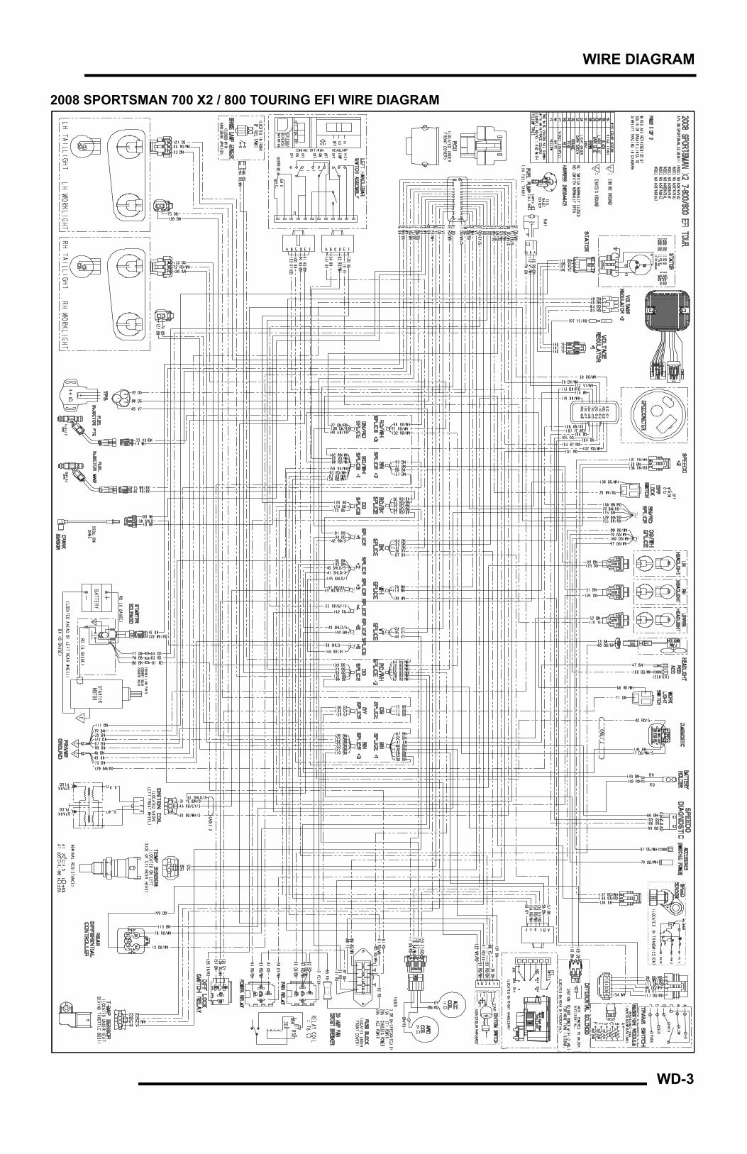
WD-3
WIRE DIAGRAM
2008 SPORTSMAN 700 X2 / 800 TOURING EFI WIRE DIAGRAM

WD-4
WIRE DIAGRAM

WD-5
WIRE DIAGRAM
2008 SPORTSMAN 800 TOURING EFI INTERNATIONAL WIRE DIAGRAM

WD-6
WIRE DIAGRAM
Copyright © 2022 FDOKUMEN