
TABLE OF CONTENTS - Vintage Snow
182
TABLE OF CONTENTS Safe Riding Instructions and General Information .......... ... ..... .. . 1 Setup and Predelivery Instructions .............. . ................... 2 Suspension . . .. .. ... . ......... .... .. ............. .... .... . ..... 22 Shock Manual ................... . .. . ........................... 39 Performance .......... .. .. .. ......... . ..... . ................... 68 Engine Servicing ................................................ 75 650 Engine Specifications & Torque Specifications .. .. ... . .. ... ...... 82 Shimming The 650 UC Pinion Gear ... .. ........................... 83 Crankshaft & Engine Specs . . . .................................... 84 Fuel Pump ................. . ............ ... ..... ... . .... .... ... 94 Carburetion ................... . ... . ....... . ............. .. ..... 95 Exhaust Gas Temperature ....................................... 101 Oil & Testing Fuel For Alcohol Content ... .. . .. .. .. ............... 102 1990 Carburetion .................. ... .. .......... .. .. .. .. ... . .. 103 Comet Drive Clutch Basics ....................... . .............. 109 Drive Clutch/Driven Pulley Setup - General ......................... 110 Driven Pulley Basics ................ . .. .. . ... ................ . .. 111 Sprocket Ratio ...... . ............................ . .......... . . 112 Checking Drive Belt Tension . . . .................... ... .. .. ....... 114 Drive Clutch Servicing ......... . ................ . ... .... .. ...... 115 Electrical Troubleshooting ...... .... .. ........ . ............. . ... 117 . Electrical Testing . ............... .. ........................ . ... 119 Engine Timing Specifications ........... . ........................ 125 Crank Angle Chart ....... ... ................ .. .... .. ... ........ 131 Specifications ........... ... ................... .... . ... ...... .. 132 Carburetor Specifications ....... . .... . ............ ... ..... . ..... 144 High Altitude Kits ... . ........... . .... . ......................... 146 Main Jet Charts ........... .. ................................ .. . 149 Alternate Carburetor Parts .... .... .................. . .... . ...... 154 Drive System Components ......... . ............................ 157 Arctic Cat Drive Belt Dimension Chart .. . .. .. .. ................. .. . 158 Dealer Service Tools ......... .. ......... . ...... .. .... . .. . ....... 161 Manuals & Parts Books ......... . ................ .. .. .. .. ....... 163 Ramp Grinding ................................. .. .. .... ....... 1 67 Stock Snowmobile Performance Ratings .. .... ............... .. . .. 168 Setup Adjustments & General Information ... ... ................... 170 Engine Modifications 650,530 & Formula III ........ ..... .. . ...... .. 173 Modification Instructions 440 UC UW ............... ... .. . ........ 176 Tuning Record Notes Arctic Alley Cat, Arctic Circle, Boss Cat l!> , Cat Kitchen, Cat- Master, Cats Pride, Cheetah l!> , Cougar, Cross Country Cat, EI Tigre, EXT, Howl, King Kat l!> , Kitten, Kitty Cat I!> , Lynx l!> , Pan teral!>, Pantherl!> ,Pumal!>, Quad Track, Sand Cat, Sno Pro, Tales Of The Cat, Trail Cat l!> , Turf Tiger, VIP, Wildcat, and Z are trademarks of Arctco, Inc., Thief River Falls, MN 56701 I I I I I
-
Upload
khangminh22 -
Category
Documents
-
view
1 -
download
0
Transcript of TABLE OF CONTENTS - Vintage Snow

TABLE OF CONTENTS Safe Riding Instructions and General Information .......... ... ..... .. . 1 Setup and Predelivery Instructions .............. . ................... 2 Suspension . . .. . . ... . ......... .... . . ............. .... .... . ..... 22 Shock Manual ................... . .. . ........................... 39 Performance .......... .. .. .. ......... . ..... . ................... 68 Engine Servicing ................................................ 75 650 Engine Specifications & Torque Specifications .. . . ... . .. . . . ...... 82 Shimming The 650 UC Pinion Gear ... .. ........................... 83 Crankshaft & Engine Specs . . . .................................... 84 Fuel Pump ................. . ............ . . . ..... ... . .... .... . . . 94 Carburetion ................... . ... . ....... . ............. .. ..... 95 Exhaust Gas Temperature ....................................... 101 Oil & Testing Fuel For Alcohol Content ... .. . .. . . .. ~ ............... 102 1990 Carburetion .................. . . . .. .......... .. .. .. .. ... . .. 103 Comet Drive Clutch Basics ....................... . .............. 109 Drive Clutch/Driven Pulley Setup - General ......................... 110 Driven Pulley Basics ................ . .. .. . ... ................ . .. 111 Sprocket Ratio ...... . ............................ . .......... . . 112 Checking Drive Belt Tension . . . .................... ... .. .. ....... 114 Drive Clutch Servicing ......... . ................ . ... . . . . .. ...... 115 Electrical Troubleshooting ...... .... . . ........ . ............. . ... 117
. Electrical Testing . ............... .. ........................ . ... 119 Engine Timing Specifications ........... . ........................ 125 Crank Angle Chart ....... . . . ................ .. .... . . ... ........ 131 Specifications ........... ... ................... .... . ... ...... .. 132 Carburetor Specifications ....... . .... . ............ ... ..... . ..... 144 High Altitude Kits ... . ........... . .... . ......................... 146 Main Jet Charts ........... .. ................................ .. . 149 Alternate Carburetor Parts .... .... .................. . .... . ...... 154 Drive System Components ......... . ............................ 157 Arctic Cat Drive Belt Dimension Chart .. . .. .. . . ................. .. . 158 Dealer Service Tools ......... .. ......... . ...... .. .... . .. . ....... 161 Manuals & Parts Books ......... . ................ . . .. .. .. ....... 163 Ramp Grinding ................................. . . .. . . . . ....... 167 Stock Snowmobile Performance Ratings .. . . . . ............... .. . .. 168 Setup Adjustments & General Information ... . . . ................... 170 Engine Modifications 650,530 & Formula III ........ . . . . . .. . ...... .. 173 Modification Instructions 440 UC UW ............... ... .. . ........ 176 Tuning Record Notes
Arct ic Cat~ , Alley Cat, Arctic Circle, Boss Catl!> , Cat Kitchen, CatMaster, Cats Pride, Cheetah l!> , Cougar, Cross Country Cat, EI Tigre, EXT, Howl, Jag~, King Kat l!> , Kitten, Kitty Cat I!> , Lynxl!> , Panteral!>, Pantherl!> ,Pumal!>, Quad Track, Sand Cat, Sno Pro, Tales Of The Cat, Trail Catl!> , Turf Tiger, VIP, Wildcat, and Z are trademarks of Arctco, Inc., Thief River Falls, MN 56701
I
I
I
I I

I

Safe Racing Instructions & General Information
PERSONAL SAFETY PREPARATION
YOU are the most important factor in preparing for racing. Pay attention to your physical condition and "get into shape" during the preseason. A fatigued driver never wins and sometimes is a hazard to himself and others.
It is recommended that the following protective clothing be worn for your safety when racing:
Knee and shin pads Shoulder and hip pads Kidney belt Ear plugs Approved full coverage safety helmet
(ANSI A90.1-1972, Snell, CSA 0230, or DOT) Safety goggles or shield, face mask
when necessary Above ankle leather topped boots Upper body protection - safety jacket
ON THE ROAD
1. Remove all gas and solvent-soaked rags from the trailer if using an enclosed-type trailer to haul and maintain the racing snowmobile. Equip the trailer with the proper type and number of fire extinguishers.
2. Load the racing snowmobile with a winch to avoid muscle strain. Make sure the machine is secured tightly to the trailer.
3. Check lights and license plate visibility on the trailer or van before each trip.
4. Check security of hitches, safety chains, and equipment on trailer or van before each trip.
5. Know the rules and requirements for trailering in the states, provinces, and localities where you will be traveling. Be sure your equipment meets all legal and safety requirements.
SNOWMOBILE IDENTIFICATION
1. The chassis model and serial number (the same) is located on the right side of the tunnel.
1
2. The engine model and serial numbers are stamped into the crankcase on intake side.
Always provide the snowmobile name, chassis model, and serial numbers and the engine model and serial numbers when contacting Arctco about parts, accessories, and service.
PRE·START INSPECTIONS AND EQUIPMENT CHECKS
1. Inspect all assemblies (front-end, skid frame, tunnel, clutches, track, and drive components) for possible cracks, broken welds, loose hardware, and other damage.
2. Make sure all safety guards are in place and fastened securely.
3. All rotating parts of the engine and drive system must have bolts and nuts tightened to correct torque values.
4. All nuts and bolts in the steering system (handlebar, skis, tie rods, spindles, etc.) must be tightened to correct torque values.
5. All rivets, connecting devices, and hinges must be tight and in working condition.
6. Speed controllers (throttle lever and carburetor linkage) must operate freely.
7. Check the hood for proper fastening and security.
8. Check the brake for proper operation.
9. Check the engine coolant level.
10. Check to see that no one is standing in front of or to the rear of the snowmobile before starting.
11. After starting the snowmobile, make sure the engine will stop immediately when the tether cord is pulled.
IN THE PITS
1. Do not "pit race". Operate your snowmobile only in areas designated by the sponsoring race committee and slow down when traveling to and from the warm-up area.
2. Your Arctic Cat snowmobile is designed to carry one person. DO NOT exceed this seating capacity. .
3. Do not allow inexperienced drivers to operate the racing snowmobile. If other racers operate the machine, be sure they are thoroughly experienced in the operation of the snowmobile, the fundamentals of racing, and the rules of racing and safety.

4. During engine warm-up, use a stable stand approved by the race association. The stand should have a proper shield that will not allow ice, snow, cleats, or ice studs to fly from the rear of the snowmobile endangering nearby people.
5. Tell bystanders to stay clear of the snowmobile.
6. KEEP ALL SAFETY SHIELDS AND GUARDS IN PLACE WHENEVER THE SNOWMOBILE IS OPERATED.
7. During engine warm-up and pit maintenance, do not over-rev the engine. Over-revving can cause component damage to the drive system.
8. GASOLINE IS HIGHLY FLAMMABLE AND DANGEROUS ... HANDLE IT CAREFULLY.
a. Use a funnel when filling the fuel tank to prevent spills on a hot engine or exhaust system.
b. Have the proper type and number of fire extinguishers in the pit and transport van for possible emergencies.
c. Remove the fuel tank from the snowmobile before performing any welding repairs.
d. DO NOT SMOKE when handling fuel. Use of a match or lighter near the fuel system is extremely dangerous.
ON THE TRACK
1. Read your race association competition and safety rulebook carefully, making sure you know and understand all rules pertaining to on-track conduct.
2. Study the flagging code carefully and respond to flagging of any kind immediately.
3. If you are involved in an accident on the track or cannot continue due to a mechanical breakdown, remove your snowmobile from the track as soon as possible.
4. Keep your hands on the controls at all times during the running of an event and after completion of the heat, whether you receive a checkered flag or not. When the race is over, reduce speed and continue slowly around the track until waved into the winner's circle or pits by a flagman.
5. If your racing snowmobile becomes inoperative during the running of an event, immediately raise your hand and carefully steer out of traffic towards the infield if possible. Riders behind you will not always be able to see that you're rapidly slowing down; therefore, the signal is important.
2
6. Do not drink alcoholic beverages or take drugs before or during a snowmobile racing event. Drinking and driving a snowmobile, especially in a racing event, can cause severe injury to yourself and to others and damage to property.
7. Practice track courtesy at all times to reduce the chance of an accident. Thoughtfu1 and courteous racers aid in public acceptance of our sport; make it safe and enjoyable for everyone. Do not block or cut off other riders during a race in an effort to win ... you may win the race this way, but you will lose in the long run.
CONTROL LOCATIONS
Throttle Control Lever - The throttle control lever is mounted on the right side of the handlebar. Compressing the lever increases the engine and snowmobile speed. Releasing the lever allows the snowmobile to coast to a stop and the engine will return to an idle.
Brake Control Lever - The brake control lever is mounted on the left side of the handlebar. Compressing the lever activates the brake system and slows or stops the movement of the snowmobile.
Emergency Tether Switch - The emergency tether switch is optional and should be mounted on right side on console. Before starting the engine, the tether switch cap/cord must be securely fastened to the operator. To start the engine, place the switch cap/cord firmly on the tether switch and proceed with starting procedures. To stop the engine, remove the cap/cord from the tether switch.
.&. WARNING .&. If the emergency tether switch is used during operation because of a mechanical problem, make sure the condition is diagnosed and corrected before restarting engine.
LUBRICATION POINTS ON CHASSIS
There are 7 grease fittings on the 1988 AFS chassis and 8 grease fittings on the new style 1989 AFS chassis. When lubrication is needed, use a grease gun with a flexible hose filled with a good low-temperature grease.
There is a grease fitting located on the front and inside of each spindle and 1 in the bearing flange on the left side of the drives haft. See the Operator's Manual for the location of the grease fittings on the skid frame and on the rear and front arm assemblies. Grease should be applied to all fittings until excess grease is seen on each side
\ ' 'I

of the pivot points. The extra grease will then force any moisture out of the pivot areas and prevent sticking. Using a rag, remove any excess grease from the chassis.
RECOMMENDED GASOLINE
The recommended gasoline to use is 88-92 octane leaded or lead free premium.
• CAUTION • Gasoline additives and white gas MUST NOT BE USED; they will eventually cause engine damage.
RECOMMENDED OIL
The recommended oil to use for both the oilinjection system and for pre-mixing is Arctco 50:1 Injection Oil.
CHAIN CASE (NON-REVERSE MODELS)
The recommended amount of chainlube in the chain case is 236 ml (8 fl oz). Adding more chainlube to the chain case (above the recommended amount) may result in leakage. To check the chainlube level, use the following procedure:
1. With the snowmobile level, shut engine off and wait. for all moving parts to stop; then open the hood.
2. Remove the check plug from the chain case cover. Using a long piece of wire bent to an L shape at approximately 5 cm (2 in.), check the oil level by inserting the wire into the check plug hole (like a dipstick). Make sure the end of the wire touches the bottom of the chain case.
Wire Dipstick
f 2 in. (5 cm)
0727·161
3. Remove the wire and measure the height of the oil. The measurement must be 3.5 cm (1 3/8 in.).
3
4. If oil is low, remove the filler plug and add Arctco Arctic Cat Chainlube through the filler plug hole. When the oil level is correct, install both the check plug and the filler plug.
II NOTE: If excessive oil deposits are noticed in the belly pan, take the snowmobile to an
authorized Arctco Arctic Cat Snowmobile dealer for service.
COOLING SYSTEM (PANTERA-EL TIGRE 6000 ·89)
These snowmobiles are equipped with a radiator designed to provide maximum cooling. For coolant, mix water and antifreeze according to the recommended directions on the container for the coldest temperatures to be encountered during racing. Generally a 60% antifreeze/40% water will provide the proper mixture for most racing. This mixture should be maintained in the cooling system during storage periods to prevent rusting and corrosion.
Drain Cooling System (Pantera·EI Tigre 6000 . 89)
1. Slowly rotate the radiator cap until all pressure is released; then remove the cap completely.
A WARNING ill Drain the system only when the coolant is at room temperature. Personal injury will occur if contact is made with hot coolant.
2. Loosen the clamp securing the water pump hose to the exhaust side coolant manifold. Slide hose free of manifold and drain coolant from cylinders and cylinder head.
II NOTE: Wipe any spilled coolant immediate· Iy.
Filling Cooling System (Pantera·EI Tigre 6000 . 89)
1. Make sure all radiator hoses are in position and properly secured.
2. Add the necessary mixture of coolant to the radiator filler neck until the level is about one inch below the filler neck.
II NOTE: The coolant system capacity is ap· proximately 6 U.S. quarts.
3. Start the engine and allow it to warm up.
II NOTE: Engine is thoroughly warmed up when all radiator hoses feel warm to the
touch.
4. Allow engine to cool. Carefully remove radiator cap and make sure level is one inch below the filler neck. Add coolant if necessary.
L I --~~ oj.

FILLING COOLING SYSTEM (Wildcat 650·EI Tigre EXT·Pantera·Prowler)
1.
• CAUTION • Be sure to thoroughly fill the cooling system with coolant. Bleeding the system does take time as air pockets do develop while filling.
Remove the three bolts from the thermostat housing; then remove the thermostat housing and thermostat.
_ NOTE: On the EI Tigre EXT, when removing - the thermostat housing, caution should be taken so that the gasket does not get damaged.
2. Remove the filler cap to vent the system.
3.
4.
5.
6.
7.
Pour coolant into the cooling system through the thermostat manifold. Keep filling the system until coolant reaches the thermostat opening.
Install thermostat and thermostat cap; tighten securely.
Finish filling the cooling system by pouring coolant in the filler spout. The system is full when coolant reaches the top of the filler neck. The Wildcat 650 system holds approximately 3.3 I (3.5 qt). The EI Tigre EXT system holds approximately 2.7 I (2.9 qt.)
Remove the green cap from the coolant holding tank and fill the tank % full of coolant.
Test ride the snowmobile 5 to 6 minutes and recheck coolant level.
Left Heat Exchanger
Coolant Filler Neck and Cap
Coolant Flow:
.J
With Thermostat Open -With Thermostat Closed --- - ---- 0727-540
4
ALIGNING SKIS
1. Turn the handlebar to the straight-ahead position .
2. Place a long straightedge against the outside edge of the track so it lies along the inside edge of the left-side ski.
Equal Distance
Straightedge
0727-005
_ NOTE: The straightedge should be long - enough to extend from the back of the track to the front of the ski.
3. Measure the distance from the straightedge to the edge of the ski in two places. Take one measurement from the forward end of the ski edge and the other measurement from the rearward end of the ski edge.
II NOTE: Make sure the measurements are taken on the flat surface of the ski edge and
not on the rounded surface.
4.
5.
The measurement from the forward and rearward ends of the ski edge must either be equal or the forward measurement must not exceed the rearward measurement by more than 3 mm (1/8 in.).
If an adjustment is necessary, loosen the adjusting stud jam nuts. Adjust ski by rotating the adjusting stud.
II NOTE: If an adjustment is required on the left tie rod, tip the machine up on its side and
remove the inspection/access door from the bot· tom of the belly pan. Loosen the tie rod jam nuts and set snowmobile back down. Adjustment can now be made by reaching up from the bottom, us· ing a 9/16 in. wrench and viewing the adjuster from the top side.
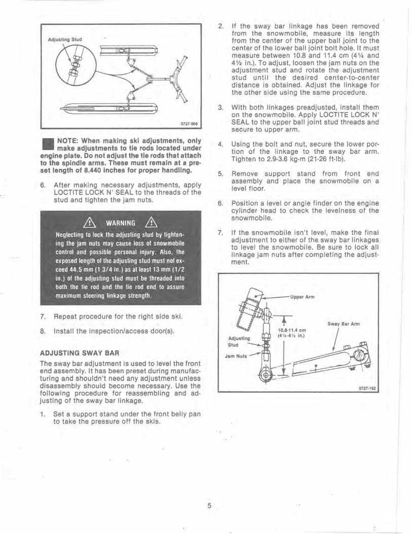
Adjusting Stud
0727·006
II NOTE: When making ski adjustments, only make adjustments to tie rods located under
engine plate. Do not adjust the tie rods that attach to the spindle arms. These must remain at a pre· set length of 8.440 inches for proper handling.
6. After making necessary adjustments, apply LOCTITE LOCK N' SEAL to the threads of the stud and tighten the jam nuts.
& WARNING & Neglecting to lock the adjusting stud by tightening the jam nuts may cause loss of snowmobile control and possible personal injury. Also, the exposed length of the adjusting stud must not exceed 44.5 mm (1 3/4 in.) as at least 13 mm (1/2 in.) of the adjusting stud must be threaded into both the tie rod and the tie rod end to assure maximum steering linkage strength.
7. Repeat procedure for the right side ski.
8. Install the inspection/access door(s).
ADJUSTING SWAY BAR
The sway bar adjustment is used to level the front end assembly. It has been preset during manufacturing and shouldn't need any adjustment unless disassembly should become necessary. Use the following procedure for reassembling and adjusting of the sway bar linkage.
1. Set a support stand under the front belly pan to take the pressure off the skis.
5
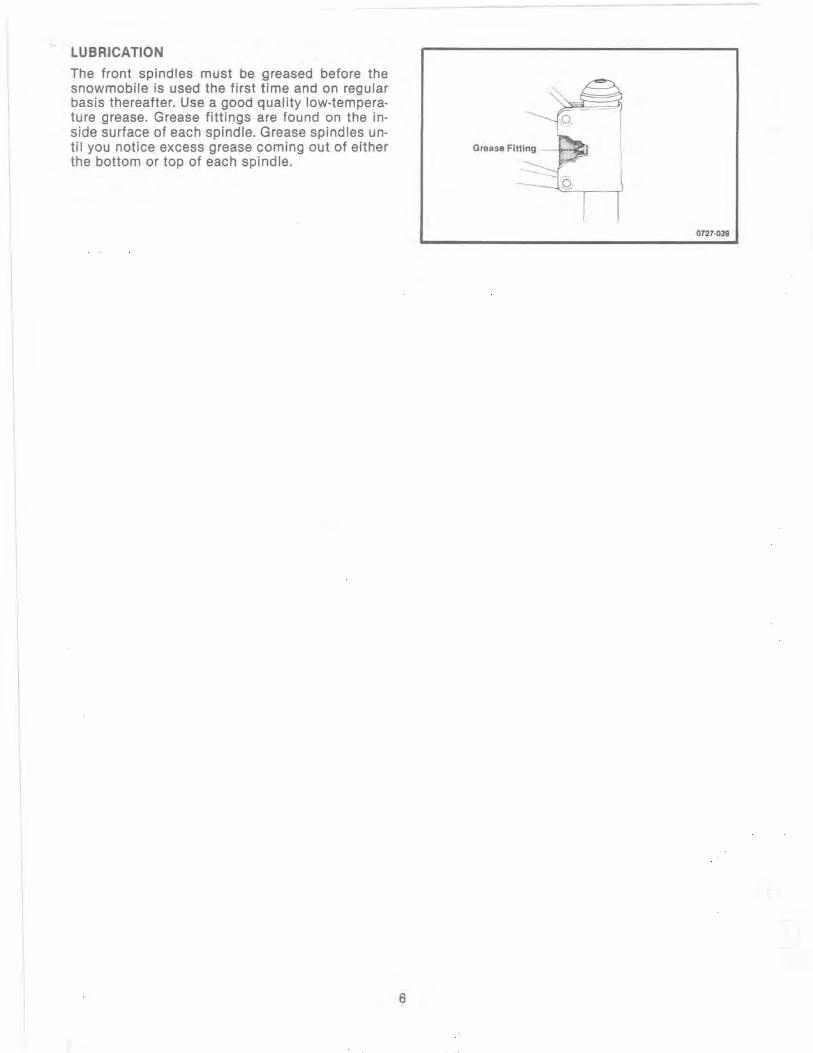
2. If the sway bar linkage has been removed from the snowmobile, measure its length from the center of the upper ball joint to the center of the lower ball joint bolt hole. It must measure between 10.8 and 11.4 cm (4 % and 4 % in.). To adjust, loosen the jam nuts on the adjustment stud and rotate the adjustment stud until the desired center-to-center distance is obtained. Adjust the linkage for the other side using the same procedure.
3. With both linkages preadjusted, install them on the snowmobile. Apply LOCTITE LOCK N' SEAL to the upper ball joint stud threads and secure to upper arm.
4. USing the bolt and nut, secure the lower portion of the linkage to the sway bar arm. Tighten to 2.9-3.6 kg-m (21-26 ft-Ib).
5. Remove support stand from front end assembly and place the snowmobile on a level floor.
6. Position a level or angle finder on the engine cylinder head to check the levelness of the snowmobile.
7. If the snowmobile isn't level, make the final adjustment to either of the sway bar linkages to level the snowmobile. Be sure to lock all linkage jam nuts after completing the adjustment.
'-_--Upper Arm
10.8·11.4 em (4'/.·4 V. in.)
J~ - .. --0727·192
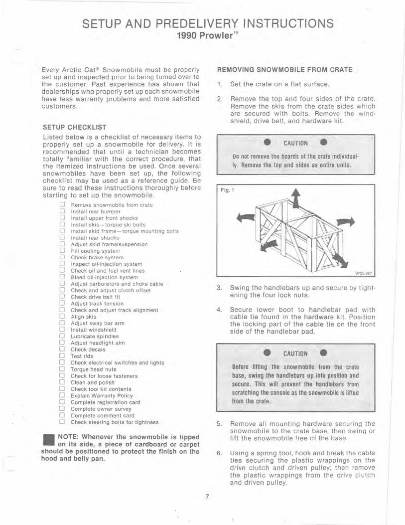
LUBRICATION
The front spindles must be greased before the snowmobile is used the first time and on regular basis thereafter. Use a good quality low-temperature grease. Grease fittings are found on the inside surface of each spindle. Grease spindles until you notice excess grease coming out of either the bottom or top of each spindle.
r
0727·039
6
SETUP AND PREDELIVERY INSTRUCTIONS 1990 Prowler™
Every Arctic Cat@ Snowmobile must be properly set up and inspected prior to being turned over to the customer. Past experience has shown that dealerships who properly set up each snowmobile have less warranty problems and more satisfied customers.
SETUP CHECKLIST
Listed below is a checklist of necessary items to properly set up a snowmobile for delivery. It is recommended that until a technician becomes totally familiar with the correct procedure, that the itemized instructions be used. Once several snowmobiles have been set up, the following checklist may be used as a reference guide. Be sure to read these instructions thoroughly before starting to set up the snowmobile.
o Remove snowmobile from crate o Install rear bumper o Install upper front shocks o Install skis- torque ski bolts lJ Install skid frame - torque mounting bolts [.J Install rear shocks o Adjust skid frame/suspension o Fill cooling system o Check brake system o Inspect oil·injection system o Check oil and fuel vent lines o Bleed o i l·injection system o Adjust carburetors and choke cable o Check and adjust clutch offset o Check drive belt fit o Adjust track tension o Check and adjust track alignment o Align skis o Adjust sway bar arm o Install windshield o Lubricate spindles o Adjust headlight aim o Check decals o Test ride o Check electrical switches and lights o Torque head nuts o Check for loose fasteners o Clean and polish o Check tool kit contents o Explain Warranty Policy o Complete registration card o Complete owner survey o Complete comment card o Check steering bolts for tightness
II NOTE: Whenever the snowmobile is tipped on its side, a piece of cardboard or carpet
should be positioned to protect the finish on the hood and belly pan.
7
REMOVING SNOWMOBILE FROM CRATE
1. Set the crate on a flat surface.
2. Remove the top and four sides of the crate . Remove the skis from the crate sides which are secured with bolts. Remove the windshield, drive belt, and hardware kit.
• CAUTION • Do not remove the boards of the crate individualIy. Remove the top and sides as entire units .
Fig.1
0725·327
3. Swing the handlebars up and secure by tight· ening the four lock nuts.
4. Secure lower boot to handlebar pad with cable tie found in the hardware kit. Position the locking part of the cable tie on the front side of the handlebar pad.
• CAUTION • Before lifting the snowmobile from the crate base, swing the handlebars up into position and secure. This will prevent the handlebars from scratching the console as the snowmobile is lifted from the crate.
5. Remove all mounting hardware securing the snowmobile to the crate base; then swing or lift the snowmobile free of the base.
6. Using a spring tool , hook and break the cable ties securing the plastic wrappings on the drive clutch and driven pulley; then remove the plastic wrappings from the drive clutch and driven pulley.

TIGHTENING FRONT ARM MOUNTING BOLTS
& WARNING & The hardware securing the front arms has been installed but has not been torqued in order to fit the snowmobile into the crate. The mounting bolts must be torqued.
1. On each side of the snowmobile, torque the four arm mounting lock nuts to 7.9·11.1 kg-m (70-80 ft-Ib).
Fig.2 Lock Nuts
\f-~ . . · Ski Spindle
G:J Adjustment o ~o;~, o 0
Tie Rod
fr' 'Steering Steering l.'\. Tie Rod Drag Link
Steering Post 0728·078
2. Inspect all tie rod nuts for cotter keys; make sure they are all secure.
3. Remove the stand from beneath the front end assembly and set snowmobile on the floor.
INSTALLING FRONT SHOCKS
1. In turn on each shock, rotate the spring adjuster nut upward until you have 19 mm (3/4 in.) of thread exposed below the adjuster.
2. Position a suitable stand under the front end assembly that will firmly support the snowmobile off the floor.
3. Place the threaded end of shock absorber into the lower arm; then install the lower and upper shock mounting bolts. Apply a good quality low-temperature grease to the bolts before installing.
II NOTE: Install the shock bolts so the lock nuts will be located on the backside of the
shock brackets.
4. Install the lock nuts and tighten to 2.8 kg-m (20 ft-Ib).
5. Repeat steps 3 and 4 for mounting the other front shock.
8
INSTALLING SKIS
1. Carefully move a ski up into position onto the spindle.
2. Align the hole in the ski with the spindle and slide the cap screw w/washer through the ski and spindle assembly. Be sure to position the cap screw so the lock nut will be located to the inside. Install the washer and lock nut; then tighten the lock nut 9.7-11.1 kg-m (70-80 ft-Ib) .
3. Place the cotter key through the ski bolt and nut; then spread.
4. Install the other ski using steps 1-3.
INSTALLING SKID FRAME
1. Place a piece of carpet on the floor next to the snowmobile to prevent scratching; then carefully tip the snowmobile on its side.
2. ~ Align the rear arm of the skid frame with the rear hole in lower mounting bracket. Secure with a cap screw and lock washer. DO NOT TIGHTEN AT THIS TIME.
3. Tip the snowmobile upright, position the carpet on the oppOSite side, and carefully tip the snowmobile on the opposite side. Install the remaining cap screw and lock washer securing the rear arm to the rear hole of the lower bracket.
4. Set the snowmobile upright; then tighten all four skid frame mounting cap screws to 2.9-3.6 kg-m (21-26 ft-Ib).
INSTALLING REAR SPRINGS
1. Remove the cap screw securing the spring block and spring to the center idler wheel.
2. Position the short arm of the spring on the rear adjustment cam. Place the spring and block into position and secure to the idler wheel shaft with cap screw and washer. Torque to 1.5 kg-m (11 ft-Ib).
II NOTE: The spring must be positioned above the cap screw.
3. Perform steps 1 and 2 on the other rear spring.
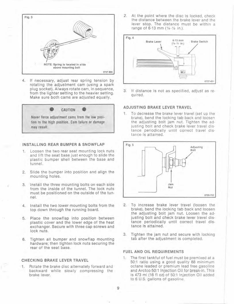
Fig. 3
NOTE: Spring is located in slide above mounting bolt
0727·896
4. If necessary, adjust rear spring tension by rotating the adjustment cam (using a spark plug socket). Always rotate cam, in sequence, from the lighter setting to the heavier setting. Make sure both cams are adjusted equally.
• CAUTION • Never force adjustment cams from the low position to the high position. Cam failure or damage may result.
INSTALLING REAR BUMPER & SNOWFLAP
1. Loosen the two rear seat mounting lock nuts and lift the seat base just enough to slide the plastic bumper shell between the base and tunnel.
2. Slide the bumper into position and align the mounting holes.
3. Install the three mounting bolts on each side from the inside of the tunnel. The lock nuts must be positioned on the outside of the tunnel.
4. Install the two lower mounting bolts from the top down through the running board.
5. Place the snowflap into position between plastic cover and the lower edge of the heat exchanger. Secure with three cap screws and lock nuts.
6. Tighten all bumper and snowflap mounting hardware; then tighten lock nuts securing the rear of the seat base.
CHECKING BRAKE LEVER TRAVEL
1. Rotate the brake disc alternate.:ly forward and backward while slowly compressing the brake lever.
9
2. At the point where the disc is locked, check the distance between the brake lever and the lever stop. The distance must be within a range of 6-13 mm (%-V2 in.).
Fig.4 Brake Lever 6·13 mm Brake Switch
0727·451
3. If distance is not as specified, adjust as required.
ADJUSTING BRAKE LEVER TRAVEL
1. To decrease the brake lever travel (set up the brake), bend the locking tab back and loosen the adjusting bolt jam nut. Tighten the ad· justing bolt and check brake lever travel distance periodically until correct travel distance is attained.
Fig.5
1 Jam Nut
Adjusting Bolt
0726·753
2. To increase brake lever travel (loosen the brake), bend the locking tab back and loosen the adjusting bolt jam nut. Loosen the adjusting bolt and check brake lever travel distance periodically until correct travel distance is attained.
3. Tighten the jam nut and secure with locking tab after the adjustment is completed.
FUEL AND OIL REQUIREMENTS
1. The first tankful of fuel must be premixed at a 50:1 ratio using a good quality 88 minimum octane leaded or premium lead free gasoline a'nd Arctco 50:1 Injection Oil for break-in. This is 473 ml (16 fl oz) of 50:1 Injection Oil added to 6 U.S. gallons of gasoline.

• CAUTION • Be sure to select a good quality gasoline of at least 88 octane with no alcohol additives.
2. Fill the injection oil tank with Arctco 50:1 Injection Oil.
3. Inspect the oil lines, fittings, and clamps for any signs of leakage. Be sure the oil lines to the manifold/cylinders are in position and tight.
II NOTE: The oil injection system will bleed it· self. No special bleeding procedure will be
necessary.
INSPECTING OIL·INJECTION SYSTEM
1. With the engine off, move the throttle lever to the wide-open·throttle position.
2. Check to be sure the mark on the control arm is aligned with alignment mark on the oil injection pump boss.
Fig.6
Control Arm
Pump Boss
Oil Bleed Plug
0727·185
3. If the marks are not aligned when the throttle lever is in the wide·open·throttle position, ad· just synchronization by loosening the jam nuts on the cable. Rotate until proper alignment is attained. Tighten jam nuts.
II NOTE: When the cable is adjusted correctly, a small amount of cable slack must be evi·
dent in the IDLE position to ensure the throt· tie/ignition monitor switch will function properly.
VENT LINES (GAS AND OIL TANK)
Both gas and oil tank lines must be checked to make sure the lines are open and free of any obstructions or kinks. Lightly blow into each vent line (with tank cap removed) to make sure air flows freely without any obstructions.
10
FILLING COOLING SYSTEM
• CAUTION • Extra care must be used to make sure the cooling system is completely filled. The cooling system capacity is 3 U.S. quarts.
1. Open the drain valve on the front side of the engine crankcase several turns.
2. Remove the filler cap. Pour coolant into the filler neck while watching the drain valve . As soon as coolant starts flowing from the drain valve, slide a 3 foot piece of clear fuel line on the drain valve tube. Grasp the end of the tube and hold the fuel line above the cylinder heads. Continue to pour coolant into the filler neck until the coolant level in the fuel line (attached to drain valve tube) and the filler spout are at equal heights. The coolant should be 37 mm (11/2 in.) below the top of the filler neck opening.
II NOTE: You may need to squeeze the hose _ leading to the water pump to force air from
the system.
3. Once the coolant level has equalized in the line from front of engine, tighten the drain valve using a 17 mm wrench .
4. Finish filling the cooling system by pouring coolant into the filler spout; then install the filler cap.
5. Remove the green cap from the coolant holding tank and fill the tank % full.
6. When setup is complete, test ride the snowmobile 5 to 6 minutes and recheck coolant level.
ADJUSTING CARBURETORS
II NOTE: When setting up a snowmobile that is to be operated at high altitude, be sure to
refer to the main jet chart and the high altitude clutching specifications section.
II NOTE: The carburetor safety switches have been pre·set at the factory and should need
no further adjustment. Adjustment screws have been secured with cement and shouldn't be loosened.
1. Be sure the ignition switch key is in the OFF position and the parking brake is set.
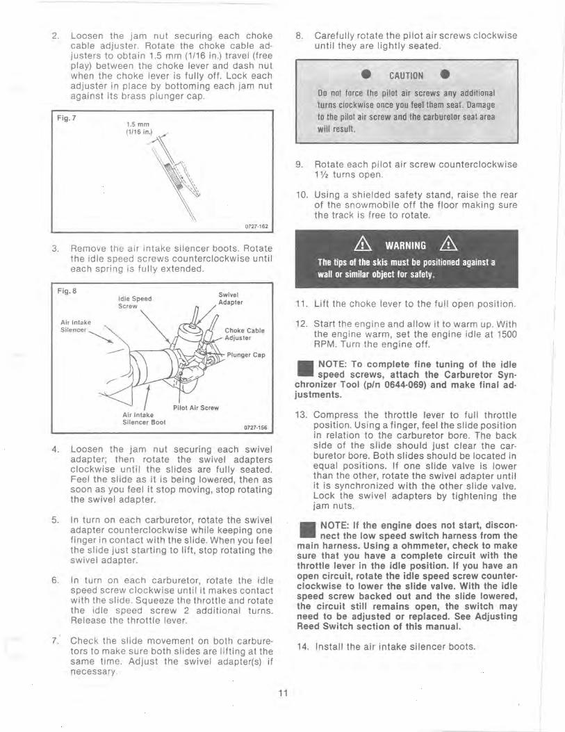
2. Loosen the jam nut securing each choke cable adjuster. Rotate the choke cable adjusters to obtain 1.5 mm (1/16 in.) travel (free play) between the choke lever and dash nut when the choke lever is fully off. Lock each adjuster in place by bottoming each jam nut against its brass plunger cap.
Fig . 7
0727·162
3. Remove the air intake silencer boots. Rotate the idle speed screws counterclockwise until each spring is fully extended.
Fig.8
Air Intake Silencer~
Air Intake Silencer Boot
Swivel Adapter
Choke Cable _--I,1,...I.¥'" Adjuster
Plunger Cap
Pilot Air Screw
0727·156
4. Loosen the jam nut securing each swivel adapter; then rotate the swivel adapters clockwise until the slides are fully seated. Feel the slide as it is being lowered, then as soon as you feel it stop moving, stop rotating the swivel adapter.
5. In turn on each carburetor, rotate the swivel adapter counterclockwise while keeping one finger in contact with the slide. When you feel the slide just starting to lift, stop rotating the swivel adapter.
6. In turn on each carburetor, rotate the idle speed screw clockwise until it makes contact with the slide. Squeeze the throttle and rotate the idle speed screw 2 additional turns. Release the throttle lever.
7. Check the slide movement on both carburetors to make sure both slides are lifting at the same time. Adjust the swivel adapter(s) if necessary.
11
8. Carefully rotate the pilot air screws clockwise until they are lightly seated.
• CAUTION • Do not force the pilot air screws any additional turns clockwise once you feel them seat. Damage to the pilot air screw and the carburetor seat area will result.
9. Rotate each pilot air screw counterclockwise 1 V2 turns open.
10. Using a shielded safety stand, raise the rear of the snowmobile off the floor making sure the track is free to rotate.
& WARNING & The tips of the skis must be positioned against a wall or similar object for safety.
11. Lift the choke lever to the full open position .
12. Start the engine and allow it to warm up. With the engine warm, set the engine idle at 1500 RPM. Turn the engine off.
II NOTE: To complete fine tuning of the idle speed screws, attach the Carburetor Syn
chronizer Tool (pIn 0644-069) and make final adjustments.
13. Compress the throttle lever to full throttle position. Using a finger, feel the slide position in relation to the carburetor bore. The back side of the slide should just clear the carburetor bore. Both slides should be located in equal positions. If one slide valve is lower than the other, rotate the swivel adapter until it is synchronized with the other slide valve. ~ock the swivel adapters by tightening the Jam nuts.
II NOTE: If the engine does not start, disconnect the low speed switch harness from the
main harness. Using a ohmmeter, check to make sure that you have a complete circuit with the throttle lever in the idle position. If you have an open circuit, rotate the idle speed screw counterclockwise to lower the slide valve. With the idle speed screw backed out and the slide lowered the circuit still remains open, the switch may need to be adjusted or replaced. See Adjusting Reed Switch section of this manual.
14. Install the air intake silencer boots.
I
I
I

15. Test the throttle control lever by compressing and releasing it several times. The lever must return to the idle position quickly and completely.
A WARNING A Do not operate the snowmobile when any component in the throttle system is damaged, frayed, kinked, worn, or improperly adjusted. If the snowmobile is operated when the throttle system is not functioning properly, personal injury could result.
ADJUSTING REED SWITCH
To properly adjust the reed switches, you will need an ohmmeter, a number 38 and 32 drill bit, and a screwdriver.
1. Disconnect the reed switch wiring harness from the main harness.
2. Zero out the ohmmeter in the X1 position, then attach the ohmmeter leads to the two switch leads.
3. With the slide in the idle position, the ohmmeter should indicate a CLOSED circuit or not more than 1 ohm.
_ NOTE: If the circuit tests OPEN, double-check - to make sure the throttle cable isn't adjusted too tight.
4. Remove the carburetor from the carburetor flange and place the number 38 drill bit under the backside (engine side) of the slide. Locate the drill bit in the center of the bore by rotati ng and roll i ng the dri II bit back and forth with your fingers.
5. Loosen the two screws securing the switch mounting bracket to the carburetor body.
6. Move the switch bracket either up or down while observing the ohmmeter. When you see the ohmmeter indicate a CLOSED circuit, tighten the bracket screws.
_ NOTE: All adjustments to the reed bracket - should be made by hand. Using a metal screwdriver to pry the bracket up or down may cause an inaccurate reading as the screwdriver may be magnetized.
7. Place the number 32 drill bit under the slide. The ohmmeter must now indicate an OPEN circuit.
12
8. Remove the drill bit from the carburetor and raise and lower the slide with the throttle lever, while observing the ohmmeter. The ohmmeter must indicate an OPEN and CLOSED circuit as the throttle lever is squeezed and released.
9. If the ohmmeter doesn't indicate a CLOSED circuit with the throttle lever released, repeat the adjustment procedure. If the circuit stili remains OPEN, replace the reed switch.
10. With the switch adjusted, mount the carburetor back into the flange and tighten the clamp. Repeat the same procedure on the other carburetor.
CHECKING OFFSET
1. Open cluch shield and remove drive belt (if in_ stalled earlier).
2. Install the Clutch Alignment Bar (pIn 0644-033) between the drive clutch sheaves.
3. Allow the bar to rest on the drive clutch shaft and against the outside edge of the driven pulley stationary sheave.
Fig.9 Stationary /Sheave
Up to 1.5 mm (0.060 in.) clearance
Clutch Alignment Bar 0727·172
4. With the bar against the outside edge of the driven pulley stationary sheave at points A and B, the bar should just clear the inside edge of the stationary sheave of the drive clutch and rest on the stationary shaft. If the bar will not either clear the inside edge or is more than 1.5 mm (0.060 in.) from the inside edge, the offset needs to be adjusted.
CORRECTING OFFSET
1. To correct offset, the driven pulley must be moved laterally on the driven shaft. Remove the cap-lock screw and flat washer securing the driven pulley.
2. To move the driven pulley inward on the shaft, remove alignment washer(s) from the bearing support side of the pulley. To move the driven pulley outward on the shaft, install additional alignment washer(s) on the bearing support side of the pulley.
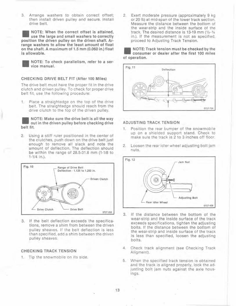
3. Arrange washers to obtai n correct offset; then install driven pulley and secure. Install drive belt.
II NOTE: When the correct offset is attained, use the large and small washers to correctly
position the driven pulley on the driven shaft. Ar· range washers to allow the least amount of float on the shaft. A maximum of 1.5 mm (0.060 in.) float is allowable.
II NOTE: To check parallelism, refer to a ser· vice manual.
CHECKING DRIVE BELT FIT (After 100 Miles)
The drive belt must have the proper fit in the drive clutch and driven pulley. To check for proper drive belt fit, use the following procedure:
1. Place a straightedge on the top of the drive belt. The straightedge should reach from the drive clutch to the top of the driven pulley.
II NOTE: Make sure the drive belt is all the way out in the driven pulley before checking drive
belt fit.
2. Using a stiff ruler positioned in the center of the clutches, push down on the drive belt just enough to remove all slack and note the amount of deflection. The deflection should be within the range of 28.5·31.8 mm (1·1/8 to 1·114 in.).
Fig. 10 Range of Drive Belt Dellection . 1.125 to 1.250 in.
Driven Clutch
Drive Clutch Drive Belt 0727·252
3. If the belt deflection exceeds the specifica· tions, remove a shim from between the driven pulley sheaves. If the belt deflection is less than specified, add a shim between the driven pulley sheaves.
CHECKING TRACK TENSION
1. Tip the snowmobile on its side.
13
2. Exert moderate pressure (approximately 9 kg or 20 Ib) at mid·span of the lower track section. Measure the distance between the bottom of the wear·strip and the inside surface of the track. The desi red distance is 13·19 mm (%.314 in.). If the measurement is not as specified, proceed to Adjusting Track Tension.
II NOTE: Track tension must be checked by the consumer or dealer after the first 100 miles
of operation.
Fig.11 Deflection
0727·726
ADJUSTING TRACK TENSION
1. Position the rear bumper of the snowmobile up on a shielded support stand. Check to make sure the track is 2 to 3 inches off floor.
2. Loosen the rear idler wheel adjusting bolt jam nuts.
Fig.12 Jam Nut
-------..-.-'--) Adjusting Bolt
Rear Idler Wheel 0727·456
3. If the distance between the bottom of the wear·strip and the inside surface of the track exceeds specifications, tighten the adjusting bolts. If the distance between the bottom of the wear·strip and inside surface of the track is less than specified, loosen the adjusting bolts.
4. Check track alignment (see Checking Track Aligment).
5. When the specified track tension is obtained and the track is aligned properly, lock the ad· justing bolt jam nuts against the axle housings.
J
I
& WARNING & If jam nuts are not locked, the adjusting bolts could loosen causing the track to ratchet or lock.
• CAUTION • When the consumer takes delivery of his snowmobile, you must instruct him to check track tension every fifty miles for the first 250 to 300 miles. If the track isn't tightened by the con-sumer during this period, it will stretch and may derail causing suspension and track damage. This is not covered by our warranty policy.
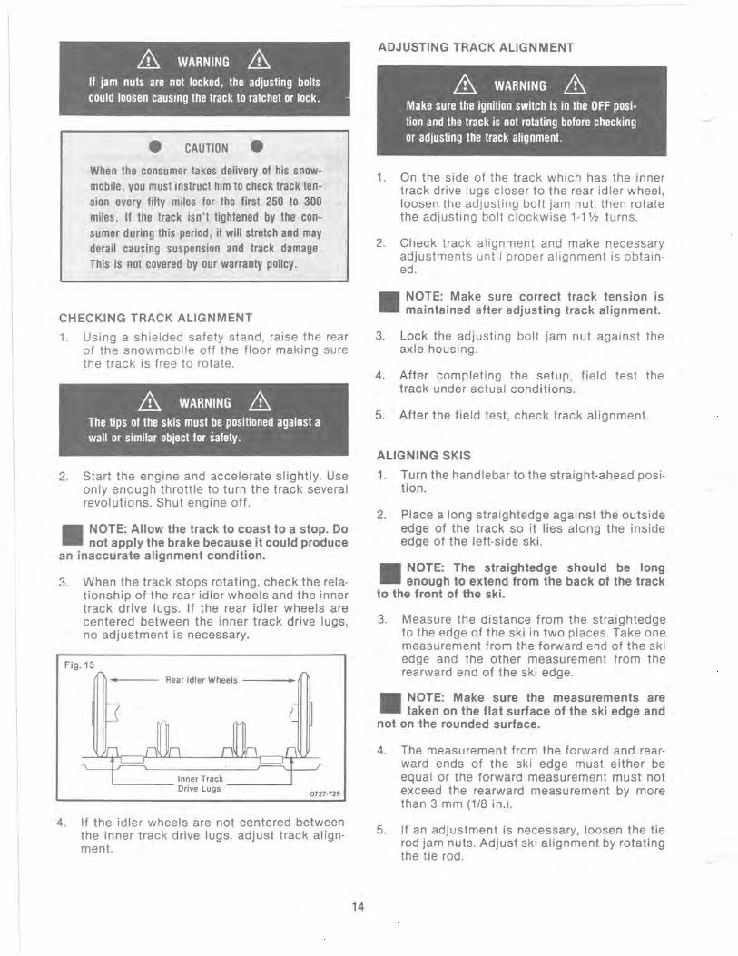
CHECKING TRACK ALIGNMENT
1. Using a shielded safety stand, raise the rear of the snowmobile off the floor making sure the track is free to rotate.
2. Start the engine and accelerate slightly. Use only enough throttle to turn the track several revolutions. Shut engine off.
II NOTE: Allow the track to coast to a stop. Do not apply the brake because it could produce
an inaccurate alignment condition.
3. When the track stops rotating, check the relationship of the rear idler wheels and the inner track drive lugs. If the rear idler wheels are centered between the inner track drive lugs, no adjustment is necessary.
Fig.13
Rear Idler Wheels ---+-
Inner Track '------ Drive Lugs -----'
0727·729
4. If the idler wheels are not centered between the inner track drive lugs, adjust track alignment.
14
ADJUSTING TRACK ALIGNMENT
& WARNING & Make sure the ignition switch is in the OFF position and the track is not rotating before checking or adjusting the track alignment.
1. On the side of the track which has the inner track drive lugs closer to the rear idler wheel, loosen the adjusting bolt jam nut; then rotate the adjusting bolt clockwise 1-1 V2 turns.
2. Check track alignment and make necessary adjustments until proper alignment is obtained.
II NOTE: Make sure correct track tension is maintained after adjusting track alignment.
3. Lock the adjusting bolt jam nut against the axle housing.
4. After completing the setup, field test the track under actual conditions.
5. After the field test, check track alignment.
ALIGNING SKIS
1. Turn the handlebar to the straight-ahead position.
2. Place a long straightedge against the outside edge of the track so it lies along the inside edge of the left-side ski.
II NOTE: The straightedge should be long enough to extend from the back of the track
to the front of the ski.
3. Measure the distance from the straightedge to the edge of the ski in two places. Take one measurement from the forward end of the ski edge and the other measurement from the rearward end of the ski edge.
II NOTE: Make sure the measurements are taken on the flat surface of the ski edge and
not on the rounded surface.
4. The measurement from the forward and rearward ends of the ski edge must either be equal or the forward measurement must not exceed the rearward measurement by more than 3 mm (1/8 in.).
5. If an adjustment is necessary, loosen the tie rod jam nuts. Adjust ski alignment by rotating the tie rod.

Fig. 14 Lock Nuts
~__ ___ I~_~"·r-T~_ Ski Spindle
[ ~teering I.,I~ Tie Rod
Steering Post
Adjustment Tie Rod
Steering Drag Link
0728·078
6. After making necessary adjustments, apply LOCTITE LOCK N' SEAL to the threads of the tie rod and tighten the jam nuts against the tie rod.
&. WARNING &. Neglecting to tighten the jam nuts may cause loss of snowmobile control and possible personal injury.
7. Repeat procedure for the right side ski.
ADJUSTING SWAY BAR
1. Place the rear of the snowmobile up on a jackstand and on a level surface.
2. Open the hood and place an angle finder on the crossbrace tube. If the snowmobile isn't level, use step 3 to adjust the sway bar linkage to level the snowmobile.
3. Loosen the jam nut securing the adjusting bolt to the ball joint; then rotate the adjusting bolt. Tighten the jam nut against the ball joint upon completion of the adjustment.
II NOTE: There is a jam nut located just above the rubber bushing on the sway bar adjuster.
Do not loosen this jam nut as it has been loctited and adjusted at the factory. Adjustment should be made with this jam nut tight. Sway bar adjust· ments may not be equal from side to side. This isn't anything to worry about, just make sure the snowmobile is level.
15
Fig. 15 Sway Bar Arm
Sway ear
Ball Joint
(Do Not Loosen)
Lower Arm
0728·208
ADJUSTING SPINDLE CAMBER
II NOTE: The snowmobile must be setting on a level surface with the rear of the snowmobile
positioned on a jackstand. Be sure the skis are positioned straight ahead. These items are all very important before adjusting spindle camber.
1. Place angle finder up aga inst the side of the spindle. Spindle must be set at 1 V2 0 ± '/2 0
posit ive. The angle must be out at the bottom of the spindle.
Fig.16 ~- Spindle
Upper " A" Arm
Lower "A" Arm
0728·209
2. If an adjustment is required , make the adjustment by working with lower ball joint jam nuts. When all adjustments are completed, apply red LOCTITE to ball joint threads and torque the inner jam nut to 24 kg-m (180 ft-Ib) .
Fig. 17
Front Suspension Shock .nd Spring
Shock Spring Ad justor
Shock Tow.r
Upper " A" Ann
G ~.) . Splndl.
-0 c=) 0 c .. I
Spindle Adjus ting . Nut. Front End Frem.
lower " A" Arm lower " A" Arm
B.II Joint Ski
0728·211
- ....

3. Verify the adjustment by placing the angle finder against the spindle once again after the nuts have been torqued. You must have 1 Y2 0 ± 1f2 0 camber on each spindle. The spindle angle must be out at the bottom, in on the top.
ADJUSTING FRONT SHOCK SPRINGS
The front wishbone arm shock springs are fully adjustable for the driving style of the owner. We recommend that they be set at 19-25 mm (% - 1 in .)
When adjusting the front shock springs, it should be remembered that as you tighten the spring tension, you will have increased ski pressure upon deceleration and additional traction upon acceleration. This is because more weight will be transferred to the track with the additional spring tension.
To adjust spring tension, rotate the entire spring in whichever direction is desired. The adjuster nut will rotate with the spring (see Fig . 17).
If, after adjusting the spring tension, you note that the snowmobile front end wants to pitch, soften the spring tension on the side that is pitching. If both sides are pitching equally, you must soften both sides.
The snowmobile comes equipped with springs and shocks to handle normal trail riding (30-40 MPH) speeds. If the owner is a very hard driver, you may need to install heavier springs and shocks for that style of riding. These items are available and are considered optional equipment.
ADJUSTING FRONT ARM
The skid frame front arm shock is adjustable. However, caution must be used when making adjustments in this area. It is very easy to ruin the good handling features of this snowmobile by applying too much front arm spring tension.
It must be remembered that if you have too much front arm spring ' tension, the snowmobile will want to pivot around that point. This means the snowmobile will handle like a very short snowmobile. It will become very tricky to handle upon deceleration because you will be driving a snowmobile that has pressure points at the front arm and at the skis. This leaves little traction because of less track on the ground and the back end of the snowmobile will want to slide around.
Also, with too much front arm spring tension, the front end will be thrown upward when hitting bumps at medium or fast speeds. This leaves the skis either off the ground or with little steering tension which leaves the operator with less control.
16
The ideal situation in suspension adjustment is to have equal pressure from the rear idler wheel to the skis. A good rule to remember when adjusting the front arm is, when in doubt. reduce front arm pressure.
The misconception that you should tighten the front arm to reduce ski pressure, isn't true and should not be done.
ADJUSTING REAR ARM
The rear spring tension is adjusted for the weight of the driver. There are 3 possible adjustments and they should be made as follows.
Block Position Weight of Rider
1 st 100 Ibs.
2nd 150-190 Ibs.
3rd 200 Ibs. and over
Fig. 18
0727·720
INSTALLING WINDSHIELD
1. Place the handlebars in the down position.
2. Place the windshield down into the lower cover and secure using rubber bands.
3. Place the windshield and its lower cover assembled, into position on the handlebars and secure with hardware. Do not tighten at this time.
4. Place and attach the two windshield supports on either side of the handlebars. Attach to the windshield. Tighten all hardware and swing the handlebars back up into position.
LUBRICATION
Suspension
Use a good quality, low-temperature grease for lubricating the front end assembly and rear suspension.

The front end assembly has eight ball joints (four on each side), which must be greased before the snowmobile is used. The grease fittings are located on the backside of each ball joint. Grease each ball joint fitting until you notice a small amount of excess grease coming out around the ball joint. Wipe the excess grease from ball joint.
The rear suspension has four grease fittings. Each pivot point and cross shaft has a fitting for lubrication. Grease all four fittings.
Chain Case
1. Remove the check plug from the chain case cover.
Fig.19
0725·062
2. Using a long piece of wire bent to an L shape at approximately 5 cm (2 in.), check the oil level by inserting the wire into the check plug hole (like a dipstick). Make sure the end of the wire touches the bottom of the chain case.
Fig. 20
t 2 In.
(5 em)
Wire Dipstick
13/8In. (3.5 em) Oeplh ot lubricant
0727·161
3. Remove the wire and measure the height of the oil. The measurement must be 3.5 cm (1 3/8 in.).
4. If oil is low, remove the filler plug and add Arctco Chainlube through the filler plug hole. When the oil level is correct, install both the check plug and the filler plug.
17
• CAUTION • The correct lubricant to use in the chain case is Arctco Chainlube. Any substitute may cause premature chain failure or serious damage to the chain drive system.
ADJUSTING HEADLIGHT AIM
Th.e headlight can be adjusted for vertical and horizontal aim of the HIGH/LOW beam. The geometric center of the H IG H beam light zone is to be used for vertical and horizontal aiming .
1. Make sure suspension is adjusted properly.
2. Position the snowmobile on a level floor so the headlight is approximately 8 m (25 ft) from an aiming surface (wall or similar aiming surface).
II NOTE: There should be an average operating load on the snowmobile when adjusting the
headlight aim.
3. Measure the distance from the floor to the midpoint of the headlight.
4. Using the measurement obtained in step 3, make a horizontal mark on the aiming surface.
5. Make a vertical mark which intersects the horizontal mark on the aiming surface directly in front of the headlight.
6. Start the engine. Make sure the HIGH beam is on. DO NOT USE LOW BEAM.
Fig. 18 Aiming Surface
Scm (2 in.)
0727·265
7. Observe the headlight beam aim. Proper aim is when the most intense beam is centered on the vertical mark 5 cm (2 in.) below the horizontal mark on the aiming surface.
8. Adjust the four headlight housing mounting screws until correct aim is obtained .
I I I
I
I I
FINAL PREDELIVERY PROCEDURES
1. Check the coolant level. Add coolant (mixed according to the coolant manufacturer's recommendations) as needed.
2. Make sure all safety decals are in place and clearly legible.
3. Test all switches (ignition, dimmer, brake· light , emergency stop, and throttlelignition monitor switch) to make sure they all function properly.
4. Test ride the snowmobile, check all electrical and mechanical functions under actual field conditions. Remember to use a 50:1 gas/oil mixture in conjunction with the oil injection system during the break·in period. After break·in (1 tankful of fuel) the injection system will provide ample lubrication.
5. After the engine has been run for a half hour, torque the cylinder head nuts (see Engine Tor· que Specifications chart) .
6. Check the entire snowmobile (especially the steering system) for any loose fasteners. Tighten as required .
7. Check engine compartment for any signs of fuel or oil leakage.
8. Clean and polish the snowmobile just prior to pickup or delivery.
9. Check the contents of the tool kit .
10. Inform the consumer about operation, main· tenance, main jet usage, and safety features of the snowmobile.
11. Inform the consumer about keeping the track tension properly adjusted. This is his respon· sibility and derailment problems won't be covered by our warranty policy.
12. Inform the consumer about the proper sum· mer storage preparation for the snowmobile.
13. Explain the Warranty Policy.
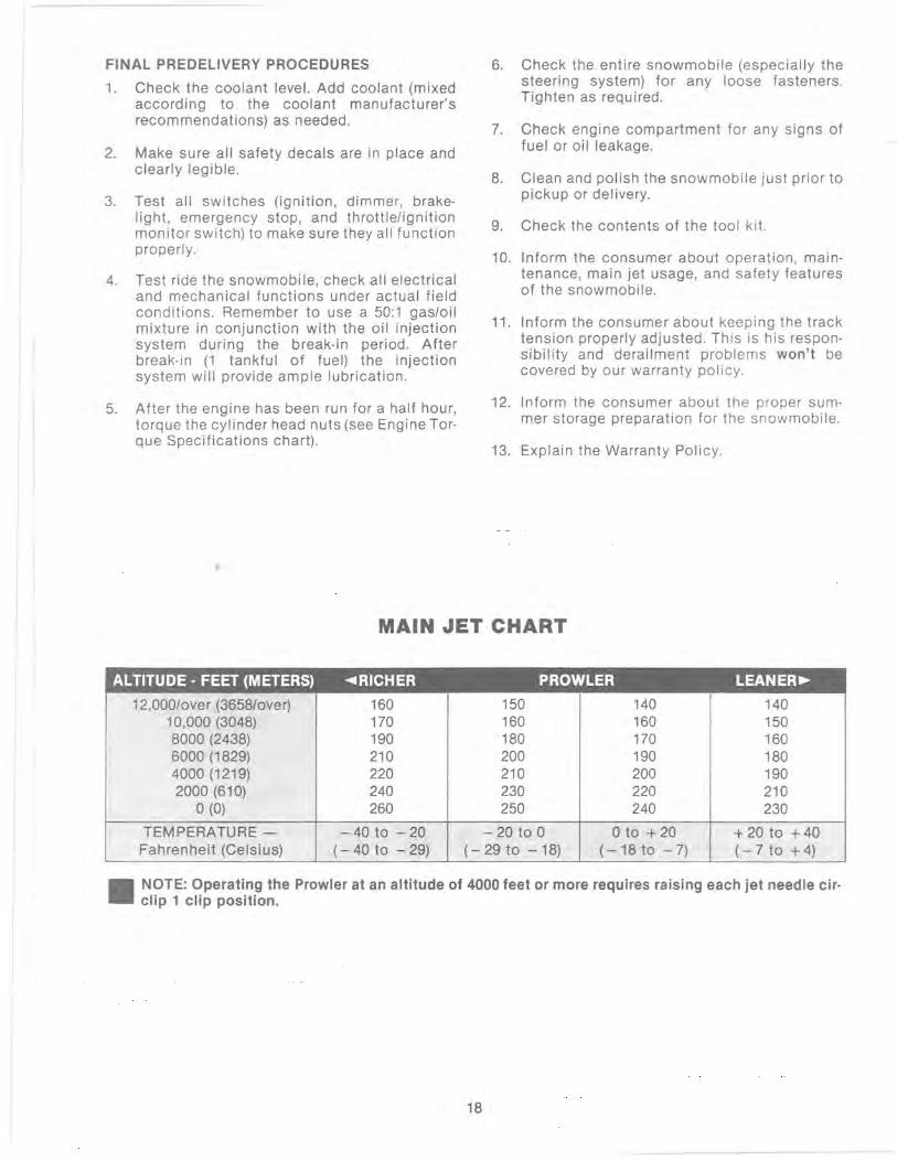
MAIN JET CHART
ALTITUDE· FEET (METERS) ~RICHER PROWLER LEANER~
12,000/over (3658/over) 160 150 140 140 10,000 (3048) 170 160 160 150 8000 (2438) 190 180 170 160 6000 (1829) 210 200 190 180 4000 (1219) 220 210 200 190 2000 (610) 240 230 220 210
0(0) 260 250 240 230
TEMPERATURE - - 40 to - 20 - 20 to 0 o to + 20 + 20 to + 40 Fahrenheit (Celsius) (- 40 to - 29) (- 29 to - 18) (-18to -7) (- 7 to + 4)
II NOTE: Operating the Prowler at an altitude of 4000 feet or more requires raising each jet needle cir· clip 1 clip position.
18

DRIVE TORQUE FACTORS
Drive Clutch ft-Ib 47-50 kg-m 6.5-6.9
Spider ft-Ib 125 kg·m 17.25
Drive Clutch Cover ft-Ib 7 Plate kg·m 1.0
Driven Pulley ft · lb 11·13 Retainer kg·m 1.5·1.8
Driven Pulley ft · lb 19·24 kg·m 2.6·3.3
CHASSIS TORQUE FACTORS
Ski ft · lb 70·80 kg·m 7.9·11.1
Skid Frame Mounting ft·lb 23 kg·m 3.2
Skid Frame ft·lb 17 Crossbraces kg·m 2.4
Idler Wheels ft·lb 17 kg·m 2.4
Idler Wheel Brackets ft·lb 17 kg·m 2.4
Skid Frame Arms ft·lb 30 kg·m 4.2
End Caps ft-Ib 8 kg·m 1.1
Chain Case ft-Ib 19·24 Sprockets kg·m 2.6·3.3
Handlebar Block ft · lb 10 kg-m 1.4
Tie Rods ft · lb 23 kg·m 3.2
Sway Bar ft ·b 13 kg·m 1.8
Front Arm Mounting ft · lb 70·80 kg·m 7.9-11 .1
TRACK STUDS
Studs must only be installed on the center belt, using the pattern illustrated. For proper installa· tion, measure 43.1 mm (1112 in.) in from the edge of the center belt and drill the stud hole using the Track Stud Hole Drill (pIn 0644·014); then install stud, backing plate, and T·nut. Apply red LOCTITE to the threads of the stud before installing the T-nut.
19
Fig . 22
0726·207
• CAUTION • Do not use studs that are longer than 22 mm (0.870 in.), that rivet to the track belt, or do not have a backing plate. Also, do not install studs in the outer track belts.
HIGH ALTITUDE CLUTCHING SPECIFICATIONS
Operating the snowmobile at varying altitudes reo quires changes in drive clutch components . These changes are in addition to the necessary carburetion changes (main jets etc.) . Listed are the high altitude clutch recommendations .
Altitude Cam Arm
0·4000 ft pIn 0646·080 (48.5 g) 4000-8000 ft pIn 0646-079 (43.5 g)
8000-10,000 ft pIn 0646-079 (43.5 g) Over 10,000 ft pIn 0646-019 (42 g)
When operating at 4000 feet or above, install a red driven clutch spring (pIn 0646-083), and change the gear ratio to an 18 tooth upper sprocket (pIn 0107-341) and a 40 tooth lower sprocket (pIn 0107-903). Install two chain tightener pads (pIn 0107-411).

PROWLER SPECIFICATIONS
GENERAL IGNITION SYSTEM ,
Length w/Skis cm 275.6 Ignition Type CDIINCI in. 108.5 Lighting Coil
Height cm 120.7 Output 12V/210W w/Windshield in. 47.5 Ignition Timing degree 18 ° @ 6000 rpm
Overall Width cm 105.4 BTDC in. 41.5 . mm BTDC 1.860
Track Width cm 38 . in. BTDC 0.073
in. 15 Spark Plug· Std. NGK BR9ES
Curb Weight kg 187 Spark Plug Gap mm 0.7 (approx.) Ib 475 in. 0.028
Dry Weight kg 171 (approx.) Ib 435
Fuel Tank I 27.3 FUEL SYSTEM
Capacity U.S. gal. 7.2 Carburetor Type VM·34
Ski Centers cm 91.5 No. of Carburetors 2 in. 36 Main Jet 240
Brake I Mechanical Caliper Disc w/Parking Brake
Pilot Jet 35
Pilot Air Screw (Turns Out) 1%
Engine Break·in Ratio 50:1
Recommended Gasoline DRIVE SYSTEM (Min. Octane) 88
Drive Clutch Engagement rpm 3200·3400
Clutch/Pulley mm 35 ENGINE TORQUE FACTORS
Offset in. 1.365 Cylinder Head kg·m 2.0·2.5
Clutch/Pulley mm 25.9 ft·lb 14·18
Center·to·Center in. 10.2 Cylinder Base kg·m 3.0·4.0
Drive Belt pin 0227·103 10 mm ft·lb 22·29
Drive Belt Width mm 34·36 in. 1 11/32·1 13/32
Cylinder Base kg·m 1.8·2.2 8 mm ft · lb 13·16
Drive Belt Length cm 110.5 · 111.1 in. 437/16·43 13/16
Crankcase kg·m 0.8·1 .2 6 mm ft·lb 6·9
Sprocket Ratio 20/39
Chain Pitch 70
Peak Engine rpm 7400·7600
Crankcase kg·m 1.8·2.2 8 mm ft · lb 13·16
Crankcase kg·m 3.0·4.0 10 mm ft·lb 22·29
Flywheel kg·m 9.0-11.0
ENGINE ft·lb 65·79
Model AJ44L2 Exhaust Manifold kg·m 1.8·2.2
ft·lb 13-16 Type 2 Engine Mounting kg·m 7.6 No. of Cylinders 2 ft·lb 55 Lubrication System Oil Injection Spark Plug kg·m 2.5-2.8
Bore mm 68 ft-Ib 18.20
in. 2.677 Intake Flange kg-m 1.8-2.2 Stroke mm 60 ft-Ib 13·16
in. 2.362
Displacement cc 436 cu. in. 26.6
Compression Ratio 6.6:1
20

1990 Prowler") Setup Addendum
Please follow these additional instructions and the Prowler Setup and Predelivery Manual closely.
SPINDLE CAMBER
Because of limitations in crate width , the spindle camber could not be adjusted at the factory. The camber must be set according to the instructions provided in the Setup Manual.
The spindle camber must be adjusted before adjusting ski alignment.
• CAUTION • After you have adjusted the spindle camber, the lower ball jOint sides must be centered in the spindle housing or held parallel to the lower arm while locking the jam nut. Hold the ball joint by positioning a screw driver blade between the side of the ball joint and spindle housing. Apply red LOCTITE to the ball joint threads before tightening the jam nut.
&. WARNING &. The lower ball joint jam nuts have not been tightened and are loose. Camber must be adjusted and jam nuts torqued before the Prowler is used.
REAR SUSPENSION ARM MOUNTING LOCATION
The rear skid frame arm must be mounted in the lower rear mounting hole for proper suspension operation. This is also explained in the Prowler Setup Manual.
WINDSHIELD AND LOWER SHROUD MOUNTING INSTRUCTIONS
Please refer to the following illustration when installing the windshield and its lower shroud.
1. Pull the rubber handlebar pad from the steering post.
2. Slide the lower windshield shroud into position on the four long machine screws secured to the handlebar on each side of the adjustment block. Secure the shroud with four flat washers and nuts.
_ NOTE: The shroud must be secured with its - flat side up.
3. Position the windshield tabs through the shroud slots and secure with rubber O-rings from the underside.
4. Slide a plastic mounting block onto each of the windshield support rods.
5. Slide the end of each windshield support rod into the rod mounting tubes located on the handlebar.
6. Place the small rubber pad into the plastic mounting block. Slide the mount up against the inside of the windshield.
7. On each side, align the two holes in the mounting block with the holes in the windshield. Start the four self-tapping screws: then , once all have been started, tighten securely.
8. Align the end of each adjustment rod flush with the backside of its mounting tube on the handlebar and secure each with a set screw. Apply red LOCTITE to the threads of the set screws before tightening .
II NOTE: Before installing the handlebar pad, inspect all wiring to be sure there aren't any
pinched wires.
9. Install the handlebar pad and secure with four push pins.
Push Pin (Pad Retainer), 4 Req'd. ."'-,.
Handlebar Ass'y. on Machine
Set Screw (Secure Support Rod in Mounting Tube as Instructed), 2 Places
,~ ""- Handlebar Pad
Windshield Support Rod, 2 Req'd. - .. '
Mounting Block, 2 Req'd. .. , .... !~ Rubber Pad, 2 Req'd. - -...... . J .. ,,~, ~.
Windshield .. D.' ''~ ~ 'V' ~i:,l;~~::; , "'0"
(Instruments)
Black Flat Washer, 4 Req'd. , i, r:-.. " Black Mounting Screw, 4 Req'd. '~"'~' . Windshield Fairing
.: \ '~
; ~-+ -,,' -~..--.
.. , Ir--- -~
.h- Flat Washer, 4 Req'd.
J- Lock Nut, 4 Req'd. Windshield a ·Ring, 4 Req'd.
0728·319
Printed in U.S.A. 21 , Registered trademark of Arctco. Inc. , Thief River Falls , MN 56701
•

Suspension
UNDERSTANDING THE SUSPENSION
General
Quick acceleration and the ability to go through the turns with power are the most important handling qualities for flat track racing. This section explains how the skid frame functions to provide these two important handling qualities. Before we can proceed however, we should define a few terms:
Weight Transfer - A shift in the center of gravity in any direction depends on the force applied.
Track Tension - The amount of tightness or looseness of the track when correctly mounted in the chassis.
Spring Tension - The amount of force exerted on the spring by either fork tension adjustment or eyebolt adjustment.
Ski Pressure - The amount of force exerted downward on the skis.
Good weight transfer characteristics are needed for fast acceleration (shift of weight from skis to track) and for cornering (shift of weight back to skis to hold the front end in turns). Effective weight transfer depends on suspension tension, position of rider, and the position of the front arm limiter.
To understand how the suspension system works, think of the entire system in terms of three points; the skid frame rear axle center, the skid frame front arm, and the ski saddle center.
Assume that the front arm functions as a stationary pivot point between the rear axle center and the ski saddle center. Also assume that the ski saddle center is the same height off the ground as the rear axle center. This produces the arrangement shown, standard position.
22
0728·180
Under acceleration, when the center of gravity is transferred to the rear of the machine, the rear suspension collapses slightly. This brings the rear arm pOint downward and with the front arm stationary the teeter-totter effect reduces the pressure on the skis, position A.
However, for controlled cornering, more pressure is needed on the skis. So, when the driver decelerates coming into a corner, the center of gravity is transferred forward, putting the required pressure onto the skis and reducing the pressure on the rear suspension, position C.
0728-181
This is essentially what weight transfer is all about-the shift of weight to the rear of the machine for positive traction and good acceleration, to the front of the machine for positive handling and cornering control.

UJ :E <C a: u. c ~ CIJ a: UJ ...J
3: o a: 0..
23
..
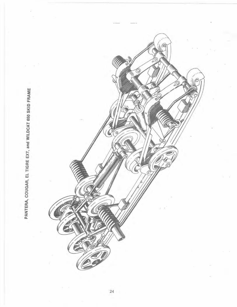
LIJ
== c::a:: a:: LL C 52 (/)
o &I) <0
!;i o C ...J
i '0 C
'" ...... X W w a::
" i= ...J W
~ c::a:: Cl ::l o o <i a:: w ~ Z <C I:L.
24
SUSPENSION SET-UP
ALL MODELS (EXCEPT PROWLER)
Below are some basic adjustment instructions for the new suspension used in the Wildcat, EXT, Cougar and Pantera. To understand many of these suggestions, you should first read through the suspension theory section of this manual. Many of the suggestions found below are based on this important section and it must be fully understood. Once you understand the theory section, you will be able to better set-up your snowmobile suspension for most snow conditons.
Front Arm
On the 1989 models, there are two different tunnel mounting locations for the front arm. The standard mounting hole is located just above the running board, another mounting hole is located 1" above the standard mounting position. The upper mounting hole isn't drilled through the tunnel. It is only found in the inner bracket. To use the upper hole, drill from the inside, out through the tunnel and move the front arm up to the new location.
If the problem of track ratcheting is experienced on the 1989 models, it is suggested that you use the upper mounting hole. This problem was experienced in some cases, when driving in deep powder snow. The skid frame would compress and the track would become slack enough to ratchet. Moving the arm to the upper mounting hole keeps the track tight under these conditions.
On the 1990 models, there has been an extra hole added to the front arm mounting brackets, located on the rails. It is located 3/4" lower than what was used in 1989. With the front arm moved to this location, the track is tightened when the front of the rail is compressed and there aren't any track ratcheting problems.
Along with the new mounting holes in the front bracket, the front arm guide deflector has been made 3/8" higher to prevent the track guides from hitting the top of the brackets.
NOTE: On the 1990 models, do not use the upper mounting holes in the tunnel. This would cause a very tight track under certain conditions and could cause track binding.
Front Spring Tension
It is desirable to run with very light front arm spring tension. When riding in 4" or more of snow, the machine will be quicker if the front spring tension is adjusted light.
If the spring tension is adjusted too stiff, the track angle at the front of the skid frame is steep. This steep angle prevents the machine from getting up on plane and slows it down by 5 to 8 mph.
When riding in sticky snow (springtime or warm day) or hill climbing on hard snow, it may be desirable to adjust the fornt arm spring tension stiffer. When this is done, weight is transferred back quicker. The problem with too much front arm spring tension is that the feel of the sled becomes very short. The reason for this is because the front arm becomes your pivot point between the spindles and rear of the machine, as shown in the illustrations on page 64. With dominant spring tension on the front arm, your suspension is basically contacting the snow from a point below the front arm to the skis or the spidle pressure point. This makes for a very short and darting machine on the trail. This is especially true when you decelerate and the center of gravity is transferred forward.
A good method of adjusting the front spring tension is as follows:
Spring tension adjustment - front arm
1. Loosen adjustment nuts on both front arm springs.
2. Starting on either side, lift the springs off the roller and move that portion of the spring down under the tube that supports the roller.
25

3. While holding the spring against the bottom side of the tube with one hand, start tightening the spring adjustment nut with your other hand.
Spring Spring tension should begin when spring leg is at this point
0728·050
4. Tighten the adjustment nut until you start to feel tension on the spring end being held against the bottom of the tube.
5. As soon as you can feel definite spring tension, stop adjustment and reposition the spring back onto the rol.ier. Repeat this same procedure for adjusting the remaining spring. Spring tension with spring on roller should be between 10 to 12 Ibs. measured 1 in. back from end of the spring.
NOTE: Because all springs are not alike, the amount of adjustment may be different from side to side.
Front Arm Limiter Rod and Straps
Under no circumstances should the front arm limiter rod be changed in length. If changed , it will cause shock travel problems.
The two limiter straps can be shortened if desired. They should not , however, be lengthened. This adjustment must be made to suit your driving style and some test driving time will be required. With the rear arm in its present mounting location, we found no advantage in changing the strap length. If the straps are shortened, the result will be more ski pressure and aggressive steering.
Front A-Frame Arm Shock Springs
The front shock springs have been matched to the shock valving and rear suspension. These springs are the result of hours of testing and comparison riding, trying many different combinations of springs and shocks. If there is a need to make changes, because the customer doesn't feel the standard set-up meets his driving style, there are several spring and shock sizes to choose from. While making these changes, keep the following points in mind:
Heavier or stiffer front springs_
1. These may require shocks with more rebound control or the front end will become like a pogo stick.
2. With stiffer springs, the front end will become more aggressive in the corners, as more weight will be transferred to the skis when the driver decelerates. Also, more weight is transferred to the rear on acceleration and can cause the rear shocks and spring to bottom out.
3. If the springs are too stiff for general riding conditions and driver style, the ride can fort is gone.
26
(
Front spring tension too soft.
1. Front end bottoms out, hard on front end parts.
2. Less aggressive steering in corners on deceleration, less weight is transferred to the skis because of softer springs.
3. Less weight gets transferred to rear of the machine upon acceleration.
NOTE: When you soften up the front, you should also soften up the rear to match entire suspension.
Front skid frame arm spring tension too stiff.
1. Slows machine down in any amount of loose snow.
2. Causes the machine to dart and dive as a result of less track on the ground on deceleration.
NOTE: It has been our experience that a tight front arm works good under only two condi· tions: sticky snow conditions in the spring of the year and in hill climbing on hard pack snow.
It has also been our experience that with the front arm adjusted too soft, you can have the spring come off the roller. There haven't been any other problems in handling caused by a soft front arm.
Rear Arm Spring Tension
The rear arm spring tension is set up for the weight of the rider. It is adjusted by rotating the rear adjustment block to either a lower or higher position.
Under normal conditions, the rear spring tension should be adjusted stiff enough to only use half the travel when the rider jumps up and down on the rear of the running board.
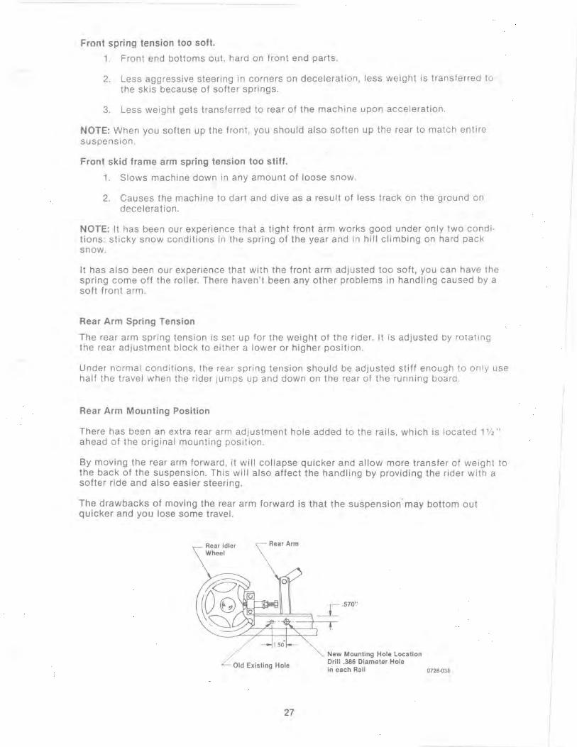
Rear Arm Mounting Position
There has been an extra rear arm adjustment hole added to the rails, which is located 1 112" ahead of the original mounting position.
By moving the rear arm forward, it will collapse quicker and allow more transfer of weight to the back of the suspension. This will also affect the handling by providing the rider with a softer ride and also easier steering .
The drawbacks of moving the rear arm forward is that the suspension· may bottom out quicker and you lose some travel.
Rear Idler Wheel
Rear Arm
Old Existing Hole
27
New Mounting Hole Location Drill .386 Diameter Hole in each Rail 0728·038
- ~- +--

NOTE: When making any changes to the front or rear suspension, the change should be made at both ends to keep the suspension balanced. For example, if you install stiffer springs in front, you may also want to install the next step stiffer spring in back, to keep everything in balance.
In an effort to assist everyone with suspension adjustment, you will find an Adjustment Handling Guide on the following pages. If there are any questions, please contact the Service Department.
PROWLER SUSPENSION
The Prowler suspension is totally new for 1990. In our testing , it has proven to be both reliable as well as an excellent handling system.
Because the new suspension has many adjustments, it can be set up to meet everyone's driving style. Another point to keep in mind however, is it can also be set up to be a very poor handling machine if not adjusted correctly. This is what the next few pages are all about. Anyone who is going to be setting up this model or making repairs on the suspension, should read through this section before starting either of these tasks.
Ski Alignment
NOTE: Before Starting the ski alignment procedure, be sure the track has been properly tightened and aligned.
1. Turn the handlebar to the straight-ahead position.
2. Place a long straight edge against the outside edge of the track so it lies along the inside edge of the left-side ski.
NOTE: The straight edge should be long enough to extend from the back of the track to the front of the ski.
3. Measure the distance from the straight edge to the edge of the ski in two places. Take one measurement from the forward end of the ski edge and the other measurement from the rearward end of the ski edge.
NOTE: Make sure the measurements are taken on the flat surface of the ski edge and not on the rounded surface.
4. The measurement from the forward and rearward ends of the ski edge must either be equal or the forward measurement must not exceed the rearward measurement by more than 3 mm (1/8 in .).
5. If an adjustment is necessary, loosen the tie rod jam nuts. Adjust ski alignment by rotating the tie rod.
Ski Spindle
Adjustment Tie Rod
Steering Drag Link
Steering Post 0728·078
TOP VIEW - STEERING LINKAGE
28
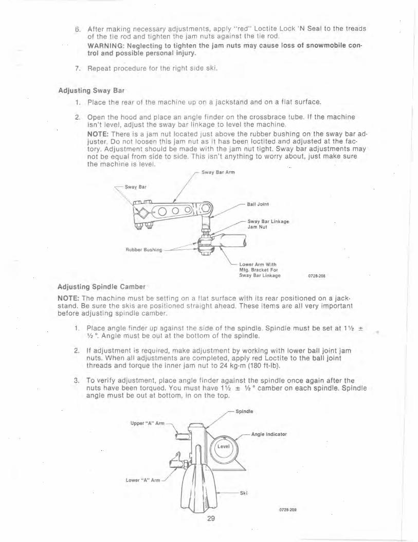
6. After making necessary adjustments, apply "red" Loctite Lock 'N Seal to the treads of the tie rod and tighten the jam nuts against the tie rod. WARNING: Neglecting to tighten the jam nuts may cause loss of snowmobile con· trol and possible personal injury.
7. Repeat procedure for the right side ski.
Adjusting Sway Bar
1. Place the rear of the machine up on a jackstand and on a flat surface.
2. Open the hood and place an angle finder on the crossbrace tube. If the machine isn't level, adjust the sway bar linkage to level the machine. NOTE: There is a jam nut located just above the rubber bushing on the sway bar ad· juster. Do not loosen this jam nut as it has been loctited and adjusted at the fac· tory. Adjustment should be made with the jam nut tight . Sway bar adjustments may not be equal from side to side. This isn't anything to worry about, just make sure the machine is level.
Sway Bar Arm
Ball Joint
Sway Bar Linkage Jam Nut
Rubber Bushing ~c::::.::::::::~e~ri~-~
Adjusting Spindle Camber
Lower Arm With Mtg. Bracket For Sway Bar Linkage 0728·208
NOTE: The machine must be setting on a flat surface with its rear positioned on a jack· stand. Be sure the skis are positioned straight ahead. These items are all very important before adjusting spindle camber.
1. Place angle finder up against the side of the spindle. Spindle must be set at 1'/2 ± '12 0. Angle must be out at the bottom of the spindle.
2. If adjustment is required, make adjustment by working with lower ball jOint jam nuts. When all adjustments are completed, apply red Loctite to the ball joint threads and torque the inner jam nut to 24 kg·m (180 ft·lb).
3. To verify adjustment, place angle finder against the spindle once again after the nuts have been torqued. You must have 1 % ± % 0 camber on each spindle. Spindle angle must be out at bottom, in on the top.
Spindle
Upper "AU Arm
Angle Indicator
Lower" A" Arm
0728·209
29

Front Shock Springs
The front wishbone arm shock springs are fully adjustable for the driving style of the owner. We recommend that they be adjusted between 3/4 and 1 inch.
When adjusting the front shock springs, it should be remembered that as you tighten the spring tension, you will have increased ski pressure upon deceleration and additional traction upon acceleration_ This is because more weight will be transferred to the back with additional spring tension.
To adjust spring tension, rotate the entire spring in whichever direction is desired. Adjuster nut will rotate with the spring.
If after adjusting the spring tension, you note that the snowmobile front end wants to pitch, soften up the spring tension on the side that is pitching. If both sides are pitching equally, you must soften up both sides.
The machine comes equipped with springs and shocks to handle normal trail riding (30-40 mph) speeds. If the owner is a very hard driver, you may need to install heavier springs and shocks for that style of riding. These items are available and are considered optional equipment.
Front Suspension Shock and Spring
Front Arm Adjustment
- Shock Tower
Spindle Adjusting Nuts Front End Frame
lower "A" Arm
Ski __ _
Upper "A" Arm
Spindle
0728·211
The skid frame front arm shock is also adjustable. Caution must be used when making adjustments in this area. It is very easy to ruin the good handling features of this machine by applying too much front arm spring tension.
It must be remembered that if you have too much front arm spring tension, the machine will want to pivot around that point. This means the machine will handle like a very short machine_ It will become very tricky to handle upon deceleration because you will be driving a machine that has contact points from below the front arm to the skis. This leaves little traction because of less track on the ground and the back end of the sled will want to spin around.
Also, with too much front arm spring tension, the front end will be thrown upward when hitting bumps at medium or fast speeds. This leaves the skis either off the ground or with little tension which leaves the operator with less control.
The ideal situation in suspension adjustment is to have equal pressure from the rear idler wheel to the.skis. A good rule to remember when adjusting the front arm is, when in doubt, take away front arm pressure.
There is the misconception that you should tighten the front arm to reduce ski pressure. This isn't true and should never be done.
30
I
, L
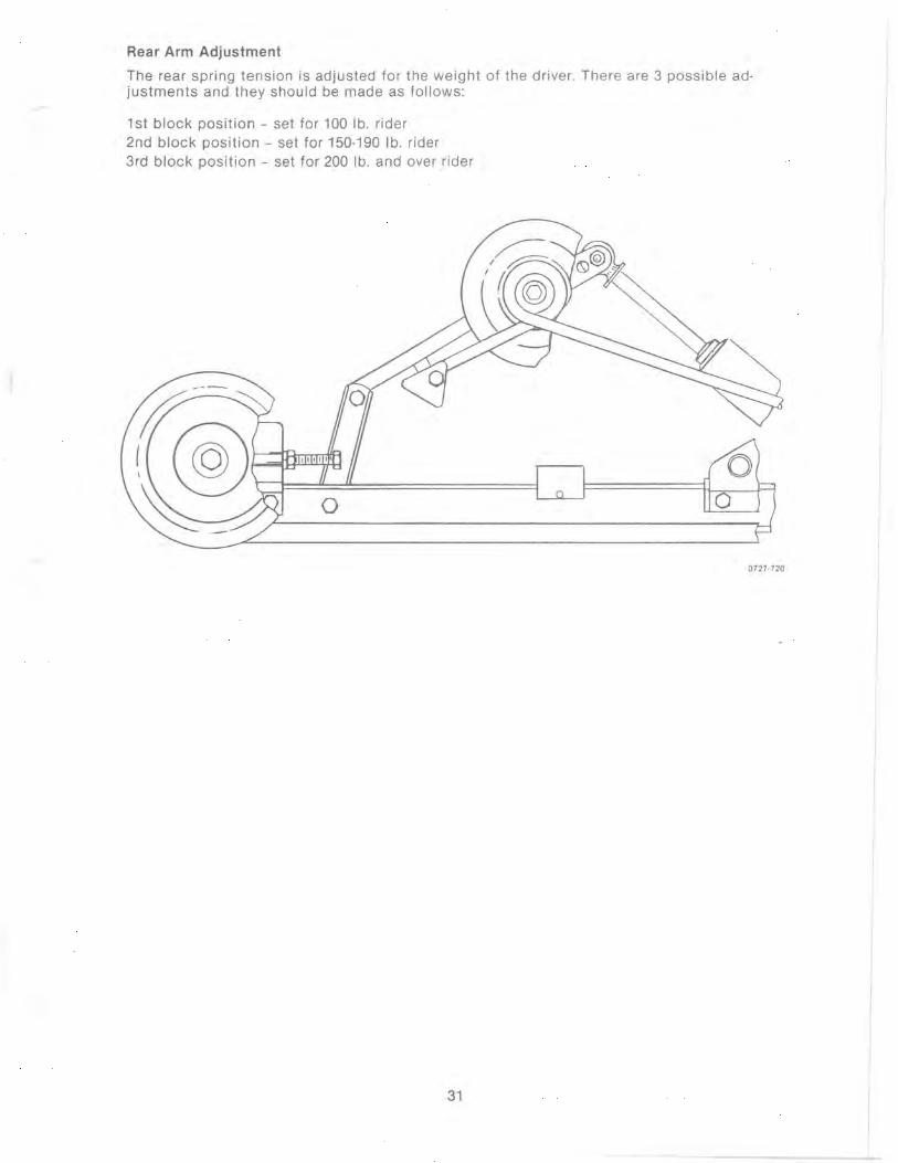
Rear Arm Adjustment
The rear spring tension is adjusted for the weight of the driver. There are 3 possible ad· justments and they should be made as follows:
1st block position - set for 100 lb. rider 2nd block position - set for 150-190 lb. rider 3rd block position - set for 200 lb. and over rider
0727·720
31
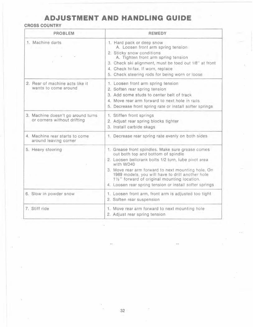
ADJUSTMENT AND HANDLING GUIDE CROSS COUNTRY
PROBLEM REMEDY
1. Machine darts 1. Hard pack or deep snow A. Loosen front arm spring tension
2. Sticky snow conditions A. Tighten front arm spring tension
3. Check ski alignment, must be toed out 1/8" at front 4. Check hi-fax. If worn, replace 5. Check steering rods for being worn or loose
2. Rear of machine acts like it 1. Loosen front arm spring tension wants to come around 2. Soften rear spring tension
3. Add some studs to center belt of track 4. Move rear arm forward to next hole in rails 5. Decrease front spring rate or install softer springs
3. Machine doesn 't go around turns 1. Stiffen front springs or corners without drifting 2. Adjust rear spring blocks tighter
3. Install carbide skags
4. Machine rear starts to come 1. Decrease rear spring rate evenly on both sides around leaving corner
5. Heavy steering 1. Grease front spindles. Make sure grease comes out both top and bottom of spindle
2. Loosen bellcrank bolts 1/2 turn, lube pivot area with WD40
3. Move rear arm forward to next mounting hole. On 1989 models, you will have to drill another hole 1112" forward of original mounting location .
4. Loosen rear spring tension or install softer springs
6. Slow in powder snow 1. Loosen front arm, front arm is adjusted too tight
2. Soften rear suspension
7. Stiff ride 1. Move rear arm forward to next mounting hole 2. Adjust rear spring tension
32
Suspension Setup (Wildcat-EXT -Cougar)
Below are some basic set-up instructions for the new '89 suspension used in the Wildcat, EXT, and Cougar models. To understand many of these suggestions, you should first read through the suspension theory section of this manual. Many of the suggestions found below are based on this important section and it must be fully understood. Once you understand the theory section, you will be able to better set-up your snowmobile suspension for most all track conditions.
It is important that not only the mechanic understand suspension theory, but also the driver too must have a very good understanding of what is happening on the race track with his machine. He must be able to tell his crew if the machine is pushing, lifting, breaking loose, or what is happening as he enters and leaves each corner. Knowing and being aware of every small detail concerning how the snowmobile is handling on the track and being able to accurately provide the crew with this information often is the difference between winning and losing.
Good weight transfer characteristics are needed for fast acceleration (shift of weight from skis to track) and for cornering (shift of weight back to skis to hold front end in turns).
Front Arm
There are two different mounting locations for the front arm. The standard mounting hole located just above the running board and another which is located 1" above the standard mounting hole.
It is suggested that the upper hole be drilled out and used for oval track racing. The lower mounting hole should be used during cross country or drag racing events. The upper hole position will place more ski pressure on the skis and better corner control.
Front Spring Tension
It is desirable to run with very light front arm spring tension. There should be no more than 1 or 2 threads exposed behind the adjuster jam nut. Depending on driving style, in some cases this may still be too much front arm spring tension. To reduce the spring tension even further, the springs can be bent to reduce the amount of pre-load. To bend the springs, use a piece of pipe and slide pipe into the long portion of the spring up to where the spring leg is already bent at a downward angle. Slightly straighten angle by bending leg forward. Be careful not to have the spring end contact the track drive lugs.
33
Front Arm Limiter Rod and Straps
Under no circumstances should the front arm limiter rod be changed in length. If changed it will cause front arm shock travel problems. The two front arm limiter straps can be shortened if desired. They should not however, be lengthened. This adjustment must be made to suit your driving style and some test driving time will be required. With the rear arm in its present mounting location, we found no advantage in changing the strap length.
Front Arm Shock Springs
It is to your advantage to keep the front A-frame arms as close to parallel as possible. This can be done by shortening the front springs. To shorten the front springs, heat the coils using a torch. Shorten springs only enough to level the A-frame arms. You may need to place spacer washers under the springs once they have been shortened to have enough pre-load to hold the top spring retainer in position.
Remember that front shock spring pressure is very critical in handling. As the driver decelerates, his weight is transferred forward on the machine putting more pressure onto the skis. If the front shock spring tension is of a soft rate, less pressure will be applied to the skis. If the front shock spring tension is increased, the transferred weight will apply more pressure to the front skis.
The standard springs (shortened) should be used for initial set-up. A second set of springs may be purchased by the owner for use on warm days or under soft ice conditions. These springs would have less tension and would be needed, as the stiffer springs would be too aggressive for soft ice conditions. The different springs and their rates are listed in this section.
Rear Arm Mounting
There are two different mounting locations for the rear arm. One is located above the running board and the other directly below the running board. The lower bracket has two holes. Never under any conditions use the lower forward hole. The suspension will not work properly if mounted in this position.
For all race events (drag racing - oval track) it is suggested that the upper mounting hole (above running board) be used.
Rear Arm Spring Tension
It is important that each driver understand the rear arm spring adjustment. Adjusting more or less pre-load onto the rear arm springs will have a large effect on how the skid frame will transfer the driver's weight to the track. It must be remembered that upon acceleration, the driver's weight is transferred to the rear arms. If the springs are adjusted to the softest position, the track will have more traction as the springs are easily overcome and the driver's weight is then applied to the rear arms, putting more pressure on the track.
On the other hand, if more pre-load is adjusted onto the rear arm springs, less of the driver's weight will reach the rear arm, as the tension will resist and not allow as much weight to be transferred. Traction in this case would be less.
The Cougar springs have the least amount of preload and some drivers may prefer these on the EXT and Wildcat for oval racing. The driver must experiment with the spring tension until weight shift is sufficient for cornering and acceleration.
In summary, the driver will be working with the rear arm springs and front shock springs to fine tune the suspension. Depending on what kind of ice (soft, hard, ice mixed with sawdust) the machine is being run on (along with the driver's weight) will determine the spring tension required.
1989 SUSPENSION (Cougar-EI Tigre EXT·Wildcat 650)
The new suspension for '89 does allow the machine to move through loose snow much quicker than the external shock system. Because of this, these models are faster in loose snow conditions than the '88 models. Along with the new suspension comes a new 15" full block track design which will provide much better traction in all snow conditions over the track used last season.
The suspension adjustment pOints are two eyebolts on either side of the front arm and two tension cams on either side of the rear arm. When making adjustments to either the front or rear arms, always adjust each side equally.
Front Arm· It has been our experience to adjust the front arm eyebolts so there is 3/8 to 1/2 inch of thread exposed behind the adjustment nut. This adjustment works best in loose snow or slushy conditions. When trail riding over hard pack snow or on groomed trails, the spring tension on the front arm can be adjusted stiffer.
Rear Arm· The rear adjustment cams are to be adjusted for the weight of the rider. Set the cam into a position where the rider will not bottom out the rear arm.
34
LUBRICATION POINTS
There are 6 lubrication points on the entire suspension. These should be lubricated several times during the season with a good low-temperature grease. The grease will force moisture out from between moving parts and prevent corrosion from forming. It is the best way to assure that the suspension works freely and the way it has been designed to perform.
OPTION SPRING KITS.
There are heavier suspension springs available for most models this year. These are considered optional, however, and will not be replaced or exchanged on warranty basis.
Spring Kits and Application
0636-434 - Jag AFS, Jag 340 0636-435 - Cheetah Touring, Super Jag 0636-436 - Panther
Suspension Arm Springs (Cougar·EXT·Wildcat):
Rear· 0604-314 and 0604-315
Front· 0604-264 and 0604-265
Spring Specification· Front End Assembly
1988 EI Tigre and Pantera Small or Short Spring, 1 3/4 inch 750lb Long, 5 inch 570lb
Cougar Small, 21/2 inch 350lb Long, 5 inch 570lb
1988 Wildcat Long, 7.250 inch 420lb
Rear Springs, 1988 Suspension (all the same spring)
EI Tigre 20 Ib Cougar-Pantera
Wildcat, 1988 Model, Progressive Rate 28-751b
Skid Frame Front Shock Spring EI Tigre, Cougar, Wildcat
Sway Bar 5/8 inch diameter (standard) 3/4 inch diameter (racing)
150lb
650lb 1200-1300 Ib
1989 FRONT SUSPENSION NOTES (EI ·Tlgre·Cougar·Pantera·Cheetah Touring)
All use 1988 EI Tigre shock valving with the same springs as last years EI Tigre 6000. See rate listed above.
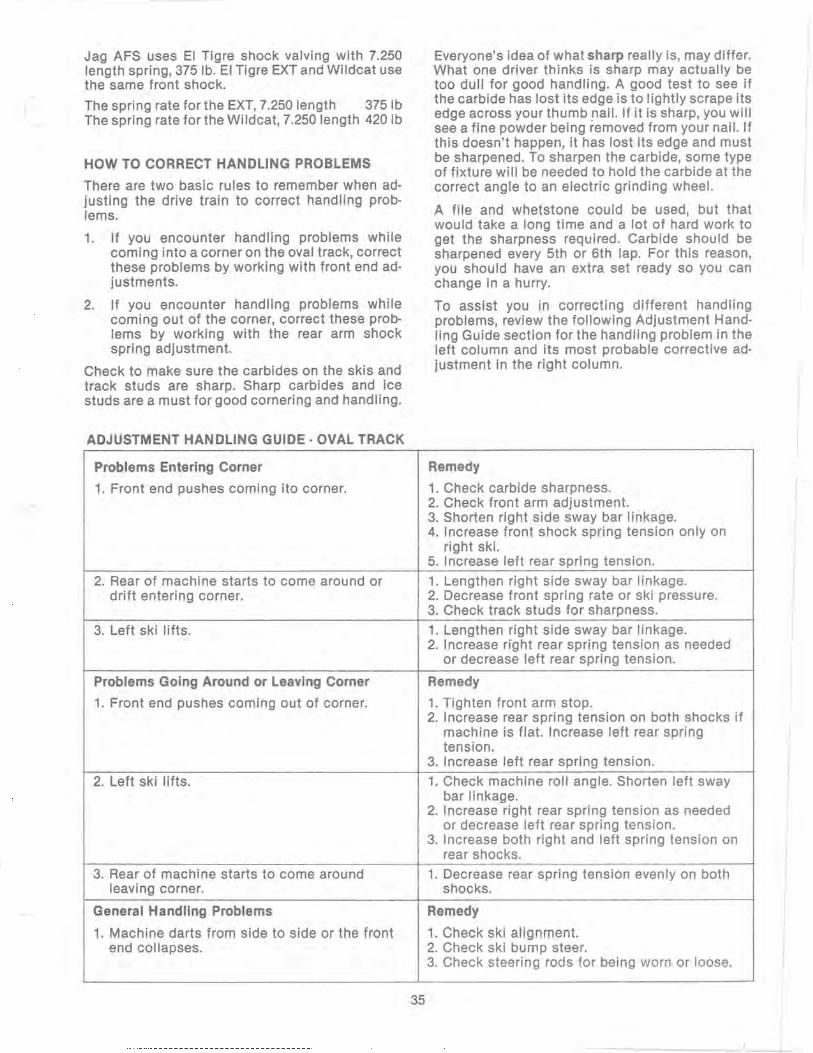
Jag AFS uses EI Tigre shock valving with 7.250 length spring, 375 lb. EI Tigre EXT and Wildcat use the same front shock.
The spring rate for the EXT, 7.250 length 3751b The spring rate for the Wildcat, 7.250 length 420lb
HOW TO CORRECT HANDLING PROBLEMS
There are two basic rules to remember when adjusting the drive train to correct handling problems.
1. If you encounter handling problems while coming into a corner on the oval track, correct these problems by working with front end adjustments.
2. If you encounter handling problems while coming out of the corner, correct these problems by working with the rear arm shock spring adjustment.
Check to make sure the carbides on the skis and track studs are sharp. Sharp carbides and ice studs are a must for good cornering and handling.
ADJUSTMENT HANDLING GUIDE - OVAL TRACK
Problems Entering Corner
1. Front end pushes coming ito corner.
2. Rear of machine starts to come around or drift entering corner.
3. Left ski lifts.
Problems Going Around or Leaving Corner
1. Front end pushes coming out of corner.
2. Left ski lifts.
3. Rear of machine starts to come around leaving corner.
General Handling Problems
1. Machine darts from side to side or the front end collapses.
35
Everyone's idea of what sharp really is, may differ. What one driver thinks is sharp may actually be too dull for good handling. A good test to see if the carbide has lost its edge is to lightly scrape its edge across your thumb nail. If it is sharp, you will see a fine powder being removed from your nail. If this doesn't happen, it has lost its edge and must be sharpened. To sharpen the carbide, some type of fixture will be needed to hold the carbide at the correct angle to an electric grinding wheel.
A file and whetstone could be used, but that would take a long time and a lot of hard work to get the sharpness required. Carbide should be sharpened every 5th or 6th lap. For this reason, you should have an extra set ready so you can change in a hurry.
To assist you in correcting different handling problems, review the following Adjustment Handling Guide section for the handling problem in the left column and its most probable corrective adjustment in the right column.
Remedy
1. Check carbide sharpness. 2. Check front arm adjustment. 3. Shorten right side sway bar linkage. 4. Increase front shock spring tension only on
right ski. 5. Increase left rear spring tension.
1. Lengthen right side sway bar linkage. 2. Decrease front spring rate or ski pressure. 3. Check track studs for sharpness.
1. Lengthen right side sway bar linkage. 2. Increase right rear spring tension as needed
or decrease left rear spring tension.
Remedy
1. Tighten front arm stop. 2. Increase rear spring tension on both shocks if
machine is flat. Increase left rear spring tension.
3. Increase left rear spring tension.
1. Check machine roll angle. Shorten left sway bar linkage.
2. Increase right rear spring tension as needed or decrease left rear spring tension.
3. Increase both right and left spring tension on rear shocks.
1. Decrease rear spring tension evenly on both shocks.
Remedy
1. Check ski alignment. 2. Check ski bump steer. 3. Check steering rods for being worn or loose.
TRACTION
The finest tuned engine in the world is useless if it cannot convert its power potential to motion. Careful attention to type of track, track studding, and properly designed ski wear bars will ensure the maximum use of available engine power. In order to maintain a competitive edge, the racer must spend time in preparing the traction components for a race event, he must know the basic principles of race traction, and he must be able to make the adjustments for different types of race tracks and weather conditions.
Racing traction means studs. Listed below are five principles which can be used to get the most traction out of studs.
1. Sharpness counts more than quantity. Fewer sharp, fresh studs work much better than a great many dull studs with a few new ones thrown in. Replace dull studs.
2. Too many studs are worse than too few. Too few studs will give some traction but will waste some engine performance through slippage. Too many studs will cause the machine to "float" rather than hook up; even more of the engine's speed potential is wasted. Too many studs can also cause difficulty in turning by overcoming the effectiveness of the wear bars.
3. Use studs which are designed to do a specific job. Some studs have side points to give the machine bite. Others have front points for agg ressive acceleration. Sti II others have characteristics that make them especially effective under certain track or weather conditions. Know the stud characteristics and use the stud best suited for a particular job.
4. Place studs where weight will be concentrated. Acceleration-type should be placed in the center of the track because they are aggressive.
5. Stud to suit the riding style. The best way to determine suitable studding is to stud up and test the pattern. Compare several patterns for acceleration and cornering. The fastest way around a corner is to drive around rather than slide around. Properly setup, the machine will give maximum acceleration and still permit driving around corners with a minimum of sliding.
WEAR BARS
General
Once the machine is able to accelerate to racing speeds, the next need is to control that speed through a corner. Basically, cornering is the ability to enter and exit a corner with the least possible delay.
36
---- - ........
There are three basic principles to follow in checking wear bars.
1. Sharp edges dig. Dull edges don't. Carbide must be sharp to cut through ice and frozen ground; yet this same frozen ground dulls the carbide very quickly. The deeper the bar penetrates, the better the snowmobile will go around a corner. Keep the wear bars sharp.
2. The forces on a turn try to roll a wear bar off its edges. Centrifugal force created by turning will be pushing the wear bar over and trying to make it run on its side. Use flat backed wear bars and keep them bolted tight to the ski.
3. Carbide will both chip and wear, but it works best. Carbide is actually a combination of two elements: carbide (which chips but resists wear) and cobalt (which wears quickly but resists chipping). Different grades of carbide are made by varying the percentage of each, but it is impossible to have both excellent wear resistance and excellent chip resistance.
Arctic Cat Carbides
Carbides have been developed through years of racing experience and designed specifically for racing. The 61 0 carbide piece is the sharpest edge legally allowed by racing organizations. Arctic Cat carbides have a 90 0 back host bar that is fitted with studs which match the holes in the ski. It is a very simple matter to tighten the bar snugly to the ski and therefore, minimize wear bar roll over. The carbide formulation in the Arctic Cat carbide bar has been selected to give long wear and high resistance to impact.
Wear Bar Maintenance
Because frozen ground will dull any sharp edge, the carbide wear bars will need to be sharpened. A hand sharpening stone or power grinder must be used. Two precautions in sharpening the carbide wear bar are: (1) Be sure to get a straight and even edge. This will make steering easier. (2) Do not remove any more carbide than necessary to get an edge, as this will just shorten the life of the bar. After repeated sharpening and as the carbide becomes beyond repair, the carbide wear bars must be replaced. Since many of the carbide wear bars used for racing are a single piece length of carbide, it is not possible to replace just the carbide insert. Also, always replace any bent carbide wear bars.

TRACK STUDDING
We are supplying several different ice stud kits for the coming year. Each design is meant for a special application and is explained below.
0636·045· Ice Stud Kit This is a steel nail type stud. It is a good stud for traction on hard packed snow and ice covered trails. The kit comes complete with everything required for installation. Drill the holes in the track using special tool pIn 0644-014. This tool is available through Arctco.
The kit has 18 studs which is enough for normal trail riding. The stud is 5/8 in. long which is the maximum length that can be used without installing a Stud Clearance Kit.
0636·046 . Ice Stud Kit This kit is the same as above except the steel nail studs have a carbide tip for extra life. It is meant as a good trail, ice traction stud. It comes 18 studs per package.
0636-145· Ice Stud Kit The stud used in this kit is a 3/4 in. long steel nail. Extra length means additional penetration and traction. It also means that a Stud Clearance Kit must be used in conjunction with this stud kit or tunnel damage will be experienced. It comes 18 studs per package.
0636·146· Ice Stud Kit This is a 3/4 in. carbide tipped nail type stud to be used when additional penetration and traction is desired. The kit cannot be used without first installing a Stud Clearance Kit. Damage to the tunnel will result if the clearance kit isn't installed . It comes 18 studs per package.
0636·147· Wedge Type Stud This is a carbide wedge type stud to be used on hard-packed snow and on slush or soft ice tracks. These studs are usually used along with another stud and mixed in throughout the stud pattern. They come 10 studs per package. If any of these are used , the Stud Clearance Kit (pIn 0636·265) must be used or tunnel damage will occur.
0636·148 . Star Stud This is an original multi-directional point designed to provide aggressive acceleration and braking on hard pack and snow. It prOVides good cornering control. It can be used by itself or in conjunction with other studs. It comes 20 studs per package.
0636·150· Hooker Kit To use any of the Hooker Stud Kits, you must first move the heat exchangers to the center of the tunnel on all UC models. Stud holding plates are welded to the track wear clips, but you must first trim the excess rubber that bulges up from between the wear clip ends. Plates are then welded directly to the ends of the wear clips. The clip must be cooled with water and sponge to prevent overheating of the fiberglass bar in the track. If overheated, the fiberglass bar will become brittle and break out. When installing any of the Hooker Stud Kits you must also install the Stud Clearance Kit (pIn 0636-265) or tunnel damage will occur. It comes 96 studs per package.
0636·153· Hooker Wedge This is to be used with the hooker plate. The wedge stud is a good snow, slush, and soft ice stUd. It is used in conjunction with other studs in racing. It also provides some good side slip control. Because of the large carbide wedge, this stud is very durable. It comes 24 studs per package.
0636·156· 314 inch Carbide Stud (sharp) This stud has a carbide tip which has been sharpened to a needle point. It is a stud meant for racing on ice and very hard packed snow conditions. It comes 48 studs per package.
37
---~ -
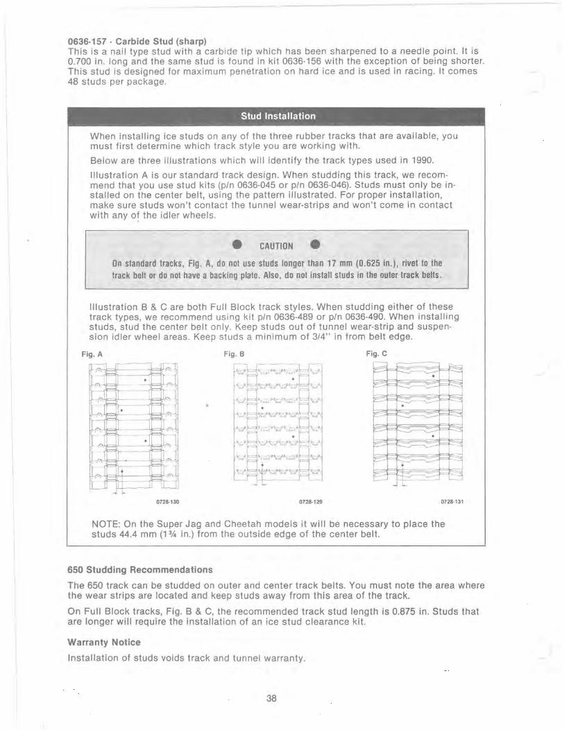
'.
0636·157· Carbide Stud (sharp) This is a nail type stud with a carbide tip which has been sharpened to a needle point. It is 0.700 in. long and the same stud is found in kit 0636·156 with the exception of being shorter. This stud is designed for maximum penetration on hard ice and is used in racing. It comes 48 studs per package.
Stud Installation
When installing ice studs on any of the three rubber tracks that are available, you must first determine which track style you are working with.
Below are three illustrations which will identify the track types used in 1990.
Illustration A is our standard track design. When studding this track, we recom· mend that you use stud k its (pIn 0636·045 or pIn 0636-046). Studs must only be installed on the center belt, using the pattern illustrated. For proper installation, make sure studs won't contact the tunnel wear-strips and won't come in contact with any of the idler wheels.
• CAUTION • On standard tracks, Fig . A, do not use studs longer than 17 mm (0.625 in.), rivet to the track belt or do not have a backing plate . Also, do not install studs in the outer track belts.
Illustration B & C are both Full Block track styles. When studding either of these track types, we recommend using kit pIn 0636-489 or pIn 0636-490. When installing studs, stud the center belt only. Keep studs out of tunnel wear-strip and suspension idler wheel areas . Keep studs a minimum of 3/4" in from belt edge.
Fig. A Fig. C 1-:;:; ~
~ ~ o r;-r ,--,
-<<;=j- ,......., 0
'=- "f" ~
0
~
....., f--,
,I -,
0
" ....., "
I r ,-; ~ ~
0 r-- P c-o
0.-~
~ f= '-...0
• .~ f=~-' - --I L
"7' = ~ -j
• II . ........ "-/
.L---' ILl -11-
0728·130 0728·129 0728·131
NOTE: On the Super Jag and Cheetah models it will be necessary to place the studs 44.4 mm (1 3/.1 in.) from the outside edge of the center belt.
650 Studding Recommendations
The 650 track can be studded on outer and center track belts. You must note the area where the wear strips are located and keep studs away from this area of the track.
On Full Block tracks, Fig. B & C, the recommended track stud length is 0.875 in. Studs that are longer will require the installation of an ice stud clearance kit.
Warranty Notice
Installation of studs voids track and tunne l warranty,
38

THE MOTO-X FOX
FACTORY saox
DESIGNED BY FOX FACTORY, INC. DISTRIBUTED BY MOTO-X-FOX, INC.
520 McGlincey lane Campbell, California 95008
39

INTRODUCTION
Congratulations! You now own the finest, most easily and fully tuneable spring shock absorbers ever produced for motocross.
Fox Factory Shox are based on a new state-of-the-art design which sets new standards for tuneability and fade-free performance. Compression and rebound damping, both low and high speed, can be precisely adjusted to your personal requirements. A wide choice of dual-rate springs, straight-wound and progressive types, are available. Fox Factory Shox are completely rebuildable. They can be taken apart and reassembled in minutes using simple tools. To ensure that you get the maximum performance and long service life that your new shocks are designed for, take the time now to read this Owner's Manual carefully .
• If you have any questions, comments, or problems, drop me a note.
40
Good luck and good racing,
Bob Fox President Fox Factory, Inc.

41

.. --- - ..
TABLE OF CONTENTS
SECTION I. Installation ............................. .... . ....................................... .. ........ .. 5
SECTION II Disassembly ........ .. .......... .. ...... ..... .. ........ ..... .. ... .. .... ...... ............. ..... 6
SECTION III Tuning-Damping ......................... ............ ....... .............................. .22
SECTION IV Tuning-Spring Rates ......... ........ .. ............... .. ........ ............ .. ... ..... ... 35
SECTION V Maintenance .... ............. .... ... ... ........ ..... .... ....... .... ..... .. ........... ......... . 38
SECTION VI Troubleshooting ... .. ... ...... ... ................................... ......................... 38
SECTION VII Parts List ....... ........................... .... ... .. .... .... ..... .... .. ... ... ...... .. ... .... ... .. 39
WARNING! Failure to follow the instructions in this manual could cause damage to .your shocks, your bike, your body, or "all of the above"!
42
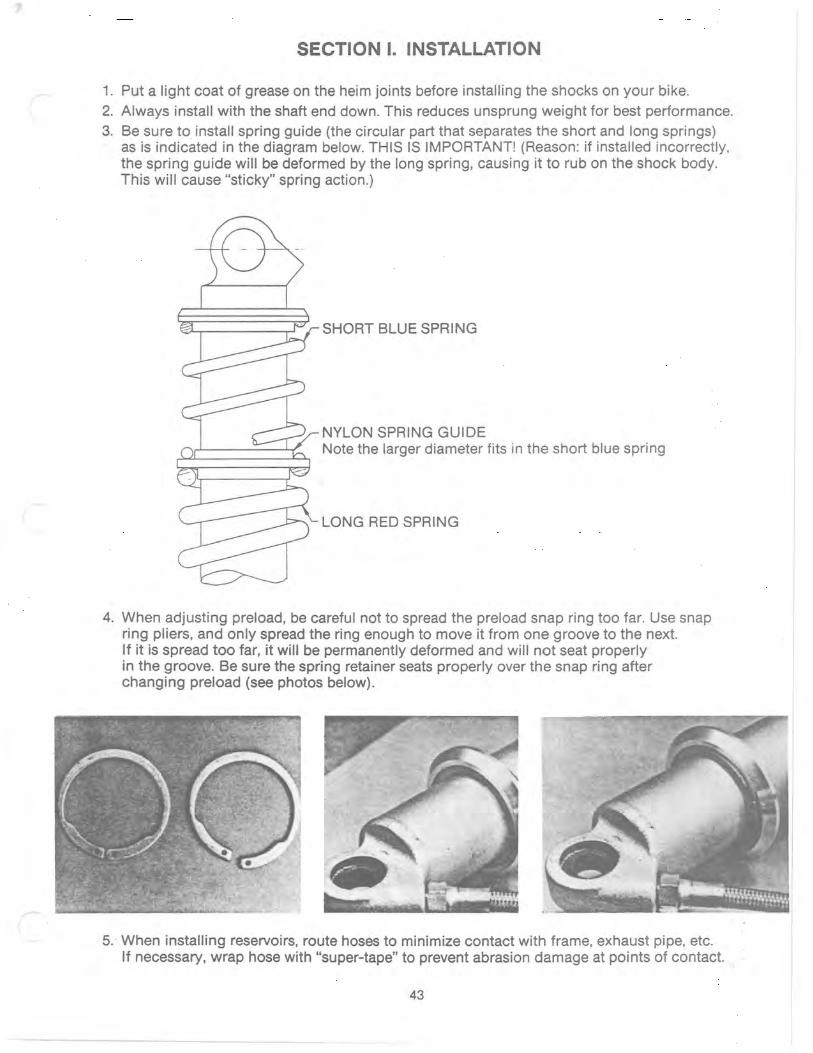
SECTION I. INSTALLATION
1. Put a light coat of grease on the heim joints before installing the shocks on your bike. 2. Always install with the shaft end down. This reduces unsprung weight for best performance. 3. Be sure to install spring guide (the circular part that separates the short and long springs)
as is indicated in the diagram below. THIS IS IMPORTANT! (Reason: if installed incorrectly, the spring guide will be deformed by the long spring, causing it to rub on the shock body. This will cause "sticky" spring action.)
SHORT BLUE SPRING
NYLON SPRING GUIDE Note the larger diameter fits in the short blue spring
LONG RED SPRING
4. When adjusting preload, be careful not to spread the preload snap ring too far. Use snap ring pliers, and only spread the ring enough to move it from one groove to the next. If it is spread too far, it will be permanently deformed and will not seat properly in the groove. Be sure the spring retainer seats properly over the snap ring after changing preload (see photos below).
5 .. When installing reservoirs, route hoses to minimize contact with frame, exhaust pipe, etc. If necessary, wrap hose with "super-tape" to prevent abrasion damage at points of contact.
43

SECTION II. DISASSEMBLY
IMPORTANT NOTE: Extreme cleanliness is of utmost importance during all disassembly and assembly operations to prevent any dirt or foreign particles from getting in the shocks.
A. TO TUNE DAMPING:
STEP 1. Remove springs, spring retainers, and spring guide from shock.
STEP 2. DEPRESSURIZE RESERVOIR. Be sure to do this before further disassembly.
STEP 3. Clean exterior of shock and reservoir thoroughly. Remove all dirt and grit. If available, use compressed air to blow dirt out of hard-to-reach areas like the reservoir end, the shaft wiper, and the heim joints. Extreme cleanliness is crucial to prevent any dirt from getting inside the shock during disassembly or assembly. Any foreign particles, for example even a single grain of sand, will affect the valving and cause incorrect or erratic damping.
44

STEP 4. Hold shock in a vise and unscrew the shaft bearing with a crescent wrench. Keep shaft fully extended during this operation (otherwise you will spill a lot of oil when you remove the shaft in Step 5).
STEP 5. Keeping shaft fully extended, remove shaft assembly from body. Piston ring may fall off as you do this-be prepared to catch it.
STEP 6. Inspect for any remaining dirt at the end of the body (caught between the bearing and the end of the body), and very carefully wipe any away. Cover end of body with a clean sheet of paper held on with a rubber band.
45
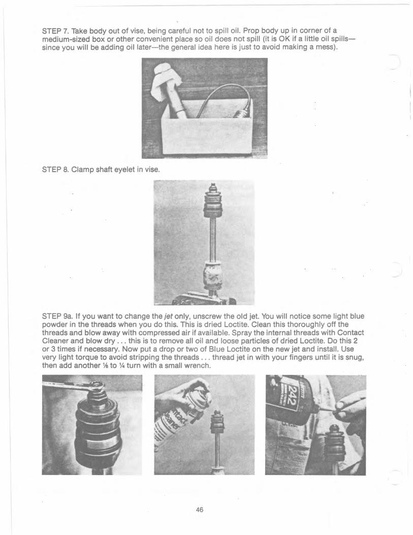
STEP 7. Take body out of vise, being careful not to spill oil. Prop body up in corner of a medium-sized box or other convenient place so oil does not spill (it is OK if a little oil spillssince you will be adding oil later-the general idea here is just to avoid making a mess).
STEP 8. Clamp shaft eyelet in vise.
STEP ga. If you want to change the jet only, unscrew the old jet. You will notice some light blue powder in the threads when you do this. This is dried Loctite. Clean this thoroughly off the threads and blow away with compressed air if available. Spray the internal threads with Contact Cleaner and blow dry ... this is to remove all oil and loose particles of dried Loctite. Do this 2 or 3 times if necessary. Now put a drop or two of Blue Loctite on the new jet and install. Use very light torque to avoid stripping the threads ... thread jet in with your fingers until it is snug, then add another 1h to v.. turn with a small wrench.
46

STEP 9b. If you want to change the rebound and/or compression valves, remove shaft locknut. Remove piston/valve assembly, being careful to note arrangement of all parts. Clean pistons thoroughly. Inspect pistons carefully for any small particles of dirt embedded in the surfaces that the valves seat on. If desired, the valve seat on the CD piston can be lightly lapped by running the piston face over 400 grit sandpaper placed on a flat surface. For the RD piston, any particles of embedded dirt can be removed with steel wool or with 400 grit sandpaper using your fingers. (Note: the RD piston has a slightly "dished" surface ... DO NOT ATTEMPT TO SAND IT FLAT!). Install new valves (see Section III, TUNING, for recommendations). Be very careful to install valves in correct sequence as shown in diagrams in Section III. Before tightening locknut, be certain that the RD valves are fully seated on the piston-be sure they are not "hung-up" on the shaft groove just below the shaft threads (if they are, they will be ruined when you tighten the locknut!). Tighten locknut to 110-120 in-Ibs. (9-10 ft-Ibs.) torque. DO NOT OVERTORQUE! If excess torque is applied, you will damage the RD piston, the RD Stop Plate, and the RD valves, and they will have to be replaced! If too much torque is used, RD valves will not stay flat-they will become "wavy" (something like a potato chip) .
STEP 10. Remove shaft assembly from vise. STEP 11. Put body back in vise. Lean shock slightly to one side-about 10° to 15° angle from vertical.
47
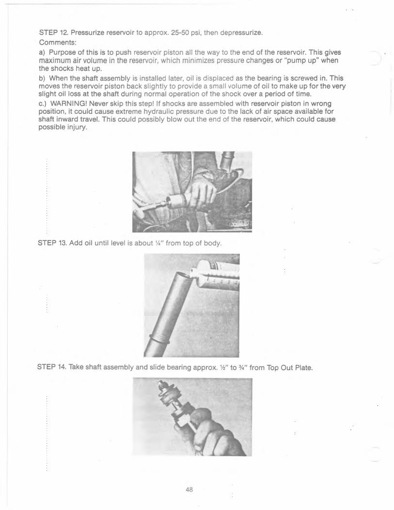
STEP 12. Pressurize reservoir to approx. 25-50 psi, then depressurize. Comments: a} Purpose of this is to push reservoir piston all the way to the end of the reservoir. This gives maximum air volume in the reservoir, which minimizes pressure changes or "pump up" when the shocks heat up. b) When the shaft assembly is installed later, oil is displaced as the bearing is screwed in. This moves the reservoir piston back slightly to provide a small volume of oil to make up for the very slight oil loss at the shaft during normal operation of the shock over a period of time. c.} WARNING! Never skip this step! If shocks are assembled with reservoir piston in wrong position, it could cause extreme hydraulic pressure due to the lack of air space available for shaft inward travel. This could possibly blowout the end of the reservoir, which could cause possible injury.
STEP 13. Add oil until level is about 1,4" from top of body.
STEP 14. Take shaft assembly and slide bearing approx. W' to %" from Top Out Plate.
48

STEP 15. Reinstall piston ring on piston. Notice small slot on CD piston under the valves (slot cuts through valve seat). Line up the piston ring gap with this slot and hold piston ring in this position for next step.
STEP 16. Install shaft ass~mbly in body. Install so that piston ring gap (and piston slot) is on the high side of the tilted shock body as you slowly immerse piston in the oil. This allows air trapped under the piston to escape. Be sure to hold piston ring firmly on the piston-especially at the ends of the piston ring-so it does not come out of its groove. After piston is fully immersed in oil, push shaft in farther until bearing contacts end of body. Push down slowly on bearing to allow any trapped air to escape. Be sure oil is overflowing from the body during this operation (otherwise there may be an air pocket under the bearing). Now screw in bearing and tighten with crescent wrench (about 50 to 75 ft-Ibs. torque). Do not use Loctite on bearing threads. Clean off overflowed oil with paper towels.
IMPORTANT: To ensure elimination of all air, the entire shaft installation should be done slowly and smoothly. Do not pull shaft partially back out, after piston is immersed in the oil (this may create air pockets) . If for some reason you have to pull back on the shaft, pull it all the way back out, then start over again. Although a small amount of air in the oil will NOT degrade the performance of your Fox Factory Shox, it is still best to try to eliminate all air completely. DO NOT STROKE SHOCK UNTIL RESERVOIR HAS BEEN PRESSURIZED.
49
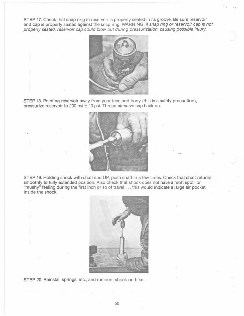
------------ --~
STEP 17. Check that snap ring in reservoir is properly seated in its groove. Be sure reservoir end cap is properly seated against the snap ring. WARNING: if snap ring or reservoir cap is not properly seated, reservoir cap could blowout during pressurization, causing possible injury.
STEP 18. POinting reservoir away from your face and body (this is a safety precaution), pressurize reservoir to 200 psi ± 10 psi. Thread air valve cap back on.
STEP 19. Holding shock with shaft end UP, push shaft in a few times. Check that shaft returns smoothly to fully extended position. Also check that shock does not have a "soft spot" or "mushy" feeling during the first inch or so of travel ... this would indicate a large air pocket inside the shock.
STEP 20. Reinstall springs, etc., and remount shock on bike.
50
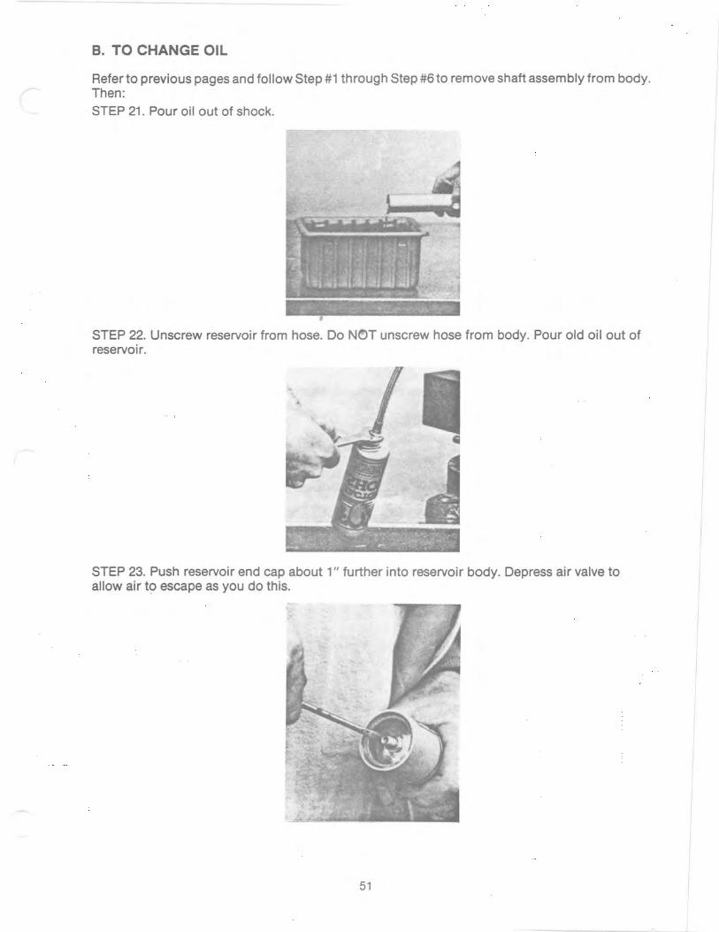
B. TO CHANGE OIL
Refer to previous pages and follow Step #1 through Step #6to remove shaft assembly from body. Then: STEP 21. Pour oil out of shock.
STEP 22. Unscrew reservoir from hose. Do NOT unscrew hose from body. Pour old oil out of reservoir.
STEP 23. Push reservoir end cap about 1" further into reservoir body. Depress air valve to allow air to escape as you do this.
51

STEP 24. Remove reservoir snap ring.
STEP 25. Using medium-grit sandpaper, sand edges of snap ring groove thoroughly to completely remove any burrs or sharp edges. If this is not done thoroughly, the O-rings may be damaged during the next operation. After sanding, wipe out and blowout dirt and grit thoroughly.
STEP 26. Push out reservoir piston and reservoir end cap. Use blunt screwdriver with about 5" long blade (or something similar) inserted into hose end of reservoir. These parts should push out easily except when the O-rings reach the snap ring groove at the end of the reservoir ... a little extra force will be required to push past this point. After removal, clean parts thoroughly and inspect O-rings carefully for any cuts or nicks. Replacement of the O-rings is recommended, but not absolutely necessary if not damaged.
52

STEP 27. Flush out body and reservoir thoroughly, using mechanic's solvent or equivalent. Blow clean and dry with compressed air if available.
STEP 28. Clean threads at end of hose and threads in end of reservoir thoroughly. Finish cleaning by spraying Contact Cleaner on threads, then blow dry.
STEP 29. Apply 3 or 4 drops of Blue Loctite or Red Loctite on hose threads. (Absolutely DO NOT USE TEFLON TAPE or any other tape-type sealant here ... no matter how careful you are, pieces of the tape almost always end up getting into the oil, causing erratic damping). Thread hose into reservoir and tighten.
STEP 30. With shock body held in vise, pour fresh oil into reservoir. Spectro Suspension Fluid (5 wt.) or Bel-Ray LT-100 oil are recommended. However, any good shock oil will periorm very well. When pouring oil in: a) Hold reservoir somewhat below level of the top of shock body. b) Hold reservoir so it is at about a 15° to 30° angle from vertical, and slowly pour oil against side of reservoir. (Do NOT hold reservoir vertical and pour oil straight down ... this causes the oil to splash and create bubbles.) c) Pour oil in until it is about W' to W' from top of reservoir. Wait ·about 15 seconds and add more oil if the level goes down (note that oil is also flowing through the hose into the body). Hold reservoir at a steady height while doing this, or the oil level will go up and down ·as the level in the shock body and reservoir keep trying to balance. d) If there are any bubbles in oil, wait until they rise to the suriace and dissipate before proceeding with next step.
53
•

STEP 31. Holding reservoir in one hand and reservoir piston in other hand (with O-ring and piston ring installed), slowly push piston into reservoir about 1". Note: a) Piston should be oriented so piston ring goes in first, then the O-ring. b) Be sure piston ring does not come out of its groove-especially hold in the ends of the piston ring to prevent this. Check visually when ring is about % of the way in, that the ends have not come partially out of the groove. c) It is a little tricky to hold and install the piston with one hand if you haven't done it before. If a friend is handy to hold the reservoir while you use both hands to install the piston, it is easier.
STEP 32. Turn reservoir upside down and let it hang vertically from the hose. (Piston will not fall out ... O-ring holds it in.) Let reservoir hang for about 1 minute while you tap lightly on the sides with the plastic end of a screwdriver or similar object. Now hold reservoir vertical (hose end UP) and slowly push piston all the way in until it contacts the far end of the reservoir. Use blunt screwdriver or similar tool to do this. Be sure reservoir is vertical (not at an angle). Be sure you push piston all the way in. Comment: Reason for this step is as follows ... When piston was installed (Step 31), a small pocket of air was trapped under the·piston. By letting the reservoir hang vertical from the hose, the pocket of air travels to the other end of the reservoir (hose end). Then when the piston is pushed in, the air pocket travels through the hose and out through the oil in the shock body. It is important to push the piston up slowly (it should take 10 or 15 seconds), since, if the piston is pushed up in one ql;Jick stroke, the air pocket will create turbulence which will generate small bubbles in the oil in the shock body. If some bubbles do occur, it is OK, but you will have to wait several minutes for them to rise to the surface and dissipate before continuing.)
54
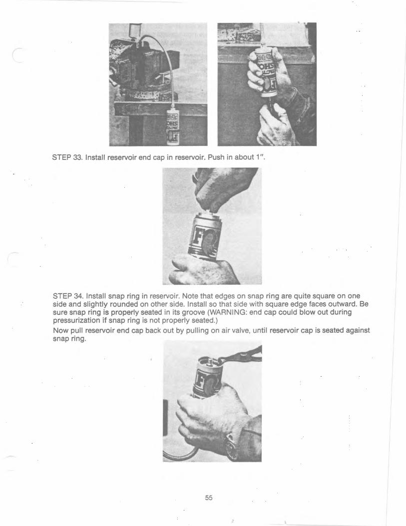
STEP 33. Install reservoir end cap in reservoir. Push in about 1".
STEP 34. Install snap ring in reservoir. Note that edges on snap ring are quite square on one side and slightly rounded on other side. Install so that side with square edge faces outward. Be sure snap ring is properly seated in its groove (WARNING: end cap could blowout during pressurization if snap ring is not properly seated.) Now pull reservoir end cap back out by pulling on air valve, until reservoir cap is seated against snap ring.
55

.. - - --- -
STEP 35. Slowly pour oil into the shock body until it is about 1.4" from the top. Have shock body at approx. 10° to 20° angle from vertical and pour oil against side of shock. (Do NOT have shock body vertical and pour oil straight down, since this will cause splashing and turbulence which will create small air bubbles.) Check for air bubbles in oil before continuing. If bubbles exist, wait for them to rise to the surface and dissipate. (This may take several minutes if there are a lot of small bubbles.) Now complete reassembly by following Steps 14 through 20 on previous pages.
C. MISCELLANEOUS OPERATIONS
INSTALLING NEW SHAFT O-RING AND WIPER:
Disassemble per Step 1 through Step 8 in previous section. Remove piston assembly- per first part of Step 9b. Now: STEP 36. Slide bearing off shaft.
56
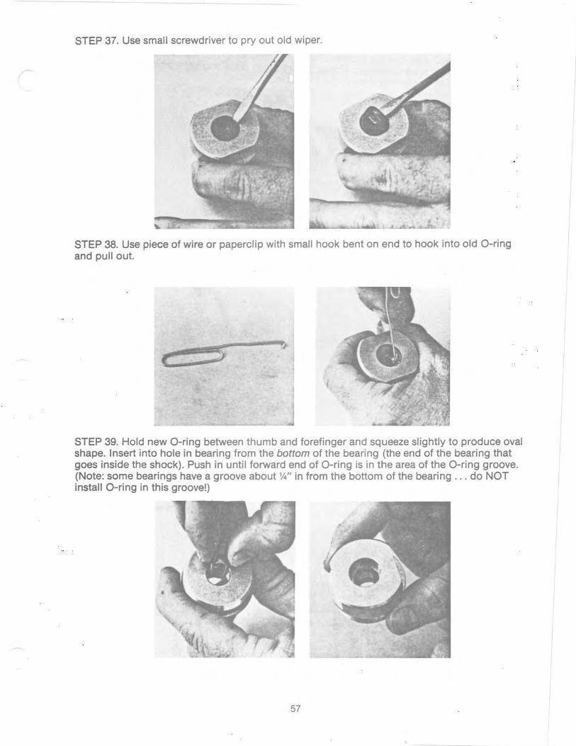
STEP 37. Use small screwdriver to pry out old wiper.
STEP 38. Use piece of wire or paperclip with small hook bent on end to hook into old a-ring and pull out.
STEP 39. Hold new a-ring between thumb and forefinger and squeeze slightly to produce oval shape. Insert into hole in bearing from the bottom of the bearing (the end of the bearing that goes inside the shock). Push in until forward end of a-ring is in the area of the a-ring groove. (Note: some bearings have a groove about W' in from the bottom of the bearing ... do NaT install a-ring in this groove!)
57

STEP 40. Now insert small finger of your other hand into the other end of the bearing and work a portion of the O-ring into the groove. (This is a little tricky to do. You may find it easier to use the eraser end of a pencil instead of your small finger.) Once you get a portion of the O-ring in the groove, it is relatively easy to get the rest in.
STEP 41. Install new wiper by squeezing it into an oval shape, then pushing one end into the groove. Now push wiper, a portion at a time, into the groove. If it "hangs up" slightly at the edge, use eraser end of pencil or blunt screwdriver to push it down and in.
STEP 42. Apply light coat of oil on new wiper and O-ring. Also apply light coat of oil on the "step" or "shoulder" portion of the shaft. Inspect for sharp edges or burrs in this area of shaft which could nick the O-ring, and remove if necessary. Now slide bearing back onto shaft. It helps to "wiggle" or oscillate the bearing slightly to help get the wiper past the "step" portion of the shaft. After bearing is on, inspect "step" portion of shaft carefully for any small shavings of black rubber which would indicate that the O-ring or wiper were cut during installation. Now reassemble per second part of Step 9b and Step 10 through Step 20 in previous section.
58
, . ,

INSTALLING NEW SHAFT:
Basic disassembly and reassembly of the shock is as covered in previous sections. Disassembly of shaft and shaft eyelet is not necessary or recommended unless one of the parts is damaged. STEP 43. Press out rubber bushing or heim joint from eyelet. Use a socket from a socket wrench set which just barely fits inside the eyelet to help drive out heim joint.
STEP 44. Clamp shaft in vise using aluminum blocks in contact with shaft to protect surface. If you have access to a machine shop, a %" collet or a typical mill vise with flat, hardened steel jaws is preferable.
STEP 45. Use propane torch or welding torch to heat eyelet to approx. 3000 -3500 F. (This weakens the Red Loctite on the threads.)
59

STEP 46. Use crescent wrench to unscrew eyelet. Avoid shaft slipping or turning in vise or collet. as this could damage shaft suriace.
STEP 47. Clean threads on shaft and eyelet with Contact Cleaner. Apply several drops of Red Loctite on threads and reassemble.
SECTION III. TUNING-DAMPING
A. PRINCIPLES OF OPERATION
The damping action of Fox Factory Shox is described in this section. We have attempted to present this information in a simplified , easy-to-read style, so that you don't need an engineering degree to understand it. A good basic understanding of how your shocks work will help you tune them to exactly meet your requirements and preferences.
REBOUND DAMPING ("RD")
On the rebound stroke, the oil "trapped" below the piston must flow through the piston assembly to the other side. On Fox Factory Shox, this oil flows into a hole in the shaft and then flows through the piston assembly via two possible paths:
Note: Dark Lines Indicate Oil Flow
60
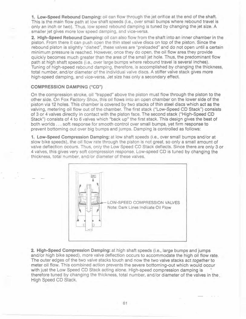
1. Low-Speed Rebound Damping: oil can flow through the jet orifice at the end of the shaft. This is the main flow path at low shaft speeds (Le., over small bumps where rebound travel is only an inch or two). Thus, low speed rebound damping is tuned by changing the jet size. A smaller jet gives more low speed damping, and vice-versa.
2. High-Speed Rebound Damping: oil can also flow from the shaft into an inner chamber in the piston. From there it can push open the thin steel valve discs on top of the piston. Since the rebound piston is slightly "dished", these valves are "preloaded" and do not open until a certain minimum pressure is reached. However, once they do open, the oil flow area they provide quickly becomes much greater than the area of the small jet hole. Thus, the predominant flow path at high shaft speeds (i.e., over large bumps where rebound travel is several inches). Tuning of high-speed rebound damping, therefore, is accomplished by changing the thickness, total number, and/or diameter of the individual valve discs. A stiffer valve stack gives more high-speed damping, and vice-versa. Jet size has only a secondary effect.
COMPRESSION DAMPING ("CD")
On the compression stroke, oil "trapped" above the piston must flow through the piston to the other side. On Fox Factory Shox, this oil flows into an open chamber on the lower side of the piston via 12 holes. This chamber is covered by two stacks of thin steel discs which act as the valving, metering oil flow out of the chamber. The first stack ("Low-Speed CD Stack") consists of 3 or 4 valves directly in contact with the piston face. The second stack ("High-Speed CD Stack") consists of 4 to 6 valves which "back up" the first stack. This design gives the best of both worlds ... soft response for smooth control over small bumps, yet firm response to prevent bottoming out over big bumps and jumps. Damping is controlled as follows:
1. Low-Speed Compression Damping: at low shaft speeds (i.e., over small bumps and/or at slow bike speeds). the oil flow rate through the piston is not great, so only a small amount of valve deflection occurs. Thus, only the Low Speed CD Stack deflects. Since there are only 3 or 4 valves, this gives very soft compression response. Low-speed CD is tuned by changing the thickness, total number, and/or diameter of these valves.
_~- LOW-SPEED COMPRESSION VALVES Note: Dark Lines Indicate Oil Flow
2. High-Speed Compression Damping: at high shaft speeds (Le., large bumps and jumps and/or high bike speed), more valve deflection occurs to accommodate the high oil flow rate. The outer edges of the two valve stacks touch and now the two valve stacks act together to meter oil flow. This combined action prevents the severe bottoming-out which would occur with just the Low Speed CD Stack acting alone. High-speed compression damping is therefore tuned by changing the thickness, total number, and/or diameter of the valves in the. High Speed CD Stack.
61

LOW-SPEED COMPRESSION VALVES HIGH-SPEED COMPRESSION VALVES Note: Dark Lines Indicate Oil Flow
You may be wondering, "What about the jet ... oil flows through it on the compression stroke, so doesn't it affect compression damping also?" Good question! The answer is, "Yes, it does." But only very slightly! The reason is that typical piston speeds on compression strokes are several times faster than on rebound strokes (this can be seen in slow motion movies), so that the flow area of the jet is much smaller than the flow area under the CD valves at typicai compression speeds. Since only a small amount of oil flows through the jet (compared to the amount that flows under the CD valves), the jet has only a very small effect.
62

"Perfect" damping control is as important as fine-tuning your engine, when it comes to cutting precious seconds off your lap times. Fox Factory Shox were especially designed to offer a full range of tuning possibilities. Just as important, they were designed to offer ease and simplicity of disassembly for making the tuning changes. Disassembling the shocks and changing damping may look complicated the first time you read this manual. However, most riders who have basic mechanical ability will find that it is really quite easy. It takes longer to read the instructions than to actually do it! Once you know how, it's easy! Since no special tools are needed (except for a 200 psi source of air or nitrogen pressure for charging the reservoir ... and most riders will know someone with AirShox who has a nitrogen tank to borrow), many riders will want to tune damping themselves, rather than having their dealer do it.
OIL VISCOSITY
Do NOT try to change the damping on your Fox Factory Shox by changing the oil viscosity. This will NOT work! Changes must be made by changing the valves or jet only.
Comment: The following explains why this is true, just in case you are curious (if not, you can skip this). The reason is that your Fox Factory Shox have been specifically designed to not be sensitive to viscosity ch&nges. That is, they are "viscosity insensitive". (P.S.: This wasn't easy to do! It took literally hundreds of hours of designing and testing, and re-designing and re-testing, to achieve "viscosity insensitivity".) At first, this seems like a bad design idea. After all, wouldn't it be nice to be able to change damping by just changing oil viscosity, like you can on some shocks? Well, yes, but there's a "rub" here ... . ,. The "rub" is this: As you know, all shocks heat up during a race. Now, when they heat up, the oil thins out-Le., the viscosity changes. All oils do this. For a typical shock oil, the viscosity at 200 0 F (a typical temperature for a fast rider on a rough track) is only about 10% of its viscosity at 70 0 F (at the start of the race). So what? ... Well, if a shock is designed so that damping can be changed by changing oil viscosity, then that means that when the shock heats up the damping will also chqnge. You've heard the word for that phenomenon before ... FADE! Put another way, if damping can be changed by changing viscosity, then the damping will change when the shock heats up ... in other words, FADE! So this is why damping on Fox Factory Shox can't be adjusted by changing oil viscosity (you can go from 5 wt. to 30 wt. and there will be no difference). And this is why hundreds of hours were spent designing them to be "viscosity insensitive" (Fox Factory Shox set ne~ standards for no-fade performance). And this also means that any shock that can be adjusted by changing oil viscosity is, by definition, a shock that will fade. Think about it!
TUNING
Go out and ride. Tune your senses to what the rear of the bike is doing. Concentrate on what the bike is doing, not on going 110% WFO! Sometimes you know the bike isn't handling quite right, but, for example, it may be hard to tell whether the problem is too little rebound damping or too much compression damping. Sometimes the difference in "feel" is subtle, and you have to really concentrate to tell. An experienced friend watching you ride usually helps. Developing a good "feel" for what the rear of the bike is doing isn't easy. Often it takes years of experience to get really good at it. In the following we will try to describe what happens, and what to "feel" for, when damping isn't quite right. However, it is difficult to describe some of these things in words, and some of
63
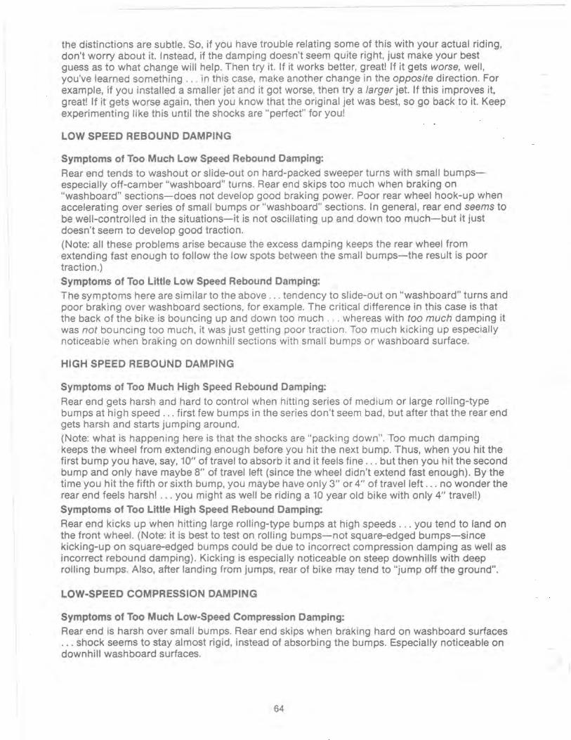
the distinctions are subtle. So, if you have trouble relating some of this with your actual riding, don't worry about it. Instead, if the damping doesn't seem quite right, just make your best guess as to what change will help. Then try it. If it works better, great! If it gets worse, well, you've learned something ... in this case, make another change in the opposite direction. For example, if you installed a smaller jet and it got worse, then try a larger jet. If this improves it, great! If it gets worse again, then you know that the original jet was best, so go back to it. Keep experimenting like this until the shocks are "perfect" for you!
LOW SPEED REBOUND DAMPING
Symptoms of Too Much Low Speed Rebound Damping: Rear end tends to washout or slide-out on hard-packed sweeper turns with small bumpsespecially off-camber "washboard" turns. Rear end skips too much when braking on "washboard" sections-does not develop good braking power. Poor rear wheel hook-up when accelerating over series of small bumps or "washboard" sections. In general, rear end seems to be well-controlled in the situations-it is not oscillating up and down too much-but it just doesn't seem to develop good traction. (Note: all these problems arise because the excess damping keeps the rear wheel from extending fast enough to follow the low spots between the small bumps-the result is poor traction.) Symptoms of Too Little Low Speed Rebound Damping: The symptoms here are similar to the above ... tendency to slide-out on "washboard" turns and poor braking over washboard sections, for example. The critical difference in this case is that the back of the bike is bouncing up and down too much ... whereas with too much damping it was not bouncing too much, it was just getting poor traction. Too much kicking up especially noticeable when braking on downhill sections with small bumps or washboard surface.
HIGH SPEED REBOUND DAMPING
Symptoms of Too Much High Speed Rebound Damping:
Rear end gets harsh and hard to control when hitting series of medium or large rolling-type bumps at high speed ... first few bumps in the series don't seem bad, but after that the rear end gets harsh and starts jumping around. (Note: what is happening here is that the shocks are "packing down". Too much damping keeps the wheel from extending enough before you hit the next bump. Thus, when you hit the first bump you have, say, 10" of travel to absorb it and it feels fine ... but then you hit the second bump and only have maybe 8" of travel left (since the wheel didn't extend fast enough). By the time you hit the fifth or sixth bump, you maybe have only 3" or 4" of travel left ... no wonder the rear end feels harsh! ... you might as well be riding a 10 year old bike with only 4" travel!) Symptoms of Too Little High Speed Rebound Damping: Rear end kicks up when hitting large rolling-type bumps at high speeds ... you tend to land on the front wheel. (Note: it is best to test on rolling bumps-not square-edged bumps-since kicking-up on square-edged bumps could be due to incorrect compression damping as well as incorrect rebound damping). Kicking is especially noticeable on steep downhills with deep rolling bumps. Also, after landing from jumps, rear of bike may tend to "jump off the ground".
LOW-SPEED COMPRESSION DAMPING
Symptoms of Too Much Low-Speed Compression Damping: Rear end is harsh over small bumps. Rear end skips when braking hard on washboard surfaces ... shock seems to stay almost rigid, instead of absorbing the bumps. Especially noticeable on downhill washboard surfaces.
64

Symptoms of Too Little Low-Speed Compression Damping: Shocks bottom-out on medium-sized bumps. Shocks bottom out at bottom of deep, smooth gullies, or rising portions of deep, rolling sand whoops.
HIGH-SPEED COMPRESSION DAMPING
Symptoms of Too Much High-Speed Compression Damping: Rear end is harsh at high speeds over large or medium square-edged bumps. Shocks stay too rigid ... do not use enough travel to absorb bumps. Shocks rarely or never seem to bottom out, even off the biggest jumps.
Symptoms of Too Little High-Speed Compression Damping: At high speed, rear end takes medium square-edged bumps smoothly, but bottoms out too easily on larger bumps. Bottoms out too easily off jumps. Bottoms out badly at high speeds over large square-edged bumps, kicking up rear end violently.
SUMMARY OF DAMPING SYMPTOMS
Damping Best Places on Track "Perfect" when .. . Adjustment For Testing 1. Low-Speed Small bumps; sweeper turns over Heavy enough to prevent rear end
Rebound Damping washboard sections; off-camber bouncing or oscillation, yet light washboard turns; braking on enough to allow rear wheel to washboard surfaces extend fast enough to maintain
good contact with ground. Rear end tracks well on washboard sweepers and off-camber washboard turns; brakes well on washboard.
2. High-Speed Series of medium or large Heavy enough to prevent rear end Rebound Damping rolling-type bumps on high-speed kicking up, yet light enough to
sections; fast downhill sections prevent "packing down" on series with deep rolling bumps. of bumps.
3. Low-Speed Small bumps and medium bumps; Heavy enough to prevent bottom-Compression deep, rolling sand whoops; ing out on medium bumps or Damping washboard sections; deep. rising portions of sand whoops or
smooth gullies. at bottom of deep, smooth gullies, yet light enough to allow shock to stroke smoothly on small bumps and avoid skipping when braking on washboard surfaces.
4. High-Speed Large square-edged bumps in Heavy enough to prevent excess Compression fast sections; big jumps bottoming out off jumps or over Damping large square-edged bumps, yet
light enough so shock strokes deeply to absorb these bumps without harshness or rigidity.
TUNING NOTE
It is common practice for riders to "test" shock absorber damping two ways. One way is to stroke the shock in and out by hand and notice the damping resistance. The other way is to push down or jump down on the back of the bike and observe the shock response.
65

These tests are useful, but very limited. You should be aware that these tests only involve lowspeed damping action. They tell you nothing about shock response at medium and high shaft speeds! (This applies to all shocks, not just Fox Factory Shox). It is important for you to realize this when tuning your shocks. Remember that, with these two tests, you will be able to notice tuning changes that affect low-speed damping (Le., jet changes and Low-Speed CD Stack changes). But you will not be able to notice the changes that affect high-speed damping. The only way to notice high-speed damping changes is by actual hard riding.
TUNING RECOMMENDATIONS
The percentage change in damping when going from one setting (e.g., High Speed CD #8) to the next setting (High-Speed CD #9) is fairly small. This is so you can really fine-tune your shocks.
However, a "one-step" change is hard to notice. Therefore, we recommend making changes of two steps at a time. For example, if after testing you feel HCD #8 is too soft for you, try HCD #10 (a two-step change). If that feels just right, then fine, you've got it. On the other hand, if that now feels a little too stiff, then you've got it "bracketed" ... change to HCD #9 and that should be just right! The above comments apply to Jet changes, Rebound Damping Stack changes, and LowSpeed Compression Stack (LCD) changes also.
66

SECTION V. MAINTENANCE
1. Grease heim joints periodically. 2. Change shock oil about once every 3 to 6 months. More often if you ride in the mud.
SECTION VI. TROUBLESHOOTING
1. Problem: Erratic damping or loss of damping. Solution: A) First, check for possible loss of air pressure in one or both reservoirs. If there is no pressure, determine source of leak by pressurizing reservoir and immersing in water-leak at O-ring or air valve is possible. Correct leak and repressurize to 200 psi. If reservoir pressure is OK, then problem is probably caused by dirt or foreign particles in the oil. B) Disassemble shock and reservoir, disassemble piston and all valves, clean entire shock thoroughly, and install new oiL
2. Problem: "Sticky" spring action. Solution: Check for spring guide'''upside down". See Section I, "Installation", item #3. Correct if necessary. Spray dry lubricant on shock body in area where spring guide rubs (where paint is worn off).
3. Problem: Loss of reservoir pressure. Solution: Check for air leak at air valve or reservoir O-ring. Pressurize reservoir and immerse in water to find leak. Replace air valve or O-ring as required.
4. Problem: Too much "kick" when braking on washboard surfaces, especially on down hills. Solution: A) Reduce spring preload and/or B) Use softer short spring and/or C) I nstall smaller jet and/or D) Reduce low-speed compression damping.
5. Problem: Miscellaneous damping problems. Solution: See Section III, "Tuning".
67

-• PERFORMANCE
(General)
During the past season, we did receive a number of calls relating to performance problems. In most case the problem was either a bogging at low end or a low peak engine RPM. Below are some examples of last season's problems that we heard about. Following the examples are remedies that have proven to correct the problem.
1. Engine bogs upon clutch engagement (low altitude). 2. Engine runs below peak RPM (low altitude). 3. Engine loses RPM after several minutes of operation. 4. Engine cuts out and runs erratically
Remedies
1. Engine bogs upon clutch engagement
II NOTE: For troubleshooting this problem, we have listed IN ORDER the areas to check. Following the recommendations in the order in which they appear should
assist you in correcting the problem.
A. Check for correct drive belt part number B. Check belt manufacturer C. Check belt condition (If worn more than 1/8 in., replace) D. Check belt deflection
If the belt is made by another manufacturer you should try an original Arctco Arctic Cat belt. All of our testing and clutch calibration work is done to match the rubber compound used in the Arctic Cat belts. Another belt style may require different clutch weights or ramps for peak performance.
To check belt deflection, see the procedure found later in this manual. If all of the above areas check out, proceed to: E. Check driven clutch spring F. Check drive clutch spring G. Check drive clutch components to be sure they are correct H. Check for a broken reed (on liquid cooled models)
2. Engine runs below peak RPM (with cold or hot engine)
A. High altitude dealers should check to be sure the proper high altitude kit has been installed.
B. Check for proper main jet(s) - see Jet Chart and jet according to your area's average temperature and altitude.
C. Check driven spring tension, try the next hole tighter in the driven clutch. D. Check to make sure the drive clutch components are correct: ramps, weights, cam
arms, etc. E. See the Engine Troubleshooting section in this manual.
68

3. Engine loses RPM after several minutes of operation
II NOTE: This problem is covered under engine troubleshooting. Because it is often asked about, it will be covered twice.
If the engine runs good, then looses RPM after several minutes of operation, the pro· blem is almost always electrical. If you do not have an Arctco Ignition Analyzer, the best method of troubleshooting is as follows: A. Disconnect the throttle monitor switch(es) and bypass the system using the by·
pass plug provided in the tool kit. Run the snowmobile and if the problem still ex· ists, proceed to B.
B. Take a new external coil and COl unit with you and test ride the snowmobile until the problem appears. As soon as the problem appears, stop the snowmobile and plug in the new external coil. Start the engine and run the snowmobile. If the problem goes away, you've corrected the problem.
C. If the problem is still present, plug in the new COl unit and run the snowmobile. If the problem is still present, replace the coils on the stator plate.
4. Engine cuts out and runs erratically
II NOTE: This problem can usually be traced to either the throttle monitor switch or the ignition switch.
The throttle monitor switch may function in all throttle areas except one. Ask the customer, at which throttle setting does the problem exist. Any additional information you can get will make your job of finding the problem easier. To troubleshoot this problem, follow these steps: A. By-pass the monitor switch using the by-pass plug provided in the tool kit. With
the engine warm, drive the snowmobile at different throttle settings. B. If the problem still exists, by-pass the key switch using a short jumper wire be
tween the two wires that attach to the back of the key switch. C. If the problem of erratic engine operation still exists, check the ignition system
using the Arctco Ignition Analyzer (pIn 0644-046), or follow steps A-C under Engine Loses Power After Several Minutes of Operation.
1988650 UC PERFORMANCE
There were some problems last season with ring land breakage, caused by detonation. If the engines were allowed to run higher than 8250, they would lose power and detonate at the 1/4 throttle range.
The problem of high rpm was caused by clutch weights being too light once the clutch sheaves became polished by the drive belt. We covered this situation in a Service Newsletter dated January 18 and again February 18.
To best correct this problem, heavier clutch weights are required. In the '89 models, the new Clutch Cam Arms are 52.5 grams. It is also a good idea to keep the driven cam buttons in mind. Once they become worn, the rpm starts to run some higher. The peak horse power on both the '88 and '89650 engines comes between 8000-8250 rpm.
Another method of adjusting peak rpm is to change spring tension on the driven clutch. Last season, we made a recommendation in the Newsletter to place the spring tab in the 1st hole or the least amount of spring tension. This would lower the rpm on those models that were running too high of rpm in most cases.
If, after placing the driven spring in the 1st hole, the rpm is still over 8250, you must then replace the driven cam buttons. This would, in most cases, bring the rpm down within range.
The jetting for the 1988 models below 2000 feet altitude was good without any changes being required. The standard 380 production main jet turned out to be a good, all around, safe jet size to run. Operating above 2000 feet required a jetting change for peak performance.
In the mountain areas, the standard production cam arm worked best after the clutch sheaves became polished by the drive belt. Many dealers ended up using the 0627-001 belt as it is just a little longer than the 0627-004 and lasted longer.
69
1989650 UC SPARK PLUG FOULING
There were reports of the 1989650 engine fouling spark plugs. In a newsletter dated Feb. 27, 1989, we instructed everyone to change the pilot jets to a #50 and the spark plugs to BR9ES, gapped at 0.7 mm (0.028 in.). This would normally correct the problem. On the 1990 model 650, these recommendations have been followed.
If there are still problems with spark plug fouling, the spark plug cap, ignition switch, throttle monitor switch and wire connections to all rubber plugs should be checked.
In some cases, a dirty or loose connection at any of the rubber connectors (engine-COlstator plate) can and will cause erratic engine rpm and low rpm. Disconnect each rubber plug, one at a time, spray with contact cleaner and plug back together. Be sure all connectors fit tightly together. You may need to squeeze them with a pliers so they snap firmly together.
NOTE: Be sure the correct main jet is being used. Select the proper main jet from the chart found on the clutch guard. Selection must be based on your area altitude and temperature.
EXTERNAL IGNITION COILS
Whenever the external ignition coil appears to be the source of the problem, the following procedure should be completed before it is removed and replaced.
1. Remove the spark plug caps.
2. Cut 3/8" from the end of each high tension lead.
3. Test the spark plug caps. If out of tolerance, replace them.
4. Install spark plug caps and test engine to see if the problem has been corrected.
NOTE: Last year, it was found that over 85% of the ignition coils replaced were OK. All could have been saved if the above procedure would have been followed.
70
ENGINE TROUBLESHOOTING
Two-cycle engine requirements to run 1. Fuel 2. Primary compression 3. Secondary compression 4. Ignition at correct time
IF THE ENGINE FAILS TO RUN (NO SPARK). 1. Pinpoint problem to one of the following four areas:
a. Electrical-loose throttle cable-defective or corroded switches-wiring harness b. Ignition components c. Engine components-lack of primary or secondary compression d. Fuel system-lack of fuel
2. Method of troubleshooting (no spark) a. Check spark plug condition-if they appear to be fouled, install new set. b. Gap spark plugs at 0.125 in. for test purposes-ground them against a clean
metal engine surface. c. Turn on switches. d. Crank the engine over and observe the spark plug firing tip-if no spark is seen,
check to make sure all ignition switches are in the "ON" position. e. If switches are "ON", squeeze throttle to half open position to tension throttle
cable-crank the engine over once again-if there is now spark, adjust the throt· tie cable to take all slack out of the cable.
f . If there still isn't any spark, disconnect the main engine wiring harness plug. Run a jumper wire between the brown and black wires in the engine plug. Crank engine over once again watching the spark plug firing tip. If there is now spark, check: - wiring for tightness at connections - ignition switch - safety switch - wiring harness
To check the above, use an ohmmeter and first check between the black and brown wires in the four prong connector of the main wiring harness. With all switches in the "ON" position, the ohmmeter must read closed (swing toward the zero end of the scale).
If the needle fails to show a closed circuit, there is definitely a problem in one of the above. Refer to your Service Manual· Electrical Section.
g. If no spark is seen after disconnecting the main engine wiring harness and com· pleting the ground between the black and brown wires in the four prong connec· tor, one or more of the main ignition components are bad. See the Service Manual for Testing Instructions of these components.
71
-- ...... ---
3. Engine has spark, but fails to start. a. Set rear of the snowmobile up on safety stand. b. Squirt fuel into the bore of the carburetor(s)-two or three squirts. c. Crank the engine over-if the engine starts, but soon stops, check fuel system
(fuel in tank, fuel filter, fuel pump, impulse line, clean and adjust carburetor(s)) . d. If the engine fails to start after fuel has been squirted into carburetor(s), remove
the spark plug(s) and check the firing tips for traces of fuel. If the tips are dry, this indicates the fuel squirted into carburetor(s) isn 't being transferred from the crankcase to the combustion chamber. This pinpoints the problem to low primary compression. Low primary compression is caused by: - worn piston rings - leaking end seals - leak in crankcase sealing surfaces - bad center seal - badly worn piston skirts
NOTE: To prove the above, squirt two or three squirts of fuel into each spark plug hole and install plugs. Crank the engine over. If the engine starts and stops, disassemble engine and overhaul.
e. If engine fails to start after fuel has been squirted into the spark plug holes, check secondary compression and confirm that you have ignition .
ENGINE STARTS, BUT FAILS TO DEVELOP POWER. 1. Pinpoint problem area:
a. Electrical-ignition component-engine timing b. Fuel-incorrect jetting-plugged passageway or jets c. Compression- primary and secondary too low d. Drive system components-broken driven clutch spring-dirty driven e. Broken reed pedal
2. Method of troubleshooting (engine starts, but no power) To pinpOint the problem to one of the above areas, set the rear of the snowmobile up on a safety stand . Start the engine and allow it to warm up for 2 to 3 minutes. As the engine is idling , note rpm and how the engine runs. Engine idle should be set at 1800 to 2000 rpm. If the engine idles rough, adjust air screw(s) to 1 % - 111z turns open. If engine loads up and exhaust smoke is heavy at idle check choke adjustment , pilot jet and pilot air screw, and float level .
a. Carburetion: If the engine idles good, but doesn 't want to accelerate past the 1/4 to 3/4 throttle position , check the carburetor midrange (jet needle and needle jet) circuit. If the problem is beyond 3/4 throttle range, check the main jet circuit.
b. Drive System: After checking the fuel system and eliminating it as a problem source, quickly observe a couple of important points in the drive system. They are: drive belt condition and drive clutch engagement speed. If the drive belt is worn narrow or is too long, the clutch sheaves will grip the drive belt at a higher ratio and the engine won't have enough torque to move the snowmobile. If the belt is too long, the engagement speed and ratio will not be correct. With the specifications given in the Drive System Section of the Service Manual, check the drive belt's length and width.
If drive belt checks out according to the specifications, doublecheck to make sure the rear of the snowmobile is securely positioned up on a safety stand. Start the engine and begin to accelerate the engine. Note clutch engagement speed and driven clutch shift pattern . If the belt is drawn down into the driven clutch prematurely, spring and spring position should be checked closely. Clean both the drive and driven clutches every 400 to 500 miles.
72

c. Electrical: Another cause of low power is improper engine timing. With all COl ignition systems presently being used, the timing curve is controlled electrically, there is always a chance the timing isn't being matched to the engine rpm. This will cause an engine to either be low on power or to overheat. To check for this condition, follow the procedure given in thy Service Manual. Remember that before checking engine timing, the engine must be run for 5 minutes to thoroughly warm it up and timing must be checked at an rpm of 6000.
d. Compression: Low secondary compression will cause a noticeable power loss. Low compression can be caused by worn rings, scored cylinder walls, blown head gaskets, or damaged pistons. Check compression and compare the cylinders to each other. The compression between cyli nders must not vary by more than 10 percent. If there is more variance, remove the cylinder head(s) and cylinder(s) to inspect for damage.
ENGINE STARTS AND RUNS GOOD FOR A SHORT TIME, THEN LOSES POWER AND RPM_ NOTE: The above problem is one where the engine runs excellent for the first 1/4 to 1/2 mile. The engine then starts to drop in rpm and runs very poorly. If the engine is turned off and allowed to cool down, it will again run poorly after just a short time under load.
1. Pinpoint problem area: a. Electrical - There is only one method to quickly pinpoint this problem. It is to take
a new external coil and COl along on a test r"ide. Run the snowmobile until the problem shows up. Stop the engine and quickly replace the external coil. Start the engine and run the snowmobile to test the results.
If the problem still exists, replace the COl unit next. Test drive the snowmobile. If the problem is still present, replace internal coils. We have seen many times where these components check good cold but fail as soon as they reach running temperature.
NOTE: All that is necessary when installing the above components is to plug them in. You won't need to attach them to the engine for test purposes. Once the bad component is pinpointed, the new component can be securely attached.
ENGINE PEAK RPM IS LOW (COLD OR HOT ENGINE) 1. Check for proper main jet for your area and temperature. See Jet Chart and jet accor
dingly.
2. Check wiring harness connectors for being clear and tight.
3. Check clutch components. Are they correct?
4. Check driven and driven spring. Has the spring lost some of its tension?
5. Is the driven spring in the proper torque bracket hole?
ENGINE FAILS TO STOP If you have experienced a problem in being able to turn off the engine, the problem is the COl unit itself. If the engine fails to stop with all switches in the "OFF" position, use the choke to stop the engine. Replace the COl unit. The COl has an internal short to ground which completes the circuit and there isn't any way to repair the COl unit itself.
73

-_ .......
Piston damage Just about everyone who has been in business for a number of years has seen one of the following:
Piston seizure Piston has heavy or medium seizure marks around the outside, but yet, the dome doesn't appear to have any damage and color looks good .
This problem is usually caused by not properly warming up the engine before subjecting it to heavy use-sometimes called cold seizure. It can also be caused by poor lubrication or use of gasoline with methanol alcohol. How to check for methanol alcohol is covered in this manual under Lubrication.
Piston burn-down (hole in piston dome or melted pocket). If a hole has started or been burned through the dome, this problem can be caused by lean conditions (air leak or lean jetting). This is also caused by advanced timing or too hot a spark plug. Methanol alcohol may also cause this condition.
Intake skirt wearing thin and breaking off This is another problem caused by running a cold engine hard. It can also be caused by the engine sucking in a lot of loose snow into the air intake.
Piston dome has a sand·blasted appearance This problem is caused by pre-ignition, which can start from any sharp edge exposed in the combustion area. Also , advanced timing or low octane fuel can cause this type of damage.
Piston dome burned away in exhaust port area This problem can be caused by lean jetting, incorrect ignition timing, or improperly tuned exhaust system.
Piston seizure· appearance of piston is dry Problem is usually caused by a lean or overheated condition. Air leaks, improper jetting , or over-advanced timing can al l cause the above. If the spark plug electrode has melted out of the plug center, it usually is caused by too lean a mixture.
Ringland Breakage
Ringland breakage is a result of detonation. The hammering forces that are applied to the piston dome when detonation occurs, cause both ringlands and piston skirts to crack. Detonation will leave distinct signs on the piston dome which resemble sandblasting. To check for detonation , closely inspect the outer edge of the piston. If any area appears to have a sandblasted appearance, detonation may have occurred.
If detonation has taken place, it must be corrected or further engine damage will result. The following should be checked in eliminating the problem.
1. Fuel octane
2. Fuel mixture - Is the correct jet being used? 3. Timing
4. Engine rpm - Is the engine operating within the manufacturer's recommended range?
74

Engine Servicing
REMOVE ENGINE (440 UC·530 UC)
General
1. Remove the hood.
2. Remove the drive belt.
3. Remove the springs securing the expansion chambers; then remove chambers.
4. Remove the drive clutch.
5. Loosen clamp on injection pump oil line, remove hose and plug.
6. Loosen the hose clamp securing hose to water intake manifold. Drain coolant; then remove hose from intake manifold.
7. Loosen the clamp securing hose to the thermostat cap; then slide hose off cap.
8. Disconnect spark plug caps; then disconnect coil harness from CDI unit.
9. Remove carburetors.
10. Remove impulse lines for fuel pump and lubricator pump.
11. Remove radiator hose from water pump inlet.
12. Disconnect main ignition harness.
13. Remove the four cap screws and washers securing motor plate to front end assembly.
14. Disconnect oil injection cable from pump arm.
15. Remove motor plate/engine.
DISASSEMBLE LIQUID COOLED ENGINE
1. Place the engine on a clean workbench.
2. Remove the recoil starter. Make note of its original location.
3. Remove the magneto cover.
4. Using the Arctic spanner wrench to hold the flywheel, remove the starter pulley.
5. Carefully pry the belt pulley off magneto; set belt and pulley aside.
6. Use the spanner wrench to hold flywheel and remove flywheel nut, lock washer, and spacer.
II NOTE: Make sure mounting bolts do not come in contact with the internal magneto
coils.
7. Using the Arctic Flywheel Puller, remove the flywheel from the crankshaft. Set flywheel on a bench with the magnets facing upward.
8. Loosen the screw securing the magneto harness clamp.
75
9. Note the position of the timing marks on the stator plate and crankcase. Use a scribe mark to aid in correct positioning during engine assembly.
10. Remove the two socket-head screws securing stator plate to crankcase. Slide plate free of crankshaft; lay plate in magneto housing.
11. Using an impact screwdriver, remove magneto housing.
12. Disconnect the coolant bypass hose from the cylinder head.
13. Using a rubber mallet, tap the magneto case to remove it from the crankcase.
14. Remove the cap screws securing the thermostat cap to the cylinder head; then remove cap.
15. Remove the thermostat.
II NOTE: The thermostat used is set to open at 150 0 F (60 0 C). To test the thermostat, thread
a piece of string under the valve. Suspend the thermostat in a pan of water. Begin heating water. As the seal opens, the thermostat should fall at about 150 0 F (60 0 C). If the valve does not open, replace the thermostat.
16. Remove the cylinder head.
17. Using a rubber mallet, tap the cylinder head until it is free of cylinders. Remove head gaskets.
18. Remove the water intake manifold.
19. Remove the cylinder base nuts, lock washers, and flat washers. USing a rubber mallet, tap the cylinders to free them from the crankcase.
20. Carefully slide each cylinder straight up over each piston assembly. Mark all components so they can be installed with their respective cylinders.
II NOTE: Exercise extreme care when handling the cylinder to prevent the reed stop from be·
ing damaged.
21. Remove the outward piston pin circlips.
22. Using the Arctco Piston Pin Puller, remove the piston pins.
23. Place rubber bands over the connecting rods to prevent rods from damaging crankcase should the crankshaft be accidentally rotated.
24. Remove the screws and plate from the PTO end of the crankcase.
25. Lay the engine on its side. Remove the six· teen bolts and washers securing the crankcase halves together.
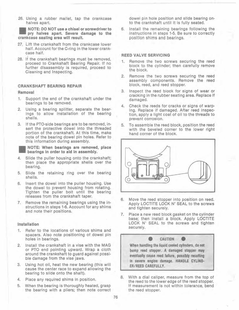
26. Using a rubber mallet, tap the crankcase halves apart.
II NOTE: DO NOT use a chisel or screwdriver to pry halves apart. Severe damage to the
crankcase sealing area will result.
27. Lift the crankshaft from the crankcase lower half. Account for the Coring in the lower crankcase half.
28. If the crankshaft bearings must be removed, proceed to Crankshaft Bearing Repair. If no further disassembly is required, proceed to Cleaning and Inspecting.
CRANKSHAFT BEARING REPAIR
Removal
1. Support the end of the crankshaft under the bearings to be removed.
2. Using a bearing splitter, separate the bearings to allow installation of the bearing shells.
3. If the PTO-side bearings are to be removed, insert the protective dowel into the threaded portion of the crankshaft. At this time, make note of the bearing dowel pin holes. Refer to this information during assembly.
II NOTE: When bearings are removed, place bearings in order to aid in assembly.
4. Slide the puller housing onto the crankshaft; then place the appropriate shells over the bearing.
5. Slide the retaining ring over the bearing shells.
6. Insert the dowel into the puller housing. Use the dowel to prevent housing from rotating. Tighten the puller bolt until the bearing releases from the crankshaft taper.
7. Remove the remaining bearings using the instructions in steps 1-6. Account for any shims and note their positions.
Installation
1. Refer to the locations of various shims and spacers. Also note positioning of dowel pin holes in bearings.
2. Install the crankshaft in a vise with the MAG or PTO end pointing upward. Wrap a cloth around the crankshaft to guard against possible damage from the vise jaws.
3. Using hot oil, heat the new bearing (this will cause the center race to expand allowing the bearing to slide onto the shaft).
4. Place any required shims in position.
5. When the bearing is thoroughly heated, grasp the bearing with a pliers; then note correct
76
____ ..... L_
dowel pin hole position and slide bearing onto the crankshaft until it is fully seated.
6. Install the remaining bearings following the instructions in steps 1-5. Be sure to correctly position shims and bearings.
REED VALVE SERVICING
1. Remove the two screws securing the reed block to the cylinder; then carefully remove the block.
2. Remove the two screws securing the reed assembly components. Remove the reed block, reed, and reed stopper.
3. Inspect the reed block for signs of wear or cracking in the rubber seating area. Replace if damaged.
4. Check the reeds for cracks or signs of warping. Replace if damaged. After reed inspection, apply a light coat of oil to the threads to prevent corrosion.
5. To assemble the reed block, position the reed with the beveled corner to the lower right hand corner of the block.
6.
7.
Move the reed stopper into position on reed. Apply LOCTITE LOCK N' SEAL to the screws and tighten securely.
Place a new reed block gasket on the cylinder base; then install a block. Apply LOCTITE LOCK N' SEAL to the screws and tighten securely.
• CAUTION •
When handling the liquid cooled cylinders, do not bump reed stopper. A damaged stopper may eventually cause reed failure, possibly resulting in severe engine damage. HANDLE CYLINDER/REED CAREFULLY.
8. With a dial caliper, measure from the top of the reed to the lower edge of the reed stopper. If measurement is not within tolerance, bend the reed stopper.

Base
REED STOPPER HEIGHT Model in. mm
440 UC 0.276 7.0 530 UC 0.354 9.0
650 UC 0.315 8.0
CLEANING AND INSPECTION
II NOTE: Whenever a part is worn excessively, cracked, defective, or damaged in any way,
replacement is necessary.
Cylinder Head
1. Remove any carbon buildup which has col-lected in the combustion chamber.
II NOTE: Use a non-metallic tool to prevent scratching and scoring of the combusion
chamber.
2. Thoroughly clean the cylinder head in cleaning solvent.
3. Inspect spark plug threaded area for any damage.
4. True the cylinder head on a surface plate with #400 grit wet-or-dry sandpaper to ensure a true sealing surface.
Cylinders
1. Remove carbon buildup from the exhaust ports.
II NOTE: Use a non·metallic carbon removal tool.
2. Wash the cylinders in cleaning solvent.
3. Inspect cylinders for pitting, scoring, scuffing, or corrosion. Replace if damaged.
4. To remove minor imperfections or marks in the cylinders, use a flex hone with 500 grit stones to clean cylinder bores. Use honing oil for lubrication. Move hone so a "crosshatch" pattern will result.
II NOTE: The cylinders can be honed using a rigid hone and 500 grit stones.
5. Inspect all threaded areas for damaged or stripped threads.
77
Pistons
1. Remove carbon buildup from dome of each piston using a non-metallic carbon removal tool.
2. Examine the side of each piston for evidence of excessive "blowby". Excessive "blowby" will indicate worn piston rings or an out-ofround cylinder.
3. Check the sides and skirts for evidence of scuffing. To remove minor marks, use #400 grit wet-or-dry sandpaper and lightly sand the affected areas.
4. Check the pistons for signs of cracks in the piston pin and skirt areas. Replace any cracked pistons.
5. Use a piece of a ring to remove any carbon buildup from the piston ring grooves.
II NOTE: Because the engine uses keystone· type rings, conventional ring groove
cleaners must not be used.
Crankcase Halves
1. Remove dowel pins from the crankcase halves.
2. Thoroughly wash halves using cleaning solvent.
3. Inspect halves for scoring, pitting, scuffing, or any imperfections in the casting.
4. Inspect all threaded areas for damaged or stripped threads.
5. Check the bearing areas for signs of cracking or bearing movement; then check retaining dowel pins and holes in the bearing areas for wear.
6. Examine the crankcase sealing area. If any nicks or scratches are found in the sealing area, use a surface plate and rotate the crankcase in a figure eight motion until a uniform finish is noted. Continue until high spots are removed.
Crankshaft
1. Thoroughly wash crankshaft w/bearings in cleaning solvent.
2. Inspect edges of bearings for external wear, scoring, and scuffing. Rotate the bearings by hand to ensure they turn freely without binding or roughness.
3. Check the connecting rods using the same method. If binding or roughness is noted, the connecting rod, bearing, and crank pin will have to be replaced.

MEASURING CRITICAL COMPONENTS
General
Special measuring instruments are needed for measurement of critical parts and tolerances. The tools must be kept in the shop area, must be kept clean at all times, and must be handled properly.
Check Cylinder Wear
1. Insert an inside micrometer, cylinder gauge, or snap gauge into the cylinder bore and take six measurements of the bore. Measure front to back and side to side at points below intake port, above exhaust port, and 1 cm (0.375 in.) below top of cylinder. If measurements vary by more than 0.05 mm (0.002 in.), the cylinder is either tapered or out-of-round and must be replaced.
2. Proceed to Check Piston Skirt Clearance. If clearance is more than allowable, the excessive clearance may be reduced with the installation of a new piston. If clearance is still excessive, replace the cylinder.
Check Piston Skirt Clearance
1. Insert an inside micrometer approximately 3 cm (1 in.) from the bottom of the cylinder. Take measurement from front to back.
2. Measure the piston skirt 1 cm (0.375 in.) above the bottom of the piston skirt.
3. Subtract the measurement in step 2 from measurement in step 1. The difference is the piston skirt clearance and must fall within the range listed below.
ACCEPTABLE PISTON SKIRT CLEARANCE
Model
440 UC, 530 UC
Clearance (mm)
0.113-0.15
Clearance (in.)
0.0044-0.006
II NOTE: If the clearance (fxceech» the wear limit, th~ piston must be replac~d to bring
clearance into acceptable range. However, if clearance is still excessive, the cylinder will have to be replaced.
Check Piston Ring End Gap
1. In turn insert each piston ring approximately 1 cm (0.375 in.) into the top of the cylinder bore. Position the ring horizontally in cylinder by pressing the dome of its piston against the ring.
2. Slide a feeler gauge between the ends of the ring.
78
ACCEPTABLE PISTON RING END GAP
Engine
440 UC, 530 UC
(mm)
0.20-0.83
(in.)
0.008-.033
3. End gap must be within specifications. Since the amount of wear at the ends and center of the piston ring arc affects the end gap, replace the ring set if the ring end gap is excessive.
Check Piston Pin and Piston Pin Bore (440 UC·530 UC)
1. Measure the piston pin approximately 1 cm (0.375 in.) from each end. Piston pin diameter must be between 17.995-18.000 mm (0.7085-0.7087 in.) for both models.
II NOTE: If piston pin is not within specifica· tions, replace the piston pin and bearing as a
set.
2. Insert an inside snap gauge about 1 cm (0.375 in.) from the outside of the piston pin bore. Carefully remove the snap gauge.
3. Measure the snap gauge with a micrometer. Piston pin bore must be 17.998-18.006 mm (0.7086-0.7089 in.).
Connecting Rod Small End Diameter
1. Insert a snap gauge about 1 cm (0.375 in.) into the bore of the connecting rod small end diameter. Lock the gauge and carefully remove it.
2. Measure the snap gauge with a micrometer. The diameter must be between 23.00-23.03 mm (0.9056-0.9059 in.). If the diameter is not within specifications, the connecting rod must be replaced.
Crankshaft Runout
1. Firmly moul'lt the crankshaft in a truing jig or on a setup using a surface plate, V-blocks, and a dial indicator with a mounting base.
2. Support the crankshaft with the outer crankshaft bearings on the V-blocks.
3. Mount the dial indicator against the crankshaft at the area of the oil seals. Be sure the crankshaft is clean. DO NOT take readings on the tapered areas because an inaccurate reading will be obt~ined.
4. Slowly rotate the crankshaft and observe the "total" crankshaft runout (total indicator reading). This is the difference between the highest and lowest readings. Maximum runout must not exceed 0.05 mm (0.002 in.). If runout exceeds specifications, the crankshaft must be straightened or replaced.
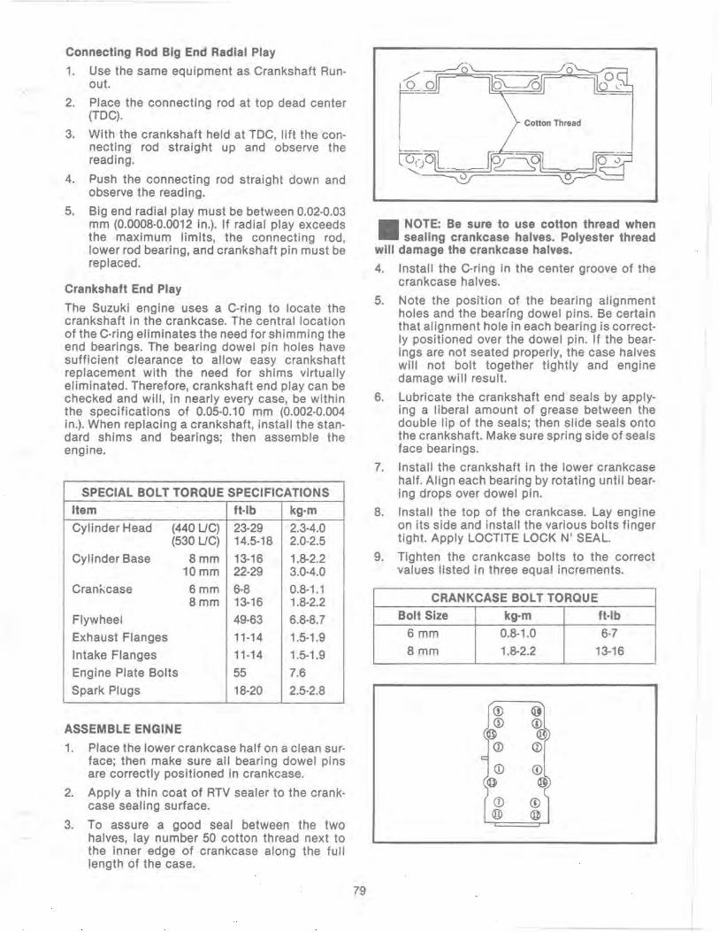
Connecting Rod Big End Radial Play
1. Use the same equipment as Crankshaft Runout.
2. Place the connecting rod at top dead center (TOC).
3. With the crankshaft held at TOC, lift the connecting rod straight up and observe the reading.
4. Push the connecting rod straight down and observe the reading.
5. Big end radial play must be between 0.02-0.03 mm (0.000B-0.0012 in.). If radial play exceeds the maximum limits, the connecting rod, lower rod bearing, and crankshaft pin must be replaced.
Crankshaft End Play
The Suzuki engine uses a Coring to locate the crankshaft in the crankcase. The central location of the Coring eliminates the need for shimming the end bearings. The bearing dowel pin holes have sufficient clearance to allow easy crankshaft replacement with the need for shims virtually eliminated. Therefore, crankshaft end play can be checked and will, in nearly every case, be within the specifications of 0.05-0.10 mm (0.002-0.004 in.). When replacing a crankshaft, install the standard shims and bearings; then assemble the engine.
SPECIAL BOLT TORQUE SPECIFICATIONS
Item ft·lb kg·m
Cylinder Head (440 UC) 23·29 2.3-4.0 (530 UC) 14.5-1B 2.0-2.5
Cylinder Base Bmm 13-16 1.B-2.2 10mm 22-29 3.0-4.0
Crani\case 6mm 6-B 0.B-1.1 Bmm 13-16 1.B-2.2
Flywheel 49-63 6.B-B.7
Exhaust Flanges 11-14 1.5-1.9
Intake Flanges 11-14 1.5-1.9
Engine Plate Bolts 55 7.6
Spark Plugs 1B-20 2.5-2.B
ASSEMBLE ENGINE
1. Place the lower crankcase half on a clean surface; then make sure all bearing dowel pins are correctly positioned in crankcase.
2. Apply a thin coat of RTV se'aler to the crankcase sealing surface.
3. To assure a good seal between the two halves, lay number 50 cotton thread next to the inner edge of crankcase along the full length of the case.
79
Cotton Thread
II NOTE: Be sure to use cotton thread when sealing crankcase halves. Polyester thread
will damage the crankcase halves.
4. Install the Coring in the center groove of the crankcase halves.
5. Note the position of the bearing alignment holes and the bearing dowel pins. Be certain that alignment hole in each bearing is correctly positioned over the dowel pin. If the bearings are not seated properly, the case halves will not bolt together tightly and engine damage will result.
6. Lubricate the crankshaft end seals by applying a liberal amount of grease between the double lip of the seals; then slide seals onto the crankshaft. Make sure spring side of seals face bearings.
7. Install the crankshaft in the lower crankcase half. Align each bearing by rotating until bearing drops over dowel pin.
B. Install the top of the crankcase. Lay engine on its side and install the various bolts finger tight. Apply LOCTITE LOCK N' SEAL.
9. Tighten the crankcase bolts to the correct values listed in three equal increments.
CRANKCASE BOLT TORQUE
Bolt Size kg·m ft·lb
6 mm 0.8-1.0 6-7
B mm 1.B-2.2 13-16
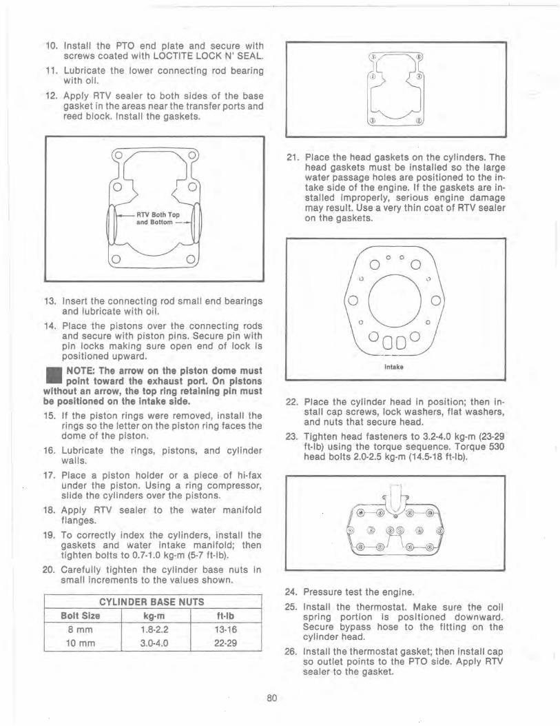
10. Install the PTa end plate and secure with screws coated with LOCTITE LOCK N' SEAL.
11. Lubricate the lower connecting rod bearing with oil.
12. Apply RTV sealer to both sides of the base gasket in the areas near the transfer ports and reed block. Install the gaskets.
RTV Both Top and Bottom ---
13. Insert the connecting rod small end bearings and lubricate with oil.
14. Place the pistons over the connecting rods and secure with piston pins. Secure pin with pin locks making sure open end of lock is positioned upward.
II NOTE: The arrow on the piston dome must point toward the exhaust port. On pistons
without an arrow, the top ring retaining pin must be positioned on the intake side.
15. If the piston rings were removed, install the rings so the letter on the piston ring faces the dome of the piston.
16. Lubricate the rings, pistons, and cylinder walls.
17. Place a piston holder or a piece of hi·fax under the piston. Using a ring compressor, slide the cylinders over the pistons.
18. Apply RTV sealer to the water manifold flanges.
19. To correctly index the cylinders, install the gaskets and water intake manifold; then tighten bolts to 0.7·1.0 kg·m (5·7 ft·lb).
20. Carefully tighten the cylinder base nuts in small increments to the values shown.
CYLINDER BASE NUTS
Bolt Size kg·m ft·lb 8 mm 1.8·2.2 13·16 10 mm 3.0·4.0 22·29
80
21. Place the head gaskets on the cylinders. The head gaskets must be installed so the large water passage holes are positioned to the in· take side of the engine. If the gaskets are in· stalled improperly, serious engine damage may result. Use a very thin coat of RTV sealer on the gaskets.
Intake
22. Place the cylinder head in position; then in· stall cap screws, lock washers, flat washers, and nuts that secure head.
23. Tighten head fasteners to 3.2·4.0 kg·m (23·29 ft·lb) using the torque sequence. Torque 530 head bolts 2.0·2.5 kg·m (14.5·18 ft·lb).
24. Pressure test the engine.
25. Install the thermostat. Make sure the coil spring portion is positioned downward. Secure bypass hose to the fitting on the cylinder head.
26. Install the thermostat gasket; then install cap so outlet points to the PTa side. Apply RTV sealer to the gasket.

27. Install the magneto case. Apply LOCTITE LOCK N' SEAL to the eight screws and tighten with an impact screwdriver.
28. Move the stator plate into position. Align the marks noted during disassembly; then tighten the two socket-head screws.
II NOTE: If no marks were made during dis· assembly, refer to Checking Ignition Timing
section.
29. Tighten the wiring harness clamp.
30. Make sure woodruff key is in place. Check to ensure the flywheel magnets are clean; then install flywheel. Install spacer, lock washer, and nut.
31. Install the belt, belt pulley, and starter cup. Using the spanner wrench to hold flywheel, tighten flywheel nut to 6.8-8.7 kg-m (49-63 ftIb). Then tighten starter cup bolts to 0.8-1.0 kg-m (5-7 ft-Ib).
32. Check belt deflection. Deflection should be no more than 6 mm (1f4 in.) at midspan. Belt tension can be adjusted with the bolt located on the rear side of the water pump housing.
33. Install the belt cover and tighten all screws.
34. Connect hose to water intake manifold and tighen clamp.
35. Install recoil. Install the engine. (Refer to Install Engine section).
CHECK ENGINE SEALING
In a two-stroke engne it is extremely important that there are no air leaks in the engine. An air leak may result in poor engine performance, overheating, or severe engine damage. To check the engine, either a homemade or commercial tester may be used. The Arctic Pressure Tester Kit (pin 0144-127) may be ordered from Arctco, Inc. The kit includes the necessary plugs, plates, adapters, and pump to completely pressure check an engine.
A homemade tester can be constructed of various fittings, a valve, and a gauge.
1. Install port plugs or covers on both the intake and exhaust ports.
2. Depending on the type of tester, connect tester to engine. Make sure all other engine openings are plugged (spark plug holes, impulse line, etc.).
3. USing a pump, pressurize the crankcase to 12 pounds and close the valve. DO NOT exceed 15 pounds of pressure or seals will be damaged.
4. Watch the gauge and determine the rate of leakage. Pressure must not drop more than one pound per minute per cylinder.
81
5. If the pressure drops more than the acceptable rate, check for leaks with soapy water and a brush or completely submerge the engine in water (engine pressurized only). Bubbles will identify any leak. Repair any leaks.
II NOTE: When engine Is submerged for a pres· sure test, be sure the electrical components
have not been Installed.
6. If the tester is capable of vacuum testing, check engine for vacuum leaks. DO NOT submerge engine for this test.
7. To locate a vacuum leak, apply an oil film along all sealing surfaces while watching gauge needle for movement. A stop of needle movement would mean location of leak has been found. Correct any leaks.
8. Proceed to assemble engine.
INSTALLING ENGINE
1. Install engine plate; then tighten cap screws to 7.6 kg-m (55 ft-Ib).
2. Set engine into motor mounts; then secure with cap screws. Tighten cap screws to 3.2 kg-m (23 ft-Ib).
3. Connect the fuel pump impulse lines in the crankcase fittings.
4. Connect the main ignition harness; then connect the ignition coil harness.
5. Connect the upper radiator hose to the thermostat cap.
6. Connect the lower hose to the water pump fitting.
7. Move the carburetors into position. Tighten the intake flange clamps and the connector clamps.
8. Install the oil line on injection pump and secure with clamp.
9. Install oil injection cable and check adjust-ment.
10. Install the spark plug caps on the plugs.
11. Secure the exhaust chambers to the engi ne.
12. Install drive clutch.
13. Fill the cooling system with coolant.
14. Check clutch alignment; then install drive belt.
15. Check engine timing.
16. Test drive snowmobile checking all aspects of operation.

650 ENGINE SPECIFICATIONS & TORQUE SPECIFICATIONS
ITEM SPECIFICATION ITEM
Peak RPM Range 8,250-8,500 Cylinder Head 8 mm ft-Ib Spark Plug BR10EV kg-m
Spark Plug Gap mm 0_7 in. 0.028
Cylinder Base 10 mm ft-Ib kg-m
Lighting Coil Output 12V/150W 8 mm ft-Ib
kg-m Ignition Type CDI Flywheel ft-Ib Piston Skirt Cylinder mm 0.07-0.15 kg-m Clearance Range in. 0.0028-0.006 Exhaust Manifold ft-Ib
Piston Ring End Gap mm 0.20-0.80 Intake Flange kg-m Range in. 0.0080-0.0337 Flywheel Housing ft-Ib
Maximum Cylinder mm 0.1 kg-m Trueness Limit in. 0.0039 Crankcase 6mm ft-Ib
Piston Pin Diameter mm 19.995-20.000 kg-m Range in. 0.7870-0.7874 8mm ft-Ib
Piston Pin Bore mm 19.996-20.006 Diameter Range in. 0.7871-0.7876
kg-m 10 mm ft-Ib
kg-m ConnectiHg Rod Small mm 20.002-20.010
End Diameter in. 0.7875-0.7878 Spark Plug ft-Ib kg-m
Crankshaft Runout (TIR) mm 0.05 in. 0.0020
Crankshaft End Play mm 0.05-0.10
Drive Clutch ft-Ib kg-m
Range in. 0.002-0.004
Reed Stopper Height mm 7.6-8.0 in. 0.300-0.315
Ignition Timing (6000 mm 2.830 RPM with engine at in. 0.111 running temperature)
TORQUE PATTERNS
~0 ______ ~0 ~0 _______ 0~1
0727·158 0726-376
82
SPECIFICATION
13.0-20.0 1.8-2.8
29.0-43.5 4.0-6.0 13.0-16.0 1.8-2.2
65.0-79.5 9.0-11.0
13.0-16.0 1.8-2.2
13.0-16.0 1.8-2.8
6.0-9.0 0.8-1.2 13.0-16.0 1.8-2.2 29.0-43.5 4.0-6.0
18-20 2.5-2.8
47-50 6.5-6.9
1.
0727·491

SHIMMING THE 650 LIe PINION GEAR
There are two shim charts available for setting the clearance on the pinion gear shaft. The chart below is to be used with the special tool pIn 0644-055. Measure clearance is shown in the illustration and then refer to the chart after taking your reading from the calipers. The specifications given in the chart below have the thickness of the service tool figured into the reading, so no additional subtracting is necessary to calculate shim thickness required.
CHART FOR 650 UC GEAR SHIMMING
Reading "8"
21.51 - 21.6 21.61 - 21.7 21.71 - 21.8 21.81 - 21.9 21.91 - 22.0 22.01 - 22.1 22.11 - 22.2 22.21 - 22.3 22.31 - 22.4 22.41 - 22.5 22.51 - 22.6
Shimming Tool
Caliper
Shim Reading "8"
1.0 22.61 - 22.7 1.1 22.71 - 22.8 1.2 22.81 - 22.9 1.3 22.91 - 23.0 1.4 23.01 - 23.1 1.5 23.11 - 23.2 1.6 23.21 - 23.3 1.7 23.31 - 23.4 1.8 23.41 - 23.5 1.9 23.51 - 23.6 2.0
Top Side of Crankcase
Shim
2.1 2.2 2.3 2.4 2.5 2.6 2.7 2.8 2.9 3.0
Pinion Gear, Shaft, Bearing, and Drive Gear
0727·556
When using the shim chart found in the 1988 Service Manual, you must subtract the thickness of the tool being used to calculate correct shim size.
83

CRANKSHAFT REPAIR For the 1990 season, Suzuki has provided Arctco with some valuable information concerning crankshaft repair_
For those of you who have your crankshaft work sent out to another shop, you may want to provide them with this information.
To use the specifications on page 52, first refer to the drawing. Find the letter which indicates the specification you are interested in and then refer to the chart below. Be sure to note the proper engine column. Specifications are called out in both millimeters and inches.
NOTE: For the past several years, we have always given the proper location for checking crankshaft runout as the very edge of the straight portion of the shaft where the oil seal makes contact. From the drawing below, you will note that Suzuki has called out 3 check points. At either end, out on the taper as shown and also on the center bearing race. The crankshaft is still supported on the outer bearings using v-blocks. The maximum runout seen shouldn't exceed 0.05 mm (.002 in).
Notice Service Department
Don't forget Arctco's Special Services Department does factory Crankshaft and engine rebuilding on all Suzuki Arctic Cat Motors.
For shipping instructions and pricing, contact me at Extension 189_
M N 1·800·862·9598 US 1·800·328·5694
»aAo.~ Special Services Department
84

- ArtB! -
n~ t Ii ~ ~
r E-
,"'" " ~ lDI G -1---
r~ F4~ ~ 1 r TliirimiJin c
-- - ----- - -Li
~ ~",(E! lJl!m I
~F~ 6 ~ J - -- --
,"""," '--- ~ ~VL
I 0728·144
Bore X Run Out Model Stroke A B C G D, E, F Point
440F/C-CI (±002)
AF44A mm 65 X 65 100 ± 0.015 55 ± 0.01 100 22 o 35 IF 15
AK44A (in.) (3.937 ± .0005) (2.165 ± .0003) (3.937) (.866) (1.377) (590)
500UC-E (± .002)
AH50L mm 70 X 65 103 ± 0.02 60 ± 0.02 102 24 o 30 IF 10
(in.) (4055 :!: .0007) (2362 ± .0007) (4.015) (.944) (1.181) (393)
60F/C (± 002)
AA06A mm 41 X 45 - - 34 ± 0.02 74 16 o 32.5 IF 26
(in.) (1.338 ± .0007) (2913) (.629) (1.279) (1.023)
340F/C-CI (± .002)
AF34A mm 60 X 60 93 ± 0.015 53 ± 0.015 94 22 o 35 IF 15
(in.) (3.661 ± .0005) (2.086 ± _0005) (3.700) (.866) (1.377) (.590)
500F/C-CCI (± .002)
AL50A mm 70 X 65 103 ± 0.02 55 ± 0.02 100 22 o 35 IF 15
(in.) (4.055 ± .0007) (2.165 ± .0007) (3.937) (.866) (1.377) (.590)
500F/C·E (± .002)
AM50A mm 70 X 65 103 ± 0.02 55 ± 0.02 100 22 0 35 IF 15 (in.) (4.055 ± .0007) (2.165 ± .0007) (3.937) (.866) (1.377) (.590)
440UC-CI (± .002)
AH44L mm 68 X 60 103 ± 0.02 60 ± 0.2 102 24 0 30 IF 10 (in.) (4.055 ± .0007) (2 .362 ± .007) (4.015) (.944) (1.181) (.393)
530UC (± .002)
AA53L mm 72 X 65 103 ± 0.02 60 ± 0.2 102 24 0 30 IF 10 (in.) (4.055 ± .0007) (2.362 ± .007) (4.015) (.944) (1.181) (.393)
650UC (± .002)
AA65L mm 78 X 68 130 ± 0.05 64 ± 0.015 116-0.2 28 o 35 IF 15 (in.) (5.118 ± .002) (2.519 ± .0005) (4.566 - .007) (1.102) (1.377) (.590)
440UC-LW (± .002)
AJ44L mm 68 X 60 106 ± 0.02 55 ± 0.015 94·0.4 22 o 30.5 r 10 (in.) (4.173 ± .0007) (2.165 ± .0005) (3.700 - .015) (.866) (1.200) (.393)
NOTE: Measure in from the shaft end the specified amount, when checking runout at points o . F. When checking runout in the center, place indicator on center of bearing as shown in Point E. Maximum runout at any of the 3 measuring points is ± .05 mm (.002 in).
85
• -,- --
1989 AND 1990 ENGINE SPECIFICATIONS
CYLINDER HEAD SQUISH VOLUME
Listed below, you will find both the squish gap clearance and cc volume for the engine cylinder head combustion area.
To check the cylinder head volume and squish , follow the procedures that are outlined below.
Squish Gap
To check the squish gap, you will need a micrometer and a heavy piece of solder.
Procedure 1. Remove the spark plugs from the engine.
2. Insert solder down through the spark plug hole and push it up against the inner cylinder bore, towards the recoil side of the engine.
3. Pull the recoil rope and turn the engine over several times while solder is being held firmly in place.
4. Remove the solder from the cylinder. Using the micrometer, measure the very end of the squeezed solder piece. Record your read ing.
NOTE: If you find that the solder hasn't been squeezed by the piston , you will need a piece of solder with a larger diameter. Repeat procedure.
5. Using the opposite end of the solder piece, insert it down through the spark plug hole towards the PTO side of the engine . Push on the solder until you feel it contact the inner cylinder bore.
6. Pull the recoil rope and turn the engine over several times. Remove the solder from the cylinder and measure the squeezed end with a micrometer. Record reading and refer to chart below.
NOTE: You must measure from PTO to mag side of the piston to accurately measure the squish gap. Never measure across piston, exhaust to carburetor side, as the piston will rock and your reading won 't be accurate.
Your readings may vary from side to side. Make sure your smaller reading is within the specifications listed below.
Checking CC Volume
To check the cc volume, you will need a measuring tool called a Buret. It is capable of measuring a liquid in cc volumes.
Procedure 1. Fill buret with No. 10W engine oil.
2. Remove the spark plugs from the cylinders.
3. Run piston up to T.D.C. (Top Dead Center).
4. Insert buret into spark plug hole and open buret valve. Run oil into the spark plug hole until it reaches the top of the spark plug hole. Turn off the buret valve.
5. Check the buret scale to see how much oil has been used to fill the combustion chamber. From the total amount, subtract 2.2 cc. Compare your findings with the chart found on page 54.
86
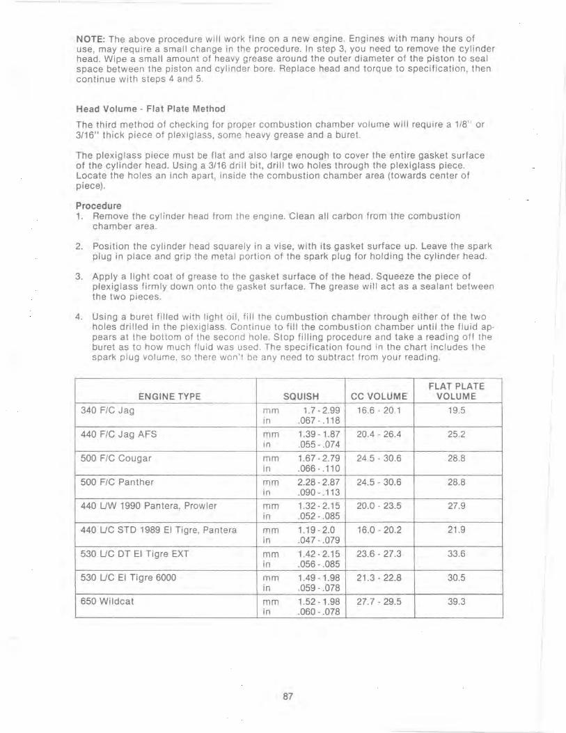
1
NOTE: The above procedure will work fine on a new engine. Engines with many hours of use, may require a small change in the procedure. In step 3, you need tp remove the cylinder head. Wipe a small amount of heavy grease around the outer diameter of the piston to seal space between the piston and cylinder bore. Replace head and torque to specification, then continue with steps 4 and 5.
Head Volume - Flat Plate Method
The third method of checking for proper combustion chamber volume will require a 1/8" or 3/16" thick piece of plexiglass, some heavy grease and a buret.
The plexiglass piece must be flat and also large enough to cover the entire gasket surface of the cylinder head. Using a 3/16 drill bit, drill two holes through the plexiglass piece. Locate the holes an inch apart, inside the combustion chamber area (towards center of piece).
Procedure 1. Remove the cylinder head from the engine. Clean all carbon from the combustion
chamber area.
2. Position the cylinder head squarely in a vise, with its gasket surface up. Leave the spark plug in place and grip the metal portion of the spark plug for holding the cylinder head.
3. Apply a light coat of grease to the gasket surface of the head. Squeeze the piece of plexiglass firmly down onto the gasket surface. The grease will act as a sealant between the two pieces.
4. Using a buret filled with light oil , fill the cumbustion chamber through either of the two holes drilled in the plexiglass. Continue to fill the combustion chamber until the fluid appears at the bottom of the second hole. Stop filling procedure and take a reading off the buret as to how much fluid was used. The specification found in the chart includes the spark plug volume, so there won't be any need to subtract from your reading.
FLAT PLATE ENGINE TYPE SQUISH CC VOLUME VOLUME
340 FIC Jag mm 1.7-2.99 16.6-20.1 19.5 in .067 - .118
440 FIC Jag AFS mm 1.39 - 1.87 20.4 - 26.4 25.2 in .055 - .074
500 FIC Cougar mm 1.67 - 2.79 24.5 - 30.6 28.8 in .066 - .110
500 FIC Panther mm 2.28 - 2.87 24.5 - 30_6 28.8 in .090 - .113
440 UW 1990 Pantera, Prowler mm 1.32 - 2.15 20.0 - 23.5 27.9 in .052 - .085
440 UC STD 1989 EI Tigre, Pantera mm 1.19 - 2.0 16.0 - 20.2 21.9 in .047 - .079
530 UC DT EI Tigre EXT mm 1.42 - 2.15 23.6 - 27.3 33.6 in .056 - .085
530 UC EI Tigre 6000 mm 1.49-1.98 21.3 - 22.8 30.5 in .059 - .078
650 Wildcat mm 1.52 -1.98 27.7 - 29.5 39.3 in .060 - .078
87
, I'
I: I
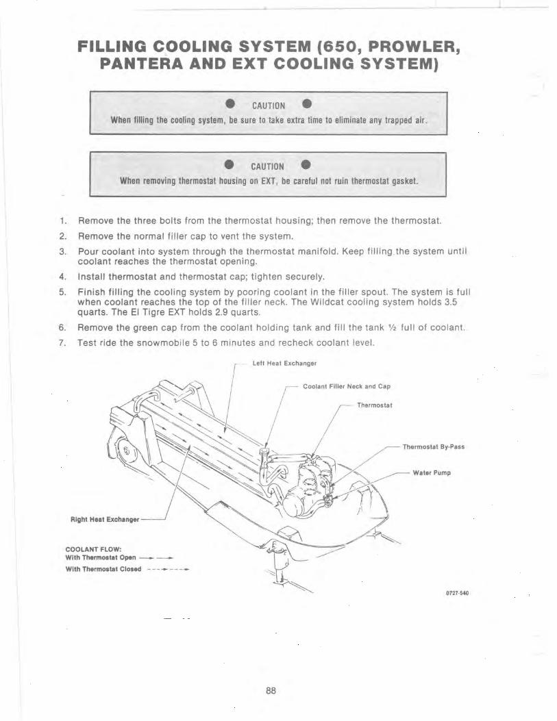
,.1,. ____ ........ ___ _
--~---
FILLING COOLING SYSTEM (650, PROWLER, PANTERA AND EXT COOLING SYSTEM)
• CAUTION •
When filling the cooling system, be sure to take extra time to eliminate any trapped air.
• CAUTION •
When removing thermostat housing on EXT, be careful not ruin thermostat gasket.
1. Remove the three bolts from the thermostat housing; then remove the thermostat.
2. Remove the normal filler cap to vent the system.
3. Pour coolant into system through the thermostat manifold. Keep filling . the system until coolant reaches the thermostat opening.
4. Install thermostat and thermostat cap; tighten securely.
5. Finish filling the cooling system by pooring coolant in the filler spout. The system is full when coolant reaches the top of the filler neck. The Wildcat cooling system holds 3.5 quarts. The EI Tigre EXT holds 2.9 quarts.
6. Remove the green cap from the coolant holding tank and fill the tank 1/2 full of coolant .
7. Test ride the snowmobile 5 to 6 minutes and recheck coolant level.
Right Heat Exchanger
COOLANT FLOW: With Thermostat Open - -
With Thermostat Closed - - - - - - - -
Left Heat Exchanger
88
/ Coolant Filler Neck and Cap
Thermostat
Thermostat By·Pass
Water Pump
0727·540

NOTE: The above procedure will work fine on a new engine. Engines with many hours of use, may require a small change in the procedure. In step 3, you need to remove the cylinder head. Wipe a small amount of heavy grease around the outer diameter of the piston to seal space between the piston and cylinder bore. Replace head and torque to specification, then continue with steps 4 and 5.
Head Volume - Flat Plate Method
The third method of checking for proper combustion chamber volume will require a 1/8" or 3/16" thick piece of plexiglass, some heavy grease and a buret.
The plexiglass piece must be flat and also large enough to cover the entire gasket surface of the cylinder head. Using a 3/16 drill bit, drill two holes through the plexiglass piece. Locate the holes an inch apart, inside the combustion chamber area (towards center of piece).
Procedure 1. Remove the cylinder head from the engine. Clean all carbon from the combustion
chamber area.
2. Position the cylinder head squarely in a vise, with its gasket surface up. Leave the spark plug in place and grip the metal portion of the spark plug for holding the cylinder head.
3. Apply a light coat of grease to the gasket surface of the head . Squeeze the piece of plexiglass firmly down onto the gasket surface. The grease will act as a sealant between the two pieces.
4. Using a buret filled with light oil , fill the cumbustion chamber through either of the two holes drilled in the plexiglass. Continue to fill the combustion chamber until the fluid appears at the bottom of the second hole. Stop filling procedure and take a reading off the buret as to how much fluid was used. The specification found in the chart includes the spark plug volume, so there won't be any need to subtract from your reading .
FLAT PLATE ENGINE TYPE SQUISH CC VOLUME VOLUME
340 FIC Jag mm 1.7 - 2.99 16.6 - 20.1 19.5 in .067-.118
440 FIC Jag AFS mm 1.39-1 .87 20.4 - 26.4 25.2 in .055 - .074
500 FIC Cougar mm 1.67 - 2.79 24.5 - 30.6 28.8 in .066 - .110
500 FIC Panther mm 2.28 - 2.87 24.5 - 30.6 28.8 in .090 - .113
440 UW 1990 Pantera, Prowler mm 1.32-2.15 20.0 - 23.5 27.9 in .052 - .085
440 UC STD 1989 EI Tigre, Pantera mm 1.19 - 2.0 16.0 - 20.2 21.9 in .047 - .079
530 UC DT EI Tigre EXT mm 1.42 - 2.15 23.6 - 27.3 33.6 in .056 - .085
530 UC EI Tigre 6000 mm 1.49 - 1.98 21 .3 - 22.8 30.5 in .059 - .078
650 Wildcat mm 1.52 -1.98 27.7 - 29.5 39.3 in .060 - .078
87

FILLING COOLING SYSTEM (650, PROWLER, PANTERA AND EXT COOLING SYSTEM)
• CAUTION •
When filling the cooling system, be sure to take extra time to eliminate any trapped air.
• CAUTION •
When removing thermostat housing on EXT, be careful not ruin thermostat gasket.
1. Remove the three bolts from the thermostat housing; then remove the thermostat.
2. Remove the normal filler cap to vent the system.
3. Pour coolant into system through the thermostat manifold. Keep filling . the system until coolant reaches the thermostat opening.
4. Install thermostat and thermostat cap; tighten securely.
5. Finish filling the cooling system by pooring coolant in the filler spout. The system is full when coolant reaches the top of the filler neck. The Wildcat cooling system holds 3.5 quarts. The EI Tigre EXT holds 2.9 quarts.
6. Remove the green cap from the coolant holding tank and fill the tank '/2 full of coolant.
7. Test ride the snowmobile 5 to 6 minutes and recheck coolant level.
Right Heat Exchanger
COOLANT FLOW: With Thermostat Open - -
With Thermostat Closed - - - - - - --
- left Heat Exchanger
88
/ Coolant Filler Neck and Cap
I Thermostat
Thermostat By·Pass
Water Pump
0727·540

1990 DRIVE SYSTEM C·HANGES
Drive Clutch· Comet 108 (All models except EXT & Wildcat)
The drive clutch used on most all 1990 models (except 340 Jag) have undergone some changes and improvement.
The stationary and moveable sheave angles have been changed to a straight 13V2 degree angle. The 1989 108c drive clutch was a compound angle of 12% to 14°. When comparing the compound versus the straight angle sheaves, performance is nearly equal. The advantage of the straight angle sheave is improved drive belt life and a smoother shift pattern.
The drive belt part number has also changed for 1990. The dimensions (width and length) are the same as they were in 1989. The only difference is the belt side angles. The new belt part number used on all 1990 models with the Comet drive clutch is 0227·103. There is one exception, however, the Wildcat will again use the high performance drive belt (pin 0627-006).
It must be kept in mind when making repairs on the new 108c, that you do not install a compound angle stationary or movable sheave with a new straight angle sheave. Use only those part numbers called out in the 1990 parts books whE!n making any repairs -to the Comet drive clutch.
Another improvement made to all 108c drive clutches is the washer material on either side of the rollers. It will be a very hard plastic washer, which has improved the washer life.
Comet 108c (Wildcat· EXT· Prowler - Pantera)
The new drive clutch on the 1990 EXT, Prowler, Pantera and Wildcat is different from the other models in the way it is secured to the engine. On all models except for these four , the drive clutch will be secured using the standard method of a clutch bolt and large washer.
The method used on the new 108c is a new clutch bolt, which is 1" shorter and is recessed down into the stationary shaft, approximately the same amount. From the tapered bore side. a urathane spacer, followed by an aluminum spacer are both placed onto the clutch bolt before installing the drive clutch onto the engine .'
With the clutch on the crankshaft, torque the clutch bolt using a 12 point, V2 socket to 6.9-7.6 kg-m (50-55 ft-lb). The therory behind the newly designed clutch bolt set-up (see illustration below) is, the aluminum spacer gets forced against the urathane spacer by the end of the crankshaft, as the clutch bolt is torqued down. The urathane spacer then squeezes and secures the clutch bolt within the stationary bore. This eliminates bolt vibration and reduces bolt breakage.
Clutch Pullers· Comet
Retainer Cap Lock Washer
Flat Washer __ Lock Washer
Clutch Bolt Urathime Spacer
_ .. ,umlO,um Spacer
III. 0728·179
Because of the new Comet drive clutch used on these models, a new clutch puller will be required. The new cluch puller part number is 0644-096 and can be ordered through the Arctco's Parts Department. This puller will only be used on these four (EXT, Wildcat, Prowler, Pantera) models.
89

SUMMER STORAGE CHECKLIST (General Inspection of Machine)
Following this list is a sample letter which may be sent out by your dealership to all of your customers to alert them of your summer storage service special.
1. Check all lights for proper operation.
2. Check all switches for proper operation.
3. Remove seat; then clean tunnel and seat.
4. Clean snowmobile by hosing dirt, oil, and other foreign matter from engine compartment and skid frame.
5. Start engine and allow it to idle with air boots removed or pulled back. Inject Engine Preserver (pIn 0636-177) into the carburetor(s) for a period of 10 to 20 seconds or unt il engine almost stops. This will protect all crankshaft parts . Stop engine.
6. With ignition key in the OFF position:
a. Disconnect spark plug wires from spark plugs and remove spark plugs.
b. Pour 1 fl. oz. of SAE #30 petroleum-based oil into each spark plug hole and pull the recoil handle slowly about ten times. This will coat the cylinder walls with oil.
c. Install spark plugs and connect spark plug caps.
7. Drain .fuel tank. Remove the float bowl plug from each carburetor and completely drain the carburetor and wipe the plug dry. Install float bowl plugs. Install air boots on carburetor(s) . Snap throttle full open and release several times to make sure cable(s) are working properly.
8. Grease all fittings on front end and skid frame as shown (under lubrication) in the Operator's Manual.
9. Check chain case lubricant.
10. Apply light o i l to the upper steering post bushing .
11. Remove drive belt and clean clutch sheaves of any rubber buildup. Place belt on flat surface or in cardboard belt sleeve.
12. Check all nuts, bolts, and screws. Care must be taken to tighten all calibrated nuts and bolts to specifications.
Dear ________________ __
The end of the season is fast approaching and it is time to think about storing your Arctic Cat for the summer months.
Along these lines, it is very important that certain precautions be taken to assure that there won't be any problems starting out next season. Our service shop is prepared to complete the summer storage check on your machine at the special price of $ . This will assure you a successful snow season next year.
All you need to do is give us a call and make an appointment. We are most anxious to provide this service for you.
Best regards!
Sincerely,
90
ENGINE SERVICE NOTES
340 F/C:
EXTERNAL COIL External coil leads have been increased in diameter for added strength.
No other changes from last season.
440 F/C:
EXTERNAL COIL External coil leads are larger in diameter for additional strength.
CRANKCASE The crankcase has a flat area molded into the left side of the case to support the rubber snubber. The rest of the engine is the same as last year. This engine has proven to be very reliable .
500 F/C:
EXTERNAL COIL The external coil has been moved from the engine to the air silencer. It has been moved to this location to isolate it from engine vibration , which caused coil lead breakage.
530 EXT
IGNITION BACKING PLATE SCREWS The backing plate screws have been changed to 8mm in size. This was done to elimnate bolt breakage in this area.
CYLINDER AND HEAD The cylinder port timing has been changed for additional power. The cylinder head volume is smaller due to exhaust port change.
650 WILDCAT
PISTON AND RINGS There will be an improved piston for 1990. The ring locating pin has been placed in the ring groove center. In the past, it was located half in the ring groove and half in the ring land area. Because of this, the ring land will be stronger. A Molysteel ring is used in 1990 instead of cast iron as was used in the past.
CRANKCASE A flat area has been formed into the front of the crankcase for the snubber to seat against.
OIL PUMP The oil pump has been recalibrated for 1990. It will deliver less oil at lower throttle position.
91
-

AFTER THE BREAK·IN PERIOD (100 MILES)
We have seen where the 100 mile checkup offered by some of our dealers is a definite problem and warranty reducer. A program of this kind should be offered by dealerships. Many dealers have worked the price of the checkup into the selling price of the snowmobile and others offer it as a bonus to the customers who purchase snowmobiles from their dealership.
There are three areas that require adjustment after the break-in period in order to obtain peak performance. These areas are:
A. Jetting (only if above 2000 feet altitude) B. Drive belt deflection C. Track adjustment
Jetting· The main jet supplied in our '90 snowmobiles is the correct all around jet size, for an altitude of 0-2000 feet in most cases. If operating the machine above this range, the proper main jet size should be selected from the main jet chart that best suits your region's average temperature and altitude.
Drive Belt Deflection - Drive belt deflection is very important to the snowmobile low-end performance. Even if it is checked and is correct when the snowmobile is pre-delivered, it does change (more so during the break-in period). This is because the rubber engine mounts and the rubber snubber on the torque link will all take a "set" during the first 100 miles, which allows the distance between the drive clutch and driven pulley to shorten. When this happens, the snowmobile will appear to have too long a drive belt. To add to this problem, the drive belt itself wears and stretches somewhat. This all leads to a low-end performance problem and, if not corrected, premature drive belt failure.
After the break-in period, drive belt deflection should be checked according to the instruc· tions given in this manual. To correct for too much deflection, washer(s) from between the driven pulley sheaves can be removed to "tighten the drive belt " and allow the belts to return to the proper ratio for drive clutch engagement.
Track Adjustment - There is a certain amount of track stretch on all of our snowmobiles during the first 500 miles. The track must be adjusted after the first 100 miles to the specifica· tions given in the Set-Up Manual and periodically thereafter. If these adjustments aren't performed, the customer may derail a track, which leads to track and slide rail damage. Along with these three major areas there are also other areas that should be checked and adjusted during the "After Break-In Checkup". A checklist to assist you with this service follows. Not only will you have a happier customer, but it also gets your customer back into your dealership which, in many cases, will mean additional sales in accessories, belts, oil, etc.
92

AFTER BREAK·IN CHECKUP CHECKLIST
o Jet carburetor(s) according to average temperature and altitude if above 2000 feet
0 Adjust drive belt deflection
0 Adjust track tension
0 Adjust throttle cable tension
0 Check oil pump adjustment
0 Check engine idle
0 Check coolant level
0 Check chain case lubricant level
o Check lights (high-low beam, brake light)
o Check safety switch operation
o Check driveshaft area for any rubbing components
o Check steering hardware for tightness
o Check skid frame mounting hardware for tightness
o Check brake lever travel and adjustment
o Grease all lubrication pOints
93

Fuel Pump
FUEL PUMP TEST PROCEDURE Preliminary Checks
1. Make sure there is adequate fuel in the fuel tank.
2. Make sure all lines are clear and free of kinks and obstructions.
3. Make sure all fuel filters are not plugged or damaged.
4. Make sure fuel and impulse lines are in good condition.
5. Make sure there is evidence of good impulse at the crankcase impulse fitting.
Fuel Pump Pressure
1. Connect pressure gauge between fuel pump and carburetor using a piece of fuel line and a "tee" .
2. Place snowmobile on a safety stand. Start engine. At the following engine speeds, the specified pressures must be indicated.
94
rpm psi g/cm2
1000-2000 3.0-3.5 200-240 3000-4000 4.5-5.5 310-375 5000-6000 6.0-7.0 420-490
3. Remove gauge, lines, and connect fuel line to carburetor.
Fuel Pump Vacuum
1. Disconnect fuel pump inlet line (from gas tank) and plug line.
2. Connect vacuum gauge directly to the fuel pump inlet fitting.
3. With snowmobile on a safety stand, start engine and accelerate to 2000-3000 rpm for a period of 30 seconds. Note maximum reading of gauge. Reading must be within the range listed.
II NOTE: Make sure adequate fuel is in the carburetor for this test.
Acceptable Fuel Pump Vacuum
Model in. Hg mm Hg
All 7-10 175-250
4. Stop engine. Connect fuel inlet line.

r
Carburetion
General
This section contains theory, specifications and proper tuning for the Mikuni carburetor. It is strongly recommended that one carburetor be removed from the snowmobile to use as visual reference while studying this section.
• CAUTION •
If the air silencer box is removed from the carburetors, the change in pressure in the intake system will create a lean mixture that could cause engine failure. The air silencer box must be secured to the carburetors during carburetor tuning and adjustment and must always be in place when the engine is operated. Examine the silencer box regularly for cleanliness and freedom from obstruction.
Mlkuni Carburetor Theory
In Mikuni VM-type carburetors, different fuel mixing components function according to throttle opening (position of throttle slide) and each system is tuned accordingly. The 5 systems and their range of effectiveness, as the throttle slide moves from closed to full open position are illustrated below.
THROTILE VALVE OPENING
~4--------~~--~~-------,~~ 112 - - ___ ......... ----I .... !t------....--~I-
114~~~~ 118
Pilot Air Screw and Air Jet Throttle Vallie
Jet Needle -------' Needle Jet --------'
Main Jet ---- --'
0725·295
95
Pilot Jet and Pilot Air Screw
Pilot jets available from Arctco range from no. 17.5 (leanest) to no. 55 (richest) in increments of 5. The pilot air screw is an adjustable metering device that meters air mixing with fuel from the pilot jet. Normal tuning start procedure calls for the pilot air screw to be opened one (1) full turn from the closed position.
Before beginning this pilot system tuning procedure, make sure the throttle slide is resting against the idle adjusting screw when the throttle is closed. This can be checked visually by looking through the carburetor bore.
Needle Jet
Air Screw Assembly
0725·297
Raise the back of the snowmobile using a safety stand. Start engine and allow time for a complete warm-up.
Slowly turn the throttle stop screw clockwise until a point is reached where rpm increases to 300-500 rpm higher than your chosen idle speed.
Turn the air screw in or out in % to % increments until engine rpm reaches its maximum. Clockwise rotation enriches the air/fuel mixture, counterclockwise rotation leans the air/fuel mixture.
- Turn the throttle stop screw counterclockwise to obtain the desired speed for idling and repeat adjustment of air screw, turning it in or out in % to % turn increments until a maximum engine speed is obtained. If engine speed increases more than needed for idling, lower rpm with throttle stop screw and repeat air screw adjustment until idle is satisfactory.
Turn engine off.
Carefully turn the air screw clockwise until it bottoms, counting the number of turns it takes to close completely. DO NOT FORCE THE AIR SCREW. If it takes 2% turns or more, the pilot jet is too large and must be replaced by a smaller jet (smaller number).

- If a change of pilot jet is found to be necessary from the above procedure, start the tuning procedure from the beginning to obtain the proper adjustment.
Pilot Jet/Air Screw Diagnosis
Smooth idle is not the best indication of proper pilot tuning. If the jetting is too lean, engine speed will not pick up smoothly, especially at small throttle openings. If exhaust smoke is heavy and exhaust sound is dull at small throttle openings, the pilot is too rich. The first 10-15% of throttle response is determined in part by the piot jet and air screw setting.
Throttle Slide Cutaway
The amount of throttle slide cutaway affects the air/fuel mixture from idle to % throttle. Slides available from Arctco are listed by carburetor size (mm) and by numbers stamped on the slide (1.5, 2.0, 2.5, etc.) that indicate the degree of cutaway on the slide bottom. The cutaway also controls the point at which the main fuel system takes over from the pilot idle system. Larger slide numbers indicate a greater cutaway and a leaner mixture.
t / Cutaway
0725·265
Tuning procedure. Watch for clean part-throttle acceleration.
- Start the engine and allow time for a complete warm-up.
- Accelerate from a stop at % throttle setting. If the engine hesitates, or spitback occurs, a lean condition exists due to a too-large throttle cutaway. Correct the condition with a smallernumbered throttle slide.
If the engine drags or four-cycles when accelerating under a % throttle, a rich condition exists due to a too-small throttle cutaway. If this condition is experienced, turn the pilot air screw out one full turn, but never more than 3 turns total. If this does not correct the problem, go to a larger throttle slide.
Throttle Slide Diagnosis
Clean acceleration from the idle positon to % throttle will usually indicate the correct throttle slide cutaway. However, if the pilot air screw has a significant effect on engine performance, the throttle valve has the wrong cutaway and must be changed.
~6
Jet Needle Size and Position
Grooves
Upper
i Taper Total Length
Lower
i Taper
0725·299
The size and position of the jet needle affects the air/fuel mixture from approximately % to % throttle. Jet needles available from Arctco use a four figure code (like 50P?) to indicate mixture characteristics:
First Number - designates the total length of the needle, the larger the number the longer the needle. The 5 indicates a needle at least 50 mm long, but not as long as 60 mm.
Letters - the letters in the middle of the fourfigure code indicate the taper of the needle. The first letter indicates the taper on the upper part of the needle, the second letter indicates taper on the lower part of the needle. For example, the letter "A" equals 0 0 15", the letter "G" equals 1 0 45", and so on. Later letters indicate more taper and richer fuel flow. The upper taper is effective at the top of the needle's operating range. The main fuel source is the jet into which the needle drops.
Second Number - refers only to manufacturer lot number and is not an adjustment factor.
Tuning Procedure: The needle works on a combination of POSTION and TAPER.
POSITION - On the top of the needle is a small Eclip that determines the position of the needle in the throttle assembly. Moving the E-clip to a higher notch lowers the needle in the jet and leans the mixture. If evidence of rich mixture is encountered, the clip should be moved to a higher notch; if a lean mixture exists the clip is moved down. Needle position should be the first check for mixture problems in the % to 3/4 throttle range. If short on notches either on the top or bottom when tuning for mid-range, a needle of different length and/or taper or a different needle jet is needed.
TAPER - The effect of the lower taper will be from near % to full throttle. This is where the transition between needle jet and main jet takes place and it is controlled by the sharp taper at the tip of the needle. Lean mixtures will cause engine heating and back-firing at near open throttle; rich mixtures are indicated by a lack of difference between near-open and full throttle and four-cycling under load.

Jet Needle Diagnosis
Adjustments to the jet needle have approximately a 10% effect on main jetting. Changes in main jetting will also have a 10% effect on the needle jetting. Most mid-range fine tuning will take the form of changes in the position of the needle and tuner's ability to identify rich and lean mixtures and adjust accordingly. Experience in the effects of these adjustments will demonstrate that midrange tuning is a step-by-step, change and test procedure.
Needle Jet
Needle Jet ____
0725·300
The needle jet is available from Arctco in various sizes. The needle jet works in conjunction with the jet needle. Because the needle jet orifice remains constant throughout the length of the jet, changing the jet will have a greater effect on midrange performance than a change in position of the needle. Needle jets available from Arctco are coded with a letter and a number stamped into the jet, such a N3 or 02 that indicate size of orifice.
Letter - designates the orifice size with earlier letters like "N" being smaller (and leaner) than a jet marked "0".
Number - designates the specific diameter of the jet with number 1 the leanest and 9 the richest.
Tuning Procedure: The needle and the jet work together to meter fuel for mid-range operation.
Needle jet tuning comes into play when adjusting the position of the needle itself is unsatisfactory. For example, if experiencing a rich condition with the E-clip on the needle in the top notch, a smaller orifice (earlier letter or lower number) in the needle jet will reduce overall fuel flow through the system and provide leaner tuning in each position with the same needle in place. A lean condition with the E-clip in the bottom notch indicates a need for a change to larger jet (later letter and/or lower number).
97
There will almost never be a need for changing the needle jet in stock applications. The stock engine is accurately calibrated to respond to mid-range tuning of the needle alone.
Needle Jet Diagnosis
Check the orifice of the needle jet regularly for possible blockage or plugging. Loss of power at 1f2 to % throttle or an impossible-to-tune lean condition when throttle is wide open can be indications of a dirty or mismatched needle jet.
Main Jet
0725-301
The main jet affects fuel mixture from % throtlle to wide-open. Main jets available from Arctco are coded in graduated steps of 10 starting at 120 and going through 720. The smaller numbers indicate lesser fuel flow and are for use in the smaller (mm) carburetors. The orifice size increases with the number. Normal tuning procedure requires a selection of main jets available for change-andtest procedure.
Tuning Procedure: Select the main jet for optimum wide-open performance.
Start engine and allow time for a complete warmup.
Run the snowmobile on a flat, hard-packed surface at full throttle. If the engine fails to pull full rpm or labors at full throttle, the main jet is too large (rich). Install the next lowest available jet size and repeat full throttle test. Continue to change jetting one size at a time until engine runs efficiently at full-open throttle. Check the condition of sparks plugs after each run to determine mixture.
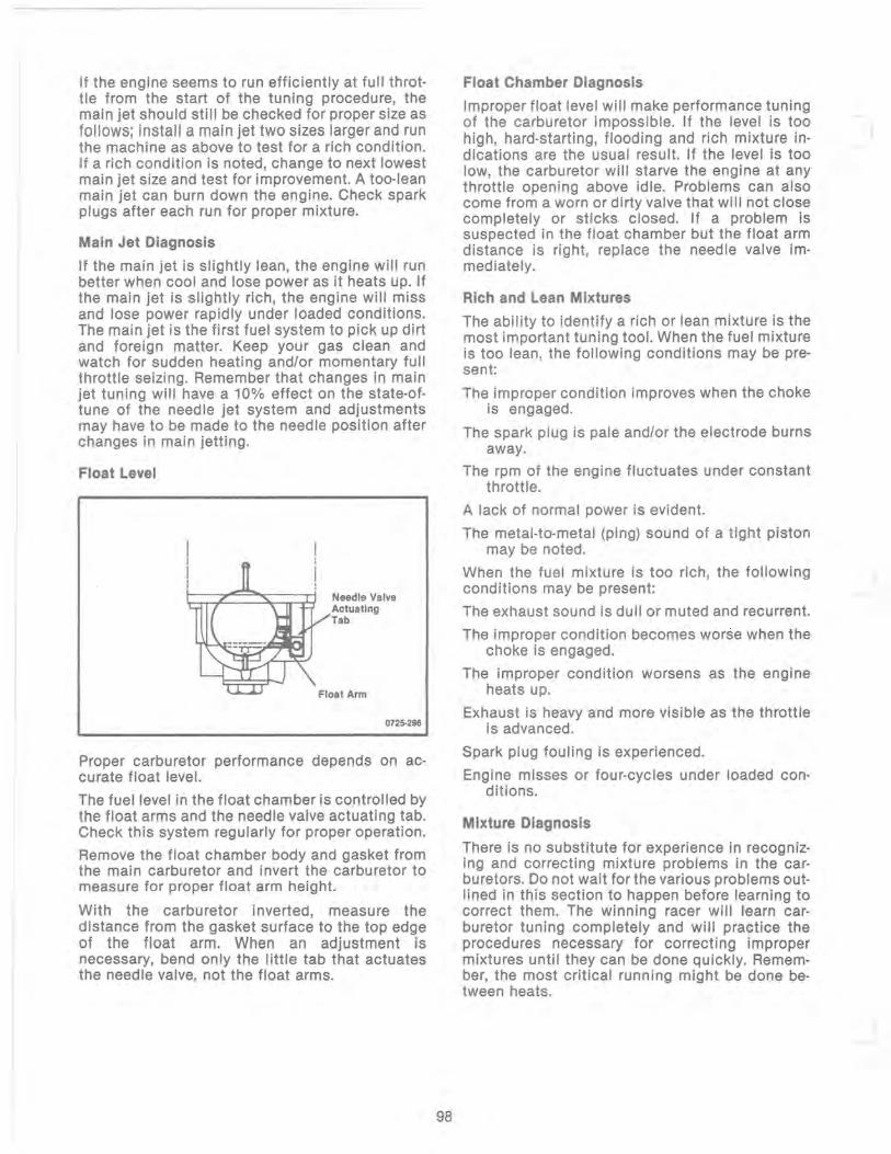
If the engine seems to run efficiently at full throttle from the start of the tuning procedure, the main jet should still be checked for proper size as follows; install a main jet two sizes larger and run the machine as above to test for a rich condition. If a rich condition is noted, change to next lowest main jet size and test for improvement. A too-lean main jet can burn down the engine. Check spark plugs after each run for proper mixture.
Main Jet Diagnosis
If the main jet is slightly lean, the engine will run better when cool and lose power as it heats up. If the main jet is slightly rich, the engine will miss and lose power rapidly under loaded conditions. The main jet is the first fuel system to pick up dirt and foreign matter. Keep your gas clean and watch for sudden heating and/or momentary full throttle seizing. Remember that changes in main jet tuning will have a 10% effect on the state-oftune of the needle jet system and adjustments may have to be made to the needle position after changes in main jetting.
Float Level
Needle Valve Actuating Tab
0725-296
Proper carburetor performance depends on accurate float level.
The fuel level in the float chamber is controlled by the float arms and the needle valve actuating tab. Check this system regularly for proper operation.
Remove the float chamber body and gasket from the main carburetor and invert the carburetor to measure for proper float arm height.
With the carburetor inverted, measure the distance from the gasket surface to the top edge of the float arm. When an adjustment is necessary, bend only the little tab that actuates the needle valve, not the float arms.
98
Float Chamber DiagnOSis
Improper float level will make performance tuning of the carburetor impossible. If the level is too high, hard-starting, flooding and rich mixture indications are the usual result. If the level is too low, the carburetor will starve the engine at any throttle opening above idle. Problems can also come from a worn or dirty valve that will not close completely or sticks closed. If a problem is suspected in the float chamber but the float arm distance is right, replace the needle valve immediately.
Rich and Lean Mixtures
The ability to identify a rich or lean mixture is the most important tuning tool. When the fuel mixture is too lean, the following conditions may be present:
The improper condition improves when the choke is engaged.
The spark plug is pale and/or the electrode burns away.
The rpm of the engine fluctuates under constant throttle.
A lack of normal power is evident.
The metal-to-metal (ping) sound of a tight piston may be noted.
When the fuel mixture is too rich, the following conditions may be present:
The exhaust sound is dull or muted and recurrent.
The improper condition becomes worse when the choke is engaged.
The improper condition worsens as the engine heats up.
Exhaust is heavy and more visible as the throttle is advanced.
Spark plug fouling is experienced.
Engine misses or four-cycles under loaded conditions.
Mixture Diagnosis
There is no substitute for experience in recognizing and correcting mixture problems in the carburetors. Do not wait for the various problems outlined in this section to happen before learning to correct them. The winning racer will learn carburetor tuning completely and will practice the procedures necessary for correcting improper mixtures until they can be done quickly. Remember, the most critical running might be done between heats.

USE OF TEMPERATURE/BAROMETRIC PRESSURE CHART
The chart is designed to take some of the guess work out of carburetor jetting. Because both temperature and barometric pressure directly affect main jet selection, use of the chart and following formulas will determine the correct main jet selection. Before the formula can be used, the snowmobile must be tuned for maximum performance on a given day. This will determine the baseline main jet and the baseline constant. To determine baseline values, set aside one day for thorough testing and calibration.
To determine baseline values:
1. Test drive snowmobile to achieve maximum performance. Consult carburetor theory section for calibration guidelines.
2. When correct main jet is decided upon, read both the thermometer and barometer. Mark down the readings.
3. Write down the main jet size. This will be referred to as the baseline main jet.
4. Using the chart, plot a point for the temperature versus barometric pressure. At that pOint, choose the nearest diagonal line and write down the corresponding value. This value is the baseline constant.
For example: At -10°F vs. 28.5 in. Hg = 1.10 (baseline constant) At 25°F vs. 29.5 in. Hg = 1.05 (baseline constant)
At this time we have determined the baseline main jet and the baseline constant. These two values will be used in calculating daily main jets at any temperature and barometric pressure.
99
To determine daily main jet:
1. Read thermometer for temperature.
2. Read barometer for barometric pressure.
II NOTE: Always use the same thermometer and barometer for carburetor calibration.
3. USing the chart, plot a point for the temperature versus barometric pressure. At that point, choose the nearest diagonal line and write down the corresponding value. This number is your daily constant.
4. Calculate the new main jet size using the following formula:
A x C = X Where A = Baseline Main Jet B B = Baseline Constant
C = Daily Constant X = New Main Jet
II NOTE: Round value X to the nearest main jet size (multiples of ten).
Example A: Baseline Baseline Temperature: -12°F Barometric Pressure: 29.0
Baseline Main Jet: 410
On race day:
Using chart, Baseline Constant = 1.125
Temperature: 15°F Barometric Pressure: 29.5 Using the chart, the Daily Constant = 1.075
To calculate the New Main Jet using the formula A x C = X
B
410 x 1.075 = X 1.125
391.8 = X Use a 390 Main Jet

LL o
-40
-30
-20
-10
o
10
20
30
40
50 31
--_.- -
30 29 28 27 26
BAROMETRIC PRESSURE (UNCORRECTED IN. OF MERCURy)
100
25

EXHAUST GAS TEMPERATURE
Wildcat
EI Tigre 6000
EI Tigre EXT (1990)
Prowler (1990)
Pantera (1990)
Jag 440 UC (1986-89)
Cougar
Panther (1988)
Jag AFS
Panther 440
1990 Prowler, Pantera
2.750 in. 1150 field 1250 max.
1990 EXT
2.750 In_ 1160 field 1250 max_
1989-90 Wildcat
6.750 in. 1220 field 1300 max.
1987-89 EI Tigre 6000
6.625 in. 1200 field 1300 max.
1989 EI Tigre EXT
2.625 in. 1105 field 1200 max.
1988-90 Cougar
3.0 in. 1230 field 1250 max.
Panther
2.5 in. 1230 field 1300 max.
Inches
6.750
6.625
2.750
2.750
2.750
2.625
3.0
2.5
2.5
2.5
1989-90 Jag 440 & 1990 Panther
2.5 in. 1150 field 1250 max.
Normal Pre-Ignition
mm F C F C
171 1220 660 1300 704
168 1200 649 1300 704
70 1160 627 1250 677
70 1150 621 1250 677
70 1150 621 1250 677
66 1112 600 1200 649
76 1230 666 1250 677
63 1230 666 1300 704
63 1150 621 1250 677
63 1150 621 1250 677
The probe is mounted in the exhaust pipe down stream from the port and is connected to the gauge with two leads. No outside power source is needed to run the gauge.
101
..
OIL
Arctco supplies its own Arctic Cat labeled oil. It is a high-quality two-cycle oil and is B.I.A. approved. This oil has been tested and used in our Engineering Department. It has been approved by the Suzuki Motor Company and meets their requirements.
Suzuki has approved only petroleum-based oils at a ratio not leaner than what is recommended in our Operator's Manuals. Any engine failures due to lack of lubrication will be the owner's responsibility.
The Arctco Arctic Cat oil part numbers are:
Arctic Cat 50:1 Injection Oil, 55 gal. container Arctic Cat 50:1 Injection Oil, 1 gal. container, 6 per case Arctic Cat 50:1 Injection Oil, 1 qt. container, 12 per case Arctic Cat 20:1 Oil, 1 qt. container, 12 per case Arctic Cat 50:1 Injection Oil, 1 pt. container, 24 per case
0636-023 0636-024 0636-286 0636-028 0636-308
TESTING FUEL FOR ALCOHOL CONTENT
1. Using the 12 cc syringe, take a sample of fuel from the bottom of the fuel tank.
2. Place 10 cc of gasoline into a graduated glass cylinder.
3. Draw clean water into the 1 cc syringe. Invert the syringe and adjust the plunger to the 1 cc mark. Be sure there are no air pockets.
4. Inject the 1 cc of water into the 10 cc of fuel in the glass cylinder. Tightly cap cylinder and shake. The water will attract the alcohol.
5. After mixing, let settle until a clear line has been established between the gasoline and the water/alcohol. If a clear line does not appear use the center of the clouded area for your reading.
6. If a reading of more than 1 cc appears at bottom, alcohol is present in fuel. Use chart for percentage present.
The alcohol tester is available from Arctco, Inc. under part number 0644-044. Arctco dealer cost is $22.50.
102
1990 CARBURETION
Several changes have been made to the 1990 carburetion, which are worth mentioning. These changes are covered in the following pages.
There are four different size carburetors used for 1990. They are as follows:
- 340 Jag VM30-161 VM34-386B VM34-396 VM34-397 VM38-210 VM40-47
- Jag AFS - Super Jag - Panther - Cougar - Cheetah Touring - Prowler - Pantera - EI Tigre EXT - Wildcat
Of the four different size carburetors listed, in the 34mm series, there are three different models as you can see from the above listing. Each model is listed below to answer any questions that you may have, and also to cover changes and adjustments made for the 1990 season .
JAG 340 AND JAG DELUXE
Mikuni VM30-161 - This carburetor hasn't changed for the coming season. Jetting has remained the same and won 't require any changes (low altitudes) after the break-in period. Changes were made to this carburetor last season. The change was a larger float -bowl vent system , which improved the starting on hot engines.
If you are having problems with any 1988340 Jags starting after the engine reaches running temperature, we suggest that you install insulator blocks between the intake manifold on the engine. Next , enlarge the carburetor float-bowl vents as outlined in the 1989 Service Training Manual.
JAG AFS - SUPER JAG - PANTHER
Mikuni VM34-386-A
This style Mikuni carburetor has a double float-bowl vent system, and was designed to prevent excessive pressure build-up in the float-bowl during high temperature operation. It was used for the first time on all 1989 fan cooled 440 engines. It did help prevent hard "hot" start problems.
For 1990, the only change in carburetion is on the Jag AFS and Panther models. The E-clip position has been changed to the fourth position on the jet needle. The needle jet has been changed from a P-6 (480) to a P-4 (480) to richen up the mid-range mixture.
COUGAR - CHEETAH TOURING
Mikuni VM34-384-A
The carburetion hasn't changed from the 1989 models. There won't be any need to change jetting after the break-in period unless operating above 2,000 ft. In this case, follow the jet chart located on the clutch guard.
When synchronizing the carburetion on these models, it is recommended that you use special tool pIn 0644-069. This is a carb synchronizer, and it will assist you in getting both carburetors adjusted evenly.
Instructions for using this tool can be found in the back of this section.
NOTE: When using the carburetor synchronizer tool on the Cougar and Cheetah Touring, attach the hoses from the tool to the primer fittings on the carburetors_
103

PROWLER· PANTERA
Mikuni VM34·397
The carburetors used on the Prowler and Pantera for 1990 are a new design. The new design offers two features which are; a center pull slide and a magnetic safety switch . The switch will stop the engine in the event a slide should not return to the closed position.
The center pull slide system is used to reduce throttle cable wear. On the standard Mikuni , the cable pulls at an angle, which can cause some wear problems.
The magnetic switch is a safety feature designed to stop the engine in the event one of the slides should stick. The system is made up of a reed switch, which is mounted to the outside of the carburetor and a magnet. The magnet is attached to the side of the slide. When the magnet aligns with the switch, the reeds within the switch are pulled closed and the circuit for ignition is completed. This switch is also referred to as a low speed switch , and must close when the throttle is released. The high speed switch is located in the throttle lever housing, both switches override one another to a certain extent.
Switch Bracket Mounted on Carburetor Body
0728·168
Magnet in Slide
The reed switch is fully adjustable by loosening the two screws, which mount the switch bracket to the carburetor body.
The switch bracket can then be adjusted either up or down to align the switch with the magnet at the correct throttle opening.
When the throttle cables are being adjusted, it is important that the cables are not adjusted too tight on this system.
Unlike all the other models, the Prowler and Pantera low speed switch is not activated by throttle cable tension. If the cables are adjusted too tight and the slides do not fully close, the reed switch will not be closed, and the engine will stop. The cables should only be tight enough to remove any excess slack.
Reed Switch Adjustment
To properly adjust the reed switch, you will need an ohmmeter, a number 38 and 32 drill bit, and a screwdriver.
1. Disconnect the reed switch wiring harness from the main harness.
2. Zero out the ohmmeter in the X1 position, then attach the ohmmeter leads to the two switch leads.
104
3. With the slide in the idle position, the ohmmeter should indicate a closed circuit or not more than 1 ohm. ~
NOTE: If the circuit test open, double·check to make sure the throttle cable isn't adjusted too tight.
4. Remove the carburetor from the carb flange and place a number 38 drill bit under the backside (engine side) of the slide, making sure it is in the center of the bore. To center the drill bit in the bore, roll the bit between your fingers back and forth. It will automatically find center after a few turns if it isn't centered to start with.
5. Loosen the two screws securing the switch mounting bracket to the carburetor body.
6. Move switch bracket either up or down, while observing the ohmmeter. When you see the ohmmeter indicate a closed curcuit , tighten the bracket screws.
NOTE: All adjustments to the reed bracket should be made by hand. Using a metal screwdriver to pry bracket up or down may cause an inaccurate reading as the screwdriver may be magnetized.
7. Place the number 32 drill bit under the slide. The ohmmeter must now indicate an open circuit.
8. Remove the drill bit from the carburetor and raise and lower the slide with the throttle lever, while observing the ohmmeter. You must see the ohmmeter indicate an open and closed circuit as the throttle lever is squeezed and released .
9. If the ohmmeter doesn 't indicate a closed circuit with the throttle lever released , repeat above adjustment procedure. If the circuit still remains open, replace the reed switch.
10. With the switch adjusted, mount the carburetor back into the carb flange and tighten th e clamp. Repeat the same procedure on th e remaining carburetor.
EL TIGRE EXT
Mikuni VM38-210
The VM38 Mikuni has been used on the 1990 EXT model for additional power. This carburetor will again have the sight glass feature , plus a place where a carburetor hose adapter can be screwed into th'e carb for using the synchronizer tool.
The sight glass feature can be used during the set-up procedure, to get both of the slides lifting exactly the same.
WILDCAT
Mikuni VM40-47
The VM40 carburetor for 1990 has had a synchron izer tube molded into the carburetor body. A rubber cap covers the tube during operation of the machine.
During set-up of the machine, the caps can be removed to allow the hoses from the carburetor synchronizing tool to be attached .
Another change for 1990 is the pilot jets. They have been changed from size 55 to 50.
After the break-in period is over, the main jet should be changed. Follow the chart on the clutch guard to determine proper size for your area and temperature.
105

---------------~ - - - - --
Form No. 0653·056
Carburetor Synchronizing Tool Usage Instructions
1. Place the snowmobile up on a jackstand; then thoroughly warm up the engine and be sure the engine timing is correct.
2. On carburetors with a threaded hole in the side of the rear carburetor bore, remove the screw and washer from the threaded hole of each carburetor; then install a Carburetor Synchronizing Tool Adapter (pIn 0644-023) into each threaded hole. On models equipped with a primer, disconnect the primer line to each carburetor; then using either new or existing primer line, cut a short length of primer line (112 in. or so) and slide it into the #1 and #2 hoses of the tool.
3. Connect the #1 hose of the synchronizer to one of the carburetors; then start the engine and rotate the air screw of the #1 synchronizer hose until the steel ball rises to the center of the lower line.
II NOTE: For proper carburetor balancing and synchronizing, the synchronizer must be
held in a vertical position for steps 3 through 6.
4. Disconnect the #1 hose of the synchronizer from the carburetor and connect the #2 hose to the same carburetor as in step 3. Rotate the air screw of the #2 synchronizer hose until the steel ball rises to the center of the lower line on the synchronizer.
II NOTE: Steps 3 and 4 are necessary to set the synchronizer tubes identically; use the two
tubes that have been adjusted to balance the carburetors.
pIn 0644-027
106
5. Connect one of the "balanced" hoses to each carburetor; then check the carburetor synchronization at idle. Adjust the idle speed screw(s) until the carburetors are synchronized (both steel balls at the same height) and the engine idles smoothly at the desired rpm (2000-2500 rpm is recommended) .
6. Crack the throttle slightly and bring up the engine rpm to between 3500 and 4000 rpm; then check the carburetor synchronization. If the carburetors are not synchronized, loosen the jam nut securing the swivel adapter on the carburetor connected to the tube with the lowest steel ball. Adjust the swivel adapter until the carburetors are synchronized (both steel balls at the same height). Secure the adjustment by tightening the jam nut.
& WARNING & If the snowmobile is not up on a jackstand, DO NOT run the engine at a speed that will allow the clutch to engage.
7. Disconnect the synchronizer; then either in· stall the primer lines or remove the adapters from the carburetors and install the screws and washers that were removed in step 2.
..
OIL INJECTION CHECK VALVE TEST In the event there is an engine failure due to lack of lubrication , the oil injection pump check va lves should be checked using a vacuum pump to make sure the two valves are operating properly.
When testing the two check valves, you must remove them from the oil pump body and follow this test procedure:
1. Remove the check valves from the oil injection pump.
2. Attach the vacuum pump hose to the check valve.
3. Work vacuum pump handle and keep a close watch on the pump gauge. The check valve should release at 4.5-5 Ibs. and again seat itself at 3.5-4 Ibs.
4. Write down readings and perform the same test on the remaining check valve. Both the release and hold readings must be within 1.5 Ibs. of each othe.r.
FUEL& BREAK·IN RECOMMENDATIONS FOR 1990
BREAK-IN RECOMMENDATIONS
All 1990 models with the exception of the Kitty Cat are oil injected. The recommended break-in procedure is to mix the f irst tankful of fuel at a 50:1 ratio . This break-in fuel mixture is to be used in conjunction with the oil injection sys tem .
Instruct the operator to run the engine at no more than hal f throttle during the first 50 miles. Only bri ef periods of three-fourths throttle (3-5 seconds) should be used . It is best to fluc tuate rpm from idle to half throttl e, only holding at one con tinu ous setting for just several second s during the first 50 miles. After 50 miles, full throt t le ca n be used for brief spurts.
After the first tankful of fuel has been used, the break-in period has ended. This, however, doesn ' t mean the engine is ready to run at full load or full throttle for miles on end. Some extra time and consideration should be given in full throttle use.
ENGINE WARM-UP
All customers should be instructed to warm up the engine for a period of three to five minutes before subjecting it to full load. Full load with no warm-up will cause what is called cold seizure and piston damage. This is not covered by the warranty policy.
FUEL RECOMMENDATION
Suzuki is recommending the use of lead-free gasoline or leaded gasoline with an octane rating of at least 88.
At no time should gas blended with methanol alcohol be used. Methanol (Methyl or wood alcohol) mayl cause engine damage. In some states, fuel suppliers are required to label pumps which have alcohol blended fuel. Such labels may provide enough information. In other states, pumps may not be clearly labeled as to content. In this case, the service station operator should be asked.
The engine damage that is caused by the use of methanol blended gasoline would be the same as operating the engine on fuel with a very lean mixture. Piston skirt scuffing, seizure, and bearing failures caused by lack of lubrication may result. This is not covered by the warranty policy.
107

FUEL MIXING RECOMMENDATIONS 1971 . 1990
Each year, the service department receives many calls concerning recommended fuel mixtures for some of the older models. To update everyone, we have put together this page on Fuel Mixing Recommendations for model years from 1971 to 1990. If there are still any ques· tions, please contact the Service Department at Arctco.
I. The lubrication recommendation for all Kawasaki engines, with one exception, is 20:1. For the VIP which was built in 1973, use Arctic Cat 50:1 Injection Oil.
A. Recommended Oil 1. Arctic Cat 20:1 Oil - All Kawasaki engines (except VIP) 1970-75 2. Arctic Cat 50:1 Injection Oil - VIP Models
B. Premium fuel can be used but isn't necessary. Non-leaded fuel isn't recommended in the Kawasaki engine.
II. Wankel KM914 and KM24
A. KM914 1. Shell -Rotella SAE 30 mixed 40:1
B. KM24 1. Roto-Lube or Shell-Rotella mixed 25:1
III. The lubrication recommendations for Suzuki engines are as follows:
A. A 50:1 mixture is recommended in all Suzuki engines with the following exceptions: 1. A 40:1 mixture is recommended for the 6000 liquid cooled· 1979 models. 2. The new oil injection models must use Arctic Cat 50:1 Injection Oil. 3. The 1980-81 and '84 EI Tigre 6000 liquid cooled engine requires a 20:1 mixture. 4. The 1985 EI Tigre 6000 liquid cooled engine requires a 40:1 mixture.
B. Recommended Oil 1. Arctic Cat 20:1 Oil - mix 1 qt. per 5 gal. for the 1980 EI Tigre 6000 model. 2. Arctic Cat 50:1 Injection Oil - All Suzuki engines 1976-90
C. Regular gasoline o'f 88 octane minimum can be used in all models. It must be at least 88 octane in the 1980-81 EI Tigre 5000. If any questions, use Premium in this model.
D. If regular fuel is used, it must be the leaded type. If premium is used. it can be nonleaded if leaded is not available.
E. 20:1 oil mixtures can be used in all Suzuki engines, if desired. Use Arctic Cat 20:1 Oil.
F. Summer Storage Recommendations 1. Fog the engine with Arctic Cat Engine Preserver (pIn 0636-177) until the engine
nearly stops running. Then stop engine. 2. Remove each carburetor float bowl plug and drain each carburetor. This is a must
at the end of each snowmobile season.
108

(
COMET DRIVE CLUTCH BASICS General
The quick change characteristics of the Comet drive clutch make it particularly well suited for snowmobiles. Only six cap screws hold the cover plate in place. Removal of the cover plate allows easy access to the spider and its moving parts.
The Comet drive clutch functions by centrifugal force (engine rpm) creating a reaction of three cam arms and a spring. The cam arms are designed and calibrated to cause specific engagement and shift pattern characteristics. The engagement of the clutch is further controlled by the tension of the spring. Changing the spring (higher or lower tension) will change clutch engagement to the rpm requirements of the operator. The cam arms in combination with the correct spider provide the drive clutch with a smooth, positive action at any point within its range of ratios between engagement and full throttle operation.
The contour and weight of the cam arms playa vital role in the performance of the drive clutch. The cam arms are directly responsible for clutch engagement, shifting pattern, and belt side pressure.
Altering the contour (see arrow A) of the cam arms will change the shift pattern of the clutch. The contour of the cam arms should never be changed unless a thorough understanding of the change of clutch characteristics is Known.
Fig. 7·19
0726-652
The shape of the head on the cam arm plays an important part in the engagement cycle of the drive clutch. Referring to the diagrams that show the center of gravity for the cam arm, it is easy to see how far the arm must travel to slide the movable sheave face to its largest pitch diameter. Note also how the cam arm swings from the negative side of the gravity center to the positive side.
109
Depending on the weight of the cam arms, the belt side pressure can be varied considerably from the pOint of engagement through the entire speed range.
Operational Characteristics
Figures 7-20 to 7-23 illustrate the actions of the movable sheave, cam arms, and spring of the drive clutch with the drive belt.
Fig. 7-20 shows the neutral position of the clutch. Note the position of the belt. Using a drive belt with the cross section dimensions as recommended, the belt will not engage at the neutral position . Note also the pOSition of the cam arm and the spring. The spring is extended to its farthest point against the spider at the neutral pOSition. Shown is the approximate CG (center of gravity) of the cam arm for purposes of following its action from neutral to the high speed. Note also two spacers are used between the shoulder of the main post and the spider assembly. The quantity and thickness of spacers will vary for different drive appl ications.
Fig. 7·20
SPACER RINGs
0726·653
Figure 7-21 shows the engagement of the drive belt as the movable sheave begins to close in. Note the movement of the cam arm from its original center of gravity and note the compression of the spring.
Fig. 7·21
SPACER RINGS
\ .

As the rpm of the engine increases, the force of the cam arm increases forcing the movable sheave closer to the fixed sheave. This in turn forces the drive belt to a larger driving diameter. Figure 7-22 indicates the intermediate range.
Fig. 7·22
rLC;nte; ~ig~a;iiY ~ -----T--- .. I .'
SPACER RINGS
DRIVE CLUTCHI DRIVEN PULLEY SETUP-GENERAL Clutch Alignment Basics
The key to proper operation of the drive system is that the entire system be aligned and adjusted correctly. Vital factors are:
1. That the engine crankshaft and the driven shaft be parallel.
2. That the driven pulley be set at the proper offset with the drive clutch so the belt will be aligned at its highest speed.
3. That the center-to-center distance between L... ________________ .:::07:.:26::;:.6::::55~ engine crankshaft and driven shaft be correct
for the drive belt as specified.
Figure 7-23 shows the engine rpm is now at a speed that forces the cam arm to maximum attitude. At this speed the drive belt has attained its highest point (largest diameter) in the sheaves and thus its greatest speed. Note the travel of the cam arm from the original center of gravity.
Fig. 7·23
0726·656
THIS IS A SAFETY FEATURE OF THE CLUTCH DRIVE. When the three spacers are in place between the spider and the main post and the rpm of the clutch driver is at a speed that forces the centrifugal weights to their high speed attitude, the movable sheave is at its farthest travel point and the spider assembly is resting against the clutch cover and front safety plate. This limiting factor prevents the clutch from exerting undue pressure to the assembly in the event of runaway speeds. Note the spring is at its greatest tension.
Any reduction in rpm at this point will cause the spring to force the movable sheave back toward its starting point.
110
4. That the drive belt have the correct outside circumference and proper top width.
Under these ideal conditions, the system will have proper belt side pressure at all positions from the low rpm range to the highest speed possible. This means positive engagement and minimum wear on the belt, drive clutch, and driven pulley. All this is providing the internal clutch parts are in good condition.
DRIVE BELT
There are some common problems that often do not allow for ideal operation of the drive system. Most of these center on the belt. Care must be taken that the drive belt is the proper length and width. If the belt is too long or worn, it will cause a loss of efficient operation. With a long or worn belt, the drive system loses its low end power ratios because the belt cannot be pulled down into the high speed pitch diameter of the driven pulley. The belt that is too long will run out of line at the higher engine rpm and cause excessive wear.
If the belt is too short, a number of things can happen that will rob the drive system of its efficiency, including fast belt wear and not being able to attain the highest speed ratio.
The proper belt length of drive belt pin 0227-101 is 43-1/8 to 43-1/2 in. The top surface of the belt should measure 1-318 in.

To help eliminate the problem with different belt lengths, the Arctic driven pulley sheaves should be shimmed by either adding or subtracting shims to make up the difference. Belt tension is very important in regards to how the machine is going to perform.
When installing a new belt, always run the belt during practice laps for break-in. At that time note any changes in machine response. If after a few laps of break-in time, the machine still doesn't respond favorably, the driven pulley will have to be shimmed for that particular belt length.
A new belt should never be used in a race without any prior break-in time. This could be the difference in winning or losing. The chance of poor performance because of a drive belt could be eliminated with a few laps of break-in time before the belt is used under race conditions.
CLUTCH/PULLEY MUST BE PARALLEL
The worst condition for a drive system to operate under is that of the crankshaft and driven shaft not being parallel. If shafts are not parallel, the belt will be pulled to the side of the sheave face creating uneven and damaging side pressure and heat. When the shafts are not parallel, the system will be erratic in its operation from engagement through the highest speed. Belts will wear very rapidly, and the uneven wear pressure will in some cases cause severe wear and damage to the drive system.
Drive belts have attained such sophistication that if the drive system is not properly aligned or adjusted, the belt may tear up the drive system before stretching or breaking.
For this reason alone and to eliminate the expense, trouble, and possible safety hazard of blown belts, damaged drive clutch, or damaged driven pulley, the drive system on your AFS machine should be given extra care to be sure it is operating properly.
Basic guidelines are as follows:
1. Check the belt for uneven wear, frayed edges, ply separation, cord breakage, and cracking. If any of these conditions exist, replace the belt. Check the drive belt before each race.
2. Check to be sure the drive belt is free in the bottom of the drive clutch and approximately flush with the outside diameter of the driven sheaves.
3. Check both drive and driven to be sure both are free of dirt or belt dust. Clean as required.
111
4. Inspect all clutch bolts and pins for tightness and wear on regular basis.
• CAUTION • DO NOT under any circumstance operate the drive clutch system during inspection without the drive belt in place. Do not stand or allow anyone to stand in line with the drive clutch and driven pulley while performing any drive system checks. Always place the back of the machine up on a shielded safety stand so that the track isn't contacting the ground. Keep both the back and front of machine clear of people. Keep all clutch shields in place.
DRIVEN PULLEY BASICS Fig. 7·24
KEY
1. Stationary Sheave 2. Key 3. Movable Sheave 4. Shoe· Ramp Slide 5. Spring 6. Torque Bracket 7. Retaining Ring
0700·278
General
The driven pulley mounted on the driven shaft transfers power to the driveshaft and track through the chain case and drive chain. The purpose of the driven pulley is to sense the load on the snowmobile and keep proper tension on the drive belt.
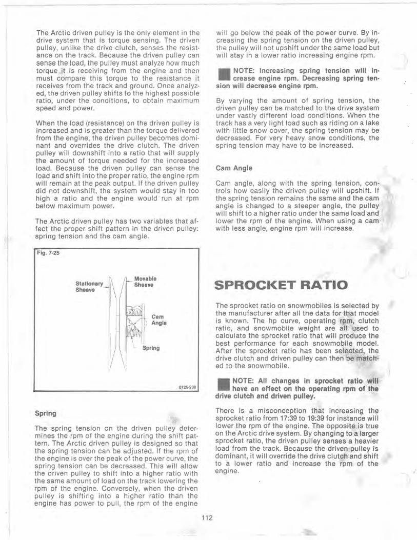
The Arctic driven pulley is the only element in the drive system that is torque sensing. The driven pulley, unlike the drive clutch, senses the resistance on the track. Because the driven pulley can sense the load, the pulley must analyze how much torque it is receiving from the engine and then must compare this torque to the resistance it receives from the track and ground. Once analyzed, the driven pulley shifts to the highest possible ratio, under the conditions, to obtain maximum speed and power.
When the load (resistance) on the driven pulley is increased and is greater than the torque delivered from the engine, the driven pulley becomes dominant and overrides the drive clutch. The driven pulley will downshift into a ratio that will supply the amount of torque needed for the increased load. Because the driven pulley can sense the load and shift into the proper ratio, the engine rpm will remain at the peak output. If the driven pulley did not downshift, the system would stay in too high a ratio and the engine would run at rpm below maximum power.
The Arctic driven pulley has two variables that affect the proper shift pattern in the driven pulley: spring tension and the cam angle.
Fig. 7·25
Spring
Stationary Sheave
Ij
Movable Sheave
Cam Angle
Spring
0725·230
The spring tension on the driven pulley determines the rpm of the engine during the shift pattern. The Arctic driven pulley is designed so that the spring tension can be adjusted. If the rpm of the engine is over the peak of the power curve, the spring tension can be decreased. This will allow the driven pulley to shift into a higher ratio with the same amount of load on the track lowering the rpm of the engine. Conversely, when the driven pulley is shifting into a higher ratio than the engine has power to pull, the rpm of the engine
112
will go below the peak of the power curve. By increasing the spring tension on the driven pulley, the pulley will not upshift under the same load but will stay in a lower ratio increasing engine rpm.
II NOTE: Increasing spring tension will increase engine rpm. Decreasing spring ten·
sion will decrease engine rpm.
By varying the amount of spring tension, the driven pulley can be matched to the drive system under vastly different load conditions. When the track has a very light load such as riding on a lake with little snow cover, the spring tension may be decreased. For very heavy_ snow conditions, the spring tension may have to be increased.
Cam Angle ?
Cam angle, along with the spring tension, con· trois how easily the driven pulley will upshift. If the spring tension remains the same and the cam angle is changed to a steeper angle, the pulley will shift to a higher ratio under the same load and lower the rpm of the engine. When using a cam with less angle, engine rpm will increase.
SPROCKET RATIO
The sprocket ratio on snowmobiles is selected by the manufacturer after all the data for that model is known. The hp curve, operating rpm, clutch ratio, and snowmobile weight are all used to calculate the sprocket ratio that will produce the best performance for each snowmobile model. After the sprocket ratio has been selected, the drive clutch and driven pulley can then be match· ed to the snowmobile.
II NOTE: All changes in sprocket ratio will have an effect on the operating rpm of the
drive clutch and driven pulley.
There is a misconception that increasing the sprocket ratio from 17:39 to 19:39 for instance will lower the rpm of the engine. The opposite is true on the Arctic drive system. By changing to a larger sprocket ratio, the driven pulley senses a heavier load from the track. Because the driven pulley is dominant, it will override the drive clutch and shift to a lower ratio and increase the rpm of the engine.
)
"
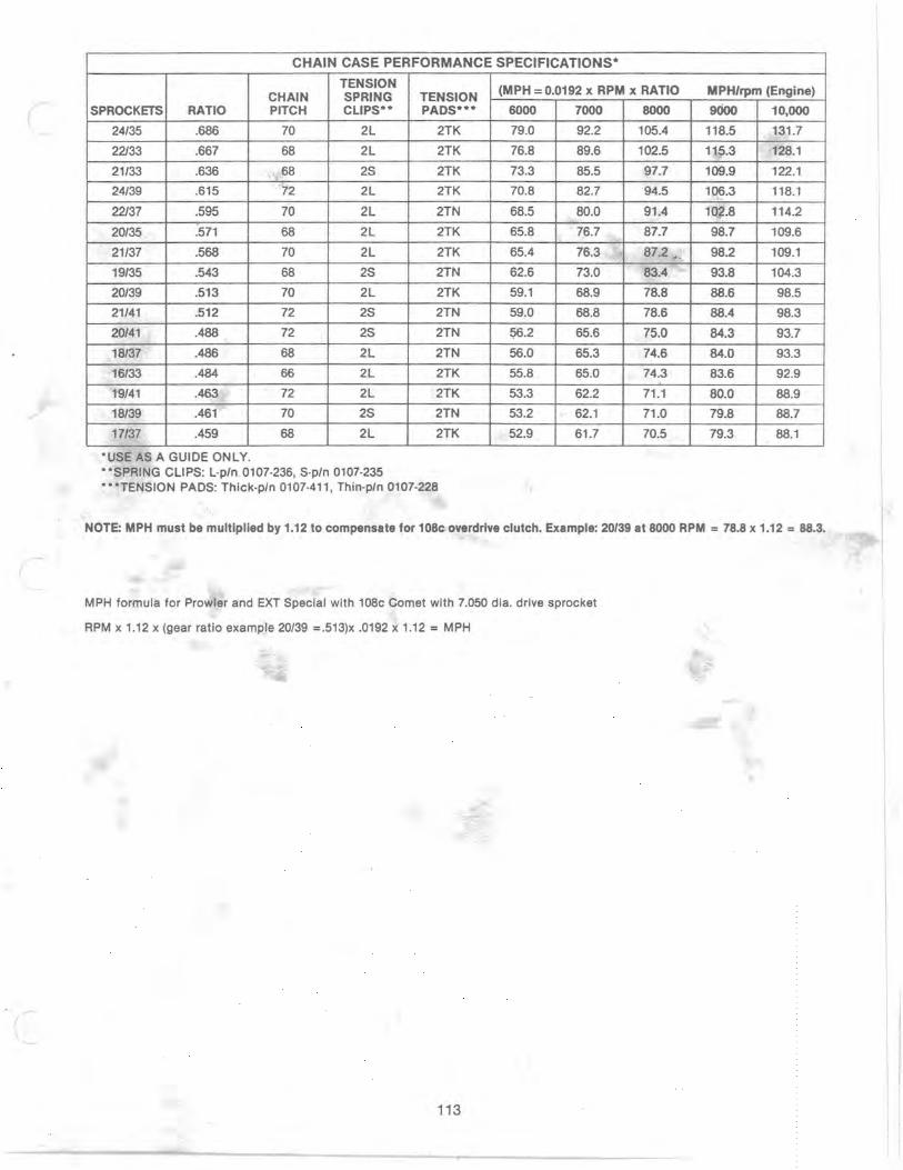
CHAIN CASE PERFORMANCE SPECIFICATIONS·
TENSION CHAIN SPRING TENSION
SPROCKETS RATIO PITCH CLIPS·· PADS···
24/35 .686 70 2L 2TK
22133 .667 68 2L 2TK
21/33 .636 68 2S 2TK
24/39 .615 72 2L 2TK
22137 .595 70 2L 2TN
20/35 .571 68 2L 2TK
21/37 .568 70 2L 2TK
19/35 .543 68 2S 2TN
20/39 .513 70 2L 2TK
21/41 .512 72 2S 2TN
20/41 .488 72 2S 2TN
18137 .486 68 2L 2TN
16/33 .484 66 2L 2TK
19/41 .463 72 2L 2TK
18139 .461 70 2S 2TN
17/37 .459 68 2L 2TK
·USE AS A GUIDE ONLY . • ·SPRING CLIPS: L·p/n 0107·236, S·p/n 0107·235 ···TENSION PADS: Thick·p/n 0107·411, Thin·p/n 0107·228
(MPH = 0.0192 x RPM x RATIO
6000 7000 8000
79.0 92.2 105.4
76.8 89.6 102.5
73.3 85.5 97.7
70.8 82.7 94.5
68.5 80.0 91.4
65.8 76.7 87.7
65.4 76.3 " 87.2 < ,
62.6 73.0 83.4
59.1 68.9 78.8
59.0 68.8 78.6
~.2 65.6 75.0
56.0 65.3 74.6
55.8 65.0 74.3
53.3 62.2 71.1
53.2 62.1 71.0
52.9 61.7 70.5
MPH/rpm (Engine)
9000 10,000
118.5 131.7
115.3 128.1
109.9 122.1
106.3 118.1
101.8 114.2
98.7 109.6
98.2 109.1
93.8 104.3
88.6 98.5
88.4 98.3
84.3 93.7
84.0 93.3
83.6 92.9
80.0 88.9
79.8 88.7
79.3 88.1
NOTE: MPH must be multiplied by 1.12 to compensate for 10Sc overdrive clutch. Example: 20/39 at SOOO RPM = 7S.S x 1.12 = SS.3.
MPH formula for Prowler and EXT Special with 108c Comet with 7.050 dia. drive sprocket
RPM x 1.12 x (gear ratio example 20/39 =.513)x .0192 x 1.12 = MPH
113

CHECKING DRIVE BELT TENSION
Drive belt length and condition are very important for peak performance. Over the years, we have used several different methods in determining the correct belt tension. It seems all of these methods have their good and bad points.
If the drive belt is too long or worn, the engine will bog upon clutch engagement as the belt will cause the clutches to be in too high of a ratio. This lessens the torque required to get the snowmobile moving.
If the belt is too short or tight, this will cause a loss in performance. The drive clutch and driven pulley will have a different shift pattern and a different ratio than conditions for which originally matched.
To determine if the belt is of the proper tension, use the method listed below.
a. First check belt condition. A worn belt should be replaced. Check the belt width. If worn 1/8 in. or more, replacement is necessary.
b. Always install the new drive belt so the part number can be read. Anytime the belt is then removed, it can be put back on the same way so it always turns the same direction.
c. Make sure the drive belt is all the way out in the driven clutch before checking for belt tension.
d. Place a straightedge on the top of the belt. The straightedge should reach from the drive clutch to the top of the driven.
Fig. 8
Range of Drive Belt Deflection· 1.125 to 1.250 in.
Driven Clutch
0727·252
e. USing a stiff ruler, push down on the drive belt at a point in the center of the clutches just enough to remove all slack. Note the amount of deflection on the ruler at the bottom of the straightedge. An acceptable amount of deflection is 1-1/8 to 1-1/4 in.
f. To correct belt tension, washers can be removed or added between the stationary and movable sheave of the driven clutch.
114
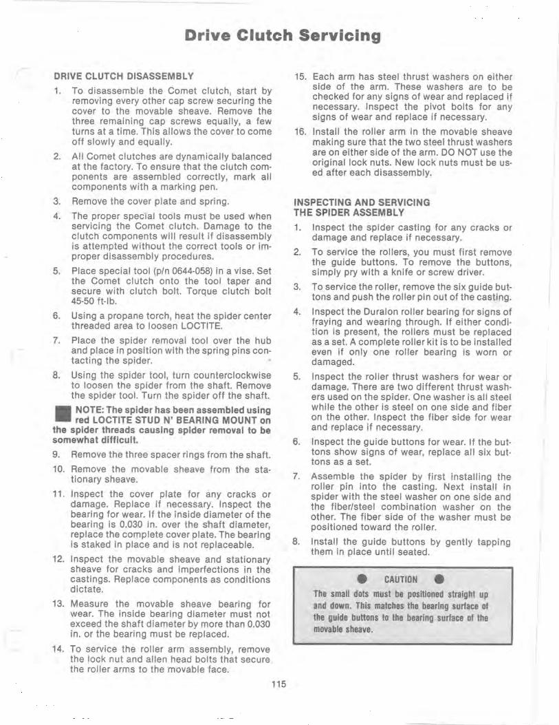
Drive Clutch Servicing
DRIVE CLUTCH DISASSEMBLY
1. To disassemble the Comet clutch, start by removing every other cap screw securing the cover to the movable sheave. Remove the three remaining cap screws equally, a few turns at a time. This allows the cover to come off slowly and equally.
2. All Comet clutches are dynamically balanced at the factory. To ensure that the clutch components are assembled correctly, mark all components with a marking pen.
3. Remove the cover plate and spring.
4. The proper special tools must be used when servicing the Comet clutch. Damage to the clutch components will result if disassembly is attempted without the correct tools or improper disassembly procedures.
5. Place special tool (p/n 0644-058) in a vise. Set the Comet clutch onto the tool taper and secure with clutch bolt. Torque clutch bolt 45-50 ft-Ib.
6. Using a propane torch, heat the spider center threaded area to loosen LOCTITE.
7. Place the spider removal tool over the hub and place in position with the spring pins contacting the spider.
8. Using the spider tool, turn counterclockwise to loosen the spider from the shaft. Remove the spider tool. Turn the spider off the shaft.
II NOTE: The spider has been assembled using red LOCTITE STUD N' BEARING MOUNT on
the spider threads causing spider removal to be somewhat difficult.
9. Remove the three spacer rings from the shaft.
10. Remove the movable sheave from the stationary sheave.
11. Inspect the cover plate for any cracks or damage. Replace if necessary. Inspect the bearing for wear. If the inside diameter of the bearing is 0.030 in. over the shaft diameter, replace the complete cover plate. The bearing is staked in place and is not replaceable.
12. Inspect the movable sheave and stationary sheave for cracks and imperfections in the castings. Replace components as conditions dictate.
13. Measure the movable sheave bearing for wear. The inside bearing diameter must not exceed the shaft diameter by more than 0.030 in. or the bearing must be replaced.
14. To service the roller arm assembly, remove the lock nut and allen head bolts that secure the roller arms to the movable face.
115
15. Each arm has steel thrust washers on either side of the arm. These washers are to be checked for any signs of wear and replaced if necessary. Inspect the pivot bolts for any signs of wear and replace if necessary.
16. Install the roller arm in the movable sheave making sure that the two steel thrust washers are on either side of the arm. DO NOT use the original lock nuts. New lock nuts must be used after each disassembly.
INSPECTING AND SERVICING THE SPIDER ASSEMBLY
1. Inspect the spider casting for any cracks or damage and replace if necessary.
2. To service the rollers, you must first remove the guide buttons. To remove the buttons, simply pry with a knife or screw driver.
3. To service the roller, remove the six guide buttons and push the roller pin out of the casting.
4. Inspect the Duralon roller bearing for signs of fraying and wearing through. If either condition is present, the rollers must be replaced as a set. A complete roller kit is to be installed even if only one roller bearing is worn or damaged.
5.
6.
7.
8.
Inspect the roller thrust washers for wear or damage. There are two different thrust washers used on the spider. One washer is all steel while the other is steel on one side and fiber on the other. Inspect the fiber side for wear and replace if necessary.
Inspect the guide buttons for wear. If the buttons show signs of wear, replace all six buttons as a set.
Assemble the spider by first installing the roller pin into the casting. Next install in spider with the steel washer on one side and the fiber/steel combination washer on the other. The fiber side of the washer must be positioned toward the roller.
Install the guide buttons by gently tapping them in place until seated.
• CAUTION •
The small dots must be positioned straight up and down. This matches the bearing surface of the guide buttons to the bearing surface of the movable sheave.

DRIVE CLUTCH ASSEMBLY
1. Place the movable sheave over the stationary shaft. Install the three spacer washers on the shaft.
2. Before installing the spider assembly, apply red LOCTITE STUD N' BEARING MOUNT to the threads of the spider.
3. Install the spider assembly on the stationary sheave and turn the spider and movable face clockwise on the shaft. Tighten the spider as far as possible by hand.
4. Install the spider tool on the clutch. Clamp securely in a vise and tighten the spider by turning it clockwise. Torque to 125 ft·lb.
5. Place the spring and cover plate in position. The alignment mark on the cover must align with the marks on the spider and movable sheave.
6. Compress the spring by pushing down on the cover plate and lifting up on the movable sheave until both components contact. Tighten the six screws evenly.
116

Electrical Troubleshooting & Wiring Diagrams
The following pages are made up of electrical test procedures and wiring diagrams for 1989. In conjunction with the 1988-1989 Service Manual, all electrical components are covered by a step-by-step test procedure. For the first time, Arctco has each electrical circuit illustrated with a clear simplified wiring diagram. Locate the circuit diagram you are working on and follow the instructions given in this booklet or the service manual. If you have any questions, please contact the Service Department.
At the start of this section is a complete color code description of all wires used on the 1989 models. You will note that some colors are numbered Red #1, Red #2, Red #3, etc. When you see on the wiring diagram, Red #2 or any others, refer to the color code description sheet, and it will provide you with additional information.
• CAUTION •
Before conducting any test procedure using an ohmmeter, if there is a 12 volt battery in the circuit to be tested, first disconnect the battery. This will eliminate the chance of ohmmeter dar.nage caused by DC voltage.
COLOR
Brown
Yellow
White
Blue
1989 SNOWMOBILE HARNESS Wire Color Code and Function Description
FUNCTION DESCRIPTION
Electrical Common; Chassis Ground The brown wire is connected to the chassis at the engine stator plate and also through the voltage regulator chassis bolt. (Prior to 1989, the taillight harness also had a chassis connection.) The headlight bracket is grounded on some 1989 models to reduce the bracket RFI emissions. All brown wires are common ground.
AC Power; 13 Volts AC (Alternating Current) The yellow wire is connected to the engine stator plate lighting coil and the voltage regulator. The voltage produced by the lighting coil is very engineRPM dependent. The voltage regulator is necessary to maintain 13.5 VAC on the yellow wire whenever the engine exceeds about 3000 RPM. All yellow wires are 13 VAC. As mentioned above, the signal on the yellow wire is AC. Not only is the voltage level of this signal RPM dependent, but the signal frequency (cycles per second) is RPM dependent, as well. The electric tachometer uses this changing frequency phenomenon to indicate the engine RPM. An electric tachometer will operate properly when connected to any yellow (13 VAG) and brown (common) wire pair.
Headlight Low Beam The white wire connects the brake control assembly beam switch to the headlight bulb. The low beam filament will illuminate when the beam switch connects the white wire to 13 VAC power.
Headlight High Beam and Indicator Light The blue wire connects the beam switch to the headlight bulb. The high beam will illuminate when the beam switch connects the blue wire to 13 VAC power. Some 1989 models use a tachometer with a high beam indicator light. The "beam" light will also illuminate when the beam switch connects the blue wire to 13 VAC power.
117
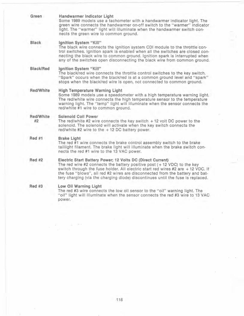
Green
Black
Black/Red
Red/White
Red/White #2
Red #1
Red #2
Red #3
Handwarmer Indicator Light Some 1989 models use a tachometer with a handwarmer indicator light. The green wire connects the handwarmer on-off switch to the "warmer" indicator light. The "warmer" light will illuminate when the handwarmer switch connects the green wire to common ground.
Ignition System "Ki"" The black wire connects the ignition system CDI module to the throttle control switches. Ignition spark is enabled when all the switches are closed connecting the black wire to common ground. Ignition spark is interrupted when any of the switches open disconnecting the black wire from common ground.
Ignition System "Kill" The black/red wire connects the throttle control switches to the key switch. "Spark" occurs when the black/red is at a common ground level and "spark" stops when the black/red wire is open, not connected to common ground.
High Temperature Warning Light Some 1989 models use a speedometer with a high temperature warning light. The red/white wire connects the high temperature sensor to the temperature warning light. The "temp" light will illuminate when the sensor connects the red/white #1 wire to common ground.
Solenoid Coil Power The red/white #2 wire connects the key switch + 12 volt DC power to the solenoid. The solenoid will activate when the key switch connects the red/white #2 wire to the + 12 DC battery power.
Brake Light The red #1 wire connects the brake control assembly switch to the brake taillight filament. The brake light will illuminate when the brake switch connects the red #1 wire to the 13 VAC power.
Electric Start Battery Power; 12 Volts DC (Direct Current) The red wire #2 connects the battery positive post (+ 12 VDC) to the key switch through the fuse holder. All electric start red wires #2 are + 12 VDC. If the fuse "Olows", all red #2 wires are disconnected from the battery and battery charging (via the charging diode) discontinues until the fuse is replaced.
Low Oil Warning Light The red #3 wire connects the low oil sensor to the "oil" warning light. The "oil" light will illuminate when the sensor connects the red #3 wire to 13 VAC power.
118
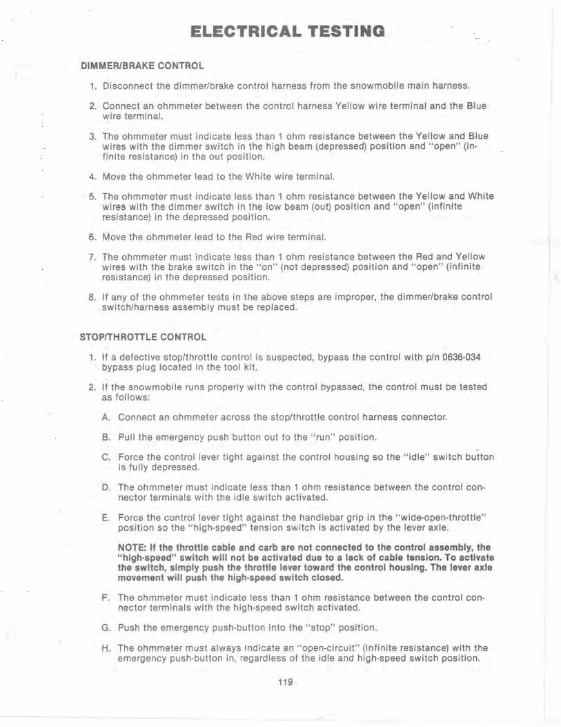
ELECTRICAL TESTING
DIMMER/BRAKE CONTROL
1. Disconnect the dimmer/brake control harness from the snowmobile main harness.
2. Connect an ohmmeter between the control harness Yellow wire terminal and the Blue wire terminal.
3. The ohmmeter must indicate less than 1 ohm resistance between the Yellow and Blue wires with the dimmer switch in the high beam (depressed) position and "open" (infinite resistance) in the out position.
4. Move the ohmmeter lead to the White wire terminal.
5. The ohmmeter must indicate less than 1 ohm resistance between the Yellow and White wires with the dimmer switch in the low beam (out) position and "open" (infinite resistance) in the depressed position.
6. Move the ohmmeter lead to the Red wire terminal.
7. The ohmmeter must indicate less than 1 ohm resistance between the Red and Yellow wires with the brake switch in the "on" (not depressed) position and "open" (infinite resistance) in the depressed position.
8. If any of the ohmmeter tests in the above steps are improper, the dimmer/brake control switch/harness assembly must be replaced.
STOP/THROTTLE CONTROL
1. If a defective stop/throttle control is suspected, bypass the control with pIn 0636-034 bypass plug located in the tool kit.
2. If the snowmobile runs properly with the control bypassed, the control must be tested as follows:
A. Connect an ohmmeter across the stop/throttle control harness connector.
B. Pull the emergency push button out to the "run" position.
C. Force the control lever tight against the control housing so the "idle" switch button is fully depressed.
D. The ohmmeter must indicate less than 1 ohm resistance between the control connector terminals with the idle switch activated.
E. Force the control lever tight against the handlebar grip in the "wide-open-throttle" position so the "high-speed" tension switch is activated by the lever axle.
NOTE: If the throttle cable and carb are not connected to the control assembly, the "high·speed" switch will not be activated due to a lack of cable tension. To activate the switch, simply push the throttle lever toward the control housing. The lever axle movement will push the high·speed switch closed.
F. The ohmmeter must indicate less than 1 ohm resistance between the control connector terminals with the high-speed switch activated.
G. Push the emergency push-button into the "stop" position.
H. The ohmmeter must always indicate an "open·circuit" (infinite resistance) with the emergency push-button in, regardless of the idle and high-speed switch position.
119
..

3. If any of the ohmmeter tests in the above steps are improper, the stop/throttle control must be replaced.
4. If the all ohmmeter tests indicate the correct resistance readings but the engine will not run with the stop/throttle control connected into the snowmobile main harness, the throttle cable must be adjusted. Refer to the appropriate carburetor set-up procedure for proper throttle cable idle and wide-open throttle adjustments. The stop/throttle control switches will not allow the engine to run with an incorrectly adjusted throttle cable.
HI-TEMP SENSOR - LIQUID COOLED ENGINES
1. Disconnect the snowmobile main harness connector from the water temp sensor.
2. Connect an ohmmeter from the sensor terminal to any convenient chassis ground (or any brown wire). The ohmmeter must indicate less than 20 ohms resistance with the water temperature more than 230°F. The ohmmeter must indicate "open" (infinite reSistance) with the water temperature less than 190°F.
NOTE: It may be easier to remove the sensor from the water manifold for testing purposes_ Immerse the sensor body (only up the threads) in automatic transmission fluid and slowly heat the fluid. The ohmmeter must indicate the above resistance when connected between the sensor terminal and the sensor body/chassis.
HI-TEMP WARNING LIGHT
1. Disconnect the snowmobile main harness connector from the water temp sensor.
2. Temporarily place a jumper wire from the snowmobile main harness sensor connector to any convenient chassis ground (or any brown wire).
3. If the hi-temp warning light is not illuminated with the engine running (and the harness terminal grounded), test the light bulb. An ohmmeter must indicate less than 10 ohms across the bulb filament.
4. If the bulo will not illuminate even when tested good, use the ohmmeter to test the bulb harness. Also, test the red/white wire continuity from the temp sensor connector to the bulb connector.
WARNING LIGHT POSISTER
1. Disconnect the posister from the harness connector.
2. Connect an ohmmeter between the posister terminals.
3. The ohmmeter must indicate less than 65 ohms at less than + 80°F. Slowly raise the temperature of the posister element. The ohmmeter must indicate more than 200 ohms at more than + 135°F.
NOTE: DO NOT USE AN OPEN FLAME to heat the posister. An open flame will destroy the posister body. Cigarette lighters, matches, or propane torches are NOT suitable heat sources. Hot air guns and ovens ARE suitable heat sources.
KEY SWITCH (MANUAL STARn
1. Remove the snowmobile main harness connectors from the key switch.
2. Rotate the key to the "off" pOSition (CCW).
3. An ohmmeter must indicate "open" (infinite reSistance) between the key switch terminals (X and V).
1-20
4. Rotate the key to the "run" position (CW).
L . 5. An ohmmeter must indicate less than 1 ohm resistance between the key switch ter-minals (X and V).
HANDWARMER HEATING ELEMENTs
1. Disconnect the handwarmer heating elements from the snowmobile main harness and the handwarmer ON-OFF switch.
2. Connect an ohmmeter between the handwarmer heating element lead wires.
3. If the ohmmeter indicates between 3.5 to 5.5 ohms, the elements are within specifications; reconnect the harnesses. If the ohmmeter indicates less than 3.5 ohms or more than 5.5 ohms, proceed to the next step.
4. Disconnect anyone. of the four heating element lead wires from the others so each element can be measured separately.
5. Connect the ohmmeter to one heating element at a time. An individual element must indicate no less than 7 ohms or no more than 11 ohms.
NOTE: Overheating will occur on elements measuring less than 7 ohms and insufficient heating will occur on elements measuring more than 11 ohms.
6. Replace only the heating element measuring less than 7 ohms or more than 11 ohms.
HANDWARMER ON·OFF SWITCH
1. Disconnect both wire connectors from the handwarmer ON-OFF switch.
2. Connect an ohmmeter between the switch terminals.
3. The ohmmeter must indicate less than 1 ohm with the switch in the "ON" position.
4. The ohmmeter must indicate "open" (infinite resistance) with the switch in the "OFF" position.
LOW OIL SENSOR
1. Disconnect the low oil sensor harness from the snowmobile main harness.
2. Connect an ohmmeter between the sensor harness connector terminals.
3. Raise and lower the oil level to activate the sensor. The ohmmeter must indicate less than 1 ohm resistance with the tank empty and "open" (infinite resistance) with the tank full of oil.
NOTE: It may be easier to remove the sensor from the tank for testing purposes. The ohmmeter must indicate less than 1 ohm resistance with the sensor in an upright ver· tical position and "open" (infinite resistance) with the sensor in an inverted vertical position.
LOW OIL WARNING LIGHT
1. Disc6nnect the low oil sensor harness from the snowmobile main harness.
2. Temporarily place a jumper wire (or tool kit ignition bypass plug pIn 0709-011) across the snowmobile harness oil sensor connector. .
121

3. If the low oil warning light is not illuminated with the engine running (and the sensor bypassed), test the light bulb. An ohmmeter must indicate less than 10 ohms across the bulb filament.
4. If the bulb will not illuminate even when tested good, use the ohmmeter to test the bulb harness. Also test the RED wire continuity from the oil sensor connector to the bulb connector.
ELECTRIC START
Solenoid Testing ( 0645-078)
A. METHOD #1
1. Disconnect the electric start harness (0686-042) from the snowmobile main harness.
2. Place an ohmmeter lead across the solenoid coil terminals (Brown wire and Red/White wire).
3. Ohmmeter reading must indicate 3 to 5 ohms.
B. METHOD #2
1. Connect the battery to the solenoid coil terminals (Brown wire and Red/White wires).
2. A loud audible "click" should be heard as the solenoid internal contacts make connection.
3. Disconnect the battery from the solenoid.
4. A loud audible "click" should be heard as the solenoid internal contacts return to their normally open position.
5. An in-line ammeter would measure 2.0 to 4.0 amps of solenoid coil current flow with the battery connected.
NOTE: NEVER connect an ammeter in-line with the large starter cables. The 200 amps of current flow will instantly destroy most ammeters.
Charging Diode (0630-002)
1. Disconnect the electric start harness (0686-042) from the snowmobile main harness.
2. Place an ohmmeter across the diode (Red wire and Yellow wire).
3. The ohmmeter will indicate approximately 300 to 700 ohms when the ohmmeter positive lead (red) is connected to the diode yellow wire and the ohmmeter negative lead (black) is connected to the diode red wire.
4. The ohmmeter will indicate "open circuit" (infinite resistance) when the ohmmeter positive lead (red) is connected to the diode yellow wire and the ohmmeter negative lead (black) is connected to the diode red wire.
Fuse (0231-021) and Fuse Holder (0630-003)
A. FUSE HOLDER WITH FUSE
1. Disconnect the electric start harness (0686-042) from the snowmobile main harness.
122

2. Disconnect the fuse holder lead (red wire) from the battery positive (red battery cable pigtail lead)'.
3. Connect an ohmmeter across the fuse holder (red wires).
4. The ohmmeter must indicate less than 1 ohm resistance with a fuse installed.
B. FUSE ONLY
1. Remove the fuse (0231 -021) from the fuse holder (0630-003).
2. Connect an ohmmeter across the fuse end caps.
3. The ohmmeter must indicate less than 1 ohm resistance.
Key Switch (0609·082)
1. Remove the snowmobile harness connector from the key switch.
2. Rotate the key to the "OFF" position (CCW).
3. An ohmmeter must indicate no connection (infinite resistance) between any of the switch contacts.
4. Rotate the key to the "RUN" position (center).
5. An ohmmeter must indicate less than 1 ohm resistance between the X + Y terminals and also between the B + A terminals. The ohmmeter must indicate no connection to the Band S terminal. The ohmmeter must indicate no connection between the X + Y terminals to the B + A terminals.
6. Rotate and hold the key in the "start" position (CW).
7. An ohmmeter must indicate less than 1 ohm resistance between the X + Y terminals and also between the B + S terminals. The ohmmeter must indicate no connection to the A terminal. The ohmmeter must indicate no connection between the X + Y terminals to the B + S terminals.
NOTE: Some key switch terminals are not labeled (X, Y, A, e, or S). Some key switch terminals are improperly labeled. Refer to the wiring harness diagrams of the key switch when connecting the ohmmeter. DO NOT use the designations stamped on the key switch terminals when connecting the ohmmeter, erroneous resistance measurements may result.
123

I .
ALL MODELS EXCEPT KITTY CAT
Since all models in 1989 are using the same ignition coils, electrical test procedures and specifications will be the same for each model, except the Kitty Cat.
Testing spark plug cap resistance 1. Remove the spark plug caps from the high tension leads (turn counterclockwise). 2. Set the ohmmeter selector knob in the X1 K position. 3. Touch leads together and zero meter. 4. In turn on each cap, touch a test lead to each end of the spark plug cap. 5. Reading must be 5000 ohms ± 20%.
Testing ignition coil primary resistance 1. Disconnect the double plug from the COl unit to the ignition coil. 2. Set the ohmmeter selector knob in the X1 position and zero the meter. 3. Touch the red ohmmeter lead to the white/blue lead in the coil double plug. Touch
the remaining black test lead to the black/white lead of the coil. 4. Reading must be 0.3 ohms ± 15%.
Testing ignition coil secondary resistance 1. Remove the two spark plug caps from the high tension leads. 2. Set the ohmmeter selector knob in the X1 K position and zero the meter. 3. Touch the leads to the high tension leads making sure you are making good contact
with the wires. 4. Reading must be 6300 ohms ± 20%.
Testing charge coil resistance 1. Disconnect the triple-wire plug from the COl unit to the magneto. 2. Set the ohmmeter selector knob in the X100 position and zero the meter. 3. Touch the red test lead to the red/white wire in the triple plug and touch the black
test lead to the black/white wire in the triple plug. 4. Reading must be 160 ohms ± 20%.
Testing trigger coil resistance 1. Disconnect the triple-wire plug from the COl unit to the magneto. 2. Set the ohmmeter selector knob in the X10 position and zero the meter. 3. Connect the red test lead to the black/red lead in the triple-plug from magneto and
connect the black test lead to the red/white test lead in the triple-plug. 4. Reading must be .17 ohms ± 20%.
Testing lighting coil resistance 1. Disconnect the 4-prong conneqt.or from the magneto wiring harness. 2. Set the ohmmeter selector knob' in the X1 position and zero the meter. 3. Touch the two test 1eads to the two yellow leads in the 4-prong connector. 4. Reading must be 0.22 ohms ± 20%.
124

340, 440 & 500 FIC 1989 JAG, SUPER JAG, PANTHER, COUGAR AND CHEETAH TOURING
Magneto Case
Ignition Timing Checked at 6000 RPM
440 UC ~ 1989 PANTERA
BTDC180~ BTDC 16° BTDC 14° BTDC 12°
,
BTDC 24° BTDC 22° BTDC 20° BTDC 18°
Ignition Timing Checked at 6000 RPM with At Engine Operating Temperature
Rotating Direction
125
BTDC 20° BTDC 22° BTDC 24°
Ignition Timing BTDC 18 ° @ 6000 RPM Hot
BTDC 22° BTDC 20° BTDC 18° BTDC 16°
Magneto Rotor
BTDC 26° BTDC 28° BTDC 30°
Ignition Timing BTDC 24 ° @ 6000 RPM HOT
BTDC:~~ BTDC240~ BTDC 26°
r-
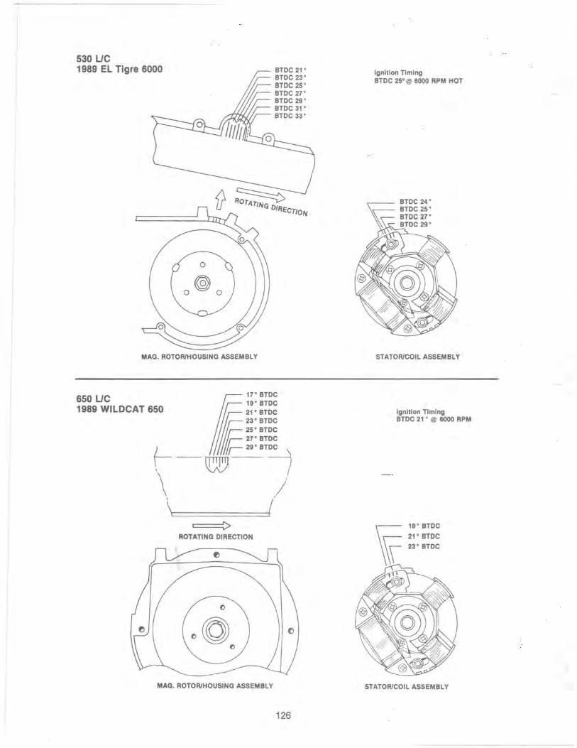
530 UC 1989 EL Tigre 6000
MAG. ROTOR/HOUSING ASSEMBLY
650 UC 17" BTDC
1989 WILDCAT 650 If ~!: :~~~ 'l~ 25° BTDC
(--df~::~~
\ .J \ ( =~>
ROTATING DIRECTION
MAG. ROTOR/HOUSING ASSEMBLY
126
Ignition Timing BTDC 25°@ 6000 RPM HOT
BTDC 24° BTDC 25°
~ BTDC27° ~~ BTDC 29°
STATOR/COIL ASSEMBLY
Ignition Timing BTDC 21 ° @ 6000 RPM
STATOR/COIL ASSEMBLY

530 UC EL TIGRE EXT
MAG. ROTOR/HOUSING ASSEMBLY
15' BTDC 17' BTDC 19' BTDC 21' BTDC 23' BTDC 25' BTDC 27' BTDC
127
Ignition Timing BTDC 21' @ 6000 RPM HOT
..------ 19' BTDC 21' BTDC
~ 23'BTDC
STATOR/COIL ASSEMBLY

• 60 FIC 1990 KITTY CAT
Ignition Timing BlOC 20· @ 6000 RPM
Crankcase
Magneto Rotor
BlOC 20·
BTDC 18·
BTDC20.~_ I BlOC 22 · __ ==- ,
Rotating Direction
Ignition liming Checked at 6000 RPM
340, 440, & 500 FIC 1990 JAG, SUPER JAG, PANTHER, COUGAR AND CHEETAH TOURING
Ignition liming Checked at 6000 RPM
BlOC18.~ BlOC 16· BlOC 14· BlOC 12·
128
BTDC 20· BlOC 22· BlOC 24·
Ignition liming BlOC 18· @ 6000 RPM Hot
BlOC 22· BlOC 20· BlOC 18· BlOC 16·
Magneto Rotor

440 LlC 1990 PANTERA
BTOC 16° - . ----.!1~~
BTOC 14°- ·--.........LJ,
______ BTOC 18°
BTOC 20°
BTOC 22°
BTOC 24° BT DC 12° ---""'~n
1990 PROWLER
BTOC 16°
BTOC 14° ----.....'"1111_ BTOC 12°- ----..
______ BTOC 18°
- BTDC 20·
BTDC 22°
BTDC 24°
129
Ignition Timi~~oo RPM BToC 18° @
Ignition Timingoo
RPM BTOC 18° if! 60

650 LlC 17' BTDC
1990 WILDCAT 650
I ~~::~~~
530 LlC
23' BTDC E 2S'BTDC
f- - q:}f ;;: :~~ ,
\ \'t:=1 ====:::j(
==> ROTATING DIRECTION
o~ o
MAG. ROTOR/HOUSING ASSEMBLY
/
1990 EL TIGRE EXT
MAG. ROTOR/HOUSING ASSEMBLY
130
Ignition Timing BTDC 21 ' @ 6000 RPM
STATOR/COIL ASSEMBL Y
Ignition Timing BTDC 21 ' @ 6000 RPM HOT
r--- 19' BTDC 21' BTDC
~ 23' BTDC
STATOR/COIL ASSEMBLY
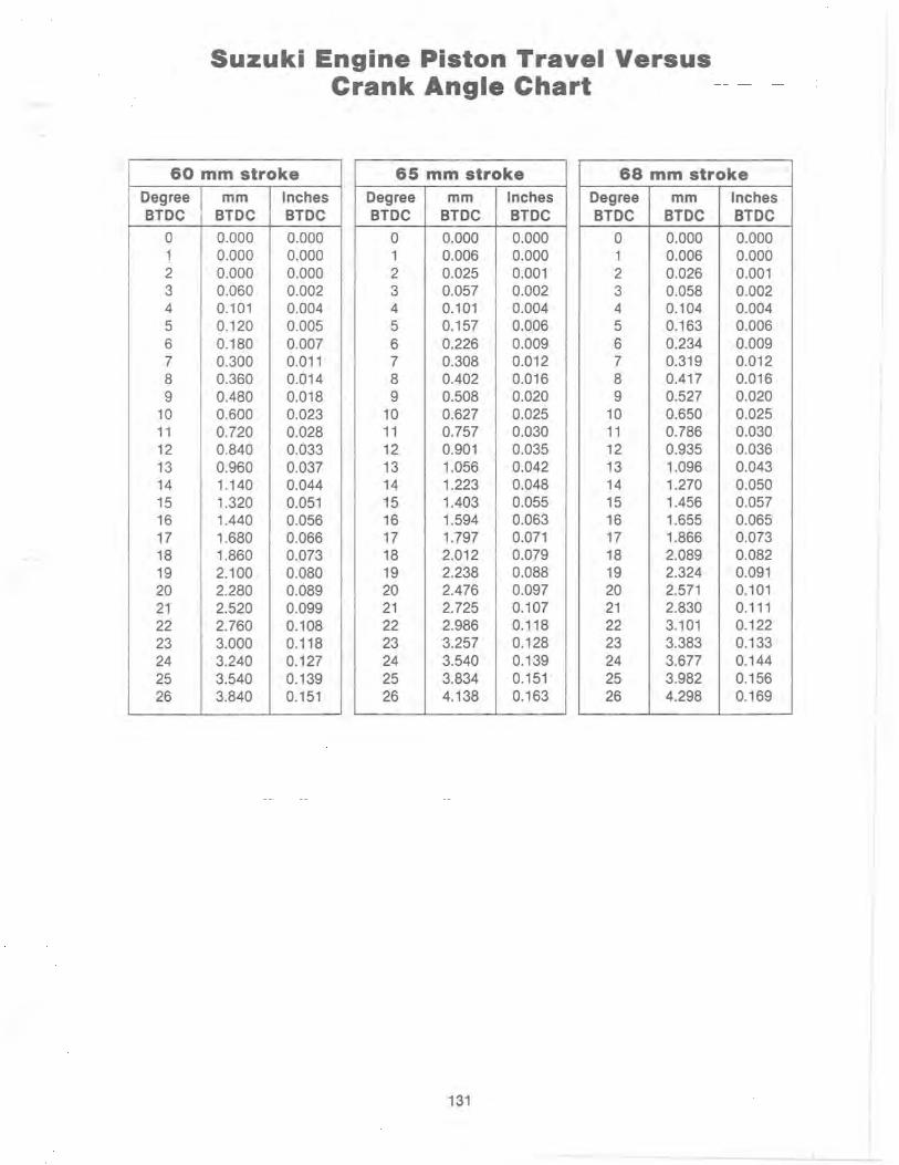
Suzuki Engine Piston Travel Versus Crank Angle Chart
60 mm stroke 65 mm stroke 68 mm stroke Degree I mm Inches BlOC BlOC BlOC
Degree mm Inches BlOC BlOC BlOC
Degree mm Inches BlOC BTOC BTOC
0 0.000 0.000 0 0.000 0.000 0 0.000 0.000 1 0.000 0.000 1 0.006 0.000 1 0.006 0.000 2 0.000 0.000 2 0.025 0.001 2 0.026 0.001 3 0.060 0.002 3 0.057 0.002 3 0.058 0.002 4 0.101 0.004 4 0.101 0.004 4 0.104 0.004 5 0.120 0.005 5 0.157 0.006 5 0.163 0.006 6 0.180 0.007 6 0.226 0.009 6 0.234 0.009 7 0.300 0.011 7 0.308 0.012 7 0.319 0.012 8 0.360 0.014 8 0.402 0.016 8 0.417 0.016 9 0.480 0.018 9 0.508 0.020 9 0.527 0.020
10 0.600 0.023 10 0.627 0.025 10 0.650 0.025 11 0.720 0.028 11 0.757 0.030 11 0.786 0.030 12 0.840 0.033 12 0.901 0.035 12 0.935 0.036 13 0.960 0.037 13 1.056 0.042 13 1.096 0.043 14 1.140 0.044 14 1.223 0.048 14 1.270 0.050 15 1.320 0.051 15 1.403 0.055 15 1.456 0.057 16 1.440 0.056 16 1.594 0.063 16 1.655 0.065 17 1.680 0.066 17 1.797 0.071 17 1.866 0.073 18 1.860 0.073 18 2.012 0.079 18 2.089 0.082 19 2.100 0.080 19 2.238 0.088 19 2.324 0.091 20 2.280 0.089 20 2.476 0.097 20 2.571 0.101 21 2.520 0.099 21 2.725 0.107 21 2.830 0.111 22 2.760 0.108 22 2.986 0.118 22 3.101 0.122 23 3.000 0.118 23 3.257 0.128 23 3.383 0.133 24 3.240 0.127 24 3.540 0.139 24 3.677 0.144 25 3.540 0.139 25 3.834 0.151 25 3.982 0.156 26 3.840 0.151 26 4.138 0.163 26 4.298 0.169
131
-- -'
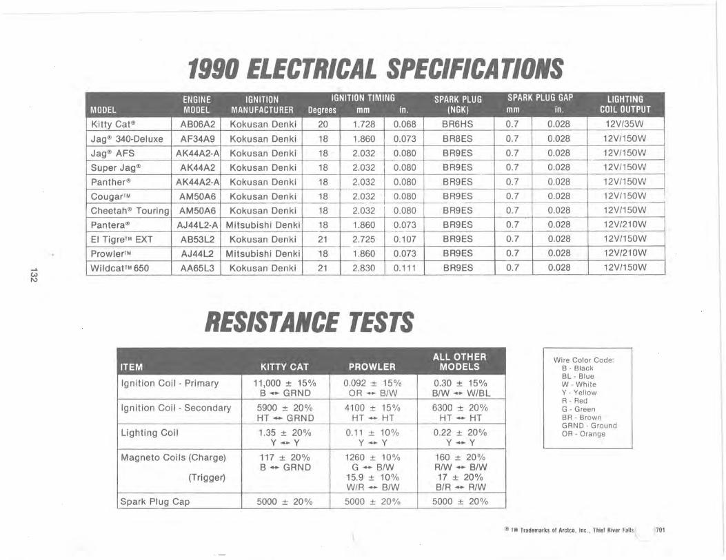
1990 ELECTRICAL SPECIFICATIONS
0.028 12V/150W
Jag® AFS AK44A2-A Kokusan Denki 18 2.032 0.080 SR9ES 0.7 0.028 12V/150W -
Super Jag(!) AK44A2 Kokusan Denki 18 2.032 0.080 SR9ES 0.7 0.028 12V/150W
Panther(!) AK44A2-A Kokusan Denki 18 2.032 0.080 SR9ES 0.7 0.028 12V/150W -- ------_ .. --
Cougar™ AM50A6 Kokusan Denki 18 2.032 , 0.080 SR9ES 0.7 0.028 12V/150W ._- i ---- --
Cheetah(!) Touring AM50A6 Kokusan Denki 18 2.032 i 0.080 SR9ES 0.7 0.028 12V/150W
Pantera® AJ44L2-A Mitsubishi Denki 18 1.860 0.073 SR9ES 0.7 0.028 12V/210W --------
EI Tigre™ EXT AS53L2 Kokusan Denki 21 2.725 0.107 SR9ES 0.7 0.028 12V/150W ---- --
Prowler™ AJ44L2 Mitsubishi Denki 18 1.860 0.073 SR9ES 0.7 0.028 12V/210W
...... WildcatTM 650 AA65L3 Kokusan Denki 21 2.830 0.111 SR9ES 0.7 0.028 12V/150W w I\)
RESISTANCE TESTS Wire Color Code:
B - Black
Ignition Coil - Primary I 11,000 ± 15% 0.092 ± 15% BL - Blue
0.30 ± 15% W -White S ... GRND OR ... S/W S/W'" W/SL Y - Yellow
Ignition Coil - Secondary I 5900 ± 20% 4100 ± 15% R - Red
6300 ± 20% G - Green HT - GRND HT - HT HT - HT BR - Brown
GRND - Ground Lighting Coil I 1.35 ± 20% 0.11 ± 10% 0.22 ± 20% OR - Orange
y-y y-y y-y
Magneto Coils (Charge) 117 ± 20% 1260 ± 10% 160 ± 20% S - GRND G - S/W R/W ... S/W
(Trigger) 15.9 ± 10% 17 ± 20% W/R - S/W SIR - R/W
Spark Plug Cap I 5000 ± 20% I 5000 ± 20% 5000 ± 20%
<!) TM Trademarks of Arctco, Inc. , Thief River Falls ;701
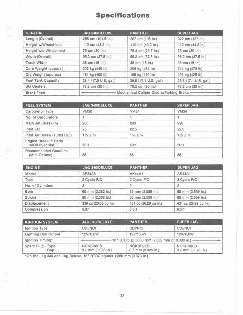
Specifications
GENERAL JAG 340IDELUXE PANTHER SUPER JAG
Length (Overall) 258 cm (101.5 in.) 267 cm (105 in.) 322 cm (127 in.)
Height w/Windshield 110 cm (43.2 in.) 110 cm (43.2 in.) 112 cm (44.2 in.)
Height w/o Windshield 76 cm (30 in.) 75.4 cm (29.7 in.) 76 cm (30 in.)
Width (Overall) 95.2 cm (37.5 in.) 95.2 cm (37.5 in.) 95.2 cm (37.5 in.)
Track Width 38 cm (15 in.) 38 cm (15 in.) 38 cm (15 in.)
Curb Weight (approx.) 202 kg (445 Ib) 205 kg (451 Ib) 214 kg (470 Ib)
Dry Weight (approx.) 181 kg (400 Ib) 186 kg (410 Ib) 193 kg (425 Ib)
Fuel Tank Capacity 28.4 I (7.5 U.S. gaL) 26.8 I (7.1 U.S. gaL) 26.8 I (7.1 U.S. gaL)
Ski Centers 76.2 cm (30 in.) 76.2 cm (30 in.) 76.2 cm (30 in.)
Brake Type ~ Mechanical Caliper Disc w/Parking Brake ~
FUEL SYSTEM JAG 340IDELUXE PANTHER SUPER JAG
Carburetor Type VM30 VM34 VM34
No. of Carburetors 1 1 1
Main Jet (Break-In) 200 290 290
Pilot Jet , 25 22.5 22.5
Pilot Air Screw (Turns Out) 1Y2±'/4 1Y2±V4 1Y2±V4
Engine Break-In Ratio w/Oil Injection 50:1 50:1 50:1
Recommended Gasoline (Min. Octane) 88 88 88
ENGINE JAG 340IDELUXE PANTHER SUPER JAG
Model AF34A8 AK44A1 AK44A1
Type 2-Cycle F/C 2-Cycle F/C 2-Cycle F/C
No. of Cylinders 2 2 2
Bore 60 mm (2.362 in.) 65 mm (2.559 in.) 65 mm (2.559 in.)
Stroke 60 mm (2.362 in.) 65 mm (2.559 in.) 65 mm (2.559 in.)
Displacement 339 cc (20.68 cu in.) 431 cc (26.29 cu in.) 431 cc (26.29 cu in.)
Compression 6.8:1 6.5:1 6.5:1
IGNITION SYSTEM JAG 340IDELUXE' PANTHER SUPER JAG
Ignition Type CDIINCI CDIINCI CDIINCI
Lighting Coil Output 12V/150W 12V/150W 12V/150W
Ignition Timing· • 18° BTDC @ 6000 rpm (2.032 mm or 0.080 in.) ~
Spark Plug - Type NGKBR8ES NGKBR9ES NGKBR9ES - Gap 0.7 mm (0.028 in.) 0.7 mm (0.028 in.) 0.7 mm (0.028 in.)
·On the Jag 340 and Jag Deluxe, 18° BTDC equals 1.860 mm (0.073 m.).
133

DRIVE SYSTEM JAG 340IDELUXE PANTHER SUPER JAG
Engagement RPM 3200-3600 3200-3600 3200-3600
Peak Engine RPM 6500 6500 6500
Drive ClutchlDriven Pulley Offset 35 mm (1.365 in.) 35 mm (1.365 in.) 35 mm (1.365 in.)
Center-to-Center Distance 28.7 cm (11.300 in.) 25.9 cm (10.2 in.) 25.9 cm (10.2 in.)
Drive Belt pIn 0227-100 0227-032 0227-032
Sprocket Ratio 20/39 20/39 19/39
Chain Pitch 70 70 70
ENGINE TORQUE FACTORS JAG 340IDELUXE PANTHER SUPER JAG
Cylinder Head 13-16 ft-Ib 13-16 ft-Ib 13-16 ft-Ib 1.8-2.2 kg-m 1.8-2.2 kg-m 1.8-2.2 kg-m
Flywheel 65-79 ft-Ib 65-79 ft-Ib 65-79 ft-Ib 9.0-11.0 kg-m 9.0-11.0 kg-m 9.0-11.0 kg-m
Intake Manifold 11-14 ft-Ib 6-9 ft-Ib 6-9 ft-Ib 1.5-1.9 kg-m 0.8-1.2 kg-m 0.8-1.2 kg-m
Exhaust Manifold & 13-16 ft-Ib 13-16 ft-Ib 13-16 ft-Ib Intake Flange 1.8-2.2 kg-m 1.8-2.2 kg-m 1.8-2.2 kg-m
Flywheel Housing 13-16 ft-Ib 13-16 ft-Ib 13-16 ft-Ib 1.8-2.2 kg-m 1.8-2.2 kg-m 1.8-2.2 kg-m
Crankcase 6 mm 6-9 ft-Ib 6-9 ft-Ib 6-9 ft-Ib 0.8-1.2 kg-m 0.8-1.2 kg-m 0.8-1.2 kg-m
8 mm 13-16 ft-Ib 13-16 ft-Ib 13-16 ft-Ib 1.8-2.2 kg-m 1.8-2.2 kg-m 1.8-2.2 kg-m
Spark Plug 18-20 ft-Ib 18-20 ft-Ib 18-20 ft-Ib 2.5-2.8 kg-m 2.5-2.8 kg-m 2.5-2.8 kg-m
Oil Injection Pump 5 ft-Ib 5 ft-Ib 5 ft-Ib 0.7 kg-m 0.7 kg-m 0_7 kg-m
Axial Fan 18-29 ft-Ib 18-29 ft-Ib 18-29 ft-Ib 2.5-4.0 kg-m 2.5-4.0 kg-m 2_5-4.0 kg-m
Engine Plate 55 ft-Ib 55 ft-Ib 55 ft-Ib 7.6 kg-m 7.6 kg-m 7.6 kg-m
Engine Mounting 23 ft-Ib 23 ft-Ib 23 ft-Ib 3.2 kg-m 3.2 kg-m 3_2 kg-m
DRIVE TORQUE FACTORS JAG 340IDELUXE PANTHER SUPER JAG
Drive Clutch 55-60 ft-Ib 55-60 ft-Ib 55-60 ft-Ib 7.6-8.3 kg-m 7.6-8.3 kg-m 7.6-8.3 kg-m
Clutch Weight 35-45 in-Ib N/A N/A 0.4-0.5 kg-m
Drive Clutch Cover 15-17 ft-Ib 7 ft-Ib 7 ft-Ib 2.1-2.4 kg-m 1.0 kg-m 1.0 kg-m
Driven Pulley Retainer 11-13 ft-Ib 11-13 ft-Ib 11-13 ft-Ib 1.5-1.8 kg-m 1.5-1.8 kg-m 1.5-1.8 kg-m
Driven Pulley 19-24 ft-Ib . 19-24 ft-Ib 19-24 ft-Ib 2.6-3.3 kg-m 2.6-3.3 kg-m 2.6-3.3 kg-m
134

CHASSIS TORQUE FACTORS JAG 340IDELUXE PANTHER SUPER JAG
Ski 21-26 ft-Ib 21-26 ft-Ib 21-26 ft-Ib 2.9-3.6 kg-m 2.9-3.6 kg-m 2.9-3.6 kg-m
Skid Frame Mounting 21-26 ft-Ib 21-26 ft-Ib 21-26 ft-Ib 2.9-3.6 kg-m 2.9-3.6 kg-m 2.9-3.6 kg-m
Skid Frame Crossbraces 17 ft-Ib 17 ft-Ib 17 ft-Ib 2.4 kg-m 2.4 kg-m 2.4 kg-m
Idler Wheels 17 ft-Ib 17 ft-Ib 17 ft-Ib 2.4 kg-m 2.4 kg-m 2.4 kg-m
Idler Wheel Brackets 17 ft-Ib 17 ft-Ib 17 ft-Ib 2.4 kg-m 2.4 kg-m 2.4 kg-m
Skid Frame Arms 30 ft-Ib 30 ft-Ib 30 ft-Ib 4.2 kg-m 4.2 kg-m 4.2 kg-m
End Caps 8 ft-Ib 8 ft-Ib 8 ft-Ib 1.1 kg-m 1.1 kg-m 1.1 kg-m
Chain Case Sprockets 19-24 ft-Ib 19-24 ft-Ib 19-24 ft-Ib 2.6-3.3 kg-m 2.6-3.3 kg-m 2.6-3.3 kg-m
Handlebar Block N/A 10 ft-Ib 10 ft-Ib 1.4 kg-m 1.4 kg-m
Tie Rods 25-30 ft-Ib 25-30 ft-Ib 25-30 ft-Ib 3.5-4.2 kg-m 3.5-4.2 kg-m 3.5-4.2 kg-m
ENGINE TORQUE PATTERNS
CYLINDER HEAD CYLIN DER BASE CRANKCASE
CD 0 CD 0 l~jAV @ @ k:r - \
0 CD 0 CD r ~ , I
0725-318 0728-412
135
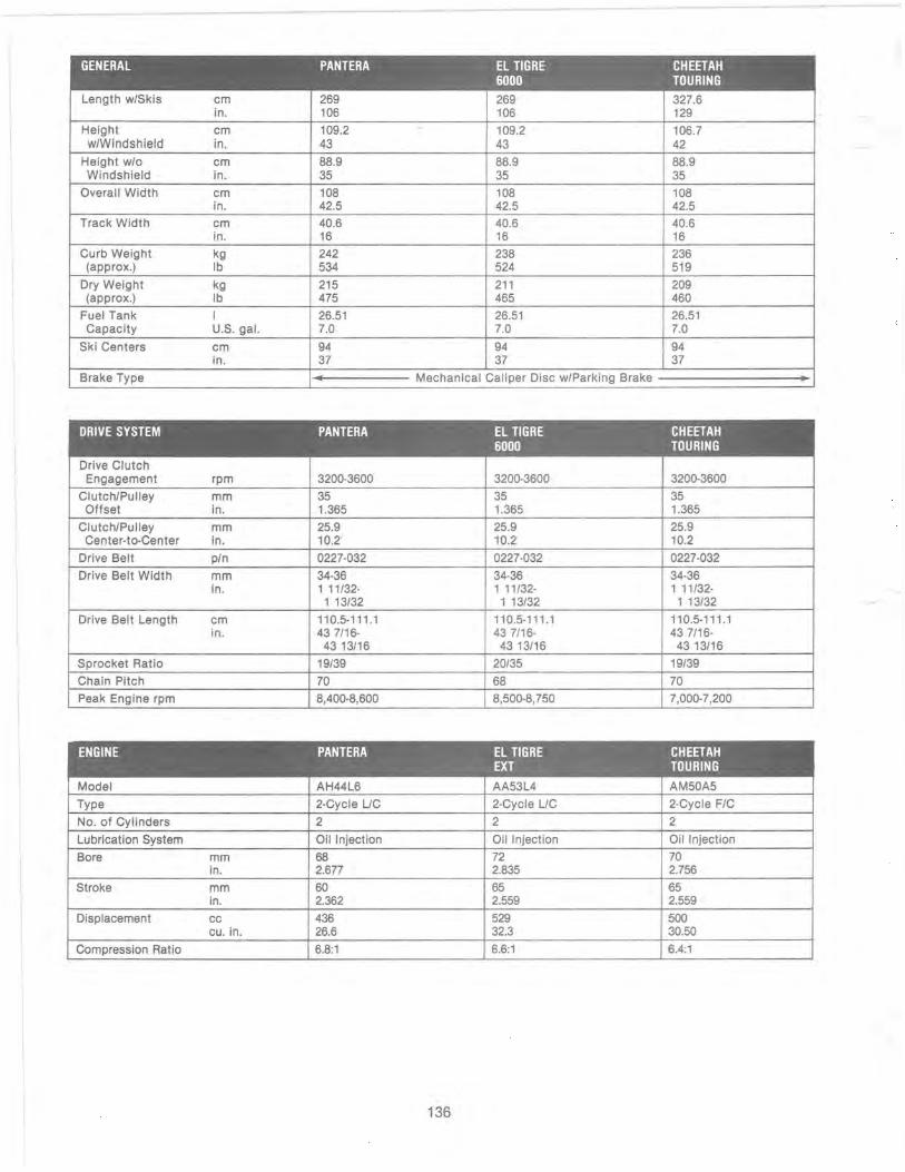
GENERAL PANTERA EL TIGRE CHEETAH 6000 TOURING
Length w/Skis cm 269 269 327.6 in. 106 106 129
Height cm 109.2 . 109.2 106.7 w/Windshield in. 43 43 42
Height w/o cm 88.9 88.9 88.9 Windshield in. 35 35 35
Overall Width cm 108 108 108 in. 42.5 42.5 42.5
Track Width cm 40.6 40.6 40.6 in. 16 16 16
Curb Weight kg 242 238 236 (approx.) Ib 534 524 519
Dry Weight kg 215 211 209 (approx.) Ib 475 465 460
Fuel Tank I 26.51 26.51 26.51 Capacity U.S. gal. 7.0 7.0 7.0
Ski Centers cm 94 94 94 in. 37 37 37
Brake Type ~ Mechanical Caliper Disc w/Parking Brake ~
DRIVE SYSTEM PANTERA EL TIGRE CHEETAH 6000 TOURING
Drive Clutch Engagement rpm 3200-3600 3200-3600 3200-3600
Clutch/Pulley mm 35 35 35 Offset in. 1.365 1.365 1.365
Clutch/Pulley mm 25.9 25.9 25.9 Center-to-Center in. 10.2 10.2 10.2
Drive Belt pin 0227-032 0227-032 0227-032
Drive Belt Width mm 34-36 34-36 34-36 in. 1 11/32- 1 11/32- 1 11/32-
1 13/32 1 13/32 1 13/32
Drive Belt Length cm 110.5-111 .1 110.5-111.1 110.5-111.1 in. 437/16- 437/16- 437/16-
43 13/16 43 13/16 43 13/16
Sprocket Ratio 19/39 20/35 19/39
Chain Pitch 70 68 70
Peak Engine rpm 8,400-8,600 8,500-8,750 7,000-7,200
ENGINE PANTERA EL TIGRE CHEETAH EXT TOURING
Model AH44L6 AA53L4 AM50A5
Type 2-Cycle UC 2-Cycle UC 2-Cycle F/C
No. of Cylinders 2 2 2
Lubrication System Oil Injection Oil Injection Oil Injection
Bore mm 68 72 70 in. 2.677 2.835 2.756
Stroke mm 60 65 65 in. 2.362 2.559 2.559
Displacement cc 436 529 500 cu. in. 26.6 32.3 30.50
Compression Ratio 6.8:1 6.6:1 6.4:1
136

IGNITION SYSTEM PANTERA EL TIGRE CHEETAH 6000 TOURING
Ignition Type CDIINCI CDIINCI CDIINCI
Lighting Coil Output 12V/150W 12V/150W 12V/150W
Ignition Timing degree 24° @6000 25° @6000 18° @6000 BTDC rpm rpm rpm
- mm BTDC 3.226 3.835 2.032 - in. BTDC 0.127 0.151 0.080
Spark Plug - Std. NGK BR9ES NGK BR10EV NGK BR9ES
Spark Plug Gap mm 0.7 0.7 0.7 in. 0.028 0.028 0.028
FUEL SYSTEM PANTERA EL TIGRE CHEETAH 6000 TOURING
Carburetor Type , VM-34 VM-38 VM-34
No. of Carburetors 2 2 2
Main Jet 260 350 260'
Pilot Jet 27.5 30 35
Pilot Air Screw (Turns Out) 1 1/2 1 1/2 1 1/2
Engine Break-In Ratio 50:1 50:1 50:1
Recommended Gasoline 88 88 88 (Min. Octane)
'If the snowmobile is to be operated at sea level, use a 280 main jet for the break-in period.
ENGINE TORQUE FACTORS PANTERA EL TIGRE CHEETAH 6000 TOURING
Cylinder Head kg-m 3.0-4.0 2.0-2.5 2.0-2.5 ft-Ib 22-29 14-18 14-18
Cylinder Base kg-m 3.0-4.0 3.0-4.0 3.0-4.0 10 mm ft-Ib 22-29 22-29 22-29
Cylinder Base kg-m 1.8-2.2 1.8-2.2 1.8-2.2 8 mm ft-Ib 13-16 13-16 13-16
Crankcase 6 mm kg-m 0.8-1.2 0.8-1.2 0.8-1.2 ft-Ib 6-9
) 6-9 6-9
Crankcase 8 mm kg-m 1.8-2.2 - r 1.8-2.2 1.8-2.2 ft-Ib 13-16 13-16 13-16
Crankcase 10 mm kg-m 3.0-4.0 3.0-4.0 3.0-4.0 ft-Ib 22-29 22-29 22-29
Flywheel kg-m 9.0-11.0 9.0-11.0 9.0-11.0 ft-Ib 65-79 65-79 65-79
Exhaust Manifold kg-m 1.8-2.2 1.8-2.2 1.8-2.2 f\-Ib 13-16 13-16 13-16
Engine Mounting kg-m 7.6 7.6 7.6 ft-Ib 55 55 55
Spark Plug kg-m 2.5-2.8 2.5-2.8 2.5-2.8 ft-Ib 18-20 18-20 18-20
Intake Flange kg-m 1.8-2.2 1.8-2.2 1.8-2.2 ft-Ib 13-16 13-16 13-16
137
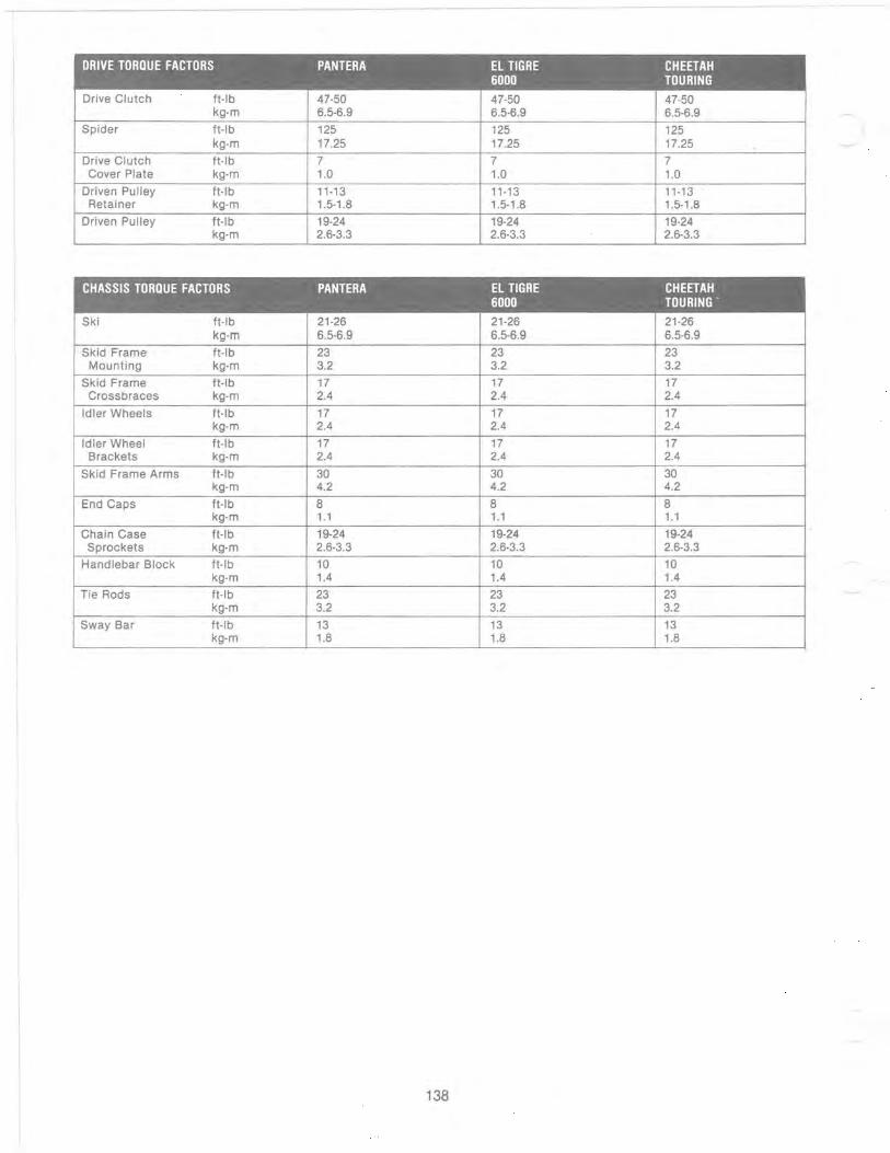
DRIVE TORQUE FACTORS PANTERA El TIGRE CHEETAH 6000 TOURING
Drive Clutch ft-Ib 47-50 47-50 47-50 kg-m 6.5-6.9 6.5-6.9 6.5-6.9
Spider ft-Ib 125 125 125 kg-m 17.25 17.25 17.25 .
Drive Clutch ft-Ib 7 7 7 Cover Plate kg-m 1.0 1.0 1.0
Driven Pulley ft-Ib 11-13 11-13 11-13 Retainer kg-m 1.5-1.8 1.5-1.8 1.5-1.8
Driven Pulley ft-Ib 19-24 19-24 19-24 kg-m 2.6-3.3 2.6-3.3 2.6-3.3
CHASSIS TORQUE FACTORS PANTERA EL TIGRE CHEETAH 6000 TOURING '
Ski ft-Ib 21-26 21-26 21-26 kg-m 6.5-6.9 6.5-6.9 6.5-6.9
Skid Frame ft-Ib 23 23 23 Mounting kg-m 3.2 3.2 3.2
Skid Frame ft-Ib 17 17 17 Crossbraces kg-m 2.4 2.4 2.4
Idler Wheels ft-Ib 17 17 17 kg-m 2.4 2.4 2.4
Idler Wheel ft-Ib 17 17 17 Brackets kg-m 2.4 2.4 2.4
Skid Frame Arms ft-Ib 30 30 30 kg-m 4.2 4.2 4.2
End Caps ft-Ib 8 8 8 kg-m 1.1 1.1 1.1
Chain Case ft-Ib 19-24 19-24 19-24 Sprockets kg-m 2.6-3.3 2.6-3.3 2.6-3.3
Handlebar Block ft-Ib 10 10 10 kg-m 1.4 1.4 1.4
Tie Rods ft-Ib 23 23 23 kg-m 3.2 3.2 3.2
Sway Bar ft-Ib 13 13 13 kg-m 1.8 1.8 1.8
138
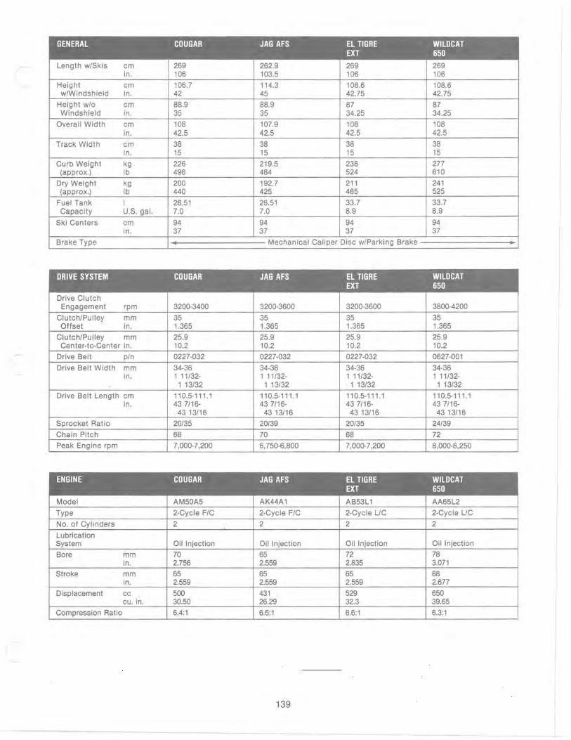
,
GENERAL COUGAR JAG AFS EL TIGRE WILDCAT EXT 650
Length w/Skis cm 269 262.9 269 269 in. 106 103.5 106 106
Height cm 106.7 114.3 108.6 108.6 w/Windshield in. 42 45 42.75 42.75
Height w/o cm 88.9 88.9 87 87 Windshield in. 35 35 34.25 34.25
Overall Width cm 108 107.9 108 108 in. 42.5 42.5 42.5 42.5
Track Width cm 38 38 38 38 in. 15 15 15 15
Curb Weight kg 226 219.5 238 277 (approx.) Ib 496 484 524 610
Dry Weight kg 200 192.7 211 241 (approx.) Ib 440 425 465 525
Fuel Tank I 26.51 26.51 33.7 33.7 Capacity U.S. gal. 7.0 7.0 8.9 8.9
Ski Centers cm 94 94 94 94 in. 37 37 37 37
Brake Type .. Mechanical Caliper Disc w/Parking Brake •
DRIVE SYSTEM COUGAR JAG AFS EL TIGRE WILDCAT EXT 650
Drive Clutch Engagement rpm 3200-3400 3200-3600 3200-3600 3800-4200
ClutchlPulley mm 35 35 35 35 Offset in. 1.365 1.365 1.365 1.365
ClutchlPulley mm 25.9 25.9 25.9 25.9 Center·to-Center in. 10.2 10.2 10.2 10.2
Drive Belt pin 0227-032 0227-032 0227-032 0627·001
Drive Belt Width mm 34-36 34-36 34-36 34·36 in. 1 11/32- 1 11/32- 1 11/32- 1 11/32-
1 13/32 1 13/32 . 1 13/32 1 13/32
Drive Belt Length cm 110.5-111.1 110.5-111.1 110.5-111.1 110.5-111.1 in. 43 7/16- 43 7/16- 43 7/16- 43 7/16-
43 13/16 43 13/16 43 13/16 43 13/16
Sprocket Ratio 20/35 20/39 20/35 24/39
Chain Pitch 68 70 68 72
Peak Engine rpm 7,000-7,200 6,750·6,800 7,000-7,200 8,000-8,250
ENGINE COUGAR JAG AFS EL TIGRE WILDCAT EXT 650
Model AM50A5 AK44A1 AB53L 1 AA65L2
Type 2-Cycle FIC 2-Cycle FIC 2-Cycle UC 2-Cycle UC
No. of Cylinders 2 2 2 2
Lubrication System Oil Injection Oil Injection Oil Injection Oil Injection
Bore mm 70 65 72 78 in. 2.756 2.559 2.835 3.071
Stroke mm 65 65 65 68 in. 2.559 2.559 2.559 2.677
Displacement cc 500 431 529 650 cu. in. 30.50 26.29 32.3 39.65
Compression Ratio 6.4:1 6.5:1 6.6:1 6.3:1
139

IGNITION SYSTEM COUGAR JAG AFS EL TIGRE WILDCAT EXT 650
Ignition Type COIINCI COIINCI COIINCI COIINCI Lighting Coil Out-put 12V/150W 12V/150W 12V/150W 12V/15~W
Ignition Timing degree 18 0 @6000 18 0 @6000 21 0 @6000 21 0 @6000 BTDC rpm rpm rpm rpm
- mm BTOC 2.032 2.032 2.725 2.830 - in. BTDC 0.080 0.080 0.107 0.111
Spark Plug - Std. NGK BR9ES NGK BR9ES NGK BR9EV NGK BR10EV Spark Plug Gap mm 0.7 0.7 0.7 0.7
in. 0.028 0.028 0.028 0.028
FUEL SYSTEM COUGAR JAG AFS EL TIGRE WILDCAl EXT 650
Carburetor Type VM-34 VM-34 VM-34 VM-40 No. of Carburetors 2 1 2 2 Main Jet 260' 300 240 400 Pilot Jet 35 22.5 30 55 Pilot Air Screw (Turns Out) 1 1/2 1 1/2 1 1/2 1 1/2 Engine Break-In Ratio 50:1 50:1 50:1 50:1 Recommended Gasoline 88 88 88 88 (Min. Octane)
'If the snowmobile is to be operated at sea level, use a 280 main jet for the break-in period.
ENGINE TORQUE FACTORS COUGAR JAG AFS EL TIGRE WILDCAT EXT 650
Cylinder Head kg-m 2.0-2.5 1.8-2.2 2.0-2.5 1.8-2.8 ft-Ib 14-18 13-16 14-18 13-20
Cylinder Base kg-m 3.0-4.0 N/A 3.0-4.0 4.0-6.0
10 mm ft-Ib 22-29 22-29 29-43.5
Cylinder Base kg-m 1.8-2.2 N/A 1.8-2.2 1.8-2.2 8 mm ft-Ib 13-16 13-16 13-16
Crankcase 6 mm kg-m 0.8-1.2 0.8-1.2 0.8-1.2 0.8-1.2 ft-Ib 6-9' 6-9 6-9 6-9
Crankcase 8 mm kg-m 1.8-2.2 1.8-2.2 1.8-2.2 1.8-2.2 ft-Ib 13-16 13-16 13-16 13-16
Crankcase 10 mm kg-m 3.0-4.0 N/A 3.0-4.0 4.0-6.0 ft-Ib 22-29 22-29 29-43.5
Flywheel kg-m 9.0-11.0 , 9.0-11.0 9.0-11.0 9.0-11.0 ft-Ib 65-79 65-79 65-79 65-79
Exhaust Manifold kg-m 1.8-2.2 1.8-2.2 1.8-2.2 1.8-2.2 ft-Ib 13-16 13-16 13-16 13-16
Engine Mounting kg-m 7.6 7.6 7.6 7.6 ft-Ib 55 55 55 55
Spark Plug kg-m 2.5-2.8 2.5-2.8 2.5-2.8 2.5-2.8 ft-Ib 18-20 18-20 18-20 18-20
Intake Flange kg-m 1.8-2.2 1.8-2.2 1.8-2.2 1.8-2.2 ft-Ib 13-16 13-16 13-16 13-16
140
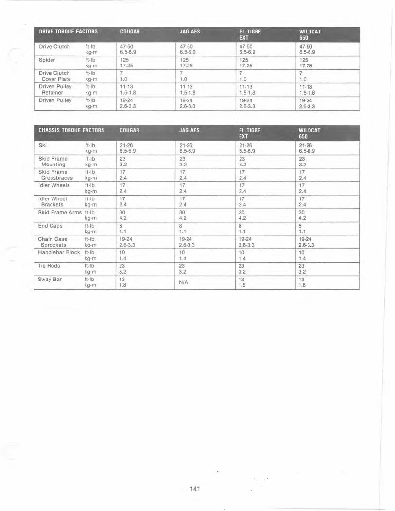
DRIVE TORQUE FACTORS COUGAR JAG AFS EL TIGRE WILDCAT EXT 650
Drive Clutch ft-Ib 47-50 47-50 47-50 47-50 kg-m 6.5-6.9 6.5-6.9 6.5-6.9 6.5-6.9
Spider ft-Ib 125 125 125 125 kg-m 17.25 17.25 17.25 17.25
Drive Clutch ft-Ib 7 7 7 7 Cover Plate kg-m 1.0 1.0 1.0 1.0
Driven Pulley ft-Ib 11-13 11-13 11-13 11-13 Retainer kg-m 1.5-1.8 1.5-1.8 1.5-1.8 1.5-1.8
Driven Pulley ft-Ib 19-24 19-24 19-24 19-24 kg-m 2.6-3.3 2.6-3.3 2.6-3.3 2.6-3.3
CHASSIS TORQUE FACTORS COUGAR JAG AFS EL TIGRE WILDCAT EXT 650
Ski ft-Ib 21-26 21-26 21-26 21-26 kg-m 6.5-6.9 6.5-6.9 6.5-6.9 6.5-6.9
Skid Frame ft-Ib 23 23 23 23 Mounting kg-m 3.2 3.2 3.2 3.2
Skid Frame ft-Ib 17 17 17 17 Crossbraces kg-m 2.4 2.4 2.4 2.4
Idler Wheels ft-Ib 17 17 17 17 kg-m 2.4 2.4 2.4 2.4
Idler Wheel ft-Ib 17 17 17 17 Brackets kg-m 2.4 2.4 2.4 2.4
Skid Frame Arms ft-Ib 30 30 30 30 kg-m 4.2 4.2 4.2 4.2
End Caps ft-Ib 8 8 8 8 kg-m 1.1 1.1 1.1 1.1
Chain Case ft-Ib 19-24 19-24 19-24 19-24 Sprockets kg-m 2.6-3.3 2.6-3.3 2.6-3.3 2.6-3.3
Handlebar Block ft-Ib 10 10 10 10 kg-m 1.4 1.4 1.4 1.4
Tie Rods ft-Ib 23 23 23 23 kg-m 3.2 3.2 3.2 3.2
Sway Bar ft-Ib 13 N/A 13 13
kg-m 1.8 1.8 1.8
141

ENGINE TORQUE PATTERNS
CYLINDER HEAD
Cougar
0725·320
JagAFS
CD 0 CD 0 @ @
CD CD 0) CD
0726-318
EI Tigre EXT
0727·158
Wildcat 650
0727·158
CYLINDER BASE
DI 0DI 0
CD 0 CD 0
142
-------- - ----
0726-318
0726-376
0726-376
CRANKCASE
0725·321
l~jAv
k;fr~
(J) @
CD @
0726-412
0725·321
0727·491
1 .

ENGINE TORQUE PATTERNS
CYLINDER HEAD CYLIN DER BASE CRANKCASE
Cheetah Touring
0' 00' 0 o CD 0 0
0725·320 0726-318 0725·321
Pantera
0725-746 0726·376 0725-321
EI Tigre 6000
CD 0 "" /. CD 0 "" /. ,0 Q)<D 0
10 0 I 0 0 11 0 0
o 0/ 0 0/
~~ CD CD CD CD
0727·158 0726-376 0725·321
143

...... ~ ~
1989 CARBURETOR SPECIFICATIONS
Jag@ 340-Deluxe I VM-30 I 2002 I P-4 (169) 5DP7-3 5DP7-2 I 25 I 25 I 3.5
Jag@ AFS I VM-34 I 3002 I P-6 (480) 6DH3-3 6DH3-3 I 22.5 I 22.5 I 2.5 6DH3-24
SuperJag@ VM-34 2902 0-0 (480) 6DH2-3 6DH2-2 22.5 22.5 2.5
Panther@ VM-34 2902 0-0 (480) 6DH2-3 6DH2-2 22.5 22.5 2.5
CougapM VM-34 2602 P-6 (480) 6DH2-3 6DH2-2 35 30 3.0
Pantera@ VM-34 2602 P-4 (480) 6DH3-3 6DH3-2 27.5 27.5 2.5
EI Tigre™ EXT VM-34 2402 P-5 (480) 6DH7-4 6DH7-3 30 30 3.0 P-4 (480)4
I EI Tigre™ 6000 I VM-38 I 3502 I 0-5 (166) I 6DH8-3 I 6DH8-3 I 30 I 30 I 3.5 0-2 (166)3 0-0 (166)4
Cheetah@ Touring VM-34 2602 P-6 (480)
WildcatTM 650 VM-40 4002 AA-2 (224) AA-O (224)3 Z-5 (224)4
1 Elevations above 1524 m (5000 ft) 2 Refer to Jet Chart after engine break·in 3 Elevations 1524·3048 m (5000·10,000 ft) above sea level 4 3048 m (10,000 ft) above sea level and higher
6DH8-24
6DH2-3 6DH2-2 I 35 I 30 I 3.0
7DJ2-2 7DJ2-2 I 55 I 55 I 3.5
I 3.5 I Atmospheric I 1% I 1112
I 2.5 I Atmospheric I 1% I 1%
2.5 Atmospheric 1% 1%
2.5 Atmospheric 1% 1%
3.0 Atmospheric 1% 1%
2.5 Atmospheric 1% 1%
3.0 Atmospheric 1 1%
I 3.5 I Atmospheric I 1% 1%
I 3.0 I Atmospheric I 1% I 1%
I 3.5 I Atmospheric I 1% I 1%
® TM Trademarks of Arclco. Inc., Thief River Falls, MN 56701

I
1
1990 CARBURETOR SPECIFICATIONS
Jag@ 340-Deluxe
Jag@ AFS VM-34 3002 P-4 (480)
SuperJag@ VM-34 2902 Q-O (480)
Panther@ VM-34 3002 P-4 (480)
CougarrM VM-34 2602 P-6 (480)
~ I Pantera@ VM-34 2402 P-4 (480)
EI Tigre™ EXT VM-38 3102 Q·O (480) P-8 (480)1
ProwlerrM VM-34 2402 P-4 (480)
Cheetah@ Touring VM-34 2602 P-6 (480)
WildcatTM 650 VM-40 4002 AA-2 (224) AA·O (224)3 Z-5 (224)4
1 Elevations above 1219 m (4000 ft) 2 Refer to Jet Chart after engine break-in 3 Elevations between 1219-3048 m (4000-10,000 tt).above sea level 4 3048 m (10,000 tt) above sea level and higher
+'
6DH3-4 6DH3-33 I 22.5 I 22.5 I 2.5 I 2.5 I Atmospheric I 1 V2 I 1 V2 6DH3-2 4
6DH2-3 6DH2-2 : 22.5 I 22.5 I 2.5 I 2.5 I Atmospheric I 1 V2 I 1 V2
6DH3-4 6DH3-33 i 22.5 I 22.5 I 2.5 I 2.5 I Atmospheric I 1% I 11/2 6DH3-2 4
-6DH2-3 6DH2-2 35 30 3.0 3.0 Atmospheric 1% 11/2
6DH7-3 6DH7-2 35 35 3.0 3.0 Atmospheric 11/2 1%
6DH8-4 6DH8-3 I 25 25 3.5 3.5 Atmospheric 1 1%
6DH7-3 6DH7-2 ! 35 35 3.0 3.0 Atmospheric ,
11/2 1 V2 --t-
6DH2-3 1 6DH2-2 i 35 30 3.0 3.0 Atmospheric 11/2 11/2
7DJ2-2 I 7DJ2-2 : 50 50 3.5 3.5 Atmospheric 1 V2 1%
@ TM Trademarks of Areteo, Inc .. Thief River Falls, MN 56701

1990 HIGH ALTITUDE KITS
MODEL ALTITUDE PIN CONTENTS MODEL ALTITUDE PIN CONTENTS
Wildcat 650 & 4-8000 ft 0636-568 (3) 0646-t02 (50.5 G) Cam Arm Cougar & 4-8000 ft 0636-470 (1) 0148-227 (Yellow) Driven Spring Mountain Cat 650 (1) 0136-292 (Green Yellow) Spring Mountain Cat (1) 0107-220 Sprocket 39T
(2) 6505-544 Needle Jet AA-O (1) 0107-216 Chain 70P (1) 0107-409 Sprocket 20T (2) 6505-073 H30 Pilot Jet (1) 0107-325 Sprocket 35T (1) 0107-215 Chain 68P Cougar & 8-10.000 ft 0636-471 (3) 0646-021 (46.5 G) Cam Arm
Mountain Cat (1) 0148-227 (Yellow) Driven Spring Wildcat 650 & 8-10.000 It 0636-569 (3) 0646-102 (50.5 G) Cam Arm (1) 0107-220 Sprocket 39T Mountain Cat 650 (1) 0136-292 (Green/Yellow) Spring (1) 0107-216 Chain 70P
(1) 0148-222 51 0 Torque Bracket (2) 6505-073 H30 Pilot Jet (2) 6505-544 AA-O Needle Jel (1) 0107-409 Sprocket 20T (1) 0107-325 Sprocket 35T (1) 0107-215 Chain 68P
Cheetah 4-8000 ft 0636-560 (3) 0636-021 (46.5 G) Cam Arm Touring (1) 0148-222 51 0 Torque Bracket
(2) 6505-073 H30 Pilot Jet
Wildcat 650 & 10.000 ft 0636-570 (3) 0646-031 (485 G) Cam Arm Mountain Cat 650 & Above (1) 0136-292 (Green/Yellow) Spring
(1) 0148-222 51 0 Torque Bracket
Cheetah 8-10.000 ft 0636-323 (3) 0146-530 (44.5 G) Cam Arm Touring (1) 0148-222 51 0 Driven Cam
(2) 6505-073 H30 Pilot Jet
(2) 6505-541 Z-5 Needle Jet (1) 0107-409 Sprocket 20T (1) 0107-375 Sprocket 35T (1) 0107-215 Chain 68P
Panther AFS 4-8000 ft 0636-472 (1) 0148-227 (Yellow) Driven Spring
Panther AFS 8-10.000 ft 0636-473 (3) 0646-021 (46.5 G) Cam Arm (1) 0148-227 (Yellow) Driven Spring
EI Tigre EXT & 4-8000 ft 0636-565 (3) 0646-021 (46.5 G) Cam Arm Mountain Cat (2) 6505-543 P-8 (480) Needle Jet
Panther Mountain 4-8000 ft 0636-559 (3) 0646-031 (48.5 G) Cam Arm Cat (1) 0148-227 (Yellow) Driven Spring
(1) 0107-220 Sprocket 39T (1) 0107-216 Chain 70P
Panther Mountain 8-10.000 ft 0636-473 (3) 0646-021 (46.5 G) Cam Arm Cat (1) 0148-227 (Yellow) Driven Spring
EI Tigre EXT & 8-10.000 ft 0636-566 (3) 0646-078 (45 G) Cam Arm Mountain Cat (2) 6505-543 P-8 (480) Needle Jet
(1) 0107-220 Sprocket 39T (1) 0107-216 Chain 70P
Super Jag 4-8000 ft 0636-557 (1) 0636-021 (46.5 G) Cam Arm (1) 0148-222 51 0 Torque Bracket (1) 0148-227 (Yellow) Driven Spring
EI Tigre EXT & 10.000 ft 0636-567 (3) 0646-079 Cam Arm Mountain Cat & Above (2) 6505-543 P-8 (480) Needle Jet
(1) 0107-220 Sprocket 39T (1) 0107-216 Chain 70P
Super Jag 8-10.000 ft 0636-558 (3) 0646-021 (46.5 G) Cam Arm (1) 0646-084 (White) Spring (1) 0148-222 51 0 Torque Bracket (1) 0148-227 (Yellow) Driven Spring
Prowler 4-10.000 ft 0636-563 (3) 0646-079 (43.8-44 G) Cam Arm (1) 0646-083 (Red) Spring
Jag AFS 440 & 4-8000 ft 0636-472 (1) 0148-227 (Yellow) Driven Spring Deluxe
(1) 0107-341 Sprocket 18T Jag AFS 440 & 8-10.000 ft 0636-473 (3) 0646-021 (46.5 G) Cam Arm (1) 0107-903 Sprocket 40T Deluxe (1) 0148-227 (Yellow) Driven Spring (2) 0107-411 Pads
Jag 340 4-8000 ft 0636-330 (6) 0146-123 Weight Prowler 10.000 ft 0636-564 (3) 0646-019 (42 G)Cam Arm
& Above (1) 0646-083 (Red) Spring Jag 340 8-10.000 It 0636-331 (6) 0146-106 Weight
(1) 0107-341 Sprocket 18T (1) 0107-903 Sprocket 40T (2) 0107-411 Pad
Jag 340 4-8000 ft 0636-555 (3) 0646-019 (42 G) Cam Arm Mountain Cat (1) 0648-010 (White) Driven Spring
Pantera 4-10.000 ft 0636-561 (3) 0646-079 (43.8-44 G) Cam Arm (1) 0646-083 (Red) Spring
Jag 340 8-10.000 ft 0636-556 (3) 0646-030 (41 G) Cam Arm Mountain Cat (1) 0648-010 (White) Drive Spring
Pantera 10.000 ft 0636-562 (3) 0646-019 (42 G) Cam Arm & Above (1) 0646-083 (Red) Spring
NOTE: High Altitude Order Form in back of manual.
146
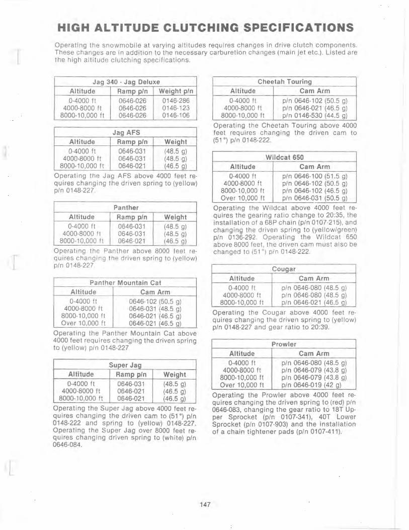
HIGH ALTITUDE CLUTCHING SPECIFICATIONS Operating the snowmobile at varying altitudes requires changes in drive clutch components. These changes are in addition to the necessary carburetion changes (main jet etc .). Listed are the high altitude clutching specifications.
Jag 340 - Jag Deluxe
Altitude Ramp pIn Weight pIn
0-4000 ft 0646-026 0146-286 4000-8000 ft 0646-026 0146-123
8000-10,000 ft 0646-026 0146-106
Jag AFS Altitude Ramp pIn Weight
0-4000 ft 0646-031 (48.5 g) 4000-8000 ft 0646-031 (48.5 g)
8000-10,000 ft 0646-021 (46.5 g)
Operating the Jag AFS above 4000 feet requires changing the driven spring to (yellow) pIn 0148-227.
Panther Altitude Ramp pIn Weight 0-4000 ft 0646-031 (48.5 g)
4000-8000 ft 0646-031 (48.5 g) 8000-10,000 ft 0646-021 (46.5 g)
Operating th e Panther above 8000 feet requires changing the driven spring to (yellow) pIn 0148-227.
Panther Mountain Cat
Altitude Cam Arm 0-4000 ft 0646-102 (50.5 g)
4000-8000 ft 0646-031 (48.5 g) 8000-10,000 ft 0646-021 (46.5 g) Over 10,000 ft 0646-021 (46.5 g)
Operating the Panther Mountain Cat above 4000 feet requires changing the driven spring to (yellow) pIn 0148-227
Super Jag Altitude Ramp pIn Weight 0-4000 ft 0646-031 (48.5 g)
4000-8000 ft 0646-021 (46.5 g) 8000-10,000 ft 0646-021 (46.5 g)
Operating the Super Jag above 4000 feet requires changing the driven cam to (51 0
) pIn 0148-222 and spring to (yellow) 0148-227. Operating the Super Jag over 8000 feet requires changing driven spring to (white) pIn 0646-084.
147
Cheetah Touring
Altitude Cam Arm
0-4000 ft pIn 0646-102 (50.5 g) 4000-8000 ft pIn 0646-021 (46.5 g)
8000-10,000 ft pIn 0146-530 (44.5 g)
Operating the Cheetah Touring above 4000 feet requires changing the driven cam to (51 0
) pIn 0148-222.
Wildcat 650
Altitude Cam Arm
0-4000 ft pIn 0646-100 (51.5 g) 4000-8000 ft pIn 0646-102 (50.5 g)
8000-10,000 ft pIn 0646-102 (46.5 g) Over 10,000 ft pIn 0646-031 (50.5 g)
Operating the Wildcat above 4000 feet requires the gearing ratio change to 20:35, the installation of a 68P chain (pIn 0107-215), and changing the driven spring to (yellow/green) pIn 0136-292. Operating the Wildcat 650 above 8000 feet , the driven cam must also be changed to (51 0) pIn 0148-222.
Cougar
Altitude Cam Arm
0-4000 ft pIn 0646-080 (48.5 g) 4000-8000 ft pIn 0646-080 (48.5 g)
8000-10,000 ft pIn 0646-021 (46.5 g)
Operating the Cougar above 4000 feet requires changing the driven spring to (yellow) pIn 0148-227 and gear ratio to 20:39.
Prowler
Altitude Cam Arm
0-4000 ft pIn 0646-080 (48.5 g) 4000-8000 ft pIn 0646-079 (43.8 g)
8000-10,000 ft pIn 0646-079 (43.8 g) Over 10,000 ft pIn 0646-019 (42 g)
Operating the Prowler above 4000 feet requires changing the driven spring to (red) pIn 0646-083, changing the gear ratio to 18T Upper Sprocket (pIn 0107-341), 40T Lower Sprocket (pIn 0107-903) and the installation of a chain tightener pads (pIn 0107-411).

Pantera
Altitude Cam Arm
0-4000 ft pIn 0646-080 (48.5 g) 4000-8000 ft pIn 0646-079 (43.8 g)
8000-10,000 ft pIn 0646-079 (43.8 g) Over 10,000 ft pIn 0646-019 (42 g)
Operating the Pantera above 4000 feet requires changing the drive clutch spring to (red) pIn 0646-083.
EI Tigre EXT & EI Tigre EXT Mountain Cat
Altitude Cam Arm 0-4000 ft pIn 0646-105 (50.5 g)
4000-8000 ft pIn 0646-02l (46.5 g) 8000-10,000 ft pIn 0646-078 (45 g) Over 10,000 ft pIn 0646-079 (44 g)
Operating the EI Tigre EXT and the EI Tigre EXT Mountain Cat above 4000 feet requires changing the lower sprockets to 39T (pIn 0107-220) and changing the chain to 70P (pIn 0107-216).
148
Jag Mountain Cat Altitude Cam Arm 0-4000 ft 0646-027 (44.5 g)
4000-8000 ft 0646-019 (42 g) 8000-10,000 ft 0646-030 (41 g)
Operating the Jag Mou nta in Cat above 4000 feet requires changing the driven spring to (white) pIn 0648-010.
Panther Mountain Cat Altitude Cam Arm
0-4000 ft 0646·102 (50.5 g) 4000-8000 ft 0646-031 (48.5 g)
8000-10,000 ft 0646-021 (46.5 g) Over 10,000 ft 0646-021 (46.5 g)
Operating the Panther Moun tain Cat above 4000 feet , change the driven spirng to (yellow) , pIn 0148-227.
(

MAIN JET CHARTS
ALTITUDE - FEET (METERS) .... RICHER WILDCAT 650 LEANER.
Over 12,000 (over 3658) 270 260 250 240 10,000 (3048) 290 280 270 260 8,000 (2438) 320 300 290 280 6000 (1829) 340 330 310 300 4000 (1219) 370 350 330 320 2000 (610) 400* 380 360 350
0(0) 420 410 390 380
ALTITUDE - FEET (METERS) .... RICHER CHEETAH TOURING - COUGAR LEANER.
Over 12,000 (over 3658) 190 180 180 170 10,000 (3048) 200 190 190 180 8000 (2438) 210 210 200 190 6000 (1829) 220 220 210 200 4000 (1219) 240 230 220 210 2000 (610) 260 250 240 230
0(0) 280 270 260· 250
ALTITUDE - FEET (METERS) .... RICHER PANTHER - JAG AFS LEANER.
Over 10,000 (3048) 8000-10,000 (2438-3048) 5000-8000 (1524-2438)
0-5000 (0-1524)
230 240 270 320
220 230 260 310
210 220 250 290
200 210 230 280
ALTITUDE - FEET (METERS) .... RICHER EL TIGRE EXT LEANER. Over 12,000 (over 3658) 230 220 220 210
10,000 (3048) 250 240 230 220 8000 (2438) 260 250 240 230 6000 (1829) 280 270 260 250 4000 (1219) 300 290 280 270 2000 (610) 320 310' 300 290
0(0) 340 330 320 310
ALTITUDE - FEET (METERS) .... RICHER PANTERA LEANER.
Over 12,000 (over 3658) 160 150 140 140 10,000 (3048) 170 160 160 150 8000 (2438) 190 180 170 160 6000 (1829) 210 200 190 180 4000 (1219) 220 210 200 190 2000 (610) 240 230 220 210
0(0) 260 250 240' 230
TEMPERATURE - - 40 to - 20 - 20 to 0 o to + 20 + 20 to + 40 Fahrenheit (Celsius) (- 40 to - 29) (-29 to -18) (- 18 to - 7) (- 7 to + 4)
* Production Jet
II NOTE: Operating the WILDCAT 650 at high altitudes requires the following carburetion changes: 5000-10,000 feet, install an AA-O (224) needle jet; 1 a,ooo feet and above, install a Z·5 (224) needle jet.
Keep the jet needle circlip in the 2nd position for all altitudes.
Operating the COUGAR and CHEETAH TOURING at an altitude of 5000 feet or more, requires installing 30 pilot jets and raising each jet needle circlip 1 clip position. Operating the COUGAR and CHEETAH TOUR· ING at sea level requires installing 280 main jets.
Operating the JAG AFS, PANTERA, and PANTHER above 5000 feet requires raising the jet needle circlip 1 clip position.
Operating the EL TIGRE EXT at an altitude of 4000 feet or more, requires the raising the jet needle circlip 1 Clip position, changing the needle jet to a P4·480 and adjusting the pilot air screws to 1 % turns open.
After the break-in period, the main jet should be changed in accordance to the appropriate main jet chart.
149
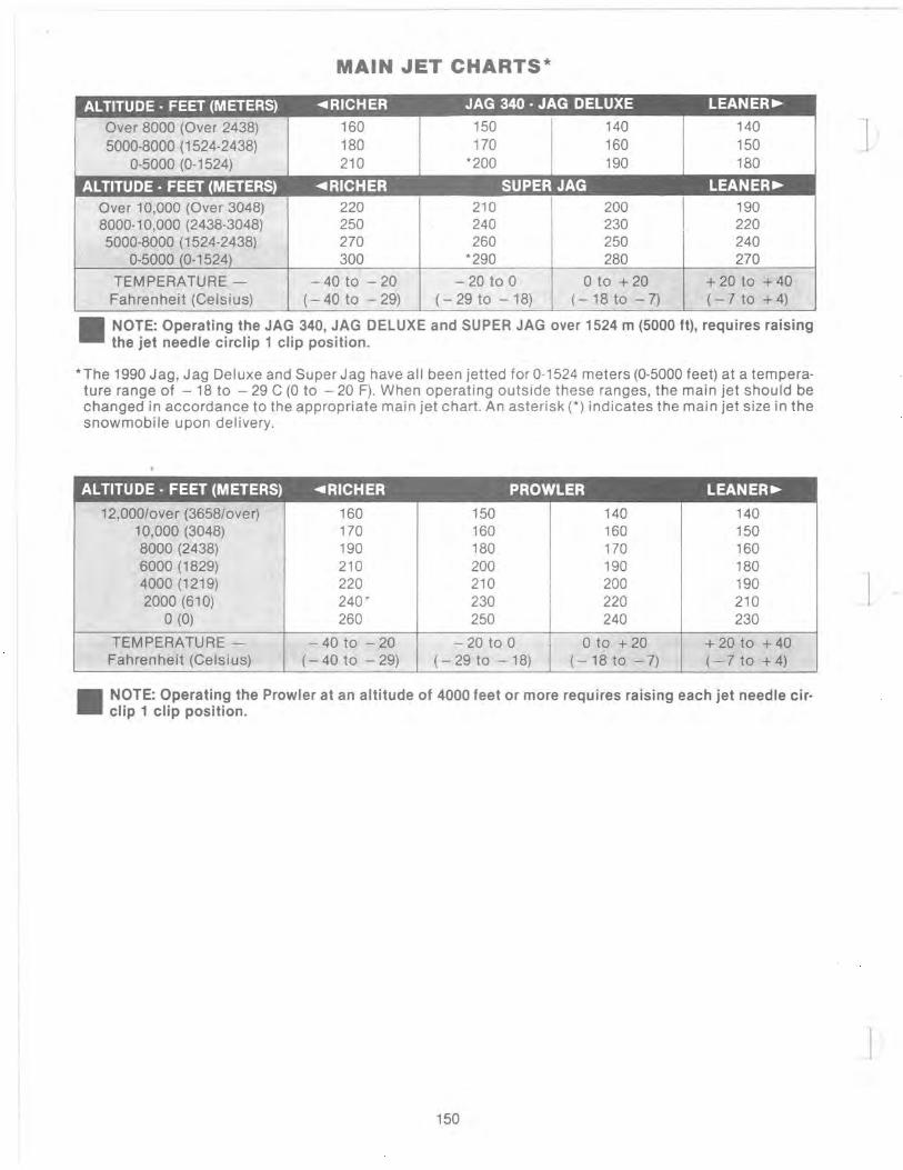
MAIN JET CHARTS·
ALTITUDE· FEET (METERS) ... RICHER JAG 340· JAG DELUXE LEANER~
Over 8000 (Over 2438) 5000-8000 (1524-2438)
0-5000 (0-1524)
ALTITUDE· FEET (METERS)
Over 10,000 (Over 3048) 8000-10,000 (2438-3048) 5000-8000 (1524-2438)
0-5000 (0-1524)
TEMPERATURE -Fahrenheit (Celsius)
160 180 210
"'RICHER 220 250 270 300
- 40 to - 20 (- 40 to - 29)
150 170
*200
140 160 190
SUPER JAG 210 200 240 230 260 250
*290 280
- 20 to 0 o to + 20 (-29to - 18) (-18to -7)
I
140 150 180
LEANER~
190 220 240 270
+ 20 to + 40 (-1 to + 4)
_ NOTE: Operating the JAG 340, JAG DELUXE and SUPER JAG over 1524 m (5000 tt), requires raising the jet needle circlip 1 clip position_
* The 1990 Jag, Jag Deluxe and Super Jag have all been jetted for 0-1524 meters (0-5000 feet) at a temperature range of - 18 to - 29 C (0 to - 20 F). When operating outside these ranges, the main jet should be changed in accordance to the appropriate main jet chart. An asterisk (*) indicates the main jet size in the snowmobile upon delivery.
AL TITUDE • FEET (METERS) "'RICHER PROWLER LEANER~
12,0001over (3658/over) 160 150 140 140 10,000 (3048) 170 160 160 150 8000 (2438) 190 180 170 160 6000 (1829) 210 200 190 180 4000 (1219) 220 210 200 190 2000 (610) 240 ' 230 220 210
o (0) 260 250 240 230
TEMPERATURE - - 40 to - 20 - 20 to 0 o to + 20 + 20 to + 40 Fahrenheit (Cels ius) (- 40 to - 29) (- 29 to - 18) (-18to -7) (- 7 to + 4)
_ NOTE: Operating the Prowler at an altitude of 4000 feet or more requires raising each jet needle cir- clip 1 clip position.
150

.1
1990 CARBURETION STANDARD COMPONENTS
ITEM JAG 340 JAG AFS PANTHER COUGAR SUPER JAG JAG DELUXE
Carburetor VM30 VM34 VM34 VM34 VM34
Number of Carburetors 1 1 1 2 1
Main Jet 200 300 300 260 290
Pilot Jet 25 22.5 22.5 35 22.5
Needle Jet P-4 (169) P-4 (480) P-4 (480) P-6 (480) 0-0 (480)
Jet Needle 5DP7-3 6DH3-4 6DH3-4 6DH2-3 6DH2-3
Slide 3.5 2.5 2.5 3.0 2.5
Air Screw Setting 1- 1/2 1- Y2 1- V2 1- Y2 1- Y2
ITEM PANTERA PROWLER CHEETAH WILDCAT EL TIGRE TOURING 650 EXT
Carburetor VM34 VM34 VM34 VM40 VM38
Number of Carburetors 2 2 2 2 2
Main Jet 240 240 260 400 310
Pilot Jet 35 35 35 50 25
Needle Jet P-4 (480) P-4 (480) P·6 (480) AA-2 (224) 0-0 (480)
Jet Needle 6DH7-3 6DH7-3 6DH2-3 70J2-2 6DH8-4
Slide 3.0 3.0 3.0 3.5 3.5
Air Screw Setting 1- 1/ 2 1- Y2 1· V2 1- Y2 1
NOTE: The carburetor main jet size used by Arctco in all 1990 production models, is a good all around jet and shouldn't be changed unless the area altitude is over 2000 feet. If the altitude is over 2000 feet, the standard main jet supplied with the machine should be changed by selecting the new jet size from the main jet chart found on the clutch guard.
151

1990 DRIVE SYSTEM STANDARD COMPONENTS
MOOEL JAG 340 JAG MOUNTAIN JAG AFS PANTHER PANTHER COUGAR JAG DELUXE CAT MOUNTAIN CAT
Drive Clutch Type Arctic Hex Comet Comet Comet Comet Comet Drive Clutch pi n 0725-018 0725-086 0725-087 0725-087 0725-081 0725-089
Driven Clutch Type Arctic Reverse Arctic Reverse Arctic Reverse Arctic Reverse Arctic Reverse Arctic Reverse Cam Cam Cam Cam Cam Cam
Driven Clutch pin 0726-008 0726-008 0726-015 0726-015 0726-015 0726-015
Drive Clutch Weights pin 0146-286 N/ A N/A N/ A N/A N/A Drive Clutch Ramps pin 0646-026 0646-027 0646-031 0646-031 0646-102 0646-080
44 .5 Grams 48.5 Grams 48.5 Grams 50.5 Grams 48 .5 Grams
Drive Clutch Spring pin 0146-068 0646-096 0646-096 0646-096 0646-096 0646-097 Drive Clutch Spring Color Green Silver Silver Silver Silver BluelRed
Driven Cam pin 0148-229 0148-229 0648-002 0648-002 0648-002 0648-002 Driven Cam Degree 48-44 48 -44 53 53 53 53
Driven Spring pin 0148-176 0148-176 0648-010 0648-010 0648-010 0648-010 Driven Spring Color Black Black White White White White
Center to Center Distance 11.300 11 .300 10.2 in . 10.2 in . 10.2 in. 10.2 in.
Gear Ratio 20/39 20/39 20/39 20/39 20/39 20/35
Drive Belt pin 0227-100 0227-100 0227-103 0227-103 0227-103 0227-103
Drive Belt Length 45-1/2 in. 45-1/2 in. 43-5/8 in . 43-5/ 8 in . 43-5/8 in . 43-5/8 in . ± 3/16 ± 3/16 ± 3/16 ± 3/ 16 ± 3/16 ± 3/16
MODEL PANTERA EL TIGRE EXT PROWLER SUPER JAG CHEETAH WILDCAT 650 TOURING
Drive Clutch Type Comet Comet Comet Comet Comet Comet Drive Clutch pin 0725-088 0725-083 0725·088 072 5-087 0725-082 0725-084
Driven Clutch Type Arctic Reverse Arctic Reverse Arcti c Reverse Arcti c Reverse Arctic Reverse Arctic Reverse Cam Cam Cam Cam Cam Cam
Driven Clutch pin 0726-019 0726-020 0726-019 0726-015 0726-017 0726-018
Drive Clutch Weights pin N/A N/A N/A N/A N/A N/A
Drive Clutch Ramps pin 0646-080 0646-105 0646-080 0646-031 0646-102 0646-100 48.5 Grams 50.5 Grams 48.5 Grams 48.5 Grams 50.5 Grams 52.5 Grams
Drive Clutch Spring pin 0646-097 0646-083 0646-097 0646-096 0646-084 0646-083 Drive Clutch Spring Color BluelRed Red Blue/Red Silver White Red
Driven Cam pin 0148-180 0148-229 0148-180 0648-002 0648-002 0648-002 Driven Cam Degree 45 48/44 45 53 53 53
Driven Spring pin 0648-010 0648-010 0648-010 0648-010 0148-227 0148-227 Driven Spring Color White White White White Yellow Yellow
Center to Center 10.2 10.2 in. 10.2 in . 10.2 in . 10.2 in. 10.2 in.
Gear Ratio 19/39 20/35 20/35 19/39 19/39 24/39
Drive Belt pin 0227-103 0227-103 0227-103 0227-103 0227-103 0627-006
Drive Belt Length 43-5/8 in. 43-5/8 in. 43-5/8 in. 43-5/8 in. 43-5/8 in. 43-5/8 in. ± 3/16 in. ± 3/16 in. ± 3/16 in. ± 3/16 in. ± 3/16 in. ± 3/16 in.
152
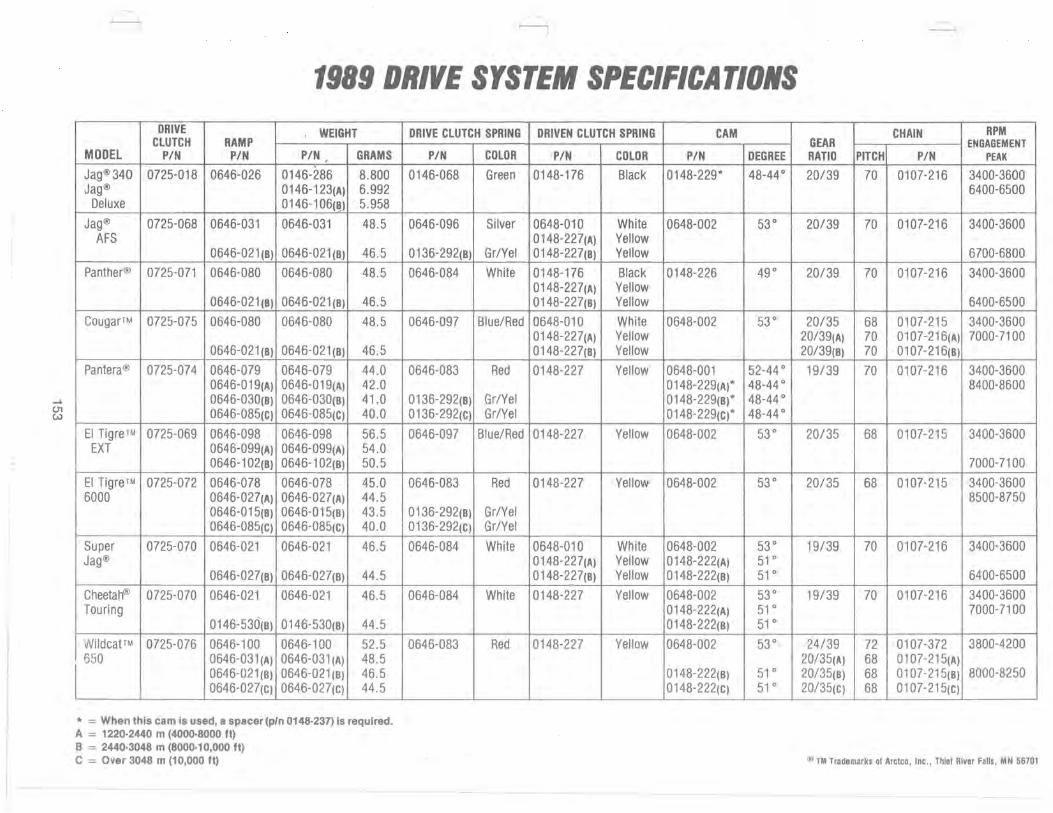
~
U1 W
1989 DRIVE SYSTEM SPECIFICATIONS DRIVE , WEIGHT
CLUTCH RAMP MODEL PIN PIN PIN , GRAMS
Jag®340 0725-018 0646-026 0146-286 8.800 Jag® 0146-123(A) 6.992
Deluxe 0146-106(8) 5.958 Jag® 0725-068 0646-031 0646-031 48.5
AFS 0646-021(8) 0646-021 (8) 46.5
Panther® 0725-071 0646-080 0646-080 48.5
0646-021 (8) 0646-021 (8) 46.5 CougarTM 0725-075 0646-080 0646-080 48.5
0646-021 (8) 0646-021 (8) 46.5 Pantera@ 0725-074 0646-079 0646-079 44.0
0646-019(A) 0646-019(A) 42 .0 0646-030(8) 0646-030(8) 41.0 0646-085(c) 0646-085(c) 40.0
EI Tig re™ 0725-069 0646-098 0646-098 56.5 EXT 0646-099(A) 0646-099(A) 54.0
0646-102(8) 0646-102(8) 50.5
EI Tigre™ 0725-072 0646-078 0646-078 45.0 6000 0646-027(A) 0646-027(A) 44.5
0646-015(8) 0646-015(8) 43.5 0646-085(C) 0646-085(c) 40.0
Super 0725-070 0646-021 0646-021 46.5 Jag®
0646-027(8) 0646-027(8) 44.5
Cheeta~ 0725-070 0646-021 0646-021 46.5 Touring
0146-530(8) 0146-530(8) 44.5
Wildcat TM 0725-076 0646-100 0646-100 52 .5 650 0646-031 (A) 0646-031 (A) 48.5
L 0646-021 (8) 0646-021 (8) 46.5 0646-027(C) 0646-027(C) 44.5
* = When this cam is used, a spacer (pIn 0148·237) is required. A = 1220·2440 m (4000·8000 tt) B = 2440·3048 m (8000·10,000 tt) C = Over 3048 m (10,000 tt)
DRIVE CLUTCH SPRING DRIVEN CLUTCH SPRING CAM
PIN COLOR PIN COLOR PIN DEGREE
0146-068 Green 0148-176 Black 0148-229* 48-44°
0646-096 Silver 0648-010 White 0648-002 53° 0148-227(A) Yellow
0136-292(8) Gr/Yel 0148-227(8) Yellow
0646-084 White 0148-176 Black 0148-226 49° 0148-227(A) Yellow 0148-227(8) Yellow
0646-097 Blue/Red 0648-010 White 0648-002 53° 0148-227(A) Yellow 0148-227(8) Yellow
0646-083 Red 0148-227 Yellow 0648-001 52-44 ° 0148-229(A)* 48-44 °
0136-292(8) Gr/Yel 0148-229(8)* 48-44 ° 0136-292(c) Gr/Yel 0148-229(c)* 48-44°
0646-097 Blue/Red 0148-227 Yellow 0648-002 53°
0646-083 Red 0148-227 Yellow 0648-002 53°
0136-292(8) Gr/Yel 0136-292(c) GrlYel
0646-084 White 0648-010 White 0648-002 53° 0148-227(A) Yellow 0148-222(A) 51 ° 0148-227(8) Yellow 0148-222(8) 51°
0646-084 White 0148-227 Yellow 0648-002 53° 0148-222(A) 51 ° 0148-222(8) 51°
0646-083 Red 0148-227 Yellow 0648-002 53°
0148-222(8) 51° 0148-222(c) 51°
CHAIN RPM I GEAR ENGAGEMENT RATIO PITCH PIN PEAK
20/39 70 0107-216 3400-3600 ; 6400-6500
20/39 70 0107-216 3400-3600
6700-6800
20/39 70 0107-216 3400-3600
6400-6500
20/35 68 0107-215 3400-3600 20/39(A) 70 0107-216(A) 7000-7100 20/39(8) 70 0107-216(8)
19/39 70 0107-216 3400-3600 8400-8600
20/35 68 0107-215 3400-3600
7000-7100
20/35 68 0107-215 3400-3600 8500-8750
19/39 70 0107-216 3400-3600
6400-6500
19/39 70 0107-216 3400-3600 7000-7100
24/39 72 0107-372 3800-4200 20/35(A) 68 0107-215(A) 20/35(8) 68 0107-215(8) 8000-8250 20/35(C) 68 0107-215(c)
@ TM Trademarks of Arctco, tnc., Thief River Falls, MN 56701

-------------- ---
Alternate Carburetor Parts
MIKUNI MAIN JETS AVAILABLE MIKUNI PILOT JETS AVAILABLE
JET PIN JET PIN (VM-SERIES CARBURETORS)
120 6505-270 390 6505-078 JET NO. PIN 130 6505-216 400 6505-124 17.5 6505-218 140 6505-217 410 6505-212 20 6505-138 150 6505-168 420 6505-125 22.5 6505-310 160 6505-064 430 6505-146 25 6505-075 170 6505-065 440 6!;i05-126 27.5 6505-503 180 6505-056 450 6505-147 30 6505-073 190 6505-066 460 6505-127 35 6505-029 200 6505-144 470 6505-148 40 6505-047 210 6505-145 480 6505-149 45 6505-278 220 6505-137 490 6505-150 50 6505-262 230 6505-067 500 6505-151 52.5 6505-261 240 6505-079 520 6505-530 55 6505-255 250 6505-068 530 6505-170 260 6505-017 540 6505-531 270 6505-069 560 6505-172 280 6505-080 580 6505-211 290 6505-123 590 6505-173 MIKUNI INLET NEEDLE ASSEMBLIES AVAILABLE
300 6505-128 600 6505-532 SEAT DIA. CARB. SIZE (MM) PIN 310 6505-136 620 6505-174 320 6505-074 .()40 6505-533 330 6505-070 650 6505-534
1.5 mm (Steel) 28, 30, 32, 34 6505-026 1.5 mm (Viton) 28, 30, 32, 34 6505-160 1.5 mm (Steel) 28 - 34 GVM 6505-245
340 6505-076 660 6505-535 1.5 mm (Steel) 36, 38, 40, 44 6505-103 350 6505-071 680 6505-169 1.5 mm (Viton) 36, 38, 40, 44 6505-171 360 6505-038 700 6505-536 1.8 mm (Viton) 36, 38, 40, 44 6505-175 370 6505-072 710 6505-537 2.0 mm (Viton) 36, 38, 40, 44 6505-176 380 6505-077 720 6505-538
MIKUNI PISTON VALVES AVAILABLE MIKUNI NEEDLE JETS AVAILABLE CARBURETOR NEEDLE JET PIN
SLIDE SIZE (mm) PIN
2.0 28-30 6505-048 3.0 28-30 6505-161 3.5 30 6505-528 1.5 32-34 6505-256 2.0 32-34 6505-002 2.0 32-34 6505-257 2.5 32-34 6505-246 3.0 32-34 6505-222 3.5 32-34 6505-248 2.5 34 6505-500 3.0 34 6505-507 2.0 36 6505-177 2.5 38 6505-254 3.5 38 6505-436 3.5 38 6505-526 4.0 38 6505-504 1.0 40-44 6505-092 2.0 40-44 6505-179 2.5 40-44 6505-253 3.5 40-44 6505-548
0-8 (182) 6505-181 p-o (159) 6505-155 p-o (166) 6505-007 p-o (169) 6505-051 P-4 (159) 6505-221 P-4 (166) 6505-502 P-4 (480) 6505-540 P-4 (169) 6505-164 P-5 (480) 6505-542 P-6 (159) 6505-247 P-6 (166) 6505-268 P-6 (480) 6505-539 P-6 (251) 6505-235 P-8 (159) 6505-298 P-8 (166) 6505-433 0-0 (159) 6505-260 0-0 (166) 6505-190 0-0 (480) 6505-529 0-2 (166) 6505-508 0-4 (166) 6505-214 0-5 (159) 6505-119 0-5 (166) 6505-520
MIKUNI JET NEEDLES AVAILABLE 0-6 (166) 6505-506
JET NEEDLE PIN R-O (166) 6505-505 Z-5 (224) 6505-541
6CH3 6505-519 AA-O (224) 6505-544 60H2 6505-252 AA-2 (224) 6505-545 60H3 6505-509 AA-5 (244) 6505-099 60H4 6505-003 88-0 (224) 6505-182 60H7 6505-215 88-5 (224) 6505-180 60H8 6505-236 70J2 6505-546
154

ARCTIC DRIVE BELT REPLACEMENT CHART 1967
Panther P8, P12, P15 ......... 0100-022
1968 Cougar ..................... 0100-022 Panther P-20 w/o Kohler Eng ... 0100-032
w/Kohler Eng .............. 0100-022
1969 Panther Models, P35H ........ 0100-042 P17J, P19J, K or S, P22J or H . .. 0100-043 P12K, P19H, P20W, P23K ...... 0100-066 P17H .................. .... 0100-080 P27H . .. . ........ . ......... 0100-088
1969·71 Mini Bike .... . ............ .. 2201-001
1970 Panther P246, P292, P295,
P340 Eng .. ........ ... . .... 0100-080 P303, P399 Eng ............... 0100-088 P440 Eng ................. . .. 0100-092 P634 , P760, P793 Eng . . .. .. ... 0100-042
1971 Panther & Puma
P303 (303cc), P340, PM340 (340cc) . . . . . . . . . . . . . . .. ..0100-088 P399, PM399 (398cc), P440, PM440 (436cc) . . . . . . . ... 0100-092 P650, PM 650, (634cc) . . ..... 0100-042
Ly,nx L295 (292cc), L303 (303cc), L340 (340cc) . .. .. ..... . . . .. 0100-080
Ext E295 (292cc) ............. 0100-088 E340 (339cc), E399 (398cc),
E440 (436cc) ... ........... 0100-092
1972 Uynx 292AL, Panther 292AP
(Kawasaki KT 150B) ........ 0100-080 Puma 340APU, Cheetah 340AC,
Panther 340AP (Kawasaki TIA 340S1), Panther 303WP (Wankel KM 914) ... ... ..... 0100-088
Puma 399APU, Cheetah 399AC, Panther 399AP (Kawasaki TIA 400S1), Cheetah 440AC, Panther 440AP (Kawasaki TIA 440S1) ... . ... 0100-092
Ext (All Engines) ........... .. 0227-002
1973 Lynx 292 . .................. 0100-080 Pu ma 440 . .. . .. ... .. . ...... 0100-092 Cheetah 340 ............... 0227-007t Cheetah 400, 440 ....•.. .... 0227-007t Panther 340 ................ 0227-007t Panther 400,440 .. . ......... 0227-007t Panther Wankel ......... ... 0100-088 EI Tigre 250,340 ....... ... .. 0227-011 EI Tigre 400,440 .. . ... ...... 0227-011 Ext 290,340 ............ . ... 0227-020 Ext 440,650 .......... ...... 0227-020
1974 Lynx 1292. . . . . . _ ........ 0227-011 Lynx I 295 . . ...... . . .. ... .. . 0227-007t Lynx 11340,440 .......... . .. 0227-007t Cheetah 340, 440 ... . ....... 0227-007t Panther 295W, 340, 440 .... . . 0227-007t EI Tigre 295,340,400,440 .... 0227-014
1975 EI Tigre Z, 340, & 440 . . . . .. . .. 0227-020 Pantera .... ..... ...... . ... 0227-007t Lynx 250 ............ .. . . ... 0227-017 Cheetah295 ............... 0227-016 Cheetah 340, 440 ...... .. ... 0227-007 Panther 340,440 ... . .. . ... .. 0227-007 Jag340 . ... . ..... ... _ ...... 0227-014
1976 EI Tigre 4000 & 5000 . .. ... . .. 0227-020 Pantera 5000 ..... . ...... . .. 0227-020 Panther 4000 . .. .. .. ........ 0227-007t Cheetah 4000 . ... . . .. .. .... 0227-007t Panther 5000 ............. . . 0227-019 Cheetah5000 ..... . .... . ... 0227-019 Jag 2000 & 3000 ..... ...... . 0227-014 Lynx 250. . . . . . . ... 0227-017 Arctic Z ..... . ....... . 0227-022 Cross Country Cat ... .. . . ... 0227-020
1977 EI Tigre 4000 & 5000 ...... 0227-020 Pantera 5000F/A & 5000F/C ... 0227-020 Panther 4000 ............... 0227-007t Panther 5000 . . .. 0227-019 Cheetah 4000 . . 0227-019 Jag 3000. . .. . ............ 0227-014 Lynx 2000T & 2000S .... 0227-007t
1978 Lynx 2000S & 2000T .... . .... 0227-007t Jag 2000 & 3000 ... . . ..... . . 0227-014 Panther 4000 .. . ............ 0227-007t Panther 5000 ...... . .. . ..... 0227-019 Cheetah 5000 ..... ... ... ... 0227-019 EI Tigre 5000F/A & 6000UC ... 0227-019 Pantera 5000F/A & 5000F/C ... 0227-020
1979 Lynx 2000S & 2000T ........ . 0227-007t Jag 2000, 3000 & FC/OI. .... . . 0227-014 Panther 5000F/C . . .. ........ 0227-019 EI Tigre 5000F/A & 6000UC ... 0227-019 Pantera 5000F/C . . .......... 0227-020 Trail Cat ......... . ......... 0227-019 EI Tigre 340 & 440
Special Edition ........ . .. 0227-026
1980 Lynx 2000S & 2000T ... .. . ... 0227-007t Jag 2000, 3000, & 3000F/C ... . 0227-01 4 Trail Cat 3000 & 4000 ... .. .. . 0227-019 Panther, Pantera,
EI Tigre 5000 & 6000 .. . .... 0227-019
t Also Available in Kevlar (Fiber 8) Material-Part 0227-019
155
1981 Jag.. . . . . ... 0227-014 Trail Cat. . ..... .... .. 0227-019 Panther, Pantera . . . . . .0227-019 EI Tigre 5000 . .......... . ... 0227-030 EI Tigre 6000 . . .0227·032
1984 Panther EI Tigre 6000
.. 0227·030 -... 0227·032
1985 Jag . ..... . . . .. . .... . 0227-100 Panther, Pantera . . . .0227-030 Cougar. . . . . . . . .... 0227-030 .EI Tigre 6000 .............. . 0227-032
1986 Jag............. . .0227·100 Panther, Pantera. . . . . .0227-030 Cougar, Cheetah F/C . .0227-030 EI Tigre, Cheetah UC ....... . 0227·032
1987 Jag 340, 440. . . ... 0227-100 Super Jag . . . .0227·030 Panther, Pantera. . .... 0227·030 Cougar, Cheetah F/C .' .... 0227-030 EI Tigre 5000, 6000 .......... 0227·032 Cheetah UC . . 0227·032
1988 Jag 340, 440 & Deluxe ........ 0227·100 Super Jag, Panther.. .0227-030 Cougar, Pantera . . . . .0227·101 EI Tigre 5000, 6000 . . . .0227·101 Cheetah Touring, UC . . . ... 0227·101 Wildcat 650 ......... . .0627-004
1989 Jag 340 & Deluxe ...... .. .. . 0227-100 SuperJag,JagAFS ......... 0227-032 Panther, Cougar .... .. .. . ... 0227-032 Pantera, Cheetah Touring . . .. 0227-032 EI Tigre 6000 & EXT .. ... .. . .. 0227-032 Wildcat 650 ...... .. ....... . 0627·001
1990 Jag@ 340 ....... .. .. . . .... . 0227-100 Jag Mountain Cat@ ......... 0227-100 Panther~ Jag AFS . ..... ... . 0227-103 CougarTM, Cheetah@ Touring .0227-103 Pantera~ EI Tigre™ EXT .. . .. 0227-103 Wildcat™ 650 ...... . ... ' .. . . 0627-006 Prowle~ .................. 0227-103
Extended life drive belts for high altitude operation are available under the following part numbers:
Standard Extended Belt Life Belt
0227-030 = 0627-002 0227-032 = 0627-001 0227-1 01 0627-004 0227 -103 = 0627-006
" TM Trademarks of Areteo, Inc., Thief River Falls , MN 56701
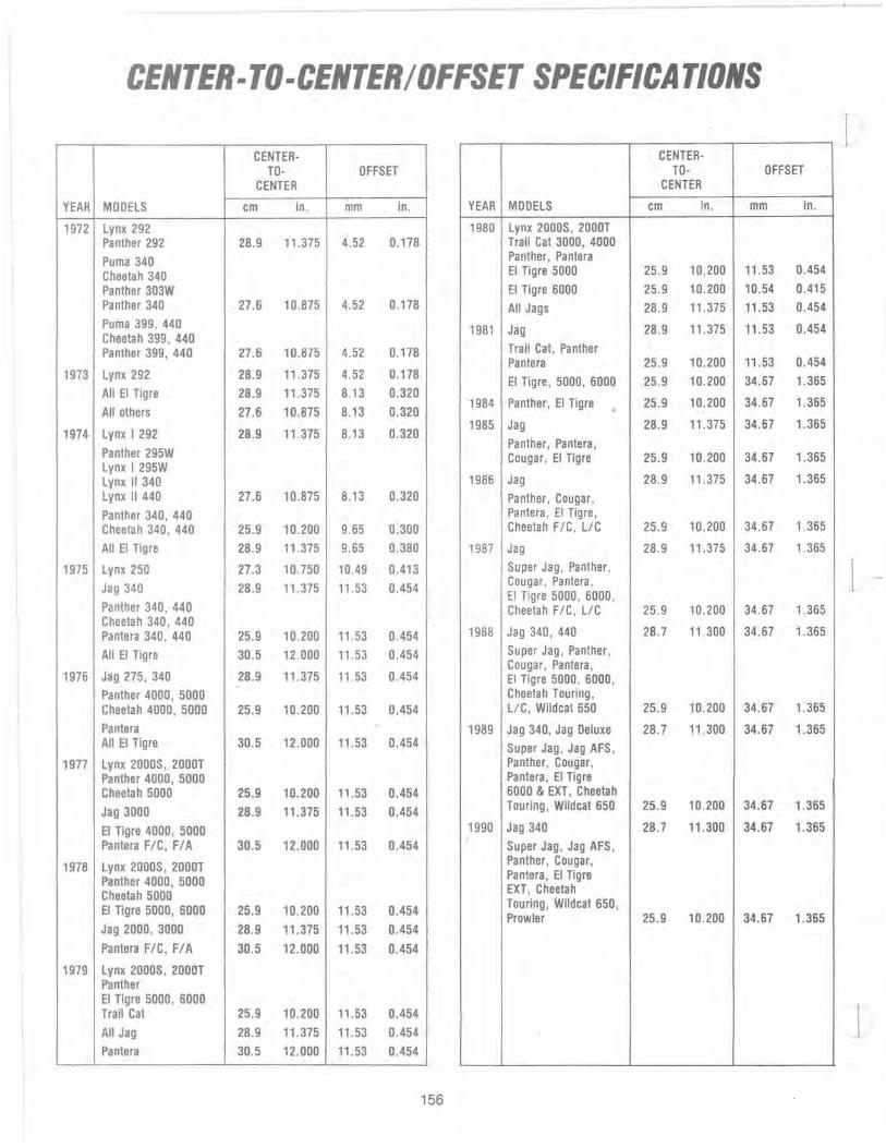
CENTER-TO-CENTER/OFFSET SPECIFICATIONS
CENTER- CENTER-TO- OFFSET TO- OFFSET
CENTER CENTER
YEAR MOOElS cm in. mm in. YEAR MODELS cm in. mm in.
1972 lynx 292 1980 lynx 2000S, 2000T Panther 292 28.9 11.375 4.52 0.178 Trail Cat 3000, 4000
Puma 340 Cheetah 340
Panther, Pantera EI Tigre 5000 25.9 10.200 11.53 0.454
Panther 303W EI Tigre 6000 25.9 10.200 10.54 0.415 Panther 340 27.6 10.875 4.52 0.178 All Jags 28 .9 11 .375 11.53 0.454 Puma 399, 440 Cheetah 399, 440 Panther 399, 440 27.6 10.875 4.52 0.178
1981 Jag 28 .9 11.375 11.53 0.454
Trail Cat, Panther Pantera 25.9 10.200 11.53 0.454
1973 lynx 292 28.9 11.375 4.52 0.178
All EI Tigre 28.9 11.375 8.13 0.320
All others 27.6 10.875 8.13 0.320
EI Tigre, 5000, 6000 25.9 10.200 34.67 1.365
1984 Panther, EI Tigre 25 .9 10.200 34.67 1.365
1974 lynx I 292 28.9 11.375 8.13 0.320
Panther 295W lynx I 295W lynx II 340
1985 Jag 28.9 11.375 34.67 1.365
Panther, Pantera, Cougar, EI Tigre 25.9 10.200 34.67 1.365
1986 Jag 28.9 11.375 34.67 1.365 lynx II 440 27.6 10.875 8.13 0.320 Panther, Cougar, Panther 340, 440 Cheetah 340, 440 25.9 10.200 9.65 0.300
Pantera, EI Tigre, Cheetah FIC, lIC 25.9 10.200 34.67 1.365
All EI Tigre 28.9 11 .375 9.65 0.380 1987 Jag 28.9 11.375 34.67 1.365
1975 lynx 250 27.3 10.750 10.49 0.413
Jag 340 28.9 11.375 11.53 0.454
Pa nther 340, 440
Super Jag, Panther, Cougar, Pantera, EI Tigre 5000, 6000, Cheetah FIC, llC 25.9 10.200 34.67 1.365
Cheetah 340, 440 Pa ntera 340, 440 25.9 10.200 11.53 0.454 1988 Jag 340, 440 28.7 11.300 34 .67 1.365
All EI Tigre 30.5 12.000 11.53 0.454
1976 Jag 275, 340 28.9 11.375 11.53 0.454
Super Jag, Panther, Cougar, Pantera, EI Tigre 5000, 6000,
Panther 4000, 5000 Cheetah Touring, Cheetah 4000, 5000 25.9 10.200 11.53 0.454 lIC, Wildcat 650 25.9 10.200 34.67 1.365
Pantera - 1989 Jag 340, Jag Deluxe 28.7 11.300 34.67 1.365 All EI Tigre 30.5 12.000 11.53 0.454 Super Jag, Jag AFS,
1977 lynx 2000S, 2000T Panther, Cougar, Panther 4000, 5000 Pa ntera, EI Tigre Cheetah 5000 25.9 10.200 11.53 0.454 6000 & EXT, Cheetah
Jag 3000 28.9 11.375 11.53 0.454 Touring, Wildcat 650 25.9 10.200 34.67 1.365
EI Tigre 4000, 5000 1990 Jag 340 28.7 11.300 34.67 1.365 Pantera FIC, FIA 30.5 12.000 11.53 0.454 Super Jag, Jag AFS,
1978 lynx 2000S, 2000T Panther 4000, 5000 Cheetah 5000 EI Tigre 5000, 6000 25.9 10.200 11.53 0.454
Panther, Cougar, Pantera, EI Tigre EXT, C heeta h Touring, Wildcat 650, Prowler 25.9 10.200 34.67 1.365
Jag 2000, 3000 28.9 11.375 11.53 0.454
Pantera FIC, F/A 30.5 12.000 11.53 0.454
1979 lynx 2000S, 2000T Panther EI Tigre 5000, 6000 Trail Cat 25.9 10.200 11.53 0.454
All Jag 28.9 11.375 11.53 0.454
Pantera 30.5 12.000 11.53 0.454
156

DRIVE SYSTEM COMPONENTS
Below is a list of Comet Drive Clutch and Arctic Driven Clutch Components that are available through the Arctco Parts Department. Hopefully, this information will be useful when doing any fine tuning on the drive system. There now is virtually a cam arm weight for most all needs.
COMET CAM ARMS
pin Grams pin Grams
0646-085 40.0 0646-009 46.5 0646·030 41.0 0646-021 46.5 0646·019 42.0 0146·514 48.0 0646-015 43.5 0646·031 48.5 0646-079 43.5 0646-080 48.5 0146-525 44.0 0646-102 50.5 0646-002 44.0 0646-100 52.5 0646-027 44.5 0646-099 54.0 0146-530 44.5 0646-098 56.5 0646-078 45.0
SPRING - COMET DRIVE
pin Color Rate @ 2 3/8" Rate @ 1 3/8"
0646-083 Red 92 222 0646-097 BluelRed 68 197 0646-096 Silver 85 169 0646-084 White 78 178 0136-292 Yellow/Green 134 264
DRIVEN CAMS ARCTIC REVERSE CAM DRIVEN SPRINGS - ARCTIC DRIVEN
pin Degree pin Color
0148-226 49 0148-227 Yellow 0148-229 * 48/44 0148-176 Black
*(Must also use pIn 0148-237, Spacer) 0648-010 White 0148-222 51 0648-001 52/44 0648-002 53 0648·005 55 0648-006 57
157

1 _
ARCTIC CAT DRIVE BELT DIMENSION CHART
BEL T PIN LENGTH WIDTH
0100-022 41 3/8 + 3/64 inch 1 3/16 nch 0100-032 43 1/2 + 3/64 inch 1 3/16 nch 0100-042 46 3/4 + 3/64 inch 1 3/16 nch 0100-043 46 9/16 + 3/64 inch 1 3/16 nch 0100-066 45 7/16 + 3/64 inch 1 3/16 nch 0100-080 44 1/8 + 3/8 inch 1 3/16 nch 0100-088 43 1/8 + 3/16 inch 1 3/16 nch 0100-092 43 13/16 + 3116 inc h 1 1/4 inch 0227-002 47 1/2 + 3/16 inch 1 1/4 inch 0227-007 43 1/4 + 3/16 inch 1 1/4 inch 0227-010 49 + 3/16 inch 1 1/4 inch 0227-011 44 + 3/16 inch 1 1/4 inch 0227-014 45 1/2 + 3/16 inch 1 1/4 inch 0227-016 45 1/16 + 3/16 inch 1 1/4 inch 0227-017 42 13/16 + 3116 inch 1 1/4 inch 0227-019 43 1/4 + 3/16 inch 1 1/4 inch 0227-020 46 11/16 + 3116 inch 1 1/4 inch 0227-022 45 1/2 + 3/16 inch 1 1/4 inch 0227-023 45 7/16 + 1/8 inch 1 1/4 inch 0227-026 43 1/4 + 3/16 inch 1 1/4 inch 0227-027 43 1/4 + 3/16 inch 1 1/4 inch 0227-030 43 1/2 + 3/16 inch 1 3/8 inch 0227-032 43 5/8 + 3/16 inch 1 3/8 inch 0227-100 45 1/2 + 3/16 inch 1 3/8 inch 0227-101 435/16 + 3/16 inch 1 3/8 inch 0227-103 43 5/8 + 3/16 inch 1 3/8 inch
*0627-001 43 5/8 + 3/16 inch 1 3/8 inch *0627-002 43 3/8 + 3/16 inch 1 3/8 inch *0627-004 43 5/16 + 3/16 inch 1 3/8 inch *0627-006 43 5/8 + 3/16 inch 1 3/8 inch
* High Performance Belt
158

• 1990 DRIVE SYSTEM SPECIFICATIONS
DRIVEN CLUTCH SPRING CAM
PIN COLOR PIN DEGREE
Black 0148-229" 48-44" 20/39 70 0107-216 3400-3600 6400-6500
Jag'" AFS I 0725-068 I 0646-031 I 0646-031 I 48_5 I 0646-096 Silver I 0648-010 White 0648-002 53" 20/39 70 0107-216 3400-3600 6500-6700 Yellow Yellow
Panther'" I 0725-068 I 0646-031 0646-031 48.5 0646-096 Silver 0648-010 White 0648-002 I 53" I 20/39 I 70 I 0107-216 I 3400-3600 I 6500-6700 0148-227(A) Yellow
0646-021(8) 0646-021(8) 46.5 0148-227(8) Yellow
Panther'" Mountain Cat I 0725-081 I 0646-102 0646-102 50.5 0646-096 Silver 0648-010 White 0648-002 53" 20/39 70 0107-216 3400-3600 6500-6700 0646-031(A) 0646-031 (A) 48.5 0148-227(A) Yellow
(8) 0646-021(8) 46.5 0148-227(8) Yellow CougarT• 1 0725-075 1 0646-080 0646-080 48.5 0646-097 BluelRed 0648-010 White 0648-002 53" 20/35 68 0107-215 3400-3600 7000-7100 Cougar Mountain Cat 0148-227(A) Yellow 20/39(A) 70 0107-216(A)
Yellow 20/39(8) 70 0107-216(8)
Pantera'" I 0725-075 I 0646-080 I 0646-080 I 48.5 I 0646-097 Blue/Red I 0648-010 I White 0148-180 45" 19/39 70 0107-216 I 3400-3600 I 7400-7500 0646-083(A) Red 0646-083(8) Red
Red
EI Tigre T• EXT - EI Tigre 0725-083 0646-105 0646-105 50.5 0646-083 Red 0648-010 White 0148-229" 48-4 4" 20/35 68 0107-215 I 3400-3600 I 7500-7800 EXT Mountain Cat 0646-021(A) 0646-021(A) 46.5 0148-226(A) 49" 20/39(A) 70 0107-216(A)
I 0646-078(8) 0646-078(8) 45.0 0148-226(8) 49 " 20/39(8) 70 0107-216(8)
(J1 0646-079(C) 0646-079(c) 43.5 0148-226(C) 49" 20/39(C) 70 0107-216(C) CD ProwlerT• 0725-075 0646-0800 0646-080 48.5 0646-097 BluelRed 0648-010 White 0148-180 45" 20/39 70 0107-216 I 3400-3600 I 7400-7500
0646-083(A) Red 0646-083(8) Red
Red
Super Jag'" I 0725-068 I 0646-031 I 0646-031 I 48.5 I 0646-096 I Silver 0648·010 White 0648-002 53" I 19/39 I 70 I 0107-216 I 3400·3600 I 6400-6500 0148-227(A) Yellow 0148-222(A) 51"
0646·084(8) White 0148-22718) Yellow 0148-222(8) 51" White 0148-2271c) Yellow 0148-222(C) 51"
Cheetah'" Touring 0725-082 0646·102 0646-102 50.5 0646-084 White" 0148·227 Yellow 0648-002 53" 19/39 70 0107-216 3400-3600 7000·7100 0646-021(A) 0646-021(A) 46.5 0148-222(A) 51" 0146-530(8) 0146-530(8) 44.5 0148-222(8) 51" 0146·530(C) 0146-530(C) 44.5 0148-222(C) 51"
Jag' · 340 131" Track 0725·036 0646-027 0646-027 44.5 0646-096 Silver 0148·176 Black 0148-229" 48/44" 20/39 70 0107-216 3400·3600 6200-6500 0646-0 19(A) 0646-019(A) 42.0 0648·010IA) While 0646-030(8) 0646-030(8) 41.0 0648-010(8) White
41 .0 0648-01OIC) White
Wildcat T• 650 - Wildcat 1 0725-076 1 0646·100 0646-100 52.5 0646-083 Red 0148-227 Yellow 0648-002 53" 24/39 72 0107-372 I 3800-4000 I 8000-8250
650 Mountain Cat 0646-102(A) 0646-102(A) 50.5 0136-292(A) Gr/Yel 0648-002(A) 53" 20/35(A) 68 0107-215(A) 0646-102(8) 0646-102(8) 50.5 0136-292(8) Gr/Yel 0148-222(8) 51" 20/35(8) 68 0107-215(8) 0646-031 (C) 0646-031 (C) 48.5 0136-292(C) Gr/Yel 0148-222tCI 51" 20/35tCI 68 0107-21
• = When this cam Is used, a spacer (pin 0148·237) is required . A = 1220-2440 m (4000·8000 ttl 8 = 2440·3048 m (8000-10,000 ttl C = O.er 3048 m (10,000 ttl
('0, tM Trademarks 01 ArclcD, Inc . Thiel River Falls, MH 56701
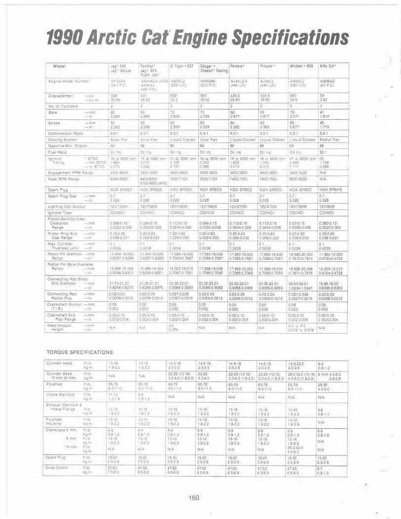
1990 Arctic Cat~ Engine Specifications !
Model 1 Jag' 340 Panther~ EI Tigre'" EXT Cougar'" Pantera" Prowler I '.~ Wildcat '" 650 Kitty Cat'·
~Deluxe Jag' AFS Cheetah" Touring
I Super Jag'
i Engine Model Numbe' , AF34A9 AK44A2·A (AFS) AB53L2 AM50A6 AJ44L2,A AJ44L2 AA65L3 I AB06A2 I (340 F/C ) I AK44A2 (530 UC) (500 F/C) (440 UC) (440 UG) , 1650 UC) (60 F/C)
(440 FIG)
I Displacement -cc 339 431 529 500 435,8 435,8 650 59 -cu In. 20,68 26.29 32.3 30,50 26,60 26.60 39,6 3.60
No, of Cylinders 2 2 2 2 2 2 2 I
Bore -mm 60 65 72 70 68 68 78 41 -In. 2,362 2,559 2,835 2,756 2,677 2,677 3.071 1.614
Stroke -mm 60 65 65 65 60 60 68 45 -In. 2,362 2,559 2,559 2,559 2,362 2,362 2,677 1,772
Compression Ratio 6,8:1 6,5:1 6,6:1 6.4:1 6.5:1 6,5:1 6,3:1 6,6:1
Cooling System Axial Fan Axial Fan liquid Cooled Axial ~an liquid Cooled liquid Cooled liquid Cooled Radial Fan
Gasoline-Min. Octane 88 88 88 88 88 88 88 88
Fuel RatiO Olllnj, Oil In), Oillnj, Oillnj, Oillnj, Oillnj. 10illn). 50:1
Ignition • BTDC 18 @ 6000 rpm 18 @ 6000 rpm 21 @ 6000 rpm 18 @ 6000 rpm 18 @ 6000 rpm 18 ei· 6000 rpm I 21 @ 6000 rpm i 20 i Timing -mm BTDC i 1 860 2,032 I 2.725 2,032 1,860 1 860 ~ 2830 , 1.728 I
0.080 0.080 0.073 l o,on ! 0.111 ' 0,068 I I - ,no BTDC 0.073 0.107
I i Engagement RPM Range 3400·3600 3400·3600 3400·3600 3400·3600 3400·3600 3400,3600 --'3800.4200 ! N/A
I Peak RPM Range i 6400·6500 6400·6500 7000,7100 7000·7100 7400·7500 7400,7500 , 8000.8250 I N/A I I 6700·6800 IAFS)
Spark Plug NGK BR8ES NGK BR9ES NGK BR9ES NGK BR9ES NGK BR9ES NGK BR9ES NGK BR9ES NGK BR6HS
Spark Plug Gap -mm 0.7 0.7 0,7 0,7 0.7 0.7 0.7 0,7 -in. 0,028 0.028 0.028 0.028 0,028 0,028 0,028 0,028
lighting Coil Output 12V/150W 12V/150W 12V/150W 12V/150W 12V/210W 12V/21OW 12V/150W 12V/35W
Ignitien Type CDIINCI CDI/NCI CDI/NCI CDI/NCI CDiINCI CDiINCI CDI/NCI CDI/NOI
Piston Skirt/Cylinder Clearance - mm 0,058·0, I 5 0.084·0,15 0,113·0.15 0.084·0,15 0,113·0,15 0,113·0,15 0,07·0,15 0,050·0,13
Range -in. 0,002300.006 0.0033·0,006 0,0044·0,006 0,0033·0,006 0,0044·0,006 0,0044·0.006 0,0028·0,006 0,0020·0,005
Piston Ring End -mm 0.15·0,80 0.20·0.83 0.20·0.80 0.20·0.83 0.20·0,83 0.20·0,83 0.20·0,80 0.20·0,80 Gap Range -in. 0.006·0.031 0.008·0.033 0,008·0,033 0,008·0,033 0.008·0,033 0.008·0,033 0.008·0,033 0,008·0,031
Max. Cylinder -mm 0,1 0.1 0.1 0.1 0,1 0.1 1
01 0,1 Trueness limit -in. 0,0039 0.0039 0.0039 0.0039 0,0039 0,0039 0.0039 0.0039
Piston Pin Diameter - mm 15,994· I 6.000 15.994·16.000 17,995·18.000 17,995· I 8.000 17,995·18,000 17.995·18.000 19.995·20.000 I I .990· I 2.000 Range -In. 0,6297·0.6299 0,6297·0,6299 0.7085·0.7087 0,7085·0.7087 0.7085·0.7087 0.7085·0,7087 0.7870:0,7874 0.4720·0.4724
Piston Pin Bore Diameter Range -mm 15.996·16,004 15.996·16.004 18.002·18,010 17,998·18.006 17,998'18,006 17.998·18,006 19,996·20.006 12,000·12,010
-In. 0,6298·0,6301 0.6298·0.6301 0,7087·0.7091 0,7086·0.7089 0,7086·0.7089 0.7086,0,7089 0.7871·0,7876 0,4724·0.4728
Connecling Rod Small End Diameter -mm 21.00·21,01 21.00·21.01 23.00·23.01 23.00·23.01 23.00·23,01 23.00·23,01 26,00·26,01 15.99·16.00
-in. 0,8268·0.8273 0.8268·0,8273 0.9056·0.9059 0,9056·0.9059 0,9056·0,9059 0,9056·0,9059 1,0234·1,0241 0,6295·0,6303
Connecling Rod -mm 0.02·0,03 0,02·0,03 0027·0,038 0.02·0.03 0,02·0,03 0.02·0,03 0,027 ·0.038 0.02·0.03 Radial Play -In. 0,0008·0,0012 0,0008·0,0012 0,0007·0.0015 0.0008·0.0012 0.0008·0,0012 0.0008·0,0012 0,0007·0.0015 0.0008·0.0012
Crankshaft Runeut -mm 0,05 0.05 0.05 0,05 0.05 0,05 0,05 0.05 IHR,) -in. 0,002 0,002 0.002 0,002 0,002 0.002 0,002 0,002
Crankshaft End -mm 0,05·0.10 0.05·0,10 0.05·0,10 0,05·0,10 0,05·0.10 0.05·0.10 0.05·0,10 0,05·0,10 Play Range -In. 0,002·0,004 0,002·0,004 0.002·0,004 0.002·0,004 0.002·0,004 0.002,0.004 0.002·0,004 0.002·0,004
Reed Stopper -mm I N/A N/A 9,0 N/A N/A N/A I 8 0 : 0,5 I N/A Height - In. 0.354 10315 : 0,019
TORQUE SPECIFICATIONS
Cylinder Head It·lb 13·16 13·16 14,5·18 14.5·18 14.5·18 14,5·18 14,0'20,0 6·9 kg·m 1.8·2.2 1.8·2.2 2,0·2,5 2.0·2.5 2,0·2.5 2,0·2,5 2,0·2,8 0,8·1.2
Cylinder Base It·lb N/A N/A 22·29113·16) 22·29 22,29113·16) 22,29113·16) 29,0·43.5113·16) 6 mm 4.5·6,5
10 mm 18 mm) kg·m 3,0·4.0 11,8·2,2) 3,0·4,0 3.0·4.0 11,8·2,2) 3,0·4,0 11,8·2,2) 4.0,6.0 11.8·2,2) 0,6·0,9
Flywheel ft·lb 65·79 65,79 65·79 65·79 65·79 65·79 65·79 29·36 kg.m 9.0·11 .0 9,0' 11 ,0 9.0·11,0 9,0·11.0 9,0·11.0 9,0·11.0 9,0·11.0 4,0·5,0
Intake Manifold It·lb 11·14 6·9 N/A N/A N/A kg·m 1.5·1.9 08,t 2 N/A N/A N/A
Exhaust Manifold & I Intake Flange It·lb 13,16 13·16 13,16 13·16 13·16 13·16 13,16 6·8 kg·m 1.8·2.2 I 8·2,2 1.8·2.2 1,8·2.2 1,8·2,2 1,8·2.2 1.8·2,2 0,8·1, I
Flywheel 11,lb 13·16 13·16 13·16 13·16 13·16 t3·16 13·16 HOlJsing kg·m 1.8·2,2 1.8·2.2 1.8·2.2 1.8·2.2 1.8·2,2 1.8·2.2 1.8·2.8 N/A
Crankcase 6 mm ft·lb 6·9 6·9 6·9 6·9 6·9 6·9 6·9 6·9 kg·m 0.8·1.2 0,8·1.2 0,8·1,2 0,8·1.2 0,8·1,2 0,8·1,2 0.8·1,2 0,8·1.2
8 mm It·lb 13·16 13·16 13·16 13·16 13·16 13·16 13·16 kg·m 1,8·2,2 18·2.2 1.8·2.2 1.8·2.2 1,8·2.2 1.8·2.2 1.8·2.2 N/A
10 mm ft·lb N/A N/A N/A N/A 29,0·43,5
kg·m N/A N/A 4,0·6,0 N/A
Spark Plug It·lb 18·20 18·20 18·20 18·20 18·20 18·20 18·20 18·20 kg·m 2,5·2,8 2.5·2.8 2,5·2,8 2.5·2,8 2.5·2,8 2,5·2.8 2,5·2,8 2,5·2,8
Drive Clutch ft·lb 55·60 47·50 47·50 47·50 47·50 47·50 47·50 6·7 kg·m 7,6·8.3 6,5·6,9 6.5·6,9 6,5·6,9 6,5·6.9 6,5·6.9 6,5·6,9 0.8·1,0
• 160
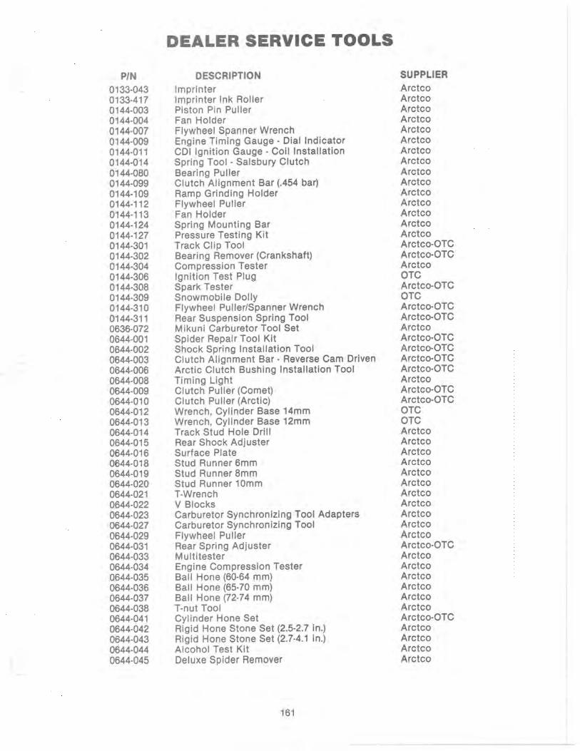
PIN 0133-043 0133-417 0144-003 0144-004 0144-007 0144-009 0144-011 0144-0·14 0144-080 0144-099 0144-109 0144-112 0144-113 0144-124 0144-127 0144-301 0144-302 0144-304 0144-306 0144-308 0144-309 0144-310 0144-311 0636-072 0644-001 0644-002 0644-003 0644-006 0644-008 0644-009 0644-010 0644-012 0644-013 0644-014 0644-015 0644-016 0644-018 0644-019 0644-020 0644-021 0644-022 0644-023 0644-027 0644-029 0644-031 0644-033 0644-034 0644-035 0644-036 0644-037 0644-038 0644-041 0644-042 0644-043 0644-044 0644-045
DEALER SERVICE TOOLS
DESCRIPTION Imprinter Imprinter Ink Roller Piston Pin Puller Fan Holder Flywheel Spanner Wrench Engine Timing Gauge - Dial Indicator CDI Ignition Gauge - Coil Installation Spring Tool - Salsbury Clutch Bearing Puller Clutch Alignment Bar (.454 bar) Ramp Grinding Holder Flywheel Puller Fan Holder Spring Mounting Bar Pressure Testing Kit Track Clip Tool Bearing Remover (Crankshaft) Compression Tester Ignition Test Plug Spark Tester Snowmobile Dolly Flywheel Puller/Spanner Wrench Rear Suspension Spring Tool Mikuni Carburetor Tool Set Spider Repair Tool Kit Shock Spring Installation Tool Clutch Alignment Bar - Reverse Cam Driven Arctic Clutch Bushing Installation Tool Timing Light Clutch Puller (Comet) Clutch Puller (Arctic) Wrench, Cylinder Base 14mm Wrench, Cylinder Base 12mm Track Stud Hole Drill Rear Shock Adjuster Surface Plate Stud Runner 6mm Stud Runner 8mm Stud Runner 10mm T-Wrench V Blocks Carburetor Synchronizing Tool Adapters Carburetor Synchronizing Tool Flywheel Puller Rear Spring Adjuster Multitester Engine Compression Tester Ball Hone (60-64 mm) Ball Hone (65-70 mm) Ball Hone (72-74 mm) T-nut Tool Cylinder Hone Set Rigid Hone Stone Set (2.5-2.7 in.) Rigid Hone Stone Set (2.7-4.1 in.) Alcohol Test Kit Deluxe Spider Remover
161
SUPPLIER Arctco Arctco Arctco Arctco Arctco Arctco Arctco Arctco Arctco Arctco Arctco Arctco Arctco Arctco Arctco Arctco-OTC Arctco-OTC Arctco OTC Arctco-OTC OTC Arctco-OTC Arctco-OTC Arctco Arctco-OTC Arctco-OTC Arctco-OTC Arctco-OTC Arctco Arctco-OTC Arctco-OTC OTC OTC Arctco Arctco Arctco Arctco Arctco Arctco Arctco Arctco Arctco Arctco Arctco Arctco-OTC Arctco Arctco Arctco Arctco Arctco Arctco Arctco-OTC Arctco Arctco Arctco Arctco

PIN
0644-046 0644-051 0644-052 0644-055 0644-056 0644-057 0644-058 0644-072 0644-076 0644-077 0644-079 0644-084 0644-087
DESCRIPTION
Ignition Analyzer Snowmobile Dolly Starter Assembly Tool Pinion Shimming Tool Snowmobile Dolly (3 piece) Shock Spring Removal Tool Comet Clutch Holder Exhaust Spring Tool Jackstand Scale-Gram Engine Stand Water Pump Rebuilding & Bearing Kit Tool - Spider Remover Comet
162
SUPPLIER
Arctco Arctco Arctco Arctco Arctco Arctco Arctco Arctco Arctco Arctco Arctco Arctco Arctco
;
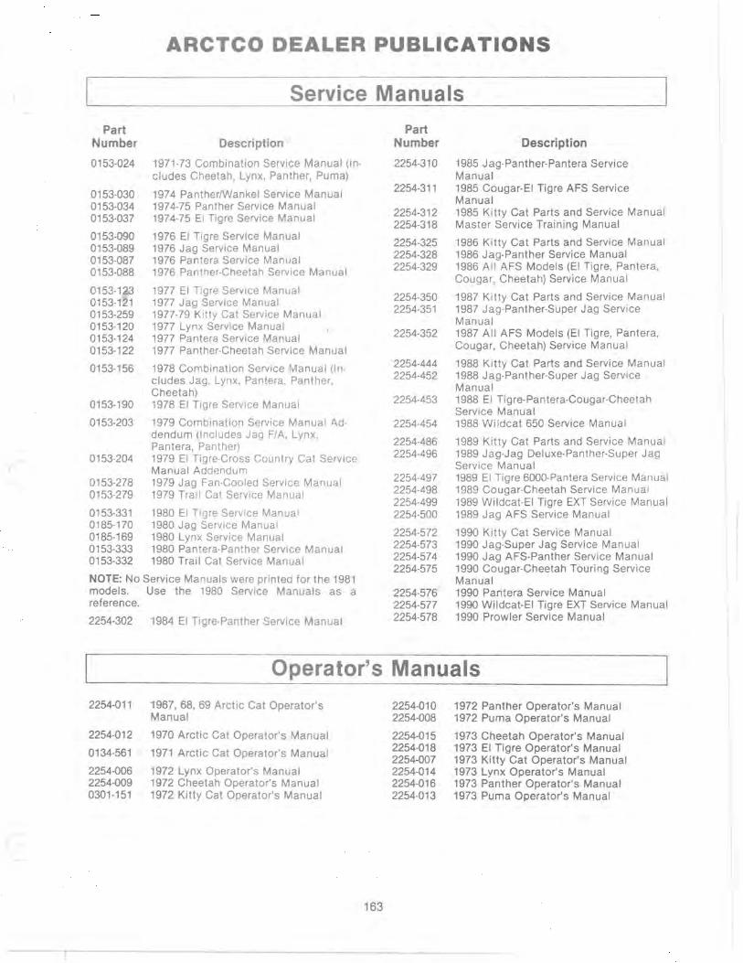
I
ARCTCO DEALER PUBLICATIONS
Service Manuals
Part Number
0153-024
0153-030 0153-034 0153-037
0153-090 0153-089 0153-087 0153-088
0153-123 0153-121 0153-259 0153-120 0153-124 0153-122
0153-156
0153-190
0153-203
0153-204
0153-278 0153-279
0153-331 0185-170 0185-169 0153-333 0153-332
Description
1971-73 Combination Service Manual (includes Cheetah, Lynx, Panther, Puma)
1974 Panther/Wankel Service Manual 1974-75 Panther Service Manual 1974-75 EI Tigre Service Manual
1976 EI Tigre Service Manual 1976 Jag Service Manual 1976 Pantera Service Manual 1976 Panther-Cheetah Service Manual
1977 EI Tigre Service Manual 1977 Jag Service Manual 1977-79 Kitty Cat Service Manual 1977 Lynx Service Manual 1977 Pantera Service Manual 1977 Panther-Cheetah Service Manual
1978 Combination Service Manual (Includes Jag, Lynx, Pantera, Panther, Cheetah) 1978 EI Tigre Service Manual
1979 Combination Service Manual Addendum (Includes Jag F/A, Lynx , Pantera, Panther) 1979 EI Tigre-Cross Country Cat Service Manual Addendum 1979 Jag Fan-Cooled Service Manual 1979 Trail Cat Service Manual
1980 EI Tigre Service Manual 1980 Jag Service Manual 1980 Lynx Service Manual 1980 Pantera-Panther Service Manual 1980 Trail Cat Service Manual
NOTE: No Service Manuals were printed for the 1981 models. Use the 1980 Service Manuals as a reference.
2254-302 1984 EI Tigre-Panther Service Manual
Part Number
2254-310
2254-311
2254-312 2254-318
2254-325 2254·328 2254-329
2254-350 2254-351
2254-352
2254-444 2254-452
2254-453
2254-454
2254-486 2254-496
2254-497 2254-498 2254-499 2254-500
2254-572 2254-573 2254-574 2254-575
2254·576 2254-577 2254-578
Description
1985 Jag-Panther-Pantera Service Manual 1985 Cougar-EI Tigre AFS Service Manual 1985 Kitty Cat Parts and Service Manual Master Service Training Manual
1986 Kitty Cat Parts and Service Manual 1986 Jag-Panther Service Manual 1986 All AFS Models (EI Tigre, Pantera, Cougar, Cheetah) Service Manual
1987 Kitty Cat Parts and Service Manual 1987 Jag-Panther-Super Jag Service Manual 1987 All AFS Models (EI Tigre, Pantera, Cougar, Cheetah) Service Manual
1988 Kitty Cat Parts and Service Manual 1988 Jag-Panther-Super Jag Service Manual 1988 EI Tigre-Pantera-Cougar-Cheetah Service Manual 1988 Wildcat 650 Service Manual
1989 Kitty Cat Parts and Service Manual 1989 Jag·Jag Deluxe·Panther·Super Jag Service Manual 1989 EI Tigre 6000-Pantera Service Manual 1989 Cougar-Cheetah Service Manual 1989 Wildcat-EI Tigre EXT Service Manual 1989 Jag AFS Service Manual
1990 Kitty Cat Service Manual 1990 Jag-Super Jag Service Manual 1990 Jag AFS-Panther Service Manual 1990 Cougar-Cheetah Touring Service Manual 1990 Pantera Service Manual 1990 Wildcat-EI Tigre EXT Service Manual 1990 Prowler Service Manual
Operator's Manuals
2254-011 1967, 68, 69 Arctic Cat Operator's 2254-010 1972 Panther Operator's Manual Manual 2254-008 1972 Puma Operator's Manual
2254-012 1970 Arctic Cat Operator's Manual 2254-015 1973 Cheetah Operator's Manual 2254-018 1973 EI Tigre Operator's Manual 0134-561 1971 Arctic Cat Operator's Manual 2254-007 1973 Kitty Cat Operator's Manual
2254-006 1972 Lynx Operator's Manual 2254-014 1973 Lynx Operator's Manual 2254-009 1972 Cheetah Operator's Manual 2254-016 1973 Panther Operator's Manual 0301-151 1972 Kitty Cat Operator's Manual 2254-013 1973 Puma Operator's Manual
163
- r

Part Number
2254-020 2254-025 2254-026 2254-029 2254-021 2254-024 2254-019
2254-031 2254-038 2254-039 2254-037 2254-034 2254-030
2254-051 2254-046 2254-054 2254-053 2254-052 2254-055
2254-068 2254-070 2254-067 2254-066 2254-071 2254-069 2254-072 2254-073
2254-100
2254-101 2254-099
2254-110 2254-138
2254-114 2254-129 2254-105 2254-113 2254-116 2254-115 2254-112
2254-138 2254-134 2254-132 2254-133 2254-148 2254-154 2254-151
2254-464 2254-479
0185-547 0185-018 0185-035 0185-052
Part Description Number
1974 Cheetah Operator's Manual 2254-155 1974 EI Tigre Operator's Manual 2254-156 1974 Lynx I Operator's Manual 2254-158 1974 Lynx II Operator's Manual 2254-168 1974 Panther Operator's Manual 2254-169 1974 Panther Wankel Operator's Manual 2254-300 1974 VIP Operator's Manual
1975 Cheetah Operator's Manual 2254-308 2254-309
1975 EI Tigre Operator's Manual 1975 Jag Operator's Manual 1975 Lynx Operator's Manual 1975 Pantera Operator's Manual 2254-320 1975 Panther Operator's Manual 2254-321
1976 Cheetah Operator's Manual 2254-322
1976 EI Tigre Operator's Manual 1976 Jag Operator's Manual 2254-344 1976 Pantera Operator's Manual 2254-345 1976 Panther Operator's Manual 1976 "Z" Operator & Setup Manual 2254-346
1977 Cheetah Operator's Manual 1977 EI Tigre Operator's Manual 2254-420 1977 Jag Operator's Manual 2254-421 1977 Lynx Operator's Manual 2254-422 1977 Pantera Operator's Manual 2254-423 1977 Panther Operator's Manual 2254-424 1977 "Z" Operator & Service Guide 2254-425 1977 Cross Country Cat Operator's 2254-426 Manual 2254-427
1978 Combination Operator's Manual (In- 2254-466 eludes Jag, Lynx, Pantera, Panther, 2254-467 Cheetah) 2254-468 1978 EI Tigre Operator's Manual 2254-469 1978 Kitty Cat Operator's Manual 2254-470
1979 EI Tigre Operator's Manual 2254-471
1979 EI Tigre Cross Country Operator's 2254-472
Manual 2254-473 1979 Jag Operator's Manual 2254-474 1979 Jag Fan-Cooled Operator's Manual 2254-478 1979 Kitty. Cat Operator's Manual 1979 Lynx Operator's Manual 2254-527 1979 Pantera Operator's Manual 2254-528 1979 Panther Operator's Manual 1979 Trail Cat Operator's Manual 2254-529
1980 EI Tigre Operator's Manual 2254-530
1980 Jag Operator's Manual 2254-531
1980 Kitty Cat Operator's Manual 2254-532
1980 Lynx Operator's Manual 2254-533
1980 Pantera Operator's Manual 2254-534
1980 Panther Operator's Manual 2254-535
1980 Trail Cat Operator's Manual 2254-536 2254-537
Parts Manuals Expandable Parts Book Binder (4-6 in.) Parts Book Binder Dividers
1972 Cheetah Parts Manual 1973 Cheetah Parts Manual 1974 Cheetah Parts Manual 1975 Cheetah Parts Manual
164
0185-053 0185-065 0185-076 0185-103
N/A
Description
1981 Kitty Cat Operator's Manual 1981 Panther-Pantera Operator's Manual 1981 Trail Cat Operator's Manual 1981 Jag Operator's Manual 1981 EI Tigre Operator's Manual
1984 EI Tigre-Panther Operator's Manual
1985 Kitty Cat Operator's Manual 1985 Combination (Jag, Panther, Pantera, Cougar, EI Tigre 6000) Operator's Manual
1986 Kitty Cat Operator's Manual 1986 Jag-Panther Operator's Manual 1986 All AFS Models (EI Tigre, Pantera, Cougar, Cheetah) Operator's Manuals
1987 Kitty Cat Operator's Manual 1987 Jag-Panther-Super Jag Operator's Manual 1987 All AFS Models (EI Tigre, Pantera, Cougar, Cheetah) Operator's Manual
1988 Kitty Cat Operator's Manual 1988 Wildcat 650 Operator's Manual 1988 Jag Operator's Manual 1988 Super Jag Operator's Manual 1988 Panther Operator's Manual 1988 EI Tigre-Pantera Operator's Manual 1988 Cougar Operator's Manual 1988 Cheetah Operator's Manual
1989 Kitty Cat Operator's Manual 1989 Jag Operator's Manual 1989 Panther Operator's Manual 1989 Super Jag Operator's Manual 1989 Jag AFS Operator' s Manual 1989 Cougar Operator's Manual 1989 Pantera-EI Tigre 6000 Operator's Manual 1989 EI Tigre EXT Operator's Manual 1989 Cheetah Operator's Manual 1989 Wildcat 650 Operator's Manual
1990 Kitty Cat Operator's Manual 1990 Jag 340-Jag Deluxe Operator's Manual 1990 Jag AFS Operator's Manual 1990 Panther Operator's Manual 1990 Cougar Operator's Manual 1990 Pantera Operator's Manual 1990 Cheetah Touring Operator's Manual 1990 EI Tigre EXT Operator's Manual 1990 Wildcat Operator's Manual 1990 Prowler Operator's Manual 1990 Super Jag Operator's Manual
1975 Cheetah Wankel Parts Manual 1976 Cheetah Parts Manual 1977 Cheetah Parts Manual 1978 Cheetah Parts Manual
Clutch Section 1 C - Reference Pages A-E

Part Part Number Description Number Description
N/A Clutch Section 1C - Pages 13-36 0185-126 1979 Pantera Parts Manual N/A Clutch Section 1 C - Pages 37-60 0185-154 1980 Pantera Parts Manual N/A Clutch Section 1C - Pages 61-72 0185-190 1981 Pantera Parts Manual
0185-071 1976 Cross Country Cat Parts Manual 0185-044 1970 Panther Parts Manual 0185-081 1977 Cross Country Cat Parts Manual 0185-543 1971 Panther Parts Manual 0185-139 1979 EI Tigre Cross Country Parts 0185-548 1972 Panther Parts Manual
Manual 0185-019 1973 Panther Parts Manual 0185-037 1974 Panther Parts Manual
0185-027 1973 EI Tigre Parts Manual 0185-036 1974 Panther Wankel Parts Manual 0185-038 1974 EI Tigre Parts Manual 0185-051 1975 Panther Wankel Parts Manual 0185-055 1975 EI Tigre Parts Manual 0185-067 1976 Panther Parts Manual 0185-069 1976 EI Tigre Parts Manual 0185-077 1977 Panther Parts Manual 0185-078 1977 EI Tigre Parts Manual 0185-104 1978 Panther Parts Manual 0185-105 1978EI Tigre Parts Manual 0185-125 1979 Panther Parts Manual 0185-127 1979 EI Tigre Parts Manual 0185-155 1980 Panther Parts Manual 0185-156 1980 EI Tigre Parts Manual 0185-189 1981 Panther Parts Manual 0185-192 1981 EI Tigre Parts Manual
0185-043 1970 Puma Parts Manual N/A Engine Section 18 - Reference Pages 0185-544 1971 Puma Parts Manual
A-E 0185-546 1972 Puma Parts Manual N/A Engine Section 18 - Pages 49-68 0185-017 1973 Puma Parts Manual 0134-531 1971 Engine KT 150 A & 8
0185-011 Sachs/Wankel KM9148 Parts Manual 0185-005 1972 Engine KT 150 8 0134-557 1971 Engine T1A 340-400-440 0185-082 Snowmobile Trailer Double Unit, Model 0185-004 1972 Engine T1A 340-400-440 No. 250-133 0185-545 1971 EXT Parts Manual 0185-121 Snowmobile Trailer 4-Place Unit, Model 0185-012 1972 EXT Parts Manual No. 250-296 0185-029 1973 EXT Parts Manual 0185-130 1979 Trail Cat Parts Manual 0185-030 1973 Formula II Parts Manual 0185-152 1980 Trail Cat Parts Manual
0185-059 1975 Jag Parts Manual 0185-191 1981 Trail Cat Parts Manual
0185-068 1976 Jag Parts Manual 0185-033 1974 VIP Parts Manual 0185-075 1977 Jag Parts Manual 0185-061 1975 "Z" Parts Manual 0185-102 1978 Jag Parts Manual 0185-070 1976 "z" Parts Manual 0185-128 1979 Jag Parts Manual 0185-080 1977 "Z" Parts Manual 0185-153 1980 Jag Parts Manual 0185-201 1981 Jag Long Track Parts Manual 2254-301 1984 EI Tigre-Panther Parts Manual
2254-312 1985 Kitty Cat Parts & Service Manual 0153-014 Kawasaki T1A-FA 2254-313 1985 Cougar-EI Tigre AFS Parts Manual 0185-007 1972 Kawasaki T1A-R1A 2254-314 1985 Jag-Panther-Pantera Parts Manual 0185-013 1972 Kawasaki T38-R2A 2254-325 1986 Kitty Cat Parts & Service Manual 0185-541 1972 Kitty Cat Parts Manual 2254-326 1986 Jag-Panther Parts Manual 0185-028 1973 Kitty Cat Parts Manual 2254-327 1986 All AFS Models (EI Tigre, Pantera, 0185-087 1977 Kitty Cat Parts Manual Cougar, Cheetah) Parts Manual 0185-100 1978 Kitty Cat Parts Manual 2254-350 1987 Kitty Cat Parts & Service Manual 0185-129 1979 Kitty Cat Parts Manual 2254-353 1987 Jag-Panther-Super Jag Parts 0185-150 1980 Kitty Cat Parts Manual Manual 0185-186 1981 Kitty Cat Parts Manual 2254-354 1987 All AFS Models (EI Tigre, Pantera,
Cougar, Cheetah) Parts Manual 0185-014 1971 Lynx Parts Manual 2254-444 1988 Kitty Cat Parts & Service Manual 0185-002 1972 Lynx Parts Manual 2254-445 1988 Jag Parts Manual 0185-016 1973 Lynx Parts Manual 2254-446 1988 Panther Parts Manual 0185-041 1974 Lynx I Parts Manual 2254-447 1988 EI Tigre-Pantera Parts Manual 0185-040 1974 Lynx II Parts Manual 2254-448 1988 Cougar Parts Manual 0185-063 1975 Lynx Parts Manual 2254-449 1988 Super Jag Parts Manual • 0185-074 1977 Lynx Parts Manual 2254-450 1988 Cheetah Parts Manual 0185-101 1978 Lynx Parts Manual 2254-451 1988 Wi Idcat 650 Parts Manual 0185-124 1979 Lynx Parts Manual 0185-151 1980 Lynx Parts Manual 2254-486 1989 Kitty Cat Parts and Service
Manual 0185-064 1975 Pantera Parts Manual 2254-487 1989 Jag-Jag Deluxe Parts Manual 0185-066 1976 Pantera Parts Manual 2254-488 1989 Panther Parts Manual 0185-079 1977 Pantera Parts Manual 2254-489 1989 EI Tigre 6000-Pantera Parts 0185-107 1978 Pantera Parts Manual Manual
165

Part Number
2254-490 2254-491 2254-492 2254-493 2254-494 2254-495
2254-561 2254-562
Description
1989 Cougar Parts Manual 1989 Jag AFS Parts Manual 1989 Super Jag Parts Manual 1989 Cheetah Touring Parts Manual 1989 EI Tigre EXT Parts Manual 1989 Wildcat 650 Parts Manual
1990 Kitty Cat Parts Manual 1990 Jag, Jag Deluxe Parts Manual
166
Part Number
2254-563 2254-564
2254-565 2254-566 2254-567 2254-568 2254-569 2254-570 2254-571
Description
1990 Panther Parts Manual 1990 Jag AFS, Jag AFS Deluxe Parts Manual 1990 Super Jag Parts Manual 1990 Cougar Parts Manual 1990 Pantera Parts Manual 1990 EI Tigre EXT Parts Manual 1990 Wildcat 650 Parts Manual 1990 Prowler Parts Manual 1990 Cheetah Touring Parts Manual
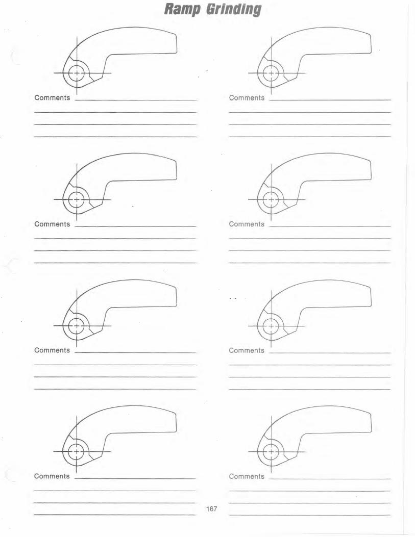
Ramp arlnlling
Comments Comments
Comments _ _ __________ _ Comments
Comments Comments
Comments Comments
167

International Snowmobile Racing
1990 Stock Snowmobile Performance Ratings
ARCTIC CAT
MODEL CC OVAL DRAG SX SR
JAG 340 & Deluxe 339 F F 1 1
SUPER JAG 431 F E 1 2
PANTHER 431 F E 1 2
JAG AFS & DELUXE 431 E E 2 2
PANTHER 431 F E 1 2
PANTERA 440 C C 3 6
CHEETAH TOURING 500 C D 3 4
COUGAR (cs) 500 C C 4 5
PROWLER 440 C C 4 6
EL TIGRE EXT & MOUNTAIN CAT 529 B B 6 8 EXT SPECIAL 529 B B 6 8
EL TIGRE EXT 56 H.P. 500 PS X PS X
WILDCAT 650 & MOUNTAIN CAT 650 A AA 7 11
1989 Stock Snowmobile Performance Ratings
ARCTIC CAT
MODEL CC OVAL DRAG SIC SR
JAG 340 (Deluxe) 339 F F 1 1
JAG 440 AFS 431 E E 2 2
SUPER JAG 431 F E 1 2
PANTHER 431 F E 1 2
PANTERA 436 B B 4 6
CHEETAH TOURING 500 D D 3 4
COUGAR 500 C/PS C 4/PS 5
EL TIGRE EXT 529 B B 6 8 EL TIGRE 6000 529 A A 7 10
EL TIGRE EXT 56 H.P. (cs) 529 PS X PS X
EL TIGRE 6000 56 H.P. (cs) 529 PS X PS X
WILDCAT 650 650 A AA 7 12
168

1988 Stock Snowmobile Performance Ratings
ARCTIC CAT
MODEL CC OVAL DRAG SC JAG 340 339 F F 1
JAG 440 431 F E 2
SUPER JAG 431 F E 2
PANTHER 500 F E 2
CHEETAH TOURING 500 0 0 3
CHEETAH UC 529 B B 6
COUGAR (cs) 500 CIPS C 5/PS
PANTERA 435 B B 6
EL TIGRE 5000 435 B B 6
EL TIGRE 6000 529 A A 7
WILDCAT 650 650 A AA 7
Setup Adjustments
II The following Information Is a composite of different set-up adjustments that can be done with the Arctic Cat snowmobile. Before making any type of changes to your
machine always check your race association rulebook (preferably I.S.R.) and see that It is within rules and guidelines. You, as a driver, are totally responsible for your machine .
• 169
SR
1
2
2
4
F
8 5
8 8 10
12
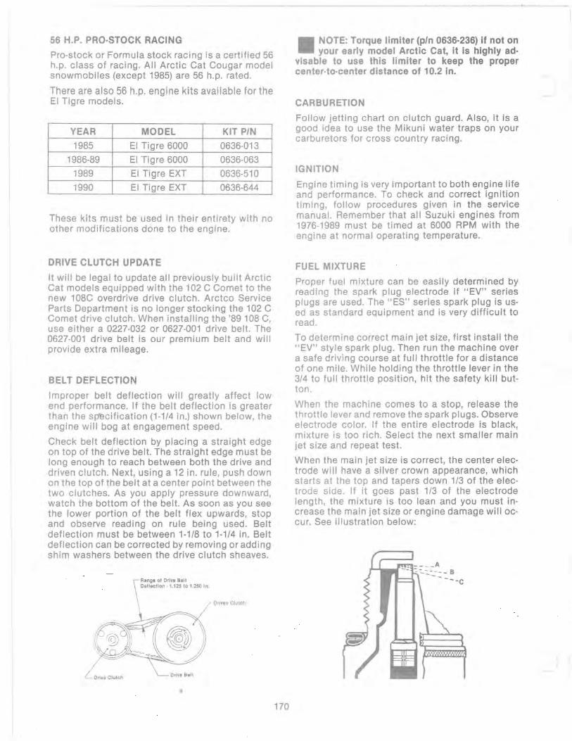
----- ------- ---------~~ . -
56 H.P. PRO·STOCK RACING
Pro·stock or Formula stock racing is a certified 56 h.p. class of racing. All Arctic Cat Cougar model snowmobiles (except 1985) are 56 h.p. rated.
There are also 56 h.p. engine kits available for the EI Tigre models.
YEAR MODEL KIT PIN
1985 EI Tigre 6000 0636-013
1986-89 EI Tigre 6000 0636-063
1989 EI Tigre EXT 0636-510
1990 EI Tigre EXT 0636-644
These kits must be used in their entirety with no other modifications done to the engine.
DRIVE CLUTCH UPDATE
It will be legal to update all previously built Arctic Cat models equipped with the 102 C Comet to the new 108C overdrive drive clutch. Arctco Service Parts Department is no longer stocking the 102 C Comet drive clutch. When installing the '89 108 C, use either a 0227-032 or 0627-001 drive belt. The 0627-001 drive belt is our premium belt and will provide extra mileage.
BELT DEFLECTION
Improper belt deflection will greatly affect low end performance. If the belt deflection is greater than the spllcification (1-1/4 in.) shown below, the engine will bog at engagement speed.
Check belt deflection by placing a straight edge on top of the drive belt. The straight edge must be long enough to reach between both the drive and driven clutch. Next, using a 12 in. rule, push down on the top of the belt at a center point between the two clutches. As you apply pressure downward, watch the bottom of the belt. As soon as you see the lower portion of the belt flex upwards, stop and observe reading on rule being used. Belt deflection must be between 1·118 to 1·1/4 in. Belt deflection can be corrected by removing or adding shim washers between the drive clutch sheaves.
Driven Clutch
• 170
_ NOTE: Torque limiter (pin 0636·236) if not on - your early model Arctic Cat, it is highly ad·
visable to use this limiter to keep the proper center·to·center distance of 10.2 in.
CARBURETION
Follow jetting chart on clutch guard. Also, it is a good idea to use the Mikuni water traps on your carburetors for cross country racing.
IGNITION
Engine timing is very important to both engine life and performance. To check and correct ignition timing, follow procedures given in the service manual. Remember that all Suzuki engines from 1976-1989 must be timed at 6000 RPM with the engine at normal operating temperature.
FUEL MIXTURE
Proper fuel mixture can be easily determined by reading the spark plug electrode if "EV" series plugs are used. The "ES" series spark plug is used as standard equipment and is very difficult to read.
To determine correct main jet size, first install the "EV" style spark plug. Then run the machine over a safe driving course at full throttle for a distance of one mile. While holding the throttle lever in the 3/4 to full throttle position, hit the safety kill button.
When the machine comes to a stop, release the throttle lever and remove the spark plugs. Observe electrode color. If the entire electrode is black, mixture is too rich. Select the next smaller main jet size and repeat test.
When the main jet size is correct, the center electrode will have a silver crown appearance, which starts at the top and tapers down 1/3 of the electrode side. If it goes past 1/3 of the electrode length, the mixture is too lean and you must increase the main jet size or engine damage will occur. See illustration below:

, ,
To read spark plug electrode for proper main jet size, refer to the drawing.
A would indicate a rich condition. B would indicate a correct main jet and C would be a lean condition. Anything below B would be lean with C being near the burndown point. The crown will be a metallic color.
BRAKES
It is very advisable to duct air to your brakes through an EXISTING VENT IN THE HOOD.
LIGHTS
Cover headlight with plexiglass or screen to prevent breakage.
SHOCK ABSORBERS
Reweld all eyelet tubes on shocks. But be absolutely sure not to over-heat and boil the oil inside the shock. Venting air to shocks is advisable when running in severe, rough conditions. Keeping them cool will reduce fading of shock control. Grease all pivot points on shocks to allow free and easy movement.
TRACK TENSION
To prevent derailing, tighten your track so that you are only able to pull it off the rails 1/2 to 3/4 in., using 22 Ibs of spring pull. This seems very tight at first, but it will not slow you down and will prevent derailing, which is a problem for all brands with long travel suspensions. Try to get at lease 200 to 250 miles of break-in time on tracks before your first race. Retighten track every 50 miles during the break-in period.
DRIVEIDROPCASE
Venting of the dropcase is also being done by many drivers and definitely helps if the dropcase becomes overheated and oil and pressure buildup occurs. Vent out of top filler plug by drilling and tapping plug. Install a small fitting and attach small hose such as primer line.
OIL CONSUMPTION
Approximately 175-200 miles per tank.
FUEL CONSUMPTION (1988)
10 MPG; 60-70 miles to the tank. Cougar, 5000 and 6000. Auxiliary fuel tank is recommended. Part No. 0636-055.
~ - - - -----------
171
SKID FRAME (ALL '88 & '89 MODELS)
Additional front skid frame mounting holes can be drilled to raise the front of the skid frame 1 in. higher into the tunnel. The new mounting holes are located in the tunnel support brackets just above existing mounting holes. Simply drill through tunnel from inside using these holes as a guide. By moving the skid frame up 1 in., additional weight is applied to the skis, as well as lowering the machine for better stability in cornering during oval and sno-cross racing.
(EI Tigre 6000 & Pantera '88 & '89 Models)
All front skid frame shock pre-load should be removed by backing the adjusted bolt off to the me.ximum amount. To accomplish this, cut 2 in. from the end of the adjuster bolt as it will come in contact with the crossbrace which is located directly behind it. This adjustment will allow tension to be taken off the shock and spring of the front arm.
REAR SUSPENSION AND SLIDE RAIL ASSEMBLY (88-89 EI Tigre 6000 & Pantera)
a. Add an extra stop arm (pIn 0114-324) or a limiter strap to the front arm assembly.
b. Gusset the two ear tabs on the front arm which fasten the pivot link (pIn 0604-001) as they could break above the weld.
c. Front arm should have a gusset welded in the corner of the square tube as they may break just below the existing gusset and weld.
d. Slide rail nose piece must be securely fastened and red LOCTITE is recommended.
e. Advisable to use Wheel Kit (pIn 0636-167).
f. OEM wheels used on 1979 Cross-Country EI Tigres (pIn 0104-871) small diameter wheel (idler) and pIn 0114-061 large diameter wheel (rear) are very durable to use. These are aluminum cast wheels.
SWAY BAR AND SPRING SPECIFICATIONS (EI Tigre, Cougar, and Wildcat - 1988 Models)
Standard Sway Bar: 5/8 in. diameter, 650 Ib
Optional Sway Bar for Racing: 3/4 in. diameter, 1200-1300 Ib
Rear Springs: EI Tigre and Cougar: 20 Ib Wildcat 28 Ib 75 Ib progressive
Front Springs: EI Tigre: Small - 1 3/4 in., 750 Ib, Long - 5 in., 570 Ib Cougar: Small- 2 1/4 in., 350 Ib, Long -5 in., 570 Ib Wildcat: 7.75 in., 420 Ib
Front Arm Spring in Skid Frame: EI Tigre and Cougar: 150 Ib Wildcat: 150 Ib

Total Length Travel on Front Suspension: 7 in.
Total Length Travel on Rear Suspension: 8 in.
Sway Bar Kit: pIn 0636-022 (Racing)
Heavy Rear Spring Kit: pin 0636-066
FRONT SUSPENSION - 1988 MODELS
The Cougar and EI Tigre front ends can be lowered by removing the small spring from each shock. Shock rod should be cut to compensate for shorter stroke.
Racing sway bar is highly recommended for oval and ice sno-cross. This will maintain front end stability from rocking back and forth when cornering.
II NOTE: Below are instructions to strengthen the upper and lower A·arms (0703·018) and
(0703·017). This will reduce wear of the A·arms during racing events.
BUSHING SUPPORT INSTRUCTIONS (1988·89) .. I.
2.
Remove lower arm (0703-018) from chassis .
Remove axle tube (0603-063) and axles (0603-061) from arm.
172
3. Bolt tube and axles back into chassis as shown in illustration.
4. Place supports against chassis panel, make absolutely sure supports are p2rallel so arm can be removed after weldmlint. Supports should be pointing at the 5 and 10 o'clock position.
5. Some trimming is required on belly pan around supports to allow room. These supports have shown to control excessive elongation and axle breakage under extreme racing conditions.
If you have any questions, call Joey Hallstrom at Arctco, Inc. (218)681-8558.
~ ':~ . , ~ ..........
, I I;· Weld to ChassIs
" " I' I'
I: " I 1

650 MODIFICATION SPECIFICATIONS (1988-89)
Each season we receive a number of calls from customers looking for information concerning engine modification. To assist you in answering these questions, we have added the information we have available on the 650 and 530 engines. You must understand, however, that any modification does void the warranty and the customer should be told this before any work is done or any of this information is given to the customer.
If you are going to do the modification work yourself, follow the recommendations given in this book very closely. Both carburetion and clutch information are starting pOints and fine tuning may be required for each area.
CYLINDER HEADS Remove .020 from flat surface of head Squish Gap - .055-.060 CCV - PTa (22.63) MAG (22.27) AVG (22.45) CR - With 32.0 exhaust port height ::: 6.81:1
IGNITION TIMING 25 0 /6000 RPM hot engine temperature 8750 Max. RPM
CARBURETORS VM44 dyno jetting MJ - 620 PJ - 40 In - 7DH-2 CA - 1.5
NJ - cc-O AS - 1.0
This has not been calibrated for the field. Use high octane fuel.
TRANSFERS 54.0 mm no change
REED LIFT 10.0 mm
INTAKE PORT Leave bottom and top of port as is, only widen. Keep port shape as shown.
Match VM 40 mm Flange to Cylinder
115.0 mm Top of Cylinder to Bottom of Intake
50.0 Mod.
173
~ -..- -,...
EXHAUST PORT Keep port shape the same as stock match outlet to exhaust gasket.
32.0 mm Top of Cylinder to top of Exhaust
\ ,
t
>--____ ---'u i I
I-- 50.0 Stock ~ 55 Mod.
650 EXHAUST SYSTEM
Use original 650 Pipes. Head Pipe: 1 7/8 0.0. (1.777 1.0.) Remove 2 in. of
head pipe Tail Pipe: 1 1/8 Diameter (1.025 1.0.) May go
longer if needed to reach out belly pan of machine.
Basic pipe stamping to remain the same.
Lc:=c:" "/B
ln r- ~
"L:~l) 1. ----- \ 12 In. \
i \ t~1 14 In. \ ~ength_\
\
\
\
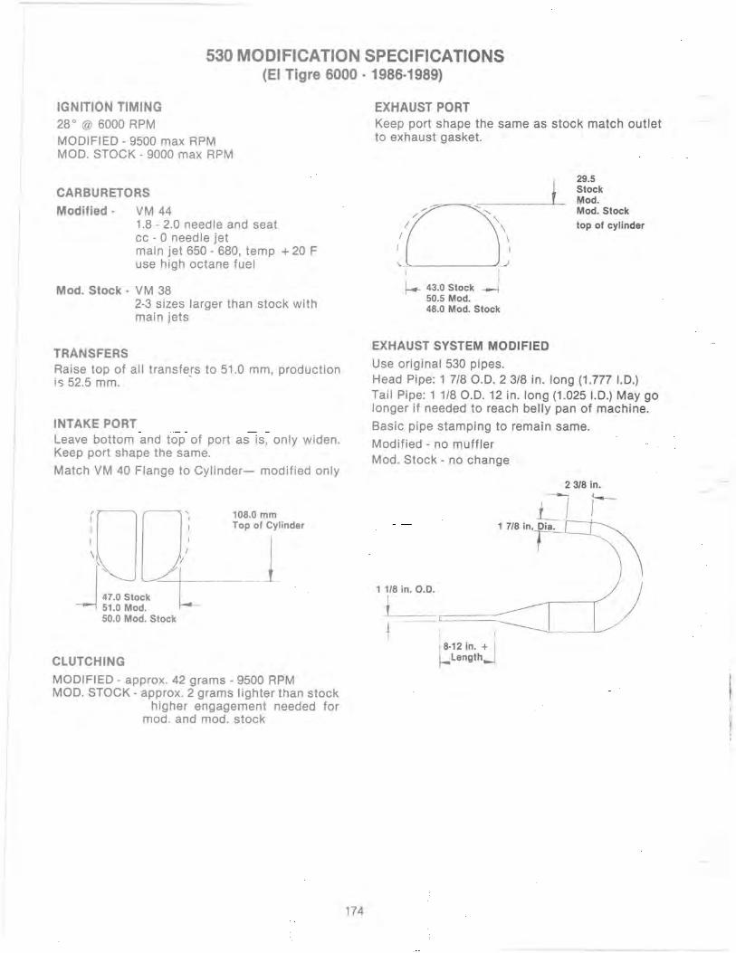
530 MODIFICATION SPECIFICATIONS (EI Tigre 6000 - 1986-1989)
IGNITION TIMING
28° @ 6000 RPM MODIFIED - 9500 max RPM MOD. STOCK - 9000 max RPM
CARBURETORS
Modified - VM 44 1.8 - 2.0 needle and seat cc - 0 needle jet main jet 650 - 680, temp + 20 F use high octane fuel
Mod. Stock· VM 38 2-3 sizes larger than stock with main jets
TRANSFERS Raise top of all transfers to 51.0 mm, production is 52.5 mm. .
INTAKE PORT Leave bottom and top of port as is, only widen. Keep port shape the same.
Match VM 40 Flange to Cylinder- modified only
108.0 mm Top of Cylinder
51.0 Mod. 50.0 Mod. Stock
CLUTCHING
MODIFIED - approx. 42 grams - 9500 RPM MOD. STOCK - approx. 2 grams lighter than stock
higher engagement needed for mod. and mod. stock
174
EXHAUST PORT Keep port shape the same as stock match outlet to exhaust gasket.
\. _'---____ ..J.
i
I-- 43.0 Stock ----j 50.5 Mod. 48.0 Mod. Stock
\
I
29.5 Stock Mod. Mod. Stock
top of cylinder
EXHAUST SYSTEM MODIFIED
Use original 530 pipes. Head Pipe: 1 7/80.0.2318 in. long (1.777 1.0.) Tail Pipe: 1 1/80.0.12 in. long (1.0251.0.) May go longer if need~d to reach belly pan of machine.
Basic pipe stamping to remain same.
Modified - no muffler Mod. Stock - no change
2318 in.
-, 1-LI. 1 7/8 in'-r-~~
~ \ 1 118 in. 0.0. ) I
1 c=::=, ===~_~J 18.12 in. + I f-Length_
--- ---
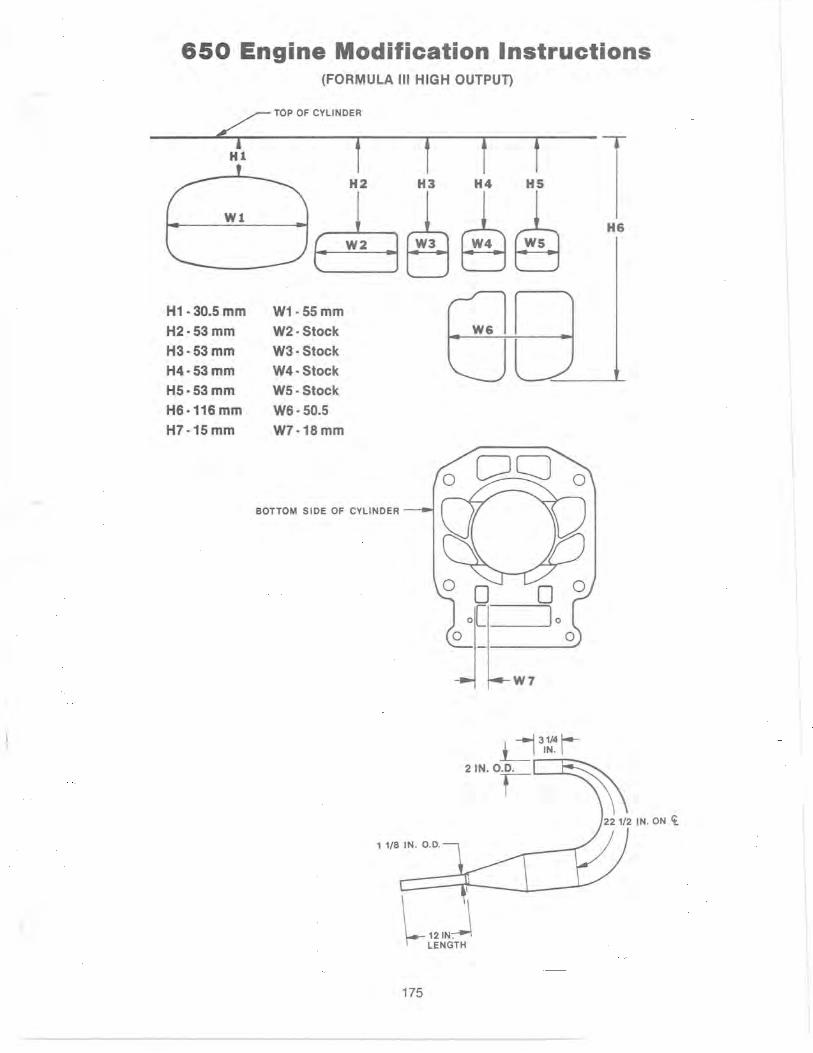
650 Engine Modification Instructions (FORMULA III HIGH OUTPUn
~ TOP OF CYLINDER
H1 t
W1
H1· 30.5 mm
H2·53 mm
H3·53mm
H4·53mm
H5·53mm
H6·116mm
H7·15 mm
H2
( W2
l
W1·55mm
W2· Stock
W3· Stock
W4· Stock
W5·Stock
W6· 50.5
W7·18mm
BOTTOM SIDE OF CYLINDER
t f f H3 H4 HS
W3 ~~
W7
d31~~r-2IN.0.0. r-
l 121NJ LENGTH
175
--..... , --....--------
H6

I
440 LIe L/W Engine Modification Instructions (PROWLER)
~ TOP OF CYLINDER
HI f H2
WI
~ H1 ·31.0 mm
H2· Stock
H3· Stock
H4· Stock
H5· Stock
H6· Stock "(
36 mm Carbs 3.0 Slide
W1· 44 mm
W2· Stock
W3· Stock
W4· Stock
W5· Stock
W6· Stock
PO 159 Needle Jet
6F9·3 Needle 300 Main Jet 35 Pilot
- 1 to .5 Gram Off Side Of Weight 7750·8000 RPM
176
f H3
W3
1 IN. HEAD PIPE
-1 r-
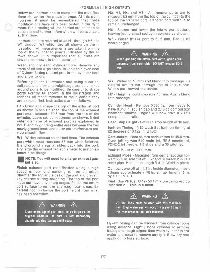
(FORMULA III HIGH OUTPUT)
Below are instructions to complete the modifica· tions shown on the previous page. At this point however, it must be remembered that these modifications have only been tested in our dyno room. Field testing will be carried out as soon as possible and further information will be available at that time.
Instructions are referred to as Hl through H6 and Wl through W7 which are all shown on the il· lustration. All measurements are taken from the top of the cylinder to points indicated by the ar· rows shown. It is important that all ports are shaped as shown in the illustration.
Wash and dry each cylinder bore. Remove any trace of oil and wipe clean. Brush a thin even coat of Dykem Bluing around port in the cylinder bore and allow to dry.
Referring to the illustration and using a scribe, calipers, and a small straightedge, scribe all lines around ports to be modified. Be careful to shape ports exactly as shown in the illustration and recheck all measurements to make certain they are as specified. Instructions are as follows:
H1 • Grind and shape the top of the exhaust port as shown. When finished, the top of the exhaust port must measure 30.5 mm from the top of the cylinder. Leave radius in corners as shown. Grind outer diameter of exhaust port as explained in Wl. Blend by grinding entire area between the two newly ground inner and outer port surfaces to pro· vide smooth flow.
W1 . Widen exhaust to scribed lines. The exhaust port width must measure 55 mm when finished. Blend ground areas at sides back into the port. Englarge the exhaust outlet diameter to match ex· haust pipe flange.
- NOTE: You will need to enlarge exhaust gas· - ket also.
Finish exhaust port modification using a high speed grinder and sanding roll on an arbor. Chamfer the top and sides of the port and prevent any chance of ring snagging. The top of the port must not have any sharp edges. Polish the entire port surface to remove any rough port areas. Be careful not to change the port height from what has been spec ified.
& WARNING & Chamfer on top of port must be as large as the original chamfer. If port is left improperly chamfered, ring damage will occur.
177
H2, H3, H4, and H5 . All transfer ports are to measure 53 mm from the top of the cylinder to the top of the transfer port. Transfer port width is to remain unchanged.
H6 . Square and lower the intake port bottom, leaving just a small radius in corners as shown.
W6 . Widen intake port to 50.5 mm. Radius all sharp edges.
& WARNING & When grinding the intake port width, grind equal amounts from each side. DO NOT exceed 50.5 mm.
W7· Widen to 18 mm and blend into passage. Be careful not to cut through top of intake port. Widen port toward the center.
H7· Height should measure 15 mm. Again blend into passage.
Cylinder Head· Remove 0.036 in. from heads to have 0.040 in. squish gap and 23.6 cc combustion chamber volume. Engine will now have a 7.17:1 compression ratio.
Reed Stop Height· Set reed stop height at 10 mm.
Ignition Timing· (150 watt) Set ignition timing at 22 degrees or 0.122 in. BTDC.
Carburetors· Bore 44 mm carburetors to 45.5 mm. Dyno jetting was 640 main jet, BB·5 needle jet, 7DH2·2 jet needle, 1.5 slide and a 35 pilot jet.
Peak H.P .. is at 9000 rpm.
Exhaust Pipes· Measure from center section for· ward 22.5 in. and cut off. Expand to match 2 in. 00 head pipe. Head pipe length 3 1Jt in. Weld in place.
Cut rear cone off at 1 1/8 in. inside diameter, insert stinger approximately 1/8 in. stinger length 12 in. by 1 1/8 in. 00.
Fuel· Use VP fuel, C·12· 50:1 mixture using Arctco Injection oil. This is a must.
& WARNING & VP fuel, C·12 must be used with this modification. Engine damage will occur in a short time if this recommendation isn't followed.
Dykem bluing can be washed from cylinder bore using acetone. Lightly hone cylinder to remove bluing and rough edges; then wash cylinder in hot water and soap to remove any grit. Blow dry and apply oil to bore surface.
- -r ---.,.----

TUNING RECORD
Race _____________________________________________ Date
Barometric Temperature ______________________________________ _ Pressure _______ __ Altitude
Track Condition (ice, loose snow, slush, etc.) ________________________________________ _ Size ________________________ _
Carburetor Set·Up: Main Jet _________________ Pilot Jet _________________ Needle Jet ________________ _ Jet Needle Clip Position ________________ _ Throttle Valve Cutaway ________________ _
Drive Clutch Set·Up: Spring ________________________ Cam Arms ________________________ Profile
Gearing Set-Up: Chain _________________ Sprocket Ratio ________________ _
Results ______________________________________________________________________________________________ -
Comments _________________________________________________________________________________________ _
Race ____________________________________________ Date
Barometric Temperature ______________________________________ _ Pressure ________ _ Altitude
Track Cond it ion (ice, loose snow, slush, etc.) ________________________________________ _ Size ________________________ _
Carburetor Set-Up: Main Jet _________________ Pi lot Jet ________________ Need Ie Jet _______________ _ Jet Needle Clip Position ________________ _ Throttle Valve Cutaway ________________ _
Drive Clutch Set-Up: Spring _________________________ Cam Arms _________________________ Profi Ie
Gearing Set-Up: Chain _________________ Sprocket Ratio ________________ _
Results _____________________________________________________________________________________________ _
Comments ____________________________________________________________________________________ ~ ____ __