SERVICE MANUAL - Vintage Hifi
39
TEAC SERVICE MANUAL 1. Caution……………………………………………………………2 2. Specification………………………………………………………6 3. BOM List ……………………… ……………...............................9 4. Alignment Procedure………………………………………….…29 5. Block Diagram……………………………………………………36 6. Schematic Diagram………………………………………………37 7. PCB Layout………….……………………………………………38 8. Explode Diagram…….……………………………………………39 This manual is the latest at the time of printing, and does not include the modification which may be made after the printing, by the constant improvement of product. CTM5110H
-
Upload
khangminh22 -
Category
Documents
-
view
0 -
download
0
Transcript of SERVICE MANUAL - Vintage Hifi

TEAC SERVICE MANUAL
1. Caution……………………………………………………………2
2. Specification………………………………………………………6
3. BOM List ……………………… ……………...............................9
4. Alignment Procedure………………………………………….…29
5. Block Diagram……………………………………………………36
6. Schematic Diagram………………………………………………37
7. PCB Layout………….……………………………………………38
8. Explode Diagram…….……………………………………………39
This manual is the latest at the time of printing, and does not
include the modification which may be made after the printing, by
the constant improvement of product.
CTM5110H

WARNING: TO REDUCE RISK OF FIRE OR ELECTRIC SHOCK, DO NOT
EXPOSE THIS APPLIANCE TO RAIN OR MOISTURE.
CAUTION: TO REDUCE THE RISK OFELECTRICAL SHOCK, DO NOT REMOVECOVER (OR BACK). NO USER SERVICEABLEPARTS INSIDE. REFER SER VICING TOQUALIFIED SERVICE PERSONNEL.
The lighting flash with arrowhead symbol, with an equilateral triangle is intended to
alert the user to the presence of uninsulated voltage within the products
enclosure that may be of sufficient magnitude to constitute a risk of electric shock to
the person.
The exclamation point within an equilateral triangle is intended to alert the user to the
presence of important operating and maintenance (servicing) instructions in the
literature accompanying the appliance.
CAUTION:Use of controls, adjustments or procedures other than those specified herein may result inhazardous radiation exposure.
CAUTIONRISK RISK OF OF ELECTRIELECTRICC
SHOCK SHOCK DO DO NOT NOT OPEN.OPEN.
2
dangerous

3
FOR YOUR PERSONAL SAFETY1. When the power cord or plug is damaged or frayed, unplug this television set from the wall outlet and refer servicing to
qualified service personnel.
2. Do not overload wall outlets and extension cords as this can result in fire or electric shock.
3. Do not allow anything to rest on or roll over the power cord, and do not place the TV where power cord is subject totraffic or abuse. This may result in a shock or fire hazard.
4. Do not attempt to service this television set yourself as opening or removing covers may expose you to dangerousvoltage or other hazards. Refer all servicing to qualified service personnel.
5. Never push objects of any kind into this television set through cabinet slots as they may touch dangerous voltagepoints or short out parts that could result in a fire or electric shock. Never spill liquid of any kind on the television set.
6. If the television set has been dropped or the cabinet has been damaged, unplug this television set from the wall outletand refer servicing to qualified service personnel.
7. If liquid has been spilled into the television set, unplug this television set from the wall outlet and refer servicing toqualified service personnel.
8. Do not subject your television set to impact of any kind. Be particularly careful not to damage the picture tube surface.
9. Unplug this television set from the wall outlet before cleaning. Do not use liquid cleaners or aerosol cleaners. Use adamp cloth for cleaning.
10.1. Do not place this television set on an unstable cart, stand, or table. The television set may fall, causing serious injuryto a child or an adult, and serious damage to the appliance. Use only with a cart or stand recommended by themanufacturer, or sold with the television set. Wall or shelf mounting should follow the manufacturer s instructions, andshould use a mounting kit approved by the manufacturer.
10.2. An appliance and cart combination should be moved with care. Quick stops, excessive force, and uneven surfacesmay cause the appliance and cart combination to overturn.
CAUTION:
Read all of these instructions. Save these instructions for later use. Follow all Warnings andInstructions marked on the audio equipment.
1. Read Instructions- All the safety and operating instructions should be read before the product is operated.
2. Retain Instructions- The safety and operating instructions should be retained for future reference.
3. Heed Warnings- All warnings on the product and in the operating instructions should be adhered to.
4. Follow Instructions- All operating and use instructions should be followed.
IMPORTANT SAFETY INSTRUCTIONS

4
PROTECTION AND LOCATION OF YOUR SET11. Do not use this television set near water ... for example, near a bathtub, washbowl, kitchen sink, or laundry tub, in a
wet basement, or near a swimming pool, etc.Never expose the set to rain or water. If the set has been exposed to rain or water, unplug the set from the walloutlet and refer servicing to qualified service personnel.
12. Choose a place where light (artificial or sunlight) does not shine directly on the screen.
13. Avoid dusty places, since piling up of dust inside TV chassis may cause failure of the set when high humidity persists.
14. The set has slots, or openings in the cabinet for ventilation purposes, to provide reliable operation of the receiver, toprotect it from overheating. These openings must not be blocked or covered.
Never cover the slots or openings with cloth or other material.Never block the bottom ventilation slots of the set by placing it on a bed, sofa, rug, etc.Never place the set near or over a radiator or heat register.Never place the set in enclosure, unless proper ventilation is provided.
PROTECTION AND LOCATION OF YOUR SET15.1. If an outside antenna is connected to the television set, be sure the antenna system is grounded so as to provide some
protection against voltage surges and built up static charges, Section 810 of the National Electrical Code, NFPA No.70-1975, provides information with respect to proper grounding of the mast and supporting structure, grounding of thelead-in wire to an antenna discharge unit, size of grounding conductors, location of antenna discharge unit, connectionto grounding electrode, and requirements for the grounding electrode.
15.2. Note to CATV system installer : (Only for the television set with CATV reception)
This reminder is provided to call the CATV system attention to Article 820-40 of the NEC that providesguidelines for proper grounding and, in particular, specifies that the cable ground shall be connected to the groundingsystem of the building, as close to the point of cable entry as practical.
16. An outside antenna system should not be located in the vicinity of overhead power lines or other electric lights or powercircuits, or where it can fall into such power lines or circuits. When installing an outside antenna system, extreme careshould be taken to keep from touching such power lines or circuits as contact with them might be fatal.
17. For added protection for this television set during a lightning storm, or when it is left unattended and unused for longperiods of time, unplug it from the wall outlet and disconnect the antenna. This will prevent damage due to lightningand power-line surges.
ANTENNALEAD- IN WIRE
ANTENNA DISCHARGEUNIT (NEC SECTION810-20)
GROUNDINGCONDUCTORS(NEC SECTION810-21)
GROUND CLAMPS
POWER SERVICE GROUNDINGELECTRODE SYSTEM(NEC ART 250. PART H)
ELECTRIC SERVICEEQUIPMENT
GROUND CLAMP
NEC-NATIONAL ELECTRICAL CODE
EXAMPLE OF ANTENNA GROUNDING AS PER
NATIONAL ELECTRICAL CODE
EXAMPLE OF ANTENNA GROUNDING AS PER NATIONAL ELECTRICAL CODE INSTRUCTIONS
a built-in
installer s

OPERATION OF YOUR SET18. This television set should be operated only from the type of power source indicated on the marking label. If you are not
sure of the type of power supply at your home, consult your television dealer or local power company. For televisionsets designed to operate from battery power, refer to the operating instructions.
19. If the television set does not operate normally by following the operating instructions, unplug this television set from thewall outlet and refer servicing to qualified service personnel. Adjust only those controls that are covered in the operatinginstructions as improper adjustment of other controls may result in damage and will often require extensive work by aqualified technician to restore the television set to normal operation.
20. When going on a holiday : If your television set is to remain unused for a period of time, for instance, when you go ona holiday, turn the television set and unplug the television set from the wall outlet.
IF THE SET DOES NOT OPERATE PROPERLY21. If you are unable to restore normal operation by following the detailed procedure in your operating instructions,
do not attempt any further adjustment. Unplug the set and call your dealer or service technician.
22. Whenever the television set is damaged or fails, or a distinct change in performance indicates a need forservice, unplug the set and have it checked by a professional service technician.
23. It is normal for some TV sets to make occasional snapping or popping sounds, particularly when beingturned on or off. If the snapping or popping is continuous or frequent, unplug the set and consult yourdealer or service technician.
FOR SERVICE AND MODIFICATION24. Do not use attachments not recommended by the television set manufacturer as they may cause hazards.
25. When replacement parts are required, be sure the service technician has used replacement parts specifiedby the manufacturer that have the same characteristics as the original part. Unauthorized substitutionsmay result in fire, electric shock, or other hazards.
26. Upon completion of any service or repairs to the television set, ask the service technician to performroutine safety checks to determine that the television is in safe operating condition.
5
off

PFS2 FORMAT-1 ReportDate: 2003-9-16 15:12 ProductView......: Report by............: Specs / ProductsMasterData Customer Id TEAC AUSTRALIA PTY LTD Version 0.1 Status New Brand TEAC EAN \ UPC \Reception +Tuning - presets/channels 100 +Tuning - technology VST +Tuning - Indication X +Freq Bands UVSH +Channels 100 +IF Freq +TV Systems Off Air PAL B/G +Add Systems Ext In NTSC 3.58, NTSC 4.43, NTSC
Play Back, PAL 60 +TV Systems Multi PAL-Multi +Sound Systems AV StereoPicture - Processing +Scan Standard +Scan Modes 4;3 +Wide Screen Switching +Combfilter +Picture Control Brightness, Colour, Contrast,
Color Temperature, Hue,Sharpness Cont Var, Smart Pict.4 Modes
+Pict Enhancement Black Stretch +Pict Noise ReductionPicture - Display +Display Type DV - CRT - RF +Screen Format 4:3 +Size(Visual)" - size/vis. cm 21" +Deflection System (CRT only) +Tube Technology (CRT only) Black Matrix, Iron +CRT Defl +CRT Gun Stand Gun +CRT Magn field Neutral +Resolution +Coating (only for D.V. sets) +White PointSound +RMS Power Intern +RMS Power Extern +Surround Sound +Sound Features Mute +Sound Control VolumeSound - Speakers +Speaker configuration 2 +Speakers used Normal +Speaker SizeUser Interface +Interface Name L01- Full Interface +Voice Control +Menu Cursor Control +Menu Colours +Menu Languages English +Special Features No signal Auto Standby,Timer
Power ON/OFF, FavoriteChannel, Sleep timer, Game,Calendar, Notebook, Hotel lock ,Auto Search
+Operational Features +PP Features +Tuning/Install Features Auto Store, Factory Mode, Fine
Tuning, Manual Search/Store,Manual Sort, Service Mode
+Clock/Timer Functions Clock, On/off timer, Sleep timer
Product:CT-M5110H
2003-9-16 15:13 21166 PFS 1 of 3
Date: 2003-9-16 15:12 ProductView......: Report by............: Specs / Products
Product:CT-M5110H
+Local Controls Front Channel +-, Volume +-,TV/AV,MENU,Power Switch,
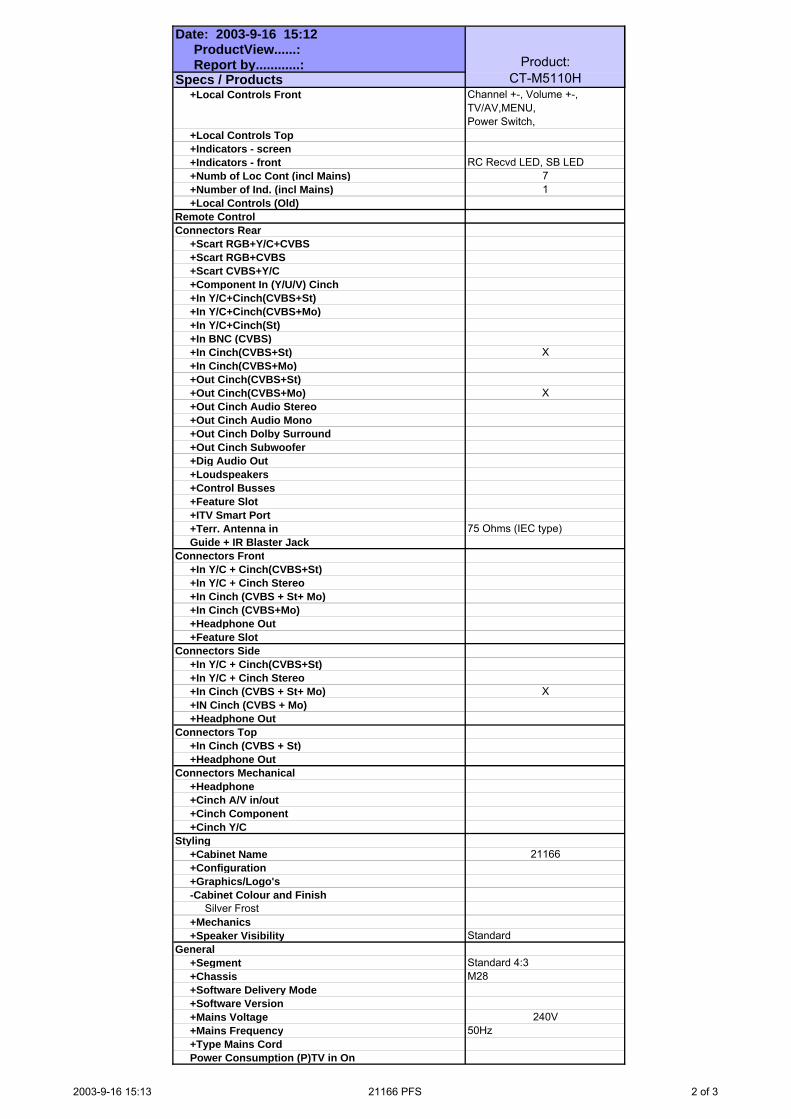
+Local Controls Top +Indicators - screen +Indicators - front RC Recvd LED, SB LED +Numb of Loc Cont (incl Mains) 7 +Number of Ind. (incl Mains) 1 +Local Controls (Old)Remote ControlConnectors Rear +Scart RGB+Y/C+CVBS +Scart RGB+CVBS +Scart CVBS+Y/C +Component In (Y/U/V) Cinch +In Y/C+Cinch(CVBS+St) +In Y/C+Cinch(CVBS+Mo) +In Y/C+Cinch(St) +In BNC (CVBS) +In Cinch(CVBS+St) X +In Cinch(CVBS+Mo) +Out Cinch(CVBS+St) +Out Cinch(CVBS+Mo) X +Out Cinch Audio Stereo +Out Cinch Audio Mono +Out Cinch Dolby Surround +Out Cinch Subwoofer +Dig Audio Out +Loudspeakers +Control Busses +Feature Slot +ITV Smart Port +Terr. Antenna in 75 Ohms (IEC type) Guide + IR Blaster JackConnectors Front +In Y/C + Cinch(CVBS+St) +In Y/C + Cinch Stereo +In Cinch (CVBS + St+ Mo) +In Cinch (CVBS+Mo) +Headphone Out +Feature SlotConnectors Side +In Y/C + Cinch(CVBS+St) +In Y/C + Cinch Stereo +In Cinch (CVBS + St+ Mo) X +IN Cinch (CVBS + Mo) +Headphone OutConnectors Top +In Cinch (CVBS + St) +Headphone OutConnectors Mechanical +Headphone +Cinch A/V in/out +Cinch Component +Cinch Y/CStyling +Cabinet Name 21166 +Configuration +Graphics/Logo's -Cabinet Colour and Finish Silver Frost +Mechanics +Speaker Visibility StandardGeneral +Segment Standard 4:3 +Chassis M28 +Software Delivery Mode +Software Version +Mains Voltage 240V +Mains Frequency 50Hz +Type Mains Cord Power Consumption (P)TV in On
2003-9-16 15:13 21166 PFS 2 of 3

Date: 2003-9-16 15:12 ProductView......: Report by............: Specs / Products
Product:CT-M5110H
Power Consumption SB in Watts Less then 3W Power Consumption Semi SB in W +Power in "ON" for +Power in Standby for +Power in "OFF" for Weight (P)TV (incl. Packaging) Weight (P)TV (excl. Package) Weight AVUnit excl Packaging +INDICATION on BACKCOVER +ChannelFinal Equipment +Packaging - methods +Documents and manuals +Languages DFU +Cables Supplied +Antenna Supplied +Stand Supplied +Aux Equipm Supplied Packaging - width cm Packaging - height cm Packaging - depth cmMiscellaneous +EAN Indication +Approbation +Tests +Local IntegrationVarious Perf. Param. +Service Call-RatePIP/POP +Type +Features NoDigital Reception +TransmissionBuilt-in Data System +Text Standard +(Tele)text Features No +Nbr bckgrnd page / Mem Size No +Text Technology No +Digital Data handling +Program GuideBuilt-in Clock/Timer +Type +FeaturesBuilt-in Radio +TypeBuilt-in PC display +PC Synch +PC ControlBuilt-in DVD drive +Type of Medium +Type of Deck +Version of DeckPhased Out Items +Tuner/Frontend +Sensitivity +CRT EHT +Lightning Protection +Account +XX(Radio Antenna in) +Non Volatile Memory +In Y/C + Cinch(CVBS+Mo) Version of deck
2003-9-16 15:13 21166 PFS 3 of 3

Item No. Description Quantity Req. Designator Remarks
08-HS46F0-M28A ASS'Y - IR HANDSET 1
13-00AS12-13B IC AS1213B 1 IC1501
14-IRE05B-XX0 IR EMITTING DIODE TSAL6200 1 D1501
18-CB0221-JNX RES. C.F. 220 OHM 1/6W +/-5% 1 R1502
18-CB0229-JNX RES. C.F. 2.2 OHM 1/6W +/-5% 1 R1501
25-HBB479-M1X CAP. ELEC 4.7 UF 10V +/-20% 1 C1502
26-EBP101-JCX CAP. CER 100PF 50V +/-5% CH 1 C1503
26-EBP101-JCX CAP. CER 100PF 50V +/-5% CH 1 C1504
40-113SLF-RMB P.C.B. REMOTE HANDSET BD 1
41-WJ0070-B00 WIRE BARE JUMPER 7MM 1 J1501
45-COS455-KY1 CERAMIC RESONATOR 455KHz 1 X1501
49-HS46F0-00X RUBBER PAD KEYS 1
55-HS46FB-0HA CASE LOWER - REMOTE HANDSET 1
55-HS46FD-0HA DOOR BATT. - REMOTE HANDSET 1
55-HS46FT-0HA CASE UPPER - REMOTE HANDSET 1
58-HS46F3-7UI INLAY REMOTE HANDSET 1
63-B26060-BT2 S/T SCREW B 2.6 X 6 BT 1
67-X26968-0E2 BATT. TERMINAL (+/-) 1
67-X31028-0E2 SPRING - BATTERY (-) 1
67-X31029-0E2 SPRING - BATTERY (+) 1
74-009022-60C POLYBAG HANDSET (9CMX22CM) 1
11-0BC337-0BX TRANSISTOR (NPN) BC337-40 1 Q1501
08-02135H-CRY ASS'Y - CRT BD 1
10-1N4148-ABX DIODE 1N4148 (SWITCHING) 1 D502
10-1N4148-ABX DIODE 1N4148 (SWITCHING) 1 D501
11-SA1015-YBX TRANSISTOR 2SA1015Y 1 Q510
11-SC2482-0BX TRANSISTOR 2SC2482 1 Q501
11-SC2482-0BX TRANSISTOR 2SC2482 1 Q502
11-SC2482-0BX TRANSISTOR 2SC2482 1 Q503
18-CB0101-JNX RES. C.F. 100 OHM 1/6W +/-5% 1 R501
18-CB0101-JNX RES. C.F. 100 OHM 1/6W +/-5% 1 R504
18-CB0101-JNX RES. C.F. 100 OHM 1/6W +/-5% 1 R507
18-CB0102-JNX RES. C.F. 1K OHM 1/6W +/-5% 1 R522
18-CB0272-JNX RES. C.F. 2.7k OHM 1/6W +/-5% 1 R524
18-CB0472-JNX RES. C.F. 4.7k OHM 1/6W +/-5% 1 R502
18-CB0472-JNX RES. C.F. 4.7k OHM 1/6W +/-5% 1 R505
9

Item No. Description Quantity Req. Designator Remarks
18-CB0472-JNX RES. C.F. 4.7k OHM 1/6W +/-5% 1 R508
18-CB0681-JNX RES. C.F. 680 OHM 1/6W +/-5% 1 R525
18-CB0681-JNX RES. C.F. 680 OHM 1/6W +/-5% 1 R526
18-CB0681-JNX RES. C.F. 680 OHM 1/6W +/-5% 1 R527
18-CB0681-JNX RES. C.F. 680 OHM 1/6W +/-5% 1 R523
18-CB0751-JNX RES. C.F. 750 OHM 1/6W +/-5% 1 R503
18-CB0751-JNX RES. C.F. 750 OHM 1/6W +/-5% 1 R506
18-CB0751-JNX RES. C.F. 750 OHM 1/6W +/-5% 1 R509
18-CD0104-JNX RES. C.F. 100K OHM 1/4W +/-5% 1 R521
18-FE0272-JNX RES. M.O. 2.7K OHM 1/2W +/-5% 1 R514
18-FE0272-JNX RES. M.O. 2.7K OHM 1/2W +/-5% 1 R515
18-FE0272-JNX RES. M.O. 2.7K OHM 1/2W +/-5% 1 R518
18-FG0153-JHX RES. M.O. 15k OHM 2W +/-5% 1 R510
18-FG0153-JHX RES. M.O. 15k OHM 2W +/-5% 1 R511
18-FG0153-JHX RES. M.O. 15k OHM 2W +/-5% 1 R512
26-EBP103-ZFX CAP. CER 0.01UF 50V +80/-20% F 1 C507
26-EBP181-JCX CAP. CER 180PF 50V +/-5% CH 1 C510
26-EBP181-JCX CAP. CER 180PF 50V +/-5% CH 1 C511
26-EBP181-JCX CAP. CER 180PF 50V +/-5% CH 1 C512
26-EBP681-JCX CAP. CER 680 pF 50V +/-5% 1 C501
26-EBP681-JCX CAP. CER 680 pF 50V +/-5% 1 C502
26-EBP681-JCX CAP. CER 680 pF 50V +/-5% 1 C503
26-AIM103-KBX CAP. CER 0.01UF 500V +/-10% B 1 C504
26-AMK221-KBX CAP. CER 220PF 2KV +/-10% B 1 C505
26-EBP103-ZFX CAP. CER 0.01UF 50V +80/-20% F 1 C514
35-139730-00X FERR. BEAD BF60 2 FOR C514 (L505 & L506)
40-02135S-CRD P.C.B. CRT BD 1
41-WJ0050-B00 WIRE BARE JUMPER 5MM 1 FOR Q509 (B - E)
41-WJ0050-B00 WIRE BARE JUMPER 5MM 1 FOR Q507 (B - E)
41-WJ0050-B00 WIRE BARE JUMPER 5MM 1 FOR Q505 (B - E)
41-WJ0075-B00 WIRE BARE JUMPER 7.5MM 1 J502
41-WJ0075-B00 WIRE BARE JUMPER 7.5MM 1 J503
41-WJ0100-B00 WIRE BARE JUMPER 10MM 1 J501
41-WJ0100-B00 WIRE BARE JUMPER 10MM 1 J504
46-10967W-01X PIN BASE *1 TJC1-1A 1 P503
46-30615H-04X HS 4P24 460 F/W TJC3-4Y/SCN-4 1 P502 FOR M. BD P402
10

Item No. Description Quantity Req. Designator Remarks
46-28816H-05X HS 5P24 500 TJC3-5Y/SCN-5Y 1 P501 FOR M. BD P201
25-BCB221-M1X CAP. ELEC 220 UF 16V +/-20% 1 C508
47-CRT004-XX0 CRT SOCKET GZS10-2-108 1 FOR CRT
41-WJ0075-B00 WIRE BARE JUMPER 7.5MM 1 J505
08-0D166H-AVY ASS'Y - AV BD 1
40-21166F-SIA P.C.B. SIDE AV BD 1
46-30790H-06X HS 6P24 400 TJC3-6Y/SCN-6Y 1 P1104B FOR M.BD P904
47-RCA001-XX0 RCA SOCKET AV-8.4-6 (RED) 1 P1103
47-RCA002-XX0 RCA SOCKET AV-8.4-6 (WHITE) 1 P1102
47-RCA003-XX0 RCA SOCKET AV-8.4-6 (YELLOW) 1 P1101
08-0D166H-KEY ASS'Y - KEY BD 1
18-CB0152-JNX RES. C.F. 1.5k OHM 1/6W +/-5% 1 R022A
18-CB0182-JNX RES. C.F. 1.8K OHM 1/6W +/-5% 1 R023A
18-CB0272-JNX RES. C.F. 2.7k OHM 1/6W +/-5% 1 R024A
18-CB0432-JNX RES. C.F. 4.3K OHM 1/6W +/-5% 1 R025A
18-CB0622-JNX RES. C.F. 6.2k OHM 1/6W +/-5% 1 R026A
46-38628H-02X HS 2P 2468#24 850 TJC3-2Y/JC25-2Y 1 P001A FOR M.BD P001
48-TAC001-XX0 TACT SWITCH 1 S001A
48-TAC001-XX0 TACT SWITCH 1 S002A
48-TAC001-XX0 TACT SWITCH 1 S003B
48-TAC001-XX0 TACT SWITCH 1 S004A
48-TAC001-XX0 TACT SWITCH 1 S005A
48-TAC001-XX0 TACT SWITCH 1 S006A
40-21166H-KEB P.C.B. KEY BD 1
08-0D166H-PW2 ASS'Y - POWER PARTS (AUST,220UF) 1
10-0FR104-FBX DIODE FR104 (FAST RECTIFIER) 1 D830
10-0FR104-FBX DIODE FR104 (FAST RECTIFIER) 1 D802
10-0FR104-FBX DIODE FR104 (FAST RECTIFIER) 1 D833
10-1N4148-ABX DIODE 1N4148 (SWITCHING) 1 D805
10-1SS136-ABX DIODE 1SS136 1 D804
10-1SS136-ABX DIODE 1SS136 1 D835
10-79C8V2-DBX DIODE ZENER 8V2 1/2W 5% 1 D839
10-HER108-FBX DIODE HER108 1 D806
10-HS16VC-DBX DIODE 500mW 16HSC 1 D838
10-HS6V2B-DBX DIODE 6V2 500mW 1 D840
11-SC1815-YBX TRANSISTOR 2SC1815Y 1 Q832
11

Item No. Description Quantity Req. Designator Remarks
11-SC1815-YBX TRANSISTOR 2SC1815Y 1 Q831
11-SC2688-LAX TRANSISTOR 2SC2688L (NPN) 1 Q830
11-SK2996-0AX TRANSISTOR 2SK2996 (MOS) 1 Q801
13-0HPC92-2CP PHOTO COUPLER HPC922-C 1 IC802
13-44608P-40P IC MC44608P40 1 IC801
18-CB0102-JNX RES. C.F. 1K OHM 1/6W +/-5% 1 R809
18-CB0103-JNX RES. C.F. 10K OHM 1/6W +/-5% 1 R844
18-CB0332-JNX RES. C.F. 3.3k OHM 1/6W +/-5% 1 R834
18-CB0333-JNX RES. C.F. 33K OHM 1/6W +/-5% 1 R838
18-CB0362-JNX RES. C.F. 3.6K OHM 1/6W +/-5% 1 R807
18-CB0472-JNX RES. C.F. 4.7k OHM 1/6W +/-5% 1 R806
18-CB0622-JNX RES. C.F. 6.2k OHM 1/6W +/-5% 1 R850
18-CD0123-JNX RES. C.F. 12K OHM 1/4W +/-5% 1 R804A
18-CD0220-JNX RES. C.F. 22 OHM 1/4W +/-5% 1 R811A
18-CD0221-JNX RES. C.F. 220 OHM 1/4W +/-5% 1 R833
18-CD0392-JNX RES. C.F. 3.9K OHM 1/4W +/-5% 1 R835
18-CD0471-JNX RES. C.F. 470 OHM 1/4W +/-5% 1 R811
18-CE0479-JNX RES. C.F. 4.7 OHM 1/2W +/-5% 1 R832
18-CE0563-JNX RES. C.F. 56k OHM 1/2W +/-5% 1 R831
18-DD0104-FNX RES. M.F. 0.1M OHM 1/4W +/-1% 1 R804
18-FG0153-JHX RES. M.O. 15k OHM 2W +/-5% 1 R837
18-GJ0103-KTX RES. CEMENT 10K OHM 5W +/-10% 1 R836
18-GJ0223-KTX RES. WIRE ROUND 5W 22K OHM +/-10% 1 R808
18-KF0825-JH3 RES. H.VOLT.CC 8.2M OHM 1W +/-5% 1 R812
20-TR103H-5CX TRIMMER B10K HORIZ TYPE 1 VR830
22-NTC479-XX0 NTC 4.7 OHM +/-18% NTC4.7D2-14 1 RT802
25-382890-M1X CAP. ELEC 150UF 400V +/-20% 30X30 1 C806
25-BCA102-M1X CAP. ELEC 1000 UF 16V +/-20% 1 C849
25-BEB100-M1X CAP. ELEC 10 UF 35V +/-20% 1 C812
25-BJG101-M1X CAP. ELEC 100 UF 160V +/-20% 1 C835
26-ABC221-JZX CAP. CER 220 PF 50V +/-5% SL 1 C841
26-AGK221-KRX CAP. CER 220 PF 250V +/-10% 1 C830
26-AIC472-KBX CAP. CER 4700 PF 500V +/-10% B 1 C807
26-AIC472-KBX CAP. CER 4700 PF 500V +/-10% B 1 C808
26-AIM103-KBX CAP. CER 0.01UF 500V +/-10% B 1 C834
26-AIM103-KBX CAP. CER 0.01UF 500V +/-10% B 1 C805
12

Item No. Description Quantity Req. Designator Remarks
26-AKK221-KRX CAP. CER 220 PF 1KV +/-10% R 1 C833
26-AMK102-KRX CAP. CER 1000 pF 2KV +/-10% R 1 C815
26-APK102-ME4 CAP. CER 1000PF 400VAC+/-20% E 1 C816
26-APK102-ME4 CAP. CER 1000PF 400VAC+/-20% E 1 C803
26-APK102-ME4 CAP. CER 1000PF 400VAC+/-20% E 1 C804
26-EBP102-KBX CAP. CER 1000 PF 50V +/-10% B 1 C848
26-EBP102-KBX CAP. CER 1000 PF 50V +/-10% B 1 C804A
27-AQT224-MVH CAP. M.PP 0.22 UF 250VAC 20% 1 C801
27-MBC104-J0X CAP. M.P.E 0.1 UF 63V +/-5% 1 C836
27-MBC104-J0X CAP. M.P.E 0.1 UF 63V +/-5% 1 C850
27-MHM104-K0X CAP. METAL P.E. 0.1UF 400V 10% 1 C802A
27-RJP472-J0X CAP. PP 4700 PF 630V +/-5% 1 C809
34-R101K2-1BX COIL CHOKE 100 UH +/-10% 1 L804
34-R330J2-0EX COIL PL - 33 UH +/-5% 1 L843
35-139730-00X FERR. BEAD BF60 2 FOR D806
35-139730-00X FERR. BEAD BF60 2 FOR D833
35-139730-00X FERR. BEAD BF60 2 FOR D831
35-139730-00X FERR. BEAD BF60 2 FOR D830
36-LIF004-AX0 LINE FILTER 1 T801
41-WJ0050-B00 WIRE BARE JUMPER 5MM 1 J800A
41-WJ0050-B00 WIRE BARE JUMPER 5MM 1 J800B
41-WJ0050-B00 WIRE BARE JUMPER 5MM 1 J800C
41-WJ0050-B00 WIRE BARE JUMPER 5MM 1 J800D
41-WJ0050-B00 WIRE BARE JUMPER 5MM 1 J801A
41-WJ0050-B00 WIRE BARE JUMPER 5MM 1 J801B
41-WJ0050-B00 WIRE BARE JUMPER 5MM 1 J801C
41-WJ0050-B00 WIRE BARE JUMPER 5MM 1 J801D
41-WJ0065-B00 WIRE BARE JUMPER 6.5MM 1 J810
41-WJ0075-B00 WIRE BARE JUMPER 7.5MM 1 J809
41-WJ0085-B00 WIRE BARE JUMPER 8.5MM 1 J812
41-WJ0090-B00 WIRE BARE JUMPER 9MM 1 J805
41-WJ0100-B00 WIRE BARE JUMPER 10MM 1 R804B
41-WJ0100-B00 WIRE BARE JUMPER 10MM 1 J822
41-WJ0100-B00 WIRE BARE JUMPER 10MM 1 J827
41-WJ0100-B00 WIRE BARE JUMPER 10MM 1 R807A
41-WJ0105-B00 WIRE BARE JUMPER 10.5MM 1 J824
13

Item No. Description Quantity Req. Designator Remarks
41-WJ0110-B00 WIRE BARE JUMPER 11MM 2 FOR S801
41-WJ0115-B00 WIRE BARE JUMPER 11.5MM 1 J823
41-WJ0125-B00 WIRE BARE JUMPER 12.5MM 1 J804
41-WJ0125-B00 WIRE BARE JUMPER 12.5MM 1 J808
41-WJ0125-B00 WIRE BARE JUMPER 12.5MM 1 J832
41-WJ0145-B00 WIRE BARE JUMPER 14.5MM 1 J826
41-WJ0150-B00 WIRE BARE JUMPER 15MM 1 J802
41-WJ0150-B00 WIRE BARE JUMPER 15MM 1 J821
41-WJ0160-B00 WIRE BARE JUMPER 16MM 1 J825
41-WJ0170-B00 WIRE BARE JUMPER 17MM 1 J830
41-WJ0175-B00 WIRE BARE JUMPER 17.5MM 1 J807
41-WJ0175-B00 WIRE BARE JUMPER 17.5MM 1 J831
41-WJ0190-B00 WIRE BARE JUMPER 19MM 1 J811
41-WJ0195-B00 WIRE BARE JUMPER 19.5MM 1 J828
41-WJ0195-B00 WIRE BARE JUMPER 19.5MM 1 J829
46-10962W-02X PIN BASE *2 TJC2-2A 1 P801
46-28559W-02X PIN BASE *2 TJC1-2A 1 P802
50-02000D-1VS7 FUSE 250V/2A 1 F801
64-B30100-104 M/C SCREW B 3 X 10 1 FOR Q801
66-20516X-0B0 FUSE HOLDER 2 FOR FUSE
66-343730-0B0 HOLLOW RIVET 1.6X3.0XL3.2 2 FOR C835
66-343730-0B0 HOLLOW RIVET 1.6X3.0XL3.2 4 FOR T803
66-343730-0B0 HOLLOW RIVET 1.6X3.0XL3.2 3 FOR RT801
66-343730-0B0 HOLLOW RIVET 1.6X3.0XL3.2 6 FOR D830,D831,L804
71-DYP000-WX1 LABEL 1 STICK ON H.SINK(Q801)
90-209770-SR1 SILICONE GREASE G-746 0.0006
66-382330-0B7 RIVET 2.0X3.7X3.5 8 FOR R808,R836,C806,P801
67-H35984-5A0 HEAT SINK 1 FOR Q801
18-RG0228-JHX RES. WIRE ROUND 0.22 OHM 2W +/-5% 1 R810
26-EBP101-JCX CAP. CER 100PF 50V +/-5% CH 1 C814
25-BCB471-M1X CAP. ELEC 470 UF 16V +/-20% 1 C843
25-BCA102-M1X CAP. ELEC 1000 UF 16V +/-20% 1 C832
26-EBP471-JCX CAP. CER 470PF 50V +/-5% CH 1 C851
10-0RU3AM-F0X DIODE RU3AM (FAST RECOVERY) 1 D831
26-EBP103-ZFX CAP. CER 0.01UF 50V +80/-20% F 1 C813
26-EBP103-ZFX CAP. CER 0.01UF 50V +80/-20% F 1 C831
14

Item No. Description Quantity Req. Designator Remarks
26-EBP103-ZFX CAP. CER 0.01UF 50V +80/-20% F 1 C842
10-0RL255-EBX DIODE RL255 (POWER RECTIFIER) 1 D815
10-0RL255-EBX DIODE RL255 (POWER RECTIFIER) 1 D816
10-0RL255-EBX DIODE RL255 (POWER RECTIFIER) 1 D817
10-0RL255-EBX DIODE RL255 (POWER RECTIFIER) 1 D818
22-PTC200-XX1 PTC 20 OHM +/-20% 1 RT801
36-TRF133-AX0 TRANSFORMER CONV.BCK-3546 1 T803
08-D1664H-FC1 ASS'Y - FRONT CAB(94V0,LS-SG1A) 1
02-GND021-XX0 ASS"Y - CRT GND WIRE&HOUSE 1 FOR CRT GROUNDING
36-DEG210-BX3 DEGAUSSING COIL 2500mm 1
42-50908D-XX0 SPEAKER 8 OHM 5W (50mmX90mm) 1 W601
42-50908D-XX0 SPEAKER 8 OHM 5W (50mmX90mm) 1 W602
44-21OFLS-SG1A CRT A51JSY63X13(CR)RED (AUST) 1 CRT01
46-27250H-02X HS 2P24 450/5 F/W TJC3-02H 1 P602H FOR M. BD P602
46-27688H-04X HS 4P A/B 400/13 RBGW TJC1/4Y 1 P401H FOR D.Y COIL
46-37144H-02X HS 2P 2468#22 450mm S11-2Y/7mm 1 P601H FOR M. BD P601
54-113970-0U0 PVC TUBE #5 L=ROLL 0.32 FOR SPK HOUSING
54-205140-000 SPACER CRT MOUNTING T=2MM 4
54-271620-000 SPACER CRT MOUNTING T=1mm 4 MTG CRT & F. CAB.
54-314740-0X0 CRT FIBRE SHEET (22mmX22mmX0.8mm) 16
54-314740-0X0 CRT FIBRE SHEET (22mmX22mmX0.8mm) 8 FOR CRT & F. CAB.
56-D166FB-0HA PUSH BUTTON (II) 1
56-D166LS-0HC LENS 1
56-D166PK-0HA POWER KNOB 1
59-130460-00X RUBBER PAD (25mmX7mm) 2 STICK ON F. CAB.(FOOTING)
62-10654X-00F UNI-TIE (2.5mmX95mm) 13
62-369290-0CN CRT BRACKET 2
63-B30080-AB4 S/T SCREW B 3 X 8 AB 3 MTG KEY BD & PUSH BUTTON
63-B40150-AB4 S/T SCREW B 4 X 15 AB 2 MTG CRT HOLDER TO F. CAB.
63-H60300-BT4 S/T SCREW H 6 X 30 BT 4 MTG CRT & F.CAB
63-W30100-AB4 S/T SCREW W 3 X 10 AB 4 MTG TRACK TO F. CAB.
63-W30100-AB4 S/T SCREW W 3 X 10 AB 2 MTG PUSH BUTTON & F.CAB.
63-W30100-AB4 S/T SCREW W 3 X 10 AB 8 MTG SPK & F. CAB.
63-W35100-AB4 S/T SCREW W 3.5 X 10 AB 2 MTG F. CTL BKT & F. CAB.
65-A60200-20E WASHER 6 X 20 X 2MM 4 MTG CRT
62-216340-0UA HOLDER POWER CORD HIPS-KINGFA 113(VO) 1
15

Item No. Description Quantity Req. Designator Remarks
62-378080-1UN TRACK 1
62-345690-1UN ASSISTANT RAIL HIPS-KINGFA 113 (VO) 1
67-X12668-0E0 SPRING CRT 6mmX40mmX0.5mm 1
67-X24970-0E0 SPRING 1
55-D166FC-2AN FRONT CABINET 1
18-CB0225-JNX RES. C.F. 2.2M OHM 1/6W +/-5% 1 R1
41-BF0450-0BB WIRE UL1007#24 450 BLACK 1 FOR R1
54-343300-0X0 HEAT SHRINKABLE TUBE 3 X 0.25 0.02 FOR R1
67-105580-0E2 SOLDERING TAG 1 FOR R1
08-D1664H-MA2 ASS'Y -MAIN BD 1
10-0FR104-FBX DIODE FR104 (FAST RECTIFIER) 1 D401
10-0FR104-FBX DIODE FR104 (FAST RECTIFIER) 1 D402
10-1N4001-EBX DIODE 1N4001 (RECTIFIER) 1 D301
10-1N4002-EBX DIODE 1N4002 (RECTIFIER) 1 D405
10-1N4148-ABX DIODE 1N4148 (SWITCHING) 1 D005
10-1N4148-ABX DIODE 1N4148 (SWITCHING) 1 D206
10-1N4148-ABX DIODE 1N4148 (SWITCHING) 1 D006
10-1N4148-ABX DIODE 1N4148 (SWITCHING) 1 D007
10-1N4148-ABX DIODE 1N4148 (SWITCHING) 1 D601
10-1N4148-ABX DIODE 1N4148 (SWITCHING) 1 D008
10-1N4148-ABX DIODE 1N4148 (SWITCHING) 1 D002
10-79C5V1-DBX DIODE ZENER 5V1 1/2W 5% 1 D001
10-79C6V2-DBX DIODE ZENER 6V2 1/2W 5% 1 D404
11-2N3904-0BX TRANSISTOR 2N3904 (NPN) 1 Q103
11-C124ES-0BX TRANSISTOR PDTC124ES (NPN) 1 Q604
11-C144ES-0BX TRANSISTOR PDTC144ES (NPN) 1 Q606
11-C144ES-0BX TRANSISTOR PDTC144ES (NPN) 1 Q607
11-C144ES-0BX TRANSISTOR PDTC144ES (NPN) 1 Q211
11-DD1555-0AX TRANSISTOR 3DD1555 1 Q402
11-SA1015-YBX TRANSISTOR 2SA1015Y 1 Q003
11-SA1015-YBX TRANSISTOR 2SA1015Y 1 Q202
11-SA1015-YBX TRANSISTOR 2SA1015Y 1 Q005
11-SA1015-YBX TRANSISTOR 2SA1015Y 1 Q209
11-SA1015-YBX TRANSISTOR 2SA1015Y 1 Q210
11-SA1015-YBX TRANSISTOR 2SA1015Y 1 Q605
11-SC1815-YBX TRANSISTOR 2SC1815Y 1 Q203
16

Item No. Description Quantity Req. Designator Remarks
11-SC1815-YBX TRANSISTOR 2SC1815Y 1 Q002
11-SC1815-YBX TRANSISTOR 2SC1815Y 1 Q208
11-SC1815-YBX TRANSISTOR 2SC1815Y 1 Q905
11-SC1815-YBX TRANSISTOR 2SC1815Y 1 Q609
11-SC1815-YBX TRANSISTOR 2SC1815Y 1 Q603
11-SC1815-YBX TRANSISTOR 2SC1815Y 1 Q608
11-SC2482-0BX TRANSISTOR 2SC2482 1 Q401
11-SC3779-DBX TRANSISTOR 2SC3779D (RF AMPL) 1 Q101
13-000040-66P IC 4066 (ANALOG SW.) 1 IC603
13-00M24C-08P IC EEPROM 8K M24C08 1 IC001
13-L7809C-VAP IC L7809CV 1 IC401
13-LA7840-00S IC LA7840 1 IC301
13-TDA705-7AS IC TDA7057AQ (R/L AUDIO O/P) 1 IC601
13-UA7805-C0S IC UA7805C 1 IC402
18-CB0101-JNX RES. C.F. 100 OHM 1/6W +/-5% 1 R001A
18-CB0101-JNX RES. C.F. 100 OHM 1/6W +/-5% 1 R033
18-CB0101-JNX RES. C.F. 100 OHM 1/6W +/-5% 1 R034
18-CB0101-JNX RES. C.F. 100 OHM 1/6W +/-5% 1 R047
18-CB0101-JNX RES. C.F. 100 OHM 1/6W +/-5% 1 R218
18-CB0102-JNX RES. C.F. 1K OHM 1/6W +/-5% 1 R005
18-CB0102-JNX RES. C.F. 1K OHM 1/6W +/-5% 1 R013
18-CB0102-JNX RES. C.F. 1K OHM 1/6W +/-5% 1 R015
18-CB0102-JNX RES. C.F. 1K OHM 1/6W +/-5% 1 R029
18-CB0102-JNX RES. C.F. 1K OHM 1/6W +/-5% 1 R116
18-CB0102-JNX RES. C.F. 1K OHM 1/6W +/-5% 1 R415
18-CB0102-JNX RES. C.F. 1K OHM 1/6W +/-5% 1 R604A
18-CB0102-JNX RES. C.F. 1K OHM 1/6W +/-5% 1 R610
18-CB0102-JNX RES. C.F. 1K OHM 1/6W +/-5% 1 R622
18-CB0102-JNX RES. C.F. 1K OHM 1/6W +/-5% 1 R637
18-CB0102-JNX RES. C.F. 1K OHM 1/6W +/-5% 1 R901
18-CB0102-JNX RES. C.F. 1K OHM 1/6W +/-5% 1 R912
18-CB0102-JNX RES. C.F. 1K OHM 1/6W +/-5% 1 R961
18-CB0102-JNX RES. C.F. 1K OHM 1/6W +/-5% 1 R962
18-CB0103-JNX RES. C.F. 10K OHM 1/6W +/-5% 1 R003
18-CB0103-JNX RES. C.F. 10K OHM 1/6W +/-5% 1 R004
18-CB0103-JNX RES. C.F. 10K OHM 1/6W +/-5% 1 R009
17

Item No. Description Quantity Req. Designator Remarks
18-CB0103-JNX RES. C.F. 10K OHM 1/6W +/-5% 1 R001
18-CB0103-JNX RES. C.F. 10K OHM 1/6W +/-5% 1 R019
18-CB0103-JNX RES. C.F. 10K OHM 1/6W +/-5% 1 R030
18-CB0103-JNX RES. C.F. 10K OHM 1/6W +/-5% 1 R032
18-CB0103-JNX RES. C.F. 10K OHM 1/6W +/-5% 1 R611
18-CB0103-JNX RES. C.F. 10K OHM 1/6W +/-5% 1 R614
18-CB0103-JNX RES. C.F. 10K OHM 1/6W +/-5% 1 R406
18-CB0103-JNX RES. C.F. 10K OHM 1/6W +/-5% 1 R017
18-CB0104-JNX RES. C.F. 100K OHM 1/6W +/-5% 1 R031
18-CB0122-JNX RES. C.F. 1.2k OHM 1/6W +/-5% 1 R010
18-CB0123-JNX RES. C.F. 12k OHM 1/6W +/-5% 1 R212
18-CB0151-JNX RES. C.F. 150 OHM 1/6W +/-5% 1 R217
18-CB0151-JNX RES. C.F. 150 OHM 1/6W +/-5% 1 R115
18-CB0151-JNX RES. C.F. 150 OHM 1/6W +/-5% 1 R117
18-CB0153-JNX RES. C.F. 15k OHM 1/6W +/-5% 1 R111
18-CB0153-JNX RES. C.F. 15k OHM 1/6W +/-5% 1 R112
18-CB0183-JNX RES. C.F. 18k OHM 1/6W +/-5% 1 R414
18-CB0221-JNX RES. C.F. 220 OHM 1/6W +/-5% 1 R201
18-CB0221-JNX RES. C.F. 220 OHM 1/6W +/-5% 1 R202
18-CB0221-JNX RES. C.F. 220 OHM 1/6W +/-5% 1 R203
18-CB0222-JNX RES. C.F. 2.2k OHM 1/6W +/-5% 1 R016
18-CB0222-JNX RES. C.F. 2.2k OHM 1/6W +/-5% 1 R042
18-CB0223-JNX RES. C.F. 22k OHM 1/6W +/-5% 1 R014
18-CB0223-JNX RES. C.F. 22k OHM 1/6W +/-5% 1 R215
18-CB0223-JNX RES. C.F. 22k OHM 1/6W +/-5% 1 R633
18-CB0223-JNX RES. C.F. 22k OHM 1/6W +/-5% 1 R636
18-CB0224-JNX RES. C.F. 220k OHM 1/6W +/-5% 1 R206
18-CB0271-JNX RES. C.F. 270 OHM 1/6W +/-5% 1 R233
18-CB0273-JNX RES. C.F. 27k OHM 1/6W +/-5% 1 R922A
18-CB0303-JNX RES. C.F. 30K OHM 1/6W +/-5% 1 R205
18-CB0331-JNX RES. C.F. 330 OHM 1/6W +/-5% 1 R219
18-CB0331-JNX RES. C.F. 330 OHM 1/6W +/-5% 1 R228
18-CB0331-JNX RES. C.F. 330 OHM 1/6W +/-5% 1 R227
18-CB0331-JNX RES. C.F. 330 OHM 1/6W +/-5% 1 R220
18-CB0332-JNX RES. C.F. 3.3k OHM 1/6W +/-5% 1 R218A
18-CB0332-JNX RES. C.F. 3.3k OHM 1/6W +/-5% 1 R046
18

Item No. Description Quantity Req. Designator Remarks
18-CB0333-JNX RES. C.F. 33K OHM 1/6W +/-5% 1 R110
18-CB0333-JNX RES. C.F. 33K OHM 1/6W +/-5% 1 R602
18-CB0333-JNX RES. C.F. 33K OHM 1/6W +/-5% 1 R922
18-CB0333-JNX RES. C.F. 33K OHM 1/6W +/-5% 1 R232
18-CB0392-JNX RES. C.F. 3.9K OHM 1/6W +/-5% 1 R213
18-CB0392-JNX RES. C.F. 3.9K OHM 1/6W +/-5% 1 R307
18-CB0392-JNX RES. C.F. 3.9K OHM 1/6W +/-5% 1 R214
18-CB0392-JNX RES. C.F. 3.9K OHM 1/6W +/-5% 1 R007
18-CB0470-JNX RES. C.F. 47 OHM 1/6W +/-5% 1 R002
18-CB0471-JNX RES. C.F. 470 OHM 1/6W +/-5% 1 R119
18-CB0471-JNX RES. C.F. 470 OHM 1/6W +/-5% 1 R238
18-CB0471-JNX RES. C.F. 470 OHM 1/6W +/-5% 1 R243
18-CB0471-JNX RES. C.F. 470 OHM 1/6W +/-5% 1 R401
18-CB0471-JNX RES. C.F. 470 OHM 1/6W +/-5% 1 R923
18-CB0471-JNX RES. C.F. 470 OHM 1/6W +/-5% 1 R020
18-CB0472-JNX RES. C.F. 4.7k OHM 1/6W +/-5% 1 R244
18-CB0472-JNX RES. C.F. 4.7k OHM 1/6W +/-5% 1 R308
18-CB0472-JNX RES. C.F. 4.7k OHM 1/6W +/-5% 1 R612
18-CB0472-JNX RES. C.F. 4.7k OHM 1/6W +/-5% 1 R613
18-CB0472-JNX RES. C.F. 4.7k OHM 1/6W +/-5% 1 R011
18-CB0473-JNX RES. C.F. 47K OHM 1/6W +/-5% 1 R109
18-CB0473-JNX RES. C.F. 47K OHM 1/6W +/-5% 1 R216
18-CB0473-JNX RES. C.F. 47K OHM 1/6W +/-5% 1 R245
18-CB0473-JNX RES. C.F. 47K OHM 1/6W +/-5% 1 R924
18-CB0473-JNX RES. C.F. 47K OHM 1/6W +/-5% 1 R927
18-CB0473-JNX RES. C.F. 47K OHM 1/6W +/-5% 1 R925
18-CB0473-JNX RES. C.F. 47K OHM 1/6W +/-5% 1 R926
18-CB0560-JNX RES. C.F. 56 OHM 1/6W +/-5% 1 R114
18-CB0561-JNX RES. C.F. 560 OHM 1/6W +/-5% 1 R209
18-CB0564-JNX RES. C.F. 560K OHM 1/6W +/-5% 1 R210
18-CB0681-JNX RES. C.F. 680 OHM 1/6W +/-5% 1 R028
18-CB0683-JNX RES. C.F. 68K OHM 1/6W +/-5% 1 R211
18-CB0750-JNX RES. C.F. 75 OHM 1/6W +/-5% 1 R904
18-CB0820-JNX RES. C.F. 82 OHM 1/6W +/-5% 1 R914
18-CB0821-JNX RES. C.F. 820 OHM 1/6W +/-5% 1 R118
18-CB0822-JNX RES. C.F. 8.2K OHM 1/6W +/-5% 1 R237
19

Item No. Description Quantity Req. Designator Remarks
18-CB0822-JNX RES. C.F. 8.2K OHM 1/6W +/-5% 1 R006
18-CB0912-JNX RES. C.F. 9.1K OHM 1/6W +/-5% 1 R312
18-CD0100-JNX RES. C.F. 10 OHM 1/4W +/-5% 1 R027
18-CD0479-JNX RES. C.F. 4.7 OHM 1/4W +/-5% 1 R640
18-CD0682-JNX RES. C.F. 6.8k OHM 1/4W +/-5% 1 R310
18-CD0822-JNX RES. C.F. 8.2K OHM 1/4W +/-5% 1 R309
18-CE0109-JNX RES. C.F. 1 OHM 1/2W +/-5% 1 R314
18-CE0122-JNX RES. C.F. 1.2k OHM 1/2W +/-5% 1 R316
18-CE0331-JNX RES. C.F. 330 OHM 1/2W +/-5% 1 R409
18-CE0560-JNX RES. C.F. 56 OHM 1/2W +/-5% 1 R317
18-EF0109-JGX RES. FUS. 1 OHM 1W +/-5% (LS) 1 R403
18-EF0109-JGX RES. FUS. 1 OHM 1W +/-5% (LS) 1 R405
18-EF0109-JGX RES. FUS. 1 OHM 1W +/-5% (LS) 1 R418
18-EG0159-JHX RES. FUS. 1.5 OHM 2W +/-5% 1 R407
18-FF0103-JGX RES. M.O. 10k OHM 1W +/-5% 1 R410
18-FF0122-JGX RES. M.O. 1.2k OHM 1W +/-5% 1 R441
18-FF0123-JGX RES. M.O. 12k OHM 1W +/-5% 1 R408
18-FF0221-JGX RES. M.O. 220 OHM 1W +/-5% 1 R336
18-FF0560-JGX RES. M.O. 56 OHM 1W +/-5% 1 R108
18-FG0129-JHX RES. M.O. 1.2 OHM 2W +/-5% 1 R313
18-FG0153-JHX RES. M.O. 15k OHM 2W +/-5% 1 R404
18-GJ0332-JTX RES. CEMENT 3.3K OHM 5W +/-5% 1 R402
25-BCB100-M1X CAP. ELEC 10 UF 16V +/-20% 1 C004
25-BCB100-M1X CAP. ELEC 10 UF 16V +/-20% 1 C023
25-BCB100-M1X CAP. ELEC 10 UF 16V +/-20% 1 C227
25-BCB100-M1X CAP. ELEC 10 UF 16V +/-20% 1 C242
25-BCB100-M1X CAP. ELEC 10 UF 16V +/-20% 1 C907
25-BCB100-M1X CAP. ELEC 10 UF 16V +/-20% 1 C908
25-BCB100-M1X CAP. ELEC 10 UF 16V +/-20% 1 C220
25-BCB101-M1X CAP. ELEC 100 UF 16V +/-20% 1 C016
25-BCB101-M1X CAP. ELEC 100 UF 16V +/-20% 1 C240
25-BCB101-M1X CAP. ELEC 100 UF 16V +/-20% 1 C605
25-BCB101-M1X CAP. ELEC 100 UF 16V +/-20% 1 C211
25-BCB101-M1X CAP. ELEC 100 UF 16V +/-20% 1 C416
25-BCB101-M1X CAP. ELEC 100 UF 16V +/-20% 1 C009
25-BCB220-M1X CAP. ELEC 22 UF 16V +/-20% 1 C909
20

Item No. Description Quantity Req. Designator Remarks
25-BCB220-M1X CAP. ELEC 22 UF 16V +/-20% 1 C305
25-BCB221-M1X CAP. ELEC 220 UF 16V +/-20% 1 C232
25-BCB221-M1X CAP. ELEC 220 UF 16V +/-20% 1 C635
25-BCB221-M1X CAP. ELEC 220 UF 16V +/-20% 1 C903
25-BCB470-M1X CAP. ELEC 47 UF 16V +/-20% 1 C423
25-BCB470-M1X CAP. ELEC 47 UF 16V +/-20% 1 C202
25-BCB470-M1X CAP. ELEC 47 UF 16V +/-20% 1 C108
25-BCB470-M1X CAP. ELEC 47 UF 16V +/-20% 1 C081
25-BCB470-M1X CAP. ELEC 47 UF 16V +/-20% 1 C418
25-BCB471-M1X CAP. ELEC 470 UF 16V +/-20% 1 C217
25-BDA102-M1X CAP. ELEC 1000 UF 25V +/-20% 1 C308
25-BDA471-M1X CAP. ELEC 470 UF 25V +/-20% 1 C604
25-BEA221-M1X CAP. ELEC 220 UF 35V +/-20% 1 C302
25-BEA471-M1X CAP. ELEC 470 UF 35V +/-20% 1 C413
25-BEB101-M1X CAP. ELEC 100 UF 35V +/-20% 1 C303
25-BFB109-M1X CAP. ELEC 1 UF 50V +/-20% 1 C208
25-BFB109-M1X CAP. ELEC 1 UF 50V +/-20% 1 C622
25-BFB109-M1X CAP. ELEC 1 UF 50V +/-20% 1 C624
25-BFB109-M1X CAP. ELEC 1 UF 50V +/-20% 1 C203
25-BFB109-M1X CAP. ELEC 1 UF 50V +/-20% 1 C214
25-BFB229-M1X CAP. ELEC 2.2 UF 50V +/-20% 1 C008A
25-BFB478-M1X CAP. ELEC 0.47 UF 50V +/-20% 1 C218
25-BFB479-M1X CAP. ELEC 4.7 UF 50V +/-20% 1 C307
25-BFB479-M1X CAP. ELEC 4.7 UF 50V +/-20% 1 C101
25-BFB479-M1X CAP. ELEC 4.7 UF 50V +/-20% 1 C103
25-BFB479-M1X CAP. ELEC 4.7 UF 50V +/-20% 1 C216
25-BFB479-M1X CAP. ELEC 4.7 UF 50V +/-20% 1 C601
25-BFB479-M1X CAP. ELEC 4.7 UF 50V +/-20% 1 C602
25-BFB479-M1X CAP. ELEC 4.7 UF 50V +/-20% 1 C603
25-BHB100-M1X CAP. ELEC 10 UF 100V +/-20% 1 C420
25-BLA100-M1X CAP. ELEC 10 UF 250V +/-20% 1 C408
26-AIC102-KBX CAP. CER 1000 PF 500V +/-10% B 1 C401
26-AIC102-KBX CAP. CER 1000 PF 500V +/-10% B 1 C404
26-AIC332-KBX CAP. CER 3300 PF 500V +/-10% B 1 C407
26-AIC391-KBX CAP. CER 390 PF 500V +/-10% B 1 C409
26-AIC391-KBX CAP. CER 390 PF 500V +/-10% B 1 C412
21

Item No. Description Quantity Req. Designator Remarks
26-AMK331-JZX CAP. CER 330 pF 2KV +/-5% SL 1 C406B
26-EBP100-JCX CAP. CER 10PF 50V +/-5% CH 1 C304
26-EBP102-KBX CAP. CER 1000 PF 50V +/-10% B 1 C112
26-EBP102-KBX CAP. CER 1000 PF 50V +/-10% B 1 C219
26-EBP102-KBX CAP. CER 1000 PF 50V +/-10% B 1 C306
26-EBP103-ZFX CAP. CER 0.01UF 50V +80/-20% F 1 C212
26-EBP103-ZFX CAP. CER 0.01UF 50V +80/-20% F 1 C109
26-EBP103-ZFX CAP. CER 0.01UF 50V +80/-20% F 1 C019
26-EBP103-ZFX CAP. CER 0.01UF 50V +80/-20% F 1 C114
26-EBP103-ZFX CAP. CER 0.01UF 50V +80/-20% F 1 C024
26-EBP103-ZFX CAP. CER 0.01UF 50V +80/-20% F 1 C201
26-EBP103-ZFX CAP. CER 0.01UF 50V +80/-20% F 1 C241
26-EBP103-ZFX CAP. CER 0.01UF 50V +80/-20% F 1 C005
26-EBP103-ZFX CAP. CER 0.01UF 50V +80/-20% F 1 C228
26-EBP103-ZFX CAP. CER 0.01UF 50V +80/-20% F 1 C230
26-EBP103-ZFX CAP. CER 0.01UF 50V +80/-20% F 1 C233
26-EBP103-ZFX CAP. CER 0.01UF 50V +80/-20% F 1 C425
26-EBP103-ZFX CAP. CER 0.01UF 50V +80/-20% F 1 C417
26-EBP103-ZFX CAP. CER 0.01UF 50V +80/-20% F 1 C110
26-EBP103-ZFX CAP. CER 0.01UF 50V +80/-20% F 1 C239
26-EBP103-ZFX CAP. CER 0.01UF 50V +80/-20% F 1 C020
26-EBP103-ZFX CAP. CER 0.01UF 50V +80/-20% F 1 C017
26-EBP103-ZFX CAP. CER 0.01UF 50V +80/-20% F 1 C636
26-EBP103-ZFX CAP. CER 0.01UF 50V +80/-20% F 1 C931
26-EBP103-ZFX CAP. CER 0.01UF 50V +80/-20% F 1 C135
26-EBP103-ZFX CAP. CER 0.01UF 50V +80/-20% F 1 C082
26-EBP103-ZFX CAP. CER 0.01UF 50V +80/-20% F 1 C221
26-EBP181-JCX CAP. CER 180PF 50V +/-5% CH 1 C207
26-EBP221-JCX CAP. CER 220PF 50V +/-5% CH 1 C007
26-EBP221-JCX CAP. CER 220PF 50V +/-5% CH 1 C104
26-EBP221-JCX CAP. CER 220PF 50V +/-5% CH 1 C427
26-EBP270-JCX CAP. CER 27PF 50V +/-5% CH 1 C010
26-EBP270-JCX CAP. CER 27PF 50V +/-5% CH 1 C011
26-EBP331-JCX CAP. CER 330PF 50V +/-5% CH 1 C006
26-EBP331-JCX CAP. CER 330PF 50V +/-5% CH 1 C003
26-EBP390-JCX CAP. CER 39PF 50V +/-5% CH 1 C021
22

Item No. Description Quantity Req. Designator Remarks
26-EBP390-JCX CAP. CER 39PF 50V +/-5% CH 1 C022
27-AGQ394-JSX CAP. M.PP 0.39UF 250VAC +/-5% 1 C421
27-AGQ563-J0X CAP. M.PP 0.056 UF 250V +/-5% 1 C410
27-ALR103-J0X CAP. M.PP 0.01 UF 1.6KV +/-5% 1 C402
27-MBC104-J0X CAP. M.P.E 0.1 UF 63V +/-5% 1 C106
27-MBC104-J0X CAP. M.P.E 0.1 UF 63V +/-5% 1 C301
27-MBC104-J0X CAP. M.P.E 0.1 UF 63V +/-5% 1 C309
27-MBC104-J0X CAP. M.P.E 0.1 UF 63V +/-5% 1 C610
27-PBA224-J0X CAP. P.E 0.22UF 63V +/-5% 1 C105
27-PBC103-J0X CAP. P.E. 0.01UF 63V +/-5% 1 C215
27-PBC152-J0X CAP. P.E 0.0015UF 63V +/-5% 1 C209
27-PBC222-J0X CAP. P.E 0.0022UF 63V +/-5% 1 C213
27-PBC222-J0X CAP. P.E 0.0022UF 63V +/-5% 1 C204
27-PBC272-J0X CAP. P.E 0.0027UF 63V +/-5% 1 C210
27-PBC472-J0X CAP. P.E 0.0047UF 63V +/-5% 1 C607
27-PBC472-J0X CAP. P.E 0.0047UF 63V +/-5% 1 C608
27-PBC473-J0X CAP. P.E 0.047 UF 63V +/-5% 1 C107
27-PBC562-J0X CAP. P.E 0.0056UF 63V +/-5% 1 C422
27-PBC822-J0X CAP. P.E 0.0082UF 63V +/-5% 1 C235
34-A109K0-1IX COIL CHOKE 1 UH +/-10% 1 L103
34-R100J2-0EX COIL PL - 10 UH +/-5% 1 L002
34-R120J2-0EX COIL PL - 12 UH +/-5% 1 L204
34-R220J2-0EX COIL PL - 22 UH +/-5% 1 L208
34-R220J2-0EX COIL PL - 22 UH +/-5% 1 L201
34-R220J2-0EX COIL PL - 22 UH +/-5% 1 L207
34-R330J2-0EX COIL PL - 33 UH +/-5% 1 L080
36-HDR001-AX1 TRANSFOR HOR. DRIVE (MAGNETIC CORE) 1 T401
36-LIN500-XX1 COIL LINEARITY 50 UH 1 L412
36-WID400-XX2 COIL WIDTH 40UH 1 L411
37-SC2502-99D0X FLYBACK TRANS. BSC25-0299D 1 T402
41-WJ0050-B00 WIRE BARE JUMPER 5MM 1 J411
41-WJ0050-B00 WIRE BARE JUMPER 5MM 1 J412
41-WJ0050-B00 WIRE BARE JUMPER 5MM 1 J420
41-WJ0050-B00 WIRE BARE JUMPER 5MM 1 L101
41-WJ0050-B00 WIRE BARE JUMPER 5MM 1 L202
41-WJ0055-B00 WIRE BARE JUMPER 5.5 MM 1 J008
23

Item No. Description Quantity Req. Designator Remarks
41-WJ0060-B00 WIRE BARE JUMPER 6mm 1 C243
41-WJ0060-B00 WIRE BARE JUMPER 6mm 1 C915
41-WJ0060-B00 WIRE BARE JUMPER 6mm 1 J010
41-WJ0060-B00 WIRE BARE JUMPER 6mm 1 J101
41-WJ0060-B00 WIRE BARE JUMPER 6mm 1 J104A
41-WJ0060-B00 WIRE BARE JUMPER 6mm 1 J107
41-WJ0060-B00 WIRE BARE JUMPER 6mm 1 J109
41-WJ0060-B00 WIRE BARE JUMPER 6mm 1 J110
41-WJ0060-B00 WIRE BARE JUMPER 6mm 1 J210
41-WJ0060-B00 WIRE BARE JUMPER 6mm 1 J218
41-WJ0060-B00 WIRE BARE JUMPER 6mm 1 J222
41-WJ0060-B00 WIRE BARE JUMPER 6mm 1 J226
41-WJ0060-B00 WIRE BARE JUMPER 6mm 1 J406
41-WJ0060-B00 WIRE BARE JUMPER 6mm 1 J421
41-WJ0060-B00 WIRE BARE JUMPER 6mm 1 J605
41-WJ0060-B00 WIRE BARE JUMPER 6mm 1 J901A
41-WJ0060-B00 WIRE BARE JUMPER 6mm 1 J915
41-WJ0060-B00 WIRE BARE JUMPER 6mm 1 J916
41-WJ0060-B00 WIRE BARE JUMPER 6mm 1 J919
41-WJ0060-B00 WIRE BARE JUMPER 6mm 1 R008
41-WJ0060-B00 WIRE BARE JUMPER 6mm 1 R012
41-WJ0060-B00 WIRE BARE JUMPER 6mm 1 R200
41-WJ0060-B00 WIRE BARE JUMPER 6mm 1 R917
41-WJ0065-B00 WIRE BARE JUMPER 6.5MM 1 J011
41-WJ0065-B00 WIRE BARE JUMPER 6.5MM 1 J208
41-WJ0065-B00 WIRE BARE JUMPER 6.5MM 1 J305
41-WJ0065-B00 WIRE BARE JUMPER 6.5MM 1 J908
41-WJ0065-B00 WIRE BARE JUMPER 6.5MM 1 J913
41-WJ0065-B00 WIRE BARE JUMPER 6.5MM 1 J920
41-WJ0065-B00 WIRE BARE JUMPER 6.5MM 1 R311
41-WJ0065-B00 WIRE BARE JUMPER 6.5MM 1 J911
41-WJ0070-B00 WIRE BARE JUMPER 7MM 1 J104
41-WJ0070-B00 WIRE BARE JUMPER 7MM 1 J307
41-WJ0070-B00 WIRE BARE JUMPER 7MM 1 J906
41-WJ0070-B00 WIRE BARE JUMPER 7MM 1 J015
41-WJ0075-B00 WIRE BARE JUMPER 7.5MM 1 J001
24
Item No. Description Quantity Req. Designator Remarks
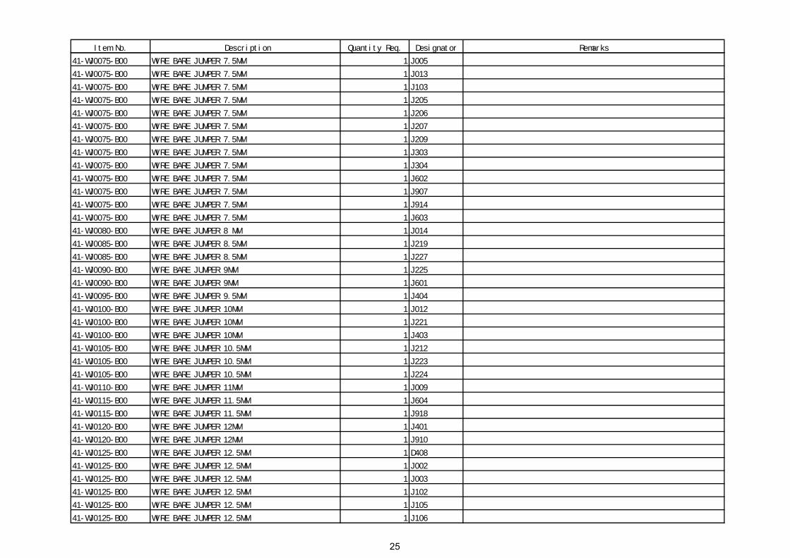
41-WJ0075-B00 WIRE BARE JUMPER 7.5MM 1 J005
41-WJ0075-B00 WIRE BARE JUMPER 7.5MM 1 J013
41-WJ0075-B00 WIRE BARE JUMPER 7.5MM 1 J103
41-WJ0075-B00 WIRE BARE JUMPER 7.5MM 1 J205
41-WJ0075-B00 WIRE BARE JUMPER 7.5MM 1 J206
41-WJ0075-B00 WIRE BARE JUMPER 7.5MM 1 J207
41-WJ0075-B00 WIRE BARE JUMPER 7.5MM 1 J209
41-WJ0075-B00 WIRE BARE JUMPER 7.5MM 1 J303
41-WJ0075-B00 WIRE BARE JUMPER 7.5MM 1 J304
41-WJ0075-B00 WIRE BARE JUMPER 7.5MM 1 J602
41-WJ0075-B00 WIRE BARE JUMPER 7.5MM 1 J907
41-WJ0075-B00 WIRE BARE JUMPER 7.5MM 1 J914
41-WJ0075-B00 WIRE BARE JUMPER 7.5MM 1 J603
41-WJ0080-B00 WIRE BARE JUMPER 8 MM 1 J014
41-WJ0085-B00 WIRE BARE JUMPER 8.5MM 1 J219
41-WJ0085-B00 WIRE BARE JUMPER 8.5MM 1 J227
41-WJ0090-B00 WIRE BARE JUMPER 9MM 1 J225
41-WJ0090-B00 WIRE BARE JUMPER 9MM 1 J601
41-WJ0095-B00 WIRE BARE JUMPER 9.5MM 1 J404
41-WJ0100-B00 WIRE BARE JUMPER 10MM 1 J012
41-WJ0100-B00 WIRE BARE JUMPER 10MM 1 J221
41-WJ0100-B00 WIRE BARE JUMPER 10MM 1 J403
41-WJ0105-B00 WIRE BARE JUMPER 10.5MM 1 J212
41-WJ0105-B00 WIRE BARE JUMPER 10.5MM 1 J223
41-WJ0105-B00 WIRE BARE JUMPER 10.5MM 1 J224
41-WJ0110-B00 WIRE BARE JUMPER 11MM 1 J009
41-WJ0115-B00 WIRE BARE JUMPER 11.5MM 1 J604
41-WJ0115-B00 WIRE BARE JUMPER 11.5MM 1 J918
41-WJ0120-B00 WIRE BARE JUMPER 12MM 1 J401
41-WJ0120-B00 WIRE BARE JUMPER 12MM 1 J910
41-WJ0125-B00 WIRE BARE JUMPER 12.5MM 1 D408
41-WJ0125-B00 WIRE BARE JUMPER 12.5MM 1 J002
41-WJ0125-B00 WIRE BARE JUMPER 12.5MM 1 J003
41-WJ0125-B00 WIRE BARE JUMPER 12.5MM 1 J102
41-WJ0125-B00 WIRE BARE JUMPER 12.5MM 1 J105
41-WJ0125-B00 WIRE BARE JUMPER 12.5MM 1 J106
25

Item No. Description Quantity Req. Designator Remarks
41-WJ0125-B00 WIRE BARE JUMPER 12.5MM 1 J216
41-WJ0125-B00 WIRE BARE JUMPER 12.5MM 1 J306
41-WJ0125-B00 WIRE BARE JUMPER 12.5MM 1 J402
41-WJ0125-B00 WIRE BARE JUMPER 12.5MM 1 R306
41-WJ0130-B00 WIRE BARE JUMPER 13MM 1 J204
41-WJ0130-B00 WIRE BARE JUMPER 13MM 1 J211
41-WJ0135-B00 WIRE BARE JUMPER 13.5MM 1 J006
41-WJ0135-B00 WIRE BARE JUMPER 13.5MM 1 J215
41-WJ0150-B00 WIRE BARE JUMPER 15MM 1 C406A
41-WJ0150-B00 WIRE BARE JUMPER 15MM 1 L402
41-WJ0150-B00 WIRE BARE JUMPER 15MM 1 J112
41-WJ0165-B00 WIRE BARE JUMPER 16.5MM 1 J220
41-WJ0165-B00 WIRE BARE JUMPER 16.5MM 1 J302
41-WJ0175-B00 WIRE BARE JUMPER 17.5MM 1 J004
41-WJ0180-B00 WIRE BARE JUMPER 18MM 1 R045
41-WJ0195-B00 WIRE BARE JUMPER 19.5MM 1 J217
41-WJ0200-B00 WIRE BARE JUMPER 20MM 1 J213
45-OSC8M0-0Y0 CRYSTAL 8.0MHZ 1 X001
45-SAW296-6M00G SAW FILTER K2966M 1 Z101
45-TRA5M5-0Y0 CER TRAP TPS 5.5MHZ 1 X203
46-12866W-02X PIN BASE *2 S11-02Y 1 P601 FOR FRONT CAB. (SPK)
46-20598W-04X PIN BASE *4 TJC1-4A 1 P401 FOR DY CONNECTOR
46-33079W-02X PIN BASE *2 TJC3-2A 1 P602 FOR FRONT CAB. (SPK)
46-33079W-02X PIN BASE *2 TJC3-2A 1 P001 FOR KEY BD P001A
46-33079W-03X PIN BASE *3 TJC3-3A 1 P203
46-33079W-04X PIN BASE *4 TJC3-4A 1 P002 FOR SW. BD P105
46-33079W-04X PIN BASE *4 TJC3-4A 1 P402 FOR CRT BD P502
46-33079W-05X PIN BASE *5 TJC3-5A 1 P201 FOR CRT BD P201
46-33079W-06X PIN BASE *6 TJC3-6A 1 P904 FOR SIDE AV BD
47-RCA035-XX0 RCA JACK AV-3.2-6W-K 1 P901
62-227680-0UA BRACKET ABS-KINGFA 606 (UO) 1
64-P30060-104 M/C SCREW 3 X 6 (ZINC) 2 FOR IC401 & IC402
64-P30100-104 M/C SCREW P 3 X 10 2 FOR IC601
64-P30100-104 M/C SCREW P 3 X 10 2 FOR Q402 & IC301
65-Z30050-23M NUT M 3 2 FOR Q402 & IC301
66-343730-0B0 HOLLOW RIVET 1.6X3.0XL3.2 2 FOR L411
26

Item No. Description Quantity Req. Designator Remarks
66-343730-0B0 HOLLOW RIVET 1.6X3.0XL3.2 2 FOR L412
66-343730-0B0 HOLLOW RIVET 1.6X3.0XL3.2 3 FOR Q402
66-343730-0B0 HOLLOW RIVET 1.6X3.0XL3.2 4 FOR T402
66-382330-0B7 RIVET 2.0X3.7X3.5 2 FOR R402
67-H30752-3A0 HEAT SINK 2 FOR IC301 & Q402
67-H34423-CA0 HEAT SINK 1 FOR IC601
70-271510-00A SERVICE CARD 1 FOR PRODUCTION USE
71-270870-0A9 LABEL 2
90-269080-ZU0 CLEAN COATING TC-131L 14KG/BARREL 0.0001
40-2135MH-MAE P.C.B. MAIN PCB BD 1
66-343730-0B0 HOLLOW RIVET 1.6X3.0XL3.2 2 FOR D407
41-WJ0050-B00 WIRE BARE JUMPER 5MM 1 L209
18-CB0102-JNX RES. C.F. 1K OHM 1/6W +/-5% 1 C226
18-RG0228-JHX RES. WIRE ROUND 0.22 OHM 2W +/-5% 1 R620
07-389VI5-NX0 TUNER UVS1053-EW(HB 5V 38.9) 1 TU101
25-BJA470-M1X CAP. ELEC 47 UF 160V +/-20% 1 C411
67-H10918-4M2 HEAT SINK 1 FOR IC401
67-H10918-4M2 HEAT SINK 1 FOR IC402
26-EBP471-JCX CAP. CER 470PF 50V +/-5% CH 1 C008
25-BCB221-M1X CAP. ELEC 220 UF 16V +/-20% 1 C231
18-CB0681-JNX RES. C.F. 680 OHM 1/6W +/-5% 1 FROM PIN 31 IC201 TO GND
41-WJ0065-B00 WIRE BARE JUMPER 6.5MM 1 J108
13-A19V04-TOP IC A19V04-TO 1 IC201
25-GFB228-K1X CAP. ELEC 0.22 UF 50V +/-10% 1 C205
25-GFB478-K1X CAP. ELEC 0.47 UF 50V 10%CEC-K 1 C236
27-RCP333-J0X CAP. PP 0.033 UF 100V +/-5% 1 C405
25-GFB478-K1X CAP. ELEC 0.47 UF 50V 10%CEC-K 1 C234
10-CW574C-DJX DIODE CW574CD 1 D102
25-DFB109-M1X CAP. ELEC 1 UF 50V +/-20% NP 1 C916
08-D1664H-PAN ASS'Y - PACKING 1
49-382550-BAT BATTERY R06P AA 1.5V 5# 2
72-D1664H-E23 OPERATION MANUAL 1
74-022032-6WE POLYBAG (23cmX34cmX0.06mm) 1
74-120120-80HAA POLYBAG W/SUFFOCATION WARNING 1
75-D166LL-CC0 POLYFOAM "LL" 1
75-D166LR-CC0 POLYFOAM "LR" 1
27

Item No. Description Quantity Req. Designator Remarks
75-D166UL-CC0 POLYFOAM "UL" 1
75-D166UR-CC0 POLYFOAM "UR" 1
76-AD166G-1AT CARTON BOX 1
08-D1664H-RC1 `ASS'Y - REAR CAB(94V0,RCA-2) 1
54-114000-00X FELT TAPE (150mmX19mmX0.3mm) 9 STICK ON REAR CAB.
58-D166MP-JKT PLATE MODEL NO. 1
58-D166SI-2UI INLAY SIDE AV 1
59-130460-00X RUBBER PAD (25mmX7mm) 2 FOR FOOTING OF R.CAB.
63-F30100-BT3 S/T SCREW F 3 X 10 BT (BLACK) 2 MTG RCA JACK & REAR CAB.
63-W30100-AB4 S/T SCREW W 3 X 10 AB 2 MTG M.BD TRACK & R. CAB.
63-W30100-AB4 S/T SCREW W 3 X 10 AB 2 MTG SIDE AV BD & R. CAB.
55-D166RC-2AN REAR CABINET 1
58-D166RI-2UI INALY REAR AV 1
62-378080-1UN TRACK 1
63-B40200-AB4 S/T SCREW B 4 X 20 AB 4 MTG F.CAB & R.CAB
63-B40300-AB4 S/T SCREW B 4*30 AB 2 MTG F.CAB & R.CAB
08-21166H-SW1 1
11-IRR001-3X0 IR RECEIVER MODULE HK381A 1 IR001
14-LED05R-XX1 LED RED FB205 1 D051C
18-CB0470-JNX RES. C.F. 47 OHM 1/6W +/-5% 1 R018A
41-WJ0060-B00 WIRE BARE JUMPER 6mm 1 R016A
41-WJ0060-B00 WIRE BARE JUMPER 6mm 1 R013A
25-BCB220-M1X CAP. ELEC 22 UF 16V +/-20% 1 C011A
46-27266H-04X HS 4P24 350F/W TJC3-4Y/JC25-4Y 1 P002A FOR M BD P002
46-28559W-02X PIN BASE *2 TJC1-2A 1 P804A FOR POWER CORD
46-28559W-02X PIN BASE *2 TJC1-2A 1 P804
46-35049H-02X HS 2P 1617#22 350 TJC1-2Y/TJC1-2Y 1 FOR PWR BD/PWR PARTS
48-POW001-AX0 SWITCH POWER 1 SW801
51-JC0243-0CH01 POWER CORD SAA PLUG W/HOUSING 1
62-226920-0HA LED HOLDER ABS-LG H121 (HB) 1 FOR D051C
62-265160-0HA POWER SW. ADAPTOR 1
63-B30060-BT4 S/T SCREW B 3 X 6 BT 2 MTG SW BD/BKT
40-21166H-SWA P.C.B. POWER SW BD 1
62-378070-1UN FRONT CTL BD BRACKET 1
28

Flowchart chart of alignment procedure for M28 chassis: B+ adjustment NICAM
Adjustment Electrical properties
checking for chassis
RF AGC adjustment
Sub-brightness
Adjustment White balance
Adjustment Aging Adjustment of
screen voltage and focus
Sub-color & Sub-tint
adjustment
Pincushion and
screen width adjustment
Screen center & size
adjustment (PAL)
Screen center & size
adjustment (NTSC)
QC checking
ALIGNMENT PROCEDURE FOR M28 CHASSIS: I) Adjustment of B+ voltage
1. Apply 110-240VAC(±5V) to mains power input, and Philips standard testing pattern to RF input. 2. Adjust VR830 in STANDARD mode until voltage at TP2 (B+) is 112V ±0.5V.
II) NICAM Adjustment (for NICAM model only)
1. Apply a 38.9MHz color bar with NICAM signal to the IF input. 2. Monitor the DC voltage at pin 15 of IC1101. 3. Adjust T1101 until the voltage at pin 15 of IC1101 becomes 2.5 +/- 0.1V. 4. Then check the waveform at pin 4 and 6 of P1103 and it must show correct audio signal.
III) The alignment of RFAGC
1. Connect the detector shown below to collector of Q101. 2. Receive a grey scale signal with 70dBμV amplitude. 3. Adjust RFAGC item until the output of the detector becomes 0.8Vpp
Collector of Q101
To CRO

IV) Adjustment of Sub-contrast, Sub-tint and Sub-colour for NSTC and PAL signal.
1. Enter D-mode, and connect the probe of Oscilloscope to the conjunction between R201 and P201 (B-out).
2. Apply the Grey-scale/Colour-bar (NTSC signal) to the AV input, in STANDARD status. 3. Select CNTC to adjust the sub-contrast, until that the amplitude “A” is 2.5V P-P as shown below. 4. Select COLC to adjust the sub-colour by tuning the amplitude of “a” and “d” to the same. 5. Select TNTC to adjust the sub-tint by tuning the amplitude of “b” and “c” to the same. 6. Apply the Grey-scale/Colour-bar (PAL signal) to the AV input, in STANDARD status. 7. Select COLP to adjust the sub-colour by tuning the amplitude of “a”, “b”, “c” and “d” to the
same.
V) Adjustment of Focus, Screen Voltage and Sub-brightness
1. Receive a crosshatch pattern. 2. Adjust the “FOCUS” VR on the flyback the make the picture clear. 3. Enter D-mode and press “MUTE” key and the screen will become a horizontal line. Then adjust
the “SCREEN” VR on the flyback transformer to set the intensity of the line to a minimum visible level (the line can just be seen).
4. Press “MUTE” key again and the TV will become full raster. 5. Select BRTC to adjust the sub-brightness, until that the 2nd dark bar of 8 level grey scales just can
be seen. VI) Adjustment of White balance
1. Receive a black and white pattern at STANDARD status. 2. Use a color analyzer to measure the black side of the screen. By changing the value of BB and
GB, set the reading of the color analyzer to x=284, y=299. 3. Then measure the white side of the screen. By changing the value of BD and GD, set the reading
of the color analyzer to x=284, y=299. 4. Repeat step 2&3 until you can get the correct reading for both black and white sides.
VII) Adjustment of Pincushion and Picture Width (for pure flat model only)
1. Receive a crosshatch pattern. 2. Adjust VR302 until the vertical line become straight. 3. Adjust VR303 for horizontal size.
A
a b cd

VIII) Adjustment of Picture Geometry (PAL)
1. Apply the crosshatch pattern (PAL signal) to the RF input, in STANDARD status. 2. Select HPOS to adjust the Horizontal center. 3. Select VP50 to adjust the Vertical center. 4. Select HIT to adjust the Vertical amplitude. 5. Select VLIN to adjust the vertical linearity. 6. Select VSC to adjust the vertical S-correction.
IX) Adjustment of Picture Geometry (NTSC)
1. Apply the crosshatch pattern (NTSC signal) to the RF input, in STANDARD status. 2. Select HPS to adjust the Horizontal center. 3. Select VP60 to adjust the Vertical center. 4. Select HITS to adjust the Vertical amplitude. 5. Select VLIS to adjust the vertical linearity. 6. Select VSS to adjust the vertical S-correction.
X) Adjustment of OSD position
1. Enter D-mode and press key “1”, then choose OSDH(OSDHS) item and adjust the OSD vertical position 50HZ(60HZ).
2. Enter D-mode and press key “NOTE”, then choose the OSD1 item and adjust the OSD horizontal position(Volume bar,Picture bar,Half blue panel OSD).
3. Enter D-mode and press key “NOTE”, then choose the OSD2 item and adjust the OSD horizontal position except OSD1 item.
XI)D-mode: 1. press D-Mode ON/OFF key, and then you can enter the D-mode. 2. press VOLUME DOWN key on the unit until the volume decrease to minimum level, then press the DISPLAY key on the remote handset (don’t release the volume key) and you can enter D- mode. After enter D-mode you can adjust the setting according to the following procedure,

ITEM Description Initial
GROUP1 KEY 0 RB R CUT OFF GB G CUT OFF BB B CUT OFF GD G DRIVE BD B DRIVE GROUP2 KEY 1 HPOS/ Horizontal Position 50HZ HPS Horizontal Position 60HZ HIT/ Hight 50Hz HITS hight 60 hz VP50 Vertical Position 50Hz VP60 Vertical Position 60HZ VLIN V Linearity 50Hz VLIS V Linearity 60hz VSC VS Correction 50Hz VSS VS Correction 60HZ VBLK V BLK Start / Stop VCEN V CENTERING OSDH OSD vertical position 50HZ OSDHS OSD vertical position 60HZ GROUP 3 KEY 3 CNTX CONTRAST MAX. CNTN CONTRAST MIN. BRTX BRIGHT MAX.(difference from center) BRTN BRIGHT MIN.(difference from center) COLX COLOR MAX.(difference from center) COLN COLOR MIN. TNTX TINT MAX.(difference from center) TNTN TINT MIN.(difference from center) GROUP 4 KEY 4 BRTC BRIGHT CENTER COLC COLOR CENTER NTSC COLS COLOR CENTER SECAM COLP COLOR CENTER PAL(shift data from COLC) SCOL SUB COLOR ( Cr input (#21) gain up) SCNT SUB CONTRAST CNTC CONTRAST CENTER TNTC TINT CENTER GROUP 5 KEY 5 ST3 SHARP CENTER 3.58NTSC TV SV3 SHARP CENTER 3.58NTSC VIDEO ST4 SHARP CENTER OTHER TV SV4 SHARP CENTER OTHER VIDEO SVD SHARP CENTER DVD ASSH ASYMMETRY-SHARPNESS SHPX SHARP MAX.(difference from center)

SHPN SHARP MIN.(difference from center) GROUP 6 KEY 6 OPT OPTION DATA
0 D mode key 0: No use 1 :use 1 0:normal 1: mute sound when no sync in TV 2 0:NORMAL 1: mute video during change channle 3 au gain 0:50khz 1: 25khz 4 when no sync 1: AFT 0: no AFT 5 AV change 1: mute 0: no mute sound 6 Korea PAL50 BLINK function 1:enable 0:disable 7 standby state 0: high standby 1: low standby
FLG0 0 OVER MOD 1 N Buzz Cancel 2 3 SLO f0 shift 4 hotel mode TV mode enter 5 hotel mode av mode enter 6 hotel mode 7 vco readjust when position select 0:enable 1:disable
FLG1
0 1: 7 key 0: 6 key 1 Secam 0:disable 1:enable 2 LOGO 0:disable 1:enable 3 TINT por 4 PIF SELECT 01:45.75 MHZ 5 011 :38.9MHZ 6 100 :38MHZ 7 APC 1:AUTO 0:PRESET
STBY
0 1 2 3
hd kill timer set *40us
4 when STBY.5=0 ,after AC on 0: standby 1: power on 5 after AC power on, 0: ref STBY.4 1: last state 6 auto sleep function 7
MODE0 0 NICAM 0:DISABLE 1:ENABLE 1 English language select 2 Russia language select 3 vietnam language select 4 mute type 0: y mute 1: RGB mute 5 when mode0.7 = 1 ; preset sound system after ASM 6 00: BG 01 :I 10:DK 11: M 7 preset sound system after ASM 0:disable 1:enable
MODE1 0 BG system enable 1 I system enable 2 DK system enable

3 M system enable 4 VIDEO2 enable 5 video3 enable 6 YUV enable 7 Thailand Dual language 0:Disable 1:Enable
MUTT standby -->wake time STAT contrast up timer afer standy off GROUP 7 KEY 7 RF AGC RF AGC SBY SECAM B-Y BLACK ADJUST SRY SECAM R-Y BLACK ADJUST BRTS SUB BRIGHT shift data of BRTC TXCX TEXT RGB CONTRAST MAX. RGCN TEXT RGB CONTRAST MIN. SECD SECAM MODE GROUP 9 KEY 8 V25 VOLUME 25 V50 VOLUME 50 V100 VOLUME 100 GROUP 10 KEY 9 SVM SVM PYNX Normal H.SYNC max PYNN Normal H.SYNC min PYXS Search H.SYNC max PYNS Search H.SYNC min GROUP 11 KEY CALENDAR CLTO TV mode & SOUND SYS != M CLTM TV mode & SOUND SYS = M CLVO VIDEO CLVD YUV MODE CLTO CLTM CLVO CLVD bit setting
7 KILLER OFF 6 P/N ID 5 C GAMMA 4 3
NTSC-MATRIX
2 1 0
Y DL
ABL ABL SETUP
5 TB1254N RGB ABL 4 TB1254N WPS 3 2 1 0
ABLpoint setup
DCBS VIDEO DATA SETUP

0~3 Y GAMMA BLACK STRETCH 4~5 OSD LEVEL
DEF V AGC SELECT 0 V AGC reference, 0:depends on YC Vcc
1:Depends on integrated regulator GROUP 14 KEY NOTE-BOOK
OSD1 OSD Horizontal Position(volume bar, Picture bar,Half blue panel OSD)
OSDF1 OSD PLL DATA(volume bar, Picture bar,Half blue panel OSD)
OSD2 OSD Horizontal Position except OSD1 items OSDF2 OSD PLL DATA except OSDF1 items HAFC
0 when nois.2 = 1 ; TV hafc gain 1 if nois.2 = 0 TV hafc gain depend on noise(0~1) 2 in video mode hafc gain 3
NOIS HAFC DATA 0 noise det 1 2 fix the hafc gain
UCOM MCU DATA
TCL ad
*Reset EEPROM Data: Press D-mode and Press 0752.

M117 Block Diagram By ZSM 2001/12/20
220V~ D801—D804
IC801
Q801 AMP.
T803 Transformer
112v12V 12V
Tuner TU101
IF AMPQ101
SAW Z101
TMPA8821
IC201
Q501 Q503Q505 AMP. R/G/B CRTR/G/B
V. AMP. IC301
V.out
H.drive AMP.Q401 Q402
H.outFBT T402 220V,24V
6.3V
EHT FOCUS SCREEN
CPU IC001
E2PROM IC002
KEY IR001Sensor
AV Vin
IC603
TV/AV SW
Audio AMP.
IC601
AV AoutAV Vout
Speaker
AV Ain