Sirona Orthophos XG Dental X-Ray - Service manual.pdf
578
båÖäáëÜ loqelmelp ud mäìë ap L `ÉéÜ loqelmelp ud R ap L `ÉéÜ loqelmelp ud P ap pÉêîáÅÉ j~åì~ä sÉêëáçå NPKM ORTHOPHOS XG Plus DS Easypad ORTHOPHOS XG 5 / 3 / 3 PPE DS T R Prog. S kV mA P1 Multipad
-
Upload
khangminh22 -
Category
Documents
-
view
0 -
download
0
Transcript of Sirona Orthophos XG Dental X-Ray - Service manual.pdf

båÖäáëÜ
loqelmelp=udmäìë=ap=L=`ÉéÜloqelmelp=ud=R=ap=L=`ÉéÜloqelmelp=ud=P=appÉêîáÅÉ=j~åì~ä
sÉêëáçå=NPKM
ORTHOPHOS XGPlus DS
Easypad
ORTHOPHOS XG 5 / 3 / 3 PPE DS
T R
Prog. S kV mAP1
Multipad

About the Service Manual:
• This Service Manual is valid for the following unit versions:– ORTHOPHOS XGPlus DS / Ceph
– ORTHOPHOS XG 5 DS / Ceph
– ORTHOPHOS XG 3 DS*
NOTEiThese two system versions differ regarding the equipment offered by their user interfaces and their possible configuration levels (see page 1-5).
NOTEiBoard DX41 is no longer installed in units with hardware version BA or higher (as of November 2006).
In addition, you also require:
• Spare parts list: Order No. 59 38 423– ORTHOPHOS XGPlus DS / Ceph, ORTHOPHOS XG 5 DS / Ceph,
ORTHOPHOS XG 3 DS
• Wiring diagrams: Order No. 59 38 332– ORTHOPHOS XGPlus DS / Ceph, ORTHOPHOS XG 5 DS / Ceph,
ORTHOPHOS XG 3 DS
• Installation Instructions– ORTHOPHOS XGPlus DS / Ceph: Order No. 59 87 651
– ORTHOPHOS XG 5 DS / Ceph: Order No. 60 04 902
– ORTHOPHOS XG 3 DS: Order No. 60 51 416
• Tools– Screwdriver, medium sized
– Torx offset screwdrivers TX10, TX20, TX25
– Open-end wrench, 13 mm A/F
– Socket wrench, 13 mm A/F
– Side cutters
– Spirit level
• Auxiliary devices– Digital multimeter, Accuracy Class 1
– Soldering tool for repairing cables
– Cable ties
– Teflon tape
– Loctite

General information/Software update 1
Messages 2
Troubleshooting 3
Adjustment 4
Service routines 5
Repair 6
Maintenance 7


Contents
59 38 399 D3352D3352.076.01.13.02 07.2008 V
1 General information ..................................................................... 1-5
1.1 Safety .................................................................................. 1-5
1.2 XGPlus and XG 5 / 3 / 3 PPE system classes ...................... 1-6
1.3 Programs and functions of the XG 5 / 3 / 3 PPE system class ............................................ 1-8
1.4 Programs and functions of the XGPlus system class ........... 1-9
1.5 Operation notes ................................................................. 1-11
1.6 Demo mode – Operation without radiation release ........... 1-13
1.7 Demo mode – Repacking and transport ........................... 1-15
1.8 List of software versions .................................................... 1-16
1.9 Software update ................................................................ 1-22
1.10 Selecting More details ....................................................... 1-32
1.11 The most important modules and components ................. 1-34
1.12 Cabling overview ............................................................... 1-38
1.13 Illustrations of boards ........................................................ 1-42
1.14 Removing the covers ........................................................ 1-50
2 Messages .................................................................................... 2-3
2.1 Help messages ................................................................... 2-4
2.2 System messages ............................................................... 2-6
2.3 Status displays .................................................................... 2-6
2.4 Error messages ................................................................... 2-6
2.5 List of error messages ......................................................... 2-9
2.6 List of available service routines ....................................... 2-62
3 Troubleshooting .......................................................................... 3-3
3.1 Error logging memory .......................................................... 3-4
3.2 Check the CAN bus ............................................................. 3-6
3.3 Checking the boards ......................................................... 3-12
3.4 Checking the motors ......................................................... 3-14
3.5 Checking the light barriers ................................................ 3-15
3.6 Device leakage current too high ........................................ 3-16
3.7 Checking the cables .......................................................... 3-17
3.8 Error analysis of X-RAY control signal path: up to unit hardware revision AG(with board DX41) ............................................................. 3-18
3.9 Error analysis of X-RAY control signal path: unit HW version BA or higher(without board DX41) ........................................................ 3-22
3.10 Check data paths/Generate test images ........................... 3-25
Contents
59 38 399 D3352 VI D3352.076.01.13.02 07.2008
4 Adjustment ................................................................................... 4-3
4.1 Important information concerning adjustment ...................... 4-3
4.2 Diaphragm/system adjustment menu .................................. 4-5
4.3 Adjusting the panoramic X-ray unit ...................................... 4-9
4.4 Adjusting the cephalometer (XGPlus/ XG 5, if ceph is installed) ..................................... 4-56
4.5 TSA sensor adjustment(XGPlus full version only) .................................................. 4-107
4.6 Resetting the adjustment (XGPlus / 5 / 3 / 3 PPE) ..................................................... 4-115
5 Service routines ........................................................................... 5-9
5.1 Selecting the Service menu ............................................... 5-10
5.2 Selecting a service routine ................................................. 5-15
5.3 Service routines with SIDEXIS .......................................... 5-18
5.4 Service routine S001 ......................................................... 5-21
5.5 Service routine S002 ......................................................... 5-23
5.6 Service routine S005 ......................................................... 5-28
5.7 Service routine S007 ......................................................... 5-40
5.8 Service routine S008 ......................................................... 5-48
5.9 Service routine S009 ......................................................... 5-56
5.10 Service routine S012 ......................................................... 5-59
5.11 Service routine S014 ......................................................... 5-67
5.12 Service routine S015 ......................................................... 5-74
5.13 Service routine S017 ......................................................... 5-77
5.14 Service routine S018 ....................................................... 5-109
5.15 Service routine S020 (XGPlus only) .................................. 5-118
5.16 Service routine S021 (not for XG 3 / 3 PPE) ................... 5-121
5.17 Service routine S032 ....................................................... 5-126
5.18 Service routine S033 (not for XG 3 / 3 PPE) ................... 5-130
5.19 Service routine S034 ....................................................... 5-134
5.20 Service routine S037 ....................................................... 5-151

Contents
59 38 399 D3352D3352.076.01.13.02 07.2008 VII
6 Repair .......................................................................................... 6-5
6.1 Replacing the height adjustment motor (M1_4)/spindle ...... 6-6
6.2 Replacing the ring motor (M1_3) ....................................... 6-14
6.3 Replacing the PAN actuators (M1_1/2) ............................. 6-17
6.4 Replacing the headrest ..................................................... 6-19
6.5 Replacing the Easypad (XGPlus) or the Multipad (XG 5 / 3 / 3 PPE) ..................................... 6-21
6.6 Replacing the control panel ............................................... 6-24
6.7 Replacing/adjusting the FH light localizer (PAN) .............. 6-26
6.8 Replacing/adjusting the MS light localizer laser module (PAN) ........................................................... 6-28
6.9 Replacing/adjusting the FH light localizer (Ceph) ............. 6-30
6.10 Removing the light localizers from the ring(for the XGPlus and XG 5, if present) ................................. 6-32
6.11 Replacing the support piece (bite block holder) ................ 6-33
6.12 Replacing the motor-driven diaphragm (for XGPlus / XG 5) ............................................................. 6-34
6.13 Replacing the fixed diaphragm (only XG 3 / 3 PPE) ........................................................... 6-37
6.14 Replacing the X-ray tube assembly .................................. 6-38
6.15 Replacing the fan (tube assembly) .................................... 6-42
6.16 Replacing the PAN (TSA) sensor holder ........................... 6-43
6.17 Replacing the ceph sensor holder ..................................... 6-47
6.18 Replacing the sensor ........................................................ 6-48
6.19 Replacing the light barriers ............................................... 6-49
6.20 Replacing circuit boards .................................................... 6-59
6.21 Replacing cables ............................................................... 6-91

Contents
59 38 399 D3352 VIII D3352.076.01.13.02 07.2008
7 Maintenance ................................................................................ 7-3
7.1 Checking the height adjustment .......................................... 7-4
7.2 Checking the forehead and temple supports ....................... 7-6
7.3 Checking the sensor holder (pan and ceph) ........................ 7-7
7.4 Checking the support piece (bite block holder) .................... 7-9
7.5 Checking the light localizers .............................................. 7-10
7.6 Checking the X-ray images ................................................ 7-12
7.7 Checking the tube data ...................................................... 7-13
7.8 Checking the diaphragm .................................................... 7-17
7.9 Checking the cables for damage ....................................... 7-35
7.10 Checking the idling rollers .................................................. 7-36
7.11 Checking the grounding straps .......................................... 7-37
7.12 Checking the cable shields ................................................ 7-38
7.13 Checking the protective ground wires ................................ 7-39
7.14 Checking the device leakage current ................................. 7-43

ORTHOPHOS XG 1General information

59 38 399 D33521 – 2 D3352.076.01.13.02 07.2008
Tab 1
Contents
1.1 Safety ......................................................................1 – 5
1.2 XGPlus and XG 5 / 3 / 3 PPE system classes..........1 – 61.2.1 Overview of the ORTHOPHOS XG system
classes and versions ............................................ 1 – 7
1.3 Programs and functions of the XG 5 / 3 / 3 PPE system class ................................1 – 81.3.1 XG 5 system version ............................................ 1 – 8
1.3.2 XG 3 system version ............................................ 1 – 8
1.3.3 XG 3 PPE (pay per exposure) system version..... 1 – 8
1.4 Programs and functions of the XGPlus system class1 – 91.4.1 Programs and functions of the basic version ....... 1 – 9
1.4.2 Programs and functions of the full version ......... 1 – 10
1.5 Operation notes.....................................................1 – 11
1.6 Demo mode – Operation without radiation release1 – 131.6.1 Switching the demo mode ON............................ 1 – 14
1.6.2 Switching the demo mode OFF.......................... 1 – 14
1.7 Demo mode – Repacking and transport ...............1 – 15
1.8 List of software versions........................................1 – 161.8.1 ORTHOPHOS XG 3 PPE .................................. 1 – 16
1.8.2 ORTHOPHOS XG 3 .......................................... 1 – 17
1.8.3 ORTHOPHOS XG 5 / Ceph ............................... 1 – 18
1.8.4 ORTHOPHOS XGPlus / Ceph............................. 1 – 20
1.9 Software update ....................................................1 – 221.9.1 Important information on the software update.... 1 – 22
1.9.2 Permissible software updates ............................ 1 – 23
1.9.3 Performing a software update ............................ 1 – 24
1.9.4 Software update for ORTHOPHOS XG 5 to V02.30 or higher............................................. 1 – 29
1.9.5 Software Update for ORTHOPHOS XGPlus from V02.20 to V02.30 or higher ........................ 1 – 30
1.9.6 Software update for ORTHOPHOS XGPlus from V02.22 to V02.30 or higher ........................ 1 – 31
1.10 Selecting More details ...........................................1 – 32

59 38 399 D3352D3352.076.01.13.02 07.2008 1 – 3
Tab 1
1.11 The most important modules and components .....1 – 341.11.1 Slide ................................................................... 1 – 35
1.11.2 Stand .................................................................. 1 – 36
1.11.3 Cephalometer(arm mounted on left side or on right side)......... 1 – 37
1.11.4 Remote control ................................................... 1 – 37
1.12 Cabling overview...................................................1 – 38
1.13 Illustrations of boards ............................................1 – 421.13.1 Boards in the slide.............................................. 1 – 42
1.13.2 Boards in the stand ............................................ 1 – 46
1.13.3 Boards in the cephalometer(arm mounted on right side or on left side)......... 1 – 47
1.13.4 Boards in the remote control .............................. 1 – 48
1.14 Removing the covers.............................................1 – 50

59 38 399 D33521 – 4 D3352.076.01.13.02 07.2008
Tab 1

1.1
båÖäáëÜ
59 38 399 D3352D3352.076.01.13.02 07.2008 1 – 5
Tab 1 1.1 Safety
1.11 General information
1.1 Safety
It is essential that you comply with the warning and safety information con-tained in this Service Manual.
All such information is highlighted by one of three signal words, i.e. CAUTION, WARNING or DANGER.
CAUTIONNonobservance may result in minor physical injuries or material damage and malfunctions.
WARNINGNonobservance may lead to serious physical injury or death.
DANGERImmediate danger to life and limb. Threat of serious physical injury or death.

59 38 399 D33521 – 6 D3352.076.01.13.02 07.2008
1.2 XGPlus and XG 5 / 3 / 3 PPE system classes Tab 1
1.2 XGPlus and XG 5 / 3 / 3 PPE system classes
The XGPlus and XG 5 / 3 / 3 PPE system versions differ with regard to their user interface. While the ORTHOPHOS XG (XGPlus) features a control panel with a color touchscreen (Easypad), the (XG 5 / 3 / 3 PPE) basic class is equipped with a simpler control panel with a single-line display (Multipad).
Due to their different control panels, the operating procedures for these two system classes also vary.
All ORTHOPHOS XG units are digital systems (DS).
The ORTHOPHOS XGPlus and XG 5 system versions are suitable for opera-tion with a cephalometer (ceph). The cephalometer for the XGPlus system ver-sion is also available with the ceph arm mounted either on the left or the right side. Only the cephalometer version with the arm mounted on the left side is offered for the XG 5 system version. Operation of the XG 3/3 PPE system ver-sion is not possible with a cephalometer.
NOTEiThe version with the ceph arm mounted on the left side is basically described and illustrated in this Service Manual. Unless described separately, all dis-mantling and assembly steps must be performed laterally reversed for the ver-sion with the ceph arm mounted on the right side.
Remote control operation is possible in all system versions.
The (XGPlus) system class comes in a basic and a full version (see page 1-9), however, the basic system class (XG 5 / 3 / 3 PPE) is available only in a basic version.
The XGPlus system class optionally includes TSA operation.
This Service Manual describes both system classes in the highest possible configuration.
For more information on the different installation versions, please refer to the Installation Instructions.
NOTEiThe empty digits in the single-line display of the Multipad are markedwith underscores in this Manual. They have been added to enhance clarity and are not present on the real Multipad.
Comfort class with Easypad (XGPlus)
Basic class with Multipad (XG 5 / 3 / 3 PPE)
T R
Prog. S kV mA
1 2 3
S005_______1____

1.2
båÖäáëÜ
59 38 399 D3352D3352.076.01.13.02 07.2008 1 – 7
Tab 1 1.2 XGPlus and XG 5 / 3 / 3 PPE system classes
1.21.2.1 Overview of the ORTHOPHOS XG system
classes and versions
T R
Prog. S kV mA
T R
Prog. S kV mA
T R
Prog. S kV mA
ORTHOPHOS XGPlus with ceph arm on right sidewith ceph arm on left side
Comfort class (Easypad, basic or full version, TSA option, remote control option)
ORTHOPHOS XG 5with ceph arm on left side
ORTHOPHOS XG 3
Basic class (Multipad, basic equipment, remote release optional)
T R
Prog. S kV mA
ORTHOPHOS XG 3 PPE

59 38 399 D33521 – 8 D3352.076.01.13.02 07.2008
1.3 Programs and functions of the XG 5 / 3 / 3 PPE system class Tab 1
1.3 Programs and functions of the XG 5 / 3 / 3 PPE system class
1.3.1 XG 5 system version
8 panoramic programs P 1, P 1C, P 10
P 1L, P 1R
TM 1.1/TM 1.2
S 1
MS 1
5 Ceph programs C 1, C 2, C 3, C 3F, C 4
Functions Half-views of right/left side possible only with P1 (not upper/lower jaw).
Constant magnification factor of 1.25 possible only with program P 1.
No Quickshot function.
No "jaw shape" program presetting.
No artifact-free display mode.
No orthodontic image series P 1 - C 3 - C 4 without cooling periods.
No TSA configuration level.
No TSA operation possible.
No welcome screen.
1.3.2 XG 3 system version
5 panoramic programs P 1, P 1C
P 1L, P 1R
TM 1.1/TM 1.2
Functions Half-views of right/left side possible only with P1 (not upper/lower jaw).
Constant magnification factor of 1.25 possible only with program P 1.
No Quickshot function.
No "jaw shape" program presetting.
No artifact-free display mode.
No orthodontic image series P 1 - C 3 - C 4 without cooling periods.
No TSA configuration level.
No TSA operation possible.
No welcome screen.
1.3.3 XG 3 PPE (pay per exposure) system version
ORTHOPHOS XG 3 with PPE concept (for USA only).
Functionality and programs identical to those of system version XG 3.

1.4
båÖäáëÜ
59 38 399 D3352D3352.076.01.13.02 07.2008 1 – 9
Tab 1 1.4 Programs and functions of the XGPlus system class
1.41.4 Programs and functions of the XGPlus system
class
The XGPlus system class is available in two configuration levels:
Basic version
Full version
This Service Manual describes the full version of the system.
1.4.1 Programs and functions of the basic version
10 panoramic programs P 1, P 1C, P 2, P 10
P 1L, P 1R
P 12
TM 1.1/TM 1.2
S 1
MS 1
5 Ceph programs C 1, C 2, C 3, C 3F, C 4
Functions Half-views of right/left side possible only with P1 (not upper/lower jaw).
Preselection of individual quadrants not possible.
Constant magnification factor of 1.25 possible only with program P 1.
No Quickshot function.
No "jaw shape" program presetting.
No artifact-free display mode.
No orthodontic image series P 1 - C 3 - C 4 without cooling periods.
No TSA configuration level (TSA operation retrofittable).
No welcome screen with patient data from SIDEXIS.
Ceph: No shadowing in upper head region with programs C3 and C3F.
Ceph: No shadowing in thyroid region with programs C1 and C2.

59 38 399 D33521 – 10 D3352.076.01.13.02 07.2008
1.4 Programs and functions of the XGPlus system class Tab 1
1.4.2 Programs and functions of the full version
The full version offers the following programs and functions in addition to those featured in the basic version:
Additional Pan programs Constant magnification factor of 1.25 P 2C, P 10C
Artifact-free display P 1A, P 2A, P 10A
Additional functions Selectable right/left partial view and individual quadrantsP 1A, P 2/A/C, P 10/A/C, P12.
Selectable upper/lower jaw partial view and individual quadrantsP 1/A/C, P 2/A/C, P 10/A/C.
Temporomandibular joint views TM 2, TM 3, TM 4, TM 5, TM 6
Sinus views S2, S3, S4.
Selectable "jaw shape" program setting.
Quickshot function possible (for Pan and Ceph).
Orthodontic image series P 1 - C 3 - C 4 without cooling periods possible.
TSA configuration level
TSA operation possible (optional)
Welcome screen with patient data from SIDEXIS (SIDEXIS V01.50 and higher).
Ceph: Shadowing in upper head region with programs C3 and C3F.
Ceph: Shadowing in thyroid region with programs C1 and C2.

1.5
båÖäáëÜ
59 38 399 D3352D3352.076.01.13.02 07.2008 1 – 11
Tab 1 1.5 Operation notes
1.51.5 Operation notes
Rated line voltage The ORTHOPHOS XG X-ray unit can be operated in the following rated line voltage ranges:
200 V - 240 V
50/60 Hz
The permissible line voltage fluctuations are as follows:
200 - 230 V: ± 10 %
The internal line impedance must not exceed max. 0.8 Ω.
NOTEiOnly permanent electrical connection of the system is allowed in Germany.
Remote control The system can be equipped with...
a 1 - 3 m coiled cable with release button inside the treatment room or ...
a remote control with or without coiled cable located outside the X-ray room (see installation instructions).
Warm-up time After it is switched ON, the system requires a warm-up time of approx. 1 min.
Self-adjustment routine At the same time, a mechanical and electronic self-adjustment routine is exe-cuted. If a button is pressed during the self-adjustment routine, an error mes-sage is displayed on the Multipad (XG 5 / 3 / 3 PPE) or Easypad (XGPlus).
Cooling period The cooling period between two exposures is maintained by an automatic exposure blocking function according to the pulse/pause ratio. A countdown of the waiting time is displayed on the Multipad (XG 5 / 3 / 3 PPE) or Easypad (XGPlus).
Turn-off time The turn-off time must amount to at least 60s.
Demo units If the X-ray unit is to be presented as a demo unit at trade fairs or exhibitions, it must be ensured that radiation release is blocked (see “Demo mode – Operation without radiation release” on page 1-13).
Software version The overall system software version is determined by the software statuses of the EEPROMs on the boards (see “List of software versions” on page 1-16).
Wireless phone interference with medical electrical equipment
To ensure safe operation of medical electrical equipment, the use of mobile wireless phones in practice or hospital environments is prohibited.
Disposal The X-ray tube assembly contains a tube with potential implosion hazard, a small amount of beryllium, a lead lining as well as mineral oil.
Error messages Error messages are displayed on the single-line display of the Multipad (XG 5 / 3 / 3 PPE) or on the touchscreen of the Easypad (XGPlus).

59 38 399 D33521 – 12 D3352.076.01.13.02 07.2008
1.5 Operation notes Tab 1
Help messages in case exposure readiness cannot be attained
Help messages are displayed on the single-line display of the Multipad (XG 5 / 3 / 3 PPE) or on the touchscreen of the Easypad (XGPlus).
If you have to remove covers from the unit
Proceed according to section "1.14 Removing the covers".
When removing covers, always remember that direct sunlight or bright room lighting can cause system malfunctions due to activated light barriers.
Therefore: avoid direct sunlight and bright room lighting above the unit!
When attaching the covers: be sure to screw the sheet metal cover back on.
CAUTIONFor reasons of electromagnetic compatibility, be sure to fasten all screws.
Reattach the covers.
Secondary diaphragm Do not manually move or otherwise exert force on the secondary diaphragm (e.g. when removing it from its packaging).
Measurements Always switch the unit OFF before connecting a measuring instrument.
Select the correct current/voltage type and adjust the measuring range to match the expected readings.
Perform continuity tests only on units which are switched off.
If several exposures with radiation must be taken to check a measurement, make sure that the prescribed cool-down intervals are observed. They are maintained by an automatic exposure blocking function (see operating instructions).
The pulse/pause ratio is 1: 10, i.e. a 10-second pause is maintained for each second of radiation emission. The pulse/pause ratio is automatically main-tained (automatic exposure blocking).
A pulse/pause ratio of 1:20 is better for the X-ray tube.
WARNINGIt is essential that you observe the radiation protection regulations ap-plicable in your country prior to radiation release.
The test rotations triggered by pressing the T key on the Easypad and then the release button are executed without radiation.
When replacing parts Switch the unit OFF before replacing parts.
The unit must be disconnected from the junction box of the building installa-tion before replacing any parts near the power supply, power switch, board DX 32 or the X-ray tube assembly!
Please always wear an ESD wrist band to protect sensitive components on printed circuit boards (ESD).
Always check the system and adjust it as required after replacing a board or the X-ray tube assembly.
The article numbers for ordering spare parts can be found in the spare parts list, Order No. 59 38 423. The diagrams contained in the spare parts list pro-vide a useful guide when replacing parts.

1.6
båÖäáëÜ
59 38 399 D3352D3352.076.01.13.02 07.2008 1 – 13
Tab 1 1.6 Demo mode – Operation without radiation release
1.61.6 Demo mode – Operation without radiation
release
NOTEiStarting with system SW version V02.28, the complete possible functionality of the system class is simulated, regardless of the current configuration.
4.3.
1. 2.
A
B
S2
Board DX6J6

59 38 399 D33521 – 14 D3352.076.01.13.02 07.2008
1.6 Demo mode – Operation without radiation release Tab 1
1.6.1 Switching the demo mode ON
When operated in demo mode, the unit must not release any radiation. For this reason, you must take the following safety measures:
Switch the unit OFF.
1. Remove the cover of the tube assembly.
2. Loosen screws A and remove cover plate B.
3. Set dip switch S2 (DX6) to position 2.
4. Pull cable L5 (X-RAY) off of connector J6 (DX6).
Radiation release is now no longer possible.
5. Switch the unit ON and check the mode with theinfo menu (XG 5 / 3 / 3 PPE) or the info screen (XGPlus).
Demo mode: ON means that: The demo mode is switched ON (Radiation release is not possible)
Demo mode: OFF means: The demo mode is switched OFF (Radiography, X-ray radiation are possible!)
Switch the unit OFF again and reattach cover plate B and the tube assem-bly covers by following the dismantling procedure in reverse order.
1.6.2 Switching the demo mode OFF
Switch the unit OFF.
1. Remove the cover of the tube assembly.
2. Loosen screws A and remove cover plate B.
3. Set dip switch S2 (DX6) to position 1.
4. Pull cable L5 (X-RAY) off of connector J6 (DX6).
Radiation release is now once again possible.
5. Switch the unit ON and check the mode with the info menu (XG 5 / 3 / 3 PPE) or the info screen (XGPlus).
Demo mode: ON means that: The demo mode is switched ON (Radiation release is not possible)
Demo mode: OFF means: The demo mode is switched OFF (Radiography, X-ray radiation are possible!)
Switch the unit OFF again and reattach cover plate B and the tube assem-bly covers by following the dismantling procedure in reverse order.
5.Info menu for XG 5 / 3 / 3 PPE
65
Mac adress : 010001200000IP adress : 192.168.15.19Subnet mask : 155.155.255.0Default Gateway : 192.168.15.1Net API version : 1Net API revision : 14Demomode : ONTube Exposures : 2217
Orthophos XG configuration
Info screen for XGPlus
1 2 3
P1______14.1__64_8
1 2 3
SYSTEM SOFTWARE____
Scroll through the list until the demo mode is displayed
2/2

1.7
båÖäáëÜ
59 38 399 D3352D3352.076.01.13.02 07.2008 1 – 15
Tab 1 1.7 Demo mode – Repacking and transport
1.71.7 Demo mode – Repacking and transport
Panoramic X-ray unit Switch the panoramic X-ray unit ON and move it to its packing height by pressing the UP/DOWN keys on the Multipad (XG 5 / 3 / 3 PPE) or Easypad (XGPlus).
– Bite block height = 965 mm (displayed as height on Multipad (XG 5 / 3 / 3 PPE) or Easypad (XGPlus)
– Bottom edge of slide cover = 702 mm
NOTEiThe bottom edge of the slide cover must be at the same height as the mark-ings A in the column.
Cephalometer Start service routine S034, test step 6.
Move the cephalometer to the packing position (see page 5-143).
For information on packing the units and on the packing condition, see the relevant installation instructions.
1.
A
NOTEiIf the unit is installed with a floor stand, its height in-creases by 30 mm. The bite block height value dis-played on the Multipad (XG 5 / 3 / 3 PPE) or Easypad (XGPlus) remains the same, however!

59 38 399 D33521 – 16 D3352.076.01.13.02 07.2008
1.8 List of software versions Tab 1
1.8 List of software versions
NOTEiAny software combinations other than those listed here are not allowed. If the software version of any particular module does not match the overall software version, the overall software version will be marked with an asterisk on the info screen (e.g. 02.20*).
1.8.1 ORTHOPHOS XG 3 PPE
Panoramic unit Remarks
Board DX6 DX71 DX11 DX81
Overall softwareV 02.28 02.60 02.33 02.40 02.33 compatible with SIDEXIS versions
V01.61 and higher
Overall softwareV 02.28.2 02.60 02.33 02.40.01 02.33 compatible with SIDEXIS versions
V01.61 and higher
Overall softwareV 02.30 02.60 02.34 02.42 02.33 compatible with SIDEXIS versions
V01.61 and higher
Overall softwareV 02.31 02.60 02.34 02.42 02.33 compatible with SIDEXIS versions
V01.61 and higher
Overall softwareV 02.32 02.60 02.34 02.43 02.33 compatible with SIDEXIS versions
V01.61 and higher
Remote control Remarks
Board DX42
Overall softwareV 02.28 02.30
Overall softwareV 02.28.2 02.30
Overall software V 02.30 02.31
Overall software V 02.31 02.31
Overall software V 02.32 02.31
Sidexis XG Remarks Database
V 01.53 requires ORTHOPHOS XG 3 PPEOverall Software Version V02.28.2 or higher
old Database
V 01.54 requires ORTHOPHOS XG 3 PPEOverall Software Version V02.28.2 or higher
V 01.55 requires ORTHOPHOS XG 3 PPEOverall Software Version V02.28.2 or higher
V 01.61 requires ORTHOPHOS XG 3 PPEOverall Software Version V02.28.2 or higher
new Database
V 02.00 requires ORTHOPHOS XG 3 PPEOverall Software Version V02.28.2 or higher
V 2.2 requires ORTHOPHOS XG 3 PPEOverall Software Version V02.28.2 or higher
V 2.3 requires ORTHOPHOS XG 3 PPEOverall Software Version V02.28.2 or higher

1.8
båÖäáëÜ
59 38 399 D3352D3352.076.01.13.02 07.2008 1 – 17
Tab 1 1.8 List of software versions
1.81.8.2 ORTHOPHOS XG 3
* As of hardware version BA (from November 2006) new systems will be delivered withoutboard DX41 (see also page 1-44).
Panoramic unit Remarks
Board DX6 DX71 DX11 DX41 DX81
Overall softwareV 02.25 02.57 02.29 02.37 02.22 02.30 compatible with SIDEXIS versions
V01.45 and higher
Overall softwareV 02.27 02.60 02.31 02.39 02.23 02.32 compatible with SIDEXIS versions
V01.53 and higher
Overall softwareV 02.28 02.60 02.33 02.40 (02.23*) 02.33 compatible with SIDEXIS versions
V01.53 and higher
Overall softwareV 02.28.2 02.60 02.33 02.40.01 (02.23*) 02.33 compatible with SIDEXIS versions
V01.53 and higher
Overall softwareV 02.30 02.60 02.34 02.42 (02.23*) 02.33 compatible with SIDEXIS versions
V01.53 and higher
Overall softwareV 02.31 02.60 02.34 02.42 (02.23*) 02.33 compatible with SIDEXIS versions
V01.53 and higher
Overall softwareV 02.32 02.60 02.34 02.43 (02.23*) 02.33 compatible with SIDEXIS versions
V01.53 and higher
Remote control Remarks
Board DX42
Overall softwareV 02.25 02.27
Overall softwareV 02.27 02.28
Overall softwareV 02.28 02.30
Overall softwareV 02.28.2 02.30
Overall softwareV 02.30 02.31
Overall softwareV 02.31 02.31
Overall softwareV 02.32 02.31
Sidexis XG Remarks Database
V 01.51 requires ORTHOPHOS XG 3 Overall Soft-ware Version V02.25 or higher
old Database
V 01.53 requires ORTHOPHOS XG 3 Overall Soft-ware Version V02.25 or higher
V 01.54 requires ORTHOPHOS XG 3 Overall Soft-ware Version V02.25 or higher
V 01.55 requires ORTHOPHOS XG 3 Overall Soft-ware Version V02.25 or higher
V 01.61 requires ORTHOPHOS XG 3 Overall Soft-ware Version V02.25 or higher
new Database
V 02.00 requires ORTHOPHOS XG 3 Overall Soft-ware Version V02.25 or higher
V 2.2 requires ORTHOPHOS XG 3 Overall Soft-ware Version V02.25 or higher
V 2.3 requires ORTHOPHOS XG 3 Overall Soft-ware Version V02.25 or higher
59 38 399 D33521 – 18 D3352.076.01.13.02 07.2008
1.8 List of software versions Tab 1
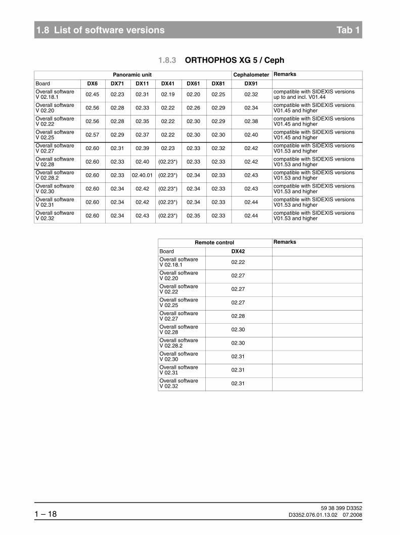
1.8.3 ORTHOPHOS XG 5 / Ceph
Panoramic unit Cephalometer Remarks
Board DX6 DX71 DX11 DX41 DX61 DX81 DX91
Overall softwareV 02.18.1 02.45 02.23 02.31 02.19 02.20 02.25 02.32 compatible with SIDEXIS versions
up to and incl. V01.44
Overall softwareV 02.20 02.56 02.28 02.33 02.22 02.26 02.29 02.34 compatible with SIDEXIS versions
V01.45 and higher
Overall softwareV 02.22 02.56 02.28 02.35 02.22 02.30 02.29 02.38 compatible with SIDEXIS versions
V01.45 and higher
Overall softwareV 02.25 02.57 02.29 02.37 02.22 02.30 02.30 02.40 compatible with SIDEXIS versions
V01.45 and higher
Overall softwareV 02.27 02.60 02.31 02.39 02.23 02.33 02.32 02.42 compatible with SIDEXIS versions
V01.53 and higher
Overall softwareV 02.28 02.60 02.33 02.40 (02.23*) 02.33 02.33 02.42 compatible with SIDEXIS versions
V01.53 and higher
Overall softwareV 02.28.2 02.60 02.33 02.40.01 (02.23*) 02.34 02.33 02.43 compatible with SIDEXIS versions
V01.53 and higher
Overall softwareV 02.30 02.60 02.34 02.42 (02.23*) 02.34 02.33 02.43 compatible with SIDEXIS versions
V01.53 and higher
Overall softwareV 02.31 02.60 02.34 02.42 (02.23*) 02.34 02.33 02.44 compatible with SIDEXIS versions
V01.53 and higher
Overall softwareV 02.32 02.60 02.34 02.43 (02.23*) 02.35 02.33 02.44 compatible with SIDEXIS versions
V01.53 and higher
Remote control Remarks
Board DX42
Overall softwareV 02.18.1 02.22
Overall softwareV 02.20 02.27
Overall softwareV 02.22 02.27
Overall softwareV 02.25 02.27
Overall softwareV 02.27 02.28
Overall softwareV 02.28 02.30
Overall softwareV 02.28.2 02.30
Overall softwareV 02.30 02.31
Overall softwareV 02.31 02.31
Overall softwareV 02.32 02.31

1.8
båÖäáëÜ
59 38 399 D3352D3352.076.01.13.02 07.2008 1 – 19
Tab 1 1.8 List of software versions
1.8
* As of hardware version BA (from November 2006) new systems will be delivered withoutboard DX41 (see also page 1-44).
Sidexis XG Remarks Database
V 01.33 - V01.44 requires ORTHOPHOS XG 5 Overall Software Version < V02.20
old Database
V 01.45 requires ORTHOPHOS XG 5 Overall Software Version V02.20 or higher
V 01.50 requires ORTHOPHOS XG 5 Overall Software Version V02.20 or higher
V 01.51 requires ORTHOPHOS XG 5 Overall Software Version V02.20 or higher
V 01.53 requires ORTHOPHOS XG 5 Overall Software Version V02.20 or higher
V 01.54 requires ORTHOPHOS XG 5 Overall Software Version V02.20 or higher
V 01.55 requires ORTHOPHOS XG 5 Overall Software Version V02.20 or higher
V 01.61 requires ORTHOPHOS XG 5 Overall Software Version V02.20 or higher
new Database
V 02.00 requires ORTHOPHOS XG 5 Overall Software Version V02.20 or higher
V 2.2 requires ORTHOPHOS XG 5 Overall Software Version V02.20 or higher
V 2.3 requires ORTHOPHOS XG 5 Overall Software Version V02.20 or higher

59 38 399 D33521 – 20 D3352.076.01.13.02 07.2008
1.8 List of software versions Tab 1
1.8.4 ORTHOPHOS XGPlus / Ceph
Panoramic unit Cephalometer Remarks
Board DX6 DX7 DX11 DX41 DX61 DX81 DX91
Overall softwareV 02.17 02.41 02.25 02.30 02.16 02.17 02.23 02.31 compatible with SIDEXIS versions
up to and incl. V01.44
Overall softwareV 02.19 02.52 02.31 02.32 02.20 02.25 02.26 02.34 compatible with SIDEXIS versions
up to and incl. V01.44
Overall softwareV 02.20 02.56 02.35 02.33 02.22 02.26 02.29 02.34 compatible with SIDEXIS versions
V01.45 and higher
Overall softwareV 02.22 02.56 02.38 02.35 02.22 02.30 02.29 02.38 compatible with SIDEXIS versions
V01.45 and higher
Overall softwareV 02.25 02.57 02.40 02.37 02.22 02.32 02.30 02.40 compatible with SIDEXIS versions
V01.45 and higher
Overall softwareV 02.27 02.60 02.42 02.39 02.23 02.33 02.32 02.42 compatible with SIDEXIS versions
V01.53 and higher
Overall softwareV 02.28 02.60 02.44 02.40 (02.23*) 02.33 02.33 02.42 compatible with SIDEXIS versions
V01.53 and higher
Overall softwareV 02.28.2 02.60 02.44 02.40.01 (02.23*) 02.34 02.33 02.43 compatible with SIDEXIS versions
V01.53 and higher
Overall softwareV 02.30 02.60 02.44 02.42 (02.23*) 02.34 02.33 02.43 compatible with SIDEXIS versions
V01.53 and higher
Overall softwareV 02.31 02.60 02.44 02.42 (02.23*) 02.34 02.33 02.44 compatible with SIDEXIS versions
V01.53 and higher
Overall softwareV 02.32 02.60 02.44 02.43 (02.23*) 02.35 02.33 02.44 compatible with SIDEXIS versions
V01.53 and higher
Remote control Remarks
Board DX42
Overall softwareV 02.17 02.17
Overall softwareV 02.19 02.24
Overall softwareV 02.20 02.27
Overall softwareV 02.22 02.27
Overall softwareV 02.25 02.27
Overall softwareV 02.27 02.28
Overall softwareV 02.28 02.30
Overall softwareV 02.28.2 02.30
Overall softwareV 02.30 02.31
Overall softwareV 02.31 02.31
Overall softwareV 02.32 02.31

1.8
båÖäáëÜ
59 38 399 D3352D3352.076.01.13.02 07.2008 1 – 21
Tab 1 1.8 List of software versions
1.8
* As of hardware version BA (from November 2006) new systems will be delivered withoutboard DX41 (see also page 1-44).
Sidexis XG Remarks Database
V 01.33 - V01.44 requires ORTHOPHOS XGPlus Overall Soft-ware Version < V02.20
old Database
V 01.45 requires ORTHOPHOS XGPlus
Overall Software Version V02.20 or higher
V 01.50 requires ORTHOPHOS XGPlus
Overall Software Version V02.20 or higher
V 01.51 requires ORTHOPHOS XGPlus
Overall Software Version V02.20 or higher
V 01.53 requires ORTHOPHOS XGPlus
Overall Software Version V02.20 or higher
V 01.54 requires ORTHOPHOS XGPlus
Overall Software Version V02.20 or higher
V 01.55 requires ORTHOPHOS XGPlus
Overall Software Version V02.20 or higher
V 01.61 requires ORTHOPHOS XGPlus
Overall Software Version V02.20 or highernew Database
V 02.00 requires ORTHOPHOS XGPlus
Overall Software Version V02.20 or higher
V 2.2 requires ORTHOPHOS XGPlus
Overall Software Version V02.20 or higher
V 2.3 requires ORTHOPHOS XGPlus
Overall Software Version V02.20 or higher

59 38 399 D33521 – 22 D3352.076.01.13.02 07.2008
1.9 Software update Tab 1
1.9 Software update
1.9.1 Important information on the software update
NOTEiRead the information provided on the ORTHOPHOS XG Software CD and on the SIRONA dealer page on the internet very carefully. It always con-tains the latest information on the software update.
NOTEiBefore performing a software update, it is essential to read the program-ver-sion-specific information in sections 1.9.4 to 1.9.6.
CAUTIONImportant for TSA operation:For downgrading from a software version ≥ V2.20 to one < V2.20 with the TSA mode activated, the TSA sensor holder must be equipped with the transport safety device and set to the PAN position!
CAUTIONImportant for XGPlus units with serial numbers21007 (without Ceph) or 41001 (with Ceph):A downgrade to a software version V02.25 must not be performed on these units in any case. Such a downgrade would result in permanent and irreparable failure of the user interface!
CAUTIONImportant for units with the following serial numbers or higher:
A downgrade to a software version < V02.32 cannot be performed on these units.
ohne Ceph mit Ceph
XG 3 PPE 104000 –
XG 3 104000 –
XG 5 63500 83500
XGPlus 23500 43500

1.9
båÖäáëÜ
59 38 399 D3352D3352.076.01.13.02 07.2008 1 – 23
Tab 1 1.9 Software update
1.91.9.2 Permissible software updates
Not all software versions are suitable for both system classes. The following table gives you an overview of the software version permissible for each sys-tem class.
CAUTIONIf an update is nevertheless performed accidentally, the version must be downgraded again immediately before acknowledging any error messages or executing any service routines!
Overall software XG 3 PPE XG 3 XG 5 XGPlus
V 02.17 – – – X
V 02.18.1 – – X –
V 02.19 – – – X
V 02.20 – – X X
V 02.22 – – X X
V 02.25 – X X X
V 02.27 – X X X
V 02.28 X X X X
V 02.28.2 X X X X
V 02.30 X X X X
V 02.31 X X X X
V 02.32 X X X X

59 38 399 D33521 – 24 D3352.076.01.13.02 07.2008
1.9 Software update Tab 1
1.9.3 Performing a software update
Opening SIXABCON.exe 1. Open the SIXABCON utility program in the SIDEXIS XG program folder.
Click on SIXABCON.exe (see screen shot) or
use the pull-down menus PROGRAMS ‡ SIDEXIS ‡ CONFIGURATION OF X-RAY COMPONENTS.
to open the SOFTWARE UPDATE menu 2. Open the SOFTWARE UPDATE menu.
Click the ATTRIBUTES tab and then SOFTWARE UPDATE.
The dialog box for entering the service password appears on the screen.
Entering the password 3. Enter the service password.
NOTEiAs servicepassword, enter the first 4 digits of the current system date in reverse order (e.g. on 05/24/1995, 5042 must be entered as the service password.
If an incorrect service password or no password at all is then entered, the lim-ited update menu for users will then be started. This includes only the possi-bility for an automatic update (see page 1-26).
The dialog box for selecting the installation source opens.
1.
2.

1.9
båÖäáëÜ
59 38 399 D3352D3352.076.01.13.02 07.2008 1 – 25
Tab 1 1.9 Software update
1.9Selecting an installation source 4. IMAGE FILE is preset as the installation source for the software update.
5. Select the path and the desired update file and confirm your selection by clicking OPEN.
Click on NAME UPDATE and OPEN.
NOTEiThe update file can be found on the ORTHOPHOS XG Software CD. It is de-livered with each DX11 replacement board and also included in the country set. The contents of the CD can be downloaded from the Dealer domain of the SIRONA Internet home page (under Product Info ‡ X-ray Systems): www.sirona.com
Selecting the update mode 6. Select the mode for the software update.
You can select two different update modes via the index tabs:
Automatic
The software of all components is automatically updated to a higher soft-ware version.
Main version
The software can be upgraded or downgraded to the desired version.
This update mode is required e.g. if a replacement component delivered out of stock has a newer status than the prevailing overall system status. In this case, a main version update to the overall system status (displayed on the info screen) must be performed for the corresponding component with the appropriate update file (*.SUI). The module is then repro-grammed.
(For more information on the update mode, see the next page.)
4. 5.

59 38 399 D33521 – 26 D3352.076.01.13.02 07.2008
1.9 Software update Tab 1
7. Select the update mode and the update or component.
Automatic
A list of modules, their installed soft-ware version and the latest software version offered by the update func-tion is displayed in the right pane.
Main version
(E.g. if modules have a newer ver-sion status than the overall system following module replacement.)
Automatic
(Accessible without password.)
NOTEi
Modules which are connected and whose program status agrees with that of the current main program version are marked by a continuous green bar.
Modules which are not elements of the current system configuration (e.g. DX71 with XGPlus) or, as a removable medium (e.g. sensors) are not connected, are marked by a broken red bar.
If the actual status of the module could not be polled forthe update, the actu-al SW version will then be displayed as = V00:00.
If a module has a hardware incompatibility to the program status to be pro-grammed or the software version on the module is newer than the one in the update file, this will be indicated by a red triangle with an exclamation mark.
If the version of the selected update file is lower than the current software ver-sion of the unit, then there will be no display in the right window. The down-grade required in this case is possible only via the MAIN VERSION mode.
User domain Service domain

1.9
båÖäáëÜ
59 38 399 D3352D3352.076.01.13.02 07.2008 1 – 27
Tab 1 1.9 Software update
1.9Starting the update 8. Start the update by clicking START UPDATE.
NOTEiBefore starting the software update, make sure that no unit movements are active (especially any diaphragm movements)! Otherwise the system may be-come inoperable in rare cases.
All of the sensors located in the unit (Pan or Ceph) must be inserted in the cor-responding slots. Exposure readiness must be deselected in SIDEXIS and the system must not be in the service mode already.
The update is started. A message box informs you when the update pro-cess is completed. Confirm the update with OK.
Checking the log file 9. Check the log file to make sure that the update was completed success-fully.
Click SHOW LOGFILE.
NOTEiIf messages such as Update of DXxx failed! appear there, please perform the update again. Repeat this procedure as often as necessary until the “failed” messages no longer appear.
7.

59 38 399 D33521 – 28 D3352.076.01.13.02 07.2008
1.9 Software update Tab 1
10. Reboot the system.
CAUTIONIt is always necessary to reboot the system after any software update. (The new DX11 version will run only after the system has been reboo-ted (see also Section 6.20.1, "Measures following replacement of boards").
NOTEiAny errors with the consecutive numbers 01, 03, 04, 06 and/or 07 displayed immediately following the software update may be ignored. If these messages appear again after the unit is rebooted, perform troubleshooting according to Section 2.5.
If anything conspicuous occurs in connection with system handling on com-pletion of the software update, please repeat the software update as the first measure. Also check whether the system software version is displayed with-out an asterisk (*) on the info screen.
Checking the program versions 11. Check whether all modules contain the current program version via the SW Update Manager or service routine S008.2 (see page 5-48). Program version included.
NOTEi
Modules which are connected and whose program status agrees with that of the current main program version are marked by a continuous green bar.
Modules which are not elements of the current system configuration (e.g. DX71 with XGPlus) or, as a removable medium (e.g. sensors) are not connected, are marked by a broken red bar.
If the actual status of the module could not be polled forthe update, the actual SW version will then be displayed as = V00:00.
If a module has a hardware incompatibility to the program status to be pro-grammed or the software version on the module is newer than the one in the update file, this will be indicated by a red triangle with an exclamation mark.
If the version of the selected update file is lower than the current software ver-sion of the unit, then there will be no display in the right window. The down-grade required in this case is possible only via the MAIN VERSION mode.
12. Open the "Extended Details“ via SIXABCON.
This generates an XML file (with the system parameters) which is filed un-der the network name of the system in the PDATA/P2K_Config folder (see also section 1.10 on page 1-32).
SW Update Manager
1.9
båÖäáëÜ
59 38 399 D3352D3352.076.01.13.02 07.2008 1 – 29
Tab 1 1.9 Software update
1.91.9.4 Software update for ORTHOPHOS XG 5 to
V02.30 or higher
NOTEiIf the sensors previously used are to be used in the future as well, plug them into the slots on the panoramic unit and/or cephalometer before you begin the update.
1. Switch the unit ON.
2. Execute the software update to Version V02.30 or higher (automatic up-date) as described on page 1-24.
3. Switch the unit OFF.Wait for approx. 1 minute. Then switch the unit ON again.
Error message E6 15 04 (undefined activation data) is displayed.
4. Acknowledge the error message with the R key .
5. Perform a ceph adjustment if a cephalometer is installed (see chapter 4.4).
6. Switch the unit OFF.Wait for approx. 1 minute. Then switch the unit ON again.
The process is completed.
E6 15 04 RR

59 38 399 D33521 – 30 D3352.076.01.13.02 07.2008
1.9 Software update Tab 1
1.9.5 Software Update for ORTHOPHOS XGPlus from V02.20 to V02.30 or higher
NOTEiIf the sensors previously used are to be used in the future as well, plug them into the slots on the panoramic unit and/or cephalometer before you begin the update.
1. Switch the unit ON.
2. Execute the software update to Version V02.25 or higher (automatic up-date) as described on page 1-24.
3. Switch the unit OFF.Wait for approx. 1 minute. Then switch the unit ON again.
Error message E6 15 04 (undefined activation data) is displayed.
4. Acknowledge the error message with the R key .
5. Open the Service menu (see page 5-10).
6. Start service routine S008.3 and confirm the unit serial number (see page 5-50).
NOTEiThe unit serial number is located on the rating plate of the unit.
CAUTIONIn case of a wrong serial number, cancel the update and contact the SIRONA Customer Service Center!
7. Start service routine S008.3 and enable the function activation. Exit the Service menu again.
8. Switch the unit OFF.Wait for approx. 1 minute. Then switch the unit ON again.
9. Perform the complete system adjustment (see chapter ):
– PAN adjustment
– For TSA units: TSA adjustment
– CEPH adjustment if cephalometer is installed
The process is completed.
E6 15 04 RR

1.9
båÖäáëÜ
59 38 399 D3352D3352.076.01.13.02 07.2008 1 – 31
Tab 1 1.9 Software update
1.91.9.6 Software update for ORTHOPHOS XGPlus from
V02.22 to V02.30 or higher
NOTEiIf the sensors previously used are to be used in the future as well, plug them into the slots on the panoramic unit and/or cephalometer before you begin the update.
1. Switch the unit ON.
2. Execute the software update to Version V02.30 or higher (automatic up-date) as described on page 1-24.
3. Switch the unit OFF.Wait for approx. 1 minute. Then switch the unit ON again.
– Perform a ceph adjustment if a cephalometer is installed (see chapter 4.4).
The process is completed.

59 38 399 D33521 – 32 D3352.076.01.13.02 07.2008
1.10 Selecting More details Tab 1
1.10 Selecting More details
Opening SIXABCON.exe 1. Open the SIXABCON utility program in the SIDEXIS XG program folder.
Click on SIXABCON.exe (see screen shot) or
use the pull-down menus PROGRAMS ‡ SIDEXIS ‡ CONFIGURATION OF X-RAY COMPONENTS.
Opening the EXTENDED DETAILS menu 2. Open the EXTENDED DETAILS menu.
Click the ATTRIBUTES tab and then EXTENDED DETAILS.
The current parameters are read from the unit and stored as an XML file under the network name of the unit in the PDATA/P2K_Config folder.
This process can take up to 30 seconds.
After the parameters are read, an editor displaying the XML file is opened automatically.
1.
2.

1.10
båÖäáëÜ
59 38 399 D3352D3352.076.01.13.02 07.2008 1 – 33
Tab 1 1.10 Selecting More details
1.10NOTEi
You can scroll down further in the file using the scroll bar. The "Changed system parameters", i.e. the system parameters that were modified in relation to the factory setting, are displayed there. This is especially interesting after a module change. The parameter settings can thus be easily traced.
1951C59C.txt----------------------------------------------------------------------------------------------- Changed Systemparameter -----------------------------------------------------------------------------------------------The following systemparameters have been changed compared to the factorysettings.After replacing an DX11-PCB, the listed values must be reconfigured.
--- Changed System Configuration Settings ---Setting of system version (configured in S17.2) actual value: 0x0043Setting of head rest type (configured in S17.10) actual value: 1Setting of language index (configured in S17.4) actual value: 0x0001Setting of language-set index (configured in S17.5) actual value: 0x0002Setting of remote control activation (configured in S17.6) actual value: active (01)Setting of DX41 configuration (configured in S17.9) actual value: mounted (01)Setting of image format (configured in S17.11) actual value: enabled (01)Settings of welcome-screen configuration (configured in S17.14) actual value: 01=1, 02=1, 03=1, 04=1, 05=0, 06=0, 07=0, 08=0Settings of CEPH-adjustment (Stored by the adjustment-routines) actual value: DAlpha = 2810 | DX = 0 | DY = 35160Settings of CEPH-adjustment QuickShot (Stored by the adjustment-routines) actual value: DAlpha = 2810 | DX = 0 | DY = 35160Settings of PAN- and TSA-adjustment (Stored by the adjustment-routines) actual value: DAlpha = -202 | DX = -191 | DY = -6044 | A1 = 0 | A2 = 0 | C1 = -77Setting of ring type (configured in S34.7) actual value: 100Setting of kVmA level series (configured in S17.8) actual value: FIFO_2ASettings of network configuration actual value: IP: 192.168.15.176 | Subnet: 255.255.255.0 | Gateway: 192.168.15.1
--- Changed User Preference Settings ---Settings of patientensymbols PAN (configured in 'select basic settings')Settings of patientensymbols CEPH (configured in 'select basic settings')Setting of anomaly default (configured in 'select starting settings')Setting of default patientsymbol PAN (configured in 'select starting settings')Setting of default patientsymbol CEPH (configured in 'select starting settings')

59 38 399 D33521 – 34 D3352.076.01.13.02 07.2008
1.11 The most important modules and components Tab 1
1.11 The most important modules and components
The X-ray system comprises the following main modules:
Slide with rotary unit
Stand
Cephalometer, arm on right side or on left side (optional)
Remote control (optional)
Cephalometer,arm on right side or on left side(see section 1.11.3)
Remote control(see section 1.11.4)
Slide(see section 1.11.1)
Stand(see section 1.11.2)

1.11
båÖäáëÜ
59 38 399 D3352D3352.076.01.13.02 07.2008 1 – 35
Tab 1 1.11 The most important modules and components
1.111.11.1 Slide
DX11
DX1
DX5*
DX6*
DX61**
DX7*
DX81P*, DX85P*
LS*
M1*, M2*M ULS
LS
M AK1, M AK2
*) not available as individual spare part (see spare parts list)
**) not for XG 3 / 3 PPE (fixed diaphragm)
DX71
Easypad (XGPlus)
Multipad (XG 5 / 3 / 3 PPE)
Component Designation Function
Boards DX1 Open-loop/automatic control in general
DX11 Controller board
DX5* Headrest adapter
DX6* Open-loop/automatic control for tube assembly
DX7* Touchscreen on the Easypad (XGPlus)
DX71 LED display on Multipad (XG 5)
DX61** Diaphragm control
DX81P Digital sensor
DX85P* Digital sensor power supply
Motors M1*, M2* Linear movement of headrest
M U Rotary movement of rotating element
AK1, AK2 Linear movement of rotating element
Light barriers LS Position check

59 38 399 D33521 – 36 D3352.076.01.13.02 07.2008
1.11 The most important modules and components Tab 1
1.11.2 Stand
* As of hardware version BA (from November 2006) new systems will be delivered withthe new version of board DX32 (see Section 1.9).
** As of hardware version BA (from November 2006) new systems will be delivered withoutboard DX41.
DX41**
DX32*
M HA
Component Designation Function
Boards DX32* Power supply board
DX41** Interface board
Motors M HA Linear movement of height adjustment
1.11
båÖäáëÜ
59 38 399 D3352D3352.076.01.13.02 07.2008 1 – 37
Tab 1 1.11 The most important modules and components
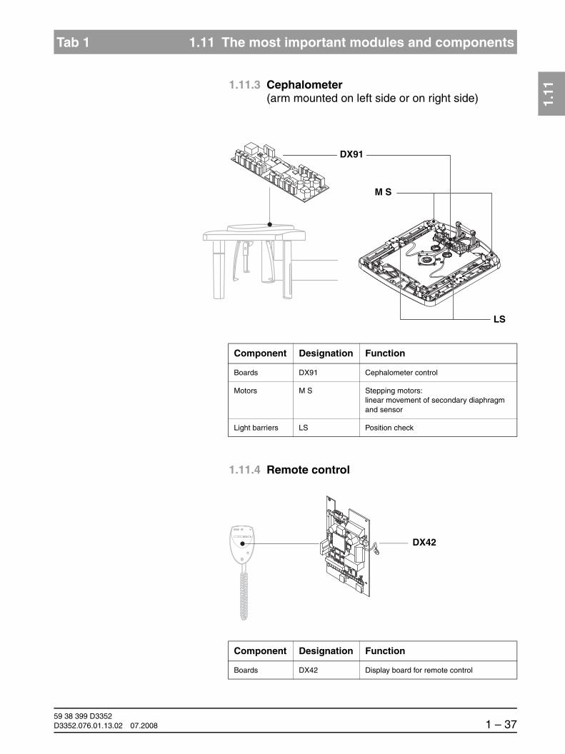
1.111.11.3 Cephalometer
(arm mounted on left side or on right side)
1.11.4 Remote control
DX91
M S
LS
Component Designation Function
Boards DX91 Cephalometer control
Motors M S Stepping motors:linear movement of secondary diaphragm and sensor
Light barriers LS Position check
DX42
Component Designation Function
Boards DX42 Display board for remote control
59 38 399 D33521 – 38 D3352.076.01.13.02 07.2008
1.12 Cabling overview Tab 1
1.12 Cabling overview
DX
32
/ X
2
DX
6 /
X3
DX
32
/ X
1
DX
1 /
X1
00
DX1
/ J30
2
DX6
/ J6
1
2
3
4
5
4
DX1
DX6
5
3
1
2Line filter
DX32
Power switch
Wago terminal
DX
1 / J
306
– J3
02
DX
6 / J
2 –
J3
DX
1 / J
901
DX
41
DX
1 / X
303
DX
41 /
X10
0
DX
1 / X
104
DX
7 / X
102
DX
1 / X
302
DX
7 / X
103
DX
1 / X
102
DX
61 /
X50
1
6
7
8*
9
10
11
10
DX1
DX41**
DX61
DX6
DX7/DX71
6
11
7
8/108*
9
* Unit HW version BA and higher** Board DX 41 omitted in unit HW version
BA and higher
108*

1.12
båÖäáëÜ
59 38 399 D3352D3352.076.01.13.02 07.2008 1 – 39
Tab 1 1.12 Cabling overview
1.12
DX
1 / X
306
DX
61 /
X10
1
DX
1 / X
404
DX
5 / X
1
DX
1 / X
610
DX
1 / X
403
18
DX5
DX61
12DX1
DX81
M HA
LS sensor
1319
16
12
1316
18
19

59 38 399 D33521 – 40 D3352.076.01.13.02 07.2008
1.12 Cabling overview Tab 1
DX123
21
38DX61
25DX41**
DX42
DX81 35
22/24***
212131
PotentiometerDX91
M U
LS SensorDX
42 /
X10
0
DX
41 /
X10
3
DX
61D
X91
DX
5D
X41
Med
ia K
onv
erte
rD
X81
/ X
100
DX1 / X503
17
17/117*
21
22
23
25
31
35
38
* Unit HW version BA and higher** Board DX 41 omitted in unit HW version
BA and higher
117*/24***
DX
61
24***
Media converter
Laser module

1.12
båÖäáëÜ
59 38 399 D3352D3352.076.01.13.02 07.2008 1 – 41
Tab 1 1.12 Cabling overview
1.12DX91
36 39DX1
40
37
DX
91 /
X6
DX
91 /
X10
1
DX
1 / X
103
DX
1 / X
309
36
37
39
40

59 38 399 D33521 – 42 D3352.076.01.13.02 07.2008
1.13 Illustrations of boards Tab 1
1.13 Illustrations of boards
1.13.1 Boards in the slide
Boards DX1 / DX11
To facilitate cable routing to the side, RJ 45 connectors with a 45° incline were introduced in August 2006.
Board DX5
DX1
DX11
X500
X307X503X303
X104X403
X611X607
X306X302J307J306
J302X402
X1000
X102
X103
X404
X804
X802
X803
X100
X811X812
X813
X610
X309
J309 only with GALILEOS
X3
X4 X6 X1 X2
X5X7

1.13
båÖäáëÜ
59 38 399 D3352D3352.076.01.13.02 07.2008 1 – 43
Tab 1 1.13 Illustrations of boards
1.13
Board DX6 (not available as spare part)
Board DX61 (not for XG 3 / 3 PPE)
X2X1 X306X305
J2
J3
J6
S2
X3
F201
X501
X101
X203
X202
X406 X405 X402 X401 X400 X304 X303 X302 X301 X300 X200X201

59 38 399 D33521 – 44 D3352.076.01.13.02 07.2008
1.13 Illustrations of boards Tab 1
Board DX7 (XGPlus only, not available as repair part)
NOTEiBoard DX7 is shown here only for enhanced clarity. The Easypad may be replaced only as a complete unit!
Board DX7 (XG 5/3/3 PPE only, not available as repair part)
NOTEiBoard DX71 is shown here only for enhanced clarity. The Multipad may be replaced only as a complete unit!
X104
X203
X202
X106
X103 X102

1.13
båÖäáëÜ
59 38 399 D3352D3352.076.01.13.02 07.2008 1 – 45
Tab 1 1.13 Illustrations of boards
1.13
Boards DX81P / DX85P (not available as repair parts)
NOTEiBoards DX81 and DX85 are shown here only for enhanced clarity.
CAUTIONIt is not allowed to open the sensor! The sensor may be replaced only as a complete unit!
DX81
DX85

59 38 399 D33521 – 46 D3352.076.01.13.02 07.2008
1.13 Illustrations of boards Tab 1
1.13.2 Boards in the stand
Board DX32
up to unit hardware version AG
Board DX32
as of unit hardware version BA(from November 2006)
X100
F100X1
F101 F102 F103 X2
X100
F100X1
F101 F102 X2

1.13
båÖäáëÜ
59 38 399 D3352D3352.076.01.13.02 07.2008 1 – 47
Tab 1 1.13 Illustrations of boards
1.13
Board DX41
omitted as of unit hardware version BA(from November 2006)
1.13.3 Boards in the cephalometer(arm mounted on right side or on left side)
Board DX91
X100
X103X104X102
X501
X101
X202
X304 X302X201
X407
X306X307X308

59 38 399 D33521 – 48 D3352.076.01.13.02 07.2008
1.13 Illustrations of boards Tab 1
1.13.4 Boards in the remote control
Board DX42
up to unit hardware version AG
X200
X201
X107
X101
X100 X105
V103
V100
V101
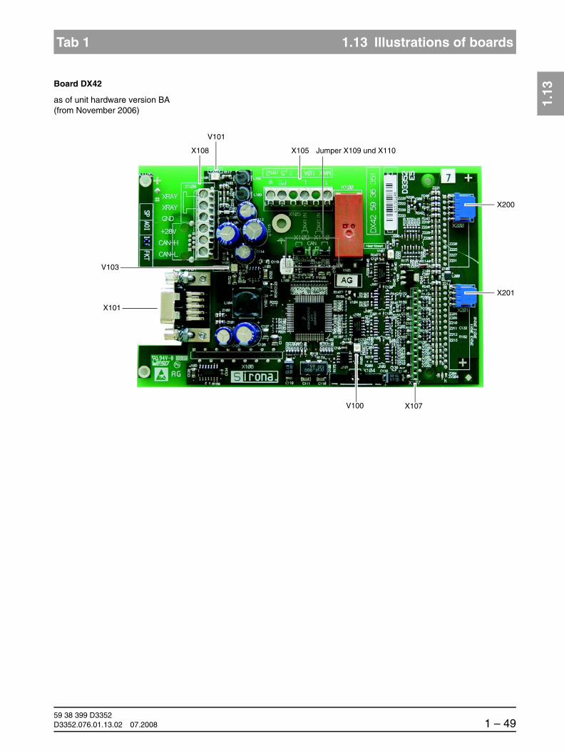
1.13
båÖäáëÜ
59 38 399 D3352D3352.076.01.13.02 07.2008 1 – 49
Tab 1 1.13 Illustrations of boards
1.13
Board DX42
as of unit hardware version BA(from November 2006)
X200
X201
X107
X101
X108 X105 Jumper X109 und X110
V100
V103
V101

59 38 399 D33521 – 50 D3352.076.01.13.02 07.2008
1.14 Removing the covers Tab 1
1.14 Removing the covers
13
12
6
7
1
2
8
9
3
4
11
10
5
14
1. Profile cover
2. Intermediate piece
3. Arm cover, top
4. Slide cover, top rear
5. Slide cover, bottom rear
6. Support cover, top
7. Support cover, bottom
8. Tube assembly cover, front
9. Tube assembly cover, rear
10. Slide cover, center rear
11. Sensor holder cover
12. Slide cover, front complete
13. Ring cover
14. Cephalometer cover

ORTHOPHOS XG 2 Messages

59 38 399 D33522 – 2 D3352.076.01.13.02 07.2008
Tab 2
Contents
2.1 Help messages .......................................................2 – 3
2.2 System messages...................................................2 – 6
2.3 Status displays ........................................................2 – 6
2.4 Error messages.......................................................2 – 62.4.1 Ex yy zz................................................................ 2 – 7
2.4.2 Ex yy zz................................................................ 2 – 8
2.4.3 Ex yy zz ................................................................ 2 – 8
2.4.4 General handling of error messages .................... 2 – 8
2.5 List of error messages.............................................2 – 9
2.6 List of available service routines ...........................2 – 62

båÖäáëÜ
59 38 399 D3352D3352.076.01.13.02 07.2008 2 – 3
Tab 2
2 Messages
The different message texts are displayed...
For XGPlus: on the Easypad touchscreen
For XG5/3/3 PPE: on the Multipad display
on the display of the remote control
There are 3 groups of message texts:
Help messages (Hxxx)
– Help messages are caused by operator errors
– The user must take action
Error messages (Exyyzz)
– Error messages indicate system faults
– The user must take action to eliminate the fault(s)
System messages (Sxxx)
– System messages inform the user about the current operating status of the system
– The user is not required to take action

59 38 399 D33522 – 4 D3352.076.01.13.02 07.2008
2.1 Help messages Tab 2
2.1 Help messages
Help messages are displayed as help codes (Hxxx) on the touchscreen of the Easypad (XGPlus), on the display of the Multipad (XG5/3/3 PPE) or on the remote control display (if available). The codes tell you how to operate the system if radiation release is not possible due to a previous operator error.
The following list provides you with an overview of all help codes, their mean-ing and the action required to eliminate the corresponding problems:
Help code Description Actions required
H3 01 The rotating element on the panoramic unit is not located in its starting position.
Press the R key:The panoramic unit moves to the starting position.
H3 10 The system is performing an action. Wait until the system is ready.
H3 20 The exposure parameters have not been acknowledged yet.
Press the R key:The exposure parameters are confirmed.
H3 21 The X-ray room door contact is not detected. Close the door or check door contact.
H3 22(for XGPlus only)
Quadrant for TSA exposure is not selected. Select quadrant via Easypad.
H3 30(XG 3 PPE only)
Indicates number of exposures remaining (PPE concept).
1. After each switch-on (see S017.22)2. After each exposure if the number of expo-sures remaining is below the defined warning level (see S017.23)
Request new activation code via Sirona Customer Service Center (CSC) in due time.
H3 31(XG 3 PPE only)
No further exposures available. Enter new activation code.
H4 01 The sensor on the panoramic unit is not properly plugged in or is missing.
Plug sensor into PAN slot.
HINWEISiIf this message does not disappear after the sensor is plugged in, this indicates a system er-ror. Perform error diagnosis according to Section 3.2.
H4 02 The sensor on the cephalometer is not properly plugged in or is missing.
Plug sensor into Ceph slot.
HINWEISiIf this message does not disappear after the sensor is plugged in, this indicates a system er-ror. Perform error diagnosis according to Section 3.2.
H4 03 SIDEXIS is not ready for exposure. Make SIDEXIS ready for exposure.
H4 04 The sensor does not match the selected expo-sure type
Plug in the ceph sensor.
H4 05 The sensor does not match the selected expo-sure type
Plug in the TSA sensor.
H4 06 The cephalometer is not located in its starting position.
Press the R key:The cephalometer moves to the starting po-sition.

båÖäáëÜ
59 38 399 D3352D3352.076.01.13.02 07.2008 2 – 5
Tab 2 2.1 Help messages
2.1
HINWEISiThe above measures clear those help messages that result from operator er-rors. If it is not possible to clear the help message by taking the above mea-sures, another type of error is the cause. To identify the error, proceed as de-scribed in section 2.5 .
H4 07 Unit supports default settings for this exposure, since the settings specified by SIDEXIS cannot be taken over.
Perform alternative program setting.
H4 10 The sensor is being polled. Wait until the message disappears.
H4 20 The image could not be transferred to SIDEXIS.
VORSICHTDo not switch the system off until the help mes-sage has disappeared.
Retrieve the exposure with SiRescue (see SIDEXIS Operator’s Manual).
Help code Description Actions required

59 38 399 D33522 – 6 D3352.076.01.13.02 07.2008
2.2 System messages Tab 2
2.2 System messages
2.3 Status displays
2.4 Error messages
Error messages are displayed as error codes (Ex yy zz) on the touchscreen of the Easypad (XGPlus), on the display of the Multipad (XG 5/3/3 PPE) or on the remote control display (if available). The codes provide you with error type, error location and troubleshooting information.
Error code: Ex yy zz The error messages are encoded according to the following pattern:
The error messages are sorted by modules in the table on page 2-7.
System code Description Actions required
S100 ORTHOPHOS XG is started Wait, no action required
S110 Exposure cannot be performed. Quit readiness for exposure, switch unit OFF, wait for 30 sec., switch unit back ON and observe error messages dis-played after switch-on.
Repeat procedure if necessary
Status displays (for XGPlus only) Description
ORTHOPHOS is ready for exposure The unit is ready for operation.
Wait until ORTHOPHOS is ready Unit waiting on readiness for operation.
ORTHOPHOS is ready in XX s The cooling time countdown is running.
X-RAY active! Exposure in progress.
Ex yy zz
Error type
“Troubleshooting” classification for the
Location
Module, subsystem or logi-cal function unit
Consecutive number
with error ID
båÖäáëÜ
59 38 399 D3352D3352.076.01.13.02 07.2008 2 – 7
Tab 2 2.4 Error messages
2.4
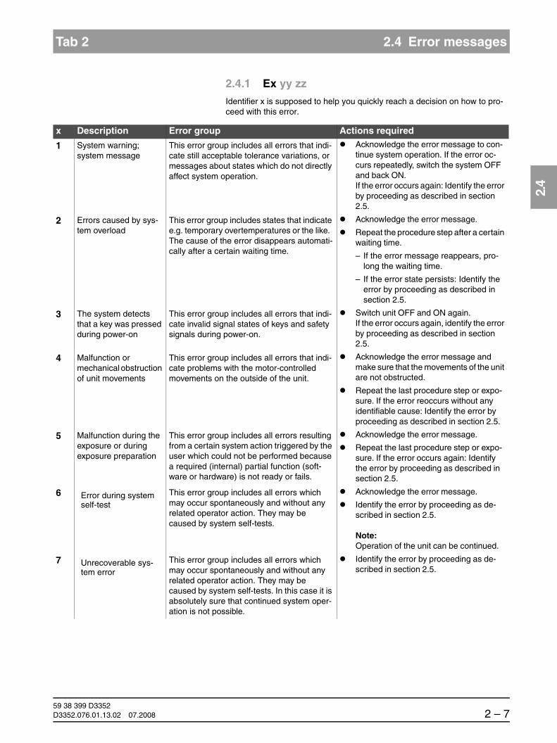
2.4.1 Ex yy zz
Identifier x is supposed to help you quickly reach a decision on how to pro-ceed with this error.
x Description Error group Actions required
1 System warning; system message
This error group includes all errors that indi-cate still acceptable tolerance variations, or messages about states which do not directly affect system operation.
Acknowledge the error message to con-tinue system operation. If the error oc-curs repeatedly, switch the system OFF and back ON. If the error occurs again: Identify the error by proceeding as described in section 2.5.
2 Errors caused by sys-tem overload
This error group includes states that indicate e.g. temporary overtemperatures or the like. The cause of the error disappears automati-cally after a certain waiting time.
Acknowledge the error message.
Repeat the procedure step after a certain waiting time.
– If the error message reappears, pro-long the waiting time.
– If the error state persists: Identify the error by proceeding as described in section 2.5.
3 The system detects that a key was pressed during power-on
This error group includes all errors that indi-cate invalid signal states of keys and safety signals during power-on.
Switch unit OFF and ON again. If the error occurs again, identify the error by proceeding as described in section 2.5.
4 Malfunction or mechanical obstruction of unit movements
This error group includes all errors that indi-cate problems with the motor-controlled movements on the outside of the unit.
Acknowledge the error message and make sure that the movements of the unit are not obstructed.
Repeat the last procedure step or expo-sure. If the error reoccurs without any identifiable cause: Identify the error by proceeding as described in section 2.5.
5 Malfunction during the exposure or during exposure preparation
This error group includes all errors resulting from a certain system action triggered by the user which could not be performed because a required (internal) partial function (soft-ware or hardware) is not ready or fails.
Acknowledge the error message.
Repeat the last procedure step or expo-sure. If the error occurs again: Identify the error by proceeding as described in section 2.5.
6 Error during system self-test
This error group includes all errors which may occur spontaneously and without any related operator action. They may be caused by system self-tests.
Acknowledge the error message.
Identify the error by proceeding as de-scribed in section 2.5.
Note:Operation of the unit can be continued.
7 Unrecoverable sys-tem error
This error group includes all errors which may occur spontaneously and without any related operator action. They may be caused by system self-tests. In this case it is absolutely sure that continued system oper-ation is not possible.
Identify the error by proceeding as de-scribed in section 2.5.

59 38 399 D33522 – 8 D3352.076.01.13.02 07.2008
2.4 Error messages Tab 2
2.4.2 Ex yy zz
Identifier yy defines the location or logical function unit where the error has occurred.
The location may be a DX module number standing for an entire HW function unit, or a logical SW function unit on board DX11 (central control).
2.4.3 Ex yy zz
Identifier zz constitutes a consecutive number with the error identification.
2.4.4 General handling of error messages
Error messages always must be acknowledged with the R key.
If failure-free operation is possible after the error is acknowledged, then no further action is necessary.
If error messages reoccur or occur frequently, identify the error as described in section 2.5 and take appropriate action to eliminate the corresponding error or fault.
In some cases, it may make sense to obtain more information on the history and frequency of errors via the error logging memory (S007) and SIXAB-CON‡PROPERTIES‡EXTENDED DETAILS (see section 1.10 on page 1-32) (see also section 3.1).
yy Location/Function unit Board
06 Tube assembly DX6
61 Diaphragm control (not for XG 3/3 PPE, fixed diaphragm) DX61
07 User interface on the Easypad (XGPlus) DX7
71 User interface on the Multipad (XG5/3/3 PPE) DX71
10 System hardware DX11/DX1
11 System software DX11/DX1
12 CAN bus DX11/DX1
13 Stand peripherals DX11/DX1
14 Digital extension DX11/DX1
15 Configuration/update (wrong software, wrong module constellation, etc...) DX11/DX1
41 Media interface card (omitted as of HW version BA, November 2006) DX41
42 Remote control DX42
81 Sensor (Pan slot: zz=1-23 ; ceph slot: zz= 51-73) DX81
91 Cephalometer DX91

båÖäáëÜ
59 38 399 D3352D3352.076.01.13.02 07.2008 2 – 9
Tab 2 2.5 List of error messages
2.5
2.5 List of error messages
HINWEISiIn the following table, the error codes are sorted by the location or function unit where the error has occurred. For enhanced clarity, the corresponding ID in the error code is printed in bold type.
Location 06: Tube assembly / Board
Error code Description Actions required see page
E6 06 01 General error during module initializa-tion
Please contact the Sirona Customer Service Center (CSC) to find out whether a bugfix by means of a software update is possible and per-form such an update if necessary.
1-22
If the error occurs frequently,replace the X-ray tube assembly
6-38
E6 06 02 Invalid system data or uninitialized module storage data
Perform service routines S005.2 5-29Please contact the Sirona Customer Service Center (CSC) to find out whether a bugfix by means of a software update is possible and per-form such an update if necessary.
1-22
E6 06 03 Invalid commanding of control data, CAN bus error
Note:This error may also occur in connec-tion with other causal error messages! Please also observe the causal error message! It appears only after you acknowledge the first error message.
Checking the CAN bus 3-6Please contact the Sirona Customer Service Center (CSC) to find out whether a bugfix by means of a software update is possible and per-form such an update if necessary.
1-22
E6 06 04 Data transfer error or dialog error to module (master side)
Checking the CAN bus 3-6Please contact the Sirona Customer Service Center (CSC) to find out whether a bugfix by means of a software update is possible and per-form such an update if necessary.
1-22
E6 06 05 Data transfer error or dialog error to bootloader of module
Note:Occurs only in connection with soft-ware update
Repeat software update 1-22Checking the CAN bus 3-6If the error occurs repeatedly or the module is no longer addressable, replace the tube assembly
6-38
E6 06 06 Module failed in TTP* (detected on master side)
Note:This error may also occur in connec-tion with other causal error messages. Please also observe the causal error message! It appears only after you acknowledge the first error message.
Checking the CAN bus 3-6Please contact the Sirona Customer Service Center (CSC) to find out whether a bugfix by means of a software update is possible and per-form such an update if necessary.
1-22
If the error occurs repeatedly or the module is no longer addressable, replace the tube assembly
6-38

59 38 399 D33522 – 10 D3352.076.01.13.02 07.2008
2.5 List of error messages Tab 2
E6 06 07 TTP* timeout error(detected on slave side)
Note: The module was temporarily not addressed by the master:- Undervoltage on the master side- Procedure error in the software- Master (DX11) receives no
return commanding from the module
Note:This error may also occur in connec-tion with other causal error messages! Please also observe the causal error message! It appears only after you acknowledge the first error message.
Checking the CAN bus 3-6Check power supply of board DX11; measuring point 3.3 V on board DX1 (see wiring diagrams).
– If 3.3 V are present, replace board DX11 6-59
– If 3.3 V are not present, replace board DX1 6-59
– Check cable L6, 3-17replace if necessary 6-91
– Check tube assembly (DX6)
replace if necessary 6-38
E6 06 08 General fault detected locally on mod-ule (slave side). CAN controller being reinitialized.
Checking the CAN bus 3-6Check software versions via info screen or ser-vice routine S008.2,
5-48
perform a software update if necessary 1-22Please contact the Sirona Customer Service Center (CSC) to find out whether a bugfix by means of a software update is possible and per-form such an update if necessary.
1-22
Replace the X-ray tube assembly 6-38
E7 06 10 Module is stuck in bootloader stage Check board DX6 (note LED states) 3-12
If the board remains in the bootloader stage...
Repeat software update 1-22
Replace the X-ray tube assembly 6-38
E7 06 12 Unit is not ready for operation
Note:This error may also occur in connec-tion with other causal error messages! Please also observe the causal error message! It appears only after you acknowledge the first error message.
Checking the CAN bus 3-6
If this error occurs in combination with other errors
Unit restart:Switch the unit OFF. Wait 30 sec.Switch unit ON.
Repeat procedure and observe causal error messages.
Replace the X-ray tube assembly 6-38
E6 06 13 Error when writing to EEPROM
Note: Stored data may be lost
Acknowledge error and repeat procedure
If the error occurs again...
Replace the X-ray tube assembly 6-38
E2 06 20 Overtemperature of single tank/power pack
Wait until the X-ray tube assembly has cooled down.
Check fan function using service routine S005.4;
5-31
replace fan if necessary 6-42Check temperature sensor in single tank using service routine S005.5,
5-33
replace tube assembly if necessary 6-38
Error code Description Actions required see page

båÖäáëÜ
59 38 399 D3352D3352.076.01.13.02 07.2008 2 – 11
Tab 2 2.5 List of error messages
2.5
E6 06 21 Hardware signal of release button not detected
Check cable L5 (fiber optic cable), 3-17replace if necessary 6-91Replace board DX1 6-59Replace the X-ray tube assembly 6-38
E6 06 22 Broken temperature sensor Replace the X-ray tube assembly 6-38
E3 06 23 Hardware signal of release button applied during power-on
Check cable L5:
– Switch unit OFF
– Pull cable L5 off of tube assembly
– Switch the unit ON
– Perform optical check of L5:
- If light is visible: Replace board DX1 6-59- If no light is visible, replace the tube as-
sembly6-38
E5 06 30 Total radiation time exceeded If a CAN bus error had been reported before...
Checking the CAN bus 3-6Please contact the Sirona Customer Service Center (CSC) to find out whether a bugfix by means of a software update is possible and per-form such an update if necessary.
1-22
E5 06 31 Partial radiation time exceeded If a CAN bus error had been reported before...
Checking the CAN bus 3-6Please contact the Sirona Customer Service Center (CSC) to find out whether a bugfix by means of a software update is possible and per-form such an update if necessary.
1-22
E5 06 32 Minimum preheating time not observed
If a CAN bus error had been reported before...
Checking the CAN bus 3-6Please contact the Sirona Customer Service Center (CSC) to find out whether a bugfix by means of a software update is possible and per-form such an update if necessary.
1-22
E1 06 40 Tolerance exceeded: Preheating (VH) - nom.
Perform service routines S005.2 5-29Replace the X-ray tube assembly 6-38
E1 06 41 Tolerance exceeded: kV - nom. Perform service routines S005.2 5-29Replace the X-ray tube assembly 6-38
E1 06 42 Tolerance exceeded: mA - nom. Perform service routines S005.2 5-29Replace the X-ray tube assembly 6-38
E1 06 43 Tolerance exceeded: Preheating (VH) - act.
Perform service routines S005.2 5-29Replace the X-ray tube assembly 6-38
E1 06 44 Tolerance exceeded: kV - act. Perform service routines S005.2 5-29Replace the X-ray tube assembly 6-38
E1 06 45 Tolerance exceeded: mA - act. Perform service routines S005.2 5-29Replace the X-ray tube assembly 6-38
Error code Description Actions required see page

59 38 399 D33522 – 12 D3352.076.01.13.02 07.2008
2.5 List of error messages Tab 2
DX6 *) TTP = Time Trigger Protocol
E6 06 50 Undervoltage in intermediate circuit (400 V)
Check fuse F201 on board DX6 (see wiring dia-grams), replace if necessary
Check cable L3 (tube assembly), 3-17replace if necessary 6-91Check electronic fuse on board DX32:
– Switch unit OFF
– Wait for at least 7 minutes (due to electronic fuse)
– Switch unit back ON
– Check functioning
If the error occurs again...
Check board DX32, 3-12replace if necessary 6-59
E6 06 51 VHmax Perform service routines S005.2 5-29Replace the X-ray tube assembly 6-38
E6 06 52 MAmax Perform service routines S005.2 5-29Replace the X-ray tube assembly 6-38
E6 06 53 KVmax Perform service routines S005.2 5-29Replace the X-ray tube assembly 6-38
E7 06 54 Basic heating pulses not applied Replace the X-ray tube assembly 6-38
E6 06 56 Error during auto-compensation Please contact the Sirona Customer Service Center (CSC) to find out whether a bugfix by means of a software update is possible and per-form such an update if necessary.
1-22
Let the tube assembly cool down for approx. 30 min and repeat this procedure.
If the error occurs again...
Replace the X-ray tube assembly 6-38
Error code Description Actions required see page

båÖäáëÜ
59 38 399 D3352D3352.076.01.13.02 07.2008 2 – 13
Tab 2 2.5 List of error messages
2.5
Location 07 (XGPlus): Easypad/Board DX7
Error code Description Actions required see page
E6 07 01 General error during module initializa-tion
Please contact the Sirona Customer Service Center (CSC) to find out whether a bugfix by means of a software update is possible and per-form such an update if necessary.
1-22
If the error occurs again...
Check user interface with electronics (DX7) or 3-12Replace Easypad 6-21
E6 07 02 Invalid system data or uninitialized module storage data
Please contact the Sirona Customer Service Center (CSC) to find out whether a bugfix by means of a software update is possible and per-form such an update if necessary.
1-22
Acknowledge error and repeat procedure
If the error occurs again...
Check user interface with electronics (DX7) or 3-12Replace Easypad 6-21
E6 07 03 Invalid commanding or control data
Note:This error may also occur in connec-tion with other causal error messages. Please also observe the causal error message! It appears only after you acknowledge the first error message.
Checking the CAN bus 3-6Please contact the Sirona Customer Service Center (CSC) to find out whether a bugfix by means of a software update is possible and per-form such an update if necessary.
1-22
E6 07 04 Data transfer error or dialog error to module (master side)
Checking the CAN bus 3-6Please contact the Sirona Customer Service Center (CSC) to find out whether a bugfix by means of a software update is possible and per-form such an update if necessary.
1-22
E6 07 05 Data transfer error or dialog error to bootloader of module
Note:Occurs only in connection with software update
Repeat software update 1-22Checking the CAN bus 3-6Check user interface with electronics (DX7) or 6-59Replace Easypad 6-21
E6 07 06 Module failed in TTP* (detected on master side)
Note:This error may also occur in connec-tion with other causal error messages. Please also observe the causal error message! It appears only after you acknowledge the first error message.
Checking the CAN bus 3-6Please contact the Sirona Customer Service Center (CSC) to find out whether a bugfix by means of a software update is possible and per-form such an update if necessary.
1-22
Replace Easypad 6-21

59 38 399 D33522 – 14 D3352.076.01.13.02 07.2008
2.5 List of error messages Tab 2
E6 07 07 TTP* timeout error(detected on slave side)
Note: The module was temporarily not addressed by the master:- Undervoltage on the master side- Procedure error in the software- Master (DX11) receives no
return commanding from the module
Note:This error may also occur in connec-tion with other causal error messages. Please also observe the causal error message! It appears only after you acknowledge the first error message.
Checking the CAN bus 3-6Check power supply of board DX11; measuring point 3.3 V on board DX1 (see wiring diagrams).
– If 3.3 V are present, replace board DX11 6-59
– If 3.3 V are not present, replace board DX1 6-59
E6 07 08 General fault detected locally on mod-ule (slave side). CAN controller being reinitialized.
Checking the CAN bus 3-6Check software versions via info screen or ser-vice routine S008.2,
5-48
perform a software update if necessary 1-22Check user interface with electronics (DX7) or 6-59Replace Easypad 6-21Please contact the Sirona Customer Service Center (CSC) to find out whether a bugfix by means of a software update is possible and per-form such an update if necessary.
1-22
E7 07 10 Module is stuck in bootloader stage Check user interface with electronics (DX7)(note LED states)
3-12
If the board remains in the bootloader stage...
Repeat software update 1-22
Check user interface with electronics (DX7) or 6-59Replace Easypad 6-21
E7 07 12 Unit is not ready for operation
Note:Therefore, the error can be displayed only on the remote control (DX42).
Checking the CAN bus 3-6
This error is a sequential fault.
Unit restart:Switch the unit OFF. Wait 30 sec.Switch unit ON.
Repeat procedure and observe causal error messages.
E6 07 20 Contact to DX11 interrupted during operation.
Note error message on remote control (DX42) and check log memory (via extended details)
Checking the CAN bus 3-6Check cable L9, 3-17replace if necessary 6-91
Error code Description Actions required see page
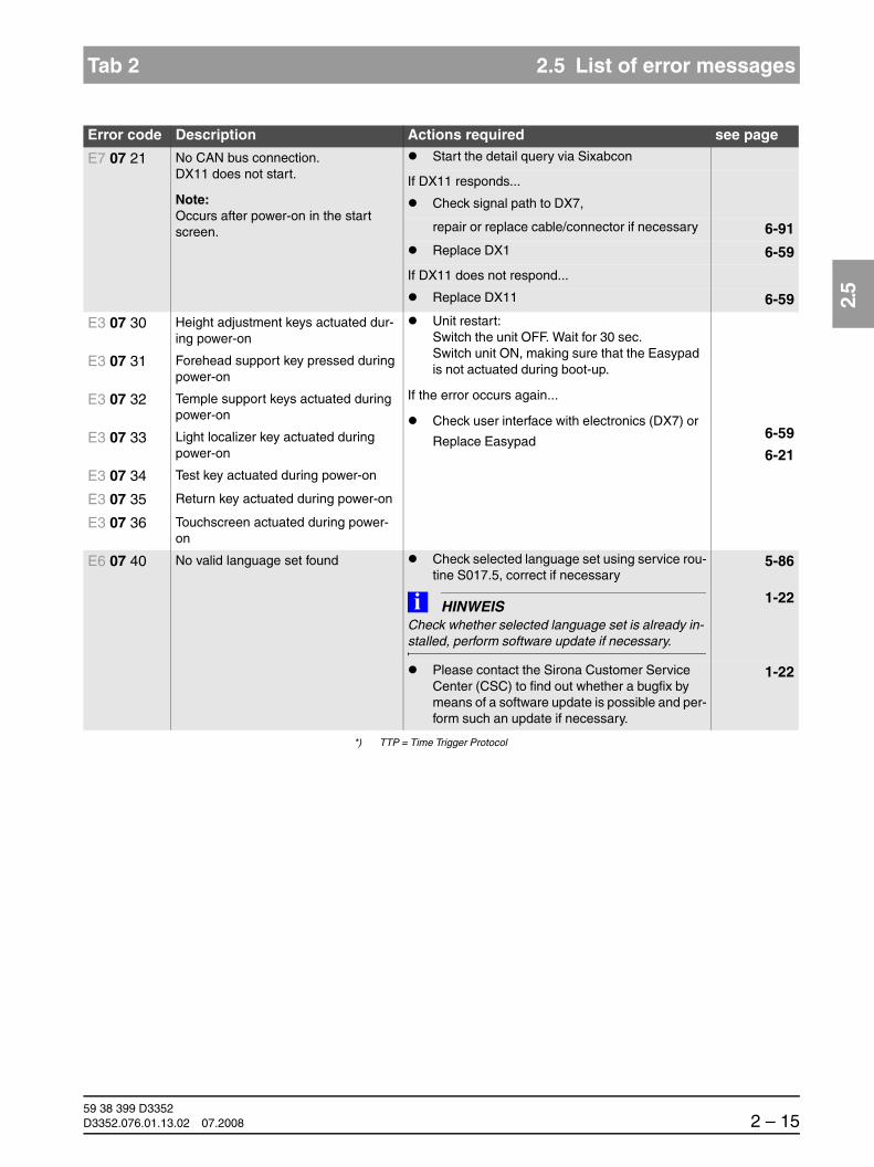
båÖäáëÜ
59 38 399 D3352D3352.076.01.13.02 07.2008 2 – 15
Tab 2 2.5 List of error messages
2.5
*) TTP = Time Trigger Protocol
E7 07 21 No CAN bus connection.DX11 does not start.
Note:Occurs after power-on in the start screen.
Start the detail query via Sixabcon
If DX11 responds...
Check signal path to DX7,
repair or replace cable/connector if necessary 6-91Replace DX1 6-59
If DX11 does not respond...
Replace DX11 6-59
E3 07 30 Height adjustment keys actuated dur-ing power-on
Unit restart:Switch the unit OFF. Wait for 30 sec.Switch unit ON, making sure that the Easypad is not actuated during boot-up.
If the error occurs again...
Check user interface with electronics (DX7) or
Replace Easypad6-59
6-21
E3 07 31 Forehead support key pressed during power-on
E3 07 32 Temple support keys actuated during power-on
E3 07 33 Light localizer key actuated during power-on
E3 07 34 Test key actuated during power-on
E3 07 35 Return key actuated during power-on
E3 07 36 Touchscreen actuated during power-on
E6 07 40 No valid language set found Check selected language set using service rou-tine S017.5, correct if necessary
5-86
HINWEISiCheck whether selected language set is already in-stalled, perform software update if necessary.
1-22
Please contact the Sirona Customer Service Center (CSC) to find out whether a bugfix by means of a software update is possible and per-form such an update if necessary.
1-22
Error code Description Actions required see page

59 38 399 D33522 – 16 D3352.076.01.13.02 07.2008
2.5 List of error messages Tab 2
Location 10: System hardware
*) FPGA = Field Programmable Gate Array
Error code Description Actions required see page
E7 10 01 EEPROM cannot be written. Acknowledge error and repeat procedure
If the error occurs again...
Replace board DX11 6-59
E7 10 02 FPGA* of DX1 is not addressable. Replace board DX1 6-59
E1 10 03 The flash file system must be format-ted.
Note:Occurs after replacement of board DX11.
Acknowledge error
HINWEISiThe flash file system is formatted and error message E1_10_04 is displayed.
E1 10 04 Flash file system formatting in progress.
Wait until the message automatically disap-pears (approx. 2 - 3 min.)
E1 10 05 Flash file system is not ready for oper-ation.
Execute service routine S009.4 and format flash file system.
HINWEISiThe contents of the error memory are thus lost.
5-56
If the error occurs again...
Replace board DX11 6-59

båÖäáëÜ
59 38 399 D3352D3352.076.01.13.02 07.2008 2 – 17
Tab 2 2.5 List of error messages
2.5
Location 11: Power PC, board DX11
Error code Description Actions required see page
E6 11 01 Program sequence error Please contact the Sirona Customer Service Center (CSC) to find out whether a bugfix by means of a software update is possible and perform such an update if necessary.
1-22
Acknowledge error and repeat procedure
If the error occurs again...
Reset the entire unit adjustment (Pan, Ceph, TSA) and readjust the unit
4-3
Replace board DX11 6-59
E6 11 02 Watchdog error Acknowledge error and repeat procedure
If the error occurs again...
Replace board DX11 6-59
E6 11 03 Operating system/resource error Acknowledge error and repeat procedure
If the error occurs again...
Replace board DX11 6-59
E7 11 04 Implausible data in EEPROM Check the device configuration via service rou-tines S017 and S018 and reconfigure if neces-sary
5-77, 5-109
Check adjustment with diaphragm test expo-sures
7-17
If the adjustment is not OK...
Readjust the unit 4-3
If the adjustment is OK...
perform the individual system settings again (e.g. programming of the patient symbol keys; see operating instructions)
E6 11 05 RAM allocation failed Replace board DX11 6-59
E7 11 07 Unknown or invalid definition of system class
Note:Occurs during first power-on after replacement of board DX6 or DX11.
Perform actions required according to Chapter "Replacing circuit boards".
6-59
E7 11 08 The user interface connected to this unit does is not compliant with the unit's system class configuration
Install the user interface compliant with the system class configuration of this unit
6-21
E5 11 09 Internal error in program flow of board DX11
Acknowledge error
If the error occurs again...
Perform a software update (bug fix) 1-22

59 38 399 D33522 – 18 D3352.076.01.13.02 07.2008
2.5 List of error messages Tab 2
E1 11 10 The system is operating with default settings; exposure is possible
Note:If this error occurs in combination with errors E1 61 02, E1 91 02 or E1 11 04 (see error logging memory), these additional errors provide an indication of the module involved.
Read out log memory and take the appropriate actions
Readjust the unit
If the error occurs again...
4-3
Replace the defective module (DX61, DX91 or DX11).
6-5
E7 11 11 Wrong device configuration Check the device configuration via service rou-tine S017.2 and reconfigure if necessary
5-78
E7 11 12 Internal error in data management of board DX11
If the error occurs after a module has been replaced...
display "Extended Details" via SIXABCON and coordinate all further action with the Sirona Customer Service Center.
If no module has been replaced...
switch the unit off, wait for 30 seconds and then switch it back on.
Check software versions via info screen or ser-vice routine S008.2,
5-48
perform a software update if necessary 1-22
If the error occurs again...
Perform a software update (bug fix) 1-22
E6 11 13 Up to HW version AG:Short circuit in radiation release signal path between board DX42 and board DX41 (cable L17).
The release signal was detected on boards DX11 and DX41, but not on board DX42.
Up to HW version BA (from 11.2006):Short circuit in radiation release signal path between board DX42 and board DX11 (cables L117 and L108).
The release signal was detected on board DX11, but not on board DX42
see section entitled "Error analysis of X-RAY control signal path" up to unit hardware version AG (with board DX41)"
3-18
E7 11 14 Wrong remote control for this unit
HINWEISiThis error message blocks all unit func-tions. Work is possible at the unit again after the remote control is unplugged and the unit is switched off and on again.
Install the correct remote control.
If necessary, obtain new remote control from the manufacturer.
(A remote control from GALILEOS or from an outside manufacturer might have been con-nected)
Error code Description Actions required see page

båÖäáëÜ
59 38 399 D3352D3352.076.01.13.02 07.2008 2 – 19
Tab 2 2.5 List of error messages
2.5
Location 12: CAN bus
E1 11 88 The unit is set to the demo mode
Note:Occurs when the unit is switched on.
If the user mode is expressly required...
Switch the demo mode OFF
VORSICHTRadiation can be released after the demo mode is switched off!
1-13
Error code Description Actions required see page
Error code Description Actions required see page
E6 12 01 CAN controller init error on DX1 Checking the CAN bus 3-6
E6 12 02 CAN malfunction (cannot be assigned to module)
Checking the CAN bus 3-6

59 38 399 D33522 – 20 D3352.076.01.13.02 07.2008
2.5 List of error messages Tab 2
Location 13: Stand, peripherals
Error code Description Actions required see page
E4 13 01 Actuator 1 has not reached pan home position
Check the actuator mechanisms manually for smooth and easy running.
In case of stiffness...
manually reset the actuators to the zero position and run a test cycle via P1.
If the error occurs again...
Check light barrier V1_1 (X802) with service routine S015.5,
5-74
replace light barrier if necessary 6-49Check electric drive and jolt-free running with service routine S015.5 (free travel),
5-74
replace the actuators and/or spindles and 6-17replace board DX1 if necessary 6-59
E4 13 02 Actuator 1 has not left pan home posi-tion
Check the actuator mechanisms manually for smooth and easy running.
In case of stiffness...
manually reset the actuators to the zero position and run a test cycle via P1.
If the error occurs again...
Check light barrier V1_1 (X802) with service routine S015.5,
5-74
replace light barrier if necessary 6-49Check electric drive and jolt-free running with service routine S015.5 (free travel),
5-74
replace the actuators and/or spindles and 6-17replace board DX1 if necessary 6-59
E5 13 03 Malfunction of actuator 1 during operation
Check the actuator mechanisms manually for smooth and easy running.
In case of stiffness...
manually reset the actuators to the zero position and run a test cycle via P1.
If the error occurs again...
Check light barrier V1_1 (X802) with service routine S015.5,
5-74
replace light barrier if necessary 6-49Check electric drive and jolt-free running with service routine S015.5 (free travel),
5-74
replace the actuators and/or spindles and 6-17replace board DX1 if necessary 6-59
E4 13 04 Actuator 1; position counter error Check the actuator mechanisms manually for smooth and easy running.
In case of stiffness...
manually reset the actuators to the zero position and run a test cycle via P1.

båÖäáëÜ
59 38 399 D3352D3352.076.01.13.02 07.2008 2 – 21
Tab 2 2.5 List of error messages
2.5
If the error occurs again...
Check light barrier V1_1 (X802) with service routine S015.5,
5-74
replace light barrier if necessary 6-49Check electric drive and jolt-free running with service routine S015.5 (free travel),
5-74
replace the actuators and/or spindles and 6-17replace board DX1 if necessary 6-59
E6 13 05 Actuator 1 is not ready for operation This error is a sequential fault.
Unit restart:Switch the unit OFF. Wait 30 sec.Switch unit ON.
Repeat procedure and observe causal error messages.
E6 13 07 Error when activating actuator 1 Unit restart:Switch the unit OFF. Wait 30 sec.Switch unit ON and check functioning.
Please contact the Sirona Customer Service Center (CSC) to find out whether a bugfix by means of a software update is possible and per-form such an update if necessary.
1-22
E4 13 11 Actuator 2 has not reached pan home position
Check the actuator mechanisms manually for smooth and easy running.
In case of stiffness...
manually reset the actuators to the zero position and run a test cycle via P1.
If the error occurs again...
Check light barrier V1_2 (X803) with service routine S015.5,
5-74
replace light barrier if necessary 6-49Check electric drive and jolt-free running with service routine S015.5 (free travel),
5-74
replace the actuators and/or spindles and 6-17replace board DX1 if necessary 6-59
E4 13 12 Actuator 2 has not left pan home posi-tion
Check the actuator mechanisms manually for smooth and easy running.
In case of stiffness...
manually reset the actuators to the zero position and run a test cycle via P1.
If the error occurs again...
Check light barrier V1_2 (X803) with service routine S015.5,
5-74
replace light barrier if necessary 6-49Check electric drive and jolt-free running with service routine S015.5 (free travel),
5-74
replace the actuators and/or spindles and 6-17replace board DX1 if necessary 6-59
Error code Description Actions required see page
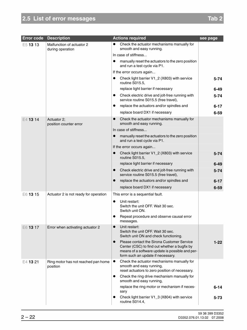
59 38 399 D33522 – 22 D3352.076.01.13.02 07.2008
2.5 List of error messages Tab 2
E5 13 13 Malfunction of actuator 2 during operation
Check the actuator mechanisms manually for smooth and easy running.
In case of stiffness...
manually reset the actuators to the zero position and run a test cycle via P1.
If the error occurs again...
Check light barrier V1_2 (X803) with service routine S015.5,
5-74
replace light barrier if necessary 6-49Check electric drive and jolt-free running with service routine S015.5 (free travel),
5-74
replace the actuators and/or spindles and 6-17replace board DX1 if necessary 6-59
E4 13 14 Actuator 2; position counter error
Check the actuator mechanisms manually for smooth and easy running.
In case of stiffness...
manually reset the actuators to the zero position and run a test cycle via P1.
If the error occurs again...
Check light barrier V1_2 (X803) with service routine S015.5,
5-74
replace light barrier if necessary 6-49Check electric drive and jolt-free running with service routine S015.5 (free travel),
5-74
replace the actuators and/or spindles and 6-17replace board DX1 if necessary 6-59
E6 13 15 Actuator 2 is not ready for operation This error is a sequential fault.
Unit restart:Switch the unit OFF. Wait 30 sec.Switch unit ON.
Repeat procedure and observe causal error messages.
E6 13 17 Error when activating actuator 2 Unit restart:Switch the unit OFF. Wait 30 sec.Switch unit ON and check functioning.
Please contact the Sirona Customer Service Center (CSC) to find out whether a bugfix by means of a software update is possible and per-form such an update if necessary.
1-22
E4 13 21 Ring motor has not reached pan home position
Check the actuator mechanisms manually for smooth and easy running, reset actuators to zero position of necessary.
Check the ring drive mechanism manually for smooth and easy running,
replace the ring motor or mechanism if neces-sary
6-14
Check light barrier V1_3 (X804) with service routine S014.4,
5-73
Error code Description Actions required see page

båÖäáëÜ
59 38 399 D3352D3352.076.01.13.02 07.2008 2 – 23
Tab 2 2.5 List of error messages
2.5
replace light barrier if necessary 6-49Check electric drive and jolt-free running with service routine S014.3,
5-71
replace board DX1 if necessary 6-59
E4 13 22 Ring motor has not left pan home position
Check the actuator mechanisms manually for smooth and easy running, reset actuators to zero position of necessary.
Check the ring drive mechanism manually for smooth and easy running,
replace the ring motor or mechanism if neces-sary
6-14
Check light barrier V1_3 (X804) with service routine S014.4,
5-73
replace light barrier if necessary 6-49Check electric drive and jolt-free running with service routine S014.3,
5-71
replace board DX1 if necessary 6-59
E5 13 23 Malfunction of ring motorduring operation
Acknowledge error
If the error occurs again...
Replace board DX1 6-59
E4 13 24 Ring motor; position counter error
Check the actuator mechanisms manually for smooth and easy running, reset actuators to zero position of necessary.
Check the ring drive mechanism manually for smooth and easy running,
replace the ring motor or mechanism if neces-sary
6-14
Check light barrier V1_3 (X804) with service routine S014.4,
5-73
replace light barrier if necessary 6-49Check electric drive and jolt-free running with service routine S014.3,
5-71
replace board DX1 if necessary 6-59
E4 13 25 Ring motor has not reached ceph home position
Check the actuator mechanisms manually for smooth and easy running, reset actuators to zero position of necessary.
Check the ring drive mechanism manually for smooth and easy running,
replace the ring motor or mechanism if neces-sary
6-14
Check light barrier V1_3 (X804) with service routine S014.4,
5-73
replace light barrier if necessary 6-49Check electric drive and jolt-free running with service routine S014.3,
5-71
replace board DX1 if necessary 6-59
Error code Description Actions required see page
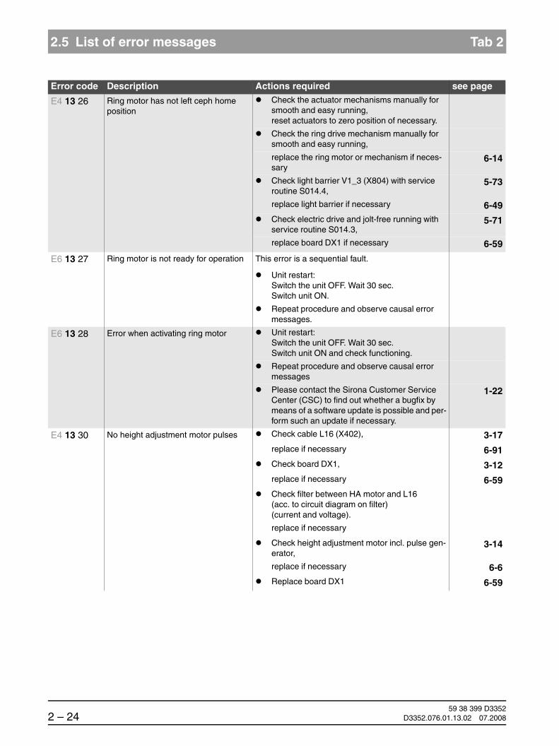
59 38 399 D33522 – 24 D3352.076.01.13.02 07.2008
2.5 List of error messages Tab 2
E4 13 26 Ring motor has not left ceph home position
Check the actuator mechanisms manually for smooth and easy running, reset actuators to zero position of necessary.
Check the ring drive mechanism manually for smooth and easy running,
replace the ring motor or mechanism if neces-sary
6-14
Check light barrier V1_3 (X804) with service routine S014.4,
5-73
replace light barrier if necessary 6-49Check electric drive and jolt-free running with service routine S014.3,
5-71
replace board DX1 if necessary 6-59
E6 13 27 Ring motor is not ready for operation This error is a sequential fault.
Unit restart:Switch the unit OFF. Wait 30 sec.Switch unit ON.
Repeat procedure and observe causal error messages.
E6 13 28 Error when activating ring motor Unit restart:Switch the unit OFF. Wait 30 sec.Switch unit ON and check functioning.
Repeat procedure and observe causal error messages
Please contact the Sirona Customer Service Center (CSC) to find out whether a bugfix by means of a software update is possible and per-form such an update if necessary.
1-22
E4 13 30 No height adjustment motor pulses Check cable L16 (X402), 3-17replace if necessary 6-91Check board DX1, 3-12replace if necessary 6-59Check filter between HA motor and L16 (acc. to circuit diagram on filter) (current and voltage).
replace if necessary
Check height adjustment motor incl. pulse gen-erator,
3-14
replace if necessary 6-6Replace board DX1 6-59
Error code Description Actions required see page

båÖäáëÜ
59 38 399 D3352D3352.076.01.13.02 07.2008 2 – 25
Tab 2 2.5 List of error messages
2.5
E5 13 31 Unit has traveled to upper limit switch Check max. travel height with service routine S018.2, adjust if necessary
Run HA motor in the other direction with the UP/DOWN keys and reference (value approx. 1500)
5-110
Check light barriers V1_4 3-15 replace if necessary 6-49Check HA motor for overtravel,
replace DX1 if necessary 6-59
If the error occurs again...
check the limit switch or wiring,
correct or replace the limit switch if necessary
E5 13 32 Unit has traveled to lower limit switch Run HA motor in the other direction with the UP/DOWN keys and reference (value approx. 1500)
5-110
Check light barriers V1_4 3-15 replace if necessary 6-49Check HA motor for overtravel,
replace DX1 if necessary 6-59
If the error occurs again...
check the limit switch or wiring,
correct or replace the limit switch if necessary
E5 13 33 Height adjustment motor position counter too small for current position
Note:Error may occur after replacement of board (DX11)
Run HA motor in the other direction with the UP/DOWN keys and reference (value approx. 1500)
Check max. travel height using service routine S018.2, adjust if necessary
5-110
Check light barriers V1_4, 3-15replace if necessary 6-49
E5 13 34 Height adjustment motor position counter too large for current position
Note:Error may occur after replacement of board (DX11)
Run HA motor in the other direction with the UP/DOWN keys on the Easypad (XGPlus) or the Multipad (XG5/3/3 PPE) and reference (value approx. 1500)
Check light barriers V1_4, 3-15replace if necessary 6-49
HINWEISiAs an aid, the current switching state can be queried via service routine S018.4.
5-113
E5 13 35 Height adjustment motor; wrong direction of rotation
Check connector assignment on filter or in front of HA motor,
correct if necessary
Replace board DX1 6-59
Error code Description Actions required see page

59 38 399 D33522 – 26 D3352.076.01.13.02 07.2008
2.5 List of error messages Tab 2
E5 13 36 Software signal of key is applied, but hardware signal is not
Check cables L9 and L10, 3-17replace if necessary 6-91Check limit switches SE1_1 and SE1_2, 7-4replace if necessary 6-6Replace the user interface(Easypad for XGPlus, Multipad for XG5 / XG 3)
6-21
E7 13 37 Overtravel of HA motor occurs or height adjustment power transistor defective
Check HA motor for overtravel,
replace board DX1 if necessary 6-59Unit restart:Switch the unit OFF. Wait 30 sec.Switch unit ON and check functioning.
Replace board DX1 6-59
E6 13 38 Height adjustment motor is not ready for operation
This error is a sequential fault.
Unit restart:Switch the unit OFF. Wait 30 sec.Switch unit ON.
Repeat procedure and observe causal error messages.
E6 13 39 Error when activating height adjust-ment motor
Unit restart:Switch the unit OFF. Wait 30 sec.Switch unit ON and check functioning.
Please contact the Sirona Customer Service Center (CSC) to find out whether a bugfix by means of a software update is possible and per-form such an update if necessary.
1-22
Replace board DX1 6-59
E3 13 40 Release signal applied during power-on.
Unit restart:Switch the unit OFF. Wait for 30 sec.Switch unit ON, making sure that the release button is not pressed during boot-up.
If the error occurs again...
Check the X-ray signal path 3-18
Error code Description Actions required see page

båÖäáëÜ
59 38 399 D3352D3352.076.01.13.02 07.2008 2 – 27
Tab 2 2.5 List of error messages
2.5
E3 13 41 Release signal not applied on DX11 Check signal path for interruption according to wiring diagrams, replace component if neces-sary
Deactivate remote control with service routine S017.6; connect release button directly to DX41 (instead of cable L17) and check for proper functioning
5-78
Check release button
If the release button is functioning...
Check cable L17, 3-17replace if necessary 6-91
If the release button is not functioning...
Check board DX41, 3-12replace if necessary 6-59
E6 13 42 The hardware signal for radiation release is applied on board DX1 dur-ing unit operation even when no actu-ated X-RAY release button is reported via the CAN bus.
Check the X-ray signal path 3-18
E5 13 43 The door was opened during the exposure.
Check the X-ray signal path 3-18
E5 13 50 Forehead support; has not left home position despite movement pulses
Check light barriers V5_1 to V5_4, 3-15replace headrest or 6-19light barrier if necessary 6-49Check cable L18, 3-17replace if necessary 6-91Check board DX5, 3-12replace if necessary 6-59
E4 13 51 Forehead support; has not left home position and no motor movement
Check motor M5_1, 3-14replace headrest if necessary 6-19Check light barriers V5_1 to V5_4, 3-15replace headrest or 6-19light barrier if necessary 6-49Check cable L18, 3-17replace if necessary 6-91Check board DX5, 3-12replace if necessary 6-59
E5 13 52 Forehead support; has left home posi-tion without detected movement pulses
Check light barriers V5_1 to V5_4, 3-15replace headrest or 6-19light barrier if necessary 6-49Check cable L18, 3-17replace if necessary 6-91Check board DX5, 3-12
Error code Description Actions required see page

59 38 399 D33522 – 28 D3352.076.01.13.02 07.2008
2.5 List of error messages Tab 2
replace if necessary 6-59
E5 13 53 Forehead support; system does not block within setting range
Check headrest mechanics,
replace if necessary 6-19
E6 13 54 Forehead support is not ready for operation
This error is a sequential fault.
Unit restart:Switch the unit OFF. Wait 30 sec.Switch unit ON.
Repeat procedure and observe causal error messages.
E6 13 57 Error when activating forehead sup-port motor
Unit restart:Switch the unit OFF. Wait 30 sec.Switch unit ON and check functioning.
Please contact the Sirona Customer Service Center (CSC) to find out whether a bugfix by means of a software update is possible and per-form such an update if necessary.
1-22
Check headrest mechanics,
replace if necessary 6-19Replace board DX1 6-59
E6 13 58 Error when activating forehead sup-port motor
Timeout of FPGA* module on board DX1.
Acknowledge error
If the error occurs again...
Replace board DX1 6-59Replace board DX11 6-59
E4 13 59 Forehead support drive defective Replace the headrest 6-19
E5 13 60 Temple supports; have not left home position despite movement pulses
Check light barriers V5_1 to V5_4, 3-15replace headrest or 6-19light barrier if necessary 6-49Check cable L18, 3-17replace if necessary 6-91Check board DX5, 3-12replace if necessary 6-59
E4 13 61 Temple supports; have not left home position and no motor movement
Check motor M5_2, 3-14replace headrest if necessary 6-19Check light barriers V5_1 to V5_4, 3-15replace headrest or 6-19light barrier if necessary 6-49Check cable L18, 3-17replace if necessary 6-91Check board DX5, 3-12replace if necessary 6-59
Error code Description Actions required see page

båÖäáëÜ
59 38 399 D3352D3352.076.01.13.02 07.2008 2 – 29
Tab 2 2.5 List of error messages
2.5
E5 13 62 Temple supports; have left home posi-tion without detected movement pulses
Check light barriers V5_1 to V5_4, 3-15replace headrest or 6-19light barrier if necessary 6-49Check cable L18, 3-17replace if necessary 6-91Check board DX5, 3-12replace if necessary 6-59
E5 13 63 Temple supports; system does not block within setting range
Check headrest mechanics, replace if neces-sary
6-19
E6 13 64 Temple supports are not ready for operation
This error is a sequential fault.
Unit restart:Switch the unit OFF. Wait 30 sec.Switch unit ON.
Repeat procedure and observe causal error messages.
E6 13 67 Error when activating temple support motor
Unit restart:Switch the unit OFF. Wait 30 sec.Switch unit ON and check functioning.
Please contact the Sirona Customer Service Center (CSC) to find out whether a bugfix by means of a software update is possible and per-form such an update if necessary.
1-22
Check headrest mechanics,
replace if necessary 6-19Replace board DX1 6-59
E6 13 68 Error when activating temple support motor
Timeout of FPGA* module on board DX1.
Acknowledge error
If the error occurs again...
Replace board DX1 6-59Replace board DX11 6-59
E4 13 69 Forehead support drive defective Replace the headrest 6-19
E5 13 73 Malfunction of height adjustment during operation
Acknowledge error
Unit restart:Switch the unit OFF. Wait 30 sec.Switch unit ON and check functioning.
Please contact the Sirona Customer Service Center (CSC) to find out whether a bugfix by means of a software update is possible and per-form such an update if necessary.
1-22
If the error occurs repeatedly...
Replace board DX1 6-59
Error code Description Actions required see page

59 38 399 D33522 – 30 D3352.076.01.13.02 07.2008
2.5 List of error messages Tab 2
*) FPGA = Field Programmable Gate Array
E5 13 83 Error while generating pulse for sen-sor
Unit restart:Switch the unit OFF. Wait 30 sec.Switch unit ON and check functioning.
Please contact the Sirona Customer Service Center (CSC) to find out whether a bugfix by means of a software update is possible and per-form such an update if necessary.
1-22
If the error occurs repeatedly...
Replace board DX1 6-59
E6 13 87 Error when activating pulse genera-tion
Unit restart:Switch the unit OFF. Wait 30 sec.Switch unit ON and check functioning.
Please contact the Sirona Customer Service Center (CSC) to find out whether a bugfix by means of a software update is possible and per-form such an update if necessary.
1-22
Error code Description Actions required see page
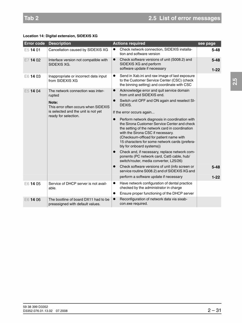
båÖäáëÜ
59 38 399 D3352D3352.076.01.13.02 07.2008 2 – 31
Tab 2 2.5 List of error messages
2.5
Location 14: Digital extension, SIDEXIS XG
Error code Description Actions required see page
E5 14 01 Cancellation caused by SIDEXIS XG Check network connection, SIDEXIS installa-tion and software version
5-48
E7 14 02 Interface version not compatible with SIDEXIS XG.
Check software versions of unit (S008.2) and SIDEXIS XG and perform software update if necessary
5-48
1-22
E6 14 03 Inappropriate or incorrect data input from SIDEXIS XG
Send in Xab.ini and raw image of last exposure to the Customer Service Center (CSC) (check the binning setting) and coordinate with CSC
E5 14 04 The network connection was inter-rupted
Note:This error often occurs when SIDEXIS is selected and the unit is not yet ready for selection.
Acknowledge error and quit service domain from unit and SIDEXIS end.
Switch unit OFF and ON again and reselect SI-DEXIS.
If the error occurs again...
Perform network diagnosis in coordination with the Sirona Customer Service Center and check the setting of the network card in coordination with the Sirona CSC if necessary.(Checksum-offload for patient name with 15 characters for some network cards (prefera-bly for onboard systems))
Check and, if necessary, replace network com-ponents (PC network card, Cat5 cable, hub/switch/router, media converter, L25/26)
Check software versions of unit (info screen or service routine S008.2) and of SIDEXIS XG and
5-48
perform a software update if necessary 1-22
E6 14 05 Service of DHCP server is not avail-able.
Have network configuration of dental practice checked by the administrator in charge
Ensure proper functioning of the DHCP server
E6 14 06 The bootline of board DX11 had to be preassigned with default values.
Reconfiguration of network data via sixab-con.exe required.

59 38 399 D33522 – 32 D3352.076.01.13.02 07.2008
2.5 List of error messages Tab 2
E6 14 10
E6 14 11
E6 14 12
Clock signals for sensor image trans-fer not received on board DX1/DX11 (...10).
Faulty detection of sensor image transfer data signals on board DX1/DX11; nonrecurring (...11)
Faulty detection of sensor image transfer data signals on board DX1/DX11; recurring (...12)
Acknowledge error and, if possible, check func-tion at another slot (PAN/CEPH) via test image (PAN/CEPH).
3-25
If both test images indicate the error ...
- Check image signal on board DX1 (does the image LED on DX1 switch on when the ring cycle starts in the test im-age mode?), replace DX1 if necessary
5-128
6-59
If only the PAN test image is not OK...
- Check cable L13 for crushed spots and check for kinks and connectors, repair or replace if necessary
- Check board DX1, replace if necessary
- Perform service routine S032.10.In this way it can be determined whether the fault is stationary or permanent; re-place sensor or cable if necessary.
6-91
6-595-126
6-91
If only the CEPH test image is not OK...
For E06 14 10 and Ceph exposure:
- Check board DX91 and cables (L37, L40), replace if necessary
- Perform service routine S033.10.In this way it can be determined whether the fault is stationary or permanent; re-place sensor or cable if necessary.
Otherwise:
- Check cable L35/L38 for crushed spots and check for kinks and connectors, repair or replace if necessary
- Check board DX1, replace if necessary
- Perform service routine S033.10.In this way it can be determined whether the fault is stationary or permanent; re-place sensor or cable if necessary.
3-176-91
5-130
6-91
3-17
6-916-59
5-130
6-91
Error code Description Actions required see page

båÖäáëÜ
59 38 399 D3352D3352.076.01.13.02 07.2008 2 – 33
Tab 2 2.5 List of error messages
2.5
Location 15: Configuration, update
Error code Description Actions required see page
E7 15 01 Wrong memory modules. If a DRAM memory module is plugged into board DX11...
Replace memory module or DX11 6-59
If no DRAM memory module is plugged into board DX11...
Replace DX11 6-59
E7 15 02 Wrong module constellation for this unit.
Incompatible modules were used.
Refer to list of software versions
Check to make sure the correct modules are in-stalled (e.g. after replacing modules)
Perform a software update 1-22
If the error occurs again...
Contact the Sirona Customer Service Center (CSC)
E7 15 03 Wrong software constellation of mod-ules.
Check software versions of unit (info screen or service routine S008.2) and of SIDEXIS XG and
5-48
Perform or repeat software update or down-grade if necessary
1-22
E6 15 04 Product activation keys invalid or not available.
Note:Occurs after replacement of tube assembly (DX6) or DX11 and possibly after software updates.
See also chapter "Measures following replacement of boards" starting on page 6-60.
Execute service routine S008.4 and confirm the existing activation profile of the unit.
5-54
E6 15 05 Unit serial number invalid or not avail-able.
Note:Occurs during first power-on after replacement of board DX6 or DX11.
See also chapter "Measures following replacement of boards" starting on page 6-60.
Execute service routine S008.3 and confirm or enter the unit serial number at the unit.
5-50
E6 15 06 Wrong or invalid manufacturer code on an module was detected.
Replace board DX11 6-59Replace the X-ray tube assembly 6-38
E6 15 07 The user interface or the remote con-trol is not compatible with the unit.
HINWEISiAn Orthophos XG5 (Multipad) or XG-Plus (Easypad) as well as an Ortho-phos remote control must be installed.
Install the correct user interface or remote control.
If necessary, obtain a new user interface or re-mote control from the manufacturer.

59 38 399 D33522 – 34 D3352.076.01.13.02 07.2008
2.5 List of error messages Tab 2
Location 41: Media interface card Board DX41 is omitted as of unit hardware version BA(see page 1-34).
E6 15 10 Update file for module is corrupt Obtain current update file from the Sirona CSC and perform software update via the SIRONA home page
1-22
Error code Description Actions required see page
E6 41 01 General module initialization error If the error is a software error known to the Siro-na Customer Service Center, a software update (bugfix) must be performed
1-22
Replace board DX41 6-59
E6 41 02 Invalid system data or uninitialized module storage data
If the error is a software error known to the Siro-na Customer Service Center, a software update (bugfix) must be performed
1-22
Acknowledge error and repeat procedure
If the error occurs again...
Replace board DX41 6-59
E6 41 03 Invalid commanding or control data
Note:This error may also occur in connec-tion with other causal error messages. Please also observe the causal error message! It appears only after you acknowledge the first error message.
Checking the CAN bus 3-6Please contact the Sirona Customer Service Center (CSC) to find out whether a bugfix by means of a software update is possible and per-form such an update if necessary.
1-22
E6 41 04 Data transfer error or dialog error to module (master side)
Checking the CAN bus 3-6Please contact the Sirona Customer Service Center (CSC) to find out whether a bugfix by means of a software update is possible and per-form such an update if necessary.
1-22
E6 41 05 Data transfer error or dialog error to bootloader of module
Note:Occurs only in connection with software update
Repeat software update 1-22Checking the CAN bus 3-6Replace board DX41 6-59
E6 41 06 Module failed in TTP* (detected on master side)
Note:This error may also occur in connec-tion with other causal error messages. Please also observe the causal error message! It appears only after you acknowledge the first error message.
Checking the CAN bus 3-6Replace board DX41 6-59Please contact the Sirona Customer Service Center (CSC) to find out whether a bugfix by means of a software update is possible and per-form such an update if necessary.
1-22

båÖäáëÜ
59 38 399 D3352D3352.076.01.13.02 07.2008 2 – 35
Tab 2 2.5 List of error messages
2.5
E6 41 07 TTP* timeout error(detected on slave side)
Note: The module was temporarily not addressed by the master:- Undervoltage on the master side- Procedure error in the software- Master (DX11) receives no
return commanding from the module
Note:This error may also occur in connec-tion with other causal error messages. Please also observe the causal error message! It appears only after you acknowledge the first error message.
Checking the CAN bus 3-6Check power supply of board DX11; measuring point 3.3 V on board DX1 (see wiring diagrams).
– If 3.3 V are present, replace board DX11 6-59
– If 3.3 V are not present, replace board DX1 6-59
E6 41 08 General fault detected locally on mod-ule (slave side). CAN controller being reinitialized.
Checking the CAN bus 3-6Check software versions via info screen or ser-vice routine S008.2,
5-48
perform a software update if necessary 1-22Replace board DX41 6-59Please contact the Sirona Customer Service Center (CSC) to find out whether a bugfix by means of a software update is possible and per-form such an update if necessary.
1-22
E6 41 09 Board DX41 is installed in the unit, but not configured
Perform device configuration via service routine S017.9
5-91
E7 41 10 Module is stuck in bootloader stage Check operating status of board (note LED states)
3-12
If the board remains in the bootloader stage...
Repeat software update 1-22Replace board DX41 6-59
E7 41 12 Unit is not ready for operation This error is a sequential fault.
Unit restart:Switch the unit OFF. Wait 30 sec.Switch unit ON.
Check unit configuration (with or without DX41) via service routine S017.9,
5-91
configure correctly if necessary 5-91If the error occurs again...
Repeat procedure and observe causal error messages.
Error code Description Actions required see page

59 38 399 D33522 – 36 D3352.076.01.13.02 07.2008
2.5 List of error messages Tab 2
*) TTP = Time Trigger Protocol
E3 41 20 Release signal applied during power-on
Unit restart:Switch the unit OFF. Wait for 30 sec.Switch unit ON, making sure that the release button is not pressed during boot-up.
If the error occurs again...
Check signal path for short-circuit according to wiring diagrams (see section "Error analysis of X-RAY control signal path: up to unit hardware revision AG (with board DX41)"),
replace component if necessary
E6 41 21 CAN bus connection to board DX41 interrupted.
Board DX41 cannot address board DX42 via the separate CAN bus con-nection.
Check cable L17, 3-17replace if necessary 6-91Check board DX42, 3-12replace if necessary 6-59Check board DX41, 3-12replace if necessary 6-59
E6 41 23 Hardware fault at controller input on board DX41.
Board DX41 detects a wrong signal level of the hardware signal for radia-tion release.
See section "Error analysis of X-RAY control signal path: up to unit hardware revision AG (with board DX41)"
3-18
E6 41 24 Short circuit in radiation release signal path between board DX42 and board DX41 (cable L17).
The release signal was detected on boards DX11 and DX41 but not on board DX42.
See section "Error analysis of X-RAY control signal path: up to unit hardware revision AG (with board DX41)"
3-18
E6 41 25 X-Ray hardware signal present, software signal not present
Check cable L17, 3-17replace if necessary 6-91Check board DX42, 3-12replace if necessary 6-59Check board DX41, 3-12replace if necessary 6-59
Error code Description Actions required see page

båÖäáëÜ
59 38 399 D3352D3352.076.01.13.02 07.2008 2 – 37
Tab 2 2.5 List of error messages
2.5
Location 42: Remote control, board DX42
Error code Description Actions required see page
E6 42 01 General module initialization error
Note:Error generated during module self-test
Check unit configuration (with or without DX41) via service routine S017.9,
5-91
configure correctly if necessary 5-91Please contact the Sirona Customer Service Center (CSC) to find out whether a bugfix by means of a software update is possible and per-form such an update if necessary.
1-22
Replace board DX42 6-59
E6 42 02 Invalid system data or uninitialized module storage data
Please contact the Sirona Customer Service Center (CSC) to find out whether a bugfix by means of a software update is possible and per-form such an update if necessary.
1-22
Acknowledge error and repeat procedure
If the error occurs again...
Replace board DX42 6-59
E6 42 03 Invalid commanding or control data
Note:This error may also occur in connec-tion with other causal error messages. Please also observe the causal error message! It appears only after you acknowledge the first error message.
Check software version of DX42 (in comparison to overall software version) via service routine S008.2,
5-48
perform a software update if necessary 1-22Checking the CAN bus 3-6Check the signal path from board DX1 to board DX42,
replace module DX42 if necessary
Please contact the Sirona Customer Service Center (CSC) to find out whether a bugfix by means of a software update is possible and per-form such an update if necessary.
1-22
E6 42 04 Data transfer error or dialog error to module (master side)
Checking the CAN bus 3-6Please contact the Sirona Customer Service Center (CSC) to find out whether a bugfix by means of a software update is possible and per-form such an update if necessary.
1-22
E6 42 05 Data transfer error or dialog error to bootloader of module
Note:Occurs only in connection with software update
Repeat software update 1-22Checking the CAN bus 3-6Replace board DX42 6-59
E6 42 06 Module failed in TTP* (detected on master side)
Checking the CAN bus 3-6Check the signal path from board DX1 to board DX42, replace module, if necessary
Replace board DX42 6-59Please contact the Sirona Customer Service Center (CSC) to find out whether a bugfix by means of a software update is possible and per-form such an update if necessary.
1-22

59 38 399 D33522 – 38 D3352.076.01.13.02 07.2008
2.5 List of error messages Tab 2
E6 42 07 TTP* timeout error(detected on slave side)
Note: The module was temporarily not addressed by the master:- Undervoltage on the master side- Procedure error in the software- Master (DX11) receives no
return commanding from the module
Note:This error may also occur in connec-tion with other causal error messages. Please also observe the causal error message! It appears only after you acknowledge the first error message.
Checking the CAN bus 3-6Check power supply (3.3V) of board DX11, replace board DX1 or DX11 if necessary
6-59Check the signal path from board DX1 to board DX42, replace module, if necessary
Replace board DX42 6-59
E6 42 08 General fault detected locally on mod-ule (slave side). CAN controller being reinitialized.
Note:Occurs if software of boards is incom-patible.
Check software versions via info screen or ser-vice routine S008.2,
5-48
perform a software update if necessary 1-22Checking the CAN bus 3-6Replace board DX42 6-59Please contact the Sirona Customer Service Center (CSC) to find out whether a bugfix by means of a software update is possible and per-form such an update if necessary.
1-22
E7 42 10 Module is stuck in bootloader stage Check board DX42 (note LED states) 3-12
If the board remains in the bootloader stage...
Repeat software update 1-22Replace remote control, see installation instructions
E7 42 12 Unit is not ready for operation This error is a sequential fault.
Unit restart:Switch the unit OFF. Wait 30 sec.Switch unit ON.
Check unit configuration (with or without DX41) via service routine S017.9,
5-91
configure correctly if necessary 5-91Repeat procedure and observe causal error messages.
Check the signal path from board DX1 to board DX42, replace module, if necessary
Error code Description Actions required see page

båÖäáëÜ
59 38 399 D3352D3352.076.01.13.02 07.2008 2 – 39
Tab 2 2.5 List of error messages
2.5
E6 42 20 Contact to DX11 interrupted during operation
Check the signal path from board DX1 to board DX42, replace module, if necessary
Check connection of remote control,see installation instructions
Checking the CAN bus 3-6Check cable L17, 3-17replace if necessary 6-91Check board DX42, 3-12replace if necessary 6-59Check board DX41, 3-12replace if necessary 6-59
HINWEISiIf the error cannot be eliminated immediately, the unit can be temporarily reconfigured and operated with a release button located directly on the unit (see installation instructions)
E7 42 21 No CAN bus connection.DX11 does not start.
Note:Occurs after power-on in the start screen.
Check configuration (with or without DX41) via service routine S017.9,
5-91
configure correctly if necessary 5-91Check the signal path from board DX1 to board DX42,
replace module if necessary
Checking the CAN bus 3-6Check remote control via service routine 17.6, configure if necessary
5-87
Start the detail query via Sixabcon
If DX11 responds...
Check the signal path to DX42,
repair or replace cable/connector if necessary 6-91Replace DX1 6-59
If DX11 does not respond...
Replace DX11 if this error persists 6-59
E3 42 30 R key actuated during power-on Unit restart:Switch the unit OFF. Wait for 30 sec.Switch unit ON, making sure that the remote control is not actuated during boot-up.
If the error occurs again...
Replace remote control, see installation instructions
Error code Description Actions required see page
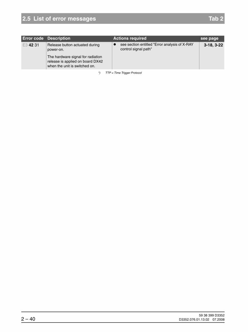
59 38 399 D33522 – 40 D3352.076.01.13.02 07.2008
2.5 List of error messages Tab 2
*) TTP = Time Trigger Protocol
E3 42 31 Release button actuated during power-on.
The hardware signal for radiation release is applied on board DX42 when the unit is switched on.
see section entitled "Error analysis of X-RAY control signal path"
3-18, 3-22
Error code Description Actions required see page

båÖäáëÜ
59 38 399 D3352D3352.076.01.13.02 07.2008 2 – 41
Tab 2 2.5 List of error messages
2.5
Location 61: Diaphragm control, board DX61 (not for XG 3/3 PPE, fixed diaphragm)
Error code Description Actions required see page
E6 61 01 General error during module initializa-tion
Please contact the Sirona Customer Service Center (CSC) to find out whether a bugfix by means of a software update is possible and per-form such an update if necessary.
1-22
Check board DX61, replace if necessary 3-12
Replace board DX61 or 6-59
Replace diaphragm unit 6-34
E6 61 02 Invalid system data or uninitialized module storage data
Please contact the Sirona Customer Service Center (CSC) to find out whether a bugfix by means of a software update is possible and per-form such an update if necessary.
1-22
Acknowledge error and repeat procedure
If the error occurs again...
Check board DX61, replace if necessary 3-12
Replace board DX61 or 6-59
Replace diaphragm unit 6-34
E6 61 03 Invalid commanding or control data
Note:This error may also occur in connec-tion with other causal error messages. Please also observe the causal error message! It appears only after you acknowledge the first error message.
If the error occurs during the acceptance/constancy test:
Check filter offset Bf in the "Reset values" menu. If the value is < -500 (e.g. -502), repeat the adjustment of the pan symmetry and check the position of the diaphragm.
HINWEISiFor software versions ≤ V02.22, the filter offset value must be < 500 (e.g. ± 450).
4-3
If the error occurs in the normal mode:
Checking the CAN bus 3-6Please contact the Sirona Customer Service Center (CSC) to find out whether a bugfix by means of a software update is possible and per-form such an update if necessary.
1-22
E6 61 04 Data transfer error or dialog error to module (master side)
Checking the CAN bus 3-6Please contact the Sirona Customer Service Center (CSC) to find out whether a bugfix by means of a software update is possible and per-form such an update if necessary.
1-22
E6 61 05 Data transfer error or dialog error to bootloader of module
Note:Occurs only in connection with software update
Repeat software update 1-22Checking the CAN bus 3-6Check board DX61, replace if necessary 3-12
Replace board DX61 or 6-59
Replace diaphragm unit 6-34

59 38 399 D33522 – 42 D3352.076.01.13.02 07.2008
2.5 List of error messages Tab 2
E6 61 06 Module failed in TTP* (detected on master side)
Checking the CAN bus 3-6Check board DX61, replace if necessary 3-12
Replace board DX61 or 6-59
Replace diaphragm unit 6-34Please contact the Sirona Customer Service Center (CSC) to find out whether a bugfix by means of a software update is possible and per-form such an update if necessary.
1-22
E6 61 07 TTP* timeout error(detected on slave side)
Note: The module was temporarily not addressed by the master:- Undervoltage on the master side- Procedure error in the software- Master (DX11) receives no
return commanding from the module
Note:This error may also occur in connec-tion with other causal error messages. Please also observe the causal error message! It appears only after you acknowledge the first error message.
Checking the CAN bus 3-6Check power supply of board DX11; measuring point 3.3 V on board DX1 (see wiring diagrams).
– If 3.3 V are present, replace board DX11 6-59
– If 3.3 V are not present, replace board DX1 6-59
E6 61 08 General fault detected locally on mod-ule (slave side). CAN controller being reinitialized.
Checking the CAN bus 3-6Check software versions via info screen or ser-vice routine S008.2,
5-48
perform a software update if necessary 1-22Check board DX61, replace if necessary 3-12
Replace board DX61 or 6-59
Replace diaphragm unit 6-34Please contact the Sirona Customer Service Center (CSC) to find out whether a bugfix by means of a software update is possible and per-form such an update if necessary.
1-22
E7 61 10 Module is stuck in bootloader stage Check operating status of board (note LED states)
3-12
If the board remains in the bootloader stage...
Repeat software update 1-22Check board DX61, replace if necessary 3-12
Replace board DX61 or 6-59
Replace diaphragm unit 6-34
Error code Description Actions required see page

båÖäáëÜ
59 38 399 D3352D3352.076.01.13.02 07.2008 2 – 43
Tab 2 2.5 List of error messages
2.5
E7 61 12 Unit is not ready for operation This error is a sequential fault.
Unit restart:Switch the unit OFF. Wait 30 sec.Switch unit ON.
Repeat procedure and observe causal error messages.
Checking the CAN bus 3-6Replace diaphragm unit 6-34
E5 61 15 Drive overtemperature
Note: Can occur after frequent diaphragm travel, e.g. during demo operation at a fair
Allow unit to cool down.
If the error occurs again...
Check board DX61, replace if necessary 3-12
Replace board DX61 or 6-59
Replace diaphragm unit 6-34
E5 61 20 Horizontal motor malfunction during operation
Note: Can occur after frequent diaphragm travel, e.g. during demo operation at a fair
Allow unit to cool down.
If the error occurs again...
Check board DX61, replace if necessary
3-12
Replace board DX61 or 6-59
Replace diaphragm unit 6-34
E5 61 21 Horizontal motor limit switch error Check light barrier V61_1 and connectors, re-place if necessary
3-156-49
Perform diaphragm adjustment 4-3Please contact the Sirona Customer Service Center (CSC) to find out whether a bugfix by means of a software update is possible and per-form such an update if necessary.
1-22
If the error occurs again...
Check board DX61, replace if necessary 3-12Replace board DX61 or 6-59Replace diaphragm unit 6-34
E5 61 22 Horizontal motor movement error Acknowledge error and repeat procedure
If the error occurs again...
Check board DX61, replace if necessary
3-12
Replace board DX61 or 6-59
Replace diaphragm unit 6-34
E5 61 30 Vertical motor malfunction during operation
Allow unit to cool down.
If the error occurs again...
Check board DX61, replace if necessary 3-12
Replace board DX61 or 6-59
Replace diaphragm unit 6-34
Error code Description Actions required see page

59 38 399 D33522 – 44 D3352.076.01.13.02 07.2008
2.5 List of error messages Tab 2
E5 61 31 Vertical motor limit switch error Check light barrier V61_2 and connectors, re-place if necessary
3-156-49
Perform diaphragm adjustment 4-3Please contact the Sirona Customer Service Center (CSC) to find out whether a bugfix by means of a software update is possible and per-form such an update if necessary.
1-22
If the error occurs again...
Check board DX61, replace if necessary 3-12Replace board DX61 or 6-59Replace diaphragm unit 6-34
E5 61 32 Vertical motor movement error Acknowledge error and repeat procedure
If the error occurs again...
Check board DX61, replace if necessary 3-12
Replace board DX61 or 6-59
Replace diaphragm unit 6-34
E5 61 40 Filter motor malfunction during opera-tion
Allow unit to cool down.
If the error occurs again...
Check board DX61, replace if necessary 3-12
Replace board DX61 or 6-59
Replace diaphragm unit 6-34
E5 61 41 Filter motor limit switch error Check light barrier V61_1 and connectors, 3-15
replace if necessary 6-49Perform diaphragm adjustment 4-3Please contact the Sirona Customer Service Center (CSC) to find out whether a bugfix by means of a software update is possible and per-form such an update if necessary.
1-22
If the error occurs again...
Check board DX61, replace if necessary 3-12Replace board DX61 or 6-59Replace diaphragm unit 6-34
E5 61 42 Filter motor movement error Acknowledge error and repeat procedure
If the error occurs again...
Check board DX61, replace if necessary 3-12
Replace board DX61 or 6-59
Replace diaphragm unit 6-34
Error code Description Actions required see page

båÖäáëÜ
59 38 399 D3352D3352.076.01.13.02 07.2008 2 – 45
Tab 2 2.5 List of error messages
2.5
E5 61 50 Sensor positioning drive malfunction during operation
Allow unit to cool down
If the error occurs again...
Check connector of TSA motor and TSA-LS (V61_4) for correct position, replug if necessary
Check pan sensor holder mechanics (TSA) for smooth and easy movement, replace sensor holder if necessary
6-43
E5 61 51 Sensor positioning drive limit switch error
Check light barrier V61_4, replace if necessary
3-156-49
Check connector of TSA motor and TSA-LS (V61_4) for correct position, replug if necessary
Check extension cord to light barrier, replace if necessary
Check pan sensor holder mechanics (TSA) for smooth and easy movement, replace sensor holder if necessary
6-43
Check board DX61, replace if necessary 3-12
Replace board DX61 or 6-59
Replace diaphragm unit 6-34
E5 61 52 Sensor positioning drive movement error
Acknowledge error and repeat procedure
If the error occurs again...
Check to make sure TSA transport safety de-vice has been removed (see TSA installation in-structions), remove if necessary
Check cable L20, 3-17replace if necessary 6-91Check pan sensor holder mechanics (TSA) for smooth and easy movement,
replace sensor holder if necessary 6-43Check board DX61, 3-12
Replace board DX61 or 6-59
Replace diaphragm unit 6-34
E5 61 53 Limit switch sensor adjustment for TSA defective
Check light barrier V61_4 and connector, replace if necessary
3-153-176-49
E5 61 54 Limit switch sensor adjustment for PAN/CEPH defective
Check light barrier V61_5 and connector, replace if necessary
3-153-176-49
Error code Description Actions required see page

59 38 399 D33522 – 46 D3352.076.01.13.02 07.2008
2.5 List of error messages Tab 2
*) TTP = Time Trigger Protocol
E1 61 60 Voltage error on DX61, 40 V or 28 V
Note: If several drives are operated simulta-neously under unfavorable circum-stances, this may cause voltages to fall below their minimum tolerances.
Acknowledge error and repeat procedure
If the error occurs again...
Check height adjustment (soft start),
replace DX1 if necessary 6-59Check voltages at X501 on board DX61 accord-ing to wiring diagrams,
replace diaphragm unit if necessary 6-34Check cable L11, 3-17replace if necessary 6-91Check voltage path from DX32 to DX1 (X102) according to wiring diagrams, replace component if necessary
E6 61 70 Error during the configuration of the diaphragm unit
If this error occurs after board DX11 has been replaced:
Check configuration of diaphragm unit via service routine S017.17
5-103,5-105
Configure correctly if necessary 5-103,5-105
If this error occurs after the diaphragm unit has been replaced:
Check order number of inserted diaphragm unit
Replace diaphragm unit if necessary 6-34,6-38
Error code Description Actions required see page

båÖäáëÜ
59 38 399 D3352D3352.076.01.13.02 07.2008 2 – 47
Tab 2 2.5 List of error messages
2.5
Location 71 (XG5/3/3 PPE): Multipad/Board DX71
Error code Description Actions required see page
E6 71 01 General error during module initializa-tion
Please contact the Sirona Customer Service Center (CSC) to find out whether a bugfix by means of a software update is possible and per-form such an update if necessary.
1-22
If the error occurs again...
Check board DX71 or 6-59replace Multipad 6-21
E6 71 02 Invalid system data or uninitialized module storage data
Please contact the Sirona Customer Service Center (CSC) to find out whether a bugfix by means of a software update is possible and per-form such an update if necessary.
1-22
Acknowledge error and repeat procedure
If the error occurs again...
Check board DX71 or 6-59 replace Multipad 6-21
E6 71 03 Invalid commanding or control data
Note:This error may also occur in connec-tion with other causal error messages. Please also observe the causal error message! It appears only after you acknowledge the first error message.
Checking the CAN bus 3-6Please contact the Sirona Customer Service Center (CSC) to find out whether a bugfix by means of a software update is possible and per-form such an update if necessary.
1-22
E6 71 04 Data transfer error or dialog error to module (master side)
Checking the CAN bus 3-6Please contact the Sirona Customer Service Center (CSC) to find out whether a bugfix by means of a software update is possible and per-form such an update if necessary.
1-22
E6 71 05 Data transfer error or dialog error to bootloader of module
Note:Occurs only in connection with software update
Repeat software update 1-22Checking the CAN bus 3-6Check board DX71 or 6-59replace Multipad 6-21
E6 71 06 Module failed in TTP* (detected on master side)
Checking the CAN bus 3-6Replace board DX71 6-21Please contact the Sirona Customer Service Center (CSC) to find out whether a bugfix by means of a software update is possible and per-form such an update if necessary.
5-9

59 38 399 D33522 – 48 D3352.076.01.13.02 07.2008
2.5 List of error messages Tab 2
E6 71 07 TTP* timeout error(detected on slave side)
Note: The module was temporarily not addressed by the master:- Undervoltage on the master side- Procedure error in the software- Master (DX11) receives no
return commanding from the module
Note:This error may also occur in connec-tion with other causal error messages. Please also observe the causal error message! It appears only after you acknowledge the first error message.
Checking the CAN bus 3-6Check power supply of board DX11; measuring point 3.3 V on board DX1 (see wiring diagrams).
– If 3.3 V are present, replace board DX11 6-59
– If 3.3 V are not present, replace board DX1 6-59
E6 71 08 General fault detected locally on mod-ule (slave side). CAN controller being reinitialized.
Checking the CAN bus 3-6Check software versions via info screen or ser-vice routine S008.2,
5-48
perform a software update if necessary 1-22Check board DX71 or 3-59replace Multipad 6-21Please contact the Sirona Customer Service Center (CSC) to find out whether a bugfix by means of a software update is possible and per-form such an update if necessary.
1-22
E7 71 10 Module is stuck in bootloader stage Check board DX71 3-12
If the board remains in the bootloader stage...
Repeat software update 1-22Check board DX71 or 6-59replace Multipad 6-21
E7 71 12 Unit is not ready for operation Checking the CAN bus 3-6
This error is a sequential fault.
Unit restart:Switch the unit OFF. Wait 30 sec.Switch unit ON.
Repeat procedure and observe causal error messages.
E6 71 20 Contact to DX11 interrupted during operation.
Note error message on remote control (DX42) and check log memory (via extended details)
Checking the CAN bus 3-6Check cable L9, 3-17replace if necessary 6-91
Error code Description Actions required see page

båÖäáëÜ
59 38 399 D3352D3352.076.01.13.02 07.2008 2 – 49
Tab 2 2.5 List of error messages
2.5
*) TTP = Time Trigger Protocol
E7 71 21 No CAN bus connection.DX11 does not start.
Note:Occurs after power-on in the start screen.
Start the detail query via Sixabcon
If DX11 responds...
Check signal path to DX71,
repair or replace cable/connector if necessary 6-91Replace DX1 6-59
If DX11 does not respond...
Replace DX11 6-59
E3 71 30 Height adjustment keys actuated dur-ing power-on
Unit restart:Switch the unit OFF. Wait for 30 sec.Switch unit ON, making sure that the Multipad is not actuated during boot-up.
If the error occurs again...
Replace board DX71 or Multipad
6-596-21
E3 71 31 Forehead support key pressed during power-on
E3 71 32 Temple support keys actuated during power-on
E3 71 33 Light localizer key actuated during power-on
E3 71 34 Test key actuated during power-on
E3 71 35 Return key actuated during power-on
E3 71 36 Service key actuated during power-on
E3 71 37 Memory key actuated during power-on
E3 71 38 Program selection key actuated during power-on
E3 71 39 Radiation time key actuated during power-on
E3 71 40 kV/mA key actuated during power-on
E3 71 41 Patient symbol key actuated during power-on
Error code Description Actions required see page

59 38 399 D33522 – 50 D3352.076.01.13.02 07.2008
2.5 List of error messages Tab 2
Location 81, zz = 1-23: Board DX81, pan slot
Error code Description Actions required see page
E6 81 01 PAN
General error during module initializa-tion
Please contact the Sirona Customer Service Center (CSC) to find out whether a bugfix by means of a software update is possible and per-form such an update if necessary.
1-22
Check pan sensor, replace if necessary
E6 81 02 PAN
Invalid system data or uninitialized module storage data
Please contact the Sirona Customer Service Center (CSC) to find out whether a bugfix by means of a software update is possible and per-form such an update if necessary.
1-22
Acknowledge error and repeat procedure
If the error occurs again...
Check pan sensor, replace if necessary
E6 81 03 PAN
Invalid commanding or control data
Note:This error may also occur in connec-tion with other causal error messages. Please also observe the causal error message! It appears only after you acknowledge the first error message.
Checking the CAN bus 3-6If the error is a software error known to the Siro-na Customer Service Center (CSC), a software update (bugfix) must be performed
1-22
E6 81 04 PAN
Data transfer error or dialog error to module (master side)
Checking the CAN bus 3-6Please contact the Sirona Customer Service Center (CSC) to find out whether a bugfix by means of a software update is possible and per-form such an update if necessary.
1-22
E6 81 05 PAN
Data transfer error or dialog error to bootloader of module
Note:Occurs only in connection with software update
Repeat software update 1-22Checking the CAN bus 3-6Check pan sensor, replace if necessary
E6 81 06 PAN
Module failed in TTP* (detected on master side)
Checking the CAN bus 3-6Check pan sensor, replace if necessary
Please contact the Sirona Customer Service Center (CSC) to find out whether a bugfix by means of a software update is possible and per-form such an update if necessary.
1-22

båÖäáëÜ
59 38 399 D3352D3352.076.01.13.02 07.2008 2 – 51
Tab 2 2.5 List of error messages
2.5
E6 81 07 PAN
TTP* timeout error(detected on slave side)
Note: The module was temporarily not addressed by the master:- Undervoltage on the master side- Procedure error in the software- Master (DX11) receives no
return commanding from the module
Note:This error may also occur in connec-tion with other causal error messages. Please also observe the causal error message! It appears only after you acknowledge the first error message.
Checking the CAN bus 3-6Check cable L13, 3-17replace if necessary 6-91Check power supply of board DX11; measuring point 3.3 V on board DX1 (see wiring diagrams).
– If 3.3 V are present, replace board DX11 6-59
– If 3.3 V are not present, replace board DX1 6-59
E6 81 08 PAN
General fault detected locally on mod-ule (slave side). CAN controller being reinitialized.
Checking the CAN bus 3-6Check software versions via info screen or ser-vice routine S008.2,
5-48
perform a software update if necessary 1-22Check pan sensor, replace if necessary
Please contact the Sirona Customer Service Center (CSC) to find out whether a bugfix by means of a software update is possible and per-form such an update if necessary.
1-22
E7 81 10 PAN
Module is stuck in bootloader stage
Check sensor or board DX81 (replacement sen-sor), replace sensor if necessary
If the board remains in the bootloader stage...
Repeat software update 1-22Check pan sensor, replace if necessary
E7 81 12 PAN
Unit is not ready for operation
This error is a sequential fault.
Unit restart:Switch the unit OFF. Wait 30 sec.Switch unit ON.
Repeat procedure and observe causal error messages.
E5 81 13 PAN
Error when writing to EEPROM
Note: Stored data may be lost
Acknowledge error and repeat procedure
Perform a software update 1-22
If the error occurs again...
Check log memory (via extended details)
Check pan sensor, replace if necessary
Error code Description Actions required see page

59 38 399 D33522 – 52 D3352.076.01.13.02 07.2008
2.5 List of error messages Tab 2
E6 81 20 PAN
The sensor type on the panoramic unit is not compatible with SIDEXIS speci-fications
Check with the Sirona Customer Service Cen-ter (CSC) for SIDEXIS specifications
Check version compatibility of XG software and Sidexis,
1-16
perform a software update if necessary 1-22Pull sensor out of slot and plug it back in, repeat procedure
E7 81 21 PAN
File system error on DX81P
Perform a software update 1-22Check sensor or board DX81 (replacement sen-sor), replace sensor if necessary
E6 81 23 PAN
Sensor in pan slot active on CAN bus, but no hardware detection
Check cable L13, replace if necessary 3-176-91
Check Pan LED (V500) on DX1(hardware detection of sensor)
3-12
Check sensor or board DX81 (replacement sen-sor), replace sensor if necessary
Check connector X500 on DX1,replace DX1 or DX11 if necessary 6-59Replace board DX1 or DX11 6-59
E5 81 24 PAN
Sensor in PAN slot not detected.
Check cable L13, replace if necessary
3-176-91
Check Pan LED (V500) on DX1(hardware detection of sensor)
3-12
Check sensor or board DX81 (replacement sen-sor), replace sensor if necessary
Check plug X500 on DX1,
replace DX1 if necessary 6-59Checking the CAN bus 3-6
E5 81 25 PAN
Error while synchronizing image data
Perform a software update 6-59
If the error occurs again...
Check pan sensor, replace if necessary
E5 81 27 PAN
Voltage error detected on sensor.(CCD voltages on board DX81P)
Note:If this error occurs in connection with other causal error messages (e.g. E6 6160, E6 9150), take appropriate action
Check cable L13, 3-17replace if necessary 6-91Check plug X500 on DX1,
replace DX1 if necessary 6-59Check pan sensor, replace if necessary
Error code Description Actions required see page

båÖäáëÜ
59 38 399 D3352D3352.076.01.13.02 07.2008 2 – 53
Tab 2 2.5 List of error messages
2.5
*) TTP = Time Trigger Protocol
E5 81 28 PAN
Invalid data at start of exposure.
Acknowledge error and repeat procedure
If the error occurs again...
Perform a software update 1-22Check version compatibility of XG software and Sidexis,
1-16
perform a software update if necessary 1-22Contact the Sirona Customer Service Center for the settings/sensor information in the Xab.ini file
Error code Description Actions required see page

59 38 399 D33522 – 54 D3352.076.01.13.02 07.2008
2.5 List of error messages Tab 2
Location 81, zz = 51-73: DX 81, ceph slot
Error code Description Actions required see page
E6 81 51 Ceph
General error during module initializa-tion
Please contact the Sirona Customer Service Center (CSC) to find out whether a bugfix by means of a software update is possible and per-form such an update if necessary.
1-22
Check ceph sensor, replace if necessary
E6 81 52 Ceph
Invalid system data or uninitialized module storage data
Please contact the Sirona Customer Service Center (CSC) to find out whether a bugfix by means of a software update is possible and per-form such an update if necessary.
1-22
Acknowledge error and repeat procedure
If the error occurs again...
Check ceph sensor, replace if necessary
E6 81 53 Ceph
Invalid commanding or control data
Note:This error may also occur in connec-tion with other causal error messages. Please also observe the causal error message! It appears only after you acknowledge the first error message.
Checking the CAN bus 3-6Please contact the Sirona Customer Service Center (CSC) to find out whether a bugfix by means of a software update is possible and per-form such an update if necessary.
1-22
E6 81 54 Ceph
Data transfer error or dialog error to module (master side)
Checking the CAN bus 3-6Please contact the Sirona Customer Service Center (CSC) to find out whether a bugfix by means of a software update is possible and per-form such an update if necessary.
1-22
E6 81 55 Ceph
Data transfer error or dialog error to bootloader of module
Note:Occurs only in connection with software update
Repeat software update 1-22Checking the CAN bus 3-6Check ceph sensor, replace if necessary
E6 81 56 Ceph
Module failed in TTP* (detected on master side)
Checking the CAN bus 3-6Check ceph sensor, replace if necessary
Please contact the Sirona Customer Service Center (CSC) to find out whether a bugfix by means of a software update is possible and per-form such an update if necessary.
1-22

båÖäáëÜ
59 38 399 D3352D3352.076.01.13.02 07.2008 2 – 55
Tab 2 2.5 List of error messages
2.5
E6 81 57 Ceph
TTP* timeout error(detected on slave side)
Note: The module was temporarily not addressed by the master:- Undervoltage on the master side- Procedure error in the software- Master (DX11) receives no
return commanding from the module
Note:This error may also occur in connec-tion with other causal error messages. Please also observe the causal error message! It appears only after you acknowledge the first error message.
Checking the CAN bus 3-6Check power supply of board DX11; measuring point 3.3 V on board DX1 (see wiring diagrams).
– If 3.3 V are present, replace board DX11 6-59
– If 3.3 V are not present, replace board DX1 6-59
E6 81 58 Ceph
General fault detected locally on mod-ule (slave side). CAN controller being reinitialized.
Checking the CAN bus 3-6Check software versions via info screen or service routine S008.2,
5-48
perform a software update if necessary 1-22Check ceph sensor, replace if necessary
Please contact the Sirona Customer Service Center (CSC) to find out whether a bugfix by means of a software update is possible and per-form such an update if necessary.
1-22
E7 81 60 Ceph
Module is stuck in bootloader stage
Check sensor or board DX81 (replacement sen-sor)
3-12
If the board remains in the bootloader stage...
Repeat software update 1-22Check ceph sensor, replace if necessary
E7 81 62 Ceph
Unit is not ready for operation
This error is a sequential fault.
Unit restart:Switch the unit OFF. Wait 30 sec.Switch unit ON.
Repeat procedure and observe causal error messages.
E5 81 63 Ceph
Error when writing to EEPROM
Note: Stored data may be lost
Acknowledge error and repeat procedure
If the error occurs again...
Check ceph sensor, replace if necessary
E7 81 71 Ceph
File system error on DX81C
Perform a software update 1-22
Error code Description Actions required see page

59 38 399 D33522 – 56 D3352.076.01.13.02 07.2008
2.5 List of error messages Tab 2
*) TTP = Time Trigger Protocol
E6 81 73 Ceph
Sensor in ceph slot active on CAN bus, but no hardware detection
Check cable L35/L38, 3-17replace if necessary 6-91Check plug X500 on board DX1,
replace board DX1 if necessary 6-59Check Ceph sensor holder,
replace if necessary 6-47
E5 81 74 Ceph
Sensor in ceph slot not detected.
Check cables L35 and L38, 3-17replace if necessary 6-91Checking the CAN bus 3-6Check connector X503 on board DX1,replace board DX1 if necessary 6-59Check ceph sensor holder, replace if necessary 6-47
E5 81 75 Ceph
Error while synchronizing image data
Perform a software update 1-22
If the error occurs again...
Check ceph sensor, replace if necessary
E5 81 77 Ceph
Voltage error detected on sensor.(CCD voltages on board DX81P)
Note:If this error occurs in connection with other causal error messages (e.g. E6 6160, E6 9150), take appropriate action
Check cable L35/L38, 3-17replace if necessary 6-91Check plug X503 on board DX1,
replace board DX1 if necessary 6-59Check ceph sensor holder, replace if necessary 6-47Perform a software update 1-22Check ceph sensor, replace if necessary
E5 81 78 Ceph
Invalid data at start of exposure.
Acknowledge error and repeat procedure
If the error occurs again...
Perform a software update 1-22Check version compatibility of XG software and Sidexis,
1-16
perform a software update if necessary 1-22Contact the Sirona Customer Service Center for the settings/sensor information in the Xab.ini file
Error code Description Actions required see page

båÖäáëÜ
59 38 399 D3352D3352.076.01.13.02 07.2008 2 – 57
Tab 2 2.5 List of error messages
2.5
Location 91: Cephalometer, board DX91
Error code Description Actions required see page
E6 91 01 General error during module initializa-tion
Please contact the Sirona Customer Service Center (CSC) to find out whether a bugfix by means of a software update is possible and per-form such an update if necessary.
1-22
Replace board DX91 6-59
E6 91 02 Invalid system data or uninitialized module storage data
Please contact the Sirona Customer Service Center (CSC) to find out whether a bugfix by means of a software update is possible and per-form such an update if necessary.
1-22
Acknowledge error and repeat procedure
If the error occurs again...
Replace board DX91 6-59
E6 91 03 Invalid commanding or control data
Note:This error may also occur in connec-tion with other causal error messages. Please also observe the causal error message! It appears only after you acknowledge the first error message.
Checking the CAN bus 3-6Please contact the Sirona Customer Service Center (CSC) to find out whether a bugfix by means of a software update is possible and per-form such an update if necessary.
1-22
E6 91 04 Data transfer error or dialog error to module (master side)
Checking the CAN bus 3-6Please contact the Sirona Customer Service Center (CSC) to find out whether a bugfix by means of a software update is possible and per-form such an update if necessary.
1-22
E6 91 05 Data transfer error or dialog error to bootloader of module
Note:Occurs only in connection with software update
Repeat software update 1-22Checking the CAN bus 3-6Replace board DX91 6-59
E6 91 06 Module failed in TTP* (detected on master side)
Checking the CAN bus 3-6Replace board DX91 6-59Please contact the Sirona Customer Service Center (CSC) to find out whether a bugfix by means of a software update is possible and per-form such an update if necessary.
1-22

59 38 399 D33522 – 58 D3352.076.01.13.02 07.2008
2.5 List of error messages Tab 2
E6 91 07 TTP* timeout error(detected on slave side)
Note: The module was temporarily not addressed by the master:- Undervoltage on the master side- Procedure error in the software- Master (DX11) receives no
return commanding from the module
Note:This error may also occur in connec-tion with other causal error messages. Please also observe the causal error message! It appears only after you acknowledge the first error message.
Checking the CAN bus 3-6Check power supply of board DX11; measuring point 3.3 V on board DX1 (see wiring diagrams).
– If 3.3 V are present, replace board DX11 6-59
– If 3.3 V are not present, replace board DX1 6-59
E6 91 08 General fault detected locally on mod-ule (slave side). CAN controller being reinitialized.
Checking the CAN bus 3-6Check software versions via info screen or ser-vice routine S008.2,
5-44
perform a software update if necessary 1-22Replace board DX91 6-59Please contact the Sirona Customer Service Center (CSC) to find out whether a bugfix by means of a software update is possible and per-form such an update if necessary.
1-22
E7 91 10 Module is stuck in bootloader stage Check operating status of board (note LED states)
3-12
If the board remains in the bootloader stage...
Repeat software update 1-22Check DX91, 3-12replace if necessary 6-59
E7 91 12 Unit is not ready for operation This error is a sequential fault.
Unit restart:Switch the unit OFF. Wait 30 sec.Switch unit ON.
Repeat procedure and observe causal error messages.
E3 91 13 Error when writing to EEPROM
Note: Stored data may be lost
Complete unit adjustment 4-3incl. check of center position of Ceph scan via service routines S034.4 and S034.5,readjust if necessary
5-135,5-139
Acknowledge error and repeat procedure
If the error occurs again...
Check board DX91, 3-12replace if necessary 6-59
E5 91 15 Drive overtemperature Allow unit to cool down.
If the error occurs again...
Error code Description Actions required see page

båÖäáëÜ
59 38 399 D3352D3352.076.01.13.02 07.2008 2 – 59
Tab 2 2.5 List of error messages
2.5
Check complete mechanics/spindle of motor M91_3 for smooth and easy running,
replace if necessary
Replace board DX91 6-34
E5 91 16 Motor control timeout (M91_2/3) Replace board DX91 6-59
E5 91 20 Sensor drive malfunction during oper-ation
Allow unit to cool down.
If the error occurs again...
Check complete mechanics/spindle of motor M91_3 for smooth and easy running,
replace if necessary
Check light barrier V91_2, 3-15
E5 91 21 Sensor drive, opposite light barrier reached prematurely
replace if necessary 6-49Check cable to light barrier (L21/L24),
replace if necessary 6-49Check board DX91, 3-12replace if necessary 6-59Please contact the Sirona Customer Service Center (CSC) to find out whether a bugfix by means of a software update is possible and per-form such an update if necessary.
1-22
E5 91 22 Sensor drive timeout Check motor M91_3 incl. cable and connector,
replace if necessary
Check cable to light barrier (L21/L24),
replace if necessary 6-49
E5 91 30 Secondary diaphragm drive malfunc-tion during operation
Allow unit to cool down.
If the error occurs again...
Check motor M91_2 incl. cable and connector,
replace if necessary
Check cable to light barrier (L21/L24),
replace if necessary 6-49
E5 91 31 Secondary diaphragm drive, opposite light barrier reached prematurely
Check light barrier V91_2, 3-15replace if necessary 6-49Check cable to light barrier (L21/L24),
replace if necessary 6-49Check board DX91, 3-12
replace if necessary 6-59Please contact the Sirona Customer Service Center (CSC) to find out whether a bugfix by means of a software update is possible and per-form such an update if necessary.
1-22
Error code Description Actions required see page

59 38 399 D33522 – 60 D3352.076.01.13.02 07.2008
2.5 List of error messages Tab 2
*) TTP = Time Trigger Protocol
E5 91 32 Secondary diaphragm drive timeout Check motor M91_2,
replace if necessary
Check cable to light barrier (L21/L24),
replace if necessary 6-49
E6 91 40 Rotary table pot compensation not yet performed
Perform software update to version V02.25 or higher
1-22
If the error occurs again...
Replace DX91, 6-59
E6 91 41 Ear plug pot compensation not yet performed
Perform software update to version V02.25 or higher
1-22
If the error occurs again...
Replace DX91 6-59
E6 91 42 Nose support pot compensation not yet performed
Perform software update to version V02.25 or higher
1-22
If the error occurs again...
Replace DX91 6-59
E1 91 50 Voltage error on DX91, 40V or 28V
Note: If several drives are operated simulta-neously under unfavorable circum-stances, this may cause voltages to fall below their minimum tolerances.
Check height adjustment (soft start),
replace DX1 if necessary 6-59Check cables L36, L39 and adapter, replace if necessary
3-176-91
Check voltages at X103 on board DX91 accord-ing to wiring diagrams, replace DX91 if neces-sary
6-59
Check boards DX1 and DX91, replace if necessary
3-126-59
If multiple boards report errors...
Check DX32, 3-12replace if necessary 6-59
Error code Description Actions required see page
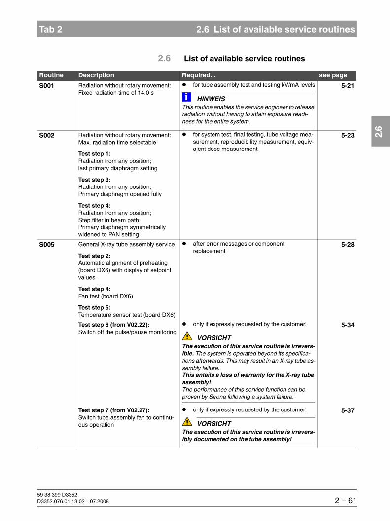
båÖäáëÜ
59 38 399 D3352D3352.076.01.13.02 07.2008 2 – 61
Tab 2 2.6 List of available service routines
2.6
2.6 List of available service routines
Routine Description Required... see page
S001 Radiation without rotary movement: Fixed radiation time of 14.0 s
for tube assembly test and testing kV/mA levels
HINWEISiThis routine enables the service engineer to release radiation without having to attain exposure readi-ness for the entire system.
5-21
S002 Radiation without rotary movement: Max. radiation time selectable
Test step 1:Radiation from any position;last primary diaphragm setting
Test step 3:Radiation from any position;Primary diaphragm opened fully
Test step 4:Radiation from any position;Step filter in beam path;Primary diaphragm symmetrically widened to PAN setting
for system test, final testing, tube voltage mea-surement, reproducibility measurement, equiv-alent dose measurement
5-23
S005 General X-ray tube assembly service
Test step 2:Automatic alignment of preheating (board DX6) with display of setpoint values
Test step 4:Fan test (board DX6)
Test step 5:Temperature sensor test (board DX6)
after error messages or component replacement
5-28
Test step 6 (from V02.22):Switch off the pulse/pause monitoring
only if expressly requested by the customer!
VORSICHTThe execution of this service routine is irrevers-ible. The system is operated beyond its specifica-tions afterwards. This may result in an X-ray tube as-sembly failure. This entails a loss of warranty for the X-ray tube assembly!The performance of this service function can be proven by Sirona following a system failure.
5-34
Test step 7 (from V02.27):Switch tube assembly fan to continu-ous operation
only if expressly requested by the customer!
VORSICHTThe execution of this service routine is irrevers-ibly documented on the tube assembly!
5-37

59 38 399 D33522 – 62 D3352.076.01.13.02 07.2008
2.6 List of available service routines Tab 2
S007 Error logging
Test step 1:Display error logging memory
Test step 2:Clear error logging memory
after error messages 5-40
Test step 5 (from V02.27):Activation of CAN bus logging in the miniweb
only after consulting with the Sirona Customer Service Center!
S008 Update service
Test step 2:Display of module software version statuses
for checking the configuration 5-48
Test step 3:Input/confirmation of unit serial number
Test step 4 (not for XG3 and XG3PPE):Initializing the function activation
after error messages
S009 Flash file system
Test step 4:Format flash file system
after error messages 5-56
S012(V02.27 or higher)
CAN bus service
Test step 2:Query of CAN status register of mod-ules
on suspicion of unstable CAN bus
in case of accumulated error messages EX yy 12; Ex yy 06, Ex yy 07, Ex yy 03
not suitable as an accompanying measure e.g. "check connector of CAN bus" or "check bus ter-minations"
5-59
Test step 3:Query of CAN status register of mod-ules
to be executed prior to service routine S012.2 if required
Test step 4:Display of CAN bus cycle on LEDs of modules
in case of sporadic failures of modules on CAN bus (after Ex yy 06, Ex yy 07,Ex yy 08, Ex yy 12)
as accompanying measure during check of plugs (wiggle) for firm seating
S014(V02.28 or higher)
Rotation motor service
Test step 1:Travel of rotational drive to the Pan home position
Test step 2:Travel of rotational drive to the Ceph home position
Test step 3:Free travel of rotational drive
Test step 4:Display of light barrier signals of rota-tional drive
for electromechanical problems with the ring motor or the ring rotation system
5-67
Routine Description Required... see page

båÖäáëÜ
59 38 399 D3352D3352.076.01.13.02 07.2008 2 – 63
Tab 2 2.6 List of available service routines
2.6
S015(V02.28 or higher)
Actuator service
Test step 5:Functional test of actuators 1 + 2
for electromechanical problems with the actua-tors or the actuator movement
5-74
S017 Configuration serviceUnit ID
Test step 2:Configure hardware version
Test step 3:Select the country group code
Test step 4 (XGPlus only):Select language index within lan-guage set
Test step 5 (XGPlus only):Select language set index within lan-guage set
for changing the configuration 5-77
Test step 6:Activate remote control
for installation and removal of remote control
Test step 8:Select kV/mA level ID
for changing the configuration
Test step 9 (V02.28 and higher):Configuration of unit with or without board DX41
for software updates and replacement of DX11
Test step 10 (V02.28 or higher):Configuration of headrest
for replacement of board DX11 or the headrest
Test step 11 (for XG 5 only):Select image format
for changing the configuration
Test step 12 (V02.22 or higher, XGPlus only):Activate/deactivate the preview image
At the customer's request: Switch the preview image ON and OFF (after update to version V02.22)
Test step 13 (V02.22 or higher, XGPlus full version only):Enable/disable the welcome screen
At the customer's request: Enabling or disabling the welcome screen (after update to V02.22)
Test step 14 (V02.22 or higher, XGPlus full version only):Activate/deactivate certain lines of the welcome screen
At the customer's request or compliant to legal regulations: Configure the appearance of the welcome screen.
Test step 15 (V02.25 or higher, XGPlus full version only):Activate/deactivate the acoustic signal for the end of exposure
At the customer's request: Switch the acoustic signal for the end of exposure ON or OFF.
Test step 17 (V02.32 and higher):
After replacing the diaphragm:
– RöV FRG: Configuration of standard for ac-ceptance/constancy test
– Worldwide: Check/accept the diaphragm configuration
Routine Description Required... see page

59 38 399 D33522 – 64 D3352.076.01.13.02 07.2008
2.6 List of available service routines Tab 2
S017 Test step 18 (V02.28 or higher, for XGPlus only):in preparation!
VORSICHTThis routine must not be selected, since it would cause malfunctions of the unit!
Test step 22 (V02.28 or higher, for XG 3 PPE only):Configuration of PPE display
Configuration of display of remaining exposures after power-on
Test step 23 (V02.28 or higher, for XG 3 PPE only):Configuration of warning level for PPE display
Configuration of warning level for display of re-maining exposures after an exposure
S018 Set travel height
Test step 2:Limit maximum travel height
Test step 3:Undo limit of maximum travel height setting
if room height is lower than 2.27 m (2.30 m with floor stand)
5-109
Test step 4:Test of the height adjustment sensor system
Check of the sensor system for the height ad-justment (upper and lower limit switches, cor-rection switch, pulse counter)
Test step 5 (V02.27 and higher):Limit minimum travel height
Test step 6 (V02.27 and higher):Undo limit of minimum travel height setting
if the minimum travel height must be limited
S020 Service for temple support
Test step 1 (V02.22 or higher, XGPlus only):Activate/deactivate switching thresh-olds of the temple supports
in case of complaints regarding the allocation of the temple support distances to the jaw widths
5-118
S021 Diaphragm service: motor-driven dia-phragm
Test step 1:Initialization of diaphragm axis
following replacement of diaphragm unit 5-121
Test step 3:Function test of TSA sensor adjustment
Important for TSA Ready units:after replacing the sensor holder
S032 Test function for sensor in PAN slot
Test step 10 (from V02.27):Test function for sensor in PAN slot
for troubleshooting HSI problems (E6 14 10, E6 14 11, E6 14 12)
5-126
S033 Test of CEPH image path without SIDEXIS
Test step 10 (V02.27 or higher, not for XG 3 / 3 PPE):Test of CEPH image path without SIDEXIS
for troubleshooting HSI problems (E6 14 10, E6 14 11, E6 14 12)
5-130
Routine Description Required... see page

båÖäáëÜ
59 38 399 D3352D3352.076.01.13.02 07.2008 2 – 65
Tab 2 2.6 List of available service routines
2.6
S034 Service for the digital cephalometer after replacing ceph module 5-134
Test step 4:Calibrate center position of ceph scan (sensor side)
Test step 5:Calibrate center position of ceph scan (diaphragm side)
for adjustment problems (only after consulting the Sirona Customer Service Center
Test step 6:Move cephalometer to packing posi-tion
to repack the cephalometer
Test step 7 (for XGPlus only):Set the ring type
for PAN units up to serial number 20056,for PAN/CEPH units up to serial number 40104
Test step 8:User-specific definition of shadowing limit for C1 and C2
at customer's request
Test step 9:User-specific definition of shadowing limit for C3 and C3F
at customer's request
S037 Network service, PC service
Test step 1:Display network data
Test step 2:Reset IP address
Test step 3:Toggle DHCP and UDP boot mode
Test step 4:Manual input of IP address, default gateway address and subnet mask
for problems with exposure readiness
for changing the network configuration5-151
Routine Description Required... see page

59 38 399 D33522 – 66 D3352.076.01.13.02 07.2008
2.6 List of available service routines Tab 2

ORTHOPHOS XG 3 Troubleshooting

59 38 399 D33523 – 2 D3352.076.01.13.02 07.2008
Tab 3
Contents
3.1 Error logging memory..............................................3 – 43.1.1 Example of error logging data .............................. 3 – 5
3.2 Check the CAN bus.................................................3 – 63.2.1 Checking the CAN bus with the diagnostic
function of board DX1........................................... 3 – 9
3.2.2 Jumper positions in the CAN bus ....................... 3 – 10
3.3 Checking the boards .............................................3 – 123.3.1 Checking board DX32 ........................................ 3 – 13
3.4 Checking the motors .............................................3 – 14
3.5 Checking the light barriers ....................................3 – 15
3.6 Device leakage current too high............................3 – 16
3.7 Checking the cables..............................................3 – 17
3.8 Error analysis of X-RAY control signal path: up to unit hardware revision AG(with board DX41) .................................................3 – 183.8.1 Error and help messages with remote
control installed .................................................. 3 – 18
3.8.2 Error messages without installed remote control .................................................... 3 – 20
3.8.3 Error messages with and without installed remote control ...................................... 3 – 21
3.9 Error analysis of X-RAY control signal path: unit HW version BA or higher(without board DX41) ............................................3 – 223.9.1 Error and help messages with remote
control installed .................................................. 3 – 22
3.9.2 Error messages without installed remote control .................................................... 3 – 23
3.9.3 Error messages with and without installed remote control ...................................... 3 – 24
3.10 Check data paths/Generate test images...............3 – 25

59 38 399 D3352D3352.076.01.13.02 07.2008 3 – 3
Tab 3
3 Troubleshooting
DANGERShock hazard! It is essential that you switch the X-ray unit OFF before replacing any components!
CAUTION– Switch the X-ray unit OFF before connecting a measuring instrument.– Select the correct current/voltage type and adjust the measuring range to
match the expected readings.– Perform continuity tests only on units which are switched off.– Observe the prescribed cool-down intervals if several exposures must be
taken to check a measurement.
CAUTIONPlease observe the usual precautionary measures for han-dling printed circuit boards (ESD).
Touch a ground point to discharge static electricity before touching any boards.
CAUTIONCAN bus cable: When unplugging CAN bus cables, it is essential to unplug the power supply as well.

59 38 399 D33523 – 4 D3352.076.01.13.02 07.2008
3.1 Error logging memory Tab 3
3.1 Error logging memory
The error logging memory is a component of the EXTENDED DETAILS (see section 1.10 on page 3-4).
Data which might be expected to occur in the logging memory are explained below to help you interpret them better:
System time Entry type Entry data

59 38 399 D3352D3352.076.01.13.02 07.2008 3 – 5
Tab 3 3.1 Error logging memory
3.1
3.1.1 Example of error logging data
System time 2006-03-06, 20:13:02 : System time (clock on DX11)
Entry type [Message] : General system event
[Error] : Error event
[Error Sidexis] : Network error event
[Stringname] : Free status texts
[Stringsegment] : Additional data (string names)
Entry data [Message] Recording started : Beginning of a recording
Value: 9000 : Sequence ID of recording
Recording stopped : End of a recording
Recording cancelled : Recording cancellation
Logbook started : Corresponds to power-on of unit
Image state switched to Released : Recording has been delivered toand confirmed by SIDEXIS
Other entry data which document the occurrence of a rescue event include:
– Image state switched to Rescue
– Rescue request Sidexis Error
– Rescue request Sidexis TrackEpilogue
– Rescue request Sidexis Timeout
These entry data may also occur after "Recording stopped" or "Cancel" and indicate an exceptional circumstance. You can supply important information for error diagnosis in coordination with the Sirona Customer Service Center.
Entry data [Error] E6 07 06 : Error code
ERR_DX7_TTP_LOST : Cleartext display of error
Entry data [Error Sidexis] SidErr: ERR_SOCKET_ERROR : Details onnetwork error(for Sirona only)
SockErr: : Details onnetwork error (for Sirona only)
Entry data [Stringname] Key Act : Activation transaction
Key Ok : Activation transaction
Counter (XG 3 PPE) : Current counter reading
Entry data [Stringsegment] 7YFWDUFV- : e.g. activation orE4MMRJBW confirmation code
(for activation transaction)
061-00133 : e.g. counter (ID counter reading)

59 38 399 D33523 – 6 D3352.076.01.13.02 07.2008
3.2 Check the CAN bus Tab 3
3.2 Check the CAN bus
CAUTIONWhen unplugging CAN bus cables, it is essential that the voltage supply is ap-plied at the module!
Measure ohmic resistance between pins 1 and 2 of connector X310 on board DX1 (unit HW version < AG) or the measuring pins CAN H and CAN L (unit HW version >= AG)
Unit HW version BA and higher:Check jumpers on board DX42 (if present) for correct setting, see section 6.20.4.Are the jumpers plugged in correctly?
Insert jumpercorrectly.
no
Continue on page 3-8
yes
< 50 Ω
120/0 Ω
Fault in the electric CAN bus connection
Only for unit hardware versions ≥ BA:Check cable L117 and manual release A2 (without remote control).Are cable L117 and manual release A2 properly connected?
noPlug in L117/manual release A2 (unit HW version ≥ BA) properly, or replace if necessary.
yes
Check jumpers for correct position on board DX1, see section 5.13.1.
• Are the jumpers plugged in correctly?
yes
Cabling fault in the connec-tors or modules
no Plug in jumpers correctly.
Check CAN plug connections from board DX1 to the connected mod-ules!
• Are the plug connections OK?(see also service routine S012.4 (LED test), page 5-65)
no Make a plug connection.
Continue on page 3-7
yes
60 Ω

59 38 399 D3352D3352.076.01.13.02 07.2008 3 – 7
Tab 3 3.2 Check the CAN bus
3.2
Is a substitute cable available?
Connect a substitute cable to each module in succession and measure ohmic resistance between pins 1 and 2 of connector X310 on board DX1 (unit HW version < AG) or the measur-ing pins CAN H and CAN L (unit HW version >= AG) each time.
Was a bus resistance of 60 Ω mea-sured in any particular constellation?
Replace the defective cable in the corresponding signal path.
from page 3-6
yes
Cyclical test using the same substitute cable
yes Replace board DX1.
no
Bypass the individual bus outputs to the modules in succession and mea-sure ohmic resistance between pins 1 and 2 of connector X310 on board DX1 (unit HW version < AG) or the measuring pins CAN H and CAN L (unit HW version >= AG) in each case.
Was a bus resistance of 60 Ω mea-sured in any particular constellation?
no
Cyclical test with bypassing of components
no
Replace the defective cable in the corresponding signal path.
yes
Find defective component or faultycable by process of elimination.
Fault in cablingor in modules
59 38 399 D33523 – 8 D3352.076.01.13.02 07.2008
3.2 Check the CAN bus Tab 3
from page 3-6
Check optical CAN bus connection L6 to board DX6.("Wiggle test“ or substitute cable)
• Can the fault be traced to this connection?
no
Test connection quality of CAN bus with service routine S012.2 (see page 5-60). To do this, display the fault status of all modules in succession.
• Is there any information on bus faults in the status registers of one or more modules?
Check individual signal paths and con-nectors. ("Wiggle test" or see also ser-vice routine S012.4 (LED test), page 5-65).
• Can a CAN error message or fail-ure of the LED flashing be caused for one or more modules?
Replace the correspondingconnectors, cables or modules.
Unstable CAN bus orsporadic faults
yes
Defectiveconnection quality
yes
noContact the SIRONA Customer Service Center (CSC).
Replace optical label L6.
Fault on opticalCAN bus connection
yes
no

59 38 399 D3352D3352.076.01.13.02 07.2008 3 – 9
Tab 3 3.2 Check the CAN bus
3.2
3.2.1 Checking the CAN bus with the diagnostic function of board DX1
Board DX1 features a diagnostic function for diagnosing malfunctions of the CAN bus via LEDs V700 and V701 (see wiring diagrams). The following table indicates the operating status of the CAN bus and the recommended error correction measures:
*) TTP = Time Trigger Protocol
V700 V701 Operating status of CAN bus Error correction measures
Slow flashing Slow flashing CAN bus OK Not required
Fast flashing Off CAN error, no communication with board DX7, i.e. no display of error messages
Check cablingCheck CAN jumper(see section 3.2.2)
Fast flashing Fast flashing CAN error, no physical communica-tion with CAN bus possible; there is probably a short circuit in the CAN cable or on the board of a module
Disconnect CAN cables succes-sively (set jumper to inner posi-tion!) until the CAN bus functions again (V700 and V701 flash slowly)Replace defective module
Off Fast flashing CAN error, CAN bus TTP* disturbed by defective, constantly transmitting board (bus-heavy)
Disconnect CAN cables succes-sively (set jumper to inner posi-tion!) until the CAN bus functions again (V700 and V701 flash slowly)Replace defective module
Off Off System did not power up (DX11) Switch unit OFF and ON again and wait until end of power-up time

59 38 399 D33523 – 10 D3352.076.01.13.02 07.2008
3.2 Check the CAN bus Tab 3
3.2.2 Jumper positions in the CAN bus
The jumpers are located on board DX1 at sockets X302, X303, X306, X307, X309, X500 and X503 (see also wiring diagrams).
If a cable is plugged into the socket, the corresponding jumpers must be set to the outer position. If no cable is plugged in, the jumpers must be set to the inner position.
If a jumper is not set to the inner position with a cable plugged in, the CAN bus is interrupted at this location. Modules located behind this location can no longer be connected to the CAN bus, and therefore do not function.
Up to unit hardware version AG
* Connector not plugged in for XG 3/3 PPE,Jumper must be connected to socket X306 inside for XG 3 / 3 PPE
Socket,e.g. X500
Socket, e.g. X309
Jumper outside Jumper insideModule con-nected, i.e. con-nector plugged in
Module not con-nected, i.e. con-nector not plugged in
DX11PowerPC
RS
RS
X503SUB_D
X500SUB_D
X309RJ45
X307SUB_D
X306RJ45
X303RJ45
X302RJ45
DX81Ceph sensor
DX81Pan sensor
DX61*Dia-phragm
DX41Inter-face
DX7Display
DX91Ceph sensor
Jumper
JumperOptional connection
DX42Remote control
DX1

59 38 399 D3352D3352.076.01.13.02 07.2008 3 – 11
Tab 3 3.2 Check the CAN bus
3.2
Unit HW version BA and higher(from November 2006)
*) Connector not plugged in for XG 3 / 3 PPE, Jumper must be connected to socket X306 insidefor XG 3 / 3 PPE
Socket, e.g. X500
Socket, e.g. X309
Jumper outside Jumper insideModule con-nected, i.e. con-nector plugged in
Module not con-nected, i.e. con-nector not plugged in
DX11PowerPC
RS
RS
X503SUB_D
X500SUB_D
X309RJ45
X307SUB_D
X306RJ45
X303RJ45
X302RJ45
DX81Ceph sensor
DX81Pan sensor
DX61*Dia-phragm
DX7Display
DX91Ceph sensor
Jumper
JumperOptional connection
DX42Remote control
DX1
X103SUB_D
Cornerinterface
X103SUB_D A2

59 38 399 D33523 – 12 D3352.076.01.13.02 07.2008
3.3 Checking the boards Tab 3
3.3 Checking the boards
Important LEDs on the boards (see also wiring diagrams)
* Board DX41 is not installed in units with HW vers. BA and higher (from Nov. 2006).
Check operating status of board.
Visual inspection:• Is the board intact?• Do the LEDs indicate normal operation?
(see table below)
Measure voltages:• Are the voltage levels OK?
(see wiring diagrams)
yes
Locate board (DX1 or other connected board) or component (e.g. cable) causing fault/error; replace component if necessary.
no
Insert replacement board and check unit functioning.• Is the unit functioning properly?
yes
Replace board or module, see section 6.
Board is OK!Continue troubleshooting acc. to error list (see section 2.5).
no
Board LEDs Normal operation Malfunction Bootloader
DX1 V100V101V109V110V610
litlitlitlitlit
not litnot litnot litnot litnot lit
DX6 V1V203
flashing at 1 Hzlit
not litnot lit
flashing at 2 Hz
DX61 V101V501
flashing at 1 Hzlit
not litnot lit
flashing at 2 Hz
DX7 V100V101
litlit
not litnot lit
DX71 V101V103V107
litlitflashing at 1 Hz
not litnot litnot lit flashing at 2 Hz
DX41* V103V202
flashing at 1 Hzlit
not litnot lit
flashing at 2 Hz
DX42 V101V103
litlit
not litnot lit
DX91 V101V501
flashing at 1 Hzlit
not litnot lit
flashing at 2 Hz

59 38 399 D3352D3352.076.01.13.02 07.2008 3 – 13
Tab 3 3.3 Checking the boards
3.3
3.3.1 Checking board DX32
Check operating status of board.
Visual inspection:• Is the board intact?
Check automatic circuit breakers F101 and F102 on board DX32.
• Have the circuit breakers tripped?
Press automatic circuit breakers and test unit function.
• Is the unit functioning properly?
The fault is corrected!
If board DX32 is visibly damaged, replace board;see section 6.20.
no
no
Check cable L4:
• Is the cable OK?Replace cable L4,see section 6.21
no
Check fuses on board DX32:
• Switch the unit OFF. Wait 7 minutes (el. discharge).
• Check fuses F100 and F103 (HW status up to AG),replace if necessary
• Switch unit ON and check function.
Is the unit functioning properly?
no
Replace board DX32,see section 6.20.
• Are LEDs V100 and V101on board DX1 lit?
Measure voltages on DX1:AA107/AA108 = 28 V ± 10 %AA109/AA108 = 40 V ± 10 %
• Are the voltage levels OK? and are the LEDs lit?
no
Board DX32 is OK.yes
Unit hardware version < BA: • Are LEDs V132 and V133 on board DX32 lit?Unit hardware version ≥ BA: • Are LEDs V111 and V112 on board DX32 lit?
yes
yes
yes
yes
yes
yes
no

59 38 399 D33523 – 14 D3352.076.01.13.02 07.2008
3.4 Checking the motors Tab 3
3.4 Checking the motors
Check operating status of motors.
Visual inspection:• Is the motor intact?• Are the plug connections OK?
Temporarily install replacement motor and check unit function.
• Is the unit functioning properly?
Replace motor, see section 6.2 or section 6.3.
Replace the motor and/or fix the plug connections.
no
Motor is OK!Continue troubleshooting according to error list (see section 2.5).
no
yes
yes
59 38 399 D3352D3352.076.01.13.02 07.2008 3 – 15
Tab 3 3.5 Checking the light barriers
3.5
3.5 Checking the light barriers
Pin Signal1 GND2 3.3 V or 5 V3 Signal4 GND
Is the plug connection between the light barrier and the board OK?
Is a replacement light barrieravailable?
Temporarily install replacement light barrier and check unit functioning.
• Is the unit functioning properly?
Replace light barrier,see section 6.19.
Clean plug; in case of a defect, fix or replace defective component,see section 6.
no
Actuate light barrier manually and check signal change on pin 3 of light barrier connector:
Note:When inspecting the light barrier, check to see whether ambient light can influence its function.
• Are the signals OK?
no
no
Replace light barrier,see section 6.19.
Light barrier is OK!Continue troubleshooting acc. to error list (see section 2.5).
no yes
yes
yes
yes

59 38 399 D33523 – 16 D3352.076.01.13.02 07.2008
3.6 Device leakage current too high Tab 3
3.6 Device leakage current too high
Pull tube assembly cable L3 off of connector X3 on board DX6 and per-form measurement of leakage current according to sect. 7.14.
• Is the leakage current OK?
Check the cable shields (see section 7.12) and check the cables for visible signs of damage.
• Are the cable shields andcables OK?
yes
Replace tube assembly, see section 6.14.
no
yes
Replace board DX32,see section 6.1.2.
Fix cable shields and/or replace any defective cables.
no

59 38 399 D3352D3352.076.01.13.02 07.2008 3 – 17
Tab 3 3.7 Checking the cables
3.7
3.7 Checking the cables
NOTEiYou can use a standard Cat5 cable as a test cable for L8*, L10, L12, L40 and L37. Caution! This cable must not be permanently installed.
NOTEiMost cables have the same plug at both ends and are connected 1:1 (see also section "1.12 Cabling overview').
* up to unit hardware version AG
Is the cable plug connection OK?
For shielded cables:Is the cable shield connection OK?
yes
If a substitute cable is available, temporarily connect it and check unit functioning.
• Is the unit functioning properly?
yes
Replace cable, see section 6.21.
Clean plug; in case of a defect, fix plug, replace cable if necessary, see section 6.21.
no
Repair shield, replace cable if necessary, see section 6.21.
no
Locate module causing fault and replace component,see section 6.
no
yes

59 38 399 D33523 – 18 D3352.076.01.13.02 07.2008
3.8 Error analysis of X-RAY control signal path: up to unit hardware revision AG
3.8 Error analysis of X-RAY control signal path: up to unit hardware revision AG(with board DX41)
3.8.1 Error and help messages with remote control installed
E3 42 31 + E3 13 40 + E3 41 20 occur in combination after the unit is switched ON with the door contact closed.
E3 42 31occurs individually after the unit is switched ON.
yesno
Was the release but-ton actuated during switch ON?
Switch the unit OFF and then ON again. Make sure that the release button is not actuated during switch-ON.
Do the error messages recur?
yes
Short circuit in the coiled cable of the release button or on the membrane keyboard of the remote control:• Replace release button• Replace remote control
Hardware fault on display board DX42 or short circuit in coiled cable of release button or on membrane keyboard of the remote control:• Replace release button (unit hardware version < BA) • Replace remote control (see section 6.20)

59 38 399 D3352D3352.076.01.13.02 07.2008 3 – 19
Tab 3 3.8 Error analysis of X-RAY control signal path: up to unit hardware revision AG
3.8
E3 41 20occurs individually after the unit is switched ON.
E3 41 24occurs individually during operation of unit.
E6 13 43occurs individually during operation of unit.
no
Door contact open?
• Close door contact• Switch unit OFF and ON again
Does the error message recur?
yes
yes
Short circuit in signal path between boards DX41 and DX42 during switch-ON:• Replace cable L17, (see section 6.21)• Replace remote control• Replace board DX41 (see section 6.20)
Short circuit in signal path between boards DX41 and DX42 during switch-ON:• Replace cable L17, (see section 6.21)• Replace board DX42 (see section 6.20)• Replace board DX41 (see section 6.20)
no
Was the door opened during the exposure?
yes
• Check door contact, repair if necessary• Replace cable L17, (see section 6.21)• Replace board DX42 (see section 6.20)• Replace board DX41 (see section 6.20)
• Acknowledge error message with R key
• Close door contact• Repeat the exposure

59 38 399 D33523 – 20 D3352.076.01.13.02 07.2008
3.8 Error analysis of X-RAY control signal path: up to unit hardware revision AG
H321is triggered at start of exposure.
3.8.2 Error messages without installed remote control
E3 13 40 + E3 41 20 occur in combination after the unit is switched ON.
Door contact open?
• Close door contact• Start exposure again
Is the error message displayed again?
yes
yesno
• Check door contact, repair if necessary• Replace cable L17, (see section 6.21)
yes
yesno
Was the release but-ton actuated during switch ON?
Switch the unit OFF and then ON again. Make sure that the release button is not actuated during switch-ON.
Do the error messages recur?
yes
Short circuit in coiled cable of release button:• Replace release button (unit hardware version < BA)• Replace board DX41 (see section 6.20)

59 38 399 D3352D3352.076.01.13.02 07.2008 3 – 21
Tab 3 3.8 Error analysis of X-RAY control signal path: up to unit hardware revision AG
3.8
3.8.3 Error messages with and without installed remote control
Error code Description Actions required see page
E3 41 20 Faulty detection of release signal by DX41 processor when the unit is switched ON.
Replace board DX41 6-59
E6 41 23 Faulty detection of release signal by DX41 processor during operation of the unit.
Replace board DX41 6-59
E6 41 25 The DX41 detects no release signal when the exposure is started.
Replace board DX41 6-59
E3 13 40 Short circuit in signal path between boards DX11 and DX41 during switch-ON.
Replace cable L17 6-91Replace board DX41
Replace board DX1
Replace board DX11
6-59
E6 13 41 Release signal missing on board DX11 at start of exposure.
Replace cable L17 6-91Replace board DX41
Replace board DX1
Replace board DX11
6-59
E3 13 42 Short circuit in signal path between boards DX11 and DX41 during opera-tion of the unit.
Replace cable L17 6-91Replace board DX41
Replace board DX1
Replace board DX11
6-59

59 38 399 D33523 – 22 D3352.076.01.13.02 07.2008
3.9 Error analysis of X-RAY control signal path: unit HW version BA or higher
3.9 Error analysis of X-RAY control signal path: unit HW version BA or higher(without board DX41)
3.9.1 Error and help messages with remote control installed
E3 42 31 + E3 13 40 occur in combination after the unit is switched ON with the door contact closed.
E3 42 31occurs individually after the unit is switched ON.
E6 13 43occurs individually during operation of unit.
yesno
Was release button A2 actuated during switch-ON?
Switch the unit OFF and then ON again. Make sure that release button A2 is not actuat-ed during switch-ON.
Do the error messages recur?
yes
Short circuit in coiled cable of release button A2 or on membrane keyboard of remote control:• Replace coiled cable• Replace membrane keyboard of remote control• Replace display board DX42 of remote control
(see section 6.20)
Hardware fault on display board DX42 or short circuit in coiled cable of release button A2 or on membrane keyboard of remote control:• Replace release button A2 (unit hardware version ≥ BA)• Replace remote control (see section 6.20)
no
Was the door opened during the exposure?
yes
• Check door contact, repair if necessary• Replace cable L117, (see section 6.21)• Replace remote control (see section 6.20)
• Acknowledge error message with R key
• Close door contact• Repeat the exposure
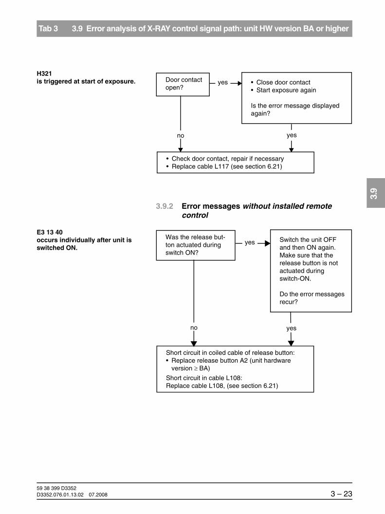
59 38 399 D3352D3352.076.01.13.02 07.2008 3 – 23
Tab 3 3.9 Error analysis of X-RAY control signal path: unit HW version BA or higher
3.9
H321is triggered at start of exposure.
3.9.2 Error messages without installed remote control
E3 13 40occurs individually after unit is switched ON.
Door contact open?
• Close door contact• Start exposure again
Is the error message displayed again?
yes
yesno
• Check door contact, repair if necessary• Replace cable L117 (see section 6.21)
yesno
Was the release but-ton actuated during switch ON?
Switch the unit OFF and then ON again. Make sure that the release button is not actuated during switch-ON.
Do the error messages recur?
yes
Short circuit in coiled cable of release button:• Replace release button A2 (unit hardware
version ≥ BA)
Short circuit in cable L108:Replace cable L108, (see section 6.21)

59 38 399 D33523 – 24 D3352.076.01.13.02 07.2008
3.9 Error analysis of X-RAY control signal path: unit HW version BA or higher
3.9.3 Error messages with and without installed remote control
Error code Description Actions required see page
E3 13 40 Short circuit in signal path between release button A2 and board DX11 during switch-ON.
Replace cable L117 or L108 6-91Replace board DX1
Replace board DX116-59
E6 13 41 Release signal missing on board DX11 at start of exposure.
Replace cable L117 or L108 6-91Replace board DX1
Replace board DX116-59
E3 13 42 Short circuit in signal path between release button A2 and board DX11 during unit operation.
Replace cable L117 or L108 6-91Replace board DX1
Replace board DX116-59

59 38 399 D3352D3352.076.01.13.02 07.2008 3 – 25
Tab 3 3.10 Check data paths/Generate test images
3.10
3.10 Check data paths/Generate test images
SIDEXIS XG must be installed and configured before you begin checking the data paths.
NOTEiFor a panoramic test image, the panoramic mode must be activated on the unit; for a ceph test image, the cephalometric mode must be activated; for a TSA test image, the TS mode must be selected (see operating instructions). Generate the test images for the different operating modes in succession.
1. Select constancy test in SIDEXIS XG: Select EXTRAS ‡ CONSTANCY TEST
The typical SIDEXIS user interface is started. Constancy test is already preset.
2. Starting the exposure mode:Click XCXP
The dialog box for selecting the X-ray device opens.
NOTEiIf no X-ray device has been configured yet in SIDEXIS XG, the password input dialog box will appear instead of the dialog box for selecting the X-ray device.
3. Select/confirm the X-ray device:Select e.g. KAMMER4 and click OK
The dialog box for selecting the test type appears on the screen.
4. Select/confirm the test type:Click SERVICE EXPOSURE
The dialog box for selecting the service exposure appears on the screen.

59 38 399 D33523 – 26 D3352.076.01.13.02 07.2008
3.10 Check data paths/Generate test images Tab 3
5. Select/confirm the service exposure:Click DIGITAL TEST PATTERN
– If several different X-ray components are available, a dialog box for selecting the X-ray component appears on the screen. In this case, select/confirm the required component.
– If only one X-ray component is available, the exposure readiness dia-log box appears on the screen and shows the status of the exposure.
NOTEiDuring operation in the service mode, the unit switches from the user mode to the PC service mode logged by the PC.
Once the exposure is completed, the unit switches back to the user mode.
6. Take an exposure:
– Press the R key on the Easypad (XGPlus) or Multipad (XG 5/3/3 PPE) to move the unit back to its starting position.
– Press the release button. Hold down the button until the exposure has been completed.
NOTEiA service message box indicates whether the generated test image is correct. Acknowledge this message with OK. The test image is displayed on the screen.T R
�

59 38 399 D3352D3352.076.01.13.02 07.2008 3 – 27
Tab 3 3.10 Check data paths/Generate test images
3.10
7. Check the images according to the following criteria:
– Tile structure of the existing segments
NOTEiTo facilitate checking, you may adjust the image contrast and brightness in SIDEXIS.
– Linear grayscale gradient
– Intensity steps clearly recognizable
– No image artifacts detectable
PAN test image CEPH test image
TSA test image

59 38 399 D33523 – 28 D3352.076.01.13.02 07.2008
3.10 Check data paths/Generate test images Tab 3

ORTHOPHOS XG 4 Adjustment

59 38 399 D33524 – 2 D3352.076.01.13.02 07.2008
Tab 4
Contents
4.1 Important information concerning adjustment .........4 – 3
4.2 Diaphragm/system adjustment menu......................4 – 5
4.3 Adjusting the panoramic X-ray unit .........................4 – 94.3.1 Pan needle phantom ............................................ 4 – 9
4.3.2 Dismantling the fixed diaphragm(XG 3 / 3 PPE only) ............................................ 4 – 10
4.3.3 Adjusting the pan sensor (XGPlus / XG 5 / 3 / 3 PPE) ................................. 4 – 12
4.3.4 Adjusting the (motorized) pan diaphragm (XGPlus / XG 5) ................................................... 4 – 22
4.3.5 Adjusting the (fixed) pan diaphragm (XG 3 / 3 PPE).................................................... 4 – 32
4.3.6 Adjusting the pan filter (XGPlus / XG 5, not for XG 3 / 3 PPE)................. 4 – 39
4.3.7 Adjusting the pan symmetry (XGPlus / 5 / 3 / 3 PPE) ....................................... 4 – 45
4.3.8 Checking and adjusting the touchscreen (XGPlus only)....................................................... 4 – 54
4.4 Adjusting the cephalometer (XGPlus/ XG 5, if ceph is installed) ........................4 – 564.4.1 Check the ring type
(for XGPlus with arm on left side only) ................ 4 – 56
4.4.2 Ceph test phantom ............................................. 4 – 57
4.4.3 Adjusting the ceph primary diaphragm............... 4 – 58
4.4.4 Adjusting the ceph fixed point of rotation ........... 4 – 68
4.4.5 Adjusting the ceph main X-ray beam direction... 4 – 81
4.4.6 Adjusting the ceph quickshot(XGPlus full version only) .................................... 4 – 90
4.4.7 Checking and adjusting the alignment of the ear plugs................................................. 4 – 100
4.5 TSA sensor adjustment(XGPlus full version only) .....................................4 – 107
4.6 Resetting the adjustment (XGPlus / 5 / 3 / 3 PPE) ........................................4 – 115

båÖäáëÜ
59 38 399 D3352D3352.076.01.13.02 07.2008 4 – 3
Tab 4 4.1 Important information concerning adjustment
4.1
4 Adjustment4.1 Important information concerning adjustment
WARNINGWhen performing the following tests, be sure to observe the radiation protection regulations applicable in your country (see operating instruc-tions).
CAUTIONBefore starting the service routines for system adjustment, make sure that no unit movements are active (especially diaphragm travels)! Otherwise the sys-tem may become inoperable in rare cases.
NOTEi“Radiation” is signaled with the message “X-RAY active!” (only for XGPlus), a beep and an X-RAY LED.
NOTEiBe sure to take screenshots of the PAN - RESET ADJUSTMENT and CEPH - RESET ADJUSTMENT menus before and after the adjustment (see sec-tion 4.6) and save them to the C:\SIDEXIS\XGRAW directory along with the time and date!
Coarse and precision adjustment using the Diaphragm/system adjustment menu in SIDEXIS XG
NOTEiThe Pan - Sensor adjustment, Pan - Diaphragm and Ceph - Fixed point of ro-tation submenus provide a coarse adjustment and a precision adjustment (precision adjustment is preset). Always try to use precision adjustment first when adjusting the unit. In most cases, previous coarse adjustment is not necessary.
With SIDEXIS Version V02.20 and higher, a message window indicates when a coarse adjustment is necessary.
Only if you cannot achieve your goal with precision adjustment, e.g. if the exposed area is completely outside the image field, should you perform a coarse and then a precision adjustment.
If a coarse adjustment proves necessary, deactivate the PRECISION ADJUSTMENT check box and follow the adjustment steps de-scribed in the present chapter to perform a coarse adjustment.
The steps and correction procedure required for coarse adjustment are iden-tical to those for precision adjustment. The only difference between the two modes is the size of the image area considered. Furthermore, there are fewer auxiliary lines in the coarse adjustment mode.

59 38 399 D33524 – 4 D3352.076.01.13.02 07.2008
4.1 Important information concerning adjustment Tabs 4
Default values in the Diaphragm/system adjustment menu in SIDEXIS XG
During the adjustment, the default adjustment values are displayed in the text boxes of the Diaphragm/system adjustment menu.
First perform the adjustment with these default values. If you do not attain the desired result via this automatic adjustment, you should determine the adjust-ment values manually by measuring the exposure with the SIDEXIS measur-ing ruler and then overwrite the default values in the menu.
This procedure is described in the following sections.
Return ring travel with unit SW version V02.27 and higher
Starting with unit version V02.27, return ring travel is automatically performed during service operation (during adjustment). Actuation of the R key before or after each adjustment exposure (as described in the following chapters) can thus be omitted.
NOTEiIt is not possible to select a new exposure during the return ring travel (incl. resetting of the actuators)!If a selection is made during this period, the error message "It is not possible to set the adjustment values at this time" or “No exposure can be taken" appears. Acknowledge the error message and wait until the return ring travel has been completed.

båÖäáëÜ
59 38 399 D3352D3352.076.01.13.02 07.2008 4 – 5
Tab 4 4.2 Diaphragm/system adjustment menu
4.2
4.2 Diaphragm/system adjustment menu
Menu: Diaphragm/system adjustment
The DIAPHRAGM/SYSTEM ADJUSTMENT menu guides you through the adjustment of the panoramic unit and the cephalometer. This service routine is started from SIDEXIS XG:
EXTRAS CONSTANCY TEST XCXP SELECT X-RAY DEVICE SERVICE EXPOSURE DIAPHRAGM/SYSTEM ADJUSTMENT
NOTEiThe DIAPHRAGM/SYSTEM ADJUSTMENT menu is password-protected. As password, enter the first four digits of the current system date (PC) in reverse order.
Example: On 05/30/2004, the service password is 5003
NOTEiWhen you open the DIAPHRAGM/SYSTEM ADJUSTMENT menu, the unit switches from the user mode to the PC service mode logged by the PC.
ORTHOPHOS XGPlus / Ceph:This mode is indicated by the PC service screen displayed on the Easypad.In the PC service mode, the control options that are available on the Easypad are determined by SIDEXIS and the currently selected service routine. Gen-eral control of the unit by means of the Easypad (as in the user mode) is not possible in this mode.
ORTHOPHOS XG 5 / Ceph bzw. XG 3 / 3 PPE:This mode is indicated by the SERVICE reading on the Multipad.In the PC service mode, the Multipad control options are determined by SIDEXIS and the currently selected service routine. General control of the unit by means of the Multipad (as in the user mode) is not possible in this mode.
XGPlus
XG 5 / 3 / 3 PPE
SERVICE

59 38 399 D33524 – 6 D3352.076.01.13.02 07.2008
4.2 Diaphragm/system adjustment menu Tabs 4
NOTEiThe tabs of the DIAPHRAGM/SYSTEM ADJUSTMENT menu and several check-boxes corresponding to the system version are present and activated in the software (i.e. visible) depending on the system configuration. The following description of the menus is always based in the maximum configuration of the comfort class (XGPlus).
The DIAPHRAGM/SYSTEM ADJUSTMENT menu has 12 submenus:
Pan - Sensor adjustment (XGPlu s/ XG 5 / 3 / 3 PPE)
Pan - Diaphragm or Pan - Fixed Diagphragm (XGPlus / XG 5 or XG 3 / 3 PPE)
Pan - Filter (XGPlus / XG 5)
Pan - Symmetry (XGPlus / XG 5/ 3 / 3 PPE)
Ceph - Primary diaphragm (XGPlus / XG 5)
Ceph - Fixed point of rotation (XGPlus / XG 5)
Ceph - Main X-ray beam direction (XGPlus / XG 5)
Ceph quickshot (XGPlus full version only)
TSA sensor (XGPlus full version only)
Pan - Reset adjustment (XGPlus / XG 5 / 3 / 3 PPE)
Ceph - Reset adjustment (XGPlus / XG 5)
Sirona Service Sheet (for internal use only)
You can change between the individual submenus by clicking the menu tabs with the mouse. To quit the DIAPHRAGM/SYSTEM ADJUSTMENT menu, click CANCEL.
The following submenus are required for pan adjustment (XGPlus, XG 5 / 3 / 3 PPE):
Pan - Sensor adjustment: see page 4-12
Pan - Diaphragm or Pan - Fixed diaphragm: see page 4-22 (XGPlus / XG 5) or page 4-32 (XG 3 / 3 PPE)
Pan - Filter (not for XG 3 / 3 PPE): see page 4-39
Pan - Symmetry: see page 4-45
For the ceph adjustment (with XGPlus and XG 5) you require the following submenu:
Ceph - Primary diaphragm (see page 4-58)
Ceph - Fixed point of rotation (see page 4-68)
Ceph - Main X-ray beam direction (see page 4-81)
Ceph quickshot (XGPlus full version only, see page 4-90)
For the TSA adjustment (XGPlus full version only) you need the submenu:
TSA - Sensor (see page 4-107)

båÖäáëÜ
59 38 399 D3352D3352.076.01.13.02 07.2008 4 – 7
Tab 4 4.2 Diaphragm/system adjustment menu
4.2
Direction of displacement of the exposed image area/Information on the pictographs in the system adjustment menu
The Pan - Sensor adjustment, Pan - Filter and Pan - Symmetry submenus each contain a pictographic representation of the expected adjustment image to help you perform the adjustment. The shifting directions indicated by the plus and minus signs located below and next to the pictograph refer to shifting of the exposed image area in the direction of the stationary auxiliary lines (see the following example):
In the example the exposed image area is offset to the left by the value Sx and upward by the value Sy. In order to shift the image area so that it comes to lie inside the auxiliary lines, you must enter …
Sx (shift to the right) with a positive sign
Sy (shift downward) with a negative sign
in the text boxes of the submenu.
NOTEiFor system version XG 3/3 PPE: The pan fixed diaphragm of the XG 3/3 PPE system version cannot be adjusted via the software, i.e. the pan fixed diaphragm must be adjusted by moving it mechanically (see section 4.3.5).
Generally speaking, the exposed image area must always be shifted toward the auxiliary lines:
- Shift to the right or upward: Enter the value(measured offset from the auxiliary line) with a positive sign (XGPlus / XG 5) or mechanicallyshift the diaphragm to to the right or upward (XG 3 / 3 PPE)
– Shift to the left or downward: Enter the value (measured offset from the auxiliary line) with a negative sign (XGPlus / XG 5) or mechanicallyshift the diaphragm to the left or downward (XG 3 / 3 PPE)
Sx
Sy+
- +-

59 38 399 D33524 – 8 D3352.076.01.13.02 07.2008
4.2 Diaphragm/system adjustment menu Tabs 4
Displays during the adjustment procedure
During the adjustment procedure, different service routines are started from SIDEXIS; they are displayed one after the other on the Easypad touchscreen (XGPlus) or the Multipad display (XG 5 / 3 / 3 PPE).
...ORTHOPHOS XGPlus / Ceph
In addition to the relevant parameters, the Easypad touchscreen shows the service routines which are currently executed as well as different help mes-sages (see section 2.1).
...ORTHOPHOS XG 5 / Ceph or XG 3 / 3 PPE
In addition to the relevant parameters, the single-line display of the Multipad shows different help messages (see section 2.1).
Help messages during the adjustment procedure
The most frequent help and status displays during adjustment are the follow-ing:
Help messages H301: Move panoramic unit into starting position ‡ Press the R key
H401: Plug the sensor into the PAN slot
H402: Plug the sensor into the CEPH slot
H406: Move cephalometer into starting position ‡ Press the R key
Status displays ORTHOPHOS is ready for exposure
Exposure not possible
Wait until ORTHOPHOS is ready
ORTHOPHOS is ready in XX s
X-RAY active!
NOTEiIf any other help or error messages are displayed during adjustment, please follow the instructions provided in chapter 2.
R
R

båÖäáëÜ
59 38 399 D3352D3352.076.01.13.02 07.2008 4 – 9
Tab 4 4.3 Adjusting the panoramic X-ray unit
4.3
4.3 Adjusting the panoramic X-ray unit
4.3.1 Pan needle phantom
Accessory: Pan needle phantom
In order to perform the pan sensor adjustment and the symmetry adjust-ment you must insert the needle phantom (A) in the bite block holder of the panoramic X-ray unit.
The needle phantom must be removed from the bite block holder for the PANdiaphragm and for the TSA adjustment.
CAUTIONIt is essential that the needle phantom is removed from bite block holder of the panoramic X-ray unit again before a Ceph exposure is taken; otherwise the phantom may collide with the sensor.
NOTEiWhen fitting the needle phantom, make sure that it is correctly oriented. For the adjustment of the X-ray unit, the phantom must be fitted in such a way that the needles point upward.
A
Needles onTop side

59 38 399 D33524 – 10 D3352.076.01.13.02 07.2008
4.3 Adjusting the panoramic X-ray unit Tabs 4
4.3.2 Dismantling the fixed diaphragm(XG 3 / 3 PPE only)
1.
2.
B B B B
Version delivered until approx. end of 2006 Version delivered after approx. end of 2007

båÖäáëÜ
59 38 399 D3352D3352.076.01.13.02 07.2008 4 – 11
Tab 4 4.3 Adjusting the panoramic X-ray unit
4.3
The fixed diaphragm must be dismantled in order to perform the sensor adjustment of the ORTHOPHOS XG 3/3 PPE X-ray unit. To do this, proceed as follows:
1. Remove the covers:
– Tube assembly, front
– Tube assembly, rear
2. Loosen the two screws (B) (approx. 2-3 turns) and push the fixed diaphragm upward.
Assemble by following the same procedure in reverse order.
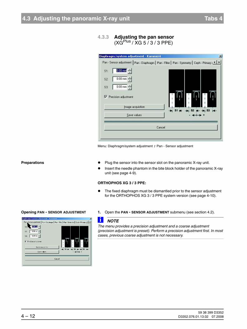
59 38 399 D33524 – 12 D3352.076.01.13.02 07.2008
4.3 Adjusting the panoramic X-ray unit Tabs 4
4.3.3 Adjusting the pan sensor (XGPlus / XG 5 / 3 / 3 PPE)
Menu: Diaphragm/system adjustment ‡ Pan - Sensor adjustment
Preparations Plug the sensor into the sensor slot on the panoramic X-ray unit.
Insert the needle phantom in the bite block holder of the panoramic X-ray unit (see page 4-9).
ORTHOPHOS XG 3 / 3 PPE:
The fixed diaphragm must be dismantled prior to the sensor adjustment for the ORTHOPHOS XG 3 / 3 PPE system version (see page 4-10).
Opening PAN - SENSOR ADJUSTMENT 1. Open the PAN - SENSOR ADJUSTMENT submenu (see section 4.2).
NOTEiThe menu provides a precision adjustment and a coarse adjustment (precision adjustment is preset). Perform a precision adjustment first. In most cases, previous coarse adjustment is not necessary.

båÖäáëÜ
59 38 399 D3352D3352.076.01.13.02 07.2008 4 – 13
Tab 4 4.3 Adjusting the panoramic X-ray unit
4.3
Making the unit ready for exposure: 2. Make SIDEXIS XG ready for exposure:
Click IMAGE ACQUISITION
SIDEXIS screen The exposure dialog box showing the exposure status appears in SIDEXIS.
XGPlus: Display on the Easypad The Easypad touchscreen shows service routine S010.1 as well as the related exposure parameters.
XG 5 / 3 / 3 PPE: Display on the Multipad The single-line display of the Multipad shows the exposure parameters of service routine S010.1.
1
2
3
+- 60 kV/3 mA
0.60 s
S10
1
1 2 3
60/3____0.60____

59 38 399 D33524 – 14 D3352.076.01.13.02 07.2008
4.3 Adjusting the panoramic X-ray unit Tabs 4
Starting the exposure 3. Take an exposure (60kV/3mA; 0.60 s):
– Press the R key to move the unit back to the starting position.
XGPlus:
The procedure is completed when the status message “ORTHOPHOS is ready for exposure“ appears on the touchscreen and the exposure parameters of service routine S010.1 are displayed.
XG5 / 3 / 3 PPE:
The procedure is completed when the exposure parameters of service routine S010.1 are displayed and the progress indicator disappears.
– Press the release button. Hold down the release button until image ac-quisition is completed and the preview image appears in the exposure dialog box.
Evaluating the X-ray image 4. Evaluate the X-ray image:
– The three needle images must lie in the center of the exposed ar-eas and inside the auxiliary lines (A).
NOTEiIf these criteria are not fulfilled (B), the pan sensor must be adjusted.
R
WAIT!UNTIL UNIT IS IN STARTING POSITION
Adjustment: ok
A B
Adjustment: not ok

båÖäáëÜ
59 38 399 D3352D3352.076.01.13.02 07.2008 4 – 15
Tab 4 4.3 Adjusting the panoramic X-ray unit
4.3
Coarse or precision adjustment? Sensor adjustment can usually be performed directly via precision adjust-ment. Only in exceptional cases, e.g. if one or several needles are completely outside of the image field C in an image acquired with the PRECISION ADJUSTMENT presetting, is it necessary to perform a coarse adjustment prior to precision adjustment D. To do this, deactivate the PRECISION ADJUST-MENT check box (see page 4-3) and then perform a coarse adjustment pro-ceeding in the same way as for precision adjustment. The only difference between coarse and precision adjustment is the size of the image area con-sidered. Furthermore, there are fewer auxiliary lines in the coarse adjustment mode.
X-ray image with unadjusted pan sensor: Alternatively with precision adjustment setting (C) and coarse adjustment setting (D)
On the X-ray image with coarse adjustment (D), the center pin is just barely visible on the left margin of the image field in the middle. Even in this extreme case, an adjustment would still be possible.
NOTEiWith SIDEXIS SW V01.45 and higher, a message window indicates whether a coarse adjustment is required on completion of the precision exposure.
C D

59 38 399 D33524 – 16 D3352.076.01.13.02 07.2008
4.3 Adjusting the panoramic X-ray unit Tabs 4
Making the unit ready for exposureNOTEi
The default values for S1, S2 and S3 were automatically determined by SIDEXIS based on the exposure and entered in the text boxes of the menu.
For manual adjustment, the values displayed at this position in the text boxes of the menu can be overwritten (see page 4-21).
First continue with the automatic adjustment. Manual determination of the ad-justment values is required only if you fail to reach your goal via automatic ad-justment (see page 4-20).
5. Make SIDEXIS XG ready for exposure:
Click IMAGE ACQUISITION
The PAN - SENSOR ADJUSTMENT dialog box appears in SIDEXIS.
The dialog box suggests a value Lx for the mechanical adjustment of the sensor.
If the suggested value is greater than ±0.5mm, then perform a mechani-cal adjustment of the sensor.
Moving the sensor 6. Adjust the sensor:
NOTEiPositive sign = moves the sensor to the rightNegative sign = moves the sensor to the left
– Mark the position of the sensor.
– Loosen the three screws A (approx. 2 turns, do not unscrew fully)
– Move the sensor to the left or right by the displayed value Lx.
– Tighten screws A again.
AA
A
+-
System version 1: Fixed sensor holder
A AA
Hardware version 2: motor-driven sensor holder
+-
(XGPlus, TSA only)

båÖäáëÜ
59 38 399 D3352D3352.076.01.13.02 07.2008 4 – 17
Tab 4 4.3 Adjusting the panoramic X-ray unit
4.3
Making the unit ready for exposure 7. Confirm the sensor adjustment and make SIDEXIS XG ready for exposure:
Click OK
SIDEXIS screen The exposure dialog box showing the exposure status appears in SIDEXIS.
XGPlus: Display on the Easypad The Easypad touchscreen shows service routine S010.1 as well as the related exposure parameters.
XG 5 / 3 / 3 PPE: Display on the Multipad The single-line display of the Multipad shows the exposure parameters of service routine S010.1.
1
2
3
+- 60 kV/3 mA
0.60 s
S10
1
1 2 3
60/3____0.60____

59 38 399 D33524 – 18 D3352.076.01.13.02 07.2008
4.3 Adjusting the panoramic X-ray unit Tabs 4
Starting the exposure 8. Take an exposure (60kV/3mA; 0.60 s):
– Press the R key to move the unit back to the starting position.
XGPlus:
The procedure is completed when the status message “ORTHOPHOS is ready for exposure“ appears on the touchscreen and the exposure parameters of service routine S010.1 are displayed.
XG5 / 3 / 3 PPE:
The procedure is completed when the exposure parameters of service routine S010.1 are displayed and the progress indicator disappears.
– Press the release button. Hold down the release button until image ac-quisition is completed and the preview image appears in the exposure dialog box.
Evaluating the X-ray image 9. Evaluate the X-ray image:
– The three needle images must lie in the center of the exposed ar-eas and inside the auxiliary lines (A).
NOTEiIf these criteria are not yet fulfilled, repeat the adjustment procedure starting with step 5.
R
WAIT!UNTIL UNIT IS IN STARTING POSITION
Adjustment: ok
A

båÖäáëÜ
59 38 399 D3352D3352.076.01.13.02 07.2008 4 – 19
Tab 4 4.3 Adjusting the panoramic X-ray unit
4.3
NOTEiIf you do not reach your goal via automatic adjustment, repeat the adjustment procedure with manually determined adjustment values (see page 4-20).
Saving the values 10. If the image is identical to the ideal image (A), save the values:
Click SAVE VALUES
NOTEiIn SIDEXIS versions higher than V01.50. the values for S1 - S3 in the PAN - SENSOR ADJUSTMENT submenu are setequal to zero with a correct adjust-ment, i.e. if they are within the permissible tolerance. For versions < V01.50, the values in the text boxes may deviate slightly from zero even with a correct adjustment.
Remove the needle phantom from the bite block holder of the unit.
ORTHOPHOS XG 3 / 3 PPE:
Reattach the fixed diaphragm (see page 4-10).
Go on to the next adjustment step.

59 38 399 D33524 – 20 D3352.076.01.13.02 07.2008
4.3 Adjusting the panoramic X-ray unit Tabs 4
Manual adjustment of the PAN sensor
The manual adjustment procedure is similar to the one for automatic adjust-ment. The only difference is that the default adjustment values automatically determined by SIDEXIS are overwritten by manually determined adjustment values in the PAN - SENSOR ADJUSTMENT submenu.
Determining the adjustment values for S1, S2 and S3 manually
Measure distances S1, S2 and S3 with the SIDEXIS measuring ruler.
NOTEiTo measure S1, S2 and S3, estimate the horizontal center position of the dis-played needles. Measure in the lower area of the needles if possible, since they may have been bent slightly after repeated use.
Tip: To facilitate the measuring procedure, you can color the image in SIDEX-IS (see also SIDEXIS Operator’s Manual).
S1 S2 S3

båÖäáëÜ
59 38 399 D3352D3352.076.01.13.02 07.2008 4 – 21
Tab 4 4.3 Adjusting the panoramic X-ray unit
4.3
Overwriting default values for S1, S2 and S3
Overwrite the default values for S1, S2 and S3 with the measured values in the text boxes of the PAN - SENSOR ADJUSTMENT submenu.
NOTEiFor information on the direction of displacement (input of +/- sign in the menu) see page 4-7. Use points as decimal separators!
Proceed with step 5 of the adjustment procedure.

59 38 399 D33524 – 22 D3352.076.01.13.02 07.2008
4.3 Adjusting the panoramic X-ray unit Tabs 4
4.3.4 Adjusting the (motorized) pan diaphragm (XGPlus / XG 5)
Menu: Diaphragm/system adjustment ‡ Pan - Diaphragm
Preparations Remove the needle phantom from the bite block holder of the panoramic X-ray unit (see page 4-9).
NOTEiIf a message window indicating that the diaphragm is tilted appears during the pan diaphragm adjustment, this means that the primary diaphragm is me-chanically maladjusted in the vertical axis. In this case, contact the Sirona Customer Service Center:
Opening PAN - DIAPHRAGM 1. Go to the PAN - DIAPHRAGM submenu.
NOTEiThe menu provides a precision adjustment and a coarse adjustment (precision adjustment is preset). Perform a precision adjustment first. In most cases, previous coarse adjustment is not necessary.

båÖäáëÜ
59 38 399 D3352D3352.076.01.13.02 07.2008 4 – 23
Tab 4 4.3 Adjusting the panoramic X-ray unit
4.3
Making the unit ready for exposure 2. Make SIDEXIS XG ready for exposure:
Click IMAGE ACQUISITION
SIDEXIS screen The exposure dialog box showing the exposure status appears in SIDEXIS.
XGPlus: Display on the Easypad The Easypad touchscreen shows service routine S030.2 as well as the related exposure parameters.
XG 5: Display on the Multipad The single-line display of the Multipad shows the exposure parameters of service routine S030.2.
1
2
3
+- 60 kV/3 mA
0.20 s
S30
2
1 2 3
60/3____0.20____

59 38 399 D33524 – 24 D3352.076.01.13.02 07.2008
4.3 Adjusting the panoramic X-ray unit Tabs 4
Starting the exposure 3. Take an exposure (60 kV/3 mA; 0.20 s):
– Press the R key to move the unit back to the starting position.
XGPlus:
The procedure is completed when the status message “ORTHOPHOS is ready for exposure“ appears on the touchscreen and the exposure parameters of service routine S030.2 are displayed.
XG5:
The procedure is completed when the exposure parameters of service routine S030.2 are displayed and the progress indicator disappears.
– Press the release button. Hold down the release button until image ac-quisition is completed and the preview image appears in the exposure dialog box.
R
WAIT!UNTIL UNIT IS IN STARTING POSITION

båÖäáëÜ
59 38 399 D3352D3352.076.01.13.02 07.2008 4 – 25
Tab 4 4.3 Adjusting the panoramic X-ray unit
4.3
Evaluating the X-ray image 4. Evaluate the X-ray image:
– The exposed diaphragm area must lie horizontally centered in the image field as well as inside the superimposed auxiliary lines (A).
– A white border surrounding the image on all sides must be visible. The maximum density must lie in the center of the diaphragm area (A).
NOTEiIf these criteria are not fulfilled (B), the pan diaphragm must be adjusted.
Adjustment: ok
B
Adjustment: not ok
A

59 38 399 D33524 – 26 D3352.076.01.13.02 07.2008
4.3 Adjusting the panoramic X-ray unit Tabs 4
Coarse or precision adjustment? In most cases, the diaphragm can be adjusted using precision adjustment from the start (see step 5 onward). Only in exceptional cases, e.g. if the exposed image area is completely outside the image field C in an image acquired with PRECISION ADJUSTMENT setting, is it necessary to perform a coarse adjustment prior to precision adjustment D. To do this, deactivate the PRECISION ADJUSTMENT check box (see page 4-3) and then perform a coarse adjustment proceeding in the same way as for precision adjustment. The only difference between coarse and precision adjustment is the size of the image area considered. Furthermore, there are fewer auxiliary lines in the coarse adjustment mode.
X-ray image with unadjusted pan diaphragm: Alternatively with precision adjustment setting (C) and coarse adjustment setting (D)
On the X-ray image with coarse adjustment D, the exposed area is just barely visible at the right margin of the image field. Even in this extreme case, an adjustment would still be possible.
NOTEiWith SIDEXIS SW V01.45 and higher, a message window indicates whether a coarse adjustment is required on completion of the precision exposure.
NOTEiWhen the diaphragm is correctly adjust-ed, a course adjustment does not produce a meaningful image, since no surrounding border can be seen in this case (similar to image C).
C D

båÖäáëÜ
59 38 399 D3352D3352.076.01.13.02 07.2008 4 – 27
Tab 4 4.3 Adjusting the panoramic X-ray unit
4.3
Making the unit ready for exposureNOTEi
The default values for Sx and Sy were automatically determined by SIDEXIS based on the exposure and entered in the text boxes of the menu.
For manual adjustment, the values displayed at this position in the text boxes of the menu can be overwritten (see page 4-31).
First continue with the automatic adjustment. Manual determination of the ad-justment values is required only if you fail to reach your goal via automatic ad-justment (see page 4-30).
5. Make SIDEXIS XG ready for exposure:
Click IMAGE ACQUISITION
SIDEXIS screen The exposure dialog box showing the exposure status appears in SIDEXIS.
XGPlus: Display on the Easypad The Easypad touchscreen shows service routine S030.2 as well as the related exposure parameters.
XG 5: Display on the Multipad The single-line display of the Multipad shows the exposure parameters of service routine S030.2.
1
2
3
+- 60 kV/3 mA
0.20 s
S30
2
1 2 3
60/3____0.20____

59 38 399 D33524 – 28 D3352.076.01.13.02 07.2008
4.3 Adjusting the panoramic X-ray unit Tabs 4
Starting the exposure 6. Take an exposure (60 kV/3 mA; 0.20 s):
– Press the R key to move the unit back to the starting position.
XGPlus:
The procedure is completed when the status message “ORTHOPHOS is ready for exposure“ appears on the touchscreen and the exposure parameters of service routine S030.2 are displayed.
XG5:
The procedure is completed when the exposure parameters of service routine S030.2 are displayed and the progress indicator disappears.
– Press the release button. Hold down the release button until image ac-quisition is completed and the preview image appears in the exposure dialog box.
Evaluating the X-ray image 7. Evaluate the X-ray image:
R
WAIT!UNTIL UNIT IS IN STARTING POSITION
Adjustment: ok
A

båÖäáëÜ
59 38 399 D3352D3352.076.01.13.02 07.2008 4 – 29
Tab 4 4.3 Adjusting the panoramic X-ray unit
4.3
– The exposed diaphragm area must lie horizontally centered in the image field as well as inside the superimposed auxiliary lines (A).
– A white border surrounding the image on all sides must be visible. The maximum density must lie in the center of the diaphragm area (A).
NOTEiIf these criteria are not yet fulfilled, repeat the adjustment procedure starting with step 5.
NOTEiIf you do not reach your goal via automatic adjustment, repeat the adjustment procedure with manually determined adjustment values (see page 4-30).
NOTEiIf a message window indicating the need to take an additional X-ray exposure opens at this point, repeat the adjustment procedure starting with item 5. This is necessary even if the X-ray exposure which has been taken is already within the tolerance limits. This additional exposure ensures that the new diaphragm gap width offset is also correctly adjusted.
Saving the values 8. If the image is identical to the ideal image (A), save the values:
Click SAVE VALUES
NOTEiIn SIDEXIS versions higher than V01.50. the values for Sx and Sy in the PAN - DIAPHRAGM submenu are setequal to zero with a correct adjustment, i.e. if they are within the permissible tolerance. For versions < V01.50, the values in the text boxes may deviate slightly from zero even with a correct adjustment.
Go on to the next adjustment step.

59 38 399 D33524 – 30 D3352.076.01.13.02 07.2008
4.3 Adjusting the panoramic X-ray unit Tabs 4
Manual adjustment of the PAN diaphragm
The manual adjustment procedure is similar to the one for automatic adjust-ment. The only difference is that the default adjustment values automatically determined by SIDEXIS are overwritten by manually determined adjustment values in the PAN - DIAPHRAGM submenu.
Determining adjustment values for Sx and Sy manually
Measure distances Sx and Sy with the SIDEXIS measuring ruler.
NOTEiTip: To facilitate the measuring procedure, you can color the image in SIDEX-IS (see also SIDEXIS Operator’s Manual).
S2
Sy
Sx
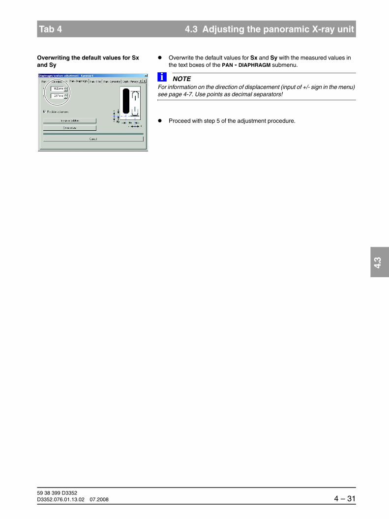
båÖäáëÜ
59 38 399 D3352D3352.076.01.13.02 07.2008 4 – 31
Tab 4 4.3 Adjusting the panoramic X-ray unit
4.3
Overwriting the default values for Sx and Sy
Overwrite the default values for Sx and Sy with the measured values in the text boxes of the PAN - DIAPHRAGM submenu.
NOTEiFor information on the direction of displacement (input of +/- sign in the menu) see page 4-7. Use points as decimal separators!
Proceed with step 5 of the adjustment procedure.
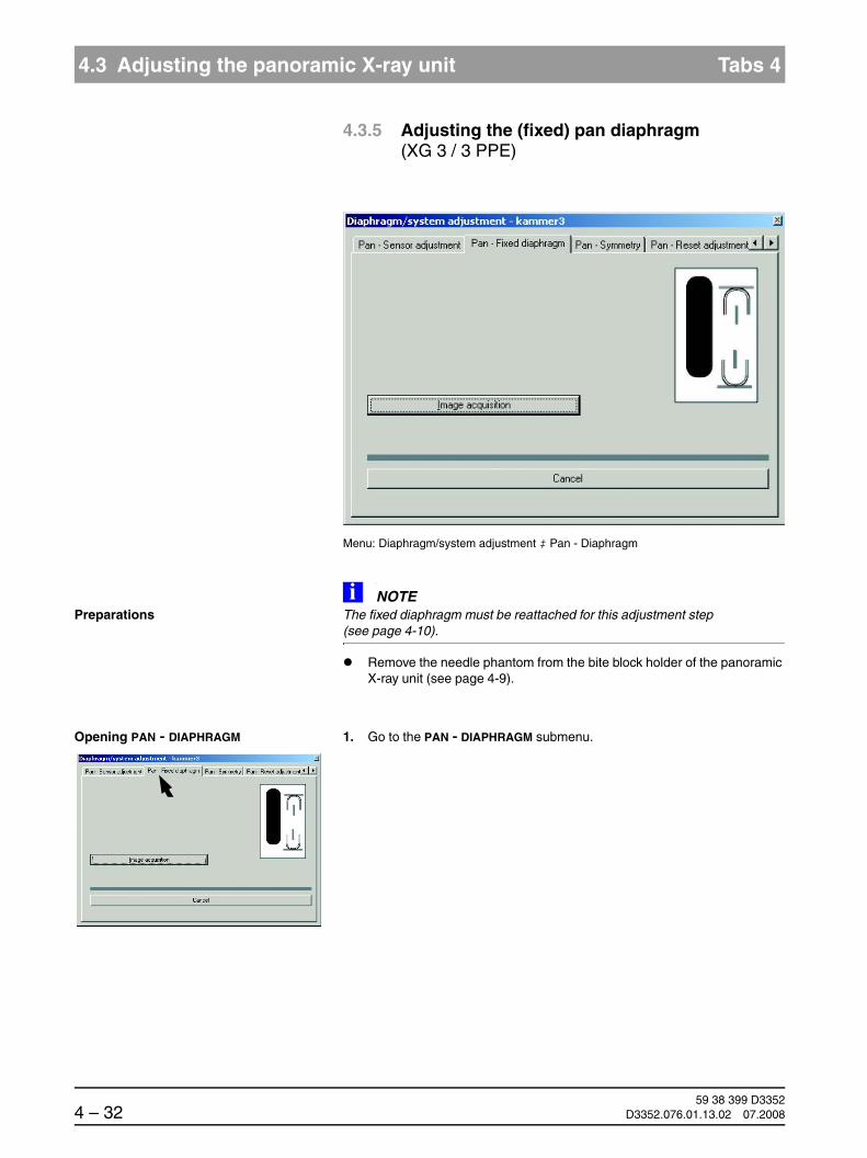
59 38 399 D33524 – 32 D3352.076.01.13.02 07.2008
4.3 Adjusting the panoramic X-ray unit Tabs 4
4.3.5 Adjusting the (fixed) pan diaphragm (XG 3 / 3 PPE)
Menu: Diaphragm/system adjustment ‡ Pan - Diaphragm
PreparationsNOTEi
The fixed diaphragm must be reattached for this adjustment step (see page 4-10).
Remove the needle phantom from the bite block holder of the panoramic X-ray unit (see page 4-9).
Opening PAN - DIAPHRAGM 1. Go to the PAN - DIAPHRAGM submenu.
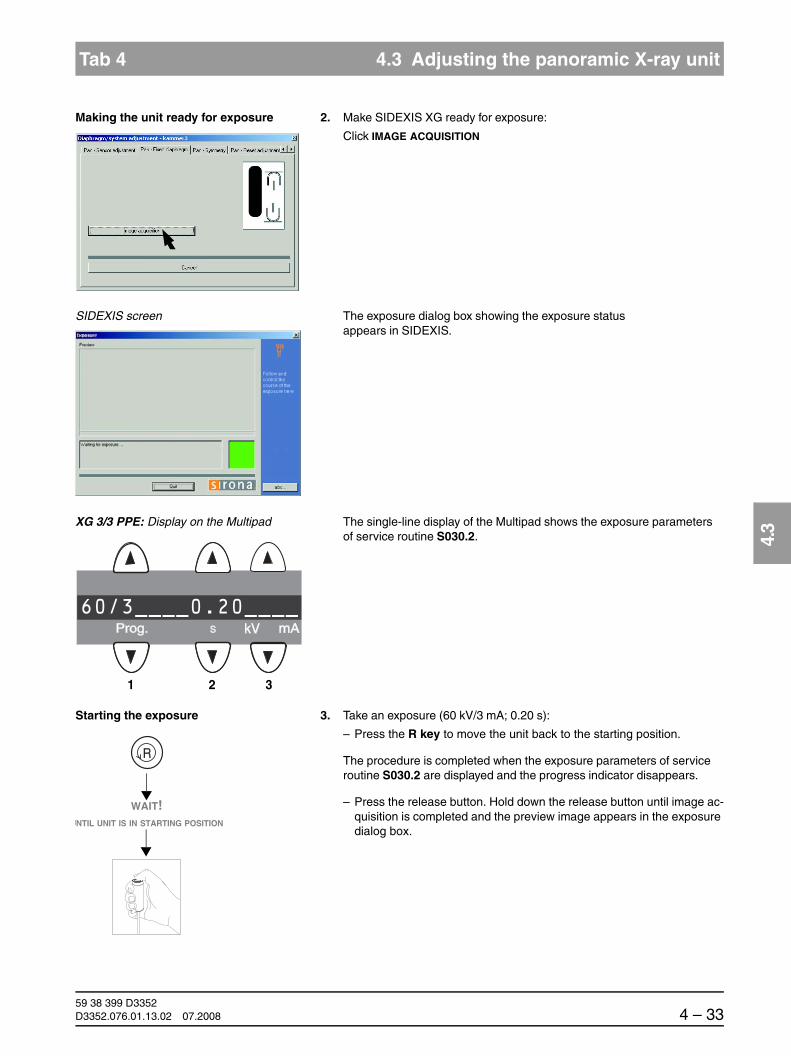
båÖäáëÜ
59 38 399 D3352D3352.076.01.13.02 07.2008 4 – 33
Tab 4 4.3 Adjusting the panoramic X-ray unit
4.3
Making the unit ready for exposure 2. Make SIDEXIS XG ready for exposure:
Click IMAGE ACQUISITION
SIDEXIS screen The exposure dialog box showing the exposure status appears in SIDEXIS.
XG 3/3 PPE: Display on the Multipad The single-line display of the Multipad shows the exposure parameters of service routine S030.2.
Starting the exposure 3. Take an exposure (60 kV/3 mA; 0.20 s):
– Press the R key to move the unit back to the starting position.
The procedure is completed when the exposure parameters of service routine S030.2 are displayed and the progress indicator disappears.
– Press the release button. Hold down the release button until image ac-quisition is completed and the preview image appears in the exposure dialog box.
1 2 3
60/3____0.20____
R
WAIT!UNTIL UNIT IS IN STARTING POSITION

59 38 399 D33524 – 34 D3352.076.01.13.02 07.2008
4.3 Adjusting the panoramic X-ray unit Tabs 4
Evaluating the X-ray image 4. Evaluate the X-ray image:
– The exposed diaphragm area must lie horizontally centered in the image field as well as inside the superimposed auxiliary lines (A).
– A white border surrounding the image on all sides must be visible. The maximum density must lie in the center of the diaphragm area (A).
NOTEiIf these criteria are not fulfilled (B), the pan diaphragm must be adjusted.
The adjustment of the pan fixed diaphragm (XG 3/3 PPE) must be performed mechanically, i.e. this cannot be done via SIDEXIS!
Adjustment: ok
B
Adjustment: not ok
A

båÖäáëÜ
59 38 399 D3352D3352.076.01.13.02 07.2008 4 – 35
Tab 4 4.3 Adjusting the panoramic X-ray unit
4.3
Measuring adjustment values in SIDEXIS
Measure distances Sx and Sy with the SIDEXIS measuring ruler.
NOTEiMeasured value x 0.27 (mm) = mechanical adjustment value of diaphragm (mm)
NOTEiTip: To facilitate the measuring procedure, you can also color the image in SI-DEXIS (see SIDEXIS Operator’s Manual).
S2
Sy
Sx

59 38 399 D33524 – 36 D3352.076.01.13.02 07.2008
4.3 Adjusting the panoramic X-ray unit Tabs 4
Mechanical adjustment of the fixed diaphragm
Remove the covers (see also page 1-50):
– Tube assembly, front
– Tube assembly, rear
Loosen both screws (A) slightly(approx. 1 turn).
Adjust the diaphragm position via eccentric screws B (horizontal adjust-ment) and C (vertical adjustment).
– CW rotation of the eccentric screws:movement of the diaphragm to the right or upward
– CCW rotation of the eccentric screws:movement of the diaphragm to the left or downward
NOTEiTo measure the shift, refer to the gap between the plastic support and the lead diaphragm (D).
Tighten screws A again.
D
Plasticsupport
Lead diaphragm
D
Version delivered until approx. end of 2006 Version delivered after approx. end of 2007

båÖäáëÜ
59 38 399 D3352D3352.076.01.13.02 07.2008 4 – 37
Tab 4 4.3 Adjusting the panoramic X-ray unit
4.3
Making the unit ready for exposure 5. Make SIDEXIS XG ready for exposure:
Click IMAGE ACQUISITION
SIDEXIS screen The exposure dialog box showing the exposure status appears in SIDEXIS.
XG 3 / 3 PPE: Display on the Multipad The single-line display of the Multipad shows the exposure parameters of service routine S030.2.
Starting the exposure 6. Take an exposure (60 kV/3 mA; 0.20 s):
– Press the R key to move the unit back to the starting position.
The procedure is completed when the exposure parameters of service routine S030.2 are displayed and the progress indicator disappears.
– Press the release button. Hold down the release button until image ac-quisition is completed and the preview image appears in the exposure dialog box.
1 2 3
60/3____0.20____
R
WAIT!UNTIL UNIT IS IN STARTING POSITION

59 38 399 D33524 – 38 D3352.076.01.13.02 07.2008
4.3 Adjusting the panoramic X-ray unit Tabs 4
Evaluating the X-ray image 7. Evaluate the X-ray image:
– The exposed diaphragm area must lie horizontally centered in the image field as well as inside the superimposed auxiliary lines (A).
– A white border surrounding the image on all sides must be visible. The maximum density must lie in the center of the diaphragm area (A).
NOTEiIf these criteria have not yet been fulfilled, repeat the mechanical adjustment of the diaphragm (see page 4-35) and then continue with step 5.
If the image is identical to the ideal image (A), then the adjustment of the diaphragm is completed:
Reattach the covers.
Go on to the next adjustment step.
Adjustment: ok
A

båÖäáëÜ
59 38 399 D3352D3352.076.01.13.02 07.2008 4 – 39
Tab 4 4.3 Adjusting the panoramic X-ray unit
4.3
4.3.6 Adjusting the pan filter (XGPlus / XG 5, not for XG 3 / 3 PPE)
Menu: Diaphragm/system adjustment ‡ Pan - Filter
Opening PAN - FILTER 1. Go to the PAN - FILTER submenu.
Making the unit ready for exposure 2. Make SIDEXIS XG ready for exposure:
Click IMAGE ACQUISITION

59 38 399 D33524 – 40 D3352.076.01.13.02 07.2008
4.3 Adjusting the panoramic X-ray unit Tabs 4
SIDEXIS screen The exposure dialog box showing the exposure status appears in SIDEXIS.
XGPlus: Display on the Easypad The Easypad touchscreen shows service routine S030.3 as well as the related exposure parameters.
XG 5: Display on the Multipad The single-line display of the Multipad shows the exposure parameters of service routine S030.3.
Starting the exposure 3. Take an exposure (60 kV/3 mA; 0.20 s):
– Press the R key to move the unit back to the starting position.
XGPlus:
The procedure is completed when the status message “ORTHOPHOS is ready for exposure“ appears on the touchscreen and the exposure parameters of service routine S030.3 are displayed.
XG5:
The procedure is completed when the exposure parameters of service routine S030.3 are displayed and the progress indicator disappears.
– Press the release button. Hold down the release button until image ac-quisition is completed and the preview image appears in the exposure dialog box.
1
2
3
+- 60 kV/3 mA
0.20 s
S30
3
1 2 3
60/3____0.20____
R
WAIT!UNTIL UNIT IS IN STARTING POSITION

båÖäáëÜ
59 38 399 D3352D3352.076.01.13.02 07.2008 4 – 41
Tab 4 4.3 Adjusting the panoramic X-ray unit
4.3
Evaluating the X-ray image 4. Evaluate the X-ray image:
– The superimposed filter must cover one half of the diaphragm (A).
NOTEiIf these criteria are not fulfilled (B), the pan filter must be adjusted.
Making the unit ready for exposureNOTEi
The default value for Fx was automatically determined by SIDEXIS based on the exposure and entered in the text box of the menu.
For manual adjustment, the value displayed at this position in the text box of the menu can be overwritten (see page 4-44).
First continue with the automatic adjustment. Manual determination of the ad-justment value is required only if you fail to reach your goal via automatic ad-justment (see page 4-44).
5. Make SIDEXIS XG ready for exposure:
Click IMAGE ACQUISITION
Adjustment: ok
B
Adjustment: not ok
A

59 38 399 D33524 – 42 D3352.076.01.13.02 07.2008
4.3 Adjusting the panoramic X-ray unit Tabs 4
SIDEXIS screen The exposure dialog box showing the exposure status appears in SIDEXIS.
XGPlus: Display on the Easypad The Easypad touchscreen shows service routine S030.3 as well as the related exposure parameters.
XG 5: Display on the Multipad The single-line display of the Multipad shows the exposure parameters of service routine S030.3.
Starting the exposure 6. Take an exposure (60 kV/3 mA; 0.20 s):
– Press the R key to move the unit back to the starting position.
XGPlus:
The procedure is completed when the status message “ORTHOPHOS is ready for exposure“ appears on the touchscreen and the exposure parameters of service routine S030.3 are displayed.
XG5:
The procedure is completed when the exposure parameters of service routine S030.3 are displayed and the progress indicator disappears.
– Press the release button. Hold down the release button until image ac-quisition is completed and the preview image appears in the exposure dialog box.
1
2
3
+- 60 kV/3 mA
0.20 s
S30
3
1 2 3
60/3____0.20____
R
WAIT!UNTIL UNIT IS IN STARTING POSITION

båÖäáëÜ
59 38 399 D3352D3352.076.01.13.02 07.2008 4 – 43
Tab 4 4.3 Adjusting the panoramic X-ray unit
4.3
Evaluating the X-ray image 7. Evaluate the X-ray image:
– The superimposed filter must cover one half of the diaphragm (A).
NOTEiIf this criterion is not yet fulfilled (B), repeat the adjustment procedure starting with step 5.
If you do not reach your goal via automatic adjustment, repeat the adjustment procedure with a manually determined adjustment value (see page 4-44).
Saving a value 8. If the image is identical to the ideal image (A), save the value:
Click SAVE VALUES
NOTEiIn SIDEXIS versions V01.50 and higher, the value for Fx in the PAN - FILTER submenu is setequal to zero with a correct adjustment, i.e. if it is within the permissible tolerance. For versions < V01.50, the value in the text box may deviate slightly from zero even with a correct adjustment.
Go on to the next adjustment step.
Adjustment: ok
A

59 38 399 D33524 – 44 D3352.076.01.13.02 07.2008
4.3 Adjusting the panoramic X-ray unit Tabs 4
Manual adjustment of the PAN filter
The manual adjustment procedure is similar to the one for automatic adjust-ment. The only difference is that the default adjustment value automatically determined by SIDEXIS is overwritten by a manually determined adjustment value in the PAN - FILTER submenu.
Determining the adjustment value for Fx manually
Measure distance Fx with the SIDEXIS measuring ruler.
NOTEiTip: To facilitate the measuring procedure, you can color the image in SIDEX-IS (see also SIDEXIS Operator’s Manual).
Overwriting the default value for Fx Replace the default value for Fx by entering the measured value in the text box of the PAN - FILTER submenu.
NOTEiFor information on the direction of displacement (input of +/- sign in the menu) see page 4-7. Use points as decimal separators!
Proceed with step 5 of the adjustment procedure.
Fx

båÖäáëÜ
59 38 399 D3352D3352.076.01.13.02 07.2008 4 – 45
Tab 4 4.3 Adjusting the panoramic X-ray unit
4.3
4.3.7 Adjusting the pan symmetry (XGPlus / 5 / 3 / 3 PPE)
Menu: Diaphragm/system adjustment ‡ Pan - Symmetry
Preparations Insert the needle phantom in the bite block holder of the panoramic X-ray unit (see page 4-9).
Opening PAN - SYMMETRY 1. Go to the PAN - SYMMETRY submenu.
Making the unit ready for exposure 2. Make SIDEXIS XG ready for exposure:
Click IMAGE ACQUISITION

59 38 399 D33524 – 46 D3352.076.01.13.02 07.2008
4.3 Adjusting the panoramic X-ray unit Tabs 4
SIDEXIS screen The exposure dialog box showing the exposure status appears in SIDEXIS.
XGPlus: Display on the Easypad The Easypad touchscreen shows service routine S010.2 as well as the related exposure parameters.
XG 5 / 3 / 3 PPE: Display on the Multipad The single-line display of the Multipad shows the exposure parameters of service routine S010.2.
Starting the exposure 3. Take an exposure (60kV/3mA; 14.1 s):
– Press the R key to move the unit back to the starting position.
XGPlus:
The procedure is completed when the status message “ORTHOPHOS is ready for exposure“ appears on the touchscreen and the exposure parameters of service routine S010.2 are displayed.
XG5 / 3 / 3 PPE:
The procedure is completed when the exposure parameters of service routine S010.2 are displayed and the progress indicator disappears.
– Press the release button. Hold down the release button until image ac-quisition is completed and the preview image appears in the exposure dialog box.
1
2
3
+- 60 kV/3 mA
14.1 s
S10
2
1 2 3
60/3____14.1____
R
WAIT!UNTIL UNIT IS IN STARTING POSITION
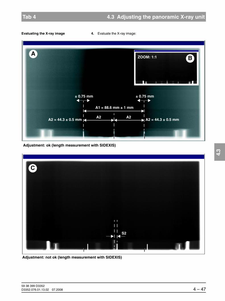
båÖäáëÜ
59 38 399 D3352D3352.076.01.13.02 07.2008 4 – 47
Tab 4 4.3 Adjusting the panoramic X-ray unit
4.3
Evaluating the X-ray image 4. Evaluate the X-ray image:
Adjustment: not ok (length measurement with SIDEXIS)
S2
C
A2 = 44.3 ± 0.5 mm
A1 = 88.6 mm ± 1 mm
Adjustment: ok (length measurement with SIDEXIS)
± 0.75 mm
ZOOM: 1:1A
B
A2 = 44.3 ± 0.5 mmA2 A2
± 0.75 mm
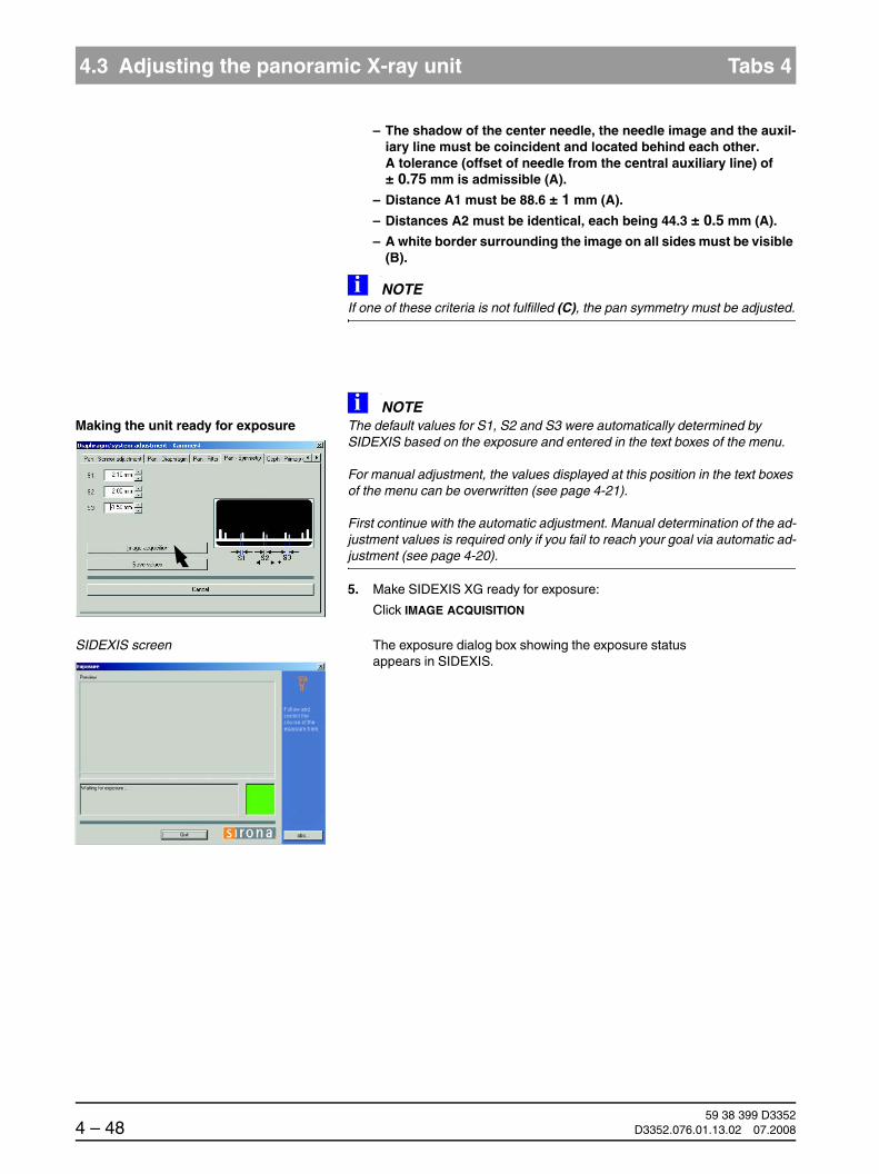
59 38 399 D33524 – 48 D3352.076.01.13.02 07.2008
4.3 Adjusting the panoramic X-ray unit Tabs 4
– The shadow of the center needle, the needle image and the auxil-iary line must be coincident and located behind each other. A tolerance (offset of needle from the central auxiliary line) of ± 0.75 mm is admissible (A).
– Distance A1 must be 88.6 ± 1 mm (A).
– Distances A2 must be identical, each being 44.3 ± 0.5 mm (A).
– A white border surrounding the image on all sides must be visible (B).
NOTEiIf one of these criteria is not fulfilled (C), the pan symmetry must be adjusted.
Making the unit ready for exposureNOTEi
The default values for S1, S2 and S3 were automatically determined by SIDEXIS based on the exposure and entered in the text boxes of the menu.
For manual adjustment, the values displayed at this position in the text boxes of the menu can be overwritten (see page 4-21).
First continue with the automatic adjustment. Manual determination of the ad-justment values is required only if you fail to reach your goal via automatic ad-justment (see page 4-20).
5. Make SIDEXIS XG ready for exposure:
Click IMAGE ACQUISITION
SIDEXIS screen The exposure dialog box showing the exposure status appears in SIDEXIS.

båÖäáëÜ
59 38 399 D3352D3352.076.01.13.02 07.2008 4 – 49
Tab 4 4.3 Adjusting the panoramic X-ray unit
4.3
XGPlus: Display on the Easypad The Easypad touchscreen shows service routine S010.2 as well as the related exposure parameters.
XG 5 / 3 / 3 PPE: Display on the Multipad The single-line display of the Multipad shows the exposure parameters of service routine S010.2.
Starting the exposure 6. Take an exposure (60kV/3mA; 14.1 s):
– Press the R key to move the unit back to the starting position.
XGPlus:
The procedure is completed when the status message “ORTHOPHOS is ready for exposure“ appears on the touchscreen and the exposure parameters of service routine S010.2 are displayed.
XG5 / 3 / 3 PPE:
The procedure is completed when the exposure parameters of service routine S010.2 are displayed and the progress indicator disappears.
– Press the release button. Hold down the release button until image ac-quisition is completed and the preview image appears in the exposure dialog box.
1
2
3
+- 60 kV/3 mA
14.1 s
S10
2
1 2 3
60/3____14.1____
R
WAIT!UNTIL UNIT IS IN STARTING POSITION

59 38 399 D33524 – 50 D3352.076.01.13.02 07.2008
4.3 Adjusting the panoramic X-ray unit Tabs 4
Evaluating the X-ray image 7. Evaluate the X-ray image:
– The shadow of the center needle, the needle image and the auxil-iary line must be coincident and located behind each other. A tolerance (offset of needle from the central auxiliary line) of ± 0.75 mm is admissible (A).
– Distance A1 must be 88.6 ± 1 mm (A).
– Distances A2 must be identical, each being 44.3 ± 0.5 mm (A).
– A white border surrounding the image on all sides must be visible (B).
NOTEiAlways measure exactly from pin center to pin center.
A2 = 44.3 ± 0.5 mm
A1 = 88.6 mm ± 1 mm
Adjustment: ok (length measurement with SIDEXIS)
± 0.75 mm
ZOOM: 1:1A
B
A2 = 44.3 ± 0.5 mmA2 A2
± 0.75 mm

båÖäáëÜ
59 38 399 D3352D3352.076.01.13.02 07.2008 4 – 51
Tab 4 4.3 Adjusting the panoramic X-ray unit
4.3
NOTEi
If the X-ray image still does not correspond to the ideal image, it is pos-sible that one or more criteria have not yet been fulfilled:
Case 1: Center needle not coincident with auxiliary lineIf the shadow of the center needle, the needle image and the auxiliary line do not yet coincide, then repeat the adjustment procedure starting with step 5.
Case 2: Symmetry not OKIf the shadow of the center needle, the needle image and the auxiliary line co-incide, but the symmetry or the distance between the two outer needles is not yet correct, then repeat the adjustment procedure starting with step 5.
NOTEiIf you do not reach your goal via automatic adjustment, repeat the adjustment procedure with manually determined adjustment values (see page 4-52).
Saving the values 8. If all criteria are fulfilled and the current image is identical to the ideal im-age A + B, then save the values:
Click SAVE VALUES
NOTEiIn SIDEXIS versions V01.50 and higher, the values for S1, S2 and S3 in the PAN - SYMMETRY submenu are set equal to zero with a correct adjustment, i.e. if they are within the permissible tolerance. For versions < V01.50, the values in the text boxes may deviate slightly from zero even with a correct adjustment.
Go on to the next adjustment step.

59 38 399 D33524 – 52 D3352.076.01.13.02 07.2008
4.3 Adjusting the panoramic X-ray unit Tabs 4
Manual adjustment of the PAN symmetry
The manual adjustment procedure is similar to the one for automatic adjust-ment. The only difference is that the default adjustment values automatically determined by SIDEXIS are overwritten by manually determined adjustment values in the PAN - SYMMETRY submenu.
Determining the adjustment values for S1, S2 and S3 manually
Measure distances S1, S2 and S3 with the SIDEXIS measuring ruler.
NOTEiMeasure in the lower area of the needles if possible, since they may have been bent slightly after repeated use.
Always measure exactly from pin center to pin center.
NOTEiTip: To facilitate the measuring procedure, you can color the image in SIDEX-IS (see also SIDEXIS Operator’s Manual).
S2S1 S3

båÖäáëÜ
59 38 399 D3352D3352.076.01.13.02 07.2008 4 – 53
Tab 4 4.3 Adjusting the panoramic X-ray unit
4.3
Overwriting default values for S1, S2 and S3
Overwrite the default values for S1, S2 and S3 with the measured values in the text boxes of the PAN - SYMMETRY submenu.
NOTEiFor information on the direction of displacement (input of +/- sign in the menu) see page 4-7. Use points as decimal separators!
Proceed with step 5 of the adjustment procedure.
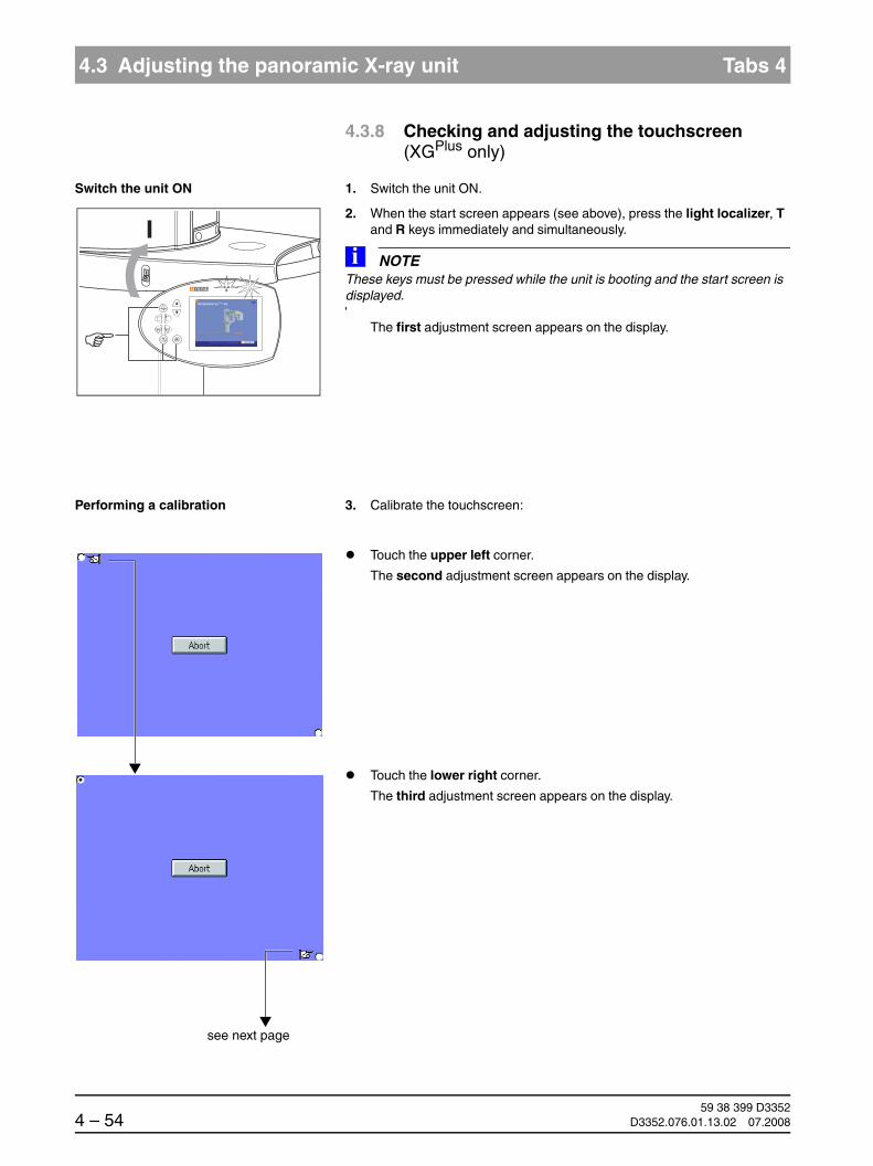
59 38 399 D33524 – 54 D3352.076.01.13.02 07.2008
4.3 Adjusting the panoramic X-ray unit Tabs 4
4.3.8 Checking and adjusting the touchscreen (XGPlus only)
Switch the unit ON 1. Switch the unit ON.
2. When the start screen appears (see above), press the light localizer, T and R keys immediately and simultaneously.
NOTEiThese keys must be pressed while the unit is booting and the start screen is displayed.
The first adjustment screen appears on the display.
Performing a calibration 3. Calibrate the touchscreen:
Touch the upper left corner.
The second adjustment screen appears on the display.
Touch the lower right corner.
The third adjustment screen appears on the display.
see next page

båÖäáëÜ
59 38 399 D3352D3352.076.01.13.02 07.2008 4 – 55
Tab 4 4.3 Adjusting the panoramic X-ray unit
4.3
Touch the center of the green square in the upper right corner.
The fourth adjustment screen appears on the display.
NOTEiTry to place the black dots which then appear as close to the centers of the squares as possible by touching the centers of the squares.
Touch the center of the green square in the lower left corner.
The fifth adjustment screen appears on the display.
Confirm the adjustment with YES.
The touchscreen is now adjusted.
To repeat the adjustment, touch NO.
You can abort the adjustment at any time by pressing the ABORT button.
59 38 399 D33524 – 56 D3352.076.01.13.02 07.2008
4.4 Adjusting the cephalometer (XGPlus/ XG 5, if ceph is installed) Tabs 4
4.4 Adjusting the cephalometer (XGPlus/ XG 5, if ceph is installed)
4.4.1 Check the ring type(for XGPlus with arm on left side only)
In XGPlus units with the ceph arm mounted on the left side, a diffferent ring type is used with a serial number ≤ 40104 than with a serial number > 40104.
Due to the different ring types used, the default ring offsets stored in the sys-tem for the position of the ring switching plate are also different.
If a software update is performed on a system with the old ring type, this pre-sents no problem as long as no module replacement (DX11) is performed and the system adjustment is not reset to the factory setting via the CEPH - RESET ADJUSTMENT menu (see page 4-115).
If the previous system adjustment values are lost for any of the above rea-sons, the correct ring type must be reset via service routine S034.7 before beginning the adjustment of the cephalometer.
Therefore, check before beginning the adjustment...
whether an old ring type is installed in the system
Old ring type = ceph units with serial nos. up to 40104new ring type = ceph units with serial no. 40105 or higher
whether a module has been replaced or the adjustment values have been reset and...
if the answer is yes, execute service routine S034.7 (see page 5-145).
NOTEiXG 5 and XGPlus units with the ceph arm mounted on the right side are always equipped with the new ring type. It is therefore not necessary to check the ring type of these units.

båÖäáëÜ
59 38 399 D3352D3352.076.01.13.02 07.2008 4 – 57
Tab 4 4.4 Adjusting the cephalometer (XGPlus/ XG 5, if ceph is installed)
4.4
4.4.2 Ceph test phantom
Accessory: Ceph test phantom
For the adjustment of the ceph primary diaphragm and the ceph main X-ray beam direction, you must insert test phantom B in the sensor slot on the panoramic X-ray unit.
For the adjustment of the ceph fixed point of rotation, you must remove the test phantom from the sensor slot on the panoramic X-ray unit.
B

59 38 399 D33524 – 58 D3352.076.01.13.02 07.2008
4.4 Adjusting the cephalometer (XGPlus/ XG 5, if ceph is installed) Tabs 4
4.4.3 Adjusting the ceph primary diaphragm
Menu: Diaphragm/system adjustment ‡ Ceph - Primary diaphragm
NOTEiFor units with a unit software < V02.27 the exposure parameters for the prima-ry diaphragm adjustment may deviate from the parameters shown here (64 kV/16 mA; 6.1 s).
CAUTIONIt is essential that the PAN needle phantom is removed from bite block holder of the panoramic X-ray unit before a Ceph exposure is taken; otherwise the phantom may collide with the sensor.
Preparations Move the ear plug holders on the cephalometer completely apart and swing them out of the beam direction (ap).
Insert the test phantom in the sensor slot on the panoramic X-ray unit (see page 4-57).
Plug the sensor into the sensor slot on the cephalometer.
Open the DIAPHRAGM/SYSTEM ADJUSTMENT menu (see page 4-5).

båÖäáëÜ
59 38 399 D3352D3352.076.01.13.02 07.2008 4 – 59
Tab 4 4.4 Adjusting the cephalometer (XGPlus/ XG 5, if ceph is installed)
4.4
Call up CEPH - PRIMARY DIAPHRAGM 1. Go to the CEPH - PRIMARY DIAPHRAGM submenu.
Making the unit ready for exposure 2. Make SIDEXIS XG ready for exposure:
Click IMAGE ACQUISITION
SIDEXIS screen The exposure dialog box showing the exposure status appears in SIDEXIS.

59 38 399 D33524 – 60 D3352.076.01.13.02 07.2008
4.4 Adjusting the cephalometer (XGPlus/ XG 5, if ceph is installed) Tabs 4
XGPlus: Display on the Easypad The Easypad touchscreen shows service routine S010.3 as well as the related exposure parameters.
XG 5: Display on the Multipad The single-line display of the Multipad shows the exposure parameters of service routine S010.3.
Starting the exposure 3. Take an exposure (64 kV/16 mA; 6.1 s):
– Press the R key to move the unit back to the starting position.
XGPlus:
The procedure is completed when the status message “ORTHOPHOS is ready for exposure“ appears on the touchscreen and the exposure parameters of service routine S010.3 are displayed.
XG5:
The procedure is completed when the exposure parameters of service routine S010.3 are displayed and the progress indicator disappears.
– Press the release button. Hold down the release button until image ac-quisition is completed and the preview image appears in the exposure dialog box.
1
2
3
+- 64 kV/16 mA
6.1 s
S10
3
1 2 3
64/16____6.1____
R
WAIT!UNTIL UNIT IS IN STARTING POSITION

båÖäáëÜ
59 38 399 D3352D3352.076.01.13.02 07.2008 4 – 61
Tab 4 4.4 Adjusting the cephalometer (XGPlus/ XG 5, if ceph is installed)
4.4
Evaluating the X-ray image 4. Evaluate the X-ray image:
Adjustment: not ok
Adjustment: ok
S2
S2
A
S3 = approx. 60 mm
B
Length measurement with SIDEXIS
Length measurement with SIDEXIS

59 38 399 D33524 – 62 D3352.076.01.13.02 07.2008
4.4 Adjusting the cephalometer (XGPlus/ XG 5, if ceph is installed) Tabs 4
– The vertical pin must be horizontally centered in the exposed im-age area A. A slight vertical offset of the grid is permissible.
– A uniform white border surrounding the image on all sides must be visible A.
– Distance S3 must be approx. 60mm.
NOTEiIf these criteria are not fulfilled (B), the ceph primary diaphragm must be adjusted.
NOTEiIf S3 is > 70 mm, then contact the Sirona Customer Service Center: Phone: 0 62 51/16 - 16 16
Making the unit ready for exposureNOTEi
The default values for S1, S2, S3 and S4 were automatically determined by SI-DEXIS based on the exposure and entered in the text boxes of the menu.
For manual adjustment, the values displayed at this position in the text boxes of the menu can be overwritten (see page 4-67).
First continue with the automatic adjustment. Manual determination of the ad-justment values is required only if you fail to reach your goal via automatic ad-justment (see page 4-66).
5. Make SIDEXIS XG ready for exposure:
Click IMAGE ACQUISITION
SIDEXIS screen The exposure dialog box showing the exposure status appears in SIDEXIS.

båÖäáëÜ
59 38 399 D3352D3352.076.01.13.02 07.2008 4 – 63
Tab 4 4.4 Adjusting the cephalometer (XGPlus/ XG 5, if ceph is installed)
4.4
XGPlus: Display on the Easypad The Easypad touchscreen shows service routine S030.2 as well as the related exposure parameters.
XG 5: Display on the Multipad The single-line display of the Multipad shows the exposure parameters of service routine S010.3.
Starting the exposure 6. Take an exposure (64 kV/16 mA; 6.1 s):
– Press the R key to move the unit back to the starting position.
XGPlus:
The procedure is completed when the status message “ORTHOPHOS is ready for exposure“ appears on the touchscreen and the exposure parameters of service routine S010.3 are displayed.
XG5:
The procedure is completed when the exposure parameters of service routine S010.3 are displayed and the progress indicator disappears.
– Press the release button. Hold down the release button until image ac-quisition is completed and the preview image appears in the exposure dialog box.
1
2
3
+- 64 kV/16 mA
6.1 s
S10
3
1 2 3
64/16____6.1____
R
WAIT!UNTIL UNIT IS IN STARTING POSITION

59 38 399 D33524 – 64 D3352.076.01.13.02 07.2008
4.4 Adjusting the cephalometer (XGPlus/ XG 5, if ceph is installed) Tabs 4
Evaluating the X-ray image 7. Evaluate the X-ray image:
– The vertical pin must be horizontally centered in the exposed im-age area A. A slight vertical offset of the grid is permissible.
– A uniform white border surrounding the image on all sides must be visible A.
– Distance S3 must be approx. 60mm.
NOTEiIf these criteria are not yet fulfilled, repeat the adjustment procedure starting with step 5.
NOTEiIf you do not reach your goal via automatic adjustment, repeat the adjustment procedure with manually determined adjustment values (see page 4-66).
S2
S2
A
S3 = approx. 60 mm
Adjustment: ok

båÖäáëÜ
59 38 399 D3352D3352.076.01.13.02 07.2008 4 – 65
Tab 4 4.4 Adjusting the cephalometer (XGPlus/ XG 5, if ceph is installed)
4.4
Saving the values 8. If the image is identical to the ideal image (A), save the values:
Click SAVE VALUES
Go on to the next adjustment step.

59 38 399 D33524 – 66 D3352.076.01.13.02 07.2008
4.4 Adjusting the cephalometer (XGPlus/ XG 5, if ceph is installed) Tabs 4
Manual adjustment of the ceph primary diaphragm
The manual adjustment procedure is similar to the one for automatic adjust-ment. The only difference is that the default adjustment values automatically determined by SIDEXIS are overwritten by manually determined adjustment values in the CEPH - PRIMARY DIAPHRAGM submenu.
Determining the adjustment values for S1, S2, S3 and S4 manually
Measure distances S1 - S4 with the SIDEXIS measuring ruler:
S1: Distance from the top edge of the image
S2: Distance from the right edge of the exposed area to the middle of the center pin
S3: Width of the exposed area
S4: Distance from the bottom edge of the image
NOTEiTip: To facilitate the measuring procedure, you can invert or color the image in SIDEXIS (see also SIDEXIS Operator’s Manual).
new
S2
S3
S1
S4

båÖäáëÜ
59 38 399 D3352D3352.076.01.13.02 07.2008 4 – 67
Tab 4 4.4 Adjusting the cephalometer (XGPlus/ XG 5, if ceph is installed)
4.4
Overwriting default values for S1, S2, S3 and S4
Overwrite the default values for S1, S2, S3 and S4 with the measured val-ues in the text boxes of the CEPH - PRIMARY DIAPHRAGM submenu.
NOTEiFor information on the direction of displacement (input of +/- sign in the menu) see page 4-7. Use points as decimal separators!
Proceed with step 5 of the adjustment procedure.

59 38 399 D33524 – 68 D3352.076.01.13.02 07.2008
4.4 Adjusting the cephalometer (XGPlus/ XG 5, if ceph is installed) Tabs 4
4.4.4 Adjusting the ceph fixed point of rotation
Menu: Diaphragm/system adjustment ‡ Ceph - Fixed point of rotation
CAUTIONIt is essential that the PAN needle phantom is removed from bite block holder of the panoramic X-ray unit before a Ceph exposure is taken; otherwise the phantom may collide with the sensor.
Preparations Remove the ceph test phantom from the sensor slot of the panoramic X-ray unit (see page 4-57).
Opening CEPH - FIXED POINT OF ROTATION
1. Go to the CEPH - FIXED POINT OF ROTATION submenu.
NOTEiThe menu provides a precision adjustment and a coarse adjustment (precision adjustment is preset). Perform a precision adjustment first. In most cases, previous coarse adjustment is not necessary.

båÖäáëÜ
59 38 399 D3352D3352.076.01.13.02 07.2008 4 – 69
Tab 4 4.4 Adjusting the cephalometer (XGPlus/ XG 5, if ceph is installed)
4.4
Making the unit ready for exposure 2. Make SIDEXIS XG ready for exposure:
Click IMAGE ACQUISITION
SIDEXIS screen The exposure dialog box showing the exposure status appears in SIDEXIS.
XGPlus: Display on the Easypad The Easypad touchscreen shows service routine S010.5 as well as the related exposure parameters.
XG 5: Display on the Multipad The single-line display of the Multipad shows the exposure parameters of service routine S010.5.
1
2
3
+- 80 kV/14 mA
0.60 s
S10
5
1 2 3
80/14___0.60____

59 38 399 D33524 – 70 D3352.076.01.13.02 07.2008
4.4 Adjusting the cephalometer (XGPlus/ XG 5, if ceph is installed) Tabs 4
Starting the exposure 3. Take an exposure (80 kV/14 mA; 0.60 s):
– Press the R key to move the unit back to the starting position.
XGPlus:
The procedure is completed when the status message “ORTHOPHOS is ready for exposure“ appears on the touchscreen and the exposure parameters of service routine S010.5 are displayed.
XG5:
The procedure is completed when the exposure parameters of service routine S010.5 are displayed and the progress indicator disappears.
– Press the release button. Hold down the release button until image ac-quisition is completed and the preview image appears in the exposure dialog box.
R
WAIT!UNTIL UNIT IS IN STARTING POSITION

båÖäáëÜ
59 38 399 D3352D3352.076.01.13.02 07.2008 4 – 71
Tab 4 4.4 Adjusting the cephalometer (XGPlus/ XG 5, if ceph is installed)
4.4
Evaluating the X-ray image 4. Evaluate the X-ray image:
– The exposed diaphragm area must lie centered and straight in the image field as well as inside the superimposed auxiliary lines (A).
– A white border surrounding the image on all sides must be visible. The maximum density must lie in the center of the diaphragm area (A).
NOTEiIf these criteria are not fulfilled (B), the ceph fixed point of rotation must be ad-justed.
Adjustment: ok
B
Adjustment: not ok
A
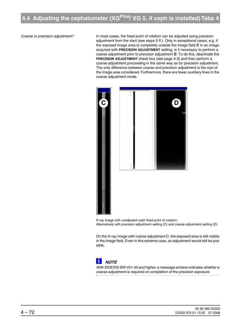
59 38 399 D33524 – 72 D3352.076.01.13.02 07.2008
4.4 Adjusting the cephalometer (XGPlus/ XG 5, if ceph is installed) Tabs 4
Coarse or precision adjustment? In most cases, the fixed point of rotation can be adjusted using precision adjustment from the start (see steps 5 ff.). Only in exceptional cases, e.g. if the exposed image area is completely outside the image field C in an image acquired with PRECISION ADJUSTMENT setting, is it necessary to perform a coarse adjustment prior to precision adjustment D. To do this, deactivate the PRECISION ADJUSTMENT check box (see page 4-3) and then perform a coarse adjustment proceeding in the same way as for precision adjustment. The only difference between coarse and precision adjustment is the size of the image area considered. Furthermore, there are fewer auxiliary lines in the coarse adjustment mode.
X-ray image with unadjusted ceph fixed point of rotation: Alternatively with precision adjustment setting (C) and coarse adjustment setting (D)
On the X-ray image with coarse adjustment D, the exposed area is still visible in the image field. Even in this extreme case, an adjustment would still be pos-sible.
NOTEiWith SIDEXIS SW V01.45 and higher, a message window indicates whether a coarse adjustment is required on completion of the precision exposure.
C D
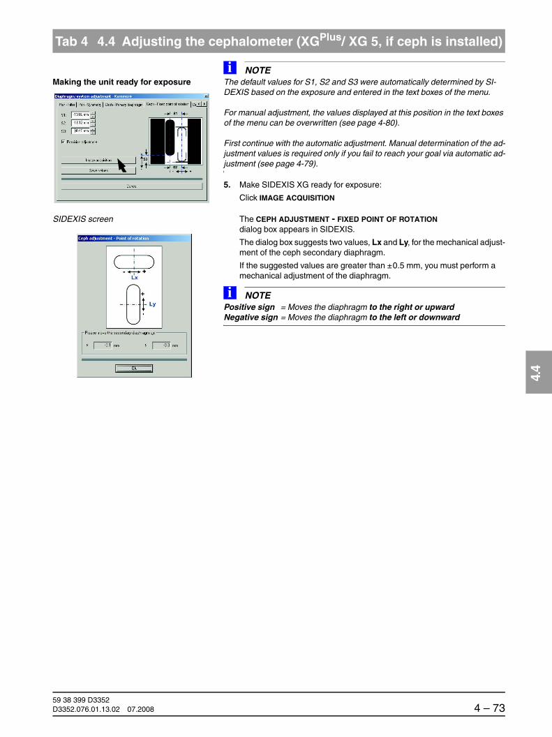
båÖäáëÜ
59 38 399 D3352D3352.076.01.13.02 07.2008 4 – 73
Tab 4 4.4 Adjusting the cephalometer (XGPlus/ XG 5, if ceph is installed)
4.4
Making the unit ready for exposureNOTEi
The default values for S1, S2 and S3 were automatically determined by SI-DEXIS based on the exposure and entered in the text boxes of the menu.
For manual adjustment, the values displayed at this position in the text boxes of the menu can be overwritten (see page 4-80).
First continue with the automatic adjustment. Manual determination of the ad-justment values is required only if you fail to reach your goal via automatic ad-justment (see page 4-79).
5. Make SIDEXIS XG ready for exposure:
Click IMAGE ACQUISITION
SIDEXIS screen The CEPH ADJUSTMENT - FIXED POINT OF ROTATION dialog box appears in SIDEXIS.
The dialog box suggests two values, Lx and Ly, for the mechanical adjust-ment of the ceph secondary diaphragm.
If the suggested values are greater than ±0.5 mm, you must perform a mechanical adjustment of the diaphragm.
NOTEiPositive sign = Moves the diaphragm to the right or upwardNegative sign = Moves the diaphragm to the left or downward

59 38 399 D33524 – 74 D3352.076.01.13.02 07.2008
4.4 Adjusting the cephalometer (XGPlus/ XG 5, if ceph is installed) Tabs 4
Adjusting the diaphragm 6. Adjust the diaphragm on the cephalometer mechanically. To do this, proceed as follows:
Removing the cover 7. Loosen screw B and remove the cover of the secondary diaphragm by pulling it downward.
Detaching the diaphragm 8. Loosen screws C slightly (approx. 2-3 turns).
B
C
C

båÖäáëÜ
59 38 399 D3352D3352.076.01.13.02 07.2008 4 – 75
Tab 4 4.4 Adjusting the cephalometer (XGPlus/ XG 5, if ceph is installed)
4.4
Adjusting the inclination 9. Adjust the inclination of the diaphragm with screw D (Lx mm) and the height of the diaphragm with screw E (Ly mm).
NOTEi
Screw D: CCW rotation = Correction of diaphragm to the rightCW rotation = Correction of diaphragm to the left
Screw E: CCW rotation = downward correction of diaphragmCW rotation = upward correction of diaphragm
Use a ruler to measure the displacement.
The directions of rotation specified for the screws above apply equally to both versions (with the ceph arm on the left and on the right).
Tighten screws C again.
Confirming the diaphragm adjustment 10. Confirm the mechanical correction of the ceph secondary diaphragm:
Click OK
SIDEXIS screen The exposure dialog box showing the exposure status appears in SIDEXIS.
Lx
Ly
D
E

59 38 399 D33524 – 76 D3352.076.01.13.02 07.2008
4.4 Adjusting the cephalometer (XGPlus/ XG 5, if ceph is installed) Tabs 4
XGPlus: Display on the Easypad The Easypad touchscreen shows service routine S010.5 as well as the related exposure parameters.
XG 5: Display on the Multipad The single-line display of the Multipad shows the exposure parameters of service routine S010.5.
Starting the exposure 11. Take an exposure (80 kV/14 mA; 0.60 s):
– Press the R key to move the unit back to the starting position.
XGPlus:
The procedure is completed when the status message “ORTHOPHOS is ready for exposure“ appears on the touchscreen and the exposure parameters of service routine S010.5 are displayed.
XG5:
The procedure is completed when the exposure parameters of service routine S010.5 are displayed and the progress indicator disappears.
– Press the release button. Hold down the release button until image ac-quisition is completed and the preview image appears in the exposure dialog box.
1
2
3
+- 80 kV/14 mA
0.60 s
S10
5
1 2 3
80/14___0.60____
R
WAIT!UNTIL UNIT IS IN STARTING POSITION

båÖäáëÜ
59 38 399 D3352D3352.076.01.13.02 07.2008 4 – 77
Tab 4 4.4 Adjusting the cephalometer (XGPlus/ XG 5, if ceph is installed)
4.4
Evaluating the X-ray image 12. Evaluate the X-ray image:
– The exposed diaphragm area must lie centered and straight in the image field as well as inside the superimposed auxiliary lines (A).
– A white border surrounding the image on all sides must be visible. The maximum density must lie in the center of the diaphragm area (A).
NOTEiIf this criterion is not yet fulfilled, repeat the adjustment procedure starting with step 5.
If you do not reach your goal via automatic adjustment, repeat the adjustment procedure with manually determined adjustment values (see page 4-79).
Adjustment: ok
A

59 38 399 D33524 – 78 D3352.076.01.13.02 07.2008
4.4 Adjusting the cephalometer (XGPlus/ XG 5, if ceph is installed) Tabs 4
Saving the values 13. If the image is identical to the ideal image (A), save the values:
Click SAVE VALUES
NOTEiIn SIDEXIS versions V01.50 and higher, the values for S1, S2 and S3 in the CEPH - FIXED POINT OF ROTATION submenu are setequal to zero with a cor-rect adjustment, i.e. if they are within the permissible tolerance. For versions < V01.50, the values in the text boxes may deviate slightly from zero even with a correct adjustment.
Go on to the next adjustment step.

båÖäáëÜ
59 38 399 D3352D3352.076.01.13.02 07.2008 4 – 79
Tab 4 4.4 Adjusting the cephalometer (XGPlus/ XG 5, if ceph is installed)
4.4
Adjusting the ceph fixed point of rotation manually
The manual adjustment procedure is similar to the one for automatic adjust-ment. The only difference is that the default adjustment values automatically determined by SIDEXIS are overwritten by manually determined adjustment values in the CEPH - FIXED POINT OF ROTATION submenu.
Determining the adjustment values for S1, S2 and S3 manually
Measure distances S1, S2 and S3 with the SIDEXIS measuring ruler.
S1
S2
B
S3

59 38 399 D33524 – 80 D3352.076.01.13.02 07.2008
4.4 Adjusting the cephalometer (XGPlus/ XG 5, if ceph is installed) Tabs 4
Overwriting default values for S1, S2 and S3
Overwrite the default values for S1, S2 and S3 with the measured values in the text boxes of the CEPH - FIXED POINT OF ROTATION submenu.
NOTEiFor information on the direction of displacement (input of +/- sign in the menu) see page 4-7. Use points as decimal separators!
Proceed with step 5 of the adjustment procedure.

båÖäáëÜ
59 38 399 D3352D3352.076.01.13.02 07.2008 4 – 81
Tab 4 4.4 Adjusting the cephalometer (XGPlus/ XG 5, if ceph is installed)
4.4
4.4.5 Adjusting the ceph main X-ray beam direction
Menu: Diaphragm/system adjustment ‡ Ceph - Main X-ray beam direction
CAUTIONIt is essential that the PAN needle phantom is removed from bite block holder of the panoramic X-ray unit before a Ceph exposure is taken; otherwise the phantom may collide with the sensor.
Preparations Insert the test phantom in the sensor slot on the panoramic X-ray unit (see page 4-57).
Swing the ear plug holders out of the beam direction.
Opening CEPH - MAIN X-RAY BEAM DIRECTION
1. Go to the CEPH - MAIN X-RAY BEAM DIRECTION submenu.

59 38 399 D33524 – 82 D3352.076.01.13.02 07.2008
4.4 Adjusting the cephalometer (XGPlus/ XG 5, if ceph is installed) Tabs 4
Making the unit ready for exposure 2. Make SIDEXIS XG ready for exposure:
Click IMAGE ACQUISITION
SIDEXIS screen The exposure dialog box showing the exposure status appears in SIDEXIS.
XGPlus: Display on the Easypad The Easypad touchscreen displays service routine S010.6 as well as the related exposure parameters.
XG 5: Display on the Multipad The single-line display of the Multipad shows the exposure parameters of service routine S010.6.
?
1
2
3
+- 80 kV/14 mA
14.9 s
S10
6
1 2 3
80/14___14.9____

båÖäáëÜ
59 38 399 D3352D3352.076.01.13.02 07.2008 4 – 83
Tab 4 4.4 Adjusting the cephalometer (XGPlus/ XG 5, if ceph is installed)
4.4
Starting the exposure 3. Take an exposure (80 kV/14 mA; 14.9 s):
– Press the R key to move the unit back to the starting position.
XGPlus:
The procedure is completed when the status message “ORTHOPHOS is ready for exposure“ appears on the touchscreen and the exposure parameters of service routine S010.6 are displayed.
XG5:
The procedure is completed when the exposure parameters of service routine S010.6 are displayed and the progress indicator disappears.
– Press the release button. Hold down the release button until image ac-quisition is completed and the preview image appears in the exposure dialog box.
R
WAIT!UNTIL UNIT IS IN STARTING POSITION

59 38 399 D33524 – 84 D3352.076.01.13.02 07.2008
4.4 Adjusting the cephalometer (XGPlus/ XG 5, if ceph is installed) Tabs 4
Evaluating the X-ray image 4. Evaluate the X-ray image:
10 mm
10 mm
Adjustment: ok
A
10 mm
10 mm
B
Adjustment: not ok

båÖäáëÜ
59 38 399 D3352D3352.076.01.13.02 07.2008 4 – 85
Tab 4 4.4 Adjusting the cephalometer (XGPlus/ XG 5, if ceph is installed)
4.4
– A horizontal bar must be visible in the center of the image (A). If this bar is visible, the exposure is OK and ...
– the two beams imaged are within the tolerance band of ± 10 mm (A).
NOTEiIf the above criteria are not fulfilled (B), the ceph main X-ray beam direction must be adjusted.
Making the unit ready for exposureNOTEi
The default value for S1 was automatically determined by SIDEXIS based on the exposure and entered in the text box of the menu.
For manual adjustment, the value displayed at this position in the text box of the menu can be overwritten (see page 4-89).
First continue with the automatic adjustment. Manual determination of the ad-justment value is required only if you fail to reach your goal via automatic ad-justment (see page 4-88).
5. Make SIDEXIS XG ready for exposure:
Click IMAGE ACQUISITION
SIDEXIS screen The exposure dialog box showing the exposure status appears in SIDEXIS.

59 38 399 D33524 – 86 D3352.076.01.13.02 07.2008
4.4 Adjusting the cephalometer (XGPlus/ XG 5, if ceph is installed) Tabs 4
XGPlus: Display on the Easypad The Easypad touchscreen displays service routine S010.6 as well as the related exposure parameters.
XG 5: Display on the Multipad The single-line display of the Multipad shows the exposure parameters of service routine S010.6.
Starting the exposure 6. Take an exposure (80 kV/14 mA; 14.9 s):
– Press the R key to move the unit back to the starting position.
XGPlus:
The procedure is completed when the status message “ORTHOPHOS is ready for exposure“ appears on the touchscreen and the exposure parameters of service routine S010.6 are displayed.
XG5:
The procedure is completed when the exposure parameters of service routine S010.6 are displayed and the progress indicator disappears.
– Press the release button. Hold down the release button until image ac-quisition is completed and the preview image appears in the exposure dialog box.
1
2
3
+- 80 kV/14 mA
14.9 s
S10
6
1 2 3
80/14___14.9____
R
WAIT!UNTIL UNIT IS IN STARTING POSITION

båÖäáëÜ
59 38 399 D3352D3352.076.01.13.02 07.2008 4 – 87
Tab 4 4.4 Adjusting the cephalometer (XGPlus/ XG 5, if ceph is installed)
4.4
Evaluating the X-ray image 7. Evaluate the X-ray image:
– A horizontal bar must be visible in the center of the image (A). If this bar is visible, the exposure is OK and ...
– the two beams imaged are within the tolerance band of ± 10 mm (A).
NOTEiIf this criterion is not yet fulfilled, repeat the adjustment procedure starting with step 5.
If you do not reach your goal via automatic adjustment, repeat the adjustment procedure with a manually determined adjustment value (see page 4-88).
Saving a value 8. If the image is identical to the ideal image (A), save the value:
Click SAVE VALUES
Go on to the next adjustment step.
Adjustment: ok
A

59 38 399 D33524 – 88 D3352.076.01.13.02 07.2008
4.4 Adjusting the cephalometer (XGPlus/ XG 5, if ceph is installed) Tabs 4
Manual adjustment of the ceph main X-ray beam direction
The manual adjustment procedure is similar to the one for automatic adjust-ment. The only difference is that the default adjustment value automatically determined by SIDEXIS is overwritten by a manually determined adjustment value in the CEPH - MAIN X-RAY BEAM DIRECTION submenu.
Determining the adjustment value for S1 manually
Measure distance S1 with the SIDEXIS measuring ruler.
Measuring range
NOTEiMeasure within the measuring range shown in C.
Measure maximum distance S1. If the X-ray beam is imaged in the form of an S curve, measure S1 at the inflection point of the curve, but always within the measuring range shown.
S1
Measuring range
C
Inflection point

båÖäáëÜ
59 38 399 D3352D3352.076.01.13.02 07.2008 4 – 89
Tab 4 4.4 Adjusting the cephalometer (XGPlus/ XG 5, if ceph is installed)
4.4
Overwriting the default value for S1 Replace the default value for S1 displayed in the text box of the CEPH MAIN X-RAY BEAM DIRECTION submenu with the measured value if nec-essary.
NOTEiUse points as decimal separators!
Proceed with step 5 of the adjustment procedure.

59 38 399 D33524 – 90 D3352.076.01.13.02 07.2008
4.4 Adjusting the cephalometer (XGPlus/ XG 5, if ceph is installed) Tabs 4
4.4.6 Adjusting the ceph quickshot(XGPlus full version only)
Menu: Diaphragm/system adjustment ‡ ceph quickshot
CAUTIONIt is essential that the PAN needle phantom is removed from bite block holder of the panoramic X-ray unit before a Ceph exposure is taken; otherwise the phantom may collide with the sensor.
Preparations Remove the ceph test phantom from the sensor slot of the panoramic X-ray unit (see page 4-57).
Opening CEPH - QUICKSHOT 1. Go to the CEPH QUICKSHOT submenu.
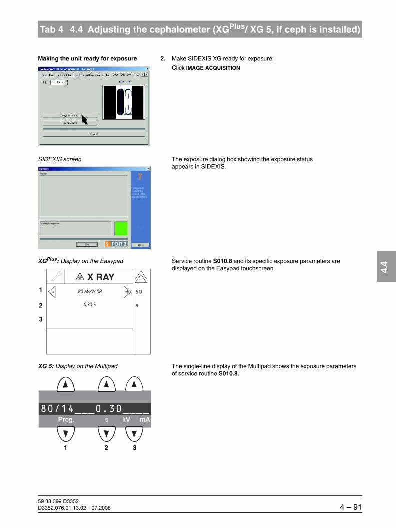
båÖäáëÜ
59 38 399 D3352D3352.076.01.13.02 07.2008 4 – 91
Tab 4 4.4 Adjusting the cephalometer (XGPlus/ XG 5, if ceph is installed)
4.4
Making the unit ready for exposure 2. Make SIDEXIS XG ready for exposure:
Click IMAGE ACQUISITION
SIDEXIS screen The exposure dialog box showing the exposure status appears in SIDEXIS.
XGPlus: Display on the Easypad Service routine S010.8 and its specific exposure parameters are displayed on the Easypad touchscreen.
XG 5: Display on the Multipad The single-line display of the Multipad shows the exposure parameters of service routine S010.8.
1
2
3
+- 80 kV/14 mA
0.30 s
S10
8
1 2 3
80/14___0.30____

59 38 399 D33524 – 92 D3352.076.01.13.02 07.2008
4.4 Adjusting the cephalometer (XGPlus/ XG 5, if ceph is installed) Tabs 4
Starting the exposure 3. Take an exposure (80 kV/14 mA; 0.30 s):
– Press the R key to move the unit back to the starting position.
XGPlus:
The procedure is completed when the status message “ORTHOPHOS is ready for exposure“ appears on the touchscreen and the exposure parameters of service routine S010.8 are displayed.
XG5:
The procedure is completed when the exposure parameters of service routine S010.8 are displayed and the progress indicator disappears.
– Press the release button. Hold down the release button until image ac-quisition is completed and the preview image appears in the exposure dialog box.
R
WAIT!UNTIL UNIT IS IN STARTING POSITION

båÖäáëÜ
59 38 399 D3352D3352.076.01.13.02 07.2008 4 – 93
Tab 4 4.4 Adjusting the cephalometer (XGPlus/ XG 5, if ceph is installed)
4.4
Evaluating the X-ray image 4. Evaluate the X-ray image:
– The exposed diaphragm area must lie centered and straight in the image field as well as inside the superimposed auxiliary lines (A).
– A white border surrounding the image on all sides must be visible. The maximum density must lie in the center of the diaphragm area (A).
NOTEiIf these criteria are not fulfilled (B), the ceph quickshot must be adjusted.
B
Adjustment: ok
A
Adjustment: not ok
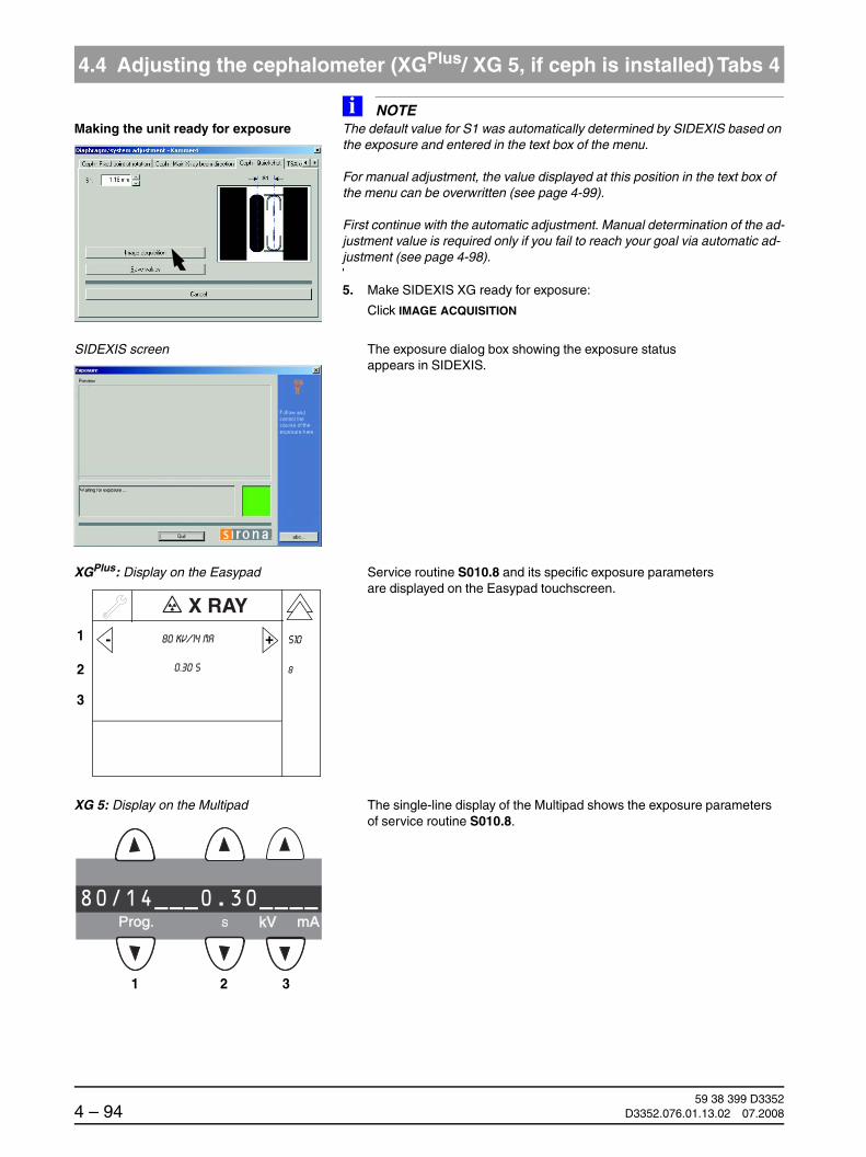
59 38 399 D33524 – 94 D3352.076.01.13.02 07.2008
4.4 Adjusting the cephalometer (XGPlus/ XG 5, if ceph is installed) Tabs 4
Making the unit ready for exposureNOTEi
The default value for S1 was automatically determined by SIDEXIS based on the exposure and entered in the text box of the menu.
For manual adjustment, the value displayed at this position in the text box of the menu can be overwritten (see page 4-99).
First continue with the automatic adjustment. Manual determination of the ad-justment value is required only if you fail to reach your goal via automatic ad-justment (see page 4-98).
5. Make SIDEXIS XG ready for exposure:
Click IMAGE ACQUISITION
SIDEXIS screen The exposure dialog box showing the exposure status appears in SIDEXIS.
XGPlus: Display on the Easypad Service routine S010.8 and its specific exposure parameters are displayed on the Easypad touchscreen.
XG 5: Display on the Multipad The single-line display of the Multipad shows the exposure parameters of service routine S010.8.
1
2
3
+- 80 kV/14 mA
0.30 s
S10
8
1 2 3
80/14___0.30____

båÖäáëÜ
59 38 399 D3352D3352.076.01.13.02 07.2008 4 – 95
Tab 4 4.4 Adjusting the cephalometer (XGPlus/ XG 5, if ceph is installed)
4.4
Starting the exposure 6. Take an exposure (80 kV/14 mA; 0.30 s):
– Press the R key to move the unit back to the starting position.
XGPlus:
The procedure is completed when the status message “ORTHOPHOS is ready for exposure“ appears on the touchscreen and the exposure parameters of service routine S010.8 are displayed.
XG5:
The procedure is completed when the exposure parameters of service routine S010.8 are displayed and the progress indicator disappears.
– Press the release button. Hold down the release button until image ac-quisition is completed and the preview image appears in the exposure dialog box.
R
WAIT!UNTIL UNIT IS IN STARTING POSITION

59 38 399 D33524 – 96 D3352.076.01.13.02 07.2008
4.4 Adjusting the cephalometer (XGPlus/ XG 5, if ceph is installed) Tabs 4
Evaluating the X-ray image 7. Evaluate the X-ray image:
– The exposed diaphragm area must lie centered and straight in the image field as well as inside the superimposed auxiliary lines (A).
– A white border surrounding the image on all sides must be visible. The maximum density must lie in the center of the diaphragm area (A).
NOTEiIf this criterion is not yet fulfilled, repeat the adjustment procedure starting with step 5.
If you do not reach your goal via automatic adjustment, repeat the adjustment procedure with a manually determined adjustment value (see page 4-98).
Adjustment: ok
A

båÖäáëÜ
59 38 399 D3352D3352.076.01.13.02 07.2008 4 – 97
Tab 4 4.4 Adjusting the cephalometer (XGPlus/ XG 5, if ceph is installed)
4.4
Saving a value 8. If the image is identical to the ideal image (A), save the value:
Click SAVE VALUES
NOTEiIn SIDEXIS versions V01.50 and higher, the value for S1 in the CEPH - QUICK-SHOT submenu is setequal to zero with a correct adjustment, i.e. if it is within the permissible tolerance. For versions < V01.50, the value in the text box may deviate slightly from zero even with a correct adjustment.
Quit the DIAPHRAGM/SYSTEM ADJUSTMENT menu and proceed to the section 4.4.7 "Checking and adjusting the alignment of the ear plugs" or continue the adjustment procedure with the TSA sensor menu (see page 4-107).
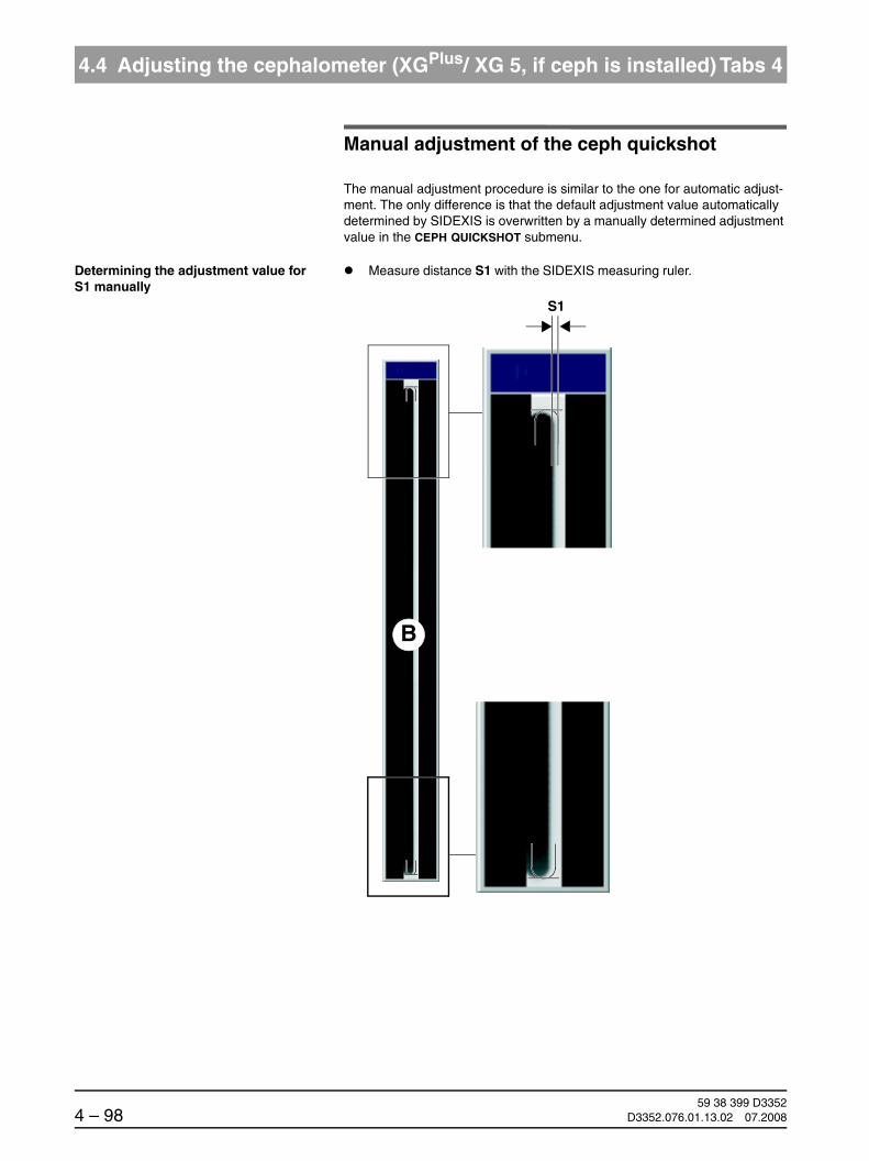
59 38 399 D33524 – 98 D3352.076.01.13.02 07.2008
4.4 Adjusting the cephalometer (XGPlus/ XG 5, if ceph is installed) Tabs 4
Manual adjustment of the ceph quickshot
The manual adjustment procedure is similar to the one for automatic adjust-ment. The only difference is that the default adjustment value automatically determined by SIDEXIS is overwritten by a manually determined adjustment value in the CEPH QUICKSHOT submenu.
Determining the adjustment value for S1 manually
Measure distance S1 with the SIDEXIS measuring ruler.
B
S1
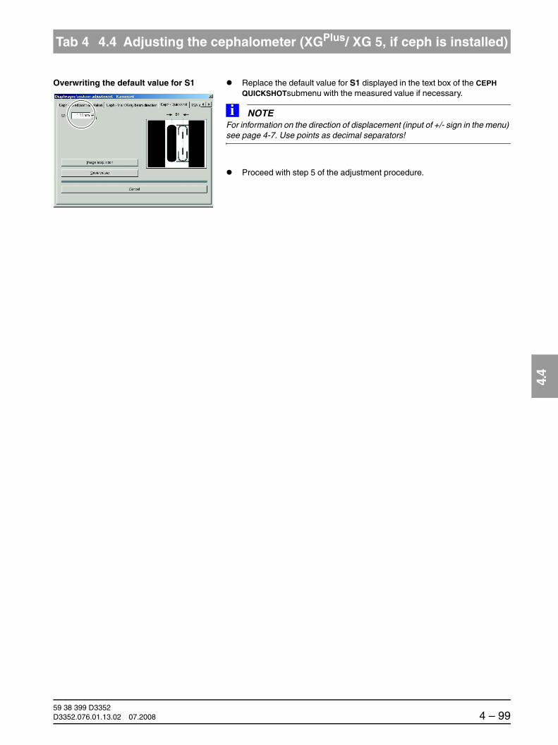
båÖäáëÜ
59 38 399 D3352D3352.076.01.13.02 07.2008 4 – 99
Tab 4 4.4 Adjusting the cephalometer (XGPlus/ XG 5, if ceph is installed)
4.4
Overwriting the default value for S1 Replace the default value for S1 displayed in the text box of the CEPH QUICKSHOTsubmenu with the measured value if necessary.
NOTEiFor information on the direction of displacement (input of +/- sign in the menu) see page 4-7. Use points as decimal separators!
Proceed with step 5 of the adjustment procedure.

59 38 399 D33524 – 100 D3352.076.01.13.02 07.2008
4.4 Adjusting the cephalometer (XGPlus/ XG 5, if ceph is installed) Tabs 4
4.4.7 Checking and adjusting the alignment of the ear plugs
Checking the ear plug alignment
NOTEiThe sensor must be plugged into the sensor slot on the cephalometer. The sensor must not be plugged into the sensor slot on the panoramic X-ray unit.
Preparations XGPlus:
Select the CEPH mode in the main menu on the Easypad.
XG 5:
Select one of the ceph programs on the Multipad.
Position of the ear plug holders 1. Move the ear plug holders completely apart and swing them into the beam path.
Fitting the adjusting caps 2. Fit adjusting caps D onto the ear plugs and secure them with adhesive tape.
Fit the black adjusting cap on the outside (sensor side)
Fit the transparent adjusting cap on the inside (tube assembly side).
D
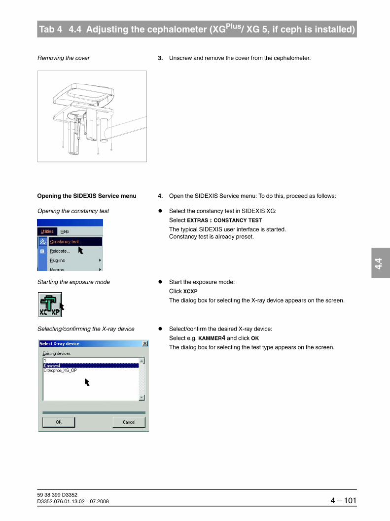
båÖäáëÜ
59 38 399 D3352D3352.076.01.13.02 07.2008 4 – 101
Tab 4 4.4 Adjusting the cephalometer (XGPlus/ XG 5, if ceph is installed)
4.4
Removing the cover 3. Unscrew and remove the cover from the cephalometer.
Opening the SIDEXIS Service menu 4. Open the SIDEXIS Service menu: To do this, proceed as follows:
Opening the constancy test Select the constancy test in SIDEXIS XG:
Select EXTRAS ‡ CONSTANCY TEST
The typical SIDEXIS user interface is started. Constancy test is already preset.
Starting the exposure mode Start the exposure mode:
Click XCXP
The dialog box for selecting the X-ray device appears on the screen.
Selecting/confirming the X-ray device Select/confirm the desired X-ray device:
Select e.g. KAMMER4 and click OK
The dialog box for selecting the test type appears on the screen.

59 38 399 D33524 – 102 D3352.076.01.13.02 07.2008
4.4 Adjusting the cephalometer (XGPlus/ XG 5, if ceph is installed) Tabs 4
Selecting/confirming the test type Select/confirm the test type:
Click SERVICE EXPOSURE
The dialog box for selecting the service exposure appears on the screen.
Selecting/confirming the service exposure Select/confirm the service exposure:
Click QUALITY TEST EXPOSURE
NOTEiThe ceph mode must be activated for the ceph quality test exposure (see page 4-100).
NOTEiIf necessary, select the X-ray component.
SIDEXIS screen The exposure dialog box showing the exposure status appears in SIDEXIS.

båÖäáëÜ
59 38 399 D3352D3352.076.01.13.02 07.2008 4 – 103
Tab 4 4.4 Adjusting the cephalometer (XGPlus/ XG 5, if ceph is installed)
4.4
Starting the exposure 5. Take an exposure:
– Press the R key to move the unit back to the starting position.
XGPlus:
The procedure is completed when the status message “ORTHOPHOS is ready for exposure“ appears on the touchscreen.
XG5:
The procedure is completed when the progess indicator disappears.
– Press the release button. Hold down the release button until image ac-quisition is completed and the preview image appears in the exposure dialog box.
Image The lead balls in the adjusting caps appear as dots on the image. The two dots must be coincident.
NOTEiIf the two dots are not coincident, the ear plugs must be adjusted.
R
WAIT!UNTIL UNIT IS IN STARTING POSITION

59 38 399 D33524 – 104 D3352.076.01.13.02 07.2008
4.4 Adjusting the cephalometer (XGPlus/ XG 5, if ceph is installed) Tabs 4
Adjusting the ear plug alignment
Horizontal correction 6. Loosen screws A slightly. Do not unscrew them completely!
7. Adjust the ear plugs in the horizontal direction by turning screw B coun-terclockwise or clockwise. The direction of rotation corresponding to a unit with the Ceph arm mounted on the left or on the right side is shown in the following illustration:
Tighten screws A again.
B
A
A
Ceph arm mounted on left-hand side
Ceph arm mounted on right-hand side

båÖäáëÜ
59 38 399 D3352D3352.076.01.13.02 07.2008 4 – 105
Tab 4 4.4 Adjusting the cephalometer (XGPlus/ XG 5, if ceph is installed)
4.4
Vertical correction 8. Turn the rotary table counterclockwise approx. 100 degrees until you can see screw C through the opening in the cover plate.
C
approx. 100 degrees
C
D

59 38 399 D33524 – 106 D3352.076.01.13.02 07.2008
4.4 Adjusting the cephalometer (XGPlus/ XG 5, if ceph is installed) Tabs 4
9. Loosen screw C slightly (do not unscrew it completely!) and adjust the ear plugs in the vertical direction with knurled nut D. The direction of ro-tation corresponding to a unit with the Ceph arm mounted on the left or on the right side is shown in the following illustration:
Tighten screw C again.
Position of the ear plug holders 10. Turn the ear plug holders back into the beam direction. Make sure that the black adjusting cap is located on the outside again.
Release radiation again to check the adjustment (see page 4-101).
– If the two dots displayed on the screen are coincident, reattach the cov-er (see page 4-101).
– If the two dots displayed on the screen are not yet coincident, repeat the adjustment procedure.
The adjustment of the unit is now completed.
Ceph arm mounted on left-hand side
Ceph arm mounted on right-hand side
outside

båÖäáëÜ
59 38 399 D3352D3352.076.01.13.02 07.2008 4 – 107
Tab 4 4.5 TSA sensor adjustment (XGPlus full version only)
4.5
4.5 TSA sensor adjustment(XGPlus full version only)
Menu: Diaphragm/system adjustment ‡ TSA sensor
Open the DIAPHRAGM/SYSTEM ADJUSTMENT menu if it is not already open (see page 4-5).
Opening TSA - SENSOR 1. Go to the TSA - SENSOR submenu.
Making the unit ready for exposure 2. Make SIDEXIS XG ready for exposure:
Click IMAGE ACQUISITION

59 38 399 D33524 – 108 D3352.076.01.13.02 07.2008
4.5 TSA sensor adjustment (XGPlus full version only) Tabs 4
SIDEXIS screen The exposure dialog box showing the exposure status appears in SIDEXIS.
XGPlus: Display on the Easypad The Easypad touchscreen shows service routine S030.4 as well as the related exposure parameters.
Starting the exposure 3. Take an exposure (60 kV/3 mA; 0.20 s):
– Press the R key to move the unit back to the starting position.
The procedure is completed when the status message “ORTHOPHOS is ready for exposure“ appears on the touchscreen and the exposure parameters of service routine S030.4 are displayed.
– Press the release button. Hold down the release button until image ac-quisition is completed and the preview image appears in the exposure dialog box.
1
2
3
+- 60 kV/3 mA
0.20 s
S30
4
R
WAIT!UNTIL UNIT IS IN STARTING POSITION

båÖäáëÜ
59 38 399 D3352D3352.076.01.13.02 07.2008 4 – 109
Tab 4 4.5 TSA sensor adjustment (XGPlus full version only)
4.5
Evaluating the X-ray image 4. Evaluate the X-ray image:
– The exposed diaphragm area must lie horizontally centered in the image field (A).
– A white border surrounding the image on all sides must be visible. The maximum density must lie in the center of the diaphragm area (A).
NOTEiIf these criteria are not fulfilled (B), the TSA sensor must be adjusted.
Adjustment: ok Adjustment: not ok
A B

59 38 399 D33524 – 110 D3352.076.01.13.02 07.2008
4.5 TSA sensor adjustment (XGPlus full version only) Tabs 4
Making the unit ready for exposureNOTEi
The default values for S1 and S2 were automatically determined by SIDEXIS based on the exposure and entered in the text box of the menu.
For manual adjustment, the values displayed at this position in the text boxes of the menu can be overwritten (see page 4-114).
First continue with the automatic adjustment. Manual determination of the ad-justment value is required only if you fail to reach your goal via automatic ad-justment (see page 4-113).
5. Make SIDEXIS XG ready for exposure:
Click IMAGE ACQUISITION
SIDEXIS screen The exposure dialog box showing the exposure status appears in SIDEXIS.
XGPlus: Display on the Easypad The Easypad touchscreen shows service routine S030.4 as well as the related exposure parameters.
Starting the exposure 6. Take an exposure (60 kV/3 mA; 0.20 s):
– Press the R key to move the unit back to the starting position.
The procedure is completed when the status message “ORTHOPHOS is ready for exposure“ appears on the touchscreen and the exposure parameters of service routine S030.4 are displayed.
– Press the release button. Hold down the release button until image ac-quisition is completed and the preview image appears in the exposure dialog box.
1
2
3
+- 60 kV/3 mA
0.20 s
S30
4
R
WAIT!UNTIL UNIT IS IN STARTING POSITION

båÖäáëÜ
59 38 399 D3352D3352.076.01.13.02 07.2008 4 – 111
Tab 4 4.5 TSA sensor adjustment (XGPlus full version only)
4.5
Evaluating the X-ray image 7. Evaluate the X-ray image:
– The exposed diaphragm area must lie horizontally and vertically centered in the image field (A).
– A white border surrounding the image on all sides must be visible. The maximum density must lie in the center of the diaphragm area (A).
NOTEiIf these criteria are not yet fulfilled, repeat the adjustment procedure starting with step 5.
NOTEiIf you do not reach your goal via automatic adjustment, repeat the adjustment procedure with manually determined adjustment values (see page 4-113).
Adjustment: ok
A
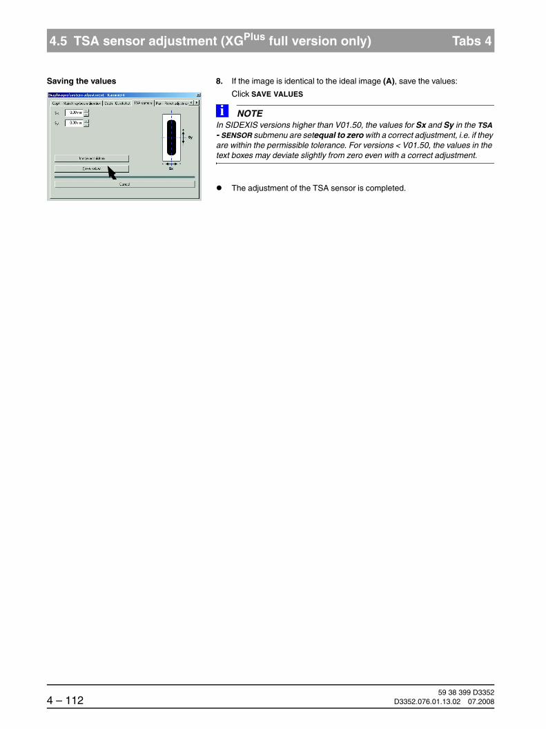
59 38 399 D33524 – 112 D3352.076.01.13.02 07.2008
4.5 TSA sensor adjustment (XGPlus full version only) Tabs 4
Saving the values 8. If the image is identical to the ideal image (A), save the values:
Click SAVE VALUES
NOTEiIn SIDEXIS versions higher than V01.50, the values for Sx and Sy in the TSA - SENSOR submenu are setequal to zero with a correct adjustment, i.e. if they are within the permissible tolerance. For versions < V01.50, the values in the text boxes may deviate slightly from zero even with a correct adjustment.
The adjustment of the TSA sensor is completed.

båÖäáëÜ
59 38 399 D3352D3352.076.01.13.02 07.2008 4 – 113
Tab 4 4.5 TSA sensor adjustment (XGPlus full version only)
4.5
Manual adjustment of the TSA sensor
The manual adjustment procedure is similar to the one for automatic adjust-ment. The only difference is that the default adjustment values automatically determined by SIDEXIS are overwritten by manually determined adjustment values in the TSA - SENSOR submenu.
Determining adjustment values for Sx and Sy manually
Measure distances Sx and Sy with the SIDEXIS measuring ruler.
NOTEiMeasure from the edge of the imaged diaphragm area roughly up to the edge of the image area. Leave a small border, since a surrounding white border should be present following the correction.
S2
Sy
Sx

59 38 399 D33524 – 114 D3352.076.01.13.02 07.2008
4.5 TSA sensor adjustment (XGPlus full version only) Tabs 4
Overwriting the default values for Sx and Sy
Overwrite the default values for Sx and Sy with the measured values in the text boxes of the TSA - SENSOR submenu.
NOTEiFor information on the direction of displacement (input of +/- sign in the menu) see page 4-7. Use points as decimal separators!
Proceed with step 5 of the adjustment procedure.
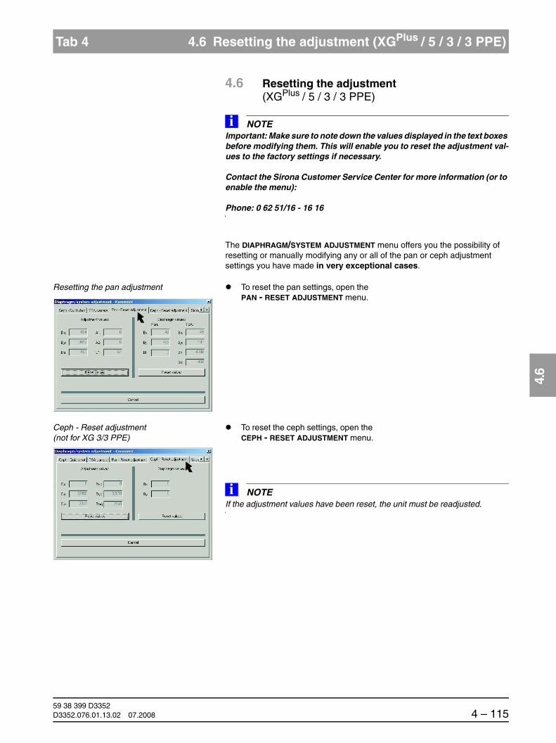
båÖäáëÜ
59 38 399 D3352D3352.076.01.13.02 07.2008 4 – 115
Tab 4 4.6 Resetting the adjustment (XGPlus / 5 / 3 / 3 PPE)
4.6
4.6 Resetting the adjustment (XGPlus / 5 / 3 / 3 PPE)
NOTEiImportant: Make sure to note down the values displayed in the text boxes before modifying them. This will enable you to reset the adjustment val-ues to the factory settings if necessary.
Contact the Sirona Customer Service Center for more information (or to enable the menu):
Phone: 0 62 51/16 - 16 16
The DIAPHRAGM/SYSTEM ADJUSTMENT menu offers you the possibility of resetting or manually modifying any or all of the pan or ceph adjustment settings you have made in very exceptional cases.
Resetting the pan adjustment To reset the pan settings, open the PAN - RESET ADJUSTMENT menu.
Ceph - Reset adjustment (not for XG 3/3 PPE)
To reset the ceph settings, open the CEPH - RESET ADJUSTMENT menu.
NOTEiIf the adjustment values have been reset, the unit must be readjusted.

59 38 399 D33524 – 116 D3352.076.01.13.02 07.2008
4.6 Resetting the adjustment (XGPlus / 5 / 3 / 3 PPE) Tabs 4

ORTHOPHOS XG 5 Service routines

59 38 399 D33525 – 2 D3352.076.01.13.02 07.2008
Tab 5
Contents
5.1 Selecting the Service menu ..................................5 – 105.1.1 Selection on the Easypad (XGPlus) .................. 5 – 10
5.1.2 Selection on the Multipad (XG 5 / 3 / 3 PPE) ... 5 – 13
5.2 Selecting a service routine ....................................5 – 155.2.1 Service routines with security access............... 5 – 17
5.3 Service routines with SIDEXIS..............................5 – 18
5.4 Service routine S001.............................................5 – 21
5.5 Service routine S002.............................................5 – 235.5.1 S002: Test step 1 ............................................. 5 – 24
5.5.2 S002: Test step 3 (not for XG 3 / 3 PPE) ......... 5 – 26
5.5.3 S002: Test step 4 (not for XG 3 / 3 PPE) ......... 5 – 27
5.6 Service routine S005.............................................5 – 285.6.1 S005: Test step 2 ............................................. 5 – 29
5.6.2 S005: Test step 4 ............................................. 5 – 31
5.6.3 S005: Test step 5 ............................................. 5 – 33
5.6.4 S005: Test step 6 ............................................. 5 – 34
5.6.5 S005: Test step 7 ............................................. 5 – 37
5.7 Service routine S007.............................................5 – 405.7.1 S007: Test step 1 ............................................. 5 – 41
5.7.2 S007: Test step 2 ............................................. 5 – 44
5.7.3 S007: Test step 5 ............................................. 5 – 46
5.8 Service routine S008.............................................5 – 485.8.1 S008: Test step 2 ............................................. 5 – 48
5.8.2 S008: Test step 3 ............................................. 5 – 50
5.8.3 S008: Test step 4 (XG5 / XGPlus only) ............. 5 – 54
5.9 Service routine S009.............................................5 – 565.9.1 S009: Test step 4 ............................................. 5 – 56
5.10 Service routine S012.............................................5 – 595.10.1 S012: Test step 2 ............................................. 5 – 60
5.10.2 S012: Test step 3 ............................................. 5 – 63
5.10.3 S012: Test step 4 ............................................. 5 – 65

59 38 399 D3352D3352.076.01.13.02 07.2008 5 – 3
Tab 5
5.11 Service routine S014.............................................5 – 675.11.1 S014: Test step 1 ............................................. 5 – 67
5.11.2 S014: Test step 2 ............................................. 5 – 69
5.11.3 S014: Test step 3 ............................................. 5 – 71
5.11.4 S014: Test step 4 ............................................. 5 – 73
5.12 Service routine S015.............................................5 – 745.12.1 S015: Test step 5 ............................................. 5 – 74
5.13 Service routine S017.............................................5 – 775.13.1 S017: Test step 2 ............................................. 5 – 78
5.13.2 S017: Test step 3 ............................................. 5 – 82
5.13.3 S017: Test step 4 (XGPlus only) ....................... 5 – 84
5.13.4 S017: Test step 5 (XGPlus only) ....................... 5 – 86
5.13.5 S017: Test step 6 ............................................. 5 – 87
5.13.6 S017: Test step 8 ............................................. 5 – 89
5.13.7 S017: Test step 9 ............................................. 5 – 91
5.13.8 S017: Test step 10 (XGPlus only) ..................... 5 – 93
5.13.9 S017: Test step 11 (XG 5 / 3 only) ................... 5 – 95
5.13.10 S017: Test step 12 (XGPlus only) ..................... 5 – 96
5.13.11 S017: Test step 13 (XGPlus full version only) ... 5 – 97
5.13.12 S017: Test step 14 (XGPlus full version only) ... 5 – 98
5.13.13 S017: Test step 15 ........................................ 5 – 101
5.13.14 S017: Test step 17 Setting the standard acceptance/constancy test, RöV FRG ........... 5 – 103
5.13.15 S017: Test step 17 Checking or accepting the diaphragm configuration, worldwide(not for XG 3 / 3 PPE) .................................... 5 – 105
5.13.16 S017: Test step 22 (XG 3 PPE only).............. 5 – 107
5.13.17 S017: Test step 23 (XG 3 PPE only).............. 5 – 108
5.14 Service routine S018...........................................5 – 1095.14.1 S018: Test step 2 ........................................... 5 – 110
5.14.2 S018: Test step 3 ........................................... 5 – 112
5.14.3 S018: Test step 4 ........................................... 5 – 113
5.14.4 S018: Test step 5 ........................................... 5 – 115
5.14.5 S018: Test step 6 ........................................... 5 – 117
5.15 Service routine S020 (XGPlus only) .....................5 – 1185.15.1 S020: Test step 1 ........................................... 5 – 119

59 38 399 D33525 – 4 D3352.076.01.13.02 07.2008
Tab 5
5.16 Service routine S021 (not for XG 3 / 3 PPE).......5 – 1215.16.1 S021: Test step 1 ........................................... 5 – 121
5.16.2 S021: Test step 3 ........................................... 5 – 123
5.17 Service routine S032...........................................5 – 1265.17.1 S032: Test step 10 ......................................... 5 – 126
5.18 Service routine S033 (not for XG 3 / 3 PPE).......5 – 1305.18.1 S033: Test step 10 ......................................... 5 – 130
5.19 Service routine S034...........................................5 – 1345.19.1 S034: Test step 4 ........................................... 5 – 135
5.19.2 S034: Test step 5 ........................................... 5 – 139
5.19.3 S034: Test step 6 (not for XG 3 / 3 PPE) ....... 5 – 143
5.19.4 S034: Test step 7 (XGPlus only) ..................... 5 – 145
5.19.5 S034: Test step 8 (XGPlus and full version only) ......................... 5 – 146
5.19.6 S034: Test step 9 (XGPlus and full version only) ......................... 5 – 148
5.20 Service routine S037...........................................5 – 1515.20.1 S037: Test step 1 ........................................... 5 – 152
5.20.2 S037: Test step 2 ........................................... 5 – 154
5.20.3 S037: Test step 3 ........................................... 5 – 157
5.20.4 S037: Test step 4 ........................................... 5 – 159

båÖäáëÜ
59 38 399 D3352D3352.076.01.13.02 07.2008 5 – 5
Tab 5
Directory of all available service routines
Service routine XG 3 XG 3 PPE XG 5 XGPlus Function Page
S001 X X X X Radiation without rotary movement, fixed radiation time
5-21
S002 X X X X Radiation without rotary movement, maximum radiation time can be selected
5-23
S002: Test step 1 X X X X Primary diaphragm remains in last position selected
5-24
S002: Test step 3 (not for XG 3 / 3 PPE)
– – X X Primary diaphragm opened fully 5-26
S002: Test step 4 (not for XG 3 / 3 PPE)
– – X X Filter element for 0.8 mm Cu step filter; the primary diaphragm is set to a widened opening symmetrical to the PAN setting so that the step filter still remains covered
5-27
S005 X X X X General X-ray tube assembly service 5-28
S005: Test step 2 X X X X Automatic adjustment of preheating 5-29
S005: Test step 4 X X X X Fan test 5-31
S005: Test step 5 X X X X Temperature sensor test 5-33
S005: Test step 6 X X X X Switch off cool-down interval of the single tank
5-34
S005: Test step 7 X X X X Setting continuous operation of the tube assembly fan
5-37
S007 X X X X Error logging memory 5-40
S007: Test step 1 X X X X Display error logging memory 5-41
S007: Test step 2 X X X X Clear error logging memory 5-44
S007: Test step 5 X X X X Enabling the CAN bus logging in the Miniweb
5-46
S008 X X X X Update service 5-48
S008: Test step 2 X X X X Overview of the module software versions 5-48
S008: Test step 3 X X X X Input/confirmation of unit serial number 5-50
S008: Testschritt 4 – – X X Initialize the function activation 5-54
S009 X X X X Flash file system 5-56
S009: Test step 4 X X X X Format flash file system 5-56
S012 X X X X CAN bus service 5-59
S012: Test step 2 X X X X Inquiry of the CAN status register of the modules
5-60
S012: Test step 3 X X X X Resetting the CAN status register of the modules
5-63
S012: Test step 4 X X X X Display of CAN bus cycle on LEDs of modules
5-65

59 38 399 D33525 – 6 D3352.076.01.13.02 07.2008
Tabs 5
S014 X X X X Rotation motor service 5-67
S014: Test step 1 X X X X Travel of rotational drive to the Pan home position
5-67
S014: Test step 2 – – – X Travel of rotational drive to the Ceph home position
5-69
S014: Test step 3 X X X X Free travel of rotational drive 5-71
S014: Test step 4 X X X X Display of light barrier signals of rotational drive
5-73
S015 X X X X Actuator service 5-74
S015: Test step 5 X X X X Functional test of actuators 1 + 2 5-74
S017 X X X X Configuration service 5-77
S017: Test step 2 X X X X Configure hardware version (Ceph, Pan, TSA)
5-78
S017: Test step 3 X X X X Entering the country group code 5-82
S017: Test step 4 – – – X Selecting the language index within a language set
5-84
S017: Test step 5 – – – X Selecting the language set index within a language set
5-86
S017: Test step 6 X X X X Activating the remote control display 5-87
S017: Test step 8 X X X X Selecting the kVmA level series 5-89
S017: Test step 9 X X X X Configuring operation without or with DX41 5-91
S017: Test step 10 (XGPlus only)
X X X X Configuration of headrest 5-93
S017: Test step 11 (XG 5 / 3 only)
– – X – Selecting the image format 5-95
S017: Test step 12 (XGPlus only)
– – – X Enabling/disabling the preview image 5-96
S017: Test step 13 (XGPlus full version only)
– – – X Enabling/disabling the welcome screen 5-97
S017: Test step 14 (XGPlus full version only)
– – – X Enabling/disabling certain lines of the welcome screen
5-98
S017: Test step 15 X X X X Enabling/disabling the acoustic signal for the end of exposure
5-101
S017: Test step 17 – – X X Setting acceptance/constancy test standard, RöV FRG
5-103
Checking and accepting the diaphragm configuration, worldwide
5-105
S017: Test step 18 – – – – In preparation.Caution! This routine must not be activated, since it will cause malfunctioning of the unit
Service routine XG 3 XG 3 PPE XG 5 XGPlus Function Page

båÖäáëÜ
59 38 399 D3352D3352.076.01.13.02 07.2008 5 – 7
Tab 5
S017: Test step 22 (XG 3 PPE only)
X X – – Configuration of PPE display 5-107
S017: Test step 23 (XG 3 PPE only)
X X – – Configuration of PPE display warning level 5-108
Service routine XG 3 XG 3 PPE XG 5 XGPlus Function Page

59 38 399 D33525 – 8 D3352.076.01.13.02 07.2008
Tabs 5
S018 X X X X Service for height adjustment 5-109
S018: Test step 2 X X X X Setting the maximum travel height 5-110
S018: Test step 3 X X X X Undoing the maximum travel height setting 5-112
S018: Test step 4 X X X X Check of the height adjustment sensor system
5-113
S018: Test step 5 X X X X Set minimum travel height 5-115
S018: Test step 6 X X X X Undoing the minimum travel height setting 5-117
S020 X X X X Service for temple support 5-118
S020: Test step 1 – – – X Pramming the switching thresholds of the temple support
5-119
S021 – – X X Service for motor-driven diaphragm 5-121
S021: Test step 1 – – X X Initialization of diaphragm axis 5-121
S021: Test step 3 – – X X Function test (movement) of the TSA sensor holder
5-123
S032 X X X X Test function for sensor in PAN slot 5-126
S032: Test step 10 X X X X Test function for sensor in PAN slot 5-126
S033 – – X X Test of CEPH image path without SIDEXIS 5-130
S033: Test step 10 – – X X Test of CEPH image path without SIDEXIS 5-130
S034 – – X X Service for the digital cephalometer 5-134
S034: Test step 4 – – X X Display/calibrate center position of ceph scan sensor axis
5-135
S034: Test step 5 – – X X Display/calibrate center position of ceph scan secondary diaphragm axis
5-139
S034: Test step 6 (not for XG 3 / 3 PPE)
– – X X Moving to the ceph packing position 5-143
S034: Test step 7 (XGPlus only)
– – – X Display/change ring type 5-145
S034: Test step 8 (XGPlus and full version only)
– – – X User-specific determination of the shadowing limit for C1 and C2
5-146
S034: Test step 9 (XGPlus and full version only)
– – – X User-specific determination of the shadowing limit for C3 and C3 30x23
5-148
S037 X X X X Network service 5-151
S037: Test step 1 X X X X Displaying the network data 5-152
S037: Test step 2 X X X X Setting the default IP address, default gateway address and default subnet mask
5-154
S037: Test step 3 X X X X Toggling the DHCP and UDP boot mode (DEFAULT/STATIC)
5-157
S037: Test step 4 X X X X Manual input of IP address, default gateway address and subnet mask
5-159
Service routine XG 3 XG 3 PPE XG 5 XGPlus Function Page

båÖäáëÜ
59 38 399 D3352D3352.076.01.13.02 07.2008 5 – 9
Tab 5
5 Service routines
Using the service routines, you can check certain components and modules of the unit for proper functioning.
This chapter describes all of the service routines which can be selected and started via the service menu on the Easypad (XGPlus) and on the Multipad (XG 5 / 3 / 3 PPE).
NOTEiService routines S010 and S030 are not manually selectable and therefore are not described here. They are used only for system adjustment (see chapter 4).
Important for ceph unitsNOTEi
In addition to unit configuration via the service routines, starting with SIDEXIS Version V01.51 for ceph units another option is also available for ceph images (via a kind of mirror flag in the XAB.ini file). I.e. the Y axis can be displayed lat-erally reversed (e.g. for C3 the nose tip of the exposure then points to the left instead of to the right as in the normal configuration).
This configuration is effective for all ceph images created (C1-C4) andis possible with the ceph arm mounted either on the left or on the right side of the unit.
To activate the lateral image reversal, please contact the SIRONA Customer Service Center. They will be glad to give you all the information you need on this subject.

59 38 399 D33525 – 10 D3352.076.01.13.02 07.2008
5.1 Selecting the Service menu Tabs 5
5.1 Selecting the Service menu
5.1.1 Selection on the Easypad (XGPlus)
Design of the user interface The touchscreen user interface of the Easypad is subdividedinto 4 levels:
Level 1: Main menu
Level 2: Program Settings
Level 3: Basic Settings
Level 4: Service menu
Main menu 1. To select level 2 (Program Settings menu), touch the blue arrow in the up-per right corner of the touchscreen.
Program Settings menu 2. To select level 3 (Basic Settings menu), touch the left blue arrow in the up-per right corner of the touchscreen.
Basic Settings menu 3. To select level 4 (Service menu/access), touch the wrench symbol.
Leve
l 1Le
vel 2
Opens the info screen
Leve
l 3

båÖäáëÜ
59 38 399 D3352D3352.076.01.13.02 07.2008 5 – 11
Tab 5 5.1 Selecting the Service menu
5.1
Service menu/access 4. Access the Service menu:
– Press and hold down the Service key until the patient symbol keys light up (approx. 2 s).
– Then press the patient symbol keys in the following order within 4 s:b – d – a.
– After you have entered the key combination correctly, the Service menu appears. You can return to the next higher level with the double arrow key at any time.
Service menu To quit the Service menu and return to the main menu, press the double-arrow key .
a b d Leve
l 4
c
approx. 2 s
Leve
l 4/
Ser
vice
men
u

59 38 399 D33525 – 12 D3352.076.01.13.02 07.2008
5.1 Selecting the Service menu Tabs 5
Displays and symbols in the Service menu
From the Service menu, you can run all available service routines and per-form important system settings, tests and compensations.
Depending on the procedure step, different control symbols and displayfields are activated in a context-sensitive way in the Service menu on the touchscreen:
Display Title bar: X RAY Radiation can be releasedX RAY Active! Caution, radiation active!
Selection fields 1 - 3: Display fields for service routines, test steps, values, IDs, etc.
Buttons Patient symbol keys Different functions,a - d: depending on the service routine
Memory key: For saving an input
Service key: Different functionsdep. on service routine, however usually for confirming a selection or jumping to the next test step
Test key: For starting a test
Return key: For moving the unit to the starting position or confirming a save operation
Double arrow key: Return to the Main menu
T R
1
2
3
+-
-
-
+
+
XXX.XXX.XXX.XXX
X
XXX
E X RAY Active!
S2
1
+-
+-
+-
1
2
3
a b c d
T
R

båÖäáëÜ
59 38 399 D3352D3352.076.01.13.02 07.2008 5 – 13
Tab 5 5.1 Selecting the Service menu
5.1
5.1.2 Selection on the Multipad (XG 5 / 3 / 3 PPE)
1. Press the Service key until the LED above the Service key lights up.
After the Service key is released, the LEDs above the patient symbol keys light up.
2. Then press the patient symbol keys in the following order within 4 s:b – d – a.
After you have entered the key combination correctly, the Service menu appears.
NOTEiThe service mode is signaled by a slow flashing of the Power LED å.
Service menu To quit the Service menu and return to the Main menu, press the up arrow key above selection field 3 (see section 5.1.2).
approx. 2 s
a b dc
S001____________
1 2 3

59 38 399 D33525 – 14 D3352.076.01.13.02 07.2008
5.1 Selecting the Service menu Tabs 5
Displays and keys on the Multipad(for service only)
From the Service menu, you can run all available service routines and perform important system settings, tests and compensations.
Depending on the procedure step, different hints, error messages and param-eters are displayed in a context-sensitive way on the Multipad:
Display Selection fields 1 - 3: Display fields for service routines, test steps, values, IDs, etc.
NOTEiThe empty digits in the single-line display of the Multipad are marked with underscores in this Manual (see page 1-6). They have been added to en-hance clarity and are not present on the real Multipad.
Keys Patient symbol keys different functions,a - d: depending on the service routine
Memory key: For saving an input
Service key: different functionsdep. on service routine, however usually for confirming a selection or jumping to the next test step
Test key: For starting a test
Return key: For moving the unit to the starting position or confirming a save operation
Double arrow key: Return to the Main menu
T R
Prog. S kV mA
18 digits
24 digits
34 digits
Prog. S kV mA
a b c d
T
R

båÖäáëÜ
59 38 399 D3352D3352.076.01.13.02 07.2008 5 – 15
Tab 5 5.2 Selecting a service routine
5.2
5.2 Selecting a service routine
Select the Service menu (see section 5.1).
Selecting a service routine 1. Select the desired system version using the arrow keys of selection field 1 and confirm this selection with the Service key.
NOTEiIf the selected service routine comprises several test steps, the first selectable test step is displayed in selection field 2.
Selecting a test step 2. Select the desired test step using the arrow keys of selection field 2 and confirm your selection by pressing the Service key.
1
2
3
+- S005
1
1 2 3
S005_______1____
XGPlus: Easypad touchscreen XG 5 / 3 / 3 PPE: Multipad
+-
1
2
3
+- S005
4
1 2 3
S005_______4____
XGPlus: Easypad touchscreen XG 5 / 3 / 3 PPE: Multipad
+-
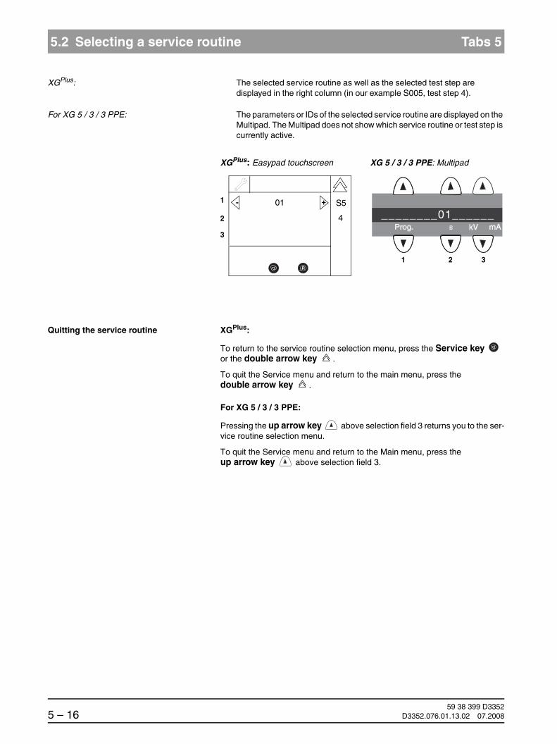
59 38 399 D33525 – 16 D3352.076.01.13.02 07.2008
5.2 Selecting a service routine Tabs 5
XGPlus: The selected service routine as well as the selected test step are displayed in the right column (in our example S005, test step 4).
For XG 5 / 3 / 3 PPE: The parameters or IDs of the selected service routine are displayed on the Multipad. The Multipad does not show which service routine or test step is currently active.
Quitting the service routine XGPlus:
To return to the service routine selection menu, press the Service key or the double arrow key .
To quit the Service menu and return to the main menu, press the double arrow key .
For XG 5 / 3 / 3 PPE:
Pressing the up arrow key above selection field 3 returns you to the ser-vice routine selection menu.
To quit the Service menu and return to the Main menu, press the up arrow key above selection field 3.
R
1
2
3
+- 01
1 2 3
________01______
XGPlus: Easypad touchscreen XG 5 / 3 / 3 PPE: Multipad
4
S5

båÖäáëÜ
59 38 399 D3352D3352.076.01.13.02 07.2008 5 – 17
Tab 5 5.2 Selecting a service routine
5.2
5.2.1 Service routines with security access
NOTEiA security code is required for accessing service routines involving functions such as radiation release or editing of configuration data or stored values. This procedure prevents the inadvertent selection or activation of these service routines.
To select a service routine or test step with security access, proceed as fol-lows:
WARNINGBe sure to observe the radiation protection regulations applicable in your country.
Selecting the service routine/test step 1. Select the service routine or the test step and confirm your selection with the Service key.
After you have confirmed your selection, a 0 appears in selection field 2.
Confirming the security access 2. Confirm the security access by once again selecting the number of the main routine (in our example 2) with the arrow keys of selection field 2 and then pressing the Service key.
Following this double selection and confirmation, the service routine is ac-tivated.
1
2
3
+- S002
1
1 2 3
S002_______1____
XGPlus: Easypad touchscreen XG 5 / 3 / 3 PPE: Multipad
+-
1
2
3
2
1 2 3
___________2____
XGPlus: Easypad touchscreen XG 5 / 3 / 3 PPE: Multipad
+-

59 38 399 D33525 – 18 D3352.076.01.13.02 07.2008
5.3 Service routines with SIDEXIS Tabs 5
5.3 Service routines with SIDEXIS
WARNINGBe sure to observe the radiation protection regulations applicable in your country.
1. Switch the unit ON.
ORTHOPHOS XGPlus The X-Ray radiation indicator ç lights up briefly.
After approx. 2 s, the green LED å in the upper right corner of the Easypad lights up. This LED remains permanently lit as long as the unit is ON.
The start screen appears on the touchscreen of the Easypad and the sys-tem’s self-adjustment routine starts running (for approx. 1 min.). At the same time, the rotating element rotates briefly clockwise and counter-clockwise and the diaphragm is positioned. The forehead and temple sup-ports on the panoramic unit open and close and then stop moving in fully opened position.
Once the self-adjustment routine is completed, the main menu appears on the touchscreen and help message H301 prompts you to move the unit to the starting position.
ORTHOPHOS XG 5 / 3 / 3 PPE All LEDs and the LED display on the Multipad light up briefly.
The green LED in the upper right corner of the Multipad å remains perma-nently lit as long as the unit is ON.
The initialization status is visualized by a progress indicator while the unit performs a self-adjustment routine (approx. 1 min.). At the same time, the rotating element rotates briefly clockwise and counterclockwise and the diaphragm is positioned. The forehead and temple supports on the pan-oramic unit open and close and then stop moving in fully opened position.
Once the self-adjustment routine is completed, help message H301 prompts you to move the unit to the starting position.
2. Press the R key to move the unit back to the starting position.
Switch the PC ON and start SIDEXIS.
XGPlus: Easypad touchscreen XG 5 / 3 / 3 PPE: Multipad
�

båÖäáëÜ
59 38 399 D3352D3352.076.01.13.02 07.2008 5 – 19
Tab 5 5.3 Service routines with SIDEXIS
5.3
3. Select the constancy test in SIDEXIS XG: Select EXTRAS ‡ CONSTANCY TEST.
The typical Sidexis user interface is started. Constancy test is already preset.
4. Start the exposure mode:Click XCXP.
The dialog box for selecting the X-ray device appears on the screen.
5. Select/confirm the X-ray device:Select the desired X-RAY DEVICE and click OK.
The dialog box for selecting the test type appears on the screen.
NOTEiUnder certain circumstances, the dialog box for selecting the X-ray device may be skipped by the software and the dialog box for selecting the test type ap-pears immediately.
6. Select/confirm the test type:Click SERVICE EXPOSURE.
The dialog box for selecting the service exposure appears on the screen.

59 38 399 D33525 – 20 D3352.076.01.13.02 07.2008
5.3 Service routines with SIDEXIS Tabs 5
7. Select/confirm the SERVICE EXPOSURE.
The following service exposures are available for selection:
DIGITAL TEST PATTERN: Checks the data transmission path between PC and sensor
FACTORY SERVICE: Sets interlock signal for service programs (only for D3297)
DIAPHRAGM TEST EXPOSURE: Check of pan andceph adjustments
DIAPHRAGM/SYSTEM ADJUSTMENT: Adjustment
QUALITY TEST EXPOSURE: Test exposure not stored in PDATA
If several different X-ray components are available, a dialog box for select-ing the X-ray device appears on the screen. In this case, select/confirm the required component.
If only one X-ray component is available, the exposure readiness dialog box appears on the screen and shows the status of the exposure.
NOTEiDuring operation in the service mode, the unit switches from the user mode to the PC service mode logged by the PC (see section 4.2).
When you select the DIAPHRAGM/SYSTEM ADJUSTMENT menu...
the dialog box for entering the service password appears on the screen.
Enter the service password and confirm your input by clicking OK.
NOTEiAs servicepassword, enter the first 4 digits of the current system date in re-verse order (e.g. on 05/24/1995, 5042 must be entered as the service password).

båÖäáëÜ
59 38 399 D3352D3352.076.01.13.02 07.2008 5 – 21
Tab 5 5.4 Service routine S001
5.4
S001: Radiation without rotary movement, fixed radiation time
5.4 Service routine S001
Radiation without rotary movement, fixed radiation time
WARNINGBe sure to observe the radiation protection regulations applicable in your country.
Select the Service menu (see page 5-10).
Selecting service routine S001 1. Use the arrow keys in selection field 1 to select service routine S001 and confirm this selection with the Service key .
Confirming the security access 2. Confirm the security access by once again selecting the number of the main routine (1) with the arrow keys of selection field 2 and then pressing the Service key .
Function S001: Test of X-ray beam and kV/mA levels
Radiation with selected kV/mA level
Radiation time cannot be selected, max. 14.0 sec.
Primary diaphragm remains in last position selected
Security access
1
2
3
+- S001
1 2 3
S001____________
XGPlus: Easypad touchscreen XG 5 / 3 / 3 PPE: Multipad
1
2
3
- +1
1 2 3
___________1____
XGPlus: Easypad touchscreen XG 5 / 3 / 3 PPE: Multipad

59 38 399 D33525 – 22 D3352.076.01.13.02 07.2008
5.4 Service routine S001 Tabs 5
S001: Radiation without rotary movement, fixed radiation time
Selecting the kV/mA level 3. Use the arrow keys in selection field 1 to select the desired kV/mA level.
NOTEiThe maximum radiation time is displayed in selection field 2. The maximum radiation time cannot be changed in this service routine and equals 14.0 seconds.
Radiation is emitted as long as the release button remains pressed until the maximum time of 14.0 seconds is reached.
Releasing radiation 4. Release radiation by pressing the release button.
Radiation from any tube assembly position, no rotary movement
The primary diaphragm remains in the last position set
The radiation time is 14.0 seconds
NOTEiIf you let go of the release button before the maximum radiation time has elapsed, radiation is terminated prematurely and the exposure is interrupted. The actual radiation time is not displayed.
When you release radiation during the cool-down interval, a countdown of the remaining waiting time is displayed in selection field 2 on the Multipad (automatic exposure blocking).
Quitting the service routine XGPlus:
Pressing the Service key or the double arrow key returns you to the service routine selection menu.
To quit the Service menu and return to the Main menu, press the double arrow key .
For XG 5 / 3 / 3 PPE:
To return to the service routine selection menu, press the up arrow key above selection field 3.
To quit the Service menu and return to the Main menu, press the up arrow key above selection field 3.
1
2
3
+- 60 kV/8 mA
14 s
1 2 3
60/8____14.0____
XGPlus: Easypad touchscreen XG 5 / 3 / 3 PPE: Multipad
E X RAY

båÖäáëÜ
59 38 399 D3352D3352.076.01.13.02 07.2008 5 – 23
Tab 5 5.5 Service routine S002
5.5
S002: Radiation without rotary movement, maximum radiation time can be selected
5.5 Service routine S002
Radiation without rotary movement, maximum radiation time can be selected
WARNINGBe sure to observe the radiation protection regulations applicable in your country.
Select the Service menu (see page 5-10).
Selecting service routine S002 1. Select service routine S002 using the arrow keys of selection field 1.
Function S002 X-ray beam test
Radiation with selected kV/mA level
Maximum radiation time selectable
Radiation from any position
Test step 1 Primary diaphragm remains in last position selected Security access
Test step 3 Primary diaphragm opened fully Security access
Test step 4 Filter element for 0.8 Cu step filterThe primary diaphragm is set to a widened opening symmetrical to the PAN setting so that the step filter still remains covered.
Security access
1
2
3
+- S002
1
1 2 3
S002_______1____
XGPlus: Easypad touchscreen XG 5 / 3 / 3 PPE: Multipad
+-

59 38 399 D33525 – 24 D3352.076.01.13.02 07.2008
5.5 Service routine S002 Tabs 5
S002.1: Radiation w/o rot. movement, max. radiation time selectable, prim. diaphr. in last pos.
5.5.1 S002: Test step 1
Selecting test step 1 1. Select test step 1 in selection field 2 with the arrow keys and confirm your selection by pressing the Service key .
Confirming the security access 2. Confirm the security access by once again selecting the number of the main routine (2) with the arrow keys of selection field 2 and then pressing the Service key .
Selecting the kV/mA level and radiation time
3. Use the arrow keys of
– selection field 1 to select the desired kV/mA level and
– selection field 2 to select the desired radiation time.
1
2
3
+- S002
1
1 2 3
S002_______1____
XGPlus: Easypad touchscreen XG 5 / 3 / 3 PPE: Multipad
+-
1
2
3
- +2
1 2 3
___________2____
XGPlus: Easypad touchscreen XG 5 / 3 / 3 PPE: Multipad
1
2
3
+- 60 kV/8 mA
2 s
1 2 3
60/8____2.00____
XGPlus: Easypad touchscreen XG 5 / 3 / 3 PPE: Multipad
- +

båÖäáëÜ
59 38 399 D3352D3352.076.01.13.02 07.2008 5 – 25
Tab 5 5.5 Service routine S002
5.5
S002.1: Radiation w/o rot. movement, max. radiation time selectable, prim. diaphr. in last pos.
Releasing radiation 4. Release radiation by pressing the release button.
Radiation from any tube assembly position, no rotary movement
The primary diaphragm remains in the last position set
The maximum radiation time corresponds to the selected radiation time
NOTEiIf you let go of the release button before the maximum radiation time has elapsed, radiation is terminated prematurely and the exposure is interrupted. The actual radiation time is not displayed.
When you release radiation during the cool-down interval, a countdown of the remaining waiting time is displayed in selection field 2 on the Multipad (au-tomatic exposure blocking).
Quitting the service routine XGPlus:
Pressing the Service key or the double arrow key returns you to the service routine selection menu.
To quit the Service menu and return to the main menu, press the double arrow key .
For XG 5 / 3 / 3 PPE:
Pressing the up arrow key above selection field 3 returns you to the ser-vice routine selection menu.
To quit the Service menu and return to the Main menu, press the up arrow key above selection field 3.

59 38 399 D33525 – 26 D3352.076.01.13.02 07.2008
5.5 Service routine S002 Tabs 5
S002.3: Radiation w/o rot. movement, max. radiation time selectable, prim. diaphr. opened fully
5.5.2 S002: Test step 3 (not for XG 3 / 3 PPE)
Difference from S002, test step 1:
Primary diaphragm is opened fully
NOTEi
For selection and operating sequence, see S002, test step 1.
After you have selected test step 3, the primary diaphragm is moved to the new position (opened fully). During this time, a progress indicator is displayed in selection field 1.
1 2 3
1
2
3
XGPlus: Easypad touchscreen XG 5 / 3 / 3 PPE: Multipad
3
S2

båÖäáëÜ
59 38 399 D3352D3352.076.01.13.02 07.2008 5 – 27
Tab 5 5.5 Service routine S002
5.5
S002.4: Radiation without rotary movement, max. radiation time selectable, with 0.8 mm Cu
5.5.3 S002: Test step 4 (not for XG 3 / 3 PPE)
Difference from S002, test step 1:
A filter element for a 0.8 Cu step filter is inserted in the beam path
The primary diaphragm is widened symmetrically to the pan position so that the step filter still remains covered
NOTEi
For selection and operating sequence, see S002, test step 1.
After you have selected test step 4, the primary diaphragm is moved to the new position (opened fully and symmetrical to PAN position). During this time, a progress indicator is displayed in selection field 1.
1 2 3
1
2
3
XGPlus: Easypad touchscreen XG 5 / 3 / 3 PPE: Multipad
4
S2
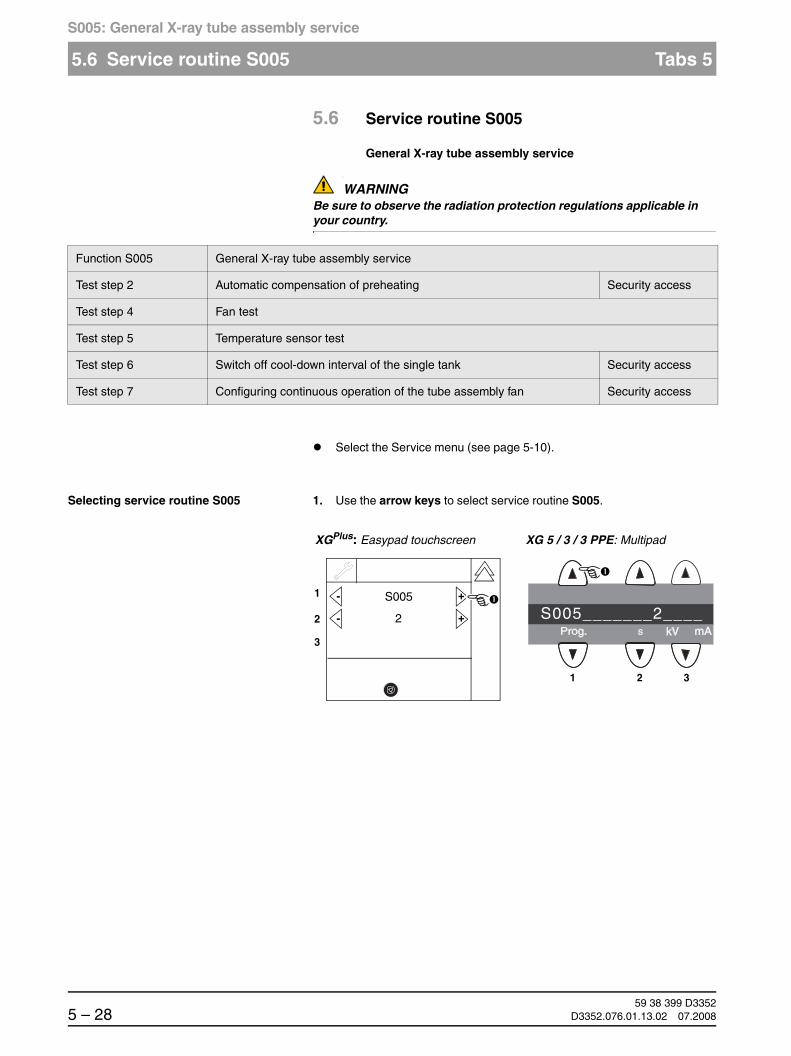
59 38 399 D33525 – 28 D3352.076.01.13.02 07.2008
5.6 Service routine S005 Tabs 5
S005: General X-ray tube assembly service
5.6 Service routine S005
General X-ray tube assembly service
WARNINGBe sure to observe the radiation protection regulations applicable in your country.
Select the Service menu (see page 5-10).
Selecting service routine S005 1. Use the arrow keys to select service routine S005.
Function S005 General X-ray tube assembly service
Test step 2 Automatic compensation of preheating Security access
Test step 4 Fan test
Test step 5 Temperature sensor test
Test step 6 Switch off cool-down interval of the single tank Security access
Test step 7 Configuring continuous operation of the tube assembly fan Security access
1
2
3
+- S005
2
1 2 3
S005_______2____
XGPlus: Easypad touchscreen XG 5 / 3 / 3 PPE: Multipad
+-

båÖäáëÜ
59 38 399 D3352D3352.076.01.13.02 07.2008 5 – 29
Tab 5 5.6 Service routine S005
5.6
S005.2: Automatic adjustment of preheating
5.6.1 S005: Test step 2
Selecting test step 2 1. Select test step 2 in selection field 2 with the arrow keys and confirm your selection by pressing the Service key .
Confirming the security access 2. Confirm the security access by once again selecting the number of the main routine (5) with the arrow keys of selection field 2 and then pressing the Service key .
An inactive progress indicator in selection field 1 and the message FFFFin selection field 2 signal that the system is ready for compensation.
1
2
3
+- S005
2
1 2 3
S005_______2____
XGPlus: Easypad touchscreen XG 5 / 3 / 3 PPE: Multipad
+-
1
2
3
- +5
1 2 3
___________5____
XGPlus: Easypad touchscreen XG 5 / 3 / 3 PPE: Multipad
1
2
3
FFFF
1 2 3
_______FFFF____
XGPlus: Easypad touchscreen XG 5 / 3 / 3 PPE: Multipad
S5
2
E X RAY

59 38 399 D33525 – 30 D3352.076.01.13.02 07.2008
5.6 Service routine S005 Tabs 5
S005.2: Automatic adjustment of preheating
Performing the compensation 3. Start the automatic compensation by pressing the release button.
CAUTIONThe tube assembly must be at operating temperature before the compensation. To do this, release radiation once for 14.0 s at kV/mA level 60/9 via service routine S001 (see page 5-21).
NOTEiKeep pressing the release button until compensation is completed and the new offset value for preheating is displayed. During the compensation proce-dure, a progress indicator is displayed in selection field 1.
NOTEiIf you interrupt the compensation procedure prematurely by letting go of the release button, the message EEEE appears in selection field 2. This message must be acknowledged with the R key.
Quitting the service routine XGPlus:
To return to the service routine selection menu, press the Service key or the double arrow key .
To quit the Service menu and return to the main menu, press the double arrow key .
For XG 5 / 3 / 3 PPE:
To return to the service routine selection menu, press the up arrow key above selection field 3.
To quit the Service menu and return to the Main menu, press the up arrow key above selection field 3.
1
2
3
2 mV(VH)
1 2 3
XGPlus: Easypad touchscreen XG 5 / 3 / 3 PPE: Multipad
S5
2
E X RAY Active!
__________2____

båÖäáëÜ
59 38 399 D3352D3352.076.01.13.02 07.2008 5 – 31
Tab 5 5.6 Service routine S005
5.6
S005.4: Fan test
5.6.2 S005: Test step 4
Selecting test step 4 1. Select test step 4 in selection field 2 with the arrow keys and confirm your selection by pressing the Service key .
Testing the fan 2. Switch the fan ON by selecting code 01 with the arrow keys and confirm-ing with the R key .
Code: 00 = Fan OFF
01 = Fan ON
Check the fan for running noise.
1
2
3
+- S005
4
1 2 3
S005_______4____
XGPlus: Easypad touchscreen XG 5 / 3 / 3 PPE: Multipad
+-
R R
R
1
2
3
+- 01
1 2 3
__01____________
XGPlus: Easypad touchscreen XG 5 / 3 / 3 PPE: Multipad
R

59 38 399 D33525 – 32 D3352.076.01.13.02 07.2008
5.6 Service routine S005 Tabs 5
S005.4: Fan test
Quitting the service routine XGPlus:
Pressing the Service key or the double arrow key returns you to the service routine selection menu.
To quit the Service menu and return to the main menu, press the double arrow key .
For XG 5 / 3 / 3 PPE:
To return to the service routine selection menu, press the up arrow key above selection field 3.
To quit the Service menu and return to the Main menu, press the up arrow key above selection field 3.
NOTEiWhen you quit the service routine the fan is automatically switched OFF again.

båÖäáëÜ
59 38 399 D3352D3352.076.01.13.02 07.2008 5 – 33
Tab 5 5.6 Service routine S005
5.6
S005.5: Temperature sensor test
5.6.3 S005: Test step 5
Selecting test step 5 1. Select test step 5 in selection field 2 with the arrow keys and confirm your selection by pressing the Service key .
After test step 5 is selected, selection field 1 displays the single tank temperature in °C. The display is updated once per second.
Quitting the service routine XGPlus:
To return to the service routine selection menu, press the Service key or the double arrow key .
To quit the Service menu and return to the main menu, press the double arrow key .
For XG 5 / 3 / 3 PPE:
To return to the service routine selection menu, press the up arrow key above selection field 3.
To quit the Service menu and return to the Main menu, press the up arrow key above selection field 3.
1
2
3
+- S005
5
1 2 3
S005_______5____
XGPlus: Easypad touchscreen XG 5 / 3 / 3 PPE: Multipad
+-
1
2
3
31.5C
1 2 3
__31.5_C________
XGPlus: Easypad touchscreen XG 5 / 3 / 3 PPE: Multipad
S5
5

59 38 399 D33525 – 34 D3352.076.01.13.02 07.2008
5.6 Service routine S005 Tabs 5
S005.6: Switch off cool-down interval of the single tank
5.6.4 S005: Test step 6
Upon explicit customer request, the monitored pulse/pause ratio can be dis-abled in exceptional cases. This can be done one time via service routine S005, test step 6. Re-enabling the pulse/pause monitoring function is not possible, though. Such a one-time disablement can be displayed on the info screen and in the detail query by entering "PulsePause-Disable".
CAUTIONThe execution of this service routine is irreversible. The system is operated beyond its specifications afterwards. This may result in an X-ray tube assembly failure. As a result, the system warranty expires. SIRONA is able to prove this system setting after a system failure.
Selecting test step 6 1. Select test step 6 in selection field 2 with the arrow keys and confirm your selection by pressing the Service key .
Confirming the security access 2. Confirm the security access by once again selecting the number of the main routine (5) with the arrow keys of selection field 2 and then pressing the Service key .
1
2
3
+- S005
6
1 2 3
S005_______6____
XGPlus: Easypad touchscreen XG 5 / 3 / 3 PPE: Multipad
+-
1
2
3
- +5
1 2 3
___________5____
XGPlus: Easypad touchscreen XG 5 / 3 / 3 PPE: Multipad

båÖäáëÜ
59 38 399 D3352D3352.076.01.13.02 07.2008 5 – 35
Tab 5 5.6 Service routine S005
5.6
S005.6: Switch off cool-down interval of the single tank
The status of the pulse/pause treatment is displayed in the selection field 1:
01 = Pulse/pause monitoring enabled
00 = Pulse/pause monitoring disabled
Disabling the pulse/pause monitoringCAUTION
The execution of this service routine is irreversible. The system is operated beyond its specifications afterwards. This may result in an X-ray tube assembly failure. As a result, the system warranty expires. SIRONA is able to prove this system setting after a system failure.
3. To distable the pulse/pause monitoring, select code 00 in selection field 1 with the arrow keys.
The Memory key (XGPlus) or the LED above theMemory key (XG 5 / 3 / 3 PPE) lights up.
1
2
3
- +01
6
1 2 3
______01________
XGPlus: Easypad touchscreen XG 5 / 3 / 3 PPE: Multipad
R
1
2
3
- +00
6
1 2 3
______00________
XGPlus: Easypad touchscreen XG 5 / 3 / 3 PPE: Multipad
R

59 38 399 D33525 – 36 D3352.076.01.13.02 07.2008
5.6 Service routine S005 Tabs 5
S005.6: Switch off cool-down interval of the single tank
4. To save the selection, first press the Memory key (R key (XGPlus)/LED above R key (XG 5 / 3 / 3 PPE) lights up) and then the R key .
NOTEiIf pulse/pause monitoring has been disabled before already, this service rou-tine serves as a mere status display. The arrow keys, memory key and R key are not displayed by the XGPlus. These keys are then disabled on the XG 5 / 3 / 3 PPE.
Quitting the service routine XGPlus:
To return to the service routine selection menu, press the Service key or the double arrow key .
To quit the Service menu and return to the main menu, press the double arrow key .
For XG 5 / 3 / 3 PPE:
To return to the service routine selection menu, press the up arrow key above selection field 3.
To quit the Service menu and return to the Main menu, press the up arrow key above selection field 3.
R R
1
2
3
- +00 S5
6
1 2 3
______00________
XGPlus: Easypad touchscreen XG 5/3/3 PPE: Multipad
R
R
1
2
3
00 S5
6
1 2 3
______00________
XGPlus: Easypad touchscreen XG 5/3/3 PPE: Multipad

båÖäáëÜ
59 38 399 D3352D3352.076.01.13.02 07.2008 5 – 37
Tab 5 5.6 Service routine S005
5.6
S005.7: Setting continuous operation of the tube assembly fan
5.6.5 S005: Test step 7
The tube assembly fan can be configured for continuous operation at the express wish of the customer This can be done via service routine S005, test step 7. The customer should be informed in advance about the increaed noise development to be expected. A demonstration of the fan noise can be made with service routine S005.4.
CAUTIONBecause of the expected greater contamination of the fan and of the single tank housing, the configuration of continuous operation is documented irreversibly on the tube assembly in order to obtain additional information in the case of returned goods.
Selecting test step 6 1. Select test step 7 in selection field 2 with the arrow keys and confirm your selection by pressing the Service key .
Confirming the security access 2. Confirm the security access by once again selecting the number of the main routine (5) with the arrow keys of selection field 2 and then pressing the Service key .
1
2
3
+- S005
7
1 2 3
S005_______7____
XGPlus: Easypad touchscreen XG 5 / 3 / 3 PPE: Multipad
+-
1
2
3
- +5
1 2 3
___________5____
XGPlus: Easypad touchscreen XG 5 / 3 / 3 PPE: Multipad

59 38 399 D33525 – 38 D3352.076.01.13.02 07.2008
5.6 Service routine S005 Tabs 5
S005.7: Setting continuous operation of the tube assembly fan
The operating mode of the fan is displayed in selection field 1:
01 = continuous operation of the fan
00 = controlled operation of the fan
Switching on continuous fan operation 3. To switch the fan to continuous operation, select code 01 in selection field 1 with the arrow keys.
The Memory key (XGPlus) or the LED above the Memory key (XG 5 / 3 / 3 PPE) lights up.
1
2
3
- +00
7
1 2 3
00____________
XGPlus: Easypad touchscreen XG 5 / 3 / 3 PPE: Multipad
R
1
2
3
- +01
7
1 2 3
00____________
XGPlus: Easypad touchscreen XG 5 / 3 / 3 PPE: Multipad
R

båÖäáëÜ
59 38 399 D3352D3352.076.01.13.02 07.2008 5 – 39
Tab 5 5.6 Service routine S005
5.6
S005.7: Setting continuous operation of the tube assembly fan
4. To save the selection, first press the Memory key (R key (XGPlus)/LED above R key (XG 5 / 3 / 3 PPE) lights up) and then the R key .
Quitting the service routine XGPlus:
To return to the service routine selection menu, press the Service key or the double arrow key .
To quit the Service menu and return to the main menu, press the double arrow key .
For XG 5 / 3 / 3 PPE:
To return to the service routine selection menu, press the up arrow key above selection field 3.
To quit the Service menu and return to the Main menu, press the up arrow key above selection field 3.
R R
1
2
3
- +01 S5
7
1 2 3
______01________
XGPlus: Easypad touchscreen XG 5 / 3 / 3 PPE: Multipad
R
R

59 38 399 D33525 – 40 D3352.076.01.13.02 07.2008
5.7 Service routine S007 Tabs 5
S007: Error logging memory
5.7 Service routine S007
Error logging memory
NOTEiIn addition to Service routine S007.1, you can also use the extended detail query in SIXABCON to check the error logging memory.
Select the Service menu (see page 5-10).
Selecting service routine S007 1. Use the arrow keys to select service routine S007.
Function S007 Error logging memory
Test step 1 Display error logging memory
Test step 2 Clear error logging memory Security access
Test step 5 Enabling the CAN bus logging in the Miniweb
1
2
3
+- S007
1
1 2 3
S007_______7____
XGPlus: Easypad touchscreen XG 5/3/3 PPE: Multipad
+-

båÖäáëÜ
59 38 399 D3352D3352.076.01.13.02 07.2008 5 – 41
Tab 5 5.7 Service routine S007
5.7
S007.1: Display error logging memory
5.7.1 S007: Test step 1
Selecting test step 1 1. Select test step 1 in selection field 2 with the arrow keys and confirm your selection by pressing the Service key .
2. Select the desired error event (in example 66).
XGPlus: Easypad touchscreen You can browse between the different occurred error numbers with the arrow keys in selection field 1.
The corresponding error message is displayed in selection field 2 (see section 2.5). Selection field 3 displays the date and time of the error event.
You can set the step width for browsing between the error numbers with the patient symbol keys.
The currently selected patient symbol key is lit. A step width of 1 is preset (left patient symbol key is lit).
1
2
3
+- S007
1
1 2 3
S007_______1____
XGPlus: Easypad touchscreen XG 5/3/3 PPE: Multipad
+-
1
2
3
+- 66
E6 81 07
2004-12-14; 12:31:09
1
Step width 100Step width 10Step width 1

59 38 399 D33525 – 42 D3352.076.01.13.02 07.2008
5.7 Service routine S007 Tabs 5
S007.1: Display error logging memory
XG 5 / 3 / 3 PPE: Multipad You can browse between the different occurred error numbers with the arrow keys in selection field 1. You can display the error code, time or date of the error event with the arrow keys in selection field 2.
You can set the step width for browsing between the error numbers with the first three patient symbol keys (starting from the left).
The LED above the selected patient symbol key is lit. A step width of 1 is pre-set (the LED above the left patient symbol key is lit).
1 2 3
66______E6_81_07
1 2 3
66______E6_81_07
1 2 3
65______E7_11_08
1 2 3
66______13:30:57
1 2 3
66______05-01-17
Browse back
Browse forward
Dat
eT
ime
Err
or
cod
e
Step width 100Step width 10Step width 1

båÖäáëÜ
59 38 399 D3352D3352.076.01.13.02 07.2008 5 – 43
Tab 5 5.7 Service routine S007
5.7
S007.1: Display error logging memory
Quitting the service routine XGPlus:
Pressing the Service key or the double arrow key returns you to the service routine selection menu.
To quit the Service menu and return to the main menu, press the double arrow key .
For XG 5 / 3 / 3 PPE:
To return to the service routine selection menu, press the up arrow key above selection field 3.
To quit the Service menu and return to the Main menu, press the up arrow key above selection field 3.

59 38 399 D33525 – 44 D3352.076.01.13.02 07.2008
5.7 Service routine S007 Tabs 5
S007.2: Clear error logging memory
5.7.2 S007: Test step 2
Selecting test step 2 1. Select test step 2 in selection field 2 with the arrow keys and confirm your selection by pressing the Service key .
Confirming the security access 2. Confirm the security access by once again selecting the number of the main routine (7) with the arrow keys of selection field 2 and then pressing the Service key .
The system's readiness to clear the memory is indicated by the display mes-sage FFFF in selection field 1. If the error logging memory does not contain any data, 0000 is displayed.
1
2
3
+- S007
2
1 2 3
S007_______2____
XGPlus: Easypad touchscreen XG 5 / 3 / 3 PPE: Multipad
+-
1
2
3
- +7
1 2 3
___________7____
XGPlus: Easypad touchscreen XG 5 / 3 / 3 PPE: Multipad
1
2
3
FFFF
1 2 3
____FFFF________
XGPlus: Easypad touchscreen XG 5 / 3 / 3 PPE: Multipad
R
S7
2

båÖäáëÜ
59 38 399 D3352D3352.076.01.13.02 07.2008 5 – 45
Tab 5 5.7 Service routine S007
5.7
S007.2: Clear error logging memory
Clear error logging memory 3. To clear the memory, first press the Memory key (R key (XGPlus)/LED above R key (XG 5 / 3 / 3 PPE) lights up) and then the R key .
Quitting the service routine XGPlus:
Pressing the Service key or the double arrow key returns you to the service routine selection menu.
To quit the Service menu and return to the main menu, press the double arrow key .
For XG 5 / 3 / 3 PPE:
To return to the service routine selection menu, press the up arrow key above selection field 3.
To quit the Service menu and return to the Main menu, press the up arrow key above selection field 3.
R R
R
1
2
3
FFFF
1 2 3
____FFFF________
XGPlus: Easypad touchscreen XG 5 / 3 / 3 PPE: Multipad
R
S7
2
1
2
3
0000
1 2 3
____0000________
XGPlus: Easypad touchscreen XG 5 / 3 / 3 PPE: Multipad
R
S7
2

59 38 399 D33525 – 46 D3352.076.01.13.02 07.2008
5.7 Service routine S007 Tabs 5
S007.2: Clear error logging memory
5.7.3 S007: Test step 5
CAUTIONThis service routine should be executed only in consultation with and with the support of the SIRONA Customer Service Center!
Selecting test step 5 1. Select test step 5 in selection field 2 with the arrow keys and confirm your selection by pressing the Service key .
Activation of logging 2. Select the desired setting using the arrow keys of selection field 1:
– WS CAN bus off (factory setting): Logging switched off
– WS CAN bus on: Logging switched on
– WS CAN bus Ex. on: Extended logging switched on
After the test step has been selected the Test key (XGPlus) or the LED above the Test key (XG 5 / 3 / 3 PPE) lights up.
3. To activate the logging function, press the Test key .
All CAN bus events occurring from now on during operation of the system will be logged and can be displayed with a web browser (e.g. Internet Explorer). This log will help you when consulting the SIRONA customer service center for error diagnosis.
1
2
3
+- S007
5
1 2 3
S007_______5____
XGPlus: Easypad touchscreen XG 5 / 3 / 3 PPE: Multipad
+-
T
T
T T
1 +- WS CAN bus on1
2
3
1 2 3
WS_CAN-BUS_ON
XGPlus: Easypad touchscreen XG 5 / 3 / 3 PPE: Multipad
S7
5
TT
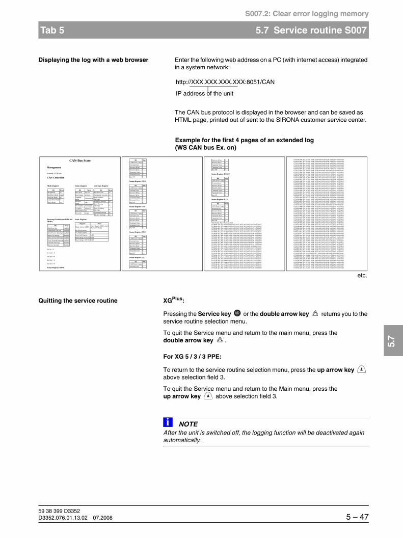
båÖäáëÜ
59 38 399 D3352D3352.076.01.13.02 07.2008 5 – 47
Tab 5 5.7 Service routine S007
5.7
S007.2: Clear error logging memory
Displaying the log with a web browser Enter the following web address on a PC (with internet access) integrated in a system network:
The CAN bus protocol is displayed in the browser and can be saved as HTML page, printed out of sent to the SIRONA customer service center.
Quitting the service routine XGPlus:
Pressing the Service key or the double arrow key returns you to the service routine selection menu.
To quit the Service menu and return to the main menu, press the double arrow key .
For XG 5 / 3 / 3 PPE:
To return to the service routine selection menu, press the up arrow key above selection field 3.
To quit the Service menu and return to the Main menu, press the up arrow key above selection field 3.
NOTEiAfter the unit is switched off, the logging function will be deactivated again automatically.
http://XXX.XXX.XXX.XXX:8051/CAN
IP address of the unit
CAN-Bus State
Management
Busmode: STTP-Auto
CAN-Controller
ErrCnt = 0
ErrCnt0 = 0
ErrCnt1 = 0
ErrCnt2 = 0
ErrCnt3 = 0
Status-Register DX41
Mode-Register
Bit WertSleepMode noAccFilter Mode singleSelfTest Mode noListenOnly Mode noReset Mode no
Status-Register
Bit WertBus status bus-onError status no error Transmit status transmitting
Receivestatus idle
Tx complete incompleteTx buffer releasedData overrun noRx buffer empty
Interrupt-Register
Bit WertBus Error Intr noArbitration Lost Intr noError Passive Interrupt no
Wake-Up Iterrupt noData Overrun Interrupt no
Error Warning Interrupt no
Transmit Interrupt noReceive Interrupt no
Interrupt-Enable (nur PeliCAN-Mode)
Bit WertBus Error Intr enabled Arbitration Lost Intr enabled Error Passive Interrupt enabled Wake-Up Iterrupt disabledData Overrun Interrupt enabled Error Warning Interrupt enabled Transmit Interrupt disabledReceive Interrupt disabled
Sonst. Register
Register Wert
Clock divider (CDR) Clock divider (CDR): 0xc0(PeliCAN-Mode)
RX ErrorCounter 0TX ErrorCounter 0ErrorCodeCapture 0x00Bus-Timing 0 (BTR0) 0x03Bus-Timing 1 (BTR1) 0x18
Status-Register DX42
Status-Register DX6
Status-Register DX61
Status-Register DX7
Bit WertCAN-Error Comp. 0Overrun Error 0Receiver Warn. 0Receiver Error 0Tramsmit Warn. 0Tramsmit Error 0Bus Off 0
Bit WertCAN-Error Comp. 0Overrun Error 0Receiver Warn. 0Receiver Error 0Tramsmit Warn. 0Tramsmit Error 0Bus Off 0
Bit WertCAN-Error Comp. 0Overrun Error 0Receiver Warn. 0Receiver Error 0Tramsmit Warn. 0Tramsmit Error 0Bus Off 0
Bit WertCAN-Error Comp. 0Overrun Error 0Receiver Warn. 0Receiver Error 0Tramsmit Warn. 0Tramsmit Error 0Bus Off 0
Bit WertCAN-Error Comp. 0Overrun Error 0
Status-Register DX81P
Status-Register DX91
TimeStamp; Typ; ID; Len; ;Data0758084.419; Tx; 0x500; 0x08; 0x55 0x55 0x55 0x55 0x55 0x55 0x55 0x550758086.420; Tx; 0x480; 0x08; 0x55 0x55 0x55 0x55 0x55 0x55 0x55 0x550758088.420; Tx; 0x680; 0x08; 0x55 0x55 0x55 0x55 0x55 0x55 0x55 0x550758090.435; Tx; 0x700; 0x08; 0x55 0x55 0x55 0x55 0x55 0x55 0x55 0x550758092.421; Tx; 0x780; 0x08; 0x55 0x55 0x55 0x55 0x55 0x55 0x55 0x550758096.435; Rx; 0x081; 0x08; 0x00 0x00 0x00 0x00 0x00 0x00 0x00 0x000758098.431; Rx; 0x101; 0x08; 0x00 0x00 0x00 0x00 0x00 0x00 0x00 0x000758100.445; Rx; 0x201; 0x08; 0x00 0x00 0x00 0x00 0x00 0x04 0x00 0x000758104.432; Rx; 0x301; 0x08; 0x00 0x00 0x00 0x00 0x00 0x03 0x00 0x000758106.432; Rx; 0x401; 0x08; 0x00 0x00 0x00 0x00 0x00 0x00 0x00 0x000758108.432; Rx; 0x501; 0x08; 0x00 0x00 0x00 0x00 0x00 0x00 0x00 0x000758110.434; Rx; 0x481; 0x08; 0x00 0x00 0x00 0x00 0x00 0x01 0x00 0x000758120.453; Tx; 0x001; 0x08; 0x26 0x3b 0x0f 0x01 0x0b 0x49 0x1b 0xe00758122.425; Tx; 0x080; 0x08; 0x55 0x55 0x55 0x55 0x55 0x55 0x55 0x550758124.425; Tx; 0x100; 0x08; 0x55 0x55 0x55 0x55 0x55 0x55 0x55 0x550758126.439; Tx; 0x200; 0x08; 0x55 0x55 0x55 0x55 0x55 0x55 0x55 0x550758128.426; Tx; 0x280; 0x08; 0x55 0x55 0x55 0x55 0x55 0x55 0x55 0x550758130.459; Tx; 0x300; 0x08; 0x55 0x55 0x55 0x55 0x55 0x55 0x55 0x550758132.461; Tx; 0x400; 0x08; 0x55 0x55 0x55 0x55 0x55 0x55 0x55 0x550758134.428; Tx; 0x500; 0x08; 0x55 0x55 0x55 0x55 0x55 0x55 0x55 0x550758136.430; Tx; 0x480; 0x08; 0x55 0x55 0x55 0x55 0x55 0x55 0x55 0x550758138.429; Tx; 0x680; 0x08; 0x55 0x55 0x55 0x55 0x55 0x55 0x55 0x550758140.431; Tx; 0x700; 0x08; 0x55 0x55 0x55 0x55 0x55 0x55 0x55 0x550758142.429; Tx; 0x780; 0x08; 0x55 0x55 0x55 0x55 0x55 0x55 0x55 0x550758146.442; Rx; 0x081; 0x08; 0x00 0x00 0x00 0x00 0x00 0x00 0x00 0x00
Receiver Warn. 0Receiver Error 0Tramsmit Warn. 0Tramsmit Error 0Bus Off 0
Bit WertCAN-Error Comp. 0Overrun Error 0Receiver Warn. 0Receiver Error 0Tramsmit Warn. 0Tramsmit Error 0Bus Off 0
Bit WertCAN-Error Comp. 0Overrun Error 0Receiver Warn. 0Receiver Error 0Tramsmit Warn. 0Tramsmit Error 0Bus Off 0
0758148.440; Rx; 0x101; 0x08; 0x00 0x00 0x00 0x00 0x00 0x00 0x00 0x000758150.461; Rx; 0x201; 0x08; 0x00 0x00 0x00 0x00 0x00 0x04 0x00 0x000758154.440; Rx; 0x301; 0x08; 0x00 0x00 0x00 0x00 0x00 0x03 0x00 0x000758156.441; Rx; 0x401; 0x08; 0x00 0x00 0x00 0x00 0x00 0x00 0x00 0x000758158.441; Rx; 0x501; 0x08; 0x00 0x00 0x00 0x00 0x00 0x00 0x00 0x000758160.464; Rx; 0x481; 0x08; 0x00 0x00 0x00 0x00 0x00 0x01 0x00 0x000758170.458; Tx; 0x001; 0x08; 0x26 0x3b 0x0f 0x01 0x0b 0x49 0x00 0x0a0758172.450; Tx; 0x080; 0x08; 0x55 0x55 0x55 0x55 0x55 0x55 0x55 0x550758174.436; Tx; 0x100; 0x08; 0x55 0x55 0x55 0x55 0x55 0x55 0x55 0x550758176.469; Tx; 0x200; 0x08; 0x55 0x55 0x55 0x55 0x55 0x55 0x55 0x550758178.436; Tx; 0x280; 0x08; 0x55 0x55 0x55 0x55 0x55 0x55 0x55 0x550758180.451; Tx; 0x361; 0x08; 0x00 0x00 0x00 0x00 0x00 0x00 0x00 0x000758182.438; Tx; 0x400; 0x08; 0x55 0x55 0x55 0x55 0x55 0x55 0x55 0x550758184.438; Tx; 0x500; 0x08; 0x55 0x55 0x55 0x55 0x55 0x55 0x55 0x550758186.439; Tx; 0x480; 0x08; 0x55 0x55 0x55 0x55 0x55 0x55 0x55 0x550758188.439; Tx; 0x680; 0x08; 0x55 0x55 0x55 0x55 0x55 0x55 0x55 0x550758190.468; Tx; 0x700; 0x08; 0x55 0x55 0x55 0x55 0x55 0x55 0x55 0x550758192.440; Tx; 0x780; 0x08; 0x55 0x55 0x55 0x55 0x55 0x55 0x55 0x550758196.450; Rx; 0x081; 0x08; 0x00 0x00 0x00 0x00 0x00 0x00 0x00 0x000758198.450; Rx; 0x101; 0x08; 0x00 0x00 0x00 0x00 0x00 0x00 0x00 0x000758200.451; Rx; 0x201; 0x08; 0x00 0x00 0x00 0x00 0x00 0x04 0x00 0x000758204.450; Rx; 0x337; 0x08; 0xc7 0x32 0x00 0x00 0x00 0x00 0x00 0x000758206.464; Rx; 0x401; 0x08; 0x00 0x00 0x00 0x00 0x00 0x00 0x00 0x000758208.455; Rx; 0x501; 0x08; 0x00 0x00 0x00 0x00 0x00 0x00 0x00 0x000758210.468; Rx; 0x481; 0x08; 0x00 0x00 0x00 0x00 0x00 0x01 0x00 0x000758220.467; Tx; 0x001; 0x08; 0x27 0x3b 0x0f 0x01 0x0b 0x49 0x1b 0xe00758222.446; Tx; 0x080; 0x08; 0x55 0x55 0x55 0x55 0x55 0x55 0x55 0x550758224.445; Tx; 0x100; 0x08; 0x55 0x55 0x55 0x55 0x55 0x55 0x55 0x550758226.461; Tx; 0x200; 0x08; 0x55 0x55 0x55 0x55 0x55 0x55 0x55 0x550758228.447; Tx; 0x280; 0x08; 0x55 0x55 0x55 0x55 0x55 0x55 0x55 0x550758230.450; Tx; 0x300; 0x08; 0x55 0x55 0x55 0x55 0x55 0x55 0x55 0x550758232.447; Tx; 0x400; 0x08; 0x55 0x55 0x55 0x55 0x55 0x55 0x55 0x550758234.447; Tx; 0x500; 0x08; 0x55 0x55 0x55 0x55 0x55 0x55 0x55 0x550758236.476; Tx; 0x480; 0x08; 0x55 0x55 0x55 0x55 0x55 0x55 0x55 0x550758238.449; Tx; 0x680; 0x08; 0x55 0x55 0x55 0x55 0x55 0x55 0x55 0x550758240.465; Tx; 0x700; 0x08; 0x55 0x55 0x55 0x55 0x55 0x55 0x55 0x550758242.450; Tx; 0x780; 0x08; 0x55 0x55 0x55 0x55 0x55 0x55 0x55 0x550758246.464; Rx; 0x081; 0x08; 0x00 0x00 0x00 0x00 0x00 0x00 0x00 0x000758248.460; Rx; 0x101; 0x08; 0x00 0x00 0x00 0x00 0x00 0x00 0x00 0x000758250.475; Rx; 0x201; 0x08; 0x00 0x00 0x00 0x00 0x00 0x04 0x00 0x000758254.461; Rx; 0x301; 0x08; 0x00 0x00 0x00 0x00 0x02 0x03 0x00 0x610758256.471; Rx; 0x401; 0x08; 0x00 0x00 0x00 0x00 0x00 0x00 0x00 0x000758258.464; Rx; 0x501; 0x08; 0x00 0x00 0x00 0x00 0x00 0x00 0x00 0x000758260.463; Rx; 0x481; 0x08; 0x00 0x00 0x00 0x00 0x00 0x01 0x00 0x000758270.488; Tx; 0x001; 0x08; 0x27 0x3b 0x0f 0x01 0x0b 0x49 0x00 0x070758272.454; Tx; 0x080; 0x08; 0x55 0x55 0x55 0x55 0x55 0x55 0x55 0x550758274.455; Tx; 0x100; 0x08; 0x55 0x55 0x55 0x55 0x55 0x55 0x55 0x550758276.469; Tx; 0x200; 0x08; 0x55 0x55 0x55 0x55 0x55 0x55 0x55 0x550758278.455; Tx; 0x280; 0x08; 0x55 0x55 0x55 0x55 0x55 0x55 0x55 0x550758280.478; Tx; 0x300; 0x08; 0x55 0x55 0x55 0x55 0x55 0x55 0x55 0x550758282.457; Tx; 0x400; 0x08; 0x55 0x55 0x55 0x55 0x55 0x55 0x55 0x550758284.457; Tx; 0x500; 0x08; 0x55 0x55 0x55 0x55 0x55 0x55 0x55 0x550758286.459; Tx; 0x4df; 0x08; 0xc7 0x00 0x00 0x00 0x00 0x00 0x00 0x000758288.458; Tx; 0x680; 0x08; 0x55 0x55 0x55 0x55 0x55 0x55 0x55 0x550758290.460; Tx; 0x700; 0x08; 0x55 0x55 0x55 0x55 0x55 0x55 0x55 0x550758292.458; Tx; 0x780; 0x08; 0x55 0x55 0x55 0x55 0x55 0x55 0x55 0x550758296.470; Rx; 0x081; 0x08; 0x00 0x00 0x00 0x00 0x00 0x00 0x00 0x000758298.468; Rx; 0x101; 0x08; 0x00 0x00 0x00 0x00 0x00 0x00 0x00 0x000758300.486; Rx; 0x201; 0x08; 0x00 0x00 0x00 0x00 0x00 0x04 0x00 0x000758304.469; Rx; 0x301; 0x08; 0x00 0x00 0x00 0x00 0x04 0x03 0x00 0x610758306.478; Rx; 0x401; 0x08; 0x00 0x00 0x00 0x00 0x00 0x00 0x00 0x00
Example for the first 4 pages of an extended log (WS CAN bus Ex. on)
etc.

59 38 399 D33525 – 48 D3352.076.01.13.02 07.2008
5.8 Service routine S008 Tabs 5
S008: Update service
5.8 Service routine S008
Update service
Select the Service menu (see page 5-10).
Selecting service routine S008 1. Use the arrow keys to select service routine S008.
5.8.1 S008: Test step 2
Selecting test step 2 1. Select test step 2 in selection field 2 with the arrow keys and confirm your selection by pressing the Service key .
Function S008 Checking the software versions
Test step 2 Overview of the module software versions
Test step 3 Entry of a unit serial number
Test step 4(XG5/XGPlus only)
Initialize the function activation
1
2
3
+- S008
2
1 2 3
S008_______2____
XGPlus: Easypad touchscreen XG 5/3/3 PPE: Multipad
+-
1
2
3
+- S008
2
1 2 3
S008_______2____
XGPlus: Easypad touchscreen XG 5/3/3 PPE: Multipad
+-

båÖäáëÜ
59 38 399 D3352D3352.076.01.13.02 07.2008 5 – 49
Tab 5 5.8 Service routine S008
5.8
S008.2: Overview of the module software versions
XGPlus: Easypad touchscreen The software versions currently installed in the modules are displayed on the info screen of the touchscreen display.
XG 5 / 3 / 3 PPE: Multipad The single-line display of the Multipad shows the message SYSTEMSOFTWARE.
Select the desired module using the arrow keys of selection field 1 and con-firm your selection by pressing the Memory key .
The software version of the selected module is displayed in selection field 1.
To return to the module selection menu, press the Service key .
Quitting the service routine XGPlus:
To return to the Main menu, press the arrow key .
For XG 5 / 3 / 3 PPE:
To return to the module selection menu, press the up arrow key above selection field 3.
To return to the service routine selection menu and then to the Main menu, press the up arrow key above selection field 3 repeatedly.
65
System : V02.20.00
DX11 : V00.02.56DX6 : V00.02.35DX7 : V00.02.56DX41 : V00.02.33DX42 : V00.02.22DX61 : V00.02.26DX81 : V00.02.28
1 2 3
SYSTEMSOFTWARE__
1 2 3
DX11____________
1 2 3
V02.18.00_______

59 38 399 D33525 – 50 D3352.076.01.13.02 07.2008
5.8 Service routine S008 Tabs 5
S008.3: Input/confirmation of unit serial number
5.8.2 S008: Test step 3
Selecting test step 3 1. Select test step 3 in selection field 2 with the arrow keys and confirm your selection by pressing the Service key .
This test step is required...
if a software update is performed...
for XG 5 / 3 / 3 PPE: from V02.18.1 to a higher versionfor XGPlus: from V02.19 to a higher
version. The value X is then displayed in selection field 1 of service routine S008.3 (and with the arrow keys for the XGPlus ). When opened, the routine is initially in the editing mode for entry of the unit serial number (case A).
if modules have been replaced. In this case, the backup copy of the unit serial number still stored in the unit must be reconfirmed (case B).
If this service routine is called up with a valid unit serial number, the possibility of entering or confirming the serial number will be deactivated. The valid serial number is displayed in selection field 1.
1
2
3
+- S008
3
1 2 3
S008_______3____
XGPlus: Easypad touchscreen XG 5 / 3 / 3 PPE: Multipad
+-

båÖäáëÜ
59 38 399 D3352D3352.076.01.13.02 07.2008 5 – 51
Tab 5 5.8 Service routine S008
5.8
S008.3: Input/confirmation of unit serial number
Case A: Entry of a unit serial number
1. Get the unit serial number from the rating plate of the unit (e.g. 00123).
2. Select the first digit of the serial number with the arrow keys in selection field 1 (from the left in example 1) and accept this value with the R key .
1X is now displayed in selection field 1 and the second digit of the serial num-ber can be selected.
3. Select the second digit of the serial number with the arrow keys in selec-tion field 1 (from the left in example 2) and accept this value with theR key .
R R
1
2
3
1
1 2 3
1___ ___________
XGPlus: Easypad touchscreen XG 5 / 3 / 3 PPE: Multipad
R
3
+-
R
1
2
3
1X
1 2 3
1X_____________
XGPlus: Easypad touchscreen XG 5 / 3 / 3 PPE: Multipad
R
3
+-
R R
1
2
3
12
1 2 3
12______________
XGPlus: Easypad touchscreen XG 5 / 3 / 3 PPE: Multipad
R
3
+-
R

59 38 399 D33525 – 52 D3352.076.01.13.02 07.2008
5.8 Service routine S008 Tabs 5
S008.3: Input/confirmation of unit serial number
12X is now displayed in selection field 1 and the third digit of the serial number can be selected.
4. Repeat this procedure until the complete unit serial number has been en-tered.
5. Save the unit serial number with the Memory key .
The complete serial number is displayed for review. The system automatically changes the entry to a 9-digit number by adding leading zeroes at the left.
NOTEiAt this point you have the possibility of discarding an incorrectly entered serial number. This is done by quitting the service routine without finally confirming the serial number via the R key.
1
2
3
12X
1 2 3
12X_____________
XGPlus: Easypad touchscreen XG 5 / 3 / 3 PPE: Multipad
R
3
+-
1
2
3
123X
1 2 3
123X ____________
XGPlus: Easypad touchscreen XG 5 / 3 / 3 PPE: Multipad
R
3
+-
1
2
3
000000123
1 2 3
000000123_______
XGPlus: Easypad touchscreen XG 5 / 3 / 3 PPE: Multipad
R
3
+-

båÖäáëÜ
59 38 399 D3352D3352.076.01.13.02 07.2008 5 – 53
Tab 5 5.8 Service routine S008
5.8
S008.3: Input/confirmation of unit serial number
6. Check the correctness of the unit serial number you have entered and, if it is OK, confirm this by pressing the R key .
CAUTIONMake sure that you do not accidentally press the R key and/or the Memory key before all digits of the serial number have been entered. Otherwise an incorrect serial number will be irreversibly entered.
Case B: Confirming the unit serial number
1. To confirm the displayed serial number, press the R key .
You can interrupt this procedure with the Service key . The unit serial number will then not be confirmed.
Quitting the service routine XGPlus:
To return to the service routine selection menu, press the Service key or the double arrow key .
To quit the Service menu and return to the main menu, press the double arrow key .
For XG 5 / 3 / 3 PPE:
Pressing the up arrow key above selection field 3 returns you to the ser-vice routine selection menu.
To quit the Service menu and return to the Main menu, press the up arrow key above selection field 3.
R R
1
2
3
000000123
1 2 3
000000123_______
XGPlus: Easypad touchscreen XG 5 / 3 / 3 PPE: Multipad
R
3
R
S8
R R
1
2
3
000000123
1 2 3
000000123_______
XGPlus: Easypad touchscreen XG 5 / 3 / 3 PPE:Multipad
R
3
R
S8

59 38 399 D33525 – 54 D3352.076.01.13.02 07.2008
5.8 Service routine S008 Tabs 5
S008.4: Initialize the function activation
5.8.3 S008: Test step 4 (XG5 / XGPlus only)
Selecting test step 4 1. Select test step 4 in selection field 2 with the arrow keys and confirm your selection by pressing the Service key .
After the test step has been selected, there are two possibilities:
It is possible to initialize the function activation (case A)
It is not possible to initialize the function activation (case B)
Case A: Initialization of function activation is possible
Case B: Initialization of function activation is not possible
NOTEiIf it is possible to initialize the function activation, then the Memory key (XGPlus) or the LED above the Memory key (XG5) will light up at this point.
1
2
3
+- S008
4 +-
S8
1 2 3
S008_______4____
XG 5: MultipadXGPlus: Touchscreen on Easypad
XGPlus: Touchscreen on Easypad
R
1
2
3
S8
4
1 2 3
_________________
XG 5: Multipad
1
2
3
FFFF S8
4
XGPlus: Touchscreen on Easypad
1 2 3
FFFF____________
XG 5: Multipad

båÖäáëÜ
59 38 399 D3352D3352.076.01.13.02 07.2008 5 – 55
Tab 5 5.8 Service routine S008
5.8
S008.4: Initialize the function activation
Performing initialization 2. To initialize the function activation, first press the Memory key (R key (XGPlus) or the LED above the R key (XG5) lights up) and then the R key .
Quitting the service routine For XGPlus:
Via the Service or double-arrow key you can return to the menu for selecting the service routines.
From the Service menu, you can enter the Main menu via the double-arrow key .
For XG 5:
You can return to the menu for selecting the service routines with the up arrow key above selection field 3.
From the Service menu, you can return to the Main menu via the up arrow key above selection field 3.
R R
R
R
1
2
3
S8
4
XGPlus: Touchscreen on Easypad
1 2 3
_________________
XG 5: Multipad

59 38 399 D33525 – 56 D3352.076.01.13.02 07.2008
5.9 Service routine S009 Tabs 5
S009: Initializing the flash file system
5.9 Service routine S009
Flash file system
NOTEiIf the flash file system is initialized, the contents of the Error logging memory are also lost.
Select the Service menu (see page 5-10).
Selecting service routine S009 1. Use the arrow keys to select service routine S009.
5.9.1 S009: Test step 4
Selecting test step 4 1. Select test step 4 in selection field 2 with the arrow keys and confirm your selection by pressing the Service key .
Function S009 Flash file system
Test step 4 Initializing the flash file system Security access
1
2
3
+- S009
4
1 2 3
S009_______4____
XGPlus: Easypad touchscreen XG 5 / 3 / 3 PPE: Multipad
+-
1
2
3
+- S009
4
1 2 3
S009_______4____
XGPlus: Easypad touchscreen XG 5 / 3 / 3 PPE: Multipad
+-

båÖäáëÜ
59 38 399 D3352D3352.076.01.13.02 07.2008 5 – 57
Tab 5 5.9 Service routine S009
5.9
S009.4: Initializing the flash file system
Confirming the security access 2. Confirm the security access by once again selecting the number of the main routine (9) with the arrow keys of selection field 2 and then pressing the Service key .
After the test step has been selected the Memory key (XGPlus) or the LED above the Memory key (XG 5 / 3 / 3 PPE) lights up.
Initializing the flash file system 3. To initialize the flash file system, first press the Memory key (R key (XGPlus) or the LED above the R key (XG 5 / 3 / 3 PPE) lights up) and then the R key .
Flash file system formatting in progress. This process takes approx. 5 - 6 min. and is visualized by a progress indicator. The end of this process is indicated by the message 0000 in selection field 2. The Memory key (XGPlus) or the LED above the Memory key (XG 5 / 3 / 3 PPE) lights up.
1
2
3
9
1 2 3
___________9____
XGPlus: Easypad touchscreen XG 5 / 3 / 3 PPE: Multipad
+-
R R
R
1
2
3
1 2 3
XGPlus: Easypad touchscreen XG 5 / 3 / 3 PPE: Multipad
R
S9
4
1
2
3
1 2 3
XGPlus: Easypad touchscreen XG 5 / 3 / 3 PPE: Multipad
R
S9
4
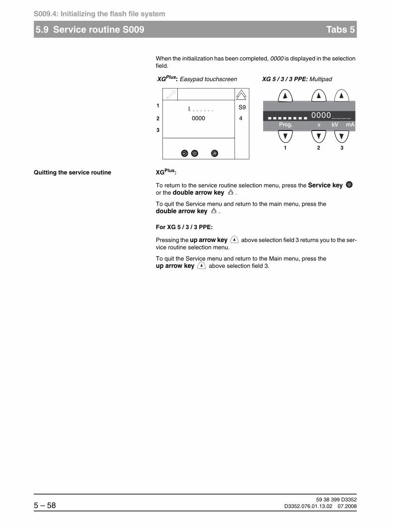
59 38 399 D33525 – 58 D3352.076.01.13.02 07.2008
5.9 Service routine S009 Tabs 5
S009.4: Initializing the flash file system
When the initialization has been completed, 0000 is displayed in the selection field.
Quitting the service routine XGPlus:
To return to the service routine selection menu, press the Service key or the double arrow key .
To quit the Service menu and return to the main menu, press the double arrow key .
For XG 5 / 3 / 3 PPE:
Pressing the up arrow key above selection field 3 returns you to the ser-vice routine selection menu.
To quit the Service menu and return to the Main menu, press the up arrow key above selection field 3.
1
2
3
0000
1 2 3
XGPlus: Easypad touchscreen XG 5 / 3 / 3 PPE: Multipad
R
S9
4 0000____

båÖäáëÜ
59 38 399 D3352D3352.076.01.13.02 07.2008 5 – 59
Tab 5 5.10 Service routine S012
5.10
S012: CAN bus service
5.10 Service routine S012
CAN bus service
NOTEiThe CAN bus service is not yet implemented for module DX11.
Select the Service menu (see page 5-10).
Selecting service routine S012 1. Use the arrow keys to select service routine S012.
Function S012 CAN bus service
Test step 2 Inquiry of the CAN status register of the modules
Test step 3 Resetting the CAN status register of the modules
Test step 4 Display of CAN bus cycle on LEDs of modules
1
2
3
+- S012
1 2 3
S012_______2____
XGPlus: Easypad touchscreen XG 5 / 3 / 3 PPE: Multipad

59 38 399 D33525 – 60 D3352.076.01.13.02 07.2008
5.10 Service routine S012 Tabs 5
S012.2: Inquiry of the CAN status register of the modules
5.10.1 S012: Test step 2
NOTEiBefore querying the CAN status register for the modules, you should first reset the registers via service routine S012.3 (see page 5-63).
Selecting test step 2 1. Select test step 2 in selection field 2 with the arrow keys and confirm your selection by pressing the Service key .
The selected module is displayed in the selection field 1.
Selecting a module 2. Select the desired module using the arrow keys of selection field 1.
After the module has been selected the Test key (XGPlus) or the LED above the Test key (XG 5 / 3 / 3 PPE) lights up.
1
2
3
+- S012
2
1 2 3
S012_______2____
XGPlus: Easypad touchscreen XG 5 / 3 / 3 PPE: Multipad
+-
S12
T
1
2
3
+- DX61
1 2 3
DX61____________
XGPlus: Easypad touchscreen XG 5 / 3 / 3 PPE: Multipad
T
T
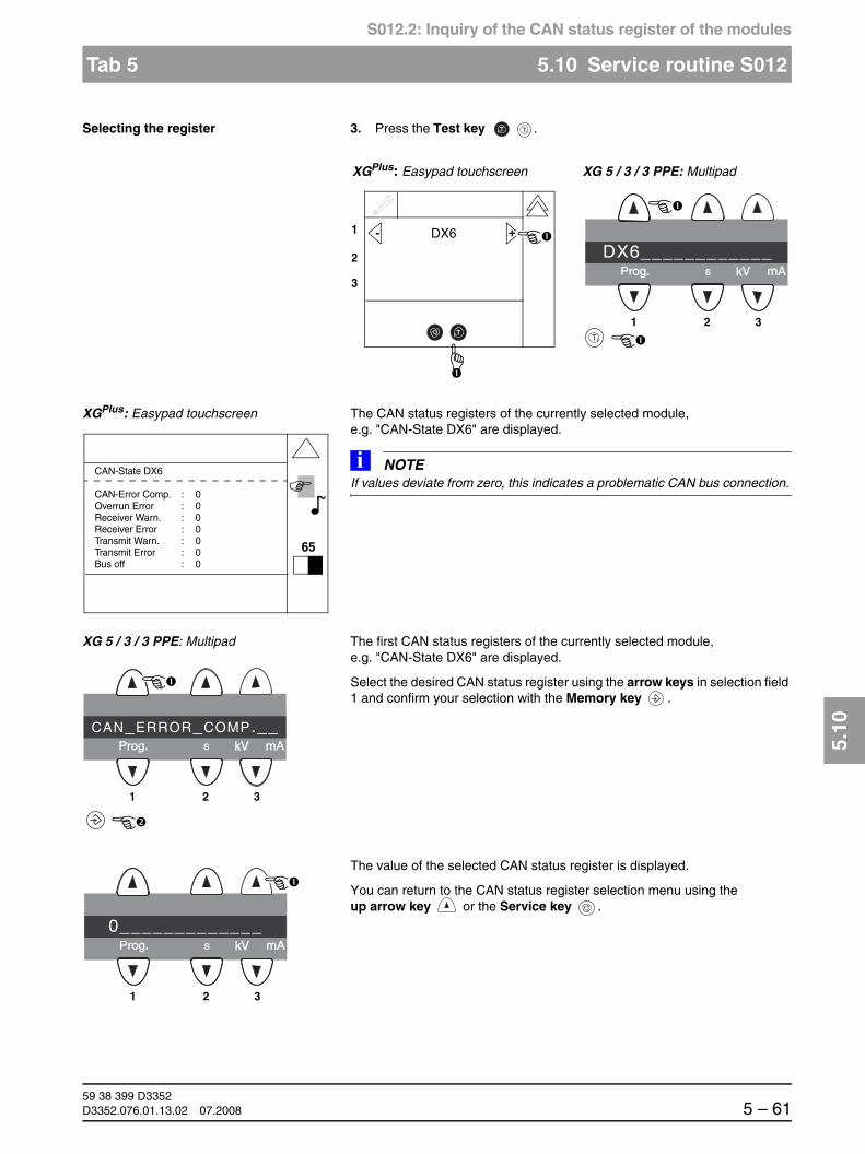
båÖäáëÜ
59 38 399 D3352D3352.076.01.13.02 07.2008 5 – 61
Tab 5 5.10 Service routine S012
5.10
S012.2: Inquiry of the CAN status register of the modules
Selecting the register 3. Press the Test key .
XGPlus: Easypad touchscreen The CAN status registers of the currently selected module, e.g. "CAN-State DX6" are displayed.
NOTEiIf values deviate from zero, this indicates a problematic CAN bus connection.
XG 5 / 3 / 3 PPE: Multipad The first CAN status registers of the currently selected module, e.g. "CAN-State DX6" are displayed.
Select the desired CAN status register using the arrow keys in selection field 1 and confirm your selection with the Memory key .
The value of the selected CAN status register is displayed.
You can return to the CAN status register selection menu using the up arrow key or the Service key .
T T
TT
1
2
3
+- DX6
1 2 3
DX6____________
XGPlus: Easypad touchscreen XG 5 / 3 / 3 PPE: Multipad
65
CAN-State DX6
CAN-Error Comp. : 0Overrun Error : 0Receiver Warn. : 0Receiver Error : 0Transmit Warn. : 0Transmit Error : 0Bus off : 0
1 2 3
CAN_ERROR_COMP.__
1 2 3
0_____________

59 38 399 D33525 – 62 D3352.076.01.13.02 07.2008
5.10 Service routine S012 Tabs 5
S012.2: Inquiry of the CAN status register of the modules
Quitting the service routine XGPlus:
To return to the service routine selection menu, press the Service key or the double arrow key .
To quit the Service menu and return to the main menu, press the double arrow key .
For XG 5 / 3 / 3 PPE:
Pressing the up arrow key above selection field 3 returns you to the ser-vice routine selection menu.
To quit the Service menu and return to the Main menu, press the up arrow key above selection field 3.
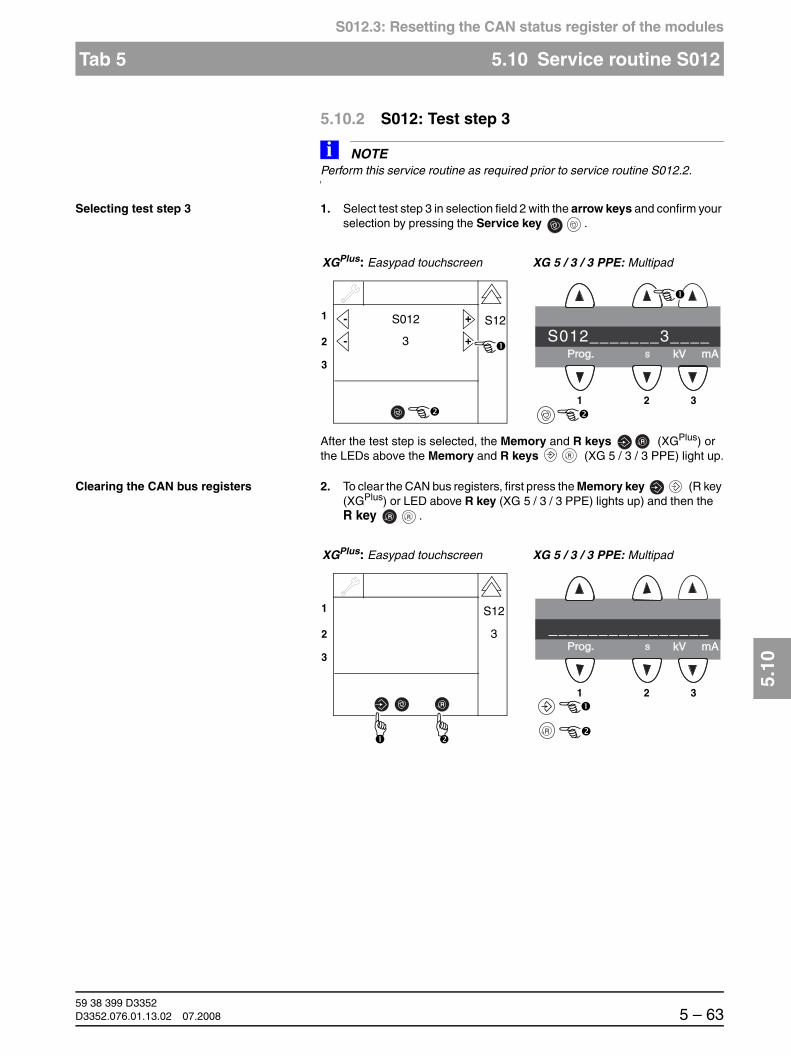
båÖäáëÜ
59 38 399 D3352D3352.076.01.13.02 07.2008 5 – 63
Tab 5 5.10 Service routine S012
5.10
S012.3: Resetting the CAN status register of the modules
5.10.2 S012: Test step 3
NOTEiPerform this service routine as required prior to service routine S012.2.
Selecting test step 3 1. Select test step 3 in selection field 2 with the arrow keys and confirm your selection by pressing the Service key .
After the test step is selected, the Memory and R keys (XGPlus) or the LEDs above the Memory and R keys (XG 5 / 3 / 3 PPE) light up.
Clearing the CAN bus registers 2. To clear the CAN bus registers, first press the Memory key (R key (XGPlus) or LED above R key (XG 5 / 3 / 3 PPE) lights up) and then the R key .
1
2
3
+- S012
3
1 2 3
S012_______3____
XGPlus: Easypad touchscreen XG 5 / 3 / 3 PPE: Multipad
+-
S12
R
R
R R
1
2
3
1 2 3
________________
XGPlus: Easypad touchscreen XG 5 / 3 / 3 PPE: Multipad
R
R
S12
3

59 38 399 D33525 – 64 D3352.076.01.13.02 07.2008
5.10 Service routine S012 Tabs 5
S012.3: Resetting the CAN status register of the modules
Quitting the service routine XGPlus:
To return to the service routine selection menu, press the Service key or the double arrow key .
To quit the Service menu and return to the main menu, press the double arrow key .
For XG 5 / 3 / 3 PPE:
Pressing the up arrow key above selection field 3 returns you to the ser-vice routine selection menu.
To quit the Service menu and return to the Main menu, press the up arrow key above selection field 3.

båÖäáëÜ
59 38 399 D3352D3352.076.01.13.02 07.2008 5 – 65
Tab 5 5.10 Service routine S012
5.10
S012.4: Display of CAN bus cycles on the LEDs of the modules
5.10.3 S012: Test step 4
Selecting test step 4 1. Select test step 4 in selection field 2 with the arrow keys and confirm your selection by pressing the Service key .
After the test step is selected, the code for the current setting of the display appears in selection field 1:
00 = LED display on the modules switched OFF
01 = LED display on the modules switched ON
Switching LED display on/off 2. Select the desired code using the arrow keys of selection field 1 and con-firm your selection by pressing the Test key .
NOTEiThe LEDs on the modules normally flash slowly (1 Hz) (for code 00). When code 01 has been selected and confirmed, the CAN bus clock pulse of the TTP protocol, which is output by the master module as a broadcast with a fre-quency of 20 Hz, is output on the LEDs (the green life LED flashes on DX7). Thus, by "wiggling through" all of the connectors, you can directly detect the contact loss of the module on the CAN bus. The activation or deactivation of this function simultaneously acts on all modules.
1
2
3
+- S012
4
1 2 3
S012_______4____
XGPlus: Easypad touchscreen XG 5 / 3 / 3 PPE: Multipad
+-
S12
T T
1
2
3
+- 01
1 2 3
01______________
XGPlus: Easypad touchscreen XG 5 / 3 / 3 PPE: Multipad
TT

59 38 399 D33525 – 66 D3352.076.01.13.02 07.2008
5.10 Service routine S012 Tabs 5
S012.4: Display of CAN bus cycles on the LEDs of the modules
Quitting the service routine XGPlus:
To return to the service routine selection menu, press the Service key or the double arrow key .
To quit the Service menu and return to the main menu, press the double arrow key .
For XG 5 / 3 / 3 PPE:
Pressing the up arrow key above selection field 3 returns you to the ser-vice routine selection menu.
To quit the Service menu and return to the Main menu, press the up arrow key above selection field 3.

båÖäáëÜ
59 38 399 D3352D3352.076.01.13.02 07.2008 5 – 67
Tab 5 5.11 Service routine S014
5.11
S014: Rotation motor service
5.11 Service routine S014
Rotation motor service
Select the Service menu (see page 5-10).
Selecting service routine S014 1. Use the arrow keys to select service routine S0014.
5.11.1 S014: Test step 1
This test step realizes "isolated" travel of the rotation motor to the pan home position Actuators 1 and 2 remain in their current positions.
Selecting test step 1 1. Select test step 1 in selection field 2 with the arrow keys and confirm your selection by pressing the Service key .
Function S014 Rotation motor service
Test step 1 Travel of rotational drive to the Pan home position
Test step 2 Travel of rotational drive to the ceph home position
Test step 3 Free travel of rotational drive
Test step 4 Display of light barrier signals of rotational drive
1
2
3
+- S014
1
1 2 3
S014_______1____
XGPlus: Easypad touchscreen XG 5 / 3 / 3 PPE: Multipad
+-
1
2
3
+- S014
1
1 2 3
S014_______1____
XGPlus: Easypad touchscreen XG 5 / 3 / 3 PPE: Multipad
+-

59 38 399 D33525 – 68 D3352.076.01.13.02 07.2008
5.11 Service routine S014 Tabs 5
S014.1: Travel of rotational drive to the Pan home position
After the test step is selected, selection field 1 displays the current status:
FFFF = Position of rotation undefined(following activation of service routine)
Moving the ring 2. Press the R key to move the ring to the pan home position.
After the test step is selected, selection field 1 displays the current status:
FFFF = Position of rotation undefined (following activation of service routine)
0000 = Pan home position reached
EEEE = Pan home position not reached due to an error state
1
2
3
+- FFFF
1 2 3
____FFFF________
XGPlus: Easypad touchscreen XG 5 / 3 / 3 PPE: Multipad
S14
R
1
R R
R
1
2
3
+- FFFF
1 2 3
____FFFF________
XGPlus: Easypad touchscreen XG 5 / 3 / 3 PPE: Multipad
R
1
S14

båÖäáëÜ
59 38 399 D3352D3352.076.01.13.02 07.2008 5 – 69
Tab 5 5.11 Service routine S014
5.11
S014.2: Travel of rotational drive to the ceph home position
Quitting the service routine XGPlus:
To return to the service routine selection menu, press the Service key or the double arrow key .
To quit the Service menu and return to the main menu, press the double arrow key .
For XG 5 / 3 / 3 PPE:
Pressing the up arrow key above selection field 3 returns you to the ser-vice routine selection menu.
To quit the Service menu and return to the Main menu, press the up arrow key above selection field 3.
5.11.2 S014: Test step 2
This test step realizes "isolated" travel of the rotation motor to the ceph home position (with the arm in the right or the left position, depending on the config-uration). Actuators 1 and 2 remain in their current positions.
Travel to the ceph home position is also possible without configuring the sys-tem version for the cephalometer mode.
Selecting test step 2 1. Select test step 2 in selection field 2 with the arrow keys and confirm your selection by pressing the Service key .
1
2
3
+- S014
2
1 2 3
S014_______2____
XGPlus: Easypad touchscreen XG 5 / 3 / 3 PPE: Multipad
+-

59 38 399 D33525 – 70 D3352.076.01.13.02 07.2008
5.11 Service routine S014 Tabs 5
S014.2: Travel of rotational drive to the ceph home position
After the test step is selected, selection field 1 displays the current status:
FFFF = Position of rotation undefined(following activation of service routine)
Moving the ring 2. Press the R key to move the ring to the ceph home position.
After the test step is selected, selection field 1 displays the current status:
FFFF = Position of rotation undefined (following activation of service routine)
0000 = Ceph home position reached
EEEE = Ceph home position not reached due to an error state
1
2
3
+- FFFF
1 2 3
____FFFF________
XGPlus: Easypad touchscreen XG 5 / 3 / 3 PPE: Multipad
S14
R
2
R R
R
1
2
3
+- FFFF
1 2 3
____FFFF________
XGPlus: Easypad touchscreen XG 5 / 3 / 3 PPE: Multipad
R
2
S14

båÖäáëÜ
59 38 399 D3352D3352.076.01.13.02 07.2008 5 – 71
Tab 5 5.11 Service routine S014
5.11
S014.3: Free travel of rotational drive
Quitting the service routine XGPlus:
To return to the service routine selection menu, press the Service key or the double arrow key .
To quit the Service menu and return to the main menu, press the double arrow key .
For XG 5 / 3 / 3 PPE:
Pressing the up arrow key above selection field 3 returns you to the ser-vice routine selection menu.
To quit the Service menu and return to the Main menu, press the up arrow key above selection field 3.
5.11.3 S014: Test step 3
This test step realizes "isolated" travel of the rotation motor to the ceph home position (with the arm in the right or the left position, depending on the config-uration). Actuators 1 and 2 remain in their current positions.
Travel to the ceph home position is also possible without configuring the sys-tem version for the cephalometer mode.
Selecting test step 3 1. Select test step 3 in selection field 2 with the arrow keys and confirm your selection by pressing the Service key .
1
2
3
+- S014
3
1 2 3
S014_______3____
XGPlus: Easypad touchscreen XG 3 / 3 / 3 PPE: Multipad
+-

59 38 399 D33525 – 72 D3352.076.01.13.02 07.2008
5.11 Service routine S014 Tabs 5
S014.3: Free travel of rotational drive
After the test step is selected, selection field 1 displays the arrow keys (for XGPlus):
Moving the ring 2. Press the arrow keys to move the ring to the right (+) or to the left (-). The ring keeps moving as long as the key remains pressed.
Quitting the service routine XGPlus:
To return to the service routine selection menu, press the Service key or the double arrow key .
To quit the Service menu and return to the main menu, press the double arrow key .
For XG 5 / 3 / 3 PPE:
Pressing the up arrow key above selection field 3 returns you to the ser-vice routine selection menu.
To quit the Service menu and return to the Main menu, press the up arrow key above selection field 3.
1
2
3
+-
1 2 3
________________
XGPlus: Easypad touchscreen XG 5 / 3 / 3 PPE: Multipad
S14
3
1
2
3
+-
1 2 3
________________
XGPlus: Easypad touchscreen XG 5 / 3 / 3 PPE: Multipad
3

båÖäáëÜ
59 38 399 D3352D3352.076.01.13.02 07.2008 5 – 73
Tab 5 5.11 Service routine S014
5.11
S014.4: Display of light barrier signal of rotational drive
5.11.4 S014: Test step 4
This test step realizes display of the switching state of rotation motor light bar-rier V1_3.
Selecting test step 4 1. Select test step 3 in selection field 2 with the arrow keys and confirm your selection by pressing the Service key .
After the test step is selected on the Easypad (with XGPlus) the service key and patient symbol key 1 are displayed:
Checking the light barrier 2. Move the ring manually. Tripping of the light barrier is indicated by illumi-nation of the patient symbol key (on XGPlus) or by illumination of the LED above patient symbol key 1 (on XG 5 / 3 / 3 PPE).
Quitting the service routine XGPlus:
To return to the service routine selection menu, press the Service key or the double arrow key .
To quit the Service menu and return to the main menu, press the double arrow key .
For XG 5 / 3 / 3 PPE:
Pressing the up arrow key above selection field 3 returns you to the ser-vice routine selection menu.
To quit the Service menu and return to the Main menu, press the up arrow key above selection field 3.
1
2
3
+- S014
4
1 2 3
S014_______4____
XGPlus: Easypad touchscreen XG 5 / 3 / 3 PPE: Multipad
+-
1
2
3
+-
1 2 3
________________
XGPlus: Easypad touchscreen XG 5 / 3 / 3 PPE: Multipad
S14
4

59 38 399 D33525 – 74 D3352.076.01.13.02 07.2008
5.12 Service routine S015 Tabs 5
S015: Actuator service
5.12 Service routine S015
Actuator service
Select the Service menu (see page 5-10).
Selecting service routine S015 1. Use the arrow keys to selec service routine S015.
5.12.1 S015: Test step 5
The use of this service routine is suitable for troubleshooting of motor and cable defects. Furthermore, the possibility of performing isolated travel with an individual drive makes it possible to release the clamping of the actuator/rotation system and check the stiffness of the individual adjusting axes.
Selecting test step 5 1. Select test step 5 in selection field 2 with the arrow keys and confirm your selection by pressing the Service key .
Function S015 Actuator service
Test step 5 Testing of actuators 1 and 2
1
2
3
+- S015
5
1 2 3
S015_______5____
XGPlus: Easypad touchscreen XG 5 / 3 / 3 PPE: Multipad
+-
1
2
3
+- S015
5
1 2 3
S015_______5____
XGPlus: Easypad touchscreen XG 5 / 3 / 3 PPE: Multipad
+-

båÖäáëÜ
59 38 399 D3352D3352.076.01.13.02 07.2008 5 – 75
Tab 5 5.12 Service routine S015
5.12
S015.1: Testing of actuators 1 and 2
After the test step is selected, selection field 1 displays the arrow keys (for XGPlus):
Patient symbol key 1 indicates the switching state of the light barrier for actu-ator 1; patient symbol key 2 indicates the switching state of the light barrier for actuator 2:
Patient symbol key (XGPlus), = Light barrier located in switching LED above patient symbol key plate(XG 5 / 3 / 3 PPE) lit
Patient symbol key (XGPlus), = Light barrier not located LED above patient symbol key in switching plate(XG 5 / 3 / 3 PPE) not lit
Moving the actuators 2. Press the arrow keys in selection field 1 (for actuator 1) or selection field 2 (for actuator 2) to move the actuator to the right (+) or to the left (-). The ac-tuor keeps moving as long as the key remains pressed.
Using the R key , the system (actuators 1 and 2) can be moved back to the pan home position. In this position, patient symbol keys 1 and 2 (XGPlus) and the LEDs above patient symbol keys 1 and 2 (XG 5 / 3 / 3 PPE) light up.
1
2
3
1 2 3
_______________
XGPlus: Easypad touchscreen XG 5 / 3 / 3 PPE: Multipad
5
S15+-
R
1
2
3
1 2 3
_______________
XGPlus: Easypad touchscreen XG 5 / 3 / 3 PPE: Multipad
+-
R
+- 5
R R

59 38 399 D33525 – 76 D3352.076.01.13.02 07.2008
5.12 Service routine S015 Tabs 5
S015.1: Testing of actuators 1 and 2
Quitting the service routine XGPlus:
To return to the service routine selection menu, press the Service key or the double arrow key .
To quit the Service menu and return to the main menu, press the double arrow key .
For XG 5 / 3 / 3 PPE:
Pressing the up arrow key above selection field 3 returns you to the ser-vice routine selection menu.
To quit the Service menu and return to the Main menu, press the up arrow key above selection field 3.

båÖäáëÜ
59 38 399 D3352D3352.076.01.13.02 07.2008 5 – 77
Tab 5 5.13 Service routine S017
5.13
S017: Configuration service
5.13 Service routine S017
Configuration service
Select the Service menu (see page 5-10).
Function S017 System configuration
Test step 2 Configuring the hardware version Security access
Test step 3 Entering the country group code Security access
Test step 4(XGPlus only)
Selecting a language index within the language set Security access
Test step 5(XGPlus only)
Selecting a language set index within the language set Security access
Test step 6 Activating the remote control display Security access
Test step 8 Selecting the kVmA level series Security access
Test step 9 Configuring operaton without board DX41 Security access
Test step 10 Configuring the headrest Security access
Test step 11 Selecting the image format Security access
Test step 12(XGPlus only)
Enabling/disabling the preview image Security access
Test step 13(XGPlus only)
Enabling/disabling the welcome screen Security access
Test step 14(XGPlus only)
Enabling/disabling certain lines of the welcome screen Security access
Test step 15 Activating/deactivating the acoustic signal for end of exposure Security access
Test step 17 Setting the standard acceptance/constancy test, RöV FRG Security access
Checking or accepting the diaphragm configuration, worldwide
Test step 18 In preparation.Caution! This routine must not be activated, since it will cause malfunctioning of the unit.
Security access
Test step 22(XG 3 PPE only)
Deactivating/activating the PPE display after each unit power-up Security access
Test step 23(XG 3 PPE only)
Defining the PPE display warning level after each exposure Security access

59 38 399 D33525 – 78 D3352.076.01.13.02 07.2008
5.13 Service routine S017 Tabs 5
S017.2: Configuring the hardware version
Selecting service routine S017 1. Use thearrow keys to select service routine S017.
5.13.1 S017: Test step 2
Selecting test step 2 1. Select test step 2 in selection field 2 with the arrow keys and confirm your selection by pressing the Service key .
Confirming the security access 2. Confirm the security access by once again selecting the number of the main routine (17) with the arrow keys of selection field 2 and then press-ing the Service key .
1
2
3
+- S017
2
1 2 3
S017_______2____
XGPlus: Easypad touchscreen XG 5 / 3 / 3 PPE: Multipad
+-
1
2
3
+- S017
2
1 2 3
S017_______2____
XGPlus: Easypad touchscreen XG 5 / 3 / 3 PPE: Multipad
+-
1
2
3
17
1 2 3
__________17____
XGPlus: Easypad touchscreen XG 5 / 3 / 3 PPE: Multipad
+-

båÖäáëÜ
59 38 399 D3352D3352.076.01.13.02 07.2008 5 – 79
Tab 5 5.13 Service routine S017
5.13
S017.2: Configuring the hardware version
Selecting the system version 3. Select the desired system version using the arrow keys of selection field 1.
0001 = panoramic digital0003 = panoramic digital/ceph left digital0005 = panoramic digital/ceph right digital
0041 = panoramic digital, TSA (XGPlus only)0043 = panoramic digital, ceph left digital, TSA (XGPlus only)0045 = panoramic digital, ceph right digital, TSA (XGPlus only)
0081 = system version XG 3 / 3 PPE
After the system version has been selected the Memory key (XGPlus) or the LED above the Memory key (XG 5 / 3 /3 PPE) lights up.
4. To save the selected system version, first press the Memory key (R key (XGPlus) or LED above R key (XG 5 / 3 / 3 PPE) lights up) and then the R key .
NOTEiThe set value is permanently saved as the relevant system version.
1
2
3
+- 0003
1 2 3
____0003________
XGPlus: Easypad touchscreen XG 5 / 3 / 3 PPE: Multipad
R
2
R R
R
1
2
3
+- 0003
1 2 3
____0003________
XGPlus: Easypad touchscreen XG 5 / 3 / 3 PPE: Multipad
R
2
S17

59 38 399 D33525 – 80 D3352.076.01.13.02 07.2008
5.13 Service routine S017 Tabs 5
S017.2: Configuring the hardware version
Checking/setting the jumper position 5. Check the jumper settings of sockets
306 (DX61, diaphragm)(only if XG 3 / 3 PPE= 0081), 309 (DX91, ceph sensor) and 503 (DX81, ceph sensor)
on board DX1.
DX1
Socket X309
Jumper inside
Cephalometer not connected, i.e. connector not plugged in
0001 and 0041
Socket X503
NOTEiFor more information on the correct jumper positions and CAN bus wiring, refer to sec-tion 3.2.2. Socket X309
Jumper outside
Cephalometer connected, i.e. connector plugged in
0003, 000, 0043 and 0045
Socket X503

båÖäáëÜ
59 38 399 D3352D3352.076.01.13.02 07.2008 5 – 81
Tab 5 5.13 Service routine S017
5.13
S017.2: Configuring the hardware version
Quitting the service routine XGPlus:
To go on to the next test step, press the Service key .
To return to the Service menu, press the double arrow key .
To quit the Service menu and return to the main menu, press the double arrow key .
For XG 5 / 3 / 3 PPE:
To go on to the next test step, press the Service key .
To return to the Service menu, press the up arrow key above selection field 3.
To quit the Service menu and return to the Main menu, press the up arrow key above selection field 3.
0081 = XG 3 / 3 PPE
Socket X306
Jumper inside
Socket X309
Jumper inside
Socket X503
Jumper inside
Cephalometer and motor-driven diaphragm not connected,i.e. connector not plugged in

59 38 399 D33525 – 82 D3352.076.01.13.02 07.2008
5.13 Service routine S017 Tabs 5
S017.3: Entering the country group code
5.13.2 S017: Test step 3
Start test step 3 in the same way as described on page 5-78 or by pressing the Service key in test step 2.
NOTEiIf you go to test step 3 from test step 2 by pressing the Service key, the security access confirmation will be skipped.
Selecting the country group code 1. Select the desired country group code using the arrow keys of selection field 1.
00 = worldwide01 = Asia02 = USA
After the country group code is selected, the Memory key (XGPlus) or the LED above theMemory key (XG 5 / 3 / 3 PPE) lights up.
2. To save the selected country group code, first press the Memory key (R key (XGPlus) or LED above R key (XG 5 / 3 / 3 PPE) lights up) and then the R key .
NOTEiThe setting is permanently saved.
1
2
3
+- 00
1 2 3
______00________
XGPlus: Easypad touchscreen XG 5 / 3 / 3 PPE: Multipad
R
3
R R
R
1
2
3
+- 00
1 2 3
______00________
XGPlus: Easypad touchscreen XG 5 / 3 / 3 PPE: Multipad
R
3
S17

båÖäáëÜ
59 38 399 D3352D3352.076.01.13.02 07.2008 5 – 83
Tab 5 5.13 Service routine S017
5.13
S017.3: Entering the country group code
Quitting the service routine XGPlus:
To go on to the next test step, press the Service key .
To return to the Service menu, press the double arrow key .
To quit the Service menu and return to the main menu, press the double arrow key .
For XG 5 / 3 / 3 PPE:
To go on to the next test step, press the Service key .
To return to the Service menu, press the up arrow key above selection field 3.
To quit the Service menu and return to the Main menu, press the up arrow key above selection field 3.

59 38 399 D33525 – 84 D3352.076.01.13.02 07.2008
5.13 Service routine S017 Tabs 5
S017.4: Selecting the language index within a language set
5.13.3 S017: Test step 4 (XGPlus only)
Start test step 4 in the same way as described on page 5-78 or by pressing the Service key in test step 3.
NOTEiIf you go to test step 4 from test step 3 by pressing the Service key, the security access confirmation will be skipped.
Selecting a language index 1. Use the arrow keys in selection field 1 to select the desired language index.
00 = English01 = German02 = French03 = Italian04 = Dutch05 = Spanish06 = Russian07 = Norwegian08 = Portuguese09 = Swedish10 = Chinese11 = Korean12 = Japanese
After the language index is selected, the Memory key lights up.
R
1
2
3
+- 01
XGPlus: Easypad touchscreen
4

båÖäáëÜ
59 38 399 D3352D3352.076.01.13.02 07.2008 5 – 85
Tab 5 5.13 Service routine S017
5.13
S017.4: Selecting the language index within a language set
2. To save the selected language index, first press the Memory key (the R key lights up) and then the R key .
NOTEiThe setting is permanently saved.
NOTEiIf the selected language is not contained in the installed language set, English is set as the default language.
Quitting the service routine To go on to the next test step, press the Service key .
To return to the Service menu, press the double arrow key .
To quit the Service menu and return to the main menu, press the double arrow key .
R
R
1
2
3
+- 01
XGPlus: Easypad touchscreen
4
S17

59 38 399 D33525 – 86 D3352.076.01.13.02 07.2008
5.13 Service routine S017 Tabs 5
S017.5: Selecting the language set index within a language set
5.13.4 S017: Test step 5 (XGPlus only)
Start test step 5 in the same way as described on page 5-78 or by pressing the Service key in test step 4.
NOTEiIf you go to test step 5 from test step 4 by pressing the Service key, the security access confirmation will be skipped.
Selecting a language set index 1. Select the desired language set index using the arrow keys of selection field 1.
00 = German, English, French, Italian01 = German, English, French, Dutch02 = German, English, Spanish, Russian03 = German, English, Korean, Japanese
After the language set index is selected, the Memory key lights up.
2. To save the selected language set index, first press the Memory key (R key lights up) and then press the R key .
NOTEiThe setting is permanently saved.
Perform a software update to install the corresponding languages in the system (see section 1.9).
R
1
2
3
+- 00
XGPlus: Easypad touchscreen
5
R
R
1
2
3
+- 00
XGPlus: Easypad touchscreen
5
S17

båÖäáëÜ
59 38 399 D3352D3352.076.01.13.02 07.2008 5 – 87
Tab 5 5.13 Service routine S017
5.13
S017.6: Activating the remote control display
Quitting the service routine To go on to the next test step, press the Service key .
To return to the Service menu, press the double arrow key .
To quit the Service menu and return to the Main menu, press the double arrow key .
5.13.5 S017: Test step 6
Start test step 6 in the same way as described on page 5-78 or by pressing the Service key in test step 5.
NOTEiIf you go to test step 6 from test step 5 by pressing the Service key, the security access confirmation will be skipped.
Selecting the device status 1. Select the desired device status using the arrow keys of selection field 1.
00 = Remote control inactive01 = Remote control active
After the device status is selected, the Memory key (XGPlus) or the LED above the Memory key (XG 5 / 3 / 3 PPE) lights up.
1
2
3
+- 00
1 2 3
______00________
XGPlus: Easypad touchscreen XG 5 / 3 / 3 PPE: Multipad
R
6

59 38 399 D33525 – 88 D3352.076.01.13.02 07.2008
5.13 Service routine S017 Tabs 5
S017.6: Activating the remote control display
2. To save the selected device status, first press the Memory key (R key (XGPlus) or LED above R key (XG 5 / 3 / 3 PPE) lights up) and then the R key .
NOTEiThe setting is permanently saved.
Quitting the service routine XGPlus:
To go on to the next test step, press the Service key .
To return to the Service menu, press the double arrow key .
To quit the Service menu and return to the main menu, press the double arrow key .
For XG 5 / 3 / 3 PPE:
To go on to the next test step, press the Service key .
To return to the Service menu, press the up arrow key above selection field 3.
To quit the Service menu and return to the Main menu, press the up arrow key above selection field 3.
R R
R
1
2
3
+- 00
1 2 3
______00________
XGPlus: Easypad touchscreen XG 5 / 3 / 3 PPE: Multipad
R
6
S17

båÖäáëÜ
59 38 399 D3352D3352.076.01.13.02 07.2008 5 – 89
Tab 5 5.13 Service routine S017
5.13
S017.8: Selecting the kV/mA level series
5.13.6 S017: Test step 8
Start test step 8 in the same way as described on page 5-78 or by pressing the Service key in test step 6.
NOTEiIf you go to test step 8 from test step 6 by pressing the Service key, the security access confirmation will be skipped.
Selecting the kV/mA level series 1. Select the desired kV/mA level series using the arrow keys of selection field 1.
1A = 16 mA series for PAN6 mA series for Ceph8/10 mA series for TSA (XGPlus only)
2A = 8 mA series for PAN16 mA series for Ceph8/10 mA series for TSA (XGPlus only)
4A = 8/16 mA series for PAN16 mA series for Ceph8/10 mA series for TSA (XGPlus only)
After the kV/mA level series are selected, the Memory key (XGPlus) or the LED above the Memory key (XG 5 / 3 / 3 PPE) lights up.
1
2
3
+- 1A
1 2 3
______1A________
XGPlus: Easypad touchscreen XG 5 / 3 / 3 PPE: Multipad
R
8
S17
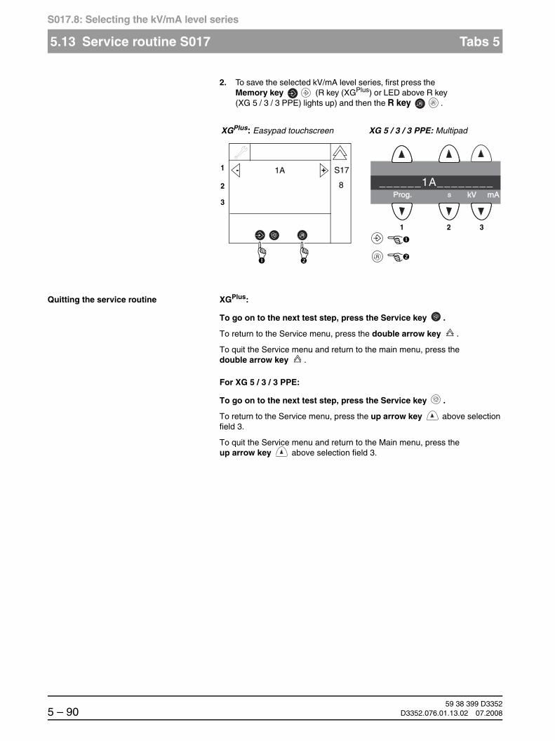
59 38 399 D33525 – 90 D3352.076.01.13.02 07.2008
5.13 Service routine S017 Tabs 5
S017.8: Selecting the kV/mA level series
2. To save the selected kV/mA level series, first press the Memory key (R key (XGPlus) or LED above R key (XG 5 / 3 / 3 PPE) lights up) and then the R key .
Quitting the service routine XGPlus:
To go on to the next test step, press the Service key .
To return to the Service menu, press the double arrow key .
To quit the Service menu and return to the main menu, press the double arrow key .
For XG 5 / 3 / 3 PPE:
To go on to the next test step, press the Service key .
To return to the Service menu, press the up arrow key above selection field 3.
To quit the Service menu and return to the Main menu, press the up arrow key above selection field 3.
R R
R
1
2
3
+- 1A
1 2 3
______1A________
XGPlus: Easypad touchscreen XG 5 / 3 / 3 PPE: Multipad
R
8
S17

båÖäáëÜ
59 38 399 D3352D3352.076.01.13.02 07.2008 5 – 91
Tab 5 5.13 Service routine S017
5.13
S017.9: Configuring operaton without DX41
5.13.7 S017: Test step 9
This service routine is used to configure operation of the system with or with-out the module DX41. This configuration is necessary for software updates and module replacement or board DX11 if systems with or without board DX41 should be supported.
Start test step 9 in the same way as described on page 5-78 or by pressing the Service key in test step 8.
NOTEiIf you go to test step 9 from test step 8 by pressing the Service key ≤≤, the security access confirmation will be skipped.
Setting configuration without DX41 1. Select the desired device status using the arrow keys of selection field 1.
00 = operation without DX41(Factory setting for unit hardware versions ≥ BA)
01 = operation with DX41 (Factory setting for unit hardware versions ≤ AG)
After the device status is selected, the Memory key (XGPlus) or the LED above the Memory key (XG 5 / 3 / 3 PPE) lights up.
1
2
3
+- 00
1 2 3
_______00________
XGPlus: Easypad touchscreen XG 5 / 3 / 3 PPE: Multipad
R
9

59 38 399 D33525 – 92 D3352.076.01.13.02 07.2008
5.13 Service routine S017 Tabs 5
S017.9: Configuring operaton without DX41
2. To save the selected device status, first press the Memory key (R key (XGPlus) or LED above R key (XG 5 / 3 / 3 PPE) lights up) and then the R key .
NOTEiThe setting is permanently saved.
Quitting the service routine XGPlus:
To go on to the next test step, press the Service key .
To return to the Service menu, press the double arrow key .
To quit the Service menu and return to the main menu, press the double arrow key .
For XG 5 / 3 / 3 PPE:
To go on to the next test step, press the Service key .
To return to the Service menu, press the up arrow key above selection field 3.
To quit the Service menu and return to the Main menu, press the up arrow key above selection field 3.
R R
R
1
2
3
+- 00
1 2 3
______00________
XGPlus: Easypad touchscreen XG 5 / 3 / 3 PPE: Multipad
R
9
S17

båÖäáëÜ
59 38 399 D3352D3352.076.01.13.02 07.2008 5 – 93
Tab 5 5.13 Service routine S017
5.13
S017.10: Configuration of headrest
5.13.8 S017: Test step 10 (XGPlus only)
The operation of the unit for the installed headrest version is configured with this service routine.
This configuration is required for replacement of board DX11 and a unit hard-ware version ≥ AG (for XGPlus systems) as well as for the installation of head-rest version 2 in systems with a hardware version ≤ AG.
Start test step 10 as described on page 5-80 or by pressing the Service key in test step 9.
NOTEiIf you go to test step 10 from test step 9 by pressing the Service key, the security access confirmation will be skipped.
Configuring the headrest 1. Select the currently installed headrest using the arrow keys in selection field 1.
00 = operation with headrest version 1 (until approx. October 2006)(Factory setting for unit hardware versions ≤ AG)
01 = operation with headrest version 2 (from approx. November 2006)(Factory setting for unit hardware versions ≥ BA)
After the headrest version is selected, the Memory key lights up.
Kopfstützenversion 1(will be replaced by headrest version 2 in 2007 and is then no longer available as a repair part)
Kopfstützenversion 2(will be available (from 2007) under the part number: 5969741)
vertical
set obliquely toward the back
1
2
3
+- 01
XGPlus: Easypad touchscreen
R
10

59 38 399 D33525 – 94 D3352.076.01.13.02 07.2008
5.13 Service routine S017 Tabs 5
S017.10: Configuration of headrest
2. To save the selected headrest version, first press the Memory key (R key lights up) and then press the R key .
NOTEiThe setting is permanently saved.
Quitting the service routine To go on to the next test step, press the Service key .
To return to the Service menu, press the double arrow key .
To quit the Service menu and return to the main menu, press the double arrow key .
R
1
2
3
+- 01
XGPlus: Easypad touchscreen
R
10
S17

båÖäáëÜ
59 38 399 D3352D3352.076.01.13.02 07.2008 5 – 95
Tab 5 5.13 Service routine S017
5.13
S017.11: Selecting the image format
5.13.9 S017: Test step 11 (XG 5 / 3 only)
Start test step 11 in the same way as described on page 5-78 or by pressing the Service key in test step 8.
NOTEiIf you go to test step 11 from test step 8 by pressing the Service key, the security access confirmation will be skipped.
Selecting the image format 1. Select the desired image format using the arrow keys of selection field 1.
00 = C3 = 18 x 23 cm
01 = C3F = 30 x 23 cm
After the image format is selected, the LED above the Memory key lights up.
2. To save the selected image format, first press the Memory key (LED above the R key lights up) and then the R key .
Quitting the service routine To go on to the next test step, press the Service key .
To return to the Service menu, press the up arrow key above selection field 3.
To quit the Service menu and return to the Main menu, press the up arrow key above selection field 3.
1 2 3
______01________
XG 5: Multipad
R
R
1 2 3
______00________
XG 5: Multipad

59 38 399 D33525 – 96 D3352.076.01.13.02 07.2008
5.13 Service routine S017 Tabs 5
S017.12: Enabling/disabling the preview image
5.13.10 S017: Test step 12 (XGPlus only)
Start test step 12 in the same way as described on page 5-78 or by pressing the Service key in test step 11.
NOTEiIf you go to test step 12 from test step 11 by pressing the Service key, the security access confirmation will be skipped.
Enabling/disabling the preview image 1. Select the code for displaying the preview image using the arrow keys of selection field 1.
00 = Preview image disabled
01 = Preview image enabled
After the code is selected, the Memory key lights up.
2. To save the selection, first press the Memory key (the R key lights up) and then the R key .
Quitting the service routine To go on to the next test step, press the Service key .
To return to the Service menu, press the double arrow key .
To quit the Service menu and return to the main menu, press the double arrow key .
1
2
3
+- 01
XGPlus: Easypad touchscreen
R
12
R
1
2
3
+- 01
XGPlus: Easypad touchscreen
R
12
S17

båÖäáëÜ
59 38 399 D3352D3352.076.01.13.02 07.2008 5 – 97
Tab 5 5.13 Service routine S017
5.13
S017.13: Enabling/disabling the welcome screen
5.13.11 S017: Test step 13 (XGPlus full version only)
Start test step 13 in the same way as described on page 5-78 or by pressing the Service key in test step 12.
NOTEiIf you go to test step 13 from test step 12 by pressing the Service key, the security access confirmation will be skipped.
Enabling/disabling the welcome screen 1. Select the code for enabling or disabling the welcome screen using the arrow keys of selection field 1.
00 = Welcome screen disabled
01 = Welcome screen enabled
2. After the code is selected the Memory key lights up. To save the changes, first press the Memory key (R key lights up) and then press the R key .
The welcome screen is enabled or disabled.
NOTEiAfter the welcome screen is disabled all parameters of the service routine S017.14 are reset back to the factory setting.
1
2
3
+- 01
XGPlus: Easypad touchscreen
R
13
R
1
2
3
+- 01
XGPlus: Easypad touchscreen
R
13
S17

59 38 399 D33525 – 98 D3352.076.01.13.02 07.2008
5.13 Service routine S017 Tabs 5
S017.14: Enabling/disabling certain lines of the welcome screen
Quitting the service routine To go on to the next test step, press the Service key .
To return to the Service menu, press the double arrow key .
To quit the Service menu and return to the main menu, press the double arrow key .
5.13.12 S017: Test step 14 (XGPlus full version only)
Start test step 14 in the same way as described on page 5-78 or by pressing the Service key in test step 13.
NOTEiIf you go to test step 14 from test step 13 by pressing the Service key, the security access confirmation will be skipped.
After the test step is selected, a welcome screen line ID appears in selection field 1.
1
2
3
+- 1
XGPlus: Easypad touchscreen
R
14
17
+- 0

båÖäáëÜ
59 38 399 D3352D3352.076.01.13.02 07.2008 5 – 99
Tab 5 5.13 Service routine S017
5.13
S017.14: Enabling/disabling certain lines of the welcome screen
Enabling/disabling certain lines of the welcome screen
1. Select the desired line using the arrow keys of selection field 1.
1 = First name
2 = Surname
3 = Date of birth
4 = Patient number
The activation status code is displayed in selection field 2.
0 = disabled
1 = enabled
2. Select the desired status using the arrow keys of selection field 2.
1
2
3
+- 1
XGPlus: Easypad touchscreen
R
14+- 0
1
2
3
+- 1
XGPlus: Easypad touchscreen
R
14
17
+- 1

59 38 399 D33525 – 100 D3352.076.01.13.02 07.2008
5.13 Service routine S017 Tabs 5
S017.14: Enabling/disabling certain lines of the welcome screen
3. After the code is selected the Memory key lights up. To save the changes, first press the Memory key (R key lights up) and then press the R key .
Quitting the service routine To go on to the next test step, press the Service key .
To return to the Service menu, press the double arrow key .
To quit the Service menu and return to the main menu, press the double arrow key .
R
1
2
3
+- 1
XGPlus: Easypad touchscreen
R
14
17
+- 1

båÖäáëÜ
59 38 399 D3352D3352.076.01.13.02 07.2008 5 – 101
Tab 5 5.13 Service routine S017
5.13
S017.15: Activating/deactivating the acoustic signal for end of exposure
5.13.13 S017: Test step 15
Start test step 15 in the same way as described on page 5-78 or by pressing the Service key in test step 14.
NOTEiIf you go to test step 15 from test step 14 by pressing the Service key, the security access confirmation will be skipped.
Activating/deactivating the acoustic signal for end of exposure
1. Select the code for activating or deactivating the acoustic signal using the arrow keys of selection field 1.
00 = acoustic signal for end of exposure = OFF
01 = acoustic signal for end of exposure = ON
2. After the code is selected the Memory key lights up. To save the changes, first press the Memory key (R key lights up) and then press the R key .
1
2
3
+- 00
XGPlus: Easypad touchscreen
R
15
1 2 3
______00________
XG 5 / 3 / 3 PPE: Multipad
R
1
2
3
+- 01
XGPlus: Easypad touchscreen
R
15
S17
R
1 2 3
______01________
XG 5 / 3 / 3 PPE: Multipad
59 38 399 D33525 – 102 D3352.076.01.13.02 07.2008
5.13 Service routine S017 Tabs 5
S017.15: Activating/deactivating the acoustic signal for end of exposure
Quitting the service routine XGPlus:
To go on to the next test step, press the Service key .
To return to the Service menu, press the double arrow key .
To quit the Service menu and return to the main menu, press the double arrow key .
For XG 5 / 3 / 3 PPE:
To go on to the next test step, press the Service key .
To return to the Service menu, press the up arrow key above selection field 3.
To quit the Service menu and return to the Main menu, press the up arrow key above selection field 3.

båÖäáëÜ
59 38 399 D3352D3352.076.01.13.02 07.2008 5 – 103
Tab 5 5.13 Service routine S017
5.13
S017.17: Setting the standard acceptance/constancy test, RöV FRG
5.13.14 S017: Test step 17 Setting the standard acceptance/constancy test, RöV FRG
Selecting test step 17 1. Select test step 17 using the arrow keys in selection field 2 and confirm your selection with the Service key .
NOTEiIn XGPlus and XG 5 units, the default value is already displayed correctly as soon as service routine S017.17 is opened, and therefore only need by stored. In XG 3 units, the standard must be set as described in the following step.
1
2
3
+- S017
17
XGPlus: Easypad touchscreen
+-
S17
1 2 3
S017______17____
XG 5 / 3 / 3 PPE: Multipad
1
2
3
+- 02
XGPlus: Easypad touchscreen
R
S17
1 2 3
______01________
XG 5 / 3 / 3 PPE: Multipad
17

59 38 399 D33525 – 104 D3352.076.01.13.02 07.2008
5.13 Service routine S017 Tabs 5
S017.17: Setting the standard acceptance/constancy test, RöV FRG
For XG3 units only:
2. Select the standard for the acceptance/constancy test using the arrow keys in selection field 1:
01 = old standard: 0.8mmCu
02 = new standard: 1.8mmCu
3. To save the setting, first press the Memory key (the R key or the LED above the R key then lights up) and then the R key .
Quitting the service routine XGPlus:
To go on to the next test step, press the Service key .
To return to the Service menu, press the double arrow key .
To quit the Service menu and return to the main menu, press the double arrow key .
For XG 5 / 3 / 3 PPE:
To go on to the next test step, press the Service key .
To return to the Service menu, press the up arrow key above selection field 3.
To quit the Service menu and return to the Main menu, press the up arrow key above selection field 3.
1 2 3
______02________
XG 3 / 3 PPE: Multipad
R R
1
2
3
+- 02
XGPlus: Easypad touchscreen
R
S17
17
R
1 2 3
______02________
XG 5 / 3 / 3 PPE: Multipad

båÖäáëÜ
59 38 399 D3352D3352.076.01.13.02 07.2008 5 – 105
Tab 5 5.13 Service routine S017
5.13
S017.17: Checking or accepting the diaphragm configuration, worldwide
5.13.15 S017: Test step 17 Checking or accepting the diaphragm configuration, worldwide(not for XG 3 / 3 PPE)
Selecting test step 17 1. Select test step 17 using the arrow keys in selection field 2 and confirm your selection with the Service key .
2. When the Memory key or the LED above the Memory key lights up, save the configuration.
This is done by pressing the Memory key first (R key or LED abo-ve the R key lights up) and then pressing the R key .
Otherwise, quit the service routine once again.
1
2
3
+- S017
17
XGPlus: Easypad touchscreen
+-
S17
1 2 3
S017______17____
XG 5: Multipad
R R
1
2
3
+- 02
XGPlus: Easypad touchscreen
R
S17
17
R
1 2 3
______02________
XG 5: Multipad

59 38 399 D33525 – 106 D3352.076.01.13.02 07.2008
5.13 Service routine S017 Tabs 5
S017.17: Checking or accepting the diaphragm configuration, worldwide
Quitting the service routine XGPlus:
To go on to the next test step, press the Service key .
To return to the Service menu, press the double arrow key .
To quit the Service menu and return to the main menu, press the double arrow key .
For XG 5 / 3 / 3 PPE:
To go on to the next test step, press the Service key .
To return to the Service menu, press the up arrow key above selection field 3.
To quit the Service menu and return to the Main menu, press the up arrow key above selection field 3.

båÖäáëÜ
59 38 399 D3352D3352.076.01.13.02 07.2008 5 – 107
Tab 5 5.13 Service routine S017
5.13
S017.22: Configuration of PPE display
5.13.16 S017: Test step 22 (XG 3 PPE only)
Start test step 22 as described on page 5-78.
Enabling/disabling display of the remaining exposures after each power-on
1. Select the code for displaying the number of remaining exposures using the arrow keys of selection field 1.
00 = display of remaining exposures = OFF
01 = display of remaining exposures = ON (factory setting)
2. After the code is selected the Memory key lights up. To save the changes, first press the Memory key (R key lights up) and then press the R key .
Quitting the service routine To go on to the next test step, press the Service key .
To return to the Service menu, press the double arrow key .
To quit the Service menu and return to the main menu, press the double arrow key .
1 2 3
______01________
XG 3 PPE: Multipad
R
R
1 2 3
______00________
XG 3 PPE: Multipad
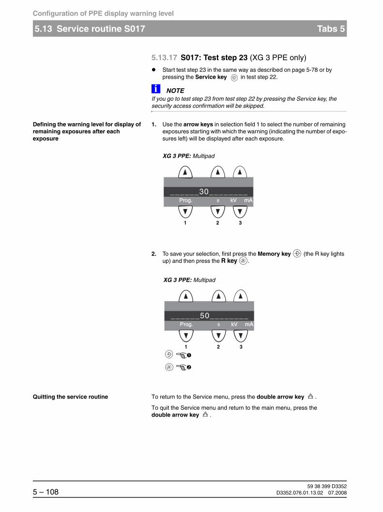
59 38 399 D33525 – 108 D3352.076.01.13.02 07.2008
5.13 Service routine S017 Tabs 5
Configuration of PPE display warning level
5.13.17 S017: Test step 23 (XG 3 PPE only)
Start test step 23 in the same way as described on page 5-78 or by pressing the Service key in test step 22.
NOTEiIf you go to test step 23 from test step 22 by pressing the Service key, the security access confirmation will be skipped.
Defining the warning level for display of remaining exposures after each exposure
1. Use the arrow keys in selection field 1 to select the number of remaining exposures starting with which the warning (indicating the number of expo-sures left) will be displayed after each exposure.
2. To save your selection, first press the Memory key (the R key lights up) and then press the R key .
Quitting the service routine To return to the Service menu, press the double arrow key .
To quit the Service menu and return to the main menu, press the double arrow key .
1 2 3
______30________
XG 3 PPE: Multipad
R
R
1 2 3
______50________
XG 3 PPE: Multipad

båÖäáëÜ
59 38 399 D3352D3352.076.01.13.02 07.2008 5 – 109
Tab 5 5.14 Service routine S018
5.14
S018: Service for height adjustment
5.14 Service routine S018
Service for height adjustment
Select the Service menu (see page 5-10).
Selecting service routine S018 1. Use thearrow keys to select service routine S0018.
Function S018 Service for height adjustment
Test step 2 Limitation of the maximum travel height
Test step 3 Undoing the maximum travel height setting
Test step 4 Check of the height adjustment sensor system
Test step 5 Setting of the minimum travel height
Test step 6 Undoing the minimum travel height setting
1
2
3
+- S018
2
1 2 3
S018_______2____
XGPlus: Easypad touchscreen XG 5 / 3 / 3 PPE: Multipad
+-

59 38 399 D33525 – 110 D3352.076.01.13.02 07.2008
5.14 Service routine S018 Tabs 5
S018.2: Setting the maximum travel height
5.14.1 S018: Test step 2
Moving the unit 1. Move the unit to the required maximum travel height by pressing the Up/Down keys in the user mode.
NOTEiProgramming the maximum travel height is possible only for a system height above the upper correction switch level (> position value of 1500)!
Selecting test step 2 2. Select test step 2 using the arrow keys in selection field 2 and then confirm your selection with the Service key .
The current height position is displayed in selection field 1. The Memory key (XGPlus) or the LED above the Memory key (XG 5 / 3 / 3 PPE) lights up.
Saving the maximum travel height 3. To save the maximum travel height, first press the Memory key (R key (XGPlus) or LED above R key (XG 5 / 3 / 3 PPE) lights up) and then the R key .
T R
Prog. S kV mA
1
2
3
+- S018
2
1 2 3
S018_______2____
XGPlus: Easypad touchscreen XG 5 / 3 / 3 PPE: Multipad
+-
R R
R
1
2
3
1.342mm
1 2 3
_1342_MM________
XGPlus: Easypad touchscreen XG 5 / 3 / 3 PPE: Multipad
R
S18
2

båÖäáëÜ
59 38 399 D3352D3352.076.01.13.02 07.2008 5 – 111
Tab 5 5.14 Service routine S018
5.14
S018.2: Setting the maximum travel height
Setting the mechanical limit stop on the unit
4. Loosen nut A and slide mechanical limit stop B for the limit switch toward the limit switch until it switches. Retighten nut A.
NOTEiThe next time the Up key is pressed, the unit will stop 10 mm below the limit switch.
Quitting the service routine XGPlus:
To return to the service routine selection menu, press the Service key or the double arrow key .
To quit the Service menu and return to the main menu, press the double arrow key .
For XG 5 / 3 / 3 PPE:
Pressing the up arrow key above selection field 3 returns you to the ser-vice routine selection menu.
To quit the Service menu and return to the Main menu, press the up arrow key above selection field 3.
A
B

59 38 399 D33525 – 112 D3352.076.01.13.02 07.2008
5.14 Service routine S018 Tabs 5
S018.3: Undoing the maximum travel height setting
5.14.2 S018: Test step 3
Selecting test step 3 1. Select test step 3 in selection field 2 with the arrow keys and confirm your selection by pressing the Service key .
The current height position is displayed in selection field 1. The Memory key (XGPlus) or the LED above the Memory key (XG 5 / 3 / 3 PPE) lights up.
Undoing the maximum travel height setting
2. To undo the maximum travel height setting, first press the Memory key (R key (XGPlus) or LED above R key (XG 5 / 3 / 3 PPE) lights up)
and then the R key .
Quitting the service routine XGPlus:
Pressing the Service key or the double arrow key returns you to the service routine selection menu.
To quit the Service menu and return to the main menu, press the double arrow key .
For XG 5 / 3 / 3 PPE:
To return to the service routine selection menu, press the up arrow key above selection field 3.
To quit the Service menu and return to the Main menu, press the up arrow key above selection field 3.
1
2
3
+- S018
3
1 2 3
S018_______3____
XGPlus: Easypad touchscreen XG 5 / 3 / 3 PPE: Multipad
+-
R R
R
1
2
3
1.342mm
1 2 3
_1342_MM________
XGPlus: Easypad touchscreen XG 5 / 3 / 3 PPE: Multipad
R
S18
3

båÖäáëÜ
59 38 399 D3352D3352.076.01.13.02 07.2008 5 – 113
Tab 5 5.14 Service routine S018
5.14
S018.4: Check of the height adjustment sensor system
5.14.3 S018: Test step 4
Selecting test step 4 1. Select test step 4 in selection field 2 with the arrow keys and confirm your selection by pressing the Service key .
The current height position is displayed in selection field 1.
NOTEiFollowing the selection of the service routine, the stand can be moved up or down up to the limit switches using the UP/DOWN keys on the control console. The "soft limit positions" set by the software are ig-nored in this case.
The first three patient symbol keys (from the left) indicate the switching state of the limit switches:
First patient symbol key = State of correction switch
Second patient symbol key = State of bottom limit switch
Third patient symbol key = State of top limit switch
1
2
3
+- S018
4
1 2 3
S018_______4____
XGPlus: Easypad touchscreen XG 5 / 3 / 3 PPE: Multipad
+-
1
2
3
1.342mm
1 2 3
_1342_MM________
XGPlus: Easypad touchscreen XG 5 / 3 / 3 PPE: Multipad
S18
4
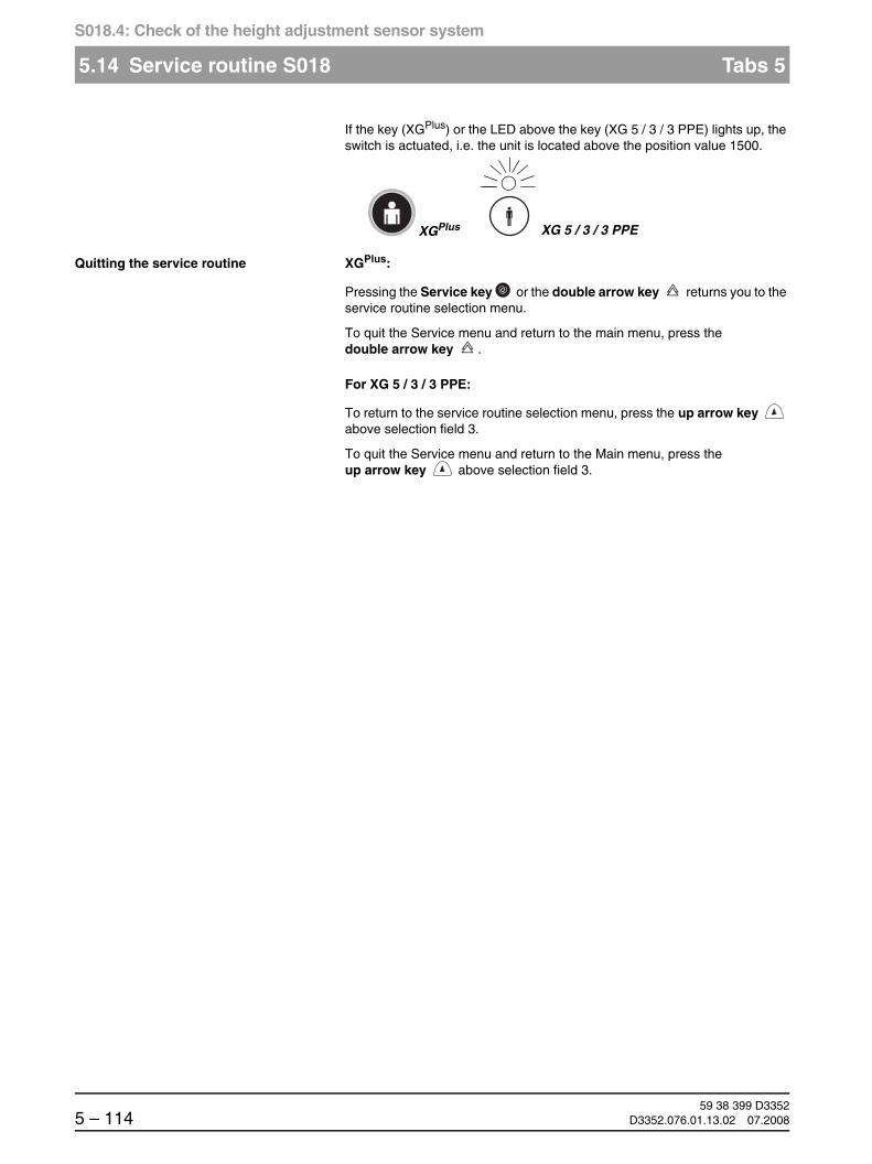
59 38 399 D33525 – 114 D3352.076.01.13.02 07.2008
5.14 Service routine S018 Tabs 5
S018.4: Check of the height adjustment sensor system
If the key (XGPlus) or the LED above the key (XG 5 / 3 / 3 PPE) lights up, the switch is actuated, i.e. the unit is located above the position value 1500.
Quitting the service routine XGPlus:
Pressing the Service key or the double arrow key returns you to the service routine selection menu.
To quit the Service menu and return to the main menu, press the double arrow key .
For XG 5 / 3 / 3 PPE:
To return to the service routine selection menu, press the up arrow key above selection field 3.
To quit the Service menu and return to the Main menu, press the up arrow key above selection field 3.
XGPlus XG 5 / 3 / 3 PPE

båÖäáëÜ
59 38 399 D3352D3352.076.01.13.02 07.2008 5 – 115
Tab 5 5.14 Service routine S018
5.14
S018.2: Set minimum travel height
5.14.4 S018: Test step 5
Moving the unit 1. Move the unit to the required minimum travel height by pressing the Up/Down keys in the user mode.
NOTEiProgramming the minimum travel height is possible only for a system height that is below the lower correction switch level (< position value of 1500)!
Selecting test step 5 2. Select test step 2 using the arrow keys in selection field 5and then confirm your selection with the Service key .
The current height position is displayed in selection field 1. The Memory key (XGPlus) or the LED above the Memory key (XG 5 / 3 / 3 PPE) lights up.
T R
Prog. S kV mA
1
2
3
+- S018
5
1 2 3
S018_______5____
XGPlus: Easypad touchscreen XG 5 / 3 / 3 PPE: Multipad
+-

59 38 399 D33525 – 116 D3352.076.01.13.02 07.2008
5.14 Service routine S018 Tabs 5
S018.2: Set minimum travel height
Saving the minimum travel height 3. To save the minimum travel height, first press the Memory key (R key (XGPlus) or LED above R key (XG 5 / 3 / 3 PPE) lights up) and then the R key .
NOTEiThe limitation of the minimum travel height is purely software based. The lower limit switch is not adapted to the new minimum travel height!
Quitting the service routine XGPlus:
To return to the service routine selection menu, press the Service key or the double arrow key .
To quit the Service menu and return to the main menu, press the double arrow key .
For XG 5 / 3 / 3 PPE:
Pressing the up arrow key above selection field 3 returns you to the ser-vice routine selection menu.
To quit the Service menu and return to the Main menu, press the up arrow key above selection field 3.
R R
R
1
2
3
200mm
1 2 3
__200_MM________
XGPlus: Easypad touchscreen XG 5 / 3 / 3 PPE: Multipad
R
S18
5

båÖäáëÜ
59 38 399 D3352D3352.076.01.13.02 07.2008 5 – 117
Tab 5 5.14 Service routine S018
5.14
S018.6: Undoing the minimum travel height setting
5.14.5 S018: Test step 6
Selecting test step 6 1. Select test step 6 in selection field 2 with the arrow keys and confirm your selection by pressing the Service key .
The current height position is displayed in selection field 1. The Memory key (XGPlus) or the LED above the Memory key (XG 5 / 3 / 3 PPE) lights up.
Undoing the minimum travel height setting
2. To undo the minimum travel height setting, first press the Memory key (R key (XGPlus) or LED above R key (XG 5 / 3 / 3 PPE) lights up)
and then the R key .
Quitting the service routine XGPlus:
Pressing the Service key or the double arrow key returns you to the service routine selection menu.
To quit the Service menu and return to the main menu, press the double arrow key .
For XG 5 / 3 / 3 PPE:
To return to the service routine selection menu, press the up arrow key above selection field 3.
To quit the Service menu and return to the Main menu, press the up arrow key above selection field 3.
1
2
3
+- S018
6
1 2 3
S018_______6____
XGPlus: Easypad touchscreen XG 5 / 3 / 3 PPE: Multipad
+-
R R
R
1
2
3
200mm
1 2 3
__200_MM________
XGPlus: Easypad touchscreen XG 5 / 3 / 3 PPE: Multipad
R
S18
6

59 38 399 D33525 – 118 D3352.076.01.13.02 07.2008
5.15 Service routine S020 (XGPlus only) Tabs 5
S020.1: Service for temple support
5.15 Service routine S020 (XGPlus only)
Service for temple support
This service routine can be used to change the factory-set switching points of the temple width measurement used for setting the jaw width (“small”, “normal” or “large”) within certain limits.
The following drawing shows the motor position values (initial and individual offset ranges) as well as the mechanical end stops of the temple support.
Headrest version 1(up to unit hardware version AG)
Headrest version 2(as of unit hardware version BA)
The switching point between large and normal is referred to as the lower switching point (marked L = lower) and the switching point between normal and small as the upper switching point (marked U = upper).
These switching points can be set via service routine S20.1 within the follow-ing limits:
Headrest version 1 (up to unit hardware version ≤ AG):
Lower switching point (L): Setting range -10...+5Upper switching point (U): Setting range -5...+10
Headrest version 2 (up to unit hardware version ≥ BA):
Lower switching point (L): Setting range -10...+5Upper switching point (U): Setting range -5...+13
NOTEiA negative offset shifts the respective switching threshold toward larger skulls; a positive offset has the opposite effect.
Function S020 Service for temple support
Test step 1 Change switching thresholds of the temple support
0 34 46 60large
-10 (24) +5 (39)
normal small
-5 (41) +10 (56)U
L
0 31 43 60large
-10 (21) +5 (36)
normal small
-5 (38) +13 (56)U
L

båÖäáëÜ
59 38 399 D3352D3352.076.01.13.02 07.2008 5 – 119
Tab 5 5.15 Service routine S020 (XGPlus only)
5.15
S020.1: Change switching points of the temple support
Select the Service menu (see page 5-10).
Selecting service routine S002 1. Use the arrow keys to select service routine S020.
5.15.1 S020: Test step 1
Selecting test step 1 1. Select test step 1 in selection field 2 with the arrow keys and confirm your selection by pressing the Service key .
After the service routine is selected, the lower switching point is displayed in selection field 1 in the form of L: 0. The upper switching point is dis-played in selection field 2 in the form U: 0.
1
2
3
+- S020
1
XGPlus: Easypad touchscreen
+-
1
2
3
+- S020
1
XGPlus: Easypad touchscreen
+-
S20
R
1
2
3
+- L: 0
U: 0
XGPlus: Easypad touchscreen
+-
S20
1

59 38 399 D33525 – 120 D3352.076.01.13.02 07.2008
5.15 Service routine S020 (XGPlus only) Tabs 5
S020.1: Change switching points of the temple support
2. Select the desired offset for the switch-over point using the arrow keys of the corresponding selection field (see page 5-118).
Selection field 1: Lower switching point (L)Selection field 2: Upper switching point (U)
NOTEiA negative offset shifts the respective switching threshold toward larger skulls; a positive offset has the opposite effect.
After the offset value is changed, the Memory key lights up.
3. To save the offset values, first press the Memory key (R key lights up) and then the R key .
Quitting the service routine Pressing the Service key or the double arrow key returns you to the service routine selection menu.
To quit the Service menu and return to the main menu, press the double arrow key .
R
1
2
3
+- L: -3
U: 0
XGPlus: Easypad touchscreen
+- 1
R
R
1
2
3
+- L: -3
U: 0
XGPlus: Easypad touchscreen
+-
S20
1

båÖäáëÜ
59 38 399 D3352D3352.076.01.13.02 07.2008 5 – 121
Tab 5 5.16 Service routine S021 (not for XG 3 / 3 PPE)
5.16
S021: Service for motor-driven diaphragm
5.16 Service routine S021 (not for XG 3 / 3 PPE)
Service for motor-driven diaphragm
Select the Service menu (see page 5-10).
Selecting service routine S021 1. Use the arrow keys to select service routine S021.
5.16.1 S021: Test step 1
Selecting test step 1 1. Select test step 1 in selection field 2 with the arrow keys and confirm your selection by pressing the Service key .
Function S021 Service for motor-driven diaphragm
Test step 1 Initialization of diaphragm axis
Test step 3 Perform TSA sensor adjustment (TSA) even if TSA is not configured (function test)
1
2
3
+- S021
1
1 2 3
S021_______1____
XGPlus: Easypad touchscreen XG 5: Multipad
+-
1
2
3
+- S021
1
1 2 3
S021_______1_____
XGPlus: Easypad touchscreen XG 5: Multipad
+-

59 38 399 D33525 – 122 D3352.076.01.13.02 07.2008
5.16 Service routine S021 (not for XG 3 / 3 PPE) Tabs 5
S021.1: Initialization of diaphragm axis
An inactive progress indicator in selection field 1 and the message FFFF in selection field 2 signal that the system is ready for initialization of the diaphragm axis.
Performing the initialization of the diaphragm axis
2. Start the automatic initialization of the diaphragm axis by pressing the T key .
When the axis initialization is completed, the result is displayed in selec-tion field 2:
0000 = Initializiation OKEEEE = Initialization error
The initialization can be restarted at any time by pressing the T key.
T
1
2
3
FFFF
1 2 3
_______FFFF____
XGPlus: Easypad touchscreen XG 5: Multipad
S21
1
T T
TT
1 2 3
1
2
3
XGPlus: Easypad touchscreen XG 5: Multipad
1
S21
T
1
2
3
0000
1 2 3
_______0000____
XGPlus: Easypad touchscreen XG 5: Multipad
S21
1

båÖäáëÜ
59 38 399 D3352D3352.076.01.13.02 07.2008 5 – 123
Tab 5 5.16 Service routine S021 (not for XG 3 / 3 PPE)
5.16
S021.3: Function test of TSA sensor adjustment
5.16.2 S021: Test step 3
Selecting test step 1 1. Select test step 3 in selection field 2 with the arrow keys and confirm your selection by pressing the Service key .
An inactive progress indicator in selection field 1 and the message FFFF in selection field 2 signal that the system is ready for initialization of the di-aphragm axis.
1
2
3
+- S021
3
1 2 3
S021_______3_____
XGPlus: Easypad touchscreen XG 5: Multipad
+-
T
1
2
3
1 2 3
________________
XGPlus: Easypad touchscreen XG 5: Multipad
S21
3

59 38 399 D33525 – 124 D3352.076.01.13.02 07.2008
5.16 Service routine S021 (not for XG 3 / 3 PPE) Tabs 5
S021.3: Function test of TSA sensor adjustment
Axis initialization of the TSA sensor holder
2. Start the automatic axis initialization of the TSA sensor holder by pressing the T key .
When the axis initialization is completed, the result is displayed in selec-tion field 2:
0000 = Initializiation OKEEEE = Initialization error
The initialization can be restarted at any time by pressing the T key .
T T
T T
1 2 3
1
2
3
XGPlus: Easypad touchscreen XG 5: Multipad
3
S21
T T
T
1
2
3
0000
1 2 3
_______0000____
XGPlus: Easypad touchscreen XG 5: Multipad
S21
3

båÖäáëÜ
59 38 399 D3352D3352.076.01.13.02 07.2008 5 – 125
Tab 5 5.16 Service routine S021 (not for XG 3 / 3 PPE)
5.16
S021.3: Function test of TSA sensor adjustment
Moving the TSA sensor holder 3. Move the TSA sensor holder by alternately pressing patient symbol keys a and d.
When key P1 is pressed, the TSA sensor holder moves to thePAN/CEPH position for Set key P4 to the TSA position.
When the action is completed, the result is displayed in selection field 2:
0000 = action OKEEEE = action error
Quitting the service routine XGPlus:
Pressing the Service key or the double arrow key returns you to the service routine selection menu.
To quit the Service menu and return to the main menu, press the double arrow key .
XG 5:
To return to the service routine selection menu, press the up arrow key above selection field 3.
To quit the Service menu and return to the Main menu, press the up arrow key above selection field 3.
T
1 2 3
1
2
3
XGPlus: Easypad touchscreen XG 5: Multipad
3
S21
a d
a d
T
1
2
3
0000
1 2 3
_______0000____
XGPlus: Easypad touchscreen XG 5: Multipad
S21
3

59 38 399 D33525 – 126 D3352.076.01.13.02 07.2008
5.17 Service routine S032 Tabs 5
S032: Test function for sensor in PAN slot
5.17 Service routine S032
Test function for sensor in PAN slot
Select the Service menu (see page 5-10).
Selecting service routine S032 1. Use the arrow keys to select service routine S032.
5.17.1 S032: Test step 10
Selecting test step 10 1. Select test step 10 in selection field 2 with the arrow keys and confirm your selection by pressing the Service key .
After test step 10 is selected, selection field 1 displays the current selection for synchronized readout sequence.
Function S032 Test function for sensor in the PAN slot
Test step 10 Test function for sensor in the PAN slot
1
2
3
+- S032
1 2 3
S032_______10___
XGPlus: Easypad touchscreen XG 5 / 3 / 3 PPE: Multipad
1
2
3
+- S032
10
1 2 3
S032_______10___
XGPlus: Easypad touchscreen XG 5 / 3 / 3 PPE: Multipad
+-
S32

båÖäáëÜ
59 38 399 D3352D3352.076.01.13.02 07.2008 5 – 127
Tab 5 5.17 Service routine S032
5.17
S032.10: Test function for sensor in PAN slot
Selecting the synchronized readout sequence
2. Select the mode of the desired synchronized readout sequence using the arrow keys of selection field 1.
HSIPan3x3 = sensor in the PAN mode with synchronized readoutsequence 3x3 clocked out
HSIPan4x4 = sensor in the PAN mode with synchronized readoutsequence 4x4 clocked out
HSITSA4x4 = sensor in the TSA mode with synchronized readoutsequence 4x4 clocked out
After the mode for the synchronized readout sequence has been selected the Test key (XGPlus) or the LED above the Test key lights up (XG 5 / 3 / 3 PPE).
NOTEiIf the R key (XGPlus) or the LED above the R key (XG 5 / 3 / 3 PPE) initially lights up, the sensor holder must be moved to the corresponding position first. To do this, press the R key .
Starting synchronized readout sequence
NOTEiThe sensor must be plugged in for at least 15 seconds before starting the synchronized readout sequence.
3. Start the synchronized readout sequence with the Test key .
CAUTIONThe sensor must not be removed while the synchronized readout sequence is active! Otherwise the electronics may be damaged.
1
2
3
+- HSIPan3x3
1 2 3
HSIPAN3X3______
XGPlus: Easypad touchscreen XG 5 / 3 / 3 PPE: Multipad
T
10
T T
R R
T T
1
2
3
Take Image...
1 2 3
TAKE_IMAGE_____
XGPlus: Easypad touchscreen XG 5 / 3 / 3 PPE: Multipad
10
S32

59 38 399 D33525 – 128 D3352.076.01.13.02 07.2008
5.17 Service routine S032 Tabs 5
S032.10: Test function for sensor in PAN slot
Explanations on the test procedure:
The synchronized readout sequence of the sensor is performed with real data transmissions and CAN bus commands.
The image data are analyzed in the memory of the DX11.
It is possible to evaluate the LEDs on DX1 (IMAGE; PAN; CEPH) during the synchronized readout sequence.
IMAGE-LED V501:
Stand By mode = LED dark
Active synchronized readout sequence = LED lights up
CEPH-LED V502:
Sensor in the Ceph slot/Stand By mode = LED lights up
No sensor in the Ceph slot/Stand By mode = LED dark
Sensor in the Ceph slot/active synchronized readout sequence = LED dark
PAN-LED V500:
Sensor in the Pan slot/Stand By mode = LED lights up
No sensor in the Pan slot/Stand By mode = LED dark
Sensor in the Pan slot/active synchronized readout sequence = LED dark
In addition, "wiggle tests" of cables or ring rotation tests can also be per-formed.
XGPlus: Easypad touchscreen The result of the synchronized readout sequence is displayed:
Image Size = total size of the image
Row Length = image height in pixels
Nr of Rows = Number of image rows
CRC Errors = Number of detected CRC errors during the synchronized readout sequence
Exp.-Therm TMO = Exposure interrupted by a timeout while reading image data
Exp.-Therm CRC = Exposure interrupted by an excess number of CRC errors
V500Pan
V502Ceph
V501Image
DX1
65
HSI-State
Image Size : NOK : 26320Row Length : OK : 1314Nr of Rows : NOK : 10CRC Errors : NOK : 10Exp.-ThermTMO : NOK : 1Exp.-ThermCRC : OK : 0
65
HSI-State
Image Size : OK : 8134984Row Length : OK : 2186Nr of Rows : OK : 1859CRC Errors : OK : 0Exp.-ThermTMO : OK : 0Exp.-ThermCRC : OK : 0

båÖäáëÜ
59 38 399 D3352D3352.076.01.13.02 07.2008 5 – 129
Tab 5 5.17 Service routine S032
5.17
S032.10: Test function for sensor in PAN slot
XG 5 / 3 / 3 PPE: Multipad The single-line display of the Multipad initially shows the HSI-STATE.
Use the arrow keys in selection field 1 to select the desired parameters, e.g. IMAGE SIZE and confirm your selection by pressing the Memory key .
The result of the synchronized readout sequence for the selected parameters is displayed.
Using the up arrow key in selection field 3 or the Service key , you can return to the parameter selection menu.
Quitting the service routine XGPlus:
Pressing the Service key or the double arrow key returns you to the service routine selection menu.
To quit the Service menu and return to the main menu, press the double arrow key .
For XG 5 / 3 / 3 PPE:
To return to the service routine selection menu, press the up arrow key above selection field 3.
To quit the Service menu and return to the Main menu, press the up arrow key above selection field 3.
1 2 3
IMAGE SIZE______
1 2 3
OK: 8134984______
59 38 399 D33525 – 130 D3352.076.01.13.02 07.2008
5.18 Service routine S033 (not for XG 3 / 3 PPE) Tabs 5
S033: Test of CEPH image path without SIDEXIS
5.18 Service routine S033 (not for XG 3 / 3 PPE)
Test of CEPH image path without SIDEXIS
Select the Service menu (see page 5-10).
Selecting service routine S033 1. Use the arrow keys to select service routine S033.
5.18.1 S033: Test step 10
Selecting test step 10 1. Select test step 10 in selection field 2 with the arrow keys and confirm your selection by pressing the Service key .
After test step 10 is selected, selection field 1 displays the current selection for the synchronized readout sequence.
Function S033 Test of CEPH image path without SIDEXIS
Test step 10 Test of the CEPH image path without SIDEXIS
1
2
3
+- S033
1 2 3
S033_______10___
XGPlus: Easypad touchscreen XG 5: Multipad
1
2
3
+- S033
10
1 2 3
S033_______10___
XGPlus: Easypad touchscreen XG 5: Multipad
+-
S33

båÖäáëÜ
59 38 399 D3352D3352.076.01.13.02 07.2008 5 – 131
Tab 5 5.18 Service routine S033 (not for XG 3 / 3 PPE)
5.18
S033.10: Test of CEPH image path without SIDEXIS
Selecting the synchronized readout sequence
2. Select the mode of the desired synchronized readout sequence using the arrow keys of selection field 1.
HSIC4x4 = Sensor in CEPH mode with synchronized readoutsequence 4x4 clocked out without CEPH scan
HSIC4x4M = Sensor in CEPH mode with synchronized readoutsequence 4x4 clocked out with CEPH scan
After the mode for the synchronized readout sequence has been selected, the Test key (XGPlus) or the LED above the Test key (XG 5) lights up.
NOTEiIf the R key (XGPlus) or the LED above the R key (XG 5) initially lights up, the sensor holder must be moved to the corresponding position first. To do this, press the R key .
Starting the synchronized readout sequence
3. Start the synchronized readout sequence with the Test key .
1
2
3
+- HSC4x4
1 2 3
HSIC4X4_________
XGPlus: Easypad touchscreen XG 5: Multipad
T
10
T T
R R
T T
1
2
3
Take Image...
1 2 3
TAKE_IMAGE_____
XGPlus: Easypad touchscreen XG 5: Multipad
10
S33

59 38 399 D33525 – 132 D3352.076.01.13.02 07.2008
5.18 Service routine S033 (not for XG 3 / 3 PPE) Tabs 5
S033.10: Test of CEPH image path without SIDEXIS
XGPlus: Easypad touchscreen The result of the synchronized readout sequence is displayed:
Image Size = Total size of the image
Row Length = Image height in pixels
Nr of Rows = Number of image rows
CRC Errors = Number of detected CRC errors during the synchronized readout sequence
Exp.-Therm TMO = Exposure interrupted by a timeout while reading image data
Exp.-Therm CRC = Exposure interrupted by an excess number of CRC errors
XG 5: Multipad The single-line display of the Multipad initially shows the HSI-STATE.
Use the arrow keys in selection field 1 to select the desired parameters, e.g. IMAGE SIZE and confirm your selection by pressing the Memory key .
The result of the synchronized readout sequence for the selected parameters is displayed.
Using the up arrow key in selection field 3 or the Service key , you can return to the parameter selection menu.
65
HSI-State
Image Size : NOK : 26320Row Length : OK : 1314Nr of Rows : NOK : 10CRC Errors : NOK : 10Exp.-ThermTMO : NOK : 1Exp.-ThermCRC : OK : 0
65
HSI-State
Image Size : OK : 8134984Row Length : OK : 2186Nr of Rows : OK : 1859CRC Errors : OK : 0Exp.-ThermTMO : OK : 0Exp.-ThermCRC : OK : 0
1 2 3
IMAGE SIZE______
1 2 3
OK: 8134984______

båÖäáëÜ
59 38 399 D3352D3352.076.01.13.02 07.2008 5 – 133
Tab 5 5.18 Service routine S033 (not for XG 3 / 3 PPE)
5.18
S033.10: Test of CEPH image path without SIDEXIS
Quitting the service routine XGPlus:
Pressing the Service key or the double arrow key returns you to the service routine selection menu.
To quit the Service menu and return to the main menu, press the double arrow key .
XG 5:
To return to the service routine selection menu, press the up arrow key above selection field 3.
To quit the Service menu and return to the Main menu, press the up arrow key above selection field 3.

59 38 399 D33525 – 134 D3352.076.01.13.02 07.2008
5.19 Service routine S034 Tabs 5
S034: Service for the digital cephalometer
5.19 Service routine S034
Service for the digital cephalometer
Select the Service menu (see page 5-10).
Selecting service routine S034 1. Use the arrow keys to select service routine S034.
Function S034 Service for the digital cephalometer
Test step 4 Display/calibrate center position of ceph scan sensor axis
Test step 5 Display/calibrate center position of ceph scan secondary diaphragm axis
Test step 6 Moving to the ceph packing position
Test step 7(XGPlus only)
Display/change ring type
Test step 8(XGPlus full version only)
User-specific determination of the shadowing limit for C1 and C2
Test step 9(XGPlus full version only)
User-specific determination of the shadowing limit for C3 and C3F
1
2
3
+- S034
1
1 2 3
S034_______1____
XGPlus: Easypad touchscreen XG 5: Multipad
+-

båÖäáëÜ
59 38 399 D3352D3352.076.01.13.02 07.2008 5 – 135
Tab 5 5.19 Service routine S034
5.19
S034.4: Display/calibrate center position of ceph scan sensor axis
5.19.1 S034: Test step 4
Remove the cover from the cephalometer (see also section 1.14).
Selecting test step 4 1. Select test step 4 in selection field 2 with the arrow keys and confirm your selection by pressing the Service key .
After test step 4 is selected, the current offset value for the center position of the ceph scan sensor axis is displayed in selection field 1.
1
2
3
+- S034
4
1 2 3
S034_______4____
XGPlus: Easypad touchscreen XG 5: Multipad
+-
S34
1
2
3
1500
1 2 3
____1500________
XGPlus: Easypad touchscreen XG 5: Multipad
S34
4
RT

59 38 399 D33525 – 136 D3352.076.01.13.02 07.2008
5.19 Service routine S034 Tabs 5
S034.4: Display/calibrate center position of ceph scan sensor axis
Switching the test mode ON 2. Press the T key to switch the test mode on.
NOTEiIn the test mode, travel to the center position of the ceph scan sensor axis is initially performed without offsets. The T key (XGPlus) or the LED above the T key (XG 5) lights up and displays the test mode.
Determining the offset values 3. Move the sensor to its front position by pressing the R key .
NOTEiThe sensor can always be moved back and forth between its front and center positions with the R key.
4. Move the sensor to its center position by pressing the R key .
5. Measure distances L2 and L1 with a slide gage.
6. Calculate the offset value according to the following formula:
Ceph arm mounted on left side:
Ceph arm mounted on right side:
T T
Wall side
Sensor side
Room side
R R
R R
L1L2
Wall side
Room side
L1L2
Ceph arm mounted on left-hand side
Ceph arm mounted on right-hand side
L2 L1 ) 2÷–( Offsetwert=
L1 L2 ) 2÷–( Offsetwert=

båÖäáëÜ
59 38 399 D3352D3352.076.01.13.02 07.2008 5 – 137
Tab 5 5.19 Service routine S034
5.19
S034.4: Display/calibrate center position of ceph scan sensor axis
Entering the offset value 7. Select an offset value using the arrow keys of selection field 1.
NOTEiThe offset value can have a positive or a negative sign.
Ceph arm on left side:– A positive offset value shifts the sensor toward the room center.– A negative offset value shifts the sensor toward the wall.
Ceph arm mounted on right side:– A positive offset value shifts the sensor toward the wall.– A negative offset value shifts the sensor toward the room center.
Since the offset value can be set only in large steps of 500 (500 = 0.5 mm), you should set a value which comes as close as possible to the one you calculated.
8. To save the offset value, first press the Memory key (the R key (XGPlus) or the LED above the R key (XG 5) lights up) and then the R key .
1
2
3
+- 1500
1 2 3
____1500________
XGPlus: Easypad touchscreen XG 5: Multipad
R
4
T
R R
R
1
2
3
+- 1500
1 2 3
____1500________
XGPlus: Easypad touchscreen XG 5: Multipad
R
S34
4

59 38 399 D33525 – 138 D3352.076.01.13.02 07.2008
5.19 Service routine S034 Tabs 5
S034.4: Display/calibrate center position of ceph scan sensor axis
Checking the new center position of the ceph scan (sensor axis)
9. Quit the test mode by pressing the T key .
NOTEiThe offset settings are taken into account in normal operation.
10. Move the sensor to its referenz position by pressing the R key .
NOTEiThe sensor can always be moved back and forth between its front and center positions with the R key.
11. Move the sensor to its center position by pressing the R key .
12. Measure distances L1 and L2 with a slide gage and calculate the remain-ing offset as described on page 5-136.
– If the offset is still > ± 0.5 mm, the offset value must be corrected again. Repeat the service routine from item 2.
– If the offset is < ± 0.5 mm, the calibration is OK.
Continue with service routine S034.5.
Quitting the service routine XGPlus:
To return to the Service menu, press the double arrow key .
To quit the Service menu and return to the main menu, press the double arrow key .
XG 5:
To return to the Service menu, press the up arrow key above selection field 3.
To quit the Service menu and return to the Main menu, press the up arrow key above selection field 3.
T T
R R
R R

båÖäáëÜ
59 38 399 D3352D3352.076.01.13.02 07.2008 5 – 139
Tab 5 5.19 Service routine S034
5.19
S034.5: Display/calibrate center position of ceph scan secondary diaphragm axis
5.19.2 S034: Test step 5
Selecting test step 5 1. Select test step 5 in selection field 2 with the arrow keys and confirm your selection by pressing the Service key .
After test step 5 is selected, the current offset value for the center position of the ceph scan secondary diaphragm axis is displayed in selection field 1.
Switching the test mode on 2. Press the T key to switch the test mode on.
NOTEiIn the test mode, travel to the center position of the ceph scan secondary dia-phragm axis is initially performed without offsets. The T key (XGPlus) or the LED above the T key (XG 5) lights up and displays the test mode.
1
2
3
+- S034
5
1 2 3
S034_______5____
XGPlus: Easypad touchscreen XG 5: Multipad
+-
S34
1
2
3
1500
1 2 3
____1500________
XGPlus: Easypad touchscreen XG 5: Multipad
S34
5
RT
T T

59 38 399 D33525 – 140 D3352.076.01.13.02 07.2008
5.19 Service routine S034 Tabs 5
S034.5: Display/calibrate center position of ceph scan secondary diaphragm axis
Determining the offset values 3. Move the secondary diaphragm to its front position by pressing the R key .
NOTEiThe secondary diaphragm can always be moved back and forth between its front and center positions with the R key.
4. Move the secondary diaphragm to its center position by pressing the R key .
5. Measure distances L2 and L1 with a slide gage.
6. Calculate the offset value according to the following formula:
Ceph arm on left side:
Ceph arm on right side:
Secondary diaphragm side
Wall side
Room side
R R
R R
Wall side
Room side
L1
Ceph arm mounted on left-hand side
Ceph arm mounted on right-hand side
L2 L2L1
L2 L1 ) 2÷–( Offsetwert=
L1 L2 ) 2÷–( Offsetwert=

båÖäáëÜ
59 38 399 D3352D3352.076.01.13.02 07.2008 5 – 141
Tab 5 5.19 Service routine S034
5.19
S034.5: Display/calibrate center position of ceph scan secondary diaphragm axis
Entering the offset value 7. Select an offset value using the arrow keys of selection field 1.
NOTEiThe offset value can have a positive or a negative sign.
Ceph arm on left side:– A positive offset value shifts the secondary diaphragm toward the room
center.– A negative offset value shifts the secondary diaphragm toward the wall.
Ceph arm mounted on right side:– A positive offset value shifts the secondary diaphragm toward the wall.– A negative offset value shifts the secondary diaphragm toward the room
center.Since the offset value can be set only in large steps of 500 (500 = 0.5 mm), you should set a value which comes as close as possible to the one you calculated.
8. To save the offset value, first press the Memory key (the R key (XGPlus) or the LED above the R key (XG 5) lights up) and then the R key .
1
2
3
+- 1500
1 2 3
____1500________
XGPlus: Easypad touchscreen XG 5: Multipad
RT
R R
R
1
2
3
+- 1500
1 2 3
____1500________
XGPlus: Easypad touchscreen XG 5: Multipad
R

59 38 399 D33525 – 142 D3352.076.01.13.02 07.2008
5.19 Service routine S034 Tabs 5
S034.5: Display/calibrate center position of ceph scan secondary diaphragm axis
Checking the new center position of the ceph scan (secondary diaphragm axis)
9. Quit the test mode by pressing the T key .
NOTEiThe offset settings are taken into account in normal operation.
10. Move the secondary diaphragm to its referenz position by pressing the R key .
NOTEiThe secondary diaphragm can always be moved back and forth between its front and center positions with the R key.
11. Move the secondary diaphragm to its center position by pressing the R key .
12. Measure distances L1 and L2 with a slide gage and calculate the remain-ing offset as described on page 5-140.
– If the offset is still > ± 0.5 mm, the offset value must be corrected again. Repeat the service routine from item 2.
– If the offset is < ± 0.5 mm, the calibration is OK.
Reattach the ceph cover.
Quitting the service routine XGPlus:
To return to the Service menu, press the double arrow key .
To quit the Service menu and return to the main menu, press the double arrow key .
XG 5:
To return to the Service menu, press the up arrow key above selection field 3.
To quit the Service menu and return to the Main menu, press the up arrow key above selection field 3.
T T
R R
R R

båÖäáëÜ
59 38 399 D3352D3352.076.01.13.02 07.2008 5 – 143
Tab 5 5.19 Service routine S034
5.19
S034.6: Moving to the ceph packing position
5.19.3 S034: Test step 6 (not for XG 3 / 3 PPE)
Selecting test step 6 1. Select test step 6 in selection field 2 with the arrow keys and confirm your selection by pressing the Service key .
After the test step is started, an inactive progress indicator is displayed in selection field 1. Selection field 2 shows the characters FFFF.
Moving to the ceph packing position 2. Press the T key .
The cephalometer moves to the packing position. The procedure is visu-alized by an active progress indicator in selection field 1. Once the proce-dure is completed, the characters 0000 appear in selection field 2.
1
2
3
+- S034
6
1 2 3
S034_______6____
XGPlus: Easypad touchscreen XG 5: Multipad
+-
S34
T
1
2
3
FFFF
1 2 3
_______FFFF____
XGPlus: Easypad touchscreen XG 5: Multipad
S34
6
T T
T
1 2 3
1
2
3
+-
XGPlus: Easypad touchscreen XG 5: Multipad
6
S34
T

59 38 399 D33525 – 144 D3352.076.01.13.02 07.2008
5.19 Service routine S034 Tabs 5
S034.6: Moving to the ceph packing position
When the cephalometer has reached its packing position, 0000 is displayed in selection field 2.
Quitting the service routine XGPlus:
To return to the Service menu, press the double arrow key .
To quit the Service menu and return to the main menu, press the double arrow key .
XG 5:
To return to the Service menu, press the up arrow key above selection field 3.
To quit the Service menu and return to the Main menu, press the up arrow key above selection field 3.
T
1
2
3
0000
1 2 3
_______0000____
XGPlus: Easypad touchscreen XG 5: Multipad
S34
6

båÖäáëÜ
59 38 399 D3352D3352.076.01.13.02 07.2008 5 – 145
Tab 5 5.19 Service routine S034
5.19
S034.7: Display/change ring type
5.19.4 S034: Test step 7 (XGPlus only)
Selecting test step 7 1. Select test step 7 in selection field 2 with the arrow keys and confirm your selection by pressing the Service key .
2. Select the ring type using the arrow keys of selection field 1:
01 = old ring type = PAN unit serial numbers up to 20056PAN/CEPH units up to serial number 40104
02 = new ring type = PAN units with serial no. 20056 and higherPAN/CEPH units with serial no. 40104 and higher
3. To save the setting, first press the Memory key (R key lights up) and then press the R key .
1
2
3
+- S034
7
XGPlus: Easypad touchscreen
+-
S34
1
2
3
+- 01
XGPlus: Easypad touchscreen
R
S34
R R
1
2
3
+- 01
XGPlus: Easypad touchscreen
R
S34
7

59 38 399 D33525 – 146 D3352.076.01.13.02 07.2008
5.19 Service routine S034 Tabs 5
S034.8: Determining shadowing limit C1 and C2
Quitting the service routine To return to the Service menu, press the double arrow key .
To quit the Service menu and return to the main menu, press the double arrow key .
To quit the Service menu and return to the Main menu, press the up arrow key above selection field 3.
5.19.5 S034: Test step 8 (XGPlus and full version only)
In CEPH programs C1 and C2 for full-version XGPlus systems, the shadowing limit set by default can be provided with an individual offset. In this way the shadowing can be shifted within certain limits.
The offset must be determined by reference to an existing exposure. Starting from the default setting, an offset can be selected and saved within a range of +30,000 μm to -15,000 μm.
For C1/C2
+30,000 μm
-15,000 μm Shadowing limit

båÖäáëÜ
59 38 399 D3352D3352.076.01.13.02 07.2008 5 – 147
Tab 5 5.19 Service routine S034
5.19
S034.8: Determining shadowing limit C1 and C2
Selecting test step 8 1. Select test step 8 in selection field 2 with the arrow keys and confirm your selection by pressing the Service key .
2. Select the desired offset value using the arrow keys in selection field 1 (step width = 500, offset value = 1000 corresponds to a 1 mm shift of the shadowing limit).
3. To save the setting, first press the Memory key (R key lights up) and then press the R key .
4. Take a C1 or C2 exposure to check the effectiveness of the setting (see operating instructions).
1
2
3
+- S034
8
XGPlus: Easypad touchscreen
+-
S34
1
2
3
+- 5500
XGPlus: Easypad touchscreen
R
8
R R
1
2
3
+- 5500
XGPlus: Easypad touchscreen
R
S34
8

59 38 399 D33525 – 148 D3352.076.01.13.02 07.2008
5.19 Service routine S034 Tabs 5
S034.9: Determining the shadowing limit for C3 and C3F
Quitting the service routine To return to the Service menu, press the double arrow key .
To quit the Service menu and return to the main menu, press the double arrow key .
To quit the Service menu and return to the Main menu, press the up arrow key above selection field 3.
5.19.6 S034: Test step 9 (XGPlus and full version only)
In CEPH programs C3 and C3F for full-version XGPlus systems, the shadow-ing limit set by default can be provided with an individual offset. In this way the shadowing can be shifted within certain limits.
The offset must be determined by reference to an existing exposure. Starting from the default setting, an offset can be selected and saved within a range of +15,000 μm to -30,000 μm.
For C3 and C3F
Shadowing limit
+15,000 μm
-30,000 μm
båÖäáëÜ
59 38 399 D3352D3352.076.01.13.02 07.2008 5 – 149
Tab 5 5.19 Service routine S034
5.19
S034.9: Determining the shadowing limit for C3 and C3F
Selecting test step 8 1. Select test step 9 in selection field 2 with the arrow keys and confirm your selection by pressing the Service key .
2. Select the desired offset value using the arrow keys in selection field 1 (step width = 500, offset value = 1000 corresponds to a 1 mm shift of the shadowing limit).
3. To save the setting, first press the Memory key (R key lights up) and then press the R key .
4. Take a C3 or C3F exposure to check the effectiveness of the setting (see operating instructions).
1
2
3
+- S034
9
XGPlus: Easypad touchscreen
+-
S34
1
2
3
+- -2500
XGPlus: Easypad touchscreen
R
9
R R
1
2
3
+- -2500
XGPlus: Easypad touchscreen
R
S34
8

59 38 399 D33525 – 150 D3352.076.01.13.02 07.2008
5.19 Service routine S034 Tabs 5
S034.9: Determining the shadowing limit for C3 and C3F
Quitting the service routine To return to the Service menu, press the double arrow key .
To quit the Service menu and return to the main menu, press the double arrow key .
To quit the Service menu and return to the Main menu, press the up arrow key above selection field 3.

båÖäáëÜ
59 38 399 D3352D3352.076.01.13.02 07.2008 5 – 151
Tab 5 5.20 Service routine S037
5.20
S037: Network service
5.20 Service routine S037
Network service
Select the Service menu (see page 5-10).
Selecting service routine S037 Use the arrow keys to select service routine S037.
Function S037 Network service
Test step 1 Showing the network data
Test step 2 Setting the default IP address, default gateway address and default subnet mask
Security access
Test step 3 Toggling the DHCP and fixed address boot mode (DEFAULT/STATIC) Security access
Test step 4 Manual input of IP address, default gateway address and subnet mask Security access
1
2
3
+- S037
1
1 2 3
S037_______1____
XGPlus: Easypad touchscreen XG 5 / 3 / 3 PPE: Multipad
+-

59 38 399 D33525 – 152 D3352.076.01.13.02 07.2008
5.20 Service routine S037 Tabs 5
S037.1: Displaying the network data
5.20.1 S037: Test step 1
Selecting test step 1 1. Select test step 1 in selection field 2 with the arrow keys and confirm your selection by pressing the Service key .
The IP address of the unit is displayed.
XGPlus:
DEFAULT or STATIC or IS DHCP is displayed in selection field 2.
DEFAULT= fixed address, factory setting
STATIC = fixed address, changed setting
DHCP = automatic address allocation
Bei XG 5 / 3 / 3 PPE:
The first digit in the single-line display of the Multipad denotes DEFAULT or STATIC.
X = DEFAULT= fixed address, factory setting
S = STATIC = fixed address, changed setting
D = DHCP = automatic address allocation
Patient symbol key a (XGPlus) or the LED above patient symbol key a (XG 5 / 3 / 3 PPE) lights up.
1
2
3
+- S037
1
1 2 3
S037_______1_____
XGPlus: Easypad touchscreen XG 5 / 3 / 3 PPE: Multipad
+-
1
2
3
192.168.15.240
DEFAULT
1 2 3
X192.168.15.240_
XGPlus: Easypad touchscreen XG 5 / 3 / 3 PPE: Multipad
1
S37
a
a

båÖäáëÜ
59 38 399 D3352D3352.076.01.13.02 07.2008 5 – 153
Tab 5 5.20 Service routine S037
5.20
S037.1: Displaying the network data
Displaying the network data 2. You can display different network data in selection field 1 by pressing patient symbol keys a, b and c.
a : Display of the IP addressb : Display of the standard gatewayc : Display of the subnet mask
The currently selected patient symbol key (XGPlus) or the LED above the selected patient symbol key (XG 5 / 3 / 3 PPE) is lit.
XGPlus:
DEFAULT or STATIC or IS DHCP is displayed in selection field 2.
Bei XG 5 / 3 / 3 PPE:
The first digit in the single-line display of the Multipad denotes DEFAULT or STATIC.
X = DEFAULT = fixed address, factory setting
S = STATIC = fixed address, changed setting
D = DHCP = automatic address allocation
NOTEiIf all network data is set to DEFAULT, the system is in the UDP boot mode.
Quitting the service routine XGPlus:
Pressing the Service key or the double arrow key returns you to the service routine selection menu.
To quit the Service menu and return to the main menu, press the double arrow key .
For XG 5 / 3 / 3 PPE:
To return to the service routine selection menu, press the up arrow key above selection field 3.
To quit the Service menu and return to the Main menu, press the up arrow key above selection field 3.
a b c d
XGPlus
XG 5 / 3 / 3 PPE

59 38 399 D33525 – 154 D3352.076.01.13.02 07.2008
5.20 Service routine S037 Tabs 5
S037.2: Setting the default IP address, default gateway address and default subnet mask
5.20.2 S037: Test step 2
Selecting test step 2 1. Select test step 2 in selection field 2 with the arrow keys and confirm your selection by pressing the Service key .
Confirming the security access 2. Confirm the security access by once again selecting the number of the main routine (37) with the arrow keys of selection field 2 and then press-ing the Service key .
After test step 2 is selected, the network data display appears as in test step 1. In addition, the Memory key and R key are also displayed. The Memory key is lit.
1
2
3
+- S037
2
1 2 3
S037_______2____
XGPlus: Easypad touchscreen XG 5 / 3 / 3 PPE: Multipad
+-
S37
1
2
3
37
1 2 3
__________37____
XGPlus: Easypad touchscreen XG 5 / 3 / 3 PPE: Multipad
+-
R R
1
2
3
192.168.15.178
STATIC
1 2 3
S192.168.15.178__
XGPlus: Easypad touchscreen XG 5 / 3 / 3 PPE: Multipad
S37
2
R

båÖäáëÜ
59 38 399 D3352D3352.076.01.13.02 07.2008 5 – 155
Tab 5 5.20 Service routine S037
5.20
S037.2: Setting the default IP address, default gateway address and default subnet mask
Checking the network data 3. Check the network data still in the system before resetting.
a : Display of the IP addressb : Display of the standard gatewayc : Display of the subnet mask
The currently selected patient symbol key (XGPlus) or the LED above the selected patient symbol key (XG 5 / 3 / 3 PPE) is lit.
Resetting the network data 4. To reset the network data, first press the Memory key (R key (XGPlus) or LED above R key (XG 5 / 3 / 3 PPE) lights up) and then the R key .
NOTEiThe network data cannot be reset selectively. All network data are reset.
The default network data is displayed. To switch between the display of the different network data, proceed as in test step 1.
NOTEiIt is possible to reset the network address to the default value only in the fixed address boot mode (no DHCP).
5. Switch the unit off and then on again.
a b c
XGPlus
XG 5 / 3 / 3 PPE
R R
1
2
3
+- 192.168.15.178
STATIC
1 2 3
S192.168.15.178__
XGPlus: Easypad touchscreen XG 5 / 3 / 3 PPE: Multipad
+-
S37
2
R
R
1
2
3
+- 192.168.15.178
DEFAULT
1 2 3
X192.168.15.178__
XGPlus: Easypad touchscreen XG 5 / 3 / 3 PPE: Multipad
+-
S37
2
R
59 38 399 D33525 – 156 D3352.076.01.13.02 07.2008
5.20 Service routine S037 Tabs 5
S037.2: Setting the default IP address, default gateway address and default subnet mask
Quitting the service routine XGPlus:
Pressing the Service key or the double arrow key returns you to the service routine selection menu.
To quit the Service menu and return to the main menu, press the double arrow key .
For XG 5 / 3 / 3 PPE:
To return to the service routine selection menu, press the up arrow key above selection field 3.
To quit the Service menu and return to the Main menu, press the up arrow key above selection field 3.

båÖäáëÜ
59 38 399 D3352D3352.076.01.13.02 07.2008 5 – 157
Tab 5 5.20 Service routine S037
5.20
S037.3: Toggling the DHCP and fixed address boot mode (DEFAULT/STATIC)
5.20.3 S037: Test step 3
Selecting test step 3 1. Select test step 3 in selection field 2 with the arrow keys and confirm your selection by pressing the Service key .
The current boot mode of the unit is displayed in selection field 1.
Selecting the boot mode 2. Using the arrow keys in selection field 1, select the desired boot modeDHCP or fixed address (STATIC).
1
2
3
+- S037
3
1 2 3
S037_______3_____
XGPlus: Easypad touchscreen XG 5 / 3 / 3 PPE: Multipad
+-
R
1
2
3
+- STATIC
1 2 3
_STATIC__________
XGPlus: Easypad touchscreen XG 5 / 3 / 3 PPE: Multipad
3
S37
R
1
2
3
+- DHCP
1 2 3
_DHCP__________
XGPlus: Easypad touchscreen XG 5 / 3 / 3 PPE: Multipad
3

59 38 399 D33525 – 158 D3352.076.01.13.02 07.2008
5.20 Service routine S037 Tabs 5
S037.3: Toggling the DHCP and fixed address boot mode (DEFAULT/STATIC)
Saving the boot mode 3. To save the boot mode, first press the Memory key (R key (XGPlus) or LED above R key (XG 5 / 3 / 3 PPE) lights up) and then the R key .
NOTEiIf the system is reset to the STATIC mode, the network addresses will be reset to the factory setting
4. Switch the unit off and then on again.
Quitting the service routine XGPlus:
Pressing the Service key or the double arrow key returns you to the service routine selection menu.
To quit the Service menu and return to the main menu, press the double arrow key .
For XG 5 / 3 / 3 PPE:
To return to the service routine selection menu, press the up arrow key above selection field 3.
To quit the Service menu and return to the Main menu, press the up arrow key above selection field 3.
R R
3
S37
R
1
2
3
+- DHCP
1 2 3
____DHCP________
XGPlus: Easypad touchscreen XG 5 / 3 / 3 PPE: Multipad
R

båÖäáëÜ
59 38 399 D3352D3352.076.01.13.02 07.2008 5 – 159
Tab 5 5.20 Service routine S037
5.20
S037.4: Manual input of IP address, default gateway address and subnet mask
5.20.4 S037: Test step 4
NOTEiPerformance of this service routine is not possible in the DHCP mode (T keyis blocked).
Selecting test step 4 1. Select test step 4 in selection field 2 with the arrow keys and confirm your selection by pressing the Service key .
Confirming the security access 2. Confirm the security access by once again selecting the number of the main routine (37) with the arrow keys of selection field 2 and then press-ing the Service key .
The IP address of the unit is displayed in selection field 1.
XGPlus only:
DEFAULT or STATIC or IS DHCP is displayed in selection field 2.
DEFAULT= fixed address, factory setting
STATIC = fixed address, changed setting
DHCP = automatic address allocation
1
2
3
+- S037
4
1 2 3
S037_______4____
XGPlus: Easypad touchscreen XG 5 / 3 / 3 PPE: Multipad
+-
S37
1
2
3
37
1 2 3
__________37____
XGPlus: Easypad touchscreen XG 5 / 3 / 3 PPE: Multipad
+-

59 38 399 D33525 – 160 D3352.076.01.13.02 07.2008
5.20 Service routine S037 Tabs 5
S037.4: Manual input of IP address, default gateway address and subnet mask
Selecting/displaying the network data 3. To select the network data you would like to edit, press patient symbol key a, b or c:
a : Display of the IP addressb : Display of the standard gatewayc : Display of the subnet mask
The currently selected patient symbol key (XGPlus) or the LED above the selected patient symbol key (XG 5 / 3 / 3 PPE) is lit.
Selecting the network data 4. To change the selected parameter, first press the T key .
1
2
3
192.168.15.240
DEFAULT
1 2 3
X192.168.15.240_
XGPlus: Easypad touchscreen XG 5 / 3 / 3 PPE: Multipad
4
S37
T
a b c d
XGPlus
XG 5 / 3 / 3 PPE
1
2
3
192.168.15.240
DEFAULT
1 2 3
X192.168.15.240__
XGPlus: Easypad touchscreen XG 5 / 3 / 3 PPE: Multipad
4
S37
T
T T
1
2
3
192.168.15.240
DEFAULT
1 2 3
X192.168.15.240__
XGPlus: Easypad touchscreen XG 5 / 3 / 3 PPE: Multipad
4
S37
T T

båÖäáëÜ
59 38 399 D3352D3352.076.01.13.02 07.2008 5 – 161
Tab 5 5.20 Service routine S037
5.20
S037.4: Manual input of IP address, default gateway address and subnet mask
Selecting the octet 5. Select the desired octet 1-4 with patient symbol keys a-d:
a : Octet B1b : Octet B2c : Octet B3d : Octet B4
The currently selected patient symbol key is lit.
a b c d
XGPlus
XG 5 / 3 / 3 PPE
Example:
192.168.015.178
B1 B2 B3 B4 (Octets 1 - 4)
1 2 3 (Digit 1 - 3 of octet)
RT
1
2
3
Digit No. 3
2
1 2 3
__DIG:_3___2____
XGPlus: Easypad touchscreen XG 5 / 3 / 3 PPE: Multipad
4
S37+-
+-

59 38 399 D33525 – 162 D3352.076.01.13.02 07.2008
5.20 Service routine S037 Tabs 5
S037.4: Manual input of IP address, default gateway address and subnet mask
Selecting the digit 6. Use the arrow keys in selection field 1 to select the desired digit within the octet (see step 5).
NOTEiThe digits always refer to the selected octet only. Reprogramming the last digit is shown here as an example.
Selection field 2 shows the value of the selected digit.
Changing the value under the digit 7. To change the value under the digit, use the arrow keys of selection field 2.
192.168.015.178
Octet 3, digit 12, with the value 8
RT
1
2
3
+- Digit No. 12
8
1 2 3
__DIG:12___8____
XGPlus: Easypad touchscreen XG 5 / 3 / 3 PPE: Multipad
+- 4
192.168.015.179
Octet 3, digit 12, with the value 9
RT
1
2
3
+- Digit No. 12
9
1 2 3
__DIG:12___9____
XGPlus: Easypad touchscreen XG 5 / 3 / 3 PPE: Multipad
+-
S37

båÖäáëÜ
59 38 399 D3352D3352.076.01.13.02 07.2008 5 – 163
Tab 5 5.20 Service routine S037
5.20
S037.4: Manual input of IP address, default gateway address and subnet mask
Saving the changes 8. To save the changes, first press the Memory key (R key (XGPlus) or LED above R key (XG 5 / 3 / 3 PPE) lights up) and then the R key .
9. Switch the unit off and then on again.
Quitting the service routine XGPlus:
Pressing the Service key or the double arrow key returns you to the service routine selection menu.
To quit the Service menu and return to the main menu, press the double arrow key .
For XG 5 / 3 / 3 PPE:
To return to the service routine selection menu, press the up arrow key above selection field 3.
To quit the Service menu and return to the Main menu, press the up arrow key above selection field 3.
R R
R
RT
1
2
3
+- Digit No. 12
9
1 2 3
__DIG:12___9____
XGPlus: Easypad touchscreen XG 5 / 3 / 3 PPE: Multipad
+-
S37
4
1
2
3
192.168.15.179
1 2 3
S192.168.15.179___
XGPlus: Easypad touchscreen XG 5 / 3 / 3 PPE: Multipad
S37
4

59 38 399 D33525 – 164 D3352.076.01.13.02 07.2008
5.20 Service routine S037 Tabs 5
S037.4: Manual input of IP address, default gateway address and subnet mask

ORTHOPHOS XG 6 Repair

59 38 399 D33526 – 2 D3352.076.01.13.02 07.2008
Tab 6
Contents
6.1 Replacing the height adjustment motor (M1_4)/spindle ........................................................6 – 66.1.1 Preparing for motor replacement.......................... 6 – 6
6.1.2 Removing board DX32 ......................................... 6 – 9
6.1.3 Replacing the height adjustment motor/spindle . 6 – 10
6.1.4 Laying cables when replacing the height adjustment motor..................................... 6 – 12
6.2 Replacing the ring motor (M1_3)...........................6 – 146.2.1 Laying cables when replacing the ring motor ..... 6 – 16
6.3 Replacing the PAN actuators (M1_1/2).................6 – 176.3.1 Laying cables when replacing
actuators (M1_1/2) ............................................. 6 – 18
6.4 Replacing the headrest .........................................6 – 196.4.1 Laying cables when replacing the headrests ..... 6 – 20
6.5 Replacing the Easypad (XGPlus) or the Multipad (XG 5 / 3 / 3 PPE).........................6 – 21
6.6 Replacing the control panel...................................6 – 246.6.1 Laying cables when replacing the control panel. 6 – 25
6.7 Replacing/adjusting the FH light localizer (PAN) ..6 – 26
6.8 Replacing/adjusting the MS light localizer laser module (PAN)...............................................6 – 28
6.9 Replacing/adjusting the FH light localizer (Ceph) .6 – 30
6.10 Removing the light localizers from the ring(for the XGPlus and XG 5, if present) .....................6 – 32
6.11 Replacing the support piece (bite block holder) ....6 – 33
6.12 Replacing the motor-driven diaphragm (for XGPlus / XG 5) ...............................................6 – 346.12.1 Cables and connectors for replacement
of the motor-driven diaphragm unit .................... 6 – 36
6.13 Replacing the fixed diaphragm (only XG 3 / 3 PPE)...............................................6 – 37

59 38 399 D3352D3352.076.01.13.02 07.2008 6 – 3
Register 6
6.14 Replacing the X-ray tube assembly.......................6 – 386.14.1 Cables and connectors for replacement
of the tube assembly .......................................... 6 – 40
6.15 Replacing the fan (tube assembly)........................6 – 42
6.16 Replacing the PAN (TSA) sensor holder...............6 – 436.16.1 Laying cables when replacing the
PAN sensor holder ............................................. 6 – 45
6.17 Replacing the ceph sensor holder.........................6 – 47
6.18 Replacing the sensor.............................................6 – 48
6.19 Replacing the light barriers....................................6 – 496.19.1 Replacing light barrier V1_3 ............................... 6 – 51
6.20 Replacing circuit boards ........................................6 – 596.20.1 Measures following replacement of boards........ 6 – 60
6.20.2 Replacing a DX11 .............................................. 6 – 64
6.20.3 Replacing an X-ray tube assembly incl. DX6 ..... 6 – 80
6.20.4 Check jumper on circuit board DX42 (replacement of board DX42) ............................. 6 – 90
6.20.5 Jumper position on circuit board DX42 .............. 6 – 90
6.21 Replacing cables ...................................................6 – 916.21.1 Laying the cable conduit on the rotating element
(applicable to cables L3, L5, L6, L11 and L12) .. 6 – 92
6.21.2 Replacing cable L7 and L8/L108*(in cable track 2)................................................. 6 – 94
6.21.3 Laying cable L1 and the grounding strap(in cable track 1)................................................. 6 – 97

59 38 399 D33526 – 4 D3352.076.01.13.02 07.2008
Tab 6

båÖäáëÜ
59 38 399 D3352D3352.076.01.13.02 07.2008 6 – 5
Tab 6
6 Repair
DANGERShock hazard! It is essential that you switch the X-ray unit OFF before replacing any components!
The unit must be disconnected from the junction box of the building installation before replacing any parts near the power supply, power switch, board DX 32 or the X-ray tube assembly!
CAUTIONPlease observe the usual precautionary measures for han-dling printed circuit boards (ESD).
Touch a ground point to discharge static electricity before touching any boards.
NOTEiOpen the PAN and CEPH RESET ADJUSTMENT menus in SIDEXIS and note the old adjustment values before you begin replacing boards or modules (which contain boards).
NOTEiAfter replacing boards or modules containing boards, check to make sure that the programming of the module corresponds to the current software status of the system. The software version for the modules can...
for XGPlus:be accessed through service routine S008.2 or the extended detail query in SIXABCON. You can also check the info screen in advance to determine whether the current software constellation is permissible. If this is not the case, the version number of the entire software is labeled with an asterisk (e.g. V02.20*)
bei XG 5 / 3 / 3 PPE:be accessed through service routine S008.2 or the extended detail query in SIXABCON.
Perform a software update in case of software incompatibilities (see Section 1.9).
CAUTIONWhen replacing modules, be sure to note which ones contain boards and fol-low the instructions in section "Measures following replacement of boards" starting on page 6-60. Also check whether the current ORTHOPHOS XG CD or the Sirona dealer page contains any additional, up-to-date information on module replacement.
CAUTIONBe sure to observe the information on action required following module replacement. You will find this information at the end of each set of repair instructions.

59 38 399 D33526 – 6 D3352.076.01.13.02 07.2008
6.1 Replacing the height adjustment motor (M1_4)/spindle Tabs 6
6.1 Replacing the height adjustment motor (M1_4)/spindle
6.1.1 Preparing for motor replacement
Remove the sensor and store it in a safe place.
Switch the unit ON.
Moving the unit up and removing the profile covers
Use the UP/DOWN keys on the Easypad (XGPlus) or Multipad (XG 5 / 3 / 3 PPE) to move the slide upward and remove the cover parts (see section 1.14):
– Intermediate piece
– Profile covers, top and bottom
NOTEiTip: When unscrewing the profile cover, press it toward the top of the unit and let it slide down after detaching it.
NOTEiIf the height adjustment motor is inoperative, you can also move the slide man-ually.
Moving the slide manually 1. Loosen the two screws A and remove cover B.
2. Loosen screws C on spindle holder D and turn the spindle holder with a socket wrench (18 mm A/F):
– CW rotation of spindle = slide moves upward
– CCW rotation of spindle = slide moves downward
The spindle and slide can thus be manually moved in the vertical axis.
1.A
A
B
2.
C C
D

båÖäáëÜ
59 38 399 D3352D3352.076.01.13.02 07.2008 6 – 7
Tab 6 6.1 Replacing the height adjustment motor (M1_4)/spindle
6.1
Securing the slide position Make a mark at the position of the upper limit stop.
3. Loosen nut G on upper profile clamp H and remove upper limit stop J from the stand.
4. Install limit stop J above the lower limit stop so that there is a distance of approx. 560 mm ( 22’’) between the lower edge of the unit and the lower edge of the limit stop.
Use the UP/DOWN keys on the Easypad (XGPlus) or Multipad (XG 5 / 3 / 3 PPE) to move the slide downward.
NOTEiIf the height adjustment motor is inoperative, you can also move the slide man-ually (see page 6-6).
Switch the unit OFF and de-energize it.
4.
GH
J
J
GH
3.
approx. 560 mm
DX41*
* Board DX41 is omitted in unit HW version BA and higher.
approx. 22’’

59 38 399 D33526 – 8 D3352.076.01.13.02 07.2008
6.1 Replacing the height adjustment motor (M1_4)/spindle Tabs 6
Removing the remaining covers Remove the top cover and pull connector X607 off of board DX1.
Now remove the following cover parts:
– Arm cover, top
– Slide cover, top rear
– Slide cover, bottom rear
– Slide cover, frontAttention: FH laser cable (PAN)!
NOTEiTo prevent scratches, also remove the covers of the slide table and the drawer.

båÖäáëÜ
59 38 399 D3352D3352.076.01.13.02 07.2008 6 – 9
Tab 6 6.1 Replacing the height adjustment motor (M1_4)/spindle
6.1
6.1.2 Removing board DX32
1. Unscrew cover plates E (bottom and top) from connection box F of board DX32.
NOTEiCable L3 can remain on the top cover plate (remove the shield terminal if nec-essary). The cover plate can simply be folded to the side and stored laterally in the stand.
Pull connector X2 off of board DX32 and detach the protective ground wire.
2. Detach cable L2 from the cable tie and from terminal X100 and pull it out of connection box F toward the bottom.
3. Loosen the four screws (G) and remove the connection box including board DX32.
F
E
L3
L2
X100
L3
1.
2.
3.GG
G
G
DX32*
* The drawing shows board DX32 with a unit hardware version ≤ AG.
In order to facilitate removal of board DX32, the bottom edge of the slide should be roughly flush with the upper bracket in the stand.

59 38 399 D33526 – 10 D3352.076.01.13.02 07.2008
6.1 Replacing the height adjustment motor (M1_4)/spindle Tabs 6
6.1.3 Replacing the height adjustment motor/spindle
Removing the spindle 1. Turn spindle holder D (with an 18 mm A/F socket wrench) CCW until the motor comes to rest on the limit stop and spindle L has been turned all the way out of the motor. Remove the straight pin(K).
Remove the spindle (L).
NOTEiTip: First pull spindle L downward along the motor, and then diagonally up-ward and out of the unit.
Removing the defective motor Unplug connector X402 of the motor cable from board DX1, detach the motor cable from the cable harness and carefully pull it out of the stand.
2. Loosen the three screws (M). Remove the motor while carefully pulling the motor cable out of the stand.
Inserting the dampers 3. Attach the new rubber pads to the new motor.They are included in the scope of supply of the HA motor.
1.
D
K
L
M
2.
3.N
N

båÖäáëÜ
59 38 399 D3352D3352.076.01.13.02 07.2008 6 – 11
Tab 6 6.1 Replacing the height adjustment motor (M1_4)/spindle
6.1
Installing the new motor Install the height adjustment motor in the reverse order of removal. Please observe the following:
NOTEiWhen fastening the motor, make sure that all three screws are tightened uniformly and protrude approx. 3 mm out of the nut.
NOTEiDon't forget to plug all connectors and cables back in again in their original positions and to reattach all cable ties and clamps (see section "Laying cables when replacing the height adjustment motor" on page 6-12).
Make sure that none of the cables are crushed by the cover plates of the DX32 connection box.
NOTEiDon't forget to install the upper limit stop in the marked position after replacing the height adjustment motor.
ATTENTION: What to do after replacement?
– After inserting the new spindle above and below the HA motor, grease it generously with Chesterton 622.
– Check the function of the height adjustment motor with the UP/DOWN keys on the user interface.
– Readjust the travel height (see "Service routine S018" on page 5-109).

59 38 399 D33526 – 12 D3352.076.01.13.02 07.2008
6.1 Replacing the height adjustment motor (M1_4)/spindle Tabs 6
6.1.4 Laying cables when replacing the height adjustment motor
Plugging connector X2 (cable L3) into DX 32
Connecting cable L2 to terminal X100 (DX32)
Plug connector X2(L3) into DX32.
Fasten cable L2 to bottom strain relief with cable tie (on plate DX32). Cable L2 must be run behind the EMC plate of DX32 without any loops.
Don't forget! Screw in the varistor.
NOTEiVaristor no longer required after 1st quar-ter of 2005, since integrated in line filter

båÖäáëÜ
59 38 399 D3352D3352.076.01.13.02 07.2008 6 – 13
Tab 6 6.1 Replacing the height adjustment motor (M1_4)/spindle
6.1
Motor cable and cable L3
Plug connector X402into DX1
Green mark must lie in recess.
Motor cable
Cable L3
Lay cable in cable harness and secure its position with cable clamps

59 38 399 D33526 – 14 D3352.076.01.13.02 07.2008
6.2 Replacing the ring motor (M1_3) Tabs 6
6.2 Replacing the ring motor (M1_3)
Removing the covers Remove the covers (see section 1.14):
– Top arm cover
Removing the defective motor 1. Detach the motor cable from the cable harness and pull it off of connector X813 on board DX1.
2. Loosen the four screws A on the ring motor and remove the motor including the screws and the serrated washers B.
A
B
C
D
E
F
1.2.
3.

båÖäáëÜ
59 38 399 D3352D3352.076.01.13.02 07.2008 6 – 15
Tab 6 6.2 Replacing the ring motor (M1_3)
6.2
Reusing the coupling and flywheel 3. Loosen set screws C and D and remove coupling E and absorber F from the defective motor.
Attach the coupling and absorber to the new motor and retighten the set screws.
NOTEiSeal set screws C and D with Loctite 242 before tightening them.
Installing the new motor Insert the new motor including coupling and absorber in the ring.
NOTEiWhile inserting the motor, turn it back and forth slightly until the pinion engages in the ring gear.
Use the screws and serrated washers B to screw the new motor onto the ring securely.
4. Run the motor cable along its original path and plug it back into connector X813 on board DX1 (see "Laying cables when replacing the ring motor" on page 6-16).
NOTEiDon't forget to reattach all cable ties and clamps.
Attaching the covers Reattach the covers.
ATTENTION: What to do after replacement?
– Check the function of the ring motor.
– Perform the complete unit adjustment (see chapter 4).

59 38 399 D33526 – 16 D3352.076.01.13.02 07.2008
6.2 Replacing the ring motor (M1_3) Tabs 6
6.2.1 Laying cables when replacing the ring motor
Plug in connectorX813 on DX1.
Lay motor cable ina single loop (from
top to bottom).

båÖäáëÜ
59 38 399 D3352D3352.076.01.13.02 07.2008 6 – 17
Tab 6 6.3 Replacing the PAN actuators (M1_1/2)
6.3
6.3 Replacing the PAN actuators (M1_1/2)
Removing the covers Remove the covers (see section 1.14):
– Top arm cover
Removing the defective actuator 1. Loosen the actuator cable from the cable holders and pull it off of connec-tors X811 (AK1; M1_1) and X812 (AK2; M1_2) on board DX1.
2. Loosen set screws A on the coupling and the two screws B on the actua-tor holder and pull the actuator including the holder out toward the rear.
Reusing the motor holder (if required) 3. Loosen the four screws (C) and remove the actuator holder from the defective motor.
Place the new actuator in the holder and fasten it with the four screws C.
M1_1 = right
M1_1 = left
A
B
C
NOTEiSeal set screws A with Loctite 242 before fastening them tight.
1.
3.
2.DX1

59 38 399 D33526 – 18 D3352.076.01.13.02 07.2008
6.3 Replacing the PAN actuators (M1_1/2) Tabs 6
Installing the new actuator Install the actuator in the reverse order of removal.
NOTEiDon't forget to plug connectors X811 and X812 back in, lay the cables in their original positions and reattach all cable ties and clamps (see section "Laying cables when replacing actuators (M1_1/2)" on page 6-18).
ATTENTION: What to do after replacement?
– Check the function of the actuators.
– Perform the complete unit adjustment (see chapter 4).
6.3.1 Laying cables when replacing actuators (M1_1/2)
Lay cable in a single loop and fasten it with a cable tie.

båÖäáëÜ
59 38 399 D3352D3352.076.01.13.02 07.2008 6 – 19
Tab 6 6.4 Replacing the headrest
6.4
6.4 Replacing the headrest
Removing the defective headrest 1. While holding the headrest firmly from below, loosen screw A and remove the defective headrest.
Pull cable L18 off of connector X1 on board DX5 (see "Laying cables when replacing the headrests" on page 6-20).
Installing the new headrest Plug cable L18 into connector X1 on board DX5 of the new headrest.
Position the new headrest in the unit and screw it on loosely with screw A until a slight stop is perceptible.
ATTENTION: What to do after replacement?
Unit software version V02.28 or higher is required to operate a unit with head-rest version 2 (delivered from 2007 on as spare part (5969741). For this rea-son, be sure to perform a software update after replacing the headrest. A CD-ROM containing software version V02.28 is attached to the spare part.
For XGPlus units:Check the headrest configuration via service routine S017.10 and make sure that the ID is set to "02" (also see section 5.13.8).
A1.
Headrest version 1(will be replaced by headrest version 2 in 2007 and then no longer available as a spare part)
Headrest version 2(will be available (from 2007 on) under the part no.: 5969741)
Vertical
set obliquely toward the back Headrest version 1

59 38 399 D33526 – 20 D3352.076.01.13.02 07.2008
6.4 Replacing the headrest Tabs 6
Aligning the new headrest Switch the unit ON.
Switch the light localizers ON and align the headrest so that the MS light beam strikes the center of the forehead support.
Tighten screw A securely.
NOTEiMake sure that the headrest does not turn when you tighten the screw.
ATTENTION: What to do after replacement?
– Check the function of the headrest using the forehead and temple support keys on the user interface.
– No further action is required.
6.4.1 Laying cables when replacing the headrests
29
Plug cable L13 into con-nector X1 (DX5).

båÖäáëÜ
59 38 399 D3352D3352.076.01.13.02 07.2008 6 – 21
Tab 6 6.5 Replacing the Easypad (XGPlus) or the Multipad (XG 5 / 3 / 3 PPE)
6.5
6.5 Replacing the Easypad (XGPlus) or the Multipad (XG 5 / 3 / 3 PPE)
Removing the defective user interface 1. Press into slit A of the housing cover with a screwdriver (do not pry!) and remove the defective user interface from the control panel.
2. Pull cables L9 and L10 off of connectors X102 (L9) and X103 (L10) on board DX7/DX71.
1.
2.
L9 (X102)
L10 (X103)
DX7/DX71
Easypad (XGPlus)
Multipad (XG 5 / 3 / 3 PPE)
* * Shielded in unit HW version BA and higher (see page 6-25)
A

59 38 399 D33526 – 22 D3352.076.01.13.02 07.2008
6.5 Replacing the Easypad (XGPlus) or the Multipad (XG 5 / 3 / 3 PPE) Tabs 6
Installing the new user interface 3. Check the defective cover whether a grounding strap ist present.
– If not, (for ORTHOPHOS XG3 and XG5) cut off the projekting length B of the gounding strap C from the new cover.
– If so, (for ORTHOPHOS XGPlus) insert grounding strap C from the new cover into the Easypad.Remove old adhesive strip. Clean the adhesive surface and adhere grounding strap C.
Plug the cables of the new user interface into connectors X102 (L9) and X103 (L10) on board DX7/DX71 and clip the new user interface onto the control panel.
CB
C
3.
C

båÖäáëÜ
59 38 399 D3352D3352.076.01.13.02 07.2008 6 – 23
Tab 6 6.5 Replacing the Easypad (XGPlus) or the Multipad (XG 5 / 3 / 3 PPE)
6.5
ATTENTION: What to do after replacement?
– Since board DX7/DX71 is always replaced along with the user interface, be sure to also observe the “Measures following replacement of boards“ (see section 6.20.1)
- Check the user interface for correct functioning as well as the function of the display elements. (After the unit is switched ON all of the display elements must light up briefly!)
Easypad (XGPlus only): – Perform a software update to the current system version (see section 1.9).
Following replacement of the Easypad, the language set on baord DX7 is set to the factory setting by default (00 = German, English, French, Italian). If the configured unit language set (displayable via service routine S017.5 or the "extended detail query“ in SIXABCON) has any configuration other than 00, this configuration will be copied to DX7 by the update.

59 38 399 D33526 – 24 D3352.076.01.13.02 07.2008
6.6 Replacing the control panel Tabs 6
6.6 Replacing the control panel
Removing the user interface Remove the user interface (see page 6-21).
Removing the defective control panel 1. Swing folding mechanism A for the user interface all the way up. This makes it easier to remove the cover.
2. Press into slit B of the housing cover with a screwdriver (do not pry!) and remove the cover.
3. Detach cables L9 and L10 from the strain reliefs.
4. Rotate the control panel to the center position and loosen the four screws C.
Pull the cables out of the control panel and remove the panel.
Installing the new control panel To install the control panel and the user interface, follow the procedure for removing them in reverse order.
NOTEiDon't forget to plug connectors X102 and X103 back into board DX7/DX71, lay the cables in their original positions and reattach the strain re-liefs (see "Laying cables when replacing the control panel" on page 6-25).
ATTENTION: What to do after replacement?
– Check the user interface for correct functioning as well as the function of the display elements. (After the unit is switched ON all of the display elements must light up briefly!)
– No further action is required.
AB
C
2.
1.4.

båÖäáëÜ
59 38 399 D3352D3352.076.01.13.02 07.2008 6 – 25
Tab 6 6.6 Replacing the control panel
6.6
6.6.1 Laying cables when replacing the control panel
L9 (gray)
L10
Reattach the strain reliefs.
Up to unit hardware version AG (until approx. Oct. 2006)
L9
Reattach the strain reliefs.
From unit hardware version BA (since approx. Nov. 2006)
(green)
L10 (green)
(gray)

59 38 399 D33526 – 26 D3352.076.01.13.02 07.2008
6.7 Replacing/adjusting the FH light localizer (PAN) Tabs 6
6.7 Replacing/adjusting the FH light localizer (PAN)
Removing the covers Remove the covers (see also section 1.14):
– Top arm cover
1. Pull the cable of the FH laser module off of connector X807 on board DX1.
Detach the cover (see also section 1.14):
– Front slide cover, carefully pulling it together with the FH light localizer off toward the front.
Removing the defective laser module 2. Detach the cable from the strain reliefs.
3. Loosen the two screws (A) and remove the holder including the laser module (FH).
4. Loosen the two screws (B) and carefully pull laser module C out of the holder toward the front.
DX11.
2.
A
A
B
B
C
3.
4.

båÖäáëÜ
59 38 399 D3352D3352.076.01.13.02 07.2008 6 – 27
Tab 6 6.7 Replacing/adjusting the FH light localizer (PAN)
6.7
Installing the new laser module Insert the new laser module (FH) in the holder and retighten screws B.
NOTEiMake sure that the lines in the laser module run vertically.
Screw the holder securely back onto the cover with screws A and reattach the strain reliefs.
Set the front slide cover down on the top support cover and plug the cable of the new FH laser module into connector X807 on board DX1.
NOTEiBefore reattaching the front slide cover, you must adjust the FH light localizer.
Adjusting the FH light localizer (PAN) Switch the unit ON.
Switch the light localizers ON.
Loosen screws A slightly and align the laser module (FH) including the holder so that the FH light beam runs parallel to the edge of the tube as-sembly light localizer C (visible here in the mirror).
Tighten screws A securely.
NOTEiMake sure that the holder does not turn when you tighten the screws.
Check the light localizer again and perform a correction if necessary.
Attaching the covers Reattach the top arm and front slidecovers.
ATTENTION: What to do after replacement?
– No further action is required.
C
59 38 399 D33526 – 28 D3352.076.01.13.02 07.2008
6.8 Replacing/adjusting the MS light localizer laser module (PAN) Tabs 6
6.8 Replacing/adjusting the MS light localizer laser module (PAN)
Removing the covers Remove the covers (see also section 1.14):
– Top arm cover
Pull the cables of the laser modules (FH+MS) off of connectors X807 (FH) and X811 (MS) on board DX1.
Detach the cover (see also section 1.14):
– Front slide cover, carefully pulling it together with the FH light localizer off toward the front.
Removing the defective laser module Detach the cable from the cable holder.
1. Loosen the two screws A and carefully remove the laser module (MS) to-ward the front.
Installing the new laser module Insert the new laser module (MS) in the holder and tighten the screws A loosely.
NOTEiMake sure that the lines in the laser module run horizontally.
Plug the cable of the new MS laser module into connector X811 on board DX1 and run the cable in the cable holder.
NOTEiBefore reattaching the front slide cover, you must adjust the MS light localizer.
DX1
A
1.

båÖäáëÜ
59 38 399 D3352D3352.076.01.13.02 07.2008 6 – 29
Tab 6 6.8 Replacing/adjusting the MS light localizer laser module (PAN)
6.8
Adjusting the MS light localizer (PAN) Insert a bite block in the support piece.
Switch the unit ON.
Switch the light localizers ON and align the laser module (MS) so that the MS light beam (C) strikes the center of the bite block or support piece.
Tighten screws A securely.
NOTEiBe careful not to turn the laser module any more when tightening the screws.
Check the light localizer again and perform a correction if necessary.
Attaching the covers Set the front slide cover down on the top support cover.
Plug the cable of the FH laser module back into connector X807 on board DX1.
Reattach the top arm and front slide covers.
ATTENTION: What to do after replacement?
– No further action is required.
29
C

59 38 399 D33526 – 30 D3352.076.01.13.02 07.2008
6.9 Replacing/adjusting the FH light localizer (Ceph) Tabs 6
6.9 Replacing/adjusting the FH light localizer (Ceph)
Removing the covers Remove the covers (see also section 1.14):
– Cover of cephalometer
– Outer cover of secondary diaphragm
CAUTIONDo not under any circumstances remove or move the secondary diaphragm! Otherwise the system will require readjustment.
Removing the defective laser module Pull the cable of the Ceph laser module off of connector X407 on board DX91 and detach the cable from the cable ties and holder.
1. Loosen screw A and remove the FH laser module (Ceph).
Installing the new laser module Insert the new laser module (FH) and tighten screw A loosely.
NOTEiMake sure that the lines in the laser module run vertically.
Plug the cable of the FH laser module back into connector X407 on board DX91.
Lay the cable in its original position and secure it there with cable ties.
NOTEiBefore reattaching the cover of the secondary diaphragm, you must adjust the Ceph light localizer.
Cable holder andcable ties
Laser module
A
1.

båÖäáëÜ
59 38 399 D3352D3352.076.01.13.02 07.2008 6 – 31
Tab 6 6.9 Replacing/adjusting the FH light localizer (Ceph)
6.9
Adjusting the Ceph light localizer (FH) Switch the unit ON.
Switch the light localizers ON.
Align the Ceph (FH) laser module so that FH light beam C runs horizontal between the ear plugs (tolerance: ± 1.5 mm).
Tighten screw A securely.
NOTEiBe careful not to turn the laser module when you tighten the screws.
Check the light localizer again and perform a correction if necessary.
Attaching the covers Reattach the cover of the secondary diaphragm.
Reattach the cover to the cephalometer.
ATTENTION: What to do after replacement?
– No further action is required.
60 90 12070 80 100 110
C
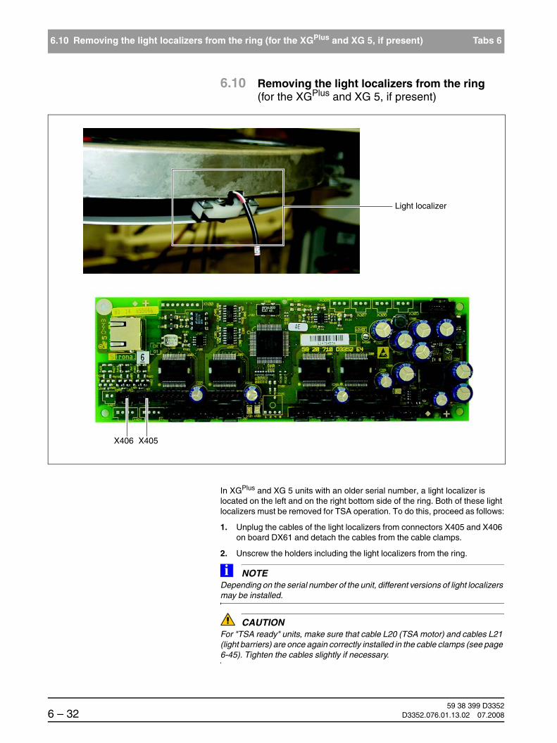
59 38 399 D33526 – 32 D3352.076.01.13.02 07.2008
6.10 Removing the light localizers from the ring (for the XGPlus and XG 5, if present) Tabs 6
6.10 Removing the light localizers from the ring(for the XGPlus and XG 5, if present)
In XGPlus and XG 5 units with an older serial number, a light localizer is located on the left and on the right bottom side of the ring. Both of these light localizers must be removed for TSA operation. To do this, proceed as follows:
1. Unplug the cables of the light localizers from connectors X405 and X406 on board DX61 and detach the cables from the cable clamps.
2. Unscrew the holders including the light localizers from the ring.
NOTEiDepending on the serial number of the unit, different versions of light localizers may be installed.
CAUTIONFor "TSA ready" units, make sure that cable L20 (TSA motor) and cables L21 (light barriers) are once again correctly installed in the cable clamps (see page 6-45). Tighten the cables slightly if necessary.
X406 X405
Light localizer

båÖäáëÜ
59 38 399 D3352D3352.076.01.13.02 07.2008 6 – 33
Tab 6 6.11 Replacing the support piece (bite block holder)
6.11
6.11 Replacing the support piece (bite block holder)
Removing the defective support piece 1. Loosen the two screws (A) and remove the support piece.
Installing the support piece Place the support piece on the tube bend and fasten it with the two screws (A).
ATTENTION: What to do after replacement?
– Check the system adjustment via a diaphragm test exposure PAN - Symmetry (see page 7-22).
– Perform a complete PAN unit adjustment(see chapter 4).
A
1.

59 38 399 D33526 – 34 D3352.076.01.13.02 07.2008
6.12 Replacing the motor-driven diaphragm (for XGPlus / XG 5) Tabs 6
6.12 Replacing the motor-driven diaphragm (for XGPlus / XG 5)
CAUTIONBe sure to install the diaphragm unit that matches the given unit hardware version (see spare parts list for unit serial number and part number of matching diaphragm). If the wrong diaphragm unit is installed, error code E6 61 70 will be displayed prior to exposure release (see Chapter 2-9).
Removing the covers Remove the covers (see also section 1.14):
– Tube assembly, front
– Tube assembly, rear
A
B
1.

båÖäáëÜ
59 38 399 D3352D3352.076.01.13.02 07.2008 6 – 35
Tab 6 6.12 Replacing the motor-driven diaphragm (for XGPlus / XG 5)
6.12
Removing the defective diaphragm unit Pull cables L11 and L12 off of connectors X501 (L11) and X101 (L12) on board DX61 (see page 6-36).
TSA operation only:Pull cables off of connectors X203, X303, X304, X405 and X406 on board DX61.
1. Loosen the upper screw (A) and the two lower screws (B) and remove the diaphragm unit.
NOTEiIf the two lower screws are not accessible, push the lower slider (B) upward manually. If the slider is in such an unfavorable position that it cannot be pushed upward, then:– Remove board DX61,– Loosen the 4 screws on motor C and raise it together with the spindle.
Installing the new diaphragm unit Start by fastening the new diaphragm unit to the unit with screw A.
Then screw in the two lower screws (B) and carefully tighten them securely (to a torque of 80 Ncm); Caution! Aluminum housing.
Plug cables L11 and L12 onto connectors X501 (L11) and X101 (L12) on board DX61 (see "Cables and connectors for replacement of the mo-tor-driven diaphragm unit" on page 6-36).
For TSA operation:Plug cables back onto connectors X203 (motor cable L20), X303 (light barrier cable L21), X304 (light barrier cable L21), X405 (laser light localiz-er 1 TSA) and X406 (laser light localizer 2 TSA) on board DX61 (see "Ca-bles and connectors for replacement of the motor-driven diaphragm unit" on page 6-36).
Attaching the covers Reattach the covers.
ATTENTION: What to do after replacement?
– Since board DX61 is always replaced along with the diaphragm unit, also be sure to observe the “Measures following replacement of boards“ (see section 6.20.1).
– Perform a complete unit adjustment (see chapter 4).– Take diaphragm test exposures for possible later evaluation by an expert.
B
DX61
C
DX61

59 38 399 D33526 – 36 D3352.076.01.13.02 07.2008
6.12 Replacing the motor-driven diaphragm (for XGPlus / XG 5) Tabs 6
6.12.1 Cables and connectors for replacement of the motor-driven diaphragm unit
X101 (L12) X501 (L11)
X203(L20)
X304(L21)
X303(L21)
X406 X405

båÖäáëÜ
59 38 399 D3352D3352.076.01.13.02 07.2008 6 – 37
Tab 6 6.13 Replacing the fixed diaphragm (only XG 3 / 3 PPE)
6.13
6.13 Replacing the fixed diaphragm (only XG 3 / 3 PPE)
Removing the covers Remove the covers (see also section 1.14):
– Tube assembly, front
– Tube assembly, rear
Removing the defective diaphragm unit 1. Loosen the two screws (A) (approx. 2-3 turns) and push the fixed diaphragm upward.
Installing the new diaphragm unit Assemble by following the same procedure in reverse order.
Attaching the covers Reattach the covers.
ATTENTION: What to do after replacement?
– Take PAN diaphragm test exposures (see page 7-17) (e.g. for possible later evaluation by experts).
– Perform the PAN system adjustment (see chapter 4).
A A A A
Version delivered until approx. end of 2006 Version delivered after approx. end of 2007
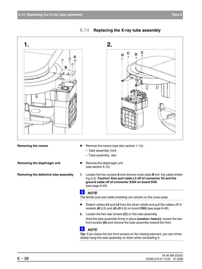
59 38 399 D33526 – 38 D3352.076.01.13.02 07.2008
6.14 Replacing the X-ray tube assembly Tabs 6
6.14 Replacing the X-ray tube assembly
Removing the covers Remove the covers (see also section 1.14):
– Tube assembly, front
– Tube assembly, rear
Removing the diaphragm unit Remove the diaphragm unit (see section 6.12).
Removing the defective tube assembly 1. Loosen the four screws A and remove cover plate B incl. the cable shield-ing (L3). Caution! Also pull cable L3 off of connector X3 and the ground cable off of connector X304 on board DX6. (see page 6-40)
NOTEiThe ferrite core and cable shielding can remain on the cover plate.
Detach cables L5 and L6 from the strain reliefs and pull the cables off of sockets J6 (L5) and J2-J3 (L6) on board DX6 (see page 6-40).
2. Loosen the two rear screws (C) on the tube assembly.
Hold the tube assembly firmly in place (caution: heavy!), loosen the two front screws (D) and remove the tube assembly toward the front.
NOTEiTip: If you leave the two front screws on the rotating element, you can imme-diately hang the tube assembly on them when reinstalling it.
1. 2.
A
B
CD C D

båÖäáëÜ
59 38 399 D3352D3352.076.01.13.02 07.2008 6 – 39
Tab 6 6.14 Replacing the X-ray tube assembly
6.14
Installing the new tube assembly Hang the new tube assembly on the two front screws of the rotating ele-ment and tighten them securely.
CAUTIONMake sure that the cables of the diaphragm unit once again lie in their original position (see section 6.21 page 6-41), as they could otherwise get in the way while you're attaching the covers later on.
Insert the two rear screws and tighten them firmly.
Plug cables L3, L5 and L6 as well as the ground cable back onto board DX6 and reattach the cables to the strain reliefs.
Attach the cover plate.
Installing the diaphragm unit Install the diaphragm unit (see section 6.12).
Attaching the covers Reattach the covers.
ATTENTION: What to do after replacement?
– Since board DX6 is always replaced along with the tube assembly, also be sure to observe the “Measures following replacement of boards“ (see section 6.20.1)
– Perform a complete unit adjustment (see chapter 4).
– Perform an acceptance test (applies to Germany only); without consulting an expert
– Take diaphragm test exposures for possible later evaluation by an expert.

59 38 399 D33526 – 40 D3352.076.01.13.02 07.2008
6.14 Replacing the X-ray tube assembly Tabs 6
6.14.1 Cables and connectors for replacement of the tube assembly
Unplug/plug in cable L6 (socketJ2-J3 on board DX6)
Unplug/plug in cable L5 (socketJ6 on board DX6)
Unplug/plug in cable L3(connector X3 on board DX6)
Laying cables cor-rectly on the cover plate
Unplug/plug in ground cable(connector X304 on board DX6)

båÖäáëÜ
59 38 399 D3352D3352.076.01.13.02 07.2008 6 – 41
Tab 6 6.14 Replacing the X-ray tube assembly
6.14
Cable routed on left side of tube assembly: 2x L21, L11 and TSA laser light localizer
Cable routed on right side of tube assembly: L12, L20 (TSA motor) and TSA laser light local-izer

59 38 399 D33526 – 42 D3352.076.01.13.02 07.2008
6.15 Replacing the fan (tube assembly) Tabs 6
6.15 Replacing the fan (tube assembly)
Removing the covers Remove the covers (see section 1.14):
– Tube assembly, front
Replacing the fan 1. Loosen the four screws A and carefully remove the cover plate including the fan. Caution: Cable!
Pull the fan cable off of connector X2 on board DX6.
Install the new fan in the reverse order of removal.
ATTENTION: What to do after replacement?
– Check the function of the fan using service routine S005.4 (see section 5.6.2).
– No further action is required.
A
1.
Connector X2

båÖäáëÜ
59 38 399 D3352D3352.076.01.13.02 07.2008 6 – 43
Tab 6 6.16 Replacing the PAN (TSA) sensor holder
6.16
6.16 Replacing the PAN (TSA) sensor holder
Removing the covers Remove the covers (see section 1.14):
– Sensor holder cover, large
Remove the sensor.
Removing the defective sensor holder 1. For TSA sensor holder (PAN), XGPlus only: Detach motor cable L20 and both light barrier cables (L21) from the cable tie on the unit and pull the ca-bles off of connectors X203 (L20), X303 and X304 (L21) of the TSA sen-sor holder.
2. Loosen the three screws A and remove the sensor holder. Caution: Cable L13!
3. Loosen the two screws (B) and remove the small sensor holder cover.
4. Loosen the three screws (C) and remove the connection socket.
A
B
C
2.
4.
3.
A
B
C
3.
2.
4.
1.
TSA sensor holder (XGPlus comfort class)
Rigid sensor holder (XG 5 / 3 / 3 PPE + XGPlus basic class)
1.

59 38 399 D33526 – 44 D3352.076.01.13.02 07.2008
6.16 Replacing the PAN (TSA) sensor holder Tabs 6
5. Detach the shield clamp (L13) on the rear side of the connection socket.
6. Loosen the connector screw connection on the front side of the connec-tion socket and thread the connector to the rear through the connection socket and the sensor holder.
Installing the new sensor holder 7. Install the new sensor holder in the reverse order of removal.
NOTEiDon't forget to plug all connectors and cables back in again in their original position and reattach the cable shields as well as all cable ties and strain re-liefs (see section "Laying cables when replacing the PAN sensor holder" on page 6-45).
ATTENTION: What to do after replacement?
– Perform the PAN system adjustment (see section 4.3). The TSA adjustment also must be performed for TSA units!
– Take diaphragm test exposures for possible later evaluation by an expert.
Shield clamp
6.5.

båÖäáëÜ
59 38 399 D3352D3352.076.01.13.02 07.2008 6 – 45
Tab 6 6.16 Replacing the PAN (TSA) sensor holder
6.16
6.16.1 Laying cables when replacing the PAN sensor holder
Sensor holder, rigid (XG 5 / 3 / 3 PPE) or XGPlus basic version)

59 38 399 D33526 – 46 D3352.076.01.13.02 07.2008
6.16 Replacing the PAN (TSA) sensor holder Tabs 6
TSA sensor holder (XGPlus full version)
Reattach cable ties
Reattach cable shield
Lay cables on the ring!
Draw cable back into sensor holder (no longer appli-cable as from system hardware version BA, approx. from November 2006)

båÖäáëÜ
59 38 399 D3352D3352.076.01.13.02 07.2008 6 – 47
Tab 6 6.17 Replacing the ceph sensor holder
6.17
6.17 Replacing the ceph sensor holder
1. Remove the sensor.
Removing the defective sensor holder 2. Loosen the three screws A and remove the connection socket B. Caution: Cable L35!
3. Detach the cable shield from terminal C and the connector screw connec-tion (loosen the two screws D from the rear) and thread the connector to the rear through the connection socket.
Installing the new sensor holder Install the new sensor holder in the reverse order of removal.
NOTEiDon't forget to reattach the cable shields.
ATTENTION: What to do after replacement?
– Perform the CEPH system adjustment (see section 4.4).
1.
A
B2.
3.
D
D
C

59 38 399 D33526 – 48 D3352.076.01.13.02 07.2008
6.18 Replacing the sensor Tabs 6
6.18 Replacing the sensor
ATTENTION: What to do after replacement?
– Since board DX81 is always replaced along with the sensor, also be sure to observe the “Measures following replacement of boards“ (see section 6.20.1)
– Perform a software update of the unit to version V02.20 or higher.

båÖäáëÜ
59 38 399 D3352D3352.076.01.13.02 07.2008 6 – 49
Tab 6 6.19 Replacing the light barriers
6.19
6.19 Replacing the light barriers
V1_3
V1_1V1_2
V91_2
V91_1
V1_4
V1_3
unit HW version < AG
unit HW version ≥ AG

59 38 399 D33526 – 50 D3352.076.01.13.02 07.2008
6.19 Replacing the light barriers Tabs 6
The following light barriers can be replaced:
In the panoramic X-ray unit Light barrier at actuator 1, ON position: V1_1
Light barrier at actuator 2, ON position: V1_2
Light barrier at ring motor, starting position of rotation: V1_3
Light barrier at HA motor, height adjustment: V1_4
In the cephalometer Light barrier for patient diaphragm position detection, ceph: V91_1
Light barrier for sensor position detection, ceph: V91_2
ATTENTION: What to do after replacement?
After replacing V1_1, 2 and 3: – Perform a complete unit adjustment (see chapter 4).
After replacing V1_4:– Perform a function check.
After replacing V91_1 and 2:– Execute S034.4 and S034.5 (see pages 5.19.1 ff.) – Check the CEPH adjustment by taking diaphragm test exposures:Fixed
point of rotation and Quickshot– Perform a CEPH unit adjustment if necessary (see chapter 4).

båÖäáëÜ
59 38 399 D3352D3352.076.01.13.02 07.2008 6 – 51
Tab 6 6.19 Replacing the light barriers
6.19
6.19.1 Replacing light barrier V1_3
Removing light barrier V1_3 Remove the covers (see also section 1.14):
– Top arm cover
1. Loosen the two clamping screws A on the tie rods and remove the tie rods by pulling them B upward.
2. Pull the light barrier cables (V1_1, V1_2 and V1_3) off of connectors X802, X803 and X804 and the ring motor cable off of connector X813 on board DX1.
1.
A
A
B
Pull light barrier cables off of con-nectors X802, X803 and X804 on
board DX1
Pull ring motor cable off of con-nector X813 on board DX1
2.
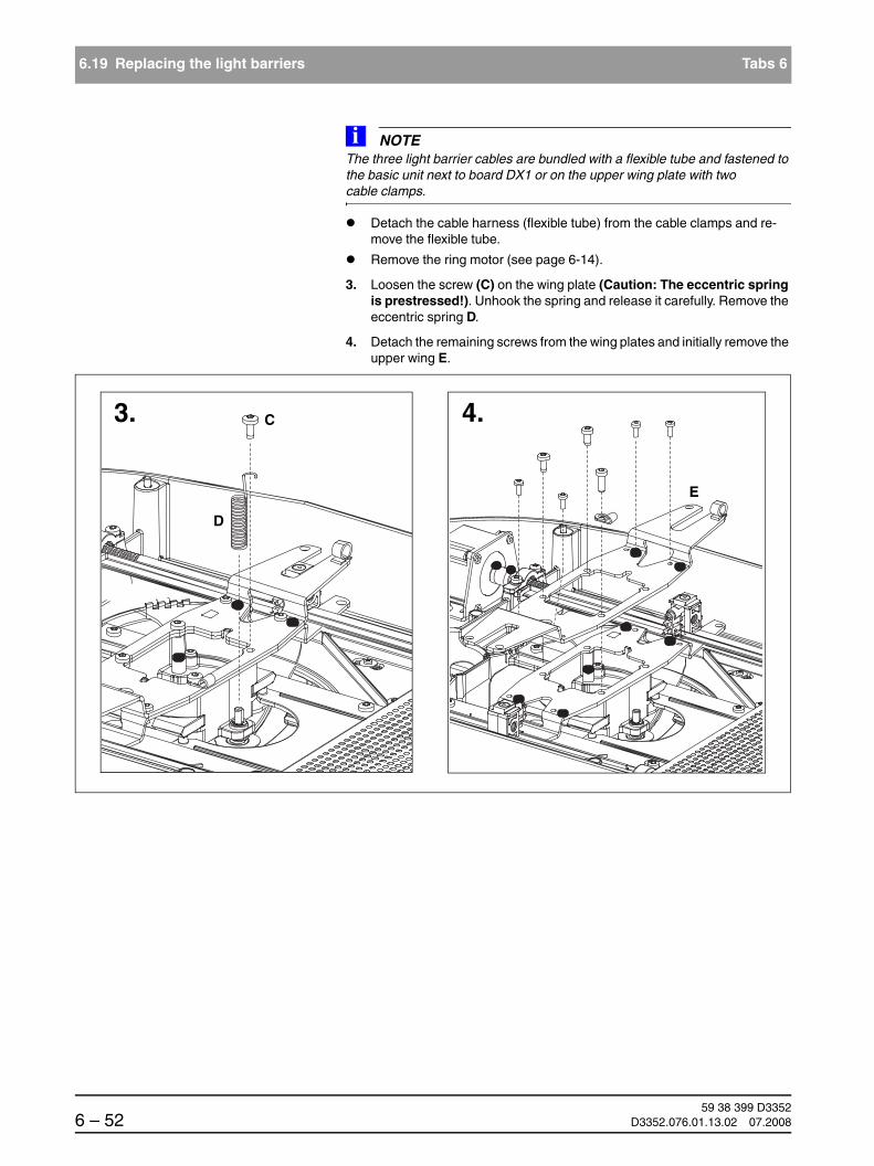
59 38 399 D33526 – 52 D3352.076.01.13.02 07.2008
6.19 Replacing the light barriers Tabs 6
NOTEiThe three light barrier cables are bundled with a flexible tube and fastened to the basic unit next to board DX1 or on the upper wing plate with two cable clamps.
Detach the cable harness (flexible tube) from the cable clamps and re-move the flexible tube.
Remove the ring motor (see page 6-14).
3. Loosen the screw (C) on the wing plate (Caution: The eccentric spring is prestressed!). Unhook the spring and release it carefully. Remove the eccentric spring D.
4. Detach the remaining screws from the wing plates and initially remove the upper wing E.
3. C
D
4.
E

båÖäáëÜ
59 38 399 D3352D3352.076.01.13.02 07.2008 6 – 53
Tab 6 6.19 Replacing the light barriers
6.19
5. Loosen the screws from the bearing covers of the actuator spindles and detach the spindles. Now you can remove the lower wing plate (F).
Position the motor mount ring so that the tensioning roller is positioned above a recess (so that the roller can be removed from below).
6. Detach the retaining ring and the washer. Remove tensioning roller G incl. eccentric bolt (downward).
5.
F
6.
G

59 38 399 D33526 – 54 D3352.076.01.13.02 07.2008
6.19 Replacing the light barriers Tabs 6
7. Loosen the screws on the right guide profile (on spring side) H and re-move the profile including tension spring J.
CAUTIONLook out for bearing shells K. They may fall out after the profile is removed.
8. Remove bearing shells K.
9. Loosen the screws on motor mount ring L and remove motor housing M.
7. - 9.
H J
K
L
M

båÖäáëÜ
59 38 399 D3352D3352.076.01.13.02 07.2008 6 – 55
Tab 6 6.19 Replacing the light barriers
6.19
10. Loosen the two screws on light barrier V1_3 and remove it.
10.
V1_3
M

59 38 399 D33526 – 56 D3352.076.01.13.02 07.2008
6.19 Replacing the light barriers Tabs 6
Installing light barrier V1_3 Screw new light barrier V1_3 onto motor housing M securely.
Reattach motor housing M to motor mount ring L and screw them together again with the four screws.
CAUTIONSeal the screws with Loctite 242.
Reinsert the left part of the bearing shell and bring the motor mount ring along with the motor mount back into position.
Reinsert the right part of the bearing shell K with the guide profile H and the tension spring J and tighten the profile screws loosely.
Reattach tensioning roller G to the motor housing with the eccentric bolt from below and fasten the eccentric bolt from above using a washer and a retaining ring.
Pull the rotary ring (with motor mount ring) into the frontmost position and fasten the front screw of guide profile H securely.
Now push the rotary ring (with motor mount ring) into the rearmost posi-tion (from the column) and fasten the rear screw of guide profile H secure-ly.
Slide the rotary ring back and forth another 1 to 2 times to make sure that it glides smoothly in the guide.
NOTEiCheck to make sure that the guide profile is still sufficiently greased following assembly. Grease the profile with Chesterton 622 if necessary.
Reinsert the lower wing plate F.
Insert both spindles with spindle nuts and screw the bearing cover back on tight.
Reinsert upper wing plate E and refasten the wing plates with the eight screws (Note Tighten screw C for fastening the eccentric spring only loosely!).
Attach eccentric spring D to the eccentric bolt of the tensioning roller and reattach it to screw C on the upper wing plate with a prestress of 2½ turns. Tighten screw C securely.
Reinstall the ring motor (see page 6-15).
CAUTIONNote the correct procedure for laying the cables of the ring motor.
Now perform the cabling (see page 6-57).

båÖäáëÜ
59 38 399 D3352D3352.076.01.13.02 07.2008 6 – 57
Tab 6 6.19 Replacing the light barriers
6.19
Cabling V1_1, V1_2 and V1_3
Run the light barrier cables together next to the ring motor and pull the flexible tube over them.
11. Secure the flexible tube at the motor end with a cable tie and fasten it to the wing plate with the cable clamp.
12. Twist the flexible tube (only the tube, not the cables!) clockwise at the con-nector end, secure it with a cable tie and fasten it to the basic unit next to board DX1 with the cable clamp.
13.
CAUTIONIn its installed state, the cable harness (flexible tube) must exhibit a tendency to move upward and form a loop during travel of the rotary ring. It must dip into the unit!Also make sure that the cable harness is refastened to the cable clamps in its original position.
Properly run cable harness
11. 12.
13.

59 38 399 D33526 – 58 D3352.076.01.13.02 07.2008
6.19 Replacing the light barriers Tabs 6
Plug the ring motor cable and the light barrier cables back into connectors X813, X802, X803 and X804 on board DX1.
Reattach the covers.

båÖäáëÜ
59 38 399 D3352D3352.076.01.13.02 07.2008 6 – 59
Tab 6 6.20 Replacing circuit boards
6.20
6.20 Replacing circuit boards
CAUTIONPlease observe the usual precautionary measures for handling printed circuit boards (ESD).Touch a ground point to discharge static electricity before touching any boards.
CAUTIONReplacement of printed circuit boards DX6 and DX11:Never replace both boards at the same time. After replacing one of these boards, first proceed as specified in section 6.20.1 and then restart the unit. Only then may you begin replacement of the other module.
CAUTIONPrior to circuit board replacement:Open the PAN and CEPH RESET ADJUSTMENT menus in SIDEXIS and write down the adjustment values before you start replacing the boards.
CAUTIONReplacement of circuit board DX11:– If the old DX11 is still working:
Open the "extended detail query"in SIXABCON, search for the "Language Set ID" (listed in "Extended Configuration DX7") and write down the configuration of theLanguage Set Index. If it differs from 00 the Language Set Index has to be resetafter inserting a new DX11, using the service routine S017.5 (see page 5-86).
– The replacement of circuit board DX11 also causes the loss of userpreference settings (patient symbols, quickshot pre-selections etc.). Point this out to the user or set the original values up again after the replacement of the circuit board, provided they could still be queried prior to the replacement.
CAUTIONPlease be sure to read the notes in Section "Measures following replacement of boards" (see page 6-60)!
This Service Manual describes all measures required after the replacement of modules or circuit boards, provided they were known at the time of publication. You will find more up-to-date information and supplements concerning this subject on the latest ORTHOPHOS XG CD and on the Sirona dealer page on the Internet. For this reason, you should always check for the latest informa-tion on the replacement of modules and performing updates before you start replacing any modules or boards.
NOTEiThe connectors on the boards are labeled on delivery of the system.
Tip: Check the designations on the connectors when pulling off the cables and label them correctly if necessary.

59 38 399 D33526 – 60 D3352.076.01.13.02 07.2008
6.20 Replacing circuit boards Tabs 6
6.20.1 Measures following replacement of boards
CAUTIONAfter replacing boards or modules containing boards, check to make sure that the software version of the module corresponds to the current software status of the system. The software version for the modules can...
for XGPlus:be accessed through service routine S008.2 or the extended detail query in SIXABCON. You can also check the info screen in advance to determine whether the current software constellation is permissible. If this is not the case, the version number of the entire software is labeled with an asterisk (e.g. V02.20*)
for XG 5 / 3 / 3 PPE:be accessed through service routine S008.2 or the extended detail query in SIXABCON.
Perform a software update or downgrade (see Section 1.9) in case of software incompatibilities.
Always perform the measures described below in the given sequence and do not carry out any other actions between the steps.
DX32
DX61*
DX11
DX1
DX91
DX41**DX42
see page 5-9
DX71
* not with XG 3 / 3 PPE** from system hardware version BA
does not apply to circuit board DX41

båÖäáëÜ
59 38 399 D3352D3352.076.01.13.02 07.2008 6 – 61
Tab 6 6.20 Replacing circuit boards
6.20
The following table provides an overview of various possible replacement sit-uations and cross-references to detailed descriptions of the actions required for the corresponding situations following board replacement.
Board Constellation Measures Page
DX1 Inserting a new DX1
ORTHOPHOS XGPlus
System software version V02.20 or higher
Switch the unit ON.
Perform a software update of the unit to version V02.27 or higher as described in section 1.9.
1-22
ORTHOPHOS XG 5 / 3 / 3 PPE
DX11 Replacing a DX11
NOTEiThe circuit board DX11 with software version V02.22 or higher requires SIDEXIS software version V01.45 or higher for the update. Consequently, it is necessary to update the entire unit to software version V02.22 or higher or SIDEXIS V01.45 or higher.
Inserting a new DX11
ORTHOPHOS XGPlus
System software version V02.20
Please proceed as described in sec-tion 6.20.2, Case A.
6-64
Inserting a new DX11
ORTHOPHOS XGPlus
System software version V02.22 or higher
Please proceed as described in sec-tion 6.20.2, Case B.
6-67
Inserting a DX11 from another unit with soft-ware version V02.22 or higher
ORTHOPHOS XGPlus
System software version V02.22 or higher
Please proceed as described in sec-tion 6.20.2, Case C.
6-70
Inserting a new DX11
ORTHOPHOS XG 5
System software version V02.20
Please proceed as described in sec-tion 6.20.2, Case D.
6-72
Inserting a DX11 from another unit with soft-ware version V02.20 or higher
ORTHOPHOS XG 5 / 3
System software version V02.20 or higher
CAUTIONNever use a module from another unit in an XG 3 PPE unit or vice versa.
Please proceed as described in sec-tion 6.20.2, Case E.
6-75
Inserting a new DX11
ORTHOPHOS XG 5 / 3 / 3 PPE
System software version V02.22 or higher
Please proceed as described in sec-tion 6.20.2, Case F.
6-77

59 38 399 D33526 – 62 D3352.076.01.13.02 07.2008
6.20 Replacing circuit boards Tabs 6
DX6
(Tube assembly)
Replacing an X-ray tube assembly incl. DX6
Inserting a new X-ray tube assembly
ORTHOPHOS XGPlus
System software version V02.20
Please proceed as described in sec-tion 6.20.3, Case G.
6-80
Inserting a new X-ray tube assembly
ORTHOPHOS XGPlus
System software version V02.22 or higher
Please proceed as described in sec-tion 6.20.3, Case H.
6-83
Inserting an X-ray tube assembly from an-other unit with software version V02.22
ORTHOPHOS XGPlus
System software version V02.22 or higher
Please proceed as described in sec-tion 6.20.3, Case I.
6-85
Inserting a new X-ray tube assembly
ORTHOPHOS XG 5 / 3 / 3 PPE
System software version V02.20 or higher
Please proceed as described in sec-tion 6.20.3, Case J.
6-86
Inserting an X-ray tube assembly from an-other unit with software version V02.20
ORTHOPHOS XG 5/3
System software version V02.20 or higher
CAUTIONNever use a module from another unit in an XG 3 PPE unit or vice versa.
Please proceed as described in sec-tion 6.20.3, Case K.
6-88
DX61
(Diaphragm unit)
Inserting a new DX61 Check the compatibility between the software status of the modules and that of the overall system. Perform an update or a downgrade if neces-sary.
NOTEiPlease note that the specific diaphragm unit required depends on the unit serial numbers specified in the spare parts list.
1-24
DX7
(Easypad)
Inserting a new Easypad incl. DX7
ORTHOPHOS XGPlus
System software status V02.20 or higher
It isessential that you perform a software update to a system version ≥ V02.25 (see section 1.9).
NOTEiAfter the replacement of the Easypad, the language settings on circuit board DX7 are at the factory default (00 = German, English, French,Italian). If the configured system lan-guage set (displayable via service rou-tine S017.5 or the “extended detail que-ry“ in SIXABCON) has a configuration other than 00, this configuration will be copied to board DX7 by the update func-tion.
1-24
Board Constellation Measures Page

båÖäáëÜ
59 38 399 D3352D3352.076.01.13.02 07.2008 6 – 63
Tab 6 6.20 Replacing circuit boards
6.20
* circuit board DX41 no longer applies in system hardware version BA.Circuit board DX41 is available as a spare part for systems up to hardware version AG.
DX71
(Multipad)
Inserting a new DX71 Check the compatibility between the software status of the modules and that of the overall system. Perform an update or a downgrade if neces-sary.
1-24
DX32
(Stand)
Inserting a new DX32 No further action is required.
DX41*
(Stand)
Inserting a new DX41 Check the compatibility between the software status of the modules and that of the overall system. Perform an update or a downgrade if neces-sary.
1-24
DX42
(Remote control)
Inserting a new DX42 Check the compatibility between the software status of the modules and that of the overall system. Perform an update or a downgrade if neces-sary.
1-24
To system hardware version < BA: Set jumper X109 and X110 to "Con-figuration with DX41“ (inside jumper) (see also Section 6.20.4).
6-90
DX81
(Sensor)
Using a new sensor Perform an update to an overall soft-ware version of V02.25 or higher.
1-24
DX91
(Ceph)
Inserting a new DX91 Check the compatibility between the software status of the module and that of the overall system. Perform an update or a downgrade if neces-sary.
1-24
Perform service routine S034, test steps 4 and 5.
5-134
Perform the ceph adjustment. 4-56
Board Constellation Measures Page

59 38 399 D33526 – 64 D3352.076.01.13.02 07.2008
6.20 Replacing circuit boards Tabs 6
6.20.2 Replacing a DX11
Case A: New DX11,ORTHOPHOS XGPlus
System software status V02.20
CAUTIONAfter a new DX11 is inserted, the IP address is initially reset to the factory setting. Make sure that no second system is running on the same IP address before switching the system to a new IP address.
1. Switch the unit ON.
NOTEiDo not acknowledge any error messages at this point.
2. Install the current SIDEXIS software version (V01.53 or higher).
NOTEiIf the current SIDEXIS version is a patch version, the previous officially released main version of SIDEXIS has to be installed before the current version can be installed.
3. Update the software to the latest version via the automatic update opti-on(see SIRONA internet website, Dealer domain (under Product Info ' X-ray Systems) (see also Section 1.9.6).
NOTEiThe current update file can be found on the ORTHOPHOS XG Software CD. This CD is supplied along with every spare DX11 PC board and is also inclu-ded in the language-specific set. The contents of this CD can also be down-loaded (under Product Info X-ray Systems) from the Dealer domain of the SIRONA internet website at www.sirona.com .
4. If several devices are installed in the network:Set the IP address with the help of SIXABCON.
5. Switch the unit OFF.Wait approximately 1 minute. Then switch the unit ON again.
The error message E1 10 03 (format flash file system) is displayed.
6. Acknowledge the error message with the R key .
The formatting of the flash file system is started automatically. Error mes-sage E1 10 04 is displayed during the entire process (approx. 5 - 6 min.). When the formatting is finished, the error message is automatically ac-knowledged by the system and error message E6 11 07 (undefined sys-tem class) is displayed.
7. Acknowledge the error message with the R key .
The access level for the service menu (level 4) is automatically started.
E1 10 03 R
E1 10 04
E6 11 07
5 - 6 min.
R
E6 11 07 RR

båÖäáëÜ
59 38 399 D3352D3352.076.01.13.02 07.2008 6 – 65
Tab 6 6.20 Replacing circuit boards
6.20
8. Press and hold down the Service key until the patient symbol keys light up (approx. 2 s).
9. Then press the patient symbol keys in the following order within 4 s: b – d – a.
Once the key combination has been entered correctly, service routine 017, test step 1 (select/confirm system class) is started automatically. The Memory button is lit.
NOTEiAcknowledge any additional error messages with the R key .
10. Confirm the “Comfort“ system class (01):
To do this, first press the Memory button (R key lights up) and then the R key .
11. Quit the service routine via the double arrow key .
12. Switch the unit OFF.Wait approximately 1 minute. Then switch the unit ON again.
Error message E6 15 05 (undefined system serial number) is displayed.
13. Acknowledge the error message with the R key .
Error message E6 15 04 (undefined activation data) is displayed.
14. Acknowledge the error message with the R key .
15. Open the Service menu (see page 5-10).
16. Start service routine S008.3, check the unit serial number and confirm it if it is correct (see page 5-50).
NOTEiThe unit serial number is located on the rating plate of the unit.
CAUTIONIn case of a wrong serial number, cancel the update and contact the Sirona Customer Service Center!
17. Switch the unit OFF.Wait approximately 1 minute. Then switch the unit ON again.
Error message E6 15 04 (undefined activation data) is displayed.
18. Acknowledge the error message with the R key .
a b d Leve
l 4
c
approx. 2 s R
?
1
2
3
+- 01
R
R
E6 15 05 RR
E6 15 04 RR
E6 15 04 RR

59 38 399 D33526 – 66 D3352.076.01.13.02 07.2008
6.20 Replacing circuit boards Tabs 6
19. Open the Service menu (see page 5-10).
20. Start service routine S008.4 and confirm the unit equipment.
21. Determine the ring type based on the system serial number.
PAN unit serial numbers up to 20056 = old ring type = 01
PAN unit serial numbers from 20057 = new ring type = 02
PAN/CEPH unit serial numbers up to 40104 = old ring type = 01
PAN/CEPH unit serial numbers from 40105 = new ring type = 02
22. Start service routine S034.7 and select the corresponding ring type (see page 5-145).
23. Start service routine S017 and perform the system configuration (test step 2-17) (see page 5-78).
NOTEiFor systems with hardware version< BA (until October 2006):– Circuit board DX41 must be configured with service routine S017.9.– Review the installed headrest version and adjust the configuration, using
service routine S017.10 if necessary (see page 5.13.8).
NOTEiInform the customer about the new possibilities of the software status, such as welcome screen (XGPlus only) or acoustic exposure signal. Activate these functions if they are required.
24. If the minimum travel height of the system must be limited:Set the travel height with service routine S018.2. (see page 5-110).
25. Perform another software update to the current system software version as described in section 1.9.3. This updates all modules in accordance with the configuration.
26. Perform the complete system adjustment (see chapter 4):
– PAN adjustment
– For TSA units: TSA adjustment
– CEPH adjustment if cephalometer is installed
27. Open the "Extended Details“ via SIXABCON.
This generates an XML file (with the system parameters) which is saved under the network name of the system in the PDATA/P2K_Config folder (see also section 1.10 on page 1-32).
The process is completed.

båÖäáëÜ
59 38 399 D3352D3352.076.01.13.02 07.2008 6 – 67
Tab 6 6.20 Replacing circuit boards
6.20
Case B: New DX11,ORTHOPHOS XGPlus System software status V02.22 or higher
CAUTIONAfter a new DX11 is inserted, the IP address is initially reset to the factory setting. Make sure that no second system is running on the same IP address before switching the system to a new IP address.
1. Switch the unit ON.
NOTEiDo not acknowledge any error messages at this point.
2. Install the current SIDEXIS software version (V01.53 or higher).
NOTEiIf the current SIDEXIS version is a patch version, the previous officially released main version of SIDEXIS has to be installed before the current version can be installed.
3. Perform a software update to the latest software version via the automatic update option (see SIRONA internet website, Dealer domain (under Pro-duct Info X-ray Systems) (see also Section 1.9.6).
NOTEiThe current update file can be found on the ORTHOPHOS XG Software CD. This CD is supplied along with every spare DX11 PC board and is also inclu-ded in the country set. The contents of this CD can also be downloaded (under Product Info X-ray Systems) from the Dealer domain of the SIRONA internet website at www.sirona.com
NOTEiIf the DX11 used already has the same software version as the overall unit, a software update to this version must nevertheless be performed so that an ad-ministrative entry can be made in the memory of the DX11.
4. Switch the unit OFF.Wait approximately 1 minute. Then switch the unit ON again.
The error message E1 10 03 (format flash file system) is displayed.
5. Acknowledge the error message with the R key .
The formatting of the flash file system is started automatically. Error mes-sage E1 10 04 is displayed during the entire process (approx. 5 - 6 min.). When the formatting is finished, the error message is automatically ac-knowledged by the system and error message E6 11 07 (undefined sys-tem class) is displayed.
6. Acknowledge the error message with the R key .
The access level for the service menu (level 4) is automatically started.
E1 10 03 R
E1 10 04
E6 11 07
5 - 6 min.
R
E6 11 07 RR

59 38 399 D33526 – 68 D3352.076.01.13.02 07.2008
6.20 Replacing circuit boards Tabs 6
7. Press and hold down the Service key until the patient symbol keys light up (approx. 2 s).
8. Then press the patient symbol keys in the following order within 4 s: b – d – a.
Once the key combination has been entered correctly, service routine 017, test step 1 (select/confirm system class) is started automatically. The Memory button is lit.
NOTEiAcknowledge any additional error messages with the R key .
9. Confirm the “Comfort“ system class (01):
To do this, first press the Memory button (R key lights up) and then the R key .
10. Quit the service routine via the double arrow key .
11. Switch the unit OFF.Wait approximately 1 minute. Then switch the unit ON again.
Error message E6 15 05 (undefined system serial number) is displayed.
12. Acknowledge the error message with the R key .
13. Open the Service menu (see page 5-10).
14. Start service routine S008.3, check the unit serial number and confirm it if it is correct (see page 5-50).
NOTEiThe unit serial number is located on the rating plate of the unit.
CAUTIONIn case of a wrong serial number, cancel the update and contact the Sirona Customer Service Center!
15. Switch the unit OFF.Wait approximately 1 minute. Then switch the unit ON again.
NOTEiIn systems that already run with a system software version V02.27 or higher, please check that there is a XML file in the PDATA/P2K_Config with the net-work name of the system (Extended details). This file contains up-to-date in-formation about the previous system configuration! See also section 1.10, on page 1-32).
a b d Leve
l 4
c
approx. 2 sR
?
1
2
3
+- 01
R
R
E6 15 05 RR

båÖäáëÜ
59 38 399 D3352D3352.076.01.13.02 07.2008 6 – 69
Tab 6 6.20 Replacing circuit boards
6.20
16. Determine the ring type based on the system serial number.
PAN unit serial numbers up to 20056 = old ring type = 01
PAN unit serial numbers from 20057 = new ring type = 02
PAN/CEPH unit serial numbers up to 40104 = old ring type = 01
PAN/CEPH unit serial numbers from 40105 = new ring type = 02
17. Start service routine S034.7 and select the corresponding ring type (see page 5-145).
18. Start service routine S017 and perform the system configuration (test step 2-17) (see page 5-78).
NOTEiFor systems with hardware version< BA (until October 2006):– Circuit board DX41 must be configured with service routine S017.9.– Review the installed headrest version and adjust the configuration, using
service routine S017.10 if necessary (see page 5.13.8).
NOTEiInform the customer about the new possibilities of the software status, such as welcome screen (XGPlus only) or acoustic exposure signal. Activate these functions if they are required.
19. If the minimum travel height of the system must be limited:Set the travel height with service routine S018.2. (see page 5-110).
20. Perform another software update to the current system software version as described in section 1.9.3. This updates all modules in accordance with the configuration.
21. Perform the complete system adjustment (see chapter 4):
– PAN adjustment
– For TSA units: TSA adjustment
– CEPH adjustment if cephalometer is installed
22. Open the "Extended Details“ via SIXABCON.
This generates an XML file (with the system parameters) which is saved under the network name of the system in the PDATA/P2K_Config folder (see also section 1.10 on page 1-32).
The process is completed.

59 38 399 D33526 – 70 D3352.076.01.13.02 07.2008
6.20 Replacing circuit boards Tabs 6
Case C: DX11 from an external device,ORTHOPHOS XGPlus System software status V02.22 or higher
CAUTION– The replacement of a DX11 from an external device is possible if
theDX11 board and the system have at least the software version V02.22.
– The replacement is only possible within the same system class, i.e. the DX11 board must come from a XGPlus system if it is to be installed in another XGPlus system
CAUTIONAfter inserting the board, you must reconfigure the IP address to match the IP address of the existing X-ray component. Before you set the unit to the correct IP address, make sure that this address has not been assigned to any other device.
1. Switch the unit ON.
NOTEiDo not acknowledge any error messages at this point.
2. Install the current SIDEXIS software version (V01.53 or higher).
NOTEiIf the current SIDEXIS version is a patch version, the previous officially released main version of SIDEXIS has to be installed before the current version can be installed.
3. Perform a software update to a software version V02.25, however, ideally to the latest software version via the automatic update option (see SIRO-NA internet website, Dealer domain (under Product Info X-ray Systems) (see also Section 1.9.6).
NOTEiThe current update file can be found on the ORTHOPHOS XG Software CD. This CD is supplied along with every spare DX11 PC board and is also inclu-ded in the language-specific set. The contents of this CD can also be down-loaded (under Product Info X-ray Systems) from the Dealer domain of the SIRONA internet website at www.sirona.com
NOTEiIf the DX11 used already has the same software version as the overall unit, a software update to this version must nevertheless be performed so that an ad-ministrative entry can be made in the memory of the DX11.
4. Switch the unit OFF.Wait approximately 1 minute. Then switch the unit ON again.
Error message E6 15 05 (undefined system serial number) is displayed.
5. Acknowledge the error message with the R key .
Error message E6 15 04 (undefined activation data) is displayed.
6. Acknowledge the error message with the R key .
7. Open the Service menu (see page 5-10).
8. Start service routine S008.3 (see page 5-50).
E6 15 05 RR
E6 15 04 RR

båÖäáëÜ
59 38 399 D3352D3352.076.01.13.02 07.2008 6 – 71
Tab 6 6.20 Replacing circuit boards
6.20
9. Get the unit serial number from the rating plate of the unit and enter it (see page 5-50).
NOTEiAny serial number which is unknown to the unit will not be accepted by the unit. The serial number entered must be identical with the one on the rating plate of the unit. If an inadmissible serial number is entered, the input will not be accepted and the serial number can be entered again.
10. Switch the unit OFF.Wait approximately 1 minute. Then switch the unit ON again.
NOTEiIn systems that already run with a system software version V02.27 or higher, please check that there is a XML file in the PDATA/P2K_Config with the net-work name of the system (Extended details). This file contains up-to-date in-formation about the previous system configuration! See also section 1.10, on page 1-32).
11. Determine the ring type based on the system serial number.
PAN unit serial numbers up to 20056 = old ring type = 01
PAN unit serial numbers from 20057 = new ring type = 02
PAN/CEPH unit serial numbers up to 40104 = old ring type = 01
PAN/CEPH unit serial numbers from 40105 = new ring type = 02
12. Start service routine S034.7 and select the corresponding ring type (see page 5-145).
13. Start service routine S017 and perform the system configuration (test step 2-17) (see page 5-78).
NOTEiFor systems with hardware version< BA (until October 2006):– Circuit board DX41 must be configured with service routine S017.9.– Review the installed headrest version and adjust the configuration, using
service routine S017.10 if necessary (see page 5.13.8).
14. If the minimum travel height of the system must be limited:Set the travel height with service routine S018.2. (see page 5-110).
15. Perform another software update to the current system software version as described in section 1.9.3. This updates all modules in accordance with the configuration.
16. Perform the complete system adjustment (see chapter 4):
– PAN adjustment
– For TSA units: TSA adjustment
– CEPH adjustment if cephalometer is installed
17. Open the "Extended Details“ via SIXABCON.
This generates an XML file (with the system parameters) which is saved under the network name of the system in the PDATA/P2K_Config folder (see also section 1.10 on page 1-32).
The process is completed.

59 38 399 D33526 – 72 D3352.076.01.13.02 07.2008
6.20 Replacing circuit boards Tabs 6
Case D: New DX11,ORTHOPHOS XG 5System software status V02.20
CAUTIONAfter a new DX11 is inserted, the IP address is initially reset to the factory setting. Make sure that no second system is running on the same IP address before switching the system to a new IP address.
1. Switch the unit ON.
CAUTIONDo not acknowledge any error messages displayed at this point!
2. Install the current SIDEXIS software version (V01.53 or higher).
NOTEiIf the current SIDEXIS version is a patch version, the previous officially released main version of SIDEXIS has to be installed before the current version can be installed.
3. Perform a software update to the latest software version via the automatic update option (see SIRONA internet website, Dealer domain (under Pro-duct Info X-ray Systems) (see also Section 1.9.6).
NOTEiThe current update file can be found on the ORTHOPHOS XG Software CD. This CD is supplied along with every spare DX11 PC board and is also inclu-ded in the language-specific set. The contents of this CD can also be down-loaded (under Product Info X-ray Systems) from the Dealer domain of the SIRONA internet website at www.sirona.com
CAUTIONIf the DX11 used already has the same software version as the overall unit, a software update to this version must nevertheless be performed so that an ad-ministrative entry can be made in the memory of the DX11.
4. Switch the unit OFF.Wait approximately 1 minute. Then switch the unit ON again.
The error message E1 10 03 (format flash file system) is displayed.
5. Acknowledge the error message with the R key .
The formatting of the flash file system is started automatically. Error mes-sage E1 10 04 is displayed during the entire process (approx. 5 - 6 min.). When the formatting is finished, the error message is automatically ac-knowledged by the system and error message E6 11 07 (undefined sys-tem class) is displayed.
6. Acknowledge the error message with the R key .
The access level for the service menu (level 4) is automatically started.
NOTEiAcknowledge any additional error messages with the R key .
E1 10 03
E1 10 04
E6 11 07
5 - 6 min.
RR
E6 11 07 RR
R

båÖäáëÜ
59 38 399 D3352D3352.076.01.13.02 07.2008 6 – 73
Tab 6 6.20 Replacing circuit boards
6.20
7. Press and hold down the Service key until the LEDs above the patient symbol keys light up (approx. 2 s).
8. Then press the patient symbol keys in the following order within 4 s:b – d – a.
Once the key combination has been entered correctly, service routine 017, test step 1 (select/confirm system class) is started automatically. automatically. The LED above the Memory key lights up.
9. Confirm the “Basic“ system class (02):
To do this, first press the Memory button (LED above the R key lights up) and then the R key .
10. Quit the service routine via the Top arrow key above selection field 3.
11. Switch the unit OFF.Wait approximately 1 minute. Then switch the unit ON again.
Error message E6 15 05 (undefined system serial number) is displayed.
12. Acknowledge the error message with the R key .
13. Start service routine S008.3 and confirm the system serial number (see page 5-50).
14. Quit the service routine via the up arrow key above selection field 3.
15. Switch the unit OFF.Wait approximately 1 minute. Then switch the unit ON again.
16. Start service routine S034.7 and select ring type 02 (see page 5-145).
approx. 2 s
a b dc
R
1 2 3
______02_______
R
E6 15 05 RR

59 38 399 D33526 – 74 D3352.076.01.13.02 07.2008
6.20 Replacing circuit boards Tabs 6
17. Start service routine S017 and perform the system configuration (test step 2-17) (see page 5-78).
NOTEiFor systems with hardware version< BA (until October 2006):Circuit board DX41 must be configured with service routine S017.9 .
18. If the minimum travel height of the system must be limited:Set the travel height with service routine S018.2. (see page 5-110).
19. Perform the complete system adjustment (see chapter 4):
– PAN adjustment
– CEPH adjustment, if installed
20. Perform another software update to the current system software version as described in section 1.9.3. This updates all modules in accordance with the configuration.
21. Open the "Extended Details“ via SIXABCON.
This generates an XML file (with the system parameters) which is saved under the network name of the system in the PDATA/P2K_Config folder (see also section 1.10 on page 1-32).
The process is completed.

båÖäáëÜ
59 38 399 D3352D3352.076.01.13.02 07.2008 6 – 75
Tab 6 6.20 Replacing circuit boards
6.20
Case E: DX11 from an external device,ORTHOPHOS XG 5 / 3 (not XG 3 PPE)System software status V02.20 or higher.
CAUTION– The replacement of a DX11 from an external device is possible if
the DX11 board and the system have at least the software version V02.20.
– The replacement is only possible within the same system class, i.e. DX11 must come from an XG 5 or XG 3 device if it is to be installed inan XG 5 or XG 3 system.
CAUTIONAfter inserting the board, you must reconfigure the IP address to match the IP address of the existing X-ray component. Before you set the unit to the correct IP address, make sure that this address has not been assigned to any other device.
1. Switch the unit ON.
CAUTIONDo not acknowledge any error messages displayed at this point!
2. Perform a software update to a software version V02.25, however, ideally to the latest software version via the automatic update option (see SIRO-NA internet website, Dealer domain (under Product Info X-ray Systems) (see also Section 1.9.6).
NOTEiThe current update file can be found on the ORTHOPHOS XG Software CD. This CD is supplied along with every spare DX11 PC board and is also inclu-ded in the language-specific set. The contents of this CD can also be down-loaded (under Product Info X-ray Systems) from the Dealer domain of the SIRONA internet website at www.sirona.com
CAUTIONIf the DX11 used already has the same software version as the overall unit, a software update to this version must nevertheless be performed so that an ad-ministrative entry can be made in the memory of the DX11.
3. Switch the unit OFF.Wait approximately 1 minute. Then switch the unit ON again.
Error message E6 15 05 (undefined system serial number) is displayed.
4. Acknowledge the error message with the R key .
5. Open the Service menu (see page 5-10).
6. Start service routine S008.3 (see page 5-50).
7. Get the unit serial number from the rating plate of the unit and enter it (see page 5-50).
NOTEiAny serial number which is unknown to the unit will not be accepted by the unit. The serial number entered must be identical with the one on the rating plate of the unit. If an inadmissible serial number is entered, the input will not be accepted and the serial number can be entered again.
8. Switch the unit OFF.Wait approximately 1 minute. Then switch the unit ON again.
E6 15 05 RR

59 38 399 D33526 – 76 D3352.076.01.13.02 07.2008
6.20 Replacing circuit boards Tabs 6
NOTEiIn systems that already run with a system software version V02.27 or higher, please check that there is a XML file in the PDATA/P2K_Config with the net-work name of the system (Extended details). This file contains up-to-date in-formation about the previous system configuration! See also section 1.10, on page 1-32).
9. Start service routine S034.7 and select ring type 02 (see page 5-145).
10. Start service routine S017 and check the system configuration or perform the system configuration (test step 2-23) (see page 5-78).
NOTEiFor the XG 3: Service routine S017.17 must be set according to the serial number of the unit (see page 5-103).
11. If the minimum travel height of the system must be limited:Set the travel height with service routine S018.2. (see page 5-110).
12. Perform the complete system adjustment (see chapter 4):
– PAN adjustment
– CEPH adjustment, if installed
13. Perform another software update to the current system software version as described in section 1.9.3. This updates all modules in accordance with the configuration.
14. Open the "Extended Details“ via SIXABCON.
This generates an XML file (with the system parameters) which is saved under the network name of the system in the PDATA/P2K_Config folder (see also section 1.10 on page 1-32).
The process is completed.

båÖäáëÜ
59 38 399 D3352D3352.076.01.13.02 07.2008 6 – 77
Tab 6 6.20 Replacing circuit boards
6.20
Case F: New DX11,ORTHOPHOS XG 5/3/3 PPESystem software status V02.22 or higher.
CAUTIONAfter a new DX11 is inserted, the IP address is initially reset to the factory setting. Make sure that no second system is running on the same IP address before switching the system to a new IP address.
1. Switch the unit ON.
CAUTIONDo not acknowledge any error messages displayed at this point!
2. Install the current SIDEXIS software version (V01.53 or higher).
NOTEiIf the current SIDEXIS version is a patch version, the previous officiallyreleased main version of SIDEXIS has to be installed before the current version can be installed.
3. Perform a software update to the latest software version via the automatic update option (see SIRONA internet website, Dealer domain (under Pro-duct Info X-ray Systems) (see also Section 1.9.6).
NOTEiThe current update file can be found on the ORTHOPHOS XG Software CD. This CD is supplied along with every spare DX11 PC board and is also inclu-ded in the language-specific set. The contents of this CD can also be down-loaded (under Product Info X-ray Systems) from the Dealer domain of the SIRONA internet website at www.sirona.com
CAUTIONIf the DX11 used already has the same software version as the overall unit, a software update to this version must nevertheless be performed so that an ad-ministrative entry can be made in the memory of the DX11.
4. Switch the unit OFF.Wait approximately 1 minute. Then switch the unit ON again.
The error message E1 10 03 (format flash file system) is displayed.
5. Acknowledge the error message with the R key .
The formatting of the flash file system is started automatically. Error mes-sage E1 10 04 is displayed during the entire process (approx. 5 - 6 min.). When the formatting is finished, the error message is automatically ac-knowledged by the system and error message E6 11 07 (undefined sys-tem class) is displayed.
6. Acknowledge the error message with the R key .
The access level for the service menu (level 4) is automatically started.
NOTEiAcknowledge any additional error messages with the R key .
E1 10 03
E1 10 04
E6 11 07
5 - 6 min.
RR
E6 11 07 RR
R

59 38 399 D33526 – 78 D3352.076.01.13.02 07.2008
6.20 Replacing circuit boards Tabs 6
7. Press and hold down the Service key until the LEDs above the patient symbol keys light up (approx. 2 s).
8. Then press the patient symbol keys in the following order within 4 s: b – d – a.
Once the key combination has been entered correctly, service routine 017, test step 1 (select/confirm system class) is started automatically. automatically. The LED above the Memory key lights up.
9. Confirm the “Basic“ system class (02):
To do this, first press the Memory button (LED above the R key lights up) and then the R key .
10. Quit the service routine via the Top arrow key above selection field 3.
11. Switch the unit OFF.Wait approximately 1 minute. Then switch the unit ON again.
Error message E6 15 05 (undefined system serial number) is displayed.
12. Acknowledge the error message with the R key .
13. Start service routine S008.3 and confirm the system serial number (see page 5-50).
14. Quit the service routine via the up arrow key above selection field 3.
15. Switch the unit OFF.Wait approximately 1 minute. Then switch the unit ON again.
approx. 2 s
a b dc
R
1 2 3
______02_ _________
R
E6 15 05 RR

båÖäáëÜ
59 38 399 D3352D3352.076.01.13.02 07.2008 6 – 79
Tab 6 6.20 Replacing circuit boards
6.20
NOTEiIn systems that already run with a system software version V02.27 or higher, please check that there is a XML file in the PDATA/P2K_Config with the net-work name of the system (Extended details). This file contains up-to-date in-formation about the previous system configuration! See also section 1.10, on page 1-32).
16. Start service routine S034.7 and select ring type 02 (see page 5-145).
17. Start service routine S017 and perform the system configuration (test step 2-23) (see page 5-78).
NOTEiFor systems with hardware version< BA (until October 2006):Circuit board DX41 must be configured with service routine S017.9.
NOTEiFor the XG 3: Service routine S017.17 must be set according to the serial number of the unit (see page 5-103).
18. If the minimum travel height of the system must be limited:Set the travel height with service routine S018.2. (see page 5-110).
19. Perform another software update to the current system software version as described in section 1.9.3. This updates all modules in accordance with the configuration.
20. Perform the complete system adjustment (see chapter 4):
– PAN adjustment
– CEPH adjustment, if installed
21. Open the "Extended Details“ via SIXABCON.
This generates an XML file (with the system parameters) which is saved under the network name of the system in the PDATA/P2K_Config folder (see also section 1.10 on page 1-32).
The process is completed.

59 38 399 D33526 – 80 D3352.076.01.13.02 07.2008
6.20 Replacing circuit boards Tabs 6
6.20.3 Replacing an X-ray tube assembly incl. DX6
Case G: New X-ray tube assembly,ORTHOPHOS XGPlus System software status V02.20
1. Switch the unit ON.
CAUTIONDo not acknowledge any error messages displayed at this point!
2. Perform a software downgrade (via the main version) of the X-ray tube assembly or board DX6 to software status V02.20 as described in section 1.9.3.
CAUTIONAt this place do not perform any software update to a higher version!
3. Switch the unit OFF.Wait approximately 1 minute. Then switch the unit ON again.
Error message E6 11 07 (undefined system class) is displayed.
4. Acknowledge the error message with the R key .
The access level for the service menu is automatically started.
NOTEiAcknowledge any additional error messages with the R key .
5. Press and hold down the Service key until the patient symbol keys light up (approx. 2 s).
6. Then press the patient symbol keys in the following order within 4 s: b – d – a.
Once the key combination has been entered correctly, service routine 017, test step 1 (select/confirm system class) is started automatically. automatically. The Memory button is lit.
7. Confirm the “Comfort“ system class (01):
To do this, first press the Memory button (R key lights up) and then the R key .
8. Quit the service routine via the double arrow key .
E6 11 07 RR
R
a b d Leve
l 4
c
approx. 2 s
?
1
2
3
+- 01
R
R

båÖäáëÜ
59 38 399 D3352D3352.076.01.13.02 07.2008 6 – 81
Tab 6 6.20 Replacing circuit boards
6.20
9. Switch the unit OFF.Wait approximately 1 minute. Then switch the unit ON again.
Error message E6 15 05 (undefined system serial number) is displayed.
10. Acknowledge the error message with the R key .
Error message E6 15 04 (undefined activation data) is displayed.
11. Acknowledge the error message with the R key .
12. Open the Service menu (see page 5-10).
13. Start service routine S008.3, check the unit serial number and confirm it if it is correct (see page 5-50).
NOTEiThe unit serial number is located on the rating plate of the unit.
CAUTIONIn case of a wrong serial number, cancel the update and contact the Sirona Customer Service Center!
14. Switch the unit OFF.Wait approximately 1 minute. Then switch the unit ON again.
Error message E6 15 04 (undefined activation data) is displayed.
15. Acknowledge the error message with the R key .
16. Open the Service menu (see page 5-10).
17. Start service routine S008.4 and confirm the unit equipment.
18. Quit the service routine via the double arrow key .
19. Switch the unit OFF.Wait approximately 1 minute. Then switch the unit ON again.
20. Install the current SIDEXIS software version (V01.53 or higher).
NOTEiIf the current SIDEXIS version is a patch version, the previous officially re-leased main version of SIDEXIS has to be installed before the current version can be installed.
21. Perform a software update to Version V02.27 or higher (automatic up-date) (see also section 1.9.5).
22. Perform the complete system adjustment (see chapter 4):
– PAN adjustment
– For TSA units: TSA adjustment
– CEPH adjustment if cephalometer is installed
23. Perform an acceptance test (applies to Germany only); without consulting an expert
E6 15 05 RR
E6 15 04 RR
E6 15 04 RR

59 38 399 D33526 – 82 D3352.076.01.13.02 07.2008
6.20 Replacing circuit boards Tabs 6
24. Open the "Extended Details“ via SIXABCON.
This generates an XML file (with the system parameters) which is saved under the network name of the system in the PDATA/P2K_Config folder (see also section 1.10 on page 1-32).
The process is completed.

båÖäáëÜ
59 38 399 D3352D3352.076.01.13.02 07.2008 6 – 83
Tab 6 6.20 Replacing circuit boards
6.20
Case H: New X-ray tube assembly,ORTHOPHOS XGPlus System software status V02.22 or higher.
1. Switch the unit ON.
2. If the software status of the newly installed DX6 board is not compatible with the current overall system software version, perform a software up-date to the current system version as described in section 1.9.3.
3. Switch the unit OFF.Wait approximately 1 minute. Then switch the unit ON again.
Error message E6 11 07 (undefined system class) is displayed.
4. Acknowledge the error message with the R key .
The access level for the service menu is automatically started.
NOTEiAcknowledge any additional error messages with the R key .
5. Press and hold down the Service key until the patient symbol keys light up (approx. 2 s).
6. Then press the patient symbol keys in the following order within 4 s: b – d – a.
Once the key combination has been entered correctly, service routine 017, test step 1 (select/confirm system class) is started automatically. automatically. The Memory button is lit.
7. Confirm the “Comfort“ system class (01):
To do this, first press the Memory button (R key lights up) and then the R key .
8. Quit the service routine via the double arrow key .
9. Switch the unit OFF.Wait approximately 1 minute. Then switch the unit ON again.
Error message E6 15 05 (undefined system serial number) is displayed.
10. Acknowledge the error message with the R key .
E6 11 07 RR
R
a b d Leve
l 4
c
approx. 2 s
?
1
2
3
+- 01
R
R
E6 15 05 RR
59 38 399 D33526 – 84 D3352.076.01.13.02 07.2008
6.20 Replacing circuit boards Tabs 6
11. Open the Service menu (see page 5-10).
12. Start service routine S008.3, check the unit serial number and confirm it if it is correct (see page 5-50).
NOTEiThe unit serial number is located on the rating plate of the unit.
CAUTIONIn case of a wrong serial number, cancel the update and contact the Sirona Customer Service Center!
13. Switch the unit OFF.Wait approximately 1 minute. Then switch the unit ON again.
14. Install the current SIDEXIS software version (V01.53 or higher).
NOTEiIf the current SIDEXIS version is a patch version, the previous officially released main version of SIDEXIS has to be installed before the currentversion can be installed.
15. Perform a software update to Version V02.27 or higher (automatic up-date) (see also section 1.9.5).
16. Perform the complete system adjustment (see chapter 4):
– PAN adjustment
– For TSA units: TSA adjustment
– CEPH adjustment if cephalometer is installed
17. Perform an acceptance test (applies to Germany only); without consulting an expert
18. Open the "Extended Details“ via SIXABCON.
This generates an XML file (with the system parameters) which is saved under the network name of the system in the PDATA/P2K_Config folder (see also section 1.10 on page 1-32).
The process is completed.

båÖäáëÜ
59 38 399 D3352D3352.076.01.13.02 07.2008 6 – 85
Tab 6 6.20 Replacing circuit boards
6.20
Case I: X-ray tube assembly from an external device,ORTHOPHOS XGPlus System software status V02.22 or higher.
CAUTION– The replacement of an X-ray tube assembly from an external device is
possible if the X-ray tube assembly and the system have at least the software version V02.22.
– The replacement is only possible within the same system class, i.e. the X-ray tube assembly must come from a XGPlus system if it is to be installed in another XGPlus system
1. Switch the unit ON.
2. Perform a software update to a software status ≥ V02.25.
3. Switch the unit OFF.Wait approximately 1 minute. Then switch the unit ON again.
Error message E6 15 05 (undefined system serial number) is displayed.
4. Acknowledge the error message with the R key .
Error message E6 15 04 (undefined activation data) is displayed.
5. Acknowledge the error message with the R key .
6. Open the Service menu (see page 5-10).
7. Start service routine S008.3 (see page 5-50).
8. Get the unit serial number from the rating plate of the unit and enter it (see page 5-50).
NOTEiAny serial number which is unknown to the unit will not be accepted by the unit. The serial number entered must be identical with the one on the rating plate of the unit. If an inadmissible serial number is entered, the input will not be accepted and the serial number can be entered again.
9. Switch the unit OFF.Wait approximately 1 minute. Then switch the unit ON again.
10. Perform the complete system adjustment (see chapter 4):
– PAN adjustment
– For TSA units: TSA adjustment
– CEPH adjustment if cephalometer is installed
11. Perform an acceptance test (applies to Germany only); without consulting an expert
12. Open the "Extended Details“ via SIXABCON.
This generates an XML file (with the system parameters) which is saved under the network name of the system in the PDATA/P2K_Config folder (see also section 1.10 on page 1-32).
The process is completed.
E6 15 05 RR
E6 15 04 RR

59 38 399 D33526 – 86 D3352.076.01.13.02 07.2008
6.20 Replacing circuit boards Tabs 6
Case J: New X-ray tube assemblyORTHOPHOS XG 5 / 3 / 3 PPESystem software status V02.20 or higher.
1. Switch the unit ON.
CAUTIONAt this place do not perform any software update to a higher version! (Important for the configuration!) The tube assembly must first be brought to the existing system software status.
2. Perform a software update to the overall system software status (automat-ic update) as described in section 1.9 in order to bring the tube assembly firstly to the existing system software status.
3. Switch the unit OFF.Wait approximately 1 minute. Then switch the unit ON again.
Error message E6 11 07 (undefined system class) is displayed.
4. Acknowledge the error message with the R key .
The access level for the service menu is automatically started.
NOTEiAcknowledge any additional error messages with the R key .
5. Press and hold down the Service key until the LEDs above the patient symbol keys light up (approx. 2 s).
6. Then press the patient symbol keys in the following order within 4 s: b – d – a.
Once the key combination has been entered correctly, service routine 017, test step 1 (select/confirm system class) is started automatically. automatically. The LED above the Memory key lights up.
E6 11 07 RR
R
approx. 2 s
a b dc

båÖäáëÜ
59 38 399 D3352D3352.076.01.13.02 07.2008 6 – 87
Tab 6 6.20 Replacing circuit boards
6.20
7. Confirm the “Basic“ system class (02):
To do this, first press the Memory button (LED above the R key lights up) and then the R key .
8. Quit the service routine via the up arrow key above selection field 3.
9. Switch the unit OFF.Wait approximately 1 minute. Then switch the unit ON again.
Error message E6 15 05 (undefined system serial number) is displayed.
10. Acknowledge the error message with the R key .
11. Open the Service menu (see page 5-10).
12. Start service routine S008.3 and confirm the system serial number (see page 5-50).
13. Quit the service routine via the up arrow key above selection field 3.
14. Switch the unit OFF.Wait approximately 1 minute. Then switch the unit ON again.
15. Install the current SIDEXIS software version (V01.53 or higher).
NOTEiIf the current SIDEXIS version is a patch version, the previous officiallyreleased main version of SIDEXIS has to be installed before the current version can be installed.
16. Perform a software update to Version V02.27 or higher (automatic up-date) (see also section 1.9.5).
17. Perform the complete system adjustment (see chapter 4):
– PAN adjustment
– CEPH adjustment, if installed
18. Perform an acceptance test (applies to Germany only); without consulting an expert
19. Open the "Extended Details“ via SIXABCON.
This generates an XML file (with the system parameters) which is saved under the network name of the system in the PDATA/P2K_Config folder (see also section 1.10 on page 1-32).
The process is completed.
R
1 2 3
______02_ _________
R
E6 15 05 RR

59 38 399 D33526 – 88 D3352.076.01.13.02 07.2008
6.20 Replacing circuit boards Tabs 6
Case K: X-ray tube assembly from external system,ORTHOPHOS XG 5 / 3 (not XG 3 PPE)System software status V02.20 or higher.
CAUTION– The replacement of an X-ray tube assembly from an external device is
possible if the X-ray tube assembly and the system have at least the software version V02.20.
– The replacement is only possible within the same system class, i.e. X-ray tube assembly must come from an XG 5 or XG 3- system if it is to be installed in an XG 5 or XG 3 system
1. Switch the unit ON.
CAUTIONDo not acknowledge any error messages displayed at this point!
2. Install the current SIDEXIS software version (V01.53 or higher).
NOTEiIf the current SIDEXIS version is a patch version, the previous officially re-leased main version of SIDEXIS has to be installed before the current version can be installed.
3. Perform a software update to Version V02.25 or higher (automatic up-date) (see also section 1.9.5).
4. Switch the unit OFF.Wait approximately 1 minute. Then switch the unit ON again.
Error message E6 15 05 (undefined system serial number) is displayed.
5. Acknowledge the error message with the R key .
6. Open the Service menu (see page 5-10).
7. Start service routine S008.3 (see page 5-50).
8. Get the unit serial number from the rating plate of the unit and enter it (see page 5-50).
NOTEiAny serial number which is unknown to the unit will not be accepted by the unit. The serial number entered must be identical with the one on the rating plate of the unit. If an inadmissible serial number is entered, the input will not be accepted and the serial number can be entered again.
9. Switch the unit OFF.Wait approximately 1 minute. Then switch the unit ON again.
10. Install the current SIDEXIS software version (V01.53 or higher).
NOTEiIf the current SIDEXIS version is a patch version, the previous officially released main version of SIDEXIS has to be installed before the current version can be installed.
11. Perform a software update to Version V02.27 or higher (automatic up-date) (see also section 1.9.5).
E6 15 05 RR

båÖäáëÜ
59 38 399 D3352D3352.076.01.13.02 07.2008 6 – 89
Tab 6 6.20 Replacing circuit boards
6.20
12. Perform the complete system adjustment (see chapter 4):
– PAN adjustment
– CEPH adjustment, if installed
13. Perform an acceptance test (applies to Germany only); without consulting an expert
14. Open the "Extended Details“ via SIXABCON.
This generates an XML file (with the system parameters) which is saved under the network name of the system in the PDATA/P2K_Config folder (see also section 1.10 on page 1-32).
The process is completed.

59 38 399 D33526 – 90 D3352.076.01.13.02 07.2008
6.20 Replacing circuit boards Tabs 6
6.20.4 Check jumper on circuit board DX42 (replacement of board DX42)
From system hardware version BA (November 2006), the DX42 board will have two jumpers which are configured through the system hardware version with or without board DX41.
If board DX42 is supplied as a spare part (from November 2006), the jumpers will be set to operation without circuit board DX41. If a new DX42 circuit board (supplied during/after November 2006) is to be inserted in a system with a system hardware version <BA as a spare part, the jumpers must be reconfig-ured prior to installation in accordance with the following steps.
6.20.5 Jumper position on circuit board DX42
Unit operation without DX41(factory setting from November 2006,hardware system version ≥ BA)
Unit operation with DX41(factory setting until October 2006,system HW version < BA)
DX42
DX
41 IN
DX
41 IN
X110X109
Jumper outside
DX
41 IN
DX
41 IN
X110X109
Jumper inside

båÖäáëÜ
59 38 399 D3352D3352.076.01.13.02 07.2008 6 – 91
Tab 6 6.21 Replacing cables
6.21
6.21 Replacing cables
CAUTIONSwitch the unit OFF before you start replacing cables or removing connectors.
CAUTIONBe careful not to twist the cables or kink the fiber-optic light guides when in-stalling them.
NOTEiAn overview of all cables can be found in section 1.12.
Always check the cables before replacing them (see section 3-17).
The cables are labeled with small flags. They specify the designation and part number of the cable.
The plugs and sockets on the cables are designated both on the boards and cables.Check the designations of the cables when pulling them off.
Some of the cables are marked with green adhesive tape. Mark the corre-sponding positions on the unit before removing an old cable. Lay the new ca-ble so that the cable markings again come to rest at the corresponding posi-tions marked on the unit while removing the old cable.

59 38 399 D33526 – 92 D3352.076.01.13.02 07.2008
6.21 Replacing cables Tabs 6
6.21.1 Laying the cable conduit on the rotating element(applicable to cables L3, L5, L6, L11 and L12)
CAUTIONThe connectors and cables must be protected by inserting them in the fabric tube supplied with the cables.
Preparations
Remove the covers.
Pull the connectors off of board DX6.
For L12: Protect the tongue of connector RJ45 by wrapping it with insulat-ing tape. Make sure that the contacts don't get sticky or stuck together!
For L3: Remove the connector of the cable with tool W1.
Pull off the flexible tube and the spiral spring.
Remove the defective cable and run the new cable up to the rotary ring in the original position.
Use insulating tape to fasten the end of the grounding strap to cable L12.
1. Bunch the cables together to form a loom. Fasten the defective cable to the loom and use it as a pull wire to pull the loom through the fabric tube (A). Pull the fabric tube over the connector and as far over the cable look as possible.
2. Use the pull wire to pull the fabric tube into the spiral spring.
1.
2.
W1
A

båÖäáëÜ
59 38 399 D3352D3352.076.01.13.02 07.2008 6 – 93
Tab 6 6.21 Replacing cables
6.21
3. Slide the flexible tube over the spiral spring. Remove the fabric tube and the pull wire. Fasten the cable loom or flexible tube, reattach the connec-tors and refit the covers.
Tu
be
asse
mb
ly s
ide
Sen
sor
sid
e
3.

59 38 399 D33526 – 94 D3352.076.01.13.02 07.2008
6.21 Replacing cables Tabs 6
6.21.2 Replacing cable L7 and L8/L108*(in cable track 2)
Removing cables L7 and L8/L108* from board DX1
Switch the unit ON.
Move the slide downward to a pleasant working position using the UP/DOWN keys on the Easypad/Multipad.
Switch the unit OFF again.
Remove the covers (see section 1.14):
– Arm
Remove the two cross braces and the cover plate of board DX1.
Pull fiber optic cable L7 and cable L8/L108* off of board DX1.
CAUTIONImmediately after pulling off the cables, wrap the detent of connector X303 (cable L8/L108*) with adhesive tape to protect it against breaking off.
Moving the unit up and removing the profile covers
Switch the unit ON.
Move the slide upward using the UP/DOWN keys on the Easypad.
Switch the unit OFF again.
Remove the covers (see section 1.14):
– Intermediate piece
– Profile covers (top and bottom)
NOTEiTip: When unscrewing the upper profile cover, press it against the unit and let it slide down after detaching it.
If the height adjustment motor is inoperative, you can also move the slide man-ually.
Removing board DX32 Remove board DX32 (see section 6.1.2).
*) unit HW version ≥ AG

båÖäáëÜ
59 38 399 D3352D3352.076.01.13.02 07.2008 6 – 95
Tab 6 6.21 Replacing cables
6.21
Removing the cable track 1. Detach fiber optic cable L7 and cable L8/L108* from the cable clamps at the rear of the unit and pull the cables through the slit in the slide toward the front into the stand.
2. Unscrew the angle brackets on both sides of the cable track.
3. Remove the motor-side end piece from the cable track.
Remove both cable covers (on the right and on the left in the stand) and pull the cable track (behind the motor) down and out of the stand.
Detaching old cables from the cable track
4. If cable L7 is defective:Unscrew cable L7 from the interface board and remove the shielding.
NOTEiThis step is not required if cable L7 is intact and therefore will be reused. Un-less it is not possible to lay down the cable track flat near the stand (see next step)
Remove the cable ties from the cable track and lay the cable track down on a flat surface stretched out.
5. Carefully pull both cables (together) out of the cable track and out of the fabric tube.
CAUTIONAt the same time, be sure to check the position of connector X303 on cable L8/L108* (see photo above).
*) unit HW version ≥ AG
1. 2. 3.
5.
X303
4.

59 38 399 D33526 – 96 D3352.076.01.13.02 07.2008
6.21 Replacing cables Tabs 6
Drawing new cables into the cable track If cable L8/L108* is defective:Wrap the detent of connector X303 on new cable L8/L108* with adhesive tape to protect it against breaking off.
Lay the cable track down on a flat surface stretched out.
6. Fasten the two (new) cables together with adhesive tape above the flag la-bels.
7. Push both cables (together) into the cable track up to the cable markings.
CAUTIONPush the green cable. The white cable is carried along. In this way, you can prevent the sensitive fiber optic cable from being damaged.
NOTEiNew cables have no cable markings. Orientate yourself according to the mark-ing on the second (old) cable and make sure that both cables protrude equally far out of the cable track once they have been drawn in. Then make a mark on the new cable.
Reinstalling the cable track in the unit 8. Before installing the cable track in the stand, fasten the cables to both ends of the cable track using cable ties.
CAUTIONThe cable ties should only fix the position of the cables. They must not be fas-tened too tightly, as overtightening them could damage fiber optic cable L7.
The actual installation of the cable track is performed in the reverse order of its removal.
*) unit HW version ≥ AG
6. 7. 8.

båÖäáëÜ
59 38 399 D3352D3352.076.01.13.02 07.2008 6 – 97
Tab 6 6.21 Replacing cables
6.21
6.21.3 Laying cable L1 and the grounding strap(in cable track 1)
The procedure for replacing cable L1 and the grounding strap is basically analogous to the procedure described in chapter 6.21.2.

59 38 399 D33526 – 98 D3352.076.01.13.02 07.2008
6.21 Replacing cables Tabs 6

ORTHOPHOS XG 7 Maintenance

59 38 399 D33527 – 2 D3352.076.01.13.02 07.2008
Tab 7
Contents
7.1 Checking the height adjustment..............................7 – 4
7.2 Checking the forehead and temple supports ..........7 – 6
7.3 Checking the sensor holder (pan and ceph) ...........7 – 7
7.4 Checking the support piece (bite block holder) .......7 – 9
7.5 Checking the light localizers..................................7 – 10
7.6 Checking the X-ray images ...................................7 – 12
7.7 Checking the tube data .........................................7 – 137.7.1 kV actual value and radiation time ..................... 7 – 13
7.7.2 Tube current verification..................................... 7 – 13
7.7.3 Fan and temperature.......................................... 7 – 16
7.8 Checking the diaphragm .......................................7 – 177.8.1 Dismantling the fixed diaphragm
(XG 3 / 3 PPE only)7 – 17
7.8.2 Diaphragm test exposures ................................. 7 – 18
7.8.3 Pan diaphragm test exposure ............................ 7 – 19
7.8.4 Pan symmetry test exposure.............................. 7 – 22
7.8.5 Ceph – Fixed point of rotation(not for XG 3 / 3 PPE)7 – 26
7.8.6 Quickshot test exposure(XGPlus and full version only) ............................. 7 – 29
7.8.7 TSA sensor (XGPlus and full version only) ............................. 7 – 32
7.9 Checking the cables for damage...........................7 – 35
7.10 Checking the idling rollers .....................................7 – 36
7.11 Checking the grounding straps .............................7 – 37
7.12 Checking the cable shields ...................................7 – 38
7.13 Checking the protective ground wires ...................7 – 39
7.14 Checking the device leakage current ....................7 – 43
båÖäáëÜ
59 38 399 D3352D3352.076.01.13.02 07.2008 7 – 3
Tab 7
7 Maintenance
DANGERShock hazard! It is essential that you switch the X-ray unit OFF before replacing any components!
The unit must be disconnected from the junction box of the building installation before replacing any parts near the power supply, power switch, board DX 32 or the X-ray tube assembly!
CAUTION– Switch the X-ray unit OFF before connecting a measuring instrument.– Select the correct current/voltage type and adjust the measuring range to
match the expected readings.– Perform continuity tests only on units which are switched off.– Observe the prescribed cool-down intervals if several exposures must be
taken to check a measurement.
CAUTIONPlease observe the usual precautionary measures for handling boards (ESD).
Touch a ground point to discharge static electricity before touching any boards.

59 38 399 D33527 – 4 D3352.076.01.13.02 07.2008
7.1 Checking the height adjustment Tabs 7
7.1 Checking the height adjustment
Check the threaded rod and motor for abrasion
Perform a visual inspection of the motor and the threaded rod for abrasion.
If abrasion clearly has occurred:
Replace the height adjustment motor including spindle (see Page 6-6)
Check whether the height adjustment produces atypical running noises
Use the UP/DOWN keys on the Easypad (XGPlus) or Multipad (XG 5 / 3 / 3 PPE) to move the unit up and down throughout its entire travel range.
If the height adjustment is mechanically defective, atypical running noises may occur:
Speed-dependent hammering noises: Bearing on the height adjustment motor is damaged
Replace the height adjustment motor including spindle (see Page 6-6)
Check whether precise, jolt-free height adjustment is possible
Use the UP/DOWN keys on the Easypad (XGPlus) or Multipad (XG 5 / 3 / 3 PPE) to move the unit up and down and watch the movement of the slide: The slide must begin moving with a soft start and then speed up its movement.
If precise height positioning with a soft start is not possible:
Lubricate the spindle with a light coat of Chesterton 622
NOTEiIf the X-ray unit is not used for a longer period of time, a slight jolt may occur the first time it starts moving. However, the next time it starts moving, it must execute a jolt-free soft start.
Spindle
HA motor

båÖäáëÜ
59 38 399 D3352D3352.076.01.13.02 07.2008 7 – 5
Tab 7 7.1 Checking the height adjustment
7.1
Check whether the height adjustment limit switches are functioning properly
Manually actuate both limit switches one after the other while the height adjustment motor is running: The motor must stop.
If the limit switches are not functioning:
Check the corresponding microswitch and replace if necessary
Check cable L19, replace if necessary
Check whether an audible signal can be heard during height adjustment
Run the unit up and down: An audible signal must sound.
If no audible signal sounds:
Replace board DX1 (see Page 6-59)
Actuator
Limit switch
50
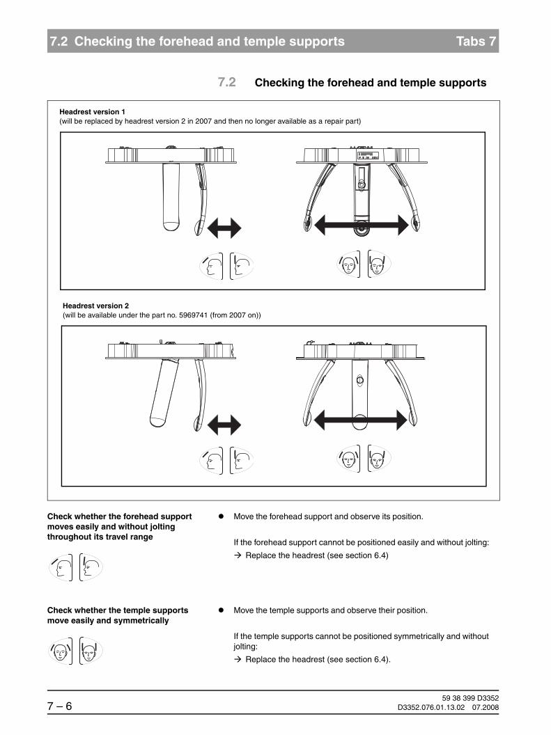
59 38 399 D33527 – 6 D3352.076.01.13.02 07.2008
7.2 Checking the forehead and temple supports Tabs 7
7.2 Checking the forehead and temple supports
Check whether the forehead support moves easily and without jolting throughout its travel range
Move the forehead support and observe its position.
If the forehead support cannot be positioned easily and without jolting:
Replace the headrest (see section 6.4)
Check whether the temple supports move easily and symmetrically
Move the temple supports and observe their position.
If the temple supports cannot be positioned symmetrically and without jolting:
Replace the headrest (see section 6.4).
Headrest version 1(will be replaced by headrest version 2 in 2007 and then no longer available as a repair part)
Headrest version 2(will be available under the part no. 5969741 (from 2007 on))
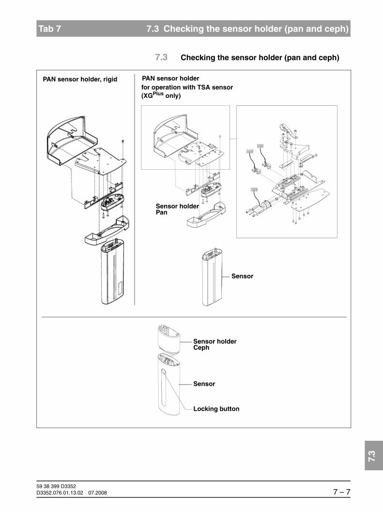
båÖäáëÜ
59 38 399 D3352D3352.076.01.13.02 07.2008 7 – 7
Tab 7 7.3 Checking the sensor holder (pan and ceph)
7.3
7.3 Checking the sensor holder (pan and ceph)
Sensor holderPan
Sensor
for operation with TSA sensor(XGPlus only)
Sensor holderCeph
Sensor
Locking button
PAN sensor holder, rigid PAN sensor holder

59 38 399 D33527 – 8 D3352.076.01.13.02 07.2008
7.3 Checking the sensor holder (pan and ceph) Tabs 7
Check whether the sensor locks and unlocks easily and is firmly seated in the holder
Carefully insert the sensor upward into the holder: The sensor must snap in place audibly.
Check the sensor for firm seating.
Press the locking button and carefully pull the sensor downward out of the holder: The sensor must be easy to remove.
If the sensor cannot easily be inserted in or removed from the holder, or is seated too loosely in the holder:
Check the magnets on the sensor for dirt or foreign particles and clean them or remove any foreign particles if necessary
Replace the sensor holder (see Page 6-43)
Replace the sensor

båÖäáëÜ
59 38 399 D3352D3352.076.01.13.02 07.2008 7 – 9
Tab 7 7.4 Checking the support piece (bite block holder)
7.4
7.4 Checking the support piece (bite block holder)
Check whether the bite block, contact segment and chin rest can be fitted securely in the bite block holder
Insert the bite block, contact segment and chin rest one after the other in the bite block holder and check them to make sure they are firmly seated.
If loosely seated:
Check the bite block, contact segment and/or chin rest for damage; re-place with new parts if necessary
Replace the support piece (see Page 6-33)
Support piece

59 38 399 D33527 – 10 D3352.076.01.13.02 07.2008
7.5 Checking the light localizers Tabs 7
7.5 Checking the light localizers
Check whether the FH light localizer (PAN) can be adjusted easily
Adjust the FH light localizer on the PAN with slider A.
If the light localizer cannot be moved easily:
Lubricate the slider (rail) with a light coat of Vaseline
FH light localizer PAN
MS light localizer Light localizer CephPAN
A = FH light
MS lightlocalizer
localizer

båÖäáëÜ
59 38 399 D3352D3352.076.01.13.02 07.2008 7 – 11
Tab 7 7.5 Checking the light localizers
7.5
Checking the position of the light lines (FH and MS) on the PAN
Switch the light localizers on and check the positions of the light lines:
– The horizontal light line (FH) must be running horizontally
– The vertical light line (MS) must be running vertically through the cen-ter of the forehead support down to the center of the support piece
NOTEiTip: When checking and adjusting the light localizers use the following as reference lines:
For the FH light localizer: Edge of the tube assembly light localizerFor the MS light localizer: Support piece, inserted bite block or
Forehead support
If the light beam alignment is not correct:
Adjust the light localizers (see chapter 6)
Checking the position of the light lines (FH) on the Ceph
Switch the light localizers on and check the positions of the light lines:
The horizontal light line (FH) must be running horizontally between the temple supports at the height of the ear plugs
NOTEiTip: When checking or adjusting the light localizer, you may use a PA or AP view to assess the light beam on the ear plugs.
FH
29
MS
60 90 12070 80 100 110
FH

59 38 399 D33527 – 12 D3352.076.01.13.02 07.2008
7.6 Checking the X-ray images Tabs 7
7.6 Checking the X-ray images
Check whether the X-ray images taken by the dentist are OK
Check to see whether the X-ray images taken by the dentist exhibit an un-exposed border on all 4 sides.
Check whether the X-ray images show normal definition.
Check whether the density of the X-ray images is OK.
If the quality of the X-ray images is unsatisfactory in some way:
Check the adjustment and readjust the system if necessary (see sec-tion 4)

båÖäáëÜ
59 38 399 D3352D3352.076.01.13.02 07.2008 7 – 13
Tab 7 7.7 Checking the tube data
7.7
7.7 Checking the tube data
7.7.1 kV actual value and radiation time
Select service routine S002.3 for the exposure (radiation without rotary movement, radiation time selectable, see page 5-26) and set the following parameters:
– Radiation time: 1 s
– kV value: 66 kV
Release radiation and check the kV actual value and radiation time spec-trometrically, e.g. using a Mult-O-Meter.
If the measured values deviate from the values set above (1 s, 66 kV) by more than ± 10 %:
‡ Replace the tube assembly (see Page 6-38)
NOTEiFor the XG 3/3 PPE system version, sensor positioning must be performed un-til the beam strikes the sensor precisely. If the sensor is positioned correctly, the corresponding values can be compared with the setpoint values.
7.7.2 Tube current verification
WARNINGThe electronics of the X-ray tube assembly are always connected to line volt-age.
Always switch the X-ray unit off and wait until V203 is no longer illuminated be-fore contacting the test leads.
WARNINGThe test leads and measuring instruments used must have a dielectric strength of at least 1000V!
Be sure to use a battery-powered measuring instrument with shock-hazard-protected sockets.
Use only test leads with shock protection.
WARNINGBe sure to switch the X-ray unit off before removing the jumper for the mA measuring jack.
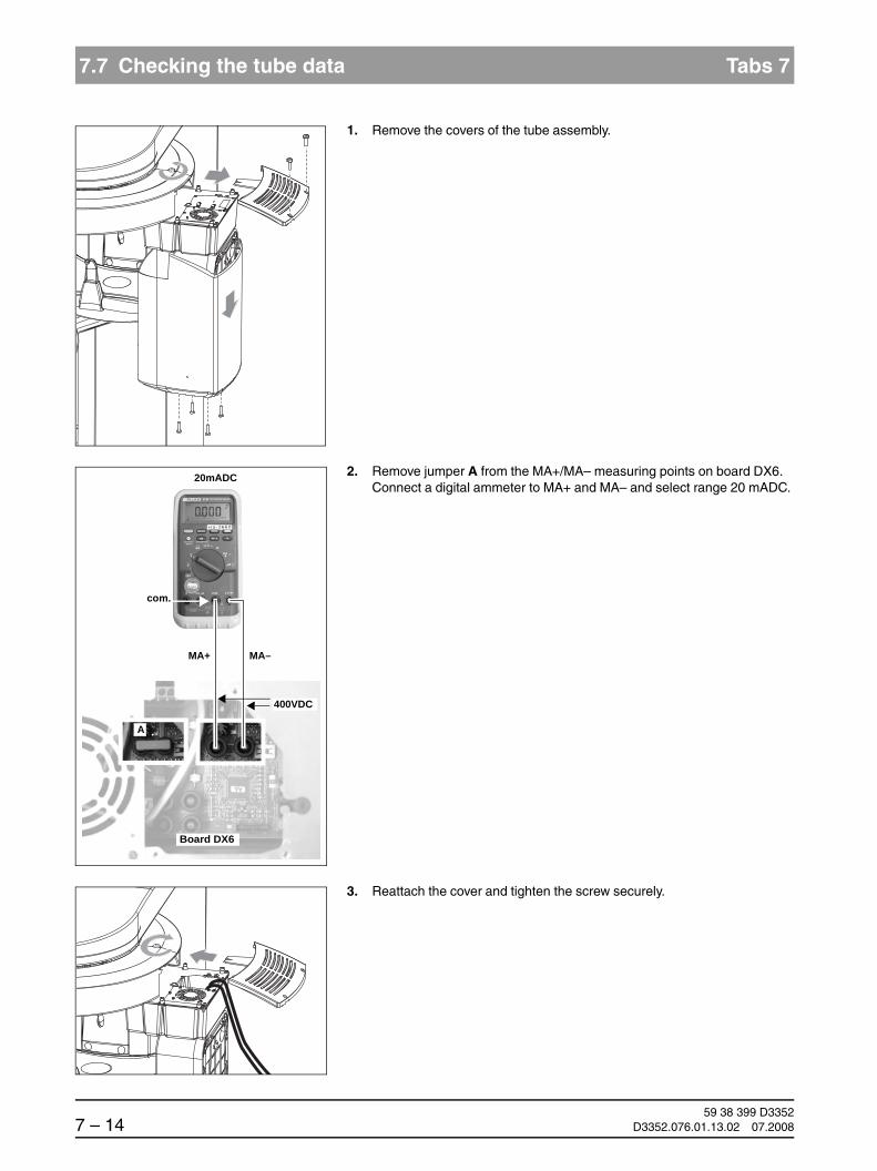
59 38 399 D33527 – 14 D3352.076.01.13.02 07.2008
7.7 Checking the tube data Tabs 7
1. Remove the covers of the tube assembly.
2. Remove jumper A from the MA+/MA– measuring points on board DX6. Connect a digital ammeter to MA+ and MA– and select range 20 mADC.
3. Reattach the cover and tighten the screw securely.
MA–MA+
20mADC
com.
Board DX6
·A
400VDC

båÖäáëÜ
59 38 399 D3352D3352.076.01.13.02 07.2008 7 – 15
Tab 7 7.7 Checking the tube data
7.7
4. Switch the unit ON å.Wait 1 min. for self-adjustment of the unit.Press the R key ç to return the X-ray tube head into the initial position.
Select 66 kV/8 mA. Make SIDEXIS XG ready for exposure.
As soon as program P1 and 66 kV/8 mA have been selected, the unit is ready for exposure.
Measurement 5. Press and hold down the exposure key until a meter reading is obtained.
The ammeter should indicate 8 mA ± 1.6 mA. Record the display reading.
NOTEiDisplay: 1mA corresponds to a tube current of 1mA, permissable tolerance +/-20%.
If the measured value deviates from the permissible value (1 mA) by more than ± 20 %:
‡ Replace the tube assembly (see 6-38)
If the specified value is obtained, switch the unit OFF.
6. Remove the upper cover and the meter leads.
Replace jumper!
Reattach the covers of the tube assembly.
XG 5 / 3 / 3 PPEXGPlus

59 38 399 D33527 – 16 D3352.076.01.13.02 07.2008
7.7 Checking the tube data Tabs 7
7.7.3 Fan and temperature
Check whether the fan is functioning Check the function of the fan using service routine S005.4 (see Page 5-31)
If the fan is defective:
‡ Replace the fan (see Page 6-42)
Check whether the temperature sensor is supplying plausible values
Read the temperature in the single tank via service routine S005.5 (see page 5-33)
If the displayed temperature reading is not plausible:
‡ Replace the tube assembly (see Page 6-38)

båÖäáëÜ
59 38 399 D3352D3352.076.01.13.02 07.2008 7 – 17
Tab 7 7.8 Checking the diaphragm
7.8
7.8 Checking the diaphragm
7.8.1 Dismantling the fixed diaphragm (XG 3 / 3 PPE only)
Check the fixed diaphragm for completeness.
Then release the diaphragm test exposures (see page 7-18ff.).
Version delivered until approx. end of 2006 Version delivered after approx. end of 2007

59 38 399 D33527 – 18 D3352.076.01.13.02 07.2008
7.8 Checking the diaphragm Tabs 7
7.8.2 Diaphragm test exposures
The diaphragm test exposures are used for a quick check of the system adjustment. The TEST EXPOSURE menu is started without a service pass-word. Diaphragm test exposures can thus be performed by the user as well.
Menu: Test exposure
The TEST EXPOSURE menu is started from SIDEXIS XG:
EXTRAS ‡ CONSTANCY TEST ‡ XCXP ‡ SELECT X-RAY DEVICE ‡ SERVICE EXPO-SURE ‡ DIAPHRAGM TEST EXPOSURE
NOTEiWhen you open the TEST EXPOSURE menu, the unit switches from the user mode to the PC service mode logged by the PC.
In the PC service mode, the control options that are available on the Easypad are determined by SIDEXIS and the currently selected service routine. General control of the unit (as in the user mode) is not possible in this mode.
You can switch between the PAN - DIAPHRAGM, PAN - SYMMETRY, CEPH - FIXED POINT OF ROTATION and TSA - SENSOR menus by clicking the corresponding tab with the mouse. To quit the TEST EXPOSURE menu, click CANCEL.
NOTEiThe Ceph - Fixed point of rotation and TSA - Sensor tabs are not present in the XG 3/3 PPE system version.

båÖäáëÜ
59 38 399 D3352D3352.076.01.13.02 07.2008 7 – 19
Tab 7 7.8 Checking the diaphragm
7.8
7.8.3 Pan diaphragm test exposure
Menu: Test exposure ‡ Pan diaphragm
NOTEiThe exposure is performed without a needle phantom.
Opening PAN - DIAPHRAGM 1. Select the PAN - DIAPHRAGM submenu.
Making the unit ready for exposure 2. Make SIDEXIS XG ready for exposure:
Click IMAGE ACQUISITION

59 38 399 D33527 – 20 D3352.076.01.13.02 07.2008
7.8 Checking the diaphragm Tabs 7
SIDEXIS screen The exposure dialog box showing the exposure status appears in SIDEXIS.
XGPlus: Display on the Easypad Service routine S030.2 and its specific exposureparameters are displayed on the Easypad touchscreen.
XG 5 / 3 / 3 PPE: Display on the Multipad The single-line display of the Multipad shows the exposure parametersof service routine S030.2.
Starting the exposure 3. Take an exposure (60 kV/3 mA; 0.20 s):
– Press the R key to move the unit back to the starting position.
XGPlus:
The procedure is completed when the status message “ORTHOPHOS is ready for exposure“ appears on the touchscreen and the exposure parameters of service routine S030.2 are displayed.
XG5 / 3 / 3 PPE:
The procedure is completed when the exposure parameters of service routine S030.2 are displayed and the progress indicator disappears.
– Press the release button. Hold down the release button until image ac-quisition is completed and the preview image appears in the exposure dialog box.
?
1
2
3
+- 60 kV/3 mA
0.20 s
S30
2
1 2 3
60/3____0.20____
R
WAIT!UNTIL UNIT IS IN STARTING POSITION

båÖäáëÜ
59 38 399 D3352D3352.076.01.13.02 07.2008 7 – 21
Tab 7 7.8 Checking the diaphragm
7.8
Evaluating the X-ray image 4. Evaluate the X-ray image:
– The exposed diaphragm area must lie horizontally centered in the image field as well as inside the superimposed auxiliary lines (A).
– A white border surrounding the image on all sides must be visible. The maximum density must lie in the center of the diaphragm area (A).
NOTEiIf these criteria are not fulfilled (B), the pan diaphragm must be adjusted. (see chapter 4)
Adjustment: ok
B
Adjustment: not ok
A

59 38 399 D33527 – 22 D3352.076.01.13.02 07.2008
7.8 Checking the diaphragm Tabs 7
7.8.4 Pan symmetry test exposure
Menu: Test exposure ‡ Pan diaphragm
Preparations Insert the needle phantom in the bite block holder of the panoramic X-ray unit (see page 4-9).
CAUTIONIt is essential that the needle phantom is removed from bite block holder of the panoramic X-ray unit again before a Ceph exposure is taken; otherwise the phantom may collide with the sensor.
Opening PAN - SYMMETRY 1. Select the PAN - SYMMETRY submenu.
Making the unit ready for exposure 2. Make SIDEXIS XG ready for exposure:
Click IMAGE ACQUISITION

båÖäáëÜ
59 38 399 D3352D3352.076.01.13.02 07.2008 7 – 23
Tab 7 7.8 Checking the diaphragm
7.8
SIDEXIS screen The exposure dialog box showing the exposure status appears in SIDEXIS.
XGPlus: Display on the Easypad Service routine S010.2 and its specific exposure parameters are displayed on the Easypad touchscreen.
XG 5 / 3 / 3 PPE: Display on the Multipad The single-line display of the Multipad shows the exposure parameters of service routine S010.2.
Starting the exposure 3. Take an exposure (60kV/3mA; 14.1 s):
– Press the R key to move the unit back to the starting position.
XGPlus:
The procedure is completed when the status message “ORTHOPHOS is ready for exposure“ appears on the touchscreen and the exposure parameters of service routine S010.2 are displayed.
XG5 / 3 / 3 PPE:
The procedure is completed when the exposure parameters of service routine S010.2 are displayed and the progress indicator disappears.
– Press the release button. Hold down the release button until image ac-quisition is completed and the preview image appears in the exposure dialog box.
?
1
2
3
+- 60 kV/3 mA
14.1 s
S10
2
1 2 3
60/3____14.1____
R
WAIT!UNTIL UNIT IS IN STARTING POSITION

59 38 399 D33527 – 24 D3352.076.01.13.02 07.2008
7.8 Checking the diaphragm Tabs 7
Evaluating the X-ray image 4. Evaluate the X-ray image:
Adjustment: not ok (length measurement with SIDEXIS)
S2
C
A2 = 44.3 ± 0.5 mm
A1 = 88.6 mm ± 1 mm
Adjustment: ok (length measurement with SIDEXIS)
± 0.75 mm
ZOOM: 1:1A
B
A2 = 44.3 ± 0.5 mmA2 A2
± 0.75 mm

båÖäáëÜ
59 38 399 D3352D3352.076.01.13.02 07.2008 7 – 25
Tab 7 7.8 Checking the diaphragm
7.8
– The shadow of the center needle, the needle image and the auxil-iary line must be coincident and located behind each other. A tolerance (offset of needle from the central auxiliary line) of ± 0.75 mm is permissible (A).
– Distance A1 must be 88.6 ± 1 mm (A).
– Distances A2 must be identical, each being 44.3 ± 0.5 mm.
– A white border surrounding the image on all sides must be visible (B).
NOTEiIf one of these criteria is not fulfilled (C), the pan symmetry must be adjusted. (see chapter 4)
Remove the needle phantom from the bite block holder of the unit.

59 38 399 D33527 – 26 D3352.076.01.13.02 07.2008
7.8 Checking the diaphragm Tabs 7
7.8.5 Ceph – Fixed point of rotation(not for XG 3 / 3 PPE)
Menu: Test exposure ‡ Ceph - Fixed point of rotation
CAUTIONIt is essential that the PAN needle phantom is removed from bite block holder of the panoramic X-ray unit before a Ceph exposure is taken; otherwise the phantom may collide with the sensor.
Opening CEPH - FIXED POINT OF ROTATION
1. Select the CEPH - FIXED POINT OF ROTATION submenu.
NOTEiThe QUICKSHOT check box must not be selected.
Making the unit ready for exposure 2. Make SIDEXIS XG ready for exposure:
Click IMAGE ACQUISITION

båÖäáëÜ
59 38 399 D3352D3352.076.01.13.02 07.2008 7 – 27
Tab 7 7.8 Checking the diaphragm
7.8
SIDEXIS screen The exposure dialog box showing the exposure status appears in SIDEXIS.
XGPlus: Display on the Easypad Service routine S010.5 and its specific exposure parameters are displayed on the Easypad touchscreen.
XG 5: Display on the Multipad The single-line display of the Multipad shows the exposure parameters of service routine S010.5.
Starting the exposure 3. Take an exposure (80 kV/14 mA; 0.60 s):
– Press the R key to move the unit back to the starting position.
XGPlus:
The procedure is completed when the status message “ORTHOPHOS is ready for exposure“ appears on the touchscreen and the exposure parameters of service routine S010.5 are displayed.
XG5:
The procedure is completed when the exposure parameters of service routine S010.5 are displayed and the progress indicator disappears.
– Press the release button. Hold down the release button until image ac-quisition is completed and the preview image appears in the exposure dialog box.
?
1
2
3
+- 80 kV/14 mA
0.60 s
S10
5
1 2 3
80/14___0.60____
R
WAIT!UNTIL UNIT IS IN STARTING POSITION

59 38 399 D33527 – 28 D3352.076.01.13.02 07.2008
7.8 Checking the diaphragm Tabs 7
Evaluating the X-ray image 4. Evaluate the X-ray image:
– The exposed diaphragm area must lie centered and straight in the image field as well as inside the superimposed auxiliary lines (A).
– A white border surrounding the image on all sides must be visible. The maximum density must lie in the center of the diaphragm area (A).
NOTEiIf these criteria are not fulfilled (B), the ceph fixed point of rotation must be ad-justed (see chapter 4).
Adjustment: ok
B
Adjustment: not ok
A

båÖäáëÜ
59 38 399 D3352D3352.076.01.13.02 07.2008 7 – 29
Tab 7 7.8 Checking the diaphragm
7.8
7.8.6 Quickshot test exposure(XGPlus and full version only)
Menu: Test exposure ‡ Ceph - Quickshot
CAUTIONIt is essential that the PAN needle phantom is removed from bite block holder of the panoramic X-ray unit before a Ceph exposure is taken; otherwise the phantom may collide with the sensor.
Opening CEPH - FIXED POINT OF ROTATION
1. Select the CEPH - FIXED POINT OF ROTATION submenu.
Opening QUICKSHOT 2. Activate the QUICKSHOT check box.

59 38 399 D33527 – 30 D3352.076.01.13.02 07.2008
7.8 Checking the diaphragm Tabs 7
Making the unit ready for exposure 3. Make SIDEXIS XG ready for exposure:
Click IMAGE ACQUISITION
SIDEXIS screen The exposure dialog box showing the exposure status appears in SIDEXIS.
XGPlus: Display on the Easypad Service routine S010.8 and its specific exposure parameters are displayed on the Easypad touchscreen.
Starting the exposure 4. Take an exposure (80 kV/14 mA; 0.30 s):
– Press the R key to move the unit back to the starting position.
The procedure is completed when the status message “ORTHOPHOS is ready for exposure“ appears on the touchscreen and the exposure parameters of service routine S010.8 are displayed.
– Press the release button. Hold down the release button until image ac-quisition is completed and the preview image appears in the exposure dialog box.
?
1
2
3
+- 80 kV/14 mA
0.30 s
S10
8
R
WAIT!UNTIL UNIT IS IN STARTING POSITION

båÖäáëÜ
59 38 399 D3352D3352.076.01.13.02 07.2008 7 – 31
Tab 7 7.8 Checking the diaphragm
7.8
Evaluating the X-ray image 5. Evaluate the X-ray image:
– The exposed diaphragm area must lie centered and straight in the image field as well as inside the superimposed auxiliary lines (A).
– A white border surrounding the image on all sides must be visible. The maximum density must lie in the center of the diaphragm area (A).
NOTEiIf these criteria are not fulfilled (B), the ceph quickshot must be adjusted (see chapter 4).
B
Adjustment: ok
A
Adjustment: not ok

59 38 399 D33527 – 32 D3352.076.01.13.02 07.2008
7.8 Checking the diaphragm Tabs 7
7.8.7 TSA sensor (XGPlus and full version only)
Menu: Test exposure ‡ TSA sensor
NOTEiThe exposure is performed without a needle phantom.
Opening TSA - SENSOR 1. Select the TSA - SENSOR submenu.
Making the unit ready for exposure 2. Make SIDEXIS XG ready for exposure:
Click IMAGE ACQUISITION

båÖäáëÜ
59 38 399 D3352D3352.076.01.13.02 07.2008 7 – 33
Tab 7 7.8 Checking the diaphragm
7.8
SIDEXIS screen The exposure dialog box showing the exposure status appears in SIDEXIS.
XGPlus: Display on the Easypad Service routine S030.4 and its specific exposure parameters are displayed on the Easypad touchscreen.
Starting the exposure 3. Take an exposure (60 kV/3 mA; 0.20 s):
– Press the R key to move the unit back to the starting position.
The procedure is completed when the status message “ORTHOPHOS is ready for exposure“ appears on the touchscreen and the exposure parameters of service routine S030.4 are displayed.
– Press the release button. Hold down the release button until image ac-quisition is completed and the preview image appears in the exposure dialog box.
?
1
2
3
+- 60 kV/3 mA
0.20 s
S30
4
R
WAIT!UNTIL UNIT IS IN STARTING POSITION

59 38 399 D33527 – 34 D3352.076.01.13.02 07.2008
7.8 Checking the diaphragm Tabs 7
Evaluating the X-ray image 4. Evaluate the X-ray image:
– The exposed diaphragm area must lie horizontally centered in the image field (A).
– A white border surrounding the image on all sides must be visible. The maximum density must lie in the center of the diaphragm area (A).
NOTEiIf these criteria are not fulfilled (B), the TSA sensor must be adjusted (see chapter 4).
Adjustment: ok Adjustment: not ok
A B

båÖäáëÜ
59 38 399 D3352D3352.076.01.13.02 07.2008 7 – 35
Tab 7 7.9 Checking the cables for damage
7.9
7.9 Checking the cables for damage
Check whether the cables feeding the unit are OK
Perform a visual check of the power cable, protective ground wire, control cables and data cables.
If cables are externally damaged:
‡ Replace the respective cables (see Page 6-91)

59 38 399 D33527 – 36 D3352.076.01.13.02 07.2008
7.10 Checking the idling rollers Tabs 7
7.10 Checking the idling rollers
Check whether the idling rollers are OK Rotate ring B by hand and check it for smooth and easy running.
If the ring does not run smoothly and easily:
Remove the housing covers and check the idle rollers for dirt and for-eign particles. Clean and remove foreign particles if necessary.
B
Idling roller

båÖäáëÜ
59 38 399 D3352D3352.076.01.13.02 07.2008 7 – 37
Tab 7 7.11 Checking the grounding straps
7.11
7.11 Checking the grounding straps
Check whether the grounding straps have complete and firm contact
Perform a visual and “hands-on” inspection of the ground straps to ensure that they have complete and firm contact at the positions marked.
If the grounding straps do not have proper contact:
‡ Fasten them properly
If the grounding straps are damaged:
‡ Replace the grounding straps

59 38 399 D33527 – 38 D3352.076.01.13.02 07.2008
7.12 Checking the cable shields Tabs 7
7.12 Checking the cable shields
Check whether the cable shielding is OK
Perform a visual and “hands-on” inspection of the cable shields to ensure that they have complete and firm contact at the positions marked.
If the cable shields do not have proper contact:
‡ Fasten them properly
Shield on housing DX32
Shield on the tube assembly

båÖäáëÜ
59 38 399 D3352D3352.076.01.13.02 07.2008 7 – 39
Tab 7 7.13 Checking the protective ground wires
7.13
7.13 Checking the protective ground wires
DANGERShock hazard! It is essential that you switch the X-ray unit OFF before replacing any components!
Switch OFF the line voltage at the main switch of the building installation.
Disconnect the power cable and the second protective ground wire from the building installation.
Remove the following cover parts (see section 1.14):
– Profile cover (10)
– Tube assembly cover, front (65)
– Tube assembly cover, rear (70)
Measuring setup for protective ground wire test
V
A ~ A
BCDE
Ammeter Power sourceMeasuring pointCentral ground wire
Measuring points B-E
Voltmeter

59 38 399 D33527 – 40 D3352.076.01.13.02 07.2008
7.13 Checking the protective ground wires Tabs 7
Check whether the ground wire resistance complies with the specifications
A power source with a current of at least 0.2 A and a no-load voltage of 24 V max. and 4 V min. is required.
Connect the power source between the measuring points specified in the table for at least 5 s and measure:
– the voltage drop with the voltmeter
– the current with the ammeter and
– calculate the resistance using the formula R = U/I
Measuring point A: Central ground wire
Protective ground wire test between...
A and B GNYE wire 0,1Ω
A and C 2. Protective ground wire
0,1Ω
A and D Housing DX32 0,2Ω
A

båÖäáëÜ
59 38 399 D3352D3352.076.01.13.02 07.2008 7 – 41
Tab 7 7.13 Checking the protective ground wires
7.13
Measuring points B and C: GNYE power connection and 2nd ground wire
Second protective
Power cablePE
Orthophos XG
Po
wer
cab
le
Sec
on
dP
rote
ctiv
e g
rou
nd
wir
e
Sec
on
dP
rote
ctiv
e g
rou
nd
wir
e
to t
he
Ort
ho
ph
os
XG
Po
wer
cab
leto
th
e O
rth
op
ho
s X
G
B C B CB
C
A
ground wire

59 38 399 D33527 – 42 D3352.076.01.13.02 07.2008
7.13 Checking the protective ground wires Tabs 7
Measuring points D and E: Board cage DX32 and tube assembly
housing
NOTEiIf the resistance exceeds the value specified in the adjacent table, check whether the protective ground wire is fastened according to specifications:
– Check whether the flat washer, toothed lock washer and cable lug are fitted on the protective ground wire in the right order (see page 7-40) and whether the nuts of the ground wire connections are tightened securely.
If the ground wire is not fastened according to specifications, fasten the ground wire properly.(see page 7-40).
Do not connect the power cable and the second ground wire to the build-ing installation yet, but perform a measurement of the device leakage current first (see section 7.14).
E
DTube assembly
BoardcageDX32

båÖäáëÜ
59 38 399 D3352D3352.076.01.13.02 07.2008 7 – 43
Tab 7 7.14 Checking the device leakage current
7.14
7.14 Checking the device leakage current
DANGERShock hazard! It is essential that you switch the X-ray unit OFF before replacing any components!
NOTEiA high resistance measuring voltage source at line frequency and a measur-ing circuit compliant with the requirements of IEC 601 are required.Complete test units, e.g. the "Bender tester", fulfill these requirements.
If you have not done it already...
Switch OFF the line voltage at the main switch of the building installation.
Disconnect the power cable and the second protective ground wire from the building installation.
Remove the following cover parts (see section 1.14):
– Profile cover (10)

59 38 399 D33527 – 44 D3352.076.01.13.02 07.2008
7.14 Checking the device leakage current Tabs 7
Measuring setup for testing the device leakage current
Check whether the power switch of the unit is turned ON.
Connect a high-resistance measuring voltage source between the short-circuited power cable (B) and ground wire A.
Measure the voltage drop across MD.
NOTEiThe measured value must not exceed 5 mA.
If the leakage current is not OK, perform troubleshooting according to section 3.6.
Reconnect the unit to the building installation (see the Installation Instruc-tions for the ORTHOPHOS XG).
Power cableto the Orthophos XG
B
V
~
L
N
PE
A
Voltmeter
208 V / 230 V± 10%
MD
1kΩ
10kΩ0.015μF
Voltage source

båÖäáëÜ
59 38 399 D3352D3352.076.01.13.02 07.2008 7 – 45
Tab 7 7.14 Checking the device leakage current
7.14

59 38 399 D3352D3352.076.01.13.02 07.2008
Service Manual History D3352
Version 1: Software version V02.17, ORTHOPHOS XGPlus/Ceph and not yet all errors and service routines described.
Version 2: Software versions V02.18.1 (XG 5) and V02.19 (XGPlus), system version XG 5,complete revision.
Version 3: Software version V02.20, service routine S034.7, error messages added, chapter update added, additional general revision
Version 4: Software version V02.22, TSA, service routines S017.12/13/14 and S020, chapter update added, additional general revision
Version 5: Software version V02.24, system version XG 3, Ceph right-hand arm, service routines S017.15 and S021.3, chapter update added, additional general revision
Version 6: Software version V02.25
Version 7: Software version V02.27; new service routines S005.7, S007.5, S012.2/3/4, S017.9S018.5/6, S032.10 and S033.10, optimized error lists, troubleshooting chapter added (CAN bus diagnosis, sensor data path), additional general revision
Version 8 Software version V02.28; system hardware version BA, DX41 omitted, new headrest; new fixed diaphragm; XG 3 PPE "pay per exposure" concept (USA only); new service routines S014, S015, S017.10, S017.22 and S017.23, optimized error lists, troubleshooting chapter extended, additional general revision
Version 9 Software version V02.28.1
Version 10 Software version V02.30
Version 11 Software version V02.31
Version 12 Chapter 6 "Repair", sections "Replacing the light barriers" and "Replacing cables in the cable tracks" changed and corrections in Chapter 3 "Troubleshooting".
Version 13 General: Software version V02.32, Chapter 2: Error message E6 61 70 added, Chapter 5: Service routine S017.17, Chapter 6: Section "Replacing the tube bend" omitted, Section "Measures following replacement of boards" changed.

båÖäáëÜ
59 38 399 D3352D3352.076.01.13.02 07.2008

tÉ=êÉëÉêîÉ=íÜÉ=êáÖÜí=íç=ã~âÉ=~åó=~äíÉê~íáçåë=ïÜáÅÜ=ã~ó=ÄÉ=êÉèìáêÉÇ=ÇìÉ=íç=íÉÅÜåáÅ~ä=áãéêçîÉãÉåíëK
«=páêçå~=aÉåí~ä=póëíÉãë=dãÄe=OMMQ péê~ÅÜÉW=ÉåÖäáëÅÜ= mêáåíÉÇ=áå=dÉêã~åóaPPROKMTSKMNKNPKMO===MTKOMMU ûKJkêKW= NNM=N40 fãéêáã¨=Éå=^ääÉã~ÖåÉ
páêçå~=aÉåí~ä=póëíÉãë=dãÄe=
áå=íÜÉ=rp^Wc~Äêáâëíê~≈É=PN páêçå~=aÉåí~ä=póëíÉãë=ii`aJSQSOR=_ÉåëÜÉáã QUPR=páêçå~=aêáîÉI=pìáíÉ=NMM lêÇÉê=kç RV=PU=PVV=aPPROdÉêã~åó `Ü~êäçííÉI=k`=OUOTPïïïKëáêçå~KÇÉ rp^