ZG1200_Service Manual.pdf
276
Kawasaki ··J/·XH Motorcycle Ser-vice Manual
-
Upload
khangminh22 -
Category
Documents
-
view
0 -
download
0
Transcript of ZG1200_Service Manual.pdf

Kawasaki ··J/·XH
Motorcycle
Ser-vice Manual
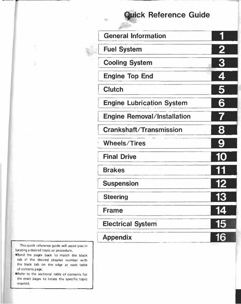
This quick refe rence guide will assist you in locating a desired topic or procedure . • Send the pages back to match the black
tab of the des ired chapter number with the black tab on the edge at each table of contents page.
eRefer to the sec tional table of contents for the exact pages to locate the specific topic required.
Quick Reference Guide
General Information
Fuel System
Cooling System
Engine Top End
Clutch
Engine Lubrication System
Engine Removal/Installation
Crankshaft/Transmission
, Wheels/Tires
Final Drive
Brakes
Suspension
Steering
Frame
Electrical System
Appendix
1 2 3 4 5 6 7 8 9 10 11 12 13 14 15 16
KaVlasaki
Motorcycle
Service Manual
xu
All rights reserved. No parts of this publication may be reproduced, stored in a retrieval system, or transmitted in any form or by any means, electronic mechanical photocopying, recording or otherwise, without the prior written permission of Quality Assurance Department/Consumer Products Group/ Kawasaki Heavy Industries, Ltd., Japan.
No liability can be accepted for any inaccuracies or omissions in this publication, although every possible care has been taken to make it as complete and accurate as possible.
The right is reserved to make changes at any time without prior notice and without incurring an obligation to make such changes to products manufactured previously. See your Motorcycle dealer for the latest information on product improvements incorporated after this publication.
All information contained in this publication is based on the latest product information available at the time of publication. Illustrations and photographs in this publication are intended for reference use only and may not depict actual model component parts.
@Kawasakl Heavy Industries. Ltd .. 1986 First Edition (9): June 25. 1997 (K)

LIST OF ABBREVIATIONS I A ampere(s)
ABOC after bottom dead center ~ AC alternating current ti ATOC after top dead center ~ BBOC before bottom dead center i • BOC bottom dead center I BTOC before top dead center • I °c degree(s) Celsius •
DC direct current
F farad(s) of degree( s) F ah renheit
ft foot, feet
g gram(s)
h houris)
L liter(s)
Ib pound(s)
m meter(s)
min minute(s)
N newton(s)
Pa pascal(s)
PS horsepower
psi pound(s) per square inch
r revolution
rpm revolution(s) per minute
TOG top dead center
TIR total indicator reading
V volt(s)
W watt(s)
n ohm(s)
Read OWNER'S MANUAL befqre operating

EMISSION CONTROL INFORMATION
To protect the environment in which we all live, Kawasaki has incorporated crankcase emission (1) and exhaust emission (2) control systems in compliance with applicable regulations of the United States Environmental Protection Agency and California Air Resources Board. Additionally, Kawasaki has incorporated an evaporative emission control system (3) in compliance with applicable regulations of the California Air Resources Board on vehicles sold in California only. 1. Crankcase Emission Control System
This system eliminates the release of crankcase vapors into the atmosphere. Instead, the vapors are routed through an oil separator to the intake side of the engine. While the engine is operating, the vapors are drawn into combustion chamber, where they are burned along with the fuel and air supplied by the carburetion system.
2. Exhaust Emission Control System This system reduces the amount of pollutants discharged into the atmosphere by the exhaust of this motorcycle. The fuel and ignition systems of this motorcycle have been carefully designed and constructed to ensure an efficient engine with low exhaust pollutant levels.
3. Evaporative Emission Control System Vapors caused by fuel evaporation in the fuel system are ·not vented into the atmosphere. Instead, fuel vapors are routed into the running engine to be burned, or stored in a canister when the engine is stopped. Liquid fuel is caught by a vapor separator and returned to the fuel tank.
The Clean Air Act, which is the Federal law covering motor vehicle pollution, contains what is commonly referred to as the Act's "tampering provisions."
"Sec. 203(a) The following acts and the causing thereof are prohibited ... (3)(A) for any person to remove or render inoperative any device or element of design
installed on or in a motor vehicle or motor vehicle engine in compliance with regulations under this title prior to its sale and delivery to the ultimate purchaser, or for any manufacturer or dealer knowingly to remove or render inoperative any such device or element of design after such sale and delivery to the ultimate purchaser.
(3)(B) for any person engaged in the business of repairing, servicing, selling, leasing, or trading motor vehicles or motor vehicle engines, or who operates a fleet of motor vehicles knowingly to remove or render inoperative any device or element of design installed on or in a motor vehicle or motor vehicle engine in compliance with regulations under this title following its sale and delivery to the ultimate purchaser ... "
(Continued on next page)

NOTE
:~~ 0 The phrase "remove or render inoperative any device or element of design" has been ~ ~ generally interpreted as follows: ~ ~v.. 1. Tampering does not include the temporary removal or rendering inoperative of ~ m devices or elements of design in order to perform maintenance. ~
~ 2. Tampering could include: ~
~._. a. Maladjustment of vehicle components such that the emission standards are ~I!
exceeded. ~
b. Use of replacement parts or accessories which adversely affect the performance :fl! ~~ ~ m or durability of the motorcycle. ~
~•• c. Addition of components or accessories that result in the vehicle exceeding the ~:f':
standards. ~ d. Permanently removing. disconnecting. or rendering inoperative any component
or element of design of the emission control systems. :fl! ~ ~ ~~ WE RECOMMEND THAT ALL DEALERS OBSERVE THESE PROVISIONS DF FEDERAL ~ ~ LAW. THE VIOLATION OF WHICH IS PUNISHABLE BY CIVIL PENALTIES NOT ~ m EXCEEDING $10.000 PER VIOLATION . :fl!
~ ~ ~~*******~*~**~~*~~~~*~~~~*~
TAMPERING WITH NOISE CONTROL SYSTEM PROHIBITED
Federal law prohibits the following acts or the causing thereof: ! 1) The removal or rendering inoperative by any person other than for purposes of maintenance, repair, or replacement, of any device or element 01 design incorporated into any new vehicle for the purpose of noise control prior to its sale or delivery to the ultimate purchaser or while it is in use, or (2) the use of the vehicle after such device or element of design has been removed or rendered inoperat ive by any person.
Among those acts presumed to constitute tampering are the acts listed below : eReplacement of the original exhaust system or muffler with a component not in com-
pliance with Federal regulations. eRemoval of the muffler!s) or any internal portion of the muffler!s). eRemoval of the air box or air box cover. eModifications to the muffler(s) or air intake system by cutting. qrilling, or other means if
such modifications result in increased noise levels.
, tr.i ~~ In~ ~
~d pn ou WI or rn OJ
te tl P tt s l
r

-
Foreword This manual is designed primarily for use by
trained mechanics in a properly equipped shop. However, it contains enough detail and basic information to make it useful to the owner who desires to perform his own basic maintenance and repair work. A basic knowledge of mechanics, the proper use of tools, and workshop procedures must be understood in order to carry out maintenance and repair satisfactorily. Whenever the owner has insufficient experience or doubts his ability to do the work, all adjustments, maintenance, and repai r shou Id be carried out only by qualified mechanics_
I n order to perform the work efficiently and to avoid costly mistakes, read the text, thoroughly familiarize yourself with the procedures before starting work, and then do the work carefully in a clean area. Whenever special tools or equipment are specified, do not use makeshift tools or equipment . Precision measurements can only be made if the proper instruments are used, and the use of substitute tools may adversely affect safe operation.
For the duration of your warranty period, especially, we recommend that all repairs and scheduled maintenance be performed in accord ance with this service manual. Any owner maintenance or repair procedure not performed in accordance with th is manual may void the warranty.
To get the longest life out of your Motorcycle: _ Follow the Periodic Maintenance Chart in the Service Manual.
-Be alert for problems and non·scheduled maintenance.
_Use proper tools and genuine Kawasaki Motorcycle parts. Special tools, gauges, and testers that are necessary when servicing Kawasaki motorcycles are introduced by the Special Tool Manual. Genuine parts provided as spare parts are I isted in the Parts Catalog.
_Follow the procedures in this manual carefully . Don 't take shortcuts.
_Remember to keep complete records of main tenance and repair w ith dates and any new parts installed .
.... ......... .................... ...... .. ... ................ ... .... .... ..... How to Use this Manual . ......................... ............. .. ....... ........................... .
In preparing this manual, we divided the product into its major systems. These systems became the manual 's chapters. All information for a particular system from adjustment through disassembly and inspection is located in a single chapter.
The Quick Reference Guide shows you all of the product's systems and assists in locating their chapters. Each chapter in turn has its own comprehensive Table of Contents.
The Periodic Maintenance Chart is located in the General Information chapter . The chart gives a time schedule for required maintenance operations.
I f you want spark plug information , for example, go to the Periodic Maintenance Chart first. The chart tells you how frequently to clean and gap the plug. Next, use the Quick Reference Guide to locate the Electrical System chapter. Then, use the Table of Contents On the first page of the chapter to find the Spark Plug section.
Whenever you see these WA R N I NG and CAUTION symbols, heed their instructions! Always follow safe operating and maintenance practices.
I WARNING'
o This warning symbol identifies special instructions or procedures which, if not correctly followed, could result in personal injury, or loss of life.
o This caution symbol identifies special instructions or procedures which, if not strictly observed, could result in damage to or destruction of equipment.
This manual contains five more symbols (in addition to WARNING and CAUTION) which will help you distinguish different types of information .
NOTE
c This note symbol indicates points of particular interest for more efficient and convenient operation.
I
elndicates a procedural step or work to be done. 01 ndicates a procedural sub·step or how to do
the work of the procedural step it follows . It also precedes the text of a WARNING , CAUTION , or NOTE .
*Indicates a conditional step or what action to take based on the results of the test or inspec· tion in the procedural step or sub·step it follows.
"'Indicates a conditional sub·step or what action to take based upon the results of the condi· tional step it follows.
In most chapters an exploded view il lustration of the system components follows the Table of Contents. In these illustrations you will find the instructions indicating which parts require specified tightening torque, oil , grease or a locking agent during assembly.
- .,.. GENERAL INFORMATION 1-1
General Information Table of Contents
Before Servicing _ . . . . . . . . . . . . . . . . . . . . . . . . . . . . . . . . . . . . . . . . . . '-2
Model Identification .......................... . .... _ . . . . . . . . '-4
General Specifications ...................................... '-5
Periodic Maintenance Chart . . . . . . . . . . . . . . . . . . . . . . . . . . . . . . . . . . '-7
Torque and Locking Agent .. ..... .. _ ... . ... . ......... . _ . . . . . . '-8
Cable. Wire, and Hose Routing..... . ....... .. ................ . '-'2

1-2 GENERAL INFORMATION
Before Servicing
Before starting to service a motorcycle, careful reading of the applicable section is recommended to eliminate unnecessary work. Photographs, diagrams, notes, cautions, warnings, and detailed descriptions have been included wherever necessary. Nevertheless, even a detailed account has limitations, a certain amount of basic knowledge is also required for successful work .
Especially note the fOllowing: (1) Dirt
Before removal and disassembly, clean the motorcycle. Any dirt entering the engine or other parts will work as an abrasive and shorten the life of the motorcycle. For the same reason, before installing a new part, clean off any dust or metal filings.
(2) Battery Ground Remove the ground (-) lead from the battery before performing any disassembly operations
on the motorcycle_ This prevents: (a) the possibility of accidentally turning the engine over while partially disassembled. (b) sparks at electrical connections which will occur when they are disconnected. (c) damage to electrical parts.
(3) Tightening Sequence Generally, when installing a part w ith several bolts, nuts, or screws, they should all be started
in their holes and tightened to a snug fit. Then tighten them evenly in a cross pattern. This is to avoid distortion of the part and/or causing gas or oil leakage. Conversely when loosening the bo lts, nuts, or screws, first loosen all of them by about a quarter of turn and then remove them.
Where there is a tightening sequence indication in this Service Manual, the bolts, nuts, or screws must be tightened in the order and method indicated.
(4) Torque The torque values given in this Service Manual should always be adhered to. Either too little
or too much torque may lead to serious damage. Use a good quality, reliable torque wrench. (5) Force
Common sense should dictate how much force is necessary in assembly and disassembly . If a part seems especially difficult to remove or install, stop and examine what may be causing the problem. Whenever tapping is necessary, tap lightly using a wooden or plastic faced mallet. Use an impact driver for screws (particularly for the removal of screws held by a locking agent) in order to avoid damaging the screw heads ..
(6) Edges Watch for sharp edges, especially during major engine disassembly and assembly. Protect your
hands with gloves or a piece of thick cloth when lifting the engine or turning it over. (7) High Flash-point Solvent
A high flash-point solvent is recommended to reduce fire danger. A commercial solvent commonly available in North America is Stoddard solvent (generic name). A lways follow manufac· turer and container directions regarding the use of any solvent.
(B) Gasket, O-ring Do not reuse a gasket or O-ring once it has been in service. The mating
surfaces around the gasket should be free of foreign matter and perfectly smooth to avoid oil or compression leaks.
(9) Liquid Gasket, Non-permanent Locking Agent Follow manufacturer's directions for cleaning and preparing surfaces where these compounds
will be used. Apply sparingly . Excess ive amounts may block engine oil passages and cause serious damage. An example of a non·permanent locking agent commonly available in North America is Loctite Lock'n Seal (Blue) .
(10) Press A part installed using a press or driver, such as a wheel bearing, should first be coated with oil
on its outer or inner circumference so that it will go into place smoothly. ( 11) Ball Bearing
When installing a ball bearing, the bearing race which is affected by friction should be pushed by a su itable driver. Th is prevents severe stress on the balls and races, and prevents races and balls from being dented. Press a ball bearing until it stops at the stop in the hole Or on the shaft.
( 121
(1

Pi
GENERAL INFORMATION 1-3
(12) Oil Seal and Grease Seal Replace any oil or grease seals that were removed with new ones, as removal generally damages
seals. When pressing in a seal which has manufacturer's marks, press it in with the marks facing out.
Seals should be pressed into place using a suitable driver, which contacts evenly with the side of seal, until the face of the seal is even with the end of the hole.
(13) Seal Guide A seal guide is required for certain oil or grease seals during installation to avoid damage to the
seal lips. Before a shaft passes through a seal, apply a little oil, preferably high temperature grease on the lips to reduce rubber to metal friction.
(14) Circlip, Retaining Ring Replace any circlips and retaining rings that were removed with new ones, as removal weakens
and deforms them. When installing circlips and retaining rings, take care to compress or expand them only enough to install them and no more.
(15) Lubrication Engine wear is generally at its maximum while the engine is warming up and before all the
rubbing surfaces have an adequate lubricative film. During assembly, oil or grease (whichever is more suitable) should be applied to any rubbing surface which has lost its lubricative film. Old grease and dirty oil should be cleaned off. Deteriorated grease has lost its lubricative quality and may contain abrasive foreign particles.
Don't use iust any oil or grease. Some oils and greases in particular should be used only in certain applications and may be harmful if used in an application for which they are not intended. This manual makes reference to molybdenum disulfide grease (MoS,) in the assembly of certain engine and chassis parts. Always check manufacturer recommendations before using such special lubricants.
(16) Electrical Wires All the electrical wires are either single-color or two-color and, with only a few exceptions,
must be connected to wires of the same color. On any of the two-color wires there is a greater amount of one color and a lesser amount of a second color, so a two-color wire is identified by first the primary color and then the secondary color. For example, a yellow wire with thin red stripes is referred to as a "yellow/red" wire; it would be a "red/yellow" wire if the colors were reversed to make red the main color.
Wire Name of Picture in (cross-section) Wire Color Wiring Diagram
-~ Red Yellow Wire 'I'
I if f', t1' strands Yellow/red
~ - - -t 7' +--Yellow - Red ___ ~Red
(17) Replacement Parts .. When there is a replacement instruction, replace these parts with new ones every time they are
removed. These replacement parts will be damaged or lose their origin~1 function cnce removed. (18) Inspection
When parts have been disassembled, visually inspect these parts for the following conditions or other damage. If there is any doubt as to the condition of them, replace them with new ones.
Abrasion Crack Hardening Warp Bent Dent Scratch Wear Color change Deterioration Seizure
(19) Service Data Numbers of service data in this text have following meanings:
"Standards": Show dimensions or performances which brand-new parts or systems have_ "Service limits": Indicate the usable limits. If the measurement shows excessive wear or deteriorated performance, replace the damaged parts.
f
I

1-4 GENERAL INFORMATION
Model Identification
ZG1200-Al Left Side View:
ZGl200·A1 Right Side View :
......... Gener ........ ,
ItlfRl -OliN ~ ()
0' W R S C (
I -Pel
-Er

General Specifications
Items
Dimensions: Overall length Overall width Overall height Wheelbase Road clearance Seat height Dry weight Curb weight: Front
Rear Fuel tank capacity
Performance: Braking distance Minimum turning radius
Engine: Type Cooling system Bore and stroke Displacement Compression ratio Carburetion system
Starting system Ignition system Timing advance Ignition timing Spark plug Cylinder numbering method Firing order Valve timing:
Inlet
Exhaust
Lubrication system Engine oil:
Grade
Viscosity Capacity
Drive Train:
Primary reduction system: Type Reduction ratio Clutch type
Open Close Duration Open Close Duration
GENERAL INFORMATION 1-5
ZG1200-A1
2,815mm 965 mm 1,485 mm 1,620 mm 140mm 755 mm 317 kg ~ 317.5 kg 155 kg 191.5kg ~ 192kg 23.2 L
12.5 m from 50 kml h
2.9 m
4·stroke, DOHC, 4·cylinder Liquid-cooled 78.0 x 62.6 mm
1,196 mL 10.0
~ : California Model
Carburetors, Keihin CVK30 x 4 Electric starter Battery and coil (transistorized) Electronically advanced 10" BTDC @800 rlmin (rpm) NGK DPR8EA-9 or ND X24EPR·U9 Left to right, 1-2·3-4 1-2-4·3
20" BTDC 48" ABDC 2480
54" BBDC 14" ATDC
2480
Forced lubrication (wet sump)
SE Or SF class
SAE10W40, 10W50, 20W40, or 20W50 4.0 L
Gear 1.706 (99/ 58) Wet multi disc

1-6 GENERAL INFORMATION
Items Transmission :
Type Gear ratios: 1st
2nd 3rd 4th 5th
Final drive system : Type Reduction ratio Overall drive ratio
Final gear case oil: Type
Capacity
Frame: Type Caster (rake angle) Tra il Front tire:
Type Size
Rear tire: Type
Size Front suspension :
Type Wh eel t ravel
Rear suspension : Type Wheel travel
8rake type: Front
Rear
Electrical Equipment: Battery Headl ight:
Type Bulb
T ail / brake light Alternator:
Type Rated output
Vo ltage regulator: Type
ZG1200-Al
5-speed, constant mesh, return shift 2.733 (41 / 15) 1_800 (36/ 20) 1.333 (32/ 24) 1.035 (29/ 28) 0 .838 (26/31)
Shaft 2.424 (15/22 x 32/ 9) 3.4 70 @Top gear
API GL-5 Hypoid gear oil SAE 80
210 mL
Tubular, double cradle 30° 121 mm
Tubeless 130/90-1667 H
Tubeless 150/90-15 74 H
Telescopic fork (pneumatic)
140 mm
Swing arm 100 mm
Dual disc Single disc
12 V 20 Ah
Semi -sealed beam 12 V 60/ 55 W (quartz-halogen) 12V8127Wx4
Three-phase AC 35 A @7,500 r/ min (rpm), 13_5 V
Short-circuit
Specifications subject to change w ithout not ice, and may not apply to every country .

GENERAL INFORMATION 1·7
Periodic Maintenance Chart
The scheduled ma intenance must be done in accordance with this chart to keep the motorcycle in good runn ing condition. The initial maintenance is vitally important and must not be neglected .
~;;:.~~ FREQUENCY t ~ '*"~ '*"~ '*"~ '*"~ '*"~ OPERATION
'*" ~ s;) "'.s><;) .s><;) .s><;) ~ .s><;) S Every <0<;)<;) <¢~<;j ,<;). ~. tf>. '),<¢<i5 ,..,<;). Pa~:
Spark plug .. clean • • • • • • 15·20 Spark plug .. check' • • • • • • 15·20 Air suction valve .. check (US)' • • • • • • 4-7 Air cleaner element .. clean • • • • 2·15 Throttle grip play .. check" • • • • 2·6 Idle speed .. check' • • • • • • • 2·8 Engine vacuum synchronization .. check' • • • • • • • 2·9 Fuel system -- check" • • • 2·10 Cylinder head bolt tightness .. check' • • • • ---Evaporative emission control system • • • • • • • 2-20 ··check (Ca l)' ,E"gine oil .- change year • • • • 6-5 Oil filter -- replace • • • • 6·5 Radiator hoses, connections _. check' year • • • • 3-12 Coolant .. change 2 years • 3·4 Final gear case oil level -- check' • • • 10:5 Final gear case oil ·· change • • 10-5 Propeller shaft joint .- lubricate • . • 10-9 Fuel hose _. rep Ieee 4 years - --Clutch flu id level·· check' month • • • • • • • 5-5 Clutch fluid .- chan!lf1 2 years • 5·5 Clutch fluid hose and pipe -- replace 4 years - - -Clutch master cylinder cup and dust seal
2 yea rs 5-7 .. replac~ Clutch slave cy linder piston seal ·· replace 2 years 5-8 Brake lining or pad wear -. check' • • • • • • 11 · 13 Bra ~e fluid level·· check' month • • • • • • • 11 -5 Brake flu id _. change 2 years , • 11-6 Brake hose .. replace 4 years 11·14 Brake master cylinder cup and dust seal
2 years 11 -8 .' replace Caliper piston seal and dust seal .- replace 2 years 11·11 Brake light switch .- check' • • • • • • • 15-39 Steering -- check' • • • • • • • 13-4 Steering stem bearing '- lubricate 2 years • 13-8 Front fork oil -- change • 12-5 Tire wear .- check ' • • • • • • 9-10 Swing arm pivot _. lubricate • • 12·13 General ~ubrication _. perform • • • • • • 16-8 Nut, bolt, and fast ener tightness .. check' • • • • 16·8
T : For hi gher odom eter readings, repeat at the frequency interval establi shed here . • : Replace, add, adjust, clean, or torque if necessary . (Cal) : California vehicle only (US) : US only
,.

1·8 GENERAL INFORMATION
Torque and Locking Agent
The following tables list the tightening torque for the major fasteners, and the parts requiring use of a non·permenent locking agent or liquid gasket. Letters used in the " Remarks" column mean : L : Apply a non·permanent locking agent to the threads. LG : Apply liquid gasket to the th reads. M : Apply a molybdenum disulfide lubricant (grease or oil) to the threads and seated surface, or
washer. S : T ighten the fasteners fol/owing the specified sequence. SS : Apply silicone sealant to the threads. St : Stake the fasteners to prevent loosening.
Fastener N·m
Cooling System: Radiator Fan Switch 7.8 Water Temperature Sensor 15
Engine Top End : Cylinder Head Cover Bolts 9.8 Camshaft Cap Bolts 12 Oil Filter Reta iners -Cylinder Head Bolts : 11 mm (New) 51
11 mm 48 8mm 25
Oil Pipe Banjo Bolts (8 mm) 25 Camshaft Sprocket Bolts 15 Chain Guide (Rear) Bolt -Chain Tensioner Bolts 9.8
Clutch: Clutch Lever Pivot Nut 5 .9 Master Cyl inder Clamp Bolts 11 Clutch Hose Banjo Bolts 25 Cl utch Hose Connecting Nut 18 Clutch Slave Cylinder Bolts -81eed Valve 7.8 Clutch Cover Damper Bolts 9.8 Clutch Hub Nut 130 Clutch Spring Bolts 11
Engine Lubrication System: Crankcase (Lower) Oil Passage Plug 18 Crankcase (Lower) Cap 18 Oil Pump Gear Holder Screws -Oi l Pump Mounting Bolts 12 Oil Pump Bracket Bolts 12 O il Pressure Relief Valve 15 Oil Pressure Switch 15 Engine Dra in Plugs 29 Oil Filter Mounting Bolt 20 Oil Pipe Banjo Bol ts (12 mm) 25 Oil Pan Bolts -
Torque Remarks
kg·m ft·lb
0.80 69 in·lb
1.5 11.0 SS
1.0 B7 In·lb 1.2 104 in·lb - - St 5.2 38 M,S 4.9 35 M,S 2.5 18.0 2.5 18.0 1.5 11.0 L - - L 1.0 87 in·lb
0.60 52 in· lb 1.1 95 in·lb 2.5 18.0 1.8 13.0
- - L 0.80 69 in·lb 1.0 87 in· lb L
13.5 98 1.1 95 in·lb
1.8 13.0
1.8 13.0 - - L 1.2 104 in· lb L 1.2 104 in·lb 1.5 11 .0 L 1.5 11.0 SS 3.0 22 2.0 14.5 2.5 18.0 - - L (2)
I E~r
Er) Er Ri
Cra~
C
(
,
p
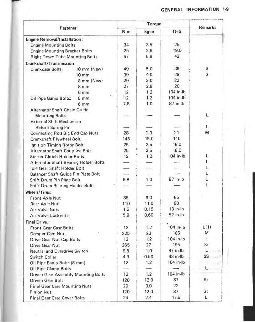
GENERAL INFORMATION 1-9
Fastener Torque
Remarks N-m kg-m ft-Ib
Engine Removal/Installation: ,
Engine Mounting Bolts 34 3.5 25
Engine Mounting Bracket Bo lts 25 2.6 19.0
Right Down Tube Mounting Bolts 57 5.8 42
Crankshaft/Transmission: Crankcase Bolts: 10 mm (New) 49 5.0 36 S
10 mm 39 4.0 29 S
8 mm (New) 29 3.0 22
8mm 27 2.8 20
6mm 12 1.2 104 in-Ib
Oil Pipe Banjo Bolts: 8mm 12 1.2 104 in-Ib
6mm 7.8 1.0 87 in-Ib
Alternator Shaft Chain Guide Mou nting Bolts - - - L
External Shift Mechanism Return Spring Pin - - - L
Connect ing Rod Big End Cap Nuts 28 2.9 21 M
Crankshaft Flywheel Bolt 145 15.0 110
Ignition Timing Rotor Bolt 25 2.5 18.0
Alternator Shaft Coupling Bolt 25 2.5 18.0
Starter Clutch Holder Bolts 12 1.2 104 in-Ib L
Alternator Shaft Bearing Holder Bolts - - - L
Idle Gear Shaft Holder Bolt - - - L
Balancer Shaft Guide Pin Plate Bolt - - - L
Shift Drum Pin Plate Bolt 9.8 1.0 87 in-Ib L
Shift Drum Bearing Holder Bolts - I - - L
Wheels/Tires: I Front Axle Nut 88 9.0 65
Rear Axle Nut 110 11 .0 80
Air Valve Nuts 1.5 0.15 13 in-Ib
Air Valve Locknuts 5.9 0.60 52 in-Ib
Final Drive: • Front Gear Case Bolts 12 1.2 104 in- Ib L( 1)
Damper Cam Nut 225 23 165 M
Drive Gear Nut Cap Bolts 12 1.2 104 in-Ib L
Drive Gear Nut 265 27 195 St
Neutra l and Overdrive Sw itch 9.8 1.0 87 in-Ib L " Switch Collar 4.9 0.50 43 in-Ib SS
Oi l Pipe Banjo Bo lts (8 mm l 12 1.2 104 in-Ib
Oi l Pipe Clamp Bo lts - - - L
Driven Gear A ssembly Mounting Bo lts 12 1.2 104 in-Ib
Driven Gear Bo It 120 12.0 87 St
Final Gear Case Mounting Nuts 29 3.0 22
Pinion Nut 120 12.0 87 St
Final Gear Case Cover 80lts 24 2.4 17.5 L

1-10 GENERAL INFORMATION
Fastener N-m
Final Gear Case Studs -(For reference)
Pinion Bearing Retainer 540 Reta iner Stop Screw 16
Brakes: Brake Lever Pivot Nut 5.9 Front Master Cylinder Clamp Bolts 11 Brake Hose Banjo Bolts 25 Caliper Mounting Bolts 32 Bleed Valves 7.B Disc Mounting Bolts 23 Rear Master Cylinder Mounting Bolts 23 Rear Caliper Holder Bolt 98
Suspension: Front Fork Clamp Bolts 20 Front Axle Clamp Nut 14 Front Fork Drain Screws -Front Fork Bottom Allen Bolts 20 Swing Arm Pivot Shaft Retainer Bolts 11 Swing Arm Pivot Shaft Adjuster 18 Adjuster Locknut 53 Rear Shock Absorber Mounting
Bolt and Nuts 30 Rear Shock Absorber Air Hose Fittings 12
Steering: Handlebar Clamp Bolts 27 Handle Grip Bar Mounting Allen Bolts 44 Weight Mounting Screws -Steering Stem Nut 42 Steering Stem Locknut 11
Frame: Trunk Guide Mounting Screws -Right Down Tube Mounting Bolts 57 Rear Frame Mounting Bolts 57
Electrical System: Alternator Mounting Bolts -Alternator Coupling Bolt 9 .8 Starter Relay Terminal Nuts 4.9 Spark Plugs 14 Ign ition Timing Rotor Bolt 25
Torque
kg-m
-
55 1.6
0.60 1. 1 2.5 3.3
0.80 2.3 2.3 10.0
2.0 1.4 -2.0 1. 1 1.8 5.4
3.1 1.2
2.8 4.5
-4.3 1. 1
-
5.8 5.B
-1.0
0.50 1.4 2.5
Tt-Ib
-
400 11.5
52 in-Ib 95 in-Ib
18.0 24
69 in-Ib 16.5 16.5 72
14.5 10.0 -14.5
95 in-Ib 13.0 39
22 104 in-Ib
20 33 -31
95 in-Ib
-
42 42
-87 in-Ib 43 in-Ib
10.0 18.0
Remarks
L
L L
L
L
L
The and " All 0

GENERAL INFORMATION 1-11
The table below, relating tightening torque to thread diameter, lists the basic' torque for the bolts and nuts. Use this table for only the bolts and nuts which do not require a specific torque value. All of the values are for use with dry solvent-cleaned threads.
General Fasteners:
Torque
Threads dia. Imml N-m kg-m ft-Ib
5 3.4 - 4.9 0.35 - 0.50 30 - 43 in-Ib
6 '5.9 - 7.8 0.60 - 0.80 52 - 69 in-Ib
8 14 - 19 1.4 - 1.9 10.0 - 13.5
10 25 - 34 2.6 - 3.5 19.0 - 25
12 44 -61 4.5 - 6.2 33 -45
14 73 -98 7.4 - 10.0 54 -72
16 115 - 155 11.5 - 16.0 83 - 115
18 165 - 225 17.0 - 23 125 - 165
20 225 - 325 23 -33 165 - 240
. -.. ( I
,.' ,

1·12 GENERAL INFORMATION
Cable, Wire, and Hose Routing
Control Cables
Viewed from Top
Viewed from Front
1. Right Han dlebar Switch Leads 2. F rant Brake Hose 3. Throttle Cables 4. Clutch Fluid Hose 5. Left Handlebar Switch Leads 6. Choke Cable 7. Connecting Pipe 8. Strap (holding (ro n I fork air hose
and right handlebar switch leads) 9. Strap (holding fu se case leads and
left haodletw switch leads) 10 . Ignition Coil (#1 & 4)

Electrical Wires
Viewed from Left
Vi twed from F ront
o
GENERAL INFORMATION 1-13
' I 5"
"J '" j~
1. Main Harness 2. Connectors 3. Surge Tank 4. Side Stand ~ . Rear Frame 6. Wiring Holder 7. FuelTank 8. Harness Position Mark 9. Clamps (both left and ' .
10. Strap (both If ' right Sides) e t and right sides)
1
11 . Connecting P' 12. Left H 'pe 13 p .ndlebar Switch Leads
. assenger Switch Leads 14. Passenger Switches 15. Travel Trunk 16. Antenna Lead
1-14 GENERAL INFORMATION
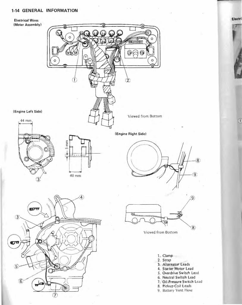
Electrical Wires IMeter Assembly)
I Engine Left Side)
144 mm
40mm
Ellctri
Viewed from Bottom
IEngine Right Side)
Viewed from Bottom
1. Clamp 2. Strap 1. Allernator Lead, 4. SUrter Motor Lead j. Overdrive Switch lead 6. Neutral Switch Lead 7. Oil Pressure Switch Lead 8. Pickup Coil l eads 9. B<tttery Vent Hose

GENERAL INFORMATION 1-15
Electrical Wires
I. R.ld iator Fan Switch Lead 5. Saddlebag 2. Ground Lead 6. Rear Fender Rear 3. Travel Trunk 7. Tail / Brake Ligh! Leads 4. Trunk Room Light Leads 8. License Light Leads
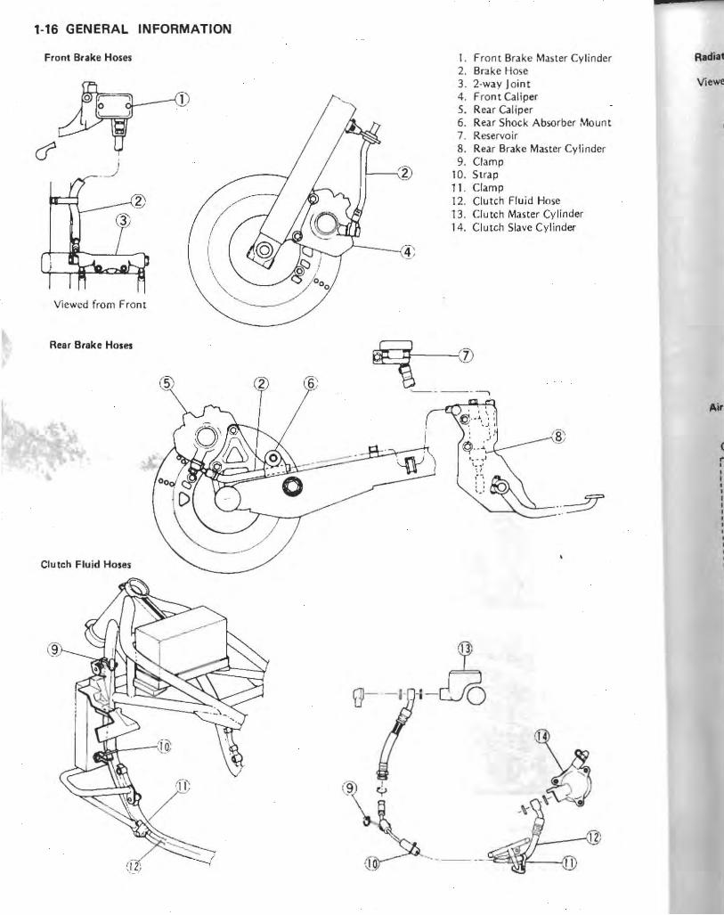
1-16 GENERAL INFORMATION
Front Brake Hoses I. Front Brake Master Cylinder 2 . Brake Hose 3. 2·way Joint 4 . Front Caliper 5. Rear Caliper 6. Rear Shock Absorber l<1ount 7. Reservo ir 8. Rear Brake Master Cylinder 9. Clamp
10. Strap 11 . Clamp 12. Clutch Fluid Hose 13. Clutch Master Cylinder 14. Clutch Slave Cylinder
Viewed from Front
Rear Brake Hoses
Clutch Fluid Hose,
9
(J--' H23 (9 I
'T'
~~ t---@
?---.-~W--:1
Radilt,
Air
(
" , , , • • , ,
• • ,

GENERAL INFORMATION 1·17
Radiator Hmes
Viewed from Top
'f Front
,," : 'H D' 45 _ 50°
Front
(3'" = , Viewed from To p
-0-/~ Viewed from Fro nt
Air Hoses and Vacuum Hoses (US Model)
California Model r-- ----- -- - - - -- --- -------~ ,
Viewed from Top
<Lt 1~) l. Clam p 2. Thermostat Housing 3. Bypass Hose 4. To water pu mp 5. Radiator 6. Clamp 7. Reservoir Tank 8. Reservoir Tank Hose 9. Radiator Cap
10. To canister II. ,.\ ir Cleaner Housing 12. Air Suction Valve Cover 13 . Si lenc.er 14. Vacuum Swi tch Valw
Viewed from Right 15. Tu carburetors

1-18 GENERAL INFORMATION
Fuel Hoses Viewed from F ron t Bruth,
(I"'
Viewed from Left 6' -'
C§:;,--~.~rJ\
(fQ; <> Cali
( ,
/~.' +-t-t (QY/"--t- .'
V,
Vacuum Hoses and Breather Hoses (US Model) ' '. l. Fuel Tank 2. Rear Brake Light Switch Leads 3. Fuel Pump Leads 4. Fuel Pump 5. Fuel Filter 6. Drain Hose
0 7. Frame Tube 8. From Fuel Tank 9. Inlet Filling
10. To carburetors Il. Swing Arm 12. Frame Tube 13. Choke Cable 14. To Vacuum Switch Valve 15. Cyl inder Head Cover 16. Carburetors
Viewed from Left 17. Surge Tank , IS. To Vacuum Valve '19. To Liquid jVagpr Separator '20. To Canister
'California Model
Viewed from Top

Breather Hoses (~~l
, 'i::
, , , r U
-1--- --- ~
·ii'."-"'~"'"
California Model
Viewed from Top
Vacuum Hoses and Breather Hoses (California Modell
I. 2. 3. 4. 5. 6. 7. 8. 9.
10. 11-12. 13. 14. 15.
GENERAL INFORMATION 1-19
California Model
Viewed from Front _ ";,21 'J
lijP'ff o 0
(0/
Fuel Tank Cap 16. Liqu id!Vapor Separator Check Valve 17. Hose (White) To Liquid/Vapor Separator 18. Hose (Blue, Short) Plug 19. To Vacuum Valve Surge Tank 20. To Carburetors Reservoir Tank Overflow Hose 21. Vacuum Valve Catch Tank Drain Hose Catch Tank Hase (Red) Hose (Bluc. Lon g) To Fuel Tank To Air Clcaner Hose (treen) Hose (Yellow) Canister

1·20 GENERAL INFORMATION
Rear Shock Absorber Air Hoses
-
'I. Rear Shock Absorber 2. Fuel Tank 3. Oil Separator 4. Ignition Coil (#2 & 3; 5. Air Valve 6. Battery 7 . Battery Venl Hose
--- ---
J;© , , , ,
Battery Vent Hose

p
FUEL SYSTEM 2-1
Fuel System
Table of Contents
Exploded View . .... , ..
Specifications ........ . ........ , . .. . .
Special Tools ..... . . . .
High Altitude Performance Adjustment
IUS Model) " , , , , , ' High Altitude Carburetor Adjustment . ...
Throttle Grip and Cable . .. .... . .
Throttle Gri p Play Inspection ........ .
Throt1le Cable Adjustment . . ... . .. .. .
Throt1 le Cable Lubricat ion . ... . . _ .. . .
Thrott le Cable Inspection . ..... .
Choke Cable """""" '," ' ". ,
Choke Cable Free Play Inspection , .. '"
Choke Cable Adjustment
Choke Cable Lubrication
Choke Cable Inspection
Carburetors . .. .. . , , . . ......•. . . •....
Idle Speed Inspect ion " , , . .. ... ,
Idle Speed Adjustment
Carbure tor Synchronization
2·2
2·5 2·5
2,6
2-6
2·6
2·6
2·7 2,7
2·7
2·7
2·7 2,8
2,8
2·8
2 ·8
2,8
2-8
Inspection .... ... . . ...... . •.. 2-9
Carburetor Synchronization .... . . . . .. 2·9
Fuel Level Inspection .. . .. . , .. 2 ·9
Fuel Level Adjustment .... 2·10
Fuel System Cleanl iness Inspection 2 -10
Carburetor Removal l
Insta llation Notes . . . . . . . . . . . . 2·10
Carburetor Disassemb ly !
Assembly Notes ......... , ..... .
Carburetor Separation!
Assembly Notes .. ... .... , .. ... '
Carburetor Cleaning .. ... .
2,11
2·12
2,12
Carbureto r Inspection ...... ... . ... . 2 ·13
Air Cleaner .. .. ... , ........ .. .. 2·14
Air Cleaner Element Removal . . 2·14
Air Cleaner Element Installation Notes . .. 2·14
Air Cleaner Element Cleaning . .. .. . ... 2 ,15
Air Cleaner Element Inspection 2· 15
Air Cleaner Housing Removal
Catch Tank " ", .. ,""
2,1 5
2·16
Catch Tank Draining , , , ' , . , , , ' 2,16
Fuel Pump """""", . ',.,.. 2·16
Fuel Pump Removal ..
Fuel Pump Installation Notes
2·16
2·1 6
Fuel Filter . ... 2·17
Fuel Filter Removal .. ..... . ....... 2 ·17
Fuel Fi l ter Installation Notes . ... .. ... 2-17
Fuel Filter Inspection ,. ,. 2-17
Fuel Tank and fuel Level Sensor . ...• . 2·17
Fuel Tank Removal , . , . , , . , . •. , . . , , 2·17
Fuel Tank Installation Notes , ' , • , 2·18
Fuel Level Sensor Removal /
Installation Notes .... . . . . . ...... 2-18
Fuel Tank Cleaning, , , , • , , , ' . , ' , ' , , 2-19
Fuel Tank Inspection .,,' , ", . , " " 2·19
Check Valve Inspection , . ' . ' . , , , , , , , 2·19
Evaporative Emiss ion Control System
(US Californ ia Veh icle Only) ,""""" 2,19
Parts Removal/Installation Notes . . 2·19
Hose Inspection . .. ... . ..... .. .. . .
Separator Inspection .. .. . .. , ... ... ,
Separator Operation Test
Canister Inspection . , ...
Vacuum Valve Inspection .
2·20
2·20
2·20
2-20
2-20

2-2 FUEL SYSTEM
Exploded View
v
I .
California Model
CD-f

p
1 1
1. Jet Needle 2. Pilot Screw
11. Pilot Jet 4 Needle Jet 5: Needle Jet Holder 6 Main Jet 7 : Catch Tank 8 Check Valve 9: Fuel Level Sensor
10. Fuel Filter 11. Fuel Pump
~ . .
FUEL SYSTEM 2-3
US Model
California Model I Q>
<9

2-4 FUEL SYSTEM
California Model r- - - - - - - - - - - - - - - - - - - - - - - - - - - - - - - - - - - - - - - - 1
I I I I
I
I I
Yellow
\
I @
Green
Blue
Blue I
~~ I I I I I I I. I I I I
ite
•
L _ _____________ _ __ ___ - - - - - - - - - - - - - - - - - - - - - - - - --12. filter 13. V •• uum Valve 14. Canister 15. Liquid/Vapor Separator
SplCi .......

-
- - T
r I
r
I I I I I I I I I I I I I I
I I I I I I I I
p
FUEL SYSTEM 2-5
Specifications
- Item Standard
High Altitude Performance Adjustment (US model only):
Carburetor Adjustment : Main Jet 105
Pilot Jet 35
Throttle Grip:
Throttle Grip Free Play 2-3mm
Choke Cable:
Choke Cable Free Play 2-3mm
Carburetors:
Idle Speed • 800 ±50 rlmin (rpm)
Synchronization Vacuum Less than 2.7 kPa (2 cmHg)
Standard Specifications: MakefType Keihin/CVK30
Main Jet 108
Main Air Jet 100 •
Needle Jet 6
Jet Needle N36G, California: N36H
Pilot Jet 38
Pilot Air Jet 150
Pilot Screw 2 turns out, US : --
Starter Jet 48
Service Fuel Level -0.5 ±1 mm
Float Height
Special Tools -Alorlll with common hand LOol,. the following more
specialize<fJ tools arc required for complete fuel system servic ing .
Pre .. ur. Cable luber : K56019.(J21
Fuel level Gauge: 57001·1017
17.0 mm ,,'
Vacuum Gauge: 57001·1198
- ' --:c.=..: . .
NOTE
OThe vacuum gauge & lachom~~r (PIN 57001·1291) can be ust1d instead of ,the Y/lCuum gauge (PI N 57001· 1198).

2-6 FUEL SYSTEM
High Altitude Performance Adjustment (US Modell
To improve the Emission Contfol Performance of vehicles operated above 4,000 feet (1,219 meters), Kawasaki recommends the following Environmental protection Agency (EPA) approved modification.
NOTE
CWhen properly performed, these specified adjustments are nor considered to be emission control system "tampering" and vehicle performance is generally unchanged as a result.
High Altitude Carburetor Adjustments eHigh altitude carburetor adjustments require replace
ment of certain carburetor jets.
High Altitude Carburetor Specifications
Main Jet: 105 Pilot Jet: 35
eAfter high altitude carburetor adjustments are performed, provide the customer with the Vehicle Emission Control Information Update Label and label installation instructions (PIN 99969-0614i.
-Advise the customer that by law, the Vehicle Emission Control Information Update Label must be affixed to any vehicle modified with the high altitude carburetor adjustments.
NOTE
C If a vehicle wirh rhe high a/rirude adjusrmenrs is used below 4,000 fee, (T ,219 me,ers), 'he upda,e label must be removed and rhe original carburetor pans musr be reinsralled.
Throttle Grip and Cables
Throttle Grip Play Inspection -Check throttle grip free play by lightly turning the
throttle grip back and forth. *Ir free play is not correct, adjust the throttle c(tbles.
Throttle Grip Free Play
2 -3mm
A. Throttle Grip Free Play
-With the throttle grip closed, check that [he decelerator inner cable is tight by touching it at the lower end with a thin-bladed screwdriver.
A. Decelerator Cable
*If the lhrottle grip free play is incorrect or the decelerator inner cable is loose with the throttle closed, adjust the throttle cables.
*If the free play is correct, make the following tcst: -Start the engine. _Turn the handlebar from side· to side while idling the
engine. *If idle speed varies, the ttlrottle ca ble~ may be poorly
routed or they may be damaged. _Correct any problem before operating the motorcycle.
I WARNING.
COperation with an improperly adjusted. incorrectly routed, or damaged cable could result in an unsafe riding condition.
Thro .Loo
.dju so •
• Witl deci bee
.Tur thn
A. B.

Throttle Cable Adjustment .Loosen lhe locknuts and ~crew both throttle cable adjusters in fully at the upper end of the throttle cables so as to give the thronle grip plenty of play ,
eWjth the throttle grip completely closed, turn out the decelerator cable adjuster until the inner cable just becomes light. Tighten the locknut.
.Turn the accele ra tor cable adjuster until the correct throttle grip free pla y is obtained. Tighten the locknut.
A. Accelerator Cable C. Adjusters B. Decelerator Cable D. Locknuts
NOTE
Off the throttle cables can not be adjusted by using the cable adjusters at the upper end of the throttle cables, use the cable adjusters at the lower ends of the throttle cables. Do not forget to securely tighten the locknuts after adjustment.
_Start the engine. eTurn the handll:bar from side to ~idc whik: idling the engine.
*if idle speed varies, the throttle cables may be poorly routed or they may be damaged .
-COrrect any problem before operating the motorcycle.
I WARNING.
COperation with an improperly adjusted, incorrectly routed, or damaged cable could result in an unsafe riding condition.
Throttle Cable Lubrication Whenever t he throttle cables are removed and in
accord ance with the Periodic Maintenance Chart lubricate lhe throltle cables (see Appendi x chapter). '
FUEL SYSTEM 2-7
Throttle Cable Inspection eWith the throttle cable disconnected at both ends, the
cable should move freely within the cable housing.
Throttle Cable Inspection
1. Throttle wbl.
*If cable movement is not free after lubricating (see Throllie Cable Lubrication), if the cable is frayed, or if the housing is kinked, replace the cable.
Choke Cable
Choke Cable Free Play Inspection eChec k t.hat the cl10ke le ver return s properly and that
the inner cable slides smoothly. *If there is any irregularity, ch ec k the choke cable. as
follows: eOetermine the amount of choke cable play at the
choke leve.r. Pull the choke lever until the starter plunger lever at the carburetor contacts with the st.arter plunger; the amount of choke lever travel is the amount of choke cable play.
A. Starter Plunger Lever B. Starter Plunger

2-8 FUEL SYSTEM
A. Choke Lever C. Adjuster B. Free Play D. Locknut
*If free play b not correct, adjust the choke cable.
Choke Cable Fr •• Ploy
2-3mm
Choke Cable Adjustment eLoosen the locknut at the adjuster of the choke
cable, and turn the adjuster until the cable has the proper amount of play.
_Tighten the locknut after adjustment.
Choke Cable Lubrication Whenever the choke cable is removed, and in
accordance with the Periodic Maintenance Chart, lubricate the choke cable (se() Appendix chapter).
Choke Cable Inspection .With the choke cable disconnected a t the both ends,
the cable should move freely within the cable housing.
Choke Cable Inspection
CD
1. Choke Cabl c
* 1 f cable movement is not free after lubricating, if the cable is frayed, or jf the housing is kinked, replace the cable.
Carbu retors
Idle Speed Inspection -Start th e engine and warm it up thoroughly, -With the cngine idling, turn the handlebar to both
sides. *If handlebar movement changes the idle speed; the
throttle cables may be improperly adjusted or incorrectly routed, o r they may be damaged. Be sure to correct any of these conditions before riding.
I WARNING I GOperation with improperly adjusted, incorrectly
routed, or a damaged cable could result in an unsafe riding condition.
-Check idle speed. *If the idle speed is out. of the specified range, adjust it.
Idle Speed
800 ±50 rlmin (rpml
Idle Speed Adiustment eTurn the idle adjusting screw until idle speed is correct.
A. Idle Adjusting Screw
eOpen and close· the ,throttle a few limes to make Sure that the idle speed is within the specified range. Re· adjust if neCessary.
(I
•

Carburetor Synchronization Inspection .Warm up the engine. -Check idle speed an d adjust if necessary. -Remove the air delmer housing. OAttach the vacuum gauge sct (speciallOol: P/,'l 57001-1198) to the vacuum hose fittings on the carburetors.
(Viewed from front)
A. Vacuum Hose Fitting B_ Adjusting Screw
-Install the air cleaner housing. Be sure to install the air cleaner element.
-Start the engine and let it idle to measure the engine intake vacuum.
*If the intake vacuum difference between any two cylinders exceeds the Iimit ,synchroni7.e the carburetors.
Carburetor Synchronization Vacuum
Le" than 2.7 kPa (2 cmHg) difference between any two cylinden
_Remove the vacuum gauge set, and install the removed parts ,
Carburetor Synchronization _Turn th e adjusting screws to synchroni ze the car· buretor<;,
NOTE
OFirst synchronize the left two and then the right two cylinders by means of the adiusting screw between No. T and No, 2 cylinders, and between No.3 and No.4 cylinders.
oThen synchronize the left two cylinders and the right two cylinders using the center adjusting screw.
ICheck idle speed and adjust jf neccssarr.
FUEL SYSTEM 2·9
Fuel Level Inspection
I WARNING I CGasoline is extremely flammable and can be explosive
under certain conditions. Turn the ignition switch OFF. Do not smoke. Make sure the area is well ventilated and free from any source of flame or sparks; this includes any appliance with a pilot light.
eRemove the carburetors, and hold them in upright on a stand.
-Connect <1 fucl tank to the carburetors with a suitable hose.
ePrepare a fuel hose (6 mm in diameter and about 300 mm long),
'Connect the fuel level gauge (speci,1 tool) to the carburetor float bowl with the fuel hose.
eHold the gauge vertically against the side of the carburetor body so that the "zero" line is several milli meters higher than the bottom edge of the carburetor body,
.Hold the fuel tank to feed fuel to the carburetor, then turn out the carburetor drain plug a few turns.
.Wait until the fuel level in the gauge settles. eKeeping the gauge vertical, slowly lower the gauge until
the "zero" line is even with the. bottom edge of the car· buretor body_
NOTE
ODD not lower the "zero" line below tIle bottom edge of the carburetor body. If the gauge is lowered and then raised again, the fuel level measure shows somewhat higher than the actual fuel level. If the gauge ;s lowered too far, dump the fuel out of it into suitable container and stan the procedure over again.
eRead the fuel level in the gauge and compare it to the specification. Screw in the carburetor drain plug.
eRemove th e fuel lev.el ::rauge. .Inspect the fucl I~vejin the other carburetors in the
same manner. *If any fuel level is ihcorrect, .dju~t it,
A_ Fuel Leyel Gauge : 57001-1017 B, Carburetor Body Boltom Edge
I ~

2-10 FUEL SYSTEM
Fuel level
OS ±1 mm above the bottom edge of carburetor body
Fuel Level Adjustment -Read the WARNING in the Fuel Level Inspection. eDrain the fuel out of the carburetors into a suitable container.
-Remove th e fioat bowl by taking out the screws with lockwashers.
-Sl ide out the pivot pin and re move the float. -Bend the tang on the float arm very slightly to change
the float height. Increasing the float height lowers the fuel level and decreasing the fioat height raises the fuel level.
Float Height
17.0 mm
A. Tang
eAssemble the carburetor, and recheck the fuel level. *If the fuel level cannot be adjulted by this method, the
float or the float valve is damaged.
Float Height Measurement-Keihin Carburetor
1. Float Bowl Mating Surface 2. Float Valve Needle Rod (con tacted but unloadedj 3. Float
Fuel System Cleanliness Inspection
I WARNING I cGasoline it extremely flammable and can be explosive
under certain conditions. Turn the ignition switch OFF. Do not smoke. Make sure the area is well ventilated and free from any source of flame or sparks; this includes any appliance with a pilot light.
-Connect a suitable hose to the fitting at the bottom of each carburetor float bowl.
eRun the lower ends of the hoses into a suitable container.
eTurn out each drain plug a few turns and drain the fioat bowls.
A. Drain Plug
eCheck to sec if waler or dirt comes out. -Tighten the drain plugs. *If any water or dirt appeared during the above inspec
tion, clean the fuel system (see Carb uretor Cleaning and Fuel Tank Cleaning).
Carburetor Removal/Installation Notes
I WARNING I C:Gasoline is extremely flammable and can be explosive
under certain conditions . Turn the ignition switch OFF. Do not smoke . Make sure the area is well ventilated and free from any source of flame or sparks; this includes any appliance with a pilot light.
eTa remove the carbu retors, remove the air cleaner housing,
eAfter removing the carburetors, stoff pieces of lint-free, clean clOlh inlo the carburetor holders and the intake ducts to keep dirt out of the engine and air cleaner.
OIf bl CIt
011
"
c

p
I WA.RNING.
QI' dirt' or ,dust d.nowed to pass' through into the carbur,tors. the t!vQttl, may beoome stuck. possibly cousin, on Iccidont.
01' dirt gets through into the engine, excessive engine wear and possibly engine damage will occur.
-Install the carburetor holder clamps so thal the screws are positioned downward to prevent them from contacting anything.
eAfter installing the Qrburetors, perform the following. cCheck fuel leakage from the carburetors.
I WARNING I OFuel spilled from the carburetors is hazardous.
OAdjust the following items if necessary. Idle Speed Carburetor Synchronization Throttle Cables Choke Cable
Carburetor Disassembly/Assembly Notes ORead the WAR NINGS in the Carburetor Removal !
Installation Notes . • For the US model, remove the pilot screw plug as
follows: oPunch a hole in the plug and pry it at with an awl or other suitable [001.
_Turn in the pilot screw and count the number of turn~
until it seats funy but not tightly, and thell remo\le the screw. This is to, set the screw to its original position when assembling.
eAfter insta!llng the upper chamber cover, check that the vacuum piston slides up and down smooth ly without binding in the carburetor bore.
CDuring carburetor disassembly. be careful not to damage the diaphragm. Never use a sharp edge to remove the diaphragm.
eTurn in the pilot screw fully but not tightly, and then back it oul the same number of turns counted during disassembly.
eFor the US model, install the pilot screw plug as fo llow:
Olnstall a new plug in the pilot screw hole, and appl y a sma ll amount of a bonding agent to the circum ference of the plug to fix the pltlg.
FUEL SYSTEM 2-11
COo not apply too much bonding agent to the plug or the pilot screw itself may be fixed.
Plug Installation (US model onlyl
1. Apply bonding agent . 3. Pilot Screw 2. Plug 4. Carburetor Body
_Turn the carburetor body upside-down r and drop the needle jet into place so that the smaller diameter end of the jet goes in first.
A. Small End
OCarcfully screw in the air. bleed pipe. It will seat against the needle jet, pushing the end of the jet into the carburetor bore.
GOo not force the air bleed pips or overtighten it . The needle jet or the carburetor body could be damaged requiring replacement.

2-12 FUEL SYSTEM
.S lip the needle th ro ugh the hole in the center of the vacuum pis ton, and put the spri ng seat on t he to p o f the needle. Turn [he sea t so that it does no t block the ho le a t the bo tto m of the vacuum piston _
A. Spring Seat B. Hole
Carburetor Separation/Assembly Notes .Read th e WA RNIN GS in th e Carburetor Remova l!
Installa t ion Notes, - The center li nes of the carburt! tor bores must be
paral lel both horizon tall y and ver ticall y. If they are no t , loosen the mo untin g screws and align the carbure to rs o n a fla t surface. Re tighten the mounting screws.
e Aft er assembling the choke mechanism, chec k to see tha t the choke shaft sl ides righ t to left smoo thly without abnormal fric tion.
OFuel mixture trouble could result if the starter does not seat properly in its rest position aher the choke knob it returned .
- Visually synchronize the thro ttle (butterfly) va lves. CCheck to see that all thro ttle va lves o pen and close
smoothl y without binding when turn ing the pulley . oVisua lly check the clearance between tht: th ro tt le va lve and the carburetor bore in each carbureto r.
~If there is a difference between any two carburetors, turn tht: balance adjusting screw (s) to ob ta in the same clearance.
A, Balance Adjusti ng Screw 8 , Cleara nce
NOTE
OFirst synchronize the left two and then the right two carburetors by means of the adjusting screw between No . 1 and No. 2 carburetors. and between No, 3 and No , 4 carburetors.
OThe synchronize the left two carburetors and the right two carburetors using the center adjusting screw.
Carburetor Cleaning
I WARNING I CClean the carburetors in a well ·ventilated area , and take
care that there is no spark or flame anywhere near the working area; this includes any appliance with a pilot light . Because of the dang .. of highly flammable liquids, do not use gasoline or fow flash·po int solvents to clean the carburetors.
{ CAUTlO~] 0 00 not use compressed air on an assembled carburetor,
the floats may be aushed by the pressure, and the vacuum piston diaphragms may be damaged.
ORemave as many rubber or plastiC parts from the car· buretor as possible before cleaning the carburetor with a cleaning solution. This will prevent damage or deterioration of the parts.
o The carburetor body has plastic parts that cannot be removed. 00 NOT use a strong carburetor cleaning solution which could attack these parts; instead , use a mild high ffash-point cleaning solution safe for plastic parts.
c Oo not use wire or any other hard instrument to clean carburetor parts , especially jets, as they may be damaged.
•
.[
.1 5
. 1 e\ eI .,
c
(

•
'Disassemble the carburetors. 'lmmcr~e all the metal pans in a carburetor cleaning sofution.
eRinse the: plrts in water . • When the parts are clean, dry them with compressed air. eBiow through the air and fuel passages with compressed ~r.
eAssemble the carburetors.
Carburetor Inspection
I WARNING'
OGasoline is extremely flammable and can be explosive under certain conditions. Turn the ignition switch OFF. Do not smoke. Make sure the area is weH ventilated and free from any source of flame or sparks; this includes any appliance with a pilot light.
eRemove the carburetors . 'Before disassembling the carburetors, check the fuel level.
*If the fuel I.vel is Incorrect, inspect the rest of the carburetor before correcting it.
'Move the choke shaft left and release it to check that the starter plungers move smoothly and return by spring tension.
*\f the starter plungers do not work properly, replace the carburetors.
eTurn the throttle Cdble pulley to check that the throttle valves move smoothly and return by spring tension,
*If the throttle valves do not move smoothly, replace the carburetors .
A. Throttle Valves B. Starter Plungers
-Oi sasse mble the carb uretors. IClean the carburetors. _Check that the O-rings on the carburetors and the diaphragm on the vacuum piston are in good condition.
FUEL SYSTEM 2-13
*If any of the O-rins> o r diaphragms are not in good condition, replace them.
eCheck the plastic tip of the float valve needle. It should be smo'oth, without any grooves, scratches, or tears.
Float Valve Wear
-I---{2
Push and release
1. Rod 3. Valve Needle Wear 2. Valve Needle
*1 f the plastic ti p is damaged , replace the needle. -Push i,n the rod in the other end of the float valve
needle and then replace it. *I f it does not :"pring out, replace the needle. eCheck the tapered portion of the pilot screw for wear or damage,
Pilot Screw
1. Pilot Screw 2. Tapered Portion
*1 f the pilot screw is '''forn or damaged on the tapered portion, it will prevent the engine from idling smoothly, Replace it.
-Check that til e vacuum piston moves smoothly in the carburetor body. The surface of the pislOn must not be excessively worn.
*If the vacuum piston does not move smooth1v, or if it is very loose in carburetor body, replace the carburelOr.

2-14 FUEL SYSTEM
A. Vacuum Pisto n
............................................................................ Air Cleaner ............................................................................ Air Cleaner Element Removal eRemove the dummy tank cover .
A . Dummy Tank Cover C. Retaining Knob B. Screw
e()pen the air cleaner housing upper half by taking out the housing bolts. It is not required to remove the Ie igniter.
A. IC Igniter B. Housing Bolts
.Pu ll out air cleaner element holders, and take off the element.
A. Element B. Holders
-Stuff pieces of lint-free , clean cloth into the air in take dUClS to keep din .GU[ of engine.
I WARNING I elf dirt of dust is allowed to pall through into the
carburetors, the. butterfly .alve. mlY become stuck, possibly causing In ,accident.
Clf dirt gets through into the Ingine, excessive engine wear and possibly engine damage will occur .
Air Cleaner Element Installation Notes eMeet the element sponge gas~et' with the body opening
in the air cleaner housing lowt r half.
A.
eE
A
c
• •

A, Sponge Gasket
eSe sure! to install the element holders in their place.
Air Cleaner Element Cleaning
NOTE
Oln dusty areas, the element should be cleaned more frequently than the recommended interval.
OAfter riding through rain or on muddy roads, the element should be cleaned immediately.
-Remove the air cleaner element. -Ory the element by directing a stream of compressed
air from the clean side to thl.:! dirt)' side.
A, Compresicd Air B, Clean Side (Sponge Gasket Side)
elnspect the element before installing it.
Air Cleaner Element Inspection -Visually check the element for lears of breaks , Check
the sponge gasket also. and the plastic frame.
FUEL SYSTEM 2-15
.,8
A. Element B. Gasket
*' f the clement or gasket have any tears or breaks, replace the element.
*If the clement frame is damaged or distorted, replace the clement.
*If the sponge gasket comes loose, stick it back on with an adhesi ve sealant.
Air Cleaner Housing Removal eRe move the following.
Dummy Tank Cover Battery and Tray IC Igniter
.Pull the air hose connecting the housing to the silencer off the housing,
A. Air HO:iC C. Housing Mounting Bolt B, Air Intake Duct Clamps
eLoosen the air intake duct clamp screws. eRemove the remaining housing mounting bolt. epull the air cleaner housing upward and take it off the
surge tank .

2·16 FUEL SYSTEM
............................................................................ Catch Tank
A catch tank is provided beneath the surge tank, and catches the water or oil from the bottom of the surge tank. Usually water or oil do not collect at the bottom of the surge tank. In the event that rain water is drawn in through the air cleaner, or if engine oil is blown back, drain the tank.
Catch Tank Draining -Visually check the catch tank if the water or oil
accumulates in the tank . *tf any water or oil accumulates in the tank, drain it by
taking off the drain plug at the lower end of the drain hose .
eBe sure to install the plug firmly, or the air is drawn in through it .
A. Catch Tank B. Drain Plug
Fuel Pump
Fuel Pump Removal eRemove the fuel tank for extra clearance.
A. Fuel Pump B. Pump Bracket Mounting Bolts
eTake out [he bolts and remove the fuel pump with its bracket.
_Djsconnect the pump lead connector. .Pull the fucl hoses off the fuel pump. Be prepared for
fuel spillage.
WARNING'
OGasoline is extremely flammable and can be explosive under certain conditions. Turn the ignition switch OFF. Do not smoke. Make Sure the area is well ventilated and free from any source of flame or sparks, this includes any appliance with a pilot light.
A. Fuel Pump B. Fuel Filter
Fuel Pump Installation Notes -Connect the fuel hose from the filter to the fitting
marked INLET, and the hose to tMC c.arburetors to the another fitting.
A. 8.
,

A. Fuel Hose from Filter B. Fuel Hose to Carburt:'tors
• Be sure to route the hoses so they wilt not be kinked or stretched.
Fuel Filter
Fuel Filter Removal -Remove the fuel tank for e-xtra clearance. .Pul l the filter off the hose. Be prepared fo r fuel spillage.
WARNING I cGasoline is extremely flammable and can be explosive
under certain conditions . Turn the ignition switch OFF . Do not smoke . Make sure the area is well ventilated and free from any source of flame or 5parks; this includes any appliance with a pilot light .
Fuel Filter Installation Notes -Install the fuel filt er so that the arrow on it shows the
fuel flow from the fuel tank to the fuel pump.
FUEL SYSTEM 2-17
A. Fuel Hose from Tank B. Fuel Hose to Pump
eBe sure to route the hoses so they will not be kinked or stretched .
Fuel Filter Inspection -Visually inspect the fuel filtec. *If the filter is c1e.r with no signs of dirt or other
contamination , it is OK and need nor be replaced. *If the filt .. is dark or looks dirlY, repl". it. Also,
check the res t of the fuel system for contamination.
Fuel Tank and Fuel Level Sensor
Fuel Tank Removal
I WARNING I CGasoline is extremely flammable and can be explosive
under certain conditions. Turn the ignition switch OFF. Do not smoke. Make sure the area is well ventilated and free from any source of flame or sparks; this includes any applilnce with a pilot light.
Olf gasoline, solvent, water or any other liquid enters the canister, the canister's vapor absorbing capacity is greatly reduced . If the canister does become contaminated replace it with a new one.

2·18 FUEL SYSTEM
eBefore removing the fuel tank, remove the fuel in the tank as possible using a suitable pump.
eRemove the rear shock absorbers. It is not required to remove the air hoses from the shock absorbers.
-oisconnect the fuel level sensor lead connector. eFree the overflow hose lower end from the clamp~n the
frame lower pipe . oFar California vehicles. the breather and fuel return
hoses must be disconnected from the tank fittings . • Holding the fuel tank on its position , remove the rear
frame. -Clamp the fuel hose conn ecting the fuel tank with the
filter shut using the locking pliers.
A. Clamp this hose .
• Pull the fu el hose off the filter. Be prepared for fuel spillage .
-Tilt the tank out the rear of th~ frame . eDrain the fuel tank. oArrange a suitable container under the fucl t.ank . ORemove the locking pliers from the fuel hose to flow
the remaining fuel in the tank.
Fuel Tank Installation Notes eBc sure to install the rubber dampers in place.
A. Dampers
A. Dampers
.,f the check valve at the breather hose was removed , install it so that the arrow on it shows the fuel vapor flow from the tank to the tank filler tray or e-anister.
A. Check Valve
eBe sure to route the hoses so th ey will not be kinked or stretched.
Fuel Level Sensor Removal/Installation Notes
I WARNING I CGasoline is extremely flammable and can be explosive
under certain conditions. Turn the ignition switch OFF. Do not smoke. Make sure the area is well ventilated and free from any source of flame o,r sparks; this includes any appliance with a pilot light.
eSefore removipg the fuel level sensor. check the fuel level in the fue l tank is low enough to remove the sensor. The fuel level shou ld be below the opening for the sensor mounting .
-Be sure to install the gasket in its place.

Fuel level Sensor Gasket
I. Slepped Bo h 3. Gaske t 2. Sensor Bracket 4 . Fuel Tank Bracke t
Fuel Tank Cleaning -Remove the fuel tank and drai n it. _Remove th e fuel level sen sor , .pour some high flash-poin t solvent into the fue l tank
and shake the tank to remove din and fuel deposits,
[ WARNING I CClean the tank in a well-ventilated area, and take care that there is no spark or flame anywhere near the working area. Because of the danger of highly flammable liquids, do not use gasoline or low flash-point solvents to clean the tank .
-Po ur the so lvent out of the tank , - Ory the tank with co mpressed air. -Instal/ th e f uel level sensor, Oinslalll hc f uel lan k.
Fuel Tank Inspection . Visuall y inspec t the gaskets on the sensor and ca p for
any damage , *Replace the gaskets if they are damaged. _Check to sec jf the o ri fice at th e:: bo tto m of the
brca ther hose fi tti ng is no t clogged . *I r it is clogged, blo w through the fi tting to frce the
orifi ce from clogging.
Breather Hose Fitting Orifice
/1- ' '- --'
1. Breather Hose Fitting 2 . Orifice 3. Fuel Ta nk
FUEL SYSTEM 2-19
Check Valve Inspection -Inspect the ch eck valve by blo wi ng air inro each hose
fitt ing of the valve , Air flo ws in the directio n o f the arrow on the valve, and does not fl ow in the reverse di rec tion .
*I f it docs no t , re p lace the ch eck va lve.
Check Valve
Air flows .
¢~C (~:~~J<:; Air does no t flow.
0 00 not use compressed air during the valve check, or the check valve may be damaged .
Evaporative Emission Control System (US California Vehicle only)
The Eva pora tive Em ission Control System roules fuel va pors from the fue l sys tem into t he run ning engine or stores th e vapo rs in a canister when the engine is sto p· ped. Although no ad jus tments are required , a tho rough ViS UCi!' inspec ti on must be mad e a t the interval s specified by the Periodi c Mai ntenance Char t.
Parts Removal/ Installation Notes
I WARNING I oGasoline is extremely flammable and can be explosive
under certain conditions. Turn the ignit ion switch OFF . Do not smoke . Make sure the area is well ventilated and free from any source of flame or sparks; this includes any appliance with a pilot light.
Olf gasoline, solvent, water or any other liquid enters the canister. the canister's vapor absorbing capacity is greatly reduced . If the canister does become contaminated replace it with a new one .

2·20 FUEL SYSTEM
-To prevent the gasoline from flowing into the canister or from flowing out of the canister, hold the separator perpendicular to the ground.
-Connect the host'S according to the diagram of the system. Make sure they do not get pinched or kinked.
Hose Inspection -Ch eck that the hoses (lfe securely connected. -Replace any kinked, deteriorated or damaged hoses.
Separator Inspection - Visually inspect the separator for cracks and other
damage. -If the separator has any cracks or is bad ly damaged,
replace it with a new one.
Separator Operation Test
I WARNING I c Gasoline is extremely flammable and can be explosive
under certain conditions. Do not smoke. Make sure the area is well ventilated and free from any source of flame or sparks.
-Connect the hoses to the separator, and install the separator on the motorcycle.
-Disconnect the breather hose from the se parator, and inject about 20 mL of gasoline into the separator through the ho,e fitting.
-Disconnect the fuel return hose from the fue l tank. -Run the open end of the return hose into the container
level with th~ tank top. -Start the engine, and let it idle. -If the gasoline in the separator comes o ut of the hose,
the sep arator works well. If it does not, replace. the separator with a new one.
Vacuum Valve Operation
_;J~i~:;}--:- Vacuum
Canister Inspection -Visually inspect the canister for cracks and other
damage. -If the ca nister has any crack or bad damage, replace it
with a new one.
NOTE
OThe canister is designed to work well through the motorcycle's life without any maintenance if it is used under normal conditions.
Vacuum Valve Inspection -Ch eck the vacuum valve by blowing air into the hose
fitting of the valve. oll'h en applying vacuum (2 cmHg) to the vacuum
sensing fitting, th~ valve is opened and air flows from the filter fitting to the carburetor float cha mber fitting, a.nd vice \'ersa.
c Whcn stopping to apply vacuum. the valve is clost:!d and air does not flow.
*If the vacuum va lve does not operate as described. replace the va lve.
COo not use compressed air during the valve check, or the vacuum valve may be damaged .
NOTE
0 The vacuum valve is opened to apply atmospheric pressure to the carburetor floBt chambers when the engine is running, and closed to store the vapors from the float chambers in the can;srer when the engine is stopped.
~~~r;;;;~ No vacuum
Air does not flow. I • I
Valve c losed

• COOLING SYSTEM 3-1
Cooling System
Table of Contents
Exploded View. . . . . . . . . . . . . . . . . . . . . . . . . . . . . . . . . . . . . . . . . . . . 3-2
Specifications. . . . . . . . . . . . . . . . . . . . . . . . . . . . . . . . . . . . . . . . . . . . . 3-3
Coolant Flow Chart .................... _ . . . . . • . . . . . . . . . . . . . 3-3
Coolant ........................ _ . . . . . . . . . . . . . . . . . . . . . . . . 3-4
Coolant Level Inspection ........ . ..... . ....... _ . . . . . . . . . 3-4
Coolant Inspection. . . . . . . . . .• . . . . . . . . . . . . . . . . . . • . . . . . . . 3-4
Coolant Change ................ . •....... . .•.... __ . . • . . 3-4
Cooling System Air Bleeding . .................... . •.. . ... 3-5
Mechanical Seal Inspection (Visual Leak Inspection) . . . . • . . . .. . 3-6
Cooling System Pressure Test. . . . . . . . . . . . . . . . . . . . . . . . . . . . . 3-6
Cooling System Flushing ......... . ... . ...... . .... .. ..... 3-6
Radiator Cap ................. , . .... . •... , . ........ . ...... 3-7
Radiator Cap Inspection ..... , .......... , . . . . . . . . . . . . . . . . 3-7
Radiator, Fan, and Fan Switch .......... . ......... . .... . ... , , . 3-7
Radiator Removal Notes .......................... • ..... 3-7
Radiator Installation Notes ....••....•... . .....•...•... . . 3-8
Radiator Inspection. . . . . . . . . . . • . . . . • . . . . . . . . . . . . . • . . . . . 3-B
Radiator Cleaning. . . . . . . • . . . . . . . . . . . . . . . . . . . . . . . . . . . . . . 3-8
Water Pump. . . . . . . . . . . . . . . .. . . . . • . . . .. . . . . . . . . . . . . . . . . . . . 3-8
Water Pump Removal. . . . . . . . . . . . . . . . . . . . . . . . . . • . . . . . . . . 3-8
Water Pump I nstallation Notes. . . . . . . . . . . . . . . . . . . . . . . . . . . . 3-9
Pump I mpeller Inspection ........... .. .................. 3·9
Thermostat and Temperature Sensor . . . . . . . . . . . . . . . . . . . . . . . . . . . 3-9
Thermostat Removal Note ................... , . . . . . . . . . . . 3-9
Thermostat I nstallation Notes ............ _ . . . . . . . . . . . . . . . 3-9
Thermostat Inspection. . . . . . . . . . . . . . . . . . . . . . . . . . . . . . . . . . 3-10
Hoses and Pipes ... . .. . .... . .... . .... . .. . ... . .... . .. . .. . , .. 3-10
Hose and Pipe Removal Note ...... , . . . . . . . . . . . . . . . . . . . . . . 3-10
Hose and Pipe Installation Notes ......... .. .......... , . . .. 3-10
Hose Inspection ..... .. ......... _ .......... . ..... . , .. , . 3·12

3·2 ........ COOLING ........................... .. SYST
EM .. .... . . ... .......
'E"x"p"loded View ............ .... .. . .......... ........ . .. ................ .. .. ... ... .. ..... .. .. .. ..... .. ... .. ..... ......
Switch 1. Radiator Fan
2 Radiator Fan e Sensor . Temperatur 3 Water
. . . Sealant . b) SS · SoI,eone 69 on.1 . (080 kg·m,
Tl : 7 .8 N.." . 11.0 ft.lb) T2: 15 N-m (1.5 kg·m,

SplI!;ifications
Item
Coolant: Type (recommended)
Mixed Ratio (Provided coolant when shipping) Freezing Point (Provided coolant when shipping) Total Amount
Radiator Cap: Relief Pressure
Thermostat: Valve Opening Temperature
Valve Full Opening Lift
Coolant Flow Chart
COOLING SYSTEM 3·3
Standard
Permanent type of antifreeze (soft water and ethylene glycol plus corrosion and rust inhib· itor chemicals for aluminum engines and radiators) Soft water 57%, coolant 43%
- 30°C (- 22°F) 3.8 L
73.5 - 103 kPa (0.75 - 1.05 kg/cm 2
, 11 - 15 psi)
80 - 84° C (176 -183°F)
More than 8 mm @95°C (2030 F)
Thermostat Operation (Cold Engine) ~@
~ .~~ Cold Coolant
Hot Coolant
~ ® (fa) ~ ~ ~~W' ~-,~~-~:j-
___, .......... / ltI. ...
~ @~t c
~ ,~ m '- "
(Hot Engine)
:f'O) '-
1. ihdia'lor Cap 2. To Reservoir Tank 3. Radiator 4. W.ter P"mp 5. To, Cylinde< lacket 6. From Cylinder Head (cold Engine) 7. From Cylinder Head (Hot Engine) 8. Thermostat 9. To Bypass PalS.ge
10. To Radiator

3-4 COOLING SYSTEM
Coolant
Coolant Level Inspection -Set the motorcycle up on its center stand. -Rt'move the rese rvoi r tan k cover. ec:heck the coolant level in the reservoir tank. The
coolant level should be between the " F" and rhe "L" marks.
NOTE
cCheck (he level when the engine is cold (room or ambient temperature),
ODD not check the level by removing the radiator cap. If the cap is removed, air may get into the coo/ant, and lower cooling efficiency.
A. "F" Mark C. Tank Cap B. " L " Mark
*If the coolant level is low, add coolant thro ugh th~ filler opening to the "F" mark.
OFor refilling, add the specified mixture of coolant and soh water . Adding water alone dilutes the cooJant and degrades its anticorrosion properties. The diluted coolant can attack the aluminum engine parts. In an emergency I soft water can be added. But the diluted coolant must be returned to the correct mixture ratio within a few days.
0 1f coolant must be added often, or the reservoir tank has run completely dry; there is probably leakage in the cooling system, Check the system for leaks.
Coolant Inspection -Visually in spect the coolant in the reservoi r tank. *If whitish coLlon-like wafts arc observed, a.luminum
parts in the cool ing system are corroded. If the coolant is brown, iron or steel pans are rus ting, In either case, flush the cooling system .
*If the coolant gives off an abnormal smell when changing , check for a cooling sl'stem leak. It may be caused by exhaust gas leakiog ioto the cooling system .
NOTE
cBe sure to inspect the coolant at the reservo ir tank. If the coolant is checked by removing the radiator cap. the air must be bleed from the COOling system.
'Coolan t Change
CUte coolant containing corrosion inhibitors made specifically for aluminum engines and radiators in accordance with the instructions of the manufactures,
WARNING I a To avoid burns, do not remove the radiator cap or try
to change the coolant when the engine is still hot. Wait until it cools down.
c Coolant on tires will make them slippery and can cause an accident and injury . Immediataly wipe up or wash away any coolant that spills on the frame. engine, or other painted parts.
GSince coolant is harmful to the human body. do not use for drinking.
- Set the motorq'c!c up on its center stand. -Remove the dummy tank cover. eRemove the radiator cap in two steps. Firs t turn the
cap counterclockwise to the first stop and wait t here for J few seconds. Then push down and remove the cap.
A. Radiator Cap

-Place a container under the drain plug at the boltom of the coolant pipe .
eDrain the coolant from the radiator and engine by removing the drain plug.
A. Coolan t Pi pe 8. Drain Plug
-Remove the reservoir tank cover. -Unscrew the bolt and remove the reservoir tank with hoses attached .
-Unscrew the cap and pour the coolant into a container .
A. Bolt B. Reservoir Tank
-Inspect the coolant de teriora tion . -I nstall the drain plug. Always replace the gasket with
new one , if it is damaged. - Fill the radiator up to the top of th e filler neck with coolant.
NOTE
OPour in the coolant slowly so that it can expel the air from the engine and radiator.
c The radiator cap must be installed in two steps. First turn the cap clockwise to the first stOp. Then push down on it and the rest of the way.
COOLING SYSTEM 3-5
Radiator Filler Neck
1. Radiator Filler Neck 2. Coolant Level
eFill the reservoir tank up to the "F" mark wilh coolant, and install the cap .
-Bl eed the air from the system.
[CAUTION I USoft or distilled weter must be used with the antifreeze
(see below for antifreeze) in the cooling system. Olf hard water is used in the syuem, it causes scales
accumulation in the water passages, and considerably reduces the efficiency of the cooling system.
NOTE
CChoose a suitable mixture ratio by referring to the coolant manufacturer's directions.
Original Coolant
Type
Color Mixed Ratio Freezing Point Total Amount
Permanent type antifreeze for aluminum engina and radiator green soft wate, 57%, coolant 43% -looe (_22°F)
3.8 L (up to "F" mark)
Cooling System Air Bleeding -Loosen the air bleeder bolt on the top of the water
pump cover, and the coolant begins to flow ou t the air bleeder bolt hole (that is , when alilhe remain ing air has been forced out).

3-6 COOLING SYSTEM
A. Air Bleeder Bolt B. IVater Pump Cover
-Tighten the air bleeder bolt. - Fill the radiator up to the radiator filler neck with
coolant. -Check the cooling system for leaks. -In sta ll the radiator cap turning it clockwise about Vo,
turn . _Start the engine, warm it up thoroughly, and then stop
it. -Check the coolant level in the reservoir tank after the
engine cools down. *If th e coolant level is low, add coolant up to the "F"
mark through the reservoir tank opening.
Mechanical Seal Inspection (Visual Leak Inspection) Any time th e sys tem slowly loses water. inspect for
leaks. -Check the water pump body drainage outlet passage for
coolant lea ks . *If the mechanical seal is damaged, the coolant leaks
through the seal and drains through the passage . Replace the water pump unit.
*If there are no apparent leaks, pressure test the system .
A. Drainage Outlet Passage :at the bottom of the pump body
Cooling System Pressure Test
CDuring pressure testing, do not exceed the pressure for which the system is designed. The maximum pressure is 103 kP. (1.05 kglem', 15 psi) .
• Remove the radiator cap, and in5tall a cooling system pressure tester on the radiator filler neck .
• Wet the cap sealing surfaces with water or coolant to prevent pressure leaks .
eBuild up pressure in the system carefully until the pressure reaches 103 kPa (1.05 kg/em', 15 psi).
-Watch the gauge for at least 6 seconds. *If the pressure holds steady, the system is all right.
A. Pressure Tester B. Adapter
eRemove the pressure tester, replenish the. coolant, and install the radiator cap.
_If the pressure drops and no external so urce is found, check for internal leaks. Droplets in the engine oil indicate internal lea kage. Check the cylinder head gasket and the cylinder liner O-ring leak .
Cooling System Flushing Over a period of time, the !;ooling system accumu
lates rust, scale , and lime in the water jacket and radiator. When this accumulation is suspected or observed, flush the cooling system. If this accumutation is not removed, it will clog up th~ waler passage and considerably reduce the efficiency of the cooling system . -Drain th e cooling ~ystem.
eFill the cooling system with fresh water mixed with a flu shing compound .

OAvotd the use of a flushing compound which harmful to the aluminum engine and radiator. Carefully follow the instructions supplied by the manufacturer of the cIeoning product.
-Warm up the engine, and run it at normal operating temperature for about ten minutes.
estop the engine, and drain the cooling system. -Fill the system with fresh water. -Warm up the engine and drain the system. eR.epeat the previous two steps once more. -FiU the system with a permanent type coolant·, and
bleed the air from the system.
Radiator Cap
Radiator Cap Inspection ec:heck the condition of the valve spring, and the top and bottom valve seals of the radiator cap.
ICheck the condition of the top and bottom sealing seats in the filler neck. They must be smooth and clean for the radiator cap to function properly ,
*If anyone of them shows visible damage, replace the cap or cap assembly.
A. Valve Spring C. Sealing Seats B. Seals
.Wet the cap sealing surfaces with water Of <:oo1ant to prevent pressure leaks,
.'nstall the cap on a cooling system pressure tester,
.Watching the pressure gauge, pump the ,pressure tester to build up the pressure. The cap. must retain the pressure at least 6 seconds. Alw the cap must open at the specjfied relief pressure.
Radiator Cap Relief Pressure
73.5 -103kPa (0.75 - 1.05 kglem' , 11 - 1S psi)
*If the cap C4nnot hold the specified pressure, or if it holds too much pressure, replace it with a new one.
COOLING SYSTEM 3·7
Radiator Cap TIHt
1. Pressure Tester 2. Radiator Cap
Radiator, Fan, and Fan Switch
Radiator Removal Notes
I WARNING.
CThe radiator fan and fan switch are connected directly to the battery. The radiator fan may start even if the ignition switch is off. NEVER TOUCH THE RADIATOR FAN UNTIL THE ENGINE COMPLETELY COOLS OFF. TOUCHING THE FAN BEFORE THE ENGINE COOLS COULD CAUSE INJURY FROM THE FAN BLADES .
• Wait until the coolant cools down , and then drain the coolant (see Coolant Change) .
• Do not touch the radiator core directly, or the radiator fins are deformed.
Radiator Installation Notes .,f the radiator fan was removed, install it onto the
radiator . Be sure to ground the lead by tightening it with the fan mountin, bolt.
A. Ground Lead B. Radiator Fan

3·8 COOLING SYSTEM
elf the radiator fan switch was removed, tighten it to the specified torque (see Exploded View) . Be sure to instJlIlhe O-ring onto the switch.
A. Radiator Fan Switch
-Fill th e cooling s)'stem with the coolant and bleed the air from the system .
Radiator Inspection e<::heck the radiator core . *Jf there are obstructions to air flow, remove them, *If the corrugated fins arc deformed, carefully straighten
them with the blade of a thin screw driver.
A. Thin Screwd river
.,r the air passages of the radiator core are blocked more than 20% by unremovable obstructions or irreparabl y deformed fins, replace the radiator with a new one.
Radiator Cleaning When cleaning the radiator with a steam cleaner, be
careful of the following to prevents radiator damage. -Keep Ihe steam gun J.wa~' more than 0.5 m from lhe
radiator core .
®-1-----r-
A. Steam Gun B. More than 0.5 m
-Run the gun horizontally following the core fin direction holding it perpendicular to the core surface.
Water Pump
Water Pump Removal eWail until the coolant cools down, and then drain the
coolant (see Coolant Change) . eRemove the following .
Shift Pedal Linkage Front Gt!ar Ca~e Cover Clutch Slave Cylinder Radiator 1\1ufncrs and Exhaus;t Pipe')
eRemove the water pipe holding bolts and pull the pipes off the pump .
•
•

.awas
A. Pipe Holding Bolts B. Pump Mounting Bolts
'Pull the pump out of the crankcase.
W,ter Pump Installation Notes IWhen installing the water pump, note the position of
the oil pump shaft projection and turn the water pump s~aft so that the projection fits into the slot.
A. Oil Pump Shaft Projection B. Water Pump Shaft Slot
IBe sure to inslall the O-ring on each water pip~ fitting.
A. O-ring
COOLING SYSTEM 3-9
-Fill the cooling system with the coolant and bleed the air from the system.
Pump Impeller Inspection -Visually check the impeller. *If the surface is corroded, or if the blades are damaged,
replace the water pump unit .
A. Impeller
, •
•
Thermostat and Temperature Sensor
Thermostat Removal Note .Wait until the coolant cools down, and then drain the
coolant (see C.oolant Change).
Thermostat Installation Notes .Slow the air bleeder hole in the thermostat housing
with compressed air.
A. Air Bleeder Hole B. Air Bleeder Valve

3-10 COOLING SYSTEM
elnstall the thermostat in its housing so that the air bleeder valve is on lOp.
elf the coolanr temperature sensor was removed, apply a silicone sealant to the threads, and tighten it to the specified torque (see Exploded View) .
A. Temperature Sensor
-Fill the cooling system with the coolant and bleed the air from the system.
Thermostat Inspection -Remove the thermostat, and inspect the thermostat
valve at room temperature, *If the valve is open, replace the valve with a new one, eTa check valve opening temperature, suspend the
thermostat and an accurate thermometer in a container of water .
• Place the container dYer a source of heat and gradually raise the temperature of the water while stirring the water gently .
Valve Opening Temperature Measurement
Thermometer ----J
Thermostat ' : must be completely submerged
/ They must not touch the container sides or bottom.
-Watch the valve. As soon as the valve starls to open, note the temperature.
*If it is out of the speCified range, replace the ther mostat.
Thermortat Valve Opening Temperature
80 - 84'C (176 - '83'F)
e(ontinue heating until the water temperature is 95°C (203'F), and hold the water at the temperature for five minutes.
-Then measure the bypass valve height. The difference between the two bypass valve heights, measured at room temperature and at 9S'C (203'F), is the full valve lift.
*Ir it is less than the standard range, replace the thermostat.
Valve Lift Measurement
Bypass Valve Height
>!<The bypass valve height difference is the valve lift.
Thermostat Valve Full Opening Lift
Mor. than 8 mm @9S'C 1203'F)
Hoses and Pipes
Hose and Pipe Removal Note -Wait until the coolant cools down, and then drain the
coolant (see Coolant Change) .
Hose and Pipe Installation Notes -Be sure to install the O-ring on tach pipe fitting which
is mounted onto the ty'llnder, cylinder head , thermostat housins , or water pump_

O-ring on Pipe Fitting
1. G-ring 2. Raised Rib on Pipe
-Install the hoses and pipes being careful to follow bending direction or installat ion marks. Avoid sharp bending, kinking, flattening , or twisting,
Iistallation Marks on Hoses and Pipes
COOLING SYSTEM 3-11
-lnsta.11 the clamps as near as possible to the hose e nd to clear the raised rib on the fitting, This will prevent the hoses from working loose.
oThe clamp screws should be posi ti o ned correctly to prevent the clamps from contacting anything.
Hose and Clamp Installation
1. Fitting 4. Hose Clamp 2. Rai sed Rib 5. Hose 3. Hose End
li\i-t --@ g
1. Line Mark 2. Arrow Mark 3. Paint ,\lark (White) 4. Pa int Mark (Yellow)

3-12 COOLING SYSTEM
-Fill the cooling system with the coolant and bleed the air from the system.
Hose Inspection -Visually inSp!!Cl the hoses for signs of deterioration.
Squeeze the hoses. A hose should be not hard and brittle, nor should not be soft or swollen.
-Replace any damaged hoses.

ENGINE TOP END 4-1
Engine Top End
Table of Contents
Exploded View
5pe(ifications .. . . , ... . . ...• , .. , • •..
Si>t<:ial Tools . ... ........... .. .. • ••.
Cltan Air System (US model)
Air Suction Valve
Installation Note . .. . . . .. ..•••.
Air Suct ion Valve Inspection ... .•...
Vacuum Switch Valve Test ... . .. . • . .
Cylinder Head Covers . ....
Cylinder Head Cover
Removal Notes . .... .. ... . .. •. .
Cylinder Head Cover
Installation Notes
Camshaft Chain Tens ioner
Camshaft Chain Tensioner
Removal Notes .
Camshaft Chain Tensioner
Installation Notes
Replacement Cha in
Tensioner Installat ion Notes .... . . .
Camshafts and Sprockets
Camshaft Removal Notes ....... .
Camshaft Installation Notes
4·2
44
4·6
4·7
4·7
4·7
4-7
4 ·8
4·8
4·8
4·9
4·9
4·9
4·9
4·10
4·10
(Including Chain Timing Procedure) . . 4-10
Camshaft Sprocket Installa tion Notes. . . 4-12
Cam Height Measurement .. ..... . .. .
Camshah Runo ut ........ .. _ .
Camshaft Bearing Oil Clearance
Inspection ............. .
Camshah Chain and Guides .... _ .. .
Camshaft Chain Removal Note .... ".
Camshaft Chain Guide
Removal No tes . _ ...... . .. .... .
4·12
4·12
4·12
4·13
4 ·13
4·13
Camshaft Chain Wear ,........ . . . 4 -13
Camshaft Chain Guide Wear . . . . . . 4-13
Hydraulic Lash Adjuster (HLA) ... . .. .... , 4·13
H LA Removal Notes 4·13
HLA Installation Notes. . . . • . •• . . .. 4-14
H LA Air Bleeding . ... ... . .. . . . . 4·14
HLA Leak-down Measurement . , 4-14
HLA Troubleshooting Guide. . . . . . . .. 4·16
Cylinder Head .. . .. ... , . .. , ...... , ..
Cylinder Head Removal Note .. ".,.,
Cylinder Head Installation Notes ..... .
Cylinder Compression Measurement
Cylinder Head Warp ........ ....•.
Cylinder Head Cleaning
Carburetor Holders ... . . . ........... . .
Carburetor Holder Installation Notes ,_,
Valves .. " . . . . , ...... . " ........ .
4·18
4-18
4·18
4·18
4-19
4-20
4-20
4·20
4 ·20
Valve Mechanism Removal Notes .. , . .. 4 -20
Valve Mechanism Installation Notes ... .
Valve Head Thickness
Valve Stem Bend ., _ . , . , . ..... ,
Valve/ Valve Guide Clearance
4·20
4·21
4·2 1
Measurement (Wobble Method) . . . .. 4·21
Valve Seat Inspection ........ ..... 4 ·22
Valve Seat Repair ... , . ..... • ... .
Cylinders and Pistons . ...... , ..... , .. .
4·22
4 ·25
Piston Removal Notes .. .. , . . .. ... , 4-25
Piston Installat ion Notes ...... . .... 4 -26
Cylinder Installation Notes .... • .. .. '
Cylinder Inside Diamete( . . . ' . • . _ . .
Piston Diameter ..... , .. , ...... ' .
4 ·27
4·27
4·28
Piston /Cyli nder Clearance ., .. • ... ,. 4·28
Cylinder Bor ing and Honing ... .. .. , . 4·28
Piston / Cylinder Seizure ...... •.. , ..
Piston Cleaning .. , ... . .. .
Piston Ring and Ring Groove Wear ...
Piston Ring End Gap . ..
Exhaust Pipes and Mufflers , . .... ' , ..... .
Muffler Removal Notes ...... . . . . . .
Exhaust Pipe and Muffler
Installat ion Notes .. , .. .. .
4 ·28
4·29
4·29
4·29
4·30
4·30
4·30
.. I

4-2 ENGINE TOP END
Exploded View
Canada Model 1- - - -.,
Ii: I '" I I )/"W] I I~I L __ _
/- 0 0 ,0.-~ .l'~.,o . _ ~v
1 . Vacuum Switch Valve
L : Non-permanent Locking Agent
M : Molybdenum Di5ulfide Grease S : Follow the specified tightening sequence .
SS: Silicone Sealant St : Stake the fastener.
T1 : 9.8 N-m (1.0 kg-m. 87 in-Ib' T2: 12 N-m (12 kg-m. 104 in-Ib' T3: 15 N·m (1.5 kg-m. ll.o ft-Ib' T4 : 25 N-m (2.5 kg-m. 18.0 It-Ib' T5 : 48 N-m (4.9 kg·m. 35 ft-Ib) T6: 51 N-m (52 kg-m. 38 ft~b)
St
~'I ~ i

~) ~
{ . , ; U '~! \ ,f, /
I
/ /
r /
END 4-3 ENGINE TOP

4-4 ENGINE TOP END
Specifications
Item Standard Service Limit
Clean Air System (US model only):
Vacuum Switch Valves Switch Pressure:
Open .... Close 57 - 65 kPa ---(430 - 490 mmHg)
Camshafts:
Cam Height 37.021 - 37.163 mm 36.92 mm
Camshaft Runout 0.03 mm TIR 0.1 mm TlR
Camshaft Bearing Oil Clearance :
Journal A 0.030 - 0.072 mm 0.16 mm
Journal B 0.070 - 0.112 mm 0.20mm
Camshaft Journal Diameter:
Journal A 24.949 - 24.970 mm 24.92 mm
Journal B 24.909 - 24.930 mm 24.88 mm
Camshaft Bearing I nside Diameter 25.000 - 25.021 mm 25.08 mm
Camshaft Chain:
Camshaft Chain 20·link Length 158.8 - 159.0 mm 161 .2mm
Hydraulic Lash Adjuster (HLA):
Hydraulic Lash Adjuster Leak Down Distance 0- 0.2 mm 0.2mm
Cylinder Head:
Cylinder Compression (usable range)
960 kPa - 1,470 kPa ---(9.8 - 15.0 kg/em' ,
139 - 213 psi)
Cylinder Head Warp - - - 0.05 mm
Valves:
Valve Head Thickness: Inlet 0.8mm 0.4 mm
Exhaust 1.0mm 0.5mm
Valve Stem Bend 0.02 mm TIR 0.05 mm TIR
Va lve Stem Diameter: Inlet 5.4 75 - 5.490 mm 5.46 mm
Exhaust 5.455 - 5.470 mm 5.44 mm Valve Guide I nside Diameter 5.500 - 5.512 mm 5.58 mm Valve/Valve Guide Clearance
(wobble method): Inlet 0.02 - 0.09 mm 0.29 mm
Exhaust 0.07 - 0.14 mm 0.34 mm Valve Spring Free Length 41.3 mm 39.5 mm
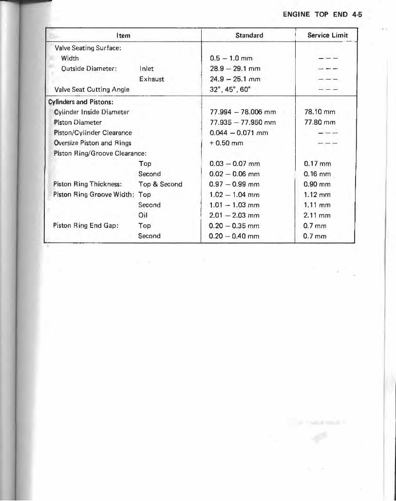
ENGINE TOP END 4-5
Item Standard Service Limit
Valve Seating Surface:
Width 0.5 - 1.0 mm ---Outside Diameter: Inlet 28.9 - 29.1 mm ---
Exhaust
I 24.9 - 25.1 mm ---
Valve Seat Cutting Angle 32". 45". 60" ---
Cylinders and Pistons:
Cylinder Inside Diameter 77.994 -78.006 mm 78.10 mm
Piston Diameter 77.935 -77.950 mm 77.80 mm
Piston/Cylinder Clearance 0.044 - 0.071 mm ---Oversize Piston and Rings + 0.50 mm ---
Piston Ring/Groove Clearance:
Top I 0.03 - 0.07 mm 0.17 mm
Second 0.02 - 0.06 mm 0.16 mm
Piston Ring Thickness: Top & Second 0.97 - 0.99 mm 0.90 mm
Piston Ring Groove Width: Top 1.02 - 1.04 mm 1.12 mm
Second 1.01 -1.03 mm 1.11 mm
Oil 2.01 - 2.03 mm 2.11 mm Piston Ring End Gap: Top 0.20 - 0.35 mm 0.7mm
Second 0.20 - 0.40 mm 0.7mm

4-6 ENGINE TOP END
Special Tools
Along with common hand tools, the following more special ized tools are required for complete engine top end servicing.
Piston Ba,e: 57001-149
Compression Gauge : 57001-221
Adapter: 57001-1183
Valve Spring Compr~ssor Assembly: 57001-241
Adapter: 57001-1019
.~
Piston Pin Puller Assembly: 57001-910
. .. o
Valve Guide Arbor: 57001-1021
Valve Guide Reamer: 57001-1079
Piston Ring Compressor Assembly (4): 57001-1094
Valve Seat_Cutter 45° - <1>27.5 Valve Seat CUller 32° - <1>28.0 Valve Seat Cutter 32° - <1>30.0 Valve Seat Culler 60° - ¢ 3O_0 Valve Seat Culler 45° - \\30.0
Cutter Holder ¢5.5: 57001-1125
Bar: 57001-1128
Tappet Bloeder: 57001-1200
)
57001 -1114 57001 -1119 57001-1120 57001-1123 57001-1187

Clean Air System (US model)
Air Suction Valve Installation Note elnstall the air suction valve Jlssembly into its h9using so
that the rear edge of it contacts with the rear projection on the housing.
A. Air Suction Valve Assembly B. No gap.
Air Suction Valve Inspection -Visuall y inspect the reeds for cracks, folds, warps, heat damage, or other damage,
*If there is any doubt as to the condition of the reed, replace the air suct ion valve as an assembly.
A. Valve Holder B. Reeds
echeck the reed contact areas of the valve ho lder for grooves, scratches, any signs of separation from the holder , or heat damage.
*If there is an y doubt as to the condition of the reed contact areas. replace the air suction valve as an assemb ly.
elf any carbon or other fore ign particles have accumulated between the reed and the reed contaCt area, wash the valve' aS5tmbl y clean with a high flash-point solvent.
ENGINE TOP END 4-7
[~AUTION :I 000 not scrape off the deposits with a scraper 8S this
could damage the rubber. requiring replacement of the suction valve assembly.
Vacuum Switch Valve Test -Check the vacuum switch va lve by blowing air into the
air hose fitting . oWhen the vacuum applied to the vacuum hose fitting of
the valve is low, the vacuum switch valve is opened and air flows through th~ air hos~ f ittings.
oWhcn the vacuum rises gradually and reach a certain level, the valve is closed and air does not flow .
• If the vacuum switch valve does not operate as described, replace the valve.
Vacuum Switch Valve Operation
During Cruising (Open Throttle)
No Vacuum
During Engine Braking (Closed Throttle)
'--iYI Air does not flow .
Vacuum
Vacuum Switch Valve Closing Pressure
Open .... Close: 57 - 65 kPa (430 - 490 mmHg)

4-8 ENGINE TOP END
Cylinder Head Covers
Cylinder Head Cover Removal Notes -Remove the cylinder head covers by taking out the
cover moun tin g bolts.. oRemovc the air suction valves and head cover assembl y
Allen bolts and separate the left and right covers if the cngine is on the frame.
A. Cylinder Head Cover Mounting Bolts B. Clamp
eBe care ful not to fall the rubber dampers on each fitting of the oil pipe inlo the chain tun nel.
A. Rubber Dampers
Cylinder Head Cover Installation Notes elf the left and right covers were s.ep~r:\lcd, assemble
th t;:m with bolts. and knoc k pins. One of the bolt should be tightened with the cable clamp.
- Aprly a silicone sea lant to Ihe ma ting surfacc5 of the cylinder head and (overs a:. shown .
A. Apply si licone scalant.
A. Apply sil icone sea lant.
eSe sure to in stall the rubber damper onto each fitting of the oil pipe with the correct side of it facing up.
Oil Pipe Damper Installation
1. Rubber Damper 2. Oil Pipe Fitting 3. O·r ing

Camshaft Chain Tensioner
Camshaft Chain Tensioner Removal Notes
This is a non-return type cam chain tensioner. The push rod does not return to its original position once it moves out to tllke up cam chain slack. Observe all the rules listed below: CWhen removing the tensioner, do not take out the
mounting bolts only halfway. Retightening the mounting bolts from this position could damage the tensioner and the camshaft chain. Once the bolts are loosened, the tansioner must be removed and reset as described in "Chain Tensioner Installation,"
COo not turn over the crankshaft while the tensioner is removed. This could upset the cam chain timing, and damage the va,yes.
. Loosen the cap bolt before tensioner removal for later disassembl y convenience .
• Unscrcw th e mounting bolts and rem ove the camshaft chain ten sion cr.
A. Mounting Bolts B. Ca p Bolt
Camshaft Chain Tensioner Installation Notes .Removc the: cap bol t and O-ring . • Whi lc co mpressing thc push rod , lurn it clockwise with
a sui tab le screwdriver to put it imo unt il the rod protrusion Comes to about 10 mm from the tensioncr body as sho wn .
COo not turn the rod counterclockwise at installation. Tliis could detach the rod and the tensioner cannot be reinstalled.
ENGINE TOP END 4·9
A. Compress the rod . C. Screwdriver B. About 10 mm D. Clockwise
.While ho lding th e rod in. posi l ion with [he screwdriver im,ta li t he tens ioner on the cylinder block .
• While pushing the tensioner agai nst th e cylinder block as shown , remove the screwdriver .
A. Push the tensioner. B. Screwdrivcr
-Holding the tcnsioner. tiiht f!n the mo unting bolts to
the specified (org,ue (see Explo ded View) . • Insull the O-ring and tighten the cap bol t.
Replacement Chain Tensioner Installation Notes . A replacement cha in tensioner (spare partS) has a push
rod holder plate .
0 00 not pull the rod holder plate while the tensioner hi removed . This could detach the rod and the tensioner cannot be installed easily .

4-10 ENGINE TOP END
-Remove the plate to release the push rod after installing the tensioner .
>\. Rod Holder Plate
Camshafts and Sprockets
Camshaft Removal Notes eRemove the camshaft chain tensioner before removing
the camshaft caps. .Pull the oil pipes with the rubber dampers and O-rings.
A. Oil Pipes C. Camshaft Caps B. Chain Guide
-Remove the camshaft cap bolts and take off the camshaft caps.
_Remove tht: camshafts. At this time, t.he rocker arms can be removed easily. Be careful not to fall them into the chain runnel.
A. Rocker Arms
! ~~UTlO~] OThe crankshaft may be turned, while the camshafts are
removed, but always pull the chain taut while turning the crankshaft. This avoids kinking the chain on the lower (crankshaft) sprocket. A kinked chain could damage both the chain and the sprocket.
Camshaft Installation Notes (Including Chain Timing Procedure)
eThe camshaft caps are machined with the cylinder head, so if a new cylinder head is installed, use the caps that arc supplied with the new head,
-If the oil filter(s) for the lash adjuster oil passage will be replaced, install the spring, new filter, and retainer.
oThe top end of the retainer should be level with the bottom of the oil reservoir. Stake the retainer to secure it in place.
lash Adjuster Oil Filter
.........
Il,
(3;--------l;~.JIH__Jjl: ::,::· · .. .... - --.--»' r.-, ''-,:-::, ,:-:-:-:
'-4/>-----~f': ....
1. Cylinder Head :-:: ::::":':,::: >::: .:\-.,.-+-,., .. . :., .... :- ..... .. .
2. Retainer ' .':-. ' .'. 3. Oil Filter 4. Spring
-Fill the oil reservoirs on the cylinder head with engine oil before installing (he camsh afts_
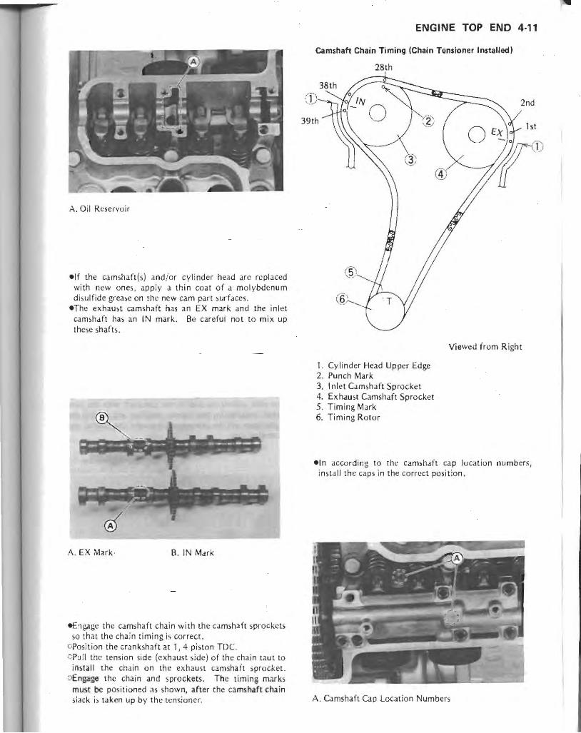
A. Oil Reservoir
elf the camshaft{s) andicr cylinder head arc replaced with new ones, apply a thin coat of a molybdenum di sulfide grea')e on the new cam part surfaces.
eThe exhau')l camshaft has an EX mark and [he inl~t
camshaft has an IN mark. Be careful not to mix up these shafts.
A. EX Mark · B. IN Mark
eEngage the camshaft chain with the camshafl sprockets so that th e chain timing is correct.
OPosition the crankshaft at 1,4 piston TOe CPull the tension side (exhaust side) of the chain taut to
ins tall the chain on th e exh aust camshaft sprocket. oEngag~ the chain and sprockets, The timina marks
must be positi oned ;lS shown, after the camshaft chain slac k is taken up by the tensioner.
ENGINE TOP END 4·"
Camshaft Chain Timing (Chain Tensioner In .. alled)
28th
2nd
Viewed from Right
I. Cylinder Head Upper Edge 2. Punch Mark 3. I nlet Camshaft Sprocket 4. Exhaust Camshaft Sprocket 5. Timing Mark 6. Timing Rotor
eln according to the camshaft cap location numbers, inslall the ca ps in the correct pos ition.
A. Camshaft Cap Locat ion Numbers
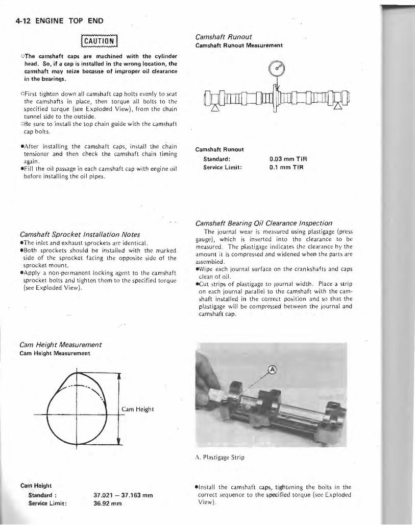
4-12 ENGINE TOP END
oTha camshaft caps are machined with the cylinder head. So, if a cap is installed in the wrong location, the camshaft may seize because of improper oil clearance in the bearings.
OFirst tighten down all camsha ft cap bolts evenl )' to scat the camshafts in place, then torque a ll bolts to tht: specified torque (see Exploded View). from the chai n tunnel side to th e outside.
c-Be sure to install the top chain guide with the camshaft cap bo lts .
eAfter installing the camshaft ca ps, install the chain tensioner and then check the camshaft chain timing again.
-Fill the oil passage in each camshaft cap with engine oil before ins talling the oil pipes.
Camshaft Sprocket Installation Notes -The inlet and exhaust sprockeL~ arc identical. e Bo th sprockets should be installed with the marked
side of the sprocket facing th e opposi te side of the sprocket mount.
eAppl y a non-permanent locking agent to tht: camshaft sprocket boils and tighten them to th e specified torq ue (see Exploded View).
Cam Height Measurement Cam Height Measurement
Cam Height -t---+--t-+-
Cam Height
Standard: Service Limit:
37.021 - 37.163 mm 36.92mm
Camshaft Runout Camshaft Runout Measurement
Camshaft Runout
Standard: Service Limit:
0.03 mm TlR 0.1 mm TIR
Camshaft Bearing Oil Clearance Inspection The journal wear is measured using plastigage (press
gauge), which is Inserted into the clearance to be measured. The pi astigagc in dicates lh c dearance by the amount il is compressed Jnd widened when the parts are assembled. eWipe each jo urnal surface on the crankshafts and caps
clean o f oil. -Cut strips of plastigage to journal width. Place a strip
on each jo urnal parallel to the camshaft with the camshaft installed in the co rrec t position and so that th e plastigagc will be compressed between the journal and camshaft cap.
;\ . Plastigage Strip
elnslall the cam sha ft caps, tightening the bolts in the correct sequen ce to the ~pecincd torq ue (see Ex ploded View) .

NOTE
ODo not turn the camshaft when the plastigage is between the journal and camshah cap.
-Remove the camshaft caps again, and measure the pl as tigage width to determine the clearance between each journal and the camshaft cap. Measure the widest portion of the plastigage.
*1( any clearance exceeds th e service limi[, measure the diameter of each camshaft journal.
Camshaft Bearing Oil Clearance
Standard Journal A 0.030 - 0.072 mm Journal B 0.070 - 0.112 mm
Camshaft Journal Ide.ntification
A. Journal A B. Journal B
Service Limit 0.16 mm
0.20mm
*If the camshaft journal diameter is less than the service limit, replace the camshaft with a new one and measure the clearance again.
Camshaft Journal Diameter
Journal A Journal B
Standard 24.949 - 24.970 mm
24.909 - 24.930 mm
Service Limit 24.92 mm 24.88 mm
_If the clearance sti ll remains out of the limit, replace the cylinder head unit.
Camshaft Chain and Guides
Camshaft Chain Removal Note e<:amshaft chai n removal requires the crankcase splittin g and crankshaft removJI.
ENGINE TOP END 4-13
Camshaft Chain Guide Removal Notes eThe top chain guide is removed during camshaft
removal . -The front chain guides (upper and lower) can be
remo\'ed after removing the cylinder head, eThe rear chain guide can be removed after splitting the
crankcase.
Camshaft Chain Wear -Hold the chain taut with a force of about 5 kg in some
manner, and measure a 20·link length , Since the chain may wear unevenly, take measurements at several places.
*If any measurement exceeds the s.ervice limit, replace the chain.
Chain Length Measurement
20·l ink Length
Camshaft Chain 20·link Length
Standard: 158.8 - 159.0 mm Service Limit: 161.2 mm
Camshaft Chain Guide Wear eVisually inspect the rubber on th e guides. *If the rubber is damaged, cut, or is missing pieces,
replace the guides.
Hydraulic Lash Adjuster (HLA)
HLA Removal Notes eTake off the rocker arms, _Pull o ut the hydraulic lash adjuster.
c ee careful not to damage or deform a lash adjuster by tapping it during removal or installation.
0 00 not drop the lash adjuster or hit it sharply. If it is deformed, the plunger will not operate smoothly.

4-14 ENGINE TOP END
A. Rocker Arms B. Hydraulic Lash Adjuster
HLA Installation Notes
oPrior to installation, measure the lash adjuster feakdown. If it is greater than specified, replace the ad· juster. Also, be sure to air-bleed it.
eTa clean the adjuster, rinse it in clean kerosene and then blow it dry with compressed air. Do not dry it with 8 cloth to prevent dust or lint contamination. Be careffJl not to get any adhesives or liquid gasket on the adjuster during servicing.
eBefore installing the adjusters in the cylinder head, fill the holes for adjuster with clean engine oil.
.Put the adjusters in their holes, being careful not to get any air or dust in the holes and not to allow the kerosene to leak out of the adjusters.
elnstall the rocker arms.
HLA Air Bleeding .Provide a container filled with kerosene. elnsert the lash adiuster into [he tappet bleeder (special
too! ) and move it up and down in the kerosene. -Check that the lash adjuster plunger moves up and down smoothl~'.
"If the plunger do~s not move smoothly, rep!act! the lash adjuster.
NOTE
OKeep the lash adjuster always upright and immersed in kerosene for easy air bleeding.
Lash Adjuster Air Bleeding
..
1. Tappet Bleeder: 57001-1200 2. Hydraulic Lash Adjuster
eWhen air bubbles stop coming out of the adjuster, lift the bleeder off the adjuster and take the adjuster out of the container with the adjuster kept upright.
HLA Leak.<fown Measurement ePut the lash adjuster vertically on a measuring stand
and set the dial gauge on the adjuster. .Push down the head of the adjuster quickly with your
fingers and measure the distance it sinks.
Measuring Leak-down Distance of the Lash Adjuster
Dial Gauge
Lash Adjuster
Leak-down Distance
Standard: Service Limit:
O-O.2mm O.2mm

*If the leak -down distan ce exceeds the service limit, repeat the air bleeding opera.t ion and t.hen measure the leak-down agai n. If leak-down is still out of the service limit, replace th e adjuster .
NOTE
C8e careful not to tip the lash adjuster and nO( to allow the kerosene (0 leak out of the adjuster.
Hydraulic Lash Adjuster (Fr •• Ball Type)
1. Pi vot Plunger 2. Bod\, 3. Oil Feed Passage 4. Ball ·check Valve 5. Plunger Spring 6. Retai ner Cap 7. Reservoir 8. Ball Seat 9. Ball Cage
10. High Pr essure Chamber
ENGINE TOP END 4-15

Go
4-16 ENGINE TOP END
HLA Troubleshooting Guide Aeration of Oil
Insufficient engine oil will cause air to enter the lash adjuster resulting in tappet noise or poor engine running at both low Jnd high ,peeds. Pump-Up
Excessive oil pressure will cause the lash adjuster to hold the valve open . Also, operation in red zone can cause valve float. This allows the rockers to momentarily lift. off the end of the HLA, which t.hen draws in oil to move the plunger up, preventing the valve from scating completely.
(NOiSY Valve Train Hydraulic la,h Adjuster (HlAI
Trouble,hooting Guide (11
I
Is engi ne warmed up No , Wait 2 to 3 minutes
thoroughly? 1 with the engine idling
Ye, U Advise the user not to run the engine beyond usable range
Open and close throttle valves 1/ Yes Is
about 10 times, and then run valve still noisy /
the engine for 2 minutes at ,
about 3,000 r/ min (rpm) with no load. No Did engine Ye,
operate in red zone?
\ Good
No Is
No Since valve noise may 1, valve still noisy return, check oil level ? and contam ination Check oil line
Yes I \ ~OOd
Check oil level and contamination Bad Clean oil screen, replace oil
I ~~ ;;0
filter, and add or change oiL Air in HLA to
~ inSUffiCIent andlor Good Noise test from beginning
contammated ad ,
~ Bad
Check oil preS5ure
ad or hi~ pressure 1 Too low pressure Aeration of oil
J,
Remove cylinder head cover and Bad outside oil pipe to inspect oil line Repair oil line and noise
f- Check and repair the ~- test from beginning following parts and noise
-IGOOd test from beginning . Oil Pump ~ Oil Screen
Inspect HLA wear, stick, spring Oil Filler break, excessive leakdown Good Inspect and repair camshaft, Crankcase Oil Passage
rocker arm, and valve. Noise
Bad test from beginning,
\ I,
Replace HLA

ENGINE TOP END 4·1 7
Hydraulic Lash Adjuster (HLA) Trouble Shooting Guide (2) I
Poor runn ing or no power at low and/or high speed
L
\It'
Does .... engine s1art
Ves " easily?
-J; No
_Run the engine for 2 to 3 minutes Trouble may be caused by engine at about 3,000 r/min (rpm) with
no load, or raise the engine speed Sad
parts other than HLA. See trouble-for a moment within usable range, shooting gu ide in appendix and
.Check startabi lity and idling ,
repai r the related parts. stabil ity .
Good \l,t
f AdYise the user not to p<§""""' ~'M" run the engine beyond operate in red compreS;ion low uw~e range. zone? Check and repa ir the
\ oil line in the crank · case.
\/NO Oil pump -Oil relief valve
No Oil filter
Clean oil screen, \ / r) Sad ~ Crankcase oil
Che(:k oil pr essure passage replace oi l filter, / Sad Check oil level and >nd add or ~ contamination I
change oil. +- II Good I I Check and repair the oil line
I from crankcase to cylinder head. SId
) Oil pipes
Good Cylinder head oil passages I and filters
\if I Oil passages in the camshaft
Trouble may be caused by pump-up caps
due to excessively high oil pressure. If pump-up occurs too often , check
Good oil pressure. II I
Remove HLA to check it.
Good II
,
\ Sad Trouble may be caused
HLA damaged or worn. by other parts of tht
Replace HLA. valve train . See Trou' :-bleshooting guide in
appendix and repa ir the
I related parts

4·18 ENGINE TOP END
Cylinder Head
Cylinder Head Removal Note eBe sure to remove the bolts at the front and rear of the
cyHnder head chain tunnel.
A. Cylinder Head Bolts
Cylinder Head Installation Notes eBefore installing the cylinder head, be sure the front camsh<:tft chain guides are in place.
Front Camshaft Chain Guides
1. Front Chain Guide (Upper) 2. Front Chain Guide (Lower) ). Cylinder Head 4. Cylinder 5. Crankcase
elnstall the new cylinder head gasket with the side marked UP fac ing up.
.~.
eTighten the cylinder head bolts. CApply a molybdenum disulfide lubricant (grease or oil
type, either will do) to both upper and lower sides of the 11 mm cylinder head bolt washers.
OTorque the 11 mm cylinder head bolts following the tightening sequence. Torque them first to about one half of the specified torque and then torque them to the specified torque (see Exploded View).
Cvlinder Head Bolt Tightening Sequence
Exhaust
Inlet
oT orque the 8 mm cylinder head boilS to the spec ified torque (sec Exploded View).
elnst.all new washers on each side of the oil pipe finings, and tighten the banio bolts to the specified torque (see Exploded View).
Cylinder Compression Measurement eBefore: measuring compression, do the fo llowing: OBe sure the battery is fully charged. oWarm up the engine (if the engine will run).

CDuring warm-up, check fo r leaks around the cylinder head gas keto
-Stop the engine, remove the spark plugs, and attach compression gauge and adapter (special tool s) fi rm ly into the spark plug hole.
A. Compression Gauge : 57001·221 8. Adapter: 57001·1183
-Using the jumper cables, connect th e rl! moved battery to the disconnected battery cables.
cConnect the jumper cable from the positive (+) terminal of the battery to the positi ve (+) batlery cable.
cConncct another jumper cable from the nega tive ( --) terminal of th e battery to the negative (-) battery cable .
I WARNING'
OTake care thal you do not louch lhe positive and negative cables together, and do not touch the cables to the frame.
c Oo not reverse polarity by connecting positive (+) to negative (-) or a serious damage to lhe electrical system may occur.
-HoJd the throttle wide open and crank the engine with the starter.
-When the gauge sto ps rising, stop eran king and read the gauge.
-Repea t the measurement for the other cyl inder.
Cylinder Compression
U,able Range: 960 - 1,470 kPa (9.8 -15.0 kglem', 139 - 213 psi!
*If th e compress ion is within the specified range, the piston rings, cylinder and valves arc probabl y in good conditio n.
*I f cylinder compress ion is higher than the specified ra ng0, check the followi ng:
ENGINE TOP END 4-19
c Carbon build·up on the piston head and cylinder head. - clean off an y carbon on the piston head and cylinder head.
CCylinder head gasket, cylinder base gasket -- use onl y the proper gaskets for the cylinder head and basc o The use of gaskets of the incorrect thickness will change the compression.
oValve stem oil sea ls a.nd piston rings -- rapid carbo n accumulation in the combustion chambers may be caused by damaged valve stem oil seals and /or damaged piston oil rings. Th is may be indicated by white exhaust smoke.
*If the comprcssion is below the specified range, squirt a litt le oil into the spark plug ho le and repeat the compression measurement.
~r lf thc compression does no t changl: Vl:ry much, the piston rings are probably OK, check the following :
C-Gas leakage around the cylinder head - replace the damaged gasket and check the cylinder head for warp.
OC:ondition of the valve sea ting. OHydraulic lash adjuster (operation, seizure, spring
breakage) - replace the damaged lash adjuster. COil pressure - if the pressure is high, check the oil
lin e for clogs. ~~If the compression increases , the pi ston rings are not
sealing properly, check the following: iJPiston/cylinder clearance, pi ston seizure. OPislon ring, piston ring groove .
Cvlinder Head Warp -Lay a straightedge across th e lower surface of the head at several d iffe rent points, and measure warp by in5erting a thi ckness gauge between the straighledge an d the h""d.
*Jf warp exceeds th e service limit, repair the mating surface. Replace the cylinder head if the mating surface is badly damaged .
A. Straightedge 8. Thickness Gauge
Cylinder Head Warp
Service limit: 0.05 mm

4-20 ENGINE TOP END
Cylinder Head Cleaning eRemove the cylinder head. eRemove the valves . • Wash the head with a high flash-point solvent. -Scrape the carbon out of the combustion chamber and
exhaust port with a suitable tool.
.................... ••••••••••••••••••••••••••••••••••••••••••• •••••••• ••••• • 00
Carburetor Holders
Carburetor Holder Installation Notes .Install the carburetor holders so that the projections of
them face upwards and aljgn with the cylinder head ribs.
A. Holder Projection B_ Rib
-Install the holder clamps as shown being careful of the screw position and the screw head direction.
II WARNING I Olnstall the clamps in the correct poSition. 0" the
clamps could come in contact with the carburetor control parts. resulting in an unsa.fe riding condition.
Holder Clamp Installation
Top
Bottom
Holder Clamp
Screw Head S crew
Valves
Valve Mechanism Removal Notes -Use the valve spring compressor assembly and adapter
(special tools) to press down the valve spring retainer, and remove the split keepers .
A. Valve Spring Compressor Assembly: 57001-241 B. Adapter: 57001-1019
eHeat the area around the valve guide to about 120 --150°C (248 - 302°F), and hamm er lightly on the valve guide arbor (special tool) to remove the guide from the top of the head.
A. Valve Guide Arbor: 57001-1021
Valve Mechanism Instal/ation Notes .'nstall the valve guide. OApply oil to the valve guide outcr surface before
installation . ('; Heat the area around the valve guide hole to about 120
- 150°C 1248 - 302°F). c Drive the valve guide in from the top of the head using
the valve guide arbor. Be sure to instal! the O-ring under the valve guide flange.
ORea m the valve guide with the valve guide rcamer (special tool) even if rhe old guide is ro-u sed .

A. Valve Guide Reamer: 57001 ·1079
-Install the valve. CChcck to sec that the valve moves smoothly up and
down in the guide. CC.heck to see that the valve seats properly in the valv~ seat. If it does not, repair the \lalve seat.
OApply a thin ooat of molybdenum disulfide grease to the valve stem before valve installation.,
OBc sure to install the spring seat under the spring. 8-1nsrall the spring so that the closed coil end is fac in::;
toward the valve sca t (downwards).
Valve and Spring
fit&- Split Keepers
Valve Spring --@ Retainer
Spring --A~~,;{
Spring Seat
OilSeal~
Valve
ENGINE TOP END 4-21
Valve Head Thickness Valve Head Shape
Valve Head Thickn.ss
Valve Head Thickness
Standard Inlet 0.8 mm Exhaust 1.0mm
Valve Stem Bend Valve Stem Bend Measurement
45°
Service Limit 0.4 mm
OS mm
Valve Stem Bend
Standard: Service Limit:
0.02 mm TIR 0.05 mm TIR
Valve/Valve Guide Clearance Measurement (Wobble Method) If a small bore gauge is not available, inspect the valve
guide wear by measuring the. valve to valve guide clearance with the wobble method, .IS indicated below. -Insert a new valve into the guide and set a dial gauge
.Igainst the stem perpendicular to it as close as possible to the cylinder head mating surface.
-wlo ve the stem back and forth to measure valve/valve guide clearance.
_Repeat the measurement in a direction at J right angle to the first.
*If the reading exceeds the service limit, repJact: the guide.

4-22 ENGINE TOP END
NOTE
OThe reading is not actual IIBlve/llalve guide clearance because the measuring point is above the guide.
ValveNalve Guide Clearance (Wobble Method)
Standard Inlet 0.02 - 0 .09 mm Exhaust 0.07 - 0.14 mm
Wobble Method
Senice limit 029mm 0.34 mm
Close as possible.
Valve Guide
Valve Seat Inspection eCoat valve seat with machinist 's dye . • Push the valve into the guide.
about 30mm
eRo tate the valve against the seat with a lapping tool. .Pull the valve out, and check th e sealing pattern on the
valve head. I t must be the correct width and even all the way around.
Valve Seating Surface Width
Inlet 0.5 - 1.0 mm Exhaust 0.5 -1.0 mm
NOTE
C The valve stem and guide must be in good condition or this check will not be valid.
*If the valve seating pattern is not correct, repair the seat (see Valve Scat Repair).
Valve Seating Area Dimensions
:3)
Valva Seating Pattern
Good
Too Narrow
1. Valve 2. Valve Seat 3. Seating Area Outside
Diameter 4. Seating Area Width
Too Wide
Uneven
-Measure the outside diameter of the seating pattern on the valve seat.
*1 f the outside diameter of lhe valve sealing pattern is too large o r too small , repair the seat (see Valve Seat Repair).
Valve Seating Surface Outside Diameter
Inlet 28.9 - 29.1 mm Exhaust 24.9 - 25 .1 mm
Valve Seat Repair -Use the following procedures and lools to repair the
valve seat.
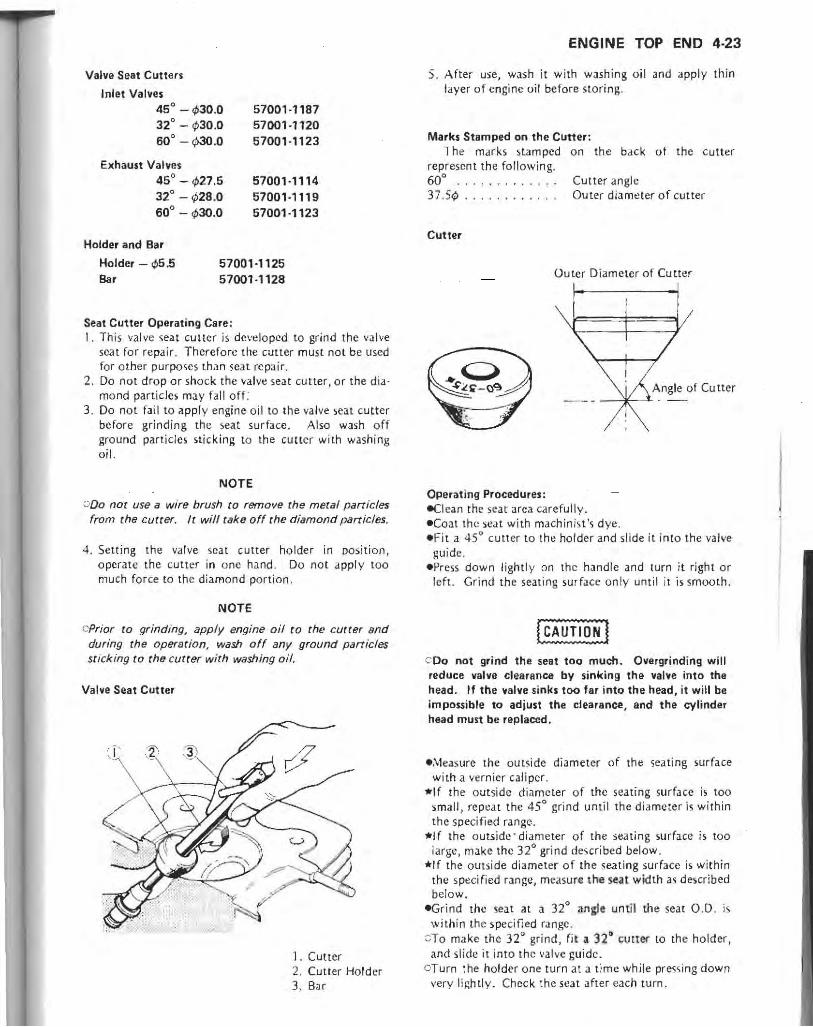
Valve Seat Cutters
Inlet Valves 45° -";30.0 32° - ¢30.0 60' -~O.O
Exhaust Valves 45° - ";27.5 32° - '1128.0 60° - ";30.0
57001·1187 57001·1120 57001·1123
57001·1114 57001·1119 57001·1123
Holder and Bar
Holder - ¢5.5 Bar
57001-1125 57001·1128
Seat Cutter Operating Care: I. This valve seat cutter is dc vt! lopcd to grind the valve
seat for repair. Therefore the cutter musr not be used for other purposes than scal repair.
2, Do not drop or shock the valve seat cu tter , or the diamond particles may falloff:
3. Do not fail to apply engine o il to the valve seat cutter before grinding the seat surface. Also wash o ff ground particles sticking to the cutter with washing o il.
NOTE
000 not use a wire brush to remove the metal particles from the cutter. It will take off the diamond particles.
4. Setting the va lve sca t cutter holder in position, operate the cutter in o ne hand . Do not apply too much force to th e diamond port ion.
NOTE
cPrior to grinding, apply engine oil to the cutter and during the operation, wash off any ground particles sticking to the cutter with washing oil,
Valve Seat Cutter
1. Cutter 2. Cutter Hold er 3. Bar
ENGINE TOP END 4·23
S, After use, wash it with washing oil and apply thin layer of engine oil before storing,
Marks Stamped on the Cutter: The marks stamped on the
represent th e following. back of the cutler
60° . 37.54>
Cutter
Operating Procedures:
Cutter angle Outer diameter of cutter
Outer Diameter of Cutter
Angle of Cu ner _¥-..i-
-Clean the seat area carefull y. -Coat the seat with machinist 's dye , -Fit a 45° cutter to the holder and slide it into the valve
guide. -Press down lightl y on the handle and turn it right or
left. Grind th e sealing surface only until it is smooth ,
COo not grind the seat too much. Overgrinding will reduce valve clearance by sinking the valve into the head. If the "falve sinks too far into the head, it will be impossible to adjust the clearance, and the cylinder head must be replaced,
-;v1easure the outside diameter of the seating surface with a vern ier cali per,
*If the outside d iame ter of the seating surface is too small, repeat the 45° grind until the diameter is within the specified range.
*If the o utsid~'diameter of the seating surface is too la rge , make the 320 grind described below,
*If the outside di ameter of the seating surface is within the speci fied range, measu re the seat width as described belo w.
-Grind the seat at a 320 angle until the seat 0 ,0. is
within the specified range. 8To make the 32' grind, fit. 32' evtter to the holder, and slide it into th e \'JI ve guide.
aTurn the holder one turn at a time while pressing down very li ghtly. Check theseat after each turn,

4-24 ENGINE TOP END
Valve Seat Repair , ( START Machinis.t 's
I dyt: on -;eJ!
+ 45° Grind
Tool : 45° Cutler Purpose-: make seati ng area
smooth and round , Measure St'<tting Area 0.0.
Tool Vernier Caliper Purpose: chec k seat 0.0.
against spec.
I Rl:IU'IS
t , t I Tool small I I OK I I Too big I , ,
45° Grind Machinist 's
Tool: 45'Cutter dvc on seat
Purpose: increase 0.0. of s~at t ar~a to spec. 32' Grind
Tool : 32' Cutter Purpose: reduce 0 .0. of seat area
to spec.
Measure Seat Width
Tool : Vernier Caliper Purpose : check seat width
against spec.
I Rcs,lb
t , t I Too narrow I I OK I I Too wide I , t
45° Grind Machinist's
Tool: 45 ' Cutter dye on sea t Purpose: increase width of seat t area beyond spec. to
increase O. D. 60' Grind
Tool: 60' Cutter Purpose: reduce seat width
to spec.
Lap Valve
Tools: Valve lapper, grinding compound
Purpose : perfectl y match valve ( FINISHED ) and seat area; check valve head for damage
L

OThe 32° cutter removes material very quickly. Check the seat outside diameter frequently to prevent overgrinding.
Valve Seat Repair
Widened width of engagement by machining with 45° cutter
Ground volume by 32° cu lter
t
Ground volume / by 60° cu ttcr
CAfter making the 32° grind, return to (h e seat 0.0. measurement step above.
eTa measure the seat width , use a vernier caliper to measure the width of the 45° angle portion of the seat at several places around the seat,
*If the sear width is too narrow, repeat the 45° grind until the ~eat is. slightly too wide, a nd then return to the seat 0.0. mea~urement step above.
* If the scat width is too wide, make the 60° grind described below.
*If the seat width i ~ within the specified range, lap the valve to the seat as described below.
eGrind the sca t at a 60° angle until the seat width is withi n the specified range.
J To make the 60 Q grind, fit a 60° cutter to the holder,
and slide it into the valve guide. oTurn the ho lder, while pressing down lightly. OAftcr making the 60° grind, return to the seat width
measurement step above. eLap the valve to the seat, once the seat width and 0.0.
are within the ranges specified above, CPut a little coarse grinding compound on the face of
the valve in a number of places around the valve head. cSpin the valve against the: seat until the grinding com
pound produces a smooth, matct1ed ~urrface on both the seat and the valve.
ORepeat the prUess with a, fine grinding· compound. eTh e sea ting area should be mark~d about in the middle of the valve face.
ENGINE TOP END 4·25
*If the seat area is not in the right place on the va lve, check to be sure the valve is the correct part. If it is, it may have been refaced too much; replace it.
eBc su re to remove all grinding compound befo re assembly.
Valve Lapping
1. Lapper 3. Valve 2. Valve Seat
Cylinders and Pistons
Piston Removal Notes eRemove t.he piston pin snap rings from the outside of
each piston. OBe sure to place a clean cloth under the piston to
prevent the snap ring from falling into the crankcase.
A. Snap Ring

4-26 ENGINE TOP END
eRe move the piston by pushing its piston pin out the side that the snap ring ~as removed. Use the piston pin puller assembly (special tool), if the pin is tight.
A. Piston Pin Puller Assembly: 57001-910
eRemove the top and second piston rings. cSpread the ring opening with your thumbs 'and then
push up on the opposite side of the ring to remove it.
.Remove the 3-piece oil ring with your thumbs in the same manner.
•
A. Spre.ld . B_ Push up.
Piston Installation Notes elf a new piston is installed, be sure to check piston/
cylinder clearance before starting (see Piston/Cylinder Clearance) .
• Install the 3-piece oil ring. CFirst install the expander in the bottom ring groove
so that the expander ends butt together, never overlap.
A. Expander ends butt together.
Cl nstall the upper and lower steel rails. There is no UP or DOWN to the ralls. They can be installed either way.
-Install the top and second rings in that order. COo not mix up the top and second rings. The top and
second rings are not symmetrical and must be installed with the correct side facing up.
Piston Rings
R Mark
Top Ring
2nd Ring
-The arrow on the tep of the piston must poim toward the front of the engine,
-When installing a piston pin snap ring, compress it only enough to install it and no more .
COo not reuse deforms them. cylinder wall.
! ~AUTIII~J snap rings, as removal weakens and
They could fan out and score the

Cylinder Installation Notes elf a new cylinder is installed, be sure to check piston!
cylinder clearance before starting (see Piston/Cylinder Clearance).
-Turn the piston rings so that the openings are in the specified positions.
Piston Ring Opening Positions
Top Ring : Forward Second Ring: Oil Expander: Top Oil Rail: Bottom Oil Rail:
Rear Forward 30° Left of Forward 30 0 Right of Forward
Piston Ring Openings: Viewed from Front
:f._~ - ~#--Rmark R~~ (2;~
U Front
Arrow
I. Top Ring 2. Second Ring 3. Steel R,il, Oil Ring 4. Expander, Oil Ring
-Install a new cylinder base gasket with the side marked UP facing up.
ENGINE TOP END 4-27
-Install the cylinder block on the pistons . cSlip the piston blSes (special tools) under 'he base
gasket and pistons to hold them level. c Compress the piston rings using the piston ring com
pressor assemblie;:s (special tools).
A. Piston Ring Compressor Assembly : 57001-1094 B. Piston Base: 57001-149
Cylinder Inside Diameter eMeasure the cyli nder inside diameter. :JUse a dial bore gauge to measure front-to-back and side-to-side at the points shown below.
Cylinder Inside Diameter
Standard: 77.994 - 78.006 mm, and I." than 0.01 mm difference between any two measurements
Service Limit : 78.10 mm, or more than 0.05 mm difference between any two measure-ments
*If any of the cylinder inside diameter measuremt:nts is grealer than the service limit, the cylinder must be bored oversize and then honed (see Cylinder Boring and Honing). However, jf the amount of boring necessary would make the cylinder imide diameter greater than the bore limit, [he cylinder must be replaced.
NOTE
O/f the cylinder has been bored oversize, see the Oversize Cvlinder Inside Diameter table.

4-28 ENGINE TOP END
Oversize Cylinder Inside Diameter
Standard: Measure at bottom of cylinder for baseline standard diameter
Service Limit: Standard plus 0.' mm, or more than 0.05 mm difference between any two measurements
Bore Limit: 78.50 mm
Cylinder Inside Diameter Measurement
;>H-*20mm 10 mm-?l---J<-
60mm
Piston Diameter Piston Diameter Measurement
Piston Diameter
Standard: 77 .935 - 77 .950 mm Service Limit 77.80 mm
NOTE
elf rhe oversize piston has been used, see Oversize Piston Diameter table,
Oversize Piston Diameter
Standard: 77.935 - 77.950 mm plus 0050 mm as stamped in piston head.
Service Limit: Standard size minus 0.15 mm
Piston/Cylinder Clearance eMeasure the piston diameter, eMeasure the cylinder inside diameter with a dial bore
gauge at the bottom of the cylinder. _SubtrJct the piston diameter from the cylinder inside
diameter to get the piston/cylinder clearance. *If the piston/cylinder clearance is less than the spe
cified range. use a small piston or increase the cylinder inside diameter by honing (sec Cylinder Boring and Honing).
*If the piston/cylinder clearance is greater than the specified range, usc a large piston or bore to the next larg~r oversize (see Cylinder Boring and Honing) .
Piston/Cylinder Clearance
Standard: 0.044 - 0.071 mm
Cylinder Boring and Honing .\Vhen boring and honing a cylinder, follow the boring
and honing tool manufacturer's instructions. Note the following:
.Before boring a cylinder, measure the diameter of the piston to be used . Bore and hone the cylinder to obtain the standard piston/cylinder clearance specified .
• Cylinder inside diameter must not vary by more than 0.01 mm at any point.
.Do not measure the cylinder inside diameter immediately after boring or honing, because the boring and honing operations heat the cylinder. Heat affects cylinder size.
Piston/Cylinder Seizure .Visually inspect the cylinder and piston damage. *1 f there is only light dlm;age, ,5mooth the piston with
#400 emery cloth. Remove small aluminum deposits from the cylinder with #400 emery cloth or light honing.
*If the damage is severe, the cylinder must be bored oversize and an oversized piston installed.

Piston Cleaning -Remo ve the pis ton and piston rings.
(CAUTlO~ I c Never clean the pinon head with the engine assernbled. Carbon particles will fall between the piston and cylinder, and damage the crankshaft bearings.
- Scrape the carbon o ff the p is ton head. oUse the scraping tool care fu lly. Do not gouge th e
piston head . .clean the piston ri ng groove with a broken piston ring or o ther suitable tool.
c ae careful not to widen the ring grooves or the piston must be replaced.
Piston Ring and Ring Groove Wear • Visually inspect the piston rings and ring grooves. -If the piston ri ngs are v.'orn unevenly or damaged,
re place them. -If the ring groo ves .a re worn unevenly o r damaged,
repla ce both the piston and piston rings. eMeasu re (he clearance between the to p and second
rings and their grooves.
Piston Ring/Groove Clearance
Standard
Top 0.03 - 0.07 mm Second 0 .02-0.06mm
A. Th iL:k ness Gauge
Service Limit 0.17 mm 0.16 mm
*/f the piston ring groove clearance is grea ter than the service limit, measure [he ring thicknes,) and groo ve wid th a') fo llows to decide whclher to replace the rings, the piston or both .
ENGINE TOP END 4-29
Piston Ring Thickness (Top &. Second)
Standard: 0 .97 - 0.99 mm Service Limit: 0.90 mm
Piston Ring Grooye Width Standard Service Limit
Top 1.02 -1.04 mm 1 .12 mm Second 1.01-1.03mm 1.11 mm Oil 2.01 - 2.03 mm 2.11 mm
NOTE
C:When using new rings in a used piston, check for uneven groove wear. The rings should fit perfectly parallel to the groove sides. If not, replace the piston.
Piston Ring End Gap (top and second only) ePush each ring (one at a time) into the bottom end of
the cylinder . ':"'Use the piston [0 push it in to be ~ure it is square. e Measure the ga p between the end of the ring with "'
thickness gauge.
Piston Ring End Gap
Top Second
Standard 0.20 - 0.35 mm 0 .20 - 0.40 mm
Piston Ring End Gap Measurement
Pi ston Ring
~ap
Service Limit
0.7mm 0.7mm

4-30 ENGINE TOP END
Exhaust Pipes and Mufflers
Muffler Removal Notes -Remove the mufflers as following. o Remove the left and right muffler covers,
A. Muffier Cover B. Muffler Mounting Bolt
OLoosen the clamps connecting the left and right mufflers a.nd exhaust pi pes.
ORe move the left and right muffler mounting bo lts . oPul1 the mufflers out rear en ds of the exhaust pipes .
Clamp Positions
about 16 mm
Viewed from front
More than 45° Level of Road Clearance
Exhaust Pipe and Muffler Installation Notes elnstall the clamps so that the openings are in the
specified positions to obtain the specified road clearance of the veh icl e.
eTighten th e exhaust pipe and muffler mounting bolts, nuts, and da mp bolts in the order and method indicated below.
CFirsl, tighten all the bolts and nuts to a snug fit. cScco ndl y, t ighten the exhaust pipe holder nuts evenly
to avoid exhaust leaks.
A. Exhaust Pipe Holder Nuts
CLastly, tighten the rest of rhe mounting bolts and clamp bolts securely.
-Thorough ly warm up the engine, wait until the engine cools down, and ret ighten all the clamp bolts .
Viewed from Left
t Level of Road Clearance
. • p •
(

CLUTCH 5·'
Clutch
Table of Contents
Exploded View . . . . . . . . . . . . . . . . . . . . . . . . . . . . . . . . . . . . . . . . . . . . 5-2
Specifications . . . . . . . . . . . . . . . . . . . . . . . . . . . . . . . . . . . . . . . . . . . . . 5-4
Special Tool . . . . . . . . . . . . . . . . . . . . . . . . . . . . . . . . . . . . . . . . . . . . . . 5·4
Clutch Fluid . . . . . . . . . . . . . . . . . . . . . . . . . . . . . . . . . . . . . . . . . . . . . . 5-5
Clutch Fluid Recommendation .......... . .. .. .... .... .... 5-5
Clutch Fluid Level Inspection . .... .. .. . ...•. . ... . .. . . . .. . 5-5
Clutch Fluid Changing . . . . . . . . . . . . . . . . . . . . . . . . . . . . . . .. . . 5-5
Clutch Line Air Bleeding ... .. . . . . . . . . . . . . . . . . . . . . . . . . . . . 5-6
Clutch Master Cylinder. . . . . . . . . . . . . . . . . . . . . . . . . . . . . . . . . . . . . . 5-7
Clutch Master Cylinder Removal ............•....•....•... 5-7
Clutch Master Cylinder Installation Notes. . . . .•. . . . . •. . . .•. . 5-7
Clutch Master Cylinder Disassembly. . . . . . . . . . . . . . . . . . . . . . . . 5·7
Clutch Master Cylinder Assembly Notes. . . • . . . . • . . . . . . . . . . . . 5-7
Clutch Master Cylinder Inspection. . . . . . . • . . . . . . . . . . • . . . . . . 5·7
Clutch Slave Cylinder . . . . . . . . . . . . . . . . . . . . . • . . . . . . . . . . . . . . . . . 5-8
Clutch Slave Cylinder Removal Notes ........... . .. .•. .... . 5·8
Clutch Slave Cylinder I nstallation Notes. . . . . . . . . . . . . . . . . . . . . 5·8
Clutch Slave Cylinder Disassembly. . . . . . . . . . . . . . . . . . . . . . . . . 5·8
Clutch Slave Cylinder Assembly Notes. . . . . . . . . . . • . . . . • . . . . . 5-8
Clutch Slave Cylinder Inspection .............. .•.... . .. ... 5-9
Clutch . ............ .............. . ..... . ..... • ....•..... 5·9
Clutch Removal ......... ........•...... .... • .... .. .. .. 5·9
Clutch Installation Notes. . . . . . • . . . .• . . . . • . . . . • . . . . . . . . . . 5·10
Clutch Hub Disassembly. . . . . . . . . . . . . . . . . . . . . . . . . . . . . . . . . 5·11
Friction Plate Wear, Damage Inspection . . . . . . . . . . . . . . . . . . . . . 5·11
Friction or Steel Plate Warp Inspection . ..... . ...... . . . ..... 5-11
Clutch Spring Free Length Measurement. . . . ... .. .. . .. . . . .. . 5·11
Clutch Housing Finger Inspection .. ........ . . .. ..... . . . . . . 5-12
Clutch Hub Spline Inspection ..... . ..... .... .. .. . ...... . .. 5-12
Cam Damper Inspection.......... . . . .. . .. . .. . .... . ... ... 5-12

5-2 CLUTCH ___________ _ .......................................................................
~~:._I~~~_~_i_~~ ________ __ . __ .. _. ____ .. __ . ____ .. _ .. .. _._ .................. .
T5
T4
i

Viewed from Righ t
CLUTCH 5-3
1. Starter Lockout Switch
G : Grease L : Non-permanent Locking Agent M ; Molvbdenum Disulfide Grease SS: Silicone Sealant
T1 ; 5.9 N-m (0 .60 kg-m. 52 in·lbl T2; 7 .8 N ill (0 .80 kg·m. 69 in·lb) T3; 9.8 N 'm (1 .0 kg·m. 87 in-Ib) T4; 11 N-m (1.1 kg 'm, 95 in·lb) T5; 18 N-m (1 .8 kg ·m, 13.0 ft·lbl T6; 25 N-m (2.5 kg·m, 18.0 ft·lb) T7 ; 130 lI!·m (13.5 kg·m, 98 ft·lbl

5-4 CLUTCH
Specifications
Item
Clutch Fluid: Grade
Brand (recommended)
Clutch : Friction Plate Thickness
Friction and Steel Plate Warp
Clu tch Spring Free Length
Special Tool .. .... .. ... .. ...... ................. ........... ...................... .. ..... .
Along wi th common hand tools, the followi ng more speciali zed tool is requi red for complete clutch servicing .
Clutch Holder: 57001·305
NOTE
CThe clu tch holder (PI N 51001· 1243) can be used instead of the clu tch holder (PI N 5100 1·305).
Standard Service Limit
D.O.TA Heavy Duty Brake Fluid
Castro I Girling·Universal
Castrol GT (LMA)
Castrol Disc Brake Fluid
Check Shock Premium Heavy Duty
2.9 -3.1 mm 2.8mm
Less than 0.2 mm 0.3mm
33.2mm 32.1 mm

Clutch Fluid
Clutch Fluid Recommendation Recommended fluids are given in the table below. If
nonc of the recommended fluids are avai lable, use extra heavy-duty brake fluid only from il container marked D.O.T.4.
Recommended Clutch Fluid
Grade: D.O.T.4 Heavy Duty Brake Fluid Brand: Castrol Girling-Universal
Castrol GT (LMA) Castrol Disc Brake Fluid Check Shock Premium Heavy Duty
NOTE
OSince the clutch fluid is the same as the brake fluid, refer to Brake Fluid Section in Brakes for further details.
Clutch Fluid Level Inspection -Posi tion the reservoir hori zon tal , and check that the
fluid level in [he reservoir is higher than the lower level.
A. Lower Level
*If the fluid level is lower than the lower level, check for the fiuid leakage of the clutch line , and add the fluid as follows.
ORemove the reservoir c.ap, and fill the reservoir to the upper level line in th~ reservoir with the same type and brand of the fiuid that already is in the reservoir. And then install the reservoir cap.
I WARNING'
~Change the fluid in the clutch line compl~tely if the fluid must be refilled but the type and brand of the flu id that already is in the reservoir are unidentified.
CLUTCH 5·5
OAfter changing the fluid, use only the same type and brand of flutd thereafter. Mixing different types and brands of fluid lowers the fluid boiling point and could cause the clutch to be ineffective. It may also cause the rubber clutch parts to deteriorate.
A. Upper Level Line
eQperate tile clutch, and check for fluid leakage around the fittings.
I WARNING'
Olf the clutch lever has a soft or "Spongy feeling" when it is appli~d, there might be air in the clutch lines or the clutch m8Y be defective. Since it is dangerous to operate the motorcycle under such conditions, bleed the air from the clutch line immediately.
Clutch Fluid Changing eRemove the reservoir cap. eAttach a clear plastic hose to the bleed va lve on the
clutch slave cylinder, and run (he other cnd of the hose into a container.
-Open the bleed valve (counterclockwise to open), and rump the clutch lever until all the fluid is drained from the line.
e<:lose the bleed valve. -Remove the diaphragm. eFil1 the res€fvoir with fresh fluid. e()pen the bleed val,e, ~queele the dutch lever, clo'Se
the valve with the clutch tlcld applied, and then quickly release th e lever. RepeOit th is. operation until the d utch line is filled and fluid starts coming out into th~ plastic hme.
NOTE
OReplenish the fluid in the reservoir as often as necessary to keep ;r from running completely out.
eTighten the bleed valve to the specified torque Exploded View).

5-6 CLUTCH
Filling up Clutch Line
1. Open the bl«d valve. 2. Appll' the clutch lever and hold it. 3. Close the bleed valve. 4. Then rei casu the clutch lever suddenl y,
Clutch Line Air Bleeding -Remove the reservoir cap, and check th,,[ there is
plenty of fluid in the reservoir.
NOTE
o The fluid lellel must be checked severill times during the b/~ing operation and replenished as necessary. /I the fluid in the reservoir runs completely out any time during bleeding, the bleeding operation must be done over again from the beginning since air will have entered the line.
-Connect a clear plastic hose to the bleed \'alve at the clutch slave cylinder, running the other end of the hose into a container.
-With the reservoir cap off, slowly pump the clutch le\'t~r
several times until no air bubbles can be seen rising up through th e fluid from the holes at the bottom of the reservoir. This bleeds the air from the master cylinder t'nd of the lin~ .
• Pump the clutch lever a few times until it becomt"s hard and then, holding the lever squt'czcd, quickly open (tlR'n counterclockwise) .lnd close the bleed valve. Then relcase the lever. Repeat this opcldtion until no morc air can be seen coming out into the plastic hose.
.When air bleeding is finished, check th"t the fluid is filled to the upper level line- marked in the reservoir.
A. Upper Level Line
-Install the reservoir cap. -Tighten the bleed valve to the specified torque (see
Exploded View), -Apply the clutch lever forcefully for a few seconds, and
check for fluid leakage around the fittings.
Bleeding Clutch Line
1. Hold the clutch lever applied. 2. Quickly open and c/OSI.! tht: valve. 3. Rc ! c~se the clutch lever.

............................................................................. Clutch Master Cylinder
Clutch Master Cylinder Removal -Disconnect the slaner lockout switch wires. -Remove the clamp bolts and clamp, and t.ake the clutch
master cylinder off the handlebar.
Clu tch Master Cylinder Installation Notes -The master cylinder clamp must be installed wilh the
UP mtlrk faced upwards. -Tighten the upper clamp boll first, and then t.he lower clamp bolt to the specified torque (see Exploded View). There will be a gap at the lower part of the clamp after tightening.
A. Tighten upper clamp bolt first. B. UP Mark
Clutch Master Cylinder Disassembly -Orian the clutch fluid. -Pull b£lCk the dust cover, and remove the banjo bolt to
disconnect [he clutch hose from the masler cylinder. There i-. a flat washer on each side of the hose fitting.
_Remove the clutch lever Jnd the master cylinder. -Remove the push rod, the dust seal and the circlip.
Master Cylinder Inside Parts
Push Rod Rod Round End
~ ,r 3. Dust Seal 6 4. Circiip ~5. Primary Cup
6. Piston Assembly ~ 7. Secondary Cup
8. Spring
CLUTCH 5-7
000 not remove the secondary cup from the piston since removal will damage it.
Clutch Master Cylinder Assembly Notes -Before assembly, clean all parts including the master
cylinder with brake fluid or alcohol.
oUse only disc brake fluid, isopropyl alcohol, or ethyl alcohol, for cleaning parts. Do not use any other fluid for cleaning these parts. Gasoline, motor oil, or any other petroleum distillate will cause deterioration of the rubber parts. Oil spilled on any part will be difficult to wash off completely, and will eventually deteriorate the rubber used in the cylinder.
_Apply brake fluid to the parts removed and to the inner wall of the cylinder. Take care not to scratch the piston or the inner wall of cylinder.
_Check to see thai the piston return spring pushes back the piston to its rest position when the spring is compressed.
-Install the push rod with the dust seal fitted into the groove.
cThe push rod round end must be faced inwards. -Use a new fl.lt washer on each side of the hose fitting. -Tighten the banjo bolt to the specified torque (see
Exploded View). _Fill the clutch fluid into the clutch line dnd bleed the
clutch Itne (see Clutch Fluid Changing and Clutch Line Air Bleeding).
Clutch Master Cylinder Inspection IVislJallnspection)
-Check tha.I there are no scratches, rust or pitting on the inside of the master cylinder and on 'he outside of the pi'non.
*If the master cylinder or piston s.hows any damage', replace them.
_I nspect the primary cu p Jnd secondary cup. *If a cup is worn, damaged, softened (rotted), or swollen,
replace it. *If fluid leakage is noted at the clutch lever, the piston
assembly should be replaced to renew the cup. -Check the dust cover for damage. *If it is damaged, replace It. _Check that the relief and supply por ts are not plugged. *If the small rel ief port becomes plugged, the clutch will
slip. Blow the ports clean with compressed air. -Check the piston return spring for any damage. *If the spring is damaged, replJce it.
I

5·8 CLUTCH
Clutch Slave Cylinder
Clutch Slave Cylinder Removal Notes eRemove the mounting bolts. eRemove the slave cylinder unit and spacer.
A. Slave Cylinder Unit C. Spacer B. Mounting Bolts
cOo not spill clutch fluid onto any painted surface. 000 not squeeze the clutch lever during the slave
cylinder removal, or the slave cylinder will be moved out of their proper position.
Clutch Slave Cylinder Installation Notes eReplace the spacer with new one. elf the clutch push rod was pulled out, apply a
molybdenum disulfide grease to the flat end of [he rod, and insert it with the round end of it facing outward (towards the engine left side).
A. Round End
Clutch Slave Cylinder Disassembly eReomove the banjo bolt and pour the fluid into a
container. "Using compressed air, remove the piston. cCover the cylinder opening with a clean, heavy cloth. cFace the opening downwards. oRemove the piston by lightly applying compressed air
to where the clutch line fits into the slave cylinder.
A. Apply compressed air. B. Cloth
Olf the fluid seal is removed from the piston, replace the seal with a new one. Removal would damage the seal.
I WARNING.
eTo avoid serious injury, never place your fingers or palm in front of the cylinder opening. If you apply high compressed air to the cylinder, the piston may injure your hand or fingers.
Clutch Slave Cylinder Assembly Notes eBefore assmebly! clean all parts including the cylinder
with brake fluid or alcohol.
{ CAUTj~~] QUse only disc brake flUid, isopropyl alcohol, or ethyl
alcohol, for cleaning parts. Do not use any other fluid for cleaning these parts. Gasoline, motor oil, or any other petroleum distillat. will cause deterioration of the rubber parts. Oil Ipilled on any part will be difficult to wash off completely,_nd will eventually deteriorate the rubber USedl in the cylinder.
eApply clutch fiuid to the Qutsid~ 'of the piston and the fluid seal, and push the piston into the cylinder by hand. Take care that neither the cylinder nor the piston get scratched.

Clutch SI ••• Cylinder
1. Cylinder 2. Piston 3. Fluid Seal 4. Spring
- Use J new flat washer on each side of the hose fitting. eTighten the banjo bolt to the specified torque (see Ex ·
ploded View). e Fili tile clutch fluid into tile clutch line and bleed the
clutch line (sec Clutch Fluid Changing and Clutch Line Air Bleeding).
Clutch Slave Cylinder Inspection !Visually Inspection)
- Visually inspect the piston and cylinder surfaces. *Replace the cylinder and pi;ton if they arc badly
scored or rust)'. *Replace the fluid ,.al under any of the following
cond itions: flu id leakage around the piston or the sCJI is stuck to the cylinder.
-Check the piston spring for any damage. *If the spring is damaged, replace it.
Clutch
Clutch Removal -Remove the clutch cover. o Remove the brake pedal and right footpeg. eRemove the clutch spring Allen bolts, washers, and sprin~.
eRemove the spring plate with the spring plate pusher and circlip.
CLUTCH 5·9
A. Clutch Spring Bolt C. Spring Plate B. lVasher D. Spring Plate Pusher
eRemove the friction plates and steel plates. eWhen loosening the clutch hub self·locking nut, use the
holder (special tool) to keep the ' clutch hub from turning as shown in the fia,ure below.
OReinstali the right footpeg to set the holder. 01 nseft a thick cloth or • baird between the holder and
the frame tube to avoid damag,ing the painted surface of the tube. -
A. Hub Nut B. Holder: 57001·305
ePu l1 out the clutch hub, splined collar, thrust washer, clutch housing bearing collar, needl'e bearin&, Clutch housing, oil pump dri'te gear, and t.paca".
cThe ,Iutch housing ,bear ins collar can easily b. removed by in'lAlling clutch cover bol .. into the collar lapping holes and pulJjng them.
oThe ,IUICh housing can be removed after removing the bearing collar.

5-10 CLUTCH
A. Collar C. Clutch Housing B. Clutch Cover Bolts
Clutch Instal/ation Notes elnstall the spacer with the chamfer side facing in.
A. Spacer B. Chamfer
-Install the clutch housing bearing collar with tapping hale side facing ou t.
.Discard the used clutch hub self-locking nUL, and install a new nut.
_Install the cl utch holder to keep the clutch hub from turning and tighten the clutch hub nut to the specified torque (see Exploded View).
CPUl a wooden bar behind the cylinder block to set the holder.
A. Holder: 57001-305
elnsta ll the friction plates and steel plates, starting with a friction plalc and alternating them.
oThe grooves on the friction plate surfaces are cut tangentiall y and radially, install the friction plat.es so that the grooves run toward the center in the direction of the clutch housing rotation (cou nterclockwise viewed from the engine right side).
Friction Plate Installation
1. Oil Groove 2. Direction of Rotation
oThe first steel plate and the last steel plate must be a thinner one (2.6 mm thick). The other plates from the second to the seventh must be a thicker one (2.9 mm thick ).
Olf new dry steel plates and friction plates are installed, apply engine oil to the surfaces of each plate to avoid clutch plate seiZUre.
NOTE
oFirst, Install the seven friction plates fitting the tangs of plates in the grooves @ in the clutch housing. And then, install the last one fitting the tangs in the grooves ® in the housing.

eApplya si licone sealant to the crankcase halves mating surface on the front and rear sides of the cover mount,
1.\, Apply silicone sealant.
Clutch Hub Disassembly -Push in the damper spring plate, ar,d remove the circ!ip,
A. Press C. RetJiner B. Damper Spri ng PI.te
- Take the damper ,pring plate, damper springs, damper spring scat , seat stop, and damper cam foll ower out of the clutch hub.
Friction Plate Wear, Damage Inspection -Visuall y inspect the fricti on plates to see if they show
<my signs o f seizure, overheating, or uneven wear. *If any plates show signs of dam,18,e , replace the friction
pla tes and steel pla tes JS a set.
Friction Plate Thickness
Standard :
Service Limit:
2.9-3.1mm
2.8 mm
CLUTCH 5-11
Friction Plate Thickness Measurement
A. Friction Plate
Friction or Steel Plate Warp Inspection -Place each fric tion plate o r steel plate on a surface
platl:':, and measure the gap between the surface plate d.nd each fricti o n plate or steel plate. The gap is the amount of or steel plate warp.
*If any plale is warped o~er th e service limit, replace it with J new one.
Friction and Steel !>tate Warp
Standard: Service limit:
less than 0.2 mm O.3mm
F ric1ion and Steel Plate Warp Measurement
A. Friction Plate B. Steel Plate
Clutch Spring Free Length Measurement
Clutch Spring Free Length
Standard: Service Limit:
33.2mm 32.1 mm

5-12 CLUTCH
Clutch Housing Finger Inspection .Visually inspect the fingers of the clutch housing where
the tangs of the friction pl.tes hit them. *If they are badly worn or if there arc grooves cut where
the tangs hit, replace the housing, Also, replace the friction plates if their tangs are damaged.
A. Clutch Housing Finger B. Friction PI.te Tang
Clutch Hub Spline Inspection .Visualry inspect where the teeth on the steel plates
wear against the spline,of the clutch hub. *If there are hatches worn into the splines, replace the
clutch nub. Also, replace the steel plates if their teeth are d.maged.
A. Clutch Hub Spline
Cam Damper Inspection eVisually inspect the damper cam, damper spring, and
cam follower. *Replace any pan that appears damJged.
A. Damper Cam C. Cam Follower B. Damper Spring
ENGINE LUBRICATION SYSTEM 6-1
Engine Lubrication System
Table of Contents
Exploded View. . . . . . . . . . . . . . . . . • . . . . . . . . . . • . . . • . . . . . . . . . . . 6-2
Engine Oil Flow Chart ................ . .... _ . . . . . • . . . . . . . . . . 6-3
Specifications. . . . . . . . . . . . . • . . . . . . . . . . . . . . . . . . . . . . . . . . . . . . . 6-4
Special Tools .............•..........................•..•. 6-4
Engine Oil and Filter ....... ... .. . ...... . . .. . ... . ........... 6-5
Engine Oil Level Inspection . . . . . . . . . . . . . . . . . . . . . . . . . . . . . . 6-5
Engine Oil and/or Filter Change. . . . . . . . . . . . • . . . . . . . . . . . . . . 6-5
Oil Filter and Bypass Valve Removal .... ........ ...... .• . .. 6-6
Oil Filter and Bypass Valve Installation Notes. . . . . . . . . . . . . . . . 6-6
Bypass Valve Disassembly ................ . . .. ........ .. . 6-6
Bypass Valve Assembly . ............. . • . ... . ... . •....... 6-6
Bypass Valve Cleaning and Inspection . .. . .....•.. .. ........ 6-6
Oil Pan and Oil Pressure Switch . . . . . . . . . . . . . . . . . . . . . . .. . . . . . . . 6-6
Oil Pan Removal. . . . . . . . . . . . . . . . . . . . . . . . . . . • . . . . . . . . . . . 6·6
Oil Pan Installation Notes ... . .. .. _. . . . . . . . . . . . . .. . .. . . . . . 6-7
Oil Pump and Relief Valve. . . . . . . . . . . . . . . . . . . . . . . . . . . . . . . . . . . 6-7
Oil Pump and Relief Valve Removal. . . . . . . . . . . . .. . . . . . . . .. . 6-7
Oil Pump and Relief Valve I nstallation Notes. . . . . . • . . . . • . . . . . 6-8
Oil Pump Disassembly ....... ..... ......... _ . . _ . . . • . . . . . 6·8
Oil Pump Assembly Notes ......... . ......... . ... . .. . ..• . 6·8
Oil Pump Drive Gear Removal ............ . • . ... . . . ... .. . . 6·8
Oil Pump Drive Gear Installation. . . . . • . . . . . . . . . . • . . . . . . . . . 6-8
Oi l Pump Gear Removal. . . . . . . . . . . . . . . • . . . . . . . . . . . . . . • . . 6·8
Oil Pump Gear I nstallation Notes. . . . . . . . . . . . . • . . . . . . . . . . . . 6·9
Oil Pressure Measurement. . . . . . . . . . . . . . . . . . . . . . . • . . . . . . . . 6-9
Oil Pump Inspection. . . . . . . . . . . . .. . . .. • . . . . . . . . . . . . .. . . . 6-10
Relief Valve Inspection .. . • ...... . ... .• ... . .. ... .....•.. 6-10
Oil Screens . . . . . . . . . . . . . . .. .. .. . . . . •. . .. .. . . . . . . . . . . . . . . . . 6-10
Oil Screen Removal ........ . .... . ....... ... •....... . ... 6·10
Oil Screen Installation Note ... .. ......... " .. . . . . . . • . ... . 6·10
Oil Screen Cleaning and Inspection ........•........ . •.. . .. 6·10

6-2 ENGINE LUBRICATION SYSTEM
..................... .................. ................................... ........ , Exploded View ...................................................................................
o I
1. Oil Pressure Switch
l : Non-permanent Locking Agent M : Molybdenum Disulfide Grease
SS : Silicone Sealant
Tl : 12 N-m (12 kg-m, 104 in-Ib) T2 : 15 N-m (1 .5 kg-m , 11.0 ft -Ib) T3 : 18 N-m (1 .8 kg-m, 13.0 ft·lb) T4 : 20 N-m (2 .0 kg·m, 14.51t·lb) 15: 25 N·m (2 .5 kg-m, 18.0 It·lb)
©~ T6 : 29 N·m (3.0 kg-m , 22 ft~b)
~f~ @
T5
1 I !
~

Engine Oil Flow Chart
ENGINE LUBRICATION SYSTEM 6-3
1. Camshaft 2. Hydraulic Las h Ad juster 3. Connec ting Rod 4. Crank'haft S. Balancers 6 . To Primary Chain 7 . Alterna tor Shaft 8. Drive Shaft 9. Output Shaft
10. To Fro nt Bevel Gears 11. To Driven Gear Bearings 12. From Transmisson Chamber 1 3. From Balancer Chamber 14. To Transmissio n Chamber

6-4 ENGINE LUBRICATION SYSTEM
Specifications
Item
Engine Oil : Grade
Viscosity
Capacity i
Oil level
Oil Pump and Relief Valve:
Oil Pressure @4,000 r/min (rpm),
Oi l Temp. BO" C ( 176" F)
Special Tools
Alo ng with common h.and too ls, th e fo ll owing more speci ali zed tool s arc requ ired for complete engine lubrica t ion system servici ng.
Oil Pressure Gauge : 57001·164
Standard
SE or SF class
SAE 10W40, 10W50, 20W40, or 20W50
3.2 L (when filter is not removed)
3.5 L (when filter is removed)
4.0 L (when engine is completely dry)
Between upper and lower levels
About 370 kPa (3.B kg/em' , 54 psi)
Oil Pressure Gauge Adapter: 57001 ·1188

Engine Oil and Filter ., ............ , ...................................................... , .. , .. .
I WARNING I CMotorcycie operation with insufficient. deteriorated, or
contaminated engine oil will cause accelerated wear and may result in engine or transmission seizure. accident, and injury.
Olnsufficient, deteriorated. or contaminated engine oil will cause the hydraulic lash adjusters to malfunction, and develop tappet noise or poor engine running.
Engine Oil Level Inspection elf the oi l has just been cha nged, start the engine and
run it for several minutes at- idle speed. This fills the oil filter with oil. Stop the engi ne, then wait several minutes until the oil scttl(;:s.
ORacing the engine before the oil reaches every part can cause engine seizure.
-If the motorcycle has just been used, wait several minutes for all the oil to drain down.
_Situate the motorcycle sa (hat it is perpend icu lar to the ground, and check the engine oi l level through the oil level gauge.
*The oil level ihould come up between the upper and lower level lin es.
*If the oil level is too high, remove the excess oil, using a syringe or some other suitable device.
*If the oi ll t!vel is too low, add che correct amount of oil through the oil filler opening. Use the :;arne type and make of oil that is already in the engine.
NOTE
olf the engine oil type and make iJre unknown. use any brand of the specified oil to top up the level in preference to running the engine with the oil level low. Then at your earliest convenience, change the oil completely.
~"Jlf lhe engine oil gets exuemely low or if lhe oil pump or oil passages clog up or otherwise do not function properly. lhe oil pressure warning light will lighl. If lhis light stays on when the engine is running above idle speed, stop the engine immediately and find the cause.
ENGINE LUBRICATION SYSTEM 6-5
A. Upper Level C. Oil Filler Opening Cap B. Lower Level
Engine Oil and/or Filter Change -Warm up the engine so thac the oil will pick up any
sediment and drain easily. Then sto p the engine. _With the motorcycle up on its center stand, place an oil
pan beneath the engi ne. -Remove two engi ne drain plugs, and let the oil drain
completely.
A. Drain Plug B. Oil Filter Mounting Bolt
-If the oil fi ltc( is ( 0 be changed, replace it with a new one (see Oil Filter and Bypass Valve Removal and Installatio n Notes).
-Check the gasket< at the drain plug< for damage. *Replace the gaskets with new ones i:t they are damaged. -Aftcr the oil has completely droined out, install the
drain plugs with the gaskets, and tighten them to the specified torque (see Exploded Viewl.
-F ill the engine with a good quality motor o il specified in the table.
eCheck the oil level.

6-6 ENGINE LUBRICATION SYSTEM
Engine Oil
Grade: Viscosity:
SE or SF cia .. SAE 10W40. 10W50.
20W40. or 20WsO
Required Amount When filter is not removed: 3.2 L When filter is removed: 3.5 L
Oil Filter and Bypass Valve Removal -With the motorcycle up on its center stand, place an oil
pan beneath the engine. -Unscrew the oil filter mounting bolt and drop out the
fII ter. eRe move the oil fence. eHolding the filter steady, turn the mounting bolt to
work the filter free. eRemove the flat washer and spring, and pull the filter
cover off the bolt. eThe oil filter bypass valve is assembled in the mounting
bolt.
Oil Filter and Bypass Valve Installation Notes echeck that the O-rings are in good condition. *If they are damaged, replace them with new ones,
00
A. ().ring' B. Bypa" Valve
eApply oil to the mounting bolt, turn the filter or the mounting bolt to work the filter into place. Be careful that the filter grommets do not slip out of place.
A. Turn {he filter. B. Grommet
elnstall the oil filter and tighten the mounting bolt to
the 'pecined torque (see Exploded View). eAdd engine oil (,ee Oil Level Inspection).
Bypass Valve Disassembly eRemove the oil filter. Oil draining is not necessary. eDrive the retaining pin out of the filter mounting bolt. eDrop out the spring and the bypass valve steel ball.
Bypass Valve Assembly eDrop the bypass valve ~teel ball into the filter mounting
bolt. ePut the spring into the mounting bolt and compress it
beyond the small hole. eDrive the retaining pin into the small hole to hold the
spring. eln't~11 the oil filter.
Bypass Valve Cleaning and Inspection eRemove the oil filter. eDisassemble the bypass valve. e(lean the bypass valve parts in a high flash·point
solvent..
I WARNING I celean the parts in a well ventilated area, and take care
that there is no spark or flame anywhere near the working area. Because of the danger of highly flammable liquids, do not use gasoline or low flash'point solvent.
eVbually inspect the bypass valve parts. *If there is any damaged part, replace it.
Oil Pan and Oil Pressure Switch
Oil Pan Removal eDrain the engine oil (see Engine Oil and/or Filter
Change). eRemove the mufflers and exhaust pipes. eRemove the oil niter (,ee Oil Filter and Bypa" Valve
Removal and I",tallation Notes). eRemove the banjo bolts at both ends of the oil pipe
connecting the oil pan and the crankcase lower half. eRemove the banjo bolt at the lower end of the oil pipe
connecting the oil pan and the cylinder head. eRemove the oil pan bolts, and oil pipe and pull the oil
pan off the crankcase. eThe oil pipes in the crankcase and one of the oil screens
come off with the oil pan.

Oil Pan Installation Notes -Check that the O-rings are in good condition. cThe outlet side O-ring between the oil pan and oil
pump bracket must be installed so that flat side faces the bracket.
A. O-rings
A. O-ring
-Apply a small amount of oil to the O-rings. -Apply a non-permanent locking agent to the threads of
the two oil pan bolts which are indicated by the triangular marks.
A. Bolts requiring locking agent. B. Triangular 1\1ark C. Oil Pressure Switch
ENGINE LUBRICATION SYSTEM 6-7
-If the oil pressure switch was removed, apply a silicone sealant to the threads and tighten it to the specified torque (see Exploded Viewl.
_Tighten the oil pipe banjo bolts to the specified torque (see Exploded View).
_Install the oil filter and fill the engine with tl1e specified oil (sec Engine Oil and/or Filter Changel_
Oil Pump and Relief Valve
Oil Pump and Relief Valve Removal _Remove the oil pan . • Pull out the oil screen, oil pipe, collar, and O-rings. -Unscrew the oil pump bracket bolts, and pull out the
bracket and pump as an assembly. oRemovc the pickup coil cover, and turn the crankshaft
until the catches of the pump shaft ends are vertical. Th is procedure allows the pump and bracket assembly to be removed easily, if the pump drive gear and/or water pump are installed.
A. Catches
-Remove the oil pump mounting bolts, and separate the pump from the brackcL
A. Oil Pump B. Relief Valve
_Unscrew the relief valve.
1

6-8 ENGINE LUBRICATION SYSTEM
Oil Pump and Relief Valve Installation Notes eApply a non -permanen t locking agent to the threads of
the relief valve, and torque it to the specified (sec Exploded View).
COo not over-apply a non-pennanent locking agent to the threads. This may block the oil passage.
-F ill the pump with engine oil before installation. -Ch eck that the collars and O-rings are between the oil
pump and the bracket. The o utlet side O-rings must be installed so that the flat sid!: faces the bracket.
A. Collars B. Q·rings
eAppl y a non-permanent locking agent to the threads of the oil pump mounting bolts,
eTighten the oil pump mounting bolts to th e specified torque (see Explodod View).
-Check that the knock pin, nozzle, and Q·ring are between the crankcase lower half and the oil pump bracket. Tht! small hole of th e nozzle must face the br.)ckct.
A. Knock Pin C. Q-ring B. Nozzle
elf the oil pump drive gear and/or water pump are installed, check that the oil pump shaft catches of both components arc vertical.
eTighten the oil pump bracket bolts to the specified torque (see Exploded View).
Oil Pump Disassembly eRemove the oil pump. eTake out the oil pump cover screws. eTake out the oil pump cover. eDrop the rotors out of the oil pump body. ePu l1 the pin out of the pump shaft. eRemove the rotors from the other side of the pump in
the same manner. ePull the oil pump shaft out of the body.
Oil Pump Assembly Notes eSe sure the dowel pins are in place in the pump body.
A. Dowel Pin
eBefore installing the oil pump, be sure the shaft and rotors turn freely .
Oil Pump Drive Gear Removal eThe oil pump drive gear is removed during clutch
assembly removal (see Clutch chapter) .
Oil Pump Drive Gear Installation eThe oil pump drive gear is installed during clutch
assembly installation (see Clutch chapter).
Oil Pump Gear Removal eRemove the clutch assembly (see Clutch chapter). eTurn the oil pump gear until th e gcar holder screws arc
visible through the hol es in the oil pump gear.

A. Oil Pump Drive Gear B. Oil Pump Gear
eTake o ut th e screws and r~move th~ oil pump gedr with the Il older.
-Remove the circlip and separ.ate the gear fro m the holder.
Oil Pump Gear Installation Notes -When installing the o il pump gear, nOle the po siti o n o f
the oi l pump shaft projectio n and !Ufn th e gL'Jf so that the projection fits into th e slot o f the ~h.1ft.
A. Slot B. Projection
. Apply a non-permanent lock ing agent to the th reads of the ho lder screws.
ENGINE LUBRICATION SYSTEM 6-9
Oil Pressure Measurement
eMc.a::,urc th e o il pressure al normal operating temperature.
OWarm up the engine, and then stop the engine.
0Removt' the oi l Pdssage plug. c lmlall th ~ oil pressure gauge and adapter (special
to ols) .
A. Oil Pressure Gauge: 57001-164 B. Adapter: 57001·1188 C. Plug
WARNING I GIf the oil passage plug is removed while the engine is
warm, hot engine oil will drain through the oil passage; take care against burns.
OStart the engine again. ORull th e engine at the specified speed, and read the o il
pressure gauge.
0Stop the;' engine. ORemo ve the oil prcssu rt! ga uge and adapter. Glnst.]!! the oil passage plug.
*If the oil pressure is significantly belo w the specificatio n, inspec t the oil pump and reli ef valve.
Oil Pressure
About 370 kPa (3.B kglem' , 54 psi) @4,OOO rlmill (rpm), BOoe (176° F)
>'!If th e o il pump and relief valve a re not at fault , inspect th e rest of the lubrication sv stem .

6-10 ENGINE LUBRICATION SYSTEM
Oil Pump Inspection .Disassemble the oil pump. _Visually inspect the oil pump body , outer and inner
rotors, and Covers. *If there is any damage or uneven wear, replace the
rotors or the oil pump assembly.
Relief Valve Inspection -RellK>vc the relief valve. -Check to sec if the steel ball inside the valve slides
smoothly when pushing it in with a wooden or other soft rOd, and see if it comes back to its sea t by valve spring pressure.
NOTE
olnspect the valve in its assembled state. Disassembly and assembly may change the valve performance.
*If any rough spots are found during above inspection, wash the valve clean with a high 'flash-point solvent and blowout ;any foreign particles that may be. in the valve with compressed air.
I WARNING.
CClean the parts in a well·ventilated area, and take care that there is no spark or flame anywhere near the working area. Because of the danger of highly flammable liquids, do not use gasoline or low flashpoint solvents.
*If cleaning does not solve the problem, replace the relief valve as ,1 n assembly. The relief valve is precision made with no allowance (or replacemen t of individual parts.
Oil Screens
Oil Screen Removal eRemove lhc oil ran . ePul1 the oil screen which is loca led on the oil pump
bracket , and take it off the bracket.
A. Oil Screen>
eUnscrew the screws and lake off the oil screen which is located on the oi l pan.
Oil Screen Installation Note e(l ean the oi l screens thoroughly whenever they are
removed for any reason.
Oil Screen Cleaning and Inspection -Clean the oil screen with high flash-point solvent and
remove any particles stuck to i·t.
I WARNING I Celean the screen in a well-ventilated area, and take care
that there is no spark or flame anywhere near the working area. Because of the danger of highly flammable liquids. do not use gasoline or low flash'point solvents.
NOTE
oWhile cleaning th.lCreen, check for any metal particles that might indic.til internal enginl! damage.
e(heck the screen carefully for ilny damage: hol es and broken wires.
*If the screen i,s da.rnag~Q. replace it.

ENGINE REMOVAl/INSTALLATION 7-1
Engine Removal/Installation Table of Contents
Exploded View . . . . . . . . . . . . . . . . . . . . . . . . . • . . . . . . . . . . . . . • . . . . 7-2
Engine Removal / I nstallation .... . •....•.. .•. .. .. . ..• .. .. ... . . 7-3
Engine Removal . . . . . . . . . . . . . . . . • . . . . . . . . . . . . • . . . . . . . . . 7-3
Engine Installation Notes. . . . . . . . . . . . . • . . . . . . . . . . . . . . . . . . 7-3

7-2 ENGINE REMOVAL/INSTALLATION
Exploded View
T1: 25 N-m 12.6 kg·m. 19.0 ft·lb) T2: 34 N-m 13.5 kg·m. 25 ft·lb) T3: 57 N-m 15.8 kg·m . 42 ft~b)
T2
=-----...<Tl

Engine Removal/Installation ............................................................... ~ ........... .
Engine Removal -Drain the engine oil (see Engine O il Cha nge in the
Engine Lubrication System chapter) . eOrain the coolant (see Coolanl Change in the Cooling
Systcm chapter). eFor later inslallation (;onvenicncc, nole and record how
and where cables, wirings, and hoses are rouled. They should not be bent sharply, k inked, or twisted.
eRemove the following: Battery Air Cleaner Housing Carburetor ::. Fa iring Radiator Thermostat Housing Ignit ion Coils Mufflers and ExhauSt Pipe> Rcar Wheel Fina.l Gear Case
eDisconnect wirings fr om the engine components, Jnd free them from the clamps if there are.
Starter Motor Lead Alternator Leads Neutral Switch Wire Overdrive Switch Wire Oil Pressure Switch Wire Pickup Coil Leads Battery Ground Le.ld
eRemove thl;! engine mounting bolts. Support the engine before sliding out the engine mounting bolts.
eRemO't'e the engine mounting brackt!t bolts and tcike off (he brackets.
eRemove the right down tube and (he rear brakl;! peda l. eRemove the engine.
Engine Installation Notes eBe sure to install the rubber dampt.::rs on the engine
mounting bracke~s, . • Ti ghten the engine mounting bolts and bracket bolts to
the specified torque (see Exploded View ). eRemove the swing arm to engage the propeller shaft
with the front driven gear joint, if necessary. eFill the engine with engine oil (see Engine Oil Change
in the Engine Lubricati on Syst~m chap ter ). eF111 the engine with coolant (see Coolant Change in the Cooli ng System chapter).
eAdjust (he fo llowing. Thrott le Cables Choke Cable
ENGINE REMOVAL/INSTALLATION 7-3
A. Mounting Bolts B. Bracket Bolts
I
t
A. Mounting Bolts C. Right Down Tube B. Bracket Bolt s D. Tube Mounting Bolts

CRANKSHAFTITRANSMISSION 8·'
Crankshaft/Transmission Table of Contents
Exploded View .....••. . . .•• ...•• . ..
Specifications .......•..........•...
Special Tools ... ......... . . . ... • ....
Crankcase Splitting . .. ........ .. . .. • . .
Crankcase Splitting ............. . .
Crankcase Assembly Notes •...• .• . ..
8·2
8·5
8·7
8·8
8·8
8·8
Crankshaft/Connecting Rods ........•••. 8·10
Crankshaft , Connecting Rods
Removal / Installation . ......... . .. .
Flywheel Removallln.tallation
Notes .... _ ... . .... ..... . .. .
Crankshaft Removal "', ...... . .. ,
8·10
8·10
8·10
Crank.haft In.tallation Notes ... ..•.. 8-11
Connecting Rod Removal , ... __ .. , ., 8-1 1
Connecting Rod Installation Notes, . . _. B-l1
Crankshaft, Connecting Rods
Inspection/Maintenance , .. , , .. , . .. _ 8-11
Crankshaft/Connecting Rod Cleaning. .. 8·11
Connecting Rod 8endITwist . . . . . . . .. 8·12
Connecting Rod 8ig End
Side Clearanoe .. . .. .. . .. . .. . 8·12
Connecting Rod Big End Bearing
Insert/Crank pin Wear .......... . 8·12
Crankshaft Runout . . . . . . . . . • . . . .. 8·14
Crankshaft Main Bearing
Insert/Journal Wear. . . . . . . . . . . .. 8·14
Crankshaft Side Clearanoe .... .•.. 8·16
Balancers 8·16
Balancer Removal . ... _ ..... . . . _ .. 8-16
Balancer Installation Notes. . . . . . . . . . 8-16
Balancer Gear Inspection ...... , ... . 8·17
Damper Inspection .. , , . . . . . . . . . .. B-17
Needle eearing Wear . . . . . . . . . . . • .. 8·18
Alternator Shaft/Starter Motor Clutch . . . •.. 8·18
Alternator Shaft and
Starter Clutch Removal .. 8-18
Alternator Shaft and Starter
Clutch Installation Notes ... _ . . . .. 8-19
Starter Clutch Disassembly. . . . . . . • .. 8·19
Starter Clutch As.embly Notes 8·19
Alternator Shaft Chain Wear , .
Cha~n Guide Wear . .
8·19
8·20
Damper Inspection .............. .
Starter Motor Clutch Inspection ..... .
eall and Needle eearing Wear ....... .
Transmission ... . ............. , ... _ .
Transmission External Shift Mechanism ...
External Shift Mechanism Removal
External Shift Mechanism Installation Notes ...... _ .. ,
External Shift Mechanism
Inspection . ...... , ... . ... .
Transmission Shafts , Shift Drum, Forks
Transmission Shaft Removal . .
Transmission Shaft Installation Notes . .
Transmiss ion Shaft Disassembly .. , ...
Transmission Shaft Assembly Notes . , . ,
Shift Drum and Fork Removal ...... .
Shift Drum and Fork
Installation Notes . .... , , ..... . .
Gear Backlash ............ • .....
Shift Fork Bending ..... ... . ... .. .
Shift Fork / Gear Groove Wear
Shift Fork Guide Pin/Shift
Drum Groove Wear . . . , , .
Gear Dog, Dog Hole , and
Recess Damage . ...... ..... .
8·20
8·20
8·20
8·21
8·21
8·21
8·21
8·21
8·22
8·22
8·22
8·22
8·23
8·23
8·24
8·25
8·25
8·25
8·26
8·26
Ball and Needle Bearing Wear ....•... 8·26

RANSMISSION CRANKSHAFT/T ................ ........ . . 8-2 ...... .. . .. ... ..... ...
............... . .......... . ······ ·· ····ed··· ·V·'9W ............. . ..... .. ........ Explod ..... ........... . ........... ......... .....
T5 '1t~~Fr!!! New: @
o
T7
@ @ New: @

...
® T6
SS
L
CRANKSHAFTITRANSMISSION 8-3
G : Grease l : Non-permanent locking Agent LG : Liquid Gasket M : Molybdenum Disulfide Gr .... S : Follow the specified tightening sequence. SS : Silicone Seolant
n : 7.8 N-m (0.80 kg-m, 69 in-Ib) T2: 9.8 N-m (1 J) kg..", 87 in~b) T3: 12 N-m (1.2 kg..", 104 in-Ib) T4 : 25 N-m (2.5 kg·m, 18.0 ft·lb) T5 : 27 N'm (2.8 kg·m, 20 ft·lb) T6: 28 N·m 12.9 kg·m, 21 ft·lb) T7: 39 N-m 14.0 kg·m, 29 ft~b) Ta: 145 N-m 115.0 kg..." 110 ft·lb) T9: 49 N-m (5.0 kg·m, 36 ft·lb)
no: 29 N-m (3.0 kg-m. 22 ft·lb)
f

8-4 CRANKSHAFT/TRANSMISSION
L : Non·parmanent locking Agem
T2 : 9.8 N-m (1 .0 kg..", 87 in-Ib)

CRANKSHAFT/TRANSMISSION 8-5
Specifications
Item Standard Service Limit
Crankshaft/Connecting Rods:
Connecting Rod Bend - -- 0.2/100 mm
Connecting Rod Twist --- 0.2/100 mm
Connecting Rod Big End Side Clearance 0.13 - 0.38 mm O.SOmm
Connecting Rod Big End Bearing
Insert/Crankpin Clearance 0.040 - 0.064 mm 0.10 mm
Crankpin Diameter: 37.984 - 38.000 mm , 37.97 mm , I
None 37.984 - 37.992 mm Marking
0 37.993 - 38.000 mm
Connecting Rod Big End Bore Diameter : 41.000 -41 .016 mm - - -
Marking None 41 .000 - 41.008 mm
0 41.009 - 41.016 mm
Connecting Rod Big End Bearing
Insert Thickness: Brown 1.476 - 1.480 mm - - -Black 1.480 - 1.484 mm -- -Blue 1.484 - 1.488 mm - --
Connecting Rod Big End Bearing Insert Selection :
Con ·rod Big End Crank pi n Diameter Bearing Im ert
Bore Diameter
Marking Mark ing
Size Co lor Part Number
0 0 Black 92028·1395
None None
0 None Blue 92028-1394
Non e 0 Brown 92028-1396
Crankshaft Runout -- - 0.05 mm TIR
Crankshaft Main Bearing Insert/ I Journal Clearance 0.022 - 0.046 mm 0.08 mm
Crankshaft Main Journal Diameter : 37.984 - 38.000 mm 37.96 mm
Marking None 37.984 - 37.992 mm
1 37.993 - 38.000 mm
Crankcase Main Bear ing Bore Diameter: 41 .000 -41 .016 mm ---
Marking 0 41 .000 - 41_008 mm
None 41.009 - 41 .016 mm

8-6 CRANKSHAFTrrRANSMISSION
Item Standard Service Limit
Crankshaft Main Bearing Insert Thickness:
Brown 1.490 - 1.494 mm ---Black 1.494 - 1.498 mm ---
Blue 1.498 - 1.502 mm - --
Crankshaft Main Bearing Insert Selection:
Crankcase Main Crankshaft Main Bearing Insert-Bearing Bore Journal Diameter
Diameter Marking Marking Size Color Part Number Journal Nos.
0 1 Brown 92028-1460 2,4
92028-1457 1,3,5
None None Blue 92028-1458 2,4
92028-1455 1,3,5
0 None 92028-1459 2,4 Black
None 1 92028-1456 1,3,5
-The bearing inserts for Nos. 2 and 4 journals have oil grooves,
Crankshaft Side Clearance 0.05 - 0.20 mm 0.40 mm
Alternator Shaft:
Alternator Shaft Chain 20-link Length 158.8 - 159.0 mm 161.2 mm
Transmission:
Gear Backlash 0.02 - 0.19 mm 0.25 mm
Shift Fork Ear Thickness 5.9 -6.0mm 5.8mm
Gear Shift Fork Groove Width 6.05 - 6.15 mm 6.3 mm
Shift Fork Guide Pin Diameter 7.9 - 8.0 mm 7.8mm
Shift Drum Groove Width 8.05 - 8.20 mm 8.3mm
Primary Reduction:
Primary Gear/Clutch Housing Gear Backlash 0.03 - 0.11 mm 0.15 mm

Special Tools
Along with common hand tools, the following more specialized tool s are required for complete crankshaft! transmission servicing.
Dr1ver: 57001-137
Circlip Pliers: 57001·144
Boaring Puller: 57001-158
Adapter: 57001 -317
Magneto Puller: 57001 -259
CRANKSHAFT{TRANSMISSION 8·7
Bearing Driver Set: 57001-1129
Clutch Holdor: 57001-1156
Rotor Puller: 57001-1216

8-8 CRANKSHAFT/TRANSMISSION
Crankcase Splitting
Crankcase Splitting -Remove the engine (see Engine Removal/Installati on chapter).
-Set the engine on a clean surface and hold the engine jtcady while parts are being removed .
-Remove the following parts from the engine. External Shift Mechanism Starter Motor Alternator Pickup Coils Clutch Cover Left Engine Cover
eRemove the following parts only if the cra nkshaft is to be removed,
Pistons Flywheel
eRemove the following part onl y if the tr.lnsmission drive shaft assembly is to be di sassemb led .
Clutch -Remove the following part onl y if the tra.nsmission outpul shaft assembly is to be disassembled.
Damper Cam -Remove the 6 mm upper crankcase-half bolts first, and
then the 8 mm bolts .
Crankcase Bolts
, ®
A. 6 mm Bolts B. 8 mm Bolts
eTurn the engine upside down and remove the fo llowing parts .
Oil Pump and Brac ket eRemove the 6 mm lower crankc.l)e-h,:tlf bolts fir)t, and
then the 10 mm bolls. B~ careful not to lake out th e .;:;rankshaft main bearing cap 001 t:i .
OThe clamp is in) talled with one of the 6 mm bo lts.
Crankcase Bolts
I
®--
A. 6 mm Bolts B. 10 mm Bolli C. Removal is not necessary for cr,lOkcase split. D. Clamp
ePry the points indicated in the figure to split th e crank case halves itpart, and remove the lower crankcase half. There arc two knock pins on the left and right of the mating surface_
Crankca5e Pry Points
A. Pry Point
Crankcase Assemblv Notes
NOTE
~: The upper crankcase half, the lower crankcase half, and the crankshaft main bearing cap are machined at tlu! factory in the assembled state, $0 the crankcase halves and the main bearing cap must be replaced together as a set.

eBefore fitting the lower case on the upper case, check the following.
CChcck to see that the following parts are in place on the upper crankcase half.
A. Knock Pins
CCheck to see that the shift drum is in the neutral position, that is, the neutral positioning lever fits into the detent on the shih drum bearing holder.
A. Neutral Positioning Lever 8 . Neutral Det.ent
CCheck that the crankshaft is positioned so the #1 and 4 pistons are at TDC.
CChcck that the oil iea ls are in both ends of thu crank · shaft if the crankshaft have been rcmoved . Be careful not to mix up the seals (see CrankihJ.ft Insta llation) .
• With a high flash-po in t solvent, clean of( the mating surfaces of the crankcases halves and wipe dry .
. Apply a liquid gasket to the mating sur face of the lower crankcase half and the circumference of each sClil.
[~AUTION I COo not apply a liquid gasket around the crankshaft
main bearing inserts.
CRANKSHAFT/TRANSMISSION 8-9
A. Do nOI apply a liquid gasket here.
e Apply a si licone sealant to the circumference of the o il se.!J.l s at both ends of the crankshaft .
• Fit the lower crankcase half on the upper crankcase half observing 'he following .
USet the shift forks so that the fingers of each fork fit into the.! groov~s of the gears .
DHoid the balancers so that the mark on the rear balancer weight aligns with the center of the oil passage hole. At th is time, the mark on the front balancer weight is a little closer to the rt:ar side.
A. Align mark with hole center .
eTi ghten the lower cra nkcase half bolts using the following 3 steps:
OLightly tighten all lower crankcase half bolts to a snug fit. The three 10 mm bo lts (sequence numbered 1 through 3) have J flat washer.
e>rollowing the sequence numbers on the lower crank· case half, torque the 10 mm bolts nrst to about one half of th e specifica t ion {see Exploded ViewL and finally to the specification in the same sequence.

8-10 CRANKSHAFT/TRANSMISSION
10 mm Boh Tightening Sequence
Torque Value for 10 mm Bolts
First: 20 N·m (2.0 kg·m, 14.5 It·lb) Final: 39 N·m (4.0 kg·m, 29 fl-lb)
(when using new boilS) First: 25 N'm (2.5 kg·m, 18.0 ft·lb) Final: 49 N·m (5.0 kg·m, 36 It·lb)
OTorque the 6 mm bolts to the specification (see Exploded View).
eAfter tightening all crankcase bolts, check the follow· ing items :
cDrive shaft and output shaft turn freely_ c While spinning (he output shaft, gears shift smoothly
from the 1st to 5th gear, and 5th to 1st. ;: When the output shait stays still , the gear can nol be
s-hifted 10 2nd gear or other higher gear positions.
Crankshaft/Connecting Rods
Crankshaft , Connecting Rod Removal!1 nstallation:
Flywheel Removal/ Installation Notes euse the cl utch holder (special tool ) to loosen and
tighten the crankshaft flywheel bolt. OPrepare three 8 mm bolts (20 mm or more length , 1.25
mm pitch ) and three or six 10 mm nuts (8 mm or more hight) .
Oln sta ll the clutch holder using the 8 mm boll,. The 10 mm nuts are set to the both sides or inside of the holder ... collar.
eTil!f1ten the 8 mm bolts securely.
A. Clutch Holder: 57001·1156
eUsing the magneto puller (special tool) to hold the flywheel steady, remove the flywheel with the rotor puller (special tool) .
A. Magneto Puller: 57001 ·259 B. Rotor Puller: 5700 1· 1216
-When installing the flywheel, clean the inside of the flywheel hub and the end of the crankshaft thoroughly or the taper will not fit ,nugly.
eTighten the flywheel bolt to the specified torque (sec Exploded View).
o Replace the flywheel bolt with new one. This bolt is a special finishi ng bolr.
Crankshaft Removal -Remove the engi ne . _Remove the pistons. - Sp lit the crankcasC'. -Remove the alternator shaft and sta rter clutch . -Remove the main bearing cap boits with flat washers, and take o ff the cap .
eLift up th e crankshaft with the camshaft chain and alternator shaft chai n. There is the oil seal on both ends of the crankshaft.

Crankshaft Installation Notes elf the crankshaft or bearing inserts are replaced with
new ones, check clearance with plastigage before assembli ng engine to be sure the correct bearing inserts are insLl lled .
eApply a high temperature grease to the lips of the right side oil sea l (timing roLOr side), and fit the oil seals onto both ends of the crankshaft with the arrow mdrk on the seal facing out. The arrow mark should show the same direction of the cranksha ft rOLa tion (c lockwise, watching from th e ignition timing rotor ,ide).
• eApply a si licone sealant to the circumference of the oil seals.
elnstall the crankshaft main bearing cap with the arrow on it pointing forward. TIghten bolts to the specified torque (see E. ploded View) .
A. Arrow point forward .
Connecting Rod Removal eRemove the crankshaft. -Mark Jnd record lo cati ons of the connecting rods Jnd
their big end caps so that they can be re-assembled in their original positions.
eRemove the connecting rod big end cap nuts! and t .. lke off the rod and cap with the bearing inserts.
CRANKSHAFT/TRANSMISSION 8-11
I CAU~jO~] OTo prevent damage to the crankpin surfaces, do not
allow the big end cap bolts to bump against them.
Connecting Rod Installation Notes eTa minimize vibration, J pair of connecting rod (left
two rods or right two) should have the same weight mark. Th e left two rods arc a pair Jnd the right two rods are a pair. The weight mark is indicated by a capit.a.1 letter, and is stamped on the connecting rod big end.
Weight Mark Location
I
NGfF------(l
1. Big End Cap 2_ Connecting Rod 3. Weight Mark , Alphabet
_Before installin g the connecting rods, blow the crankshaft oil passages with compressed air to remove any foreign particl es or residue tha t may have accumulated in the passages.
-If the connecting rods or bearing inserts are replaced wjth new ones, check clearance with plastigage before assembling engine to be sure the correct bearing inserts are installed.
_Tighten the cap nuts to the specified torque (see Exploded Vi.wj.
Crankshaft, Connecting Rod Inspection/Maintenance:
Crankshaft/Connecting Rod Cleaning _After removing lhe connecting rods from the crank
shaft with a high flash-pOint solvent. -Blow the crankshaft oil passages with compressed air to
remove any forejgn particles or re sidue that may have accumulated in the passages.

8·12 CRANKSHAFTITRANSMISSION
Connecting Rod Bend/Twist eMeasure connecting rod bend. ORemove the connecting rod big end bearing inserts, and
reinstall the connecting rod hig end cap. oSelect an arbor of the same diameter as the connecting
rod big end, and insert the arbor through the Con necting rod big end.
oSelect an arbor of the same diameter as the piston pin and at least 100 mm long, and insert the arbor through the connecting rod small end .
o()n a surface plate, set the big-end arbor on V block . oWith the connecting rod held vertically, use a height
gauge to measure the difference in the height of the arbor above the surface plate over a 100 mm length to determine the amount of connecting rod bend .
*If connecting rod bend exceeds the service limit, the connecting rod must be replaced .
Connecting Rod Bend
Seryice limit: 0.2/100 mm
Connecting Rod Bend Measurement
/
100mm
.Measure connecting rod twist. " With the big·end arbor still on V block. hold the
connecting rod horizontally and measure the amount that the arbor varies form being parallel with the surface plate over a 100 mm length of the arbor to determine the amount of connecting rod twist.
*If connecting rod twist exceeds the service limit, the connecting rod must be replaced .
Connecting Rod Twist
k,rvice Limit: 0.2/100 mm
Connecting Rod Twist Measurement
100mm
Connecting Rod Big End Side Clearance _Measu re connecting rod big end side clearance. o lnsert a thickness gauge between the big end and either
crank web to determine clearance.
Connecting Rod Big End Side Clearance
Standard: Service limit:
A. Connecting Rod
0.13 - 0.38 mm 0.50 mm
B. Thickness Gauge
*If Glearance exceeds the service limit, replace the connecting rod with new one and then check clearance again. If clearance is too large after connecting rod replaccment ~ also the crankshaft must be replaced .
Connecting Rod Big End Bearing Insert/Crankpin Wear Bearing insert/crankpin wear is measured using a
plastigage (press gauge), which is inserted into the clearance to be measured. The plastigage indicates the clearance by the amount it is compressed and widened when the parts are assembled.

eMtasure the beari ng insert/crankpin clearance . c Rcmove the connecting rod big end caps and wipe each
bearing insert and crankpin surface clea n of oil. CCUI strips of plasLigage [0 bearing insert width, and
place a s\rip on the crankpin for each connecting rod paraliel to the cran kshaft so that the plastigage will be compressed between the crankpin Jnd [he bearing insert.
Olnstall the connec ting rod big end caps and tighten the big end cap nuts to the specified torque (see Exploded View).
NOTE
00 0 not turn the crankshaft during clearance measurement.
oRemove the connect ing rod big end caps, and measure the plastigage width to dctermine the bearing insen/ crankpin clearance.
A. Cr.n kpin B. Plastig.ge
Connecting Rod Big End Bearing Insert/Crankpin Clearance
Standard : Service Limit :
0.040 - 0.064 mm 0.10 mm
Crankshah Mark location
#1
- --
C~~ f--.-
..;:: :::-.. I'-
-~ ;.....-
\ -''-L- -
Left
#3
r-T
.,\ :-] t-'l: ..
"-
CRANKSHAFT/TRANSMISSION 8-13
*I f clearance is within the standard, no bearing replacement is required .
*I f clearance is between 0.064 mm and the service limit (0. 10 mOl ). replace the beari ng inserts wi th inserts painted blue. Check insert /crankpin clearance with plastigage. The clearance may exceed the standard slightly, bUl it must not be less than the minimum in order to avoid bearing seizure.
*If clearance exceeds the service limit, measure the diameter of the cran kpins.
Crankpin Diameter
SllIndard: Service limit :
37 .984 - 38 .000 mm 37.97 mm
*If any cra nkpin has worn past the service limit, replace the crankshaft with a new one.
*I f the measured crankpin diameter are no t Jess than the service lim it, but do no t coincide wi th the original diameter mark ings on (he crankshaft, write new marks on it. .
Crankpin Diameter Marks
None : 0:
37.984 - 37.992 mm 37.993 - 38.000 mm
ePut th ~ connecti ng rod big end ca ps on the rods and tighten the nuts to the specified torque (see Ex ploded View).
eMeasure the inside diameter I and mark each connecting rod big end in accordance with the inside diameter.
NOTE
o The mark already on rhe big end should almos( coincide wirh the measuremenr.
Connecting Rod Big End Inside Diameter Marks
None: 0:
r-
41 .000 - 41.008 mm 41.009 - 41 .016 mm
#4
~r-- F r-
~\ ,:" G t--
f!:. ' j~
V
~ bd~'-U -
#s
~r-D '-
Right

8-14 CRANKSHAFT/TRANSMISSION
Connecting Rod Mark Location
I. Big End Cap 3. Diameter Mark 2. Connecting Rod Cmark or no mark, around
weight mark alphabet
-Select the proper bearing insert in accordance with the combination of the connecting rod and crankshaft coding,
-Install the new insert in the connecting rod and check insert/crankpin clearance with plastigage.
Bearing Insert Selection
CDn-rod Big Crankpin Bearing Insert End Bore Dia- Diameter Size meter 1\-1ark Mark Color Part Number
0 0 Black 92028-1395
None None
0 None Blue 92028-1394
None 0 Brown 92028-1396
Bearing Insert Size Mark Location
1-----<(1)
1. Bearing Insert 2. Color Size Mark
Crankshaft Runout eMeasure the crankshaft runout. CSet the crankshaft in a flywheel alignment jig or on V
blocks. OSet a dial gauge against the center journal. OT urn the eran kshaft slowly to measure the runout, The
difference between the highest and lowest dial gauge readings (TI R) is the amount of runout.
*If the measurement exceeds. the service limit, replace the crankshaft.
Crankshaft Runout
Service Limit: 0.05 mm TIR
Crankshaft Runout
Crankshaft Main Bearing Insert/Journal Wear Bearing insert/journal wear is measured using a
plastigage (press gauge), which is inserted into the clearance to be measured. The pJastigage indicates the clearance by the amount it is compressed and widened when the parts are assembled. -Measure the bearing insert/journal clearance. uSplit the crankcase and wipe each bearing insert and
journal surface clean of oil. CCut strips of plastigage to bearing insert width, and
place a strip on each journal parallel to the crankshaft so that the plastigage will be compressed between the journal and the bearing insert.
olnstall the lower crankcase half, and tighten the case bolts to the specified torque (see Exploded View).
NOTE
ODD not turn the crankshaft during clearance measure· menlo
CRemove the lower crankcase half and measure the plastigage width to determine the bearing insert/journal clearance.
A. Journal B. Plastigage

Crankshaft Main Bearing Insert/Journal Clearance
Standard: 0.022 - 0.046 mm
Service Limit: 0.08 mm
.If clearance is within the standard, no bearing replacement is required.
.If clearance is between 0.046 mm and the service limit (0.08 mm). replace the bearing inserts with inserts painted blue. Check insert/ journal clearance with plastigage. The clearance may exceed the standard slightlY, but it must not be less than the minimum in order to avoid bearing seizure.
*If clearance exceeds the service limit, measure the diameter of the crankshaft main jo urnal.
Crankshaft Main Journal Diameter
Standard: Service Limit:
37.984 - 38.000 mm
37.96mm
"If an y journal has worn past the service limit, replace the crankshaft with a new one .
• If the measured journal diameter are not les~ than the service limit, but do not coincide with the original diameter markings on the crankshaft, write new marks on it.
Crankshaft Main Journal Diameter Marks
None: 1 :
37.984 - 37.992 mm 37.993 - 38.000 mm
-Put the lower crankCdSC half and bearing cap on the upper crankcase half without bearing inserts, and tighten the case and cap bolts to the specified torque and sequence (see Crankcase Assembly).
-Measure the main bearing bore diameter, and mark the upper crankcase half in accordance with the bore diameter.
Crankshaft Mar\( Location
#1 #3
,- r- .-- r-
~:
Cr-.~ ·r\ \
U· _ .. .. : :--- ... r--
I- 1\. .. 1-'--r...... V
\ 1-'-'--- '-- L.-
Left
CRANKSHAFT/TRANSMISSION 8-15
NOTE
o The mark already on the upper crankcase half should almost coincide with the measurement.
Crankcase Main Bearing Bore Diameter Marks
o None:
41.000 - 41.008 mm 41.009 - 41.016 mm
Crankcase Mark Location
#5 #4 #3 #2 #1
-Select the proper bea ring insert in accordance with the combination of the crankcase and crankshaft coding.
-Install the new insert in the crankcase and cap and check insert/ journal clearance with plastigage.
Bearing Insert Size Mark Location
1---0
1. Bearing Insert 2. Color Size Mark
#4 #5
r-- F ,c- r-
!\ U,
~'J ::;. t--~,
V -'-t:;
- r-'-- LI '-- -6=0
Right

8-16 CRANKSHAFTITRANSMISSION
Bearing Insert Selection
Crankcase Main Crankshaft Main Bearing Insert'" Bearing Bore Journal Diameter Size
Part Number Journal Nos. Diameter Mark Mark Color
Brown 92028·1460 2,4 0 1
92028·1 457 1,3,5
None None Blue 92028·1458 2,4 92028·1455 1,3,5
0 None 92028·1459 2,4 None 1
Black 92028·1456 1,3,5
*The bearing inserts for Nos. ~ and 4 journals have oil groove .
Crankshaft Side Clearance -Measure cfilnkshaft side clearance. olnsert a thickness gauge between the crankcase main
bearing and the crank web at the No.2 journal to determine clearance.
*If the clearance exceeds the service limit, replace [he crankcase halves ,md main bear ing cap as a sec
NOTE
OThe upper crankcase half, lower crankcase half, and main bearing cap are machined at the facrory in the assembled state, so they must be replaced as a set.
Crankshaft Side Clearance
Standard:
Service Limit:
A. Measure here .
0.05 -020mm 0.40 mm
Balancers
Balancer Removal -Split the crankcase. -Unscrew the balancer shaft clamp bolts, and pull off
the clamp lever . -Unscrew the bolt holding the balancer shaft guide pin
plate , and take off the plate and guide pins. -Pull the balancer shafts with the oil seals toward the
right out of the crankcase. At the:: same time, the balancer weight and gear assemblies come off.
Balancer Installation Notes -When coupling the balancer weight and the damper
housing, observe the following. CCheck that the damper rubbers are in place. OFit the balancer weight into the balancer housing so
that the weight is opposite the mark on the balancer housing.
A. Weight Center B. Mark

_If the balancer gears were removed, install the balancer gears onto the damper housing with the punch mark on the main gear aligning with the mark on the end of the damper housing. The oil grooved side of the sub gear must be faced to the main gear .
A. Align marks. B. Oil Groove
- Fi t the copper washers on both sides of the weight and gear assembly. The projected side Faces toward the assembly .
A. Pro jected Side
eMesh the Front and rear balancer gears aligning the punch marks on the gears.
A. Align marks.
CRANKSHAFT/TRANSMISSION 8-17
eTurn the balancer shafts until the punch mark o n the end of each shaft points to the correct side. The mark on the Front shaft po(nts to the rear. And then, install the clamp lever on the shafts and tighten the damp bolts temporarily.
A. Punch Mark C. Clamp lever B. Balancer ShaFt
eAdjust the balancer gear backlash during the preparation of the motorcycle. The amount of backlash can be changed by turning the balancer shafts .
OStart the engi ne and let it at idle. o loosen the balancer shaFt clamp bolts. oTurn the front balancer shaft clockwise until the
balan cer gear makes a noise . o Turn back Ihe shaft counlerclockwise untIl jusl [he sear
spots making a nojse.
OAdjust the rear balancer shaft in the same manner. OTighten the balancer shaFt damp bolts securely.
Balancer Gear Inspection eVisually inspect the balancer gears For chipping,
abrasion, color change, or other damage. *If they appear damaged or deteriorated. replace them.
Damper Inspection eVisuall y inspect the rubber dampers. *IF they appear damaged or deteriorated, replace them.
A. Rubber Dampers

8-18 CRAN KSHAFT /TRANSMISSION
allenc.r Timing ® Viewed from Right
Front
© Viewed from Bottom
4'
1. Balancer Gear 2, Align the punch marks, 3, Lower Crankcase Bauam Edge 4. Punch Mark 5. Oil Passage Hole
Needle Bearing Wear -Visually check the ncedle bearings. oThe roll ers in d needle bearing normally wear very
little, and wear is difficult to measure . Instead of measuring, inspect the bearing for abrasion, color change, or other damage .
*If there is any doubt as to the condition of a needle bearing, replace it.
Alternator Shaft/Starter Motor Clutch
Alternator Shaft and Starter Clutch Removal eRemove the engine. -Split the crankcase.
@ Viewed from Right
® Viewed from Right
-Remove the transmission output and drive shaft assemblies .
eKeeping the crankshaft from turning , remove --the coupling bolt at the alternator shaft left end,
A, Coupling Bolt

ePu11 the coupling from the shaft with the damper rubbers and flat washer.
eRemove the bearing holder bolts and take off the holder.
eHolding the chain tensioner bracket, remove the tensioner bra.cket bolts a.nd take off the tensioner assembly.
A. Tensioner Bracket Bolts
eRemove [he oil pipe by taking out the banjo bolt.
A. Oil Pipe
e Holding the starter motor clutch, pull the alterna.tor shaft with the ball bearing. And then, free the starter motor clutch from the chain.
Alternator Shaft and Starter Clutch Installation Notes
el f the starter motor idle gear is removed, instan it so that the small diameter gear side faces to the starter motor side. Apply a non-permanent locking agent to the threads o f the idl e ge~tr shaft holder bolr..
elf the alternator sh.Jft right t.:nd ball bearing was removed, install it so tho:ll the shield side of it faces in and press it until it stops by th~ bearing drivt'r se t (special tool: PIN 57001·1129).
eApply a non-permancnr locking agent to tht' threads of the- alternator shaft bearing holder bolts.
eLock the chain tensioner inserting a thin wire into the hole on the tensioner push rod, and install rhe tensioncr ass.embly.
CRANKSHAFT/TRANSMISSION 8·19
A. Insert a wire into the hole.
Starter Clu tch Disassembly eRemo ve thl! circlip and flat washer. ePull the starter clutch gcar and take off the needle
bearing and fla t washer_ -Holding the starter clutch assembly with a vise, remove
the Allen bolts and take off the one-way clutch.
Starter Clutch Assembly Notes -Se sure to ins.tall the one-way clutch so that the flange of it fits on the holder dent.
A. One·w~y Clutch 8. flange
c. Holder Dent
eApply. non-permanent locking 'gellt \0 1)1. threads of the Allen bolts and tighten them to the specified torque (see Exploded View) .
Alternator Shaft Chain Wear eHold the alternator shaft chain so that it may be pulled
tight. eMeasure the length of 20 links (21 pins) with a v~rnier
caliper.

8·20 CRANKSHAFT/TRANSMISSION
*If the 20 link length of the alternator shaft chain is greater than the service limit, replace it.
Alternator Shaft Chain 20~ink length
Standard: 158.8 - 159.2 mm Service Limit: 161.2 mm
Chain 20·Links Length Measurement
2o-link Length
Chain Guide Wear -Visuall y inspect the rubber on the guides. *If the rubber is cut or damaged in any way, replace the
guide.
Damper Inspection -Visually inspect the rubber dampers of the coupling
between the alternator and the al lernator shaft. *If they appear damaged or deteriorated, replace them.
A. Rubber Dampers
Startil Motor Clutch Inspection eRem(H'e the starter motor , -Turn dIe starter motor idle gear by hand. When viewed
from the left side of the engine, the idle gear should turn COlantcrclockwise freely I but should no t lurn clockwi~.
A. Turn freel y. B. Locked.
*If the starter clutch docs not operate as it should or if it makes noise, go to the nex t step.
eDisassemble the starter motor clutch, and visuall y inspect the dutch parts.
*If there is any worn or damaged part, replace it.
NOTE
cExamine the starter clutch gear as well. Replace it if it is worn or damaged.
A. Inspect surface.
Ball and Needle Bearing Wear -Check the ball bearings: alternator 'haft LH and RH. c Since the ball bean"ng' is made to extremely close
toleran ces, the wear must be judged by fee~ rather than measurement. Cleoan the bearing 1n a high flasb-point solvent, dry it (do not spjn the bearing while it is dryl. and oil it with ensine oil.
OSpin the bearing by hand to check its 90ndition. *If the bearing is noisy, does not spin smoothly, or has
any rough spots, replace it. -Check the follo.wing needle bearing: Starter motor
clutch.

OThe rollers in a needle bearing normally wear very little , and wear is difficult to measure. Instead of measuring) inspect the bearing for abrasion, color change, or other damage.
-If there is any doubt as to the condition of a needle bearing, repla.ce it.
Transmission
Transmission External Shift Mechanism: External Shift Mechanism Removal eRemove the front bevel gear case. -Move the shift mechanism arm out of its position on
lho end of the shift drum, and pull out the shift shaft with the arm, spring, and shaft return spring.
A. Neutral Positioning Lever D. Arm Spring B. Gear Positioning Lever E. Return Spring C. Shift Mechanism Arm F. Shift Shaft
eRemove. the nuts and take off the neutral positioning lever and gear positioning lever. Each lever has the collar, spring, and washer.
External Shift Mechanism Installation Notes eThe neutral positioning jevt!r spring is painted red. eThe projected side of the coUar must fact! toward the
lever.
CRANKSHAFT/TRANSMISSION 8·21
A. Neutral Positioning Lever B. Gear Positioning Lever
External Shift Mechanism Inspection eExamine the shift shaft for any damage.
I r
®
A. Splines B. Return Spring
C. Arm Spring D.Arm
CCheck the shift shaft for bending or damage to the splines.
"If the shaft i, bent, ,t,.ighten or replace it. If the splines are damaged, ,replace the shaft.
OCheck the return spring and arm spring for breaks or distortion.
l'rlf the springs are damaged in any way, replace them. cCheck the shift mechanism arm for distortion, *If the shift mechanism arm is damaged in any way,
replace the arm. -Check the return spring pin is not loose, -If it is loose) unscrew it , apply a non-permanent locking
agent to the threads, and tighten it. eCheck the gear positioning lever, neutral positioning
lever, and their springs for breaks or distortion. *If [he levers or springs art! damaged in any way, replace
them.

8-22 CRANKSHAFT/TRANSMISSION
A. Gear Positioning Lever C. Springs 8. Neutral Positioning Lever D. Return Spring Pin
-Visually inspect the shift drum pins) pin holder, and pin plate.
*If they are badly worn or if they show any damage, replace them.
Transmission Shafts, Shift Drum, Forks: Transmission Shaft Removal -Remove the engine. -Split the crankcase, eTake out the drive and output shaft assemblies. -If the drive shaft assembly is to be disassembled ,
remove the clutch. If the output shaft assembly is to be disassembled, remove the damper cam.
Transmission Shaft Installation Notes -With a high ftash-point solvent, clean off the outer
circumferences of the transmission ball bearings and needle bearings, and their beating housings, and wipe dry.
e<::heck to see that the set rings and set pins are in place in the transmission bearing housings, and blow the oil passages in the bearing housings clean with compressed air,
NOTE
Olf the standard set ringslPIN: 14013-1054) cannot be put intD the crankcilSe and ball bearing grooves, use the thin set rings (PIN: 14013-1055) instead of the standard sec rings.
A. Set Ring C. Oil Passage Holes B. Set Pin
eThe bearing set pins and rings must match properly with the holes or grooves in the bearing outer races, Wh en they are properly matched, there is no clearance between the crankcase and the bt:.aring outer races .
A. No Clearance (both left and right sides)
Transmission Shaft Disassembly eRemove the transmission shafts. -Using the circlip pliers (special tool : PiN 57001-144)
to r~move the c:irclips, disassemble the transmission shafts.
-The 4th gear on the output shaft has three steel balls assembled into it for the positive neutral finder mechanism . To re move this gear from the shaft, quickly spin this gear in a vertical position while holding the 3rd gear, and pull off the gear upwards.
eThe ball bearings arc press-fit on the transmission shafts . To remove the bearings, use the bearing puller and adapter (special tools: 57001-158 and 57001-317).

A.4th Gear
Transmission Shaft Assembly Notes eWhen installing the 4th gear and steel balls on the output shaft, do not apply grease to the balls to hold them in place. ,This will cause the positive neutral finder mechanism to malfunction.
eWhen assembling the dri\'e shaft 5th gear bushing and output shaft 3rd gear bushing to the shaft , align their oil holes with the holes in the shaft.
If /' .I ,
A. Align oil holes.
eReplace any circlip that were removed with new ones. -Always install circlips so that (he opening is aligned
with a spline groove. -The transmission gears can be identified by size;
Drive shaft gears - the smallest diameter gear is 1st gear, and the large.st is 5th.
Output shaft gears - the largest diameter gear is 1st gear, and thl' smallest is 5th.
CRANKSHAFTITRANSMISSION 8-23
Circlip Installation
Opening
eUsing the driver (special tool: 57001-137), install the ball bearings. The ball bearing for the drive shaft must be pressed on with the set ring groove toward the clutch side. The bearing for the output shaft must be pressed on with the set ring groove toward the opposite side of the damper cam.
Shift Drum and Fork Removal -Remove the external shift mechanism. -Split the crankcase. eUnscrew the Allen bolts holding the shift drum ball
bearing holders.
A. Shift Drum B. Shi ft Rods
ePul1 out the shift rods, and take off the shift forks. ePul1 out the shift drum.

8-24 CRANKSHAFT/TRANSMISSION
Transmission Gears
Drive Shaft 2nd 5th 3rd 4th 1 sl
Output Shaft 2nd 5th 3rd
5.5 mm -o>I~-l-- 3 mm
Shift Drum and Fork Installation Notes elf the shift drum pin plate was removed , install it as
following. cOne of the six pins is longer than the others. The long
shift drum pin must be installed in the correct position , and must be fit into the recess in the back of the pin plate. If these parts are assembled in the wrong position, the neutral indicator light will not light when (he gears. are in neutral.
Clnstall the overdrive switch contact with the tooth of the contact fitting into the hole of the shift drum pin plate. Be careful not to bend the contact. If the contact is installed in the wrong position or is bent, the overdrive indicator light will not light when the gcars are in overdrive.
OApply a non-permanent locking agent to the threads of the pin plate bolt and tighten it to the specified torque (see Exploded View).
4th 1 st
1. Long Pin
Shih Drum Pin Plate and Overdrive Contact
A. Long Pin B. Overdrive Switch Contact

.The fingers of the drive shaft shift fork are shorte.r than output shaft fork's. The output shaft forks are identical.
A. Drive Shaft Fork B. Output Shaft Forks
.Appl y a no n-pe rmanent locki ng agent to the threads of the shift drum bearing holder Allen bolts.
Gear Backlash .Split the crankcase leaving the transmiSSion in place . .Sl!t a dial gauge against the teeth on one gear, and move
the gear back and forth while holding the other gear steady. The difference between the highest and the lowest gauge readings is the amount of backlash.
*Replace both gears if the amount of backlash exceeds the service limit.
Gear Backlash
Standard: Service Limi1 :
0.02 - 0.19 mm 0.25 mm
A. Move back and forth lightl y. B. Hold stead y.
Shi ft Fork Bending .Vi~uJlIy inspect the shift forks, and replace any fork
that is bent. A bent fork could cause difficulty in shiftin g, or allow the transmission to jump out of gear when under power.
CRANKSHAFTITRANSMISSION 8-25
A. 90'
Shift Fork /Gear Groove Wear .Measure the ' thickness of the ears shift .fork, and
measure the width of the shift fork grooves on transmissio n gears.
*If the thickness of a shift fork ear is less than the service limit, the shift fork must be replaced.
Shift Fork Ear Thickne ..
Standard: Service Limit:
5.9 -6.0mm 5.Bmm
*If a gear shift fork groove is worn over the service limit , the gear must be replaced.
Gear Shift Fork Groove Width
Standard: Service Limi1:
6.05 - 6.15 mm 6.3mm

8·26 CRANKSHAFT/TRANSMISSION
Shift Fork Guide Pin/Shift Drum Groove Wear _Me .. ure the diameter of each shift fork guide pin, and
measure the width of each shift drum groove. *If the guide pin on any shift Jork is less than the service
limit, the fork must be replaced.
Shift Fork Guide Pin Diameter
Standard: Service Limit:
7.9-B.Omm 7.8 mm
*If any shift drum groove is worn over the service limit, the drum must be replaced.
Shift Drum Groo •• Width
Standard: Service Limit:
A. Shift Fork Gu ide Pin
A. Shift Drum Grooves
B.05 - B.20 mm B.3mm
B. Shift Fork Ears
, ' ~
I . @ .,.
Gear Dog, Dog Hole, and Recess Damage -Visually inspect the gear dogs, and gear dog holes, and recesses.
*Replace any gears that have damaged or excessively worn dogs or dog holes.
.. A. Dog B. Dog Hole
®
. I!/ . .. ' ,-. . -
C. Recess
Bal/ and Needle Bearing Wear -Check the following ball bearings: shift drum LH, drive
shaft RH, and output shaft LH. cSi nee the ball bearings are made to extremely close
tolerances, the wear must be judged by feel rather than measurement. Clean each bearing in a high flash-point solvent , dry it (do not spin the bearing while it is dry), and oil it with engine oil.
OSpin the bearing by hand to check its condition. *If the bearing is noisy. does not spin smoothly, or has
any rough spots, replace it. -Check the following needle bearing: drive shaft LH and
output shaft RH, and LH. OThe rollers in a needle bearing normally wear very
little, and wear is difficult to measure, Instead of measuring, inspect the bearing for abrasion, eolor change, or other damage.
*If there is any doubt as to the condition of a needle beari ng, replace it.

WHEELS/TIRES g.,
Wheels/Tires Table of Contents
Exploded View . . . . . . . . . . . . . . . . . . . . . . . . . . . . . . . . . . . . . . . . . . . . 9-2
Specifications ........ .. ... _ . . . . . . . . . . . . . . . . . . . . . . . . . . . . . . . 9-3
Special Tools ....... . ..... ,. .. . ...... .. ......... .. .. . . . .. . 9-3
Wheels .................. " ...... . ... " ... . .. . . . . .. . .. . .. 9-4
Front Wheel Removal .................. .. .... .. ... _ . . . . . 9-4
Front Wheel I nstallation Notes ... _ . . . . . . . . . . . . . . . . . . . . . . . . 9-4
Rear Wheel Removal ............ _ .. . .. . _ . . . . . . . . . . . . . . . 9-5
R ear Wheel I nstallation Notes ............... _ . , . . . . . . . . . . 9-5
Wheel (Rim) Inspection. . . . . . . . . . .. . . . . ... . . . . .. . . . . . . . . 9-6
Axle Inspection ....................................... 9-6
Wheel Balance ..... . ............ . ..... . ........ .... ... 9-6
Tires. . . . . . . . . . . . . . . . . • . . . . . . . . . . . . . . . . . . . . . . . . . . . . . . . . . . 9-8
Tire Removal ............ . ............ . ...... ...... ... 9-8
Tire Installation . ... .... . . . . . _ . . . . . . . . . . . . . . . . . . . . . . . . . 9-10
Tire Inspection. . . . . . . . . . . . . . . . . . . . . . . . . . . . . . . . . . . . . . . . 9-10
Tire Repair Recommendation ............... . .......... .. 9-11
Wheel Bearings and Grease Seals. . . . . . . . . . . . . . . . . . . . . . . . . . . . . . . 9-11
Wheel Bearing Removal Notes ....... ... ...... ,..... . . .... 9-11
Wheel Bearing Installation Notes. . . . . . . .. . .. . .... . ..... . .. 9-11
Wheel Bearing Inspection ........... . . . ... . ...... . ..... " 9-11
Grease Seal Inspection ... , . ..... .. , ., ........... . .. . .. ,. 9-11
Speedometer Gear Housing .. .... , .. .. ,', .... ', .......... ',.. 9-11
Speedometer Gear Housing Disassembly Notes , ...... ,....... 9-11
Speedometer Gear Housing Assembly Notes " .. ... . ..... . . '.' 9-11

9-2 WHEELS/TIRES
~~~i~d;;;; ' v"': "" " """ "" " " '" lew ····· ····· ............ ..... . .................. . .. _... .. .... .., .... .. . ... .... .. ............... ~ .. . ....... ... .. .. ..... .... .. .
G
®
G : Grease M : Molybdonum . St : Stake the f DISulfide G, ••••
aS1ener .
n · 1 5 . . N'm (0.15 T2 : 5.9 N.m (0.60 kg-m. 13 in-Ibl T3 : 88 N.m (90 kg·m. 52 in·lbl
T4: 110 N.m (~ kg·m. 65 ft-Ibl 1.0 kg·m 80 • !t-Ibl

WHEELS/TIRES 9-3
Specifications
Item Standard Service Limit
Wheels:
Rim Runout: Axial --- 0_5mm
Radial --- O.Bmm
Axle Runout/ l00 mm --- 0.2mm
0.7 mm : Repair Limit
Wheel Balance Less than 109 ---Balance Weights 10 g, 20 g, 30 9 -- -
Tires:
Ti re Tread Depth: Front 4.5mm 1 mm
Rear 7.3mm 2 mm : Under 130 km/h
3 mm : Over 130 km /h
Standard Tire: Front 130/90-1667H ---DUN LOP F21 Tubeless
Rear 150/90-1574H - --DUNLOP K425A Tubeless
Tire Air Pr~ssure:
Front 225 kPa 12.25 kg/em'. 32 psi)
Up to 120 kg (265Ib) Load 225 kPa (2.25 kg/em' . 32 psil Rear
280 kPa (2.8 kg/em' . 40 psi) 120 - 203 kg (265 - 448 Ib) Load
Bead Breaker: 57001-1072 Special Tools
Along with common hand tools. the followin, more specialized toolJ arc required for complete wheels/tires serv ici ng.
Circlip Pliers : 57001-143
Bearing Driver Set: 57001-1129
Rim Protector: 57001-1063

9-4 WHEELS/TIRES
Wheels
Front Wheel Removal eDisconnect the speedometer cable lower end, eRemove the both mounting bolts for one of the brake
calipers. Support the caliper so that it does not hang by its brake hose.
A. Caliper Mounting Bolts B. Speedometer Cable
eRemove the axle nu t. eLoosen the axle clamp bolt.
A. Axle Clamp Bolt
C. Axle Nut
-Use a jack under the engine or other suitable means to lift the front of the motorcycle .
• Pull out the axle and drop the front wheel out of the forks.
COo not lay the wheel down on one of the discs. This can damage or warp the disc. Place blocks under the wheel so that the discs do not touch the ground.
elnsert J wood wedge (4 - 5 mm thick) between the disc brake pads. This prevents the pads from being moved out of their proper position, should the brake lever be squeezed accidentally.
Front Wheel Installation Notes eApply grease to the ~eal lip~ for the grease seals on the
speedometer gear housing and the right end of the wheel hub.
elmIal1 the speedometer gear housing so that it fits in the speedometer gear drive notches.
A. Fit in the gear drive notches.
eFit the speedometer gear housing tongue between the stops on the left fork leg.
A. Tongue B. Stops
elnsert the speedometer inner cable into the speed· ometer gear housing while turning the wheel so that the slot in the end of the cable will seat on the tongue of the cable- will seat on tbe tongu e of the speedometer pinion. Tighten the cable nut with pliers.

B. Turn the wheel.
-Tighten the following fasteners to the specified torque (sec Exploded View).
AxleNut Axl e Clamp Bolt (see Suspension chapter) Brake Caliper Mounting Bolb (see Brakt:s chapter)
-Completely clean off any grease that has gotten on either side of Lhe brJke discs with a high nash point solvent. Do no t usc one which will leave an oil y residue .
• Pump the brake lever several times until a full, firm lever "feel" is o btained.
I WARNING'
COo not attempt to drive the motorcycle until a full brake lever is obtained by pumping the brake lever until the pads are against the disc. The brakes will not function on the first application of the lever if this is not done.
Rear Wheel Removal eRemove the foll owing parts.
Saddlebags Rear Fender Rear and Bracket Muffler,
eRemove the colter pin and ·ax!~ nut.
A. Axle Nut B. ca l iper Holder Bolt
WHEELS!TIRES 9-5
eRem ove the brake caliper holder bolt. ePull out the ax le and slide the caliper off til e disc.
Support the caliper so that it docs not hang by its brake h o~e .
eSlide the rear wheel toward the right to disengage the wheel fro m the fina l gear casco
eln sert a wood wedg~ (4 - 5 mm thick) between the di~c brake pads. Thi~ prevents the pad~ from being moved out of their proper positio n, ~hould the brake pedal be squee7.ed accide nrally,
Rear Wheel Installation Notes eApply grease to the ~plines on the rear wheel coupling
and the seal I ip~ of the grease seal o n the right end of the wheel hub.
A. Grease.
eBe ... ure insert thc di ... tance collar between the final gear ca~e and the left cnd of th e hUb .
A. DisLlnce Collar
eTighten the following fasteners to the s.pecified torqut' (see Exploded View).
;\xle Nut Caliper Holder Bdl , (see Brakes chap'er)
eComplete ly clean off any gcase that ha ... gotten on either side of the brake d isc with a hig.h flash po int solv~nt. Do not usc one which w(1I leJ \'c an oily re, idue.

9-6 WHEELS/TIRES
.Pump the brake pedal several times until a full. firm pedal "feel" is obtained.
I WARNING'
000 not attempt to drive the motorcycle until a full brake pedal is obtained by pumping the brake pedal until the pads are against the disc. The brake will not function on the first application of the pedal if this is not done.
Wheel (Rim) Inspection If there is any doubt as to the condition of the wheel
or if the wheel has received a heavy impact check the rim runout as follows: -Remove the tire and support the wheel by the axle. -Set a dial gauge against the side of the rim, and rotate
the wheel to measure the axial runout. The difference between the highest and fowest dial readings is the amount of runout.
-Set the dial gauge against the outer circumference of the rim, and rOLlte the wheel to measure radial runout. The difference between the highest and lowest dial readings is the amount of runout,
*If rim runout exceeds the service limit, check the wheel bearings first. Replace them if they are damaged.
_If the problem is not due to the bearings, the wheel must be replaced. 00 not attempt to repair a damaged wheel.
Rim Runout
Axial Radial
Rim Runout
Service Limit
0.5mm 0.8mm
_Carefully inspect the wheel for small cracks, dents, bending, or warping.
_If there is any damage to the wheel, j[ must be replaced.
I WARNING I CNever attempt to repair a damaged wheel. If there is
any damage besides wheel bearings, the wheel must be replaced to insure safe operational condition.
*If the rim has a scratch del'Pcr than 0.5 mm and/or across the rim scaling surface, replace the wheel.
Axle Inspection -To measure axle runout, remove the axle, place it in
V blocks that arc 100 mm apart, and set a dial gauge on the axle at a point halfway between the blocks. Turn the axle to measure the runuut. The amount of runout is the amount of dial variation.
*If runout exceeds the service limit, straighten the axle or replace it.
_If the axle cannot be straightened to within service limit, or if runout exceeds the repair limit, replace the axle.
Axle Runout/100 mm
Service limit: Repair Limit:
Axle Runout
Wheel Balance
0.2 mm 0.7mm
l00mm
To check the wheel balance: .Support the wheel so that it can be .pun freely . • Spin the wheel lightly, ~nd .mark the wheel at the top
when the wheel stops.

Wheel Balance Check
I. Mark
eRepeat this procedure several times. If the wheel stops of its own accord in various positions, it is well balanced.
To balance the wheel: elf the wheel always stops in one position, provisionally
attach a balance weight on the rim at the marking using adhesive tape.
.Rotate the wheel YI turn, and sec whether or not the wheel stops in this position. If it does, the correct balance weight is being used.
*If the wheel rotates and the weight goes UP. repL:1cc the weight with the next heavier sileo If the wheel rotates and the weight goes down, replace the weight with the next lighter size. Repeat these steps until the wht!el remains ~t rest after being rotated % turn .
eRotate the wheel ,mother ~~ turn an d then another y. turn to sec if the wheel is correctly balanced.
eRepeat the entire procedure as many times as necessary [0 .1chieve correct wheel halanc\!.
ePermanently install the balance weight.
Wheel Balonce Adjust
I. Bal.nee Weight 2. YI Turn
WHEELS/TIRES 9-7
To install the balance weight: -Check if the weight portion has any play on the bladc
and-clip plate. *If it does, discard it. eLubrica tc the b;}[ance weight blade, tire bead, and rim
fiange with a soap and water solution or rubber lubricant. Thi:o. helps the balance weight ~lip onto the rim flange.
0 00 not lubricate the tire bead with engine oil or gasoline because they will deteriorate the tire.
elnstall the balance weight on the rim. c Slip the weight onto the rim flange by pushing or
lightly hammering the weight in the direction shown in the figure.
CCheck that the bladt: and weight seat fully on the rim flange, and lhal the clip is hooked over the rim ridge and reaches the Oat portion of the rim .
8alanCi! Weight Installation
(a) Press or lightly hammer the weight in_
Rim Flange
Tire Bead
(b) In>lallation (Ompleted.
~ Weight
Clip

9-8 WHEELS/TIRES
I WARNING'
Olf the balance weight has any play on the rim flange, the blade and/or the clip have been stretched. Replace the loose balance weight.
COo not reuse balance weights.
Balance Weight
Part Number 41075·1014 41075·1015 41075·1016
Tires
Tire Removal
Weight ~gram') 10 20 30
-Remove the wheel from the motorcycle, and remove the disc(s) from the hu b.
eTa maintain wheel bal ance, mark the valve slem posi · tion on the tire with chalk so that the tire can be reinstalled in the same position.
-Take out the valve core to let out the air.
A. Valve Core B. Chalk Mark
ellibrieale the lire beads and rim flanges. on both sides with a soap and water solution or rubber lubricant. This helps the tire beads slip off the rim flanges.
ONever lubricate with mineral oil {engine oil) or gasoline because they will cause deterioration of the tire.
-Break the beads away from both sides of the rim with the bead breaker (s peci al tool ).
Tire Bead Breaker
\
1. Bead Breaker : 57001·1072
-Install the rim protectors (special tools) around the valve stem. Lubricate the tire iron) and rim protectors with a soap and water solution, or rubber lubricant.
-Step on the side of the tire opposite the valve stem, and start prying the tire off the rim near the valve stem with tire irons (special tools) ,
Tire Removal
1. Rim Protectors: 57001 ·1063 2. Tire Irons: 57001·1073
NOTE
OFor easier removal, always position rhe tire bead opposite the valve stem ;n the rim well, and pry the rire bead iJ little at a time.
o Be careful not to scratch the inner liner and air sealing surface$ of the rim and tire with the tire irons. A scratched inner liner or sealing surface may allow air to leak .
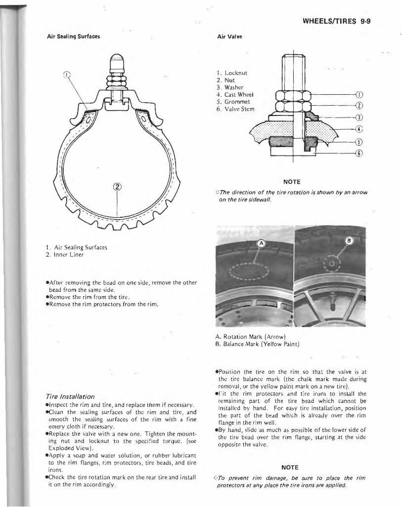
Air S •• lIng Surlaces
1. Air Sealing Surfaces 2. Inner Liner
eAfter removing the bead on one side, remove the other bead from the same 'iidc.
eRemove the rim from the tift:. -R emove the rim protectors from the rim.
Tire Installation elnspect the rim and tire, and replace them if necessary. eclean the sealing surfaces of the rim and tire, and
smooth the sealing )urfaces of the rim with J. fine emery cloth if necessary .
eReplace the valve with a new one. Tighten the mount· ing nut and locknut to the spec ified wrque. (sec Exploded View).
eApply a soap and water solution, or rubbt!r lubricant to the rim flanges . rim protectors, tire beads , and life irons.
-Check the life rotation mark on the rear tire and install it on the rim accord ingly .
WHEELS!TIRES 9-9
Air Valve
I. Locknut 2 . Nut 3. Was her 4. Cast Wheel 5. Grommet 6. Valve Stem
NOTE
G The direction of the tire rotation is shown by an arrow on the tire sidewall.
A. Rotation Mark (Arrow) B. Balanco Mark (Yellow Paint)
epOSilion the tire on the rim so tha t the valve is at the tire balance mark (the chalk mark made during removal, or the yellow paint mark on a new ti re).
eFit the rim protectors and tire irons to install the remaining part of the tire bead which cannot be installed by hand. For easy tire installat ion, position the part of the bead which is already over the rim flange in the r im well .
eBy hand, slide as much as poss ible o f the lower side of the tire bead over the rim flange, starting at the side opposite the valve.
NOTE
OTo prevent rim damage, be sure to place the rim protectors at any place the tire irons are applied.

9-10 WHEELSfTlRES
-'nstall the other side of the tire bead onto the rim in the same manner.
-Lubricate the tire beads and rim flanges with a soap and water solution or rubber lubricant to help seat the tire beads in the sealing surfaces of tile rim while inflating the lire.
-Center the rim in the tire be.ldsJ and inflate the lire with compressed air until the tire beads seat in the seal ing surfaces.
I WARNING I OBe sure to inltall the valve core
the tire, and do not inflate the 390 kPa (4.0 kg/em'. 57 psi) .
whens't'sr inflating tire to more than Overinflation can
explode the tire with possibility of injury and loss of life .
e(:heck to sec that the rim lines on both sides of the tire sidewalls are parallel with the rim flanges.
Rim line
1. Rim Line
elf the rim flanges and tire sidewall rim lines are not parallel, remove the valve core. Lubricate the rim flanges and tire beads. Install the valve core and inflate the tire again.
eAfter the lire beads seat in the rim flanges , check for a'ir leaks . Inflate the tire slightly above standard in· flation. Use a soap and water solution or submerge it, and check for bubbles that would indicate leakage.
-Adjust the air pressure to the specified pressure (see Tire Inspection ).
-Install the brake disc(s). -Balance the wheel.
Tire Inspection As the tire tread wears down, the rire becomes more
susceptible the puncture and failure. An accepted estimate is that 90% of all tire failures occur during the 1.15110% of tread life (90% worn). So it is false economy and unsafe to use the tires until they are bald.
-Remove any imbedded stones or other foreign particles from the tread .
-Visually inspect Ihe tire for cra.cks and cuts, replacing the Lire in case of bad damage . Swelling or high spots indicate internal damage, requiring tire replacement.
-Measure the tread depth at the center of the tread with a depth gauge. Since the tire may \\lear unevenly, take measurements at severa l places.
*If any measuremem is Jess than the service limit, replace the tire.
A. Depth Gauge
Tire Tread Depth
Front Standard Ser't'ice Umit
Rear Standard SerVice Limit
~ \
4.5mm 1 mm
7.3mm 2 mm lUnde, 130 km/h) 3 mm 10v., 130 km/hl
I WARNING I e Ta ensure safe handling and stability. use only the reo
commended standard tires for replacement. inflated to the standard preSlure.
NOTE
cCheck and balance the wheel when a tire is replaced with a new one.
Standard Tire
Front Size 130/90-1667H Make, Type DUNLOP F21 Tubeless
Rear Size 150/90-1574 H Make, Type DUNLOP K425A Tub.I ...

Tire Air Pressure (when cold)
Front 225 kPa (2.25 kg/em', 32 psi)
Up to 120 kg 225 kPa
Rear (265 Ib) Load (2.25 kg, 32 psi)
120 - 203 kg 280 k?a (2 65 - 448 Ib) Load (2.8 kgJcm' , 40 psi)
Tire Repair Recommendation Current.ly two types of repair for tubeless rires
have come into wide use. One type is called a temporary (extern al) repair which can be carr ied out without removing th e tire from the rim. and t.he other type is called permanent (internal) repair which requires tire removal. It is generally understood that higher running durability is obtained by permanent (internal) repairs than by temporary (~x ternal ) ones. Also, permanent (internal) repairs also have the advantage of permitting a thorough examination for seco ndary damage not visjble from external inspection of the tire. For these reasons, Kawasaki does not recommend temporary (external) repair. Only appropria te permanent (i nternal) repairs are recommended. Repair methods may vary sl ightly from make to make . Follow the repai r methods indi ca ted by the manufacturer of the repair tools and materials 50 that safe results can be obtained.
Wheel Bearings and Grease Seals
Wheel Bearing Removal Notes
Cl Oo not lay the wheel on the ground with the disc facing down. This can damage or warp the disc. Place blocks under the wheel so the disc does not touch the ground.
-Remove [he front wheel bearings. c'lnsert a metal rod into the hub from the right side, and
remove the left side bearing by tapping evenly around the bearing in ner race . Th~ dis tance collar comes out with the bearing.
oRemovc the remaining bearing by tapping \!venl y around the bearing inner race.
-Remove the rear wheel bearings. Olnsert a metal rod into the hub from the left si dl:, and
remove the right side bearing by tapping evenly around the bearing inner race. The distance collar comes out with the bearing.
o Remo\'e the remaining bearing by tapping evenly around the bearing inner race.
WHEELS/TIRES 9·11
Wheel Bearing Installation Notes -Before installing the wheel bearings, blow any dirt or
foreign particles ou t of the hub with compressed air [0 prevent contamination of the bearings.
.Pac k the front bearings (sin gle face shield type) with a good quality bearing grease before installation .
-Install the wheel bearings using the bearing driver set (special tool: PIN 57001-1129) so that the marked sides face out. The front bearings (single face shield type) should be insta lled with the sh ielded sides facing out.
Wheel Bearing Inspection - Turn the bearing back and forth while checking for
roughness of binding. _If roughness or binding is found, replace the bearing. - Ex amin e the bearing seal for tears or leakage . -If the sea! is torn or is leaking, replace the bearing.
Grease Seal Inspection -Visually inspect the grease seal. -Replace any if the lips are misshapen , discolored
(indicating that the rubber has deteriorated), hardened , or been otherwise damaged.
Speedometer Gear Housing
Speedometer Gear Housing Disassembly Notes -If the speedometer cable bushing or speedometer
pinion needs to be removed, first drill the housing th ro ugh the pin using a 1.0 to 1.5 mm drill bit. Drill the housing from the under side using a 3.0 to 3.5 mm drill bit. Using a suitable 3 mm rod, tap out the pin , and then pull out the speedometer cable bushing, pinion, and washers .
NOTE
Olt is recommended that rhe assembly be replaced rather than attempting to repair the components.
Speedometer Gear Housing Assembly Notes -Aft!.:!r inserting a new ph1, stake the housing hole to secure the pin in place.
-Pack the gear housing with a high tempera ture grease.

9·12 WHEELS/TIRES
Wheel Bearings
Front Wheel
Rear Wheel
~ II ' \ \ , \ \ . \'-,
I 1
\ l .
L
---------
G
n I : : "-..----:
I r -'-'
i..-.. .J
fJ c.0"
n i!
-----------
(4 Q I,
G
I I
I (
"/ ,\ -
; I
\ , .. , , ,
I
1. Axle NUL 2. Speedometer Gear Homing 3. Speedometer Gear 4. Pinion 5. Speedometer Gear Drive 6. Grease Seal 7. Circlip 8. Bearing 9. Distance Collar
10. Rim 11 . Grease Seal 12. Collar 13. Axle G : Grease.
1. Axle 2. Cover 3. Distance Collar 4. Bearing 5. Rear Wheel Coupling 6. Circlip 7. Rubber Damper 8. O-ring 9. Distance Collar
10. Rim 11. Circlip 12. Grease Seal 13. Collar 14. Axle Nut 1 S. Cotton Pin fl G : Grea!e.

FINAL DRIVE 10-1
Final Drive Table of Contents
Exploded View, , , . ' , . , , . , . , , , ' . , ...... , . , . , .. ' . , , .. , ' , .. , , 10-2
Specifications, , , , , , , , . • ' , , ... , , . , . • , . , .. , , .. , . , ' . , .. . , .. ' . 10-3
Special Tools , .. ,',' ... . , ..... " .. _ , ' , ..• , , . . , ... . . . , . . . . . lOA
Final Gear Case Oil .. , , , , . , . , , .. , , , , , . , , , , . . . , , ... . . , , . , , . , . 10-5
Final Gear Case Oil Level Inspection .. ,., .• "."" . . "."., 10·5
Final Gear Case Oil Change ". " ... , ....... , ., . , . •. ', ., . , 10-5
Final Gear Case ", . . ,.,., . . . . , . . , .... ,., .•. . ' _ .. .. . , . , , . . . 10-5
Final Gear Case Removal " .. ',." .. ", . . . , ... , ..•.... ," 10-5
Final Gear Case Installation Notes , , ... , .. .•. , .. , . , . _ , , . , , , 10-6
Final Gear Case Disassembly " .... , . . . .. . . ' ...... , ..... ,. 10.6
Final Gear Case Assembly Notes". , . .• ,., . .... "" . • ,.,., 10.7
Bevel Gear Inspection. , . . .. , . . ... , . . .... .. , . .... . .. . . , , . 10-B
Pinion Joint Inspection ... " .. • ,., . . . ,',................ 10-B
Ball Bearing Inspection. , , . , .. , ... .. , . . . . . . . . . • . . . . . . . . . . 10.8
Needle Bearing Inspection .. . .. .• ... .. . ... . .......... . • .. 10-8
Oil Seal Inspection .. , . , .... , . ..•... . .. , ...... . , . . . . . . . . 10-8
Propeller Shaft ...... , , . , ... ........ . .... , . .. •. . . . •. .. . . .. , 10-8
Propeller Shaft Removal . . , . , ..........•...... , . . . . . . . . . . 10-8
Propeller Shaft I nstallation Notes , ............ , . . . • . . . . . . • . 10-9
Propeller Shaft Joint Lubrication ..... _ . . .. , _ . ....... . , __ . . 10-9
Propeller Shaft Inspection .. ,.,., . ... , .. • ' , ........ _ . , . . . 10-9
Propeller Shaft Sliding Joint Inspection ... . .... . , .. _ .•. .. , . . 10-9
Front Bevel Gears ........... . . ," ... , .. .. . ... . .. , . . . . •.. , .. 10-10
Front Gear Case Removal ... , .. , .. , . . . . . . . . . . . . . . . . . . . . .. 10-10
Front Gear Case Installation Notes ........... _ , . .. . . .. .. .. , 10.10
Front Gear Case Disassembly . ... , . . , ......• ' . . . . . . . . . . . .. 10-11
Front Gear Case Assembly Notes." ..... , .... , .. "., ... ,., 10-12
Driven Gear Disassembly , ... , .. " .. . .... .. ' . . , .". , . .. ,' 10-12
Driven Gear Assembly Notes ...... " ... ,., _ .. . . . _., ..• _, . 10-13
Damper Cam Removal, . , , .. , , ...........• , , .• .... .. . • . , 10-13
Damper Cam Installation Notes .. " .... ,., . ... .... , .. , .... 10-13
Front Bevel Gear Adjustment ..............•... . , ......• ,. 10-13
Bevel Gear Inspection. , .... , .. . , , .... , . .. .... . ... . , , .... 10-1B
Cam Damper Inspection, .. , . , , .. . , , . , ... , . .. ... . , . , . . . .. 10-18
Ball Bearing Inspection .... " .... , . . .. ..... ,." ... , ...... 10- lB
Tapered Roller Bearing Inspection ..... , ... .. . .. .... . . . , . .. lo.1B
Needle Bearing Inspection " . ... ', ... , .. . , ... , . .. ,. , ..... 10-lB
Oil Seal Inspection , .. , . . ..•..... . . , . . . • ,' . ... ', .... " .. 10-lB
Rear Wheel Coupling, .. , .. , . , .. , ... . .. . , .. ...... , . , .. . . .. ,. 10-18
Rear Wheel Coupling I nstallation Note , . .. .. , . . . . . . . . . . . . . . . 10-18
Damper Inspection , ... ... .. .... ... . , , . . . . . . . . . . . . . . . . .. 10-18

10-2 FINAL DRIVE
Exploded View
Ii)/
~.% Ii) ~~
® CD T9
T3
1. Neutral and Overdrive Switch
G : Grease L : Non·permanent Locking Agent SS : Sil icone Sealant M : Molybdenum Disulfide Grease St : Stake the fastener.
Viewed from Left
o 0
v •
o· CD () ~
; 1 ()
.®~~ ~
vO~@ D ®
0@ @ ~~J
T1 : 4.9 N·m 1050 kg-m , 43 in ·lbl T2: 9.8 N-m 11.0 kg·m, 87 In-Ibl T3 : 12 N-m /1 .2 kg·m, 104 in·lb) T4 : 16 N·m /1 .6 kg·m,ll .5 ft -Jb) T5 : 24 N-m /2 .4 kg-m , 17.51t·lb) T6 : 29 N-m 13.0 kg-m , 22 It ·Jb) T7: 120 N-m /12 .0 kg-m , 871t·lb) T8 : 225 N·m /23 kg-m, 165 ft4b) T9 : 265 N-m /27 kg·m, 195 ft4b) no: 540 N-m 155 kg-m , 400 ft ·Jb)
s

Specifications
Final Gear Case Oil:
Final Gear Case:
Item
Grade
Viscosity
Amount
Oil Level
Final Bevel Gear Backlash
Front Bevel Gears:
Preload for Driven Gear Bearings
Front Bevel Gear Backlash
FINAL DRIVE 10-3
a
°c::noo ~~© 'I' Q@
~~/ @
@r:?
Standard
API GL5 Hypoid Gear Oil
SAE80
210 mL
Bottom of filler opening
0.06 - 0.10 mm (at gear shaft spline)
0.10- 0.15 mm (at gear tooth)
0.6 - 1.0 N·m (0.06 - 0.10 kg-m, 5 - 9 in-Ib)
0.13 - 0.18 mm (at gear tooth)

10-4 FINAL DRIVE
Special Tools
Along with common hand tools, the following more specialized tools are required for complete final drive servicing.
Bearing Puller: 57001-158
Adapter: 57001-317
Driv",: 57001-382
Damper Cam Holder: 57001-1025
Drivon Gear Holder: 57001-1027
.. :..:~.:/
Dial Gauge Holder: 57001-1049
o
o
Oil Seoland Bo.ring Remover: 57001-1058
Bearing Driver Set: 57001-1129
Pinion Gear Holder: 57001-1165
Drive Gear Holder: 57001-1226

Final Gear Case Oil
Final Gear Case Oil Level Inspection -Support the motorcycle on its center stand. eRemove the left saddlebag. _Unscrew th e filler plug. The oil level should come to th~ bottom of the filler opening,
A. Filler Opening B. Drain Plug
*If it is low, first check the final gear case for oil leakage, remedy it if necess.ary, and add oil through the filler opening. Use the same type and brand of oil that is already in the final gear case,
-Install the filler plug.
Final Gear Case Oil Change .Warm up the oil by running the motorcycle so that the
oil will pick up any sediment and drain easily. Then stop it.
-Support the motorcycle on its center stand . • Place an oil pan beneath the final gear caSt::, and remove
the drain plug.
I WARNING.
C::When draining or filling the final gear case, be careful that no oil gets on the tire or rim. Clean off any oil that inadvertently gets on them with'3 high flash-point sol~ent.
eAfter the oil has completely drained out, install the dra in plug with a new gaske t.
eFili the final gear case with the specified oil and quantity.
Final Gear Case Oil
Amount Grade Viscosity :
210 mL API G L-5 hypoid gear oil SAE 80
FINAL DRIVE 10-5
NOTE
o The term "GL·5N indicates a quality and additive rating. A "GL-6 N rated hypoid gear oil can also be used.
-Be sure the O-ring is in place,and Install the filler plug.
Final Gear Case
NOTE
o This manual does not cOlier the pinion gear removal because of the highly specialized equipment that is required. If the pinion gear remollal is necessary, it should be done by a properly equipped shop.
Final Gear Case Removal elf the final gear case is to be disassembled, drain the
final gear case oil. eRemove the following.
Travel Trunk and Bracket Rear Seat Saddlebag:; and Brackets Rear Wheel
eRemove the Idt shock absorber from its studs by taking off the mount ing nuts.
eRemove th e final gear case by taking off the mounting nuts. The spring comes off with the case.
NOTE
Glf the final gear caSe is full of oil, place the case so that the breather hole is on top.
A. Final Gear Case Mounting Nuts B. Breather Hole
, I
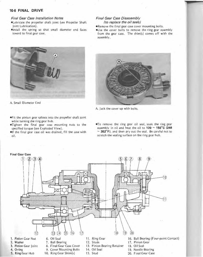
10-6 FINAL DRIVE
Final Gear Case Insrallarion Nores eLubricate the propeller shaft joint (see Propeller Shaft Joint Lubrication ).
elnstall the spri ng so that small diameter end faces toward to final gear case ,
A. Small Diameter End
-Fit the pinion gear splines into the propell er shaft joint white turning the ring gear hub .
eTighten the final gear case mounting nuts to the specified to rq ue (see Ex ploded Vi ew).
elf the final gear case oil was drained, fill the case with oil.
Final Gear Case
1. Pinion Gear Nut 6. Oil Seal 2. Washer 7. Ball Bearing 3. Pinion Gear J oi n l 8. Final Gear Case Cover 4. O-ring 9. Cover Mounting Bolts 5. Ring Gear Hub 10. Ring Gear Shim(s)
1l. 12. 13. 14. 15.
Final Gear Case Disassemblv (ro replace rhe oil seals)
-Remo ve the final gear case cover mount ing bolts. - Use the cover bolts to remove the ring gear assembly
from the gear case. The shim(s) comes off with the assembly.
A. Jack the cover up with bolts.
eTo remove the ring gear oil seal, soak the ring gear assembly in oil and heat the oil to 120 - 150°C 1248 - J02"F), and then pry out the seal. Be careful not to scratch the sealing surface on the ring gt::ar hub.
Ring Gear 16. Ball Bearing (Four-point Contact) Studs 17. Pini on Gear Pinion Bearing Retainer 18. Oil Seal Oil Seal 19. Needle Bca ri ng Stud 20. Final Gear Case

( CAUTlO~] COo not heat the case with a lorch. This will warp the
case.
-Remove the snap ring and pull out the needle bearing outer race and oil seal together using the oil st:aj and bearing remover (special tool: PIN 57001-1058)_
-Remove the o il seal on the pinion bearing retainer without the pinion removal.
oUnscrew the pinion nut using the pinion gear holder (spcc iallool),
A, Pinion Gear Holder: 57001-1165
GRemo\'c the washer and pinion joint with the a ·ring. c pull out the oil ')eal on the pinion bearing retainer using
a suitable puller.
Final Gear Case Assembly Notes (to replace the oil seals)
eThe ring gear and pinion are lapped as a set in the faclOry to get the best tooth contac.t. They must be installed as a pair, never replac.e one without the other .
• Use a suitable driver to drive in the oil seals being careful of installation direction and depth.
ePress the ring gear assembl y slowly with a suitable driver to firmly sea t the ball bearing if it may slide out a liule by removal.
FINAL DRIVE 10·7
A. Pre!is here.
eAlign the oil hole in the needle bearing outer race with the hole on the bearing housing (pinion gear side).
A_ Oil Hole
eBlow the breather hole in [he final gear case cover clean with compressed air.
A, Breather Hole

10-8 FINAL DRIVE
OReinstal1 the original ring gear shim(s} to keep the gear backlash and the tooth contact unchangeiL
'Appl y a non-permanent locking agent to the threads of the cover bolts, and tighten them to the specified torque (see Exploded View).
-Replace the pinion nut with new one, -Using the pinion gear holder (special tool). tighten the
pinion nut to the specin ed torque (see E.plodcd View).
_Stake the pinion nut with a punch.
{ CAUTlO:~] GWhen staking the nut, be careful not to apply shock to
the pinion and its bearing. Such a shock could damage the pinion and/or bearing.
eApply a non-permanent locking agent to the threads of each stud and install them to the case if they were removed.
Bevel Gear Inspection -Visually check the bevel gears for scoring, chipping, or
other damage. *Replace the bevel gears as a set if ei ther gear is
damaged .
Pinion Joint Inspection _Visually inspect the splines of the pinion joint. *If they are badly worn or chipped, replace the joint
with a new one. Also, inspect the propeller shaft sliding joint.
A. Check splined portion.
Ball Bearing Inspection Since the ball bearing is made to extremely dose
tolerances, the wear must be judged by feel rather than measurement. -Spin the bearing by hand 10 chec.k its condition. *If fhe bearing is noisy. does not spin smoothly, or
has any rough spots, replace it (as a gear set ).
Needle Bearing Inspection .The rollers in a needle bearing normall y wear very
little, and wear is difficult to measure. Instead of measuring, inspect the bearing for abrasion, color change! or other damage.
*If there is any doubt as to the condit ion of a neeqle bearing, replace it.
Oil Seal Inspection elnspect the oil seal. *Rcplace it if the lips arc misshapen, discolored (in
dicating that the rubber has deterio rated), hardened, or been otherwise damaged.
Propeller Shaft
Propeller Shaft Removal eRemove the following.
Rear Wheel Final Gear Case Swing Arm
.Remove the propeller shaft from the front driven gear joint.
c Turn the propellt.'f shaft so that the locking pin access hole on the propeller shaft comes outside.
A. Locking Pin Access Hole
CPushing on the locking pi n J liule into the propeller shaft, slip the propeller shaft off the driven gear joint.
• •

Disengagement of Propeller Shaft from Driven Gear Joint
-
1. Propeller Shaft 4 . Spring 2. Universal Joint 5. Driven Gear Joint 3. Locking Pin
.Remove the drc!ip and washer from the rear end of the propeller shaft.
-Pull out the propeller shaft sliding joint off the propell er shaft.
Propeller Shaft Installation Notes e<:heck the O-ring on the rear end of the propeller sh aft
for any kind of damage, and replace it if nece~sary .
-Lubricate the propeller shaft joint (see Propeller Shaft Joint Lubrication).
. ... \fter connecting the propel ler shaft to the driven gear joint, pull the propeller shaft rearward to check that the shaft is secured in place by the locking pin.
Propeller Shaft Joint Lubrication -Wipe off the old groase from th e propeller shaft slid ing
joint and pinion joint. _Pack the propeller shaft sl iding joint with 20 mL (16
grams) of high temperature grease.
FINAL DRIVE 10-9
Propeller Shaft Sliding Joint Lubrication
High Temperature Grease
. - - . -----4::8-
Propeller Shaft Inspection e<::heck that the universal joint works smoothl y wi thout
ratt ling or sti ck ing. *If it does not work smoothly) the needle bearings of
the universal joint are damaged. Replace the propeller shaft as sembly with a new one .
• Visually inspect the bearing of the shaft and the wear of the splined section at the rear end of the shaft.
*If it is bent at all, repl.ace th e propeller shaft assembly. 00 not attempt to straighten a ben t shaft.
A. Check universal joinl. B. In spect shaft and splined port ion .
Propeller Shaft Sliding Joint Inspection .Visual ly inspe ct the internal splines of the propeller
shaft sliding joint. *I f they are badly worn or chipped , repl ace the joint
with a new one.
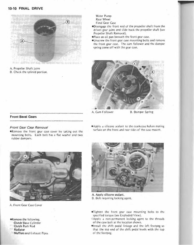
10-10 FINAL DRIVE
A. Propeller Shaft Joint B. Check the splined portion .
Front Bevel Gears
Front Gear Case Removal -Remove the front gear case cover by laking out the
mounting bolts. Each bolt has a flat washer and two rubber dam pers.
A. Front Gear Case Cover
-Remove the following. Clutch Slave Cylinder GUlCh Push Rod Radiat", Illume<' and Exhaust Pi pe,
Water Pump Rear Wheel Final Gear Case
eDisengage the front end of the propeller shaft from the driven gear joint and slide back the propeller shaft (sec Propeller Shaft Removal) .
• Place an oil pan beneath the front gear case, -Unscrew the front gear case mounting bolts and remove
the front gear case. The cam follower and the damper spring come off with the gear case,
•• -A. Cam Follower B. Damper Spring
eApply d silicone sealant to the crankcase halves mating sur face on th e front and rear si des of the CdSI! mount.
A. Apply silicone sealant. B. Bolt requiring locking agent.
-Tighten the front gear ca!le mounting bolts to the specified torque (se< Exploded View).
OApply a non-permanent locking agent to the threads of the case bolt at the location shown .
-Install the Ihift pedal linkage and the left footpeg so that the top end of the shift pedal levels with the top of the footpog .

A Level B,90'
e lf the shift peda.l linkage was removal from the footpeg bracket, apply a grease to the pivot shaft before in· stalling it [0 the bracket.
e<::heck the engine oil level and add oil if necessary. -Fit the rubber dampers and bolts onto the front gear
case, and then the screw in the bolts to mount the Co\'er .
Front Gear Case Cover Bolt and Rubber Dampers
CD (2' 3' (4;
1. Bolt 2. Wa,her 3. Rubber Damper
i ~)
I
~ 4. Rubber Damper 5. Front Gear Case Cover 6. Fran t Gear Case
Front Gear Case Disassembly (including drive gear removal)
_R emove tht: cam follower and the damper spring. -Remo\'c the driven gear assembly mounting bolts and
pull the assembly off the case. -Unscrew the oil pipe Clamp bolts from inside the case
and remove the oil pipe with the Q-ring.
A. Cam Follower B. Damper Spring C Oil Pipe Clamp Bolts
-Remo\'e the drive gear.
FINAL DRIVE 10-11
D. Driven Gear Assembly Mounting Bolt,
o Unscrew the drive gear nut cap mounting boilS, and remove the cap with the O-ring.
A. Drive Gear Nu t Cap
OPry open the drive gear nut with a small chisel. OUnscrcw the drive gear nul hold ing the drive gear shaft
with the holder (,pecial tool ).
A. Drive Gear Holder : 57001·1226
o Pull off the drive gear shaft with the drive gear, collar , and shim(s),
_Remove the drive gear shaft ball bearing using [he bearing drive r set (,pecial tool : PIN 5700'1·1129),
I.

10·12 FINAL DRIVE
Front Gear Case Assembly Notes (including drive gear Instal/ation)
eThe drive and driven gears are lapped as a set in the factory to get the best tooth contact. They must be replaced as a set.
.Press the drive gear and shaft assembly slowly with the driver (special tool) to firml y seat the gear onto the shaft.
A. Driver : 57001·382
eBe sure to check and adjust the bearing preload and the bevel gear backlash and tooth contact, when any of the backlash-related parts are replaced (see Front Bevel Gear Adiustment).
eAfter completing all adjustment, re-assemble the front gear case.
;JReplace the dri\'e gear nut with a new one. OApply oil to the threads and seating surface of the nUl,
and tighten it to the specified torque (see Exploded View).
OLoosen the nut completely and retighten it to the specified torque.
GStake the nut to secure it in place.
::When staking the nut, be careful not to apply shock to the shaft and its bearing. Such a shock could damage the shaft and/or bearing.
:)Apply a non-permanent locking agent to the threads, and tighten the cap mounting Allen bolts to the specified torque (see Exploded View).
Olnstall the driven gear assembly so that the oil hole on the housing aligns with the oi l hole in the case.
OTightcn the driven gear asst!mbly mounting bolts to the specified torque (sec Exploded View).
OApply a non-permanent locking agent to the threads, and tighten the case inside oil p ipe clamp bolts.
A. Oil Holes
.If the neutral and o verdrive switch and collar were removed, install them as following.
o;\pply a silicone sealant to the threads of the collar and tighten it to the specified torque (see Exploded View).
oApply a non-permanent locking agent to the threads, and install the neutral and overdrive switch so that the terminal lead runs toward the front of the case. Tighlell the switch to the specified torque (see Exploded View) .
• ,f the case outside oil pipe was removed, use a new flat washer on each side of the fittings, and tighten the banio bolts to the specified torque (see Exploded View).
Driven Gear Disassembly .Holding the driven gear joint with t he driven gear
holder (special tool), unscrew the driven gear bolt.
A. Driven Gear Bolt B. Driven Gear Holder: 57001·1027

eRemove the driven gear joint with the O-ring. eRemove the driven gear from the bearing housing. eRemove the co llar and the spacer from the driven gear . ePress the tapered roller bearing and oil seal out o f the
ho using using the bearing driver set (special tool: 57001-1129).
-Remove the tapered roller bearing which is pressed onto the driven gear sha ft with the bearing puller and adapter (special tools : 57001-158 and 57001-317).
Driven Gear Assembly Notes -The drive and driven gears are lapped as a set at the
factory to get the best tooth contact, They must be replaced as a set. .
eBe sure to check and adjust the bearing preload and the bevel gear backlash and tooth co ntact (see Front Bevel Gear Adjustment).
-Drive the tapered roller bearing inner race onto the driven gear shaft using the bearing driver (special tool).
A. Bearing Driver: 57001-382
- After completely the bearing preload adj ustment, re-assemble the driven gear assembl y.
CU , ing the bearing driver set (s pecial 1001 : 5700 1-1129), press the oi l seal in unti l the face of the seal is level with the end of the bearing housing hole.
OTighten the driven gcar bo lt to the specified torqu~ (see Ex ploded View).
CStake the driven gear bolt to prevent it from loosen ing.
c..:When staking the nut. be careful not to apply shock to the driven gear and their bearings. Such a shock could damage the driven gear and/or bearings.
Damper Cam Removal -Remove the retainer and needle bearing . -Holdi ng the damper cam with the damper cam holder
(special tool ), unscrew the dam per cam nut.
FINAL DRIVE 10-13
A. Damper Cam B. Holder: 57001-1025
Damper Cam Installation Notes -Replace the damper cam nut with a new one. -Tjght~n the damper cam nut to the specified torque
(see Exploded View). o;\pply a small amount of oil (0 th~ threads and the
seating surface of the nut.
Front Bevel Gear Adjustment In order to prevent one gear from moving away from
the oth er gear under load, the tapered roll~r bearings must be properly preloaded. Also the backlash (distance one gear will move back and forth without moving the other gear) and tooth contact pattern of the bevel gears must be correct to prevent the gears from making noise and b~ing damaged.
f-\bove three adjustments are of critical importance and must b~ carried out in the correct sequence and method .
Front Bevel Gear Adjustment Procedure
I Preload the driven gear bearings. I ,It
I Adjust gear backlash_ I I ,
,
I Adjust tooth contact pattern_ I \ It
I Assemble the front gear case completly. I

10-14 FINAL DRIVE
When the any of the baoklash-related parts arc replaced, or the driven gear bolt is loosened; even if the purpose is not to replace the parts, be sure to check and adjust the bearing preload and the bevel gear baoklash and tooth contact by replacing shims.
Backlash-Related Parts
1. Drive Gear 2. Collar 3. Drive Gear Shim(s) 4. Ball Beari ng 5. Drive Gear Shaft 6. Front Gear Case 7. Driven Gear 8. Tapered Roller Bcaring 9. Driven Gear Shim(s)
10. Driven Gear Bearing Housing
Parts which influence bearing preload only
11. Collar (Preload Adjustment) 12. Spacer (Preload Adjustment) 13. Tapered Rollar Bearing
·14. Driven Gear Bolt
*Prcload adjustment is necessary whcn e ... er the bolt is loos ened, even if the purpose is not to replace the parts.
Preload adjustment -Assemble the driven gear asse mbly , and li ghten the
driven gear nut to the specified torque (~te Ex ploded View). Do not install the oil seal and do nor stake Ihr.: bo lt until the correct bearing preload is oblained.
e Ta start With, choose a shim or collar so that the bearings are just SNUG with NO play but also with NO preJoad.
OAny over-preload on the bearings could damage the bearings.
-Apply a little engine oil to the bearings , and turn the gear shaft more than 5 turns lo allow thl.! bearings to sea t.
-Measure the bearing preload. Bearing: preload is defined as th e force or torque which is needed to start the gear shaft turn ing.
Preload for Driven Gear Bearing
USing Spring Scal.: 3 - 5 N (0.30 - 0.50 kg,0.7 -l.llb)
Using Torque Wrench: 0.6 - 1.0 Ni11 (0.06 - 0.10 kg·m, 5 - 9 in~b)
NOTE
CPrelo8d can be measured eirher with a spring scale or a beam-rype torque wrench. When measured with a spring scafe, the preload is designated by force (N, kg, Ib), and when measured with a torque wrench , it is designated by torque (N-m, kg-m, in-fbi.
OUsing Spring Scale: Hook the spring scale on the handle ae a point 200
mm apart from the center of the gear shaft. Hold the bearing housing in a vise so that the gear
shaft axis is vertical. Apply force to the handle horizontally and at a right angle to it.

A. Spri ng Scale C. Driven Gear Holder : 57001·1027 B. Hole D. 200 mm
Bearing Prel08ding Mechanism
(A) Before Tightening
Under No Preload
Init ia l Clearance
Under No Preload
Collars for Preload Adjustment
Lengt~ (mm)
22.8 22.9 23.0 23.1 232 23.3 23.4 23.5 23 .6 23.7 23.8 23.9 24 .0 24.1
Part Number
92027·1152 92027 ·1153 92027 ·1154 92027·1155 92027 ·1156 92027·1157 92027·1158 92027·1159 92027 ·1160 92027·1161 92027 ·1 162 92027·1163 92027 ·1164 92027 ·1165
FINAL DRIVE 10-15
*If the pteload is out of the specified range, replace the bearing collar andior spacer. To increase preload, decrease the stack length of the collar and spacer. To decrease preload increase the slack length of the collar and spacer .
..:rchange the stack length a little at a lime . eRe-check the bearing preload, and re-adiust as neces
sary _
(8) Mter Tightening
Under Pre load
~--No Clearance
Under Preload
1, Bearing Housing 2. Tapered Roller BeJri ng 3. Spacer 4. Col/ar 5. Tapered Roller Bearing
Spacers for Preload Adjustment
Thickness (mm)
1.70 1.72 1.74 1.76 1.78 1.80
Port Number 92025-1072 92025·1073 92025·1074 92025·1075 92025·1076 92025·1071

10-16 FINAL DRIVE
Backlash adjustment -Clean any dirt and oil off bevel gear teeth . -Install the drive gear with the primary shim (1.0 mm
thickness), and tighten the nut to the specified torque (see Exploded View).
NOTE
8Do nor stake the head of the nut until both backlash and tooch contact adjustments are finished.
-Insta ll the driven gear assembly to the front gear case with the primary shim (1.0 mm thickness), and tighten the mo unting bolts to the spccifi~d torque (st:t:: Exploded View).
cCheck the backlash during the tightening of the mounting bolts, and stop tightening them immediately if the backlash disappears. Then, change the 'him to a thicker o ne ,
-In stall the dial gauge holder (special tool) with 6 mm bolts .and nuts on the fro nt gear case to mount a dial gauge .
- Set up a dial gauge against a drive gear tooth to check gear backlash. The gauge stem must be in line with the direction of tooth travel.
e T 0 measure the backlash, move the drive gear back and forth while holding the driven gear steady with a suitable tool. The difference between the highest and lowest gauge 'readings is the amount of back lash.
*If th e backlash is not within the limit, replace the gear shim(s) at the dri\/c and/or driven gear. To increase backlash, increase the thickness of the shim(s) . To decrease backlash f decrease the thickness of the shim(s) .
' .change the thickness a little at a time. e Re ·check ttie backlash, and re ·adjust as necessary .
NOTE
Olt is OK to use the pack of two shims. Do not use the pack of three or more shims.
Front Bevel Gear Backlash (at the gear tooth)
0.13 - 0.18 mm
A. Holder : 57001·1049 C. Move the drive gear. B. Hold t he driven gear.
Shims for Drive Gear
Thickness (mm) Part Numbor 0.15 92025·1688 0.5 92025-1689 0 .6 92025·1690 0.7 92025-1691 0.8 92025-1692 0.9 92025-1693 1.0 92025-1694 1.1 92025-1695 1.2 92025·1696
Shims for Driven Gear
Thickness (mm) Part Number 0.1 92025·1724 0 .15 92025-1725 0 .5 92025·1726 0.6 92025 ·1727 0 .7 92025-1728 0 .8 92025·1729 0.9 92025-1730 1.0 92025·1731 12 92025·1732
Tooth contact adjustment e(lean any din and oil off the bevel gear teeth. - Apply checking ccmpound to 4 or 5 teeth on the
driven gear.
NOTE
OApply checking compound to the teeth in a thin , even coat with a fairly sriff paint brush. If painted too thickly, the exact tooth pattern may not appear.
;";The checking compound must be smooth and firm, with tIle consistency of tooth paste.
OSpecial compounds are available from automotive supply stores for the purpose of checking differential gear tooth patterns and contact. Use this for checking the bevel gears.
eTurn the driven gear for 3 or 4 revolutions in the drive and rc\'erse (coas t) direct ions , while creating a drag on the drive gear.
echcck the drive pattern and coast pattern of the bevel gear teeth. The tooth contact patterns of both drive and coast sides should be centrally located between the top and boltom of the tooth, and little closer to the toe of the tooth.
*,f the tooth contact pattern is incorrect , replace the shim(s) at the drive gear and shim(s) at the driven gear, following the exam ples shown . Then erase the tooth contact palterns f and check them again. Also check the backlash every t ime the shims are replaced. Repeal the shim change procedure as necessary.
NOTE
CIf t /'e backlash goes out of standard range after changing shims, co" ect the backlash before checking the tooth contact pattern.
Olt is OK to use the PliCk of two shims. Do not use the pack of three or morfJ shims.

Correct Tooth Contact Pattern
Heel
rl'---+-"<--'T ,~~ >,6--+_-fu~e , t
Bottom
1. Drive Gear 2. Driven Gear
Incorrect Tooth Contact Patterns
Example 1: Increase the thickness of [he drive gear shim(s) by 0.05 mm , and/or increase the th ickness of the driven gear shim(s) by 0.05 mm to correct the pattern stlOwn below. Repeat in 0.05 rnm steps jf nc(essary.
"'1 ''---I '-'-'
2
Heel \ .~TOP
T Toe Bottom
\ Heel
Top \
n4-_-+-_..;T",,~~ \
-----'''' Bottom
FINAL DRIVE 10.17
Example 2: Decrease the thickness of the drive gear shim(s ) by 0 .05 mm, and/or decrease the th ic kness of the driven gear shim(s) by 0 .05 mm to correct the pattern sh own be low. Repeat in 0.05 mm steps if nc(essa ry.
(! I-----1
/',"
~2
Heel .. _~TOP
I ioe Bottom
Heel Top \
TOH~.) d-:9--->-----<n # r
Bottom
1. Drive Gear 2, Driven Gear

10-18 FINAL DRIVE
Bevel Gear Inspection -Visually check the bevel gears for scoring, chipping, or
other damage. *Replace the bevel gears as a set if either gear is
damaged .
Cam Damper Inspection .Visually inspect the damper cam, cam follower J spr ing,
and shaft. .Replace the part if it appears damaged.
0) !
A. Cam C. Spring B. Cam Follower D. Shaft
Ball Bearing Inspection -5i nee the ball bearing is mad!! to extremely close {Q lcrance~J the wear must be judged by fee! ratht:r than measurement. Clean the bearing in a high flashpoint solvent, dry it (do not spin the bearing while it b dry). and oi l it with engine oil.
eSpin the bearing by hand to check its condition . *If the bearing is noisy, does not spin smoothly. or has
any rough spots, replac~ it.
Tapered Roller Bearing Inspection eVi sually inspect the bearing for abrasion, color change,
or other damage. *If there is any doubt as to the condition of a bearing,
replace it.
Needle Bearing Inspection eThe rol1er~ in a needle bearing normally wear very
little, and wear 4S difficult to measure. In:itead of mea'suring, inspect the bearing for abrasion, color chang,e~ or other damage.
*If there is any doubt .as to the condition of a needle bearing, replace it.
Oil Seal Inspection elnspect the oil seals. *Rcplacc it if the lips arc misshapen , discolored (i n
dicating that the rubber has deteriorated), hardened, or been otht:rwisc damaged.
Rear Wheel Coupling
Rear Wheel Coupling Installation Note eAppl y grease to the G-r ing on the rear hub and install
the rear whee 1 coupl ing.
A. Grease. B. G-ring C. Rear Wh ee l Coupling
Damper Inspection eVisually inspect the rubber damper of the rear wheel
coupling. *If it appear ... damaged or deteriorated, replace it.
A. Rubber Damper

BRAKES 11-1
Brakes Table of Contents
Exploded View. . . . . . . . . . . . . . . . . . . . . . . . . . . . . . . • . . . . • . . . . • . . 11-2
Specifications ..... _ .....• ... . _ ...............•......... _ . . 11-4
Special Tool ...... . ...........•..........•.........•... . _ . 11-4
Brake Fluid .................. .... ........•............. . . 11-5
Brake Fluid Requirement. . . . . . . . . . . . • . . . . . . . . . . . . . • . . . . . 11 -5
Brake Fluid Level Inspection. . . . . . . . . . . . . . . . . . . . . . . . • . . . . 11-5
Brake Fluid Changing. . . . . . . . . . . . . . . . . . . . . . . . . . . . . . . . . . . 11 -6
Brake Line Air Bleeding. . .. . . . ... . . . .. . . .. . . . . . . . . . .. . .. 11-6
Master Cylinders. . . . . . . . . . . . . . . . . . . . . . . . . . . . . . . . . . • . . . . . . . . 11-7
Front Master Cylinder Removal. . . . . . . . . . . . . . . .. ... . . .• . . . 11-7
Front Master Cylinder Installation Notes. . . . . . • . . .. . .. . . . . . . 11-7
Rear Master Cylinder Removal. . . . . . . .. . . . . . . . . . .. .. ... . • . 11-7
Rear Master Cylinder I nstallation Notes. . . . . . . . . . . . . . . . . . . . . 11·B
Front Master Cylinder Disassembly .......•.........•...... 11-8
Front Master Cylinder Assembly Notes. . . . . . . . . .. .. . . . . . . . .. 11-9
Rear Master Cylinder Disassembly. . . . . . . . . . . . . . . . . . . . . . . . . 11-9
Rear Master Cylinder Assembly Notes. . . .. . . . . . • . . . . .. . . . . . 11-9
Master Cylinder Inspection. . . . . . . . . . . . . . . . . . . . . . . . . . . . . . . 11-9
Calipers ............ ... ...... . ...... . .......... _ •.. . •.... 11-10
Caliper Removal ..............•.... _ . . . . . . . . . . • . . . . . . .. 11-10
Caliper Installation Notes . . . . . . . • . . . . . . . . . . . . . . . • . . . . • . .. 11-11
Caliper Disassembly Notes. . . . . . • • . . . . . . . . . • . . . . . . . . . . . .. 11-11
Caliper Assembly Notes . . . . . . . . . . . . . . . . . . . • . . . . . . . . . . . .. 11-11
Fluid Seal Damage. . . . . . . . . . . . . . . . . . . . . . . . . . . . . . . . . . . .. 11-11
Dust Seal and Cover Damage ......................•...•.. 11-12
Piston and Cylinder Damage. . . . . . • . . . . . . . . . . • . . . . . . . . . . .. 11-12
Caliper Holder Shaft Wear ............ . .... . ....... ... ... 11-12
Pads . . . . . . . . . . . . . . . . . . . . . . . . . . . . . . . . . . • . . . . • . . . . . . . . . . .. 11 -12
Pad Removal .... ... ........ .. ............ ..... ....... 11·12
Pad Installation Notes ......•.... .• ... . ................. 11-12
LiningWear ........ .... . .. •..... . ... . •...•........... 11-13
Discs. . . . . . . . .. . . . . . . . . . . .. . . ... . . .. . .. . . .. . . .•. . . . .. . . .. 11·13
Disc Removal . . . . . . . . . . . . . . . . . . . . . . . . . . . . . . . • . . . . . . . .. 11·13
Disc Installation Notes .... . . .. . . . . ...... . .. .... • . ....... 11-13
Disc Wear ...................... . ..•.... .... . .. ....... 11-13
Disc Warp. . . . . . .•. . . . . . . . . . . ... . . .. . . . . . . . . ..... . . ... 11-13
Brake Hoses ........ . . . . . . . . . . . . . . . . . . . . . . . . . • . . . . . . . . . . .. 11 -14
Brake Hose Inspection ....... ..... ..................... . 11·14
Brake Hose Replacement . . . . . . . . . . . . . . . . . . . . . . . . . • . . . . .. 11 -14

11-2 BRAKES
Exploded View
o
1. Front Brake Light Switch 2. R.ar Brake Light Switch
G : Grea!e
T1 : 5.9 N-m (0.60 kg-m, 52 in-Ibl T2: 7.8 N-m 10.80 kg-m, 69 in-Ib) T3: 11 N-m 11.1 kg-m,95 in-Ib) T4: 23 N-m 12.3 kg-m, 16.5 fHb) T5: 25 N·m 12.5 kg-m, 18.0 ft-Ib) T6: 32 N-m (3.3 kg-m, 24 ft-Ib) T7: 98 N-m 110.0 kg-m, 72 ft -Ib)
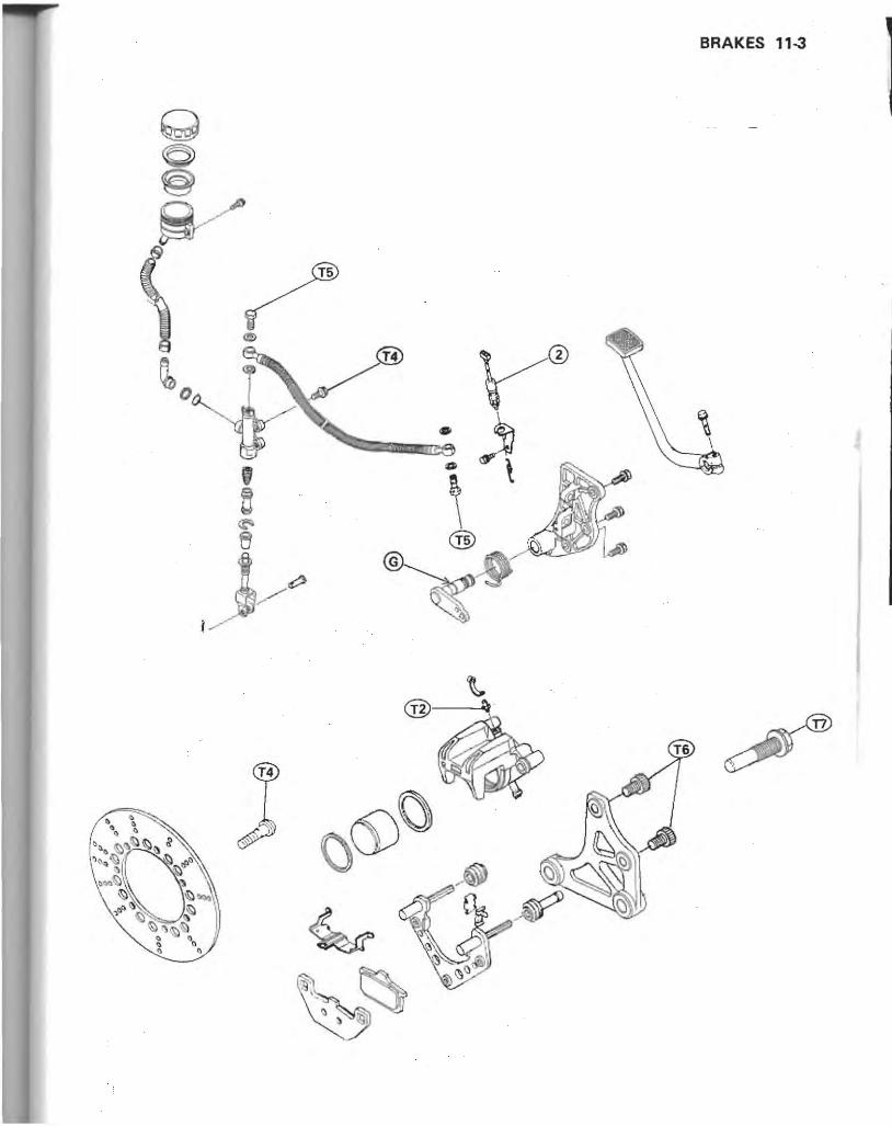
BRAKES 11-3
@-""

11-4 BRAKES
Specifications
Item
Brake Fluid : Grade
Brand (recommended)
Pads: Pad Lining Thickness:
Discs: Disc Thickness : Front
Rear
Disc Runout
Special Tool
;-\Jong with common hand tools, th e fo ll owing more specialized tool IS required for co mplete brake servicing.
Circlip Pliers: 57001 ·143
/
Standard Service Limit
D.O.T.4
Castro I Girling·Universal
Castrol GT (LMA)
Castrol Disc Brake Fluid
Check Shock Premium Heavy Duty
5mm 1 mm
4.8 - 5.1 mm 4.5mm
6.8 - 7.1 mm 6.0mm
Under 0.15 mm 0.3mm

Brake Fluid
Brake Fluid Requirement Recommended fluids are given in the tabl e below. If
hone of the recommended brake fluids are available, use extra heavy-duty brake fluid only from a container marked D.O.T.4.
Recommended Disc Brake Fluid
Type: Brand:
D.O.T.4. Check Shock Premium Heavy Duty Castrol Girting-Universal Castrol GT (LMA) Castrol Disc Brake Fluid
I WARNING I c Never reuse old brake fluid. COo not use fluid from a container that has been left
unsealed or that has been open for a long time. COo not mix two types and brands of fluid for use in
the brake. This lowers the brake fluid boiling point and could cause the brake to be ineffective. It may also cause the rubber brake parts to deteriorate.
GOon't leave the reservoir cap off for any length of time to avoid moisture contamination of the fluid.
c Don' t add or change the fluid in the rain or when a strong wind is blowing.
Olf any of the brake line fittings or the bleed valve i. opened at any time, the AIR MUST BE BLED FROM THE BRAKE.
::'Brake fluid quickly ruins painted surfaces; any spilled fluid should be completely wiped up immediately.
Brake Fluid Level Inspection .Position the resen'oir hori zontal , and check that the
fluid level in the reservoi r is ht!;her than the lower level. *I f the fluid level is lower than the lower level, ch..:ck for
the fluid leakage of the brake fi ne , and add the nuid as follows.
GRemove the reservoir cap, and fill the reservoir to the upper level line in the reservoir with the same type and brand of the fluid that already is in the reservoir. And then instal! the reservoir cap.
BRAKES 11·5
I WARNING I CChange the fluid in the brake line completely if the
fluid must be refilled by the type and brand of the fluid that already is in the reservoir are unidentified.
Front Brake Fluid Reservoir
A. Lower Level Line B. Upper Level Line
Rear Brake Fluid Reservoir
A. Lower Level Line B. Upper Level Line
e Apply a brake forGefully for a few seconds , and check for fluid leakage around the fit t ings.
I WARNING I Clf the brake lever or pedal has a soft or "sponge
feeling" when it is applied, there might be air in the brake line or the brake may be defective. Since it is dangerous to operate the vehicle under such conditions, bleed the air from the brake line immediately.

11-6 BRAKES
Brake Fluid Changing eRemove the reservoir cap. and remove the rubber cap on the bleed valve.
-Attach a clear plastic hose to the bleed valve on the caliper, and run the other end of the hose into a container.
e{)pen the bleed valve (counterclockwise to open), and pump the brake lever or pedal until all the fluid is drained from the line.
0(1050 the bleed valve. eFront brake: Since a dual disc brake is used, repeat the above 4 steps one more time for the other side.
-Fill the reservoir with fresh brake fluid . eopen the bleed valve, appl y the brake by the brake
lever or pedal, close the valve with the brake held applied, and then quickly release the lever or peda/. Repeat this operation until the brake line is filled and fluid starts coming out of the plastic hose.
NOTE
OReplenish the fluid in the reservoir as often 8S necessary to keep it from running completely out.
eFront brake: Repeat the above 2 steps one more time for the other ·side .
eBleed the a ir from the lines.
Filling up the Brake Line
eJ l
1. Open the bleed valve. 2. Apply the brake and hold it . 3. Close t he bleed valve 4. Then quickly release the brake.
Brake Line Air Bleeding eRemove the reservoir cap, and check that there is
plent y of fluid in the reservoir .
NOTE
oThe fluid level must be checked several times during the bleeding operation and replenished as necessary. If the fluid in the reservoir runs completely out any time during bleeding, the bleeding operation must be done over again from the beginning since air will have entered the line.
-Connect a clear plastic hose to the bleed v.lve{s) at the caliper(s), running the other end of the hose into a container.
.With the reservoir cap off, slowl y pump the brake lever or pedal several times until no air bubbles can be seen rising up through the fluid from the holes at the bottom of the reservoir. This bleeds the air from the master cylinder end of the line.
eFront brake line: c Pump the brake lever a few times until it becomes hard
and then. holding the lever squeezed, quickly open (turn counterclockwise) and close the bleed valve. Then release the lever. Repeat this operation until no more air can be seen corning out into the plastic hose.
ORe peat the previous step one more t ime for the other side.
Bleeding the Brake Line
1. Hold the brake applied. 2. Quickly o pen and close the "Ive. 3. Re lease the brake.

eRear brake line: oPump the b'rake pedal a few times until it becomes hard
and then, holding the pedal pushed down, quickly open (turn counterclockwise) and close the bleed valve. Then release the pedal. Repeat this operation until no more air can be seen coming out into the plastic hose.
eWhen air bleeding is finished, check that the fluid is filled to the upper level line marked in the reservoir (see Brake Fluid Level Inspection).
elnstall the reservoir cap. eTighten the bleed valve(s) to the specified torque (see
Exploded View). eApply the brake forcefully for a few seconds, and
check for fluid leakage around the fittings.
............................................................................ Master Cylinders
Front Master Cylinder Removal eDisconnect the front brake light switch wires from the
switch . eRemove the front master cylinder clamp bolts and
clamp , and take the master cylinder off the handlebar.
Front Master Cylinder Installation Notes eThe master cylinder clamp must be installed with the
arrow mark upward. eTighten the upper clamp bolt first and then the lower
clamp bolt to the specified torque (sec Exploded View) . There will be a gap at the 10IVer part of the clamp after tightening.
A. Tighten upper clamp bolts first. B. Arrow Mark
BRAKES 11-7
Rear Master Cylinder Removal -Remove the reservoir mounting bolt. -Remove the banjo bolt to disconnect the brake hose
from the master cylinder, and temporarily secure the end of the brake hose to some high place to keep fluid loss to a minimum. There is a flat washer on each side of the hose fitting. Immediately wipe up any brake fluid that spills.
A. Reservoir C. Master Cylinder Bracket Bolts B. Banjo Bol t
eRemove the brake pedal bolt and take off the brake pedal.
_Remove the rear master cylinder bracket mounting bolts.
e Free the brake light switch spring and brake pedal shaft lever return spring.
A. Master Cylinder D. Clevis Pin B. Brake Light Switch Spring E. Lever Return Spring C. Colter Pin
eRemove the cotter pin from the clevis pin and pull out the clevis pin.
eRemove the maHer cylinder mounting bolts and take off the cylinder.

11-8 BRAKES
Rear Master Cylinder Installation Notes elf the brake pedal shaft is' removed from the bracket,
wipe the old grease off the shaft and apply a grease to the shaft.
elf the push rod clevis nut or locknut was loosened, adjust the clevis position to obtain the correct pedal position.
eTa adjust the clevis position so that the push rod protrusion is 4 - 5 mm below the clevis nut, the pedal position will be the correctly.
Push Rod Protrusion
A, 4 - 5 mm
Pedal Position
A. Level with top of footpeg,
NOTE
OJ{ the correct pedal position cannot be obtained by adjusting the push rod clevis~ the pedal may be deformed or incorrectly installed.
CAfter adjusting the cfevis, tighten the locknut to the specified torque (see Exploded View) .
-Ti ghten the rear master cylinder mounting bolts to the , pecified torque (see Exploded View),
e Use a new nat washer on each >idc of the brake hose fitting, and tighten the banjo bolts to he specified torque (>ee Exploded View), Be ,ure that the metal pipe i, properl y fitted into the U-shaped notch in the ma>ter cylinder.
-Install the brake pedal to the pedal 'haft aligning the marks on the pedal and shaft.
... \. Align marks.
_Check and adjust th e rear brake light switch (see Electrical System chaprcr).
eSleed the brake line after ma>ter cylinder in>tallation . e<:heck the brake for weak braking power, brake drag,
and fluid leakage,
Front Master Cylinder Disassembly ePull back the dust cover, and remove the banjo bolt to
disconnect the upper brake hose from the master cylinder. There is a flat washer on each side of the hose fitting. Immediatel y wipe up any brake fluid that spill"
eRemove the reservoir cap and diaphragm. and empty out the brake fluid,
eRemove the locknut and pi'v'ot bolt, and remove the brake lever .
eSlide the dust cover out of place. eRemove the retaine r with circlip plier> and pull out the
piston with the secondary cup, and take off the primary cup and spring.
COo not remove the secondary cup from the piston since removal will damage it.
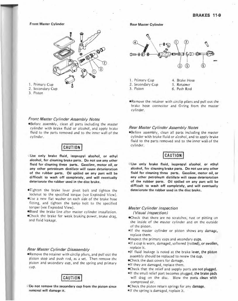
Front Masler Cylinder
I . Primary Cup 2. Secondary Cup 3. PiSion
Front Master Cylinder Assembly Notes -Before Jssembly, clean all parts includ ing the master
cylinder with brake fluid or alcohol, and apply brake fl uid to the parts removed and to the inner wall of the cylinder.
CUse only brake fluid, isopropyl alcohol, or elhyl alcohol, for cleaning brake parts, Do nOI use any other fluid for cleaning these parts. Gasoline, motor oil, or any other petroleum distillate will cause deterioration of the rubber paru . Oil spilled on any part will bit d ifficult to wash off completely, and will eventually deteriorate the rubber used in the disc brake .
-Tighten the brake lever pivo t bolt and tighten the locknut to the specified torqut': (sec Ex ploded View).
- Use a new flat washer on each side of the brake hose fiuing, a nd tighten the banjo bolt to the specified torque (see Exploded View).
-Bleed the brake line after master cylinder ins Lll1ation. -Ch~ck th e brake for weak braking power, brake drag, and fluid leakage.
Rear Master Cylinder Disassembly -RemOVe! the retainer with drclip pli ~rs , and pull out the
pis to n stop and push rod, as a set. Then remove the pisto n and secondary cup , and the spring and primary (U p .
0 00 not remove the secondary cup from the piston since removal will damage it.
BRAKES 11-9
Rear Master Cylinder
1. Primary Cup 4. Brake Hose 2. Secondary Cup 5. Retainer 3. Piston 6 . Push Rod
-Remove the retainer with ci rciip pliers and pull out [he brJke hose conneCtor and O-ring from the master cylinder .
Rear Master Cylinder Assembly Notes eBe fore assembly) clean all parts includ ing [he master
cylinder with brake fluid or alcohol, and to apply brake fl uid to the parts removed and to the inner wall of the cylinder .
OUse only brake fluid, isopropyl alcohol, or ethyl alcohol, for cleaning brake parts . Do not use any other fluid for cleaning these parts . Gasoline, motor oil, or any other petroleum distillate will cause deterioration of the rubber parts . Oil spilled on any part will be difficult to wash off completely. and will eventually deteriorate the rubber used in the disc brake.
Master Cylinder Inspection ( Visual Inspection)
eCh eck that there a.re no scratches, rust or pitting on the in si de of the master CY linder and on the ou tside o f the pi ston .
*I f the master cyli nder or piston shows any damage, replace them .
- Inspect the primary cups and secondary tvps. * If a cup is worn, damaged, softened (ro tted). or swollen,
rep lace i t. *If fluid leakage is noted at the bra ke lever, (he pistOn
assembly should be replaced to renew the cup. eCheck [he dust covers for damage. "If they are damaged , replace them. e(heck that the relief and supply ports are Oa t plugged. *I f the small relief port becomes plugged , the brake pad,
will drag on the disc. Blow the ports clean wIth compressed air ,
-Chec k the piston return springs for any damage. *If the spring is damaged, rcplace it.

11-10 BRAKES
Front and Rear Master Cylinders
(i) (0
1. Reservoir 2. Diaphragm 3. Relief Port 4 . Supply port 5. Cylinder 6. Return Spring 7. Primary Cap 8. Piston 9. Secondary Cu p
10. Dust Cover 11. Brake lever 12. Push Rod 13 . Clamp 14. Hose
Calipers
Caliper Removal eRemove the caliper mounting bolts an d take the caliper off th e disc.
A. Caliper Mounting Bolts A. Caliper Mounting Bolts

Caliper Installation Notes eTighten the caliper mounting bolts to the specified
torque (see Exploded View), -Check the brake for wea.k braking power, brake drag,
and fluid leakage.
WARNING.
COo not attempt to drive the motorcycle until iii full brake lever or pedal is obtained by pumping the brake lever or pedal until the pads are against the disc. The brake will not function on the first application of the lever or pedal if this is not done.
Caliper Disassembly Notes elf the caliper is to be disassembled after removal and if
compressed air is not available, remove lhe pisron using the following two steps before disconnecting the brake hose from the ca liper.
o Rcmove the pads. oPump the brakl: lever or pedal to remove the caliper
piston. o lmmediately wipe up any brake fiuid that spills . • Remove the brake hose banjo boll and disconnect the
hose from the caliper. There is a flat washer on each side of the hose fitting, Immediately wipe up any brake fluid that spills .
• Using compressed air, remove the piston. c Cover the caliper opening with a dean, heavy cloth. ~)Remove the piston by lightly applying compressed air
to where the brake line fits into the caliper.
I WARNING I GTo avoid serious injury. never place your fingers or
palm inside the caliper opening. If you apply compreued air into the caliper, the piston may crush your hand or fingers.
Piston Removal
1. Apply compressed air. 2. Cloth
BRAKES 11·11
Caliper Assembly Notes .Before assembly, clean all pans including the caliper
with brake fluid or alcohol / and apply brake fluid to the parts removed and to the inner wall of the caliper cylinder.
OExcept for the disc pads and disc; ule only disc brake fluid, isopropyl alcohol, or ethyl alcohol, for cleaning brake parts. Do not use any other fluid for cleaning these parts. Gasoline, motor oil, or any other petroleum distillate will cause deterioration of the rubber parts. Oil spilled on any part will be difficult to wash off completely. and will eventually deteriorate the rubber used in the disc brake .
• Apply a thin coal of PBC (Poly Butyl Cuprysi l) grease to the caliper holder shafts and holder holes . (PBC is a special high temperature, water-resistant grease:).
.'nstall rhe an ti -rattle spring in the calipers as shown.
A. Anti-rattle Spring
econncct the brake hose to the caliper putting a new flat washer on each side of the brake hose fitting. Tighten the brake hose banjo bolt to the specified torque (sec Exploded View) .
• Blced the brake line after caliper installation.
Fluid Seal Damage The fluid seal around the piston maintains the proper
pad /disc clearance. If this seal is not satisfactory, pad wear will increase, and constant pad drag on the disc will raise brake and brake fluid temperature . • Replace the fluid seals un.der any of the foHowing conditions: (al fluid leakage around the pad; (b) brakes overheat; (c) there is a large difference in left and right pad wear; (d) the setll is stuck to the piston. If the fluid seal is replaced, replace the dust seal as well. Also, replace all seals every other t ime the pads are changed,

11·12 BRAKES
Caliper
1. Caliper 6. Piston 2. Brake Pad 7. Anti·Rattle Spring 3. Brake Pad 8 . DUH Seal 4. Cali per Holder 9. Fluid Seal
5. Dust Cover 10. Friction Boot
Dust Seal and Cover Damage e<:heck that the du st sea ls and covers are not cracked,
worn, swollen, or o th erwise damaged. *If they ~how any damage, replace them.
Piston and Cylinder Damage -Vi sually inspect the piston and cylinder surfaces. "'Re place the cylinder and piston if they are badl y
scored or rust.,., .
Caliper Holder Shaft Wear The caliper body mu st sl ide smoot hly on the caliper
holder shafts. If the body does not slide smoothly, one pad will wear more than the other, pad wear will in~
crease, and constant drag on the disCawili raise brake and brake fluid temperature.
-Check to see that the cali per holder shafts are not badly worn or stepped. or the rubber friction boots are not damaged.
*If th e rubber fric tion boots are damaged, replace {he rubber friction boots, and the cali per holder.
Pads
Pad Removal .Remove the caliper. The brake hose di scon nection is
not required. eTake the piston-5idc pad oul of the caliper holder . ePu sh the caliper holder forward the piston, and then
remove the pad from the caliper ho lder shafts.
A. Pad B. Caliper Holder
Pad Installation Notes -Before insLallation, clean the pads with a high flash
point solv~nt.
I WARNING.
OWhen handling the disc pads or disc, be careful that no disc brake fluid or any oil gets on them. Clean off any fluid or oil that inadvertently !JeU on the pads or disc with a high flash-point solvent. Do not use one which will leave an oily residue. Replace the pads with new ones if they cannot be cleaned satisfactorily.
.Push the cali pN piston in by hand as fa r as it will go, and then instdll the pads.

Lining Wear -Check the lining thic knc i) o f the pads in each caliper. *If th~ linin g thickness of ei ther pad i :i less than the
service limit, re place both pad s in the calipe r as a se t.
Brake Pad
1. Li ning Th ickness 1 . Service Lim it
BRAKES 11-13
A. Min imum Thi ckness 1'¥1arkin g
eTighten the d isc mo unt in g Allen bo lts to the s pec;fj~d
lorque (see Exploded View).
Disc Wear eMeasure th~ thick ness o f each disc at the po int where
it has worn the most. Pad Lining Thickness *Replace the disc if it has wo rn past the service limit.
Standard 5 mm Service Limit 1 mm
Discs
Disc Removal -Remo ve the fro nl or rear wheel . eRemo vt: th e disc mo un ting Allen bolts and take o ff the
d isc.
[CAUTlO~] :::00 not lay the wheel down on one of the discs. This
can damage or warp the di5C. Place blocks under the wheel so that the discs do not touch the ground.
Disc Installation Notes -Th e minimum thickness. of the disc is mark l;: d on the
disc. Instilll the disc with the marked side fa cing o ut.
Disc Wear Measurement
Front Disc Thickness
Standard
Service Limit Rear Disc Thickness
Standard
Service Limit
Disc Warp
Brake Disc Measuring Area
4.8 - 5.1 mm 4.5 mm
6.8 - 7 .1 mm 6.0mm
-Se t up d dial gauge against the disc at the point as sh o wn in the figure, and mea sure d isc runo ut.
.,f runout t: xccl'-d s the service limit , re place the disc.

11-14 BRAKES
Disc Warp Measurement
1. Bra ke Disc 2. Mcasuring Area
Disc Runout
Standard Service Limit
Brake Hoses
Under 0.15 mm O.Jmm
............................................................................
Brake Hose Inspection The high pressure inside the brake line can cause fluid
to leak or the hose to burst jf the line is not properl y maintained. -Bend and twisl the rubber hose while examining il. *Rcp lace it if any cracks or bu lges are noticed.
Brake Hose Replacement . Pump the brake fluid ou t of the line as explained in the
Brake Fluid Changing. eRemove the banjo bolts at both ends of the brake hose,
and pull the hose off the motorcycle. Especially, for the brake hose between the rear master qljinder and the reservoir, loosen the clamps at both ends of the hose, and take off the hose.
-I nstall the new brake hose in its place putting a new flat wash~r on each side of Ihe brake hose fitting.
eTighten the brake hose banjo bolts to thl! specified torque (sec Exploded View).

SUSPENSION 12-1
Suspension Table of Contents
Exploded View. . . . . . . . . . . . . . . . . . . . . . . • . . . . . . . . . • . . . . . . . . . . 12-2
Specifications. . . . . . • . . . . . . . • . . . . . . . . . • . . . . . . . . . • . . . . • • . . . . 12-3
Special Tools .......•..................•.. •• ... ... ...•.... 12-4
Front Fork _ . .. ..... . .. ... . . . . ... • . .... ..... _. . . .. .. . . . . . . 12-5
A ir Pressure Adjustment .. . . .....• . ..•. _ . _ . . . . . . . . . . . . . . . 12-5
Fork Oil Change . . . . . . . . . • . . . . . • . . . . • . . . . . . . . . • . . . . . . . . 12-5
Front Fork Removal . . . .... .. ... . .. ................... . 12·6
Front Fork Installation Notes ...........•................ 12·6
Fork Leg Disassembly .................................. 12·6
Fork Leg Assembly Notes ... . . . ....•........ . .... .. . . ... 12· 7
I nner Tube Inspection ... .... . . . . . . • .... •.. ..... . .••. ... 12-8
Guide Bush Inspection. . . . . . . . . . . . . . . . . . .. . . . . . . .. .•. . . . 12·8
Oil Seal and Dust Seal Inspection . . . . . . . .. . . . . . . . . . . .. . . . . . 12·8
Rear Shock Absorbers . . ...... . . . ... ..... .. ...... .. . . . ...... 12·8
Air Pressure Adjustment . . . . . . . . . . . . . • . . . . . . . . . • . . . . . • . . . 12·8
Damping Force Adjustment. . . . . . . . . . . . . . . • . . . . . . . . . . . • . . 12·9
Rear Shock Absorber Removal. . . . . . . . . . . . . . • . . . . . . . . . . . . . 12-9
Rear Shock Absorber Installation Notes ...... . • • ...• •.. .. . " 12·10
Rear Shock Absorber Oil Filling ....... , . . . .. . . . . . . . . . . . . .. 12·10
Rear Shock Absorber Inspection ..................•....... 12-11
Rear Shock Absorber Scrapping. . . . . . . . . . . . . . . . . . . . • . . . . .. 12-11
Swing Arm ........................•..........•........... 12-11
Swing Arm Removal. . . . . . . . . . . . . . • . . . . • . . . . • . . . . . . . . . .. 12· 11
Swing Arm Installation Notes .. . . . . . .. .. .•... .. . ....• .... . 12·12
Swing Arm Bearing Removal. . . . . .. • . . . . . • . . . ... . . .. . . . .. 12-12
Swing Arm Bearing Installation .... . .......... . .. . ... . .. .. 12-13
Swing Anm Bearing Inspection . . . . . . . . .. .. . . . . .... . .. . . . . . 12· 13
Swing Arm Bearing Lubrication ................. '" . ... . .. 12·13
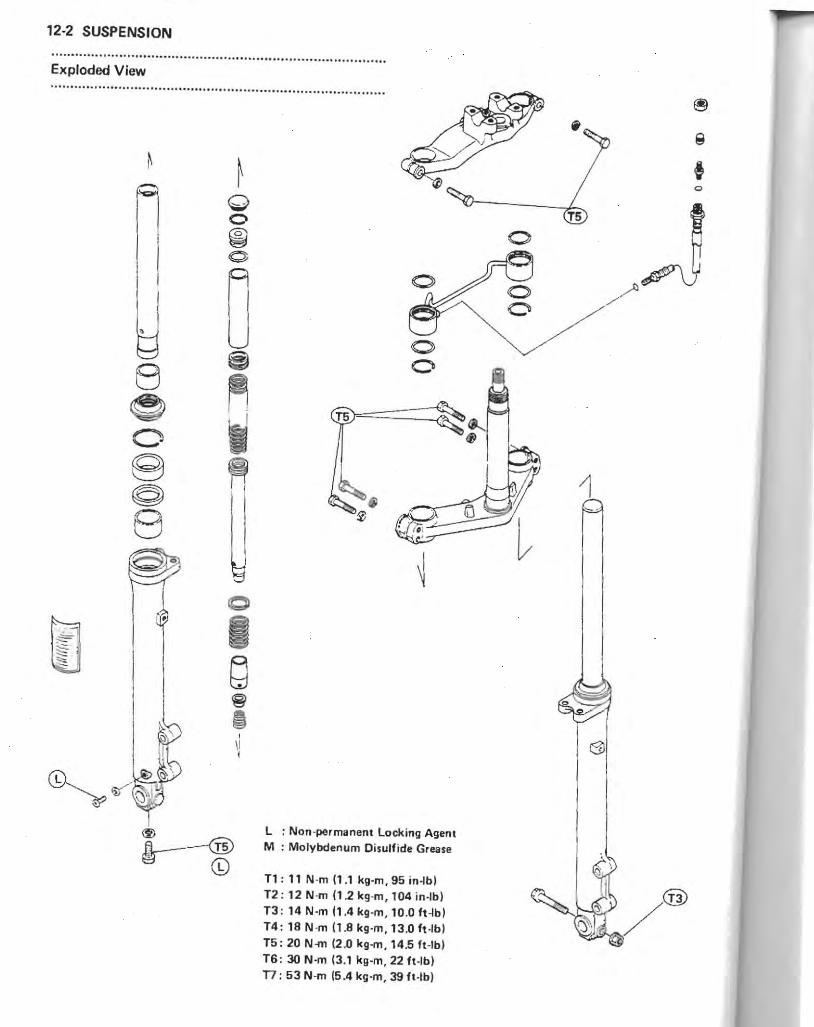
12-2 SUSPENSION
.. ........... .............................................. ................ ........ Exploded View .. ... .. .. ........... ........................................... ....................
i1 ~ =' ~l
"" ~
,
8 e C:'l (9 ©l 8
10
I 8 ~ ~ , \1 ,
~ B ----------<TsJ g- ©
10 o
L : Non -permanent Locking Agent M : Molybdenum Disulfide Grease
T1 : 11 N'm (1.1 kg·m, 95 in~bl T2 : 12 N·m (12kg·m, 104in·lb) T3 : 14 N·m (1 .4 kg·m , 10.0 ft~bl T4 : 18 N ·m (1.8 kg·m. 13.0 ft·lbl T5: 20 N-m (2.0 kg..", 14.5 ft -Ibl T6: 30 N 'm (3.1 kg·m , 22 ft·lbl T7 : 53 N-m (5.4 kg·m, 39 h·lb)
o
~ .
6l

SUSPENSION 12·3
~ ."
~ r~ I
I I @&, Cif
@ \., ~I
Specifications
Item Standard
Front Fork:
Air Pressure 50 kPa (0,5 kg/em' , 7,1 psi)
Usable Range: 40 - 60 kPa (OA - 0,6 kg/em', 5,7 - 8,5 psi)
Fork Oil: Viscosity SAE10W20
Amount/Side 391 ±2,5 mL
Oil Level 160 ±2 mm (Fully compressed)
Rear Shock Absorbers:
Air pressure 150 kPa (1,5 kg/em' , 21 psi)
Usable Range: 150 - 250 kPa (1,5 - 2,5 kg/em', 21 - 36 psi)
Damping Force No, 2 of 4 positions
Shock Absorber Oil:
Viscosity SAE5W
Oil Capacity/Side 230 mL
Air Chamber Capacity/Side 160 mL

124 SUSPENSION
Special Tools
Along wi th common hand tools, the following rr.ore specialized tools are requ ired for complete suspension servici ng.
Front Fork Cylinder Holder Handle : 57001-183
Adapter: 57001-1057
Oil Seal and Bearing Remover: 57001-1058
Be.ring Oriver Set: 57001 -1129
-"" '-C.' , ' , ' , " , ,
','. , ,
Fork Outer Tube Weight: 57001-1218
Fork Oil Seal Driver: 57001 -1219
Socket Wrench Holder: 57001 -1225

Front Fork
Air pressure Adjustment • Put the motorcycle on its center stand, and raise the
front wheel off the ground using a jack or other suitable stand under the engine.
-Check and adjust the air pressure when the front fork is cold (room temperature).
NOTE
000 not use tire gauges for checking the air suspension is air pressure. They may not indicate the correct pressure because at air leaks chat occur when the gauge is applied to the valve.
oLower air pressure is (or comfortable riding, but it should be increased for high spetJd riding, or riding on bad roads.
Olnject air little by little so that air pressure does not rise rapidly. Air pressure aXC89ding 250 kPa (2.50 kg/em', 36 p,i) may damage the oil ,eol.
I WARNING I CBe sure to adjust the air pressure within the usable
range. Pressure too high or too low can produce 8
hazardous riding condition. c Only air or nitrogen gas can be used. Never inject
oxygen or any kind of explosive gas. 0 00 not incinerate the front fork. 0 00 not remove the springs and rely on compressed air
only. Correct springs must be used in this suspension system. Use without springs can lead to a condition causing accident and injury.
A. Air Valve
Front Fork Air Pressure
Standard:
Usable Range:
50 kP. (0 .5 kg/em', 7 .1 psi)
40 - 60 kPa (0.4 - 0 .6 kg/em' , 5.7 - 8.5 psil
Fork Oil Change eRemove the front fork legs.
SUSPENSION 12-5
eRemove the cap, retaining ring, and top plug from the fork leg.
ePushing the top plug down, remove the retaining ring .
A. Top Plug B. Rel<!ining Ring
-Pull out the collar, oil filter, and spring. ePour out the fork oil into a suitable container, pumping
as necessary to empty out all the oil. ePour in the specified type and "amount of oil. -Pump the fork enough times to expel the air from the
upper and lower chambers. -With the fork fully compressed and held upright, insert a tape measure or rod in the inner tube, and measure the distance from the top of the inner tube to the oil.
*If the oil is above or below the specified level , remove or add oit and recheck the oil level.
Fork Oi' Leve' Measurement
Oil Level

12·6 SUSPENSION
f CAUTION]
o The operation of air front forks is especially dependent upon correct oil level. Higher levef than specified may cause oil leakage and seal breakage. So be sure to maintain the specified level.
elnspect the O-ring on the top plug, and replace it with a new one if it is damaged.
eln )ull the !:Ipring, oil filter , and collar. Thl.! spring must be installed with the small diameter end of it down.
elnstall the top plug with the retaining ring. Install the cap.
echange the oil of the other fork leg in the same manner.
Fork Oil
Viscosity Amount per side
When changing oil: After disassembly and completely dry:
Level
SAE10W20
330mL
391 ±2.5 mL 160 ±2 mm (fully compressed)
Front Fork Removal (each fork leg) eRelease the air pressure from the fork. eRemo ve the following.
Front Wheel Front Fender Fairing
.Remove the caliper from the fork leg to be, removed, and fest the C.lli per on some kind of stan d so that it doesn't dangle.
-Loosen the upper and lower fork cla mp bolts. -Holding the connectin g: pipe. work the fork leg down
and out of the Stem head and con nectin g pipe with a twisting motion.
A. Upper Clamp Bolt C. Connecting Pipe B. Lower Clamp Bolts D. Retaining Ring
-Remove the connecting pipe retaining ring toward the fork leg top, and slide the fork leg off the stem base.
-Stick a piece of tape over the air hole to keep the oil from running out of the fork.
Front Fork Installation Notes (each fork leg) _Route the control cables, clutch and brake hoses, and
electrical wirings correctly. -The conn ecting pipe is between the stem head and the
rctain ing ring on the fork leg. elnstall the fork leg so that the top of the inner tube is
aligned with the upper surface of the stem head.
A. Inner Tube Top B. Upper Surface of Stem Head
-Tighten the upper and lower clamp bolts to the specified torque (sec Exploded View).
- Adjus t th~ fron t fork air pressure .
Fork Leg Disassembly -Remove the cap, retain ing ring, and top plug. c Pushing the top plug down, remove the retaining r ing. _Pull out the collar, o il filter, and spring.
® =8' '~ ,
A. Col lar B. Oil Filter C. Spring

·Pour out the fork oil into a suitable container. eRemove the axle clamp bolt and nut if it is the right
fork leg. _Stop the cylinder from turning by using the front fork
cylinder holder handle and adapter (s pecial too ls ). Unscrew the Allen bolt and take the bolt and gasket out of the bottom of th e outer tube.
Front Fork Cylinder Removal
1. Front Fork Cylinder Holder Handle: 57001-183 2 . Adapter: 57001-1057 3 . Front Fork Cylinder
eRemove the cylinder unit and the short spring from the top of the front fork tube .
eSeparate the inner tube from the outer tube. CRemove the dust seal and retainer from the outer tube
top. e Mount the weight (special tool) on the top of the outer
tube, by fitting [he step of the weight to the top corner of the outer tube .
CHolding the inner tube by hand in a vertical position, stroke the outer tube several times and pull it down.
------------------
A Fo rk Outer Tube Weight: 5700 1-1218
ORemove the oil seal, wasner, and outer tube guide bush from the inner tube,
SUSPENSION 12-7
A
@~ \ \
A. Inner Tube Guide Bush C. Washer B. Outer Tube Guid e Bush D. Oil Seal
eThere is the cylinder base, valve, and spring at the outer tube bottom.
® I
A. Cylinder Base C. Spring B. Valve
Fork Leg Assembly Notes -Inspect the guid e bushes (see Guide Bush Inspection),
and replace them with new ones if necessary. echeck the top plug O-ring fo r damage. Replace it with
new one if damaged. eApply a non-permanent locking agent to the threads of
the Allen bolt. Tighten the Allen bolt to the specified torq ue (see Exploded View), using the front fork cyli nder holder handle and ada pter (special tools) to stop the cylinder from turning.
-Use the fork oil seal driver (special tool) to install the guide bush and the oi l seal in the front fork.
Olnstall the guide bush (with a used guide bush or washer on it) by tapping the used guide bush or washer with the driver until it stops. The slit of the bush must be faced toward the left or right.
el f the drain screw was removed, check the gasket for damage. Replace th e damaged gasket with a new one, Before installing the drain screw, apply a nonpermanent locking agent to the threads of the screw, and lighten the screw securel y.
ePour in the type and amount of fork oil specified and adjust the oil level.
elnstall the long spring with the smal l diameter end of it down.
•
I

12-8 SUSPENSION
Guido Bush Installation
CD
1. Driver: 57001-1219 2. Used Guide Bush 3. Slit (toward the left or right) 4. New Guide Bush 5. Tap
Inner Tube Inspectian -Visually inspect the inner tube, and repair any damage. • Nicks or rust damage can sometimes be repaired by
using a wetstone to remove sharp edges or raised areas which cause seal damage.
*If the damage is not repairable, replace the inner tube. Since damage to the inner tube damages the oil seal, replace the oil seal whenever the inner tube is repaired or replaced .
Clf the inner tube is badly bent or creased; replace it. Ex.cessive bending, followed by subsequent straightening. can weaken the inner tube.
Guide Bush Inspection -Visually inspect the guide bushes. *Replace them if necessary.
Oil Seal and Oust Seal Inspection -Inspect the oil seal and dust seal for any signs of
deterioration or damage. *Replace them jf necessary. Replace the oil sea.l with a.
new one whenever it has been removed.
Rear Shock Absorbers
Air Pressure Adjustment .Put the motorcycle up on its center stand to raise the
rear wheel off the ground. -check and adjust the air pressure when the rear shock
absorbers are cold (room temperature).
NOTE
000 not use tire gauges for checking air pressure. They may not indicate the correct air pressure because of air leaks that occur when the gauge ;s applied to the valve.
oLower air pressure is for comfortable riding for an average-built rider with no accessories. Ordinarily, the heavier the rotal load becomes, the higher the air pressure should be set.
Clnject air little by little so that air pressure does not rise rapidly. Air pre .. ure exceeding 500 kPa 15.0 kglem', 71 psi) may damage tho oil ••• 1.
I WARNING'
a Be sure to adjust the air prnsure wit.hin the usable range. Pressure too high or too low can produce a hazardous riding condition .
COnly air or nitrogen gas can be used. Never inject oxygen or any kind of explosive gas.
COo not incinerate the rear shock absorber.
A. Air Valve
Rear Shock Absorber Air Pressure
Air Pressure Usable Range Setting Load Road
kPa (kg/em', psi)
150 (1.5, 21) Soft Light Good
t J 1 J 250 (2.5, 36) Hard Heavy Bad

NOTE
OThe recommended air pressure is 150 kPa (1,5 kg/cm 2 ,
21 psi) for average rider with no accessories.
Damping Force Adjustment eTurn the adjusters to the desired number until you feel
a click. The numbers on the adjuster show the setting position of the damper.
eBe sure to turn both adjusters to the same setting position.
A. Damper Adjuster B. Position Number
I WARNING.
o rf both adjusters are not adjusted equally, handling may be impaired and II hazardous condition may result.
NOTE
o The damping force can be left soft for average riding. But it should be adjusted harder for high speed ridingl
or riding with a passenger. If the damping feels too soft or too stiff, adjust it in accordance with the follOWing table:
GThe recommended setting position is the No.2 position lor one rider with no accessories.
Damper Force
Setting Damping Setting Load Road
Position Force
1
1 Soft Light Good
2
1 1 1 3
4 Stronger Hard Heavy Bad
Rear Shock Absorber Removal eSupport the motorcycle on its cent er stand.
Speed
Low
i ~
High
eRe lease the air pressure from the rear shock absorbers.
eRe move the following. Travel Trunk and Bracket Rear Seat Saddlebags and Brackets
SUSPENSION 12-9
eRemove the nuts and bolt holding the rear shock absorbers.
ePull the shock units off their mounting studs and disconnect the air hose from the oil separator. Plug the hose fitting hole on the right shock unit to keep the oil from running out of the unit.
A. Disconnect th is hose.
elf the oil separator and air valve are to be removed, remove the following.
Fairing Dummy Tank Cover Front Seat
A. Oil Separator B. Air Valve
NOTE
000 not compress only one 01 the shock units. If this is done, the damper oil may flow out through the connecting hose to the other shock unit, 8trd the ail levels will change.
CAlter removal, place the shock units so that the correct side is up. If they are left upside down or in other incorrect conditions, the oil in the shack unit may flaw through the connecting hose and the oil level may change.

12-10 SUSPENSION
Placing Methods of Rear Shock Absorb ...
GA . I
I I
~ I
I I Down
WV Down
(A) GOOD: Correct side up. (C) BAD: Upside down.
Top Bottom
Top -,-~
-~' . ,a, \ ~
\,,\ IJ' Block , ,;» >?'»,.
(B) GOOD: Top is higher. (D) BAD: Top is lower. (E) BAD: Oil flows.
Rear Shock Absorber Installation Notes -Before installing the rear shock absorbers, connect the
air hose from the oil separator if it was disconnected. Tighten the hose filling to the specified torque (see Exploded View).
-Install each ~hock un it with the damper adjuster faced oul.
R.ar Shock Absorber Installation
®~
A. Front
elnstall the shock absorber mounting nuts and bolt. Each nut has a large flat washer , and each upper nut has lockwasher additionally.
eTighten the mounting nuts and bolt to the specified torque (see Exploded View).
e ;.\djusl the air pressure and damping forcc_
Rear Shock Absorber Oil Filling eDisconnect the air hose from the shock unit. -Fill the shock un it with the specified oil from the hose
fitting hole,
Shock Absorber Oil (per one unit)
Oil Vi,easily: SAE5W
Oil Capacity: 230 m L Air Chamber Capacily: 160 mL

1. Hose Fitting Hole: Fill the shock unit with the specified oil.
.Drain the oil until the removed oil volume comes to the specified air chamber capacity,
2. Removed Oil
eStop to remove the oil when the removed oil volume becomes equal to the specified air chamber volume.
c The shock unit should have a specified amount of oil.
3 . Removed Oil (equal to air chamber volume) 4. Specified Air Chamber Capacity 5. Specified Oil Capacity
SUSPENSION 12-11
Rear Shock Absorber Inspection -Since the rear shock absorbers are sealed units which
cannot be disassembled, only external checks are necessary.
*If one unit is damaged, replace both shock absorbers as a set. If only one unit is replaced and the two arc not balanced, motorcycle instability at high speeds may result.
-Check the rubber bushings. *RcpJace any that arc worn, cracked, hardened , or
otherwise damaged.
Rear Shock Absorber Rubber Bushings
1. Rubber Bushings
Rear Shock Absorber Scrapping eBefore a rear shock absorber is scrapped, release any air
pressure and oil completely by removing the air hoses.
I WARNING I 0 00 not incinerate 8 shock absorber without first
removing the air hose or it may explode.
Swing Arm
Swing Arm Removal eRemove the following.
Travel Trunk and Bracket Saddlebags and Brackets Rear Wheel Final Gear Case
eRemove the mounting bolt from the 100\'er end of the right shock absorber.
eFree the brake hose from the clamps on the swing arm. ePry off the s\ving arm pivot caps. eUnscrew the ;\!Ien holts to remove the shaft retainers
on bOlh sides.

12-12 SUSPENSION
A. Retainer B. Bolts
-While holding the swing arm, pull out the swing arm shahs usinga suitable bolt or screw.
A. A Suitable Bolt or Screw B. Swing Arm Shaft
.Pull back the swing: arm and take it off.
Swing Arm Instal/ation Notes (including Swing Arm Alignment)
eGrease the swing arm shaft holes with a molybdenum disulfide grease and install the swing Jrm shafrs.
A. Swing Arm Shaft Hole B. Grease.
eAlign the swing arm as the following sequence . Olnstall the left shaft rct.:liner and tighten the Allen
bolts to the specified torque (see Exploded View)_ Clnstall the spacer and right shaft retainer. Temporarily
tighten the retainer mounting Allen bolts.
A. Spacer 8. Retainer
C. Adjuster D. Locknut
OScrew in the adjuster until it stops and tighten it to the specified torque (see Exploded View).
OUsing the socket wrench holder (special tool)' tighten the adjuster locknut to the specified torque (see Exploded View) while keeping the adjuster from turning.
f\. Socket Wrench Holder: 57001-1225
oTightcn the right shaft retainer mounting Allen bolts to the spccified rorque (sce Exploded View),
eMove the swing arm up and down to check for abnormal friction, and push and pull it from side to side to check for bearing play (see Swing Arm Bearing Inspection) .

Swing Arm Bearing Removal .Pull (Jut th e grease seals and Tapered roller bearing
inner races .
• Pull out the ouler races of the tapered roller bearings using the oil seJI and bearing remover Cspecial lOol: PIN 57001-1058)
Swing Arm Bearing Installation - Lubricate the 'iwing arm bearings before installation
(see Swing Arm Bearing Lubrica tion). - U'ie rht: bearing driwr set (special t.oo l: PiN 57001 ·
1129) to press in the tapered roller bearing ou ter races and grease seals.
Swing Arm Bearing Inspection - Remove the rea r wheel, both r~<H shock absorbers , and
final gear case. eMov(.:' the swing arm up and do wn to check for abnormal friction, and push and pull it from side to side 10 check for bea(ing play,
*If abnormal frict ion is felt, the bearings arl: damaged . Replace both left and right bearings and g:reasc st.'a ls.
*Th~ play developed during use ma y indicate beari ng damage. In this case, remOVl! the swing arm and inspect the bearings. Replace both Icft and right bearings if onc of the beMings is damaged .
Swing Arm Bearing Lubrication -Remove the o;wing Jrm, dnd remove th e grease st'als from bo th sides of the swing arm.
e(;kan o ul the o ld grease from the beari ngs. and apply a mo lYbdenum disu lfide grcast::: to them.
SUSPENSION 12-13
A. Grease.
- In stall the new grease seals, smearing [hem with a th in coat of molybdenum disulfide grease.
- Install the swing arm .

STEERING 13-'
Steering Table of Contents
Exploded View. . . . . . . . . . . . . . . . . . . . .. . . • . . . . . .• . . . . . . . . . . . . 13-2
Special Tools .. ....... .. .....•...... . ........•............ 13-3
Steering Adjustment ........ _ ........ _ . . . . . . . . . . . . . . . . . . . . . . 13-4
Steering Inspection .........•..... _ . . . . . . . . . . . . . . . . • . . . . 13·4
Steering Adjustment. . . . . . . . . • • . . . . . . • . . . . . . . • . . . . . . . . . . 13-4
Handlebar ................. .... • . ..... . ....... _ • . . . . . . • . . . 13-5
Handlebar Removal . ...... .. .. .............. ... ... . •... 13-5
Handlebar Installation Notes ... . •.....................•.. 13-5
Steering Stem and Bearings ............... . .•................ 13-6
Steering Stem and Bearing Removal' . . . . . . . . . . . . . . • . . . . . . . . . 13-6
Steering Stem and Bearing Installation Notes . . . . . . . . • • . . . . . .. 13-7
Steering Stem Bearing Inspection and Lubrication. . . . . . . . . . . . . 13-B
Grease Seal and G-ring Inspection ................ • •. .. .. .. 13-8
Steering Stem Warp ................. . . . . ............... 13-8

13·2 STEERING
~~~;~d;;;;'~: .......... ........... . ........ lew " ...... ..... .... . ......... . .................. . .......... ... ... ...... ....... ... ... .. ... .. .. .. ....... ...... ...
1. LH Switch H . 2. RH S ' ou"ng
witch Haus' 3 . Ignit ion Sw' '"9 Itch
A : Adhe . L . Slye Agent . Non·po rmanent l .
M : Molybdenum D' ocklng Agent Isulfide Grea
T 5'
1; 11 N·m 11 1 k T2 ; 27 N.m 12' g·m. 95 in·lb) T3 : 42 N'm 14'~ kg·m. 20 ft ·lb) T4 ; 44 N-m 14' kg·m.31 h·lbl
.5 kg·m, 33 h·lbl
~
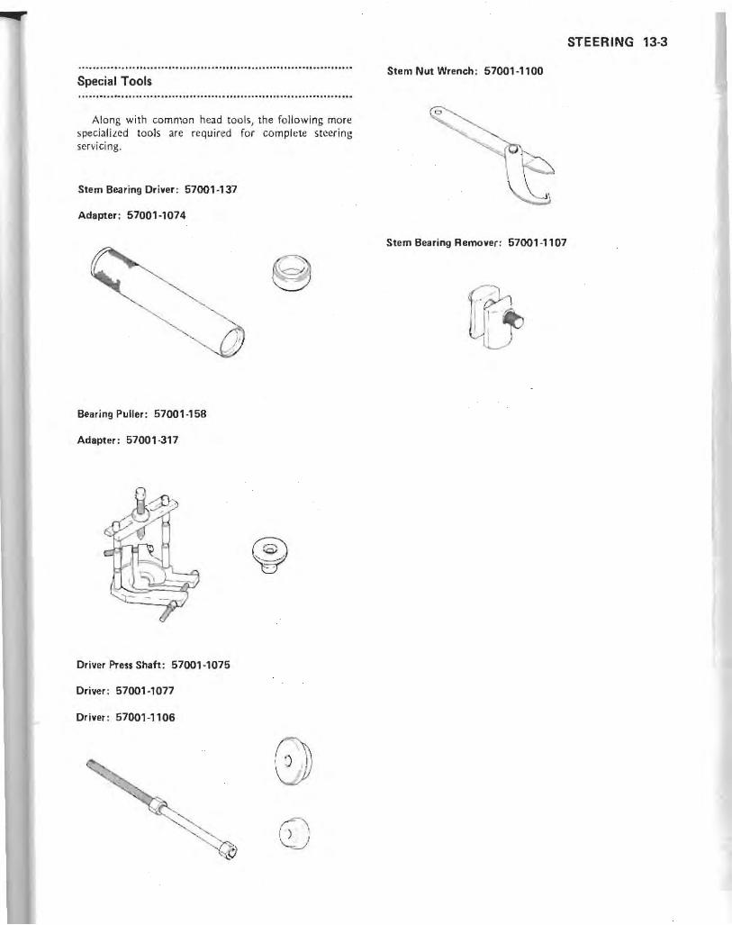
Special Tools
Along with common head tools, the fo llowing more speciali zed tools are required for complete steering servici ng.
Stem Bearing Driver: 57001 ·137
Adapter: 57001·1074
Bearing Puller: 57001·158
Adapter: 57001·317
Driver Pre .. Shaft : 57001·1075
Driver: 57001·1077
Driver: 57001 ·1106
STEERING 13·3
Stem Nut Wrench : 57001·1100
Stem Bearing Remover: 57001 ·1107

13-4 STEERING
Steering Adjustment
When the steering bearings are properly adjustt:d, the handlebar will turn freely from side to side with no looseness of the steering stem within the frame. In other words, the bearings will have little or no free play and abwlutely no preload . Inspect the steering according to the Periodic Maintenance Chart or if the following symptoms an: noticed.
Symptoms : (Tight) I. The motorcYc!1;) wanders while being ridden. 2. The steering feels light. 3. The bearing races becomes notch ed.
(Loose) 1. The forks "clu nk" or "click" when the brake is
applied or when the motorcycle is ridden over a pothole.
2. The handlebars seem to "ibrate more than normal.
Steering Inspection _Set the motorcycle on its center stand. -Use a jack under the engine to lift the front wheel off
the ground.
Checking for steering too tight: -With the front wheel pointing straight ahead, alter
natel y nudge each end of the handleba r. The fro nt wheel shou ld swing fully left and right from the force of gravity until the fork hits the stop.
*If the wheel binds or catches before the stop , the steering is too tight.
NOTE
o The wires and cables will have some effect on rhe motion of the fork which must be taken into accounr. Be sure the wires and cables are properly routed.
oThe bearings must be in good condition and properly lubricated in order for any rest to be valid.
Checking for steering too loose: -St.and in front of the motorcycle and grasp the lower
ends of the fork near the ax le . _Feel for steering looseness by pushing and pul ling the
forks. *tf you feel looseness, the steer in g is LOa loose.
Steering Adjustment - Set the motorcycle up un its center stand. -Remove the following parts.
Dumm y Tank Cover Battery Ste m Head Cover Fairing
-Loosen the front fork lower clamp bolts and stern head nu t.
- Using a jack under the engine, lift the front wheel off the ground.
_Loosen the stem locknut all the way with the stem nut wrench (special tuol).
A. Stem Head Nut C. Stem Nut Wrench : 57001-1100 B. Stem Locknut
elf the steering is LOa tight, loosen the stem locknu t a fraction of a turn ; jf the steering is too loose, tighten the lockn ut a fraction of a turn. Turn the locknut 1/8 turn at a time maximum.
-Ti ghten the steering stem head nut LO the specified torque (see Exploded View).
-Tighten the front fork lower clamp bo lts LO the specified torque (scc Exploded View in Suspensi on chapter ).
-Check the steering again. *I f the steering is st ill too tight or tou loose, repeat the
adjustrnent. _In stall the removed parts.

Handlebar
Handlebar Removal -Remove the handle grip bars. o Remove the dut.ch and front brake master cylinders
with their hoses connected by taking out th e clamp bolts, and I"tthem hang free.
COpen the handlebar switch housings by taki ng out their screws, and let them hang free.
c Remove the grip bars by t.lking out the caps and Allen bolts.
A. Handle Grip Bar C. Weight B. Cap
-Remove the handlebar. ORemow the straps to free the cables and wires from the
handlebar. ORemove the stem head cover by taking out the scre\\o"S. o Remove the handlebar by taking out the clamp bolts,
stem head cover hra.cket. and damps.
.c\. Handl ebar B. Clamps
C. Clamp Bolts D. Stem Head Cover Bracket
STEERING 13-5
Handlebar Installation Notes (including Handlebar Position AdiustmentJ
-Handlebar position can be adjusted to change height, to be inclined the handlebar forwards and backwards, and to be bent the grip bars inwards and outwards.
I WARNING I CWhen adjusting handlebar position out of the standard,
always check that the handlebar does not contact the fairing or windshield, by turning the handlebar to either side. If the handlebar contacts anything, the handlebar position must be adjusted again.
-To set the handlebar into the standard position J
observe the following. OAlign the angle of the handlebar with the angle of the
front fork.
A. Parallel
OAlign the marks on the handlebar and the handle grip bars.
f\. Marks

13-6 STEERING
elnstall the handlebar clamps with the arrow marks on them pointing forward,
-Tighten the front clamp bolts first, and then the rear cla mp bolts to the specified torque (see Exploded View). There will be a gap at the rear part of the clamp after tightening.
A. Arrow C. Even Gap B. No Gap
eTighten the handle grip bar Allen bolts to the specified torque (see Exploded View) .
eApply a non-permanent locking agent to th e threads of the screws, and install the weights with them.
-Route the cables and wires correctly. The c.ables and wires must not hinder handlebar movement.
eThe upper or lower half of the switch housings has a small projection. Fi t the projection into the small hole in each handle grip bar.
A. Projecti on B. Hole
echeck and adjust the following. Throttle Grip Choke Coble Front Brake Clutch
Steering Stem and Bearings ..............................................................................
Steering Stem and 8earing Removal eRe move th e following parts.
Handlebar Fairing Dummy Tank Cover Battery Front Wheel Front Fork Legs
eRe move the mounting bolts, free the brake hose joint from the stem base, and remove the front brake assembly as a set.
-Remove the stem head nut, and take off the Oat washer, stem head, and lockwasher .
ePush up on the stem base, and remove the steering stem locknut with the stem nut wrench (special tool: PIN 57001-1100), then remove the steering stem and stem base (single unit).
-Remove the steering stem cap and upper tapered roller bearing inner race and O-ring.
-To remove the outer races pressed into the head pipe, install the stem bearing remover (special tool) as shown below, and hammer the stem bearing remo\'cr to drive it out.
NOTE
olf either steering stem bearing is damaged, it is recommended that both the upper and lower bearings (including outer races) should be replaced with new ones,
Outer Race Removal
I. Stem Bcaring Remover: 57001-1107
eRemove the lower inner race {with its grease seal} which is pressed onto the steering stem, with the bearing puller and adapter (special too l,).

A. Bearing Puller : 57001-158 B. Adapter: 57001-317 C. Bcaring Inner Race
Steering Stem and Bearing Installation Notes .Apply grease to the outer races) and then drive them
into th e head pipe using the drivers and the driver press shaft (special tools).
Outer Race Installation
1. Driver Press Shaft: 57001-1075 2. Driver : 57001-1106 3. Driver : 57001-1077
eApply grease to the tapered roller bearing, and drive it onto the steering stem usjn~ the stem bearing driver and adapter (speci .1 tools ).
STEERING 13-7
A. Stem Bearing Driver: 57001-137 B. Adapter : 57001-1074
eLubricate the steering stem bearings with grease, -Insull the stem locknut so that the stepped side faces
down.
A. Stepped Side B. Cap
.,f the stem bearing outer races was reinstalled, perform the following four steps to sett.le the bearings in place.
OUsing the stem nut wrench, lighten the stem locknut to 39 N·m (4.0 kg·m, 29 ft·lb) of torque. (To tighten the ~teering ste m locknut to the specified torque, hook the wren ch on the stem locknut, and pull the wrench at the hole by 215 N (22 kg) force in the direction shown.)
Torquing Stem Locknut
<i;---- ---- j 80 mm -----~
1. Stem Nut Wrench : 57001-1100
215 N (22 kg)

13-8 STEERING
QCheck that there is no play and the steering stem turns smoothly without rattles. If not, the steering stem bearings may be damaged.
OAgain back out the stem locknut a fraction of a turn until it turns lightly.
o Turn the stem locknut lightly clockwise until it just becomes hard to turn. Do not overtighten, or the steering will be too tight.
eRoute the cables and wires correctly. The cables and wire:; mu:.t not hinder handlebar mo ... cmcnt.
e<:heck and adjust the steering after installation.
Steering Stem Bearing Inspection and Lubrication
-Using a high fl ash-point solvent, wash the upper and lower tapered roller bearings in the cages, and wipe the upper and lower outer races, which arc press-fitted into the frame head pipe, clean of grease and dirt.
.Visually check the outer races and the rollcrs. *Rcplacc the beari ng assemb lies if they shown wear or
damage. .Pack the upper and lower tapered roller bearings in the
cages with grease I and apply a light coat of grease to the upper and lower outer races.
•
A. T dpcr Roller Bearings B. Grease Seals
Grease Seal and D-ring Inspection eVisually inspect the grease seal and Cori ng for any signs
of deterioration or damage. *Replace the gre.lse seal , O-ring, or bearing (assembl ed
with grease seal) if it shows any signs of damagt:.
A. O-ring
Steering Stem Warp eWhenever the steering is removed, or if the steering
cannot be adjusted for smooth action, check the steering stem for suaightness.
*If the steering stem shaft is bent , replace [he steering stem.

~--
FRAME 14-1
Frame Table of Contents
Exploded View . . . . . . . . . . . . . . . . . . . . . . . . . . . • . . . .. . . . . • . . . . . . 14-2
Fair ing. . . . . . . . . . . . . . . . . • . . . . . . . . . • . . . . . . . . . . . . . . . . . . .. . . 14-6
Fairing Removal . . . . . . . . . . . . . . . . . . . . . . . . . . . . . . . . . . . . . . . 14·6
Fair ing Installation Notes. . . . • . . . . . . . . . . . . . . . . . . . . . . . . . . . 14·9
Travel Trunk and Saddlebags . . . . . . . . . . . . • . . . . . . . . . . . . . . . . . . .. 14-10
Travel Trunk Remova l Notes .. . .. . ..•.... . . . ...•.. . . .. .. . 14· 10
Travel Trunk Installation Note. . . . . . . . . . . . . . . . . • . . . . . . . . .. 14-11
Saddlebag Removal Note . . . . . . . . . . . . . . . . . . . . . . . . . . . . . . . . 14-11
Saddlebag Installation Notes
(including Tail End Alignment) 14·11
Bracket Removal Notes ... . ... ... . . .. .. .. .. . .... .... ... . 14-12
Bracket Installation Note . . . . . . . . . . . . . . . . . . . .. . . . . . . . . •.. 14-13
Front Fender . . . . . . . . . . . . . . . . . . . . . . . . . . . . . . .• . . . . . . . . . . . . . 14· 13
Front Fender Installation Note ... .. ...•.. .. .. .... .. .. .... 14-13
Rear Fender . . . . . . . . . . . . . . . . . . . . . . . . . . . . . . . . . . . . . . . . . . .. .. 14·13
Rear Fender Remova l Notes . . . . . .• . . . . . . . . . . . . . . . . . . . •. .. 14· 13
Seats . . . . . . . . . . . . . . . . . . . . . . . . . . . . . . . . . • . . . . • . . . . . . . . . . . .. 14· 13
Seat Removal Note . . . . . . . . . . . . . . . . . . . . . . . . . . . . . . . . . . . .. 14·13
Rear Frame . . ..... .... ... . .. . .. .. . ... . ... .. . . . . .. . . . . . . . . 14· 14
Rear Frame Removal Notes . . . . .. . .. .. .. ..... .....• ... .. . 14-14
Rear Frame Installation Notes .. . . . . . ... .• .. .. .. . . . .•.. . . . 14· 14

14-2 FRAME ... ...... ........... .................... .
E~~;~~;;d·v·i·~~· · ·· · ·· · ·· ······· · ..... .. ....... ..................... . ............ ................................... p ,p
~ r
1 Relay Assembly . . S '9"al Control Unit 2 Turn I .
. L ' hting Device 3 Reserve Ig
4: Power Amplifier
" A : Adh.,i.e Agent

FRAME 14-3
~ ~
~<> ~A f' '-<7
~ ~. ~ 1~
"
:~ '" ~
~ '">!. ~ ~ 63'
JJ .

14-4 FRAME
k Room Light 5. Trun m Light Switch 6 Trunk Roo
· S',g08' Relay 7 Turn · Motor Relay 8 Starter
9' Relay Assembly · d 'o Antenna 10 Ra , . h · nd SWlte 11. Side St.
G : Grease Locking Agent permanent L : Non·
k 42 ft·lb) T1 : 57 N'm {S .S g·m,

FRAME 14·5
1 • • • ~.
..,.
--~
~
~~
..-"" I
~ 0.-(~?
1
"
1
I tf~ '~~ I ~
i; ~ " 1
~~
--~ --
.. ,
I ~~
I ~ -- / " .~
,- --~ @- - --- ' , ~ , J ~~!);
I
I
t~ ' I I
: I ~~~ I
I. / ..' I I 7/ G I
I :J/ I
""
I I
~--
" "- --
- I
--, /
"
_ _ ...J
'-/

14-6 FRAME
Fairing
Fairing Removal eRemove the windshield as the following sequence.
A. Rear View Mirrors C. Screws B. Windshield Cover
A. Wind,hield C. Remove this screw. B. Loosen these screws .
• Remove the fai ring outer covers.
A. Headlight Cover B. Screws
A. Lower Cover B. Screws
A Upper Cover B. Screws
A. Air Duct,
eRemove the headlight unit with the remote ca ble. oTa free th e remote cable from the fairinp; inner cover,
remove the headlight beam adjuster and .:..1blc mounting nut.

A. Headlight Unit D. Mount ing Bolts B. Remote Cable E. Screw C. Adjuster F. Cable Mounting Nut
_Remove the speaker') and meter assembly.
A. Speaker Cover C. Speaker B. Allen Bolts D. Screws
.~ . Meter Assemb ly 8 . Mounting Nuts
e Remove the fairing inner covers. oTo r~movc the right inn~r cover, free the suspension
air hoses from the cover,
FRAME 14·7
A , Air Hoses
A. Inncr Cover B. Screws
eRemove the electrical components from the fairing brac.kcl.
A. Speaker Housing B. BoilS
• ~
, ,

14-8 FRAME
A. Turn Signal Control Unit A. I nsid e Cover B. Screws C. Clamps B. Reserve Lighting Device
.Remove lhc radiator shoulder covers.
A Power Amplifier
A. Radiator Shoulder Cover B. Screws
_Remove th e fairing inside covers.
A. Radiator Shoulder Cover B. Screw:;
A. Inside Cover B. Screws C Clamps .Remove the fairing bracket.

f\ . Fairing Bracket B. Bolt,
A. Fairing Bracket B. Bolt,
eRcmm'e the radiator fron t cover,
A. Radiator Front Cover B. Screws
Fairing Installation Notes eRoute t.he cables, wirings, and hoses correc tl y, elf the ventilation louvers were removed, install them
with the arrow pointin::; up.
FRAME 14-9
®
•
.~ I
I ~ j A. Louver 8. Arrow
eBe sure to cover the radio and cassette player with the watenigh 1 sea t.
A. Watertight Seat B. Radio."d Cassette Player
elnsta ll the windshield a, the fo llowing. OBefore in, tailing the wind,hiel\! on the fairing. route a
string around the groove o f the seal trimming.
A. Seal Trimming B. String
oPlacc the windshield onto the fairi ng so that ib dented portions fit between the collars and the fairin g.

14·10 FRAME
Windshield Installation
(1'
1. Fairing 2. Windshield Cover 3. Rubber Damper 4. Windshield
'f1--P-_c----\~~ ~I-k-----c(j)
5. Mounting Bolts 6. Flanged Collar 7. Collar 8. Bracket
oPul1 up the string which has been routed around the groove of the seal trimming so that the upper end of the trimming properly fits to the inside of the windshield.
A. String B. Seal Trimming
COo not use any tools iUch ilS a screwdriver to prevent the black-printed area of the windshield from being damoyod.
oPrcss the sea l trimming against the windhsicld with your fingers to make watertight contacts at them.
.. it the end trimmings onto the left and right ends of the windshield lower portion.
OA pply an adhesive agent to the area shown to fix the end trimming onto the windshield cover trimming.
A. End Trimming C. i\dhesive Agent B. Windshield Covcr Trimming D. Clamp
Travel Trunk and Saddlebags
Travel Trunk Removal Notes eMove the travel trunk rearward as far as it will go, and disconnect the wiring conne-ctcrs from the trunk and passenger switches.
A. Connectors 8. Passenger Switches
.Remove the wing screws at the bottom of the travel trunk.

A. Wing Screws
Travel Trunk Installation Note .Place th e travel trunk on the bracket so that the
holders on its bo ttom fi t into the bracket holes.
A. Ho lders B. Holes
Saddlebag Removal Note eRemove th e li d fro m the saddl ebag, pu ll the knob and
unhook the saddlebag from the bracket.
A. Knob
FRAME 14-11
Saddlebag Installation Notes (including Tail End Alignment)
eHoo k the saddlebag onto the saddlebag bracket, and push in the locking pin .
A. Lock ing Pin B. Red Line
I WARNING.
CWhen installing the saddlebags, be sure the locking pin is all the way in. If you can '$e' 'he red line on the locking pin, it is not securely latched. Be sure the red line is out of sight. If the saddlebag is not secure. it could fall off while you art riding the motorcycle possibly causing a crash.
. Align the ta il ends of the rear fender rear an d saddlebags if the par t' which relate to the tai l end alignment were handled.
A. Level B. Even Clearance

14-12 FRAME
A. No Step
cLoosen the saddlebag leg mounting bolts and nuts, turn the adjusters to raise or lower them, and align the saddlebag tail end with the fender tail end.
cSlide the saddlebag and equalize the left and right saddlebag side clearances.
A. Saddlebag Leg Mounting Bolts
A. Adjusters B. Nuts
Saddlebag Leg
'''II I. Mounting Bolt 2. Saddlebag
· --I4.V·· J. Lcg " 4. Bracket "5; 5. Adjuster -' 6. Nut
GLaasen the rear fender rear mounting bults and slide it back and forth to align the fender tail end with the saddlebag end.
A. Rear Fender Rear Mounting Bolts
OTighten the bolts and nuts after adjustment.
Bracket Removal Notes -Remove the travel tran k bracket together with the
saddlebag brackets. OBefore removing the travel trank bracket, free the
antenna bracket from the trank bracket.
,
©
A. Travel Trank Bracket C. Antenna Bracke t B. Saddlebag Bracket

Bracket Installation Note eTighten the rcar shock absorber upper mounting nuts
to the specified torque (see Exploded Vicw in the Suspension chaptcr).
Front Fender
Front Fender Installation Note .I nstall the (rant fender brac:e with the arrow pointing
forward.
A. Front Fender B. Brace C. Arrow
.............................................................................. Rear Fender ..............................................................................
Rear Fender Removal Notes eRe move the rear fender relr and its bracket.
A. Rear Fender Rear C. Bracket B. Fendcr Mounting Bolts D. Bracket Mounting Bolts
FRAME 14-13
-Remove the rear fender front.
A. Rea.r Fender Front B. Mounting Bolls
Seats
Seat Removal Note eMove the rear seat forward as far as it will go.
A. Rear Seat B. Mounting Bolts
1-\. Front Seat B. Mounting Bolts

14·14 FRAME
Rear Frame
Rear Frame Removal Notes IBefore removing the rcar frame, remove the fuel in the fuel tank as possible using a suitable pump.
IRemove the rear shock absorbers. I t is not required to remove the air hoses from the shock absorbers.
eRemove the followine. Travel Trank and Bracket Saddlebags and Brackets Rear Fender and Bracket Mufflers SealS Rear Shock Absorbers Side Covers Footboards Jnd Bumpers
A. Footboard C. Mounting Bolts B. Bumper
eHolding the fuel tank, remove the rear frame.
A. Rear Frame C. Damper Rubbers B. Moun ting Bol h
Rear Frame Installation Notes eSe sur. to install the damper rubbers in place. eTighten the rear frame mounting boilS to the spedii ed
torque (;ec Expl oded View). eRou te the wirings and hom correc tl y.

ELECTRICAL SYSTEM 15-1
Electrical System Table of Contents
Precautions, . . ............... .
Wiring Diagram (Main) ...... , ...... .
Wiring Diagram (Audio) ........ .
Exploded View ","""" Specifications' , ............. ..... .. .
15-2 15-3
15-4 15-S 15-8 IS-9 IS-9 15,9
15-9
Special Tools, , , , , , , , , _ , _ . ____ _
Battery . .... . ... . ..... . Precautions . . . ............. .. ... . Electrolyte .. . ....... .
Electrolyte Level Inspection, , , . ' , IS-9 BatteryCharging .".,"', .. _, . ," ,15-10
Battery Condition ,_, _"" ,_IS-10 Battery Initial Charging, , , _ , _15-10 Battery Ordinary Charging, , , . , _, _ IS-II Battery Test Charging , ______ , , ,IS-II
Alternator, , . , , , , , . , ' , _ , , , _ , , , ,IS-12
Alternator Removal Note . .
Alternator Installation Notes ...
, . ,IS-12 , , ,IS-12
Alternator Disassembly Notes, ...... . 15-13
Alternator Assembjy Notes, " _"" IS-13 Alternator Operational Inspection . , .. . 15-15 Carbon Brush Length . _ , _ , , ___ . _ , _ 15-16
BrushSpringTension . _ , . ... . ,'" _ 15-16 Rotor Co il Inspection . ...... . . , .. . 15-16 Slip Ring Cleaning _, .. ' . ,., . •. , _ ,15-16 Slip Ring Diameter, , ,15,16 Stator Coil I n,pection ,15-16 Rectifier Inspection .... ,.,., ..... 15-17 Ball Bearing Inspection ,15-17
Ignition System ., _ _ _""" _" ,IS-17 IC Igniter Installation Note, , , , , , , , , ,15,17 Ignition Coil Installation Notes . ..... . 15-17 Spark Plug Removal Note, _ , 15-18 Spark Plug Installation Note, , , . _, ,_15-1B IC Igniter Inspection, , , , , , , , , _ , , , ,15-18 Pickup Coil Inspection . .. . . .... .. . 15-19
Ignition Coil Inspection. . . ..... . . 15-20
Spark Plug Cleaning and Inspection . .. . 15-20
Spark Plug Gap , , , 15-20 Electric Starter System
Starter Motor Removal Note.
Starter Motor I nstallation Note
, __ lS-22
, , ,IS-22 ,15-22
Starter Motor Disassembly Note ..... . 15-22
Starter Motor Assembly Note, '" _ , _ , 15-22 Carbon BrUSh Length """ _ , , , ,IS-23
Brush Spring Inspection . .......... . 15-23
Commutator Cleaning and Inspection . . . 15·23
Armature Inspection . ............ . 15·23
Field Coil Inspection _ , , , ' , , , , , ' , , ,IS-24 Brush Plate Inspection, , ' , , , , , , , , , _ IS,24 Starter Motor Relay Inspection . ..... . 15-25
Lighting System, , , , , . _ .. , , ' ... , .. _ . _ 15-25 Headlight Circuit _, _ . , .. _ . , , , . , , , _ , 15-25
Headlight Beam
Horizontal Adjustment . . , . , ..... . 15-25
Headlight Beam Vertical Adjustment ....... , . , , .15-25
Headlight Reserve Lighting
System Inspection ,.. . ..... ,15-27
Turn Signal Circuit _ , ' , , , , , , ' , ' , . ' _ .15-27 Turn Signal Control Unit Inspection, .. . 15-27
Turn Signal Relay Inspection """,,15-29 Bulb Replacement , IS-29
Bulb Replacement Notes .. , , _ , , ,IS-29
Fuel Pump "_" _ , ' , ,15-31 Fuel Pump Internal Resistance . ..... . 15·31
Cooling Fan Circuit . ... ..... . ........ . 15-32
Cooling Fan Circuit Inspection ...... . 15·23
Fan Motor Inspection . , .. , ... . ... . 15-32
Fan Switch Inspection . ...... _ , .. . . 15-32
Meters and Gauges ... , ....
Meter Assembly Removal!
Installation Notes
Meter Assembly Separation/
Assembly Notes
, _ , __ , ,15-33
, _ ' __ 15-33
, , _ , _ 15-33
Meter and Gauge Replacement Notes . . ,15-34
Tachometer Inspection ., ......... ,15-36
Fuel Gauge Operation Inspection . . ... ,15-36
Water Temperature Gauge
Operation Inspection, , .. , , . . . , , .15-36
Indicator Light Self-check
Unit Inspection ., .... , ... . " _ .15-36 AV lAC Signal Unit Inspection " ... __ 15-37 Distance Sensor Inspection . .... .... . 15·37
AV Control Circuit Inspection .. . 15·37
AC Control Circuit Inspection . . 15·38
Electrolyte Level Sensor Inspection . .. ,15-38
Fuel Level Sensor I nspectior) ........ 15·38
Water Temperature
Sensor Inspection, .. , .... ... .. . 15-38
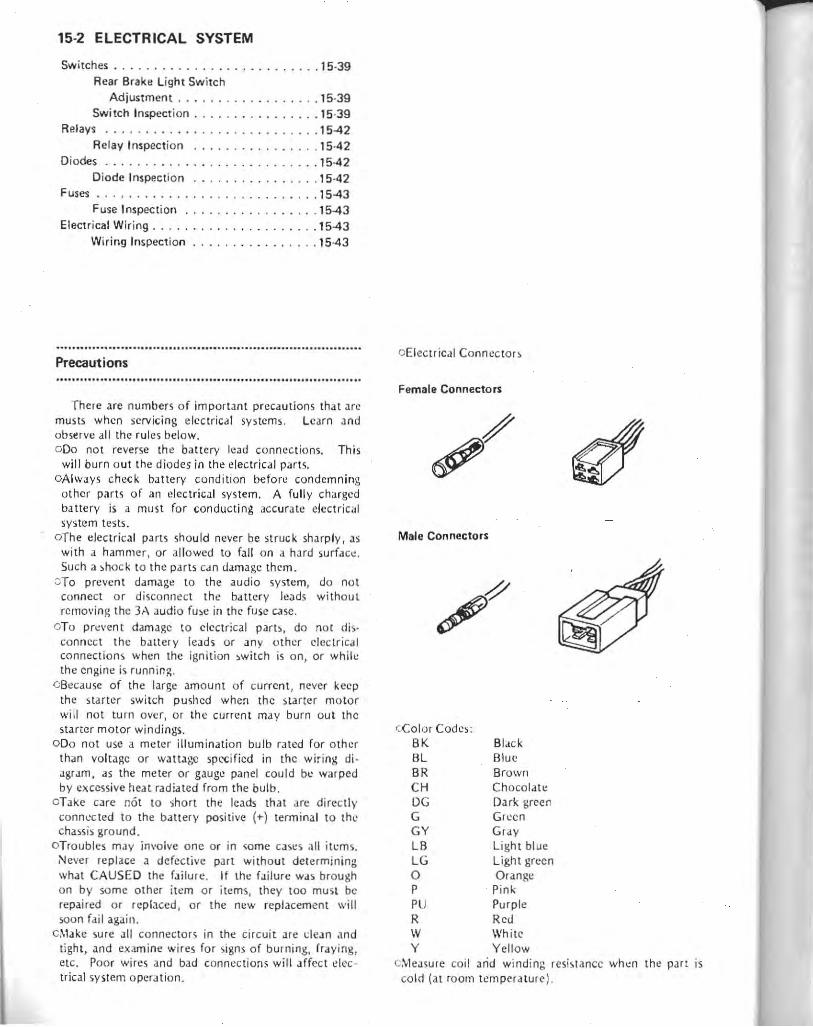
15-2 ELECTRICAL SYSTEM
Switches .................. . .... •.. 15·39 Rear Brake Light Switch
Adjustment .. . ..........• . ... 15·39 Switch Inspection .. . .. . . . • .... . .. 15·39
Relays ..... . . ..... ..... _ .•....... 15-42 Relay Inspection . . . .. . _ . •..•. . .. 15·42
Diodes .. ..... . .. ... . • • . . .. ..... .. 15-42 Diode Inspection . . •. .. . .•.... ... 15·42
Fuses . .. .. _ . _ .. . ... . . •. . .. .. . . . .. 15-43 Fuse Inspection . ... ..... . .. .. ... 15-43
Electrical Wiring .......... • .... • ..... 15-43 Wiring Inspection. . . . . . . . . . . •. .. 15-43
Precautions
There arc numbers of important precautions that ar~ musts when servicing electrical systems. Learn and observe all the rules below. 000 not reverse th~ battery lead connections. This
will burn out the diodes in the electrical parts. oAlways check battery condition befor!.": condemning
other parts of an electrical system. A fully charged battery is a must for conducting accurate electrical system te::as.
oThe electrical parts should never be struck sharply, as with a hammer , or allowed to fall on a hard surfac~. Such a ~hock to the parts c.m damage them.
c;To prevent damage to the audio system, do not connect or disconnect the battery leads without removing the 3;.\ audio fu~e in the fuse c.lse,
aTo pr~\'ent damage to electrical parts, do nor disconnect the baltery !cads or any other electrical connections when the ignition ~witch is on, or whih: the engine is running,
c Becausc of the large amount of current, never keep the starter switch pushed when the starter motor will not turn ov~r, or th e current may burn out the starter motor windings.
000 not use a meter illumination bulb rated for o ther than voltage or wattage spccified in the wiring di agram, as the meter or gauge panel could be warped by excessive heat radiated from the bulb .
oTake care not to short the leads that are directly connl.'cted to the battery positive (+) terminal to the chassis ground.
oTroubles may involve one or in some cases al l itl:ms. Never re place a defective part with out det ermin ing what CAUSED the failure. If the failure was brough on by so me other item or items, they too mu st be repaired or replaced, or the new replacemen t will soon fai l again.
c,\1ake sure all connectors in the circuit are dean .1nd tight, and examine wires for signs of burning. fraying, etc. Poor wires and bad connections will affect ~Iec
trical system operation.
oElectrical Conncctor~
Female Connectors
Male Connectors
OCo lor Codc~: BK BL BR CH DG G GY LB LG o P PU R IV Y
Bl ack Blue Browll Chocolate Dark green Green Gray Light blue Light green Orang!! Pink Purpl e Red White Yellow
C:Vleasure coil arid winding resis tance when the pan is co ld (at room temperature ).

ZG1200-Al Main Wiring Diagram
--....... , . ., II ... ....
___ L.,.. "",..
t __ ,_,_, .. . ,,, ...
o
r-----,_, :::::--~:;:tI .~
111111 E=ii .f i L-11!.~~
I
:;-;tt:"_L_:" ~
~'-.-..'7V~'.
--.... ','I II.
--'I"" ·
'--- ,.,.. . . ,,,,.-
-~, II ... , ••
T_~ .... __ L.,.. "'C' 'I" a. ...
-'-
IC )-J
1
I ( 1::::::
~
~-~ I'J
@aF-~-=
r-- - - --- - - -- --..... _C-, I
~H~HU 1
: ~ •• I
I ~HH;H i 1.--------------' ~-- iI==:;o(P-
,_ ~ :r= iH . wr ~-=~ vi~ , . 1i1f Ii f ~~ ~
::: 1:~1 ID,1lW H j , "f 7iif 7MtJtr ~ o ~ of • ~,u·
~
~~;:-- :: ,_. • -l.!:l_ , ' . ,a _
-I ~ ~ . ~
" -"". " .... - .. _. ~
~
M
-" .~
" ,
~. nk_ ---------------.:.-;--,U , ~ =-~f"T:":r-:;. ~ _________________ .J
--
L

-• '" _ "" ..a:. o-~ .. _----
-
---
-
1
I~ ::
I ir
ELECTRICAL SYSTEM 15-3
•
I
• ~ !
1 !
,
:~a!
I I , l' j~ - ,II ~ ,
" s
i
Ii ' i . I~
it' Ii
I,. II Ii ~.
I • II
I ~ .. -- ~
IS • • I • 1
~
!~ Ii h :r II I
• • ! ,I
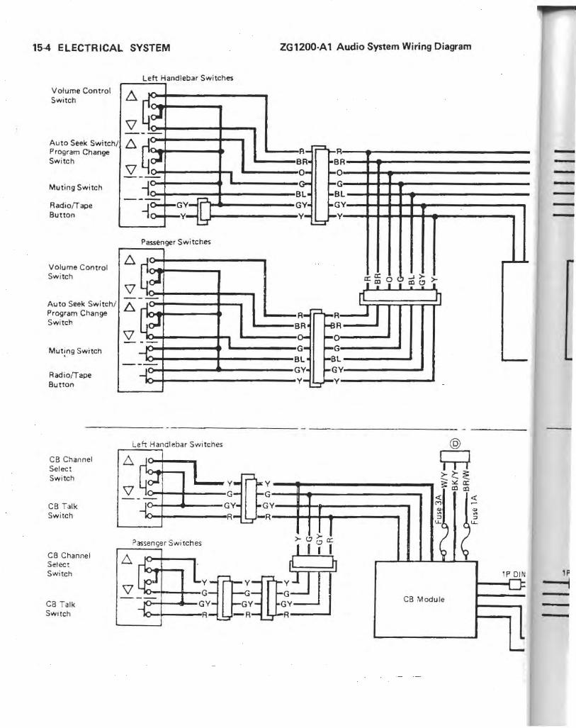
15-4 ELECTRICAL SYSTEM
Volume Control Swi tch
Auto Seek Switch Program Change Switch
Muting Switch
Radio/Tape Button
Volume Control Switch
I
Auto Seek Switch/ Program Change Switch
Mut!ng Switch
Radio/Tapo Button
CB Channel Select Switch
CB Talk Switch
CB Channel Select Switch
ca Talk SwitCh
Left Hand lebar Switches
:c? --l:,
\l Jool , I
-- r:::t ,O-.... GY-
Y-:,:r
Passenger Switches
:c? --
:~ -- I
---i~
Leh Handlebar Switches
Passenger Switches
ZG 1200·A 1 Audio System Wiring Diagram
A"= R B o G B G
Y
BA· R 0- -, -Bl- f-! l GY- ~( Y
Y-~~
A- -;:J~I BA f-e
A R
o G l
~I G- ~( Bl ~B
GY 1-6 Y Y Y- .=r-'
,.",,.1 I i 'I I
rl h
~:J GY-A
0: ... ,. ,. 'f '" 'i' III '" I
r1 11 I
;:"'0: "'Ill
« « M -~ ~ ~ ~ ~ ~ ~ u..
~ ~ CB Module
---------
'---
l P....Q!N
u ----

r'-----------------------
Speakers
r--GY~~ ~GY/BK~W/BK Lett
<i <i M _
1-
AM / FM Antenna
t-------- - ----- ---,1-- - - -------- - --- ----
C8 Antenna
- 8P D IN
~
5P DIN
CB Radio (Op!ional )
C8 ContrOl Unit
Helmet Sound System (Optional )
5P OIN r-1.
5P DIN
NOTE
oConnectors @ through @ are connec ted to the Connectors of the same reference lerrer in the main wiring diagram .

....... ..... Explod~~ ·~·;~~ ······-· .. ··· ········ ····· · .. .. _ .................... ............ -........................ ........... ....... .
... ... ... .. ... ....... ... .. .... ....
L : Non p . ermanent Lock ' Ing Agent
T1 : 4.9 N -m (050 T2 : 9.8 N.m (1 '0 kg-m. 43 in-Ib) T3 : 14 N.m (1 . kg -m. 87 in-Ib) T4 : 25 N.m (2 ': kg-m. 10.0 It ·lb )
. kg-m. 18 .0 It ·lb )
ELECTRICAL SYSTEM 1 5-5
...
+ ... n

15~ ELECTRICAL SYSTEM

ELECTRICAL SYSTEM 15-7
11 ~~ tJ ~ .,R II'! ff
0
... ~ q .., I
ff
~ ~
, ~
.y I · I rrl I ':' II- i;ll ~ ~ ~ 11., k· IlftJ ' ~ I e l I I ~(§~
Replacement Parts
,~ ... !l • ~ :; • ~ ., •
~
•

15-8 ELECTRICAL SYSTEM
Specifications
Item Standard Service Limit
Battery: Type 12 V 20 Ah Specific Gravity 1.2BO@20'C (6B'F)
Alternator: Type Three-phase AC, regulator and rectifier
contained in the unit Rated Output 35 A @7500 r/min (rpm), 13.5 V
Charging Voltage 13.5 V Night @4000 r/min (rpm) Charging Amperage 19 A Night @4000 rIm in (rpm) Regulated Voltage 14.7 ±0.5 V
Carbon Brush Length 16.5 mm Bmm
Brush Spring Tension 310 - 430 g (with new brush) 210 g
Rotor Coil Resistance 3.5 - 5.01]. -Slip Ring Diameter 23 mm 22.2 mm
Ignition System: Ignition Timing 10' BTDC @BOO rIm in (rpm) Pickup Coil Resistance 360 -4401]. Ignition Coil:
3·needle Arcing Distance 7 mm or more Primary Winding Resistance 1.B-2.BI]. Secondary Winding Resistance 10 - 16 kl].
Spark Plug: Standard NGK DPRBEA·9 or ND X24EPR·U9 Option: Low Speed, Cold NGK DPR7EA·9 or ND X22EPR·U9
High Speed NGK DPR9EA·9 or ND X27EPR·U9 Plug Gap O.B- 0.9 mm
Electric Starter System:
Starter Motor: Carbon Brush Length 12.0 - 13.0 mm 6mm
Commutator Groove Depth 0.5 - O.Bmm 0.2mm
Cooling Fan Circuit: Fan Switch ON: above 94 - 100°C (201 - 212' F)
OFF: below 91 ' C (196°F)
Meters and Gauges: Electrolyte Level Sensor Resistance about 6BO I]. Fuel Level Sensor Resistance Full Position: 3 - 12 I].
Empty Position: 70 - 120 I]. Water Temperature Sensor Resistance BO°C (176° F): about 52 I].
100° C (212'F) : about 27 I].
Switches: Rear Brake Light Switch ON after about 15 mm pedal travel

Special Tools
Along with common hand tools, the following more specialized too ls are required for complete electrical system servicing.
Hand Tester: 57001·983
Spark Plug Wrench: 57001·1024
Bearing Driver Set: 57001 ·1129
Battery
Precautions: Following a few simple rules will greatly extend the
life of the battery. OWhcn the level of IhL! electrolyte in 'he battery is low, add onl~f distilled water to each cell', until the level is at the upper level line marked on tne outside of (he baItery. Ord inarv tap wat~r is nO[ it substitute fo r di sti lled water and will sh o rten the life of the battery.
eN ever add sulphuric acid sol ution to the ba ttery , This will make the electrolyte solution too strong and will ruin the battery within a very short time.
OAvoid Q,uick<harging the battery . A quick-charge will dama ge t'he battery plates.
ELECTRICAL SYSTEM 15-9
c Ncyer let a good battery stand for more than 30 days without giving it a supplemerHal charge, and never let a discharged battery stand without charging it. If a battery st..lnds for any length of lime, it slowly selfdischarges . Once it is discharged, the plates sulphate (turn white), and the battery will no longer take a charge.
o Keep the battery well-charged during cold weather so that the ell.!ctrolyte does no t freeze and crack open the battery. The more discharged thl.! battery becomes, the more easily it freezes.
OAlways keep the battery vent ho se free of obstruction, and make sure it doe~ not get pinched, crimped, or melted shut by contact with the hal muffler. If battery gases cannot escape through this hose, t.hey will explode the battery.
c DON'T INSTALL THE BATIERY BACKWARDS. The negative side is grounded.
Electrolyte: Electrolyte Level Inspection .Remove the battery . • Visually check the electrolyte level in the battery.
*1 f the level of electrolyte in any cell is below the !ower level line on the battery case, add distilled water only to that cell.
elnstall the battery.
A. Level Lines
A. Electro ly te Level Sensor B. Arrow shows 5ensor position.

15-10 ELECTRICAL SYSTEM
Battery Charging: Battery Condition eBefore charging. check battery condition by testing the
specific gravity of the electrolyte in each cell with a hydrometer.
Hydrometer
Read here
eLook for sediment and white su lfation inside the cells on th e bottom of the plates.
A. Sulfation here B. Sediment here
_See the Battery Troubleshooting Guide in Battery Test Charging.
*If the specific gravity is below 1.200 the batter~' need s to be c.harged.
NOTE
OThe speci fic gravity of the electrolyte varies with changes in temperature, so the specific gravity reading must be corrected for the temperature of me electrolyte.
CCelsius: Add 0.007 poinrs to reading for each lOoe above 20°C or subtract 0.007 points for each 10°C below 20°C.
OFahrenheit: Add 0.004 points to reading for each 10° F aboye 68°F Or !>UUUd<.:l 0.004 po;nu for each 100 F below6SoF .
• ,f th e specific gravity of any of the cells is more than 0 .050 away from any other reading, the battery will probab~y not accept a charge. If it generally best to replace a b,lltery in this condition.
*If the specific gravity of all the cells is 1.280 or more th e battery is fully charged.
Battery Initial Charging Befo re being placed in service, a new battery should
be given an initial charging . • Cu t off the scaled en d o f the battery vcnt hose and
remove the filler caps and electrolyte level sensor . • Fill each ce ll to the upper Jevcllinc on the battery case
with fresh elec trolyte at a temperature of 30°C (86° F) or less. Let the battery stand for about 30 minutes before charging.
NOTE
Olf me electrolyte level drops, add electrolyte to me upper level line before charging .
• LC3ving the caps off the cells, connect the battery to a charger, set the charging rate at 1/10 thl;: battery c.apacity. and charge it for 10 hours. For example, j f the battery is ra led at 1 BAh, the charging rate would be 1.8 A.
WARNING I CKeep the battery away from sparks and open flames
during charging, since the battery gives off an explosive gas mixture of hydrogen and oxygen. When using a battery charger, connect the battery to the charger before turning on the charger. This procedure prevenu sparks at the battery terminals which could ignite any battery gases.
c Oo not use a high rate battery charger, as is typically employed at automotive service stations, unless the charger rate can be reduced to the level required. Charging the battery at a rate higher than specified may ruin the battery. Charging at a high rate causes excess heat which can warp the plates and cause internal shorting. Higher·than -normal charging rates also cause the plates to shed active material. Deposits will accu· mulate. and can cause internal shorting.
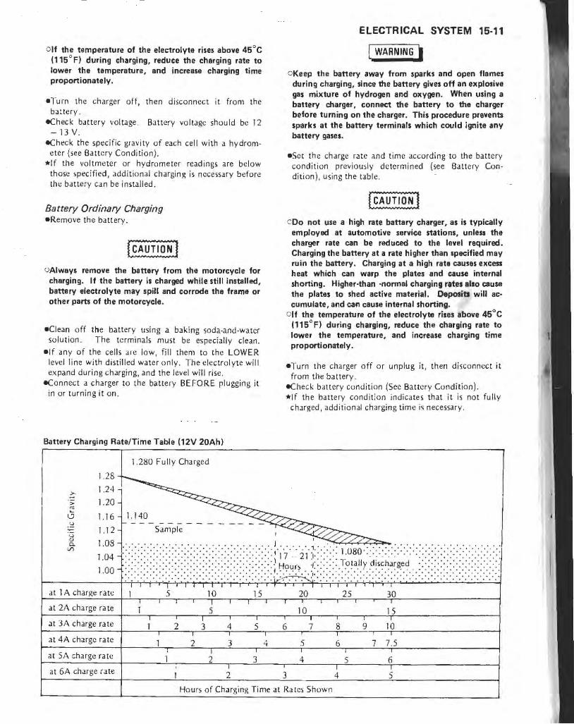
Glf the temperature of the electrolyte rises above 4SoC (llS oF) during charging, reduce the charging rate to lower the temperaturs l and increase charging time proportionately.
-Turn the charger off, then disconnect it from the battery.
-Check battery volt.lge . Battery voltage should be 12 - 13 V.
-Check the specific gravity of each cell with. hydrom· eter (see Battery Condition).
*If the voltmeter or hydrometer readings are below those specified, additional charging is necessary before the battery can be installed,
Batterv Ordinary Charging -Remove the battery.
[CAUTlO~ I OAlways remove the battery from the motorcycle for
charging. If the battery i. charged while still in.talled, battery electrolyte may spill and corrode the frame or other parts of the motorcycle.
-Clean off the battery using a baking soda-and·water solut ion. The terminals must be especially clean.
-If any of the cells are low, fill them to the LOWER level line with distilled water only. The electrolyte will expand during charging, and the level will rise .
-Connect a charger to the battery BEFORE plugging it in or turning it on.
Battery Charging Rate/Time Table (12V 20Ah)
1.280 Fully Charged
1.28 1.24
1.20
1.16 1.140
2 t- - - - S;;';pl-;; - -1.1
ELECTRICAL SYSTEM 15-11
I WARNING I OKeep the battery away from sparks and open flames
during charging, since the battery gives off an eXplotlve gas mixture of hydrogen and oxygen. When using a battery charger, connect the battery to the charger before turning on the charger. This procedure prevents sparks at the battery terminals which could ignite any battery ga.e •.
-Sot the charge rate and time according to the battery condition previously determined (see Battery Condition), using the tab le .
COo not use a high rate battary charger, as is typically employed at automotive service stations, unless the charger rate can be reduced to the level required. Charging the battery at • rate higher than .pecified may ruin the battery. Charging at a high rate causes excess heat which can warp the plates and cause internal shorting. Higher-than -normal charging rite. lisa cause the plates to shed active material. Deposits will accumulate, and can cause internal shorting.
Clf the temperature of the electrolyte riles above 45°C (115'F) during charging, reduce the charging rate to lower the temperature, and increase charging time proportionately.
-Turn the charger off or unplug it, then disconnect it from the battery.
-Check battery condition (See Ba ttery Condition), *If the battery condit ion indicates that it is not fully
charged, additional charging time is necessary.
u " "VI
1 08' ...... , . , J • , • , •••• •• , • ••
~ :~~ ::,,::,::::::.:.::.::::::,.::. i: '::::::: i:':::':: i'~~u~~~.I, i::::::, ·:~:~t~~Yd:~Ch~;g~d:.:: i: ii,:::·::::',:':' i.:'.: .... ' ,' .... '.'.' , ............. , ... , ". . .. ',' , , , . '.' '.' . , .. , .... , . , , .. , , .
l' S •• 10 , ,
25 30 at 1 A charge rate 15 20
at 2A charge rate •
.5 ,
10 15
at 3A charge rate 3 ,
8 9 10 2 4 5 6 7
at 4A charge rate ,
4 5 6 ,
7.5 2 3 , at SA charge rate :1 :i
, 1 4 5 6
at 6A charge rate , ,
5 1 2 3 4
Hours of Charging Time at Rates Sh own

15-12 ELECTRICAL SYSTEM
Battery Troubleshooting Guide
Good Battery
Plates (+) chocolate color H gray
Sediment none, or small amount
Vo ltage above 12 V
Electrolyte Level above plates
Specific Gra lli ty above 1.200 in all cells; no two cells more than 0.020 ditferent
Battery Test Charging elf the battery is suspec ted of being defective, sulfated,
0( unable to take a char$c, consult the table.
eTo test (;harge a battery. perform the ordinary charging procedure and monitor the battery voltage dnd other signs as men tioned below.
*If the battery voltage suddenly jumps to o ver 13 V just after the start of charging, th e plates arc probably sulfated. A good battery will risc to 12 V immeditel), and then gradually go up to 12.5 or 13 V in about 30 min to an hou r after the start of charging.
*If one cell produces no gas bubbles or has a very low specific gravity, it is probabl y shorted.
*1 f there does not appear to be enough sediment in a cell to short the plates, but that cell has a very low specific gral'ity after the battery is full y charged, the trouble may be that there is not enough acid in that one cell. In this case only, sulfuric. acid solution mdY be added to correct the specific gravity.
*I f a fully charged battery not in usc loses its charge after 2 to 7 days; or if the specific gravity drops markedly. the battery is defective. The 'ielf-discharge rate of a good battery is only about 1% per day .
................ ....................................... ......... ............. Alternator .... .. ................................................. ......................
The alternator contains the following: electrical components in its co mpact housing :
Alternator Stator and Rotor Recti ficr Regulator
Alternator Removal Note .Remov~ the alternator.
Suspect Battery Action
white (,ulphated); + plate. Replace
broken or corrodl!o
sediment up to plates, cau')ing sh o rt Replace
below 12 V Test charge
below lOp of plates , Fill and test charge
below 1.100, or difference of more Test charge
[ha.n 0.020 belW~t!n lwu Lt:'lb
A. Alternator B. Mounting Bolts
. Alternator Installation Notes - Cheel..: that the rubber dampers Me in place before
instal ling the alternator. - Clean the alternator legs and crankcase where the
al ternator is grounded .
A. Clean here. B. Rubber Damper;
eAppl ya non-permanen t locking .lgent to the threads of th e alternator mounting bolts.

Alternator Disassembly Notes eSeparate the alternator LH and RH housings. \,;Mark the housings before separation so that the
housings can be assembled in the same pOSItion.
Olf necessary. heat the left end of the LH housing to about 50 - 60°C (120 - 140°F).
A. LH Housing D. Coupling B. RH Housing E. Heat here. C. Housing Screws
eRemove the rotor from the RH housing.
A.Rotor B. Bearing Holder Screws
• Remove the stator, rectifier, regulator, and carbon brush assembly together from the LH hou sing.
A. Rectifier Mounting Screws C. Terminal NUl
B. Regulator ,\lounting Screws
ELECTRICAL SYSTEM 15-13
-Unsolder the stator coil leads from the rectifier terminals.
Alternator Assembly Notes .Press (he LH bearing onto the rotor shaft with the
bearing long end from the ring groove facing out. eSolder the carbon brush lead end with the brush holder
so that the brush projects as shown.
Carbon Brush Installation
A. Carbon Brush C. Solder. B. 3 - 4 mm D. Thin Wire
.Push the brushes into the holder, and ho ld them in their positions with a thin wire running through the holes on the LH housin g) brush holder, and brushes .
• Posi ti on the retainer on the LH bearing groove so that the protruding: port ion of tht: retainer comes to the deeper side of th e groove .
A. Retainer (Pro truding Portion) B. Groove (Deeper Side)
. After assembling the alternator, be surt: lhe rOLDr turns freely.

15-14 ELECTRICAL SYSTEM
Charging System Circuit
1. LH Bearing 2. Carbon Brushes Alternator 3. Rotor 4. Stator 5. O-ring 6. RH Bearing 7. Oil Seal 8. Spring Washer 9. Retainer
10. Rectifier 11. Slip Ring 12. LH Housing 13. RH Housing 14 . Regulator 15. Allernalor 16. Ignition Switch 17. Main Relay 18. Fuse Case 19. 10 A Fuse 20. 30 A Fuse 21. Battery
Alternator Intarnal Circuit
(17)
-:: 1--- BK/Y--~
WI'~ IV
BR 1 BK/ Y
1[81 "-'~ r----
W/ BK IV /BK,
R- '---BR BR , , , --
+
(;j'. ~-'

Alternator Operational Inspection For any cha.rging system problems, always check the
chargi ng system wiring first, and then check the system with the foilowing tests shown in th e tes t guide.
Test Guide
Trouble Bt.'ginning Test No.
Ba ttery discharged Test No. I
Battery overcharged Test No.6
Test No.1 - Charging Voltage eReplace the discharged battery with a good battery_ . Check the charging voltage at the alternator B terminal
wi lh the engine idling and running at 2000 rlmin (rpm). _I f the voltage at 2000 rl min (rpm) is higher than the
voltage at idle speed, go to Test No.3. *1 f the voltage at 2000 r Imin (rpm ) is the same as the
voltage at idle speed (voltage docs no t changeL go to Test No.2.
A. B Terminal B. Voltmeter
Test No.2 - Battery Power Supply - Check the voltage at the IF terminal with the ign ition
switch turned on but engine stopped. *I f the battery voluge appea" at lh~ f \ermina r, go to
Test No.3 . _I f the voltage is OV, check the main harness si de.
A. F Terminal B. Vol tmeter
ELECTRICAL SYSTEM 15·15
Te.t No.3 - Regulated Voltage _Remove the lOA fuse for the headlight in the fuse case. _Check the charging voltage at the B terminal with the
engine running at 4000 - 5000 r l min (rpm ). * If the voltage is within 14.2 - 15.2 V, the regulator i,
OK. Go to Tes t No . 4 . -If the voltage is less than 14.0 or more than 15.5 V,
the alterlliltor is defecdve. Chock the alternltor unit.
Test No.4 - Charting Amper. -Disconnec t the lead from the B terminal. -Check the charging amperage between, the B terminal
and the lead whh the enigne running at 2000 r/min (rpm) . Turn on the hoadlight , tail/ bra ke lights, turn signal tights, CIC. during the test.
·a'lf the am perage is less than 15 A, the alternator is defective.
*I f the a mperage is 15 - 20 A, go to Test No. 5. * Jf 'he amperage is more [han 20 A, the alternator is OK.
The trouble is in the other pa rts.
A. B T .rmi nal B. Ammeter
Test No. 5 - Charging Amperage (Review) _Discharge the battery a little or rdnstallthe discharged
ba t tery. .Check the wiri ng betvveen the B terminal and the battery
( + ) termir1dL -Check the charging amperage a t 2000 rlmin (rpm )
again . *I f the amperage is less than 20 A, check the alternator unit.
*If the amperage is mor~ than 20 A, the allc:rnator is OK. The trouble is in the other part.s .
Test No. 6 - Charging Voltage - Replace the overCharged ballery with a good battery. _ Check the charging vol tage at the B t.erminal with ihe
cns ine running. Increase the engi ne spt\..~ sJowly dur ing the tesl.
*If the voltage docs no t r ise more than 15.5 V, go to Test No.7.
*I f the voltage rises morc than 15.5 V, tht:: alternalOr (regulato r) is defective.

15-16 ELECTRICAL SYSTEM
A. B Terminal B. Voltmeter
Test No.7 - Regulated Voltage e!<.emove the 10 A fuse for t he headlight in the fuse
case, e<:heck the charging vo lLage at the B terminal with the
engine running at 4000 - 5000 rlmi n (rpm). *If the voltage is within 14.2 - 15.2 V, the alternator
(regulator) is OK. The trouble is in other parts. *If the voltage is more than 15.5 V, the alternator is
dcfcctiye.
Carbon Brush Length
Carbon Brush Length
Standard: Service limit:
Carbon Brush Length
Brush Leng th
16.5 mm 8mm
[AJ 5 en'ice Limit
Brush Spring Tension .Push the carbon brush into th e holder until the pro
trusion of it come) to 2 mm from the holder, and then measure the spring tension at this ins tart.
*If the tension is less than the service limit, replace the spring.
Brush Spring Tension
Standard:
Service limit: 310 - 430 g (with new brush I 210 g
Rotor Coil Inspection eMeasure the rotor co il resistance between the slip rings. *If the resistance is not as specified, replace the roto r.
Rotor Coil Resistance
3.5 - 5.0 Q
-Using the highest ohmmeter range, measure the resistance between he rotor shaft and each of the slip rings.
*If there.: b any rcadi n~ ,.II (111, the rotor I;oil has a short and must be replaced.
Slip Ring Cleaning _Visually in ~ pect the slip ring for dirt or pitting. *If necessary, smooth the slip ring with lathe or fine
emery cloth.
Slip Ring Diameter
Slip Ring Diameter
Standard: Service Limit:
A. Slip Rings
23mm 22.2mm
B. Stator Coil Windings
Stator Coil Inspection eUsing an Ohmmeter, che<:k the stuor coil windings for
continuity ("lose to 0 !2) . *Ii the meter shows. no continuity, the Sialor coi l winding
has an open lead .nd m~'t be replaced. -Using the highC"Sl ohmmeter range. measure the resist
ance between the stator co il (or:c and each of the coil windings .
• If there is any reading at all, the stator coil winding has J short and must be replaced.

Rectifier Inspection -Set an ohmmeter to the x I kQ range. _Connect the ohmmeter to the ends of each diode, and
check the resislJ.nce in both direction. The resistance should be low in one direction and more than len times as much in the o ther direction.
*If any diode shows low or high in both directions, the diode is defective and the rectifier must be replaced.
NOTE
CThe actual meter reading varies with the meter used and the individual diode, but, generally speaking, the lower reading should be from zero to the first 1/2 of the scale.
Clf a megger or a meter with a large-capacity battery is used, the rectifier will be damaged.
Rectifier Inspection
Ball Bearing Inspection
Rectifier --,
A, C,
A, C,
.Turh e~ch bearing b.lcl\ and forth while check ing for r.oughneis Of binding.
*If roughne» or binding is found, replace thiJ bearing, eExami,ne the bearing >eai for tears or leakage. *If [he seal is torn or is leaking, rt!place the bearing.
ELECTRICAL SYSTEM 15-17
Ignition System
I WARNING.
c The ignition system produces extremely high voltage. Do not touch the spark plugs, high tension coils, or spark plug leads while the engine is running, or you could receive a severe electrical shock.
! CAUTlO~] 0 00 not disconnect the battery leads or any other
electrical connections when the ignition switch is on, or while the engine is running. This is to prevent Ie igniter damage.
COo not install the battery backwards. The negative side is grounded. This is to prcvel'lt damage to the diodes and Ie igniter.
IC Igniter Installation Note -Connect the filter to the vacuum hoses so that the
marked side of the filter faces to the opposite side of the IC igniter.
A. IC Igniter C. ,\1arked Side B. Filler
Ignition CoN Installation Notes eConnect the primary wires to the primary coil termi-
nab as follows: o Bl ack and rcd wi res - #1 & 4 ignition coil (Left) cCreen an d red wires - #2 & 3 ignition coil (Right) eThe + and - markings n~xt to the prim.uy coil termi -
nals on the ignition coil body indicate the polarity of the terminals. The polarity of the two spark. plug leads are as shown when the primary le'ads are connL'Clcd as indicated in the figure. But both the primary wtrcs (pos itive red , .and negati ve bl.ack and green) can be connected with either terminal on the ignition coil without changing the cngine performance.

15-18 ELECTRICAL SYSTEM
Polarity of Ignition Coil
(-) #1 or #2 spark plug lead
c==r':; ::J::lI:::r::G~°I!J::====.J;:2J~ ~;;~:i: green lead
(+) #4 or #3 spark plug lead
... . Ignition Coil (#1 & 4)
Spark Plug Removal Note -Remoye the battery before remoying the #2 and #4
spark plugs. If necessary , usc the spark plug wrench (special tool: PIN 57001·1024).
Ie Igniter Internal Resistance-
Spark Plug Installation Note -Tighten the spark plug to the specified torque (see
Expl oded View).
Ie Igniter Inspection _Check the IC igniter in according to the IC Igniter
Troubleshooting chart. eTo inspect the Ie igniter internal resistance, perform
the following. -Set the ohmmeter to the x 1 kU range and make the
measurements shown in th e table. *If the meter readings arc not as specified, replace the Ie
igniter.
[CAUTIO~] CUse only Hand Tester 57001·983 for this test. A tester
other than the Kawasaki Hand Tester may show different readings,
0 1f a megger or a meter with a large-capacity battery is used, the Ie igniter will be damaged.
Terminal No. of Ie Igniter
Tester (+) Lead Connection
Terminal 1 2 3 4 5
Number 6 7 8 9 10
1 "" 00 00 00 00 00 - - - -
2 00 "" 00 00 00 00 - - - -
c 3 C 00 ~ C D A c - - - -.;:; u
"" u
4 00 00 00 ~ ~ c - - - -c 0
~ u 5 F 00 0 F E - - - -~
~ ~
-' 6 B 00 A B E - - - -I
~ ~ 7 - - - - - - C C C 3 .~
~ ~ 8 - - - - - - C C C
Value (kU) 00 Infinity
A 0.9 - 1.5
B 2 - 3.8
C 3.6 - 5.5
D 8 - 12
E 9 - 13
9 - - - .- - - C C "" C F 13 - 24
10 - - - - - - C C c I~ "'Me.asured with hand tester 57001 ·983. A tester other than the Kawasaki Hand Tester may show different readings.

IC Igniter Troubleshooting
Replace the Ie igniter with the or ig inal one.
Engine operates still poorly ?
"-"
Yes
Pickup Coil Inspection
No
No
Engine operates poorly.
There is no trouble in the ignition system except for the IC ignit er.
Inspection of IC ignitcr internal resiSliH1ce proves th c igniter is good?
Yes
Replace Ie ignit ~r.
Engin !;) o p~ra tcs
still poorly? /'
Yes
T ro uble should be caused by the o ther parts or engine itself.
Trouble is in Ie igni tcr.
ELECTRICAL SYSTEM 15-19
No
No
Replace Ie ignitt:r.
Engine operates Sli II poorly?
Yes
Trou ble is in Ie igniter and should be caused by the other parts o r engine itself.
ei\1~a5ure the pickup coil winding resistance. el\·leasure the resi stance between the pickup coil leads
and the co il mounting plate. *If th e resi stance is less than infinity, replace the pickUp
coil asc;embly. *If the resi stance is no t as specified, replace the pickup
coil assemb ly.
Pickup Coil Resistance
360 - 440 n

15-20 ELECTRICAL SYSTEM
A. Pickup Coils
Ignition Coil Inspection -Check the spark plug leads for visible damage. *1 f any spark plug lead is damaged, replace the coil. l\t1easuring arcing distance:
The most accurate test for determining the condition of the ignition coil is made by measuring arcing distance with a suitable tester for the 3-needle method. -Connect the ignition coil (with the spark plug cap left
installed at each of the spark plug leads) to the tester, and measure the arcing distance.
I WARNING I OTo avoid extremely high voltage shocks, do not touch the coil or leads.
*If the distance reading is less than the specified value, the ignition coil or spark plug caps arc defective.
Ignition Coil Arcing Distance 7 mm or more
eTa determine which part is defective, measure the arcing distance again with the spark plug caps removed from the ignition coil.
*If the arCing distance is subnormal as before, the trouble is with the ignition coil itself. If [he arcing dis[a nee is now normal, the trouble is with the spark plug cap~_
Measuring coil resistance: If the arcing tester is not available) the coil can be
checked lor a broken or badly shorted winding with an ohmmeter. However, an ohmmeter cannot detect layer shorts and shorts resulting from insulation breakdown under high voltage. eMeasure the primary winding resistance and the
,econdary winding resistance. *If the resistance is not as specified, replace the ignition
coil.
Ignition Coil Winding Resistance
Primary windings: 1.8 - 2.8 n Secondary windings: 10 -16 kn
A. Measure primary winding resistance. B. Measure secondary winding resistance. C Spark Plug Cap (removed)
Spark Plug Cleaning and Inspection -Cle~n the spark plug, preferably in a sandblasting
device, and then clean off any abrasive particles. The plug may also be cleaned using a high flash-point solvent and a wire brush or other suitable tool.
*1 f the spark plug electrodes are corroded or damaged, or if the i nsu lator is cracked, replace the plug. Use the standard spark plug or its equivalent.
Spark Plug Gap eMeasure the gap with a wire-type thickness gauge. *If the gap is incorrect, carefully bend the side ele
ctrode with a suitable tool to obtain the correct gap.
Spark Plug Gap
0.8 -0.9 mm
Spark Plug Gap
1
1. 2. 3. 4.
Insulator Center Electrode Plug Gap Side Electrode

Ignition Circuit
>-
r h 'I I ~...J~>~ O? co co
CD
'"
'" (5'. I , j
@
" P/ BL--.,
'---BK/Y
0
"P Tl1
Y/ R , ""
, 3:
I (§) '
~Cl e:.> LL_ >- _
(J)
~~i~~~ I Uj cttr
..... ?-~ ~ I ... ,
L..:::r
I . IC IgniiCr 2. Pickup Coil (#2 & 3) 3. Pickup Coi l (#1 & 4) 4. Timing Rotor 5. Ignition Coil (#1 & 4) 6. I~n i t io n Coil (#2 & 3) 7. Spark Plugs 8. Engine Stop Switch
BR/ R
LG
Y/G P/ BL
P/ BL P/ BL
.----BK
BK/R ...j I ~BRI R_
9. Ignition Switch 10. Diode Assembly 11 . Starter Lockout Swi tch 12. N~utral Switch 13. Side Stand Switch 14. FuseCase 15. 30 A Fuse 16. Battery
Lf "0
'" ~ >-
r4 " Tf~ ~ ~.
co
''"$ >-
" r BK
/
Y
>-fJ4) ,,~
'-or r----' ,
,@ , , L ____ .J
'"
@
" co"..
m rm o -4 :Il ('; l> r-en ~ -4 m ~ .... U1 N ....

15-22 ELECTRICAL SYSTEM
Electric Starter System
Starter Motor Removal Note eRemove the starter motor.
A. Starter Motor B. Mounting Bolts
Starter Motor Installation Note -Clean the starter motor legs and crankcase where the
starter motor is grounded.
A. Clean here.
Starter Motor Disassembly Note eRemove the (+) side carbon brush lead screw, and take
off the brush plate.
A. Brush Plate C. Screw B. (+) Side Carbon Brush
Starter Motor Assembly Notes ePush the brush plate into place with the tab in the
notch.
A. Tab B_ Notch
elnstall the brush end cover so that the long vertical tab on the brush plate aligns with the key slot in the cover.
A Tab B_ Key Slot

Carbon Brush Length
Carbon Brush Length
A
C<lrbon Brush Length
Standard : 12.0 -13.0 mm Service Limit: 6 mm
Brush Spring Inspection - Check thal the brush springs are in place and snap the
brushes firml y into place. *J f not , reinstall or replilc~ the spring.
Commutator Cleaning and Inspection - Smooth the commuta tor surfac ~ if necessary wi th fine
e mery cloth, and clean out the grooves as illustrated .
A Commuta tor
.De termin~ as accurately as possible the depth of the grooves between commutator segments.
*Replacc th e slaner molor with d new one if the groove depth is less than the service limit.
ELECTRICAL SYSTEM 15-23
Commutator Groove Depth
Standard : 0.5 - 0.8 mm Service Limit : 0.2 mm
Commutator
Good
t
MiC.J.
Commutator
Armature Inspection
Groove Depth
.Mea~urc t he rc) islance between each segment and all the others.
*1 f the resistance is too high or even infinite, the armature wi nding has an o pen circui t . Rep lace the starter motor.
e Measure the resistance between the commutator and the armature shaft.
* If the resistance is less than infinite, the armature is shorted. Rep/ace the starter motor.
A. Segme nts B. Sha ft

15-24 ELECTRICAL SYSTEM
Field Coil Inspection .Measure the resistance between the starter motor
terminal and the (+) side carbon brush terminal lead. • If the resistance is greater than 0 n, the field coils have
an open. Replace the starter motor. .Measure the resistance between the yoke and the
starter motor terminal or (+) side carbon brush terminal lead.
*If the resistance is less than infinite, the field coils are "hart",d to ground. Re pl:tcC' th (! <;urtf'.r mntnr.
A. Starter Motor Terminal B. (+) Side Carbon Brush Termi nal Lead C. Yoke
Electric Starter Circuit
1. Engine Sto p Switch 2. Starter Button 3. Starter Relay 4. Starter Lockou t Switch 5. Neutral Switch 6. Ignition Switch 7. Fuse Use 8. 30 A Fuse 9. S14rter Motor
10. Starter Motor Relay 11. Banery
BKiR-[D-LG
C§)
7' \.oj r-----., I
I @ I
I I I L _____ -.l
Brush Plate Inspection eMeasure the resistance between the (+) side c.arbon
brush holder and the metal pl ate . *1 f the resistance is less than infinite, the holder has a
short. Replace the starter motor. _Measure the resistance between the (- ) side carbon
brush and the mewl plate. *If the resistance is greater than O!1: , the brush assemb ly
has an open. Replace the starter motor.
A. (+)Side Carbon Brush Holder B. (- ) Side Carbon Brush C. Metal Plate
>'L
~ g-BK/Y
"" C
+
1\1)
'L co,r-.

Starter Motor Relay Inspection -Connect an ohmmeter and 12 V battery to the starter
motor re lay as shown. *1 f the rclay does no t work as specified, the re lay is
defective.
Testing Relay
Meter Range: x 1 n range Criteria: When battery is connected """ 0 n
When battery is disconnected - ) 00 n
Testing Relay
.~. Starter Motor Re lay
Lighting Sys tern
Headlight Circuit : Headlight Beam Horizontal Adjustment e Remove the headl ight cover.
A. Headlight Cover B. f\"ounti ng Screws
.Put a Phillips screwdriver into the adjuster guide. eTurn the adjuster in or out until the beam points strai~ht ahead.
ELECTRICAL SYSTEM 15-25
A. Adjuster C. Left B. Adjuster Guide D. Right
. lnst.11 the headlight cover.
Headlight Beam Vertical Adjustment
NOTE
oOn high beam, the brightest point should be slightlY below horizontal with the motorcycle an its wheels and the rider seated. Adjust tho headlight to the proper angle according to local regulations .
• Turn the adjuster to the di rection " UP" or "DOWN ", to adjust the headlighl vertically.
A. Ad juster B. UP C. DOWN
Vertical Adjustment

Headlight Circuit
1. Head light 2. High Beam Indicator Light 3. Failure In dicator Light 4. Dimmer Switch 5. Resen'e Lighting Device 6. Starter Circuit Relay 7. Starter Circuit 8. Headlight Relay 9. Main Relay
CD
10. Ignition Switch 11, Di ode A,<cmbly 12, Fu seC.,. 13. 15 A Fu,e 14. 30 A Fuse 15 , Starter Motor 16. Starter Motor Relay 17. Battery
~
i'J)
BK/Y I , I + ~R/BK
R/Y
@ R/BKiitR/BK
'c:::T-+- G/ R .ill LG/ R
~BK/Y .fIf.BK/Y @ l..bJ
:.:' I BL/Y--CIl >- >O? O?::J L BL/O
~T r::::: 'h et: et: -' ::J I
. CIl CIl
@ ®
®
...../ ..j 3" ...../ coco - co ---- ~ -a! a! co >-
®
-' -' CIl CIl - ->- et:
(ID >-
~ >-
',I ,, ® ihlofl I ~
!:
I I ~>---:.::.: CIlCIl
H
>-' ~~ !: _ et: :.: CIl>-
I t!:
-' :.:
1-4 ~
!: Qt '" CIl ~3
0~~U --,
I
I " 4' '''rL' I
L ___ _ _J
I >-0<
("" -~ ¢ 0< >--:.: CIl
®
... U'1 N en m rm (') -I :II
~ r-en -< en -I m ~

..
Headlight Reserve Lighting System Inspection If either high or low beam burns out, the reserve
lighting system switches over to the remaining filament automatically, and lights th e white headlight failure indicator light to show that the headlight bulb must be replaced . If the high beam filament burns out, the low beam is automatically turned on; ir low beam burns out, the high beam is turned on but more dimly than normal.
The US and Canadian models contain a relay in the headlight goes on on l:e the st.1rter button is pushed to start the engine, and stays on until the ignition switch is turned off. But the headlight goC'j out whenever the starter button is pushed ro restart the engine after engine ':!ta1!ing. *1 f all wirings and components other than the reverse
lighting device check out good , the device is defeaive.
A, Reserve Ligh ti ng Device B, Turn Signal Control Unit
Reserve Lighting System Operation
Headlight Dimmer Switch
Position
Both high and low HI beam filaments arc normal LO
High beam filam ent HI
burned out LO
Lo w beam filament HI
burned ou t LO
ELECTRICAL SYSTEM 15-27
Turn Signal Circuit: Turn Signal Control Unit Inspection
When the turn signitl switch is in ON position, a solenoid turns off the turn signal after it has been on fo r 4 seconds, plus the time that the motorcycle has traveled
an additional 50 meters. The cancelling sys tem consists of th e battery (power source), lurn signal comrol unit, distance sensor, solenoid, and turn signal switch. When the turn signal ~wjtch is pushed to the left or right, the turn signal s start flashing and the control unit starts co unting off 4 seconds. At the end of this time, the control unit starts ca lculating distance traveled using pulses from the distance sensor at {he rear of the speedometer. When the motorcycl e has traveled 50
meters, the control unit o perates the solenoid, which rt"turns the turn signal switch to the OFF position . • If all wirings and components ot her thitn the turn signal
control unit check o ut good, the unit is defecrive.
Headlight Failure Reserve Lighting
Indica tor Light
Goes on (hardly vi sible)
Goes on (hardly \'isible)
Goes on Low beam comes on .
Goes on (hardly visible)
Goes o n (hardly visible)
~oes on High beam comes on dimly.

Turn Signal Circuit
ITI :t~ ~~W ;r ;r _'
~~ ~. ~
;r >- - -,
BK! Y-----"~'
GY , , GY
- G KIY
(8 1
;r t - 0 ~ ~ 1 0
:}.ii
~ 19 0 ~
I ;r ""-
~ ~ ;r _.
I ~ 0 I I
·ro., ,J
¥;r",
'" --:;;:.. -. ':¥. ~
-""'L -; I
' I I) '.'
~ __ ::;. __ :::t-
o-~ -
~illp o - ~-
lJj
~
U1 N c:o m r m (') -l :0 (')
l> r CI)
< ~ m 3::
m", ~"
;DJ:GY~ , "'" . , ' " , ,J J -, t . I ~ l ~ ~ p
~ ~ ~ ;; : h . ,,",",", L..BKIYl ® : ¥ Front RightTurn Signa !
(.4) • 0 ~ ~ ~ • "', '''"" 't,~ ,,~."'OO"",. " (L?) tJ° ~~ - I- -, 2. Front L.ft . u t
o _ _ '",,,,,,",,. S' "I LighT
L, ~ vr if\~ 4. Rcar Lcf~:~~nnal~ndica t or Light
I P . ht 1 urn Ign,. I I 3. Rcar Rig Si nal Light
- - - - - - 5. Right 1 u . g I Ind icator Light L - - " "f Turn Signa •... " " ~ . ,,, C '"', 1,5.: VG' h " r H '.15; 7. Meter and Gauge " ::::-> G Y G ;r ~. _ I _ ', 7 l ' rn Signal Rela y
G
, . _. 0" , '" . " -W/ R '" ~ 0 <ll J. i: 9. Hazard SWITC
"/C l ~ """ ". ".," ",./ " -! .r h •• n. ,~,,,"" ,.,,, "" -, " ,~ U" .' . ·, t, , OOOI~ ;r 1-I . IOAFu,"
" . " I I I, ~, " ;0 """ '" "
?; .:0 -- \ 6: Turn Signal Co~tro n
17 . Turn Signal SW itch l B. Battery '16\
o o 1"t @ ' ... - --- ':!... _ ----

Turn Signal Relay Inspection -Remove the turn signal relay. - Con nect one 12 V battery an d turn signal lights as
in dicated in the figu re, and count how many times the lights fl ash for one minute.
*If the ligh ts do no t flash as specified, re place the turn signal re lay.
Testing Turn Signa' Relay (Example : Two lighu are connected.)
Turn Sing. 1 Re l.y
12 V Ba ttery
Testing Turn Signal
Load
Turn Signal Ug_h lS
The Nu mber Flashing Time~ (c /m'\') of Turn Wattage (IV) Sign.1 Ligh ts
1 21 - 2 3 More tha. 150
2 42 - 46
3 63 - 69 75 - 95 4 84 - 92
• : Cycle(s) per minute
A. Turn Signal Re lay
ELECTRICAL SYSTEM 15-29
Bulb Replacement : Bulb Replacement Notes
! CAUT!:O~J :.:':00 not use bulbs rated for greater wattage than the
specified value, as the meter or gauge panel could become warped by excessive heat radiated from the bulb •.
eRemove and insta ll the head light bulb.
!CAUTI~~J GWhen handling quaru·halogen bulbs, never touch
the glan with bare hands. Always use a clean cloth. Oil contamination from hands or dirty rags can reduce bulb life or cause the bulb to explode.
e Fi t the d ust cover onto the headl ight bu lb firmly as shown.
A. To p Mark B. Dus t Cover
Dust Cover Installalion
Good Bad
I . Dus t Cover 2. Headl ight Bulb

15·30 ELECTRICAL SYSTEM
eRemove the wedge·base type bulbs. oPul1 out the bulbs and sockets , and/or pull the bulbs
off the s:ockets.
A. Indicator Bulbs B. Illumination Bulbs
A. Side Marker Light Bulb
A. Trunk Room Light Bulb
.Remove the lock pin type bulbs. c Pull out the bulbs and sockets. oPush the bu lb in, turn it counterclockwise, and pull it
out of the socket.
A. Tail/Brake Light Bulbs
A. Tail /Brake Light Bulbs B. License Plate Light Bulb
A. Turn Signal/Running Posi t ion Light Bulb

A Turn Signal Light Bulb
................................................................ .. ............ Fuel Pump ............................................................ ... ...............
The fuel pump does not operate wh en the ignition switch is turned on only. The pump operates when the starter button is pushed on or thl! engine is running.
Fuel Pump Circuit
If ', \. . ../ o
1. Engine Stop Swilch 2. Starter BUllon 3. Fuel Pump 4. Ignition Coil (#1 & 4) 5. Ignition Circu it 6. Ignition Switch 7. Fuse Case 8. 30 A Fuse 9. Battery
ELECTRICAL SYSTEM 15-31
Fuel Pump Internal Resistance -Set the ohmmeter to the x I kU range and make the
measurements shown in the table. *If the meter readings are not as specified} replace the
fuel pump.
Fuel Pump Internal Resistance
" ~ c
" -' 0
_ u
I " -2 , ~ 0
~~ ~
f--
o
IV
Tester (+) Lead Connection
Lead BK BL BK/ Y
BK ~ ~ ~
BL ~ ~ ~
BK/Y ~
More than
~ 20 kU
BKR-qL __ --' --g ® ~---L,
'"7" \!..) r-----, I
+
o

15-32 ELECTRICAL SYSTEM
Cooling Fan Circuit
Cooling Fan Circuit Inspection If the fan doe~ not run while the water temperature
gauge hand is in the hot range, check the water tem· perature gauge, or the cooling fan circuit. -Visually inspect the radiator fan . *1 t the fan blJ.lh:'!I or )hroud arc damaged, replace: the f:t.n
assembly . • Pull off the fan switch lead, and ground it with a
suitable lead. *If the fan turns, inspect the fan switch. .,f the fan does not turn, check the fan, fan relay or
wiring as follows.
WARNING.
cBe careful not to touch the fan blades to avoid injury.
Fan Motor Inspection .Pull out the fan connector and connect it to 12 V
battery as follows.
Fan connector (male)
G
BL Battery 1-)
Battery (+)
*1 f the fan does not turn, replace the fan assembly.
Cooling Fan Circuit
r ,J)
.6:r1-G BKj Y
"3--~ '=)
~Bl-I--l Bl-+----....l
Fan Switch Inspection .Remove the fan switch, and check the internal resis
tance of the fan switch across the switch terminal and the bod y.
-Suspend the switch in a container of water so ,that the temperature-sensing projection and threaded portion are submerged.
*The fan switch resistance should change as shown in the Lable. If it does not, replace the switch.
Fan Switch Resistance
Temperalure
Atmospheric temperature
Raise 94 -100°C ~ (201 - 212°F)
91°C Lower (196°F) ~
lI'iBl
® ,------, I I
I ,'5' ,-,<)
I I
I I l ____ .J
Resistance Change
~n
00 ..... 0.5 Q
~<- O.S n
I. Cooling Fan 2. Fan Switch 3. Fan Relay 4. Fuse Case 5. 10 A Fuse 6. Battery
BK /Y
,~

n Fan Sw itch Inspection
Fan Swi tch
/ They must no t louch the container sides or bOllom.
Meters and Gauges
Thermometer ~l
Meter Assembly Removal/ Installation Notes eThe meter Jssembly is removed and installed during the
fairing removal and installation.
I CAUTIO~ I CPlace the meter or gauge so that the face is up. If a
meter or gauge is left upside down or sideways for any length of time it will malfunction.
Meter Assembly Separation/Assembly Notes eRemove the radio and cas)cltt! player.
f\. Radio and Cassette Player B. Player From Panel
C. Mounting Screws
ELECTRICAL SYSTEM 15-33
A. Radio and c.sscttc Player B. Mounting Bolts
A. Mounting Bracket C. Watertight Scat B. Louvers
eRemove the meter and gauge a~sembly.
A. Meter and Gauge Assembly D. Mounting N~ts B. Mounting Bracket E. Mounting S.crew\ C. Rubber Dampers
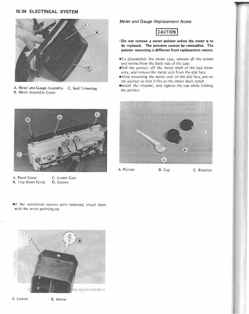
15-34 ELECTRICAL SYSTEM
A. Meter and Gauge A"embly C. Seal Trimming B. Meter Assembly Cover
A. Panel Cover C. Lower Case B. Trip Re.et Knob D. Screws
elf the venti lation louvers were removed, install them with the arrow pointing up.
;..\ . Louver B. Arrow
Meter and Gauge Replacement Notes
COo not remove a meter pointer unless the meter is to be replaced. The pointers cannot be reinstalled. The pointer mounting is different from replacement meten.
eTa disassemble the meter case, remove all the sc rew'i and wiring from the back side of the case,
.Pull the po inter off the meter shaft of the bad meter only, and remove the meter unit from the dial face.
eAfter mounting the meter unit on the dial face, put on the pointer so that it fit s on the meter s.haft notch.
elnstall the rc tainer, and tighten the cap while holding the pointer.
A
A. Pointer B. Cap C. Retainer

Meter and Gauge Circuit
I (1) I I ~ I I ~ I ~ _ ct: CO-- o... _::IiCCC-1-1
m I I co
:;:
~ '" ~co _ a.. IX) -" -"
ii:l
R
(- f-
,
l-f-
(
- -( -
E
,
~ ~cL
(iwl I I
P ::L '" IX) L
I I
L
~
BRUB P G/
L/ R BL
I I
,VjY W, (
LB L
B K/Y BK '(
L
BK B /W Y
G/BK R
---"
7) (IZi
I [ ~ :;: . _ co>->-
( - I-
~e '-
~ "" "'" '--''I
r -c>e=tBK/W ~ RK!W
'"8" "=,'
- Q)>->-ru I \ ? ~ ,. '" Bc
® Y BL~
"_~>- ~-":;;- >2
B:~)1J' !2P I I
o
1, Indicator Light Self·check Unit
(q : "cw ?! Qj >-
I I
- ..
~ '" -3:
11 M
2. Battery Indicator Light 3. Oil Pressure Warning Light 4. Fuel L~ve l Warning Light 5, Fuel Gauge 6. Tachometer 7. Water Temperature Gauge 8, Distance Sensor 9. ,W/ AC Signal Un it
AV: Auto Volume (Aud io ) AC: Auto Cancel (Signal)
10, Meter Assembly Side 11. Ignition Coil (#1 & 4) 12. Ignition Circuit 13, Main Relay 14. Ignition Switch 15, Fuse Case 16, 10 A Fuse 17 . 30AFusc 18. Turn Signal Circuit 19. Audio Circuit 20. Water Temperature Sensor 21. Fuel Level Sensor
(Low Fuel Level Sensor) 22. Oil Pressure Switch
~lt1 r - -
' 6! ---
-, 23. Electrolyte Level Sensor : 24. Battery
" ,
1 -" l '" ::J ;;- -
~ ~~ -" 0< -"
IX) - '" - :;: -(f2)~ ,~
::L f BK
/
Y
>--::L IX)
1 . 'JV
~ !2 ~ (?}j ~L~
m rm (') -I ::0 (')
» r-en < ~ m
== ... U1 W U1

15-36 ELECTRICAL SYSTEM
Tachometer Inspection
NOTE
oThe tachometer inspection is explained on the assumption that the ignition system operates normally.
. Check to sec that the rubber dampers at the meter mounting bracket are in good conditio n. They should not be hard or cracked.
• '{eplacc any dama.ged rubbt:r dampers ~"jlh new U fl e).
e<:heck to see that all meter mounting bolts and nuts are ti gh telled· secure l y.
*Tighten the loose fasteners. _Check the tachome ter circui t wiring. *1 f all wiri ng and components o ther than the tac ho
meter unit check out good, the un it is suspect. Check the un it as shown.
eTurn the ign i tion switch ON. .With the BK/ Y and the BR I.ad conn ected, open or
connect the BK lead to the BR lead repeat edly. Then, the meter hand should flick.
*I f the hand does not fl ick, replace the tacho meter un it.
Fuel Gauge Opeartion Inspection .Prepare an auxiliary wire , and check the operatio n of
the gauge.
Fuel Gauge Operation Check
Ignition Switch Position : ON Wire Location:
Results:
Female 3-pin sensor connector (disconnected) Gauge should read E when W/Y and BK/Y wires are opened. Gauge ,hould read F when W/Y and BK /Y wires are shorted.
COo not short-circuit the leads longer than necessary. When the hand swings to the "F" position, stop shortcircuiting. Otherwise a good meter could be damaged.
*If the gauge readings are correct, the fuel level sensor is bad. If these readings are not obtained, the trouble is with the gauge and /or wiring.
-Che,k the fuel gauge circuit wiring. * If a ll wiring and components other [han the fuel gauge
unit check out good, the uni t is defective.
Water Temperature Gauge Operation Inspection .Prepare an auxiliary wire, and check the o pera t ion of
the gauge.
Water Temperature Gauge Operation Check
Ignition Switch Position: ON Wire Location: Female, Sensor Connector
(dioconnected)
Results : Gauge should r.ad C when connector wire is opened. Gauge should read H when connector w ire is grounded to engine .
COo not ground the wiring longer than necessary. After the needle swings to the H position, stop the test. Otherwise the gauge could be damaged.
*I f the gauge readings are correct, the water temperature sensor is bad. If these readings arc no t ob tained, the trouble is with the gauge and /or wiring.
-Check the water temperature gauge circuit wiring. *If all wiring and components o ther than the water tem
perature gauge unit chec k out good, the un it is defective.
Indicator Light Self-check Unit Inspection .Pre pare four auxiliary wires and 12 V battery . • Disconnect the 9-pin connectors fro m the meter
assemb ly. -Connect the battery (+) terminal to the BR meter lead, and the battery (-) term inal to the BK/ Y me ter lead . The battery indicator light shou ld turn o n at this time.
*If the indicator light does no t turn on, check the wiring and bu lb. If th ey are OK, the self-check unit is defective. Replace the meter assembly.
-Connect the battery (+) term inal to the P meter lead. The battery indicator light should turn o ff a t th is time.
*If the indicator light does not turn uff, the self·check uni t is defective. Replace the meter assembly .
-Connect the battery (- I terminal to th e BU R meter lead. The ba llery, oil, and fuel indicator ligh ts should turn on at thj~ time.
*I f any light docs not turn on. check thl.! wiring and bu lb. If they arc OK, the self·check unit is defective. Rep lace the meter assembly.
*If th e above teSIS prove that th e left-check unit is good, chec k the main wiring harness side.

Indicator Light Self·check Operation
Ignition
Battery
Switch (Electrolyte Level)'
and Fuel Level Sensor
(Low Fuel)--
Oil Pressure'""**
Battery
Indicator Fuci Level Light
Oil Pressure
"Electrolyte Level Sensor:
OFFi ON
~ OFF . , , , ,
fl , , OFF
, , , ! , , ,
, , , , I OFF [ ,
[ [ , [ , [
-.fONt , , I , :
[ONlJ
OFF - Less than 2 V ON - More than 4 V
I
ELECTRICAL SYSTEM 15·37
L
Fl fOOl
ON L ON L ON L ON L
>0; .. Low Fuel Level Sensor:
..... "Oil Pressure Swi tch:
OFF -+ Fuel level is above the sensor. ON - Fuel level is below the sensor. OFF -,. Engine is running .
AV/AC Signal Unit Inspection .Prepare an auxiliary wire.
ON - Engine is stopped.
eDisconnect the AV/AC signal unit BK/W lead from the distance sensor.
eTurn an the ignition switch and audio power switch. eMeasure the voltage between the Y lead (+) and the BL
lead (- ). The VOltage should be 8 V. *If the volt.tgc is not as specified, check the AV control
circuit. If the f\ V control circuit is good , the signa l unit is defective. Replace the meter assembly.
eGround the signal unit BK/W lead with an auxiliary wire and measure the voltage again. The voltage should be 2 V.
*If the voltage is not as specified. the signal unit is defective. Replace the meter assembly.
.. Turn on (L or R) the turn signal switch. eMeasure the voltage between the LG/BK lead (+) and
the BKjY lead (-). The voltage should be 6 V when th e signal unit BK/W lead is grounded, and 0 V when the BK/W lead is opened.
*If it does not as specified, check the AC control circuit. If the AC control circuit is good, the signal unit is defective. Replace the meter assembly.
*If the above tesb prove that the AV/AC signal unit is good, check the distance sensor, audio system, and/or turn signal circuit.
Distance Sensor Inspection -Olsconnect the distance sensor leads. -M e::a sure the resistance between the stnsor leads while
turning the front wheel slowly. The meter should show con tinuity and then open periodicall y as the wheel revolutions.
*I f it does not, replace the distance sensor.
A
A. Indicator Light Self·check Unit B. AV/AC Signal Unit C Distance Sensor
A V Control Circuit Inspection
.. -:.®
-Disconnect the 2-pin connector from the meter assembly.
_Turn on the ignition switch dnd audio power switch. e~'lcasure the vollJge between the Y lead (+) and the BL
lead (-) in the female 2'pin connector. The voltage should be 8 V.
*If the voltage is not as specified, the trouble is in the audio system.
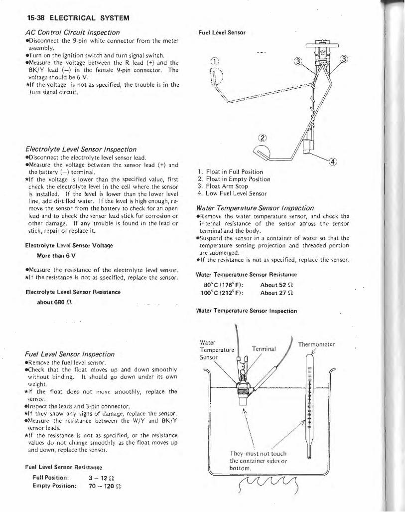
15-38 ELECTRICAL SYSTEM
A C Control Circuit Inspection eDisconnect the 9-pin white connector from the meter
assembly. eTurn on the ignition swi tch and turn signa l switch. eMeasure t he voltage between the R lead (+) and the
BKi Y lead (-) in the female 9-pin conneCtor. The voltage should be 6 V.
*If the voltage is not as specified, the trouble is in the turn signal circuit.
Electrolyte Level Sensor Inspection eDisconnect the electrolyte level sensor lead. eMeasure the voltage between the sensor lead (+) and
the battery (- ) terminal. *If the vo ltage is lower than the specified value, first
check the electrolyte level in the cell where . the sensor is installed. If the level is lower than th e lower level line, add disti ll ed water. If the level is high enough, remove th e sensor from the battery to check for an open lead and to check the sensor lead stick for corrosion or other damage. If any trouble is found in th e lead or stick, repai r or replace it.
Electrolyte Level Sensor Voltage
More than 6 V
eMeasure the resistance of the electrolyte level sensor. *1 f the resistance is not as specified, replace the sensor.
Electrolyte Level Sensor Resistance
about 680 n
Fuel Level Sensor Inspection .Remove the fuel level sensor. e<:heck that the noat moves up and down smoolhly
without bindi ng. It should go down under its own weight.
*If the float does not move smoothly, replace the sensor .
• Inspec t the leads and 3-pin connector. *If th~y show any signs of damage, replace the sensor. .i\.·leasure the resistance between the WjY and I3KjY
sensor leads. *If the resistance is not as specified, or t he resistance
values do not change smoothly as the float moves up and down, replace the sensor.
Fuel Level Sensor Resistance
Full Position : Empty Position:
3 -12 n 70 - 120 n
Fuel Level Sensor
1. Float in Full Position 2. Float in Empty Posit ion 3. Float Arm Stop 4. Low Fuel Level Senso r
Water Temperature Sensor Inspection -Remove the water temperature sensor, and check the
internal resistance of the sensor across the sensor terminal and the body.
-Suspend the sensor in a container of water so that the temperature sensing projection and threaded portion are submerged.
*If the resistance is not as specified, replace the sensor.
Water Temperature Sensor Resistance
80"C (176"F): 100"C (212"F):
About 52 n About 27 n
Water Temperature Sensor Inspection
Water Temperature Sensor
,~
Thermometer /
\ / They must not touch the conL:lincr sides or boltom.

Switches
Rear Brake Light Switch Adjustment -Check the operation of the rcar brake light switch by
depressing the brake pedal. The brake light should go on after abou t 15 mm of pedal trave l.
A. Rear Brake Light Switch D. Lights later. B. Adjusting Nut E. 15 mm C. Ligh ts sooner.
Ignition Switch Connections
W YIR BL(W OFF, LOCK
ACC
ON
P(Park)
Starter Lockout Switch Connections
When du tch levcr is pu lied in
When clu tch lever is re leased
Horn Button Connections
Push on BKJW
c
Turn Signal Switch Connections
BK/ Y
BK/Y )
BK/ R BK
BR
GY 0 G BLIIV \VIR BKIY R
N
L r
ELECTRICAL SYSTEM 15-39
*If it does not, adjust the rcar brake light switch up or down, To change the switch position, turn the adjusting nut.
oro avoid damaging the electrical connections inside the switch, be sure that the switch body does not turn during adjustment.
Switch Inspection - Usi ng an ohmmeter, check to see that only the con
nections shown in the table have continuity (about lero ohms).
*If the switch has an open or short, repair it or replace it wi th new one.
R IV OIG
Dimmer Switch Connections
BL/ Y BL/O R/Y RIBK
HI
LO
Volume Control Switch Connections
R GY BR .. UP
." DOWN
WIG
" ')
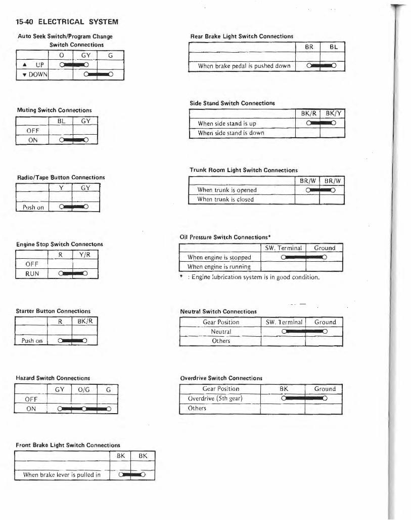
15-40 ELECTRICAL SYSTEM
Auto Seek Switch/Program Change SWitch Connections
o c
Muting Switch Connections
OFF
ON
Radio!Tape Button Connections
I V
I GV
Push on C ")
Engine Stop Switch Connectons
OFF
RUN I : I V: I
Starter Button Connections
Push on
Hazard Switch Connections
OFF
ON
Front Brake Light Switch Connections
BK
When brake lever is pulled in
BK
Rear Brake Light Switch Connections
BR BL
When brake pedal is pushed down
Side Stand Switch Connections
BK/ R BK/V
When side stand is up
When side stand is down
Trunk Room Light Switch Connections
BR/W BRjW
When tru nk is opened
When trunk is closed
Oil Pressure Switch Connections·
51'.'. Terminal Ground
When engine ;s slOpped
When engine is running
... : Engine lubrication system is in good condition.
Neutral Switch Connections
Gear Position SW. Terminal Ground
Neutral
Others
Overdrive Switch Connections
Gear Position BK Ground
Overdrive (5th gear)
Others

A. Ignition Switch 8. Starter Lockout Switch C. Horn Bu tton
A. Volume Control Switch
D. Turn Signal Switch E. Dimmer Switch
B. Auto Seck Switch/Program Change Switch C. Muting Switch D. Radio!Tape Button
A. Engine Stop Switch 8. Starter Button
C. Hazard Switch D. Front Brake Light Switch
ELECTRICAL SYSTEM 1&41
A. Rear Brake Light Switch B. Side Stand Switch
A. Trunk Room Light Switch
A. Oil Pressure Switch B. Neutral and Overdrive Switch

15·42 ELECTRICAL SYSTEM
Relays
Relay Inspection
NOTE
oFor inspections of the starter motor relay and turn signal relay, fefer to the appropriate sections for them .
.connect an ohmm eter and 12 V battery to the re lay as shown.
*I f the rclay does not work as specified, the relay is defective.
Testing Relay A. Relays (~Iain, Starter Circuit, Headlight)
Meier Range: x 1 n. range Criteria: When battery is connected -~ 0 n
When battery is disconnected - OQ n
Testing Relay
Ohmmeter
Relay
+
12 V Battery
<D and @ : Relay Coil Terminals @ and @) : Relay Switch Terminals
A. Relays (Fan , Brake Light, ACC)
Diodes
Diode I nspec tion _ Zero the oh mmeter, and connect it to each pair of
terminals to check the resistance in both directions. *The resistance should be low in o ne direc ti on and more
th an ten times as much in the other directi on . I f any d iode shows low or high in both directions, the diode is defec tive and the d iode assembl y mUSI be replaced .
NOTE
oThe actusl merer reading 'Iaries with the merer used and the individual diode, but, generally speaking, the lower reading should be from zero to the first ~ of the scale.
A. Diode Assembly (Ignition)

A. Diode Assembly (Headlight)
Fuses ......... , .................................................................. .
Fuse Inspection elnsepct the fuse element. *If it is blown OUI, replace the fuse. Before replacing J.
blO\vn fuse, always check th~ amp~rage in the affected circuit. If the arnpl::ragc is equal to or greater than the fuse rating, check the wiring and related components for a short circuit.
CWhen replacing a fuse, be sure the new fuse matches the specified fuse rating for that circuit. Installation of a fuse with a higher rating may cause damage to wiring and components.
Fuse (Wedge Typel
Fuse Elemenr Blown Element
fHl Terminals
ELECTRICAL SYSTEM 15-43
A. Fuse Case
A. Fuse Cases for Audio System
Electrical Wiring
Wiring Inspection -Visually inspect the wiring for signs of burning, fraying,
etc . *If any wiring is poor, replace the damaged wiring. .Pull each connector apart and inspect it for corrosion,
dirt, and damage. *If the connector is corroded or dirty, c lean it carefully.
If it is damaged, replace it. -Check the wiring for continuity. o Use the wiring diagram to find the ends of the lead
whic.h i'i ')U'ipected of being a problem. :J,"'casure the resistance bt!twt!en the ends of the Icads. *1 f the resistance is nut 0 n, thl.! lead is defective.
Replace the lead or the wiring loom if necessary.

APPENDIX 16-1
Appendix
Table of Contents
Additional Considerations for Racing . . . . . . . . . . . . . . . . . . . . . . . . . . . 16·2
Carbu retor . . . . . . . . . . . . . . . . . . . . . . . . . . . . . . . . . . . . . . . . . . . . . 16-2
Spark Plug ... .. . .. . . . . .•. .. . ... . ............ . . .... •. . .. 16-2
Spark Plug Inspection. . . . . . . . . . . . . • • . . . . . . . . . . . . . . . . . . . . 16-2
Troubleshooting Guide . . . . . . . • . . . . . . . . . .. . . . . . . . . . . . . . . . • . . . 16·4
General Lubrication . . . . . . . . . . . . . . . . . . . . • . . . . . . . . . . . . . . . . • . . 16-8
Lubrication . ............. ............. ... ... . .• ...... 16-8
Nut, Bolt, and Fastener T ightness . ... . .. .. . . . . .... . .. . . .. . . • • . 16-8
Tightness Inspection. . . . . . . . . . . . . . . . . . . . . . . . . . . . . • . . . . . . 16-8
Unit Conversion Table . . . . . . . . . . . . . . . . . . . . . . . . . . . . . . . . . . . . .. 16-10

16-2 APPENDIX
Additional Considerations for Racing
Thi'5 motorcycle has been manufactured (or use in a reasonable and prudent manner and as a vehicle only_ However, some may wish to subject this motorcycle lO
abnormal operation, ~uch as wuuld be experienced under racing condition.. KAWASAKI STRONGLY RECOM· MENDS THAT ALL RIDERS RIDE SAFELY AND OBEY ALL LAWS AND REGULATIONS CONCERN· ING THEIR MOTORCYCLE AND ITS OPERATION.
Racing should be done under su pervised conditions, and recognized sanctioning bodies should be contacted for (u rther details. For those who desire to participate in competitive racing or related use, the following technical information may prove useful. However, please nOle the following important points. .You are entirely responsible for the use of your motor
cycle UndL'f abnormal conditions such as rae.jng. and Kawasaki shall not be liable for any damages which might arise from such usc .
eKawasaki 's Limited Motorcycle Warranty and Limited E(l1ission Control Systems Warranty specifically (:xelude motorcycles which arc used in competitive or related uses. Please read the warranty carefully.
eMotorcycie racing b a very sophisticated sport, subject to many variables, The following information is theoretical only, and Kawasaki shall not be liable for any damages which might arise from alteration~ utilizin~ this information.
eWhen the motorcycle is operated on public roads, it must b~ in it::. original state in order to ensure :kifety and compliance with applicable regularions.
Carburetor: Sometimes an alteration may be desirab le for im
proved performance under special conditions when proper mixture is not obtained after the carburetor has been properly adjusted, and a/l pans cleaned and found to be functioning properly .
If the engin e still exhibits symptoms of overly lean carburetion after all maintenance and oidjustments are correctly performed, the main jet can be replaced with it
smaller or larger one. .At smaller numbered jet gives a leaner mixture and a larger numbered jet a richer mixture.
Spark Plug: The spark plug ignites the fuel /air mixture in thl!
combustion chamber, To do this effectively and at the proper time, the correct spark plug must be used, and the spark plug must be kept clean and adjusted,
Test have shown the plug listed in the "Electrical System" chapter LO be the best plug for general usc.
Since spark plug requirements change with the igni · tion and carburetion adjustments an.d wi th riding condi· tions, whether or not a spark plug of a correct heat range is used should be determined by removing and inspecting the plug.
When a plug of the correct heat range is being used, the electrodes will stay hot enough to keep all the carbon burned off, but cool enough £0 keep from damaging the engine and the plug ilself. This temperature is .bout 400 - 800°C (750 - 1 ,450°F) and can be judged by noting the condition and color o( the ceramic in sula lOr around the center electrode. I f the ceramic is clean and of a light brown color, the plug is operating at the right temperalUre.
A spark plug (or higher operating tcmperature~ is used for racing. Such a plug is designed rur vetter cooling efficiency so that it will not overheat and thus is often called a "colder"· plug. If a spark plug with too high a heat range is used ,- thar is, a "co ld" plug that cools itest:lf too well - Ihe plug will stay too cool to burn off the carbon, and the carbon will collect on the electrodes and the ceramic insulator.
The carbon on the electrodes conduct'5 electricity, and can short the center electrode to ground by either coating the ceramic insulator or bridging across the gap. Such a short will prevent an effective spark. Carbon build-up on the plug can also cause other troubles. It can heat up red-hot and cause preignition and knocking, which may e\lcntually burn a hole in the top of the piston ,
Spark Plug
Reach
Plug gap
1. Terminal 2. Insulator 3. Cement
Spark Plug Inspection eRemovc the spMk plug and
lator.
4. Gasket 5. Center electrode 6. Side electrode
inspect the ceramic insu-

Spark Plug Condition
Carbo n fouling O il fou ling
*Wht, ther or no t the right tem peratu re pl ug is being used can be ascerta in ed by not ing the condition of t he ceram ic insulato r around t he electrode. A light bro wn color indica tes. the correc t p lug is being used. If the ceram ic is white , the plug is o perati ng a t too high a tem pera ture and it shou ld be rep laced wi th the nex t colder type,
{CAUTlO~ I Clf the spark plug is replaced with a type other than the
standard plug, make certain the replacement plug has the same thread pitch and reach (lenqth of threaded portion) and the same insulator type Iregular type or projected type) as the standard plug.
Cif the plug reach is too short, carbon will build up on the plug hole threads in the cylinder head, causing overheating and making it very difficult to insert the conect spark plug later.
e ll the reach is too long, carbon will build up on the exposed spark plug threads causing overheating, preigniton, and possibly burning a hole in the piston top. I n addition, it may be impossible to remove the plug without damaging the cylinder he.d.
Plug Reach
Too sho rt
Carbon bu ilds up here
Standard Spark Plug Threads
Diameter : Pitch : Reach :
12 mm 1.25 mm 19.0 mm
Correct reach
APPENDIX 16-3
Normal o perati o n Overheating
NOTE
OThe heat range of the spark plug functions like 8
thermostat for the engine. Using the wrong type of spark plug can make the engine run too hot (resulting in engine damage) or too cold (with poor performance, misfiring, and stalling).

16-4 APPENDIX
Troubleshooting Guide
NOTE
OThis is not an exhaustive list, giving every possible cause for each problem listed. It is meant simply as a rough guide to assist the troubleshooting for some of the more common difficulties.
Engine Doesn't Start, Starting Difficulty: Starter motor not rotating:
Starter lockout or neutral switch trouble Surter motor trouble Battery voltage low Relays not contacting or operating Starter button noc contacting Wi ri ng open or shorted Ignition switch troubl e Engine stop switch trouble Fuse blown
Starter motor rotating but engine doesn't turn over: Starter motor clutch trouble
Engine won't turn over: Val vc seizure Cylinder, piston seizure Crankshaft seizure Connecting rod small (!nd seizure Connecting rod big end seizure Transmission gear or bearing seizure Camsha ft seizure Alternator shaft bearing seizure Balancer beari ng seizure
No fuel II ow: Fuel tank air vent obstructed Fuel pump troubk Fuel line clogged Float valve clogged
Engine flooded: Fud level in carburetor float bowl too high Float valve worn or stuck open Starting technique faulty (When flooded, crank the cngine with the throttle
fully open to allow more air to reach the engine,)
No spark; spark weak; Elattery voltage low Spark plug dirty, broken, or maladjush.:d Spark plug cap or high tension wiring trouble Spark plug cap not in good conLlct Spark plug incorrect IC igniter trouble Neutral, staner loCkout, or side stand switch
tro uble Pickup coil trouble Ignilion coil trouble Ign ition or engine stop switch shorted Wiring shorted or open Fuse blown
Compression low: Spark plug loose Cylinder head not sufficiently Lightened down Cylinder, piston worn
Piston ring bad (worn, weak, broken, or sticking) Piston ring/land clearance excessive Cylinder head gasket damaged Cylinder head warped Valve spring broken or weak Valve not seating properly (valve bent, worn, or
carbon accumulation on the seating surface) Hydraulic lash adjuster damaged (worn, seizure, or
spring broken) Hydraulic lash adjuster oil passage clogged
Poor Running at Low Speed: Spark weak:
Battery voltage low Spark plug dirty, broken, or maladjusted Spark plug cap or high tension wiring trouble Spark plug cap shorted or not in good contact Spark plug incorrect IC igniter trouble Pickup coil trouble Ignition coil trouble
Fuel/air mixture incorrect: Pilot screw maladj usted Pilo t jet, or air passage clogged Air bleed pipe bleed holes clogged Pilot passage clogged Air cleaner clogged, poorly scaled , or missi ng Starter plunger stuck open Fuel level in carburetor fl oat bowl too high or too
low Fuel lan k air vent obstructed Carburetor hold~r loose Air cleaner or surge tank duct loose Fuel pump trouble
Comprenion low: Spark plug loose Cylinder head not sufficiently tightened down Cylinder, piston worn Piston ring bad (worn, weak, broken, or sticking) Piston ring/land clearance excessi ve Cylinder head warped Cylinder head gasket damaged Engine not sufficie.ntly warmed up after lash
adjuster install ation Hydraulic lash adjusler dam~ged (worn, seizure, or
spring broken) Hydraulic lash adjuster o il passage clogged Valve spring broken or weak Valve not seating properl,! (valve bent, worn, or
carbon accumulalion on the seating surface) Backfiring when deceleration:
Vacuum switch valve broken Air suction valve trouble
Other: IC igniter trouble Carburetors no t synchronizing Carburetor vacuum piston doesn't slide smoothly Engine oil viSCOSity too high Driw train t(ouble Final gcar case 011 viscosity too high Brake draggi ng Air suction valve trouble Vacuum switch valve trouble

Poor Running or No Power at High Speed : Firing incorrect:
Spark plug dirty, broken, or maladjusted Spark plug cap shorted Of not in good contact Spark plug incorrect Ie ignite r trouble Pickup coil trouble Ignition coil trouble
Fuel/ai r mixture incorrect: Starter plunger sWt,,:k open Main jet clogged or wrong size Jet needle or needle jet worn Air jet clogged Fuel level in carburetor float bowl too high Of toO
low Bleed holes of air bleed pipe or needle jet clogged Air cleaner clogged, poorly sealed, or missing Air cleaner or surge tank dUCl poorly scaled Water of foreign matter in fuel Carburetor holder loose Fuel unk air vent obstructed Fuel line clogged Fuel pump trouble
Compression low: Spark plug loose Cylinder head nOl sufficiently lightened down Cylinder, piston worn Piston ring bad (worn, weak, broken, or stiCking) Piston ring/land clearance excessive Cyl inder head sa,ket damaged Cylinder head warped Hydraulic lash adjuster damaged (worn, sdzure, or
,pring broken) Hydraulic'lash adjuster oil pa>sage clogged Valve spring broken or weak Valve not seating properly (valve bem, worn, or
carbon acc umulation on tile scating surface.) Knocking:
Carbon built up in combustion chamber Fuel poor ~uality or incorrect Spar/... plug im:orrcct Ie igniter trouble
Backfiring when deceleration : Vacuum swi t...:h valve broken Air suc tion va lve tro uble
Miscellaneous : Thro ttle \'a l v~ won't fully open Vacuum piston don't slide smoothly Brake draggi ng Clutch slipping Overheating Engine oi l level too high Engine oil viscosity too high Drive train trouble Final 2,ear case oil viscosity too high Air suction valve trouble Vacuum switch valve trouble Balancer mechaoism mal funct ioning
Overheating : Firing incorrect:
Sp"k plug dirty, broken, or maladjusted Spark plug incorrect
APPENDIX 16-5
IC igniter trouble Fuel/air mixture incorrect :
Main jet c logged or wrong size Fuel level in carburetor float bowl lOa low Carburetor ho lder loose Air cleaner poo rly sca led, o r missing Air cleaner o r surge tank duct poorly sealed Air cleaner clogged
Compression high: Carbon built up in combustion chamber
Engine load faulty: Clu tch slipping Engine o il level too high Engine o il viscosity too h igh Driv/: train trouble Fi nal gear case o il viscosity too high Brake dragging
Lubrication inadequate: Engine oi l level too low Engine o il poor quality or incorrect
Gauge incorrect: Water temperature gauge bro ken Water temperature sensor broken
Coolant incorrect : Coola nt levd too low Coolant deteriorated
Cooling system component incorrect : Radiator clogged Th ermostat trouble Rad iator cap trouble Thermost.atic fan switch troubl e Fan rel:<I' trouble Fan motor broken Fan hlade d.lmaged Water pump not lurning \Va rer pump impeller damaged
Over Cooling : Gauge incorrect :
Waler temperature gduge brok~n Wal er temperature sensor broken
Cooling system component incorrect ; Thermostatic fan switch trouble Thermostat trouble
Clutch Operation Faulty: Clutch slipping:
Fric tion plate worn or warped Steel plate worn o r warped Clut.ch sp ring broken or weak Clutch rlollcas~ mt:chanism trouhle Clutch hub or housing unevenlv worn
Clutch not disengaging properly : Clutch plate warped or too rough Clutch spring tension uneven Engine oil deteriorated Engine oil viscosity too high Engine oillevd too high Clutch housi ng fro zen on drive shaft Clutch release mechilnism trouble Clutch hub locknut loose Air in the clutch fluid lint' Clu tch fluid leak

16-6 APPENDIX
Clutch nuid deterio ra ted Primary or secondary cup damaged Master cyli nder scra tched in side
Gear Shifting Faulty: Doesn 't go into gear; shift pedal does't return:
Clutch not disengaging Shift fork bent or seiled Gear s tuck o n the shaft Gear position lever binding Neutral positioning lever binding Shift return spring: weak or broken Shifl return spring pin loose Shift mechanism arm spring broken Shift mechanism arm broken Shift pawl broken
Jumps out of gear: Shift fork worn Gear groove worn Gear dogs Jnd/or dog holes worn Sh ift drum groove worn GeM position ing lever spri ng weak or broken Sh ift fork pin worn Drive shaft, output sha ft, and/or gear splines worn
Overshifts : Gear positioning lever spring weak or broken Shift mechanism arm spring broken
Abnormal Engine Noise: Knocking:
IC igniter trouble Carbon built up in combustion chamber Fuel poor quality or incorrect Spark plug intOrrecl Overheating
Piston slap : Cylinder/ piston clearance exces~ivc Cylinder , piston worn Connecting rod ben t Piston pin, piston holt'S worn
Valve noise: Engine not su fficiently warmed up after lash
a.djus ler instalJali on Hydraulic Ia.sh a.djuster damaged (worn, seizure, or
;pring broken) Air in hydraul ic lash adjuster ~' c tal chips or dust jammed in hydraulic lash
adjuster Engine operated in rcd zone Valve spring broken or weak Camshaft bearing worn
Other noise: Connecting rod small end clearance ex cessivl! Connecting rod big end clearance C!xcessive Piston ring worn, broken or stuck Piston seizure , damage Cylinder head gasket ledking Ex ha ust pipe leaking at cylinder head connection Crankshaft runout excessive Engine mounts loose CrdnkshJft bearing worn Primary gear worn o r chipped
Camshaft chain tensioner trouble Camshaft chain, sprocket, guide worn Air suction va lve damaged Vacuum switch valve damaged Balancer gear worn or chipped Balancer shaft position ma ladjusted Bala ncer bearing worn Balancer or alt ernator shaft coupling rubber
damper damaged Alternator shaft chain tens ioner troubl e Alternator shaft chdin, sprocket, guide worn
Abnormal Drive Train Noise: Clutch noise:
Weak or damaged rubber d.tmper Clutch housing/ friction plate cJeardncc excessive Clutch housing gear worn
Transmission noise : Bearings worn Tr;msmission geMS worn or chipped t\.k tal chips jammed in geM teeth Engine oil insufficient
Drive line noise: Beve! gear bearings worn Bevel gears worn or chipped Bevel gears malad justed Rear wheel coupling damaged Insufficient lubricant
Abnormal Frame Noise: Front fork noise :
Oil insufficient or 100 thin Spring weak or broken
Rear shock absorber noise: Shock Jb;orber damaged
Disc brake noise : Pad installed incorrectl y Pad ,urface gl azed Disc warped Caliper trouble
Other noise : Bracket , nut , bolt , etc . not properly mounted or
tightened
Oil Pressure Warning Light Goes On: Engine oi I pump damaged cngine oil screen clogged Engine oil filter clogged Engine oil level too low Engine o il visco5,ity too low Camshaft bearings worn Crankshaft bearings worn Oil pressure swi tch dam.lged Wiring damJged Relief valve stuck open Q-ring at the oil pipe in the crJnkc.J~c damaged
Exhaust Smokes Excessively: White smoke:
Piston oil ring worn Cylinder worn Valve oil seal damased

Valve guide worn Engine oil level tOO high
Black ,moke : Air cleaner clogged Main jet too large or fa llen off Starter plunger stuck open Fuel level in carburetor float howl too high
Brown smoke: Mai f'i jet too small Fuel II;.'vei in carburetor float bowl too low Air cleaner or surge tank duct loose Air cleaner poorly sealed or mi ssing
Handling and/or Stability Unsatisfactory; Handlebar hard to turn:
Steering stem locknut too tight Bearing damaged Steering bearing lubrication inadequalt: Steering stem bent Tire <lir pressure too low
Handlebar shakes Dr excessively vibrates : Tire worn Swing arm pivot beari ng worn Rim warped, or nO[ balanced Wheel bearing worn Handlebar clamp loose Steering stL'nl head nut loose
Handlebar pulls to one side: Frame bent Wh eel misalignment Swing arm bent or twisted Steering maladjusted Front fork bent Righ t/left fork legs unbalanced (oi l level, air
pressure) Shock absorption unsatisfactory:
(Too hard) Front fork oi l excessive Front fork oil viscosity too high From fork air pressure too high Rear shock absorber air pressurt! too high Tire air pressure too high Front fork bent (Too soft) Front fork oil insufficient and/or leaking Front fork oil viscosi ty too low Front fork air pressure too low Rear shock absorber dir pressure too low Front fork, rear shock absorber spring weak Rear shock absorber oil leaki ng
Brake Doesn't Hold: Air in the brake line Pad or disc worn Brake Ouid leak Di« warped Contaminated pad Brak. fluid deteriorated Primary or secondary cup damaged ,\laslCr cyl inder scralched inside
APPENDIX 16-7
Battery Discharged: Battery fau lty (e.g., plate! lulphated, shorted
through sedimentation, electro lyte lewl too low)
Batterly It!ads making poor contact Load excessive (e.g. , bulb of excessive wattage) Ignition switch trouble Alternator trouble Wiring faul lY
Battery Overcharged: Ahernaror trouble

16-8 APPENDIX
General Lubrication
Lubrication eBefore lubricating each PJrt, clean off any rusty spots
with rust remover and wipe off any grease, oil, dirt, or grime.
eLubricate the points listed below with indic.atcd lubricant.
NOTE
CWhenever the vehicle has been operated under wet or rainy conditions; or especially after using a high·pressure spray water, perform the general lubdcation.
Pivots: Lubricate with Motor Oil. Center Stand Side Stand Clutch Lever Brake Lever Brake Pedal Rear Brake Rod Joint
Points: Lubricate with Grease. Throttle Inner Cable Upper End s Speedometer I nner Cablc~
*Grease the lower part of the inner cable sparingly.
Cables: Lubricate with Rust Inhibitor. Choke Cable Throttle Cables
Cable Lubrication
1. Pressure Cable Luber: KS6019-021 2. Lubricate cabks with a penetrating rust inhibitor.
Nut, Bolt, and Fastener Tightness
Tightness Inspection e<:heck the tightness of the bolts and nuts li,ted here.
Also, check to st;)i! that each cotler pin is in place a.nd in good condition.
NOTE
uFor the engine fasteners, check the tightness of them when the IJngine is cold (at room temperature).
*If lher~ are loos~ fasteners, retorque them to [he specified torque following the specified tightening sequence. Refer to the appropriate chapter for torque specifications. If torque specifications are not in the appropriate chapter, see the basic torque [able (see Torque and Locking Agent in the General Information chapter). For each fastener, first loosen it by % turn, then tighten it.
*If cotter pins are damaged, replace them with new ones.
Nut, Bolt, and Fastener to be checked Wheels:
Front Axle Nut Front Axle Clamp Bolts Rear Axle Nut Rear Axle Nut Cotter Pin
Brakes: Front Master Cylinder Clamp Bolts Front Caliper Mounting Bolts Rear Master Cylinder Mounting Bolts ReM Caliper Holder Mounting Bolt Rear Caliper Mounting Bolts Brake Lever Pivot Nut Brake Pedal Bolt Brake Rod Joint Cotter Pin
Suspension: Front Fork Clamp Bolts Front Fender Mounting Bolts Rear Shock Absorber Mounting Bolt and Nuts Swing Arm Pivot Shaft Nuts
Steering: Stem Head Nut Handlebar Clamp Bolts Handle Grip Bar Bolts
Engine: Engine Mounting Bolts Cylinder Head Bolts Exhaust Pipe Mounting Nuts Muffler Mounting Bolts Exhau>t Pipe and Muffler Connecting Clamp Bolts Clutch Master Cylinder Clamp Bolts Clutch L~ver Pivot Nut Radiator Mounting BoilS Shift Pedal Bolt
Other" Center Stand Bolts Side Stand Nut Rear Frame (I.·lounting Bolts

Right Down Tube Mounting Bolts Footpeg Bracket Mounting Bol ts Footboard Bracket Mount ing Bolts Final Gear Case Mounting Nuts Engine Guard Mounting Bolts Bumper Mounting Bolts Grab Bar Mounting Bolts Travel Trunk Mounting Bolts Dummy Tank Cover ,\ lounting Screws
APPENDIX 16·9

16-10 APPENDIX
Unit Conve~ion Table
Prefixes for Units:
Prefix Symbol mega kilo eenti milli micro
Units of Mass:
kg g
x x
Units of Volume:
L x
L x L x L x L x L x mL x mL x mL x
Units of Force:
N x N x
kg x kg x
M k e m
!1
Units of Temperature:
9 (OC+401_40~ of 5
OF ~4
AO ~20 :0 20
I I I I,
I
~40 -20:
°C -17.8
2.205 0.03527
0.2642 0.2200 1.057 0.8799 2.113 1.816 0.03381 0.02816 0.06102
0.1020 0.2248
9.807 2.205
32
: 40 60
I I I
0 :
4.4
Power x 1,000,000 x 1,000 x 0.01 x 0.001 x 0.000001
Ib oz
~ gal (US) gal (imp)
~ qt (US) qt (imp) pint (US)
~ pint (imp) oz (US)
~ oz (imp) cu in
kg ~ Ib ~ N
Ib
5 (OF +40)
9
63 104 , 80 100: 120 140 ,
I I I I' I
" I
20 40 60
26.7 4B.9
Units of Length:
km m mm
x x x
Units of Torque:
N·m x N·m x N·m x
kg·m x kg·m x kg·m x
Units of Pressure:
kPa x kPa x kPa x
kg/em' x kg/em' x em Hg x
Units of Speed:
km/h x
Units of Power:
kW x kW x
PS x PS x
176 212
160 : 180 200 : 220 I . I I
,
I I: I I , I 80
, 100 ,
71.1 93.3
I
0.6214 ~
3.281 0.03937
0.1020 0.7376 ~
8.851 ~
9.807 7.233 ~
86.80 ~
0.01020 0.1450 ~
0.7501
98.07 ~
14.22 ~
1.333
0.6214
1.360 ~
1.341
0.7355 ~
0.9863
248 2S4
240 I 260 280:
I ,
I I I , I : 120 :140
"" 133
mile ft in
kg·m ft·lb in-Ib
N·m ft·lb in-Ib
kg/em' psi em Hg
kPa psi kPa
mph
PS HP
kW HP
OF 300 320
I I I
160
°c
!

-
'.
MODEL APPLICATION
Year Model &ginning Frame No.
1986 ZG1200·Al I KAZG9A 1IOGAOOOOOI . or
J KAZG9A lOGB500001
0: This dicit in the frame number changes from one machine to
another .
~Kawasaki KAWASAKI HEAVY INDUSTRIES, LTD, Consumer Products Group
Part No. 99924-1064-01