
TB230-Operators-Manual.pdf - Rentalex
279
-
Upload
khangminh22 -
Category
Documents
-
view
0 -
download
0
Transcript of TB230-Operators-Manual.pdf - Rentalex


SAFETY ALERT SYMBOL
This symbol represents the safety alert.The message that follows the symbol contains important information about safety.Read and understand the message to avoid personal injury or death.
It is the owner or employer’s responsibility to fully instruct each operator in the proper and safe operation of all equipment. All persons using this machine should thoroughly familiarize themselves with the contents of this manual.
All operators must be instructed on the proper functions of the excavator before running the machine.
Learn and practice correct use of the machine controls in a safe, clear area before operating this machine on a job site.
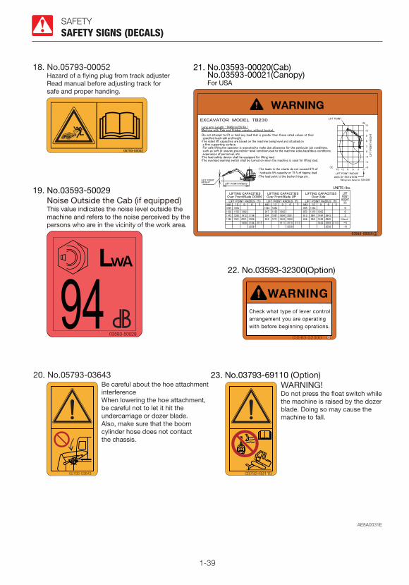
Improper operation, inspection and maintenance of this machine can cause injury or death.Read and understand this manual before performing any operation, inspection or maintenance on this machine.
Always store this manual near at hand preferably on the machine itself. If it should be lost or damaged, immediately order a new one from your Takeuchi dealer.When transferring ownership of this machine, be sure to hand this manual to the next owner.
Takeuchi supplies machines complying with the local regulations and standards of the country of export. If your machine has been purchased in another country or from a person or company of another country, it may not have the safety devices or safety standards required for use in your country. Should you have any question about whether your machine complies with the regulations and standards of your country, contact a Takeuchi dealer.

0-1
SIGNAL WORDS
Safety messages appearing in this manual and on machine decals are identified by the words “DANGER”, “WARNING” and “CAUTION”. These signal words mean the following:
DANGER indicates a hazard with a high level of risk which, if not avoided, will result in death or serious injury.
WARNING indicates a hazard with a medium level of risk which, if not avoided, could result in death or serious injury.
CAUTION indicates a hazard with a low level of risk which, if not avoided, could result in minor moderate injury.
IMPORTANT: The word IMPORTANT is used to alert operators and maintenance personnel about situations which could result in damage to the machine and its components.
It is impossible to foresee every possible circumstance that might involve a potential hazard. The warnings in this manual or on the machine can not cover all possible contingencies. You must exercise all due care and follow normal safety procedures when operating the machine so as to ensure that no damage occurs to the machine, its operators or other persons.

0-2
FOREWORD
This manual describes operation, inspection and maintenance of the machine, as well as safety instructions to be heeded during these operations.If you have any questions about the machine, please contact a Takeuchi sales or service outlet.
INTRODUCTION
MANUAL STORAGE COMPARTMENT
A compartment for storing this manual is provided at the position shown on the diagram below.
Cabine
Canopy
SERIAL NUMBERS
IMPORTANT: Do not remove the machine name plate with the serial number.Check the serial numbers of the machine and engine and write them down in the spaces below.
Machine number:
Engine number:
1. Insert the ignition key and turn it counterclockwise to open the cover (1).
2. After using the manual, place it in the plastic pouch and store it back in the manual storage compartment.

0-3
FRONT, REAR, LEFT AND RIGHT
MACHINE DESCRIPTION
This manual refers the front, rear, left and right of the machine as seen when sitting in the operator’s seat with the dozer blade visible to the front.
DESIGNATED OPERATIONS
Use this machine primarily for the following operations:• Excavation• Digging ditches• Digging side ditches• Leveling• Loading
BREAK-IN PERIOD
When the machine is new, operate the machine for the first 100 hours (as indicated on the hour meter) by following the instructions below.Using a new machine without a break-in period will lead to quicker deterioration of machine performance and may shorten the machine’s service life.• Sufficiently warm up the engine and
hydraulic oil.• Avoid heavy loads and rapid operations.
Operate with a load of about 80% the maximum load.
• Do not abruptly start up, accelerate, change directions, or stop unless necessary.
0-4
NOTES ON READING THIS MANUALPlease note that the descriptions and diagrams included in this manual may not be applicable to your machine.The numbers used in the illustration are with circles around them. The same numbers appear between the parentheses in the text. (Example: (1))
Symbols used in this manualThe symbols used in this manual have the following meanings. ...... Prohibition ............. Lock ............. Unlock
0-5
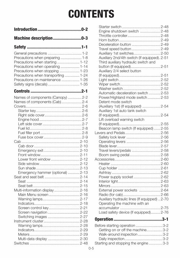
CONTENTSIntroduction .....................................0-2
Machine description ........................0-3
Safety ..............................................1-1General precautions ................................ 1-2Precautions when preparing .................... 1-8Precautions when starting ..................... 1-12Precautions when operating .................. 1-14Precautions when stopping ................... 1-23Precautions when transporting .............. 1-24Precautions on maintenance ................. 1-26Safety signs (decals) .............................. 1-35
Controls ...........................................2-1Names of components (Canopy) ............. 2-2Names of components (Cab) ................... 2-4Covers ..................................................... 2-6
Starter key ........................................... 2-6Right side cover ................................... 2-6Engine hood ........................................ 2-7Left side cover ..................................... 2-7Fuel lid ................................................. 2-8Fuel filler port ....................................... 2-8Fuse box cover .................................... 2-9
Cab ....................................................... 2-10Cab door ........................................... 2-10Emergency exit .................................. 2-10Front window ..................................... 2-11Lower front window ........................... 2-12Side window ...................................... 2-12Sun shade ......................................... 2-13Emergency hammer (optional) ........... 2-13
Seat and seat belt ................................. 2-14Seat .................................................. 2-14Seat belt ............................................ 2-15
Multi-information display ........................ 2-16Main Menu screen ............................. 2-16Warning lamps ................................... 2-17Indicators........................................... 2-18Screen control key ............................. 2-21Screen navigation .............................. 2-22Switching images .............................. 2-27
Instrument cluster .................................. 2-28Warning lamps ................................... 2-28Indicators........................................... 2-29Meters ............................................... 2-29Multi-data display .............................. 2-30
Switches ............................................... 2-48
Starter switch .................................... 2-48Engine shutdown switch ................... 2-48Throttle controller ............................... 2-48Horn button ....................................... 2-49Deceleration button ........................... 2-49Travel speed button ........................... 2-49Auxiliary 1st switches ......................... 2-50Auxiliary 2nd/4th switch (If equipped) . 2-51Third auxiliary hydraulic switch and button (If equipped) ............................ 2-51Auxiliary 2/4 select button (If equipped) ....................................... 2-51Light switch ....................................... 2-52Wiper switch ...................................... 2-52Washer switch ................................... 2-52Automatic deceleration switch ........... 2-53Power/Highland mode switch ............ 2-53Detent mode switch (Auxiliary 1st) (If equipped) ................. 2-54Auxiliary 1st auto tank switch (If equipped) ....................................... 2-54Lift overload warning switch (If equipped) ....................................... 2-55Beacon lamp switch (If equipped) ...... 2-55
Levers and Pedals ................................. 2-56Safety lock lever ................................ 2-56Operating levers ................................ 2-56Blade lever ......................................... 2-57Travel levers/pedals ........................... 2-58Boom swing pedal ............................. 2-58
Accessories ........................................... 2-60Heater ............................................... 2-60Cup holder ........................................ 2-61Ashtray .............................................. 2-62Power supply socket ......................... 2-62Interior light ........................................ 2-63Mirrors ............................................... 2-63External power sockets .................... 2-64Radio (for cab) ................................... 2-66Auxiliary hydraulic lines (If equipped) .. 2-70Operating the machine with an accumulator ...................................... 2-75Load safety device (If equipped) ......... 2-76
Operation .........................................3-1Before starting operation ......................... 3-2
Getting on or off the machine ............... 3-2Walk-around inspection ....................... 3-2Daily inspection .................................... 3-2
Starting and stopping the engine ............. 3-3
0-6
Before starting the engine .................... 3-3Starting the Engine .............................. 3-4Warming up the engine ........................ 3-5Stopping the engine ............................ 3-5
Operating the machine ............................ 3-6Lever pattern (ISO pattern) ................... 3-6Lever pattern (G pattern) (If equipped) .. 3-7Warming up the machine (hydraulic oil) 3-8Inspection after warm-up ..................... 3-9Operating the travel levers/pedals ...... 3-10Stopping travel .................................. 3-13Operating the working equipment ...... 3-14
Operating procedures ............................ 3-16Prohibited operations ......................... 3-16Cautions on operating ....................... 3-19Cautions on traveling on slopes ........ 3-20Getting out of mud ............................ 3-22Operations possible with this machine............................................. 3-22
Parking the machine .............................. 3-24Parking .............................................. 3-24Inspection and checks after stopping the engine.......................................... 3-24
Handling in cold climates ....................... 3-25Preparing for cold climates ................ 3-25Cautions after operations ................... 3-25After the cold climate ......................... 3-25
Handling rubber crawlers ....................... 3-26Prohibitions ........................................ 3-26Cautions ............................................ 3-27Preventing the rubber crawlers from coming off ......................................... 3-27
Transport .........................................4-1Loading and unloading ............................ 4-2Hoisting the machine ............................... 4-4Securing the machine .............................. 4-6
Maintenance ....................................5-1General .................................................... 5-2
Maintenance overview ......................... 5-2Cautions on maintenance .................... 5-2
Service data ............................................ 5-4Fuel and lubricant table ........................ 5-4Regularly replace the hydraulic oil ........ 5-8List of consumables ............................. 5-9List of tools (If equipped) .................... 5-10List of tightening torques ................... 5-11
Safety-critical parts ................................ 5-12Maintenance list ..................................... 5-14
Walk-around inspection ......................... 5-16Inspecting by opening the engine hood and covers................................ 5-16Inspecting by walking around the machine............................................. 5-17Inspecting while sitting in the operator’s seat ................................... 5-17
Daily inspection (every 10 hours) ............ 5-18Inspecting and replenishing the coolant .............................................. 5-18Inspecting and replenishing the engine oil ........................................... 5-19Inspecting the water separator .......... 5-20Inspecting the fuel level ...................... 5-21Inspecting the hydraulic oil tank level and replenishing ................................ 5-22Lubricating the working equipment .... 5-23
After the initial 50 hours (only for new machines) ......................... 5-24
Replacing the engine oil and the oil filter ................................................... 5-24Inspecting and adjusting the fan belt .. 5-26
Every 50 hours ...................................... 5-28Inspecting and adjusting the crawler tension .............................................. 5-28Lubricating the slew bearing .............. 5-30Draining the water from the fuel tank .. 5-31Inspecting the battery ........................ 5-32
Every 100 hours .................................... 5-34Cleaning the water separator ............ 5-34
After the initial 250 hours (only for new machines) ......................... 5-35
Replacing the hydraulic oil return filter 5-35Replacing the pilot line filter ................ 5-36Replacing the travel motor gear oil ..... 5-37
Every 250 hours .................................... 5-38Replacing the engine oil and the oil filter ................................................... 5-38Inspecting and adjusting the fan belt .. 5-38Cleaning the air cleaner ..................... 5-38Cleaning the radiator fins and the oil cooler fins .......................................... 5-40Cleaning the air filter (CAB) ................ 5-41
Every 500 hours .................................... 5-42Replacing the fuel filter ....................... 5-42
Every 1000 hours .................................. 5-43Replacing the hydraulic oil return filter 5-43Replacing the pilot line filter ................ 5-43Replacing the travel motor gear oil ..... 5-43Cleaning the engine cooling system ... 5-43

0-7
Replacing the air cleaner element ...... 5-45Replacing the air breather filter .......... 5-46Inspecting and adjusting the engine valve clearance .................................. 5-46
Every 1500 hours .................................. 5-47Inspecting, cleaning and checking operation of the engine fuel injectors .. 5-47Inspecting the crankcase breather system ............................................... 5-47
Every 2000 hours .................................. 5-48Lapping the engine valve seats (If necessary)...................................... 5-48
Every 3000 hours .................................. 5-49Inspecting, cleaning and checking operation of the EGR valve ............... 5-49
Every 4000 hours .................................. 5-50Replacing the hydraulic oil and cleaning the suction strainer .............. 5-50
When required ....................................... 5-53Replacing the bucket teeth and the side cutters ........................................ 5-53Replacing the bucket ......................... 5-56Adjusting the gap between the bucket and arm (If equipped) ......................... 5-58Inspecting and replenishing the windshield washer fluid ...................... 5-59Lubricating the levers and pedals ....... 5-60Inspecting the rubber crawlers ........... 5-61Replacing the rubber crawlers ........... 5-62
Maintenance during extended storage period .................................................... 5-64
Troubleshooting ...............................6-1Symptoms that are not malfunctions ....... 6-2If the engine overheats ............................. 6-3If the battery goes dead ........................... 6-4If a fuse blows ......................................... 6-6
Inspecting and replacing the fuse ......... 6-6Inspecting the fusible link ..................... 6-8
Restarting after adding fuel ...................... 6-9Bleeding air from the fuel system ......... 6-9
If a warning lamp flashes ....................... 6-10Vehicle error code list ............................. 6-12Engine error code list ............................. 6-14Other symptoms .................................... 6-16Lowering the boom to the ground ......... 6-19Towing ................................................... 6-20If the cab or canopy is damaged ........... 6-21
Specifications ..................................7-1Basic Specifications ................................. 7-2Machine dimensions ................................ 7-4Operating ranges ..................................... 7-6Lifting Capacities ..................................... 7-9
Options ............................................8-1General precautions ................................ 8-2
Safety precautions ............................... 8-2Cautions when installing attachments .. 8-2Cautions when operating attachments . 8-3
Attachment combination table ................. 8-4Selecting a lever pattern .......................... 8-5
Switching the lever pattern .................. 8-5Hydraulic breaker .................................... 8-6
Cautions on operating ......................... 8-6Replacing the hydraulic oil regularly ..... 8-7
Travel alarm ............................................. 8-8Optional equipment mass ..................... 8-10Biodegradable oil ................................... 8-11
Replacing the hydraulic oil with biodegradable oil ............................... 8-11
Cab options ........................................... 8-12Angle dozer blade ................................. 8-13
Specifications .................................... 8-14

0-8

1-1
SAFETY
1-2
SAFETY
GENERAL PRECAUTIONSIt is your responsibility to observe all pertinent laws and regulations and to follow the manufacture’s instructions on machine operation, inspection and maintenance.
Virtually all accidents occur as the result of a failure to observe basic safety rules and precautions.Most accidents can be prevented by identifying the potentially hazardous situations beforehand.Read and understand all safety messages which describe how to prevent accidents. Do not operate the machine until you are sure that you have gained a proper understanding of its operation, inspection and maintenance.
Observe all safety rules
• Operation, inspection and maintenance of this machine must be performed only by a trained and qualified person.
• All rules, regulations, precautions and safety procedures must be understood and followed when performing operation, inspection and maintenance of this machine.
• Do not perform any operation, inspection and maintenance of this machine when under the adverse influence of alcohol, drugs, medication, fatigue, or insufficient sleep.
GENERAL PRECAUTIONS
When a problem is found on the machine
If any problem (noise, vibration, smell, disorder of instrument, smoke, oil leak, wrong indication of alarm or unusual indication in the instrument cluster, etc.) is detected during the operation or inspection and maintenance of the machine, immediately inform your sales or service dealer and take proper actions. Do not operate the machine until the trouble is cleared.
Operating temperature range
To maintain the performance of machine and to prevent it from early wear, observe the following operating conditions.• Do not operate the machine if the ambient
temperature is higher than +45°C (+113°F) or lower than –15°C (+5°F).· If operated at an ambient temperature of
higher than +45°C (+113°F), the engine may overheat and cause the engine oil to degrade. Also, the hydraulic oil may become very hot, causing damage to the hydraulic equipment.
· If operated at an ambient temperature of lower than –15°C (+5°F), the parts made of rubber such as gaskets may get hardened to cause an early wear or damage to the machine.
· If the machine is to be used outside the ambient temperature range described above, consult your sales or a service dealer.
1-3
SAFETY
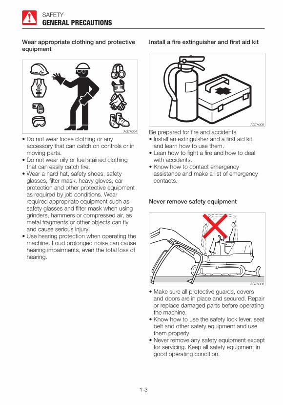
Wear appropriate clothing and protective equipment
• Do not wear loose clothing or any accessory that can catch on controls or in moving parts.
• Do not wear oily or fuel stained clothing that can easily catch fire.
• Wear a hard hat, safety shoes, safety glasses, filter mask, heavy gloves, ear protection and other protective equipment as required by job conditions. Wear required appropriate equipment such as safety glasses and filter mask when using grinders, hammers or compressed air, as metal fragments or other objects can fly and cause serious injury.
• Use hearing protection when operating the machine. Loud prolonged noise can cause hearing impairments, even the total loss of hearing.
GENERAL PRECAUTIONS
Install a fire extinguisher and first aid kit
Be prepared for fire and accidents• Install an extinguisher and a first aid kit,
and learn how to use them.• Lean how to fight a fire and how to deal
with accidents.• Know how to contact emergency
assistance and make a list of emergency contacts.
Never remove safety equipment
• Make sure all protective guards, covers and doors are in place and secured. Repair or replace damaged parts before operating the machine.
• Know how to use the safety lock lever, seat belt and other safety equipment and use them properly.
• Never remove any safety equipment except for servicing. Keep all safety equipment in good operating condition.

1-4
SAFETY
Use a signal person and a flag person
GENERAL PRECAUTIONS
Learn how to use the hand signals required for particular jobs and make sure who has the responsibility for signaling.• All personnel must fully understand all the
signals.• The operator must respond to signals only
from the appointed signal person, but must obey a stop signal at any time from anyone.
• The signal person must stand in a clearly visible location when giving signals.
Cautions when standing up from or leaving the operator’s seat
• Before standing up from the operator’s seat to open/close the window or remove/install the lower window, lower the working equipment to the ground, raise the safety lock levers to engage the lock and stop the engine. If any controls should be accidentally touched when the safety lock levers is lowered (unlocked), the machine will suddenly move and cause serious injury or death.
• Be careful not to touch the operating levers when raising or lowering the safety lock levers.
• Before leaving the operator’s seat, lower the working equipment to the ground, raise the safety lock levers to engage the lock and stop the engine. Also, be sure to remove the key, lock the door and covers, take it with you and store it in a specified place.

1-5
SAFETY
Avoid fire and explosion hazards
GENERAL PRECAUTIONS
Keep flames away from fuel, oil, grease and antifreeze. Fuel is particularly flammable and dangerous.• When handling these combustible
materials, keep lit cigarettes, matches, lighters and other flames or sources of flames away.
• Do not smoke or permit open flames while handling fuel or working on the fuel system.
• Do not leave the location while refilling with fuel or oil.
• Never remove the fuel cap or add fuel when the engine is running or still hot. Also, do not spill the fuel on the hot surface of the machine or the component of the electric system.
• Clean up spilled fuel or oil immediately.• Check for fuel, oil leak. Stop all leaks and
clean the machine before operating.• When operating with grinder or welding,
move inflammables to a safe place.• Do not cut or weld on pipes or tubes that
contain flammable fluids. Clean thoroughly with nonflammable solvent before cutting or welding.
• Remove all trash or debris from the machine. Make sure that oily rags or other flammable material are not stored on the machine.
• Handle all solvents and dry chemicals (foam type fire extinguisher) according to procedures identified on manufacturer’s containers. Work in a well-ventilated area.
• Never use fuel for cleaning purposes. Always use a nonflammable solvent.
• When handling the fuel, washing oil or paint, open the door and windows to ventilate thoroughly.
• Store all flammable fluids and materials in a safe and well-ventilated place.
• The short circuit of the electric system may cause the fire. Check for any loosened connections or damage to the wires every day. Retighten the loosened connector and wire clamp. Fix or change the damaged wire.
• Fire from the pipes: Make sure that the clamps, guards and
cushions of the hoses and tubes are securely fixed. If not, hoses or tubes may be damaged due to vibration or contact with other parts during operation. This can cause the high-pressure oil to spurt out, resulting in the fire or injury.

1-6
SAFETY
Exhaust fumes from the engine is poisonous
GENERAL PRECAUTIONS
• Do not operate the engine in an enclosed area without adequate ventilation.
• If natural ventilation is not possible, install ventilators, fans, exhaust extension pipes or other venting devices.
Handling asbestos dust
Inhaling asbestos dust can cause lung cancer. When handling the materials which may contain asbestos, take the following precautions:• Never use compressed air for cleaning.• Avoid brushing or grinding parts containing
asbestos.• For clean up, use a vacuum equipped with
a high efficiency particulate air filter (HEPA).• Wear the stipulated respirator if there is no
other way to control the dust. When working indoors, install a ventilation system with a macromolecular filter.
• Do not allow unauthorized personnel in the work area while working.
• Follow the rules and environmental standard applicable to the work area.
Be careful not to get crushed or cut
Never put your hands, feet or other parts of your body between the upperstructure and the undercarriage or tracks, between the machine body and working equipment, or between a cylinder and moving part. The sizes of these gaps change when the machine moves, and a person can suffer severe injury or death.

1-7
SAFETY
Using optional products
• Consult with Takeuchi before installing optional attachments. Depending on the type of attachments or the combination of them, the attachment may come into contact with the operator’s compartment or the other parts of the machine. Make sure that the optional attachment installed is not contacted with other parts before use.
• Do not use attachments that have not been approved by Takeuchi. Doing so may compromise safety or adversely affect the machine’s operation or service life.
• Takeuchi will not be held responsible for any injuries, accidents or damage to its products caused by the use by a non-approved attachment.
GENERAL PRECAUTIONS
Never modify the machine
Unauthorized modifications to this machine can cause injury or death. Never make unauthorized modifications to any part of this machine.
1-8
SAFETY
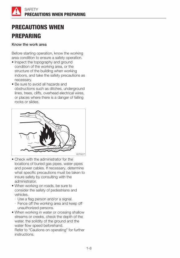
PRECAUTIONS WHEN PREPARINGKnow the work area
Before starting operation, know the working area condition to ensure a safety operation.• Inspect the topography and ground
condition of the working area, or the structure of the building when working indoors, and take the safety precautions as necessary.
• Be sure to avoid all hazards and obstructions such as ditches, underground lines, trees, cliffs, overhead electrical wires, or places where there is a danger of falling rocks or slides.
PRECAUTIONS WHEN PREPARING
• Check with the administrator for the locations of buried gas pipes, water pipes and power cables. If necessary, determine what specific precautions must be taken to insure safety by consulting with the administrator.
• When working on roads, be sure to consider the safety of pedestrians and vehicles.· Use a flag person and/or a signal.· Fence off the working area and keep off
unauthorized persons.• When working in water or crossing shallow
streams or creeks, check the depth of the water, the solidity of the ground and the water flow speed beforehand.
Refer to “Cautions on operating” for further instructions.

1-9
SAFETY
Check the strength of the bridge
When traveling over a bridge or a structure, check the permissible load. If the strength is insufficient, reinforce the bridge or the structure.
Always keep the machine clean
• Clean windows, mirrors and lights to ensure good visibility.
Adjust the mirror to the best position for the operator to see the rear view (blind spot) from the operator’s seat.
• Wipe off any oil, grease, mud, snow or ice, to prevent accidents due to slipping.
• Remove all loose objects and unnecessary devices from the machine.
• Remove any dirt, oil or grease from the engine area to prevent fires.
• Clean around the operator’s seat and remove any unnecessary object from the machine.
PRECAUTIONS WHEN PREPARING

1-10
SAFETYPRECAUTIONS WHEN PREPARING
Cautions in the operator’s compartment
• Remove mud and grease from shoe soles before entering the operator’s compartment. Pedaling the machine with the shoes with mud and grease will cause a slip accident.
• Do not leave the parts or tools around the operator’s seat.
• Do not leave any plastic bottles in the operator’s compartment or attach any suction cups on the window glass. The plastic bottle or suction cup act as a lens and can cause fire.
• Do not use the mobile phone during traveling or working.
• Do not bring combustibles or explosives into the operator’s compartment.
• After smoking, be sure to tightly close the lid of the ashtray to put out the match or cigarette.
• Do not leave the cigarette lighter in the operator’s compartment. When the room temperature rises, the lighter may explore.
Perform inspection and maintenance every day
Failure to identify or repair the irregularities or damage on machine can lead to accidents.• Before operating, perform the specified
inspection and make prompt repairs where necessary.
• If a failure occurs and the operation becomes impossible or the engine fails, immediately stop the machine by following the shutdown procedure, and keep machine securely parked until the malfunction is corrected.

1-11
SAFETYPRECAUTIONS WHEN PREPARING
Emergency exit
Front window (excluding machines with a front guard)
If you should become trapped inside the cab, open the front window to get out.
Emergency hammer (optional)
An emergency hammer is installed to be used to escape from the cab in an emergency. When escaping, break the windows with the hammer.• When breaking the window pane with a
hammer, take great care not to injure yourself with the broken glass pieces.
• Remove the glass pieces from the window sill so as not to cut yourself when evacuating. Broken glass will fall from the window, so be careful of your footing and do not slip on the glass.
1-12
SAFETY
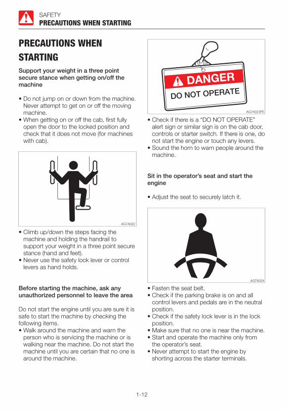
PRECAUTIONS WHEN STARTINGSupport your weight in a three point secure stance when getting on/off the machine
• Do not jump on or down from the machine. Never attempt to get on or off the moving machine.
• When getting on or off the cab, first fully open the door to the locked position and check that it does not move (for machines with cab).
PRECAUTIONS WHEN STARTING
• Climb up/down the steps facing the machine and holding the handrail to support your weight in a three point secure stance (hand and feet).
• Never use the safety lock lever or control levers as hand holds.
Before starting the machine, ask any unauthorized personnel to leave the area
Do not start the engine until you are sure it is safe to start the machine by checking the following items. • Walk around the machine and warn the
person who is servicing the machine or is walking near the machine. Do not start the machine until you are certain that no one is around the machine.
• Check if there is a “DO NOT OPERATE” alert sign or similar sign is on the cab door, controls or starter switch. If there is one, do not start the engine or touch any levers.
• Sound the horn to warn people around the machine.
Sit in the operator’s seat and start the engine
• Adjust the seat to securely latch it.
• Fasten the seat belt.• Check if the parking brake is on and all
control levers and pedals are in the neutral position.
• Check if the safety lock lever is in the lock position.
• Make sure that no one is near the machine.• Start and operate the machine only from
the operator’s seat. • Never attempt to start the engine by
shorting across the starter terminals.

1-13
SAFETY
Starting with jumper cables
PRECAUTIONS WHEN STARTING
Use jumper cables only in the recommended manner. Improper use of jumper cables can result in battery explosion or unexpected machine motion.Refer to “If the battery goes dead” for further instructions.
After starting the engine
After starting the engine, perform the operations and checks described below in a safe place with no persons or obstacles in the area. If any malfunction is found, follow the shutdown procedure and report the malfunction.• Warm up the engine and hydraulic oil.• Check if all gauges and warning devices
are properly working.• Check for any noises.• Test the engine speed control.• Operate each control to ensure they are
properly working.
In cold climates
• Be careful of slippery conditions on freezing ground, steps and hand holds.
• In severe cold climates, do not touch any metal parts of the machine with bare hands. The skin will freeze to the metal, resulting in severe injury.
• Do not use ether or starting fluid on this engine. The starting fluids can cause explosion and serious injury or death.
• Warm up the engine and hydraulic oil. If the levers are operated without warming, the machine will not react or move promptly or properly, resulting in accident.
1-14
SAFETY
PRECAUTIONS WHEN OPERATINGEnsure good visibility
• When working in dark places, turn on the machine’s working lights and headlights and additional lighting equipment installed, as necessary.
• When visibility is poor due to bad weather (fog, snow, rain or a cloud of dust), stop operating the machine and wait until visibility improves.
PRECAUTIONS WHEN OPERATING
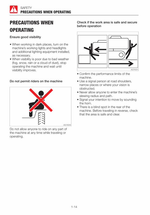
Do not permit riders on the machine
Do not allow anyone to ride on any part of the machine at any time while traveling or operating.
Check if the work area is safe and secure before operation
• Confirm the performance limits of the machine.
• Use a signal person at road shoulders, narrow places or where your vision is obstructed.
• Never allow anyone to enter the machine’s slewing radius and path.
• Signal your intention to move by sounding the horn.
• There is a blind spot in the rear of the machine. Before traveling in reverse, check that the area is safe and clear.

1-15
SAFETY
Check the position of the undercarriage (tracks) before traveling
PRECAUTIONS WHEN OPERATING
Before operating the travel levers/pedals, make sure that the dozer blade is to the front of the operator’s seat. Remember that when the dozer blade is to the rear of the operator’s seat, the travel levers/pedals must be operated in the reverse direction from when it is to the front.
Travel safely
• Travel with the dozer blade raised, the hoe attachment folded as shown on the figure above, and the bucket raised 30 to 40 cm (12 to 16 in.) above the ground.
• Do not slew while traveling. If you must operate the hoe attachment while traveling, operate at speeds slow enough so you have complete control at all times.
• When a load greater than a set value is applied during traveling in 2nd (high) speed, the speed will automatically slow down to 1st (low) speed. When the load becomes lighter, the speed will increase and return to 2nd (high) speed. It should be
noted that the travel speed changes depending on the load condition (for machines with the automatic travel shift-down system).
• When traveling on the uneven road or sharp slope, turn off the deceleration switch and the auto-deceleration switch. If the machine is operated on such roads with these switches turned on, the engine speed may increase, causing the machine to travel unexpectedly rapidly (for machines with the deceleration and auto-deceleration switches).
• Avoid crossing over obstacles whenever possible. If you must do so, keep the hoe attachment close to the ground level and travel slowly. Never cross obstacles which will tilt the machine to an angle of 10° or greater.
• On uneven ground, maintain the low speed and avoid starting, stopping or changing directions abruptly. Otherwise, the working equipment may come in contact with the ground, causing the machine to lose its balance and get damaged or to damage the structures in the surrounding area.
1-16
SAFETY
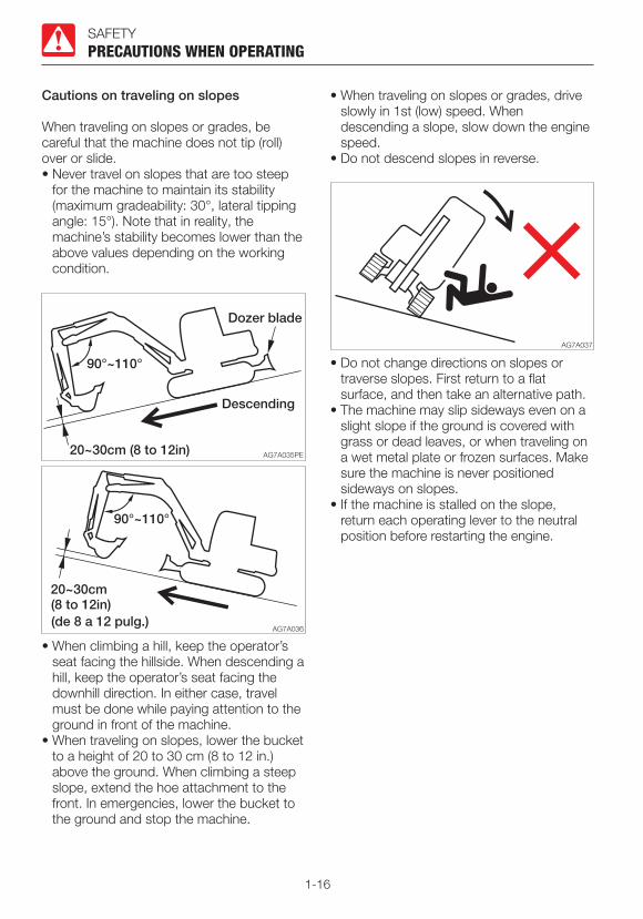
Cautions on traveling on slopes
When traveling on slopes or grades, be careful that the machine does not tip (roll) over or slide.• Never travel on slopes that are too steep
for the machine to maintain its stability (maximum gradeability: 30°, lateral tipping angle: 15°). Note that in reality, the machine’s stability becomes lower than the above values depending on the working condition.
PRECAUTIONS WHEN OPERATING
• When climbing a hill, keep the operator’s seat facing the hillside. When descending a hill, keep the operator’s seat facing the downhill direction. In either case, travel must be done while paying attention to the ground in front of the machine.
• When traveling on slopes, lower the bucket to a height of 20 to 30 cm (8 to 12 in.) above the ground. When climbing a steep slope, extend the hoe attachment to the front. In emergencies, lower the bucket to the ground and stop the machine.
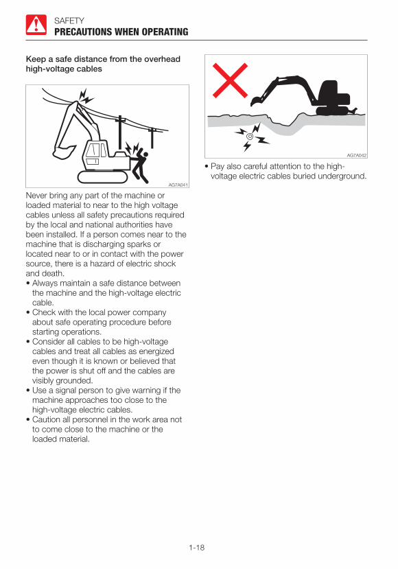
• When traveling on slopes or grades, drive slowly in 1st (low) speed. When descending a slope, slow down the engine speed.
• Do not descend slopes in reverse.
• Do not change directions on slopes or traverse slopes. First return to a flat surface, and then take an alternative path.
• The machine may slip sideways even on a slight slope if the ground is covered with grass or dead leaves, or when traveling on a wet metal plate or frozen surfaces. Make sure the machine is never positioned sideways on slopes.
• If the machine is stalled on the slope, return each operating lever to the neutral position before restarting the engine.

1-17
SAFETY
Operate the machine on snow or ice with extra care
• When traveling on snow or on frozen surfaces, drive at a low speed and avoid starting, stopping or changing directions abruptly.
• In the snowy area, the road shoulder and objects placed beside the road are buried in the snow and cannot be seen. There is a hazard of the machine tipping over or hitting covered objects, so always carry out operations carefully.
• If the machine enters deep snow, there is a hazard that it may tip over or become buried in the snow.
Be careful not to drive beyond the road shoulder or to get trapped in a snow drift.
• With frozen ground surfaces, the ground becomes soft when the temperature rises, and this may cause the machine to tip over, resulting in an operator trapped inside the machine.
• When parking the machine on an unstable ground, lower the dozer blade.
PRECAUTIONS WHEN OPERATING
Do not move the bucket over the heads of people
Moving the bucket over the heads of people entails the danger of the load spilling or the sudden dropping of the bucket.
Ensure driver’s safety when loading
Do not load a truck unless the truck driver is in a safe place.• Never swing or position the bucket over a
person or the cab room.• Load the truck from the rear.
1-18
SAFETY
Keep a safe distance from the overhead high-voltage cables
PRECAUTIONS WHEN OPERATING
Never bring any part of the machine or loaded material to near to the high voltage cables unless all safety precautions required by the local and national authorities have been installed. If a person comes near to the machine that is discharging sparks or located near to or in contact with the power source, there is a hazard of electric shock and death.• Always maintain a safe distance between
the machine and the high-voltage electric cable.
• Check with the local power company about safe operating procedure before starting operations.
• Consider all cables to be high-voltage cables and treat all cables as energized even though it is known or believed that the power is shut off and the cables are visibly grounded.
• Use a signal person to give warning if the machine approaches too close to the high-voltage electric cables.
• Caution all personnel in the work area not to come close to the machine or the loaded material.
• Pay also careful attention to the high-voltage electric cables buried underground.
1-19
SAFETY
Watch out for hazardous working conditions
PRECAUTIONS WHEN OPERATING
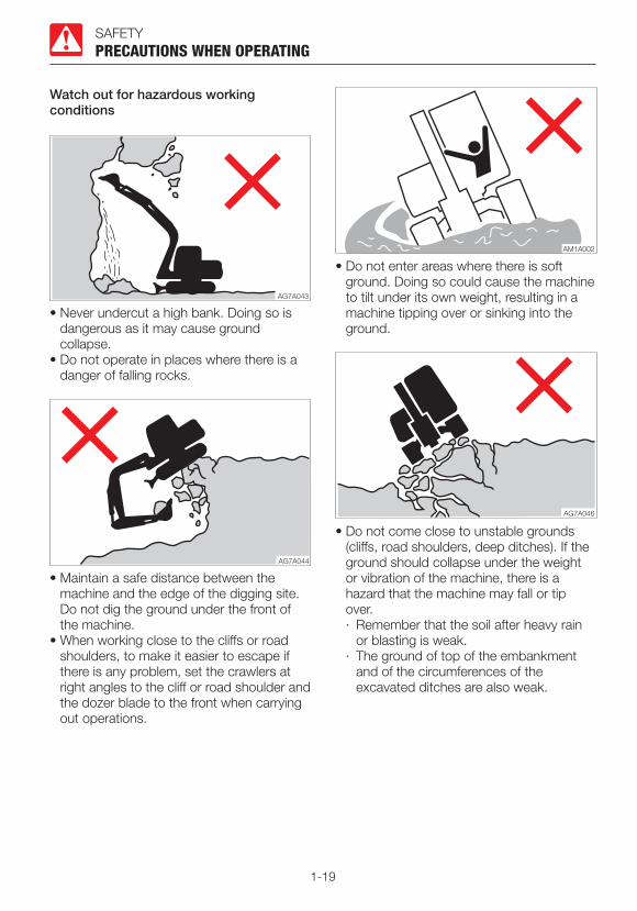
• Never undercut a high bank. Doing so is dangerous as it may cause ground collapse.
• Do not operate in places where there is a danger of falling rocks.
• Maintain a safe distance between the machine and the edge of the digging site. Do not dig the ground under the front of the machine.
• When working close to the cliffs or road shoulders, to make it easier to escape if there is any problem, set the crawlers at right angles to the cliff or road shoulder and the dozer blade to the front when carrying out operations.
• Do not enter areas where there is soft ground. Doing so could cause the machine to tilt under its own weight, resulting in a machine tipping over or sinking into the ground.
• Do not come close to unstable grounds (cliffs, road shoulders, deep ditches). If the ground should collapse under the weight or vibration of the machine, there is a hazard that the machine may fall or tip over.· Remember that the soil after heavy rain
or blasting is weak.· The ground of top of the embankment
and of the circumferences of the excavated ditches are also weak.
1-20
SAFETY
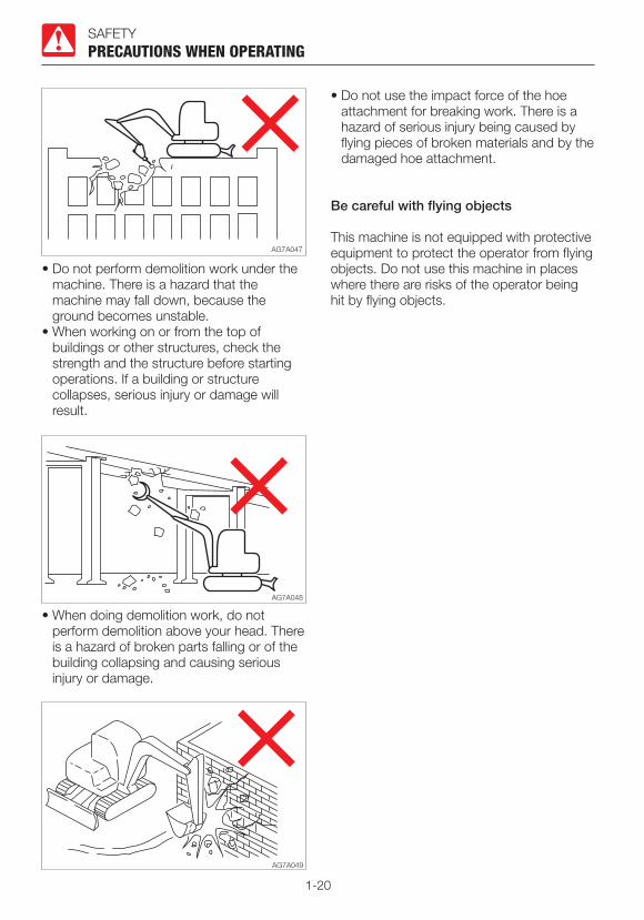
• Do not perform demolition work under the machine. There is a hazard that the machine may fall down, because the ground becomes unstable.
• When working on or from the top of buildings or other structures, check the strength and the structure before starting operations. If a building or structure collapses, serious injury or damage will result.
• When doing demolition work, do not perform demolition above your head. There is a hazard of broken parts falling or of the building collapsing and causing serious injury or damage.
PRECAUTIONS WHEN OPERATING
• Do not use the impact force of the hoe attachment for breaking work. There is a hazard of serious injury being caused by flying pieces of broken materials and by the damaged hoe attachment.
Be careful with flying objects
This machine is not equipped with protective equipment to protect the operator from flying objects. Do not use this machine in places where there are risks of the operator being hit by flying objects.
1-21
SAFETY
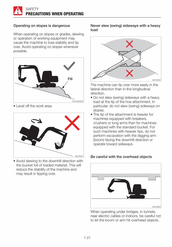
Operating on slopes is dangerous
When operating on slopes or grades, slewing or operation of working equipment may cause the machine to lose stability and tip over. Avoid operating on slopes whenever possible.
PRECAUTIONS WHEN OPERATING
• Level off the work area.
• Avoid slewing to the downhill direction with the bucket full of loaded material. This will reduce the stability of the machine and may result in tipping over.
Never slew (swing) sideways with a heavy load
The machine can tip over more easily in the lateral direction than in the longitudinal direction.• Do not slew (swing) sideways with a heavy
load at the tip of the hoe attachment. In particular, do not slew (swing) sideways on slopes.
• The tip of the attachment is heavier for machines equipped with breakers, crushers or long arms than for machines equipped with the standard bucket. For such machines with heavier tips, do not perform excavation with the digging arm (boom) facing the downhill direction or operate toward sideways.
Be careful with the overhead objects
When operating under bridges, in tunnels, near electric cables or indoors, be careful not to let the boom or arm hit overhead objects.

1-22
SAFETY
Excavators are not designed for lifting loads
This machine is specifically designed for excavation work. Therefore, it has no safety equipment for crane operation. Extreme caution should be paid if the excavator is used for lifting.• Never lift loads in excess of capacity.
Overload will cause the machine to roll and can result in serious injury or death.
• All rated lift capacities are determined by using a machine placed on a stable and flat ground. For a safe lifting work, the user is expected to make due allowance for the particular job conditions. They include, soft or uneven ground, non-level condition, side loads, dynamic or jerked loads, hazardous conditions, and experience of personnel. The operator and other personnel should fully acquaint themselves with the operator’s manual before operating this machine, and rules for safe operation of equipment shall be adhered to at all times.
• The bucket linkage or lifting device may fail if chains or lifting device are incorrectly attached, resulting in serious injury or death.
• Do not attempt to pull stumps out of the ground when using the machine as a crane. The loads imposed on the machine under this use are completely unknown.
• Do not allow anyone to stand on or under the lifted loads or come close to the work area.
PRECAUTIONS WHEN OPERATING
Cautions when towing
When towing, serious injury or death could result, if performed incorrectly or the wire rope being used is inappropriate or not properly inspected. • Do not tow using only a towing hole on one
side. • It becomes dangerous if the wire rope
breaks or becomes disengaged. Use a wire rope appropriate for the required tractive force.
• Do not use a wire rope that is kinked, twisted or otherwise damaged.
• Do not apply heavy loads abruptly to the wire rope.
• Wear safety gloves when handling the wire rope.
• Make sure there is an operator on the machine being towed as well as on the machine that is towing.
• Never tow on slopes.• Do not let anyone come near to the wire
rope while towing. Refer to “Towing” for further instructions.
AG8A001

1-23
SAFETY
PRECAUTIONS WHEN STOPPINGPark safely
PRECAUTIONS WHEN STOPPING
• Park the machine on a flat, rigid and safe ground. Set the parking brake.
If you must park on a slope or incline, park the machine securely and block the movement of the machine.
• When parking on a street, use barriers, caution signs, lights, etc., so that the machine can easily be seen even at night to avoid collision with other vehicles.
• Before leaving the machine, do the followings:1. Lower the bucket and the dozer blade to
the ground.2. Raise the safety lock lever to the locked
position.3. Stop the engine and remove the starter
key.4. Lock the cab and covers and take the
key with you.
1-24
SAFETY
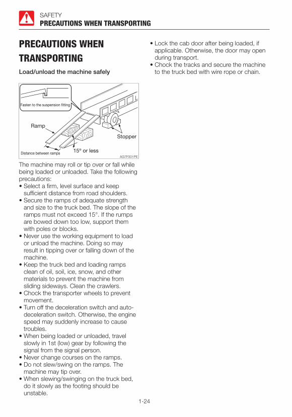
PRECAUTIONS WHEN TRANSPORTINGLoad/unload the machine safely
PRECAUTIONS WHEN TRANSPORTING
The machine may roll or tip over or fall while being loaded or unloaded. Take the following precautions:• Select a firm, level surface and keep
sufficient distance from road shoulders.• Secure the ramps of adequate strength
and size to the truck bed. The slope of the ramps must not exceed 15°. If the rumps are bowed down too low, support them with poles or blocks.
• Never use the working equipment to load or unload the machine. Doing so may result in tipping over or falling down of the machine.
• Keep the truck bed and loading ramps clean of oil, soil, ice, snow, and other materials to prevent the machine from sliding sideways. Clean the crawlers.
• Chock the transporter wheels to prevent movement.
• Turn off the deceleration switch and auto-deceleration switch. Otherwise, the engine speed may suddenly increase to cause troubles.
• When being loaded or unloaded, travel slowly in 1st (low) gear by following the signal from the signal person.
• Never change courses on the ramps.• Do not slew/swing on the ramps. The
machine may tip over.• When slewing/swinging on the truck bed,
do it slowly as the footing should be unstable.
• Lock the cab door after being loaded, if applicable. Otherwise, the door may open during transport.
• Chock the tracks and secure the machine to the truck bed with wire rope or chain.

1-25
SAFETY
Hoist the machine safely
• Know and use correct crane signals.• Check the hoisting equipment for damaged
or missing parts on a daily basis and replace as necessary.
• When hoisting, use a wire rope capable of lifting the machine mass.
• Hoist the machine in such a manner described in the procedure below. Do not do it in any other manner, as it may result in the machine losing its balance.
Refer to “Hoisting the machine” for further instructions.
• Do not hoist the machine with an operator on it.
• When hoisting, hoist slowly so that the machine does not tip.
• Keep everyone out of the area when hoisting. Do not move the machine over the heads of the persons.
PRECAUTIONS WHEN TRANSPORTING
Transport the machine safely
• Know and follow the applicable safety rules, vehicle code and traffic laws when transporting the machine.
• Select the best transport route by considering the length, width, height and weight of the truck with the machine loaded on it.
• Never abruptly start or stop or run at a high speed at the sharp curves during transport. Doing so will move or lose the balance of the loaded machine.
1-26
SAFETY
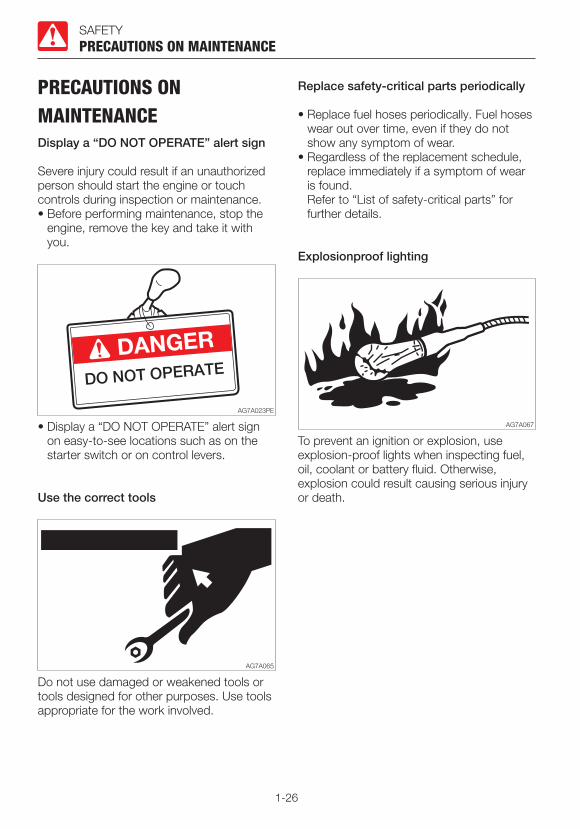
PRECAUTIONS ON MAINTENANCEDisplay a “DO NOT OPERATE” alert sign
Severe injury could result if an unauthorized person should start the engine or touch controls during inspection or maintenance.• Before performing maintenance, stop the
engine, remove the key and take it with you.
PRECAUTIONS ON MAINTENANCE
• Display a “DO NOT OPERATE” alert sign on easy-to-see locations such as on the starter switch or on control levers.
Use the correct tools
Do not use damaged or weakened tools or tools designed for other purposes. Use tools appropriate for the work involved.
Replace safety-critical parts periodically
• Replace fuel hoses periodically. Fuel hoses wear out over time, even if they do not show any symptom of wear.
• Regardless of the replacement schedule, replace immediately if a symptom of wear is found.
Refer to “List of safety-critical parts” for further details.
Explosionproof lighting
To prevent an ignition or explosion, use explosion-proof lights when inspecting fuel, oil, coolant or battery fluid. Otherwise, explosion could result causing serious injury or death.

1-27
SAFETY
Prohibit access by unauthorized persons
Do not allow unauthorized personnel in the work area while working. Be careful when grinding, welding or using a hammer. You could be injured by flying debris from the machine.
PRECAUTIONS ON MAINTENANCE
Prepare work area
• Select a firm, level work area. Make sure there is adequate light and, if indoors, ventilation.
• Clear obstacles and dangerous objects. Eliminate slippery areas.
Always keep the machine clean
• Clean the machine before performing maintenance.
• Stop the engine before washing the machine. Cover the electrical parts so that water cannot enter. Water on electrical parts could cause short-circuits or malfunctions. Do not use water or steam to wash the battery, electronic control components, sensors, connectors or the operator’s compartment.
Stop the engine before performing maintenance
• Avoid lubrication or mechanical adjustments while the machine is moving or while the engine is running when the machine is not moving.
• If maintenance must be performed with the engine running, always work as a two person team communicating each other.· One person must sit in the operator’s
seat so that he/she can immediately stop the engine when necessary. He/she must take care not to touch the lever or pedal unless necessary.
· The one who performs maintenance must make sure to keep his/her body or clothing away from the moving part of the machine.

1-28
SAFETY
Stay clear of the moving parts
• Stay clear of all rotating and moving parts. If a hand or tool becomes trapped in the rotating or moving part, serious injury or death could result.
• If a tool or other objects is dropped or inserted in the fan or fan belt, it will be flown or cut in pieces. Do not drop or insert anything in the fan or fan belt.
PRECAUTIONS ON MAINTENANCE
Firmly secure the machine or any component that may fall
• Before performing maintenance or repairs under the machine, lower all moveable working equipment to the ground or in the lowermost position.
• Chock the tracks.• If you must work beneath the raised
machine or equipment, always use wood blocks, jack-stands or other rigid and stable supports. Never get under the machine or working equipment if they are not sufficiently supported. This procedure is especially important when working on hydraulic cylinders.
Secure the working equipment
To prevent unexpected movement, firmly secure the working equipment when repairing or replacing the bucket teeth or side cutter.
Secure the engine hood or cover when opened
Be sure to secure the engine hood or cover before working the inside. Do not keep the hood or cover open on a windy day or if the machine is parked on a slope.
Place heavy objects in a stable position
When it is necessary to temporally place a heavy object or an attachment on the ground during removal or installation, be sure to place it in a stable position. Keep off unauthorized persons from the storage place for such object.

1-29
SAFETY
Cautions when refueling
PRECAUTIONS ON MAINTENANCE
• Do not smoke or permit open flames while fueling or near fueling operations.
• Never remove the fuel cap or add fuel when the engine is running or still hot. Do not spill fuel on the hot surface of the machine.
• Fill the fuel tank in a well ventilated place.• Do not fill the fuel tank to capacity. Allow
room for oil expansion.• Clean up spilled fuel immediately.• Securely tighten the fuel filler cap. If the fuel
cap is lost, replace it only with the genuine cap. Use of a non-approved cap without proper venting may result in pressurization of the tank.
• Never use fuel for cleaning.• Use the correct grade of fuel for the
operating season.
Handling of hoses
Oil leak or fuel leak can cause a fire.• Do not twist, bend or hit the hoses.• Never use twisted, bent or cracked pipes,
tubes or hoses; otherwise, they may burst.• Retighten loose connection.
Be careful with hot and pressurized components
Stop the engine and allow the machine to cool down before performing maintenance.• The engine, muffler, radiator, hydraulic
lines, sliding parts and many other parts of the machine are hot immediately after the engine is stopped. Touching these parts will cause burns.
• The engine coolant, hydraulic oil and other oils are also hot and under high pressure.
Be careful not to touch the hydraulic oil when loosening the cap or plug. Working on the machine under these conditions could result in burns or injuries due to the hot oil spurting out.
• The DPF and the exhaust gas emitted from the exhaust line can be very hot while the engine is running or the regeneration is under way, as well as immediately after the engine is stopped. Be careful not to accidentally touch them; doing so could cause burns.

1-30
SAFETY
Be careful with hot cooling systems
PRECAUTIONS ON MAINTENANCE
Do not remove the radiator cap or the drain plug when the cooling water is hot. Stop the engine and wait until the engine and the cooling water cool. Then, slowly loosen the radiator cap to release the internal pressure and remove it.
Be careful with oil internal pressure
Pressure is maintained in the hydraulic circuit long after the engine has been shut down.• Completely relieve the internal pressure
before performing maintenance work.
• The hydraulic oil is high enough pressure to penetrate the skin or eyes and cause serious injury, blindness or death. Remember that the hydraulic oil escaping from a small hole is almost invisible. When checking for leaks, wear protective goggle and thick gloves, and use a paperboard or plywood to keep your skin from oil spurting.
If oil penetrates the skin, it must be surgically removed within a few hours by a doctor familiar with this type of injury.
Release pressure before working on the hydraulic system
Oil may spurt out if caps or filters are removed or pipes are disconnected before releasing the pressure in the hydraulic system.• Immediately after the engine is stopped,
and while the safety lock lever is still in the unlock position, turn the starter switch to ON and move all the control levers and pedals several times all the way in each direction to release the pressure from the working equipment circuitry.
• Press the air breather button to relieve the internal pressure from the tank.
• When removing plugs or screws, or when disconnecting hoses, stand to the side and loosen them slowly to gradually release the internal pressure before removing.
• Oil or plug may spurt out according to the pressure in the travel motor case. Loosen the plug slowly and release the internal pressure.
Be careful with debris when the hammer is being used
When using a hammer, pins may fly out or metal particles may be scattered. This may lead to serious injury.• If hard metal parts such as pins, bucket
teeth, side cutter or bearings are hit with a hammer, wear protective gear such as safety goggles and gloves.
• When hitting pins or bucket teeth, always check that there is no one in the surrounding area.
1-31
SAFETY
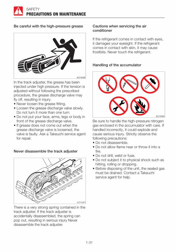
Never disassemble the track adjuster
PRECAUTIONS ON MAINTENANCE
There is a very strong spring contained in the track adjuster. If the track adjuster is accidentally disassembled, the spring can pop out, resulting in serious injury Never disassemble the track adjuster.
Cautions when servicing the air conditioner
If the refrigerant comes in contact with eyes, it damages your eyesight. If the refrigerant comes in contact with skin, it may cause frostbite. Never touch the refrigerant.
Handling of the accumulator
Be sure to handle the high-pressure nitrogen gas enclosed in the accumulator with care. If handled incorrectly, it could explode and cause serious injury. Strictly observe the following precautions:• Do not disassemble.• Do not allow flame near or throw it into a
fire.• Do not drill, weld or fuse.• Do not subject it to physical shock such as
hitting, rolling or dropping.• Before disposing of the unit, the sealed gas
must be drained. Contact a Takeuchi service agent for help.
Be careful with the high-pressure grease
AG7A086
In the track adjuster, the grease has been injected under high pressure. If the tension is adjusted without following the prescribed procedure, the grease discharge valve may fly off, resulting in injury.• Never loosen the grease fitting.• Loosen the grease discharge valve slowly.
Do not turn it more than one turn.• Do not put your face, arms, legs or body in
front of the grease discharge valve.• If grease does not come out when the
grease discharge valve is loosened, the valve is faulty. Ask a Takeuchi service agent for repair.

1-32
SAFETY
Disconnect the battery wiring
PRECAUTIONS ON MAINTENANCE
Disconnect the battery wiring before working on the electrical system or doing electric welding. Disconnect the negative (–) battery cable first. When reconnecting, connect the negative (–) battery cable last.
Use caution when handling batteries
• Batteries contain sulfuric acid which will damage the eyes or skin in case of contact.· If eye contact occurs, flush immediately
with clean water and get prompt medical attention.
· If accidentally swallowed, drink large quantities of water or milk and call a physician immediately.
· If acid contacts skin or clothing, wash off immediately with a lot of water.
• Wear protective goggle and gloves when working with batteries.
• Batteries generate flammable hydrogen gas which may explode. Keep away from flame, sparks, fire or lighted cigarettes.
• When checking the level of the battery fluid, use a flashlight.
• Be sure to stop the engine by turning off the starter switch before inspecting or handling the battery.
• Be careful not to let metal tools or any metal objects come into contact with the battery terminals and cause a short circuit.
• Loose battery terminals may result in sparks. Be sure to fasten terminals tightly.
• Make sure the battery caps are tightened securely.
• Do not charge a battery or jump-start the engine if the battery is frozen; otherwise it may explode. Warm the frozen battery to 15°C (60°F) before use.
• Do not use or charge the battery when the battery indicator is white. The battery is at its end of life. Immediately replace the battery.
• Do not tilt the battery. Doing so could cause the battery fluid to leak out of the exhaust hole. If contacted, it may cause skin irritation or the machine part corrosion.
• Use a dampened cloth to clean the battery indicator and check the fluid level. Do not clean with a dry cloth; it can cause static electricity to build up, resulting in ignition or explosion.
1-33
SAFETY
Periodically replace the safety-critical parts
• To use the machine safely for a longer period, periodically add oil and perform inspection and maintenance. To improving the safely, replace the safety-critical parts like hoses and seat belts periodically. Refer to “Safety-critical parts to be replaced periodically” for further details.
• The “Safety-critical parts to be replaced periodically” are the parts which deteriorate, wear and fatigue after repeated use and whose properties change over time. While these characters of these parts could cause serious physical or personal damage, judging the remaining life of these part are difficult from external inspection or the feeling when operating.
• Replace the “Safety-critical parts to be replaced periodically” if any defect is found from external inspection, even when they have not reached the time specified interval.
PRECAUTIONS ON MAINTENANCE
Jump starting with booster cables
• When starting the engine using the booster cables, be sure to connect the cables in the proper order described below. Wrongly connected cables can result in sparking and battery explosion.· Do not allow the “machine in trouble” and
“rescue machine” to touch each other. · Do not allow the positive (+) and negative
(–) clips of the booster cables to touch each other or to come in contact with the machine.
· When connecting, attach the positive booster cable to the positive (+) terminals first. When disconnecting, remove the negative cable from the negative (–) terminal (ground) first.
· Be sure to connect the clips securely.· Connect the last clip of the booster cable
to a point as far away from the battery as possible.
• Always wear the protective goggle and gloves when starting the engine by using the booster cables.
• Use the booster cables and clips of a size suited to the capacity of battery. Do not use damaged or corroded booster cables and clips.
• Be sure that the battery of the “rescue machine” has the same capacity as the battery of the “machine in trouble”.
1-34
SAFETY
Have a Takeuchi service agent repair welding
If welding must be performed, make sure that it is done by a qualified person in a properly equipped workplace. To prevent any part from breaking down or being damaged due to overcurrent or sparks, observe the following. • Disconnect the wiring from the battery
before doing electric welding.• Do not continuously apply 200 V or more.• The earth ground must be connected
within one meter from the welding section. Do not connect the earth ground near to an electronically controlled device/instrument or connectors.
• Make sure that there are no seals or bearings between the welding section and the earth ground.
• Do not connect the earth ground around the pins for the working equipment or hydraulic cylinders.
• When welding is to be done on the machine body, disconnect the connectors for the electronically controlled devices before working.
PRECAUTIONS ON MAINTENANCE
Vibrations operators are subject to
According to the results of the tests conducted to determine the vibrations transmitted to the operator by the machine, the upper limbs are subjected to vibrations lower than 2.5 m/s2 (8.2 ft/s2) while the seated part of the body is subjected to vibrations lower than 0.5 m/s2 (1.64 ft/s2).
Checks after maintenance
• Gradually increase the engine speed from a low idle to maximum speed and check that there is no oil or water leaking from the serviced parts.
• Operate each control lever and check that the machine is operating properly.
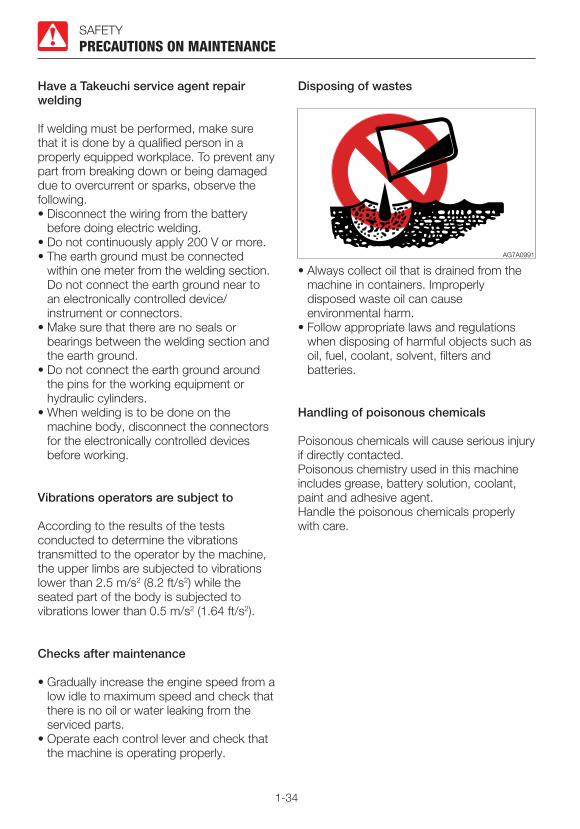
Disposing of wastes
• Always collect oil that is drained from the machine in containers. Improperly disposed waste oil can cause environmental harm.
• Follow appropriate laws and regulations when disposing of harmful objects such as oil, fuel, coolant, solvent, filters and batteries.
Handling of poisonous chemicals
Poisonous chemicals will cause serious injury if directly contacted.Poisonous chemistry used in this machine includes grease, battery solution, coolant, paint and adhesive agent.Handle the poisonous chemicals properly with care.

1-35
SAFETY
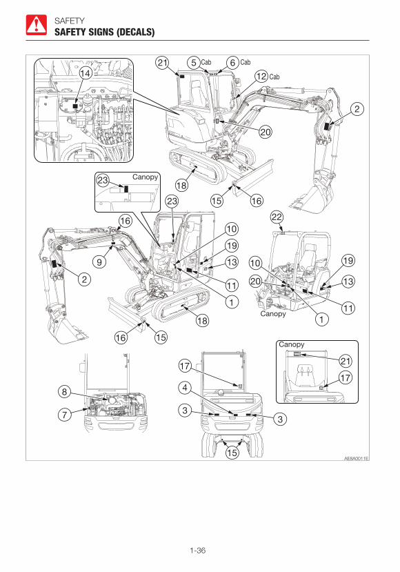
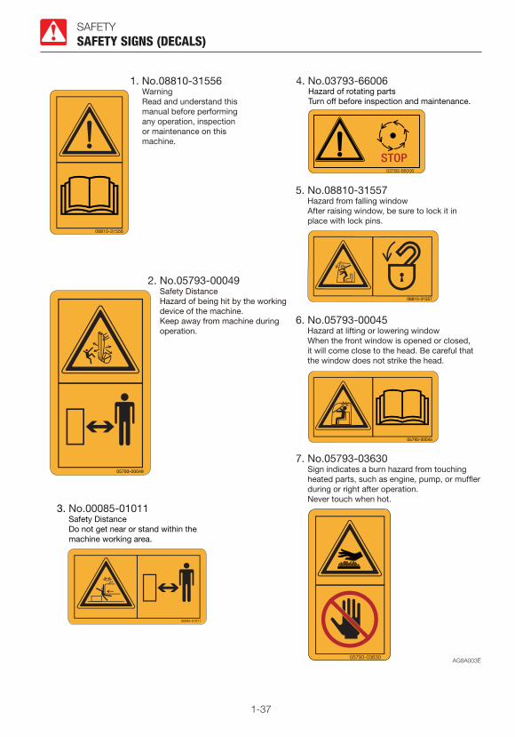
SAFETY SIGNS (DECALS)For the safety of the operator and the personnel working around the site, safety signs (decals) are placed at certain locations on the machine as shown below. Walk around the machine with this manual, and check the content and location of these safety signs. Review these signs and the operating instructions in this manual with your machine operators.• Keep the signs clean and legible. If any of the safety labels is peeling or damaged and
becomes difficult to read, replenish it with a new one. Please include your product serial number when ordering a new sign from the Takeuchi service agent.
• When a part/unit to which a safety sign is attached is replenished, a new sign must be attached to the new part/unit.
SAFETY SIGNS (DECALS)
1-36
SAFETYSAFETY SIGNS (DECALS)
1-37
SAFETYSAFETY SIGNS (DECALS)

1-38
SAFETYSAFETY SIGNS (DECALS)
1-39
SAFETYSAFETY SIGNS (DECALS)

1-40

2-1
CONTROLS
2-2
CONTROLS
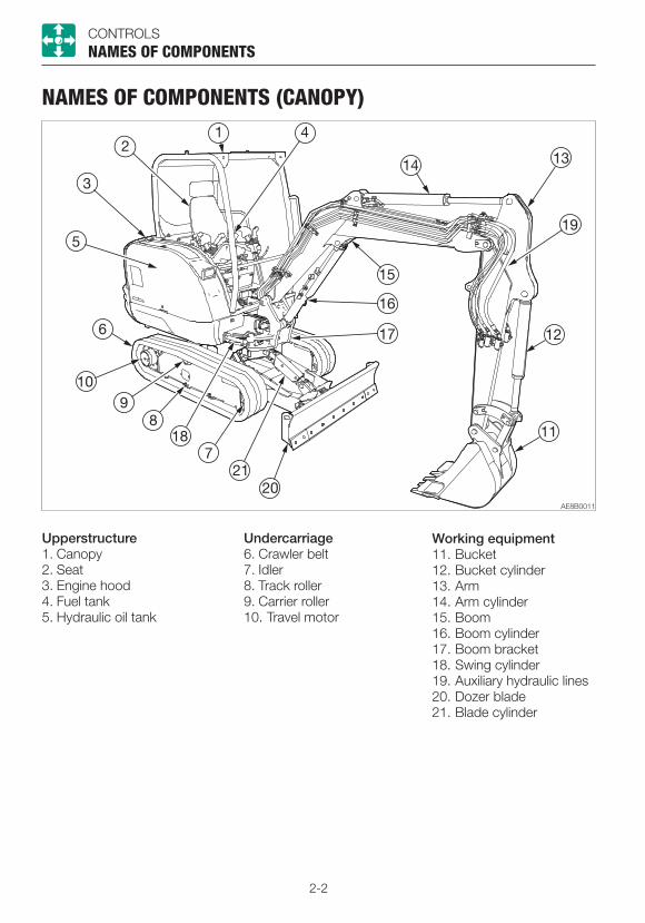
NAMES OF COMPONENTS (CANOPY)
NAMES OF COMPONENTS
Upperstructure1. Canopy2. Seat3. Engine hood4. Fuel tank5. Hydraulic oil tank
Undercarriage6. Crawler belt7. Idler8. Track roller9. Carrier roller10. Travel motor
Working equipment11. Bucket12. Bucket cylinder13. Arm14. Arm cylinder15. Boom16. Boom cylinder17. Boom bracket18. Swing cylinder19. Auxiliary hydraulic lines20. Dozer blade21. Blade cylinder

2-3
CONTROLS
1. Instrument cluster2. Starter switch3. Blade lever4. Throttle controller5. Right operating lever*6. Horn button7. Deceleration button8. Boom swing pedal9. Travel levers/pedals10. Travel speed button11. Left operating lever12. Auxiliary 1st switches13. Safety lock lever
NAMES OF COMPONENTS
14. Light switch15. Automatic deceleration switch16. Power/Highland mode switch17. Detent mode switch18. Auxiliary 1st auto tank switch*19. Lift overload warning switch*20. Beacon lamp switch*21. Engine shutdown switch*22. Auxiliary 2nd/4th switch*23. Auxiliary 2/4 select button*24. Third auxiliary hydraulic button*25. Third auxiliary hydraulic switch*
*: Subject to the specifications or optional products selected
2-4
CONTROLS
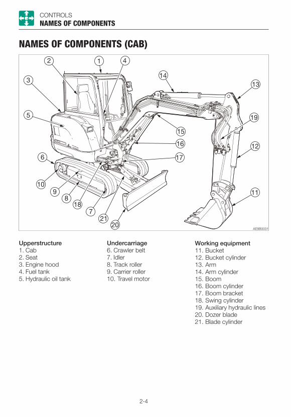
NAMES OF COMPONENTS (CAB)
NAMES OF COMPONENTS
Upperstructure1. Cab2. Seat3. Engine hood4. Fuel tank5. Hydraulic oil tank
Undercarriage6. Crawler belt7. Idler8. Track roller9. Carrier roller10. Travel motor
Working equipment11. Bucket12. Bucket cylinder13. Arm14. Arm cylinder15. Boom16. Boom cylinder17. Boom bracket18. Swing cylinder19. Auxiliary hydraulic lines20. Dozer blade21. Blade cylinder

2-5
CONTROLS
1. Multi-information display2. Starter switch3. Blade lever4. Throttle controller5. Right operating lever*6. Horn button7. Deceleration button8. Boom swing pedal9. Ashtray10. Travel levers/pedals11. Travel speed button12. Left operating lever13. Auxiliary 1st switches14. Safety lock lever15. Light switch16. Wiper switch
NAMES OF COMPONENTS
17. Washer switch18. Heater switch19. Automatic deceleration switch20. Power/Highland mode switch21. Detent mode switch22. Auxiliary 1st auto tank switch*23. Lift overload warning switch*24. Beacon lamp switch*25. Engine shutdown switch*26. Auxiliary 2nd/4th switch*27. Auxiliary 2/4 select button*28. Third auxiliary hydraulic button*29. Third auxiliary hydraulic switch*30. Power supply socket*31. Radio*
*: Subject to the specifications or optional products selected
2-6
CONTROLS
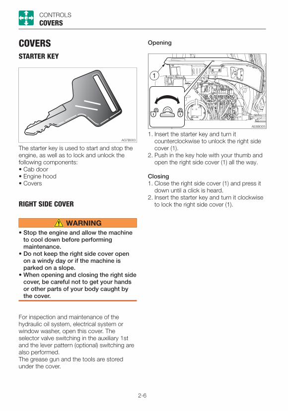
COVERSSTARTER KEY
COVERS
The starter key is used to start and stop the engine, as well as to lock and unlock the following components:• Cab door• Engine hood• Covers
RIGHT SIDE COVER
• Stop the engine and allow the machine to cool down before performing maintenance.
• Do not keep the right side cover open on a windy day or if the machine is parked on a slope.
• When opening and closing the right side cover, be careful not to get your hands or other parts of your body caught by the cover.
For inspection and maintenance of the hydraulic oil system, electrical system or window washer, open this cover. The selector valve switching in the auxiliary 1st and the lever pattern (optional) switching are also performed.The grease gun and the tools are stored under the cover.
1. Insert the starter key and turn it counterclockwise to unlock the right side cover (1).
2. Push in the key hole with your thumb and open the right side cover (1) all the way.
Closing1. Close the right side cover (1) and press it
down until a click is heard.2. Insert the starter key and turn it clockwise
to lock the right side cover (1).
Opening
2-7
CONTROLSCOVERS
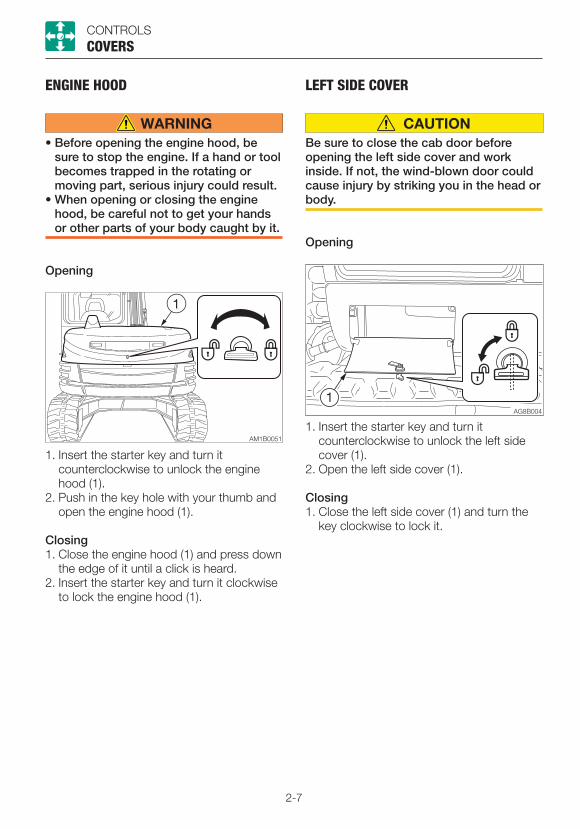
ENGINE HOOD
• Before opening the engine hood, be sure to stop the engine. If a hand or tool becomes trapped in the rotating or moving part, serious injury could result.
• When opening or closing the engine hood, be careful not to get your hands or other parts of your body caught by it.
Opening
1. Insert the starter key and turn it counterclockwise to unlock the engine hood (1).
2. Push in the key hole with your thumb and open the engine hood (1).
Closing1. Close the engine hood (1) and press down
the edge of it until a click is heard. 2. Insert the starter key and turn it clockwise
to lock the engine hood (1).
LEFT SIDE COVER
Be sure to close the cab door before opening the left side cover and work inside. If not, the wind-blown door could cause injury by striking you in the head or body.
Opening
1. Insert the starter key and turn it counterclockwise to unlock the left side cover (1).
2. Open the left side cover (1).
Closing1. Close the left side cover (1) and turn the
key clockwise to lock it.
2-8
CONTROLS
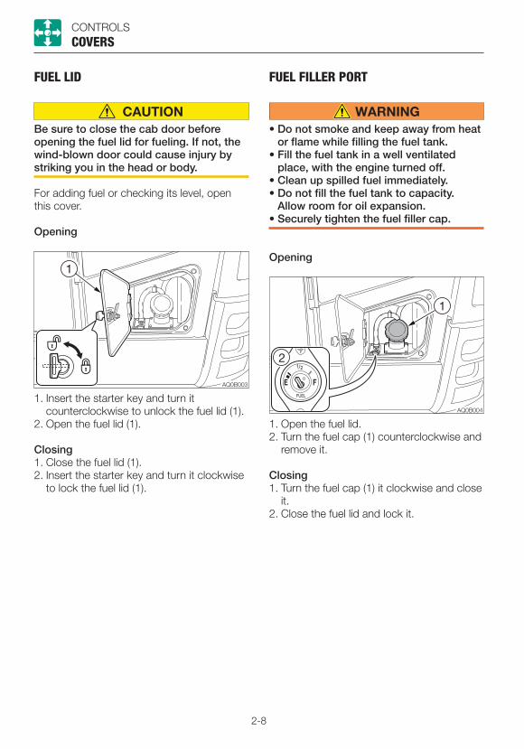
FUEL LID
Be sure to close the cab door before opening the fuel lid for fueling. If not, the wind-blown door could cause injury by striking you in the head or body.
For adding fuel or checking its level, open this cover.
Opening
1. Insert the starter key and turn it counterclockwise to unlock the fuel lid (1).
2. Open the fuel lid (1).
Closing1. Close the fuel lid (1).2. Insert the starter key and turn it clockwise
to lock the fuel lid (1).
FUEL FILLER PORT
• Do not smoke and keep away from heat or flame while filling the fuel tank.
• Fill the fuel tank in a well ventilated place, with the engine turned off.
• Clean up spilled fuel immediately.• Do not fill the fuel tank to capacity.
Allow room for oil expansion.• Securely tighten the fuel filler cap.
Opening
1. Open the fuel lid.2. Turn the fuel cap (1) counterclockwise and
remove it.
Closing1. Turn the fuel cap (1) it clockwise and close
it.2. Close the fuel lid and lock it.
COVERS

2-9
CONTROLSCOVERS
FUSE BOX COVER
For inspection and maintenance of the fuse, open this cover.
Opening
1. Insert the starter key and turn it counterclockwise to unlock the fuse box cover (1).
2. Tilt the fuse box cover (1) forward.
Closing1. Close the fuse box cover (1) and turn the
key clockwise to lock it.
2-10
CONTROLS
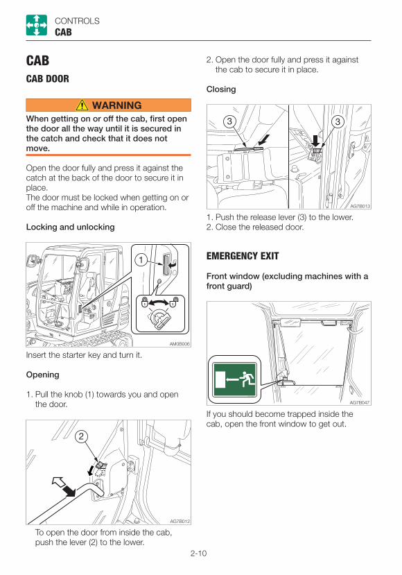
CABCAB DOOR
When getting on or off the cab, first open the door all the way until it is secured in the catch and check that it does not move.
Open the door fully and press it against the catch at the back of the door to secure it in place.The door must be locked when getting on or off the machine and while in operation.
Locking and unlocking
CAB
Insert the starter key and turn it.
Opening
1. Pull the knob (1) towards you and open the door.
To open the door from inside the cab, push the lever (2) to the lower.
2. Open the door fully and press it against the cab to secure it in place.
Closing
1. Push the release lever (3) to the lower.2. Close the released door.
EMERGENCY EXIT
Front window (excluding machines with a front guard)
If you should become trapped inside the cab, open the front window to get out.
2-11
CONTROLS
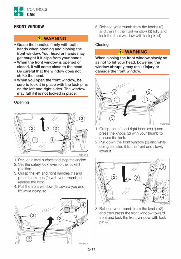
FRONT WINDOW
• Grasp the handles firmly with both hands when opening and closing the front window. Your head or hands may get caught if it slips from your hands.
• When the front window is opened or closed, it will come close to the head. Be careful that the window does not strike the head.
• When you open the front window, be sure to lock it in place with the lock pins on the left and right sides. The window may fall if it is not locked in place.
Opening
CAB
1. Park on a level surface and stop the engine.2. Set the safety lock lever to the locked
position.3. Grasp the left and right handles (1) and
press the knobs (2) with your thumb to release the lock.
4. Pull the front window (3) toward you and lift while doing so.
5. Release your thumb from the knobs (2) and then lift the front window (3) fully and lock the front window with lock pin (4).
Closing
When closing the front window slowly so as not to hit your head. Lowering the window abruptly may result injury or damage the front window.
1. Grasp the left and right handles (1) and press the knobs (2) with your thumb to release the lock.
2. Pull down the front window (3) and while doing so, slide it to the front and slowly lower it.
3. Release your thumb from the knobs (2) and then press the front window toward front and lock the front window with lock pin (4).
2-12
CONTROLS
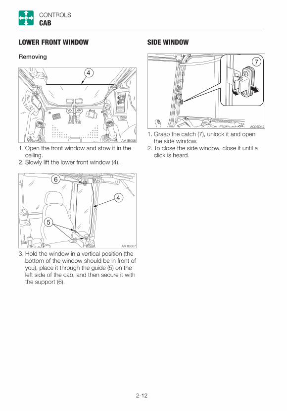
LOWER FRONT WINDOW
Removing
1. Open the front window and stow it in the ceiling.
2. Slowly lift the lower front window (4).
CAB
3. Hold the window in a vertical position (the bottom of the window should be in front of you), place it through the guide (5) on the left side of the cab, and then secure it with the support (6).
SIDE WINDOW
1. Grasp the catch (7), unlock it and open the side window.
2. To close the side window, close it until a click is heard.
2-13
CONTROLSCAB
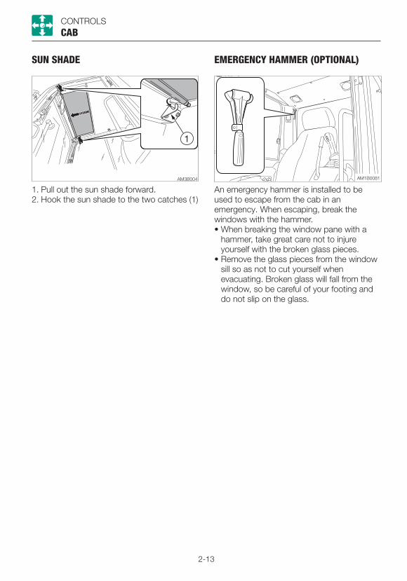
EMERGENCY HAMMER (OPTIONAL)
An emergency hammer is installed to be used to escape from the cab in an emergency. When escaping, break the windows with the hammer.• When breaking the window pane with a
hammer, take great care not to injure yourself with the broken glass pieces.
• Remove the glass pieces from the window sill so as not to cut yourself when evacuating. Broken glass will fall from the window, so be careful of your footing and do not slip on the glass.
SUN SHADE
1. Pull out the sun shade forward.2. Hook the sun shade to the two catches (1)

2-14
CONTROLS
SEAT AND SEAT BELTSEAT
• Adjust and secure the seat.• Do not make any adjustments while
operating the machine.• Do not set the backrest to its maximum
reclining position and slide the seat backwards at the same time. Doing so may damage the rear window or cause injury.
• Remember that the backrest returns to the forward position abruptly due to the spring force.
SEAT AND SEAT BELT
(A) Adjusting the backrest angle1. Sit up and sit back in the chair.2. Pull up the lever (1), recline the backrest
by using the spring force. Release the lever (1) at the desired angle to secure the backrest.
(C) Adjusting according to operator’s weight1. Turn the handle (3) until the scale (4)
indicates the weight of operator. Adjustment range: 50 to 130 kg (110 to
287 lbs)
(D) Adjusting the height of the seatUpward1. Lift the seat to first or second position
click-stop. Adjustment ranges: 2positions, in 60mm
(2.36 in.)Downward1. First lift the seat to highest position, then
the seat can be lowered to lowest position.
(B) Fore-and-aft adjustment1. Pull up the lever (2) and slide the seat
backward or forward to the desired position for operation of machine.
2. Release the lever (2) at the desired position to secure the seat.
Adjustment range: 15 positions, in 150 mm (5.9 in.)
12
3
4
A E
B
AG7B021
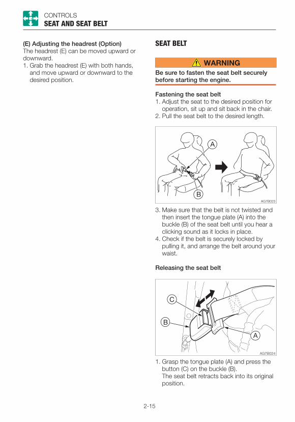
2-15
CONTROLS
(E) Adjusting the headrest (Option)The headrest (E) can be moved upward or downward.1. Grab the headrest (E) with both hands,
and move upward or downward to the desired position.
SEAT AND SEAT BELT
SEAT BELT
Be sure to fasten the seat belt securely before starting the engine.
Fastening the seat belt1. Adjust the seat to the desired position for
operation, sit up and sit back in the chair.2. Pull the seat belt to the desired length.
3. Make sure that the belt is not twisted and then insert the tongue plate (A) into the buckle (B) of the seat belt until you hear a clicking sound as it locks in place.
4. Check if the belt is securely locked by pulling it, and arrange the belt around your waist.
Releasing the seat belt
1. Grasp the tongue plate (A) and press the button (C) on the buckle (B).
The seat belt retracts back into its original position.
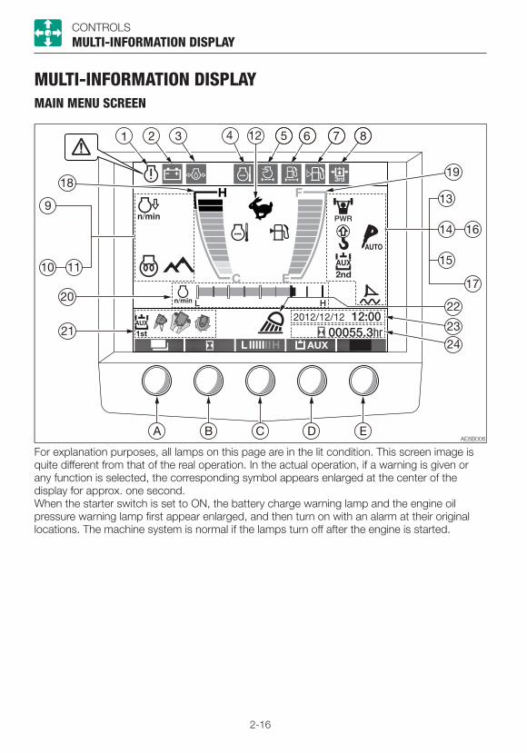
2-16
CONTROLSMULTI-INFORMATION DISPLAY
MULTI-INFORMATION DISPLAYMAIN MENU SCREEN
For explanation purposes, all lamps on this page are in the lit condition. This screen image is quite different from that of the real operation. In the actual operation, if a warning is given or any function is selected, the corresponding symbol appears enlarged at the center of the display for approx. one second. When the starter switch is set to ON, the battery charge warning lamp and the engine oil pressure warning lamp first appear enlarged, and then turn on with an alarm at their original locations. The machine system is normal if the lamps turn off after the engine is started.
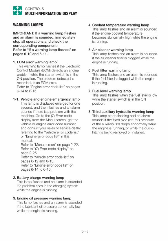
2-17
CONTROLSMULTI-INFORMATION DISPLAY
WARNING LAMPS
IMPORTANT: If a warning lamp flashes and an alarm is sounded, immediately stop all operations and check the corresponding component.Refer to “If a warning lamp flashes” on pages 6-10 and 6-11.
1. ECM error warning lamp This warning lamp flashes if the Electronic
Control Module (ECM) detects an engine problem while the starter switch is in the ON position. The problem detected is recorded as an ECM error.
Refer to “Engine error code list” on pages 6-14 to 6-15.
1-1. Vehicle and engine emergency lamp This lamp is displayed enlarged for one
second, and then flashes and an alarm sounds if there is a problem with the machine. Go to the (7) Error code display from the Menu screen, get the vehicle or engine error code number, and consult your sales or service dealer referring to the “Vehicle error code list” or “Engine error code list” in this manual.
Refer to “Menu screen” on page 2-22. Refer to “(7) Error code display” on
page 2-25. Refer to “Vehicle error code list” on
pages 6-12 and 6-13. Refer to “Engine error code list” on
pages 6-14 to 6-15.
2. Battery charge warning lamp This lamp flashes and an alarm is sounded
if a problem rises in the charging system while the engine is running.
3. Engine oil pressure warning lamp This lamp flashes and an alarm is sounded
if the lubricant oil pressure abnormally low while the engine is running.
4. Coolant temperature warning lamp This lamp flashes and an alarm is sounded
if the engine coolant temperature becomes abnormally high while the engine is running.
5. Air cleaner warning lamp This lamp flashes and an alarm is sounded
if the air cleaner filter is clogged while the engine is running.
6. Fuel filter warning lamp This lamp flashes and an alarm is sounded
if the fuel filter is clogged while the engine is running.
7. Fuel level warning lamp This lamp flashes when the fuel level is low
while the starter switch is in the ON position.
8. Third auxiliary hydraulic warning lamp This lamp starts flashing and an alarm
sounds if the fixed side (left “e”) pressure of the auxiliary 3rd drops abnormally while the engine is running, or while the quick-hitch is being removed or installed.

2-18
CONTROLSMULTI-INFORMATION DISPLAY
INDICATORS
9. Deceleration indicator lamp
........ Automatic deceleration indicator
........ Deceleration indicator
Automatic deceleration indicator It flashes when the automatic
deceleration switch is pressed and remains lit while in the deceleration mode.
Refer to “Deceleration button” on page 2-49.
Refer to “Automatic deceleration switch” on page 2-53.
Deceleration indicator lamp This lamp turns on when the deceleration
button is pressed. The lamp lights up to indicate that the engine is in the deceleration mode at low idling speed (1100 rpm).
10. Glow indicator lamp This indicator lamp turns off when the
engine preheating is completed.
11. Highland mode indicator lamp Highland mode is selected. Refer to “Power/Highland mode switch”
on page 2-53.
........ High-speed travel
........ Low-speed travel
This lamp turns on when the travel speed button is set to the 2nd (high) speed.
13. Power mode indicator lamp This lamp lights up when the power
mode side of the Power/Highland mode select switch is pressed. The maximum engine output is maintained for as long as this lamp is lit.
14. Lift overload warning indicator lamp This lamp turns on when the lift overload
warning switch is turned on.
15. Auxiliary 2nd/4th select indicator lamp
........ Auxiliary 2nd is selected.
........ Auxiliary 4th is selected.
16. Auxiliary 1st one-way (one-way circuit) indicator lamp
........ Auxiliary 1st auto tank is selected.
........ Auxiliary 1st one-way is selected.
No display: ....Two-way (two-way circuit) is selected.
12. Travel speed indicator lamp

2-19
CONTROLSMULTI-INFORMATION DISPLAY
17. Dozer blade float indicator lamp (If equipped)
........ This lamp lights up when the float switch on the blade lever is pressed.
18. Water temperature gauge Indicates the temperature of the engine
coolant water. The indicator level must be within the green range during machine operation. The red range indicates overheating.
19. Fuel gauge
IMPORTANT: If the fuel gauge changes the color from green to orange while traveling on a flat ground, do not go to a sloping land. Engine stalling may occur on the sloping land. Before operating on the sloping land, be sure to add enough fuel.
Indicates the amount of fuel in the tank. Be sure to fill up the tank before running out of fuel.
20. Throttle opening position indicator
The red range increases as the engine load increases, indicating higher fuel consumption. When the button (C) (Bar meter key) is pressed in a normal screen, the display is changed from the throttle opening position to the lift load factor and the PM accumulation amount, in this order.• The lift load factor is displayed if there
is no change in the throttle opening position for five seconds after the lift alarm switch is turned on.
• The throttle opening position is displayed if the highland mode switch is turned on or there is a change in the throttle opening position.
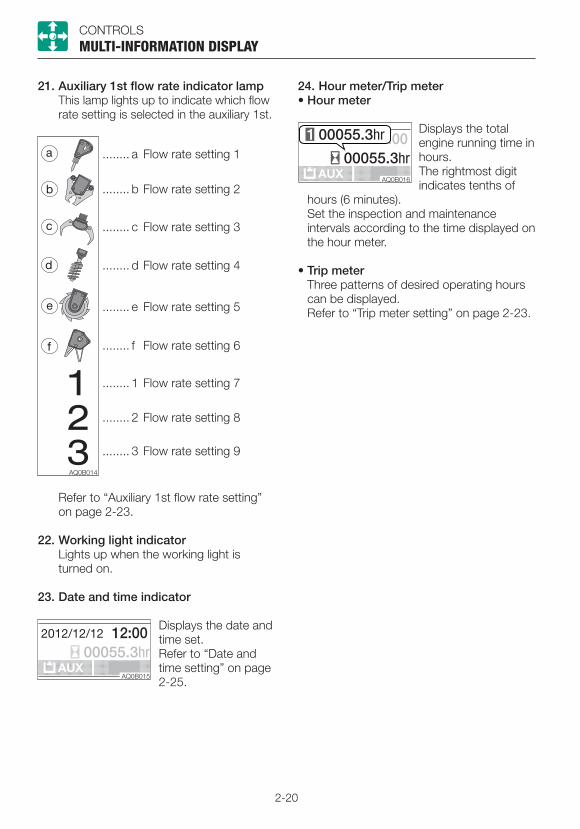
2-20
CONTROLSMULTI-INFORMATION DISPLAY
........ a Flow rate setting 1
........ b Flow rate setting 2
........ c Flow rate setting 3
........ d Flow rate setting 4
........ e Flow rate setting 5
........ f Flow rate setting 6
........ 1 Flow rate setting 7
........ 2 Flow rate setting 8
........ 3 Flow rate setting 9
Refer to “Auxiliary 1st flow rate setting” on page 2-23.
22. Working light indicator Lights up when the working light is
turned on.
23. Date and time indicator
Displays the date and time set.Refer to “Date and time setting” on page 2-25.
24. Hour meter/Trip meter• Hour meter
Displays the total engine running time in hours.The rightmost digit indicates tenths of
hours (6 minutes). Set the inspection and maintenance
intervals according to the time displayed on the hour meter.
• Trip meter Three patterns of desired operating hours
can be displayed. Refer to “Trip meter setting” on page 2-23.
21. Auxiliary 1st flow rate indicator lamp This lamp lights up to indicate which flow
rate setting is selected in the auxiliary 1st.

2-21
CONTROLSMULTI-INFORMATION DISPLAY
SCREEN CONTROL KEY
Note: Do not press the symbol keys on the display. The LCD could be damaged if the symbol keys are pressed hard. For actual operation, press the push button keys located at the bottom of the screen.
A. Menu key Use this key to switch between the Home
screen and the Menu screen. This key is also used to cancel changes made in each setting. The screen returns to the Home screen if this key is pressed in the information screen.
B. Hour meter key This hour meter symbol is displayed in the
initial screen. Pressing this key changes the meter display in the following order. Trip meter 1, Trip meter 2, Trip meter 3, Hour meter.
Down ( ) key Use this key to move the cursor
downward and to decrease the value in each setting. Press and hold this key for one second to rapidly decrease the value.
C. Bar meter key This hour meter symbol is displayed in the
initial screen. Pressing this key changes the meter display in the following order.
Throttle opening position, Lift load factor, PM accumulation amount
Up ( ) key Use this key to move the cursor upward
and to increase the value in each setting. Press and hold this key for one second to rapidly increase the value.
D. Auxiliary 1st key The auxiliary 1st symbol is displayed in the
initial screen. Pressing this key changes the symbol display in the following order. Auxiliary 1st setting 1, Auxiliary 1st setting 2, Auxiliary 1st setting 3.
Enter key Use this key to confirm or execute the
setting made by each key. To clear the trip meter being displayed,
press and hold this key for three seconds.
E. —
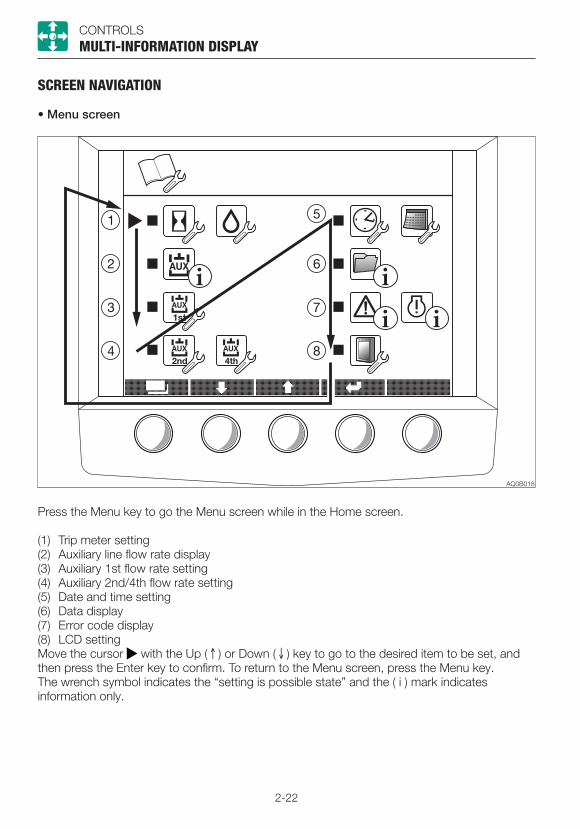
2-22
CONTROLSMULTI-INFORMATION DISPLAY
SCREEN NAVIGATION
• Menu screen
Press the Menu key to go the Menu screen while in the Home screen.
(1) Trip meter setting(2) Auxiliary line flow rate display(3) Auxiliary 1st flow rate setting(4) Auxiliary 2nd/4th flow rate setting(5) Date and time setting(6) Data display(7) Error code display(8) LCD settingMove the cursor with the Up ( ) or Down ( ) key to go to the desired item to be set, and then press the Enter key to confirm. To return to the Menu screen, press the Menu key.The wrench symbol indicates the “setting is possible state” and the ( i ) mark indicates information only.

2-23
CONTROLSMULTI-INFORMATION DISPLAY
(1) TRIP METER SETTING
Six patterns of desired operating hours can be set.To start setting, press the Enter key. The value flashes while being set.Up ( ) key: Increases the value or moves the cursor upward. Rapidly increases the value when pressed and held for one second.Down ( ) key: Decreases the value or moves the cursor downward. Rapidly decreases the value when pressed and held for one second.Enter key: Confirms settingMenu key: Cancels setting or returns to the Menu screen.Pressing and holding the Enter key for three seconds clears the trip meter pointed by the cursor.
(2) AUXILIARY LINE FLOW RATE DISPLAY
Displays the flow rate of the Auxiliary 1st, 2nd and 4th.The flow rate cannot be changed.
(3) AUXILIARY 1ST FLOW RATE SETTING
Three flow rate patterns can be set in the auxiliary 1st.Refer to the trip meter setting for the key operation. To move the cursor in the direction of the arrow, use the Down ( ) key.To move the cursor in the opposite direction of the arrow, use the Up ( ) key.
Initial condition
A/B common, standard flow
Variable range
Auxiliary 1st-1100%
= 54 L/min ( 14.3 US gpm)
10 to 100%
Auxiliary 1st-275%
= 40.5 L/min ( 10.7 US gpm)
10 to 100%
Auxiliary 1st-350%
= 27 L/min ( 7.1 US gpm)
10 to 100%
The table shows the 1-way flow rate when there is no load.

2-24
CONTROLSMULTI-INFORMATION DISPLAY
(4) AUXILIARY 2ND/4TH FLOW RATE SETTING
One pattern of the auxiliary 2nd/4th flow rate can be set.
Initial condition Standard flow Variable
range
Auxiliary 2ndC/D 100%
=21.6 L/min ( 5.7 US gpm)
10 to 100%
Auxiliary 4thG/H 100%
=21.6 L/min ( 5.7 US gpm)
10 to 100%
The table shows the 1-way flow rate when there is no load.
Refer to the trip meter setting for the key operation. To move the cursor in the direction of the arrow, use the Down ( ) key.To move the cursor in the opposite direction of the arrow, use the Up ( ) key.
Pressing the Enter key while the cursor is at “Select ATT” goes to the attachment select screen. Pressing the Down ( ) key will move the blue flashing light in the direction of the arrow. Pressing the UP ( ) key will move the blue flashing light in the opposite direction of the arrow. Move the blue flashing light to the desired symbol or the number, and then press the Enter key to confirm.The selected symbol will appear at the lower left of the Home screen.
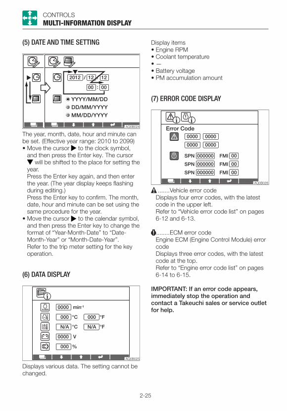
2-25
CONTROLSMULTI-INFORMATION DISPLAY
(5) DATE AND TIME SETTING
The year, month, date, hour and minute can be set. (Effective year range: 2010 to 2099)• Move the cursor to the clock symbol,
and then press the Enter key. The cursor will be shifted to the place for setting the
year. Press the Enter key again, and then enter the year. (The year display keeps flashing during editing.)
Press the Enter key to confirm. The month, date, hour and minute can be set using the same procedure for the year.
• Move the cursor to the calendar symbol, and then press the Enter key to change the format of “Year-Month-Date” to “Date-Month-Year” or “Month-Date-Year”.
Refer to the trip meter setting for the key operation.
(6) DATA DISPLAY
Display items• Engine RPM• Coolant temperature• —• Battery voltage• PM accumulation amount
(7) ERROR CODE DISPLAY
.......Vehicle error code Displays four error codes, with the latest
code in the upper left. Refer to “Vehicle error code list” on pages
6-12 and 6-13.
........ECM error code Engine ECM (Engine Control Module) error
code Displays three error codes, with the latest
code at the top. Refer to “Engine error code list” on pages
6-14 to 6-15.
IMPORTANT: If an error code appears, immediately stop the operation and contact a Takeuchi sales or service outlet for help.
Displays various data. The setting cannot be changed.
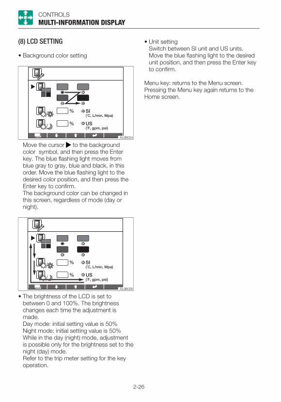
2-26
CONTROLSMULTI-INFORMATION DISPLAY
(8) LCD SETTING
• Background color setting
Move the cursor to the background color symbol, and then press the Enter key. The blue flashing light moves from blue gray to gray, blue and black, in this order. Move the blue flashing light to the desired color position, and then press the Enter key to confirm.
The background color can be changed in this screen, regardless of mode (day or night).
• Unit setting Switch between SI unit and US units. Move the blue flashing light to the desired
unit position, and then press the Enter key to confirm.
Menu key: returns to the Menu screen. Pressing the Menu key again returns to the Home screen.
• The brightness of the LCD is set to between 0 and 100%. The brightness changes each time the adjustment is made.
Day mode: initial setting value is 50% Night mode: initial setting value is 50% While in the day (night) mode, adjustment
is possible only for the brightness set to the night (day) mode.
Refer to the trip meter setting for the key operation.
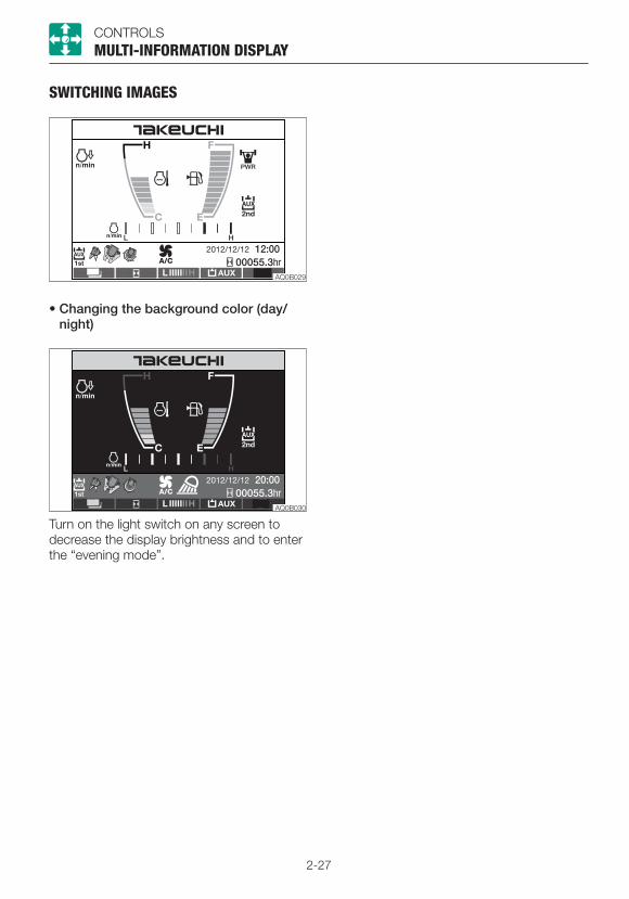
2-27
CONTROLSMULTI-INFORMATION DISPLAY
SWITCHING IMAGES
• Changing the background color (day/night)
Turn on the light switch on any screen to decrease the display brightness and to enter the “evening mode”.
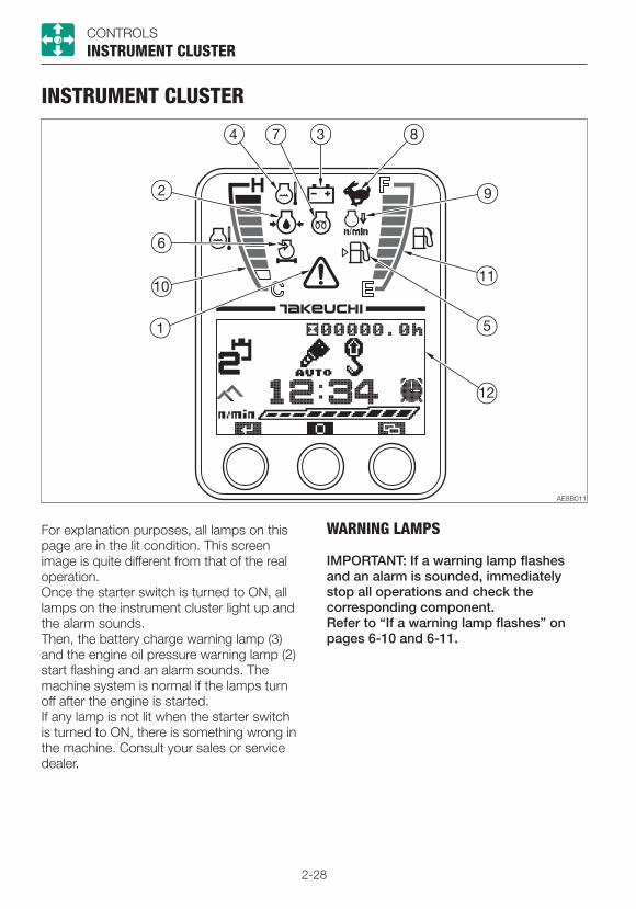
2-28
CONTROLSINSTRUMENT CLUSTER
INSTRUMENT CLUSTER
For explanation purposes, all lamps on this page are in the lit condition. This screen image is quite different from that of the real operation.Once the starter switch is turned to ON, all lamps on the instrument cluster light up and the alarm sounds.Then, the battery charge warning lamp (3) and the engine oil pressure warning lamp (2) start flashing and an alarm sounds. The machine system is normal if the lamps turn off after the engine is started.If any lamp is not lit when the starter switch is turned to ON, there is something wrong in the machine. Consult your sales or service dealer.
WARNING LAMPS
IMPORTANT: If a warning lamp flashes and an alarm is sounded, immediately stop all operations and check the corresponding component.Refer to “If a warning lamp flashes” on pages 6-10 and 6-11.

2-29
CONTROLSINSTRUMENT CLUSTER
1. Vehicle and engine emergency lamp This lamp flashes and an alarm sounds if
there is a problem with the machine. Go to the “Failure Record (FAILURE RECORD)” from the side menu screen, get the vehicle or engine error code number, and then consult your sales or service dealer referring to the “Vehicle error code list” or “Engine error code list” in this manual.
Refer to “Side menu screen” on page 2-39.
Refer to “Failure Record (FAILURE RECORD)” on page 2-46.
Refer to “Vehicle error code list” on pages 6-12 and 6-13.
Refer to “Engine error code list” on pages 6-14 to 6-15.
2. Engine oil pressure warning lamp This lamp flashes and an alarm is sounded
if the lubricant oil pressure abnormally low while the engine is running.
3. Battery charge warning lamp This lamp flashes and an alarm is sounded
if a problem rises in the charging system while the engine is running.
4. Coolant temperature warning lamp This lamp flashes and an alarm is sounded
if the engine coolant temperature becomes abnormally high while the engine is running.
5. Fuel level warning lamp This lamp turns on if the fuel level
becomes low while the starter switch is in the ON position.
6. Air cleaner warning lamp This lamp flashes and an alarm is sounded
if the air cleaner filter is clogged while the engine is running.
INDICATORS
7. Glow lamp This lamp goes out when the engine
preheating is completed.
8. Travel speed lamp This lamp turns on when the travel speed
button is set to the 2nd (high) speed.
9. Deceleration lamp This lamp turns on when the deceleration
button is pressed. The lamp lights up to indicate that the engine is in the deceleration mode at low idling speed (1200 rpm).
It flashes When the automatic deceleration switch is pressed to indicate that the machine is in the automatic deceleration mode.
Refer to “Deceleration button” on page 2-49.
Refer to “Automatic deceleration switch” on page 2-53.
METERS
10. Water temperature gauge Indicates the temperature of the engine
coolant water. The LED should be within the green
range during machine operation. The red range indicates overheating.
11. Fuel gauge Indicates the amount of fuel in the tank. Be sure to top off the tank before running
out of fuel.

2-30
CONTROLSINSTRUMENT CLUSTER
MULTI-DATA DISPLAY
12. LCD (Liquid Crystal Display) It displays various functions and data on
hour meter, trip meter, clock, tachometer and the machine.
Home screen
1. Key function display The key function display changes
depending on the screens (Home, Menu and each setting)
For actual operation, use the buttons, “A”, “B” and “C”, located beneath each symbol.
Refer to “Function of each key” on pages 2-34 to 2-47.
2. Hour meter/Trip meter• Hour meter Displays the total engine running time in
hours. The rightmost digit indicates tenths of
hours (6 minutes). Set the inspection and maintenance
intervals according to the time displayed on the hour meter.
• Trip meter Three patterns of desired operating hours
can be displayed. Refer to “Trip meter display” on page
2-34.
3. Time display Displays the time set. Refer to “Time setting” on page 2-37.
4. Tachometer
Displays the engine RPM in 10 levels. Pressing the (B) key while the tachometer is displayed changes to the display of the PM accumulation rate and lift load factor, in this order.• The throttle opening position is displayed if
the lift alarm switch is turned on and there is no change in the throttle opening position.
• The tachometer is displayed if the highland mode switch is turned on or there is a change in the throttle opening position.
• For TB230, the PM accumulation rate does not change.
5. Functions (Page 1)
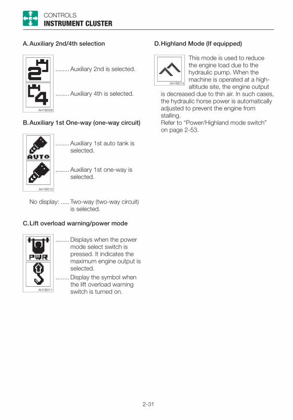
2-31
CONTROLSINSTRUMENT CLUSTER
........ Auxiliary 2nd is selected.
........ Auxiliary 4th is selected.
B. Auxiliary 1st One-way (one-way circuit)
........ Auxiliary 1st auto tank is selected.
........ Auxiliary 1st one-way is selected.
No display: ..... Two-way (two-way circuit) is selected.
C. Lift overload warning/power mode
........ Displays when the power mode select switch is pressed. It indicates the maximum engine output is selected.
D. Highland Mode (If equipped)
This mode is used to reduce the engine load due to the hydraulic pump. When the machine is operated at a high-altitude site, the engine output
is decreased due to thin air. In such cases, the hydraulic horse power is automatically adjusted to prevent the engine from stalling.
Refer to “Power/Highland mode switch” on page 2-53.
........ Display the symbol when the lift overload warning switch is turned on.
A. Auxiliary 2nd/4th selection

2-32
CONTROLSINSTRUMENT CLUSTER
6. Function indicators (Page 2)When the (A) key is pressed, the display changes as the following.
F. Auxiliary 1st indicator
G. Auxiliary 1st flow rate selection indicator
Press the (B) key to move the and select the desired flow rate.
Refer to “Auxiliary 1st Flow Rate Setting” on page 2-40.
H. Attachment symbol indicator
Displays the symbol of the attachment selected in the “Auxiliary 1st Flow Rate Setting” section.
I. Dozer blade float indicator Displays the symbol of the dozer blade
float when the float button is pressed.
7. Warning indicators (Page 3)When the (A) key is pressed, the display changes as the following. If there is no warning, the screen returns to the “Functions” on Page 1.
Warning display is first flashed and enlarged for three seconds and then stays displayed, if there is a problem with the machine. If multiple warnings are to be displayed, the highest priority warning is displayed. Priority from the highest to the lowest: ECM error warning, Auxiliary 3rd hydraulic pressure warning, water separator warning and fuel filter warning.No enlarged display for the maintenance warning. Go to the “MAINTENANCE/FAILURE RECORD/Error cord display” from the Side menu screen, get the vehicle or engine error code number, and consult your sales or service dealer referring to the “Vehicle error code list” or “Engine error code list” in this manual.
Displays the clock symbol when the alarm function is turned on.Refer to “Alarm setting” on page 2-37.
E. Alarm

2-33
CONTROLSINSTRUMENT CLUSTER
J. ECM error warning indicator This warning lamp flashes if the Electronic
Control Module (ECM) detects an engine problem while the starter switch is in the ON position. The problem detected is recorded as an ECM error.
Refer to “Engine error code list” on pages 6-14 to 6-15.
K.Fuel filter warning indicator This lamp flashes and an alarm is sounded
if the fuel filter is clogged while the engine is running.
L. Auxiliary 3rd hydraulic pressure warning indicator (If equipped)
This warning lamp starts flashing and an alarm sounds if the pressure in the fixed side (left “e”) of the Auxiliary 3rd drops abnormally while the engine is running, or while the quick-hitch is being used for changing the bucket.
M. Maintenance warning indicator When the time for maintenance set by the
trip meter is reached, this warning lamp flashes and an alarm sounds.
When the time for maintenance set by the trip meter is reached, the screen is changed from the Main to the Trip Meter for Maintenance on the DATA screen. Each value remains flashing until its corresponding key is pressed. At this stage, the trip meter values cannot be reset. Pressing any key returns to the Warning (Page 3) of Main screen in which the maintenance warning lamp is flashing and the alarm is sounding. Promptly inspect and service the relevant item.
Refer to “Menu/Trip meter reset” on page 2-35.
Refer to “Maintenance” on page 5-1.
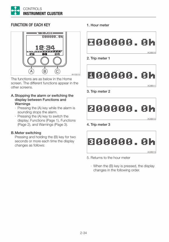
2-34
CONTROLSINSTRUMENT CLUSTER
FUNCTION OF EACH KEY
The functions are as below in the Home screen. The different functions appear in the other screens.
A. Stopping the alarm or switching the display between Functions and Warnings · Pressing the (A) key while the alarm is
sounding stops the alarm.· Pressing the (A) key to switch the
display; Functions (Page 1), Functions (Page 2), and Warnings (Page 3).
B. Meter switching Pressing and holding the (B) key for two
seconds or more each time the display changes as follows:
1. Hour meter
3. Trip meter 2
4. Trip meter 3
5. Returns to the hour meter
· When the (B) key is pressed, the display changes in the following order.
2. Trip meter 1
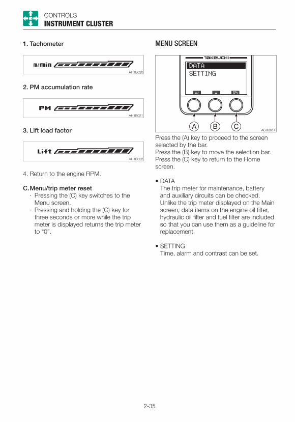
2-35
CONTROLSINSTRUMENT CLUSTER
1. Tachometer
2. PM accumulation rate
4. Return to the engine RPM.
C. Menu/trip meter reset· Pressing the (C) key switches to the
Menu screen.· Pressing and holding the (C) key for
three seconds or more while the trip meter is displayed returns the trip meter to “0”.
MENU SCREEN
Press the (A) key to proceed to the screen selected by the bar.Press the (B) key to move the selection bar.Press the (C) key to return to the Home screen.
• DATA The trip meter for maintenance, battery
and auxiliary circuits can be checked. Unlike the trip meter displayed on the Main
screen, data items on the engine oil filter, hydraulic oil filter and fuel filter are included so that you can use them as a guideline for replacement.
• SETTING Time, alarm and contrast can be set.
3. Lift load factor

2-36
CONTROLSINSTRUMENT CLUSTER
• Battery (BATTERY) Displays the battery voltage.
Press the (C) key to return to the DATA screen.
• Auxiliary circuit (AUXILIARY) Displays the flow rate in the auxiliary
circuits of the 1st, 2nd or 3rd.
Each time the (B) key is pressed, the auxiliary circuit is displayed in this order: Auxiliary 1st, Auxiliary 2nd and Auxiliary 4th.
Press the (C) key to return to the Data screen.
DATA SCREEN (DATA)
Press the (A) key to proceed to the screen selected by the bar.Press the (B) key to move the selection bar.Press the (C) key to return to the Menu screen.
• Trip meter (TRIP METER) for maintenance
The trip meters for the engine oil filter, hydraulic oil filter or fuel filter are displayed.
Press and hold the (A) key for at least five seconds resets the selected trip meter to “0”.
Press the (B) key to move the selection bar. Press the (C) key to return to the DATA
screen.

2-37
CONTROLSINSTRUMENT CLUSTER
SETTING SELECTION SCREEN (SETTING)
Press the (A) key to proceed to the screen selected by the bar.Press the (B) key to move the selection bar.Press the (C) key to return to the Menu screen.
• Time setting (CLOCK) The time to be displayed on the Home
screen can be set here.
a. When the selection bar is at CLOCK, press the (A) key to proceed to the time setting screen (CLOCK SET).
b. Pressing the (A) key in this screen moves the selection bar and flashes the figures on the bar.
Setting range: hours, 1 to 24; minutes, 00 to 59
c. Press the (B) key to increase the number value selected.
Press and hold the (B) key to rapidly increase the number value selected.
d. Press and hold the (A) key for at least two seconds to complete the setting and to return to the Setting Selection screen.
e. Press the (C) key cancels editing and to return to the Setting Selection screen.
• Alarm setting (ALARM) Five patterns of alarm setting are
available. Alarm function can be set to on or off
within the five patterns.
a. When the selection bar is at ALARM, press the (A) key to proceed to the alarm setting screen (ALARM SET).
b. Press the (A) key in this screen to place a checkmark in the box at the left of the setting bar. Press the (A) key again to remove the checkmark.
The alarm setting cannot be changed only by placing or removing a checkmark.
c. Press and hold the (A) key for at least two seconds to complete the setting and to return to the Setting Selection screen.
Be sure to perform the above operation when you wish to set the alarm.
A clock symbol is displayed on the Home screen.
d. Press the (B) key to move the selection bar.
e. Press and hold the (B) key for at least three seconds to enter the alarm time setting mode.
f. Press the (C) key to cancel editing and to return to the Setting Selection screen.
Checked ............On Unchecked ........Off
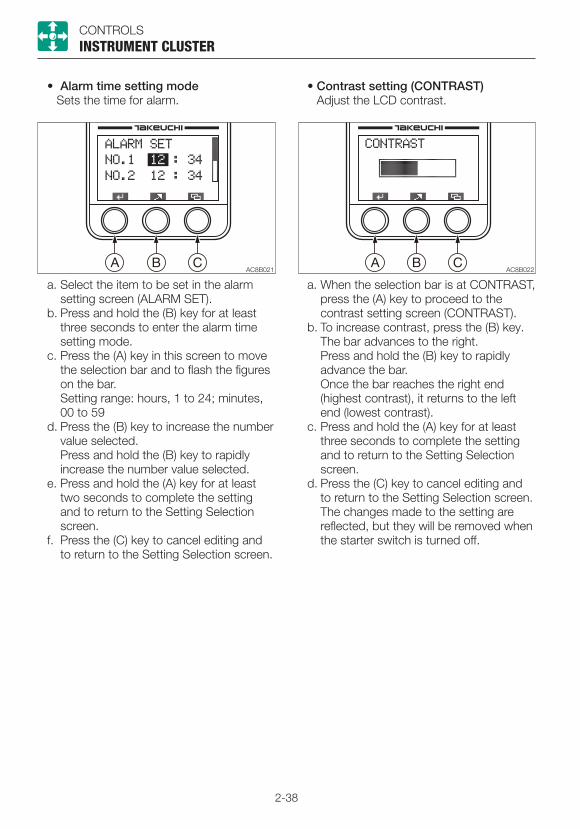
2-38
CONTROLSINSTRUMENT CLUSTER
• Alarm time setting mode Sets the time for alarm.
a. Select the item to be set in the alarm setting screen (ALARM SET).
b. Press and hold the (B) key for at least three seconds to enter the alarm time setting mode.
c. Press the (A) key in this screen to move the selection bar and to flash the figures on the bar.
Setting range: hours, 1 to 24; minutes, 00 to 59
d. Press the (B) key to increase the number value selected.
Press and hold the (B) key to rapidly increase the number value selected.
e. Press and hold the (A) key for at least two seconds to complete the setting and to return to the Setting Selection screen.
f. Press the (C) key to cancel editing and to return to the Setting Selection screen.
• Contrast setting (CONTRAST) Adjust the LCD contrast.
a. When the selection bar is at CONTRAST, press the (A) key to proceed to the contrast setting screen (CONTRAST).
b. To increase contrast, press the (B) key. The bar advances to the right.
Press and hold the (B) key to rapidly advance the bar.
Once the bar reaches the right end (highest contrast), it returns to the left end (lowest contrast).
c. Press and hold the (A) key for at least three seconds to complete the setting and to return to the Setting Selection screen.
d. Press the (C) key to cancel editing and to return to the Setting Selection screen.
The changes made to the setting are reflected, but they will be removed when the starter switch is turned off.
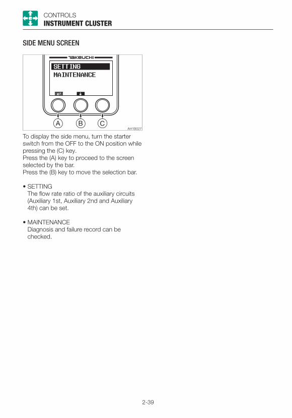
2-39
CONTROLSINSTRUMENT CLUSTER
SIDE MENU SCREEN
To display the side menu, turn the starter switch from the OFF to the ON position while pressing the (C) key. Press the (A) key to proceed to the screen selected by the bar.Press the (B) key to move the selection bar.
• SETTING The flow rate ratio of the auxiliary circuits
(Auxiliary 1st, Auxiliary 2nd and Auxiliary 4th) can be set.
• MAINTENANCE Diagnosis and failure record can be
checked.
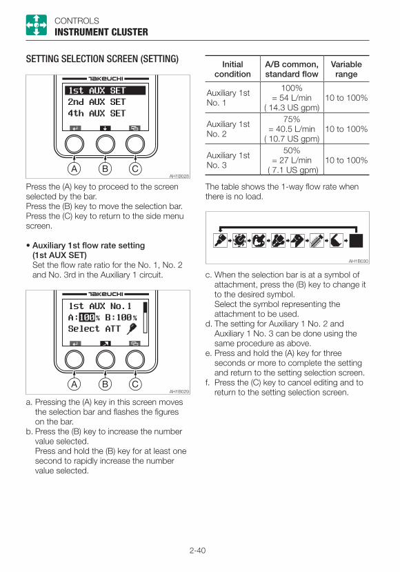
2-40
CONTROLSINSTRUMENT CLUSTER
Initial condition
A/B common, standard flow
Variable range
Auxiliary 1st No. 1
100%= 54 L/min
( 14.3 US gpm)10 to 100%
Auxiliary 1st No. 2
75%= 40.5 L/min
( 10.7 US gpm)10 to 100%
Auxiliary 1st No. 3
50%= 27 L/min
( 7.1 US gpm)10 to 100%
The table shows the 1-way flow rate when there is no load.
c. When the selection bar is at a symbol of attachment, press the (B) key to change it to the desired symbol.
Select the symbol representing the attachment to be used.
d. The setting for Auxiliary 1 No. 2 and Auxiliary 1 No. 3 can be done using the same procedure as above.
e. Press and hold the (A) key for three seconds or more to complete the setting and return to the setting selection screen.
f. Press the (C) key to cancel editing and to return to the setting selection screen.
SETTING SELECTION SCREEN (SETTING)
Press the (A) key to proceed to the screen selected by the bar.Press the (B) key to move the selection bar.Press the (C) key to return to the side menu screen.
• Auxiliary 1st flow rate setting (1st AUX SET)
Set the flow rate ratio for the No. 1, No. 2 and No. 3rd in the Auxiliary 1 circuit.
a. Pressing the (A) key in this screen moves the selection bar and flashes the figures on the bar.
b. Press the (B) key to increase the number value selected.
Press and hold the (B) key for at least one second to rapidly increase the number value selected.
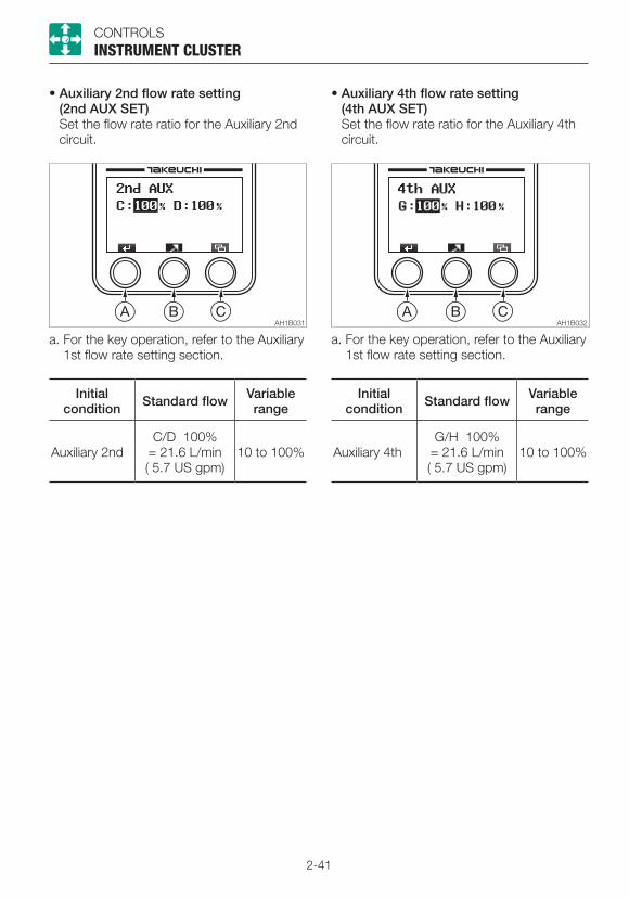
2-41
CONTROLSINSTRUMENT CLUSTER
• Auxiliary 2nd flow rate setting (2nd AUX SET)
Set the flow rate ratio for the Auxiliary 2nd circuit.
a. For the key operation, refer to the Auxiliary 1st flow rate setting section.
Initial condition Standard flow Variable
range
Auxiliary 2ndC/D 100%
= 21.6 L/min ( 5.7 US gpm)
10 to 100%
• Auxiliary 4th flow rate setting (4th AUX SET)
Set the flow rate ratio for the Auxiliary 4th circuit.
a. For the key operation, refer to the Auxiliary 1st flow rate setting section.
Initial condition Standard flow Variable
range
Auxiliary 4thG/H 100%
= 21.6 L/min ( 5.7 US gpm)
10 to 100%

2-42
CONTROLSINSTRUMENT CLUSTER
MAINTENANCE
Diagnosis and failure record can be checked.Press the (A) key to proceed to the screen selected by the bar.Press the (B) key to move the selection bar.Press the (C) key to return to the side menu screen.
• Diagnosis (DIAGNOSIS) Input/Output, Analog Input, PWM Output,
Engine Control Module (ECM) can be checked.
Press the (A) key to proceed to the screen selected by the bar.Press the (B) key to move the selection bar.Press the (C) key to return to the Maintenance screen.
· Inputs/outputs (INPUTS/OUTPUTS)
The 9-page diagnosis data can be displayed.
Press the (B) key to display a different page.
Press the (C) key to return to the Diagnosis screen.
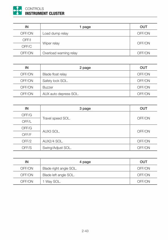
2-43
CONTROLSINSTRUMENT CLUSTER
IN 1 page OUT
OFF/ON Load dump relay OFF/ON
OFF/IWiper relay OFF/ON
OFF/C
OFF/ON Overload warning relay OFF/ON
IN 2 page OUT
OFF/ON Blade float relay OFF/ON
OFF/ON Safety lock SOL. OFF/ON
OFF/ON Buzzer OFF/ON
OFF/ON AUX auto depress SOL. OFF/ON
IN 3 page OUT
OFF/GTravel speed SOL. OFF/ON
OFF/L
OFF/GAUX3 SOL. OFF/ON
OFF/F
OFF/2 AUX2/4 SOL. OFF/ON
OFF/S Swing/Adjust SOL. OFF/ON
IN 4 page OUT
OFF/ON Blade right angle SOL. OFF/ON
OFF/ON Blade left angle SOL. OFF/ON
OFF/ON 1 Way SOL. OFF/ON
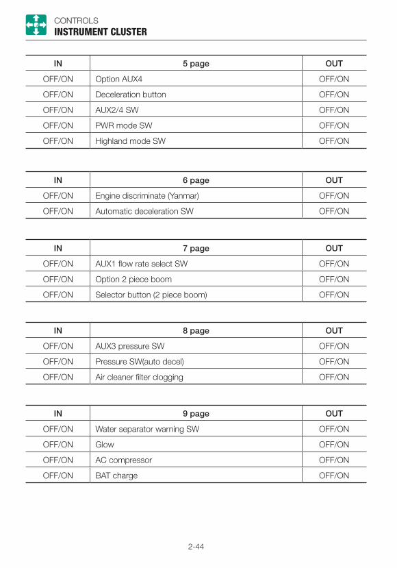
2-44
CONTROLSINSTRUMENT CLUSTER
IN 7 page OUT
OFF/ON AUX1 flow rate select SW OFF/ON
OFF/ON Option 2 piece boom OFF/ON
OFF/ON Selector button (2 piece boom) OFF/ON
IN 8 page OUT
OFF/ON AUX3 pressure SW OFF/ON
OFF/ON Pressure SW(auto decel) OFF/ON
OFF/ON Air cleaner filter clogging OFF/ON
IN 9 page OUT
OFF/ON Water separator warning SW OFF/ON
OFF/ON Glow OFF/ON
OFF/ON AC compressor OFF/ON
OFF/ON BAT charge OFF/ON
IN 6 page OUT
OFF/ON Engine discriminate (Yanmar) OFF/ON
OFF/ON Automatic deceleration SW OFF/ON
IN 5 page OUT
OFF/ON Option AUX4 OFF/ON
OFF/ON Deceleration button OFF/ON
OFF/ON AUX2/4 SW OFF/ON
OFF/ON PWR mode SW OFF/ON
OFF/ON Highland mode SW OFF/ON
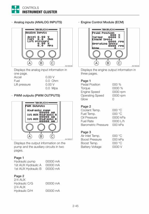
2-45
CONTROLSINSTRUMENT CLUSTER
· Analog inputs (ANALOG INPUTS) · Engine Control Module (ECM)
Displays the analog input information in one page.
Accel 0.00 V Fuel 0.0 Ohm Lift pressure 0.00 V 0.0 Mpa
· PWM outputs (PWM OUTPUTS)
Displays the output information on the pump and the auxiliary circuits in two pages.
Page 1 Hydraulic pump 00000 mA 1st AUX Hydraulic A 00000 mA 1st AUX Hydraulic B 00000 mA
Page 2 2/4 AUX Hydraulic C/G 00000 mA 2/4 AUX Hydraulic D/H 00000 mA
Displays the engine output information in three pages.
Page 1 Pedal Position 000 % Torque 0000 % Engine Speed 0000 rpm Operating Speed 0000 rpm Glow 0
Page 2 Coolant Temp. 000 °C Fuel Temp. 000 °C Oil Pressure 0000 kPa Fuel Rate 0000 L/h Barometric Pressure 000 kPa
Page 3 Air Inlet Temp. 000 °C Boost Pressure 000 kPa Boost Temp. 000 °C Battery Voltage 0000 V
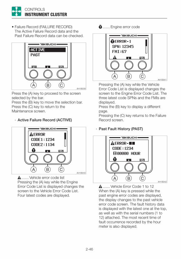
2-46
CONTROLSINSTRUMENT CLUSTER
• Failure Record (FAILURE RECORD) The Active Failure Record data and the
Past Failure Record data can be checked.
....... Engine error code
Press the (A) key to proceed to the screen selected by the bar.Press the (B) key to move the selection bar.Press the (C) key to return to the Maintenance screen.
· Active Failure Record (ACTIVE)
....... Vehicle error code list Pressing the (A) key while the Engine
Error Code List is displayed changes the screen to the Vehicle Error Code List. Four latest codes are displayed.
Pressing the (A) key while the Vehicle Error Code List is displayed changes the screen to the Engine Error Code List. The three latest code SPNs and the FMIs are displayed.
Press the (B) key to display a different page.
Pressing the (C) key returns to the Failure Record screen.
· Past Fault History (PAST)
....... Vehicle Error Code 1 to 12 When the (A) key is pressed while the
past engine error codes are displayed, the display changes to the past vehicle error code screen. The fault history data is displayed with the latest one at the top, as well as with the serial numbers (1 to 12) attached. The most recent time of fault occurrence recorded by the hour meter is also displayed.
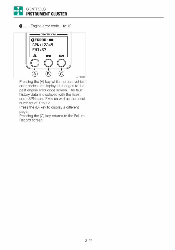
2-47
CONTROLSINSTRUMENT CLUSTER
....... Engine error code 1 to 12
Pressing the (A) key while the past vehicle error codes are displayed changes to the past engine error code screen. The fault history data is displayed with the latest code SPNs and FMIs as well as the serial numbers of 1 to 12.
Press the (B) key to display a different page.
Pressing the (C) key returns to the Failure Record screen.
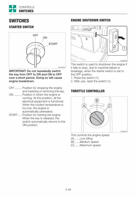
2-48
CONTROLS
SWITCHESSTARTER SWITCH
SWITCHES
IMPORTANT: Do not repeatedly switch the key from OFF to ON and ON to OFF over a short period. Doing so will cause engine breakdown.
OFF ......... Position for stopping the engine and inserting or removing the key.
ON .......... Position in which the engine is running. At this position, all the electrical equipment is functional. When the coolant temperature is too low, the engine is automatically preheated.
START ..... Position for starting the engine. When the key is released, the switch automatically returns to the ON position.
ENGINE SHUTDOWN SWITCH
This switch is used to shutdown the engine if it fails to stop, due to machine failure or breakage, when the starter switch is set to the OFF position.1. Press the switch (1).2. After use, reset the switch (1).
THROTTLE CONTROLLER
This controls the engine speed.(A) .......Low idling(B) ......Medium speed(C) ......Maximum speed
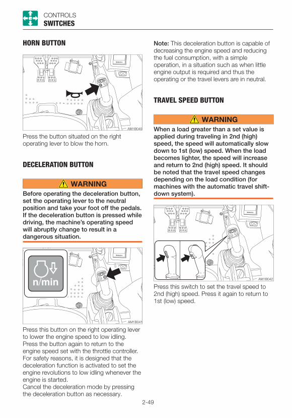
2-49
CONTROLS
HORN BUTTON
SWITCHES
Press the button situated on the right operating lever to blow the horn.
DECELERATION BUTTON
Before operating the deceleration button, set the operating lever to the neutral position and take your foot off the pedals. If the deceleration button is pressed while driving, the machine’s operating speed will abruptly change to result in a dangerous situation.
Press this button on the right operating lever to lower the engine speed to low idling.Press the button again to return to the engine speed set with the throttle controller.For safety reasons, it is designed that the deceleration function is activated to set the engine revolutions to low idling whenever the engine is started.Cancel the deceleration mode by pressing the deceleration button as necessary.
Note: This deceleration button is capable of decreasing the engine speed and reducing the fuel consumption, with a simple operation, in a situation such as when little engine output is required and thus the operating or the travel levers are in neutral.
TRAVEL SPEED BUTTON
When a load greater than a set value is applied during traveling in 2nd (high) speed, the speed will automatically slow down to 1st (low) speed. When the load becomes lighter, the speed will increase and return to 2nd (high) speed. It should be noted that the travel speed changes depending on the load condition (for machines with the automatic travel shift-down system).
Press this switch to set the travel speed to 2nd (high) speed. Press it again to return to 1st (low) speed.
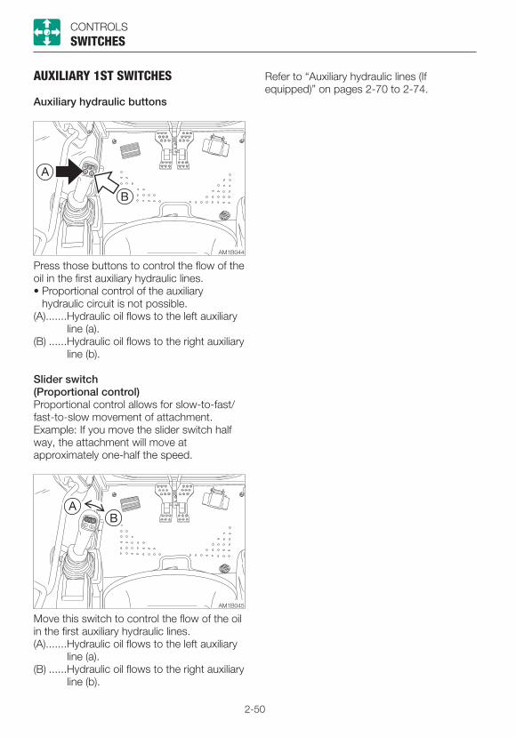
2-50
CONTROLS
AUXILIARY 1ST SWITCHES
Auxiliary hydraulic buttons
SWITCHES
Press those buttons to control the flow of the oil in the first auxiliary hydraulic lines.• Proportional control of the auxiliary
hydraulic circuit is not possible.(A) .......Hydraulic oil flows to the left auxiliary
line (a).(B) ......Hydraulic oil flows to the right auxiliary
line (b).
Slider switch(Proportional control)Proportional control allows for slow-to-fast/fast-to-slow movement of attachment.Example: If you move the slider switch half way, the attachment will move at approximately one-half the speed.
Move this switch to control the flow of the oil in the first auxiliary hydraulic lines.(A) .......Hydraulic oil flows to the left auxiliary
line (a).(B) ......Hydraulic oil flows to the right auxiliary
line (b).
Refer to “Auxiliary hydraulic lines (If equipped)” on pages 2-70 to 2-74.
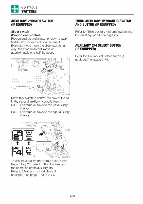
2-51
CONTROLS
AUXILIARY 2ND/4TH SWITCH (IF EQUIPPED)
Slider switch(Proportional control)Proportional control allows for slow-to-fast/fast-to-slow movement of attachment.Example: If you move the slider switch half way, the attachment will move at approximately one-half the speed.
Move this switch to control the flow of the oil in the second auxiliary hydraulic lines.(C): .....Hydraulic oil flows to the left auxiliary
line (c).(D): .....Hydraulic oil flows to the right auxiliary
line (d).
To use the auxiliary 4th hydraulic line, press the auxiliary 2/4 select button to change to the operation of the auxiliary 4th.Refer to “Auxiliary hydraulic lines (If equipped)” on page 2-70 to 2-74.
SWITCHES
THIRD AUXILIARY HYDRAULIC SWITCH AND BUTTON (IF EQUIPPED)
Refer to “Third auxiliary hydraulic switch and button (If equipped)” on page 2-73.
AUXILIARY 2/4 SELECT BUTTON (IF EQUIPPED)
Refer to “Auxiliary 2/4 select button (If equipped)” on page 2-74.
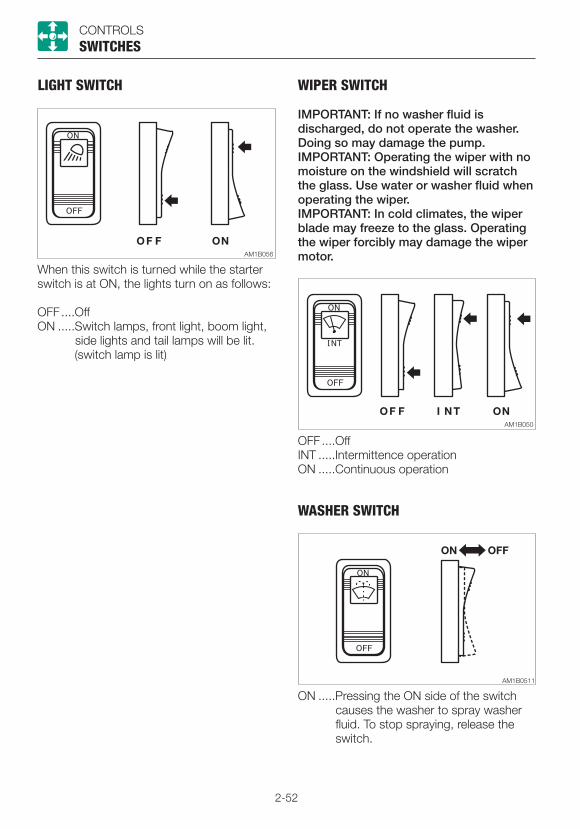
2-52
CONTROLS
WIPER SWITCH
IMPORTANT: If no washer fluid is discharged, do not operate the washer. Doing so may damage the pump.IMPORTANT: Operating the wiper with no moisture on the windshield will scratch the glass. Use water or washer fluid when operating the wiper.IMPORTANT: In cold climates, the wiper blade may freeze to the glass. Operating the wiper forcibly may damage the wiper motor.
SWITCHES
OFF ....OffINT .....Intermittence operationON .....Continuous operation
WASHER SWITCH
ON .....Pressing the ON side of the switch causes the washer to spray washer fluid. To stop spraying, release the switch.
LIGHT SWITCH
When this switch is turned while the starter switch is at ON, the lights turn on as follows:
OFF ....OffON .....Switch lamps, front light, boom light,
side lights and tail lamps will be lit. (switch lamp is lit)
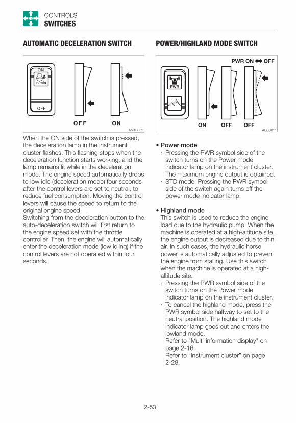
2-53
CONTROLS
AUTOMATIC DECELERATION SWITCH
When the ON side of the switch is pressed, the deceleration lamp in the instrument cluster flashes. This flashing stops when the deceleration function starts working, and the lamp remains lit while in the deceleration mode. The engine speed automatically drops to low idle (deceleration mode) four seconds after the control levers are set to neutral, to reduce fuel consumption. Moving the control levers will cause the speed to return to the original engine speed.Switching from the deceleration button to the auto-deceleration switch will first return to the engine speed set with the throttle controller. Then, the engine will automatically enter the deceleration mode (low idling) if the control levers are not operated within four seconds.
SWITCHES
POWER/HIGHLAND MODE SWITCH
• Power mode· Pressing the PWR symbol side of the
switch turns on the Power mode indicator lamp on the instrument cluster.
The maximum engine output is obtained. · STD mode: Pressing the PWR symbol
side of the switch again turns off the power mode indicator lamp.
• Highland mode This switch is used to reduce the engine
load due to the hydraulic pump. When the machine is operated at a high-altitude site, the engine output is decreased due to thin air. In such cases, the hydraulic horse power is automatically adjusted to prevent the engine from stalling. Use this switch when the machine is operated at a high-altitude site.· Pressing the PWR symbol side of the
switch turns on the Power mode indicator lamp on the instrument cluster.
· To cancel the highland mode, press the PWR symbol side halfway to set to the neutral position. The highland mode indicator lamp goes out and enters the lowland mode.
Refer to “Multi-information display” on page 2-16.
Refer to “Instrument cluster” on page 2-28.
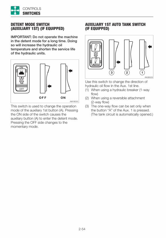
2-54
CONTROLS
DETENT MODE SWITCH (AUXILIARY 1ST) (IF EQUIPPED)
IMPORTANT: Do not operate the machine in the detent mode for a long time. Doing so will increase the hydraulic oil temperature and shorten the service life of the hydraulic units.
This switch is used to change the operation mode of the auxiliary 1st button (A). Pressing the ON side of the switch causes the auxiliary button (A) to enter the detent mode. Pressing the OFF side changes to the momentary mode.
SWITCHES
AUXILIARY 1ST AUTO TANK SWITCH (IF EQUIPPED)
Use this switch to change the direction of hydraulic oil flow in the Aux. 1st line.(1) When using a hydraulic breaker (1-way
flow)(2) When using a reversible attachment
(2-way flow)(3) The one-way flow can be set only when
the button “A” of the Aux. 1 is pressed. (The tank circuit is automatically opened.)

2-55
CONTROLS
LIFT OVERLOAD WARNING SWITCH (IF EQUIPPED)
If the overload is not removed after the overload warning horn is sounded, the machine may tip over. If the horn starts sounding, stop operating the machine and lighten the load.
If a weight greater than the lifting capacity is applied or lifted, the overload warning device is activated and the horn sounds. (When the lift overload warning switch is turned on.)OFF ....OffON .....On
SWITCHES
BEACON LAMP SWITCH (IF EQUIPPED)
When this switch is turned on while the starter switch is at ON, the lamp turns on as follows:OFF ....OffON .....Beacon lamp is lit
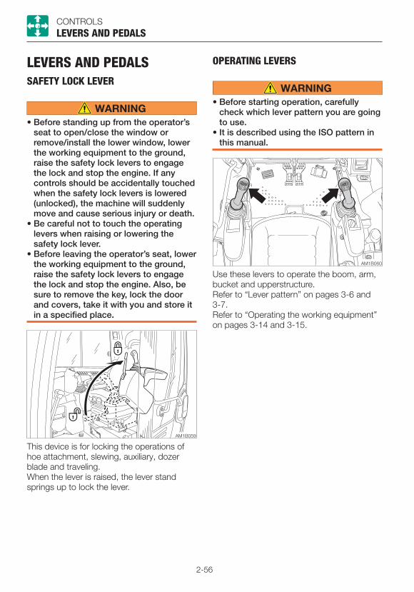
2-56
CONTROLS
LEVERS AND PEDALSSAFETY LOCK LEVER
• Before standing up from the operator’s seat to open/close the window or remove/install the lower window, lower the working equipment to the ground, raise the safety lock levers to engage the lock and stop the engine. If any controls should be accidentally touched when the safety lock levers is lowered (unlocked), the machine will suddenly move and cause serious injury or death.
• Be careful not to touch the operating levers when raising or lowering the safety lock lever.
• Before leaving the operator’s seat, lower the working equipment to the ground, raise the safety lock levers to engage the lock and stop the engine. Also, be sure to remove the key, lock the door and covers, take it with you and store it in a specified place.
LEVERS AND PEDALS
This device is for locking the operations of hoe attachment, slewing, auxiliary, dozer blade and traveling.When the lever is raised, the lever stand springs up to lock the lever.
OPERATING LEVERS
• Before starting operation, carefully check which lever pattern you are going to use.
• It is described using the ISO pattern in this manual.
Use these levers to operate the boom, arm, bucket and upperstructure.Refer to “Lever pattern” on pages 3-6 and 3-7.Refer to “Operating the working equipment” on pages 3-14 and 3-15.
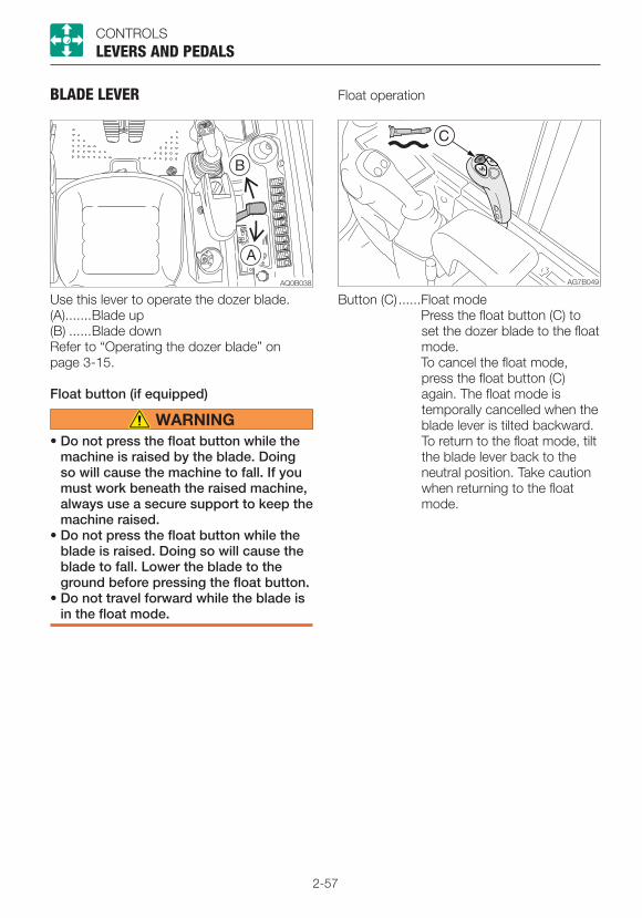
2-57
CONTROLS
BLADE LEVER
LEVERS AND PEDALS
Use this lever to operate the dozer blade.(A) .......Blade up(B) ......Blade downRefer to “Operating the dozer blade” on page 3-15.
Float button (if equipped)
• Do not press the float button while the machine is raised by the blade. Doing so will cause the machine to fall. If you must work beneath the raised machine, always use a secure support to keep the machine raised.
• Do not press the float button while the blade is raised. Doing so will cause the blade to fall. Lower the blade to the ground before pressing the float button.
• Do not travel forward while the blade is in the float mode.
Float operation
Button (C) ......Float mode Press the float button (C) to
set the dozer blade to the float mode.
To cancel the float mode, press the float button (C) again. The float mode is temporally cancelled when the blade lever is tilted backward. To return to the float mode, tilt the blade lever back to the neutral position. Take caution when returning to the float mode.
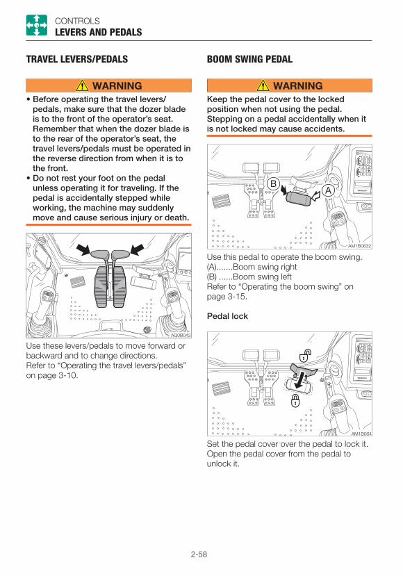
2-58
CONTROLS
TRAVEL LEVERS/PEDALS
• Before operating the travel levers/pedals, make sure that the dozer blade is to the front of the operator’s seat. Remember that when the dozer blade is to the rear of the operator’s seat, the travel levers/pedals must be operated in the reverse direction from when it is to the front.
• Do not rest your foot on the pedal unless operating it for traveling. If the pedal is accidentally stepped while working, the machine may suddenly move and cause serious injury or death.
Use these levers/pedals to move forward or backward and to change directions.Refer to “Operating the travel levers/pedals” on page 3-10.
LEVERS AND PEDALS
BOOM SWING PEDAL
Keep the pedal cover to the locked position when not using the pedal. Stepping on a pedal accidentally when it is not locked may cause accidents.
Use this pedal to operate the boom swing.(A) .......Boom swing right(B) ......Boom swing leftRefer to “Operating the boom swing” on page 3-15.
Pedal lock
Set the pedal cover over the pedal to lock it. Open the pedal cover from the pedal to unlock it.

2-59
MEMO

2-60
CONTROLSACCESSORIES
ACCESSORIESHEATER
• Always be sure to allow sufficient ventilation.
• Do not place combustible or explosive objects near the air outlets.
Heater fan switch
............ LowNeutral .... OFF
............ High
Ventilation/Circulation lever
Use this lever to switch between Ventilation and Circulation.
...Full ventilation: For heating with ventilation. Intake of external air. Defrosting the windows.
........ Circulation: Quick heating or when external air is dirty.
Outlets
Move the louver up and down or left and right to adjust the air flow direction and amount.
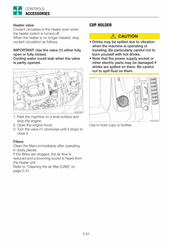
2-61
CONTROLSACCESSORIES
Heater valveCoolant circulates in the heater even when the heater switch is turned off.When the heater is no longer needed, stop coolant circulation as follows.
IMPORTANT: Use the valve (1) either fully open or fully closed.Cooling water could leak when the valve is partly opened.
1. Park the machine on a level surface and stop the engine.
2. Open the engine hood.3. Turn the valve (1) clockwise until it stops to
close it.
FiltersClean the filters immediately after operating in dusty places.If the filters are clogged, the air flow is reduced and a booming sound is heard from the heater unit.Refer to “Cleaning the air filter (CAB)” on page 5-41.
CUP HOLDER
• Drinks may be spilled due to vibration when the machine is operating or traveling. Be particularly careful not to burn yourself with hot drinks.
• Note that the power supply socket or other electric parts may be damaged if drinks are spilled on them. Be careful not to spill fluid on them.
Use to hold cups or bottles.
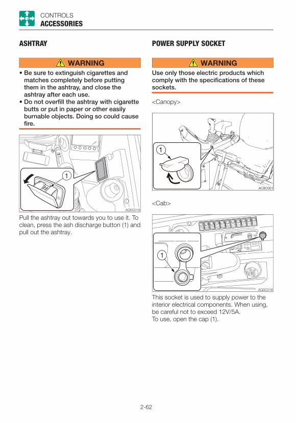
2-62
CONTROLSACCESSORIES
ASHTRAY
• Be sure to extinguish cigarettes and matches completely before putting them in the ashtray, and close the ashtray after each use.
• Do not overfill the ashtray with cigarette butts or put in paper or other easily burnable objects. Doing so could cause fire.
Pull the ashtray out towards you to use it. To clean, press the ash discharge button (1) and pull out the ashtray.
POWER SUPPLY SOCKET
Use only those electric products which comply with the specifications of these sockets.
<Canopy>
<Cab>
This socket is used to supply power to the interior electrical components. When using, be careful not to exceed 12V/5A.To use, open the cap (1).
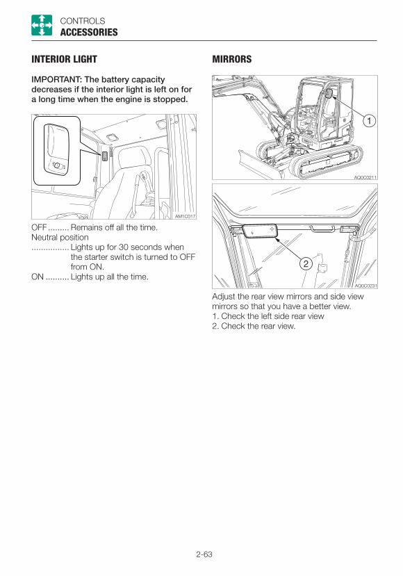
2-63
CONTROLS
INTERIOR LIGHT
IMPORTANT: The battery capacity decreases if the interior light is left on for a long time when the engine is stopped.
OFF ......... Remains off all the time.Neutral position................ Lights up for 30 seconds when
the starter switch is turned to OFF from ON.
ON .......... Lights up all the time.
ACCESSORIES
MIRRORS
Adjust the rear view mirrors and side view mirrors so that you have a better view.1. Check the left side rear view2. Check the rear view.

2-64
CONTROLSACCESSORIES
EXTERNAL POWER SOCKETS
Use only those electric products which comply with the specifications of these sockets.
For beacon
Use these sockets to connect the external power supply. When using, be careful not to exceed 12V/5A.To use, open the cap (1).

2-65
MEMO
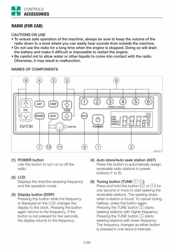
2-66
CONTROLSACCESSORIES
RADIO (FOR CAB)
CAUTIONS ON USE• To ensure safe operation of the machine, always be sure to keep the volume of the
radio down to a level where you can easily hear sounds from outside the machine.• Do not use the radio for a long time when the engine is stopped. Doing so will drain
the battery and make it difficult or impossible to restart the engine.• Be careful not to allow water or other liquids to come into contact with the radio.
Otherwise, it may result in malfunction.
NAMES OF COMPONENTS
(1) POWER button Use this button to turn on or off the
radio.
(2) LCD Displays the time/the receiving frequency
and the operation mode.
(3) Display button (DISP) Pressing this button while the frequency
is displayed on the LCD changes the display to the clock. Pressing the button again returns to the frequency. If the button is not pressed for five seconds, the display returns to the frequency.
(4) Auto store/Auto seek station (AST) Press this button to automatically assign
receivable radio stations to preset buttons (1 to 6).
(5) Tuning button (TUNE ) Press and hold this button ( or ) for
one second or more to start seeking the receivable stations. The seeking stops when a station is found. To cancel tuning halfway, press the button again.
Pressing the TUNE button starts seeking stations with higher frequency. Pressing the TUNE button starts seeking stations with lower frequency. The frequency changes as either button is pressed in one second intervals.

2-67
CONTROLS
(6) Preset buttons (1 to 6) (PRESET STATION)
Each button can store three FM stations (FM1, FM2, FM3) and one MW (AM) station. For how to set these buttons, refer to “Presetting stations”.
(7) Band button (BAND) Pressing this button changes the band
from FM1 to FM2, FM3 and MW (AM) in this order. The received band and its frequency appear on the display.
(8) VOL buttons Use these buttons to control the sound
volume. Press the button to increase the volume and the button to decrease the sound volume. Press and hold each button to continuously increase/decrease the volume.
(9) Clock zero set button (ZERO) Use this button to set the minute to “00”
when it is between “55” to “59” or “01” to “05”.
The LCD returns to the frequency display if no more operation is performed for five seconds.
(10) Auxiliary input select button (AUX) Pressing this button changes the input
source to the external device connected to the AUX-IN (11) jack. The display of “AUX” appears on the LCD. Pressing the button again returns to the radio.
ACCESSORIES
(11) Auxiliary input jack (AUX-IN) Use this jack to connect an external
audio source such as a portable music player. Pull off the rubber cap and connect the output terminal (headphone jack) of the portable player to the AUX-IN with the stereo mini-plug (3.5 mm) cord. Be sure that jack is closed with the rubber cap when not in use.
Playing the radio1. Turn the ignition key to the ACC or ON
position, and then press the power button (1) to turn on the radio.
2. Select the band, FM or MW (AM) by pressing the BAND button.
3. Select the station with the preset button or the tuning button, and adjust the volume with the volume button.
4. To turn off the radio, press the power button.
Selecting a station-auto selectPress and hold the TUNE button for one second or more to start seeking stations in the higher frequencies direction. Press and hold the TUNE button for one second or more to start seeking stations in the lower frequencies direction. The radio will stop seeking when it finds an receivable station and start playing.
Selecting a station-manual selectThe selection can be done manually. Press the tune button to seek stations with higher frequencies. Press the tune button to seek stations with lower frequencies.

2-68
CONTROLS
Presetting stations1. Press the BAND button to select a band
(MW (AM) or FM), and then select the station by pressing the TUNE button for seeking.
2. To assign the selected station to a preset button, press and hold the button to be assigned for one second or more. The number of the preset button appears on the LCD.
3. For more stations to preset, repeat the steps 1 and 2 above.• If the preset button on which a station
has been assigned is pressed and held for one second or more, the preset information will be modified.
• If the stored information is erased during battery replacement on the vehicle, assign the stations again to the preset buttons.
• Each preset button (1 to 6) can store three FM stations (one from each FM1, FM2, FM3) and one AM station.
Auto storing (AST)Press the AST button while playing the radio. The radio automatically starts seeking the receivable stations within the band currently selected and assign each preset button (1 to 6) a station.Note: The previous stations stored will be cleared (cancelled) by the auto storing. If the station stored in the preset button is not desirable, try to preset the station manually.
ACCESSORIES
Auxiliary input (AUX)• Connect a portable audio player and listen
to your favorite music.• Plug a patch cord (without resistor) into the
headphone jack of the audio player.• Plug a stereo mini plug (3.5 mm) into the
AUX-IN jack on the radio.• To listen to an external portable audio
player, press the AUX button. (The “AUX” display appears on the LCD and the frequency display is changed to the clock display.)
• To return to the radio, press the AUX button again.
• When connecting, adjust the sound volume level of the audio player so that it is same as that of the radio.
• Adjust the sound volume of the audio player by using the volume control buttons on the radio.
• Do not connect a device with a larger output compared with a portable audio player.
Setting the clock
• If a frequency is displayed on the LCD, press the AUX button (auxiliary input) to display the clock.
• Use the tune button to set the minute. Use the tune button to set the hour.
• To set the minute digits to “00” when they are from “55” to “59” or from “01” to “05”, press the ZERO button.
2-69
CONTROLS
ResettingIf there are any problems, such as the abnormal display of frequency or failure of selection, reset the radio by pressing the “4” button while pressing the AST button and the AUX button together. Then, “JP” and the clock display appear on the LCD, indicating that the radio is turned off. Note that the memory stored in the preset button is cleared.
Switching the volume mode when the radio is onSwitch the modes between SU and FI by pressing the (1) button while pressing the AST and AUX buttons together, when the radio is on.The SU or FI display appears on the LCD, followed by the radio turning off by itself.SU mode: .....The volume at power-off is
retained.FI mode: .......The volume at power-off is
reset.
ACCESSORIES
SPECIFICATIONSPower source: .... 12/24 VDC (negative
ground)Maximum power consumption:........................... 3A or less (at max. volume,
24 V)Maximum output power:........................... 16 W + 16 W (4Ω) (at 28.8
VDC input) 5W+5W (4Ω) (at 14.4 VDC
input)Rated output power:........................... 12 W + 12 W (10%
distortion, 4Ω) (at 28.8 VDC input)
3.5 W + 3.5 W (10% distortion, 4Ω) (at 14.4 VDC input)
Dimensions: ........ 178 (W) x 50 (H) x 65 (D) mm (excluding protrusions)
Receiving frequency:........................... MW (AM) 531 to 1602 kHz
(Europe, Asia), 530 to 1710 kHz (North, Central and South America)
FM 87.5 to 108 MHz (Europe, Asia), 87.9 to 108 MHz (North, Central and South America)
Practical sensitivity:........................... MW (AM) 32 dB or less
(S/N 20 dB) FM 12 dB or less (S/N 30
dB)S/N ratio: ............ MW (AM) 40 dB or more FM 50 dB or moreAUX-IN: .............. Stereo mini jack (3.5 mm);
rated input, 90 mV; 20 kΩ impedance
Note: Specifications and dimensions may be changed without notice.

2-70
CONTROLS
AUXILIARY HYDRAULIC LINES (IF EQUIPPED)
ACCESSORIES
Oil may spurt out if pipes disconnected before releasing the pressure in the hydraulic system.• Immediately after the engine is stopped
and while the safety lock lever is still in the unlock position, turn the starter switch to ON and press each auxiliary hydraulic switch several times to release the pressure from the auxiliary hydraulic circuit.
• Press the air breather button to relieve the tank pressure.
• When disconnecting hoses, stand to the side and loosen them slowly to gradually release the internal pressure before removing.
These lines deliver the hydraulic oil necessary for operating a hydraulic breaker, crusher or other attachments.
(1) .......First auxiliary hydraulic lines(2) .......Second auxiliary hydraulic lines(3) .......Third auxiliary hydraulic lines(4) .......Fourth auxiliary hydraulic lines
Stop valve(S) : Closed(O) : Open
2-71
CONTROLS
Connecting the hydraulic circuitsTo connect the attachment hydraulic lines, observe the following procedures:1. Release the pressure remaining in the
lines, and then close the stop valve. Refer to “Releasing the residual pressure”
on page 2-72.2. Remove the plugs.3. Connect the attachment hydraulic lines to
ports (a/c) and (b/d). When installing a hydraulic breaker, connect the supply circuit to the port (a) and the return circuit to port (b).
4. Open the stop valves. When installing a hydraulic breaker, open the selector valve (1).
Refer to “Selector valve” on page 2-73.5. When connecting is complete, purge air
from the hydraulic lines.a. Start the engine and run it at a low idle
speed with no load for 10 minutes.b. With the engine running in low idle,
operate the auxiliary hydraulic switches repeatedly (approx. 10 times) to purge air from the hydraulic lines.
c. Stop the engine and wait for at least 5 minutes until bubbles escape from the hydraulic oil in the tank.
IMPORTANT: Follow the procedures for purging air as instructed by the attachment manufacturer, if applicable.
6. Check for oil leaks.
Disconnecting the hydraulic circuits1. Release the pressure remaining in the
lines, and then close the stop valve. Refer to “Releasing the residual pressure”
on page 2-72.2. Disconnect the lines from the ports (a/c)
and (b/d).3. Install the plugs.
ACCESSORIES
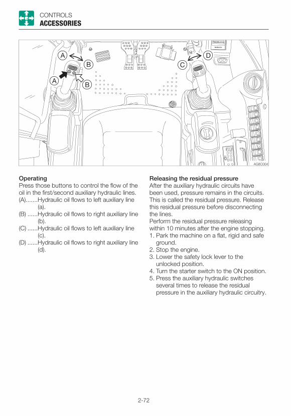
2-72
CONTROLS
OperatingPress those buttons to control the flow of the oil in the first/second auxiliary hydraulic lines.(A) .......Hydraulic oil flows to left auxiliary line
(a).(B) ......Hydraulic oil flows to right auxiliary line
(b).(C) ......Hydraulic oil flows to left auxiliary line
(c).(D) ......Hydraulic oil flows to right auxiliary line
(d).
Releasing the residual pressureAfter the auxiliary hydraulic circuits have been used, pressure remains in the circuits. This is called the residual pressure. Release this residual pressure before disconnecting the lines.Perform the residual pressure releasing within 10 minutes after the engine stopping.1. Park the machine on a flat, rigid and safe
ground.2. Stop the engine.3. Lower the safety lock lever to the
unlocked position.4. Turn the starter switch to the ON position.5. Press the auxiliary hydraulic switches
several times to release the residual pressure in the auxiliary hydraulic circuitry.
ACCESSORIES

2-73
CONTROLS
Selector valve
Open ....... When using a hydraulic breaker (1-way flow)
Closed ..... When using a reversible attachment (2-way flow)
Change the direction of the hydraulic oil flow by opening or closing the selector valve (1) inside the right side cover.For the machine with the auxiliary 1st auto tank switch, use the switch to select the flow.Refer to “Auxiliary 1st auto tank switch (If equipped)” on page 2-54.
ACCESSORIES
Third auxiliary hydraulic switch and button (If equipped)
The auxiliary 3rd is mainly used for the attachment that can quickly connect/disconnect the bucket. After the engine is started, hydraulic oil constantly flows into the pipe (e). This allows the pressure in the (e) side to increase, preventing the pin inserted on the bucket from coming out. If the pressure in the (e) side drops, the warning lamp starts flashing to warn that the bucket may come out. For a safety reason, the bucket can be disconnected only when the button (1) and the switch (2) are pressed at the same time. When they are pressed, the hydraulic oil flows into the line (f) to increase the pressure there. As the result, the pin on the bucket comes out and the bucket is removed from the machine.
• Bleeder unit for simultaneous use with the auxiliary 1st and 2nd (if equipped)
Pressing both the auxiliary 3rd button (1) and the switch (2) makes it possible to release internal pressure from the auxiliary 3rd (e side), auxiliary 1st and auxiliary 2nd at the same time. (The pressure is kept drawn for six seconds after the button and the switch are released.) This enables faster attachment change.
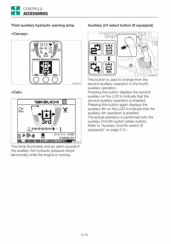
2-74
CONTROLS
Auxiliary 2/4 select button (If equipped)
This button is used to change from the second auxiliary operation to the fourth auxiliary operation.Pressing this button displays the second auxiliary on the LCD to indicate that the second auxiliary operation is enabled. Pressing this button again displays the auxiliary 4th on the LCD to indicate that the auxiliary 4th operation is enabled. The actual operation is performed with the auxiliary 2nd/4th switch (slider switch).Refer to “Auxiliary 2nd/4th switch (If equipped)” on page 2-51.
ACCESSORIES
Third auxiliary hydraulic warning lamp
<Canopy>
<Cab>
This lamp illuminates and an alarm sounds if the auxiliary 3rd hydraulic pressure drops abnormally while the engine is running.
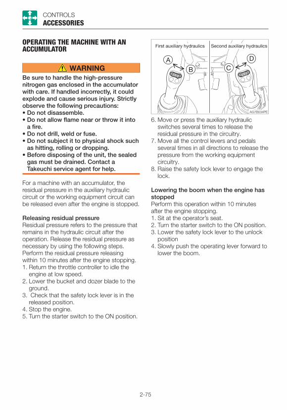
2-75
CONTROLS
OPERATING THE MACHINE WITH AN ACCUMULATOR
Be sure to handle the high-pressure nitrogen gas enclosed in the accumulator with care. If handled incorrectly, it could explode and cause serious injury. Strictly observe the following precautions:• Do not disassemble.• Do not allow flame near or throw it into
a fire.• Do not drill, weld or fuse.• Do not subject it to physical shock such
as hitting, rolling or dropping.• Before disposing of the unit, the sealed
gas must be drained. Contact a Takeuchi service agent for help.
For a machine with an accumulator, the residual pressure in the auxiliary hydraulic circuit or the working equipment circuit can be released even after the engine is stopped.
Releasing residual pressureResidual pressure refers to the pressure that remains in the hydraulic circuit after the operation. Release the residual pressure as necessary by using the following steps.Perform the residual pressure releasing within 10 minutes after the engine stopping.1. Return the throttle controller to idle the
engine at low speed.2. Lower the bucket and dozer blade to the
ground.3. Check that the safety lock lever is in the
released position.4. Stop the engine.5. Turn the starter switch to the ON position.
6. Move or press the auxiliary hydraulic switches several times to release the residual pressure in the circuitry.
7. Move all the control levers and pedals several times in all directions to release the pressure from the working equipment circuitry.
8. Raise the safety lock lever to engage the lock.
Lowering the boom when the engine has stoppedPerform this operation within 10 minutes after the engine stopping.1. Sit at the operator’s seat.2. Turn the starter switch to the ON position.3. Lower the safety lock lever to the unlock
position4. Slowly push the operating lever forward to
lower the boom.
ACCESSORIES

2-76
CONTROLS
LOAD SAFETY DEVICE (IF EQUIPPED)
The load safety devices include an emergency shut-off valve and an overload warning device.
Emergency shut-off valve
If the boom or arm stops due to the breakage of hose, immediately move away from the load being lifted and go to a safe location.
The emergency shut-off valve (1) prevents the boom or arm from falling rapidly in case the hydraulic hose is broken.
Boom
Arm (option)
If the hose breaks and the emergency shut-off valve (1) is activated to stop the operation of boom or arm, lower the boom or arm by slowly operating the lever while ensuring safety. Ask your sales or service dealer for repair.
ACCESSORIES
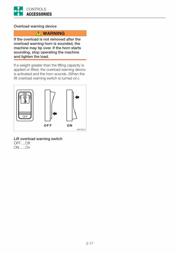
2-77
CONTROLS
Overload warning device
If the overload is not removed after the overload warning horn is sounded, the machine may tip over. If the horn starts sounding, stop operating the machine and lighten the load.
If a weight greater than the lifting capacity is applied or lifted, the overload warning device is activated and the horn sounds. (When the lift overload warning switch is turned on.)
Lift overload warning switchOFF ....OffON .....On
ACCESSORIES

2-78

3-1
OPERATION
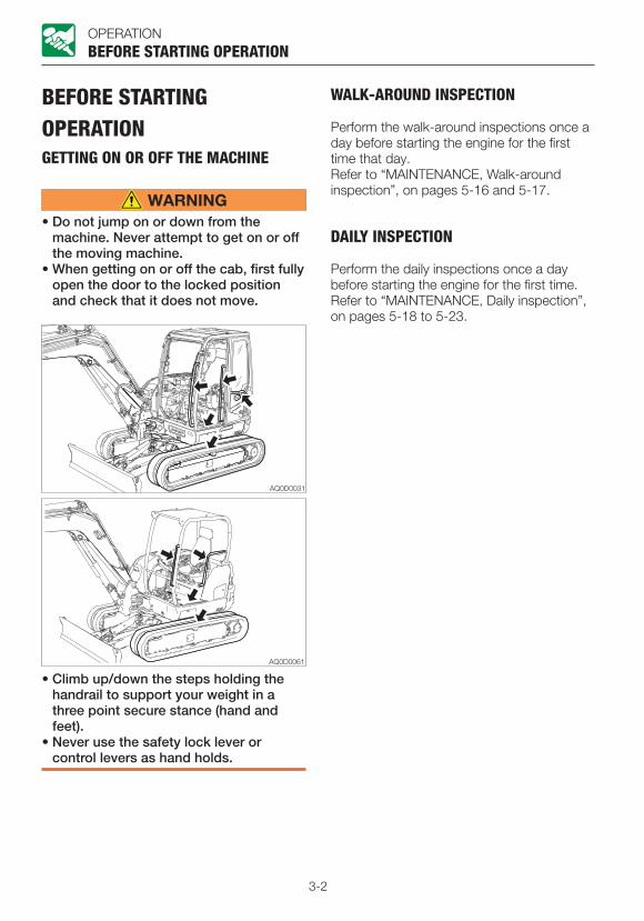
3-2
OPERATION
BEFORE STARTING OPERATIONGETTING ON OR OFF THE MACHINE
• Do not jump on or down from the machine. Never attempt to get on or off the moving machine.
• When getting on or off the cab, first fully open the door to the locked position and check that it does not move.
BEFORE STARTING OPERATION
• Climb up/down the steps holding the handrail to support your weight in a three point secure stance (hand and feet).
• Never use the safety lock lever or control levers as hand holds.
WALK-AROUND INSPECTION
Perform the walk-around inspections once a day before starting the engine for the first time that day.Refer to “MAINTENANCE, Walk-around inspection”, on pages 5-16 and 5-17.
DAILY INSPECTION
Perform the daily inspections once a day before starting the engine for the first time.Refer to “MAINTENANCE, Daily inspection”, on pages 5-18 to 5-23.

3-3
OPERATION
STARTING AND STOPPING THE ENGINEBEFORE STARTING THE ENGINE
1. Adjust the seat for a comfortable operating position.
2. Fasten the seat belt.
STARTING AND STOPPING THE ENGINE
3. Check that the safety lock lever is in the locked position.
4. Check that all levers and pedals are in the neutral position.
5. Insert the key into the starter switch, turn it to the ON position, then perform the following inspections:
<Canopy>
· All warning lamps flash and an alarm is sounded for two seconds. The meters also start functioning. After two seconds, the deceleration lamp (3) stops flashing and remains lit, while the battery charge warning lamp (1) and engine oil pressure warning lamp (2) remain flashing. (If the auxiliary 3rd is selected, it is also flashing.) The other lamps go out.
· Turn on the light switch to check that the boom light, front light and tail lamps turn on.
· Check the fuel level.
If a lamp does not light or the alarm is not sounded, the display or a wire may be damaged. Ask your sales or service dealer for repair.
<Cab>
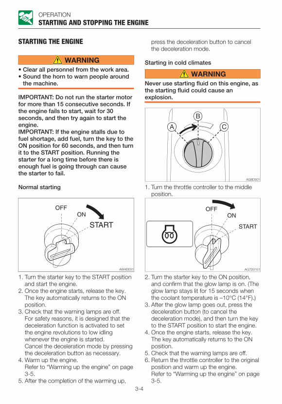
3-4
OPERATION
STARTING THE ENGINE
• Clear all personnel from the work area.• Sound the horn to warn people around
the machine.
IMPORTANT: Do not run the starter motor for more than 15 consecutive seconds. If the engine fails to start, wait for 30 seconds, and then try again to start the engine.IMPORTANT: If the engine stalls due to fuel shortage, add fuel, turn the key to the ON position for 60 seconds, and then turn it to the START position. Running the starter for a long time before there is enough fuel is going through can cause the starter to fail.
Normal starting
STARTING AND STOPPING THE ENGINE
1. Turn the starter key to the START position and start the engine.
2. Once the engine starts, release the key. The key automatically returns to the ON position.
3. Check that the warning lamps are off. For safety reasons, it is designed that the
deceleration function is activated to set the engine revolutions to low idling whenever the engine is started.
Cancel the deceleration mode by pressing the deceleration button as necessary.
4. Warm up the engine. Refer to “Warming up the engine” on page
3-5.5. After the completion of the warming up,
press the deceleration button to cancel the deceleration mode.
Starting in cold climates
Never use starting fluid on this engine, as the starting fluid could cause an explosion.
1. Turn the throttle controller to the middle position.
2. Turn the starter key to the ON position, and confirm that the glow lamp is on. (The glow lamp stays lit for 15 seconds when the coolant temperature is –10°C (14°F).)
3. After the glow lamp goes out, press the deceleration button (to cancel the deceleration mode), and then turn the key to the START position to start the engine.
4. Once the engine starts, release the key. The key automatically returns to the ON position.
5. Check that the warning lamps are off.6. Return the throttle controller to the original
position and warm up the engine. Refer to “Warming up the engine” on page
3-5.

3-5
OPERATION
WARMING UP THE ENGINE
IMPORTANT: Avoid racing the engine until it has warmed up.Do not warm up the engine for a long time (20 minutes or more). When idling is required, occasionally place a load or run the engine at medium speed.
1. Return the throttle controller, and then run at a low idle with no load for 5 minutes.
STARTING AND STOPPING THE ENGINE
STOPPING THE ENGINE
IMPORTANT: Do not stop the engine suddenly when operating with heavy loads or at the maximum speed. Doing so may cause the engine to overheat or seize. Never stop running the engine suddenly except in emergency.
1. Return the throttle controller.2. Idle the engine for about 5 minutes to
gradually let it cool.
3. Turn the starter key to the OFF position to stop the engine.

3-6
OPERATIONOPERATING THE MACHINE
OPERATING THE MACHINELEVER PATTERN (ISO PATTERN)
• Before starting operation, carefully check which lever pattern you are going to use.• It is described using the ISO pattern in this manual.
Left crawler forward Right crawler forward
Left crawler reverse Right crawler reverse
Arm out Boom lower
Arm in Boom raise
Upperstructure slew left Bucket load
Upperstructure slew right Bucket dump
Boom swing left Dozer blade lower
Boom swing right Dozer blade raise
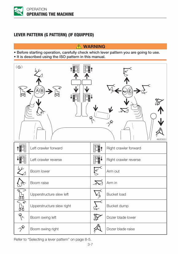
3-7
OPERATIONOPERATING THE MACHINE
LEVER PATTERN (G PATTERN) (IF EQUIPPED)
• Before starting operation, carefully check which lever pattern you are going to use.• It is described using the ISO pattern in this manual.
Left crawler forward Right crawler forward
Left crawler reverse Right crawler reverse
Boom lower Arm out
Boom raise Arm in
Upperstructure slew left Bucket load
Upperstructure slew right Bucket dump
Boom swing left Dozer blade lower
Boom swing right Dozer blade raise
Refer to “Selecting a lever pattern” on page 8-5.
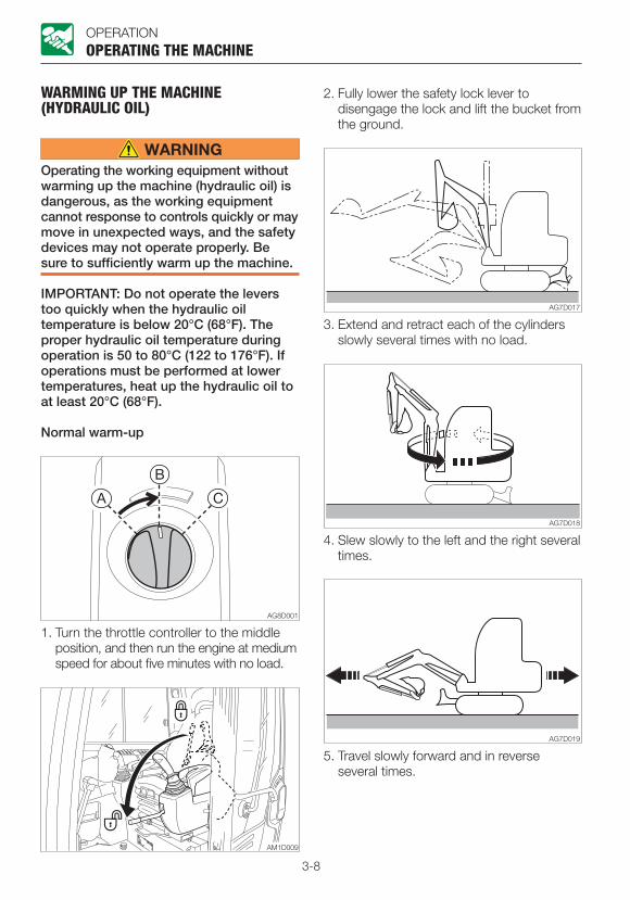
3-8
OPERATION
WARMING UP THE MACHINE (HYDRAULIC OIL)
Operating the working equipment without warming up the machine (hydraulic oil) is dangerous, as the working equipment cannot response to controls quickly or may move in unexpected ways, and the safety devices may not operate properly. Be sure to sufficiently warm up the machine.
IMPORTANT: Do not operate the levers too quickly when the hydraulic oil temperature is below 20°C (68°F). The proper hydraulic oil temperature during operation is 50 to 80°C (122 to 176°F). If operations must be performed at lower temperatures, heat up the hydraulic oil to at least 20°C (68°F).
Normal warm-up
OPERATING THE MACHINE
1. Turn the throttle controller to the middle position, and then run the engine at medium speed for about five minutes with no load.
2. Fully lower the safety lock lever to disengage the lock and lift the bucket from the ground.
3. Extend and retract each of the cylinders slowly several times with no load.
4. Slew slowly to the left and the right several times.
5. Travel slowly forward and in reverse several times.
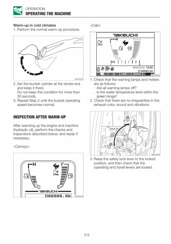
3-9
OPERATION
Warm-up in cold climates1. Perform the normal warm-up procedure.
OPERATING THE MACHINE
2. Set the bucket cylinder at the stroke end and keep it there.
Do not keep this condition for more than 30 seconds.
3. Repeat Step 2 until the bucket operating speed becomes normal.
INSPECTION AFTER WARM-UP
After warming up the engine and machine (hydraulic oil), perform the checks and inspections described below, and repair if necessary.
<Canopy>
1. Check that the warning lamps and meters are as follows:· Are all warning lamps off?· Is the water temperature level within the
green range?2. Check that there are no irregularities in the
exhaust color, sound and vibrations.
3. Raise the safety lock lever to the locked position, and then check that the operating and travel levers are locked.
<Cab>
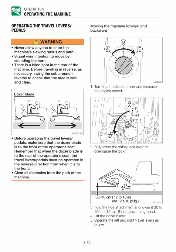
3-10
OPERATION
OPERATING THE TRAVEL LEVERS/PEDALS
• Never allow anyone to enter the machine’s slewing radius and path.
• Signal your intention to move by sounding the horn.
• There is a blind spot in the rear of the machine. Before traveling in reverse, as necessary, swing the cab around in reverse to check that the area is safe and clear.
OPERATING THE MACHINE
• Before operating the travel levers/pedals, make sure that the dozer blade is to the front of the operator’s seat. Remember that when the dozer blade is to the rear of the operator’s seat, the travel levers/pedals must be operated in the reverse direction from when it is to the front.
• Clear all obstacles from the path of the machine.
1. Turn the throttle controller and increase the engine speed.
2. Fully lower the safety lock lever to disengage the lock.
3. Fold the hoe attachment and lower it 30 to 40 cm (12 to 16 in.) above the ground.
4. Lift the dozer blade.5. Operate the left and right travel levers as
below.
Moving the machine forward and backward
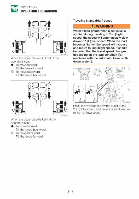
3-11
OPERATION
When the dozer blade is in front of the operator’s seat:
To move forward: Tilt the levers forward.
To move backward: Tilt the levers backward.
OPERATING THE MACHINE
When the dozer blade is behind the operator’s seat:
To move forward: Tilt the levers backward.
To move backward: Tilt the levers forward.
Traveling in 2nd (High) speed
When a load greater than a set value is applied during traveling in 2nd (high) speed, the speed will automatically slow down to 1st (low) speed. When the load becomes lighter, the speed will increase and return to 2nd (high) speed. It should be noted that the travel speed changes depending on the load condition (for machines with the automatic travel shift-down system).
Press the travel speed switch to set to the 2nd (high) speed, and press it again to return to the 1st (low) speed.
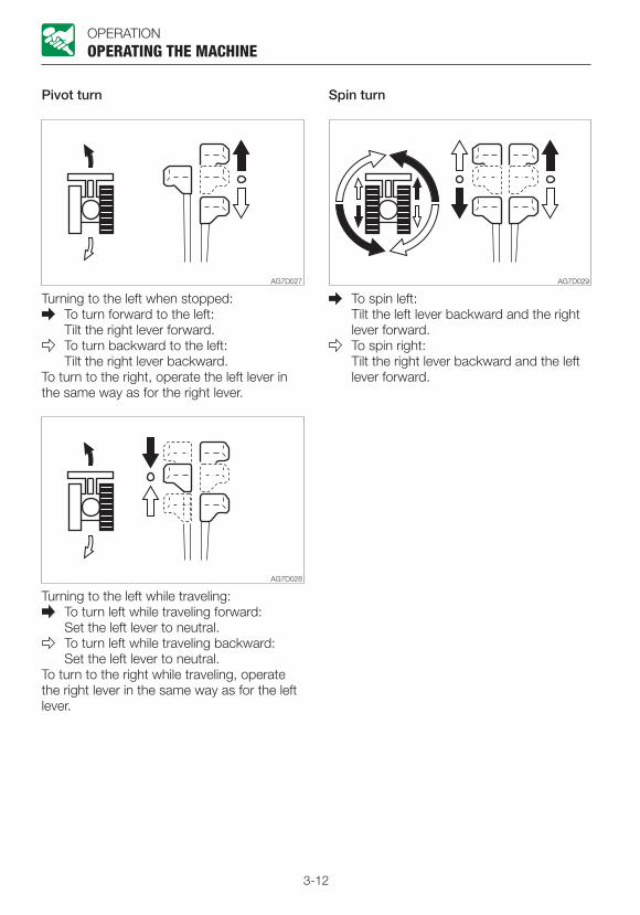
3-12
OPERATION
Pivot turn
Turning to the left when stopped: To turn forward to the left:
Tilt the right lever forward. To turn backward to the left:
Tilt the right lever backward.To turn to the right, operate the left lever in the same way as for the right lever.
Turning to the left while traveling: To turn left while traveling forward:
Set the left lever to neutral. To turn left while traveling backward:
Set the left lever to neutral.To turn to the right while traveling, operate the right lever in the same way as for the left lever.
Spin turn
OPERATING THE MACHINE
To spin left: Tilt the left lever backward and the right
lever forward. To spin right:
Tilt the right lever backward and the left lever forward.
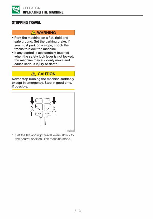
3-13
OPERATION
STOPPING TRAVEL
• Park the machine on a flat, rigid and safe ground. Set the parking brake. If you must park on a slope, chock the tracks to block the machine.
• If any control is accidentally touched when the safety lock lever is not locked, the machine may suddenly move and cause serious injury or death.
Never stop running the machine suddenly except in emergency. Stop in good time, if possible.
1. Set the left and right travel levers slowly to the neutral position. The machine stops.
OPERATING THE MACHINE

3-14
OPERATIONOPERATING THE MACHINE
OPERATING THE WORKING EQUIPMENT
• Before starting operation, carefully check which lever pattern you are going to use.
• It is described using the ISO pattern in this manual.
Use the right operating lever to operate the boom and bucket.Use the left operating lever to operate the arm and slewing.Return the operating levers to the neutral position to stop the hoe attachments.1. Lower the safety lock lever to the
unlocked position.2. Set the pedal cover to the unlocked
position.
Slewing
Check the surrounding area for safety before slewing.
Upperstructure slew left: Tilt the left operating lever to the left.
Upperstructure slew right: Tilt the left operating lever to the right.
Operating the boom
Boom lower: Tilt the right operating lever forward.
Boom raise: Tilt the right operating lever backward.

3-15
OPERATIONOPERATING THE MACHINE
Operating the arm
Arm in: Tilt the left operating lever backward.
Arm out: Tilt the left operating lever forward.
Operating the bucket
Bucket load: Tilt the right operating lever to the left.
Bucket dump: Tilt the right operating lever to the right.
Operating the boom swing
Boom swing left: Step on the left side of the pedal.
Boom swing right: Step on the right side of the pedal.
Operating the dozer blade
Dozer blade lower: Tilt the lever forward.
Dozer blade raise: Tilt the lever backward.

3-16
OPERATION
OPERATING PROCEDURESPROHIBITED OPERATIONS
• Do not operate on bedrock (hard or soft).
• Do not slew /swing while traveling. If you must operate the hoe attachment while traveling, operate at speeds slow enough so you have complete control at all times.
Do not perform demolition or leveling using slew force
OPERATING PROCEDURES
Do not demolish walls or level ground using slew force. Also, do not dig the bucket teeth into the ground during slewing. Doing so will damage the hoe attachment.
Do not dig while traveling
Do not dig the bucket into the ground and use the traveling force to dig.
Be gentle when using the hydraulic cylinder
Do not extend the hydraulic cylinders to the stroke ends. Operate them with leeway.
Do not support the machine body with the hoe attachment when the body is lowering with the arm cylinder fully extended. Doing so concentrates the load on the arm cylinder and could damage the arm cylinder.

3-17
OPERATION
Do not drive piles with the bucket or dig by banging the bucket
OPERATING PROCEDURES
Doing so will shorten the service life of the hoe attachment. Use the hydraulic force to dig.
Do not perform operations using the machine’s dropping force
Putting excessive strain on the machine will shorten its service life. When digging, use the hydraulic force of the cylinders and the shallow and long strokes.
Digging bedrock
For hard base rock, break the rock up into small pieces with a breaker, etc., before digging. This prevents damage to the machine and is thus more economical in the end.
Caution on exposing the dozer blade to shocks
Hitting the dozer blade against rocks, etc., could damage the dozer blade or the blade cylinder.
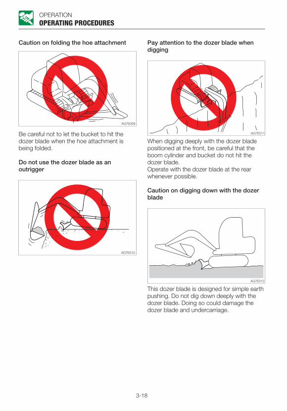
3-18
OPERATION
Caution on folding the hoe attachment
OPERATING PROCEDURES
Be careful not to let the bucket to hit the dozer blade when the hoe attachment is being folded.
Do not use the dozer blade as an outrigger
Pay attention to the dozer blade when digging
When digging deeply with the dozer blade positioned at the front, be careful that the boom cylinder and bucket do not hit the dozer blade.Operate with the dozer blade at the rear whenever possible.
Caution on digging down with the dozer blade
This dozer blade is designed for simple earth pushing. Do not dig down deeply with the dozer blade. Doing so could damage the dozer blade and undercarriage.

3-19
OPERATION
CAUTIONS ON OPERATING
Cautions on traveling
OPERATING PROCEDURES
Traveling over obstacles (rocks, stumps, etc.) may put a great load on the machine body and may cause damage to it. Avoid crossing over obstacles whenever possible. If you must do so, keep the hoe attachment near the ground, travel at a low speed, and go over the obstacle at the center of the crawler.
Cautions on traveling in 2nd (High) speed
• On uneven ground, maintain the low speed and avoid starting, stopping or changing directions abruptly.
• When a load greater than a set value is applied during traveling in 2nd (high) speed, the speed will automatically slow down to 1st (low) speed. When the load becomes lighter, the speed will increase and return to 2nd (high) speed. It should be noted that the travel speed changes depending on the load condition. (for machines with the automatic travel shift-down system)
• When traveling in 2nd speed, do so with the dozer blade at the front.
Cautions on using machine in water
If the rear of the machine is submerged in water as shown in the figure above, it causes the radiator fan to turn in water, resulting in damage to the fan. The rear of the machine must not be submerged.
• Allowable water depth Use the machine in water only when the
water is up to the bottom of the carrier roller (1).
• For those parts used in water for a long time, apply enough grease until the old grease is expelled.
• Never submerge the slew bearing or main body in water or sand. If submerged, contact a Takeuchi service agent for inspection.

3-20
OPERATION
CAUTIONS ON TRAVELING ON SLOPES
• Never travel on slopes that are too steep for the machine to maintain its stability. (maximum gradeability: 30°, lateral tipping angle: 15°) Note that in reality, the machine’s stability becomes lower than the above values depending on the working condition.
• When traveling on slopes, lower the bucket to a height of 20 to 30 cm (8 to 12 in.) above the ground. When climbing a steep slope, extend the hoe attachment to the front. In emergencies, lower the bucket to the ground and stop the machine.
• When traveling on slopes or grades, drive slowly in 1st (low) speed.
• When climbing a hill, keep the operator’s seat facing the hillside. When descending a hill, keep the operator’s seat facing the downhill direction. In either case, travel must be done while paying attention to the ground in front of the machine.
• Do not descend slopes in reverse.
OPERATING PROCEDURES
• Do not change directions on slopes or traverse slopes. First return to a flat surface, and then take an alternative path.
• The machine may slip sideways even on a slight slope if they are covered with grass or dead leaves, or when traveling on a wet metal plate or frozen surfaces. Do not allow the machine to position sideways to slopes.
Traveling posture on slopesClimbing slopes
When climbing slopes of 15° or more, maintain the machine posture as shown in the figure above.
Descending slopes
When descending slopes of 15° or more, slow down the engine speed and maintain the machine posture as shown in the figure above.
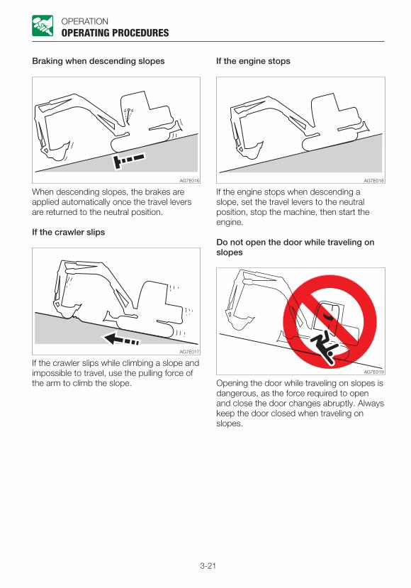
3-21
OPERATION
Braking when descending slopes
When descending slopes, the brakes are applied automatically once the travel levers are returned to the neutral position.
If the crawler slips
If the crawler slips while climbing a slope and impossible to travel, use the pulling force of the arm to climb the slope.
OPERATING PROCEDURES
If the engine stops when descending a slope, set the travel levers to the neutral position, stop the machine, then start the engine.
Do not open the door while traveling on slopes
If the engine stops
Opening the door while traveling on slopes is dangerous, as the force required to open and close the door changes abruptly. Always keep the door closed when traveling on slopes.

3-22
OPERATION
GETTING OUT OF MUD
If the machine gets stuck in mud, use the procedure below to get it out.
If one crawler is stuck
OPERATING PROCEDURES
1. Swing the bucket to the side of the crawler being stuck.
2. Set the arm and boom to an angle of 90 to 110°.
3. Press the bottom of the bucket (not the teeth) against the ground.
4. Place a plank or the like under the lifted crawler.
5. Lift the bucket and slowly move the machine out of the mud.
If both crawlers are stuck
1. Perform the steps 1 to 4 above for both crawlers.
2. Dig the bucket into the ground in front of the machine.
3. Pull with the arm while traveling forward to slowly move the machine out.
OPERATIONS POSSIBLE WITH THIS MACHINE
Excavating
1. Set the dozer blade on the side opposite to the side you want to dig on.
2. Use the arm and bucket and dig with shallow, long strokes. The maximum digging force can be obtained when the boom and arm angle is 80 to 120°. Use this angle for effective digging.
Digging ditches
Install a bucket suited for digging ditches and set the crawlers parallel to the ditch to be dug for greater efficiency.When digging wide ditches, dig the sides first, and then dig the center.
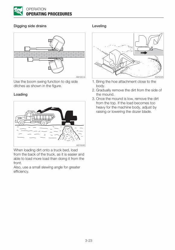
3-23
OPERATION
Digging side drains
OPERATING PROCEDURES
Use the boom swing function to dig side ditches as shown in the figure.
Loading
When loading dirt onto a truck bed, load from the back of the truck, as it is easier and able to load more load than doing it from the front.Also, use a small slewing angle for greater efficiency.
Leveling
1. Bring the hoe attachment close to the body.
2. Gradually remove the dirt from the side of the mound.
3. Once the mound is low, remove the dirt from the top. If the load becomes too heavy for the machine body, adjust by raising or lowering the dozer blade.
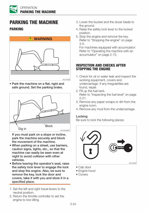
3-24
OPERATION
PARKING THE MACHINEPARKING
PARKING THE MACHINE
• Park the machine on a flat, rigid and safe ground. Set the parking brake.
If you must park on a slope or incline, park the machine securely and block the movement of the machine.
• When parking on a street, use barriers, caution signs, lights, etc., so that the machine can easily be seen even at night to avoid collision with other vehicles.
• Before leaving the operator’s seat, raise the safety lock lever to engage the lock and stop the engine. Also, be sure to remove the key, lock the door and covers, take it with you and store it in a specified place.
1. Set the left and right travel levers to the neutral position.
2. Return the throttle controller to set the engine to low idling.
3. Lower the bucket and the dozer blade to the ground.
4. Raise the safety lock lever to the locked position.
5. Stop the engine and remove the key. Refer to “Stopping the engine” on page
3-5. For machines equipped with accumulator: Refer to “Operating the machine with an
accumulator” on page 2-75.
INSPECTION AND CHECKS AFTER STOPPING THE ENGINE
1. Check for oil or water leak and inspect the working equipment, covers and undercarriage. If any irregularities are found, repair.
2. Fill up the fuel tank. Refer to “Inspecting the fuel level” on page
5-21.3. Remove any paper scraps or dirt from the
engine room.4. Remove any mud from the undercarriage.
LockingBe sure to lock the following places:
• Cab door• Engine hood• Covers

3-25
OPERATION
HANDLING IN COLD CLIMATESPREPARING FOR COLD CLIMATES
Starting engine in cold climates is not easy, and it becomes more difficult if the coolant freezes. Prepare for cold-climate problems as follows.
Replacing the fuel and lubricant Replace the hydraulic oil, engine oil and fuel with those intended for cold climates.Refer to “Fuel and lubricant table” on page 5-4.
Engine coolant
The engine coolant is combustible. Keep away from flame.Use long-life coolant (antifreeze) and tap water for the engine coolant.
Note: New machines are delivered with JIS Type 2 long-life coolant (antifreeze) at a concentration of 50%.Refer to “Fuel and lubricant table” on page 5-4.
BatteryAs the temperature drops, the battery performance decreases.Inspect the battery. If it is discharging, contact a Takeuchi service agent to have the battery recharged.Refer to “Inspecting the battery” on page 5-32.
HANDLING IN COLD CLIMATES
CAUTIONS AFTER OPERATIONS
Observe the following cautions to prevent mud, water, or the undercarriage from freezing and making it impossible for the machine to move.• Remove all mud and water from the
machine body. In particular, wipe the hydraulic cylinder rod clean to prevent damage to the seal caused by mud or dirt on the rod surface getting inside the seal together with drops of water.
• Park the machine on hard and dry ground. If this is impossible, park the machine on a wooden board placed on ground.
• Drain any water in the fuel tank to prevent it from freezing.
Refer to “Draining the water from the fuel tank” on page 5-31.
• As the battery capacity drops markedly in low temperatures, cover the battery or remove it from the machine and keep it in a warm place.
If the electrolyte level is low, add distilled water in the morning before beginning work. To prevent the battery electrolyte from freezing in the night, do not add water after the day’s work.
AFTER THE COLD CLIMATE
When the climate becomes warmer, do as follows:• Replace the fuel and oil for all parts with
those specified in the “Fuel and lubricant table”.
Refer to “Fuel and lubricant table” on page 5-4.
• If a coolant of “one season type” is used, drain the cooling system completely, clean out the inside of the cooling system thoroughly, and fill with tap water.
Refer to “Cleaning the engine cooling system” on page 5-43.
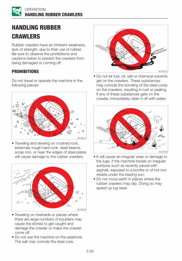
3-26
OPERATION
HANDLING RUBBER CRAWLERSRubber crawlers have an inherent weakness, lack of strength, due to their use of rubber. Be sure to observe the prohibitions and cautions below to prevent the crawlers from being damaged or coming off.
PROHIBITIONS
Do not travel or operate the machine in the following places:
HANDLING RUBBER CRAWLERS
• Traveling and slewing on crushed rock, extremely rough hard rock, steel beams, scrap iron, or near the edges of steel plates will cause damage to the rubber crawlers.
• Traveling on riverbeds or places where there are large numbers of boulders may cause the stones to get caught and damage the crawler or make the crawler come off.
• Do not use the machine on the seashore. The salt may corrode the steel core.
• Do not let fuel, oil, salt or chemical solvents get on the crawlers. These substances may corrode the bonding of the steel cores on the crawlers, resulting in rust or peeling. If any of these substances gets on the crawler, immediately clean it off with water.
• It will cause an irregular wear or damage to the lugs, if the machine travels on irregular surfaces such as recently paved with asphalt, exposed to a bonfire or of hot iron sheets under the blazing sun.
• Do not move earth in places where the rubber crawlers may slip. Doing so may speed up lug wear.
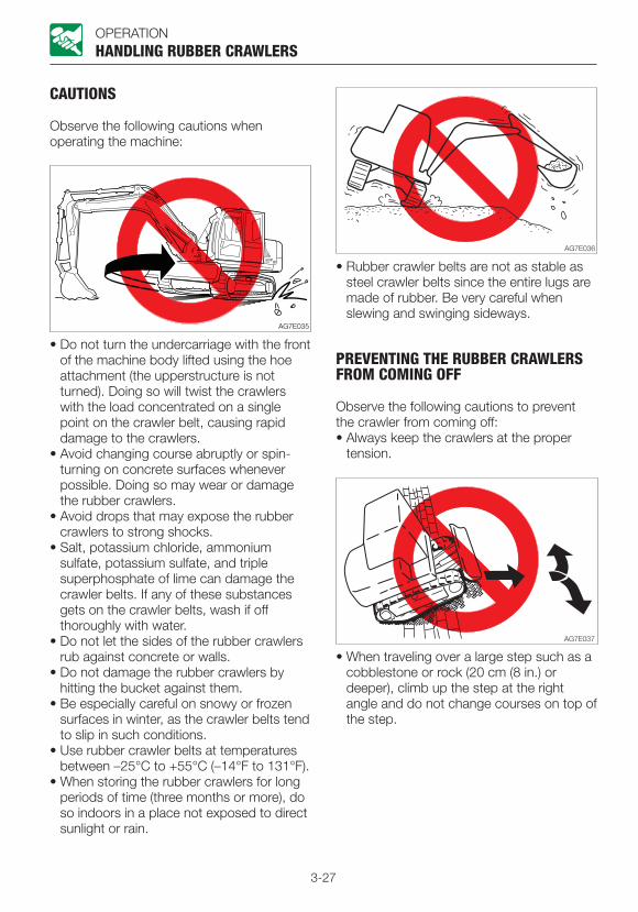
3-27
OPERATION
CAUTIONS
Observe the following cautions when operating the machine:
HANDLING RUBBER CRAWLERS
• Do not turn the undercarriage with the front of the machine body lifted using the hoe attachment (the upperstructure is not turned). Doing so will twist the crawlers with the load concentrated on a single point on the crawler belt, causing rapid damage to the crawlers.
• Avoid changing course abruptly or spin-turning on concrete surfaces whenever possible. Doing so may wear or damage the rubber crawlers.
• Avoid drops that may expose the rubber crawlers to strong shocks.
• Salt, potassium chloride, ammonium sulfate, potassium sulfate, and triple superphosphate of lime can damage the crawler belts. If any of these substances gets on the crawler belts, wash if off thoroughly with water.
• Do not let the sides of the rubber crawlers rub against concrete or walls.
• Do not damage the rubber crawlers by hitting the bucket against them.
• Be especially careful on snowy or frozen surfaces in winter, as the crawler belts tend to slip in such conditions.
• Use rubber crawler belts at temperatures between –25°C to +55°C (–14°F to 131°F).
• When storing the rubber crawlers for long periods of time (three months or more), do so indoors in a place not exposed to direct sunlight or rain.
• Rubber crawler belts are not as stable as steel crawler belts since the entire lugs are made of rubber. Be very careful when slewing and swinging sideways.
PREVENTING THE RUBBER CRAWLERS FROM COMING OFF
Observe the following cautions to prevent the crawler from coming off:• Always keep the crawlers at the proper
tension.
• When traveling over a large step such as a cobblestone or rock (20 cm (8 in.) or deeper), climb up the step at the right angle and do not change courses on top of the step.

3-28
OPERATION
• When climbing in reverse, do not change directions at the point where the slope starts.
• Avoid traveling by setting one crawler on a slope or projecting portion and the other crawler on a flat surface (with the machine at a tilt of 10° or more). Travel with both crawlers set on flat surfaces.
• Do not change directions when the crawler belts are slack as shown in the figure.
• The rubber crawler belts will come off if the machine travels backward in this condition.
• The rubber crawler belts will come off if the machine turns in this condition.
HANDLING RUBBER CRAWLERS

4-1
TRANSPORT
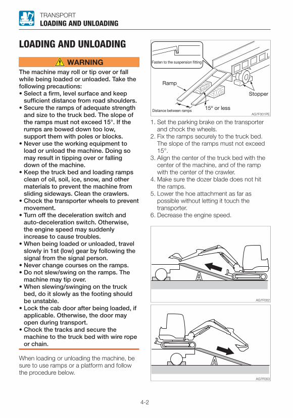
4-2
TRANSPORT
LOADING AND UNLOADING
The machine may roll or tip over or fall while being loaded or unloaded. Take the following precautions:• Select a firm, level surface and keep
sufficient distance from road shoulders.• Secure the ramps of adequate strength
and size to the truck bed. The slope of the ramps must not exceed 15°. If the rumps are bowed down too low, support them with poles or blocks.
• Never use the working equipment to load or unload the machine. Doing so may result in tipping over or falling down of the machine.
• Keep the truck bed and loading ramps clean of oil, soil, ice, snow, and other materials to prevent the machine from sliding sideways. Clean the crawlers.
• Chock the transporter wheels to prevent movement.
• Turn off the deceleration switch and auto-deceleration switch. Otherwise, the engine speed may suddenly increase to cause troubles.
• When being loaded or unloaded, travel slowly in 1st (low) gear by following the signal from the signal person.
• Never change courses on the ramps.• Do not slew/swing on the ramps. The
machine may tip over.• When slewing/swinging on the truck
bed, do it slowly as the footing should be unstable.
• Lock the cab door after being loaded, if applicable. Otherwise, the door may open during transport.
• Chock the tracks and secure the machine to the truck bed with wire rope or chain.
When loading or unloading the machine, be sure to use ramps or a platform and follow the procedure below.
LOADING AND UNLOADING
1. Set the parking brake on the transporter and chock the wheels.
2. Fix the ramps securely to the truck bed. The slope of the ramps must not exceed 15°.
3. Align the center of the truck bed with the center of the machine, and of the ramp with the center of the crawler.
4. Make sure the dozer blade does not hit the ramps.
5. Lower the hoe attachment as far as possible without letting it touch the transporter.
6. Decrease the engine speed.

4-3
TRANSPORT
7. Drive the machine straight toward the ramps and travel up or down the ramps at 1st (low) speed, by following the signal from the signal person.
8. Load the machine at the specified position on the transporter.
Refer to “Transporting posture” on page 4-6.
LOADING AND UNLOADING
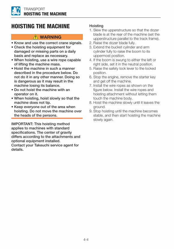
4-4
TRANSPORT
HOISTING THE MACHINE
• Know and use the correct crane signals.• Check the hoisting equipment for
damaged or missing parts on a daily basis and replace as necessary.
• When hoisting, use a wire rope capable of lifting the machine mass.
• Hoist the machine in such a manner described in the procedure below. Do not do it in any other manner. Doing so is dangerous as it may result in the machine losing its balance.
• Do not hoist the machine with an operator on it.
• When hoisting, hoist slowly so that the machine does not tip.
• Keep everyone out of the area when hoisting. Do not move the machine over the heads of the persons.
IMPORTANT: This hoisting method applies to machines with standard specifications. The center of gravity differs according to the attachments and optional equipment installed. Contact your Takeuchi service agent for details.
HOISTING THE MACHINE
Hoisting1. Slew the upperstructure so that the dozer
blade is at the rear of the machine (set the upperstructure parallel to the track frame).
2. Raise the dozer blade fully.3. Extend the bucket cylinder and arm
cylinder fully to raise the boom to its uppermost position.
4. If the boom is swung to either the left or right side, set it in the neutral position.
5. Raise the safety lock lever to the locked position.
6. Stop the engine, remove the starter key and get off the machine.
7. Install the wire ropes as shown on the figure below. Install the wire ropes and hoisting attachment without letting them touch the machine body.
8. Hoist the machine slowly until it leaves the ground.
9. Stop hoisting until the machine becomes stable, and then start hoisting the machine slowly again.
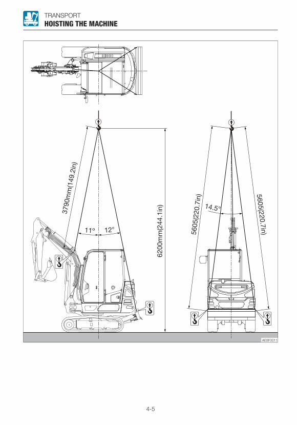
4-5
TRANSPORTHOISTING THE MACHINE

4-6
TRANSPORT
SECURING THE MACHINEAfter loading the machine at the specified position, secure it as described below.
Transporting posture
SECURING THE MACHINE
1. Lower the dozer blade.2. Extend the bucket cylinder and arm
cylinder fully, and then lower the boom.3. Raise the safety lock lever to the locked
position.4. Stop the engine, remove the starter key
and lock all locks.5. Place the stoppers (chocks) in front and
behind the crawlers.6. Install a chain or wire rope over the lower
frame of the machine and fasten it securely to prevent the machine from slipping sideways.
7. Secure the bucket with a chain or wire rope.
IMPORTANT: Place a wooden block under the bucket to protect the floor from damage caused by the bucket.
Precautions to be taken during transportation
• Know and follow the applicable safety rules, vehicle code and traffic laws when transporting the machine.
• Select the best transport route by considering the length, width, height and weight of the truck with the machine loaded on it.
• Never abruptly start or stop or run at a high speed at the sharp curves during transport. Doing so will move or lose the balance of the loaded machine.

5-1
MAINTENANCE

5-2
MAINTENANCE
GENERALMAINTENANCE OVERVIEW
To keep the machine in good condition and use if for a long period, perform the inspection and maintenance properly and safely following the procedures recommended by this manual.
The inspection and maintenance items are divided into groups according to the machine’s total operating time: every 10 hours (walk-around and daily inspection), every 50 hours, every 250 hours, etc. Refer to the hour meter readings to determine when to schedule an inspection and maintenance. Items for which it is not possible to determine the inspection and maintenance interval are included under “When Required”.
When operating the machine in extremely harsh environments (with high dust levels or high temperatures), inspection and maintenance should be performed earlier than the times specified on the Maintenance List.
GENERAL
CAUTIONS ON MAINTENANCE
Do not perform any other inspection and maintenance works than those listed in this manual.For works not listed in this manual, ask your sales or a service dealer for help.
Keep the machine clean• Clean the machine before performing
inspection and maintenance and try to keep it clean.
• Stop the engine before washing the machine. Cover the electrical parts so that water cannot enter. Water on electrical parts could cause short-circuits or malfunctions. Do not use water or steam to wash the battery, electronic control components, sensors, connectors or the operator’s compartment.
Fuel, lubricant and grease• Choose fuel, lubricant and grease by
following to the “Fuel and lubricant table”.• Use fuels, lubricants and greases which do
not contain water, and be careful to keep dirt out when changing or replenishing fuel, lubricant or grease.
• Store fuels, lubricants and greases in the prescribed places and in such a way that no water or dirt can get in them.
Cautions on refueling• If the port includes a strainer, do not
remove the strainer when fueling.• After fueling, be sure to securely tighten the
fuel filler cap.• Do not add more than the specified
amount of fuel.
Do not use fuel to clean partsDo not use fuel to clean parts. Use a non-combustible cleaning agent.
Keep dirt outWhen mounting and removing parts, do so in a place where there is no dust, clean the working area and the part, and keep dirt out.

5-3
MAINTENANCEGENERAL
Clean the installation surfacesWhen installing and removing parts, be sure that the surfaces of contact of the parts are clean. If the sealing grooves of the surface of contact are damaged, consult your sales or service dealer for repair or release.
Seals and split pins• Be sure to replace all seals and cotter pins
with new ones.• When installing, be careful not to damage
or twist the seal.
Sealing tape
• When wrapping the plug with sealing tape, remove any old sealing tape from the threads and clean the threads.
• Wrap the thread tight with seal tape starting 1 or 2 threads away from the thread end.
Disposing of wastes• Always collect oil that is drained from the
machine in containers. Improperly disposed waste oil can cause environmental harm.
• Follow appropriate laws and regulations when disposing of harmful objects such as oil, fuel, cooling water, coolant, filters and batteries.
Check after maintenance• Gradually increase the engine speed from a
low idle to maximum speed and check that there is no oil or water leaking from serviced parts.
• Operate each control lever and check that the machine is operating properly.
Cautions on handling of battery wiring• Disconnect the wiring from the both
terminals (+ and –) on the battery before working on the electrical system or doing electric welding.
Always disconnect it from the earth side (–). When connecting, connect the earth side last.
• Do not disconnect the battery wiring while the engine is moving. Otherwise, the electric circuits of the rotary converter or others may be damaged.
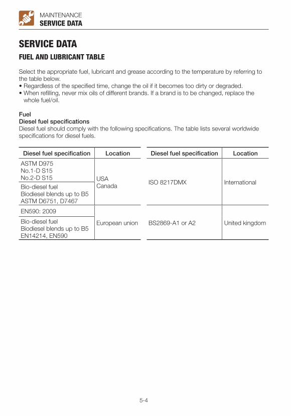
5-4
MAINTENANCE
SERVICE DATAFUEL AND LUBRICANT TABLE
Select the appropriate fuel, lubricant and grease according to the temperature by referring to the table below.• Regardless of the specified time, change the oil if it becomes too dirty or degraded.• When refilling, never mix oils of different brands. If a brand is to be changed, replace the
whole fuel/oil.
FuelDiesel fuel specificationsDiesel fuel should comply with the following specifications. The table lists several worldwide specifications for diesel fuels.
Diesel fuel specification Location Diesel fuel specification Location
ASTM D975 No.1-D S15No.2-D S15 USA
Canada ISO 8217DMX InternationalBio-diesel fuelBiodiesel blends up to B5ASTM D6751, D7467
EN590: 2009
European union BS2869-A1 or A2 United kingdomBio-diesel fuelBiodiesel blends up to B5EN14214, EN590
SERVICE DATA
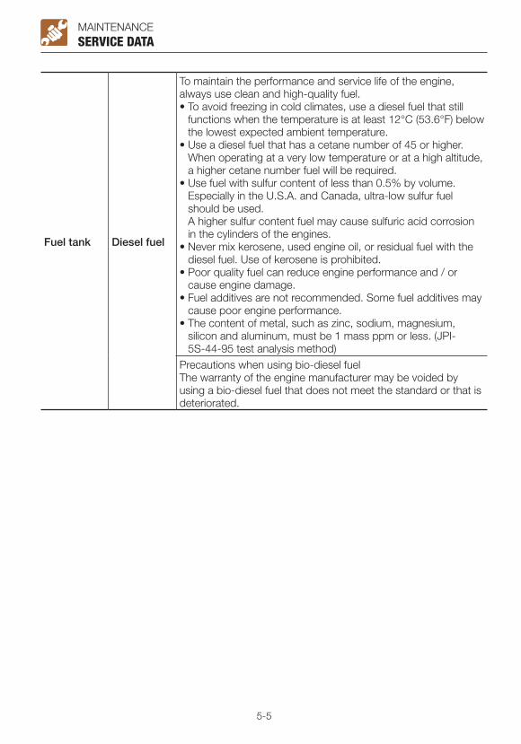
5-5
MAINTENANCESERVICE DATA
Fuel tank Diesel fuel
To maintain the performance and service life of the engine, always use clean and high-quality fuel.• To avoid freezing in cold climates, use a diesel fuel that still
functions when the temperature is at least 12°C (53.6°F) below the lowest expected ambient temperature.
• Use a diesel fuel that has a cetane number of 45 or higher. When operating at a very low temperature or at a high altitude, a higher cetane number fuel will be required.
• Use fuel with sulfur content of less than 0.5% by volume. Especially in the U.S.A. and Canada, ultra-low sulfur fuel
should be used. A higher sulfur content fuel may cause sulfuric acid corrosion
in the cylinders of the engines.• Never mix kerosene, used engine oil, or residual fuel with the
diesel fuel. Use of kerosene is prohibited.• Poor quality fuel can reduce engine performance and / or
cause engine damage.• Fuel additives are not recommended. Some fuel additives may
cause poor engine performance.• The content of metal, such as zinc, sodium, magnesium,
silicon and aluminum, must be 1 mass ppm or less. (JPI-5S-44-95 test analysis method)
Precautions when using bio-diesel fuelThe warranty of the engine manufacturer may be voided by using a bio-diesel fuel that does not meet the standard or that is deteriorated.
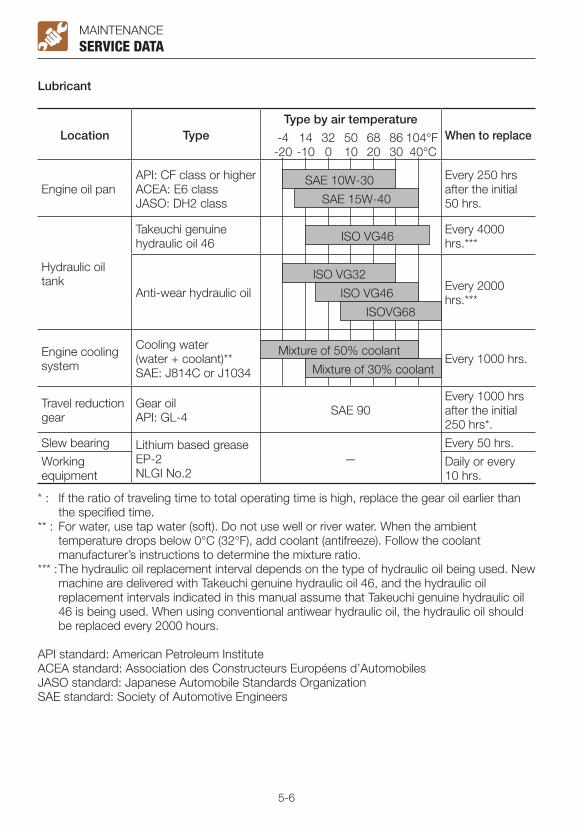
5-6
MAINTENANCESERVICE DATA
Lubricant
Location TypeType by air temperature
When to replace -4 14 32 50 68 86 104°F -20 -10 0 10 20 30 40°C
Engine oil panAPI: CF class or higherACEA: E6 classJASO: DH2 class
Every 250 hrs after the initial 50 hrs.
Hydraulic oil tank
Takeuchi genuine hydraulic oil 46
Every 4000 hrs.***
Anti-wear hydraulic oil Every 2000 hrs.***
Engine cooling system
Cooling water (water + coolant)**SAE: J814C or J1034
Every 1000 hrs.
Travel reduction gear
Gear oil API: GL-4 SAE 90
Every 1000 hrs after the initial 250 hrs*.
Slew bearing Lithium based grease EP-2NLGI No.2
—Every 50 hrs.
Working equipment
Daily or every 10 hrs.
* : If the ratio of traveling time to total operating time is high, replace the gear oil earlier than the specified time.
** : For water, use tap water (soft). Do not use well or river water. When the ambient temperature drops below 0°C (32°F), add coolant (antifreeze). Follow the coolant manufacturer’s instructions to determine the mixture ratio.
*** : The hydraulic oil replacement interval depends on the type of hydraulic oil being used. New machine are delivered with Takeuchi genuine hydraulic oil 46, and the hydraulic oil replacement intervals indicated in this manual assume that Takeuchi genuine hydraulic oil 46 is being used. When using conventional antiwear hydraulic oil, the hydraulic oil should be replaced every 2000 hours.
API standard: American Petroleum Institute ACEA standard: Association des Constructeurs Européens d’AutomobilesJASO standard: Japanese Automobile Standards OrganizationSAE standard: Society of Automotive Engineers
SAE 10W-30
SAE 15W-40
ISO VG46
ISO VG32
ISO VG46
ISOVG68
Mixture of 50% coolant
Mixture of 30% coolant

5-7
MAINTENANCESERVICE DATA
Volume
Engine oil pan Engine cooling system
Hydraulic oil tank Fuel tank Travel reduction
gearUpper limit4.7 L (5 US qt.)Lower limit 2.9 L (3.1 US qt.)
4 L (4.2 US qt.) System 56 L (14.8 US gal.)Tank 35 L (9.2 US gal.)
Level capacity46 L (12.2 US gal.)
0.5 L X 2(0.53 US qt.) X 2
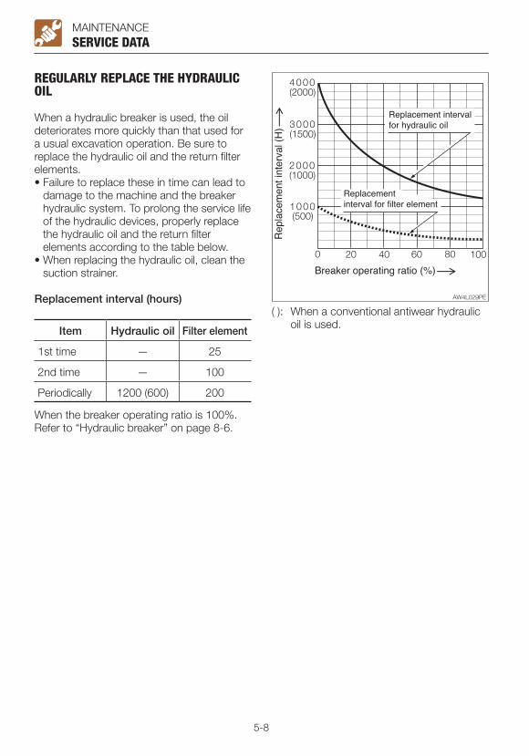
5-8
MAINTENANCESERVICE DATA
REGULARLY REPLACE THE HYDRAULIC OIL
When a hydraulic breaker is used, the oil deteriorates more quickly than that used for a usual excavation operation. Be sure to replace the hydraulic oil and the return filter elements.• Failure to replace these in time can lead to
damage to the machine and the breaker hydraulic system. To prolong the service life of the hydraulic devices, properly replace the hydraulic oil and the return filter elements according to the table below.
• When replacing the hydraulic oil, clean the suction strainer.
Replacement interval (hours)
Item Hydraulic oil Filter element
1st time — 25
2nd time — 100
Periodically 1200 (600) 200
( ): When a conventional antiwear hydraulic oil is used.
When the breaker operating ratio is 100%. Refer to “Hydraulic breaker” on page 8-6.

5-9
MAINTENANCE
LIST OF CONSUMABLES
Periodically replace consumables such as filters and elements according to the table below.
System Item Part name Part No. When to replace
Hydraulic system
Hydraulic oil return filter
Element
15511-03900 Every 1000 hrs after the initial 250 hrs.Pilot line filter 15512-00703
Air breather filter 15520-02715 Every 1000 hrs.
Engine lubrication system Engine oil filter Cartridge Y129150-35153 Every 250 hrs after
the initial 50 hrs.
Fuel system Fuel filter Cartridge Y129A00-55800 Every 500 hrs.
Air cleaner system Air cleaner
Primary (Outer) element Y129004-12520
Every 1000 hrs. or after 6 cleanings (whichever comes first)
Secondary (Inner) element 19111-02772
When the primary elements are replaced.
Heater system Filter Element 19115-13680Once a year or if clogging remains after cleaning
SERVICE DATA
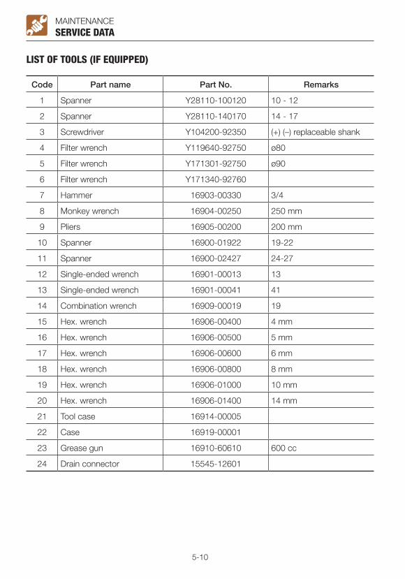
5-10
MAINTENANCE
LIST OF TOOLS (IF EQUIPPED)
Code Part name Part No. Remarks
1 Spanner Y28110-100120 10 - 12
2 Spanner Y28110-140170 14 - 17
3 Screwdriver Y104200-92350 (+) (–) replaceable shank
4 Filter wrench Y119640-92750 ø80
5 Filter wrench Y171301-92750 ø90
6 Filter wrench Y171340-92760
7 Hammer 16903-00330 3/4
8 Monkey wrench 16904-00250 250 mm
9 Pliers 16905-00200 200 mm
10 Spanner 16900-01922 19-22
11 Spanner 16900-02427 24-27
12 Single-ended wrench 16901-00013 13
13 Single-ended wrench 16901-00041 41
14 Combination wrench 16909-00019 19
15 Hex. wrench 16906-00400 4 mm
16 Hex. wrench 16906-00500 5 mm
17 Hex. wrench 16906-00600 6 mm
18 Hex. wrench 16906-00800 8 mm
19 Hex. wrench 16906-01000 10 mm
20 Hex. wrench 16906-01400 14 mm
21 Tool case 16914-00005
22 Case 16919-00001
23 Grease gun 16910-60610 600 cc
24 Drain connector 15545-12601
SERVICE DATA
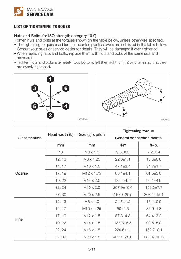
5-11
MAINTENANCE
LIST OF TIGHTENING TORQUES
Nuts and Bolts (for ISO strength category 10.9)Tighten nuts and bolts at the torques shown on the table below, unless otherwise specified.• The tightening torques used for the mounted plastic covers are not listed in the table below.
Consult your sales or service dealer for details. They will be damaged if over tightened. • When replacing nuts and bolts, replace them with nuts and bolts of the same size and
standards.• Tighten nuts and bolts alternately (top, bottom, left then right) or in 2 or 3 times so that they
are evenly tightened.
SERVICE DATA
ClassificationHead width (b) Size (a) x pitch
Tightening torque
General connection points
mm mm N·m ft-lb.
Coarse
10 M6 x 1.0 9.8±0.5 7.2±0.4
12, 13 M8 x 1.25 22.6±1.1 16.6±0.8
14, 17 M10 x 1.5 47.1±2.4 34.7±1.7
17, 19 M12 x 1.75 83.4±4.1 61.5±3.0
19, 22 M14 x 2.0 134.4±6.7 99.1±4.9
22, 24 M16 x 2.0 207.9±10.4 153.3±7.7
27, 30 M20 x 2.5 410.9±20.5 303.1±15.1
Fine
12, 13 M8 x 1.0 24.5±1.2 18.1±0.9
14, 17 M10 x 1.25 50±2.5 36.9±1.8
17, 19 M12 x 1.5 87.3±4.3 64.4±3.2
19, 22 M14 x 1.5 135.3±6.8 99.8±5.0
22, 24 M16 x 1.5 220.6±11 162.7±8.1
27, 30 M20 x 1.5 452.1±22.6 333.4±16.6

5-12
MAINTENANCE
SAFETY-CRITICAL PARTSTo use the machine safely, periodically perform inspection and maintenance. The safety-critical parts listed below must be periodically replaced for an increased safety.Serious injury or a fire could result if they are worn or damaged.
List of safety-critical parts
Unit Safety-critical parts to be replaced periodically When to replace
Fuel systemFuel hoses
Every 2 years
Packing on fuel filler cap
Heater Heater hoses
Hydraulic system
Main body
Hydraulic hoses (pump - delivery)
Hydraulic hoses (pump - suction)
Hydraulic hoses (slew motor)
Hydraulic hoses (travel motor)
Working equipment
Hydraulic hoses (boom cylinder piping)
Hydraulic hoses (arm cylinder piping)
Hydraulic hoses (bucket cylinder piping)
Hydraulic hoses (swing cylinder)
Hydraulic hoses (blade cylinder)
Hydraulic hoses (angle blade cylinder)
Hydraulic hoses (pilot valve)
Hydraulic hoses (auxiliary piping)
Seat belt Every 3 years
SAFETY-CRITICAL PARTS

5-13
MAINTENANCE
The material of the safety-critical part listed above tends to change over time and cause wear or deterioration. It is difficult to determine the degree of deterioration at the periodic inspection, and thus they need to be replaced with new ones after a certain time to maintain their proper performance even if they appear in good condition. Note that regardless of the replacement schedule, replacement must be performed immediately if a symptom of wear is found. If a hose clamp is deformed or cracked, replace it together with the hose immediately. When replacing the safety-critical parts, ask your sales or service dealer.In addition to the safety-critical parts, inspect the hydraulic hoses and retighten or replace as necessary. When replacing the hydraulic hoses, replace the O-rings and seals at the same time.Check the fuel and hydraulic hoses according to the periodic schedule described below.Refer to “Maintenance”.
Type of inspection Inspection item
Daily inspection Leakage from the connecting parts of hydraulic or fuel hosesDamage to cab or canopy - replace*
Monthly inspection Leakage from the connecting parts of hydraulic or fuel hosesDamaged hydraulic or fuel hoses (cracks, wear and tear)
Annual inspectionLeakage from the connecting parts of hydraulic or fuel hosesDeteriorated, twisted, damaged hydraulic or fuel hoses (cracks, wear and tear) or hoses in contact with other parts of the machine
SAFETY-CRITICAL PARTS
*: Canopy parts No. 05584-00085*: Cab parts No. 03586-00070

5-14
MAINTENANCE
MAINTENANCE LISTInspection and maintenance item Page
Walk-around inspection
Inspecting by opening the engine hood and covers 5-16
Inspecting by walking around the machine 5-17
Inspecting while sitting in the operator’s seat 5-17
Daily inspection (every 10 hours)
Inspecting and replenishing the coolant 5-18
Inspecting and replenishing the engine oil 5-19
Inspecting the water separator 5-20
Inspecting the fuel level 5-21
Inspecting the hydraulic oil tank level and replenishing 5-22
Lubricating the working equipment 5-23
After the initial 50 hours (only for new machines)
Replacing the engine oil and the oil filter 5-24
Inspecting and adjusting the fan belt 5-26
Every 50 hours
Inspecting and adjusting the crawler tension 5-28
Lubricating the slew bearing 5-30
Draining the water from the fuel tank 5-31
Inspecting the battery 5-32
Every 100 hours
Cleaning the water separator 5-34
After the initial 250 hours (only for new machines)
Replacing the hydraulic oil return filter 5-35
Replacing the pilot line filter 5-36
Replacing the travel motor gear oil* 5-37
Every 250 hours
Replacing the engine oil and the oil filter 5-38
Inspecting and adjusting the fan belt 5-38
Cleaning the air cleaner 5-38
Cleaning the radiator fins and the oil cooler fins 5-40
Cleaning the air filter (CAB) 5-41
Every 500 hours
Replacing the fuel filter 5-42
*: If the percentage of the traveling time within the total operating time is high, replace the gear oil earlier than the specified time.
MAINTENANCE LIST

5-15
MAINTENANCE
Inspection and maintenance item Page
Every 1000 hours
Replacing the hydraulic oil return filter 5-43
Replacing the pilot line filter 5-43
Replacing the travel motor gear oil * 5-43
Cleaning the engine cooling system 5-43
Replacing the air cleaner element 5-45
Replacing the air breather filter 5-46
Inspecting and adjusting the engine valve clearance 5-46
Every 1500 hours
Inspecting, cleaning and checking operation of the engine fuel injectors 5-47
Inspecting the crankcase breather system 5-47
Every 2000 hours
Lapping the engine valve seats (If necessary) 5-48
Every 3000 hours
Inspecting, cleaning and checking operation of the EGR valve 5-49
Every 4000 hours
Replacing the hydraulic oil and cleaning the suction strainer 5-50
When required
Replacing the bucket teeth and the side cutters 5-53
Replacing the bucket 5-56
Adjusting the gap between the bucket and arm (If equipped) 5-58
Inspecting and replenishing the windshield washer fluid 5-59
Lubricating the levers and pedals 5-60
Inspecting the rubber crawlers 5-61
Replacing the rubber crawlers 5-62
*: If the percentage of the traveling time within the total operating time is high, replace the gear oil earlier than the specified time.
MAINTENANCE LIST
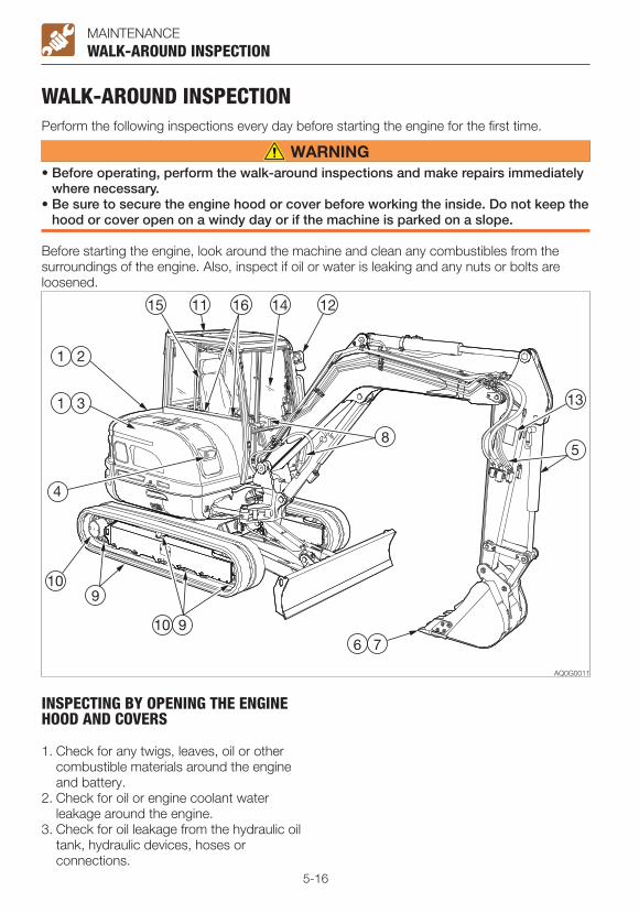
5-16
MAINTENANCE
WALK-AROUND INSPECTIONPerform the following inspections every day before starting the engine for the first time.
• Before operating, perform the walk-around inspections and make repairs immediately where necessary.
• Be sure to secure the engine hood or cover before working the inside. Do not keep the hood or cover open on a windy day or if the machine is parked on a slope.
Before starting the engine, look around the machine and clean any combustibles from the surroundings of the engine. Also, inspect if oil or water is leaking and any nuts or bolts are loosened.
WALK-AROUND INSPECTION
INSPECTING BY OPENING THE ENGINE HOOD AND COVERS
1. Check for any twigs, leaves, oil or other combustible materials around the engine and battery.
2. Check for oil or engine coolant water leakage around the engine.
3. Check for oil leakage from the hydraulic oil tank, hydraulic devices, hoses or connections.

5-17
MAINTENANCE
INSPECTING BY WALKING AROUND THE MACHINE
4. Check lights for dirt, damage and burnt out bulbs.
5. Check attachments and hoses for damage.
6. Check the bucket, bucket teeth and side cutter for wear, damage and looseness.
7. Check the hook, slip stopper and hook mount of buckets with hooks for damage. (Option)
8. Check the handrail, the steps and the slip-resistant surfaces for damage and loose bolts.
9. Check the crawlers, carrier rollers, track rollers, idlers and sprockets for damage, wear and loose bolts.
10. Check for oil leakage from the travel motor, carrier rollers, track rollers and idlers.
11. Check the cab and guard for damage and loose nuts and bolts.
12. Check the mirrors for dirt or damage, and adjust them.
13. Check the labels for dirt and damage.
WALK-AROUND INSPECTION
INSPECTING WHILE SITTING IN THE OPERATOR’S SEAT
14. Check the windshield for dirt or damage.15. Check the seat and seat belt for dirt or
damage. Check the operator’s seat for dirt, oil or
other combustible materials.16. Check the monitor, instruments and
switches for dirt or damage.
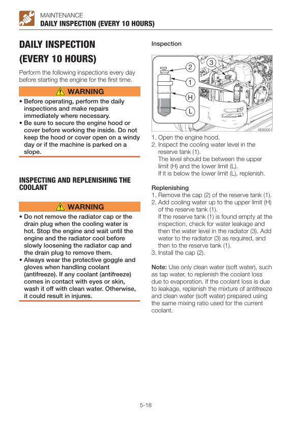
5-18
MAINTENANCE
DAILY INSPECTION (EVERY 10 HOURS)Perform the following inspections every day before starting the engine for the first time.
• Before operating, perform the daily inspections and make repairs immediately where necessary.
• Be sure to secure the engine hood or cover before working the inside. Do not keep the hood or cover open on a windy day or if the machine is parked on a slope.
INSPECTING AND REPLENISHING THE COOLANT
• Do not remove the radiator cap or the drain plug when the cooling water is hot. Stop the engine and wait until the engine and the radiator cool before slowly loosening the radiator cap and the drain plug to remove them.
• Always wear the protective goggle and gloves when handling coolant (antifreeze). If any coolant (antifreeze) comes in contact with eyes or skin, wash it off with clean water. Otherwise, it could result in injures.
DAILY INSPECTION (EVERY 10 HOURS)
Inspection
1. Open the engine hood.2. Inspect the cooling water level in the
reserve tank (1). The level should be between the upper
limit (H) and the lower limit (L). If it is below the lower limit (L), replenish.
Replenishing1. Remove the cap (2) of the reserve tank (1).2. Add cooling water up to the upper limit (H)
of the reserve tank (1). If the reserve tank (1) is found empty at the
inspection, check for water leakage and then the water level in the radiator (3). Add water to the radiator (3) as required, and then to the reserve tank (1).
3. Install the cap (2).
Note: Use only clean water (soft water), such as tap water, to replenish the coolant loss due to evaporation. If the coolant loss is due to leakage, replenish the mixture of antifreeze and clean water (soft water) prepared using the same mixing ratio used for the current coolant.

5-19
MAINTENANCE
INSPECTING AND REPLENISHING THE ENGINE OIL
Stop the engine and allow the machine to cool down before performing maintenance.
Inspection
DAILY INSPECTION (EVERY 10 HOURS)
1. Open the engine hood.2. Take out the dipstick (1) and wipe the oil
off with a rag.3. Fully reinsert the dipstick (1), and then pull
it back out.4. Check the oil on the dipstick (1). The level should be between the upper
limit (H) and the lower limit (L). If it is below the lower limit (L), replenish.
Replenishing1. Remove the oil filler cap (2).2. Add oil up to between the upper limit (H)
and the lower limit (L) of the dipstick (1). Problems could arise if the oil level is either
too low or too high.3. Tighten the oil filler cap (2).4. Start the engine, run it at low idle for about
5 minutes, then stop it.5. After about 10 to 20 minutes, inspect the
oil level.

5-20
MAINTENANCEDAILY INSPECTION (EVERY 10 HOURS)
INSPECTING THE WATER SEPARATOR
• Do not smoke or permit open flames while handling fuel or working on the fuel system.
• Stop the engine in a well-ventilated place and allow it to cool down before performing maintenance.
• Clean up spilled fuel immediately.
1. Open the engine hood.2. Check if there is water in the water
separator (1). If water collects in the separator, the float
(red ring) (6) goes up. Be sure to drain water before the float goes up to the element (5),
3. Loose the vent plug (8) and then the drain plug (7) to discharge water collected inside.
4. After drainage of water, tighten each plug and bleed air from the fuel system.
Refer to “Bleeding air from the fuel system” on page 6-9.
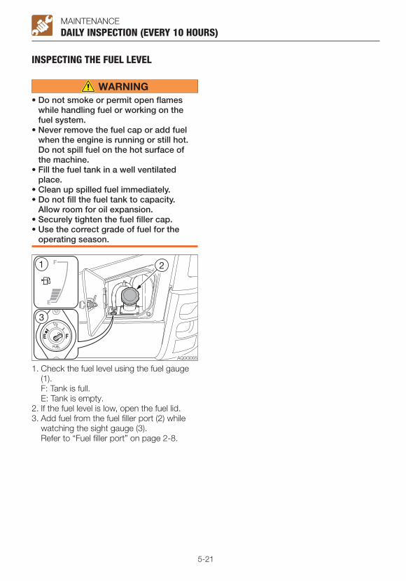
5-21
MAINTENANCE
INSPECTING THE FUEL LEVEL
• Do not smoke or permit open flames while handling fuel or working on the fuel system.
• Never remove the fuel cap or add fuel when the engine is running or still hot. Do not spill fuel on the hot surface of the machine.
• Fill the fuel tank in a well ventilated place.
• Clean up spilled fuel immediately.• Do not fill the fuel tank to capacity.
Allow room for oil expansion.• Securely tighten the fuel filler cap.• Use the correct grade of fuel for the
operating season.
DAILY INSPECTION (EVERY 10 HOURS)
1. Check the fuel level using the fuel gauge (1).
F: Tank is full. E: Tank is empty.2. If the fuel level is low, open the fuel lid.3. Add fuel from the fuel filler port (2) while
watching the sight gauge (3). Refer to “Fuel filler port” on page 2-8.

5-22
MAINTENANCE
INSPECTING THE HYDRAULIC OIL TANK LEVEL AND REPLENISHING
Oil may spurt out if caps or filters are removed or pipes are disconnected before releasing the pressure in the hydraulic system.• Press the air breather button to relieve
the internal pressure from the tank.
InspectionThe oil level changes with the oil temperature. Inspect the oil by maintaining the machine at posture shown in the figure at the next.• Machine posture for inspecting the
hydraulic oil level
DAILY INSPECTION (EVERY 10 HOURS)
1. Start the engine and run it at low speed.2. Fully retract the cylinders (arm and
bucket), and lower the bucket to the ground.
3. Lower the dozer blade, and then stop the engine.
4. Open the right side cover.5. Inspect the oil level using the sight gauge
(1).· When the oil temperature is about 20°C
(68°F): The level should be between the upper
limit (H) and the lower limit (L). If it is below the lower limit (L), replenish.· When the oil temperature is about 50 to
80°C (122 to 176°F): The level should be slightly below the
upper limit (H).
Replenishing
IMPORTANT: Do not fill up to the level higher than the upper limit (H). It will damage the hydraulic circuits or result in oil spurting. If accidentally done, stop the engine and wait the hydraulic oil to cool, and then let the excessive oil to drain from the drain plug.
1. Open the right side cover.2. Press the air breather button (2) to relieve
the internal pressure from the tank.3. Remove the plug (3).4. Add the hydraulic oil up to the middle
point of the sight gauge (1). 5. Tighten the plug (3).
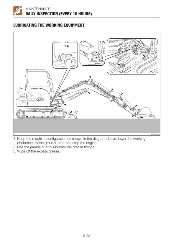
5-23
MAINTENANCE
LUBRICATING THE WORKING EQUIPMENT
1. Keep the machine configuration as shown in the diagram above, lower the working equipment to the ground, and then stop the engine.
2. Use the grease gun to lubricate the grease fittings.3. Wipe off the excess grease.
DAILY INSPECTION (EVERY 10 HOURS)
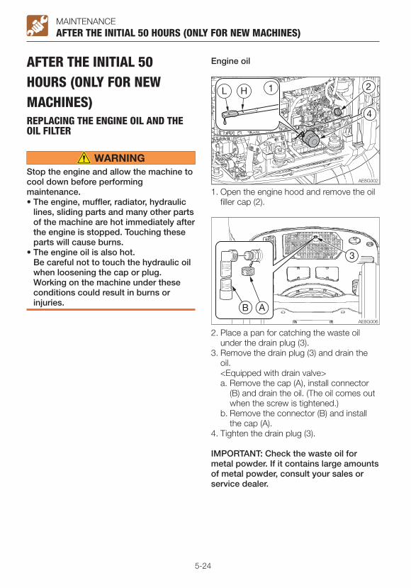
5-24
MAINTENANCE
AFTER THE INITIAL 50 HOURS (ONLY FOR NEW MACHINES)REPLACING THE ENGINE OIL AND THE OIL FILTER
Stop the engine and allow the machine to cool down before performing maintenance.• The engine, muffler, radiator, hydraulic
lines, sliding parts and many other parts of the machine are hot immediately after the engine is stopped. Touching these parts will cause burns.
• The engine oil is also hot. Be careful not to touch the hydraulic oil
when loosening the cap or plug. Working on the machine under these conditions could result in burns or injuries.
AFTER THE INITIAL 50 HOURS (ONLY FOR NEW MACHINES)
1. Open the engine hood and remove the oil filler cap (2).
2. Place a pan for catching the waste oil under the drain plug (3).
3. Remove the drain plug (3) and drain the oil.
<Equipped with drain valve>a. Remove the cap (A), install connector
(B) and drain the oil. (The oil comes out when the screw is tightened.)
b. Remove the connector (B) and install the cap (A).
4. Tighten the drain plug (3).
IMPORTANT: Check the waste oil for metal powder. If it contains large amounts of metal powder, consult your sales or service dealer.
Engine oil

5-25
MAINTENANCE
Engine oil filter5. Turn the filter (4) counterclockwise with the
filter wrench and remove it.6. Clean the surface of installation of the filter
stand.7. Apply a thin layer of oil on the packing of
the new filter.8. Install the new filter by hand.9. Tighten one more turn (with the filter
wrench) after the filter packing comes in contact with the surface of installation. (Torque when tightening with filter wrench: 19.6 to 23.5 N·m or14 to 17 ft-lb.)
10. Add oil up to between the upper limit (H) and the lower limit (L) of the dipstick (1). Problems could arise if the oil level is either too low or too high. It takes around 10 to 20 minutes for all of the added oil to go down to the oil pan.
11. Tighten the oil filler cap (2).12. Start the engine, run it at low idle for
about 5 minutes, then stop it.13. After about 10 minutes, inspect the oil
level.
AFTER THE INITIAL 50 HOURS (ONLY FOR NEW MACHINES)

5-26
MAINTENANCE
INSPECTING AND ADJUSTING THE FAN BELT
Stop the engine and allow the machine to cool down before performing maintenance.• The engine, muffler, radiator, hydraulic
lines, sliding parts and many other parts of the machine are hot immediately after the engine is stopped. Touching these parts will cause burns.
IMPORTANT: The loose belts could result in bad battery charge, overheat of engine or early wear of belt. Too tight belts could damage the water pump or bearing and belt used to drive the alternator.IMPORTANT: Do not let any oil or grease get on the belt.
Inspection
AFTER THE INITIAL 50 HOURS (ONLY FOR NEW MACHINES)
1. Loosen the bolt (5) and locking nut (4).2. Turn the adjustment bolt (6) to move the
alternator (7) and to adjust the tension of the fan belt (1).· Tighten: Clockwise· Loosen: Counterclockwise
3. Tighten the bolt (5) and locking nut (4).Note: When replacing with a new belt, run the engine at low idle speed for about 3 to 5 minutes to break in the new belt, before adjusting the tension.
3. Press the fan belt (1) at the midpoint between the fan pulley (2) and alternator pulley (3) to check the tension (approx. 98 N or 22 lbf).
The slack (A) should be 7 to 10 mm (0.28 to 0.4 in).
4. Inspect the fan belt (1) and replace if it is as follows.· There are cuts or cracks.· The belt is worn and touches the bottom
of the V groove in the pulley.· The belt stretched too loose to be
adjusted.
Adjustment
1. Move the sheet all the way forward.2. Loosen the bolts and remove the cover
(A).

5-27
MEMO

5-28
MAINTENANCEEVERY 50 HOURS
EVERY 50 HOURSINSPECTING AND ADJUSTING THE CRAWLER TENSION
• If you must work beneath the raised machine or working equipment, always use wood blocks, jack-stands or other rigid and stable supports. Never get under the machine or working equipment if they are not sufficiently supported. This procedure is especially important when working on hydraulic cylinders.
• Be careful with the high-pressure grease In the track adjuster, the grease has
been injected under high pressure. If the tension is adjusted without following the prescribed procedure, the grease discharge valve may fly off, resulting in injury.· Never loosen the grease fitting.· Loosen the grease discharge valve
slowly. Do not turn it more than one turn.
· Do not put your face, arms, legs or body in front of the grease discharge valve.
· If grease does not come out when the grease discharge valve is loosened, the valve is faulty. Ask a Takeuchi service agent for repair.
Inspection
1. For rubber crawlers, move the machine so that the “M”, “J” or “∞” mark at the joint is at the top center of the crawler frame.
2. Use the working equipment to lift the machine body. Operate the levers slowly.
3. Inspect the gap (A or B) between the bottom surface of the frame at the center of the crawler frame and the top surface of the crawler.
The gap (A or B) must be within the following range:
(A) Rubber crawler77 to 87 mm (3.0 to 3.4 in.)(B) Steel crawler144 to 154 mm (5.7 to 6.1 in.)(B) Rubber pads144 to 154 mm (5.7 to 6.1 in.)

5-29
MAINTENANCEEVERY 50 HOURS
AdjustmentIncreasing the tension
1. Remove the cover (1).2. Using the grease gun, insert grease
through the grease fitting (3) in the grease discharge valve (2).
3. Inspect the crawler tension.
Decreasing the tension
1. Remove the cover (1).2. Using the spanner, slowly loosen the
grease discharge valve (2) (one turn) and drain the grease.
If the grease does not drain easily, move the machine forward or backward.
3. Tighten the grease discharge valve (2).· Tightening torque: 59 to 88 N·m (43.4 to
65.1 ft-lb.)

5-30
MAINTENANCE
LUBRICATING THE SLEW BEARING
Do not slew while lubricating. Doing so is dangerous, as you may get caught in the machine.
1. Stop the engine with the machine in the posture shown on the figure above.
EVERY 50 HOURS
2. Use the grease gun to grease the grease fitting (1).
3. Start the engine, lift the bucket and slew clockwise 90°.
4. Lower the bucket to the ground, and then stop the engine.
5. Repeat the steps 2 to 4 above three times.
6. Wipe off the grease expelled from the slew bearing and grease fitting.

5-31
MAINTENANCEEVERY 50 HOURS
DRAINING THE WATER FROM THE FUEL TANK
• Do not smoke or permit open flames while handling fuel or working on the fuel system.
• Never remove the fuel cap or add fuel when the engine is running or still hot. Do not spill fuel on the hot surface of the machine.
• Fill the fuel tank in a well ventilated place.
• Do not fill the fuel tank to capacity. Allow room for oil expansion.
• Clean up spilled fuel immediately.• Securely tighten the fuel filler cap.• Use the correct grade of fuel for the
operating season.
Do the draining operation before starting the machine.
AG8G005
1. Open the fuel lid.2. Remove the fuel filler cap (2).3. Loosen the bolts and remove the under
cover (3).4. Place a pan under the drain plug (4).5. Remove the drain plug (4), and then drain
the water and sediment buildup in the bottom of the tank.
6. Tighten the drain plug (4).7. Install the under cover (3).8. Add fuel while watching the sight gauge
(1).9. Tighten the fuel filler cap (2).10. Close the fuel lid and lock it with the key.11. Bleed air.
Bleeding air from the fuel systemRefer to “Bleeding air from the fuel system” on page 6-9.
Note: Air in the fuel system causes the engine to fail to start or to have problems. Bleed air when the fuel tank is emptied, using the same procedure above.

5-32
MAINTENANCEEVERY 50 HOURS
InspectionTurn the starter switch to ON and check the battery voltage on the display. The battery is normal if the voltage is 12 V or more.Refer to “(6) Data display” on page 2-25 and “Data screen (DATA)” on page 2-36.
Note: Under normal operating conditions, the maintenance-free battery does not require addition of water because of the special plate designed to minimize fluid loss.
1. Open the right side cover.
2. Inspect the indicator (1).· Green: Good· Black: Charging needed· White: Replace the battery
3. Check the battery terminal for looseness, dirt and corrosion.
4. Check the exhaust holes (2) for dirt.5. Check the battery voltage. Confirm it is 12
V or more. Refer to “(6) Data display” on page 2-25
and “Data screen (DATA)” on page 2-36.
INSPECTING THE BATTERY
• Do not use or charge the battery when the battery indicator is white. The battery is at its end of life. Immediately replace the battery.
• Batteries generate flammable hydrogen gas which may explode. Keep away from flame, sparks, fire or lighted cigarettes.
• Use a dampened cloth to clean the battery indicator and check the fluid level. Do not clean with a dry cloth; it can cause static electricity to build up, resulting in ignition or explosion.
• Do not use the cable if it’s connecting terminal is loose or corroded. If used, ignition or explosion may occur.
• Wear protective goggle and clothing when working with batteries.
• Do not tilt the battery. Doing so could cause the battery fluid to leak out of the exhaust hole. If contacted, it may cause skin irritation or the machine part corrosion.
• Batteries contain sulfuric acid which will damage eyes or skin if contacted.· If eye contact occurs, flush
immediately with clean water and get prompt medical attention.
· If accidentally swallowed, drink large quantities of water or milk and call a physician immediately.
· If acid contacts skin or clothing, wash off immediately with a lot of water.

5-33
MEMO
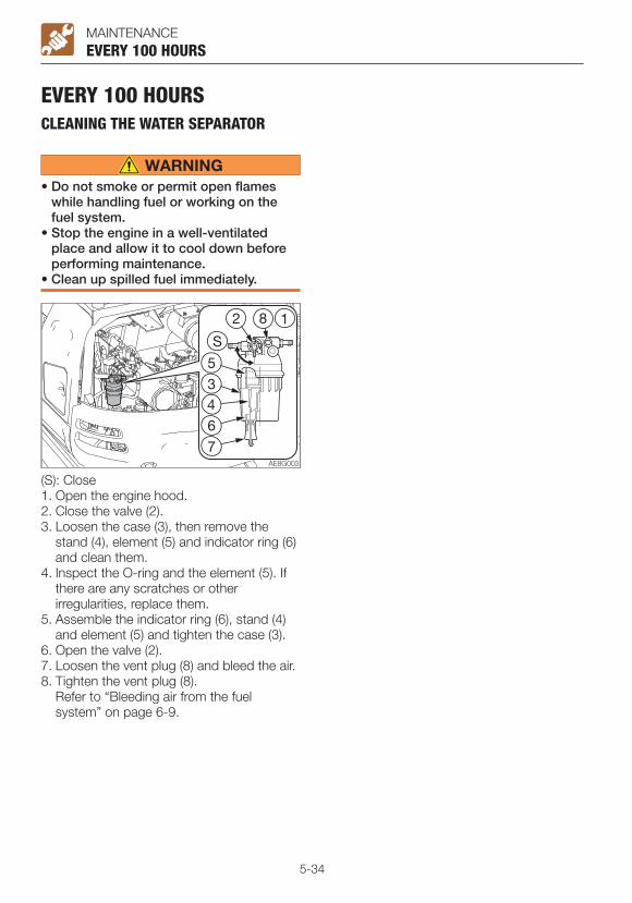
5-34
MAINTENANCEEVERY 100 HOURS
EVERY 100 HOURSCLEANING THE WATER SEPARATOR
• Do not smoke or permit open flames while handling fuel or working on the fuel system.
• Stop the engine in a well-ventilated place and allow it to cool down before performing maintenance.
• Clean up spilled fuel immediately.
(S): Close1. Open the engine hood.2. Close the valve (2).3. Loosen the case (3), then remove the
stand (4), element (5) and indicator ring (6) and clean them.
4. Inspect the O-ring and the element (5). If there are any scratches or other irregularities, replace them.
5. Assemble the indicator ring (6), stand (4) and element (5) and tighten the case (3).
6. Open the valve (2).7. Loosen the vent plug (8) and bleed the air.8. Tighten the vent plug (8). Refer to “Bleeding air from the fuel
system” on page 6-9.
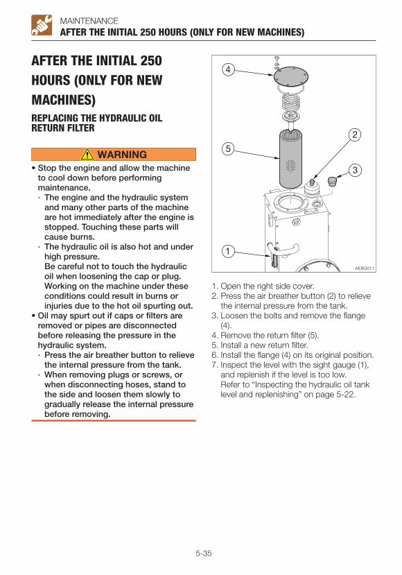
5-35
MAINTENANCE
AFTER THE INITIAL 250 HOURS (ONLY FOR NEW MACHINES)REPLACING THE HYDRAULIC OIL RETURN FILTER
• Stop the engine and allow the machine to cool down before performing maintenance.· The engine and the hydraulic system
and many other parts of the machine are hot immediately after the engine is stopped. Touching these parts will cause burns.
· The hydraulic oil is also hot and under high pressure.
Be careful not to touch the hydraulic oil when loosening the cap or plug. Working on the machine under these conditions could result in burns or injuries due to the hot oil spurting out.
• Oil may spurt out if caps or filters are removed or pipes are disconnected before releasing the pressure in the hydraulic system.· Press the air breather button to relieve
the internal pressure from the tank.· When removing plugs or screws, or
when disconnecting hoses, stand to the side and loosen them slowly to gradually release the internal pressure before removing.
AFTER THE INITIAL 250 HOURS (ONLY FOR NEW MACHINES)
1. Open the right side cover.2. Press the air breather button (2) to relieve
the internal pressure from the tank.3. Loosen the bolts and remove the flange
(4).4. Remove the return filter (5).5. Install a new return filter.6. Install the flange (4) on its original position.7. Inspect the level with the sight gauge (1),
and replenish if the level is too low. Refer to “Inspecting the hydraulic oil tank
level and replenishing” on page 5-22.
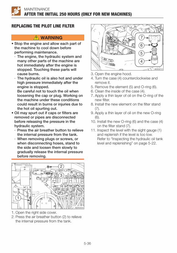
5-36
MAINTENANCE
REPLACING THE PILOT LINE FILTER
• Stop the engine and allow each part of the machine to cool down before performing maintenance.· The engine, the hydraulic system and
many other parts of the machine are hot immediately after the engine is stopped. Touching these parts will cause burns.
· The hydraulic oil is also hot and under high pressure immediately after the engine is stopped.
Be careful not to touch the oil when loosening the cap or plug. Working on the machine under these conditions could result in burns or injuries due to the hot oil spurting out.
• Oil may spurt out if caps or filters are removed or pipes are disconnected before releasing the pressure in the hydraulic system.· Press the air breather button to relieve
the internal pressure from the tank.· When removing plugs or screws, or
when disconnecting hoses, stand to the side and loosen them slowly to gradually release the internal pressure before removing.
AFTER THE INITIAL 250 HOURS (ONLY FOR NEW MACHINES)
1. Open the right side cover.2. Press the air breather button (2) to relieve
the internal pressure from the tank.
3. Open the engine hood.4. Turn the case (4) counterclockwise and
remove it.5. Remove the element (5) and O-ring (6).6. Clean the inside of the case (4).7. Apply a thin layer of oil on the O-ring of the
new filter.8. Install the new element on the filter stand
(7).9. Apply a thin layer of oil on the new O-ring
(6).10. Install the new O-ring (6) and the case (4)
on the filter stand (7). 11. Inspect the level with the sight gauge (1)
and replenish if the level is too low. Refer to “Inspecting the hydraulic oil tank
level and replenishing” on page 5-22.
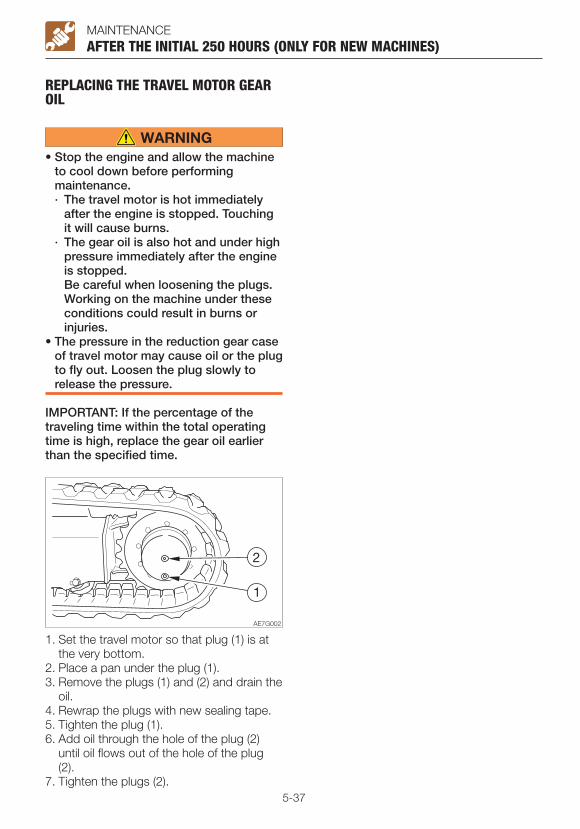
5-37
MAINTENANCEAFTER THE INITIAL 250 HOURS (ONLY FOR NEW MACHINES)
REPLACING THE TRAVEL MOTOR GEAR OIL
• Stop the engine and allow the machine to cool down before performing maintenance.· The travel motor is hot immediately
after the engine is stopped. Touching it will cause burns.
· The gear oil is also hot and under high pressure immediately after the engine is stopped.
Be careful when loosening the plugs. Working on the machine under these conditions could result in burns or injuries.
• The pressure in the reduction gear case of travel motor may cause oil or the plug to fly out. Loosen the plug slowly to release the pressure.
IMPORTANT: If the percentage of the traveling time within the total operating time is high, replace the gear oil earlier than the specified time.
1. Set the travel motor so that plug (1) is at the very bottom.
2. Place a pan under the plug (1).3. Remove the plugs (1) and (2) and drain the
oil.4. Rewrap the plugs with new sealing tape.5. Tighten the plug (1).6. Add oil through the hole of the plug (2)
until oil flows out of the hole of the plug (2).
7. Tighten the plugs (2).
AE7G002
1
2
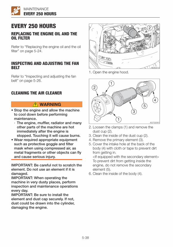
5-38
MAINTENANCE
EVERY 250 HOURSREPLACING THE ENGINE OIL AND THE OIL FILTER
Refer to “Replacing the engine oil and the oil filter” on page 5-24.
EVERY 250 HOURS
INSPECTING AND ADJUSTING THE FAN BELT
Refer to “Inspecting and adjusting the fan belt” on page 5-26.
CLEANING THE AIR CLEANER
• Stop the engine and allow the machine to cool down before performing maintenance.· The engine, muffler, radiator and many
other parts of the machine are hot immediately after the engine is stopped. Touching it will cause burns.
• Wear required appropriate equipment such as protective goggle and filter mask when using compressed air, as metal fragments or other objects can fly and cause serious injury.
IMPORTANT: Be careful not to scratch the element. Do not use an element if it is damaged.IMPORTANT: When operating the machine in very dusty places, perform inspection and maintenance operations every day.IMPORTANT: Be sure to install the element and dust cap securely. If not, dust could be drawn into the cylinder, damaging the engine.
1. Open the engine hood.
2. Loosen the clamps (1) and remove the dust cup (2).
3. Clean the inside of the dust cup (2).4. Remove the primary element (3).5. Cover the intake hole at the back of the
body (4) with cloth or tape to prevent dirt from getting in.
<If equipped with the secondary element> To prevent dirt from getting inside the
engine, do not remove the secondary element (5).
6. Clean the inside of the body (4).

5-39
MAINTENANCEEVERY 250 HOURS
7. Clean the primary element (3) with dried compressed air (294 to 490 kPa or 43 to 71 psi).
First blow the air from the inside of the element along the pleats. Then blow the air from the outside and finally from the inside again.
8. Light up the inside of the primary element (3) with a light bulb, inspect it, and replace it if there are small holes or thin spots.
9. Remove the cloth or tape applied in step 5.10. Install the primary element (3).11. Install the dust cup (2) with its
“ TOP ” mark facing, and then fasten it with the clamps (1).

5-40
MAINTENANCE
CLEANING THE RADIATOR FINS AND THE OIL COOLER FINS
Wear required appropriate equipment such as protective goggle and filter mask when using compressed air, as metal fragments or other objects can fly and cause serious injury.
IMPORTANT: Be careful not to damage the fins when cleaning.• When using compressed air or
pressurized water, make sure the pressure is no higher than 200 kPa (28 psi) and hold the nozzle sufficiently away from the fins.
IMPORTANT: When using water, cover the electrical system to prevent water from getting in.IMPORTANT: When operating the machine in very dusty places, perform inspection and maintenance operations every day.
EVERY 250 HOURS
1. Open the engine hood and right side cover.
2. Blow compressed air on the fins to remove mud and dirt stuck on them.

5-41
MAINTENANCE
CLEANING THE AIR FILTER (CAB)
Wear required appropriate equipment such as protective goggle and filter mask when using compressed air, as metal fragments or other objects can fly and cause serious injury.
Clean the filter immediately after operating in dusty places.If the filter is clogged, the air flow is reduced and a booming sound is heard from the air conditioner unit.
Removing the filter
EVERY 250 HOURS
1. Open the fuel lid.2. Loosen the screw and remove the cover
(4).3. Remove the circulation filter (5).4. Use compressed air or water to clean the
filter, depending on how dirty it is. Circulation filter (2) Part No. 19115-13680
Cleaning1. Blow dry, compressed air (138 kPa or 20
psi or less) directly on the filter from the inside, moving up and down along the pleats.
Be sure to keep the nozzle at an adequate distance from the filter.
2. Wash the filter with neutral detergent if it is very dirty. Dry the filter completely after washing it.
ReplacingReplace the filter with a new one once a year or if it is still clogged after blow-drying with compressed air and washing.

5-42
MAINTENANCE
EVERY 500 HOURSREPLACING THE FUEL FILTER
• Do not smoke or permit open flames while handling fuel or working on the fuel system.
• Stop the engine in a well-ventilated place and allow it to cool down before performing maintenance.
• Clean up spilled fuel immediately.
EVERY 500 HOURS
1. Open the engine hood.2. Turn the filter (1) counterclockwise with the
filter wrench and remove it.3. Clean the surface of installation of the filter
stand.4. Apply a thin layer of oil on the packing of
the new filter.5. Install the new filter by hand.6. Tighten one more turn after the filter
packing comes in contact with the surface of installation. (Torque when tightening with filter wrench: 19.6 to 23.5 N·m or 14 to 17ft-lb.)
7. Bleed the air. Refer to “Bleeding air from the fuel
system” on page 6-9.
5-43
MAINTENANCE
EVERY 1000 HOURSREPLACING THE HYDRAULIC OIL RETURN FILTER
Refer to “Replacing the hydraulic oil return filter” on page 5-35.
EVERY 1000 HOURS
REPLACING THE PILOT LINE FILTER
Refer to “Replacing the pilot line filter” on page 5-36.
REPLACING THE TRAVEL MOTOR GEAR OIL
Refer to “Replacing the travel motor gear oil” on page 5-37.
CLEANING THE ENGINE COOLING SYSTEM
• Stop the engine and allow the machine to cool down before performing maintenance.· The engine, muffler, radiator and many
other parts of the machine are hot immediately after the engine is stopped. Touching these parts will cause burns.
· The engine coolant is also hot and under high pressure immediately after the engine is stopped. Be careful when loosening the caps or plugs. Working on the machine under these conditions could result in burns or injuries due to the hot coolant spurting out.
• If maintenance must be performed with the engine running, always work as a two person team communicating each other.· One person must sit in the operator’s
seat so that he/she can immediately stop the engine when necessary. He/she must take care not to touch the lever or pedal unless necessary.
· The one who performs maintenance must make sure to keep his/her body or clothing away from the moving part of the machine.
• Standing at the back of the machine while the engine is running is extremely dangerous, as the machine could move suddenly. Never stand at the back of the machine while the engine is running.
• Do not remove the radiator cap or the drain plug when the cooling water is hot. Stop the engine and wait until the engine and the cooling water cool. Then, slowly loosen the radiator cap and the drain plug to remove them.
When cleaning, if the temperature of the coolant is low, the thermostat will be closed and the coolant will not circulate in the radiator. Heat the coolant water to at least 90°C (194°F) before cleaning.

5-44
MAINTENANCE
2. Gradually loosen the radiator cap (3) to release the internal pressure, and then remove the cap.
EVERY 1000 HOURS
3. Place a pan for catching the waste coolant under the drain plug (4), and then loosen the drain plug (4) to drain the coolant.
4. Tighten the drain plug (4).5. Add tap water to the radiator through the
coolant fill port up to the top of the port. Take time and slowly add water, so that no air enters the radiator.
6. Close the radiator cap (3).7. Start the engine and run it at a speed
slightly above low idling. Raise the water temperature to at least 90°C (194°F), and then run the engine for about 10 minutes with the thermostat open.
8. Stop the engine, wait until the cooling water temperature becomes lower, and then remove the drain plug (4) to drain the water.
9. After draining, clean the cooling system using a cleaning agent. When using the cleaning agent, follow the instructions included with the agent.
10. Repeat the steps 4 to 8 to rinse the cooling system.
11. Tighten the drain plug (4).12. Take time and slowly add the new
coolant (mixture of antifreeze and tap water) to the radiator through the fill port until it is full.
13. Close the radiator cap (3).14. Warm up the engine. Use the meters to
check that there are no irregularities in the cooling system at this time.
15. Increase the water temperature to at least 90°C (194°F). Then, run the engine for about 10 minutes with the thermostat kept open.
16. Stop the engine, wait until the cooling water temperature becomes lower, and then check the level of coolant in the radiator.
If necessary, add cooling water until the radiator is full.
17. Close the radiator cap (3).18. Clean the interior of the reserve tank (1),
and then add coolant to the upper limit (H).
19. When the coolant has been replaced, inspect the coolant level once again after operating the machine.
Once the machine is operated, the coolant is distributed throughout the entire system, resulting in the lower coolant level.
Replenish the cooling water that has been used.
1. Open the engine hood and the side cover.
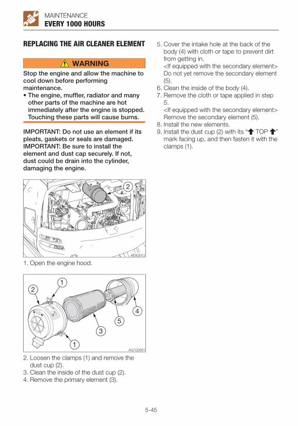
5-45
MAINTENANCE
REPLACING THE AIR CLEANER ELEMENT
Stop the engine and allow the machine to cool down before performing maintenance.• The engine, muffler, radiator and many
other parts of the machine are hot immediately after the engine is stopped. Touching these parts will cause burns.
IMPORTANT: Do not use an element if its pleats, gaskets or seals are damaged.IMPORTANT: Be sure to install the element and dust cap securely. If not, dust could be drain into the cylinder, damaging the engine.
1. Open the engine hood.
2. Loosen the clamps (1) and remove the dust cup (2).
3. Clean the inside of the dust cup (2).4. Remove the primary element (3).
5. Cover the intake hole at the back of the body (4) with cloth or tape to prevent dirt from getting in.
<If equipped with the secondary element> Do not yet remove the secondary element
(5).6. Clean the inside of the body (4).7. Remove the cloth or tape applied in step
5. <If equipped with the secondary element> Remove the secondary element (5).8. Install the new elements.9. Install the dust cup (2) with its “ TOP ”
mark facing up, and then fasten it with the clamps (1).
EVERY 1000 HOURS
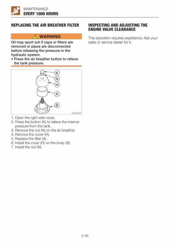
5-46
MAINTENANCE
REPLACING THE AIR BREATHER FILTER
Oil may spurt out if caps or filters are removed or pipes are disconnected before releasing the pressure in the hydraulic system.• Press the air breather button to relieve
the tank pressure.
EVERY 1000 HOURS
1. Open the right side cover.2. Press the button (K) to relieve the internal
pressure from the tank.3. Remove the nut (N) on the air breather.4. Remove the cover (H).5. Replace the filter (A).6. Install the cover (H) on the body (B).7. Install the nut (N).
INSPECTING AND ADJUSTING THE ENGINE VALVE CLEARANCE
This operation requires experience. Ask your sales or service dealer for it.

5-47
MAINTENANCE
EVERY 1500 HOURSINSPECTING, CLEANING AND CHECKING OPERATION OF THE ENGINE FUEL INJECTORS
This operation requires experience. Ask your sales or service dealer for it.
EVERY 1500 HOURS
INSPECTING THE CRANKCASE BREATHER SYSTEM
This operation requires experience. Ask your sales or service dealer for it.

5-48
MAINTENANCE
EVERY 2000 HOURSLAPPING THE ENGINE VALVE SEATS (IF NECESSARY)
This operation requires experience. Ask your sales or service dealer for it.
EVERY 2000 HOURS

5-49
MAINTENANCEEVERY 3000 HOURS
EVERY 3000 HOURSINSPECTING, CLEANING AND CHECKING OPERATION OF THE EGR VALVE
This operation requires experience. Ask your sales or service dealer for it.

5-50
MAINTENANCE
EVERY 4000 HOURSREPLACING THE HYDRAULIC OIL AND CLEANING THE SUCTION STRAINER
• Stop the engine and allow the machine to cool down before performing maintenance.· The engine and the hydraulic system
and many other parts of the machine are hot immediately after the engine is stopped. Touching these parts will cause burns.
· The hydraulic oil is also hot and under high pressure immediately after the engine is stopped.
Be careful when loosening the caps or plugs. Working on the machine under these conditions could result in burns or injuries due to the hot oil spurting out.
• Oil may spurt out if caps or filters are removed or pipes are disconnected before releasing the pressure in the hydraulic system.· Press the air breather button to relieve
the internal pressure from the tank.· When removing plugs or screws, or
when disconnecting hoses, stand to the side and loosen them slowly to gradually release the internal pressure before removing.
1. Slew 60° clockwise and set the machine to the hydraulic oil level inspection posture.
Refer to “Inspecting the hydraulic oil tank level and replenishing” on page 5-22.
2. Open the right side cover.
EVERY 4000 HOURS
3. Press the button (2) to relieve the internal pressure from the tank.
4. Replace the air breather filter (A). Refer to “Replacing the air breather filter”
on page 5-46.5. Remove the plug (3).6. Loosen the bolts and remove the flange
(4).7. Remove the return filter (5).8. Place a pan under the plug (6) to catch the
waste oil.9. Remove the drain plug (6), and then drain
the hydraulic oil.10. Loosen the bolts and remove the flange
(7).11. Remove the suction strainer (8) and
clean it.12. Clean the inside of the hydraulic oil tank.13. Tighten the drain plug (6).14. Install the suction strainer (8) on the tank
and then install the flange (7).

5-51
MAINTENANCE
15. Install the new return filter (5) and the flange (4) on the tank.
16. Add hydraulic oil from the hole of plug (3) up to the level between the upper limit (H) and the lower limit (L) in the sight gauge (1).
17. Tighten the plug (3).18. Bleed air from the hydraulic oil circuit
following “Bleeding air” below.19. Set the machine to the hydraulic oil level
inspection posture and inspect the oil level after the oil cools.
Refer to “Inspecting the hydraulic oil tank level and replenishing” on page 5-22.
Bleeding air
IMPORTANT: After replacing the hydraulic oil or hydraulic devices, or after performing maintenance of the hydraulic devices, bleed air from the hydraulic circuits and hydraulic devices. Failure to do so may damage the hydraulic devices.
• Hydraulic pump
EVERY 4000 HOURS
1. Open the engine hood.2. Loosen the vent plug (1) on the hydraulic
pump.3. Once hydraulic oil overflows from the vent
plug hole (1), tighten the vent plug (1).
• Cylinders1. Start the engine, let it run at a low-idling
speed for 10 minutes.2. Maintain the engine at low idle, and then
slowly extend and retract each cylinder 4 or 5 times, without letting them reach the stroke end.
3. While running the engine at high speed, slowly extend and retract each cylinder 4 or 5 times, without letting them reach the stroke end.
4. Return the engine speed to low idle, and then slowly extend and retract each cylinder 4 or 5 times to the stroke end.
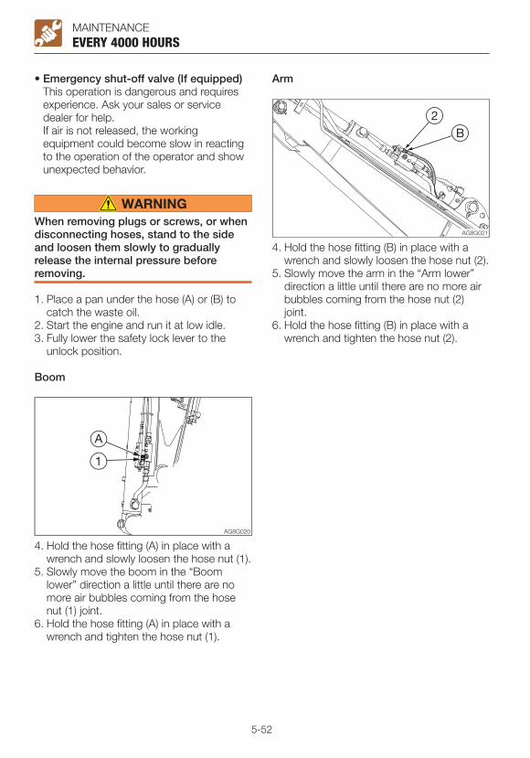
5-52
MAINTENANCEEVERY 4000 HOURS
4. Hold the hose fitting (A) in place with a wrench and slowly loosen the hose nut (1).
5. Slowly move the boom in the “Boom lower” direction a little until there are no more air bubbles coming from the hose nut (1) joint.
6. Hold the hose fitting (A) in place with a wrench and tighten the hose nut (1).
4. Hold the hose fitting (B) in place with a wrench and slowly loosen the hose nut (2).
5. Slowly move the arm in the “Arm lower” direction a little until there are no more air bubbles coming from the hose nut (2) joint.
6. Hold the hose fitting (B) in place with a wrench and tighten the hose nut (2).
• Emergency shut-off valve (If equipped) This operation is dangerous and requires
experience. Ask your sales or service dealer for help.
If air is not released, the working equipment could become slow in reacting to the operation of the operator and show unexpected behavior.
When removing plugs or screws, or when disconnecting hoses, stand to the side and loosen them slowly to gradually release the internal pressure before removing.
1. Place a pan under the hose (A) or (B) to catch the waste oil.
2. Start the engine and run it at low idle.3. Fully lower the safety lock lever to the
unlock position.
Boom
Arm
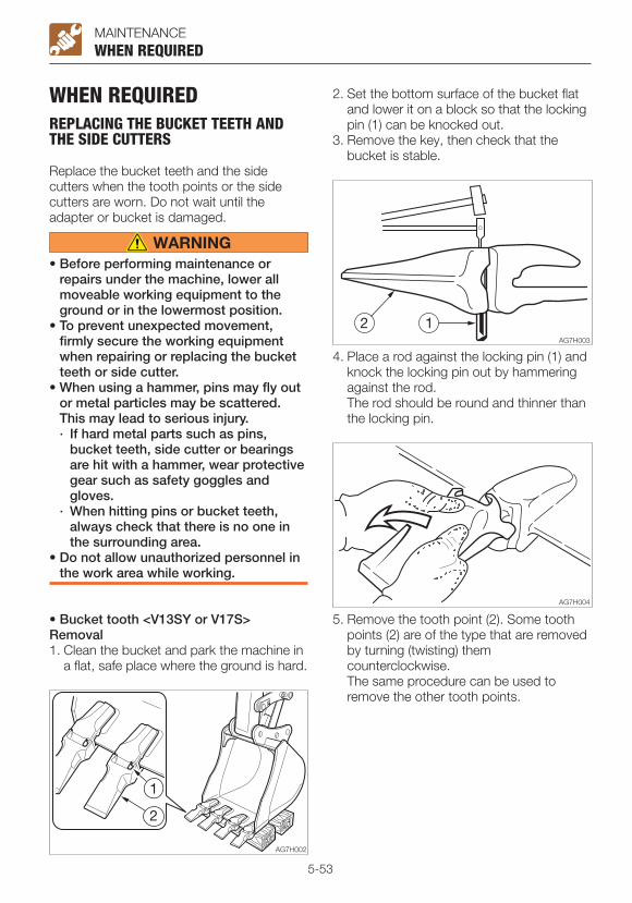
5-53
MAINTENANCEWHEN REQUIRED
WHEN REQUIREDREPLACING THE BUCKET TEETH AND THE SIDE CUTTERS
Replace the bucket teeth and the side cutters when the tooth points or the side cutters are worn. Do not wait until the adapter or bucket is damaged.
• Before performing maintenance or repairs under the machine, lower all moveable working equipment to the ground or in the lowermost position.
• To prevent unexpected movement, firmly secure the working equipment when repairing or replacing the bucket teeth or side cutter.
• When using a hammer, pins may fly out or metal particles may be scattered. This may lead to serious injury.· If hard metal parts such as pins,
bucket teeth, side cutter or bearings are hit with a hammer, wear protective gear such as safety goggles and gloves.
· When hitting pins or bucket teeth, always check that there is no one in the surrounding area.
• Do not allow unauthorized personnel in the work area while working.
• Bucket tooth <V13SY or V17S>Removal1. Clean the bucket and park the machine in
a flat, safe place where the ground is hard.
2. Set the bottom surface of the bucket flat and lower it on a block so that the locking pin (1) can be knocked out.
3. Remove the key, then check that the bucket is stable.
4. Place a rod against the locking pin (1) and knock the locking pin out by hammering against the rod.
The rod should be round and thinner than the locking pin.
5. Remove the tooth point (2). Some tooth points (2) are of the type that are removed by turning (twisting) them counterclockwise.
The same procedure can be used to remove the other tooth points.
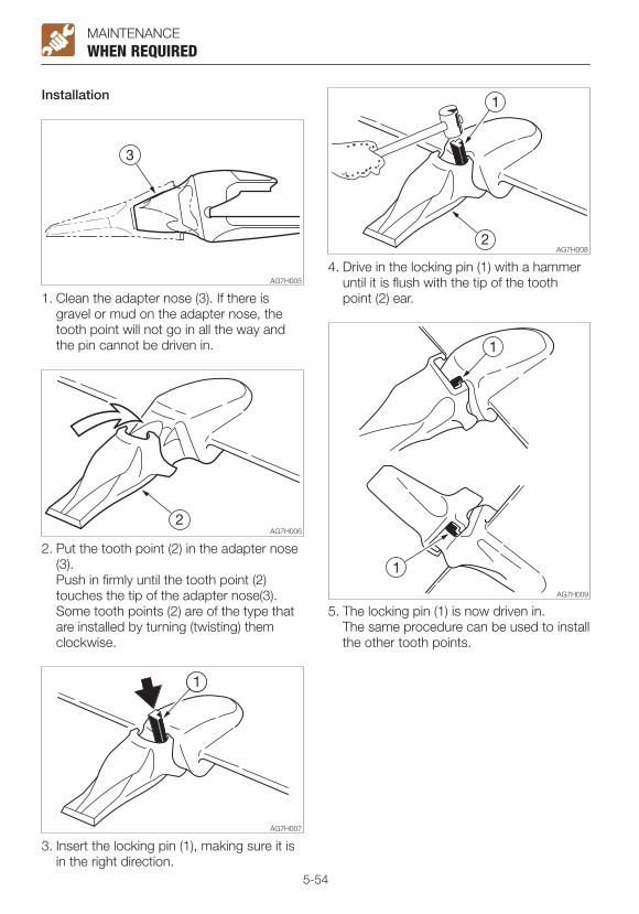
5-54
MAINTENANCEWHEN REQUIRED
1. Clean the adapter nose (3). If there is gravel or mud on the adapter nose, the tooth point will not go in all the way and the pin cannot be driven in.
Installation
2. Put the tooth point (2) in the adapter nose (3).
Push in firmly until the tooth point (2) touches the tip of the adapter nose(3).
Some tooth points (2) are of the type that are installed by turning (twisting) them clockwise.
3. Insert the locking pin (1), making sure it is in the right direction.
4. Drive in the locking pin (1) with a hammer until it is flush with the tip of the tooth point (2) ear.
5. The locking pin (1) is now driven in. The same procedure can be used to install
the other tooth points.

5-55
MAINTENANCEWHEN REQUIRED
• Side cutterInstallation
1. Insert the bolts from the inner of the bucket and tighten the side cutterwith nuts.
Tightening torque: 241 N·m (178 ft-lb)2. Caulk the bolts with a punch at three
spots along the periphery of the screw to prevent the nuts from coming loose.
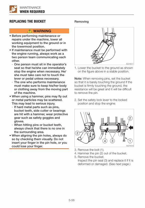
5-56
MAINTENANCE
REPLACING THE BUCKET
• Before performing maintenance or repairs under the machine, lower all working equipment to the ground or in the lowermost position.
• If maintenance must be performed with the engine running, always work as a two person team communicating each other.· One person must sit in the operator’s
seat so that he/she can immediately stop the engine when necessary. He/she must take care not to touch the lever or pedal unless necessary.
· The one who performs maintenance must make sure to keep his/her body or clothing away from the moving part of the machine.
• When using a hammer, pins may fly out or metal particles may be scattered. This may lead to serious injury.· If hard metal parts such as pins,
bucket teeth, side cutter or bearings are hit with a hammer, wear protective gear such as safety goggles and gloves.
· When hitting pins or bucket teeth, always check that there is no one in the surrounding area.
• When aligning the pin holes, always do so by checking them visually. Do not insert your finger in the pin hole, or you could lose your finger.
WHEN REQUIRED
1. Lower the bucket to the ground as shown on the figure above in a stable position.
Note: When removing pins, set the bucket so that it is barely touching the ground If the bucket is firmly touching the ground, the resistance will be great and it will be difficult to remove the pin.
2. Set the safety lock lever to the locked position and stop the engine.
3. Remove the bolt (1).4. Hammer the pin (2) out of the bucket.5. Remove the bucket. Inspect the pin seal (3) and replace it if it is
deformed or damaged. (See next page.)
Removing
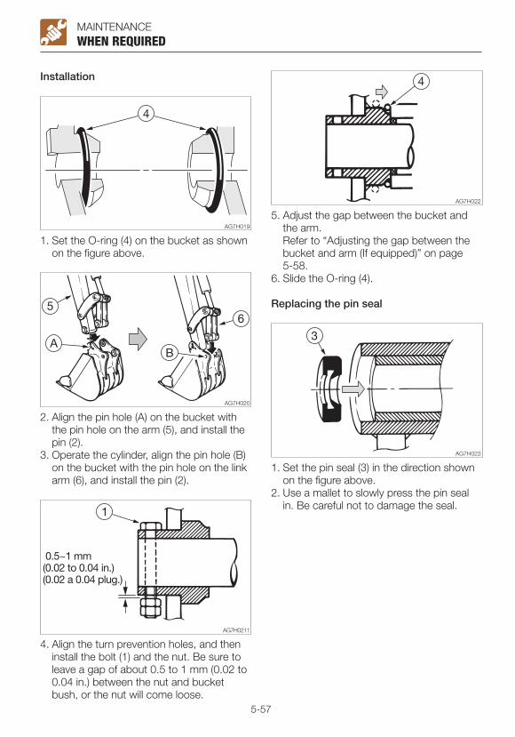
5-57
MAINTENANCE
Installation
WHEN REQUIRED
1. Set the O-ring (4) on the bucket as shown on the figure above.
2. Align the pin hole (A) on the bucket with the pin hole on the arm (5), and install the pin (2).
3. Operate the cylinder, align the pin hole (B) on the bucket with the pin hole on the link arm (6), and install the pin (2).
4. Align the turn prevention holes, and then install the bolt (1) and the nut. Be sure to leave a gap of about 0.5 to 1 mm (0.02 to 0.04 in.) between the nut and bucket bush, or the nut will come loose.
5. Adjust the gap between the bucket and the arm.
Refer to “Adjusting the gap between the bucket and arm (If equipped)” on page 5-58.
6. Slide the O-ring (4).
Replacing the pin seal
1. Set the pin seal (3) in the direction shown on the figure above.
2. Use a mallet to slowly press the pin seal in. Be careful not to damage the seal.
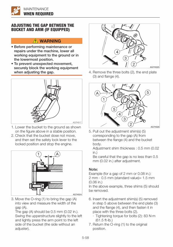
5-58
MAINTENANCE
ADJUSTING THE GAP BETWEEN THE BUCKET AND ARM (IF EQUIPPED)
• Before performing maintenance or repairs under the machine, lower all working equipment to the ground or in the lowermost position.
• To prevent unexpected movement, securely block the working equipment when adjusting the gap.
WHEN REQUIRED
1. Lower the bucket to the ground as shown on the figure above in a stable position.
2. Check that the bucket dose not move, and then set the safety lock lever to the locked position and stop the engine.
3. Move the O-ring (1) to bring the gap (A) into view and measure the width of the gap (A).
The gap (A) should be 0.5 mm (0.02 in.). Swing the upperstructure slightly to the left and lightly press the arm point to the left side of the bucket (the side without an adjuster).
4. Remove the three bolts (2), the end plate (3) and flange (4).
5. Pull out the adjustment shim(s) (5) corresponding to the gap (A) from between the flange (4) and the bucket body.
Adjustment shim thickness : 0.5 mm (0.02 in.)
Be careful that the gap is no less than 0.5 mm (0.02 in.) after adjustment.
Note:Example (for a gap of 2 mm or 0.08 in.): 2 mm - 0.5 mm (standard value)= 1.5 mm (0.06 in.)In the above example, three shims (5) should be removed.
6. Insert the adjustment shim(s) (5) removed in step 5 above between the end plate (3) and the flange (4), and then fasten it in place with the three bolts (2).· Tightening torque for bolts (2): 83 N·m
(61.5 ft-lb.)7. Return the O-ring (1) to the original
position.

5-59
MAINTENANCE
INSPECTING AND REPLENISHING THE WINDSHIELD WASHER FLUID
Choose ethyl alcohol as washer solution.Do not use methyl alcohol as washer solution. It could damage the eyes.
Use a windshield washer fluid designed specifically for motor vehicles. Follow the instructions included with the washer fluid.
WHEN REQUIRED
Inspection1. Open the right side cover.2. Inspect the washer tank (1) and add
washer fluid if the level is low.
Replenishing1. Mix the washer fluid to the prescribed
concentration.2. Remove the cap (2) and add washer fluid. Keep the dust away while replenishing the
washer fluid.3. Install the cap (2).

5-60
MAINTENANCEWHEN REQUIRED
LUBRICATING THE LEVERS AND PEDALS
Set the machine to the parking posture, stop the engine, remove the starter key and store it. Failure to do so may result in the machine moving abruptly, leading to serious injury or death.
If the levers or pedals no longer move smoothly, grease them.
Operating levers
Travel levers
Boom swing pedal
Dozer blade lever
1. Remove the lower mount section of the boot (1) and turn it upward.
2. Wipe off the old grease.3. Apply grease to points (A) and (B).4. Set the boot (1) back as it was.
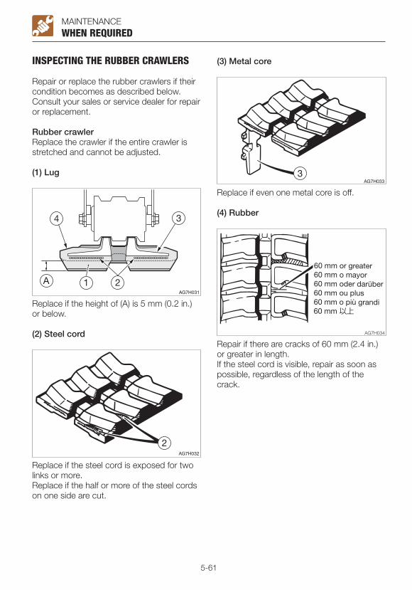
5-61
MAINTENANCE
INSPECTING THE RUBBER CRAWLERS
Repair or replace the rubber crawlers if their condition becomes as described below. Consult your sales or service dealer for repair or replacement.
Rubber crawlerReplace the crawler if the entire crawler is stretched and cannot be adjusted.
(1) Lug
WHEN REQUIRED
Replace if the height of (A) is 5 mm (0.2 in.) or below.
(2) Steel cord
Replace if the steel cord is exposed for two links or more.Replace if the half or more of the steel cords on one side are cut.
(3) Metal core
Replace if even one metal core is off.
(4) Rubber
Repair if there are cracks of 60 mm (2.4 in.) or greater in length.If the steel cord is visible, repair as soon as possible, regardless of the length of the crack.
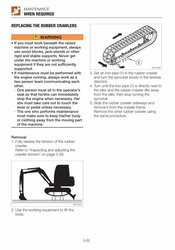
5-62
MAINTENANCEWHEN REQUIRED
REPLACING THE RUBBER CRAWLERS
• If you must work beneath the raised machine or working equipment, always use wood blocks, jack-stands or other rigid and stable supports. Never get under the machine or working equipment if they are not sufficiently supported.
• If maintenance must be performed with the engine running, always work as a two person team communicating each other.· One person must sit in the operator’s
seat so that he/she can immediately stop the engine when necessary. He/she must take care not to touch the lever or pedal unless necessary.
· The one who performs maintenance must make sure to keep his/her body or clothing away from the moving part of the machine.
Removal1. Fully release the tension of the rubber
crawler. Refer to “Inspecting and adjusting the
crawler tension” on page 5-28.
2. Use the working equipment to lift the body.
3. Set an iron pipe (1) in the rubber crawler and turn the sprocket slowly in the reverse direction.
4. Turn until the iron pipe (1) is directly next to the idler and the rubber crawler lifts away from the idler, then stop turning the sprocket.
5. Slide the rubber crawler sideways and remove it from the crawler frame.
Remove the other rubber crawler using the same procedure.
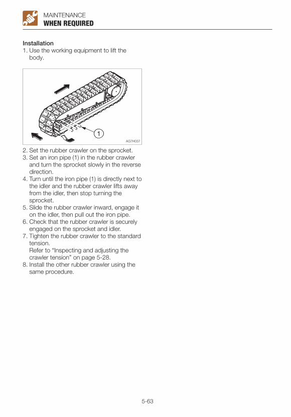
5-63
MAINTENANCEWHEN REQUIRED
Installation1. Use the working equipment to lift the
body.
2. Set the rubber crawler on the sprocket.3. Set an iron pipe (1) in the rubber crawler
and turn the sprocket slowly in the reverse direction.
4. Turn until the iron pipe (1) is directly next to the idler and the rubber crawler lifts away from the idler, then stop turning the sprocket.
5. Slide the rubber crawler inward, engage it on the idler, then pull out the iron pipe.
6. Check that the rubber crawler is securely engaged on the sprocket and idler.
7. Tighten the rubber crawler to the standard tension.
Refer to “Inspecting and adjusting the crawler tension” on page 5-28.
8. Install the other rubber crawler using the same procedure.
5-64
MAINTENANCE
MAINTENANCE DURING EXTENDED STORAGE PERIODStorage proceduresIf the machine is to be stored for 30 days or more, store it indoors. If it must be stored outdoors, park the machine on a surface laid with lumber on a flat ground, and place a waterproof cover over it so that it stays dry.1. Clean the machine.2. Inspect for oil leakage, water leakage,
cracks and loose nuts and bolts.3. Add fuel and replace the hydraulic oil and
oil.4. To prevent rusting and freezing, replace
the engine coolant with long-life coolant (LLC).
Refer to “Cleaning the engine cooling system” on page 5-43.
5. Use the grease gun to lubricate the grease fittings.
6. Fully retract the bucket and arm cylinders and lower the bucket and dozer blade to the ground.
7. Apply rust-inhibiting oil to the hydraulic cylinder rods.
8. Disconnect the negative cable from the battery and cover the battery to prevent freezing.
During storage
• Do not operate the machine in an enclosed area without adequate ventilation.
• If natural ventilation is not possible, install ventilators, fans, exhaust extension pipes or other venting devices.
1. To prevent rusting, operate the machine once a month so that the oil can be circulated throughout the system.
2. Inspect the battery and recharge it as necessary.
Ask your sales or service dealer for recharging.
Starting the machine after storage
IMPORTANT: If the above “Storage procedures” have not been followed during the extended storage periods, consult your sales or service dealer before starting the machine again.
1. Wipe off the rust-inhibiting oil that was applied on the piston rods of the hydraulic oil cylinders.
2. Add oil or grease as necessary.
Returning the engine to service1. Perform the daily checks.2. The engine should be pre-oiled before
startup.a. Crank the engine, leaving the fuel
system shut off so the engine will not start, for 15 seconds.
b. Then pause for 30 seconds.c. Repeat the procedure until you have
cranked the engine for a total of one minute. This will circulate the oil in the engine’s lubrication system.
3. Prime the fuel system.4. Start the engine. Allow the engine to idle
for approximately 15 minutes while you check for:· Proper oil pressure· Fuel, engine oil or coolant leaks· Proper operation of the indicators and/or
gauges5. Avoid prolonged operation at minimum or
maximum engine speeds and loads for the remainder of the first hour of operation.
MAINTENANCE DURING EXTENDED STORAGE PERIOD

6-1
TROUBLESHOOTING

6-2
TROUBLESHOOTING
SYMPTOMS THAT ARE NOT MALFUNCTIONSThe symptoms listed below are not malfunctions.
SYMPTOMS THAT ARE NOT MALFUNCTIONS
• The arm retracting speed momentarily slows down when it reaches an almost vertical position while the engine is running at low speed.
• The bucket teeth moving speed momentarily slows down when it reaches an almost horizontal position while the engine is running at low speed.
• The slew motor produces noise at the beginning and end of the slewing.
• The travel motor produces noise when stopped suddenly from its high speed traveling.
• The control valve produces noise if excessive force is applied to the working equipment or when it moved to the stroke end.
• It becomes less easy to operate the machine when an attachment weighing more than a standard arm or bucket is installed.
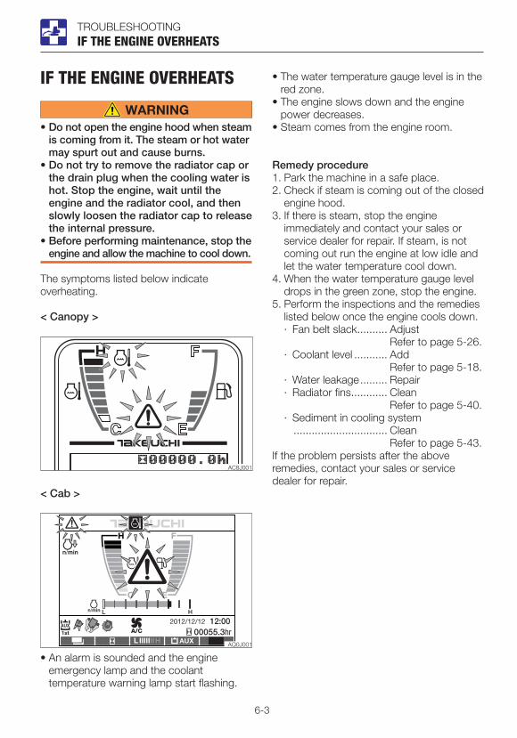
6-3
TROUBLESHOOTING
IF THE ENGINE OVERHEATS
• Do not open the engine hood when steam is coming from it. The steam or hot water may spurt out and cause burns.
• Do not try to remove the radiator cap or the drain plug when the cooling water is hot. Stop the engine, wait until the engine and the radiator cool, and then slowly loosen the radiator cap to release the internal pressure.
• Before performing maintenance, stop the engine and allow the machine to cool down.
The symptoms listed below indicate overheating.
< Canopy >
IF THE ENGINE OVERHEATS
• An alarm is sounded and the engine emergency lamp and the coolant temperature warning lamp start flashing.
• The water temperature gauge level is in the red zone.
• The engine slows down and the engine power decreases.
• Steam comes from the engine room.
Remedy procedure1. Park the machine in a safe place.2. Check if steam is coming out of the closed
engine hood.3. If there is steam, stop the engine
immediately and contact your sales or service dealer for repair. If steam, is not coming out run the engine at low idle and let the water temperature cool down.
4. When the water temperature gauge level drops in the green zone, stop the engine.
5. Perform the inspections and the remedies listed below once the engine cools down.· Fan belt slack .......... Adjust
Refer to page 5-26.· Coolant level ........... Add
Refer to page 5-18.· Water leakage ......... Repair· Radiator fins ............ Clean
Refer to page 5-40.· Sediment in cooling system
............................... Clean Refer to page 5-43.
If the problem persists after the above remedies, contact your sales or service dealer for repair.
< Cab >

6-4
TROUBLESHOOTING
IF THE BATTERY GOES DEADThe symptoms below indicate that the battery is dead.• The starter motor does not turn or fails to
start the engine.• The horn is too weak.
Remedy procedureStart the engine using the booster battery on the other vehicle (booster vehicle) and the jumper cables.
• When starting the engine using the jumper cables, be sure to connect the cables by following the proper steps. Improper use of jumper cables can result in battery explosion or unexpected machine motion.· Do not allow the booster vehicle and
the machine with a dead battery (dead machine) to touch each other.
· Do not allow the positive (+) and the negative (–) clips of the jumper cables to touch each other.
· When connecting, attach the jumper cable to the positive (+) terminals first. When disconnecting, remove the cable from the negative (–) terminal (ground) first.
· Connect the last clip of the jumper cable to a point as far away from the battery as possible.
• Always wear the protective goggle when jump starting the engine by using the jumper cables.
• Set the battery charging current to at or below one tenth of the rated capacity. Too high charging current could cause the battery to leak or be depleted, resulting in explosion if ignited.
IMPORTANT: Use the jumper cables and clips of a size suited to the capacity of battery. Do not use damaged or corroded jumper cables and clips.
IF THE BATTERY GOES DEAD
IMPORTANT: Be sure that the battery of the booster vehicle has the same capacity as the battery of the dead machine.IMPORTANT: Be sure to connect the clips securely.
Connecting the jumper cables
IMPORTANT: Set the starter keys of the booster vehicle and the dead machine to the OFF position.
1. Connect the clip of jumper cable (R) to the positive (+) battery terminal of the dead machine.
2. Connect the other clip of jumper cable (R) to the positive (+) battery terminal of the booster vehicle.
3. Connect the clip of jumper cable (B) to the negative (–) battery terminal of the booster vehicle.
4. Connect the other clip of jumper cable (B) to the engine block of the dead machine. Connect the clip to a place as far from the battery as possible.
Starting the engine1. Check that the clips are securely
connected to the terminals.2. Start the engine of the booster vehicle and
run it at high speed.3. Start the engine of the dead machine.
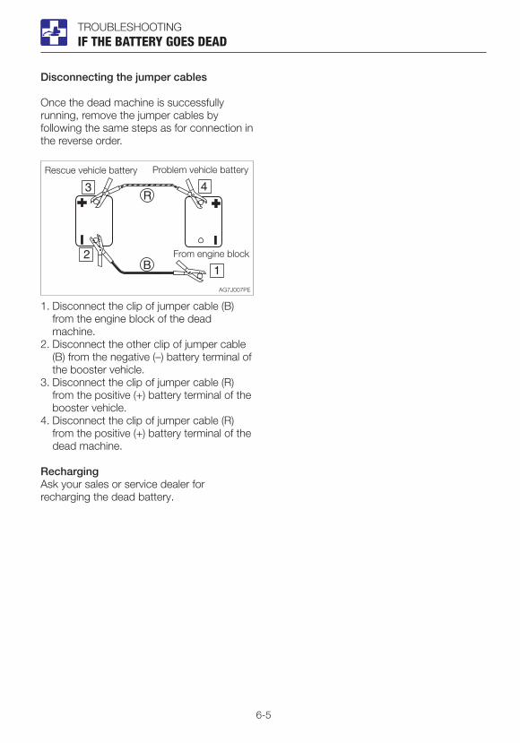
6-5
TROUBLESHOOTING
Disconnecting the jumper cables
Once the dead machine is successfully running, remove the jumper cables by following the same steps as for connection in the reverse order.
1. Disconnect the clip of jumper cable (B) from the engine block of the dead machine.
2. Disconnect the other clip of jumper cable (B) from the negative (–) battery terminal of the booster vehicle.
3. Disconnect the clip of jumper cable (R) from the positive (+) battery terminal of the booster vehicle.
4. Disconnect the clip of jumper cable (R) from the positive (+) battery terminal of the dead machine.
RechargingAsk your sales or service dealer for recharging the dead battery.
IF THE BATTERY GOES DEAD

6-6
TROUBLESHOOTING
IF A FUSE BLOWSIf a light does not come on or the electrical system does not work, a fuse may be blown. Inspect the fuses.
INSPECTING AND REPLACING THE FUSE
If the fuse blows again soon after replacement, then the electric system is likely faulty. It may pose a fire hazard if not properly repaired. Contact your sales or service dealer for advice.
1. Turn the starter key to the OFF position to stop the engine.
IF A FUSE BLOWS
2. Open the fuse box cover (1).3. Check for any blown fuses (2).
4. If a fuse is blown, replace it with a spare fuse of the same capacity.
Fuse layout and circuits protected (1)
<Cab>
Capacity Symbol Protected circuit
5A Switch lighting
10A Horn
5A Starter switch
10A Immobilizer
20A Light
10A Wiper
20A Lever lock
10A Controller power supply (2)
10A Solenoid
20A Cab interior power supply
25A OPT Option
10A Heater
10A Feed pump
30A Blower motor
20A Cab light
20A Controller power supply (1)
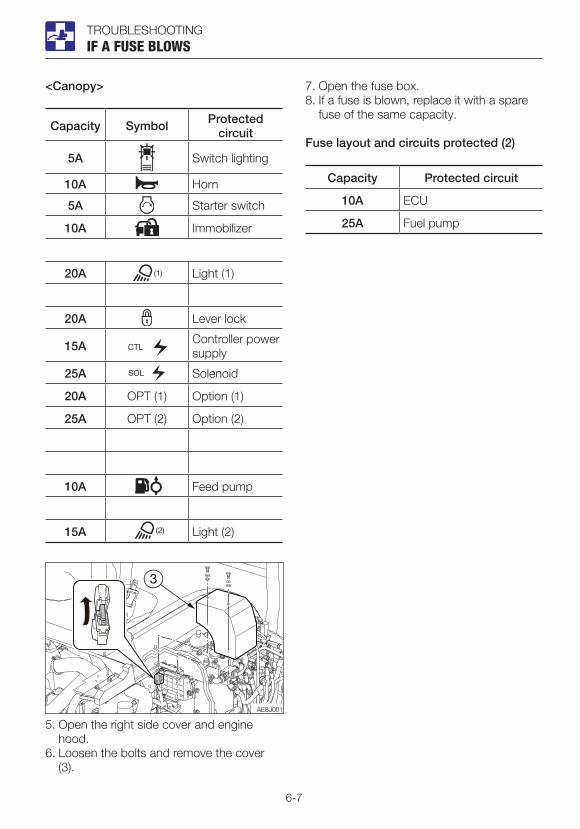
6-7
TROUBLESHOOTINGIF A FUSE BLOWS
<Canopy>
Capacity Symbol Protected circuit
5A Switch lighting
10A Horn
5A Starter switch
10A Immobilizer
20A Light (1)
20A Lever lock
15A Controller power supply
25A Solenoid
20A OPT (1) Option (1)
25A OPT (2) Option (2)
10A Feed pump
15A Light (2)
5. Open the right side cover and engine hood.
6. Loosen the bolts and remove the cover (3).
7. Open the fuse box.8. If a fuse is blown, replace it with a spare
fuse of the same capacity.
Fuse layout and circuits protected (2)
Capacity Protected circuit
10A ECU
25A Fuel pump
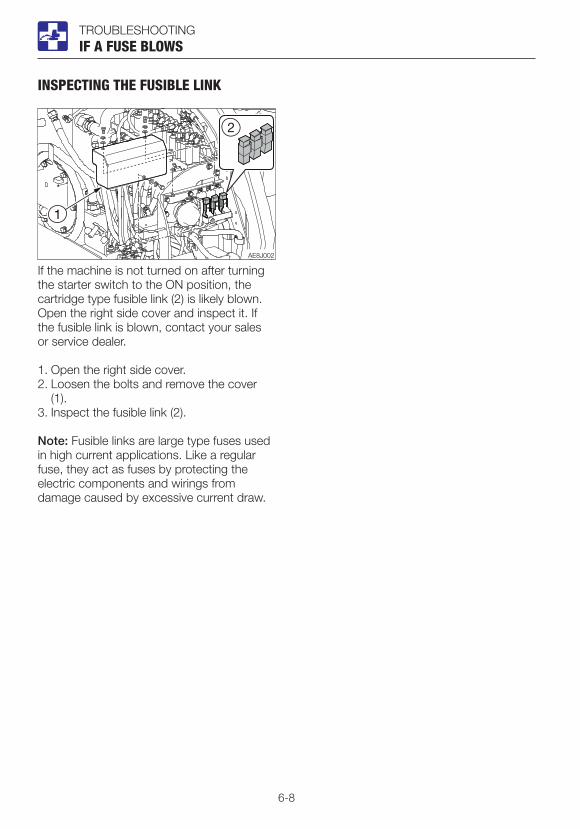
6-8
TROUBLESHOOTINGIF A FUSE BLOWS
INSPECTING THE FUSIBLE LINK
If the machine is not turned on after turning the starter switch to the ON position, the cartridge type fusible link (2) is likely blown. Open the right side cover and inspect it. If the fusible link is blown, contact your sales or service dealer.
1. Open the right side cover.2. Loosen the bolts and remove the cover
(1).3. Inspect the fusible link (2).
Note: Fusible links are large type fuses used in high current applications. Like a regular fuse, they act as fuses by protecting the electric components and wirings from damage caused by excessive current draw.
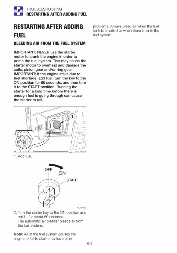
6-9
TROUBLESHOOTINGRESTARTING AFTER ADDING FUEL
RESTARTING AFTER ADDING FUELBLEEDING AIR FROM THE FUEL SYSTEM
IMPORTANT: NEVER use the starter motor to crank the engine in order to prime the fuel system. This may cause the starter motor to overheat and damage the coils, pinion gear and/or ring gear.IMPORTANT: If the engine stalls due to fuel shortage, add fuel, turn the key to the ON position for 60 seconds, and then turn it to the START position. Running the starter for a long time before there is enough fuel is going through can cause the starter to fail.
1. Add fuel.
2. Turn the starter key to the ON position and hold it for about 60 seconds.
The automatic air bleeder bleeds air from the fuel system.
Note: Air in the fuel system causes the engine to fail to start or to have other
problems. Always bleed air when the fuel tank is emptied or when there is air in the fuel system.
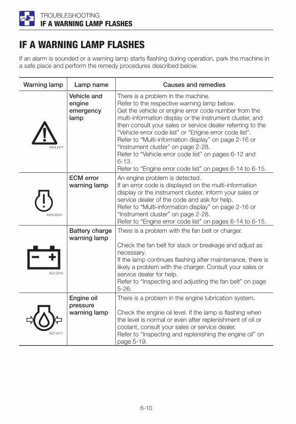
6-10
TROUBLESHOOTING
IF A WARNING LAMP FLASHESIf an alarm is sounded or a warning lamp starts flashing during operation, park the machine in a safe place and perform the remedy procedures described below.
Warning lamp Lamp name Causes and remedies
Vehicle and engine emergency lamp
There is a problem in the machine.Refer to the respective warning lamp below.Get the vehicle or engine error code number from the multi-information display or the instrument cluster, and then consult your sales or service dealer referring to the “Vehicle error code list” or “Engine error code list”. Refer to “Multi-information display” on page 2-16 or “Instrument cluster” on page 2-28.Refer to “Vehicle error code list” on pages 6-12 and 6-13.Refer to “Engine error code list” on pages 6-14 to 6-15.
ECM error warning lamp
An engine problem is detected.If an error code is displayed on the multi-information display or the instrument cluster, inform your sales or service dealer of the code and ask for help.Refer to “Multi-information display” on page 2-16 or “Instrument cluster” on page 2-28.Refer to “Engine error code list” on pages 6-14 to 6-15.
Battery charge warning lamp
There is a problem with the fan belt or charger.
Check the fan belt for slack or breakage and adjust as necessary. If the lamp continues flashing after maintenance, there is likely a problem with the charger. Consult your sales or service dealer for help.Refer to “Inspecting and adjusting the fan belt” on page 5-26.
Engine oil pressure warning lamp
There is a problem in the engine lubrication system.
Check the engine oil level. If the lamp is flashing when the level is normal or even after replenishment of oil or coolant, consult your sales or service dealer.Refer to “Inspecting and replenishing the engine oil” on page 5-19.
IF A WARNING LAMP FLASHES
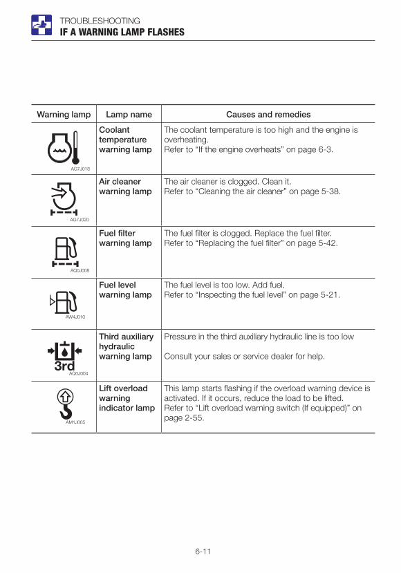
6-11
TROUBLESHOOTING
Warning lamp Lamp name Causes and remedies
Coolant temperature warning lamp
The coolant temperature is too high and the engine is overheating.Refer to “If the engine overheats” on page 6-3.
Air cleaner warning lamp
The air cleaner is clogged. Clean it.Refer to “Cleaning the air cleaner” on page 5-38.
Fuel filter warning lamp
The fuel filter is clogged. Replace the fuel filter.Refer to “Replacing the fuel filter” on page 5-42.
Fuel level warning lamp
The fuel level is too low. Add fuel.Refer to “Inspecting the fuel level” on page 5-21.
Third auxiliary hydraulic warning lamp
Pressure in the third auxiliary hydraulic line is too low
Consult your sales or service dealer for help.
Lift overload warning indicator lamp
This lamp starts flashing if the overload warning device is activated. If it occurs, reduce the load to be lifted.Refer to “Lift overload warning switch (If equipped)” on page 2-55.
IF A WARNING LAMP FLASHES

6-12
TROUBLESHOOTING
VEHICLE ERROR CODE LISTWhen the multi-information display is set to the data mode, the number that is corresponding to the error, if applicable, appears in the error code field. Up to four types of error codes are displayed (the leftmost code is the most recent error). If this occurs, consult your sales or service dealer.
Error code Error details
9 Impossible to sense ACC key
19 Parameter version mismatching
402 CAN 0 communication error
502 CAN communication error (engine ECU)
602 CAN communication error (cluster gauge)
612 CAN communication error (OX024)
1703 Main power supply voltage error (too high)
1704 Main power supply voltage error (too low)
1713 OX024 power supply voltage error (too high)
1714 OX024 power supply voltage error (too low)
2503 Sensor voltage error (too high) MMC
2504 Sensor voltage error (too low) MMC
3300 Alternator charge faulty
3401 Engine oil pressure error
3500 Overheat
3600 Air cleaner clogged
5303 Accelerator sensor error (too high)
5304 Accelerator sensor error (too low)
5505 Fuel gauge resistance value error (cable break)
5603 Lift alarm sensor error (too high)
5604 Lift alarm sensor error (too low)
6503 AUX1 slide switch voltage value error (too high)
6504 AUX1 slide switch voltage value error (too low)
6509 AUX1 slide switch neutral error
VEHICLE ERROR CODE LIST

6-13
TROUBLESHOOTING
Error code Error details
6519 AUX1 (L) switch error
6529 AUX1 (R) switch error
6603 AUX2 slide switch voltage value error (too high)
6604 AUX2 slide switch voltage value error (too low)
6609 AUX2 slide switch neutral error
6709 AUX3 button error (Grip)
6719 AUX3 switch error (Foot)
8005 Pump PWM output voltage error (too low)
8006 Pump PWM output voltage error (too high)
8015 AUX1 (L) PWM output voltage error (too low)
8016 AUX1 (L) PWM output voltage error (too high)
8025 AUX1 (R) PWM output voltage error (too low)
8026 AUX1 (R) PWM output voltage error (too high)
8035 AUX2 (L) PWM output voltage error (too low)
8036 AUX2 (L) PWM output voltage error (too high)
8045 AUX2 (R) PWM output voltage error (too low)
8046 AUX2 (R) PWM output voltage error (too high)
9990 Model change
9991 Unknown models
PWM = Pulse width modulation
VEHICLE ERROR CODE LIST
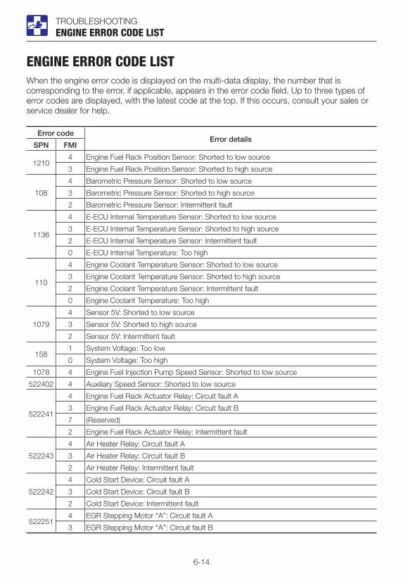
6-14
TROUBLESHOOTINGENGINE ERROR CODE LIST
ENGINE ERROR CODE LISTWhen the engine error code is displayed on the multi-data display, the number that is corresponding to the error, if applicable, appears in the error code field. Up to three types of error codes are displayed, with the latest code at the top. If this occurs, consult your sales or service dealer for help.
Error codeError details
SPN FMI
12104 Engine Fuel Rack Position Sensor: Shorted to low source
3 Engine Fuel Rack Position Sensor: Shorted to high source
108
4 Barometric Pressure Sensor: Shorted to low source
3 Barometric Pressure Sensor: Shorted to high source
2 Barometric Pressure Sensor: Intermittent fault
1136
4 E-ECU Internal Temperature Sensor: Shorted to low source
3 E-ECU Internal Temperature Sensor: Shorted to high source
2 E-ECU Internal Temperature Sensor: Intermittent fault
0 E-ECU Internal Temperature: Too high
110
4 Engine Coolant Temperature Sensor: Shorted to low source
3 Engine Coolant Temperature Sensor: Shorted to high source
2 Engine Coolant Temperature Sensor: Intermittent fault
0 Engine Coolant Temperature: Too high
1079
4 Sensor 5V: Shorted to low source
3 Sensor 5V: Shorted to high source
2 Sensor 5V: Intermittent fault
1581 System Voltage: Too low
0 System Voltage: Too high
1078 4 Engine Fuel Injection Pump Speed Sensor: Shorted to low source
522402 4 Auxiliary Speed Sensor: Shorted to low source
522241
4 Engine Fuel Rack Actuator Relay: Circuit fault A
3 Engine Fuel Rack Actuator Relay: Circuit fault B
7 (Reserved)
2 Engine Fuel Rack Actuator Relay: Intermittent fault
522243
4 Air Heater Relay: Circuit fault A
3 Air Heater Relay: Circuit fault B
2 Air Heater Relay: Intermittent fault
522242
4 Cold Start Device: Circuit fault A
3 Cold Start Device: Circuit fault B
2 Cold Start Device: Intermittent fault
5222514 EGR Stepping Motor “A”: Circuit fault A
3 EGR Stepping Motor “A”: Circuit fault B

6-15
TROUBLESHOOTINGENGINE ERROR CODE LIST
Error codeError details
SPN FMI
5222524 EGR Stepping Motor “B”: Circuit fault A
3 EGR Stepping Motor “B”: Circuit fault B
5222534 EGR Stepping Motor “C”: Circuit fault A
3 EGR Stepping Motor “C”: Circuit fault B
5222544 EGR Stepping Motor “D”: Circuit fault A
3 EGR Stepping Motor “D”: Circuit fault B
1004 Oil Pressure Switch: Shorted to low source
1 Oil Pressure: Too low
1674 Battery Charge Switch: Shorted to low source
1 Charge warning
522314 0 Engine Coolant Temperature: Abnormal temperature
522323 0 Air Cleaner: Mechanical malfunction
522329 0 Oily Water Separator: Mechanical malfunction
190 0 Engine speed: Overspeed condition
638
4 Engine Fuel Rack Actuator: Shorted to low source
3 Engine Fuel Rack Actuator: Shorted to high source
7 Engine Fuel Rack Actuator: Mechanical malfunction
2 Engine: Malfunction
639 12 High-speed CAN Communication: Communication fault
6302 E-ECU internal fault: EEPROM checksum error (Data Set 2)
12 E-ECU internal fault: EEPROM read/write fault
628
12 E-ECU internal fault: Flash ROM checksum error (Main software)
2 E-ECU internal fault: Flash ROM checksum error (Data Set 1)
2 E-ECU internal fault: Flash ROM checksum error (Data Set 2)
1485 4 E-ECU Main Relay: Shorted to low source
522727
12 E-ECU internal fault: Sub-CPU error A
12 E-ECU internal fault: Sub-CPU error B
12 E-ECU internal fault: Sub-CPU error C
522728 12 E-ECU internal fault: Engine Map Data Version Error
52273012 Immobilizer: CAN communication fault
8 Immobilizer: Pulse communication fault
1202 2 Immobilizer: System fault
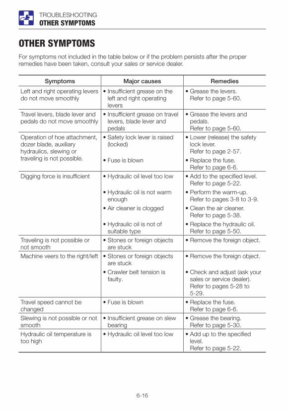
6-16
TROUBLESHOOTINGOTHER SYMPTOMS
OTHER SYMPTOMSFor symptoms not included in the table below or if the problem persists after the proper remedies have been taken, consult your sales or service dealer.
Symptoms Major causes Remedies
Left and right operating levers do not move smoothly
• Insufficient grease on the left and right operating levers
• Grease the levers. Refer to page 5-60.
Travel levers, blade lever and pedals do not move smoothly
• Insufficient grease on travel levers, blade lever and pedals
• Grease the levers and pedals.
Refer to page 5-60.Operation of hoe attachment, dozer blade, auxiliary hydraulics, slewing or traveling is not possible.
• Safety lock lever is raised (locked)
• Lower (release) the safety lock lever.
Refer to page 2-57.• Fuse is blown • Replace the fuse.
Refer to page 6-6.Digging force is insufficient • Hydraulic oil level too low • Add to the specified level.
Refer to page 5-22.• Hydraulic oil is not warm
enough• Perform the warm-up. Refer to pages 3-8 to 3-9.
• Air cleaner is clogged • Clean the air cleaner. Refer to page 5-38.
• Hydraulic oil is not of suitable type
• Replace the hydraulic oil. Refer to page 5-50.
Traveling is not possible or not smooth
• Stones or foreign objects are stuck
• Remove the foreign object.
Machine veers to the right/left • Stones or foreign objects are stuck
• Remove the foreign object.
• Crawler belt tension is faulty.
• Check and adjust (ask your sales or service dealer).
Refer to pages 5-28 to 5-29.
Travel speed cannot be changed
• Fuse is blown • Replace the fuse. Refer to page 6-6.
Slewing is not possible or not smooth
• Insufficient grease on slew bearing
• Grease the bearing. Refer to page 5-30.
Hydraulic oil temperature is too high
• Hydraulic oil level too low • Add up to the specified level.
Refer to page 5-22.
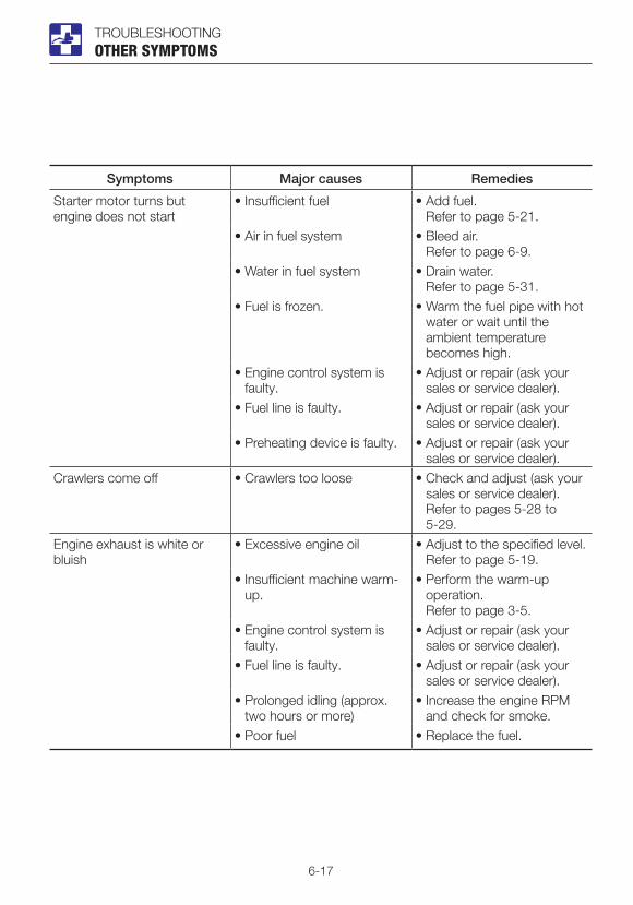
6-17
TROUBLESHOOTINGOTHER SYMPTOMS
Symptoms Major causes Remedies
Starter motor turns but engine does not start
• Insufficient fuel • Add fuel. Refer to page 5-21.
• Air in fuel system • Bleed air. Refer to page 6-9.
• Water in fuel system • Drain water. Refer to page 5-31.
• Fuel is frozen. • Warm the fuel pipe with hot water or wait until the ambient temperature becomes high.
• Engine control system is faulty.
• Adjust or repair (ask your sales or service dealer).
• Fuel line is faulty. • Adjust or repair (ask your sales or service dealer).
• Preheating device is faulty. • Adjust or repair (ask your sales or service dealer).
Crawlers come off • Crawlers too loose • Check and adjust (ask your sales or service dealer).
Refer to pages 5-28 to 5-29.
Engine exhaust is white or bluish
• Excessive engine oil • Adjust to the specified level. Refer to page 5-19.
• Insufficient machine warm-up.
• Perform the warm-up operation.
Refer to page 3-5.• Engine control system is
faulty.• Adjust or repair (ask your
sales or service dealer).• Fuel line is faulty. • Adjust or repair (ask your
sales or service dealer).• Prolonged idling (approx.
two hours or more)• Increase the engine RPM
and check for smoke.• Poor fuel • Replace the fuel.
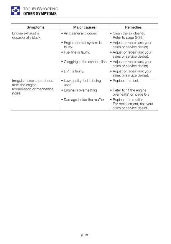
6-18
TROUBLESHOOTINGOTHER SYMPTOMS
Symptoms Major causes Remedies
Engine exhaust is occasionally black
• Air cleaner is clogged • Clean the air cleaner. Refer to page 5-38.
• Engine control system is faulty.
• Adjust or repair (ask your sales or service dealer).
• Fuel line is faulty. • Adjust or repair (ask your sales or service dealer).
• Clogging in the exhaust line. • Adjust or repair (ask your sales or service dealer).
• DPF is faulty. • Adjust or repair (ask your sales or service dealer).
Irregular noise is produced from the engine (combustion or mechanical noise)
• Low quality fuel is being used
• Replace the fuel.
• Engine is overheating • Refer to “If the engine overheats” on page 6-3.
• Damage inside the muffler • Replace the muffler. For replacement, ask your
sales or service dealer.

6-19
TROUBLESHOOTINGLOWERING THE BOOM TO THE GROUND
LOWERING THE BOOM TO THE GROUNDIf the hoe attachment must be lowered to the ground while the engine is stopped, use the following procedure.
Procedure 1 (machines with an accumulator)Perform this operation within 10 minutes after the engine stopping.1. Sit at the operator’s seat.2. Turn the starter switch to the ON position.3. Lower the safety lock lever to the unlock
position4. Slowly push the operating lever forward to
lower the boom.
Procedure 2 (machines without an accumulator)This operation is dangerous and requires experience. Ask your sales or service dealer for it.
• Stop the engine and allow the machine to cool down before performing maintenance.· The engine and the hydraulic system
and many other parts of the machine are hot immediately after the engine is stopped. Touching these parts will cause burns.
· The hydraulic oil is also hot and under high pressure immediately after the engine is stopped.
Be careful when loosening the caps or plugs. Working on the machine under these conditions could result in burns or injuries due to the hot oil spurting out.
• Keep away from the working area when the hoe attachment is lowered. You may be hit by dirt falling out of the bucket or the hoe attachment as it drops.
• Slowly turn the hose nut and lower the boom at a slow pace.
• Do not loosen or remove the hoses not located in the specified places. Oil may spurt out if wrongly handled.
Equipped with emergency shut-off valve
1. Place a pan under the hose to catch the waste oil.
2. Hold the hose fitting (1) with a wrench and slowly loosen the hose nut (2) with another wrench.
3. The oil in the boom cylinder is drained and the hoe attachment is lowered.
4. After the hoe attachment is lowered to the ground, check the safety and stability of the machine.
5. Hold the hose fitting (1) with a wrench and tighten the hose nut (2) with another wrench.· Tightening torque: 31.4 N·m (23.1 ft-lb.)
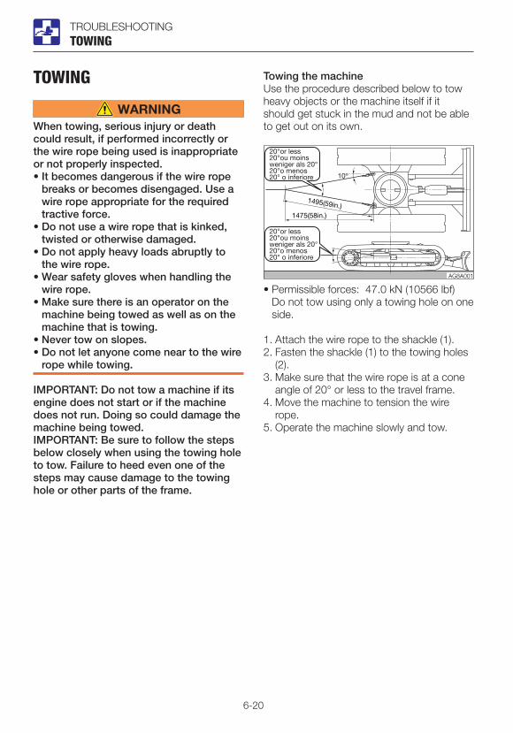
6-20
TROUBLESHOOTING
TOWING
When towing, serious injury or death could result, if performed incorrectly or the wire rope being used is inappropriate or not properly inspected. • It becomes dangerous if the wire rope
breaks or becomes disengaged. Use a wire rope appropriate for the required tractive force.
• Do not use a wire rope that is kinked, twisted or otherwise damaged.
• Do not apply heavy loads abruptly to the wire rope.
• Wear safety gloves when handling the wire rope.
• Make sure there is an operator on the machine being towed as well as on the machine that is towing.
• Never tow on slopes.• Do not let anyone come near to the wire
rope while towing.
IMPORTANT: Do not tow a machine if its engine does not start or if the machine does not run. Doing so could damage the machine being towed.IMPORTANT: Be sure to follow the steps below closely when using the towing hole to tow. Failure to heed even one of the steps may cause damage to the towing hole or other parts of the frame.
TOWING
Towing the machineUse the procedure described below to tow heavy objects or the machine itself if it should get stuck in the mud and not be able to get out on its own.
• Permissible forces: 47.0 kN (10566 lbf) Do not tow using only a towing hole on one
side.
1. Attach the wire rope to the shackle (1).2. Fasten the shackle (1) to the towing holes
(2).3. Make sure that the wire rope is at a cone
angle of 20° or less to the travel frame. 4. Move the machine to tension the wire
rope.5. Operate the machine slowly and tow.
AG8A001

6-21
TROUBLESHOOTINGIF THE CAB OR CANOPY IS DAMAGED
IF THE CAB OR CANOPY IS DAMAGED
Immediately replace the damaged cab or canopy. Serious injury or death may occur if the machine is operated with damaged cab/canopy.Do not operate the machine until the replacement is complete. Do not try to repair the damaged cab or canopy by welding. Doing so could endanger the safety of the cab/canopy.
Canopy part number: 05584-00085Cab part number: 03586-00070

6-22

7-1
SPECIFICATIONS
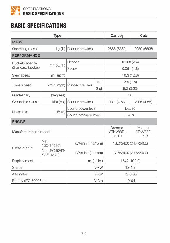
7-2
SPECIFICATIONSBASIC SPECIFICATIONS
BASIC SPECIFICATIONS
Type Canopy Cab
MASS
Operating mass kg (lb) Rubber crawlers 2885 (6360) 2950 (6505)
PERFORMANCE
Bucket capacity(Standard bucket) m3 (cu. ft.)
Heaped 0.068 (2.4)
Struck 0.051 (1.8)
Slew speed min-1 (rpm) 10.3 (10.3)
Travel speed km/h (mph) Rubber crawlers1st 2.9 (1.8)
2nd 5.2 (3.23)
Gradeability (degrees) 30
Ground pressure kPa (psi) Rubber crawlers 30.1 (4.63) 31.6 (4.58)
Noise level dB (A)Sound power level LWA 93
Sound pressure level LpA 78
ENGINE
Manufacturer and modelYanmar
3TNV88F- EPTB1
Yanmar 3TNV88F-
EPTB
Rated output
Net (ISO 14396) kW/min-1 (hp/rpm) 18.2/2400 (24.4/2400)
Net (ISO 9249/ SAEJ1349) kW/min-1 (hp/rpm) 17.6/2400 (23.6/2400)
Displacement ml (cu.in.) 1642 (100.2)
Starter V-kW 12-1.7
Alternator V-kW 12-0.66
Battery (IEC 60095-1) V-A·h 12-64

7-3
MEMO

7-4
SPECIFICATIONS
MACHINE DIMENSIONS
MACHINE DIMENSIONS

7-5
SPECIFICATIONSMACHINE DIMENSIONS
Unit: mm (inch)
ItemLong arm
Rubber crawlers
A Overall length 4595 (180.9)
B Upperstructure overall width 1460 (57.5)
C Overall height 2540 (100) 2525 (99.3)**
D Slew radius 1330 (52.4)
E Clearance height under upperstructure 590 (23.2)
F Crawler base 1440 (56.7)
G Crawler overall length 1900 (74.9)
H Crawler overall width 1450 (57.1)
J Crawler shoe width 300 (11.8)
K Ground clearance of undercarriage 305 (11.9)
L Minimum radius of equipment and attachment 1895 (74.7)
M Minimum radius of equipment at maximum front offset 1505 (59.2)
P Offset distance of bucket (right swing) 490 (19.3)
Q Offset distance of bucket (left swing) 610 (23.9)
R Dozer blade width 1450 (57.1)
S Dozer blade height 355 (14.0)
T Front distance to axis of rotation 3265 (128.5)
U Dozer blade distance to axis of rotation 1455 (57.3) 1480 (58.3)*
V Boom swing angle (Left) 79°
W Boom swing angle (Right) 58°
X Overall length (dozer blade at rear) 4730 (186.3) 4755 (187.2)*
* : With an angle dozer blade** : Cab
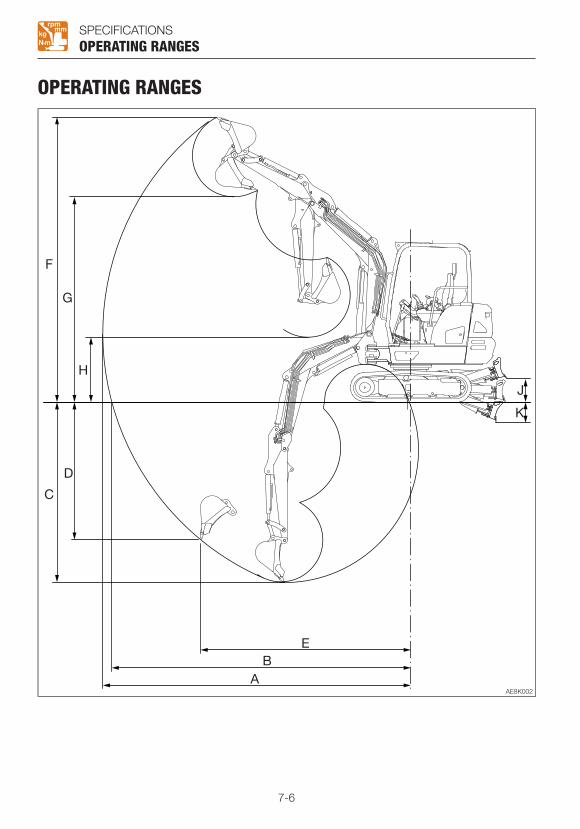
7-6
SPECIFICATIONS
OPERATING RANGES
OPERATING RANGES

7-7
SPECIFICATIONSOPERATING RANGES
Unit: mm (inch)
ItemLong arm
Rubber crawlers
A Maximum reach 4850 (190.9)
B Maximum reach at ground reference plane 4710 (185.4)
C Maximum digging depth 2835 (111.6)
D Maximum vertical digging depth 2165 (85.2)
E Reach at maximum vertical digging depth 3310 (130.4)
F Maximum height of cutting edge 4490 (176.7)
G Maximum dumping height 3230 (127.2)
H Minimum dumping height 1020 (40.2)
J Dozer blade maximum lifting 380 (15.0) 370 (14.5)*
K Dozer blade maximum lowering 310 (12.2) 325 (12.9)*
*: With an angle dozer blade

7-8
MEMO

7-9
SPECIFICATIONS
LIFTING CAPACITIESRated lift capacity chart• The loads in the charts do not exceed 87%
of hydraulic lift capacity or 75% of tipping load.
• Figures marked with an asterisk (*) are hydraulically-limited capacities.
• The mass of slings and any other lifting devices shall be deducted from the rated load to determine the net load that may be lifted.
• The load point is the bucket hinge pin, and the bucket posture is with the standard bucket completely retracted under the arm.
• Unit: daN (lbs)
Load hooking systemA load hooking system must be provided with the following capabilities.1. A system which can withstand twice the
rated lift capacity no matter at what position the load is applied.
2. A system that poses no risk of the lifted load falling from the hooking device. For example, equipped with a hook slippage prevention device.
3. A system that poses no risk of the hooking system slipping from the hoe attachment.
LIFTING CAPACITIES
• Do not attempt to lift or hold any load that is greater than these rated values at their specified load radii and height.
• The rated lift capacities are based on the machine being level and situated on a firm supporting surface. For safe lifting, the operator is expected to make due allowance for the particular job conditions such as soft or uneven ground, non-level condition, load to the machine sides, hazardous conditions, experience of personnel, etc. The operator and other personnel should fully acquaint themselves with the operator’s manual furnished by the manufacturer before operating this machine. When operating the machine, the safety rules of the equipment must also be followed.
• Do not travel while lifting a load; It is very dangerous.

7-10
SPECIFICATIONS
<Cab> Long arm
LIFTING CAPACITIES

7-11
SPECIFICATIONSLIFTING CAPACITIES
<Cab> Long arm

7-12
SPECIFICATIONS
<Canopy> Long arm
LIFTING CAPACITIES
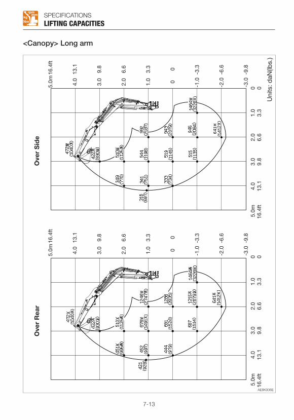
7-13
SPECIFICATIONS
<Canopy> Long arm
LIFTING CAPACITIES

7-14

8-1
OPTIONSOPTIONS

8-2
OPTIONS
GENERAL PRECAUTIONSSAFETY PRECAUTIONS
When removing or installing an attachment or optional part, take the following precautions.• Consult with Takeuchi before installing
an optional attachment.• Do not use any attachments not
approved by Takeuchi. Doing so may cause safety problems. Or, it may adversely affect the machine’s operation or service life.
• We will not be held responsible for any injuries, accidents or damage to its products caused by the use by a non-approved attachment.
• Select a firm, level work area. Also, be sure to park in a well ventilated place.
• Clear obstacles and dangerous objects, and clean up spilled fuel immediately.
• When hoisting, be sure to designate a person to act as a signalman.
Follow the instructions of the signalman regarding the procedure and measures.
• When it is necessary to temporally place a heavy object or an attachment on the ground during removal or installation, be sure to place it in a stable position.
• Keep everyone out of the area when hoisting. There is a hazard of objects falling or contacting with people in the area.
• Use a crane to move heavy objects (25 kg (55 lb.) or greater).
• Before removing a heavy object, be sure to put a support to it. When lifting with a crane, pay attention to the center of gravity of the load to keep the machine in balance.
• Do not operate the machine while the load is lifted by a crane stand.
GENERAL PRECAUTIONS
• Use the proper procedure when mounting a boom or arm; otherwise serious damage could result. Consult your sales or service dealer for help.
CAUTIONS WHEN INSTALLING ATTACHMENTS
Be sure to perform a test operation after an optional or other special attachment has been replaced. Inspect the hydraulic oil level and recharge it as necessary. Consult your sales or service dealer for detailed procedures on installing/removing attachments.

8-3
OPTIONS
CAUTIONS WHEN OPERATING ATTACHMENTS
Long attachments reduce stability of the machine. The machine may tip over if it loses the balance when traveling or slewing on slopes. Never perform the operations listed below as they are extremely dangerous.
GENERAL PRECAUTIONS
• Traveling down the slopes with the attachment raised
• Traveling across slopes
• Slewing on slopes• If there is a heavy attachment is
installed, the machine takes longer distance than usual to come to a complete stop when the stopping operation is performed. Carefully judge the distance so as not to bump into an object around the machine. Keep a safe distance from surrounding obstacles.
When a heavy attachment is installed, natural drop (the gradual dropping of the attachment under its own weight when it is stopped in midair) increases.
• The machine can tip over more easily in the lateral direction than in the longitudinal direction.· Do not slew sideways with a heavy
load at the how attachment. In particular, do not slew sideways on slopes.
· The attachment is heavier for machines equipped with breakers or crushers than for machines equipped with the standard bucket. Do not operate such machines sideways, especially digging downhill.
• When a long arm is installed, the operating range increases. Carefully judge the distance so as not to bump into an object around the machine. Keep a safe distance from surrounding obstacles.
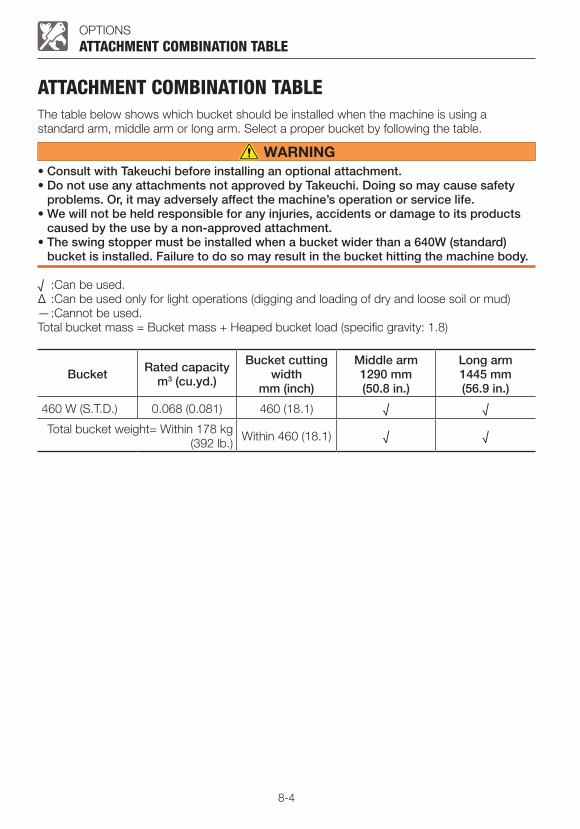
8-4
OPTIONS
ATTACHMENT COMBINATION TABLEThe table below shows which bucket should be installed when the machine is using a standard arm, middle arm or long arm. Select a proper bucket by following the table.
• Consult with Takeuchi before installing an optional attachment.• Do not use any attachments not approved by Takeuchi. Doing so may cause safety
problems. Or, it may adversely affect the machine’s operation or service life. • We will not be held responsible for any injuries, accidents or damage to its products
caused by the use by a non-approved attachment.• The swing stopper must be installed when a bucket wider than a 640W (standard)
bucket is installed. Failure to do so may result in the bucket hitting the machine body.
√ :Can be used.∆ :Can be used only for light operations (digging and loading of dry and loose soil or mud)— :Cannot be used.Total bucket mass = Bucket mass + Heaped bucket load (specific gravity: 1.8)
ATTACHMENT COMBINATION TABLE
Bucket Rated capacitym3 (cu.yd.)
Bucket cutting width
mm (inch)
Middle arm1290 mm (50.8 in.)
Long arm1445 mm (56.9 in.)
460 W (S.T.D.) 0.068 (0.081) 460 (18.1) √ √
Total bucket weight= Within 178 kg(392 lb.) Within 460 (18.1) √ √
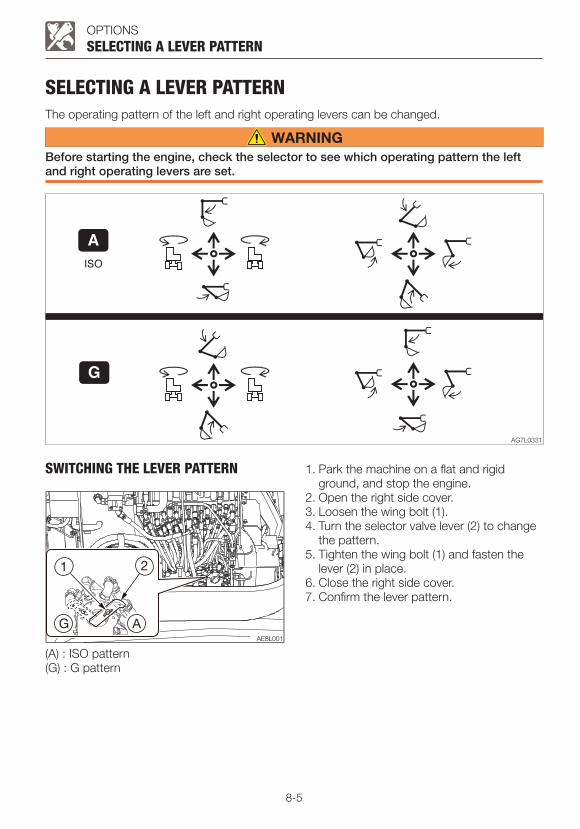
8-5
OPTIONS
SELECTING A LEVER PATTERNThe operating pattern of the left and right operating levers can be changed.
Before starting the engine, check the selector to see which operating pattern the left and right operating levers are set.
SELECTING A LEVER PATTERN
SWITCHING THE LEVER PATTERN
(A) : ISO pattern(G) : G pattern
1. Park the machine on a flat and rigid ground, and stop the engine.
2. Open the right side cover.3. Loosen the wing bolt (1).4. Turn the selector valve lever (2) to change
the pattern.5. Tighten the wing bolt (1) and fasten the
lever (2) in place.6. Close the right side cover.7. Confirm the lever pattern.
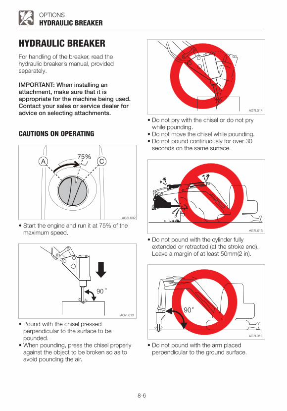
8-6
OPTIONS
HYDRAULIC BREAKERFor handling of the breaker, read the hydraulic breaker’s manual, provided separately.
IMPORTANT: When installing an attachment, make sure that it is appropriate for the machine being used.Contact your sales or service dealer for advice on selecting attachments.
CAUTIONS ON OPERATING
HYDRAULIC BREAKER
• Start the engine and run it at 75% of the maximum speed.
• Pound with the chisel pressed perpendicular to the surface to be pounded.
• When pounding, press the chisel properly against the object to be broken so as to avoid pounding the air.
• Do not pry with the chisel or do not pry while pounding.
• Do not move the chisel while pounding.• Do not pound continuously for over 30
seconds on the same surface.
• Do not pound with the cylinder fully extended or retracted (at the stroke end). Leave a margin of at least 50mm(2 in).
• Do not pound with the arm placed perpendicular to the ground surface.
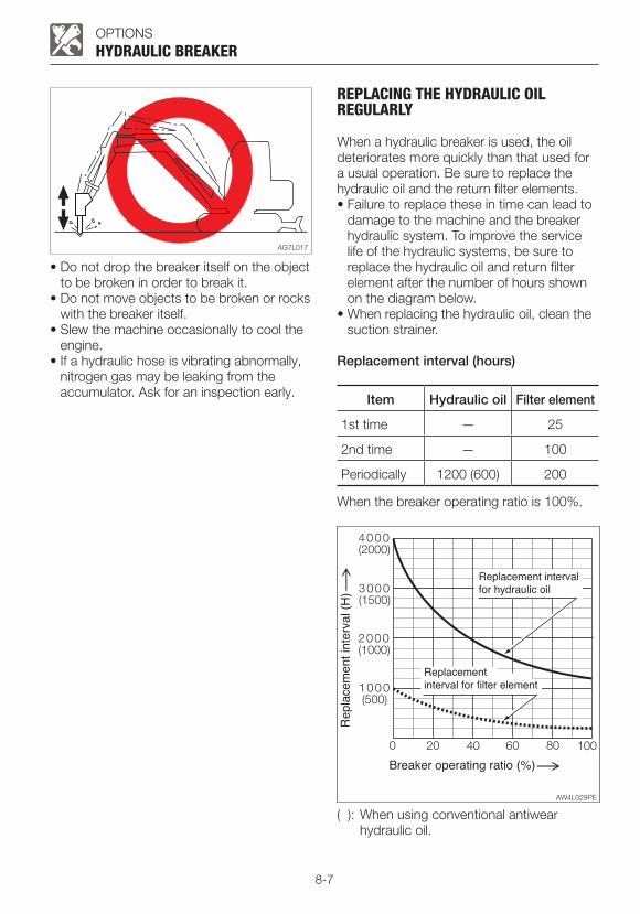
8-7
OPTIONS
• Do not drop the breaker itself on the object to be broken in order to break it.
• Do not move objects to be broken or rocks with the breaker itself.
• Slew the machine occasionally to cool the engine.
• If a hydraulic hose is vibrating abnormally, nitrogen gas may be leaking from the accumulator. Ask for an inspection early.
HYDRAULIC BREAKER
REPLACING THE HYDRAULIC OIL REGULARLY
When a hydraulic breaker is used, the oil deteriorates more quickly than that used for a usual operation. Be sure to replace the hydraulic oil and the return filter elements.• Failure to replace these in time can lead to
damage to the machine and the breaker hydraulic system. To improve the service life of the hydraulic systems, be sure to replace the hydraulic oil and return filter element after the number of hours shown on the diagram below.
• When replacing the hydraulic oil, clean the suction strainer.
Replacement interval (hours)
Item Hydraulic oil Filter element
1st time — 25
2nd time — 100
Periodically 1200 (600) 200
When the breaker operating ratio is 100%.
( ): When using conventional antiwear hydraulic oil.

8-8
OPTIONS
TRAVEL ALARMThe alarm sounds while the machine is traveling and stops when the machine stops traveling.If the alarm does not sound when the machine travels, the fuse may be blown. Inspect the fuses.
If the fuse blows again soon after replacement, then the electric system is likely faulty. It may pose a fire hazard if not properly repaired. Contact your sales or service dealer for advice.
1. Turn the starter key to the OFF position to stop the engine.
TRAVEL ALARM
2. Open the fuse box cover (1).3. Check for any blown fuses (2).
4. If a fuse is blown, replace it with a spare fuse of the same capacity.
Fuse layout and circuits protected
<Cab>
Capacity Symbol Protected circuit
5A Switch lighting
10A Horn
5A Starter switch
10A Immobilizer
20A Light
10A Wiper
20A Lever lock
10AController power supply (2), Travel alarm
10A Solenoid
20A Cab interior power supply
25A OPT Option
10A Heater
10A Feed pump
30A Blower motor
20A Cab light
20A Controller power supply (1)

8-9
OPTIONSTRAVEL ALARM
<Canopy>
Capacity Symbol Protected circuit
5A Switch lighting
10A Horn
5A Starter switch
10A Immobilizer
20A Light (1)
20A Lever lock
15AController power supply, Travel alarm
25A Solenoid
20A OPT (1) Option (1)
25A OPT (2) Option (2)
10A Feed pump
15A Light (2)

8-10
OPTIONS
OPTIONAL EQUIPMENT MASS
OPTION
Steel crawler (Including shoe guide) 83 (183)
Angle blade 89 (196)
Long arm 9 (20)
Roof guard (Level II: ISO 10262) 47 (104)
Front guard (Level II: ISO 10262) 42 (91)
Units: kg (lb)*: Mass of optional equipment is added to the standard machine mass.*: This table only contains the optional equipment of 10kg (20lb) or more in mass.
OPTIONAL EQUIPMENT MASS

8-11
OPTIONS
BIODEGRADABLE OILBiodegradable oil is a new type of hydraulic oil that is decomposed into carbon dioxide and water by microorganisms in the soil and water. It is highly safe for living organisms and offers advantages in term of environmental protection.• Recommended biodegradable oil: Mobile
EAL Envirosyn 46H (an ester synthetic oil). When replacing the hydraulic oil with
biodegradable oil, use the above or an equivalent oil.
Note that other oils, even other brands of ester synthetic oils, may damage O-rings, packings and seals. Takeuchi products shipped with the optional biodegradable oil are shipped with the above brand of oil.
• When switching from a mineral oil to a biodegradable oil, the parking brake torque decreases by about 30%.
REPLACING THE HYDRAULIC OIL WITH BIODEGRADABLE OIL
Mixing mineral oil with biodegradable oil will result in a decrease of the hydraulic oil’s performance as well as a decrease in biodegradability and safety. The hydraulic oil system must be flushed as described below before supplying the biodegradable oil. This operation is dangerous and requires experience. Have it performed by a Takeuchi sales or service outlet.
FlushingTo be performed by a Takeuchi sales or service outlet1. Drain the hydraulic oil (mineral oil) from the
hydraulic oil tank and clean the inside of the tank and suction strainer.
Refer to “Replacing the hydraulic oil and cleaning the suction strainer”.
2. Remove the cylinder hoses and drain the hydraulic oil (mineral oil) from inside the cylinders.
3. Supply new biodegradable oil to the hydraulic oil tank.
4. Bleed the air from the hydraulic oil system.5. Operate the hydraulic devices for 30
minutes.6. Drain the biodegradable oil from the tank
and cylinders.7. Replace the hydraulic oil return filter with a
new filter.8. Repeat steps 3 and 4.9. Operate the hydraulic devices for 30
minutes.10. Drain the biodegradable oil from the tank
and cylinders.11. Repeat steps 3 and 4.12. Operate the hydraulic devices for 1 hour.13. Drain the biodegradable oil from the tank
and cylinders.14. Replace the return filter with a new filter.15. Repeat steps 3 and 4.16. Operate the hydraulic devices, then
check for oil leakage.There is no need to flush the hydraulic oil system when switching from biodegradable to mineral hydraulic oil.
BIODEGRADABLE OIL
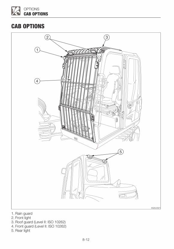
8-12
OPTIONS
CAB OPTIONS
CAB OPTIONS
1. Rain guard2. Front light3. Roof guard (Level II: ISO 10262)4. Front guard (Level II: ISO 10262)5. Rear light
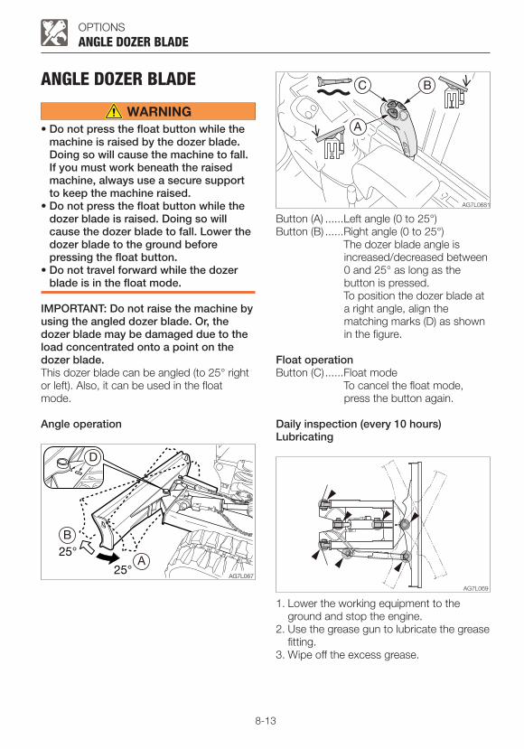
8-13
OPTIONS
ANGLE DOZER BLADE
• Do not press the float button while the machine is raised by the dozer blade. Doing so will cause the machine to fall. If you must work beneath the raised machine, always use a secure support to keep the machine raised.
• Do not press the float button while the dozer blade is raised. Doing so will cause the dozer blade to fall. Lower the dozer blade to the ground before pressing the float button.
• Do not travel forward while the dozer blade is in the float mode.
IMPORTANT: Do not raise the machine by using the angled dozer blade. Or, the dozer blade may be damaged due to the load concentrated onto a point on the dozer blade.This dozer blade can be angled (to 25° right or left). Also, it can be used in the float mode.
Angle operation
ANGLE DOZER BLADE
Button (A) ......Left angle (0 to 25°)Button (B) ......Right angle (0 to 25°) The dozer blade angle is
increased/decreased between 0 and 25° as long as the button is pressed.
To position the dozer blade at a right angle, align the matching marks (D) as shown in the figure.
Float operationButton (C) ......Float mode To cancel the float mode,
press the button again.
Daily inspection (every 10 hours)Lubricating
1. Lower the working equipment to the ground and stop the engine.
2. Use the grease gun to lubricate the grease fitting.
3. Wipe off the excess grease.

8-14
OPTIONSANGLE DOZER BLADE
SPECIFICATIONS
Item Rubber crawlers
A Dozer blade width 1450 (57.1)
B Dozer blade height 355 (14)
C Dozer blade distance to axis of rotation 1480 (58.3)
D Dozer blade maximum lifting 370 (14.5)
E Dozer blade maximum lowering 325 (12.9)
F Angle degree (Left/Right) 25°
Unit: mm (inch)

8-15

8-16
First Published August 2014Second Published December 2014
Printed in Japan by STATION M Co., Ltd.
OPERATOR’S MANUAL
No.43521
Mini excavatorTB230
Edited and issued by TAKEUCHI MFG. CO., LTD.
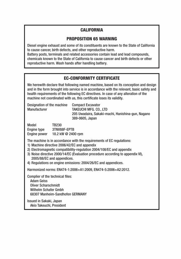
CALIFORNIA
PROPOSITION 65 WARNINGDiesel engine exhaust and some of its constituents are known to the State of California to cause cancer, birth defects, and other reproductive harm.Battery posts, terminals and related accessories contain lead and lead compounds, chemicals known to the State of California to cause cancer and birth defects or other reproductive harm. Wash hands after handling battery.
EC-CONFORMITY CERTIFICATEWe herewith declare that following named machine, based on its conception and design and in the form brought into service is in accordance with the relevant, basic safety and health requirements of the following EC directives. In case of any alteration of the machine not coordinated with us, this certificate loses its validity.
Designation of the machine Compact ExcavatorManufacturer TAKEUCHI MFG. CO., LTD 205 Uwadaira, Sakaki-machi, Hanishina-gun, Nagano
389-0605, Japan
ModelEngine typeEngine power
The machine is in accordance with the requirements of EC regulations:1) Machine directive 2006/42/EC and appendix2) Electromagnetic compatibility-regulation 2004/108/EC and appendix3) Noise directive 2000/14/EC (Evaluation procedure according to appendix VI),
2005/88/EC and appendices.4) Regulations on engine emissions: 2004/26/EC and appendices.
Harmonized norms: EN474-1:2006+A1:2009, EN474-5:2006+A2:2012.
Complier of the technical files:Adam GeissOliver ScharschmidtWilhelm Schafer Gmbh68307 Manheim-Sandhofen GERMANY
Issued in Sakaki, JapanAkio Takeuchi, President
TB2303TNV88F-EPTB18.2 kW @ 2400 rpm