Apollo Experience Report - Spacecraft Pyrotechnic Systems ...
46
' NASA TECHNICAL NOTE a c- APOLLO EXPERIENCE REPORT - SPACECRAFT PYROTECHNIC SYSTEMS by Mario J. Falbo and Robert L. Robinson Manned Spacecrafi Center Houstoiz, Texas 7 705 8 NATIONAL AERONAUTICS AND SPACE ADMINISTRATION WASHINGTON, D. C. MARCH 1973
-
Upload
khangminh22 -
Category
Documents
-
view
7 -
download
0
Transcript of Apollo Experience Report - Spacecraft Pyrotechnic Systems ...
' NASA TECHNICAL NOTE
a c-
APOLLO EXPERIENCE REPORT - SPACECRAFT PYROTECHNIC SYSTEMS
by Mario J. Falbo and Robert L. Robinson
Manned Spacecrafi Center Houstoiz, Texas 7 705 8
N A T I O N A L A E R O N A U T I C S A N D SPACE A D M I N I S T R A T I O N W A S H I N G T O N , D. C. M A R C H 1973

1. Report No.
NASA TN D-7141
APOLLO EXPERIENCE REPORT SPACECRAFT PYROTECHNTC SYSTEMS
2. Government Accession No. 3. Recipient's Catalog No.
March 1973 6. Performing Organization Code
4. Title and Subtitle
7. Author(s) Mario J. Falbo and Robert L. Robinson, MSC
5. Report Date
8. Performing Organization Report No. I MSC S-340
9. Performing Organization Name and Address Manned Spacecraft Center Houston, Texas 77058
10. Work Unit No.
914 -50-17-08-72
11. Contract or Grant No.
13. Type of Report and Period Covered
Technical Note 2. Sponsoring Agency Name and Address
19. Security Classif. (of this report)
None
National Aeronautics and Space Administration Washington, D. C. 20546
20. Security Classif. (of this page) 21. NO. of Pages 22. Price
None 46 $3.00
14. Sponsoring Agency Code
1 15. Supplementary Notes
The MSC Director waived the use of the International System of Units (SI) for this Apollo Experience Report, because, in his judgment, the use of SI Units would impair the usefulness of the report o r result in excessive cost.
16. Abstract
mrotechnic devices were used successfully in many systems of the Apollo spacecraft. physical and functional characteristics of each device are described. The development, .qualification, and performance tests of the devices and the ground-support equipment a r e discussed briefly. Recommendations for pyrotechnic devices on future space vehicles a r e given.
The
17. Key Words (Suggested by Author(s) )
Initiator * Disconnects Linear -Shaped Charge Cartridges Mild Detonating Fuse Valves Thrusters ' High Explosive ' Parachute Mortars Actuators ' Circuit Interrupters Guillotines . Separation System
18. Distribution Statement

CONTENTS
Section Page
SUMMARY . . . . . . . . . . . . . . . . . . . . . . . . . . . . . . . . . . . . . INTRODUCTION . . . . . . . . . . . . . . . . . . . . . . . . . . . . . . . . . . . DESCRIPTION OF SYSTEMS . . . . . . . . . . . . . . . . . . . . . . . . . . .
Launch-Escape System . . . . . . . . . . . . . . . . . . . . . . . . . . . . . Command and Service Module Systems . . . . . . . . . . . . . . . . . . . . Lunar Module Systems. . . . . . . . . . . . . . . . . . . . . . . . . . . . .
COMPONENT DESIGN AND DEVELOPMENT . . . . . . . . . . . . . . . . . . Single Bridgewire Apollo Standard Initiator . . . . . . . . . . . . . . . . . . Cartridge Assemblies . . . . . . . . . . . . . . . . . . . . . . . . . . . . . Detonators . . . . . . . . . . . . . . . . . . . . . . . . . . . . . . . . . . . . Core Charges . . . . . . . . . . . . . . . . . . . . . . . . . . . . . . . . . Line Cutters . . . . . . . . . . . . . . . . . . . . . . . . . . . . . . . . . .
GROUND-SUPPORTEQUIPMENT . . . . . . . . . . . . . . . . . . . . . . . . Pyrotechnic Simulators . . . . . . . . . . . . . . . . . . . . . . . . . . . . Spacecraft Verification Equipment . . . . . . . . . . . . . . . . . . . . . .
CONCLUSIONS . . . . . . . . . . . . . . . . . . . . . . . . . . . . . . . . . . . RECOMMENDATIONS . . . . . . . . . . . . . . . . . . . . . . . . . . . . . . .
Single Bridgewire Apollo Standard Initiator
Explosive Trains and Interfaces . . . . . . . . . . . . . . . . . . . . . . . . . . . . . . . . . . . . . . . . .
Separation Systems. . . . . . . . . . . . . . . . . . . . . . . . . . . . . . . Reefing Line Cutters . . . . . . . . . . . . . . . . . . . . . . . . . . . . . . Firing Circuitry . . . . . . . . . . . . . . . . . . . . . . . . . . . . . . . .
8
14
17
18
20
21
23
25
26
26
32
36
37
38
38
39
39
39
iii

Table
TABLES
Page
I APOLLO PYROTECHNIC CARTRIDGES
11
(a) Pressure and igniter cartridges . . . . . . . . . . . . . . . . . . (b) Detonator cartridges . . . . . . . . . . . . . . . . . . . . . . .
5 5
APOLLO CORE-CHARGE ASSEMBLIES . . . . . . . . . . . . . . . . 6
FIGURES
Figure
1 Locations of Apollo pyrotechnic devices . . . . . . . . . . . . . . . . 2 Single bridgewire Apollo standard initiator . . . . . . . . . . . . . . 3 Apollo pyrotechnics configuration . . . . . . . . . . . . . . . . . . . 4 Launch-escape-tower jettison . . . . . . . . . . . . . . . . . . . . . 5 Tower -separation system . . . . . . . . . . . . . . . . . . . . . . . 6 Lunar module separation system . . . . . . . . . . . . . . . . . . . . 7 Adapter panel explosive train system . . . . . . . . . . . . . . . . . 8 Separation of SLA panels
(a) Operating details . . . . . . . . . . . . . . . . . . . . . . . . . . (b) Panel jettison . . . . . . . . . . . . . . . . . . . . . . . . . . .
9 Electrical circuit interrupters
(a) Command module . . . . . . . . . . . . . . . . . . . . . . . . . (b) Service module . . . . . . . . . . . . . . . . . . . . . . . . . . .
10 Pyrotechnically operated valve
(a) Closed position . . . . . . . . . . . . . . . . . . . . . . . . . . . (b) Open position . . . . . . . . . . . . . . . . . . . . . . . . . . . .
11 Command module and service module structural separation system . . . . . . . . . . . . . . . . . . . . . . . . . . . . . . . .
12 Command module/service module guillotine . . . . . . . . . . . . . . 13 Command module forward compartment . . . . . . . . . . . . . . . .
Page
4
7
7
8
8
9
9
10 10
11 11
11 11
12
12
13
iv

Figure
14 Apex-cover thruster locations . . . . . . . . . . . . . . . . . . . . . . Reefing line cutter . . . . . . . . . . . . . . . . . . . . . . . . . . . .
16 Parachute disconnect system . . . . . . . . . . . . . . . . . . . . . . 17 Earth landing sequence. . . . . . . . . . . . . . . . . . . . . . . . . . 18 Lunar module pyrotechnics . . . . . . . . . . . . . . . . . . . . . . . 19 Lunar module landing-gear uplock and cutter assembly . . . . . . . .
. 15
20
21
22
23
24
25
26
27
28
29
30
31
Lunar module electrical circuit interrupter. . . . . . . . . . . . . . . Lunar module interstage nut and bolt assembly
Page
13
13
13
14
14
14
15
(a) Before firing . . . . . . . . . . . . . . . . . . . . . . . . . . . . . 16 (b) After firing . . . . . . . . . . . . . . . . . . . . . . . . . . . . . 16
Lunar module interstage umbilical guillotine
(a) Cross section . . . . . . . . . . . . . . . . . . . . . . . . . . . . 16 (b) Installation . . . . . . . . . . . . . . . . . . . . . . . . . . . . . . 16
Initiator indexing 19
Electrically initiated cartridge . . . . . . . . . . . . . . . . . . . . . 20
. . . . . . . . . . . . . . . . . . . . . . . . . . . . .
Spacecraft cartridges . . . . . . . . . . . . . . . . . . . . . . . . . . 20
Spacecraft/lunar module adapter thruster cartridge 21 . . . . . . . . . . 21 Initiator with weld washer . . . . . . . . . . . . . . . . . . . . . . . .
Apollo standard detonator
. 21 21
22
22
(a) Detonator cartridge assembly . . . . . . . . . . . . . . . . . . . . (b) Cross section . . . . . . . . . . . . . . . . . . . . . . . . . . . . End-detonating cartridge . . . . . . . . . . . . . . . . . . . . . . . . Long-reach detonator . . . . . . . . . . . . . . . . . . . . . . . . . . Core charges
. . . . . . . . . . . . . . . . . . . . . . . . . 23 (a) Mild detonating fuse 23 . . . . . . . . . . . . . . . . . . . . . . . . 23 (c) Linear-shaped charge
(b) Confined detonating cord . . . . . . . . . . . . . . . . . . . . . .
V

Figure Page
32 Command and service module initiator simulator
(a) Frontview . . . . . . . . . . . . . . . . . . . . . . . . . . . . . . 27 (b) Rearview . . . . . . . . . . . . . . . . . . . . . . . . . . . . . . . 27
33 Schematic of CSM initiator simulator . . . . . . . . . . . . . . . . . . 27
34 Functional block diagram of LM initiator simulator . . . . . . . . . . . 29
35 Environmental initiator simulator . . . . . . . . . . . . . . . . . . . . 30
36 Static EM1 device . . . . . . . . . . . . . . . . . . . . . . . . . . . . . 30
37 Stray electrical energy indicator . . . . . . . . . . . . . . . . . . . . . 31
38 . High-energy -initiator simulator . . . . . . . . . . . . . . . . . . . . . 31
39 Pyrotechnic checkout test set
(a) Dummy initiator . . . . . . . . . . . . . . . . . . . . . . . . . . . 32 (b) Portable measuring device . . . . . . . . . . . . . . . . . . . . . . 32
40 Pyrotechnic bridge checkout unit
(a) Remote control assembly . . . . . . . . . . . . . . . . . . . . . . 33 (b) B r i d g e u n i t . , . . . . . . . . . . . . . . . . . . . . . . . . . . . . 33
41 Explosive device test set . . . . . . . . . . . . . . . . . . . . . . . . . 34
42 Current regulator . . . . . . . . . . . . . . . . . . . . . . . . . . . . . 35
43 Functional block diagram of the current regulator . . . . . . . . . . . 35
44 Pyroharness shorting plugs and cable set . . . . . . . . . . . . . . . . 35
vi

APOLLO EXPER I ENCE REPORT
SPACECRAFT PYROTECHNIC SYSTEMS
By M a r i o J. Falbo and Robert L. Robinson Manned Spacecraft Center
SUMMARY
Pyrotechnic devices were used in the Apollo spacecraft systems to perform the following functions: launch-escape-tower separation, separation-rocket ignition, sepa- ration of the booster stage from the lunar module, forward-heat-shield jettison, spacecraft/lunar module adapter panel separation, lunar module landing -gear deploy - ment, pressurization and activation of the lunar module propulsion systems, deployment and release of parachutes, opening and closing of electrical circuits, execution of timing and delayed-time functions, and cutting of lines and cables.
Requirements for high reliability and maximum safety were met with devices of minimum weight and volume. low-energy charges for puncturing gas bottles to high-energy charges for cutting 0.153-inch-thick steel.
The capabilities of the devices ranged from relatively
Conventional electrical and mechanical components were used, when possible, to minimize potential design problems, Selection of proper explosive materials also was very important. Test and evaluation programs were continued after the flight qualifica- tion of the devices to understand better the reliability, safety, vulnerability, and output factors. Redundancy and common usage enhanced confidence in the overall pyrotechnic systems. To protect against spurious forms of electrical energy, standard safety practices were followed in the design of the electrical systems.
NO failures of pyrotechnic devices have been detected during any of the Apollo missions. This reliability probably is attributable, at least in large measure, to the conservative design, closely controlled manufacturing processes and testing techniques, and thorough acceptance procedures.
INTRODUCTION
The total number of pyrotechnic devices in the Apollo spacecraft systems varied for different spacecraft. More than 210 pyrotechnic devices were used per flight to perform a myriad of onboard, inflight, timed, and controlled tasks automatically o r on command in the Apollo spacecraft systems. All devices required high reliability and safety. Most were classified as either crew-safety critical o r mission critical, because

improper operation o r failure to operate could have resulted in loss of the crew, in failure to meet a mission objective, o r in an aborted mission.
The high specific energy and other unique properties of explosive and pyrotechnic materials afforded the method for providing a large energy source in a small package. By using explosives, numerous functions were accomplished reliably and safely with minimum weight and space limitations. These properties, coupled with the capability of the pyrotechnic devices to release energy at a high rate in a short time, made wide acceptance in the Apollo Program a natural result.
Confidence in the subsystems was further enhanced with maximum use of redun- dancy. When complete system or device redundancy was not possible because of space or weight limitations, redundant cartridges or single cartridges with dual initiators were used. Two separate and electrically independent systems operated in parallel and provided complete redundancy in the firing circuitry.
Early in the Apollo Program, the concept of modular cartridge assemblies based on a standardized hot-wire initiator was adopted to avoid the expense and time involved in extensive testing associated with the development of different initiators for various applications. A higher confidence in reliability was achieved by the use of standardized, high-volume items. Components, subassemblies, and assemblies were qualified se r i - ally during development of complete systems. Thus, confidence in the reliability of the initiator was enhanced through increased testing with its common use in components.
When possible, the principle of commonality was extended to other assemblies. That is, where a new application required an assembly that used a device (or devices) in a manner almost identical to the use for which existing devices were originally de- signed and tested, the new assembly would be closely related in design and functional characteristics. Additional confidence was attained through extensive performance data that were compiled for all applications, because the systems were largely dependent on component interactions. The policy of standardization of components, which was achieved in the Apollo Program to a greater extent than in any other space program, was not easy to implement, primarily because of natural tendencies of various prime contractors and subcontractors to diverge on the basis of unique technical requirements, both real and unreal,
Where use of the same hardware in different applications was not feasible, the For example, the opposing-blade guillotine, same or s imilar techniques were used.
which severed the umbilical between the command module (CM) and the service module (SM), w a s used as the basis for the designs of the following: (1) the lunar module (LM) interstage guillotine, (2) the two guillotines for umbilicals between the LM and the spacecraft/lunar module adapter (SLA), and (3) the landing-gear uplock cutter on the LM.
The quality of explosive materials was very important in the reliability of each system. Only newly manufactured, specification-controlled cyclotrimethylenetrinitra- mine (RDX) and hexanitrostilbene (HNS) were used to ensure consistent quality and traceability of the high-explosive materials. HNS 11, differed in particle size and purity.
The two types of HNS used, HNS I and
2

The need for indexing initiator connectors and for specifying thread direction was , recognized because of the proximity of the launch-escape cartridges and the tower-
jettison-motor cartridges. To ensure noninterchangeability of the similarly shaped cartridges, an indexing technique - which provided special keyway combinations - was developed, and different threads were used on the output ends of the cartridges,
During manufacture, all critical components were tested nondestructively and inspected on a 100-percent basis. Randomly selected samples of each manufacturing lot were expended for functional verification testing at each level of assembly. In addi- tion, a representative sample from each lot of devices to be installed on a spacecraft was fired at the NASA John F. Kennedy Space Center (KSC) before every flight to en- sure that no appreciable deterioration was caused by shipping, handling, o r storage after original certification of each lot. Standard design practices for satisfactory pro - tection against radio-frequency interference (RF'I) and other electromagnetic interfer - ence (EMI) were followed in the pyrotechnic electrical system. The firing circuitry design used twisted firing leads that were completely shielded with no gaps o r discon- tinuities in the shield. The twisted pairs of firing leads were used to minimize EM1 problems. The RFI was attenuated by the formation of a Faraday barr ier . The Fara- day barr ier consisted of a shield that was continuous and completely enclosed the firing circuitry, including the relays. The pyrotechnic firing system was isolated electrically from other electrical systems. Circuit routing was controlled so that the pyrotechnic wiring was not near other high-current-carrying circuits.
Most of the development and test effort described in this report was accomplished at the respective plants of the vendors with monitoring and direction from prime con- tractor and Government personnel. Because the final decision concerning product ac- ceptability was the responsibility of the NASA Manned Spacecraft Center (MSC), limited independent testing on a selective basis was conducted at MSC to confirm the validity of data from each vendor. Only a brief description of the pyrotechnic components and test histories is presented in this report.
DESCRIPTION OF SYSTEMS
The Apollo pyrotechnic devices were not recognized o r controlled as a single pr i - mary system but were divided by function among various systems. As par ts of the spacecraft systems, the devices were broadly classified as follows: (1) launch-escape system (LES) components, (2) command and service module (CSM) system components, (3) SLA separation system, and (4) LM system components. The general locations of the devices are shown in figure 1. Details on the cartridge and detonator assemblies '
and on the core -charge assemblies (mild detonating fuse (MDF), confined detonating cord (CDC), linear-shaped charge (LSC), etc. ) are presented in tables I and II.
A double bridgewire initiator, the Apollo standard initiator (ASI), was originally .
developed and qualified for Apollo use, but the device was unsatisfactory because of electrical sensitivity problems. A second initiator, the single bridgewire Apollo stand- a r d initiator (SBASI) (fig. 2), was developed and qualified as the initiating element for all electrically initiated pyrotechnic devices. A primary goal in standardization was to accumulate extensive performance data on a single device and, thus, to avoid the devel- opment and qualification costs and the time necessary for development of different sys- tems with different initiators. Therefore, during development of higher assemblies,
3

vhf antenna deployment
Pitch-control motor
separation thruste
LM ascent propulsion system (helium and propellant) valves CM separation system
tiedown line guillotine Notes RCS - reaqtion control system
GSE - ground-support equipment SBASI - single bridgewire Apollo standard initiator vhf = very-high frequency
Figure 1. - Locations of Apollo pyrotechnic devices.
main
4

TABLE I. - AF'OLLO PYROTECHNIC CARTFUDGES
(a) P r e s s u r e and igniter car t r idges
Cartridge 1 Car t r idee charac te r i s t ics 1 Nominal I Romh I
Use ~ perform-
ance. Volume in. in. psi Type
Diameter, Threads/ Type
in
Type n 3 /4 16
P r e s s u r e cartriQes
Right hand 2 100 10 Closed Tower-Jettison motor 2 (e)
Canard
Type 1
Type n
Type N
Type N
Type N
Type VI
Type 100
Type 100
Type 200
Drogue disk
Main disk
LM valve
Electrical circuit interrupter
Explosive nul
Explosive bolt
SBASI
SLA thrus te r
Nominal performance capability
0.045-in. dent in aluminum
,045-in, dent in aluminum
,018-in. dent in steel
,022-in. dent in steel
1-1/2
718
11/16
15/16
15/16
15/16
1-1/16
11/16
11/16
3 /4
13/16
1
3/8
1/16
9/16
1 -1/16
3/8
1-1/16
Use
Various locations on CSM
SLA separation
LM guillotine and landing-gear uplock.
Docking ring separatio
12
14
12
16
16
16
18
24
24
16
20
16
24
24
24
18
24
18
h a m e t e r , in.
9/16
9/16
9/16
5 /8
Right hand
Right hand
Right hand
Right hand
Rtght hand
Left hand
Right hand
Righl hand
Left hand
Left hand
Right hand
Right hand
Left hand
Right hand
Right hand
Right hand
Right hand
Right hand
Type Threads/
in.
18 Right hand
18 Left hand
18 Right hand
18 Right hand
13 500
14 500
11 200
2 250
2 250
2 250
14 500
9 000
9 000
12 900
5 800
10 500
1 600
I 000
6 800
23 000
650
4 200
2
10
- 20
4 . 8
. 9
1 . 9
4 -
(1)
2000
-
52
8.9
8.8
8 .8
8.8
. 5
. 5
I. 0
10
10
2.7
2 . 5
10
Igniter cartridges
- Closed
Venied
Vented
Closed
Closed
Closed
Vented
Closed
Closed
Closed
Closed
Closed
Closed
Closed
Closed
Closed
Closed
Closed
C m a r d thruster
Drogue parachute mor ta r
Pilot and drag p a r a - chute mor ta r
CM RCS propellant valve
SM circuit interrupter
CM RCS propellant valve
Apex-cover thrus te r
CM and LM RCS helium valves
CM RCS helium valve
CM circuit interrupter
Dropue parachute disconneci
Main parachute disconnect
LM propulsion sys tem
LM circuit interrupler
LM interstage separation
LM tnterstage sys tem
Vent valve and docking probe retraction
SLA-panel deployment
Number of car t r idges
on each spacecraft
2
4
8
5
4
1
4
12
2
4 C
C
22
4
4
4
4
8
Approximate number f i red
a f t e r qualificalion
500
1000
2000
(a)
(a)
(a)
1000
(b)
(b)
200
300
400
300
200
200
200
(b)
600
I I (e)
Type I I 5/8 I 18 1 Right hand I 2 100 I I 10 I Closed I Launch-escape/pitch- control motors
(b) Detonator cartridges
Cartridge type
Apollo standard detonator
Apollo standard detonator
End-type detonator
Long-reach detonator
Number of car t r idges
on each Spacecraft
26
Approximate number f i red
a f t e r qualification
I 300
a ~ t a ~ number of type N fir ings i s 100.
bTotal number of SBASI firings i s approximately 1000.
c ~ o SBAWS per c a r t r i a e .
dNonelectric cartridge initiated by confined detonating cord.
e ~ ~ t a l number of igniter cartr!dge fir ings i s 1500.
'Total number of standard detonator fir ings i s 5000.
5

TABLE II. - APOLLO CORE-CHARGE ASSEMBLIES
Concentration Number of and type of explosive
Linear - shag
Assembly name
!d charge
100-grain/ft RDX I P b I 2 (6) I Tension-tie cutter
2 - grain/f t RDX
Z-grain/ft RDX 2-grain/ft RDX 3-grain/ft HNS II Two 5-grain/ft RDX
Two ZO-grain/ft RDX B-grain/ft RDX Two B-grain/ft RDX Two 5-grain/ft RDX Two 5-grain/ft RDX Two 5-grainlft RDX Two 5-grain/ft RDX Two 5-grain/ft RDX Two B-grain/ft RDX Two 7-grain/ft RDX 1 B-grain/ft RDX Two lO-grain/ft RDX Two lO-grain/ft RDX 28. L-grain/ft HNS II
Confined detonating cord
Pb
P b Pb
Ag Pb
Pb P b Pb Pb P b P b Pb P b Pb P b Pb P b Pb
Ag
Lower umbilical guillotine Ground- support equipment (GSE) umbilical guillotine SM/SLA umbilical disconnect GSE umbilical guillotine LM guillotine SLA panel thruster
Mild detonating fuse
CSM umbilical guillotine CSM umbilical guillotine SLA - forward inside longitudinal SLA - forward outside longitudinal SLA - aft circumferential SLA - lower inside longitudinal SLA - lower outside longitudinal Center outside longitudinal SLA - center inside longitudinal SLA - forward circumferential SM/SLA umbiltcal disk Lower umbilical guillotine GSE umbilical guillotine LM guillotine
%umbers in parentheses represent total number of i tems on a spacecraft.
6

Spark gap detail
Pressure cartridge(type UI
Forward-heat-shield augmented mortar Pilot parachute mortar
Igniter cartridge(types I and 11)
- Launch-escape-motor igniter - Pitch-control-motor igniter
Tower-jettison-motor igniter
i End-detonating cartridge 1 LM landing-gear uplock LM interstage guillotine
Pressure cartridge l t p El
SM circuit interrupter CM RCS propellant Valve
Pressure cartridge ItypeV11
L C h a r g e w a s h e r hole L Weld washer
- Canard thruster pressure cartridge - LM circuit interrupter pressure cartridge - Drogue parachute mortar pressure cartridge - CM c i rcu i t interrupter pressure cartridge - LM RCS helium valve cartridge - LM propulsion system valve cartridge - LM interstage separation nut cartridge - LM interstage separation bolt cartridge - Long-reach detonator for docking r ing
- Docking probe hel ium bottle valve - Docking tunnel pressurization valve - Main parachute disconnect cartridge L Drogue parachute disconnect cartridge
,
separation charge
Figure 2. - Single bridgewire Apollo standard initiator.
the explosive train systems were designed to be dependent on the proper interaction of the standard initiator and on exactly matched input and output characteristics. The selection of a standard initiator also (1) played an important role in the over- all reliability of the pyrotechnic systems, (2) resulted in shorter development times for higher assemblies, and (3) allowed demonstration of high reliability at a high confidence level for each device.
The Apollo pyrotechnics configuration is shown in figure 3. In some applications, the initiator was used alone as a pressure cartridge. However, for most applications, additional explosive elements o r explosive trains were assembled to the initiator to produce a desired effect. For example, an intermediate charge was used in a detonator to augment and transfer a detonation wave to the main charge of high explosive. Other examples a r e certain types of cartridges for pressure generation systems in which an in- termediate and an output charge are required.
Apollo initiator L Apollo standard detonator
Linear-shaped charge for CMlSM tension-tie cutter
CMlSM umbilical guillotine Tower-separation frangible nut LMlSLA lower umbilical guillotine LMlSLA frangible l ink
Thruster cartridge Joints and interfaces
LMlSLA umbilical guillotine SMlSLA umbilical guillotine
Figure 3. - Apollo pyrotechnics configuration.
7

Launch-Escape System
The LES included the launch-escape motor, the pitch-control motor, the canard actuating mechanism, and the tower-jettison motor. The LES was designed to pull the CM from the launch vehicle if a pad abort o r an abort during first-stage ascent was nec- essary, To the present, it has not been necessary to use the LES for its intended function on any Apollo mission.
Frangible nuts were used to secure the LES to the CM.
In a nominal flight, the LES is jettisoned after the ignition of the second-stage booster (fig. 4). The separation is accomplished by simultaneously igniting the tower- jettison motor and the frangible nuts in the base of each tower leg (fig. 5). However, if an emergency should occur, the CM would be separated from the launchvehicle immedi- ately, and the pitch-control motor would ignite simultaneously with the launch-escape motor to provide lateral translation and to assure safety of separation. Eleven seconds after LES abort initiation, the canards would deploy to stabilize the system. Three sec- onds later, the docking ring would separate from the CM to be jettisoned with the LES. The jettison of the apex cover and the deployment of landing parachutes would complete the abort sequence.
Identical igniter cartridges were used in the launch-escape and pitch-control rocket -motor igniters; only the thread and connector indexing differed for the tower - jettison-motor igniter cartridge. A power cartridge was used to pressurize a thruster linkage, which deployed the canards. Detonators were used for fracturing the frangi- ble nuts that secured the tower to the CM;
Launch-escape motor
Figure 4. - Launch-escape-tower jettison.
Figure 5. - Tower-separation system.
Command and Service Module Systems
The CM and SM pyrotechnic devices performed a multitude of tasks in each flight. On a typical lunar mission, these tasks began approximately 4 hours into the mission with CSM. separation from the third stage (S-WB) of the launch vehicle and were
8

completed a few moments after CM splashdown. The pyrotechnic events accomplished during a mission are described in the following paragraphs.
Separation of the CSM and the SLA. - The SLA connected the CSM to the S-IVB until separation. Until then, the LM was contained in the SLA and was secured to the lower section by means of four tiedown straps attached to the apex of the four outriggers (fig. 6). An explosive train system formed an integral part of the SLA system and was used to disengage the four SLA panels on command. The explosive train system con- sisted of a number of MDF lines, panel thrusters, an umbilical disconnect, and an um- bilical guillotine. The components were interconnected by means of CDC and transfer charges. Details of the explosive train system are shown in figure 7.
A
LFlexible polyurethane t Block
system Detail A
L o e t o n a t o r
Detail B
Figure 6. - Lunar module separation system.
shield'. Section A-A Section 6-B Section C-C
Asxxiated devices
-SLA panel
. . .. . . . .
Umbilical guillotine
Detail C
housing- / (adapter) C h a r g e h o w Detail retainer
SMlSLA electrical umbilical disconnect
Detail 0
Figure 7, - Adapter panel explosive train system.
9

Detonators were fired to initiate the explosive train system, which caused the four SLA panels to be jettisoned and permitted separation of the CSM from the S-NB (fig, 8). The MDF was used to sever the forward and aft circumferential and the inner and outer longitudinal splice plates of the SLA. The four panels were folded back and were jettisoned by means of the cartridge-actuated thrusters. When the splice plate was severed, an explosive-operated guillotine severed the umbilical between the LM and the SLA. A spring reel then retracted the umbilical a rm, which was jettisoned with the panel. An explosive charge separated the SM/SLA umbilical disconnect.
/-Support
After panel deployment, dar t of jettison
(a) Operating details. (b) Panel jettison.
Figure 8. - Separation of SLA panels.
Separation of the SLA and the LM. - After the CSM separated from the S-IVB, the CSM w a s docked to the LM, and an electrical umbilical was connected to the LM/SLA separation firing circuits through the docking tunnel. Detonators in frangible links, attached to the four tiedown straps, were fired to permit separation of the LM from the SLA. Thirty milliseconds after firing the frangible-link detonators, an explosive guillotine was fired to sever the umbilicals for the frangible-link firing circuit. De- tails of the LM separation system a r e shown in figure 6.
Docking probe retraction. - During docking of the CM to the LM, the docking probe (which provided for CM/LM coupling) was retracted by means of SBASI units in the probe retraction system. The SBASI, when fired, punctured a gas bottle to release gas that drove a piston to re t ract the probe.
Docking ring separation. - The LM docking ring separation system was par t of the CM. The system contained MDF charges that were used to cut the ring and to permit final separation of the LM from the CM. During a normal mission, the docking ring vas separated from the CM and remained with the LM. In the event of a launch emer- gency requiring LES abort, the docking ring would have been jettisoned with the launch- escape tower.
10

Separation of the CM and the SM. - On return to earth and before the CSM entered the atmosphere, the propellant tanks in the CM reaction control system (RCS) were pressurized by opening pyrotechnically operated isolation valves. At separation, sev - era1 pyrotechnic events occurred. The circuit interrupters in the CM and SM (fig. 9) were actuated by means of electrically in- itiated pressure cartridges to dead-face the CM and SM electrical circuits. Nu- merous fuel and oxidizer dump and purging functions were performed by pyrotechnically operated valves. The general configura - tion of the valves is shown in figure 10.
I
,n,t,ator
(a) Command module. (b) Service module. Figure 9. - Electrical circuit interrupters.
m - Initiator -Initiator
Body Body
(a) Closed position. (b) Open position.
Figure 10. - Pyrotechnically operated valve.
11
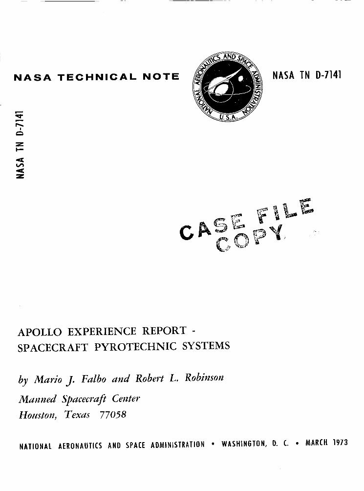
The CM RCS contained 16 pyrotechnically operated valves, which were used to control the distribution of helium and propellants. Each valve (normally closed) was actuated by an electrically initiated cartridge. Upon firing, the valves remained open permanently.
Tension t ies connecting the SM and the CM (fig. 11) were cut by means of linear- shaped charges. The CM/SM guillotine (fig. 12) cut the umbilical between the CM and the SM to allow the hinged umbilical boom to swing clear of the CM and permitted sep- aration of the C M from the SM. Similar pyrotechnic events would have occurred im- mediately upon initiation of an LES abort.
Era(
-- Tension ties
’ Tension- tie strap
Figure 11. - Command module and service module structural separa- tion system.
Manifold charge Booster charge
Blade -
Booster c h a r g e l
Figure 12. - Command module/service module guillotine.
Earth landing system. - The installa- tion of earth landing system (ELS) equip- ment in the forward compartment of he CM is shown in figures 13 and 14. During nor- mal entry, the apex cover was jettisoned when the spacecraft had descended to ap- proximately 24 000 feet. As the cover sep- arated from the CM, a lanyard-operated switch fired a drag parachute mortar at- tached to the cover, When deployed, the drag parachute prevented the apex cover from recontacting the CM o r from inter- fering with drogue parachute deployment, which followed 2 seconds after cover jetti- son. The drogue parachutes were deployed in a reefed condition. At line-stretch, the
time-delay line cutters (fig. 15) were actuated; the line cutters disreefed the drogues 10 seconds later. At approximately 10 000 feet, the drogue parachutes were released by severing the r i s e r s with cartridge-actuated guillotines (fig. 16). The main para- chutes were deployed in the reefed condition at the same time by means of mortar- ejected pilot parachutes. At line-stretch, 6- and 10-second-time-delay line cutters were actuated to effect disreef in two stages. The deployment of the main parachute actuated line cutters that, 8 seconds later, automatically deployed two very-high f r e - quency (vhf) recovery antennas and a recovery beacon from the forward compartment.
12

RCS engine protector -
LES tower M r a c h u t e \ electrical
Sea recovery Drogue cable 7
\mortar \receptacle 7
L Parachute \ \ r=F Main landing and Swimmer parachute u mbi I ical
r i ser protector
L Uprighting bags L-High-frequency under main parachutes recovery
mortar 13 places) antenna
Forward-heat-shield th rus t pressure cartridges (2 required) -l
-Y
Figure 13, - Command module forward Figure 14. - Apex-cover thruster compartment. locations.
7 7 Retainer
Fir ing p i n
Time-delav mix -
R N adhesive J Figure 15. - Reefing line cutter.
Immediately after splashdown, the main parachutes were released by cartridge- actuated blades in the parachute disconnect assembly. After touchdown and main para- chute release, all pyrotechnic functions were completed for the CSM systems. The ELS sequence is illustrated in figure 17.
Note Al l r isers shown are bundles of steel cables
Section A-A
Figure 16. - Parachute disconnect system.
13

Lunar Module Systems
The LM pyrotechnic devices and systems were used for deployment of the landing gear; for opening of valves for pres- surization of the descent, ascent, and RCS propellant tanks; for venting of descent pro- pellant tanks; for electrical circuit inter - ruption; for interstage umbilical severance; and for separation of the ascent and descent stages. The'general locations of the LM pyrotechnic devices are shown in figure 18.
1. Apex cover jettisoned at 24ooO ft + 4 sec
2. Drogue parachutes deployed reefed at 24 OOO fl + 2 sec
3. Drogue parachute single-stage disreef, 10 sec
4. M a i n parachute deployed reefed by way of pi lot F and drogue parachutes released at 10 ooO fl
5. M a i n parachute init ial inf lat ion
I
6. M a i n parachute first-stage disreef, 6 sec 7. vhf recovery antennas and f lashing beacon
deployed. 8 sec 8. M a i n parachute second-stage disreef, 10 sec 9. Main parachutes released
Figure 17. - Earth landing sequence.
RCS hel ium Ascentpropulsion ED control panel isolation valves compatibility valves
Descent propulsion Landing gear ED relay box (2) hel ium isolation valve uplock (descentlascent
14 places) stagel
Note: ED explosive devices
Figure 18. - Lunar module pyrotechnics.
Landing-gear operation. - The LM landing gear was retracted during t rans- lunar flight. Before separation of the LM from the CSM, detonators in the uplock devices (fig. 19) were fired to drive a blade that severed the s t rap and permitted springs in the deployment mechanism to extend the landing gear. The design of the landing- gear uplock device included two opposing blades to sever the holding strap. Before a problem that was uncovered during qualifi- cation testing, both blades were driven simultaneously by firing both detonators at the same time. The problem was that this procedure sometimes resulted in the s t rap being "captured" between the two blades and,
Cutter blade-
Strap-
Landing-gear primary s t ru t mounting interface
L t
-Detonator cartridge
pin
Strap housing attachment
7 1 Descent-stay mounting interface
Figure 19. - Lunar module landing-gear uplock and cutter assembly.
14

because of simultaneous firing, caused the blades to meet at the center of travel and
reliability of a single blade severing the s t rap already had been demonstrated. There- fore , the sequence of firing the detonator for each blade was staggered to eliminate the probability of capture of the strap. The second blade acts as a backup if the f i r s t blade malfunctions. Otherwise, the second system is fired only to eliminate the live detonator.
I deflect one another. Capture of the s t rap could prevent landing-gear release. The
Pressurization valvAs. - When opened, pyrotechnically actuated valves installed in the LM propulsion systems allowed descent propellant tank pressurization and vent- ing, ascent propellant tank pressurization, and RCS propellant tank pressurization. The valves operated instantaneously upon command by firing self-contained explosive charges, which provided the necessary impulse for valve functioning. The valves nor- mally were closed to provide complete shutoff of flow, and, after actuation, valves were opened permanently. The configuration of the valves was similar to the valve shown in figure 10. Helium-isolation valves, fuel and oxidizer valves, and vent valves were the pyrotechnically operated valves in the descent propulsion system. The ascent propulsion system contained helium-isolation valves and fuel and oxidizer compatibility valves. Helium-pressurization valves were used in the RCS. Electrically initiated explosive cartridges were used for actuation.
Separation of ascent stage. - Four explosive nuts and bolts were used in the inter- stage structural connections, and an interstage umbilical cutter was used to sever the interstage electrical umbilical. The separation of the ascent and descent stages in- volved the following steps: (1) operation of the circuit interrupter (fig. 20) to break the interstage electrical circuits, (2) separation of the interstage nuts and bolts (fig. 21), and (3) severance of the umbilical by the interstage umbilical guillotine (fig. 22).
Ascent connector
lock detent
disconnected Pin 4 (spring loaded) I
Figure 20. - Lunar module electrical circuit interrupter.
15

,nitiator r B o l t cartridge
N u t cartridge .-
(a) Before firing.
Figure 21. - Lunar module
1 Init iator
Shear blade
Detonator
U (a) Cross section.
interstage nut
(b) After firing.
and bolt assembly.
(b) Installation.
Figure 22. - Lunar module interstage umbilical guillotine.
16

COMPONENT DES I GN AND DEVELOPMENT
The pyrotechnic devices were of prime importance for flight safety. The safety design reliability goal was established to be 0.9999 at the 95 -percent confidence level. The demonstration of such reliability was impractical by direct testing methods (because it would have required demonstration of no more than one failure in approximately 45 000 firings); however, statistical test methods were used to obtain data upon which acceptable estimates could be made. Under conditions simulating the complete mission profile (including.launch, space flight, and recovery), abbreviated test programs were conducted to determine that each device tested was functionally safe and reliable.
Tests of the initiators were performed in all applicable types of environment and storage conditions to obtain information on the safety aspects o r the no-fire capabilities of a particular device. Sensitivity and output tests were conducted to determine the capabilities of the initiators (1) as separate components and as integral par ts of other devices and (2) as parts of complete systems. Test fixtures and conditions simulated the intended applications that incorporated the electrical input sources and characteris - t ics and the output characteristics. Physical and environmental surroundings were simulated to assess functional capabilities and requirements.
The performance evaluation of each device consisted mainly of obtaining informa - tion on input and output characteristics. In general, testing of input characteristics consisted of sensitivity measurements to determine energy requirements for satisfac- tory firing of the device. Testing of output characteristics consisted of obtaining data on the physical phenomena that resulted from the firing of the device. during the performance evaluation of the SBASI, sufficient data were obtained to predict the true all-fire and no-fire current levels for particular functioning times. Another example is the reefing line cutter, f o r which tests were conducted to determine, at vari- ous pull angles, the pull force required to trigger the ignition system for satisfactory performance. Also, the reefing line cutter was tested at different temperatures to ob- tain curves of the shift in functioning times.
For example,
Depending on the circumstances, tests to determine the hazards associated with the pyrotechnic devices required special test procedures and equipment. Because most pyrotechnic devices were initiated electrically and normally would not discriminate be - tween sources of ignition energy, tes ts were conducted under various conditions with a range of electrical sources of energy. Test hardware also was subjected to miscella- neous tests that cannot be considered input, output, o r electrical hazards tests, but were performed to observe and resolve the effects of different conditions on the devices. Surveillance tests, sealing and moisture-proofing tests, and vibration and shock tests' were included in the development program.
The types of inspection and nondestructive tests common to all units included vis- ual and X-ray examination of the product, bridgewire and insulation resistance tests, leakage tests, and neutron radiographic (N-ray) inspections. However, N-ray inspec- tions were not performed on the initiators,
I 1
Neutron radiography is a relatively new technique. In a number of instances, such as examining the explosive core in an MDF for discontinuities, the N-ray technique
17

w a s superior to X-ray. The opacity of the lead sheath and of the explosive core to ther- mal neutrons is the reverse of that with X-rays; however, the advantage was lost when the MDF was bonded into a chargeholder with a hydrogenous material such as epoxy. Therefore, the N-ray technique was applied only selectively to Apollo pyrotechnics to supplement X-ray examination.
Over the past 6 years, all Apollo pyrotechnic devices and systems have been tested extensively on the ground, in unmanned flights, and in manned flights. The following is a summary of the evolution of the components and accumulated history from all test programs conducted before the Apollo 13 mission.
Single Bridgewire Apollo Standard Initiator
As stated earlier, a double bridgewire initiator, the ASI, originally was developed for use in the Apollo Program but was replaced by the single bridgewire initiator, the SBASI. More than 20 000 AS1 units were tested or used satisfactorily during the space- craft development program. Approximately 7000 SBASZ units have been tested and used since. Approximately 140 initiators were installed for each Apollo mission. The AS1 units were used in all Block I Apollo spacecraft, except for the vehicles used for the Apollo 4 and 6 missions, in which both AS1 and SBASI units were used. All Block 11 Apollo spacecraft were equipped with SBASI units.
Except for having only one bridgewire, the SBASI w a s identical physically to the dual-bridge ASI. The modification to a single bridgewire unit was made primarily be- cause of electrical sensitivity problems associated with the bridgewire -to-bridgewire mode, firings were attributed to buildup and discharge of accumulated electrostatic charges. Other recorded data showed that a difference of approximately a 50-volt potential be- tween the bridgewires would cause degradation of the primary charge. The built-in spark gap w a s not intended to protect against ignition from spurious forms of stray electrical energy in the bridgewire-to-bridgewire mode.
In addition to low interbridge electrical resistance, occasional, inadvertent
The design of the SBASI retained the performance and desirable electrical char- acteristics of the original AS1 and incorporated the following changes.
1. To improve the impact resistance a t temperatures below -65" F, the body material was changed from type 17-4 PH steel to Inconel 718.
2. To increase internal pressure capability, the wall thickness surrounding the charge cup was increased, the shape of the header was modified, and the header was welded to the body.
3. To ensure that the pins would remain securely fixed under high internal pres - sures , the header material was changed from ceramic to Inconel 718, and the pins were glassed to the header instead of being brazed to a plating material coating the ceramic.
4. To protect against environmental contamination (i. e. , humidity, air density changes, and dust particles), the spark gap location was changed to the interior of the unit. The spark gap was required to prevent inadvertent firing from extraneous high- voltage discharges by diverting discharge to ground.
18
A design deficiency that remained with the SBASI involved the built-in spark gap and was associated with the breakdown of insulation resistance. Contamination could be unintentionally introduced in the spark gap during manufacturing operations, and some units were rejected because of insulation resistance failure. However, units exhibiting resistance failure were rejected on an individual basis.
During development of the SBASI, the body-header assembly was tested hydro- statically after repeated thermal shocks, ranging from -320" to 500" F, to over 100 000 psi without failure. During production, all units were tested to 40 000 psi. All production units also were tested for electrostatic survival capability to withstand 25 000 volts (from pin to case) and were leak tested with helium to ensure proper her- .metic sealing. extensively to ensure complete interchangeability. Sectioned and exploded views of the SBASI a r e shown in figure 2.
The AS1 and SBASI units produced by the two manufacturers were tested
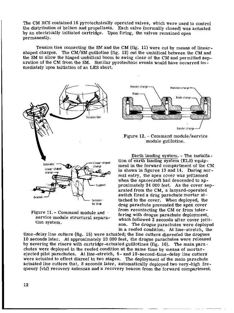
Indexing the connector end of the SBASI after manufacture permitted manufacture and stocking of a standard unit. Indexing of the units was accomplished as needed by staking the bar re l s to meet a specific keyway combination (fig. 23). Nine special key- way combinations were used to meet special requirements.
Keyway
7 numbers Master
XX1 XX2 XX3 XX4 XX5 XX6 XX7 XXB XX9 (XXOl
Basic part Dash number number A -
SEB26100001 - 1XX SEB26100001 - ZXX
SEB26100001 - BXX SEB261MXX)l - X1X SEB26100001 - X5X SEBZ6100001 - X X l SEBZ6100001 - XXZ SEB26100001 - XX3 SEBZ6100001 - XX4 SEB26100001 - XX5 SEB26100001 - XX6 SEB26100001 - XX7 SEB26100001 - XX8 SEB26100001 - XX9 SEB26100001 - XXO
Designation
Prototype, developmental experimental Fl ight configuration, qualified o r
I n e r t device Weld washer attached No weld washer Keyways 1 and 6 closed (nonfl ight) Keyways 2 and 6 closed (f l ight) Keyways 3 and 6 closed (f l ight) Keyways 4 and 6 closed (f l ight) Keyways 5 and 6 closed (f l ight) Keyways 1 and 2 closed (f l ight) Keyways 1 and 3 closed (f l ight) Keyways 1 and 4 closed (f l ight) Keyways 1 and 5 closed If l ight) All keyways open (required specific
MSC author i ty for use)
qualifiable
Staking was accomplished by blocking keyways. The keyways were blocked by crimping the outer lip of the keyway inward to a dimension that prevented the mating connector key from entering the slot. After qualification of the staking procedure, it was found that improper crimps could result from the use of worn crimping tools. The resultant improper staking in the electrical connector portion of the SBASI allowed a mating electrical plug of different key con- figuration to be connected.
To prevent the use of crimping tools worn beyond dimensional tolerances, man- datory dimensional checks of the crimping tool were established. Dimensional checks also were established on the initiator itself and were verified by using a comparator for acceptance inspection.
Figure 23. - Initiator indexing.
19

Cartr idge Assemblies
Cartridges of various sizes and configuration were used in the following applica- tions: (1) actuation of electrical circuit interrupters and disconnects, (2) operation of thrusters, (3 ) deployment of parachutes, (4) operation of valves, and (5) as component par t s of separation systems. Most cartridges were similar in construction, but dif- fered in thread size and type and in amount of output charge. Figure 24 i s a sketch of a typical electrically initiated cartridge assembly. various cartridges, including detonator cartridges.
Figure 25 i s a photograph of the
Figure 24. - Electrically initiated cartridge.
- Figure 25. - Spacecraft cartridges.
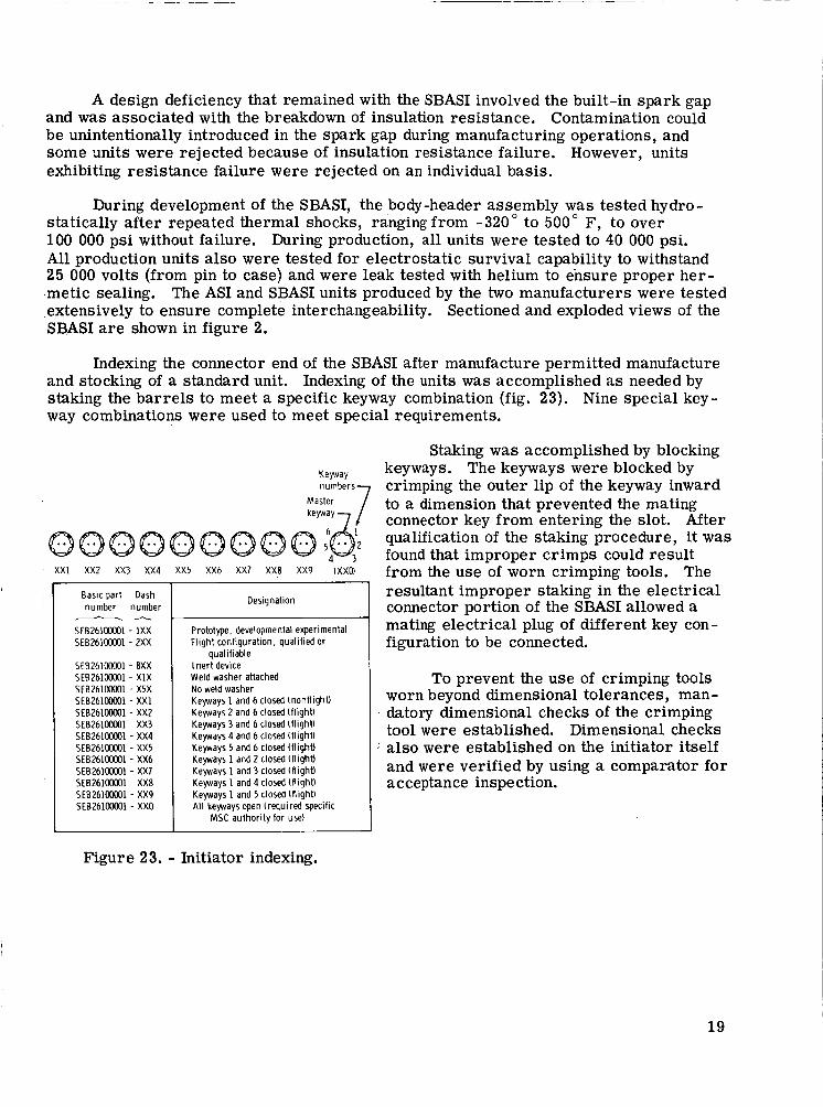
All but one type of cartridge were initiated electrically by an SBASI. The only nonelectric cartridge (fig. 26) was initiated by CDC and was used to operate the SLA- panel thrusters. By adding booster modules containing various charges, special pur- pose cartridges were obtained. The physical configuration, performance, and uses of all cartridge and detonator assemblies are listed in table I. The SBASI is included in table I because the unit was used alone as a pressure cartridge in the docking probe retraction system and in the docking tunnel vent valve. The indexing of the SBASI in the cartridges is shown in figure 23. Cartridges with different outputs had different threads to prevent improper installation. close to each other in the spacecraft and fired at different times, were indexed differ- ently. Thus, the same thread and indexing could be used in various locations on the spacecraft.
Cartridges with the same output, but located
Each cartridge assembly (except the SLA-panel thruster cartridge, which w a s fired by CDC) consisted of one o r two SBASI units hermetically sealed to a cartridge body by a weld washer. cartridge contained no charge other than that in the SBASI; the cartridge module was an adapter necessary to install the SBASI in a small explosive valve, Approximately 250 units of each type of cartridge assembly were fired during qualification test programs.
The weld washer is shown in figure 27. The type 100 pressure
20
Output charge containing boron and potassium nitrate to provide gas pressure r 7 Initiatina train
" 1 Pentaerythritol tetranitrate used to transfer charge through bulkhead
Figure 26. - Spacecraft/lunar module adapter thruster cartridge.
Torquing
(welded under torquing section)
Figure 27. - Initiator with weld washer.
Detonators
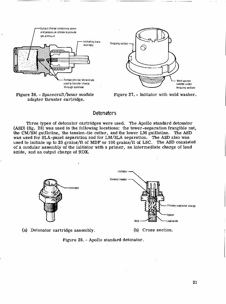
Three types of detonator cartridges were used. The Apollo standard detonator (ASD) (fig. 28) was used in the following locations: the tower-separation frangible nut, the CM/SM guillotine, the tension-tie cutter, and the lower LM guillotine. The ASD w a s used for SLA-panel separation and for LM/SLA separation, The ASD also was used to initiate up to 20 grains/ft of MDF or 100 grains/ft of LSC. The ASD consisted of a modular assembly of the initiator with a primer, an intermediate charge of lead azide, and an output charge of RDX.
Initiator\
.Initiator
Ceramic header '- \
Primary E
Spacer
Lead azide
(a) Detonator cartridge assembly. (b) Cross section.
Figure 28. - Apollo standard detonator.
!xplosive charge
21

The end-detonating cartridge (EDC) was developed for high-temperature appli- cations where a directional shock was re- quired for the initiation of high-explosive elements. The EDC had a heavy wall thickness along the threaded length of the output end (fig. 29). The EDC was used on the LM guillotine and on the landing-gear uplock. The EDC had an intermediate charge of lead azide and an output charge of HNS.
The long-reach detonator (LRD) (fig. 30) was used in the docking ring'as- sembly only. The configuration was nec- essary to extend the output charge to an interface area that was inaccessible with either the ASD or the EDC. The LRD had an intermediate charge of lead azide and an output charge of HNS.
A significant problem, which was relevant to lack of manufacturing control rather than to design, arose on July 30, 1969. Two of four detonators tested in LM guillotine lot acceptance tests failed to fire high order. Results of the failure an- alysis showed that the failures were caused by alcohol contamination and that this contamination apparently was isolated to only one lot of detonators. This con- tamination was confirmed by both N-ray inspection and mass spectrometric analy- sis. Spectrometric analysis of one suspect unit showed it to have an alcohol content of 18. 3 microliters. Further investigation in- dicated that the threshold could be below 6.75 microliters and that the N-ray tech- nique could not be used alone to determine whether units contain alcohol at this level.
In addition to the requirement that no alcohols or solvents be permitted in loading rooms, corrective action required that two units from each lot be selected at random for mass spectrometric analysis. Total volatiles, excluding water, could not exceed 0.040 microliter per unit. This value was arrived at by sampling a normal lot of detonators and determining the level of contamination, which turned out to be 0.02 to 0 .03 microliter.
f = = L
Figure 29. - End-detonating cartridge.
r 0 . 8 1 2 i n . ( r e f l y
- Lead azide
-HNS
-lead azide
\ c
Figure'30. - Long-reach detonator.
22

Core Charges
Three types of core charges were used (fig. 31). An LSC w a s used to sever the tension t ies connecting the SM and the CM. An MDF was used to sever the forward and aft circumferential and the inner and outer longitudinal splice plates of the SLA and for separation of the docking ring from the CM. The MDF also was used as the explosive element in the guillotines for driving the blade that cut the umbilicals. A CDC was used for detonation transfer between various points in the SLA separation system. Core-charge assemblies and their uses are listed in table 11.
Sheath
Explosive MDF core
(a) Mild detonating fuse. (b) Confined detonating cord.
(c) Linear-shaped charge.
Figure 31. - Core charges.
The principal explosive used as the core explosive was RDX; however, in the CM-to-LM docking tunnel and in the LM interstage guillotine, where temperature re- quirements were more severe, a heat- and vacuum-resistant explosive (HNS) was used. In most applications, booster charges containing lead azide were attached to both ends of the linear charge to ensure detonation transfer. In the SLA, in addition to the boosters on the ends of the linear charge, separate boosters were employed for addi- tional assurance of reliable detonation transfer.
23

Approximately 100 separate explosive train assemblies incorporating linear charges were installed on each spacecraft. The assemblies were developed during qualification of the components containing linear charges. More than 2500 feet of linear charges were tested satisfactorily during component qualification.
Problems related to the use of core charges that occurred during the Apollo Pro- gram include the following.
Tension-tie cutter. - The tension-tie-cutter core charge consisted of an LSC of lOO-grain/ft RDX in lead sheath. Boosters were attached to the ends to effect reliable detonation transfer from detonator to cord. During the thermal vacuum exposure por- tion of the qualification program, blistering of the booster charges and bulging of the V-angles to out-of-specification values occurred after exposure to a temperature of 120" F for 72 hours. This phenomenon had been anticipated during development because knowledge existed concerning similar problems in other military and space programs ; however, because the expected blistering or bulging did not occur during the develop- ment program, no measures were taken in the design of the system to ensure structural integrity when exposed to elevated temperatures.
After the anomaly occurred, a program was conducted to determine whether deg- radation had occurred as a result of impurities in the explosives or if other sources of contamination were responsible for the bulging and blistering. Results of analyses indicated that no degradation of the explosive products had occurred and that no contam- inant was introduced into the system to cause the angle change or the blistering. All tes ts conducted to determine the reason for angle change and blistering proved incon- clusive. However, tes ts conducted on "worst parts" showed breakage of 120-percent plates.
Lack of positive information concerning bulging and blistering was sufficient justification for modifying the design, even though it had been demonstrated that even "worst case" units were capable of severing the t ies. The material for end caps, which originally were made of preformed lead soldered to the LSC, was changed to aluminum with epoxy adhesive for mating to the LSC. This change in design eliminated the proba- bility of blistered end caps. To control V-angle bulging, the boostered LSC's were inspected and selected only after being subjected to a ser ies of temperature screening cycles; the acceptance criterion specified that all charges selected maintain a 96" f 2" angle during and after exposure to all temperature cycles.
Spacecraft/LM adapter. - The SLA core charges consisted of MDF's of 5- and T-grain/ft RDX in lead sheath. During disassembly of charges from the chargeholders in tests conducted at MSC, severe degradation of the lead sheath was observed for that portion of the MDF in contact with the RTV adhesive used for bonding the charge to the holder.
24

Several samples of the same lots of material (ranging in age from 3.5 to 5 years) had unacceptably low detonation velocities. The change in detonation velocity from an average of 6500 m/sec to as low as 5300 m/sec was attributed to the degradation of the sheath material. As a result of degradation, the lead sheath no longer confined the explosive core to the extent required for satisfactory functioning.
Adhesive RTV 30-121 was used to bond the cords in place. Acetic acid is an intermediate product during curing of the RTV adhesive. Results of metallurgical analyses conducted on degraded MDF lead-sheath samples indicated that the product of interaction of the acetic acid with the lead sheath was responsible for degradation of the sheath. As a result, all SLA core-charge assemblies were 9trecalledT7; the RTV 30- 12 1 adhesive and explosive cord were removed from the chargeholders and replaced with new MDF lines potted in place with RTV 577 adhesive. Tests were conducted to demonstrate the compatibility of RTV 577 adhesive with the lead sheath.
Docking ring separation system. - The docking ring separation system core charge consisted of two strands of 6-grain/ft HNS-MDF in si lver sheath. Adhesive RTV 30-121 was used for potting the MDF in the chargeholder. On December 8, 1971, during verification tests to check capability for single-cord functioning, a failure to completely sever the docking ring occurred. A s a result, the design of the docking ring separation system and its redundancy capabilities were investigated.
Results of design analysis indicated that as much as 0.006 square inch in cross- se'ctional-area f ree volume (approximately the same volume as that occupied by the cord) could exist with improper potting of the RTV adhesive in the chargeholder groove. Tests conducted to determine the effect of change in cord location relative to the amount of free volume resulted in the determination that lack of adequate confinement could result in 'incorhplete separation of the docking ring separation system.
To eliminate the possibility of inadequate confinement, a procedure was developed for the buildup and installation. The RTV adhesive was applied in three different stages to ensure that no voids remained in the chargeholder groove after potting of the charge- holder was complete. Special tooling and jigs were developed to locate and control the cord and the RTV adhesive to within critical dimensions. Several full system tests demonstrated single-cord capability and redundancy after using the new installation procedure.
Line Cutters Time-delay line cutters (fig. 15) were used for deployment of recovery aids and
for cutting of parachute reefing lines. Eight 10-second time-delay cutters were used on the drogue parachutes. Twelve 6-second and six 10-second time-delay cutters were used on the main parachutes for disreefing in two stages. A total of six 8-second time- delay cutters were used to deploy vhf and high-frequency antennas and the recovery beacon. More than 1000 units were fired satisfactorily in tes ts and during flights.
Another example of a problem relevant to a lack of quality and manufacturing control was an anomaly that occurred on October 1, 1971, when, during lot acceptance test firing, a "spit of flame" of a few milliseconds duration was observed coming f rom the hole of the firing pin retainer of one unit. An X-ray examination revealed that the
25

anomaly occurred because of primer header assembly blowback during ignition and that the phenomenon actually had occurred on other units as well, although previous occurrences were not observed visually. Review of X-rays taken of the entire lot before functioning revealed that the general quality of manufacture, assembly, and in- spection were f a r below par.
As a result of analyses conducted, the following determinations were made.
1. A new lot of M42 primers was used in the assembly of the cutters. Until then, a single lot of pr imers had been used in the assembly of all cutters.
2. Because of the difference in output of the new lot of primers, a change in delay column height was made to accommodate the change in primer output pressure.
3. The change in pr imers and in delay column height resulted in stackup of tolerances, which w a s cause for a less than satisfactory crimp of critical interfaces,
Although all requirements for function time, reefing line severance, and required pull force for initiation were met, the lot was rejected because of the header blowback anomaly, attributed to the substandard quality of workmanship coupled with the higher pressure output of the primer. Better quality control measures for correction of the problem included conducting appropriate tests for making determinations upon which criteria would be based for the use of certain pr imers in specific applications,
GROUND-SUPPORT EQUl PMENT
Ground-support equipment (GSE) was used to service and check out spacecraft systems before flight. lators and spacecraft verification equipment,
The pyrotechnic checkout equipment included pyrotechnic simu-
Pyrotechnic Simulators
The CSM initiator simulator. - The CSM initiator simulator was an electrome- chanical device used in lieu of actual hot bridgewire initiators during systems and integrated tests of the CM and the SM. The device (fig. 32) was a suitcase-type enclosure that housed six bridgewire simulator circuits. Each circuit was composed of relays, diodes, fixed and variable res is tors , and test jacks in a combined network and w a s joined to external connectors (fig, 33). The unit was portable and was designed to be ignition-proof for use in hazardous areas. The case assembly was constructed with a f i l l valve to pressurize the case with an inert gas for ignition-proofing purposes. The case measured 12 by 10 by 7 inches and weighed 20 pounds. The power require- ments were 28 volts direct current (dc) at 0. 7 ampere,
The unit contained six circuits capable of substituting electrically for six pyro- technic initiator bridgewires and provided a simulated result of initiator bridgewire action. cuit to simulate bridgewire burnout while protecting spacecraft circuitry from over - current drain. All units were capable of being reset remotely,
The input resistance to each simulator was 1 ohm, which became an open c i r -
Signal input originated
26

c
Spacecraft signal inout
Key: K, Go and reset relay
Relief valve i 1 Fill valve
Bolt W
(a) Front view.
I P
I I 1 1
(b) Rear view.
. , . KZ Transient relay
K Time-delay relay
K4 Transient holding relay
28 V dc reset
- I
1
28 V dc return
Transien output
Go output
Figure 33. - Schematic of CSM initiator simulator.
Figure 32. - Command and service module initiator simulator.
27

and was controlled by the spacecraft sequencers. The input was detectable by each subcircuit in three modes: an all-fire condition, positive and negative transient condi- tions, and a no-fire condition. Output signals from the device were transmitted through an interface junction, the initiator stimuli unit, to the acceptance checkout equipment (ACE) consoles, which provided discrete light indications. A transient output signal of 6 volts dc was generated when a signal input voltage was greater than 0.17 volt (positive or negative polarity) but was of insufficient magnitude to initiate a "go" output signal. The go output signal voltage was also 6 volts dc when an input current level of 5 amperes o r greater was applied for 10 milliseconds. The 6-volt output signals eventually controlled the go/no-go lamps on the ACE console.
Many problems occurred during the evolution of the unit. Examples of such problems are listed here to point out a reas where special attention should be given on any future work.
1. The simulator must provide a 1-ohm load to the spacecraft circuitry and must become an open circuit after a specified current pulse has been received. If the device failed to become an open circuit, the spacecraft circuitry would be damaged by extended current drain. The circuitry was damaged on three spacecraft because the original design required facility power to operate the circuit-opening relay. In each case, the damage was caused by a loss of facility power. The present Apollo design includes fail-safe requirements and redundant circuit-opening features. The fail-safe requirement was met by a relay circuit design that required facility power to complete the 1-ohm spacecraft load. Loss of facility power would result in an open-circuit load, which would protect the vehicle circuits. Redundant circuit opening was accomplished by using two separate relays with contacts wired in ser ies so that failure of a relay would still allow the 1-ohm load to become an open circuit in the specified time and, thus, prevent damage to the spacecraft circuit.
2. The devices, as originally designed, gave false no-go indications because the open circuit did not occur as fast as required. Even though the lag did not damage spacecraft wiring, overlapping of the time-sequenced functions resulted in higher than normal loads on the spacecraft circuitry. To correct this problem, a relay and ca- pacitor combination that would open a t the proper time sequence to prevent overlapping of functions was added in ser ies with the 1-ohm load circuit.
3. In one early design, current flow was significantly longer than planned. This situation occurred because transient actuation did not result in the simulation of an open circuit when the spacecraft bus voltage was low. With no open circuit, the space- craft circuitry could be damaged. To correct this problem, the transient detecting relay was wired so that either it o r the go relay could open the circuit.
4. The time response of the transient detector was not fast enough for detection of short-duration pulses. With very high current levels of very short duration, the initiator actually could be fired without detection of a current pulse by the simulator. The fast response time could not be obtained by using relays. A change to solid-state detection would not have supported the schedule for the CSM; therefore, a "workaround" procedure that consisted of monitoring the 1-ohm load resistance with an oscilloscope was used.
28

The LM initiator simulator. - The LM initiator simulator (fig. 34) was a portable unit used to check out the function of electrical systems by simulating the electrical characteristics of the initiator. The simulator also was capable of detecting transients o r interference signals at the initiator connector.
The equipment consisted of 40 circuit -monitor modules having dimensions of 5 by 3 by 3 inches. Each module weighed approximately 2 pounds and was hermetically sealed. The modules were stored in a carrying case capable of accommodating 45 modules. The carrying case was a suitcase-type enclosure with dimensions of 30 by 30 by 30 inches and weighed 10 pounds. The power requirements were 28 volts dc at 9.0 amperes.
rr
Approximately 34 individual simulators I I II Vehicle under test
J '-t I I I -
1 !
Digital signal I conditioner and I multiplexer I I I
I I I
ACE carry-on equipment
I I
ACE carry-on equipment I
I I I
lntelieaver To ACE station
Figure 34. - Functional block diagram of LM initiator simulator.
Each module provided a 1-ohm input to simulate the bridgewire resistance of each initiator. The 1-ohm input became an open circuit after receiving either an all- fire or a transient signal; a current of 7.5 amperes o r greater resulted in a go indication; and a 200-milliampere o r greater current, with a duration of 5 micro- seconds or longer, would result in a tran- sient indication. The output signals were processed through the ACE to the go and transient lamps located on ACE consoles. Solid-state electronic devices were used in each module to obtain the faster response times.
The first design was a solid-state device but had three major undesirable characteristics: (1) The unit did not have redundant capability to obtain an open cir- cuit after firing and, thus, prevent damage to spacecraft firing circuits. The redun- dancy w a s accomplished later by providing ser ies redundant relay contacts actuated by both the go and transient circuits. (2) Use of a common power supply without isolation between modules caused sneak circuits and ground loops that resulted in false output indications. These problems were solved by providing isolation resis tors between each simulator module and the power sup- ply. (3) The unit could be actuated pre- maturely by EMI. This problem was solved by incorporation of EM1 f i l ters in the power supply input circuit and by the use of shielded cables on all input and output leads.
29

The environmental initiator simulator. - The environmental initiator simulator (fig. 35) was developed fo r use during vacuum-chamber testing of the spacecraft. The device was an inert SBASI with a normal bridgewire. Each device was hermetically sealed for operation in an environment containing hazardous propellant gases. The initiator was sealed by welding the unit into a stainless-steel block; thus, inadvertent installation of an inert unit in a flight vehicle was prevented. Seventy-five of the inert devices were packaged in a portable carrying case.
The inert SBASI provided an exact electrical simulation of the flight initiator be- cause a flight-type bridgewire was used. When a sufficient spacecraft firing current was received, the bridgewire was burned and an open circuit resulted. Because no ex- ternal output indicators were used. each device had to be inspected with an ohmmeter after Spacecraft testing was completed.
-Weld washer 7 Connector
Figure 35. - Environmental initiator simulator.
7 -r - Spacecraft connector Fuseholder
Figure 36. - Static EM1 device.
The static EM1 device. - The static EM1 device was developed for use during one of the spacecraft systems verification tes ts in which the GSE was not connected to the spacecraft (plugs out). The device was used for passive monitoring of the ordnance electrical system to ensure that interference from other systems would not affect the ordnance undesirably. A l/lS-ampere fuse in the device was mated directly with spacecraft wiring.
Each device (fig. 36) was contained in a cylindrical module 2-3/4 inches long with a diameter of 1 inch. The device had a spacecraft mating connector on one end and a fuseholder on the other end. The de- vices were transported and stored in a portable container having a capacity of 43 units. Because the unit had no external read-out capability, an ohmmeter inspection had to be made after the plugs-out testing was completed. The device was not her- metically sealed and could be used only for ambient environmental testing.
During use in the Apollo Program, two problems were encountered. Some of the units were found to have actuated pre-
maturely, and others failed to actuate tr.ien exposed to sufficient actuation current. In- vestigation showed that the units were actuated prematurely during checkout by the use of a non-current-limiting ohmmeter. The output current was sufficient to actuate the unit. This problem was corrected by requiring the use of current-limiting ohmmeters. Investigation of the units that failed to actuate showed that the problem was caused by use of improper fuses. The module required plug-in-type fuses. Some of the fuses used were of the pigtail type, which had longer leads. These leads were cut to the approximate length of the plug-in type. Cutting the leads resulted in a flattened pin,
30

which caused improper contact with the fuseholder. This problem was corrected by requiring the use of proper fuses.
The s t ray electrical energy indicator. - The stray electrical energy indicator was used to simulate the electrical characteristics of the initiator while detecting excessive levels of RFI on the ordnance electrical system of the spacecraft. The stray electrical energy indicators were installed in lieu of flight initiators on the totally stacked vehicle at the launch pad. All onboard and ground radio-frequency (rf) emitters were energized to verify RFI compatibility.
The stray electrical energy indicator (fig. 37) consisted of a special SBASI that was screwed into an adapter. The unit was 3 inches long with a diameter of 1 inch. The indicator consisted of a bellows that expanded to give visual indication of unit actu- ation. The special SBASI contained a more sensitive bridgewire (higher resistance) and an rf-sensitive ignition explosive. The unit was hermetically sealed, even after firing. When the initiator was fired, the plunger in the indicator was forced outward to expand the metal indicator bellows. The unit connector had all keyways left open so that the unit could mate directly with any spacecraft ordnance connector.
Considerable effort was expended in the development of an acceptable RFI detector because of the problem of obtaining a proper impedance simulation across the frequency spectrum. The use of an actual explosive device w a s the only solution.
0.3 i n . H I -3 in. I
Figure 37. - Stray electrical energy indicator.
7 r C o n n e c t o r pins Photoflash bulb
Figure 38. - High-energy-initiator simulator.
The high-energy -initiator simulator. - The high -energy-initiator simulator, also a device to simulate the initiator during ground testing, presented the spacecraft with electrical characteristics similar to the SBASI. This unit was used during check- out of all flight vehicles at KSC, including both the CSM and the LM. The device was used during performance of simulated mis- sions, including the altitude-chamber runs. A visual indication of status was required without an interface with the chamber wiring. This requirement, along with the high cost of the environmental simulator, prevented use of either the LM initiator simulator o r the environmental simulator, described ear l ier , in this application. Each high -energy- initiator simulator (fig. 38) was 3 inches long with a diameter of 0 . 7 5 inch and weighed less than one-quarter pound. The device was hermetically sealed and could be used in vacuum-chamber testing and in hazardous gas areas, The carrying case was capable of accommodating 100 units. The device was mated directly with the spacecraft initiator connector and provided a resistance of 1 .05 ohms before firing. When the device
31

received a firing current, an open circuit resulted within a time interval that was dependent upon the current level through it .
The device consisted of a fuse in series with a 1-ohm resis tor ; a second resistor and a photoflash bulb were in parallel with the series circuit. The second resis tor was adjusted to a value that caused the bulb to flash when the reqyired firing current level was reached. Temperature-sensitive paper was placed around the bulb to provide a, visual indication that either an all-fire o r a no-fire current level was reached.
The only failures with the device involved flashbulbs that did not function. Space- craft system failures were distinguished f rom bulb failures by verifying that the simu- lated bridgewire (fuse and resistor) was in an open-circuit condition after tests. Upon consulting the flashbulb manufacturer, it was determined that the incidence of failure was well within that to be expected and no reasonable corrective action could be taken.
Spacecraft Ver i f icat ion Eq u i pme n t
The pyrotechnic checkout test set. - The pyrotechnic checkout test se t was a port- able, self-contained unit that was used for the following: (1) to detect and measure stray voltages in the spacecraft pyrotechnic circuits, (2) to measure resistance and to verify continuity of these circuits, and (3) to measure the resistance of the installed pyrotechnic initiators. The test set (fig. 39), which was approximately 11 by 8 by 8 in- ches in size, had carrying handles and a removable top cover. Included with the test set were 20 dummy initiators that were integrated with the pyrotechnic circuitry in
(a) Dummy initiator. (b) Portable measuring device.
Figure 39. - Pyrotechnic checkout test set.
32
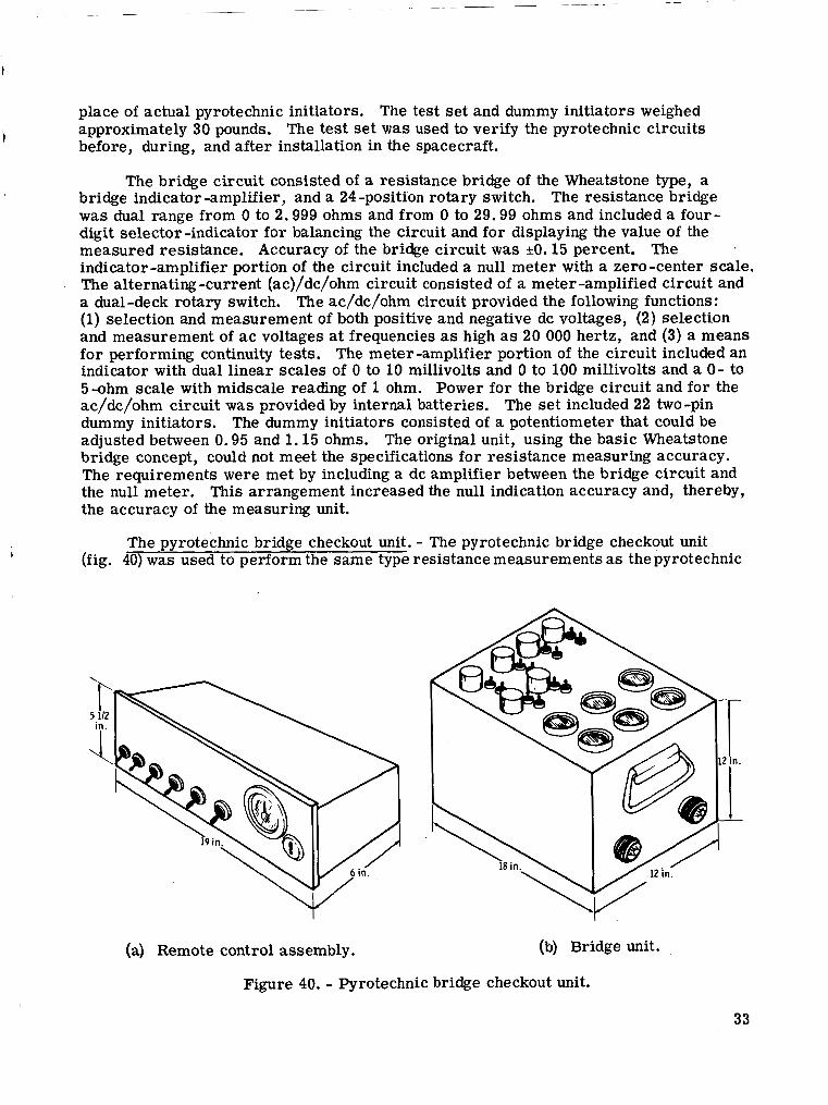
place of actual pyrotechnic initiators. The test se t and dummy initiators weighed approximately 30 pounds. The test set w a s used to verify the pyrotechnic circuits before, during, and after installation in the spacecraft. i
The bridge circuit consisted of a resistance bridge of the Wheatstone type, a
was dual range from 0 to 2.999 ohms and from 0 to 29.99 ohms and included a four- digit selector -indicator for balancing the circuit and for displaying the value of the measured resistance. Accuracy of the bridge circuit was *O. 15 percent. The indicator-amplifier portion of the circuit included a null meter with a zero-center scale. The alternating -current (ac)/dc/ohm circuit consisted of a meter -amplified circuit and a dual-deck rotary switch. The ac/dc/ohm circuit provided the following functions: (1) selection and measurement of both positive and negative dc voltages, (2) selection and measurement of a c voltages at frequencies as high as 20 000 hertz, and (3) a means for performing continuity tests. The meter-amplifier portion of the circuit included an indicator with dual linear scales of 0 to 10 millivolts and 0 to 100 millivolts and a 0- to 5-ohm scale with midscale reading of 1 ohm. Power for the bridge circuit and for the ac/dc/ohm circuit was provided by internal batteries. The set included 22 two-pin dummy initiators. The dummy initiators consisted of a potentiometer that could be adjusted between 0.95 and 1.15 ohms. The original unit, using the basic Wheatstone bridge concept, could not meet the specifications for resistance measuring accuracy. The requirements were met by including a dc amplifier between the bridge circuit and the null meter. This arrangement increased the null indication accuracy and, thereby, the accuracy of the measuring unit.
I bridge indicator -amplifier, and a 24 -position rotary switch. The resistance bridge
The pyrotechnic bridge checkout unit. - The pyrotechnic bridge checkout unit 1 (fig. 40) was used to perform the same type resistance measurements as the pyrotechnic
(a) Remote control assembly. (b) Bridge unit.
Figure 40. - Pyrotechnic bridge checkout unit.
33

checkout test se t and, in addition, could be controlled remotely at the launch site. The unit w a s used to check the circuit resistance of the launch-escape motor, of the tower- jettison motor, and of the SLA separation system, because these circuits were consid- e red to be potentially hazardous to personnel in the a rea when fired. In size, the pyrotechnic initiator bridge unit was 12 by 1 2 by 18 inches, the remote control panel assembly was 5.5 by 6 by 19 inches, and the dummy was 1 .5 by 1 .5 by 4 inches. The system weighed approximately 100 pounds and was designed to be portable.
The explosive device test set. - The explosive device test se t was used for no- voltage tests and electrical resistance measurements of the LM pyrotechnic circuitry before and after installation of flight ordnance. The test set (fig. 41) was a suitcase- type configuration that contained a resistance measuring unit, a 500-volt megohmmeter, and the associated batteries and switches. A cable set was provided to effect an inter- face with the LM vehicle. The unit measured 20 by 10 by 10 inches and weighed 51 pounds.
Figure 41. - Explosive device test set.
The resistance measuring portion of the test s e t w a s used to measure and dis- play the circuit resistance of the LM pyrotechnic circuitry. A removable, panel- mounted megohmmeter was used to measure and display the isolation resistance of the LM pyrotechnic circuitry. The power sup- ply provided the necessary power to operate relays in the relay box. The power supply iucluded current-limiting and protective devices to prevent high currents from flow- ing in the pyrotechnic circuitry i f a failure occurred. The monitor and control panel was capable of the following functions: (1) the selection of subassemblies, specific stimuli, and monitoring points; (2) mechani - cal mounting of the resistance measuring unit and the megohmmeter; and (3) visual displays of ac and dc voltages, of pyrotech- nic battery voltage, of internal power sup- ply voltage, of battery polarity, and of the state of gaseous purge when pressurized fo r use in hazardous gaseous areas.
The current regulator. - The current regulator was used in conjunction with the explosive device test set to limit the spacecraft power bus current to a safe level during pyrotechnic circuit testing after the flight pyrotechnics were installed in the vehicle. The unit (fig. 42) was portable, had dimensions of 18 by 12 by 12 inches, and weighed 15 pounds. Mating connectors were supplied both for the LM electrical power bus and for the ground power. The current regulator controlled the output power of a 28-volt dc, 250-ampere power supply. In the bypass mode, the regulator was capable Of carrying and breaking a current of 150 amperes a t 28 volts dc. In the current-limiting mode, the minimum output current was 100 milliamperes. The limiting current level w a s adjustable continuously from 300 to 500 milliamperes, When the limiting current level was reached, the circuits were opened. The circuits remained open until the
34

I I I I I I I I I I I I I I
I I I I I
I
I 1 I 1
Switching Limiting Milliam- network network meter
I
I I I I I I I I I I I I Vehicle power supply I
Mode selector
I I
1 I I I I
Key- actuated
I I I I
I I I I Ground power
supply return
I I I I
Limiting indicatior
L
indication
Power for umbilical ! r
I I I I I I I I
1 L M ~
q
1
uli
Figure 43. - Functional block diagram of the current regulator.
regulator was reset. The controls and indi- cators included a two -position, key -actuated switch and an indicator-light read-out of the selected mode. Provision also was made for remote read-out of the selected mode in the form of 28-volt dc signals. A functional diagram of the current regulator is shown in figure 43.
The only problems were premature opening of circuits because of the occur- rence of ground loops and capacitive effects in the facility wiring. The regulator was modified to correct the problems.
The Dvroharness shorting. Dlum and cable set. - The pyroharness shorting plugs and cable sets were used to short circuit and to ground the CM forward compartment initiator circuits. The live pyrotechnic de - vices were installed at the manufacturing plant during the buildup of the forward com- partment. The inaccessibility of the pyro- technic devices in the forward compartment made removal after installation impractical. The cables were mated with the pyrotechnic continuity verification box o r the lunar dock- ing events controller, The shorting plugs were removed at the appropriate time during the prelaunch operations at the launch site. The plug and cable set consisted of six cable assemblies (fig. 44).
6 pyrotechnic initiators located i n the forward compartment area compartment area
6 pyroharness shorting plugs located in the crew
4 circuits to the pyrotechnic circuit verification box
'
+---=- -- d - { l l #
+--- ----ill,
. +--- ----/I,*
&--- ----11,, 2 circuits to the
controller
Figure 44. - Pyroharness shorting plugs and cable set.
35

CONCLUSIONS
The pyrotechnic device offered a convenient means to the spacecraft engineer for accomplishing numerous functions in the spacecraft systems. The large number and variety of critical functions performed by Apollo spacecraft pyrotechnic devices im - posed an obligation to provide the most reliable and the safest system devised fo r aero- space applications to that point in time. each pyrotechnic component as an integral and critical par t of an overall system and by then conducting appropriate design reviews and evaluations to ensure that every con- ceivable variable in the system was controlled. The magnitude and complexity of prob- lems were minimized by using conventional electrical and mechanical components wherever possible. New and unfamiliar requirements necessitated experimental and analytical studies that, in some cases, uncovered a number of potentially serious problems, which, if not uncovered at an opportune time, would have resulted in costly rework and a severe strain on space program objectives. An outstanding example is the incompatibility problem associated with the use of RTV 30-121 adhesive to bond lead-sheath explosive -core charges in the spacecraft/lunar module adapter charge - holders. Had the problem not been uncovered during almost routine in-house tests, it is possible that the condition could have resulted in failure to separate during a mission. Other examples include the docking tunnel separation system redundancy question and the Apollo standard initiator sensitivity problem. Costly rework o r redesign (or both) of the docking ring separation system was avoided because results of analytical tests and experiments proved the system to be reliable and redundant with only relatively minor corrections. As a result of exhaustive evaluation programs to search out hidden weaknesses in the Apollo standard initiator design, the possibilities of both a premature fire and a misfire occurring during flight were uncovered.
This obligation was met by initially considering
Although there is no question as to the suitability, quality, and reliability of Apollo pyrotechnic devices for applications in Apollo systems, and the desirability of using devices having high reliability is not open to question, the methods employed to attain and to demonstrate confidence in reliability for a number of Apollo devices were not the most efficient o r the most practical. As shown in the examples, most Apollo pyrotechnic devices did not provide for reliability control o r monitoring before the evaluation phase, and design information was generated largely through intuition rather than through a combination of scientific approach, statistical experimentation, and subsequent observation. As a result, in a number of cases, a considerable amount of hardware that w a s ordered o r acquired could not be used when the design was later found to be deficient, usually at a time which was too late to make modifications eco- nomically o r to redesign for reliability improvement. Often, the funds already spent were too great to be written off, and i t was considered to be more expedient to add funds in an attempt to make a product improvement. Another reason for the hardware problems was that development time was not available for redesign.
Although the reliability probability of each device was established at design con- ception, the evaluation, qualification, and production acceptance tests and the flight use of the devices contributed to confidence in the reliability of the design. This con- fidence was enhanced further by following the policy of standardization of components wherever possible.
36
Within the pyrotechnics area, the most outstanding example of the potentialities in following the policy of standardization of components is the exclusive use by the Manned Spacecraft Center of the standard initiator in all Apollo spacecraft applications requiring electrical initiation. Maintaining standardization required considerable effort on a continuing basis but proved worthwhile in enhanced system reliability and reduction of total program cost, as a result of eliminating multiple initiator develop- ment programs.
By strict adherence to the philosophy of concentrated attention to all details of design, including inert and explosive materials used in the construction of all compo- nents and systems, the Apollo spacecraft pyrotechnic systems played a major and very important role in the resultant highly successful Apollo Program.
RECOMMENDATIONS
Future manned-space -flight technology will place a greater demand on extremely sophisticated, reliable, compact, and lightweight pyrotechnic devices, purpose of a reliability program for future systems should be to ensure that reliability is treated as a design parameter of equal importance with performance parameters during the initial design-conception phase as wel l a s during the evaluation of a proto- type design. The approach to design and development must be more fundamental than that taken during development of Apollo pyrotechnic devices, where the "cut and try" method was used in most instances. Adequate information is available and should be used to assist the design engineer in the selection of proper materials in'any given development program. Proper knowledge of the candidate materials and components, of their behavior and characteristics, and of the specific requirements that the end item must meet should be acquired before design can begin. Jus t as important are the manufacturing, handling, and testing of these components and materials, because vari - ables can have a dramatic effect on the performance and functioning of the end device.
The primary
Qualification of safe, reliable pyrotechnic systems for future programs can come about more efficiently and effectively if , during initial design and development, detailed and in-depth knowledge is obtained of all aspects of the design encompassing a full cross section of the capabilities as well as the limitations of the system. This "keeping abreast" can be accomplished most effectively by maintaining close control of proc- esses, equipment, and facilities used to manufacture and qualify any specific item. Unfortunately, it was not until the latter part of the Apollo device development programs that measures to control and maintain homogeneity of a product o r design were attained. A method of lot certification was developed to certify ordnance devices for flight. This technique was used to purge the system of all nonflightworthy hardware and has pro- duced the desired results as no known failures have occurred in flight. It is recom- mended that, for future systems, configuration and process control should be maintained by system engineers from the time of initial design concept to final delivery of the prod- uct. The most effective way of accomplishing this control is to provide a repeatable method of producing a given product with the use of definitive written instructions that cover all facilities, equipment, instrumentation, and processes used in the manufac- ture, qualification, and final production of the end item.
37

Although there is no question concerning the suitability of pyrotechnic devices developed for Apollo spacecraft use, experience has shown that several components might require improvement or redesign to meet more stringent requirements for mis- sions of longer duration than the Apollo missions. These components a r e described in the following paragraphs.
Single Bridgewire Apollo Standard In i t ia tor
Meeting electromagnetic -interference and radio -frequency-interference problems associated with long-duration missions may be impossible with the present design be- cause of more powerful radar and communication systems requirements. On long- duration missions, it becomes impractical to use separate power supplies (as was the case on the Apollo missions) for ordnance systems. have to be shared with main spacecraft systems. As a consequence, ordnance c i r - cuitry will have to survive higher electromagnetic -interference levels to which the present initiator may not be tolerable.
Therefore, power supplies will
The single bridgewire Apollo standard initiator consists of 12 basic parts. In addition to modification necessary to meet future requirements, an attempt should be made to produce the unit more economically. It is conceivable that, with the use of an ignition material having better electrical characteristics than the present mix, a unit can be made from as few as three parts. A minimum number of parts will enhance the reliability of the unit as well as decrease the cost. be to develop a cheaper electric initiator that inherently pould be immune to electrical problems associated with the Apollo unit.
The ultimate objective should
Explosive Tra ins and Interfaces
With only a few exceptions, cyclotrimethylenetrinitramine was used as the high- explosive material throughout the Apollo command and service module systems. How- ever, of prime importance is potential degradation of the chemical stability of the explosive when exposed to an extended high vacuum environment. New, recently de- veloped temperature - and vacuum -resistant high -explosive materials should be exploited for use in development of new systems for future programs. Some of these new materials (e. g. , hexanitrostilbene) were incorporated into the design of some lunar module and command module devices.
Lead azide was used as the primary explosive for the initiation of high explosives in the Apollo systems. Lead azide has some undesirable properties, including incom- patibility with other organic explosives at elevated temperatures, that might limit its usefulness in future programs, New initiator materials should be evaluated for use, if situations occur where a replacement is needed. These materials should be tempera- ture and vacuum resistant and should be compatible with other explosives at elevated temperature s .
A potential problem associated with core charges is the interface. A consider- able amount of improvement is needed over the approaches taken on Apollo systems, where the "over -kill" philosophy in detonation transfer was used throughout. For example, in practically all designs of Apollo explosive train systems containing right
38

angles, an overpowered and cumbersome system was used to overcome the unreliabil- ity of the system because of the strong anisotropic characteristics of explosives in ge'neral. Such a cumbersome approach is unnecessary if , during initial development, the proper design is used to either eliminate the necessity for right-angle turns or, if necessary, provide for reliable detonation transfer across the right -angle turn.
Separation Systems
Separation systems used in the Apollo Program were neither entirely consumable nor free from smoke and debris. Also, shock induced into other systems has created areas of concern. It is recommended that new separation systems be developed to include one o r a combination of the following characteristics: (1) be entirely consum- able, (2) be smoke free, (3) be debris free, and (4) have low shock levels.
Reef ing L i n e Cut te rs
As is characteristic of all pyrotechnic delay systems, the Apollo reefing line cutter was lacking in timing reliability and reproducibility when compared to mechani- cal o r electronic delay systems. A small, reliable, electrically initiated and timed reefing line cutter with built-in delay should be developed as a replacement for the con- ventional mechanically actuated and pyrotechnic timed type. To overcome the poor characteristics of pyrotechnic delay systems, a small solid-state ignition and electronic delay system should be used in a cutter no larger than the Apollo cutter.
F i r i n g C i r c u i t r y
Based on experience gained from designing the Apollo spacecraft pyrotechnic fir - ing circuitry and the expected power and radio-frequency requirements for longer dura- tion missions, future design features should include the following.
1. The circuitry should be completely redundant, and the redundancy should be both parallel and series. Parallel redundancy is required to obtain the reliability necessary for proper function, and series redundancy is required to avoid premature pyrotechnic functioning. Redundancy should not be defeated by using system intercon- nects and crossovers.
2. Checkout and inspection capability should be considered during initial design of the system. breaking any flight connections should be provided. The checkout capability should provide for verification of initiator bridgewire resistance after the last electrical con- nection is made. The design of checkout equipment must be considered as a part of the overall system design to prevent expensive wasted effort resulting in useless equipment.
Electrical access points that allow checkout of the system without
3. For longer duration missions, firing energy probably will be supplied from the main power source of the vehicle; that is, from fuel cells, solar panels, or atomic energy. Special design consideration should be given to methods for prevention of
39

excessive electromagnetic interference and bus -voltage variations. Possible solutions would be the use of line fi l ters and smoothing capacitors. 1
4. Future missions will require higher vehicle radio -frequency -interference environments because of greater power output levels from radar and communication equipment. To prevent radio -frequency -interference problems in pyrotechnic systems, a combination of improved explosive devices and improved control circuitry will be required. Good design practices, such as twisted, shielded firing circuit leads, should be retained; but, to be effective, the use of good design ideas must be included in the original concept of future spacecraft and not be patched and placed on the completed system as afterthoughts. To be completely effective, a shield must completely cover the circuit being protected, and penetration of the shield must be by way of fi l ters to prevent "contamination of the clean system" by radio -frequency interference. Shielding on Apollo systems was implemented haphazardly and contained holes and breaks at bulk- heads and other places, because standard electrical connectors were used. In some cases, the connectors were patched and modified in an attempt to meet radio-frequency- interference requirements. Many problems in system function resulted because of electrical shorts created by the patching and modifying of the standard connectors. Radio-frequency-type connectors should have been designed into the initial Apollo systems.
5. All future electrical systems should be electrically isolated from vehicle structures, and electromagnetic and radio-frequency interference should be reduced by keeping the systems electrically balanced so that the interference signals cancel each other. The isolated electrical systems also will greatly decrease the probability of problems from electrical short circuits, because a short of either the hot or return circuit to the vehicle structure would have no effect on performance.
Manned Spacecraft Center National Aeronautics and Space Administration
Houston, Texas, October 3, 1972 914-50-17-08-72
40 NASA-Langley, 1913 - 31 S-340