APOLLO 16 MISSION REPORT AUGUST 1972
393
- t"" ======================= MSC-07 2 3 0 -NATIONAl. AERONAUTICS AND SPACE ADMINISTRATION ::::::::::::::::::::::: °°°°°°%%°°°°%.°°.%° °o°.°.°°*.*°°°-...o.°.° !!i!i!i!iii!iiiii!!!iii APOLLO 16 MISSION REPORT iiiiiiiiiiiiiiiiiiiiiii :.:-:.:.:-:.:,:.:.:-:°: ...... ° ..... _ _ °°°°°°,°o°°°° °°°°°°°°° . ...... °.°. °o-.*°-=*°.o.°°*=.°°°. =°-.°°*....°°°*.°°°°°°* °°o°.°*.*°-°... -.-.° • °•-.= °..°-==°. -**=o°. °o°.-.°...-.o...***°°.. ::::::::::::::::::::::: .......... .° •°,** *..°°°°.. -o°=°.. °.°°..°...°.°°°°.°* *°* • ::::::::::::::::::::::: '!1 ::::::::::::::::::::::::::::::::::::::::::::::''""'"'" DISTRIBUTION AND RE F ERENCING ::::::::::::::::::::::: This paper is not suitable for general distribution or referencing. It may be referenced only in other working correspondence and documents by participating organizations. -°°°°°°°°°°°°°°.-°-°°.- °°°°-°°°°.°°°°*°°°°°°o° °°°°°°°°*•°°°°°°°°°°°•° °°%°°-.,_-°°°°°°°°°-o_ MANNED SPACECRAFT CENTEF' HOUSTON,TEXAS AUGUST 1972 ======================= :.:.:.:-:.:.:.:.:.:.:.: *°°°°.,,*** ::::::::::::::::::::::: ..... ,° ....
-
Upload
khangminh22 -
Category
Documents
-
view
2 -
download
0
Transcript of APOLLO 16 MISSION REPORT AUGUST 1972

-t"" ======================= MSC- 0723 0
-NATIONAl. AERONAUTICS AND SPACE ADMINISTRATION
:::::::::::::::::::::::°°°°°°%%°°°°%.°°.%°
°o°.°.°°*.*°°°-...o.°.°
!!i!i!i!iii!iiiii!!!iii APOLLO 16 MISSION REPORTiiiiiiiiiiiiiiiiiiiiiii:.:-:.:.:-:.:,:.:.:-:°:
...... ° ....._ _ °°°°°°,°o°°°° °°°°°°°°°
. ...... °.°.°o-.*°-=*°.o.°°*=.°°°.
=°-.°°*....°°°*.°°°°°°*
°°o°.°*.*°-°... -.-.° •°•-.= °..°-==°. -**=o°.°o°.-.°...-.o...***°°..
:::::::::::::::::::::::.......... .°
•°,** *..°°°°.. -o°=°..
°.°°..°...°.°°°°.°* *°*
• :::::::::::::::::::::::
'!1 ::::::::::::::::::::::::::::::::::::::::::::::''""'"'" DISTRIBUTION AND REFERENCING::::::::::::::::::::::: This paper is not suitable for general distribution or referencing. It may be referenced
only in other working correspondence and documents by participating organizations.-°°°°°°°°°°°°°°.-°-°°.-°°°°-°°°°.°°°°*°°°°°°o°°°°°°°°°*•°°°°°°°°°°°•°
°°%°°-.,_-°°°°°°°°°-o_
MANNED SPACECRAFT CENTEF'
HOUSTON,TEXAS
AUGUST 1972
=======================:.:.:.:-:.:.:.:.:.:.:.:*°°°°.,,***:::::::::::::::::::::::..... ,° ....

APOLLO SPACECRAFT FLIGHT HISTORy
Mission report
Mission number S_acecraft Descri ti_ Launch date Launch site
PA-I Fostlaunch BP-6 First pad abort Nov. 7, 1963 White Sands
memorandum Missile Range,N. Mex.
A-001 MSC-A-R-64-1 BP-12 Transonic abort May 13, 1964 White Sands
Missile Range,N. Max.
AS-10I _C-A-R-6h-2 BP-13 Nomin_l launch and May 28, 196h Cape Kennedy, _ /exit environment Fla.
AS-102 MZC-A-R-64-3 BP-15 Nominal launch and Sept. 18, 1964 Cape Kennedy,
exit environment Fla.
A-O02 _C-A-R-65-1 BP-23 Maximum dynamic Dec. 8, 196h White Sands
pressure abort Missile Range,N. Max.
AS-103 _R-SAT-FE-66-4 BP-16 Micrometeoroid Feb. 16, 1965 Cape Kennedy,(MSFC) experiment Fla.
A-003 MSC-A-R-65-2 BP-22 Low-altitude abort _Tay 19, 1965 White Sands
(planned high- Missile Ea_ge,altitude abort) N. Max.
AS-104 Not published BP-26 Micrometeoroid May 25, 1965 Cape Kennedy,
experiment and Fla.service module
reaction control
system launchenvironment
PA-2 M_3C-A-R-65-3 BP-23A Second pad abort June 29, 1965 White Sands
Missile Range,N. Max.
AS-105 Not published BP-gA Mierometeoroid July 30, 1965 Cape Kennedy,experiment 8/]d Fla.
service module
reaction control
system launchenvi ronment
MSC-A-R-66-3 SC-002 Power-on tb_nbling Jan. 20, 1966 White SandsA-O04
boundary abort Missile Range,
N. Max.
As-Eel MSC-A-R-66-4 SC-009 Supereircttlar Feb. 26, 1966 Cape Kennedy, _"
entry with high Fla.heat rate
AS-202 MSC-A-R-66-5 SC-011 Supereircular Aug. 25, 1966 Cape Kennedy, ,ent_ with high Fla.heat load
(Continued inside back cover)

MSC-07230
APOLLO 16 MISSION REPORT
PREPARED BY
- Mission Evaluation Team
/
APPROVED BY
0wen G. Morris
Manager, Apollo Spacecraft Program
NATIONALAERONAUTICS AND SPACE ADMINISTRATION
MANNED SPACECRAFT CENTER
HOUSTON, TEXAS
August 1972
/


iii
TABLE OF CONTENTS
Section Page
1.0 SUMMARY ................ 1-1
2.0 INTRODUCTION .... ............. 2-i
3.0 TRAJECTORY ............... 3-i
3.1 LAUNCH AND TRANSLUNAR TRAJECTORIES ....... 3-i
3.2 S-IVB STAGE ............. 3-i
3.3 LUNAR ORBIT ............... 3-1
3.4 TRANSEARTH AND ENTRY TRAJECTORY ...... 3-9
4.0 LUNAR SURFACE SCIENCE .............. 4-i
4.1 SUMMARY OF LUNAR SURFACE ACTIVITIES ..... 4-i
4.2 APOLLO LUNAR SURFACE EXPERIMENTS PACKAGE
CENTRAL STATION ............ 4-1
4.3 PASSIVE SEISMIC EXPERIMENT ...... _ 4-10
4.4 ACTIV_ SEISMIC EXPERIMENT ..... . 4-13
4.5 LUNAR SURFACE MAGNETOMETER EXPERIMENT .... 4-14
4.6 HEAT FLOW EXPERIMENT ........... 4-14
4.7 LUNAR PORTABLE MAGNETOMETER EXPERIMENT . . . 4-16
4.8 FAR ULTRAVIOLET CAMERA/SPECTROSCOPE EXPERIMENT. 4-16
4.9 COSMIC RAY DETECTOR EXPERIMENT ........ 4-17
4.10 SOLAR WIND COMPOSITION EXPERIMENT ....... 4-21
4.11 LUNAR GEOLOGY ............. .... 4-21
4.12 SOIL MECHANICS EXPERIMENT ........... 4-24
5.0 INFLIGHT SCIENCE AND P_OTOGRAPHY ......... 5-1
5.1 GAMMA-RAY SPECTROMETER EXPERIMENT ...... 5-1
5.2 X-RAY FLUORESCENCE EXPERIMENT ........ 5-2
5.3 ALPHA-PARTICLE EXPERIMENT .......... 5-3
5.4 MASS SPECTROMETER EXPERIMENT ........ 5-4
5.5 PARTICLES AND FIELDS SUBSATELLITE EXPERIMENTS 5-4
5.6 S-BA_D TRANSPONDER EXPERIMENT ........ 5-6

iv
Se etion Page
5.7 DOWN-LINK BISTATIC RADAR OBSERVATIONS
OF THE MOON .................. 5-6
5.8 SERVICE MODULE ORBITAL PHOTOGRAPHY ....... 5-7
5.9 COMMAND MODULE ORBITAL PHOTOGRAPHY ....... 5-12
5.10 VISUAL OBSERVATIONS FROM LUNAR ORBIT ...... 5-14
5.11 ULTRAVIOLET PHOTOGRAPHY - EARTH AND MOON .... 5-14
5.12 GEGENSCHEIN FROM LUNAR ORBIT .......... 5-15
5.13 SKYLAB CONTAMINATION STUDY ........... 5-15
5.14 APOLLO WINDOW METEOROID EXPERIMENT ....... 5-16
5.15 VISUAL LIGHT FLASH PHENOMENON .......... 5-18
5.16 MICROBIAL RESPONSE IN SPACE ENVIRONMENT ..... 5-18
5.17 BIOSTACK EXPERIMENT .............. 5-19
5.18 BONE MINERAL MEASUREMENT ........... 5-19
5.19 FLUID ELECTE_PHORESIS IN SPACE DEMONSTRATION . . 5-20
6.0 COMMAND AND SERVICE MODULE PERFORMANCE ........ 6-1• L
6.1 THERMAL, STRUCTURES AND MECHANICAL SYSTEMS . . . 6-1
6.2 ELECTRICAL POWER AND FUEL CELLS ......... 6-2
6.3 CRYOGENIC STORAGE ............... 6-3
6.4 COMMUNICATIONS ................. 6-3
6.5 INSTRUMENTATION ................. 6-4
6.6 GUIDANCE, NAVIGATION AND CONTROL ........ 6-5
6.7 PROPULSION ................... 6-i0
6.8 ENVIRONMENTAL CONTROL SYSTEM AND CREW
STATION EQUIPMENT ............... 6-ii
6.9 CONTROLS AND DISPLAYS ............ 6-14
6.10 EXTRAVEHICULAR ACTIVITY EQUIPMENT ...... 6-14
6.ii CONSUMABLES .................. 6-15
7.0 LUNAR MODULE PERFORMANCE ............. 7-1
7.1 THERMAL, STRUCTURAL AND MECHANICAL SYSTEMS 7-1
7 •2 ELECTRICAL POWER ............ 7-2
7 •3 COMMUNICATIONS ........... . . . 7-2

v
Sect ion Page
7.4 RADAR ...................... 7-'3
7.5 GUIDANCE, NAVIGATION AND CONTROL ........ 7-4
7.6 PROPUIS ION ................... 7-10
7.7 ENV]]_ONMENTAL CONTROL ............. 7- ii
7 •8 CONSUMABLES ................... 7-13
8.0 LUNAR SURFACE EQUIPMENT PERFORMANCE ........... 8-1
8.1 LUNSLR ROVING VEHICLE ........... 8-1
8.2 LUNI_R COMMUNICATIONS RELAY UNIT AND GROUNDCOMMANDED TELEVISION ASSEMBLY ......... 8-2
8.3 EXTRAVEHICULAR MOBILITY UNIT ........... 8-3
9.0 PILOT 'S REPORT ................... 9-i
9-i TRAINING ................. 9-1
9.2 LAUNCH ...................... 9-3
9.3 EARTH ORBITAL FLIGHT ............... 9-4
9.4 TRAfl_SLUNAR INJECTION .............. 9-5
9•5 TRAJ_SLUNAR FLIGHT ................ 9-5
9.6 LUNAR ORBITAL OPERATIONS PRIOR _) DESCENT .... 9-12
9.7 POWERED DESCENT AND LANDING ........... 9-17
9.8 LUNAR SURFACE OPERATIONS ........... 9-19
9.9 LUNAR ORBITAL SOLO OPERATIONS .......... 9-43
9.10 ASCF,NT RENDEZVOUS AND DOCKING .......... 9-47
9.11 LUNAR ORBITAL OPERATIONS - DOCKING TOTRANSEARTH INJECTION ............ 9-49
9.12 TRAI_ISEARTHFLIGHT ................ 9-52
9.13 ENTRY, LANDING AND RECOVERY ........... 9-56
9.14 GEI_ERAL OBSERVATIONS AND RECOMMENDATIONS .... 9-57
9.15 CREW EVALUATION OF THE MISSION ......... 9-77
i0.0 BIOMEDICAL EVALUATION ................. i0-i
i0.i BIOMEDICAL INSTRUMENTATION ANDPHYSIOLOGICAL DATA ............ i0-i
i0.2 MEDICAL OBSERVATIONS .............. 10-4

vi
Section Page
i0.3 PHYSICAL EXAMINATIONS .............. 10-14
10.4 IMPROVED GAS/WATER SEPARATOR ANDFECAL COLLECTION BAG ........ 10-14
i0.5 APOLLO TIME AND MOTION STUDY ...... 10-15
i0.6 STEREOMETR!C BODY VOLUME MEASUREMENT .... 10-15
10.7 VESTIBULAR FUNCTION TESTS ............ i0-16
ii.0 MISSION SUPPORT PERFORMANCE .............. ii-i
Ii.i FLIGHT CONTROL ................. ii-i
ii. 2 NETWORK ..................... ii-2
ii.3 RECOVERY OPERATIONS ............... i!-2
12.0 ASSESSMENT OF MISSION OBJECTIVES ........... 12-i
13.0 LAUNCH PHASE SUMMARY ................. 13-i
13.1 WEATHER CONDITIONS ............... 13-i
13.2 ATMOSPHERIC ELECTRICITY ........... 13-i
13.3 LAUNCH VEHICLE PERFORMANCE ........... 13-i
14.0 ANOMALY SUMMARY .................... 14-i
14.1 COMM_a_NDAND SERVICE MODULE ANOMALIES ...... 14-i
14.2 LUNAR MODULE ANOMALIES ............. 14-41
14.3 GOVERNMENT FURNISHED EQUIPMENT ANOMALIES .... 14-66
14.4 LUNAR SURFACE EXPERIMENTS EQUIPMENT ANOMALIES . 14-80
14.5 ORBITAL EXPERIMENT EQUIPMENT ANOMALIES ..... 14-100
14.6 LUNAR ROVING VEHICLE ANOMALIES ......... 14-115
15.0 CONCLUSIONS ................. 15-1
APPENDIX A - VEHICLE AND EQUIPMENT DESCRIPTION ....... A-I
A.I COMMAND AND SERVICE MODULES ........... A-I
A. 2 LUNAR MODULE .................. A-4
A.3 LUNAR SURFACE MOBILITY SYSTEMS .......... A-5
A.4 EXPERIMENT EQUIPMENT ........... A-7
A. 5 MEDICAL EXPERIMENTS ......... A-18
A. 6 MASS PROPERTIES ............. A-22

vii
z
Section Page
APPENDIX B - SPACECRAFT KISTORIES ............. B-I
APPENDIX C . POSTFLIGHT TESTING ............ C-I
APPENDIX D - DATA AVAILABILITY ................ D-I
APPENDIX E - MISSION REPORT SUPPLEMENTS ........... E-I
APPENDIX F - GLOSSARY .................. F-I
REFERENCES ........................... R-I

i-I
i.0 SUMMARY
The Apollo 16 space vehicle was launched from the Kennedy Space Cen-
ter (Launch Complex 39A) at 12:54:00 p.m.e.s.t. (17:54:00 G.m.t.) on
April 16, 1972. The crew for this mission were Captain John W. Young,
Commander; Lt. Commander Thomas K. Mattingly II, Command Module Pilot ;
and Lt. Colonel Charles M. Duke, Jr., Lunar Module Pilot.
The spacecraft/S-IVB combination was inserted into an earth parking
orbit for spacecraft systems checkout and preparation for translunar in-
jection. Following the translunar injection maneuver, the command andservice modules were separated from the S-IVB for lunar module docking
and ejection. 0ne midcourse correction was required during the trans-
lunar phase to achieve the desired lunar orbit insertion maneuver condi-tions. The S-IVB impact point was not accurate because a leak in the
auxiliary propulsion system produced an unpredictable thrust and also
prevented the final targeting maneuver from being performed.
During translunar coast, a significant command and service module
systems problem was encountered in that an indication of inertial meas-
urement unit gimbal lock was received by the spacecraft computer when no
gimbal lock condition existed. Subsequently, a software program was used
to inhibit the computer from responding to such indications during crit-
ical operations. Activities during translunar coast included a cislunar
navigation exereise, ultraviolet photography of the earth and moon, a
fluid electrophoresis demonstration, and investigation of the visual light
flash phenomenon that has been experienced on previous flights. The docked
spacecraft were inserted into a lunar orbit of 170 by 58 miles following
a service propulsion firing of 374.9 seconds.
Preparations for lunar descent proceeded on schedule; however, while
activating the lunar module systems, the S-band steerable antenna was not
movable in the yaw plane. As a result, the two omnidirectional antennas
were used for most of the remaining lunar operations. The powered descent
to the lunar surface was delayed approximately 5 3/4 hours because of os-
cillations detected in a secondary yaw gimbal actuator on the service pro-
pulsion system engine during systems checks for the circularization maneu-ver. A command-and-service-module-active rendezvous was performed to place
the vehicles in close proximity while the problem was being evaluated.
Tests and analyses showed that the redundant system was still usable and
safe, had it been required. Therefore, the vehicles were separated agairand the mission continued on a revised timeline.
The lunar :module was landed approximately 276 meters northwest of the
planned landing site at about 104 1/2 hours. About i00 seconds of hovertime remained at touchdown. The landing coordinates were 8 degrees 59 min-
utes 29 seconds south latitude and 15 degrees 30 minutes 52 seconds east

1-2
longitude based on the Lunar Topographic Photomap of Descartes, FirstEdition, January 1972.
The first extravehicular activity was initiated at ll9 hours after
an 8-hour rest period. Television coverage of surface activity was de-
layed until the lunar roving vehicle systems were activated because thesteerable antenna on the lunar module could not be used. The lunar sur-
face experiments packages were deployed, but accidental breakage of the
electronics cable rendered the heat flow experiment inoperable. Aftercompleting their activities at the experiments site, the crew drove the
lunar roving vehicle west to Flag Crater where they performed the planned
tasks. The inbound traverse route was Just slightly south of the outbound
route, and the next stop was Spook Crater. The crew then returned, via
the experiment station, to the lunar module at which time they deployedthe solar wind composition experiment. The duration of the extravehicu-
lar activity was approximately 7 hours ll minutes and the distance trav-
eled by the lunar roving vehiclewas approximately 4.2 kilometers.
The second extravehicular traverse was south-southeast to a mare
sampling area near the Cinco Craters on Stone Mountain. The crew then
drove in a northwesterly direction, making stops near Stubby and Wreck
Craters. The last leg of the traverse was north to the experiments sta-tion and the lunar module. The duration of the second extravehicular ac-
tivity was approximately .7 hours 23 minutes and the distance traveled bythe lunar roving vehicle was ll.1 kilometers.
Four stations were deleted from the third extravehicular traverse
because of time limitations. The first stop was North Ray Crater and
"House Rock", on the rim of North Ray Crater, was sampled. The crew thendrove southeast to "Shadow Rock". The return route to the lunar module
nearly retraced the outbound route. The duration of the third extrave-
hicular activity was approximately 5hours 40 minutes and the distancetraveled by the lunar roving vehicle was ll.4 kilometers.
The lunar surface activities lasted 20 h0urrs and 14 minutes and about95 kilograms of samples were collected. The total distance traveled in
the lunar roving vehicle was 26.7 kilometers. The crew remained on the
lunar surface approximately 71 hours.
While the lunar module crew was on the surface, the Command Module
Pilot was obtaining photographs, measuring physical properties of the moon
and deep space, and making visual observations. Essentially the same com-
pliment of instruments was used to gather data as was used on the Apollo
15 mission; however, different areas of the lunar surface were flown over,
and more comprehensive deep space measurements were made, providing scien-
tific data that can be used to validate findings from Apollo 15 as well
as add to the total store of knowledge of the moon and its atmosphere,
the solar system, and galactic space.

1-3
Lunar ascent was initiated at 175 1/2 hours and was followed by anormal rendezvous and docking. Attitude control of the lunar module was
lost at Jettison; consequently, a deorbit maneuver was not possible. The
estimated orbital life of the lunar module is about 1 year.
The particles and fields subsatellite was launched into lunar orbit
and normal systems operation was noted. However, the spacecraft orbitalshaping maneuver was not performed prior to ejection and the subsatellite
was placed in a non-optimum orbit that resulted in a much shorter life-
time than the planned year. Loss of all subsatellite tracking and telem-etry data on the 425th revolution (May 29, 1972) indicated that the sub-
satellite had impacted the lunar surface.
The mass spectrometer deployment boom stalled during a retract cycleand was, therefore, Jettisoned prior to transearth injection. The second
plane change maneuver and some orbital science photography were deletedso that transearth injection could be performed about 24 hours earlier
than originally planned.
Activities during the transearth coast phase of the mission included
photography for a Skylab contamination study, and completion of the vis-
ual light flash phenomenon investigation which had been partially accomp-lished during translunar coast. A 1-hour and 23-minute transearth extra-
vehicular activity was conducted by the Command Module Pilot to retrieve
the film cassettes from the scientific instrument module cameras, visu-
ally inspect the equipment, and expose a microbial response experimentto the space environment. Two midcourse corrections were made on the re-
turn flight to achieve the desired entry interface conditions.
Entry and landing were normal. The command module was viewed on
television while on the drogue parachutes and continuous coverage was
provided through crew recovery. The spacecraft landed at 0 degrees 42minutes 0 seconds south latitude and 156 degrees 12 minutes 48 seconds
west longitude, as determined by the onboard computer. Total time for
the Apollo 16 mission was 265 hours, 51 minutes, and 5 seconds.

2-1
2.0 INTRODUCTION
The Apollo 16 mission was the second in the science-oriented J series
of missions, and the vehicle configuration and science payload were simi-
lar to those of Apollo 15. The differences are described in Appendix A.
A major objective of the mission was to investigate the lunar surface in
the Descartes highlands area because it was considered to be representa-tive of much of tlhe moon's surface, and an area of this type had not been
previously visited. A detailed assessment of the degree to which this
and other mission objectives were accomplished is given in section 12.0.
This report primarily provides information on the operational and
engineering aspects of the mission. Preliminary scientific results and
launch vehicle performance are reported in references i and 2, respec-
tively. A complete analysis of all applicable data is not possible with-in the time frame of the preparation of this report. Therefore, report
supplements will be published as necessary. Appendix E lists the reports
and gives their status, either published or in preparation.
Customary units of measurement are used in those sections of the re-
port pertaining to spacecraft systems and trajectories. The International
System of Units (IS) is used in sections pertaining to science activities.
Unless otherwise specified, time is expressed as elapsed time from range
zero (established as the integral second before lift-off), and does not
reflect the two time updates shown in table 3-I. Mileage is given in nau-
tical miles and weight is referenced to earth gravity.
3-1
3.0 TRAJECTORY
The trajectory profile of this mission was similar to that of Apollo
15. The major differences, aside from the trajectory differences neces-sary to reach another landing site, were the elimination of the command
and service module orbit-shaping maneuver and a plane change maneuver, and
the inability to deorbit the lunar module ascent stage. The sequence anddefinition of ew_nts for the Apollo 16 mission are shown in tables 3-1
and 3-11. Tables 3-111 and 3-1V contain the listing and definition of
trajectory parameters, and table 3-V contains a summary of the maneuvers.
3,,1 LAUNCH AND TRANSLUNAR TRAJECTORIES
The launch trajectory is given in reference 3. The translunar injec-tion was normal _d ejection of the command and service module/lunar mod-
ule from the S-IVB stage after the translunar injection firing were normal.One translunar midcourse correction was required.
3.2 S-IVB STAGE
The S-IVB stage evasive maneuver and first lunar impact maneuver were
performed. However, as a result of an auxiliary propulsion system leakageproblem, the second lunar impact maneuver was cancelled. Therefore, the
impact point of the S-IVB on the lunar surface was inaccurate. Further,tracking was lost at about 29 hours and this prevented an accurate deter-
mination of the impact point and time. Two determinations of the impact
point have been made - one on the basis of tracking data and the other
from lunar surface seismic data. The point determined from the seismic
data was 1.3 degrees north latitude and 23.8 degrees west longitude; where-
as, the point determined from tracking data was 2.1 degrees north latitude
and 22.1 degrees west longitude. The final impact point will be published
by the Marshall Space Flight Center after review of existing data.
3.3 LUNAR ORBIT
3.3.1 Orbital Phase
The lunar orbit insertion maneuver placed the spacecraft into an or-
bit having a 170-mile apocynthion and a 58-mile pericynthion. Four hours
later, a descent orbit insertion maneuver was performed which lowered the
/

3-2
TABLE 3-1.- SEQUENCE OF EVENTS
Events a Elapsed timeHr:min:sec
Lift-off (Range zero = 17:54:00 G.m.t., April 16, 1972) 00:00:00.6Earth orbit insertion 00:11:56
Translunar injection maneuver 02:33:37
S-IVB/command and service module separation 03:04:59
Translunar docking 03:21:53Spacecraft ejection 03:59:15
First midcourse correction 30:39:01Scientific instrument module door jettison 69:59:01
Lunar orbit insertion 74:28:28
S-IVB lunar impact 75:08:04Descent orbit insertion 78:33:45
Lunar module undocking and separation 96:14:00Circularization maneuver 103:21:43Powered descent initiation ,_I04:17:25 _
Lunar landing ,104:29:35
Mission Control Center time update (+00:11:48) 118:06:31
Start first extravehicular activity q's _i18:53:38 i_%Apollo lunar surface experiment package first data 121:44:00 _
End first extravehicular activity _126:04:40 _Start second extravehicular activity -142:39:35
End second extravehicular activity _150:02:44Start third extravehicular activity -165:31:28
Plane change 169:05:52End third extravehicular activity _171:ii:31Lunar ascent 175:31:48
Vernier adjustment maneuver 175:42:18
Terminal phase initiation 176:26:05Terminal phase finalization 177:08:42
Docking 177:41:18Lunar module jettison 195:00:12
Separation maneuver 195:03:13
Mass spectrometer experiment and boom jettison 195:23:12Subsatellite launch 196:02:09
Transearth injection 200:21:33
Mission Control Center time update (+24:46:00) 202:18:12Second midcourse correction 214:35:03
Start transearth extravehicular activity 218:39:46
End transearth extravehicular activity 220:03:28Third midcourse correction 262:37:21
Command module/service module separation 265:22:33
Entry interface (400 000 feet) 265:37:31Begin blackout 265:37:47End blackout 265:41:01
Forward heat shield jettison 265:45:25
Drogue deployment 265:45:26Main parachute deployment 265:46:16
Landing 265:51:05
asee Table 3-11 for identification of events shown in this table.

3-3
TABLE 3-11.- DEFINITION 0F EVENTS
Event Definition
Range zero Final integral second before lift-off
Lift-off Time of instr_mentation unit umbilical disconnect
as indicated by launch vehicle telemetry
Earth orbit insertion S-IVB engine cutoff time plus i0 seconds as indi-
indicated by launch vehicle telemetry
Trslqslunar injection m_aeuver Start tank discharge valve opening, allowing fuel
to be pumped to the S-IVB engine
S-IVB/co_nand module separation, translunar The time of the event based on analysis of space-
docking, spacecraft ejection, scientific in- craft rate and aceelerometer data
strlmlent module door jettison, lunar module
undocking and separation, docking, lunar mod-
ule jettison, and subsatellite launch
First midcourse correction, lunar orbit inser- The time the spacecraft computer comms/ided the
tion, descent orbit insertion, circ_larization engine on as indicated in the computer word tele-
maneuver, powered descent initiation, plane merry data
chsnge, lunar ascent, _ad transearth injection
Second and third midco_se corrections Engine ignition as indicated by the appropriate
engine bilevel telemetry measurement or other
telemetry data
S-IVB lunar impact The time determined from Apollo lunar surface
experiment package seismic data.
Lthnar landing The time of first contact of lunar module foot-
pads with the lunar surface as derived from
spacecraft rate data
Beginning of extravehicl/lar activity The time cabin pressure reaches 3 psia during
depressurization as indicated by telemetry data
End of extravehicular ac.-tivity The time cabin pressure reaches 3 psia during
repressurization as indicated by telemetry data
Apollo lunar surface e_0eriment package first The receipt of first data considered valid from
data the Apollo lunar surface experiments package
telemetry
Terminal phase initiation The time of start of the terminal phase initiation
maneuver during the rendezvous sequence as cal-
culated by the computer
Terminal phase finalization The time during the rendezvous sequence when the
first breaking maneuver is performed as calculated
by the computer
Com_snd module/service laodule separation The time of separation by command module�service
module separation relays via the telemetry system
Entry interface The time the cold,and module reaches h00 000 feet
geodetic altitude as indicated by the best esti-
mate of trajectory
Begin blackout The time of S-band co_tulieation loss due to air
ionization during entry
End blackout The time of aquisition of S-band communications
following blackout
Forward heat shield Jettison, drogue deploy- The time of deployment as indicated by the rels_v
ment, and main parachute deployment actuations via the telemetry system
Earth landing The time the spacecraft was visually observed totouch the water
Time update The Mission Control Center time was updated twice
during the mission to conform to the time in the
onboard flight plan.
NOTE: These time updates are not reflected in
this report.

TABLE 3-111.- TRAJECTORY PARAMETERSa
I l I oe:o,osE 0e-fl,e08p oe-f**edSp*oe-fi*edReference Time Latitude Longitude Altitude f_/gee
velocity flight-path heading angle,Event Body hr:mln:sec deg:mLn n. ml. angle_ dee dee E of N
Translunar ph_e
Trau_lunar inJectlon Earth 02:39:26 11:595 16E:E9 g 171.0 35 565.7 7.47 59.5
Command and service module/lunar Earth 03:59:15 32t38 N 111:13 M 12 492,7 16 533.5 61.07 88.39module ejection from 8-1VR
First mideourse correction
Z_Ition Earth 80:39:01 28:18 M 106:29 W ll9 843.8 4 514,8 76.86 111.56Cutoff E_th 30:89:08 25:13 N 106:30 W 119 345.3 4 508.1 76.72 lll.50
Scientific inshr_nt module Moon 69:59:01 02:45 S 54:56 W ii 135,4 3 896.5 -79,85 -82.39door jettison
Lth_arorbit phase
L_nar orbit insertion
I_itlon Moon 74:28:28 08:09 N 166:38 W 93.9 8 105.4 -9.51 -_9.95Cutoff Moon 74:84:43 07:07 N 169:19 E 75.3 5 399.2 2.22 -95.5
!Descen_ O_:it inse_tlon
I_ition Moon 78:33:45 08:35 N 186_01 E 58.5 5 486.3 -0,40 -87.16Cutoff Moon 78:34:09 08:37 N 137:16 W 58.4 5 281.9 0.i0 -87.31
Co_mLnd Lnd service module/lunar Moon 96:13:31 02:22 N 121:55 E 33.8 5 417.2 -i.43 -98.88module separation
Command and service module¢Ire_lgrlzatlon
I_mltlon Moon 103:21:43 08:53 N 181:59 W 59.2 8 277.8 -0.06 -87.75Cutoff Moon 103:21:48 08:84 M 151:57 W 59,1 5 348,7 0._E -87.75
Powered descent initiation Moon i04:17:E5 08t40 S 32:44 E iO,5 5 548.8 -0.07 -93,04
C_and and service module
plane changeI_i_ion Moon 169t08:52 05:36 N 108:30 E 58,6 5 349.8 0,26 -97.57Cutoff Moon 169:08:89 03:34 N E108:30 88.6 5 349.9 0.28 -98.93
%
Ascent insertion Moon 175:38:56 09:46 8 05:26 E 9.9 5 523.3 0.34 -93.88
_Vernier adjustment Moon 175:42:18 10_20 2 05158 M 11.2 5 515.2 0,59 -91.89
Te_inal phase initiation Moon 176:26:05 06_53 N 147:E2 W 40.2 5 351.6 -O.O0 -82.07
Docking Moon 177:41:18 10:82 S 35:39 W 65,6 5 813,7 -0.04 -90,33
Lunar module _ettison Moon 198:00:ig 01:08 N 70:28 E 59.2 5 347.9 0,39 -iO0.50
8uhsatelllte launch Moon 196:02:09 O0:Ol 8 115:59 W 58.4 5 349.4 -0.41 -79.43
Trem_ear_h injection 200_21:33 09:43 N 175:16 EIgnition Moon , 52.2 5 383.6 -0.18 -85.80
Cutoff MoOn 200:24:15 10t88 M 164:21 E 59.7 8 663.0 5.12 -82.37
Tr_nslunar coast
Second midcourse correction
Ignitlon Earth 214:35:03 03:46 8 74:32 E 183 668.0 3 806.8 -78.08 165.08
Cutoff Earth 214:35:25 03:46 0 74:30 E 183 664,8 3 807.9 -80.35 164.99
Thlrdmldcollrse correction
X_ition Earth 262:37:21 29:38 S 82:11 E 25 312.9 12,256.5 -69.02 157.11
Cutoff Earth 262:37:27 29:38 S 82:10 E 25 305.2 12 258.3 -69.02 157.10
Entry and l_ndln_ _hanesI I
Entry interface Earth I 265:37:31 19:52 S 162:08 W 65.8 36 196.1 I -6.55 21.08
Landing Earth I 265;51;05 00:42 0 156;18_ .... ]
ages Table 3-IV for trajectory parameter definitions.

3-5
TABLE 3-1V.- DEFINITION OF TRAJECTORY AND ORBITAL PARAMETERS
Tra_ector_ parameters Definition
Geodetic latitude The spherical coordinate measured along a meridian on
the earth from the equator to the point directly be-neath the spacecraft, deg:min
Selenographic latitude The definition is the same as that of the geodetic lati-tude except that the reference body is the moon ratherthan the earth, deg:min
Longitude The spherical coordinate, as measured in the equatorialplane, between the plane of the reference body's primemeridian and the plane of the spacecraft meridian, deg
Altitude The distance measured between the spacecraft and the ref-erence radius of the earth along a llne from the center ofthe earth to the spacecraft. When the reference body isthe moon, it is the distance measured from the spacecraftalong the local vertical to the surface of a sphere havinga radius equal to the distance from the center of the moonto the landing Site, ft or miles
Space-fixed velocity Magnitude of the inertial velocity vector referenced to
the body-centered, inertial reference coordinate system,ftlsec
Space-fixed flight-path angle Flight-path angle measured positive upward from the body-centered local horizontal plane to the inertial velocityvector, deg
Space-fixed heading angle Angle of the projection of the inertial velocity vectoronto the body-centered local horizontal plane, measuredpositive eastward from north, des
Apogee The point of maximum orbital altitude of the spacecraftabove the center of the earth, miles
Perigee The point of minimum orbital altitude of the spacecraftabove the center of the e_th, miles
Apocynthion The point of maximum orbital altitude above the moon asmeasured from the radius of the lunar landing site, miles
Pericynthion The point of minimum orbital altitude above the moon asmeasured from the radius of the lunar landing site, miles
Period Time required for spacecraft to complete 360 degrees oforbit rotation, min
Inclination The true angle between the spacecraft orbit plane andthe reference body's equatorial plane, deg
Longitude of the ascending node The longitude at which the orbit plane crosses the ref-erence body's equatorial _Lane going from the Southernto the Northern Hemisphere, deg

3-6
T_3-V.LMANEUVERSUMMARY
(a) 'fTauslunar
Maneuver System Ignition time, Firing time, VelocitYchange, Resultant perilune conditionshr:_n:sec sec ftlsec Altitude, Velocity, Latitude, Longitude, Azrival time¸
miles ft/sec dog :rain dog :rain hr:min:sec
Translunar i,Jection S-IVB 2:33:37 341.9 i0 389.6 lh6.y 7941.I 7:48 N 178:06 E 74:32:22
First mldco_se correc- Service propulsion 30:39:01 2.0 12.5 71.7 8180.0 7:47 _ 176:47 E 74:32:07tion
(b) Lunar orbit
Resultant orbitVelocity
M_euver System Ignition time, Firing time, ch_ge,hr:min :see see ft/sec Apoc_,thion, Pericynthion,
miles miles
L_ orbi_ insertion SerVice propulsion 74:28:28 374,9 2802.0 170.3 58.1
l)esoentorbit inse_ion Ser_ice prop%L]sion 78:33:45 24.4 209°5 58.5 10.9
Circularization Service propulsion 103:21:43 4.7 81.6 68.0 53.1
Powered descent initiation Descent proptLlsion 104:17:25 734.0 6703.0 .....
L_*_ orbit pl_e eh_ge Ser%_icep_op_sion 169:05:52 7.i 124.0 64.6 55.0
Ascent Ascent propulsion 175:31:48 427.7 6054.2 40.2 7-9
•_er_in8.1pkase _itlabion Ascent l-_rop_sion 176:26:05 2.5 78.0 64.2 40.1
(c) Transe_th
Velocity Resultant entry interface conditionEvent System I@mltion time, Firing tim_, change,
}_:mdn:sec sec ft/sec Flight-path Velocity, Latitude, Longitude, Arriv_l time.angle, dog ft/sec dog :rain dog :min hr ;min:sec
Transe_th injection Service propulsion 200:21:33 162.3 3370.9 -7.44 36 196.9 21:30 $ 16P:43 W 265:36:52
Second midcourse Re_tion coatrol 21_:35:03 8.0 3.4 -6.5 36 196.h 19:48 S 162:05 W 265:47:34correction
Third midcourse Re_tion control 262:37:21 3.2 1.4 -6.48 36 196.2 19:44 S 162:06 W 265:47:32correction
apocynthion to 58 miles and the pericynthion to ii miles. After lunarmodule separation and while preparing the command and service module forthe lunar orbit circularization maneuver, a service propulsion system con-
trol problem was detected (section 14.1.10) which caused a 5 3/4-hour de-
lay in the circularization maneuver and the lunar module descent.
3.3.2 Descent
At powered descent initiation, the lunar module was at an altitude
of 66 500 feet and the target w_s 3.56 miles out of the orbital plane.

3-7
A landing site update of 800 feet downrange was entered into the onboard
computer about 2 minutes after powered descent initiation. Landing oc-
curred 12 minutes and l0 seconds after engine ignition at 8 degrees 59
minutes 29 seconds south latitude and 15 degrees 30 minutes 52 seconds
east longitude as shown on the NASA Lunar Topographic Photomap of Des-
cartes, First Edition, January, 1972 (fig. 3-1). This point is 270 me-
ters (886 ft) north and 60 meters (197 ft) west of the prelaunch target
point.
3.3.3 Ascent and Rendezvous
The lunar mod_le ascent stage lifted off fk'om the lunar surface at
175:31:48 and was inserted into a 40-mile by 8-mile lunar orbit about 7
minutes later. Insertion was approximately 33 000 feet further downrange
than desired, and a vernier adjustment maneuver of l0 ft/sec was neces-
sary to change the orbit to the desired conditions. The required ren-
dezvous maneuvers were performed and the lunar module was docked withthe command and service module about 2 hours and lO minutes after lunar
lift-off.
3.3.4 Lunar Module Deorbit Ma_leuver
It was planned to deorbit the lunar module ascent stage to impact the
lunar surface at a predetermined target point. However, immediately after
the lunar module was jettisoned, attitude control of the lunar module was
lost (see see. 14.2.6). As a result, the ascent stage remained in lunar
orbit with an expected orbital lifetime of about one year.
3.3.5 Orbit-Shaping Maneuver and Subs_;ellite Launch
An orbit-shaping maneuver was to have been accomplished in order to
position the command and service module properly for launching the parti-cles and fields s_satellite into an orbit that would provide a minimum
lifetime of one year. However, because of the service propulsion system
control problem mentioned previously, the maneuver was cancelled. As a
result, the subsatellite was launched into an orbit that provided a life-
time considerably less than planned.

3-8
9°00' 9000
9°08' 9008,
15024' 15028' 15032' 15036'Eastlongitude
SCALE 1;25,000
'_ _-_ _ i _ _
Figure 3-i.- Lunar module landingsite on photomap of Descartes.

3-9
3.4 TRANSEARTH AND ENTRY TRAJECTORY
The transearth injection maneuver was performed after 64 revolutions.
Two midcourse corrections were made during transearth flight to achievethe desired entry interface conditions. The command and service modules
were separated 15 minutes prior to entry interface. Entry was nominal
with the command module landing about 3 miles from the target point. The
landing coordin_;es, determined from the spacecraft computer, were 0 de-
gree 42 minutes 0 seconds south latitude and 156 degrees 12 minutes 48 sec-onds west longitude.

4-1
4.0 LUNAR SURFACE SCIENCE
The experiments which comprised the Apollo lunar surface experiments
package for this mission consisted of a passive seismometer, an active
seismometer, a lunar surface magnetometer, and a heat flow experiment.
Other lunar surface experiments consisted of a portable magnetometer ex-
periment, a far ultraviolet camera/spectroscope experiment, a cosmic ray
detector experiment, a solar wind composition experiment, geological in-
vestigation, and a soil mechanics experiment. Descriptions of the experi-
ment equipment or references to other documents in which descriptions may
be found are contained in appendix A. A comprehensive discussion of the
preliminary scientific results of the mission are contained in reference 1.
4.1 SUMMARY OF LUNAR SURFACE ACTIVITIES
The Commauder landed the lunar module on an undulating cratered sur-
face about 270 meters north and 60 meters west of the preplanned target
point. It was landed on the west side of a 5-meter-deep crater and with
the minus-Y footpad adjacent to a 50-centimeter block, one of many blocks
of varying sizes that dot the landscape. Figure 4-1 shows the proximity
of the lunar mo_le to the edge of the crater.
The topogrmphic characteristics of the Descartes highlands landing
site provided the opportunity for exploration and sampling of a kind of
terrain never before visited on the lunar surface. During the approxi-
mately 71 hours on the surface, the crew completed three periods of ex-
travehicular activity. The events of each of the three periods are sum-
marized in table 4-1 and the routes traversed are shown in figure 4-2.
The arrangement of the experiment equipment is shown in figure 4-3. More
detailed descriptions of the lunar surface activities _re given in sections4.11 and 9.8.
4.2 APOLLO LUNAR SURFACE EXPERIMENTS PACKAGE CENTRAL STATION
The site selected for emplacement of the Apollo lunar surface exper-
iments package was approximately 95 meters southwest of the lunar module.
As shown in figure 4-4, the deployment site is highly cratered and rockstrewn but this was unavoidable because this is the general character of
the terrain. While the Lunar Module Pilot was carrying the experimentspackage to the deployment site, subpackage 2 fell off the carry bar. The
subpackage became detached because the latch pin had not locked. Lunar
dirt in the subpackage socket had prevented tlhe flanged end of the carry
q
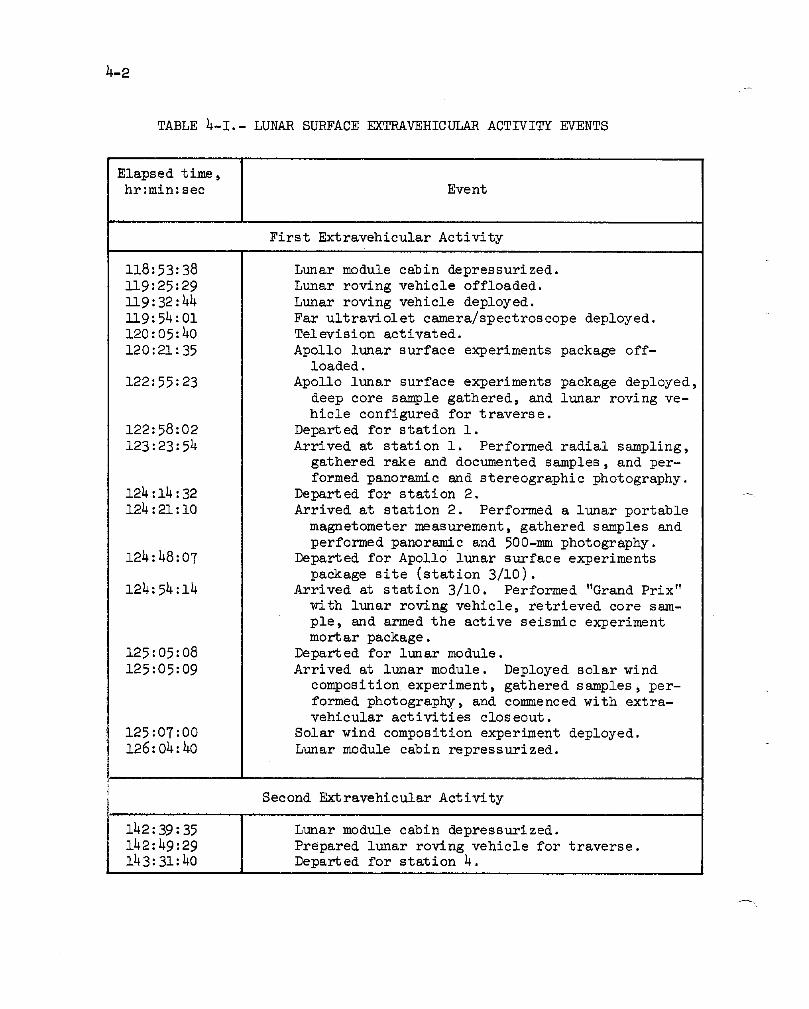
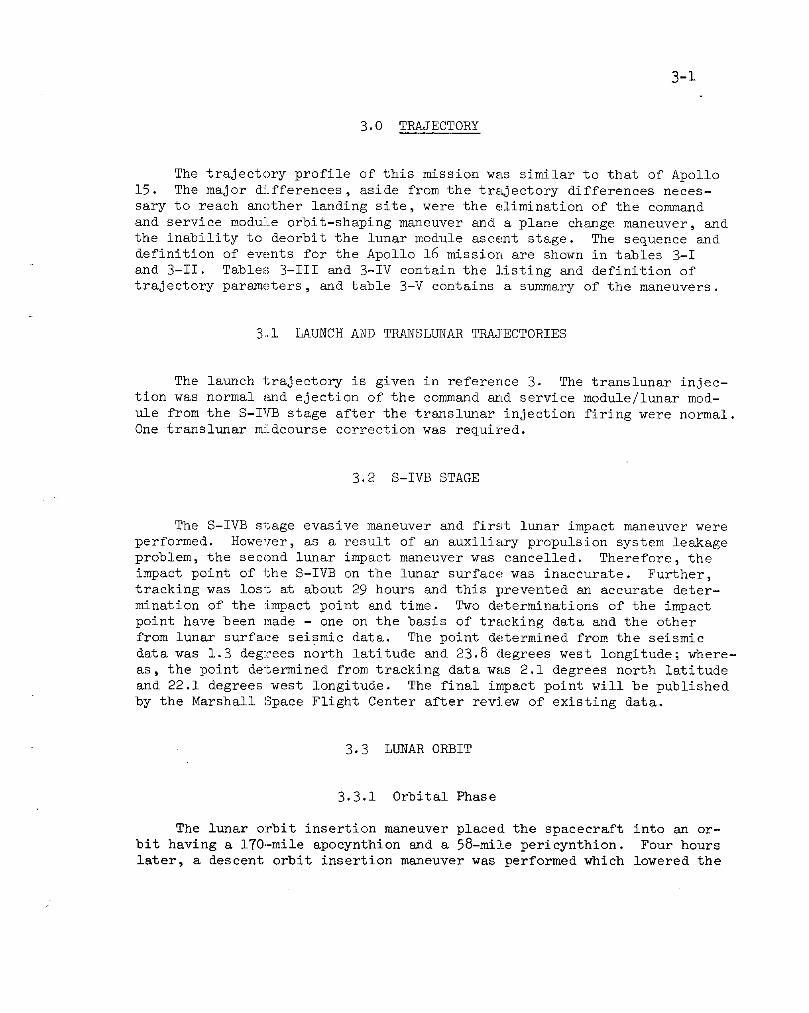
TABLE 4-I.- LUNAR SURFACE EXTRAVEHICULAR ACTIVITY EVENTS
Elapsed time,hr:min:sec Event
First Extravehicular Activity
118:53:38 Lunar module cabin depressurized.
119:25:29 Lunar roving vehicle offloaded.
119:32:44 Lunar roving vehicle deployed.
119:54:01 Far ultraviolet camera/spectroscope deployed.120:05:40 Television activated.
120:21:35 Apollo lunar surface experiments package off-loaded.
122:55:23 Apollo lunar surface experiments package deployed,
deep core sample gathered, and lunar roving ve-
hicle configured for traverse.
122:58:02 Departed for station 1.
123:23:54 Arrived at station 1. Performed radial sampling,
gathered rake and documented samples, and per-
formed panoramic and stereographic photography.124:14:32 Departed for station 2.
124:21:10 Arrived at station 2. Performed a lunar portable
magnetometer measurement, gathered samples and
performed panoramic and 500-mm photography.124:48:07 Departed for Apollo lunar surface experiments
package site (station 3/10).124:54:14 Arrived at station 3/10. Performed "Grand Prix"
with lunar roving vehicle, retrieved core sam-
ple, and armed the active seismic experiment
mortar package.
125:05:08 Departed for lunar module.
125:05:09 Arrived at lunar module. Deployed solar wind
composition experiment, gathered samples, per-
formed photography, and con_nenced with extra-vehicular activities closeout.
125:07:00 Solar wind composition experiment deployed.
126:04:40 Lunar module cabin repressurized.
Second Extravehicular Activity
142:39:35 I Lunar module cabin depressurized.
142:49:29 1 Prepared lunar roving vehicle for traverse.143:31:40 Departed for station 4. i

4-3
TABLE 4-1.-- LUNAR SURFACE EXTRAVEHICULAR ACTIVITY EVENTS
Elapsed time, Eventhr:min:sec
144:07:26 Arrived at station 4. Performed penetrometer
measurements, gathered samples, obtained a dou-
ble core tube sample,, gathered a soil trench
sample, and.performed 500-ram and panoramic pho-
tography.
145:05:16 Departed for station 5u
145:10:05 Arrived at station 5. Gathered samples, performed
lunar portable magnetometer measurement, and per-
formed panoramic photography.
145:58:40 Departed for station 6_
146:06:37 Arrived at station 6. Gathered samples and per-
formed panoramic photography.
146:29:18 Departed for station 8 (station 7 deleted).
146:40:19 Arrived at station 8. Gathered samples, obtained
a double core tube sample, and performed pano-
ramic photography.
147:48:15 Departed for station 9.
147:53:12 Arrived at station 9. Gathered samples, obtained
single core tube sample, and performed panoramic
photo graphy.
148:29:45 Departed for station i0.
148:54:16 Arrived at station i0. Gathered samples, performed
penetrometer measurements, obtained a double core
tube sample, and performed panoramic photography.149 :21:17 Departed for lunar module.
149:23:24 Arrived at lunar module and began extravehicular
activity closeout.
150:02:44 Lunar module cabin repressurized.
Third Extravehicular Activity
165 :31 :28 Lunar module cabin depressurized.
165:43:29 Prepared lunar roving vehicle for traverse.
166:09:13 Departed for station 11.
166:44:50 Arrived at station ii. Gathered samples, per-
formed 500-ram and panoramic photography.
168:09:46 Departed for station 113.
168:17:39 Arrived at station 13. Gathered samples, per-
formed lunar portable magnetometer measurement
and performed panor_nic photography.

TABLE 4-I.- LUNAR SURFACE EXTRAVEHICULJU_ ACTIVITY EVENTS (Concluded)
Elapsed timeshr:min:sec Event
168:46:33 Departed for station i0 prime.
169:15:38 Arrived at station i0 prime. Gathered samples,
obtained a double core tube sample, and per-
formed 500-mm and panoramic photography.
169:01:48 Drove lunar roving vehicle to lunar module.
Gathered samples and con_nenced extravehicular
activity closeout.
170:12:00 Solar wind composition experiment retrieved.
170:23:06 Departed for lunar roving vehicle final parkingarea.
170:27:09 Arrived at final parking area. Performed two lu-
nar portable magnetometer measurements, gatheredsamples, and continued with extravehicular ac-
tivity closeout.
171:01:42 Retrieved film from far ultraviolet camera/spec-
troscope.
171:11:31 Lunar module cabin repressurized. _
_I
4-9
f
Figure 4-4.- Apollo lunar surface experiments
package central station
bar from sliding all the way into place so that the pin could lock. As
a result, the package was free to rotate and w._rtical oscillations causedthe detachment. The Lunar Module Pilot knocked the dirt out of the socket
and re-attached the package. Dropping of the package caused no operational
degradation.

4-10
Initial data were received in the Mission Control Center at 1938
G.m.t. on April 21 and the received signal strength (-139 +2 dBm) was in
the range of values measured on other packages operating on the moon.Within 68 minutes of emplacement of the central station, all instruments
were turned on and their operational checkout showed normal performance
except the heat flow experiment which was inoperative because of a broken
cable, as discussed in section 4.6. The radioisotope thermoelectric pow-
er source is providing 70.4 watts, approximately 15 watts higher than the
basic system requirement. The solid-state timer has generated all sched-
uled 18-hour pulses which provide a backup means of initiating certainfunctional changes.
The temperature of the central station electronics, as indicated by
sensors on the thermal plate, has varied from a maximum of 42.8 ° C during
lunar day to a minimum of 2.8 ° C during lunar night.
4.3 PASSIVE SEISMIC EXPERIMENT
J
The passive seismic experiment (S-031) was deployed as planned. All
elements of the experiment have functioned normally with the exception of
the thermal control system. Two days after activation, the temperature
increased markedly beyond the controller set point and eventually exceeded
the range of the sensor, 61.4 ° C. The temperature stabilized at night to
52.2 ° C. Photographs of the instrument show the shroud skirt to be raised
at several places (fig. 4-5); further, dust was inadvertently kicked onto
the skirt after the photographs were taken. These factors are believed
to be responsible for the abnormal temperatures. The temperatures are not
expected to affect instrument life or seismic data, but will degrade thetidal data.
Seismic signals were detected from surface activities by the crew
and movements of the lunar roving vehicle at all points along the trav-
erses (maximum range of 4.4 km). Abrupt changes in the signals detected
from the rover appear to be correlated in some cases with the blockinessof the terrain being traversed. Other changes remain to be explained.
Seismic signals from the S-IVB impact, which preceded deployment of
the Apollo 16 station, were recorded at all three seismic stations (Apollostations 12, 14, and 15) (fig. 4-6). The first detectable signals arrived
at station 12 in approximately 30 seconds, at station 14 in approximately
46 seconds, and at station 15 in approximately 148 seconds. The loss of
normal S-IVB tracking data (see sec. 13.3) prevented accurate determina-tion of the time and location of the impact. This uncertainty will great-
ly reduce the lunar structural interpretation based upon these data. As
4-13
data from the fot_r stations will expand the knowledge of the lunar struc-
ture much beyond that previously possible.
Three grenades were fired onMay 23 from the active seismic experi-
ment mortar package (see sec. 4.4). The largest and the one having the
longest range tilted the passive seismic experiment sensor 3 arc seconds
southward. This tilt is within the capability of the passive seismic ex-
periment leveling system and the experiment was re-leveled. The two smal-
ler grenades showed no effect.
4.4 ACTIVE SEISMIC EXPERimENT
The active seismic experiment (S-033) mortar package was deployed
about 17 meters northeast of the central station with the geophone lineextending 90 meters northwest of the mortar package (fig. 4-4). The cen-
tral station was commanded to high-bit-rate mode at 19:54:30 G.m.t. on
April 21 to record the active seismic experiment/thumper mode of opera-tion. Thumping operations began about 7 minutes later at geophone 3 (fur-
thest from the central station) and proceeded at 4.5-meter intervals (ex-
cept between positions ii and 12 and positions 18 and 19 which are 9-meter
intervals) toward geophone i (nearest to the central station). The final
thumper charge was fired about 14 minutes after the first firing. Thecentral station was commanded to normal bit r_te at 20:16:32 G.m.t. The
thumper was fired at the 19 scheduled cable positions. Two attempts were
needed to fire the thumper at position 2 because the thumper was not armed
for the necessary 5 seconds prior to firing. Seismic signals were recorded
at all three geoplhones for all 19 thumper firings. A calibration pulse
was sent after the last thumper firing verifying that all three geophoneswere still operational.
Minor difficulty was experienced in the deployment of the mortar
package pallet when one of the four stakes that support the mortar pack-
age could not be deployed. This anomaly is discussed in section 14.4.2.
The mortar packa@e was leveled and armed to fire four grenades on command
to distances of 150, 300, 900, and 1500 meters. Near the close of the
third extravehicular activity, the mortar package roll angle sensor read-
ing was off scale (see sec. 14.4.3); however, a television panorama takennear the close of the third extravehicular activity verified that the mor-
tar package was properly positioned and aligned.
The central station was commanded to high bit rate at 0106 G.m.t. on
April 24 to record the impulse produced by the lunar module ascent. A
strong seismic signal was recorded by the geoplhone array. The central
station is scheduled for periodic operation in the high-bit-rate mode for
listening to detect natural seismic signals and to verify experiment op-erational capability.

4-14
On May 23, the Apollo lunar surface experiment package was commandedto high bit rate between 0520 and 0644 G.m.t. for the active seismic ex-
periment/mortar mode of operation. Three of the four high-explosive gren-ades in the mortar package were successfully launched. Grenade 2 (1024
grams) was launched a distance of 900 meters; grenade 4 (695 grams) waslaunched a distance of 150 meters; and grenade 3 (775 grams) was launched
a distance of 300 meters; in the sequence given. Grenade 1 (1261 gramsand planned to be launched a distance of 1500 meters) was not launched
because the mortar package pitch angle sensor went off-scale high after
firing grenade 3. (See section 14.4.12 for a discussion of this anomaly.)
The off-scale indication makes the pitch position of the launch assemblyuncertain. Seismic signals were noted by all three geophones for each
grenade launched. The data from the mortar firings combined with the data
from the thumper mode of operation indicates that the regolith has a depthof about 12 meters in the Descartes area.
4.5 LUNAR SURFACE MAGNETOMETER EXPERIMENT
The lunar surface magnetometer (S-034) was successfully deployed ap-
proximately 15 meters west of the central station (fig. 4-7). The experi-
ment was initially commanded on during the first extravehicular activity.
All operations of the experiment have been normal. A one-time site surveywas successfully completed on April 28. The remanent magnetic field meas-
ured at the lunar surface magnetometer site is 230 ±15 gammas. The in-
strument is also continuously measuring magnetic fields induced in thelunar interior by changing solar magnetic fields.
4.6 HEAT FLOW EXPERIMENT
Deployment of the heat flow experiment (S-037) was initiated on sched-
ule. The experiment instrument package was moved to the selected site andthe electronics cable was connected to the central station. A hole was
drilled to the depth of the first bore stem section in 51 seconds at an
average penetration rate of 2.3 centimeters per second. The second bore
stem section was added and the hole drilled to the depth of the two sec-
tions in 39 seconds at an average rate of 1.8 centimeters per second. Up-
on adding the final section, the hole was drilled to the planned depth in54 seconds at a rate of 1.3 centimeters per second. Total penetration was
approximately 250 centimeters. The lunar surface wrench was used success-fully to restrain the bore stems during power head removal.
Heat flow probe number 1 was inserted into bore hole number 1 to the
full depth and both radiation shields were properly emplaced. While the
Commander was working near the central station, he became entangled in the
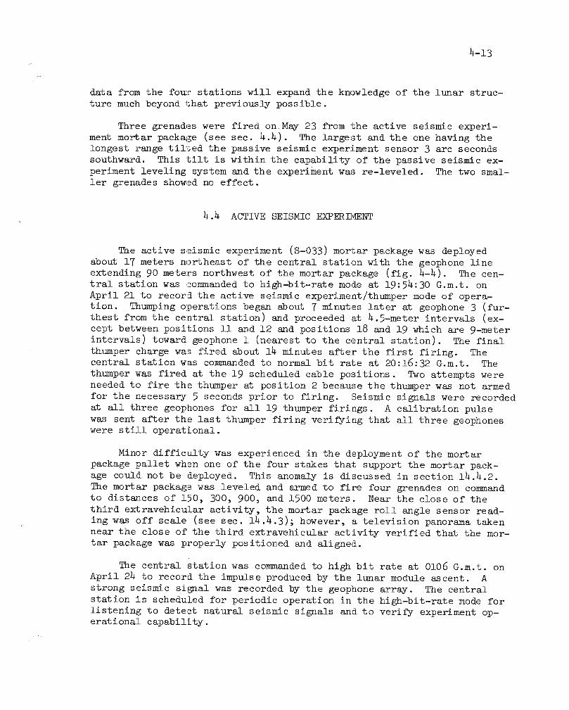
4-15
_agnetometer
Figure 4-7.- Ltmar surface magnetometer experiment andCommander performing active seismic experiment.
heat flow experiment electronics cable and broke it loose at the connector
to the central station. Further deployment was abandoned and the experi-ment is inoperable. The details of this failure are given in section 14.4.1.

4-16
4.7 LUNAR PORTABLE MAGNETOP_ETER EXPERIMENT
The deployment and operation of the lunar portable magnetometer ex-
periment (S-198) was normal in all respects; leveling, orientation, posit-
ioning, switching, and cable winding operations were accomplished without
difficulty. The instrument was operated at four different sites. Digital
readings relayed over the voice link indicated total magnetic field mag-
nitudes of 180 +15 gammas at station 2, 125 +15 gammas at station 5, 310
-+15 gammas at station 13, and 120 +-15 gammas at the lunar roving vehicle
final parking site. After completion of the first measurement at the fi-nal site, a lunar rock sample was placed on top of the magnetometer sensor
block, and a second field measurement was made to study the magnetization
of the sample.
4.8 FAR ULTRAVIOLET CAMERA/SPECTROSCOPE EXPERIMENT
The far ultraviolet camera/spectroscope (S-201) was deployed approx-
imately 2 meters southwest of the down-sun footpad of the lunar modulewith the camera in the shade and the battery in sunlight (fig. 4-8). Be-
cause of the landing delay and the consequently high sun angle, it was
necessary to move the camera into the shade during the second and thirdextravehicular activities. Difficulty was experienced in adjustment of
the azimuth ring. The condition degraded with each adjustment. Section14.4.9 contains a discussion of this anomaly.
The camera was turned on at the beginning of the first extravehicu-
lar activity and operated until closeout of the third extravehicular ac-
tivity for a span of approximately 51 hours. The film was retrieved for
postflight analysis. The camera was pointed at ii targets by the crew as
planned. No data were recorded for the eleventh target because the cam-era had run out of film, as expected.
Imagery of the earth in the 1216-angstrom wavelength of hydrogen
(Lyman-alpha) revealed that the geocorona is nearl_ spherical and extendsout more than i0 earth radii (fig. 4-9). Imagery of the earth's atmos-
phere in the 1230- to 1550-angstrom range showed two auroral belts - oneon either side of the magnetic equator and inclined about 15 degrees to
the equator (fig. 4-10). Spectroscopic data without the lithium fluoride
(LiF) transmission optics shows the 584-angstrom line of helium in the
solar wind plasma. The photographs and spectra contain a great deal of
astrophysical detail.

4-17/
Figure 4-8.- Far ultraviolet camera/spectroscope experiment,
4.9 COSMIC RAY DETECTOR EXPERIMENT
The panel arrsy of the cosmic ray detector experiment (S-152) was
exposed in its initial configuration upon jettisoning of the spacecraft-
launch vehicle adapter panels. The hidden surface of panel 4 was partly
exposed by the Commander early in the first extravehicular activity (fig.
4-11). The planned area of exposure for detecting particles at the lunar
surface could not be obtained because the experiment mechanism jammed as
described in section 14.4.4. The detector pane] array was retrieved at

4-18
Figure 4-9.- Lyman-alpha imagery of hydrogen
cloud surrounding earth.
the end of the third extravehicular activity, folded in the proper config-
uration for transearth coast data collection, and returned for analysis.
It was difficult to separate the panel assembly from the main frame at
the end of the third extravehicular activity because of thermal expansionof the Teflon slides.

-19
The plastic in all panels of the experiment was degraded by heatingabove the design limit of 54° C, at which temperature degradation begins.The high temperature was most likely caused by a film accumulating on thethermal control surface, in addition to lunar dust. Analysis of the filmhas not been completed.
Analysis of the data received on the lunar surface and during trans-lunar and transearth coast will be degraded because of the minor solarflare which occurred during translunar flight. This flare blanketed thedetector panels with low energy tracks which interfere with the analysisof the higher energy tracks received during the previously discussed per-iods. Also, the resolution will be reduced because of the high tempera-ture which the experiment hardware experienced on the lunar surface.
N80 60
40 20
Auroralbelts
Zero
latitude
-20
-40
Magnetic -60dip eq_
Ter_dnator./ Zero Slong itude
Figure 4-10.- Newly discovered auroral belts.
4-20
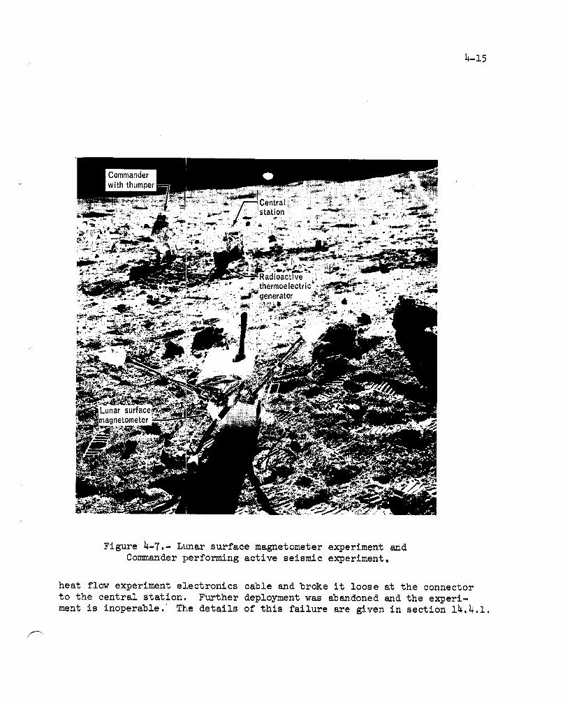
Figure 4-11.- Cosmic ray detector experiment,
As a result of the incomplete exposure of panel 4, the portion of the
experiment designed to measure neutron flux was degraded, as were those
designed to measure solar wind gas, and search for radon (Rn222) and argon(ArgO).
The plastics should be suitable for a study of solar wind particles.
In addition, both solar and galactic cosmic ray tracks have been observed
in the plastics and some of the glasses of the panels. The plastics that
were pre-irradiated with neon (Ne20) showed annealing effects from over-
heating, but neutrons from the fuel cask will be measurable.
h-21r
4.1,3 SOLAR WIND COMPOSITION EXPERIMENT
The solar wind composition experiment (S-080) for this mission dif-
fered from those of previous missions in that pieces of platinum foil were
attached to the specially prepared aluminum foil used to entrap noble gas
particles. This was done to determine whether or not the platinum foil
pieces could be cleaned with fluoridic acid to remove lunar-dust contami-
nation without destroying rare gas isotopes of solar wind origin up to themass of krypton.
The experiment was deployed about 18 meters northwest of the lunar
module at the end of the first extravehicular activit_ period and re-trieved near the end of the third extravehicular period. The total foil
exposure time was _5 hours and 5 minutes, some 3 hours longer than thatof any previous mission.
h.ll LUNAR GEOLOGY
h.ll.l Sample Collection
Areas visited and sampled for the lunar geology investigation (S-059)
during the extravehicular activities included the northwest flank of Stone
Mountain (Descartes Mountains), Flag and Spook Craters west of the lunar
module landing site on the Cayley Plains, North Ray Crater, and South Ray
Crater eJecta on the plains between the lunar module and Stone Mountain.
The sampling stations and traverses are shown in figure h-2.
On the first traverse, the tasks at stations 1 and 2 were performed
as planned except for sampling the rim of Spook Crater. A 2.6-meter deep
core sample was obtained at the Apollo lunar surface experiments packagesite.
Station 7 was deleted from the second extravehicular activity to al-
low more time for sampling in the lunar module/Apollo lunar surface exper-
iments package area. Double cores were collected at stations h, 8, and i0.
Documented and rake/soil samples were collected at all traverse stops ex-
cept for station 9 which was devoted to obtaining undisturbed surface ma-
terial with the lunar surface samplers, sampling the top and bottom of a
large boulder, and sampling the soil beneath the boulder after it was over-turned.
4-22
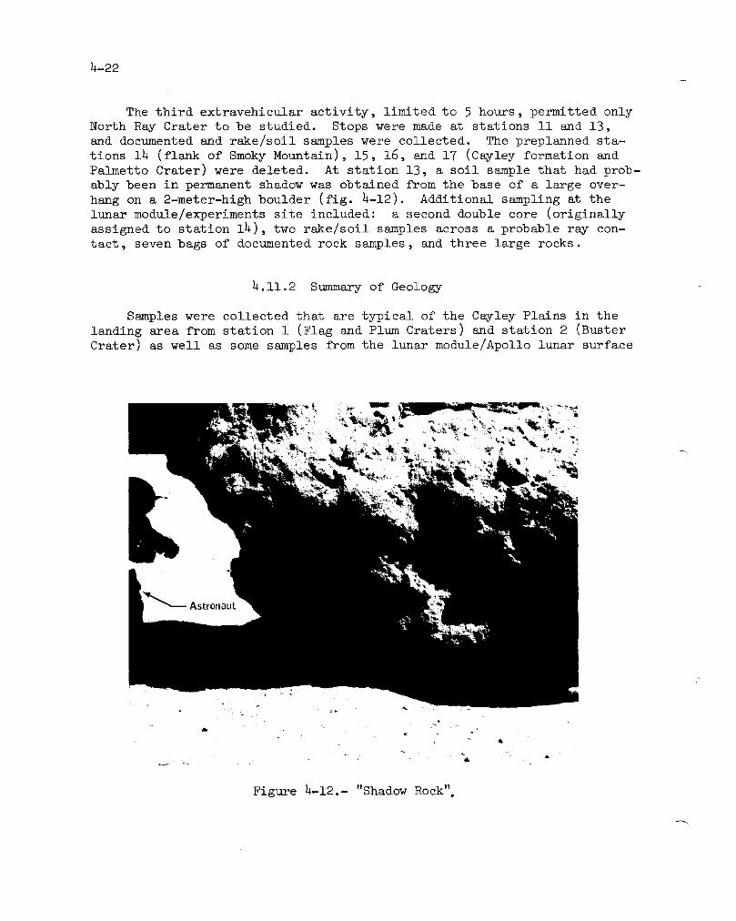
The third extravehicular activity, limited to 5 hours, permitted only
North Ray Crater to be studied. Stops were made at stations ii and 13,
and documented and rake/soil samples were collected. The preplanned sta-
tions 14 (flank of Smoky Mountain), 15, 16, and 17 (Cayley formation and
Palmetto Crater) were deleted. At station 13, a soil sample that had prob-
ably been in permanent shadow was obtained from the base of a large over-
hang on a 2-meter-high boulder (fig. 4-12). Additional sampling at the
lunar module/experiments site included: a second double core (originally
assigned to station 14), two rake/soil samples across a probable ray con-
tact, seven bags of documented rock samples, and three large rocks.
4.11.2 Summary of Geology
Samples were collected that are typical of the Cayley Plains in the
landing area from station i (Flag and Plum Craters) and station 2 (Buster
Crater) as well as some samples from the lunar module/Apollo lunar surface

4-23
experiments packag_ site (station 3/10); South Ray Crater ejecta was col-lected at stations 4, 8, 9, and station 3/10; North Ray Crater ejecta werecollected at stations ii and 13. Descartes materials were collected from
the flank of Stone Mountain at stations 4, 5, Emd 6.
The Cayley formation appears to consist of light- and dark-colored
breccias, possibly in interstratified layers. It does not consist, at
least in this area, of lava flows, as had been widely supposed. TheDescartes highland materials of Stone Mountain consist of light-colored
breccias and crystalline fragments of, as yet, unknown origin.
No bedrock was sampled by the crew although they tentatively iden-
tified bedrock layers in North Ray Crater and in a large crater high on
Stone Mountain. Elsewhere, all large craters were heavily mantled with
deep regolith that completely masks any possible strata. Boulders of
varying sizes were sampled by the crew, the largest being the 20-meter
"House Rock" on the rim of North Ray Crater (fig. 4-13).
About 95 kilograms of documented rock and soil samples were obtained.
The material collected from widely distributed sampling stations, includ-
ing samples of ejecta from deep craters, should provide for the study of
the Cayley Plains region down to depths of 200 meters.
4.11.3 Equipment
The equipment used during the geology portion of the extravehicular
activities perforated well with the following exceptions:
a. One of the retractable tethers (yo-yo's) would not fully retract.
Postflight inspection showed that the tether was operating, but that the
friction increased during the retraction cycle (see sec. 14.3.7).
b. The vertical staff of the gnomon was ]pulled off at station 6.
When the gnomon was being unstowed, the leg assembly stayed in the bag
and the vertical staff came out by itself (see sec. 14.4.5).
c. The Velcro hook patch which provides the attachment point for a
Velcro wrapping strap on each of the two padded sample bags came off be-fore use (see sec. 14.4.10).
d. The reseau plate on the Lunar Module Pilot's 70-ram electric data
camera was smeared during a magazine change between extravehicular activ-ities 2 and 3.
e. Sample return container i did not ses_1 properly because part of
a sample collection bag was caught in the seal area between the knife edgeand the indium seal.

4-24
f. The sample collection bags fell off the portable life supportsystem mounts (see sec. 14.4.8).
g. The documented sample bag dispensers repeatedly fell off theattachment brackets on the 70-ram camera (see sec. 14.4.6).
h. The screws came loose on one of the documented sample bag dis-penser assemblies (see sec. 14.4.7).
i. The lanyard loop came off the penetrometer stowage release pin(see sec. 14.4.11).
4.11.4 Photography
A total of 1774 photographs were taken on the lunar surface with the
70-mm electric data cameras using the 60-mm and 500-ram focal-length lenses,and 4 1/2 magazines of 16-mm lunar surface data acquisition camera film
were exposed. At least one 360-degree 60-ram panorama was taken at each
station. The first successful use of a polarimetric filter on the lunar
surface was an 80-meter stereobase polarimetric panorama of the interiorof North Ray Crater.
4.12 SOIL MECHANICS EXPERIMENT
The soil mechanics experiment (S-200) provided a greater amount of
qualitative data on the properties of the lunar surface and subsurface
soils than has been previously obtained. All parts of the soil mechanics
experiment were completed with the exception of the soil_mechanics trenchat station i0 which was omitted because of time limitations.
Preliminary analysis has indicated that the self-recording penetrom-
eter performed normally with a loss of data for only one of eleven tests.
Four cone penetration tests were accomplished at station 4. Five cone
penetration tests were performed between the experiments station and the
lunar module. Of these, four were on a line between the deep drill core
site and the station i0 double-core tube site. Cone penetration depths
range between 20 and 75 centimeters. Additionally, two plate-load testswere performed at station i0.
Preliminary analysis of the self-recording penetrometer data has in-
dicated that the soil density and strength characteristics are highly var-
iable, both laterally and vertically. Definite evidence of layering is
visible in some of the load-versus-penetration tracks indicated on the
penetrometer.

5-1
5.0 INFLIGHT SCIENCE AND PHOTOGRAPHY
This section contains a discussion of experiments and science-ori-
ented detailed objectives which were performed in lunar orbit, and dur-
ing translunar and transearth flight. Preliminary scientific findingsare not given in detail in the discussion since this information will be
included in reference i, which is in preparation. The experiment equip-
ment was similar to that of the Apollo 15 mission. Appendix A provides
information on minor changes from the Apollo 15 configuration.
Experiments located in the scientific instrument module consisted of
a gamma_ray spectrometer, an X-ray spectrometer, an alpha-particle spec-
trometer, a mass spectrometer, and a subs atellite which was the vehicle
for three experiments that were to obtain data on particles and fields.
The scientific instrument module equipment also included a mapping camera,
a panoramic camera, and a laser altimeter.
The other e_?eriments and detailed objectives performed during flight,
and which required active crew participation, consisted of: an S-band
transponder experiment; a down-link bistatic radar experiment; ultravio-
let photography of the earth and moon; photography of the Gegenschein,
other astronomical subjects, and the lunar surface; visual observations
from lunar orbit; an experiment to determine _Lcrobial response to the
space environment; investigation of the visual light flash phenomenon;
and a demonstration of fluid electrophoresis in space. Experiments that
did not require active crew participation consisted of measurement of
meteoroid impacts on the spacecraft windows, a biostack experiment to de-
termine the effects of high-energy heavy ions on biological systems, andmeasurement of bome mineral loss in the crew.
5.1 GAMMA-RAY SPECTROMETER EXPERIMENT
Over 80 hours of prime data were obtained in lunar orbit and during
transearth coast from the gamma ray spectrometer experiment (S-160). Some
planned data measurements were not made in lunar orbit because of the earlytermination of l_aar orbit operations. However, the large amount of data
reduced and analyzed indicates that all major objectives were accomplished.
The instrument performed satisfactorily throughout the mission. Gain
stability was sigaificantly improved over that of Apollo 15. At initialturn-on, the spectrometer calibration was the nominal preflight value.
Thereafter, a small downward gain drift occurred, after which the gain
calibration was stable. Energy resolution of the instrument based upon

5-2
measurements of the classical monoenergetic line of 0.511 Mev in the spec-
trum was improved approximately 15 percent over Apollo 15. The extraneousshield event counts that had been noted in preflight calibration were ex-
perienced during flight. However, the rate stabilized and was not detri-
mental to the data. As a result of the problem with the mapping camera
deployment mechanism, the mapping camera door remained open during the
entire period in which the gamma ray spectrometer was active in lunar or-
bit. This resulted in some loss in sensitivity due to the increased back-
ground radiation contributed by the thorium lens of the mapping camera.
The deployment boom failed to fully retract on three occasions but thecondition had no effect on the data. Details of the boom failure are no-
ted in section 14.1.9.
Maps prepared from over 50 hours of data confirm earlier conclusions
pertaining to the geochemistry of the lunar surface, that the regions of
highest radioactivity are the western maria - Oceanus Procellarum and Mare
Imbrlum. Data obtained during transearth coast indicate that the space-
craft background radiation and the total cosmic gamma-ray spectrum are inessential agreement with Apollo 15 results. Preliminary analysis of data
collected from a scan of the supergalactic equator along four planes indi-
cates that galactic gamma rays exhibit anisotroplc properties.
5.2 X-RAY FLUORESCENCE EXPERIMENT
Over 60 hours of prime data were obtained with the X-ray fluorescence
experiment (S-161) and nearly 12 hours were spent with the spectrometer
pointed at two celestial X-ray sources, Scorpius X-1 and Cygnus X-1. The
flight plan changes had an effect upon the schedule for ground-based astro-
nomical observatlons; however, some coverage was obtained. The following
table gives the times of the observations and indicates the coverage by the
ground-based observatories.
Duration of Ground-based
Observation Object Starting time, G.m.t., observation, observatory
April 1972, day:hr:min hr:min Coverage
1 Sco X-1 25:03:25 00:40 -
2 Cyg X-1 25:22:55 03:00
3 Sco X-1 26:02:15 02:30 aAlgonquin
4 Sco X-1 26:20:15 03:20 bLeyden,
Cwise
5 Cyg X-1 27:02:45 02:55 -

5-3f
aAlgonquin Radio Observatory, Canada
bLeyden (optical) Observatory, South Africa
Cwise (optical) Observatory, Israel
The overall performance of the instrument was satisfactory. Nominal
operation of the four detectors was evidenced by calibration data from thebuilt-in sources. A high count rate in channel 1 of detector 1 was ob-
served, but a simiilar high count was observed during the Apollo 15 mls-sion. Detectors 2 and 3 incorporate filters to enhance the detection of
X-rays from alumin1_n and magnesium sources, but detector 1 is unfiltered.
Detector h is part of the solar monitor and does not view the lunar sur-
face. The orienta,_ion required to view Cygnus X-1 subjected the spectrom-eter to an undesirable cold soak and necessitated a special maneuver to
alleviate the condition. The maneuver caused the loss of X-ray pointingand may result in some loss of data. The X-ray detectors survived thecold soak condition quite well.
The region of overlap between the Apollo 15 and Apollo 16 coverage
shows excellent agreement. The Descartes region shows the high aluminum
and low magnesium content that is characteristic of the highlands on the
far side. The mare areas to the west of Descartes show a substantial de-crease in the ratio of aluminum to silicon.
Data monitored in real time indicate that Scorpius X-l, the bright-
est object in the X-ray sky, may have been rather active during one ofthe viewing sessions.
5.B ALPHA-PARTICLE SPECTROMETER
Approximately 70 hours of prime data were collected in lunar orbit
with the alpha-particle spectrometer experiment (S-162). Deletion of the
second lunar orbit plane change prevented an observation of the highlyinteresting Alphonsus area.
The spectrometer operated satisfactorily during all scheduled orbi-
tal and transearth observations. All ten detectors performed within the
expected energy resolution. There were no periods of noisy operation as
experienced on Apollo 15. The alpha-particle spectrometer was subjected
to the same cold soaks as the X-ray spectrometer and lowered temperaturesan undetermined amount below the red-line limit. No detrimental effects
on detector perfo_lance resulted.
From a preliminary analysis of real-time data, a localized concentra-
tion of polonium (Po210) in the general vicinity' of Mare Fecunditatus was
detected. This is shown in the calculation of polonium count rate versus

5-4
lunar latitude. It appears that the increase of polonium is statistically
significant.
Deep-space observations to determine non-radon-related background re-
vealed significant solar alpha particle activity. The deep-space counting
rates exceeded the lunar rates by a factor of 2 or 3, indicating that a
solar alpha-particle background will have to be considered in the analy-sis of the data.
5.4 MASS SPECTROMETER EXPERIMENT
The mass spectrometer experiment (S-165) instrument operate d very well
in lunar orbit collecting approximately 84 hours of data, three-fourths of
this being in the minus-X direction of flight of the command and service
module, the prime data mode, wherein the gas entrance scoop points in theram direction and scoops up native lunar gases. The remainder was back-
ground data taken primarily in the plus-X direction.
Telemetry data about 15 hours prior to lunar module undocking indi-
cated that the plus 12-volt power supply voltage had dropped from ii.9
to 9.4 volts, although the instrument operated nominally. After severaloscillations between these values, the voltage stabilized at 12 volts for
the remainder of the flight. Postflight analysis showed that the 12-volt
sensor had a slow rise time and was sampled before reaching its full value.
The power supply itself did not malfunction.
As on Apollo 15, the boom would not fully retract. On the initial
occurrence, the boom retracted to within 12 inches of full retraction,
sufficient for a safe service propulsion system firing. The number ofboom retractions was minimized following this problem. During the final
retraction for the transearth injection maneuver, the boom stalled at ap-
proximately 2/3 of full extension necessitating jettisoning of the boomand instrument. The transearth coast data were to have been used to sup-
plement analysis of the lunar orbit data. However, Apollo 15 data canbe used for this purpose.
The Apollo 16 data resembles that of Apollo 15 on the distribution
of gasses in the lunar atmosphere. Preliminary analysis indicates that
lunar atmospheric neon is lower than predicted.
5.5 PARTICLES AND FIELDS SUBSATELLITE EXPERIMENTS
The subsatellite was launched on the dark side of the moon about one
hour after lunar module jettison during the 62nd revolution (April 2_,

5-5
21:56:09 G.m.t.). An orbit-shaping maneuver was to have been performed
prior to launching of the subsatellite to obtain the desired lifetime of
one year. However, the maneuver was not performed because of the decis-
ion to limit the use of the service propulsion system to the transearth
injection maneuver as a result of the engine gimbal actuator control prob-
lem (discussed in section 6.6). Consequently, the planned orbit was not
obtained. The initial orbital parameters, as compared to the Apollo 15
parameters, were as follows :
Mission Perilune _ km (ml) Apolune _ _n (mi) Inclination
Apollo 15 i105 (55) 144 (76) -28 °
Apollo 16 97 (52) 120 (66) -Ii °
It was not possible to activate the subsatellite for about 20 hours
after launch because of communications frequency interference resulting
from the failure of the lunar module ascent stage to deorbit. At the time
of launch, the subsatellite _as in the magnetosheath heading toward the
magnetopause and geomagnetic tail. The delay in activation had no detri-mental effect on tlhe subsatellite systems.
The subsatellite is calculated to have impacted the far side of the
moon (ii0 degrees east longitude) during revolution 425 on May 29, 1972.
The last telemetry data were received at 2031 G.m.t., coinciding with
loss of signal. The signal should have been reacquired at 2200 G.m.t.,but was not.
The physical cause for the short orbital life appears to be the lu-nar mass concentrations on the front and far sides located relatively near
the subsatellite ground track.
5.5.1 Particle Shadows/Boundary Layer
All charged-particle telescopes and electrostatic analyzer detectors
operated normally during the lifetime of the particle shadows/boundary
layer experiment (S-173) portion of the subsatellite. On two passes,usable data were c_tained in the geomagnetic tail of the magnetosphere.
Particle tracing was improved by a better shadow structure than on
Apollo 15. This resulted from the telescopes operating at a lower tem-
perature.
5.5.2 Magnetometer
The biaxial fluxgate magnetometer experiment (S-174) performed satis-
factorily. Meastu'ement_ are in agreement with Apollo 15 results that the
5-6
lunar magnetic field is more varied on the far side than the near side.
However, individual features overflown during the first geomagnetic tall
pass are not as clearly defined as those measured on Apollo 15. While in
the solar wind, the magnetometer mapped the diamagnetic cavity, examined
limb compressions over the terminator, and measured lunar induction fields
produced by transients in the interplanetary field. While the size of the
magnetic enhancement in the diamagnetic cavity (approximately 1/2 gamma)
is similar to that seen on Explorer 35, the limb compression exterior to
this cavity is significantly stronger at the low subsatellite altitudes(up to 6 gammas).
5.5.3 S-band Transponder
The subsatellite S-band transponder experiment (S-164) system func-
tioned satisfactorily. Better-than-planned coverage was obtained fromMay 8 through May 16 when the altitude of the subs atellite was between
ii and 20 kilometers. Several orbits just prior to impact are expected
to reveal new gravity data, but since the impact was on the far side, much
of the extremely low-altitude portion of the trajectory occurred during
occultation. Therefore, only that portion of the trajectory near the
eastern limb will supply new information. A good gravity profile is ex-pected over Copernicus.
5.6 S-BAND TRANSPONDER EXPERIMENT (CSM/LM)
The S-band transponder experiment (S-164) systems on the command and
service module and the lunar module performed satisfactorily. Gravita-
tional profile data were obtained while the docked spacecraft were in el-liptical orbit and while the command and service module was in circular
orbit (except for revolutions 12 through 16 when firing of thrusters dur-
ing stationkeeping degraded the data). No S-band doppler measurements
from the lunar module ascent stage after undocking were obtained because
of the inability to control its attitude. Data reduced in real-time were
of excellent quality and definite gravity variations were observed. Grav-
ity anomalies in the Ptolemaeus, Descartes, Fecunditatus, and Procellarumregions were identified.
5.7 DOWN-LINK BISTATIC RADAR OBSERVATIONS OF THE MOON
Dual S-band/VHF observations were conducted for the down-link bistatic
radar observations of the moon experiment (S-170) during revolution 40.
Strong direct and reflected S-band signals were received by the Jet Pro-
pulsion Laboratory 210-foot dish antenna, and weak VHF reflected signals

_ 5-7
were received by the 150-foot dish antenna at Stanford University. Inter-
ference was experienced with the VHF signals during one-seventh of the
pass from the Apollo test and training satellite (TETR-D satellite 5492
launched September 29, 1971, for testing of NASA tracking stations and
training of ground network personnel) transmitter operating on the samefrequency. The transmitter could not be comm_ded off prior to the
Apollo 16 mission because of a satellite systems failure.
The VHF-only test was initiated on revolution 42. The other omni-
directional antenna was used to improve signal strength, but this was notsuccessful because of poor antenna orientation and the transmitter was
switched back to the original antenna and good signals were received.
Data obtained during revolutions 42, 43, and 44 were clear of the inter-ference from the training satellite. The reason for the weak reflectionsis unknown.
The S-band data appear to be of high quality and most of the scien-
tific goals dependent upon dual S-band and VI_' data can be met even thoughthe VHF data on revolution 40 were of poor qu_Llity. The VHF data taken on
revolutions 42 szld 43 have enough similarity that it may be substituted.
5.8 S_VICE MODULE ORBITAL PHOTOGRAPHY
5.8.1 Panoramic Camera
The panoramic camera was carried on Apollo 16 to obtain high-resolu-
tion photography of the lunar surface. The priority of the coverage wasthe Apollo 16 landing site area both prior to and after .the extravehicu-
lar activities, _reas near the terminators, sz_d other areas of the ground
track. The coverage during lunar orbit operations is shown in figure 5-1.In addition to that shown in the figure, some coverage was obtained aftertrans earth injection.
Concurrent with camera activation for revolution 3 photography, anabnormal bus voltage condition was noted. Consequently, the camera was
turned off after exposing only four frames, thereby resulting in the loss
of coverage between 170 degrees west and 168 degrees east longitude. An-
alysis showed that the under-voltage condition was caused by the space-
craft configurat'Lon, and that camera operation was normal. Reschedulingof subsequent panoramic camera passes recovered a portion of this loss as
well as other losses incurred as a consequence of the delay in the circu-
larization maneuver, cancellation of the plane change maneuver, and theone-day-early return to earth.

5--8
From the beginning of camera operation, the exposure sensor consis-
tently read lower light levels than were present (sec. 14.5.4). Post-
flight analysis of data shows that frames taken over approximately 25 de-
grees away from the terminator were over-exposed by 1 to 2 f-stops. A
development process using a lower gamma compensated for the overexposure
in the subsolar area without compromising the resolution of the near-
terminator photographs. A section of film, taken after transearth in-
jection, was cut from the roll and processed separately to test the change
in the chemical processing. Examination of the main roll after develop-
ment showed excellent quality photographs. Revolution 47 telemetry dataindicated several unusual transients in the lens motor current. This con-
dition persisted for several successive frames. A review of the film dis-
closed no corresponding degradation in the photography.
A photograph of the Descartes area obtained with the panoramic camera
on revolution 28 (fig. 5-1) was used in the preparation of figure 4-2.The lunar module can be identified in the photograph.
5.8.2 Mapping Camera System
The mapping camera provided cartographic-quality photographs fromwhich selenodetic data were derived for use in mapping at a scale of
1:250 000. Complete mapping camera coverage was obtained of all areas
overflown by the spacecraft in daylight. Simultaneous vertical operation
of the mapping camera was performed with the panoramic camera to provide
geometric support for photographic reduction. The mapping camera was also
operated vertically during revolutions 4, 29, 46, 59, 60, and after trans-
earth injection.
Oblique photography was taken 25 degrees forward of the spacecraft
on the 25th revolution, 40 degrees south of the lunar ground track on the26th and 48th revolutions, and 40 degrees north of the lunar ground track
on the 27th and 37th revolutions. Approximately 90 percent of the planned
coverage was obtained. Figure 5-2 shows the daylight coverage obtained
during lunar orbit. The obtained coverage is less than 5 percent of the
lunar surface and about 80 percent of the Coverage is new, i.e., not pho-
tographed during Apollo 15. The coverage lost because of flight plan
changes was along the northeast and southwest edges of the ground track,
and 8 degrees of longitude at the western daylight limit. This coverage
loss is discussed in the panoramic camera section (5.8.1).
The mapping camera system consists of a mapping (metric) camera anda stellar camera; the function of the stellar camera is to obtain synchro-
nized star field photographs for each frame of metric photography whileon the illuminated side of the moon and for each laser altimeter firing
on the dark side of the moon. Measurements and computations from these
photographs provide an independent determination of attitude. Satisfac-
tory stellar photography was obtained on all mapping camera passes, and
5-11
camera operation was normal; however, during the transearth extravehicu-lar activity, the glare shield for the stellar camera was found jan_ned
against the handrail paralleling the scientific instrument module bay.
This anomaly is discussed further in section 14.5.2.
The mapping camera deployment mechanism exhibited anomalous perform-
ance similar to the Apollo 15 problem. The first extension was normal,
but the retract time was excessive by a factor of two. (This anomaly is
discussed further in section 14.5.1.) In order to reduce the possibility
of total failure of the mechanism, the camera remained in the extended
position after the second extension (on revolution 17) until retraction
(on revolution 48) for the plane change maneuver. The remaining nine
planned deployment cycles were reduced to three - two during lunar orbit,
and one between transearth injection and the transearth extravehicular
activity. As a result, the mapping camera and laser altimeter were left
extended for long periods of time. This presented no apparent problemsfor these instruments.
Upon opening the cassettes for film development, the film was found
to be contaminated with metal chips (see sec. ].4.5.7). A scheme was de-
vised using air jets and tacky rollers to clean both the mapping andstellar film before processing. Examination of the developed film shows
the image quality of the mapping photography to be excellent. Nine or
more frames, however, are overexposed (see sec. 14.5.6). In most cases,this condition occurred when the shutter speed changed from 1250 to 800
rpm.
It is conceivable that some of the metal (;hips found in the cassette
may have been between the emulsion and the reseau plate at the focal plane.
This would not seriously degrade the image quality, but may introduce geo-
metric distortions which will adversely affect the measurements on some
frames. The photography will satisfy all basic; requirements.
5.8.3 Laser Altimeter
The functions of the laser altimeter are to provide a distance meas-
ure from the spacecraft to the lunar surface in synchronism with each map-
ping camera expos_ire, and to provide topographic profiles for correlation
with gravity anomalies obtained from tracking data.
Altimeter data were obtained on all mapping camera passes on the il-
luminated side of the moon. Initial operation was normal but the percent-
age of valid measurements gradually decreased as the mission progressed
because the laser output power decreased. This anomaly is discussed in
section 14.5.3. About 65 percent of the observations were valid through
revolution 60, but on the last pass (revolution 63), only i0 percent ofthe measurements were valid. (See section 14.5.5 for a discussion of

5-12
this anomaly. ) The loss of altitude data on the illuminated side of the
moon will have little effect on the interpretation of mapping photography
since there is redundancy in determining altitude. However, some inter-
polation will be required in correlating topographic profiles with gravityanomalies.
Altimeter data on the dark side was not affected as severely because
less laser output power is required when ranging against non-illuminated
surfaces. Approximately 82 percent of these data was good.
5.9 COMMAND MODULE ORBITAL PHOTOGRAPHY
5.9.1 Astronomical Photography
Astronomical light sources ranging from the relatively bright solar
corona to extremely faint galactic regions were photographed with the
16-ram data acquisition camera (T-1 18-ram lens), the 35-mm camera (f/1.2,
55-ran lens), the 70-ram camera (f/2.8, 80-ram lens), and hlgh-speed film with
an American Standards Association speed rating of 2485.
Solar corona photography.- The objective of the photographic obser-
vations included two lunar sunrise sequences and two lunar sunset se-
quences, but revisions to the flight plan caused by the early return to
earth would not permit the sunset sequences. Two sequences of the east-ern half (sunrise) of the solar corona were obtained, each of which re-
quired seven exposures starting 75 seconds prior to sunrise and ending
l0 seconds prior to sunrise. Exposures of i0, 4, i, 1/2, 1/3, 1/30 and
1/60 seconds were made on high-speed recording film using the 70-mm cam-
era with 80-_ lens set at f/2.8. However, the 1-second and 1/2-sec-
ond exposures were not obtained because of a procedural error. The trig-
ger was released too quickly for the 1-second exposure, so the shutter
remained open, and the film was transported for the next exposure. Pro-per actuation of the trigger for the 1/2-second exposure returned the
camera to normal status. The result of the action was an exposure ofless than 1 second and another of more than l0 seconds. Neither were us-
able because the exact durations of the exposures were unknown.
The 16-ran camera was run as a secondary data source. However, the
maximum available exposure time of 1/60-second (1 ft/sec) was not long
enough for the low light levels present, and no images were observed onthe film.
Faint galactic regions .- Two 5-minute exposures to study the outerregions of galaxies were taken, one each adjacent in time to the Gegen-
schein/Moulton region sequences. These are among the first attempts to

5-13
perform deep-space photography above the earth's airglow. The resultswill aid in planning the trade-off's between exposure time and smear for
Apollo 17. The 5-minute exposures do exhibit greater instability than is
ultimately desired. In an effort to reduce the problems associated with
long exposures, an intensive effort will be made during the analysis to
enhance the already high sensitivity of the f/1.2 aperture-Y485 filmsystem.
Ground-based photography.- Ground-based photography in support of
the inflight photography was planned for Haleakala Observatory, Maul,
Hawaii. Unfavorable cloud conditions prevented photography there. How-
ever, good quality supporting photography was obtained in the MoJaveDesert during the mission and at Mt. Palomar after the mission.
5.9.2 Command Module Lunar Surface Photography
Color photosraph_ with 70-mm camera.- Because of insufficient time,
photographs of two of the planned fifteen targets were not taken using the70-_z_ camera with the 250-ram lens and color exterior film. Most of the
756 frames obtained are adequate, although over 50 frames show detectable
smear, and a few are excessively underexposed.
Black-and-white photo_raphz with 70-ram camera.- Two of the scheduledeleven targets for near terminator photography using the 70-ram camera with
the 250-mm lens and the very-high-speed black and white film were deleted
because of insufficient time. However, a few unscheduled targets were ob-
tained which compensates for the loss. A total of 103 frames was exposed
and most are good. Only a few frames are slightly overexposed.
Earthshine plhotography.- Earthshine photography was scheduled onrevolutions 15 and 16 using the 35-mm camera with black-and-white film
(2485). Due to tlhe delay in the lunar module landing, the scheduled earth-
shine photography could not be obtained. The Command Module Pilot did, at
his option, take a few earthshine photographs. These very dark exposures
were taken much farther west and later in the mission. However, two of
the exposures are usable in that features have been identified as beingnear the crater Riccioli, which is only about _15 degrees east of the earth-
shine terminator. This is in an area not previously photographed on any
Apollo mission. Surface features were readily distinguished by the eyesof the Command Module Pilot at the time the photographs were taken. The
shutter speed of 1/8-second was fast for the lighting conditions, but was
chosen as a compromise between lighting and smear.
These results indicate that it may be possible to obtain usable earth-
shine photography on Apollo 17, with more of the earth being illuminated atthe time of the lunar landing.

5-14
5.10 VISUAL OBSERVATIONS FROM LUNAR ORBIT
Visual observations were successfully performed on 9 of the i0 sched-
uled targets _ One target (Goddard area) was deleted because of the flightplan changes and returning to earth one day early.
The visual observation site graphics were adequate and the 10-power
binoculars were very useful in the investigations of small scale features.The significant results of the task are the following:
a. A thorough description of the landing site area was obtained
that helped with real-time traverse planning.
b. Formations which appeared as lava flows were observed coming from
a small crater on the western wall of the crater Lobachevsky.
c. The distribution of small lineaments on the lunar surface werenoted.
d. Numerous lava-like marks were detected along highland hills in
Mare Nubium, Mare Cognitum, and Oceanus Procellarum.
5.11 ULTRAVIOLET PHOTOGRAPHY - EARTH AND MOON
The ultraviolet photography - earth and moon experiment (S-177) was
a continuation of an effort begun on Apollo 15 to record the appearance
of the earth and the moon at ultraviolet wavelengths. A 70-ram camera
equipped with a 105-ram ultraviolet transmitting lens was used with lla-0
film to obtain images through the right side window of the command module.
The regular glass panes were replaced with annealed-fused silica to pre-vent blockage of ultraviolet radiation. Plexiglass and cardboard shields
were provided to protect the crew. A filter wheel containing four filters
permitted the passing of specific ultraviolet bands for photography:
Filter designation Bandpass _ angstrom
UV cutoff 4000
3750 3150 - 3900
3050 2700 - 3300
2650 2550 - 2700
Sixty-six high-quality images were recorded with the three satisfac-
tory filters. (Filter 2650 did not perform satisfactorily.) Two sequen-
ces (16 frames) of translunar coast photography of the lunar crescent were

5-15
blank because of incorrect pointing of the spacecraft. There is no expla-
nation for the loss of photography. Flight plan changes required deletion
of three other sequences - one of lunar maria, and two of the earth seenfrom lunar orbit.
A preliminary study of the images has led to the following impres-sions :
i. The contrast between maria and terrae on the moon is not dramati-
cally reduced in tlhe 2700-3300 angstrom band as predicted.
2. As expected, surface detail of earth imagery is greatly reduced
when taken through the 3050-angstrom filter. Cloud patterns are clear,
but land-sea boundaries are barely discernible near the terrestrial cen-
ter and disappear completely at the limb.
3. Refraction by ice crystals in cirrus clouds seems to be the likelycause of a flare Observed at the limb of the crescent earth. It is invis-
ible at 3050 angstrom and most apparent for wavelengths greater than 4000
angstrom.
5.12 GEGENSCHEIN FROM LUNAR ORBIT
The photographic observations of the Gegenschein and Moulton regions
from lunar orbit experiment (S-178) were performed satisfactorily using
the 35-ram camera with the aperature set to f/l.2 and the focus set to in-
finity.
The desired l0 exposures - half of them i minute in duration, and the
other half, 3 minutes in duration - were obtained. The pointing was accu-rate and the quality of photography was good.
The spacecraft stability during the longer exposures was better than
0.3 degree.
Solar radiation caused less degradation of the film than on previous
missions. The data reduction plan requires careful isodensitometry of
all the observational frames including the vignetting data.
5.13 SKYLAB CONTAMINATION STUDY
The tendency of a contamination cloud to collect around a spacecraft
has been of concern to Skylab planners. The objectives of the Skylab
5-16
contamination photography were to determine if a cloud of particles ex-
ist around the spacecraft, to obtain the dynamics of the cloud through
a study of individual particles, and to determine the effects of water
dumps on the background brightness.
All lunar orbit photography and the early transearth coast photo-
graphs were deleted as an indirect result of the problem encountered with
the service propulsion system thrust vector control. The phase function,
the dump, and post-dump photographs were obtained. However, because of
the one-day-early return, all photographs were plagued by scattered moon-
light. It appears that most of the phase function and all the post-dump
photographs are unusable. During the phase function photography, moon-
light was on the window (command module window 4) opening, but not on the
window itself. There was also a considerable amount of light scattered
from the window edge and the opening. There are some restricted areas
on the photographs where data free of scattered light can be obtained.
Photographs of the residual contamination cloud were taken with the
35-ram camera late in transearth coast and resulted in 16 frames. Shortlyafterward, a waste water dump using the auxiliary hatch dump nozzle was
performed. Photographs of conditions during this dump have considerably
fewer tracks than were anticipated from similar studies of Apollo 15.
Photographs of the dump plume show a narrow cone and a varying density dis-
tribution in the cone. The post-dump photograph sequence was shortened by
15 minutes because of thermal considerations resulting from changes in at-
titude. Six frames of 70-mm film were taken through the command module
window 3, and approximately 800 frames of 16-mm photographs of the dump
and post-dump conditions were taken through command module windows 2 and4.
5.14 APOLLO WINDOW METEOROID EXPERIMENT
This Apollo window meteoroid experiment (S-176) is passive in that
approximately 0.4 square meter of the external surface of the command
module side and hatch windows are used for detecting meteoroids having
a mass of 10-9 grams or less. The windows are made of 99-percent-pure
silica glass and are mounted almost flush with the external surface ofthe heat shield contours.
The windows were returned to the Manned Spacecraft Center and are
being scanned at a magnification of 20X (200X magnification for areas of
interest) to map all visible defects. Possible meteoroid craters will be
identified to determine the meteoroid cratering flux on glass surfaces
and to discover possible correlation with lunar rock cratering studies.
Table 5-11 contains a tabulation of meteoroid impacts from previous mis-sions.

i
TABLE 5_I._ METEOROID CRATERS AND RELATED INFORMATION
Window Number of Meteoroid flux 95 percent Minimum
Mission exposure impacts number/m 2 -sec confidence limits meteoroid massm2 -sec number/m 2 -sec g
Apollo7 2.21X 10⁵ 5 2.26X 10⁻⁵ 5.29X 10_-5 1.31X 10-l°(Earth orbital without LM) 7.23 X i0 -
Apollo 8 1.8 X 10⁵ 1 1.07 X 10⁻⁵ 5.96 X i0-5 7.86 X l0-ll(lunar orbital without LM) 1.07 X l0 w
Apollo 9 1.87 X 10⁵ 1 5.36 X 10⁻⁶ 3.0 X 10⁻⁵ 5.37 X i0-10(Earth orbital with LM) 5.36 X 10⁻⁷
Apollo i0 1.99 X 10⁵ 0 -- 1.86 X 10⁻⁵ 7.86 X i0-ll(lunar orbital with LM) --
Apollo 12 2.43 X 10⁵ 0 -- 1.52 X 10⁻⁵ 7.86 X i0-ll(lunar landing) --
Apollo i3 i.42 X l05 1 1.36 X i0-5 7.6 X i0-56 5.91 X 10⁻⁹circumlunar abort with LM) 1.37 X 10--
Apollo 14 2.35 X 10⁵ 2 1.64 X 10⁻⁵ 5.9 X i0-5_ 1.64 X 10⁻¹¹(lunar landing) 1.64 X l0-6
Apollo 15 2.88 X l05 0 -- 1.28 X 10⁻⁵ 5.37 X i0-I0(lunar landing)
k_!
-q

5-18
5.15 VISUAL LIGHT FLASH PHENOMENON
Two light flash observation periods were scheduled during Apollo 16
and these were successfully completed. The first test period began atabout 49 hours and continued for 66 minutes. The Lunar Module Pilot wore
the Apollo light flash moving emulsion detector to provide a direct phys-
ical measurement of the cosmic rays that cause the light flashes. The de-
vice is worn on the head somewhat like a helmet and contains cosmic-ray-
sensitive emulsion plates that surround the eyes. The Commander wore eye
shields during this test period. The Command Module Pilot participated
in the tests as a recorder. He was to have worn the moving emulsion de-
tector, but, for an unknown reason, he was not observing any light flashes.
This is the first crewman since Apollo ll that has not experienced light
flashes. A total of 70 light flash events were reported during the 66-
minute period by the Commander and Lunar Module Pilot. The frequency of
light flashes reported by the Commander averaged one event every 3.6 min-
utes and for the Lunar Module Pilot, one event every 1.3 minutes.
During transearth coast, a test using only eyeshields was initiatedat about 238 hours and was terminated one hour later. For a 32-minute
period of voice reporting, the Commander reported 7 flashes and the Lunar
Module Pilot 15 flashes. The Con_nand Module Pilot participated, but did
not observe any flashes. The average frequency during this period was
one event every 4.5 minutes for the Commander and one every 2.1 minutes
for the Lunar Module Pilot. The number and characteristics of the light
flash events imprinted on the Apollo light moving emulsion detector will
be analyzed and correlated with the visual observations reported by thetwo crewmen.
5.16 MICROBIAL RESPONSE IN SPACE ENVIRONMENT
The microbial response in space environment experiment (M-191) was
conducted to quantitatively measure the combined effects of certain space
flight environmental parameters on selected microbial organisms and to
evaluate alterations in mutation rates and adaptive patterns. The effects
of the following space flight parameters were measured:
a. Changes in oxygen partial pressure
b. Changes in barometric pressure from sea level to hard vacuum
c. Changes from l-g environment to extended weightlessness
d. Exposure to a known flux of ultraviolet radiation

5-19
e. Exposure to galactic radiation.
The exposure of the test microbial systems to ultraviolet and cosmic
radiation was accomplished by use of the microbial ecology evaluation de-
vice (appendix A). The device was attached to the end of the television
camera boom near the end of the transearth extravehicular activity. Itwas oriented towards the sun and opened for a 10-minute period while the
spacecraft was maintained in the preselected attitude.
The dosimetry film was developed after recovery and showed that the
experiment system functioned properly. Preliminary analysis shows that
good usable data were obtained. The results of the experiment will be
published in a separate report (Appendix E).
5.17 BIOSTACK EXPERIMENT
The biostack experiment (M-211) was conducted to determine the bio-
logical effects of high-atomic-number high-energy heavy ions on selected
biological systems. The information derived from the experiment will be
important in assessing the nature and extent Of radiation hazards to fu-
ture long-duration space missions.
The experiment was unique in that it was the first medical experiment
designed, developed, fabricated, financed, and analyzed by a foreign gov-ernment (West Germany). No crew participation was required. The hermet-
ically sealed aluminum canister containing biological systems was stowed
in the command module. A description of the experiment apparatus is givenin appendix A.
The biostack canister was returned to the principal investigator where
it was first opened for postflight analysis. The results of the experiment
will be published in a separate report.
5.18 BONE MINERAL MEASUREMENT
The bone mineral measurement experiment (M-078) was again conducted
to determine the degree of bone mineral changes in Apollo crewmen that
result from exposure to weightlessness. This study employs an X-ray tech-
nique that utilizes an iodine isotope monoenergetic beam possessing pre-
dictable photon absorption characteristics to assess bone mineral changes.
No significant loss of bone mineral from the central os calcus (heel)
occurred in any of the crewmen on this mission. However, during the first
3 days after return to earth, there was a progressive decrease in the os
5-20
calcis mineral in the Command Module Pilot. An additional measurement was
taken on this cre_nnan 7 days after return to earth and essentially the
same value was obtained as on the first day following landing. This indi-cated that the expected reversal of the trend had occurred. The results
obtained were similar to those of Apollo 14, but different from those of
Apollo 15 when the crew experienced bone mineral losses during the flight.There is no explanation for the variations in bone mineral loss.
5.19 FLUID ELECTROPHORESIS IN SPACE DEMONSTRATION
Electrophoresis was first demonstrated in space on Apollo 14 when
red and blue dyes were separated. Photographs showed that the boundarydividing the dyes was sharper and better defined than on earth. The
apparatus also contained samples of hemoglobin and DNA which were not
observed to separate. Subsequent examination of the apparatus indicated
that these specimens were destroyed by bacteria, probably during the
long storage time before the demonstration in space actually took place.
As a result of what was learned from Apollo 14, the design and operation
of the apparatus was improved for a second demonstration on the Apollo16 mission.
The Apollo 16 apparatus demonstrated the electrophoresis of large,dense non-biologlcal particles in order to evaluate the potential for
separation of biological particles such as living cells. The apparatus
contained three separation columns; one column containing a mixture ofmonodispersed polystyrene latex particles of 0.2- and 0.8-micron diameter
and, in the other two columns, particles of each diameter were run sep-
arately to provide comparative data. The demonstration apparatus had the
same dimensions and comparable weight as the Apollo 14 unit, but several
modifications were made to obtain more data. Photographs were taken every
20 seconds during the separation run.
A careful examination of enlarged photographs and color contour den-
sitometer traces shows that the shape of the particle bands and sharpness
of the particle fluid boundary at the band front were extremely stable
during the first electrophoretic run down the columns. An unexplained
particle circulation in a corkscrew pattern was observed in the upper andmiddle column (but not the lo_er column) near the end of the run.
Electrophoresis in space was shown to be less subject to the disturb-ing effects of thermal convection and sedimentation than when conducted
under 1-g conditions. However, the behavior of the polystyrene latex par-
ticles during electrophoresis in space was different than expected in that
more electroosmosis accompanied the electrophoretic migration of particles
than was anticipated; i.e., the electroosmotic interaction increased par-
ticle velocity in the center of flow and retarded particle velocity near

5-21
the wall. Postflight ground tests are being conducted to understand the
relationship of these electrokinetic processes. Although the two sizes
of polystyrene latex in the same tube did not separate, distinct differ-
ences in migrating velocities did occur. A final report will be issued
explaining the observations in detail (Appendix E).
/
6-1
6.0 COMMAND AND SERVICE MODULE PERFORMANCE
This section contains an evaluation of the command and service module
systems performance with emphasis on problems encountered during the mis-sion. The consumables usage is presented in section 6.11.
6.1 THERMAL, STRUCTURES AND MECHANICAL SYSTEMS
Command and service module temperatures remained within acceptable
limits. Scientific instrument module temperatures were normal for most
of the mission. However, the X-ray spectrometer and alpha-particle spec-
trometer temperatures fell below the minimum established limits during
transearth coast because the spacecraft was held in attitudes such that
the instruments were shaded for prolonged periods.
Command module accelerometer data indicated that the launch-vehicle-
induced oscillations were similar to those measured in previous flights.
The amplitude of these oscillations and the structural loads encountered
during all phases of the mission were within the design limits of the
spacecraft structure.
Separation from the S-IVB was normal and docking transients were
less than 0.5 degree per second in all axes. [low-rate disturbances dur-
ing the rigidizing sequence reflect good alignment (less than 0.5 degree
in all axes) of the spacecraft before the probe retract sequence was in-itiated. Extraction of the lunar module from the S-IVB was normal.
Rate disturbances experienced during the scientific instrument mod-
ule bay door jettison were less than 0.i degree per second in all axes
and velocity changes to the conmuand and service module were not percept-ible.
Command module window contamination, similar to that reported on pre-
vious flights, was observed shortly after orbital insertion and remained
throughout the mission. A fine mist condensed on the inner surface of the
exterior (heat shield) panes of the two side windows (i and 5) and thehatch window (3). The outer surface of the exterior pane on window 3 was
also contaminated. This contamination was described as a residue from a
liquid droplet which produced a streak across the window and an additionalresidue which appeared to have resulted from the evaporation of a liquid
droplet. The contamination on the inner surfaces of the heat shield win-dows is attributed to outgassing of nonmetallic materials in the immediate
window area. On window 5, the contamination appeared to terminate along
a straight line. Remedial action was initiated to reduce the outgassing

problem on all spacecraft following Apollo i0; however, a small amount
of interior contamination was anticipated. The outer surface contamina-
tion was most likely caused by a liquid deposit on the window prior toboost protective cover jettisoning.
Docking ring latch no. i0 did not preload during translunar docking.All latches operated properly during undocking and during lunar orbit
docking. From postflight inspection and the inflight description of thelatch, it was concluded that the latch no. i0 was not properly cockedprior to launch.
Problems similar to those of Apollo 15 were encountered with the re-
traction of the mass spectrometer boom. The boom retracted past the "safe
service propulsion system firing" position on all occasions until prior to
transearth injection when it finally stalled beyond the "safe" position,
and was therefore jettisoned prior to the transearth injection maneuver(see sec. 14.1.8).
Full retraction of the gsanna-ray spectrometer boom was not attained
on three of five attempts. The mechanism is similar in design to the mass
spectrometer boom. Details of this anomaly are discussed in section 14.1.9.
The earth landing system performance was normal. All three main
parachutes were recovered and postflight inspections were made. Numer-
ous pinhole burns were found in the canopy of one parachute and smaller
numbers of burn holes were found in the other two parachute canopies (see
sec. 14.1.18). Microscopic examination confirmed that the damage wasidentical to that produced by reaction control system oxidizer on labora-tory samples of parachute material and also identical to that shown on
enlarged photographs of a recovered Apollo 14 main parachute which sus-
tained oxidizer burns. Postflight inspection of the recovered parachutes
revealed that the dome nuts were loose on two of the three fabric riser/steel riser pilot parachute connector links. The cause has been attri-
buted to the use of nuts with nylon inserts which did not provide a posi-
tive locking capability. Future spacecraft will be inspected to insurethat proper nuts are used and thatthe installed nuts are secure.
6.2 ELECTRICAL POWER AND FUEL CELLS
The electrical power system batteries and fuel cells performed satis-factorily through the mission.
Entry batteries A and B were charged l0 times during flight - battery
A, 4 times and battery B, 6 times. Load sharing and voltage delivery were
satisfactory during each of the service propulsion system firings, during
the service propulsion system troubleshooting procedure, and during entry.

6-B
An apparent deviation from previous missions occurred in the pressure
indication from the entry battery vent manifold. The pressure was induced
by the normal gassing of the batteries, and was relieved by venting the
manifold. The maximum pressure was approximately 14 psia. Manifold pres-
sures had followed the cabin pressure on previous missions. Postflight
testing verified that the Apollo 16 command module had an unusually goodleak-tight manifold system.
An odor (like burned insulation) was noticed during one of the bat-
tery charges. Bench tests previously performed on battery chargers had
shown that a simil_r odor could be produced from the chargers.
The fuel cells were activated 61 hours prior to launch. Following
cryogenic loading (48 hours prior to launch), f_lel cell 2 was placed on
main bus A at 25 to 30 amperes. Three and one-half hours prior to lift-
off, fuel cells 1 _d 3 were placed on main buses A and B, respectively.Load sharing was as expected throughout the flight, with a nominal spread
of 2 to 7 amperes. The fuel cells supplied 596 killowatt hours of energy
at an average current of 78 amperes and bus voltage of 28.8 volts.
6.3 CRYOGENIC STORAGE
The cryogenic storage system satisfactorily supplied reactants to
the fuel cells and metabolic oxygen to the environmental control system
throughout the mission. Quantities consumed during the mission showed
excellent agreement with preflight predictions.
Hydrogen tank 3 in sector I of the service module experienced a highinitial heat leak of 15 to 20 Btu/hr which gradually diminished to a nor-
mal value of 4 to 6 Btu/hr by 70 hours elapsed time. Analysis indicates
the most likely c_se to be degradation and subsequent recovery of the in-sulating annulus vacuum (see sec. 14.1.5).
6.4 COMMUNICATIONS
The command _d service module communications equipment functioned
satisfactorily except as discussed in the following paragraphs.
On two occasions, the up-data link would not accept commands. Each
time the problem was cleared by the crew eycli_ the up-telemetry switch
from "normal" to "off" to "normal" which resets the up-data link logic.A similar problem was experienced on Apollo 9 (see sec. 14.1.6).
f

6-4
At approximately 234 hours, the high-gain antenna would not operate
properly in the reacquisition-narrow-beamwidth mode. Normal performance
was restored after the crew selected the manual mode momentarily and thenreturned to the reacquisition mode. This anomaly is discussed in section14.i.i6.
Intermittent operation of a communications carrier headset earphonecircuit was experienced during transearth coast. The condition was cleared
by flexing the constant wear garment harness near a 21-pin connector (seesee. 14.3.6).
At various times during the mission, the network sites reported that
there was high background noise on the crew voice dumped from the data re-
corder-reproducer. Evaluation revealed that background noise was present,
but was not sufficient to impair the voice intelligibility. The noise was
of three types: (i) normal RF noise, (2) a 400-hertz tone, and (3) a tone
of approximately 3 kilohertz believed to be electromagnetic interference
in the spacecraft. The noise was present during other Apollo missions but
was higher for Apollo 16. Normal bandpass filtering improved the voicequality.
Video received from all command module telecasts was good. Non-uni-
formity of the lighting in the cabin caused some degradation. Since the
camera's sensitivity adjusts itself to average lighting, the video from
all scenes, especially those rapidly changing, is not optimized in accord-
ance with the capability of the camera. Also, focusing is not optimumsince the lens is set for distances greater than cabin dimensions. On
two occasions, the onboard monitor malfunctioned but had no effect on the
video signal to earth (see sec. 14.3.1).
6.5 INSTRUMENTATION
The instrumentation system satisfactorily supported the mission with
all 501 operational measurements providing usable data. Two measurements
deviated from the expected performance. Readings of 0.2 to 1.5 percent(on one occasion, 5.0 percent) were experienced on the oxidizer tank 2
quantity measurement when the service propulsion system was not firing.During such periods, the quantity gage is not electrically energized, and
it should read zero. Erratic readings were also observed prior to launch.
The most probable cause of the unexpected quantity indication was noise
pickup on the transducer electrical wiring.
There was a 15 psia upshift in the service propulsion system oxidizertank pressure measurement after the spacecraft reached a vacuum environ-
ment. The bias was constant throughout the mission and data were obtained

6-5
by subtracting 15 psi from the indicated pressure measurement. This anom-aly is discussed in greater detail in section 14.1.2.
6.6 GUIDANCE, NAVIGATION AND CONTROL
Performance of the guidance, navigation, and the primary and backup
control systems was good throughout the flight with the exception of four
anomalous conditions. No systems capability was lost; however, item b in
the following listing of the four anomalies had a significant impact uponthe subsequent mission operations.
a. The computer issued a gimbal lock warning when no gimbal lock
condition existed. This is discussed in this section and in greater de-tail in section 14.1.3.
b. An oscillation was detected in the secondary yaw axis servo sys-
tem for the service propulsion engine gimbal during pre-ignition checkoutfor the lunar orbit circularization maneuver. This condition is discussedin this section and in greater detail in section 14.1.10.
c. Uneven drive rates were experienced when positioning the scanningj telescope shaft axis. This anomaly is discussed in section 14.1.14.
d. Inertial subsystem warnings and inertial coupling data unit fail
indications were received on six occasions during the transearth coastphase of the mission. These anomalous conditions are discussed in sec-tion 14.1.4.
The primary guidance system provided good boost trajectory monitor-ing during launch _nd the translunar injection maneuver. At earth orbit
insertion, the differences between the primary guidance velocity vector
and the Saturn guidance velocity vector were minus 5.8, plus 18.0, and
minus 7.1 feet per second in the primary guidance X, Y, and Z axes, re-
spectively. The magnitudes of the X and Z errors are typical of previous
Apollo missions and represent 1.2- and 0.8-sigma platform errors. The Y-
axis velocity error, which is primarily sensitive to gyrocompassing error,reflects a 0.3-sigma (minus 0.0046 deg) azimuth misalignment. The small
error is a significant improvement over previous Apollo flights and rep-resents an optimized X-gyro bias drift compensation. This technique was
used for the first time on this mission to minimize anticipated gyro-compassing error.
f

6-6
A history of primary guidance error coefficients is presented in
table 6-I. The preflight performance values were obtained from system
calibrations performed after the inertial measurement unit was installed
in the command module. The flight performance values are from platform
alignment data and accelerometer bias measurements made during the mis-sion.
Table 6-II is a summary of inertial measurement unit realignments
performed during the mission. Table 6-III summarizes significant con-
trol parameters during service propulsion system maneuvers and the mid-course correction maneuvers.
The previously mentioned gimbal lock warning indication occurred
during translunar coast Just after the inertial measurement unit was be-
ing realigned. The computer downmoded the inertial subsystem to the
coarse align mode which caged the platform to the existing attitude ref-
erence. In order to prevent the platform from being caged during time-
critical periods of flight, an erasable program was manually loaded into
the computer. The program prevented the computer from changing the stat-
us of the coarse-align discrete. During non-critical time periods, the
program was removed to preserve the coarse-align mode in the event of a
true gimbal lock condition.
After a normal undocking and separation maneuver from the lunar mod-
ule, the circularization maneuver was cancelled because an oscillation
was detected in the secondary yaw servo system for the service propulsion
system engine gimbal while performing the pre-ignitlon checklist. Analy-
sis of the flight data by ground personnel indicated that the cause of
the problem was an open circuit in the rate feedback loop. A review of
existing simulation data indicated that the system was safe to use. The
mission proceeded after a delay of three lunar revolutions, which repre-
sented the time required for the problem evaluation, trajectory considera-
tions, and preliminary changes to the flight plan. The circularization
maneuver was performed successfully on the primary servo system and the
secondary system was never required for control of the spacecraft. Re-
vision of the flight plan for all subsequent mission activities was neces-
sary because of this anomaly. Two command and service module service pro-
pulsion system maneuvers were ultimately eliminated from the prelaunch
plan.
Attitude control data taken during lunar orbital operations was ex-
amined by ground support personnel in an effort to minimize reaction con-
trol thruster activity during sleep periods and to improve spacecraft
pointing accuracy. During the Apollo 15 mission, gravity gradient torques
had a tendency to hold the vehicle against one side of the deadband. The
state vector integration routines in the computer would interrupt the dig-
ital autopilot orbital rate maneuver routines and allow the vehicle to

TABLE 6-1.- COMMAND AND SERVICE MODULE INERTIAL COMPONENT SUMMARY
Number Sample Sample Countdown Flight Inflightof standard
samples deviation mean value load performance
J_ Accelerometers
X - Scale factor error, ppm ...... 6 19 -255 -252 -310 --
Bias; cm/sec 2 ........ . . . 6 0.07. -0.i0 -0_0q_ -0.04 0.00
Y - Scale factor error, ppm ...... 6 32 -1294 -1337 -1330 --
Bias, em/sec 2 . . . . . . . . . . . 6 0.03 1.15 1.20 i.i_ 1.13
Z - Scale factor error, ppm ...... 6 49 -403 -3_8 -310 --
Bias, cm/sec 2 ........... 6 0.19 -0.23 -0.08 -0.13 -0.36
Gyroscopes
X - Null bias drift, meru ....... 6 0.37 -1.87 -1.8 i.i a -0.89 -+0.25
(1si_)Accelerometer drift, spin referenceaxis, meru/g ........... 6 0.53 -11.05 -10.6 -ll --
Aeeelerometer drift, input axis,
meru/g .............. 6 1.66 8.58 10.1 8 --
Y - Null bias drift, meru 6 0.95 -0.15 -0.1 -0.h -0.09 -+0.22
(1si_)Aecelerometer drift, spin referenceaxis, meru/g ........... 6 1.40 -13.53 -13.4 -14 --
Accelerometer drift, input axis,
merulg .............. 12 2.46 -6.41 -5.5 -7 --
Z - Null bias drift, meru 6 0.66 -1.98 -2.8 -i.7 -1.17 +0.19(1si_)
Aceelerometer drift, spin reference
axis, meru/g ........... 6 0.29 -5.20 -5.0 -5.0 --
Aceelerometer drift, input axis, O_meru/g 6 2.43 14.90 18.3 14 '. . . . . . . . . . . . . . ---- __
aAd_usted to minimize lift-off gyroco_assing azimuth error.

TABLE 6-11.- COMMAND AND SERVICE MODULE PLATFORM ALIGNMENT SUMMARY o_!CO
Gyro torquing angle,
Time, aprogram Star used deg Star angledifference, Gyro drift, meru Comments
hr:min option X Y Z deg X Y Z
00:88 3 23 Denebola, 30 Menkent 0.020 0.031 0.045 0.00 - Launch orientation
06:32 3 30 Menkent, 31 Arctarus 0.188 -0.035 -0.076 0.01 - Launch orientation
06:39 1 24 Gienah, Sl Arctarus - - 0.01 - Passive thermal control orientation
11:14 3 42 Peacock, 34 Atria 0.164 -0.022 -0.052 0.00 -2.37 0?32 -0?75 Passive thermal control orientation
29:40 3 27 Alkald, 31 Arcturus 0.631 -0.063 -0.197 0.01 -2.30 0.23 -0.72 Passive thermal control orientation
29:42 3 28 Denebola, 32 Alphecca 0.000 -0.005 -0.002 0.01 Passive thermal control orientation
39:03 3 Earth, Sun -0.463 0.861 11.480 0.07 - After gimbal dump
39:09 3 06 Acamar, 07 Menkar -0.010 -0.088 -0.109 - - After gimbal dump39:13 3 12 Rigel, 21 Alphard 0.015 0.006 -0.004 0.01 Passive thermal control orientation
51:18 3 17 Regor, 22 Regulus -0.062 0.029 0.000 0.00 0734 -0-16 0700 Passive thermal control orientation
68:39 3 06 Acamar, 34 Atria -0.068 0.004 0.054 0.00 0.61 -0.04 0.49 Passive thermal control orientation
71:23 3 35 Rasalhague, 41 Dabih -0.032 0.017 0.006 0.00 0.78 0.41 0.15 Passive thermal control orientatior
71:28 1 35 Rasalhague, 41 Dabih 0.002 0.000 -0.001 0.00 - Lunar orbit insertion orientation
75:51 3 24 Giensh, 33 Antares -0.044 0.006 0.019 0.01 0_68 -0.09 0_29 Lunar orbit insertion orientation
75:59 1 23 Denebola, 30 Menkent -0.027 -0.151 0.034 0.01 Landing site orientation
76:01 3 23 Denebola, 30 Menkent -0.001 0.004 -0.O01 0.02 - - Landing site orientation
77:58 3 30 Menkent, 37 Nunki 0.011 0.015 0.009 0.01 -0.39 -0.53 0.32 Landing site orientation
81:41 3 41 Dabih, 44 Enif -0.029 0.005 0.012 0.01 0.51 -0.09 0.21 Landing site orientation
93:18 3 35 Rasalhague, 44 Enif -0.066 0.002 0.050 0.00 0.38 -0.01 0.29 Landing site orientation
i02:44 3 42 Peacock, 44 _if -0.013 -0.011 0.020 0.00 0.09 0.07 0.14 Landing site orientationi18:38 3 35 Rasalhague, 44 Enif -0.077 0.006 0.075 0.00 0.32 -0.02 0.31 Landing site orientation
130:80 3 ..... 0.054 -0.016 0.067 0.01 0.30 0.09 0.38 Landing site orientation
146:21 3 25 Acrux, 24 Gienah -0.075 0.004 0.076 0.01 0.31 -0.02 0.32 Landing site orientation
164:35 3 22 Regulus, 24 Gienah -0.103 -0.001 0.097 0.38 0.00 0.35 Landing site orientation
168:06 3 30 Menkent, 37 Numki 0.000 -0.001 0.000 0.O1 0.00 0.02 0.00 Landing site orientation
168:10 1 .... 0.087 0.776 0.324 0.00 - Plane change orientation
168:12 3 30 Menkent, 37 Nunki 0.010 -0.007 0.003 0.01 - Plane change orientation169:38 1 -- 0.108 0.061 0.001 0.01 - Lift-off orientation
170:50 3 27 A_aid, 31 Arctarus 0.005 -0.009 -0.004 - - Lift-off orientation
174:00 3 37 Nunki, 45 Fomalhaut -0.019 -0.019 0.020 0.01 0739 0.39 0?42 Lift-off orientation
190:09 3 21 Alphard, 30 Menkent -0.i00 0.002 0.095 - -0.41 -0.o1 0.39 Lift-off orientation
198:12 3 20 Dnoces, 27 Alkaid -0.032 0.001 0.034 0.00 0.27 0.01 0.28 Lift-off orientation
198:16 1 20 Dnoces, 27 Alkaid -0.375 -0.485 -0.868 0.00 Transearth injection orientation
201:50 3 3 Navi, 20 Dnoees -0.009 -0.014 0.047 0.01 0717 0_26 0-86 Transearth injection orientation201:56 1 3 Navi, 20 Dnoces 0.811 -1.535 1.172 0.01 - Passive thermal control orientation
201:58 3 3 Navi, 20 Dnoces -0.007 0.006 0.007 0.01 Passive thermal control orientation213:09 3 15 Sirius, 22 Regulus -0.040 0.030 0.058 0.00 0.22 -0718 0?34 Passive thermal control orientation
225:50 3 14 Canopus, 16 Procyon -0.039 -0.012 0.084 0.01 0.21 0.06 0.44 Passive thermal control orientation241:18 8 21 Alphard, 26 Spica -0.035 0.002 0.125 0.01 0.15 -0.01 0.54 Passive thermal control orientation
261:07 3 i0 Mirfak, 12 Rigel -0.I03 -0.029 0.141 0.01 0.35 0.i0 0.47 Passive thermal control orientation
261:13 1 l0 Mirfak, 12 Rigel 0.127 -0.089 -0.436 0.01 Entry orientation
264:05 3 15 Sirius, 21 Alphard -0.014 -0.014 0.015 0.01 0?33 0?33 0_35 Entry orientation
aThe numbers used in this column represent the following: i - Preferred; 3 - REFS_AT.
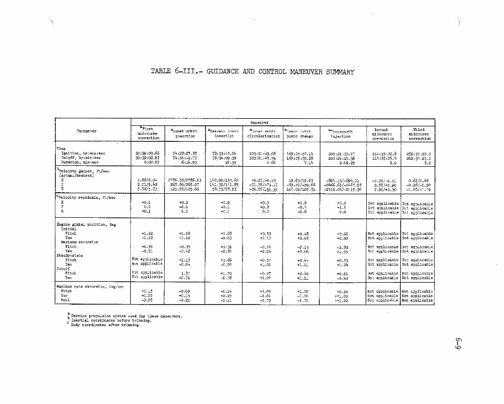
TABLE 6_III.. GUIDANCE AND CONTROL MANEUVER SUMMARY
Maneuver
P_ete_ _ir0tI _....bitI_.....to_b_tI _......_ I_T...........I _.........J Secondl _i_dmidcourse ............... mldcourse
insertion insertion eir eularization I plane change injection mid ..... Ition correction correctioni I
Time
Ignition. hr:min:sec 30:39:00.66 74:28:27.87 78;33:45.04 i03:21:43.08 169:05:52.14 200:21:33.07 214:35:02.8 262:37:20.7
Cutoff. hr:min:sec 30:39:02.67 74:34:42.77 78:34:O9.39 I03:21:47.T4 169:05:59.28 200:24:15.36 214:35:25.4 262:37:27.1
Duration. min:sec 0:02.01 6:14.90 24.35 4.66 7.14 2:42.29 8.0 3.2
bveloeity gained, ft/sec(actual/desired)
X 5.88/6.04 2786.35/2786.63 142.99/i_3.62 +0.25/-0.43 19.63/19.63 -894.13/-894.ii -0.20/-0.11 0.62/0.66Y 9.01/9.42 265.06/265.07 141.32/141.85 ,70.26/-71.17 -59.37/-59.68 -2466.65/-2467.58 0.78/+0.90 -0.38/-0.50
Z 5.58/5.75 125.67/125.69 58.73/58.93 -39.56/-39.99 i07.02/i07.71 -2116.06/-2115.36 2.98/+3.30 -1.08/-1.19
CVelooity residuals, ft/see
X +0.i +0.2 +0.9 +0.3 +0.8 +0.2 Not applicable Not applicableY 0.0 _0.I -0.i +0.2 -0.4 +1.4 Not applicable Not applicable
Z +0.i 0.0 +0.i O.O -0.6 0.0 Not applicable Not applicable
Engine gimbal position, deeInitial
Pitch +1.22 +1.18 +1.88 +0,53 +0.48 +0.66 Not applicable Not applicable
Yaw -0.12 -0.12 -0.63 +l.15 +0,98 +0,90 Not applicable Not applicableMsximttm excursion
Pitch +0.34 +0.35 +0.31 -2.10 -2.13 -1.80 Not applicable Not applicable
Yaw -0.51 -0.42 -0,34 +2.04 +2.06 +1.95 Not applicable Not applicableSteady-st_e
Pitch Not applicable +l.13 +1.66 +0.57 +0.44 +0.53 Not applicable Not applicableYaw Not applicable -0.04 -0.50 +1.02 +l.ll +1.24 Not _pplicable Not applicable
Cutoff
Pitch Not applicable 1.87 +1.70 +0.57 +0.48 +0.61 Not applicable Not applicable
Yaw Not applicable -0,71 -0.38 +i,02 +l.ll -0._2 Not applicable Not applicable
Maximum rate excursion, deg/sec
Pitch +0,15 -0.09 -0.14 +l.0h +l.00 +0.90 Not applicable Not applicableYaw +0.22 +0.14 +0.19 -1.O1 -1.O0 >±i.00 Not applicable Not applicable
Roll -0.26 -0.21 -0.11 -0.73 -1.00 >±i.00 Not applicable Not applicable
_Service propulsion system used for these maneuvers.iInertial coordinates before trimming.
c Body coordinates after trin_in g.
OhIkO

6-10
drift slightly outside the deadband. This resulted in longer than de-
sired thruster firings as well as an unnecessary number of firings. Pro-
cedura& changes were made for Apollo 16 to reduce the state vector inte-
gration routine computation time and to bias the pointing vector such that
gravity gradient torques would hold the vehicle against the positive dead-
band only. Results indicate that the procedural changes halved the num-
ber of thruster firings and the pointing accuracy was improved by a fac-tor of two.
The crew reported that the Teflon locking rings did not prevent the
optical eyeguards on the scanning telescope from unscrewing in zero g andit was annoying to have to refocus the telescope each time it was used.
The cause of both problems was the nonavailability of flight hardware for
crew training. Flight hardware has been provided in training simulators.
The entry sequence, beginning with command module/service module
separation, was normal through landing. The guidance system controlled
the spacecraft attitude and lift vector during entry and guided the ve-hicle to landing coordinates of 0 degrees 42 minutes 0 seconds south lat-
itude, 156 degrees 12 minutes 48 seconds west longitude, as determinedfrom the spacecraft computer.
6.7 PROPULSION
6.7.1 Reaction Control Systems
Performance of the service module reaction control system was normal
throughout the mission. Planned propellant consumption was exceeded by
about 90 pounds because of the unanticipated rendezvous maneuver with the
lunar module. Approximately 28 pounds of the propellant deficiency was re-
covered by subsequent systems management and by the deletion of two plannedmaneuvers.
No preheating of the command module reaction control system was re-
quired prior to activiation. Checkout firings and systems performance
were satisfactory. Both systems were active during entry. The filters
and screens were found to be deformed when the regulators were disassem-
bled during postflight testing (see sec. 14.1.21). The propellant deple-
tion firing and system purge was not performed on this mission. However,a "burp" firing from two engines in each system was initiated at an alti-
tude of about 350 feet to relieve the propellant manifold pressure. As
a result, pin-hole burns were detected in the recovered parachutes (see
sec. 14.1.18). The propellant isolation valves were in the closed posi-tion for these firings.

6-11
An explosive failure of a ground support equipment decontamination
unit tank occurred during the postflight deactivation of the oxidizer (ni-
trogen tetroxide)portion of the Apollo 16 command module reaction control
system (see sec. 14.1.20).
6.7.2 Service Propulsion System
Service propulsion system performance was satisfactory during each
of the six maneuvers. Total firing time was 575.35 seconds. For times
of ignition and durations of firings, refer to table 6-III.
There were three deviations from expected conditions:
a. The onboard oxidizer and fuel tank pressure indications were
known to be biased plus 8 and minus 7 psi, respectively.
b. The oxidizer tank pressure indication became 15 psi higher atzero-g than actual on both telemetry and onboard display (see sec. 14°1.2).
c. The propellant utilization valve was left in the normal position
throughout the flight because ofan electrical problem in the system noted
during prelaunch checkout./
Figure 6-1 shows the propellant unbalance for the lunar orbit in-
sertion and transearth injection firings as indicated by the telemetry
data. The auxiliary gaging system was activiated for the transearth in-
Jection firing; therefore, the figure shows the point sensor uncoverings
during firing as indicated by the auxiliary gaging data. The preflight-
expected unbalance is also shown in the figure.
6.8 ENVIRONMENTAL CONTROL SYSTEM AND CREW STATION EQUIPMENT
6.8.1 Environmental Control System
The environmental control system performed satisfactorily. Several
anomalies occurred, but none affected the mission significantly.
Shortly after orbital insertion, as the water/glycol reservoir was
being isolated, the system valves were inadvertently positioned to com-
pletely block the primary coolant loop. The system was supplying no add-
itional heat load in this configuration; therefore, the evaporator started
to freeze and the indicated backpressure reached the lower limit of 0.05
psia. The reservoir valves were repositioned, flow was restored, and the
evaporator recovered smoothly with no adverse effects.
f

o_IF_rO
200 --T T_---- Expectedunbalance
_mprimar
100
" ,,,,,, ,,,,,,b,_ _ ,_ _ _,_F "_0
_ -100
.N
-200
-400 Point sensors uncovered
No. 12 No. 13 No. 14 No. 15Oxidizer lO(idizer Oxidi;er Oxidizer
-500 Fuel I IFbel Fu(I l_uel0 40 80 120 16D 200 240 280 320 360 400 0 40 80 120 160 200
Firing time, sec
(a) Lunar orbit insertion maneuver. (b_ Transearth injection maneuver.
Figure 6-1.- Indicated oxidizer propellant unbalance.

6-13f-
After translu_ar injection, the water/glycol temperature control cir-
cuit malfunctioned in the automatic mode. The temperature control valve
was positioned manually to maintain acceptable coolant loop temperatures.
The mean system temperature was slightly cooler than normal during lunsm
orbit operations. For a discussion of this anomaly, see section 14.1.1.
The Command Module Pilot reported having to use more than the usual
force in performing the third daily water chlorination. Also, some fluid
leakage was noted. A detailed discussion of this anomaly is contained insection 14.1.7.
Two of the lithium hydroxide canisters used during solo lunar orbit
operations were difficult to remove. One was especially tight and con-siderable effort was required in the removal. Section 14.1.15 gives fur-
ther details of this anomaly.
Following cabin depressurization for the transearth extravehicular
activity, the water/glycol in the cabin decreased in temperature. The de-
crease was over am 8-minute period. The primary water/glycol radiator out-
let temperature decreased from 30° F to 21 ° F, the evaporator water/glycol
outlet temperature decreased from 45° F to 32 ° F, and the suit inlet tem-
perature decreased from 48 ° F to 36.6 ° F. The water/glycol temperaturecontrol valve was then adjusted and the evaporator outlettemperature sta-
bilized at approximately 57° F during the remainder of the extravehicular
activity.
A similar but less severe temperature decrease was observed at the
beginning of the Apollo 15 mission extravehicular activity. Temperaturesdecreased and rettmned to normal about i0 minutes after the cabin had been
depressurized. Slight temperature fluctuations have also been observed
during depressurized cabin operations in the manned altitude tests. These
temperature changes are caused by the freezing of water that had condensed
earlier on the water/glycol lines. An evaluation of the Apollo 16 missioncabin environment indicated a higher-than-normal humidity. This would
account for an increased amount of condensation and, therefore, greater
temperature excursions than were experienced dtming the chamber runs and
the Apollo 15 mission. Based on a 13° F decrease of the evaporator out-
let temperature, less than 173 Btu's were removed from the primary cool-
ant loop. This w_)uld require the sublimation of approximately 2.6 ouncesof water.
The vacuum cleaner failed after becoming clogged with dust. The vac-
uum cleaner was cleaned postflight and it operated properly. The design
of the vacuum cle_mer is such that lunar dust can clog the impeller.

6-14
The cabin fans began to "moan" shortly after transearth injectionand the fans were turned off for the remainder of the mission. In post-
flight tests, the fans operated properly. This anomaly is discussed insection 14.1.11.
The residue from approximately 1 teaspoon of water/glycol was dis-
covered on the command module floor during the postflight activities.
Traces of water/glycol were also found on the lower front edge of thesuit heat exchanger and on the coolant control side of the environmental
control unit (see sec. lh.l.19).
6.8.2 Crew Station/Equipment
Crew equipment performance was satisfactory. However, the extrave-
hicular mobility unit maintenance kit was swollen to about three times thethickness of a similar kit which was stowed in the lunar module. The cause
of this anomaly is discussed in section 14.3.9.
The Command Module Pilot's Y-Y couch strut was difficult to extend
and lock during entry preparations. The Command Module Pilot commented
that there was no discernable clearance between the strut pad and thecommand module wall. Postflight inspection indicated a clearance, but
did show wear and galling of the strut barrel (see sec. 14.1.17).
6.9 CONTROLS AND DISPLAYS
Performance of the controls and displays was normal, with the follow-
ing two exceptions:
Errors were present in the oxidizer and fuel tank pressure readings
and are discussed further in the instrumentation and propulsion sections.
The digital event timer, on panel l, began to malfunction about half-
way through the flight. A similar problem occurred during the Apollo lOmission. This anomaly is discussed in section 14.1.13.
6.10 EXTRAVEHICULAR ACTIVITY EQUIPMENT
The environmental control system and crew equipment performed suc-
cessfully throughout the transearth extravehicular activity.

6-15
The environmental control system suit loop pressure transducers, the
Commander's cuff gage, and the Lunar Module Pilot's cuff gage were in dis-
agreement during the time that the cabin was depressurized. See sections14.1.12 and 14.3.8 for a discussion of these anomalies.
6.11 CONSUMABLES
All command _Id service module consumables remained well within red-line limits.
6.11.1 Service Propulsion Propellant
Service propulsion propellant and helium loadings and consumptionvalues are listed in the following table. The loadings were calculated
from gaging system readings and measured densities prior to lift-off.
Condition Propellant, lb
Fuel Oxidizer Total
Loaded 15 676.2 25 070.3 40 746.5
Consumed 14 491.6 23 635.1 38 126.7
Remaining at endof transearth
injection 1184.6 1435.2 2619.8
Usable at end of
transearth in-
Jection a699.1 1140.2 1839.3
aBased on 1140.2 lb oxidizer and the propellant utilization valve innormal position.
Helium, lbCondition
Storage Bottles Propellant Tanks
Loaded 86.6 5.4
Consumed 62.6 -
Remaining at end of
transearth injection 24.0 68.0

6-16
6.11.2 Reaction Control System Propellant
Service Module.- The propellant utilization and loading data for the
service module reaction control system were as shown in the following
table. Consumption was calculated from telemetered helium tank pressurehistories and was based on pressure, volume, and temperature relation-
ships.
Propellant, ibCondition
Fuel Oxidizer Total
Loaded
Quad A ii0 227 337
Quad B ii0 225 335
Quad C ii0 226 336
Quad D ii0 225 335
Total 440 903 1343
aUsable loaded 1252
Consumed 806
Remaining atcommand module/service module
separation 446
aUsable loaded propellant is the amount loaded minus the amount
trapped with corrections made for gaging system errors.

6-19
6.11.4 Water
The water quantities loaded, produced, mad expelled during the mis-sion are shown in the following table.
Condition Quantity, lh
Loaded (at lift-off)
Potable tank 24.5
Waste tank 35.2
Produced inflight
Fuel cells 476
Lithium hydroxide 22.7
Met aboli c 22. i
Dumped overboard
Waste tank 394.3
Potable tank 6.7
Skylab contamination
expe riment 7.8
Urine and flushing a76. 3
Evaporat or usage 9.9
Remaining at command module/
service module separation
Potable tank 36.3
Waste tank 49.2
aThis is the quantity required to complete the balance. Standard
Operations Data Book values based on an average metabolic rate of467 Btu/hr indicate a urine and feces production of 77.0 lb. It
is estimated that less than 4 ib of water was used for flushing.The difference between the Standard Operations Data Book values
(plus estimated flushing) and the quantity required to complete
the balance is approximately 4.7 ib and is negligible consideringthe inaccmracy and uncertainty of the data used to obtain this bal-an ce.

6-17
Command Module.- The loading and utilization of command module reac-
tion control system propellant were as follows. Consumption was calcu-
lated from pressure, volume, and temperature relationships.
Propellant, ibCondition
Fuel Oxi dizer Total
Loaded
System i 38.6 78.1 116.7
System 2 38.5 78.2 i16.7
Total 77. i 156.3 233.4
aUs able loaded 196.6
Consumed prior to
loss of signal
during entry
System i 28
System 2 28
Total 56
aUsable loaded propellant is the amount loaded minus the amount
trapped.

6-18
6.11.3 Cryogenics
The total cryogenic hydrogen and oxygen quantities available at lift-
off and consumed were as follows. Consumption values were based on quan-tity data transmitted by telemetry.
Hydrogen, ib 0xygen, ibCondition
Actual Planned Actual Planned
Available at lift-off
Tank i 25.9 318
Tank 2 25.8 323
Tank 3 26.7 315
Total 78.4 78.4 956 956
Consumed
Tank i 18.7 188
Tank 2 18.6 152
Tank 3 16.7 186
Total 54.0 57.7 526 561
Remaining at command
module/service mod-
ule separation
Tank i 7.2 5.5 130 119
Tank 2 7.2 6.7 171 171
Tank 3 i0.0 8.5 129 105
Total 24.4 20.7 430 395

7.0 LUNAR MODULE PERFORMANCE
This section contains an evaluation of lunar module systems perform-
ance with emphasis on problems encountered during the mission. The con-
sumables usage is presented in section 7.8.
7.1 THERMAL, STRUCTURAL AND MECHANICAL SYSTEMS
Thermal performance was satisfactory. All temperatures remained with-
in acceptable limits; however, the modular equipment stowage area tempera-tures did not follow the preflight predictions. Analysis and photographs
indicate that the thermal blankets were not completely closed. Also, the
television and 16-mm can_ra brackets were not removed. The presence of
these brackets along with the lunar communications relay unit ancillary
bracket, which may not have been removed, would prevent proper closure ofthe blankets and cause the temperature increase.
The crew had difficulty in adjusting the modular equipment stowage
assembly to the proper height following deployment. This was not a hard-
ware problem; therefore, installation and training procedures will be re-vised.
Structural loads were within design values based on guidance and con-
trol data, acceleration data, onboard pressure measurements, photographs,
and crew comments. Little or no gear stroking occurred during the lunar
landing as evidenced from approximately 6 inches of clearance between thelunar surface and the undamaged descent engine skirt. The landed attitude
was estimated to be 2.3 degrees pitch up and 0.4 degree roll left.
A large number of long, thin, white particles were seen coming fromthe left side (minus-Y side) of the ascent stage at transposition and dock-
ing. Inflight exs_ination and ground analysis verified that the thermal
paint on the micrometeoroid shields had flaked and peeled. No adverse
temperature effects were experienced from this anomaly, which is discussedin detail in section 14.2.1.
The lunar surface television camera showed loose material on the as-
cent stage during the lunar lift-off. This material was later identified
as four thermal/micrometeoroid shields which were partially torn loose from
the base of the aft equipment rack. Temperattu'e control was maintained by
the thermal blankets located under the panels. Additional details of this
anomaly are given in section 14.2.2.

7-2
7.2 ELECTRICAL POWER
The performance of the batteries and the electrical power distribu-
tion system was satisfactory. The lunar landing delay caused an unplanned
energy consumption of 200 ampere hours prior to descent. Because of power
load reductions while on the lunar surface, approximately 100 ampere-hours
were recovered in the planned-versus-actual electrical power budget. Thed-c bus voltage was maintained above 28.2 volts and the maximum observed
current was 72 amperes, during powered descent. Because the lunar module
did not deorbit, data were obtained until batteries 5 and 6 had dropped
to 21.7 and 21.5 volts, respectively.
After final egress from the lunar module, a master alarm was noted
on PCM data. Review of the closeout switch position checklist revealed
that the inverter select switch was left in the "inverter 2" position,which resulted in the nuisance alarm. The switch should have been left
in the "off" position which inhibits the alarm.
7.3 COMMUNICATIONS
With the exceptions discussed in the following paragraphs, all func- -
tions, including voice, data, and ranging of both the S-band and VHF equip-ment operated satisfactorily during all phases of the mission.
The steerable antenna would not move in the yaw axis during initial
activation. Several unsuccessful activation attempts were made in both
the manual slew and auto track modes (see sec. 14.2.3). Except for a
short period of time when the vehicle attitude was changed to point thesteerable antenna at the earth, all S-band communications were maintained
using the omnidirectional antennas. As expected, the voice and data qual-
ity were degraded by the resulting low signal strength. During lunar rev-
olutions 12, 13, and 14, variations in signal strength of l0 to 15 dB were
experienced while using the forward omnidirectional antenna. An exampleof this variation is shown in the ground-station-recelved signal plot in
figure 7-1. This condition occurred at both the Madrid and Goldstone
ground stations. An analysis of the data indicates that the reduction in
signal always occurred within small areas of the antenna pattern. The
most probable cause of this is multipath reflections from portions of thevehicle structure such as the rendezvous radar antenna dish. A detailed
antenna gain pattern will be plotted of this critical area to better de-
fine what can be anticipated for Apollo 17 in the event that the omni-
directional antennas are required.

7-3/--
mm -70
. -90I
-ii0"150 _r _--
" "150 I I I I I= 100:25:30 100:26:00 100:26:30 100:27:00 100:27:30 100:28:00
Figure ?-l.- Madrid ground station received signal.
At times during the mission, it was necessary to change the systemconfiguration from "normal voice" to "down voice backup". At the timeof switching, the down-link signal strength dropped abruptly for a shortperiod. This was caused by a transient in the S-band transceiver outputwhich caused the power amplifier to recycle. During this time, the sys-tem operates in the low-power mode which is reflected in signal strengthreduction. This condition was discovered prior to the flight of Apolloii. No change was warranted due to its random occurrence and the rela-tively small effect that it has on a mission.
The lunar module cre_rmenreported voice quality of the VHF B channelwas degraded during ranging operation. The ranging switch was left on inthe command and service module at all times even when ranging data werenot being monitored. This degradation is inherent in the ranging systemdesign.
During the communications check prior to the first extravehicularactivity, the microphone audio signal from the Lunar Module Pilot's head-set was too weak to operate the voice-operated keying circuitry in hisextravehicular co_nunications system. This was attributed to a loose tipon one of the comm_mications carrier headset microphone booms plus orangeJuice blockage of the other microphone boom. This anomaly is discussedin section 14.3.5.
7.4 RADAE
Landing radar performance was satisfactory. Two successive landingradar self-tests produced erroneous data, but a third self-test, performedapproximately 30 minutes later, was normal in all respects. Analysis in-dicates the two unsuccessful self-tests resulted from lockup to signal re-turns from the lunar surface rather than the self-test stimulus. During

7-4
descent, velocity and range acquisition occurred at a slant range of ap-
proximately 48 700 feet. There was no evidence of dropout in signal track-
ing between acquisition and touchdown.
The rendezvous radar performance during separation and during the
rendezvous sequence was normal. The rendezvous radar acquired the com-
mand and service module transponder during ascent at a range of approxi-
mately 150 miles. Data indicates good correlation between the rendezvous
radar and VHF ranging system.
During the platform alignment prior to powered descent, the rendez-
vous radar antenna drifted into view of the alignment optical telescope.
This is normal since, in the unpowered state, the antenna holds its ori-
entation only by inherent frictional resistance, but this is not great
enough to resist the inertial loading on the antenna.
7.5 GUIDANCE, NAVIGATION, AND CONTROL
The guidance, navigation, and control system performance was normal
throughout the manned lunar module activities. The unmanned deorbit maneu-
ver to impact the ascent stage on the lunar surface was not accomplished
because of the loss of attitude control capability. This anomaly is dis-
cussed in greater detail later in this section and in section 14.2.6.
The primary guidance system was activated at 94 hours 33 minutes;the computer timing was then synchronized to the command module computer,
and the platform was aligned to the command module guidance system. A
manual update to the state vector in the computer was required because
of the S-band steerable antenna problem. A summary of all primary guid-
ance system platform alignments is shown in table 7-1. Table 7-11 con-
tains a summary of mission and preflight inertial component histories.
The inertial instruments performed well; only one update was required,for an accelerometer bias term.
The abort guidance system was activated following a normal undocking
and separation from the command module. A summary of preflight and in-
flight performance of the abort guidance system accelerometers and gyros
is shown in table 7-!11. The first lunar surface calibration indicated
that the X-gyro bias drift had shifted from the previous calibration by
i.i degrees per hour. Although greater than expected, this shift was
within acceptable limits.
Following a three-orbit delay, the powered descent was initiated and
was normal with two minor exceptions:

TABLE 7-1.- LUNAR MODULE PLATFORM ALIGNMENT SUMMARY
Alignment mode Star angle Gyro torquing angle, deg
Time Type ' ' I I I difference, 1 Ihr :rain alignment Options Techniqueb Detent c ' Star Detent c Star deg X Y Z
96:58 52 3 -- 26-Spica 2 B3-Antares -0.05 -0.060 0.139 -0. 018
102 :h2 52 1 -- 26-Spica 2 33~Antares -0.01 -0.067 0.108 0.050
105 :03 57 3 3 h0-Alt air .... 0.01 -0.019 O.038 -0.021
173:49 57 4 3 04-Achernar -- 0.03 -0.540 0.046 -0.056
174: 58 57 3 3 04-Achernar -- 0.04 -0.019 0.017 -0. 012
81 - Preferred; 2 - Nominal; 3 - REFS_4AT; 4 - Landing site.
b0 - Stored attitude; 1 - REFS_AT + g; 2 - Two bodies; 3 - 1 body + g.
Cl - Left front; 2 - Center; 3 - Right front; 4 - Right rear; 5 - Rezr; 6 - Left rear.
l

_-6
TABLE 7-11.- LUNAR MODULE INERTIAL COMPONENT HISTORY a
Inflight performance
Parameter Countdown Flightvalue load Power-up Surface Lift-off
to power-up to throughsurface li ft-off rendezvous
(a) Accelerometers
X - Axis
Scale factor error, ppm ....... _816 -890 -
Bias, cm/sec 2 ............ 1.83 1.84 1,83 1.84 1.81
Y - Axis
Scale factor error, ppm ........ 403 _400 .
Bias, cm/sec 2 ............ 1.57 1.60 1.62 1,66 1.65
Z - Axis
Scale factor error, ppm ........ 526 -4.70 -
Bias, cm/sec 2 ............ 1.23 1.16 1.24 1.23 1.25
(b) Gyroscopes
X - Axis
Null bias drift, meru ........ 0.3 -0.3 0.78 1.15 -
Acceleration drift along spin
reference axis, meru/g ...... -0,3 _i.0
Acceleration drift about input
axis, meru/g ........... 13.1 13.0
Y - Axis
Null bias drift, meru ......... 0.9 0.6 -1.26 -1.03 -
Acceleration drift s.long spin
reference axis, meru/g ....... 6.7 -h.0
Acceleration drift about inputaxis, meru/g ............ 6.0 -3.0
Z - Axis
Null bias drift, meru ........ -2.3 -2.6 0.58 -0.73
Acceleration drift along spin
reference axis, meru/g ...... 3.6 3.0
Acceleration drift about inputaxis, meru/g ........... 17.7 14.0
aThe pre-countdown samples, means, and standard deviations normally given in this table are not
available because the inertial measurement unit was changed in the spacecraft Just before lunarmodule closeout.

7-7
TABLE 7-111.- ABORT GUIDANCE SYST_ CALIBRATION HISTORY
Acceleromet ers
Preflight performance Infli_it performance
a_tatic bias, _g Number of Mean of Staudarddeviatio_ Flight System Pre- Post-calibrations calibrations of load activation descent ascent
calibr _tions
X 21 -.009 0.001 +0.010 +0.008 +0.0072 +0.0066
Y 21 -0.001 0.0003 -0 _001 -0.001 -0.0023 -0.0024
Z 21 -0.002 0.0002 -0. 002 -0.002 -0.0025 -0° 0027
Gyros
Preflight performance Inflight performance
Gyro drift, St audar_
deg/hr Nt_ber of Means Of deviation Flight System Surface Surfacecalibrations calibrations of loa_ activation calibration calibration Post-ascent
calibrations no. i no. 2
X 21 0.03 0.05 -0. l0 -0.06 -1.16 -1.13 Varying
Y 21 -0.29 O. 02 -0.27 -0.45 -0.52 -0.60 -0.60
Z 21 0.55 0.03 0.59 0.29 0,68 0.64 -0,64
a. An out-of-plane velocity component difference became apparent be-tween the abort and primary guidance systems. [_is increased to a maximum
of 28 feet per second near lunar touchdown.
b. The abort guidance system indicated a roll axis misalignment of
0.47 degree from the primary guidance system following the lunar landing.
These problems are discussed in section 14.2.7.
A time history of altitude during descent and several significant
events pertaining to landing radar performance are shown in figure 7-2.Table 7-IV contains the sequence of events during powered descent. The
total effect of the landing point redesignations was to move the landingsite coordinates 189 meters (620 ft) uprange and 194 meters (635 ft) south.
Data became noisy as the lunar module approached the lunar surface and this
precluded a detailed analysis of the landing dynamics.
Performance d_ing ascent was normal. Velocity residuals were low
and no trim maneuver was required; however, a vernier adjustment maneuver
was performed. Table 7-V contains a summary of insertion conditions as
indicated by the primary and abort guidance systems and by the powered
flight processor (ground computation). Table 7-VI is a summary of ren-dezvous maneuvers obtained from several sources.

Ico
70 X 103
60 ,,_
\_o _,
\40 _
<30
!
_ Ignition i
20 i i'anding _,radar velocity
i ! data - good•
lO i ii i; _Begin _itchoveri: i _Enable landing ; •}
i i ! _ i Landingi ..:I I0i04:17 i04:19 i04:21 104:23 I04:25 104:27 104:29 I04:31
Time, hr:min
Figure 7-2.- Time history of altitude and landing radar events during descent.
1 )

7-9
TABLE 7-1V.- SEQUENCE OF EVENTS DURING POWERED DESCENT
Time fromElapsed time,hr:min:sec ignition, Event
min:sec
104:17:18 -00:07 Ullage on104:17:25 00:00 Ignition
104:17:53 00:28 Throttle to full-throttle position
104:19:16 01:51 Manual target (landing site) update-Noun 69
104:20:38 03:13 Landing radar velocity data good
104:21:24 03:59 Landing radar range data good
104:21:54 04:29 Enable landing radar updates - Verb 57
104:24:14 06:49 Enter landing point redesignation phase104:24:54 07:29 Throttle down
104:26:50 09:25 Landing radar antenna to position 2
104:26:52 09:27 Approach phase program selected
Program 64, and pitchover
104:27:20 09:55 First landing point redesignation
104:27:32 10:07 Landing radar to low scale104:28:37 11:12 Select attitude hold mode
104:28:42 11:17 Select landing phase program -
Program 66
104:29:35 12:10 Lunar landing (approximate)
TABLE 7-V.- LUNAR ASCENT INSERTION SUMMARY
Velocity in inertial
Altitude, coordinates, ft/seeSourceft
X Y Z
Primary guidance system 59 957 -958.82 0.77 5441.84
Abort guidance system 59 665 -959.83 -2.81 5441.77
Powered flight processor 59 750 -959.94 2.19 5442.52
/

7-i0
TABLE 7-VI.- RENDEZVOUS SOLUTIONS
Computedvelocity change, ft/secLocal
Maneuver vertical CommandLunar module Abort guidancecoordinates module
computer guidance computer system
Terminal AVx 78._ 78.0 78.3phase AVy 2.4 2.7 2.9initiation AVz -3.8 O.7 -3.7
Total 78.5 78.O 78._
First AVx -0.2 -0.3 O.0midco_s • AVy -0.i -0.i O.9correction AVz -0.4 +0.9 0.8
Total 0.5 1.0 1.2
Second AVx 0.5 0.5 0.6mideourse AVy -0.5 0.2 0.9correction AVz 2.2 O.7 i.0
Total 2.3 0.9 1.5
After docking, the lunar module was powered-down and the crew re-
turned to the command module overnight. Power was reapplied to the pri-mary guidance and controlsystem the next day, but the 28-volt-dc enabl-
ing voltage did not reachthe primary preamplifiers. Consequently, thecontrol system could not issue engine firing cormnands. There was no
thruster firing activity following Jettison and the deorbit maneuver wasnot performed.
7.6 PROPULSION
7.6.1 Reaction Control System
Performance of system B was normal throughout the mission; however,
an anomalous condition developed when system A was activated. The regu-lated outlet pressure increased beyond the specification lockup pressure
of the system. This was attributed to regulator leakage. The condition
persisted throughout the mission causing intermittent operation of the
helium relief valves and overboard venting of the pressurant gas. The
leakage of helium through the regulator and subsequent venting overboard
was not high enough, however, to require a blowdown operation. To re-
lieve this condition, the ullage volume in system A was increased by

_ 7-ll
transferring a portion of the propellants to the ascent propulsion tanks.The ullage volume in system A tanks was thereby increased, providing suf-ficient blowdown capability so that this system could be used as a back-up in case of a malfunction in system B. The problem is discussed furtherin section 14.2.4.
7.6.2 Descent Propulsion System
The descent propulsion system performed well during powered descentwith one exception. The gaging system fuel probes indicated a lower-than-expected fuel quantity. This condition existed throughout the firing andis believed to have been caused by a difference in the conductivity ofthe fuel in the reference conductor and the measuring conductor. Previ-ous testing of these probes has shown similar errors when such differ-ences exist. Total firing time was about 731 seconds. The usable pro-pellant quantity remaining (1128 pounds) would have provided approximate-ly 102 seconds of hover time.
7.6.3 Ascent Propulsion System
System performance was satisfactory during the lunar ascent and theterminal phase initiation maneuver. Ascent firing duration was _27.7 sec-onds. Terminal phase initiation firing duration was estimated to be 2.5seconds, making the total firing time approximately _30.2 seconds.
Two upward shifts in the engine chamber pressure were recorded dur-ing the ascent maneuver, as shown in figure 7-3. A review of all otheravailable engine and acceleration data failed to substantiate the increasedchamber pressure indication. The crew did not recall feeling additionalacceleration or surges during the maneuver. This anomaly is discussedfurther in section 1_.2.8.
7.7 ENVIRONMENTAL CONTROL
The performance of the system was satisfactory. Two anomalies whichoccurred are discussed in the following paragraphs.
One off-nominal condition was experienced approximately 2 hours aftersystem activation when the suit circuit valves were configured to the cabinmode of operation. The crew reported hearing a chattering noise and exper-ienced pressure pulsations in suit circuit flow. The problem was traced
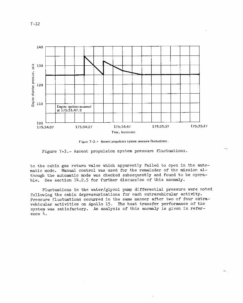
7 -12
140
,_-130
ul
_ i20
S
-g
_ iiOuJ Engine ignition occurred
at 175;31=47.9
I100175:34:07 175:34:27 175:34:47 175:35:07 175:35:27
"rime, hr:min:sec
Figure 7-3.- Ascent propulsionsystem pressurefluctuations.
Figure 7-3.- Ascent propulsion system pressure fluctuations.
to the cabin gas return valve which apparently failed to open in the auto-
matic mode. Manual control was used for the remainder of the mission al-
though the automatic mode was checked subsequently and found to be opera-ble. See section 14.2.5 for further discussion of this anomaly.
Fluctuations in the water/glycol pump differential pressure were noted
following the cabin depressurizations for each extravehicular activity.Pressure fluctuations occurred in the same manner after two of four extra-
vehicular activities on Apollo 15. The heat transfer performance of the
system was satisfactory. An analysis of this anomaly is given in refer-ence 4.

7-13
7.8 CONSUMABLES
All lunar module consumables remained well within red-line limits.
7.8.1 Des cent Propulsion System
Propellant.-The descent propulsion system propellant load quantitiesshown in the following table were calculated from known volumes and weights
of offloaded propellants, temperatures, and densities prior to lift-off.
Quantity, Ib
ConditionFue i Oxi dizer Tot al
Loaded 7530.4 12 028.9 19 559.3
Consumed 7105.4 ii 221.9 18 327.3
Remaining at engine cutoff:
Total 425 807 1232
Usable 396 732 1128
Supercritica_ helium.- The quantities of supercritical helium were
determined by computations using pressure measurements and the known vol-ume of the tank.
Quantity, ibConditi on
Act ual Pre dicted
Loaded 51 •2 51.2
Consumed 41.8 42.7
Remaining at landing 9.4 8.5
/

7-14
7.8.2 Ascent Propulsion System
Propellant.- The ascent propulsion system total propellant usage wasapproximately as predicted. The loadings shown in the following table
were determined from measured densities prior to launch and from weightsof off-loaded propellants.
Propellant mass, ib apredicte d
Condition quantity,
Fuel Oxidizer Total
Loaded 2017.8 3224.7 5242.5 5242.5
Transferred from
reaction con-
trol system 16.0 44.0
Total on board at
lunar lift-off 2033.8 3268.7
Consumed 1869.8 3011.0 4880.8 4903.6
Remaining at ascent
stage jettison 164.0 257.7 421.7 338.9
i
aPropellant required for ascent was reduced by 80.0 ibm to accountfor reaction control system consumption.
Helium.- The quantities of ascent propulsion system helium were de-termined by pressure measurements and the known volume of the tank.
Actual Quantity,Conditionib
Loaded 13.2
Consumed 8.4
Remaining at ascent stagejettison 4.8

7-15
7.8.3 Reaction Control System Propellant
The reaction control system propellant consumption was calculated
from telemetered helium tank pressure histories using the relationshipsbetween pressure, volume, and temperature.
Actual quantity, ib Predicted
Condition quantity,Fue i Oxi dizer Tot al ib
Loaded
System A 107.4 208.2 315.6
System B 107.4 208.2 315.6
Total 631.2 631.2
Transferred to
ascent propul-
sion system 16.0 44.0 60.0
Consumed to:
Lunar landing 125 142
Docking 212 266
Remaining at ascent
stage jettison 359.2 365.2
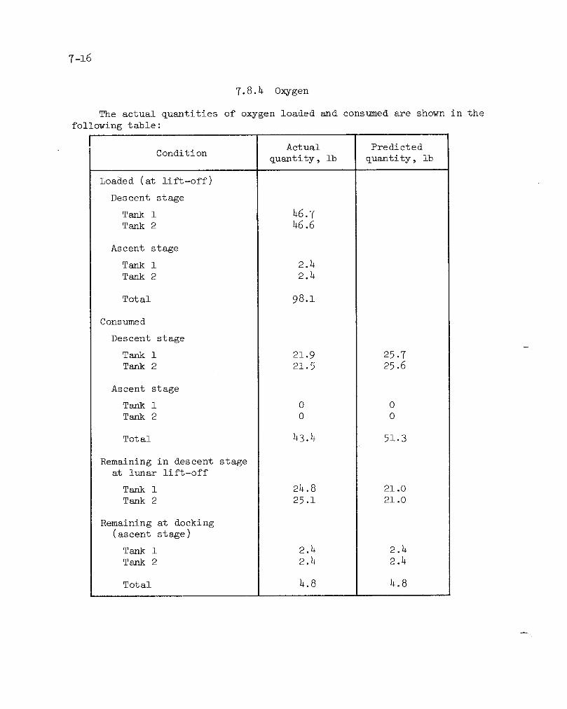
7-16
7.8.4 O_ygen
The actual quantities of oxygen loaded and consumed are shown in the
following table :
Act ual Pre dict edCondition
quantity, ib quantity, ib
Loaded (at lift-off)
Descent stage
Tank i 46.7
Tank 2 46.6
Ascent stage
Tank i 2.4
Tank 2 2.4
Total 98.]
Consumed
Descent stage
Tank i 21.9 25.7
Tank 2 21.5 25.6
Ascent stage
Tank i 0 0
Tank 2 0 0
Total 43.4 51.3
Remaining in descent stageat lunar lift-off
Tank i 24.8 21.0
Tank 2 25.1 21.0
Remaining at docking(ascent stage)
Tank i 2.4 2.4
Tank 2 2.4 2.4
Total 4.8 4.8

7-17,f
7.8.5 Water
The actual water quantities loaded and consumed, shown in the follow-
in_ table are based on telemetered data.
Act ual apre dictedCondition
quantity, ib quantity, ib
Loaded (at lift-off)
Descent stage
Tank I 193.9
Tank 2 199.4
Ascent stage
Tank i 42.5
Tank 2 42.5
Total 478.3
Consumed
Descent stage (lunar lift-off)
Tank 1 193.9 192.4
Tank 2 199.4 197.9
Ascent stage (docking)
Tank I 7.2 7.5
Tank 2 6.9 7.5
Total 407.14 405.3
Remaining in descent stageat lunar lift-off
Tankl bo i.5Tank 2 b0 i. 5
Remaining in ascent stage
at docking
Tank i 35.3 35.0
Tank 2 35.6 35.0
Total 70.9 70.0
aAdjusted to compensate for the additional 5 hours in lunar orbit
prior to descent.
bBecause of the extended lunar module activity, the descent stage
water tanks reached depletion at the s_ne time the crew selected
ascent stage consumables.
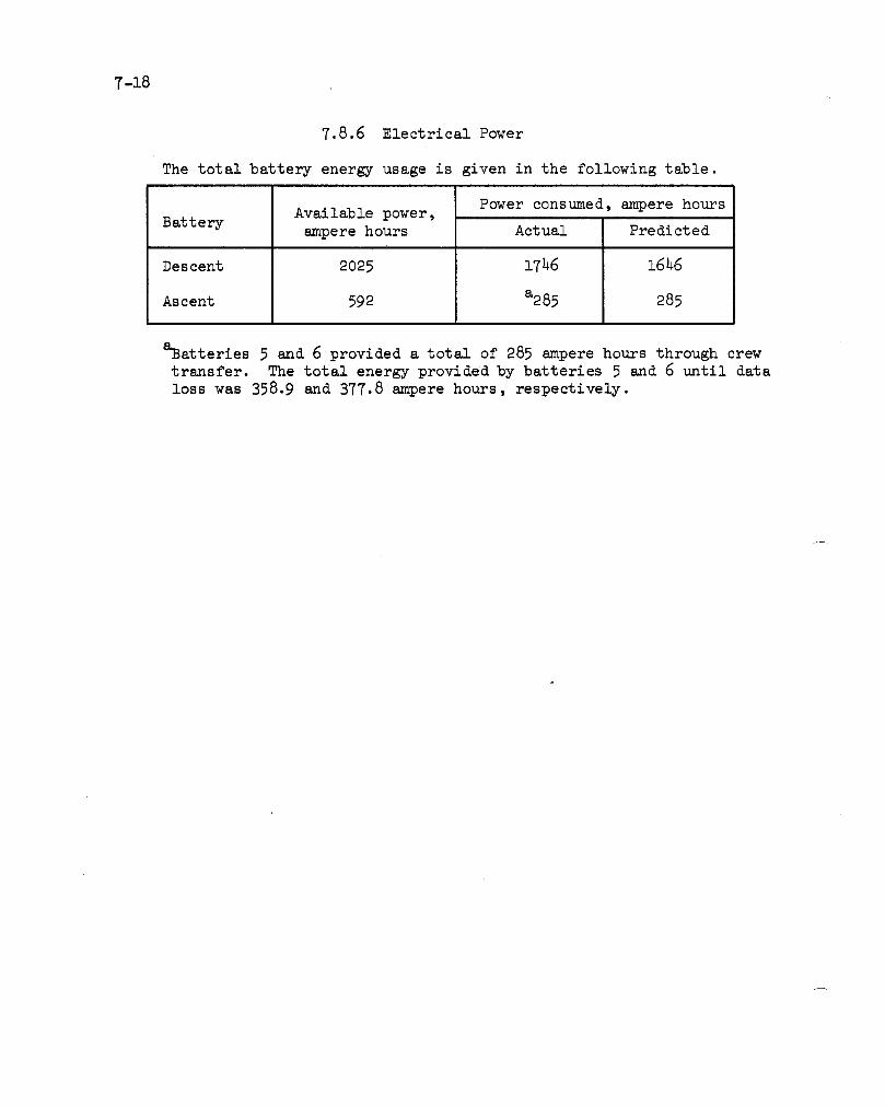
7-18
7.8.6 Electrical Power
The total battery energy usage is given in the following table.
Power consumed, ampere hoursAvailable power,
Batteryampere hours Actual Predicted
Descent 2025 1746 1646
Ascent 592 a285 285
aBatteries 5 and 6 provided a total of 285 ampere hours through crew
transfer. The total energy provided by batteries 5 and 6 until data
loss was 358.9 and 377.8 ampere hours, respectively.
8-17
8.0 LUNAR SURFACE EQUIPMENT PERFORMANCE
8.1 LUNAR ROVING VEHICLE
The lunar roving vehicle performance was good; however, several sys-tem problems occurred. These problems are:
a. Higher-than-expected battery temperatures
b. Multiple failures of instrumentation hardware
c. Loss of rear fender extension
d. Temporary loss of rear steering.
Procedural errors resulted in the temporary loss of rear drive power and
a temporary loss of all navigation displays except heading and speed.
The approximate distances driven during the three extravehicular ac-
tivities were 4.2, ll.1 and ll.4 kilometers for a total of 26.7 kilome-
ters. Speeds up to 14 kilometers per hour were achieved on the level sur-
face. Slopes estimated to be as steep as 20 degrees were negotiated with-out difficulty.
The lunar roving vehicle provided electrical power for voice, telem-
etry, and television communications throughout the first two extravehic-
ular activities, _id also provided power for television operations after
the third extravehicular activity. A total of 98.2 ampere-hours was con-sumed from the 242 ampere-hours available in the two batteries.
Several minor problems, which subsequently disappeared, were experi-
enced during the activation of the lunar rover. The rear steering was
inoperative, the battery 2 ampere-hours remaining and voltage readingswere off-scale low_, and both battery temperatures were off-scale low (seesec. 14.6.1 and 14.6.2).
After returning to the lunar module near the end of the first trav-
erse, the Commander performed a lunar roving vehicle evaluation while the
Lunar Module Pilot took 16-mm documentary motion pictures.
At the conclusion of the first extravehicular activity, the vehicle
was parked with the front of the vehicle pointing towards the north. The
battery temperatures were 104 ° F and 105 ° F with 108 and 105 ampere-hours
remaining. The battery covers were brushed and opened, the radiator sur-
faces were dusted, and the power-doE was completed. The battery coversdid not close between the first and second extravehicular activities and
temperatures at power-up for the second extravehicular activity were• 70 ° F and 82° F.

8-2
On the second traverse, the attitude indicator pitch scale fell off,
but the needle was still used to estimate pitch attitudes (see sec. 14.6.4).
Incorrect matching of switches caused a loss of rear-wheel drive. Correct
switch configuration returned the vehicle operation to normal. The crew
noted that the forward wheels tended to dig in when attempting to climb
slopes without rear-wheel power. The right rear fender extension was
knocked off and, thereafter, dust was thrown up from the right rear wheel
and covered the crew, the console, and the communications equipment. Mid-
way through the second extravehicular traverse, the ampere-hour integratorfor battery I began indicating about four times the normal battery usage.
Because of higher-than-desired temperatures on battery l, a series of pro-cedures were initiated to lower the load. These procedures probably
caused the inadvertent removal of drive power from a pair of wheels,
thereby losing two odometer inputs and the associated static range, bear-
ing, and distance displays (see sec. 14.6.3). The problem cleared whenthe normal switch and circuit breaker configuration was restored.
At power-up for the third traverse, the battery covers were closed
manus_ly and the lunar communications relay unit was switched to its own
power. The lunar roving vehicle battery temperatures were 102 ° F and
120 ° F. About 2 hours after power-up, the caution and warning flag was
activated because the battery 2 temperature exceeded 125 ° F. Rear-wheel
drive power and steering were switched to battery 1 bus B. Later, the
battery i temperature indicator went off-scale low, indicating a meter --failure. Both batteries were functional at the end of the third extrave-
hicular activity when the lunar roving vehicle was configured to provide
power for television. The closeout reading of the battery 2 temperaturewas 143 ° F.
8.2 LUNAR COMMUNICATIONS RELAY UNIT ANDGROUND COMMANDED TELEVISION ASSEMBLY
The lunar communications relay unit and ground commanded television
assembly operated for 12 hours 44 minutes during the lunar surface extra-vehicular activities. The relay unit in conjunction with the television
camera was energized by up-link command for lunar module ascent television
coverage and for six days of scientific lunar surface observations on a
once-per-day basis until April B0, 1972. At that time, the system could
not be energized by up-link command. Down-link data from the relay unit
on the preceding day showed the expected temperatures, internal voltages,
and RF signal strength. Possible causes of the problem include: (1) mal-function of the television control unit up-link decoder due to its pre-
launch predicted high temperature condition (above qualification level),and (2) loss of input power because of incorrect circuit breaker config-
uration on the lunar roving vehicle that would have placed only one ofthe two batteries on the line.

8.3 EXTRAVEHICULAR MOBILITY UNIT
Throughout the three extravehicular activities, the performance of
the extravehicular mobility units was satisfactory and the crew were able
to perform their functions in an effective manner. Telemetry data werenot available until after crew egress from the lunar module because of the
steerable antenna malfunction (see sec. 14.2.3), therefore, consumables
were computed based on previous experience with these units as well as
telemetry data.
The crew had some difficulty in closing the restraint zippers during
donning of the s_Ats. The suits are custom fitted and, by necessity, must
be tight to achieve good mobility. Particular attention will be given to
the self-donning of suits during training and a restraint zipper hook has
been provided on Apollo 17 as a donning aid.
The checkout of the portable life support system was normal on each
extravehic_]ar activity. Higher-than-predicted heat loads were experiencedon the first and third extravehicular activities ; however, thermal equilib-
rium was maintained well within acceptable limits even when the crew oper-
ated for a considerable length of time in an area of sun reflection fromboulders. The heat was so intense that the crew commented that they could
feel it. Primary feedwater supply depletion tones occurred during the
first extravehic_,]ar activity. A warning tone was received for depletion
of the Lunar Mod_gLe Pilot's auxiliary feedwater supply near the end of the
first extravehic_Llar activity when his water supply was depleted.
The purge wLlve pin on the Commander's suit was accidentally pulled
out twice during the first extravehicular activity while ingressing the
lunar roving vehicle. Both times, the pin was found and reinserted with-
out any adverse effect. To prevent a recurrence during subsequent trav-
erses, both crewmen rotated their purge valves to prevent the pins from
being accidentally removed (see sec. 14.3.10).
During ingress after the second extravehicular activity, the Commander
broke the tip off of his antenna. The two crewmen exchanged units to pre-
clude a possible limitation on range. Section 14.3.2 contains a discussion
on this anomaly.
After expos1_re to a dusty lunar environment, the both crewmen's suit
wrist-ring disconnects were hard to rotate to the locked and unlocked
position. This _uomaly is explained in section 14.3.4.
Oxygen, power, and feedwater consumption of the extravehicular mo-
bility units during the three extravehicular periods is shown in table 8-I.

8_
TABLE 8-1.- EXTRAVEHICULAR MOBILITY UNIT CONSUMABLES
Commander Lunar Module PilotCondition
Actual aPredieted Actual aPredicted
First extravehicular activity
Time, min 431 420 431 420
boxygen, lbLoaded 1.93 1.86 1.93 1.86
Consumed 1.24 1.36 1.51 1.36
Remaining 0.69 0.50 0.42 0.50Redline limit 0.37 0.37
bFeedwater, lbLoaded 12.16 12.16 12.11 12.16
Consumed 9.08 9.04 11.62 9.04
Remaining 3.08 3.12 0.49 3.12Redline limit 0.87 0.87
Battery, amp-hr
Initial charge 25.4 25.4 25.4 25.4Consumed 20.7 19.4 21.0 19.35
Remaining 4.7 6.0 4.4 6.05Redline limit 3.28 3.28
Second extravehicular activity
Time, min 444 420 444 420
b0xygen, ibLoaded 1.81 1.81 1.81 1.81
Constuned 1.22 1.31 1.26 1.31
Remaining 0.59 0.50 0.55 0.50Redline limit 0.37 0.37
bFeedwater, IbLoaded 12.46 12.46 12.41 12.46
Consumed 9.48 9.21 10.28 9.21
Remaining 2.98 3.25 2.13 3.25Redline limit 0.87 0.87
Battery, amp-hrInitial charge 25.4 25.4 25.4 25.4Consumed 21.4 19.4 21.0 19.4
Remaining 4.0 6.0 4.4 6.0Redline limit 3.28 3.28
NOTE: Refer to following pages for notes a and b.

8-5f-
TABLE 8.1.- EX_?RAVEHICULAR MOBILITY UNIT CONSUMABLES - Concluded
Commander Lunar Module Pilot
Condition Actual apredicted Actual apredicted
Third extravehicular activity
Time, min 341 420 341 420
b0xygen, lbLoaded 1.81 1.81 1.81 1.81Consumed 1.04 i.34 1.02 i.34
Remaining O.77 0.h7 0.79 O.47Redline liz_it 0.37 0.37
bFeedwater, lbLoaded 12.46 12.46 12. hl 12.h6
Consumed 8.21 9 •34 8.38 9.34
Remaining 4.25 3.12 h.03 3.12Redline limit 0.87 0.87
Battery, amp-hrLoaded 25.4 25.4 25. h 25.4Consumed 16.7 19.h 16.4
Remaining 8.7 6.0 9.0Redline limit 3.28 3.28
NOTES
aThe following values were used in the preflight prediction calculations forboth crewmen.
Period 0rygen leak rate, Heat leak rate,lb/hr Btu/hr
First extravehicular activity 0.02 0
Second extravehicular activity 0.028 215
Third extravehicular activity 0.035 225
bThe following values were used for postflight calculations,
Commander Lunar Module Pilot
PeriodOxygen leak Heat leak Oxygen leak Heat leakrate, lb/hr rate, Btu/hr rate, lb/hr rate, Btu/hr
First extravehicular activity 0.019 135 0.013 135
Second extravehicular activity 0.021 220 0.0210 220
Third extravehicular activity 0.020 290 0.0210 290

Apollo 16 flight crew
Commander John W. Young_ Command Module Pilot Thomas K. Mattingly II_
and Lunar Module Pilot Charles M. Duke_ Jr.
9-1f
9.0 PILOT'S REPORT
This section contains a description of the Apollo 16 mission as per-
formed by the crew. Specific mission features and equipment operationswhich were different than Apollo 15 are covered. Some mission activities
were modified because of the delay in performing the circularization ma-
neuver, and the effects of those changes are addressed. The flight plan,as executed, is summarized in figure 9-1 at the end of this section.
9.1 TRAINING
The Apollo 16 crew was fortunate in that they had been assigned to
J-mission spacecraft from the beginning of their training. From April of1970, they participated in Apollo 15 spacecraf_ tests as well as those of
their own vehicles. The Commander and Lunar Module Pilot participated in
early reviews of the J-mission surface hardware, of the extended-stay lu-
nar module, and of the lunar roving vehicle. 'Fne majority of the proced-
ure development time for the Commander and Lunar Module Pilot was spent on
lunar surface operations, and 40 percent of the total training of thesetwo crewmen was in lunar surface science.
The Command ]Module Pilot training can be broken into the followingdiscrete phases:
Phase I. Basic Apollo background
a. Hardware
b. Software
c. Mission techniques
d. Lunar science
Phase II. Mission-dependent procedures
a. Experiment procedures
b. Flight plan development
c. Ground track and specific lunar science study
Phase III. Pilot proficiency
a. Flight plan study
b. Contingency training

9-2
c. Operational techniques
d. Experiments practice
e. Personal
1. Physical conditioning
2. Aircraft proficiency
Because of the sophistication and complexity of the Apollo J missions,
several years of intensive training are required to properly support the
objectives. Phase-I training was essentially completed during the Command
Module Pilot's preparation for previous missions. Hardware for the sci-entific instrument module and the command module extravehicular activity
hardware were the only Phase-I training items required during the two years
immediately preceding the flight of Apollo 16. The last two months prior
to flight should have been devoted to Phase-III proficiency training; how-
ever, a 30-day delay in the launch of Apollo 16 was announced in January
1972. The delay occurred after the preliminary flight plan had been is-
sued and resulted in a great deal of Phase-III training being postponeduntil March.
Visual observations of the lunar surface were emphasized throughout
the training, and during the final 12 months, nine aircraft flyovers weremade over selected terrestrial features, and many briefing sessions were
included. Mission experience indicates that training of this type and in-
tensity is essential to take full advantage of the orbiting observer's
vantage point.
Command module experiments were tailored to take advantage of the
moon as an occulting disk while executing low-light-level photography of
celestial targets. This effort required a considerable amount of the Com-mand Module Pilot's time in developing procedures which were compatible
with orbital operations of the command and service module.
The pacing items during the Apollo 16 training period were the de-
velopment of the flight plan and the experiments checklist.
The increased emphasis on orbital science requires that the CommandModule Pilot receive detailed real-time training in flight-plan execution
that is analogous to the surface crew's extravehicular activity training.
However, unlike lunar module crews undergoing concurrent training, wherethe lunar module mission simulator and extravehicular activity facilities
can be scheduled interchangeably, the command module pilots must use thesame trainer for all their activities. This means that verification of
a 290-hour flight plan, proficiency training, and network simulation ex-ercises must be accomplished for two crews in one facility. The command
and service module mission simulator was used in the evenings for stowage
exercises and this proved to be a worthwhile use of the Command ModulePilot 's time.
9-3I-
To optimize usage of the command and service module mission simula-
tor, most Command Module Pilot extravehicular activity training was con-
ducted in the Manned Spacecraft Center mockup, while rendezvous training
was conducted primarily in the command module procedures simulator.
The Command Module Pilot's training, as reflected in the formal train-.
ing summary, is somewhat misleading in that the times shown reflect, pri-
marily, time spent in actual training activities and do not include timespent formulating and integrating the orbital timelines. In support of
the surface extravehicular activities, the formulation and integration
activity is executed by a mission scientist and an extravehicular activ-
ity training staff; whereas, the flight planners and the Command ModulePilot must add these tasks to their normal activities.
9 •2 LAUNCH
In general, the crew workload was easy during launch operations andthe crew was 15 to 20 minutes ahead of the launch count.
The Lunar Module Pilot noted prior to lat_ach that the readings on the
service propulsion system fuel and oxidizer gages were such that they ap-
peared, in combination, to violate the differential pressure limits of the
mission rule for service propulsion system thrusting. Clarification by
the ground indicated that the gage readings reflected an instrumentationbias.
The S-IC engine ignition and Saturn V lift-off were positively sensed..
Vehicle vibration on the first stage was as reported on previous missions
and is probably best characterized as being similar to a freight train
bouncing on a loose track. In-suit noise levels at maximum dynamic pres-
sure were similar to the Apollo i0 levels recalled by the Commander. Com-
munications were excellent throughout powered flight. Inboard engine cut-
off on the S-IC stage was abrupt and was characterized by approximately
four cycles of the S-If stage unloading. At S-IC outboard engine cutoff,
the major four-cycle unloading of the S-ll stage was again exhibited.
S-IC outboard engine cutoff is the most impressive physiological experi-
ence of the Saturn-V boost phase. During the first 2 to 3 minutes of S-If
engine firing, powered flight was extremely smooth and quiet. After that,
a high-frequency vibration or buzz was sensed which abruptly disappeared
approximately 9 minutes after lift-off. The vibration was also noted dur-
ing S-IVB powered flight. Saturn-V guidance and control of all threestages, as monitored from crew onboard displays, was normal.
f-

9-4
9.3 EARTH ORBITAL FLIGHT
Post-insertion activities were normal and proceeded at a comfortable
pace. The sights in earth orbit were spectacular; even on the dark side,where thunderstorms and fires in Africa captured the crew's attention.
The earth-orbit timeline provided sufficient time for viewing the earth,for unhurried crew adaptation to zero-g, and coping with hardware problems.
The optics covers were jettisoned in the dark. Jettisoning of thesextant cover could be heard, but there was no audible sound from the
scanning telescope cover. There was some initial concern that the scan-
ning telescope cover had not been jettisoned because of a total absence
of stars in the field-of-view. (The Command Module Pilot had completed
dark adaptation of his right eye. ) Eventually, the constellation Scorpiocame into the field of view and it became apparent that star patterns and
relatively dim stars were going to be quite recognizable. The first clue
that the scanning telescope cover was off, however, came when the S-IVB
auxiliary propulsion system firings became visible in the scanning tele-
scope. S-IVB auxiliary propulsion system firings could be seen through
both the window and the optics at night. Some sensation of spacecraftmotion could be felt from flexing of the space vehicle.
Sometime during the initial portions of earth orbit, the ground ad-
vised that one of the auxiliary propulsion system packages appeared to
have a double helium regulator failure and would be venting through therelief valve. This raised the possibility of helium exhaustion and thenecessity of using preplanned procedures for control of the S-IVB atti-
tude (non-thrusting) with the service module reaction control system.
A rough check of the body-mounted attitude gyro/gyro display coupler
drift was run and indicated that, with body-mounted attitude gyro 2 sup-
plying rate information, a drift of approximately 6 degrees per hour couldbe expected in roll with lesser values in pitch and yaw.
The primary coolant loop evaporator outlet temperature exhibited a
number of excursions. The crew proceeded to execute environmental control
system malfunction procedure number 16 but the results were inconclusive.
Ground assistance was requested after translunar injection, since the evap-orator was not a mandatory mission item.
9._ TRANSLUNAR INJECTION
Prior to and during the translunar injection firing, Apollo range in-
strumentation aircraft communications were used very effectively with good
volume and intelligibility. All events occurred on time. The trajectory,as monitored by the onboard displays, was normal. An unexpected onboard
monitoring surprise was the subjectively greater lag in velocity and alti-
tude computations of the translunar injection initiate/cutoff computer pro-
gram as compared to the command module simulators. This computer programprovides a display of firing time to go during the translunar injectionmaneuver. Prior to flight, the crew had been advised that this calcula-
tion was erroneous until late in the firing because of the changing ac-
celeration. They were, nevertheless, surprised at how much the calcula-tion actually differed from the predicted and actual firing time. The
computation conw_rged in the final 60 to 90 seconds of the firing and ap-peared to be very accurate at shutdown.
During both the launch phase and the translunar injection firing,particles were noticed moving in the direction of the spacecraft, and
even passing the spacecraft. They were still in evidence during steady-state thrusting.
The S-IVB e_ibited the same high-frequency vibration that had been
noted during the earth orbital insertion phase of the S-IVB powered flight.Both the Commander and the Command Module Pilot thought that the vibration:3
were morepronounced during the final half of the firing and that they in-creased in amplitude as the powered flight progressed. The increase was
enough to cause some concern that the vibration might effect a prematureS-IVB shutdown.
9.5 TRANSLUNAR FLIGh_I'
9.5.1 Transposition, Docking, and Ejection
The most remarkable feature of the transposition, docking, and ejec-tion sequence was that the command and service module mission simulator
reproduces these events perfectly. At the completion of the automatic
pitch maneuver, the command and service module was approximately 50 feet
from the lunar module and oriented such that the crewman optical alignment
sight was superimposed on the docking target. The 4-second closure firingdid not provide a positive closure rate so two additional very short fir-ings (less than 1 second) were made to insure closure. The remainder of
the approach required two small translations down and to the right, and
one attitude correction of approximately 3 degrees in pitch and yaw. The
closure rate was about 0.1 ft/sec at contact. There was no sound or space.-craft rate to indicate capture; the only indication was the probe talkback

9-6
going to barberpole. The command and service module drifted very slowly,
but positively, off in roll, pitch, and yaw alignment following capture.
Minus-Y and minus-Z translation thrusters were used to realign the two
vehicles prior to probe retraction. The two vehicles were aligned very
closely in pitch and yaw prior to probe retraction; whereas, the roll
alignment was allowed to remain off several degrees. The probe retraction
seemed to be very slow and smooth. The docking latches fired in a slow
ripple sequence. The visibility of the docking target is excellent even
though the data acquisition camera photographs indicate that the target
is immersed in a deep shadow.
Command and service module reaction control system thrusters were not
audible as the command and service module separated from the S-IVB, pitched
around, and translated toward the lunar module. However, as the two ve-hicles came within about i0 feet of each other, the sound of the command
and service module thrusters impinging on the lunar module became apparent.
This same sound was noted any time a command and service module forward fir-
ing thruster impinged on the lunar module skin while docked, but was never
heard when the two vehicles were separated. Thruster impingement could
he seen as an "oil canning" of the thermal covers. After docking, somediscoloration of the Inconel foil could be observed on the top of the lu-
nar module. Preparations for lunar module ejection proceeded normally.
Docking latch 1O was not fully engaged.
An S-IVB nonpropulsive vent was executed while the vehicles were stillattached. This produced very fine streamlines, light-purple in color,
around the vehicles. The lines, which could be observed by looking down-
sun, appeared to converge at a great distance in an unilluminated spot.
Lunar module ejection was on time and was normal. The maneuver tothe S-IVB observation attitude was also normal with the S-IVB appearing
in the hatch window on schedule. The S-IVB evasive maneuver was observed
visually. There were no visible effluents from the S-IVB and motion could
be detected only by observing its relative motion against the backgroundof stars and debris.
The television camera was used throughout transposition and docking,
and also to show a most unique view of the earth. The earth was oriented
such that it displayed the entire Western Hemisphere from the North Polar
region to the Yucatan Peninsula with practically no cloud coverage over
the United States (fig. 9-2). While attempting to show the S-IVB evasive
maneuver, the television monitor became inoperative. The monitor showeda series of horizontal lines similar to lines observed in the command and
service module mission simulator when the grounding circuit was lost (see
sec. 14.3.1). Attempts to adjust the monitor controls and reverification
of all connections produced no improvement in the monitor display; however,
a good picture was still being transmitted. This condition was repeated
during the transearth press conference; otherwise, performance was normal.

9-7
/
Figure 9-2.- View of the earth during translunar flight.
l_nediately following lunar module extraction, Mission Control re-
quested that the primary coolant loop evaporator inlet temperature valve
be placed in the manual mode to stop an apparent cycling (sec. 14.1.1).The remainder of the mission was flown with this valve in the manual mode.
f-

9-8
9.5.2 Translunar Coast Problems
One unexpected sight was the extremely high density of small partic-ulate debris surrounding the S-IVB/lunar module following command and ser-vice module separation.
Following docking, it became apparent that the paint was shreddingfrom the lunar module surfaces underneath the docking target in smallpieces (generally less than 1-inch long and 1/4-inch wide). It also be-came apparent that particles were coming from other areas. (For further
details see section 14.2.1.) These particles surrounded the spacecraftthrough undocking in lunar orbit.
At approximately 38 1/4 hours, the Command Module Pilot was using theoptics to view several planets. At the completion of this activity, theidling program of the computer was selected. At that time, the commandmodule computer sensed gimbal lock. The command module computer thencoarse-allgned the inertial measurement unit and turned on the lower equip-ment bay primary navigation, guidance and control system warning light andthe "NO ATT" light on the display keyboard. The platform was subsequentlyrealigned. The inertial measurement unit orientation was reestablishedthrough sightlngs on the earth and sun with the computer in option B ofthe inertial measurement unit realignment program. A subsequent realign-ment, using stars, placed the inertial measurement unit back into a knownorientation. Protection against another coarse alignment was providedthrough the use of erasable computer program EMP 509. This anomaly isdiscussed further in sec. l_.l.3.
At approximately 46 hours, the uplink telemetry capability was lost(see sec. l_.l.6). Cycling to "command reset" and back to "normal" failedto resolve the problem. Cycling to "off" for BO seconds and back to"normal" restored normal system operation.
One chlorine ampule broke during the chlorination attempt on the eve-ning of the third day (see sec. 14.1.7). A full buffer ampule was addedwith no further complications. On several occasions, a small amount ofwater was taken from the drink gun following chlorination and no unusualtastes were observed.
9.5.3 Lunar Module Checkout and Housekeeping
About an hour after informing Houston of the particle problem, thecrew was instructed to enter the lunar module for the first time. Thecrew cleared the tunnel, and entered the lunar module at about 8:17, andpowered-up according to the checklist which originally was to have beenaccomplished at 55 hours. Telemetry indicated that all the systems were

9-9f
in good shape and that no reaction control system or propulsion leak ex-
isted. Powerdown was accomplished within a few minutes and the tunnelwas resealed.
The second ingress, which was for housekeeping and communications
checkout, was accomplished according to the flight plan at about 33 hours.
The lunar module was found to be clean and free of loose particles except
for a washer or small screw or two that occasionally floated by and was
picked up by the crew. The checklists were adequate.
The third ingress into the lunar module was made at about 55 hours
per the checklist. During this entry into the lunar module, the Command
Module Pilot made several discrete observations of the malfunctioning dock.-
ing latch 10. Although the latch was apparently over the lunar module dock-
ing ring, it was not in contact with the ring surface. There was a gap of
approximately 0.010 inch between the latch and the docking ring. The aux-
iliary release knob was depressed and it remained in. The left side of
the latch appeared normal when compared to the other latches. The cam un-
der the power bungee on the right side of the latch did not appear to bein the same orientation as the other latches. Mission control recommended
that the latch be left alone until undocking.
9.5.4 Guidance and Navigation
One set of cislunar midcourse navigation training sightings was taken
during the early part of the translunar coast for the dual purpose of pro-
viding a measure of the Command Module Pilot's horizon altitude bias and
some practice in executing this computer program. Flying the spacecraft-
fixed line-of-sight to the substellar point seemed more difficult than thesame task in the command and service module mission simulator. The auto-
matic positioning routine placed the line-of-sight very close to the hori-zon but not on the apparent substellar point. The maximum reticle illu-
mination was too low to allow the lighted portion to be visible against
the earth; whereas, it was required against the dark sky background. The
only satisfactory' technique found for identification of the substellar
point was to identify the reticle above the earth and maneuver the space-craft until the reticle hashmarks touched the earth's horizon simultane-
ously (fig. 9-3).
There was no problem with the identification of the upper horizon,
perhaps because the sightings had to be delayed several hours, allowing
the spacecraft/earth separation distance to increase significantly beyond
the planned distance. There was only one identifiable horizon on all of
the sightings.

9-10
Figure 9-3.- Sighting through sextant forcislunar navigation training.
The optics calibration worked smoothly with reproducible results.
An interesting phenomenon observed during these sightings was a very dim
mirror image of the earth reflected in the sky portion of the sextantfield-of-view.
Passive thermal control was entered and executed per the checklist
with excellent results each time.
During a change of the reference stable member matrix (REFSMMAT),
option 1 of the inertial measurement unit realignment program was used
with the coarse-align mode. Only once during the mission did this pro-
vide an alignment of sufficient accuracy to allow auto optics to placethe stars in the sextant field of view. The standard technique used was
to place the spacecraft in stabilization and control system attitude hold,with a minimnm deadband, and record the shaft and trunnion for each star
selected in the final option 3 platform realignment program. These values
were then used to reacquire the stars in the sextant following the coarse
alignment. This is a very comfortable and rapid technique even when the
telescope is of marginal utility. The one time that the pulse-torque op-
tion was executed was during an off-normal portion of the flight plan and
a spacecraft attitude maneuver was required in order to avoid gimbal lock.

9-11
9.5.5 Midcourse Correction
The only translunar coast mideourse correction was executed at the
second option point. It consisted of a short single-bank firing of the
service propulsion system. The thrust was positive with a definite delaybetween the time that the ball valves opened sxld the time that thrusting
was sensed. One surprising feature of the checkout was that gimbal motorstart was not evident on the fuel cell bus, but was quite apparent on the
battery bus. Because of the service propulsion system pressure transducershift and the uncertainty associated with the readout, Mission Control re-
quested that the tanks be pressurized by selecting the "manual" positionof the helium valves prior to the firing. This procedure allowed ground
personnel to understand the transducer shift so that they could accurately
update the service propulsion system fuel and oxidizer pressure limits for
subsequent maneuw_rs. The service propulsion system pressure warning lightremained on for the remainder of the mission, since it uses the same ref-
erence as the gaging system.
9.5.6 Scientific Instrument Module Door Jettisonand Boom Deployment
Scientific instrument module door jettison was normal. There was a
very noticeable sound/shock associated with this pyrotechnic event. It
was approximately one-half the magnitude of the spacecraft/lunar module
adapter separation event. A considerable amount of debris was produced.The door left witlh a high velocity and was tumbling.
Release of tlhe mass spectrometer and gamma-ray spectrometer boom tie-
downs and the X-ray solar monitor door gave a very low-level sound/shock
indication of actuation. Both booms were observed during their first de-
ployment. The outer several feet could be seen from command module win-dow 5.
9.5.7 Observations Prior to Lunar Orbit Insertion
Just prior to lunar orbit insertion, the crew noticed that there wasalmost a half moon in earthshine. The apparent size was such that it was
approximately 2/3 the size of the window when viewed from a distance ofseveral feet from the window. There was sufficient illumination to show
the larger rayed craters in Oceanus Procellarum and the _ajor featuresto the west. The outer rings of Orientale were clearly visible.

9-12
9.6 LUNAR ORBITAL OPERATIONS PRIOR TO DESCENT
9.6.1 Lunar Orbit Insertion and Descent Orbit Insertion
Lunar orbit insertion was executed normally with the exception ofbringing the gimbal motors on the line 20 minutes prior to scheduled ig-
nition. This allowed time to execute the command module computer gimbaldrive check, remove erasable program EMP 509, and recover from any iner-
tial measurement unit-command module computer problem associated with these
events. The service propulsion system fuel and oxidizer pressure trans-
ducers had been analyzed by this time and a new set of maneuver rules in-
corporated. The service propulsion system pressure warning light came on
at ignition and immediately went out. It came back on at the end of the
firing, as predicted. The lunar orbit insertion maneuver was initiated
on bank A and bank B was added approximately 5 seconds later. At the time
bank B was brought on line, there was a small change in chamber pressure
and an attendant sensation of thrust change. The chamber pressure then
increased from 95 psi to about i00 psi at a rate of roughly ! psi/min for
the remainder of the firing. There was no noticeable change in chamber
pressure at propellant tank crossover. The propellant utilization gaging
system was operated in accordance with the preflight plan; however, the
propellant utilization valve was not used. The unbalance indications were
identical to those displayed in the command and service module missionsimulator.
The descent orbit insertion maneuver was executed using the same pro-
cedure adopted for the lunar orbit insertion maneuver.
9.6.2 Landmark Tracking
The first landmark tracked was a training target to the west of the
crater Theopholis. This target was selected to provide practice in land-
mark recognition and tracking speeds under conditions closely approximat-
ing those anticipated for the scheduled tracking of the landing site on
the day of powered descent. This was a very useful exercise and a con-
fidence builder. The next training target was a feature in the landing
area. This target was tracked even though the spacecraft attitude wasnot ideal. The landed lunar module was not tracked because of the alter-
ations to the timeline caused by the delay in powered descent initiation(discussed in sec. 9.6.4).
It is the judgement of the Command Module Pilot that low-altitude
tracking should be used as a vernier adjustment to the predicted location,
and that this technique should not be expected to handle large dispersions
because of the combined problems of target acquisition and sensitivity of

9-13
th_ optics shaft rates to the spacecraft relative roll angles. Trackingfrom all altitudes is accurately simulated by the command and service mod-
ule mission simulator. The Command Module Pilot was surprised by the heatsensed by the eye while viewing the lunar surface.
9.6.!3 Lunar Module Activation and Checkout
The lunar module activation and checkout ill preparation for powered
descent proceeded normally according to the flight plan, with lunar mod-
ule ingress occurring about 40 minutes early. The early ingress allowed
the crew ample time to overcome a possible restraint zipper problem ex-
perienced previously with the Lunar Module Pilot's suit. No problem was
experienced with the Lunar Module Pilot's zipper; however, closing the
Commander's restraint zipper was difficult and caused a delay of aboutl0 minutes. Lunar module activation went well. The crew was 20 to 30
minutes ahead of schedule and waiting for acquisition of signal before
proceeding with the S-band antenna checkout, pressurization of the reac-
tion control syst_n, and activation of other systems which ground per-sonnel desired to monitor.
Activities in the command module in support of lunar module activa-
tion and undocking were normal. The timeline was full, but adequate. The
use of separate c_mmand module and lunar module communications with the
Mission Control Center simplified procedures. Preparations for undockingwere completed only l0 minutes prior to the scheduled time, which is nonetOO soon.
When cocking the latches for undocking, latch l0 required only one
stroke to cock. The force required to cock this latch was significantlyless than that re_ired to cock the first stroke of the other latches.
The S-band checkout went fine until the l_lar module steerable an-
tenna test. At that point, the steerable antenna would not move in the
yaw axis (see sec. 14.2.3). This condition persisted throughout the
flight. Because of the steerable antenna problem, Houston was not able
to uplink a reference stable member matrix (REFSMMAT) or state vector,
so a manual update of the computer was performed. The Commander was pres-
surizing the reaction control system at about the same time. Immediately
upon doing so, reaction control system A indicated a high pressure condi-tion (sec. 14.2.4). Because of this, some of the reaction control system
propellant in system A was transferred into the ascent tanks to provide
enough ullage vol_ne for the maneuver. The transfer was accomplished by
cycling the ascent stage feeds open and closed while maintaining ascent
tank pressure to less than 180 psi. Except for these two anomalies, theactivation and checkout proceeded well and on schedule through undocking.

9-14
9.6.4 Undocking to Powered Descent Initiation
Following separation, the lunar module was maneuvered so that the
command module could be viewed. The maneuvers were planned to allow pho-
tography of the command module from the Lunar Module Pilot's and Command-
er's windows with 16-ram and 70-ram cameras (fig. 9-4). To improve uplink
communications, the lunar module attitude was changed to point the steer-
able antenna toward earth. This prevented the lunar module crew from view-
Figure 9-4.- Command and service module photographedfrom the lunar module.

9-15
ing the landing site; however, a visual sighting had been made on a pre-
vious revolution _id the landing site looked accessible. The checklist
and procedures went according to schedule during the front-side pass after
undocking. The platform was realigned but the optical alignment sighting
was omitted in order to provide additional time to prepare for the cir-
cularization maneuver. This was deemed prudent because of the desire to
be as methodical as possible with the modified procedures used to protect
against a recurrence of the false gimbal lock indication in the computer.
The first two landing radar checks were not acceptable because of an
attitude which pointed the lamding radar at the lunar surface and caused
interference. Later, when in a better attitude, the landing radar check
was acceptable.
Circularization maneuver preparations went well until the service
propulsion system secondary yaw gimbal checks. The secondary yaw gimbal
appeared normal when the motor was Started; however, it exhibited rapidlydiverging oscillations when the position was disturbed by trim settings
(see see. 14.1.10)o The oscillation was confirmed by vehicle dynamicsand the gimbal motor was deactivated. Subsequent tests showed the same
response in all control modes and resulted in the decision to delay the
circularization maneuver. A final change that had been made to the flightmission rules approximately one week before the flight required that four
servo loops be operative in order to execute this maneuver.
During preflight discussions, the flight controllers and the crew
had agreed that in the event of a "no-go" for powered descent a "bruteforce" rendezvous would be executed when the llmar module and command
and service module were at their closest point of approach, approximately2000 feet. The llnlar module and command and service module crews dis-
cussed execution of the join-up but decided not to expend command and ser_
vice module reaction control system propellant until ground personnel hadan opportunity to assess the situation. The llmar module crew then turned
to the section in the checklist which was the wave-off for powered descent
and configured the systems for normal lunar orbit.
The Command Module Pilot established visual contact with the lunar
module and maintained contact throughout the subsequent revolution until
requested to maneuver to an attitude which provided good high-gain antenna
coverage in order to allow the Mission Control Center to monitor the gim-
hal tests in real time. Two complete gimbal tests were executed for eval-
uation. During the final test it appeared that the gimbal oscillations
became neutrally damped at an amplitude slightly greater than +i degree.
The Mission Control Center requested that a "brute force" rendezvous
be initiated at the next closest point of approach of the two vehicles,
and provided an estimated initiation time. A retrograde service module
reaction control system engine firing near apolune was recommended. At
f

9-16
the time the maneuver was to be executed, the command and service modulewas leading the lunar module, and the distance between the vehicles was
slightly greater than 1/2 mile with the distance increasing at a rate of1 ft/sec as indicated by the lunar module radar. The maneuver was ini-
tiated; however, the Commander was concerned that with the resulting low-ering of the perilune, the command and service module would not have suf-
ficient translational authority as it approached perilune, and requestedthat the closing differential velocity be removed until such time that theinstructions could be clarified. Throughout these events, the lunar mod-ule rendezvous radar and the VHF ranging were in close agreement.
The crew was requested to continue the "brute force" rendezvous com-mencing Just prior to perilune, and an initial closing differential veloc-ity of 5 ft/sec was established. The two vehlcles, which were about 7000feet apart at that time, commenced closing at about B 1/2 ft/sec, as in-dicated by the radar. Two more engine firings provided the closing dif-ferentlal velocity necessary for rendezvous.
The technique employed for the rendezvous was to use the lunar modulerendezvous radar inertial line-of-slght error needles to detect line-of-
sight changes and have the Commander call out ground-controlled-approach-type directions to the Command Module Pilot to null the llne-of-slght ratesto zero. Range and range-rate information was also provided from the ren-dezvous radar.
The lunar module tracking light was very effective throughout therendezvous and tracking with the crew optical alignment sight verifyingthe llne-of-slght control. The lunar module outline was clearly visibleat 1/2 mile in earthshlne. At approximately 500 feet range, the opticalalignment sight was the most accurate tool for close-in line-of-sightcontrol. Range rates were difficult to assess, even when the vehicleswere close.
Following the ground determination that the yaw gimbal problem wasunderstood and the mission could safely continue, the command and servicemodule executed a radially-inward separation maneuver that returned thetwo vehicles to the normal relative trajectories for the circularlzatlonmaneuver. Because of a limited time for maneuver preparation, the sepa-ration maneuver was executed using the service module reaction controlsystem and three-axis thrusting.
The circularization maneuver was executed. The only alterations tonormal procedures were to start the secondary yaw gimbal motor after thegimbal tests had been conducted and to execute the maneuver with 90 de-grees of roll to provide the maximum middle gimbal protection.
9-17
9.7 POWERED DESCENT AND LANDING
9.7.1 Preparations for Lunar Module Powered Descent
As a result ,of the reaction control system regulator leak, lunar mod-
ule maneuvers were performed to keep the reaction control system pressurein system A from exceeding relief pressures. These maneuvers were con-ducted on the back side of the moon and consisted of an automatic maneuver
to observe the command and service module, an automatic maneuver to the
powered descent initiation attitude, and frequent yaw pulses (plus and mi-
nus) in order to minimize the orbit perturbations.
Reaction control system engine firings had to be minimized at signalacquisition to maintain omnidirectional S-band communications with the
Mission Control Center. This apparently resulted in rupture of the burst
disk in reaction control system A, followed by normal venting through therelief valves.
During three lunar orbit revolutions, one platform realignment was
completed in the :first revolution following the planned circularization
maneuver that was not executed and one realignment was completed duringthe revolution prior to powered descent initiation.
The lunar module was given "go" for powered descent about one and
one-half revolutions prior to initiation. Without the S-band steerable
antenna, the S-b_ad omnidirectional antennas had to be used for computer
data up-link. Consequently, the lunar module was yawed 20 degrees right
from the normal powered descent initiation attitude to point the lunar
module omnidirectional antenna toward the earth. It appeared that the
signal strength margins from the S-band omnidirectional antenna were im-
proved, thus allowing the final computer data up-link. The state-vector
update and proce@Ares were transmitted at circularizatlon. At acquisition
of signal, after activating the ascent batteries, a new up-link was re-
ceived from Houston and powered descent was commenced on time. Powered
descent was initiated with the command and service module monitoring VHFcommunications until after lunar module touchdown.
9.7.2 Powered Descent Initiation to Landing
According to the Mission Control Center, the powered descent was ini-
tiated at a point 16 000 feet to the south of the original ground track
and at an altitude of 66 000 feet. With these data, the crew expected to
see the lunar mo@_le moving from south to north at pitchover, and expected
to have slightly less than the planned amount of propellant for hover time
near the surface. The lunar module descent propulsion system throttle-up
was smooth and on time. The physiological cues of the descent propulsion

9-18
engine operation were readily apparent; automatic ullage engine thrust at
l0 percent, full throttle-up, and throttle-down to 55 percent were all ev-
ident. An 800-foot downrange correction was entered into the computer 2
minutes after ignition. The altitude and velocity lights which indicate
landing radar lock-on went out in the vicinity of 50 000 feet. Through-
out the descent, the fuel indication remained about 2 percent lower than
the oxidizer indication. At 20 000 feet, based on a premission study which
indicated the possibility of viewing the landing site prior to pitchover,
the Commander put his eye near the normal crewman optical alignment sightposition and he was able to see nearly parallel to the minus-X axis. The
western edge of Stone Mountain and South Ray Crater were clearly visible.
It was apparent from this early view that the lunar module was targeted
nearly perfectly into the landing site elipse. At approximately 14 000
feet, the entire landing site (Flag, Spook and Double Spot Craters) becamevisible to the Commander.
Descent propulsion system throttle-down was on time and pitchover oc-
curred at 7200 feet. After pitchover, a comparison of the landing point
designator with the computer and the movement of the vehicle showed that,
if no further trajectory corrections were made, the lunar module would
land approximately 600 meters north and 400 meters west of the center of
the landing elipse. Therefore, between altitudes of 3000 and 4000 feet,
an estimated total of five redesignationslto the south were made. The
vehicle responded properly. At a much lower altitude an estimated five
additional redesignations were made as the lunar module was approaching
Double Spot Craters. It was clear that the vehicle was going to be north
and west of the premisslon-designated landing spot (75 meters north of
Double Spot Craters). However, there was no major attempt to land at the
premission-designated spot, nor had there been any intent to do so priorto flight because the surface traverse capabilities of the lunar rover
negated the requirement to land precisely at the designated landing spot.
At about 450 feet altitude, the Lunar Module Pilot observed the lunar
module's shadow from his window. At an altitude below 200 feet, as the
Commander yawed the vehicle toward the right, he also noticed the shadow.
Observation of the lunar module shadow allowed the crew to reasonably es-
timate their absolute altitude above the surface and descent rate, and
to make an excellent objective estimate of the size of the craters that
they were seeing on the surface.
The lunar module velocity was decreased rapidly as Double Spot Craters
were passed. The Commander controlled the lunar module with the attitude-
hold control mode at about 250 feet altitude and maintained a very slow
forward velocity. The rate of descent at this time was about ll feet per
second, and this rate was quickly reduced to 5 feet per second. From 200
feet altitude to the surface, the Colander did not look inside the ve-
hicle. Small traces of dust were evident at approximately 80 feet, and

9-19
the dust increased all the way to touchdown; however, the vehicle had lu-nar contact before the visibility obstruction due to dust prevented the
Commander from seeing craters or small boulders on the surface.
A small crater (15 meters in diameter) had to be cleared prior to
landing. The vehicle was brought to a hover at an altitude of approxi-
mately 20 feet and moved forward and to the right. The rates were thennulled and the lunar module was landed. At probe contact it was evidentfrom out-the-window observation that the vehicle was not close to the sur-
face, so the engine stop button was not depressed for approximately i sec-
ond. When the engine stopped, with an estimated rate of descent of 1 1/2
feet per second, there was a sinking sensation when the vehicle settledan estimated 2 1/2 to 3 feet to the lunar surface. Later, inspection of
the probes showed that the lunar module had contacted the surface with a
slight forward velocity.
In the opinion of the pilots, there is no way to reasonably judge
shallow slopes in the landing area, as the lunar module approaches touch-
down, except in the craters where shadows are visible. Inspection of the
region during ext_avehicular activity indicated that, had the lunar mod-ule landed 25 meters in any direction from the actual site, it could have
been on a local slope of 6 to i0 degrees. The attitude of the vehicleafter touchdown was essentially zero roll, 2 i/2 degrees pitch up, with
a slight yaw to the south. The lunar landing training vehicle was con-sidered excellent training for this mission phase because its dynamic re-
sponse is identical to that of the lunar module.
The only area in the nominal sequence which might be improved duringthe command and service module activities is that a 30-minute period should
be scheduled following landing of the lunar module to allow the Command
Module Pilot to restow the command module prior to becoming engrossed in
the solo timeline.
9.8 LUNAR SURFACE OPERATIONS
9.8.1 Postlanding Activity
Immediately following touchdown, the crew went through the abbrevi-
ated powerdown to conserve power (a change from Apollo 15). The power-down circuit breaker configuration was the same as the surface extrave-
hicular activity circuit breaker configuration except the a-c bus, theS-band antenna, and the guidance computer circuit breakers were pulled.
Because of the powerdown of the a-c bus and the guidance computer, emer-
gency no-communication lift-off block times (given in ground elapsed time)
became meaningless because, with the mission timer disabled, the crew had
no ground elapsed time reference. If this maximum powerdown configuration
/f
9-20
is used on future missions, emergency no-communication lift-off time should
be given in central standard time for use with the crew wristwatches. The
lack of a mission timer was inconsequential to the remainder of the lunar
stay activities because the Mission Control Center provided timeline in-
formation during extravehicular activity preparations and post-extravehic-
ular periods. For the first time, the inertial measurement unit was
coarse-aligned to gimbal lock to eliminate gyro drift and pulse-integrat-
ing-pendulous-accelerometer bias upon powerup, which had caused problemson previous missions. The crew estimated that they were 20 minutes ahead
of the timeline at the completion of the powerdown.
After powerdown, the suits were doffed and lubricated. The Lunar Mod-
ule crew then ate their first meal on the lunar surface and reconfigured
the cabin for sleep since they had been directed to postpone the first ex-
travehicular activity until after a sleep period. Changes were made to
the original plan in real time as the revised procedures were transmitted
by the Mission Control Center. When the cabin gas return valve was placed
in the "automatic" position, there was a chattering sound and the cabin
gas flow was very low and was intermittent (see. 14.2.5). The cabin gas
return valve was then placed in the "open" position and the flow became
normal. In preparation for the first extravehicular activity, the tool
carrier fell off the portable life support system (sec. 14.3.11).
9.8.2 Extravehicular Activity
First extravehicular activity.- Following the first sleep period andnormal preparation for surface activities, the Commander egressed slightly
ahead of schedule. Because of the steerable antenna failure, there was no
television coverage of the Commander stepping onto the lunar surface. De-
ployment of the modular equipment stowage assembly by the Commander was
normal and, after its deployment, the Lunar Module Pilot egressed. The
modular equipment stowage assembly was slightly lower than the crew had
been used to in training; however, after a few moments of manipulating
the straps, the assembly was adjusted to the proper height.
The lunar module had been landed on the inner flank of a subdued cra-
ter. The almost level attitude of the lunar module made operating around
the vehicle much like that of the training environment. The crew felt very
familiar with the lunar surface environment. Consequently, the familiar-
ization period for lunar surface operations is not necessary.
The lunar module thermal panels, which had exhibited a shredded-wheat
like appearance, and the S-band steerable antenna were inspected.
The minus-Y strut and the descent engine bell were both next to, al-
though well clear of, small boulders. There was no apparent landing gear
stroking.

9-21
The rover was examined and the walking hinges had to be reset prior
to deployment. Upon pulling the rover release handle, the vehicle de-
ployed to the proper position. Normal deployment was obtained by pulling
the tapes ; however, three of the wheels had to be locked into place and
the hinge pins that locked the chassis were protruding slightly in two
locations. The pins were placed in the locked position with the conting-
ency tool. The rear steering was inoperative during rover powerup, but
instructions were received to continue with the vehicle loading. Loading
the quad-3 pallet tools on the rover was easy; the only problem associated
with the tool load-up was that a cable strap ho_lding one of the penetrom-eter pins in place pulled free (sec. 14.4.11).
The ultraviolet camera/spectroscope was extremely easy to remove from
stowage on the quad-3 pallet. Transporting the camera to the observing
site was much easier than had been anticipated from l-g training. The cam_era was emplaced according to the cuff checklist diagram.
The Apollo it_aar surface experiments subpackages were off-loaded bythe Lunar Module Pilot and placed together. The T-handles for removal of
the subpackages were not used, nor would they be required in the I/6-g
environment for abnormally high or low positioning of the descent stage
on the lunar surface. No difficulty was encountered in any of the opera-tions with the scientific experiments package at the lunar module.
Subpackage 2 was laid flat on the surface so that the radioisotope
thermoelectric generator could be serviced. The subpackage was then re-
oriented in order to provide the Lunar Module Pilot a clear access path
to the radioisotope thermoelectric generator housing. The reorientation
may have forced dust into the locking collar which, later, could have pre-
vented the Lunar Module Pilot from making a positive lock-on to the carry-ing bar. The radioisotope thermoelectric generator was fueled and then
the hike to the Apollo lunar surface experiments package deployment site
was begun. About half-way out, subpackage 2 separated from the bar and
fell to the lunar surface. The subpackage was examined and, when no dam-
age was found, it was reconnected to the bar and carried to the deploymentsite.
Because preflight data had indicated the l_uding area would be hum-
mocky and blocky, a suitable Apollo lunar surface experiments package de-ployment site was to have been selected by the Commander using the lunar
roving vehicle to explore 100 meters in front of the lunar module. How-
ever, the Commander became involved in a retake of earth imagery photog-
raphy using the far ultraviolet camera/spectroscope, so it was necessary
for the Lunar Module Pilot to carry the Apollo lunar surface experimentspackage to the best possible site that he could select on foot. The sitechosen was about lO0 to 150 meters southwest of the lunar module and was
typical of the region. Exploration with the lt_lar roving vehicle would
probably not have resulted in the selection of a significantly bettersite.

9-22
The deployment of the experiments was normal with the followingexceptions :
a. Installation of the radioisotope thermoelectric generator powercable connector to the central station was more difficult than it had
been in training.
b. The passive seismic experiment had to be emplaced on the side of
a small subdued crater which made leveling difficult. When the shield
(with its sun indicator) was removed, proper orientation did not point thepassive seismic experiment directly downsun, which surprised the Commander.
c. The heat flow experiment cable was inadvertently broken when it
became entangled with the Commander's legs as he was working near the cen-tral station. (See section 14.4.1 for details.) The Commander did not
know that the cable had broken because pressure suit mobility is restric-
tive and a crewman cannot normally see his lower legs or feet. It is well
known that the Apollo lunar surface experiments package cables have memoryand stand off the surface in the i/6-gravity environment. This condition
requires a crewman to jump clear of cables which he cannot adequately see.
In order to insure that cables are not inadvertently broken by a crewman,cables must be designed with strain relief.
The drilling for the first heat flow experiment probe was normal.
The hole for the second probe was not drilled because of the broken cable.
The drill seemed to "auger in" to the depth required for the first two
sections, but some back pressure on the drill was required for the remain-
ing sections. The deep core was removed using the extraction tool pro-
vided for that purpose and it was of great benefit. The core was placed
on the back of the rover, separated into two sections, and placed on the
tripod at the experiments package site for retrieval at the end of theextravehicular activity.
The lunar surface magnetometer was located within about 2 meters of
a small embedded block on the surface. Lunar surface magnetometer level-
ing required more time than had been anticipated because of a small slopein the locality of the instrument.
Prior to deploying the experiments around the central station, theCommander used the rover to select a traverse route for the active seis-
mic experiment. The lunar roving vehicle was driven out i00 meters on a
heading of 290 degrees to both explore for the best route for laying out
the 100-meter geophone cable and also to insure that it was laid in a
straight line. Upon the second rover powerup, the rear steering was found
to be operative. Thereafter, the front and rear steering mode was used
throughout the remainder of the lunar surface activities. The geophone
cable was accurately deployed on a heading of 290 degrees which was not

9-23
directly down the sun line. Subsequent photography shows that the cable
diverges, at most, 1/3 meter from a straight line in the 100-meter lengthof the cable. The initial extension of the first several meters of the
power and geophone cables produced a high rotational release force on the
spindles which moved the central station so that it had to be realigned.
The terrain over which the active seismic experiment cable was deployed
was both hummocky and blocky. There was at least one 6-meter-diameter
subdued crater between the second and third geophone stations and numerous
blocks in the vicinity of the third geophone station. Active seismic ex-
periment geophone thumper firings were normal except that, at the fourth
geophone station, because of a crew procedural error, the initial attempt
at firing the thumper was unsuccessful. Emplacement of the mortar pack-
age base was delayed when one of the four legs of the mortar package base
could not be deployed (sec. 14.4.2). The base was emplaced with three
legs at their full: extent, and it was level. The mortar firing package
level bubble was free from its ring.
While the Co_ander was engaged with the active seismic experiment,
the Lunar Module Pilot was taking photographs of the emplaced experiments.
He noted that a small amount of lunar soil had been deposited on the ther-
mal curtain of the passive seismic experiment. Once the active seismic
experiment was completed and some sampling had been accomplished in the
area, the rover was loaded up with the equipment needed for the geological
traverse to Flag Crater.
In driving to Flag Crater, the terrain was similar to that in the
vicinity of the lunar module - hilly and hummocky, with 1-meter-size orsmaller blocks that ranged in density from about 50 percent to i0 percent
of the surface area. Flag Crater was found with no problems. The check-
list activities at Flag Crater were accomplished on time and the rover
was driven back along the outgoing tracks to Spook and Bu_ter Craters
where sampling was accomplished according to the checklist and a lunar
portable magnetometer measurement was taken. Lunar portable magnetometer
deployment was identical to the l-g training deployments. The magnetom-
eter stowage cable deployment pull force was very much the same as had
been noted on the preflight backup unit during the delta crew compartment
fit and function checks at Cape Kennedy. The only difference was that
the cable deploy forces increased with each deployment.
A good radial sample was taken at Buster which is a rocky-rimmed cra-ter that has boulders of 2 to 3 meters in size in the bottom and up the
northeast and southwest flanks. Station 3 of the first traverse was back
at the Apollo lunar surface experiments package site for the lunar rovingvehicle Grand Prix. This was accomplished in about 2-1/2 minutes. Through-
out the entire extravehicular activity, the extravehicular mobility unit
performed beautifully, and all other equipment performed as advertised.

9-24
Second extravehicular activity.- Cabin depressurization and egress
were normal. The rover load-up procedures were adequate and no difficulty
was experienced except with the sample container bags and the method of
attachment of the bags onto the portable life support system tool harness
(sec. 14.4.8). During each attempt, it was very difficult to attach the
bottom Velcro strap to the portable life support system tool harness. A
more efficient means should be devised whereby the bags could be positiv-
ely retained on the tool harness.
With load-up accomplished, the crew drove the rover to an area on
Stone Mountain. The long traverse had been mapped to extend over the
Cayley Plain, across the contact of the Cayley and Descartes formations,
and up the Descartes formation to the Cinco Craters. The traverse route
was toward the south and it crossed ridges trending in an east-west di-
rection and having large topographic relief, on the order of l0 meters.
The ridges were covered with craters ranging in size from as small as
1 meter up to about 30 meters in diameter; also, many secondary craterswere noted along the route. Approaching the face of Stone Mountain, the
block frequency varied from ridge to ridge. During the traverse, some
areas were crossed that had block coverage as low as l0 percent. The
blocks were angular to subangular and up to a meter in diameter with a
few isolated ones as large as 3 meters. The predominant size was about20 centimeters in diameter. Some of the areas had as much as 40 to 50
percent block coverage. The rover's suspension system handled this type
of terrain adequately and the crew felt quite at home travelling throughthis area.
Survey ridge was a predominant feature that was in view each time a
ridge was topped enroute to Stone Mountain. Cinco Craters, and well be-
yond, could be seen quite clearly throughout the traverse. The general
impression gained was that Soutl_ Ray eJecta was definitely being crossed
where the rays thickened and thinned from ridge to ridge. Nowhere did the
crew feel that they were completely out of the rays. At Survey Ridge, a
more southwesterly heading was taken. The traverse down Survey Ridge was
easy at a speed of 7 or 8 kilometers per hour and after clearing the ridge
the rover was again turned to a southerly heading for the climb up Stone
Mountain. At that point, a series of secondary craters which were 5 me-
ters or so in diameter made trafficability a little more difficult, but
not impossible.
Once started up Stone Mountain, the crew had no feel for the steep-
ness of the slope while going uphill. Upon reaching the area of station4 (in the Cinco Craters area) and turning the rover back downhill to find
a parking place, the actual severity of the slope became apparent. The
rover pitch meter indicated slopes up to 20 degrees. The traverse up
Stone Mountain again crossed some very sharp craters which appeared to be
secondaries. The stop at station 4 was made on time, all activities were

9-29
Figure 9-8.- View of Smoky Mountain from station 9.
The tasks were accomplished at station i0 as outlined except for dig-ging the soil mechanics trench, which had been deleted. The rover tracks
were examined as a part of the soil mechanics experiment, and the penetra-tion or compression of the regolith was not as much as from the crew's
footprints. The penetrometer activity with the 0.2- and 0.5-inch diametercones went well at stations 4 and 10.
The extravehicular activity closeout equipment transfer and ingress
into the lunar module were normal. The sample container bags, sample re-
turn containers, and the pallets were easily handcarried while ascending
to the ascent stage. The lunar equipment conveyor was used by the Com-mander to load the equipment transfer hag when the Lunar Module Pilot was
inside the vehicle. Repressurization was normal.
Third extravehicular activity.- Load-up of the lunar roving vehicle
proceeded on schedule. The Lunar Module Pilot noticed that his watch
crystal had apparently fallen out before leavin_ the lunar module and
shortly thereafter the movement stopped (see sec. 14.3.12). After having
driven less than i00 meters from the lunar module, a 10-meter ridge was
/

9-30
climbed which might have been the rim of an old, subdued crater. Shortly
thereafter, the block frequency from the South Ray ejecta declined dras-
tically such that, by the time Palmetto Crater was reached, the block
frequency in the regolith was on the order of 1 percent or less. There
were some blocky rim craters near Palmetto and, in one instance, therewas a block sticking through the regolith about half-way down the inner
side of Palmetto. The traverse proceeded as planned past Palmetto Crater,
and on past End and Dot Craters to the objective, the rim of North Ray
Crater where stops were to be made at combined stations ll and 12.
Throughout the previous extravehicular activities, the 16_mm camera
had apparently performed flawlessly. During this extravehicular activity,the camera was started at about Palmetto Crater and it appeared to be
working normally. Also, during the previous extravehicular activities,
the Lunar Module Pilot attempted to provide traverse review film for the
geologists of the areas in which television coverage could not be obtainedbecause of rover motion.
End Crater was a blocky-rimmed crater, and appeared to be blocky as
a fairly fresh impact crater would be. The most striking part of the tra-verse was the lack of the cobble-size debris and the pronounced subdued
nature of the craters which were 1 to 5 meters in diameter. It was al-
most like driving across a craterless area in that the lunar rover hardly
responded to these subdued craters. The depth-to-width ratio of thesecraters was felt to be much shallower for their size than any previously
seen. It was much like driving across sand dunes with only very minor
undulations due to old craters. Having passed Palmetto Crater, and de-
scending off an east-west ridge into a broad valley that was, perhaps, 200
to 300 meters wide, the going was quite smooth and maximum speed for therover was obtained on level terrain. The terrain, trending mostly to the
northwest, then sloped up toward North Ray Crater. This area was almost
crater-free; however, there were scattered isolated blocks to 5 meters indiameter. One of these was selected for a radial sampling on the return
traverse and became known as "Shadow Rock" at station 13 (fig. 4-10). At
about this point, a swale between Smoky Mountain and the rim of North RayCrater was seen. This area had one of the greatest concentrations of large
blocks seen during the traverse. Unfortunately, it was out of the traverse
area and could not be sampled. The blocks were grayish-black in color with
the exception of one large pure-white block, which was at least 5 metersacross. This rock was very angular and, unfortunately, was not visible
from any of the stops that required 500-mm photography. The boulder debrisradials from North Ray Crater were evident up the side of Smoky Mountain
and toward Ravine Crater.
The North Ray area was composed of two predominant rock types: abreccia of white matrix origin with black clasts, and a black-matrix rock
with white clasts. Also, some of the largest clasts that occurred in the

9-33
The last stop was in the vicinity of the lunar module, northwest ofthe Apollo lunar surface experiment package site. Some crystalline rocks
with a sugary texture were collected as well as some breccias. A final
lunar portable magnetometer reading was made to the east of the lunar mod-ule where the rover was parked for ascent television. This reading was
not as had been e_cpected preflight ; in fact, all of the lunar portable
magnetometer readings were some of the highest lunar surface readings
seen. (The readings are given in sec. 4.7.) A crystalline rock was lo-
cated and placed on top of the lunar portable magnetometer for the final
reading. This rock was bagged and returned in one of the sample collec-
tion bags.
Closeout was performed on schedule and repressurization of the lunar
module was as expected. Equipment jettision was performed on schedule
after a short delay due to an overabundance of rocks. However, no rocks
had to be jettisoned and all the samples that were collected were returned.
Far ultraviolet camera/spectroscope problems .- The camera had to bemoved twice to keep it out of the sun. It was moved on the second extra-
vehicular activity because the sun was across the bottom half of the spec-
troscope imagery box; it was moved on the third extravehicular activitybecause the sun was across the first upper 4 centimeters of the cassettehandle.
Initially, the camera was difficult to align in azimuth (sec. 14.4.9)
and it became increasingly difficult to move each time a change was re-
quired. Setting the azimuth on the third extravehicular activity movedthe camera off level because of the torque force required. In several
realignments, it "was impossible to move the leveling bubble to the center
of the ring because of the geometry of the three camera legs on the slopesand the time available for releveling.
The battery cable lines did not lay flat and continually tangled up
in the Commander's legs almost every time he approached the camera. For-
tunately, the battery moved rather than the camera.
The crew had received training with the qualification ultravioletcamera a week before launch and had discovered that camera mode changes
produced noise on the VHF radio. There was no other apparent electro-
magnetic interference resulting from the power supply operation.
Cosmic _ray detector experiment problems.- When the Commander pulledthe red-ring lanyard to shift the shade in panel 4, the shade moved onlyabout one-fourth of the desired distance and the lanyard broke (see sec.
14.4.4). Upon examination of the cosmic ray experiment at the completion
of the first extravehicular activity, the temperature labels were off-
scale high; therefore, the experiment was moved to the minus-Y landing

9-3_
gear strut footpad. At the end of the third extravehicular activity, thecosmic ray experiment panels were hung up inside the frame. It was nec-essary to use a pair of pliers tO _et sufficient grip on the experimentpanels to break them free for sto_age_
9.8.3 Cabin Activity
Sleep.- The crew slept exceptionally well although the cabin tempera-ture varied. The ear plugs were not used; it was felt that they were un-necessary. For the first sleep period on the lunar surface, the Commanderdonned only his sleeping bag, whereas the Lunar Module Pilot wore hisliquid cooled garment while in his sleeping bag. For the second and thirdsleep periods, both crewmen wore thelr liquld cooled garments while in thesleeping bags. The intravehicular garments were never used. There wassome light leakage into the cockpit ; however, it did not prevent the crewfrom sleeping. The Lunar Module Pilot aided his first sleep period bytaking Seconal; however, he was awakened three times - the first two times
by master alarms caused by the reaction control system A problem, and thethird time by an apparent 19ss of communications lock during a handoverwhich produced noise in his earphones. The first sleep period lasted about8 hours. In general, the cabin configuration is acceptable to get a goodnight 's sleep.
Extravehicular preparations and post-extravehicular activity.- Thepart of the timeline preceding the first extravehicular activity wentnormally even though the crew had to re_Tite the first extravehicular ac-tivity section of the procedures in real time. The crew experienced noproblems throughout any of the periods preceding and following extrave-hicular activitl_s except for a communication carrier microphone problem.Prior to the first extravehicular activity, orange Juice had leaked intothe Lunar Module Pilot's communication carrier and the Lunar Module Pilotcould employ voice communications only after he had blown out his leftcommunication carrier microphone boom and refastened the right microphoneboom tip (see sec. 14.3.5). The communication carrier is a single pointfailure for the lunar surface operation; another one should be carriedas a spare.
Portable llfe support system recharges were normal. Good rechargeswere accomplished after both the first and second extravehicular activi-ties. The only troublesome problem occurred during suit donning. Ex-treme difficulty was encountered in closing the restraint zippers on boththe Commander's and Lunar Module Pilot's full pressure suits. A restraintzipper closure aid is needed to eliminate the high probability of beingunable to close the restraint zipper. The prescribed lubrication proce-dures were used to keep the pressure sealing zipper freely operable andto lubricate the 0-rings and all connectors. The pressure sealing zipper

9-35
was adequately lubricated as it would close smoothly during each suit
donning. The best time to lubricate the press_2e-sealing zipper was af-
ter doffing the suit because the suit stands erect in 1/6-g, greatly im-
proving zipper access. The crew ran out of suit lubrication during the
preparation for the third extravehicular activity. The required equip-
ment was Jettisoned without difficulty at the end of the third extrave-
hicular activity.
The major concern with housekeeping, on post-extravehicular doffing
of the pressure g_rment assemblies, was dust in the cabin. A Jettison
bag was placed over both legs of the suit and the suits were laid on theengine cover as prescribed. There was a considerable amount of dust on
the suits around tlhe neck, around the helmet, on top of the oxygen purge
system, and on the back of the portable life s_pport system. Most of
this dust ended up on the floor of the lunar module. The dusty floor was
cleaned by wetting a rag, caking the dust into mud, and picking it up in
the rag_ however, there was no way to remove the dust from the Velcro onthe floor. Since the Velcro does not restrain the crew to the floor in
zero gravity, it is not needed.
Because of the dust problem, the lower limbs of the liquid-cooled
garments were dirty. Each crewman had to help the other crewman remove
his suit. Consequently, there was appreciable dust on each crewman's
hands and up to the elbows of the liquid-cooled garments. There is no
way to avoid this problem; the crewmen's hands could not be cleaned while
on the lunar surface after the first extravehicular activity.
The dust was always a major cause of concern in that the crew never
knew when dust might get into some equipment and compromise the lunar mod-
ule or extravehicular mobility unit environmental control systems. A pro-
gram to improve housekeeping procedures must be actively _pttrsusd to re-
duce the amount of dust in the spacecraft as r_pidly and as simply as
possible.
On each occasion that the drink bag was installed into the suit, the
crew encountered leakage due to interference between the drink bag nozzle
and the left microphone boom. In the case of the Lunar Module Pilot, this
interference resulted in an estimated 4 to 5 ounces of orange Juice leak-
ing on his helmet, his face, and the pressure suit neck ring. After the
second extravehicular activity, the effect of leaking orange Juice on the
neck rings of both crewmen caused both pressure suit helmets to be prac-
tically impossible to remove. It was necessary to thoroughly clean the
helmet neck ring with water to remove the orange Juice. The drink bags
carried in the suit are a necessity to provide the crew with liquid while
they are working 7 to 8 hours on the lunar surface, but the bags must notleak.

9-36
The crew had a continual problem of donning and doffing the gloves
because there was dust in the wrist ring pull connectors (see sec. 14.3.4).
Even though the connectors were blown out repeatedly and appeared to be
free of dust, it was extremely hard to pull the wrist ring devices in or
out and, in fact, rotate the glove on or off. Some type of wrist dirt
seal over these connectors is necessary.
The crew used liquid-cooled-garment pump cooling repeatedly. This
type of cooling has a very quick heat removal capability. Donning anddoffing the full pressure suit produces the highest heat workload in in-
travehicular activity. If the crew has just completed donning the pres-
sure suit, air cooling will allow body core temperatures to rise because
it cannot remove the heat, but a quick shot of cold water in the liquid-
cooled garment immediately removes this heat and will minimize the amount
of perspiration that the crew gives off while they are operating on the
air-cooled system. In addition, the use of water cooling during the ex-
travehicular preparation allows the crew to stow the air hoses away from
the front of the suits to minimize the interference of the bulky and dif-
ficult-to-handle suit connectors. The use of water cooling alone allows
the crew to maintain cooling on both crewmen until Just before their final
pressure suit integrity check. The crew believes that this serious at-
tempt to minimize heat-up of body core temperature and remove perspiration
during the long-term wearing of the pressure garment assembly was a majorfactor in their physical well-being during the lunar module operations.
A continuous problem throughout the extravehicular activity prepara-
tions was the portable life support system tool harnesses. Whenever the
harness straps caught on the numerous fittings in the lunar module, the
harness would fall off (see sec. 14.B.11). During the first extravehic-
ular activity preparation, both crewmen had completely donned their suits
and backpacks and were in the portable life support system oxygen-supplied
heat-up mode when the Lunar Module Pilot's tool harness pulled loose. It
was extremely difficult for the crewman to put the tool harness back in
place because of the volume limitations due to the fully suited crewmenand the cooling limitations at the time.
9.8.4 Extravehicular Equipment
Extravehicular mobility unit.- The mobility of the extravehicular
pressure garment assembly with the portable life support system unit at-tached was exceptional. The crew had discovered in 1/6-g aircraft train-
ing that they could pick up rocks from the lunar surface and perform major
bending operations which were necessary to deploy and load the lunar rov-
ing vehicle as well as deploy every experiment. The dynamics experienced
in the 1/6-g flights were applicable to the conditions encountered on the
lunar surface, including the surface footing.

9-37
The cooling performance of the portable life support system was suchthat the Commander's maximum diverter valve position was half-way between
the "minimum" and "intermediate" cooling positions, even on the third ex-
travehicular activity. During the driving portion of the extravehicular
activities, both crewmen used the "minimum" position except on the third
extravehicular activity when the Commander's valve stayed in the afore-
mentioned position.
The extravehicular mobility unit visors provided excellent protection
from the stun and shielding during the S-band lunar communications relay
unit antenna alignment. On the third extravehicular activity, the Com-
mander's extravehicular mobility unit overvisor would not retract; thiswas due to dust that had accumulated on the helmet as a result of the loss
of a rear fender from the lunar roving vehicle.
On the first extravehicular activity, the Commander's purge valve
pin pulled loose three times (see sec. 14.3.10). This was probably caused
by the seat belt pulling over the pin. Downward visibility restriction
prevented the exact determination of what was causing the purge valve pin
to be pulled. For the second and third extravehicular activities, the
purge valve was reversed so that the pull pin was not in contact with the
lower part of the seat belt.
The Lunar Module Pilot had intended to use the food bar but, because
of his leaking drink bag, did not get a chance to try it. The drink bagon the Commander's suit was installed after the suit was donned for the
first extravehicular activity; this resulted in an installation in which
the Velcro was not properly mated so that the drink bag nozzle pulled
free. Therefore, the Commander was unable to drink during the first ex-
travehicular activity on the lunar surface.
The crew was rushed at ingress when concluding the first extravehic-
ular activity because the Lunar Module Pilot's portable life support sys-tem was almost out of Water. The extravehicular communications system an-
tennas were not placed in the stowed position and the Commander's antenna
was broken upon ingress (see sec. 14.3.2). Crews should consider leaving
the antennas stowed except when they may have to walk back to the lunar
module from a disabled rover, or when using the lunar module communica-
tions at extended ranges.
Because of extensive dust coverage, the Commander's remote control
unit was difficult to read. An attempt was made on the surface to dust it
off with a glove _id the abrasive dust badly scratched the remote controlunit face. After the remote control unit oxygen gage was scratched, it
was impossible to read oxygen quantity on the lunar surface and it could
be read only marginally inside the lunar module. A scratch resistant ma-terial should be used to cover the remote control unit face.

9-38
The ability to reach the extravehicular mobility unit controls variedon each extravehicular activity. Both crewmen were sometimes unable to
reach their primary oxygen and water valve shutoffs; however, they werealways able to reach their cooling and auxiliary water valves.
Making left turns in the rover and performing certain overhead oper-ations, such as unstowing the quad-3 tool pallets and the far ultraviolet
camera, caused the Commander's right wrist ring to cut the skin. The Com-
mander used a Lunar Module Pilot's wristlet during the second and thirdextravehicular activities to protect the wrist.
Because of the loss of the rear fender, both of the extravehicular
mobility units, (the oxygen purge system, the top and sides of the suit,and the front of the connectors) were covered with small dust clots. The
only method discovered to satisfactorily remove the dust from the pressure
suits was to beat the appendages of the suit against a surface area such
as the lunar roving vehicle tool pallet, the lunar module landing gearstruts, or the lunar module ladder. Dusting with the brush caused a coated
layer of dust. Therefore, dusting with the dust brush should be the last
resort in cleaning the suits.
The extravehicular maneuvering unit gloves were very fatiguing on the
long 7-hour extravehicular activities. When an object is held in the pres-
sure suit glove, a crewman must continually hold pressure on the object to
prevent dropping it. In a short period of time, the fingers become so tired
that they are aching. The hands cannot successfully be required to apply
continual pressure to grasp, hold, or manipulate objects on a long-term ba-sis, and no amount of preflight exercise will condition them to do so. For
long-duration operations in space the finger joints must have stability in
the same manner that the leg or elbow convolutes maintain stability.
The sample collection bag attachment to the tool harness was unsatis-
factory. On one occasion, one half-full bag of rocks fell off the tool
harness and, fortunately, lodged between the rear fender and the frame of
the lunar roving vehicle. Because the Velcro is subject to clogging with
dust, the manner in which it is used to attach the bags to the portable
life support system tool harness will not assure positive retention of the
sample collection bags on the portable life support system tool harness.This is discussed further in section 14.4.8.
The numerous equipment problems that the crew encountered in real
time (the sample collection bag falling from the portable life support
system tool harness, documented sample bags falling off the cameras, fail-ure of the gnomon, and failure of the retractable tether) were detriments
to crew performance. In every instance, these problems were resolved in
real time by using a normal earth-like method of carrying the sample col-
lection bags and the documented sample bags, using tools in place of the

9-39
gnomon scale, and carrying the tongs by hand. Normal earth-like proce-dures for lunar sD_face sampling operations are needed to reduce crew
training and equipment malfunctions.
Lunar rovin6 vehicle.- Manual vehicle deployment was readily accomp-
lished. The crew had to reset both sets of walking hinges, extend three
of the four wheels manually, and insert two of the four outboard hingepins. The forces required to insert the hinge pins were as expected from
preflight training,.
At initial powerup of the vehicle, the rear steering was inoperative.
However, the next time the vehicle was driven, both front and rear steer-
ing was operative. The crew has no opinions on what caused the inopera-
tive rear steering on first powerup. Mounting and dismounting of the ro-
ver was comparable to the 1/6-g training operations in the KC-135 aircraft.
At times, the Lunar Module Pilot's portable life support system would
hang up on the rubber bumper in the rear of the seat, requiring him tobend forward and slide back into the seat. The Commander had some diffi-
culty because of the tightness of his seat belt in that a major effort was
needed to push do_ the handle for seat belt fastening. Nevertheless, the
seat belt adjustments made with the seat inserts on the lunar roving ve-
hicle at the Kennedy Space Center mission simulation required no readjust-ment on the lunar surface for both the Commander and Lunar Module Pilot.
The crew noted a higher than expected temperature on battery 2 which
resulted in a power reconfiguration to allow battery 2 cool-down. An off-
scale low temperature reading was noted at the completion of the traverseon the third extravehicular activity.
Performance of the lunar roving vehicle was good. The terrain when
driving to station 1 on the first extravehicular activity was blocky and
hummocky with many subdued-rim craters. Visibility was poor while driving
to station 1 in the zero-phase direction. It was impossible to see far
enough ahead to drive at maximum speed. Speed on the outbound leg prob-ably averaged less that 5 kilometers per hour. Slopes up to 7 or 8 de-
grees were negotiated. The visibility effect of zero-phase, in some cases,caused the rover to bounce through subdued craters (2- to 3-meters in diam-eter) that could not be seen.
The vehicle had no tendency to break out at slow speeds and control
was excellent. On the return from station i to station 2, the rover tracks
were used as directional aids, and tacking out of the sun line allowed an
increase in speed to approximately i0 kilometers per hour. At this speed,
there was a tendency for the rear wheels to break out during sharp turns.Control was easily regained by turning into the breakout direction. Little
wheel slippage was noticed. Rooster tails were noticed when the front and
back wheels were driving, as shown in figure 9-10.
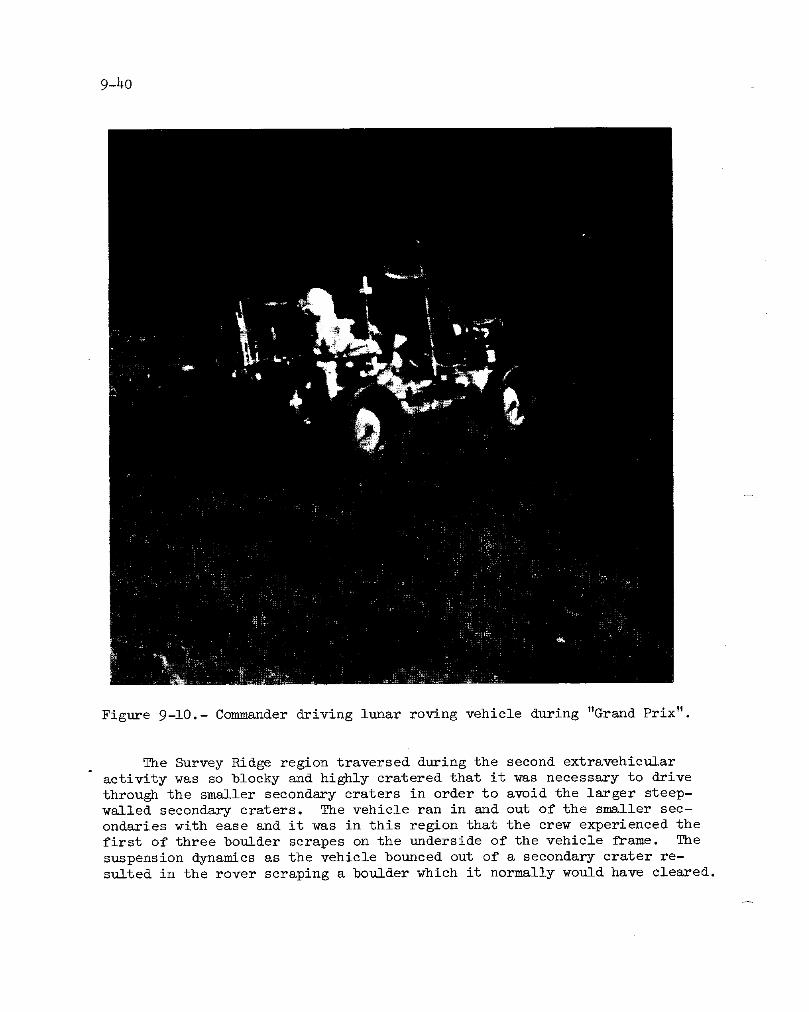
9-40
Figure 9-10.- Commander driving lunar roving vehicle during "Grand Prix".
The Survey Ridge region traversed during the second extravehicular
activity was so blocky and highly cratered that it was necessary to drive
through the smaller secondary craters in order to avoid the larger steep-
walled secondary craters. The vehicle ran in and out of the smaller sec-ondaries with ease and it was in this region that the crew experienced the
first of three boulder scrapes on the underside of the vehicle frame. The
suspension dynamics as the vehicle bounced out of a secondary crater re-sulted in the rover scraping a boulder which it normally would have cleared.

9-41z
The vehicle climbed very steep slopes going up Stone Mountain. In
several instances, the pitch needle was pegged at 20 degrees, although
the face of the pitch gage fell off as the crew departed Survey Ridge
(see. 14.6.4). Z_e only way the crew was able to judge upslope vehiclemovement in the lunar environment was by the reduction in the speed of
the vehicle as it climbed the slope. The best way to negotiate slopes
in the rover is to go straight up and straight down. Going cross-slope
or parallel to contour lines produces right or left rolls of i0 to 15 de-
grees. The feeling is very uncomfortable, even though the vehicle wasnever unstable d_ing cross-slope driving. At station 4, the lunar rov-
ing vehicle was parked in a flat bottom crater in order to eliminate the
possibility that the vehicle would roll down the hill.
The right rear fender was lost at statior, 8. Subsequently, the right
rear wheel produced a shower of dust over the vehicle which appears in the
16-mm motion picture photography as falling snow. However, a great deal
more dust was actually produced by the wheel than shows up in the film.The crew and the fTont of the vehicle, psrticttlarly the instrument panels,
were covered with dust. The instrument panel and the start, stop, and
closeout decals had 1/4 inch of dust over them at the completion of the
third extravehic1_lar activity.
Driving north of Palmetto Crater on the third extravehicular activ-
ity, it was poss_'ble to leave the throttle at a maximum setting to achieve
speeds of i0 to 12 kilometers per hour while continuing on a straight
course. One turn at this speed produced a rear-wheel breakout of approx-
imately 60 degrees. This was corrected by hardover steering in the op-
posite direction_, after which the brakes were applied. When stopped, the
vehicle was pointing about ii0 degrees and the direction was opposite tothat at which breakout occurred. There were no full spin-outs during any
traverse. When the vehicle broke out, even at high speed, the turn into
the breakout with simultaneous braking always produced a stable stop.
The dynamic vertical motions of the vehicle during the Grand Prix were
exaggerated because of the single crewman. The weight of two crewmen ap-
peared to give the vehicle more stability and to minimize the height ofbounces.
The navigation system was noted to have failed as the crew departedstation 9 on the second extravehicular activity (see sec. 14.6.3). Driv-
ing north, the crew took a heading of 30 degrees to intercept the esrliertracks of the outbound leg to station 4 on Stone Mountain. The lunar mod-
ule was acquired visually at a distance of 200 meters, however, and theoutbound tracks were not intercepted. The navigation system was reset at
the lunar module and it performed accurately during the third extravehic-
ular activity. It was a major aid in locating the rim of North Ray Crater.
9-_2
The vehicle handled very much like the l-g trainer except that the
pilot-lnduced lateral high-speed oscillations which were experienced in
the 1-g trainer were not apparent in 1/6-g. The steering sensitivity
that had been anticipated from reading the Apollo 15 mission report did
not exist. The most likely reason that the lateral sensitivity was not
experienced was that the excellent restraint of the seat belt prevented
the Comuander's arm from moving and putting inadvertent feedback intothe controller.
The battery covers were opened at the completion of each extravehic-
ular activity. Opening the battery covers threw dust onto the battery mir-ror surfaces; therefore, the mirrors were completely brushed after each ex-
travehicular activity and were brushed twice at final rover parking after
completing the third extravehicular activity. Even though the mirror sur-faces were brushed as well as possible, battery 2 temperature caused the
actuation of a caution and warning flag while driving to station ll/12.
The crew felt, subjectively, that they were riding 1/2- to 1-inch
higher than they had ridden in the 1-g training vehicle. The reason for
this is that, in 1/6-g, the crewman sits much higher inside the pressuresuit than he does in 1-g.
The maps and the map holder were inaccessible while the rover was in
motion. The only map used during the traverses was the contour map with
the bearings and distances to stations on it. A fastening clip would al-
low the Lunar Module Pilot to use the contour map while the rover is inmotion.
During initial lunar communications relay unit installation on the
lunar roving vehicle, the integrity of the power cables was difficult tomaintain. When the Lunar Module Pilot released the cable to check the
connection, the cable memory would cause the connector to pull free fromthe attach point.
At the last two stations of the third traverse, the rover was parked
on slopes such that the lunar communications relay unit antenna mast was
essentially vertical when the antenna was pointing at the earth. There-
fore, any motion on the antenna handle in yaw produced motions in roll
and pitch. This made antenna alignment more time-consuming at the last
stations. The Lunar Module Pilot assisted in pointing the antenna inseveral instances. There were also several instances in which the Com-
mander could not use the automatic gain control meter when aligning theantenna because he was standing in front of the lunar communication re-
lay unit. In those cases, a quick vector from the Lunar Module Pilotenabled S-band high gain acquisition. The final lunar communications re-
lay unit alignment tune-up always placed the earth image in the antennaalignment sight.

9-b3
The lunar communications relay unit was brushed at all extravehicu-lar activity stops and was brushed after opening the battery covers. Thethermal cover was folded over the lunar communications relay unit switchesat the final stop as stated in the preflight instructions.
9.9 LUNAR ORBITAL SOLO OPERATIONS
9.9.1 Plane Change Maneuver
The command _id service module plane change maneuver was delayed un-til Just prior to lunar module ascent. The procedures used were the sameas for all previous service propulsion system maneuvers.
9.9.2 Visual Observations
Techniques.- Man has several unique capabilities which can be used
to complement data obtained with remote sensors. These are Judgement,curiosity, and an eye with far greater dynamic range and color sensitiv-ity than any existing or proposed imaging sensor. During preflight train-ing exercises, it _as repeatedly demonstrated that the human eye, intel-ligently directed, could see and identify geologic features which eitherfailed to appear, or which appeared but could not be recognized on photo-graphs. Resolution, although a measurable quaz,tity, never seemed to bethe entire key to recognizing a geological feature. Perhaps the humanobserver's ability to absorb a big picture and then follow it to a de-
tailed small-scale feature enhances his ability to recognize the manysubtleties of interpretive observation. Another advantage of the humaneye is the ability to almost simultaneously observe features in a widerange of illuminations.
During the Apollo 16 mission, the average viewing time of a selectedtarget was slightly over 1 minute. Apollo missions are characterized byextremely high levels of crew activity and, therefore, time for visualreconnaissance is at a premium. The spacecraft attitudes which providedthe most comfortable viewing were those chosen for forward and north-oblique photography with the mapping camera. _he least desirable atti-tude was in the minus-X scientific instrument module data collection modebecause the target was at its closest point of approach at the same timeit came into the observer's field-of-view, making acquisition difficult.
Preflight training was conducted by flying a T-38 aircraft at h0 000feet where the resolution of the unaided eye is roughly equivalent to thatobtained with a 10-power magnification from 60 miles, and the angular ratesof the line-of-sight are similar. Several lessons became apparent. The

9-44
first was the necessity to develop a habit of observing and verbally de-
scribing simultaneously. The second was the requirement for an observa-
tion plan. The third was the necessity of sketching subtle features that
are anticipated not to be obvious from the accompanying photography. The
last was that, since time is at a premium, every possible effort must be
made to efficiently set the camera, acquire the target in the camera field-
of-view, and record the camera frame and magazine identification.
Considerable training time was spent in the study of lunar processes
and theory and in learning lunar geography. The latter study proved to be
a key element in the efficient utilization of the Command Module Pilot's
time by allowing him to recognize his location and the major geologic
questions associated with a particular region without having to refer to
a map.
The effectiveness of the observational techniques used on Apollo 16
has been clearly demonstrated; however, future improvement can be realized
by considering:
a. The use of optical devices with more magnification and some form
of image stabilization.
b. The allocation of more film to document unscheduled observations.
c. The use of a 35-ram camera, with through-the-lens viewing and in-
ternal light meter, to aid in rapid photographic documentation.
d. A polaroid-type camera system would allow efficient planning of
subsequent observations and also aid the crew in determining which as-
pects of a given scene do not show up clearly in photographs.
Visual impressions of the lunar surface.- During the early revolu-tions in lunar orbit, the earthshine illuminated a relatively large amount
of detail; however, this detail was lost in time as the earth's effective
reflecting area became smaller. Photographs should be taken at a time
when the earth is presenting its maximum lighted surface.
Craters on the moon can occasionally appear as hills when looking
out the window just as they do when looking at photographs. This inver-
sion occurred most often while looking out of window 5 while in the sci-
entific instrument module attitude, and almost always over the more non-
descript areas of the far side.
There is very little around the moon to aid in forming a feel for
the size of objects. Since the moon is so heavily cratered at all scales,
it looks very similar from 8 miles or 60 miles. The difference is really
in the types of features which can be detected at different ranges. For

9-45
instance, the small-size lineations, which are typical of all of the moon
except for the mare surfaces begin to show up somewhere between 25 and30 miles to the _laided eye.
In an attempt to settle the question of the moon's color, a wheel
was carried on Apollo 16 which had color chips for comparison. The con-
cept was that the erew would hold a color chip up and compare it with the
lunar surface. However, two difficulties showed up the first time this
was attempted in :Flight. First, the crew could not arrive at a consensus
on the color chip that most nearly matched. All crewmembers agreed that
none of the chips actually matched (the colors chosen were quite differ-
ent to their eyes). The second problem was the difficulty in getting
both the color chip and the lunar surface in the same lighting. The Com-
mand Module Pilot saw very obvious tonal differences, especially in the
western maria, but could not quantitatively describe them. The color im-
pressions of an _ea of backside highlands changed with the sun angle.
During the early lunar revolutions, the horizon was clearly definable
within a few minutes of entering the umbra. The time between losing earth-.
shine and detecting the horizon increased as the mission progressed, imply-.
ing a dependence ,on the solar corona.
The horizon gradually increases in definition as the sky takes on a
radiance near the ecliptic. The actual sunrise is very abrupt and can
catch an observer off guard since the intensity increase takes an appar-
ent step function as the sun's disk comes into view.
The Command Module Pilot was observing the lunar horizon and star
patterns from a totally darkened cockpit at about 122:55 when he noticeda white flash which occurred some distance below the horizon. This flash
was only momentary and was brighter than the brightest star or planet.The Command Module Pilot did not see any of the light flashes that other
crewmen have seen during lunar missions. It is possible that this was his
only observation of such a phenomenon even though he personally feels that
he saw something external to the spacecraft.
Particles in orbit with command and service module.- Particles could
be seen in lunar orbit with the command and service module during the per-
iod between spacecraft sunrise/sunset and the terminator crossing. These
particles could not be identified but appeared to be rotating since theywould flash or wink. It was not possible to judge their distance from the
command and service module. The particle density was low and essentially
constant during the mission.

9-46
9.9.3 Photography
Ten of the scheduled seventeen low-light-level photographic sequences
were accomplished. The procedures were adequate for all conditions exceptthe condensation on the windows.
The portable tape recorder was used to provide timing and instruc-
tions during the execution of the sunrise solar corona and zodiacal lightsequences. Without this technique, the sequences could not have beenaccomplished.
The moon, in either earthshine or sunlight, was in the camera field-
of view on several sequences, including Skylab contamination study pho-tography and one attitude for Gegenschein photography.
The attempt to photograph the lunar surface in earthshine should pro-vide some very useful data about the western areas.
9.9.4 Scientific Instrument Module Problems
The first time the panoramic camera was turned on, itwas accompaniedby a master alarm and a main bus B undervoltage warning. The camera was
immediately deactivated and subsequent analysis indicated that the problem
was caused by the spacecraft heaters coming on simultaneously with thepanoramic camera.
The mass spectrometer boom did not fully retract following its firstfull extension (see. 14.1.8). The panel 230 indicator remained at full
ba_berpole although the proximity sensor indicated a safe retraction.
The lunar module crew had reported that the boom appeared to be retracted.
The Mission Control Center was used as the primary source of retraction
data thereafter. Just prior to lunar module jettison, the boom stalled
near its fully-deployed position. This stall was confirmed by both vis-
ual observation from the lunar module and ground telemetry. The boom was
subsequently jettisoned. The jettisoned boom smoothly left the spacecraftwith no visually detectable angular rates.
Retraction of the mapping camera required more than 3 minutes the
first time, but the retraction time seemed to be progressively shorter
as the mission continued (see. 14.5.1). During the transearth extrave-
hicular activity, the stellar glare shield was found to be partially ex-tended when the camera was in the retracted position (sec. 14.5.2).
The gamma-ray spectrometer boom failed to retract completely during
transearth coast and finally stalled just prior to the final midcoursecorrection. This anomaly is discussed in section 14.1.9.
9-47
9.10 ASCENT, RENDEZVOUS AND DOCKING
9.10.1 Ascent
The normal powerup procedure for ascent preparation was modified
slightly; lunar s1_rface alignment stars were deleted and reaction control
system A was shut off before the ascent system feeds were turned on (after
insertion, the cross feed was opened to use both reaction control systems).
The crew was about 20 minutes ahead of the procedures at lift-off minus
35 minutes. After a 15-minute hold, the helmets and gloves were donned
and the ascent ta_iks pressurized. The crew was then ready for lift-off.
The countdown to lift-off proceeded normally and, at auto ignition, a
slight pop was heard, followed by a smooth lift-off. Program pitchoverwas on time and the profile was normal throughout the lunar ascent firing.
9.10.2 Rendezvous
Lunar module.- The maneuver residuals were so small at insertion that
no trim firing was required. The vernier adjustment was very small; minus
i0 feet per second[ in the Z axis and minus 2 feet per second in the X axis.
The vehicle was pitched up automatically upon using the rendezvous naviga-
tion program. An automatic rendezvous radar lock-on was obtained at adistance in excess of 150 miles. Both crewmen visually acquired the com-
mand and service module at this range. Although the command and service
module could not be seen through the tinted crewman optical alignment
sight, it was seen to the side and from below the sight. Since the com-mand and service _,odule can be visually acquired, the desirability of per-
forming the state vector and the radar checks in the simulators to acquireradar lock-on at extreme ranges following insertion was demonstrated. Ap-
proximately 23 marks were obtained with the rendezvous radar and they were
fed directly into the abort guidance system. Tracking was accomplished in
both the automatic and pulse-control modes of the primary guidance and
navigation system.
All four solutions for the terminal phase initiation firing were in
substantial agreement (Mission Control Center Real-Time Computer Complex,
the command module computer guidance, the lunar module abort guidance,
and the lunar mod_ie primary guidance). Terminal phase initiation was
performed with the ascent propulsion system. The maximum residuals from
the firing were about 5 feet per second in the X axis and these were trim-med to zero. During this maneuver, the radar, which was near the antenna
limits of mode-i lock-on, broke lock. The vehicle was pitched up in the
transfer phase midcourse program and radar lock-on was quickly reacquired.

9-48
Because of a procedural error in hitting the enter button too quickly
when reloading the W matrix, a second reloading of the W matrix was nec-
essary. Therefore, only five marks instead of the normal seven were ob_tained for the first midcourse correction. The first midcourse solution
had a maximum value per axis of 0.9 foot per second, and the second mid-
course solution was even smaller. After the second midcourse correction,
no line-of-sight corrections were made until the lunar module was within7000 feet of the command and service module.
The braking phase did not commence until 3000 feet separation be-
cause the relative velocity, when passing through 6000 feet, was less
than 29 feet per second. Line-of-sight control corrections during theremainder of the rendezvous were minimal. Care was taken not to exceed
the command and service module rescue capability braking limitations
which meant that the normal lunar module braking gates were approachedcons ervatively.
When the lunar module was stationkeeping with the command and ser-
vice module, the Mission Control Center requested a lunar module 360-de-
gree yaw maneuver to allow the Command Module Pilot to inspect damaged
panels on the rear of the lunar module that had been seen on television
at lift-off (see see. 14.2.2). The inspection revealed that the outer
thermal cover on the rear of the ascent stage had been bent and torn,
but the thermal blankets underneath appeared to be intact. Following
the lunar module yaw maneuver, the command and service module performeda pitch and a 360-degree roll maneuver to allow the Lunar Module Pilot
to take pictures of the scientific instrument module bay and of several
bubbles produced by heating of the thermal coating on panels of the com-mand and service modules.
Command and service module.- The stabilization and control system
was used for attitude control during the rendezvous to prevent optics us-
age from exercising the thrust vector control relay and running the risk
of a repetition of the inertial measurement unit coarse alignment prob-lem. Generally, the command and service module was flown to attitudes
under command module computer control; however, during tracking and ser-vice propulsion system thrusting routines, it was flown using the stabil-
ization and control system. This procedure was much the same as thestandard "Rendezvous Procedures with No Inertial Measurement Unit."
The digital event timer on panel i began to count incorrectly during
the rendezvous and it malfunctioned intermittently thereafter. This anom-
aly is discussed in section 14.1.13.
The Command Module Pilot had planned to optically track the lunar
module at insertion, which was scheduled to occur prior to sunset. This
did not prove feasible since identification of the lunar module was not

9-49
possible using the scanning telescope and the prelaunch state vector was
inadequate for automatic acquisition with the sextant. A new state vec-
tor was received from the Mission Control Center and tracking was initi-
ated at sunset using the sextant to acquire the lunar module tracking
light. VHF ranging and the lunar module rendezvous radar were again inclose agreement.
The sextant and scanning telescope were boresighted closely. The
lunar module tracking light was not very obvious in the scanning tele-scope until near terminal phase initiation. During the lunar module
braking maneuver, following rendezvous, the two forward firing reaction
control system engines appeared as flashlights which blinked on period-ieally. The rendezvous was normal and all terminal phase initiationsolutions were consistent.
The requirement for television coverage of the lunar module approachwas deleted so that the Space Flight Tracking and Data Network could usethe 210-foot antennas for lunar module communications since the lunar mod-
ule was transmitting on omnidirectional antennas instead of the steerableant anna.
In accordance with instructions from the Mission Control Center, the
Command Module Pilot did not don his pressure _rment assembly for the ran-.dezvous operations.
9.11 LUNAR ORBITAL OPERATIONS -
DOCKING TO TRANSEARTH INJECTION
9.11.1 Docking
Lunar module docking was very gentle, with contact being made at a
low closure rate ,0f about 0.2 foot per second. The probe did not capturethe lunar module until some delta-velocity was applied by the command and
service module. There was no indication of the lunar module bouncing awayfrom the command and service module at contact. Following lunar orbit
docking, latch I0 functioned normally.
9.11.2 Post-Docking Activities
Lunar module post-docking powerdown was to be performed accordingto procedures in the contingency checklist under "Docked Deactivation -
Staged" with minor modifications. These procedures were implemented im-mediately after _)eking and, at the same time, all the rocks and the ex-periments that w_e being returned from the l_lar surface were transferred
9-50
to the command moduie. Articles were transferred exactly as they were to
be stowed and this stowage went ahead of schedule. Because a rapid dry-
-out of the water boiler was anticipated, the crew was requested to delete
the transfer of a few items such as the personal preferance kits and the
data storage electronics assembly. However, because of a slow dry-out,
all equipment was transferred prior to final lunar module powerdo_ua and
tunnel closeout. The water boiler dry-out was so slo_, in fact, that
some equipment was reactivated to decrease the dry-out time.
During the equipment transfer, a large amount of dust had begun float-
ing around and much of it was transferred to the command module cabin. Thevacuum cleaner failed after it had been used for about 20 minutes. There-
fore, all the dust could not be collected. Most of the sample collection
bags were free of dust and debris and the only things that really needed
cleaning were the deep core sample and the big rock bags. Dust particles
in the lunar module cabin atmosphere did provide some hindrance to thecrew during the unsuiting and the dry-out period.
The lunar module could have been Jettisoned at this time and would
have resulted in a shorter day than was experienced; however, early on ren-
dezvous day, the decision had been made by Mission Control to delay lunar
module Jettison untilthe following day in an attempt to shorten the length
of the rendezvous day. This change in the lunar module-Jettison timeline
created confusion and inefficiency in that several hours were consumed on
transearth-inJection day with lunar module powerup, pressure garment don-
ning and lunar module Jettison taking the place of regularly scheduled ac-tivities.
Upon completion of water boiler dry-out, the lunar module was finally
powered-do_ra according to the procedures. The crew ingressed to the com-
mand module, closed out the lunar module tunnel hatch and the command mod-
ule hatch, and commenced their rest period at the same time they would
have if the lunar module had been Jettisoned on rendezvous day.
9.11.3 Lunar Module Jettison
Upon completion of the rest period following the rendezvous and dock-
ing the crew received a series of flight plan and procedures updates which
modified two different sections of the contingency checklist and one sec-
tion of the timeline book. By this time, the timeline book was becoming
very messy because of deletions and additions and it was difficult to fol-
low the procedures through. However, the crew felt that the proper switch,
circuit breaker, and systems configurations had been identified.
About the time of loss of signal, the crew had donned their suits and
commenced final closeout. Final closeout was completed on the backside of
the moon. The up-linked differential velocity program was verified, the

9-51
guidance computer and digital autopilot were verified, and the mode control
switch was placed in "attitude-hold" (versus the required "auto" position).
The command module was ingressed on time and a suit integrity check was
initiated at about the time of acquisition of signal. (The pre-separation
pressure garment integrity checks were never satisfactorily concluded dueto the crew falling behind the new timeline. )
Houston noted that the mode control switch was in "attitude-hold" in-
stead of "auto", but the crew was given a "go" for lunar module Jettison
nevertheless since that configuration was acceptable. The lunar module
was Jettisoned a few minutes late. At the time of Jettison, the lunar
module began a slow tumbling maneuver in all three axes, and a thrusterwas never fired as far as the crew could tell (sec. 14.2.6). Once lunar
module Jettison was accomplished, the crew unsuited and initiated the two-
revolution preparations for transearth injection.
Another problem which had been encountered during lunar orbital op-
erations was that two lithium hydroxide canisters tended to stick during
removal (sec. 14.I.15). The first one had been used 9 hours longer than
the normal time because the changeout was overlooked during one of the
solo periods when a large number of flight plan updates were being made.
This canister was snug when removed at about 152 hours. The second inci-
dent occurred on the night following rendezvous. This canister was re-
moved on schedule but removal was extremely difficult.
9.11.4 Subsatellite Launching
There were no vibrations or sounds associated with the launching ofthe particles and fields subsatellite. All indications were that it wasnormal.
9.11.5 Transearth Injection
The transearth injection maneuver was conducted normally using the
same procedures that had been used for the plane change maneuver with the
exception that the pitch-2 and yaw-2 circuit breakers were pulled after
gimbal startup. There was no explanation from the ground as to why the
philosophy in the use of these circuit breakers had been changed.
Two unexpected observations were made during the maneuver. The firstwas that the command and service module oscillated between both sides of
the roll deadband; whereas, on other long firings, the spacecraft remainedon one side of the roll deadband. The second unusual observation was the
presence of a sli@_t "buzz" approximately 30 seconds into the maneuver.

9-52
Throughout the firing, the entry monitor system, guidance and navi-
gation, and voice update values were in agreement.
9.12 TRANSEARTH FLIGHT
9.12.1 Transearth Extravehicular Activity
The transearth extravehicular activity was conducted exactly accord-
ing to the checklist procedures. A great deal of training time had been
invested in the procedures for stowage, extravehicular activity prepara-
tions, and post-extravehicular operations. This certainly paid off and
allowed the crew to speed up the preparations. The timeline and proce-
dures were more than adequate. The television camera and oxygen purge
system were stowed after the post-extravehicular activity sequences; how-
ever, these items should not have been stowed since they were subsequentlyused.
Preparations.- The final days of preflight training disclosed that,
through an oversight, the time allowed for pre-extravehicular activity
pressure garment donning was insufficient. Therefore, the planned time
for hatch opening was delayed i hour. The Mission Control Center allowedthe crew to sleep an extra hour on the day of the scheduled extravehicular
activity, which once again put them behind the timeline; however, the crew
was able to make up approximately 45 minutes of this delay due to the ex-
cellent procedures developed for this segment of the operation. Approxi-
mately i hour was spent on extravehicular activity preparations on the day
of transearth injection, but there was not a great deal that could be done
without interferring with the sleeping and eating cockpit configurations.
Quite a bit of unopened food was jettisoned in order to provide space
for the post-extravehicular activity stowage. This problem was aggravated
by reducing the length of the mission by one day, but was basically causedby an overabundance of food.
The extravehicular mobility unit maintenance kit was approximately
three times the thickness of the lunar module kit (sec. 14.3.9). The pack-
ages of pressure garment assembly helmet wipes in the command and service
module kit were approximately five times larger than those of the lunarmodule kit.
The extravehicular activity preparations and checkout were normal.
The Lunar Module Pilot and Con_nander's pressure garment assemblies were
lubricated again and this resulted in much easier glove and helmet don-
ning. The command module suit circuit integrity check was expedited by
using the hatch equalization valve to drop the cabin pressure to 5 psi.

9-53
While the hatch equalization valve was open, a continual stream of debris
was being sucked out of the cabin including a small screw which went
through the valve just prior to cabin depressurization. A debris screenshould be installed over this valve to prevent an object from becoming
permanently lodged in the valve.
Moving around in the cabin in pressurized suits is relatively easy
(much easier than in the water immersion facility); however, it is a little
harder to see some of the main display console because of the natural tend-
ency to float closer to it. Ground support personnel monitored the space-
craft systems for the crew throughout the extravehicular period.
The counterbalance was removed from the side hatch by backing out
the pin which locks the two bellcrank assemblies together. Both removal
and reinstallation of this pin were extremely simple. There was no prob-
lem with interference between the cam nut and hinge since the crew had
been trained to adjust the relative positions of these items during hatch
opening and closing. The rate of cabin depressurization decreases mark-
edly when the cabin pressure drops below 0.5 psi. Because of this, the
hatch was opened with a small positive differential pressure remaining in
the cabin. This produced a noticeable force on the hatch as soon as the
dogs were clear of the striker plates. There was very little frictional
load on the hatch during opening and closing.
Visibility.- The sun angle chosen for the extravehicular activitywas excellent from an operational point of view. It was, however, very
difficult to look at the unipole, when installed, or to look in the di-
rection of quad D while standing in the hatch. Visibility of the scien-
tific instrument module bay was good. The only area seen to be in a darkshadow was between the scientific instrument module bay bulkhead and the
side of the mapping camera. After the panoramic and mapping camera cas-
settes were removed, visibility into the empty cassette spaces was excel-lent.
Mobility.- The extravehicular activity was as easy as it was in KC-135 aircraft training. The "dutch shoes" worked fine and did not exhibit
a tendency to release the Command Module Pilot, even when leaning sideward.
Getting into and out of the shoes was easy and positive. The traverse path
is excellent and allows flexibility in orientation and sequence of opera-
tion. The only mobility problem encountered was an extremely stiff left
wrist joint on the Command Module Pilot's extravehicular glove. This in-
creased stiffness, compared to the right glove, was evident as soon as the
gloves were donned. A concentrated effort was required to move the wristjoint about the axis which corresponds to a yaw control input on a hand-
controller. As the wrist became fatigued, the right hand was used to pos-
ition the left wrist. Fortunately, the wrist joint remained stable in any
position in which it was placed.

9-54
Retrieval of the panoramic and mapping camera film cassettes was veryeasy and went just as practiced.
The umbilical was not in the way and its presence required considera-
tion only during ingress when it had to be positioned by the Lunar ModulePilot.
Extravehicular activity hardware.- All equipment functioned as antic-
ipated. The temperature was good, both in the cabin during depressuriza-
tion and during the extravehicular activity. The only nuisance item was
the extravehicular activity hook. The opaque sun visors of the Commander's
lunar extravehicular visor assembly were very easy to deploy but were im-
possible to raisewith one hand. The trap door in the visor center sec-
tion allowed adequate visibility.
During a suit pressure check, a pressure of 3.5 psi was observed on
the Commander and a pressure of 3.8 psi was observed on the Lunar Module
Pilot (sec. 14.3.8). Both crewmen were on the cabin suit loop at thetime.
Scientific instrument module bay observations.- The scientific in-
strument module door pyrotechnic cut was smooth all the way around. The
spacecraft-lunar module adapter/service module pyrotechnic cut was quitejagged, similar to cuts seen on test specimens.
The mapping camera stellar glare shield was partially deployed and
the "cuckoo door" was resting on the extravehicular handrail (sec. 14.5.2).
The gamma-ray _xperiment was retracted with the tapered portion of
the guide pins sticking through their shoes. The door was open approxi-
mately 30 degrees and was loose enough to be jiggled a couple of degrees.There was no evidence of the cause of the incomplete retraction.
The paint on the service module cork covering and on the reaction
control system quad housings was blistered. The coatings on the radia-
tors looked clean. There was no ice on the command module dump nozzles.
Unipole operations and microbial response experiment.- The pole waseasy to install and remove. Because of the sun orientation, the data ac-
quisition camera could not be verified to be operating by looking at the
camera light; however, it could be felt to be running.

9-55
Removal of the data acquisition and television cameras from the pole
was easy as was installation of the microbial ecology evaluation device.
However, two problems arose with the device. First, a Velcro strip (pro-
vided to keep the locking ring in place) continually floated to a position
that interferred with viewing the sun sight, and second, the cover of the
device did not automatically lock when it was closed. Locking the cover
was a three-handed operation. One hand was required to hold the Command
Module Pilot in position, one to close the lip and compress the seal, and
the third to rotate the lock pin. As a result, the microbial ecology
evaluation device was passed into the Lunar Module Pilot who performed
the operation inside the command module. The cover was open approximately
3 to 5 seconds beyond the planned time and was not in direct sunlight d_r-
ing this time.
The sun sight worked fine and is an excellent concept. Because of
the previous problems with the digital event timer, the Commander timed
the exposure of the microbial ecology evaluation device with his wrist-watch.
Hatch closin_ and post-extravehicular activity.- Hatch closing waseasy and went as planned. It would have been desirable to have a posi-
tive means of determining that the hatch dogs _e over center by indica-
tions from the hatc_h dogs themselves rather than relying on the gear boxindications alone.
The post-extravehicular activity reconfig_ration was a real thrill.
This took several hours and was greatly aided by the assistance of the
Mission Control Center in the execution of the flight plan.
9.12.2 Transearth Coast Problems
Severs_l problems occurred during transearth coast. The inertial sub-
system warning light mysteriously came on and went off several times ac-
companied by an inertial coupling unit failure warning on the computer
display keyboard (sec. 14.1.4). In troubleshooting this problem, it ap-peared that a "no-digital-autopilot" configuration was required in order
to do the malfunction procedure test of the error needles.
The crew couch Y-Y shock-attenuating strut was very hard to extend
and lock prior to entry (sec. 14.1.17). It seemed as though the Y-dimen-
sion of the spacecraft had changed with respect to the couch.

9-56
9-13 ENTRY, LANDING AND RECOVERY
The entire entry sequence was normal. The entry stowage was comple-
ted the night before except for stowing one pressure garment assembly andtying down loose items such as the jettison bag. On entry day, it took
less than 2 hours to finish the cabin preparations. As previously men-
tioned, several inertial subsystem warnings were observed during the fi-
nal hours prior to entry. A set of entry procedures similar to those
used during the major service propulsion system maneuvers had been worked
out. These procedures incorporated the use of erasable program _P 509
and zero coupling data unit (verb 40), and were quite straight-forwardand well explained.
All pyrotechnic events occurred on schedule. The entry profile fol-
lowed predictions. Due to extensive entry training in the simulators,
the crew felt completely comfortable about entry procedures. The Command
Module Pilot had no difficulty maintaining an effective instrument scan
under the entry deceleration, which exceeded 7-g. The only unexpected
condition was the magnitude of the command module oscillations once the
drogue parachutes were deployed. The oscillations may have been the same
as programmed into the command and service module mission simulator but,
without the dynamics, may not have been fully appreciated.
The command module reaction control system isolation valves were
closed at approximately 3000 feet and the direct coils mode was activated
in the plus- and minus-yaw directions. The yaw Jets were heard when fir-ing in the plus-yaw direction (which was fired first) but not in the minus-
yaw direction.
The firing of the command module negative pitch Jets could be con-
firmed only by changing spacecraft rates.
The landing was flat and much harder than the Commander recalled from
the Apollo l0 mission. The parachutes immediately pulled the vehicle intothe stable-II attitude. The Command Module Pilot and Lunar Module Pilot
jettisoned the parachutes and immediately initiated uprighting procedures.
Uprighting took an estimated 4 1/2 minutes, and the command module stayedfor what seemed to be an excessive time in an attitude in which the ve-
hicle seemed almost ready to upright into the stable I attitude. Post-
flight inspection showed that the center uprighting bag was only partiallyinflated.
The recovery operation proceeded smoothly until a swimmer opened the
hatch and placed a large bag inside. The swimmer said that the bag con-
tained a temperature monitoring device which must be taped to the main
display console. The crew had not seen this device before nor had they

9-57
been briefed on it. (Editor's Note: The temperature measurements were
made to determine the temperature changes after landing that may be an-
ticipated in the Skylab program. ) This unexpected operation resulted insome confusion and an unnecessary 5 to i0 minutes was expended inside the
cabin, which slowed down the quickest crew recovery ever. The time from
spacecraft splashdown until the crew was on the deck of the USS Ticonderogawas less than 37 minutes.
9.14 GENERAL OBSERVATIONS AND RECOMMENDATIONS
9.14.1 Spacecraft Systems
Li_htwei@ht headset and communications carrier.- The lightweight head-set was used extensively by the Lunar Module Pilot while the Command Module
Pilot and Commander chose to use the "Snoopy" hat almost exclusively. The
difficulty with the lightweight headset arises from the requirement to hold
the microphone in close proximity to the mouth. This requires the use of
at least one hand to maintain good communication. As a general rule, how-
ever, it is much more convenient to have both hands free for note taking
and/or manipulating switches while talking. The lightweight headset is
too bulky to be conveniently worn on the head.
The existence of the crewman's communications umbilical slows down
operations by putting unwanted forces on the crewman's body, by presenting
a constant snag potential, and by requiring a unique path around hardware.
The control head and the tee adapter are also cumbersome. The suit adapter
is very stiff which means that as the crewman moves around, the torques
coming from the umbilical are transmitted to the headset. If the headset
is the lightweight type, it is going to be repositioned or knocked off,and if the headset is the "Snoopy" type, it is going to be a constant per-
sonal nuisance. Hlither a lightweight headset like those used in the Mis-
sion Control Center or a squawk box like the executive conference telephone
adapter should be provided. The latter is preferable because it alleviates
all the problems associated with umbilicals. (Editor's Note: A config-uration exists for the attachment of the lightweight headset to the con-
stant wear garment which frees both hands for normal work. However, the
head must return to a preselected "talk" position because the microphone
is maintained at constant position relative to the body.)
The requirement for someone to monitor the communications at all times
resulted in the Command Module Pilot wearing the communications carrier theentire mission. When the communications carrier is worn continually, it
can present a personal hygiene problem. For long flights, consideration
should be given to carrying additional cloth helmets since they are sepa-
rate from the electronics. A spare set of electronics should be considered.

9-58
0nboard voice and data recordin6.- There is a need for continuousrecording of onboard voice. The Apollo equipment has several shortcomingswhich are :
a. The voice is recorded simultaneously with the spacecraft data.
b. The ground controls the record and playback sequence; consequently,the crew must refer to the flight plan or ask the ground for the currentconfiguration.
c. The tape recorder talkback indicator in the cabin indicates tapemotion and not direction.
d. The data storage equipment uses a separate recording amplifierand the crew does not know the sound level being recorded.
e. All data recorded may not be recorded on the ground as it may berecorded over before that portion of the tape is dumped.
Voice-operated ke_in_ circuit.- The voice-operated keying circuitworked flawlessly throughout the mission as long as the communicationscarrier was used. The Command Module Pilot used this mode almost contin-uously while solo in orbit and during a large portion of transearth coast.
Guidance and navigation optics.- Auto optics worked well when the in-ertial measurement unit was realigned. There was more trunnion overshootthan anticipated when acquiring targets. The Command Module Pilot had thedistinct impression that the amount of overshoot and the time to damp os-cillations increased with mission duration. Toward the end of the lunar
orbit period, the initial overshoot exceeded the sextant field of view.This overshoot, based on optics position indicator readings, occurred pri-marily in trunnion.
Sextant reticle illumination Ms normally comfortable when used atthe maximum intensity, providing good star/reticle balance. The scanningtelescope illumination had to be reduced to a minimum to allow star iden-tiflcation. The command and service module mission simulator displaysare quite accurate. During training, Kennedy Space Center simulationspersonnel had added a filter to the scanning telescope which reduced thestar intensity. This was a significant aid in providing a good feel forthe amount of time necessary to acquire stars with the scanning telescope.The star patterns, under the best conditions, were never as obvious throughthe scanning telescope as they were out the window.
The scanning telescope n_Astbe in focus before stars can be seen. It_as focused on the reticle for best results. The focus seemed to be quitesensitive and _ould drift, even when taped. Also, the sextant focus ad-Justment was at one extreme of its travel. Improper use of the Teflon

9-59
locking nut which locks the eyepiece guard cup in place caused the eye-piece to unscrew in zero-g. The crew was not properly trained for thisoperation.
Tape was app].ied to the eyepieces to retain them after the scanning
telescope eyepiece was found floating around the cabin.
There was a noise when the shaft was driven at the higher speeds.
The noise, which increased throughout the mission, sounded like that made
by the optics position indicators on the command and service module mis-
sion simulator. The noise was apparently proportional to the rate of
drive and did not seem to be affected by switching from the "resolve" tothe "direct" settings. This anomaly is discussed further in sectionl& .1.lb.
The scanning telescope was generally useless while the vehicles were
docked because of the large amount of light reflected off the lunar mod-
ule steerable antenna and one of the reaction control systems quads. Dis-
crimination between lunar module paint debris and stars was not a problem
when using the sextant because the debris particles were always out ofFOCUS •
One realignment was performed using the eE_rth and sun during trans-
lunar coast. The earth was not full at the time and some difficulty was
experienced in defining the center of the disk.
Command module computer.- Useful modifications and additions to theApollo software continue to become apparent as operational experience is
gained. Several erasable memory programs were tested and formalized prior
to flight for use as both planned evolutions and contingency work-arounds.
The EMP 509 procedure, to prevent coarse aligrmlent of the inertial meas-
urement unit in the presence of the coupling display unit transients, was
one of these and, as previously discussed, played a major role during the
mission. This is a classic example of the utility of developing procedures
to handle certain critical situations even though a reasonable cause cannot
be predicted.
Perhaps the most useful addition to the command module computer normal
procedures was a set of addresses that could be interrogated to display the
maneuver completion time during a digital-autopilot-controlled automatic
maneuver. The crew routinely executes maneuvers requiring up to 15 minutes
for completion, followed immediately by a scheduled activity. The efficient
execution of real-time flight plan changes resulted directly from being able
to determine the acceptability of the selected maneuver rate. Future auto-
pilot design should provide an option which would allow specifying maneuver
completion time. Another useful feature would be an autopilot which would
allow non-symmetrical and/or discrete deadbands for each control axis.

9-60
Prior to flight, a program to monitor for a stuck-on thruster was
developed which would turn on the inertial subsystem warning light and
master alarm if the spacecraft exceeded its deadband by some specified
amount. This program was used during the translunar coast and during
each lunar orbit sleep period. It allowed the Command Module Pilot to
sleep in lunar orbit without concern for the reaction control systemconsumables.
Electrical power.- The systems checklist requires that the batterymanifold be vented to vacuum after charging the battery. Ground support
personnel requested that the manifold not be vented below cabin pressure.The valve configuration makes it more a matter of luck to retain a posi-
tive pressure. The manifold pressure rose rapidly following each vent-
ing before stabilizing.
During the charge on battery B prior to the transearth extravehic-
ular activity, the crew detected a definite odor in the lower equipment
bay. This odor was described by the Lunar Module Pilot as being like hotelectrical insulation, while the Command Module Pilot thought it was rem-iniscent of an automobile battery charger odor.
Cabin environment.- Following insertion into earth orbit there was
quite a bit of debris floating around the cabin. This contamination con-sisted of small screws, fasteners, ends trimmed from wiring and general
trash. The quantity of this cabin debris remained fairly constant through-
out the mission. At times, the suit circuit return valve (cabin air re-
turn) had to be cleaned more than once a day in order to keep the oxygen
demand regulator flows at their normal values.
Once the transfer of equipment from the lunar module began, the com-
mand module cockpit became noticeably dusty with quite a few rock chips
floating around. The dust could be found on almost all surfaces although
there was never any problem with floating dust.
The cabin fan filter was installed on the first day of the flight.
After rendezvous, the cabin fan was turned on prior to opening the lunarmodule hatch and ran continuously until after transearth injection when it
made a very loud moaning noise and was turned off (sec. 14.1.11). The ca-bin fan inlet screen was generally covered with a great deal of trash. Af-
ter the fan was turned off, a piece of paper was taped over the cabin fan
inlet screen in an attempt to retain the dust within the ducting. There
was no problem with dirt coming out of the duct, even when the fan filter
was removed for entry.
The vacuum cleaner failed after less than i hour of use while at-
tempting to clean items in the lunar module that were to be transferredto the command module.

9-61
f
The suit hoses were arranged such that the Lunar Module Pilot's hoses
were alongside stowage container A8, the center hoses were wrapped around
the inside of the tunnel, and the left hoses were along the minus Y side
of stowage container A2. There was never any sensation of inadequate ven-tilation or circulation.
The cabin temperatures were comfortable during translunar coast.
Each crewmember found his own combination of clothing which was most com-
fortable. Wearing only the constant wear garment while in the sleeping
bag was comfortable to everyone during the translunar coast and trans-
earth coast sleep periods. While in the 60- by 8-mile lunar orbit, the
cabin felt considerably warmer and the most comfortable attire was the
constant wear garment only. During solo operations in the 60-mile cir-
cular orbit, the cabin cooled noticeably. In order to sleep, the Command
Module Pilot had to wear his inflight coverall garment in addition to the
constant wear garment. Once the lunar module crew returned to the com-
mand and service module, the cabin temperature was comfortable again.
The cabin walils and windows began to collect a great deal of conden-
sation following transearth injection. The quantity of condensate slowly
increased throughout the transearth coast and did not diminish even in
passive thermai control. By the time the Skylab dump photography was at-
tempted at approximately 246 hours, the windows had to be wiped between
each photographic sequence.
One characteristic which has been jokingly mentioned on previous
flights is that loose objects seem to eventually end up collecting in the
lunar module/command module tunnel area. This [phenomenon was evident
throughout the flight either with coupled reaction control system engines
or unbalanced jet configurations.
A qualitative observation is that the tunnel area was almost always
cooler than the rest of the spacecraft cabin.
Water/_lycol temperature control valve problem.- The primary water/glycol temperature inlet valve started oscillating rapidly while in earth
orbit. The crew was advised to select the manual mode of operation andthat mode was used for the remainder of the mission. The minimum valve
rotation seemed to cause a 10-degree shift in the evaporator outlet tem-
perature. The temperature inlet valve was initially adjusted during the
early hours of translunar coast passive thermal control. The valve wascycled just prior to the transearth extravehicular activity by going to
the automatic mode for several minutes, then returning to the manual mode.
The valve appeared to be working normally in the automatic mode; however,
the crew elected to leave it in manual for the extravehicular activity.
9-62
Water/_lycol temperature decrease durin_ extravehicular activity.-The water/glycol evaporator inlet temperature dropped during cabin depres-
surization for the transearth extravehicular activity, but the mixing valve
position did not change since it had been placed in the manual mode posi-
tion. There was a considerable amount of water in the cabin. In fact, the
crew observed ice floating out of the hatch throughout the extravehicular
activity.
9.14.2 Crew Station
Pressure 6arment donning, doffin6 and stowa6e.- Approximately i hourwas required for the Commander and Lunar Module Pilot to doff and stow
their A7LB pressure garment assemblies. The actual donning and doffingwas accomplished most easily in the lower equipment bay with a second
crewman assisting, as needed, from the couch position. Zipper closure is
probably the most difficult part of the donning operation. During the
second scheduled (third actual) lunar module manning, the Commander and
Lunar Module Pilot used the lunar module cockpit for donning to obtain
more room for zipping the suits. This seemed to speed up the donning ac-
tivity and was a more convenient place to work.
The Command Module Pilot required approximately i0 minutes to don
or doff his pressure garment assembly in the lower equipment bay by him-
self. Having another crewman to assist in zipping saves approximatelyB minutes.
The most time-consuming part of doffing the suits is the actual stow-
age of the suits in their bag. Although stowage of three pressure garment
assemblies (two A7LB's and one A7LB-CMP) in the bag had been accomplished
several times during training, it proved to be impractical in flight. Sev-eral factors may be involved in this difference. First, in flight, there
is no gravity to help fold the pressure garment assemblies and keep them
in place. Second, the accessory pockets were more prominent on the flight
suits than on the training suits. A third possible factor is that the
best possible care is taken of the pressure garment assemblies in flight,
which means that there is a minimum of pulling and bending on the zipper.
Another possible factor is that the simulator and mockup training bagshave become stretched with use.
To alleviate the stowage problem, the Command Module Pilot's suit
was Stowed under the left couch. In order to provide access to stowage
containers AI and A2, it was not tied in place.
Following the transearth extravehicular activity, all three suits
were stowed in the pressure garment assembly bag through the generous use
of kick-and-shove techniques. The center couch had to be removed at the

9-63
marmon clamp in order to accomplish this. The size of the pressure gar-
ment assembly bag should be enlarged and some extra volume made availablein the area between the center couch and the rotation hand controller
junction box.
Pre/post sleel? configurations.- The pre-sleep checklist takes approx-imately 30 uninterrupted minutes to complete. Several other items, such
as filling a drink bag for each crevman and taking one last drink before
chlorinating the water, takes additional time. The drink bags were very
useful since all the crewmen found that they would awaken during the nightand be thirsty. It is impossible for someone to move around without wak-
ing the others, so having a drink bag handy helps avoid sleep interrup-tions. For the ss_ne reason, each crewman should take care of his waste
management requirements before the sleep period begins. All of this adds
up to the pre-sleep checklist taking approximatley i hour of time. Sev-
eral items were added to the pre-sleep checks during the mission. These
were winding the watches, stowing the optics to prevent being periodic-ally awakened by the sun, and verifying that the Mission Control Center
was receiving an m_equate biomedical signature on the desired crewman.
There should be some uninterrupted time of about 30 minutes follow-
ing crew wake-up to provide an opportunity for the crew to clean up the
cabin, compile the morning reports, review the flight plan, and go to thebathroom.
Cabin lishtin,_.- The electroluminescent lighting provided just theright illumination for easy monitoring during sleep periods. The addi-
tion of some form of switch position indication would make an excellent
instrument and control display.
The floodlights were used almost continuously except "during sleepand low-light-level] photography periods. To avoid afterglow problems
with the photography, a set of cardboard shades was prepared and the
shades were taped to the floodlights nearest window 4.
The floodlights, including the fixed ones, do not provide sufficient
illumination for interior pnotography using color interior film (ASA 500)
except in selected locations.
The window shades worked quite well on all windows.
Stowage.- Flight experience indicated that the many hours of training
time that was spent on stowage and cabin reconfigurations was well spent.
The three segment nets inside the large stowage containers (AI, A2, and
A8) were very useful[ as stowed items began to "loosen up" from their or-iginal placement.

9-64
Prior to lunar orbit insertion the crew reconfigured the cabin to a
preplanned lunar orbit configuration which used containers F1 and F2 for
camera and film stowage. Each night, the crew would group the next day's
supply of film magazines for easy access.
All command and service module mission simulator timeline training
during the 2 months prior to the mission was done with the lunar-orbit
stowage. This established habit patterns that prevented spending time
looking for items.
Control and collection of waste material is a continuing problem in
space flight. Apollo 16 was equipped with three standard jettison bagsfor this purpose. The difficulty in using one of these large bags for
waste stowage stems from the method of inserting trash in zero-g. Keep-
ing trash which has already been deposited in the bag from floating outwhen the bag is reopened was a problem. Using a smaller bag like the lu-
nar module purse or the urine stowage overwrap bag for intermediate stow-
age of trash items, and periodically transferring them to the big bag
helped. A temporary stowage bag for each crewman's personal use was most
pract ical.
Another problem on an Apollo J mission is the necessity for the use
of a trash bag following the transearth extravehicular activity. Two
standard jettison bags had been completely filled at the time of lunar
module jettisoning and the third was almost full at the time of the trans-earth extravehicular activity. Two urine overwrap bags were used for the
extravehicular activity trash jettisoning in order to retain the third
jettison bag for the final two days of the mission. This last jettison
bag was almost completely full at the time of landing. An additional jet-tison bag would be a very useful item.
The addition of a fourth jettison bag should be provided with, per-
haps, a removable entrance seal such as the slit membrane presently usedon the command module waste compartment entrance.
The pouches were well located and proved to be very useful.
Spacecraft windows.- The windows were generally free of contaminationon the outsides, although there appeared to be some condensation on the
surfaces between the inner and outer panes. This was not a significant
problem; however, window 5 had an additional contaminant which appearedas a light semi-opaque band, approximately 2 inches wide, running along
the plus-X side of the outer pane.
Crew equipment .-
Portable tape recorder: A speed repeatability test was conducted on

9-65F
the portable tape recorder to serve as calibration for the experiment se-
quences which were timed using a countdown tape u A test tape having aud-ible time increments was used. The playback was consistently i second
fast in 2 minutes of playing time; that is, 121 seconds of recorded ma-
terial was played back in 120 seconds. Speed stability was adversely af-fected if the recorder was hand-held rather than free-floating.
A countdown tape was made for use with the sunrise solar corona and
zodiacal light sequences. This was done inflight rather than preflightin order to absorb any speed variations induced by the unaccelerated en-vironment.
Recorder battery performance varied widely; one operated only one
cassette, whereas another one played both sides of three full cassettes.
During lunar ,orbit, the Command Module Pilot was unable to depressthe red record button; however, it operated properly during transearth
coast. There is a possibility that the tape involved was one of the pre-
recorded ones and, therefore, was interlocked to prevent recording.
Razor: The mechanica& rotary razor worked satisfactorily at the be-
ginning of the mission up to about the time of surface activities, whenthe crew chose not to shave. After the beard had grown reasonably long,
the razor seemed to snag rather than cut. Cleaning the razor head witha wet tissue while the razor was functioning helped. A band-type blade
razor and brushless shaving cream were also carried, but there is no sat-
isfactory way to clean the blade after it is caked with the cream/haircombination. Shaving with the mechanical razor took approximately 15 min-
utes while almost 45 minutes were required with the band razor.
Binoculars: Ten-power binoculars were flown for the first time aboard
Apollo 16. A comparison of these binoculars and the previously flown mono-cular indicated a significant improvement in recognition of features. The
capability provided by the binoculars could be improved by (!) the incor-
poration of higher magnification with some form of image stabilization(2) increasing the field of view and/or providing a zoom capability, and
(3) providing a system with which a scene could be photographed without
having to change instruments.
Two problems were experienced in using the binoculars. The first was
the problem of Jitter, and the second was the difficulty encountered in ac-quiring a desired target because of the rather limited field of view. The
technique which seemed to work best for acquiring a target was to track
the desired target with the unaided eye and then slide the binoculars intothe observer's line of sight. The binocular lenses had to be cleaned sev-
era& times a day to maintain clarity.

9-66
Sunglasses: The lenses of the sunglasses were not dark enough for
comfortable use in lunar orbit. A significant amount of eye fatigue was
experienced after looking out the window for extended periods, even with
the glasses on.
Cameras: There was only one crew-option color exterior film magazine
for the electric 70-ram camera which inhibited the crew from taking manypotentially useful photographs.
The 35-mm camera system is a most useful tool. Unfortunately, the
inability to change film types without discarding the unused portions of
a magazine inhibits its use. One simple improvement would be to load less
film on each magazine and carry more magazines, although the ultimate sol-
ution would be the incorporation of a removable-magazlne concept.
Interior photography is frequently inhibited by the difficulty in
obtaining adequate lighting. Higher speed films do not appear to be the
best solution since the scenes of interest generally include extremes in
illumination caused by the location of cockpit floodlights and windows.
An electronic flash is a possible solution. The 35-mm system is the best
choice for interior photography because of its fast lens, through-the-lens
focus, and integral light meter.
Mechanical timer: Future spacecraft should have such a device built
into various areas. Ideally, these timers would not only be capable of
being set to some arbitrary time difference, but also could be slaved to
the occurrence of events, such as a boom deployment.
Scratch pad: A Skylab scratch pad was useful for writing down pro-cedures which were then displayed by taping them around the cockpit. It
was also used as a place to record instructions and as a drawing pad forsketches.
Flight data file: The Apollo 16 flight data file was very complete
and effective. However, the flight plan volumes should be reduced in
thickness to a size compatable with the available clips. Items such as
logs and summary charts should be relocated to make the flight plan only
that. Since the flight plan was in constant demand in order to allow
timeline execution, the inclusion of information such as menus and medi-
cal logs meant that either the tlmeline had to be interrupted or the data
had to be logged from memory at a later time.
The circular wheel containing photographic data and time-longitude
corrections was extremely useful.
The concept of a separate checklist containing all experiment pro-
cedures and data records made it possible to handle the large number of
real-tlme flight plan changes.

9-67
The simulated oblique views of landmarks did not prove to be partic-ularly useful on this mission.
9.1k.3 Flight Plan
The flight plans have become progressively :moredetailed and complex,requiring ever increasing amounts of preflight preparation and coordina-tion. Apollo missions consist of three distinctly different sets of re-quirements. The first is a safe and efficient plan to travel to and fromthe moon and land al a selected location. The second and third sets areconcerned with maximizing the scientific return from the lunar surfaceand the orbital environment. These two are considered separately becauseof the different way in which they are dependent on time. The surface op-erations are, by nature, quite flexible and constrained in time only byconsumables, crew fatigue, and the requirement to descend from and ascendto lunar orbit. In contrast, the orbital operations can be made only atdiscrete times which are a function of the spacecraft position and orbitalplane. This dependence on time increases the reliance on a preplannedsequencing of events.
For Apollo 16, the flight plan was constructed to maximize the returnof scientific data by integrating multiple requirements into a workabletimeline which was developed through many iterations. This vastly in-creased the potential for science return. The penalty of this choice,however, is a complex flight plan and the, perhaps, unreasonable amountof preflight preparation and training required. The flight plan was writ-ten in sufficient detail so that, as the crew became fatigued, there wouldbe a minimum requirement for thinking procedures through in real time.
Previous problems.- Several problem areas were reported during pre-vious Apollo missions. The first was a feeling that there was never ade-quate tame in flight to do the things practiced on the ground. Factorswhich caused this were the time criticality of fUnctions plus the subtleproblems arising from operating in zero-g. Much time was lost previouslyin clock watching to insure that functions were initiated precisely ontime. To alleviate this problem, the capsule communicator was responsiblefor calling all time-dependent actions when real-time communications wereavailable.
A second source of unproductive crew time is monitoring attitude ma-neuvers which may require up to 15 minutes to complete. This monitoringis required to insure that excessive middle gimbal angles are not attainedand to insure that the maneuver is completed in time to support subsequentactivities. To alleviate this problem, the crew flew each attitude se-quence preflight in the simulators which verified the time history of theinertial measurement unit gimbals and established the adequacy of the plan-ned maneuver times.

9-68
A third area for potential improvement in orbital timelines was that
a rigorous plan was needed to develop housekeeping habits which would in-
sure that the crew instinctively knew where each piece of equipment was
stowed and the development of an efficient orbital stowage plan. This
was accomplished by flying all orbital timelines in a flight-configuredsimulator.
Another problem reported by a previous crew was that the operationof the scientific instrument module and orbital experiments was too com-
plex to allow the Commander and Lunar Module Pilot to train adequately
without sacrificing important areas of their surface training. The plan
for Apollo 16 was to have the Command Module Pilot be exclusively respon-
sible for these items and to take maximum advantage of real-time helpfrom the Mission Control Center.
Evaluation of the flight plan.- The Apollo 16 flight plan was an out-
standing one thanks to a monumental effort on the part of the flight plan-ners, simulator crews, and the capsule communicators. The following les-
sons were emphasized during this mission.
a. Crew eat, rest, hygiene, stowage and exercise periods should be
rigidly adhered to and should be kept free of distractions such as com-
munications and experiment reconfigurations.
b. Each day should begin and end with at least 30 minutes of quiet
time to permit the crew to get themselves and their spacecraft squared
away.
c. One hour per day should be included in the flight plan to handle
persona& hygiene.
d. The density of crew activities that can comfortably be handledis less when three men are aboard the co, and module than when it is op-erated solo.
e. The preflight mission plan should be adhered to as closely as
possible in order to maximize the scientific return.
f. Communications that are completely public inhibit free discussion.
9.14.4 Visual Light Flash Phenomenon
The Apollo light flash moving emulsion detector was to have been used
by the Command Module Pilot. However, by the time the experiment was to
be conducted, the Command Module Pilot had seen no flashes, whereas the
Lunar Module Pilot was consistently observing them. Therefore, the Lunar

9-69
,f
Module Pilot was substituted for the Command Module Pilot in the experi-
ment. The Commander saw some flashes, although less frequently than theLunar Module Pilot. The Lunar Module Pilot did not notice any demonstrable
variation in frequency associated with his location within the spacecraft.
In fact, the Lunar Module Pilot also saw the flashes while in the lunarmodule on the surface. The Command Module Pilot never observed this phe-
nomenon because, qualitatively, he seems to have less acute night visionthan the other two crewmen.
9.14.5 Metabolic Input/Output Analysis
A metabolic input/output analysis was attempted. This analysis in-
cluded the requirement for measuring and logging all fluid and food in-
take and the timing and collection of selected urine samples. The pur-
pose of this analysis is to reduce the likelihood of inflight arrhythmiasand to further investigate the causes of body potassium loss during space
flight. The following sources of error were observed in conducting this
analysis :
a. When a conflict arose between logging and drinking, the crew
chose to drink without logging the quantity and tried to estimate the
consumed fluid later.
b. Personal estimates of the quantity of water from the drink gun
were very unreliable.
c. The amount of water delivered from the food preparation portswas not the same because the volume of an ounce of hot water was not thesame as the volume of an ounce of cold water. Gas entrapment further
added to the uncertainty.
d. Apollo urine collection devices have varying amounts of back-pressure and, when added to the crewman's natural caution, results intotally unrepeatable results.
One additional difficulty with these procedures occurs during sleep
periods when any attempt to obtain and log data invariably results inwaking the other crewmen.
9.14.6 Physiological and Medical Observations
Fecal collection.- The collection of fecal material is a time-con-
suming and demanding chore which takes between 30 and 45 minutes as a
rule. This operation requires a good bit of room and the total concen-
tration of the participant. The first step is to Velcro all of the nec-
essary equipment within easy reach (scissors, tissues, overwrap, germi-
cide, wipes, and trash bag) and clear an area. The next step is to strip

9-70
completely since the one-piece constant wear garment is not at all com-
patible with this operation. It is advisable to insert the germicide
pouch into the collection bag at the start. The sticky seal is indispen-sible. It should also be kept in mind that urine will be collected with
each fecal sample. Cleanup operations would be greatly enhanced with a
mirror. The present collection bags are marginal in size if very manytissues are required. This problem is aggravated by a diet which resultsin loose stools.
Another problem is the requirement to physically break the germicide
pouch inside the filled collection bag. This requires a great deal of
pressure in an environment where one would rather not have to exert anymore force than necessary since a rupture of the bag or leak around the
seal would not be worth taking much of a risk. It would seem possiblethat a bag could be fabricated with the germicide already inside and hav-
ing some form of chemical covering which would be dissolved by the fecalmaterial. The finger cot must be pulled out prior to use and it does nothelp in clean-up.
A Skylab fecal stowage bag was used to collect the sample bags. This
required constant venting through the waste vent system to keep odors out
of the cabin. Unfortunately, the scientific instrument module bay opera-tions prohibited doing this as often as desired. Retaining the bags
through the cabin depressurization poses additional concern, since these
collection bags are all packed at 5 psi. The possibility of having to
live with a ruptured bag in a closed environment is disturbing. This ma-
terial should be removed from the cockpit at every opportunity.
The stowage transfer lists call for jettisoning some of the unused
fecal bags. The crew elected to retain these in light of their high us-age and in consideration of the even higher usage which might be incurredshould someone develop diarrhea or vomiting.
Personal hygiene.- The basic list of personal hygiene equipment iscomplete with the exception that no soap is provided.
Urine collection and removal.- The operation of the scientific in-strument module experiments dictates that urine be stored onboard and
dumped only at selected times. An additional requirement for Apollo 16was that a one-day urine sample was to be collected and returned. The
Gemini bags, used in conjunction with an emergency water/urine bag forstowage, worked well for this purpose.
The procedure for urine dumps specifies that the dump lines be purgedfor approximately 5 minutes. The crew understood that the purge should be
conducted until the particles ceased to appear outside, but not less than
5 minutes. During this mission, it consistently required purges on the
order of 15 to 20 minutes for the particles to stop.

9-71
The urine receptacle assembly was used three times during the mis-
sion because of scientific instrument module constraints; however, the
Gemini bag is a cleaner procedure because the vacuum on the urine recep-
tacle assembly is insufficient to prevent a bubble from forming aroundthe cap, even when left on vent for approximately 15 minutes.
Physiological impressions.- With the lunar module attached, reaction
control system activity is recognized by the sound of thruster impinge-
ment on the lunar module skin and the sound of structural bending andskin "oil canning.." The vehicle dynamic response to maneuvers is charac-
terized by a gre_ deal of flexing and pulsing. With time, the crew be-
comes attuned to the sensation of the reaction control system firings andthere is a slight momentary sound as the engine is fired. The Command
Module Pilot felt that the sound of a continuously firing thruster wouldnot attract a cre_nuan's attention unless the iLmar module were attached.
Orientation.-- One frequently asked question is "Do you have any sen-
sation of being _)side down?" There were several times during the missionwhen the command raodule would appear to be in a stable II attitude. These
instances seemed to follow periods in the lunar module and in the tunnel
area with the head in the minus-X direction. There seemed to be a natural
preference for the orientations used in training even though they were not
the most efficient. On the other hand, the spacecraft orientation with re-
spect to external objects was never annoying.
The Command Module Pilot had occasional problems with target acquisi-
tion looking in the retrograde direction. This was possibly due to thefact that this orientation provides the minimtmL surface field of view in
the anticipated target area. This orientation is exactly opposite fromthe normal search mode.
Physical fatigue and slee_.- The Command Module Pilot felt that the
flight of Apollo ].6was less fatiguing than the preflight preparations.
In fact, he was considerably more rested on the final day of the mission
than on launch day. He slept soundly and continuously on only two nights,
the first solo d_ _ in lunar orbit and the night following transearth in-
jection, but he never felt sufficiently tired to be able to go to sleep.The sleep obtained during the other nights could, at best, be classified
as intermittent. Terrestrially, the Command Module Pilot averages about
6 1/2 hours of sleep per night and is generally physically tired when go-ing to bed. Seconal was not used by the Command Module Pilot. Qualita-
tively, the Command Module Pilot feels that zero-g had no effect on his
ability to sleep _mless the attendant lack of _scular fatigue is in-volved. The Comm_md Module Pilot could recall no dreams.
The only eye fatigue experienced by the Command Module Pilot was a
very noticeable eye strain resulting from observation of the lunar sur-
face with sunglasses during the first two days in orbit. The eye strain

9-72
noticeably reduced on subsequent days and eventually allowed comfortable
viewing of the moon without sunglasses.
The ultraviolet attenuator was kept in place throughout the mission
except when the metal window shades were used or when the cardboard shield
was in place during the ultraviolet photography experiments.
A continuing problem in spaceflight is the requirement to view scenes
with significantly different illumination levels. For example, looking
outside the cockpit and then reading instruments inside.
Exercise.- As a rule, one 30-minute period per day was accomplished.
The most severe limitation associated with the exercises is the inability
to remove the heat generated both in the exercise device and the crewman.
In order to minimize this problem, the exercises tended to be the isomet-
ric types and the Command Module Pilot generally felt better at the con-
clusion of an exercise period.
Adaptation to spaceflight environment.- Adaptation to zero-g and sub-sequent readaptation to one-g were immediate and very natural. The zero-g
environment can best be described as exhilarating. The one lingering nui-
sauce of the zero-g environment is that the sinuses never stay clear for
very long.
Operation and movement within the cockpit, even when totally dark,
was no problem.
Previous crews have commented on pains in the lower back. The Apollo16 Command Module Pilot felt none of these.
Stress.- The Command Module Pilot was under more than the desired
amount of physical and emotional stress during the final phases of pre-
flight preparation. Since the flight itself was rather hectic, this ap-
pears to be an undesirable situation. Some of the _factors responsiblewere :
a. The one-month launch postponement resulted in a new lunar orbital
flight plan which had to be completed by working evenings until one week
prior to launch.
b. The Command Module Pilot demonstrated an elevated Bilirubin level
during the physical given two weeks prior to flight. It was the Command
Module Pilot's impression that this was an indication of impending hepa-
titus. The effects of this type of stress are quite real in view of the
replacement of a crewmember for medical reasons on Apollo 13.
c. The prelaunch quarantine is based on sound principles; however,
it must be flexible enough to accomodate some relief from the work atmos-
phere of living in the crew quarters and simulation facility.

9-73
Medical aspects.- Changeout of the biosensors in flight generally re-
quired 20 minutes and should be undertaken only on a non-interference basi,_in lunar orbit. Attention to sensor problems should be delayed until the
next scheduled sensor maintenance period. The use of felt-tip pen mark-
ings on the skin saved considerable time in sensor replacement by making
the positioning very simple.
....Frequent and loose bowel movements plagued all crewmen and consti-/
tuted a major problem. Although the inflight diet may be the primary fac-
tor, the adoption of a low-residue prelaunch diet might have minimized thi_
problem.
The crew made a conscious effort throughout the flight to drink fluids
as often as possible in an attempt to minimize the possibility of becoming
dehydrated.
Beginning with Apollo 15, the spacecraft have been purged of all trace-
able amounts of nitrogen through repeated cabin depressurizations. In the
belief that maintaining some trace amounts of nitrogen is desirable, the
crew did not vent the nitrogen from the command module side hatch counter-balance bottle into the cabin until after the lunar module was jettisoned.
9.3-4.7 Skylab Equipment and Experimental
Gas/Water Separator Evaluation
Three Skylab contingency fecal bags were evaluated during the mission.
All comments concerning the Apollo bag apply to this one as well. In ad-
dition to the shortcomings of the Apollo bag, the proposed Skylab bag hasseveral other undesirable features. The stiff reinforcement around the
open end, while helping with positioning, prevents obtaining a gas-tightseal when it is closed and introduces additional bulk into the overbag.
The addition of the Velcro strap is superfluous.
Several Skylab food packages were evaluated and photographically doc-
umented during one meal. The use of cans arolmd the plastic bags contain-
ing rehydratable foods presented several PrOblems in the Apollo environ-ment. The cans represented two additional nonproductive pieces of trash
per item. The tear-off tops have very sharp edges which aggravate the
waste stowage problem and pose a potential safety hazard. One crewman re-
ceived a very deep cut during the preflight evaluation by inadvertently
running his thumb along the torn edge of the can top. The bags used inthese cans have no feed port but, rather, a single water valve in the cen-
ter. The use of this bag requires cutting the valve off, thus providing
an opening for access to the food. The problem encountered was that in
zero-g, the food wets the entire inner surface of the bag so that the crew-
man is trying to cut into the middle of a bubble. This is very messy.Germicide tablets are hard to retain in open cans.

9-7_
Peaches with syrup were packaged in a can with no interior bag. Assoon as the top of the can was cracked open, peach syrup spewed out. Thesepeaches had been packaged at 14.7 psi.
An accordian-type Juice bag was evaluated. This bag has many usefulfeatures including a shut-off valve which can be actuated with the crew-man's teeth. This feature allows the crewman to pause during drinkingwithout losing the fluid. Unfortunately, all of these valves leaked.
A redesigned gas/water separator was to be evaluated. The unit ap-peared to have an excessive back pressure since no water came out of theoutlet, but did come out around a crack in the inlet side (sec. 14.B.3).The unit was not examined for damage prior to attempted use_ therefore,the origin of the crack was unknown. This unit was not delivered in suf-ficient time to be checked out with the spacecraft water system beforefllght.
9.14.8 Meals and Food Preparation
Meal_____s.-A definite learning curve is apparent in preparing and eat-ing a meal in flight. Initially, over an hour of constant activity wasrequired to prepare a meal, whereas, later in the flight, all three crew-men were able to complete a meal in about 30 minutes although no morethan l0 minutes of this time spent in actual eating.
The first lesson learned was that, rather than having each crewmanhandle his own meal preparations and cleanup, it was far more effectiveto set up an assembly llne. The best method was to have only one personin the lower equipment bay while the others remained in the couches. TheCommand Module Pilot would cut open the meal packages and sort out themeals into those items requiring hot water, those requiring cold water,and the nonrehydratables. He would then cut open the water inlet valvesand pass those requiring cold water to the Commander, who would handle thehydration. While the cold items were being hydrated, the Command ModulePilot would cut open the valves on the hot water items. These itemswould then be hydrated by the Commander. The Lunar Module Pilot wouldget out the accessory items such as a trash bag, the tissues, the germi-cide tablets, and then help with the food mixing. Upon completion ofthe hydratlon, the Command Module Pilot would cut open the eating ports.Then, everyone would eat and clean up together.
It generally was best to have an intermediate size trash bag avail-able at mealtime and, when full, empty it into the Jettison bag. In or-der to minimize the trash volume, a little extra time was taken to elimi-nate as much gas as possible from the bags prior to throwing them away.The volume of trash generated from a meal was several times greater than

9-75
the unopened meal package. In summary, the eating periods require a full-
time occupation of the entire crew. Eating in parallel with other activi-ties always took longer.
Food preparation station.- Some learning was required in the use of
the food preparation station water dispensers in order to obtain consis-
tent results. The cold water dispenser required a little more patiencethan did the hot water dispenser. If a short time was taken between the
time the cold water plunger snapped in and the time it was cocked for a
subsequent shot, the quantity of water delivered more closely approxi-
mated that delivered from the hot water port.
Gas was not a nuisance until the third day. At that time, the gasquantity approached 50 percent in the hot water and something less in the
cold water, with gas production apparently greater if the water dispenser
plunger was actuated at a rapid pace. The cigar-shaped gas separator wasinstalled and, after purging, seemed to work for the remainder of the mis-
sion. The gas separator would always form a large bubble on the outlet
end when the plastic cap was left off. When the cap was used, there was
no problem with dripping or bubble formation. The hot water is very hotwhen it comes out and the hot water capacity was never exceeded.
Food and equipment.- The only problem with the hot water foods was
that they cooled quite rapidly while being mixed. The wet packs need
some method of warming to make them palatable. While the cold wet packs
were not very appetizing, they were eaten because the crew felt that theyneeded solid foods in their diet.
The crewmen were not too successful in closing the Juice bag feedports by pinching, once drinking had started. If the feed tube was folded
up, it would make a good seal; however, that took more time than Just fin-ishing the drinks.
The spoon bowl packages worked quite well. The only ones that pre-
sented a problem were the very thin packages _such as tomato soup and lob-
ster bisque. The wetting action of these liquids would cause the fluidto form a bubble around the opening. The bubble would start to form as
soon as the package was opened. If the package was opened wide, the bubble
formation was minimized. The only practicable disposal method with mostfoods was to eat the entire quantity.
The wet wipes included with each meal were not very wet and were too
small to be of much help. Their use always required the supplementaryuse of a towel.
The drinks, except for the coffee, have a very similar taste. One
of the most satis_>ing thirst quenchers was the water directly from thegun.
i

9-76
The heat seals on several of the cocoa bags prevented water, intro-
duced through the valve, from reaching the food area.
9.14.9 Liquid Dumps
Exit plume patterns.- None of the command module dump nozzles arevisible from within the cabin. The hatch nozzle is approximately 6 in-
ches beyond the limit of visibility out the window. The one opportunity
to view a nozzle during a dump came during the first lunar orbit rendez-
vous when a waste water dump was performed while the command and service
module was stationkeeping with the lunar module. The lunar module crewobserved that the effluent sprayed out at an apparently high velocity
with the cone angle remaining quite small and definite out to severalfeet from the nozzle. During the dump, the Commander observed an icicle
form on the nozzle and then dissipate. A definite translation was im-
parted to the command module as a result of this dump. This particular
dump appeared to be like a very heavy rain. Individual particles are notdistinct. When the dump valve is closed, the velocity of the particles
rapidly diminishes; however, the apparent particle density remains con-stant for a considerable time. As the exit velocity slows, the individ-
ual particles become obvious and appear more like snowflakes.
During transearth coast, a 5-pound bag of water was dumped through
the auxiliary side hatch nozzle using the cabin pressure to expel the
fluid. This provided a direct comparison of urine and water dumps under
identical pressures. The heater was turned on approximately I0 minutes
before the dump was to begin. However, as soon as the dump was started,
the nozzle apparently froze. The quick disconnect was removed and the
inlet was exposed to the cabin atmosphere for several minutes when it once
again started to flow. The water line was reconnected and the bag was
emptied with no further difficulty.
A great deal of time was spent observing the characteristics of these
dumps. The crew looked for evidence of curved tracks and returning par-
ticles. The only time particles were observed to change direction was
when they bounced off the lunar module or collided with a particle whichhad bounced off the lunar module. While following the transearth coast
dump photography, an area of increased luminosity was observed when look-
ing down-sun along the dump vector. Urine dumps did not differ in appear-ance from waste water dumps; however, the velocity of the particles ap-
peared lower and, therefore, the individual particles were more apparent.There is no detectable color difference.

9-77
9.14.10 Mass Measurement in Zero-Gravity
This experiment was executed but not documented because of the time
required to assess the inertial subsystem alarms on the day prior to en-
try. The scheme was to use a spring to accelerate a mass across a grid
while photographing the translation with the 16-mm data acquisition cam-
era. The experiment was dynamically evaluated in flight, but not photo-
graphed because Of poor lighting. A qualitative observation was that,
with very little practice, the mass could be smoothly accelerated withlittle or no rotation, indicating relatively stable and repeatable ini-tial conditions.
9.15 CREW EVALUATION OF THE MISSION
Despite the decision to return a day early and the delay in the lu-
nar landing, most major objectives were successfully completed. The suc-
cess was made possible, primarily, because both the flight crew and Mis-sion Control Center teams were very familiar with the mission plan.
In spite of the delay in landing, all orbital items scheduled for
the day of powered[ descent were accomplished except tracking of the landed
lunar module and a strip of earthshine photography.
The first full day of solo operations went quite smoothly until the
effects of resche_ling the plane change maneuver and retaining the lunar
module after rendezvous began to surface. From this point on, the Command
Module Pilot never had the full grasp of the "big picture". As the mis-
sion progressed, the flight crew was backed into a posture of only re-
sponding to the Mission Control Center requests, and had the disturbingsensation of just hanging on.
Changing the lunar module jettison time resulted in getting the crew
to sleep at the s_me time as the original timeline and created quite a bit
of confusion the following day because of the interdependency of space-
craft stowage, timeline execution and experiment performance.
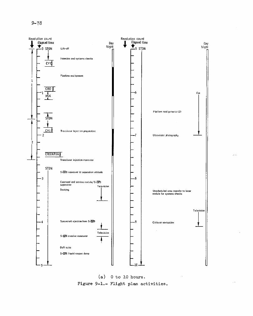
C11
_ur
=
F
°_
._o,..,.,,,_.JII
II
II
IJ
II
II
II
II
II
II
II
II
II
_,-i
)°o-g4_
orl
_'_
0F
-_
II
II
IJ
1I
II
II
II
II
I'_
II
II
_f
II
Ii
IJ
I_
__

9-79
Revolutioncount Revolutioncount
Elapsedtime Day 1 Elapsedtime Day_10 STDN Cisluna_navigation Night • _lq--15STDN Sl, pNight
B
m
_11 -- --22
-- Platform realignmentFuel celJ purge (oxygen)
Crew exercise --/
-- Waste water dump / --
-- m
-- 12 Lithium hydroxide --23 --canister change
-- Ultraviolet photography -- Eat
-- Crew exercise --/
__ Initiate passive thermal |control
_L--13 --24
-- m Lithium hydroxide canister change -- --Eat
Cycle film in panoramic andmapping cameras
-- 14 _2_ Electrophoresis demonstration
115 -- 126 -- --
(b) i0 to 26 hours.
Figure 9-i.- Continued.

9-80
Revolutioncount Revolutioncount
,_ Elapsedtime Day • Elap_edtime Day
_26 STDN Night V _'_31_STDN EatNight!
Crew exercise
_27 _32 Preparation for transfer to lunar module
m
m Pressurize lunar module
m
m
--28 _33 LU crew-transfer to lunar module
__ Lunar module
housekeeping
m
D
--Zg --34Terminate passive thermal control
Ultraviolet photography
m-- Communications
checkout
-- Platform realignments (2) /
__i_--30 _35 LM crew transfer to command module
-- Waste water dump
-- Fuel cell purge (hydrogen and oxygen)
First midcourse correction
Eat IniUate passive thermal controlm
tw
--31 -- _ _36 -- --
(e) 26 to 36 hours.
Figure 9-i.- Continued.


9-82
Revolutioncount Revolutioncount
$ Hapsedtlme Oay $ _apsedtime Dayw Night Night--", STDN Eat --56 STDN
-- -- Initiate passive thermal contro]Platform realignment
-- 1 BlstaUc radar experimentfrequency check
1 -- Eat
(Skylab food test)
ml
m52 Cycle film In panoramic Terminate --57and mapping cameras passive
thermal --control
i
UJtrav[olet photography !B
FueJ cell purge (oxygen)
l_ lj8 Lithium hydroxide canister change
Waste water dump
m 1
i Preparation for transfer to 1lunar module
/M craw transfer tO lunar module
=
m54 --59Communicationscheckout
"SI _p
I m
m
l LM crew transfer tO command module -
--55 --60Pressure garment assemblydonning/doffing exercise
m
m
m
= )m
" I---56- -- 66_--
(e) 51 to 66 hours.
Figure 9-1,- Continued.
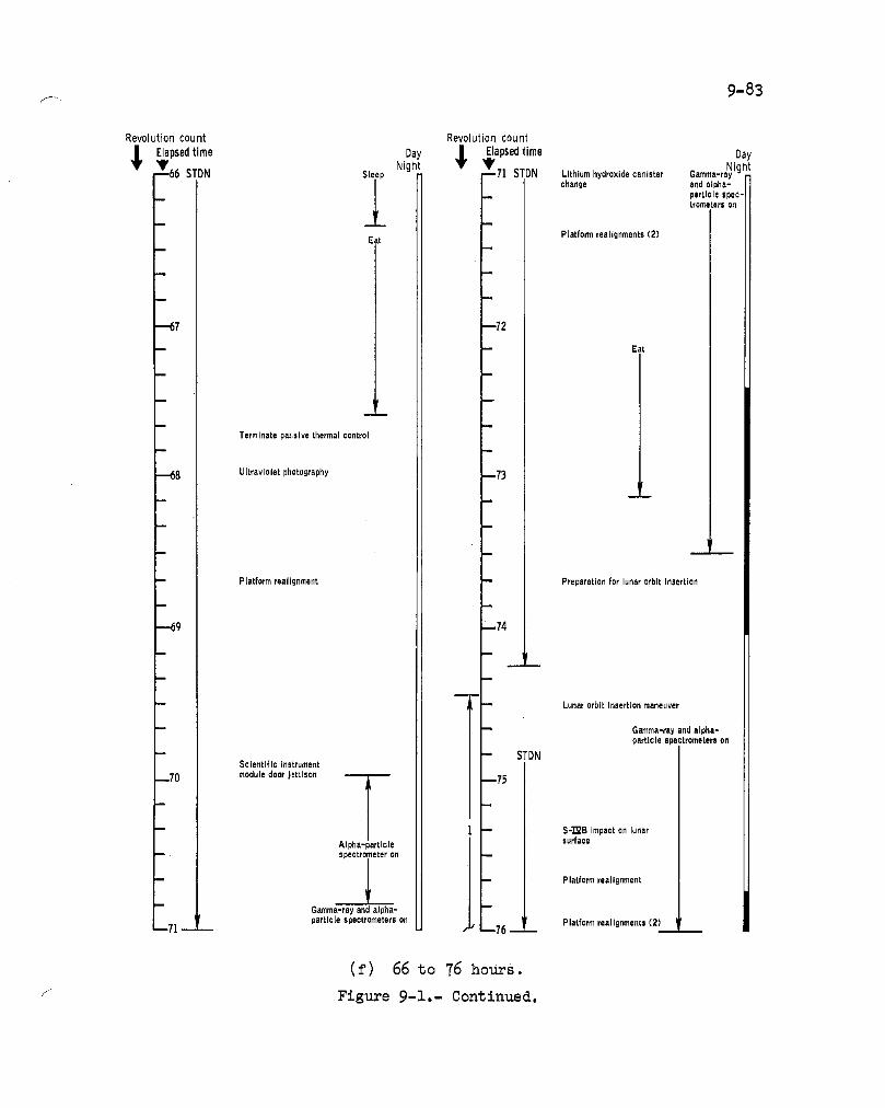
2"
i
oI o_
o__
I_"_
I|
II
|1
Ii
JI
II
II
iI
II
II
Im
tI
Il
i_
14_
-_
_
_o
__
o_.
p._4
o,.o
_I

9-84
Revolutioncount Revolutioncount
| Elapsedtime Day • Elapsedtime Day
_1_16STDN Gamma-rayandNight V _----81 Eat Gamma-ray,alpha-Night' f • particle, X-ray, and
l alpha-particle STDN l-- spectrometers on __ mass spectro_teters on
__ Fuel celt purge(hydrogen and oxygen)
_ Platform realignment-- Waste water dump
--77 STDN --82 Lithium hydroxidecanister change
B
-- 1' _ Sleep
-- Platform realignment
--]8 Prepare for descent "_3 STDN
orbit insertion /_
t
-- 5
Descent orbit STDNinsertion maneuver
--79 _91
I
-- STDN
Landmark tracking (J-2) B -- --
Gamma-ray andalpha-particleSpectronieters on
Universal tracking Eat
• r L
--80 (+X forward) __ --92
Solar monitor -- --
-- I door/tie-down Gamma -ray, alpha- J -- -- --particle, X-ray,
-- -- release Eat mass spectrometers
Gz_lma-
_ and laseraltimeter -- -_ ztY and
- 1 STDN alpha-particlePanoramic and spectrometers on
-- mapping cameras m
- _i_-- Gamma_ray,alpha-particle, X-ray, anc LM crew tzansfer
Universal h,acking mass SP_onCtrometers to lunar module, . --81 (-X forward) / J m_
(g) 76 to 93 hours.
Figure 9-i.- Continued. I

9-85
Revolutioncount Revolutioncount
_lvElapsedtime NightDay _ _lvElapsedtime NightDay"93 STDN Lunar module -- -- 98
l I activ.t,o,aod
checkout STDN
CSM platformI realignment
10 _t__Lithium hydroxide
canister change
Gamma-ray and
Undocking alpha-particle-- preparations spectrometer on
,
- --94 -- 99
- STDN -- --
-- Terminator
photography 1
11 - I
--95 -100 Rendezvous (CSM active)
STDN
Ir
14
r
--96 .... I01
-- Undocking and separation -- CSM waste water dump
STDN maneuvers
LM descent propulsionsyslem thrott[echeck
-- Landmark LM abortguidance
tracking system activation W
12 (landing | --
-- site) L.M platformrealignment
--97 --102LM abort guidancesystem aligned to STDN
-- primary guidance F --and navigation -- --
__ system 15 --
-- -- CSM/LM separation
-- -- CSM platform LM platformrealignment rea)ignment
13 tL -q8 ,L, _103-- --- CSM ctrcularization preparation
(h) 93 to 103 hours.
F±gu.re 9-]-.- Cont±nuecl..

9-86
Revolutioncount Revolutioncount
_ Elapsedtime Day ._ Elapsedtime Day_'103 STDN Night _._-108STDN_ -- LMcrewNight
-- c_ and laser altim-eter on
15 -- CSM circularization LM state vector --maneuver update T
-- Gamma- ay, alpha,[ particle, X-ray, i
I ' m Gamin; -ray and _ and mass spectrom- I-- alpha-particle 1 eters on
spectrometers on
--104 4109STDN
-- LM powered descent -- lrinitiation maneuver -- --
-- Landmark tracking
LM landing
Universal tracking _ Commaud Module(-X forward)
I Pilot sleep
16 -- ---- --l,
-- Command Module LM crew doff --
Pilot doff suit helmets and gloves
--105 I_ _110 STDNLM lunar surface
-- I' platform alignment
-- --P_noranlic
Mapping camera /t % _ "_-- and laser altimeter --
o11
--106 _L --115 LMcrewSTDN
-- LM crew -- --
Gamma-ray, X-ray, doff suits-- and alpha-particle LM crew --
spectrometers on; diebriefingmass spectrometer
-- outgassing LM crew I --eat __ _
11 -- j --
-- mSTDN
LM crew
--107 -- 116 briefing
• I
I' -- LM crew -- --
L sleepLM crew
18 - - don suits
' V __i_I --108 --- -- _ ,. --117___ __
(i) 103 to ll7 hours.
Figure 9-1.- Continued. --

F 9-87
Revolutioncount Revolutioncount
Elapsedtime Day ,_ Elapsedtime Day_---117STDNCommandMod,- Night j_, 9'122 STDN Mappingcamera Night
T LM crew prepare (25 ° forward -- --
.-L. ule PHot sleep for first extrave- obliques) JL
i__-- Gamma-ray, all_la-_ particle, X-ray, and
mass spectrometers
-- Gamma-ray, alpha- oilSTDN ;,article, X-ray,
_118 _nd mass spectrom- CMC clo( < ad -1_ __ ._ CSM zodiacaJeters on vanced 1 . mil ]ight photography
-- 48 sec al -- First extra-I18:04:19 vehicular
activity-- CSM terminator
photography t
23 -- CSM platform -- _" --realignment
-- -- Mapping cameraSTDN (40 ° south
-- CSM fuel cell purge _ obliques) Tele_ isi4
(oxygen and hydrogen) /
--].19 --124 Command Module-- -- Pilot eat
-- CSM waste waterdump
-- Command ModulePilot eat First extra-
vehicular-- -- -- activity _ _ .
m
_ STDN
--120 Television --125_ ._ __I'
- 't-- Mapping camera !
m m (40 ° north
I I obliques)
-- CSM Lerminato_' a
24 photography Ji
Lithium hydroxide STDNcanister changem
--121 --126
CSM Gum nebula CSM ultra-
i violet pho-photography Post-extra-
- -- tography vehicularMapping camera -- -- activity
(25 Qforward obliques) /
" _J__ J_I STD____ _r I r CSMGegenschein--122 .... ., --127- __ calibration __ __
(j) 117 to 127 hours.
_ Figure 9-i.- Continued.


9-89
Revolutioncount Revolutioncount
_, Elapsedtime Day ,_ Elapsedtime DayNight Night,f "--141 CommandModule IM crew r --140 STDN -- -Gamma-ray, aJpba-
34-- Pilot sleep T d°ni uits CSMorbita] particle, x-ray and
___ science vis- massspectrometers
i -- Jal sightingsI on
__ __ 1 1 Mapping camera
I_ (40 ° north |
obliques)STDN 3 CSM plat-
- If ........ lign-j j____ CSM t -Ji / .....,trao -"-- ing (+X for-
- Conlma,!dMod- / ward)ule Pilot exer- |
LM crew
--142 preparefor --147 cise Gamma-ray,alpha-second ex- l particle, X-ray_ massspectrometers, andtravehicuiar -- -- -- laseraltimeter oll
35 activity j , CSM terminatorphotographym
iI
CSM Gegenschein -- STDN-T-- Secondex-
photography L _ travehicularactivit'
-- -- Command [Module
--143 CSM Gegens:hein Ji --148 Pilot Telphotography : eat
-- Secondex- _ ] - Panorm]_ic-- travehicular :
- STDN:: activity ---.El T
: T --- CommandModule m Mapping
Pilot eat cameraon
36 I CSM solar-- _ corona pho-
tography
-- Tele isior -- Panoramic
- -- STDN ---_
CSM deep space-- measurements
m145 CSM hthium by- --150dioxide canisterchange
"_ I Post-extra-Mapping camel _ vehicular(40 ° north T activitySTDN obliques) i I-- Gamma-ray,alpha-
sciellCepho- -- -- spectrometerson
-- purge(oxygen)
146 ....... 151
(i) 141 to 151 hours.
Figure 9-i.- Continued.

9-90
Revolutioncount Revolutioncount
_.}apsedtime Day + Lapsedtime Day,,w -- Nigl" Night
31;.... CSMwast. ..,,..,..+P°st'e+a"'r' --,,°s'rDNT- l LMcrew
water dump vehicular I | +_ sleep
_ °_'["Y Z2 --- I
STDN-- _,_+ _ _ _-- Gamma-ray,alpha- -- I MHF hi-
particle andmass static ¥
spectrometerson LM crew Z _ ' radar test ---- doff suits --I
Command
-- --| I Module-- -- Pilot sleep
--152 _lstatlcradar LM crew _ "163 Gamma-ray, LM crewb / debriefing alpha-particle, eat
I _ I X-ray, and
40 l STDN massspec--- trometerson
-- LM crew --
'I !
_ LM crew
cam universal ' 1 briefing--153 tracking (-X forward) m1_4
, T Parteh+,f,-- _ -- supportsys-
I temrecharge_ ,_ CaM universal -- --
$TDN I --_ tracking LM crew
Photography _P (+X forward) Gac m-ray, donsuits-- of massapec- -- -- alpha-particle, I
trometerboom CSM platform X..ray andmass I-- realignment specttemetera I
tConference etel )n
-- CaM orbital | ' I
B
science via- ._ -- --
--154 ual slghtlngs , _ --165 iLM crow
++41 -- -- STDN thirdextra-vehicular
CaM terml- activity
natorphoto- --
graphy _ -CommandModule LM crew MapePlang°nPilot eat sleep Mass spec-tron_ter m-
l -- -- tractiontea__ _
J,
--155 ,7 --1(_ Co, ,man( rhlrd _xtr=Mo lule /ehlct lar
CaM orbital PII _teel-- -- sciencepho" Gamma-ray,alpha- ctivll
tography particle, X-ray and
massspectrometers Mass spec-
/STDN _ .___ ' tr_e+r at. ._ eL _ -- 5 feet Television
42 VHF hi- I
static radar
t 1'I -- C-'SMsolar
-- camerapho- I1156 I -- +_ --167 tography -- - --
(m) 151 to 167 hours.
Figure 9-1.- Continued.

9-91
Revolutioncount Revolutioncount
Elapsedtime Day _i_ Elapsedtime Oay_B' _1].67 Mappingcamera Night -- '_'--172STDN CSM platformm -- Night(40 ° south" / "
obliques) Oamrr -ray,1
Ipha mr- LM equipmentSTDN I title, (-ray Jettison
1 I andrr SS
CSM lithium al,_act_. 50 _48 - hydroxide can- ere l
Ister change [Mass spat- LM equipmenttrometer at5 fee _ stowage
l GSM orbital I _ Gamma-rayandsciencevisual || _ alpha-particle
--].68 observations _ _ 1 I].73 spectrometerson
CSM platform _ STDN LM guidance-- realignments_.J._
(3) computerpower-up
1 CSM maneuverto plane 1 1
-- -- changeattitude
-- Third ex- 1 LM creweatCSM fuel cell purge travehlc- /(hydrogenandoxygen) u[arac- .J_l tlvltyCSM wastewater dump 51
1 LM lunar surface1 CSM preparationfor lunar platformalignment
orbit planechange--169 Te --174 CSM platform
vie realignment
l CSM lunar orbit planechangemaneuver CSM crew op-
tical alignment- STDN r sight callbcatlon LM cabinciean,.up
l" for launch
-- _ -- LM launchprepe-
CSM platform _ rations
-- realignment m
49 W LM VHF voicel check1 m
A LM lunarsurface
--170 117 5 pletfom alignment
Gamma,ray and STDN LM prelaunch-- _Jlpha-partlcle _ _ switchchecks
sp_ctrameterson
CSM VHF I_voice check /
1 _ Television-- LM lift-off from
lunar surface ±1 LM orbitalInsertion
_ CSM platform Rendezvousrealignment
32--171 CSMGegenschein --176
photography
CSM deep-space
measurementSTDN _ I LM terminal
30 Post-extra- phaseInitiation
Module
vehicular Tactivity LM first mldcourse
1 correction
ALM secondmldcourse
, _ _3 'I correction•172 _ _177 -- --
(n) 167 to 17T hours.
Figure 9-i.- Continued.
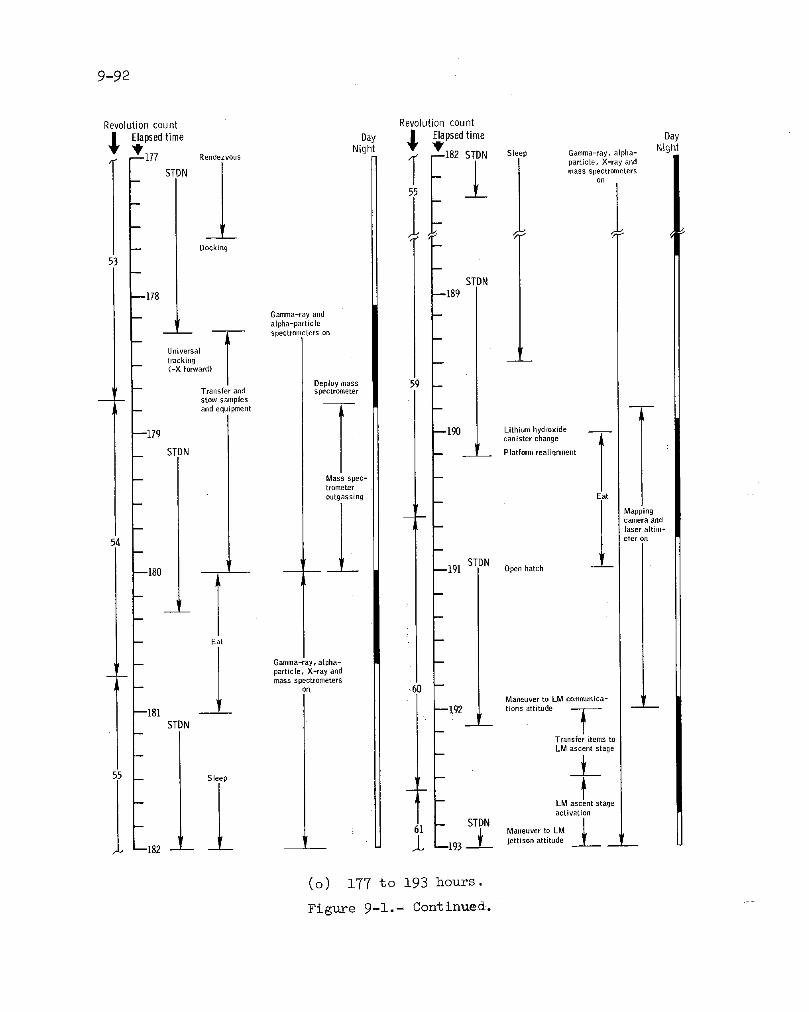
9-92
Revolutioncount RevolutioncountElapsedtime Day • Elapsedtime Day
' Night Y _ Night---_177 Rendezvous 182 STDN Sleep Gamnla-ray, alpha-
parUc[e, X-ray andI
STDN / mass spectrometers
lon
_L
Docking
53
STDN--178 --189
Gamma-ray andF alpha-particle
-- -- -- T specLrometerson
,IUniversal
tracking w-- (-X forward
Deploy nlass-- Transfer and spectrometer
-- -- stow samples
F --- and equipment -- j
--179 --190 Lithium hydroxide __canister change
STDN _ __l Platform realignment
Mass spec-trometer
outgassing Eat
L Mapping
camera andlaser altim-
54 eter On
--180 -- _ .... 191 Open hatch
Eatt
F -- l Gamma-ray, alpha- --
-- -- ___ particle, X-ray andI- .....+o+o++Maneuver to LM communtca- I
--181 --!9 2 tions attitude --
STDN _ -- --Transfer items to
-- LM ascent stage
55 Sleep
I - _Mas_ntstag°activation
L i il -- STDN M ....... to LM' ---L _L* --1()3 __..L jettison attitude.._I
, --182 -- -- -- -- --
(o) 177 to 193 hours.
Fig_e 9-i.- Continued. "-


9-94
Revolution count Revolution count
Llapsedtime Day $ Elapsedtime Day_/._ STDN _ Gamma-ray,alpha-particle Night _-_:'215STDN Cabinpreparationsfor Night
and X-ray spectrometers on transearth extravehicular-- _ -- activity
Scorpius X-1 Television from-- measurements command and
._ service module
Initiate passivem
a thermal control _Television fromlunar surface
---f- -216 ___1__Gamma-r_ i and Extravehicular equipment preparation
-- alpha-particle --spectrometers on
-- m
Sleep -- Don suitsI
'I--212 _217 Maneuver to extravehicularactivity attitude
mIII
/
-- | -- Co_lmand Module Pilot don
_J extravehicular equipment
1
1 Terminate passivethermal control
_213 --218
I 1 Suit integrity check
Platform realignment (all crewmen)m
-- Mappinq camera -- Cabin depressurizaUon and -'_on batch opening
T-- -- installation of television and
Lithium hydroxide data acquisition cameras
--214 canister change 1219
Fuel cell parge -- -- - Camera casette retrieval and(hydrogen and oxygen) scientific instrument module
-- inspection
-- Microbial response in spaceSecond mideourse environment experimentcorrection 1r
Eat __ __
Maneuver to l
thermal attitude -- Ingress and hatch closing
1215 -- - --220 w --
(q) 203 to 220 hours.
Figure 9-i.- Continued.


9-96
Revolutioncount Revolutioncount
Elapsedtime Day | Elapsedtime DayVNight Night--:-236STDN Terminatepassive --241STDN Crewexercisethermal control
-__ -- Platform realignmen Gamma_'ay andalpha-particle
-- specLr( eter!m
-- ] Gamma-ray and --alpha-particle
--237 Eat spectrometers on --242 X-ray asbronomical source __ __pointing (Scetpius X-l)
Super-galacticauxiliary passive
-- -- thermal conLro[
-- _" Eat
-- -- / Scorpius X-1
1 measurements
--238 Visual light flash _243phenomenon obser-
-- vations -- Gamma-ray, alph_parLicle and X-ra_spectromeLers on
_ _-- _ Televised press
conference
--239 -- --244
m Lithium hydroxide m
canister changem
i
-- Fuel cell purge El liptic(oxygen and auxiliary Entry monitor
= hydrogen) passive -- system entry checkthermalcontrol
-- Waste water dump
--240 Crew exercise --245 Jet firing Lest
-- -- Skylab contamina-tion photography
alpha-particle
--241-- : 6----]-- -- on
(s) 236 to 246 hours.
Figure 9-1.- Continued.
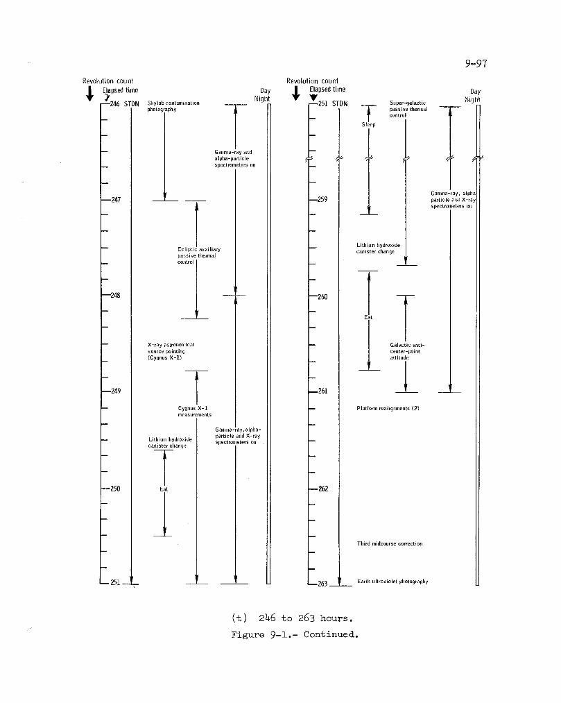
9-97
Revolution count Revolution count
F.lapsedtime Day _I Elapsedtime DayNight Night--Z40 STDN Sky[abcontanlination _'251 STDN -- Super-galacUc
-- -- control
Sl _ep
-- Gamma-ray and --
alpha-particle _ _ //__ spectrometers on _
- - Ii GaJmna-ra alpl
--247 -- --259 particleandX-ray
l spectrometers on
_ _ __m
-- Ecliptic auxiliary -- Lithium hydroxidepassive thermal canister change
_ control J __ --
Ir
--248 -- -- --260 --T--II
T__ E
-- X-ray astronomical -- Galactic anti-source pointing oetlter-point(Cygnus X-]) attitude
- - _L AT--249 --261 t
-- Cygnus X-i B Platform realignments (2)measurements
Gamma-+ay_alpha-particle and X-ray
-- Lithium hydroxide spectrometers on --canister change
--250 Eat --262
Third midcourse correctioa
__21r 'I _-- 251 ..... --263 -- --__ Earth ultraviolet photography
(t) 246 to 263 hours.
Figure 9-1.- Continued.
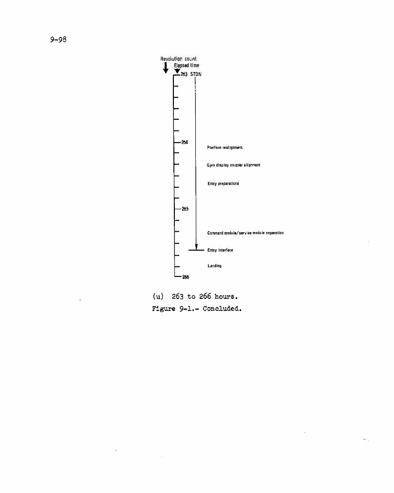
9-98
Revolutioncount
,_ Elapsedtime_' 263STDN
m
m
_2_Plat form realignment
-- Gyro display coupler a[ignmen_
m
Entry preparationsm
m 265
B
-- Command module/service module separation
r
_ Entry Interface
-- Landing
m266
(u) 263 to 266 hours.
Figure 9-1,- Conclud.ed.,

10-1
lO.0 BIOMEDICAL EVALUATION
This section summarizes the medical findings based on a preliminary
analysis of the biomedical data. A total of 797 1/2 man-hours of space-
flight experience was accumulated during the ll.-day mission. The flightcrew health stabilization program implemented on this mission was similar
to that used for Apollo 15, except for the addition of a control group.The crewmen remained in good health throughout the mission.
10.1 BI0_DICAL INSTRUMENTATION AND PHYSIOLOGICAL DATA
The quality of the physiological data obtained throughout the mis-
sion was good. The infrequent degradations of physiological data were
caused by loose biosensors, with restoration of good data upon reappli-
cation of the sensors. Physiological data losses resulting from trappedair under the elec_rodes were not experienced on this mission becausethe electrodes were modified with small vents.
All physiological measurements were within expected ranges. The
crew heart rates _Aring launch ranged from 77 to 125 beats per minute.
The heart rates of the Commanders a veteran of three space flights, were
generally lower th_l those of the other two crewmen, who had not flown
previously. The Commander's heart rates ranged from 70 to 104 beats per
minute during lunar descent and from 80 to 105 beats per minute duringlunar ascent (figs. 10-1 and 10-2). The metabolic rates of the Commander
and Lunar Module Pilot during the three lunar surface extravehicular per-
iods were correlated with the heart rates (figs. 10-3 through 10-5). A
summary of the average metabolic rates and averaged heart rates for thefour periods of extravehicular activity is presented in table 10-I.
The Command _dule Pilot's relatively high heart rate (table 10-I)
during the transearth extravehicular activity was attributed to excite-
ment rather than high workloads or cardiovascular decondltioning. Post-
flight exercise tolerance tests on the Command Module Pilot showed onlyminor cardiovascular deconditioning and verified that the high heart rate
was Caused by excitement rather than cardiovascular conditioning.
Table 10-II shows that the prelaunch metabolic rate predictions for
lunar surface activities were slightly lower than the actual values meas-
ured. The metabolic rates were higher for the Lunar Module Pilot.

10-2
TABLE i0-I.- AVERAGE HEART AND METABOLIC RATES
DURING EXTRAVEHICULAR ACTIVITIES
Metabolic
Heart rate, Rate,
Activity beats/min Btu/hr
First extravehicular activity
Commander 84 872
Lunar Module Pilot 101 lO13
Second extravehicular activity
Commander 84 784
Lunar Module Pilot 84 827
Third extra,vehicular activity
Commander 86 815
Lunar Module Pilot 87 825
Transearth extravehicular activity
Commander (a) (a)
Lunar Module Pilot (a) (a)
Command Module Pilot 120 <2200
aNo data

10-3
TABLE lO.II.- ACTUAL OBSERVED METABOLIC RATES (BTU/HR)COMPARED WITH PREDICTED
Metabolic rates, Btu/hr
Commander Lunar ModuLe Pilot Both crewmenLunar surface activity
Premission Premlssion PremissionActual Actual Actual
prediction prediction prediction
Lunar roving vehicle traverse 508 550 _54 550 h82 550
Geological station activities 889 950 982 950 936 950
Overhead 987 1050 1023 1050 1006 1050
Apollo lunar surface experi-
ments package activities 823 950 1024 950 924 950
All activities combined 818 907 901 907 859 907
n° iPower -- i' Lunar
i descent /_ ii landingi
100 _initiation-- iE
"F=
/80 _ _'_
70 i I !
60 il ii04:17 104:19 104:21 104:23 104:25 i04:27 I04:29 104:31 104:33 104:35
Time, hr:min
Figure 10-1.- Heart rates of Commander during lunar descent.
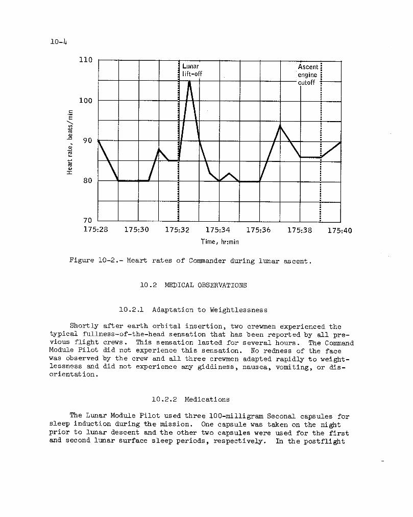
10-4
Ii0
Lunar Ascent
lift-off engine i
cutoff:i00
-r
11
70
175:28 175:30 175:32 175:34 175:36 175:38 175:40
Time, hr:min
Figure i0-2.- Heart rates of Commander during lunar ascent.
i0.2 MEDICAL OBSERVATIONS
10.2.1 Adaptation to Weightlessness
Shortly after earth orbital insertion, two crewmen experienced the
typical fullness-of-the-head sensation that has been reported by all pre-vious flight crews. This sensation lasted for several hours. The Command
Module Pilot did not experience this sensation. No redness of the face
was observed by the crew and all three crewmen adapted rapidly to weight-
lessness and did not experience any giddiness, nausea, vomiting, or dis-orient at ion.
10.2.2 Medications
The Lunar Module Pilot used three 100-milligramSeconal capsules for
sleep induction during the mission. One capsule was taken on the night
prior to lunar descent and the other two capsules were used for the first
and second lunar surface sleep periods, respectively. In the postflight

I i II_d lunar roving vehicle j
eployflag i'floadexperimentspackage• _.setfar ultravioletcamera• iTraverse toexperimentspackagedeploymentsite
HI nterconnectexperimentpackages ]__ __ 71 m eploypassiveseismicexperiment
--T mDeploy centralstation I Il _ ploylunarsurfacemagnetometeri| i iDeployactiveseismicexperiment
__ __ .__L_ __ IDeploy geophoneforactiveseismicexperimentNotes: --Deploy mortarpackage i I
1. Biomedicaldatastartedat 120:04and geologytraverseendedat 123:37. station1
2. Calculatedmetabolicratesbelow _,ctivifiesatstation1350Btulhraresubjecttolarge Traversetostation2errorsdueto non-linearitiesof Activitiesatstation2thecalibrationdata. ITraversetostation3
1690 110 LunarGrandPrixandreturn tolunar modul_ I
I A 'erheadl
it!_ 1110 _ i
- AA , r
< 350 - 70
60 __ I I120:.00 ]20:30 121:00 121:30 122:00 122:30 123:00 123:30 124:00 124:30 125:00 125:30 126:00
Time,hr:min
(a ) Commandero
Figure 10-3.- Heart rates and calculated metabolic rates during first extravehicular activity. Ik_

o|
2154
1861
1578
1274
E 981
688
3_
350
12(}00 12(}30 12hO0 12h30 122:00 122:30 123:00 123:30 124:00 12430 12_00 I_30 126:00 12&30
Time,hr:min
(b) Lunar Module Pilot
Figure i0-3.- Concluded
) i,

Preparef!r traverse;_ion4
Activitiesat station4Traverseto station5
Activitiesa on5Traverseto station6
tiesat station6I I I I Trave on8 I I I I I
1 Aclivitiesatstati°n8 I
rraverseto station9
Notes: -- Activitiesatstation]'raversetostation10
endedat 149:58. 01646 110
,- 1313 I00
== (::
979 " 90.-_ _N _E
646 _ 80__ =
t_
_< 350 70
60143:0_ 143:30 144:00 144:30 145:00 145:30 146_00 146:30 147:00 147:30 148:00 148:30 149:00 149:30 150:00 150.30
Time,hr_min
(a] Commander.
Figure i0-4.- Heart rates and calculated metabolic ratesI
during second extravehicular activity.
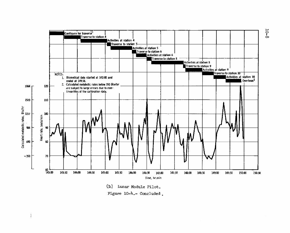
i-t
' I1 I
IConligure for traverse I iOto station, O:_
• • I atstation4m Activitiesat station 5
BTraverse to station 6
• divities at station 6
Traverseto station 8 I' Activities at station $Traverseto station 9
i _tdivities at station 9......... lTraverse to station ]0-- --NOTE_:
]. Biomedicaldata starl_l at 142:00and lActivities at station 10endedat ]49:.58. -- _ Overhead1
2. Calculatedmetabolicrates below350 Btu/hr1864 120 -- , , , • •are subject to largeerrors due to non-linearities of the calibration data.
1570 110 ' ' ' '" '
,All°" " -4 i ,/t_>
. 9o .... i fiLl 'VII
- iI :
, i v-60 , I143:.00 143:.30 144:00 144:30 145:00 145:30 146:00 146.30 147:00 147:30 148:00 148:30 149:00 14t30 150:OO 150:30
Time, hr:min
Cb_ Lunar Module Pilot.
Figure 10-4.- Concluded.

1_2 1_
1619 llO
N 1_6 lO0c
"_ 952 "__ 90
E
610 := 80
<:350 70
60165:.30 166:00 166:.30 167:00 167:30 168:00 168:.30 169:.00 169:.30 170:00 170:.30 17]:00 17]:30
Time,hr:min
(a) Co_m_ander. o|
Figure 10-5.- Heart rates and calculatedmetabolicratesduring second extravehicularactivity.

• Configurefortraverse I
-- IActivitiesatstation12 ]BBTraversetostation131 • Activitiesatstation13 J
m mTraverse tostation10'NOTES'_-_. -- -- 1 _.Activities atstation10
1. Biomedicaldatastartedat 165:45and BJ.raversetolunarmoduleendedat 171:24. iActivities at lunarmodule
2. Calculatedmetabolicratesbelow350Btu/hr erheadI .aresubjectto largeerrorsdueto non-linearitiesofthecalibrationdata. i
I
2077 130 '
i
II
1784 120 ' ' ' '
/
1490 110 ' ' _ •
_=
"E i00 ' ' ' ' •1197
. . z . . IL
'._610 80 :
<350 70 N
60 J165:30 166:00 166:30 167:00 167:30 168:00 168:30 16_.00 169:.30170:.00 17_30 171:00 171:30
Time,hr:min
0oi Lunar Module Pilot
Figure 10-5.- Concluded.
I i/

I0-ii
medical debriefing, the Lunar Module Pilot reported that the Seconal was
effective in producing a rapid onset of good sleep. The only other itemfrom the medical kits used by the crew was skin cream to reduce irrita-tion at the biosensor sites.
10.2.3 Sleep
In contrast to the Commander's Apollo I0 experience, he slept well
during all the scheduled sleep periods. Typically, the Commander's sleepwas uninterrupted for 4 to 5 hours after which he would awaken, get a
drink of water, and return to sleep for the rest of the night. The Lunar
Module Pilot slept well during all sleep periods except the first. How-
ever, the Command Module Pilot reported that he slept uninterrupted only
two nights of the mission and, characteristically, would awaken about once
every hour. He also stated that he never felt physically tired nor had
a desire for sleep.
On this mission, displacement of the terrestrial sleep cycle ranged
from 30 minutes to 5 hours during translunar coast, and from 3 1/2 hours
to 7 hours during the three lunar-surface sleep periods. This shift in
the sleep cycle on the lunar surface contributed to some loss of sleep;
however, this was the first mission in which the lunar module crewmen ob-
tained an adequate amount of good sleep while on the lunar surface. Thisassessment of the amount of sleep is based on a correlation of heart rate
during the mission sleep periods with preflight sleep electroencephalo-
grams and heart rates. The estimates of sleep duration made by ground
personnel were in general agreement with the crew's subjective evaluations.
10.2.4 Radiation
The personal radiation dosimeters showed the total absorbed dose to
the crew was approximately 0.5 rad at skin depth. This is well below thethreshold of detectable medical effects.
This was the first Apollo mission in which three minor solar flares
occurred. Althoug_h the nuclear particle detection system registered a
slight increase in proton and alpha particle fluxes, no measureable ra-diation dose increment was received by the crew from these flares.
i0.2.5 Cardiac Arrhythnn'Las
Both Apollo _K5 lunar surface crewmen demonstrated cardiac arrhythmias
(irregularities) :following completion of their extravehicular activities.
Laboratory data obtained after the flight showed a significant decrease in
exchangeable body potassium levels. This deficiency of body potassium was

10-12
considered to be an important factor in the genesis of the Apollo 15 ar-
rhythmia. As a result of these findings, several changes were instituted
on this mission to reduce the likelihood of inflight arrhythmias and to
further investigate the causes of body potassium loss during space flight.These changes included the following:
a. A high-potassium diet was instituted, commencing 72 hours priorto launch and continuing until 72 hours after the mission.
b. A metabolic input/output analysis was made with accurate dailyinflight reporting.
c. Anti-arrhythmic medications (procaine amide, atropine, and Lido-caine) were provided in the onboard medical kits.
d. A daily high-resolution electrocardiogram was taken from eachcrewman.
No medically significant arrhythmias occurred during the mission, butisolated premature heart beats were observed in two of the three crewmen.
The fact that the frequency (less than one per day) and character of these
prematurities remained consistent with electrocardiographic data obtained
on these same crewmen during ground-based tests clearly indicates that they
were not related to or resultant from space flight. Postflight exchange-able body potassium levels were normal and indicate that the increased die-
tary potassium intake, discussed in section 10.2.7, apparently was effect-
ive in maintaining a state of normal potassium balance. It is not possibleat this time to equate normal levels of exchangeable body potassium with
suppression of cardiac irritability and prevention of arrhythmias. For ex-
ample, fatigue, stress, or excitement can also produce arrhythmias. Theabsence of arrhythmias on this mission can best be attributed to a combina-
tion of factors, such as high dietary intake of potassium, better fluid and
electrolyte balance, more adequate sleep, and less fatigue.
1012.6 Water
The crew reported that the taste of the drinking water in both the
command module and the lunar module was good. The crew experienced dif-
ficulty injecting the chlorinating solution during the third daily water
chlorination in the command module. A small amount of chlorine leakage
occurred and is attributed to a failure of the inner bag of the chlorine
ampule. Section 14.1.7 contains a discussion of this anomaly. The lasttwo inflight water system chlorinations were not performed because the in-
jection device had been misplaced. Postflight analysis of the command
module water showed an increase in bacterial counts and no free chlorine ;however, no pathogenic microflora were found.

f 10-13
The use of the bacterial filter in the lunar module was not required
on the mission because the preflight iodine residual in the potable water
supply was adequate for maintenance of sterility throughout the flight.
The crew reported that there was no dissolved gas in the command mod-
ule water system during the first three days of the mission. Thereafter,
however, sporadic occurrences of gas bubbles, particularly from the hotwater port, were noted. No interference with food reconstitution resulted
from these gas bubbles.
i0.2.7 Food
Menus were designed to provide a minimum of 130 milli-equivalents of
potassium per man per day for this mission. Foods high in natural potas-
sium were selected and some beverages were fortified with potassium glu-
conate. The menus supplied approximately 2600 +i00 kilocalories per man
per day. This value was based on the calculated nutritional requirementsof each crewman.
For the first time on an Apollo mission, a preflight and postflight
control diet was provided to the crew. The purpose of this control diet
was twofold; to insure that each crewman was in an optimum nutritional
state prior to launch, and to facilitate postflight interpretation of
medical laboratory data. The control diet was initiated three days prior
to flight and terminated two days after recovery. In addition, food and
fluid intake was closely monitored during the flight.
Preliminary estimates of the inflight food consumption, based on crew
reports, indicate that an average of 2150, 1408, and 1900 kilocalories perday were consumed by the Commander, Command Module Pilot, and the Lunar
Module Pilot, respectively. Postflight, the crew commented favorably on
the quality of the food, but stated that they could not consume the quan-
tity provided. They also stated that they had an inadequate amount of
time to prepare and eat their food because the meal periods were contin-ually interrupted and shortened by other activities.
Six in-suit beverage assemblies were included in the lunar module
food system. Each assembly consisted of a drinking device and a 32-ounce
bag of potassium-fortified orange drink. Several minor problems with theuse of these assemblies were experienced. Inadvertent activation of the
tilt valve by the conm_unications cable or the microphone caused some re-
lease of fluid into the Lunar Module Pilot's helmet prior to lunar land-
ing. Prior to the first period of extravehicular activity, the Commander
installed the in-suit beverage assembly after donning his pressure suit
and could not properly position the assembly. Thus, he was unable to con-
sume any fluid during the first extravehicular activity. The Lunar Mod-
ule Pilot encountered no difficulties and drank 32 ounces of water during

10-14
this time. On the second and third periods of lunar surface activities,
each crewman consumed the fortified orange drink. In-suit food bars were
not used during extravehicular activities.
_ Four different types of Skylab food packages were evaluated for func-_jl tion under weightless conditions by each crewman. These included a rehy-
dratable soup package, a beverage package, a peanut wafer package, and a
liquid table-salt package. The crew suggested improvements of some of theSkylab food packages.
10.3 PHYSICAL EXAMINATIONS
Each crewman received a comprehensive physical examination 29, 15,
and 5 days prior to launch, with brief examinations conducted daily duringthe last 5 days before launch. Comprehensive physical examinations con-
ducted shortly after landing showed that the crewmen were in good health.
The body weight losses incurred by the Commander, Command Module Pilot,and Lunar Module Pilot during the mission were 7 1/2, 6 1/2, and 5 1/2
pounds, respectively. All crewmen suffered varying degrees of skin irri-
tation at the biosensor sites. This skin irritation resulted principally
from the crew's desire to wear the biosensor harnesses continuously in or-
der to save the long donning/doffing time (15 to 20 minutes) required.The skin irritation subsided within 48 hours without medical treatment.
The Co_nander had some sinus congestion which responded promptly to medi-
cation, and also a slight reddening and retraction of the right eardrum.
In contrast to Apollo 15, the crew returned to their preflight base-
line levels in lower body negative pressure measurements and bicycle er-
gometry tests by the third postflight day. The response pattern of these
tests, unlike Apollo 15, was consistent with other Apollo missions.
The lack of a significant decrement in the Command Module Pilot's
exercise performance was a surprising postflight finding. Because of the
high degree of preflight aerobic capacity demonstrated by this crewman,
a significant postflight decrement had been anticipated.
10.4 IMPROVED GAS/WATER SEPARATOR AND FECAL COLLECTION BAG
The improved gas/water separator was not evaluated because a struc-
tural failure of the device allowed water leakage and precluded the unitfrom functioning properly. Section 14.3.3 contains a discussion of this
anomaly.

10-15
The improved[ fecal collection bags were evaluated by the crew. The
lap belt and stiffened seat flange were found to offer no particular ad-
vantage over the existing system. The modifications made on the finger
cot did not improve its function.
i0.5 APOLLO TIME AND MOTION STUDY
Analysis of the lunar-surface traverses on level surface and down-
hill produced findings closely paralleling those of Apollo 15. Carrying
of bulky equipment, such as the Apollo lunar surface experiments package,
resulted in a significant increase of metabolic rate. During one of the
long traverses, the metabolic rates were similar, 1112 Btu/hr and 1185
Btu/hr, with one crewman using a conventional walking gait and the other
a hopping gait, respectively.
A comparison of metabolic data from ground-based training tasks and
lunar surface tasks showed that the metabolic rates were about 90 percent
higher during the training sessions. The major contribution to the higher
ground-based metabolic rate is the i00 pounds of extra weight carried by
the crewman. However, the total metabolic cost of the lunar surface tasks
was only l0 percent lower than for ground-based training. The fact that
the lunar surface tasks were spread over a longer period of time accountsfor the small total difference.
10.6 STEREOMETRIC BODY VOLUME MEASUREMENT
Body volume measurements were performed 15 and 5 days prior to launch
and immediately after recovery. The stereophotogrammetric method was used
to obtain front- and back-view stereophotographs of the crewmen. The pho-
tographs were then analyzed to derive the precise displacement of a large
number of coordinates from the body reference plane. The coordinates were
used to compute an exact volume of the three-dimensional image of eachcrewman.
Postflight testing showed that the Lunar Module Pilot had a bodyvolume decrease ,of 2.5 liters and that the Colmnand Module Pilot had adecrease of 6.9 liters. Unexpectedly, the C_nmander showed no net loss
of body volume even though he was the smallest crewman and had lost themost weight during the mission. Observation of body density change to-
gether with known caloric deficits would imply that the losses of fattytissue predominated in the lunar surface cre_nen, whereas the CommandModule Pilot lost proportionately more body water.

i0-i6
i0.7 vESTIBULAR FUNCTION TESTS
Vestibular function tests were performed because of the transitorypostfllght vestibular disturbance experienced by one of the Apollo 15crewmen and to fulfill the need for better quantitative data on the ef-fects of weightlessness on the vestibular system. Two different typesof tests were performed. The first test evaluated the postural stabil-ity with and without the aid of vision. All crewmen were within normal
limits during preflight tests. However, three days after recovery, twoofthe crewmen exhibited a significant decrement when deprived of allvisual sensory cues. Performance was similar to the preflight baselinewhen these crewmen were retested one week after landing.
The second test consisted of graphic recording of nystagmus (eyemovement) induced by water irrigation of the right and left auditory ca-nals. The water used was at temperatures of 3h.0° C and 35.5° C. Twoof the crewmen displayed apparent hypersensitivity of the semicircularcanals during postflight testing, as evidenced by an increase in the fre-quency of nystagmus and an increase in the slow-phase velocity of caloric-induced nystagmus. Repetition of this test one week after recovery indi-cated that these crewmen had returned to normal baseline conditions.

S ll-1
ii.0 MISSION SUPPORT PERFORMANCE
ii.i FLIGHT CONTROL
Flight control provided satisfactory operational support for all
areas during the _?ollo 16 mission. Ground facility difficulties exper-
ienced during this mission were resolved satisfactorily with no effecton the mission.
The S-IVB stage, the command and service module, the lunsa• module,
and the lunar roving vehicle all had some systems problems which required
special work-around or management procedures. These problems ranged in
seriousness from a mere nuisance to a potential mission termination priorto the lunar landing.
The lunar landing was delayed about 5 3/4 hours while resolution of
a service propulsion system problem was obtained. This delay caused a
major impact on the mission timeline; consequently, a new flight plan had
to be developed. The lunar surface portion was relatively easy to define -
the major issue being how many extravehicular activities could be accomp-
lished. The resolution of this question depended on the lunar module con-
sumables analysis and a management decision regarding crew work/rest cy-
cles. Since a third extravehicular activity was available, even thoughit was only 5 hours' duration instead of 7, the lunar surface activities
were not greatly perturbed.
The flight plan revision for orbital operations required that planned
activities be moved to different times or orbits. However, since the or-
bital events must occur at specific times, the updating of the crew had
to be accomplished by dictating each specific change. This was a labor-
ious and time conm_uing process. It also required a great deal of time
to prepare the flight plan updates, and in at least two instances, the
updates were not completed in time to allow an adequate review by the
entire flight control team prior to being read to the crew.
A contributing factor to the orbital operations planning difficulties
was the decision to perform transearth injection a day earlier than orig-inally planned. This resulted in a loss of one day of lunar orbit science
experiment operations, and therefore, major changes were made in the flightplan to accomplish as many as possible of the higher priority items.

11-2
11.2 NETWORK
The support of the Space Flight Tracking and Data Network was good
for the Apollo 16 mission.
There were three significant communications problems that caused a
loss of data. They were: system failures at Monrovia, Maryland, switch-
ing station prior to lift-off; poor performance of the communications pro-
cessor at Goddard; and the inability of the Jet Propulsion Laboratory 210-
foot Mars station to process lunar module high-bit-rate data when the lu-
nar module was transmitting on an omnidirectional antenna and the con_nand
and service module was transmitting on the high-gain antenna.
During the period between the Apollo 15 and Apollo 16 missions, the
Space Tracking and Data Acquisition Network and the Manned Space Flight
Network (MSFN) were combined into a single network to support both manned
and unmanned flights. The designation of the combined network is the
Space Flight Tracking and Data Network (STDN).
11.3 RECOVERY OPERATIONS
The Department of Defense provided recovery support for the Apollo 16
mission. Recovery ship support for the primary landing area in the Pacific
Ocean was provided by the aircraft carrier USS Ticonderoga. Air support
consisted of five SH-3G helicopters and one E-IB aircraft from the primary
recovery ship, and two HC-130 rescue aircraft staged from Hickam Air Force
Base, Hawaii. Three of the SH-3G helicopters carried recovery swimmer
team personnel. The first, designated "Recovery", also carried the flight
surgeon and was used for both command module and flight crew retrieval op-erations. The helicopter, designated "Swim", served as a backup to "Re-
covery". The third helicopter, designated "ELS" (earth landing system),
was used for retrieval of the main parachutes. A fourth helicopter, des-
ignated "Apex" was used for drogue parachute and apex cover retrieval op-
erations. The fifth helicopter, designated "Photo", served as a photo-
graphic platform for both motion picture photography and live television
coverage. The E-IB aircraft, designated '_elay", served as a communica-
tions relay. The two HC-130 aircraft, designated "Hawaii Rescue i" and'_awaii Rescue 2", were positioned to track the command module after it
had exited from S-band blackout, as well as to provide pararescue capa-
bility had the comand module landed uprange or downrange of the target
point. Figure ii-i shows the relative positions of the recovery ship,
its aircraft, and the two HC-130 aircraft prior to landing. The recov-
ery forces assigned to the mission are shown in table ii-I.

11-3
West longitude
157 ° 156 ° 30' 156 ° 155 ° 30'
1° I 1°West long!rude
159 ° 158 ° 157 ° 156 ° 155 °
3o i. I 2,o
• Rescue 2
I I
o 1.... io___ 0° 30' 0° 30'
_ 0 ° 0 ° z
Target point#
1° Ticonderoga-9 t- 1°USS
_,2 o 2° _u3
0 o • Rescue 1 0 o
3o I 3 °159 ° 158 ° 157 °' 156 ° 155 °
IWest longitude
__ 0o30' 0° 30' __
Target point- --_mPhoto_
Swim• ELS
IILanding point O
Tic°Apex'-_nderOga-'/ • RecoveryUSS
1 ° 1 °
157 ° 156 ° 30' 156 ° 155 ° 30'
West longitude
Figure ii-i.- End of mission recovery support.

11-4
TABLE ll-I .- APOLLO 16 RECOVERY SUPPORT
Type Number Ship name/aircraft staging base Responsibility
ARS 1 USS Opportune Launch site area and sonicboom measurements
MSO 1 USS Alacrity Sonic boom measurements
MSO 1 USS Exploit Sonic boom measurements
DD 1 USS Goldsborough Earth orbital target points
(Standby in Pearl Harbor)
AO 1 USS Ponchatula Refuel USS Ticonderoga andsonic boom measurements
CVS 1 USS Ticonderoga Deep-space secondary landingareas in the mid-Pacific and
the primary end-of-mission
landing area
Aircraft
HH-53C 2a Patrick Air Force Base Launch site area
HC-130 Ia Eglin Air Force Base Launch abort area and West
Atlantic recovery area
HC-130 ia Pease Air Force Base Launch abort area and West
Atlantic recovery area
HC-130 ia Lajes Air Force BAse Launch abort area and contin-
gency landing support
HC-130 ia Ascension Island Deep space Atlantic Ocean sec-
ondary recovery zone
HC-130 2a Hickam Air Force Base Mid-Pacific earth orbital re-
covery zone, deep space sec-
ondary landing area on the
mid-Pacific line and primary
end-of-mission landing area
SH-3G 5 USS Ticonderoga Deep space secondary landingarea and primary end-of-mission
landing area
E-1B 1 USS Ticonderoga Communications relay for pri-
mary end-of-mission landingar e a
aPlus one backup.
F 11-5
ii ._3.1 Command Module Location and Retrieval
Radar contact with the command module was made by the Ticonderoga
at 1934 G.m.t with a visual sighting of the command module occurring 5
minutes later. This initial sighting was prior to apex cover jettison;
thus, the entire descent sequence was observed. Shortly after the main
parachutes were deployed, two-way voice comm_mications were established
between the Apollo 16 crew and the recovery forces. Table ii-II is a
chronological listing of events during recovery and post-recovery opera-tions.
Landing occt_rred at 1945 G.m.t. Based upon a navigation satellite
(SRN-9) fix obtained at 1916 G.m.t., the Ticonderoga's position at the
time of landing was determined to be 0 degrees 46 minutes 30 seconds south
latitude and 156 degrees 12 minutes 12 seconds west longitude. Using this
fix of the ship's position along with visual and radar bearings and rangesto the command module, the landing point coordinates of Apollo 16 were
determined as being at 0 degrees 44 minutes 18 seconds south latitude and
156 degrees 14 r_nutes 6 seconds west longitude.
The command module landed in the stable I attitude and immediately
went to the Stable II (apex down) flotation attitude. Uprighting to the
Stable I attitude required approximately fotu" and one-half minutes. Swim-mers were deployed to the command module and had the flotation collar in-
stalled and inflated by 2000 G.m.t. The crew were delivered aboard the
USS Ticonderoga 22 minutes later.
Command module retrieval occurred at 2124 G.m.t. when the spacecraft
was lifted aboard the Ticonderoga. In addition, all three main parachuteswere recovered.
The crew remained aboard the Ticonderoga about 21 hours for a medi-
cal checkup after which they were flown to Hickam Air Force Base, Hawaii.
After a brief welcoming ceremony, a C-141 aircraft flew them to EllingtonAir Force Base, Texas.
The command module arrived at North Island Naval Air Station, San
Diego, California, on May 5 at 2400 G.m.t. On May 7, while removing the
propellants from the command module, an explosion occurred in the ground
support equil_ment. Section 14.1.20 gives additional information. Thecommand module was not damaged and was delivered to the prime contractor
at Downey, California, on May 12 at 1030 G.mot., for postflight testing.
f

ll-6
TABLE ll-II.- SIGNIFICANT RECOVERY POSTRECOVERY EVENTS
Time relative
Event Time, G.m.t. to landing
day:hr:min
April 27, 1972
Radar contact by Ticonderoga 1934 -0:00 :IiVisual contact 1939 -0 :00 :06
VHF recovery beacon contact by 1940 -0:00:05
Ticonderoga
Voice contact with Apollo 16 1941 i0:00:04
Command module landing 1945 0:00:00
Swimmers deployed to command module 1950 0:00:05Flotation collar installed and 2000 0:00:15
inflated
Hatch opened for crew egress 2004 0:00:19
Flight crew aboard helicopter 2016 0:00 :31
Flight crew aboard Ticonderoga 2022 0:00 :37
Command module aboard Ticonderoga 2124 0:01:39
April 29, 1972
First sample flight departed Ticonderoga 1145 1:16:00
First sample flight arrived Hawaii 1414 1:18:29
First sample flight departed Hawaii 1503 1:19:18Flight crew departed Ticonderoga 1730 i :21 :45
Flight crew arrived Hawaii 1921 1:23 :36
Flight crew departed Hawaii 2007 2:00:22First sample flight arrived Houston 2232 2:02:47
April 30_ 1972
Command module arrived Hawaii 0330 _ 2:07:45
Flight crew arrived Houston 0340 2:07:55
May i _ 1972
Command module departed Hawaii 1800 3:22 :15
May 5_ 1972
Command module arrived North Island, 2400 8:04:15
San Diego, California
Ms_v ii_ 1972
Command module deactivated 2400 14:04:15

ii-7!f
TABLE ii-II.- SIGNIFICANT RECOVERY POSTRECOVERY EVENTS (Concluded)
Time relative
Event Time, G.m.t. to landing
day :hr :rain
May 12, 1972
Command module departed San Diego 0300 14 :07:15
Command module arrived Downey 1030 14:14 :45
ii.3.2 Postrecovery Inspection
Visual inspection of the command module in the recovery area revealed
the following :
a. Three of the ground-plane whiskers on the number two VHF recovery
antenna and one ground-plane whisker on the number one VHF antenna werebent.
b. There were small sections missing out of the aft heat shield in
the plus Y and plus Z quadrants.
c. There were minor rips in one of the sleep restraint bags and in
the back pan of •the center couch.

12-IJ
i;._.0 ASSESSMENT OF MISSION OBJECTIVES
Three primary mission objectives were assigned to the Apollo 16 mis-sion (ref. 5). _lese were:
a. Perform selenological inspection, survey, and sampling of mate-
rials and surface features in a pre-selected area of the Descartes region.
b. Emplace and activate surface experiments.
c. Conduct in-flight experiments and photographic tasks.
Table 12-I includes the eleven detailed objectives which were derived
from the primary objectives plus twenty-five experiments (ref. 6) which
were conducted. ]Preliminary analysis of the experiments and detailed ob-
Jectives indicates a successful mission with a weighted completion average
of greater than 9(9 percent. Loss of the heat flow experiment was the onlyprime los s.
The Department of Defense and the Kennedy Space Center performedseven other tests which are as follows:
a. Chapel Bell (classified Department I of Defense test)
b. Radar skin tracking
c. Ionospheric disturbance from missiles
d. Acoustic measurement of missile exhaust noise
e. Army acoustic test
f. Long-focal-length optical system
g. Sonic boom measurement.

12-2
TABLE 12-1.- DETAILED OBJECTIVES AND EXPERIMENTS
Description Completed
Detailed Objectives
Service module orbital photographic tasks Yes
Visual light flash phenomenon Yes
Command module photographic tasks apartialVisual observations from lunar orbit Yes
Skylab contamination study _P_rtialImproved gas/water separator No
Body fluid balance analysis Yes
Subsatellite tracking for autonomous navigation aNo
Improved fecal collection bag Yes
Skylab food package YesLunar rover vehicle evaluation Yes
Crew-Participation Experiments
Lunar geology investigation (S-059) YesHeat flow (S-037) CNo
Lunar surface magnetometer (S-034) Yes __Passive seismic (S-031) dpartial
Active seismic (S-033) epartial
Far ultraviolet camera/spectroscope (S-201) Yes
Solar wind composition (S-080) f YesSoil mechanics (S-200) Partial
Portable magnetometer (S-198) Yes
Cosmic ray detector (sheets) (S-152) gPartialGamma-ray spectrometer (S-160) Yes
X-ray fluorescense (S-161) YesSubsat ellite :
S-band transponder (S-164) Yes
Particle shadows/boundary layer (S-173) Yes
Magnetometer (S-174) YesDown-link bistatic radar observations of the moon (S-170) Yes
S-band transponder (CSM/LM) (S-164) Yes
Alpha particle spectrometer (S-162) Yes
Mass spectrometer (S-165) Yes
Ultraviolet photography-earth and moon (S-177) apartial
Gegenschein from lunar orbit (S-178) Yes
Microbial response in space environment (M-191) Yes

12-3
f
TABLE 12-I.- I)_AILED OBJECTIVES AND EXPERIMENTS - Concluded
Des cript ion ICompleted
Passive Experiments
Bone mineral measurement (M-078) Yes
Biostack (M-211) Yes
Apollo window meteoroid (S-176) Yes
Operational Tests
Lunar module voice and data relay Yes
Inflight Demonstration
Fluid electropho:resis in space ]
m
Yes
a .
_Tlmellne ch_ages caused data loss.
DSeparator failed before it could be evaluated.c_Electronlcs package cable broken.-No lunar mod uile ascent stage impact.e^The fourth mortar wlll not be fired.
No trench dug - tlmellne.
gPartial deployment of panel 4.
13-i
13.0 LAUNCH PHASE SUMMARY
13.1 WEATHER CONDITIONS
The weather conditions at the launch site and in the surrounding
areas on the day of launch were gently southwesterly winds extending fromthe surface to an altitude of 25 000 feet. The main weather feature was
a ridge of high pressure extending from the Atlantic westward over Florida.
Broken strato-cumulus clouds were present in the early morning, but theskies were clear by mid-morning with scattered cumulus clouds noted about
ii a.m, The surface temperature was 88° F with the maximum winds of 41knots from 270 ° azimuth at 39 000 feet.
13.2 ATMOSPHERIC ELECTRICITY
Lightning strikes were recorded on March 5 and March 31 on the launch
umbilical tower and mobile service structure of launch complex 39. No
damage was noted in the spacecraft or associated ground support equipmentas a result of these strikes.
13.3 LAUNCH VEHICLE PERFORMANCE
The perform_u_ce of the ninth manned Saturn V space vehicle, AS-511,
was satisfactory and all objectives were accomplished except the precisedetermination of the S-IVB stage lunar impact point and time.
The ground systems supporting the launch vehicle portion of the
Apollo 16 countdown and launch performed satisfactorily with no unsched-
uled holds. Propellant tanking was accomplished satisfactorily. Damage
to the pad, launch umbilical tower, and support equipment was minimal.
The vehicle was launched on an azimuth 90 degrees east of north. A
roll maneuver was initiated 12.7 seconds after range zero and the vehiclewas placed on a flight azimuth of 72.034 degrees east of north. The tra-
jectory parameters from lift-off to command and service module separationwere nominal. Earth-parking-orbit insertion conditions were achieved at
the planned altitude, but 0.72 second later than planned, and at a veloc-
ity of 0.2 meter per second greater than planned. Translunar injectionconditions were achieved 1.78 seconds earlier than planned with altitude
and velocity 2.0 kilometers less than planned mad 1.9 meters per second
/

13-2
greater than planned, respectively. The trajectory parameters at command
and service modul@ separation deviated somewhat from planned since the
event occurred 38.6 seconds later than predicted.
All S-IC propulsion systems performed satisfactorily and performance
was very close to predicted. Likewise, the S-II propulsion systems per-formed satisfactorily throughout the flight with all engine performance
parameters near the predicted values. However, during the S-If enginestart transient, an unusually large amount of helium was expended from
the engine 4 helium tank. The most probable cause of the anomaly is slow
closing of the engine purge control valve allowing excessive helium to bevented overboard. Tests, analysis, and examination of valves from ser-
vice are being conducted to determine the cause and solutions for engines
on subsequent stages. The accumulator system was effective in suppressing
POGO-type oscillations.
The S-IVB propulsion system performed satisfactorily throughout the
operational phase of the first firing and had normal start and cutoff
transients. Firing time for the first S-IVB firing was 142.6 seconds,0.4 second longer than predicted. Engine restart conditions were within
specified limits, and restart, at the full-open position of the mixture
ratio control valve, was successful. The firing time for the second S-IVB
firing was 341.9 seconds, 2.4 seconds less than predicted. This differ-
ence is primarily due to the slightly higher S-IVB performance and lighter -
vehicle mass during the second firing. Auxiliary propulsion system module
1 experienced an external helium leak which started at about 1 hour and
continued to 06:20:00. The maximum leak rate experienced was 585 psi/hour.
The other module 1 systems functioned normally. Auxiliary propulsion sys-
tem module 2 experienced internal leakage from the high pressure system
to the low pressure system during the flight. The regulator outlet pres-
sure began to increase above the regulator setting at approximately 970
seconds. The pressure continued to increase to 344 psia, the relief set-
ting of the low-pressure-module relief valve. The regulator outlet pres-
sure remained between 344 and 203 psia until loss of data. During periods
of high propellant usage, the regulator outlet pressure decreased, but not
low enough for regulator operation. The regulator is the prime suspect
for this internal helium leakage. Data from preflight pressurization of
the auxiliary propulsion system indicates that the system probably was on
the secondary regulator at lift-off. Another leak path being examined is
the common mounting block for the high- and low-pressure helium system
pressure transducer.
The navigation, guidance, and control system successfully supported
the accomplishment of all mission objectives. The end conditions at park-
ing orbit insertion and translunar injection were attained with insignifi-
cant navigation error. Several minor problems did occur: The stabilized
platform subsystem exhibited a shift in crossrange velocity output during

13-3
lift-off vibration, probably because of accelerometer pickoff contact with
a mechanical stop. The termination of the tower avoidance yaw maneuveroccurred about a second late because of an implementation flaw in the
launch vehicle digital computer flight program.
The launch vehicle electrical systems and emergency detection system
performed satisfactorily throughout the required period of flight. How-
ever, the S-II ignition bus voltage measurement indicated an anomalous
drop during and after the ignition sequence. This may be a measurement
failure, but suggests a possible failure in the electrical networks. The
S-IVB forward battery 2 depleted early as on AS-510 and did not deliver
its rated capacity. Operation of all other batteries, power supplies,
inverters, exploding bridge wire firing units and switch selectors wasno rmal.
Temperatures were maintained within desired limits throughout the
launch vehicle. The instrument unit environmental control system per-
formed satisfactorily for approximately 5 hours. However, at approxi-
mately 5 hours, coolant fluid circulation ceased due to an excessively
high gaseous nitrogen usage rate which depleted the thermal conditioning
system storage sphere. After cooling ceased, temperatures began to in-
crease but were within acceptable values at termination of instrument
unit telemetry.
The performance of the command and communications system was satis-
factory up to 7:40:43, at which time the instrument unit telemetry sub-
carrier was inhibited. At about 27:09:59, the Madrid, Ascension, Gold-
stone, Bermuda and Merritt Island stations suddenly lost the signal car-
rier. Short duration signal dropouts occurred in the command and commu-
nications system downlink beginning over 8 hours prior to the complete
signal loss. These dropouts were very sharp and, in most cases, did not
produce any more than an instantaneous loss of lock.
After the complete signal loss, repeated reacquisition attempts by
several ground stations were unsuccessful. Therefore, it is assumed that
the command and communications system downlink flight hardware was not
operational.
All aspects of the S-IVB stage and instrument unit lunar impact mis-
sion objectives were accomplished successfullY except the precise deter-mination of the impact point and the time of impact. Based upon analy-
sis of available, tracking data, the S-IVB stage and instrument unit im-
pacted the lunar surface at approximately 2.10 degrees north latitude
and 22.1 degrees west longitude, which is about 320 kilometers (173 miles)
from the premission target point. The final determination of the impactpoint will be published by the Marshall Space Flight Center after review
of all tracking and seismic data.

lh-i
14.0 ANOMALY SUMMARY
This section contains a discussion of the significant anomalies thatoccurred during the Apollo 16 mission. The discussion is divided into sixmajor subsections: command and service modules, lunar module, government-furnished equipment, lunar surface experiments, orbital experiments, andlunar roving vehicle.
lb.1 COMMAND AND S_qVICE MODULE ANOMALIES
li$.l.1 Water/Glycol Temperature ControlCircuit Failed in the Automatic Mode
About 3 hours into the mission, the water/glycol temperature controlcircuit (fig. 14-1) malfunctioned in the automatic mode. The malfunctionallowed an excessive amount of hot water/glycol to bypass the radiatorcausing the mixed water/glycol temperature to exceed the upper control
Primaryevaporatoroutlettemperature
_.-,,.. (:old _ Warm J Primary
= _- Evaporator inlet
, o t:or'tem;letture,J Primary "_ ColdplatesandI
-,r,"
radiators heatexchanger
Temperature Temperature
& controlvalve_ I controller _ Flowrate
transducer
Hot _ •
Figure IASml.-Primary water/glycol coolant loop.

14-2
limit of 48° F. After remaining in this maximum bypass position for 5
minutes, the temperature control valve cycled regularly between maximumand minimum flow to the radiators for about 14 minutes before stopping
again at maximum bypass. The control was changed to manual and back toautomatic to restart the valve operation and, finally, left in manual at
the desired valve position. Variations in the evaporator outlet temper-
ature and total system flow rate for the period are shown in figure 14-2.
Control valve operation is evident from the variation of system flow rate.Total flow rate increases as the flow control valve opens since the total
system pressure drop decreases.
The temperature control valve was subsequently positioned manuallyseveral times to maintain acceptable coolant loop temperatures under var-
ious thermal conditions. During an attempt to position the valve auto-
matically before the transearth extravehicular activity, the valve ap-
peared to position correctly, but only for a short time. In another
attempt after the extravehicular activity, the valve again showed exces-sive bypass flow and high evaporator outlet temperatures.
Most likely, a malfunction occurred in the water/glycol temperaturecontroller which modulates the control valve by supplying signal pulses
with a duration proportional to the error of the mixed temperature sensed.
Postflight testing has isolated the problem to the valve controller.
Two separate problems have been identified in the controller. The firstis an intermittent condition in a feedback loop. The second is a loss of
control of the output silicon-controlled rectifiers. A component analysis
is being performed to determine the cause of each problem.
A controller also malfunctioned on Apollo 17 during ground tests.
Bench testing of this controller indicates that the problem is also lossof control of the output silicon-controlled rectifiers.
This anomaly is open.
14.1.2 Service Propulsion System OxidizerTank Pressure Measurement Shifted
The service propulsion system oxidfzer tank pressure measurement
shifted upward 15 psia after the spacecraft reached a vacuum environment.
The measurement responded to normal changes in pressure throughout the
mission, but always read 15 psia high as verified by other measurements
in the system.
Previous experience with this type of transducer showed that the ref-
erence cavity can leak through the feed-through tubes in the header and at


the header-to-case weld (fig. 14-3). During altitude chamber tests for
Apollo 16 and during the Apollo 12 mission, a similar transducer showed
the same type of failure. The Apollo 16 transducer (replaced after the
altitude chamber tests) had not had a vacuum check since 1965 to verify
that the reference cavity was leak tight. The altitude chamber test is
adequate to verify the integrity of this type of pressure transducer.
Typicalwire
paths
\\ 1 ....Solder-_-_
Weld
_eferencecavitypressure is14.7 psia
gages
Diaphragm
Figure 14-3.- Service propulsion system pressure transducer failure.

14-5
For all future spacecraft, replacement transducers which have a sealed
reference cavity _id are installed after altitude chamber testing is com-
plete will undergo a 12-hour vacuum check prior to installation. In those
areas where this type of transducer is critical for the mission, a redun-
dent measurement or means of determining the pressure will be provided.
In the case of this specific measurement, redtmdant fuel end oxidizer pres-sure measurements will be added to the Apollo 17 vehicle.
This anomaly is closed.
14.1.3 Erroneous Gimbal Lock Indication
At 38:18:56, the computer issued a gimbal lock indication when no
gimbal lock condition existed. The vehicle was in the passive thermal
control mode, rolling at minus 0.3 degree per second, and the computer
was in the platfo]._nrealignment program. At 38:18:54.7, the computeridling program was selected. This caused the thrust vector enable dis-
crete to be removed from the coupling data unit assembly. Removing thediscrete causes a relay to switch the source of an 800-hertz excitation
voltage. Interrupting the 800-hertz voltage caused a transient which
was electromagnetically coupled into the middle gimbal angle coupling
data unit read counter which erroneously set the 90-degree bit. Thecomputer sensed the change in the read counter and determined that the
middle gimbal angle was greater than 85 degrees (gimbal lock condition).
The computer then downmoded the inertial subsystem to the coarse align
mode which caged the platform to the present body reference angles. The
crew realigned the platform by taking optical sighting on both the sunand earth.
To prevent caging the platform if the erroneous gimbal lock indica-
tion recurred, the crew used an erasable program whenever the thrust vec-
tor enable relay was used. This program inhibited the Computer from chang-ing the coarse align relay.
Figure 14-4 is a simplified representation of the pertinent circuits
in the middle gimbal angle coupling data unit. The purpose of the read
counter is to store, in digital form, the platform gimbal angle. If the
gimbal angle changes, the analog signal is no longer the same as the dig-ital signal from the read counter and the resulting error signal causesa pulse train to be generated. The pulse train increments or decrements
the read counter ]_itil it matches the analog gimbal angle. The read
counter is a series of flip-flop logic circuits whose only inputs are
a pulse train end timing pulses. The 90-degree bit is unique, however,
because it can also be set by an ambiguity discrete. The purpose of the
ambiguity discrete is to prevent the platform from going to an ambiguousposition when the inertial measurement unit is turned on.

Referencevoltagefrom computer t-_
_ -_
Analoggimbal -. _ _ o_
anglefrom _ Analog-to Errorp_aCform digita_ converter detect Up-downcircuits logic
28V dc ,_ enable relay Ambiguity I i 90-degree bit 1
;l J _ee detai/bel°w_ I D°wn (Groundfromcomootort,rus_. I 'og,c [ /
vector control enable discrete " _ _ L._.. Gimbal angle information
I to computer[nertial subsystem I
800 Hz supply _:
800 Hz supply "
MOST LIKELY AREA OF _ _ . .
ELEOTROMAGNET,OOOUPL,NG _dLim_ige_ _ Deta,, _L_ i'_
tys
Figure 14-4.- Coupling data unit functional diagram.
14-7
The cause of the problem is contact bounce in the thrust vector en-
able relay (fig. :[4-4). The relay switches between two 800-hertz excita-
tion-voltage power sources which are applied to a transformer in the dlgl-
tal-to-analog converter portion of the coupling data unit. A relay without
a coil spike suppression diode will transfer between contacts in about 0.5millisecond with the transients caused by the [power interruption and col-
lapsing field of the transformer inconsequential. The addition of the
suppression diode across the relay increases the dropout contact transfertime to about 6 milliseconds.
Two relay problems were found during postflight testing. One was
that some relays exhibited contact bounce when energized. The other was
that when some of the relays were deenergized, the movable contact would
begin the transfer cycle, then remake with the contact it had just left,
and then complete the transfer to the other contact. The Apollo 16 relay
exhibited the latter problem.
In either condition if the relay contact initially closes the circuit
to the transformer (fig. 14-4) at the beginning of either half cycle of
the 800-hertz wave form, the current taken by the transformer during the
first 3/4 cycle of the 800-hertz excitation voltage will reach 4 to 5 timesthe steady-state level. If this higher-than-normal current is interrupted
by the relay contact reopening, the transformer will feed back a voltage
transient as high as 250 volts on the llne to the relay. Both of these
problems result in clrcuit-interruption (bounce) durations that would
cause high voltage spikes; however, the bounce must occur, as stated pre-
viously, at the right time in the 800-hertz waveform.
Corrective action will be the addition of a filter across the pri-
mary of the transformer in the digital-to-analog converter portion of the
coupling data unit.
This anomaly is closed.
14.1.4 Inertial Subsystem Warnings and
Coupling Data Unit Fail Indications
The inertial subsystem warning light was observed to illuminate six
times during the transearth portion of the flight. Each illumination was
accompanied by a program warning of an inertial coupling data unit fail-ure. The warning indications were intermittent; the first four cleared
themselves, and the last two were removed by bumping an access panel inthe lower equipment bay.
The coupling data unit assembly contains failure detection circuits
which monitor the performance of each unit and a failure discrete is sent
f
i_-8
to the computer if one or more of the following conditions exist for morethan 3 to 7 seconds. The first three conditions would be directly observ-able from flight data; the last two may not necessarily be detected fromflight data.
a. Coarse error detect - A disagreement of approximately 30 degreesbetween a read counter and the lX gimbal resolver.
b. Fine error detect - A disagreement of more than 0.7 degree be-tween a read counter and the 16X glmbal resolver.
c. Cosine (e - 4) - Voltage less than _ Vrms. This voltage is nor-mally 4 Vrme when the read counter agrees with the resolver voltage.
d. Read counter limit cycle - The read counter changes the directionin which it is counting at a rate greater than 160 times per second.
e. l_-volt-dc power supply - The l_-volt-dc power supply in thecoupling data unit decreases to 8 volts dc or less.
The time delay associated with the failure discrete to the computerwas measured in flight as approximately 5 seconds. The failure indica-tions persisted for _, 12, 16, 89_, 10, and 38 seconds, respectively.
Data during each occurrence has been reviewed and no abnormalitieswere observed. If a real failure of the coupling data unit had occurredand lasted as long as 89_ seconds, then some data indication should havebeen observed. For this reason, an intermittent short in the wiring har-ness or associated connectors shown in figure 1_-5 is indicated. However,other possible causes may be an intermittent in the failure detection logiccircuits or the input logic to the computer.
Postflight tests on the individual subassemblies are in progress.
This anomaly is open.
14.1.5 High Heat Leak Into Hydrogen Tank 3
The heat leak into cryogenic hydrogen tank 3 was abnormal during theearly hours of the mission. Analysis of the Kennedy Space Center data hasshown that the heat leak of this tank was normal prior to llft-off. Asshown in figure 1_-6, the leak decreased from a high value of 15 to 20 Btu/hour to a normal 2 to 6 Btu/hour by 70 hours and remained normal there-after. All other parameters were normal.

Note: Heavyarrowsindicatepointswhichshortedtogetherwouldcausea fail indication.
28 V_
Power [ .....servo r--
assembly I_._, _ _Temperaturein limits
ill
1 t_,neer,or-------r', l| II i un'tfa'Cosine (o-,1,)_ + _ _. )
i !Read counter oscillator---_ / lJ_ '1 _i1,,-vo,t,,owe,su,,p,yfail_ I11 t ..L Z --
2=,v>-.----._-.,r-.-._ i| I -
t ICouplingdata unit _/ L._
Co¢_nandmodulecomputer
Figure i_-5 .- Coupling data unlt fail indication.

14-1o
24
20 , 'q
S3
120(V
-_ 8
"_ C.) t.)
'_ .__ _o 0() ()0
4 0 u ( (_ 0 0
0
-80 -40 0 40 80 120 160 200 240 280
Elapsed time, hr
Figure 14-6.- Hydrogen tank heat leak data.
The insulation for this tank consists of several layers of gold-
coated H-film in a vacuum annulus that is formed between the inner pres-
sure vessel and the outer shell (fig. 14-7). The primary insulation sys-
tem is, however, the vacuum annulus. Degradation of this insulating vac-
uum will cause a significant increase in the heat leak into the tank as
shown in figure 14-8. The analysis indicates that the high initial heat
leak resulted from a degradation of this vacuum by approximately one dec-
ade (approximately 10 -6 to 10-5 torr). This degradation could have been
caused by any of three conditions.
a. If thermal insulation layers rubbed together during the launch
phase vibration, the condition could have caused the release of previouslyentrapped or absorbed gas molecules into the annulus (hereafter referred
to as "insulation scrubbing").
b. A hydrogen leak from the pressure vessel into the annulus.
c. An ambient air leak into the annulus during launch.
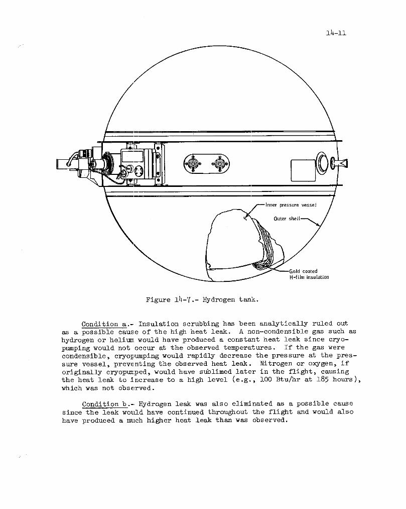
pressurevessel
Outer
_old coatedH-film insulation
Figure 14-7.- Hydrogen tank.
Condition a.- Insulation scrubbing has been analytically ruled out
as a possible cause of the high heat leak. A non-condensible gas such as
hydrogen or helium would have produced a constant heat leak since eryo-
pumping would not occur at the observed temperatures. If the gas were
condensible, cryopumping would rapidly decrease the pressure at the pres-
sure vessel, preventing the observed heat leak. Nitrogen or oxygen, if
originally cryopumped, would have sublimed later in the flight, causing
the heat leak to increase to a high level (e.g., i00 Btu/hr at 185 hours),
which was not observed.
Condition b.- Hydrogen leak was also eliminated as a possible cause
since the leak wo_Lld have continued throughout the flight and would also
have produced a much higher heat leak than was observed.

14-12
1000
100 ___
._
-
° /e-
= 10
IlJ
o _
1 I I Itttl I t t Itlll I I I IIII I I t lilt
10-8 10 -7 10 -6 t0 -5 10 -4
Annulus pressure, f.orr
Figure 14-8.- Hydrogen tank heat leak as a function of annulus pressure.
Condition c.- An ambient air leak is the most probable cause of the
high heat leak. Figure 14-8 shows that a pressure of 5 x l0 -5 torr in
the annulus would produce a heat leak of 21 Btu/hr, which is the average
observed for the first l0 hours of the flight. The heat leak returned to
a normal value of 6 Btu/hr by 80 hours, which corresponds to approximately
2 x l0 -6 torr. Assuming that a small hole opened in the outer shell dur-
ing the launch phase, the annulus pressure would quickly build up to thatrequired to produce the observed heat leak. As the bay pressure continued
to decrease and fall below that in the annulus, the annulus pressure would
follow the decrease slowly and drop to a final value sufficient to provide
the normal heat leak observed by 80 hours. Analysis shows that the area
of the opening was at least 2.2 x l0-3 sq cm. For an opening of this size,
iterative analysis places the formation of the crack or hole at approxlma- __tely 2 1/2 minutes into the flight to produce the observed conditions.

14-13
A thorough review of manufacturing, test, and checkout records wasperformed in an attempt to discern any unusual or abnormal conditions to
which the tank may have been exposed. Although the investigation failedto produce any definite reason for the failure, it did show one variancefrom normal procedures that could have affected the tank. This tank was
returned to the vendor in October, 1969, for rework of broken wires on the
vacuum ion pump power supply. Receiving inspection revealed two abnormal
conditions : water was in the bottom of the shipping container and the tank
assembly was not secured in any way to the container cradle ring assembly.
Normally, the shipping container should be dry and the tank bolted to the
shipping container. The broken wires were repaired and tests performed
to verify electrical continuity, heater and fan operation, and vacuum ion
pump operation (which checks annulus vacuum). Also, an ambient boil-off
test was performed, with cryogenic hydrogen. The tank was then X-rayed
and shipped to the prime contractor. A comparison of these data and X-
rays with data from the original acceptance tests indicates that the tank
was normal in all respects. The fact that the tank heat leak was nominal
prior to launch also verifies that the tank was normal at that time.
The most likely cause of the high heat leak rate early in the missionwas the formation of an ambient air leak into the insulation vacuum annulus
at approximately 2 1/2 minutes after lift-off. Decreasing ambient pressure
gradually returned the annulus vacuum and, likewise, the heat leak rate to
normal levels by 80 hours.
No corrective action will be taken since the preflight procedures andinspection of the tanks are adequate. In the event a leak occurs in the
outer shell during launch, the vacuum condition will be reestablished la-
ter without significantly affecting the total heat input to the tank.
This anomaly is closed.
14.1_6 Up-data Link Command Capability Loss
The spacecraft failed to respond to uplink real-time commands at
42:23:09 and again at 207:14:36. In each case, the condition existed
until the crew cycled the up-telemetry command reset switch from "normal"
to "off" and back to "normal". This restored normal operation.
A similar prc$1em was experienced on Apollo 9. Extensive review of
the spacecraft data, testing of flight hardware, and analysis of the com-
mand system did not identify a specific cause of the problem. A special
low-voltage test (_d show that a low-voltage transient could change the
vehicle address register and inhibit receipt of' any commands until power
is cycled to "off" and back to "on", resetting the register. However, on
Apollo 9, telemetx7 data failed to indicate any voltage transient condi-
tions that could be expected to change the vehicle address.
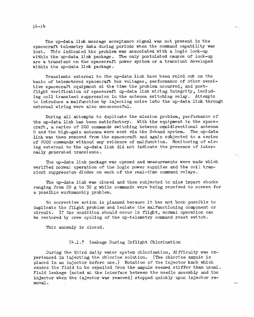
m4-14 •
The up-data link message acceptance signal was not present in the
spacecraft telemetry data during periods when the command capability was
lost. This indicated the problem was associated with a logic lock-up
within the up-data link package. The only postulated causes of lock-up
are a transient on the spacecraft power system or a transient developed
within the up-data link package.
Transients external to the up-data link have been ruled out on the
basis of telemetered spacecraft bus voltages, performance of other sensi-
tive spacecraft equipment at the time the problem occurred, and post-
flight verification of spacecraft up-data link wiring integrity, includ-
ing coil transient suppression in the antenna switching relay. Attemptsto introduce a malfunction by injecting noise into the up-data link through
external wiring were also unsuccessful.
During all attempts to duplicate the mission problem, performance of
the up-data link has been satisfactory. With the equipment in the space-
craft, a series of 200 commands switching between omnidirectional antenna
D and the high-gain antenna were sent via the S-band system. The up-data
link was then removed from the spacecraft and again subjected to a series
of 2000 commands without any evidence of malfunction. Monitoring of wir-
ing external to the up-data link did not indicate the presence of inter-
nally generated transients.--4
The up-data link package was opened and measurements were made which
verified normal operation of the logic power supplies and the coll tran-
sient suppression diodes on each of the real-time command relays.
The up-data link was closed and then subjected to nine impact shocks
ranging from 20 g to 50 g while commands were being received to screen for
a possible workmanship problem.
No corrective action is planned because it has not been possible to
duplicate the flight problem and isolate the malfunctioning component or
circuit. If the condition should occur in flight, normal operation can
be restored by crew cycling of the up-telemetry command reset switch.
This anomaly is closed.
14.1.7 Leakage During Inflight Chlorination
During the third daily water system chlorination, difficulty was ex-
perienced in injecting the chlorine solution. (The chlorine ampule is
placed in an injector before use.) Rotation of the injector knob which
causes the fluid to be expelled from the ampule seemed stiffer than usual.
Fluid leakage (noted at the interface between the needle assembly and the
injector when the injector was removed) stopped quickly upon injector re-moval.
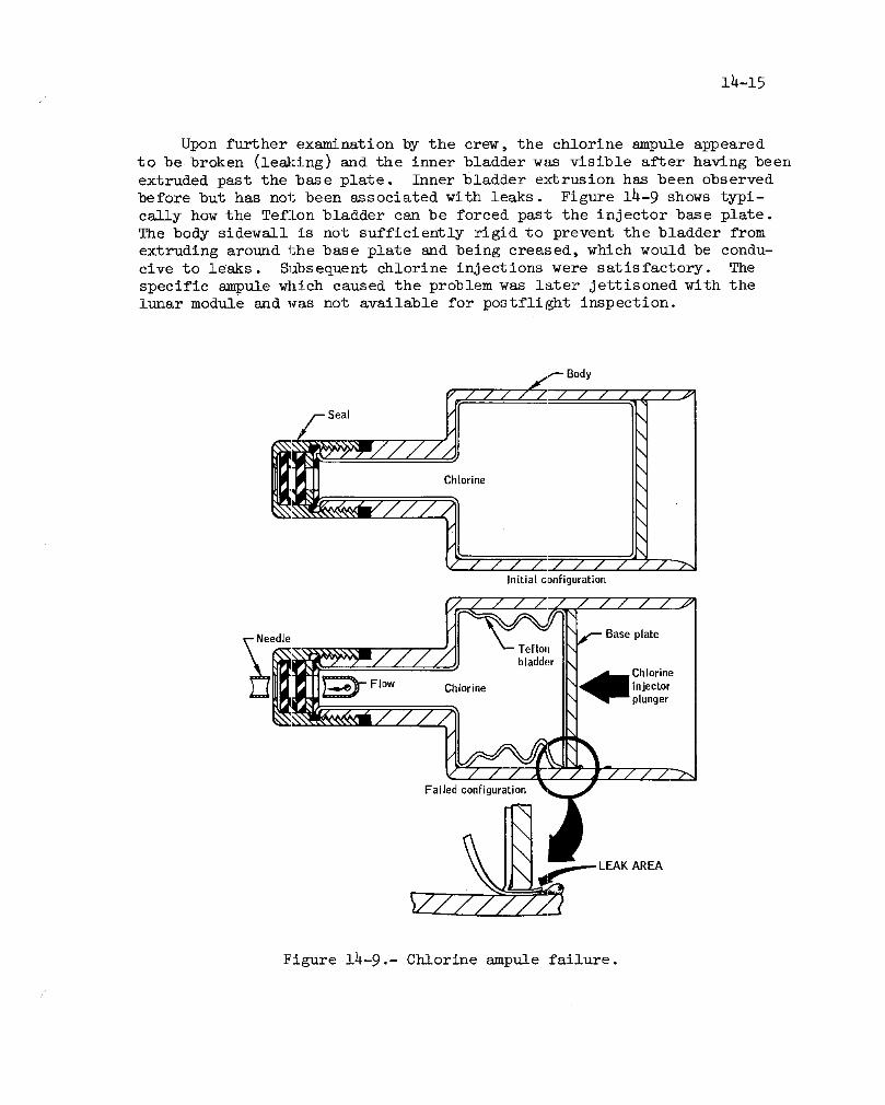
1_-15
Upon further examination by the crew, the chlorine ampule appeared
to be broken (les}:ing) and the inner bladder was visible after having been
extruded past the base plate. Inner bladder extrusion has been observed
before but has not been associated with leaks. Figure 14-9 shows typi-
cally how the Teflon bladder can be forced past the injector base plate.
The body sidewall is not sufficiently rigid to prevent the bladder from
extruding around the base plate and being creased, which would be condu-
cive to leaks. Subsequent chlorine injections were satisfactory. The
specific ampule which caused the problem was later jettisoned with thelunar module and was not available for postflight inspection.
f Body
Seal
Initial configuration
plateTeflonbladder
Chlorine
_'-Flow Chlorine injector
Failed configuration
AREA
Figure 14-9.- Chlorine ampule failure.

l_-16
Inspection of the 15 chlorine and 16 buffer ampules returned revealedthat 60 percent had loose base plates and BO percent had bonding adhesiveadhering to the inner wall. Eight (five chlorine and three buffer) of theunused ampules were leak-tested. One buffer ampule leaked because thebladder was pinched between the base plate and the side wall.
Corrective action consists of checking all ampules for detection ofbonding material on the ampule sidewall or adhesion of the bladder to thesidewall. In addition, the fluid will be evacuated for entrapped sir tohelp preclude the base plate from being loosened due to bladder disorien-tation resulting from increased pressure in the ampule as the entrappedair expands with cabin pressure decrease.
This anomaly is closed.
14.1.8 Failure of Mass Spectrometer Boom to Fully Retract
During scientific instrument module experiment operations, the massspectrometer boom mechanism stalled and would not fully retract. The prox-Imity switches indicated that the mechanism always retracted past the safeservice propulsion system firing position except before transearth injec-tion. At that time, the mechanism stalled two-thirds out (approximately200 inches) and would neither extend nor retract. Since the motor had beenpreviously stalled with the current left on for more than 40 minutes, themotor apparently burned out. The boom mechanlsm and experiment were Jet-tisoned prior to the transearth injection maneuver.
The stalls prior to the last event are believed to be caused bybunching or snagging of the coiled experiment power cable during retrac-tion as this had occurred previously during 1-g testing. On Apollo 15,the failure of the boom to fully retract was attributed to cable bunchingand some design modifications were made to help alleviate the problem(see sec. 14.1.6, reference 4).
Apollo 16 data were examined in an attempt to determine why the boomstalled, but nothing in the data revealed the cause. The data indicatesthat both motors on the mass spectrometer functioned correctly up to themoment of the final failure. The booms always retracted in anormal fas-hion to within the range of the proximity switch, except in the case ofthe final failure.
In the absence of any specific evidence, it is assumed that the ini-tial cause of the failure of the boom to fully retract was jamming of thecable in the boom housing. The repeated and prolonged stalling of the mo-tors caused the final failure of the boom in mid-stroke.

15-17/
The Apollo 17 lunar sounder has two HF antennas which are deployedand retracted by a mechanism that is the same in concept as the mass spec-trometer and the gamma ray boom mechanisms. However, the HF antenna mech-anism is a simpler design and the antenna has no cables that are requiredto travel in and owt with the antenna. Therefore, the suspected Apollo 16failure cause is not applicable to the Apollo 17 design; consequently, nocorrective action is required.
This anomaly is closed.
ih.1.9 Gamma Ray Spectrometer Boom Mechanism Stalled
During lunar orbit scientific instrument module bay operations, thegamma ray boom meclhanism stalled and would not fully retract on three offive retractions. The boom mechanism always retracted past the "safe ser-vice propulsion system firing" position as indicated by the proximityswitch. The cause of the retract failure is not known, but bunching orsnagging of the coiled experiment power cable during retraction is con-sidered the most probable cause since this has happened on other occasionsduring 1-g ground testing.
As in the case of the mass spectrometer boom, Apollo 16 data were ex-amined in an attempt to determine the cause of the incomplete retractions,but the cause was not determined. It is apparent that both motors on thegamma ray spectrometer functioned correctly. The boom always retractedin a normal fashion to within the range of the proximity switch.
In the absence of any specific evidence, it is assumed that the ini-tial cause of the failure of the boom to fully retract was Jamming of thecable in the boom housing. No further action will be taken since thismechanism will not be used on spacecraft for any future Apollo missions.
This anomaly is closed.
l_.l.10 Service Propulsion Engine Gimbal Actuator Oscillations
During the pre-ignition checklist for the lunar orbit circulariza-tion maneuver, an oscillation was detected in the yaw axis of the second-
ary servo system for the service propulsion engine glmbal actuator. Fig-ure 14-10 is a functional diagram of the servo loop. The oscillation waspresent in all modes of operation, but only when the secondary yaw servoloop was used. The oscillation was limited at +l.0 degree and at 2.4hertz with the gimbal correctly following commands to different positions.Figure lh-ll shows one occasion that the oscillation did not occur whenreposltioning the engine which implies that the failure is electrical innature.

FJI
Command Service co
module I module/--Position
I / .ansducer
I Act_' _ Negative
I 1 gimbalmotion
,,• ,_'_ _Servo_.-,,.J-,/_---,=J - - - Extend I
Gimbal commandsfrom: ,_ clutcha. Primary guidance Engine
b. Stabilization and control system I bellautomode _, __ ,.,,_.. ,... .----
e. Stabilization and control system "_-c_ -I ampur=er / Irate command
d. Stabilization and control systemacceleration command ")Retract
clutch I )" "_"
I X--.ate_Failure occurred in this area I transducer
Figure i_-i0.- Service propulsion system gimbal servo diagram.

14-19
Dampedoscillation Nooscillation Undampedoscillation+2°± i° -2°+ 0o 0o_+Io
'! _ Spacecraftyawrate
C',_-./ _" / L.__ .--, ----- ._ .._ . v __ __ _ , --',',/\1-,_.f- _,! i (; i ,i i] ' i_ {'_ ,i !t ',' f _ _, ,-'. ! 1_, J_ _ I, ;. ,_ • _ ,
lJl \/L.-- ....... !/ W tAIi I,-,!
I ', i/J v _ _,_ v v V V
! __'" k
I / Yawdifferentialclutch current;j Yawgimbalposition
Figure lh-ll.- Secondary yaw glmbal drive test
(primary guidance control).
Inflight results were matched by simulations of system performance
with an open in the rate feedback loop of the yaw servo system. It wasalso demonstrated that the oscillations would have damped after ignition
because of the side load forces exerted on the engine bell while thrust-
ing. Therefore, the secondary yaw servo system was considered safe touse if the primary servo system were to fail and it became necessary to
switch over to the secondary system.
The cause of the failure was an open in the rate feedback loop of the
secondary yaw servo system. Postflight testing of command module wiring
and connectors and bench testing of the thrust vector servo assembly did
not reveal any abnormalities. Therefore, the failure must have occurred
in the service module wiring or connectors. Possible pin corrosion on
the engine gimbal actuator wiring harness connectors or broken wires in
the yaw gimbal wiring loop are the most probable causes of the flight
problem. A broken wire would result from inadequate strain relief (see
fig. 14-12) due to cable flexing. Wiring harnesses to the actuator as-
sembly on three other vehicles were reviewed and found to move when the
engine was gimballed. Motion of the actuator produced a strain on the
harness at the lower clamp. The position of this clamp was changed for
the remaining vehicles to provide strain relief.

Yaw ac[uator
Ac[uatorharness
Figure 14-12.- Yaw actuator assembly and interconnecting wiring.
i_-2i
Routing of the wiring harness to the actuator assembly on Apollo 17has been changed to provide adequate strain re]ief and prevent harness
flexing when engine gimbaling occurs.
This anomaly is closed.
14.1.11 Noise From Cabin Fans
Approximately 2 hours after transearth injection, the cabin fans
started making a loud moaning sound. They were turned off and not usedagain during the mission.
When the spacecraft was received for postflight testing, the cabinheat exchanger inlet duct screens were blocked with lint and debris with
paper taped over the screens. However, this had no effect on the oper-ation of the fans .. Operation and sound level were normal and the fan
current was within specification. Visual inspection of the fans did not
show any nicks or indications of interference. Two small pieces of graytape, approximately 1/4 inch in diameter, and dust were found on the cabin
fan exhaust filter (which is installed by the crew after leaving earth or-bit).
The most probable cause for the fan noise was some object which gotinto the fan and was later freed.
This anomaly is closed.
14.1.12 Erroneous Suit Pressure Transducer Reading
While the cabin was depressurized during the transearth extravehicu-
lar activity, the indicated environmental control system suit loop pres-
sure transducer reading was 4.6 psia (fig. 14-]3). Specification values
for this regulated pressure are 3.5 to 4.0 psia and the control point de-
termined from Kenzledy Space Center altitude chamber testing was 3.8 psia.
The Commander's szld Lunar Module Pilot's suit cuff gage readings of 3.5
and 3.8 psia indicated that pressure regulation was satisfactory and thatthe transducer reading was erroneous.
Prior to the reduced cabin pressure operations, the suit transducer
performed acceptably and read within 0.i psi of the cabin pressure trans-
ducer with the suit loop open to cabin. After cabin repressurization, the
suit transducer again appeared to read correctly above 4.6 psia.
The suit pressure transducer was removed from the command module dur-
ing postflight testing and a reduced-pressure test and calibration check

I.-'
I1",5I'O
10
;_....-- Suit pressure8 'I
I 'II |
I :I
"_._ 6 o fSuit pressure
"_ 4 Cabin
pressure _--Expected suit pressure
2 abin pressure
0 I I218:O0 218:30 219:00 219:30 220.O0 220:.30
Time,hr:min
Figure 14-13.- Suit loop pressure data.

14-23
were conducted. The results were within tolerance. Teardown analysis re-
vealed three particles of calcium aluminum silicate (lunar origin) rangingfrom 500 to 2000 microns in size in the sense cavity. If one of the lunar
particles had been caught in the air gap (see fig. 14-14) of the variablereluctance element, the armature would transmit an incorrect signal. Nor-
real readings were obtained when the cabin was repressurized and a suit
pressure in excess of h.6 psia was obtained. This could have freed any
particle that might have been lodged in the air gap.
The corrective action for Apollo 17 and later spacecraft will be to
add a 5-micron filter in the suit pressure sense line to protect the suit
pressure transducer.
This anomaly" is closed.
t.e plate
Air gap
tors in ferrite
0 0 cup cores
F:igure 14-14.- Suit pressure transducer.

14-24
14.1.13 Digital Event Timer Counted Erratically
The digital event timer, located on panel l, indicated erroneous time(compared to computer time) after counting up or down over a preset timeinterval. It had performed satisfactorily during the early portion of theflight, but began to malfunction approximately midway through the mission.Postflight testing verified that the '%ens of seconds" wheel would not up-date, counting either up or down, and would cycle for several seconds whenthe timer was reset (the maximum tlme should have been 0.3 second).
Inspection of the digital event timer showed that the bearing pointsin the magnesium motor plates had been elongated. The idler gear is freeto rotate on the shaft (fig. 14-15); however, the design permits the stain-less steel shaft to also rotate which would account for the wear in the mo-
tor plates. The elongated bearing points permitted the idler gear to rubagainst the number wheel. This interference rubbed paint off the numberwheel and the paint particles prevented the sllp rings and brushes frommaking good contact which affected proper counting of the seconds wheel.
The bearing points also elongated on the Apollo 15 digital eventtimer. The idler gear shaft can be prevented from rotating by stakingat the bearing point in the motor plates. For Skylab, corrective actionwill be to secure the shafts of digital event timers, that require open-ing of the case for other rework. For Apollo 17, the units will be vis-ually inspected for signs of Wear.
This anomaly is closed.
14.1.14 Uneven Drive Rates of the Scanning Telescope
The crew reported that the scanning telescope shaft axis drove errat-ically and seemed to get worse with time. The condition was observed inthe computer mode and the zero optics mode and only through the telescope.The uneven drive rate was related to a change in the characteristic noiselevel when the optics was being driven. The crew could not be certainwhether the uneven drive rates were directly or inversely proportional tothe noise level.
The telescope shaft axis is slaved to the sextant shaft through lXresolvers in each unit. No drive problem was reported with the sextant;however, it is doubtful whether uneven drive rates would have been de-tectable by the crew because of the differences in the magnification andfield of view of the two instruments. No uneven drive rates have been
observed in flight data.

/ _ _.-Brushes/ A/ ,/ e71-- Contaminatedarea
Number / _]_'-Slip ring,4counter w_wheel--_ / _lnterference point.A
/ ,A _- Motorplate/ / _" (magnesium)
Bearing point _ /_
(Elongation area)_l _/_/ __-Bearing point
(Elongation area)
Motor plate T
(magnesium)---.J=."_ Shaft(Stainless steel)
Idler gear(Delrin AF),
Figure 14-15.- Digital event timer seconds counter.
The optical unit assembly was thoroughly soaked during recovery bysalt water which caused extensive corrosion. The unit was cleaned, how-ever, and tested. The intermittent flight condition was reproduced bywiggling the scanning telescope wiring harness in the Optical unit as-sembly. An examination of the female connector on this harness revealed9 of 61 contact springs (fig. 14-16) were cracked or broken. Also, sev-eral contact springs were found broken in a 91-pln connector in the op-tlcal unit assembly. The cause of the broken springs is being investi-gated.
This anomaly is open./

!_ooh
Figure i_-16.- Contact and leaf spring arrangement of optical unit connector.

14-27
14.1.15 Sticking Lithium Hydroxide Canister
During the first lithium hydroxide canister change performed after
redocking with the lunar module, considerable trouble was experienced in
removing used canister 12 from side B of the environmental control unit.
Some minor sticking was also noted during an earlier change (at approxi-
mately 152 hours) while removing canister i0 from side B. No problems
were encountered removing other canisters.
Both canisters had been used extensively during lunar orbit solo op-
erations. Under conditions of high flow, low temperature, and low carbon
dioxide supply, the exothermic reaction is insufficient to drive off the
atmospheric and reaction moisture which accumulates in the canisters.
The canisters apparently expanded due to the retension of the excessivemoisture.
Conditions conducive to this problem were present during the solo
period. The Command Module Pilot noted that he had positioned the suitflow control valves to "suit full flow", allowing significantly higher
gas flow through the environmental control unit carbon dioxide canisterthan had occurred during the comparable period on previous missions. The
average flow was 56 cu ft/min during the Apollo 16 solo period as com-
pared to 36 cu ft/min during the Apollo ll, 12, 14, and 15 solo periods.
The valves were positioned to cabin flow during these previous missions.
Although canister l0 was jettisoned with the lunar module, canister
12 was returned for inspection and analysis. Figure 14-17 shows a cross-
section of the lithium hydroxide canister. The lithium hydroxide swells
while it is being used, and to account for this swelling, the units are
fit checked in the spacecraft with 0.030-inch shims on all sides. Addi-
tionally, the pull force required to remove the canister is checked with
the shims in place. An analysis performed on five separate layers ofthe chemical bed indicated that approximately 32 percent of the lithium
hydroxide had been used. In addition, the analysis showed the moisturecontent to be approximately 21 percent compared to a range of 5 to i0 per-cent found in canisters used during the solo period on previous flights.
A dimensional analysis showed both sides of the environmental control
unit canister receptacle to be within specification, although postflight
removal forces using the canisters indicated a tighter fit in side B (53-ib
pull) than side A (22-ib pull). The preflight pull force for this canisterwas 18 pounds. Normally, pull forces for these canisters are i0 pounds orless.
The combination of the adverse environment and the initially tighter-
fitting canister apparently accounted for the removal difficulty.
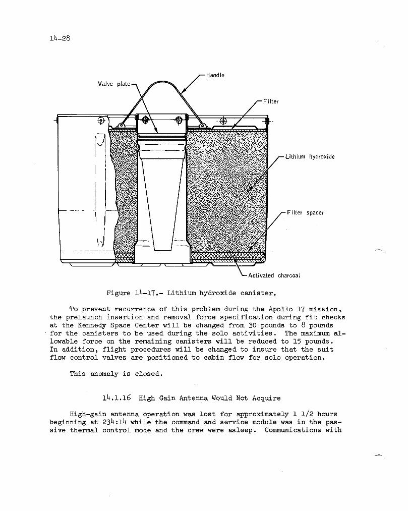
14-28
andleValve
Figure 14-17.- Lithium hydroxide canister.
To prevent recurrence of this problem during the Apollo 17 mission,
the prelaunch insertion and removal force specification during fit checks
at the Kennedy Space Center will be changed from 30 pounds to 8 pounds
for the canisters to be used during the solo activities. The maximum al-
lowable force on the remaining canisters will be reduced to 15 pounds.
In addition, flight procedures will be changed to insure that the suit
flow control valves are positioned to cabin flow for solo operation.
This anomaly is closed.
14.1.16 High Gain Antenna Would Not Acquire
High-gain antenna operation was lost for approximately 1 1/2 hoursbeginning at 234:14 while the command and service module was in the pas-
sive thermal control mode and the crew were asleep. Communications with

14_29f
the spacecraft were being maintained by ground-commanded switching be-
tween the high-gain antenna and omnidirectional antenna D. The initial
indication of a problem occurred at about 234:04 when the high-gain an-tenna reached the scan limit and failed to drive to the position set on
the manual controls° Figure 14-18 shows the path taken by the antenna
prior to the anomaly, where it stopped, and the position to which it
should have driven. The antenna remained at the position indicated un-
til the crew awakened about i 1/2 hours later _id cycled the high gain
antenna track mode switch from "reacquisition" to "manual" and then back
to "reacquisition".
90 - Antenna remained
at this point-,,X, fScan limit6O
$30
-30 _- i it
-60 ./ Spacecraftskin _Commanded position"_ interference zoneof the antenna
-90 I I I I I I I I I I I I180 210 240 270 300 330 0 30 60 90 120 150 180
Yaw, deg
Figure 14-18.- High gain antenna scan limit.
Figure 14-19 shows the pitch and yaw positions and signal strengths
in the time frame of the problem. This figure indicates normal high gain
antenna operation up to and immediately following entry into the scan-lim-
it region. The step decrease in both uplink and downlink signal strength
was due to switching from narrow to wide beam. Such a beam switch results
when the logic latchup circuit 2 latches (fig. 14-20). Logic latchup cir-
cuit 2 latches when logic latchup circuit i latches and logic latchup ilatches when the antenna with the "reacquisition" track mode selected,
tracks from the clear track area to the scan limit. Latching of logic
latchup I also internally switches the antenna to manual track. For the

14-30
,_-'- Omnidirectional antenna /_ Data recorder/reproducer
.°=- _- _mmanded on _ commanded forward°o_ cg
-- E
_= -70"C.2 - -=_, 90.E _,-Ii0 _--
_' 40 _C axts to gimbal stop
6°I
"_ E. 80
_ 280- 260 "------_--- --'---'-"
< _ I t t I t J I I I I I I I t i I i I I ->- 240234:04:27 234:04:30 254:04:33 234:04:56 254:04:59 234:04:42 234:04:45
Elapsedtime,hr:min:sec
Figure i_-19.- High-gain antenna data at beginning
of anomalous period.
antenna position (pitch = 60 degrees and yaw = 258 degrees at the scan
limit) and the commanded position (pitch = -44 degrees and yaw = 8h de-
grees), the C-axis error signal is large and it should drive the C-axis
to the gimbal stop upon switching to "manual". The A-axis should also
start rotating, but its response is very slow because it is essentially
180 degrees away from the commanded position. The A-axis manual error
signal also has a false unstable null 180 degrees away from the true null.
The rapid change in pitch shortly after the beam switching, shown in fig-
ure 14-19 (from approximately 59 deg to 71 deg) is verification that the
C-axis drove to the stop as expected. Normally, the C-axis would remain
against the gimbal stop until the A-axis rotated approximately 90 degrees
and then would drive away from the stop to the commanded position.
Shortly after the C-axis drove to the stop, the noise on the high-
gain antenna pitch and yaw readouts disappeared until the problem cleared
following the switch to "manual" track. Noise has been observed on the
high-gain antenna pitch and yaw measurements in the past. Essentially,

14-31f
+12 Volts
:)ModerAuto_ A t
select "1- Auto_ B AxisReacquisition inhibit
C
Manualerror _L To axesanddetector modecircuits
beamand]obingswitches
Earthpresence
Scanlimit
Figure 14-20.- High-gain antenna logic diagram.
no noise has been associated with the "inhibit" mode. Figure 14-20 shows
that selecting the "automatic" mode and reaching the scan limit triggersan "inhibit" circuit.
The noise on the pitch and yaw readouts reappeared following the
track mode switch. The high-gain antenna acquired and operated normally
after cycling the :mode select switch to "manual" and then back to the
"automatic reacquisition" position.
In summary, the data showed:
a. The antenna remaining near the "earth set position" instead of
driving to the "predicted earth rise position" after entering the scanlimit.
b. Noise disappeared on the high gain antenna pitch and yaw read-out s.
c. Cycling tlhe track mode switch from "reacquisition" to "manual"
cleared the problem.

lh-32
The variations in current, combined with the resistance between theelectronic box common ground and spacecraft ground cause noise on thehigh-gain antenna pitch and yaw readouts. An inhibit reduces the gainof the mode switch circuits so that the current variations, and hencethe nolse, are reduced. The reduction in noise, consequently, indicatesthat the logic went to the "inhibit" mode.
Tests associated with logic operation, for the high-gain antennaoperating conditions involved, revealed no condition or combination ofconditions in the logic of a normal circuit that could cause the anomaly.This included elimination of a possible A-axis false null hang-up. Fur-thermore, the tests showed that the noise on the pitch and yaw readoutsdid not disappear when a false null hang-up was induced.
Tests did indicate, however, that the anomaly could be the resultof simultaneous selection of both the "reacquisition" and "automatic"track modes. In this case, an inhibit would result if the antenna en-tered, and remained inside the scan limit (fig. lh-20). Simultaneousselection of both "reacquisition" and "automatic" track would requirea fault, or malfunction in the mode select switch, associated space-craft wiring, or internally in the hlgh-gain antenna electronics. Al-though the telemetry data indicate no voltage on the "automatic" selectline, such a condition could occur and not be detected. The mode selectswitch and the associated wiring, however, were thoroughly checked, in- -cluding disassembly and inspection of the switch, and no discrepancieswere noted.
Stray voltage on the "automatic" select line is highly unlikelysince tests showed that 13 to 14 volts at the electronics box input wererequired to select a track mode. A review of the electronic box circuitsinvolved indicated no internal malfunction that could result in simul-taneous "automatic" and "reacquisition" track, then be cleared by cycl-ing the track mode switch, and not exhibit other unique symptoms. Theother possibility for the cause of the anomaly is that one of the twologic inhibit gates may have malfunctioned.
The integrated circuit generating the inhibit is shown in figurelh-21. These types of devices have been found susceptible to contamina-tion from internal floating particles. A particle can move as a resultof acceleration or electric fields, and create an internal short whichchanges the state. Additional acceleration or changes in the electricfields can result in the particle moving again and either clearing theproblem, or showing itself as an intermittent problem.
The particular integrated circuit was manufactured prior to incorpo-ration of passivatlon which reduced the likelihood of floating particlecontamination.

14-33f
A particle resulting in any one of the following shorts (fig. 14-21)would result in an unscheduled inhibit.
a. Collector-to-base - QI2' QI3' Q22' or Q23
b. Collector--to-emitter - Qll' Q12' Q21' Q22
c. Base-to-collector supply - Q12' Q13' Q22' Q23
An internal short of this type would have to clear when the track
mode switch was ch_Mlged from "reacquisition" to "manual".
No corrective action is planned because experience shows contamina-
tion in the electronics box has a low probability of occurring. Further,
if the problem bec,mme permanent in one electronics box, the secondary unitcan be selected.
This anomaly is closed.
Bias voltage
Brakemode Auto,_= prime
JisitionAutoselect Q 12 Q 22 select
Earthpresence
inhibit Inhibit
Figure i_-21.- Schematic of integrated circuit
within uplink package.

14-34
14.1.17 Difficulty in Extending and Locking the Y-Y Strut
The Command Module Pilot had difficulty in extending and locking the
Y-Y strut in preparation for entry and commented that he could not discern
any clearance between the strut pad and command module wall.
Postflight investigation showed no significant binding during strut
operation. Visual examination (fig. 14-22) showed:
a. Wear areas along the keys
b. The strut barrel was 2.757 inches in diameter and should have
been between 2.740 and 2.750 inches
c. The set screws which provide a stop for the strut piston in the
strut barrel were bottomed out against the piston.
The strut barrel was deformed by the set screws and caused the wear
along the keys because the barrel became within tolerance as soon as the
set screws were adjusted to the specified gap of 0.002 to 0.005 inch.
A similar condition was reported on the Apollo 17 spacecraft and
corrected by adjusting the set screws. Engineering has been released
to verify these dimensions prior to installation for future spacecraft.
Postflight investigation of Apollo 16 also verified a sidewall clear-
ance of 0.044 inch which compares to 0.041 prior to launch. The Apollo
Operations Handbook has an inflight procedure to remedy this situation.
This anomaly is closed.
14.1.18 Holes in Canopy of Main Parachute
Inspection of the canopy of one of the recovered main parachutes in-dicated numerous small burn holes which are similar to the burn holes ob-
served on parachutes from previous missions (fig. 14-23). The cause of
the earlier holes had been attributed to the reaction control system ox-idizer.
During the final descent, at an altitude of about 350 feet, the crew
manually fired the two plus-yaw engines for the planned 1-second, then
fired the two minus-yaw engines, again for about i second. This proced-
ure was performed to bleed off the pressure trapped between the engine
valves and the propellant isolation valves which are closed at about 3000
feet altitude (the firings were thus referred to as the "burp firing").
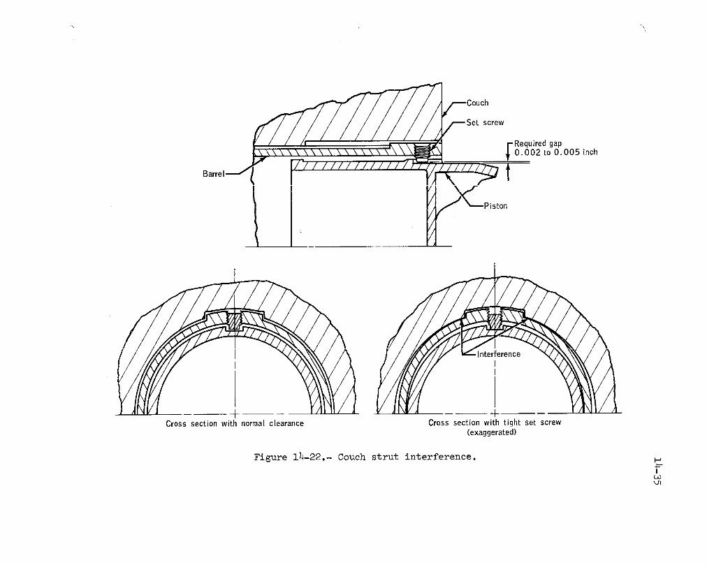
Couch
Set screw
Barrel_ l
• 7 CPist°n
!
+-Crosssection with normal clearance Cross section with tight set screw
(exaggerated)
Figure I_-22.- Couch strut interference.
I


14-37_f
Analysis of films of the burp firing indicated that flame was producedoutside of the plus-yaw engines for a period of about 0.5 second. This
flame started at the engines and extended upward toward the risers before
extinguishing itself. Oxidizer flow also appeared for about I second as
evidenced by a red vapor cloud.
The basis for this firing was the concern that the pressure increase
resulting from the sea-water wetting of the reaction control system lines
between the isolation valve and the thruster could cause the pressure to
reach the burst ill,its of the weakest component which is the thruster as-
sembly. The temperature of the reaction control system lines prior to
landing is about 55° F; however, after landing, wetting can raise the
temperature of the lines to about 85° F. The actual pressure profile in
the system due to a temperature change of about 30° F will be determinedby testing a spacecraft system. The results will show whether a "burp
firing" is necessary. Normally, the isolation valve will relieve any
pressures up to 800 psi that may be trapped between the isolation valvesand the thrusters.
A leak in the isolation valve bellows can prevent the valve from re-
lieving but this is the only failure whichl could prevent the isolation
valve from operating normally. For the condition of the isolation valve
not relieving, a test is being conducted to determine the maximum system
pressure that could be expected.
In the event that pressure relief is required in the lines, an on-
the-water operation of the isolation valve or the thrusters is being con-sidered.
This anomaly is open.
14.1.19 Water/Glycol on Command Module Floor
During postflight operations, residue from approximately one teaspoon
of water/glycol was found on the command module floor in front of the en-
vironmental control unit. A trace was also noted on the lower front edge
of the suit heat exchanger and on the coolant control panel side of theenvironmental control unit.
Subsequent proof pressure and pressure decay tests conducted on both
the primary and secondary Coolant circuits were satisfactory. The coolant
panel was cut away as required to visually observe possible leakage in the
suspected area of the primary suit heat exchanger diverter valve. No leak-
ing was observed s_idthe torque stripe was intact on all B-nuts in thata_fea.
14-38
During the helium pressure decay cheek, a leak of 255 X i0"v sce/s
was observed during repositioning of the suit heat exchanger bypass valve.A fiber was found under the two O-ring seals on the control key shaft when
the valve was disassembled (see fig. 14-24). The valve is motor driven
between two positions. The O-rings around each of the four openings (fig.
14-24) in the valve body normally maintain a seal at the selector and
valve body interface, i.e., when the selector is in either position. Dur-
ing the movement of the selector from one position to the other, which re-
quires about 20 seconds, system integrity through the valve is maintained
by the two O-rings on the key shaft. Although the only time this valve is
moved during the mission is just before entry into the earth's atmosphere,
it is activated numerous times during spacecraft testing after the system
is filled with water/glycol and pressurized.
The environmental control unit area, i.e., the bypass valve, B-nut
connections, and cabin floor will be inspected for glycol leak prior to
launch on subsequent missions.
This anomaly is closed.
14.1.20 Oxidizer Deservicing Tank Failure
An explosive failure of a ground support equipment decontamination
unit tank occurred during the postflight deactivation of the oxidizer
(nitrogen tetroxide) portion of the Apollo 16 connnand module reaction
control system.
The command module reaction control system is emptied of all remain-
ing propellant using ground support equipment designed to provide an acid/base neutralization of the propellant in both the liquid and gaseous phases
so that it may be disposed of safely. During the deactivation operation of
the oxidizer from the Apollo 16 command module on May 7, 1972, the scrubber
tank of the decontamination unit exploded, destroying the ground support
equipment unit and damaging the building that housed the operation. 0nlyminor injuries were received by the personnel in the area and the command
module was not damaged. More detailed information concerning the incident
is given in reference 7.
Test results show that the failure was caused by an insufficient
quantity of neutralizer for the quantity of oxidizer. This insufficiency
lead to exothermic nitration-type reactions which produced large quanti-
ties of gas at a very high rate and failed the decontamination tank.
Recommendations of the Apollo 16 Deactivation Investigation Board
will be implemented for Apollo 17 and following missions (ref. 8).
This anomaly is closed.

! _D
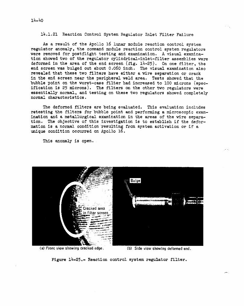
14-40
14.1.21 Reaction Control System Regulator Inlet Filter Failure
As a result of the Apollo 16 lunar module reaction control systemregulator anomaly, the command module reaction control system regulatorswere removed for postfllght testing and examination. A visual examina-tion showed two of the regulator cyllndrical-lnlet-filter assemblies weredeformed in the area of the end screen (fig. 14-25). On one filter, theend screen was bulged out about 0.060 inch. The visual examination alsorevealed that these two filters have either a wire separation or crackin the end screen near the peripheral weld area. Tests showed that thebubble point on the worst-case filter had increased to 100 microns (spec-ification is 25 microns). The filters on the other two regulators wereessentially normal, and testing on these two regulators showed completelynormal characteristics.
The deformed filters are being evaluated. This evaluation includesretestlng the filters for bubble point and performing a microscopic exam-ination and a metallurgical examination in the areas of the wire separa-tion. The objective of this investigation is to establish if the defor-matlon is a normal condition resulting from system activation or if aunique condition occurred on Apollo 16.
This anomaly is open.
(a) Frontviewshowingcrackededge. (b) Sideviewshowingdeformedend.
Figure 14-25.- Reaction control system regulator filter.

lh-41
14.2 LUNAR MODULE ANOMALIES
14.2.1 Paint Flaking From Thermal Shield Panels
Just prior to transposition and docking, particles were coming offthe thermal shield panels on the minus Y side of the ascent stage. Theparticles caused the panels shown in figure 1h-26 to have a shredded ap-pearance. (The aft equipment rack thermal shields and the insulationdangling from the bottom of the ascent stage shown in figure 7-1 are dis-cussed in section 14.2.2.) The paint flakes interferred with star sight-ings and were potential optical surface contaminants. Thermal tests con-ducted on specimer_3removed from a lunar module panel demonstrated thatthe paint on the panels starts to peel at approximately minus 120° F. Thepredicted minimum temperature of the panels during the mission is minus270° F.
Effective with the Apollo 15 spacecraft, changes were made to thevehicle to minimize the reaction control system propellant temperaturesfor the 72-hour lt_ar stay desi@q case. One change was that 16 panelson the ascent stage were painted white. Subsequently, a more effectivechange was made by the addition of tank insulation. The effect of totalloss of the paint on the panels results in a maximum reaction controlsystem propellant temperature increase of approximately 2° F.
The correctiw._action for Apollo 17 will be to remove the paint fromthe panels since the paint has little thermal value.
This anomaly is closed.
14..2.2 Aft Equipment Rack Panels Torn Loose
At lunar lift-off, four vertical thermal shields (fig. 14-26) on theaft equipment rack were torn loose from the lower standoffs and remainedattached only at the upper standoffs. This occurrence was observed fromthe lunar-based television.
The most probable cause of the failure was ascent engine exhaust en-tering the cavity behind these thermal shields. A cross section of thelower edge of the shields is shown in figure 1h-27. Analysis shows thatthe thermal shield which extends below the support tube allows a pressurebuildup on the closure shield which exceeds its capability. Once theclosure shield failed, the exhaust entered the cavity behind the shield,resulting in a pressure buildup exceeding the capability of the verticalthermal shields. _._edetailed flight configuration in this area was nottested.

I
Figure 1_-26.- Paint flaking and damaged thermal shield panels.

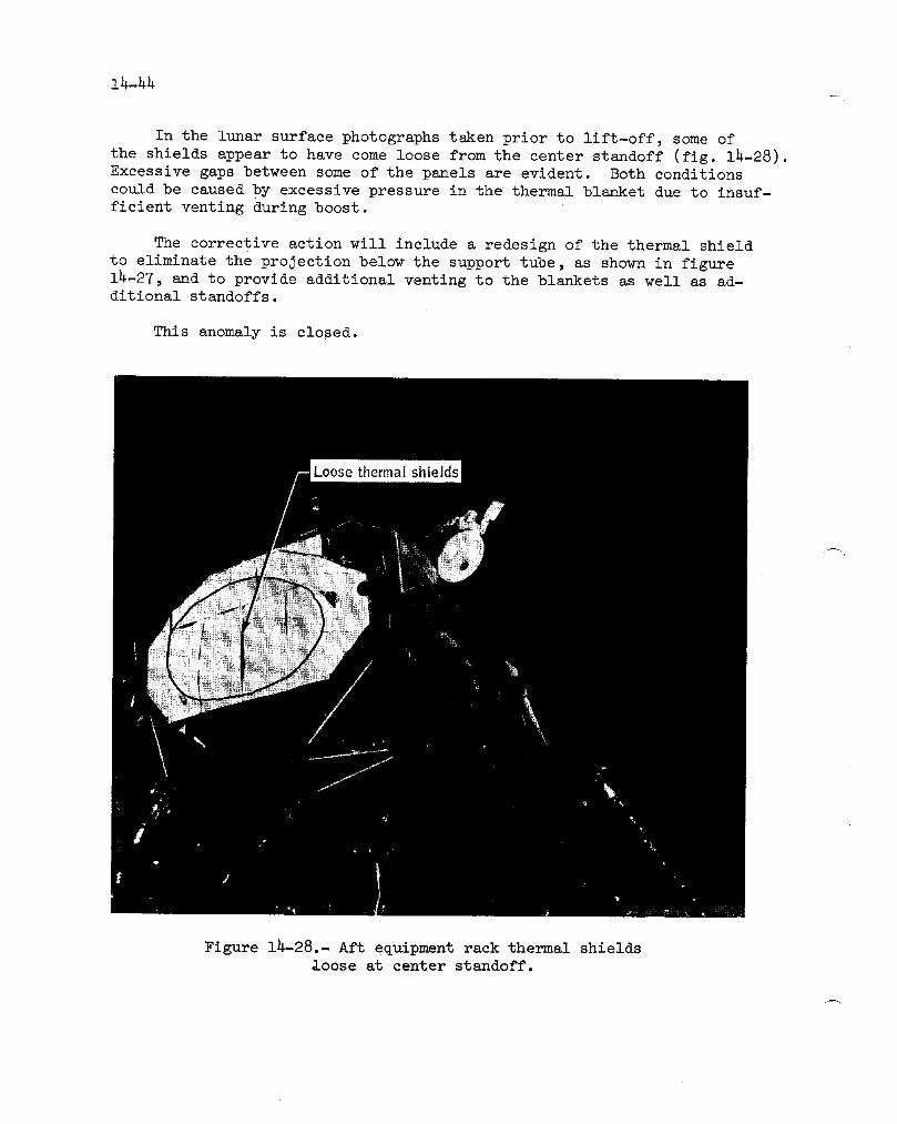
In the lunar surface photographs taken prior to lift-off, some of
the shields appear to have come loose from the center standoff (fig. 14-28).Excessive gaps between some of the panels are evident. Both conditions
could be caused by excessive pressure in the thermal blanket due to insuf-
ficient venting during boost.
The corrective action will include a redesign of the thermal shield
to eliminate the projection below the support tube, as shown in figure14-27, and to provide additional venting to the blankets as well as ad-ditional standoffs.
This anomaly is closed.
Figure 14-28.- Aft equipment rack thermal shields•oose at center standoff.

14-45
14.2.3 Steerable Antenna Inoperative In Yaw Axis
The S-band steerable antenna (fig. 14-29) would not move in the yaw
axis during initial activation. Several unsuccessful attempts were made
to operate the unit using both the manual slew and auto track modes. Pho-
tographs and inflight test data show that the problem was cs.lsed by fail-ure of the mechanical stow latch to release.
Figure 14-29.- Lunar module S-band steerable antenna.
Functionally, the stow latch restrains the antenna during launch.
Figure 14-30 shows the functional operation of the latch. The lock pin,
when extended, holds the antenna in the stowed position. A spring is held
under compression by a sleeve which is constrained to the latch housing by
a shoulder soldered to the sleeve. Melting the solder allows the spring
to push the sleeve which, in turn, raises the lock pin out of the retainer.
A manual mode is provided for checkout purposes. The lever (fig. 14-30)

joint
ring I
o',,_gelement
r wire
Machine off
housingcontact
ring
pin
solder ring)ring
contact
Heater )ring
Retainer on
Stowed position Electrically released Manually released
Figure 14-30.- Antenna stow latch mechanism.

14-47f
will pull the lock pin past the bali detent, thus releasing the antennawithout disturbing the spring-sleeve-solder configuration.
Antenna photographs taken on the lunar surface and in lunar orbit
prior to docking indicate that the lever for the yaw axis latch was stillin the locked position. The crew noted a 2- to 3-degree movement of the
yaw indicator during activation attempts. Ground tests have shown thatthe tolerances in the antenna retainer/locking mechanism will allow a
slight movement of the antenna dish even though the pin is locked.
There are several areas in the electrical circuitry which could have
caused the problem. One is that one contact ill the safe/arm switch (fig-ure 14-31) did not make. The second is that artopen may have existed down-
stream of the safe/arm switch, either in the solder-melting element or in
the wiring back through ground. A resistance measurement is made across
the two parallel solder-melting elements prior to flight. About a 3-ohmincrease in resistance was found at the last check. This change is equiv-
alent to a possible lO-ohm increase in one of the elements which could
have reduced the power dissipation below that required to melt the sol-der. Allowable tolerances on mechanical drawings and tests on sample
latches have sho_m that it is possible for a solder fillet extending be-
low the ring to make physical contact with the housing (fig. 14-30). The
Auto
__0_ Ii Gimbal motorsFilter I, ! $
s,ow / ITrack mode
switch Safe I Pitch solder I
I I I element I IArm! _L______, I
I II _ Jumper added I
i ' I [Yaws. lderI
,Safe/arm switch on Arm28V dc return antenna electronics assembly
I '
L_. S-band steerable antenna
Figure 14-31.- Lunar module steerable anteona stow-latch circuit.

1_-_8
contact allows the housing to act as a heat sink and, under marginal elec-trical conditions, draw off sufficient heat to prevent melting of the ring.
Several corrective actions are planned for Apollo 17 to cover allreasonable possibilities of failure. These include:
a. Machining off the exposed solder fillet and a portion of thehousing to eliminate possible contact.
b. Inspect 100 percent of the heating wire of the solder assemblies.
c. X-raying latch assemblies to insure proper assembly.
d. Measuring the Circuit resistance of both the antenna and associ-ated wiring on the vehicle.
e. Adding wiring to the circuit to provide redundant paths throughthe safe/arm switch to the solder melting elements.
This anomaly is closed.
lh.2._ Reaction Control System Helium Regulator Leakage
During pressurization of the system at about 95 hours, the regulatoroutlet pressure in system A (fig. lh-32) increased above regulator lockuppressure. The normal pressurization is characterized by a sharp increasefrom the nominal pad pressure, in the interval of 1 to 2 seconds, to thenormal regulator outlet pressure. The outlet pressure of system A, afterreaching the normal value of 18& psia, continued to rise at approximatelyl0 psi/minute, a condition which clearly indicated the existence of in-ternal leakage in the regulator assembly.
Approximately 3 minutes after pressurization, the first of four proppellant transfer operations was performed (fig. 1_-33) to lower the ullagepressure and to create a larger pressurant volume in the propellant tanks,thereby obtaining a blowdown capability for expulsion of the remaining pro-pellant in case of total loss of system A pressurization gas through therelief valves. The helium leakage continued throughout the mission, al-though the leakage rate varied from essentially zero to a maximum of aboutllO0 scc/min (figs. 14-34 and lh-35). The regulator outlet pressure even-tually increased to about 237 psia at which time the relief valves of sys-tem A started to periodically relieve the pressure to about 232 psia.

14-49/-
Pressure 'Q __transducer 3 Quickdisconnect
11valve
FilterRegulator J__
inlet filter--__OOrifice__-- __ i
Pr,mary _ Iregulatpr I
III I
Secondary L I
IRegulator [ ,J[
To fuel tank To oxidizertank
Figure 1_-32,,- Reaction control system press_u:izstton sys¢em.

14-50
3200 J
•_ 3ooo oJ
08
_ 8=_ 2800== o_= o ")=E o
2600 0 _) C'_)'_C_ _
OCOCD(_ Om___
2400
220 , , ,Propellanttransfers Propellanttransfer1 2 3 4
- /_ o I<8 8 _-- _)_" _"
180 0
ol95:00 95:10 95:20 95:30 96;00 96:30 97;00 97:30
Time_hr:minNOTEDIFFERENTTIME SCALES
Figure 14-33.- Comparison of helium supply pressure and regulator
outlet pressure following reaction control system pressurization.
The helium regulator assembly consists of two series regulators (fig-
ure 1_-36). The unit immediately exposed to the high pressure source is
designated as the primary regulator and the downstream unit as the second-
ary regulator. Both units are identical in configuration with the excep-tion of shims which are used to determine their pressure settings. The
primary unit is set to regulate at 181 +3 psia; the secondary, at 185 -+3
psia.

14-51
2400
Lunar
landing2200 0 li
000
2000 ('_
._ 0
m_ 0
_=18oo 0
_= (]_)0 0()0 0 O O0 0 Lunar I1600
( 0 ( O0 lift-off
1400 (_0
O0 o
1200100 110 120 130 140 150 160 170 180
Time, hr
Figure lh-3_.- Helium supply pressure for reaction
control system during lunar stay.
A series of tests was performed to determine lockup characteristics
of nine spare regulators under small differential pressure conditions.The tests showed that a design deficiency in the secondary regulator does
not exist, but did not eliminate the possibility of a weak poppet spring
or sticky poppet in the Apollo 16 regulators since they were not testedunder the same conditions. Further, the test demonstrated that the flight
anomaly was the result of two discrepancies within the regulator assembly.A matrix of the possible leakage paths is shown in table 14-I. As can be
seen from the matrix, there are 15 possible double-failure combinationswhich can result in the anomalous condition observed during the flight.
Of these, the four involving only the poppets are considered probablesince the leakage was variable. A variable leak path is usually caused
by particulate contamination on a poppet seat. The particulate contamina-tion could have been inside the regulator assembly during ground tests, but
located in such a manner that it was not dislodged by the gas flow under
1-g conditions. In a weightless condition, the contamination could have
moved and deposited between any of the poppets and their seats.

2100 _i_ F,.t="
I ,.n2000 (_
i %
1900 _llLunar Z]_
II landing }_18ooI
_L
N 1700E.
E
1500 .......cv _ _w_ LJL
G i
1400 D(3Z)(_( L
LunaFII
lift-off I% I
1300 "OOC_ OC '1(III
1200 I104 106 108 110 112 114 164 166 168 170 172 174 176
Time,hr
Figure 14-35.- Expanded plot of helium supply pressure during two periods on lunar sttrface.
) ) :

Primary Regulator Secondary Regulator
J
spring
g pin
Pilot
I
Inlet Outlet
Main
Main poppet piston
Note: Normal pressurized configuration:Primary main and pilot poppets closedSecondary main poppet closedPilot poppet-open responding topressure demand I
L,O
Figure 14-36.- Cross-section of reaction control regulator.
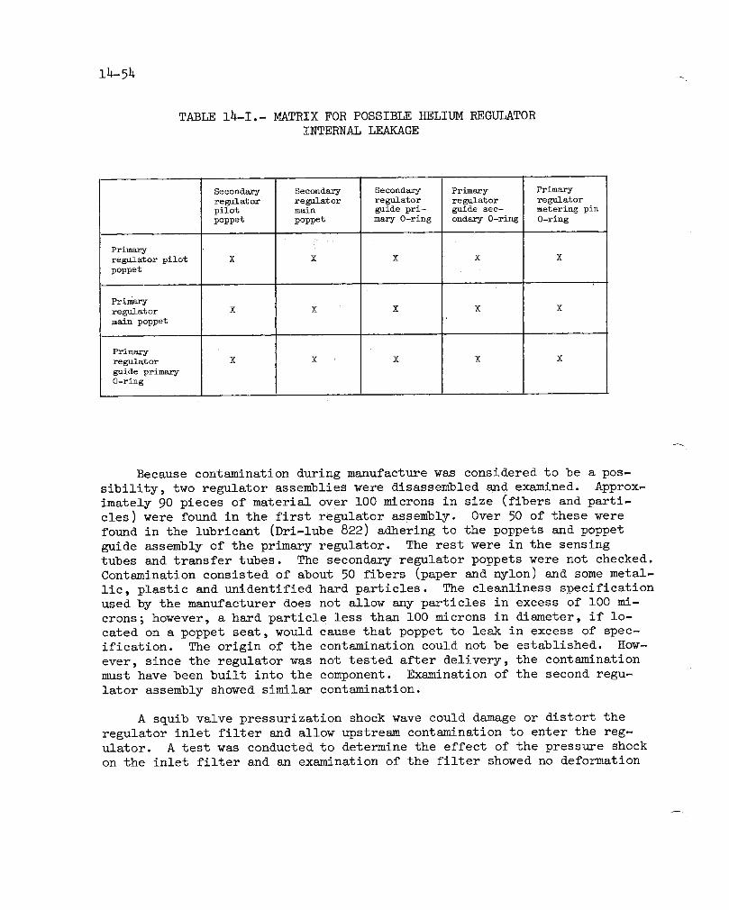
14-54 _
TABLE 14-I.- MATRIX FOR POSSIBLE HELIUM REGULATOR
INTERNAL LEAKAGE
Secondary Secondary Secondary Primary Primary
regulator regulator regulator regulator regulator
pilot main guide pri- guide see- metering pinpoppet poppet mary O-ring ondary O-ring O-ring
i
Primary
regulator pilot X X X X X
poppet
Primary
regulator X X X X X
main poppet
Primary
regulator X X X X X
guide primary
O-ring
A
Because contamination during manufacture was considered to be a pos-
sibility, two regulator assemblies were disassembled and examined. Approx_
imately 90 pieces of material over 100 microns in size (fibers and parti-
cles) were found in the first regulator assembly. Over 50 of these werefound in the lubricant (Dri-lube 822) adhering to the poppets and poppet
guide assembly of the primary regulator. The rest were in the sensingtubes and transfer tubes. The secondary regulator poppets were not checked.
Contamination consisted of about 50 fibers (paper and nylon) and some metal-
lic, plastic and unidentified hard particles. The cleanliness specification
used by the manufacturer does not allow any particles in excess of lO0 mi-crons; however, a hard particle less than lO0 microns in diameter, if lo-
cated on a poppet seat, would cause that poppet to leak in excess of spec-
ification. The origin of the contamination could not be established. How-
ever, since the regulator was not tested after delivery, the contaminationmust have been built into the component. Examination of the second regu-
lator assembly showed similar contamination.
A squib valve pressurization shock wave could damage or distort the
regulator inlet filter and allow upstream contamination to enter the reg-ulator. A test was conducted to determine the effect of the pressure shock
on the inlet filter and an examination of the filter showed no deformation

-14-55
or damage. During the disassembly of the Apollo 16 command module regula-
tors, lubricant was found on the main poppet and corresponding pilot pop-
pet in one of the four regulators. In addition, all regulators showed
grease in the area of the main poppet spring assembly. If grease from
this area was transported to the poppet surfaces of the Apollo 16 regula-
tors, it could have acted as a trap for holding contaminants, thereby
causing leakage.
During buildup of the Apollo 16 reaction control system module, a
quick disconnect (fig. 14-37) located directly downstream of the regula-
tor outlet was replaced three times. During one change a five-legged fit-
ting (fig. 14-37) required replacement. The repairs required seven braz-
ing operations in Em area which is directly above the regulator outlet
when installed in the vehicle. Any contaminants introduced during these
operations would be trapped in the volume downstream of the regulator byvarious filters (fig. 14-37). These contaminants could have been moved
around during reaction control system module installation or when the lu-
nar module ascent stage was rotated during the cleaning process. During
these operations, _my contaminants present could have been transported to
the area directly downstream of the secondary regulator primary poppet.
This volume has many areas where contaminants can be trapped (fig. 14-36).
On four occasions during quad check valve tests at the launch site,
the regulators were subjected to 5-psi backpressure with the pilot poppets
open. Backflowing the regulators has had a history of causing leakage dueto contamination. These tests were done for the first time for this mis-
sion at the launch site. Also, there may have been reverse pressurization
during checkout at the launch site. If any contamination were present at
the regulator outlet, it could have been transported into the regulator
assemblies during these tests.
The most probable cause of the leakage is contamination introduced
during component replacement and, subsequently, swept into the regulator
outlet by backflow.. There is also the possibility that lubricant existedon the sealing surfaces to capture the contaminants.
No components have been replaced downstream of the Apollo 17 lunar
module regulators. Also, the following changes will be made to the launch
site testing to eliminate regulator backflow.
a. A quad check valve cracking test will be performed by pressuriz-
ing through the quick disconnect upstream of the regulator rather thandownstream.
b. A caution and warning limits test will be performed prior to the
regulator functional test and with the secondary regulator locked up.

1_-56
Pressure
t+ x axis
_ycross
_adcheckvalve
Inlet
Quad Quick disconnect(containsintegralfilter)
INLET
ReactionconLrolregulator
Figure Ih-37.- Repaired reaction control system module area.-±
14-57
c. A test will be added to assure that the secondary regulator pop-pets seat at low differential pressures.
This anomaly is closed.
14.2.5 Apparent Sticking Of Cabin Gas Return Valve
The crew reported hearing a chattering noise and experiencing a pul-sating, insufficient flow in the suit circuit at 95:47 while configured tothe cabin mode of operation (fig. 14-38). Data indicate that the cabinmode flow was normal at system activation (93:41), and this was confirmedby the crew after the mission. The pulsing and chattering occurred againafter the demand regulator check (95:55) and after lunar landing (105:57).
The problem was traced to the cabin gas return valve which apparentlyfailed to open in the "automatic" position, thus blocking the cabin gasfrom returning to the suit circuit. This results in "deadheading" of thesuit fan, thereby causing the downstream check valve to chatter and pul-sate due to the small amount of flow drawn through the suit gas divertervalve in the cabin position. The manual "open" and "closed" positions ofthe cabin gas ret_n valve were used for the remainder of the mission.The "automatic" Ix,sitlon was selected later during the lunar stay and op-erated normally (good flow, no chatter).
Since the valve functioned properly upon activation and again latein the lunar stay_,the apparent cause of the problem was contamination.There are two possible areas of contamination: material on the inletscreen or residue on the flapper seal (fig. 14-39). A suspected sourceof residue is the .orangeJuice that leaked from the drink bags.
Alternate procedures are available to assure suit circuit flow if amalfunction should occur in the cabin gas retuzm valve. Liquid enteringthe suit circuit through the cabin gas return valve should not cause afurther problem since it would be absorbed in the lithiumhydroxide can-ister.
A test will be performed on the Apollo 17 lunar module to check theforce needed to open the cabin gas return valve flapper in the "automatic"position, thus increasing confidence in the ground checkout of the valve.
This anomaly is closed.

_Wate_ _,(30
: Water separatorSuit circuit
Oxygen supply--._-¢'- regenerative
,heat exchanger
[ _--- Wator/,11---glyoo, .._ _
Suit circuit t,_/_ _ _ Water/
heat exchanger _ glycol
_ _ To overboard t",_
vacuum
I_ _ Oxygen towater sublimation
ISuit circuit
relief valve ][
To cabin_ll I hydroxide canister
Screen To cabin-.,,._--_ __, _ fans _
Fromcabin __ Suitgas 1_C diverter valve J Suit
return valve --_ Secondary lithium cireuit__
hydroxide canister
Figure 14-38.- Atmosphere revitalization section.

14-59i
CONTAMI
Figure 14-39.- Cabin gas return valve.

14-60
14.2.6 Loss Of Lunar Module Attitude Control After Jettison
Lunar module attitude control was lost immediately after the lunar
module was Jettisoned from the command and service module at 195:00:12.
The lunar module was to be controlled between jettison and lunar surface
impact (including the deorbit firing) with the digital autopilot of the
primary guidance system (fig. 14-40). After Jettison, telemetry showed
that the autopilot was properly issuing error signals to the attitude and
translation control assembly primary preamplifiers; however, no enginedriver commands were being issued by the attitude and translation control
assembly, as indicated by telemetry.
Any of the following conditions could have caused the problem (referto fig. 14-40):
a. The circuit breaker which provides the 28-volt-dc enabling volt-
age to the primary preamplifiers may have closed mechanically but notelectrically.
b. The guidance control switch may have failed.
c. The primary guidance mode control switch may have failed.
d. The in-line filter could have failed.
e. An open or short-to-ground may have occurred in the spacecraftwiring or associated connectors.
f. The circuit breaker may have opened because of current loads inexcess of 2 amperes.
g. The circuit breaker could have been left open by the crew.
Review of flight data and failure histories has been performed andthe following conclusions reached:
a. A circuit breaker on Apollo 15 failed to make electrical continu-
ity when mechanically latched due to non-donductive contaminant betweenthe contacts.
b. The switches in items b and c in the preceding paragraph have
been X-rayed and no conductive contaminants observed. The toggle switches
have no failure history of non-conductive contaminants. The guidance con-
trol switch was not changed from the position it was in during rendezvous
and docking when the primary control system performed as expected.
c. Only one failure has been recorded for the in-line filter.

Reactiono
Computer signa[s _ o control0 systerno solenoid
_3Auto Preamp[ifiers (16)
Primary guidance and 0_1 II"_ _
Circuit navigation system __" SolenoidO_ 'driver:(16)
Attitude and translation 0
control assembly/ Abort guidance Off l -primary guidance and system %- -d"navigation system
Primary guidance andnavigation system control
Circuit Auto
I-"-I' breaker r------1 I _.o9 "i C_II-----_'.--_ _,/ "_ I,_ I Inlinel I "_.,_,I-,..I,, Attitude and translation O- --L} _---"w------ I r r--" l s-"
Attitude hold ,,rtlterj t //control assembly/abort C) ---- ,/ Preamplifiers (],6)guidance system Off
Redundant abort guidance system control I--*
I
Figure 14-40.- Reaction control system control schematic, o_

i_-624
d. Opens or shorts-to-ground may have occurred and a short may havepopped the circuit breaker, but it is unlikely that such an event occurredduring this time.
e. The most probable cause of the problem is that the circuit breaker
which provides 28 volts to the primary preamplifier either did not make
electrical contact (similar to Apollo 15) or was inadvertently left open.
Extensive changes to the flight plan and attendant procedural changes
were communicated to the crew. The procedural changes were correct and
were copied correctly. If the procedures for an engine hot-fire test had
been required by the ground before the crew left the lunar module, an opencircuit breaker or a system malfunction would have been detected. If a
system malfunction had occurred, however, the deorbit maneuver could not
have been executed. The deorbit maneuver can only be executed with the
primary guidance system. If a system malfunction had occured during the
manned portion of the flight, adequate system redundancy is available forattitude control (fig. 14-40).
No corrective action is required.
This anomaly is closed.
14.2.7 Abort Guidance System Out-Of-Plane Velocity
Error Larger Than Expected
Abort guidance system data during descent revealed two abnormal con-
ditions. First, the out-of-plane component of velocity, when compared to
the primary guidance system, increased to a maximum of 28 ft/sec near lu-
nar touchdown. Second, the roll axis was misaligned after touchdown by0.47 degree when compared to the primary guidance system roll axis. Both
of these errors are within acceptable performance limits, but they are
larger than expected and are the largest seen on any Apollo flight.
Figure 14-41 is a time history of the difference between the abort
guidance system and the primary guidance system X-axis attitude reference
during descent. The rapid error buildup during the first 2 minutes in-
dicates drift rates of up to 19 degrees per hour. No reason can be given
for these high drift rates ; however, a change in the X-axis _yro perform-
ance characteristics obviously took place. The steady drift rate of 2 de-grees per hour during the last 8 minutes is believed to have been caused
by a shift in a mass unbalance along the X gyro spin reference axis.
Drift caused by this mass unbalance was also apparent in the data for the
lunar surface calibration (due to gravity) and during ascent (due to theascent engine thrust).
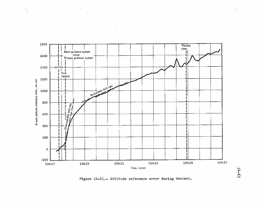
200
-200
i04:17 104,'19 i04:21 I04:23 I04:25 i04:27
Time, hr:min l-J
IO"xL,O
Figure 14-41.- Attitude reference error during descent.

14-64
The roll axis misalignment is accounted for by the higher-than-normaldrift rates during descent.
No indication of a problem existed before launch. Hardware malfunc-tions of the gyro and associated electronics have been hypothesized in anattempt to construct a model which would reproduce the error curve shownin figure 14-41. The worst-case electronics failure would only producedrift rates of 1 degree per hour compared to the 19 degrees per hour ob-served. Mechanical failures within the gyro which would duplicate flightresults have a very low probability of occurrence. Therefore, the mostlikely cause is contamination or an air bubble in the fluid between thegyro float and case.
Settling tests have been performed on abort sensor assemblies to de-tect contamination or air bubbles anddetermlne the best unit to installin the Apollo 17 lunar module. No evidence of contamination or air bub-bles was found.
This anomaly is closed.
14.2.8 Ascent Propulsion Chamber Pressure Increase and
Decay During the Ascent Firing
Approximately 157 seconds into the lunar orbit insertion firing, thetelemetry indication of the ascent propulsion engine chamber pressure re-flected an abrupt 10-psi rise followed by a slow decay to its initial valuein i0 seconds (fig. 7-3). The phenomenon was repeated ll seconds after theinitial pressure rise.
In order for the indicated pressure rise to be real, the mass flowrate into the engine and the vehicle acceleration must change. Examina-tion of the engine inlet pressure measurements and the acceleration datafrom the guidance and navigation system at the time of the pressure risesdid not show any change. Based upon these data and analyses, it is con-cluded that the observed thrust chamber pressure increases were not inthe engine, and that the indication of the pressure increase was due toinstrumentation.
Analyses and tests of the transducer did not reveal any failure modewhich would cause the transients observed in the data. The only methodby which the transducer could be forced to produce similar transients wasby heating the internal strain gage diaphragm.
The diaphragm heating could not have been caused by a leak in thesense llne or transducer since such a leak would not have sealed itself.
The heating, therefore, must have been caused by a mechanism occurring

14-65
inside the sense line, such as decomposition of small quantities of ex-plosive compounds deposited in the line by normal engine operation.
When the engine is fired, oxidizer flow starts at the injector about50 milliseconds before fuel flow. At the start of the fuel flow on Apollo16, oxidizer vapor was in the transducer and sense line at B to 6 psi pres-sure. Since the sense line was near 70° F (based on ground tests) and theoxidizer (nitrogen tetroxide) boils at 70° F, a film of liquid oxidizercould have been on the sense llne walls and in the transducer sense cav-ity.
When fuel flow was initiated, the indicated pressure increased tothe normal value of 125 psi. Since the transducer sense port is locatedin an area which is cooled by a fuel vapor barrier, the sense line wasthen pressurized with fuel (aerozine 50). The fuel could have then beennitrated by the nitrogen tetroxide depositing solid explosive compounds(such as hydrazine nitrate) on the transducer diaphragm.
The transducer temperature increases during the engine firing andstabilizes at about 130° F after 2 1/2 minutes. At 157 seconds, when thefirst pressure transient occurred, the deposits could have decomposed andprovided the necessary heat input into the strain gage diaphragm. Calcu-lations show that decomposition of less than 2 milligrams of Such com-pounds would cause the transients seen on the data.
Two to three milligrams of oxidizer can be introduced into the senseline before fuel flow starts. Since this amount of oxidizer will not gen-erate sufficient explosive compounds to damage the transducer or senseline, no corrective action is required.
This anomaly is closed.

14-66
14.3 GOVERNMENT FURNISHED EQUIPMENT ANOMALIES
14.3.1 Malfunction of Television Camera MonitorIn Command Module
The command module television camera monitor exhibited horizontal
bars during the initial usage. This condition cleared and performanceof the monitor was normal until the press conference telecast during the
transearth coast phase. At that time, the monitor had the same horizon-
tal lines reported during the initial usage. The horizontal-hold control
adjustment would not correct the horizontal line condition. The monitor
was turned off for approximately 5 minutes, then turned back on, after
which the monitor picture was normal.
Since the downlink television video signal was not affected, themalfunction was isolated to the monitor and associated cable.
Postflight testing of the flight unit has shown the following:
a. Horizontal synchronization may be maintained for 90 degrees of
the 300-degree rotation range of the horizontal synchronization control.
b. The 90-degree picture synchronization range shifts as much as
30 degrees counterclockwise in the 300-degree rotation range when the unit --is heated from ambient to 130 ° F, or when operated in a vacuum where it
heats up due to lack of convection.
c. The location of the 90-degree synchronization range within the
possible 300-degree rotation range varies as much as l0 degrees from sys-
tem activation to system activation. This condition is inherent in the
design of the monitor and was known prior to flight.
d. The optimum horizontal control knob setting is llO degrees from
the maximum counterclockwise knob position. Synchronization is lost and
horizontal bars appear when the control knob is turned 60 degrees counter-
clockwise or 30 degrees clockwise from the optimum position (fig. 14-h2).
If the horizontal synchronization control is set within 30 degrees
of the clockwise end of the 90-degree stable synchronization range at am-
blent temperature and then the unit is heated up, synchronization will be
lost. Synchronization may be reacquired by repositioning the horizontal
synchronization control; however, the repositioning must be done slowly orthe horizontal circuit does not have an opportunity to stabilize. These
conditions could have occurred in flight.

14-67
A 8
Ranges for maintaining horizontal synchronizationon the horizontal control knob at ambient turn-on con-
ditions is shown by line A and after monitor warmupis shown by line B.
Figure 14-42.- Horizontal synchronization knob operational range.
Thermal testing from minus BO° F to plus 132 ° F and vacuum testing
from 10-3 mm Hg to 10 -6 mm Hg has not disclosed any failures in the unit.
Circuit analysis has shown that the failure of any one of B compon-
ents in the horizontal hold (synchronization) circuit could have caused
the failure. These off-the-shelf commercial components are 2 dual diodes,
and one potentiometer that is the horizontal synchronization control. The
operating flight television monitor will be vibrated to search for any
possible intermittent condition.
History has shown fractures and contamination failures in similar
components. No corrective action will be taken. Prior to flight, it wasknown that this was a commercial monitor with known contamination and
drift problems.
For Apollo 17, the television monitor controls will have warm optimum-
setting marks applied to the television monitor case.
This anomaly is closed.
14.3.2 O_gen Purge System Antenna Broke
Following ingress after the second extravehicular activity, the crew
reported that approximately 2 inches had been broken off the tip of the
antenna on the Com_Lander's oxygen purge system (fig. 14-43). The antenna
had inadvertently been left unstowed while ingressing and it is believed
that the antenna was broken when it struck the ascent propulsion system
engine cover as the Commander was entering through the hatch.

14-68
Two inches
broken off_
I
)lacement Oxygenantenna purge
Antenna
plug
Portable life ..,
support system Antenna
Figure. 14-43.- Oxygen purge system antenna.

14-69/
One spare oxygen purge system antenna will be carried on Apollo 17
and will be stowed in the buddy secondary life support system bag on thelunar roving vehicle.
Installation of the spare antenna is accomplished by clamping the
_itenna adapter to the oxygen Purge system right-hand D-ring aud connec-ting the spare antenna coaxial connector in place of the broken _utenna'sconnector (fig. 14_-L3).
The installation will be made by the other crewman when operating inthe pressurized suit condition.
This anomaly is closed.
14.3.3 Experimental Gas/Water Separator Leakage
The experimental gas/water separator was cracked and leaking; there_fore, it was not used.
Postflight inspection showed that the fracture occurred at the base
of the threaded section of the lid (fig. 14-44) which is made of plexi-
glass. The unit was made of plexiglass for demonstration purposes. There
was no fillet radius provided in this area which results in a stress con-
centration point highly susceptible to cracking. The load which caused
cracking could haw_ been induced preflight or possibly when the device
was initially installed on the food preparation port by the crew.
No corrective action is required since this device will not be flownon future missions.
This anomaly is closed.
14.3.]4 Wrist Disconnects Difficult to Rotate
After exposure to the lunar surface environment, the wrist ring dis_connects on the C_mmander's and the Lunar Module Pilot's suits were hard
to rotate to the locked position and, once locked, were very difficult to
rotate out of the locked position. Lunar soil contamination is suspectedas the causes of this problem.
The wrist disconnect attaches the glove to the suit sleeve (fig. 14-45)
and is covered by a gauntlet on the glove. The gauntlet is loose fitting
around the suit sleeve and dirt can get to the wrist disconnect. Small
tolerances between the sliding surfaces are inherent in the design to make
it impossible to accidentally unlock the wrist disconnects.

14-70
Figure 14-44.- Gas/water separator failure.
Postflight inspection of the wrist disconnects showed that lunar dust
in the clearance areas caused the problem. Rubber dust covers for the ring
disconnects which will afford better protection from contamination will be
added for Apollo 17.
This anomaly is closed.

F 14-71
Pull to Compressionspring
Glove "-_
Depress to lock--_ _li_
Pull to L Retractionrelease_ seal pin
lock
0.0035 inch_ "_-fGIove
_ seal
Glove
lock,--- Retraction
_ pin"_ Cam
slot
_Compression
0. 0015 inchJ spring
Section through ring (typical eight places)
Figure 14-45.- Wrist disconnect.
/

14-72
14.3.5 Communications Carrier Microphone Boom Tip Loose
During the co_nunications check prior to the first extravehicularactivity, the microphone audio signal from the Lunar Module Pilot's head-set was too weak to operate the voice-operated keying circuitry in hisextravehicular communications system. This failure was attributed to aloose end cap on the right hand acoustic tube assembly (microphone boom),plus orange Juice blockage of the left-hand acoustic tube (fig. 14-46).The problem was cleared during flight by pushing the right_hand boom tipback into place and sucking out the orange Juice from the left-hand boom.
Postflight inspection of the right-hand boom by the manufacturershowed an insufficient amount of adhesive had been applied during fabri-cation of the tip to the acoustical tube.
Corrective action consists of a pull test to assure that sufficientadhesive has been used in attaching the tip to the tube.
This anomaly is closed.
14.3.6 Communication Carrier Intermittent
During the transearth coast phase, the Lunar Module Pilot experi-enced intermittent operation of his communications carrier headset ear-phone circuit. This condition was cleared by flexing the constant weargarment harness near the 21-pin connector (fig. 14-47).
Postflight testing involving the communications carrier umbilicaland control head, the constant-wear garment harness, and the communica-tions carrier headset showed no hardware problem. However, a conditionwas found wherein the microphone was active but the earphone was dead ifthe 21-pin connector was not mated securely. The Lunar Module Pilot stat-ed that he had disconnected the 21-pin connector several times during thetransearth coast phase.
Indications are the problem was caused because the connector was notfully seated and the flexing of the harness seated the connector.
This anomaly is closed.
14.3.7 Retractable Tether Would Not Fully Retract
The Commander's tether would not fully retract during lunar surfaceoperations.
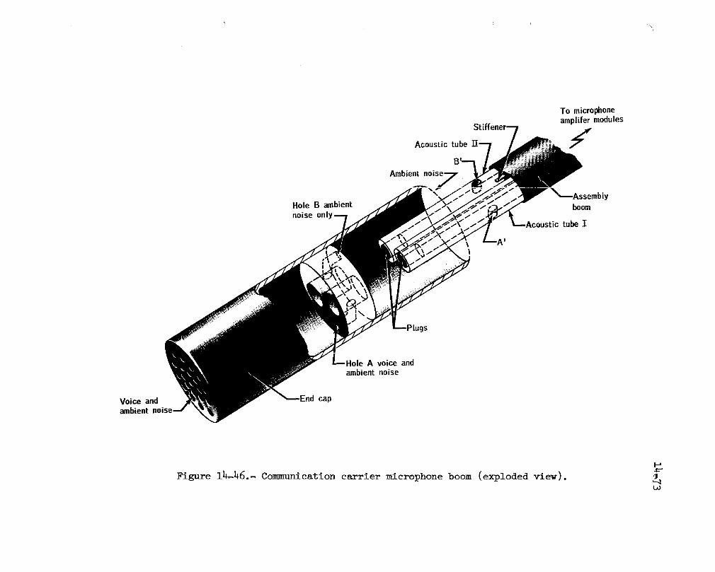
To microphoneamplifer modules
Acoustic tube f
Ambient
Hole B ambient / boomnoise
istic tube I
A voice andambient noise
Voice and End capambient
Figure 14-46.- Communication carrier microphone boom (exploded view).to

14_74
Acoustical
M icrophoneboom
Earpiece withmicrophone and
earphone drivers kmolded in
21-pin connector _,_
Figure 14_47.- Communications carrier.
Postflight inspection indicates that the tether is now operating;
however, there is a noticeable increase in friction (fig. 14-48) during
the retraction cycle. A thread sealant (loctite) was found on the spool
shaft, which increased the friction.
Future units will be tested for friction buildup prior to flight.
This anomaly is closed.
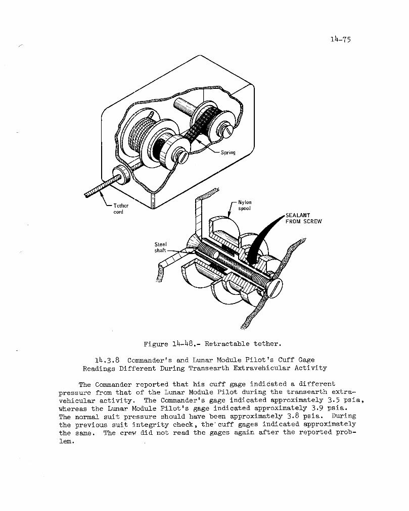
14-75/
/-- NylonTether H _/ spoolcord H _ .d_SEALANT
Steeljshaft
Figure 14-48,- Retractable tether.
14.3.8 Commander's and Lunar Module Pilot's Cuff Gage
Readings Different During Transearth Extravehicular Activity
The Commander reported that his cuff gage indicated a different
pressure from that of the Lunar Module Pilot during the transearth extra-vehicular activity. The Commander's gage indicated approximately 3.5 psia,whereas the Lunar Module Pilot's gage indicated approximately 3.9 psia.
The normal suit pressure should have been approximately 3.8 psia. During
the previous suit integrity check, the" cuff gages indicated approximatelythe same. The crew did not read the gages again after the reported prob-lem.

14-76
The cuff gage (fig. 14-49) is a bellows-actuated aneroid-type mechan-
ical gage which indicates differential pressure and has an accuracy of
+0.i psia. The gage opening to the outside of the gage is protected by
a centered plug. When the bellows is pressurized, it lifts the rocker arm,rotating the rocker in its pivots. The other arm on the rocker then rotates
the rack assembly, causing the pinion gear and pointer to rotate.
Bellows
kReturn Gear
Figure 14-49.- Cuff gage mechanism.

_ 14-77
During postflight testing at ambient and vacuum conditions, both the
Commander's and the Lunar Module Pilot's gages read well within 0.i psi ofthe 4.0 psi to which they were pressurized.
Both gages were disassembled and inspected. No discrepancies were
found. Minor contamination was found, some particles as large as 0.001 to
0.002 inch, but none were large enough to interfere with the operation of
the gage mechanism. Leak tests on the bellows were also performed and the
results were well within specification.
There are two possible explanations for the low reading. The first
is that a contaminant particle large enough to resist the movement of the
mechanism temporarily became caught in the gear train. The particle could
have been lost during disassembly. The second possibility is that thegage was misread.
Before final assembly, the gage is completely cleaned with freon and
dried. Since the cleanliness procedure is satisfactory and no anomaly
could be found in the flight gage, no corrective action is required.
This anomaly is closed.
14.3.9 Extravehicular Mobility Unit Maintenance Kit
In Command Module Expanded
The crew commented that the kit in the command module appeared tohave expanded more than the kit in the lunar module, and that the wet
wipes were the items which had expanded. This condition made it moreinconvenient to handle the kit.
Two extravehicular mobility unit maintenance kits are carried aboard
the spacecraft: one is stowed in a rigid locker in the command module and
one in a Beta cloth helmet stowage bag in the lunar module. Three flat
pockets, each containing two wet wipes for visor anti-fog treatment, are
provided in each kit. Before placing in the kit, the wet wipes packets
are evacuated to 1.5 psia and the packet is double heat-sealed. This is
done to reduce the size for packing and to reduce ballooning.
The individual packets are vacuum checked for leaks which would allow
the wipes to dry out. This check has also indicated that packet pressure
is approximately 7 psia as a result of film permeability, outgassing, etc.Therefore, some expansion can be expected at 5 psia.
The Apollo 17 crew has been familiarized with the expansion to be
expected. Some variation in expansion can be expected. Expansion doesnot create a problem, so no corrective action is required.
This anomaly is closed.

14-78
14.3.10 Purge Valve Pin Came Out
On three occasions during the first extravehicular activity, the pin
assembly (red apple) of the Commander's purge valve was accidentally re-
moved while ingressing or egressing the lunar roving vehicle. Each time,
the assembly was found and reinserted. During subsequent extravehicular
activities, the crew wore their purge valves rotated from the recommended
position to prevent the pin from being pulled out.
Testing indicates that the lunar rover lap belt buckle could be the
cause of the purge valve pin being accidentally removed.
A modification has been made to eliminate the barrel actuator spring
in the purge valve and to shorten and stiffen the pin assembly lanyard.
This modification will require manual pull-out of the purge valve barrel,
and will provide less chance of the red apple and lanyard being snagged.
This anomaly is closed.
14.3.11 Tool Carrier Fell Off Portable Life Support System
During the preparation inside the lunar module for the first extra-
vehicular activity, the tool carrier harness became disconnected and fell
off the portable life support system.
The harness is held together by a quick-disconnect snap buckle which
has a spring-loaded release pin (fig. 14-50). Only a small force (5 lh)
on the release strap is required to move the pin. The pin was inadvert-
ently pulled during the cabin activity.
The pin spring has been changed to increase the pull force required
to between i0 and 20 pounds so as to avoid inadvertent actuation.
This anomaly is closed.
14.3.12 Watch Crystal Missing
At depressurization, just prior to the third lunar extravehicular ac-
tivity, the Lunar Module Pilot noted that his chronograph crystal was gone.
The chronograph hands and face were not hit. However, about 12 minutes
later the movement stopped. Most likely, warpage caused by thermal cycling
allowed the differential pressure across the acrylic crystal to pop it out
of the case. The exposure to and penetration of lunar dust contaminationabout the Lunar Module Pilot's sleeves probably caused the failure of the
chronograph movement,

14-79
/
To Velcro attach
point on he met Oxygenpurgesystem
Portable
life support
stra_" " system-loaded release pin
(5 pounds force in upwarddirection releases)
Tool carrier
. Snap shackle
i
Figure 14-50.- Portable life support system tool carrierspring-pin shackle connection.
These chronographs are certified to a maximum temperature of 160 ° F.Testing has demonstrated that in the range of 190 ° F, the crystal is weak-
ened to the point where internal pressure can push the crystal off. For
the chronograph to reach a temperature of 190 ° F, direct continuous expo-
sure to incident solar radiation normal to its surface is required for ap-proximately 12 minutes.
These chronographs are tested at the Manned Spacecraft Center when
received, again before shipment to the Kennedy Space Center and again Just
prior to flight. The Apollo chronograph is a secondary timing device and
is not critical to mission success or crew safety. There are no plans forcorrective action.
This anomaly is closed.
jf
14-8o --
14.4 LUNAR SURFACE EXPERIMENTS EQUIPMENT ANOMALIES
14.4.1. Heat Flow Experiment Cable Broke
The Commander's legs became entangled in the heat flow experimentcable near the central station and his movements resulted in the cable
breaking at the connector to the central station (at the connector boardsolder joints); however, the central station did not move. Loss of theconnection to the central station resulted in loss of the heat flow ex-
periment.
The heat flow experiment is stowed on subpackage 2. Upon arrival at
the Apollo lunar surface experiments package deployment site, the experi-
ment is removed from the subpackage and the electrical ribbon cable is con-
nected to the central station by an Astromate connector (fig. 14-51). The
cable is bonded and soldered to a printed circuit board which is clamped
in a connector. The cable-to-board joint is reinforced by two to four
thicknesses of 0.5-mil Kapton tape.
Pull tests performed on the eable/Astromate connector configuration
indicate the strength at the cable/board interface was 31 pounds. A mod-
ified Joint assembly (fig. 14-52) which provides for strain relief and has
a pull strength of over 10O pounds will be used for the heat flow experi-ment connector and similar connectors on Apollo 17.
This anomaly is closed.
14.4.2 One Stake on Mortar Package Did Not Deploy
The lanyard pulled the release pins from three of the four spring-
loaded hinged stakes on the mortar package pallet and these three deployed
normally. The release pin for stake 3 was bent and jammed so that it couldnot be pulled out. The pallet was emplaced with the three stakes pressed
into the lunar surface, and the crew reported the complete mortar package
and pallet assembly was stable.
The mortar package pallet assembly includes four 7-inch long stakes
(fig. 14-53) which deploy normal to the pallet when the release pins are
removed. When the pallet is properly positioned, the stakes are pressed
into the lunar surface to provide additional stability to the platform.
Tests performed during the development of the pallet assembly showed
three deployed stakes are adequate to provide stability.

lh-S1
_, cable
._.._ _ Soldered
Break at ,_-_-Connector
solder joints, _ board
i
_'_S_ingcontactsI
To centralstation Before breakage
@
/
After breakage
Figure 14-51.- Heat flow experiment connector.
No corrective action is required as the experiment is not scheduledfor another mission.
This anomaly is closed.
lh.h.3 Mortar Box Roll Angle Telemetry Indicated Off-Scale High
The telemetry indication of the active seismic experiment mortar box
roll angle has been off-scale high since initial activation of the telem-
etry high-bit-rate mode after turn-on. The indication suggests the pack-
/ age rolled to the right between 25 ° and 145 °. However, the position of

Ico
i Reinforcing tape ro
Figure 14-52.- Modified heat flow experiment connector assembly.

/ 14-83
Figure 14-53.- Bottom view of active seismic
experiment mortar package pallet.
the bubble in the level indicator observed by the crew showed that the
mortar package was less than 5° off the nominal in combined pitch and
roll. The pitch angle sensor data indicated a pitch angle of minus 2.7 °
and photography confirms that the alignment was satisfactory. The off-
scale reading therefore indicates a failure of the sensor circuit.
The sensor circuitry includes a free-running multivibrator, with the
pulse-width ratio controlled by the sensor which functions as a potenti-
ometer (fig. 14-54). Numerous failure possibilities in the circuit, suchas open transistors, shorted capacitors, and open solder Joints could have
caused failure of the multivibrator and the off-scale high reading.
No corrective action is required as the experiment is not scheduledfor another mission.
/
This anomaly is closed.
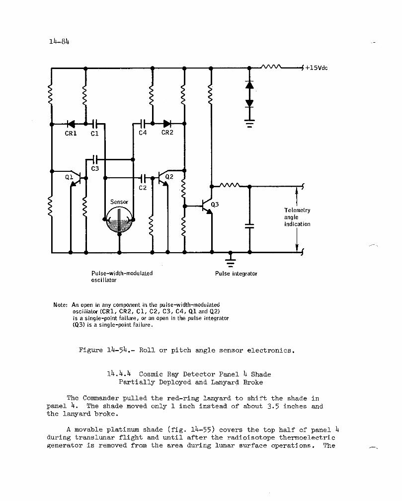
14-84
+lSVdc
D
CR1 C1 C4 CR2
lSensor _ Q3_-" Te|emetry
angleindication
Pulse-width-modulated Pulse integratoroscillator
Note: An open in any componentin the pulse-width-modulatedoscillator (CRI, CR2, Cl, C2, C3, C4, Q1 and Q2)is a single-point failure, or an open in the pulse integrator(Q3) is a single-point failure.
Figure 14-54.- Roll or pitch angle sensor electronics.
14,4.4 Cosmic Ray Detector Panel 4 Shade
Partially Deployed and Lanyard Broke
The Commander pulled the red-ring lanyard to shift the shade in
panel 4. The shade moved only i inch instead of about 3.5 inches and
the lanyard broke.
A movable platinum shade (fig. 14-55) covers the top half of panel 4
during translunar flight and until after the radioisotope thermoelectric
generator is removed from the area during lunar surface operations. The _.

s 11_85
Figure 14-55.- Panel 5 with partially deployed shade.
/
14-86
shade passes over a round guide bar at the top of the instrument (see fig.
14-56) and is connected in the back of the panel to the movable target
plate. The red-ring lanyard is attached to the bottom edge of the target
plate and, passing behind panels l, 2, and 3, it extends from the bottom
of panel 1. When the lanyard is pulled down, the target plate moves down
and the platinum foil moves upward over the round guide bar. This exposes
material mounted on the stationary backplate.
Examination of the panel assembly has shown that the failure of the
shifting mechanism was caused by a clamping of the target plate by two
retention bar screws which projected past the backplate into the target
plate, and effectively locked it in place (fig. 14-57).
Figure 1_-56 shows the panel _ assembly with the target plate and
shade fully deployed after having backed off the two projecting screws.
Note the rub mark from the screws on the target plate.
The assembly performed satisfactorily when deployed during the pre-
flight fit and function check. However, it was necessary to refurbish
the hardware after this operation, and the screw clearances may havechanged as a result of the refurbishment.
This experiment is not scheduled for another mission.
This anomaly is closed.
14.4.5 Vertical Staff of Gnomon Separated From Leg Assembly
When the gnomon (fig. 14-58) was being unstowed from its stowage bag
during the second extravehicular activity, the leg assembly remained in
the bag, and the vertical staff came out separately. The leg assembly,because of its color scale, was used during the rest of the lunar surface
photographic operations. The primary function of the complete gnomon is
to indicate the local vertical in lunar surface geology photographs.
The staff can be separated from the leg assembly by backing out the
gimbal pivot screws. However, all four screws must be backed out (fig.
14-59). There was no indication in the photographs of any screws backingout. During ground operations, a staff separated from the leg assembly
by breaking the inner gimbal pivot pins. The break occurred where the
0.040-inch-diameter pivot pin is pressed into the pivot screw.
The pivot assembly consists of standard high-speed steel reamer blank
material pressed into a stainless steel adjusting screw or retainer. The
reamer blank material provides the high strength and hardness required,

_ 14-87
Figure 14-56.- Panel 4 target plate and fully deployed shade.

14-88
Platinumsheet(movable
iOncO0 __//$ Pa/_e_ _I RetentiOnbar
iOncOlc:alrance _____ __l Back p'ate
l _///////_/_ _/_/F_///E N/_ T_ _e_IPel)ate
lrack
Figure 14-57.- Panel 4 screw interference
but has a tendency to be brittle without additional tempering. In addi-tion, the combination with stainless steel can be conducive to stress
corrosion. Either, or a combination, of the two conditions is considered
as the most likely cause of the anomaly.
Pivot pins for the Apollo 17 gnomon will be given the additionaltempering required for greater toughness, and a thin film of oil will be
applied for protection against corrosion. Ground tests have shown the
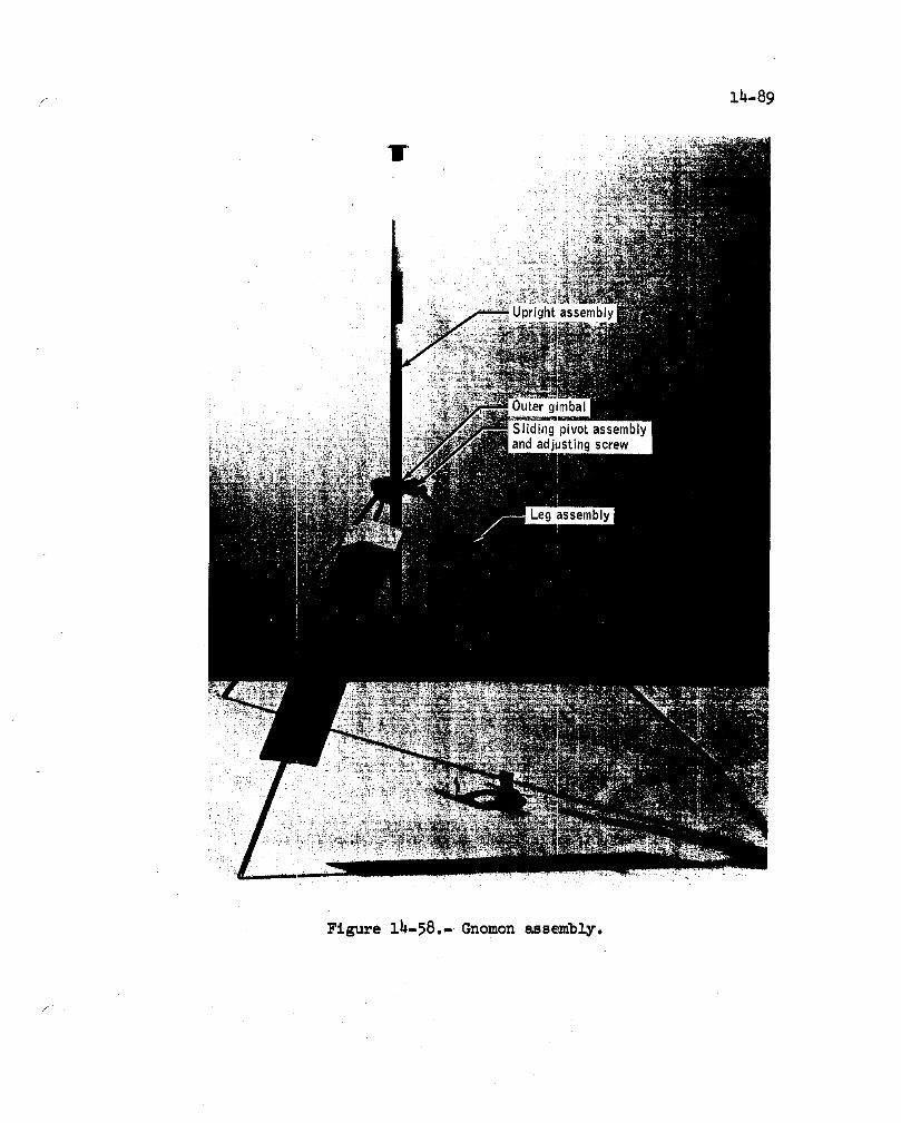
14-89
I
Figure ih-58.- Gnomon assembly.
f

14-90
, /'--Upright
,/assembly
r F Damping
Bearing _sher
=right / _ I._J//J_ Pivot pin
assemb,yBREAK Outergimbal IIIl[k\_
assemb,y kn_'_k _ PjVeOwLpin
Inner gimbal _
assembl'BREAK POINT
_lnner girnbalassembly
Figure 14-59.- Gnomon gimbal assembly
damping will be unaffected. Assembly of the pin in the screw will be de_
layed until as late as possible before launch so as to reduce the time
for possible stress corrosion to occur.
This anomaly is closed.
14.4.6 Documented Sample Bag Dispensers Fell Off
70-mm Camera Bracketsi:
During the geology activities on the lunar surface, the bag dispenser
assemblies repeatedly fell off the brackets on the 70-mm cameras.
The dispenser is mounted on an adapter (fig. 14-60) which is inserted
in the ring-sight tee-slot bracket on the camera. The adapter-to-tee slot
interface is horizontal and depends on springs in the tee slot to hold the
adapter in the latched position. This latching method is inadequate.
The adapter has been redesigned so as to provide a positive lock in
the installed position as shown in figure 14-60.
This anomaly is closed.

Ring sight
Latch _ bracket
Stop
;pring
gshoe
I
Figure i_-60.- Sample bag dispenser retention.

lh-92
14.4.7 Screws and Holding Ring Came Off One of the
Documented Sample Bag Dispensers
The three screws which fasten the bag ring to the bracket plate had
come out on one of the documented sample bag dispensers and consequentlycame apart when unstowed.
The three flat-headed stainless steel screws mate with threads in the
aluminum ring (fig. lh-61). The heads are staked to the aluminum bracket
plate. Thread sealant materials are not permitted because of the possi-bility of lunar sample contamination.
The Apollo 17 dispensers will be re-inspected to assure proper stak-
ing of the screws and tightness of the threads in the aluminum ring.
This anomaly is closed.
supportring
bracket
headscrews(3)stakedtobracket
Samplepocket
Figure 14-61.- Documented sample bag dispenser assembly.
14,4.8 Sample Collection Bag Fell Off the
Portable Life Support System Tool Carrier
During lunar surface operations, the Commander's sample collection
bag came loose from the portable life support system tool carrier severaltimes and fell off' once.
The sample collection bag essentially consists of a Teflon bag on a
metal frame (fig. 14-62). The bag opening is covered by a Teflon lid on
a hinged metal frs_e. Attached to the metal frame on one side of the bag,
about 2 inches below the lid, is a 3/8-inch-wide stainless steel strap withoffsets to accomodate the two hooks on the tool carrier. About i inch from
the bottom of the same side is a 1-inch-wide Teflon band, sewn to the hag,
with an offset loop approximately I inch by 5 inches to accomodate the
Velcro strap from the bottom of the tool carrier. The Velcro strap, when
tightened down, keeps the bag from floating or bouncing off the hooks.
During the lunar roving vehicle operations, the Velcro strap sometimes
loosened because of the entrapped lunar dust so that the bag could comeoff.
For Apollo 17, the sample container bag hooks that are attached to
the portable life support system tool carrier have been redesigned to pre-
vent the bag from floating or bouncing off the portable life support sys-
tem. The new hook design consists of a flat spring and a stop so thatthe same force is required to install and remove the bag.
This anomaly is closed.
14.4.9 Lunar Surface Far Ultraviolet Camera Azimuth
Adjustment Became More Difficult
Rotating the camera assembly for each azimuth setting was more dif-
ficult than expected, and became progressively difficult during the lunarstay.
To adjust the azimuth to the proper dial reading, the camera is ro-
tated on a 12.5-inch diameter ball-bearing ring (fig. 14-63). The bear-
ing is not sealed; however, the crew did not observe any lunar dust on thebearing.
The azimuth ring bearing was packed with a waxy, low-outgassing grease
which stiffens appreciably at temperature below 50° F. This grease is nor-mally used as a sealant rather than a lubricant. The camera was intention-
ally kept in the shade to protect the film from high temperatures. As a
result, the grease stiffened. The manual azimuth adjustment operation was
not included in cold chamber tests with other operations of the camera.
f

14-94
Figure 14-62.- Sample collection bag on portable life
support system tool carrier.

14-95
outer
Figure 14-63.- Far ultraviolet camera.

14-96
The difficulty was caused by the use of the wrong type of grease inthe azimuth ring bearing.
The experiment is not scheduled for another flight, and no furtheraction is required.
This anomaly is closed.
14.4.10 Velcro Patch Came Off Both Padded Sample Bags
When the crew wrapped the Velcro strap around each of the paddedsample bags to further secure them, the Velcro attachment patches cameoff the bags and the straps were ineffective.
A 20-1nch-long wrap-around Velcro pile strap is provided to hold thebag closed in addition to the usual tab closure (fig. 14-64). One end ofthe strap is bonded _ith a fluorel adhesive to an etched Teflon patch which
Velcropile straVelcrohook
Tab closur=
EtchedTeflon patch
CORRECTBONDINGADHESIVE
Paddedsamplebag (Teflon)
Figure 14-6_.- Padded sample bag.

14--97
is heat-sealed to the Teflon bag. A Velcro hook patch is bonded to theetched Teflon patch with a pressure-sensltlve adhesive and provides theattach point for the other end of the strap. The peel strength of thepressure-sensltlve bond was less than that of the Velcro pile-to-hook con-nections. Consequently, when the Velcro strap was adjusted to the propertension, the hook patch came off the bag.
The problem resulted from using the improper bond material for theVelcro hook patch.
This equipment is not scheduled for another flight and no furtheraction is required.
This anomaly is closed.
14.4.11 Loop Came Off Lanyard forPenetrometer Stowage Release Pin
When the Commander was unstowing the penetrometer, the end of thelanyard loop pulled out of the swaged Joint. The pin was pulled by _Tap-ping the wire around the gloved hand.
/ There were 71 lanyard assemblies on the lunar module, of which ninewere made with 3/64-inch cable, and the rest with 1/16-inch cable. Thelanyard with the pulled-out loop was made with B/64-1nch cable.
A condition similar to the one experienced by the Commander was sim-ulated by utilizing a B/64-inch cable, a B/64-inch-diameter sleeve, anda 1/16-inch-dlameter crimping device.
The nine lanyards made with 3/64-inch cable are to be changed to1/16-inch cable and pull-tested. The existing 1/16-1nch-cable lanyardswill also be pull-tested in cases where the pull pin cannot be pulledwithout the lanyard.
This anomaly is closed.
14.4.12 Active Seismic Experiment Pitch Sensor IndicatadOff-scale High After Launching the Third Grenade
Immediately prior to launching the third grenade, the pitch sensorindicated that the mortar package assembly was pitched down about 8° fromthe nominal plus 45° elevation (fig. 14-65). Within 2 seconds after fir-ing the mortar, the sensor indication was off-scale-high and has remainedoff-scale-hlgh.
/

14-98
Receiving antenna
assembly
.Stakes
Normal position Apollo 16 position prier to first(45 ° elevation) mortar firing (43 ° elevation)
Position after first mortar Position after second mortarfiring (-34° elevation) firing (37 ° elevation)
Figure lh-65.- Pitch movement of mortar package assembly.
14-99f
Based on ground tests during which the assembly was rotated through
360 °, an off-scale-high indication means either that the mortar package
assembly is pitched up between 25 ° and 155 ° above the normal plus 45° ele-
vation, or that the sensor has failed. There are two stable positions of
the mortar package and pallet assembly between these two points: (i)
pitched up 30° above normal (75° elevation), and (2) pitched up 135 ° abovenormal (180° elevation). The temperature profiles for the two temperature
sensors on the mortar package assembly, when compared with the calculated
temperature profiles for elevations of 45° and 75° , indicated that themortar package assembly was not in the 75° elevation position. In the
180 ° elevation position, the receiving antenna would have been broken off
or badly bent and ]_ing on the ground. In this case, complete real-timeevent data would not have been received during the flight of the third
grenade. However, complete real-time event data were received during theentire 19-second f]_ight, indicating that the mortar package assembly was
not in the 180 ° elevation position.
The pitch and roll sensor circuits are identical (sec. 14.4.3), andthere are numerous failure possibilities in the circuit (such as open tran-
sistors, shorted c_acitors, and open solder Joints) which can cause fail-ure of the multivibrator, and result in the off-scale-high indication.
It is most likely that there is a failure in the pitch sensor circuit,and the orientation of the mortar package is unknown.
No corrective action is required as the experiment is not scheduled
for another mission.
This anomaly is closed.

14-I00
14.5 ORBITAL EXPERIMENT EQUIPMENT ANOMALIES
14.5.1 Mapping Camera Extend/Retract Times
Were Abnormally Long
The first mapping camera extension was normal, but the retraction
required 2 minutes and 54 seconds. The normal time for extension or re-
traction is approximately i minute and 20 seconds. The second and third
extensions and retractions required about 3 minutes, but the fourth re-traction and fifth extension were both normal at i minute and 18 seconds.The fifth (final) retraction time was i minute and 34 seconds.
This anomaly is similar to the Apollo 15 problem in that the times of
the first extension and retraction were normal and subsequent times were
excessive, with some in excess of 4 minutes. In addition, the Apollo 15
camera would not retract after the final (15th) deployment. Subsequent
investigations did not isolate a probable cause of that anomaly.
Deployment rails attached to the bottom of the camera slide through
ball-bushings that are part of the deployment mechanism (fig. 14-66). De-
ployment of the camera is accomplished by the drive screw turning withinthe drive nut, which is bolted to the camera. Friction in this screw-nut
drive is minimized through the use of recirculating streams of ball bear-ings riding between the threads of the nut and screw.
Two redundant motors, each capable of deploying the camera should
the other fail, power the drive screw via a drive train consisting of
clutches, gearing, and a "no-back" device that locks the deployment mech-
anism when power is removed from the motors. The motors, clutches, andmost of the gearing are contained within the gear box. Two clutches are
used, one with each motor. Their design is such that, should a motorseize, its clutch will decouple from the drive train. The clutches con-tain bearings that are lubricated with a mixture of silicone oil and
grease; therefore, a test was conducted to determine the effect of con-
tamination of the friction surfaces by the lubricant. The result was
that lubricant applied directly to the friction elements did not signif-icantly affect the clutch performance.
Preflight deployment operations had disclosed a chattering noise in
the mechanism when the retraction was aided by the pull of the cable har-
ness to the camera. An analysis of the drive train indicates that a state
of dynamic instability may exist in a zero-g environment because of the
resultant loss of the damping provided by the deployment rail friction.
Simulated zero_g tests are being conducted by suspending the camera with
a long cable in order to remove the weight from the rails while maintain-
ing the inertial properties of the camera during the deployment.
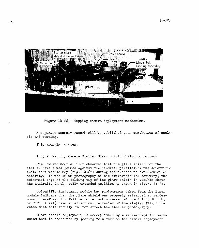
14-101,f
ballbushing assembly
Figure 14-66,-Mapping camera deployment mechanism.
A separate anomaly report will be published upon completion of analy-
sis and testing.
This anomaly is open.
14.5.2 Mapping Camera Stellar Glare Shield Failed to Retract
The Co_nand Module Pilot observed that the glare shield for the
stellar camera was jammed against the handrail paralleling the scientific
instrument module b_ (fig. 14-67) during the trsmsearth extravehicular
activity. In the 16-mm photography of the extravehicular activity, the
outermost edge of the folding tip of the glare shield is visible above
the handrail, in the fully-extendedpositi0n as shown in figure 14-64.
Scientific instrument module bay photographs taken from the lunar
module indicate th_ the glare shield was proper]_ retracted at rendez-
vous; therefore, the failure to retract occurred at the third, fourth,
or fifth (last) camera retraction. A review of the stellar film indi-
cates that this anomaly did not affect the stellar photography.
Glare shield deployment is accomplished by a rack-and-plnlon mech-
anism that is connected by gearing to a rack on the camera deployment

14-102
Figure 14-67.- Mockup photograph of glare shield handrail.
mechanism (fig. 14-66). As the camera is deployed from the scientific
instrument module bay, the glare shield is automatically ektended out-
ward from the stellar camera. Two sets of miter gears are utilized.
Both sets are located within the camera body. Each set contains a steel
gear and an aluminum gear.
During the inspection of the exposed film prior to processing, nu-
merous aluminum particles were found wound up with the film. Analysis
of the chips indicated they were 6061 alloy rather than the 2024 alloy
of the gears, showing a source other than the gears.
Since the glare shield deployment mechanism is driven by the camera
extend/retract action, useful information related to this anomaly may be
obtained from the camera zero-g tests being performed.
A separate anomaly report will be published upon completion of anal-ysis and testing.
This anomaly is open.

f 14-103
14-5.3 Laser Altimeter Output Power Degraded
The laser altimeter performed normally during its first operating
period - 41 minutes during lunar revolutions 3 and 4. Evidence of laser
degradation began to appear early in the second operating period (revo-
lution 16). The pulse forming network voltage controller began stepping
to voltage position i (step 0 is the initial setting), and the laser out-
_ put power, when in step 0, was occasionally too low for ranging - as man-
ifested by altitude readings of zero meters and an overflowing range
counter. For this period, altitude data validity was about 68 percent;
i.e., approximately 32 percent of the data was "zero".
The degradation rate appeared to be rather constant during the next
three operating periods, with voltage step 4 appearing near the end of the
fifth period (revolution 47). During the sixth operating period (revolu-
tion 60), the degradation appeared to accelerate and the pulse forming net-
work voltage controller reached step 5, the highest available step, by the
end of this run. In step 5, maximum voltage is delivered to the flashlamps
which "pump" the laser ruby. During the last scheduled operating period
(revolution 63), laser output degraded to the point that no further alti-tude data were obtained.
There were approximately 2400 laser operations (firings) during the
mission. The laser output appeared to degrade more rapidly than during
the Apollo 15 mission (fig. 14-68) but was compensated by the action of
the pulse forming network voltage controller added for this purpose as
a result of the A_ollo 15 anomaly. The voltage controller consists of a
laser power status sensor (photodiode) located inside the laser module
and associated circuitry to increase the output of the pulse forming
network power supply if the sensed laser power is lower than a pre-estab-fished threshold.
Compensation was sufficient until the last 40 minutes of the final
scheduled operating period. After this time, laser output was apparently
_. too low for ranging against the sunlit lunar sz_face. One consequence of
the pulse forming network controller operation was some loss of altitude
data on alternate laser firings ; therefore, data validity was only about
70 percent during most of this mission. Had the controller not been added
to this unit, the amount of valid data obtained would have been signifi-
cantly less. An estimate of the data that would have been obtained is
shown in figure 14-68. The controller operates to increase input power
to the laser if the laser output on the preceding operation was low, and
to decrease input if the output was high. It appears that the threshold
may have been low, or the voltage steps too large, so that inadequate out-
put was obtained on the lower step, resulting in loss of altitude data.
This was particularly true on illuminated portions of the lunar surface
where background radiance decreases receiver sensitivity.
/

I
o
Note: Expressed as percentage of valid range data obtained.
100-
8o/-Apollo 16
%%60
o_ 40 J
_ /-- Estimal_d degradation rate of Apollo 16 _--- Complete loss,igf unit without pulse forming of data due to
network cootroller photomultiplier
_lL voltage anomaly20
/"- Completion of
/Apollo 16/ lasler mission
0 4 6 8 10 12 14 16 18 20
Operating Lime, hr
Figure 14-68.- Laser degradation versus operating time.

f 14-i05
Analysis of the Apollo 15 failure indicated that the most probablecause was contamination of the internal optical surfaces by oll from theQ-swltch bearings (fig. 14-69). Consequently, a delta qualification testwas performed on a laser module, using new bearings incorporating oil-re-tainer shields. The qualification test consisted of a 220-hour thermalvacuum test which included a 50.5-hour mission operation timellne. Over9000 laser firings were performed and the voltage controller had onlyreached step 4 by the end of the test.
Since the Apollo 16 laser also incorporated these new bearings, sim-ilar improved performance was expected during the mission. The number ofprelaunch discharges was limited, however, to conserve laser life so therapid laser degradation was not detected before launch.
The plots of d_ta validity versus operating time in figure 14-68 areapproximate in that the effects of laser module temperature and lunar sur-face illumination have been averaged out. During the first ll hours oflaser operation during Apollo 15, the command and service module was ina highly eccentric orbit which, due to the range limitations of the laseraltimeter, caused tlheloss of approximately 50 percent of the altitudedata. Since the data loss was not due to a hardware malfunction, thecurve for Apollo 15 is drawn at 100 percent during this period.
Contamination of the optical surfaces within the laser module is con-
sidered to be the most likely cause of the degradation. A secondary causeis the degradation of the flashlamps because of discoloration of the lampquartz as the result of the repeating high intensity light flashes and im-purities in the quartz. The lubricant in the Q-switch motor and rotor
bearings is apparently the principal source of contamination. Bearinglife tests indicated that elimination of the oil reservoir in the bearingsby the use of oil-lmpregnated bearings does reduce oil migration. Conse-quently, the ApollO 17 laser module will be modified to incorporate Q-switch bearings wi_h oil-impregnated ball retainers and selection of flash-lamps using a high purity quartz which is not as subject to degradation.Cover plates, installed over both access openings to the motor coupling,will complete the enclosure of the motor bearing.
This anomaly is closed.
14.5.4 Panoramic Camera Automatic Exposure ControlIndicated Low Light Levels
The panoramic camera contains a light sensor and associated circuitrythat determines the film exposure. As the scene luminance decreases, theoutput from the sensor decreases ; the resulting signal delivered to thesllt width servo causes the exposure sllt to widen, thereby automaticallyincreasing the film exposure. The slit width and the light sensor outputare both telemetered (fig. 14-70)./

It.Joo-,
_ Deviation and
elevation prism
i //.,_
_ uartzQ switch motor Resonant reflector
_ ' J (20 000 rpm) lamp
,, (output port)//
/ /
""OutputI g
I ILaser
crystal-Q switch
Jartz
lamp
Q switch•, prism
Prism LQ switchhousing bearing
Figure 14-69.- Laser altimeter module light reflection components.

lh-107
Slit width control I
--] circuitryI
_-- Feedback /
Gain _capacitor i lslit width
output
I Feedhaokt I,ig tros stor--' I sonsor
_ II L'_ _J,outputlI
PhotodiodeI AmplifierI I[ I _AAA,_,-_'_'-_ Light intensity
.... _" " data to telemetryLight sensorelectronics Telemetryaseemhly buffer
Figure 1_-70.- Block diagram of panoramic camera
automatic exposure control.
/
Throughout the mission, telemetry indicated that the sensor output
was too low, resulting in a slit width that was too wide. Consequent]y,an overexposure of the film occurred. Based upo n preflight brightness
calculations and re_l-tlme mapping camera exposure data, the degree of
overexposure was estimated to be approximately 1-1/2 to 2 f-stops. As a
consequence, the filLm processing was modified to compensate for this de-
gree of overexposure°
The problem Collld have been the result of contamination on the sensor
optics or a failure in the light sensor or its associated circuitry (fig.
14-71). Analyses _nd tests have shown that component open or short cir-
cuit failures could not have caused the problem since the amount of over-
exposure could not be duplicated. Feedback capacitor leakage (equivalent
to about 6 megohms 3eakage resistance), or a decrease in the gain of the
photodiode input am[plifier (an integrated circuit), or a decrease in pho-
todiode sensltivity, shown in figure 14-70, could have caused the problem.
These components, however, have no previous history of these types of fail-
ures; therefore, no corrective action will be taken.
A review of data indicates that the problem occurred preflight, at
some time between January 5, 1972, and February 25, 1972. The failurewas not detected because the test merely ascertained that the light sen-
sor responded to stimulation (a light source placed in front of the sen-
sor). Although sensor output voltage was recorded, no voltage toleranceshad been established for the test.

14-I08
Photodiode-
_Light sensor O.O625-inch
I I_)(_'_ (_15" ,ight sensor
(cordwoodelectr°niCSmodule)aSsembly-- -- I l_1f?_ll__ lens aperature
_ L-Lens housing, /
//7_//////y/////////////y/////////////7/k////_. --I nfrared filter
Figure 14-71.- Panoramic camera light sensor assembly.
To preclude a similar problem not being detected in ground testing,sensor output voltage limits have been added to the test procedure.
This anomaly is closed.
14.5.5 Erratic Laser Altimeter Photomultiplier Tube Voltage
During the revolution-60 operation of the laser altimeter, the highvoltage supply for the photomultiplier tube was occasionally erratic.
During the next operating period (revolution 63) the erratic behavior be-came more pronounced (fig. 14-72), and there were several instances when
the voltage failed to rise from the quiescent (idling) level.
The photomultiplier tube power supply idles at approximately minus700 volts during the periods between laser firings. About three-fourths
of a second before the laser fires, the power supply is commanded to in-
crease its voltage to the value required for proper photomultiplier tube
operation. This value is determined by automatic gain control circuitry(fig. 14-73) that senses the background illumination from the lunar sur-
face. As a result of the automatic gain control action, the photomulti-
plier tube voltage varies during the mission and appears somewhat noisy,as evidenced by the normal trace (revolution 38) shown in figure 14-72.
The revolution-63 trace is unusually erratic, however, and failure to
rise from the quiescent level is indicative of anomalous operation.

14-i09/
-18000
-1350
,900 I I Quiescent voltageo -450>
4-= 2 seconds
0 Time, second,,
(a) Revolution 38
-1800
-1550I
-900"---'_'--Ik _ _ Quiescent voltageo -450>
0 _-_ 2 secondsTime, seconds
(b) Revolution 63
Figure 14-72.- Laser altimeter photomultiplier voltages.
[PhoomutipierI\tu II Signal output Video Stop signal to
Echo from amplifier Lcountercircuit'--lunar surface / [ __ __.
IIII
power supply _ Integrator detectorI1I Automatic gain
[ control circuitry /
Figure 14-73.- Laser receiver circuitry.

14-110
Some of the anomalous voltages which occurred during revolution 60
were probably caused by sunlight reflecting off the deployed spectrome-
ters. Although the spectrometers were not in the field of view of the
altimeter receiver optics, reflections from the spectrometers may have
been reflecting from the altimeter's gold-plated lens barrel and, thence,
into the photomultiplier tube, thereby unduly affecting the automatic
gain control action. This does not, however, explain the revolution-63
performance, because the mass spectrometer had been jettisoned and the
gamma-ray spectrometer was not deployed.
A number of intermittent conditions are possible that could either
increase the gain of the photomultiplier amplifier or couple electrical
noise into the amplifier's input. Either of these occurrences couldcause the effects observed in the data. An intermittent condition could
have been caused by the cyclic thermal environment that occurs as a re-sult of lunar orbit operation. Since qualification test results and ac-
ceptance tests are considered to be adequate for this equipment, no cor-rective action will be taken.
This anomaly is closed.
14.5.6 Overexposure of Nine Frames of MappingCamera Metric Photographs
Nine frames of mapping camera metric photography were overexposed.
The overexposures were single events dispersed throughout the film. Most
overexposures occurred when the shutter was being CO,handed to a slower
speed by the automatic exposure control because of decreasing scene lum-
inance. Instead of going to the next slower speed, the shutter would
drop to an even slower rate for one frame and then return to the properrate for the remainder of the frames.
Shutter speed is controlled by a photo cell which senses the lightlevel in the camera's field of view. The photocell operates in a servo
system which controls shutter speed. The photocell servo system consists
of the photocell, a comparator, a voltage reference, and a seven-stage
shift register, as shown in figure 14-74.
The complete operational sequence of the photocell servo is as fol-
lows: Assume that the reflected lunar surface light level is decreasing,
thus, the photocell output voltage is less than the reference voltage.
The comparator supplies a continuously decreasing signal to the shift
register, thus enabling the register to shift the "on stage" toward theslower shutter speed. A group of six clocking pulses are supplied to
the register once before each film exposure (about every 20 seconds).
When the first clocking pulse appears, the on condition is shifted one

Referencevoltage
generator F'-_ 1I
II
'IIncrease JComparator Decrease
Photocell
L. J ShutterControl 7 stage speedlogic shift control
registerI
Figure 14-74.-Photocellservosystem.

14-112
stage. The register then causes the reference voltage to decrease onestep. If the photocell output is still less than the ne_ reference volt-
age, the second clocking pulse will shift the on condition to the next
lower stage in line in the shift register. This sequence will continue
until the difference between the photocell output voltage and the refer-
ence voltage is within the dead band of the comparator, at which time
the comparator output sigaal to the shift register will disappear and
the register will stop shifting. The shutter speed will then be deter-
mined by which stage of the shift register is in the on condition.
The seven shift-reglster stages correspond to seven shutter speeds
with the first corresponding to the fastest speed, and the seventh cor-
responding to the slowest speed. The logic is designed such that at ini,
tial camera turn-on or whenever either of two invalid logic conditions
exist (all stages off or more than one stage on), the fifth stage isturned on and all others are turned off.
Noise voltage pulses can set or reset (turn on or off) any stage in
the register regardless of the condition of any other stage. Thus, more
than one stage could be on at the same time, and, in this condition, when
the first clocking pulse occurs, the logic would turn stage five on and
all other stages off. The remaining five clocking pulses then could still
shift to the on stage required by the light level seen by the photocell
and no anomalous operation would result. Should the noise pulse occur -
during the clocking cycle, however, there may not be enough clockingpulses left to shift the on condition back to the required stage. Since
the effect of the noise pulse is to shift the on condition to stage five,
slow shutter speed and overexposure can be expected to occur more oftenthan fast shutter speed and underexposure.
Noise voltage on the power supplied to the register or generated bysome intermittent condition in the camera must have switched one or more
stages in the shift register on or off. The camera qualification test
results and acceptance tests are adequate. No corrective action is nec-
essary.
This anomaly is closed.
Ih.5.7 Contaminated Mapping Camera Film
A considerable amount of contamination was found throughout the met-
ric and stellar film from the mapping camera during the pre-processing
inspection. Special cleaning procedures were developed and successfully
used in removing a majority of these particles prior to film development.Consequently, the photography was not compromised.

14-113
The contamination included many types of particles, most of them be-
ing metal chips of various sizes and shapes (fig. 14-75). There were
also a few particles which appeared to be paint chips.
Analysis of several of the metallic chips with a scanning electron
microscope indicated that the chips were an aluminum alloy.
The camera frame and cover are aluminum; however, consideration of
the camera and cassette mechanisms plus visual examination of the parti-
cles indicate that the contamination was not caused by wear in the camera
Figure 14.-75.- Metal particles found on mapping camera film.

14-i14
or cassette, but was more likely, either residue from manufacturlngorintroduced from some outside source,
The Apollo 16 camera and cassette were tumbled and cleaned at the
contractor's facility, and the camera again tumbled and cleaned at the
Kennedy Space Center. Contaminate particles were removed in each case.
It is possible that some additional particles remained entrapped until
the prolonged exposure to the zero-g environment during the mission.
More thorough cleaning and inspection procedures are being imple-
mented for Apollo 17. In addition, the special cleaning procedures which
were developed for the Apollo 16 film will again be used with the Apollo17 film.
This anomaly is closed.

14-115/
14.6 LUNAR ROVING VEHICLE ANOMALIES
14.6.11 Electrical System Meter Anomalies
The lunar roving vehicle experienced the following electrical system
meter anomalies at initial powerup during the first extravehicular activ-
ity:
a. Battery 2 voltmeter indicated off-scale low.
b. Battery 2 ampere-hour meter indicated off-scale low.
c. Battery 1 and 2 temperature meters indicated off-scale low.
Later, during the second and third extravehicular activities, anomalous
conditions were experienced. The battery 2 ampere-hour meter showed an
increase in ampere-hours and the battery 1 temperature meter showed a
decrease in temperature to off-scale low.
The circuitry associated with the electrical system meters is shown
in figure 14-76. Note the multiple wire-crimp splices in the system. Thereturn for the volt/ampere meter is connected to the battery return with
a five-wire crimp splice containing one 12-gage wire, one 20-gage wire,
and three 22-gage wires. This splice was associated with the electrical
modification made on the Apollo 16 lunar roving vehicle at the launch site.An intermittent connection at this splice would explain the volt meter
reading off-scale 1¢_ and then later reading properly. An open connection
at this splice would reverse the polarity on the ampere-hour integrator
sense line and give a false indication of battery 2 charging as observed
during the second and third extravehicular activities (see fig. 14-77).
Also, the battery 1 ampere-hour meter indicated a 20-ampere-hour decrease
rate which was greater than predicted. However, a review of the data shows
that the current readings taken during this period of time were correct and
a 20-ampere load was present. Therefore, the ampere-hour integrator for
battery 1 was working properly.
Both battery temperatures reading off-scale low and then reading prop-
erly could be caused by an intermittent connection at the four-wire splice
(fig. 14-76). However, this would require a simultaneous open circuit at
two splices initially, which later corrected themselves, and finally, fail-ure of a single splice in the battery 1 temperature circuit.
The second possibility is that two circuit breakers were not closed
electrically, resulting in no power to the temperature meter circuits and
ampere-hour integrators. This would also explain the battery 2 ampere-
hour integrator reading off-scale low, but would not explain the battery 1
,f

EJ
IFJF-JO'_
Test connection
Temperature 'l/Splice
sensing _ _Temperature meter
•.--, (battery 2)
Bus B circuitBridge//
Sz_Iwi_Te) J[x 3 (battery 1) / Ampere-houri _
switch C) I _ I_ Ampere-hour
Volt/ampere meter
To battery
meter
Splice circuit(5 wire)
}L I integrator /
Shun Test ]-O_ ,-1battery 2 _ ;--.... /--Ampere-hour
connection sensing I
.-=- 10_
•Jumper intest connectiml
Figure 14-76.- Lunar roving vehicle electrical meter circuitry.

Power ]supply
L_;--- tcou Iometer
Oscillator
Outputswitch
DetectorBattery 2 Pulse
Splice C amplifier(5 wire)
Normal c_ "tpath Polarity withu open at splice ' ,
+ :2.26K ohm ,2.26K ohm
/ 10 ohm
/Normal
polarity--_ Shunt IWith open at this point, 20 ohmcurrent path is through I Ampere-hour
-- meter+ two 10 ohm resistors Im
( )Splice F-'4"I
Figure 14-77.- Battery 2 ampere-hour integrator circuit.
14-118
ampere-hour integrator reading full-scale, unless a sneak circuit existed.
This sneak circuit must result from anopen circuit at the flve_wire splice
in the battery 2 volt and ampere_hour meter circuit.
If no sneak circuit can be identified, the most likely cause of temp-
erature meter anomalies would be the four-wire splice in the temperaturemeter circuits.
This anomaly is open.
14.6.2 Rear Steering Inoperative
On the initial drive to the modular equipment stowage assembly, the
crew reported that the rear steering was inoperative; however, upon leav-
ing that stop, both the front and rear steering systems were operational
and functioned normally for the remainder of the mission.
Analysis of troubleshooting procedures initiated by the crew and a
review of the switch- and circuit-breaker configuration timeline suggeststhat no intermittent hardware malfunction existed. An intermittent con-
dition in the rear steering electrical system would explain the anomalous
operation, but this is very unlikely because the system exhibited normal
performance for the balance of the lunar activity.
Figure lh-78 shows that switch 10, circuit breaker 10, and circuit
breakers 3 or 4 must be closed to provide power to the rear steering sys-
tem. In addition, circuit breakers 3 or 4 must be closed to provide ±15Vdc for the drive as well as steering control electronics. Since the ve-
hicle had both mobility and forward steering, at least one of these breakers
made contact. Switch l0 was cycled after vehicle motion; however, the rear
steering remained inoperative. Circuit breaker l0 could possibly have been
open due to some contaminate existing in the breaker.
Another possible cause of the anomalous condition is in the steering
servo system (fig. 14-79). A signal generated by the hand controller is
coupled to the input servo amplifier as an error signal across a bridge.
This signal is amplified and applied to the steering motor field coils in
a direction determined by the polarity of the input signal which depends
upon the direction of the hand controller deflection. The feedback po-
tentiometer is driven by the steering motor in a direction to balance the
bridge, thus cancelling the original error signal. A non-conductive lu-
bricant (DC h0), is applied to the wiper and resistive element of the po-
tentiometers to produce smooth operation and reduce noise. At low temper-
atures, this lubricant could become more viscous and insulate the wiper

\ \
PowerI i
Forward steeringBus A i i
_B o Bus A
Off o O_Forward drive
__ Circuit motors and control
Battery + breaker 1 B_us C breaker 91 Switch 9
_ _+15 Vdc
Circuit I I - Power Drive and steering control electronics(required for vehicle mobility)
breaker 3 __1_ supply
IIBus C i Rear steering
' ,Battery O, Bus D O_Bus D Circuit and
2 _ Switch 10 breaker 10
I-'breaker 4
i
F_Figure lh-?8.- Lunar roving vehicle steering power schem&tic. _o

Hand controller
Amplifier CW
I :I
Figure i_-79.- Steering system electrical.
from the resistive element. No error signal would then be present at theinput to the servo amplifier, although the hand controller was deflected.As the steering electronics heat up, the lubricant becomes less viscous.Exercising the hand controller then cleans the lubricant from the wiperand resistive element, allo_ing contact to be made. This would accountfor the anomalous condition. Tests will be conducted to determine the
effect of the lubricant on the potentiometers at low temperatures.
This anomaly is open.
14-121
14'.6.3 Navigation System Computed Parameters Not Updating
After leaving station 9 during the second extravehicular activity,the crew reported that the computed parameters of bearing, distance, andrange were not being updated by the navigation system. The heading andspeed indicators, however, were operating normally. In reviewing the nav-igation data reported at stations 8 and 9, the distance and bearing dataare incompatible with the time and direction of travel, respectively,from station 8 to station 9. This indicates the navigation system alsofailed to operate properly between stations 8 and 9. Again, the systemdid not update the computed parameters between stations 9 and i0. At
o station i0, the navigation system logic and displays were reset to zeroand the system functioned normally during the third extravehicular activ-ity.
The navigation system is functional with the bus B (battery i), busD (battery 2), and navigation circuit breakers closed. In thls configu-ration, the gyro operates and the heading is displayed. In addition,with the right rear motor-drive power switch to either bus B or bus Dposition, the speed indicator will register. In order to compute anddisplay distance, bearing, and range data, and to update these data, atleast three of the four motor-drive power switches must be positioned toan active bus.
At station 8, after the navigation readouts, the vehicle was movedwhile attempting to determine the cause of the rear drive loss betweenstations 6 and 8. Several switch configurations were attempted whichaccounts for the subsequent incompatible navigation readouts at station9. The readouts had the bearing and distance indicating a northeasterlydirection, although the crew reported that travel was in a northerly andnorthwesterly direction. Also, during the traverse from stations 9 andi0, the crew reported that the navigation system was not updating bear.ing, range, and distance. This condition will occur with the loss ofpower to two drive motors. From the battery and motor temperature datain figure 14-80, battery 1 temperature shows an increase while the bat-tery 2 temperature did not rise, indicating little or no load on battery2. Also, the rear motor temperature shows an increase while the forwardmotor remains constant. Thus, the navigation had no inputs from the for-ward wheels and could not update.
At station 10, the digital displays and internal registers were resetto zero and the circuit breakers and switches were returned to the nor-
mal configuration. The navigation system then performed normally through-out the third extravehicular activity.
No corrective action is required.
This anomaly is closed.f

14-122
125 I
115 Batter/y2.-N, ,,/
/ Battery 1-_i,o 105
Q_
E 95
° /b-- Rear motor
85 _ _..._ _- -
1_/Forward motor
75 I ILunar 4 5 6 8 9 i0module
Stations
Figure 14-80.- Battery and motor temperatures duringsecond extravehicular activity.
14.6.4 Scale Debonded from Pitch Attitude Indicator
During the second extravehicular activity, the crew reported that
the lunar roving vehicle pitch attitude indicator scale had fallen off.
The indicator provides a vehicle pitch reference between plus and minus
20 degrees. The loose pitch scale did not impact the mission because
the pointer for the indicator continued to work properly and the crew
could adequately estimate the vehicle pitch from the pointer position.
The pitch attitude indicator scale is bonded to a bracket (fig. 14-81)which is attached to the indicator case. The scale is constructed of 2024T3

14-123
aluminum and the bracket is 6/6 nylon. A comparison of the coefficients
of thermal expansion of the materials indicate approximately a 4-to-1
ratio for nylon-to-aluminum. With this expansion ratio, stress factors
of safety for am ideal bond are 3 and 4 at temperatures of minus 100 ° F
and plus 250 ° F, respectively. Although a review of the bonding proced-
ures did not reveal any problems, a flaw most probably existed in thebond andthis allo_ed stress buildup which caused the scale to become
unbonded. The crew experienced no difficulty in estimating the pitch
angle after the scale became unbonded. The back of the meter case must
be machined off to gain access to the scale, and special handling permitsmust be obtained before working on the meter because of the radioactivematerials within the case. For these reasons, no hardware changes will
be made for Apollo 17.
This anomaly is closed.
\Mounting
' ca,eI
Roll sca
Figure 14-81.- Pitch attitude indicator.

-_ 15-1
15.0 CONCLUSIONS
The overall performance of the Apollo 16 mission was excellent with
all of the primary mission objective and most of the detailed objectives
being met, although the mission was terminated one day earlier than planned.
Experiment data were gathered during lunar orbit, from the lunar surface,
and during both the translunar and transearth coast phases for all de-
tailed objectives and experiments except subsatellite tracking for auto-
nomous navigation and the heat flow experiment. Especially significant
scientific findings of the mission were the first photography obtained
of the geocorona in the hydrogen (Lyman alpha) wavelength from outside
the earth's atmosphere and the discovery of two new auroral belts aroundthe earth.
Lunar dust and soil continues to cause problems with some equipment
although procedural measures have been taken and equipment changes andadditions have been made to control the condition.
Loss of the heat flow experiment emphasizes that all hardware shouldbe designed for loads accidentally induced by crew movements because of
vision and mobility constraints while wearing the pressurized suits.
The Capability of the S-band omidirectional antenna system to support
the overall lunar module mission operations was demonstrated after thefailure experienced with the S-band steerable antenna.
The performance of the Apollo 16 particles and fields subsatellite
showed that the lonar gravitational model was not sufficiently accurate
for the orbital conditions that existed to accurately predict the time of
impact.
The absence of cardiac arrhythmias on this mission are, in part, at-
tributed to a better physiological balance of electrolytes and body fluidsresulting from an augmented dietary intake of potassium and a better rest-
work cycle that effectively improved the crew's sleep.
The ability of the crew and the capabi&ity of the spacecraft to land
safely in the rous_ terrain of a lunar highlands region without having
high resolution photography prior to the mission was demonstrated. Fur-
ther, the capability of the lunar roving vehicle to operate under these
conditions and on slopes up to 20 ° was demonstrated.

F A-I
APPENDIX A - VEHICLE AND EQUIPMENT DESCRIPTION
This Appendix discusses the configuration changes to the spacecraft,
the extravehicular systems, and the scientific equipment since Apollo 15.
In addition, equipment flown for the first time in the Apollo Program isdescribed.
The Apollo 16 command and service module (CSM-113) was of the block
II configuration, but was modified to essentially the same configuration
as Apollo 15 to carry out a greater range of lunar orbital science activ-ities than had been programmed on missions prior to Apollo 15. The lunar
module (LM-11) was modified, as was the Apollo 15 lunar module, to in-
crease the lunar surface stay time and return a larger scientific payload.
The launch escape system was unchanged. The potting material around the
pyrotechnic panel-separation devices in the spacecraft/launch vehicle
adapter was changed from an air-drying type to a catalyst-curing type to
prevent acetic acid, that is produced during the curing of the air-drying
material, from reacting with the lead sheath of the pyrotechnic device.
The Saturn V launch vehicle used for this mission was AS-511, and the sig-
nificant configuraiion changes for that vehicle are given in reference 2.
_ Many minor changes were made because of problems which occurred dur-
ing the Apollo 15 mission. These are briefly discussed in this section
of the report. The Apollo 15 mission report (reference 4) contains de-tailed discussions of these modifications and should be used if the de-
tailed information is required.
A.I COMMAND AND SERVICE MODULES
The mass spectrometer and gamma ray spectrometer booms in the scien-tific instrument module bay were modified to improve the extension and
retraction operations. Two proximity switches were added to the spectrom-
eter booms along with telemetry measurements to provide the crew and ground
personnel an improved indication of the boom position during the extension
and retraction cycles. The service module auxiliary battery was modifiedin the same manner as the lunar module descent batteries. These changes
are discussed in paragraph A.2.
A large heater was installed in the removable eyepiece assembly used
with the scanning telescope. The heater prevents moisture condensation
and eyepiece fogging, which was experienced on Apollo 15.
The mode IA abort sequence was extended from 42 to 61 seconds to pre-
clude the possibility of a land landing with f_tll command module reaction
control system propellant tanks. The sequence timer which inhibits the
/
A-2
firing of the pitch control motor in the launch escape system and the com-mand module reaction control system propellant dump was changed from h2 to61 seconds. In the event of a pad or early abort, the pitch control motorwill fire to provide a further downrange landing point and the reactioncontrol system propellant will dump through the command module blow-outplugs to reduce impingement of propellant on the parachutes.
As a product of improvement, the parachute riser link material waschanged from _130 steel to Inconel 718. This eliminated the need for a
plating operation on the 4130 which could possibly cause a hydrogen em-brittlement problem.
Undervoltage alarms and the loss of lighting for some controls anddisplays during Apollo 15 were caused by a short circuit in the missiontimer. For Apollo 16, a fuse has been added in the numerics power lineto each timer; if a failure of this type should recur, the fuses will pre-vent other systems from being affected.
A potential single-point failure was found during analysis of theApollo 15 mission data. As a result, two circuit breakers were added inseries with the command and service module/lunar module final separationswitches and a lanyard-operated actuating device Ms added to the circuitbreakers to enable the crew to actuate the circuit breakers while strappedin their couches during launch.
Broken glass on the range/rate meter in the Apollo 15 lunar moduleresulted in glass applications being reviewed in both vehicles. As a re-sult, transparent Teflon shields were added to the flight director atti-tude indicators, the service propulsion glmbal position and launch vehiclepropellant tank pressure indicator, the service propulsion oxidizer un-balance indicator, the fuel oxidizer quantity indlcators, and the entrymonitor roll indicator.
The configuration of the docking ring separation system was modifiedto insure slngle-cord cutting capability, thus insuring redundancy in theseparation system (fig. A-l). This modification eliminated free volume
between the explosive charge and docking ring, thus enhancing the energytransfer from the explosive charge to the docking ring.
The plastic insert within the quick disconnect on the water gun, usedto attach the bacteria filter, was modified because of breakage during theApollo 15 mission. The plastic material was changed to steel.

A-3
Dockingring _-'-Outer backupring
0 Inboard 0utboardl
_ /_ Charge holderChargeholderassembl, /retention screw
=-,
A. Silver sheathof mild detonat,ing fuseB. Explosivecoreof mild detonatingfuseC. Roomtemperaturevulcanizingmaterialfilled duringmilddetonatingfuse locationmolding.D. Roomtemperaturevulcanizingmaterialfilled duringchargeholderflushmolding.E. Roomtemperaturevulcanizingmaterialfilled duringchargeholderinstallationoperation.
f
Figure A-I.- Modifications to docking ring separation system.

A-4
A. 2 LUNAR MODULE
The lunar module batteries were modified to prevent the case-crack-
ing and low-capacity problems experienced with previous flight batteries.
These modifications included the installation of Teflon sheet separators
between the battery case and the end shells. Also, the limits of the vent
system were changed and the plate tabs were strengthened. Manufacturing
processes were altered and additional flight battery cells were fabricated
for use in ground tests to refine battery ampere-hour capacity predictions.
A manual descent battery coolant flow shutoff valve was installed to
provide control of the descent battery temperatures, thereby increasing
the battery capacity capabilities. The use of this coolant flow shutoffvalve was constrained because of temperature limitations on the two de-
scent electrical control assemblies which were on the same coolant loop.
Therefore, transducers were added for monitoring each electrical control
assembly to verify that the temperature limits were not exceeded.
The plastic insert in the quick disconnect between the water gun and
bacteria filter broke during the Apollo 15 mission when subjected of ex-
cessive torque. As a result_ the insert material was changed from plasticto steel.
During Apollo 15, electromagnetic interference caused numerous abort
guidance system master alarms and warnings. The cause of these alarmswas traced to a buffer within the warning system which was not properly
grounded. A ground has been added for Apollo 16 and 17 to prevent volt-
age spikes from initiating an alarm.
The broken glass of the range/rate meter during the Apollo 15 mission
resulted in a glass doubler being placed on the meter and tape or shields
being placed over other indicators. The flight director attitude indica-
tors were taped and a glass shield was installed over the crosspointerindicator.
A-5/
A.3 LUNAR SURFACE MOBILITY SYSTEMS
A.3.1 Extravehicular Mobility Unit
The extravehicular mobility unit was modified to improve its opera-
tional capability, safety, and to provide increased dust protection. Sig-
nificant changes were as follows:
a. A red stripe was added to the back of the Commander's oxygen
purge system to aid in personnel identification.
b. Beta cloth flaps were added on the top of each oxygen purge sys-
tem to cover those portions of the stowed antenna that were not covered
previously.
c. Dust protectors were added to the oxygen purge system gas connec--
tots and portable life support system water connectors.
d. Anti-peel patches were added to the gloves to protect the gusset
between the thumb and palm.
e. A secondary restraint was added to the knee convolute in case ofcable failure.
f. The insult drinking device soft valve seat was removed to in-crease the flow rate.
g. The length of the water transport hoses between the portable life
support system and suit was increased 4 inches to improve donning charac-teristics.
The cord within the retractable tethers, worn by the crew while on
the lunar surface, was changed from a 30- to 50-pound test cord. The term-
inating knots were changed to an improved clinch type which is normallyused with monofilament line. Also, the knots were dipped in cement to
prevent them from slipping or becoming untied.
A.3.2 Lunar Roving Vehicle
Minor changes were made to the lunar roving vehicle, these changeswere :
a. The internal circuitry of the ammeter was modified to register
from 0 to 50 amperes, but the meter face remained sealed from 0 to i00
amperes. The true value of the readout was one half that indicated onthe meter face.

A-6
b. Velcro was added to the battery covers to provide increased pro-
tection against dust. Reflective tape was added to provide more radia-tive cooling.
c. New underseat stowage bags with dust covers were provided.
d. The gnomon stowage bag strap was modified for more positive re-tention.
e. Stiffened seat belts with over-center tightening mechanisms were
added, and stowage loops for the belts were attached to the low-gain an-tenna and the camera staffs.
f. The auxiliary power circuit breaker was changed from 7.5 to l0
amperes. A switch was also added to bypass the circuit breaker and pre-vent loss of power after lunar module ascent.
A.3.3 Extravehicular Communications
The lunar communications relay unit and associated hardware were mod-
ified for better operation and increased reliability. The changes were:
a. Redesigned elevation and azimuth clutches were incorporated to -insure proper camera response to elevation and azimuth commands.
b. Optical sight earth image intensity was increased by a factor
of 3 by removing an aperture restriction and the associated baffling.
c. Fifteen square inches of mirror were added to the top of the
color television camera to allevi&te thermal problems. Also, the blackpaint on the exposed upper surfaces of the television control unit waschanged to white for thermal considerations.
d. A higher torque elevation drive motor was incorporated to provideincreased margin for operation at higher temperatures.
e. Velcro strips added to lunar communications relay unit thermal
blanket to permit covering of lunar communications relay unit control
panel for additional post-extravehicular activity thermal protection (lu-nar roving vehicle was left in different parking attitude than on Apollo 15).
/I A-7
A.4 EXPERIMENT EQUIPMENT
A.4.1 Lunar Surface Science Equipment
Two lunar surface experiments, which have not been flown previously,
were added to the Apollo 16 complement. These include the cosmic ray de-
tector (sheets) e_eriment and the far ultraviolet camera/spectroscopeexperiment. One new tool, the lunar surface sampler, was also flown for
the first time on Apollo 16. The remaining Apollo 16 lunar surface ex-
periments and tools have been flown previously and their descriptionsare found in references 4 and 9 through 13.1 Table A-1 lists the lunar
surface experiments and identifies the previous missions on which theseexperiments were conducted.
In addition to the normal repackaging of the central station (fig. A-2)
to accomodate the specific experiments for Apollo 16, one minor change wasmade. This change consisted of increasing the rear-curtain-retainer re-
lease-pin lanyard strength from 50-pound test material to 180-pound test
material to prevent the breakage problem experienced on the previous mis-sion. Also, the lunar dust detector was removed from the central station.
Modifications were made to the heat flow experiment bore stems and
to the lunar surface drill to improve the penetration ability and resolve
problems that were experienced during Apollo 15. The bore stem taperedJoints with diminished external flutes were changed to titanium threaded
Joints with the external flute depth maintained. The titanium Joints were
bonded to the boron-fiberglas bore-stem body. Bore stem lengths were also
changed so that one 54-inch long stem and two 28-inch long stems were used
for each hole instead of six 22-inch long stems. .The drill spindle was
modified to accept the bore stem threaded Joints. The spindle adapter as-sembly previously used with the bore stem, was replaced with a reducerfor use with the (:ore stem. The core stem wrench was modified so that it
can also be used for separating both the bore and core stems. A core stem
extractor was also provided for use with the treadle (fig. A-3) to assist
the crew in removing the core stems from the lunar surface.
The active seismic experiment mortar box cable was lengthened from
l0 feet to 50 feet for greater separation distance from the central sta-
tion. Also, a subpallet was added for the mortar box (fig. A-2) to pro-vide greater stability during firings and for ease of alignment when ini-
tially erecting the experiment. The thumper selector switch was modified
to provide a more positive detent and all openings around the thumper se-
lector knob and aa'ming and firing knob were covered with dust protectors.
1Although some changes have been made to the science hardware since
its initial confi_,raration, they are minor in nature and do not alter the
descriptions previously provided./

A-8
TABLE A-I.- LUNAR SURFACE SCIENCE EXPERIMENTS
Experiment Experiment Previous Apollomissions on whichnumberconducted
Apollo lunar surface experiment package:
(i) Fuel capsule for radioisotope 12, 14, 15thermoelectric generator
(2) Suhpaekage i:
(a) Passive seismic experiment S-031 12, 14, 15(b) Active seismic experiment S-033 14
(c) Lunar surface magnetometer S-034 12, 14, 15experiment
(d) Central station for command con- 12, 14, 15trol
(3) Subpackage 2:
(a) Heat flow experiment S-037 (a), 15(b) Radioisotope thermoelectric 12, 14, 15
generator
Lunar field geology S-059 ll, 12, 14, 15 -
Far ultraviolet camera/spectroscope S-201equipment
Solar wind composition experiment S-080 ll, 12, lh, 15
Lunar soil mechanics S-200 ll, 12, 14, 15
Portable magnetometer experiment S-198 14
Cosmic ray detector (sheets) experiment S-152
The operational measurement range of the lunar portable magnetometer
was increased from +100 gamma to +250 gsmlma. The motor-type gages usedto readout the measurements were changed to a solid-state digital readout.
Also, a ratchet was added to the cable reel to ease rewinding of the cable.
Cosmic Ray Detector (Sheets) Experiment.- The purpose of the cosmic
ray detector (sheets) experiment, shown in figure A-4, is to:
a. Measure the charge, mass, and energy spectrum of heavy cosmic ray
and solar wind particles in the energy ranges from 0.5 to i0 kiloelectron
volts/nucleon and from 0.2 to 200 million electron volts/nucleon.
b. Provide calibration data for glass detectors, including tektite
glass.

A-9/
'--\ Thumpergeophone
"k_ assembly(deployed) GeophoneCentral station
(deployed) "_./ Lunar surface
Sidecurtain "7 magnetometer experi ment
Sunshield_. / (deployed)
Curtain retainer -_. _t_ r_
Rearcurtain ---_/_ _
;ilidi!rirliii cb_ug_re_. _ _e c_t!!_!ils Passiveseismic
experiment(deployed))
assembly Mortar package
Structure/thermal subsystemcomponents assembly
(a) Subpackage1.
and radioisotope
Passiveseismicexperimenttool flow
experiment
Heat flowexPeriment
Sub'
Tool Antenna,aimingmechanism
Structure/thermal subsystemcomponents
Dome removal
Fueltransfer tool__,_==_=== x_ Mortar packageAntenna mastsections_ / pallet assembly
Universal handling tools
(b) Subpackage2.
Figure A-2.- Apollo lunar surface experiments package.

A-IO _
" - . Treadlem i
Figure A-3.- Core stem extractor.
c. Measure the thermal neutron flux at the lunar surface.
d. Assess the problem of Ar40 implantation.
The cosmic ray detector experiment consists of a four-panel foldabledetector array. This array, which is mounted on the outside of the lunarmodule descent stage, is directly exposed to cosmic ray and solar wind par-ticles from spacecraft/launch vehicle adapter separation through lunarlanding. During the initial phases of the first lunar surface extravehic-ular activity, a hidden surface of the number 4 detector panel is uncoveredby a crewman, and this exposes the surface to the lunar surface cosmic rayand solar wind environment.
Near the end of the last extravehicular activity, the detector panelswill be retrieved and stowed in a special bag, equipped with temperatureindicators, for return to earth. When the panels are folded, half of the

/ A-11
Shadecompletely raised
Figure A-h,- Fully deployed cosmic ray detector experiment.
fi

A-12 -_
detector sheets are automatically shifted relative to the other half, al-
lowing the detection of particles which strike the panels during trans-
earth coast while the experiment is stowed within the conmnand module.
Photographs of the experiment on the lunar surface will be taken with the70-ram electric data camera (60-ram lens).
The number 1 detector panel is composed of 31 sheets of Lexan plas-
tic, 0.025-centimeter thick, that are covered by perforated aluminized
Teflon. Two temperature indicators of the color-changing type are located
within the panel.
The number 2 detector panel is similar to the number 1 panel with the
exception that it has within its two samples, a pre-irradiated plastic for
postflight data analysis purposes.
The number 3 detector panel is composed of a stack of 40 0.20-centi-meter-thick Kodacel cellulose triacetate sheets, with a stack of ten, 5-
micron-thick, Lexan plastic sheets bonded to the upper half of the panel.
Five glass specimens of various sizes and shapes are placed within the
lower portion of the panel.
The number 4 panel, the most complex panel of all, contains a variety
of particle-detecting materials. The main detector sheets are Lexan and
cellulose triacetate, laminated as previously described. The plastic _
sheets composing the lower portion of the panel require shifting, but
those of the upper portion of the panel do not. The lowest quarter of
the panel is covered with a 0.076-centimeter-thick piece of aluminum to
which small pieces of mica, glass, and various naturally occurring crys-
tals are attached. The next highest quarter of the panel is covered with
2-micron-thick foil bonded to the adjacent plastic sheet. The number 4
panel also contains two temperature indicators. The upper half of the
number 4 panel is covered with 5-micron-thick aluminum foil bonded to a
base of platinum. The action of a crewman pulling a lanyard moves this
assembly inside the panel to expose another piece of aluminum foil bonded
to the adjacent plastic sheet.
Far Ultraviolet Camera/Spectroscope Experiment.- The purpose of thefar ultraviolet camera/spectroscope experiment (fig. A-5) is to provide
photographic imagery and spectroscopic data on celestial objects in thefar ultraviolet region (principally at the Lyman-alpha wavelength). This
experiment constitutes the first planetary-based precursor astronomy lab-
oratory. Far ultraviolet spectroscopic data are obtained in the wave-
length range from 500 to 1550 angstroms with a resolution of 30 angstroms.
Imagery data are obtained in the wavelength ranges from 1050 to 1260 ang-stroms and from 1200 to 1500 angstroms. Difference techniques are per-
formed on these imagery data to identify characteristic Lyman-alpha ra-
diation at 1216 angstroms, which will identify hydrogen gas clouds. Spe-cial targets of interest included the geocorona, earth's atmosphere, solar

A-13if
lunar
Figure A-5.- Far ultraviolet camera deployed on lunar surface.
,/

A-I_
wind, various nebulae, star clouds (Milky Way), galaxy clusters and other
galactic objects, intergalactic hydrogen , the solar bow cloud, lunar atmos-phere, and lunar volcanic gases.
The equipment for the far ultraviolet camera/spectroscope experiment
consists of a 3-inch electronographic camera with a Cesium iodide (Csl)
cathode and film transport device (containing B5-mm film). While operat-ing, it is tripod mounted in the lunar module shadow. Lithium fluoride
(LiF) and Calcium fluoride (CaF2) filters are used to obtain the imagerydifference necessary to identify hydrogen Lyman-alpha radiation at the
1216 angstroms wavelength. No filters are used to obtain the requiredspectroscopic data.
The crew deploys the tripod-mounted camera in the lunar module shadow
and adjusts the camera to the specified level and alignment tolerances,
pointing the camera at the required targets by means of the elevation and
azimuth adjustments, and activates the automatic exposure sequencer. At
the end of the last extravehicular activity, the crew removes the film
transport device from the camera, places it in a special stowage bag, andreturns it to the lunar module ascent stage for subsequent return to earth.
Orientation photographs of the deployed camera assembly are taken by thecrew with the 70-mm electric data camera (60-mm lens).
Lunar Surface Sampler Tool.- The lunar surface sampler tool is used --
to collect undisturbed lunar soil samples (fig. A-6). The sampler con-
sists of two major subassemblies; a 100-square-centimeter surface sampler
plate and a container assembly. Two of these units are used on Apollo 16 -
one having Beta cloth covering the sampler plate, and the other havingdeep-pile nylon velvet over the sampler plate. The Beta-cloth covered
sampler plate is used to pick up an undisturbed surface layer about 0.5-
millimeter thick and the nylon-velvet covered plate is used to pick upan undisturbed surface layer about 1-millimeter thick.
The universal hand tool is used in conjunction with the sampler for
ease of placing the smapler on the surface. The samplers are stowed on
the lunar roving vehicle pallet.
A.4.2 Inflight Science Experiments
The inflight science equipment within the command and service modules
for the Apollo 16 mission is the same as that flown on Apollo 15 (refer-
ence 4). Table A-II shows on which missions the equipment were flown
and in which reports the experiment is described; therefore, no overall
descriptions will be presented in this report. However, as a result of
a problem with the panoramic camera during the Apollo 15 mission, a modi-
fication was made to the camera control circuitry. A switch was provided
to manually override the automatic operation of the velocity/altitude
sensor, should sensor operation become erratic.

f A-15
il
Figure A-6.- Lunar surface sampler tool.

A-16 --
TABLE A-II.- LUNAR INFLIGHT SCIENCE EXPERIMENTS
Previous Apollo
Experiment Experiment Missions on whichNumber conducted or
Deployed
Gamma-ray spectrometer S-160 15
X-ray fluorescence S-161 15
S-band transponder (subsatellite) S-164 15
Particle shadows/boundary layer S-173 15
Subsatellite magnetometer S-174 15
S-band transponder (CSM-LM) S-164 14, 15
Alpha particle spectrometer S-162 15
Mass spectrometer S-165 15
UV photography - earth and moon S-177 15
Gegenschein from lunar orbit S-178 14, 15
Bistatic Radar S-170 14, 15 4
Also, as a result of problems during Apollo 15, minor changes were made
to the mapping camera deployment mechanism and to the laser altimeter.
The deployment mechanism of the mapping camera operated sluggishly, so
the lubrication was changed from a molybdenum disulfide dry film lubricant
to a vacuum compatible oil and grease mixture. In the laser altimeter,
compensation circuitry was added in the high voltage power supply to auto-
matically increase the voltage to the laser module should the power output
become degraded. Also, the bearing seals in the Q-switch motor were mod-
ified to prevent contamination of the optical surfaces within the laser
module. Two resistors and a relay that were included for ground safety,
were removed to prevent possible corona problems.
A.4.3 Photographic Tasks and Equipment
The photographic tasks for the Apollo 16 mission are divided between
cameras located in the service module, command module, lunar module, andon the lunar surface.

A-l?
Service module photographic tasks.- The photographic tasks for the
cameras operated in the service module are as follows:
a. Obtain high-resolution panoramic photographs of the lunar surface
using stereoscopic and monoscopic techniques.
b. Obtain stellar photographs and high-quality lunar surface metric
photographs with simultaneous exposures.
c. Obtain data on the altitude of the command and service modules
above the lunar surface.
Command modiLle photo6raphic tasks.- The photographic tasks for the
cameras operated in the command module are as follows :
a. Obtain photographs of diffuse galactic light of selected celes-
tial subjects.
b. Obtain photographs of solar corona after spacecraft sunset and
prior to spacecraft sunrise.
c. Obtain photographs of a comet, if appropriate trajectory andcelestial conditions exist.
d. Obtain photographs of zodiacal light as the spacecraft approachessunrise.
e. Obtain photographs of lunar surface areas of prime scientificinterest.
Lunar surface and lunar module photographic tasks.- The photographictasks for the c_neras operated on the lunar surface are as follows :
a. Obtain documentary metric and stereo photographs of each emplaced
lunar surface ex_?eriment, showing the relationship to other experiments.
Also, document s_L1 experiment operations while on the lunar surface.
b. Obtain documentary metric and stereo photographs of collected sam-
ples and their initial relationship to the s_rrounding area. Also, docu-
ment all geological investigations.
c. Obtain 360-degree panoramic photographs of the landing site area.
d. Obtain :motion picture photography as the lunar roving vehicle
moves during the three traverses.
e. Obtain lunar module descent and ascent sequence photography and
lunar module and service module inspection photography.
/"

A-18
Photo_raphlc equipment.- The majority of the experiments and detailedobjectives associated with lunar orbital and lunar surface operations re-quire photographic data for evaluation or validation. The photographicequipment required with these operations has been described in conjunctionwith the applicable experiments in previous sections or previous missionreports. However, for convenience, a complete listing of the equipmentand film is provided in table A-III.
A problem with the 70-mm camera while operating on the lunar surfacenecessitated minor modifications to the camera mechanism. Two surfaceflats were ground on the motor shafts for more positive retention of thedrive pinion set screws.
A. 5 MEDICAL EXPERIMENTS
Two medical experiments are being flown for the first time on Apollo16. They are the biostack experiment (M-211), and microbial response inspace environment experiment (M-191).
A.5.1 Biostack Experiment (M-211)
The biostack experiment (fig. A-7) is designed to obtain informationon the biological effects of high-atomic high-energy ions or particles ofthe cosmic radiation environment on selected biological systems. The high-atomic (number) high-energy particles are not yet obtainable from earth-based radiation sources. Therefore, information pertaining to the bio-logical effects of these particles can only be obtained from experimentsconducted in space. Such information is required to determine the natureand extent of this type radiation hazards to future manned space missions.
The biostack experiment hardware consists of four types of biologi-cal systems interlayed with nuclear radiation detectors and encased in ahermetically sealed aluminum cylinder.
The biological materials selected for this experiment are BacillusSubtilis spores (hay bacillus), Arabidopsis thaliana see_s (mouse-earcrest), Vicia Faba (broad bean roots), and Artemia Salina eggs (brineshrimp). The materials are prepared and embedded in monolayers in water-soluble foils of polyvenyl alcohol. These are Interlayed between cosmicion tract detectors, i.e., nuclear emulsions (Ilford K2 and K5) and plas-tic (cellulose nitrate and polycarbonate). The plastic detectors, whichhave different energy thresholds, facilitate determination of the chargeand energy characteristics of the high-atomic high-energy particles. Thetechniques developed for assembly and processing permit accurate correla-tion of incident high-atomic, high-energy particles with individual bio-logical objects.

A-19f
TABLE A-III.- PHOTOGRAPHIC EQUIPMENT
Experiment or objective Camera type a Lens Film typeb
Experiments
In flight :
Gar_ ray spectrometer PC 24-inch LBW (3414)
X-ray fluorescence MC 3--inch BW (3400)
Alpha particle spectrometer BW (3401)S-band transponder
Mass spectrometer
Subsatellite (launch) DAC 75-mm CEX (S0-368)
Mass spectros_ter DAC 18._m BW (S0-164)
Ultraviolet photography _ I05-_ Vla-0, CEXUV transmitting (S0-368)
LUnS.T surface:
Lunar geolo_' HEDC 60_mm BW (3401)H_C 60-ram HCEX
LDAC 10-ms CEX
HEDC 500-ram T_
Apollo lunar surface H_nO 60-ram HCEX (80-168)
Experiments package LDAC 10-ms CEX (80-368)
Far UV comers/spectroscope LSUV Eleotrono- NTB-3
graphicSchm!dt
nO 60-_m HOEX (S0-168)Solar wind composition }mDC 60-ms NCEX (S0-168)
_w (3401)Soil mechanics HEDC 60-mmm BW (3401)
LDAC 10-mm CEX (80-168)Portable magnetometer H_C 60-ms NCEX (80-168)
Cosmic ray detector _C 60-mm HCEX (80-168)
(sheets) BW (3401)
Detailed objectives
In flight :
Service module orbital PC 2_-inch LBW (3414)
Photographic tasks MC 3-inch BW (3400)
SC 3-inch BW (3401)
Cc_mand module 35 55-ms VHBW (2_85)
Photographic tasks HEC 80-mm VHBW (2485)
HEC 250-_ CEX (80-368)
VH_W(2485)DAC 18..-== "4Y,BW (2_5)
aCame ra no_ncl &ttt_e:
DAC 16-ms data a_%uisition camera
LDAC 16-ms lunar surface data anqulsition camera (battery operated)}CO TC)-mm electric camera
_C 70-_ electric data omnera (with reseau)35 3_';=,nacamera
MC 3-,inch mapping cameraSC 3-.inch stellar camera
PC 2_-inch panoramic camera
LSUV Electrouographie camera
bFilm nomenclature:
CEX Color exterior (80-368)
HCEX Hlgh speed color exterior (80-168)
BW Mediums speed black dud white (3400. 3401. end SP-16_)
LBW Low speed black and white (341_)
VHBW Very high speed black and white (2h85)
IIa-0 Ul_raviolet (UV) spactroscopin
NTB-3 Far UV spectroscopic
/
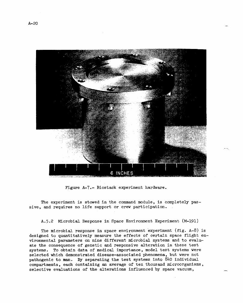
A-20
Figure A-7.- Biostack experiment hardware.
The experiment is stowed in the command module, is completely pas-
sive, and requires no life support or crew participation.
A.5.2 Microbial Response in Space Environment Experiment (M-191)
The microbial response in space environment experiment (fig. A-8) is
designed to quantitatively measure the effects of certain space flight en-
vironmental parameters on nine different microbial systems and to evalu-ate the consequence of genetic and responsive alteration in these test
systems. To obtain data of medical importance, model test systems were
selected which demonstrated disease-associated phenomena, but were not
pathogenic to man. By separating the test systems into 8_0 individual
compartments, each Containing an average of ten thousand microorganisms,selective evaluations of the alterations influenced by space vacuum,

Experimentpackage
Deployed ,_
Vro
Figure A-8.- Microbial response in space environment experiment hardware.

A-22
changes in oxygen partial pressure, lowered gravity states, and cosmic
radiation, as well as the total space flight environment are made possible.
The unusually fine sensitivity, made possible by the large sample sizes,is further increased by manipulation of the mutation rate. This is made
possible through the use of selected components of the solar ultraviolet
spectrum, controlled by a series of optical filters. The flight hardware
consists of a microbial ecology evaluation device which is exposed to so-lar radiation and space vacuum during the transearth coast extravehicular
activity. In addition to the microbial test systems, this hardware con-
tains two types of ultraviolet measuring systems, a compound high energy-multicharged article dosimeter package, and recording thermometers. These
systems provide the measurement data required for interpretation of thebiological results.
A.6 MASS PROPERTIES
Mass properties for the Apollo 16 mission are summarized in table A-IV.
These data represent the conditions as determined from postflight analysesof expendable loadings and usage during the flight. Variations in command
and service modules and lunar module mass properties are determined for each
significant mission phase from lift-off through landing. Expendables usage
are based on reported real-time and postflight data as presented in other _sections of this report. The weights and center-of-gravity of the individ-
ual modules (command, service, ascent stage, and descent stage) were meas-
ured prior to flight and inertia values calculated. All changes incorpora-
ted after the actual weighing were monitored, and the mass properties wereupdated.

A-23/-
TABLE A-IV.- MASS PROPERTIES
Weight, Center of gravity, in. Moment of inertia, slug-ft2 Productslug-ft2°finertia,
18 Iylz fizz lixziyComm_ud and service module/lunar module
Lift-off ll6 393 8h3.4 3.0 2.5 73 561 1 2_0 951 1 2hl 2h2 37hl i0 697 2617
Earth orbit insertion i07 226 804,5 3.3 2.6 72 679 767 814 768 leh 6559 ii 528 2606
Transposition and docking:Command & service modules 66 923 933.8 5.0 4,7 36 _0 80 316 81 9h0 -2095 329 2260Lunar module 36 252 1238.2 -0.Y 0.8 25 898 26 177 27 117 -519 203 -h32
Total docked 103 175 1040.8 3.0 3.3 62 580 576 73_ 579 385 -ii 409 -ShS& 193h
Lunar orbit insertion 102 652 1041.3 3.0 3,h 62 llh 575 152 577 930 i-ii 220 i -5728 2066
Descent orbit insertion 77 595 1081.2 2.1 1.9 h9 096 450 3h9 h57 001 -9172 -1127 -936
Separation 76 590 I083,9 2.1 1.9 49 925 hh6 00h h52 325 -8624 -1392 -i012
Command and service module 39 895 942.6 _.3 3.2 22 210 60 398 65 668 -2h69 lh16 -504clreularizatIon
Cc_mand and service modude 38 994 9h2.9 4.3 3,1 21 881 60 271 65 383 -2h77 i_38 -581
plane change
Docking:Command & service modules 38 452 943,2 4.2 3.1 21 590 60 203 65 079 -2h57 i_35 -501
Ascent sta_e 5866 1165.6 4.5 -2.5 3298 2312 2677 -113 -8 -377
Totsl after docking:Ascent stage manned hh 318 972.7 h.2 2.h 2_ 923 i16 885 122 091 -2h96 4h -880Ascent stage _nmanned 4_ 298 970.7 h.l 2,h 2h 839 112 588 117 80_ -2825 258 -_4
After _scent stage Jetti.=on 38 992 9h_.0 4.3 2.9 21 698 60 225 65 073 -2337 126h -527
8ubsatelllte Jettison 38 830 9_h.3 h.2 3.1 21 581 59 974 6h 861 -2257 1153 -479
Transearth injection 38 697 9_4.3 4.2 3.1 21 463 59 886 6& 793 -2258 1159 -446
Transearth extravehicular 27 h90 968.2 1,4 3,8 15 826 47 705 47 245 -898 864 -1125activity
Command and service modules 27 225 968.8 1.3 h.0 15 523 47 253 h6 846 -823 860 -1024
prior to separ&tion
After separation:Service module lh 199 905.h 2.4 2.2 9536 15 336 15 488 -h27 520 -987C_mmand module 13 026 i089.1 0.i 5.9 5958 5308 4762 55 -388 -2h
Entry 13 015 i039.1 0.1 5.9 5952 5301 h761 5h -386 -23
Main parachute deployment 12 hh2 1037.5 0.i 6.0 57&6 4900 h401 56 -334 -21
Lauding ll 995 1035.6 0.I 6.0 5680 4607 4090 52 -339 -20
Lunar module
Lunar module at earth launch 36 255 18_.1 0.4 -i.0 25 903 27 362 26 lh7 85 5_7 188
Separation 36 743 185.1 0.4 -0.5 27 348 28 894 27 243 84 834 180
Powered descent initiation 36 617 184.9 0.5 -0.5 27 280 28 29_ 26 927 184 830 166
LUnar landing 18 208 208.6 0.8 _.8 15 709 16 580 17 894 128 877 178
Lunar lift-off l0 949 243.7 0.h 2,T 6762 3390 5976 95 178 -35
Orbit insertion 6001 256.6 0.7 5.0 3365 2896 2114 84 95 -37
8Termlnal phase initiation 5972 256_4 0.6 5.0 3353 2888 2097 80 96 -36
Dockin6 5866 256.2 O.1 8.i 3298 2866 2030 64 99 -30
Jettison 5306 255.1 0.0 3.1 3142 2762 1975 75 79 -30
aPost ullage
B-I
f
APPENDIX B - SPACECRAFT HISTORIES
The history of command and service module (CSM-II3) operations at
the manufacturer's facility, Downey, California, is shown in figure B-I,
and the operations at Kennedy Space Center, Florida in figure B-2.
The history of the lunar module (LM-II) at the manufacturer's facil-
ity, Bethpage, Ne]¢ York, is shown in figure B-3, and the operations at
Kennedy Space Center, Florida, in figure B-4.
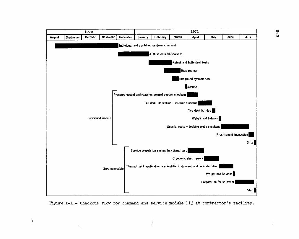
1970 1971
_ugustIse_be.Io_ I Nevem_I oecom_Janua_I Fe_.a_I M_.ohI A.i, I MayI JuneI Ju,y_ fudividual and combined systems checkout
_Retest and individual tests
m lntegrated systems test
I Domate
Pressure vessel and reaction control system checkout m
Top deck inspection - interior closeout
Top deck buildup I
Commandmodule Weight and balance I
Special tests - docking probecheckout
Preshipment inspection •
Ship
Service propulsion system functional test
Cryogenic shelf rework
Thermal paint application -scientific instrument module installation_Service module
Weight and balance I
Ship I
Figure ]3-1.- Checkout flow for command and service module lib at contractor's facility.

1971 I 1972Julyj,ugustiSe_em_rIOcto_iNovemberiOec_rJanuaryIFebroaryi_arohi ,pr,,_Receiving inspection, equipment installation and checkout
iCommand and service module/lunar module docking test
B ! iAItitude chambertests
: 'i Scientific instrument module experiments bay installation andvalidation tests
iCSM/SLA mate
iSpacecraft/launch vehicle assembly
ISpace vehicle moved to launch complex
i lntegrated systems test (first run)
Space vehicle moved to vehicle assembly building I
Command module reaction control system propellant tanks replaced and docking ring_modified
Space vehicle moved back to launch complexi
Integrated systems test (second run) and flight readiness test_
Spacecraft propulsion leak checks and propellant loadingi i
Countdown demonstration test i
Countdown•
Note: Commandand service modules delivered to Launch •Kennedy Space Center on July 28, 1971.
ILx)
Figure B-2.- Command and service module 113 checkout history at Kennedy Space Center.

t_I
1970 1971
MayI JuoeI J°'YIAugostIse°temberlOctober FebruaryIMarohI A0ri,I May_Manufacturing, combined systems test of ascent stage and cold flow I
Retest, manufacturing, cold flow II, and preparationfor_final engineeringandevaluation acceptancetest
Final engineeringandevaluation acceptancetest_
Crewcompartmentfit andfunction checksBB
Preparationsfor shipmentand ship_
Figure B-3.- Checkout flo_ for lunar module ii at contractor's facility.
) 1

1971 i i972May I June I July I August I September I October [ November I December January I February I March I April
• _Equipment installation and checkout
m m Altitude chamber runs
IExperiment equipment fit and functional checks
RLunar roving vehicle fit and deployment checks
IFlight lunar roving vehicle installation
ILanding gear ins_aJlaLion
I Lunarmodule/adapter mate
mComhined systems test
Combined systems retest, mission simulation and {light readiness test I I I
Spacecraft propulsion leak checks and propellant, loading• I
Countdown demonstration test•
Countdown I
Note: Descent stage delivered to Kennedy Space Center on Launch'S'May 6, 1971; ascent stage delivered on May 14,1971.
Figure B-_.- Lunar module ii checkout history at Kennedy Space Center.
C-1
f
.APPENDIX C - POSTFLIGHT TESTING
Postflight testing and inspection of the command module and crew
equipment for evaluation of the inflight performance and investigation
of the flight irregularities were conducted at the contractor's and ven-
dor's facilities and at the Manned Spacecraft Center in accordance with
approved Apollo Spacecraft Hardware Utilization Requests (ASHUR's), The
tests performed as a result of inflight problems are described in tableC-I and discussed in the appropriate systems performance section of this
report, Tests being conducted for other purposes in accordance withother ASHUR's and the basic contract are not included,
S

C_TABLE C-I.- POSTFLIGHT TESTING SUMMARY l
5D
ASHUR no. Purpose Tests performed Results
Guidance and Navigation
113007 Investigate cause of false gimbal lock. Perform resistance, power and coolant-on, Contact bounce in the thrust vector con-
and bench tests trol enable relay caused the anomaly.
113007 Determine cause of 8 occurrences of in- Perform resistance, power and coolant-on, See see. 14.1.4.ertial coupling data unit failure indi- and bench tests.cations.
113017 Investigate cause for secondary yaw aetu- Perform analysis, inspection, and electri- See sec. 14.i.i0.
ator serve assembly oscillations, cal checks.
113007 Investigate cause of _meven drive rates Perform analysis, inspection, and opera- See sec. 14.i.ih.of scanning telescope shaft axis tlonal checks.
Electrical, Batteries, and Cryogenics
113021 Determine cause of erratic digital event Conduct spacecraft test, disassemble, and Paint particle caused intermittent contact.
timer behavior, inspect.
113019 Investigate cause for high battery mani- Pressure check manifold, and conduct mis- Manifold was tight and batteries functioned
fold pressure, sion profile on batteries and charger, normally.
113023 Investigate cause for hydrogen tank 3 Conduct analysis and review records. See see. 14.1.5.heat leak to be excessive.
Communications
113024 Investigate loss of spacecraft up-link Integrity verification, and perform system See sec. 14.1.6.
command capability, and bench testing.
1130h2 Determine why the high-gain antenna Perform analysis, systems verification, and See sec. lh.l.16
would not acquire, bench testing.
Crew Equipment
113006 Investigate gas/water separator leskage. Perform inspection and analysls. See sec. 14.3.3
113020 Determine cause of monitor loss on color Perform thermal and vibration testing. See sec. 14.3.1television.
113032 Investigate cause for poor fit of Luuar Perform analysis. Fit was satisfactory after garment was
Module Pilot's pressure garment assembly, pressurized.
1130_5 Investigate weak signal from Lunar Mod- Perform analysis and component testing. Microphone boom tips were loose.ule Pilot's headset.
Propulsion
113508 Determine leakage and contamination in Disassemble regulators, inspect for dam- Regulators were normal. See sec. 14.1.21
in support of lunar module problem, age and contamination.
113511 Determine cause for forward heat shield Perform visual examination. Apparent leakage was normal.
thruster leakage.

TABLE C-I.- POSTFLIGHT TESTING SUMMARY (Concluded)
J
ASHUR no. Purpose Tests performed Results
Structures
113509 Determine why mass spectrometer and gamma Examine flight data and perform analysis. See sac. 14.1.8 and 14.1.9.
r_y booms failed to retract.
113510 Determine source of fibers found in com- Examine and analyze fibers. Source and quantity of fibers weremand module, normal.
113034 Determine why Y-Y strut was difficult Inspect strut clearances and evaluate Improper adjustment of set screw de-to extend, ease of operation, formed strut barrel.
Environmental Control
ll301h Investigate water/glycol mixing valve Perform operational tests and analysis to See sec. 14.1.1.fluctuations, isolate cause.
ll3011 Determine cause of chlorine injector Inspect and perform pressure and leak tes,ts Sixty percent had loose base plates
leakage, on returned ampules, excessive bonding, and one leaked.
113015 Determine why lithium hydroxide canister Inspect and perform analysis. Canister swells due to water accumula-was difficult to remove, tion during solo operation.
ll3010 Determine cause of cabin fan moaning. Inspect aud activate cabin fans. No damage. See sac. 14.1.11.
113012 Investigate apparent vacuum cleaner Inspect, operate, and analyze. Excessive dust deposits caused impellerfailure. Jamming on restart.
113013 Determine why suit loop pressure was Perform recalibration, disassembly, and Three pieces of lunar soll got inside the
not higher than expected, analysis of suit pressure transducer, sense cavity and affected the variable re-luctance element.
113512 Locate source of water/glycol spill Inspect and perform pressure and leak Suit heat exchanger bypass valve stem sealfound on cabin floor, tests, leaked.
C_!CO

D-1/
APPENDIX D - DATA AVAILABILITY
Tables D-I and D-II are summaries of the data made available for sys-
tems performance m_alyses and anomaly investigations. Table D-I lists the
data for the command and service module, and table D-II, the lunar module.
The following table contains the times that experimental data were madeavailable to the principal investigator for scientific analyses.
Time, hr :min Time, hr :min
From To From To
70:0,3 93:30 169:03 172:16
105:013 113 :35 174:15 175:16
113:54 i15:32 176:57 19h:02
i15:5,3 150:34 195:13 218:38
152:32 168:23 219:35 261:10
For addition_1 information regarding data availability, the status
listing of all mission data in the Central Metric Data File, building 12,should be consulted.
/

D-2
TABLE D-I.- COMMAND AND SERVICE MODULE DATA AVAILABILITY
Time, hr:min Data Bandpass 0scillo- SpecialSource plots Bilevels Computer Brush Special
From To (a) or tabs word tabs graph plotsrecords records programsor tabs
-0h:00 00:30 ALDS X X
00:00 00:08 MIL X X X X X X00:0h 00:14 BDA X X X X
00:05 03:30 STDN X X X
01:58 01:56 GDS X X X
02:30 02:h0 GDS X X X X X X02:50 05:50 GDS X X X X
08:30 11:30 STDN X X X
12:00 13:00 GDS X X23:00 2h:00 MAD X X
27:00 80:00 STDN X
29:39 31:38 GDS X X X X37:00 39:00 STDN X X X
37:30 38:31 GDS X X X X X
51:30 52:58 MAD X X X52:00 43:00 STDN X X X
52:56 46:58 MAD X X X58:04 59:00 GDS X X
60:00 70:00 STDN X
69:38 73:05 STDN X X X
69:50 70:00 MAD X X X
73:05 76:15 STDN x X X
73:18 75:19 MAD X X X X X74:22 74:36 GDS X X X X X X
75:57 76:18 GDS X X
76:00 81:00 STDN X X X
76:17 77:01 GDS X X X
78:00 79:11 GDS X X X X X X __
80:03 80:07 GDS X
80:16 85:52 STDN X X X
80:19 81:02 GDS X X X
81:03 82:12 _DS X
82:29 83:08 GDS X X X82:44 85:03 GDS X
84:00 89:00 STDN X X X
84:24 85:03 GDS X
85:08 85:56 GDS X X86:17 86:56 GDS X
86:18 89:38 HSK X
89:27 92:46 STDN X X X
90:06 9o:55 MAD X X
90:40 91:40 MAD X
91:35 92:26 MAD" X X92:28 93:30 MAD X X X
92:46 96:43 STDN X X X
94:25 96:11 MAD X
96:11 96:16 MAD X X X X X X
96:15 97:00 MAD X X97:31 97:41 MAD X X X X
98:11 100:54 STDN X X X X X98:30 101:13 GDS X X X
I00:38 i04:58 STDN X X X
101:57 102:47 GDS X X
103:14 103:27 GDS X X X X X
103:19 108:53 STDN X X X
105:13 106:28 GDS X X X107:05 108:50 GDS X
i08:53 i19:46 STDN X X X
110:45 111:38 HSK X
111:58 i15:32 ESK X
112:56 116:51 STDN X X X116:07 119:43 MAD X
116:51 120:48 STDN X X X
120:06 121:35 MAD X
120:48 124:_9 STDN X X X
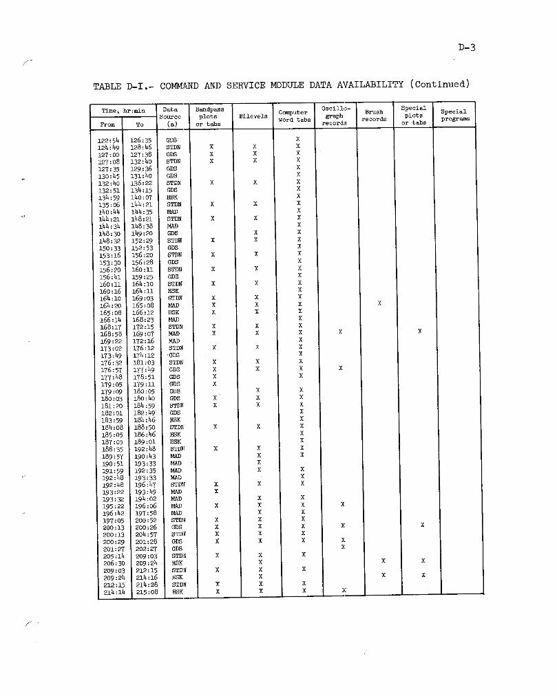

TABLE D-I.- COMMAND AND SERVICE MODULE DATA AVAILABILITY (Concluded)
Time, hr:min Data Bandpass Oscillo- Special
Source plots Bilevels Computer graph Brush plots SpecialFrom To (a) or tabs word tabs records programsrecords or tabs
218:10 220:10 STDN X X X
220:36 222:38 MAD X
221:50 224:32 STDN X X X222:34 226:30 SDS X
225:45 229:h8 STDN X X X226:28 i 227:29 GDS X
227:30 227:35 GDS X
235:13 235:15 HSK X239:06 2hi:08 MAD X X X X2h2:06 243:08 MAD X
2_2:14 245:5h STDN X X X
243:06 246:08 MAD X
248:31 256:07 GDS X
248:40 251:25 STDN X X X
256:18 260:12 HSK X
259:27 265:49 STDN X X X
260:10 265:30 HSK X X X X X X265:22 265:52 DSE X X X X X

D-5f
TABLE D-II.- LUNAR MODULE DATA AVAILABILITY
Time, hr :mln Dat6, Bandpass C_put er Oscillo- Special SpecialSource plots Bilevels graph Brush plots
From To (a) or tabs word tabs programsrecords records or tabs
-04:00 00:00 .a.LDS X X
34:02 34:07 GDS X x
53:30 53:45 STDN X X
93:17 96:43 STDN X X X
94:20 95:13 MAD X X X X X
95:12 95:29 MAD X X X96:16 96:58 MAD X X X X X X
96:43 100:37 STDH X X X
96:44 96:54 MAD X X
96:57 99:15 MAD X X X X
99:08 101:02 MAD X X X
100:05 104:30 GDS X X100:38 104:58 ST_ X X X
101:02 1103:06 GDS X X
i03:19 108:53 STDN X X X
103:50 104:31 GDS X X X X X X104:28 I05:27 GDS X X X X
108:53 i16:51 ST_ X X X
116:08 118:07 MAD X X X
116:51 120:48 STDN X X124:49 152:29 STDN X X
152:32 155:30 GDS X X
153:16 169:03 STDN X X
165:00 166:24 MAD X X
165:43 165:52 HSK X X X166:22 168:00 MAD X X
168:17 172:15 STDN X X X
171:07 172:23 MAD X X X173:02 176:12 STDN X X X
174:00 176:14 GDS X X X X X X
176:32 181:03 8TDN X X X
176:57 177:49 GDS X X X X X X
192:48 196:47 STDN X X
194:43 195:15 MAD X X X X X
195:00 195:58 MAD X X X210:32 210:55 HSK X X X
aData souroes :
STDN - Spacecraft Tracking and Data Network
STDN station call letters and location:
BDA - Bermuda IslandsGDS - Goldstone (California)
HSK - Honeysuckle (Canberra, Australia)
MAD - Madrid (Spain)MIL - Merrit Isl_ad (Florida) - launch area
0ther:
ALDS - Apollo la_seh data system (Kennedy Space Center, Florida)
DSE - Spacecraft data storage equipment
!-

E-1/
APPENDIX E - MISSION REPORT SUPPLEMENTS
Table E-I contains a listing of all reports that supplement the
Apollo 7 through Apollo 16 mission reports. The table indicates the
present status of each report not yet completed and the publication dateof those which have been published.

TABLE E-I.- MISSION REPORT SUPPLEMENTS
Supplement Title Publicationnumber date/status
Apollo 7
1 Trajectory Reconstruction and Analysis May 19692 Communication System Performance June 19693 Guidance, Navigation, and Control System November 1969
Performance Analysish Reaction Control System Performance August 19695 Cancelled
6 Entry Postflight Analysis December 1969
Apollo 8
1 Trajectory Reconstruction and Analysis December 19692 Guidance, Navigation, and Control System November 1969
Performance and Analysis3 Performance of Command and Service Module March 1970
Reaction Control SystemService Propulsion System Final Flight September 1970Evaluation
.5 Cancelled
6 Analysis of Apollo 8 Photography and December 1969Visual Observations
7 Entry Postfllght Analysis December 1969
Apollo 9
1 Trajectory Reconstruction and Analysis November 19692 Command and Service Module Guidance, Navi- November 1969
gation, and Control System Performance3 Lunar Module Abort Guidance System Perform- November 1969
ance Analysis
4 Performance of Command and Service Module April 1970Reaction Control System
5 Service Propulsion System Final Flight December 1969Evaluation
6 Performance of Lunar Module Reaction August 1970Control System
7 Ascent Propulsion System Final Flight December 1970Evaluation
8 Descent Propulsion System Final Flight December 1970Evaluation
9 Cancelled

E-3
TABLE E-I.- MISSION REPORT SUPPLEMENTS (Continued)
Supplement Title Publicationnumber date/status
i0 Stroking Test Analysis December 1969ii Communications System Performance December 196912 Entry Postflight Analysis December 1969
Apollo l0
1 Trajectory Reconstruction and Analysis Mar_h 19702 Guldsnce, Navigation, and Control System December 1969
Performance AnalysisB Performance of Command and Service Module August 1970
Reaction Control SystemService Propulsion System Final Flight September 1970Evaluation
5 Performance of Lunar Module Reaction August 1970Control System
6 Ascent Propulsion System Final Flight January 1970Evaluation
7 Descent Propulsion System Final Flight January 1970Evaluation
8 Cancelled
9 Analysis of Apollo i0 Photography and August 1971Visual Observations
l0 Entry Postflight Analysis December 1969ll Comm_mications System Performance
Apollo ii
1 Trajectory Reconstruction and Analysis May 19702 Guidsmce, Navigation, and Control System September 1970
PerformanceAnalysis3 Performance of Command and Service Module December 1971
Reaction Control System4 Service Propulsion System Final Flight October 5970
Evaluation5 Performance of Lunar Module Reaction December 1971
Control System6 Ascent Propulsion System Final Flight September 5970
Evaluation
7 Descent Propulsion System Final Flight September 1970Evaluation
8 Cancelled
9 Apollo ll Preliminary Science Report December 1969

TABLE E-I.- MISSION REPORT SUPPLEMENTS (Continued)
Supplement Title Publicati onnumber date/status
l0 Communications System Performance January 1970
ll Entry Postflight Analysis April 1970
Apollo 12
1 Trajectory Reconstruction and Analysis September 1970
2 Guidance, Navigation, and Control System September 1970
Performance Analysis
3 Service Propulsion System Final Flight December 1971Evaluat ion
4 Ascent Propulsion System Final Flight PublicationEvaluat ion
5 Descent Propulsion System Final Flight PublicationEvaluat ion
6 Apollo 12 Preliminary Science Report July 1970
7 Landing site Selection Processes Final Review
Apollo 13
i Guidance, Navigation, and Control System September 1970
Performance Analysis
2 Descent Propulsion System Final Flight October 1970Evaluat ion
3 Entry Postflight Analysis Cancelled
Apollo 14
i Guidance, Navigation, and Control System January 1972
Performance Analysis _
2 Cryogenic Storage System Performance March 1972
Analysis
3 Service Propulsion System Final Flight May 1972 _Evaluat ion
4 Ascent Propulsion System Final Flight May 1972Evaluat ion
5 Descent Propulsion System Final Flight PublicationEvaluation
6 Apollo 14 Preliminary Science Report June 1971
7 Analysis of Inflight Demonstrations January 19728 Atmospheric Electricity Experiments on January 1972
Apollo 13 and 14 Launches
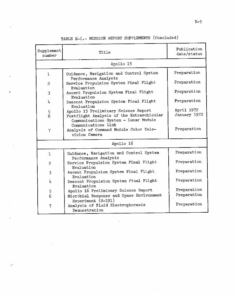
E-5
TABLE E-!.- MISSION REPORT SUPPLEMENTS (Concluded)
Supplement Title Publicationnumber date/status
Apollo 15
1 Guidance, Navigation and Control System Preparationm
Performance Analysis
2 Service Propulsion System Final Flight PreparationEvaluation
3 Ascent Propulsion System Final Flight PreparationEvsluation
4 Descent Propulsion System Final Flight PreparationEvaluation
5 Apollo 15 Preliminary Science Report April 1972
6 Postflight Analysis of the Extravehicular January 1972
Co_nunications System - Lunar ModuleCommunications Link
7 Analysis of Command Module Color Tele- Preparationvision Camera
Apollo 16
1 Guid_uce, Navigation and Control System Preparation
Performance Analysis
2 Service Propulsion System Final Flight PreparationEw_luation
3 Ascent Propulsion System Final Flight PreparationEw_luation
4 Descent Propulsion System Final Flight PreparationEvaluation
5 Apollo 16 Preliminary Science Report Preparation
6 Microbial Response and Space Environment Preparation
• E_periment (S-191)
7 Analysis of Fluid Electrophoresis PreparationDemonstration
f

F-1_f
APPENDIX F - GLOSSARY
Albedo Relative brightness, defined as the ratio of radiationreflected from a surface to the total amount incident
upon it.
Afterglow The glow that persists after the source of excitation
_ is no longer present.
Anisotropic Having different optical or other physical properties
along axes in different directions.
Auroral belts Approximately circular bands around the earth's geo-
magnetic poles resulting from interaction of high-
energy electrons and protons of solar origin with the
upper atmospheric gases. The bands are located aboutlO ° to 15 ° from the poles and broaden toward the
equator during periods of intense activity.
Bilirubin A red bile pigment that causes variations in the colorof the bile.
Breccia A rock consisting of sharp fragments embedded in a
fine-grained matrix.
Bungee Elasticized cord used as a fastener.
Cirrus Clouds formed in the highest cloud region and composed
of ice crystals. They are usually thin and wispy in
appearance.
Clast A discrete fragment of rock or mineral included in a
larger rock.
_, Double umbra When the umbra of a satellite is within the umbra of
a planetary body around which it is orbiting.
Earthshine Illumination of the moon's surface by sunlight re-
flected from the earth's surface and atmosphere.
Ecliptic The plane defined by the earth's orbit about the sun.
Endogenetic Having to do with rocks formed by solidification fromfusion, precipation from solution, or sublimation.
Ephemeris A table of the computed positions of celestial bodiesat regular intervals.
//

F-2
APPENDIX F- GLOSSARY - Continued
Fecal Pertaining to body waste discharged through the anus °
Friable Easily crumbled, pulverized, or reduced to powder.
Geocorona The envelope of atomic hydrogen surrounding the earth.
Germicide An agent that destroys pathogenic micro-organisms.
Hummocky Descriptive of an area having many low, rounded hillsor knolls.
Limb The outer edge of the apparent disc of a celestial
body, or a portion of the edge.
Magnetic equator The line on the surface of the earth that connects all
points at which the magnetic inclination is zero.
Maria Large, dark, flat areas of the lunar surface.
Pathogenic Disease producing organisms.microflora
Polarimetric Relating to the measurement of the amount of polariza-
tion of light in a partially polarized ray.
Radial sample Material taken from a crater's eJecta field at the
crater's rim, at a distance equal to the crater's
radius, and at a distance equal to the crater's diam-eter.
Ray Bright material extending radially outward from a cra-
ter and composed of ejecta from the formation of thecrater.
Regolith The surface layer of unsorted fragmented material onthe earth or moon that overlies solid material.
Reseau plate A glass plate containing a grid of fine lines of a
standard size that is photographed with an object orscene to aid in measurement.
Reticle A pattern of very fine lines in the focus of the eye-
piece of an optical instrument.
Seconal A proprietary medicine used to induce sleep.

APPENDIX F - GLOSSARY - Concluded
Selenodetic Relating to the branch of applied mathematics that
determines by observation and measurement the posi-
tions of points on the moon's surface and the size
aud shape of the moon.
Sinkhole A hollow or hole worn through a rock.
Solar corona The outer visible envelope of the sun.
Stereobase A type of photography in which photographs taken ofthe same area from different angles are combined to
produce visible features in three-dimensional relief.
Stratigraphy That branch of geology that deals with the origin,composition, distribution and succession of strata.
Substellar point A point at which a star is vertically overhead.
Terra Large areas of the lunar surface that are lighter in
color than the adjacent maria.
Umbra The conically-shaped shadow projecting from a planet
or satellite on the side opposite the sun.
Unipole The pole fastened to the side hatch of the commandmodule _and upon which devices such as cameras aremounted during transearth extravehicular operations.
Vignetting Pertaining to the progressive reduction in the inten-sity of illumination falling on a photographic filmtoward the edges of the picture due to the obstruc-
tion of oblique light beams.
Zap pits Small glass-lined depressions in rocks caused by im-pacts from particles travelling at extremely high
speeds o
Zero phase An orientation in which an area or object viewed iscoplanar with the sun and observer, resulting in poordefinition of features.
/

R-1
REFERENCES
i. Manned Spacecraft Center: Apollo 16 Preliminary Science Report.(To be published _ a NASA special publication.)
2. Marshall Space Flight Center: Saturn V Launch Vehicle Flight Evalu-
ation Report AS-511 Apollo 16 Mission, MPR-SAT-FE-72-1. June 19, 1972.
r 3. Boeing Company: AS-511 Final Postfli_ht Trajectory. Unnumbereddocument (to be published).
" _. Manned Spacecraft Center: Apollo 15 Mission Report. MBC-05161.December 1971.
5. NASA Headquarters: Mission Implementation Plan for Apollo 16 Mission.
0MSF unnumbered _)cument. Revision 5. February 25, 1972.
6. Manned Spacecraft Center: Mission Requirements SA-511/CSM-113/LM-11,
J-2 Type Mission. MSC-03974. July 19, 1971 (reprinted March 28, 1972.
7. Manned Spacecraft Center: Apollo 16 Mission Anomaly Report No. 1 -
Oxidizer Deservicing Tank Failure. MSC-07032. June 1972.
8. Manned Spacecraft Center: Final Report of the Apollo 16 Deactivation
Investigation Board. Rupture of S14-138 RCS Oxidizer Deactivation Unit,
May 7_ 1972_ at North Island Naval Air Station. Unnumbered document.June 2, 1972.
9. Manned Spacecraft Center: Apollo ll Mission Report. MSC-00171.November 1969.
10. Manned Spacecraft Center: Apollo 12 Mission Report. MSC-01855.March 1970.
ll. Manned Spacecraft Center: Apollo 13 Mission Report. MSC-02680.September 1970.
12. Manned Spacecraft Center: Apollo 14 Mission Report. MSC-04112.
" May 1971.
NASA_MSC
/

APOLLO SPACECRAFT FLIGHT HISTORY
(Continued from inside front cover)
Mission report
Mission number S_ Descri ti_ Launch date LatLuch site
Apollo h MSC-PA-R-68-1 SC-017 gupercircular Nov. 9, 1967 Kennedy Space
LTA-10R entry at lunar Center_ Fla.return velocity
Apollo 5 MSC-PA-R-68-7 LM-I First lunar Jan. 22, 1968 Cape Kennedy,
module flight Fla.
Apollo 6 MSC~PA-R-68-9 SC-020 Verification of April 4, 1968 Kennedy Space
_" LTA-SR closed-loop Center, Fla.
_ emergency detectionsystem
Apollo 7 MSC-PA-R-68-15 CSM 101 First manned flight; 0ct. ii, 1968 Cape Kennedy,
earth-orbital Fla.
Apollo $ M$C-PA-R-69-1 CSM 103 First manned itmar Dee. 21, 1968 Kennedy Space
orbital flight; first Center, Fla.
manned Saturn V launch
Apollo 9 MBC-PA-R-69-2 CSM i0_ First manned lunar March 3, 1969 Kennedy Space
LM-3 module flight; earth Center, Fla. "
orbit rendezvous; extra-
vehicular activity
Apollo l0 _C-OOI26 CSM 106 First l_nar orbit May 18, 1969 Kennedy Space
LM-4 rendezvous ; low pass Center • Fla.over lunar surface
Apollo ii MSC-O0171 CSM 107 First lunar landing July 16, 1969 Kennedy Space
- LM-5 Center, Fla.
Apollo 12 M8C-01855 CSM 108 Second lunar landing Nov. 14, 1969 Kennedy SpaceLM-6 Center, Fla.
Apollo 13 MSC-02680 CSM 109 Aborted during trs_Is- April ll_ 1970 Kennedy Space
LM- 7 lunar flight because Center, Fla.
of cryogenic oxygen loss
Apollo 14 MSC-O4112 CSM i10 Third luu_r landing Jan. 31, 1971 Kennedy Space
LM-8 Center, Fla.
Apollo 15 MSC-05161 CSM ll2 Fourth lunar landing July 26, 1971 Kennedy SpaceLM-10 an& first extended _c£- Ce_ter_ Fla.
ence capability mission
Apollo 16 MSC-07230 CSM-113 Fifth lunar 18nding and April 16, 1972 Kenned_ Spacesecond extended science Center, Fla.
capability mission
f