
Apollo 11 Press Kit
256
p R E s s K I T APOLLO 11 LUNAR LAN Dl NG MISSION NATIONAL AERONAUTICS AND SPACE ADMINISTRATION
-
Upload
khangminh22 -
Category
Documents
-
view
1 -
download
0
Transcript of Apollo 11 Press Kit

p R E s s
K I
T APOLLO 11
LUNAR LAN Dl NG MISSION
NATIONAL AERONAUTICS AND SPACE ADMINISTRATION


NATIONAL AERONAUTICS AND SPACE ADMINISTRATION
WASHINGTON,O.C. 20546
FOR RELEASE: SUNDAY July 6, 1969
RELEASE NO: 69-83K
PROJECT: APOLLO 11
TELS. WO 2-4155 wo 3-6925
(To be launched no earlier than July 16)
contents G ENERAL RELEASE---------------------------------------------1-17 APOLLO 11 COUNTDOWN-----------------------------------------18- 20 LAUNCH EVENTS-----------------------------------------------21 APOLLO 11 MISSION EVENTS------------------------------------22-25 MISSION TRAJECTORY AND MANEUVER DESCRIPTION-----------------26
Launch---------------------------------------------------26-30 Earth Parking Orbit (EP0)--------------------------------30 Translunar Injection (TLI)-------------------------------30 Transposition, Docking and Ejection (TD&E)---------------30-3 2 Translunar Coast-----------------------------------------33 Lunar Orbit Insertion (LOI)------------------------------33 Lunar Module Descent, Lunar Landing----------------------33-�1 Lunar Surface Extravehicular Activity (EVA)--------------42-47 Lunar Sample Collection----------------------------------48 LM Ascent, Lunar Orbit Rendezvous------------------------49-5 3 Transearth Injection (TEI)-------------------------------53-56 Transearth coast-----------------------------------------57 Entry Landi ng--------------------------------------------57 -63
RECOVERY OPERATIONS, QUARANTINE-----------------------------64-65 Lunar Receiving Laboratory-------------------------------65-67
SCHEDULE FOR TRANSPORT OF SAMPLES, SPACECRAFT & CREW--------68 LUNAR RECEIVING LABORATORY PROCEDURES TIMELINE
(TENTATIVE)--------------------------------�-------------69-70 APOLLO 11 GO/NO-GO DECISION POINTS--------------------------71 APOLLO 11 ALTERNATE MISSIONS--------------------------------72-73 ABORT MODES-------------------------------------------------74
Deep Space Aborts----------------------------------------74-76 ONBOARD TELEVISION------------------------------------------77
Tentative Apollo 11 TV Times-----------------------------78 PHOTOGRAPHIC TASKS------------------------------------------79-80 LUNAR DESCRIPTION-------------------------------------------81
Physical Facts-------------------------------------------81 Apollo Lunar Landing Sites-------------------------------82-85
6/26/69
-more-

Contents Continue d 2
COMMA ND AND SERVI CE MODULE STRUCTURE , SY STEMS------ ---------86 -88 CS M Systems--- - - - ------------- ---------------------- -----88- 95
LUN AR MODULE STRUCTURES , WEIG HT ----- - --------- -------- - -----96 Asc ent Stage------ ------------ ---------------------------96 -10 1 Des cent Stage --- - - - -------------------------------------101 -10 3 Lunar Module Systems------ ------- - - - ---------------------103 - 1 0 7
SATURN V LAUNCH VE HI CLE DESCRI PTI ON & OPERATI ON------ ----- --10 8 Launch Vehicle Range Safety Provisions--- - - - -------------10 8 -10 9 Space Vehicle Wei ght Summary----- - ------------------ -----1 10 -111 First Stage---------------- ------------------------- -----1 12 Second St age--- - - - ------------- --------------------------112-113 Third Stage---------------- ------------------------- -----113 I ns trument Unit---------------- -------- - - - ---------- -----11 3 - 11 4 Propulsion--- - - - --------------- --------------------------1 1 4 - 1 15 Launch Vehi cle I ns trumentation and C ommuni cation- - - - -----1 1 5 S-I VB Res tartr -- - - - --------------------------------- -----11 6 Di fferences i n Launch Vehi cl es for A-10 and A-1 1---------1 1 6
APOLLO 1 1 CREW--- - - - --------------- -------------------- -----1 17 Li fe S upport Equipmen t - Sp ace Suits ---------------- -----1 1 7-1 22 Apollo 1 1 Crew Menu------ -------- - - ------ - --------- - -----123- 132 Personal Hygiene --------------- - ------------------- - -----13 3 Medical Kit ---------------- ---- --------------------------1 3 3 Survival G e ar--- - - - --------------------------------------133 - 13 5 Biomedical I nflight Monit oring--- - - - ---------------- -----13 5 Training--- - - - ------------------- - - ------ ----------------1 36 - 13 7 Cr e w Biog raph ie s--------------- - ------------------- - ----- 1 38- 1 4 4
EARLY APOLLO S CI ENTIFI C EX PERIME NTS PACKAG E-----------------1 45 -1 5 3 APOLLO LUNAR RADI OI SOTOPI C HEATER ( ALRH ) --------------------15 4 -1 57 APOLLO LAUNCH OPERATI ONS--- - - - ------------------------- -----15 8
Pre l au n ch Preparations--- - - - ------------------------ -----15 8- 160 LAUNCH COMPLEX 39--- - - - -------------------------------- -----1 6 1
Veh i c le As semb ly Building------ --------------------- -----16 2-1 6 3 Launch Control Center--- - - - ------------------------- -----16 3-16 4 Mobi le Launcher---------------- --------- - - ---------------16 4 - 16 5 Tr ansporter---------------------- ------ - - - ---------------16 5 -16 6 Crawlerway--- - - - ---------------- -------------------- -----166 M obile Ser vi c e St ru cture --- - - - --------------------- - -----16 6 -16 7 Water Deluge System ------ ------- - - - -------------- - - -----16 7 Flame Trench and Deflector----- - -------------------------1 6 7- 16 8 Pad Areas--- - - - ------------- - - - - -------------------- -----1 6 8 Mis s i on Control Center------ - ----------------------------169-1 70
MANNED S PACE FLIG HT NETWORK--- - - - ---------------------- -----1 7 1-1 7 4 NASA Communi cations Network----- - ------------------ - -----1 7 4- 17 6 Ne tw ork Computers --------------- - -----------------------1 76- 1 77 The Apol lo Ships --------------- - ----- - - - - ---------------1 7 8 Apollo Range I nstrumentation Aircraft ( ARI A )-------------1 79 Ship Pos ition s for Apol lo 1 1----- - ---------------- - - -----1 80
-more-

Conten t s Continued 3
CONTAMINATION CONTROL PROGRAM ------------------------------18 1 Lunar Module Operations ---------------------------------1 8 1-187 Command Module Operations -------------------------------187 Lunar Mi s s ion Re covery Operat ions------------------------187 - 1 8 8 Bi ologi cal I s olation Gar ment-----------------------------188 Mobi le Quarantine Facility-------------------------------188 Lunar Receiving Laboratory-------------------------------189- 1 9 0 Sterilization and Rel ease o f Space craft------------------190 - 191
APOLLO PROGRAM MANA GEME NT-----------------------------------192 Apollo/Saturn O fficials----------------------------------193 -2 17 Major Apollo/Saturn V Contractors------------------------2 1 8 - 2 1 9
PRINCIPAL INVE S TI GATORS AND I NVE STI GATIONS OF LUNAR SURFACE SAMPLE S -----------------------------------2 20-2 41
APOLLO GLOSSARY---------------------------------------------2 42 -2 46 APOLLO ACRONY MS AND ABBREVI ATIONS---------------------------2 47 -2 4 8 CONVE RSION FACTORS-----------------------------------------249-2 5 0
- 0 -


NEWS NATIONAl AERONAUTICS AND SPACE ADMINISTRATION
WASHINGTON,O.C. 205.c6
FOR RELEASE: SUNDAY
wo 2-4155 TELS •
WO 3-6925
July 6, 1969
RELEASE NO: 69-83K
APOLLO 11
The United States will launch a three-man spacecra�t
toward the Moon on July 16 with the goal of landing two astronaut-
explorers on the lunar surface four days later.
If the mission-- called Apollo 11--is successful , man will
accomplish his long-time dream of walking on another celestial
body .
The first astronaut on the Moon ' s surface will be 38-year-old
Neil A . Armstrong of Wapakoneta , Ohio , and his initial act will be
to unveil a plaque whose mess age symbolizes the nature of the
journey.
Affixed to the leg of the lunar landing vehicle , the plaque
is signed by President Nixon , Armstrong and his Apollo 1 1 compan
ions , Michael Collins and Edwin E. Aldrin, Jr .
6/26/69
-more-

-2-
It bears a map of the Earth and this inscription:
HERE MEN FROM THE PLANET EARTH
FIRST SET FOOT UPON THE MOON
JULY 1969 A.D.
WE CAME IN PEACE FOR ALL MANKIND
The plaque is fastened t o the descent stage of the lunar
module and thus becomes a permanent artifact on the lunar sur
face .
Later Armstrong and Aldrin will emplant an American flag
on the surface of the Moon .
The Apollo 11 crew will als o carry to the Moon and return
two large American flags, flags of the 50 states, District of
Columbia and u.s. Territories, flags of other nations and that
of the United Nations Organization.
During their 2 2-hour stay on the lunar surface, Armstrong
and Aldrin will spend up to 2 hours and 40 minute s outside the
lunar module , also gathering samples of lunar surface material
and deploying scientific e xperiments which will transmit b ack
to Earth valuable data on the lunar environment .
Apollo 1 1 is s cheduled for launch at 9:32 a . m. EDT July 16
from the National Aeronautics and Space Administration's Kennedy
Space Center Launch Complex 39-A . The mission will b e the fifth
manned Apollo flight and the third to the Moon.
-more-

- 3-
The prime mission objective of Apollo 11 is stated simply:
"Perform a manned lunar landing and return". Successful fulfill
ment of this objective will meet a national goal of this decade,
as set by President Kennedy May 25 , 196 1 .
Apollo 11 Commander Armstrong and Command Module Pilot
Collins 38, and Lunar Module Pilot Aldrin, 39 , will each be
making his second space flight. Armstrong was Gemini 8 commander,
and backup Apollo 8 commander; Collins was Gemini 10 pilot and
was command module pilot on the Apollo 8 crew until spinal
surgery forced him to leave the crew for recuperation; and Aldrin
was Gemini 12 pilot and Apollo 8 backup lunar module pilot.
Armstrong is a civilian, Collins a USAF lieutenant colonel and
Aldrin a USAF colonel.
Apollo 11 backup crewmen are Commander James A. Lovell,
Command l>1odule Pilot \�illiam A. Anders, both of 'tlhom were on the
Apollo 8 first lunar orbit mission cre\>t, and Lunar r.todule Pilot
Fred H. Haise.
-more-

-4-
The backup crew functions in three significant c ategori es .
They help the prime crew with mission preparation and hardware
checkout act ivit ies . They rece ive nearly complete mission
training 'llhich b e c omes a valuable foundation for later assignment
as a prime crew and fina l ly , should the prime c rew be come unavail
ab le , they are prepared t o flY as prime crew on schedule up until
the last few weeks at which t ime fu l l dup licate training b e c omes
too cost ly and time consuming to b e practi cal .
Apollo 11 , a ft e r launch from Launch Complex 3 9 - A , will
be gin the three-day voyage to the Moon about two and a half hours
after the spacecraft is inserted into a 100-nautical mi le circular
Earth parking orb i t . The Saturn V launch vehi c le th ird st age will
restart to inj ect Apol lo 1 1 into a translunar traj ect ory as the ve -
hicle passes over the Paci fic midway through the second Earth park
ing orbit .
The "go " for translunar inject ion \'1111 follow a complete che ck
out of th e space vehicles readiness to b e committed for inj e ction .
About a hal f hour after translunar inj e ction (TLI ) , the command/
servi ce module \Or i l l separate from the Saturn t hi rd stage , turn around
and dock \'lith the lunar module nested in the space craft LM adapte r .
Spring-loaded lunar module holddowns \Olil l be re le ase d t o e j e c t the
docked spacecraft from the adapter .
-more-

-5-
Cl) c: E 0 Q) ... ... Cl) u > Q)
(/) ·-c:
-0
._ co
c: ..lO: c: u ::l Q) Cl)
0 ..t: (.)
c:
...... CIJ
() ._
t-
Q) ·-c: � co c: ::::J en c: co �
.... "C c: <t .c () c: c: 0 C) ::::J ... ._ c: ·-co Q)
_. Cl) C) c: co ...
(/) ... ::l c: co ... c: ::l ... 0 co ._ ... (/)
� Cl) � <(
0 _. _. 0 a... <t
-more-

-6 -
Late r , leftover liquid propellant in the Saturn third stage
'.>T i l l b e vented through the engine b e l l to place the stage into
a " s l ingshot" traj e ctory to miss the Moon and go into so lar orbit.
During the trans lunar c oast , Apollo 11 will be in the pass ive
thermal control mode in wh i ch the spacecraft rotates s lowly about
one o f its axe s to stabilize thermal response to s olar heating . Four
midcourse correction maneuvers are pos s ib le during trans lunar coast
and w i l l b e planned in real time to adj ust the traj e ctory.
Apollo 11 will first be inserted into a 60-by-1 70-nautical
mile e llipti cal lunar orb it , whi ch tv1o revolutions later wi l l b e
adjusted t o a near-c ircu lar 5 4 x 6 6 nm. Both lunar orbit insertion
burns ( LOI ) , using the spacecra ft's 20 , 500-p ound-thrust service
propulsion sy stem, will be made \'/hen Apol lo 11 is behind the Moon and
out of " s ight" of Manned _Sp ace Flight Network stations.
Some 2 1 hours after entering lunar orbit , Armstrong and
Aldrin will man and che ck out the lunar module for the de scent to
the surface. The LM des ce nt propuls i on system wi ll place the LM in
an e l lipti c al orbit with a p e ri cynth i on , or low point ab ove the Moon ,
of 50 ,000 fe et, from which the actual descent and touchdown w i l l b e
made .
-more-

� .c. 0)
U-'-ro c: ::J CJ) c: ro '-
1-
I () � �
0 ...J ...J 0 a.. <{
-7-
... cu c: ;:, -1 -0 c: 0 -(,) cu ... -)(
w
... Q) > ;:, Q) c: cu � c: 0 ..,., (I) 0 � (I) c: cu ... ...
-more -
c: 0 -... Q) (I) c: -.Q ... 0 ... cu c: :J -1
� () Q) � u c: 0 -cu C) > cu
z

-8-
A fter touchdown , fu e landing crew w i ll first ready the lunar
module for immedi ate as cent and then take a b ri e f re s t be fore
depre s suriz ing the cabin for tw o-man E VA about 1 0 hours after
t ouchdown . Arms trong will s tep onto the lunar surface firs t ,
fol lowed by Aldrin s ome 4 0 minu te s late r .
During the i r two hours and 40 minu te s o n the s urface ,
Arms trong and Aldrin will gather ge ologic s ampl e s for ret urn t o
E arth i n sealed s amp le return containers and s e t up two s c i entific
e xperiments for returning Moon data to E arth long after the mi s s i on
i s complete .
One experiment measures mo onqu akes and met e or oid impacts on the
lunar s urface , whi le the other experiment is a s ophisti c ated refle ct
or that will mirror laser beams b ac k t o point s on E arth to aid i n
expanding s cientifi c knowle dge both o f this p lanet and of the Moon .
The lunar module' s des cent s t age w i ll serve as a launching
pad fo r the crew c abi n as the 3 , 5 00- p ound-thrust a s ce nt e ngine
prop e l s the LM as cent s t age back in to lunar o rb i t for rendezvous
with Collins i n the c ommand/service module --orb iting 60 mi les above
the Moon .
-more-

-9-
� en (.)
1:: E 0
0 0 � ..... LL
1:: � 0 ..J - a. CD 0 ... 1:: en 0 ... ... (I) (1) .....
LL ... (1) a. CD en Q) (.) co
'+-'-�
en '-co c: ::J ...J 0 t-....,
c c: 0 Q) ::!: 0 (.) ..J ::!: C/) 0 c Q) 1- 0 c ...
CD t» -(I) c 1:: "'0 (1) c � 1- (1) .- ..J .-
0 ...J ...J 0 a.. <(
-more-

-10-
' l.
Q) c. E (Q
C»
en
c:
>
' ...
u
, u
c:
I Q) 0 (.)
Q) C) c: Q) c. ... E c: (Q 0 en
(.)
en Q) ...., ·-> ·-...., (.)
< Q) (.) C'O
� '-:::l
en '-
c:
c:
co 0 ,, 0
0
... �
u Q) 0 (.)
c: :::l
....1
c: 0 � Q)
c. w E
co en '0 Q) ... c:
� Q) � E 0 ...J ...J
J u 0 c
0 0.. <
- more -

I s
0
t-j
(D I
AP
OL
LO
11
-L
un
ar
Su
rfa
ce
Ac
tiv
itie
s
�
Ex
pe
rim
en
t P
lac
em
en
ts
TV C
am
era
-.:-
�
-·
Bu
lk
Sa
mp
le
Co
lle
cti
on
I t-1
......
I

-12-
Four b asic maneuvers , all performed by the LM crew using
the spacecraft's small maneuvering and attitude thrusters , will
bring the LM and the command module together for docking about
three and a half hours after liftoff from the Moon .
The boost out of lunar orbit for the return journey is planned
for about 135 hours after Earth liftoff and after the LM ascent
stage has been jettisoned and lunar samples and film stowed aboard
the command module . An optional plan provides for a 12- hour delay
in the transearth injection burn to allow the crew more rest after
a long hard day's work on the lunar surface and flying the rende zvous .
The total mission time to splashdown would remain about the same,
since the transearth injection burn would impart a higher velocity
to b ring t he spacecraft back to the mid-Pacific recovery line at
about the same time.
The rendezvous sequence to be flown on Apollo 11 has twice
been flown with the Apollo spacecraft---once in Earth orbit on
Apol lo 9 and once in lunar orbit wit h Apollo 10 . The Apollo 10
mission duplicated , except for the actual landing, all aspects of
t he Apollo 11 t imeline .
-more-

I 3
0
"1
<t> I
AP
OL
LO
11
-L
un
ar
As
ce
nt
An
d
Re
nd
ez
vo
us
Re
turn
T
o
Sp
ac
ec
raft
A
sc
en
t S
tag
e
La
un
ch
Re
nd
ez
vo
us
An
d
Do
ck
ing
L
M J
ett
iso
n
I t-'
w I

I 3
0
1-j
<b I
AP
OL
LO
11
-T
ran
se
art
h
Inje
cti
on
A
nd
Re
co
ve
ry
Tra
ns
ea
rth
In
jec
tio
n
CM
/S
M
Se
pa
rati
on
-====---�
IN
--�
-
-� ..
........ -
.....
�·-
·-
Re
en
try
§:._�-
Sp
las
hd
ow
n
Re
co
ve
ry
I ......
.t- 1

-15-
During the transearth c oas t p eriod , Ap ollo 11 will again
c ontrol s ol ar heat loads b y using the p as s ive thermal c ontrol
"b arb eque" tec hnique. Thr e e transearth m idc ourse c orrec t ions are
p ossible and w i ll be p lanned in re al t ime t o adj ust the Earth
entry c orridor .
Ap ollo 11 will enter the Earth' s atmosp he re ( 40 0 , 000 fee t)
at 195 hours and five minute s after launc h at 3 6 , 194 fe e t p e r
sec ond. Command module touc hdown will be 1285 nautic al mi les
downrange from entry at 10 . 6 degrees north lat i tude b y 172 . 4
we s t longitude at 195 ha urs, 19 min utes after Earth launc h 12:46 p . m .
EDT J uly 24. The t ouchdow n p oint i s ab out 1040 naut i cal m i les
s outhwe st of Honolulu , Haw ai i .
( END OF G ENERAL RELEASE ; BACKG ROUND INFORM ATION F OLLOWS )
- more-

- 1 6-
Official Apollo 11 Insignia
This photograph not for release before Saturday, July 51 1969
-more-

� � I
FL
IGH
T
PR
OF
ILE
(17)
TR
AN
SEA
RTH
IN
JEC
TIO
N B
URN
(1
6}C
SM/lM
SEP
ARA
TIO
N
�o�"<
�14
)TP
)�(.,\
� �
\\'\ \�
(1
5)D
OC
KIN
G'":
\��S
� (1
1) LM
LA
UN
CH
CS
� 9x
45 N
.M
I (1
3)C
DH
".
(3)
S-IY
B RE
STA
RT
DU
RIN
G 2
ND
O
R 3
RD O
RBIT
(19)
C
M S
PLASH
DO
WN
&
REC
OV
ERY
)IN
SERT
ION
10
0 N
.MJ.
EA
RTH
PA
RKIN
G O
RBIT
-----�--
CSM
60
N.
MI.
(10)
LAN
DIN
G
50,0
00 F
T.
60xl
70 N
.M
I.
(4i
S-IV
B 2
ND
BU
RN C
UTO
FF
(6)
S-IV
B RE
SID
UA
L 53
x65
N.M
. �
•I
TRA
NSL
UN
AR
INJE
CTI
ON
PR
OPE
LLA
NT
DU
MP
LUN
AR
ORB
IT
(5) S
/C S
EPA
RATI
ON
, TR
AN
SPO
SITI
ON
, D
OC
KIN
G &
EJE
CTI
ON
(Sli
NG
SHO
T)
. . . .
(12)
CSI
45
N .M
I.
TPF
60 N
.MI.
CSM
60
N.M
I.
(9} LM
DES
CE
NT
(7) L
UN
AR
ORB
IT
INSE
RTIO
N
(S)C
IRC
ULA
RIZ
AT
ION
I 1-'
� I

-18-
APOLLO 11 COUNTDOWN
The clock for the Apollo 11 countdown will start at T-28 hours, With a six-hour built-in-hold planned at T-9 hours, prior to launch vehicle propellant loading.
The cou�tdown is preceded by a pre-count operation that begins some 5 days before launch. During this period the tasks include mechanical buildup of both the commanq{service module and LM, ruel cell activation and servicing and loading of the super critical helium aboard the LM descent stage.
Following are same of the highlights of the final count:
'1'-28 hrs.
T-27 hrs. 30 �ns.
T-21 hrs.
T-16 hrs.
T-11 hrs. 30 mins.
T-10 hrs.
T-9 hrs.
T-9 hrs. counting
T-8 hrs. 30 mins.
T-8 hrs. 15 mins.
orricial countdown starts
Install launch vehicle flight batteries (to 23 hrs. 30 mine: ) LM stowage and cabin closeout (to 15 hrs. ) Top off LM super critical helium (to
19 hrs.) Launch vehicle range safety checks (to
15 hrs. ) Install launch veh icle destruct devices (to 10 hrs. 45 m1ns. ) Command/service module pre-ingress
operations
Start mobile service structure move to park site
Start six hour built-in-hold
ciear blast area for propellant loading
Astronaut backup crew to spacecraft for prelaunch checks
launch Veh1cle propellant loading, three stages (liquid oxygen 1n first stage) liquid oxygen and liquid hydrogen in second, third stages.
Continues thru T-3 hrs. 38 mins.
-more-

T-5 hrs. 17 JDirus.
T-5 hrs. 02 mins.
T-4 hrs. 32 m1ns.
T-3 hrs. 57 Dlins.
T-3 hrs. 07 mins.
T-2 hrs. 55 Dlins.
T-2 hrs. 4o m1ns.
T-1 hr. 55 mins.
T-1 hr. 50 m1ns.
T-1 hr. 46 m1ns.
T-43 m1ns.
T-42 m1ns.
T-4o m1ns.
T-30 m1ns.
T-20 mins. to T-10 mins.
T-15 mins.
T-6 ruins.
T-5 mins. 30 sec.
T-5 mins.
T-3 mins. 10 sec.
T-50 sec.
-19-
Flight c.rew alerted
Medical examination
Breakfast
Don space suits
Depart Manned Spacecraft Operations Build-ing tor LC-39 via crew transfer van
Arrive at LC-39
Start flight crew ingress
Mission Control Center-Houston/spacecraft command cheeks
Abort advisory system checks
Space vehicle Emergency Detection System (EDS) test
Retrack Apollo access arm to standby position {12 degrees)
Arm launch escape system
Final launch vehicle range safety checks (to 35 mi.ns • )
Launch vehicle power transfer test
LM switch over to internal power
Shutdown LM operational instrumentation
Spacecraft to internal power
Space vehicle final status checks
Arm destruct system
Apollo access arm tully retracted
Initiate firing command (automatic sequencer ) Launch vehicle transfer to internal power
-more-

T-8.9 sec.
T-2 sec.
T-o
-20-
Ignition sequence start
All engines running
Liftoff
*Hote: Some changes in the above countdown are possible as a result of experience gained 1n the Countdown Demonstration Test (CDDT) Mhich occurs about 10 da7s before launch.
-more-

I El 0 � I
Tim
e
Hrs
M
in
Sec
00
0
0
00
00
0
1
21
.0
00
0
2
15
00
0
2
40
.8
00
0
2
41
.6
00
0
2
43
.2
00
0
3
11
.5
00
0
3
17
.2
00
0
7
39
.8
00
0
9
11
.4
00
0
9
12
.3
00
0
9
15.4
0
0
11
4
0.
1
00
1
1
50
.1
02
4
11
14
.8
02
5
0
03
.1
02
5
0
13
.1
LAU
NCH
EV
ENT
S
Ev
en
t A
lti
tud
e
Fe
et
Fir
st
fr1o
tio
n
18
2.
7
Ma
ximu
m
Dyn
am
ic
Pr
ess
ur
e
43
,3
65
S-
IC
Cen
ter
En
gin
e C
uto
ff
1
!15
,6
00
S-
IC O
utb
oa
rd
E
ngi
nes
Cuto
ff
2
17
,6
55
S-
IC/
S-
II
Sep
ar
ati
on
2
19
,9
84
S-
II
Ign
itio
n
22
1,
88
1
S-
II
Af
t In
ter
sta
ge
Je
ttis
on
3
01
,2
66
LE
T J
ett
iso
n
31
5,
00
1
S-
II
Cen
ter
E
ng
ine
Cu
tof
f
58
8,
15
2
S-
II
Ou
tbo
ar
d
En
gin
es
Cuto
ff
6
09
,7
59
S-
II/
S-
IVB
Sep
ar
ati
on
6
09
,9
82
S-
IVB
Ign
itio
n
61
0,
01
4
S-
IVB
F
irst
Cu
tof
f
61
7,
95
7
Par
ki
ng O
rb
it
Inse
rti
on
6
17
,7
35
S-
IVB
Re
ign
itio
n
65
0,
55
8
S-
IVB
Se
con
d
Cu
tof
f
10
58
,8
09
Tr
an
s1u
na
r
Inje
cti
on
1
10
3,
21
5
Ve
lo
city
Ft/
Sec
1,
34
0.
67
2,
63
6.
7
6,
50
4.
5
9,
03
0.
6
9,
06
4.
5
9,
05
9.
1
9,
46
9.
0
9,
77
7.
6
18
,7
61
.7
22
,7
116
.8
22
,7
56
.7
22
,7
56
.7
25
,5
62
,II
25
,5
67
.9
25
,5
54
.0
35
,5
62
.9
35
,5
38
.5
Ra
ng
e
Na
ur
u
0.
0
2.
7
24
.9
!19
.6
50
.2
51
.3
87
.0
94
.3
60
0.
0
88
5.
0
88
7.
99
88
8.
42
14
25
.2
111
63
.9
34
81
.9
26
33
.6
26
05
.0
I 1\)
._.. I

Even
t
Lun
ar
orbi
t i
ns
erti
on
No.
1
Lun
ar
orbi
t i
ns
erti
on
No.
2
CSM
-LM
u
nd
ocki
ng,
s
epa
ra
tion
I (S
M
RCS
) s 0
Des
cen
t or
bit
in
ser
tion
'j en
(D
PS)
I
LM
pow
ered
des
cen
t i
ni
-ti
ati
on
(DP
S)
LM
to
uch
dow
n o
n l
unar
s
ur
face
Dep
res
su
ri
zati
on
for
lu
nar
s
ur
face
EV
A
Repr
ess
uri
ze
LM
af
ter
EV
A
GET
n
rs :m
in
: s
ec
75
:5ll
:28
80:0
9:3
0
10
0:0
9:5
0
10
0:3
9:
50
10
1:3
8:4
8
10
2:3
5:1
3
10
2:4
7:1
1
11
2:3
0
11
5:1
0
APO
LL
O 11
M
ISS
ION
EV
ENT
S
Da
te/E
DT
19
th 1
:26
p
19
th
5:4
2 p
20
th 1
:42
p
20
th
2:1
2 p
20
th 3
:12
p
20
th
4:0
8 p
20
th
4:1
9 p
21
st
2:0
2
a
21
st
4:4
2 a
Vel
.Cha
ng
e Pu
ro
ose
and
r
esu
lta
nt
orbi
t f
eet/
sec
-2
924
-1
57.8
--
2.5
-7
4.2
-67
61
Ins
erts
Ap
oll
o 1
1
into
60
x
170
nm
el
li
pti
cal
lun
ar
orbi
t
Cha
ng
es l
un
ar
pa
rki
ng
or
bit
to
5
4 x
6
6 n
m
Es
tabl
is
hes
eq
ui
per
iod
or
bit
for
2.
2
nm
sep
ar
ati
on
for
DO
I m
an
euv
er
Low
ers
LM
per
icy
nth
ion
to
8
nm
(8 X
6
0)
Thr
ee-
pha
se
ma
neu
ver
to
br
ak
e L
M
out
of
tra
ns
fer
or
bit,
v
erti
cal
des
cen
t an
d to
uch
dow
n o
n l
un
ar
s
urf
ace
Lun
ar
exp
lor
ati
on
I 1\)
1\) I
AP
OL
LO
1
1 M
ISS
ION
E
VE
NT
S
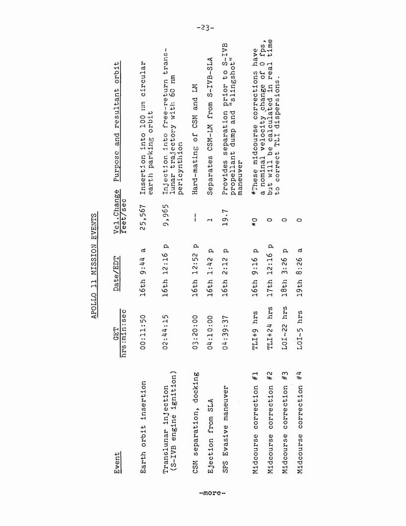
Ev
ent
GE
T
Da
te/
ED
T
Ve
l.C
ha
nge
Pu
r2
ose
a
nd
r
es
ul
ta
nt
o
rb
it
h
rs
:mi
n:s
ec
f
ee
t/
se
c
Ea
rth
o
rb
it
i
ns
er
ti
on
0
0:1
1:5
0 1
6t
h
9:4
4 a
2
5,5
67
I
nse
rt
io
n
int
o
10
0 m
n c
irc
ul
ar
ea
rt
h
pa
rk
ing
o
rb
it
Tr
an
slu
na
r
inj
ec
tio
n
02
:44:
15
1
6t
h 1
2:1
6
p
9,9
65
In
ject
ion
into
fre
e-re
turn
tra
ns-
(S-I
VB
e
ng
ine
ig
nit
ion
) lu
na
r
tr
a,j
ec
to
ry
w
ith
60
nm
p
er
ic
yn
th
ion
CS
M
se
pa
ra
ti
on
, d
oc
kin
g
03:
20
:0
0
16
th
1
2:5
2 p
-
-H
ar
d-
ma
tin
g
of
C
SM
a
nd
L
M
I I
3
t\)
0
Eje
ct
ion
f
rom
S
LA
0
4:1
0:0
0 1
6t
h
1:4
2
p
1 S
ep
ar
at
es
CS
M-
LM
fr
om
S-
IVB
-S
LA
w
�
I
Q I
SPS
Ev
asi
ve
m
an
euv
er
Oll
:39:
37
1
6t
h 2
:1
2 p
1
9.7
P
ro
vid
es
se
pa
ra
tio
n p
ri
or
t
o S
-I
VB
p
ro
pe
ll
an
t d
um
p
an
d
"sli
ng
sho
t"
m
an
euv
er
Mid
co
ur
se
co
rr
ec
tio
n
#1
TL
I+9
hr
s 1
6t
h
9:1
6 p
*0
*T
he
se
mid
co
ur
se
co
rr
ec
tio
ns
h
av
e
Mid
co
ur
se
cor
re
ct
io
n
#2
T
LI+
24
hr
s 1
7t
h
12:
16
p
a
no
min
al
ve
lo
ci
ty
,c
ha
ng
e of
0
f
ps
, 0
bu
t w
il
l b
e
ca
lcu
la�
ed
in
r
ea
l
tim
e to
cor
rect
TLI
di
spe
rs
io
ns
. M
idc
ou
rs
e
co
rr
ec
tio
n
#3
L
OI
-2
2 h
rs
18t
h
3:2
6 p
0
Mid
co
ur
se
cor
re
ct
ion
#
4 L
OI-
5
hr
s 1
9t
h 8
:26
a
0

I 3
0
�
Q I
Ev
ent
LM
a
sc
en
t
an
d
or
bi
t
in
ser
ti
on
LM
RC
S c
on
ce
nt
ri
c
se
q
ue
nc
e i
ni
ti
at
e
(CS
I)
bu
rn
LM
RC
S
con
sta
nt
de
lt
a
he
ig
ht
(C
DH
) b
ur
n
LM
R
CS
te
rm
ina
l p
ha
se
in
it
ia
te
(T
PI
) b
ur
n
Re
nd
ez
vo
us
(TP
F)
Do
ck
in
g
LM
je
tt
iso
n,
se
pa
ra
t
io
n
(SM
RC
S)
Tr
an
sea
rt
h
inj
ec
ti
on
(T
EI
) S
PS
AP
OL
LO
1
1 M
ISS
ION
E
VE
NT
S
GE
T
DA
TE
/E
DT
h
rs
:mi
n:s
ec
12
4:2
3:2
1 2
1s
t
1:5
5 p
12
5:2
1:2
0 2
1s
t
2:5
3 p
12
6:1
9:ll
0 2
1s
t
3:
52
p
1 26 :
58
:26
21st
4:
30
p
127
:ll3
:54
21
st
5:1
5 p
128
:00
:00
21
st
5
:32
p
13
1:5
3:0
5 21
st
9:2
5 p
13
5:2
4:3
4 2
2n
d
00
:57
a
Ve
l.C
han
ge
Pu
rp
ose
a
nd
re
su
lta
nt
or
bi
t
fe
et
/s
ec
60
55
B
oo
st
s a
sc
ent
sta
ge
i
nt
o
9 x
45
lu
na
r
or
bi
t
fo
r
ren
de
zvo
us
w
it
h
CS
M
ll9
.4
Ra
is
es
L
M
pe
ri
lu
ne
t
o
44
.7 n
m,
ad
ju
st
s
or
bi
ta
l
sha
pe
f
or
r
end
ez
vo
us
seq
ue
nc
e
(45
.5 x
4
4.2
)
4.5
24
.6
-4
. 7
-1
32
93
Ra
di
all
y d
own
wa
rd
b
ur
n
ad
ju
st
s
LM
or
bi
t
to
c
on
sta
nt
1
5
nm
be
low
C
SM
LM
th
ru
st
s
alo
ng
li
ne
of
sig
ht
to
wa
rd
C
SM
, m
id
co
ur
se
an
d
br
ak
ing
ma
ne
uv
er
s a
s n
ec
es
sar
y
Co
mp
le
te
s
re
nd
ezv
ou
s s
eq
ue
nc
e
(59
.5 X
5
9.0
)
Co
mm
an
de
r
an
d
LM
pi
lo
t
tr
an
sf
er
b
ac
k
to
C
SM
Pr
ev
en
ts
re
co
nt
ac
t
of
CS
M
wi
th
L
M
asc
en
t
sta
ge
d
ur
ing
r
em
ain
de
r
of
lu
na
r o
rb
it
Inj
ec
t
CS
M
in
to
5
9.6
-h
ou
r
tr
an
se
ar
th
t
ra
je
ct
or
y
I I\)
.:::
I

I 3
0
"'$
(l)
I
Even
t
Mi
dco
ur
se
cor
rec
tion
N
o.
5
Mi
dco
ur
se
cor
rec
tion
N
o.
6
Mi
dco
ur
se
cor
rec
tion
N
o.
7
CM/S
M
sep
ar
ati
on
En
try
in
ter
face
(4
00
,00
0
fee
t)
Tou
chd
own
APOL
LO
11
MIS
SIO
N
EVEN
TS
GET
D
ATE/
EDT
h
rs
:min
:sec
TE
I+l5
hr
s
22
nd
3:5
7 p
EI
-1
5 hr
s 23
rd
9:3
7 p
EI
-3 h
rs
24
th
9:3
7 a
194
:50
:04
2
4th
12
:22
p
195:
05:
04
2
4th
1
2:3
7 p
195:
19
:0
5 2
4th
12
:51
p
Ve1
.Ch
ang
e Pu
rp
ose
an
d r
esu
lta
nt
orbi
�
fee
t/s
ec
0
Tra
ns
ear
th m
idco
ur
se
cor
rec
ti
ons
wi
ll b
e c
om
pu
ted
in
r
eal
tim
e fo
r en
try
co
rr
id
or
0
con
tro
l an
d r
eco
ver
y a
rea
w
eath
er a
voi
da
nce
.
0
Comm
and
mod
ule
o
ri
ente
d
fo
r
entr
y
Com
man
d m
odu
le
ente
rs
ea
rth
's
s
ens
ible
atm
osp
her
e a
t 3
6,
19
4
fps
Lan
di
ng
12
85
nm
d
o\om
ran
ge
from
en
try
, 1
0.6
no
rth
la
titu
de
by
1
72.4
wes
t'
lon
gi
tud
e.
I 1\)
\Jl
I

-26-
MISSION TRAJECTORY AND MANEUVER DESCRI PTION
Informati on pre sented here in i s based upon a July 16 launch and i s s ubj ect to change prior t o the mis s i on or in real time during the mis si on t o mee t changing c onditions .
Launch
Apo llo 1 1 w i l l b e launched from Kennedy Space Center Launch Compl e x 39A on a launch azimuth that can vary from 72 degrees t o 106 degrees , depending upon the t ime of day of laun c h . The azimuth changes with t ime of day to permit a fue l-optimum inj e c t i on from Earth parking orb.i t int o a free-re turn ci rcumlunar traject ory . O t her factors influencing the launch windows are a day light launch and proper Sun angles on the l unar landing s ite s .
The p lanned Apollo 1 1 launch date of July 1 6 wil l call for liftoff at 9:32 a . m . EDT on a launch azimuth of 72 degre e s . The 7 . 6-mi l li on-pound thrus t Saturn V first s tage boosts the space vehicle to an altitude of 36 . 3 nm at 5 0 . 6 nm downrange and increas es t he vehicle ' s ve locity to 9030.6 fps in 2 minutes 4 n . 8 seconds of powered flight . First stage thrust builds to 9 , 0 88 , 4 1 9 pounds before center engine shutdown . Following out-b6ard engine s hutdown , the firs t s tage separates and falls into the At lantic Ocean about 3 4 0 nm downrange ( 30 . 3 degrees Nort h latitude and 7 3 . 5 degrees West longitude ) some 9 minutes after liftoff .
The 1-mi l lion-pound thrust second s tage ( S-II ) carrie s the space vehicle t o an alt i t ude of 1 0 1.4 nm and a distance of .8 8 5 nm downrange . Before engine burnout , the vehi cle w i l l be moving at a speed of 22,?46.$ fps . The outer J-2 engines w i l l burn 6 minutes 29 s e c onds during this powered phas e , b ut the center engine wi l l be cut off at 4 minute s 56 s e c onds aft e r S-II ignit i on .
At outboard engine cutoff , the S-II s eparates and , following a b alli s t i c traj ectory , p lunges into t he At lantic Ocean about 2 , 30 0 nm downrange from the Kennedy Space Center ( 3 1 degrees North lati t ude and 33 . 6 degrees Wes t longitude ) some 20 minutes after l ift off .
The firs t burn of the Saturn V third stage ( S-IVB ) occurs immediately after S-II s t age separa t i on . I t w i l l last long enough ( 145 seconds ) t o ins e rt the space vehicle into a circular Earth parking orb i t beginning at about 4 , 81 8 nm downrange . Ve locity at Earth orb ital insertion w i l l be 2 5 , 5 67 fps at 11 mtnut e s 50 seconds ground e lapsed time ( GET) . Inclination will b e 32 . 6 degre e s .
-more-

LAUN
CH W
INDO
W S
UMM
ARY
LA
UNCH
D
AT
E
16
lR
JULY
L
AUN
CH
WIN
DO
W.
E.
D.T
.
9:
32
-1
3:
54
9
:3
8-1
4:
02
S
ITE
/P
ROF
! LE
2
/F
R 3
/F
R
16-2
1 S
UN
EL
EVA
TIO
N A
NG
LE
9.
9-
12
.6
8
. 3
-1
1.
0
MIS
SIO
N T
IME
, D
AY
S:H
OU
RS
8
:3
8
:5
S
PS
R
ES
ER
VES
, F
PS
17
00
15
50
LA
UNCH
D
AT
E
14
1
6
AU
GU
ST
LA
UNCH
W
IND
OW
. E
.D
.T.
7
:51
-1
2:1
5
8:
04
-1
2:
31
S
ITE
/P
ROF
! LE
2
/H
YB
3
/H
YB
14-2
0 S
UN
EL
EVA
TIO
N
AN
GLE
6
.2
-8
.9
6
.2
-8
.9
M
ISS
ION
TIM
E,
DA
YS
:HO
UR
S
8:
5
8:
7
SP
S
RES
ERV
ES
, F
PS
16
00
17
50
LA
UNCH
D
AT
E
13
1
5
LA
UNCH
W
IND
OW
. E
.D
.T
.
6:
17
-1
0:
45
7
:0
4-.1
1:
39
SEP
S
ITE
/P
ROF
! L
E
2/
HY
B
.3/
HY
B
13-1
8 S
UN
EL
EVA
TIO
N
AN
GLE
6
.8
-9
.6
6
.3
-9
.. 2
M
ISS
ION
TIM
E,
DA
YS
:HO
UR
S
8:
7
8:
8
SP
S R
ES
ERV
ES
, FP
S
16
00
1
50
0
---
-��
--L_
_
�� �-
--
----
--�--�
--'-
21
10:
09
-1
4:
39
5
/H
YB
6
.3
-9
.0
8
:8
1
75
0
18
11
:3
1-
16
:14
5/
HY
B
6.
8-
9.
7
8:
6
105
0
20
10
:0
5-
14
:4
7
5/
HY
B
9.
0-
12
.0
8
:8
13
00
I I I
I N
-..)
I

-28-
MIS S ION DURATIONS
TOTAL MISSION TIME,
DAY:HR.
LAUNCH � ON TIME, / TST TLI OPPORTUNITY
1 / LAUNCH AT CLOSE OF WINDOW, 2ND TLI OPPORTUNITY
7d
22h '---....!------'-----..1
16 18 21
JULY 1969 LAUNCH DATE
-more-

I 3
0
�
� I
HYBR
ID L
UNA
R PR
OFI
LE
NO
N-F
REE
RET
UR
N
h p �
100 T
O 15
00 N.
M
I.
.,--
--
--
...
�
--
-..
.. ...
Ml D
CO
UR
SE
TRA
NSF
ER
.....
llV
� 10
TO 40
FPS
.... ..
.. � -
..... ..
. ...
....
--
-"'
-
-..
..
FREE
-RE
TUR
NJ
-
/
I I\)
\0
I

-30-
The crew w i ll have a backup to launch vehicle guidance during powered fligh t . I f the Saturn inst rumen t unit inertial platform fai ls , the ere�-.• can s:'li tch guidance to the command module systems for fi rst-stage po\-tered flight automatic control . Second and th ird stage backup guidance is through manual takeover in which creH hand controller inputs are fed through the co�mand module computer to the Saturn in� t i'umen t uni t .
Earth Parking Orbit ( EPO)
Apollo 11 w i ll remain in Earth parking orbit for one-and-onehalf revolution;;; after insertion and 'ltill hold a local horizontal attitude during the entire period . The crew \.zi ll perform spacecraft systems checks in preparation for the translunar injection ( TLI ) burn . The final 11go11 for the 'fLI burn 'it i ll be given to the crew through the Carnarvon , Australia , I<1anned Space Fl igh t Net\o:ork station .
Translunar InJ ection ( TLI )
Midway through the second revolution in Earth parking orbi t , the S-IVB third-stage engine w i l l restart at 2 : 4 4 : 15 GET over the mid-Pacific just south of the equator to inject Apollo 11 toward the f"ioon . 'rhe velocity 'itill increase from 2 5 ,567 fps to 35 ,53 3 fps at TLI cutoff--a ve loci ty increase o f 9971 fps . The TLI b urn is targeted for about 6 fps overspeed to compensate for the later SPS evasive maneuver after LH e xtraction . TLI \':ill place Apollo 11 on a free-return c ircumlunar traj ec tory from which midcourse corrections if necessary could be made \.,.ith the Slot RCS thrusters . Entry from a free-return traj e c tory would be at 10 : 3 7 a . m . EDT July 22 at 14 . 9 degrees south lati tude by 174 . 9 eas t longitude after a flight time of 1 4 5 hrs 04 min .
Transposition . Docking and Eje c t ion ( TD&E)
At about three hours after li ftoff and 25 minutes after the TLI burn , the Apollo 11 crew wi ll separate the command/service module from the spacecraft lunar module adapter (SLA ) , thrus t out away from the S-IVB, turn around and move back in for docldng \'o'ith the lunar module . Docking should take place at about three hours and 2 1 minutes GET, and after the c re-..t confirms all docking latches solidly engage d , they w i ll conne ct the CSl•t-to-Ll-1 umb i l icals and pressurize the LM w i th the command module surge tank . At about 4 : 0 9 GET, the spacecraft will b e e je cted from the spacecraft LM adapter by spring devi ces at the four LH landing gear 11kne e 11 attach point s . The e j ection springs will impart about one fps ve loci ty t o the spacecraft . A 19 . 7 fps servi ce propulsion system (SPS) evasive maneuver in plane at 11 : 39 GET will separate the spacecraft to a safe distance for the S-IVD 11slingshot " maneuver in which res i dual launch vehicle liquid propellants w i l l be dumped through the J-2 engine bell to propell the stage into a traj e c t ory passing behind the �ioon ' s trai ling edge and on into solar orb i t .
-more-

� � I
VE
HIC
LE
E
AR
TH
P
AR
KIN
G
OR
BIT
C
ON
FIG
UR
AT
ION
(SA
TU
RN
V T
HIR
D ST
AG
E A
ND
IN
STR
UMEN
T U
N IT
, A
POLL
O S
PAC
ECR
AFT
)
I w
._.
I

� � � I
TLI +
20
SEC
LO
CAL
/
HORI
ZONT
AL
ORBI
T RA
TE
PO
ST
TL
I T
l ME
LIN
E
TLI +
90
MIN
LM
WIT
HDRA
WAL
SP
S EV
ASIV
E M
ANEU
VER
-2
0 F
PS
I w
1'\)
I

- 3 3-
Trans lunar Coast
Up to four midcourse corre ction burns are planned during the translunar coast phas e , depending upon �he ac curacy of the traj e ctory re su·lting from t he TLI maneuver . If re quire d , the midcourse c orrection burns are p l anned at TL I +9 hours , TLI +2 4 hours , lunar orbit insertion ( LO I ) -2 2 hours and LOI - 5 h ours .
During coast peri ods between midcourse corre ction s , the space craft wi l l be in the pass i ve thermal c ontrol ( PTC ) or "barb e c ue " mode i n \vhich the space craft .,.till rotate s lowly about one axi s to stab i l i ze s p ace craft thermal re sponse to the c ontinuous s olar exposure.
Lunar Orb it Insertion ( LOI )
The first of two lunar orb it ins ertion b urn� will be made at 75 : 5 4 : 2 8 GET at an altitude of about 80 nm above the Moon . LOI-1 wi ll have a nominal retrograde veloc ity change of 2 , 9 2 4 fps and w i l l insert Apollo 1 1 into a 60xl70-nm e l lipti c al lunar orbit . LOI-2 two orbits later at 80 : 09 : 30 GET w i l l adj ust the orbit to a 5 4 x6 5-nm orb i t , wh ich b e cause of perturbati ons of the lunar gravitational potential , will be come c ircular at 60 nm at the time of rendezvous with the LM . The burn w i l l be 1 5 7 . 8 fps retrograde . Both LO I maneuvers w i l l b e with the SPS engine near peri cynthion when the spacecraft is behind the Moon and out of contact with MSFN stations. After LOI- 2 ( ci rculari zation ) , the lunar module pi lot w i l l enter the lunar module for a brief che ckout and return to the c ommand module .
Lunar Module De s cent . Lunar Landing
The lunar module will be manned and che cked out for undocking and subsequent landing on the lunar surface at Apollo site 2 . Undocking .,.t i l l take place at 100 : 0 9 : 50 GET pri or to the MSFN acqui s ition of s i gnal . A readial ly downward servi c e module RCS b urn of 2 . 5 fp s wi ll p lace the CSM on an equipe riod orbit w ith a maximum separation o f 2 . 2 nm one half revolution after the separation maneuve r . At thi s point , on lunar farside , the de s cent orb i t insertion b urn ( DOI ) w i ll be made with the lunar module des cent engine firing retrograde 7 4 . 2 fps at 101 : 3 8 : 4 8 GET . The burn wi ll start at 10 per cent throttle for 15 s e conds and the remainder at 40 per cent thrott le .
The DOI maneuver lowers LM peri cynthion to 5 0 , 000 feet at a point about 14 degre es uprange o f landing s ite 2 .
-more-

- 3 4 -
A three-phase powered des cent ini t i ation ( PDI ) maneuver begins at pericynth ion at 102 : 5 3 : 13 GET us ing the LM de s cent engine t o brake the veh i c le out of the de scent transfer orb i t . The guidance- controlled PDI maneuver s tarts about 2 60 nm prior t o t ouchdown , and i s in retrograde attitude to re duce ve locity t o essentially zero at the time vert i cal de s cent begins . Spacecraft attitude s range from windows down at the s t art of PDI , to windows up as the spacecraft reaches 4 5 , 000 fee t above the lunar surface and LM landing radar data can be integrat ed by the LM guidance computer . The b r aking phase ends at about 7 , 000 feet above the surface and the spacecraft is rotated to an upright windows-forward att i tude. The s t art of the approach phase is called high gat e , and the st art of the landing phase at 500 feet is calle d low gat e .
Both the approach phase and landing phase al low pilot t akeover from guidance cont ro l as we ll as visual evaluat ion of the landing site . The final vert i cal des cent t o t ouchdown begins at about 150 fe e t when all forward ve locity i s nulled out . Vertical de s cent rate wi l l be three fps . Touchdown wi l l take place at 102 : 4 7 : 11 GET .
-more -

z 0 ....._ � w V) z
� <( z ::> __,
z 0 t<C N a::: � :::::> u a::: u
-t I
g
-35-
/
-more-

� 'i
CD I
MSF
N..
....._/!
LOS
I ��=*=-'%
�=1 SU
RFA
CE
DAR
KN
ESS
�3 S
C D
AR
KN
ESS
.5 N
. Ml.1
ABO
VE
�. x-
LM A
BOVE
IY'
AN
D BE
HIN
D -
--
-�
EPA
RATI
ON
\.
(DO
l) DI
RECT
ION
�
�1.8
N. M
I. O
F M
OTI
ON
r I
'
/
........
_......
MO
TION
OFL
�R;
A TIV
E TO
CSM
M
OO
N
I \ \ \ �
, �
LA
ND
ING
SIT
E
' �
"
�r-'
:S
---
Q)C
SM
SEP
ARA
TIO
N !
MA
NEU
VER
(S
M R
CS
)
EART
H
CS
M/
LM
S
EP
AR
AT
ION
M
AN
EU
VE
R
I w
0\ I

� 0 � I
LU
NA
R
MO
DU
LE
D
ES
CE
NT
120
60
0 60
18
0 24
0
CD LM
DESC
ENT
ORB
IT I
NSE
RTIO
N (D
Ol)
MA
NUEV
ER,
-.:M
-RE
TRO
GRA
DE,
/ �
D
PS
-TH
ROTT
LEDr/
�·
TO 4
00/o
MSF
N
-
I LO
S
I \
(!)LA
ND
ING
SUN
y
LM BY1cJ
Pol
, r
, � �
LM A
HEA
D LM
BEH
IND
TO
UCH
DOW
N LM
-CSM
REL
ATIV
E M
OTIO
N @
POW
ERED
DES
CENT
IN
ITIA
TIO
N 50
,000
FT. A
LTIT
UDE
I w
--4
I

I s 0
11 ro I
DES
IGN
CR IT
ER lA
�CSM
ORB
IT
(60
N.
MI.
)
50,0
00 Ff
HI-
GATE
• B
RAK
ING
PH
ASE
(PD
I TO
HI-
GATE
)-EF
FIC
IENT
RED
UCT
ION
OF
ORB
ITA
L V
ELO
CIT
Y
e F
INA
l A
PPRO
ACH
PHA
SE (
HI-
GATE
TO
lO-G
ATE
)-CR
EW V
ISIB
ILIT
Y (S
AFE
TY O
F Fl
l GHT
AND
SIT
£ A
SSES
SMEN
T)
•LA
NDIN
G P
HASE
(LO
-GAT
E TO
TO
UCHD
OW
N)-
MA
NUA
L C
ONT
ROL
TAKE
OV
ER
OP
ER
AT
ION
AL
P
HA
SE
S
OF
P
OW
ER
ED
D
ES
CE
NT
I w
co
I

I 3
0
�
Cb I
ALTI
TUDE
LOW
GAT
E A
LT-
500
FT.
RAN
GE-
2000
FT.
F l NA
L APP
ROA
CH
A
ND
LAN
DIN
G PH
ASE
S
�
V"""'LAN
DIN
G S
l TE
RAN
GE
HI G
H GA
TE
ALT
-76
00 FT.
RA
NG
E-26
00 0
FT. BR
AK
ING
P
HAS
E
TA
RG
ET
S
EQ
UE
NC
E
FO
R
AU
TO
MA
TIC
G
UID
AN
CE
I w
\0 I

I 5 � � I
EN
D
OF
B
RA
KIN
G
PH
AS
E
'" 23°
�
I .,,
M �
4;0
VIS
IBIL
ITY
P
HA
SE
\
_.J. __
_ �
LUN
AR
HO
RIZ
ON
TAL
-L- =
/
'\ 57
° \
LA
ND
ING
P
HA
SE
THRU
ST
6, 0
00 L
B
I V
ERTI
CA
L
;,��slrs �
\
/1 V
ELO
CIT
Y
LAN
D I N
G R
AD
AR
80°
I _.A
�.!b
2 7
FPS
POS
ITI O
N
NO
. 1
LAN
DIN
G
RAD
AR I
----�'-
--�--· �
' PO
SIT
ION
N
O.
2 TH
RUS T
,68_
..
3,oJo F
T I
'TO
TO
UC
HD
OW
N
I I
500
FT
NO
MIN
AL
D
ES
CE
NT
TR
AJ
EC
TO
RY
FR
OM
H
IGH
G
AT
E
TO
TO
UC
HD
OW
N
VER
TIC
AL
ELO
CI
2 7 T
O 3
FP
S
�
I .J::
0 I

I 3
0
�
<D I
• P
ROBE
CON
TAC
TS L
UNA
R S
URFA
CE
• 'L
UNA
R C
ONTA
CT'
IN
DIC
ATO
R O
N C
ONTR
OL
PAN
EL L
l GH
TS
• D
ESC
ENT
ENG
INE
IS S
HUT
DO
WN
BY C
REW
AFT
ER 1
SEC
ON
D
• L
M S
ETTL
ES T
O L
UNA
R S
URFA
CE
LU
NA
R
CO
NT
AC
T
SE
QU
EN
CE
I .:::
J-' I

-42-
Lunar Surface Extravehicular Activity ( EVA)
Armstrong and Aldrin will spend about 22 hours on the lunar surface after lunar module touchdown at 102 : 47 : 11 GET . Following extensive checkout of LM systems and preparations for c ontingency ascent staging , the LM crew will eat and rest before depressurizing the LM for lunar surface EVA . Both crewmen will don p ortab le life support system ( PLSS) backpacks with oxygen purge system units ( OPS ) attache d .
LM depre s surization i s s cheduled for 112 : 30 GET with the c ommander being the first to egress the LM and step onto the lunar surface . His movements will be recorded on still and motion picture film by the lunar module pilot and by TV deployed by the commander prior to descending the ladder . The LM pilot will leave the LM about 25 minutes after the commander and both crewmen '�ill collect samples of lunar material and deploy the Early Apollo Scientific Experiments Package ( EASEP ) and the solar wind compos ition ( SWC ) experiment .
The commander , shortly after setting foot on the lunar surface , will collect a contingency sample of surface material and p lace it in his suit pocket . Later both crewmen will collect as much as 130 pounds of loose materials and core samples which will be stowed in air-tight sample return containers for return to Earth .
Prior to sealing the SRC , the SWC experiment , which measures the elemental and isotopic constituents of the noble (inert ) gases in the solar wind , is rolled up and placed in the container for return to Earth for analysi s . Principal experimenter is Dr . Johannes Geiss � University of Bern , Switzerland .
The crew will photograph the landing site terrain and inspect the LM during the EVA . They can range out to about 100 feet from the LM .
After both crewmen have ingressed the LM and have connected to the cabin suit circuit , they will doff the PLSS backpacks and j ettison them along with other gear no longer needed , through the LM front hatch onto the lunar surface .
The LM cabin will be repressurized about 2 hrs . 4 0 min . after EVA initiation to permit t ransfer by the crew to the LM life support systems . The LM will then be depressurized to j ettison unnecessary equipment to the lunar surface and be repressurized . The crew will have a meal and rest period before preparing for ascent into lunar orbit and rendezvousing with the CSM .
-more-

I 5 � I
TO
OCH
OOWN
L
IFT
OF
F
/ '
POST
-1
ST R
ES
T
EVA
EV
A
POST
· 2
ND
RES
T
AS
C.
PR
EP
L
AH
D
EAT
P
ER
IOD
EA
T
PR
EP
2
:40
EV
A
EAT
P
ER
IOD
A
ND
EA
T
C/
0
0:2
5-C
DR
C/
0
2:0
4
0:3
5 4
:00
1
:00
2
:00
2
:15
-BO
TH
1 :3
0
0:4
0
4:4
0
2:2
8
I 2
1:
27
TO
TA
L T
IME
__
__
__
__
__
__
.....,
LU
NA
R S
UR
FA
CE
A
CT
IVIT
Y
SC
HE
DU
LE
I �
w
I

I � 0 � � I
COR
LM P
ILOT
COR
LM P
ILOT
0
LM
INS
PE
CT
ION
k INSP
ECTI
ON
1•10
1•
20
PLSS
IN
ITIA
L E
NV
IR C
ONTC
PR
EL
PH
OTC
TV
BU
LK SA
MPL
E CH
ECKO
UT
EVA
FAU
lL SM
PL
CKS
LMP
OEP
LOV
MEN
T
COLL
ECTI
ON
MONI
TOR
� PL
SS
SAFE
TY
& OP
ERAT
E IN
TL
EN
VIR
sw
c EV
A &
ENV
IR
CHEC
KOUT
M
ONIT
OR
SEQ
UENC
E CA
IAERA
EV
A
FA
MIL
O
EP
EVAL
UATI
ON
j 10
20
.30
40
50
1•
00
1•10
TIME
HRS
+MIN
EASE
P RE
ST
DE
PLOV
LI�r
.T O
OC
UU
EN
TE
O S
AJAPL
E C
OLL
EC
TIO
N
PHOT
O L!.
IP
TERM
INAT
E PR
EPAR
E A
ND
EV
A
TRAN
SFER
SRC
' S
EASE
P TE
RMIN
ATE
DEPL
OYME
NT
DO
CU
UE
NT
ED
SAM
PLE
CO
LL
EC
TIO
N
EVA
RE
CE
IV
E
SRC'
S
1•30
1•
40
1+50
2•
00
2+10
2•
20
2+30
2+
40
TIME
HRS
+MIN
NO
MIN
AL
EV
A T
IME
LIN
E
I .:::
.:::
I

I 5 >-$ (1) I
VIE
W T
HRU
OPTI
CAL
CENT
ER O
F TV
LENS
IN
Dl R
ECTI
ON
OF 11Z
"-PL
ANE
INT
ERSE
CTIO
N O
F
"Z"
PLA
NE
AN
D LU
NAR
SUR
FACE
OPT
ICA
L C
ENT
ER
I .::
Vl I

I 3
0
"'S � I
REM
OV
E
PS
EP RE
MO
VE
LRR
R
LUNA
R SU
RFAC
E PH
ASE
TRA
VER
SE
DEP
LOY
P
SEP
--�__/'
DEP
LOY
LRR
R
I .t:
"'
I

I 5 01 � I
KEY
:
SWC
-SO
LAR
WIN
D C
OM
POS
ITIO
N
LR3
-LA
SER
R
AN
GIN
G R
ETR
O
REF
LEC
TO
R
TV
CAM
ERA
T
RIP
OD
POS
ITIO
N
0,
PSE
-PA
SSIV
E S
EIS
MIC
EX
PER
IMEN
T
( 30
FT
. FR
OM
LM}
I '
I
'
I ,/'
...... FO
V '
,_--8
SWC
POS
ITIO
N
: (
FEW
FEE
T
FRO
M L
M)
BULK
SA
MPL
E (
NEA
R M
ESA
IN
Q
UAD
IV}
CO
NT
INGE
NCY
SA
MPL
E (
NEA
R LA
DDER
}
\ DO
CUM
ENT
ED S
AM
PLE
\'\
(H
ITH
IN 1
00
FT.
FROM
LM
}
' '
........ -
[ill . . LR
3
POS
ITIO
N
( 70
FT
. FR
OM
LM
}
O=D P
SE
PO
SIT
ION
(
80
FT.
FRO
M L
M}
N t I .&=
-.:I
I

Lunar Sample Collection
Equipment for collecting and stowing lunar surface sampl e s i s hous ed i n t h e modularized equipment s t owage assemb ly (MESA ) on the LM descent s t age . The commander w i l l unstow the equipment aft er adj u s t ing to the lunar s urface environment .
I tems s t owed in the MESA are as follow s :
* Black and whit e TV camera .
* Large s coop for collect ing bulk and documented s amp l e s o f l o o s e lunar surface mat erial .
* Extension handle that f i t s the large s coop , core tubes and hammer .
* Tongs for collect ing s amples o f rock and for p i cking up dropped tools .
* Gnomon for vert i cal reference , color and dimension scale for lunar s urface photography .
* Hammer for driving core tube s , chipping rock and for trenching (with extens ion handle att ached ) .
* 3 5mm s tereo camera .
* Two sample ret urn containers ( SRC ) for returning up t o 1 3 0 pounds o f b u l k and documented lunar s amp le s . I tems s uch a s large and small s ampl e b ags , core t ub e s , gas analy s i s and lunar environment s amp le c ontainers are s towed in the SRC s . Both containers are s ealed after samp les have been collected , documented and s towed , and the crew w i l l hoist them into the as cent st age by means of an equipment conveyor for t rans fer into the command module and subsequent return to Earth for analy s i s i n the Lunar Re c e iving Laboratory .
Add i t i onal ly , a cont ingen cy lunar sample re turn container is s towed in the LM cabin for u s e by the commander during the early phases o f his EVA . The device i s a b ag attached t o an ext ending handle in which the commander w i l l s coop up about one liter of lunar material . He then w i l l j et t i s on the handle and st ow the contingency s ample in his pre s sure suit pocket .

-49-
LM Ascent, Lunar Orbit Rendezvous
Following the 2 2-hour lunar stay time during whi ch the commander and lunar module pilot will deploy the Early Apollo Scientific Experiments Package (EASEP ) , the Solar Wind Composition ( SWC) experiment , and gather lunar soil samples , the LM ascent stage wi ll lift off the lunar surface to begin the rendezvous sequence with the orbiting CSM . Ignition of the LM ascent engine will be at 124 :2 3 : 21 for a 7 min 1 4 sec burn with a total ve locity of 6 , 055 fps . Powered ascent is in two phases : vertical as cent for terrain clearance and the orbital insertion phase . Pitchover along the desired launch azimuth begins as the vertical as cent rate reached 50 fps about 10 seconds after liftoff at about 250 feet in altitude . Insertion into a 9 x 45-nm lunar orbit will take place about 166 nm west of the landing site .
Following LM insertion into lunar orbit , the LM c rew wil l compute onboard the four maj or maneuvers for rendezvous with the CSM which is about 255 nm ahead of the LM at this point . All maneuvers in the sequence will be made with the LM RCS thrusters . The premission rendezvous sequence maneuvers , times and velocities which likely wi ll differ slightly in real time , are as follows :
-more-

� z w u (/) <( � -.1
I I
I I
/ /
\ z \ � .... /
v '
-50-
-- - -/ /
-...
- - -
-more-
z 0 1-� LLI 1-V'l z a) - � ,_ o z . LLI -
� � <t: •
o z LU IJ"\ � !:t I.Li o-3: -0 0..

ALTITUDE, FT
-51-
400
GU I DANCE S W I TCH TO
R B I T I NSERT I ON PHASE
� 0 •
.;,.
75
16
70 14
60 A LT I TU DE 12 T I ME FROM LUNAR
RATE, FPS Ll FT-OFF, SEC
50 10
40 8
30 6
4
o 2
VERTICA L RI SE PHASE
-more -

I s
0
'i
('1)
I
END
VERT
ICAL
RI
SE
"'
�
ORBI
T I N
SERT
I ON !c:
ASCE
NT B
URN
OUT
PHAS
E CO
AST T
O 44
. 07 N
. MI .
APOL
UNE
----""'t ;9
��;�
5-rr--
--
TOTA
L ASC
ENT:
BURN
TIM
E= 7
:14.6
5 MIN
:SEC
�V
REQ
UIRE
D = 6
, 055
.39 F
PS
PROP
ELLA
NT R
EQUI
RED
= 4, 9
89.8
6 LB
INSE
RT I O
N OR
B IT
PARA
METE
RS
hp =
55,9
05.4
FT
ONBO
ARD
DISP
LAYS
AT
INSE
RTIO
N V
= 5
,535
.9FP
S h
= 32
.2 F
PS
h = 4
4. 07
N. M
I. a 'f'J
= 17.
59 °
y . =. 324
h =
60, 1
29. 5
FT
OR
BIT
IN
SE
RT
ION
PH
AS
E
I Vl
1\)
I

-5 3 -
Concent ri c s e quence ini t i ate ( CS I ) : A t first L M apolune after insertion 125 : 2 1 : 20 GET , 49 fps pos igrade , following s ome 2 0 minute s o f Lr'l rendezvous radar tracking and csr'l sextant/VHF ranging navigat i on . CSI will be targeted to plac e the LM in an orb i t 15 nm below the CSM at the t ime of the later con s t ant de l t a height ( CDH ) maneuver . The CSI burn may als o ini t :i.ate corre ctions for any out-ofplane dispers ions resulting from ins ert i on azimuth errors . Resulting LM orb it after CS I w i l l b e 4 5 . 5 x 4 4 . 2 nm and w il l have a cat chup rate to the CSM o f . 0 7 2 degrees per minute.
Another plane corre ction is p o s s i b le about 29 minute s after C S I at the nodal cros s ing �f t h e CSM and LM orb i t s to p lace b oth veh i c le s at a common node at the time o f the CDH maneuver at 126 : 1 9 : 40 . GET .
Terminal phas e initiat e ( TP I ) : This maneuver o c curs at 126 : 5 8 : 2 6 and adds 2 4 . 6 fps along the line o f s igh t to\ltard the CSM when the e levation angle to the CSM reaches 2 6 . 6 degrees . The LM orb i t b e c ome s 6 1 . 2 x 4 3 . 2 nm and the cat chup rate to the C SM de cre as e s t o . 03 2 degree s per s e cond , or a c losing rate o f 1 3 1 fps .
Two midcourse corre c t i on maneuvers will b e made i f neede d , fo l lowed by four b raking maneuvers at : 127 : 39 : 4 3 GET , 1 1 . 5 fps ; 12 7 : 40 : 5 6 , 9 . 8 fp s ; 1 2 7 : 4 2 : 3 5 GET , 4 . 8 fps ; and at 12 7 : 4 3 : 5 4 GET, 4 . 7 fp s . Docking nominally w i l l take place at 1 2 8 hrs GET to end three and one-half hours of the rende zvous s e quence .
Transearth Injection ( TEI )
The LM as cent s t age \'lill b e j e tti soned about four hours after hard docking and the CSM will make a 1 fps retrograde s eparat i on maneuver .
The nominal transearth inj e c tion burn wi l l be at 1 3 5 : 24 GET fol lowing 5 9 . 5 hours in lunar orb it . TEI w i l l take place on the lunar farside and wi l l be a 3 , 29 3 fps posigrade SPS b urn of 2 min 29 s e c duration and wi ll produce an entry ve locity o f 3 6 , 19 4 fps after a 5 9 . 6 hr transearth flight time .
An opt ional TEI plan for five revolutions lat er would allow a crew rest period b e fore making the maneuver . TEI i gnition under the optional plan would t ake place at 1 4 5 : 2 3 : 45 GET with a 3 , 6 9 8 fps posigrade SPS burn producing an entry velocity of 3 6 , 29 6 fps and a transearth flight time o f 5 1 . 8 hrs .
-more-

LU
NA
R
MO
DU
LE
CO
NC
EN
TR
IC S
EQ
UE
NC
E
INIT
IAT
ION
MA
NE
UV
ER
60 1
_c.-
_2":1
rCD
H 40
20
G)C
SI
MA�E
UVE�
J(
MSF
N L
OS
G)TP
I M
ANE
UVER
-. �
CS
I • ..
....
'· ..
.. ·-
. .!_���
��-�
o���--��--���--��--����
0 20
40
60
80
100
12
0 140
16
0 18
0 200
22
0 24
0 26
0
LM-C
SM R
ELAT
IVE
MOT
ION
!}CDH
MA
NEU
VER
I \J'l
.::
I

� 0 :l
LU
NA
R
MO
DU
LE
C
ON
ST
AN
T
DI F
FE
RE
NT
IAL
H
EIG
HT
A
ND
T
ER
MIN
AL
P
HA
SE
M
AN
EU
VE
RS
VER
TIC
AL
DIS
PLA
CH
1ENT
{ N
MI )
30
0 TPI
MA
NEUV
ER
(MI D
POI N
T OF
DA
RKNE
SS)
LM R
CS
CD
H\
�-+���-
-.
--
.r
--
--�
..-- _.
.....--
MSF
N
/
II',.
.-M
CC- 2
� REND
EZV
OU
S A
ND
LOs
.. t
/M
CC
-I
@)B
RAK
ING
STA
TIO
NKE
EP
I I
I M
ANE
UVER
A
TEN
MIN
UT
E T
IME
TIC
KS
FR0!
1
--
-DA
YL
IGHT
DOC
KI N
G
0
-DA
RK
NESS
0
20
40
6
0
TRA
ILIN
G D
ISPL
AC
EMEN
T {
N M
I )
LM-C
SM
RELA
TIV
E M
OT
ION
80
I V1
V1
I

-56-
:E (/) rf\ a.. (/) N
::r: LL � "<:S' N
U"\ � :IE � � N
z
z (.!) �
0 a-:
-t-
- uj z
.... > 0::
u . <J ::l
(.!) al
LLI -, z -
:I: .... � c( LLI "' z c(
:I: � �
� ....
-more-

-5 7 -
Transearth coast
Three corridor-c ontrol transearth midcourse corre ction burns wi ll be made i f neede d : MCC-5 at TEI +15 hrs , MCC-6 at entry interface ( EI= 400 ,000 fee t ) -15 hrs and MCC-7 at EI - 3 hrs .
Ent ry, Landing
Apollo 11 will encounter the Earth ' s atmosphere ( 4 00 ,000 fee t ) at 19 5 : 05 : 0 4 GET at a velocity o f 3 6 , 19 4 fps and w il l land some 1 , 2 85 nm downrange from the entry -int erface point using the spacecraft ' s lifting characte ris t i c s to re ach the landing point . Touchdown will be at 195 : 19 : 05 at 10 . 6 degre e s north l atitude by 172 . 4 we s t longitude .
-more-

JJ 0 :l '
EA
RT
H
EN
TR
Y
e
EN
TR
Y
RA
NG
E C
AP
AB
ILIT
Y-
1200
TO
25
00 N
. M
I.
e
NO
MIN
AL
E
NT
RY
RA
NG
E -
128
5 N
. M
I.
e
SH
OR
T
RA
NG
E S
EL
EC
TE
D
FO
R
NO
MIN
AL
MIS
SIO
N B
EC
AU
SE
:
e
RA
NG
E F
RO
M E
NT
RY
TO
L
AN
DIN
G C
AN
B
E S
AM
E F
OR
PR
IMA
RY
AN
D B
AC
KU
P C
ON
TR
OL
MO
DE
S
e
PR
IMA
RY
MO
DE
EA
SIE
R T
O M
ON
ITO
R W
ITH
SH
OR
T
RA
NG
E
e
WE
AT
HE
R A
VO
IDA
NC
E,
WIT
HIN
ON
E D
AY
P
RIO
R T
O
EN
TR
Y,
IS
AC
HIE
VE
D U
SIN
G
EN
TR
Y
RA
NG
ING
C
AP
AB
ILIT
Y T
O 2
500
N.
MI.
e
UP
TO
ON
E D
AY
P
RIO
R T
O E
NT
RY
US
E P
RO
PU
LS
ION
SY
ST
EM
TO
C
HA
NG
E L
AN
DIN
G P
OIN
T
I \.}1
co
I

� � I
60
1� ... ·
d,.....-+:
:::::JJ;::::::::w::•m £;'J.-I
-r:t ..
.... �JtV
0JIC.t ....
�•:!ttr.-l
'-'r-....i=-
-� .... ::z:;:s
,_,_.j
. ... C
I
, ..
� ..
.... �-
40
�;\u
I) I
I I
I c.J.·_
,, ... : .
... _.1.':.
· --,. :' .
·.1 En
try
inle
rfac
c A
llllu
dc;:
: 400
,341
fl
'lon
gllu
de =
171
.3 7 "
E ! 2
0 F
I '\<Gco� ·eu,c
l<�lil
ude
= 3;
53•5
7Lf-.,7,('
I I
\.JL: fl
I .; @�
� J �
� �
MoO<w� lo
ot�
;m
i.l;o �•1
I �
��
'r""""-""
';.,' · I
1 1
1 t
1 •
�
,_
. _ �
, •
:1:.
• lo
ngitu
de=
172.
5• W
� 0
V)
Geod
etic
latit
ude
= 1Q
.6s•
N
20 .
... -.
..
. -
---
··
40�----���--�----��-------L------�------�------�------�
120
14
0 16
0 Ea
st
180
Wes
t 16
0 14
0 12
0
100
80
Long
llude
, de
g
MA
NE
UV
ER
F
OO
TP
RIN
T
AN
D N
OM
INA
L G
RO
UN
DT
RA
CK
I VI
\0 I

� � I
GE
OD
ET
IC A
LTIT
UD
E
VE
RS
US
RA
NG
E
TO G
O
AL
TIT
UD
E
(1 000
FT
)
.40
0
32
0
2.4
0
160
80
NO
TE
: T
IME
T
ICK
ED
E
VE
RY
Y2
M
IN
FR
OM
E
NT
RY
IN
TE
RF
AC
E
/E
NT
ER
S-
8A
ND
BL
AC
KO
UT
1S
T
PE
AK
g,(6
.359
) 2
ND
PE
AK
g (5
.999
)
DR
OG
UE
PA
RA
CH
UT
E D
EP
LO
YM
EN
T
MA
IN
PA
RA
CH
UT
E
DE
PL
OY
ME
NT
TO
UC
HD
OW
N--
----.... 0�----�--��--��--��-��--��--�
1.4
00
1
20
0
10
00
8
00
6
00
4
00
2
00
0
RA
NG
E
TO
S
PL
AS
HD
OW
N,
(Na
uti
ca
l M
ile
s)
I 0'\
0 I

� 0 � (1) I
2 0 °
N I
�1 I
I I
I I
I I
I :o·J
I I
I I
I I
I I
I :o-1
I I
I I
1
-
I I I
I I 1
I I I
I l I
I I I
1 I I
I� I
I I
I I
I �
I v.:
'N·
f\ l' I 11
11 1 o
o N
IO
" IO
' �
vii l/�
1=1) g
I l;l
��
· '
' ,
, ,
. . . .
. . . .
��
l/,
-TA
RG
ET
� �BLAC
KO
UT
L
ll PO
INT
-I
I I I I
I I I I
t I I I k .n
1//J
l �
( H
0 R
N E
T)
0 o � �E �NTR �
�'m"
o·
•.
� 'I
IIJ �
� -
�� 'I
IIJ -
-
�-
(J;
4
170°
E
180°
17
0° w
PR
IMA
RY
LA
ND
ING
AR
EA
I C\
..... I

-62-
\ - - -- - - -- LIFT
C H UTE MAIN C H UT E S ( R E EFED)
SPLASH DOWN VELOCITIES :
3 CHUTES - 31 FT/SEC 2 CHUTES - 36 FT/ SEC
- - --- . -� - ---- - - - - -
- - -
MAIN C H UTES R E LEASED AFTER T O U C H DOWN
2 N MI (K)
MAIN CHUTES
- -
EARTH R E - E NTRY AN D LAN D I N G
-1110re-

I a 0 � � I
LAUN
CH
LAND
ING
DATE
DA
TE
JULY
1969
JULY
1969
16 1-
24
18 26
21
2 9 4
5
I 0'\
w I
6 7
8 9
10 11
LOCA
L LA
ND I N
G TI
ME,
HR
LO
CA
L L
AN
DIN
G T
IME
S

-6 4 -
RECOVERY OPERATIONS � QUARANTINE
The prime re covery line for Apollo 1 1 i s the mid-Pa c i fi c along the 175th west meridian of longitude above 15 de gre e s north lati tude , and j ogging to 16 5 degrees w e s t longitude below the equator. The aircraft c arrier USS Hornet , Apollo 11 p rime re cove ry ship , will be station e d near the end-of-mi s s i on aiming point prior to entry .
Splashdown for a full-duration lunar landing mis s ion launched on time July 16 wi l l b e at 10 . 6 degree s north by 172 . 5 degree s wes t at a ground elapsed t ime o f 1 9 5 hrs 15 min .
The latitude of s plashdown depends upon the time of the transe arth inj e ction burn and the de clinat i on of the Moon at the time of the b urn . A spacecraft returning from a lunar mi s s i on will ent er the Earth ' s atmosphere and s p lash down at a poin t on the Earth ' s farside directly opposite the Moon . Thi s point , called the antipode , is a proj e ct ion o f a line from the center of the Moon through the center of the Earth to the surface oppos i t e the Moon . The mid-Paci fi c re covery line rotat e s through the antipode once e ach 2 4 hours , and the transearth inj e ct ion burn will be targeted for sp lash down along the primary recovery line .
Other planned re covery lines for lunar mis s i ons are the East P acific l ine e xtending roughly paralle l to the coas t l ines of North and South Ameri c a ; the Atlanti c O c e an line running along the 30th west meridian in the northern hemisphere and along the 2 5th we s t meridian i n the southern hemisphere , and the Indian Ocean along the 6 5 th east meridian .
Se condary landing areas for a p os s ib le Earth orbital alternate mis s i on are in three z ones ---one in the Pacific and two in the At lant i c .
Launch abort landing areas e xt end downrange 3 , 2 00 nautical miles from Kennedy Space Cent er , fanwi s e 5 0 nm above and b elow the limit s of the variable launch azimuth ( 72-106 degree s ) . Ships on station in the launch abort area will be the de stroyer USS New , the inse rt i on tracking ship USNS Vanguard and the min e sweeper---counterme asures s hip USS Ozark .
In addition t o the primary re c overy ship located on the midPac i f i c re covery line and surface ves sels on the At l an t i c Ocean recovery line and in the launch abort are a , 1 3 HC-1 3 0 aircraft will b e on s tandby at seven s t aging b as e s around the Eartn : Guam; Hawai i ; B e rmuda ; Laj e s , Azore s ; As cens ion I s lan d ; Maurit ius and the Panama Canal Zone .
-more-

-65-
Apollo 11 recovery operations will be directed from the Recovery Operations Control Room in the Mission Control Center and will be supported by the Atlantic Recovery Control Center, Norfolk , Va . , and the Pacific Recovery Control Center, Kuni a , Hawai i .
After sp lashdown , the Apollo 11 crew will don b iological isolati on garments passed to them through the spacecraft hatch by a re covery swimme r . The crew w i l l b e carried b y helicopter to the Hornet where they will enter a Mobile Quarantine Facility ( MQF ) about 9 0 minutes after landing. The MQF , with crew aboard, will be offloaded at Ford Is lan d , Ha\'laii and loaded on a C-lln aircraft for the flight to Ellington AFB , Texas , and thence trucked to the Lunar Receiving Laboratory ( LRL) .
The crew will arrive at the LRL on July 27 following a nominal lunar landing miss ion and will go into the LRL Crew Reception area for a total of 21 days quarantine starting from the t ime they lifted off the lunar surface . The command module wi ll arrive at the LRL two or three days later to undergo a similar quarantine . Lunar material samples will undergo a concurrent analysis in the LRL Sample Operations area during the quarantine period .
Lunar Re ceiving Laboratory
The Manned Spacecraft Center Lunar Receiving Laboratory has as its main function the quarantine and t esting of lunar s amples, space craft and flight crews for possible h armful organisms brought back from the lunar surface .
Detailed analy sis of returned lunar s amples will b e done in two phases---time-cri tical investigations within the quarantine period and post-quarantine s cientific s tudies of lunar s amples repackaged and distributed to participating s cientists.
There are 36 s c ientists and scient i fic groups selected in open world-wide competition on the scientific merit s of their proposed experiments . They represent some 20 institutions in Austral i a , Belgium, Canada, Finland , Federal Repub lic of Germany , Japan , Switzerland and the United Kingdom . Maj or fields of investigation will be mineralogy and petro logy , chemical and i s otope analysi s , physical properties , and biochemical and organic analysis .
The crew reception area serves as quarters for the flight crew and at tendant technicians for the quarantine period in which the pi lots will be debriefed and ex�ined . The other crew reception area occupants are phy s i cians , medical technicians , housekeepers and cooks . The CRA i s also a contingency quarantine area for sample operations area people exposed to spills or vacuum system breaks .
Both the crew reception area and the sample operations area are contained within biological barrier systems that protect lunar materials from Earth contamination as well as protect the outside world from pos sible contaminat ion by lunar materials .
-more-

-6 6 -
BIOLOGIC A L ISOLATION GARM E NT
-more-

- 6 7 -
Analy s i s o f lunar s amp.1.es \'.'i l l b e done i n the s ample operations are a, and w i l l inc lude vacuum, magne t i c s , gas analy s i s , bi ologi c al te s t , radiation count ing and phys i cal-chemi cal t e s t laboratorie s .
:.unar s ar.:p le return containers , or "rock b oxe s " , \'li l l first be broug!:t t o the vacuum laboratory and opened in the ultra-clean vacuum system. After pre liminary e xaminat ion , the s amples will be repackaged for t rans fe r , still under vacuum , t o the gas analy si s , b iological preparat ion , phy s i cal-chemi c al test and radiat ion counting laboratorie s .
The gas analys i s lab \'li l l me asure amounts and types of gas e s produced b y lunar samples , an d geochemi s t s i n the phy s i cal-chemi cal t e s t lab will t e s t the s amples for their re ac t i ons to atmospheric gases and water vapor. Addit ionally , the phy s ical -chemi cal test lab will make detailed s tudi e s of the mineralogi c , pe trologi c , ge ochemi c al and phys i cal propertie s o f the samp les ..
Other porti ons of lunar samp l e s will travel through the LRL vacuum system to the bio logi cal t e s t lab where they w i l l undergo t e s t s to det ermine if there i s l i fe in the material that may replicate . These t e s t s \'>'i l l involve introduction of lunar samples into small germ-free animals and p lant s . The b i o logical test laboratory i s made up of s everal s maller labs ---bioprep , b ioanalys i s , germ-free , hist ology , normal animals ( amphib i a and invertebrate s ) , incubation , anaerob i c and t i s sue culture , c rew mi crpbio logy and p lant s .
Some 50 feet b e low the LRL ground floor , the radiation counting lab will conduct low-background radioac tive as s ay of lunar sample s using gamma ray spectrometry t echniques .
( Se e Contaminati on Control Program s e c t i on for more details on LRL , BIGs , and the Mobile Quarantine Fac i l it y . )
-more-

- 6 8-
SCHEDULE FOR TRANSPORT OF SAMPLES , SPACECRAFT , CREW
Sampl e s
Two helicopters will carry lunar sam pl e s from the recovery ship to Johnston I s land where they w i l l be pu� aboard a C -141 and flown directly to Houston and the Lunar Rec e i v ing Laboratory ( LRL ) . The sampl e s should arrive at Ell ington A i r Force Bas e at about 2 7 hours after recovery and r e c e i ved i n the LRL at about 9 o r 1 0 a . m . CDT , July 25 .
Spacecraft
The spacecraft is sch edu l ed to be bro ught aboard the reco very s h i p about two hours after recover y . About 5 5 hours a f t e r recovery the s h i p is expected to arrive in Hawa i i . The spacecraft will be deac t i vated in Hawa i i ( Ford Island) between 55 and 1 27 hours a f t e r recover y . At 1 30 hours it i s scheduled to b e loaded on a C -133 for return to Ell ington AFB . E s t imated time of arrival at the LRL i s on July 29 , 140 hours after recovery .
C rew
The fl ight crew is expected to enter the Mobi l e Quarantine Fac i l i ty ( M QF ) on the recovery s h i p about 90 m inut e s after splashdown. The s h i p is expected to a rr i ve in Hawa i i at recovery plus 55 hours and the M obi l e Quarantine Fac i l i ty w i l l be trans ferred to a C -141 a i rcraft at recovery plus 57 hours . The air craft w i ll land at Ell ington AFB at recovery plus 65 hours and the M QF w i l l arr i ve at the LRL about two hours later ( July 27 ) .
-mor e -

-69 -
LUNAR RECEIVI NG LABORATORY PROCEOOBES TIMELINE ( TENTATIVE)
Sample Operations Area ( S OAO)
Arrival LRL
Arrival
Arrival
" plus 5 hours
" plus 8 hours
11 plus 13 hours
Event
Sample containers arrive crew reception area , outer covering checked , tapes and films removed
Container Hl introduced into system
Containers weighed
Transfer contingency sample to F-25a chamber for examination after containers #1 and # 2
Containers steriliz e d , dried in atmospheric decontamination and passed into glove chamber F201
Residual gas analyzed ( from containers )
Open containers
Weigh , preliminary exam of samples and first visual inspection by preliminary evaluation team
Remove samples to Radiation Count·ing, Gas Analysis Lab &Mineralogy & Petrology Lab
Preliminary information Radiation counting . Transfer container # 1 out o f chamber
Initial detailed exam by Preliminary Evaluation Team Members
Sterile sample to Bio prep ( 100 gms } (24 to 48 hr preparation for analysis ) Monopole experiment
-more-
Location
Crew reception area
Vacuum chamber lab
II II "
II II II
II II II
II II II
II II "
II " II
Vacuum chamber lab RCLBasement Min-Pet 1st floor
Vacuum chamber lab
" II II
Bio Test area - lst floor
Vacuum chamber lab

Arrival LRL
11 p lus 1 3 hours
11 plus 24 hours
" plus 1-2 days
" plus 4 - 5 days
" plus about 7 -1 5 days
" plus 1 5 days
1 1 plus 17 days
"plus 30 days
- 70 -
Event Location
Transfer samples to Phys-Chem Lab Phys-Chem - lst floor
Detailed photography of samples and Vacuum chamber lab microscopic work
A l l s amples canned and remain in chamber
II II II
Preparat ions of s amp l e s in b ioprep Bio t e s t labs - 1st lab for distribution to b i o test floor lab s . ( Bacteriology , Virology , Germ-free mic e ) through TEI plus 21 days
Early release of phys-chem analy- Phys-Chem labs - lst sis floor
Detailed b i o analys i s & further Bio t e s t & min-pet phys-chem analys i s l s t floor
Conventional s amples transferred lst floor to bio t e s t area ( 2 4- 4 8 hours preparation for analy s i s )
Bio t e s t b egins on additional 1st floor bact eriological , virologi cal , microbiological invertebrat e s , ( fi s h , shrimp , oysters ) , b irds ,
mice , lower invertebrate s ( house-fly , mot h , german cockroach , e t c ) , plan t s ( about 2 0 ) ( through approximate ly arrival plus 3 0 day s )
Bio t e s t info released on pre- lst floor liminary findings
Samples go to thin s ection lab ( first time out s ide b arri e r ) for preparation and shipment to principal investigators
-more-
lst f loor

- 7 1-
APOLLO 1 1 GO/NO-GO DECISION POINTS
Like Apollo 8 and 10 , Apollo 11 will be flown on a s t ep-by-s tep comm i t point or go/no-go bas i s in which the dec i s ions will be made prior to each maneuver whether to continue the miss ion or to switch to one of the poss ible a l ternate m i s s ions . The go/no -go dec i s ions will be made by the flight control teams in M i s s ion Control Center j o intly w i t h the fl ight crew .
Go/no-go dec i s i ons will be made prior to the following events :
* Launch phase go/no-go at 1 0 min GET for orbit insertion
* Translunar inject ion
* Transpo s i t ion , docking and LM extraction
* Each translunar midcourse correction burn
* Lunar orbit insert ion burns Nos . 1 and 2
* CSM -LM undocking and separation
* L� descent orb i t insert i on
* L� powered descent ini tiat ion
* LM landing
* Periodic go/no -gos during lunar s tay
* Lunar surface extravehicular act i vi ty
* L� ascent and rendezvous ( A no-go would delay ascent one revolut ion)
* Transearth inj ection burn ( no-go would delay TEI one or more revolutions t o allow maneuver preparations to be completed )
* Each transearth midcourse correc tion burn .

-72-
APOLLO 11 ALTERNA'rE lUSSIONS
Six Apollo 1 1 alternate missions , each aimed toward meeting the maximum number of miss ion obj ectives and gaining maximum Apollo systems experienc e , have been evolved for realtime choice by the mission director . The alternate missions are summarized as folloHs :
A lternate 1 - S-IVB fils prior to Earth orb i t insert ion : CSM only contingency orbit insertion (COI ) with service propulsion system. The mission in Earth orbit would follow the lunar mission timeline as closely as possible and would include SPS burns similar in duration to LOI and TEI , while at the same time retaining an RCS deorbit capab i li ty . Landing would be targeted as closely as possible to the original aiming polnt .
Alternate 2 - S-IVB fai ls to restart for TLI : CSM would dock with and extract the LM as soon as possible and perform an Earth orbit mission, including docked DPS burns and possibly CSM-active rendezvous along the lunar mission t imeline , with landlng at the original aiming point . Failure to extract the LM would result in an Alternate 1 type mission .
A lternate 3 - No-go for nominal TLI because of orbital conditions or insufficient S-IVB propel lant s : TLI retargeted ror lunar mission i f possible ; i f not possible , Al ternate 2 wou l d b e followed . The S-IVB would be restarted for a h i gh-el l i pse injection provided an apogee greater than 35 , 000 nm could b e achieved . If propellants available i n the S-IVB were too l o\•t to reach the 3 5 , 000 nm apogee , the TLI burn would be targeted out of p l ane and an Earth orbit mission along the lunar mission timeline would b e flo'lm .
Depending upon the quantity of S-IVB propellant avai lable for a TLI-type burn that would produce an apogee greater than 35 ,000 nm, Alternate 3 is broken down into four subalternates :
Alternate 3A - Propellant insufficient to reach 35 , 000 nm
A lternate 313 - Propellant sufficient to reach apogee bet\-teen 3 5 , 000 and 6 5 , 000 nm
Alternate 3C - Px-opellant suffici ent to reach apogee bet\·Jeen 6 5 , 000 and 200 , 000 nm
Al ternate 3D - Propellant sufficient to reach apogee of 200 , 000 nm or greater ; this alternate would be a near-nominal TLI burn and m \ dcour3e correction burn No . 1 would be targeted to adj ust to a free-return traj ectory .
- more -

-73-
Alternate � - Non-nominal or early shutdown TLI turn : Real-time deci sion would be made on whether to attempt a lunar mi ss ion or an Earth orbit mi ssion , depending upon when TLI cutoff occurs . A lunar miss ion would be possible if cutoff tooY. place during the last �0 to �5 seconds of the TLI burn . Any alternate mission chosen would include adj usting the traj ectory to fit one of the above listed alternates and touchdown at the nominal mid-Paci fic target point .
Alternate 5 - Failure of LM to ej ect after transposition and docking : est� �Jould continue alone for a circumlunar or lunar orbit mission , depending upon spacecraft sy stems status .
Alternate 6 - LM systems fai lure in lunar orbit : Mission would be modified in real time to gain the maximum of LM systems experience within limits of crew safety and time . If the LM descent propulsion system operated normally , the LM would be retained for DPS backup transearth inj ection ; if the DPS were no-go , the entire LM would be j ettisoned prior to TEI .
- more -

ABORT MODES
The Apollo 11 miss ion can be aborted at any time during the launch phase or terminated during later phases after a succes s ful insertion into Earth orbit .
Atort modes can be sumr.tarized as follO\'IS :
Launch phase --
Mode I - Launch es cape system ( LES ) tower propels command module a\.zay from launch vehicle . This mode is in effect from about T-4 5 minutes when LES is armed until LES to�er j ettison at 3 : 07 GET and command module landing point �an range from the Launch Complex 39A area to 4 00 nm downrange .
Mode II - Begins \•then LES tower is j ettisoned and runs unt i l the SPS can be used to insert the CSN into a safe Earth orbit ( 9 : 22 GET) or until landing points approach the African coast . Mode II requires manual separation , entry orientation and full-lift entry with landing bet,-ween 350 and 3 , 200 nm downrange .
Mode I I I - De�ins Nhen ful l-lift landina:: ooint reached 3 , 200 nm ( 3 , 560 sm , 5 , 9 31 km ) and e x tends through Earth orbital insert i on . The CSM would separate from the launch vehicle , and if necessary , an SPS retrograde burn \'lould be made , and the command module would be flown half-lift to entry and landing at approximately 3 , 350 nm ( 3 , 852 s m , 6 , 197 km) downrange .
Mode IV and Apogee Kick - Begins after the point the SPS could be used to insert the CSM into an Earth parking orbit -from about 9 : 22 GET . 'l'he SPS burn into orbit \'tould be made two minutes after separation from the S-IVB and the mission would continue as an Earth orbit alternat e . Mode IV is preferred over Mode III . A variation of Mode IV is the apogee kick in which the SPS would be ignited at first apogee to raise perigee for a s afe orbit .
Deep Space Aborts
Translunar Inj ection Phase --
Aborts during the translunar inj ection phase are only a remote possibly , but if an abort became necessary during the TLI maneuve r , an SPS retrograde burn could be made to produce spacecraft entry . This mode of abort would be used only in the event or an extreme emergency that affected crew safety . The spacecraft landing point would vary with launch azimuth and length of the TLI burn . Another TLI abort situation would be used if a malfunction cropped up after inj e c t ion . A retrograde SPS burn at about 90 minutes after TLI shutoff ,.,ould allo\'t targeting to land on the Atlantic Ocean recovery lin e .
-more-

-75-
Translunar Coast phase --
Aborts arising during the three-day translunar coast phase would be similar in nature to the 90-minute TLI abort . Aborts from deep space bring into the play the Moon ' s anti-pode ( line proj ected from Moon ' s center through Earth ' s Center to the surface opposite the Moon ) and the effect of the Earth ' s rotation upon the geographical location of the antipode . Abort times would be selected for landing when the 165 degree west longitude l ine crosses the antipode . The mid-Paci fic recovery line crosses the ant ipode once each 2� hou rs � and i f a timecritical situation forces an abort earlier than the selected fixed abort times , landings \•lould be t argeted for the Atlantic Ocean , West Pacific or Indian Ocean recovery lines in that order of preference . When the spacecraft enters the Moon ' s sphere of influence , a circumlunar abort becomes faster than an attempt to return directly to Earth .
Lunar Orbit Insertion phase --
Early SPS shutdowns during the lunar orbit innertion burn ( LOI ) are covered by three modes in the Apollo 11 mission . All three modes would re sult in the CM landing at the Earth lati tude of the Moon antipode at the time the abort was performed .
Hode I would be a Lf.1 DPS posigrade burn into an Earthreturn traj e ctory about two hours ( at next pericynthio n ) after an LOI shutdo.,.m during the first t\oJO minutes o f the LOI burn .
Hode I I , for SPS shutdown between two and three minutes after ignition , would use the LM DPS engine to adj ust the orbit to a safe , non-lunar impact traj ectory fol lowed by a second DPS posigrade burn at next pericynthion targeted for the midPacific recovery line .
Mode I I I , from three minutes after LOI ignition until normal cutoff, \'lould allow the spacecraft to coast through one or two lunar orbits before doing a DPS posigrade burn at pericynthion targeted for the mid-Pacific recovery l ine .
Lunar Orbit Phase --
If during lunar parking orbit it became necessary to abort , the transearth inj ection (TE I ) burn would be made early and would target spacecraft landing to the mid-Pacific recovery line .
-more-

-76-
Transearth Inj ec tion phase --
Early shutdown of the TEI burn between ignit ion and two minutes would cause a Mode I I I abort and a SPS posigrade TEI burn would be made at a later pericynthion . Cutoffs after two minutes TEI burn time would call for a Mode I abort--restart of SPS as soon as possible for Earth-return traj ectory . Both modes produce mid-Pacific recovery line landings near the latitude of the antipode at the time of the TEI burn .
Transearth Coast phase --
Adj ustments of the landing point are possible during the t ransearth coast through burns with the SPS or the service module RCS thrusters , but in general , these are covered in the discussion of transearth midcourse correct ions . No abort burns will be made later than 2� hours prior to entry to avoid effects upon CM entry ve locity and flight path angle .
-more-

-7 7 -
APOLLO 11 ONBOARD TELEVI S I ON
Two televi s ion cameras w i l l b e carried aboard Apollo 1 1 . A color camera of the type used on Apollo 10 w i ll b e s t owed for use aboard the command module , and the black-and-white Ap ollo l unar televi s i on camera w i ll b e s t owed in the LM des cent s t age for te levi s ing back t o Earth a re al -time record of man ' s first s tep onto the Moon .
The lunar televi s i on camera weighs 7 . 2 5 pounds and draws 6 . 5 watts of 2 4 - 32 volts DC powe r . Scan rate i s 1 0 frames -pers econd at 3 20 lines-pe r- frame . The camera b ody i s 10 . 6 inche s long, 6 . 5 inches wide and 3 . 4 inches deep . The bayonet lens mount permi t s lens changes by a crewman in a pres surized s ui t . Two lense s , a wideangle lens for close-ups and large areas , and a lunar day lens for viewing lunar s urface fe ature s and activities in the near field o f view with s unlight i ll uminat ion , will b e provide d for the lunar TV camera .
The b lack -and-whi t e lunar televis ion camera i s s t owed in the MESA ( Modular Equipment St owage A s s emb l y ) in the LM des cent stage and w i l l be powered up b e fore Armstrong s tarts down the LM ladder . When he pulls the lanyard to dep loy the MES A , the TV c amera w i l l also swing down on the MESA to the l e ft of the ladder ( as viewed from LM front ) and relay a TV p i c t ure of h i s initial s te p s on the Moon . Armstrong later w i l l mount the TV c amera on a tripod some distan c e away from the LM after Aldrin has de s cende d to the s urface . The c amera w i l l be l e ft untended to cover the crew ' s activi t i e s during the remainder of the EVA .
The Apollo lunar t e levis ion camera i s built b y We st inghouse Electric Corp . , Aerospace Divi s ion , Baltimore , Md .
The color TV camera i s a 12 -pound We s tinghouse c amera with a zoom lens for wi deangle or c lose- up use , and has a threeinch monitor which can be mounted on the camera or in the command module . The color camera outputs a s t andard 5 2 5 -l ine , 30 frame-per- se cond s i gnal in c olor b y use o f a rotating color wheel . The b lack-and-white s i gnal from the space craft w i ll b e c onverted t o color at the M i s s ion Control Center .
The fol lowing i s a preliminary p lan for TV passes based upon a 9 : 32 a . m . EDT , July 16 laun ch .
-more-

TE
NT
AT
IVE
A
POL
LO
1
1 TV
'l'H
lES
Tim
es
of
Pla
nn
ed
Da
te
TV
(E
DT
) G
ET
P
rim
e S
ite
E
ven
t
Ju
ly
1
7
7:3
2 -
7:4
7p
.m.
34
:00
-3
4:1
5 G
ol
ds
ton
e T
ra
ns
lun
ar
C
oa
st
Ju
ly
18
7
:32
-7
:47
p.m
. 5
8:0
0-5
8:1
5 G
ol
dst
on
e
Tr
ans
lun
ar
C
oa
st
Ju
ly
19
4
:02
-4
:17
p.m
. 7
8:3
0-7
8:4
5 G
ol
ds
ton
e L
un
ar
Or
bi
t
(ge
ne
ra
l
su
r-
fa
ce
sho
ts
)
Ju
ly
20
1
:52
-2
:22
p.m
. 1
00
:20
-1
00
:50
Ma
dr
id
CM
/L
M F
or
ma
tio
n
Fl
yi
ng
I
I 8
Ju
ly
21
1
:57
-2
:07
a.m
. 1
12
:25
-1
12
:35
Go
ld
sto
ne
Lan
di
ng
Si
te
Tr
ack
ing
-.:l
'1
co
<t>
I
I J
uly
21
2
:12
-4
:52
a.m
. 1
12
:40
-1
15
:20
*Pa
rk
es
Bl
ack
a
nd
Wh
ite
L
un
ar
S
ur
fa
ce
Jul
y
22
9:0
2 -
9:1
7 p
.m.
15
5:3
0-
15
5:4
5 G
ol
ds
ton
e T
ra
ns
ea
rt
h
Co
ast
Ju
ly
2
3 7
:02
-7
:17
p.m
. 1
77
:30
-1
77
:45
Go
ld
ston
e T
ra
ns
ea
rt
h
Co
ast
* H
on
ey
suck
le
w
il
l ta
pe
th
e
Pa
rk
es
pa
ss
an
d s
hi
p
tap
e t
o M
SC
.

-79 -
APOLLO 11 PHOTOGRAPHIC TASKS
Still and motion pictures will be made of most spacecraft maneuvers as well as of the lunar surface and of crew act i v i t ies in the Apollo 11 cabin. During lunar surface act i v i t ies after lunar module touchdown and the two hour 40 minute EVA , empha s i s will b e on photographic documentation o f c re\'l mobi l i ty , lunar surface features and lunar material sample collection .
Camera equipment carried on Apollo 11 cons ists of one ?Omm Hasselblad electric camera stol'red aboard the command modul e , tNo Hasselblad ?Omm lunar surface super\'lide angle cameras s to\'red aboard the ill and a J5mm stereo close-up camera in the Lt1 t1ESA .
The 2 . 3 pound Hasselblad superwide angle camera in the Lt1 i s fi tted w i th a J8mm f/4 . 5 Zeiss B i ogon lens w i th a focusing range from 12 inches to infini ty . Shutter speeds range from time exposure and one second to 1/500 second . The angular f i eld o f v i ew with the J8mm l ens is 71 degrees vertical and horizontal on the square-format film frame .
The command module Hasselblad elect r ic camera i s normal ly f itted \'l i th an 80mm f/2 . 8 Zeiss Planar lens , but bayonet-mount 60mm and 250mm lens may be subs t i tuted f or special tasks . The 80mm lens has a focusing range from th ree feet to infinity and has a field of v i e\'1 of J8 degrees vertical and horizontal .
Stowed w i t h the Hasselblads are such associated items as a spotmeter , rings ight , polarizing filter, and f ilm magazine s . Both versions o f the Hasselblad accept the same type film magaz ine .
For mot ion pic tures , two Maurer 16mm data acqui si t i on cameras ( one in the CS�t , one ln the Lt1 ) \'l ith variable frame speed ( 1 , 6 , 12 and 24 frames per s econd) will be used . The cameras each \'leigh 2 . 8 pounds with a 130-foot film magaz ine a ttached . The command module 16mm camera \'lill have lenses of 5 , 18 and 75mm focal length availabl e , \'lhi l e the LN camera \'rill be fi tted \'lith the 18m:n t'lideangle lens . l•lot ion pic ture camera accessories include a right-angle m i rror , a power cable and a command module bore si ght \'Iindow bracke t .
-more-

-80 -
During the lunar surface extravehicular activity , the commander Nill be fi lmed by the Lf.l pilot \•ti th the LM 16mm camera at normal or near-normal frame rates ( 2 4 and 12 fps ) , but \'lhen he leaves the Lf.1 to j oin the commander , he w i l l S\'li tch to a one frame-per-second rate . The camera \'ti l l be mounted inside the Lro1 looking through the right-hand Hindo\ot . The 18rrun lens has a horizontal fie ld of vie\>t of 32 degrees and a vertical field of vie\>t of 23 degrees . At one fps , a 130-foot 16mm magazine will run out in 87 minutes in real time ; proj e cted at the standard 24 fps , the film wou l d compres s the 87 minutes to 3 . 6 minutes .
Armstrong and Aldrin will use the Hasselb lad lunar surface camera e xtensively during their surface EVA to document each of their major tasks . Addi tional ly , they \•til l make a 360-degree overlapping panorama sequence of s t i l l photos of the lunar horizon , photograph surface features in the immediate area, make close-ups of geological samples and the area from which they \o�ere collected and record on film the appearance and condition of the lunar module after landing .
StO\oJCd in the 1-lESA i s a 35mm stereo c lose -up camera .,.thich shoots 2 4mm square color s tereo pairs \'tith an image s cale of onehalf actual size . The camera is fixed focus and is equipped 'ltith a s tand-off hood to pos i tion the camera at the proper focus distance . A long handle permi ts an EVA crewman to pos ition the camera without s tooping for surface obj e ct photography . De tai l as small as 40 microns can be recorded .
A battery-powered e lectroni c flash provides i l lumination . Film capacity is a minimum of 100 stereo pairs .
The stereo close-up camera will permit the Apollo 11 landing crew to photograph significant s urface s tructure phenomena \'lhich \oJOUld remain intact only in the lunar environment , such as fine powdery depos i ts , cracks or holes and adhesion of parti cles .
Near the end of EVA , the film casette will be removed and s tO\'led in the commander ' s contingency sample container pocket and the camera body will be left on the lunar surface .
-more-

- 81-
LUNAR DESCRIPTION
Terrain - Mountainoua and crater-pitted, the former rising thousands of feet and the latter ranging from a few inches to 180 miles in diameter. The craters are thought to be formed by the impact of meteorites. The surface i s covered with a layer o f fine-grained material resembling silt or sand, as well as small rocks and boulders.
Environment - No air, no wind, and no moisture . The temperature ranges from 243 degrees in the two-week lunar. day to 279 degrees below zero in the two-week lunar night . Gravity i s one-sixth that of Earth. Micrometeoroids pelt the Moon ( there is no atmosphere to burn thea up) . Radiation might present a problem during peri ods of unusual solar activity.
Dark Side - The dark or hidden side of the Moon no longer i s a complete mystery. It was fi�st photographed by a Russian craft and since then has been photographed many times, particularly by NASA' s Lunar Orbiter spacecraft and Apollo 8 .
Origin - There i s still no agreement among scientists on the or�gin of the Moon. The three theories: ( 1 ) the Moon once was part of Earth and split off into its own orbit, ( 2 ) i t evolved as a separate body at the same t�e as Earth, and ( 3 ) it formed elaewhere in space and wandered until it was captured by Earth ' s gravitational field .
Physical Facts
Diameter 2, 160 miles ( about � that of Earth)
Circumference 6 , 790 ailes ( about � that or Earth)
Di stance from Earth 238,857 miles (mean; 221 , 463 minimum to 252,710 maximum)
Surface temperature +243°F ( Sun at zenith) -279°p ( night)
Surface gravity 1/6 that of Earth
Mass 1/lOOth that of Earth
Volume l/50th that of Earth
Lunar day and night 14 Earth days each
Mean velocity in orbit 2, 287 miles per hour
Escape velocity 1 . 48 miles per second
Month ( period of rotation around Earth) 27 days, 7 hours, 43 minutes
-more-

-82-
Apollo Lunar Landing Sites
Possible landing site s �or the Apollo lunar module have been under study by NASA ' s Apollo Site Selection Board for more than two years . Thi rty sites originally were considered . These have been narrowed down to three for the first lunar landing . ( Site 1 currently not considered for first landing . )
Selection of the final sites was based on high resolution photographs by Lunar Orbiter spacecraft , plus clo3e-up photos and surface data provided by the Surveyor spacecraft whi ch soft landed on the Moon.
The original sites are located oa the visible side of the Moon within 45 degrees east and west of the Moon ' s center and 5 degrees north and south of its equator.
The final site choi ces were based on these fac tors :
*Smoothnes s { relatively few craters and boulders)
*Approach ( no large hi l l s , high cliffs, or deep craters that could cause incorrect alti tude signals to the lunar module landing radar)
*Propellant requirements ( aelected sites require the least expenditure of spacecraft propellants )
*Recycle ( selected sites allow effective launch preparation recycling i f the Apollo Saturn V countdown i s delayed )
*Pree return ( sites are within reach o f the spacecraft launched on a free return translunar trajectory)
*Slope ( there i s little s lope -- less than 2 degrees in the approach path and landing area)

Vl w .... -
Vl
-
c z <( �
0 � � 0 0.. <(
-83-
-more -

- 8 � -
-more-

Site 2
Site 3
Site 5
-85-
The Apollo 11 Landing Sites Are :
latitude 0° � 2 ' 50" North longitude 23° q 2 • 28" East
Site 2 is located on the east central part of the Moon in southwestern Mar Tranquillitatis . The site is approximately 62 miles ( 100 kilometers ) east of the rim of Crate� Sabine and approximately 118 miles ( 190 ki lometers ) southwest of the Crater Maske lyne .
latitude 0° 21.' 10" North longitude 1° 17 ' 57 " \�est
Site 3 is located near the center of the visible face of the Moon in the southwestern part of Sinus Medi i . The site is approximately 25 miles ( 4 0 kilometers ) west of the center of the face· and 2 1 miles ( 50 kilometers ) southwest of the Crater Bruce .
latitude 1° � 0 ' 4 1 " North longitude � 1 ° 53 ' 57 " \olest
Site 5 is located on the wes t central oart of the visible face in southeastern Oceanus Procellarum . The site is approximately 130 miles ( 210 ki lometers ) southwest of the rim of Crater Kepler and 118 miles ( 190 ki lometers ) north northeast of the rim of Crater Flamsteed .
-more-

-86-
COMMAND AND SERVICE lt.ODULE STRUCTURE . SYSTEHS
The Apollo spacecraft for the Apollo 11 mission is comprised or Command J.todule 107, Serv1ce Module 107 , Lunar Nodule 5 , a spacecraft-lunar module adapter (SLA ) and a launch escape system. The SLA serves as a mating struct ure between the instrument unit atop the S-IVB s tage of the Saturn V launch vehicle and as a housing for the lunar module .
Launch Escape System ( LES) -- Propels command module to safety in an aborted launch . It is made up of an open-frame to'ller structure , mounted to the command module by four frangible bolts , and three solid-propellant rocket motors : a 1 � 7 , 000 pound-thrust launch excape system motor, a 2 , 400-pound-thrust pitch control motor, and a 3 1 , 500-pound-thrust tower j ettison motor. Two canard vanes near the top deploy to turn the command module aerodynamically to an attitude \>lith the heat-fhield forward . Attached t o the base of the launch escape tower is a boost protective cover composed of resin impregnated fiberglass covered Nith cork , that protects the command module from aerodynamic heating during boost and rocket exhaust gases from the main and the j ettison motors . The system is 33 feet t all , four reet in diameter at the base , and weighs 8 , 910 pounds .
Command Module (CI�) Structure -- The basic structure or the cornrnand · module is a pressure vessel encased in heat shields , coneshaped 11 fee t 5 inches high , base diameter of 12 feet 10 inches , and launch weight 12 ,250 pounds .
The command module consists o f the forward compartment whi ch contains two reaction control engines and components or the Earth landing system; the cre\>1 compartment or inner pressure vessel containing crew accomodations , controls and display s , and many or the spacecraft systems ; and the aft compartment housing ten reaction control engines , prope llant tankage , helium tanks , water tanks , and the CSl·t umb ilical cable . The crew compartment contains 210 cubic fee t of habitable volume .
Heat-shields around the three compartments are made of brazed stainless steel honeycomb \'lith an outer layer of phenolic epoxy resin as an ab lative material . Shield thickness , varying according to heat loads , ranges from 0 . 7 inch at the apex to 2 . 7 inches at the aft end .
The spacecraft inner structure is of sheet-aluminum honeycomb bonded sandwhich ranging in thickness from 0 . 2 5 inch thick at forward access tunnel to 1 . 5 inches thick at bas e .
-more-

tu. <( � u w u < Q.. V)
0 ..... ...... 0 � <(
- 87 -
I �
-more -

-88-
CSM 10 7 and LM-5 are equipped with the probe-and-drogue docking hardware . The probe assembly i s a powered folding coupling and impact attentuating device mounted on the CM tunnel that mates with a conical drogue mounted in the LM docking tunnel . After the 12 automati c docking latches are checked following a docking maneuver , both the probe and drogue assemblies are removed from the vehicle tunne ls and stowed t o allow free crew transfer between the CSM and LM .
Service Module ( SM ) Structure -- The servi ce module i s a cylinder 12 feet 10 inches in diameter by 2 � feet 7 inches high . For the Apollo 1 1 mis s ion , i t will weigh , 5 1 , 2q 3 pounds at launch Aluminum honeycomb panels one inch thick form the outer skin , and milled aluminum radial beams separate the interior into six sect ions arouna a central cylinder containing two helium spheres , four sections containtng service propulsion system fue l-oxidizer tankage , another containing fUel cells , cryogenic oxygen and hydrogen, and one se ctor e o c entially empty .
Spacecraft-LM Adapter { SLA) Structure -- The spacecraft LM adapter i s a truncated cone 2 8 feet long tapering from 260 inches diameter at the base to 154 inches at the forward end at the service module mating line . Aluminum honeycomb 1 . 75 inches thick is the stressed-sK�n structure for the space craft adapter . The SLA weighs 4 , 00� pounds .
CSM Svstems
Guidance. Navigation and Control System (GNCS) -- Measures and controls spacecraft position , at titude , and velocity , calculates traj ectory , controls spacecraft propulsion system thrust ve ctor , and displays abort data. The guidance system consists of three subsystems : inert ial , made up of an inertial measurement unit and associated power and data components ; computer which processes information to Gr from other component s ; and opti cs , inc luding scanning teiecope and sextant for celestial and/or landmark spacecraft navigation . CSM 107 and subsequent modules are equipped with a VHF ranging device as a backup to the LM rendezvous radar.
Stabilization and Control Systems ( SCS ) -- Controls spacecraft rotation , trans lation , and thrust vector and provides displays for crew-initiated maneuvers ; backs up the guidance system. It has three subsystems ; attitude reference , attitude control, and thrust vector control .
Service Propulsion Sys tem (SPS) -- Provides thrust for large space craft velocity changes through a gimbal-mounted 2 0 , 5qO-poundthrust hypergolic engine using a nitrogen te troxide oxidizer and a 50-50 mixture of unsymme trical dimethyl hydrazine and hydrazine fue l . This system i s in the service module . Th e system responds t o automatic firing commands from the guidance and navigation system or to manual commands from the crew . The engine provides a constant thrust leve l . The s tabilization and control system gimbals the engine t o direct the thrust vector through the spacecraft center of gravity .
-more-

� � I
�GLL
EN
G11
U
12 P
LA
CE
S)
2 f
T 7
IM.
+ J 1
fT
11 I
N.
I f 3
FT
2 1
1.
� 11
FT
i II
.
1-----12
fT
1e
IN
. ---�
SU
TA
IT
.
SC
AU
IIG
H
LE
SC
OU
CM
/S
M
U1
UIL
ICA
L
STA
BIL
IZA
TIO
N
CO
NTR
OL
EIIVlR
OIIII
EIITA
l C
ON
TRO
l
EAR
TH t
AID
ING
SUBS
YST
EM
GU
ID,
IIA
V
a C
ON
TR
OL
SO
LID
STA
TE
INV
ERTE
RS
REA
CTI
ON
CO
NTR
Ol
POSI
TIV
E EX
PUlS
ION
TA
NKS
CEN
TRA
l T
IMIN
G
EART
H L
AN
DIN
G
SEQ
UEII
CE
CDN
TRO
LLER
FOlD
ABL
E CR
EW
CO
UC
H
HO
NEY
CO
MB
HIS
PAN
ELS
CO
MM
AN
D M
OD
UL
E
SE
RV
ICE
MO
DU
LE
SM
RC
S
MG
DU
LE
GIUl
H DO
CMIN
.G liG
HT
-1
_,
SE
Ct
OR
I
· U.,J
Y $
EC
TO
II: U} S
UI
VtC
E
PII:
OP
Ul
SIO
II
SY
ST
EM
Sf
C1
0R
Ill
OI
IOUU
UIIIU
S
lC
TO
R
IV
. O
IY
CU
Uu
;S
, M
YD
.RO
GE
•
TAJI
IKS
. &
HS
fU
fl
tE
US
SE
CT
OR
V } SUI:
VICE
PR
OP
Ul
SIO
.. S'IS
ll
M
SE
CT
OR
¥1
FU
H
lA
JJK
S
CE
Nt
ER
SI
CT
IDII
I · S
UI
YIC
(
P"
OP
Ul
SIO
M
SY
SH
M
H(
LIII
M
TJ.
JU
S
I co
\0
I

-9 0-
Tele communicat i ons Sys tem -- Provides voi c e , televis ion , telemetry , and command data and tracking and ranging b e tween the s pacecraft and Earth , b e tween the command module and the lunar module and b e tween the s pace craft and the extravehi cular as t ronaut . It als o provi de s intercommuni c at ions b e tween astronauts . The telecommunications system con s i s t s of pulse code modulated te leme t ry for re laying t o Manned Space Flight Network s t at i ons data on spacecraft s y s tems and crew condi t ion , VHF/AM voi ce , and uni fied S-Band tracking transponde r , air-to-ground voi ce communi cations , onboard televi s i on , and a VHF recovery b e ac on . Network s tat i ons can transmit t o the space craft such items as updat e s to the Apol lo guidance computer and central t iming equipment , and real-time commands for certain onboard functions .
The high-gain s teerab le S-Band antenna con s i s t s of four , 31-inch-diame t er parab oli c dishes mounted on a folding boom at the aft end of the s e rvice module . Nes te d alongs i de the s ervi ce propuls i on sys tem engine noz zle unt i l deployment , the antenna swings out at right angles to the space craft longitudinal axi s , with the b oom pointing 52 degree s b e low the heads -up hori z ontal . Signals from the ground s tations can b e t racked e ither automat i c al ly or manually with the antenna ' s gimb alling system. Normal S-Band voi ce and up link/downlink communicat ions wi l l be handled by the omni and high-gain antennas .
Sequenti al System - - Inte rface s with other s p ace craft systems and sub s y s t ems to initiate time cri t ic al fun ctions during launch , docking maneuvers , sub-orb i t al abort s , and entry portions of a mission . The s y s tem also contro ls routine space craft sequencing such as s ervice module separation and deployment of the Earth landing system.
Emergen cy Detection System ( EDS ) -- De t e c t s and display s t o the crew launch vehi c le emergency c ondition s , such as e x c e s s ive pit ch or ro ll rat e s or two engines out , and automati c ally or manually shuts down the booster and activat e s the launch e s cape system; function s unti l the s pace craft is in orb i t .
Earth Landing System ( ELS) -- Inc ludes the drogue and main parachute s y s tem as we ll as pos t -landing re covery aids . In a normal entry de scent , the command module forward heat shield i s j et t i soned at 2 4 , 0 0 0 feet , p ermit ting mortar deployment of two re efed 1 6 . 5- foot diame ter drogue parachute s for orienting and de c e le rating the space craft . After di s re e f and drogue releas e , three mortar dep loye d p i lot chute s pull out the three main 8 3 . 3-foot di ame ter p arachut e s with two-s t age re e fing t o provide gradual inflation in three steps . �1o main parachute s out of three can provide a s afe landing .
-more-

e �
0 I
S-ba
nd i
nflig
ht a
nten
na
Cre
wm
en o
ptic
al a
lignm
ent
sigh
t VH
F in
flig
ht a
nten
na C2
) LM
mou
nted
CSM
-act
ive
dock
ing
alig
nmen
t ta
rget
VH
F EV
A an
tenna
Tw
o VH
F bla
de r
ecov
ery
ante
nnas
·und
er fo
rwar
d he
at s
hiel
d
lM C
OA
S li
ne o
f si
ght
post
pit
chov
er po
siti
on\
Four
S-b
ond
omni
ant
enna
s-fl
ush
� ��
--
cs�
stee
rabl
e an
tenn
a
CSM
mou
nted
LM
-act
ive
\_ do
ckin
g al
ignm
ent
targ
et
RRT
ante
nna
Two
scim
itar
VHF
om
ni a
nten
nas
on S
M
(180
deg
. apa
rt)
Trac
king
lig
ht
SP
AC
EC
RA
FT
A
XIS
AN
D A
NT
EN
NA
LO
CA
TIO
NS
I \0
.... I

� 0
t1
� I
j St
eera
ble
S-ba
nd 2
-GH
z I
high
ga
in a
nten
na
Two
scim
itar
VH
F om
ni a
nten
nas
on SM
(1
80 d
eg.
apar
t)
2 V
HF
Reco
very
an
tenn
as u
nder
fo
rwar
d he
at s
hiel
d (N
ot S
how
n)
VH
F in
flig
ht a
nten
na
S-ba
nd s
teer
able
ant
enna
LM+
Y ax
is CS
M \ +Z
axi
s
\ \ \
axis
Rend
ezvo
us r
adar
SPA
CECR
AFT
AX
IS A
ND
AN
TEN
NA
LO
CATI
ON
S
I \0
1\)
I

-93-
Reaction Control System ( RCS) -- The command module and the service module each has i ts own independent system. The SM RCS has four identical RCS "quads 11 mountea. around the SM 90 degree s apart . Each quad has four 100 pound-t�rus t engines , t�·1o fuel and two oxidizer tanks and a h elium pressurizat i on sphere . Th e SM RCS provides �edundant s pace craft attitude control through c�osscoupling logic inputs from the stab i l iz ation and guidance sys tems . Small velocity change maneuvers can als o b e made with the SM RCS .
The CM RCS cons ists of two independent s ix-engine sub sys tems of s i x 93 pound-thrust engines each . Both subsystems are activated just prior to CM s eparation from the SM: one is used for spacecraft attitude control during entry . The other serves in standby as a backup. Prop e l lants for both CM and SM RCS are monomethyl hydrazine fuel and nitrogen tetroxide oxidizer with helium pre s s urization . The s e propellants are hypergolic , i . e . , they burn spontaneously when combined without an igniter .
Electrical Power System (EPS) -- Provides e lectrical energy sources , power generation and control , power conversion and conditioning, and power distribution to the s pacecraft throughout the miss ion . The EPS also furnishes drinking water to the astronauts as a byproduct of the fue l cells . The primary source of electrical power is the fuel cells mounted in the S M . Each cel l consi s t s of a hydrogen compartment , an oxygen compartment , and two electrodes . The cryogenic gas s torage sys tem , also located in the SM, supplie s the hydrogen and oxygen used in the fuel cell p ower plan t s , as well as the oxygen use d in the ECS .
Three s ilver-zinc oxide storage batteries s upply power to the CM during entry and after landin g , provide pO\'ler for sequence controllers , and supplement the fuel cel ls during periods of peak power demand. Thes e b at terie s are located in the CM lower equipment b ay . A battery charger is located in the same bay to assure a ful l charge prior to entry .
Two other s ilver- zinc oxide batteri e s , independent of and completely is olated from t h e rest of the de po\<�er system , are used to supply power for e xplos ive devi ce s for CM/SM separation, parachute deployment and separation , third-stage separation, launch e xcape system tower separat ion , and other pyrotechnic uses .
Environmental Control Sys tem ( E CS) -- Controls space craft atmosphere , pre s s ure , and temperature and manage s water . In addition to regulating cabin and s uit gas pre s s ure , temperature and humipi t y , the system removes carbon dioxide , odors and part i c le s , and vent i late s the cabin a fter landing . It collects and stores fuel c e l l potable water for crew use , s upplies water to the glycol evaporators for cooling, and dumps surplus water overboard through the urine dump valve . Prope� operatin� temperature of e l ectronics and electrical equipment is maintained by this system through the use of the cabin heat exchangers, the space radiators, and the glycol evaporat ors .
-more-

-94 -
Recovery aids include the uprighting system , swimmer interphone c onne ctions , sea dye marke r , flashing beacon , VHF re covery beacon , and VHF tran s ceiver. The uprighting system cons i s t s o f three compre s s or-inflated b ags to upri ght the space craft i f i t should land i n the water apex down ( s tab le I I position ) .
Caution and Warning System -- Monitors s p ace craft sys tems for out - of-tolerance condit ion s and alerts c rew by vi sual and audible alarms so that crewmen may trouble-shoot the prob lem.
C ont rols and Displays -- Provide readouts and contro l fun c t ions of all other space craft systems in the command and service module s . All controls are desi gned t o be operat e d by crewmen in pres suri zed suits . Displays are grouped by s y s tem and located according to the frequency the cre\'1 re fe rs to them .
-more-

g t1 � '
LUN
AR
MO
DUL
E
DRO
GU
E A
SSEM
BLY
CO
MM
AN
D M
OD
ULE
PRO
BE A
SSEM
BLY
D
OC
KIN
G R
ING
__.A
'
AU
TOM
ATI
C D
OC
KIN
G LA
TCH
ES
(12)
AP
OL
LO
D
OC
KIN
G
ME
CH
AN
ISM
S
I \0
\}l
I

-96-
LUNAR MODULE STRUC'IDRES . WEIGHT
The lunar module i s a two-stage vehicle designed for space operations near and on the Moon . The LM is incapable of reentering the atmosphere . The lunar module stands 22 feet 1 1 inches high and is 31 feet wide (diagonally across landing gear) .
Joined by four explosive bolts and umbi lica l s , the ascent and descent stages of the LM operate as a unit unti l staging, when the ascent stage functions as a single space craft for rendezvous and docking with the CSM.
Ascent Stage
Three main sections make up the ascent stage: the crew compartment, midsection, and aft equipment bay. Only the crew compartment and midsection are pressurized { 4 . 8 psig; 337 .4 gm/sq em) as part of the LM cabin; all other sections of the LM are unpressurized . The cabin volume is 235 cubic feet { 6 . 7 cubic meters ) . The ascent stage measures 12 feet 4 inches high by 14 feet 1 inch in diameter.
Structurally, the ascent stage has six substructural areas: crew compartment, midsection, aft equipment bay, thrust chamber assembly c luster supports, antenna supports and thermal and m1crometeoro1d shield .
The cylindrical crew compartment is a semimonocoque structure of machined longerons and fusion-welded a luminum sheet and is 92 inches ( 2 . 35 m) in diameter and 42 inches ( 1 . 07 m ) deep. Two flight stations are equipped with control and display panels, armrests, body restraints , landing aids, two front windows , an overhead docking window, and an alignment optical telescope 1n the center between the two flight stations . The habitable volume is 160 cubic feet.
Two triangular front windows and the 32-inch (0 . 81 m) square inward-opening forward hatch are in the crew compartment front race .
External structural beams support the crew compartment and serve to support the lower interstage mounts at their lower ends . Ring-stiffened semimonocoque construction is employed in the midsection, with chem-milled aluminum skin over fusion-welded longerons and stiffeners . Fore-and-aft beams across the top of the midsection join with those running across the top of the cabin to take all ascent stage stress loads and, in effect, isolate the cabin from stresses .
-more-

$-BAND I N-FLIGHT ANTENNA (2)
WI NDOWS
TRACKING LIGHT
- 9 7 -
AFT EQUIPMENT BAY
RCS THRUST CHAMBER ASSEMBLY C LUSTER (4)
LUNAR SURFACE SE'NSING PROBE (3) _..,..
A P O L L O L U N A R M O D U L E
-more-

g � I
S-BA
ND
STE
ERABLE
AN
TEN
NA
TR
AN
SFER
TU
NN
EL A
ND
OV
ERH
EAD
HA
TCH
EVA
AN
TEN
NA
REN
DEZ
VO
US
RAD
AR
AN
TEN
NA
ASC
ENT
EN
GIN
E C
OV
ER
S-BA
ND
IN
FLIG
HT
AN
TEN
NA
(2)
TRAC
KIN
G L
IGH
T
REA
CTI
ON
CO
NTR
OL
ASS
EMBL
Y(4
PLA
CES
)
ING
RESS
/EG
RESS
HA
TCH
/
I D
OC
KIN
G T
ARG
ET R
ECES
S
��
/ G
ASE
OU
S O
XY
GEN
TA
NK
(2)
� �
____,..___ y..
....__. / /
AFT
EQ
UIP
MEN
T BA
Y
REPLA
CEA
BLE
ELEC
TRO
NIC
ASS
EMBL
Y
FUEL
TA
NK
(RE
AC
TIO
N C
ON
TRO
L)
u V#$ "'-\
�� -H
ELIU
M T
AN
K
\ --
• ;;
;;;...
(REA
CTI
ON
CO
NTR
OL)
OX
IDIZ
ER T
AN
K
(REA
CTI
ON
CO
NTR
OL)
AP
OL
LO
L
UN
AR
MO
DU
LE
-A
SC
EN
T S
TA
GE
I \0
Cf;) I

ENV
IRO
NM
ENTA
L C
ON
TRO
L SU
BSY
STEM
ALI
GN
MEN
T O
PTIC
AL
� TE
LESC
OPE
0
'1
(l)
I PL
SS
� I \0
REC
HA
RGE
HO
SE
\0
I
ECS
CRE
W U
MB
ILIC
ALS
LM C
AB
IN I
NT
ER
IOR
, L
EF
T
HA
LF

� � (1) I
LM C
ABI
N I
NTE
RIO
R, R
IGHT
HA.
LF PL
SS R
ECH
ARG
E A
ND
ST
OW
AG
E PO
SIT
ION
PLSS
02
REC
HAR
GE
HO
SE
UR
INE
MG
T SY
STEM
I .....
0
0
I

- 1 0 1 -
The ascent stage engine compartment i s formed b y two beams running across the lower midsection deck and mated to the fore and aft bulkheads . Systems located in the midsection include the LM guidance computer, the power and servo assembly, ascent engine propellant tanks , RCS propellant tanks , the environmental control system, and the waste management section .
A tunnel ring atop the ascent stage meshes with the command module docking latch assemblies . During docking, the CM docking ring and latches are aligned by the LM drogue and the CSM probe .
The docking tunnel extends downward into the midsection 16 inches (40 em) . The tunnel is 32 inches (0 .81 em} in diameter and is used for crew transfer between the CSM and LM. The upper hatch on the inboard end of the docking tunnel hinges downward and cannot be opened with the LM pressurized and undecked.
A thermal and micrometeoroid shield of multiple layers of mylar and a single thickness of thin aluminum skin encases the entire ascent stage structure .
Descent Stage
The descent stage consists of a cruciform load-carrying structure of two pairs of parallel beams , upper and lower decks , and enclosure bulkheads -- all of conventional skin-and-stringer aluminum alloy construction. The center compartment houses the descent engine, and descent propellant tanks are housed in the four square bays around the engine . The descent stage measures 10 feet 7 inches high by 14 feet l inch in diameter.
Four-legged truss outriggers mounted on the ends of each pair of beams serve as SLA attach points and as "lmees" for the landing gear main struts .
Triangular bays between the main beams are enclosed into quadrants housing such components as the ECS water tank, helium tanks , descent engine control assembly of the guidance , navigation and control subsystem, ECS gaseous oxygen tank, and batteries for the e lectrical power system. Like the ascent stage , the descent stage is encased in the mylar and aluminum alloy thermal and micrometeoroid shield.
The LM external platform, or "porch" , is mounted on the forward outrigger just below the forward hatch. A ladder extends down the forward landing gear s trut from the porch for crew lunar surface operations .
-more-

� 0
�
� I
OX
IDIZ
ER T
AN
K
BAC
KPA
CK
BA
TTER
IES
S-BA
ND
A
NTE
NN
A
STO
RAG
E
lAD
DER
THERM
AL
SHIE
LD
LAN
DIN
G
PAD
(4)
OX
IDIZ
ER T
AN
K
/
SCIE
NT
IFIC
EQ
UIP
MEN
T BA
Y
LM-A
DA
PTER
A
TTA
CH
MEN
T PO
INT
{4)
LUN
AR
SURF
AC
E SE
NSI
NG
PRO
BE {
3)
I �
0
rv
I

- 1 0 3 -
In a retracted po sition until after the crew mans the LM , the landing gear struts are explosively extended and provide lunar surface landing impac t attenuation . The main struts are fil led with crushable aluminum honeycomb for absorbing compress ion load s . Footpads 37 inches ( 0 . 95 m) in diame ter at the end of each landing gear provide vehicle " floatation" on the lunar surface .
Each pad ( except forward pad ) is fitted with a lunarsurface sensing probe which signals the c rew to shut down the descent engine upon c ontact with the lunar surface .
LM-5 flown on the Apollo 11 mission wi l l have a launch weight of 33 , 20 5 pounds . The weight breakdown is as follows :
Ascent stag e , dry 4 , 804 lbs . Inc ludes water and oxygen; no
Descent stage , dry 4 , 483 lbs . c rew
RCS propellants ( loaded) 604 lbs .
DPS propellants ( loaded ) 18 , 100 lbs .
APS propellants ( loaded ) 5 , 214 lbs .
33, 205 lbs .
Lunar Modu le Systems
Elec trical Power System -- The LM DC electrical system �sts of six s i lver z inc primary batteries - - four in the descent stage and two in the ascent s tage , each with its own e lec trical control assembly ( ECA ) . Power feeders from all primary batteries pass through c ircuit breakers to energize the LM DC buses , from which 28-volt DC power id distributed through c ircuit breakers to a l l LM systems . AC power ( 117v 400Hz ) is supplied by two inverters, either o f which can supply spacecraft AC load needs to the AC buses .
Environmental Control System -- Consists o f the atmosphere revitalization sec tion, oxygen supply and cabin pressure control section , water management, heat transport section, and outlets for oxy�en and water servicing o f the Portable Life Support System l PLSS ) .
-more -

- 1 04 -
Components of the atmosphere revitalization section are the suit circuit assembly which cools and ventilates the pressure garments, reduces carbon dioxide levels, removes odors , noxious gases and excessive moisture ; the cabin recirculation assembly which ventilates and controls cabin atmosphere temperatures ; and the steam flex duct which vents to space steam from the suit circuit water evaporator .
The oxygen supply and cabin pressure section supplies gaseous oxygen to the atmosphere revitalization section for maintaining suit and cabin pressure . The descent stage oxygen supply provides descent flight phase and lunar stay oxygen needs, and the ascent stage oxygen supply provides oxygen needs for the ascent and rendezvous flight phase .
Water for drinking, cooling, fire fighting, food preparation, and refilling the PLSS cooling water servicing tank is supplied by the water management section . The water is contained in three nitrogen-pressurized bladder-type tanka , one of 367-pound capacity 1n the descent stage and two of 47 . 5-pound capacity in the ascent stage .
The heat transport section has primary and secondary water-glycol solution coolant loops . The primary coo lant loop circulates water-glycol for temperature control of cabin and suit circuit oxygen and for thermal control of batteries and electronic components mounted on cold plates and rails . If the primary loop becomes inoperative, the secondary loop circulates coolant through the rails and cold plates only . Suit circuit cooling during secondary coolant loop operation is provided by the suit loop water boiler. Waste heat from both loops ia vented overboard by water evaporation or aub limators .
Communication System -- Two S-band transmitter-receivers , two VHF transmitter-receivers , a signal processing assembly, and associated spacecraft antenna make up the LM communications system. The system transmits and receives voice , tracking and ranging data, and transmits telemetry data on about 270 measurements and TV signals to the ground . Voice communications between the LM and ground stations is by S-band, and between the LM and CSM voice is on VHF .
-more -

- 1 05-
Although no real-time commands can be sent to LM-5 and subsequent spacecraft, the digital uplink is retained to process guidance officer commands transmitted from Mission Control Center to the LM guidance computer, such as state vector updates .
The data storage electronics assembly (DSEA) is a fourchannel voice recorder with timing signals with a 10-hour recording capacity which wi ll be brough back into the CSM for return to Earth. DSEA recordings cannot be 11dumped" to ground stations .
LM antennas are one 26-inch diameter parabolic S-band steerable antenna, two S-band inflight antennas, two VHF inflight antennas , and an erectable S-band antenna (optlonal ) for lunar surface .
Guidance . Navigation and Control System -- Comprised of six sections : primary guidance and navigation section (PGNS ) , abort guidance section (AGS ) , radar section, control electronics section (CES ) , and orbital rate drive electronics for Apollo and I.M (ORDEAL) •
* The PGNS is an aided inertial guidance system updated by the alignment optical telescope , an inertial measurement unit, and the rendezvous and landing radars . The system provides inertial reference data for computations , produces inertial alignment reference by feeding optical sighting data into the LM guidance computer, displays position and velocity data, computes LM-CSM rendezvous data from radar inputs, controls attitude and thrust to maintain desired LM trajectory� and controls descent engine throttling and gimbaling .
The LM-5 guidance computer has the Luminary IA software program for processing landing radar altitude and velocity information for lunar landing . LM-4, flown on Apollo 10, did not have the landing phase ln its gUldance computer Luminary I program.
* The AGS is an independent backup system for the PGNS, having its own inertial sensors and computer .
* The radar section i s made up of the rendezvous radar which provides CSM range and range rate, and line-of-sight angles for maneuver computation to the LM guidance computer; the landing radar which provide altitude and velocity data to the LM guidance computer during lunar landing. The rendezvous radar has an operating range from 80 feet to 400 nautical miles . The range transfer tone assembly, utilizing VHF electronics, is a passive responder to the CSM VHF ranging device and is a backup to the rendezvous radar.
-more -

-106-
* The CES controls LM attitude and trans lation about all axes . It also controls by PGNS command the automatic operation o f the ascent and descent engines � and the reaction control thrusters . Manual attitude controller and thrust -trans lation control ler commands are also handled by the CES.
* ORDEAL, disp lays on the flight direc tor attitude indicator, is the computed local vertical in the pitch axis during c ircular Earth or lunar orbits .
Reaction Control System - - The LM has four RCS engine c lusters of four 100-pound \45 . 4 kg } thrust engines each which use helium-pressurized hypergo lic propel lant� . The oxidizer is nitrogen tetroxide , fue l is Aerozine 50 ( 50/50 blend of hydraz ine and unsymmetrical dimethyl hydrazine ) . Propellant plumbing , valves and pre ssuriz ing components are in two paralle l , independent systems , each feeding half the engines in each c luster. Either system is capable o f maintaining attitude alone , but i f one supply system fails, a propellant crossfeed a llows one system to supply all 16 engines . Additionally, interconnec t valves permit the RCS system to draw from ascent engine prope l lant tanke .
The engine c lusters are mounted on outriggers 90 degrees apart on the ascent stage .
The RCS provides small stabiliz ing impulses during ascent and descent burns , controls LM attitude during maneuvers� and produces thrust for separation, and ascent/de�cent engine tank ullage . The system may be operated in either the pulse or steady-state modee .
Descent Propulsion System -- Maximum rated thrust of the descent engine i s 9,870 pounds (4 ,380 . 9 kg ) and is throttleable between 1 ,050 pounds ( 476 . 7 kg) and 6 , 300 pounds (2,860 . 2 kg) . The engine can be g1mbaled six degrees ln any direction in response to attitude commands and for offset center of gravity tri�ng . Propellants are helium-pressurized Aerozine 50 and nitrogen tetroxide .
Ascent Propulsion System -- The 3, 500-pound (1, 589 kg) thrust ascent engine i s not gimbaled and performs at full thrust . The engine remains dormant until after the ascent stage separates from the descent �tage . Propellants are the same as are burned by the RCS engines and the descent engine .
Caution and Warning, Controls and Displays -- These two systems have the same function aboard the lunar module as they do aboard the command module . ( See CSM systems section . )
-more-

- 107-
Tracking and Docking Lights -- A flashing tracking light ( once per second, 20 milliseconds duration ) on the front face of the lunar module is an aid for contingency CSM-active rendezvous LM rescue . Visib i lity ranges from 400 nautical miles through the CSM sextant to 130 miles with the naked eye . Five docking l ights analagous to aircraft running lights are mounted on the LM for CSM-active rendezvous : two forward yel low light s , aft white light, port red l ight and s tarboard green light . All docking lights have about a 1 , 000-foot visibility .
-more -

-10 8-
SATURN V LAUNCH VEHICLE DESCRIPTION AND OPERATION
The Apollo 11 spacecraft will be boosted into Earth orbit and then onto a lunar traj e ctory by the s ixth Saturn V launch vehicle . The 2 81-foot high Saturn V generates enough thrust to place a 125-ton payload into a 10 5 nm Earth orb it or b oost about 50 tons to lunar orbit .
The Saturn V, developed b y the NASA-Marshall Space Flight Center, underwent research and development testing in the " all-up " mode . From the first launch all stages h ave been live . This has resulted in "man rating" of the Saturn V in two launche s . 'lhe third Saturn V ( AS-5 0 3 ) carried Apollo 8 and its crew on a lunar orbit mission .
Saturn V rockets were launched November 9 , 196 7 , April 4 , 19 6 8 , December 2 1 , 196 8 , March 3 , 1969 , and May 1 8 , 1969 . The first two space vehicle were unmanned ; the last three carried the Apollo 8 , 9 and 10 crews , respectively .
Launch Vehicle Range Safety Provisions
In the event of an imminent emergency during the launch vehicle powered flight phase it could become ne cessary t o abort the mission and remove the command module and crew from immediate danger . After providing for crew safety , the Range Safety Offi cer may take further action if the remaining int act vehicle constitutes a hazard to overflown ge ographic are as . Each launch vehicle propulsive st age is equipped with a propellant dispersion system t o terminate the vehicle flight in a safe location and disperse propellants with a minimized ignition probability . A transmitted ground command shuts down all engines and a second command detonates explosives which open the fue l and oxidizer tanks enabling the propellants to disperse . On each stage the tank cuts are made in non-adjacent areas to minimize prope llant mixin g . The s tage propellant dispersion systems are safed by ground command .
-more-

� gs I � u :I: LLJ > � u z :::> :5 > z o:= :::> � Vl
-109-
SAT U R N V L A U N C H V E H I C L E
CM
I NSTR UMENT UN I T
TH I R D STAGE CS- JVB)
SECOND STAGE (S-1 1 )
F I RST STAGE (S-IC)
FIRST STAGE (S-IC)
DIAMETER 33 FEET HEIGHT 1 38 FEET WEIGHT 5,022, 674 l8S . FUELED
288, 750 LBS . DRY ENGI NES FIVE F-1 PROPELLANTS_ LIQUID OXYGEN (3, 307,855 LBS .,
346,372 GALS.) RP-1 (KEROSENE) - (1 ,426, 069 LBS ., 2 \2, 846 GALS .)
THRUST 7,653, 854 l8S . AT LIFTOFF
SECOND STAGE (5-11) DIAMETER 33 FEET HEIGHT 81 .5 FEET WEIGHT 1 , 059, 171 l8S . FUELED
79,918 LBS . DRY ENGINES FIVE J-2 PROPELLANTS_LIQUID OXYGEN (821 , 022 LBS .,
85, 973 GALS.) LIQUID HYDROGEN {158,221 LBS ., 282,555 GALS .)
THRUST 1 , 120,216 TO 1 , 157, 707 LBS . I NTERSTAGE __ l , 353 (SMALL)
8, 750 (LARGE)
THIRD STAGE (S-IVB)
DIAMETER 2 1 .7 FEET HEIGHT 58.3 FEET WEIGHT 260 I 523 LBS • FUELED
25,000 lBS . DRY ENGINES ONE J-2 PROPELLANTS-LIQUID OXYGEN (1 92,023 LBS.,
20, 107 GALS .) LIQUID HYDROGEN (43,500 LBS ., 77,680 GALS .)
THRUST 1 78, 161 TO 203,n9 LBS . INTERSTAGE __ 8,081 LBS .
I NSTRUMENT UNIT
DIAMETER 2 1 .7 FEET
HEIG HT 3 FEET
WEIGHT ""'306 LBS .
NOTE: WEIGHTS AND MEASURES GIVEN ABOVE ARE FOR THE NOMINAL VEHICLE CONFIGURATI ON FOR APOLLO 1 1 . THE FIGURES MAY VARY S LIGHTLY DUE TO C HANGES BEFORE LAUNCH TO MEET CHANGING CONDITIONS. WEIGHTS NOT I NC LUDED IN ABOVE ARE FROST AND MISCElLANEOUS SMALLER ITEMS.
-more-

-110-
SPACE VEHICLE WEIGHT SUMMARY ( p ound s )
Event
A t ignition Th rust bui ldup propellant used
At first motion S-IC frost S-IC ni trogen purge S-II frost S-I! insulation purge gas S-IVB fros t Cent er engine decay prop e l lant used Center engine expended propellant S-IC mains tage propellant used Outboard engine decay prop e l l ant used S-IC s tage drop \·Ieigh t s-:C/S-I I smal l int erst age S-!I ul lage prope llant used
At S-IC s e paration S-II thrust bui ldup propellant used S-Ir s tart tank S-II ullage prope llan t used S-IJ mains tage prope llan t and vent i ng Launch e s cape tower S-II aft i n ters tage S-II thrust decay prope l lant used S-II s tage drop Neigh t S-II/S-IVB int ers tage S-IVB aft frame dropped S-IVB de tonator package
At S-II/S-IVB separation S-IVB ullage rocket propellant
At S- IVB ign i t i on S-IVB u l lage prope l l an t S-IVB hydrogen i n s tart tan!{ Thrust b u i ldup prop e l lant S-IVS mainstage prope l lant used S-IVB ul lage rocket cases S-lVB APS propel lant
At first s-IVB cutoff s i gnal Thrust de cay propellant used A?S p rope llan t ( u l l age ) Engine propellant lost
At parking orb i t insertion Fuel tank vent APS prope l lant Hydrogen i n s t art t an k 0 2/H2 burner LOX tank vent S-IVB fue l lead loss
-more-
Wt . Chg .
85 , 7 11 5
650 37
1150 120 200
2 , 029 1106
4 , 567 , 690 8 , o81l
363 � 1125 1 , 35 3
7 3
1 , 303 2 5
1 , 288 96 3 , 913
8 , 9 3 0 8 , 750
1180 9 4 , 140
8 , 0 81 li8
3
96
22 ll
11 36 66 , 796
135 2
89 5
30
2 , 879 235
2 16 lt6
5
Veh . Wt .
6 , 4 84 , 2 80
6 , 39 8 , 535
36 7 , 0 5 3
366 , 957
2 9 9 , 5 86
299 , 562

-111-
Event
At s e cond S-IVB ignit ion S - IVB hydrogen in start tank Thrus t buildup prop e l lant S-IVB mai nst age propel lant used APS propel lant used
At s e c ond S- IVB cutoff signal Thrust de c ay p ropellant used Engine prope llant lost
At trans lunar inj ection
-more -
Wt . Chg .
4 5 6 9
16 4 , 4 3 1 8
1 2 4 40
Veh . Wt .
2 9 6 , 379
1 3 9 , 5 3 3
1 3 9 , 36 9

-112-
First Stage
The 7 . 6 million pound thrust first stage ( S-IC ) was developed j ointly by the National Aeronautics and Space Administration ' s Marshall Space Flight Center and the Boeing Co .
The Marshall Center assembled four S-IC stages : a structural test mode l , a static test version , and the first two flight stages . Subsequent flight stages are assembled by Boeing at the Michoud Assembly Facility , New Orleans .
The S-IC for the Apollo 11 mission was the third flight booster tested at the NASA-Mississippi Test Facility . The first S-IC test at MTF was on May 11 , 1967 , the second on August 9 , 1967 , and the third--the booster for Apollo 11--was on August 6 , 196 8 . Earlier flight stages were static fired at the Marshall Center .
The booster stage stands 138 feet high and is 33 feet in diameter . Maj or structural components include thrust s tructure , fuel tank, intertank structure , oxidizer tank , and forward skirt . Its five engines burn kerosene ( RP-1) fuel and liquid oxygen . The stage weighs 2 8 8 �750 empty and 5 , 022 , 6 7 4 pounds fueled .
Normal propellant flow rate to the five F-l engines is 2 9 , 364 . 5 pounds ( 2 , 2 30 gallons ) per second . Four of the engines are mounted on a ring , at 90 degree intervals . These four are gimballed to control the rocket ' s dire ction of flight . The fifth engine is mounted rigidly in the center .
Second Stage
The Space Division of North American Rockwell Corp . builds the 1 million pound thrust S-II stage at Seal Beach , California . The 81 foot 7 inch long, 3 3 foot diameter stage is made up of the forward skirt to which the third stage attaches , the liquid hydrogen tank , liquid oxygen tank ( separated from the hydrogen tank by an insulted common bulkhead ) , the thrust structure on which the engines are mounted , and an interstage section to which the first stage attaches .
Five J-2 engines power the S-I I . The are equally spaced on a 17 . 5 foot diameter engines may be gimballed through a p lus or square pattern for thrust vector control . the center engine ( number 5 ) is mounted on and i s fixed in position .
outer four engines circle . These four minus seven-degree As on the first stage , the s tage centerline
The second stage ( S-II ) , like the third stage , uses high performance J-2 engines that burn liquid oxygen and liquid hydrogen . The stage ' s purpose is to provide stage boost almost to Earth orbit .
-more-

- 1 1 3-
The s-II for Apollo 11 was static tested by North American Rockwell at the NASA-Mississippi Test Facility on September 3 , 1 9 6 8 . This stage was shipped t o test site via the Panama Canal for the test firing .
Third Stage
The third stage (S-IVB ) was developed by the McDonnell Douglas Astronautics Co . at Huntington Beach , Cali f . At Sacrament o , Calif . , the s tage passed a static firing test on July 17 , 1 9 6 8 , as part of Apollo 11 mission preparat ion . The stage was flown direct ly to the NASA-Kennedy Space Center by the special aircraft , Super Guppy .
Measuring 5 8 feet 4 inches long and 2 1 feet 8 inches in diameter, the S-IVB weighs 2 5 , 000 pounds dry . At rirst igni tion , i t weighs 2 6 2 , 0 00 pounds . The interstage section weighs an additional 8 , 08 1 pounds .
The fuel tanks contain 4 3 , 500 pounds of liquid hydrogen and 1 9 2 , 02 3 pounds of liquid oxygen at first ignition , totalling 2 3 5 , 5 2 3 pounds of propellants . Insulation between the two tanks is necessary be cause the liquid oxygen , at about 2 9 3 degrees be low zero Fahrenheit , is warm enough , re latively , to rapidly heat the liquid hydrogen , at 4 2 3 degrees below zer o , and cause it to turn to gas . The s ingle J-2 engine produces a maximum 2 30 ,000 pounds of thrust . The stage provides propulsion twi ce during the Apollo 1 1 miss ion .
Instrument Unit
The instrument unit ( IU ) is a cylinder three feet high and 2 1 feet 8 inches in diameter . It 'ileighs 4 , 3 06 pounds and contains the guidance , navigation and control equipment to steer the vehicle through its Earth orbits and into the final translunar inj ection maneuver .
The IU also contains telemetry , communications , tracking, and crew safety sys tems , along with its own support ing electrical p ower and environmental control systems .
Components making up the "brain" of the Saturn V are mounted on cooling panels fastened to the inside surface of the ins trument unit skin . The " cold plates " are part of a system that removes heat by circulating cooled fluid through a heat exchanger that evaporates water from a separate supply int o the vacuum of space .
The s ix maj or systems of the instrument unit are structural , thermal control , guidance and control , measu�ing and telemetry , radio frequency , and electrical .
-more-

- 1 1 4 -
The instrument uni t provi des navigat i on , gui dance , and control of the veh i c le me asurement of the veh i c l e p erformance and environment ; data transmi s sion w ith ground s t at i ons ; radio tracking of the vehi c le ; che ckout and mon i t oring of veh i c l e functions ; init iation o f stage func t i onal s equencing; de t e c t ion of emergency s i t uat ion s ; generation and network dis tribution of electric p ower s y s tem operation ; and prefligh t che ckout and launch and flight operat ions .
A path-adaptive guidance s cheme is used in the Saturn V instrument unit . A programmed traj e ctory i s used during first stage boos t with guidan c e beginning only after the veh i c le has l e ft the atmo sphere . Thi s i s t o prevent movements that might cause the vehi c le t o break apart while attempting to compensate for winds , j e t s tre ams , and gust s encountere d in the atmosphere .
I f after s e cond s t age ign i t i on the veh i c le deviate s from the optimum traj e ctory in c limb , the vehicle derives and c orre c t s t o a new traj e ct ory . Calculations are made about once each s e c ond throughout the flight . The launch vehicle digital computer and data adapter pe rform the navi gat ion and guidance computations and the f light contro l computer conve rts generated atti tude errors into control commands .
The ST- 1 2 4M inert ial p l at form--the heart of the navigat ion , g�idance and cont rol system--provides space-fixe d reference coordinates and me asure s acce lerat ion along tne three mutually perpendicular axes o f the coordinate system. If the inert ial plat form fai ls during boos t , space craft systems continue guidance and control fun c tions for the rocke t . After s e cond s t age ignit ion the crew can manually steer t he space veh i c le .
Internat ional Bus ine s s Machines Corp . , i s prime c ont ractor for the instrument unit and is the s upplier of the guidance signal processor and guidance compute r . Maj or s upplie rs o f instrument uni t components are : Electronic Communicat ions , Inc . , control compute r ; Bendix Corp . , ST-12 ijM inertial p l at form ; and IBM Federal Systems Divi s i on , launch vehi c le digital computer and launch vehi c le data adapter .
Propuls ion
The 4 1 rocket engines of the Sat urn V have thrust ratings ranging from 72 p ounds t o more than 1 . 5 mil lion pounds . Some engines burn l iquid prop e l lant s , others use s o lids .
The five F-1 engines in the first s tage b urn RP - 1 ( kero s ene ) and liquid oxygen . Engine s in the first s t age deve lop approximate ly 1 . 5 3 0 . 771 pounds o f thrust each at l i ftoff , b ui lding up to about 1 , 81 7 , 6 8 4 p ounds be fore cutoff . The cluster of five engines gives the first s tage a thrust range o f from 7 . 6 5 3 . 85 4 rounds at l i ftoff t o 9 , 0 8 8 . 4 19 pounds j u s t be fore center engine cutoff .
-more-

-1 15-
The F-1 engine weigh s almost 1 0 t ons , i s more than 1 8 fe e t high and h a s a nozzle-exit diameter o f nearly 1 � fee t . The F-1 undergoe s static t e s ting for an average 650 s e conds in qual i fy ing for the 16 0- · s e cond run during the Saturn V first s t age booster phas e . The engine consumes almost three tons of propellants per s e cond .
The first s t age of the Saturn V for this miss ion has e i ght other rocket mot ors . These are the s o lid-fuel retrorocke t s which wi ll s lo'I'T and s eparate the stage from the s e c ond s t age . Each rocket produces a thrus t of 8 7 , 9 0 0 pounds for 0 . 6 second .
The main propuls ion for the s e cond s t age i s a cluster of five J-2 engines b urning liquid hydrogen and liquid oxygen . Each engine deve lops a mean thrust of more than 2 2 7 . 0 0 0 pounds at 5 : 1 mixture rat i o ( variable from 2 2 4 , 0 0 0 t o 2 3 1 , 0 0 0 in phases of this flight ) , giving the stage a total mean thrust of more than 1 . 13 5 million p ounds .
Des i gned to operate in the hard vacuum of space , the 3 , 5 00 -pound J-2 i s more efficient than the F-1 be cause i t b urns the high-energy fue l hydrogen . F- 1 and J-2 engines are produced by the Rocketdyne Divi s ion of North American Rockwe l l Corp .
The s e cond s t age has four 2 1 , 00 0-pound-thrust solid fue l rocket engine s . These are t h e u llage rockets mounted o n the S-I C/S-II interstage s e c ti on . Th ese rockets fire t o s e t t le liquid propel lant in the bottom of the main tanks and help att ain a " clean" separat ion from the firs t s t age ; they remain with the int e rs t age when it drops a\'lay at s e cond plane separat ion . Four retrorocke ts are located in the S- IVB aft interst age (which never s eparates from tr.e S- I I ) to se parate the S- I I from the S-IVB prior to S- IVB ignition .
Eleven rocket engine s perform various functions on the th ird s t age . A s i ngle J- 2 provi de s the main propu ls ive force ; there are two j e t t i s onab le main ul lage rocke t s and e ight smaller engines in the two auxi l i ary propul s i on s y s tem module s .
Launch Veh i c le Instrumentation and Communi cat ion
A t ot al of 1 , 3 4 8 measurement s w i l l be taken in fl ight on the Saturn V launch veh i c l e : 3 3 0 on the first s t age , 5 1 4 on the se cond stage , 2 8 3 on the th ird s t age , and 2 2 1 on the inst rument uni t .
Te lemetry on the Saturn V includes FM and PCM systems on the S-IC , t'l'ro FM and a PCN on the S- I I , a PCM on the S- IVB , and an FM , a PCM and a CCS on the IU . Each propul s i ve s tage has a range s afety s y s tem , and t he I U has C-Band and c ommand s y s tems .
Not e : FM ( Frequency Modulated ) PCM ( Pulse Code Modulated ) CCS ( Command C ommuni cations System)
-more-

-116-
S- IVB Restart
The third s t age of the Saturn V rocket for the Apollo mi s s ion will burn twice in space . The se cond b urn p laces the space craft on the trans lunar traj e c t ory . The first opportunity for this burn is at 2 hours 44 minute s and 15 se conds after launch .
The primary pressurizat i on system o f the propellan t tanks for the S-IVB re start uses a he lium heater . In this sys t em , nine helium s t orage spheres in the liquid hydrogen tank contain gaseous helium charged to about 3 , 000 p s i . Thi s he lium i s passed through the heat er whi ch h eats and expands the gas before it enters the prope llant t anks . The heat e r operate s on hydrogen and oxygen gas from the main propellant tanks .
The backup sys tem cons i s t s of five amb ient helium spheres mounted on the s t age thrus t s t ru c ture . This sys tem , controlled by the fue l re-pre ssurization control module , can repressurize the tanks in case the primary system fai ls . The res t art will use the primary system . If that sys tem fai ls , the b ackup system will be used .
Differences in Launch Vehi c l e s for Apollo 10 and Apollo 11
The greate s t di fference b e tween the Sat urn V launch vehi c le for Apollo 10 and the one for Apollo 1 1 i s in the numb er of ins trumentat ion measurement s planned for the fligh t . Apollo 11 will b e flying the operational conf i gurat ion o f ins t rument ation . Most res e arch and deve lopment instrumentation has b een removed , redu cing the t otal number of measurements from 2 , 342 on Apollo 10 t o 1 , 348 on Apollo 11 . Measurements on Apollo 10 , with Apollo 1 1 measurements i n parentheses , were : S-I C , 6 7 2 ( 330 ) ; S- I I , 9 80 ( 5 14 ) ; S-IVB , 386 ( 2 83 ) ; and I U , 298 ( 2 21 ) .
The center engine of the S-II will b e cut off earl y , as was done during the Apollo 10 flight , to e l iminate the longitudinal oscillat ions report ed by astronauts on the Apollo 9 mi ss ion . Cutting off t he engine early on Apollo 10 was the simp lest and quicke s t method of solving the problem .
-more-

-117-
APOLLO 11 CREW
Life Support Equipment - Space Suits
Apollo 11 crewmen will wear two versions of the Apollo space suit: an intravehicular pressure garment assembly worn by the command module pilot and the extravehicular pressure garment assembly worn by the commander and the lunar module pilot. Both versions are basically identical except that the extravehicular version has an integral thermal/ meteoroid garment over the basic suit .
From the skin out, the basic pressure garment consists of a nomex comfort layer, a neoprene-coated nylon pressure bladder and a nylon restraint layer . The outer layers of the intravehicular suit are , from the inside out, nomex and two layers of Teflon-coated Beta c loth . The extravehicular inte gral thermal/meteoroid cover consists or a liner of two layers of neoprene-coated nylon, seven layers of Beta/Kapton spacer laminate , and an outer layer of Teflon-coated Beta fabric .
The extravehicular suit, together with a liquid cooling garment, portable life support system (PLSS) , oxygen purge system, lunar extravehicular visor assembly and other components make up the extravehicular mobility unit (EMU) . The EMU provides an extravehicular crewman with life support for a fourhour mission outside the lunar module without replenishing expendables . EMU total weight is 183 pounds . The intravehicular suit weighs 35 . 6 pounds .
Liquid cooling garment--A knitted nylon-spandex garment with a network or plastic tubing through which cooling water from the PLSS is c irculated . It is worn next to the skin and replaces the constant wear-garment during EVA only.
Portable life support system--A backpack supplying oxygen at 3 . 9 psi and cooling water to the liquid cooling garment . Return oxygen is c leansed or solid and gas contaminants by a lithium hydroxide canister. The PLSS includes communications and telemetry equipment, displays and controls, and a main power supply. The PLSS is covered by a thermal insulation jacket. (Two stowed in LM) .
OXYgen purge system--Mounted atop the PLSS, the oxygen purge system provides a contingency 30-minute supply of gaseous oxygen in two two-pound bottles pressurized to 5 ,880 psia . The system may also be worn separately on the front o� the pressure garment assembly torso. It serves as a mount for the VHF antenna for the PLSS. (Two stowed in u.t) .
-more-

- 1 1 8-
Lunar extravehicular visor assemhlv - - A polycarbonate she l l and two visors with thermal control and optical coatings on them. The EVA visor is attached over the pres sure helmet to provide impact , mic rometeoroid , thermal and ultraviolet infrared light protection to the EVA crewman .
Extravehicular glove s - -Bu ilt o f an outer she l l o f Chrome l -R fabric and therma l insulation to provide protec tion when handl ing extremely hot and cold objec ts . The finger tips are made o f silicone rubber to provide the crewman more sensitivity.
A one -piece constant-wear garment , s imi lar to " long johns " , is worn as an undergarment for the space suit in intravehicular operations and for the infl ight covera l l s . The garment is porous -knit cotton with a wai s t -to-neck z ipper for donning . Biomedical harness attach points are provided .
During periods out o f the space sui ts , crewmen wi l l wear two -piece Teflon fabric inflight covera lls for warmth and for pocket stowage o f personal i tems .
Communications carriers ( " Snoopy hats" ) wi th redundant microphones and earphones are worn with the pressure he lme t ; a lightweight headset i s worn with the infl ight coveralls .
-more-

- 119-
Z I PPER
��--- DOS I METER
L I Q U I D C O OL I N G GAR M E NT
-more-

SHOULDER DISCONNECT
ACCESS
lM RESTRAINT ACESS FLAP
ENTRANCE S LI DE FASTENER
FLAP URINE TRANSFER
CONNECTOR AND BIOMEDICAL INJECTION
FLAP
LOOP TAPE
S LIDE FASTE NER -��
BOOT -�\
. LOOP TAPE
-120-
HOLD DOWN STRAP ACCESS FLAP 0 .
,
I
CONNECTOR COVER CHEST COVER
PENLIGHT POCKET
--�SHELL
==: �I NSULATION
--+-LINER
LOOP TAPE
ENTRANCE S LIDE FASTENER
FLAP
TYPICAL CROSS SECTION
� BELT ASSEMBLY
� DATA LIST POCKET
ACTIVE _.lf}p\ DOSIMETER �")�- LANYARD POCKET POCKET �
SCISSORS POCKET� CHECKLIST POCKET
I NT E G R AT E D T H E R M A L M I C R O M E T E R O I D G A R M E N T
-more-

- 1 21-
EXTRAVE H I C U LAR MOBI L ITY U N IT BACKPACK S UP PORT STRA PS
S UNGLASSES POCKET
BACKPACK -�
OXYGEN
I NTEGRATED THERMA L METEORO I D GARMENT
UR I NE TRANSFER CONNECTOR, B I OMED I CAL I NJECT I ON,
DOS I METER ACCESS FLA P AND DONN I NG LANYARD POCKET
LUNAR EXTRAVEH I C ULAR V I SOR
-more-
PENL I GHT POCKET
�-- CONNECTOR COVER
COMMUN I CA T l ON, VENT I LAT I ON , AND L I QU I D COOLI NG UMB I L I CA LS
UT I L l TY POCKET

-122-
7'!' MAXIMUM REACH HE IGHT
6611 MAXIMUM WORKING HE IGHT
�I
OPTIMUM WORKING HEIGHT
30'' 28' MIN IMUM WORKING HEIGHT
22" MINIMUM REACH HEIGHT
ASTRONAUT REACH CONSTRAI NTS
-more-

- 1 2 3-
APOLLO 11 CREW MENU
The Apollo 11 crev1 had a wide range o f food items from whi ch t o s e le ct their daily miss ion space menu . More than 7 0 items comprise the food s e l e c t i on list of fre eze-dried rehydratab l e , wetpack and s poon-bowl foods .
Balanced me als for five days have been packed in man/day overNraps , and items s imilar to those in the daily menus have been packed in a s ort of snack pantry . The snack pantry permits the crew to locate eas i ly a food item in a smorgasbord mode without having to "rob " a regular meal s omewhere do\�n deep in a st orage box .
Water for drinking and rehydrating food i s obtained from thre e s ources in the command module--a dispenser for drinking water and two water spigots at the food preparation s t at i on , one supplying \'later at about 1 5 5 degre e s F , the other at about 55 degrees F . The potab le water dispenser squirts water continuous ly as long as the trigger i s held down , and the food preparation spigots di spense water in one-ounce increment s . Command module potab le water is supplied from servic e module fue l cell byproduct water .
A continuous- feed hand wat er dispenser s imilar to the one in the c ommand module i s used aboard the lunar module for cold-water rehydration of food packets s t owed aboard the LM .
After water has been inj e c ted into a food b ag , it is kneaded for about three minutes . The bag neck i s then cut off and the food squeezed into the crewman ' s mouth . After a meal , ge rmi cide p i l l s at tached to the outs ide o f t h e food b ags are p laced i n the bags t o prevent fermentat i on and gas f ormat ion . The b ags are then rolled and s t o\�ed in \'ras t e disposal compartment s .
The day-by-day , meal-by-meal Apollo 11 menu for e ach crewman as we l l as contents of the snack pantry are l i s ted on the fol lowing page s :
-more-

I 3 0 '1 Q I
HEAL
DAY
1*
, 5
A P
each
es
B c
Baco
n S
quar
es
(8)
Stra
wbe
rry
Cu
bes
(4)
Gr
ape
Drin
k
Oran
ge
Drink
Beef
and
Po
tato
es*
**
Butt
ersc
otch
Pu
ddin
g Br
own
ies
(4)
Grap
e Pun
ch
S'l
lmon S
alad
Ch
ick
en a
nd R
ice*
* Su
gar
Cook
ie C
ube
s (6
) C
ocoa
P
inea
ppl
e-Gr
apef
ru
it D
rink
APOLLO
XI (
ARMST
RON
G)
DA
Y 2
Fru
it
Cock
tail
S
ausa
ge P
atti
es*
*
Ci
��.
Tst
d.
Brea
d Cu
bes
(4)
Coco
a Gr
apef
ruit
Drink
Frankfur
ter
s***
jp
ples
auce
Ch
ocol
ate P
uddi
ng
Oran
ge-J
rape
fru
it
Drin
k
DAY
3
Pea
ches
B
acon
Squ
ares
(8
) Ap
ric
ot C
erea
l Cu
bes
(4)
Grap
e Dr
ink
Or
ange
Dr
ink
Cream
of
Chick
en S
oup
Turk
ey
and
Grav
y**
* Ch
eese
Cr
ack
er C
ube
s (6
} Ch
ocol
ate
Cube
s (6
) P
inea
pp
le-G
rap
efru
it D
rink
Spag
hett
i wi
th M
eat
Sau
ce**
Tu
na
Sala
d P
ork
and
Scal
lope
d P
otato
es*
* C
hic
ken
Ste
w**
P
inea
pp
le F
ruit
cak
e {4
) Bu
tter
scot
ch P
udd
ing
Grap
e P
unch
Co
coa
Grap
efrui
t D
rin
k
·� 1
co
nei
ats
of M
eal
B and
C o
ol7
**Spo
on-Bo
wl
Pack
age
***We
t-Pa
ck F
ood
DAY
4
Can
ad
ian
Baco
n a
nd
Ap
pl
esau
ce
Suga
r Co
ated
Corn
Fla
kes
P
ean
ut
Cu
bes
(4)
Coco
a O
ran
ge-
Gr
apef
rui
t D
rin
k
Shri
mp
Cock
tail
Ham
an
d P
otat
oe
s***
F
rui
t C
ock
tail
D
ate
Fru
itca
ke
(4)
Gr
apef
ruit
Dr
ink
Bee
f S
tew
**
Coco
nu
t Cu
bes
(4)
Bana
na
Pu
dd
ing
Gr
ape
Pu
nch
I ....
I\,)
t
I

I a 0 '1 (!) I
MEAL
D
AY
1*,
5
n P
each
es
B c
Baco
n Sq
uar
es
(8)
Stra
wbe
rry
Cube
s (4
) G
rape
Dr
ink
Ora
nge
Drin
k
Beer
and
Pot
ato
es**
* Bu
tter
scot
ch P
uddi
ng
Brow
nies
(4
) G
rape
Pun
ch
Sal.Jnon
Sala
d Ch
icke
n an
d R
ice*
* Su
gar
Cook
ie C
ube
s (6
) Co
coa
Pin
eapp
le-G
rape
frui
t Dr
ink
APOLL
O X
I (C
OLL
INS
)
DAY
2
Fru
it C
ockt
ail
S'!u
sage
Pat
tie
s••·
C
inn
. T
std
. Br
ead
Cube
s (4
) Co
coa
Gra
pefr
uit
Dri
nk
Fran
kfu
rter
a**
* Ap
ples
au�e
Ch
ocol
ate
Pu
ddin
g O
rang
e-G
rap
efru
it D
rink
DAY
3 P
each
es
Baco
n Sq
uar
es
(8)
Apri
cot
Cere
al C
ube
s (4
) G
rape
Dr
ink
Ora
nge
Drin
k
Cream
of
Chic
ken
Sou
p T
urke
y an
d Gr
avy
***
Cpee
se C
rack
er C
ubes
(6
) Ch
ocol
ate
Cub
es
(4)
Pine
�pp
lc-G
rop
efru
it D
rink
Pot
ato
Soup
Tu
na S
alad
P
ork
and
Scal
lop
ed P
otat
oes*
* CO
icke
n S
tew
**
Pin
eapp
le F
ruit
cake
(4
) Bu
tter
scot
ch P
udd
ing
Gra
pe P
unch
Co
coa
Gra
pefr
uit
Dr
ink
•o.r l
con
aist
a of
Mea
l B
and
C o
nly
**
Spoo
n-Bo
vl
Pac
kag
e **
*Wet-
Pac
k F
ood
DAY
4 Ca
nadi
an
Baco
n an
d Ap
pla
s�uc
e Su
gar
Coat
ed C
orn F
lak
es
Pea
nut
Cube
s (4
) C
ocoa
O
rang
e-G
rap
efru
it D
rink
ShrL
up
Cock
tail
H�
and
Po
ta
toe
s***
F
ruit
Ccc
kta
il
Dst
e F
ruit
cak
e (4
) G
rap
efr�
it u
rink
Bee
f St
ew**
Co
conu
t Cu
bes
(4)
Bana
na
Pudd
ing
Grs
pe
Pu
nch
I �
1\)
\.11
I

I 3
0
'1
(t)
I
AroL
LO
XI
(AL
DR
IN )
MEAL
DAY
1*
, 5
11. P
each
es
B
c
Bac
on
Sq
ua
re
s (8
) S
traw
ber
ry
C
ube
s (4
) G
rap
e D
rin
k
Or
ang
e D
rin
k
Bee
f a
nd
Pot
ato
es
**
*
But
ter
sco
tch
Pu
dd
ing
Br
own
ie
s (4
) G
rap
e Pu
nch
Sallno
n
Sal
ad
Ch
ick
en
and
Ric
e*
*
Su
gar
C
oo
kie
C
ube
s (6
) C
oc
oa
Pin
eap
pl
e-
Gra
pef
ru
it
Drin
k
iJAY
2
Fn,U
t C
ock
ta
il
Sau
sag
e P
&tt
ie
s**
C
inn
. T
st
d.
9rea
d C
ube
s
(4)
Co
coa
Gr
apef
ru
it
Dr
ink
Fr
ank
fu
rt
er
s**
*
App
lesa
uce
C
hoc
ola
te
Pu
dd
ing
O
ran
ge-
Gr
apef
ru
it
Dr
ink
Ch
ick
en S
al
ad
C
hic
ken
an
d G
rsv
y
Bee
f S
and
wic
hes
(6
) P
inea
pp
le
Fru
itca
ke
(4)
Gr
ape
Pu
nch
*Day
1 c
on
sist
s o
f M
eal
B 5n
d C
on
ly
*
*Sp
oo
n-
Bow
l P
ac
ka
ge
*
**W
et-
Pa
ck F
ood
DA
Y 3
Pe
ac
he
s B
aco
n S
qua
re
s (8
) A
pr
ico
t C
er
e11l
C
u�
$
(4)
Gr
ape
Dr
ink
O
ran
ge
Dr
ink
Cr
eam o
f C
hi
cke
n S
oup
T
ur
key
an
d
Gr
avy
**
*
Cp
eese
Cr
ac
ke
r C
ub
es
(6
) C
ho
col
at
e Cu
bes
(4
) P
in
ea
pp
le
-G
r6
pef
ru
it
Dri
nk
Tu
na
Sa
la
d
Ch
ick
en S
te
... ••
B
ut
te
rsc
ot
ch P
ud
din
g
Co
coa
-
Gr
ap
ef
ruit
D
rin
k
DA
Y 4
Ca
nad
ian
B
a�on
a
nd
Ap
pl
esa
uc
e
S1g
ar
Co
ate
d C
or
n F
la
ke
s Pe
anut
C�
he
s (4
) C
oco
a
Or
an
ge
-G
ra
pe
fru
it
Dr
ink
Sh
ri11
1p
Co
ckt
ail
H�
an
d P
ot
at
oe
s**
*
Fru
it
Co
ck
ta
il
Dst
e
Fru
itc
ak
e
(4)
Gr
apef
��
it
ur
ink
Po
rk
an
d
Sca
llo
ped
P
ot
at
oe
s*
*
Co
con
ut
Cu
be
s (4
) B
an
an
a
Pu
dd
ing
G
ra
pe
Pu
nch
I 1-'
1'\)
0'\
I

- 1 2 7-
ACCESSORIES
Chevting gum
He t s kin cleaning towe ls
Oral Hygiene Kit
3 toothbrushe s
l edible toothpaste
l dental floss
Contingency Feeding Sys tem
3 food res trainer pouches
3 beve rage packages
l valve adapter ( pontub e )
Spoons
-more-
Un i t
15
30
l
l
3

-12 8-
Snack Pantry
Breakfast
Peache s
Fruit Cocktai l
Canadian Bacon and Applesauce
Bacon Square s ( 8 )
Sausage Pat t i e s *
Sugar Coated Corn Flakes
Strawberry Cubes ( 4 )
Cinn . Tst d . Bread Cubes ( � )
Apri c ot Cereal Cub e s ( � )
Peanut Cubes ( � )
Salads/Meats
Salmon Salad
Tuna Salad
Cre am of Chi cken Soup
Shrimp C ocktai l
Spaghetti and Meat Sauce*
Beef Pot Roast
Beef and Vegetab le s
Chicken and Rice*
Chicken Stew*
Beef Stew*
Pork and S calloped Potatoes*
Ham and Potatoes ( \ve t )
Turkey and Gravy (We t )
*Spoon-Bowl Package
-more-
Units
6
6
3
12
3
6
3
6
3
__]_ 5 1
3
3
6
6
6
3
3
6
3
3
6
3
6
5 7

- 129-
Snacl" E'ant r::
Reh�dratable Desserts
Banana ?uddins
outters cot ch Pudding
Applesauce
Chocolate Pudding
Beve rages
Orange Drink
Orange-Grapefruit Drink
Pineap p le-Grapefruit Drink
Grapefruit Drink
Grape Drink
Grape Punch
Cocoa
Coffee ( B )
Coffee ( S )
Coffee ( C and S )
-more-
Uni t $
6
6
6
6
2 !J
6
3
3
3
6
3
6
15
15
15
75

- 1 3 0 -
Snack Pantry
Dried Frui ts Uni t s Stow
Apricots 6 1
Peaches 6 1
Pears 6 1
Sand\'lich Spread
Ham Salad ( 5 o z . ) 1 1
Tuna Salad ( 5 o z . ) 1 1
Chicken Salad ( 5 o z . ) 1 1
Cheddar Chee s e ( 2 oz . ) 3 1
Bread
Rye 6 6
vlhi te 6 6
-more-

- 1 3 1-
Snack Pantry
Bites Units
Chee s e Cracker Cub e s ( 6 ) 6
BBQ Beef Bits ( 4 ) 6
Chocolate Cubes ( 4 ) 6
Brm.,.nies ( 4 ) 6
Date Fruit c ake ( !J ) 6
Pineapple Fruitcake ( 4 ) 6
Je llied Fruit Candy ( 4 ) 6
Caramel Candy ( !J ) 6

- 1 3 2 -
Lr�L- 5 Food
Meal A . Bacon Square s ( 8 )
Pe aches
Sugar C ookie Cube s ( 6 )
Co ffee
Pineapple -Grapefruit drink
Meal B .
Extra
Dried
Candy
Bread
Beef s tew
Cre am of Chi cken Soup
Date Fruit C ake ( 4 )
Grape Punch
Orange Drink
Beverage
Fruit
Bar
Ham Salad Spread ( tube food )
Turkey and Gravy
Spoons
-more-
Uni t s 8
4
4
2
1
2
2

-133-
Personal Hygiene
Crew personal hygiene equipment aboard Apollo 11 includes body cleanliness items , the waste management system and one medical kit .
Packaged with the food are a toothbrush and a two -ounce tube of toothpaste for each crewman . Each man-meal package contains a 3 . 5-by-four-inch wet-wipe cleansing towe l . Additionally, three packages of 12-by-12-inch dry towels are stowed beneath the command module pilot ' s couch . Each package contains seven towels . Also stowed under the command module pilot ' s couch are seven tissue dispensers containing 53 three ply tissues each .
Solid body wastes are collected in Gemini-type plastic defecation bags which contain a germicide to prevent bacteria and gas formation . The bags are sealed after use and stowed 1n empty food containers for post-flight analysis .
Urine collection devices are provided for use while wearing either the pressure suit or the inflight coveralls . The urine is dumped overboard through the spacecraft urine dump valve in the CM and stored in the LM .
Medical Kit
The 5x5x8-inch medical accessory kit is stowed in a compartment on the spacecraft right side wall beside the lunar module pilot couch . The medical kit contains three motion sickness injector8 , three pain suppression injectors , one twoounce bottle first aid ointment, two one-ounce bottle eye drops, three nasal sprays , two compress bandages, 12 adhesive bandages , one oral thermometer and f�ur spare crew biomedical harnesses . Pills in the medical kit are 60 antibiotic , 12 nausea, 12 stimulant, 18 pain killer, 60 decongestant, 24 diarrhea, 72 aspirin and 21 s leeping . Additionally, a small medical kit containing four stimulant, eight diarrhea, two sleeping and four pain killer pills , 12 aspirin, one bottle eye drop8 and two compress bandages is stowed in the lunar module flight data file compartment .
Survival Gear
The survival kit i8 stowed in two rucksacks in the righthand forward equipment bay above the lunar module pilot.
Contents of rucksack No . 1 are : two combination survival lights , one desalter kit , three pair sunglasses , one radio beacon, one spare radio beacon battery and spacecraft connector cable , one knife in sheath, three water containers and two containers of Sun lotion .
-more -

DYE MAR KER
- 13 4 -
3-MAN LI FE RAFT W ITH S UN BONNETS
WATER
F I R ST A I D K IT
S URV IVAL L I G HTS
-11ore-
BEACON TRANSCE IVER, BATTERY AND CAB LE
- - - - .. . . .. . .
I i4:::1"iit.6 TAB I.£TS(I6)
DESALT I NG K I TS (2)

-135-
Rucksack No . 2: one three-man life raft with co inflater, one sea anchor, two sea dye markers , three iunbonnets, one mooring lanyard, three manlines , and two attach brackets .
The survival kit is designed to provide a 48-hour postlanding (water or land ) survival capability for three crewmen between 40 degrees North and South latitudes .
Biomedical InClight Monitoring
The Apollo 11 crew biomedical telemetry data received by the Manned Space Flight Network will be relayed for instantaneous display at Mission Control Center where heart rate and breathing rate data will be displayed on the flight surgeon ' s console . Heart rate and respiration rate average , range and deviation are computed and displayed on digital TV screens .
In addition, the instantaneous heart rate , real-time and delayed EKG and respiration are recorded on strip charta for each man.
Biomedical telemetry will be simultaneous from all crewmen while in the CSM, but selectable by a manual onboard switch in the LM .
Biomedical data observed by the flight surgeon and his team in the Life Support Systems Staff Support Room will be correlated with spacecraft and apace suit environmental data displays .
Blood pressures are no longer telemetered as they were in the Mercury and Gemini programs . Oral temperature, however, can be measured onboard for diagnostic purposes and voiced down by the crew 1n case of inClight illness .
-more -

- 1 36 -
Training
The crewmen of Apollo 11 have spent more than five hours o r formal crew training for each hour o f the lunar -orbit mission ' s e ight -day duration . More than 1,000 hours of training were in the Apollo 11 crew training syl labus over and above the normal preparations for the mission--technical brie fings and reviews , pilot meet ings and study .
The Apollo 11 crewmen also took part in spacecraft manu fac turing checkouts at the North American Rockwe l l plant in Downey, Cal i f . , at Grumman Aircraft Engineering Corp . , Be thpage , N .Y . , and 1n pre launch testing at NASA Kennedy Space Center. Taking part in factory and launch area tes ting has provided the crew with thorough operational knowledge o f the complex vehi c le .
Highlights of specialized Apo llo 11 crew training topics are :
* Detailed series of brie fings on spacecraft ayatems , operation and modifications .
* Saturn launch vehicle brie fings on countdown, range safety , flight dynamic s , failure modes and abort conditions . The launch vehicle brie fings were updated periodcally .
* Apo llo Guidance and Navigation system brie fings at the Massachusetts Institute o r Technology Ins trumentation Laboratory .
* Briefings and continuous training on miss ion photographic objectives and use o f camera equipment .
* Extensive pilot participation in reviews of all flight procedures for normal as we l l as emergency situations .
* Stowage reviews and practice in training sessions in the spacecraft, mockups and command module simulators al lowed the crewmen to evaluate spacecraft stowage of crew-associated equipment .
* More than 400 hours o f training per man in command modu le and lunar module simu lators at MSC and KSC , inc luding c losed loop s imulations with flight controllers in the Mission Contro l Cente r . Other Apo llo s imulators at various locations were used extensively for specialized crew training .
* Entry corridor dece leration pro files at lunar-return conditions in the MSC Flight Acceleration Fac ility manned centrifUge .
-more-

-137-
* Lunar surface briefings and 1-g walk-throughs of lunar surface EVA operations covering lunar geology and microbiology and deployment of experiments in the Early Apollo Surface Experiment Package (EASEP) . Training in lunar surface EVA included practice sessions with lunar surface sample gathering tools and return containers , cameras , the erectable S-band antenna and the modular equipment s towage as sembly (MESA ) housed in the LM descent stage .
* Proficiency flights in the lunar landing training vehicle (LLTV) for the commander.
* Zero-g aircraft flights using command module and lunar module mockups ror EVA and pressure suit doffing/donning practice and training .
* Underwater zero-g training in the MSC Water Immersion Facility using spacecraft mockups to further familiarize crew with all aspects or CSM-LM docking tunnel intraveh1cular transfer and EVA in pressurized suits .
* Water egress training conducted in indoor tanks as well as in the Gulf of Mexico( included uprighting from the Stable II position (apex down} to the Stable I position (apex up) , egress onto rafts and helicopter p�ckup.
* Launch pad egress training from mockups and from the actual spacecraft on the launch pad for possible emergencies such as fire , contaminants and power failures .
* The training covered use of Apollo spacecraft fire suppression eqUipment in the cockpi t .
* Planetar�um reviews a t Morehead Planetarium, Chapel Hill, N .C . , and at Griffith Planetarium, Los Angeles , Calif . , of the celestial sphere with special emphasis on the 37 navigational stars used by the Apollo guidance coaputer .
-more-

-138-
N ATI O N A l A E R O N A U T I C S A N D S P A C E A D M I N I S T R AT I O N
WASHINGTON, D. C. 20S46
B I O G R A P H I C Al D A T A
NAME : Neil A . Armstrong ( Mr . ) NASA Astronaut, Commander, Apollo 11
BIRTHPLACE AND DATE : Born in Wapakoneta, Ohio, on August 5, 1930 ; he is the son of Mr . and Mrs . Stephen Armstrong of 'Wapakoneta.
PHYSICAL DESCRIPTION : Blond hair; blue eyes ; height : 5 feet 11 inche s ; weight : 165 pounds .
EDUCATION : Attended secondary school in Wapakoneta, Ohio ; received a Bachelor of Science degree in Peronautical Engineering from Purdue University in 1955 . Graduate School - University of Southern california .
MARITAL STATUS : Married to the former Janet Shearon of Evanston, Illinois , who is the daughter of Mrs . Louise Shearon of Pasadena, california .
CHILDREN : Eric, June 30, 1957 ; Mark, April 8, 1963 .
OTHER ACTIVITIES : His hobb ies include soaring (for which he is a Federation Aeronautique Internationale gold badge holder) .
ORGANIZATIONS : Associate Fellow of the Society o f Experimental Tes t Pilots ; assoc iate fellow of the American Institute of Aeronautics and Astronautics ; and member of the Soaring Society of America .
SPECIAL HONORS : Recioient of the 1962 Institute of Aerospace Sciences Octave Chanute Award ; the 1966 AIAA Astronautics Award ; the NASA Exceptional Service Medal ; and the 1962 John J . Montgomery Award .
EXPERIENCE : Armstrong was a naval aviator from 1949 to 1952 and flew 78 combat missions during the Korean action.
He j oined NASA ' s Lewis Research Center in 1955 (then NACA Lewis Flight Propulsion Laboratory ) and later transferred to the NASA High Speed Flight Station (now Flight Research Center) at Edwards Air Force Base, California, as an aeronautical research pilot for NACA and NASA. In this capacity, he performed as an X-15 proj ect pilot, flying that aircraft to over 200, 000 feet and approximately 4, 000 miles per hour.
-more-

-139-
Other flight test work included piloting the X-1 rocket airplane, the 1"-100, F-101, F-102, F-104, FSD, B-47 , the paraglider, and others .
As pilot of the B-29 ''drop " aircraft, he participated in the launches of over 100 rocket airplane flights .
He has logged more than 4, 000 hours flying time .
CURRENT ASSIGNMENT : Mr . Armstrong was selected as an astronaut oy NASA in September 1962 . He served as backup command pilot for the Gemini 5 flight .
As command pilot for the Gemini 8 mission, which was launched on March 16, 1966, he performed the first successful docking of t wo vehicles in space . The rlight, originally scheduled to last three days, was terminated early due to a malfunctioning OAMS thruster; but the crew demonstrated exceptional piloting skill in overcoming this problem and bringing the spacecraft to a safe landing .
He subsequently served as backup command pilot for the Gemini 11 mission and is currently assigned as the commander for the Apollo 11 mission, and will probably be the first human to set foot on the Moon .
A s a civil servant , Armstrong , a GS-16 Step 7 , earns $30, 054 per annum
June 1969
-more-

- 1 4 0 -
N AT I O N A L A E R O N A U T I C S A N D S P A C E A D M I N I S T R A T I O N
'«A.SHIHGTOH, 0, C. 20546
8 1 0 G R A P H I C Al D A T A
NAME : Michael Collins ( Lieutenant Colonel, USAF) NASA Astronau t , Command Module Pilot, Apollo 11
BIRTHPLACE AND DATE : Born in Rome , Italy, on October 31, 1930 . His mother, Mrs . James L. Collins, resides in Washington, D . C .
PHYSICAL DESCRIPTION : Brown hair ; brown eyes ; height : 5 feet 11 inche s ; weight : 165 pounds .
EDUCATION : Graduated from Saint Albans School in Washington, D . C . ; received a Bachelor of Science degree from the United States Military Academy at West Point , New York , in 1952 .
MARITAL STATUS : Married to the f orrner Patricia M . Finnegan of Bos ton, Massachusetts .
CHILDREN : Kathleen, May 6, · 195 9 ; Ann S . , October 31, 196 1 ; Michael L. , February 23, 1963.
OTHER ACTIVITIES : His hobbies include fishing and handball .
ORGANIZATIONS : Member of the Society of Experimental Test Pilots .
SPECIAL HONORS : Awarded the NASA Except ional Service Medal , the Air Force Command Pilot Astronaut Wing s , and the Air Force Distinguished Flying Cros s .
EXPERIENCE : Collins, an Air Force L� Colone l , chose an Air Force career following graduation from West Point .
He served as an exp erimental flight test officer at the Air Force Flight Test Center, Edwards Air Force Base , California, and, in that capacity, tested pe rformance and stability and control characteris tics of Air Force aircraft --primarily jet fighters ..
He has logged more than 4, 000 hours flying time, including more than 3, 200 hours in jet aircraft .
-more-

- 1 4 1-
CURRENT ASSIGNMENT : Lt. Colonel Collins was one of the third group of astronauts named by NASA in October 1963 . He has since served as backup pilot for the Gemini 7 mission .
As pilot on the 3-day 44-revolution Gemini 10 mission, launched July 18, 1966, Collins shares with command pilot John Young in the accomplishments of that recordsetting flight . These accomplishments include a successful rendezvous and docking with a separately launched Agena target venicle and, using the power of the Agena, ma�euvering the Gemini spacecraft into another orbit for a rendezvous with a second, passive Agena. Collins ' skillful performance in completing two periods of extravehicular activity, including his recovery of a micrometeorite detection experiment from the passive Agena, added greatly to our knowledge of manned space flight .
Gemini 10 attained an apogee of approximately 475 statute miles and traveled a distance of 1 , 275,091 statute miles-after which splashdown occurred in the West Atlantic 529 statute miles east of cape Kennedy . The spacecraft landed 2 . 6 miles from the USS GUADALCANAL and became the second in the Gemini program to land within eye and camera range of a prime recovery vessel.
He is currently assigned as command module pilot on the Apollo 11 mission. The annual pay and allowances of an Air Force lieutenant colonel with Collins ' time in service totals $17, 147 . 36 .
June 1969
-more-

- 14 2 -
N AT I O N A l A E R O N A U T I C S A N D S P ACE A D M I N I S T R A T I O N
WASHINGTON, D. C . 20S46
B I O G R A P H I C A L D A T A
NAME : Edwin E. Aldrin, Jr . ( Colonel, USAF) NASA Astronaut, Lunar Module Pilot, Apollo 11
BIRTHPLACE AND DATE : Born in Montclair, New Jersey, on January 20, 1930, and i s the son of the late Marion Moon Aldrin and Colonel (USAF Retired ) Edwin E. Aldrin, who resides in Brielle, New Jersey.
PHYSICAL DESCRIPTION : Blond hair ; blue eyes ; height : 5 feet 10 inches ; weight : 165 pounds .
EDUCATION: Graduated from Montclair High School, Montclair, New Jersey ; received a Bachelor of Science degree from the United States Military Academy at West Point, New York, in 1951 and a Doctor of Science degree in Astronautics from the Massachusetts Institute of Technology in 1963 ; recipient of an Honorary Doctorate of Science degree from Gustavus. Adolphus C.ollege in 1967., Honorary degree from Clark University, Worchester, Mass .
MARITAL STATUS : Married to the former Joan A. Archer of Ho-Ho-Kus, New Jersey, whose parents, Mr . and Mrs . Michael Archer, are residents of that city .
CHILDREN : J . Michael, September 2, 1955 ; Janice R . , August 16, 1957 ; Andrew J . , June 17, 1958.
OTHER ACTIVITIES : He is a Scout Merit Badge Counsellor and an Elder and Trustee of the Webster Presbyterian Church . His hobbies include running , scuba diving, and high bar exercises .
ORGANIZATIONS : Associate Fellow of the American Institute of Aeronautics and Astronautics ; member of the Society of Experimental Test Pilots , Sigma Gamma Tau (aeronautical engineering society ) , Tau Beta Pi (nati onal engineering society ) , and Sigma Xi (national science research society) ; and a 32nd Degree Mason advanced through the Commandery and Shrine.
-more-

-1� 3-
SPECIAL HONORS : Awarded the Distinguished Flying Cross with one Oak Leaf Cluster, the Air Medal with two Oak Leaf Clusters, the Air Force Commendation Medal, the NASA Exceptional Service Medal and Air Force Command Pilot Astronaut Wings, the NASA Group Achievement Award for Rendezvous Operations Planning Team, an Honorary Life Membership in the International Association of Machinists and Aerospace Workers, and an Honorary Membership in the Aerospace Medical Association.
EXPERIENCE : Aldrin, an Air Force Colonel, was graduated third in a class of 475 from the United States Military Academy at West Point in 1951 and subsequently received his wings at Bryan, Texas, in 1952 .
He flew 66 combat missions in F-86 aircraft while on duty in Korea with the 5l�t Fighter Interceptor Wing and was credited with destroying two MIG-15 aircraft . At Nellis Air Force Base, Nevarla, he served as an aerial gunnery instructor and then attended th e Squadron Officers ' School at the Air University, Maxwell Air Force Base, Alabama .
Following his assignment as Aide to the Dean of Faculty at the United States Air Force Academy, Aldrin Flew F-100 aircraft as a flight commander with the 36th Tactical Fighter Wing at Bitburg, Germany . He attended MIT, receiving a doctorate after completing his thesis concerning guidance for manned orbital rendezvous, and was then assigned to the Gemini Target Office of the Air Force Space Systems Division, Los Angeles, Calfornia . He was later transferred to the USAF Field Office at the Manned Spacecraft Center wh tch was responsible for integrating DOD experiments into the NASA Gemini flight s .
He has logged approximately 3, 500 hours flying time, including 2,853 hours in jet aircraft and 139 hours in helicopters . He has made several flights in the lunar landing research vehicle.
CURRENT ASSIGNMENT : Colonel Aldrin was one of the third group of astronauts named by NASA in October 1963 . He has since served as backup pilot for the Gemini 9 mission and prime pilot for the Gemini 12 mission.
-more-

- 1 4 4-
On November 1 1 , 1966, he and command pilot James Lovell were launched into space in the Gemini 12 spacecraft on a 4-day 59-revolution flight which brought the Gemini · Program to a successful clos e . Aldrin established a new record for extravehicular activity (EVA ) by accruing s lightly more than 5� hours outside the spacecraft. During the umbilical EVA1 he attached a tether to the Agena ; retrieved a micro-meteorite experiment package from the spacecraft ; and evaluated the use of body restraints specially designed for comp let ing work tasks ou tside the spacecraft . He completed numerous photographic experiments and obtained the first pictures taken from space of an eclipse of t he sun.
Other major accomplishments of the 94-nour 35-minute flight included a third-revolution rendezvous with the previously launched Agena, using for the first t�ne backup onboard computations due to a radar failure , and a fully automatic controlled reentry of a spacecraft . Gemini 12 splashed down in the Atlantic Within 2i miles of the prime recovery ship USS WASP .
Aldrin is current ly assigned as lunar module pilot for the Apollo 11 flight . The annual pay and allowances of an Air Force colonel with Aldrin' s time in service total $18,622 . 56 .
June 1969
-more-

- 1 4 5 -
EARLY APOLLO SCIENTIFIC EXPERIMENTS PACKAGE ( EASEP )
The Apollo 1 1 scienti fic experiments for deployment on the lunar surface near the touchdown point of the lunar module are stowed in the LM ' s s c i entific equipment bay at the left rear quadrant of the d e scent stage looking forward .
The Early Apollo Scientific Experiments Package ( EASEP ) will b e carried only on Apollo 1 1 ; subsequent Apollo lunar landing miss ions will carry the more comprehensive Apollo Lunar Surface Experiment Package ( ALSEP ) .
EASEP c ons i s t s of two basic experiments : the passive seismic experiments package ( PSEP ) and the laser ranging retro-reflector ( LRRR ) . Both experiments are independent , se lf-contained packages that weigh a total of about 170 pounds and occupy 12 cubic f e e t of spac e .
PSEP u s e s three long-period s e ismometers and one shortperiod vertical s e i smometer for measuring meteoroid impacts and moonquakes . Such data will be useful in determining the interior s tructure of the Moon; for example , does the Moon have a core and mantle like Eart h .
The seismi c experiment package has four bas ic subsystems : structure/thermal sub system for shoc k , vibration and thermal prote ction; e lectrical power s ub system generate s 3 4 to 46 watts by solar panel array ; data sub system receives and decodes MSFN uplink c ommands and downlinks experiment dat a , handles power switching tasks ; passive s eismic experiment sub system measures lunar s e i smic activity with long-period and shortperiod seismometers which detect inertial mass displacement .
The laser ranging retro-reflector experiment is a retroreflector array with a folding s upport s tructure for aiming and aligning the array toward Eart h . The array is built of c ubes of fused silic a . Laser ranging b eams from Earth will be reflected back t o their point of origin for precise measurement of Earth-Moon distanc e s , motion of the Moon ' s center of mas s , lunar radius and Earth geophysi cal informat ion .
Earth stations which will beam lasers to the LRRR include the McDonald Ob servatory at F t . Davis , Tex . ; Lick Observatory , Mt . Hamilton , Calif . ; and the Catalina Station of the Univers ity of Arizona . Scient i s t s in other countries also p lan to bounce laser beams off the LRRR .
Principal invest igators for these experiments are D r . c . 0 . A lley , University of Maryland ( Laser Ranging Retro Feflector ) and Dr . Garry Latham, Lamont Geological Observatory ( Pas sive Seismic Experiments Package ) .
-more-

LUNAR MODULE
(LM)
-146-
EASEP/LM I NTERFACE
LM
FWD CENTERL I NE
' ..
-more-
LM SC I ENT I F I C EQU I PMENT BAY
(SEQ)
EASE P PACKAGES

-147-
E AS E P D E PLOY M E NT ZONE S
ZONE I DEPLOYMENT OF EASEP R ESTRICTED BY T H ERMAL RADIATION FROM THE LM
ZONE II S I GN I F I CANT AERODYNAMIC H EATI N G FROM
LM ASCENT ENGINE PLU ME
ZONE ill POS S I BLE C ONTA M I NATI ON BY KAPTON A N D
I NCONEL DEBRIS
ZONE Til D E S I RABLE DE PLOYMENT Z O N E S
(AVOID L M S HADOW)
-more-

-148-
PSEP STOWED CONFIGURATION
PASSIVE SEISMIC
EXPERI MENT
PACKAGE
-more-

I 5 '1 (l) I
�
EAST
PSEP
DEP
LOYE
D CO
NFIG
URA T
fON
PASS
IVE SE
ISMIC
EXPE
RIMENT
ANTEN
NA
�WE
ST
I 1-'
.::
\0
I

I 3
0 'i
(!) I
LAS
ER
RA
NG
ING
R
ET
RO
-RE
FLE
CT
OR
E
XP
ER
IME
NT
DEP
LOY
MEN
T
PR
OTEC
TIV
E
COV
ER
RET
RO
-REF
LEC
TOR
AR
RAY
PA
LLET
AS
SY
/N
GLE
IN
DIC
AT
ING
-l� I'"
A
SS
Y
;t BO
OM
ATT
AC
HM
ENT
AS
SY
REL
EASE
AS
SY
AL
IGN
MEN
T H
AN
DLE
AS
SY
I �
Vl
0 I

I 3 0
'1
(i) I
REA
R S
UP
POR
T
MO
UNT
ING
SEG
MEN
TS
(TEF
LON
)-
PAN
EL
STR
UC
TUR
E ( A
LUM
INU
M)
LRR
R D
ETA
ILS
RET
RO
-REF
LEC
TOR
AR
RAY
AIM
-AN
GLE
BRA
CKE
T
BOO
M A
TTA
CH
MEN
T S
UN
CO
MPA
SS
PLA
TE
��A
IM-A
NG
LE H
AN
DLE
LEV
EL
AL
IGN
MEN
T H
AN
DLE
RETA
INER
RIN
G (A
LUM
INUM
)
RET
RO
·R
EFLE
CTO
R _/
FR
ON
T V
IEW
SIM
PLIF
IED
TYP
ICA
L LA
SER
RA
Y
PATH
PAR
ALL
EL
I ......
Vl
..... I

-15 2-
SOLAR WIN D E X PERIME NT
-more -

I 3
0 'i
('[) I
CO
MM
AN
D A
ND
TE
LEM
ET
RY
L
INK
S
--· �
· � '!:
-��-==�
-
--
-.
-�
--
· .
�
---
---:;:;.
---
-?-::
,,.
-�--
� -
�
�-
· ·..: .
. �-=
=--�
--�
�
..c:-.;:;
-·-
�--
�
-�---
--=--=--
-.
::::--·-"
.
�
-: -
' -
--
-. .:
:. �
·-
.....
. �:::. .�
-
-.
� .
�
--.,_
�
�--�
-=--
Tl M
I NG
& -.
.;;.:.�� ---. __ ::._
.......
, "'
PAS
SIV
E SE
ISM
IC
CO
MM
AN
DS
1 ... PO
WER
I DA
TA
EXPE
RIM
ENT
I SCI
& EN
G
DATA
S
UB
SY
STEM
CO
MM
AN
DS
POW
ER
I PO
WER
SU
BSY
STE
M
ENG
DA
TA
I .....
IJI
w I

-15� -
APOLLO LUNAR RADIOISOTOPIC HEATER (ALRH)
An isotopic heater system built into the passive seismometer experiment package which Apollo 11 astronauts will leave on the Hoon wi l l protect the seismic recorder during frigid lunar nights .
The Apollo Lunar Radioisotopic Heater ( ALRH ) , developed by the Atomic Energy Commission , will be the first maj or use of nuclear energy in a manned space flight mission . Each of the two heaters is fueled with about 1 . 2 ounces of plutonium 2 38 . Heat is given off as the well shielded radioactive material decays .
During the lunar day , the seismic device will send b ack to Earth data on any lunar seismi c activity or "Hoonquakes . " During the 340-hour lunar night , vthen temperatures drop as low as 279 degrees below zero F . , the 15-watt heaters will keep the seismometer at a minimum of -65 degrees below zero F . Exposure to lovtr temperatures vtould damage the device .
Power for the seismic experiment , which operates only during the day , is from two solar panels .
The heaters are three inches in diameter , three inches long , and weigh two pounds and two ounces each including multiple layers of shielding �nd protective matcrinlo . The complete seismometer package weighs 100 pounds .
They are mounted into the seismic package be fore launch . The entire uni t vti ll be carried in the lunar module scientific equipment bay and after landing on the Moon will be deployed by an astronaut a short distance from the l unar vehi cle . There is no handling risk to the as tronaut .
They are mounted into the seismic package before launch . The entire unit will be carried in the lunar module scientific by an astronaut a short distance from the lunar vehicle . There i s no handling risk to the astronaut .
The plutonium fuel i s encased in various materials chosen for radiation shielding and for heat and shock resistance . The materials include a tantalum-tungsten alloy , a platinum-rhodium alloy , titanium , fibrous carbon , and graphite . The outside layer is stainless stee l .
Extensive safety analyses and tests \'lere performed by Sandia Laboratories at Albuquerque , 1\ew t•iexico , to determine effects of an abort or any conceivable accident in connection with the Moon flight . The safety report by the Interagency Safety Evaluation Panel , 'l'lhi ch is made up of representatives of NASA , the AEC , and the Department of Defense , concluded that the heater presents no undue safety problem to the general population under any accident condition deemed possible for the Apollo mission.
-more-

I 3
0
'i
� I
ORNL
fibto
u�
gn;�ph
it• in
svlot
o1
EX
PL
OD
ED
V
IEW
, A
PO
LL
O
LU
NA
R R
AD
IOIS
OT
OP
IC
HE
AT
ER
I ......
\J1
\J1
I

I 3
0
1-j
� I
ltuul
otor
ou
e ..
. ltly
0Yt
er
cont
oi n
et
ou
en�
.. ly
l!lu
e pl
ot•
Riv
et,
sol
i411
Ylllv
eru
l 1. ..
411
---f
rotm
ellte
tion
sh
ielol
l'f 1 1
t <
(
< 9 =.=:
::!il U
UII
I .. Iy
/ �-
"-/
). 1
�j.J ·
:: C
lool
ou
ett� ..
ly
�
r. O
Yle
r li
ner
ou
e ..
... ly
-.-!! r
·! �
'
!!
h•n•
r ll
��er
un
.....
ly
231P
u02 11
11cro
spho
rn
THE
APO
LLO
LU
NA
R RA
DIO
ISO
TOPI
C H
EATE
R
I ......
U'l
0\
I

- 1 5 7-
Sandia Laboratories i s operated for the AE C by Western Electric Company . The heater was fabricated by AEC ' s Mound Laboratory at Miamisburg , Ohio , which i s operat ed by Monsanto Res earch Corporat ion .
The first maj or u s e o f nuclear energy in space came in 19 6 1 with the launching of a navigation s at e l l i t e with an i sotop i c generat or . P lutonium 2 3 8 fue l s the dev i ce whi c h i s s t i l l operat ing . Two s imi lar unit s were launched in 1 9 6 1 and two more in 1 9 6 3 .
Las t Apri l , NASA launched Nimbus I I I , a weather s at e l l i t e with a 2-unit nuclear isotop i c sys t em for generat ing e l e ctrical power . The Sy s t ems for Nuclear Auxiliary Power ( SNAP -1 9 ) generator , developed by AEC , provides supplementary power .
Apollo 1 2 i s s cheduled t o carry a SNAP-27 radio isotope thermoelectric generat o r , also deve loped by AEC , to provide power to operate the Apollo Lunar Surface E xperiments Package ( ALSEP ) . The SNAP-27 also contains plutonium 2 3 8 as the heat s ource . Thermoelectric element s convert this heat directly into electrical energy .
-more-

- 158-
APOLLO LAUNCH OPERATIONS
Pre l aunch Preparations
NASA ' s John F . Kennedy Space Cent er performs pre flight checkout , t e s t and launch o f the Apollo 1 1 space vehicle . A government -industry team of about 5 0 0 will conduct the final countdown from Firing Room 1 of the Launch Control Center ( L CC ) .
The firing room team i s b acked up b y more than 5 , 0 0 0 persons who are dire c t ly involved i n launch operations at KSC from the time the vehi c le and spacecraft stage s arrive at the Center unt i l the launch i s comp l e t e d .
Initial checkout of the Apollo space craft i s conducted in work s tands and in the altitude chambers in the Manned Space craft Operations Buil ding ( MSOB) at Kennedy Space Cent e r . After comp l e t i on o f checkout there , the assembled space c raft is taken to the Vehicle Assembly Bui lding ( VAB ) and mated with the l aunch vehi c le . There the first int e grated spacecraft and launch vehicle t e s t s are conduc t e d . The assembled space vehicle is then roll e d out to the launch pad for final preparations and countdown t o launch .
In e arly January , 1 9 6 9 , flight hardware for Apo l l o 11 be gan arriving at Kennedy Space Cent e r , j ust as Apollo 9 and Apollo 1 0 were undergoing checkout at KSC .
The lunar module was the first piece of Apo l l o 11 flight hardware to arrive at KSC . The two stage s of the LM were moved into the altitude chamber in the Manned Spacecraft Operations Bui lding after an init i al receiving inspe c tion in January . In the chamber the LM underwent systems tests and both unmanned and manned chamb e r runs . During the se runs the chamb er air was pumped out to s i mulate the vacuum of space at altitudes in excess o f 2 0 0 , 00 0 feet . There the spac e c raft systems and the astronauts ' l i fe support systems were te sted .
While the LM was undergoing preparation for i t s manne d altit ude chamb e r runs , the Apo l l o 11 command/servi c e module arrived at KSC and after receiving inspe ction , it , too , was placed in an altitude chamb e r in the MSOB for systems t e s t s and unmanne d and manned chambe r run s . The prime and backup crews parti cipated in the chamber runs on b oth the LM and the CSM .
In early Apri l , the LM and CSM were removed from the chamb ers . After installing the landing gear on the LM and the SPS engine nozzle on the CSM, the LM was encap sulated in the spacecraft LM adapter ( SLA) and the CSM was mated to the SLA . On Apri l 1 4 , the assemb led spacecraft was moved to the VAB where it was mated t o the launch vehi cle .
-more-

- 159 -
The launch vehi cle flight hard\-rare began arriving at KSC in mid-January and by March 5 the three s tages and the instrument unit were ere cted on Mob ile Launcher 1 in high bay 1 . Tests were conducted on individual systems on each of the s t ages and on the overall launch vehi cle b e fore the spacecraft was ere cted atop the veh i c le .
After spac e craft erection , the space craft and launch veh i c le were ele c trically mated and the first overal l test ( plugs-i n ) o f the space vehi c le was conducted . In accordance with the philos ophy o f accomp l i shing as much of the che ckout as pos s ible in the VAB , the overall t e s t was conduc ted b e fore the space veh i c le was moved to the launch pad .
The plugs-in t e s t verified the compatLb i l i ty o f the space vehi cle s ys tems , ground support equipment and off- site support fac i lities by demons trating the ab ility of the sys tems to proceed through a s imul ated countdown , launch and fl i ght . During the s i mulated flight portion o f the t e s t , the s y stems were required t o respond to both emergency and normal flight condit ions .
The move to Pad A from the VAB on May 2 1 occurred whi le Apollo 10 was enroute to the Moon for a dre s s rehearsal of a lunar landing mis sion and the firs t t e s t o f a comp l e te space craft in the near-lunar environment .
Ap ollo 1 1 will mark the fi fth launch at Pad A on Complex 39 . The first two unmanned Saturn V launches and the manned Apo llo 8 and 9 launches took p lace at Pad A . Apollo 10 was the only l aunch to date from Pad B .
The space vehi cle Fligh t Readin e s s Tes t was conducted June 4 - 6 . Both the prime and backup c rews part i c ipate in portions o f the FRT , which i s a final overal l t e s t of the space vehic le systems and ground support equipment when all s y s tems are as near as pos s ible to a launch configuration .
A fter hypergo l i c fue l s were loaded aboard the space vehi cle and the launch vehicle first s tage fuel ( RP- 1 ) was brought ab oard , the final maj or t e s t of the space vehi c le b e gan . Thi s was the countdown demons tration t e s t ( CDDT) , a dre s s rehearsal for the final countdown to launch . The CDDT for Apollo 11 was divided into a "we t " and a " dry" port ion . During the· firs t , or 11\'le t " portion , the entire countdown , inc luding propel lant loading , was carried out down to T- 8 . 9 s e c onds , the time for ignit ion sequence s t art . The as tronaut crew did not p articipate in the wet CDDT .
-more-

-160-
At the completion of the wet CDDT, the cryogenic propellants ( liquid oxygen and liquid hydrogen) vrere off-loaded , and the final portion o f the countdown was re-run , this time simulating the fueling and with the prime astronaut crew participating as they will on launch day .
By the time Apollo 11 was entering the final phase of its che ckout procedure at Complex 39A , crews had already started the checkout of Apol lo 12 and Apollo 1 3 . The Apollo 12 spacecraft completed altitude chamber testing in June and was later mated to the launch vehicle in the VAB . Apollo 1 3 flight hardware began arriving in June to undergo preliminary che ckout .
Because of the comp lexity involved in the checkout of the 363-foot-tall ( 1 10 . 6 meters ) Apollo/Saturn V configuration , the launch teams make use of extensive automation in their checkout . Automation is one of the maj or di fferences in checkout used in Apollo compared to the procedures used in the Mercury and Gemini programs .
Computers , data display equipment and digital data techniques are used throughout the automati c che ckout from the time the launch vehicle is erected in the VAB through liftoff . A similar , but separate computer operation called ACE ( Ac ceptance Checkout-�quipment ) is used to verify the flight readiness of the space craft . Spacecraft checkout is controlled from separate rooms in the Manned Space craft Operations Building .
-more-

-161-
LAUNCH COMPLEX 39
Launch Complex 39 facilities at the Kennedy Space Center were planned and built specifically for the Apollo Saturn v, the space vehicle that will be used to carr.1 astronauts to the Moon .
Complex 39 introduced the mobile concept of launch operations, a departure from the fixed launch pad techniques used previously at cape Kennedy and other launch sites . Since the early 1950 ' s when the first ballistic missiles were launched, the fixed launch concept had been used on NASA missions . This method called for assembly, checkout and launch of a rocket at one site--the launch pad. In addition to tying up the pad, this method also often left the flight equipment exposed to the outside influences of the weather for extended periods .
Using the mobile concept, the space vehicle is thoroughly checked in an enclosed building before it is moved to the launch pad for final preparations . This affords greater protection, a more systematic checkout process using computer techniques and a high launch rate for the future , since the pad time is minimal .
Saturn V stages are shipped to the Kennedy Space Center by ocean-going vessels and specially designed aircraft, such as the Guppy. Apollo spacecraft modules are transported by air . The spacecra£t components are first taken to the Manned Spacecraft Operations Building for preliminary checkout . The Saturn V stages are brought immediately to the Vehicle Assembly Building after arrival at the nearby turning basin.
The major components of Complex 39 include : ( 1 ) the Vehicle Assembly Building (VAB) where the Apollo 11 was as sembled and prepared; (2) the Launch Control Center, where the launch team conducts the preliminary checkout and final countdown ; ( 3 ) the mobile launcher, upon which the Apollo 11 was erected for checkout and from where it will be launched; (4 ) the mobile service structure, which provides external access to the space vehicle at the pad; ( 5 ) the transporter, which carries the space vehicle and mobile launcher, as well as the mobile service structure to the pad; (6) the crawlerway over whi ch the space vehic le travels from the VAB to the launch pad; and (7) the launch pad itself .
-more-

-16 2 -
Vehicle Assembly Building
The Vehicle Assembly Building is the heart of Launch Comple x 39 . Covering eight acres, it is where the 363-foot-tall space vehicle is assembled and tested.
The VAB contains 129, 482 ,000 cubic feet of space, It is 716 feet long, and 5 18 feet wide and it covers 343, 500 square feet of floor space .
The foundat ion of the VAB rests on 4, 225 steel pilings, each 16 inches in diameter, driven from 150 to 170 feet to bedrock. If placed end to end, these pilings would extend a distance of 123 mile s . The skeletal structure or the building contains approximately 6o , ooo tons or structural stee l . The exterior is covered by more than a million square feet or insulated aluminum siding .
The building is divided into a high bay area 525 feet high and a low bay area 210 feet high, with both areas serviced by�a transfer aisle for movement of vehicle stages .
The low bay work area, approximately 442 feet wide and 274 feet long, contains eight stage-preparation and checkout cells . These cells are equipped with systems to simulate stage interface and operation with other stages and the instrument unit of the Saturn V launch vehicle .
After the Apollo 11 launch vehicle upper stages arrived at Kennedy Space Center, they were moved to the low bay of the VAB. Here, the s econd and third stages underwent acceptance and checkout testing prior to mating with the S-IC first stage atop the Mobile Launcher in the high bay area .
The high bay provides facilities for assembly and checkout of both the launch vehicle and spacecraft. It contains four separate bays for vertical assembly and checkout . At present , three bays are equipped, and the fourth will be reserved for possible changes in vehicle configuration.
Work platforms -- some as high as three-story buildings -- 1n the high b ays provide access by surrounding the vehicle at varying levels . Each high bay has five platforms . Each platform consists of two hi-parting sections that move in from opposite sides and mate, providing a 360-degree access to the section of the space vehicle being checked.
A 10, 000-ton-capacity air conditioning system, sufficient to cool about 3 1 000 homes , helps to control the environment within the entire office, laboratory, and workshop complex located inside the low bay area of the VAB . Air conditioning is also fed to individual platform levels located around the vehicle .
-more-

-163-
There are 141 lifting devices in the VAB, ranging from oneton hoists to two 250-ton high-lift bridge cranes .
The mobile launchers, carried by transporter vehicles , move in and out of the VAB through four doors in the high bay area, one in each of the bays . Each door is shaped like an inverted T . They are 152 feet wide and 114 feet high at the base, narrowing to 76 feet in width . Total door height is 456 feet .
The lower section of each door is of the aircraft hangar type that slides horizontally on tracks . Above this are seven telescoping vertical lift panels stacked one above the other, each 50 feet high and driven by an individual motor. Each panel slides over the next to create an opening large e nough to permit passage of the mobile launcher.
Launch Control Center
Adjacent to the VAB is the Launch Control Center (LCC) . This four-story structure is a radical departure from the dome-shaped blockhouses at other launch sites .
The electronic "brain" of Launch Complex 39, the LCC was used for checkout and test operations while Apollo 11 was being assembled inside the VAB. The LCC contains display, monitoring, and control equipment used for both checkout and launch operations .
The building has telemeter checkout stations on its seco nd floor, and four firing rooms, one for each high bay of the VAB, on its third floor. Three firing rooms contain identical sets of control and monitoring equipment , so that launch of a vehicle and checkout of others take place s�ultaneously. A ground computer facility is associated with each firing room .
The high speed computer data link is provided between the LCC and the mobile launcher for checkout of the launch vehicle . This link can b e connected to the mobile launcher at either the VAB or at the pad.
The three equipped firing roams have same 450 consoles Which contain controls and displays required ror the checkout process . The digital data links connecting with the high bay areas of the VAB and the launch pads carry vast amounts of data required during checkout and launch .
There are 1 5 display systems i n each LCC firing room, with each system capable of providing digital information instantaneously.
-more-

- 16� -
Sixty television cameras are positioned around the Apollo/ saturn V transmitting pictures on 10 modulated channel s . The LCC firing room also contains 112 operational intercommuni cation channels used by the crews in the checkout and launch countdown.
Mobile Launcher
The mobile launcher is a transportab le launch base and umbilical tower for the space vehicle . Three mobile launchers are used at Complex 39 .
The launcher base is a two-story steel structure, 25 feet high, 160 feet long, and 135 feet wide . It i s positioned on six steel pedestals 22 feet high when in the VAB or at the launch pad. At the launch pad, in addition to the six steel pedestals, four extendable columns also are used to stiffen the mobile launcher against rebound loads , if the Saturn engines cut off.
The umbilical tower, extending 398 feet above the launch platform, i s mounted on one end of the launcher base . A hammerhead crane at the top has a hook height of 376 feet above the deck with a traverse radius of 85 feet from the center of the tower.
The 12-million-pound mobile launcher stands 445 feet high when resting on its pedestal s . The base, covering about half an acre, is a compartmented s tructure built of 25-foot steel girders .
The launch vehicle sits over a 45-foot-square opening which allows an outlet for engine exhausts into the launch pad trench containing a flame deflector . This opening ie lined with a replaceable steel blast shi�ld, independent of the structure , and i s cooled by a water curtain initiated two seconds after liftoff .
There are nine hydraulically-operated service arms on the umbilical tower. These service arms support lines for the vehicle umbilical systems and provide access for personnel to the stages as well as the astronaut crew to the spacecraft .
On Apollo 11, one of the service ar.ms is retracted early in the count . The Apollo spacecraft access arm is partially retracted at T-43 minutes . A third service arm is released at T-30 seconds, and a fourth at about T-16 . 5 seconds. The remaining five arms are set to swing back at vehicle first motion after T-o .
The service arms are equipped with a backup retraction system in case the primary mode fails .
-more-

-165-
The Apollo access arm { service arm 9 ) J located at the 320-foot level above the launcher base, provides access to the apacecraft cabin for the closeout team and astronaut crews . The flight crew Will board the spacecraft starting about T-2 hours, 4o minutes in the count . The access arm will be moved to a parked position, 12 degrees from the spacecraft, at about T-43 minutes . This is a distance of about three feet, which permits a rapid reconnection of the arm to the spacecraft in the event of an emergency condition. The arm is fully retracted at the T-5 minute mark in the count .
The Apollo 11 vehicle is secured to the mobile launcher by four combination support and hold-down arms mounted on the launcher deck. The hold-down arms are cast in one piece, about 6 x 9 feet at the base and 10 feet tall, weighing more than 20 tons . Damper struts secure the vehicle near its top .
After the engines ignite, the arms hold Apollo 11 tor about six seconds until the engines build up to 95 percent thrust and other monitored systems indicate they are functioning properly. The arms releaae on receipt of a launch commit signal at the zero mark in the count . But the vehicle is prevented from accelerating too rapidly by controlled release mechanisms .
The mobile launcher provides emergency e�ress for the crew and cloaeout service personnel . Personnel may descend the tower via two 600-feet per minute elevators or by a slide-wire and cab to a bunker 2 , 200 feet from the launcher. If high speed elevators are utilized to level A of the launcher, two options are then available . The personnel may slide down the escape tube to the blast room below the pad or take elevator B to the bottoa of the pad and board armored personnel carriers and depart the area .
Transporter
The six-million-pound transporters move mobile launchers into the VAB and mobile launchers with assembled Apollo space vehicles to the launch pad . 'l'hey also are used to transfer the mobile service structure to and from the launch pads . Two transporters are in use at Complex 39 .
The Transporter is 131 feet long and 114 feet wide . The vehicle moves on four double-tracked crawlers, each 10 feet high and 40 feet long . Each shoe on the crawler track is seven feet six inches in length and weigh� about a ton.
Sixteen traction motors powered by four lJ OOO-kilowatt generatorsJ which in turn are driven by two 2,750-horsepower diesel enginesJ provide the motive power for the transporter. Two 750-kw generatorsJ driven by two 1,065-horsepower diesel engines , power the jacking, steering, lighting, ventilating and electronic systems .
Maximum speed ot the transporter is about one-mile-per-hour loaded and about two-miles-per-hour unloaded. The 3 · 5 mile trip to Pad A With Apollo 11 on ita mobile launchar took about six hours since maximum speed ia not maintained throughout the trip.
-more-

-166-
The transporter has a leveling system designed t o keep the top of the space vehicle vertical within plus-or-minus 10 minutes of arc -- about the dimensions of a basketball.
This system also provides leveling operations required to negotiate the five percent ramp which leads to the launch pad and keeps the load level when it is raised and lowered on pedestals both at the pad and within the VAB.
The overall height or the transporter is 20 feet from ground level to the top deck on which the mobile launcher is mated for transportation. The deck is flat and about the size or a baseball diamond (90 by 90 feet ) .
T�o operator control cab s # one at each end of the chassis loeated diagonally opposite each other# provide totally enclosed stations from which all operating and control functions are coordinated.
Crawlerway
The transporter moves on a roadway 131 feet wide � divided by a median strip . This is almost as broad as an eight-lane turnpike and is designed to accommodate a comb ined weight of about 18 million pounds .
The roadway is built 1n three layers with an average depth of seven feet . The roadway base layer is two-and-one-half feet of hydraulic fill compacted to 95 percent density . The next layer consists of three feet of crushed rock packed to maximum density, followed by a layer of one foot of selected hydraulic fill . The bed is topped and sealed with an asphalt pr�e coat .
On top of the three layers is a cover of river rock� eight inches deep on the curves and six inches deep on the straightway. This layer reduces the friction during steering and helps distribute the load on the transporter bearings .
Mobile Service Structure
A 4o2-foot-tall� 9 . 8-million-pound tower is used to service the Apollo launch vehicle and spacecraft at the pad. The 40-story steel-trussed tower� called a mobile service structure, provides 36o-degree platform access to the Saturn launch vehicle and the Apollo spacecraft .
The service structure has five platforms -- two self-propelled and three fixed, but movable . Two elevators carry personnel and equipment between '�rk platforms . The platforms can open and close around the 363-foot space vehi cle .
-more-

-167-
After depositing the mobile launcher with its space vehicle on the pad, the t ransporter returns to a parking area about 7, 000 reet rrom pad A . There it picks up the mobile service structure and moves it to the launch pad . At the pad , the hu�e tower is lowered and secured to four mount mechanisms .
The top three work platforms are located in fixed positions which serve the Apollo spac ecraft . The two lower movable platforms serve the Saturn v.
The mobile service structure remains in position until about T-11 hou rs when it is removed from its Mounts and returned to the parking area .
Water De luge System
A water deluge system will provide a �illion gallons ot indu strial water for cooling and fire prevention during launch of �pollo 1 1 . Once the service arms are retracted at liftot:r, a spray system will come on to cool these arms from the heat of the five saturn F-1 engines during liftoff.
On the deck of the mobile launcher are 29 water nozzles . This deck deluge will start immediately after 11fto£r and will pour across the race of the launcher for 30 Reconds At the rate of 50, 000 gallons -per�inute . After 30 second s , the flow will be reduced to 20, 000 gallons-per-minute .
Positioned on both sides of the flame trench are a series of nozzles which will begin pouring water at 8 , 000 gallons -per-minute, 10 secom s before liftoff . This water will be directed over the flame deflector.
Other flush mounted nozz les, posit ioned around the pad, will wash away any fluid spill as a protection a�ainst fire hazards .
Water spray systems also are available along the egress rou te that the astronauts and c loseout c rews wou ld follow in case an emergency evacuation was required .
Flame Trench and Deflector
The flame trench is 58 feet wide and approximately six feet above mean sea level at the base . The he ight of the trench and deflector is approximately 42 feet .
-more-

-168-
The flame deflector weighs about 1 . 3 million pounds and is stored outside the flame trench on rails . When it is moved beneath the launcher, it is raised hydrau lically into position . The deflector is covered with a four-and-one-half-inch thickness of refractory concrete consisting of a volcanic ash aggregate and a calcium aluminate binder . The heat and blast of the engines are expected to wear about three-quarters of an inch from this refractory surface during the Apollo 11 launch .
Pad Areas
Both Pad A and Pad B of Launch Complex 39 are roughly octagonal in shape and cover about one fourth of a square mile of terrain.
The center or the pad 1a a hardstand constructed or heavily reinforced concrete . In addition to supporting the weight of the mobile launcher and the Apollo Saturn V vehicle, it also must support the 9 . 8-million-pound mobile service structure and 6-million-pound transporter, all at the same time . The top of the pad stands some 48 feet above sea level.
Saturn V propellants -- liquid oxygen, liquid hydrogen and RP-1 -- are stored near the pad perimeter.
Stainless steel, vacuum-jacketed pipes carry the liquid oxygen (LOX ) and liquid hydrogen from the storage tanks to the pad, up the mobile launcher, and finally into the launch vehicle propellant tanks .
LOX is supplied from a 900, 000-gallon storage tank. A centrifugal pump with a discharge pressure of 320 pounds-persquare-inch pumps LOX to the vehicle at flow rates as high as 10, 000-gallons -per-minute .
Liquid hydrogen, used in the second and third stages , is stored in an 850,000-gallon tank, and i s sent through 1, 500 feet of 10-inch, vacuum-jacketed invar pipe . A vaporizing heat exchanger pressurizes the storage tank to 60 psi for a 10, 000 gallons-per-minute flow rate .
The RP-1 fuel, a high grade of kerosene is stored in three tanks--each with a capacity of 86, 000 gallons . It is pumped at a rate of 2,000 gallons-per-minute at 175 psig .
The Complex 38 pneumatic system includes a convertercompressor facility, a pad high-pressure gas storage battery, a high-pressure storage battery in the VAB, low and high-pressure, cross-country supply lines , high-pressure hydrogen storage and conversion equipment, and pad distribution piping to pneumatic control panels . The various purging systems require 187, 000 pounds of liquid nitrogen and 21, 000 gallons of helium.
-more-

-169-
Mission Control Center
The Mission Control Center at the Manned Spacecraft Center, Houston, is the focal point for Apollo flight control activities . The center receives tracking and telemetry data from the Manned Space Flight Network, processes this data through the Mission Control Center Real-Time Computer Complex , and displays this data to the flight controllers and engineers in the Mission Operations Control Room and staff support rooms .
The Manned Space Flight Network tracking and data acquisition stations link the flight controllers at the center to the spacecraft .
For Apollo 10 all network stations will be remote sites , that is, without flight control teams . All uplink commands and voice communications will originate from Houston, and telemetry data will be sent back to Houston at high speed rates ( 2 , 400 bits -per-second ) , on two separate data line s . They can be either real time or playback information.
Signal flow for voice circuits between Houston and the remote sites is via commercial carrier, usually satellite, wherever possible using leased lines which are part of the NASA Communications Network .
Commands are sent from Houston to NASA ' s Goddard Space Flight Center, Greenbelt , Md . , on lines which link computers at the two points . The Goddard communication computers provide automatic switching facilities and speed buffering for the command data . Data are transferred from Goddard to remote sites on high speed (2 ,400 bits-per-second ) lines. Command loads also can be sent by teletype from Houston to the remote sites at 100 words-per-minute . Again, Goddard computers provide storage and switching functions.
Telemetry data at the remote site are receiv�d by the RP receivers, processed by the pulse code modulation ground stations, and transferred to the 642B remote-site telemetry computer for storage . Depending on the format selected by the telemetry controller at Houston, the 642B will send the desired format through a 2010 data trans mission unit which provides parallel to serial conversion, and drives a 2 , 400 bit-per-second mode.
The data mode converts the digital serial data to phase-shifted keyed tones which are fed to the hi�h speed data lines of the communications network.
-more-

-170-
Tracking data are sent from the sites in a low speed ( 100 words ) teletype format and a 240-bit block hi� speed (2 , 400 bits ) format . Data rates are one sample-6 seconds for teletype and 10 samples ( frames ) per second for high speed data .
All high-speed data, whether tracking or telemetry, which origin� te at a remote site are sent to noddard on highspeed line s . Goddard reformat s the data when necessary and sends them to Hou ston in 600-bit blocks at a 40, 800 bits-persecond rate . or the 600-bit block, 480 bits are reserved for data, the other 120 bits for address, sync, interc�puter instructions, and polynominal error encoding .
A l l wideband 40, 800 bits-per-second data originating at Houston are c onverted to high speed ( 2 , 400 bits-per-second ) data at Goddard bP.fore being transferred to the designated remote site .
-more -

- 171-
MANNED SPACE FLIGHT NETWORK
Tracking, command and communi cation -- Apollo ll ' s vital links w ith the Earth -- w i l l be performed, in two broad phases .
For the first phase , the Manned Space Flight Network ( MSFN ) will depend largely on its worldwide chain of stations equipped wlth 30-foot antennas \ihile Apollo is launched and orbi ting ne�r the Earth . The second phase begins when the spacecraft moves out more than 10 , 000 miles above Earth , Hhen the 85-foot diameter antennas bring their greater pO\'t'e r and accuracy into play .
The Ne t\"orl< must furnish re liable , instantaneous contact \d th the as tronauts , their launch veh icle and spacecraft , from li ftoff through Earth orb i t , �ioon landing and lunar takeoff to splashdown in the Pacific Ocean .
For Apollo 1 1 , NSFN \·I ill use 17 ground stations , four shi ps and six to eight jet aircraft -- all directly or indirectly linked Nith lU ssion Control Center in Houston . Hh ile the Earth turns on its axis and the Moon travels in orbit nearly one-quarter million mi les aHay and Apollo 11 moves be t\·teen them, ground controllers \"i 11 be kept in the c losest possible contact . Thus , only for some 45 minutes as the spacecraft flies behind the Moon in each orbi t , will this link with Earth be out of re ach .
All elements o f the NetHork get ready early in the countdown . As the Apollo Saturn V ascends , voice and data will be transmi tted ins tantaneously to Houston . The data are sent direc tly through computers for visual display to flight controllers .
Depending on the launch azimuth , the 30-foot antennas \•li l l keep tabs on Apollo 1 1 , beginning with the station at Merri tt Island, thence Grand Bahama Is land ; Bermuda ; tracking ship Vanguard ; the Canary Islands ; Carnarvon , Austral i a ; HaNaii ; another tracking ship ; Guaymas , Mexico ; and Corpus Christi , Tex .
'l'o inject Apollo 11 into trans lunar flight path , f11ission Cont rol \>lill send a signal through one of the land st ations or one of the tracking ships in the Paci fi c . As the spacecraft heads for the l�oon , the engine burn \>li l l be monitored by the ships and an Apollo range instrumentat ion aircraft (ARIA) . The ARIA provides a relay for the astronauts ' voices and data communication \'lith Houston .
-more-

� I
»)-
� U
C:HC
OC(.\
N
IIIO
IU
tt
'A
tl
fl C
0
t:U
II
MER
CU
RY/
IN
JEC
TIO
N
..._R
EDST
ON
E/
INJE
CT
ION
S
OU
tH
P
AC
ifiC
O
Cl
AII
I
OOU
Snn
l /
@u
JtM
OOA
A
HU
JIC
� �
CAP{ <!OOf
OY �
CAO
m I>
, .... , .. \
5
@co.'""
"' V
AN
GU
AR
D/
@,
) ��
INSE
RTIO
N
e @
.t,H'tt(.l,IA
OC
[A
IIII
OC
Ul
i
®.; � I
SlAH
Jirro�
� -';!O
U:l T�·
WO\G
� .. 1?$ '
�
4""='
.1.....� �.1,
....::1 1\
�t'l -"'
�'�"'"
ucH
c oc
u�
� ��
�
("" +-
,:;. III
UIA
'I
O{
(A
fl
&""'"
"'V( �
+-
MA
NN
ED
SP
AC
E
FL
IGH
T T
RA
CK
ING
NE
TW
OR
K
I 1-'
_....,
f\)
I

-173-
When the spacecraft reaches an alti tude of 10 ,000 mi les the more powerful 85-foot antennas w i l l j oin in for primary s upport of the flight , although the 30 - foot " dis hes " will continue to t rack and record data . The 85 -foot antennas are locate d , about 120 degrees apart , near Madrid , Spain ; Golds tone , Cali f.; and Canberra , Aus tralia .
�lith the 12 0-degree spacing around the Earth, at least one o f the large antennas will have the Moon i n view at all time s . A s the Earth revolves from we s t t o eas t , one 85-foot s tation hands over control to the next 85-foot s t at i on as it moves into view o f the space craft . In this way , data and communi c ation flow i s maintained .
Data are relayed b ack through the huge antennas and transmitted via the NASA Communi cations Network ( NASCOM ) -- a two-mi l lion mile hookup of landlines , unde rsea cab le s , radio circuits and c ommuni cation s atelli te s -- to Hous ton . This informatin is fed into computers for vis ual display in Mi s s ion Control -- for example , a display of the precise posit ion of the space craft on a large map . Or , returning data my indi c ate a drop in power or s ome other difficulty in a space craft system, whi ch would energize a red light to alert a flight cont ro l le r to act ion .
Returning data flowing through the Earth s t at i on s give the neces sary informat ion for commanding midcourse maneuvers to keep Apo llo 11 in a proper traj ectory for orb i t in g the r<ioon . After Apollo 11 is in the vicinity of the Moon , these data indicate the amount of retro burn neces s ary for the servi ce module engine t o place the spacecraft i n lunar orbit .
Once the lunar module separate s from the c ommand module and goe s into a separate lunar orbit , the MSFN will b e required t o keep track o f both spacecraft at once , and provide two-way c ommunicat ion and te lemet ry bet'tteen them and the Earth . The prime antenna at e ach of the three 85-foot tracking stations will handle one space craft \>Thile a wing, or b ackup , antenna at the s ame site 'ltill handle the othe r s pace craft during each pass .
Tracking and acqui s ition of dat a bet\oJeen Earth and the two space craft \>till provide s upport for the rendezvous and docking maneuvers . The information will als o be used t o determine the tlme and durat i on of the servi ce module propulsion engine burn required to place the command module into a pre cise traj e ctory for reentering the Earth ' s atmosphere at the planned location .
-more-

As the space craft c omes toward Earth at h i gh s peed -- up t o more than 2 5 , 0 0 0 miles per hour - - i t must reenter at the proper angle . To make an accurate reentry , information from the tracking s tations and ships is fed into the MCC computers where flight contro l lers make de c i s ions that will provide the Apol lo 11 crew wi th the ne c e s s ary in format ion .
Appropriate MSFN s tati ons , inc luding the ships and aircraft in the Pac i fi c , are on hand to provide s upport during the reentry . An ARIA aircraft \•t i l l re lay as tronaut voice communications t o MCC and antennas on reentry ships will follow the s pacecraft .
Through the j ourney t o the Moon and return , television w i l l b e received from the spacecraft a t the three 8 5 - foot antennas around the world . In addi tion , 2 1 0 - foot diameter antennas in Cali fornia and Aus tralia w i l l be used to augment the televi s i on coverage while the Apollo 11 is near and on the Moon . Scan converters at the s tat ions permi t immediate transmi s s i on of commercial quality TV via NASCOM to Houston , where i t will be re leased t o TV network s .
NASA Commun icat i ons Network
The NASA Communications Network ( NASCOM) cons i s t s of several sys tems of diversely routed communicat ions channe ls leased on communications satellites , common carrier systems and high frequency radio fac i l i t i e s where ne cessary to provide the acce s s link s .
The sys tem c on s i s t s o f both narrow and wide-band channel s , and s ome TV channe l s . Inc luded are a variety of telegrap h , voi c e , and data s y s tems ( di gital and analog ) with several digital data rate s . Wide-�and sys tems do not extend overseas . Alternate routes or redundancy provide added re liabi lity .
A primary switching c enter and intermediate svti tching and con trol points provide cent ralized fac i l ity and t e chnical contro l , and S \'li t ching operations under direct NASA contro l . The primary switching center is at the Goddard Space Fl igh t Center , Greenbel� , Md . Intermediate swi tching cent ers are located at Canb erra , Madri d , London , Honolulu , Guam , and Kennedy Spac e Cente r .
For Apollo 11 , the Kennedy Space Center i s c onne cted directly to the Mi s s ion Control Cente r , Houst on vi a the Apoll o Launch Data Sys tem and to the Marshal l Space Flight Cent e r , Hun tsvi l l e , Ala . , b y a Launch Information Exchange Facility .
.O.fter laun ch , all net\'lork tracking and te lemetry data hubs at GSFC for transmi s s ion t o MCC Houston via two 5 0 , 00 0 bits-pers e cond c i rcui ts used for redundancy and in case of data overflow .
-more-

b � (D I
IJiOI 4.14
O�(A
it
Alt(
ll(
Of.U.
Irl
SOtiT
M , ..
(III
C OC
lAitl
lEG
END
·�!
AllO
NS
• Sw
rlt�
Nc; �
Tit.li
ON\
•••l
.I,"'Oll
tf ••
•c.AaU
-RA
CIO
�AI lu
lU
'
.U:C.IIC
OCIU
�
��� .
SOtiT
H
AHU
tiC
OCUJ
i
NA
SA
C
OM
MU
NIC
AT
ION
S N
ET
WO
RK
,...
..
I 1-'
-..:1
\11 I

-176-
'I\o1o Intelsat communi cations satellites ,·rill be used for Apollo 1 1 . The Atlantic sate llite will service the Ascension Island unified S-band ( US3 ) station , t�e Atlantic Ocean ship and the Canary Is lands site .
The second Apollo Intelsat communi cations s atellite over the mid-Pacific wi ll service tne Carnarvon , Aus tralia USB site and the Pac i fi c Ocean ships . All these stat i ons >'li l l be able to t ransmit s imultaneously through the satellite to Houston via Brewster Flat , Wash . , and th� Goddard Space Flight Center , Greenbelt . r1d .
Network Computers
At fraction-of-a-second intervals , the network ' s digital data processing systems , with NASA ' s Manned Spacecraft Center as the focal point , " talk " to each other or to the spacecraft . Highspeed computers at the remote site ( tracking ships included ) issue commands or "up-link " data on such matters as control of cabin pressure , orbi tal guidance commands , or "go-no-go" indi cations to perform certain functions .
When information originates from Houston , the computers re fer to the i r pre-programmed information for validi ty before transmi tting the required data to the spacecraft .
Such "up-link "information is comm.mi cated by ultra-highfrequency radio about 1 , 20 0 bits-per-second . Communi c ation between remote ground site s , vla high-speed communi cat ions links , occurs at about the same rate . Hous ton reads information from these ground s i tes at 2 , 400 b its-per-second , as well as from remote sites at 100 words-per-minute .
The computer sys tems perform many other functions , inc luding:
Assuring the quali ty of the transmission lines by continually exercising data paths .
Verifying accuracy of the messages by repetitive operations .
Constantly updating the flight s tatus .
For "ClO\'In link" dat a , sensors built into the spacecraft continually s ample cabin temperature , pressure , phys ical information on the astronauts s uch as heartbeat and respiration , among other items . These data are transmi tted t o the ground stations at 5 1 . 2 kilobits ( 12 , 800 binary digits ) per-second .
-more-

- 17 7 -
At MCC the computers :
De tect and s e lect changes or deviations , compare \d th their s t ored programs , and indicat e the problem areas or pertinent data t o the fli ght controllers .
Provide display s to mis s i on personne l .
Assemble output data in proper formats .
Log data on magne t i c tape for rep lay for the flight controllers .
Keep t ime .
-more -

-1 7 8-
The Apollo Sh ips
The mis s ion \'li l l be supported by four Apollo ins t rumentation s hips operating as integral s tations of the Manned Space Fligh t Network ( MSFN ) t o provide coverage i n areas beyond the range of land s tations .
The ships , USNS Vanguard , Reds tone , Mercury , and Hunt sville will perform tracking, t elemetry , and c ommuni cat ion fun ctions for the launch phase , Earth orb i t insertion , translunar inj e c t ion , and reentry .
Vanguard w i l l be s t at i oned about 1 , 000 mile s s outheast of Bermuda ( 25 degrees N . , 4 9 degrees \•1 . ) to b ridge the BermudaAntigua gap during Earth orbit insertion . Vanguard also functions as part of the At lantic recove ry fleet in the event of a launch phase contingency . Redst one ( 2 . 25 degrees S . , 166 . 8 degre e s E . ) ; the Mercury ( 10 N . , 175 . 2 W . ) and the Huntsville ( 3 . 0 N . , 154 . 0 E . ) provide a triangle o f mob i le stat ions be tween the MSFN s t at ions at Carnarvon and Hawaii for coverage o f the b urn interval for t ranslunar inj e c t i on . In the event the launch date s lips from July 16 , the ships wi l l all move generally northeastward t o cover the changing trans lunar inj e c tion l o cation .
Redstone and Huntsville will b e repos i t i oned along the reentry c orridor for tracking , te lemetry , and c ommuni cations function s during reentry and landing . They l'li ll t rack Apollo from about 1 , 0 00 mi les away through communicat ions b lackout when the space-craft wi l l drop belovl the hori z on and w i l l be p icked up b y the ARIA aircraft .
The Apollo ships vre re deve loped j ointly by NASA and the Department of De fense . The DOD operate s the ships in s upport of Apollo and other NASA and DOD miss ions on a non-interference bas i s with Apollo requi rement s .
Management of the Apollo ships is the re sponsib i l i ty of the Commande r , Air Force \•/est ern Te s t Range ( AFVITR ) . The Military Sea Transport Service provide s the mari time cre'lrs and the Federal Elec tric Corp . , Internati onal Te l ephone and Te le graph , under contract to AFWTR , provides the te chnical instrumen tation crews .
The t e chnical crews operate in accordance with j oint NASA/ DOD standards and spe cifi cations wh ich are c ompati b le with MSFN operational procedure s .
-more -

- 1 79 -
Apollo Range Ins t rumentation Aircraft ( ARIA )
During Apollo 1 1 , the ARIA w i l l b e used primarily to fil l coverage gaps b etween the land and ship s t ations i n the Pacifi c b e t\'>'een Australia and Hawaii during the trans lunar inj e c ti on interval . Prior t o and during the burn , the ARIA rec ord te lemetry data from Apollo and provide re alt ime voice commun i c at i on b e t\>leen the astronauts and the Mis s ion Control Center at Houston .
Eight aircraft wi ll parti cipate in this mi s s ion , operating from Pac i fi c , Australian and Indian Ocean air fie lds in pos i t i ons under the orb i tal track of the space craft and launch vehicle . The aircraft \'lill b e dep loyed in a north\'lest\'>'ard direction in the event of l aunch day s l ips .
For reentry , two ARIA w i l l be deployed t o the landing area to continue commun i c ations b e tween Apollo and Mis s ion Control at Houston and provide posit i on information on the space craft after the b lackout phas e of reentry has pas sed .
The t otal ARIA fle e t for Apollo mi s s ions cons i s t s of e ight EC-13 5 A ( Boeing 7 0 7 ) j e ts equipped speci fically to meet mis s ion needs . Seven-foot paraboli c antennas have been installed in the nose s e c ti on of the plane s giving them a large , bulbous look .
The aircraft , as wel l as fli ght and inst rumentation c rews , are provided by the Air Force and they are equipped through j oint Air Force -NASA contract act ion to operate in accordance wi th MSFN procedure s .
-more-

-180-
Ship Pos i tions for Apol l o 11
July 16 , 1969
July
Insertion Ship (VAN ) Inj e ction Ship ( MER ) Inj e c tion Ship ( RED) Inj e c t ion Ship ( HTV)
Reentry Support Reentry Ship ( HTV) Reentry Ship ( RE D )
18, 1969
Insertion Ship ( VAN ) Inj e ction Shi p ( MER ) Inj e ction Ship ( RED ) Inj ection Ship ( HTV)
Reentry Support Reentry Ship ( HTV) Reentry Ship ( RE D )
July 21 , 1969
Insertion Sh ip ( VAN ) Inj e ction Ship ( MER ) Inj e ction Ship ( RE D ) Inj e ction Ship ( HTV)
Reentry Support Reentry Ship ( HTV) Reentry Ship ( RED)
-more-
25 de gree s N 49 degre e s W 10 degree s N 175 . 2 degrees W 2 . 25 degre e s S 166 . 8 degree s E 3 . 0 degre e s N 154 . 0 degree s E
5 . 5 degrees N 178 . 2 degrees \v 3 . 0 degre e s s 165 . 5 degrees E
25 degrees N 49 degrees W 15 degrees N 166 . 5 degrees W 4 . 0 degrees N 172 . 0 degrees E 1 0 . 0 de grees N 15 7 . 0 degrees E
17 . 0 degrees N 177 . 3 degrees W 6 . 5 degre e s N 16 3 . 0 degrees E
25 degre es N 49 degrees W 16 . 5 degre e s N 15 1 degrees W 1 1 . 5 degrees N 177 . 5 degree s w 12 . 0 degrees N 166 . 0 degre e s E
26 . 0 degrees N 1 76 . 8 degrees w 17 . 3 degrees N 160 . 0 degrees E

-181-
CONTAMINATION CONTROL PROGRAM
In 1 9 6 6 an Int eragency Committee on Back C ontamination ( ICBC) was e st ab lishe d . The func t ion o f this Commi ttee was t o assist NASA in deve loping a program to prevent the cont aminat ion of the Earth from lunar materials fol lowing manned lunar e xpl oration . The committee charter included spe cific authority to review and approve the p lans and pro cedures to prevent back con taminati on . The committee membership includes repres entative s from the Pub li c Health Service , Department of Agricu l ture , Department of the Interi o r , NASA , and the National Academy of Science s .
Over the last s e ve ra l years NASA has deve loped faciliti e s , equipment and operat ional procedures t o provide an adequate back contamination program for the Apollo mis si ons . This program of fac ilit i e s and procedure s , which i s we l l beyond the current s tateof-the -art , and the overall e ffort have resulted in a laboratory with capab i l ities which have never previous ly exis t e d . The s cheme of i s olation of the Apollo crewmen and lunar s ample s , and the exhaus tive test programs to be conducted are e xtensive in s cope and comple xity .
The Ap ollo Back Contamination Program c an b e divided into thre e phas e s . The first phase covers the proce dures which are followed by the crew while in flight to reduce and , i f possible , e l iminate the re turn of lunar surface contaminants in the c ommand module .
The se cond phase include s s pace craft and c rew re covery and the provis ions for is olation and transport of the cre w , s pace craft , and lunar s amples t o the MannedSpacecraft Cent e r . The third phase encompasses the quarantine operat ions and pre l iminary sample analysis in the Lunar Re ceiving Lab oratory .
A primary s tep in preventing back contaminat ion is careful attention to space c raft clean lines s following lunar surface operations . This include s use of spe cial c l e aning equipment , s t owage provis ions for lunar-exposed equipment , and crew procedures for proper "housekeeping . "
Lunar Module Operations - The lunar module has been designed w i th a b acterial filter s y s tem t o prevent c ontamination of the lunar s urface when the cabin atmosphere is re leas ed at the s t art of the lunar e xp lorat i on .
-more-

I 3
0
1-j
ro
I
PH
AS
E I
SPA
CEC
RA
FT
OPE
RA
TIO
NS
PHA
SE
II
REC
OV
ERY
PHA
SE
Ill
LRL
--��
::.-�
--
.-:::-�
.. r-�
..
-�
�-
�-
-. <!
. __
!
. :;
-\
' ....
. �-;:
:::--�
��<"'
-
���
---�
C'
'"
SAM
PLE
CR
EW
SPA
CEC
RAFT
CR
EW R
ETR
IEV
AL
LRL
� �
MQ
F
REL
EAS
E
APO
LLO
BA
CK C
ONT
AM
INA
TIO
N P
ROG
RAM
I ....
co
1\J
I

-183-
Prior to reentering the LM after lunar surface exploration , the crewmen \'lill brush any lunar surface dus t or dirt from the space suit using the suit glove s . They will scrape their overboots on the LM footpad and ... 1hile ascending the LM ladder dislodge any clinging particles by a kicking action .
After entering the LM and pressurizing the cabin , the crew \'lill doff their portable life support system, oxygen purge system, lunar boots , EVA glove s , etc .
The equipment shown in Table I as j ettisoned equipment will be assembled and bagged to be subsequently left on the lunar s urface . The lunar boot s , likely the most contaminated items , will be placed in a bag as early as possib le to minimize the spread of lunar particles .
Following LM rendezvous and docking with the CM, the CM tunnel will be pressurized and checks made to insure that an adequate pres suri zed seal has been made . During this period , the LM, space suits , and lunar surface equipment will be vacuumed . To accomplish this , one additional lunar orbit has been added to the mission .
The lunar module cabin atmosphere will be circulated through the environmental control system suit circuit lithium hydroxide ( Li�H ) canister to filter particles from the atmosphere . A minimum of five hours weightless operation and filtering \'lill reduce the original airborne contamination to about 10 -15 per cent .
To prevent dust particles from being transferred from the LM atmosphere to the CM, a constant flow of 0 . 8 lbs/hr oxygen will be initiated in the CM at the start of combined LM/CM operation . Oxygen \'lill flow from the CM into the LM then overboard through the LM cabin relief valve or through spacecraft leakage . Since the flow of gas is always from the CM to the LM , diffusion and flow of dust contamination into the CM will be minimized . After this positive gas flow has been established from the CM, the tunnel hatch will be removed.
The CM pilot will transfer the lunar surface equipment stowage bags into the LM one at a time . The equipment listed in Tab le 1 as equipment transferred will then be bagged using the "Buddy System" and transferred b ack into the CM where the equipment will be stowed. The only equipment which will not be bagged at this time are the crewmen ' s space suits and flight logs .
-more-

I 3
0
"1
<I>
I
LUN
AR
S
UR
FA
CE
EQ
UIP
ME
NT
-
CLE
AN
ING
A
ND
T
RA
NS
FE
R
Tab
l�
I
LOCA
TIO
N EQ
UIPM
ENT
AFT
ER
LOCA
TIO
N AT
L'1
-CM
ITEM
JE
TIIS
ON
LUNA
R LA
UNCH
TRA
NSFE
R
Jet
tiso
ned
Eaui
omen
t:
Over
shoe
s (I
n Co
nta
iner
) lu
nar
surf
ace
Port
able
Lif
e Su
ppor
t Sy
stem
II
II
Cam
era
II
..
Luna
r to
ol
teth
er
II
II
Spac
esu
it c
onne
ctor
cov
er
.. II
EQui
pme
nt L
eft
in Lf
4:
EVA
te
ther
RH
sid
e st
owag
e �H
sid
e st
owag
e co
ntai
ner
cont
ain
er
EVA
vis
ors
Helm
et b
ag
Helm
et b
ag
. EV
A
glo
ves
Helm
et b
ag
Helm
et b
ag
Purg
e va
lve
Inte
rim
sto
wag
e In
teri
m s
to't1a
ge
assy
a�
sy
Oxy
gen
purg
e sy
stem
En
gin
e co
ver
Eng
ine
cove
r
EQui
pmen
t Tr
ansf
erre
d to
CM
Spac
esu
it
On
crew
O
n cr
ew
Stow
ed
in t
'\g
Liq
uid-
cool
ed g
armen
t O
n cr
ew
On c
rew
On
crew
Helm
et
On
crew
O
n cr
ew
Stow
ed i
n b
ag
Wat
ch
On c
rew
On c
rew
On
crew
Luna
r gr
ab s
ampl
e LH
stow
age
LH s
tow
age
Stow
ed
in b
ag
Luna
r sa
mpl
e bo
x SR
C ra
ck
SRC
rack
St
owed
in
bag
Film
maga
zine
SR
C ra
ck
SRC
rack
St
owed
in
bag
REMARKS
Equi
�en
t
Brus
hed
prio
r to
sto
wag
e f
or
laun
ch
I
All
eq
uipm
ent
to b
e
c�ea
ned
by v
acuum
brus
h pr
ior
to t
rins
z
fer
to at
---
-
I 1-'
CX>
.r::
I

I ;3
0 � I
PO
SIT
IVE
GA
S
FL
OW
FR
OM
CM
TO
lM
A
FTE
R
PO
ST
LAN
DIN
G
DO
CK
ING
e
PRO
CED
UR
ES
• P
RES
SU
RIZ
E T
UN
NEL
• C
M C
AB
IN P
RES
SU
RE R
ELIE
F V
ALVE
S P
OS
ITIO
NED
TO
CLO
SED
• LM
FO
RWA
RD
HA
TCH
DUM
P/R
ELIE
F V
ALV
E V
ERIF
IED
IN
AUT
OM
AT
IC
• C
M D
IREC
T 02
VA
LVE
OP
ENED
TO
EST
ABL
ISH
CM
CA
BIN
PR
ESS
UR
E
AT
lEA
ST 0.
5 P
SI
GR
EATE
R TH
AN
LM
• O
PEN
PR
ESS
URE
EQ
UALI
ZA
TIO
N O
N T
UN
NEL
HA
TCH
• O
BSE
RV
E LM
CA
B IN
PRE
SS
URE
REU
EF F
UN
CTIO
N
• A
DJU
ST C
M D
IREC
T� T
O S
TABL
E 0.8
1/H
R
• O
PEN
TU
NN
EL H
ATC
H
I .....
co
\.11
I

I ;3 0 '1 � I
OXY
GEN
USAG
E RA
TES
FOR
POSI
TIVE
GAS
FLO
W
FRO
M C
M T
O L
M
CM LE
AKAG
E •
0. 2
LB I H
R
02 F
LOW
FRO
M E
CS
• 0.
8 LSI
HR
META
BOLI
C U
CREW
MAN
)
TUNN
EL LE
AKAG
E •
0. 1
LB I H
R LM
LEA
KAG£
• 0.
2 LB
I HR
MET
ABOL
IC
(2 CR
EWM
EN)
0.16
LB/H
R
0.08 L
B/HR
--'
�
CABI
N. PR
ESSU
RE R
ELIE
F VA
LVE
OVER
BOAR
D FL
OW
NO
MIN
AL
OXY
GEN
USA
GE
RATE
S CM
MET
ABOL
IC R
ATE
CM LE
AKAG
E TU
NNEL
LEAK
AGE
LM M
ETA
BOLl
C RA
TE
LM L
EAKA
GE
FLOW
THR
U LM
CAB
IN
PRES
SURE
REL
IEF
VALVE
0. 08
LB I H
R 0.2
0 LB/
HR
0.10
LB/H
R
0.16
LB/H
R 0. 2
0 LB/
HR
0.06 LB
/HR
I ......
Q)
0\
I

-187-
Fol lot'iing the trans fe r of the LN creN and equipment , the space craft \'lill oe separated and the three cre\.,rmen will s t art the return to Earth . The separated LM cont ains the remainder of the lunar exposed equi�ment l i s te d in Tab le 1 .
Command Module Operations - through the use of ope rat i onal and hous ekeeping procedure s the command module cabin N i l l be purged of lunar surface and/or oth er particulate contamination prior to Earth reeent ry . Th ese procedure s s tart \'Jhile the Ll"'l is docked with the CM and c ont inue through reentry into the Earth ' s atmosph ere .
The LM crewmen \'li ll doff their s pace suits immediately upon separat i on o f the LM and CM . The s pace s ui t s will be s t owed and wi l l not be used again during the trans-Earth phase un less an emergency o c curs .
Spe cific peri ods for c leaning the spacecraft usine the vac uum b rush have been e s t ab l i she d . V i s ible liquids w i l l be removed by the liquid dump system. Towels w i l l be used by the crew to \oJipe surfaces clean of liquids and dirt part i cles . The three ECS suit hoses will b e located at random pos i t i on s around the space craft t o insure positive ven tilat i on , cabin atmosphere fi ltration , and avo i d part ition ing .
During the t rans e arth phas e , the command module atmosphere wi ll be cont inually filtered through the envi ronmental control sys tem lithium hydroxide canis t e r . This will remove es sentially all airborne dus t part i cles . After ab out 63 hours operat i on es sent i ally none ( l0 -90 per cent ) o f the original contaminates will remain .
Lunar Mi s s i on Re covery Operati ons
Following landing and the attachment of the flotat i on c o l lar t o the command module , the swimme r in a b i o logi cal i s olat i on garment ( BIG ) will open the s pacecraft hat ch , pass three BIGs into the space craft , and close the hatch .
The crew will don the B IGs and then egre s s into a life raft containing a de c ontaminant solut i on . The hat ch w i l l be closed immedi ately after egre s s . Tests have sh o\'m that the crew can don the ir B!Gs in l e s s than 5 minute s under ideal s e a condi tions . The space craft hatch will only b e open for a matter of a few minut e s . The space c raft and crew will b e de contaminated b y the swimmer using a l iquid agent .
-more-

- 188-
Crew re trieval w i l l b e accomplished by helic opter t o the carrier and s ubsequent crew transfer to the Mob i le Quarantine Fac i li ty . The space c raft will be re tri eved b y the aircraft c arri er .
Bio logical Isolat i on Garment - Biological isolat i on garment ( BIGs ) , will b e donned in the CM j us t prior t o egress and helicopter p i ckup and w i ll b e worn unt il the crew enters the Mob i le Quarantine Faci lity aboard the primary recovery s h ip .
The suit i s fabri cated of a light we igh t c loth fabri c whi ch comp letely covers the wearer and s erve s as a b i o logi c al barri e r . Bui l t into t h e hood are a is a face mask with a plas t i c visor , air inlet flapper valve , and an air outlet b iologi cal fi lte r .
��o types o f BIGs are used i n the recovery operation . One i s worn b y the re cove ry swimme r . In this type garment , the infl o�r air ( inspire d ) i s filtere d by a b i ological filter t o pre c lude possib le contaminat ion of s upport personne l . Th e s e cond type i s worn by the as tronaut s . The i nflow gas i s not fi ltere d , but the out flow gas ( respired ) i s passed through a biologi cal flter to prec lude contamination of the air .
Mob ile Quarantine Facility - The Mob ile Quarant ine Facil ity , i s equipped t o house s i x people for a period u p t o 1 0 days . The interior i s divided into three s e c t ions --lounge are a , gal ley , and sleep/bath are a . The fac i lity is powered through seve ral s y stems to interface with various ships , aircraft , and t ransportat i on vehicle s . The she ll is ai r and water t i ght . The pri ncipal method of ass uring quarantine is t o fi lter e ffluent air and provide a ne gative pres sure di fferent i al for biological containment in the event of le aks .
Non- fe c al liquids from the trailer are chemi cally t re ated and stored in spe cial containers . Fecal was t e s w i l l b e c ontained unt i l after the quarantine period . I tems are pas s e d i n or out of the MQF through a sub mers ible t rans fer lock . A complete communications system is provided for intercom and external communications t o land b ases from s h ip or aircraft . Eme rgency alarms are provided for oxygen alert s while in transport by aircraft for fire , l os s of power and los s of negative pressure .
Specially packaged and cont rol led me als w i l l b e pas sed into the facility where they w i l l be prepared in a mi cro-wave ove n . Med i c al equipment t o comp le t e immediat e post landing c rew examination and t e s ts are provided .
-more-

-189 -
Lunar Re ceiving Laboratory - Tile final pnase of the c ack contamination program is completed in the r1JS C Lunar ?.e ce i ving Laborat ory . The ere\·: and spacec raft are quarantined for a mini�um of 2 1 days after lunar liftoff and are released based upon the cc::.p letion of t:rescribed test requirements and result s . The lunar s ample ·,rill be quarantined for a period of 5 0 to 80 days depending upon the res ult of e xtensive biological tests .
The LRL serves four basi c purpos e s :
The quarantine of the lunar miss ion crew and space craft , the c ontainment of lunar and lunar-expos ed materials and quarantine testing t o �earch for adve rse e ffects of lunar material upon terre strial life .
The preservation and prote ction of the lunar s amp le s .
The perfo rmance of time criti cal inve stigations .
The pre liminary examination of returned s amp l e s t o as s i s t in an intel ligent distribution of s amples to principal investigators .
The LRL has the only vacuum sys tern in the \'lOrld with space gloves operated by a man leading dire c t ly into a vacuum chamber at pres s ures of l0 -7 torr . ( mm Hg ) . It has a low leve l counting fa cility , whose background count is an order of magnitude better than other known counters . Additionally , it i s a faci lity that can handle a large variety of b i ologi c al spec imens inside Clas s I I I bi ologi cal cab inets designed t o contain extremely hazardous pathogenic materia l .
The LRL , covers 83 , 00 0 square feet o f floor s pace and include s several distinct areas . These are the Crew Reception Are a ( CRA ) , Vacuum Laborat ory , Sample Lab oratories ( Ph y s i cal and Bio-Science ) and an adminis t rat ive and support are a . Special bui lding systems are' employed to maintain air flow int o s ample handling areas and the CRA to steri lize liquid wast e and to incinerate contaminated air from the primary containment systems .
The b i omedi cal laboratories provide for the required quarantine tests to de termine the e ffect of lunar s amp les on terres t ri � l li fe . These tests are des igned to provide data upon which t o base the decision to re lease lunar material from quarantine .
Among the tes to :
a . Germ-free mice will be exposed to lunar material and ob served continuously for 2 1 days for any abnormal changes . Periodically, groups will be s acrificed for pathologic ob servat i on .
-more-

-190-
b . Lunar material w i l l b e app lied t o 12 di fferent culture media and maintained under s e veral environmental condit i ons . The media wi l l then b e ob s erved for b acterial or fungal growth . Detailed inventorie s of the mi crobial flora of the s pacecraft and crew have been maintained so that any living material found in the samp le t e s t ing can be compared against this li s t of p otential contaminants t aken to the Moon by the crew or s p acecraft .
c . Six types o f human and animal ti s s ue culture cell lines will be maintained in the lab orat ory and toge ther with embryonated eggs are exposed t o the lunar material . Based on cellular and/or other changes , the presence of viral material can be e s tab l ished so that spe cial t e s t s can be c onducted to ident i fy and i s o late the type of virus present .
d . Thirty-three species of p lant s and seedlings will b e exposed t o lunar materi al . Seed germinat ion , growth of p lant cells or the health of s e ed lings then ob served , and h i s t o l ogi cal , mi crob io logi cal and biochemical t echniques used to determine the cause of any suspected abnormality .
e . A numbe r of lower animals w i l l b e exposed t o lunar mat e r i a l . The s e spe cimens include fish , b i rds , oys ters , shrimp , cockroache s , houseflie s , planaria , p aramec i a and euglena . I f abnormalities are not e d , further t e s t s will be conducted to determine i f the condit i on i s t ransmi ssible from one group to another .
The crew reception area provide s b i o logical containment for the flight crew and 12 support personnel . The nominal o c cupancy is about 14 days but the faci lity is des igned and equipped t o operate for c onsiderably l onger if necessary .
S t e r i l i zation And Re l e a s e Of Th e Space craft
Post flight t e sting and inspect ion of the space craft is pre s ently limited t o i nvest igation of anomalies which happened during the fligh t . General ly , this ent ails some specific t e s t ing of the spacecraft and removal of certain components of s y s t ems for further analys i s . The t iming of pos tflight t e sting i s important s o that c orre ctive action may be taken for subsequent fligh t s .
The s chedule calls for the space craft t o b e returned t o port where a t e am w i l l deactivate pyrotechnics , flush and drain fluid systems ( except wat er ) . This operat ion will be confined t o the exterior of the s pacecraft . The space craft wi ll then b e flown t o the LRL and placed in a special room for s t orage , sterilizat i on , and post flight checkout .
-more-

I 3 0 .-s � I
:>!"..
":.
R£C
Eif
l A
ND
EX
TERN
AL
CO
NTA
INH
OFE
NIN
G,
DEC
ON
TAMINA
TIO
N O
F
SAMP
LE E
XAMIN
ATI
ON
, SA
MPL
E C
ON
TAIN
fAS
DIV
ISIO
N
I G
LOV
E C
HAMa
U
v OFE
AATE
D
\ RE
CEI
PT
OF
IN
VA
CW
�
LUN
AR
SAMP
LE
OR
e 8U
U: SAM
PLE
GLO
VE
CHAM
IER
e O
OCIN.
ENTE
D
-1--
OPE
RA
TE
D
SAMPLE
IN
NIT
ROG
EN
e CO
Nfi
NG
ENCY
O
R SAM
PlE
CLA
SS Ill
R+
2•h
30AVS
CA
IIN
U
OPE
AATE
D
IN N
IUO
GEN
Ill
lt+3•
1+30
R "
DA
TE
OF
SPA
CEC
AAFT
ll
CO
VEA
Y
� � I'..
I<
PRH
IMIN
AA
Y E
XAMIW.
TIO
N A
ND
SAM
PLE S
TOAA
GE
DEC
ISIO
NS
AN
D
PRfP
AAA
TIO
N
QUA
AAN
TIN
E T
ESTS
e C>
aSER
VA
TIO
N F
OR
MIC
RC>-O
RGA
NISM
S
e V
IRO
LOG
Y J
ESTS
e BA
CTE
RIO
LOGY
TE
STS
e IN
VEU
E8AA
TES
AN
D
lUN
AR
VE
UE
IRA
TE
S
e MAM
MALS
e &O
TAN
Y
R+-
s-h
50/80
••
PHYSI
CA
L S
CIE
NCES
TES
TIN
G
e V
ISU
AL
& M
ICRO
SCO
PIC
EXAM
IW.TI
ON
e PE
TROG
AA
I'HIC
&
MIN
EAALO
GIC
e X·RA
Y D
IFFRA
CTI
ON
&
FWO
I:ESC
ENC
E
e PH
YSI
CA
L PR
OPE
RTIE
S
'"' e
CH!
MICA
L PR
OPE
RTI
ES
e IN
OR
GA
NIC
GA
S A
NALY
SIS
• e
ORG
AN
IC G
AS
AN
ALY
SIS
• e
lAOIO
AC
TIV
ITY
• e
MAG
NET
IC PR
OPE
RTI
ES •
e MA
GN
ETIC
MO
NO
POLE
S •
e SPE
CTR
OSC
OPI
C •
R+
S-
R+
SO
FQa
DIS
UIB
UTI
ON
r----
----
----
--
DA
TA F
OR
h. I
Y It
+ 5Q/
80 • •
RELE
ASE
D
ECIS
ION
\
RES
IDU
E
I F
ROM T
ESTS
I SAM
PLE
I L S
TORA
GE
I
llS
IDU
E
I FR
OM T
ESTS
---
---
----
---
-� \
VA
CUU
M
PAC
KA
GIN
G
\ SAM
PL
E
PREP
AR
ATI
ON
\ \ PA
CK
AG
ING
\ IN
l N
ITR
OG
EN
fAU
Y
I PA
CK
AG
ING
PE
TRO
GAA
PH
IC
I IN
T
HIN
I N
IUO
GE
N
SEC
TIO
NS
I I SE
PARA
TED
M
INERA
LS
I I R+-
20-lt
+SO
ltt-S0/
80 ••
I
AN
D
I C
ON
TIN
UIN
G
I D
ATA
FO
R �
SAM
PlE
DIS
TRI8
PL
AN
� R+SO
•• F
llS
T &
SEC
ON
D RE
LEASE O
PTIO
NS
• PRINC
IPA
L IN
VEST
IGA
TOR EF
FORT
QU_A_R
ANTI
NE P
ER
IOD
"-...,
/'
..
:>
LUNAR RECEIVIN
G ABORA rDRY
IPFRA
:IONS
� LU
NA
R SA
MPL
E O
PERA
TIO
NS
OU
TSIO
E U
SEA
lCH
� PR
INCIP
AL
I IN
VES
TIG
ATO
AS
I �
\0
tJ
I

-192-
APOLLO PROGRAM MANAGEMENT
The Apollo Program, the United States effort t o land men on the Moon and return them safely to Earth before 1970 , i s the respons ibility of the Office of Manned Space Flight ( OMSF ) , National Aeronauti c s and Space Administrat ion , Washington, D . C . Dr . George E . Mue ller is Associate Administat or for Manned Space Flight .
NASA Manned Spacecraft Center ( MSC ) , Houston, i s responsible for deve lopment of the Apollo spacecraft , flight crew training and flight control . Dr . Robert R . G ilruth i s Center Director .
NASA Marshall Space Flight Center ( MSFC ) , Huntsville , Ala . , i s respons ible for development of the Saturn launch vehicle s . Dr . Wernher von Braun i s Center Dire ctor .
NASA John F . Kennedy Space Center ( KSC ) , Fla . , i s responsible for Apollo/Saturn launch operat i ons . Dr . Kurt H . Debus i s Center Director .
The NASA Office of Tracking and Data Acqu i s ition (OTDA ) directs the program of tracking and data flow on Apollo 1 1 . Gerald M . Truszynski i s Assoc iate Administrator for Tracking and Data Acquisition .
NASA Goddard Space Flight Center ( GSFC ) , Greenbelt , Md . , manages the Manned Space Flight Network (MSFN ) and Communi cat ions Network ( NASCOM ) . Dr . John F . C lark i s Center Director .
The Department of Defense i s supporting NASA in Apollo 11 during launch , tracking and recovery operat ions . The Air Force Eastern Test Range i s responsible for range activities during launch and down-range tracking . DOD deve loped j ointly with NASA the tracking ships and aircraft . Recovery operations include the u s e of recovery ships and Navy and Air Force aircraft .
- more -

-193-
Apollo/Saturn Officials
NASA Headquarters
DR . THOMAS 0 . PAINE was appointed NASA Administrator March 5 , 1 9 6 9 . He was born in Berke ley , Calif . , Nov . 9 , 1921 . Dr . Paine was graduated from Brown Univers ity in 1942 with an A . B . degree i n engineering . After service as a submarine officer during World War I I , he attended Stanford University , receiving an M . S . degree in 1947 and Ph . D . in 1 9 4 9 in physical metallurgy . Dr . Paine worked as research assoc iate at Stanford from 1 9 4 7 to 1949 when he j oined the General Electric Research Laboratory , Schenectady , N . Y . In 1 9 5 1 he transferred to the Meter and Instrument Department , Lynn , Mas s . , as Manager of Material s Development , and later as laboratory manager . From 1 9 5 8 to 1962 he was research assoc iate and manager of engineering applicat ions at GE ' s Research and Development Center i n Schenectady . In 1963�68 he was manager of TEMPO , GE ' s Center for Advanced Studies i n Santa Barbara , Cal i f .
On January 3 1 , 19 6 8 , Pre sident Johnson appointed Dr . Paine Deputy Admin1s�rator of NASA , and he was named Acting Administrator upon the retirement of Mr . James E . Webb on Oct . 8 , 19 6 8 . His nomination as Administrator was announced by President Nixon on March 5 , 1 9 6 9 ; this was confirmed by the Senate on March 20 , 1 9 6 9 . He was sworn in by Vice President Agnew on April 3 , 1 9 6 9 .
* * *
LIEUTENANT GENERAL SAMUEL C . PHILLIPS director of the United Stat e s Apollo Lunar Landing Program, was born in Arizona in 1921 and at an early age he moved to Cheyenne , Wyoming which .be calls h i s permanent home . He graduated from the Univers ity of Wyoming in 1 9 4 2 with a B . S . degree in electrical engineering and a presidential appointment as a second lieutenant of infantry in the regular army . He transferred t o the Air Corps and earned h i s pilot ' s wi�gs i n 1 9 4 3 . Following wartime service as a combat pi lot in Europe , he studied at the Univers ity of Michigan where he received h i s master of s c i ence degree in e lectrical engineering i n 1 9 5 0 . For the next s i x years he specialized in research and developtnent work at the Air Materiel Command , Wright Patterson AFB , Ohi o . In June 1 9 5 6 h e returned t o England a s Chief of Logi s t i c s for SAC ' s 7 t h Air Division where h e part i c ipated in writ ing the international agreement with Great Britain on the use of the Thor IBM . He was ass igned to the Air Research and Development Command in 1 9 5 9 and for four years he was director of the Minuteman program . General Phillips was promoted to Vice Commander of the Ball i s t i c Systems Divis ion i n August 1 9 6 3 , and in January 1 9 6 4 he moved to Washington to become deputy director of the Apollo program . His appointment as Dire ctor of the Apollo program came i n October of that year .
* * *
- more -

-19 4-
* * *
GEORGE H . HAGE was appointed Deputy Director , Apollo Program , in January 1968 , and s erve s as "general manager" assist ing the Program Dire ctor in the management of Apollo developmental activi t i e s . In addit ion he i s the Apollo Mission Director .
Hage was born in Seat t l e Washingt on , Oct . 7 , 1925 , and received his bachelor ' s degree in e lectrical engineering from the University of Washington in 19 4 7 . He j o ined Boeing that year and held responsible positions associated with the Bomarc and Minuteman systems , culminating in respons ib i lity for directing engineering funct ions to activate the Cape Kennedy Minuteman A s s embly and t e s t comp le x in 196 2 . He then took charge of Boeing ' s unmanned Lunar Reconnaissance efforts unt i l b eing named Boeing ' s engineering manager for NASA ' s Lunar Orbiter Program in 1 9 6 3 .
Hage j oined NASA as Deputy A s sociat e Administrator for Space S cience and Applicat i ons ( Engineering) July 5 , 1967 , and was ass igned t o the Apollo Program in October 1967 as Deputy Direct or ( Engineering ) .
* * *
CHESTER M . LEE, U . S . NAVY ( RET . ) was appointed A s s i stant Apollo Mission Director in August 19 6 6 . He was born in New Derry , Pa . , in 1 9 1 9 . Lee graduated from the U . S . Naval Academy in 1 9 41 with a BS degree in e lectrical engineering . In add i tion to normal sea ass ignment s he s erved with the Directorate of Research and Engineerin� Offic e of Secretary of Defense and the Navy Polaris mis si l e program . Lee j oined NASA in August 1965 and served as Chief of Plans , M i s s i ons Operat ions Dire c t orat e , OMSF , prior to h i s present position .
* * *
COL . THOMAS H . McMULLEN (USAF ) has �een A s s i stant Mission Direc t or , Apollo Program , since March 196 8 . He was born July 4 , 1 9 2 9 , in Dayton , Ohi o . Colonel McMullen graduated from the U . S . Military Academy in 1 9 5 1 with a BS degre e . He also received an MS degree from the Air Force Institute of Technology in 1 96 4 . His Air Force assignments included : fighter pilot , 1 9 5 1-19 5 3 ; acceptance t e s t pilot , 1953-19 6 2 ; development engineer , Gemini launch vehicle program offic e , 1 9 6 4-1966 ; and Air Force Liaison Officer , 25th Infantry Divi s i o n , 1967 . He served in the Korean and Viet Nam campaigns and was awarded several high military decorations .
- more -

-195-
* * *
GEORGE P . CHANDLER , JR . , Apollo 11 Mission Engineer , Apollo Operations Directorat e , OMSF, Hq . , was born in Knoxville , Tenn . Sept . 6 , 1935 . He attended grammar and high schools in that city was graduated from the University of Tennessee with a B . S . degree in electrical engineering in 1957 . He received an army ROTC commission and served on active duty 30 months in the Ordnance Corps as a missile maintenance engineer in Germany . From 1960 until 1965 he was associated with Philco Corp . in Germany and in Houston , Texas . He joined the NASA Office of Manned Space Flight in Washington in 1965 and served in the Gemini and Apollo Applications operations offices before assuming his present position in 1967 . Chandler was the mission engineer for Apollo 9 and 10 .
* * *
MAJOR GENERAL JAMES W . HUMPHREYS , JR . , USAF Medical Corp s , j oined NASA as Director of Space Medicine , on June 1 , 1967 . He was born in Fredericksburg , Va . , on May 2 8 , 1915 . Humphreys graduated from the Virginia Military Institute with a BS degree in chemical engineering in 1935 and from the Medical College of Virginia with an MD in 1939 . He served as a medical battalion and group c ommander in the European Theater in World War II and later as mi litary advisor to the Iranian Army . Humphreys was awarded a master of sc ience in surgery from the Graduate school of the University of Colorado in 1 9 5 1 . Prior to his association with NASA , General Humphreys was. Ass istant Director , USAID Vietmam for Public Health on a two year tour of duty under special assignment by the Department of State .
Manned Spacecraft Center
ROBERT R . GILRUTH, 5 5 , Director , NASA Manned Spacecraft Center . Born Nashwauk , Minn . Joined NACA Langley Memorial Aeronauti cal Laboratory in 1936 working in aircraft stability and Control . Organized Pilotless Aircraft Research Division for transonic and supersonic flight research, 1 9 4 5 ; appointed Langley Laboratory assistant director , 1952 ; named to manage m�ned space flight program , later named Proj ect Mercury , 1958 ; named director of NASA Manned Spacecraft Center, 196 1 . BS and MS in aeronautical engineering from University of Minnesota; holds numerous honorary doctorate degrees . Fellow of the Institute of Aerospace Sciences , American Rocket Club and the American Astronautical Societ y . Holder or numerous professional society , industry and government awards and honorary memberships .
* * *
- more -

- 1 9 6 -
* * *
George M . Low , 4 3 , manager , Apollo Spacecraft Program . Born Vienna , Austri a . Married to former Mary R . McNamara . Children : Mark S . 1 7 , Diane E . 1 5 , G . David 1 3 , John M . 1 1 and Nancy A . 6 . Joined NACA Lewi s Research Center 19 49 specializing in aerodynamic heating and b oundary layer research ; assigned 1 9 5 8 to NASA Headquarters as assistant director for manned space flight programs , later becoming Deputy Assoc iate Administrator for Manned Space Flight ; named MSC Deputy Director 1 9 6 4 ; named manager , Apollo Space craft Program i n Apr i l 1967 . BS and MS in aeronautical engineering from Renss alaer Polytechnic Inst i tute , Troy , N . Y .
* * *
CHRISTOPHER C . KRAFT , JR . , 4 5 , MSC Director of Flight Operations . Born Phoebus , Va . Married to Former Eli zabeth Anne Turnbull of Hampton , Va . Chi ldren : Gordon T . 17 , and Kri s t i-Anne 1 4 . Joined NACA Langley Aeronau t i cal Laboratory in 1 9 4 5 speciali zing in aircraft stability and contr o l ; b e came member of NASA Space Task Group in 1 9 5 8 where he developed basic concepts of ground control and tracking of manned spacecraft . Named MSC Director of Flight Operations in November 1 9 6 3 . BS in aeronautical engineering from Virginia Polytechnic Institute , Blacksburg , Va . Awarded honorary doc torates from Indiana Institute of Technology and Parks College of St . Lou i s Univers ity .
* * *
KENNETH S . KLEINKNECHT, 5 0 , Apollo Spacecraft Program manager for c ommand and s ervice modules . Born Washington , D . C . Married to former Patricia Jean Todd of C leveland , Ohi o . Children : Linda Mae 1 9 , Patri c i a Ann 17 , and Frederick W . 14 . Joined NACA Lewis Research Center 1 9 4 2 in aircraft flight tes t ; transferred to NACA Flight Research Center 1 9 5 1 in des ign and deve lopment work i n advanced research aircraft ; transferred to NASA Space Task Group 1 9 5 9 as technical assistant to the director ; named manager of Proj e c t Mercury 1962 and on completion of Mercury , deputy manager Gemini Program in 196 3 ; named Apollo Spacecraft Program manager for c ommand and s ervice modules early 1 9 6 7 after Gemini Program completed . BS in mechanical engineering Purdue University .
* * *
- more -

-197-
* * *
CARROLL H . BOLENDER , 4 9 , Apollo Spacecraft Program manager for lunar module . Born Clarksville , Ohi o . He and his wife , Virginia , have two children--Carol 22 and Robert 13 . A USAF Brigadier general as s i gned to NASA , Bolender was named lunar module manager in July 1967 after serving as a mi ssion director in the NASA Office of Manned Space Flight . Prior to j o ining NASA , he was a member of a studies group in the office of the USAF chief of staff and earlier had worked on USAF aircraft and guided missile sys tems proj ects . During World War I I , he was a night fighter p i lot in the North African and Mediterranean theaters . He holds a BS from Wilmington College , Ohi o , and an MS from Ohio State Univer s ity .
* * *
DONALD K . SLAYTO N , 45 , MSC Director of Flight Crew Operat ions . Born Sparta , Wi s . Married to the former Marj orie Lunney of Los Angeles . They have a s on , Kent 12 . Selected in Apr i l 1959 as one of the seven original Mercury astronauts but was taken off flight s t atus when a heart condition was d i scovered . He subsequently became MSC Director of Flight Crew Operations in November 196 3 after resigning his commi s sion as a USAF maj or . Slayton entered the Air Force in 19 4 3 and flew 56 combat mis s i ons in Europe as a B-25 pi lot , and later · flew seven mis s i ons over Japan . Leaving the service in 1946 , he earned h i s BS in aeronauti cal engineering from University of Minnes ota . He was recal led to active duty in 1951 as a fighter p ilot , and later attended the USAF Test Pilot School at Edwards AFB , C alif . He was a test pi lot at Edwards from 1956 unti l h i s selection as a Mercury astronaut . He has logged more than 4 000 hours flying time---more than half of which are in j et aircraft .
* * *
CLIFFORD E . CHARLESWORTH , 37 , Apollo 11 prime flight director ( green team ) . Born Redwing , Minn . Married t o former Jewe ll Davis , of Mount Olive , M is s . Chi ldren : David Alan 8 , Leslie Anne 6 . Joined NASA Manned Spacecraft Center April 1962 . BS in physics from Missis sippi College 1958 . Engineer with Naval Mine Defense Lab , Panama City , Fla . 1958-60 ; engineer with Naval Ordnance Lab , Corona , Calif . � 1960-6 1 ; engineer with Army Ordnance Missile C ommand , Cape Canaveral , Fla . , 1961-6 2 ; flight systems test engineer , MSC Flight Control Divis i on , 1962-6 5 ; head , Gemini Flight Dynamics Section , FCD , 1965-66 ; assi stant Flight Dynamics Branch chief, FCD , 1966-68 .
* * *
- more -

- 1 9 8-
* * *
EUGENE F . KRAN Z , 3 5 , Apollo 1 1 flight director ( white team ) and MSC Flight Control Divi s i on chie f . Born Toledo , Ohio . Married t o former Marta I . Cadena o f Eagle Pas s , Texas , Chi ldren : Carmen 1 1 , Lucy 9 , Joan 7 , Mark 6 , Brigid 5 and Jean 3 . Joined NASA Space Task Group October 1 9 6 0 . Supervisor of mi s s i le flight test for McDonnell Aircraft 1 958-19 6 0 . USAF fighter pilot 1 9 5 5- 19 5 8 . McDonne l l Aircraft f light t e s t engineer 1 9 5� - 5 5 . BS in aeronautical engineering from Parks C o l l ege , St . Louis University , 1 9 5 4 . Ass igned as flight director of Gemini 3 , 4 , 7/6 , 3 , 9 and 1 2 ; Apollo 5 , 8 and 9 .
* * *
GLYNN S . LUNNEY , 3 2 , Apollo 11 flight director ( b lack team ) . Born Old Forge , Pa . Married to former Marilyn Jean Kurtz of C leve land , Ohi o . Chi ldren : Jenifer 8 , G lynn 6 , Shawn 5 and Bryan 3 . Joined NACA Lewis Research Center August 1 9 5 5 as c o llege c o-op emp l oyee . Transferred t o NASA Space Task Group June 1 9 5 9 . Assigned as flight director o f Gemini 9 , 1 0 , 1 1 and 12 , Apollo 20 1 , 4 , 7 , 8 and 10 . B S in aeronaut ical engineering from University o f Detro i t .
* * *
MILTON L . WINDLER , 3 7 , Apollo 1 1 flight director ( Maroon team ) . Born Hampton , Va . Married t o former Betty Selby o f Sherman , Texas . Chi ldren : Peter 1 2 , Marion 9 and Cary 7 . Joined NACA Langley Res earch Center June 1 9 5 4 . USAF fighter pilot 1 9 5 5 - 5 8 ; rej o ined NASA Space Task Group December 1 9 5 9 and ass igned t o Recovery Branch of Flight Operati ons Divi s i on in deve lopment of Proj ect Mercury recovery equipment and t echnique s . Later became chief of Landing and R e c overy Divisi on Operational Test Branch . Named Apollo flight director team April 1 9 6 8 .
* * *
CHARLES M . DUKE , 33 , astronaut and Apollo 1 1 spacecraft communic ator ( CapCom ) . Born Charlotte , N . C . Married t o former Dorothy M . C laiborne o f At lant a , Ga . Chi ldren ; Charles M . 4 , Thomas C . 2 . Selected as astronaut in April 1966 . Has rank of maj or in USAF , and is graduate of the USAF Aerospace Research P i lot School . Commis s i oned in 1 9 57 and after completion of fl�ght training , spent three years as fighter pilot at Ramstein Air Base , Germany . BS in naval s ciences from US Naval Academy 1 9 5 7 ; MS in aeronau t i c s and astronauti c s from Massachu s e t t s Institute of Technology 1 9 6 4 . Has more than 24 hours flying t ime , most of which is j et time .
* * *
- more -

-19 9 -
* * *
RONALD E . EVANS , 3 5 , astronaut and Apollo 11 spacecraft communicator ( CapCom ) . Born St . Franc i s , Kans . Married t o former Janet M . Pollom of Topeka , Kans . Chi ldren : Jaime D 9 and Jon P . 7 . Selected an astronaut in Apr i l 1 96 6 . Has rank of lieutenant c ommander in U . S . Navy . Was flying c ombat mi s sions from USS Ticonderoga off Viet Nam when s elected fo� the astronaut program . Combat flight instructor 1 9 6 1 -l 9 b 2 ; made t w o West Pacific aircraft carrier cruises prior to instructor assignment . Commis sioned 1 9 5 7 through Univers i ty of Kansas Navy ROTC program . Has more than 3 0 0 0 hours flying t ime , most of whi ch is in j e t s . BS in electrical engineering from University of Kansas 1 9 5 6 ; MS in aeronautical engineering from US Naval Postgraduate School 1 96 � .
* * *
BRUCE McCANDLESS I I , 3 2 , astronaut and Apollo 11 spacecraft c ommunicator ( CapCom ) . Born Boston , Mas s . Married t o former Bernice Doyle o f Rahway , N . J . Children : Bruce I I I 7 and Tracy 6 . Selected as astronaut April 1966 . Holds rank of lieutenant c ommander in US Navy . After flight training and earning naval aviator ' s wings in 1 9 6 0 , he saw sea duty aboard the carriers USS Forre stal and USS Enterprise , and later was assigned as instrument flight instructor at Oceana , Va . Naval Air Stat ion . He has logged almost 2 0 0 0 hours flying t ime , mos t of whi ch is in j e t s . BS in naval s c iences from US Naval Academy ( se c ond in c lass of 8 9 9 ) 19 5 8 ; MS in electrical engineering from Stanford University 19 6 5 ; working on PhD in electrical engineering at Stanford .
* * *
CHARLES A . BERRY, MD , � 5 , MSC Director of Medical Research and Operat i ons . Born Rogers , Ark . Married t o former Adella Nance of Thermal , Cali f . Chi ldren : Mike , Charlene and Janice . Joined NASA Manned Spacecraft Center July 1 9 6 2 a s chief of Center Medical Operations Offi c e ; appointed MSC Direct or of Medical Research and Operat ions May 1 9 6 6 . Previously was chief of flight medicine in the office of the USAF Surgeon General 1 9 5 9 - 6 2 ; as s i stant chief , then chief of department of aviation medicine at the School of Aviat i on Medicine , Randolph AFB, Texas 1 9 5 6 - 5 9 and served as Proj ect Mercury aeromedical monit o r ; Harvard School o f Pub lic Health aviation medicine res idency 1 9 5 5-5 6 ; base flight surgeon and c ommand surgeon in s tateside , Canal Zone and Carribean Assignment s , 1 9 5 1 - 19 5 5 . Prior t o entering the USAF in 1 9 51 , Berry interned at University o f California ; service at San Franci s c o City and County Hospital and was for three years in general pract ice in Indio and C oache lla , Cali f . BA from University of Cali fornia at Berkeley 1 9 4 5 ; MD University of California Medical School , San Franc i sc o , 1 9 4 7 ; Master of pub lic health , Harvard School of Pub l i c Health , 1956 .
- more -

-200-
* * *
DR . WILMOT N . HES S , � 2 , MSC Director of Science and Applications . Born Oberlin , Ohi o . Married t o former Winifred Lowdermi lk . Chi ldren : Walter C . 1 2 , A l i s on L . 11 and Carl E . 9 . Joined NASA Goddard Space Flight Center 1 9 6 1 as chief o f Laboratory for Theoretical Studies ; transferred to NASA Manned Spacecraft Center 1 9 6 7 as Director of Science and Applications . Previous ly leader , Plowshare Divis i on of University o f California Lawrence Radiation Laboratory 1959-6 1 ; phy s i c s instructor Oberlin Col lege 1 9 4 8-194 9 ; phy s i c s instructor Mohawk College 1 9 4 7 . B S i n e le ctrical engineering from Columbi a University 19 4 6 ; MA in phy s i c s from Oberlin College 1 9 � 9 ; and PhD in phy s i c s from University of California 1 9 5 4 .
* * *
DR . P . R . BELL, 5 6 , chief MSC Lunar and Earth Sciences Division and manager of Lunar Receiving Laboratory . Born Fort Wayne , Indiana . Married t o the former Mozelle Rank i n . One s o n � Raymond Thomas 27 . Joined NASA Manned Spacecraft Center July 1 9 6 7 . Formerly with Oak Ridge Nat i onal Laborat ories in thermonuclear research , ins trumenta t i on and p lasma physi c s , 1 9 4 6- 6 7 ; MIT Radiation Laboratories in radar s y s t ems
development , 1 9 4 1-46 ; National Defense Research Commit t e e Proj e c t Chicago , 1 9 4 0 -4 1 . Holds 1 4 patents o n e le ctronic measurement device s , thermonuc lear reactor c omponent s . BS in chemistry and doctor of s c ience from Howard College , Birmingham , Ala .
* * *
JOHN E . McLEAISH , 3 9 , Apollo 11 mission commentator and chie f , MSC Pub lic Information Office . Born Houston , Texas . Married t o former Patsy J o Thomas of Holliday , Texas . Children : Joe D . 19 , Carol Ann 1 4 , John E . Jr . 1 4 . J oined NASA Manned Spacecraft Center 1 9 6 2 , named Pub l i c Informat ion Office chief July 196 8 . Prior t o j oining NASA McLeaish was a USAF information officer and rated navigator from 1 9 5 2 t o 19 6 2 . BA i n j ournalism from University o f Houston . Assigned t o mi s s ion c ommentary on Gemini 1 1 and 12 and Apol l o 6 and 8 .
* * *
JOHN E . ( JACK) �ILEY , 4 4 , Apollo 11 mis s i on c ommentator and deputy chief MSC Public Information Office . Born Trenton , �o . Married t o former Patricia C . Pray of Kansas City , Kans . Chi ldren : Kevin � . 17 , Sean P . 1 5 , Kerry E . 13 , Brian T . 9
- more -

- 2 0 1 -
and Colin D . 6 . Joined NASA Manned Spacecraft Center Public Information Office April 196 3 . Assigned to mi s sion commentary on Gemini 9 , 10 and 11 and Apollo 7 , 9 and 10 . PIO liai son with Apollo Spacecraft Program Office . Prior to j oining NASA wes public relations representative with General Dynam i cs/Astronautics 1 9 6 1 - 6 3 ; executive editor , Independence , Mo . Examiner 1959-61 ; city editor , Kansas City Kansan 1 9 5 7 -5 9 ; report er , Cinc innat i , Ohio Times Star 1957 ; reporter-copy editor , Kansas City Kansan 1950-57 . Served in US Navy in Pac ific-Asiatic Theaters 1 9 4 2- 4 6 . BA in j ournalism University of Kansas .
* * *
DOUGLAS K . WAR D , 29 , born Idaho Falls , Idaho . Married to former Susan Diane Sellery of Boulder , Colorad0 . Children : Edward 7 ; Elisabeth , 4 ; and Crist ina , 4 . Jofned NASA Pub lic Affairs Office June 1 9 6 6 . Responsible for news media activities related to engineering and deve lopment and admini strative operations at MSC . A s signed to mission commentary on Apollo 7 , 8 , and 1 0 . BA in political s cience from the Univers ity of Colorado . Before j oining NASA worked for two years with the U . S . Information Agency , Voice of Ameri c a , writing and editing news for broadcast to Lat i n America and s erved as assistant space and s c ience editor for the VOA news divis ion .
* * *
( ROBERT ) TERRY WHITE , 4 1 , born Denton , Texas . Married to former Mary Loui s e Gradel of Wac o , Texas . Children : Robert Jr . , 4 , and Kathle e n , 2 . Joined NASA Manned Spacecraft Center Public Affairs Office Apr i l 196 3 . Was editor of MSC Roundup ( house organ ) for four years . A s s i gned to mi s si on commentary on 12 previous Gemini and Apollo mis s ions . BA in j ournalism from North Texas State University . Prior to j oining NASA , was with Employers Casualty Company , Temco Aircraft Corporat i on , ( now LTV ) , Johnston Printing Company and Ayres Compton A ssociate s , all of Dallas , Texas .
Marshall Space Flight Center
DR . WERNHER VON BRAUN became the d irector of MSFC when it was created in 1 9 6 0 . As a field c enter of NASA , the Marshall Center provides space launch vehicles and payloads , conducts related research , and studie s advanced space transportation systems . Dr . von Braun was born in Wirs i t z , Germany , on March 2 3 , 1912 . He was awarded a bachelor of s cience degree at the age of 20 from the Berlin Institute of Technology .
* * *
- more -

-202-
Two years later , he received his doctorate in physics from the University of Berli n . He was technical director of Germany ' s rocket program at Peenemunde . Dr . von Braun came to the U . S . in 19�5 , under a contract t o the U . S . Army , along with 120 of his Peenemunde colleagues . He directed high altitude firings of V-2 rockets at White Sands Missile Range , N . M . and later became the proj ect director of the Army ' s guided mi ssile development unit in Fort Bliss . In 1950 he was transferred to Redstone Arsenal , Ala . The Redstone , the Jupiter and the Pershing missile systems were developed by the von Braun team . Current programs include the Saturn IB and the Saturn V launch veh i c les for Proj ect Apollo , the nation ' s manned lunar landing program and participation in the Apollo Applications program .
* * *
DR . EBERHARD F . M . REES i s deputy director , technical , of NASA-Marshall Space Flight Center . Dr . Rees was born April 2 8 , 1908 , in Trossinge n , Germany . He received his technical education in Stuttgart and at Dresden Institute of Technology . He graduated from Dresden in 1 9 3 4 with a master of s cience degree in mechanical engineering . During World War I I . Dr . Rees worked at the German Guided Missile Center in Peenemunde . He came to the United States in 1 9 4 5 and worked in the Ordnance Research and Development , SubOffice ( rocket ) , at Fort Bliss . In 1950 the Fort Bliss activities were moved to Redstone Arsenal , Ala . Ree s , who became an American citizen in 195 4 , was appointed deputy director of Research and Development of Marshall Space Flight Center in 1960 . He held this posit ion until h i s appointment in 1963 to deputy director , technical .
* * *
DR . HERMANN K . WEIDNER i s the director of Science and Engineering at the Marshall Space Flight Center . Dr . Weidner has had long and varied experience in the field of rocketry . He became a member of the Peenemunde rocket development group in Germany in 19 4 1 . In 1945 , he came t o the United States as a member of the von Braun research and development team. During the years that followe d , this group was stationed at Fort Bli s s , as part of the Ordnance Research and Development . After the Fort Bliss group was transferred t o Huntsville , Dr . Weidner worked with the Army Ballistic Missile Agency at Redstone Arsenal . He was formerly deputy director of the Propulsion and Vehicle Engineering Laboratory . He was also director of propulsion at MSFC . Dr . Weidner received his U . S . citizenship in April of 1955 .
- more -

-203-
MAJ . GEN. EDMUND F . O ' CONNOR i s director of Program Management at NASA-Marshall Space Flight Center . He i s responsible for the technical and administrative management of Saturn launch vehicle programs and that portion of the Saturn/Apollo Applications Program assigned to Marshall . O ' Connor was born on March 31, 1922 in Fitchburg, Mas s . He graduated from West Point in 1943 , he has a bachelor of science in both military engineering and in aeronautical engineering . During World War II , O ' Connor served in Italy with the 4 95th Bombardment Group , and held several other military as signments around the world . In 1962 he went to Norton Air Force Base , as deputy director of the Ballistic Systems Division , Air Force Systems Command , He remained in that pos ition unt il 1964 when he became director of Industrial Operations ( now designated Program Management ) at Marshall Space Flight Center .
* * *
LEE B . JAMES i s the manager of the Saturn Program Office in Program Management , Marshall Space Flight Center . A retired Army Colone l , he has been in the rocket field since its infancy . He started in 1947 after graduating in one of the early c lasses of the Army Air Defense School at Fort Bliss . He i s also a graduate of West Point and he holds a master ' s degree from the University of Southern Cali fornia at Los Angeles . He j oined the rocket development team hearled by Dr . Wernher von Braun in 1956 . When the team was transferred from the Department of Defenoe t o the newly created NASA 1n 1 9 6 0 , James remained as direct or of the Army ' s Research and Development Division at Redstone Arsenal . In 1 9 6 1- 6 2 , he was transferred to Korea for a one year tour of duty . After the assignment in Kore a , he was transferred by the Army to NASA-MSFC . In 1963 he became manager of the Saturn I and IB program . For a year he served in NASA Headquarters as deputy to the Apollo Program manager . He returned in 1968 to manage the Saturn V program .
* * *
MATTHEW W . URLAUB i s manager of the S-IC stage in the Saturn Program Office at NASA-Marshall Space Flight Center . Born September 2 3 , 1927 in Brooklyn , he i s a graduate of Duke University where he earned his bachelor of sc ience degree in mechanical engineering . Urlaub entered the army in 1950 and finished his tour of duty in 195 5 . During the period of 1952-1953 he completed a one year course at the Ordnance Guided Missile School at Redstone Arsenal . Upon becoming a civilian he became a member of the Army Ballistic
- more -

-204-
Missile Agency ' s Industrial Division Staff at Redstone Arsena l . Specifically , he was the ABMA senior resident engineer for the Jupiter Program at Chrysler Corporation in Detroit . He transferred to MSFC in 1961 . The field in which he soecializes is proj ect engineering/management .
·
* * *
ROY E . GODFREY per�orms dual role s , one as deputy manager of the Saturn program and he is also the S-II stage manager . Born in Knoxville on November 2 3 , 1 9 2 2 , he earned a bachelor of science degree in mechanical engineering at the University of Tennessee . Godfrey served as second lieutenant in the Air Force during WWII and began h i s engineering career with TVA . In 1953 he was a member of the research and development team at Redstone Arsena l , when he accepted a position with the Ordnance Missile laboratories . vfuen the Army Ballistic Mis sile Agency was created in 1956 he was transferred to the new agency . He came to Marshall Center in 1 9 6 2 to become the deputy director of the Quality and Reliab ility Assurance Laboratory .
* * *
JAMES C . McCULLOCH is the S-IVB stage project manager in the Saturn Program Office at the NASA-Marshall Space Flight Center . A native of Alabama , he was born in Huntsville on February 2 7 , 1920 . McCulloch holds a bachelor of science degree in mechanical engineering from Auburn University , and a master ' s degree in busines s administration from Xavier University . Prior to coming to the Marshall Center in 1961, he had been associated with Consolidated - Vultee Aircraft Corp . , National Advisory Committee for Aeronautics ; Fairchild Engine and Airplane Corp . , and General Electric Co .
* * *
FREDERICH DUERR is the instrument unit manager in the Saturn Program Office at NASA-Marshall Space Flight Center . Born in Munich , Germany , on January 2 6 , 190 9 , he is a graduate of Luitpold Oberealschule and the Institute of Technology , both in Munic h . He h�lds B . S . and M . S . degrees in electrical engineering . Duerr specializes in the design of electrical network systems for the rocket launch vehi cles . Duerr j oined Dr . Wernher von Braun ' s research and deve lopment team in 1 9 4 1 a t Peenernuende , and came with the group to the U . S . i n 194 5 . This group , stationed at White Sands , N . M . , was transferred to Huntsville in 1950 to form the Guided Missile Development Division of the Ordnance Missile Laboratorie s at Redstone Arsenal .
* * *
- more -

-2 05-
DR . FRIDTJOF A . SPEER is manager of the Mission Operations Office in Program Management at the NASA-Marshall Space Flight Center . A member of the rocket research and development team in Huntsville since March 1955 , Dr . Speer was assistant professor at the Technical University of Berlin and Physics Editor of the Central Chemical Abstract Magazine in Berlin prior to coming to this country . He earned both his master ' s degree and Ph . D . in physics from the Technical University . From 1943 unt i l the end of the war , he was a member of the Guided Missile Development group at Peenemunde . D r . Speer was chief of the Fli�ht Evaluation and Operations Studies Division prior to accepting his present position in August 1965 . He became a U . S . citi zen in 1960 .
* * *
WILLIAM D . BROWN i s manager , Engine Program Office in Program Management at MSFC . A native of Alabama , he was born in Huntsville on December 17 , 1926 . He i s a graduate of Joe Bradley High School in Huntsville and attended Athens College and Alabama Polytechnic Institute to earn his bachelor of sc ience degree in chemical engineering . Following graduation from Auburn University in 195 1 , he returned to Hunt sville to accept a position with the Army research and development team at Redstone Arsena l , where he was involved in catalyst development for the Redstone missile . Shortly after the Army Ballistic Missile Agency was activated at Redstone , Brown became a rocket power plant engineer with ABMA . He transferred enmasse to the Marshall Space Flight Center when that organization was establi shed in 1960 .
* * *
- more -

-20 6-
Kennedy Space Center
DR . KURT H . DEBUS , Direc tor , Kennedy Spac e C enter , has b een responsible for many s tate of the art advanc es made in launch technology and is the c onceptual architect of the Kennedy Spac e Center with its mob i le fac i l i t i e s sui table for hand ling e xtremely large rockets such as the Saturn V . Born in Frankfurt , Germany , in 190 8 , he attended Darmstadt University where he earned his initial and advanced degrees in mechanical engineering . In 1 9 39 , he obtained h i s engineering doct orate and was appointed a s s i s tant profe s s or at the Univer s ity . During this period he became engaged in the rocket research program at Peenemunde . Dr . Debus came to the United States in 19 4 5 and played an active role in the U . S . Army ' s ballistic mi s s i l e development program . In 1 9 6 0 , he was appointed Dire ctor o f the Launch Operations Directorat e , G e orge C . Marshall Space F light C enter , NASA , at Cape Canaveral . He was appointed to his pres ent post in 1 9 6 2 . He brought into being the government/industry launch forc e which has carried out more than 1 5 0 suc c e ss ful launche s , inc luding those o f Explorer I, the Free World ' s first satelli t e , the first manned launch and the Apollo 8 flight , first manned orbit o f the moon .
* * *
MILES ROS S , Deputy Direc tor , C enter Operat i ons , Kennedy Space Center , is respons ible for operati ons related to engineering matters and the conduct of the Center ' s te chnical operations . He has held the p o s ition s ince September 196 7 . Born in Brunswic k , N . J . , i n 1 9 1 9 , h e i s a graduate o f Massachusetts Inst itute of Technology where h e maj ored in Mechanical Engineering and Engineering Administrati on . Prior t o his assignment at the Kennedy Space Center, Ross was a proj e c t manager of the Air Forc e Thor and �linuteman M i s s i le syst ems Ni th TR\v , Inc . He was later appointed Director o f Flight Operations and Manager o f Florida Operations for TRW .
* * *
ROCCO A . PETRONE, Director o f Launch Operat ions , Kennedy Space Center, is responsible for the management and t echnical direction o f preflight operations and integra t i on , t e s t , checkout and launch of all space vehic les ) both manned and unmanned . Born in Amsterdam, N . Y . , in 1 92 6 , h e i s a 1 9 4 6 graduate of the U . S . Military Academy and rece ived a Masters Degre e in Mechanical Engineering from Mas sachusetts Inst itute of Technology in 1 9 5 1 . H i s career in rocketry began shortly after graduat i on from MIT when h e was assigned t o the Army ' s Redstone Arsenal , Hunt s vi l l e , Ala . He partic ipated in the development o f the Redstone mi s si l e in the early 1 9 5 0 ' s and was detailed to the Army ' s General Staff at the Pentagon from 1 9 5 6 t o 1 9 6 0 . He c arne t o KSC as Saturn Pro j ect Officer in 196 0 . He later became Apollo Program Manager and was aprointed to his present post in 1 9 6 6 .
* * *
-more-

-207-
I I I
RAYMOND L . CLARK, Director of Technical Support , Kennedy Space Center, i s responsible for the management and technical direction of the operation and maintenance of KSC ' s test and launch complex fac i lities , ground support equipment and ground instrumentation required to support the assembly , test , checkout and launch of all space vehicles - both manned and unmanned . Born in Sentine l , Oklahoma , in 1924 , Clark attended Oklahoma State University and is a 1945 graduate of the u . s . Military Academy with a degree in military science and engineering . He received a master of science degree in aeronautics and guided missi les from the University of Southern California in 1950 and was a senior proj ect officer for the Redstone and Jupiter missile proj ects at Patrick AFB from 1954 to 1957 . He j oined KSC in 1960 . Clark retired from the Army with the rank of lieutenant colonel in 19 65 .
• I I
G . MERRITT PRESTON, Director of Design Engineering , Kennedy Space Center, i s responsible for design of ground support equipment , structures and facilities for launch operations and support elements at the nation ' s Spaceport . Born in Athens , Ohi o , in 1916 , he was graduated from Rensselaer Polytechnic Institute in New York with a degree in aeronautical engineering in 193 9 . He then j o ined the National Advisory Committee for Aeronautics (NAC A ) at Langley Research Center , Virginia, and was transferred in 1942 to the Lewis Flight Propulsion Center at Cleveland , Ohio , where he became chief of flight research engineering in 19 4 5 . NACA ' s responsibilities were later absorbed by NASA and Preston played a major role in Proj ect Mercury and Gemini manned space flights before being advanced to his present post in 1967 .
* * *
FREDERIC H. MILLER, Director of Installation Support , Kennedy Space Center , i s responsible for the general operation and maintenance of the nation ' s Spaceport . Born in Toledo , Ohio , in 1911 he c laims Indiana as his home stat e . He was graduated from Pu�due Universit� with a bachelor ' s degree in electrical engineering in 193 2 and a master ' s degree in business administration from the Univers ity of Pennsylvania in 194 9 . He is a graduate of the Industrial College of the Armed Forces and has taken advanced management s t udies at the Harvard Busine s s School . He entered the Army Air Corps in 1932 , took his flight training at Randolph and Kelly Fields , Texas , and held various ranks and positions in the military service before retirtng in 196 6 as an Air Force major general . He has held ·his present post since 196 7 .
* * *
-more-

-208-
* * *
REAR ADMIRAL RODERICK 0 . MIDDLETON , USN , i s Apollo Program Manager , Kennedy Space Center, a post he has held since August , 1967 . Born in Pomona , Fla . , in 1919 , he attended Florida Southern College in Lakeland and was graduated from the U . S . Naval Academy in 1937 . He served in the South Pacific during World War II and was awarded a master of s c ience degree from Harvard University in 1946 . He j oined the Polaris development program as head of the Missile Branch in the Navy ' s Special Proj ect Office in Washington, D . C . , and was awarded the Legion of Merit for his role in the Polaris proj ect in 1961 . He held a number of command posts , inc luding that as Commanding Officer of the USS Observation I sland , Polaris mis s i le test ship , before being assigned to NASA in October 196 5 .
* * *
WALTER J . KAPRYAN, Deputy Director of Launch Operations , Kennedy Space Center, was born in Flint , Michigan , in 1920 . He attended Wayne University in Detroit prior to entering the Air Force as a First Lieutenant in 19 4 3 . Kapryan j oined the Langley Research Center , National Advisory Committee for Aeronauti c s ( NACA ) in 1 9 4 7 and t h e NASA Space Task Group a t Langley in March , 1959 . He was appointed proj ect engineer for the Mercury Redstone 1 spacecraft and came to the Cape in 1960 with that spacecraft . In 19 6 3 , he estab lished and headed the Manned Spacecraft Center ' s Gemini Program Office at KSC , participating in all 10 manned Gemini flights as well as Apollo Saturn lB and Saturn V missions before advancement to his present pos t .
* * *
D R . HANS F . GRUENE, Director , Launch Vehicle Operations , Kennedy Space Center, i s responsible for the preflight test ing, preparations and launch of Saturn vehicles and operation and maintenance of associated ground support systems . Born in Braunschweig, Germany , in 1910 , he earned his degrees in electrical engineering at the Technical University in his hometown . He received his PhD in 1 9 4 1 and began his career in guided missile work as a research engineer at the Peenemunde Guided Missile Center in 194 3 . He came t o the United States with the Army ' s Ordnance Research and Development Facility at Fort Bliss , Texas , in 1 9 4 5 and held a number of management posts at the Marshall Space Flight Center , Huntsville , Ala . , before being permanent ly assigned to NASA ' s Florida launch site in June 1965 .
• * *
-more-

-209-
* * *
JOHN J . WILLIAMS, Director, Spacecraft Operations , Kennedy Space Center , i s responsible t o the Director of Launch Operations for the management and technical integration of KSC Operations related to preparation , checkout and flight readiness of manned spacecraft . Born in New Orleans , La . , in 19 2 7 , Williams was graduated from Louis iana State University with a bachelor of science degree in electrical engineering in 1949 . Williams performed engineering a s signments at Wright Patterson Air Force Bas e , Dayton, Ohi o , and the Air Force Miss i le Test Center , Patrick AFB, Florida, before j oining NASA in 1959 . Williams played important roles in the manned Mercury and Gemini programs before moving to his current post in 196 4 .
* * *
PAUL c . DONNELLY , Launch Operations Manager , Kennedy Space Center, i s responsible for the checkout of all manned space vehicle s , including both launch vehicle and spacecraft . Born in Altoona, Pa . , in 1 9 2 3 , Donnelly attended Grove City College in Pennsylvania , the University of Virginia and the U . S . Navy ' s electronics and guided mi ssile technical schools . Donnelly performed engineering assignments at naval faci lities at Chincoteague , Va . , and Patuxent Naval Air Station, Md . Prior to assuming his present post , he was Chief Test Conductor for manned spacecraft at Cape Kennedy for the Manned Spacecraft Center ' s Florida Operations , his respons ibilities extending to planning, scheduling and directing all manned spacecraft launch and prelaunch acceptance tests .
* * *
ROBERT E . MOSER , C h i e f , Test Planning Office , Launch Operations D i rectorate , Kennedy Space Center , i s respons ible for developing and cpordi nating KSC launch operat ions and test plans for the Apollo/Saturn programs . Born i n Johnstown, Pa . , in 1928 , Moser regards Daytona Beac h , Fla . , as his hometown. A 1950 graduate of Vande rbilt Univers ity w i th a degree i n el ec tri cal engineering, Moser has been as soc iated w i th the u . s . space program s ince 1953 and s erved as test conductor for the launches of Explorer 1 , the f i rs t American satell ite ; P ioneer , the f i rs t lunar pro be ; and the first American manned s pace fl ight - Freedom 7 -wi th As tronaut Alan B . Shepard aboard .
* * *
-more-

-210-
* * *
ISOM A . RIGELL , Deputy Direct or for Engineering , Launch Vehicle Operations , Kennedy Space Cente r , i s respons ible for all Saturn V launch vehi c l e engineering personnel in the f i ring room during prelaunch preparat i ons and countdown , pro viding on-s i t e resolut ion fo r eng ineering problem s . B o rn i n Slocomb , Ala . , i n 1923 , Rigell i s a 1 9 5 0 graduate o f the Georgia Ins t i tute o f Technology w i th a degree in el ectrical engineering. He has played an active role in the nati on' s space programs s i nc e May , 195 1 .
* * *
ANDREW J . PICKETT , Ch ief , Test and Operat ions Management Off i c e , Directorate of Launch Vehicle Operat ions , Kennedy Space Cent er, is respons ible for direct ing the overall planning of Saturn launch vehicle preparat ion and prelaunch tes t ing and checkout . Born in Shelby County , Ala . , Pickett is a 1950 graduate o f the University o f Alabama w i th a degree i n mechanical engineering . A veteran of well over 100 launches , P ickett began h i s rocketry career a t Hunts ville , Ala . , i n the early 1950 s . He was a member of the Army Bal l i s t ic M i ss ile Agency launch group that was transferred to NASA in 1960 .
* * *
GEORGE F . PAGE, C h i e f o f the Spacecra f t Operat i ons D i v i s ion, Di rectorate o f Launch Operati ons , Kennedy Space Cent e r , i s respons ible for pre-fl ight checkout operati ons , countdown and launch o f the Apollo spacecraft . Pri or to h i s present ass ignment , Page was Chie f Spacecraft Test Conduc tor and respons ible for prelaunch operations on Gem ini and Apollo. spacecraft at KSC . Born in Harrisburg, Pa . , in 1924 , Page is a 1952 graduate of Pennsy l vania State Univers i ty w i th a bachelor of s c i ence degree in aeronaut i cal engineering.
* * *
-more-

-211-
* * *
GEORGE T . SASSEEN , Chie f , Engineering Di v i s i on , Spacecraft Operat ions , Kennedy Space Cent er , is respons ibl e f or test planning and test procedure defini t i on fo r all spacecraft prelaunch operati ons . Born at New Rochel l e , N .Y . , in 1928 , he regards Wes ton , C onn . , a s h i s home town. A 1949 graduate o f Yale Uni vers ity with a degree in electrical engineering, he j o ined NASA in July 1961 . Prior to his present appointment in 1967 , he s erved as Chie f , Ground Sys tems Divis ion, Spacecraft Operati ons Directorate , KSC . Sasseen ' s spacecraft experience extends through t he manned M e rcury , Gemini and Apollo programs .
* * *
DONALD D . BUCHANA N , Launch Complex 39 Engineering Manager for the Kennedy Space Center Des ign Engineering Directo rate , i s responsible for cont inuing engineering support a t Launch Complex 39 . He played a key role in the des ign , fabricati on and assembly o f such complex mobile structures as the mobi l e launchers , mobi l e service structure and transporters . Born i n Macon, Ga . , i n 1 9 2 2 , Buchanan regards Lynchburg , Va . , as h i s home town. He i s a 1949 graduate of the Univer s i ty of Virginia with a degree in mechanical engineering. During the Spaceport cons truct ion phase , he was C h i e f , C rawler-Launch Tower Systems Branch , at KSC .
Offic e o f Tracking and Data Acqu i s i tion
GERALD M . TRUSZYNSKI , As sociate Adminis trator for Tracking and Data Acqu i s i t ion, has held h i s present pos i t i on s inc e Januar�, 196 8 , when he was promoted from Deputy in the same office . Truszynski has been involved in tracking, communication , and data handl ing since 1947 , at Edwards , Cal . , where he helped develop tracking and instrumentation for the X-1 , X-1 5 , and other high speed research aircraft for the National Advi sory Comm i ttee for Aeronautics ( NACA ) , NASA ' s predeces sor . He d i rec�ed technical design and development of the 500-m i l e aerodynamic testing range at Edwards . Truszynski j oined NACA Langley Laboratory in 1944 , after graduat ion from Rutgers Univer s i t y w i th a degree in electrical engineering . He was transferred to Headquarters in 1960 , and became Deputy Associate Adm inis trator in 1961 . He is a nat i ve of Jersey C it y , N . J .
* * *
-more-

-212-
* * *
H R BROCKETT was appointed Deputy Associate Administrator for Tracking and Data Acquisition March 10 , 196 8 , after serving five years as director of operations . He began his career with NACA , predecessor of NASA , in 19 4 7 , at the Langley Research Cente r , Hampton, Va . , i n the instrumentation laboratory . In 1958-59 he was a member of a group which formulated the tracking and ground instrumentation plans for the United States ' first round-the-world tracking network for Proj ect Mercury . In 195 9 , he was transferred t o NASA Headquarters as a technical assistant in tracking operat ions . Brockett was born Nov . 12 , 19 2 4 , in Atlant a , Neb . He i s a graduate o f Lafayette College , 194 7 .
* * *
NORMAN POZINSKY, Director of Network Support Implementation Div i sion , Office of Tracking and Data Acquisition, has been associated with tracking development s ince 1959 , when he was detailed to NASA as a Marine Corps officer . He assisted in negotiations for facilities in Nigeria, Canada , and other countries for NASA ' s worldwide tracking network . He retired from the marines in 19 6 3 , and remained in his present position . Before j oining NASA he was involved in r�cket and guided mi ssile development at White Sands , N . M . , and China Lake , Cal . , and served in 1956-59 as as sistant chief of staff , USMC for guided mis sile systems . Born in New Orleans in 1 9 1 7 , he is a 1937 graduate of Tulane University , the Senior Command and Staff College , and the U . S . Navy Nuclear Weapons School .
* * *
FREDERICK B . BRYANT, Director of DOD Coordination Division, Office of Tracking and Data Acquisition, has been involved with technical problems of tracking since he j oined NASA ' s Office o f Tracking and Data Acquisition a s a staff s cientist i n 1960 . He headed range requirements planning until he assumed his present position in September 196 4 . He has charge of filling technical requirements for tracking ships a�d aircraft of the Department of Defense in support of NASA flights . Before j oining NASA , Bryant spent 21 years as an electronic scientist at the U . S . Navy ' s David Taylor Model Basin, Carderock, Md . He worked on instrumentation , guidance contro l , and test programs for ship s , submarines , and underwater devi ces . Bryant received a B . S . degree in electronic engineering in � 9 3 7 at Virginia Polytechnic Institute .
* * *
-more-

-213-
* * *
CHARLES A . TAYLOR became Director of Operat ions , Communications , and ADP Divi sion, OTDA , when he j oined NASA in November 1968 . He is responsible for management and direct ion of operations of OTDA fac i lities and has functional responsibility for all NASA Automatic Data Processing . He was employed from 1942 to 1955 at NASA Langley Research Cente r , Hampton , Va . , i n research instrumentation for high speed aircraft and rockets . He worked for the Burroughs Corp . , Paoli , Pa . , in 1955-62 , and after that for General Electric Co . , Valley Forge , Pa . , where he had charge of reliability and quality assurance , and managed the NASA Voyager space probe program . Born in Georgia , April 2 8 , 1919 , he received a B . S . degree at Georgia Institute of Technology in 194 2 .
* * *
PAUL A . PRICE, Chief of Communications and Frequency Management , OTDA , has held h i s position since he j oined the NASA Headquarters staff in 1960 . He i s responsible for long-range planning and programming stations , frequencies , eauinment , ann communicat ions links in NASCOM , the worldwide communications network by which NASA supports i t s proj ects on the ground and in space flight . Before he came to NASA , Price was engaged in communicat ions and electronics work for 19 years for the Army , Navy , and Department of Defense . Born January 27 , 1913 , in Pittsburgh , he received his education in the pub lic s c hools and was graduated from the Pennsylvania State University in 193 5 , and did graduate work at the University o f Pittsburgh .
* * *
JAMES C . BAVELY , Director of the Network Operations Branch , OTDA , i s responsible for operations management of NASA ' s networks in tracking , communication , command , and data handling for earth satellite s , manned space craft , and unmanned lunar and deep space probes . Savely held te chnical positions in private industry , the Air Force and Navy before j oining NASA in 1 9 6 1 , with extensive experience i n instrumentation , computer systems , telemetry , and data handling . Born in Fairmont , W . Va . in 1924 , he is a 1949 graduate of Fairmont State College , and has since completed graduate s cience and engineering courses at George Washington University , University of Wes t Virginia and University of Maryland .
* * *
- more -

- 2 1 4 -
* * *
E . J . STOCKWELL , Program Manager of MSFN Operations , OTDA , has held his present pos ition since April 1 9 62 , when he j oined the NASA Headquarters staff . Before that he had charge of ground instrumentation at the Naval Air Test Center , Patuxent River , Md . Stockwell was born May 3 0 , 1 9 2 6 in Howe l l , Mich . He received his education at Uniontown, Pa . , and Fairmont , W . Va . He attended Waynesburg College and earned a B . S . degree in science from Fairmont State Col lege . He is a director of the International Foundation �or the Advancement of Telemetry .
* * *
LORNE M . ROBINSON, MSFN Equipment Program Manager , OTDA , is respons ible for new fac i lities and equipment supporting NASA ' s manned space flight proj ect s . He has been with OTDA since July 1 96 3 . He j o ined NASA from the Space Division of North American Rockwell , Downey , Cal . , where he ha� been a senior research engineer on manned flight proj ects for five years . Previously , he was engaged in research at the University of Michigan Research Institute and the Phillips Chemical Co . , Dumas , Tex . He was born December 2 0 , 1 9 3 0 , in Detroit . He holds a degree in chemical engineering from Carnegie Institute of Technology ( 1 9 5 2 ) and electrical engineering from the University of Michigan ( 19 58 ) , and completed graduate courses at UCLA .
Goddard Space Flight Center
OZRO N . COVINGTON is the Assistant Director , Manned Flight Support at the Goddard Center . Before j oining NASA in June 1 9 6 1 h e was with the U . S . Army Signal Missile Support Agency a s Technical Director for fifteen years . He studied electrical engineering at North Texas Agricultural College in Arlington , Texas , before embarking on an extensive career in radar and communications applicat ions and research and development .
* * *
-more-

-215-
* * *
HENRY F . THOMPSON is Deputy A s s istant Director for Manned Flight Support at the Goddard Center . Thompson graduated from the University or Texas with a B . A . degree in 1949 and a B . S . in 1952 . His studies included graduate work at Texas Western College in ElPaso and at the New Mexico State College , Las Cruc e s . Before j oining NASA in 1959 he was Technical Director or the U . S . Army Electronics Command at White Sands Missile Range , N . M .
* * *
LAVERNE R . STELTER i s chief or the Communicat ions D ivis ion at the Goddard Center . Mr . Stelter received his B . S . in e lectrical engineering from the Univers ity or Wisconsin in 1 9 5 1 . After working with the Army Signal Corp s , he j oined NASA in 1959 as head of the Goddard Communications Engineering Sect ion . In 1961 he was appointed Ground Systems Manager for TIROS weather satellites and was later as signed the same responsibi lity for Nimbus . He was appointed to his present position in 19 6 3 .
* * *
H . WILLIAM WOOD i s head of the Manned Flight Operations D ivis ion at the Goddard Center . Before j o ining NASA he was a group leader at the Langley Research Center with responsibility for implementing the Proj ect Mercury Network . Mr . Wood earned his BSEE degree at the North Carolina State University .
Department of Defense
MAJOR GENERAL DAVID M . JONES is Commander , Air Force Eastern Test Range and Department or Defense Manager for Manned Space Flight Support Operations .
He was born December 18 , 1 9 1 3 , at Marshfield , Oregon, and attended the University of Arizona at Tucson from 1932 to 1936 . He enlisted in the Arizona National Guard and served one year in the Cavalry prior to entering pilot training in the summer of 1937 .
His military decorations include the Legion of Merit , Dist inguished Flying Cros s with one Oak Leaf C luster , Air Medal , Purple Heart , Yum Hwei from the Chinese government , and the NASA Exceptional Service Medal with one device .
* * *
-more-

-216-
* * *
REAR ADMIRAL FRED E . BAKUTIS i s Commander , Task Force 1 30 , the Pac ific Manned Spacecraft Rec overy Force , in addition to his duty assignment as Commander , Fleet Air Hawaii .
He was born November 4 , 1912 , in Brockton, Massachusetts , and graduated from the U . S . Naval Academy June 6 , 1935 .
Admiral Bakutis holds the Navy Cros s , the Legion of Merit with Combat "V , " the Distinguished Flying Cross with Gold Star and the Bronze Star Meda l .
* * *
REAR ADMIRAL PHILIP S . McMANUS i s the Navy Deputy to the Department of Defense Manager for Manned Space Flight Support Operations and Commander , Task Force 1 4 0 , the Atlantic Manned Spacecraft Recovery Forc e .
He was born in Holyoke , Massachusetts , on July 1 8 , 1919 , and was commiss ioned an ensign in the U . S . Navy following his graduation from the U . S . Naval Academy , in 19 4 2 .
Admiral McManus ' decorations include the Legion of Merit with c ombat "V ; " Navy and Marine Corps Medal; Navy Commendation Medal with c ombat "V ; " and two Bronze Stars . His campaign medals include the European-African-Middle Eastern Campaign Medal with three Bronze Campaign Stars and the A siatic-Pac ific Campaign Medal with one Silver and four Bronze Campaign Stars .
* * *
BRIGADIER GENERAL ALLISON C . BROOKS i s the Commander of Aerospace Rescue and Recovery Service (ARRS ) . He has the maj or responsib i lities for both planned and contingency air recovery operations during Proj ect Apol l o .
H e was born i n Pittsburgh , Pennsylvania, June 26 , 1917 . General Brooks attended high school in Pasadena , California, and earned his Bachelor of Science degree from the University of Californi a , Berkeley , California , in 1938 . He enlisted a year later as a flying cadet in the Air Force and was graduated from Kelly Field in 1 9 40 .
General Brooks was awarded the Legion of Merit with one Oak Leaf C luster , the Distinguished Flying Cross with two Oak Leaf C lusters , the Soldier ' s Meda l , the Bronze Star Meda l , the Air Medal with seven Oak Leaf C lusters and the French Croix de Guerre .
* * *
-more-

-2 17-
* * *
COLONEL ROYCE G . OLSON is Director , Department of Defense Manned Space Flight Support Office , located at Patrick AFB , Florida . He was born March 2ij , 1917 , and is a nat ive of I llinois , where he attended the University of Illinois .
He is a graduate of the National War Colle�e and holder of the Legion of Merit and A ir Meda l , among other decorat ions .

-2 1 8-
Contractor
Major Apollo/Saturn V Contractors
Item
Be l lcomm llashington, D. C .
The Boeing Co . Washington, D. c .
General Electric -Apol lo Support Dept. , D�Utona Beach., Fla .
North American Rockwe ll Corp. Space D1v • ., DowneT, Calif.
Grumman A1rcrart Engineering Corp. , Bethpage, N.Y.
Massachusetts Institute of Techno logy , Cambridge , Mass .
Genera l Motors Corp • • AC Electronics D1Y . , Mi lwaukee , W1s .
'l'RW Inc . Systems Ol"'up Redondo Beach, Cali f .
Avco Corp . , Space Systems Div . , Lowe l l , Mass .
North American Rockwe ll Corp. Rocketdyne D1 v . Canoga Park, C&l1 f.
The Boeing Co . New Orleans
NOrth American Rockwe ll Corp. Space Di v . Seal Beach, Cali f .
McDonne ll Douglas Astl"'naut!cs C o . Huntington Beach, C&ll f .
-more-
Apo l lo Systems Engineering
Technical Integration and Evaluation
Apo l lo Checkout, and Quality and Reliability
Command and Service Module5
Lunar Module
Guidance & Navigation (Technical Management) Guidance & Navigation (l'llanufacturlng)
TraJectory Analysi s LM Descent Engine LM Abort Guidance System
Heat Shield Ablative Material
J-2 Engines., P-1 Bnginea
P1rst Stage (SIC ) or Satum v Launch Vehic le s , Saturn V Systema Engineering and Integration, Ground Support Equipment
Development and Production of Saturn V Second Stage (S-II)
Development and Production or Saturn V Thi rd Stage (S-IVB)

- 2 19 -
International :ats1ness Machines Federal Systems Div. Huntsville, Ala .
Bendix Corp. Navigation and Control Div. Teterboro, N.J.
Federal Electric Corp.
Bendix Field Engineering Corp .
Catalytic-Dow
Hamilton Standard Division United Aircraft Corp . Windsor Locka, Conn.
ILC Industries Dover, De l .
Radio Corp . o t America Van Nuys , Calif.
Sanders Associates Nashua , N.H.
Brown Engineering Huntsville, Ala .
Reynolds, Smith and Hill Jacksonville, Fla.
Ingalls Iron Works Birmingham, Ala .
Smith/Ernst (Joint Venture ) Tampa , Fla. Washington , D. C .
Power Shovel , Inc . Marion, Ohio
Hayes International Birmingham, Ala. Bendix Aerospace Systems Ann Arbor . Mi ch
Aerojet-Gen. Corp El Monte . Cal i f .
-more-
Instrument Unit
Guidance Components for Instrument Unit ( Including ST-124M Stabilized Platform)
Communications and Instrumentation SUpport, ltSC
Launch Operations/Complex Support, KSC
Facilities Engineering and Modifications, KSC
Portable Lite SUpport System; LM ECS
Space Suita
llOA Computer - Saturn Checkout
Operational Display Systems Saturn
Discrete Controls
Engineering Design ot Mobile Launchers
Mobile Launchers (ML) ( structural work)
Electrical Mechanical Portion or MLs
Transporter
Mobile Launcher Service Arms
Early Apollo Sci entific Experiments Package (EASEP)
Service Propul sion System Engi ne

I El
0
�
� I
AP
OLL
O 1
1
PR
INC
II•A
L
INV
ES
TIG
AT
OR
S
AN
D
INV
ES
TIG
AT
ION
S
OF
L
UNA
R S
UR
FA
CE
SA
MPL
ES
Inve
st
iga
tor
Ada
ms
, J
.B.
Co
-In
ve
sti
ga
tor
: J
on
es
, R
. L
.
Ad
ler
, I
. C
o-
Inv
es
tig
ato
rs
: Ha
lt
er
, L
.S.
Go
lds
tein
, J
. I
. P
hil
po
tts
, J
.A.
Lo\o:
man
, P
. D .
Fr
ench
, B
. l>t
.
Ag
re
ll,
S.O
. C
o-
Inve
st
iga
tor
: H
ui
r,
I. 0
.
Alv
ar
ez
, L
. \v.
Co
-In
ve
st
iga
tor
s:
Ha
tt
, R
.D.
An
der
s,
E.
Co
-In
ve
st
iga
tor
s:
Keay
s,
R.
R.
Ga
na
pa
thy
, R
. J
eff
ery
, P
.�1.
Inst
itu
tio
n
Ca
rib
be
an
Res
ear
ch
Ins
t.
St
. T
hom
as
, V
.I.
NA
SA
Ma
nn
ed
Sp
ace
cra
ft
Ce
nte
r
Ho
ust
on
, T
exa
s
NA
SA
G
od
da
rd
S
pa
ce
Fli
ght
Ce
nte
r,
Gr
een
be
lt
, M
d.
Un
iver
sit
y C
am
brid
ge
, E
ng
lan
d
Un
ive
rsi
ty
of
C
al
ifo
rn
ia
, B
erk
ele
y,
Ca
lif
or
nia
Un
ive
rsi
ty
of
Ch
ica
go
, C
hi
cag
o
Inve
st
iga
tio
n
Vis
ible
a
nd
N
ea
r-
Inf
ra
re
d
Ref
lec
ti
on
�p
ectr
os
cop
y o
f
Re
tu
rn
ed
Lu
na
r S
am
ple
a
t C
RI
& L
un
ar
Re
ceiv
ing
La
b.
(LR
L)
Ele
me
nta
l A
na
lysi
s b
y
Ele
ct
ro
n
Mi
cro
pr
ob
e
Br
oa
d N
ine
ra
log
ic
Stu
die
s
Sea
rch
f
or
Ma
gn
et
ic
f.1
on
op
ole
s a
t L
RL
a)
De
te
rmin
e 1
� E
lem
en
ts
By
Ne
utr
on
A
ct
iv
at
ion
A
na
lysi
s
b)
z.tea
sur
e C
os
mic
R
ay
Ind
uce
d
Al2
6 C
on
ten
t
I f\.)
f\.)
0
I

I a 0 '1 CD I
Inve
st
iga
tor
In
st
itu
tio
n
Inve
st
iga
tio
n
An
der
son
, 0
. C
o-
Inv
est
igat
ors
: S
ag
a,
N.
Ku
ma
zaw
a,
f.l.
Ar
no
ld
, J
.R.
Co
-In
vest
iga
tor
s:
Sue
ss,
H.E
. B
ha
nd
ar
i,
N.
Sh
edlo
vsk
y,
J.
Ho
nd
a,
M.
La
l,
D.
Ar
rh
eniu
s,
G.O
. C
o-I
nv
est
iga
tor
s:
Re
id
, A
. F
itzg
er
ald
, R
.
Ba
rg
hoo
rn
, E
. Co
-In
ve
sti�a
tor
: P
hil
po
tt
, •
Ba
sti
n,
J.
Co-
Inv
es
tig
ato
r:
Cle
gg
, P
.E.
Bel
l,
P.M
. Co
-In
ve
stig
at
or
: F
ing
er
, L
.
Bi
em
an
n,
K.
La
mon
t G
eo
l.
Ob
s.
Colu
mbi
a U
niv
. P
ali
sade
s,
N.Y
.
Univ
. Ca
li
f.
, Sa
n
Die
go
La
Jo
lla
, C
al
if
.
Uni
v.
Ca
li
f.,
San
Die
go
La
Jo
ll
a,
Ca
li
f.
Ha
rv
ar
d
Un
iv
. Ca
mb
ri
dge
, M
ass
. N
AS
A
Am
es
Re
s.
Cen
te
r,
Mo
ff
ett
F
ie
ld
, C
al
if
.
Qu
een
M
ar
y Co
lle
ge
Lo
nd
on
, E
ng
lan
d
Carn
egie
In
sti
tuti
on
o
f W
ash
ing
ton
, W
ash
ing
ton
D
.C.
Ma
ss
. In
st
. T
ech
. Ca
mb
ri
dge
, M
as
s.
l\tea
sur
e S
on
ic
Ve
lo
ci
ty
, T
her
ma
l E
xp
ansi
vi
ty
, S
pe
cif
ic
Hea
t,
Di
el
ect
ri
c C
on
st
ant
, a
nd
In
dex
o
f R
efr
act
io
n
De
ter
min
e C
osm
ic
Ra
y a
nd
So
lar
P
ar
ti
cle
Ac
ti
vat
ion
E
ff
ec
ts
De
te
rm
ine
Mi
cro
str
uct
ur
e Ch
ar
act
er
ist
ic
s
and
Co
mp
osi
tio
n
El
ect
ron
M
icr
osc
op
y
of
Ret
ur
n
ed
Lu
na
r
Or
gan
ic
Sa
mp
le
s
Mea
sur
e E
le
ctr
ic
Pr
op
er
ti
es
a
nd
Th
erm
al
Con
duc
ti
vi
ty
De
te
rm
ine
Cr
ys
ta
l S
tr
uct
ure
of
S
ep
ar
at
ed
Min
er
al
Ph
ase
s
Ma
ss
Sp
ect
ro
me
tr
ic
A
na
lyse
s f
or
Or
gan
ic
Ma
tt
er
in
L
un
ar
C
ru
st
I f\)
f\)
......
I

I s 0 "1 C1) I
Inve
st
iga
tor
Bir
ke
ba
k,
R.C
. C
o-
In
ve
st
iga
to
rs
: C
re
me
rs
, C
.J.
Da
\>lso
n,
J.P
.
Bow
ie,
S.H
.U.
Co
-In
ve
st
iga
to
rs
: H
or
ne
, J
.E.T
. Sn
el
li
ng
, N
.J.
Br
O\'In
, G
. M
. C
o-
Inv
es
tig
at
or
s:
Em
ele
us
, C
.H.
Ho
ll
an
d,
J.G
. P
hi
ll
ip
s,
R.
Bu
rli
nga
me
, A
.L.
Co
-In
ve
st
iga
to
r:
Bi
em
an
n,
K.
Ca
lvin
, M
. C
o-
Inv
es
tig
at
or
s:
Bu
rl
ing
am
e,
A.L
.
Cam
er
on
, E
.N.
Inst
itu
tio
n
Un
iv
. K
en
tu
cky
Le
xi
ng
to
n,
Ky.
Ins
t.
of
Ge
ol
. S
ci
en
ce
s,
Lo
nd
on
E
ng
lan
d
Uni
v.
Du
rh
am
D
urh
am
, E
ng
lan
d
Un
iv
. o
f
Ca
lif
.,
Be
rk
ele
y,
Ca
li
f.
Ma
ss
. In
st
. T
ech
. C
am
br
idg
e,
Ma
ss
.
Un
iv
. of
C
al
if
.,
B
er
ke
le
y,
Ca
li
f.
Un
iv
. W
is
con
si
n
Ma
di
son
, W
is
.
Inve
st
iga
tio
n
Me
asu
re
T
her
ma
l R
ad
ia
ti
ve
F
ea
tu
re
s a
nd
Th
er
ma
l
Co
ndu
ct
i
vi
ty
De
te
rmin
at
ive
M
in
er
al
og
y
fo
r
Op
aq
ue
Ma
te
ri
al
s b
y
El
ec
tr
on
M
ic
ro
pr
ob
e,
Di
st
ri
bu
ti
on
of
R
ad
io
ac
ti
ve
M
at
er
ia
l b
y
Au
to
R
ad
iog
ra
ph
, A
na
ly
si
s
fo
r P
b,
U
an
d
Th
Is
ot
op
es
by
M
ass
S
pe
ct
ro
me
tr
y
Pe
tr
olo
gi
c A
na
ly
si
s
by
S
tan
da
rd
M
et
ho
ds
; E
le
ct
ro
n
Pr
ob
e
An
al
ys
is
R
ef
le
ct
ed
L
ig
ht
M
ic
ro
sc
opy
Or
gan
ic
M
ass
S
pe
ct
ro
me
te
r
De
ve
lo
pm
en
t
fo
r
LR
L
St
ud
y o
f
Lu
na
r
Sam
pl
es
b
y
Ma
ss
S
pe
ct
ro
me
tr
y
(Com
pu
te
ri
ze
d)
an
d
Ot
he
r A
na
lyt
ic
al
I
ns
tr
u
me
nt
at
io
n
De
te
rm
ine
S
tr
uc
tu
re
, C
omp
os
it
i
on
Te
xt
ur
e,
an
d
Ph
as
es
o
f
Op
aq
ue
M
ate
ri
al
by
M
an
y
Me
th
od
s
I 1\)
1\)
1\)
I

I 9 0 1-$
Cb I
Inve
st
iga
tor
Ca
rt
er
, N
.L.
Cha
o,
E.C
. T.
Co
-In
ve
st
iga
to
rs:
Ja
me
s,
O.B
. vl
il
cq
x,
R.E
. M
ink
in,
J .
A.
Cl
ay
to
n,
R.N
.
Cl
ou
d,
P.
Co
-In
ve
st
igat
or
: Ph
il
po
tt
, D
.
Co
ll
et
t,
L.S
. C
o-
Inv
es
tig
ato
r:
Be
cke
r,
A.
Co
mp
st
on
, Vl
.C.
Co
-In
ve
st
iga
to
rs
: A
rr
ie
ns
, P
.A.
Ch
ap
pe
ll
, B
.W.
Ver
no
n,
M.J
.
Da
lry
mp
le
, G
.B.
Co
�In
ve§
tig
at
or
: D
de
ll
, R
.R.
Da
vis
, R
. C
o-
Inv
est
iga
to
r:
St
oen
ne
r,
R.lv
.
Inst
itu
tio
n
Ya
le
Un
iv
. N
ew
Ha
ve
n,
Co
nn
.
U.S
. G
eo
l.
Su
rv
ey
Vla
shin
gto
n,
D.C
.
Un
i v
. Ch
ica
go
Un
iv
. C
al
if
.,
Lo
s A
ng
el
es
NA
SA
Am
es
Re
s.
Ctr
.
Ge
ol
. S
ur
ve
y,
Ca
na
da
Au
str
al
ian
N
at
. Un
iv
er
si
ty
, C
an
ber
ra
U.S
. G
eo
l.
Su
rv
ey
, M
enl
o P
ar
k,
Ca
li
f.
Br
oo
kh
av
en
Na
t.
Lab
.,
L.I
.,
New
Y
or
k
Inve
st
iga
tion
De
te
rm
ine
E
ff
ec
ts
o
f S
ho
ck
on
L
un
ar
M
at
er
ia
ls
U
si
ng
Op
ti
ca
l
X-
Ra
y,
an
d
El
ec
tr
on
M
ic
ro
sc
op
ic
M
et
ho
ds
Sh
oc
ke
d M
in
er
al
S
tu
di
es
b
y
Op
ti
ca
l,
X-
Ra
y
an
d M
ic
ro
pr
ob
e
Te
ch
ni
qu
es
De
te
rm
ine
S
ta
bl
e
Is
ot
ope
o
f
Ox
yg
en
El
ec
tr
on
M
ic
ro
sc
op
y
of
Re
tu
rn
ed
L
un
ar
O
rg
an
ic
Sa
mp
le
s
De
te
rmi
ne
E
le
ct
ri
ca
l
Co
nd
uc
ti
vi
ty
S�
a
nd
S
r I
so
to
pe
s
By
X
-R
ay
F
lu
or
es
ce
nc
e
an
d M
as
s S
pe
ct
ro
m
et
ry
Me
asu
re
N
at
ur
al
&
In
duc
ed
Th
er
mo
lum
i
ne
sc
en
ce
t
o
de
te
r
min
e H
is
to
ry
an
d
En
vir
on
me
nt
al
F
ea
tu
re
s o
f
Lu
na
r
!>fa
te
ri
al
s
De
te
rm
ine
A
r3
7,
Ar
39
Co
nt
en
t
I 1\.)
1\.)
w I

I 5 'i
ro
I
Inve
st
iga
tor
Do
el
l,
R.
R.
Co
�In
ve
st
iga
tor
s:
Gr
orrun
e,
c.s.
S
en
ft
le
, F
.
Do
ug
la
s,
J.A
.V.
Co
-I
nv
es
tig
ato
rs
: C
ur
ri
e,
K.L
. D
en
ce,
f1.R
. T
ra
il
l,
R.J
,
Duk
e,
M.B
. C
o-
Inv
es
tig
ato
r:
Sm
it
h,
R.L
.
Ed
gin
gt
on
, J
.A.
Co
-In
ve
st
igat
or
: B
la
ir
, I.
M.
. E
gl
in
to
n,
G.
Co
-In
ve
st
iga
to
r:
Lo
ve
loc
k,
J.E
.
Eh
ma
nn
, \V
.D.
Co
-In
ve
st
iga
to
r:
Mo
rg
an,
J. \-.'
.
En
ge
l,
A.E
. C
o-
Inv
es
tig
at
or
: E
ng
el
, A
.C.J
.
Ep
st
ei
n,
S.
Co
-In
ve
st
iga
to
r:
Ta
yl
or
, H
.P.
Ins
tit
ut
ion
U.S
. G
eo
l.
Su
rv
ey
N
en
lo
Par
k,
Ca
li
f.
Ge
ol
. S
ur
ve
y
of
Ca
na
da
O
tt
awa
, C
an
ad
a
U.S
. G
eo
l.
Su
rv
ey
, Vl
as
hin
gto
n,
D.C
.
Qu
ee
n
Ma
ry
C
ol
leg
e,
Un
iv
. L
on
do
n
Ato
mic
E
ne
rg
y R
es
. E
s ta
b l
is
hm
en t
Un
iv.
Br
is
to
l
Br
is
to
l,
En
gla
nd
Un
iv
. K
en
tu
ck
y
Le
xi
ng
to
n,
Ky.
Un
iv
. Ca
li
f.,
Sa
n
Di
eg
o
La
J
ol
la
, C
al
if
.
Ca
l.
Ins
t.
Tec
h.
Pa
sad
en
a,
Ca
li
f.
Inve
st
iga
tio
n
Me
asu
re
me
nt
of
Ma
gn
et
ic
P
ro
p
er
ti
es
a
t
LR
L a
nd
U
SG
S
La
b
or
at
or
ie
s,
Su
rv
ey
o
f R
em
na
nt
Ma
gne
ti
sm
of
Lu
na
r S
am
pl
es
in
Va
cuu
m
in
the
L
RL
Pet
ro
lo
gi
c,
Mi
ne
ra
lo
gi
c
an
d
Te
xt
ur
al
S
tu
di
es
De
te
rm
ine
S
iz
e
Fr
eq
ue
ncy
D
is
t
rib
ut
ion
, Ph
ys
ic
al
Pr
op
er
ti
es
a
nd
C
om
po
si
ti
on
o
f L
un
ar
M
at
er
ia
ls
of
S
ub
-1
00
M
ic
ro
n
Gr
ain
S
iz
e
Me
as
ur
e
Lu
min
es
ce
nt
an
d
Th
er
mo
-lu
min
es
ce
nt
P
ro
pe
rt
ie
s
Un
de
r
Pr
ot
on
(14
7 N
EV
) B
om
ba
rd
me
nt
To
E
st
abl
ish
t
he
P
re
ci
se
N
at
ur
e o
f O
rg
an
ic
C
om
po
un
ds
in
L
un
ar
M
at
er
ia
l
An
al
ys
is
f
or
Ma
jo
r R
oc
k
Fo
rm
in
g
El
em
en
ts
us
in
g
14
ME
V
Ne
ut
ron
A
ct
iv
at
io
n
We
t
Ch
em
ica
l
An
aly
si
s
fo
r
Ma
jo
r
El
em
en
ts
De
te
rmin
e
Co
nt
en
t
of
S
ta
bl
e
Is
ot
op
es
of
o
, C
, H
, a
nd
S
i
by
M
ass
S
pe
ct
ro
me
try
I I\.)
I\.)
.1::
I

I s
0
"1
<t>
I
Inve
st
iga
tor
Ev
an
s>
H.T
. C
o-
Inv
es
tig
at
or
s:
Ba
rto
n,
P.B
.,
Jr
. R
os
eb
oom
> E
.H.
Fi
eld
s,
P.R
. C
o-
Inv
es
tig
at
or
s:
He
ss
> D
.C.
Ste
ve
ns
, C
.
Fi
rem
an
, E
.L.
Fl
ei
sch
er
, R
.L.
Co
-In
ve
st
iga
to
rs
: H
an
nem
an
, R
.E.
Ka
spe
r,
J.S
. P
ri
ce
> P
.B.
\va
lke
r,
R.M
.
Fo
x,
S.
Co
-In
ve
st
iga
to
rs
: H
ara
da
, K
. M
ue
ll
er
> G
.
Fr
ed
rik
ss
on>
K.
Co
-In
ve
st
igat
or
: N
ele
n,
J.
Fr
ied
ma
n>
I.
Co
�In
ve
st
iga
to
r:
O'N
ei
l,
J.R
.
Ins
titu
tio
n
U.S
. Ge
ol
. S
4r
ve
y,
Ha
shin
gt
on
, D
.C.
Ar
go
nn
e N
at
. L
ab
. A
rg
on
ne
, I
ll
.
Sm
it
hs
on
ian
In
st
. A
st
ro
ph
ys
ic
al
O
bs
. C
am
br
idg
e,
Ma
ss
.
Ge
ne
ra
l
El
ec
tr
ic
S
ch
ne
ct
ad
y,
N.Y
.
Wa
shi
ng
to
n
Un
iv
. S
t.
Lo
ui
s,
Mo
.
Un
iv
. M
ia
mi
Co
ra
l G
able
s>
Fl
a.
Sm
it
hso
ni
an
In
st
. N
at
. M
use
um
\v
ash
in
gt
on
, D
.C.
U.S
. G
eo
l.
Su
rv
ey
Den
ve
r,
Co
lo
.
Inve
st
iga
tio
n
Cr
ys
ta
l
St
ru
ct
ur
es
of
Su
lf
id
es
a
nd
R
el
at
ed
M
in
er
al
s
Me
as
ur
e b
y
Ma
ss
Sp
ec
tr
om
et
ry
th
e
Is
ot
op
ic
A
bu
nd
an
ce
s
of
H
eav
y E
le
me
nt
s
(a)
Me
as
ur
e th
e
Ar
37
a
nd
A
r39
Co
nt
en
t b
y
Ma
ss
Sp
ec
tro
me
tr
y
(b)
De
te
rm
ine
Tr
it
iu
m
Co
nt
en
t
by
L
ow
L
ev
el
Co
un
ti
ng
Te
ch
n
iq
ue
s
(a)
Me
asu
re
S
tr
uct
ur
al
De
fec
ts
i
n
Lu
na
r
f<1a
te
ri
al
s 'l'
hr
ou
gh
S
tud
y
of
Op
ti
ca
l,
El
ec
tr
ic
al
a
nd
M
ec
ha
ni
ca
l
Pr
op
er
ti
es
(b
) D
et
er
min
e
the
E
ff
ec
t o
f
Co
smi
c
Ra
di
at
io
n
on
L
un
ar
S
am
pl
es
b
y
Stu
dy
o
f
Fo
ss
il
T
ra
cks
Res
ul
ti
ng
f
ro
m
Ch
ar
ge
d
Pa
rt
ic
les
An
aly
si
s o
f O
rg
an
ic
L
un
ar
S
am
pl
es
f
or
A
LP
HA
A
min
o
Ac
id
s
an
d P
oly
me
rs
Th
er
eo
f
El
em
en
ta
l
An
aly
si
s b
y
El
ec
tr
on
M
ic
rop
ro
be
Iso
to
pi
c
Co
mp
os
it
io
n
of
H
, D
, a
nd
O
xy
ge
n
I I\)
I\)
Vl
I

I s
0
'1
Cb I
Inv
est
iga
tor
Fr
on
de
l,
C.
Co
-I
nv
es
tig
at
or
s:
Kl
ei
n,
c.
It
o,
J.
Ga
st
, P
.W.
Ga
y,
P.
�n
ve
st
iga
to
rs
: B
ro
wn
, M
.G.
Mc
Ki
e,
D.
Ge
ake
, J
.E.
Co
-In
ve
sti
ga
to
r:
Ga
rli
ck
, G
.F.J
.
Ge
is
s,
J.
Co
-In
ve
st
iga
to
rs
: E
be
rh
ar
dt
, P
. G
ro
gl
er
, N
. O
es
chg
er
, H
.
Go
ld
, T
.
Ins
ti
tu
ti
on
Ha
rv
ar
d
Un
iv
. C
am
br
id
ge
, M
as
s.
La
mo
nt
Ge
ol
. O
bs
. C
olu
mb
ia
U
ni
v.,
Pa
li
sa
de
s,
N.Y
.
Uni
v.
Cam
br
id
ge
Ca
mb
ri
dg
e,
En
gla
nd
Uni
v.
Ma
nch
es
te
r
Ma
nch
est
er
, E
ng
lan
d
Uni
v.
Be
rn
e
Be
rn
e,
Swi
tze
rl
and
Co
rn
el
l U
ni
v.
Ith
ac
a,
N.Y
.
Inve
st
iga
tio
n
Br
oa
d
St
ud
ie
s o
f t
he
T
ex
tu
re
, C
om
po
si
ti
on
, a
nd
R
ela
ti
on
shi
p
of
Mi
ne
ra
ls
De
te
rm
ine
Co
nc
en
tr
at
io
n
of
th
e
Al
ka
li
, A
lk
al
in
e
Ea
rt
h
an
d
La
n
th
an
ide
E
lem
en
ts
by
M
as
s S
pe
ct
rom
et
ry
X-
Ra
y
Cr
ys
ta
llo
gr
ap
hi
c S
tu
di
es
Me
asu
re
F
luo
re
sc
en
ce
E
mi
ss
io
n
an
d
ot
he
r
Ex
ci
ta
ti
on
Sp
ec
tr
a;
Op
ti
ca
l
Po
lar
iz
at
ion
; X
-R
ay
F
lu
ore
sc
en
ce
; E
le
ct
ron
S
pi
n
Re
son
anc
e;
Ne
ut
ro
n
Ac
tiv
at
io
n
An
aly
si
s
Me
asu
re
R
ar
e G
as
C
on
te
nt
a
nd
C
os
mi
c R
ay
P
ro
du
ce
d
Tr
it
iu
m b
y
Ma
ss
Sp
ec
tr
om
et
ry
Pa
rt
ic
le
Si
ze
A
na
lys
is
, P
ho
to
m
et
ri
c
St
ud
ie
s
of
R
ad
ia
ti
on
E
ff
ec
ts
f
ro
m S
ev
er
al
T
yp
es
of
R
ay
s;
Di
re
ct
M
ea
su
re
of
Ra
di
a
ti
ve
P
ro
pe
rt
ie
s;
Di
el
ect
ri
c
Co
ns
tan
t a
nd
L
os
s
Ta
ng
ent
I 1\)
1\)
0'\
I

I 3
0 "1 <t>
I
Inve
st
iga
tor
Go
le
s,
G.G
.
Gr
een
ma
n,
N.N
. C
o-
Inv
es
tig
at
or
: C
ro
ss
, H
.G.
Gr
os
sman
, J
.J.
Co
-In
ve
st
iga
to
rs
: R
ya
n,
J.A
. M
uk
he
rje
e,
N.R
.
Ha
fn
er
, S
. C
o-
Inv
es
tig
at
or
: V
irg
o,
D.
Ha
lpe
rn
, B
. C
o-
Inv
es
tig
at
or
: H
od
gs
on,
G.H
.
Ha
pk
e,
B.W
. C
o-
Inv
es
tig
at
or
s:
Co
he
n,
A.J
. C
as
sid
y,
vl.
Ha
ski
n,
L.A
.
Ins
ti
tu
tio
n
Un
iv.
Or
eg
on
E
ug
en
e,
Or
e.
McD
on
ne
ll
-D
ou
gla
s C
or
p.
Sa
nta
M
on
ic
a,
Cal
if
.
McD
on
ne
ll-
Do
ug
las
Co
rp
. Sa
nt
a
Mo
ni
ca
, C
al
if
.
Un
iv.
Ch
ic
ag
o
Ch
ic
ag
o,
Il
l.
St
an
fo
rd
U
ni
v.
Pa
lo
A
lt
o,
Ca
li
f.
Uni
v.
Pi
tt
sbu
rg
h P
it
ts
bu
rg
h,
Pa
.
Un
iv
. W
is
co
nsi
n
Ma
di
son
, W
is
.
Inve
st
iga
tio
n
El
em
en
ta
l
Ao
un
da
nc
es
by
N
eu
tr
on
A
ct
iv
at
io
n
An
al
ys
is
De
te
rm
ine
th
e
Lu
min
es
ce
nc
e
Sp
ec
tr
a
an
d E
ff
ic
ie
nc
ie
s
of
L
un
ar
M
at
er
ia
l a
nd
Co
mp
are
w
ith
M
ine
ra
l C
om
po
si
ti
on
Mi
cr
op
hy
si
ca
l,
Mi
cr
oc
he
mi
ca
l
an
d
Adh
es
iv
e
Ch
ar
ac
te
ri
st
ic
s
of
t
he
Lu
na
r
Ma
te
ri
als
Us
ing
M
os
so
au
er
a
nd
N
MR
T
ec
h
ni
qu
es
Me
as
ur
e t
he
O
xi
da
ti
on
S
ta
te
of
I
ro
n,
Ra
di
at
io
n
Da
ma
ge
an
d
Al
, N
a,
Fe
En
er
gy
S
ta
te
in
C
ry
st
al
s
De
te
rm
ine
T
er
re
st
ri
al
&
Ex
tr
a
te
rr
es
tr
ia
l
Po
rp
hy
rin
s in
A
ss
oc
ia
ti
on
w
it
h
Am
ino
A
ci
d
Co
mp
ou
nd
s
De
te
rm
ine
Ef
fec
ts
of
S
ol
ar
W
in
d
on
Lu
na
r
Ma
te
ri
al
De
te
rm
ine
Ra
re
E
ar
th
Ele
me
nt
C
on
te
nt
b
y
Ne
ut
ro
n
Ac
ti
va
ti
on
A
na
ly
si
s
I 1\)
1\)
-..1
I

I 3 0
� � I
Inve
st
iga
tor
He
lsl
ey
, c .
E.
Co
-In
ves
tig
ato
rs
: B
ur
ek
, P
.J.
Oe
tkin
g,
P.
He
lz
, A
.W.
Co-
Inv
es
ti�a
tor
: A
nn
el
l,
C.
.
He
rr
, w
. C
o-
Inve
st
iga
tor
s:
Ka
ufh
ol
d,
J.
Sk
err
a,
B.
Her
per
s,
U.
He
rze
nb
er
g,
C.L
.
Hes
s,
H.H
. Co
-In
ve
st
igat
or
: O
to
lar
a,
G.
Hey
man
n,
D.
Co
-In
ves
tig
ato
rs
: A
da
ms
, J
.A.A
. F
rye
r,
G.E
.
Ins
ti
tu
ti
on
Gr
ad
. R
es
. C
en
ter
o
f
the
S
ou
thw
es
t
Da
lla
s,
Tex
as
U.S
. G
eo
l.
Su
rv
ey
Wa
shin
gto
n,
D.C
.
Un
iv.
Co
log
ne
Co
lo
gne
, G
er
ma
ny
Il
l.
Ins
t.
Of
Te
ch.
Ch
ica
go
Pr
ince
ton
Un
iv
. P
rin
ceto
n,
N.J
.
Ri
ce
Un
iv
. H
ou
sto
n,
Te
xa
s
Inve
st
iga
tio
n
Rem
an
ent
Ma
gne
ti
sm
Stu
die
s
Sp
eci
al
T
ra
ce E
le
me
nts
by
E
mis
sio
n
Sp
ec
tr
osc
op
y
a)
De
ter
min
e
1�53
Co
nte
nt
by
H
igh
Fl
ux
Ne
utr
on
B
om
bar
dm
ent
b)
De
ter
min
e
Ag
e o
f L
un
ar
M
ate
ria
ls
Usi
ng
?i
ss
io
n
Tr
ack
t1
eth
od
c
) I"f
ea
sur
e T
her
mo
lum
ine
sce
nce
to
D
ete
rmin
e E
ff
ec
t
of
I
nt
ri
nsi
c
Ra
dio
act
ive
an
d
Co
smi
c
Ra
y P
ar
ti
cle
s a
nd
T
her
ma
l H
ist
or
y
�1e
asu
re
th
e E
ner
gy
St
at
es
of
th
e
Iro
n
Be
ar
ing
Min
er
als
a
nd
P
os
sib
le
E
ff
ect
s o
f
Co
smic
R
ad
iati
on
De
te
rmin
e
Py
ro
xe
ne
C
on
ten
t b
y
X-R
ay
an
d O
pti
cal
Me
tho
ds
De
te
rmin
e R
ar
e
Ga
se
s
an
d R
ad
io
ac
ti
ve
Iso
top
es
by
Ha
ss
Sp
ect
ro
m
etr
y
I 1\)
1\)
co
I

� 0
>1 (!) I
Inv
est
iga
tor
Hin
ten
be
rg
er
, H
. C
o-
Inv
est
i�at
or
: 13
eg
eman
n,
.
Beg
ema
nn
, R
. S
chu
ltz
, L
. V
il
cs
ek
, E
. W
ank
e,
H.
Wl
ot
zka
, A
.
Vo
sha
ge
, H
. W
an
ke
, H
. S
chu
ltz
, L.
H
ae
rin
g,
T.
Co-I
nves
tig
ator
: Ka
pla
n,
I.R
.
Hu
rle
y,
P.M
. C
o-
Inv
est
igat
or
: P
in
son
, W
.H.
, J
r.
Je
dwa
b,
J.
Joh
nso
n,
R.D
.
Ins
ti
tu
ti
on
Ma
x P
lan
ck
Ins
t.
Fu
r C
he
mie
, M
ain
z,
Ge
rma
ny
Car
neg
ie
Inst
.,
D.C
.
Un
iv
. C
ali
f.,
L.A
.
Ma
ss.
Inst
. T
ec
h.
Cam
bri
dge
, M
ass
.
Un
iv.
Lib
re
De
Br
uxe
ll
es
Br
us
se
ls,
Be
lgiu
m
NA
SA
A
mes
R
es
ear
ch
Ctr
.
Inve
st
iga
tio
n
a)
Abu
nd
an
ce
an
d
Iso
to
pi
c
Co
mp
osi
ti
on
o
f
Hy
dr
og
en
b)
Mea
sur
e C
on
cen
tr
at
io
n
an
d
Iso
to
pi
c
Co
mp
os
it
ion
o
f
Ra
re
G
ase
s
c)
Iso
to
pi
c C
om
po
sit
io
n
of
N
it
ro
gen
An
aly
ti
cal
Lu
na
r S
am
ple
A
na
ly
ses
for
cl
3;c
l2
an
d D
/H
of O
rg
ani
c
Ma
tte
r
An
aly
ze
fo
r R
b,
Sr
, a
nd
th
ei
r
Is
oto
pe
s
De
ter
min
e
the
l>t
orp
ho
lo
gi
ca
l,
Op
ti
cal
a
nd
P
et
ro
gr
aph
ic
P
ro
p
er
tie
s o
f M
ag
ne
tite
a
nd
i
ts
C
he
mi
cal
Co
mp
osi
ti
on
by
E
lect
ro
n
Mic
ro
pr
ob
e
An
aly
si
s
of
Lu
na
r
Sam
ple
f
or
O
rg
ani
c
Ca
rb
on
Be
hin
d
the
B
arr
ier
S
yst
em
of
th
e
LR
L
I I\)
I\)
\0
I
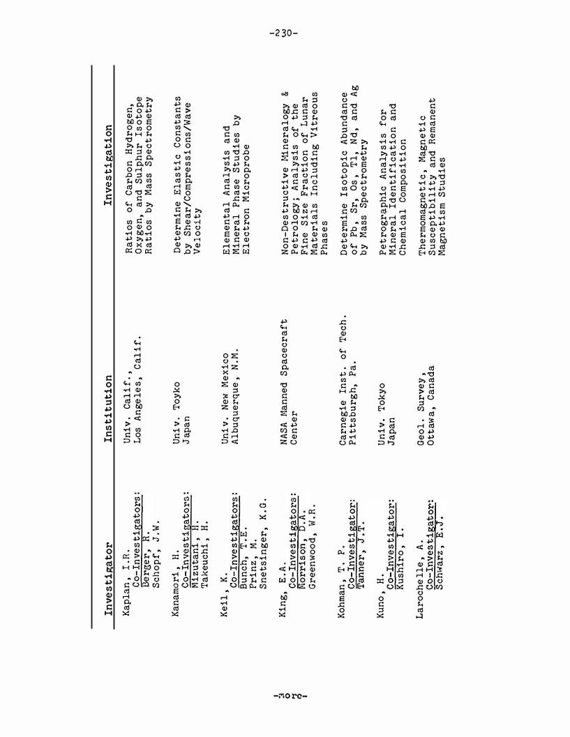
I � 0 6 I
Inve
st
iga
tor
Ka
pla
n,
r.n.
C
o-
Inve
st
iga
tor
s:
l3er
ger
, R
. S
cho
pf
, J
.W.
Kan
am
or
i,
H.
Co-I
nves
tiga
tors
: M
izu
tan
i,
H.
Ta
keu
chi
, H
.
Kei
l,
K.
Co
-In
ves
tig
ato
rs
: B
un
ch,
T.E
. Pr
in
z,
l<l.
Sn
etsi
ng
er,
K.G
.
Kin
g,
E.A
. Co
-In
ve
stig
ato
rs
: M
orr
is
on,
D.A
. G
ree
nw
oo
d,
vl. R
.
Koh
man
, T
. P
. C
o-
Inv
esti
gat
or
: T
ann
er,
J.T
.
Kun
o,
H.
Co
-In
ves
tig
at
or
: K
ush
iro
, I
.
La
roc
he
lle
, A
. C
o-I
nv
es
tig
ato
r:
Sch
w-ar
z,
E.J
.
Ins
ti
tu
tio
n
Un
iv.
Cal
if
.,
Los
A
nge
les
, C
al
if
.
Uni
v.
Toy
ko
Japa
n
Uni
v.
New
M
exic
o
Alb
uq
uer
qu
e,
N.M
.
NA
SA 1\
lan
ned
S
pa
cecr
af
t C
ente
r
Car
neg
ie
Ins
t.
of
T
ech
. P
itts
bu
rg
h,
Pa
.
Un
iv.
Tok
yo
Japa
n
Geo
l.
Sur
vey
, O
ttaw
a,
Can
ad
a
Inve
st
iga
tio
n
Ra
tio
s o
f C
ar
bo
n
Hy
dr
og
en,
Ox
yg
en,
an
d S
ulp
hu
r
Is
oto
pe
Ra
tio
s b
y
Ma
ss
Sp
ect
rom
etr
y
De
ter
min
e E
las
ti
c
Co
nst
an
ts
by
S
he
ar
/Com
pr
es
si
on
s/W
av
e V
el
oci
ty
Ele
men
tal
An
aly
sis
an
d
Min
era
l P
ha
se
Stu
die
s b
y
El
ect
ro
n
Mic
ro
pr
ob
e
No
n-D
es
tr
uct
ive
I•li
ner
alo
gy
& P
et
ro
logy
; A
na
ly
sis
of
the
Fin
e S
iz
e
Fr
act
ion
o
f L
un
ar
M
ate
ria
ls
Inc
lud
ing
V
itr
eou
s P
ha
se
s
De
te
rmin
e I
so
to
pi
c A
bu
nd
an
ce
of
Pb
, S
r,
Os
, T
l,
Nd
, a
nd
A
g
by
Ma
ss
Spe
ct
rom
etr
y
Pe
tr
ogr
a.p
hic
A
na
lys
is
f
or
M
iner
al
Ide
nt
if
ica
ti
on
an
d
Ch
emic
al
Com
posi
ti
on
Th
erm
omag
net
ic
, M
agn
et
ic
S
usc
ep
ti
bi
li
ty
a
nd
R
ema
nen
t M
ag
ne
ti
sm S
tud
ies
I 1\)
w
0
I

I 3 0 '1 (1) I
Inv
es
tig
ato
r
Ins
ti
tu
tio
n
Inve
st
iga
tio
n
Lip
sky
, S
.R.
Co
-In
ves
tig
ato
rs
: H
orv
ath
, C
.G.
McM
urr
ay
, W
.J.
Lo
ver
ing
, J
. F.
Co
-In
ves
tig
ator
s:
Bu
tter
fie
ld,
D.
(a)
Kle
eman
, J
.D.
(b)
Vei
ze
�,
J.
(b)
War
e,
N. G
. (c
)
f•1a
cGr
eg
or
, I
.D.
Co-
Inv
esti
ga
tor
: Ca
rte
r,
J.L
.
Man
att
, S
.L.
Co
-In
ves
tig
ator
s:
Ell
eman
, D
.D.
Va
ugh
an
, R
.W.
Cha
n,
S. I
.
f.1a
:;on
, B
. Co
-In
ves
tig
ator
::;:
Ja
ro
::;ew
ich
, JL
F
red
rik
sson
, K
. Wh
ite
, J
.S.
Max
we
ll
, J
.A.
Co
-I
nv
es
ti g
at
or
s:
Abb
ey,
S.
Cha
mp
, W
.H.
Ya
le
Uni
v.
New
Ha
ven
, Co
nn
.
Au
str
ali
an
Na
t.
Uni
v.
Can
ber
ra
, A
ust
ra
lia
Gr
ad
. R
es
ea
rch
Ct
r.
S.W
. D
all
as
, T
exa
s
NA
SA
Je
t
Pr
op
uls
ion
La
b.,
P
asa
den
a,
Cal
if
.
Cal
. In
st
. T
ech
.
Sm
ith
son
ian
In
st
. N
at
. l•l
use
um
W
ash
ing
ton
, D
.C.
Geo
l.
Sur
vey
, Ca
na
da
O
tt
aw
a,
Ca
na
da
Iden
ti
fic
ati
on
of
Or
gan
ic
Com
pou
nd
s in
L
un
ar
Ma
te
ria
l b
y
Me�
ns
of
Ga
s Ch
rom
ato
gr
ap
hy
f.l
a'ss
S
pe
ctr
ome
try
, N
MR,
Hig
h
Sp
ee
d L
iqu
id C
hr
om
ato
gr
aph
y,
an
d V
ar
ia
tio
ns
on
th
ese
t
ech
n
iqu
es
a)
Ne
ut
ron
Ac
tiv
at
ion
f
or
u,
�
, K
b)
Fi
ss
ion
T
ra
ck
An
aly
si
s
for
U
c
) E
le
ct
ron
M
icr
op
ro
be
A
na
ly
sis
fo
r E
lem
en
tal
Com
po
sit
ion
Pet
ro
gr
ap
hi
c A
na
lysi
s by
X
-Ra
y D
iff
ra
ctio
n
an
d
OPt
ic
al
Met
ho
ds
Nu
clea
r R
ad
io
Fr
equ
ency
An
aly
sis
Incl
ud
ing
NMR
&
ES
R
An
aly
si
s
fo
r
Ox
yg
en
, H
yd
ro
gen
, W
at
er
Co
nte
nt
and
oth
er E
lem
ents
a
nd
th
ei
r
Ch
em
ica
l
Sta
te
f.11n
era
log
ic
Inve
st
ig
ati
on
s
Wet
Ch
emi
cal
, X
-Ra
y F
lu
or
esc
en
ce
an
d
Em
is
si
on
S
pe
ctr
osc
op
y;
Fl
am
e
Ph
ot
om
et
ry
fo
r
Ma
jo
r/
M
inor
Ele
men
ts
: A
to
mi
c A
bs
orp
ti
on
Sp
ect
ro
sco
py
I 1\.)
w
,_..
I

I a
0
'1
(l) I
Inv
es
tig
ato
r
Mc
Kay
, D
.S.
Co
-In
vest
iga
tor
s:
An
der
:.;on
, D
. H
. G
ree
nw
oo
d,
W.R
. H
orr
iso
n,
D.A
.
1'-te
insc
hei
n,
W.G
.
Moo
re
, C
.
Mor
ri
so
n,
G.H
.
Mu
ir
, A
.H.
, J
r.
Mu
rth
y,
V.R
.
Na
ga
ta
, T.
.
Co
-In
ve
stig
ato
rs
: O
zim
a,
f\1.
Ish
ikaw
a,
Y.
Na
gy
, B
. C
o-
Inv
esti
ga
tor
: O
re
y,
H.
Inst
itu
tio
n
fllan
ned
Sp
ace
cra
ft
Ce
nt
er
Ind
ian
a
Un
iv.
Blo
om
ing
ton
, In
d.
Ar
izo
na
Sta
te
Un
iv.
Tem
ple
, A
ri
z.
Co
rn
ell
Uni
v.
No
rth
Am
er
ica
n R
ock
we
ll
Cor
p.
Sci
en
ce
Cen
te
r,
Th
ousa
nd
O
ak
s ,
Cali
f.
Uni
v.
Min
ne
sot
a
Min
nea
po
li
s,
Min
n.
Un
iv
. T
oky
o Ja
pa
n
Un
iv
. Ca
li
f.
, Sa
n D
ieg
o
La J
olla
, Ca
lif.
Inve
sti
p.:a
tio
n
De
te
rmin
e fl1
or
pho
log
y a
nd
Co
mp
osit
ion
o
f F
ine
Pa
rt
ic
le
s U
sin
g E
le
ct
ron
M
icr
op
ro
be
an
d S
can
nin
g E
le
ct
ron
M
ic
ros
cop
e.
An
aly
sis
t
o b
e
Un
der
tak
en
Af
te
r
Qu
ar
an
tin
e
an
d n
ot
wi
th
in
th
e
LR
L
De
te
rmin
e t
he
A
lka
ne
Cl
� T
o C
30
Con
ten
t B
y
Gas
Chr
oma
to
g
rap
hic
an
d
r.ta
ss
Spe
ctro
me
tric
T
ech
niq
ues
De
te
rmin
e T
ot
al
C
once
ntr
ati
on
o
f C
ar
bo
n
and
Nit
ro
gen
Ele
men
tal
An
aly
sis
usi
ng
Sp
ar
k
So
ur
ce M
ass
S
pe
ctr
om
etr
y
Co
nd
uct
M
oss
ba
uer
Ef
fec
t a
nd
S
pe
ctr
osc
opi
c S
tud
y
of
Ir
on
B
ea
ri
ng
Min
era
l S
epa
ra
tes
De
te
rm
ine
Ra
re
-Ea
rth
E
lem
enta
l
an
d L
ow
Ab
un
da
nce
I
so
to
pe
s o
f
K,
Ca
, V
a
nd
C
r C
on
ten
t b
y
Neu
tro
n A
ct
iva
tio
n
Rem
an
en
t M
agn
et
ism
Stu
die
s
The
P
re
se
nc
e o
r A
bs
enc
e
of
L
ipid
s,
Am
ino
A
cid
s,
an
d
"Po
lym
er-
Typ
e"
Or
ga
nic
M
at
te
r
I N
w
N I

I 3 0 � �
I
Inve
st
iga
tor
Na
sh,
D.B
.
O'H
ar
a,
M.J
. C
o-
In
ves
tig
at
or
: B
ig
ga
r,
G.M
.
O'K
el
ley
, G
.D.
Co
-In
ve
st
igat
or
s:
Be
ll
, P
.R.
Eld
rid
ge
, J
.S.
Sc
ho
nfe
ld
, E
. R
ich
ar
dso
n,
K.A
.
Or
o,
J.
Co
-In
ve
st
iga
to
rs
: Z
la
tk
is
, A
. L
ov
el
oc
k,
J.E
. B
ec
ke
r,
R.S
. U
pd
eg
ro
ve,
H.S
. F
lor
y,
D.A
.
Oy
ama
, V
.I.
Co
-In
ve
st
iga
to
rs
: M
er
ek
, E
. S
il
ve
rm
an
, M
.P.
Pe
ck,
L.C
.
Pe
pin
, R
.O.
Co
-In
ves
tig
at
or
: N
ie
r,
A.O
.C.
Ins
ti
tu
ti
on
NA
SA
J
et
P
ro
pu
lsio
n
Lab
.
Un
iv
. E
din
bu
rgh
S
co
tla
nd
Oa
k
Rid
ge
Na
t.
La
b.
Ten
ne
ss
ee
M
SC
O
RN
L
MS
C
MS
C
Un
1v
. H
ou
st
on
Ho
us
ton
, T
ex
as
Ma
nn
ed
Sp
ac
ec
ra
ft
C
tr
.
NA
SA
A
me
s R
es
. C
tr
. M
of
fe
tt
Fi
el
d,
Ca
li
f.
U.S
. Ge
ol
. S
ur
vey
D
env
er
, C
olo
.
Un
iv
. M
inn
es
ot
a
Min
ne
ap
ol
is
, M
inn
.
Inve
st
iga
tio
n
Me
asu
re
L
um
ine
sc
en
ce
, a
nd
P
hy
si
ca
l/
Ch
em
ic
al
Re
ac
ti
on
of
L
un
ar
M
at
er
ia
l
to
Bo
mb
ar
dm
ent
by
o
.5 t
o 1
0 K
eV
P
ro
to
ns
Hi
-P
re
ss
ur
e/
Te
mp
er
atu
re
P
ha
se
St
ud
ies
, D
et
er
min
e
Te
mp
er
atu
re
o
r C
ry
st
al
li
zat
io
n
of
Mi
ne
ra
ls
; P
et
ro
lo
gi
c
St
ud
ie
s
De
ve
lo
p
th
e E
qu
ipm
en
t/
Me
th
od
s f
or
L
RL
; M
ea
sur
e
th
e
K4
0,
U,
�1,
a
nd
C
os
mic
R
ay
In
du
ce
d
Ra
di
on
uc
li
de
Con
te
nt
A
Co
mp
re
he
ns
iv
e S
tu
dy
of
th
e
Ca
rb
on
ac
eo
us
an
d O
rg
an
oe
en
ic
M
at
te
r P
re
se
nt
in
R
et
ur
ne
d
Lu
na
r
Sa
mp
le
s w
ith
C
om
bin
at
ion
o
f G
as
Ch
ro
ma
tog
ra
ph
ic
a
nd
M
as
n S
pe
ct
ro
me
tr
ic
T
ech
ni
qu
es
Iso
la
tio
n
an
d
Cu
lt
ur
e
of
V
iab
le
Or
ga
nis
ms
Sta
nd
ar
d
We
t C
he
mi
ca
l
An
aly
ti
ca
l T
ec
hn
iq
ue
s
for
M
aj
or
El
em
en
ts
Me
as
ur
e t
he
E
lem
en
ta
l a
nd
I
so
to
pi
c
Ab
un
da
nc
es
o
f
He
, N
e,
Ar
, K
r,
an
d
Xe
by
Ha
�s
Sp
ec
tr
o
me
try
I !\.)
w
w
I

Inve
st
iga
tor
Per
kin
s,
R. \L
Co
-In
ves
tig
ator
s:
\1/o
gm
an
,
N .A
. Ka
ye,
J.H
. Co
oper
, J
.A.
Ra
nci
te
lli
, L
.A.
Phil
po
tts
, J
.A.
Co
-In
vest
iga
tor
s:
Schn
etz
ler
, C
. Ma
sud
a,
A.
Tho
mas
, H
.H.
Pon
na
mpe
rum
a,
C.A
. Co
-In
ves
tig
ato
rs
: O
yam
a,
V.I
. Po
lla
ck,
G.
Gehr
ke,
C. H.
Z
ill
, L
.P.
Qua
ide
, \.J
.L.
Co
-Inv
es
tiga
tors
: W
ri
gl
ey
, R
.C.
(a)
Deb
s,
R. J
. (a
) Bu
nch
, T
.E.
(b)
Ram
doh
r,
P.
Co-I
nve
stig
ato
r:
ElG
ore
sy
, A
.
Ins
tit
ut
ion
Batt
ell
e M
em.
Ins
t.
Ric
hla
nd
, W
ash
.
NASA
Go
dda
rd
Spa
ce
Flig
ht
Cen
te
r,
Gree
nbe
lt
, M
d.
NA
SA
Am
es
Res
. C
ente
r
Mof
fett
Fie
ld
, Ca
lif
.
Uni v
. r
usso
uri
Ames
R
es
. C
en
te
r
Ame
s Re
s. C
ente
r
Ma
x P
lan
ck
Inst
itu
t He
ide
lbe
rg
, G
erm
any
Inve
st
iga
tio
n
Non
-De
stru
ctiv
e Ga
mm
a-R
ay
Spe
ct
rom
et
ry
for
C
o:..;m
ic
Hay
Ind
uce
d a
nd N
atu
ra
l H
adi
o
Nu
clid
es
De
ter
min
e t
ne
Ra
re
Ea
rth
Ele
m
ent
Co
nt
en
t
U�
in
e
Dll
u�i
on
Tec
hn
iqu
e an
d M
ass
Sp
ec
tro
me
try
An
aly
tic
al
Lun
ar
Sa
mp
le A
na
ly
ses
for
Am
ino
A
cid
s,
Nuc
le
ic
Aci
ds
, Su
ga
rs
, F
att
y A
cid
s,
Hy
dr
oca
rb
on
s,
Por
ph
yr
ins
and
T
heir
Com
po
nen
ts
a)
By
N
on-D
est
ruc
ti
ve
Gam
ma
-Ra
y S
pe
ct
ro
me
tr
y
De
te
rm
in
e
th
e
Al2
6,
Na
22
, a
nd
�n
5�
Co
nte
nt
b)
lUc
ros
cop
ic,
X-Ra
J Di
ffra
ct
ion
An
aly
�is
to
De
te
rmin
e th
e
Ef
fe
ct
s
of
S
ho
ck
o
n
Mi
ne
ra
ls
a
nd
Ro
cks
Iden
tif
ica
tio
n o
f O
paq
ue
It!in
era
ls,
Pha
seG
an
d C
ompo
sit
ion
by
X-R
ay
, M
icro
pr
obe
, a
nd
Mi
cro
scop
ic A
na
lys
is
I 1\.)
w
.::
I

I s 0 '1 ro
I
Inve
st
iga
tor
Re
ed
, G
.YJ.
Co
-In
ve
st
igat
or
s:
Hu
iz
en
ga
, J
. J
ov
an
ovi
c,
S.
Fu
chs
, L
.
Re
yn
ol
ds
, J
.H.
Co
-In
ve
st
igat
or
s:
Rov
se,
M. \-1
. H
oh
enb
er
g,
C.M
.
Rh
o,
J.H
. C
o-
In
ve
st
igat
or
s:
Ba
um
an
, A
.J.
Bon
ne
r,
J.F
.
Ric
ha
rd
son
, K
.A.
Co
-I
nv
es
tig
ato
rs
: . M
cKa
y,
D.S
. F
os
s,
T.H
.
Ri
ngw
oo
d,
A.E
. C
o-
Inv
es
tig
at
or
: G
re
en
, D
.H.
Rob
ie
, R
.A.
Ro
ed
de
r,
E.
Ins
ti
tu
ti
on
Ar
go
nn
e N
at
. L
ab
. A
rg
onn
e,
Il
l.
Un
iv
. C
ali
f.
, B
er
ke
le
y
NA
SA
J
et
P
ro
pu
lsi
on
L
ab
. P
asa
den
a,
Ca
li
fo
rni
a
Cal
. In
st
. T
ech
.
NA
SA
M
an
ned
S
pa
ce
cr
af
t C
en
te
r
Ho
ust
on
, T
exa
s
Au
str
al
ian
N
at
'l U
ni
v.
Ca
nb
err
a
U.S
. Ge
ol
. S
ur
ve
y,
D.C
.
U.S
. Ge
ol
. S
ur
vey
, D
.C.
Inve
st
iga
tio
n
Con
ce
nt
ra
ti
on,
Is
ot
op
ic
C
om
po
s
it
io
n
an
d
Di
st
ri
bu
ti
on
o
f T
ra
ce
El
em
en
ts
by
N
eu
tr
on
A
ct
iv
at
io
n
An
al
ys
is
(a)
Ra
re
G
as
C
on
te
nt
by
M
as
s S
pe
ct
ro
me
try
(b
) M
ass
S
pe
ct
ro
me
tr
y
to
Id
en
t
ify
C
os
mi
c R
ay
P
ro
du
ce
d
Nu
cl
id
es
(
c)
Ma
ss
Spe
ct
ro
me
tr
y
to
De
te
r
min
e
Ra
re
Ga
s,
K a
nd
U
C
ont
en
t;
Id
en
ti
fy
Co
sm
ic
R
ay
P
ro
du
ce
d
Nu
cl
id
es
De
te
rm
ine
H
et
al
li
c
an
d
No
n
Me
ta
ll
ic
Po
rp
hy
ri
n
Co
nt
en
t b
y
Fl
uo
re
sc
en
ce
S
pe
ct
ro
ph
ot
o
me
tr
y
By
A
ut
or
ad
io
gr
ap
hy
a
nd
A
lp
ha
P
ar
ti
cle
S
pe
ct
ro
sc
op
y
Id
en
ti
fy
Al
ph
a
Em
it
ti
ng
Nu
cl
id
es
Pe
tr
og
ra
ph
ic
A
na
lys
is
b
y
St
ud
y
of
Th
in
an
d
Po
li
sh
ed
S
ec
ti
on
s
Ca
lo
ri
me
tr
y
(Th
er
ma
l P
ro
pe
rt
ie
s)
De
te
rmi
ne
t
he
N
at
ur
e
an
d
Com
po
si
ti
on
of
Flu
id
I
nc
lu
si
ons
, i
f P
re
sen
t,
in
Lu
na
r
Ma
te
ri
al
I I\)
I.JJ
V1
I

I s
0
"1 <1)
I
Inve
st
iga
tor
Ro
se
, H
.\'1.
, J
r.
Co
-In
ve
st
igat
or
s:
cu
tt
i t
ta
, F
. Dv
1orn
ik
, E
. J.
Ro
ss
, M
. C
o-
Inv
es
tig
at
or
s:
Wa
rn
er
, J
. P
ap
ike
, J
.J.
Cla
rk
, J
.R.
Ru
nco
rn,
S.K
.
Sch
ae
ffe
r,
O.A
. C
o-
In
ve
st
iga
to
rs
: Za
hr
ing
er
, J.
B
og
ar
d,
D.
Sch
mid
t,
R.A
. C
o-
Inv
es
tig
at
or
: L
ove
lan
d,
\'1. D
.
Sc
ho
pr
, \'/.
Sc
la
r,
C.B
. C
o-
Inv
es
tig
at
or
: H
el
to
n,
C.\
�.
Sc
oo
n,
J.H
.
Ins
ti
tu
ti
on
U.S
. G
eo
l.
Su
rv
ey
, D
.C.
U.S
. G
eo
l.
Su
rv
ey
Wa
shi
ng
ton
, D
.C.
NA
SA
l1
SC
US
GS
, D
.C.
Un
iv
. o
r N
ewc
as
tl
e
Up
on
T
yn
e,
En
gla
nd
St
at
e
Un
iv
. o
f N
.Y.
at
St
on
y
Br
oo
k,
N.Y
. M
ax
P
lan
ck
Ins
t.
-G
er
ma
ny
Ma
nn
ed
Sp
ac
ecr
af
t
Ct
r.
Or
eg
on
St
at
e
Un
iv
. C
or
va
ll
is
, O
re
.
Un
iv
. o
r C
al
if
., L
.A.
Lo
s A
ng
ele
s
Ba
tt
el
le
Me
m.
Ins
t.
Co
lu
mbu
s,
Oh
io
Un
iv
. C
am
br
id
ge
E
ng
lan
d
Inve
st
iga
tio
n
X-R
ay
Fl
uo
re
sc
en
ce
Me
th
od
s f
or
E
le
me
nt
al
A
na
lys
is
De
te
rm
ine
th
e
Cry
st
al
lo
gr
ap
hi
c
Pa
ra
me
te
rs
a
nd
Co
mp
os
it
ion
o
r
Py
ro
xe
ne
s,
Mi
ca
s,
Am
ph
ib
ole
s,
an
d
Ho
st
S
il
ic
at
e
Min
er
al
s b
y
X-R
ay
D
ir
fr
ac
ti
on
an
d
El
ec
tr
on
M
ic
ro
pr
ob
e
Ma
gne
ti
c
Pr
op
er
ti
es
i
n
Con
jun
ct
io
n
wi
th
M
ine
ra
lo
gi
c
St
ud
ie
s
Det
er
min
e
Ra
re
G
as
Co
nt
en
t
by
�
�s
s
Sp
ec
tr
om
et
ry
a
t
LR
L
De
te
rmin
e
Ra
re
-E
ar
th
a
nd
S
el
ec
t
ed
Tr
ace
E
lem
ent
s
Co
nt
en
t
by
N
eu
tr
on
A
ct
iv
at
ion
A
na
lys
is
. I
so
to
pe
s
or
Sm
, E
u,
Gd
w
il
l b
e
De
te
rm
ine
d
by
Ma
ss
S
pe
ct
ro
me
tr
y
Mi
cr
op
al
eon
to
lo
gi
ca
l S
tu
dy
U
sin
g
Tr
an
smi
ss
ion
a
nd
S
ca
nn
in
g
El
ect
ro
n
Mi
cr
os
co
py
Usi
ng
R
ep
lic
at
io
n
an
d
Th
in
Se
ct
ion
E
le
ct
ro
n
Mi
cr
os
co
py
D
et
er
min
e
th
e
Dam
ag
e in
M
in
er
al
s a
nd
R
oc
ks
Du
e
to
Sh
ock
\vet
C
he
mi
ca
l A
na
ly
si
s
fo
r M
aj
or
E
le
me
nt
s
I 1\,)
w
0'\
I

I 13
0
1-j
�
I
Inv
est
iga
tor
Sh
or
t,
N.M
.
Sil
ve
r,
L.T
. C
o-
Inv
es
tig
at
or
: P
at
te
rs
on
, C
. C
.
Sinun
ons
, G
. C
o-
Inve
st
igat
or
s:
Br
ac
e,
W.F
.)
P t
Won
es
, D
.R.)
--
ar
s
Sip
pe
l,
R.F
. C
o-
Inv
es
tig
at
or
: S
pe
nce
r,
A.B
.
Sk
inn
er
, B
.J.
Co
-In
ve
stig
ato
r:
\o/in
che
ll
, H
.
Sm
al
es
, A
.A.
Inst
it
uti
on
Uni
v.
Ho
ust
on
Ho
us
ton
, T
ex
as
Ca
li
f.
Ins
t.
Te
ch
. P
asa
de
na
, Ca
li
f.
Ma
ss
. In
st
. T
ech
. Ca
mb
ri
dg
e,
Ma
ss
.
A
& B
o
nly
Mob
il
Res
. a
nd
De
v.
Co
rp
. D
al
la
s,
Tex
as
Ya
le
Un
iv
. N
ew
Ha
ven
, Co
nn
.
At
om
ic
E
ner
gy
R
es
ea
rch
E
st
ab.
, H
ar
we
ll
, E
ng
lan
d
Inve
st
iga
tio
n
By
Pe
tr
og
ra
ph
ic
St
ud
ie
s
De
te
rm
in
e
Ef
fec
t o
f S
ho
ck
o
n
Ro
ck
s
an
d M
in
er
al
s a
nd
Pr
ed
ic
t M
ag
nit
ud
e
of
Sh
oc
k
an
d
Lin
e
of
Im
pa
ct
in
g M
is
si
le
De
te
rm
ine
L
ea
d
Is
ot
op
es
, C
on
c
en
tr
at
ion
s
of
U
, T
h,
Pb,
an
d
th
ei
r o
cc
ur
re
nc
e
in
Mi
ne
ra
ls
a)
Ca
lc
ul
at
e
El
as
ti
c
Pr
op
er
ti
es
F
ro
m
�1e
asu
re
men
t o
f C
om
pr
es
si
on·
al
Sh
ea
r W
av
e V
elo
ci
ti
es
a
t S
TP
b
) M
ea
su
re
Th
erm
al
Co
nd
uc
ti
vi
ty
, E
xp
an
si
on
a
nd
D
if
fu
si
vi
ty
a
t
ST
P
c)
De
te
rm
ine
D
ie
le
ct
ri
c
Co
ns
ta
nt
, R
es
is
ti
vi
ty
De
te
rm
ine
T
her
ma
l P
ro
pe
rt
ie
s
at
ST
P o
n S
am
pl
es
of
C
ore
F
ro
m
Lu
na
r S
ur
fa
ce
Ap
pl
y
Lu
min
es
ce
nc
e
Fe
tr
o(5
ra
ph
y
to
St
ud
y
of
Lu
na
r
Mat
er
ia
ls
Ex
am
ine
th
e
Re
tu
rn
ed
S
am
pl
es
f
or
C
on
de
ns
ed
Su
bl
im
at
es
an
d
if
P
re
se
nt
D
et
er
min
e t
he
M
in
er
al
P
ha
se
s
Pr
es
en
t a
nd
Ele
me
nt
al
C
om
po
si
ti
on
El
em
en
ta
l
an
d I
�o
to
pi
c
Ab
un
d
an
ce
s
by
N
eu
tr
on
Ac
ti
va
ti
on
A
na
ly
si
s
an
d
by
E
mi
ss
ion
, S
pa
rk
S
ou
rc
e,
an
d
X-
Ra
y
Fl
uo
re
sc
en
ce
S
pe
ct
ro
�r
ap
hy
I 1\.)
w
-..J I

I g ..,
� I
Inv
esti
ga
tor
Smi
th
, J
.V.
Co-
Inv
es
tig
ato
rs
: W
yl
lie
, P
.J.
Eld
er
s,
W. A
.
Ste
ph
en
s,
D.R
. Co
-In
ve
st
igat
or:
Ke
el
er
, R
.N.
Ste
wa
rt
, D
.B.
Co-
Inv
es
tig
ato
rs
: A
pp
lem
an
, D
.E.
Pa
pik
e,
J.J
. C
la
rk
, ,r
.R.
Ro
ss,
M.
Str
an
gw
ay
, D
.W.
Ta
tsurn
ot
o,
M.
Co
-In
ve
st
igat
or:
I5oe
, B
.R.
To
lan
sky
, s.
Tu
rek
ian
, K
.K.
Ins
ti
tu
tio
n
Un
iv.
Ch
ica
go
C
hic
ag
o,
Il
l.
La
wr
ence
R
ad
iati
on
La
b.
Liv
erm
ore
, C
al
ifo
rn
ia
U.S
. G
eo
l.
Sur
vey
, D
.C.
Un
iv.
To
ro
nto
Can
ad
a
U.S
. G
eo
l.
Su
rv
ey
Den
ve
r,
Co
lo
.
Ro
ya
l H
ol
low
ay
Co
lleg
e,
Un
iv.
Lon
don
, E
ng
lan
d
Yale
Un
iv.
New
H
aven
, C
on
n.
Inve
st
iga
tion
Min
er
alo
gi
c-
Pe
tr
og
ra
ph
ic
An
aly
si
s
Usi
ng
Mic
ro
pr
obe
, X
-Ra
y D
iff
ra
cti
on
a
nd
M
icr
o
sc
op
ic
Me
tho
ds
Phy
si
cal
Pr
op
er
tie
s-E
qu
ati
on
o
f S
tate
Cr
yst
al
Str
uct
ur
e a
nd
S
tab
il
it
ie
s
of
F
eld
spa
rs
De
te
rmin
e
Ma
gne
ti
c
Pro
pe
rt
ie
s In
clu
din
g R
eman
en
t,
Su
sc
ep
ti
bi
l
it
y,
Th
erm
al
, D
ema
gn
et
iz
at
io
n,
Ide
nt
ify
Ma
gn
et
ic
Min
er
als
Pb
An
al
ys
is
by
M
ass
S
pe
ctr
o
met
ry
; U
a
nd
Th
An
aly
si
s b
y
Ma
ss
Sp
ect
ro
me
try
an
d A
lph
a
Sp
ect
ro
met
ry
Is
ot
op
ic
A
bun
dan
ce
s o
f U
an
d
Th
by
Mi
cr
os
co
pi
c
Stu
di
es
of
D
iamo
nd
s
De
ter
min
e
20
E
le
men
tn
Hav
ing
H
al
fl
ive
s G
re
at
er
Tha
n
3 D
ay
s B
y
Neu
tro
n
Ac
ti
va
tio
n
An
aly
si
s
I T\)
w
())
I

I 3
0
�
Cl)
I
Inve
st
iga
tor
Tu
rk
ev
ic
h,
A.L
.
Tu
rne
r,
G.
Ur
ey
, H
.C.
Co
-In
ve
st
iga
tor
: M
ar
ti,
K.
Vo
n
En
ge
lha
rd
t,
W.
Co
-In
ve
st
iga
to
rs
: S
to
ff
le
r,
D.
Mu
lle
r,
W.
Ar
nd
t,
J.
Ha
lk
er
, R
.M.
\o/a
nk
e,
H.
Co
-In
ve
st
igat
or
s:
Be
gem
an
n,
F.
Vi
lc
sek
, E
. V
osh
ag
e,
H.
Be
gem
an
n,
F.
Vi
lc
se
k,
E.
Ins
tit
ut
ion
Un
iv
. of
C
hi
ca
go
C
hic
ag
o,
Il
l.
Un
iv
. S
he
ff
ie
ld
Un
iv
. C
al
if
.,
S.D
. L
a
Jo
ll
a,
Ca
li
f.
Uni
v.
Tu
bin
ge
n
Tu
bin
ge
n,
Ge
rm
an
y
Wa
shin
gt
on
U
ni
v.
St
. L
ou
is
,
Mo
.
Ma
x
Pl
an
ck
In
st.
Fu
r
Chem
ie
, M
ain
z G
erm
an
y
Th
is
inv
es
tig
at
ion
c
on
ti
nu
ed
o
n
ne
xt
p
ag
e.
Inve
st
iga
tio
n
a)
De
te
rmin
e
Lo
ng
Li
ve
d
Is
ot
op
es
o
f K
, U
, a
nd
T
h b
y
Ga
mm
a
Ra
y
Sp
ec
tr
om
et
ry
b
) N
eu
tr
on
A
ct
iv
at
io
n
An
aly
si
s
fo
r
U,
Th
, B
i,
Pb
, T
l,
an
d
Hg
.
De
te
rmi
ne
A
R4
0!
Ar
39
f
or
A
ge
D
at
in
g
Is
ot
opi
c
Ab
un
da
nc
es
b
y
Ma
ss
S
pe
ct
ro
sco
py
Pe
tr
og
ra
ph
ic
St
ud
y
to
D
et
er
m
in
e
Sh
oc
k
Ef
fe
ct
s
a)
Me
asu
re
t
he
S
tr
uc
tu
ra
l
Da
ma
ge
to
C
ry
st
al
li
ne
M
at
er
ia
l
by
S
ev
er
al
T
ec
hn
iq
ue
s b
) G
eo
ch
ro
no
lo
gi
ca
l
St
ud
ie
s b
y
Inv
es
ti
ga
tio
n
of
F
is
si
on
T
ra
cks
Fr
om
Ra
di
oa
ct
iv
e
an
d
Co
sm
ic
R
ay
P
ar
ti
cl
es
a)
De
te
rmi
ne
K
, T
h,
U
Co
nt
en
t
b)
Me
asu
re
C
os
mi
c
Ra
y f �
du
ce
d
Ra��o
ac
ti
ve
Nu
cl
id
es
C
an
d
Cl
I 1\)
w
\0
I

I 3
0
>j
ro
I
Inve
st
iga
tor
Ri
ed
er
, R
.
Ri
ed
er
, R
. \H
ot
zk
a,
F.
Han
le
ss
, R
.K.
Co
-In
ve
st
iga
to
rs
: S
te
ven
s,
R.D
. L
ov
er
idg
e,
vl.D
.
Ha
sse
rb
ur
g,
G.J
. C
o-
Inv
es
tig
at
or:
Bu
rn
et
t,
D.
s.
\'la
s so
n,
J. T
. C
o-
Inv
es
tig
at
or
: B
ae
de
ck
er
, P
.A.
vle
ek
s,
R.A
. C
o-
In
ve
stig
at
or
: K
ol
op
us
, J
.
vle
il
l,
D.F
.
He
th
er
i 1
1,
G. \
>1.
Hi
ik
, H
.B.
Co
-I
nv
es
tig
ato
r:
Oja
np
er
a,
P.M
.
Ins
ti
tu
ti
on
Ge
ol
. S
ur
ve
y,
Ot
taw
a,
Ca
na
da
Ca
l.
Ins
t.
Te
ch
.
Un
iv
. C
al
if
.,
Lo
s A
ng
el
es
, C
al
if
.
Oa
k
Rd
ige
N
at
. L
ab
. O
ak
R
idg
e,
Ten
n.
Un
iv
. O
re
go
n
Eu
ge
ne
, O
re
.
Un
iv
. C
al
if
.,
Lo
s
An
ge
le
s,
Ca
li
f.
Ge
ol
. S
ur
ve
y
He
ls
ink
i,
Fi
nl
and
Inve
st
iga
tio
n
c)
Ma
jo
r E
le
me
nt
al
A
bu
nd
an
ce
s
by
Fa
st
N
eu
tr
on
A
ct
iv
at
io
n
d)
Mi
no
r E
le
me
nt
al
A
bu
nd
an
ce
s
by
T
he
rm
al
Ne
ut
ro
n
Ac
ti
va
ti
on
De
te
rm
ine
C
on
ce
nt
ra
ti
ons
o
f P
b,
U,
Th
, R
b,
Sr
, A
r,
& K
a
nd
t
he
I
so
to
pi
c
Co
mp
os
it
io
ns
of
Pb
a
nd
S
r.
De
te
rm
in
e
K,
Ar
, R
b,
Sr
an
d
Ra
re
Ga
s (H
e,
Ne
, A
r,
Kr
, X
e)
Co
nt
en
t
by
Ma
ss
Sp
ec
tr
om
et
ry
El
em
en
ta
l A
bu
nd
an
ce
s
fo
r
Ga
a
nd
G
e b
y N
eu
tr
on
A
ct
iva
ti
on
De
te
rm
in
e
th
e
Va
le
nc
e
St
at
e
an
d
Sym
me
tr
y
of
t
he
C
ry
st
al
lin
e
Ma
t
er
ia
l U
sin
g
El
ec
tr
on
S
pi
n
an
d
Nu
cl
ea
r
Ma
gn
et
ic
Re
son
an
ce
Te
ch
n
iqu
es
an
d
Sp
in
L
at
ti
ce
R
el
ax
a
ti
on
S
tu
di
es
De
te
rmi
ne
T
emp
er
at
ur
e
of
Ro
ck
F
or
ma
tio
n
by
S
tu
dy
o
f P
la
gi
o
cl
ase
P
ro
pe
rt
ie
s
De
te
rmin
e
Iso
to
pe
s
of
R
b,
Sr
, U
, a
nd
Pb
by
M
ass
S
pe
ct
ro
me
tr
y
We
t
Ch
em
ic
al
M
et
ho
ds
to
D
et
er
m
in
e
Ma
jo
r
El
em
en
ta
l
Ab
un
da
nce
I !\)
.l::"
0
I

I :J 0 "1 It> I
Inve
sti
ga
tor
Wo
od
, J
.A.
Co-
Inv
est
iga
to
r:
Ma
rvi
n,
U.B
.
Zah
ri
ng
er
, J
. Co
-In
ves
tig
ato
rs
: K
irst
en
, I
. La
mm
er
zah
l,
P.
Zus
sman
, J
.
Inst
it
ut
ion
Sm
ith
son
ian
In
st
. A
str
op
hy
sica
l O
bs
. Ca
mb
rid
ge
, M
as
s.
Max
P
lan
ck
Ins
t.
He
ide
lb
er
g
He
ide
lb
er
g,
Germ
any
Un
iv.
r�an
che
ste
r
Ma
nch
es
te
r,
En
gla
nd
Inv
es
tig
ati
on
Min
era
log
ic
and
Pet
ro
lo
gic
S
tud
ies
by
Op
ti
ca
l M
icr
osc
op
y,
X-R
ay
Dif
fra
ctio
n
an
d
El
ect
ro
n
Mic
ro
pr
ob
e M
easu
rem
ents
By
Mic
ro
pr
ob
e A
na
lys
is
an
d M
ass
S
pe
ctro
me
try
De
te
rmin
e G
as
Con
ten
t a
nd
So
la
r W
ind
Par
ti
cle
D
ist
rib
ut
ion
Geo
chem
ic
al
, M
iner
alo
gi
c,
and
P
etr
ol
og
ica
l S
tud
ies
I 1\)
=
1-'
I

- 2 4 2 -
APOLLO GLOSSARY
AblattQs Materials --Special heat-dissipating aaterials on the surface or a spacecraft that vaporize during reentry.
Abort--�e unacheduled termination of a mission prior to its completion .
Accelero•eter--An instrument to sense acce lerative forces and convert thea into corresponding electrical quantities usually for contro lling, measuring , indicating or recording purposes .
Adapter Skirt --A flange or extension o f a stage or section that provides a ready means of fitting another stage or section to it.
Antipode--Point on surface o r planet exact� 180 degrees opposite from rec iprocal point on a line projected through center o f body . In Apo llo usage, antipode refers to a l ine from the center o r the Moon through the center o f the Earth and pro jected to the Earth surface on the opposite aide. The antipode crosaes the mid-Pac ific recover,y line along the 165th meridian of longitude once each 24 hours .
Apocynth1on--Point at which object 1n lunar orbit is farthest from the lunar surface - - object having been launched from body other than Moon . (Cznth1a , Roman goddess of Moon)
Apogee - -The point at which a Moon or artificial satellite 1n its orbit ia farthest fro• Earth.
Apolune--Point at which object launched from the Moon into lunar orbit i s farthest from lunar surface, e . g . : ascent stage o f lunar module after stag� into lunar orbit fo l lowing lunar landing .
Attitude--The position of an aerospace vehicle as determined by the inc lination o r its axes to some frame of reference ; for Apo l lo , an inertial, apace-fixed reference i s used.
Burnout--The point when combustion ceases in a rocket engine .
Canard --A short , stubby wing -like e lement affixed to the launch escape tower to provide CM blunt end forward aerodynamic capture during an abort .
Celestial Guidance --�e guidance of a vehic le by reference to celestial bodies .
-more -

-2 4 3 -
Celestial Mechanics- -The science that deals primari ly with the effect or force as an agent in determining the orbital paths of celestial bodies .
Cislunar--Adjective referring to space between Earth and the Moon, or between Earth and Moon ' s orbit.
Closed Loop--Automatic contro l units linked together with a process to form an endless chain .
Deboost--A retrograde maneuver which lowers either perigee or apogee or an orbiting spacecraft . Not to be contused with deorb1t.
Dec lination--Angular measurement of a body above or below celestial equator, measured north or south along the body ' s hour circ le . Corresponds to Earth surface lati tude .
Delta V--Velocity change .
Digital Computer--A computer in which quantities are represented numerically and which can be used to solve complex problems .
Down-Link--The part of a communication system that receive s , pro cesses and displays data from a spacecraft .
Entry Corridor- -The final flight path of the spacecraft before and during Earth reentry .
Ephemeri s - -Orbital measurements ( apogee� perigee , inc lination, period , etc . ) of one celestial body in relation to another at g1ven t1me s . In spaceflight, the orbital measurements of a spacecraft relative to the celestial body about which it orbited.
Escape Velocity--T.ne speed a body must attain to overcome a gravitational field, such as that of Earth; the velocity or escape at the Earth ' s surface is 36, 700 feet-per-second .
Explosive Bolts--Bolts destroyed or severed by a surrounding explosive charge which can be activated by an electrical impulse .
Fairing--A piece, part or struc ture having a smooth, streaml ined outline, used to cover a nonstreamlined object or to smooth a junc tion .
Pl ight Contro l System--A system that serves to maintain attitude stabil ity and contro l during flight.
-more -

-24 4 -
Fue l Cell--An electrochemical generator in which the chemical energy from the reaction of oxygen and a fue l is converted directly into electricity.
g or g Porce - -Force exerted upon an object by gravity or by reaction to acceleration or deceleration, aa 1n a change of direction: one g is the measure of force required to accelerate a body at the rate of 32 . 16 feet-per-aeoond .
Gimba led Motor--A rocket motor mounted on g imbal; i . e . : on a contrivance having two mutual� perpendi cular axes of rotation, so as to obtain pitching and yawing correction aoments .
Guidance System--A system which measures and evaluates flight information, correlates this with target data, converts the result into the conditions necessary to achieve the desired flight path, and communicates this data 1n the form of commands to the flight control system.
Heliocentric - -Sun-centered orbit or other activity which has the Sun at its center.
Inertial Guidance - -Guidance by means o r the measurement and integration o f acceleration from on board the spacecraft. A sophisticated automatic navigation system using gyro scopic device s , accelerameters etc . , for high-speed vehic les . It absorbs and interprets such data as speed, position , etc . , and automatically adjusts the vehic le to a pre -determined flight path . Essentially, it knows where i t ' s going and where i t is by knowing where it came from and how it got there . It does not give out any radio frequency s ignal so it cannot be detec ted by radar or jammed .
Injection--The process o f boosting a spacecraft into a calculated trajectory .
Insertion--The process of boos ting a spacecraft into an orbit around the Earth or other celestial bodies .
Multiplexing--The simultaneous transmission o f two or more signals within a single channel . The three basic methods of multiplexing involve the separation or signals by time division , frequency division and phase division .
Optical Navigation--Navigation by sight, as opposed to inertial methods , using stars or other visible objects as reference .
Oxidizer--In a rocket propellant, a substance such as liquid oxygen or nitrogen tetroxide which supports combustion of the fuel .
-more-

-2 4?-
Penumbra--Semi-dark portion or a shadow in which light i s partly cut off, e . g . : surface ot Moon or Barth away from SUn where the diec or the Sun is only partlY obscured.
Pericynthion--Point nearest Moon or object in lunar orbit--object having been launched trom body other than Moon.
Pe�igee--Point at which a Moon or an artificial satellite in its orbit ia closest to the Earth.
Perilune--The point at which a satellite ( e . g . : a spacecraft) 1n its orbit is closest to the Moon . Differs from pericynthion in that the orbit is Moon-originated.
Pitch--The movement o r a space vehicle about an axis (Y) that is perpendicular to its longitudinal axis .
Reentry--The return or a spacecraft that reenters the atmosphere after flight above it.
Retrorocket--A rocket that givee thrust in a direction opposite to the direction of the object ' s motion.
Right Ascension--Angular measurement or a body eastward alon$ the celestial equator from the vernal equinox (0 degrees RAJ to the hour c ircle of the body . Corresponds roughly to Earth surface longitude , except as expressed in hrs: min: sec instead of 180 degrees west and east from 0 degrees ( 24 hours=360 degrees) .
Roll--�e movements o f a space vehicle about its longitudinal (X) axis .
S-Band--A radio-frequency band o f 1 , 550 to 5,200 megahertz .
Selenographic --Adjective relating to physical geography or Moon. Specifically, positions on lunar surrace as measured 1n latitude from lunar equator and in longitude from a reference lunar meridian .
Selenocentric --Adjective referring to orbit having Moon as center. (Selene, Gr . Moon)
Sidereal--Adjective relating to measurement or time , position or angle 1n relation to the celestial sphere and the vernal equinox.
State vector--Ground-generated spacecraft position, velocity and t�tng information uplinked to the spacecraft computer for crew use as a navigational reference .
-more-

-246-
Te lemetering--A system for taking measurements within an aerospace vehicle in flight and transmitting them by radio to a ground station.
Terminator- -Separation line between lighted and dark portions of celestial body which 1a not self luminous.
Ullage--The volume 1n a c losed tank or container that is not occupied by the s tored liquid; the ratio of this vo lume to the total volume of the tank; also an acceleration to force propel lants into the engine pump intake lines before ignition.
Umbra--Darkes t part of a shadow in which light is complete ly absent, e . g . : surface of Moon o r Earth away from SUn where the disc of the Sun is completely obscured .
Update pad- -Information on spacecraft attitudes, thrust values , event time s , navigational data , e tc . , voiced up to the crew in standard formats according to the purpose , e . g . : maneuver update, navigation check , landmark tracking, entry update , e tc .
Up-Link Data--Information fed by radio s ignal from the ground to a spacecraft.
Yaw--Angu lar d i sp lacement of a space vehicle about its vertical (ZJ axis .
-more -

- 2 4 7-
APOLLO ACRONYMS AND ABBREVIATIONS
( Note: This l ist makes no attempt to inc lude all Apollo program acronyms and abbreviations , but several are l isted that will be encountered frequently in the Apollo 11 mission. Where pronounced as words in air-to -ground transm1ss1ons , acronyms are phone tica l ly shown in parentheses . Otherwise, abbreviations are sounded out by letter . )
AGS
AK
APS
BMAG
CDH
CMC
COl
CRS
CSI
DAP
DEDA
DFI
DOl
DPS
DSKY
EPO
FDAI
FITH
FTP
HGA
IMU
( Aggs )
( Apps )
(Bee-mag )
( Dapp)
( Dee -da)
( Dips)
( Diskey)
( Fith)
Abort Guidance System (LM) Apogee kick
Ascent Propulsion System (LM) Auxiliary Propulsion System ( S-IVB etage )
Body mounted attitude gyro
Constant delta height
Command Module Computer
Contingency orbit insertion
Concentric rendezvous sequence
Concentric sequence initiate
Digital autopilot
Data Entry and Display Assembly ( LM AGS)
Development flight instrumentation
De scent orbit insertion
Descent propulsion system
Display and keyboard
Earth Parking Orbit
Flight direc tor attitude indicator
Fire in the hole ( LM ascent abort staging )
Full throttle position
High-gain antenna
Inertial measurement unit
-more -

IRIG
LOI
LPO
MCC
MC&W
MSI
MTVC
NCC
PDI PIPA
PLSS
PTC
( Ear-ig)
( P ippa)
( P l i s s )
PUGS ( Pugs )
REFSMMAT (Re fsmat)
RHC
RTC
scs SHE SLA
SPS
TEI
THC TIG TLI
TPF TPI
'l'VC
( Shee ) ( S l ah )
(Tigg )
- 24 8 -
Inertial rate integrating gyro
Lunar orbit insertion
Lunar parking orbit
Mission Control Center
Master caution and warning
Moon sphere of influence
Manual thrust vector control
Combined corrective maneuver
Powered descent initiation Pulse integrating pendulous accelerometer
Portable life support system
Passive thermal contro l
Propellant utilization and gaging system
Reference to stable member matrix
Rotation hand controller
Real-time oommand
Stab i lization and contro l system Supercritical helium Spacecraft LM adapter
Service propulsion system
Transearth injection
Thrust hand contro l ler Time at 1gn1 tion Trans lunar injection
Termina l phase finalization
Terminal phase initiate
Thrust vector contro l
-more ...

-249-
CONVERSION FACTORS
MultiEl;E By To Obtain
Distance : feet 0 . 3048 meters
meters 3 . 281 feet
kilometers 3281 feet
kilometers 0 . 6214 statute miles
statute miles 1 . 609 kilometers
nauti cal miles 1 . 852 kilometers
nautical miles 1 . 1508 statute miles
statute miles 0 . 86898 nauti c al miles
statute mile 1760 yards
Velocity: feet/sec 0 . 3048 meters/sec
meters/sec 3 . 281 feet/sec
meters/sec 2. 237 statute mph
reet/sec 0 . 6818 statute miles/hr
feet/sec 0 . 5925 nautical miles/hr
statute rniles/hr 1 . 609 km/hr
nautical rniles/hr ( knots )
1 . 852 km/hr
krn/hr 0 . 6214 statute miles/hr
Liguid measure, weight :
gallons 3 . 785 l iters
liters 0 . 2642 gallons
pounds 0 . 4536 kilograms
kilograms 2 . 205 pounds
- more -

-250-
Multiply To Obtain
Vohune :
cubic feet 0 .02832 cubic meters
Pre ssure :
pounds/sq inch 70. 31 grams/sq em
Propellant Weights
RP-1 ( kerosene ) --------- Approx . 6.7 pounds per gal lon
Liquid Oxygen ----------- Approx . 9.5 pounds per gallon
Liquid Hydrogen --------- Approx . 0.56 pounds per gallon
NOTE : Weight of LH2 will vary as much as plus or minus 5� due to variations in density.
-end-