Apollo Program Summary Report JSC-09423
522
-
Upload
khangminh22 -
Category
Documents
-
view
0 -
download
0
Transcript of Apollo Program Summary Report JSC-09423


September 2005 Publication Note
The Apollo Program Summary Report, JSC-09423, is a summary of the major activities of Apollo. It provides reference material for those who need additional information about the project. It was published in April of 1975 by NASA. The original document was provided by Tom Sheehan, who was a Johnson Space Center Network Controller during the Apollo missions. This PDF version was produced by Bill Wood. The original pages were scanned with an Epson Expression 10000XL, using Silverfast AI Studio, to produce high quality 300 pixel per inch, 48-bit images, for further processing. Each page image was straightened and cleaned up in Photo-shop CS2 prior to producing 150 pixel-per-inch GIF page images. Mi-crosoft Word 2002 was used to compose the page images into a DOC file prior to conversion to PDF pages. Where available, high resolution NASA color images were obtained from Kipp Teague’s Project Apollo Archive and used to replace the printed black and white halftone images. Finally, Adobe Acrobat 7 Professional was used to add the bookmarks before the final PDF edition was produced. Bill Wood was a Unified S-Band Lead Engineer at the Goldstone Apollo MSFN station during the lunar missions. Tom Sheehan was the head of the MSC Instrumentation Support Team as well as a network controller during the Apollo and Skylab missions. Both are now retired in Bar-stow, California and Houston, Texas, USA.

APOLLO PROGRAM SUMMARY REPORT
NATIONAL AERONAUTICS AND SPACE ADMINISTRATION
LYNDON B. JOHNSON SPACE CENTER
HOUSTON, TEXAS
April 1975
JSC-09423

ii
The Earth above the lunar horizon, photographed during the Apollo 8 mission with a 70-mm electric camera equipped with a medium telephoto (250-mm) lens.


iv

Section
1.0 INTRODUCTION .
2.0 FLIGHT PROGRAM
CONTENTS
2.1 SATURN LAUNCH VEHICLE AND APOLLO SPACECRAFT DEVELOPMENT FLIGHTS
2.1.1 Mission SA-l
2.1.2 Mission SA-2
2.1.3 Mission SA-3
2.1.4 Mission SA-4
2.1.5 Mission SA-5
2.1.6 Mission A-101
2.1. 7 Mission A-102
2.1.8 Mission A-103
2.1. 9 Mission A-104
2.1.10 Mission A-105
2.2 APOLLO SPACECRAFT ABORT TESTS
2.2.1 Pad Abort Test 1
2.2.2 Mission A-DOl
2.2.3 Mission A-Q02
2.2.4 Mission A-Q03
2.2.5 Pad Abort Test 2
2.2.6 Mission A-004
2.3 UNMANNED APOLLO/SATURN FLIGHTS
2.3.1 Mission AS-201
2.3.2 Mission AS-203
2.3.3 Mission AS-202
2.3.4 Apollo 4 Mission
2.3.5 Apollo 5 Mission
2.3.6 Apollo 6 Mission
2.4 MANNED APOLLO/SATURN FLIGHTS
2.4.1 Apollo I Mission
2.4.2 Apollo 7 Mission
2.4.3 Apollo 8 Mission
2.4.4 Apollo 9 Mission
2.4.5 Apollo 10 Mission
2.4.6 Apollo ll Mission
2.4.7 Apollo 12 Mission
2.4.8 Apollo 13 Hiss ion
Page
1-1
2-1
2-1
2-1
2-3
2-3
2-4
2-4
2-5
2-5
2-7
2-9
2-9
2-ll
2-ll
2-13
2-13
2-15
2-15
2-16
2-17
2-17
2-19
2-21
2-22
2-24
2-26
2-27
2-27
2-27
2-29
2-32
2-34
2-36
2-38
2-39
v

vi
Section
2.5
2.4.9 Apollo 14 Mission
2.4.10 Apollo 15 Mission
2.4.11 Apollo 16 Mission
2.4.12 Apollo 17 Mission
REFERENCES
3.0 SCIENCE S��y
3.1 INTRODUCTION
3.2 LUNAR SURFACE SCIENCE
3.2.1
3.2.2
3.2.3
3.2.4
3.2.5
3.2.6
Geology of
Geology of
Geology of
Geology of
Geology of
Geology of
the
the
the
the
the
the
Apollo 11 Landing Site
Apollo 12 Landing Site
Apollo 14 Landing Site
Apollo 15 Landing Site
Apollo 16 Landing Site
Apollo 17 Landing Site
3.2.7 Geology and Soil Mechanics Eguipment .
3.2.7.1 Apollo lunar surface handtools
3.2.7.2 Tool carriers
3.2.8
3.2.9
3.2.10
3.2.ll
3.2.12
3.2.13
3.2.14
3.2.15
3.2.16
3.2.17
3.2.18
3.2.19
3.2.20
3.2.21
3.2.22
3.2.7.3 Apollo lunar sample return container
3.2.7.4 Bags and special containers
3.2.7.5 Lunar surface sampler
3.2.7.6 Lunar roving vehicle soil sampler
3.2.7.7 Penetrometers
3.2.7.8 Apollo lunar surface drill
Apollo Lunar Surface Experiments Package/ Central Station . . • •
Passive Seismic Experiment
Active Seismic Experiment
Lunar Seismic Profiling Experiment
Lunar Surface Magnetometer Experiment
Lunar Portable Magnetometer Experiment
Heat Flow Experiment . •
Lunar Surface Gravimeter Experiment
Traverse Gravimeter Experiment • • •
Surface Electrical Properties Experiment
Neutron Probe Experiment • •
Laser Ranging Retroreflector
Charged-Particle Lunar Environment Experiment
Solar Wind Spectrometer Experiment
Solar Wind Composition Experiment
Page
2-41
2-45
2-48
2-51
2-54
3-1
3-1
3-1
3-4
3-8
3-11
3-15
3-19
3-23
3-26
3-26
3-29
3-29
3-29
3-33
3-33
3-33
3-33
3-36
3-41
3-44
3-45
3-45
3-46
3-48
3-48
3-50
3-50
3-51
3-51
3-52
3-53
3-54
Section
3.2.23
3.2.24
3.2.25
3.2.26
3.2.27
3 .. 2.28
3.2.29
3.2.30
3.2.31
Suprathermal Ion Detector and Cold-Cathode Gage Experiments
Cosmic Ray Detector Experiment . . . .
Lunar Ejecta and Meteorites Experiment
Lunar Atmospheric Composition Experiment
Lunar Dust Detector
Surveyor III Analysis
Particle Implantation Studies
Long-Term Lunar Surface Exposure
Far-Ultraviolet Camera/Spectrograph
3.3 LUNAR ORBITAL SCIENCE .
3.3.1
3.3.2
3.3.3
3.3.4
3.3.5
3.3.6
3.3.7
3.3.8
3.3.9
3.3.10
3.3.11
3.3.12
3.3.13
3.).14
3.3.15
3.3.16
3.3.17
3.3.18
3.3.19
3.3.20
3.3.21
3.3.22
3.3.23
3.3.24
3.3.25
3.3.26
Bistatic Radar
S-Band Transponder
Infrared Scanning Radiometer
Lunar Sounder
Particle Shadows/Boundary Layer
Magnetometer . . . � . .
Subsatellite Performance
3.3,7.1 _Apollo 15
'3. 3. 7. 2 Apollo 16
Cosmic Ray Detector (Helmets)
Apollo Window Meteoroid
Gamma-Ray Spectrometer
X-Ray Fluorescence . .
Alpha-Particle Spectrometer
Mass Spectrometer
Far-Ultraviolet Spectrometer
Lunar Mission Photography From the Command and Service Module • . . . . . .
Lunar Multispectral Photography
Candidate Exploration Sites Photography
Selenodetic Reference Point Update
Transearth Lunar Photography • . .
Service Module Orbital Photographic Tasks
Command Module Orbital Science Photography
Visual Observations From Lunar Orbit
Gegenschein From Lunar Orbit •
Ultraviolet Photography - Earth and Moon
Dim-Light Photography • . • • . .
Command Module Photographic Tasks
vii
Page
3-54
3-56
3-57
3-60
3-62
3-62
3-62
3-63
3-63
3-65
3-65
3-71
3-71
3-72
3-73
3-75
3-75
3-75
3-76
3-76
3-76
3-77
3-78
3-79
3-79
3-80
3-81
3-82
3-82
3-82
3-82
3-83
3-85
3-86
3-87
3-87
3-88
3-88

viii
Section
3.4 EARTH RESOURCES PHOTOGRAPHY
3.4.1 Synoptic Terrain Photography
3.4.2 Synoptic Weather Photography
3.4.3 Multispectral Terrain Photography
3.5 BIOMEDICAL EXPERIMENTS •
3.5.1 Microbial Response to Space Environment
3.5.2 Biostack Experiment •
3.5.3 Biological Cosmic Radiation Experiment
3.6 INFLIGHT DEMONSTRATIONS
3.6.1 Fluid Electrophoresis
3.6.1.1 Apollo 14
3.6.1.2 Apollo 16
3.6.2 Liquid Transfer
3.6.2.1 Unbaffled tanks
3.6.2.2 Baffled tanks
3.6.3 Heat Flow and Convection
3.6.3.1 Apollo 14 demonstration
3.6.3.2 Apollo 17 demonstrations
3.6.3.3 Summary of interpretations
3.6.4 Composite Casting
3.7 REFERENCES
4.0 VEHICLE DEVELOPMENT AND PERFORMANCE
4.1 SATURN LAUNCH VEHICLES
4.1.1
4.1.2
4.1.3
4.1.4
4.1.5
4.1.6
Introduction
Saturn I
Saturn 18
Saturn V .
Design and Development
Mission Performance
4.2 LITTLE JOE II PROGRAM
4.2.1 Introduction
4.2.2 Launch Vehicle Development
4.2.3 Spacecraft
4.2.4 Concluding Remarks
Page
3-90
3-90
3-90
3-90
3-91
3-91
3-95
3-95
3-98
3-98
3-100
3-100
3-100
3-101
3-102
3-102
3-102
3-103
3-104
3-104
3-105
4-1
4-1
4-1
4-1
4-4
4-4
4-4
4-6
4-6
4-6
4-7
4-7
4-11

Section
4 . 3 COMMAND AND SERVICE MODULE DEVELOPMENT �ROGRAM
4 . 3.1 Introduction
4.3.2 Block I and Block II Hardw�re
4 . 3 . 2 . 1 Boiler2late s2acecraft
4.3.2.2 Block I s2acecraft
4.3 . 3 . 3 Block I ground test vehicles
4.3 . 3 . 4 Block II s2acec·raft
4.3.2.5 Block II ground test erogram
and fixtures
4 . 4 CONMAND AND SERVICE MODULE SYSTENS DEVELOPMENT AND PERFORMANCE
4.4.1 Introduction
4.4.2r Structures .
4.4.3 Thermal Management Systems
4 . 4.3.1 Thermal protection
4.4 . 3 . 2 Thermal control
4 . 4.4 Mechanical Systems . . • .
4.4.4.1 Earth landing system
4 . 4 . 4.2 Docking mechanism
4 . 4 . 4.3 Crew su22ort/restraint and im2act attenuation systems . . . .
4 . 4 . 4.4 UErighting system
4 . 4 . 4.5 Side access hatch
4 . 4.4.6 Exeeriment de2loyment mechanisms
4.4.5 Cryogenic Storage System
4.4.6 Electrical Power System
4 . 4 . 6 . 1 Fuel cells
4.4.6.2 Batteries
4 . 4.6.3 Power conversion and distribution
4 . 4 . 7 Propulsion Systems . . . •
4 . 4 . 7.1 Service eropulsion system
4 . 4.7.2 Reaction control systems .
4.4.8 Guidance, Navigation and Control System
4.4.9 Environmental Control System
4.4.10 Displays and Controls
4 . 4.11 Communications System
4.4.12 Instrumentation System
4 . 5 LUNAR l-K>DULE DEVELOPMENT PROGRAM
4.5.1 Introduction . . . . . .
4.5.2 Test Articles and Ground Test Program
4 . 5.2.1 Mocku2s
4 . 5 . 2 . 2 Test models
4 . 5.2.3 Lunar module test articles
ix
Page
4-11
4-11
4-12
4-12
4-12
4-12
4-13
4-13
4-13
4-13
4-13
4-19
4-19
4-20
4-23
4-23
4-2S
4-25
4-27
4-29
4-29
4-29
4-35
4-35
4-41
4-41
4-42
4-43
4-44
4-46
4-50
4-53
4-54
4-55
4-57
4-57
4-57
4-57
4-59
4-59

X
Section
4. 5. 3 Unmann-e.d Flight Test Program . . • .
4.5.4 Manned Vehicles . . • • . . . • .
4.5.4.1 Apollo 9 through Apollo 14 lunar modules
4.5.4.2 Extended-stay lunar modules
4 . 6 LUNAR MODULE SYSTEMS DEVELOPMEUT AND PERFORMANCE
4,6.1
4.6.2
Introduction
Structures •
4.6.2.1 Shear panel fatigue and thickness control
4.6.2.2 Stress corrosion • • . . •
4.6.2.3 Internally machined struts
4.6.2.4 Parts interchangeability
4.6.2.5 Flight performance
4.6.3 Thermal Control System
4.6.4 Landing Gear . •
4.6.5 Electrical Power System
4.6.5.1 Batteries
4.6.5.2 Power conversion and distribution
4. 6. 6 Propulsion Systems •· • . •
4.6.7
4.6.8
4.6.9
4.6.10
4.6.11
4.6.12
4.6.6.1 Descent propulsion system
4.6.6.2 Ascent propulsion system
4.6.6.3 Reaction control system
Guidance, Navigation and Control System
Environmental Control
Displays and Controls
Communications System
Radar Systems . • . .
Instrumentation System
4.7 ADDITIONAL SPACECRAFT DEVELOP�lliNT CONSIDERATIONS
4. 7.1
4.7.2
4.7.3
4.7.4
4.7.5
4. 7.6
4.7.7
4.7.8
Introduction . • • . • •
Electrical Wiring System
Pyrotechnic Devices
Sequencing System
Optical and Visual Aids
Emergency Detection System
Development Flight Instrumentation
Fracture Control .
Page
4-59
4-59
4-59
4-66
4-66
4-66
4-66
4-66
4-66
4-68
4-68
4-68
4-68
4-69
4-71
4-71
4-72
4-73
4-73
4-75
4-76
4-78
4-82
4-85
4-85
4-87
4-89
4-90
4-90
4-90
4-92
4-93
4-95
4-96
4-96
4-97

Section
4.8 LUNAR SURFACE MOBILITY •
4.8.1 Modular Equipment Transporter
4.8.2 Lunar Roving Vehicle
4.8.2.1 Apollo 15
4.8.2.2 Apollo 16
4.8.2.3 Apollo 1 7
4.9 LUNAR SURFACE COHMUNICATIONS
4.9.1 Introduction .
4.9.2 Extravehicular Communications Unit
4.9.3 Lunar Communications Relay Unit
4.9.4 Television Carner� Systems
4.10. FLIGHT CREW SYSTEMS AND EQUIPMENT
4.11
4.10.1 Extravehicular Nobility Unit
4.10.1.1 Pressure garment assembly
4.10.1.2 Portable life s�22ort system
4.10.1.3 Oxy&en purge system . . . .
4 .10.1. 4 Buddy secondary life support system
4.10.1.5 Transearth extravehicular system
4.10.2 Crew Station Configuration and Equipment •
4.10.2.1 ·Command module crew station and equipment
4.10.2.2 Lunar module crew station and equipment
REFERENCES . . .
5.0 SPACECRAFT DEVELOP�lENT TESTING
5.1 INTRODUCTION . .
5.2 WHITE SANDS TEST FACILITY
5.3 MANNED SPACECRAFT CENTER
5. 4 REFERENCES . •
6.0 FLIGHT CREW SUMHARY
6.1 CREW REPORT
6.1.1 Training
6.1.2 Mission Experience
6.1.2.1 Launch through docking
6.1.2.2 Translunar and transearth coast
6.1.2.3 Command and service module thrusting maneuvers
6.1.2.4 Lunar module checkout
6.1.2.5 Lunar module thrusting maneuvers
6.1.2.6 Lunar module landings
6.1.2.7 Lunar surface operations
.x i
Page
4-98
4-98
4-98
4-101
4-103
4-103
4-103
4-103
4-104
4-1�
4-107
4-108
4-108
4-108
4-112
4-114·
4-115
4-115
4-115
4-117
4-119
4-121
5-l
5-1
5-l
5-1
5-2
6-1
6-1
6-1
6-4
6-4
6-5
6-5
6-6
6-6
6-7
6-8

Xii
Section
6.1.2.8 Rendezvous and docking
6.1.2.9 Lunar orbit operations
6.1.2.10 Command module extravehicular activity
6.1.2.11 Crew accommodation to zero gravity
6.1.2.12 Guidance and navigacion systems
6.1.2.13 Entry and landing
6.2 FLIGHT CREW TRAINING PROGRAM
6.3 FLIGHT PLANNING
6.3.1 Flight Plan Development
6.3.1.1 Flight planning techniques
6.3.1.2 Alternate and contingency flight plans
6.3.1.3 Flight plan verification using simulators
6.3.2 Flight Plan Execution
6.3.3 Change Control .
6.4 OPERATIONAL PHOTOGRAPHY
6.4.1 Equipment Summary
6.4.2 Photographic Results
6.4.3 Conclusions
6.5 REFERENCES . .
7 . 0 MISSION OPERATIONS •
7.1 MISSION CONTROL
7.1.1 Mission Control Center
7.1.2 Emergency Power Building and Backup Facility
7.2
7 .1.2.1 Emergenc� power s�stem
7.1.2.2 Emergenc� lighting s:z:stem
7.1.2.3 Emergenc:z: cooling s:z:stem
7.1.2.4 Secondar� Mission Control
7 .1.3 Mission Control Functions
7 .1.4
7.1.3.1 Unmanned flights
7.1.3.2 Manned flights .
7.1.3.3 Dual-vehicle operation
7.1.3.4 Lunar operation
Concluding Remarks
MISSION PLANNING •
7.2.1 Trajectory Design
7.2.2 Consumables
7.2.3 Lunar Landing Site Selection
7.2.4 Documentation
Center
Page
6-12
6-13
6-14
6-14
6-14
6-16
6-16
6-19
6-23
6-23
6-23
6-24
6-24
6-24
6-25
6-25
6-25
6-33
6-37
7-1
7-1
7-1
7-4
7-4
7-6
7-6
7-6
7-6
7-6
7-6
. 7-7
7-7
7-8
7-8
7-8
7-9
7-9
7-9

Section
7 . 3
7 . 4
MANNED SPACE FLIGHT NETWORK
7.3.1 Command Systems
7.3.2 Telemetry Systems
7 . 3 . 3 Tracking Systems
7.3 .4 Conununications Systems
RECOVERY OPERATIONS
7.4.1 Department of Defense Support
7 .4.2 Recovery Posture . . • . • . .
7.4.2.1 Earth orbital missions
7.4.2.2 Lunar missions
7.4.3 Equipment and Procedures
7.4.4 Command Module Postretrieval and Deactivation Procedures
7 . 4.5 Concluding Remarks • . . . •
7 . 5 EFFECTS OF WEATHER ON MISSION OPERATIONS
7 . 5 . 1 Prelaunch Operations
7 . 5. 2 Launch Phase • • . •
7.5.3 Recovery Operations
7.6 APOLLO FLIGHT DATA • . •
7 . 6.1 Operational Data
7 . 6.2 Engineering Analysis Data
7 . 6 . 3 Experiment Data
7 . 7 MISSION EVALUATION
7 . 7.1 Prelaunch Support
7.7.2 Real-Time Evaluation
7.7.3 Postflight Evaluation
7.8 REFERENCES .
8 . 0 BIOMEDICAL SUMMARY
8 . 1 PREFLIGHT MEDICAL PROGRAM
8.1.1 Flight Crew Health Stabilization
8.1.1.1 Clinical medicine
8.1. 1 . 2 Immunology . • • •
8.1. 1 . 3 Exposure prevention
8.1.2 Preflight Physical Examinations
xiii
Page
7-9
7-10
7-10
7-11
7-11
7-11
7-12
7-12
7-12
7-12
7-17
7-21
7-21
7-22
7-22
7-22
7-23
7-23
7-23
7-23
7-25
7-25
7-25
7-25
7-26
7-28
8-1
8-1
8-1
8-1
8-2
8-2
8-4

xiv
Section
8.2 MEDICAL OBSERVATIONS . • • . . • . • . •
8.2.1 Cabin Environment and Toxicology
8.2.2 Radiation . . . . . . •
8.2.2.1 Radiation dose
8. 2. 2. 2 Visual light flash phenomenon
8.2.3 Adaptation to Weightlessness
8.2.4 Work/Rest Cycles . . . . . .
8.2.5 Crew Illnesses and Medications
8.2.6 Cardiac Arrhythmias . . . . .
8.2.7 Postflight �redical Evaluation
8.3 BIOMEDICAL EQUIPMENT PERFORMANCE
8.4
8.3.1 Instrumentation
8.3.2 Medication Packaging
FOOD •
8.5 APOLLO LUNAR QUARANTINE PROGRAM
8.5.1 Quarantine Program Guidelines
8.5.2 Program Elements •
8.5.2.1
8.5.2.2
8.5.2.3
8.5.2.4
Lunar surface contamination
Lunar sample collection
Inflight contamination control
Return to terrestrial biosphere
8.6 SPECIAL MEDICAL STUDIES
8.7
8.6.1 Microbiology . .
8.6.2
8.6.1.1 Apollo 7 through 12
8.6.1.2 Apollo 13 through 17
Virology
BIOCHARACTERIZATION OF LUNAR HATE.RIAL
8.7.1 M.icrobiology . . . . . . . . •
8.7.1.1 Virological investigations
8.7.1.2 Bacteriological and mycological investigations
8.7.2 Zoology
8.7.3 Botany
8.8 REFERENCES • .
Page
8-4
8-4
8-5
8-5
8-5
8-5
8-6
8-8
8-10
8-10
8-11
8-11
8-12
8-12
8-13
8-13
8-14
8-14
8-14
8-15
8-15
8-15
8-15
8-17
8-17
8-17
8-17
8-18
8-18
8-18
8-18
8-20
8-21

Section
9.0 SPACECRAFT MANUFACTURING AND TESTING
9.1
9.2
COMMAND AND SERVICE MODULE, LAUNCH ESCAPE SYSTEM AND SPACECRAFT/LUNAR MODULE ADAPTER . • . • • • . • • • . • • •
9.1.1
9.1.2
9.1.3
9.1.4
9.1.5
9.1.6
9.1. 7
Command Module Assembly and Checkout
9.1.1.1
9.1.1.2
9.1.1.3
Heat shield structure
Crew compartment structure
Final operations
Service Module Assembly and Checkout
Launch Escape System Assembly and Checkout
9.1.3.1 Canard assembl�
9.1.3.2 Skirt structural assembl�
9.1.3.3 Tower structural assembl�
9.1.3.4 Boost 2rotective cover
9.1.3.5 Final assembl�
Spacecraft/Lunar Module Adapter Assembly
Systems and Vehicle Checkout
9.1.5.1
9.1.5.2
Integrated systems checkout
Integrated test
Facilities • . . . .
9.1.6.1
9.1.6.2
9.1.6.3
Bonding and test facility
Structure fabrication area
Electronic and electromechanical equipment fabrication and checkout area
9.1.6.4 Tube fabrication and cleaning facility
9.1.6.5 Pressure testing facilities
9.1.6.6 Systems integration and checkout facility
Equipment
9.1. 7.1
9.1.7.2
Automatic circuit analyzer
Acceptance checkout equipment for spacecraft
LUNAR HODULE •
9.2.1
9.2.2
9.2.3
9.2.4
Ascent Stage Assembly and Checkout
Descent Stage Assembly and Checkout
Formal Engineering Acceptance Test
Facilities . . . .
9.2.4.1
9.2.4.2
9.2.4.3
9.2.4.4
Ascent stage structural/mechanical manufacturing area • • • • . . .
Descent stage structural/mechanical manufacturing area . . • . . . •
Centralized lunar module assembly, installation, and final acceptance test area • . • .
High-pressure test facility (cold-flow)
XV
Page
9-1
9-1
9-1
9-1
9-1
9-4
9-4
9-6
9-6
9-6
9�
9-6
9-6
9-6
9-8
9-8
9-8
9-8
9-8
9-12
9-12
9-12
9-12
9-12
9-13
9-13
9-13
9-15
9-15
9-15
9-19
9-19
9-20
9-20
9-20
9-20

xvi
Section
9.2.5 Equipment
9.2.6 Specialized Support Laboratories
9. 2. 6.1 Full-mission engineering simulator
9.2.6.2 Flight control integration laboratory
9.2.6.3 Data reduction facility
9.2.6.4 Primary guidance laboratory
10.0 LAUNCH SITE FACILITIES, EQUIPMENT, AND PRELAUNCH OPERATIONS
10.1 WHITE SANDS MISSILE RANGE
10.1.1 Launch Complex •
10.1.2 Vehicle Assembly Building
10.1.3 Little Joe II Control System Test Facility
10.1.4 Little Joe II Launcher .
10.1.5 Ground Support Equipment
10.1.5.1 Little Joe II
10.1.5.2 Command and service module
10.2 EASTERN TEST RANGE/KENNEDY SPACE CENTER
10.2.1 Saturn IB Launch and Checkout Facilities
10.2.2 Saturn V Launch and Checkout Facilities
10.2.2.1 Vehicle assembly building
10.2.2.2 Mobile launchers
10.2.2.3 Launch sites •
10.2.2.4 Mobile service structure
10.2.2.5 Transporter
10.2.2.6 Launch control center
10.2.3 Vehicle Checkout Operations
10.2.3.1 Launch vehicle
10.2.3.2 Lunar module •
10.2.3.3 Command and service module
10.2.3.4 Launch pad operations
11.0 LUNAR RECEIVING LABORATORY
11.1 INTRODUCTION . .
11.2 ORIGINAL CONCEPT
11.3 FACILITIES •
11.3.1 Crew Reception Area
11.3.2 Sample Operations Area
11.3.3 Radiation Counting Laboratory
11.3. 4 Thin Section Laboratory
Page
9-20
9-20
9-20
9-20
9-22
9-22
10-1
10-1
10-1
lQ-1
10-1
10-4
10-4
10-4
10-4
10-5
10-5
10-5
10-5
lQ-10
lQ-10
10-10
10-10
10-14
10-14
10-14
10-14'
10-16
10-17
11-1
11-1
11-1
11-1
11-1
11-3
11-3
11-3

Section
11.4 OPERATIONS . . . . . . . . . .
11.4.1 Preliminary Processing and Examination
11.4.2 Sample Processing
11.4.3 Gas Analysis . . .
11.4.4 Radiation Counting
11.4.5 Biological Testing
11.5 AFTER APOLLO . • . .
APPENDIX A - APOLLO FLIGHT DATA
APPENDIX B - APOLLO MISSION TYPE DESIGNATIONS
APPENDIX C - APOLLO SPACECRAFT WEIGHTS •
APPENDIX D - MANNED SPACE FLIGHT RECORDS ESTABLISHED DURING APOLLO PROGRAM
APPENDIX E - FLIGHT SPACECRAFT CHECKOUT HISTORY
APPENDIX F - FLIGHT ANOMALIES
xvii
Page
11-3
11-3
11-6
11-6
11-11
11-11
11-11
A-1
B-1
C-1
D-1
E-1
F-1

xviii
1-l
1. 0 INTRODUCTION
The Apollo Program Summary Report is a synopsis of the overall program activities and the technology developed to accomplish lunar exploration. The report is intended, primarily, for the reader who desires a general knowledge of the technical aspects of the Apollo program, but was also edited for comprehension by the lay reader. Huch of the information contained herein has been extracted or summarized from Apollo Mission Reports, Apollo Preliminary Science Reports, Apollo Experience Reports, and other applicable documents. However, some of the information has not been published elsewhere. A summary of the flights conducted over an 11-year period is followed by specific aspects of the overall program, including lunar science, vehicle development, flight operations, and biomedical results. Appendixes provide data on each of the Apollo missions (appendix A), mission type designations (appendix B), spacecraft weights (appendix C), ·records achieved by Apollo crewmen (appendix D) , vehicle histories (appendix E), and a listing of ano�alous hardware conditions noted during each flight beginning with Apollo 4 (appendix F). No attempt was made to include information pertaining to the management o£ the Apollo program since this area deserves special treatment. Several other areas were also considered to be beyond the scope of this document, although they were of great importance in accomplishing the established program objectives.
The names of installations and geographical locations used in the report are those that existed during the Apollo program. For example, the Lyndon B. Johnson Space Center is referred to by its former name, the Manned Spacecraft Center, and Cape Canaveral is referred to as Cape Kennedy. Customary units of measurement are used throughout the report except in lunar science discussions. Netric units were used in the lunar science discussions in the Apollo Mission Reports and are also used in this report. All references to miles mean nautical miles rather than .statute miles.

1-2

2-1
2. 0 FLIGHT PROGRAM
The Apollo program consisted of 33 flights, 11 of which were manned. The 22 unmanned flights were conducted to qualify the launch vehicle and spacecraft for manned space flight. Four of the manned flights were also conducted to man-rate the overall vehicle for lunar exploration. The final seven flights were conducted to explore the lunar environment and surface, providing man with detailed data concerning the moon and its characteristics.
Especially significant during the Apollo program was that no major launch vehicle failure occurred to prevent a mission from being accomplished and only one inflight failure of a spacecraft (Apollo 13) prevented the intended mission from being accomplished. This section of the report provides a summary of each of these flights and discusses some of the more significant findings.
2.1 SATURN LAUNCH VEHICLE AND APOLLO SPACECRAFT DEVELOPl.fENT FLIGHTS
The early development of the Saturn launch vehicle was conducted prior to the final decision that man would attempt to land on the lunar surfa�e. The initial 10 flights provided man with the first insight of the capabilities of large boosters and how such a booster would operate. The primary purposes of these missions were to flight qualify the launch vehicle stages and systems and to determine the compatibility of the launch vehicle/spacecraft combination. A byproduct. of these flights was data obtained from exper.iments conducted to extend the knowledge o f the ionosphere. Also, three Pegasus satellites were placed in orbit during this part o f the flight test program to gather data on meteoroids.
2.1.1 Mission SA-l
Apollo mission SA-l was the first flight of the Saturn I launch vehicle. The mission was unmanned and conducted for research and development purposes. The launch vehicle carried a dummy second stage and a nose cone from a Jupiter missile. The vehicle had no active path guidance, and the flight trajectory was suborbital.
The objectives of the mission included:
a. Flight test of the eight clustered H-1 engines
b. Flight test of the S-I stage clustered propellant tankage structure
c. Flight test of the S-I stage control system
d. Performance measurement of bending and flutter, propellant sloshing, base heating, aero=
dynamic-engine torque, and airframe aerodynamic heating
The SA-l vehicle was launched on October 27, 1961, from Launch Complex 34 of the Eastern Test Range, Cape Kennedy, Florida, at 01:00;06
' p.m. e.s.t. (15:00:06 G.m.t.). Two launch delays totaling 54 minutes were necessitated because of cloud cover over the launch pad. The lift-off is shown in figure 2-1.
The flight path of SA-l, close to that predicted. The than-expected accelerations. tionally lower than predicted reached a maximum altitude of
from lift-off through the cutoff of the inboard engines, was very trajectory was slightly higher than predicted because of higherThe trajectory parameters after inboard engine cutoff were properbecause the cutoff signal occurred 1.61 seconds early. The vehicle 84.6 miles and a maximum·range of 206 miles.
The mission was considered a complete success. The vehicle was instrumented for 505 inflight measurements, of which 485 performed reliably. All primary flight objectives were met.


2-3
2.1.2 Mission SA-2
Apollo mission SA-2, an unn.anned, research and developmental mission, was the second flight of the Saturn I launch vehicle. The vehicle carried a dummy second stage and a Jupiter missile nose cone. The vehicle had no active path guidance, and the flight trajectory was suborbital.
The objectives of the mission were:
a. Prove the first stage propulsion system, structural design, and control system
b. Prove the launch facilities and ground support equipment of Launch Complex 34
c. Confirm the vehicle aerodynamic characteristics in f1 ight
d. Prove the inflight performance of first stage engines and their adequacy to reach design velocity
e. Verify the structural design of the booster airframe
f. Demonstrate the capability of the guidance and control system to perform as required
g. Release 22 900 gallons of water in space as•Project High Water 1
�lission SA-2 was launched on April 25, 1962, fror.1 Cape Kennedy Launch Complex 34 at 09:00:34 a.m. e.s.t. (14:00:34 G.m.t.). There was a 30-minute launch delay because a ship was in the downrange area.
The flight path of SA-2 agreed closely with the predicted trajectory. However, the trajectory during powered flight was somewhat lower because of 10\�er-than-antio.:ipated accelerations. The destruct signal for detonating the water container of Project High Water 1 was transmitted 162.56 seconds after lift-off when the vehicle was at an altitude of 65.2 miles. Five seconds thereafter, the water formed into a 4.6-mile-diameter ice cloud, which continued to climb to an altitude of 90 miles. The purpose of the Project High \-later experiment was to upset the concentration of water vapor in the ionosphere and to study the conditions as equilibrium was regained. Several measurements were made during the experiment. For example, the electron production process rates in and near the E-region were measured. Heasurements were also made of the rates of reactions involving water, the hydroxyl ion, diatomic and triatOMic oxygen, and hydrogen in the region bet\�een 62 and 83.7 miles altitude. The experiment was performed for NASA's Office of Space Sciences and was the first such large-scale test ever made in space.
2.1.3 Mission SA-3
Apollo mission SA-3 was the third flight of the Saturn I launch vehicle. Like SA-l and SA-2, the mission was unmanned and conducted for research and development purposes. This launch vehicle also carried a dummy second stage and a Jupiter missile nose cone. The vehicle had no active path guidance, and the trajectory was suborbital. The payload was Project High Water 2. The objectives were the same as those of mission SA-2.
The SA-3 vehicle was launched on Hovember 16, 1962, from Cape Kennedy Launch Complex 34 at 12:45:02 p.m. e.s.t. (17:45:02 G.m.t.). There was a 45-minute launch delay due to a power failure in the ground support equipment.
The actual flight path of SA-3 was close to the predicted one. A slightly lower acceleration than planned caused the altitude and range to be less than predicted throughout powered flight. However, a longer firing period than planned caused both to be greater after first-stage cutoff. The destruct signal for the container of Project High \•ater 2 was transmitted at 292 seconds after lift-off when the vehicle was at an altitude of 103.7 miles. The 22 900 gallons of water formed an ice cloud that continued along the flight path of the vehicle, as had the cloud formed by Project High Water 1 on the SA-2 mission. All objectives of the mission were met.

2-4
2.1.4 Mission SA-4
Apollo mission SA-4 was the fourth launch of the Saturn I launch vehicle. Like the three previous missions, an unmanned, research and develop�ental vehicle was used. The SA-4 vehicle was equipped with a dummy second stage and a Jupiter missile nose cone. The vehicle had no path guidance, and the trajectory was suborbital.
The objectives of the mission were the sa�e as those of SA-2 and SA-3, with the following two exceptions.
a. Programmed premature cutoff of one of the eight engines of the first stage was used to demonstrate that the vehicle could perform the mission with an engine out.
b. Project High Water payload was not carried on SA-4.
Mission SA-4 was launched on March 28, 1963, fro� Cape Kennedy Launch Complex 34 at 03:11:55 p.m. e.s.t. (20:11:55 G.m.t.). Three technical delays, totaling 102 minutes, were experienced in the countdown.
The flight path was close to the predicted one. A slightly higher acceleration and an early cutoff signal caused the maximum altitude to be 0.96 mile higher and the range to be 0.13 mile shorter than planned. First-stage engine 5 was cut off at 100.6 seconds after lift-off, 0.22 second earlier than planned. The vehicle responded to the early shutdown as predicted and the flight continued, successfully accomplishing the objective.
2.1.5 Mission SA-5
Apollo mission SA-5 was the fifth launch of the Saturn I launch vehicle and the first of a more advanced research and development configuration which had a live second stage and a functional instrument unit for onboard guidance. The launch vehicle had a Jupiter missile nose cone ballasted with sand to simulate the Apollo spacecraft mass characteristics.
SA-5 was an unmanned, research and developmental mission with the following objectives.
a. Flight test of the launch vehicle propulsion, structure, and flight control systems
b. Flight test of the live second stage
c. Flight test of the vehicle instrument unit
d. Separation test of the first and second launch vehicle stages
e. Checkout of Launch Complex 37B
f. Recovery of movie cameras and filn showing oxidizer sloshing, stage separation and other performance characteristics
g. Flight test of the S-I stage fins
h. Der.;onstration test of liquid hydrogen venting in the second stage
1. Functional test of the function of the eight holddown arms on the launcher
j. Functional test of the stage separation timer
k. Operational test of a passenger ST-124 stabilized platform in the guidance unit
1. Orbiting of a payload weighing 37 700 pounds
Mission SA-5 was launched on January 29, 1964, from Cape Kennedy Launch Complex 37B at 11:25:01 a.m. e.s.t. (16:25:01 G.m.t.), Seventy-three minutes of launch delays during the countdown were necessitated because of interference on the C-hand radar and the command destruct frequencies.

2-5
The flight path of SA-5 was close to the predicted one. However, at outboard engine cutoff of the S-I stage, the cross-range deviation was 1 mile to the left of the planned point. By the end of the S-IV stage firing, the deviation had increased to 13.2 miles. The 37 700-pound payload of nose cone, including ll 500 pounds of sand, was placed into an orbit with a perigee of 162.6 miles and an apogee of 478.3 miles. The flight produced several firsts for the Saturn I vehicle. It marked the first flight of the improved.H-1 engines in the S-I stage. The new model produced 188 000 pounds of thrust. Also, several cameras that recorded data during flight were ejected and recovered. Of the eight cameras used, seven were recovered. An onboard television camera also transmitted data during the flight. The second or S-IV stage operated as planned, as did the instrument unit.
2.1.6 Mission A-101
Apollo mission A-101 was the first of two flights of Apollo boilerplate spacecraft to demonstrate the compatibility of the Apollo spacecraft with the Saturn I launch vehicle in a launch environment similar to that expected for Apollo Saturn V orbital flights. Another important objective of this mission was to demonstrate the prinary mode of launch escape tower jettison using the escape tower jettison motor.
In addition to the boilerplate command and service module, the spacecraft included a production-type launch escape system and a service module/launch vehicle adapter. Also, the spacecraft was equipped with instrumentation to obtain flight data for engineering analysis and evaluation. The assembly was designated BP-13. The launch vehicle (SA-6) consisted of an S-I first stage, an S-IV second stage, and an instrument unit. Figure 2-2 shO\vs the vehicle undergoing tests on the launch pad approximately 1 month before launch.
The space vehicle was launched into earth orbit on Hay 28, 1964, at 12:07:00 p.m. e.s.t. (17:07:00 G.m.t.) from Cape Kennedy Launch Complex 37B. The spacecraft, S-IV stage, and instru
ment unit were inserted into orbit as a single unit.
The trajectory provided the launch environment required for the spacecraft mission, and all spacecraft systems fulfilled their specified functions throughout the countdO\m and flight test. Telemetry reception was continuous during launch and exit except for about 3 seconds during launch vehicle staging. Data were obtained by tele!f1etry until the batteries were expended in the fourth orbital pass.
Aerodynamic heating produced a maximum truss member bond-line .tenperature on the launch escape tower that was less than 20 percent of the design limit (550° F). Postflight examination of strain gage, pressure, and acceleration data indicated that the spacecraft structure was adequate for the flight environment encountered.
The launch vehicle flight performance was acceptable in meeting the required spacecraft test objectives and all spacecraft objectives were satisfactorily fulfilled before insertion. The network maintained radar skin tracking until spacecraft entry over the Pacific Ocean near Canton Island during the 54th orbital pass. The spacecraft was not designed to survive entry and was not recovered.
2.1.7 Mission A-102
Mission A-102 was the second of the two boilerplate spacecraft flights conducted to demonstrate the compatibility of the Apollo spacecraft with the Saturn I launch vehicle. The alternate mode of launch escape tower jettison was also to be demonstrated using the launch escape motor and pitch control motor. The launch trajectory for this mission was similar to that of mission A-101.
The spacecraft consisted of a boilerplate command and service module, a launch escape system, and a service module/launch vehicle adapter (BP-15). The instrumentation was similar to that of the spacecraft for the A-101 mission. A significant difference, h owever, was that one of the four simulated reaction control system assemblies on the service module was instrumented to provide data on the aerodynamic heating and vibration levels experienced by the assemblies during launch. The launch vehicle (SA-7) consisted of an S-1 first stage, an S-IV second stage, and an instrument unit.

2-7
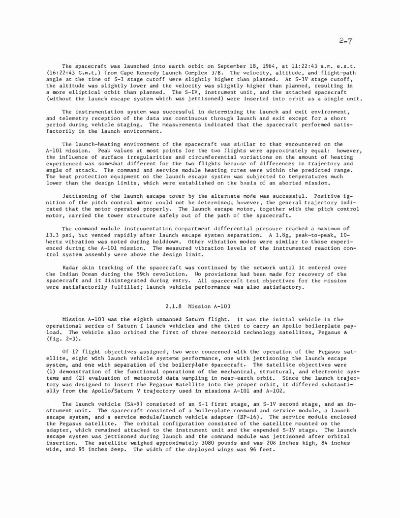
The spacecraft was launched into earth orbit on Septenber 18, 1964, at 11:22:43 a.m. e.s.t. (16:22:43 G.m.t,) from Cape Kennedy Launch Complex 37B. The velocity, altitude, and flight-path angle at the ti�:�e of S-I stage cutoff were slightly higher than planned. At S-IV stage cutoff, the altitude was slightly lower and the velocity was slightly higher than planned, resulting in a more elliptical orbit than planned. The S-IV, instrument unit, and the attached spacecraft (without the launch escape system which was jettisoned) were inserted into orbit as a single unit.
The instrumentation system was successful in deternining the launch and exit environment, and telemetry reception of the data 1�as continuous through launch and exit except for a short period during vehicle staging. The measurements indicated that the spacecraft performed satisfactorily in the launch environment.
The launch-heating environment of the spacecraft Has sit:dlar to that encountered on the A-101 mission. Peak values at most points for the t1�o flights were approxinately equal: however, the influence of surface irregularities and circumferential variations on the amount of heating experienced was some1�hat different for the two flights because of differences in trajectory and angle of attack. The command and service module heating rates were within the predicted range. The heat protection equipment on the launch escape systef'l was subjected to temperatures much lower than the design limits, which were established on the basis of an aborted mission.
Jettisoning of the launch escape to�1er by the alternate mode was successful. Positive ignition of the pitch control motor could not be determined; h01�ever, the general trajectory indicated that the motor operated properly. The launch escape motor, together with the pitch control motor, carried the tower structure safely out of the path of the spacecraft.
The command rrodule instrur.1entation conpartment differential pressure reached a maximum of 13.3 psi, but vented rapidly after launch escape systen separation. A l.Sg, peak-to-peak, lQhertz vibration was noted during holddown. Other vibration modes were similar to those experienced during the A-101 mission. The measured vibration levels of the instrumented reaction control system assembly were above the design limit.
Radar skin tracking of the spacecraft was continued by the network until it entered over the Indian Ocean during the 59th revolution. No provisions had been made for recovery of the spacecraft and it disintegrated during entry. All spacecraft test objectives for the mission were satisfactorily fulfilled; launch vehicle performance was also satisfactory.
2.1.8 �lission A-103
Mission A-103 was the eighth unmanned Saturn flight. It was the initial vehicle in the operational series of Saturn I launch vehicles and the third to carry an Apollo boilerplate payload, The vehicle also orbited the first of three meteoroid technology satellites, Pegasus A (fig. 2-3).
Of 12 flight objectives assigned, two were concerned with the operation of the Pegasus satellite, eight with launch vehicle syste�:�s perfomance, one with jettisoning the launch escape system, and one with separation of the boilerplate spacecraft. The satellite objectives were (1) demonstration of the functional operations of the mechanical, structural, and electronic systems and (2) evaluation of meteoroid data sampling in near-earth orbit. Since the launch trajectory was designed to insert the Pegasus satellite into the proper orbit, it differed substantially from the Apollo/Saturn V trajectory used in missions A-101 and A-102.
The launch vehicle (SA-9) consisted of an S-I first stage, an S-IV second stage, and an instrument unit. The spacecraft consisted of a boilerplate conmand and service module, a launch escape system, and a service module/launch vehicle adapter (BP-16). The service module enclosed the Pegasus satellite. The orbital configuration consisted of the satellite mounted on the adapter, which remained attached to the instrur.1ent unit and the expended S-IV stage. The launch escape system was jettisoned during launch and the comnand module was jettisoned after orbital insertion. The satellite weighed approximately 3080 pounds and was 208 inches high, 84 inches wide, and 95 inches deep. The width of the deployed wings was 96 feet.

z .. 8
forward
so\ar
pane\
Latera\
so\ar pane\
p.po 1 lo bo i let plate command
tnodu\e and tnodi\ied
ser\lice tnodu\e
eteoroid detector pane\

2-9
The vehicle was launched from Cape Kennedy Launch Complex 378 at 09:37:03 a.m. e.s.t. (14:37:03 G.m.t.) on February 16, 1965. A hold of 1 hour and 7 minutes was caused by a power failure in the Eastern Test Range flight safety computer. A built-in hold of 30 minutes was also used to discharge and recharge a battery in the Pegasus satellite as a check that it was functioning properly.
The launch was nonnal and the payload was inserted into orbit approximately 10.5 minutes after launch. The total mass placed in orbit was 33 895 pounds. The perigee was 307.8 miles, the apogee was 461.9 miles, and the orbital incli.nation was 31.76°. The Pegasus satellite had a period of 97.1 minutes.
The trajectory and space-fixed velocity were very nearly as planned. The Apollo shroud separated from the Pegasus satellite about 804 seconds after lift-off and deployment of two meteoroid detection panel wings of the Pegasus satellite commenced about 1 minute later. The predicted useful lifetime of Pegasus A in orbit was ll88 days. The satellite was commanded off on August 29, 1968. Although minor malfunctions occurred in both the launch vehicle and the Pegasus A satellite, mission A-103 was a success in that all objectives were met.
2.1.9 Hission A-104
Mission A-104 was the ninth test flight of the Saturn I. This mission was the second flight in the Saturn I operational series and the fourth vehicle to carry an Apollo boilerplate spacecraft, The vehicle also launched the Pegasus 8 meteoroid technology satellite, The two primary mission objectives were (1) evaluation of meteoroid data sampling in near-earth orbit and (2) demonstration of the launch vehicle iterative guidance mode and evaluation of system accuracy. The launch trajectory was similar to that of mission A-103.
The Saturn launch vehicle (SA-8) and payloa d were similar to those of mission A-103 except that a single reaction control engine assembly was mounted on the boilerplate service module (BP-26) and the assembly was instrumented to acquire additional data on launch environment tem
peratures, This assembly also differed from the one on the A-101 mission in that two of the four engines were of a prototype configuration instead of all engines being simulated. Pegasus 8 weighed approximately 3080 pounds and had the same dimensions as Pegasus A.
�lission A-104 was launched from Cape Kennedy Launch Complex 378 at 02:35:01 a.m. e.s.t. (07:35:01 G.m.t.) on May 25, 1965, the first nighttime launch in the Saturn I series (fig. 2-4).
A built-in 35-minute hold was used to ensure that launch time coincided with the opening of the launch window.
The launch was normal and the payload was inserted into orbit approximately 10.6 minutes after lift-off. The total mass placed in orbit, including the spacecraft, Pegasus 8, adapter, instrument unit, and S-IV stage, was 34 113 pounds. The perigee and apogee were 314.0 and 464.1 miles, respectively; the orbital inclination was 31.78°,
The actual trajectory was close to the one predicted, and the spacecraft was separated 806 seconds after lift-off. The deployment of the Pegasus B wings began about 1 minute later. The predicted orbital lifetime of Pegasus B was 1220 days. The satellite instrumentation and beacons were commanded off on August 29, 1968. Several minor malfunctions occurred in the S-I stage propulsion system; however, all mission objectives were successfully achieved.
2.1.10 }!ission A-105
Mission A-105, the third flight of an operational Saturn I, was the last in the series of Saturn I flights. The payload consisted of an Apollo boilerplate spacecraft (BP-9A) which served as a shroud for the third Pegasus meteoroid technology satellite, Pegasus C. The two primary flight objectives were (1) the collection and evaluation of meteoroid data in near-earth orbit and (2) the continued demonstratio� of the launch vehicle iterative guidance mode and evaluation of system accuracy.


2-11
The Saturn launch vehicle (SA-10) was similar to those of missions A-103 and A-104. As on the previous mission, the boilerplate service module was equipped with a test installation of a reaction control engine package. Pegasus C weighed 3138.6 pounds and had the same dimensions as its predecessors.
Mission A-105 was launched from Cape Kennedy Launch Complex 378 at 08:00:00 a.m. e.s.t. (13:00:00 G.m.t.) on July 30, 1965. A planned 3D-minute hold ensured that launch time coincided with the opening of the Pegasus launch window. The launch was normal and the payload was inserted into orbit approximately 10.7 minutes after lift-off. The total mass placed in orbit, including the spacecraft, Pegasus C, adapter, instrument unit, and S-IV stage, was 34 438 pounds.
The spacecraft was separated 812 seconds after lift-off. The separation and ejection system operated as planned. The two meteoroid detection panel wings of the satellite were deployed from their folded position 40 se.conds after command initiation at 872 seconds.
The predicted useful lifetime of the satellite (720 days) was exceeded, and the beacons and telemetry transmitters were commanded off on August 29, 1968. Pegasus C entered the earth atmosphere on August 4, 1969. All primary and secondary objectives were attained.
Details of the three Pegasus flights are contained in references 2-1, 2-2 and 2-3.
2.2 APOLLO SPACECRAFT ABORT TESTS
The Apollo spacecraft abort tests consisted of six flights to demonstrate the adequacy of the Apollo launch escape system and to verify the performance of the command module earth landing system. These flights were launched from Complex 36 at White Sands Missile Range, New Mexico, which is approximately 4000 feet above mean sea level. Two of the tests were conducted with the launch escape system motors being ignited at ground level, while the remaining tests were conducted using the Little Joe II launch vehicle to boost the spacecraft to various points in the Saturn launch trajectory for abort initiation. A significant event in this series of flights was an unplanned failure of a launch vehicle resulting in an actual abort situation in which all spacecraft systems operated satisfactorily.
2.2.1 Pad Abort Test 1
Apollo Pad Abort Test 1 was an unmanned flight using the launch escape system to demonstrate the capability of the Apollo spacecraft to abort from the launch pad and thus provide crew safety. Of the six first-order test objectives assigned, those of primary importance were to (1) determine the aerodynamic stability characteristics of the Apollo escape configuration during a pad abort, (2) demonstrate the capability of the escape system to propel a command module a safe distance from a launch vehicle during a pad abort, and (3) demonstrate the earth landing timing sequence and proper operation of the parachute system.
The test vehicle consisted of a production launch escape system in combination with a boilerplate command module (BP-6), the first Apollo boilerplate spacecraft to be flown (fig. 2-5). Since the command module was not representative of the actual spacecraft, no instrumentation was provided to determine structural loads. Measurements of such characteristics as vehicle accelerations, angle of attack, Mach number, and dynamic pressure allowed determination of inflight loads resulting from the external environment or vehicle dynamics. The command module was mounted in a vertical position on three bearing points of a supporting structure attached to a concrete pad.
The test was initiated on November 7, 1963, at 09:00:01 a.m. m.s.t. (16:00:01 G.m.t.) by transmitting a ground commanded abort signal to the conmand module. The signal activated the abort relay in the launch escape system sequencer, which in turn sent a signal to ignite the launch escape and pitch control motors. These motors ignited almost simultaneously and lifted the command module along a planned trajectory. The launch escape tower was separated about 15 seconds after engine ignition and followed a ballistic trajectory. The command module made a normal parachute descent at a velocity of 24 feet per second. Landing of the command module occurred at 165.1 seconds.


2-13
The vehicle exceeded the Apollo minimum altitude and range requirements for a pad abort by 970 feet and 1525 feet, respectively. Although the vehicle stability was less than predicted during the powered phase of flight, all objectives of the flight were satisfied.
2.2.2 Mission A-001
Mission A-001 was the second in the series of tests conducted to demo nstrate that the launch escape system could safely remove the command module under critical abort conditions. Unlike Pad Abort Test 1, in which the launch escape system was ignited at ground level, this mission was flown to demonstrate the capability of the escape system to propel the command module safely away from a launch vehicle while in the high-dynamic-pressure (transonic) region of the Saturn traj ectory.
The launch vehicle was the second in the series of Little Joe II vehicles, which had been developed to accomplish early and economical testing of the launch escape system. The Little Joe II
was propelled by seven solid-propellant rocket motors - one Algol sustainer motor, which provided thrust for about 42 seconds, and six Recruit motors, which burned out approximately 1.5 seconds after ignition. The spacecraft consisted of a launch escape system and a boilerplate command and service module (BP-12).
Unacceptable wind conditions had forced a 24-hour postponement of the launch, but the vehicle was successfully launche d (fig. 2-6) on May 13, 1964, at 05:59:59.7 a.m. m.s.t. (12:59:59.7 C.m.t). A ground commanded abort signal terminated thrust of the launch vehicle (by rupturing the Algol motor casing), ignited the launch escape and pitch control motors, and separated the command module from the service module. Some structural damage was incurred by the command module aft heat shield because of recontact with the boostet· at thrust termination. At approximately 44 seconds, the tower jettison motor was ignited and satisfactorily separated the launch escape tower from the command module.
The earth landing sequence was normal until a riser for one of the three main parachutes broke as a result of its rubbing against the structure on the command module upper deck. The parachute sepa·rated; however, the command module, supported by the two remaining parachutes, descended at rates of 30 to 26 feet per second instead of the predicted 24 feet per second with three parachutes. The command module landed 22 400 feet down range at 350.3 seconds after attaining an altitude of 29 772 feet above mean sea level. Except for the parachute failure, all test objectives were satisfied.
2.2.3 Hission A-002
Mission A-002 was the third in the series of abort tests to demonstrate that the launch escape system would perform satisfactorily under selected critical abort conditions. The main objective of thi s mission was to demonstrate the abort capability of the launch escape vehicle in the maximum dynamic pressure region of the Saturn trajectory with conditions approximating the altitude limit at which the Saturn emergency detection system would signal an abort.
The launch vehicle was the third in the Little Joe II series. This vehicle differed from the previous two in that flight controls and instrume.,tation were incorporated, and the vehicle was powered by two Algol and four Recruit rocket motors. The launch escape system was also changed from previous configurations in that canards (Corward control surfaces used to orient and stabilize the escape vehicle in the entry attitude) and a command module boost protective cover were incorporated. The Apollo spacecraft was simulated by a boilerplate command and service module (BP-23). The earth landing system was modified from the previous configuration by the installation of modified dual-drogue parachutes instead of a single-drogue parachute.
The A-002 vehicle was launched on December 8, 1964, at 08:00:00 a.m. m.s.t. (15:00:00 G.m.t.) by igniting all launch vehicle motors simultaneously. Conditions at abort initiation were selected from Saturn boost trajectories, and a nominal test point was used for the maximum dynamic pressure region. A pitchup maneuver and the abort were initiated by using a real-time plot of the dynamic pressure versus Mach number. However , an improper constant was used in the meteorological data input to the real-time data system, resulting in the pitchup maneuver being initiated 2.4 seconds early. Although the planned test point was not achieved, the early pitchup caused a higher maximum dynamic pressure than the design value.


2-15
Canard deployment took place as expected 11.1 seconds after abort initiation. The launch escape vehicle tumbled four times before stabilizing with the aft heat shield forward. During the first turnaround, the soft portion of the boost protective cover was torn away from the command module. Haximum altitude attained by the launch escape vehicle was 50 360 feet above mean sea level.
Baroswitches initiated the earth landing sequence at an altitude of approximately 23 500
feet above mean sea level. All parachutes deployed properly and the command module, supported by the three main parachutes, descended at the planned rate of about 24 feet per second to an earth landing 3� 800 feet down range.
The abort conditions obtained were more than adequate in verifying the abort capability in the maximum dynamic pressure region. Only one test objective was not achieved; the boost protective cover was structurally inadequate for the environ�:�ent <>xperi.enced during this mission.
2.2.4 Mission A-003
Apollo mission A-003 was the fourth mission to demonstrate the abort capability of the Apollo launch escape system. The purpose of this flight was to demonstrate launch escape vehicle performance at an altitude approximating the upper limit for the canard sul>system.
The launch vehicle was similar to the one used for mission A-002 except that the propulsion system consisted of six Algol motors. The unmanned flight test vehicle consisted of an Apollo boilerplate command and service module (BP-22) and a launch escape system similar to the one used on the previous mission. The command module earth landing system configuration was refined to be more nearly like that of the planned production system, and a forward heat shield jettisoning system was provided.
The test vehicle was launched on Hay 19, 1965, at 06:01:04 a.m. m.s.t. (13:01:04 G.m.t.). Within 2.5 seconds after lift-off, a launch veh.icle malfunction caused the vehicle to go out of control. The resulting roll rate caused the l<:unch vehicle to break up l>efore second-stage ignition, and a low-altitude spacecraft abort Has initiated instead of the planned high-altitude abort. The launch escape system canard surfaces deployed and survived the severe environment. The high roll rates (approximately 260° per second at the time of canard deployment) 'induced by the launch vehicle malfunction stabilized the launch escape vehicle in a tower-forward attitude, which overcame the destabilizing effect of the canards. Postflight simulations verified the ineffectiveness of the canards at the high roll rate, but sho1�ed that the canards would be effective at the 20° per second roll rate limit of th� Saturn emergency detect.ion system.
All spacecraft systems operated satisfactorily. Thl' command module forward heat shield was protected by the hard portion of the boost protective cover and 1�as jettisoned satisfactorily in an apex-forward attitude at low altitude. The soft portion of the boost protective cover remained intact until tower jettison. At tower jettison, part of the cover stayed with the co�:�mand module for a short time although the rest of the cover moved away with the tower. The hard portion of the boost protective cover remained intact until ground impact. Both drogue parachutes inflated, even under the severe conditions that existed; that i.s, command module apex forward and rolling. The command module was effectively stabilized and or::,N1ted for deployment of the main parachutes.
Because of the early launch vehicle breakup, the desired altitude o f 120 000 feet was not achieved. However, the spacecraft did demonstrate a !.'•Jccessful 101�-altitude (12 400 ft) abort from a rapidly rolling (approxir.tately 335° per second) launch vehicle. The Hach number, dynamic pressure, and altitude at the time of abort were similar to Saturn IB or Saturn V launch trajec
tory conditions.
2.2.5 Pad Abort Test 2
Apollo Pad Abort Test 2 was the fifth of six um"'anned Apollo missions that flight tested the capability of the launch escape system to provide for safe recovery of Apollo crews under critical abort conditions. This flight was the second test of the launch escape system with the abort initiated from the launch pad.

2-16
The launch escape syster.1 included qualified launch escape and pitch control motors and was equipped with canards to orient the vehicle aft heat shield forward prior to tower jettison and parachute deployment. A boost protective cover was also provided. The spacecraft was BP-23A, a boilerplate command module that had been used on mission A-002 and refurbished to more nearly simulate a Block-1-type command module in mass and other characteristics. The earth landing system was similar to the one used in mission A-003.
The test flight was conducted on June 29, 1965. The vehicle was lifted from Launch Complex 36 by the launch escape motor at 06:00:01 a.n. m.s.t. (13:00:01 G.c.t.). The launch escape and pitch control notors ignited simultaneously, placing the test vehicle into the planned initial trajectory. A r.�oderate roll rate developed at lift-off, which was due to the aerodynamic asymmetry of the vehicle configuration; however, the roll rate did not affect the success of the test.
The canard surfaces deployed and turned the vehicle to the desired orientation for drogue parachute deployment. During the turnaround maneuver, the launch escape tower and forward heat shield were jettisoned as planned. The boost protective cover, which was attached to the launch escape system, protected the conical surface of the co�and oodule and remained intact through a canard-induced pitch maneuver. At tower jettison, the soft boost protective cover, as expected, collapsed because of differential pressure during renoval froo the command module. No recontact or interference between the major components was evident during tower jettison and parachute deployment.
Although one of the pilot parachute steel cable risers was kinked, the earth landing system functioned properly. The drogue parachutes inflated and stabilized the command module for pilot and main parachute deployment, and the rate of descent while on the main parachutes was satisfactory. The maximum altitude achieved was 9258 feet above mean sea level, approximately 650 feet higher than predicted. The command module landed about 7600 feet from the launch site, some 2000 feet farther than planned.
Four glass samples had been mounted on the cor.unand module in the general area planned for the rendezvous and crew windows. No soot appeared on the samples, but an oily film was found on the exposed surfaces of three of the four samples. This file, however, was not expected to cause excessive degradation to the horizon scan or ground orientation ability during an abort. The test was highly successful and all planned objectives were fulfilled.
2.2.6 ltission A-004
Mission A-004 was the final test of the Apollo launch escape vehicle and the first flight of a Block I production-type spacecraft. The mission '�as unmanned and was conducted to demonstrate that (1) the launch escape vehicle would satisfactorily orient and stabilize itself in the proper attitude after being subjected to a high rate of tunbling during the powered phase of an abort and (2) the escape vehicle would maintain its structural integrity under test conditions in which the command module structure was loaded to the design limit.
The launch vehicle was the fifth and final Little Joe II flown. The propulsion system consisted of four Algol and five Recruit rocket motors. The attitude control system was similar to the one used on mission A-003 except that the reaction control system was deleted and the vehicle was provided with the capability of responding to a radio-transmitted pitchup command. The pitchup maneuver was required to help initiate tuobling of the launch escape vehicle. The spacecraft for this mission consisted of a modified Block I comoand and service module and a modified Block I launch escape system (airframe 002). The center of gravity and thrust vector were changed to assure that po,�er-on tumbling would be attained after abort initiation. The earth landing system was essentially the same as that used during Pad Abort Test 2.
The vehicle was launched on January 20, 1966, at 08:17:01 a.m. m.s.t. (15:17:01 G.m.t.) after several postponements due to technical difficulties and adverse weather conditions. The pitchup maneuver was conunanded from the ground when telemetry showed that the desired altitude and velocity conditions had been reached. The planned abort was automatically initiated 2.9 seconds later. The launch escape vehicle tumbled immediately after abort initiation. Pitch and yaw rates reached peak values of 160° per second, and roll rates reached a peak of minus 70° per second. The launch escape system canard surfaces deployed at the proper time and stabilized the
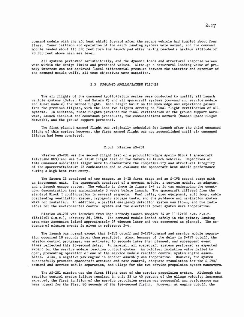
2-17
command module with the aft heat shield forward after the escape vehicle had tumbled about four times. Tower jettison and operation of the earth landing systems were normal, and the command module landed about 113 620 feet form the launch pad after having reached a maximum altitude of 78 180 feet above mean sea level.
All systems performed satisfactorily, and the dynamic loads and structural response values were within the design limits and predicted values. Although a structural loading value of primary interest was not achieved (local differential pressure between the interior and exterior of the command module wall), all test objectives were satisfied.
2.3 UNMANNED APOLLO/SATURN FLIGHTS
The six flights of the unmanned Apollo/Saturn series were conducted to qualify all launch vehicle systems (Saturn IB and Saturn V) and all spacecraft systems (command and service module and lunar module) for manned flight. Each flight built on the knowledge and experience gained fro� the previous flights, with the last two flights serving as final flight verification of all systems. In addition, these flights provided the final verification of the ground support hardware, launch checkout and countdown procedures, the communications network (Manned Space Flight Network), and the grout1d support personnel.
The first planned manned flight was originally scheduled for launch after the third unmanned flight of this series; however, the first manned flight was not accomplished until six unmanned flights had been completed.
2.3.1 Mission AS-201
Mission AS-201 was the second flight test of a production-type Apollo Block I spacecraft (airframe 009) and was the first flight test of the Saturn IB launch vehicle. Objectives of this unmanned suborbital flight were to demonstrate the compatibility and structural integrity of the spacecraft/Saturn IB combination and to evaluate the spacecraft heat shield performance during a high-heat-rate entry.
The Saturn IB consisted of two stages, an S-IB first stage and an S-IVB second stage with an instrument unit. The spacecraft consisted of a co�nd module, a service module, an adapter, and a launch escape system. The vehicle is shown in figure 2-7 as ie was undergoing the countdown demonstration test approximately 3 weeks before launch. The spacecraft differed from the standard Block I configuration in several respects. Fuel cells, crew equipment, suit loop, cabin postlanding ventilation system, cryogenic storage tanks, and the guidance and navigation system were not installed. In addition, a partial emergency detection system was flown, and the radiators for the environmental control system and the electrical power system were inoperative.
Mission AS-201 was launched from Cape Kennedy Launch Co�plex 34 at 11:12:01 a.m. e.s.t. (16:12:01 G.m.t.), February 26, 1966. The cornoand module landed safely in the primary landing area near Ascension Island approximately 37 minutes later and was recovered as planned. The sequence of mission events is given in reference 2-4.
The launch was normal except that S-IVB cutoff and S-IVB/command and service module separation occurred 10 seconds later than predicted. Also, because of the delay in S-IVB cutoff, the mission control programmer was activated 10 seconds later than planned, and subsequent event times reflected this 10-second delay. In general, all spacecraft systems performed as expected except for the service module reaction control system. An oxidizer isolation valve failed to open, preventing operation of one of the service module reaction control system engine assemblies. Also, a negative yaw engine in another assembly was inoperative. However, the system successfully provided spacecraft attitude and rate control, adequate translation for the S-IVB/ command and service module separation, and ullage for the two service propulsion system maneuvers.
The AS-201 mission was the first flight test of the service propulsion system. Although the reaction control system failure resulted in only 25 to 45 percent of the ullage velocity increment expected, the first ignition of the service propulsion system was successful and performance was near normal for the first 80'seconds of the 184-second firing. However, at engine cutoff, the


2-19
chamber pressure had decayed to approximately 70 percent of no�l. The second firing, planned for a 10-second duration, was erratic with chamber pressure oscillations that ranged from 12 to 70 percent of normal. The subnormal performance of the service propulsion system was attributed to helium ingestion.
Spacecraft communications blackout began at 1580 seconds and lasted until 1695 seconds. Entry was initiated with a space-fixed velocity of 26 481 feet per second. The co�and module was subjected to a naximum entry heating rate of 164 Btu/sq ft/sec at 1631.7 seconds and a maximum deceleration of 14.3g at 1639.7 seconds. The command module structure and heat shields performed adequately in the entry environment.
Loss of power to both command module reaction control systems at 1649 seconds resulted in an uncontrolled rolling entry (in excess of 26° per second) instead oi the planned lifting entry. Power was returned to reaction control system A at 2121 seconds, and the required depletion burning of the comr.:�and module reaction control system propellants was accomplished.
Forward heat shield jettison, drogue parachute deployment, and main parachute deployment occurred as planned. The command module landed in the Atlantic Ocean near Ascension Island at 2239.7 seconds and remained in an upright attitude. The landing time was 30.8 seconds earlier than the preflight-predicted time. Touchdown was 45 miles up range (northwest) of the-recovery ship U.S.S. Boxer. One of the main parachutes failed to disengage after landing and was cut loose by a recovery force swimmer. The spacecraft was taken aboard the recovery ship at 02:20 p.m. e.s.t., 3 hours 8 minutes after lift-off. While all primary objectives were accomplished, the subnormal performance of some systems necessitated further investigation and improvements for future flights.
2.3.2 Mission AS-203
Mission AS-203 was an unmanned, research and developmental test of the Saturn IB vehicle. Major objectives of the flight were to (1) evaluate the S-IVB stage liquid hydrogen venting, (2) evaluate the S-IVB engine chilldown and recirculation systems, and (3) determine fluid dynamics of the S-IVB tanks. The data obtained were directly applicable to the Saturn V program. The S-IVB was to be used as the third stage of the Saturn V on lunar missions. A second firing of the S-IVB engine was necessary to insert an Apollo spacecraft into a translunar trajectory. Therefore, the test was conducted to simulate Saturn V third-stage engine restart in earth orbit.
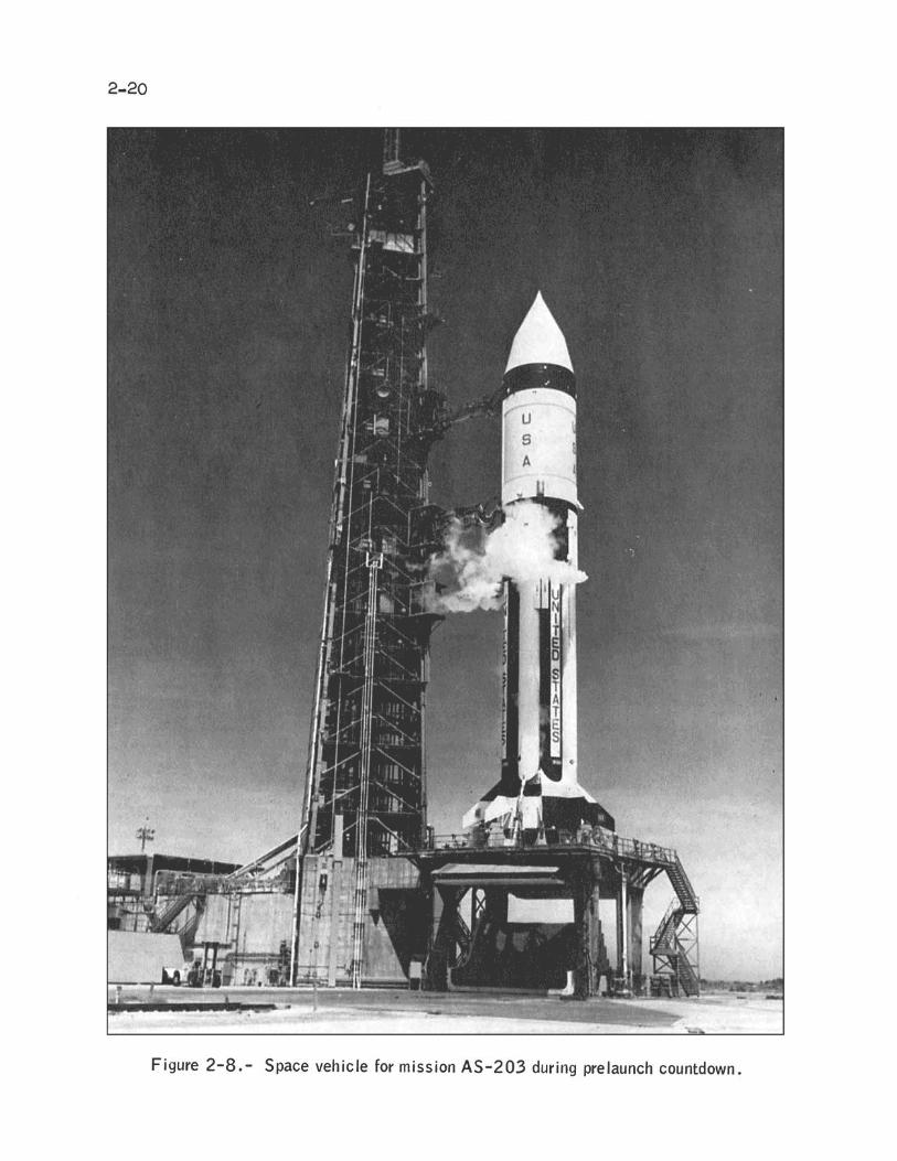
The vehicle was the second Saturn IB launched. The general configuration was similar to that of mission AS-201 except that an aerodynamic fairing (nose cone) was installed in place of the spacecraft (fig. 2-8). Telemetry and recoverable 16-mm cameras (ejected during launch) were provided to furnish data on vehicle performance. In addition, two television cameras were mounted on the forward bulkhead of the S-IVB liquid hydrogen tank to aid in determining the amount of propellant sloshing.
Mission AS-203 was launched from Cape Kennedy (14:53:17 G.m.t.) on July 5, 1966. The launch was loss of signal from one of the television cameras. cone were inserted into an orbit that was close to
Launch Complex 37B at 09:53:17 a.m. e.s.t. delayed 1 hour and 53 minutes because of a
The S-IVB stage, instrument unit, and nose the planned 100-mile circular orbit.
Satisfactory system operation was demonstrated on the first of four orbits in which the systems were planned to be active, and all mission objectives were achieved. The simulated S-IVB engine firing duration was very close to the predicted time even though the chilldown valve failed to close after engine ignition. Data were gathered on S-IVB stage behavior in other Saturn V modes during the next three orbits. At the beginning of the fifth orbit, while a test was being performed, pressure in the liquid hydrogen tank built up to a level in excess of the design value, bursting the rank and resulting in premature destruction of the stage. However, all mission objectives had been accomplished.

2-21
2.3.3 �fission AS-202
Mission AS-202 was an unmanned suborbital flight to further evaluate the Saturn IB launch vehicle and the Apollo conunand and service mdule before conunitting them to manned flight. The launch vehicle was the third Saturn IB and the spacecraft was the third production-type Block I CODU11and and service module (airframe 011). The mission objectives were (1) to obtain further launch vehicle and spacecraft information on structural integrity and compatibility, flight loads, stage separation, subsys·tem operation, and emergency detection system operation and (2) to evaluate the corranand module heat shield at high heat loads during entry at approximately 28 000 feet per second.
The Saturn IB was similar to the previous two launch vehicles. The spacecraft consisted of an adapter, the co!lliiland and service module� and a launch escape system. The spacecraft systems and equipment were generally like those of the AS-201 mission spacecraft except that the fuel cells and cryogenic reactants, the guidance and navigation system, the S-band conununications equipment, and the service propulsion system propellant gaj';ing equipment were being flown for the first time. Also, the environmental control system and electrical power system radiators were operative on this mission and a closed-loop emergency detection system was provided.
The spacecraft was launched from Cape Kennedy Launch Complex 34 at 12:55:32 p.m. e.s.t. (17:55:32 G.m.t.), August 25, 1966. The spacecraft timing sequence was initiated by the S-IVB stage separation corranand, which was 13.8 seconds early due to higher-than-expected performance of the launch vehicle. Consequently, the flight events occurred earlier than planned (ref. 2-5). The spacecraft landed in the Pacific Ocean near Wake Island.
All mission objectives were accomplished, including the performance assessment of the systems being flown for the first time. Performance of these systems is discussed in the following paragraphs.
Fuel cell power plant electrical perforr.1ance was normal, and current distribution between the cells and auxiliary batteries followed the expected ratios. The condenser exit temperatures on the two active fuel cells approached the maximum limit during the flight. The problem was attributed to entrapped air in the secondary coolant loop. Servicing procedures were changed for later spacecraft to eliminate this problem.
The cryogenic system performance was satisfactory. Pressurization, temperature, and flowrate response to fuel cell reactant gas demands were as expected.
The guidance and navigation system performed normally. Attitude control, navigation thrust vector and differential velocity control, and entry targeting were satisfactory. The command module, however, landed approximately 200 miles short of the planned point because the preflight prediction of the trim lift-to-drag ratio was not sufficiently accurate. The guidance and navigation system responded properly in attempting to correct for the undershoot condition.
The S-band conununications equipment performed satisfactorily. Simulated downvoice and upvoice (via tone signals), down-link telemetry, and ranging mdes were proper. Hinor signal reception and station handover problems, not associated with the airborne equipment, were encountered.
The propellant gaging equipment for the service propulsion system functioned normally. Appreciable biases were noted but were explainable on the basis of preflight loading conditions and dynamic flow effects.
The environmental control system radiators provided proper heat rejection and compensated for a malfunction of the water evaporator. Erratic evaporator cooling was attributed to excess water which froze and plugged the overboard vent. Prelaunch servicing procedures were changed for later spacecraft.
The emergency detection system operated properly in the closed-loop mde. The automatic abort circuit was properly enabled at lift-off and deactivated by the launch vehicle sequencer prior to staging.

2-22
2.3.4 Apollo 4 Mission
The Apollo 4 mission was the fourth unmanned flight test of a production type Block I Apollo spacecraft and the initial flight of tile three-stage Saturn V, the launch vehicle that was to be used for lunar missions. The first and second stages of the Saturn V (the S-IC and S-II stages) had not been flown previously. The third stage (the S-IVB) had been used as the second stage of the Saturn lB. The instrument unit configuration was basically the same configuration flight tested during the Saturn IB development series. Figure 2-9 shows the vehicle and mobile launcher as they were being positioned on the launch pad.
The mission had a number of important objectives applicable to both the launch vehicle and spacecraft. The principal objectives were (1) to demonstrate the structural and thermal integrity and compatibility of the Saturn V and the Apollo spacecraft, (2) to verify operation of the launch vehicle propul sion, guidance and control, and electrical systems, (3) to demonstrate separation of the launch vehicle stages, (4) to verify the adequacy of the thermal protection system developed for the Block II command module under lunar return conditions, and (5) to demonstrate a service propulsion system engine no-ullage start.
The Apollo 4 spacecraft (airframe 017) included a launch escape system, a command and service module, and a spacecraft/lunar module adapter. A lunar module test article was installed in the adapter. The command module was equipped with the lunar-mission-type thermal protection system that was to be tested and had other modifications applicable to the Block II spacecraft. As on previous unmanned flights, the command module contained a mission control programmer to actuate functions that would normally be performed by the crew.
The space vehicle was launched from Kennedy Space Center Launch Complex 39A (the first use of this facility) at 07:00:01 a.m. e.s.t. (12:00:01 G.m.t.) on November 9, 1967. Detailed flight events are given in reference 2-6.
The launch phase was normal. All planned ev·ents occurred within allowable limits, and structural loading was well within the capability of the vehicle. Measurements telemetered from the command module indicated that qualification vibration levels were not exceeded and verified the adequacy of thermal prediction techniques.
The spacecraft was inserted into a circular ·Orbit by the S-lVB stage after approximately 11 minutes of powered flight. Near the end of the second revolution, the S-IVB engine was successfully reignited to place the spacecraft into a simulated translunar trajectory. At the com
pletion of the maneuver, the command and service module was separated from the S-IVB stage, and the service propulsion system engine was fired for approximately 15 seconds to demonstrate the capability of starting the engine in zero gravity without perfoming a reaction control system ullage maneuver. There were no adverse effects, and the maneuver raised the apogee of the spacecraft trajectory from 9292 miles to 9769 miles. A few seconds after service propulsion system engine cutoff, the spacecraft was oriented to an attitude in which the side hatch was pointed directly toward the sun. This attitude was maintained for approximately 4-1/2 hours to obtain thermal data.
After approximately 8 hours and 10 minutes of flight, a second service propulsion system maneuver was performed to accelerate the spacecraft to a velocity representative of severe lunar return entry conditions. Shortly afterward, the command module was separated from the service module and oriented to the entry attitude.
The inertial velocity at atmospheric entry, which occurs at an altitude of 400 000 feet, was approximately 36 000 feet per seco.nd, about 210 feet per second greater than predicted. This overspeed was caused by a longer-than-planned firing of the service propulsion system. Because of the change in entry conditions, the peak deceleration force was 7.3g rather than the predicted 8. 3g.
The guidance and control system performed satisfactorily in guiding the spacecraft to the desired landing point. Although the landing was about 5 miles short of the target point, it was within the accuracy predicted before the mission. The forward heat shield and one of the main parachutes were recovered along with the command module by the primary recovery ship, the U.S.S. Bennington. Postflight inspection of the command module indicated that the thermal protection system withstood the lunar return entry environment satisfactorily.


2-24
2.3.5 Apollo 5 Mission
The Apollo 5 mission was the first flight of a lunar module and the fourth flight test of the Saturn JB launch vehicle. The space vehicle consisted of an S-IB stage, an S-IVB stage, an instrument unit, an adapter, the lunar module, and a nose cone. Primary objectives of the mission were to verify the lunar module ascent and descent propulsion systems and the abort staging function for manned flight. These objectives were satisfied.
Lift-off from Cape Kennedy Launch Complex 37B (fig. 2-10) was initiated at 05:48:08 p.m. e.s.t. (22:48:08 G.m.t.) on January 22, 1968. (The detailed sequence of mission events is given in reference 2-7.) The lunar module and S-IVB stage were inserted into earth orbit after 10 minutes and 3 seconds of powered flight. Lunar module loads and measured vibrations were within the design capability of the structure during powered flight. Spacecraft cooling began after S-IVB stage cutoff, and the equipment tenperatures were properly regulated by the coolant system for the remainder of the mission. The lunar module was separated from the S-IVB stage by using the reaction control system engines. Separation disturbances were small. The lunar module was maneuvered to a cold-soak attitude which was maintained by the guidance system until early in the third revolution. A minimal reaction control system engine duty cycle was required to main-tain the desired attitude.
·
Hidway through the third revolution, the first descent engine firing was initiated. The planned duration of this firing was 38 seconds; however, after only 4 seconds, the guidance system shut down the engine. Both the guidance system and the propulsion system operated properly, and the premature shutdown resulted from an incorrect definition of the engine thrust buildup characteristics as used in the guidance system software.
After the premature shutdown, a planned alternate mission that provided minimum mission requirements was selected. At approximately 6 hours and 10 minutes into the flight, the automatic sequencer within the onboard mission progral'llller initiated the sequencing for the second and third descent engine firings, the abort staging, and the first ascent engine firing. Attitude rate control was maintained with the backup control system. The descent engine gimbaled properly and responded smoothly to the conunands to full throttle. The thermal aspects of the supercritical helium pressurization system could not be adequately evaluated because of the short duration of the three descent engine firings. During abort staging, all system operations and vehicle dynamics were satisfactory for manned flight.
After the first ascent stage engine firing, the primary guidance and control system was reselected to control the spacecraft attitudes and rates. Because the primary system had been passive during the abort staging sequence, the computer program did not reflect the change of mass resulting from staging. Therefore, computations of reaction control system engine firing times were based on the mass of a two-stage vehicle and resulted in an extremely high propellant usage by the reaction control system engines, eventually causing propellant depletion. Because of excessive reaction control system engine activity, the engine cluster red-line upper limit was exceeded; however, no detrimental effects were evident.
The reaction control system was later subjected to abnormal operating conditions because of low manifold pressures after propellant depletion. Continued operation under these abnormal conditions resulted in three malfunctions within the system, but none had an appreciable effect o n the mission.
The second firing of the ascent engine, initiated by the automatic sequencer, began at 7
hours 44 minutes 13 seconds into the mission and continued until thrust decay 5 minuces and 47
seconds later. During the initial portion of the firing, attitude rate control was maintained by using propellants from the ascent propulsion system tanks through interconnect valves to the reaction control system engines. However, the sequencer automatically closed the interconnect valves and switched the system over to the already depleted tanks. With the resultant loss of rate control, the vehicle began tumbling while the ascent engine was firing. All tracking was lost within 2 minutes after ascent stage engine thrust decay. The lunar module had been in a retrograde orientation during the controlled portion of the firing, and trajectory simulations indicated that the lunar module entered over the Pacific Ocean soon after the ascent stage engine firing. The predicted point of impact was approximately 400 miles west of the coast of Central America. The duration of the flight was approxinately 8 hours.


2-26
The overall performance of the lunar module was good and met all requirements for manned orbital flight. All operational systems were successfully verified, and the abort staging sequence was demonstrated.
2.3.6 Apollo 6 Mission
The Apollo 6 mission was accomplished on April 4, 1968. This was the second mission in which a Saturn V launch vehicle was used with an unmanned Block I co�nd and service module and a lunar module test article.
The space vehicle was launched from Kennedy Space Center Launch Complex 39A at 07:00:01 a.m. e.s.t. (12:00:01 G.m.t.). Lift-off was normal but a major structural anomaly in the spacecraft/ launch vehicle adapter occurred during first-stage boost. Approximately 2 minutes 13 seconds after lift-off, abrupt changes were indicated by strain, vibration, and acceleration measurements in the S-IVB, instrument unit, adapter, lunar module test article, and command and service module. The anomaly was apparently caused by 5-hertz oscillations induced by the launch vehicle; these oscillations exceeded the spacecraft design criteria. Photographic coverage from ground and aircraft cameras revealed material coming from the area of the adapter. (Sec. 4.4.2 of this report and ref. 2-8 contain additional inforr.lation concerning this anomaly.)
After second-stage ignition, the boost phase was ·normal until two engines in the S-11 stage shut down early. The firing time of the remaining three S-II stage engines was extended approximately 1 minute in an attempt to attain the desired velocity. The S-IVB stage firing was also longer than planned. At termination of the S-IVB thrust, the orbit had a 198-mile apogee and a 96-m.ile perigee, instead of the planned 100-mile near-circular orbit.
An attempt to reignite the S-IVB engine for a simulated translunar injection firing was unsuccessful. A ground command to the comnand and service module implemented a preplanned alternate mission that consisted of a long-duration firing (442 seconds) of the service propulsion system engine. This firing was executed under onboard guidance computer control and the onboard programmed apogee of 12 000 miles was attained. After the service propulsion system engine firing, the command and service module was aligned to a preset cold-soak attitude. The preflightplanned second firing of the service propulsion system engine was inhibited by ground command.
Atmospheric entry at 400 000 feet occurred at an inertial velocity of 32 830 feet per second and a flight-path angle of minus 5.85 degrees. The entry parameters were lower than predicted because of the S-IVB failure to reignite. The landing was about 36 miles up range of the targeted landing point as a result of the abnormal launch and insertion trajectory. This was the first mission in which the command module assuned the stable II (inverted) flotation attitude after landing. The command module was returned to the stable I (upright) attitude by the uprighting system. The mission duration was 9 hours 57 minutes 20 seconds.
The overall performance of the command and service module was satisfactory and none of the system anomalies precluded satisfactory conpletion of the mission. The most significant spacecraft anomaly was the aforementioned structural anomaly.
The abnormal occurrences during the boost phase subjected the command and service module to adverse environments that would normally not be seen during a flight test program. The alternate mission flown was the more difficult to acconplish of the two alternatives, which were (1) to attempt to complete the planned trajectory and obtain new evaluation data points or (2) to abort the mission and recover the spacecraft. The manner in which the command and service module performed during the alternate mission, after the adverse initial conditions, demonstrated the versatility of the systems.
The single primary spacecraft objective, demonstration of the performance of the emergency detection system operating in a closed-loop mode, was achieved. The secondary spacecraft objectives that were satisfied included demonstration of (1) effective operation of mission support facilities during the launch, orbital, and recovery phases of the mission, (2) successful operation of the service propulsion system (including a no-ullage start), and (3) proper operation of selected spacecraft systems (including electrical power, communications, guidance and control, and environmental control). The secondary spacecraft objectives that were partially satisfied included (1) demonstration of the adequacy of the Block II command module heat shield for entry

2-27
at lunar return conditions (not fully satisfied because of failure to achieve the high velocity planned for entry), (2) demonstration of the structural and thermal integrity and compatibility of launch vehicle and spacecraft, and (3) confirmation of launch loads and dynamic characteristics. Reference 2-9 provides details on spacecraft performance.
2.4 MANNED APOLLO/SATURN FLI�ITS
The manned flights of the Apollo program were to be initiated with the AS-204 mission; however, a fire in the command module during preflight checkout on the launch pad resulted in the death of the three crewmen and an 18-month delay of the first manned mission. The manned phase included two earth orbital missions, two lunar orbital missions, and seven lunar landing missions, one of which was aborted. The six successful lunar landing missions allowed approximately 838 pounds (380 kilograms) of lunar material to be returned to earth. In addition, these missions and the lunar orbital missions provided a wealth of scientific data about the moon and its environment for analysis by scientists throughout the world.
2.4.1 Apollo I Mission
On January 27, 1967, tragedy struck the Apollo program when a flash fire occurred in command module 012 during a launch pad test of the Apollo/Saturn space vehicle being prepared for the first manned flight, the AS-204 mission. Three astronauts, Lt. Col. Virgil I. Grissom, a veteran of Mercury and Gemini missions; Lt. Col. Edward H. White, the astronaut who had performed the first United States extravehicular activity during the Gemini program; and Roger B. Chaffee, an astronaut preparing for his first space flight, died in this tragic accident.
A seven-man board, under the direction of the NASA Langley Research Center Director, Dr. Floyd L. Thompson, conducted a comprehensive investigation to pinpoint the cause of the fire. The final report (ref. 2-10), cor.tpleted in April 1967, was subsequently submitted to the HASA Administrator. The report presented the results of the investigation and made specific recommendations that led to major design and engineering modifications, and revisions to test planning, test descipline, manufacturing processes and procedures, and quality control. With these changes, the overall safety of the command and service module and the lunar module was increased substantially. The AS-204 mission was redesignated Apollo I in honor of the crew.
2.4.2 Apollo 7 Mission
Apollo 7, the first manned mission in the Apollo program was an earth orbital mission. The command and service module was the first Block II configuration spacecraft flown, and the launch vehicle was a Saturn IB. Flight crewmen for the Apollo 7 mission were Walter M. Schirra, Jr., Commander; Donn S. Eisele, Command Module Pilot; and R. Walter Cunningham, Lunar Module Pilot. The primary objectives of this flight were to demonstrate command and service module/crew performance, crew/space vehicle/mission support facilities performance, and the command and service module rendezvous capability.
The spacecraft was launched at 11:02:45 a.m. e.d.t. (15:02:45 G.m.t.) on October 11, 1968, from Cape Kennedy Launch Complex 34 (fig. 2-11). The launch phase was normal, and the spacecraft was inserted into a 123- by 153-mile earth orbit. The crew performed a manual takeover of attitude control from the launch vehicle S-IVB stage during the second orbital revolution, and the control system responded properly. The command and service module was separated from the S-IVB stage approximately 3 hours after launch; the separation was followed by spacecraft transposition, simulated docking, and stationkeeping with the S-IVB.
A phasing maneuver was performed using the service module reaction control system to establish the conditions required for rendezvous with the S-IVB stage on the following day. The maneuver was intended to place the spacecraft approximately 75 miles ahead of the S-IVB. However, the S-IVB orbit decayed more rapidly than anticipated during the six revolutions after the phasing maneuver, and a second phasing maneuver was performed to obtain the desired conditions.
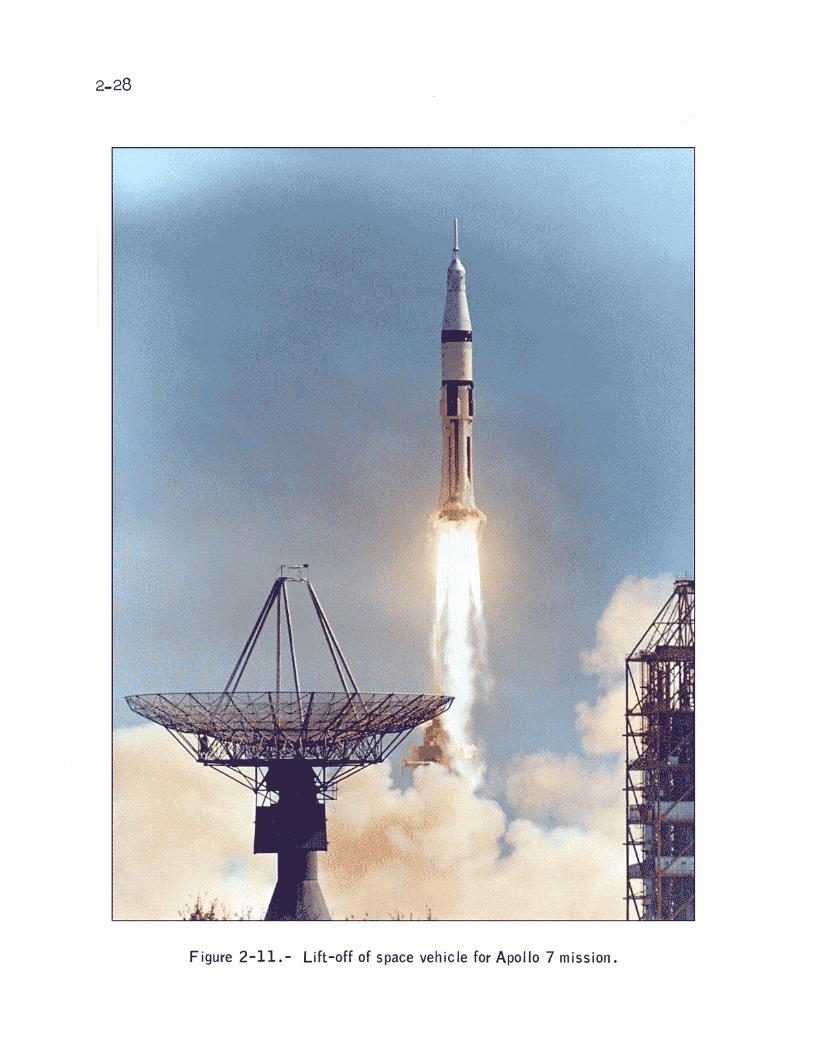
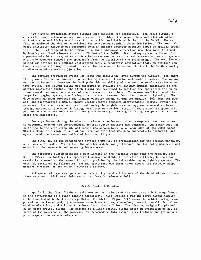
2-29
Two service propulsion system firings were required for rendezvous. The first firing, a corrective combination maneuver, was necessary to achieve the proper phase and altitude offset so that the second firing would result in an orbit coelliptic with that of the S-IVB. The two firings achieved the desired conditions for rendezvous terminal phase initiation. The terminal phase initiation maneuver was performed with an onboard cooputer solution based on optical tracking of the S-IVB stage with the sextant. A small midcourse correction was then made, followed by braking and final closure to within 70 feet of the S-IVB. Stationkeeping was performed for approximately 20 minutes, after which a 2-foot-per-second service module reaction control system posigrade maneuver removed the spacecraft from the vicinity of the S-IVB stage. The next 24-hour period was devoted to a sextant calibration test, a rendezvous navigation test, an attitude control test, and a primary evaporator test. The crew used the sextant to track the S-IVB visually to distances of as much as 320 miles.
The service propulsion system was fired six additional tioes during the mission. The third firing was a 9.1-second maneuver controlled by the stabilization and control system. The maneuver was performed to increase the backup deorbit capability of the service module reaction control system. The fourth firing was performed to evaluate the minimum-impulse capability of the service propulsion engine. The fifth firing was performed to position the spacecraft for an optimum deorbit maneuver at the end of the planned orbital phase. To assure verification of the propellant gaging system, the firing duration was increased from that planned originally. The 67.6-second maneuver produced the largest velocity change during the mission, 1693 feet per second, and incorporated a manual thrust -vector-control takeover approximately halfway through the maneuver. The sixth maneuver, performed during the eighth mission day, was a second minimumimpulse maneuver. The seventh firing, performed on the lOth mission day, placed the spacecraft perigee at the proper longitude for entry and recovery. The eighth firing was performed to deorbit the spacecraft.
Tests performed during the mission included a rendezvous radar transponder test and a test to determine whether the environmental control system radiator had degraded. The radar test was performed during revolution 48, and lockon was accomplished by a radar site at the White Sands
Missile Range at a range of 415 miles. The radiator test was also successfully conducted, and operation of the system was validated for lunar flight.
The final day of the mission was devoted primarily to preparations for the deorbit maneuver, which was performed at 259:39:16. The service module was jettisoned, and the entry was performed using both the automatic and manual guidance modes.
The parachute system effected a soft landing in the Atlantic Ocean near the recovery ship, U.S.S. Essex. On landing, the spacecraft assumed a stable II flotation attitude, but was successfully returned to the normal flotation position by the inflatable bag uprighting system. The crew was retrieved by helicopter, and the spacecraft was later taken aboard the recovery ship. Mission duration was 260 hours 9 minutes 3 seconds.
All spacecraft systems operated satisfactorily, and all but one of the detail�d test objectives were met. Additional information is given in reference 2-11.
2.4.3 Apollo 8 Mission
Apollo 8, the first flight to take men to the vicinity of the moon, was a bold step forward in the development of a lunar landing capability. Also, Apollo 8 was the first manned mission to be launched with the three-stage Saturn V vehicle. Figure 2-12 shows the vehicle being transported to the launch pad. The crewmen were Frank Borman, Commander; James A. Lovell, Jr., Command Module Pilot; and William A. Anders, Lunar Module Pilot. The mission, originally planned as an earth orbital flight, was changed to a lunar orbital flight after an evaluation of all aspects of the progress of the program. To accoomodate this change, crew training and ground support preparations were accelerated.


2-31
The primary objectives for the Apollo 8 mission were to demonstrate the combined performance of the crew, space vehicle, and mission support team during a manned Saturn V mission using the conunand and service module and to demonstrate the performance of nol!linal and selected backup lunar-orbit-rendezvous procedures. The spacecraft was a Block II command and service module. A lunar module test article was installed for mass loading purposes in the spacecraft/launch vehicle adapter in place of an actual lunar module.
The space vehicle was launched from Kennedy Space Center Launch Complex 39A at 07t51:00 a.m. e.s.t. (12:51:00 G.m.t.) on December 21, 1968, and the spacecraft was inserted into a 103- by 98-mile earth parking orbit. After th� spacecraft had been in earth orbit almost 3 hours for inflight systens checks, the translunar injection maneuver was performed. The spacec{aft was separated from the S-IVB approximately 25 minutes later using the service module reaction control system and was turned around to permit observation and photography of the S-IVB stage, The crew then performed two reaction control system maneuvers to increase the separation distance. A
ground-con:ananded liquid oxygen dump provided impulse for targeting the S-IVB stage to fly past the moon and into solar orbit.
The translunar injection maneuver was so accurate that only one small midcourse correction would have been sufficient to achieve t�e desired lunar orbit insertion altitude of approximately 65 miles. However, the second of the two �>neuver5 that separated the spacecraft from the S-IVB altered the trajectory so that a large midcourse correction at 11 hours was required to achieve the desired trajectory. For this midcourse correction, the service propulsion system was used to reduce the altitude of closest approach to the moon from 459 miles to 66.3 miles. An additional small midcourse correction was performed approximately 50 hours later to refine further the lunar insertion conditions. During t.
he 66-hour tran?lunar coast, the crew made systems checks and navigation sightings, tested the spacecraft high-gain antenna (installed for the first time on this mission), and televised pic�ures to earth.
Lunar orbit insertion was performed with the service propulsion system and the resultant orbit was 60 by 168.5 miles. After approximately 4 hours of navigation checks and ground-based determination of the·orbital parameters, a lunar orbit circularization maneuver was performed, which resulted in an orbit of 60.7 by.59.7 miles.
The next 12 hours of cre\.r activity in lunar orbit involved. photography of both the near and far sides of the moon, landing-area sightings, and television transMissions. Most remaining noncritical flight plan activities were deleted during the final 4 hours in orbit because of crew fatigue, and this period was devoted to crew rest and preparation for transearth injection, The injection maneuver was performed approximately 89 hours into the flight and resul ted in a velocity change of 3517 feet per second.
The transearth coast activities included star/horizon navigation sightings using both moon and earth horizons. Passive tl�r mal control, using a roll rate of approximately 1 revolution per hour, was used during most of the translunar and transearth coast phases to maintain nearly stable onboard temperatures. Only one small·transearth mi.dcourse correction, made with the service module reaction control system, was required.
Command module/service module separation was performed at approximately 146-1/2 hours, and command module entry occurred approximately 17 minutes later. The command module followed an automatically guided entry profile and landed in 'the Hid-Pacific after a flight duration of 147 hours 42 seconds. The transeartb injection targeting and separation and the entry guidance were so precise that the command module landed about 1 1/2 miles from the planned target point. The crew were retrieved and taken aboard the U.S.S. YorktOIJI'! at 17:20. G.m.t. on December 27, 1%8.
With only minor problems, all spacecraft systems operated as intended, and all primary mission objectives were successfully accomplished. Crew performance was admirable throughout the mission. The navigation techniques developed for translunar and lun�r orbital flight proved to. be more than adequate to maintain required accuracies for lunar orbit insertion and transearth injection. Communications and tracking at lunar distances were excellent in all modes. Additional infornation on the Apollo 8 mission is contained in reference 2-12.

2-32
2.4.4 Apollo 9 llission
The Apollo 9 mission was a 10-day flight in earth orbit to qualify the lunar module for lunar orbital operations. The crewmen were James A. McDivitt, Commander; David R. Scott, Command Module Pilot; and Russell L. Schweickart, Lunar Module Pilot. The primary objectives of the mission were (1) to demonstrate the performance of the crew, space vehicle, and mission support facilities during a manned Saturn V mission using the lunar module and the command and service module; (2) to demonstrate the ability of the crew to operate the lunar module systems for periods of time comparable to those of a lunar landing mission; and (3) to de�onstrate some of the nominal and backup lunar landing mission activities, including docking, intravehicular transfer, rendezvous, and extravehicular capability. To meet these objectives, the lunar module was evaluated during three separate manning periods that required multiple activation and deactivation of systems, a situation unique to this mission.
The space vehicle was launched from Launch Complex 39A at the Kennedy Space Center. The launch occurred on ��rch 3, 1969, at 11:00:00 a.m. e.s.t. (16:00:00 G.m.t.), and the insertion orbit was 102.3 by 103.9 miles. After postinsertiou checkout, the command and service module was separated from the S-IVB stage, transposed, and docked with the lunar module. At approximately 4 hours, an ejection mechanism, used for the first time on this mission, ejected the docked spacecraft from the S-IVB. After a separation maneuver, the S-IVB engine was fired twice by remote control, and the final maneuver placed the spent stage into a solar orbit.
Crew activity on the second day was devoted to systems checks and to three service propulsion system maneuvers while docked. On the third day, the Commander and the Lunar Nodule Pilot entered the lunar module to activate and check out the systems and to fire the descent engine with the vehicles still docked. Attitude control with the digital autopilot and manual throttling of the descent engine to full thrust were demonstrated.
Extravehicular operations were demonstrated on the fourth day of flight. The actual operations were abbreviated from those of the flight plan because of a minor inflight illness experienced by one cre1vmember on the preceding day and because of the many activities required for rendezvous preparation. \vearing the extravehicular mobility unit, the Lunar Uodule Pilot egressed the depressurized lunar module and remained near the hatch for approximately 47 minutes. During this same period, the Co=and Hodule Pilot, dependent on the command and service module systems for life support, partially exited through the command module hatch for observation, photography, and retrieval of thermal samples (fig. 2-13). The Lunar Hodule Pilot also retrieved thermal samples from the spacecraft exterior. A planned extravehicular transfer from the lunar module to the command module was not conducted because of the abbreviated operation.
On the fifth day, the Commander and the Lunar Nodule Pilot again transferred to the lunar module, this time to perform a lunar-module-active rendezvous. The lunar module primary guidance system was used throughout the rendezvous; howev�r, mirror-image backup maneuver computations were made in the command module. The lunar module descent pj:Opulsion system was used to perform the phasing and insertion maneuvers, and the ascent engine was used to establish a constant differential height after the coelliptic sequence had been initiated. After redocking and crew transfer back into the command module, the lunar roodule ascent stage was jettisoned and the ascent engine was fired to oxidizer depletion.
The sixth service propulsion maneuver, to lower the perigee, was performed successfully during the sixth day. In the final 4 days, a series of landmark tracking exercises and a multispectral photography experiment were performed.· The service propulsion system was fired for the seventh time at approximately 169-1/2 hours as a test and for the eighth time at 240-1/2 hours to deorbit the command and service module. This last maneuver was performed one revolution later than planned because of unfavorable weather in the planned recovery area. After a normal entry using the primary guidance system, the command roodule landed within 2.7 miles of the target point in the Atlantic Ocean after 241 hours 54 seconds of flight. The crewmen were recovered by helicopter and were aboard the primary recovery ship, the U.S.S. Cuadalcanal, 49 minutes after landing. Further details of the Apollo 9 mission are given in reference 2-13.


2-34
2.4.5 Apollo 10 Mission
Apollo 10 was an 8-day mission to qualify the combined spacecraft in the lunar environment. Particular primary objectives were to demonstrate the capability for rendezvous and docking in the lunar gravitational field and to evaluate docked and undockcd lunar navigation. The mission
events simulated those for a lunar landing mission. In addition, visual observations and stereoscopic strip photography of Apollo Landing Site 2, the planned location of the first lunar landing, were accomplished.
The Apollo 10 space vehicle, with crewmen Thomas P. Stafford, Commander; John W. Young, Command Module Pilot; and Eugene A. Cernan, Lunar Module Pilot; was launched on May 18, 1969, from Kennedy Space Center Launch Complex 39B at 11:4�:00 a.m. e.s.t. (16:49:00 G.m.t.). The spacecraft and S-IVB stage combination was inserted into an earth parking orbit of 102.6 by 99.6 mi.les. After onboard systems were checked, the S-IVB engine was ignited at 2-1/2 hours elapsed time to place the spacecraft on a translunar trajectory.
At 3 hours after lift-off, the conunand and service module was separated from the S-IVB stage and then transposed and docked with the lunar module. The docked spacecraft were ejected 40 minutes later, and a separation maneuver was performed. The S-IVB stage was placed into a solar orbit by ground command for propulsive venting of residual propellants.
A preplanned midcourse correction executed at 26-1/2 hours adjusted the trajectory to coincide with a July lunar landing trajectory. The passive thermal control technique was employed to maintain desired spacecraft temperatures throughout the translunar coast except when a spe
cific attitude was required.
At 76 hours mission elapsed time, the spacecraft was inserted into a lunar orbit of 60 by 171 nautical miles. After two revolutions of tracking and ground updates, a maneuver was performed to circularize the orbit at 60 nautical miles. The Lunar Module Pilot entered the lunar module, checked all systems, and then returned to the command module for the scheduled sleep period.
Activation of the lunar module systems began at 95 lwurs, and the spacecraft were undocked approximately 3 hours later. Figure 2-14 shows the command and service module as viewed from the lunar module. After stationkeeping, the lunar module was inserted into the descent orbit. An hour later, the lunar module made a low-level pass over Apollo Landing Site 2. The pass was highlighted by a test of the landing radar, by the visual observation of lunar lighting, by stereoscopic strip photography, and by the execution of the phasing maneuver using the descent engine. The lowest measured point in the trajectory was 47 400 feet above the lunar surface. After one revolution in the phasing orbit of approximately 8 by 194 miles, the lunar module ascent stage was separated from the descent stage and the ascent engine was used to perform an insertion maneuver. The rendezvous that foliowed was representative of one that would follow a normal ascent from the lunar surface. The rendezvous operation commenced with the lunar module coelliptic sequence initiation maneuver approximately one-half revolution from insertion, followed by a small constant differential height maneuver and the terminal phase initiation maneuver. Docking was complete at 106-1/2 hours, and the·lunar module crew transferred into the command module. The lunar module ascent stage was jettisoned, and the ascent engine was fired by remote control to propellant depletion at 109 hours. After a rest period, the crew conducted landmark tracking and photography exercises. Transearth injection was performed at 137-1/2 hours.
The passive thermal control technique and the navigation procedures used on the translunar portion of flight were also used during the earth return. Only one midcourse correction of approximately 2 feet per second was required; this correction was made 3 hours before command module/service module separation. The command module entry was normal, and the spacecraft landed near the primary recovery vessel, the U.S.S. Pr-inaeton, after an elapsed flight time of 192 hours 3 minutes and 23 seconds. At daybreak, the crewmen were retrieved by helicopter.
All systems in the command and service module and the lunar module were managed very well. Although some problems occurred, most were minor and none caused a constraint to completion of mission objectives. Valuable data concerning lunar gravitation were obtained during the 60 hours in lunar orbit.


2-36
Spacecraft systems performance was satisfactory, and all mission objectives were accomplished (ref. 2-14). All detailed test objectives were satisfied with the exception of the lunar module steerable antenna and relay modes for voice and telemetry communications.
2.4.6 Apollo 11 Mission
The Apollo ll mission accomplished the basic objective of the Apollo program; that is landing two men on the lunar surface and returning them safely to earth. Crewmembers for this historic mission were Neil A. Armstrong, Commander; Michael Collins, Command Module Pilot; and Edwin E. Aldrin, Jr. , Lunar Hodule Pilot.
The Apollo 11 space vehicle was launched from Kennedy Space Center Launch Complex 39A o n July 16, 1969, a t 08:32:00 a.m. e.s.t. (13:32:00 G.m.t.). The spacecraft and S-IVB stage of the launch vehicle were inserted into a 100.7- by 99.2-mile earth parking orbit. After a ·2-1/2-hour checkout period, the spacecraft/S-IVB stage combination was injected into the translunar coast phase of the mission. Trajectory parameters after the translunar injection firing were nearly perfect. A midcourse correction of 20.9 feet per second was made during the translunar phase. During the remaining periods of free-attitude flight, passive thermal control was used to maintain spacecraft temperatures within desired limits. The Commander and the Lunar Module Pilot transferred to the lunar module during the translunar phase to make the initial inspection and preparations for the systems checks that would be made shortly after lunar-orbit insertion.
The docked spacecraft were inserted into a 60- by 169.7-mile lunar orbit at approximately 76 hours after launch. Four hours later, the lunar-orbit circularization maneuver was performed to place the combined spacecraft in a 65.7- by 53.8-mile lunar orbit. The Lunar Module Pilot entered the lunar module at approximately 81 hours after launch for initial powerup and systems checks. After a planned sleep period was completed at 93-1/2 hours elapsed time, the lunar module crewmen transferred to the lunar module and made final preparations for descent to the lunar surface. The lunar module was undocked from the command and service module at a mission time of approximately 100 hours. The lunar module descent orbit insertion maneuver was performed with the descent propulsion system at 101-1/2 hours into the mission, and the powered descent initiation occurred 1 hour later. The lunar module was maneuvered manually approximately 1100 feet down range from the preplanned landing point during the final 2-1/2 minutes of descent.
Man first landed on the moon at 03:17 p.m. e.s.t. on July 20, 1969, 102 hours 45 minutes 39.9 seconds mission elapsed time. The spacecraft landed in ��re Tranquillitatis (Sea of Tranquillity) at latitude 0°41'15" N. and longitude 23°26' E. based upon the coordinates of reference 2-15. After a 2-hour postlanding checkout of all lunar module systems, the crew configured the spacecraft controls for lunar stay and ate their first meal on the lunar surface. A crew rest period had been planned to precede the extravehicular activity of exploring the lunar surface but was not needed. After donning the back-mounted portable life support and oxygen purge systems the Commander egressed through the forward hatch and deployed an equipment module from the descent stage. A camera in the equipment module provided live television coverage of the Commander as he descended the ladder to the surface. The Commander made first contact at 09:56:15 p.m. e.s.t. on July 20, 1969, or 109 hours 56 minutes 15 seconds into the mission. The Lunar Module Pilot egressed soon thereafter, and both crewmen used the initial period on the surface to become acclimated to the reduced gravity and the unfamiliar surface conditions. A contingency soil sample was taken from the surface, and the television camera was deployed to include most of the lunar module in the field of view. Figure 2-15 is a photograph of the Commander as he stood beside the deployed United States flag during this part of the extravehicular activity. The crew then activated scientific experiments which included a solar wind detector, a passive seismometer, and a laser retroreflector. The Lunar Module Pilot evaluated his ability to operate and move about, and he was able to do so rapidly and confidently. The crew collected approximately 21 kilograms of lunar surface material for analysis. The surface exploration was concluded in the allotted time of 2-1/2 hours, and the crewmen reentered the lunar module at a mission time of 111-1/2 hours.
After a rest period, ascent preparation was conducted and the ascent stage lifted off the surface at 124-1/4 hours from earth launch. A nominal firing of the ascent engine placed the vehicle into a 45- by 9-mile orbit. After a rendezvous sequence similar to that performed on Apollo 10, the two spacecraft were docked at the mission time of 128 hours. After transfer of the crew and samples to the co11111and and service module, the ascent stage was jettisoned, and the command and service module was prepared for transearth injection.

Figure 2-15.- Apollo 11 Lunar Module Pilot on the Lunar surface

2-38
The return flight started with a 150-second firing of the service propulsion engine during the 31st lunar revolution at 135-1/2 hours into the mission. As in translunar flight, only one midcourse correction was required, and passive thermal control was exercised for most of the transearth coast. Because of inclement weather in the planned recovery area, the landing point was moved 215 miles down range. The service module was separated from the command module 15 minutes before reaching the entry interface altitude of 400 000 feet. Following an automatic entry sequence and landing system deployment, the command module landed in the Pacific Ocean after a flight duration of 195 hours 18 minutes 35 seconds. The landing coordinates, as determined from the spacecraft computer, were latitude 13°19' N. and longitude 169°91 W.
After landing, the crew donned biological isolation garments; they were then retrieved by helicopter and taken to the primary recovery ship, the u.s.s. Hornet. The crew and lunar material samples were placed in a mobile quarantine facility for transport to the Lunar Receiving Laboratory in Houston.
All spacecraft systems performed satisfactorily and, with the completion of the Apollo 11, mission, the national objective of landing men on the moon and returning them safely to earth, before the end of the decade, was accoMplished. Additional information on the Apollo 11 mission is given in references 2-16 and 2-17.
2.4.7 Apollo 12 Mission
Apollo 12, the second lunar landing mission, demonstrated the capability to land at a precise point and on a rough lunar surface. The landing location was in the Oceanus Procellarum (Ocean of Storms) region. The primary objectives assigned were (1) to perform selenological inspection, survey, and sampling in a mare area; (2) to deploy the Apollo lunar surface experiments package; (3) to develop techniques for a point landing capability; (4) to develop further man's capability to work in the lunar environment; and (5) to obtain photographs of candidate exploration sites.
The space vehicle, with crewmen Charles Conrad, Jr., Commander; Richard F. Gordon, Jr., Command Module Pilot; and Alan L. Bean, Lunar Module Pilot, was launched from Kennedy Space Center Launch Complex 39A at 11:22:00 a.m. e.s.t. (16:22:00 G.m.t.) on November 14, 1969. The activities during earth-orbit checkout, translunar injection, and translunar coast were similar to those of Apollo 11, except for the special attention given to verifying all spacecraft systems as a result of lightning strikes on the space vehicle at 36.5 seconds and again at 52 seconds after launch. A non-free-return translunar trajectory profile was used for the first time in the Apollo program.
The docked command and service module and lunar module were inserted into a 168.8- by 62.6-mile lunar orbit at approximately 83-1/2 hours into the mission. Two revolutions later, a second maneuver was performed to achieve a 66.1- by 54.3-mile orbit. At approximately 104 hours after launch, the Commander and the Lunar Module Pilot entered the lunar module to prepare for descent to the lunar surface. About 4 hours later, the two spacecraft were undocked and descent orbit insertion was performed. A precision landing was accomplished through automatic guidance, with small manual corrections applied in the final phases of descent. The spa.cecraft touched down 110 hours 32 minutes 36 seconds into the mission, with landing coordinates of latitude 3°11'51" S. and longitude 23°23'8" w. (ref. 2-18). One objective of the Apollo 12 mission was to achieve a precision landing near the Surveyor III spacecraft, which had landed on April 20, 1967. The Apollo 12 landing point was 535 feet from the Surveyor III.
Three hours after landing, the crewmen began preparations for egress. As the Commander descended the ladder to the lunar surface, he deployed the modularized equipment stowage assembly which automatically activated a color television camera and permitted his actions to be televised to earth, The television camera was subsequently damaged. After the Lunar Module Pilot had descended to the surface, he erected a solar wind composition experiment. Both crewmen then deployed the first Apollo lunar surface experiments package. On the return traverse, the crew collected a core-tube sample and additional surface samples. The first extravehicular activity period lasted 4 hours.

2-39
The second extravehicular activity period began after a 7-hour rest period. Documented samples, core-tube samples, trench-site samples, and gas-analysis samples were collected on a traverse to the Surveyor III spacecraft. The crew photographed and removed parts from the Surveyor (fig. 2-16). After the return traverse, the crew retrieved the solar wind composition experiment.
The second extravehicular activity period lasted 3-3/4 hours. Crew mobility and portable life support system operation, as in Apollo 11, were excellent throughout both extravehicular periods. The Surveyor parts and approximately 34 kilograms of lunar material were returned to earth.
The lunar module ascent stage lifted off the lunar surface at a mission elapsed time of 142 hours. After a norainal rendezvous sequence, the two spacecraft were docked at 145-1/2 hours into the mission. The ascent stage, jettisoned after crew and sample transfer to the command module, was maneuvered by remote control to impact on the lunar surface; impact occurred at a mission time of 150 hours approximately 40 miles from the Apollo 12 landing site. Extensive landmark tracking and photography from lunar orbit was then conducted using a 500-mm long-range lens to obtain mapping and training data for future missions. At 172-1/2 hours into the mission, transearth injection was accomplished by using the service propulsi.on system engine.
Two small midcourse corrections were executed during transearth coast. The entry sequence was normal, and the cor.anand roodule landed in the Pacific Ocean. The landing coordinates, as determined from the onboard computer, were latitude 15°52' S. and longitude 165°10' W. Duration of the mission was 244 hours 36 minutes 25 seconds. After landing, biological isolation precautions similar to those of Apollo 11 were taken. The crew, the lunar material samples, and the spacecraft were subsequently transported to the Lunar Receiving Laboratory.
All spacecraft systems operated satisfactorily, and all primary mission objectives were accomplished. Additional information concerning the Apollo 12 mission is contained in references 2-19 and 2-20.
2.4.8 Apollo 13 Mission
Apollo 13, planned as the third lunar landing mission, was aborted during translunar flight because of the loss of all the oxygen stored in two tanks in the service module. The primary objectives assigned to the mission were (1) to perform selenological inspection, survey, and sampling of materials in a preselected region of the Fra Hauro formation; (2) to deploy and activate an Apollo lunar surface experiments package; (3) to develop further man's capability to work in the lunar environment; and (4) to obtain photographs of candidate exploration sites.
The launch vehicle and spacecraft were similar to those of Apollo 12; however, the experiment complement was somewhat different. The crewmembers were James A. Lovell, Jr., Commander; Fred w. Haise, Jr., Lunar Module Pilot; and John L. Swigert, Jr., who had been the backup Command Module Pilot until the day before launch. Because the prime ColTinand Hodule Pilot had been exposed to German measles 8 days before the scheduled launch date and was shown during his preflight physical examination to be susceptible to the disease, the decision was made to replace him with the backup pilot as a precautionary measure.
The space vehicle was launched from Kennedy Space Center Launch Complex 39A at 02:13:00 p.m. e.s.t. (19:13:00 G.m.t.) on April 11, 1970. During the launch, the second-stage inboard engine shut down early because of high-amplitude longitudinal oscillations; however, near-nominal trajectory parameters were achieved at orbital insertion. The earth orbital, translunar injection, and early translunar coast phases of flight were noi111al, and operations during these periods were similar to those of Apollo 11 and Apollo 12 with one exception. On previous lunar missions, the S-IVB stage had been maneuvered by ground command into a trajectory such that it would pass by the moon and go into a solar orbit. For Apollo 13, the S-IVB was targeted to hit the moon so that the vibrations resulting from the impact could be sensed by the Apollo 12 seismic station and telemetered to earth for study. The S-IVB impacted the lunar surface about 78 hours after launch, approximately 140 kilometers west-northwest of the Apollo 12 experiment station. The impact point was very close to the desired target.
Photographs of the earth were taken during the early part of translunar coast to support an analysis of atmospheric winds. After approximately 31 hours of flight, a midcourse correction lowered the closest point of spacecraft approach to the moon to an altitude of approximately 60 miles. Before this maneuver, the spacecraft had been on a free-return trajectory, that is, one


2-41
on which the spacecraft would have looped around the moon and returned to earth without requiring a major maneuver. At approximately 56 hours, one of the two cryogenic oxygen tanks in the service module failed. (The cause of the failure is discussed in ref. 2-21. ). The immediate result was that the oxygen in the failed tank was abruptly lost. Later, ·i t was discovered that the panel had been blown off the bay in which the tank was located (fig. 2-17). The oxygen system with which the second tank was associated also lost pressure, but at a slower rate. These tanks contained most of the oxygen for breathing in the command module and the oxygen for the fuel cells (the primary source of electrical power). Sufficient oxygen remained in the second tank to maintain primary electrical power in the co=and and service module for app.roximately 2 hours, which gave the crew time to power up the lunar module, align the inertial reference platform, and shut down the command and service module systems. The docked spacecraft were then maneuvered back into a free-return trajectory using the_lunar module descent engine.
From this point on, all systems in both vehicles were po1vered down except when absolutely required. With no further maneuvers, the command module could have landed in the Indian Ocean at 152 hours mission elapsed time, and the lunar module systems would have been required to support the crew for about 90 hours. However, because consumables were extremely marginal under these conditions and because only minimal recovery support existed in the Indian Ocean, a transearth injection maneuver using the lunar module descent propulsion system was executed to speed up the return to earth after the docked spacecraft had swung around the far side of the moon. Because of this maneuver, the landing was predicted to occur at about 143 hours mission elapsed time in the South Pacific, where primary recovery support was available. Guidance errors during the transearth injection maneuver necessitated a smail transearth midcourse correction at approximately 105 hours to bring the projected entry flight-path angle within the specified limits. During the transearth coast period, the docked spacecraft were maneuvered into a passive thermal control mode.
The unprecedented powered-down state of the command module required several new procedures for entry. The command module was briefly powered up to assess the operational capability of critical systems. Also, tbe command module entry batteries were charged through the umbilical connectors that had supplied any necessary power from the lunar module while the command module was powered down. Approximately 6 hours before entry, the passive thermal control mode was discontinued, and a final midcourse correction was made using the lunar module reaction control system to refine the flight-path angle slightly.
The service module was separated 4-3/4 hours before entry; the separation afforded the crew an opportunity to observe .and photograph the damage caused by the failed oxygen tank. The lunar module was retained until 70 minutes before entry to minimize usage of command module electrical power. At undocking, normal tunnel pressure provided the necessary force to separate the two spacecraft. From this point, the events were similar to those of previous flights·, and the command 1110dule landeQ approximately 1 mile from the target point. Some pieces of the lunar module survived entry and projected trajectory data iooicated that they impacted in .the ·open sea between Samoa and. New Zealand. The three crewmen were on board the recovery ship, the U.S.S. Iwo Jima, within 4S minutes of landing. Reference 2-22 contains details of the Apollo 13 mission.
2.4.9 Apollo 14 Mission
.Apollo 14 was the third mission to achieve a lunar landing. The landing site was located in the Fra Mauro highlands, the same area that was to have been explored on Apollo 13. Although the primary mission objectives for-Apollo 14 were the same as those of Apollo 13, provisions were made for returning a significantly greater quantity of lunar material and scientific data than had been possible previously. An innovation that allowed an increase in the range of lunar surface exploration and in the amount of material collected was the provision of a collapsible twowheeled cart, the modular equipment transporter, for carrying tools, cameras, a portable magnetometer, and lunar samples (fig. 2-18).
An investigation into the cause of the Apollo 13 cryogenic oxygen tank failure led to three significant changes in the command and service module cryogenic oxygen storag.e and electrical power systems. The internal construction of the oxygen tanks was modified, a third oxygen tank was added, and an auxiliary battery was installed. These changes were also incorporated into all subsequent spacecraft.


2-44
The mission, manned by Alan B. Shepard, Jr., Commander; Stuart A. Roosa, Command Module Pilot; and Edgar D. Mitchell, Lunar Module Pilot, was launched from Kennedy Space Center Launch Complex 39A at 04:03:02 p.m. e.s.t. (21:03:02 G.m.t.) on January 31, 1971. Because of weather conditions which might have triggered lightning, the launch was delayed approximately 40 minutes. The operations in earth orbit and translunar injection were similar to those of previous lunar missions; however, after translunar injection, several docking attempts were made before the command and service oodule was successfully docked with the lunar module.
As on Apollo 13, the S-IVB stage was targeted to impact the moon within a prescribed area to supply seismic data. The vehicle struck the lunar surface approximately 160 miles from the target, within the desired area, at 82:37:52 mission elapsed time. The Apollo 12 seismic station, located approximately 94 miles southwest of the impact point, recorded the event 37 seconds later and responded to vibrations for more than 3 hours.
Translunar activities included star and earth horizon calibration sightings in preparation for a cislunar navigation exercise to be performed during transearth coast, and dim-light photography of the earth. At approximately 61 hours, the lunar toodule crew spent approximately 2 hours in the lunar oodule cabin for housekeeping and systems checkout. While there, the crew photographed a waste-water dump from the command module to obtain data for a particle contamination study being conducted for the Skylab program. Two spacecraft translunar midcourse corrections achieved the traje�tory desired for lunar-orbit insertion.
The joined spacecraft were inserted into a 169- by 58-mile lunar orbit with the service propulsion system. After two revolutions, the same propulsion system was used to insert the spacecraft into the descent orbit, which brought the docked vehicles to within 10 miles of the lunar surface. On previous missions, the descent orbit insertion maneuver had been performed with the lunar module descent propulsion system. A change was made on this mission to allow a greater margin of lunar module propellant for landing in a toore rugged area.
The Commander and Lunar Module Pilot entered the lunar toodule, performed systems checks, and undocked during the 12th lunar revolution. After vehicle separation and before powered descent, ground personnel detected the presence of an abort command at a computer input channel although the crew had not depressed the abort switch, The failure was isolated to the abort switch, and, to prevent an unwanted abort, a workaround procedure was developed. The procedure was followed, and the powered descent was performed successfully. The vehicle touched down 12 minutes 45 seconds after engine ignition and came to rest on a slope of about 7 degrees. Sufficient propellant remained for approximately 70 additional seconds of engine firing time. The coordinates of the landing site are latitude 3°40'24" s. and longitude 17°27'55" W. based upon reference 2-23.
After undocking and separation, the command-and-service-module orbit was circularized to an altitude of approximately 60 miles. While the landing crew was on the lunar surface, the Command Module Pilot performed tasks to obtain data for scientific analyses and future mission planning. These tasks included orbital science photography of the lunar surface, photography of the proposed Descartes landing site for site selection studies, photosraphy of the lunar surface under high-sun-angle lighting conditions for operational plannins, photography of low-brightness astronomical light sources, and photosraphy of the Gegenschein and Houlton Point regions.
Preparations for the initial period of lunar surface exploration began approximately 2 hours after landing, and the crew egressed about 5-1/2 hours after landing. During the 4-3/4-hour extravehicular period, the crew deployed and loaded the modular equipment transporter; collected samples; photographed activities, panoramas, and equipment; and deployed the second Apollo lunar surface experiments package.
After a rest period of approximately 6-1/2 hours, the crew prepared to travel to the area of Cone Crater, approximately 1.3 kilometers east-northeast of the landing site. Although the cretv experienced difficulties in navigating, they reached a point within approximately 15 meters of the rim of the crater, and the objectives associated with reaching the vicinity of this crater were achieved. Various rock and soil samples were collected near Cone Crater, and, on the return to the lunar module, the crew also obtained magnetometer measurements at two sites along the traverse. This second extravehicular period lasted approxinately 4-1/2 hours for a total extravehicular time of approximately 9-1/4 hours. Approxifi�tely 43 kilograms of lunar samples were collected during the two periods.

2-45
The lunar module ascent stage lifted off after a surface stay time of 33-1/2 hours, and the vehicle was inserted into a 51.7- by 8.5-mile orbit. A direct rendezvous was performed (the first use of a direct rendezvous in the Apollo program), and the comnand-module-active docking operations were normal. After crew and sample transfer to the cocrmand module, the ascent stage was jettisoned and a pre-programmed maneuver caused lunar impact approximately 36 miles west of the Apollo 14 landing site. On previous lunar missions. lunar surface dust adhering to equipment being returned to earth had created a problem. Special dust control procedures used on this mission, however, effectively decreased the amount of dust in the cabins.
Transearth injection occurred during the 34th lunar revolution. During transearth coast, one midcourse correction was made using the service module reaction control system. In addition, a special oxygen flow-rate test was performed to evaluate the system for planned extravehicular activities on subsequent flights, and a navigation exercise simulating a return to earth without ground control was conducted using only the guidance and navigation system. Inflight demonstrations of electrophoretic separation, liquid transfer, heat flow and convection, and composite casting under zero-gravity conditions \�ere also perforr.ted and televised to earth.
Entry was normal and the cocrmand module landed in the Pacific Ocean at 216:01:58 mission elapsed time. The crewmen were retrieved by helicopter and were aboard the primary recovery ship, u.s.s. New 0Pleans, approxiMately 48 minutes after landing.
As was the case following the Apollo ll and Apollo 12 missions, the Apollo 14 crew and lunar samples were isolated and tests conducted to assure that they were not biologically hazardous. The test protocols showed no evidence of lunar micro-organisms at the three sites explored, and this was considered to be sufficient justification for discontinuance of the quarantine procedures.
All of the objectives and experiment operations were accomplished satisfactorily except for some desired photography that could not be obtained. Details of the mission are given in reference 2-24 and preliminary scientific results in reference 2-25.
2.4.10 Apollo 15 Nission
Apollo 15 was the first of the three J m.issions (appendix B) designed to conduct exploration of the moon over longer periods, over greater ranges, and with more instruments for scientific data acquisition than on previous Apollo missions. Major modifications and augmentations to the basic Apollo hardware were made. The most significant change was the installation of a scientific instrument module in one of the service module bays for scientific investigations from lunar orbit. Other hard.ware changes consisted of lunar !!lOd\lle !llQd;iJ;i,cations to accomodate a greater payload and permit a longer stay on the lunar surface, and the provision of a lunar roving vehicle (fig. 2-19). The landing site chosen for the mission was an area near the foot of the Montes Apenninus (Apennine Mountains) and adjacent to Hadley Rille. The primary objectives assigned to the Apollo 15 mission were: (1) to perform selenological inspection, survey, and sampling of materials and surface features in a preselected area of the Hadley-Apenninus region; (2) to emplace and activate surface experiments; (3) to evaluate the capability of the Apollo equipment to provide extended lunar surface stay time, increased extravehicular operations, and surface mobility; and (4) to conduct inflight experitnents and photographic tasks from lunar orbit.
The space vehicle was launched from the Kennedy Space Center Launch Complex 39A at 09:34:00.6 a.m. e.d.t. (13:34:00.6 G.m.t.) on July 26, 1971. The spacecraft was manned by David R. Scott, Commander; Alfred M. Worden, Command Hodule Pilot; and James B. Irwin, Lunar Module Pilot. The spacecraft/S-IVB combination was inserted into an earth parking orbit approximately 11 minutes 44 seconds after lift-off. The S-IVB restart for translunar injection was initiated during the second revolution at approximately 2 hours 50 minutes mission elapsed time. The maneuver placed the spacecraft/S-IVB combination on a translunar trajectory that would allow return to an acceptable earth-entry corridor using the service module reaction control system engines. Approximately 27 minutes after injection into the translunar trajectory, the command and service module was separated from the S-IVB and docked with the lunar module. The lunar module was then extracted from the spacecraft/launch vehicle adapter. Shortly thereafter, the S-IVB tanks were vented and the auxiliary propulsion system was fired to target the S-IVB for a lunar impact. The impact of the S-IVB stage was sensed by the Apollo 12 and 14 lunar surface seismometers.

2-46
Figure 2-19.- Apollo 15 Lunar Module Pilot working at the lunar roving vehicle

2-47
The docked spacecraft were inserted into a lunar orbit of approximately 170 by 57 miles and about 4 hours later, injected into a 58- by 10-mile orbit. Lunar module undocking and separation were performed at approximately 100 hours 39 minutes into the mission. The command and service module was then placed in a near-circular lunar orbit in preparation for the acquisition of scientific data.
The lunar module touched down on the lunar surface approximately 1800 feet from the planned target point at 104 hours 42 minutes 29 seconds after lift-off. The landing point was latitude 26°6'3" N. and longitude 3°39'10'' E. based on the coordinates of reference 2-26. Sufficient descent stage propellant remained after lunar touchdown to have provided a hover time capability of about 103 seconds.
Approximately 2 hours after landing, the Commander photographed and described the area surrounding the landing site by standing in the open top hatch. This extravehicular activity period lasted approximately 33 minutes. The first lunar surface extravehicular activity was initiated about 12-1/2 hours later. During the surface operations, the crew collected and stowed a contingency sample, deployed the lunar roving vehicle, unst01·1ed the third Apollo lunar surface experiments package and other equipment, and configured the lunar roving vehicle for lunar surface operations. Some problems were experienced in deploying and checking out the lunar roving vehicle, but these problems were worked out. The crew then drove the vehicle to Elbo1� Crater where they collected and documented samples and gave an enthusiastic and informative commentary on lunar features. The �fission Control Center provided television control during various stops. After obtaining additional samples and photographs near St. George Crater, the crew returned to the lunar module using the lunar roving vehicle navigation system. The distance driven was approximately 10.3 kilometers. The crew then proceeded to the selected Apollo lunar surface experiments package deployment site, approximately 110 meters west-northwest of the lunar module. There, the experiments were deployed essentially as planned, except that the second heat-flow experiment probe was not emplaced because drilling was more difficult than expected and the hole was not completed. The first extravehicular activity lasted approximately 6 hours 33 minutes.
The crew spent approximately 16 hours in the cabin betHeen the first and second extravehicular periods. On egress for the second extravehicular activity, the lunar roving vehicle was checked out and prepared for the second traverse. The first stage of the 12.5-kilometer round trip was south to the Apennine front, but east of the first traverse. Stops were nade at Spur Crater and other points along the base of the front, as well as at Dune Crater on the return trip. The return route closely followed the outbound route. Documented samples, a core sample, and a comprehensive sample were collected, and photographs were taken. After reaching the lunar module, the crew returned to the experiments package site where the Commander completed drilling the second hole for the heat flow experiment and emplaced the probe. During this period, the Lunar Module Pilot performed soil mechanics tasks. The Commander also drilled to obtain a deepcore sample but terminated the drilling because of time constraints. The crew then returned to the lunar module and deployed the United States flag . The second extravehicular activity ended
after approximately 7 hours 12 minutes.
The crew spent almost 14 hours in the cabin after the second extravehicular period. The third extravehicular activity began later than originally planned to allow additional time for cre1v rest. Because of this delay and later delays at the experir.�ents package site, the planned trip to the North Complex was deleted. The first stop was at the experiments package site to retrieve the deep-core sample. Two core sections were disengaged, but the drill and the remaining four sections could not be separated and were left for later retrieval. The third geologic traverse took a westerly direction and included stops at Scarp Crater, Rim Crater, and the Terrace, an area along the ri.m of Hadley Rille. Extensive samples and a double-core-tube sample were obtained. Photographs were taken of the west wall of Hadley Rille, where exposed layering was observed. The return trip was east toward the lunar module with a stop at the experiments package site to retrieve the remaining sections of the deep-core sample. One more section was separated, and the remaining three sections were returned in one piece. After returning to the lunar module, the lunar roving vehicle was unloaded and parked for ground-controlled television coverage of the lunar module ascent. A distance of approximately 5.1 kilometers was traveled during the third extravehicular activity, which lasted approximately 4 hours 50 minutes. The total distance traveled with the lunar roving vehicle during the three extravehicular periods was 27.9 kilometers, and the total weight of lunar samples collected was approximately 77 kilograms. The areas traversed on the lunar surface are illustrated in section 3.2.1

2-48
While the lunar module was on the surface, the Connnand Hodule 'Pilot completed 34 lunar orbits conducting scientific instrument module experiments and operating cameras to obtain data concerning the lunar surface and the lunar environment. Some scientific tasks accomplished during this time were photographing the sunlit lunar surface, gathering data needed for mapping the bulk chemical composition of the lunar surface and for determining the geometry of the moon along the ground track, visually surveying regions of the moon to assist in identifying processes that formed geologic features, obtaining lunar atmospheric data, and surveying gamma-ray and X-ray sources. High-resolution photographs were obtained with the panoramic and mapping cameras during the m.ission.
The ascent stage lifted off after 66 hours 54 minutes 53 seconds on the lunar surface. The mission elapsed time of lift-off was 171 hours 37 m.inutes 23 seconds. A nominal lunar-moduleactive rendezvous was performed followed by docking at approximately 173 hours 36 minutes.
The lunar module ascent stage was jettisoned at approximately 179 hours 30 minutes into the mission. Jettison had been delayed one revolution later than planned because of some difficulty with verifying the spacecraft tunnel sealing and astronaut pressure suit integrity. Approximately 1-1/2 hours later, the lunar module was deorbited with lunar impact occurring at latitude 26°21' N. and longitude 0°15' E. Impact was approximately 23-1/2 kilometers from the planned point and approximately 93 kilometers west of the Apollo 15 landing site. The impact was recorded by the Apollo 12, 14, and 15 lunar surface seismic stations.
Before the connnand and service module was maneuvered from lunar orbit, a subsatellite was deployed in an orbit of approximately 76 by 55 m.iles. The subsatellite was instrumented to measure plasma and energetic-particle fluxes, vector magnetic fields, and subsatellite velocity from which lunar gravitational anomalies could be deternined. All systems operated as expected. The transearth injection maneuver was initiated approximately 223 hours 49 minutes into the mission.
At a rn.ission time of approximately 242 hours, a transearth coast extravehicular activity began. Television coverage was provided for the 39-minute extravehicular period during which the Conmand Module Pilot retrieved film cassettes and examined the scientific instrument module for possible abnormalities. Total extravehicular time during the mission was 19 hours 47 minutes.
A small midcourse correction of 5.6 feet per second was performed at the seventh midcourse correction opportunity. The command module was separated from the service module as planned, and a normal entry followed with the spacecraft being observed on the main parachutes from the recovery ship, U.S.S. Okinawa. During the descent, one of the three main parachutes failed, but a safe landing was made. The best estimate of the landing coordinates was latitude 26°7'48" N. and longitude 158°8124" w., approximately 1 mile from the planned landing point. The crew was brought on board the recovery ship by helicopter about 39 minutes after landing. Duration of the mission was 295 hours 11 minutes 53 seconds.
The mission accomplished all primary objectives and provided scientists with a large amount of new information concerning the moon and its characteristics. References 2-27 and 2-28 provide details on the performance of the systems and the preliminary results of the experiments.
2.4. 11 Apollo 16 Hission
Apollo 16 was the second in the series of lunar landing missions designed to optimize the capability for scientific return. The vehicles and payload were similar to those of Apollo 15. Primary objectives assigned were (1) to perform selenological inspection, survey, and sampling of materials and surface features in a preselected area of the Descartes region of the moon; (2) to emplace and activate surface experiments; and (3) to conduct inflight experiments and photographic tasks.
The space vehicle was launched from Kennedy Space Center Launch Complex 39A at 12:54:00 p.m. e.s.t. (17:54:00 G.m.t.) on April 16, 1972. The crewmen for the mission were John W. Young, Commander; Thomas K. Mattingly II, Command Module Pilot; and Charles M. Duke, Jr., Lunar Hodule Pilot. The launch was normal, and the spacecraft, the launch vehicle third stage (S-IVB), and the instrument unit were inserted into earth orbit for systems checkout before the vehicle was committed to translunar flight. The launch sequence was similar to that described previously for a Saturn V launch.

Translunar injection was initiated during the second revolution in earth orbit. The spacecraft separation, transposition, docking, and ejection operations were performed successfully, and, on ground command, the S-IVB was maneuvered to reduce the probability of recontact with the spacecraft. Approximately 20 minutes later, the propulsive force from a liquid-oxygen dump was used to target the S-IVB for impact on the moon near the Apollo 12 landing site. As on the three previous missions, S-IVB impact was desired to produce seismic vibrations that could be used to study the nature of the lunar interior structure. Although launch vehicle systems malfunctions precluded a planned trajectory refinement, the impact point was within the desired area. However, loss of S-IVB stage telemetry prevented establishment of the precise time of impact, thereby making the interpretation of seismic data uncertain.
During translunar coast, a false gimbal lock warning was issued by the command module computer. To prevent the inertial platform from being caged during critical operations, a procedure was developed to inhibit the computer from responding to the false indications. Activities during translunar coast included a navigation exercise, ultraviolet photography, a demonstration of the effects of zero gravity on the process of electrophoresis, and the first of two sessions to acquire data to be used in trying to determine the mechanisms involved in the production of light flashes seen by some crewmen on previous flights.
The crew inserted the docked spacecraft into lunar orbit by firing the service propulsion system engine in the retrograde direction. The initial 170- by 58-mile orbit was maintained for two revolutions. The crew then inserted the spacecraft into a descent orbit that took them within approximately 10 miles of the surface. After three revolutions the lunar module crew undocked and separated the spacecraft in preparation for the lunar landing. Figure 2-20 shows the lunar module just after undocking.
As the Command Module Pilot prepared to transfer his spacecraft to a circular lunar orbit, oscillations were detected in a secondary system that controlled the direction of thrust of the service propulsion system engine. The spacecraft was maneuvered to place it close to the lunar module while the problem was being evaluated. Tests and analyses showed that the system was still usable and safe; therefore, the vehicles \.�ere separated again, and the mission continued on a revised time line. The command and service module circularization maneuver was performed successfully with the primary system.
After devoting approximately 5-3/4 hours to evaluation of the secondary control system problem, powered descent of the lunar module was initiated. The lunar module landed approximately 270 meters northwest of the planned landing site. The location of the landing site is latitude
8°59'29" S. and longitude 15°30'52" E. based on the c<;>ordinates of reference 2-29. Propellant for approximately 100 seconds of hover time remained at touchdown.
The first extravehicular activity was started after an 8-hour rest period. Television coverage of surface activity was delayed until the lunar roving vehicle systems were activated because the lunar module steerable antenna, used for initial lunar surface television transmission, remained locked in one axis and could not be used. The fourth lunar surface experiments package was deployed, but accidental breakage of the electronics cable rendered the heat flow experiment inoperative. After completing their activities at the experiments site, the crew drove the lunar roving vehicle west to Flag Crater where they made visual observations, photographed items of interest, and collected lunar samples. The inbound traverse route was just slightly south of the outbound route, and the next stop was Spook Crater. The crew then returned by way of the experiment station to the lunar module, at which time they deployed the solar wind composition experiment. The first extravehicular activity lasted approximately 7 hours 11 minutes, and the crew traveled approximately 4.2 kilometers in the lunar roving vehicle.
The second extravehicular traverse was south-southeast to a mare sampling area near the Cinco Craters on the north slope of Stone Mountain. The crew then drove in a northwesterly direction, making stops near Stubby and Wreck Craters. The last leg of the traverse was north to the experiments station and the lunar module. The second extravehicular activity lasted approxi.mately 7 hours 23 minutes, and the crew traveled 11.1 kilometers in the lunar roving vehicle.
Four stations were deleted from the third extravehicular traverse because of time limitations. The crew first drove to the rim of North Ray Crater where photographs were taken and samples gathered, some from House Rock, the largest single rock seen during the extravehicular activities. The crew then drove southeast to the second sampling area, Shadow Rock. On completing activities there, the crew drove the vehicle back to the lunar module retracing the outbound


2-51
route. The third extravehicular activity lasted approximately 5 hours 40 minutes, and the distance traveled totaled 11.4 kilometers. The total weight of the lunar samples collected was 94 kilograms. The areas explored are described in greater detail in section 3.2.1.
While the lunar module crew was on the surface, the Command Module Pilot obtained photographs, measured physical properties of the moon, and made visual observations. Also the Command Module Pilot made comprehensive deep-space measurements, providing scientific data that could be used to validate findings from the Apollo 15 mission.
Lunar ascent, initiated after the crew had spent more than 71 hours on the lunar surface, was followed by normal rendezvous and docking. Attitude control of the lunar module ascent stage was lost at jettison; consequently, a deorbit maneuver was not possible. Analysis indicated that the ascent stage impacted the lunar surface before the Apollo 17 mission commenced; however, no data were available for substantiation.
A particles and fields subsatellite like that launched from Apollo 15 was launched in to lunar orbit, and systems operation was normal. A planned spacecraft orbit shaping maneuver was not performed before ejection of the subsatellite; therefore, the subsatellite was placed in a nonoptimum orbit that resulted in a much shorter lifetime than planned. Loss of all subsatellite tracking and telemetry data on the 425th revolution (��Y 29, 1972) indicated that the subsatellite had impacted the lunar surface.
The mass spectrometer deployment boom stalled during a retract cycle and was, therefore, jettisoned before transearth injection. The second plane-change maneuver and some orbital science photography were deleted so that transearth injection could be performed approximately 24 hours earlier than originally planned.
Activities during the transearth coast phase of the mission included photography for a Skylab program study of the behavior and effects of particles emanating from the spacecraft, and the second light-flash observation session. During an extravehicular operation, the Command Module Pilot retrieved film cassettes from the scientific instrument module cameras, visually inspected the equipment, and exposed an experiment to provide data on microbial response to the space environment. Two midcourse corrections were made on the return flight to achieve the desired entry interface conditions.
Entry and landing sequences were normal. While on the drogue parachutes, the command module was viewed on television, and continuous coverage was provided through crew recovery. The spacecraft landed in the mid-Pacific near the planned target. Although the vehicle carne to rest in the stable II attitude, it was uprighted in approximately 5 minutes. The crew was delivered on
board the primary recovery ship, the U.S.S. Tico,uiePoga, 37 minutes after landing.
All of the primary mission objectives and most of the detailed objectives were met, even though the mission was terminated one day earlier than planned. Especially significant scientific data obtained were images and spectra of the earth's atmosphere and geocorona in the wavelength range below 1600 angstroms. Additional inforn�tion about the Apollo 16 mission is contained in references 2-30 and 2-31.
2.4.12 Apollo 17 Mission
Apollo 17, the final Apollo mission, was the third in the series of lunar landing missions designed for maximum scientific return. As such, the spacecraft and launch vehicle were similar to those for Apollo 15 and 16. Some experiments included in the payload, however, were unique to this mission. The selected landing site was the Taurus-Littrow area.
The space vehicle was launched fron Kennedy Space Center Launch Complex 39A at 12:33:00 a.m. e.s.t. (05:33:00 G.m.t.) on December 7, 1972, the only nighttime launch of an Apollo spacecraft (fig. 2-21). The crewmen for the flight were Eugene A. Cernan, Commander; Ronald E. Evans, Command Module Pilot; and Harrison H. Schmitt, Lunar Module Pilot.
The launch countdown had proceeded smoothly until 30 seconds before the scheduled ignition when a failure in the automatic countdown sequencer occurred and delayed the launch 2 hours 40


2-53
minutes. A successful launch placed the S-IVB/spacecraft combination in a circular earth orbit in preparation for translunar injection. After ejection of the docked spa·cecraft, the S-IVB stage was maneuvered for lunar impact, which occurred approximately 84 miles from the planned point. The impact was recorded by the Apollo 12, 14, 15, and 16 passive seismometers.
Translunar coast time was shortened to compensate for the launch delay. Activities during translunar coast included a heat flow·and convection demonstration, a continuation of the series of light-flash investigations conducted by previous cre\vS, and a midcourse correction to achieve the desired altitude of closest approach to the lunar surface. The scientific instrument module door was jettisoned as planned approximately 4-1/2 hours before lunar orbit insertion. The insertion maneuver resulted in a 170- by 53-nile orbit. Approximately 5 hours later, the first of two descent orbit insertion maneuvers was performed lmvering the orbit to 59 by 15 miles. The command and service module/lunar module combination were retained in this orbit approximately 17 hours before the spacecraft were undecked and separated. After undocking, the command and service module orbit was circularized; and the second lunar module descent orbit insertion maneuver \Vas performed, lowering the pericynthion to approximately 6 miles. Powered descent was initiated from this orbit, and the lunar module landed within 200 meters of the preferred landing point. The landing site location is latitude 20°9'55" N. and longitude 30°45'57" E. based on the coordinates of reference 2-32. Approximately 117 seconds of hover tir.te remained at engine shutdown.
The first extravehicular activity began 4 hours after landing. The lunar roving vehicle was off-loaded, equipment was unstowed, and the lunar surface experiments package was deployed approximately 185 meters west-northwest of the lunar module. At the experiments package deployment site, the Commander drilled two holes for heat-flow experiment probes and one deep-core hole. The crew sampled two geologic units, deployed two explosive packages, and took seven traverse gravimeter measurements during the extravehicular activity. The crew also collected samples weighing approximately 14 kilograms during the 7 hours 12 minutes of extravehicular activity.
The second extravehicular activity began at approximately 138 hours mission elapsed time. During the traverse, the extravehicular plan was modified to allow more time. at points of geological interest. Three explosive packages were deployed in support of the lunar seismic profiling experiment and seven traverse gravimeter measurements were taken. Approximately 34 kilograms of samples were gathered during the 7 hours 37 minutes of extravehicular activity.
The crew commenced the third extravehicular activity after a 15-1/2-hour period in the lunar module. Specific sampling objectives were accomplished, and nine traverse gravimeter measurements were made. The surface electrical properties experiment was terninated because the receiver temperature was increasing to a level \vhich could have affected the data tape. Consequently, the tape recorder was removed on the way back to the lunar module. Samples weighing approximately 62 kilograms were obtained during the 7-hour 15-minute extravehicular period for a total of approximately 110 kilograms for the mission. The lunar roving vehicle was d·riven about 34 kilometers during the three extravehicular activities. The total extravehicular time was 22 hours 4 minutes.
Numerous science activities were conducted in lunar orbit while the surface was being explored. In addition to the panoramic camera, the mapping camera, and the laser altimeter (whic.h were used on previous missions), three new experiments were included in the service module. An ultravio·let spectrometer measured lunar atmospheric density and composition, an infrared radiometer mapped the thermal characteristics of the moon, and a lunar sounder acquired data on subsurface structure. The command and service module orbit did not decay as predicted while the lunar module was on the lunar surface. Consequently, a small orbital trim maneuver was performed to lower the orbit. In addition, a planned plane-change maneuver was made in preparation for rendezvous.
Lunar ascent was initiated after a surface stay time of almost 75 hours. Rendezvous and docking were normal; and, after transfer of samples and equipment from the ascent stage to the command module, the ascent stage was jettisoned and deorbited. The impact point was about 10 kilometers southwest of the Apollo 17 landing site. After spending an additional day in lunar orbit performing scientific experiments, the crew perforned the transearth injection maneuver at the planned time.

2-54
During transearth coast, the Comnand Module Pilot conducted a 1-hour 6-rninute extravehicular operation in which he retrieved film cassettes fron the scientific instrument module bay. The crew later performed another light-flash experiment, operated the infrared radiometer and ultraviolet spectrometer, and made a transearth midcourse correction.
Entry and landing sequences were normal with the command module landing in the Pacific Ocean west of Hawaii, approximately 1 mile from the planned location. Apollo 17 was the longest mission of the program (301 hours 51 minutes 59 seconds) and brought to a close one of the most ambitious and successful endeavors of man. The Apollo 17 mission, the most productive and trouble-free lunar landing mission, represented the culmination of continual advancements in hardware, procedures, and operations. Reference 2-33 contains detailed information on the mission operations and hardware performance, and reference 2-34 has preliminary science results.
2. 5 REFERENCES
2-1. Results of the Eighth Saturn I Launch Vehicle Test Flight, SA-9. NASA Marshall Space Flight Center Report MPR-SAT-FE-66-4, Feb. 28, 1966.
2-2. Results of the Ninth Saturn I Launch VEhicle Test Flight, SA-8. NASA Marshall Space Flight Center Report �WR-SAT-FE-66-10, June 13, 1966.
2-3. Results of the Tenth Saturn I Launch Vehicle Test Flight, SA-10. NASA Marshall Space Flight Center Report MPR-SAT-FE-66-11, July 14, 1966.
2-4. Postlaunch Report for Mission AS-201. NASA Johnson Space Center Report MSC-A-R-66-4, May 6, 1966.
2-5. Postlaunch Report for Mission AS-202. NASA Johnson Space Center Report MSC-A-R-66-5, Oct. 12, 1966.
2-6. Apollo 4 Mission Report. NASA Johnson Space Center Report MSC-PA-R-68-1, Jan. 7, 1968.
2-7. Apollo 5 Mission Report. NASA Johnson Space Center Report MSC-PA-R-68-7, March 27, 1968.
2-8. Apollo 6 Anomaly Report No. 6 - Abnormal Structural Performance During Launch. NASA Johnson Space Center Report HSC-PT-R-68-22, April 1969.
2-9. Apollo 6 Mission Report. NASA Johnson Space Center Report MSC-PA-R-68-9, June 1968.
2-10. Report of Apollo 204 Review Board to the Administrator, National Aeronautics and Space Administration. April 5, 1967.
2-11. Apollo 7 �!iss ion Report. NASA Johnson Space Center Report
2-12. Apollo 8 Mission Report. NASA Johnson Space Center Report
2-13. Apollo 9 Mission Report. NASA Johnson Space Center Repo·rt
2-14. Apollo 10 Mission Report. NASA Johnson Space Center Report
2-15. Hap ORB-II-6 (100) 1:100 000. First ed., prepared of Engineers, December 1967.
2-16. Apollo 1.1 Hission Report. NASA SP-238, 1971.
for NASA
2-17. Apollo 11 Preliminary Science Report. NASA SP-214, 1969.
MSC-PA-R-68-15, December 1968.
MSC-PA-R-69-1, February 1969.
MSC-PA-R-69-2, May 1969.
HSC-00126, August 1969.
by Anny Nap Se rvic e , Corps
2-18. Surveyor III Site Hap 1:2 000. 'First ed., prepared fo·r NASA by Army Hap Service, Corps of Engineers, January 1968.
2-19. Apollo 12 Nission Report. NASA Johnson Space Center Report NSC-01855, Narch 1970.

2-20. Apollo 12 Preliminary Science Report. NASA SP-235, 1970.
2-55
2-21. Apollo 13 Anomaly Report No. 1 - Cryogenic Tank 2 Anor.1aly. NASA Johnson Space Center Report MSC-02545, July 1970.
2-22. Apollo 13 Mission Report. NASA Johnson Space Center Report MSC-02680, September 1970.
2-23. Lunar Topographic Photonap of Fra Mauro 1:25 000. Third ed., prepared by Happing Sciences Laboratory, NASA Johnson Space Center, November 1970.
2-24. Apollo 14 Mission Report. NASA Johnson Space Center Report HSC-04112, t1ay 1971.
2-25. Apollo 14 Preliminary Science Report. NASA SP-272, 1971.
2-26. Rima Hadley Lunar Photomap, Orbiter V Site 26.1 1:250 000. First ed., prepared by U.S. Army Topographic Command, April 1970.
2-27. Apollo 15 Nission Report. NASA Johnson Space Center Report MSC-05161, December 1971.
2-28. Apollo 1 5 Preliminary Science Report. NASA SP-289, 1972.
2-29. Lunar Topographic Photomap of Descartes 1:25 000. First ed., prepared by U.S. Army Topographic Command, January 1972.
2-30. Apollo 16 Mission Report. NASA Johnson Space Center Report HSC-07230, August 1972.
2-31. Apollo 16 Preliminary Science Report. NASA SP-315, 1972.
2-32. Lunar Topographic Photomap of Taurus-Littrow 1:25 000. First ed., prepared by U.S. Army Topographic Command, Septenber 1972.
2-33. Apollo 17 Hission Report. NASA Johnson Space Center Report JSC-07904, �larch 1973.
2-34. Apollo 17 Preliminary Science Report. NASA SP-330, 1973.

2-56

3-l
3.0 SCIENCE SUMMARY
3.1 INTRODUCTION
The reality of, and enthusiasm for, lunar science greatly increased with the safe return of the Apollo 11 astronauts from man's landing on the moon. Although serious effort in planning, designing, developing, testing, and training for the scientific aspects of the Apollo program had been started much earlier by NASA, the greater emphasis had been correctly concentrated on the accomplishment of the safe lunar landing and re turn of the crews. Early accomplishment of the spacecraft operational objectives opened the way for more attention to be focused on the scientific potential of Apollo missions. The operational and scientific success of each successive mission stimulated a more vigorous interest in the solar system and established the study of the moon as a modern interdisciplinary science.
Although a considerable amount of scientific data was obtained during the early Apollo missions (Apollo 7 through 14), a significantly greater amount of data was obtained as the result of the Apollo 15, 16, and 17 missions. For each of the latter missions, a diverse set of experiments was installed in the service module and collected data during lunar orbit. These experiments increased the scientific scope of the missions, and the data obtained complemented the data from the experiments being operated on the lunar surface. In addition, more extensive first-hand exploration of the lunar surface was accomplished by the crews on these missions because longer stay times were allowed, and because the addition of the lunar roving vehicle increased the range of travel on the lunar surface as well as the load of instruments, equipment, and lunar sample material transported on crew traverses. Also, more science data were provided by the lunar sur face complement of experiments operated by the crews during the extravehicular activities and by the continuing postmission telemetry from the science stations established at each site.
The large amount of data and material collected as the result of the lunar missions will continue to provide study sources for many years. The crews took thousands of science-quality photographs on the lunar surface and from lunar orbit. Approximately 380 kilograms of lunar soil and rocks were brought back to earth in the returning spacecraft. Five long-term science stations were established on the lunar surface with 22 operating experiments continuing to transmit science data to the earth. The Apollo 12 crew retrieved selected components of a previously landed Surveyor spacecraft. Many materials were transported to the moon, exposed in the lunar environment, and returned for analysis and study.
Findings resulting from the Apollo lunar science program are discussed in the following sections. :Science hardware performance is also discussed in conjunction with each experiment. Much of the information in these sections was extracted from the Apollo Preliminary Science Report series. In some cases, publication of results was scheduled by NASA before sufficient data were available to the principal investigators for comprehensive analyses. Thus, results published in the early reports were not as complete as in later reports. In these cases, an attempt has been made to include the latest information. References 3-1, 3-2 and 3-3 provide reviews of the present understanding of the moon's composition and history.
3.2 LUNAR SURFACE SCIENCE
Dur·ing each Apollo lunar landing mission, the crewmen emplaced and activated a lunar geophysical observatory to be controlled and monitored from earth, collected samples of lunar soil. and rock, photographically documented the geologic features of the landing area, and performed other exploration activities. The locations of the Apollo landing sites are shown in figure 3-1 and the lunar surface science activities (formal experiments and science detailed objectives) are identified in table 3-I. The Apollo missions during which the activities were accomplished are also indicated in the table.


TABLE 3-I.- APOLLO LUNAR SURFACE SCIENCE S��y
Experiment/objective
�unar geology investigation
Soil mechanics experiment
Lunar sample analysis b
Passive seismic experiment b
Active seismic experiment b
Sesimic profiling experiment b
Lunar surface magnetometer experiment
Portable magnetometer experiment b
Heat flow experiment b
Lunar surface gravimeter experiment
Traverse gravimeter experiment
Surface electrical properties experiment
Lunar neutron probe experiment b
Laser ranging retro-reflector b
Charged-particle lunar environment experiment
bSolar wind spectrometer experiment
Solar wind composition experiment b
Suprathermal ion detector experiment b
Cold cathode gage experiment
Cosmic ray detector (sheets) experiment b
Lunar dust detector experiment b
Lunar ejecta and meteorites experiment b
Lunar atmospheric composition experiment
Surveyor III analysis
Long-term lunar surface exposure
Far ultraviolet camera/spectrograph
Experiment number
S-059
S-200
S-031
S-033
S-203
S-034
S-198
S-037
S-207
S-199
S-204
S-299
S-078
S-()38
S-()35
S-080
S-()36
S-058
S-152
H-515
S-202
S-205
S-201
11
X
X
X
X
X
X
X
12
X
X
X
X
X
X
X
X
X
X
X
Mission
14 15
X
X
X
X
X
X
X
X
X
X
X
X
X
X
X
X
X
X
X
X
X
X
X
X
16
X
X
X
X
X
X
X
X
X
X
X
17
X
X
X
X
X
X
X
X
X
X
X
X
X
aField geology activities included documentary photography, collection of lunar
material samples, and crew observations. b
Part of an Apollo lunar surface experiments package.
3-3

)-4
As noted in table 3-I, some experiments are part of the geophysical observatories called Apollo lunar surface experiments packages. Using a long-life self-contained power source (radioisotope thermoelectric generator) and communications equipment, each Apollo lunar surface experiments package operates as a remote science station to collect and transmit to earth scientific and engineering data obtained over extended periods of time. The system was flown on Apollo 12 and all subsequent Apollo missions. The aborted lunar landing of Apollo 13 resulted in the loss of the package of experiments; however, the overall program objectives were met by rearranging the experiment assignments of the subsequent flights. A variation of the Apollo lunar surface experiments package, known as the early Apollo scientific experiments package, was flown on the Apollo 11 mission. This package was selected to minimize deployment time and to simplify crew tasks during the first extravehicular activity on the lunar surface.
Rock and soil samples have been collected from most of the major physiographic or photogeologic units identified on the lunar surface prior to the Apollo missions. This collection has and will continue to provide a steady flow of data on the history of the moon. The staggering amount of published material presenting the results of experiments and the analyses of lunar samples cannot be covered in this document. However, the major findings are briefly summarized.
The moon may have accreted to its present mass 4.6 billion years ago. Early activity may have included large-scale magmatic differentiation to produce an anorthositic crust. Throughout early lunar history until about 3.9 billion years ago, the lunar surface was subjected to intense bombardment which produced most of the large ring basins and the deposits of the lunar highlands. Samples from the highlands indicate a very complex history of shock melting and fracturing of the anorthositic crust. Fragments interpreted as plutonic rocks from the crust have been found in some breccia samples collected at highland sites.
Millions of years after the period of intense bombardment, volcanism along the margins of the large ring basins, such as Mare Imbrium, began to fill the basins with lava flows. In a period from about 3.8 to 3.1 billion years ago, these basins were filled with iron- and titaniumrich basaltic lavas; these are now the flat, dark colored mare plains.
Meteoritic bombardment of the lunar surface has continued to the present, although less vigorously than in the past, forming craters and covering the surface with loose debris or regolith. Studies of soil samples from the regolith sections (cores) reveal an incredibly complex history of bombardment by meteorites and galactic and solar radiation through time.
The moon is now inactive, having cooled to a state of inactivity more than 3 billion years ago, the time of formation of the youngest lavas. In contrast with the earth, there is no water and there are no life forms. The surface is, however, constantly changing due to bombardment by cosmic debris.
3.2.1 Geology of the Apollo 11 Landing Site
Tranquillity Base, the Apollo 11 landing site, is approximately 20 kilometers south-southwest of the crater Sabine D in the southwestern part of Mare Tranquillitatis (Sea of Tranquillity) and 41.5 kilometers north-northeast of the western promontory of the Kant Plateau, which is the nearest highland region. The Surveyor V spacecraft is approximately 25 kilometers north-northwest of the Apollo 11 landing site, and the impact crater formed by Ranger VIII is 68 kilometers northeast of the landing site (ref. 3-4). Figure 3-2 shows the Apollo 11 landing site relative to the Surveyor V and Ranger VIII locations. Figure 3-3 is a diagram of the lunar surface activity areas.
The following observations suggest that the mare material is relatively thin.
a. An unusual ridge ring named Lamont, which occurs in the southwestern part of the mare, may be localized over the shallowly buried rim of a premare crater.
b. No large positive gravity anomaly, such as those occurring over the deep mare-filletl circular basins, is associated with the Sea of Tranquillity (ref. 3-5).
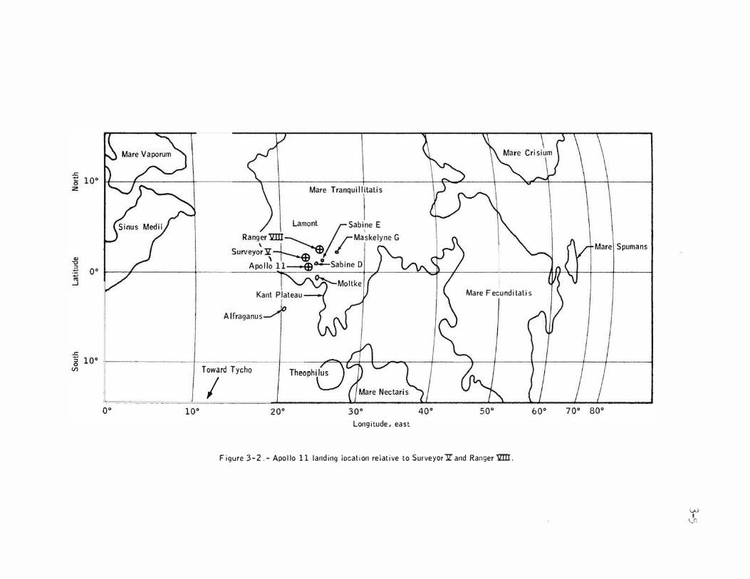
Kant Plateau
Alfraganus.-A
Toward Tycho
I
Mare Fecund ilati s
30°
Longitude, east
Figure 3-2.- Apollo lllanding location relative to Surveyor1rand Ranger1ZDI.
w I
V1

3
-
6
Television
. ........-·� •t .
. ) \. /'rArea from which core • �J ?·<
. ../ sample 2 was taken
I
' .
' I I .
I
52 meters to j 33-meter- �
tJ diameler crater �/ '
I ----·-.---• 400 meters to/ Contingency sample area ·� .--·� .·
y . :· �- " ·.
(, ·r. -"l---(�·��·�. L \ '. Documented � i ,.! \sample are;.. _...,,
t . j· : '
-----\. / - >'C.�· .. . ./ '--.J ( . ·�.-----<·�·/ • � \. \ ./ .
-- - Very subdued crater -r-- ""T'"".\ Subdued crater ..,...... • ..,...... . Relat•ve ly sharp crater
• Rock
•
Passive seismic experiment
•
• •
' •
•
•
est Crater;:.L�----... /.-..., -
......,
I'.;
0 5 • I • Meters
Figure 3-3.- Diagram of Apollo 11 lunar surface activity area.
10 • I

3-7
The southern part of the Sea of Tranquillity is crossed by relatively faint but distinct rays trending north-northwest and by prominent secondary craters associated with the crater Theophilus, which is located 320 kilometers southeast of the landing site. Approximately 15 kilometers west of the landing site is a fairly prominent ray that trends north-northeast. The crater with which this ray is associated is not definitely known; the ray may be related to the crater Alfraganus, 160 kilometers southwest of the landing site, or to Tycho, approximately 1500 kilometers southwest of the landing site. Neither the ray that trends north-northeast nor any of the rays that trend north-northwest cross the landing site; these rays are sufficiently close, however, so that material from Theophilus, Alfraganus, or Tycho is possibly found near the landing site. Craters such as Sabine D and Sabine E (fig. 3-2), with a diameter greater than 1 kilometer, may have been excavated partly in premare rocks; and premare rock fragments that have been ejected from these craters may also occur near the lunar module landing site (ref. 3-6).
Based on albedo and crater density, three geologic units can be distinguished in the mare material near the landing site. The lunar module landed on the most densely cratered unit of these three geologic units. These units may correspond to lava flows of different ages; if so, the unit at the landing site is probably the oldest.
The approximately 21 kilograms of lunar material returned by the Apollo 11 crew were characterized by the lunar sample analysis planning team as follows (ref. 3-7): The samples from Tranquillity Base consist of basaltic igneous rocks; microbreccias, which are a mixture of rock, glass and mineral fragments; and lunar soil. The soil is a diverse mixture of crystalline and glassy fragments with various shapes; the soil also includes fragments of iron, some of which may be of meteoric origin. Most rock fragments are similar to and apparently derived from the larger igneous rocks; the rocks in turn were probably once part of the underlying bedrock. A few of the crystalline fragments are totally different from any of the igneous rocks of the Tranquillity site. A strong possibility exists that these fragments represent samples from the nearby highlands.
Many rock surfaces and individual fragments in the soil show evidence of surface erosion by hypervelocity impacts. Examination of the surfaces of the glassy fragments, which are themselves formed by impact processes, shows that these objects contain beautifully preserved microscopic pits as small as 10 microns in diameter. These pits are the result of high velocity impacts by tiny particles. There is also evidence that the impact process is accompanied by local melting, splashing, evaporation, and condensation.
The crystalline rocks, which have typical igneous textures, range from very-fine-grained vesicular rocks to medium-grained equigranular rocks. The most common minerals are pyroxene (often highly zoned with iron-rich rims), plagioclase, ilmenite, olivine, and cristobalite. Free metallic iron and troilite, both of which are extremely rare on earth, are common accessory minerals in the igneous rocks. All the silicate minerals are unusually transparent and clear because of the complete absence of hydrothermal alteration. Laboratory experiments with silicate liquids similar in composition to the lunar liquids show that, at the time of crystallization, the observed phases can have coexisted only in a verl dry, highly reducing system; the partial pressure of oxygen in this system is estimated to be 10 l3 atmosphere. This pressure is more than five orders of magnitude lower than that for typical terrestrial basaltic magmas. The very low abundance of ferric ions in pyroxenes, determined by Mossbauer spectroscopy and electron spin resonance, is further evidence of the low oxidation level of the magmas. The melting experiments also indicate that 98 percent of the primary igneous liquid crystallized in the temperature range 1480° to 1330° K, with minor interstitial liquids continuing to crystallize down to temperatures around 1220° K. Microscopic and microprobe examination provides clear-cut evidence for the existence of an interstitial liquid rich in potassium and aluminum that probably was immiscible with the main liquid. Further, calculations indicate that the viscosity of the lunar magmas was approximately an order of magnitude lower than that of terrestrial basaltic magmas. This characteristic may play a significant role in the explanation of the textural features, the differentiation mechanisms that produced the observed chemical composition, and the morphological features of the lunar seas themselves.
The regolith consists chiefly of particles less than 1 millimeter in diameter. The regolith is weak and easily trenched to depths of several centimeters. Surface material was easily dislodged when kicked. The flagpole for the United States flag and the core tubes, when pressed into the surface, penetrated with ease to a depth of 10 to 12 centimeters. At that depth, the

3-
8
regolith was not sufficiently strong, however, to hold the core tubes upright; a hammer was needed to drive the core tubes to depths of 15 to 20 centimeters. The tubes, rods, and scoop that were pressed into the subsurface at several sample sites encountered rocks in the subsurface.
The crewman's boots left prints approximately 3 millimeters to 3 centimeters deep in the fine-grained regolith material. Smooth molds of the boot treads were preserved in the bootprints, and angles of 70° were maintained in the walls of the bootprints. The fine-grained surficial material tended to break into slabs, cracking as far as 12 to 15 centimeters from the edges of the footprints.
The finest fraction of the regolith adhered weakly to boots, gloves, space suits, handtools, anrl rocks on the lunar surface. On repeated contact, the coating on the boots thickened until boot color was completely obscured. When the fine particles of the regolith were brushed off, a stain remained on the space suits.
In places where fine-grained material was kicked by tl1e crewmen, the freshly exposed material was conspicuously darker than the undisturbed surface. The subsurface material probably lies at depths no greater than a millimeter from the surface. The existence of a thin surface layer of lighter colored material at widely scattered localities indicates that some widespread process of surface material alteration is occurring on the moon.
Fillets (fine-grained material which is banked against the sides of some of the larger rock fragments) were observed at least as far as 70 meters from the lunar module, and most fillets are almost certainly natural features of the surface. On sloping surfaces, the crew observed that the fillets were larger on the uphill sides of rocks than on the downhill sides. The sides of rocks are ballistic traps, and the fillets have probably been formed by the trapping of lowvelocity secondary pa�ticles. Asymmetric development of fillets around rocks on slopes may be caused partly by preferential downhill transport of material by ballistic processes and partly by do\rohill creep or flow of the fine-grained material (ref. 3-6).
3.2.2 Geology of the Apollo 12 Landing Site
The Apollo 12 landing site is on the northwestern rim of the 200-meter-diameter crater in which the Surveyor III spacecraft (fig. 3-4) touched down on April 20, 1967, in the eastern part of Oceanus Procellarum (Ocean of Storms), approximately 120 kilometers southeast of the crater Lansberg and due north of the center of Mare Cognitum (Known Sea). The landing site is on a broad ray associated with the crater Copernicus, 370 kilometers to the north. The landing site is characterized by a distinctive cluster of craters ranging in diameter from 50 to 400 meters. Two geologic traverses (fig. 3-5) were made on or near the rims of these craters and on deposits of ejecta from the craters. During the traverses, the crew collected approximately 34 kilograms of lunar material.
The lunar regolith at the Apollo 12 landing site is composed of fragmental material which ranges in size from particles too fine to be seen with the naked eye to blocks several meters in diameter. Along several parts of the traverse made during the second extravehicular activity period, the crew found fine-grained material of relatively high albedo that in some places was in the shallow subsurface and in other places lay on the surface. Some of this light-gray material may constitute a discontinuous deposit that is observed through telescopes as a ray of Copernicus.
Darker regolith material that generally overlies the light-gray material is only a few centimeters thick in some places but probably thickens greatly on the rims of some craters. The darker material varies from place to place in the size, shape, and abundance of its constituent particles and in the presence or absence of patterned ground. Most local differences are probably the result of local cratering events.
Many crew comments concerned the large amount of glass contained in the regolith. Irregularly shaped, small fragments of glass and glass beads are abundant both on and within the regolith; glass is also splattered on some blocks of rock at the surface and is found within many shallow craters.

+
Figure 3-4.- Surveyor ill with Apollo 12 lunar module in background.

Large 'T' boulders ! \ ;;Small mound
/ \ ./ First extravehicular
I ',, · 'F activity
Middle crescent crater / ALSEP ,, .. ,
/ · Large mound
...... /. ........ . . ...__ . - _ _...,.
r· ... )
Sharp crater
\ N
/.
e Sample sites
(>
f 100
I I 50
0
I 0 I 50
Lunar module
oO
Contingency sample
I
I I \
I Surveyor crater
\ r�
'......_ ·.._;
I lOOm
. .....__._.
Figure 3-5.- Apollo 12 traverse diagram.
w I
1--' 0

3-11
Much of the surface in the area of the geologic traverse made during the second extravehicular activity period is patterned by small, linear grooves. These grooves are visible on the returned photographs and were reported from several localities by the crew. The grooves are similar in appearance to those which are visible in some of the photographs from the Apollo 11 mission. The linear features have been interpreted as being caused by drainage of fine-grained material into fractures in the underlying bedrock. This interpretation would imply northeast- and northwest-trending joint sets in the bedrock of the Apollo 11 site and north- and east-trending joint sets in the Apollo 12 site bedrock.
One notable difference bet1veen the collection of rocks obtained at the Apollo 12 landing site and the collection obtained at Tranquillity Base is the ratio of crystalline rocks to microbreccia. At the Apollo 12 site, the rocks collected were predominantly crystalline, whereas, at Tranquillity Base, approximately half the rocks collected ��ere crystalline and half ��ere microbreccia. This difference is probably attributable to the fact that the rocks collected at tl1e Apollo 12 landing site ��ere primarily on or near crater rims. On the crater rims, the regolith is thin or only ��eakly developed, and many rocks observed are probably derived from craters that have been excavated in bedrock that is well below the regolith. By contrast, Tranquillity Base is on a thick, mature regolith, where many observed rock fragments were produced by shock lithification of regolith material and were ejected from craters too shallo1� to excavate bedrock (ref. 3-8).
Analysis of the returned Apollo 12 lunar samples sho�Ved the following:
a. Although still old by terrestrial standards, the Apollo 12 rocks are approximately 600 to 700 million years younger than the rocks from the Apollo 11 site.
b. Whereas the Apollo ll collection contained approximately half vitric breccias, the Apollo 12 collection contained only tiVO breccias in the 45 rocks collected.
c. The regolith at the Apollo 12 site is approximately half as thick as the regolith at the Apollo 11 site. Complex stratification within the regolith is evident.
d. A bright-colored layer of material referred to as KREEP was sampled at varying depths. It consists of fragments rich in potassium, rare earth elements, and phosphorous. It may have originated as ejecta from a distant, large crater, perhaps Copernicus.
e. The amount of solar wind material in the Apollo 12 fines is considerably lower than that in the Apollo 11 fines.
f. The lavas, in contrast to those from Apollo ll, display a wide range in both modal mineralogy and primary texture, indicating a variety of cooling histories.
g. Chemically, the "nonearthly" character of the Apollo 11 samples (high refractory element concentration and low volatile element concentration) is also noted in the Apollo 12 samples but to a lesser degree.
The soil at the Apollo 12 site is similar in appearance and behavior to the soils encountered at the Apollo ll and the Surveyor equatorial landing sites. However, local variations in soil texture, color, grain size, compactness, and consistency are evident. No direct correlation between crater slope angle and consistency of soil cover is apparent. The consistency of the soil cover depends mainly on the geologic history of lunar terrain features and local environmental conditions.
3.2.3 Geology of the Apollo 14 Landing Site
The Apollo 14·landing site is in a broad, shallow valley bet\Veen radial ridges of the Fra Hauro Formation, approximately 500 kilometers from the edge of Nare Imbrium (Sea of Rains, and also referred to geologically as the Imbrium Basin), 1vhich is the largest circular mare on the moon. The crater Copernicus lies 360 kilometers to the north, and the bright ray material that emanates from Copernicus covers much of the landing site region. The Fra t-lauro region is an area of prime scientific interest because this region contains some of the most clearly exposed geological formations that are characteristic of the Fra �Iauro Formation.

3-12
The Fra ��uro Formation is an extensive geological unit that is distributed in an approximately radially symmetric fashion around the Sea of Rains over much of the near side of the moon. Stratigraphic data indicate that the Fra Mauro Formation is older than the mare at the Apollo 11
and 12 sites. The Formation is thought to be part of the ejecta blanket that resulted from the excavation of the Imbrium Basin. The Apollo 14 landing site thus offered an opportunity to sample material that had been shocked during one of the major cataclysmic events in the geological history of the moon and, thereby, to determine the date of the event. Furthermore, because of the size of the Imbrium Basin, the belief was that some material had come from deep (tens of kilometers) within the original lunar crust. Thus, a landing at the Fra ��uro Formation, in principle, was expected to offer an opportunity to sample the most extensive vertical section available of the primordial moon (ref. 3-9).
The lunar module landed approximately 1100 meters west of Cone Crater,* which is located on the ridge of the Fra Hauro Formation. Cone Crater is a sharp-rinuned, relatively young crater approximately 340 meters in diameter that ejected blocks of material as much as 15 meters across, which were derived from beneath the regolith. Sampling and photographing of these blocks were the primary objectives of the mission. Rays of blocky ejecta from Cone Crater extend westward beyond the landing site. The landing took place on a smooth terrain unit recognized in photographs previously taken during earlier Lunar Orbiter and Apollo missions. Sampling and describing this geological unit was another important objective of this mission.
During the first period of extravehicular activity, the crew traversed westward over the smooth terrain for a round-trip distance of approximately 550 meters and deployed the Apollo lunar surface experiments package (fig. 3-6). The crew covered a round-trip distance of approximately 2900 mete)S eastward from the lunar module during the second extravehicular activity (fig. 3-6). During the traverse, the crew crossed the smooth terrain, the Fra ��uro ridge unit, and a section through the continuous ejecta blanket of Cone Crater to within 20 meters of the crater rim crest. Forty-eight rock samples, the locations of which have been determined, were collected at points along the traverse. The modular equipnent transporter (sec. 4.8) was used to transport the samples and the collection tools. Approximately 43 kilograms of lunar material, including 69 rock samples, were collected during the two periods of extravehicular activity.
Al�hough the soil surface texture and appearance at the Apollo 14 landing site are similar to those at the Apollo 11 and 12 landing sites, a greater variation exists in the characteristics of the soil at shallow depths (a few centimeters) in both lateral and vertical directions than had previously been supposed. The stratigraphy at the trench site showed a dark, fine-grained material (to a depth of 3 to 5 centimeters) underlain by a very thin glassy layer that, in turn, is underlain by a material of medium to coarse sand gradation. As had been the case in previous missions, dust was easily kicked up and tended to adhere to any surface contacted; however, overall dust was less of a problem than on previous missions. No difficulty was encountered in"digging a trench into the lunar surface. Because of unexpectedly low cohesion of the soil at the trench site, the trench sidewalls caved in at somewhat shall01�er trench depths than had been predicted.
The Apollo 14 site is densely covered with craters in all stages of destruction. Some craters as much as 400 meters across have undergone nearly complete destruction, and the overlapping of relatively large, very gentle depressions gives the topography at the site a strongly undulating aspect. In contrast, the largest craters that have undergone nearly complete destruction at the Apollo ll and 12 landing sites are approximately 50 to 100 meters in diameter.
The lunar regolith at Fra Mauro is thicker than at the mare sites. The surface material is finer grained in the western portion of the site away from the Cone Crater ejecta blanket than in the continuous ejecta blanket itself. Rock fragments larger than a few centimeters in diameter are rare in the western part of the site and become progressively more abundant toward Cone Crater. The regolith appears to be looser and less cohesive than that developed on the mare material; downslope movement of this loose debris has caused the eradication of small craters on slopes and extensive slumping of crater walls.
Boulders as large as 15 meters in diameter are present on the rim of Cone Crater; photographs of these boulders provided the first dramatic glimpse of relatively large segments derived from lunar bedrock and of detailed rock structures (fig. 3-7). Smaller boulders occur throughout the Cone Crater ejecta blanket and as isolated occurrences on raylike extensions of the ejecta blanket.
*Informal designation.

0
·.
�
LM- Lunar module location
Cone. Triplet, etc. - Informal crater names
A, B, ... . H - Photograph and sample locations
CIS - Experiment package central station
LR3 - Laser ranging retroreflector
Comp Spl - Comprehensive sample site
FSR - Football-size rock sample site
1, 2, 3 - Geophones
100
Scale: meters
I I
200 300 400 500
Figure 3-6.- Apollo 14 traverse routes.
.. �
·.

Figure 3-7.- Boulders sampled near rim of Cone Crater.
3-15
All the boulders for which stereophotographs are available appear to be coherent breccias, some with discrete clasts as much as 150 centimeters in diameter, larger than any returned samples. Both light and dark c�asts are recognizable. Resistance of the breccias to the weathering effects of the lunar environment varies considerably; some breccias have weathered to smooth, resistant surfaces and others to hackly, rough surfaces that may be rubbly. Significant and striking features within the boulders are sets of parallel fractures spaced at several millimeters to approximately 1 centimeter. Several intersecting sets of differently spaced fractures are present in some boulders.
Portions of some boulders close to the rim of Cone Crater are crudely layered with very light material that forms irregular bands from 25 to 40 centimeters thick. The light bands contain both lighter and darker clasts up to 10 centimeters across, and the host rock of the bands contains light clasts up to 10 centimeters across. Irregular parts of other boulders are also very light, but a layered relationship is not evident. Boulders containing light layers occur only near the rim of Cone Crater and, hence, may come from deeper levels in the crater.
Most large blocks have fillets of lunar fines and fragments embanked against the basal edges. The size of a fillet is commonly proportional to the size, degree of rounding, and apparent friability of the host rock. Fillets are preferentially developed against outward-sloping rock surfaces and contain coarse fragments spalled off the host rock. Burial of rocks is a combined product of (1) ejecta blanketing by adjacent impact events of all sizes, particularly on well-rounded rocks the tops of which are close to the surface, and (2) self-burial by micrometeorite and thermal erosion of the exposed rock surfaces.
Two well-developed sets of surface lineaments have the northwest and northeast trends observed at the Apollo 11 and 12 sites. A secondary set trends north. The large number of very long, straight lineaments is unique to the Apollo 14 site. These lineaments may be the result of very small, recent, vertical displacements along fractures or of the sifting of fine-grained material down into fractures that were propagated to the surface from a more coherent, joint substrate.
The samples consist almost entirely of complex breccias, displaying shock and thermal effects that are consistent with their postulated origin as debris from a large cratering event. The breccias are noritic in bulk composition. Some of the samples are vitric breccias which may have been formed by welding within the ejecta blanket of a smaller or local cratering event. Many of the breccia samples contain veins or pods of impact melt. On a larger scale, a plagioclase-rich basalt sample collected at the site may have been a lava, but was more likely crystallized in a pool of impact melt.
Radiometric ages for the Apollo 14 site cluster around a value of 3.9 billion years; if the Fra Mauro site is truly ejecta from Imbrium, then the Imbrium event occurred at that time (ref. 3-10).
Apollo 14 soil and breccia are enriched in the siderophile elements (iridium, rhenium, gold, nickel), relative to soils from mare qurfaces. They may be derived from the Imbrium projectile itself or bodies which impacted the lunar surface to form pre-Imbrium craters.
In summary, the compositions of the Apollo 14 rocks are compatible with their derivation as an ejecta deposit from the Imbrium Basin. These rock samples are largely fragmental and show pronounced shock effects, and the composition of most samples is distinctly different from that of basaltic rocks from lunar maria. The crystallinity observed in many fragmental rocks is compatible with a single very large impact event in which annealing took place within a thick, hot ejecta blanket.
3.2.4 Geology of the Apollo 15 Landing Site
The landing site of Apollo 15 is on a dark mare plain (part of Palus Putredinis, or the Marsh of Decay) near the sinuous Rima Hadley (Hadley Rille) and the frontal scarp of the Montes Apenninus (Apennine Mountains) (fig. 3-8). This scarp is the main boundary of the Imbrium Basin, which is centered approximately 650 kilometers to the northwest. The largest mountains of the Apennines are a chain of discontinuous rectilinear massifs 2 to 5 kilometers high that are interpreted as fault blocks uplifted and segmented at the time of the Imbrium impact. Between the massifs and beyond them outside the basin are hilly areas that merge southeastward with a terrain

3-16
l'ttf'At(O UNO(I 1lif OIUCTION Of !Mf OfPA�IMf.Nl Of O(f(NU AND 1'\JWSH(O 1Y IHE U S AI!MY IOI'OGAAPHIC COMMAND. WASHINCION 0 C
SCALE 1:250,000
saFlssbd bd bdo •w·
8saa skssa sY t
lEd' ltllOMf:fUS
r NAUTKAl MIUS
Figure 3-8.- Lunar module landing site on photomap of Hadley Plain.

3-17
interpreted as a blanket of ejecta from the Imbriur.1 Basin, known as the Fra Nauro Formation. The hills appear to be jostled blocks mantled and subdued by the Imbrium ejecta. The large massifs, however, are not similarly subdued and so may be composed mainly of pre-Imbrium ejecta. The area is near the old Mare Serenitatis (Sea of Serenity) basin, which suggests that at least part of the pre-Imbrium material in the massifs is ejecta from the Sea of Serenity.
The mare material of the Marsh of Decay fills the lowlands at the base of the Apennines and creates a dark plain. The regional relations to the west show that several events occurred between the formation of the Imbrium Basin and the emplacement of the mare material. These events included the deposition of the premare plains-forming material and the cratering event that formed the crater Archimedes. The morphologies of the craters on the mare surface at the landing site indicate that the age of the surface is late Imbrian or early Eratosthenian.
Some hills and mountains in the area are dark like the mare and may be coated by a thin mantle of dark material. The region contains numerous diffuse light-colored rays and satellitic clusters of secondary impact craters from the large Copernican craters Autolycus and Aristillus to the north.
Hadley Rille (fig. 3-8) follows a winding course through the mare and locally abuts premare massifs. Hadley Rille appears to be one of the freshest sinuous rilles, and rock outcrops are common along the upper walls. The rille is more than 100 kilometers long, 1500 meters wide, and 400 meters deep.
The regional relations indicate that the mare rocks may rest on faulted pre-Imbrium rocks, breccia from the Imbrium impact, and light plains-forming units such as the Apennine Bench Formation. ��ether or not the rille penetrates the premare material is unknown. The mare surface is covered with regolith approximately 5 meters thick.
Two major Apennine massifs, Mons Hadley (Hount Hadley) to the northeast and Hadley Delta just south of the landing site (fig. 3-8), tower over the Hadley plain to heights of 4.5 to 3.5 kilometers, respectively. The face of Mount Hadley is steep and high in albedo. The northern face of Hadley Delta, called the Front during the Apollo 15 mission, rises abruptly above the younger mare surface, except near Elbow Crater* where the contact is gradational, apparently because of the accumulation of debris from the slopes. As elsewhere on the moon, the steep slopes of the massifs are sparsely cratered because the craters are destroyed by the downslope movement of debris. A prominent exception is St. George,* a subdued crater 2.5 kilometers in diameter that predates the mare. The scarcity of blocks on both massifs indicates a thick regolith. The lower slopes of Hadley Delta were visited, and rock samples collected there indicate that the bedrock beneath the rego�ith consists of breccias.
The areas traversed by the Apollo 15 crew are shown in figure 3-9. The surface of the mare in the area visited is generally a plain that slopes slightly downward to the northwest. To the crew, the surface appeared hummocky or rolling, with subtle ridges and gentle valleys. The surface texture appeared smooth with scattered rocks occupying less than 5 percent of the total area. t�idely separated, locally rough areas occur where recent impacts have left sharp crater rims and small boulder fields. The visible ridges and valleys are largely the forms of greatly subdued large craters, and the smoothness is caused by the destruction of blocks by erosion from small impacts. A large but indistinct ray shown on premission maps as crossing the mare surface was not visible to the crew as either a topographic or compositional feature, but the crew did note patches of lighter-colored material that may represent remnants of rays that have been largely mixed with the mare regolith.
The contact between the mare and the front of Hadley Delta is marked by a change of slope and a band of soft material with fe1�er large craters than are typical of the mare. The soft material of the band is probably a thickened regolith that includes debris derived from the slope by both cratering processes and downslope creep. Samples from talus at the base of highlands terrain (Hadley Delta) consist of breccias rich in fragments of plagioclase-rich basalt and anorthosite. They may have been deposited as ejecta by pre-Imbrium events or the Imbrium event. One of the anorthosite samples had a radiometric age of 4.1 billion years, a lower limit, since this rock has experienced a complex history of brecciation. There is a variety of mare basalt samples and a clastic rock composed of green glass spheres which may be of volcanic origin. The basalt (lava) samples are rich in iron and poor in sodium, as are other mare lavas. They have an age of 3.3 billion years.
*Informal designations.

3-18
•'
Contacl•
0 1 2
Kilometers
Figure 3-9.- Apollo 15 lunar surtace traverse routes.

3-19
A 2.4-meter-deep core of the regolith revealed that it is composed of many soil layers ranging in thickness from a few millimeters to several tens of centimeters. The regolith is composed of layers of ejecta from impact craters, which are, in turn, reworked and mixed by micrometeorite bombardment. The 2.4-meter section at this site has undergone reworking and mixing for about 500 million years.
Soil mechanics analyses (from penetrometer tests, core sampling, and trenching performed by the astronauts; from photographs; and from other data) for the Apollo 15 site indicate the following:
a. Soil densities range from 1.36 to 2.15 grams per cubic centimeter.
b. No evidence of deep-seated slope failures is apparent, although surficial downslope movement of soil has occurred and the soil on steep slopes along the Apennine Front is in a nearfailure condition.
3.2.5 Geology of the Apollo 16 Landing Site
The Apollo 16 lunar module landed at the western edge of the Descartes Mountains approximately 50 kilometers west of the Kant Plateau, part of the highest topographic surface on the near side of the moon. The Apollo 16 mission accomplished the first landing in the central lunar highlands, and the crew successfully explored and sampled a kind of terrain not previously visited. The landing site was selected as an area characteristic 6f both terra plains and rugged hilly and furrowed terra. The consensus of premission photogeologic interpretation was that both units were of probable volcanic origin. However, surface observations indicated that few or no volcanic rocks or landforms existed at the landing site but rather that the area is underlain by a wide variety of impact-generated breccias (ref. 3-11).
Ray materials derived from North Ray and South Ray Craters (fig. 3-10)* are the two most apparent sources of surface debris on the Cayley Plains. Ejecta from South Ray Crater also appear to mantle much of the surface of Stone Mountain near sampling stations 4 and 5 (fig. 3-10), so that uncertainty still exists as to whether Descartes materials were, in fact, sampled. Size distribution studies of fragments on the lunar surface suggest that the ejecta units of these two craters differ in character. Rock fragments are much less abundant in the North Ray ejecta blanket, which suggests that the North Ray impact may have excavated more friable material, that the length of time since the cratering event has been sufficient for subsequent impacts to destroy the smaller blocks, or both. South Ray ejecta, as mapped, include bright and dark areas, but the only surface differences observed are that the brightest areas have larger block sizes and a greater abundance of blocks. The mapped interray areas have no lunar surface characteristics that distinguish them from adjacent South Ray ejecta; they are, more or less, free of coarser rock fragments. Both ray and interray areas show a progressive northward decrease in total rock abundance and in relative abundance of the coarser sizes.
The regolith present on the ejecta blanket of North Ray Crater is only a few centimeters thick. \.fuere ejecta blankets or ray deposits are not identifiable, the regolith is 10 to 15 meters thick. The surface of the regolith is medium gray, but high-albedo soils are present at depths of 1 to 2 centimeters in most of the traverse area.
The net weight of returned samples was approximately 94 kilograms. Of the total sample weight, almost 75 percent consists of rock fragmen.ts larger than 1 centimeter in diameter, nearly 20 percent consists of soil or residue fines, and 'the remainder consists of core and drive tube samples. The Apollo 16 rocks may be divided into three broad groups: fine- to coarse-grained, mostly homogeneous crystalline rocks; rocks composed substantially of glass; and fragmental rocks (breccias). The proportion of fragmental rocks in the returned samples exceeds 75 percent. Of 25 rocks classified as crystalline, 7 appear to be igneous. Although all the igneous rocks have been shattered and deformed to some extent, the predeformation textures are substantially intact. The two largest samples returned are coarse-grained nonvesicular rocks composed largely of plagioclase. These rocks resemble an Apollo 15 anorthosite sample but are probably more severely shock-deformed. Three are fine-grained, highly feldspathic rocks with crystal-lined vugs. Eighteen crystalline rocks appear to be metaclastic rocks with generally small proportions of lithic debris; these are hard, angular rocks characterized by fine-grained sugary textures. Five samples largely composed of glass were returned. Two of these are spheres, one hollow and one solid.
*Designations of lunar features shown in figure 3-10 are informal.


3-22
The remaining three glass samples are irregular, coarse, agglutinates with numerous small lithic inclusions. The fragmental rocks have been divided into five main groups on the basis of proportions of light and dark clasts and matrix color. All five groups are varieties of impactgenerated breccias; none appear to be of volcanic origin. The majority of the rocks are polymictic breccias, but a substantial minority are monomictic. Two types of clasts are clearly dominant: one type is dark, aphanitic to finely crystalline metaclastic rocks; the other is white, partly crushed to powdered feldspathic rocks. Less common clast types include light-gray or white rocks with granoblastic textures, a variety of gabbroic to anorthositic rocks with medium to coarse grain size, and rare feldspar-poor basaltic rocks. Matrices of the light- and mediumgray-matrix breccias are, for the most part, friable and not visibly altered by subsequent thermal events, whereas those of dark-matrix breccias are coherent and annealed or fused.
The rock distribution suggests that the section underlying the Cayley Plains is stratified, with an upper unit of medium-gray breccia and lower units composed mainly of light- and darkmatrix breccias. The extent of the supposed upper unit is not known but presumably extends at least between stations 1 and 6; considering the relative scarcity of the medium-gray breccias, the unit is probably not more than a few meters thick. Evidence derived from the photographs, crew descriptions, and samples collected at station 11 suggests that light-matrix breccias overlie dark-matrix breccias, whereas the color of ejecta on the rims of South Ray and Baby Ray Craters suggests that dark-matrix breccias overlie light-matrix breccias near those craters. Such a stratographic sequence in the South Ray area is consistent with the dominance of darkmatrix breccias described and photographed in South Ray ejecta between the landing site and station 8.
The Cayley Formation at the Apollo 16 site is a thick (at least 200 and possibly more than 300 meters), crudely stratified debris unit, the components of which are derived from plutonic anorthosites and feldspathic gabbros and from rr�tamorphic rocks of similar composition. The formation has an elemental composition similar to that observed over large regions of the lunar highlands by the orbital X-ray experiments of the Apollo 15 and 16 missions. The observed textures and structures of the breccias resemble those of impact breccias. The textures and structures of the breccias do not resemble those of volcanic rocks nor do the plutonic or metamorphic source rocks of the breccias have the textures or compositions of terrestrial or most of the previously sampled lunar volcanic rocks.
The physical and mechanical properties of the soil at the Apollo 16 landing site are generally similar to those of the soils encountered at the previous Apollo sites. Data obtained using the self-recording penetrometer have provided a basis for quantitative study of stratigraphy, density, and strength characteristics. These results and crew observations, photographs, and soil samples (particularly the core-tube samples) have been used to develop the following preliminary conclusions.
area.
a. Soil cover appeared to blanket all areas visited or observed at the Descartes landing
b. Soil properties are variable on regional and local (1 meter) scales.
c. Visibility degradation by blowing dust was less during the Apollo 16 lunar module descent than during previou.s missions, probably because of a faster descent rate and a higher sun angle rather than a difference in soil conditions.
d. The grain-size distributions of soil samples from the Descartes area are comparable to those from other areas of the moon, although distributions for most Descartes samples fall toward the coarser edge of a composite distribution.
e. The drive-tube samples indicate that soil density increases with depth, but the overall range of densities (1.40 to 1.80 grams per cubic centimeter) is slightly less than the range (1.36 to 2.15 grams per cubic centimeter) found for Apollo 15 core-tube samples.
f. South Ray crater material appears to cover the station 4 area to depths of 20 to 50 centimeters. Descartes Formation material may have been found at greater depths.
g. Density distributions with depth for the Apollo 16 deep-drill-stem samples are distinctly different from those of Apollo 15 and suggest that the modes of soil deposition at the two sites may have been different.

3-23
3.2.6 Geology of the Apollo 17 Landing Site
The Apollo 17 landing site was named Taurus-Littrow because of its proximity to the Montes Taurus (Taurus Mountains) and the crater Littrow. The lunar module landed on the flat floor of a deep narrow valley bounded by steep-sided mountain blocks that form part of the mountainous eastern rin o f Mare Serenitatis (Sea of Serenity, referred to geologically as the Serenitatis Basin). The blocks are thought to be bounded b y high-angle faults that are largely radial and concentric to the Serenitatis Basin. Hence, the valley itself is interpreted as a graben formed at the time of the Serenitatis impact. Figure 3-11 shows the landing site and the major geological features* that were examined by the Apollo 17 crew. During their stay on the lunar surface, the Apollo 17 crew traversed a total of about 34 kilometers, collected over 110 kilograms of rocks and soil, and took more than 2200 photographs. Their traverses span the full width of the Taurus-Littrow valley, as shown in figure 3-12.* Huch of the following discussion was exerpted from reference 3-12.
The highlands surrounding the valley can be divided on the basis of morphology into (1) high smooth massifs; (2) smaller, closely spaced domical hills referred to as the Sculptured Hills; and (3) materials of low hills adjacent to the massifs and the Sculptured Hills. Boulders that had rolled down the slopes of the massifs north and south of the valley provided samples of that area. These boulders are composed of complex breccias that are generally similar to those returned from the Apollo 15 and 16 missions.
Materials of the valley fill were sampled at many stations. Ejecta around many craters on the valley floor consists of 3.8-billion-year-old basalts, showing that the graben was partly filled by lava flows. A relatively thick layer (approximately 15 meters) of unconsolidated material overlies the subfloor basalt; this debris consists largely of finely comminuted material typical of the lunar regol.ith. For the most part, this is impact-generated regolith similar to that developed on mare basalts elsewhere on the moon. The central cluster ejecta, the light mantle, and the ejecta of Shorty and Van Serg Craters are discrete deposits recognized within the regolith.
The young pyroclastic "dark mantle" anticipated before the mission was not recognized in the traverse area as a discrete surface layer. However, soil consisting of orange glass spheres was collected. This soil most likely originated from volcanic fire fountains that accompanied lava extrusion to form irregularly shaped layers that are now buried. Strong photogeologic evidence for the existence of a dark mantle in parts of the highlands still exists. Albedo measurements show that abnormal surface darkening, consistent with the concept of the introduction of exotic dark material increases to the east and south in the Taurus-Littrow area. The dark mantle may have accumulated shortly after the extrusion o f the subfloor basalt.
The "light mantle" is an unusual deposit of high-albedo material with finger-like projections that extend 6 kilometers across dark plai.ns from the South Massif. Rock fragments collected from the light mantle are similar in lithology to the breccias of the South l1assif. This similarity supports the hypothesis that the light mantle is an avalanche deposit formed from loose materials on the face of the South Hassif. A cluster of secondary craters on the top of the South Massif may record the impact event that initiated the avalanche. Size-frequency distribution and morphologies of craters on the light mantle suggest that its age is comparable to that of Tycho Crater, on the order of 100 million years.
Fine-grained soil, darker than the underlying unconsolidated debris, was recognized at the surface at Shorty Crater, at Van Serg Crater, on the light mantle, and on the massif talus. The soil is thin (e.g., 0.5 centimeter at Shorty, and about 7 centimeters on the flank of Van Serg) and probably represents the regolith that has formed on these young ejecta or talus surfaces. Relatively young structural deformation in the landing area is recorded by the Lee-Linclon Scarp and by small fresh grabens that trend northwest across the light mantle. The sharp knickpoint at the base of the massifs may indicate that some fairly recent uplift of the massifs has kept the talus slopes active.
*The designations of the features shown in figures 3-11 and 3-12 are informal .


3-26
3.2.7 Geology and Soil Nechanics Equipment
3.2.7.1 Apollo lunar surface handtools.- The Apollo lunar surface handtools consisted of the items listed in table 3-II and illustrated in figure 3-13. The tools were continually upgraded as the lunar landing missions progressed based on the results of preflight and postflight evaluations and on geology requirements. The more significant changes are discussed in the following paragraphs.
a. Hammer: The hammer was used during all Apollo lunar surface extravehicular activities. As experience was gained, the hammer was modified as follows.
tration.
1. The spray aluminum coating on the head was changed to vacuum-deposited aluminum.
2. The originally pinned handle-to-head connection was changed to·a "magnaformed" head.
3. The head was made heavier and larger to assist in obtaining better drive tube pene-
4. Room-temperature-vulcanizing material strips were added to the handle to minimize twisting of the hammer in the hands.
b. Scoop: The scoop originally had a large pan and was nonadjustable. On Apollo 15, the design was changed to incorporate a smaller pan and an adjustable head. On Apollo 16 and 17, the adjustable feature was maintained but the pan was enlarged to obtain a larger sample.
c. Extension handle: The extension handle was designed to be mated with core tubes, scoops, hammer, and rake. Field tests and flight evaluation indicated that the original handle design should be changed to prevent shearing of the core-tube adapter pins. Also, further evaluations indicated that a longer handle was desirable. Two handles were carried on the Apollo 16 and 17 missions instead of one.
d. Gnomon: The gnomon consisted of a gimbaled rod and a color chart mounted on a tripod. The rod indicated the gravitational vector, and the chart provided a standard for color comparison in photographic processing. (Before the Apollo 14 mission, a color chart was carried separately.) Postflight evaluations following the init.ial lunar landing missions indicated that the rod would oscillate for long periods of time before damping to a fixed position. The cumulative time in awaiting rod arrestment was severely restrictive to the overall surface activity. Therefore, a damping change was incorporated for the Apollo 15 through 17 missions. On Apollo 16, the gimbaled rod separated from the leg assembly while the gnomon was being removed from its stowage bag. To prevent recurrence on Apollo 17, the gimbal pivot pins were strengthened and additional lubrication was applied to the pivot/bearing interface.
e. Tongs: The tongs consisted of a set of opposing spring-loaded fingers attached to a handle and were used for picking up samples. Postflight evaluation of Apollo missions 11, 12, and 14 indicated a need for increased length, larger jaws, and additional closing force. These changes were incorporated for Apollo missions 15 through 17. Also, to conserve traverse time and to afford maximum flex.ibility in obtaining samples, two sets of tongs were carried on the Apollo 16 and 17 missions.
f. Adjustable trenching tool: The trenching tool was used on only one mission, Apollo 14. Experience indicated that the adjustable scoop could perform the trenching task on subsequent missions.
g. Rake: A rake was designed and built for the Apollo 15, 16, and 17 missions to meet the .requirement of efficiently obtaining a number of small rock samples from the lunar surface or just below the surface. The rake served its purpose satisfactorily.
h. Core tubes/drive tubes/caps: The core tubes were originally designed to be driven into the lunar surface with the hammer. Postflight examination of the Apollo 11 samples indicated that the bit was degrading the samples. Furthermore, additional information on the cohesiveness of the lunar soil indicated that a "drive tube" with a larger diameter (increased from 2 to 4 centimeters) and an integral bit could be used. Effective w.ith the Apollo 15 mission, drive tubes were successfully used to obtain samples. The components of a drive tube set consisted of

TABLE 3-II.- GEOLOGY AND SOIL MECHANICS TOOLS AND EQUIPMENT
Item
Apollo lunar surface hand tools:
Hammer Large scoop Adjustable scoop Extension handle Gnomon Tongs Adjustable trenching tool Rake Core tubes Core tube caps Drive tubes (lower) Drive tubes (upper) Drive tube cap and bracket assembly Drive tube tool assembly Spring scale Sample scale
Tool carrier
Sample return container
Bags and special containers:
11
1 1
1 1 1
2 2
1
2
Small sample bags 5 Documented sample bags (lS-bag disp) 1 Documented sample bags (20-bag disp) Documented sample bags (35-bag disp) Round documented sample bag Protective padded sample bag Documented sample weigh bag 2 Sample collection bag Gas analysis sample container 1 Special environmental samp·le container Core sample vacuum container Solar wind compos 'it i.on bag 2 Magnetic shield sample container Extra sample collection ba.gs
Organic control sample
Lunar surface sampler (Beta cloth)
Lunar surface sampler (velvet)
Lunar roving vehicle soil sampler
Magnetic sample assembly
Tether hook
Lunar surface drill
Core stem with bit
Core stems without bit
Core stem cap and retainer assembly
Self-recording penetrometer
1
12
1 1
1 1 1
4 1
1
2
3
1
4
1 1
1
1
1
Mission use
14
1 1
1 1 1 1
6
1
2
1
2
4
3
1 1
2
1
15
1
1 1 1 1
1
5 4 3
1
1
2
6
2
3
4
2
1
1
5
2
1
16
1
1 2 1 2
1
5 4 5 1
1
1
2
7
2
2
1 1
6
2
1
1
1
1
1
5
2
1
17
1
1 2 1 2
1
5 4 5 1
1
2
6
48
2
1 1
6
1
1
1
5
2
3-27

jp Hand tool extension handle
Gnomon/ color chart assembly
Lunar surface rake
Lunar surface dri II
Adjustable sampling scoop
and associated equipment
Sample scale
Core tubes
Figure 3-13.- Lunar geology and soil mechanics tools.
�--=.,.,...,.--..,.,: _......::;:;,;) H= - ;;. ·# Hammer
32-inch tongs
Lunar roving vehicle soil sampler
\..N I (\) ())

3-29
the drive tube , a drive -tube tool, and a cap dispenser. Deep samples were obtained by joining tubes in series. The drive-tube tool was used to position a keeper against the core sample to preserve its integrity. The cap dispensers were mounted on the handtool carrier and contained Teflon caps to seal the tubes after sample collecti.on.
i . Sample scale: The sample scale was used o n Apollo 14 through 17 to weigh lunar samples before lift-off to assure that the total weight did not exceed the permitted weight.
3 . 2 . 7 . 2 Tool carriers . - The original Apollo lunar handtool carrier was designed to accommodate the early tool configurations and to be hand-carried or mounted on the modular equipment transporter used on the Apollo 14 mission. \nth the advent of the lunar roving vehicle, a new tool carrier was needed that could be mounted on that vehicle or, if the vehicle became inoperative, could be removed and hand-carried during walking traverses. The modified tool carrier was used as a stowage rack for the hammer, gnomon, scoop, and the drive·-tube tool assembly; the tool carrier also accommodated the extension handle and the tongs.
3.2.7.3 Apollo lunar sample return container . - The Apollo lunar sample return container (fig. 3-14) was designed to provide a vacuum environment for the return of lunar samples. The containers and their contents were cleaned at the manufacturing facility to a cleanliness level of less than 10 nanograms of residue per square centimeter. The containers and their contents were then shipped to the Lunar Receiving Laboratory for premission cond itioning, which consisted of sterilization to remove earth organisms before sealing under a vacuum (approximately 10-6 torr).
No major design changes were made throughout the lunar landing flights. However, the following minor changes were incorporated.
a. A York mesh liner was added on Apollo 12 to give better protection to the container and its contents, and the liner was reduced in thickness to increase the volume of the container .
b. On Apollo 14 and subsequent missions, a skirt was added to prevent debris from getting into the seal, to facilitate closing, and to ensure maintenance of vacuum.
Two organic samplers (fig. 3-15), each consisting of several rolls of York mesh packing material in a Teflon bag, were used to determine the quantity of organic compounds introduced before and during the translunar portion of a mission. One sampler was analyzed and sealed before flight. The other was placed in the sample return container, removed for environmental exposure while on the lunar surface, sealed, and returned to the container.
3 . 2 . 7 . 4 Bags and special containers.- In addition to the actual collection of samples, a requirement existed to protect, document, and identify the various samples. To perform these tasks, numerous types of bags and special containers were designed, some of which are described in the following paragraphs and illustrated in figure 3-16.
a. Documented sample bags: The crewmen used documented sample bags to identify and document the individual samples as they were collected. On Apollo 17, a quantity of round sample bags were supplied. These bags were used in conj unction with the lunar roving vehicle soil sampler (par. 3. 2.7.6).
b. Special environmental sample container: These devices were designed to contain samples of lunar soil and/or rocks to be used in specific experiments on return to earth. The containers provided a vacuum environment to protect the samples from contamination in case the Apollo lunar sample return container leaked.
c. Core sample vacuum container: The core sample vacuum container was provided as a receptacle for a drive tube so that a pristine subsurfac.e sample could be protected in a vacuum .
d. Protective padded sample bag: The protective padded sample bag was used for returning a fragile lunar sample so that maximum protection could be afforded to the surface of the sample. Bags of this type were carried only on the Apollo 16 mission.
e. Documented sample weigh bags/sample collection bags: The weigh bags (Apollo 11, 12, and 14) and the sample collection bags (Apollo 15 , 16, and 17) were large bags into which the documented samples were placed for insertion into the Apollo lvnar sample return container for return

3-30
Figure 3-14.- Apollo lunar sample return container.
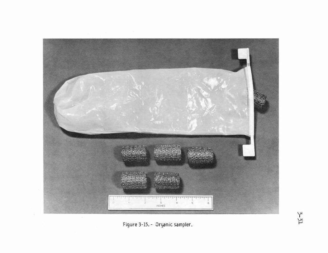
Figure 3-15.- Organic sampler.

Special environmental sample container
Sample collection bag
Documented sample bag dispensers
Core sample vacuum container
Figure 3-16.- Sample bags and special containers.

3-33
to earth. The bags were originally made of Teflon film; however, after postflight evaluation indicated that this material would tear, the design was changed to incorporate a laminated Teflon fabric/Teflon film, and the name was changed from sample weigh bags to sample collection bags.
3.2.7.5 Lunar surface sampler.- The lunar surface sampler was used with the universal handling tool. The device, which consisted of a plate assembly that contained either a Beta cloth or a velvet cloth accumulation surface , was used to obtain undisturbed surface layer lunar samples. A hinged cover plate protected the sample on the return-to-earth flight.
3.2.7.6 Lunar roving vehicle soil sampler.- The lunar roving vehicle soil sampler was a device that when mated with the universal handling tool, allo,�ed the lunar surface crewman to obtain soil samples without dismounting from the lunar roving vehicle.
3.2.7.7 Penetrometers. - On the Apollo 14 mission, the active seismic experiment geophone cable anchor shaft was used as a simple penetrometer to obtain soil mechanics data. The 0.87-centimeter-diameter 68 . 0-centimeter-long aluminum shaft had a 30° core tip at the bottom and was attached to the extension handle at the top. Alternating black and white stripes, each 2.0 centimeters long, provided a depth scale reference in photographs of the penetrations achieved. The crewman pressed the penetrometer into the lunar surface with one hand for a f irst measurement and then with two hands for a second measurement. Preflight 1/6-earth-gravity tests provided a comparative calibration for the penetrometer.
A self-recording penetrometer, used on the Apollo 15 and 16 missions (fig . 3-17), provided for the first time quantitative measurement of forces of interaction between the soil near the lunar surface and a soil testing device. The instrument provided data on soil penetration resistance as a function of depth below the lunar surface. The penetrometer could penetrate the lunar surface a maximum of 76 centimeters. On the Apollo 15 mission, the penetrometer could measure a penetration force to a maximum of 111 newtons. As a result of the Apollo 15 experience, the force spring was changed to increase the maximum measurement to 215 newtons. On the later lunar landing missions, the successful functioning of the self-recording penetrometer and core tubes, as well as the general surface-contact equipment, resulted in data which provided a basis f o r the quantitative study of stratigraphy, density, and strength characteristics of the lunar soil.
3.2.7.8 Apollo lunar surface drill. - The purpose of the Apollo lunar surface drill (fig. 3-18) was to provide two 2 . 4-meter-deep holes for emplacement of probes for the heat flow experiment. The drill was also used to obtain a continuous subsurface core sample that was 2.4 to 3.0 meters long to be returned to earth for laboratory analyses. In addition, on Apollo 17, the hole produced by the core drilling was used for emplacement of the neutron probe experiment.
The drill was a battery-powered, electric-drive , rotary-percussion-type drill which delivered vertical blows to the rotating spindle, driving carbide-tipped hollow bore stems and core stems. The boron-fiberglass bore stems and titanium core stems were sectionalized, allowing the desired penetration into the lunar surface while maintaining the capability for handling and stowage by the lunar surface crewmen.
Two significant hardware changes resulted from mission experience: bore stem joint redesign and the incorporation of a deep-core extractor. Both changes were made because of th e high density of the lunar subsurface encountered on Apollo 15. Before that mission, the subsurface density data had been based on drive-tube core information, which supported Surveyor data that showed the bulk density of the regolith to be relatively low (90 to 110 pounds per cubic foot). This soil density was used for drill testing. However, these samples had been taken from a depth of only 0.6 to 0.9 meter. When the Apollo 15 drill went beyond this depth, the density increased significantly (to 130 pounds per cubic foot). With this additional knowledge, a new bore stem design was introduced and tested in simulated soil models compacted t o a maximum bulk density. Other changes included a core-stem extractor that was developed to provide additional capability for jacking the deep-core sample from the subsurface. The changes were incorporated for the Apollo 16 mission.
A continuous improvement in drill performance was obtained from one mission to the next. In each case, the effectiveness of the hardware improvements was demonstrated. Time lines for the drill-associated tasks were nominal for Apollo 16 and 17.

•
_j/
_,
�- � , .
•
Figure 3-17.- Self-recording penetrometer.

3-35
Figure 3-18.- Apollo lunar surface drill.

3-36
3.2.8 Apollo Lunar Surface Experiments Package/Central Station
As reflected in table 3-I, a number of experiments were deployed or conducted on the lunar surface during the six lunar landing missions. To minimize weight, volume, and power requirements, several experiments were integrated into a single system, the Apollo lunar surface experiments package. The experiments that comprised the package varied from mission to mission, as shown in table 3-III. The other lunar surface experiments were self-contained.
Figure 3-19 illustrates a typical Apollo lunar surface experiments package (Apollo 15 configuration). Subpackage 1 contained magnetometer, passive seismic, and solar wind spectrometer experiments. The lower portion of subpackage 1 housed the central electronics which included the data handling, radio-frequency up-link and down-link, and power conditioning and distribution subsystems. In the erected configuration, the electronic and thermal control portions of subpackage 1 are known as the central station. A helical S-hand antenna was also carried on subpackage 1. The antenna was attached to an aiming mechanism and an antenna mast that was locked into the primary structure. Subpackage 2 consisted of a rigid structural pallet on which were mounted one or two experiments, a radioisotope thermoelectric generator, the antenna aiming mechanism, special deployment tools, and, on two flights only, the geological handtool carrier. All equipment was removed from subpackage 2 except the generator. Because the fuel element for the generator was very hot, the fuel element was carried to the moon in a separate protective cask assembly. The fuel cask assembly and the two subpackages were stowed as shown in figure 3-20.
The radioisotope thermoelectric generator developed for the Apollo lunar surface experiment package was designated "system for nuclear auxiliary power no. 27" (SNAP-27). Differing in design and materials from the previously developed SNAP-19 generator (for Nimbus and Pioneer), SNAP-27 has been the only nuclear power generator developed for manned fueling and has the largest power output of those developed for space use. Although the original design specification was for a 50-watt generator, the output developed by the actual flight hardware exceeded 70 watts in the hard vacuum environment - sufficient to handle the Apollo lunar surface experiment package power requirements which kept increasing for the growing science program. Initial power output for Apollo 12 on the lunar surface was 74 watts (66.5 watts after 4 years), for Apollo 14 was 73 watts (68 watts after 3 years), for Apollo 15 was 75 watts (69.4 watts after 3 years), for Apollo 16 was 70.9 watts (69.5 watts after 2 years), and for Apollo 17 was 77.5 watts (76.9 watts after 1 year). The actual rate of decrease in output (primarily the result of changes in the lead telluride material from time, temperature, and pressure) for all five flight radioisotope thermoelectric generators has been considerably less than calculated predictions (about onefourth the design specification rate).
The Apollo lunar surface experiments package systems flown on Apollo missions 12 through 16 were designed for a nominal lunar operating period of 1 year. The system flown on Apollo 17 incorporated various design improvements to meet a requirement of 2 years of lunar operation and to eliminate operational problems encountered on earlier systems. These changes can be broadly categorized into: the use of logic elements with improved reliability, added redundancy with refined techniques for redundant component selection, and design improvements based on lunar operating experience. Plans were that when the output of the radioisotope thermoelectric generator decreased to a lev�l too low to provide enough power for the full complement of experiments in the worst case condition (lunar sunrise), selected experiments would be commanded off or to a standby mode for lower power demand. Consequently, on June 14, 1974, three experiments (Apollo 12 lunar surface magnetometer, and Apollo 15 lunar surface magnetometer and solar wind spectrometer, all of which had been unable to provide science data for an extended period) were terminated so as t o make more power available for other experiments. These were the first experiments in the Apollo lunar surface experiments package program to be terminated by command. The only other experiment to have its operation on the lunar surface terminated was the Apollo 12 cold cathode gage experiment, which turned itself off in November, 1969, because of a circuit failure.
Overall operation of the Apollo lunar surface experiments package central station has been excellent in all areas of the mechanical, thermal, and electrical designs. All central stations deployed on the lunar surface continue to operate as planned; the Apollo 12 central station has exceeded its 1-year life requirement by more than 3 years. Although no signal processing component failure has occurred during lunar operation, numerous operational abnornalities have required procedural changes. The more significant problems and failures occurring during the hardware test phase and lunar operation are summarized in the follo1ving paragraphs.

Apollo 12 Experiment
Array A
aPassive seismic Short-period Z axis
has displayed re-duced sensitivity since deployment.
Active seismic
Lunar surface Permanently com-magnetometer manded off 6/14/74.
Solar wind Full operation ex-spectrometer cept for intermit-
tent modulation drop in two proton energy
levels each lunation since 11/5/71.
Supra thermal Periodically com-ion detector manded off to pre-
vent high voltage arcing at elevated lunar day tempera-cures since 9/9/72.
Heat flow
Cold cathode Inoperative. Failed ion gage 14 hours after turn-
on 11/20/69.
Lunar ejecta and meteor-ites
TABLE 3-III.- APOLLO LUNAR SURFACE EXPERIHENTS PACK.ACE ARRAYS AND STATUS
Apollo 13
Array B
Not deployed.
Not deployed.
Not deployed.
Apollo 14
Array c
Long-period z axis inoperative since 3/20/72. Noisy data on long-period Y axis
since 4/14/73.
Hortar not fired. Ceopbone 3 data noisy since 3/26/71. Ceophone 2 data in-valid since 1/3/74.
Periodically com-manded to standby operation to avoid mode changes at elevated lunar day temperatures since 3/29/72.
Intermittent science data since 3/29/72·
Apollo 15 Apollo 16
Array A-2 Array D
Full operation. Full operation.
Three of four gre-nades launched. Mortar pitch sensor off scale after third firing on 5/23/72.
Permanently commanded Full operation. off 6/14/74.
Permanently com-manded off 6/14/74.
Periodically com-manded to standby operation to avoid mode changes at elevated lunar day temperatures since 9/13/73.
Probe 2 not to full Inoperative since depth intended, but emplacement. experiment provides useful data.
Intermittent science data since 2/22/73.
Apollo 17
Array E
Full operation.
Thermal control de-sign not optimum for Apollo 17 site. In-strument operated for about 75 percent of lunation.
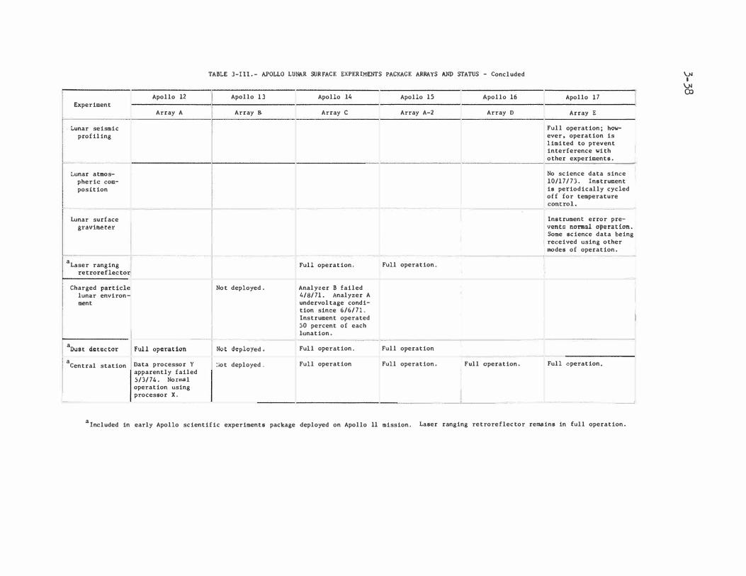
TABLE 3-111.- APOLLO LUNAR SURFACE EXPERIMENTS PACKAGE ARRAYS AND STATUS - Concluded
Apollo 12 Apollo 13 Apollo 14 Apollo 15 Apollo 16 Apollo 17 Experiment
Array A Array B. Array c Array A-2 Array D Array E
Lunar seismic Full operation; how-profiling ever, operation is
limited to prevent interference with other experiments.
Lunar atmos- No science data since pheric com- 10/17/73. Instrument position is periodically cycled
off for temperature control.
Lunar surface Instrument error pre-gravimeter vents normal operation.
Some science data being received using other modes of operation.
aLaser ranging Full operation. Full operation.
retroreflector
Charged particle Not deployed. Analyzer B failed lunar environ 4/8/71. Analyzer A ment undervoltage condi-
tion since 6/6/71. Instrument operated SO percent of each lunation.
aDust detector Full operation .Not deployed • Ful,l oper3tion. Full operation
aCentral station Data processor y !iot deployed. Full operation Full operation. Full operation. Full operation.
apparently failed 5/3/74. Normal operation using processor X.
alncluded in early Apollo scientific experiments package deployed on Apollo 11 mission. Laser ranging retroreflector remains in full operation.
\).I I
\).I co
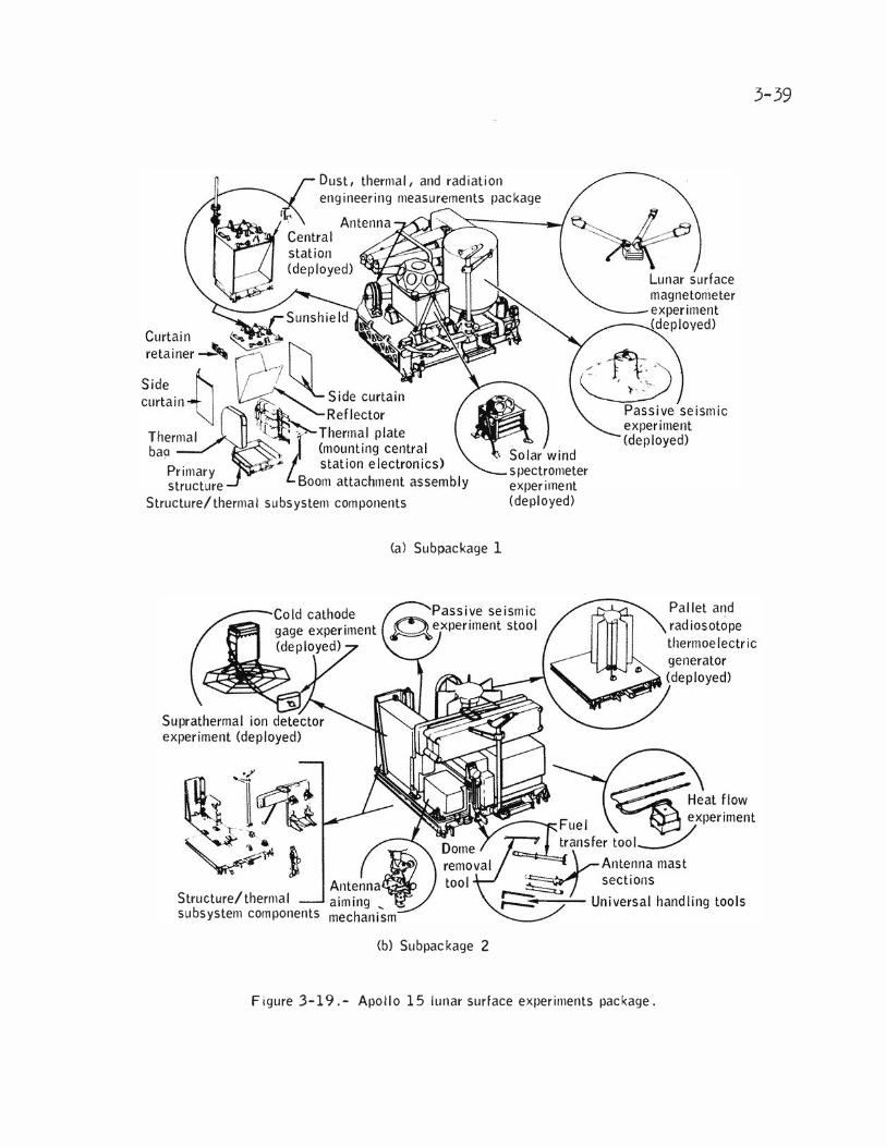
Dust, thermal, and radiation engineering measurements package
Side f-'1 curtain"i:J
Thermal ba(l
Primary structure
Structure/thermal subsystem components
Structure/thermal subsystem components
(a) Subpackage 1
(b) Subpackage 2
spectrometer ex per irnent (deployed)
Lunar surface
Pallet and
Figure 3-19.- Apollo 15 lunar surface experiments package.
3-39

3-40
I
' : Fuel caskl location ',
" '
/ Lunar module ; centerline
Compartment 2
I I I )
Lunar module scientific equipment bay
Apollo lunar surface experiments package
Figure 3-2 0.- Stowage of Apollo lunar sulrface experiments package in lunar module.

3-41
a. Analog multiplexer - analog/digital connector: The system uses a 90-channel analog multiplexer the output of which is digitized to an 8-bit word. Earlier designs used plasticencapsulated field-effect transistor switches in the multiplexer input; the transistors were subjected to prescribed tests and burn-in to assure reliability. During ground tests, numerous transistor failures occurred. The failures were traced to contamination due to the transistors not
being adequately sealed. However, no Apollo 12 and 14 lunar surface experiments package failures occurred on the lunar surface. The design used on the Apollo 15 experiments package was upgraded to use a field-effect transistor in a ceramic package. The components used on the Apollo 16 and 17 experiments packages were completely redesigned with full redundancy on all 90 analog channels.
b. Unexpected status changes: The demodulator section of the command decoder proved to be sensitive to receiver noise output occurring in the absence of an up-link signal. In operation, however, this condition did not prove to be a major problem. Operational procedures were modified to assure that the system was illuminated with an up-link signal, rendering the demodulator section insensitive to noise when the crew was on the surface imnediately following deployment. On the Apollo 16 package, a new receiver design resulted in a 10\ver noise sensitivity; on the Apollo 17 system, a new decoder design completely eliminated the problem .
3.2.9 Passive Seismic Experiment
The passive seismic experiment was designed to detect vibrations of the lunar surface and provide data that can be used to determine the internal structure, physical state, and tectonic activity of the moon. A secondary purpose is to determine the number and mass of meteoroids that strike the lunar surface. The instrument is also capable of measuring tilts of the lunar surface (tides) and changes in gravity.
The firs� of five passive seismometers was emplaced on the lunar surface during the Apollo 1 1 mission. This instrument was part of the early Apollo scientific experiments package and was po wered by a solar panel array rather than by the radioisotope thermoelectric generator used on the later missions. The instrument supplied long-period seismometer data for 20 days during the first and second lunar days after emplacement (a period of about 1 month). Short-period seismometer data were received for a longer time, with do\vn-link transmissions ending approximately 4-1/2 months after activation.
The four seismic stations emplaced during the Apollo 12, 14, 15, and 16 missions comprise a net\.;ork that spans the near side of the moon in an approximate equilateral triangle with 1100-kilometer spacing bet\veen stations. (The Apollo 12 and 14 stations are 181 kilometers apart at one corner of the triangle.) As shown in figure 3-21, four seismometers are included in the experiment package at each station: three low-frequency components forming a triaxial set (one sensitive to vertical motion and two sensitive to horizontal motion), and a high-frequency component sensitive to vertical motion. Of the 16 separate seismometers, all but three are presently operating properly. The high-frequency component at the Apollo 12 station has failed to operate since initial activation. One of the low frequency seismometers at the Apollo 14 station (Z-axis) became inoperative after 1 year of operation and another (Y-axis) began transmitting no.isy data midway through 1974. The frequency ranges of the passive seismic experiment components are compared to the ranges of other lunar surface seismic instruments in table 3-IV.
Several of the stations have exhibited thermal control problems. For collection of tidal data, limiting the instrument operating temperature to a band of approximately 1.1° K is desirable. This limitation was not achieved, partly because of problems with deployment of the thermal shroud. Corrective actions included the addition of weights to the outer edges of the shroud, the use of a Teflon layer as the outer shroud covering, and stitching of the shroud to prevent layer separation. Even so, an optimum shroud deployment was not achieved. thus, the heat loss during lunar night and the solar input incurred during the lunar day have been greater than desired.
The major findings to date are summarized (ref. 3-13):
Data from the impacts of lunar module ascent stages and launch vehicle S-lVB stages, combined with data from high-pressure laboratory measurements on returned lunar samples, provide information on lunar structure to a depth of approximately 150 kilometers. Information on lunar struc ture below this depth is derived principally from analysis of signals from deep moonquakes and distant meteoroid impacts.

Bellows (retract for uncage)
Horizontal (X, Yl sensors
long-period seismometers
Electromagnet for calibration
Level sensor"
Insulation (aluminized Mylar) ---N long-period
Short-period seismometers (3)
seismometer. heater and controller electronics�----Rr-L _ _j
Capacitor plate
Vertical (Z) sensor
LaCoste spring
Caging bellows (retract for uncage)
Wormdriver spring adjust.
Upper delta Suspension rsu�pension _ spnng � rods (3)
Magnet assembly (suspended by delta rods and suspension spring)
Coil assembly (fixed to instrument frame)
Figure 3-21.- Seismometer elements.

3-43
TABLE 3-IV.- RESPONSE SPECTRA FOR APOLLO SEISMIC EXPERIMEN�S
Frequency Experiment Sensors Apollo sites range,
Hz
Passive seismic:
Short period 1 vertical a
l2 ' 14, 15, 16 0.05 to 20
Long period 2 horizontal 12, 14' 15' 16 0.004 to 3 1 vertical 12, bl4 15, 16 0.004 to 3 '
Active seismic 3 vertical c
l4, 16 3 to 250
Lunar seismic 4 vertical 17 3 to 20 profiling
Lunar surface 1 vertical 17 gravimeter
Seismic d
0.05 to 16
Free modes e
0.00083 to 0.048
aShort-period sensor data has displayed reduced sensitivity since
deployment. b Long-period vertical sensor data invalid since }�rch 20, 1972. c
Geophone 2 data invalid since Jan. 3, 1974. d
Instrument error restricting frequency range to approximately 0.001 to 2.0 Hz with poor sensitivity.
einstrument error resulting in invalid data.

3-44
Analysis of the manmade impact data has revealed a major discontinuity at a depth of between 55 and 65 kilometers in the eastern part of the Ocean of Storr.1s. By analogy with the earth, the zone above the discontinuity is called the crust and the zone below, the mantle. Below the crust, a relatively homogeneous zone extending to a depth of approximately 1000 kilometers is suggested by the nearly constant velocity of seismic waves. Although available data are not sufficient to derive a detailed seismic velocity model for the deep interior, observations of signals originating from a large meteoroid that struck the far side of the moon and from far-side moonquakes can be explained by introducing a "core" with a radius between 600 and 800 kilometers that has markedly different elastic properties than the mantle. Current moonquake activity is concentrated near the boundary between these two zones.
Moonquakes have been detected by the low-frequency seismometers of each station at average rates of between 600 and 3000 per year, depending on the station; all the moonquakes are quite small by terrestrial standards (Richter magnitude 2 or less). Thousands of even smaller moonquakes are detected by the high-frequency seismometers. Meteoroid impacts are detected by the low-frequency seismometers at average rates of between 70 and 150 per year. Although less numerous than moonquakes, meteorid impacts generate the largest signals detected.
Lack of shallo1� seismic activity indicates that the moon is neither expanding nor contracting appreciably at the present time. Thus, the rate of heat flow out of the moon must be approximately equal to the rate of internal heat production. The presence of a thick lunar crust suggests early, intense heating of the outer shell of the moon.
3.2.10 Active Seismic Experiment
Active seismic experiment operations were conducted on the moon during the Apollo 14 and 16 missions. The purpose of the experiment was to generate and monitor seismic waves near the lunar surface. The data are being used to study the internal structure of the moon to a depth of approximately 460 meters. A secondary objective still in progress is to monitor high-frequency seismic activity during periodic listening modes.
The active seismic experiment equipment consisted of a thumper device that contained small explosive initiators, a mortar package that contained high-explosive grenades, geophones, electronics within the Apollo lunar surface experiments package central station, and interconnecting cabling. Crewmen operated the thumpers during lunar surface activities. The mortars were designed to be fired by remote command after crew departure.
The Apollo 14 geophones were deployed as planned, and the thumper part of the experiment was completed. The thumper produced excellent seismic data although the crewman was able to fire only 13 of the 21 charges. Postflight investigation showed that a malfunction occurred because lunar soil got into the arm/fire switch mechanism and the initiator selector switch was not properly seated in the detents. For Apollo 16, the thumper was successfully modified to improve switch dust seals and to increase the torque required to move the selector switch from one detent t o the next.
The Apollo 14 mortar package was deployed too close to the central station and in a position where debris would be directed toward the central station if grenades were launched. The offnominal deployment was necessitated because of a crater at the optimum mortar package deployment location. Postflight tests showed that the central station would probably be damaged if the grenades were launched. Therefore, the Apollo 14 station grenades have not been launched.
Three grenades were launched from the Apollo 16 mortar package, but the mortar pitch sensor reading varied after the first two firings and became inoperative after the third. Since the scientific objectives of the experiment had been met, the planned fourth firing was deleted.
Analysis of the seismic signals generated by the thumper during Apollo 14 has revealed important information concerning the near-surface structure of the moon. Two compressional wave seismic velocities were measured at the Fra Mauro site. The near-surface material has a seismic wave velocity of 104 meters per second. Underlying this surficial layer at a depth of 8.5 meters, the lunar material has a velocity of 299 meters per second. The measured thickness of the upper unconsolidated debris layer is in good agreement with geological estimates of the thickness of the regolith �t this site.

3-45
Combining the seismic refraction results from the active seismic experiment and the lunar module ascent seismic data recorded by the Apollo 14 passive seismic experiment allows estimates of the thickness of the underlying material to be made. These estimates range from 38 to 76 meters and may indicate the thickness of the Fra Nauro Formation at this particular site (ref. 3-14).
Two compressional wave seismic velocities have been recognized so far in the Apollo 16 data. The lunar surface material has a seismic wave velocity of 114 meters per second. Underlying this surficial material at a depth of 12.2 meters, the lunar rocks have a velocity of 250 meters per second. The 114-meter-per-second velocity agrees closely with the surface velocity measured at the Apollo 12, 14, and 15 landing sites, thus indicating that no major regional differences exist in the near-surface acoustical properties of the moon.
The seismic wave velocity of the material underlying the regolith at the Apollo 16 landing site does not indicate that competent lava flows exist in the Cayley Formation at this location. Instead, this velocity suggests the presence of brecciated material or impact-derived debris of currently undetermined thickness.
3.2.11 Lunar Seismic Profiling Experiment
The purpose of the Apollo 17 lunar seismic profiling experiment was to record the vibrations of the lunar surface as induced by explosive charges, by the thrust of the lunar module ascent engine, and by the crash of the lunar module ascent stage. Analyses of these seismic data were planned to determine the internal characteristics of the lunar crust to a depth of several kilometers. A secondary objective of the experiment was to monitor lunar seismic activity during periodic listening intervals.
Strong seismic signals were recorded from the detonation of eight explosive charges that were armed and placed on the lunar surface by the crewmen at various points along the traverses. Recording of these seismic signals generated traveltime data to a distance of 2.7 kilometers. The seismic signals received from the lunar module ascent stage impact provided a valuable traveltime datum for determining the variation of seis�ic velocity with depth in approximately the upper 5 kilometers of the moon.
The most significant discovery resulting from the analysis of the data recorded by the lunar seismic profiling experiment is that the seismic velocity increases in a marked stepwise manner beneath the Apollo 17 landing site. A surface layer with a seismic velocity of 250 meters per second and a thickness of 248 meters overlies a layer with a seismic velocity of 1200 meters per second and a thickness of 927 meters, with a sharp increase to approximately 4000 meters per second at the base of the lower layer. The seismic velocities for the upper layers are compatible with those for basaltic lava flows, indicating a total thickness of approximately 1200 meters for the infilling mare basalts at Taurus-Littro w. Hajor episodes of deposition or evolution are implied by the observed abrupt changes in seismic velocity (ref. 3-15).
3.2.12 Lunar Surface Nagnetometer Experiment
Magnetic field measurements have proved to be one of the most useful tools for determining the electromagnetic properties of the earth interior and solar-wind and ionospheric environments. This method was extended to the moon with the emplacement of a three-axis fluxgate magnetometer on the lunar surface during the Apollo 12 lunar stay. Similar magnetometers were deployed and activated during the Apollo 15 and 16 lunar stays.
The instrument has a sensor located at the end of each of three orthogonal booms. Three vector field components are measured in the normal mode of operation; however, the sensors may be rotated such that they simultaneously align parallel in each of the three boom axes. This alignment permits the calculation of the vector gradient in the plane of the sensor and permits an independent measurement of the magnetic field vector at each sensor position. The sensors and booms are located on a central structure which houses the central electronics and gimbal-flip unit. An evaluation of the performance of the Apollo 12 instrument resulted in the following changes to the Apollo 15 and 16 instruments.
a. The measurement range was changed from •100, �200, and !400 gammas to +50, tlOO, and •.200 gammas.
b. A curtain was added over the electronics box to impt:ove thermal control.

3-46
Intrinsic steady (remanent) magnetic fields provide a record of the magnetic field environment that existed 3 to 4 billion years ago when the lunar crustal material cooled below the Curie temperature. The Apollo 12 lunar surface magnetometer detected a remanent magnetic field of approximately 38 gammas superimposed on the geomagnetic tail, transition region, and interplanetary fields through which the moon passes during each orbit around the earth (ref. 3-16) . The remanent magnetic field at the Apollo 15 site was calculated to be approximately 6 gammas (small compared to the fields at the Apollo 12, 14, and 16 sites). Since the Apollo 15 site lies near the edge of the Mare Imbrium mascon basin, the existence of little or no remanent field at that site suggests that mascons are not highly magnetic (ref. 3-17).
The bulk relative magnetic permeability of the moon has been calculated from measurements obtained in the geomagnetic-tail region to be u/uo = 1.03 ±0.13. Electrical-conductivity and temperature profiles of the lunar interior have been determined from solar wind magnetic field step-transient event measurements. The data presented in the following table fit the three-layer model of the moon shown in figure 3-22 (ref. 3-18). Temperature calculations are based on conductivity as a function of temperature for pure olivine.
Electrical conductivity, Region mho/m Tem£erature1 OK
1 <10-9 <440
2 '\.).5 X 10-4 890
3 '\.10-, 1240
Qualitatively, the inductive eddy-current response at the Apollo 15 site is similar to that at the Apollo 12 site. Observations show that the solar wind compresses the steady remanent field at the Apollo 12 site during periods of high solar plasma density (ref. 3-17).
On June 14, 1974, the Apollo 12 and Apollo 15 instruments were permanently commanded off. The Apollo 12 instrument science and engineering data had been invalid for 1 year and that of the Apollo 15 instrument for 6 months. Because of decreasing output from the radioisotope thermoelectric generators and the criticality of reserve power during lunar night, spurious functional changes could have caused the loss of functional instruments. The Apollo 16 instrument was operative at the time of publication of this report.
3 . 2.13 Lunar Portable Magnetometer Experiment
Portable magnetometers were used by the Apollo 14 and 16 crews. The objective of the lunar portable magnetometer measurements was to determine the remanent magnetic field at various lunar surface locations. The magnetometer actually measured low-frequency (less than 0.05 hertz) components of the total magnetic field at the surface, which includes the remanent field, the external solar field, fields induced in the lunar interior by changing solar fields, and fields caused by solar wind interactions with the lunar remanent fields. Simultaneous measurements made by the lunar surface magnetometer of the time-varying components of the field were later subtracted to give the desired resultant remanent field values caused by magnetized crustal material.
The lunar portable magnetometer consisted of a set of three orthogonal fluxgate sensors mounted on top of a tripod. The sensor-tripod assembly was connected by a ribbon cable to an electronics box. On Apollo 14, the electronics box was mounted on the modular equipment transporter; on Apollo 16, the box was mounted on the lunar roving vehicle. After positioning the tripod at the desired location, a crewman turned the power switch on, read the digital displays in sequence, and verbally relayed the data back to earth.
The Apollo 14 instrument recorded steady magnetic fields of 103 ±5 gammas and 4 3 ±6 gammas at two sites separated by 1120 meters. These measurements showed that the unexpectedly high (38 gamma) steady field measured at the Apollo 12 site 180 kilometers away was not unique. In
deed, these measurements and studies of lunar samples and lunar-orbiting Explorer 35 data indicate that much of the lunar surface material was magnetized at a previous time in lunar history (ref. 3-19). The magnetic field of 313 gammas measured in the North Ray Crater area during the
Apollo 16 mission to the lunar highlands proved to be the highest ever measured on another body of planetary size. Other field measurements obtained by the Commander and Lunar Module Pilot at different sites along the three surface traverses varied from 121 to 313 gammas.

3-47
Figure 3-22.- Three-layer moon model.

3-48
l'lagne tic studies of returned samples indicate that they formed in a reasonably strong magnetic field (a few thousand gammas ) , yet there is no such field affecting the moon today. It is hypothesized that the moon had a reasonably strong magnetic field throughout much of its early history.
The surface fields provide reference values for extrapolation of subsatellite magnetometer measurements to the lunar surface. Further analysis should yield information on the geological nature and origin of lunar remanent fields, including the possibility of an ancient lunar dynamo , shock-induced magnetization, or another mechanism to account for the strong magnetization found in lunar surface samples.
3. 2 . 14 Heat Flow Experiment
The purpose of the heat flow experiment is to determine the rate of heat flow from the lunar interior and the thermal properties of the lunar subsurface, thereby contributing to an understanding of the thermal history of the moon. Heat loss is directly related to the internal temperature and the rate of internal heat production; therefore, measurements of these quantities enable limits to be set on long-lived radioisotopic abundances (the chief source of interior heating) and the internal temperature.
The experiment hardware consists of two temperature-sensing probes and electronics for controlling and processing the measurements. Two holes, spaced about 9 meters apart , were drilled, and the probes were inserted into these holes. Sensitive thermometers within the probes accurately measure the vertical temperature gradient over approximately the lower 100 centimeters of each hole. These readings, over an extended period of time, yield the heat-flux data. Each probe also contains heating elements. When one of these elements is energized, a known quantity o f heat is generated at a known distance from a temperature sensor. The resulting amount and rate of temperature change at the sensor are used to determine the thermal conductivity of the lunar material near the probe.
Heat flo1� ·experiments were successfully deployed and activated on the Apollo 15 and 17 missions. Deployment of a heat flow experiment was attempted during the Apollo 16 lunar stay; however, the cable connecting the electronics package with the Apollo lunar surface experiments package central station was inadvertently broken during experiment package deployment activities, rendering the heat flow experiment hardware inoperative. The only operational problem with the emplaced instruments has been the loss of one reference temperature reading on the Apollo 15 heat flow experiment . Because reference junction temperature measurements are redundant, there has been no loss of data. No specific failure mechanism was revealed during investigation of the circuit s ; therefore, no design changes were made on the Apollo 17 instrument.
The Apollo 15 and 1 7 measurements were made in similar regional settings, that is, on the margins of large mascon basins. Though the possibility of regional biases to these measurements remains, the evidence is strong that a major part of the lunar surface is characterized by heat flm� at the upper limit of that expected from geochemical models and thermal history calculations. Results to date indicate that the average heat flow from the interior of the moon outward is approximately 3 microwatts per square centimeter, about half that of the earth (ref. 3-20).
3.2.15 Lunar Surface Gravimeter Experiment
The lunar surface gravimeter was designed to assist in the search for gravitational radiation from cosmic sources. A secondary objective is to measure tidal deformation of the moon.
The lunar surface gravimeter has three basic components: a gravity meter, a structural/ thermal-control package, and an electronics package. The gravity meter uses the LaCoste-Romberg type of spring-mass suspension to sense changes in the vertical component of local gravity. The major fraction of the force supporting the sensor mass (beam) against the local gravitational field is provided by a zero-length spring (one in which the restoring force is directly proportional to the spring lengt h). As shown in figure 3-23, small changes in force tend to displace the beam up or down . This imbalance was to be adjusted to the null position by repositioning the spring pivot points with micrometer screws. Incremental masses added by command to the sensor mass and the position of the coarse and fine microme ter screws, as read out by the shaft encoder logic, were to provide the gravity measurement.

Sensor beam (caging mechanism not shown) ------::r�
Note: Scale modified for clarity
Cup
Access holes for caging fingers
Beam center of gravity
Massadding mechanism
Cross section of mass adding mechanism
Shaft (to motor)
3-49
Screw shaft (to motor)
...,.� Fine screw
screw
Fi xed capaci tor plates (detector)
Figure 3-2 3.- Lunar surface gravimeter mechanism.

3-50
The instrument was deployed during the Apollo 17 lunar stay; however, following the initial experiment turn-on, the setup procedure of nulling the sensor beam in the proper stable position between capacitor plates could not be accomplished. When the command was given to add any or all of the nulling masses to the sensor beam assembly, the data indicated that the beam would not move away from the upper capacitor plate. The only way to lower the beam was to cage the beam against the lower capacitor plate. During the second and third extravehicular activities, the Lunar Module Pilot rapped the exposed top plate on the gimbal; rocked the experiment in all directions; releveled the instrument, working the base well against the surface; and verified the sunshade tilt. These actions were taken to free a mass assembly or a sensor beam that was suspected o f being caught o r binding, but no change was apparent. Review of sensor records revealed that an error in arithmetic resulted in the sensor masses being approximately 2 percent lighter than the proper nominal weight for 1/6-earth-gravity operation of the flight unit . The sensor mechanism allows a tl . 5 percent adjustment by ground command to correct mass inaccuracies.
Several reconfigurations of the instrument have been commanded. The sensor beam has been centered by applying a load on the beam through the mass support springs by partial caging of the mass weight assembly. In this configuration, the instrument is supplying some seismic data
(ref. 3-21).
3.2.16 Traverse Gravimeter Experiment
The primary goal o f the traverse gravimeter experiment was to make relative gravity measurements at a number of sites in the Apollo 17 landing area and to use these measurements to obtain information about the geological substructure. A secondary goal was to obtain the value of the gravity at the landing site relative to an accurately known value on earth. The instrument package contained a vibrating string accelerometer from which the gravity values could be determined. The preliminary gravity profile is based upon the assumption that the material underlying the valley floor consists of basalt that is 1 kilometer thick and has a positive density contrast of 0.8 grams per cubic centimeter with respect to brecciated highland material on either side. Using this model, the gravity values at the edges of the valley are 25 milligals lower than at the lunar module site, and a variation in the central part of the valley floor is within 10 milligals of the value at the lunar module site. These values will be refined based upon more elaborate models. A value of g = 162 694.6 �5 milligals was measured at the lunar module site (ref. 3-22).
3. 2 . 17 Surface Electrical Properties Experime nt
The surface electrical properties experiment was used to explore the subsurface material of the Apollo 17 landing site by means of electromagnetic radiation. The experiment was designed to detect electrical layering, discrete scattering bodies, and the possible presence of water. The experiment data may help others interpret many observations already made with both earthbased and lunar orbital bistatic rada r. In addition, the experiment provides data needed to interpret observations made with the lunar sounder (sec. 3 . 3. 1 . 5), and the results are expected to help define the stratigraphy of the Apollo 17 landing site.
The crewmen deployed a small, low-power transmitter and laid on the surface two crossed dipole antennas that were 70 meters lo�g tip to tip. A receiver and receiving antennas were mounted on the lunar roving vehicle. Inside the receiver, there was a tape recorder which recorded the data on magnetic tape. In addition to the surface electrical properties experiment data, information on the location of the lunar roving vehicle, obtained from the lunar roving vehicle navigation system, was also recorded on the tape.
The basic principle of the experiment is the interference of two or more waves to produce an interference pattern. Electromagnetic energy radiated from a transmitting antenna travels at different velocities through different media. Thus, distinctive patterns were recorded as the lunar roving vehicle moved along the surface. Values of the electrical properties of the subsurface material (dielectric constant and loss tangent) were obtained from analysis of the data.
Two quite different structural models of the Apollo 17 site have been developed to account for the observations. Although neither is based on rigorous theory, the experiment team believes that each is correct in the essential features. The first model, preferred by most members of

3-51
the team, is one. in which the dielectric constant increases with depth from a value of 2.5 to 3 near the surface to approximately 5 at a depth of 50 to 60 meters. A d.iscontinuity is present at 50 to 60 meters, where the dielectric constant increases to a value o f 6 to 6.5. On the basis of a low value of the loss tangent, water is probably not present at the Apollo 17 site.
In the alternate structural model, the cause of the apparent change of dielectric constant with depth is assigned to a sloping interface bet1veen a thin upper layer and a thick lower layer. The upper layer is , perhaps, 20 meters thick beneath the experiment site and thins to 15 meters at station 2 (fig. 3-12). In addition, there is a hint of a discontinuity in the dielectric constant at a depth of approximately 300 meters.
Additional theoretical and scale model work is being done to determine which model is more nearly correct (ref. 3-23).
3.2.18 Lunar Neutron Probe Experiment
The lunar neutron probe experiment, one o f the Apollo 17 surface experiments, was designed to measure the rates of low-energy neutron capture as a function of depth in the lunar regolith.
Various studies of the lunar samples, particularly those involving isotopic variations in gadolinium and samarium, have documented the effects of long-term exposure of lunar materials to neutrons and have shown how such data can be used to calculate regolith accumulation and mixing rates and ages for stratigraphic layers in lunar core samples. Comparison o f a neutron capture product with a spallation product in lunar rocks can also be used to infer average irradiation depths that are required to obtain accurate exposure ages. In addition, the Apollo 15 orbital gamma ray experiment has detected gamma rays from neutron capture on such elements as iron and ti tanium, from which the relat ive chemical abundances of these elements could be inferred. In all these cases, the strength of the conclusions has been necessarily limited by the lack of experimental values for the relevant rates of neutron capture. The neutron probe experiment was proposed to obtain these data.
The experiment used two particle track detection systems. A cellulose triacetate plastic detector was used in conjunction with boron-10 targets to record the alpha particles emitted with the neutron capture on boron-10. For the second system, mica detectors were used to detect the fission fragments from neutron-induced fission in uranium-2 3 5 targe t s .
The lunar neutron probe experiment was assembled, activated, and deployed i n the hole formed by the drilling and extraction of the deep-core sample. The probe was deployed during the first extravehicular activity and retrieved at the end of the third extravehicular activity for a total activated exposure period of 49 hours.
lfuen the probe was disassembled, the targets and detectors were all in excellent condition, and indicators show that the probe temperature never exceeded 335° K. The possibility that the probe would reach higher temperatures was a serious concern before the mission, because thermal annealing of the particle tracks in the plastic could occur.
Although only the mica detectors had been analyzed at the time of publication of reference 3-24, it appears that good agreement exists between the results of the experiment and theoretical calculations of neutron capture rates and the equilibrium neutron energy spectrum. If this agreement is confirmed, interpretations of lunar sample data to determine regolith mixing rates and depths, depths of irradiation for lunar rocks, and accumulation rates and deposition times can be verified.
3 . 2 . 19 Laser Ranging Retroreflector
Arrays of optical reflectors were emplaced on the lunar surface during the Apollo 11, 14, and 15 missions. Each of the arrays consisted of a compact assembly of solid fused silica corner reflectors , 3.8 centimeters in diameter, mounted in an aluminum panel. Fused silica was used because of its known radiation resistance, thermal stability, high transparency to most wave lengths in solar radiation, long life, and operation in lunar day and lunar night. Each reflector was recessed 1.9 centimeters in the panel mounting socket to minimize temperature gradients.

3-52
Accurately timed pulses of light from a ruby laser at a ground station observatory are directed through a telescope aimed at one of the reflector packages. The light is reflected back on a path parallel to the incident beam, collected by the telescope, and detected by special receiving equipment. The time required for a pulse of light to reach the reflector and be returned is used to establish the distance from the earth ground station t o the reflector site on the lunar surface at that time. Even though the illuminated spot on the moon (the reflector) is small, the fact that each corner reflector sends the light back in almost the same direction it came from causes the return signal at the earth from the reflector panel to be 10 t o 100 times larger than the reflected intensity from the lunar surface.
The overall design for the Apollo 14 and 15 reflector arrays was similar to that for Apollo 11 except the half-angle taper of the reflector cavities was increased so as to increase the array optical efficiency 20 to 30 percent for off-axis earth positions. The number of reflectors in the array was increased from 100 for Apollo 11 and 14 to 300 for Apollo 15 to permit regular observations with simpler ground equipment, especially for groups mainly interested in obtaining geophysical information from observing only one reflector. The increase also allowed the use of a number of permanent stations on different continents for the determination of polar motion and earth rotation with high accuracy, as well as the use of movable lunar ranging stations to monitor movements of a large number of points on the earth's surface.
Ground stations obtaining successful measurements from the Apollo arrays include the McDonald Observatory in Texas, Air Force Camb ridge Research Laboratory's Lunar Ranging Observatory in Arizona, Lick Observatory, Pic du Midi Observatory in France, Tokyo Astronomical Observatory in Japan, Crimean Astrophysical Observatory in the Soviet Union, and the Smithsonian Astrophysical Observatory.
The three Apollo reflector sites form an almost equilateral triangle with sides 1250, 1100, and 970 kilometers, and are almost centered on the near side of the moon. The complex angular motions of the moon about its center of mass thus can be separated with high accuracy from the range changes due to center-of-mass motion by differential range measurements to different reflector locations.
The accuracy already achieved in lunar laser ranging represents a hundredfold improvement over any previously available knowledge of the distance to points on the lunar surface. Extremely complex structure has been observed in the lunar rotation, and significant improvement has been achieved in the lunar orbit. The selenocentric coordinates of the retroreflectors give improved reference points for use in lunar mapping, and new information on the lunar mass distribution has been obtained.
Full use of the Apollo arrays will require an observing program continuing many years and using ground stations arounrl the world. No evidence of degredation with time in the return signals from any of the Apollo reflectors has been observed so far, and thus an operational lifetime of at least 10 years may be expected for these passive retroflector arrays.
Further information is contained in reference 3-25.
3 . 2 .20 Charged-Particle Lunar Environment Experiment
The charged-particle lunar environment experiment was deployed at Fra Mauro as part of the Apollo 14 experiments package system. The instrument was designed to measure the fluxes of electrons and protons with energies ranging from 40 to 70 000 electron volts and their angular distribution and time variations.
The basic instrument of the experiment consists of two detector packages (analyzers A and B) oriented in different directions for minimum exposure to the ecliptic path of the sun. Each detector package has six particle detectors; five provide information about particle energy distribution, and the sixth provides high sensitivity at low particle fluxes. Particles entering the detector package are deflected by an electrical field into one of the six detectors, depending on the energy and polarity of the particles.

3-53
On April 8, 1971, the analyzer B detector voltage failed. Subsequent playback of the data from various remote sites revealed that the anomalous condition occurred abruptly. As a result , analyzer B is not providing any scientific data. The analyzer A detector voltage decreased significantly on June 6, 1971. The charged-particle lunar environment experiment continued to operate until June 16 , 1971, when, after another significant analyzer A voltage decrease, the experiment was commanded to the standby mode. Since then, the instrument has been operated under a revised procedure to avoid further degradation.
The data have application to investigations of various particle phenomena, including solar wind, the magnetosphere, and low-energy solar cosmic rays. Preliminary data analyses have shown the presence of a lunar photoelectron layer; an indication of modulation or acceleration o f lowenergy electrons near the moon; penetration of auroral particles to lunar distances in the magnetospheric tail; and electron fluxes in the magnetospheric tail, possibly associated with the neutral sheet (ref. 3-26).
3 . 2 . 2 1 Solar Wind Spectrometer Experiment
Two solar wind spectrometers were deployed and activated on the lunar surface - one during the Apollo 12 mission and the other during the Apollo 15 mission. The two instruments, separated by approximately 1100 kilometers, provided the first opportunity to measure the properties of the solar plasma simultaneously at two locations a fixed distan.ce apart. The instruments were designed to measure the velocity, density, and angular distribution of the solar wind plasma striking the lunar surface. Thus, the interaction of the solar wind with the moon may be studied and inferences made about the physical properties of the moon, the nature of the magnetospheric tail of the earth, and general solar wind properties.
To be sensitive to solar wind plasma from any direction (above the horizon of the moon) and to ascertain its angular distribution, the solar wind spectrometer has an array of seven Faraday cups. Because the cups are identical, an isotropic flux of particles produces equal currents in each cup; For a flux that is not isotropic, analysis of the relative amounts of current in the seven collectors determines the mean direction of plasma flot·l and is a measure of the anisotropy.
Indications of anomalous behavior of the Apollo 12 instrument were traced to August 1971 after initial discovery in November 1971. Subsequent investigation revealed that the anomaly has occurred intermittently since June 13, 1971. The periods of abnormality always occur when the sun is between 120° and 135° from the dawn horizon, and their duration increases steadily month after month. The effect of this anomaly is simply to restrict the range of energy over which positive ions can be detected, reducing the upper limit by a f actor of 2 . The instrument was designed to go as high as 9600 electron volts per unit charge to accommodate the helium component of the solar wind at the highest velocities that had ever been observed. In the high-gain mode, detectable currents of hydrogen ions are never found in the two highest energy levels, and helium ions are detectable in these levels only rarely. Thus, the absence of these two levels in the high-gain mode does not seriously compromise the validity and usefulness of the data. In the low-gain mode, hydrogen ion energies still do not extend into these levels, but data on helium ions will be lost more frequently. Thus, the occurrence of this anomalous performance necessitates operation of the solar wind spectrometer in the high-gain mode if possible.
The Apollo 15 solar wind spectrometer telemetry data became invalid coincident with a central station reserve power decrease of approximately 7 watts on June 30, 1972 . The power decrease indicated that the experiment which is current limited was drawing approximately 13 watts of power. During real-time support periods, the experiment was cycled from the standby mode to the operate mode, and verification that the instrument was demanding excess power from the central station was obtained. The instrument was permanently commanded off June 14, 1974.
Preliminary results from the data analyzed include indications that the solar plasma at the lunar surface is superficially indistinguishable from that at a distance from the moon, both when the moon is ahead of and behind the bow shock of the earth. No detectable pl asma appears to exist in the magnetospheric tail of the earth or in the shadow of the moon (ref. 3-27).

3 . 2 . 22 Solar Wind Composition Experiment
The purpose of the solar wind composition experiment is to determine the elemen tal and isotopic composition of the noble gases and other selected elemen ts in the solar wind by measurement of particle entrapment on exposed sheets of foil.
The average i.sotopic compositions of the solar wind are of significant importance because comparisons can be made with ancient compositions derived from solar wind gases trapped in lunar soil and rocks. Because solar activity varies with time, the isotopic abundances in the solar wind are expected to vary also. Therefore, to obtain accurate average abundances which exist during this age of the solar system, this experiment was performed numerous times, separated in time and with extended foil exposure times.
The experimen t was deployed on five missions (Apollo 11, 12, 14, 15, and 16) . On each mission, the experiment consisted of an aluminum foil sheet on a reel and a staff to which the foil and reel were attached. The apollo 16 experiment differed from those o f the previous missions in that pieces of plat inum foil were attached to the aluminum foil. This change was made to determine whether or not the platinum foil pieces could be cleaned with fluoridic acid to remove lunar dust contamination without destroying rare gas isotopes of solar wind origin up to the mass of krypton. The foil was posit ioned by a crewman perpendicular to the solar rays , left exposed to the solar wind, retrieved, and brought back to earth for analysis. Exposure times for each deployment were as follows.
Exposure time, Mission hr:min
Apollo ll 01:17
Apollo 12 18:42
Apollo 14 21:00
Apollo 15 41 : 08
Apollo 16 4 5 : 05
The relative elemental and isotopic abundances of helium and neon measured for the Apollo 12, 14, 15, and 16 exposure times are quite similar but differ from those obtained during the Apollo 11 mission. Particularly noteworthy is the absence of any indication of electromagnetic separation effects that might have been expected at the Apollo 16 landing site because of the relatively strong local magnetic field. Weighted averages of ion abundances in the solar wind for the five foil exposure periods are given in table 3-V. The errors cited are an estimate of the uncertainty of the averages for the indicated period. The errors are based on the variability of the observed abundances obtained from the four long exposure times (ref. 3-28).
3 . 2 . 2 3 Suprathermal Ion Detector and Cold-Cathode Gage Experiments
The suprathermal ion detector and cold-cathode gage experiments are conveniently discussed together because the data processing system is common to both experiments and because the electronics for the cold-cathode gage are contained in the suprathermal ion detector package. These two experiments were part of the 'Apollo 1 2 , 14, and 15 lunar surface experiments packages.
The suprathermal ion detector experiments measure the energy and mass spectra of positive ions near the lunar surface. A low-energy detector counts ions in the velocity range from 4 x 10� to 9 . 3 5 x 10⁶ centimeters per second with energies from 0 . 2 to 4 8 . 6 electron volts , enabling the determ.ination of the distribut ion of ion masses as large as 120 atomic mass units. A h.igherenergy detector counts ions in selected energy intervals between 1 and 3500 electron volts. The ions generated on the moon are of interest because possible sources are sporadic outgassing from volcanic or seismic activity, gases from a residual primordial atmosphere of heavy gases, and evaporation of solar wind gases accreted on the lunar surface. Ions that arrive from sources beyond the near-moon environment are also being studied. For example, the motions of .ions in the magnetosphere can be investigated during those periods when the moon passes through the magnetospheric tail of the earth.

TABLE 3-V.- COMPARISON OF WEIGHTED AVERAGES OF SOLAR WIND ION ABUNDANCESa
b Sources He4
/He3
He4/Ne20
Ne20/Ne
22 Ne22/Ne
21 Ne20
/Ar36
Solar wind (average from 2350 ±120 570 ±70 13.7 ±0.3 30 ±4 28 ±9 solar wind composition experiments)
Lunar fines 10084 2550 ±250 96 ± 1 8 12.65 ±0.2 31.0 ±1.2 7 ±2
Ilmenite from 10084 2720 ±100 218 ± 8 12.85 ±0.1 31.1 ±0.8 27 ±4
Ilmenite from 12001 2700 ±80 253 ±10 12.9 ±0.1 32.0 ±0.4 27 ±5
Ilmenite from breccia 10046 3060 ±150 231 ± 1 3 12.65 ±0.15 31.4 ±0.4 ( c )
Terres trial atmosphere 7 X 10⁵ 0.3 9.80 ±0.08 34.5 ±1. 0 0.5
aObtained from the solar wind composition experiments with abundances in surface
correlated gases of lunar fines and a breccia, and in the earth ' s atmosphere.
3-30.
b Data for surface-correlated gases in lunar materials are from references 3-29 and
c Variable.
w I ln
ln

3-56
The cold-cathode gages measure the density of neutral atoms comprising the ambient lunar atmosphere. The range of the instruments corresponds to atmospheric pressures of 10- 12 to 10-6 torr. Neutral atoms entering the sensor become ionized and result in a minute current flow that is proportional to the atmospheric density. These instruments were included in the experiments packages to evaluate the amount of gas present on the lunar surface. The gage indications can be expressed as a concentration of particles per unit volume or as pressure, which depends on the ambient temperature in addition to the concentration. The amount of gas observed can be compared with the expectation associated with the solar wind source to obtain an indication of the presence of other gas sources.
The Apollo 12 suprathermal ion detector and cold-cathode gage were commanded on after experiments package deployment and functioned satisfactorily for approximately 14 hours. At that time, the 3500-volt power supply for the suprathermal ion detector and the 4500-volt power supply for the cold-cathode gage were turned off automatically. Analysis indicates that arcing resulted from the outgassing of the electronics potting material and that the arcing protection provisions turned off the power supplies.
The 4500-volt power supply was immediately commanded on several times unsuccessfully. All attempts to command the 4500-volt power supply on have been unsuccessful because of damage incurred by the arcing. After a waiting period for gases to dissipate, the 3500-volt power supply was commanded on successfully, and the Apollo 12 suprathermal ion detector has been able to function since that time.
The Apollo 14 and 15 suprathermal ion detectors have experienced numerous arcing anomalies since lunar deployment and initial activation; howeve r, these instruments continue to function. The Apollo 14 experiment also has experienced an anomaly in the positive analog-to-digital converter, causing a loss of all engineering data processed through that converter. This anomaly has had no adverse effect on the scientific outputs of the experiments.
The suprathermal ion detectors have detected numerous single-site ion events. Multiple-site observations of ion events that possibly correlate with seismic events of an impact character (recorded at the seismic stations) have resulted in information about the apparent motions of the ion clouds. The 500- to 1000-electron-volt ions streaming down the magnetosheath have also been observed simultaneously by all three instruments (ref. 3-31).
On March 7, 1971, the Apollo 14 suprathermal ion detector recorded 14 hours of data that appears to be primarily a result of clouds of water vapor. Studies of all possible sources of such an event leads to the conclusion that the water is of lunar origin (ref. 3-32). In view of the almost total lack of water in returned samples, this is an unexpected result.
Before the Apollo program, optical and radio observations had been used to set lower limits on the density of the lunar atmosphere; apart from that, nothing was known . The Apollo program has demonstrated that the contemporary moon has a tenuous atmosphere although by earth standards the lunar atmosphere is a hard vacuum. The cold-cathode gage experiment measured the concentrations of neutral atoms at the lunar surface to be approximately 2 x 10 5 atoms per cubic centimeter. This measurement corresponds to a pressure between 10- 12 and 10- 1 1 torr (a vacuum not achievable in earth laboratories) .
3 . 2 . 24 Cosmic Ray Detector Experiment
The relative abundances and energy spectra of heavy solar and cosmic ray particles convey much information about the sun and other galactic particle sources and about the acceleration and propagation of the particles. In particular, the lowest energy range, from a few million electron volts per nuclear mass unit (nucleon) to 1000 electron volts per nucleon (a solar wind energy), is largely unexplored. The cosmic ray experiment contained various detectors designed to examine this energy range.
The experiment was carried on the Apollo 16 and 17 missions and was the outgrowth of earlier cosmic ray experiments on the Apollo 8 and 12 missions. The early experiments consis ted basically of a detector affixed to crewmen's helmets to assess the amount of cosmic ray radiation to which the crewmen were subjected in space. The purposes of and the hardware for the Apollo 16 and 17 experiments were considerably more exotic and complex.

3-57
The detection basis of nearly all the cosmic ray experiments is that particles passing through solids can form trails o f damage, revealable by preferential chemical attack, which allows the particles to be counted and identified. The Apollo 16 detector hardware consisted of a foldable four-panel array (fig. 3-24). The panels were mounted on the outside of the lunar module descent stage so as to directly expose three panels to cosmic ray and solar wind particles after the spacecraft/ lunar module adapter had been jettisoned. During the first extravehicular activity on the lunar surface, a crewman pulled a lanyard to expose the hidden surfaces of panel 4 to the lunar surface cosmic rays and the solar wind. Exposure ended just before the termination o f the third extravehicular activity , at which time the four-panel array was pulled out of its frame and folded into a compact package for return to earth. Because the folding and stowing o f the device ended the period of useful exposure of the detectors, provision was made to distinguish particles detected during the useful period from particles that subsequently penetrated the spacecraft and entered the detectors.
The full planned exposure of the four panels was not obtained on Apollo 16 because the scheduled sequence of events did not occur completely as planned.
a. Panel 4 contained a shifting mechanism that activated several experiments, most notably the neutron experiment , on the lunar surface. Because of a mistake in the final assembly, the shifting was only partially successful. This circumstance caused degradation of the information that can be obtained from the neutron experiment and made it difficult to obtain information on the time variation o f light solar wind nuclei.
b. A temperature rise in the package exceeded design specifications. Although this temperature rise has rendered the anlaysis of the experiment difficul t , the effects of the temperature rise can be taken into account .
c. At some time during the mission, panel 1 became covered with a thin, dull film that seriously degraded the performance of panel 1 .
d . During the translunar phase of the mission on April 1 8 , 1972, a medium-sized solar flare occurred. Detectors exposed to the solar flare showed that the flare contained approximately 108 protons per square centimeter with energies greater than 5 million electron volts.
The Apollo 17 hardware (fig. 3-25) consisted of a thin aluminum box with a sliding removable cover. Four particle-detector sheets were attached to the interior wall of the box, and three were attached to the inside surface of the cover. Opening was accomplished by two opposing rings, one mounted on the cover and the second mounted on the box. During the first extravehicular activity, a crewman removed the experiment from the lunar module and pulled the cover portion off the box. The cover was hung on the lunar module structure in the shade, with the detector surfaces oriented away from the sun and facing the dark sky. The open box was then hung by a Velcro strap on a lunar module strut in the sun, with the detector surfaces perpendicular to the sun. The detectors were exposed to the lunar environment for 45-1/2 hours. The experiment was retrieved at the beginning of the third extravehicular activity, earlier than planned, because o f an apparent increase in the flux o f low-energy particles caused by a visually active sunspot that was present during the entire mission.
Three teams of investigators are using data from the cosmic ray detector experiment. The preliminary findings from the Apollo 16 data are given in reference 3-33. Included are the observations that the differential energy spectrum of nuclei with Z > 6 falls by seven orders of magnitude over the interval from 0.1 to 20 million electron volts per nucleon, then remains almost flat up to approximately 100 million electron volts per nucleon. The two parts correspond to contributions from the sun and from galactic cosmic rays.
3 . 2 . 25 Lunar Ejecta and Meteorites Experiment
This experiment , emplaced on the lunar surface during the Apollo 17 mission, measures impacts of primary cosmic dust particles (10- 9 grams or less) and lunar ejecta emanating from the sites of meteorite impacts on the moon. Specific object ives are to (1) determine the background and long-term variations in cosmic dust influx rates, (2) determine the extent and nature of lunar ejecta produced by meteorite impac ts on the lunar surface, and (3) determine the relative contributions of comets and asteroids to earth meteoroids.

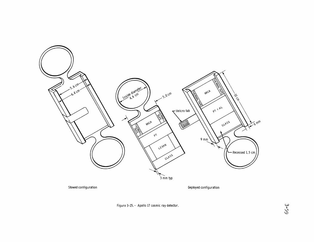


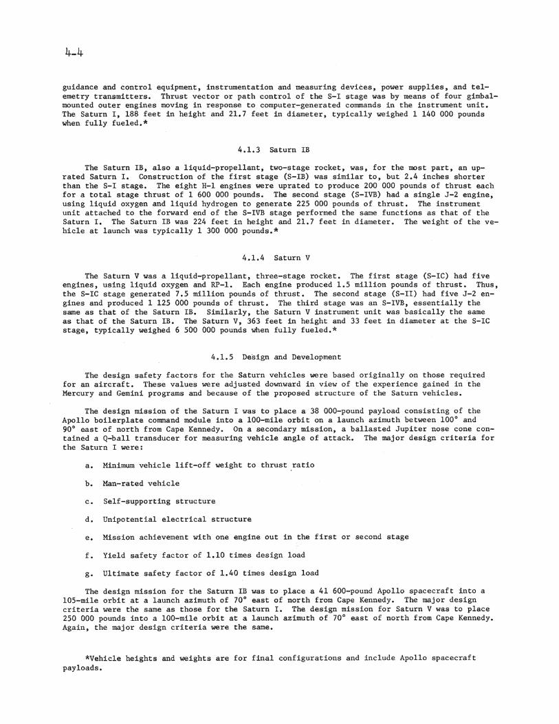


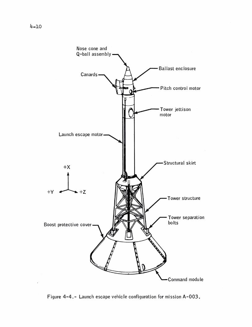


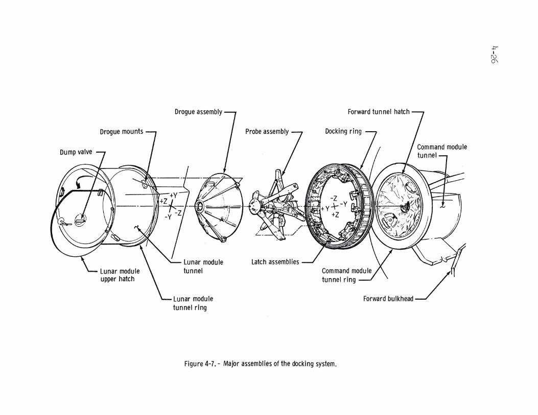


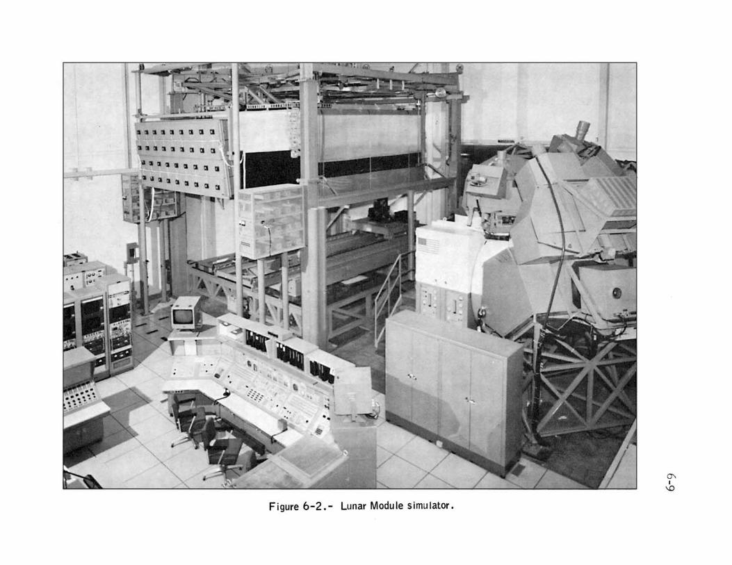


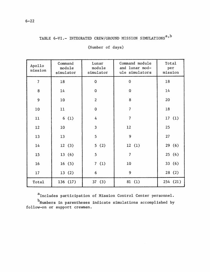


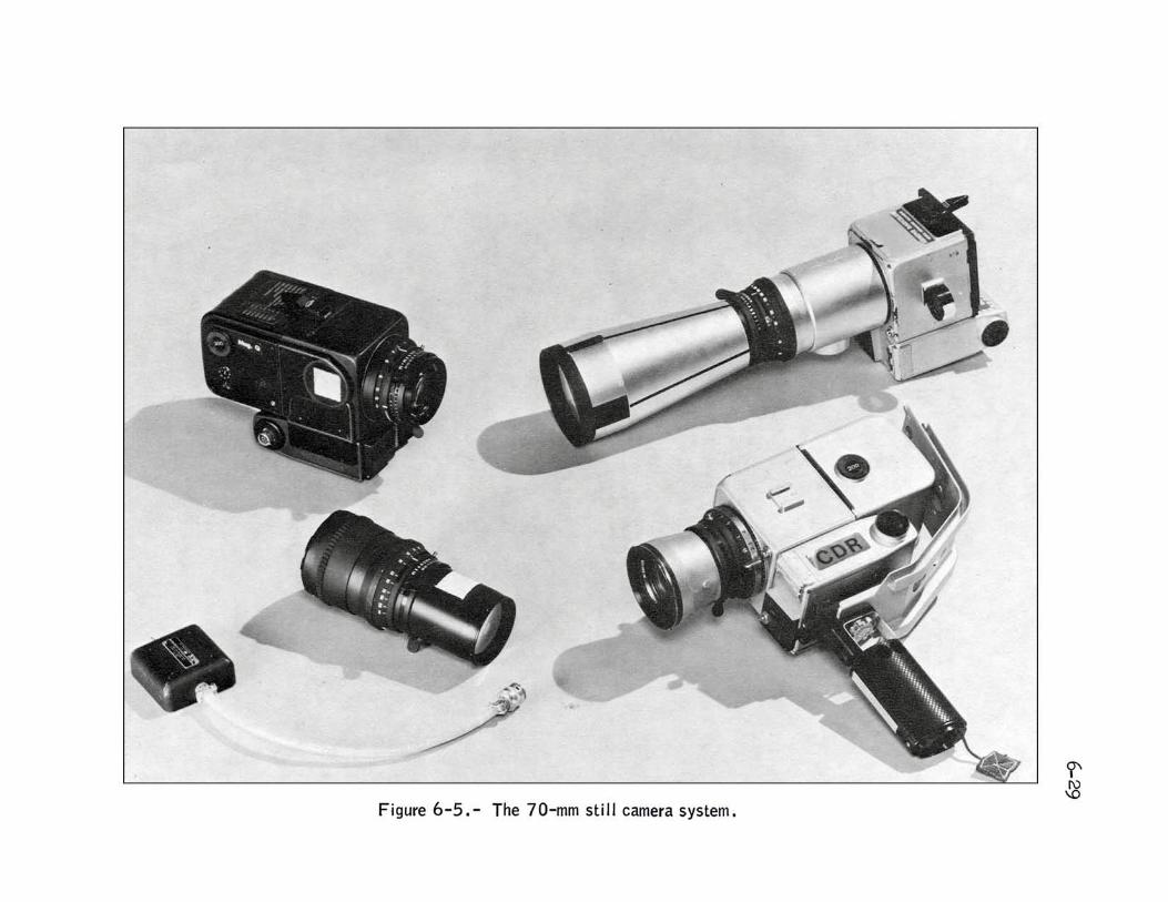


6-38


7-30


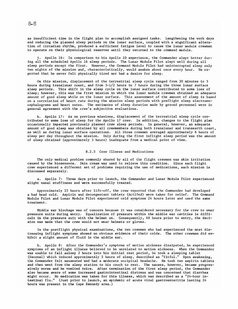


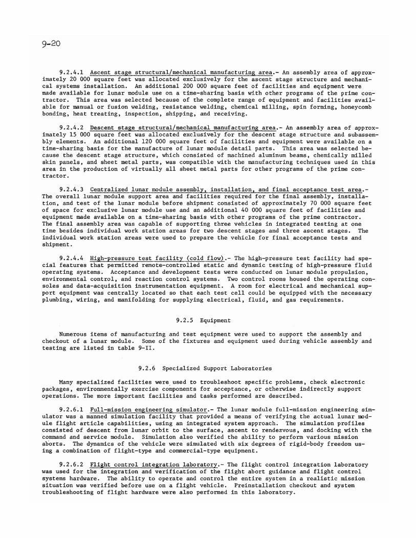


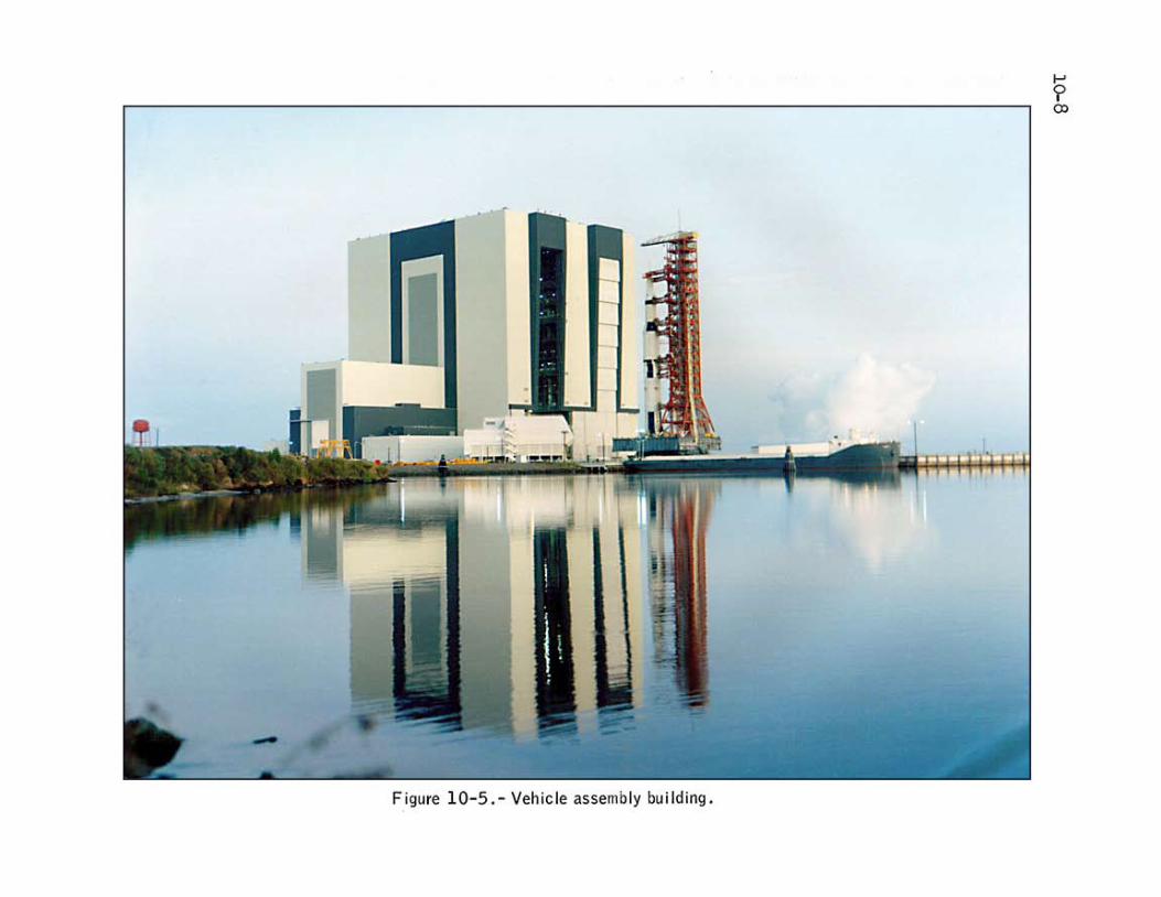


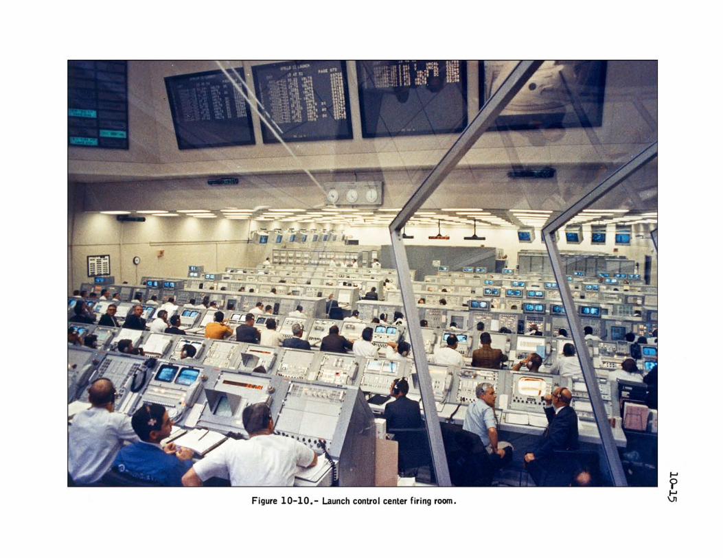


10-18


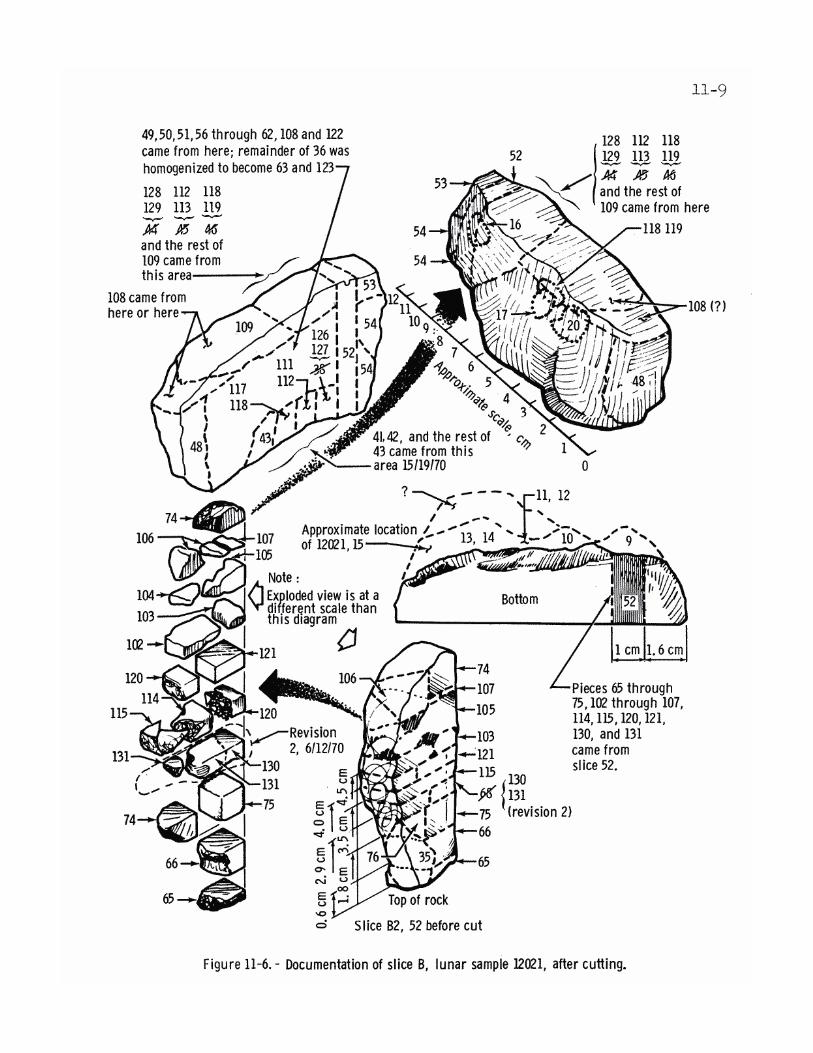


11-12


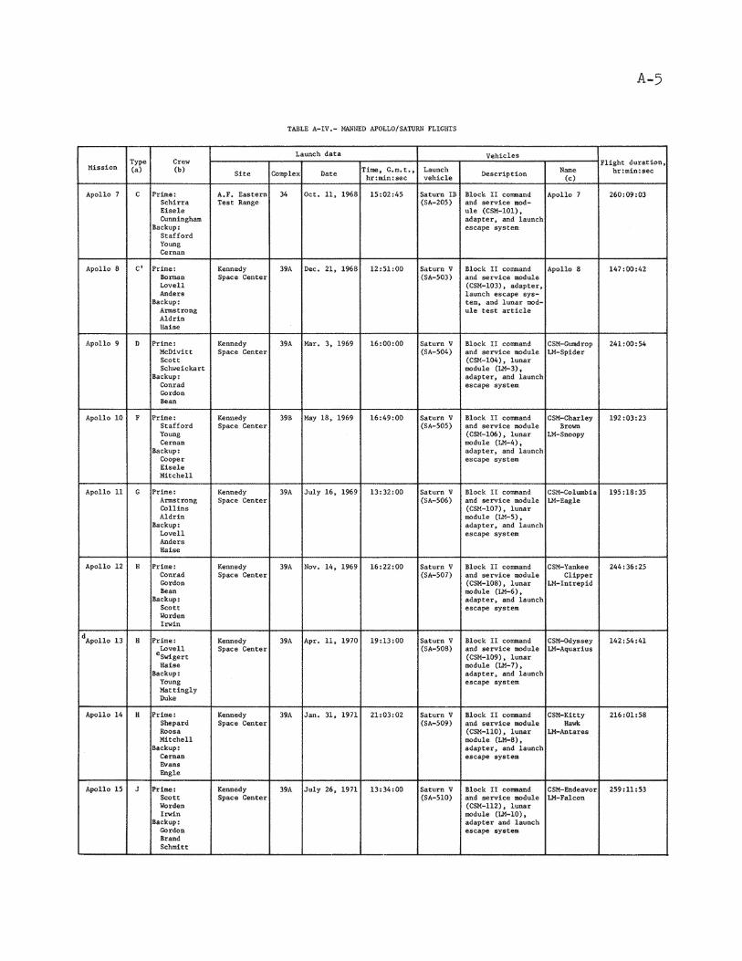


A-10


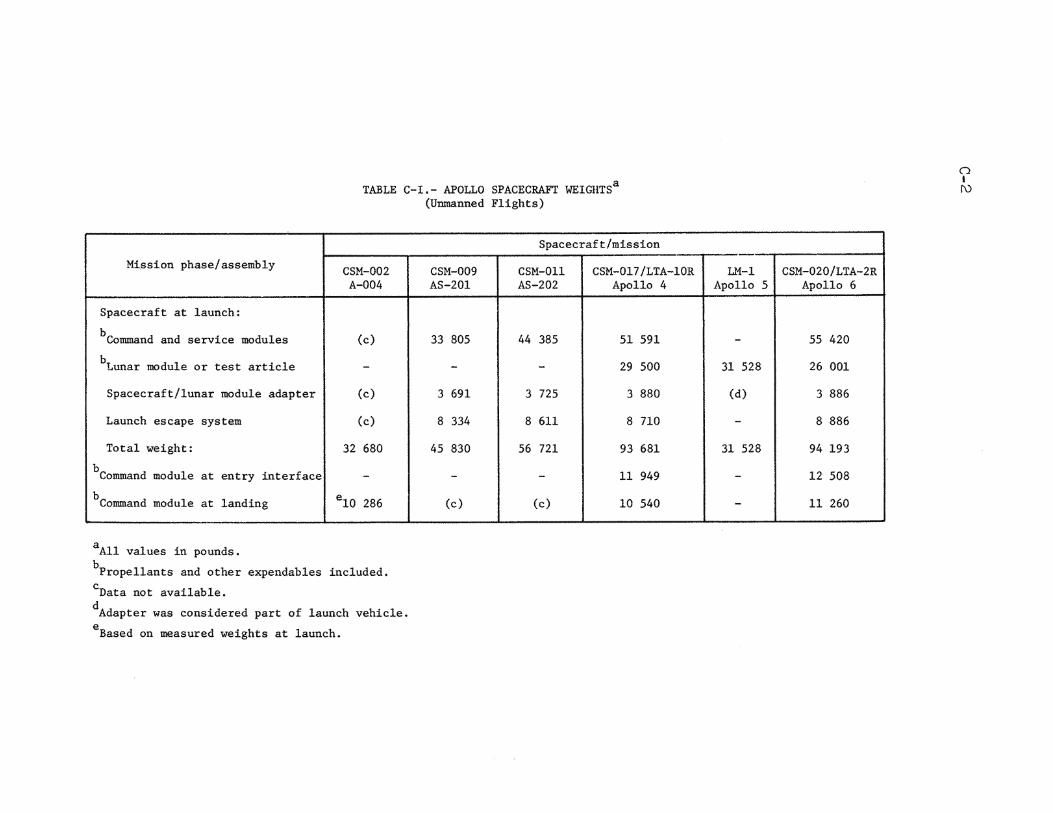


D-4


E-10


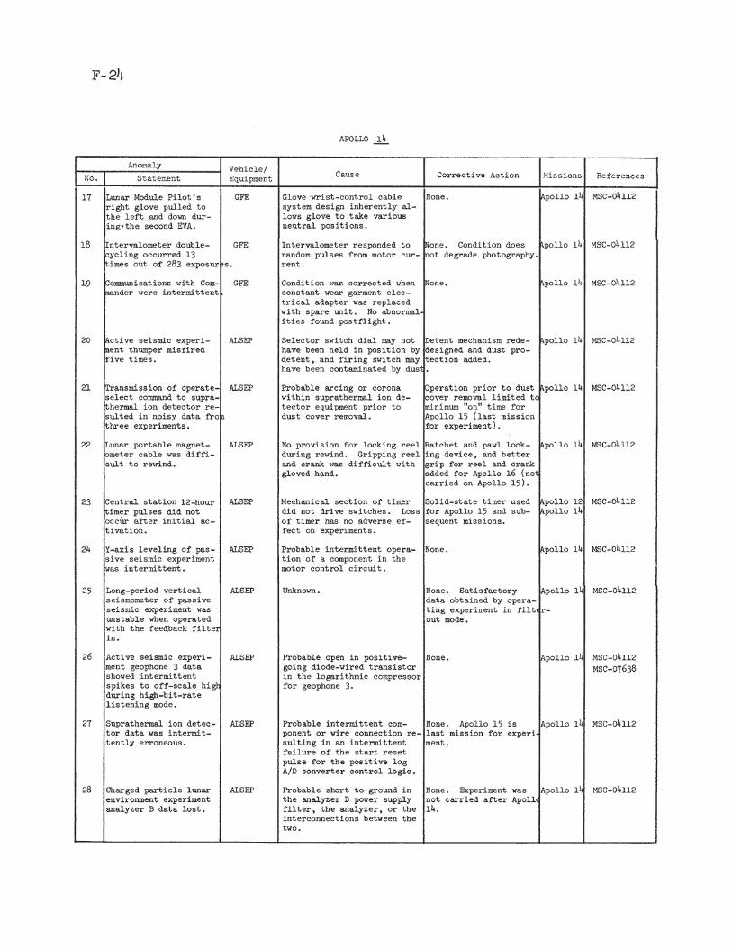


F-38