14 137 140 kvar kW kVA
44
Power Factor Controller BR 7000-T Manual Version 1.2 E Power Factor Controller BR 7000-T Auto Program Manual Service Enter OK Power Quality Solutions HELP ESC AUTO-MODE 2/2 14 137 140 kvar kW kVA Q P S cos j
-
Upload
khangminh22 -
Category
Documents
-
view
0 -
download
0
Transcript of 14 137 140 kvar kW kVA
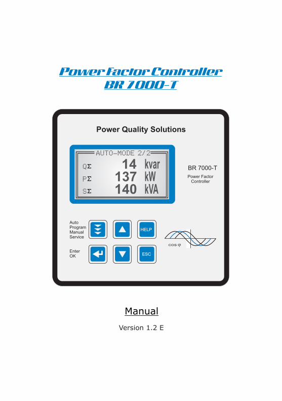
Power Factor Controller
BR 7000-T
Manual
Version 1.2 E
Power Factor Controller
BR 7000-T
AutoProgramManualService
EnterOK
Power Quality Solutions
HELP
ESC
AUTO-MODE 2/2
14137140
kvarkWkVA
Q
P
S
cos j

!CAUTIONS:
1. High voltage !
2. BR7000-T may only be used indoor !
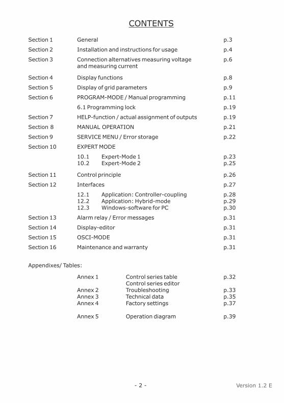
CONTENTS
Section 1 General p.3
Section 2 Installation and instructions for usage p.4
Section 3 Connection alternatives measuring voltage p.6and measuring current
Section 4 Display functions p.8
Section 5 Display of grid parameters p.9
Section 6 PROGRAM-MODE / Manual programming p.11
6.1 Programming lock p.19
Section 7 HELP-function / actual assignment of outputs p.19
Section 8 MANUAL OPERATION p.21
Section 9 SERVICE MENU / Error storage p.22
Section 10 EXPERT MODE
10.1 Expert-Mode 1 p.2310.2 Expert-Mode 2 p.25
Section 11 Control principle p.26
Section 12 Interfaces p.27
12.1 Application: Controller-coupling p.2812.2 Application: Hybrid-mode p.2912.3 Windows-software for PC p.30
Section 13 Alarm relay / Error messages p.31
Section 14 Display-editor p.31
Section 15 OSCI-MODE p.31
Section 16 Maintenance and warranty p.31
Appendixes/ Tables:
Annex 1 Control series table p.32Control series editor
Annex 2 Troubleshooting p.33Annex 3 Technical data p.35Annex 4 Factory settings p.37
Annex 5 Operation diagram p.39
- 2 - Version 1.2 E

Section 1: GENERAL
The power factor controller BR7000-T is the consequent follow-up development of the well proven series BR6000. The main distinctive feature is the new 3-phases measuring system. Due to the 3-phases recording of voltage and current the device allows a convenient usage as grid measuring device and as power factor controller. All measuring values can be edited and may be displayed in big letters for easier readability. 2 interfaces are standard. By means of the comfortable windows-software that is included in the delivery and by using one interface for a connection to a PC the execution and evaluation of grid measurements is possible. The second interface can be used for customer specific purposes. Used as PF-controller various control modes are available. They allow not only to control according to the phase with the highest load or the average demand of the phases, but also to realize a real single-phase control (balancing) or a mix of balancing and conventional three-phases-control.All well proven functions of the BR6000-series are available for the BR7000-T; for example the control series editor, the automatic initialization etc. For an easy usage the concept of graphic menu navigation has mainly been adapted. New are amongst others an integrated help (HELP-button) and the possibility to jump back in the programming menu by an additional ESCape-button.The usage of a fully graphic support display allows an additional Oscilloscope-Mode where the phases (half waves) of voltage and current can graphically be displayed.
R 3 x 5 free programmable switching outputsR 1 alarm relay, 1 programmable message relay, 1 relay for the cabinet fan R Operating voltage: 110 ... 230VAC (+/-15%)R Measuring voltage: 3 x 30 ... 440 VAC (L-N) / 50...760 V (L-L)R Measuring current: 3 x 5A / 1AR Pre-programmed control series and control series editor R Illuminated graphic display 128 x 64 dot, graphical menu navigation R 4-quadrant-operationR Measuring of capacitor current possibleR Three-phase display of various grid parameters ( U, I, F, Q, P, S Delta Q ... )R Switch over to large display possible R Display up to 31st harmonic of voltage and current R Simultaneous graphical display 1 period of voltage and current in Osci-modeR Monitoring of temperature R Storage of maximum grid parameters with time stampR Manual/automatic operation R Programming of fixed steps or mascing of particular outputs possibleR Control possible as 3-phase, 1-phase or mixed-modeR Display of different error messagesR Error storage R Complete 2nd parameter set programmableR 2 integrated separate interfacesR Integrated clock, several timers possible R Integrated help-function/plain text R Panel-mounted instrument 144 x 144 x 60 mm
- 3 -

- 4 -
Section 2: INSTALLATION AND INSTRUCTIONS FOR USAGE
The BR7000-T is designed as panel mounting instrument in PFC-systems. This requires a cut out of 138 x 138 mm according to DIN 43700 / IEC 61554. The controller has to be inserted from the front and fixed with the clamps (included in delivery). The device may only be installed by qualified personnel and may only be operated according the given safety regulations. In addition the relevant legal and safety instructions have to be obeyed.
The measuring input is designed for 1- and 3-phase grids. The maximum measuring voltage is 440V~ (L-N) / 760V ~ (L-L).The supply voltage is 110...230 V +/-15%.Wiring connections must be suitable for the particular voltages. Input leads have to be protected by over-current-protection devices. The supply voltage must be protected by a fuse; it must be possible to switch off the supply voltage by a separator. The BR7000-T must not be operated without protective earth contactor connected!
Before connecting the BR7000-T, it has to be checked that all connections are at zero potential; current transformers have to be short circuited. Correct phasing of measuring voltage and measuring current have to be checked. The measuring current circuits must
2be wired with minimum 2.5 mm Cu.
Terminals may only be plugged when de-energized!
Attention!The controller may only be operated when installed. The complete programming of all application-specific parameters is done according chapter programming. Then the device is set to automatic operation by pushing the operation mode button. The controller is now ready for operation.
Operating the controller without following to these operating instructions may be harmful and dangerous!
!
!
!

BR 7000-T rear view
Operating mode:- Automatic- Program.- Manual oper.- Service- Expert Mode- Osci - Mode- Display Editor
ENTER/ OKConfirmationstorage ofvalues
Increaseselected parameter
HELPopens
Help pages
Reduceselectedparameter
Escapeprevious
page/valuein the display
- 5 -
BR 7000-T front view
The controller is supplied for a standard operating voltage of 110...230VAC (+/-15%), a measuring voltage of 30...440 V~ (L-N) resp. 50...760V~ (L-L), 50/60Hz, and a measuring current of 5A or 1A (programmable). A voltage converter is required for different operating voltages.
Caution! Voltages which exceed the allowed voltage range can damage the
device !
!
Power Factor Controller
BR 7000-T
AutoProgramManualService
EnterOK
Power Quality Solutions
HELP
ESC
HELP
ESC
Power factor controller BR7000-T
Type: BR7000-T
Meas voltage: 50 - 760VAC 50/60Hz
Supply voltage:110 - 230VAC 50/60Hz
Ser.Nr.: 0815 / 2013
P1
P2
P3
1
6
11
2
7
12
3
8
13
4
9
14
5
10
15
Meas.current
k L1 l
Supply voltage85...265V~
Measuring voltage30 ... 440V L-N
Transistor output 11-15
Transistor output 6-10
Transistor output 1-5
Switching outputs:
Fan relay
Message relay
Alarm relay
Meas.current
k L2 l
Meas.current
k L3 l
Interface 1
Contact assignment 2nd terminal at bottom
Interface 2
External input110...230V~GND B A PE
L1 N L1 L2 L3 Monitoring 24VDC
The allocation of switching outputs 1 … 15 to the capacitors complies to the selected connection variant and the desired CONTROL-MODE(Programming/point 2)
Especially in ”Mixed Mode“ where some outputs are used for single phase capacitors, others for 3-phase-capacitors the proper connection must be assured!
In the “HELP”-menu the BR7000-T directly displays the actual correct allocation of outputs (AUTO-MODE: Help-page).
For examples also see page 12.
cos j

Section 3: CONNECTION ALTERNATIVES MEASURING VOLTAGE AND MEASURING CURRENT
According to the existing grid and the desired operating mode (CONTROL-MODE Programming) the BR7000-T has to be connected accord. one of the following alternatives. The separate auxiliary voltage (24 V DC) that is needed for the thyristor switches has to be conducted to P1…P3 and to the connection “control 24V”. The connection of PE is mandatory!
Alternative 1: measuring performed in each phase - 3 current transformers needed Use: CONTROL-MODE: 1 - 4 (control modes see page 11)
BR7000-T
Alternative 2: single-phase measuring via current transformer in L1 Values extrapolated (balance assumed). Measuring complies with conventional measuring for switching of three-phase capacitors. Use: CONTROL-MODE 5
BR7000-T
Alternative 3: single-phase measuring as alternative 2 , but with capacitor current measuring in the compensation system for collection of real capacitor currents.Use: CONTROL-MODE 6
BR7000-T
Reserve
- 6 -
PE
N
L2 (S)
L3 (T)
L1 (R)
( L1) ( N )
( L1) ( N )
( L1) ( N )
L1 L2 L3 monitoring 24VDC
aux. voltage 24VDC
aux. voltage 24VDC
aux. voltage 24VDC
L1 L2 L3 monitoring 24VDC
L1 L2 L3 monitoring 24VDC
Supply voltage110-230V~
Supply voltage110-230V~
Supply voltage110-230V~
Measuring voltageto P1...P3
to P1...P3
to P1...P3
Measuring voltage
Measuring voltage
L3
L3
L3
Measuring currentL2
Measuring currentL2
Measuring currentL2
L1
L1
L1
L1 (R)
L2 (S)
L3 (T)
PE
N
L1 (R)
L2 (S)
L3 (T)
PE
N
L1 L2 L3 N
PFC-system
Load-site
Load-site

- 7 -
kK k K
lL l L
Feed 1 Feed 2
K L K L
Measurement via sum current converter
P.F.Controller
Currentmeasurement
k l
k l
Example:
C.converter 1: 1000/5AC.converter 2: 1000/5ASum-current converter: 5A+5A / 5A
C.converter ratio is: 2000 /5A
Connection of current transformer / sum current transformer
When installing the current converter, care should be taken to ensure that the load current flows through it. The outputs of the compensation network must be installed behind the current converter (in the direction of current flow). If the is connected up via sum-current converters, the overall conversion ratio is entered.
Caution!Current converter clamps shouldbe grounded on one side !The secondary clamps of the CThave to be short circuited beforecurrent leads are iterrupted !
BR7000-T
!
BR7000-T in High Voltage Application
The example shows the connection of BR7000-T in HV-application.The measuring current is taken off primary via X/1A transformer. Measuring voltage produced via transformer 20000/100 V. In this case, the BR7000-T has to be programmed as follows: 4 I-CONVERTER sek: X / 1A14 MEASUR.VOLTAGE: 100 V15 V-CONVERTER: 20kV / 100 V
L1 (R) L1 (R)
L2 (S) L2 (S)
L3 (T) L3 (T)
N
Meas.currentIm (X/1A)
supply voltage Ub
Meas- voltage Um
BR 7000-T
PE
Meas.current Meas. voltage Um Supply voltage UbL1 L2 L3 L1 L2 L3 N L1 N
HIGH VOLTAGE LOW VOLTAGE
20 kV / 400 V
20000
100
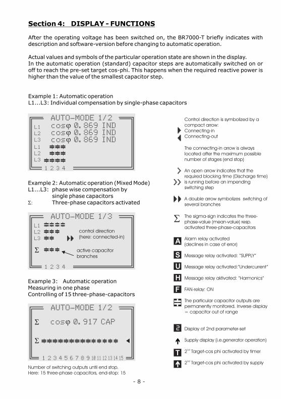
Section 4: DISPLAY - FUNCTIONS
After the operating voltage has been switched on, the BR7000-T briefly indicates with description and software-version before changing to automatic operation.
Actual values and symbols of the particular operation state are shown in the display. In the automatic operation (standard) capacitor steps are automatically switched on or off to reach the pre-set target cos-phi. This happens when the required reactive power is higher than the value of the smallest capacitor step.
Example 1: Automatic operationL1...L3: Individual compensation by single-phase capacitors
- 8 -
Number of switching outputs until end stop.Here: 15 three-phase capacitors, end-stop: 15
Control direction is symbolized by a compact arrow:Connecting-inConnecting-out
The connecting-in arrow is always located after the maximum possible number of stages (end stop)
An open arrow indicates that the required blocking time (Discharge time) is running before an impending switching step
A double arrow symbolizes switching of several branches
The sigma-sign indicates the three-phase-value (mean-value) resp. activated three-phase-capacitors
Alarm relay activated(declines in case of error)
Message relay activated: “SUPPLY”
Message relay activated:“Undercurrent”
Message relay aktivated: “Harmonics”
FAN-relay: ON
The particular capacitor outputs are permanently monitored. Inverse display = capacitor out of range
Display of 2nd parameter-set
Supply display (i.e.generator operation)
nd2 Target-cos phi activated by timer
nd2 Target-cos phi activated by supply
S
A
U
H
F
2
T
é
é
Example 2: Automatic operation (Mixed Mode) L1...L3: phase wise compensation by
single phase capacitorsS: Three-phase capacitors activated
Example 3: Automatic operation Measuring in one phaseControlling of 15 three-phase-capacitors
S
AUTO-MODE 1/2 cosj 0.869 IND cosj 0.869 IND cosj 0.869 IND
cosj 0.917 CAP
L1
L1
L2
L2
L3
L3
1 2 3 4
S
S
S
AUTO-MODE 1/3
AUTO-MODE 1/2
L1
L2
L3
1 2 3 4
1 2 3 4 5 6 7 8 9 10 11 12 13 14 15
control direction(here: connected-in)
active capacitor branches

Section 5: DISPLAY OF GRID PARAMETERS
Display of 3 selected grid parameters
In Auto-Mode, button é leads to display mode 1. Here 3 (free selectable) grid parameters are displayed in large letters. The selection and storage of these values is done in the Display- Editor.
Example: Display mode 1:
Desired values selected in theDisplay Editor (see section 14 )
Display of particular grid parameters (from AUTO-MODE by pressing ENTER)
By repeated activation of the “ENTER”-button (in automatic operation) several grid parameters can be displayed (s. table below):
Action Display Unit in% large display Bargraph 3-phasepossible possible
ENTER 1 LINE VOLTAGE V x x ENTER 2 APPARENT CURRENT A x x x ENTER 3 REACTIVE POWER kvar x x ENTER 4 ACTIVE POWER kW x x ENTER 5 APPARENT POWER kVA x x ENTER 6 DIFF. kvar to target kvar x x ENTER 7 TEMPERATURE °C / °F x ENTER 8 3.-31. HARMONICS V/ I x x x ENTER 9 HARMONICS THD-V/I x x x ENTER 10 Comp.- power (only at real capacitor current measurement) ENTER 11 TIME / DATE é / ê change the date format ENTER 12 Software version
ENTER return to: 1
Buttons é / ê change the display format:
The values can be displayed in their unit, in % or as large display resp. bar chart.Examples, see next page.
- 9 -
AUTO-MODE 2/2
14137140
kvarkWkVA
Q
P
S

=== DISPLAY ===
Examples of different displays:
VOLTAGE 3-phas. CURRENT: 3-phas. REACTIVE PWR 3-phas.
HARMONICS in % TEMPERATURE °C REACTIVE PWR in % LARGE LETTERS
HARMONICS diagram THD V/I as bar diagram REACTIVE POWER LARGE LETTERS
- 10 -
Repeated pressing of the "Operating Mode” key activates the various menus in sequence: Automatic operation - Programming - Manual (manual operation)- Service - Expert mode - OsciMode - DisplayEditor and back to Auto.
AUTO-MODE
to display operation to programming to manual operation to value buffer special functions to graphic. mode display-functions
PROGRAMMING MANUAL-MODE SERVICE EXPERT-MODE OSZI - MODE DISPLAY-EDITOR
DISPLAY 7/98 HARMONICS [3.]
L1 V 0.4% I 0.5%L2 V 1.4% I 0.8%L3 V 1.4% I 0.7%
DISPLAY 3/47 TEMPERATURE
25 °C
DISPLAY 1/31 LINE VOLTAGE
L1-N 233 VL2-N 233 VL3-N 233 V24VDC 24 V
DISPLAY 3/3
252525
kvarkvarkvar
Q1
Q2
Q3
ANZEIGE 1/32 APPAR.CURRENT
L1 235 AL2 133 AL3 133 A
DISPLAY 1/23 REACTIVE POWER
L1 71 kvarL2 23 kvarL3 22 kvar
116 kvar
DISPLAY 2/33 REACTIVE POWER
L1 31 %L2 10 %L3 10 %
17 %
HARMONICS [V-1]
1.0%
0.5%
0%
3 5 7 9 11 13 15 17 19 21 23 25 27 29 31
THD 1/2
20%
10%
0%
THD V 1 2 3 THD I 1 2 3
DISPLAY 1/3

Section 6: PROGRAM-MODE (manual programming)
Pressing the button “Operation Mode“ one time switches from automatic operation to the program mode.The upper part of the display always shows the parameter, the adjustable values are shown in the lower part. Editable values are generally given in square brackets. Changes of these values can be done by the buttons é / ê. By pressing the “ENTER-button” the value is stored. Pressing the “ESC”-button allows to go one step back (without storing).
1 LANGUAGE This selects the language of the operating menu
[GERMAN, ENGLISH, SPANISH, RUSSIAN, TURKISH]
2 CONTROL-MODE [1...16]
16 different controlling operation modes can be adjusted at the BR7000-T according the following table:
Mode Kind of measure- Number/type Connection of Operation mode No. ment(number CT) of capacitors capacitors
see page 6
1 3-phase 3x 5 single phase L-N Stand-alone
2 3-phase max.3x4 1-phase L-N Stand-alone+ Rest 3-phase 3-phase MIX - MODE
3 3-phase 3x 5 single phase L-L Stand-alone
4 3-phase 1x 15 threephase 3-phase Stand-alone
5 1-phase 1x 15 threephase 3-phase Stand-alone
6 1-phase 1x 15 threephase 3-phase Sytem current meas.internal via L2 / L3
7 3-phase 3x 5 single phase L-N Hybrid mode1x BR7000-I
8 3-phase 3x 5 single phase L-N Hybrid mode2x BR7000-I
9 3-phase 3x 5 single phase L-L Hybrid mode1x BR7000-I
10 3-phase 3x 5 single phase L-L Hybrid mode2x BR7000-I
11 3-phase 1x 15 three phase 3-phase Hybrid mode1x BR7000-I
12 3-phase 1x 15 three phase 3-phase Hybrid mode2x BR7000-I
13 1-phase 1x 15 three phase 3-phase Hybrid mode1x BR7000-I
14 1-phase 1x 15 three phase 3-phase Hybrid mode2x BR7000-I
15 3-phase 1x 15 three phase 3-phase Coupling mode
16 1-phase 1x 15 three phase 3-phase Coupling mode
- 11 -
PROGRAM-MODE 1 LANGUAGE [1]
[ ENGLISH ]

!Allocation of switching outputs 1…15 to the capacitors according to the selected connection variant and the desired CONTROL-MODE.
Especially in ”Mixed Mode“ where some outputs are used for single phase capacitors, and others for 3-phase-capacitors the proper connection must be assured!
In the HELP-function the BR7000-T directly displays the correct allocation of outputs (AUTO-MODE: Help-page 7-9).
=== PROGRAM-MODE ===
CONTROL-MODE [1]: 3-phase measuring / max. 3x5 single phase capacitors L-N (3 current transformers needed), values displayed and calculated per phase. Connection of measuring current and measuring voltage (refer to page 6). Controlling is done with max. 5 outputs per phase in case of switching of single-phase capacitors L-N.
L1 (R)
L2 (S)
L3 (T)
P1 1 2 3 4 5 P2 6 7 8 9 10 P3 11 12 13 14 15
Transistor-output 1-5
Monitoring 24VDC
Transistor-output 6-10
Transistor-output 11-15
PE
N
Example:3x 5 Single phase capacitors (L-N)
Output assignment
C1
.1 (C
1 a
t L
1-N
)
C1
.2 (C
1 a
t L
2-N
)
C1
.3 (C
1 a
t L
3-N
)
C2
.1 (C
2 a
t L
1-N
)
C2
.2 (C
2 a
t L
2-N
)
C2
.3 (C
2 a
t L
3-N
)
C3
.1 (C
3 a
t L
1-N
)
C4
.1 (C
4 a
t L
1-N
)
C5
.1 (C
5 a
t L
1-N
)
C3
.2 (C
3 a
t L
2-N
)
C4
.2 (C
4 a
t L
2-N
)
C5
.2 (C
5 a
t L
2-N
)
C3
.3 (C
3 a
t L
3-N
)
C4
.3 (C
4 a
t L
3-N
)
C5
.3 (C
5 a
t L
3-N
)
T1(T2)(T3)(T4)(T5)
T6(T7)(T8)(T9)(T10)
T11(T12)(T13)(T14)(T15)
C1.1(C2.1)(C3.1)(C4.1)(C5.1)
C1.2(C2.2)(C3.2)(C4.2)(C5.2)
C1.3(C2.3)(C3.3)(C4.3)(C5.3)
Aux. voltage 24VDC
e.g. TSM-LC-I
- 12 -
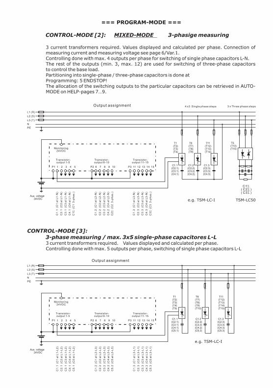
=== PROGRAM-MODE ===
CONTROL-MODE [2]: MIXED-MODE 3-phasige measuring
3 current transformers required. Values displayed and calculated per phase. Connection of measuring current and measuring voltage see page 6/Var.1. Controlling done with max. 4 outputs per phase for switching of single phase capacitors L-N. The rest of the outputs (min. 3, max. 12) are used for switching of three-phase capacitors to control the base load. Partitioning into single-phase / three-phase capacitors is done atProgramming: 5 ENDSTOP!The allocation of the switching outputs to the particular capacitors can be retrieved in AUTO-MODE on HELP-pages 7…9.
CONTROL-MODE [3]:3-phase measuring / max. 3x5 single-phase capacitores L-L3 current transformers required. Values displayed and calculated per phase. Controlling done with max. 5 outputs per phase, switching of single phase capacitors L-L
L1 (R)
L2 (S)
L3 (T)
P1 1 2 3 4 5 P2 6 7 8 9 10 P3 11 12 13 14 15
Transistor-output 1-5
Monitoring 24VDC
Transistor-output 6-10
Transistor-output 11-15
PE
N
T1(T2)(T3)(T4)
T6(T7)(T8)(T9)
T11(T12)(T13)(T14)
C1.1(C2.1)(C3.1)(C4.1)
C1.2(C2.2)(C3.2)(C4.2)
C1.3(C2.3)(C3.3)(C4.3)
Aux. voltage 24VDC
C1
.1 (C
1 a
t L
1-N
)
C1
.2 (C
1 a
t L
2-N
)
C1
.3 (C
1 a
t L
3-N
)
C2
.1 (C
2 a
t L
1-N
)
C2
.2 (C
2 a
t L
2-N
)
C2
.3 (C
2 a
t L
3-N
)
C3
.1 (C
3 a
t L
1-N
)
C4
.1 (C
4 a
t L
1-N
)
C3
.2 (C
3 a
t L
2-N
)
C4
.2 (C
4 a
t L
2-N
)
C3
.3 (C
3 a
t L
3-N
)
C4
.3 (C
4 a
t L
3-N
)
C1S
(C
1 3
-ph
as
.)
C2S
(C
2 3
-ph
as
.)
C3S
(C
3 3
-ph
as
.)
3 x Three phase steps
4 x3 Single phase steps
T5(T10)(T15)
C1S ( C2S )( C3S )
Output assignment
e.g. TSM-LC-I TSM-LC50
L1 (R)
L2 (S)
L3 (T)
P1 1 2 3 4 5 P2 6 7 8 9 10 P3 11 12 13 14 15
Transistor-output 1-5
Monitoring 24VDC
Transistor-output 6-10
Transistor-output 11-15
PE
N
Output assignment
C1
.1 (C
1 a
t L
1-L
2)
C1
.2 (C
1 a
t L
2-L
3)
C1
.3 (C
1 a
t L
3-L
1)
C2
.1 (C
2 a
t L
1-L
2)
C2
.2 (C
2 a
t L
2-L
3)
C2
.3 (C
2 a
t L
3-L
1)
C3
.1 (C
3 a
t L
1-L
2)
C4
.1 (C
4 a
t L
1-L
2)
C5
.1 (C
5 a
t L
1-L
2)
C3
.2 (C
3 a
t L
2-L
3)
C4
.2 (C
4 a
t L
2-L
3)
C5
.2 (C
5 a
t L
2-L
3)
C3
.3 (C
3 a
t L
3-L
1)
C4
.3 (C
4 a
t L
3-L
1)
C5
.3 (C
5 a
t L
3-L
1)
T1(T2)(T3)(T4)(T5)
T6(T7)(T8)(T9)(T10)
T11(T12)(T13)(T14)(T15)
C1.1(C2.1)(C3.1)(C4.1)(C5.1)
C1.2(C2.2)(C3.2)(C4.2)(C5.2)
C1.3(C2.3)(C3.3)(C4.3)(C5.3)
Aux. voltage 24VDC
e.g. TSM-LC-I
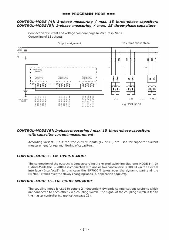
=== PROGRAMM-MODE ===
CONTROL-MODE [4]: 3-phase measuring / max. 15 three-phase capacitors CONTROL-MODE [5]: 1-phase measuring / max. 15 three-phase capacitors
Connection of current and voltage compare page 6/ Var.1 resp. Var.2Controlling of 15 outputs
CONTROL-MODE [6]: 1-phase measuring / max. 15 three-phase capacitorswith capacitor current measurement
According variant 5, but the free current inputs (L2 or L3) are used for capacitor current measurement for real monitoring of capacitors.
CONTROL-MODE 7 - 14: HYBRID-MODE
The connection of the outputs is done according the related switching diagrams MODE 1-4. In Hybrid-Mode the BR7000-T is connected with one or two controllers BR7000-I via the system interface (Interface2). In this case the BR7000-T takes over the dynamic part and the BR7000-I takes over the slowly changing loads (s. application page 29).
CONTROL-MODE 15 - 16: COUPLING MODE
The coupling mode is used to couple 2 independent dynamic compensations systems which are connected to each other via a coupling switch. The signal of the coupling switch is fed to the master controller (s. application page 28).
- 14 -
L1 (R)
L2 (S)
L3 (T)
P1 1 2 3 4 5 P2 6 7 8 9 10 P3 11 12 13 14 15
Transistor-output 1-5
Monitoring 24VDC
Transistor-output 6-10
Transistor-output 11-15
PE
N
Aux. voltage 24VDC
C1S
3
-ph
as
.
C6S
3
-ph
as
.
C11S
3
-ph
as
.
C2S
3
-ph
as
.
C7S
3
-ph
as
.
C1
2S
3
-ph
as
.
C3S
3
-ph
as
.
C8S
3
-ph
as
.
C1
3S
3
-ph
as
.
C4S
3
-ph
as
.
C9S
3
-ph
as
.
C1
4S
3
-ph
as
.
C5S
3
-ph
as
.
C1
0S
3
-ph
as
.
C1
5S
3
-ph
as
.
15 x three phase steps
T3 T2 T1
C15S C2S ........ C1S
Output assignment
e.g. TSM-LC-50
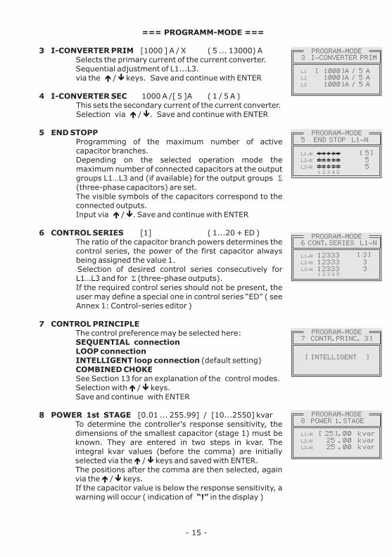
=== PROGRAMM-MODE ===
3 I-CONVERTER PRIM [1000 ] A / X ( 5 ... 13000) A Selects the primary current of the current converter.Sequential adjustment of L1...L3.via the é / ê keys. Save and continue with ENTER
4 I-CONVERTER SEC 1000 A /[ 5 ]A ( 1 / 5 A )This sets the secondary current of the current converter. Selection via é / ê. Save and continue with ENTER
5 END STOPP Programming of the maximum number of active capacitor branches. Depending on the selected operation mode the maximum number of connected capacitors at the output groups L1…L3 and (if available) for the output groups S (three-phase capacitors) are set.The visible symbols of the capacitors correspond to the connected outputs.Input via é / ê. Save and continue with ENTER
6 CONTROL SERIES [1] ( 1...20 + ED )The ratio of the capacitor branch powers determines the control series, the power of the first capacitor always being assigned the value 1.
Selection of desired control series consecutively for L1…L3 and for S (three-phase outputs).
If the required control series should not be present, the user may define a special one in control series “ED” ( see Annex 1: Control-series editor )
7 CONTROL PRINCIPLE The control preference may be selected here:
SEQUENTIAL connectionLOOP connectionINTELLIGENT loop connection (default setting)COMBINED CHOKESee Section 13 for an explanation of the control modes.Selection with é / ê keys. Save and continue with ENTER
8 POWER 1st STAGE [0.01 ... 255.99] / [10...2550] kvar To determine the controller's response sensitivity, the dimensions of the smallest capacitor (stage 1) must be known. They are entered in two steps in kvar. The integral kvar values (before the comma) are initially selected via the é / ê keys and saved with ENTER. The positions after the comma are then selected, again via the é / ê keys. If the capacitor value is below the response sensitivity, a warning will occur ( indication of “!” in the display )
- 15 -
PROGRAM-MODE 7 CONTR.PRINC. 3]
[ INTELLIGENT ]
PROGRAM-MODE 3 I-CONVERTER PRIM
[ 1000]A / 5 A1000]A / 5 A1000]A / 5 A
L1
L2
L3
PROGRAM-MODE 8 POWER 1.STAGE
[ 25].00 kvar25 .00 kvar25 .00 kvar
L1-N
L2-N
L3-N
PROGRAM-MODE 6 CONT.SERIES L1-N
123331233312333
[ 3]
33
L1-N
L2-N
L3-N
1 2 3 4 5
PROGRAM-MODE 5 END STOP L1-N
[ 5]55
L1-N
L2-N
L3-N
1 2 3 4 5

- 16 -
=== PROGRAM-MODE ===
9 TARGET COS PHI [ 0.98 ind ] ( 0.3 ind ... 0.3 cap )By setting the target cos phi, the power factor to be attained via the PF correction is defined. Save and continue with ENTER.
10 TARGET 2nd cosPhi [ NO ] ( 1...3 )1: NO ( no 2nd target cosPhi,
continue with 14 )2: Timer ( 2nd cos-phi - activated by timer,
scheduler with 12,13 )3: Energy supply (2nd target cos-phi - activated by
energy-supply)
[ 0.9 IND ] (0.3 ind ... 0.3 cap )Set point for the 2nd target cosPhi( only available if selected under 10 )
[ HH:MM:SS ]
Switch-on time of the timer for the 2nd target-cos phi( only available if selected under 10 )
[ HH:MM:SS ]
Switch-off time of the timer for the 2nd target-cos phi( only available if selected under 10 )
14 MEASURING VOLTAGE L-L [400]V ( 50...760) VProgramming of measuring voltage.The values programmed here always refer to the voltage at the clamps of the controller !Selection via é / ê. Save / continue with ENTER
15 V-CONVERTER [ NO ] (410V - 79kV / 400V )When a measuring-voltage converter (e.g. for HV-measurement) is used, its conversion ratio is to be programmed here.Selection via é / ê. Save / continue with ENTER
16 FREQUENCY [50] Hz (50 / 60Hz)Input of the grid frequency of the measuring voltage (needed for measuring system)
17 CONNECTING TIME:[ 1000 ] ms (50...1000ms) The time between connecting the capacitors to increase the momentary network capacitance. It should be noted that in practical operation the real connection time is affected by the discharge time (locking time).Selection via é / ê. Save / continue with ENTER
11 TARGET 2nd cosPhi
12 SWITCH ON TIME j2
13 SWITCH OFF TIME j2
PROGRAM-MODE12 SWITCH ON TIME j2
ON [16]: 00 MO-FR
OFF 07 : 00 MO-FR
PROGRAM-MODE15 V-CONVERTER
PRIMARY SECONDARY
[20000V] / 100V
PROGRAM-MODE10 TARGET 2nd cos j
[ TIMER ]
PROGRAM-MODE 9 TARGET cos j
[ 0.98 IND]

=== PROGRAM-MODE ===
18 DISCONNECT TIME: [ 1000 ] ms ( 50...1000)msThe time between disconnecting the capacitors to reduce the momentary network capacitance.Selection via é / ê. Save / continue with ENTER
19 DISCHARGE TIME: [ 1000 ] ms ( 50...1000)ms This is the time for which an individual output is blocked between disconnecting and connecting. It depends on the discharge device of the capacitor.
Selection with buttons é / ê. Save /Continue with ENTER
20 ALARM TEMPERATURE [ 55 ] °C ( 20...80 )°C
The alarm temperature programmed here is the temperature at which a stepwise disconnection of the capacitors is performed. After 10 min. the standard alarm relay of the controller will respond. At the same time, the display shows the cause of the alarm (over temperature). When the temperature drops again, the required branches are automatically re-connected in steps. Selection with é / ê. Save / Continue with ENTER
21 FAN TEMPERATURE [ 30 ] °C (ON/OFF/15...70°C)Threshold for the fan relay for control of a cabinet fan.
22 MESSAGE RELAY [Supply ] ( 1...3 )
The message relay can be programmed for one of the following options as required:
1 - OFF2 - Supply: Message when active power is supplied. 3- Under current:Message when the measuring current is not met. Signal is generated when the current value drops below the response sensitivity of the controller.4 - Harmonics:Message when the limiting value of the total harmonic distortion factor (THD-V) is exceeded. This value can be parameterized under ”38 Harmonics” (in %).5 - ERROR - System current measuring6 - ERROR - Com1 (interface error)7 - ERROR - Com2 (interface error)8 - ERROR - Com1/2 (interface error)
- 17 -
S
U
H
E
E
Display:
Display:
Display:
Display:
Display:
PROGRAM-MODE 19 DISCHARGE TIME
C-ON 200 ms
C-OFF 200 ms
C-DIS [ 200]ms
PROGRAM-MODE 20 ALARM TEMPERATURE
[ 55°C]
PROGRAM-MODE 22 MESSAGE RELAY [2]
[ HARMONICS ]

=== PROGRAM-MODE ===
23 EXTERNAL INPUT [ NO ] ( 1...4 )Setting of the desired action upon applying a control voltage of 110...230V~ at the external input. 1 - NO (no action)2 - 2nd parameter set (switchover to 2nd parameter set)
This selection simultaneously activates the following points 24…37 for programming of the values of the 2nd parameter set.
3 - External error (Display of an error message) 4 - Coupling operation parallel
(Selection of coupling operation via 2 CONTROL-MODE)
Programming of 2nd parameter set(only active if 23 EXTERNAL INPUT is set to 2nd parameter set)
As a standard, the values of the 2nd parameter set equal the values of the normal parameter set. Possible applications are for example: changing of target cos-phi, switch-over of current transformer or switch-over the switching times. By triggering a 110...230V~ signal at the external input, the 2nd parameter set is activated with following values:
The programming of the 2nd parameter set is performed equivalent to the programming of the standard parameters(3-11; 17-19)
38 HARMONICS [ 7 ]% (0,5...25,5)%
Threshold value THD-V (in%). In case this value is exceeded a message will be displayed. THD-V ist the ratio of the geometric sum of unequal harmonics to the 1st harmonic. In any case, a warning will be displayed. Warning via message relay will only be executed if selected in 22.
24. I-converter prim 25. I-converter sec 26. End stop27. Control serie28. Control principle 29. Power 1st stage 30. Target cos-Phi (2nd parameter set) nominal value31. 2nd target cos-Phi (2nd parameter set)NO/supply/Timer32. 2nd target cos-Phi (2nd parameter set) nominal value33. Switch on time target cos-Phi-234. Switch off time target cos-Phi-235. Connecting time36. Disconnecting time37. Discharge time
- 18 -
2
2
2
2
2
2
2
2
2
2
2
2
2
2
2
2
PROGRAM-MODE 38 HARMONICS
THD-V [ 7.0]%
2
PROGRAM-MODE 30 TARGET cos j
[ 0.98 IND]
PROGRAM-MODE 23 EXT. INPUT [2]
[ 2.PARAMETER SET]
2
2
2
PROGRAM-MODE 24 I-CONVERTER PRIM
[ 1000]A / 5 A1000]A / 5 A1000]A / 5 A
L1
L2
L3

=== PROGRAM-MODE ===
39 CLOCK [ HH:MM ], DATE [DD.MM.YY]Set system-time and date (Due to an internal battery the time will be kept even in case of power loss)Selection with é / ê. Save/continue with ENTER
40 CONTRAST [ 6 ] ( 0...10)Adjustment of display contrast for best readabilitySelection with é / ê. Save/continue with ENTER
41 BASIC SETTINGS [ NO ] (YES/NO)When selecting YES and confirmated with ENTER, all parameters are set back to the basic settings of the panel builder (optimum values for the system if the controller has been delivered together with the PFC-system). If the controller has been delivered ex works, this point corresponds to the default settings.
ATTENTION: All user settings get lost !
Section 6.1: PROGRAMMING LOCK
As a protection against unauthorized changes of the system parameters, the BR7000-T is equipped with a programming lock. This can be activated in the EXPERT MODE. When the lock is active, all parameters can be checked but not changed.
Alternatives:Lock active / Not active / Automatic activation after 24 h
- 19 -
PROGRAM-MODE 39 CLOCK
[ 15]: 27MONDAY05.03.2013
PROGRAM-MODE 41 BASIC SETTINGS
[NO ]
EXPERT-MODE 7 OPERATING LOCK
[NO ]
Section 7: HELP-Functions / actual output assignment
The BR7000-T features a context related help function.For each menu item one or more help pages are available which can be accessed directly with the HELP-button. Scrolling is done with "UP/DOWN" buttons, back retrace with ESCape.In automatic operation (==AUTO-MODE==) 9 help pages are available. The first pages explain the general meaning of used symbols.
On the help pages 7…9 the actual assignment of the internal transistor outputs to the phases and to the capacitors are shown directly. This table depends on the CONTROL-MODE that is set and will change automatically. The assignment shown here is not trivial, especially in CONTROL-MODE 2 (MIXED MODE) and must be obeyed without exeption!
s. example next page
!

- 20 -
=== Actual assignment of outputs ===
Example: CONTROL-MODE 2 (MIXED-MODE)set in END STOP to:
4 stages with 3 single- phase capacitors each and3 stages with 1 three-phase capacitor each
In case of the setting the BR7000-T will automatically assign the capacitors according to the wiring diagram.
This output assignment can always be called up in help-mode AUTO-MODE/ HELP/ page 7...9 and is displayed in the example as follows:
HELP-MODE p. 7/9 HELP-MODE p. 8/9 HELP-MODE p. 9/9 OUTPUT ASSIGNMENT OUTPUT ASSIGNMENT OUTPUT ASSIGNMENT Thy T01 -> L1 -> C1.1 Thy T06 -> L2 -> C1.2 Thy T11 -> L3 -> C1.3 Thy T02 -> L1 -> C2.1 Thy T07 -> L2 -> C2.2 Thy T12 -> L3 -> C2.3 Thy T03 -> L1 -> C3.1 Thy T08 -> L2 -> C3.2 Thy T13 -> L3 -> C3.3 Thy T04 -> L1 -> C4.1 Thy T09 -> L2 -> C4.2 Thy T14 -> L3 -> C4.3
Thy T05 -> S -> C1S Thy T10 -> S -> C2S Thy T15 -> S -> C3S
L1 (R)
L2 (S)
L3 (T)
P1 1 2 3 4 5 P2 6 7 8 9 10 P3 11 12 13 14 15
Transistor-output 1-5
Monitoring 24VDC
Transistor-output 6-10
Transistor-output 11-15
PE
N
T1(T2)(T3)(T4)
T6(T7)(T8)(T9)
T11(T12)(T13)(T14)
C1.1(C2.1)(C3.1)(C4.1)
C1.2(C2.2)(C3.2)(C4.2)
C1.3(C2.3)(C3.3)(C4.3)
Aux. voltage 24VDC
C1
.1 (C
1 a
t L
1-N
)
C1
.2 (C
1 a
t L
2-N
)
C1
.3 (C
1 a
t L
3-N
)
C2
.1 (C
2 a
t L
1-N
)
C2
.2 (C
2 a
t L
2-N
)
C2
.3 (C
2 a
t L
3-N
)
C3
.1 (C
3 a
t L
1-N
)
C4
.1 (C
4 a
t L
1-N
)
C3
.2 (C
3 a
t L
2-N
)
C4
.2 (C
4 a
t L
2-N
)
C3
.3 (C
3 a
t L
3-N
)
C4
.3 (C
4 a
t L
3-N
)
C1S
(C
1 3
-ph
as
.)
C2S
(C
2 3
-ph
as
.)
C3S
(C
3 3
-ph
as
.)
3 x Three phase steps
4 x3 Single phase steps
T5(T10)(T15)
C1S ( C2S )( C3S )
Output assignment
e.g. TSM-LC-I TSM-LC50

Section 8: MANUAL OPERATION
Manual operation is designed for maintenance and service purpose. Menu “MANUAL-MODE” consists of the following sub-windows:
1 MANUAL CONTROL [STOP] L1 ( L1...L3)In manual operation, capacitor steps can be connected /disconnected according to the control series and switching time irrespective of the prevailing power-line-conditions. Starting position is STOP (no stages connected).
CONNECTION or DISCONNECTION is done by pressing the buttons é resp. ê This manual operation is executed consecutevely for particular phases L1-L3 resp. S. The operation status and the power power factor of the actual phase are permanently shown in the display.
2 STEP STATE C1 - [AUTO] (FIXED/ AUTO/ OFF)
In special cases, all controller outputs (C1- C15) may be permanently defined (continued switching via ENTER) for the following states:
AUTO: Automatic (normal) operationThe relevant output is marked by a capacitor symbol.
FIXED: The output is continuously connected, e.g. for fixed PFC. The output is marked by an underlined capacitor symbol.
OFF: The output is continuously disconnected, e.g. for temporarily disconnecting of a defective capacitor. The capacitor symbol for this output is faded out. “MINUS” sign appears.
The active stage is blinking. The required status is set via é / ê. By pressing ENTER, the user saves this step and moves to the next stage.The programmed status for the outputs also remains visible on the display in automatic operation.
- 21 -
MANUAL-MODE 2 MAN.OPERATION L1
OUTPUT C1 [AUTO]
1 2 3 4 5
L1
MANUAL-MODE 2 STEP STATE L1
OUTPUT C1 [FIXED]
1 2 3 4 5
L1
MANUAL-MODE 2 STEP STATE L1
OUTPUT C1 [OFF]
1 2 3 4 5
L1
MANUAL-MODE 1 MAN.OPERATION L1
L1 cosj 0.983 IND
[SWITCH ON ]
1 2 3 4 5
L1
MANUAL-MODE 1 MAN.OPERATION L1
L1 cosj 0.983 IND
[SWITCH OFF]
1 2 3 4 5
L1
- 22 -
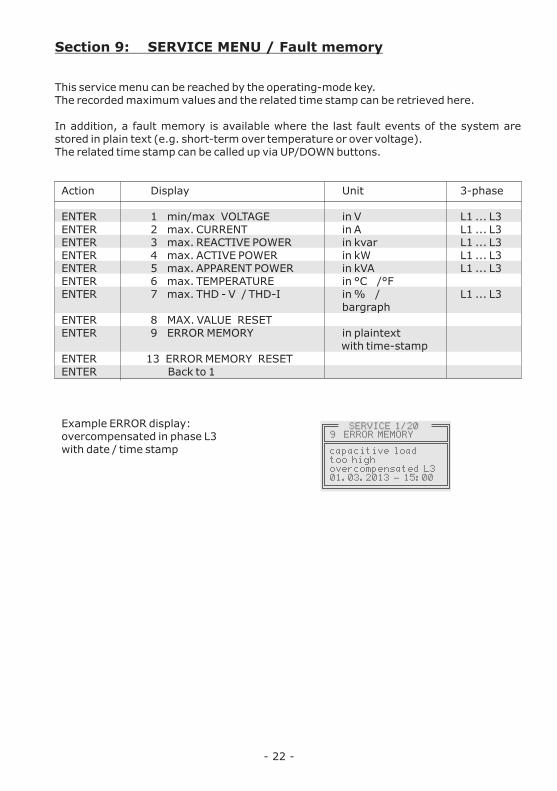
Section 9: SERVICE MENU / Fault memory
This service menu can be reached by the operating-mode key. The recorded maximum values and the related time stamp can be retrieved here.
In addition, a fault memory is available where the last fault events of the system are stored in plain text (e.g. short-term over temperature or over voltage).The related time stamp can be called up via UP/DOWN buttons.
Action Display Unit 3-phase
ENTER 1 min/max VOLTAGE in V L1 ... L3ENTER 2 max. CURRENT in A L1 ... L3ENTER 3 max. REACTIVE POWER in kvar L1 ... L3ENTER 4 max. ACTIVE POWER in kW L1 ... L3ENTER 5 max. APPARENT POWER in kVA L1 ... L3ENTER 6 max. TEMPERATURE in °C /°FENTER 7 max. THD - V / THD-I in % / L1 ... L3
bargraphENTER 8 MAX. VALUE RESETENTER 9 ERROR MEMORY in plaintext
with time-stampENTER 13 ERROR MEMORY RESETENTER Back to 1
Example ERROR display:overcompensated in phase L3with date / time stamp
9 ERROR MEMORY SERVICE 1/20
capacitive loadtoo highovercompensated L301.03.2013 - 15:00

- 23 -
Section 10: EXPERT-MODE 1 and 2
The expert modes are meant for the adjustment of values which normally should not be changed. As a protection these levels have access codes:
PASSWORD: ExpertMode 1: “6343” ExpertMode 2: “2244”
10.1 EXPERT-MODE 1 (Code: 6343)
1 BASIC SETTINGS NEW [NO] ( NO/YES)Storage of the present programming as a new basic setting (usually performed by the PFC-system manufacturer). Caution: All original values will be overwritten!
2 SWITCHING POWER max [100] kvar (multiple of smallest step)This factor specifies the maximum power which may be switched in one switching step. It can be used to control the intelligent control system, which switches several stages as a function of the power-factor requirement.
3 SWITCHING TRIGGER [66]% IND (30...100%)Threshold for switching on of the next stage. (IND. direction)
4 SWITCHING TRIGGER [66]% CAP (30...100%)Threshold for switching on of the next stage. (CAP. direction)
5 OPERATING LOCK [NO] (NO / YES / 24H) 24 H means,that the lock will be automatically after 24 hours.
[MEAN VALUE] (Mean /Maximum value)Only at single-phase measuring!Selection whether the control during single-phase measuring should be done according to the mean or the maximum value of the missing reactive power (of the 3 phases)
7 POWER 1st stage [0...255] (0...2550)Here the range for the input of the 1st stage power can be set to [0...2550]
8 DISPLAY [cos j ] (cos / tan j)
Switch over between COS Phi or TAN Phi in the display
6 CONTROL
EXPERT-MODE PASSWORD ????
0***
- 24 -
=== EXPERT-MODE ===
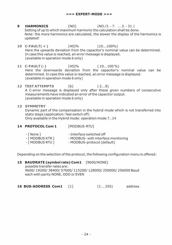
9 HARMONICS [NO] (NO /3. - 7. ... 3. - 31.)Setting of up to which maximum harmonic the calculation shall be done.Note: the more harmonics are calculated, the slower the display of the harmonics is updated!
[40]% (10...100%)Here the upwards deviation from the capacitor's nominal value can be determined. In case this value is reached, an error message is displayed.(available in operation mode 6 only)
[40]% ( 10...100 %)Here the downwards deviation from the capacitor's nominal value can be determined. In case this value is reached, an error message is displayed.(available in operation mode 6 only)
[6] ( 2...9)A C-error message is displayed only after these given numbers of consecutive measurements have indicated an error of the capacitor output.(available in operation mode 6 only)
Dynamic part of the compensation in the hybrid mode which is not transferred into static steps (application: fast switch off)Only available in the Hybrid mode: operation mode 7…14
14 PROTOCOL Com 1 [MODBUS-RTU]
- [ None ] - Interface switched off - [ MODBUS KTR ] - MODBUS- with interface monitoring - [ MODBUS RTU ] - MODBUS-protocol (default)
Depending on the selection of the protocol, the following configuration menu is offered:
15 BAUDRATE (symbol rate) Com1 [9600/NONE] possible transfer rates are:
9600/ 19200/ 38400/ 57600/ 115200/ 128000/ 250000/ 256000 Baudeach with parity NONE, ODD or EVEN
16 BUS-ADDRESS Com1 [1] (1... 255) address
10 C-FAULT( + )
11 C-FAULT (-)
12 TEST ATTEMPTS
13 SYMMETRY

10.2 EXPERT-MODE 2 ( Code: 2244 )
The 2nd expert mode defines all operation-, warning- and fault messages which can be displayed by the BR7000-T. They can be activated/de-activated separately. When de-activated, the display of the message as well as the possible activation of the alarm-relay or consequent effects on the control behavior are suppressed.
1 NOTIFICATIONS / ALARM [YES] =activ (YES / NO)
Activation/De-activation of the particular operation,- warning- and default messages:Measuring voltage, over voltage, over-/under compensated, harmonics, over-temperature, over-current, under-voltage, measuring current, error COM1, error COM2, Modbus switch off, Modbus-stop, Modbus switch on, system current <, Bus-error external, C-defect, System current >0, overload system, external error, C-defect off, Undervoltage aux. voltage 24DC
2 ALARM RELAY Delay time [10] min. (1...255 min.)
3 UNDER VOLTAGE [50] % (20...95%)If the measuring voltage falls below this value, all steps are simultaneously switched off.
4 OVER VOLTAGE [115] % (105...140%)If the measuring voltage exceeds this value, the stages are switched off step by step. If the measuring voltage is again in the defined range, stepwise re-connection of steps is done.
5 THD-MEAN VALUE Measuring cycles [3] (1...3)
6 UNDERVOLTAGE 24VDC (OFF/ <1 ... 24V)
Monitoring of auxiliary voltage 24 VIn case of undercut of the pre set limiting value the steps are switched off and an error message is displayed.
- 25 -
EXPERT-MODE 2
EXPERT-MODE 2
1 DISPLAY/ALARM
3 UNDERVOLTAGE
OVERCOMPENSATED
[ YES]
LIMITING VALUE
115 V [50] %
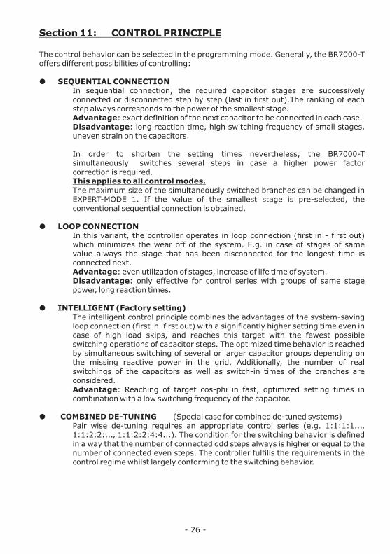
Section 11: CONTROL PRINCIPLE
The control behavior can be selected in the programming mode. Generally, the BR7000-T offers different possibilities of controlling:
˜ SEQUENTIAL CONNECTION In sequential connection, the required capacitor stages are successively connected or disconnected step by step (last in first out).The ranking of each step always corresponds to the power of the smallest stage. Advantage: exact definition of the next capacitor to be connected in each case.Disadvantage: long reaction time, high switching frequency of small stages, uneven strain on the capacitors.
In order to shorten the setting times nevertheless, the BR7000-T simultaneously switches several steps in case a higher power factor correction is required. This applies to all control modes.The maximum size of the simultaneously switched branches can be changed in EXPERT-MODE 1. If the value of the smallest stage is pre-selected, the conventional sequential connection is obtained.
˜ LOOP CONNECTION In this variant, the controller operates in loop connection (first in - first out) which minimizes the wear off of the system. E.g. in case of stages of same value always the stage that has been disconnected for the longest time is connected next. Advantage: even utilization of stages, increase of life time of system.Disadvantage: only effective for control series with groups of same stage power, long reaction times.
˜ INTELLIGENT (Factory setting)The intelligent control principle combines the advantages of the system-saving loop connection (first in first out) with a significantly higher setting time even in case of high load skips, and reaches this target with the fewest possible switching operations of capacitor steps. The optimized time behavior is reached by simultaneous switching of several or larger capacitor groups depending on the missing reactive power in the grid. Additionally, the number of real switchings of the capacitors as well as switch-in times of the branches are considered. Advantage: Reaching of target cos-phi in fast, optimized setting times in combination with a low switching frequency of the capacitor.
˜ COMBINED DE-TUNING (Special case for combined de-tuned systems) Pair wise de-tuning requires an appropriate control series (e.g. 1:1:1:1..., 1:1:2:2:..., 1:1:2:2:4:4...). The condition for the switching behavior is defined in a way that the number of connected odd steps always is higher or equal to the number of connected even steps. The controller fulfills the requirements in the control regime whilst largely conforming to the switching behavior.
- 26 -

Section 12: INTERFACES
As a standard, the BR7000-T is equipped with two isolated RS485 interfaces according to the following assignment:
View frombottom :
.
The following functions can be realized via the interfaces:
R Remote read out of grid parameters, storage, display, grid analysis with enclosed PC-software BR7000-SOFT during online-operation
R Usage as system interface for connection of accessories or for coupling of two controllers
R Usage for customer specific applications (facility master control system, SPC etc.) R Usage in a network (MODBUS-Protocol)
Interface 1 mainly designed for customer specific applications, whilst Interface 2 intended for coupling with accessories.
Coupling with a PC for the usage of Windows-Software can be done from both interfaces with accessory “USB-adapter”.
RS485- Bus structureAll devices are connected to one line in parallel. This requires a direct connection of the bus lines to the plug connection of the device (no junction box).
CableFor connection a twisted and shielded cable has to be used. The shielding has to be connected with casing or cabinet parts at both ends. Max. cable length in the bus is 1,200 m (depending on cable and baud rate). At the first and at the last device of the bus the cable has to be terminated with resistors. Activation (termination) on the controller side is done with the switch “Termination” next to the clamp “Interface1” (both white switches on “ON”).
- 27 -
1 2on
k L1 l
Supply voltage Ub110-230V~
Meas.voltage Um30 - 440V L-N
Interface 1SwitchTermination
Gnd B A PE
Interface 2 ext. Input
230V~ n.c.
Measuring current
k L2 l k L3 l( L1) ( N ) L1 L2 L3 N(PE)

12.1 Application: Controller coupling
Attention: Controller coupling only possible in CONTROL-MODE 15 or 16 !
Application example:
Two separate systems operate at two transformer feed ins; it exists one coupling with coupling switch between both systems. a) Coupler opened; both systems operate self-governed;b) Coupler closed: with the controller coupling both systems are operated symmetrically
in parallel operation (same number of steps in each system)
Coupling of 2 power factor controllers BR7000-T is done via their system interface with a standard LAN-cable.
The 110...230V~ signal "coupling switch closed“ has to be directed to the external input of a controller (master). On this controller the programming has to be done as follow:PROGRAMMING: 2 CONTROL-MODE: 15 or 16 (coupling mode)On the 2nd controller (slave) the setting is the corresponding control-mode (4 or 5)
No more settings are required !
- 28 -
Interface 2(RJ45) ext. input (110...230V~)
LAN-cable (CAT5/CAT6)
Interface 2(RJ45)
CT 1X / 5A
CT 2X / 5A
transformer1 transformer2
coupling switch
consumer (1)
BR7000-T(Master)
BR7000-T(Slave)
consumer (2)
capacitor system 1 capacitor system 2
Feed 1 Feed 2
e.g.control mode 16
e.g.control mode 5
AUTO MODE------------------
cos 0.987 IND
1 2 3 4 5 6 7 8 9 10 11 12
j
Power Quality Solutions
AUTO MODE------------------
cos 0.987 IND
1 2 3 4 5 6 7 8 9 10 11 12
j
Power Quality Solutions

12.2. Application: HYBRID-MODE BR7000-T and BR7000-I
In systems where more than 6 outputs are required respectively where the dynamic part is to be compensated for single phases, following application can be used. Here the dynamic part is compensated by the BR70000-T (single or three phase) and the base load is compensated conventionally by the BR7000-I/S485.
Programmierung und Anschluß
A mixed dynamical compensation system implements economically the advantages of a dynamic fast network. (Fast changing loads are compensated dynamically and basic loads / slowly changing loads are compensated conventionally)For designing a mixed-dynamical compensation system a special controller was developed. The BR6000-T6R6 supports up to 6 transistor-outputs (for triggering thyristor modules) and additional 6 relay-outputs for standard capacitor contactors.
LAN-Kabel (CAT5/CAT6) LAN-Kabel (CAT5/CAT6)
AdapterCV-1xRJ45-BR6000
AUTO MODE------------------
cos 0.987 IND
1 2 3 4 5 6 7 8 9 10 11 12
j
Power Quality Solutions
AUTO MODE------------------
cos 0.987 IND
1 2 3 4 5 6 7 8 9 10 11 12
j
Power Quality Solutions
AUTO MODE------------------
cos 0.987 IND
1 2 3 4 5 6 7 8 9 10 11 12
j
Power Quality Solutions
BR7000-T up to 2 BR7000-I/S485(for dynamical steps) (für conventional steps)
Menu: PROGRAMMING Menu: INTERFACE
2 CONTROL-MODE: 7...14 Protocol: [Slave Hybrid]Baudrate: [38400/NONE]
Adress: [1] Adress: [2]
BR7000-T BR7000-I/S485 BR7000-I/S485
- 29 -
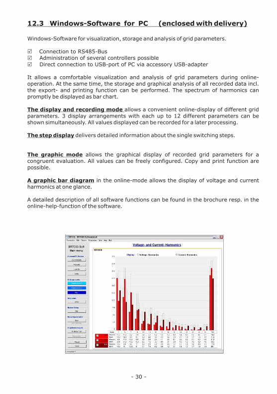
12.3 Windows-Software for PC (enclosed with delivery)
Windows-Software for visualization, storage and analysis of grid parameters.
R Connection to RS485-BusR Administration of several controllers possible R Direct connection to USB-port of PC via accessory USB-adapter
It allows a comfortable visualization and analysis of grid parameters during online-operation. At the same time, the storage and graphical analysis of all recorded data incl. the export- and printing function can be performed. The spectrum of harmonics can promptly be displayed as bar chart.
The display and recording mode allows a convenient online-display of different grid parameters. 3 display arrangements with each up to 12 different parameters can be shown simultaneously. All values displayed can be recorded for a later processing.
The step display delivers detailed information about the single switching steps.
The graphic mode allows the graphical display of recorded grid parameters for a congruent evaluation. All values can be freely configured. Copy and print function are possible.
A graphic bar diagram in the online-mode allows the display of voltage and current harmonics at one glance.
A detailed description of all software functions can be found in the brochure resp. in the online-help-function of the software.
- 30 -

Section 13: ALARM RELAY / ERROR MESSAGES
The contact of the alarm relay (compare page 5) is closed during normal operation and opens in case of failure. At the same time, the respective error is indicated in plain text in the display:
UNDER COMPENSATED - display and relay missing reactive powerOVER COMPENSATED - display and relayOVER CURRENT - display and relayMEASURING VOLTAGE ??? - display and relayOVER TEMPERATURE - display and relayOVER VOLTAGE - display and relayUNDER VOLTAGE - display and relay
HARMONICS - display and relay
Additionally, several messages for different operation states are generated. An individual adjustment resp. masking of single messages is possible in EXPERT-MODE 2.
During masking, the display of message, the eventual output via alarm relay and possible influcences on the control process are suppressed.
Section 14: DISPLAY-EDITOR
Section 15: OSCI-MODE
Section 16: MAINTENANCE AND WARRANTY
No maintenance of the BR7000-T is required when operation conditions are obeyed. Nevertheless a functional check of the controller together with the rotational check of the compensation system is recommended. The typical life expectancy of the internal Li-battery is min. 8...10 years. It is firmly connected to the circuit board and should only be exchanged by the manufacturer.In the event of any interventions in the controller during the warranty period, all warranty claims lapse.
- 31 -
To be reached via button operation mode in the main menu. In Display editor the values that will be permanently shown in the display mode 1 (s. large letter indication) can be selected. Out of all measuring values that are available for each line (three lines in total) the desired value can be selected.
To be reached via button operation menu in the main menu. In Osci-mode the actual form of a period of voltage and current is graphically displayed. This provides information about phase shift and curve form. Display possible consecutively for L1…L3
DISPLAY EDITOR 1 DISPLAY LINE 1
1 [REACTIVE POW. L1] REACTIVE POW. L2 REACTIVE POW. L3 3
2
11:00:00 L1

- 32 -
Annex 1: Table of control series
No.
1234567891011121314151617181920
"ED”
Control serie
1 : 1 : 1 : 1 : 1 .....1 : 2 : 2 : 2 : 2 .....1 : 2 : 3 : 3 : 3 .....1 : 2 : 3 : 4 : 4 .....1 : 2 : 4 : 4 : 4 .....1 : 2 : 3 : 6 : 6 .....1 : 2 : 4 : 8 : 8 .....1 : 1 : 2 : 2 : 2 .....1 : 1 : 2 : 3 : 3 .....1 : 1 : 2 : 3 : 6 .....1 : 1 : 2 : 4 : 4 .....1 : 1 : 2 : 4 : 8 .....1 : 1 : 1 : 2 : 2 .....1 : 1 : 1 : 2 : 3 .....1 : 1 : 1 : 2 : 4 .....1 : 1 : 1 : 2 : 5 .....1 : 1 : 1 : 1 : 2 .....1 : 1 : 1 : 1 : 3 .....1 : 1 : 1 : 1 : 4 .....1 : 1 : 1 : 1 : 5 .....
Control-series editor
Loop connection
possiblepossiblepossiblepossiblepossiblepossiblepossiblepossiblepossiblepossiblepossiblepossiblepossiblepossiblepossiblepossiblepossiblepossiblepossiblepossible
possible
Control series editor: Programming of step values up to 30
The control series editor enables easy creation of own control series in case the required control series is not available. In "PROGRAM-MODE" the last control series - control series ED - has to be selected and confirmed by ENTER. This adds an additional menu point to the main menu -> control series editor. It can be accessed via button „operation mode“.
In the control series editor all stages can be set consecutively to the desired value with the selection buttons é /ê. Pressing ENTER leads to the next stage.
In the control series editor the particular stages can be programmed up to a value of 30 (!). The values >9 are displayed as follows:10=A, 11= B, 12=C, 13=D, 14=E, 15=F, 16=G .... 30=U
Attention: All control series can be edited (even downwards). Whether an edited control series “makes sense” is the decision of the customer.
Maximum number of stages can be limited by a programmed ENDSTOP.
By pressing button ”Operation mode“ the editor is left.

Fault
For target cos PHI=1 and inductive load steps are switched out / for the already compensated grid steps are switched in Supply and consumption exchanged.
Wrong cos Phi is displayed
Display “Measuring current<??”(UNDERCURRENT)
Display: "OVERCURRENT”Alarm relay: after 10 min.
Display: "UNDERCOMPENSATED”Alarm relay:after 10 min.
Display: "OVERCOMPENSATED"Alarm relay: after 10 min.
Display: "MEASURING VOLTAGE ??"Alarm relay: after 10 min.
Display:”UNDERVOLTAGE”Alarm relay: after 10 min.
Display: "OVER-TEMPERATURE"Alarm relay: after 10 min.
Display: “HARMONICS”Alarm relay: after 10 min.
Undervoltage 24V
Reasons / Solution
Check terminals of measuring voltage and measuring current (l and k)!Check phase position! Check phase allocation (voltage/current in same phase)
See above
Current in measuring range ?Line interruption ?Wrong current-converter factor ?Current transformer short-circuited ?
Check ratio of current transformer (1/5A)Go through measuring current range
Check connections and phase position !All stages connected, target PF not reached:- system sufficient dimensioned ?
Check connections and phase-position !Capacitive grid although all stages are disconnected
Measuring voltage missing !
Measuring voltage (in programming) must be in line with real terminal voltageCheck programming over-/under voltage range in EXPERT-MODE 2!
System temperature too high !Outputs are switched off in stages irrespective of power line conditions.
Stages switch off consecutively according to the programmed time and control series. Check grid conditions! If permissible: increase threshold TDH-V (7 %)
Check auxiliary voltage 24V!
Annex 2: Troubleshooting
- 33 -

- 34 -
Reasons / Solution
In case a value other than 1 for target- cos-phi is pre-set, the display “<” may be illuminated despite an inductive grid load. Arrows indicate the control direction, not the grid conditions!
Check END STOP!Check CONTROL-MODE!
Check whether in the menu ”Manual operation/fixed steps“ particular steps have been programmed as fixed steps or as OUT
Check allocation of outputs to capacitors:In program mode HELP-button call page 7-9 > table of allocations is displayed.Check control-mode and END STOP!
System test is for checking of the device when starting. If the page appears, at least one test is not OK. The error may be read, but not solved here. Please contact your local service.Depending on the error (e.g. internal battery empty) the device can be used anyhow.Quit screen with “ESC”.
Check programming and the capacitance of the smallest stage.Check programming and the values of the current converters.Check programming of the control series and the capacitance of the capacitors.
Note: no display, alarm relay open
Fault
In inductive grid stages are switched off resp. in capacitive grid conditions stages are switched on
The controller does not connect all stages or cos-phi does not change at the last stages
Connected capacitor contactors are not in line with the expected capacitor stages.
After turn-on, display shows ”SYSTEM TEST“
The system permanently switches capacitors on and off although the number of consumers does not change (system oscillating).
Operation voltage missing

- 35 -
Annex 3: Technical Data
Type series
Operating voltageMeasuring voltage (3-phase)Measuring current (3-phase)Power consumptionSensitivity
Switching powerOutputs for capacitor branches(switch.voltage 24VDC, 3x120mA)Alarm relayMessage relayRelay for panel fan
Number of active outputs
Operation and display
Menu LanguagesNumber of control seriesUser-defined control series
ControllingModes of operation(1- and 3-phase)
Control principle
Meas.of true current of capacitor-system
Target- cos jnd 2 target cos j (time- or result controlled)
Switch on timeSwitch off timeDischarge time
Internal clock / several timers
Manual operation
Fixed steps / skip steps
Zero voltage releaseAux. voltage for transistor outputs
BR 7000-T....
110...230 V~, +/-15%, 50 / 60Hz3 ∙ 30...440 V~ (L-N) / 50...760V~ (L-L)3 ∙ X : 5 / 1A selectable< 3 VA50 mA / 10mA
15 transistor outputs: freely programmable for switching of single- and three-phase capacitors11, programmable1
programmable
illuminated full graphic display 128x64 dot
Ger / E / ES / RU / TR 201 via editor
true controlling of each phase ( L-N ) und ( L-L )1- phase: up to 3 ∙ 5 single phase capacitors3- phase: up to 15 three-phase capacitorsmixed Mode: for balancing and compensation
series switching, circular switching,self-optimized intelligent switching,4-quadrant operation
possible
0.3 ind. ... 0.3 cap adjustable0.3 ind. ... 0.3 cap adjustable
selectable from 50 - 1000 msselectable from 50 - 1000 msselectable from 50 - 1000 ms
yes
yes
programmable
standard24VDC

- 36 -
Display / Display functionsDisplay of grid parametersAs real value/in %/as bar graph
Large display of 3 grid parametersHarmonics
Osci-mode
Precision
Integrated auxiliary function
Storage functionStorage of maximum values with time stamp
Temperature measuring rangeTemperature monitoringError storage
Interface
Software for visualization, display and recording of grid parameters
External InputComplete 2nd parameter set
Casing
WeightOperating ambient temperature
Protection class accord. IEC 60529Safety standardsInterference resistanceEMV-resistance
3-phasecos-Phi, voltage, current,reactive-, active-, apparent power,missing kvar, temperature, THD-U / THD-Iselection via display-editor 3. - 31. harmonics of U and Idisplay also in % or as bar graphgraphical display of 1 period U/I in oscilloscope modecurrent / voltage: 1%active, reactive, apparent power: 2%context depending, plain text
voltage, current, reactive-, active-, apparent power, temperature, THD-V, THD-I
-30 ... 100°Cautomatic switching-off of stepserror register in plain text with time stamp
2 independent isolated interfaces RS485 (MODBUS RTU, system interface)enclosed in delivery
110...230V~ isolatedvia external input or event driven
panel-mounted instrumentDIN 43 700, 144 x 144 x 60 mm1 kg-20 ... +60°C
front: IP 54, rear: IP 20IEC 61010-1IEC 61000-6-2IEC 61000-4-2: 8kVIEC 61000-4-4: 4kV EN 61326
Annex 4: Factory settings
No.
12
345678910
14151617181920212223
38394041
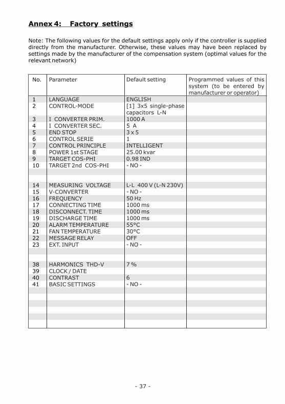
Parameter
LANGUAGECONTROL-MODE
I CONVERTER PRIM.I CONVERTER SEC.END STOPCONTROL SERIECONTROL PRINCIPLEPOWER 1st STAGETARGET COS-PHITARGET 2nd COS-PHI
MEASURING VOLTAGEV-CONVERTERFREQUENCYCONNECTING TIMEDISCONNECT. TIMEDISCHARGE TIMEALARM TEMPERATUREFAN TEMPERATUREMESSAGE RELAYEXT. INPUT
HARMONICS THD-VCLOCK / DATECONTRASTBASIC SETTINGS
Default setting
ENGLISH[1] 3x5 single-phase capacitors L-N1000 A5 A3 x 51INTELLIGENT25.00 kvar0.98 IND- NO -
L-L 400 V (L-N 230V)- NO -50 Hz1000 ms1000 ms1000 ms55°C30°COFF- NO -
7 %
6- NO -
Programmed values of this system (to be entered by manufacturer or operator)
Note: The following values for the default settings apply only if the controller is supplied directly from the manufacturer. Otherwise, these values may have been replaced by settings made by the manufacturer of the compensation system (optimal values for the relevant network)
- 37 -

- 38 -
No.
23-36
123/ 45678910111213141516
Parameter2nd parameter set /EXPERT-MODE
Values 2nd parameter set
Expert-Mode:
Code Expert-Mode 1Code Expert-Mode 2
BASIC SETTINGSSWITCH.POWERSWITCH.TRIGGEROPERATING LOCKCONTROL*OUTPUT 1st STEPDISPLAYHARMONICSC- FAULT (+) *C- FAULT ( - ) *TEST ATTEMPTS *SYMMETRYPROTOCOL*BAUDRATE/ PARITY*ADRESS *
Default setting
63432244
- NO -4 x smallest stage66 %- NO -MEAN VALUE[0...255]kvarCOS Phi[3. - 7.]40 %40 %60 %MODBUS-RTU9600/NONE1
programmed values of this system (to be entered by manufacturer or operator)
Default values are the same as in the 1st parameter set.
Cannot be changedCannot be changed

===== PROGRAM-MODE =====
1 LINE VOLTAGE L1-N 230 V L2-N 230 V L3-N 230 V PE-N 0 V
1 LANGUAGE [ 2 ]
[ ENGLISH ]
2 APPAR.CURRENT L1 123 A L2 239 A L3 167 A
2 CONTROL-MODE [ 1 ][ 3 ] PHASE MEASURINGmax. [ 3x5 single ph ]capacitors PH-N
14 MEASUR. VOLTAGE
L - L [ 400 ] V L - N 230 V
3 REACTIVE POWER L1 88 kvar L2 88 kvar L3 88 kvar S 264 kvar
3 I-CONVERTER PRIM L1 [ 1000 ] A / 5 A L2 1000 A / 5 A L3 1000 A / 5 A
15 V- CONVERTER
[ NO ]
16 FREQUENCY
[ 50 ]Hz
4 I-CONVERTER SEC. L1 1000 A / [5] A L2 1000 A / [5] A L3 1000 A / [5] A
17 - 19 ... TIME C-ON [ 1000 ] ms C-OFF 1000 ms C-DIS 1000 ms
4 ACTIVE POWER L1 88 kW L2 88 kW L3 88 kW S 264 kW
5 APPARENT POWER L1 88 kVA L2 88 kVA L3 88 kVA S 264 kVA
5 END STOP L... -N L1-N [ 5 ] L2-N 5 L3-N 5
20 ALARMTEMPERATURE [ 55 °C ]
21 FAN TEMPERATURE [ 30 °C ]
6 DIFF. TO PF L1 12 kvar L2 24 kvar L3 16 kvar N 52 kvar
6 CONT.SERIES L...-N L1-N 1 1 1 1 1 [ 1 ] L2-N 1 1 1 1 1 1 L3-N 1 1 1 1 1 1
7 CONTR. PRINC. [ 3 ] [ INTELLIGENT ]
22 MESSAGE RELAY [ 1 ] [ ENERGY SUPPLY ]
23 EXT. INPUT [ 1 ] [ NO ]
7 TEMPERATURE
8 POWER 1st STAGE L1 [ 25 ]. 00 kvar L2 25 . 00 kvar L3 25 . 00 kvar
8 HARMONICS [ 3.] L1 V 0.5% I 1.0% L2 V 0.8% I 1.0% L3 V 0.5% I 1.0%
9 TARGET cos j [ 0.98 IND ]
24 - 37 Values 2nd parameter set( if selected at item 23 )
10 TARGET 2nd cos j [ NO ]
38 HARMONICS THD-V [ 7.0 ] %
9 HARMONICS THD L1 V 0.3% I 0.2% L2 V 0.3% I 0.2% L3 V 0.3% I 0.2%
10 COMP.- POWER 100 kvar / 7%
11 TARGET 2nd cos j [ 0.98 IND ]
39 CLOCK / DATE [HH] : MM WEEKDAY TT : MM : JJJJ
12 SWITCH ON TIME j2 ON [ 16 ] : 00 MO-FR
OFF 07 : 00 MO-FR
40 CONTRAST ****** [ 6 ] ******
13 SWITCH OFF TIME j2 ON 16 : 00 MO-FR
OFF [ 07 ] : 00 MO-FR
41 BASIC SETTINGS
12 SOFTWAREVERSION BR7000-DYNAREG VERSION 1.2 26-02-2013
11 TIME / DATE 12:56:07 TUESDAY 05/26/2009
BACK TO 1
BACK TO 1
Changing of valuesby buttons:
2
25 °C
- 39 -
only available if controlserie “ED” is selected
CONTROL SERIES EDITOR
VALENCY C01 [ 1 ]
1 1 1 1 1 1 1 1 1 1 1 1 1 1 1
selection until (max.) C15with button ENTER
VALENCY C15 [ 1 ]
1 1 1 1 1 1 1 1 1 1 1 1 1 1 1
BACK TO 1
AUTO-MODE 1/2 cosj 0.869 IND cosj 0.869 IND cosj 0.869 IND
L1
L1
L2
L2
L3
L3
1 2 3 4

== SERVICE ==
1 min/max VOLTAGE *
L1-N 230 / 235 VL1-N 230 / 235 VL1-N 230 / 235 V
PASSWORD ????
0 * * * (6343)
2 max CURRENT L1 123 A L2 239 A L3 167 A
1 BASIC SETTINGS [ NO ]
7 OUTPUT 1st STEP [ 0...255] kvar
14 PROTOCOL COM1 [ MODBUS RTU ]
13 SYMMETRY [ 0 ] %
15 BAUD RATE COM1 [ 9600/ NONE ]
16 BUS ADRESS COM1 [ 1 ]
3 max REACTIVE PWR L1 88 kvar L2 88 kvar L3 88 kvar
4 max ACTIVE PWR L1 88 kW L2 88 kW L3 88 kW
5 max APPARENT PWR L1 88 kVA L2 88 kVA L3 88 kVA
6 max TEMPERATURE 35 °C
2 SWITCH.POWER max [ 160 ] kvar
5 OPERATING LOCK [ NO ]
7 max THD-V THD - I L1 V 1.0% I 2.0% L2 V 1.0% I 2.0% L3 V 1.0% I 2.0%
3 SWITCH.TRIGGER [ 66 ] % IND 66 % CAP
4 SWITCH.TRIGGER 66 % IND [ 66 ] % CAP
8 MAX. VALUES RESET [ NO ]
9 HARMONICS [ 3. - 7. ]
8 DISPLAY [ COS PHI ]
6 CONTROL [ MEAN VALUE ]
9 ERROR MEMORY
.....ERROR TEXT..... .....DATE / TIME ....
10 C-FAULT ( + )
[ 40 ] %
11 C-FAULT ( - )
[ 40 ] %
10 ERROR MEMORY
RESET [ NO ]
BACK TO 1
BACK TO 1
===== EXPERT-MODE 1 =====
- 40 -
=MANUAL-MODE=
1 MAN. OPERATION L1L1 cos j[ STOPP ]
1 MAN. OPERATION L2L2 cos j[ STOPP ]
1 MAN. OPERATION L3L3 cos j[ STOPP ]
2 STEP STATE L1 OUTPUT C1 [AUTO]
2 STEP STATE L3 OUTPUT C15 [AUTO]
C2...C14
12 TEST ATTEMPTS [ 6 ]
After 4 min. without pressingany button, automatic change
to auto-mode
Settings shown with grey background colour are active only in case
of certain other settings. If not needed they are not displayed.
Operating diagram (Brief programming)Power Factor Controller BR 7000-T (V1.2)

= OSCI-MODE = =DISPLAY EDITOR=
PASSWORD ????
0 * * * (2244)
1 DISPLAY LINE 1 *
1 [ REACTIVE PWR ]2 ACTIVE PWR S 3 APPARENT PWR S
S
2 DISPLAY LINE 2 *
1 [ REACTIVE PWR ]2 ACTIVE PWR S 3 APPARENT PWR S
S
3 DISPLAY LINE 3 *
1 [ REACTIVE PWR ]2 ACTIVE PWR S 3 APPARENT PWR S
S
4 OVERVOLTAGE LIMITING VALUE 460 V [ 115 ] %
5 THD-MEAN VALUE MEAS.CYCLES [ 3 ]
6 UNDERVOLTAGE 24 VDC [ < 12V ]
1 DISPLAY / ALARM
[ YES ]
Release [YES] orblocking [NO] offollowing reports or alarms:
MEAS.VOLTAGE ?
OVERVOLTAGE
OVER-COMPENSATED
UNDERCOMPENSATD
HARMONICS !
OVERTEMPERATURE
OVERCURRENT
UNDERVOLTAGE
UNDERCURRENT
ERROR COM 1
ERROR COM 2
BUS-SWITCH OFF
BUS-STOP
BUS-SWITCH ON
SYSTEMCURRENT < ?
BUS-ERROR-EXT.
C-DEFECT
SYSTEMCURRENT > 0
SYSTEM-OVERLOAD
EXTERNAL ERROR
C-DEFECT-OFF
UNDERVOLTAGE24VDC (Aux.voltage)
4 BASIC SETTING [ NO ]
2 ALARMRELAY
DELAY [ 10 ] min
3 UNDERVOLTAGE
LIMITING VALUE 200 V [ 50 ]%
BACK TO 1 BACK TO 1BACK TO 1
L1
L2
L3
===== EXPERT-MODE 2 =====
- 41 -


Accessories
Universal-Measuring
Devices
Thyristor-switches10 ... 200kvar / 400 ... 690V
MMI 6000 MMI 7000
RJ45-adaptorconnect several devicesto a RS485-Interface via LAN-cable
DataLog SDfor recording dataof BR6000 / BR7000