A-28 4.0 Using IGBT Modules Powerex IGBT modules ... - Galco
Upload
khangminh22Category
view
1download
0
UPS5000-S-(35 kVA-210 kVA)
User Manual (Singapore, 35 kVA Power Modules)
Issue 02
Date 2020-01-10
HUAWEI TECHNOLOGIES CO., LTD.

Issue 02 (2020-01-10) Copyright © Huawei Technologies Co., Ltd. i
Copyright © Huawei Technologies Co., Ltd. 2020. All rights reserved.
No part of this document may be reproduced or transmitted in any form or by any means without prior written consent of Huawei Technologies Co., Ltd.
Trademarks and Permissions
and other Huawei trademarks are trademarks of Huawei Technologies Co., Ltd.
All other trademarks and trade names mentioned in this document are the property of their respective holders.
Notice
The purchased products, services and features are stipulated by the contract made between Huawei and
the customer. All or part of the products, services and features described in this document may not be
within the purchase scope or the usage scope. Unless otherwise specified in the contract, all statements,
information, and recommendations in this document are provided "AS IS" without warranties, guarantees or representations of any kind, either express or implied.
The information in this document is subject to change without notice. Every effort has been made in the
preparation of this document to ensure accuracy of the contents, but all statements, information, and recommendations in this document do not constitute a warranty of any kind, express or implied.
Huawei Technologies Co., Ltd.
Address: Huawei Industrial Base
Bantian, Longgang
Shenzhen 518129
People's Republic of China
Website: https://e.huawei.com

UPS5000-S-(35 kVA-210 kVA)
User Manual (Singapore, 35 kVA Power Modules) About This Document
Issue 02 (2020-01-10) Copyright © Huawei Technologies Co., Ltd. ii
About This Document
Purpose
This document describes the UPS5000-S-(35 kVA-210 kVA) in terms of its features,
performance, working principles, appearance as well as instructions for installation, and
operation and maintenance (O&M).
Intended Audience This document is intended for:
Sales engineers
Technical support engineers
System engineers
Hardware installation engineers
Commissioning engineers
Data configuration engineers
Maintenance engineers
Symbol Conventions The symbols that may be found in this document are defined as follows.
Symbol Description
Indicates a hazard with a high level of risk which, if not
avoided, will result in death or serious injury.
Indicates a hazard with a medium level of risk which, if
not avoided, could result in death or serious injury.
Indicates a hazard with a low level of risk which, if not
avoided, could result in minor or moderate injury.
Indicates a potentially hazardous situation which, if not
avoided, could result in equipment damage, data loss, performance deterioration, or unanticipated results.
NOTICE is used to address practices not related to personal injury.

UPS5000-S-(35 kVA-210 kVA)
User Manual (Singapore, 35 kVA Power Modules) About This Document
Issue 02 (2020-01-10) Copyright © Huawei Technologies Co., Ltd. iii
Symbol Description
Supplements the important information in the main text.
NOTE is used to address information not related to
personal injury, equipment damage, and environment deterioration.
Change History Changes between document issues are cumulative. The latest document issue contains all the
changes made in earlier issues.
Issue 02 (2020-01-10)
Added SNMP descriptions to the sections about site configuration.
Added the SNMP V1 and V2 protocol description.
Updated the safety information.
Issue 01 (2018-02-05)
This issue is the first official release.

UPS5000-S-(35 kVA-210 kVA)
User Manual (Singapore, 35 kVA Power Modules) Contents
Issue 02 (2020-01-10) Copyright © Huawei Technologies Co., Ltd. iv
Contents
About This Document ............................................................................................................... ii
1 Safety Information ................................................................................................................... 1
1.1 General Safety ....................................................................................................................................................... 1
1.2 Personnel Requirements ........................................................................................................................................ 4
1.3 Electrical Safety .................................................................................................................................................... 4
1.4 Installation Environment Requirements .................................................................................................................. 6
1.5 Mechanical Safety ................................................................................................................................................. 7
1.6 Device Running Safety .........................................................................................................................................10
1.7 Battery Safety ....................................................................................................................................................... 11
1.8 Others ..................................................................................................................................................................14
2 Overview ................................................................................................................................. 15
2.1 Model Description ................................................................................................................................................15
2.2 Working Principle .................................................................................................................................................15
2.2.1 Conceptual Diagram ..........................................................................................................................................16
2.2.2 Working Modes .................................................................................................................................................16
2.2.2.1 Normal Mode .................................................................................................................................................16
2.2.2.2 Bypass Mode ..................................................................................................................................................17
2.2.2.3 Battery Mode ..................................................................................................................................................18
2.2.2.4 Joint Power Mode ...........................................................................................................................................19
2.2.2.5 Maintenance Bypass Mode .............................................................................................................................20
2.2.2.6 ECO Mode .....................................................................................................................................................21
2.3 Product Introduction .............................................................................................................................................23
2.3.1 Product Structure ...............................................................................................................................................23
2.3.2 Power Module ...................................................................................................................................................25
2.3.3 Bypass Module ..................................................................................................................................................27
2.3.4 Control Module .................................................................................................................................................28
2.3.4.1 Overview ........................................................................................................................................................28
2.3.4.2 ECM...............................................................................................................................................................29
2.3.4.3 Dry contact card .............................................................................................................................................31
2.3.4.4 Monitoring interface card ................................................................................................................................33
2.3.5 MDU .................................................................................................................................................................38
2.4 Typical configurations ..........................................................................................................................................40

UPS5000-S-(35 kVA-210 kVA)
User Manual (Singapore, 35 kVA Power Modules) Contents
Issue 02 (2020-01-10) Copyright © Huawei Technologies Co., Ltd. v
2.4.1 Single UPS ........................................................................................................................................................40
2.4.2 Parallel System ..................................................................................................................................................40
2.4.3 Dual-Bus System ...............................................................................................................................................41
2.5 Optional Components ...........................................................................................................................................42
3 Installation .............................................................................................................................. 44
3.1 Dimensions ..........................................................................................................................................................44
3.2 Installation Environment .......................................................................................................................................45
3.3 Installation Clearances ..........................................................................................................................................45
3.4 Tools and Instruments ...........................................................................................................................................46
3.5 Preparing Power Cables ........................................................................................................................................47
3.6 Unpacking and Checking ......................................................................................................................................51
3.7 Installing a Single UPS .........................................................................................................................................53
3.7.1 Installing the UPS Cabinet .................................................................................................................................53
3.7.2 Installing Batteries .............................................................................................................................................58
3.7.3 UPS Cable Connection Reference ......................................................................................................................58
3.7.4 Routing Cables ..................................................................................................................................................59
3.7.5 Installing Optional Components .........................................................................................................................65
3.7.5.1 Connecting an Ambient T/H Sensor.................................................................................................................65
3.7.5.2 Installing a Battery Grounding Failure Detector ...............................................................................................66
3.7.5.3 Connecting a BMU .........................................................................................................................................66
3.7.6 Remote EPO ......................................................................................................................................................67
3.8 Installing a Parallel System ...................................................................................................................................68
3.8.1 Mechanical Installation ......................................................................................................................................68
3.8.2 Routing Cables ..................................................................................................................................................69
3.9 Installation Verification .........................................................................................................................................73
4 User Interface .......................................................................................................................... 77
4.1 LCD Interface ......................................................................................................................................................77
4.1.1 Menu Hierarchy .................................................................................................................................................77
4.1.2 Main Menu ........................................................................................................................................................77
4.1.3 System Info .......................................................................................................................................................79
4.1.3.1 Module Data ...................................................................................................................................................79
4.1.3.2 Running ..........................................................................................................................................................79
4.1.3.3 Alarms Screen.................................................................................................................................................83
4.1.3.4 Settings...........................................................................................................................................................84
4.1.3.5 Maintenance ................................................................................................................................................. 104
4.1.3.6 About ........................................................................................................................................................... 108
4.1.4 System Status .................................................................................................................................................. 109
4.1.5 Common Functions.......................................................................................................................................... 109
4.2 WebUI ................................................................................................................................................................ 110
4.2.1 Login............................................................................................................................................................... 110
4.2.2 Monitoring Page .............................................................................................................................................. 112

UPS5000-S-(35 kVA-210 kVA)
User Manual (Singapore, 35 kVA Power Modules) Contents
Issue 02 (2020-01-10) Copyright © Huawei Technologies Co., Ltd. vi
4.2.2.1 Active Alarms ............................................................................................................................................... 113
4.2.2.2 Real-time Data .............................................................................................................................................. 113
4.2.2.3 Parameter Settings ........................................................................................................................................ 114
4.2.2.4 Communication Settings ............................................................................................................................... 121
4.2.2.5 Control ......................................................................................................................................................... 122
4.2.3 Query .............................................................................................................................................................. 122
4.2.3.1 Historical Alarms .......................................................................................................................................... 122
4.2.3.2 Logs ............................................................................................................................................................. 122
4.2.4 Config. ............................................................................................................................................................ 123
4.2.4.1 User Management ......................................................................................................................................... 123
4.2.4.2 Site Config. .................................................................................................................................................. 123
4.2.4.3 RCCMD ....................................................................................................................................................... 125
4.2.4.4 Managing the UPS by Using the NMS Complying with RFC1628 Standard ................................................... 133
4.2.5 Maintenance .................................................................................................................................................... 135
4.2.6 Protecting the Server by Using the RCCMD Software ...................................................................................... 136
4.2.6.1 Introduction to the Software .......................................................................................................................... 136
4.2.6.2 RCCMD Event Shutdown and Message Sending ........................................................................................... 137
4.2.6.3 UPS Alive Check Function ............................................................................................................................ 138
5 Operations ............................................................................................................................. 141
5.1 Powering On and Starting the UPS ..................................................................................................................... 141
5.1.1 Powering On the UPS ...................................................................................................................................... 141
5.1.2 Starting the Inverter ......................................................................................................................................... 141
5.1.2.1 Initial Startup ................................................................................................................................................ 142
5.1.2.2 Non-initial Startup ........................................................................................................................................ 148
5.1.3 Powering On Loads ......................................................................................................................................... 150
5.1.4 (Optional) Setting Parameters for the BCB Box ................................................................................................ 150
5.2 Shutting Down and Powering Off the UPS .......................................................................................................... 151
5.3 Starting the UPS in Battery Mode ....................................................................................................................... 154
5.4 Transferring to Bypass Mode .............................................................................................................................. 154
5.5 Setting ECO Mode ............................................................................................................................................. 154
5.6 Testing Batteries ................................................................................................................................................. 156
5.6.1 Forced Equalized Charging Test ....................................................................................................................... 156
5.6.2 Shallow Discharge Test .................................................................................................................................... 157
5.6.3 Capacity Test ................................................................................................................................................... 158
5.6.4 Test Data Download......................................................................................................................................... 159
5.6.4.1 Download over the LCD ............................................................................................................................... 159
5.6.4.2 Download over the WebUI ............................................................................................................................ 160
5.7 Transferring to Maintenance Bypass Mode .......................................................................................................... 161
5.8 Transferring from Maintenance Bypass Mode to Normal Mode ........................................................................... 162
5.9 Performing EPO ................................................................................................................................................. 163
5.10 Clearing the EPO State ..................................................................................................................................... 163

UPS5000-S-(35 kVA-210 kVA)
User Manual (Singapore, 35 kVA Power Modules) Contents
Issue 02 (2020-01-10) Copyright © Huawei Technologies Co., Ltd. vii
5.11 Exporting Data ................................................................................................................................................. 164
6 Routine Maintenance ........................................................................................................... 166
6.1 UPS Maintenance ............................................................................................................................................... 166
6.1.1 Monthly Maintenance ...................................................................................................................................... 166
6.1.2 Quarterly Maintenance..................................................................................................................................... 167
6.1.3 Annual Maintenance ........................................................................................................................................ 167
6.2 Battery Maintenance ........................................................................................................................................... 168
6.2.1 Precautions for Battery Maintenance ................................................................................................................ 169
6.2.2 Monthly Maintenance ...................................................................................................................................... 169
6.2.3 Quarterly Maintenance..................................................................................................................................... 170
6.2.4 Annual Maintenance ........................................................................................................................................ 171
7 Troubleshooting ................................................................................................................... 172
8 Technical Specifications ...................................................................................................... 174
A Short-circuiting the Input N and PE ................................................................................. 179
B Menu Hierarchy ................................................................................................................... 180
B.1 Menus on the LCD ............................................................................................................................................. 180
B.2 Menus on the WebUI ......................................................................................................................................... 182
C Alarm List ............................................................................................................................. 184
D Acronyms and Abbreviations............................................................................................ 193

UPS5000-S-(35 kVA-210 kVA)
User Manual (Singapore, 35 kVA Power Modules) 1 Safety Information
Issue 02 (2020-01-10) Copyright © Huawei Technologies Co., Ltd. 1
1 Safety Information
1.1 General Safety
Statement
Before installing, operating, and maintaining the equipment, read this document and observe
all the safety instructions on the equipment and in this document.
The "NOTICE", "CAUTION", "WARNING", and "DANGER" statements in this document
do not cover all the safety instructions. They are only supplements to the safety instructions.
Huawei will not be liable for any consequence caused by the violation of general safety
requirements or design, production, and usage safety standards.
Ensure that the equipment is used in environments that meet its design specifications.
Otherwise, the equipment may become faulty, and the resulting equipment malfunction,
component damage, personal injuries, or property damage are not covered under the warranty.
Follow local laws and regulations when installing, operating, or maintaining the equipment.
The safety instructions in this document are only supplements to local laws and regulations.
Huawei will not be liable for any consequences of the following circumstances:
Operation beyond the conditions specified in this document
Installation or use in environments which are not specified in relevant international or
national standards
Unauthorized modifications to the product or software code or removal of the product
Failure to follow the operation instructions and safety precautions on the product and in this document
Equipment damage due to force majeure, such as earthquakes, fire, and storms
Damage caused during transportation by the customer
Storage conditions that do not meet the requirements specified in this document
General Requirements
Do not install, use, or operate outdoor equipment and cables (including but not limited to
moving equipment, operating equipment and cables, inserting connectors to or removing
connectors from signal ports connected to outdoor facilities, working at heights, and
performing outdoor installation) in harsh weather conditions such as lightning, rain, snow, and level 6 or stronger wind.
UPS5000-S-(35 kVA-210 kVA)
User Manual (Singapore, 35 kVA Power Modules) 1 Safety Information
Issue 02 (2020-01-10) Copyright © Huawei Technologies Co., Ltd. 2
Before installing, operating, or maintaining the equipment, remove any conductive
objects such as watches or metal jewelry like bracelets, bangles, and rings to avoid electric shock.
When installing, operating, or maintaining the equipment, wear dedicated protective
gears such as insulation gloves, goggles, and safety clothing, helmet, and shoes, as
shown in the following figure.
Follow the specified procedures for installation, operation, and maintenance.
Before handling a conductor surface or terminal, measure the contact point voltage and ensure that there is no risk of electric shock.
After installing the equipment, remove idle packing materials such as cartons, foam, plastics, and cable ties from the equipment area.
In the case of a fire, immediately leave the building or the equipment area, and turn on
the fire alarm bell or make an emergency call. Do not enter the building on fire in any case.
Do not stop using protective devices. Pay attention to the warnings, cautions, and related
precautionary measures in this document and on the equipment. Promptly replace warning labels that have worn out.
Keep irrelevant people away from the equipment. Only operators are allowed to access
the equipment.
Use insulated tools or tools with insulated handles, as shown in the following figure.

UPS5000-S-(35 kVA-210 kVA)
User Manual (Singapore, 35 kVA Power Modules) 1 Safety Information
Issue 02 (2020-01-10) Copyright © Huawei Technologies Co., Ltd. 3
All cable holes should be sealed. Seal the used cable holes with firestop putty. Seal the
unused cable holes with the caps delivered with the cabinet. The following figure shows the criteria for correct sealing with firestop putty.
Do not scrawl, damage, or block any warning label on the equipment.
Tighten the screws using tools when installing the equipment.
Do not work with power on during installation.
Repaint any paint scratches caused during equipment transportation or installation in a
timely manner. Equipment with scratches cannot be exposed to an outdoor environment for a long period of time.
Before operations, ensure that the equipment is firmly secured to the floor or other solid
objects, such as a wall or an installation rack.
Do not use water to clean electrical components inside or outside of a cabinet.
Do not change the structure or installation sequence of equipment without permission.
Do not touch a running fan with your fingers, components, screws, tools, or boards before the fan is powered off or stops running.
Personal Safety
If there is a probability of personal injury or equipment damage during operations on the
equipment, immediately stop the operations, report the case to the supervisor, and take feasible protective measures.
To avoid electric shock, do not connect safety extra-low voltage (SELV) circuits to
telecommunication network voltage (TNV) circuits.

UPS5000-S-(35 kVA-210 kVA)
User Manual (Singapore, 35 kVA Power Modules) 1 Safety Information
Issue 02 (2020-01-10) Copyright © Huawei Technologies Co., Ltd. 4
Do not power on the equipment before it is installed or confirmed by professionals.
1.2 Personnel Requirements Personnel who plan to install or maintain Huawei equipment must receive thorough
training, understand all necessary safety precautions, and be able to correctly perform all operations.
Only qualified professionals or trained personnel are allowed to install, operate, and maintain the equipment.
Only qualified professionals are allowed to remove safety facilities and inspect the
equipment.
Personnel who will operate the equipment, including operators, trained personnel, and
professionals, should possess the local national required qualifications in special
operations such as high-voltage operations, working at heights, and operations of special
equipment.
Professionals: personnel who are trained or experienced in equipment operations and are
clear of the sources and degree of various potential hazards in equipment installation, operation, maintenance
Trained personnel: personnel who are technically trained, have required experience, are
aware of possible hazards on themselves in certain operations, and are able to take
protective measures to minimize the hazards on themselves and other people
Operators: operation personnel who may come in contact with the equipment, except trained personnel and professionals
Only professionals or authorized personnel are allowed to replace the equipment or components (including software).
1.3 Electrical Safety
Grounding For the equipment that needs to be grounded, install the ground cable first when
installing the equipment and remove the ground cable last when removing the equipment.
Do not damage the ground conductor.
Do not operate the equipment in the absence of a properly installed ground conductor.
Ensure that the equipment is connected permanently to the protective ground. Before
operating the equipment, check its electrical connection to ensure that it is securely
grounded.
General Requirements
Use dedicated insulated tools when performing high-voltage operations.
AC and DC Power

UPS5000-S-(35 kVA-210 kVA)
User Manual (Singapore, 35 kVA Power Modules) 1 Safety Information
Issue 02 (2020-01-10) Copyright © Huawei Technologies Co., Ltd. 5
Do not connect or disconnect power cables with power on. Transient contact between the core
of the power cable and the conductor will generate electric arcs or sparks, which may cause
fire or personal injury.
If a "high electricity leakage" tag is attached on the equipment, ground the protective
ground terminal on the equipment enclosure before connecting the AC power supply; otherwise, electric shock as a result of electricity leakage may occur.
Before installing or removing a power cable, turn off the power switch.
Before connecting a power cable, check that the label on the power cable is correct.
If the equipment has multiple inputs, disconnect all the inputs before operating the
equipment.
A circuit breaker equipped with a residual current device (RCD) is not recommended.
A damaged power cable must be replaced by the manufacturer, service agent, or professionals to avoid risks.
High voltage operations and installation of AC-powered facilities must be performed by qualified personnel.
Cabling
When routing cables, ensure that a distance of at least 30 mm exists between the cables
and heat-generating components or areas. This prevents damage to the insulation layer of the cables.
Do not route cables behind the air intake and exhaust vents of the equipment.
Ensure that cables meet the VW-1 flame spread rating requirements.
Bind cables of the same type together. When routing cables of different types, ensure that
they are at least 30 mm away from each other.
If an AC input power cable is connected to the cabinet from the top, bend the cable in a U shape outside the cabinet and then route it into the cabinet.
When the temperature is low, violent impact or vibration may damage the plastic cable sheathing. To ensure safety, comply with the following requirements:
Cables can be laid or installed only when the temperature is higher than 0°C. Handle
cables with caution, especially at a low temperature.
Cables stored at subzero temperatures must be stored at room temperature for at least 24 hours before they are laid out.
Do not perform any improper operations, for example, dropping cables directly from a vehicle.
When selecting, connecting, and routing cables, follow local safety regulations and rules.
ESD
The static electricity generated by human bodies may damage the electrostatic-sensitive
components on boards, for example, the large-scale integrated (LSI) circuits.

UPS5000-S-(35 kVA-210 kVA)
User Manual (Singapore, 35 kVA Power Modules) 1 Safety Information
Issue 02 (2020-01-10) Copyright © Huawei Technologies Co., Ltd. 6
Wear ESD gloves or a well-grounded ESD wrist strap when touching the device or
handling boards or application-specific integrated circuits (ASICs).
When holding a board, hold its edge without touching any components. Do not touch the components with your bare hands.
Package boards with ESD packaging materials before storing or transporting them.
Figure 1-1 Wearing an ESD wrist strap
Neutral-Ground Voltage
It is recommended that the three-phase loads be equalized and the neutral-ground voltage be
kept at less than 2 V to meet power distribution requirements.
1.4 Installation Environment Requirements To prevent fire due to high temperature, ensure that the ventilation vents or heat
dissipation system are not blocked when the equipment is running.
Install the equipment in an area far away from liquids. Do not install it under areas prone
to condensation, such as under water pipes and air exhaust vents, or areas prone to water
leakage, such as air conditioner vents, ventilation vents, or feeder windows of the
equipment room. Ensure that no liquid enters the equipment to prevent faults or short circuits.
If any liquid is detected inside the equipment, immediately disconnect the power supply and contact the administrator.
Do not expose the equipment to flammable or explosive gas or smoke. Do not perform
any operation on the equipment in such environments.
Ensure that the equipment room provides good heat insulation, and the walls and floor are dampproof.
Install a rat guard at the door of the equipment room.

UPS5000-S-(35 kVA-210 kVA)
User Manual (Singapore, 35 kVA Power Modules) 1 Safety Information
Issue 02 (2020-01-10) Copyright © Huawei Technologies Co., Ltd. 7
Installation at Heights Working at heights refers to operations that are performed at least 2 meters above the
ground.
Do not work at heights if the steel pipes are wet or other potential danger exists. After the
preceding conditions no longer exist, the safety director and relevant technical personnel
need to check the involved equipment. Operators can begin working only after obtaining
consent.
When working at heights, comply with local relevant laws and regulations.
Only trained and qualified personnel are allowed to work at heights.
Before working at heights, check the climbing tools and safety gears such as safety
helmets, safety belts, ladders, springboards, scaffolding, and lifting equipment. If they do not meet the requirements, take corrective measures or disallow working at heights.
Wear personal protective equipment such as the safety helmet and safety belt or waist
rope and fasten it to a solid structure. Do not mount it on an insecure moveable object or
metal object with sharp edges. Make sure that the hooks will not slide off.
Set a restricted area and eye-catching signs for working at heights to warn away irrelevant personnel.
Carry the operation machinery and tools properly to prevent them from falling off and causing injuries.
Personnel involving working at heights are not allowed to throw objects from the height
to the ground, or vice versa. Objects should be transported by tough slings, hanging baskets, highline trolleys, or cranes.
Ensure that guard rails and warning signs are set at the edges and openings of the area involving working at heights to prevent falls.
Do not pile up scaffolding, springboards, or other sundries on the ground under the area
involving working at heights. Do not allow people to stay or pass under the area
involving working at heights.
Inspect the scaffolding, springboards, and workbenches used for working at heights in advance to ensure that their structures are solid and not overloaded.
Any violations must be promptly pointed out by the site manager or safety supervisor
and the involved personnel should be prompted for correction. Personnel who fail to stop
violations will be forbidden from working.
1.5 Mechanical Safety
Hoisting Devices Do not walk under hoisted objects.
Only trained and qualified personnel should perform hoisting operations.
Check that hoisting tools are available and in good condition.
Before hoisting objects, ensure that hoisting tools are firmly secured onto a load-bearing object or wall.
Ensure that the angle formed by two hoisting cables is no more than 90 degrees, as shown in the following figure.

UPS5000-S-(35 kVA-210 kVA)
User Manual (Singapore, 35 kVA Power Modules) 1 Safety Information
Issue 02 (2020-01-10) Copyright © Huawei Technologies Co., Ltd. 8
Do not drag steel ropes and hoisting tools or bump hoisted objects against hard objects during hoisting.
Using Ladders Use wooden or fiberglass ladders when you need to perform live working at heights.
When a step ladder is used, ensure that the pull ropes are secured and the ladder is held firm.
Before using a ladder, check that it is intact and confirm its load bearing capacity. Do not overload it.
Ensure that the ladder is securely positioned. The recommended angle for a ladder
against the floor is 75 degrees, as shown in the following figure. An angle rule can be
used to measure the angle. Ensure that the wider end of the ladder is at the bottom, or protective measures have been taken at the bottom to prevent the ladder from sliding.
When climbing a ladder, take the following precautions to reduce risks and ensure
safety:
Keep your body steady.
Do not climb higher than the fourth rung of the ladder from the top.
Ensure that your body's center of gravity does not shift outside the legs of the ladder.

UPS5000-S-(35 kVA-210 kVA)
User Manual (Singapore, 35 kVA Power Modules) 1 Safety Information
Issue 02 (2020-01-10) Copyright © Huawei Technologies Co., Ltd. 9
Drilling Holes
When drilling holes into a wall or floor, observe the following safety precautions:
Do not drill holes into the equipment. Doing so may affect the electromagnetic shielding of
the equipment and damage components or cables inside. Metal shavings from drilling may
short-circuit boards inside the equipment.
Obtain the consent from the customer, subcontractor, and Huawei before drilling.
Wear goggles and protective gloves when drilling holes.
When drilling holes, protect the equipment from shavings. After drilling, clean up any shavings that have accumulated inside or outside the equipment.
Moving Heavy Objects
When removing a heavy or unstable component from a cabinet, be aware of unstable or heavy
objects on the cabinet.
Be cautious to avoid injury when moving heavy objects.
When moving the equipment by hand, wear protective gloves to prevent injuries.
Move or lift the equipment by holding its handles or lower edges. Do not hold the
handles of modules (such as power supply units, fans, and boards) that are installed in
the equipment because they cannot support the weight of the equipment.
Avoid scratching the cabinet surface or damaging cabinet components and cables during equipment transportation.
When transporting the equipment using a forklift truck, ensure that the forks are properly
positioned to ensure that the equipment does not topple. Before moving the equipment,
secure it to the forklift truck using ropes. When moving the equipment, assign dedicated personnel to take care of it.
Choose railways, sea, or a road with good condition for transportation to ensure equipment safety. Avoid tilt or jolt during transportation.
Move a cabinet with caution. Any bumping or falling may damage the equipment.

UPS5000-S-(35 kVA-210 kVA)
User Manual (Singapore, 35 kVA Power Modules) 1 Safety Information
Issue 02 (2020-01-10) Copyright © Huawei Technologies Co., Ltd. 10
1.6 Device Running Safety The UPS is used for commercial and industrial purposes only. It cannot be used as a power
supply for life support devices.
For power supply systems that are critical to significant economic interests or public order,
such as the national computing center, military command system, emergency command
center, railway signal system and control center, civil aviation and air traffic control center,
airport command center, financial clearing center, and transaction center, the Tier 4 or 3 power
architecture specified in TIA-942 must be used. That is, two power supplies must be used to
supply power to loads.
Ensure that the equipment is used in an environment that meets the product design
specifications (including power grid, temperature, and humidity). Otherwise, the equipment
may become faulty, and the resulting equipment malfunction and component damage are not
covered under the warranty.
The UPS operating environment must meet the requirements for the climate indicator,
mechanically active substance indicator, and chemically active substance indicator in ETSI
EN 300 019-1 class 3.6.
After unpacking the UPS, you are advised to power on the UPS as soon as possible. If you
temporarily do not use the UPS, take appropriate measures to prevent moisture, dust, and foreign matter from entering the UPS.
After unpacking batteries, you are advised to connect the battery supply as soon as
possible. If you temporarily do not use the batteries, store them in a dry and clean
environment. If batteries are stored for more than 90 days, charge them in time. Otherwise, the battery lifespan may be affected.
Install the UPS in an area far away from liquids. Do not install it under areas prone to
water leakage, such as air conditioner vents, ventilation vents, or feeder windows of the
equipment room. Ensure that no liquid enters the UPS to prevent short circuits. Ensure that there is no condensation inside the equipment or equipment room.
If any liquid is detected inside the equipment, immediately disconnect the power supply
and contact the administrator.
Do not expose the equipment to flammable or explosive gas or smoke. Do not perform any
operation on the equipment in such environments.
During installation and maintenance, ensure that sundries do not enter the UPS. Otherwise,
equipment damage, load power derating, power failure, and personal injury may occur.
If the valid mains voltage exceeds 320 V AC, the UPS may be damaged.
A UPS can be used to serve resistive-capacitive loads, resistive loads, and micro-inductive
loads. It is recommended that a UPS not be used for pure capacitive loads, pure inductive
loads, and half-wave rectification loads. A UPS does not apply to regeneration loads.

UPS5000-S-(35 kVA-210 kVA)
User Manual (Singapore, 35 kVA Power Modules) 1 Safety Information
Issue 02 (2020-01-10) Copyright © Huawei Technologies Co., Ltd. 11
Any operation on any electrical device in an environment that has inflammable air can cause
extreme danger. Strictly obey the operating environmental requirements specified in related
user manuals when using or storing the device.
The UPS can be configured with a backfeed protection dry contact to work with an external
automatic circuit breaker, preventing the voltage from flowing back to input terminals over
static bypass circuits. If the installation and maintenance personnel do not need backfeed
protection, paste labels on external mains and bypass input switches, informing that the UPS
is connected to a backfeed protection card. Disconnect the backfeed protection card from the
UPS before operating the UPS.
Do not use the UPS in the following places:
Environments that are close to flammable or explosive materials, dust, corrosive gases or
dust, conductive or magnetic dust, abnormal vibration, or collision
Rooms or outdoor environments where temperature and humidity are not controlled (with high temperature, low temperature, moisture, direct sunlight, or heat sources)
Non-confined environments near the ocean (0–3.7 km) and indoor or semi-indoor
environments where the temperature and humidity are not controllable, such as simple
equipment rooms, civil houses, garages, corridors, and direct ventilation cabinets near
the sea; or houses with only roofs, railway station platforms, gymnasiums, and aquariums
Environments that are conducive for the growth of microorganisms such as fungus or
mildew
Environments where rodents (such as mice) and insects exist
1.7 Battery Safety
Basic Requirements
Before operating batteries, carefully read the safety precautions for battery handling and
master the correct battery connection methods.
Do not expose batteries at high temperatures or around heat-generating devices, such as
sunlight, fire sources, transformers, and heaters. Excessive heat exposure may cause the batteries to explode.
Do not burn batteries. Otherwise, the batteries may explode.
To avoid leakage, overheating, fire, or explosions, do not disassemble, alter, or damage
batteries, for example, insert sundries into batteries or immerse batteries in water or other
liquids.
Wear goggles, rubber gloves, and protective clothing to prevent skin contact with
electrolyte in the case of electrolyte overflow. If a battery leaks, protect the skin or eyes
from the leaking liquid. If the skin or eyes come in contact with the leaking liquid, wash
it immediately with clean water and go to the hospital for medical treatment.
Use dedicated insulated tools.
Move batteries in the required direction. Do not place a battery upside down or tilt it.

UPS5000-S-(35 kVA-210 kVA)
User Manual (Singapore, 35 kVA Power Modules) 1 Safety Information
Issue 02 (2020-01-10) Copyright © Huawei Technologies Co., Ltd. 12
Keep the battery loop disconnected during installation and maintenance.
Use batteries of specified models. Using batteries of other models may damage the
batteries.
Dispose of waste batteries in accordance with local laws and regulations. Do not dispose of batteries as household waste. If a battery is disposed of improperly, it may explode.
The site must be equipped with qualified fire extinguishing facilities, such as firefighting sands and powder fire extinguishers.
To ensure battery safety and battery management accuracy, use batteries provided with the
UPS by Huawei. Huawei is not responsible for any battery faults caused by batteries not
provided by Huawei.
Battery Installation
Before installing batteries, observe the following safety precautions:
Install batteries in a well-ventilated, dry, and cool environment that is far away from heat
sources, flammable materials, moistures, extensive infrared radiation, organic solvents,
and corrosive gases. Take fire prevention measures.
Place and secure batteries horizontally.
Note the polarities when installing batteries. Do not short-circuit the positive and
negative poles of the same battery or battery string. Otherwise, the battery may be short-circuited.
Check battery connections periodically, ensuring that all bolts are securely tightened.
When installing batteries, do not place installation tools on the batteries.
Battery Short Circuit
Battery short circuits can generate high instantaneous current and release a great amount of
energy, which may cause equipment damage or personal injury.
To avoid battery short-circuit, do not maintain batteries with power on.
Flammable Gas

UPS5000-S-(35 kVA-210 kVA)
User Manual (Singapore, 35 kVA Power Modules) 1 Safety Information
Issue 02 (2020-01-10) Copyright © Huawei Technologies Co., Ltd. 13
Do not use unsealed lead-acid batteries.
To prevent fire or corrosion, ensure that flammable gas (such as hydrogen) is properly
exhausted for lead-acid batteries.
Lead-acid batteries emit flammable gas when used. Ensure that batteries are kept in a well-
ventilated area and take preventive measures against fire.
Battery Leakage
Battery overheating causes deformation, damage, and electrolyte spillage.
When the electrolyte overflows, absorb and neutralize the electrolyte immediately. When
moving or handling a battery whose electrolyte leaks, note that the leaking electrolyte may
hurt human bodies.
If the battery temperature exceeds 60°C, check for and promptly handle any leakage.
Electrolyte overflow may damage the equipment. It will corrode metal parts and boards, and ultimately damage the boards.
If the electrolyte overflows, follow the instructions of the battery manufacturer or
neutralize the electrolyte by using sodium bicarbonate (NaHCO3) or sodium carbonate
(Na2CO3).
Lithium Battery
The safety precautions for lithium batteries are similar to those for lead-acid batteries except
that you also need to note the precautions described in this section.
There is a risk of explosion if a battery is replaced with an incorrect model.
A battery can be replaced only with a battery of the same or similar model recommended
by the manufacturer.
When handling a lithium battery, do not place it upside down, tilt it, or bump it with other objects.
Keep the lithium battery loop disconnected during installation and maintenance.
Do not charge a battery when the ambient temperature is below the lower limit of the
operating temperature (charging is forbidden at 0°C). Low-temperature charging may
cause crystallization, which will result in a short circuit inside the battery.

UPS5000-S-(35 kVA-210 kVA)
User Manual (Singapore, 35 kVA Power Modules) 1 Safety Information
Issue 02 (2020-01-10) Copyright © Huawei Technologies Co., Ltd. 14
Use batteries within the allowed temperature range; otherwise, the battery performance
and safety will be compromised.
Do not throw a lithium battery in fire.
When maintenance is complete, return the waste lithium battery to the maintenance office.
1.8 Others Exercise caution when manually shutting down the UPS inverter for transferring to
bypass mode, or when adjusting the UPS output voltage level or frequency. Doing so
may affect the power supply to equipment.
Exercise caution when setting battery parameters. Incorrect settings will affect the power supply and battery lifespan.

UPS5000-S-(35 kVA-210 kVA)
User Manual (Singapore, 35 kVA Power Modules) 2 Overview
Issue 02 (2020-01-10) Copyright © Huawei Technologies Co., Ltd. 15
2 Overview
2.1 Model Description
Figure 2-1 UPS model number
Table 2-1 UPS model number description
Identifier
Meaning Value
1 Product category UPS, short for uninterruptible power system
2 UPS family 5000
3 UPS subcategory S series
4 Output capacity 210K: 210 kVA
5 Configuration type SM: standard configuration
6 Protection level IP42
This model includes the following configurations: 35 kVA, 70 kVA, 105 kVA, 140 kVA, 175
kVA, and 210 kVA.
2.2 Working Principle
indicates an input mode.

UPS5000-S-(35 kVA-210 kVA)
User Manual (Singapore, 35 kVA Power Modules) 2 Overview
Issue 02 (2020-01-10) Copyright © Huawei Technologies Co., Ltd. 16
indicates the energy flow direction.
2.2.1 Conceptual Diagram
The UPS5000 is an online product. It uses a modular design, which facilitates maintenance
and capacity expansion. The UPS5000 adopts intelligent control. Its power module consists of
a rectifier, inverter, and DC/DC converter. The UPS5000 converts inputs into pure high-
quality sine wave outputs by using the high-frequency switching technology.
Figure 2-2 UPS conceptual diagram
2.2.2 Working Modes
2.2.2.1 Normal Mode
In normal mode, the rectifier converts AC power into DC power, then the inverter converts
DC power into high-precision AC outputs. The conversions protect loads from interference
such as input harmonics, glitches, and voltage transients.

UPS5000-S-(35 kVA-210 kVA)
User Manual (Singapore, 35 kVA Power Modules) 2 Overview
Issue 02 (2020-01-10) Copyright © Huawei Technologies Co., Ltd. 17
Figure 2-3 UPS conceptual diagram in normal mode
2.2.2.2 Bypass Mode
The UPS automatically transfers to bypass mode upon detecting power module
overtemperature, overload, or other faults that may cause the inverter to shut down. The
bypass power supply is not protected by the UPS which means it may be affected by mains
outage, and incorrect AC voltage or frequency.

UPS5000-S-(35 kVA-210 kVA)
User Manual (Singapore, 35 kVA Power Modules) 2 Overview
Issue 02 (2020-01-10) Copyright © Huawei Technologies Co., Ltd. 18
Figure 2-4 UPS conceptual diagram in bypass mode
2.2.2.3 Battery Mode
If the mains input is abnormal or the rectifier becomes abnormal, the UPS transfers to battery
mode. The power module obtains DC power from batteries, and the power is converted into
AC output by the inverter.

UPS5000-S-(35 kVA-210 kVA)
User Manual (Singapore, 35 kVA Power Modules) 2 Overview
Issue 02 (2020-01-10) Copyright © Huawei Technologies Co., Ltd. 19
Figure 2-5 UPS conceptual diagram in battery mode
2.2.2.4 Joint Power Mode
If the UPS works properly and the AC input power of the rectifiers is insufficient, the UPS
transfers to joint power mode. In this case, the power module obtains energy from both the
mains and batteries, and the energy is converted into AC outputs over the inverter.

UPS5000-S-(35 kVA-210 kVA)
User Manual (Singapore, 35 kVA Power Modules) 2 Overview
Issue 02 (2020-01-10) Copyright © Huawei Technologies Co., Ltd. 20
Figure 2-6 Conceptual diagram in joint power mode
2.2.2.5 Maintenance Bypass Mode
When the UPS works in maintenance bypass mode, the current flows through the
maintenance bypass instead of the power module. You can maintain the circuit inside the
cabinet.

UPS5000-S-(35 kVA-210 kVA)
User Manual (Singapore, 35 kVA Power Modules) 2 Overview
Issue 02 (2020-01-10) Copyright © Huawei Technologies Co., Ltd. 21
Figure 2-7 UPS conceptual diagram in maintenance bypass mode
2.2.2.6 ECO Mode
The economic control operation (ECO) mode is an economical working mode, which can be
configured on the LCD or web user interface (WebUI). In ECO mode, when the bypass input
is within the ECO voltage and frequency ranges and other ECO power supply conditions are
met, the UPS works in bypass mode and the inverter is in standby state. When the bypass
voltage is outside the ECO voltage range, the UPS transfers from bypass mode to normal
mode. In bypass mode or normal mode, the rectifier keeps working and charges batteries
using a charger. The ECO mode delivers a high efficiency.

UPS5000-S-(35 kVA-210 kVA)
User Manual (Singapore, 35 kVA Power Modules) 2 Overview
Issue 02 (2020-01-10) Copyright © Huawei Technologies Co., Ltd. 22
Figure 2-8 UPS conceptual diagram in ECO mode
Manual startup is required to ensure that the inverter is in standby state and the power flow has reached the inverter.

UPS5000-S-(35 kVA-210 kVA)
User Manual (Singapore, 35 kVA Power Modules) 2 Overview
Issue 02 (2020-01-10) Copyright © Huawei Technologies Co., Ltd. 23
2.3 Product Introduction
2.3.1 Product Structure
Figure 2-9 Appearance

UPS5000-S-(35 kVA-210 kVA)
User Manual (Singapore, 35 kVA Power Modules) 2 Overview
Issue 02 (2020-01-10) Copyright © Huawei Technologies Co., Ltd. 24
Figure 2-10 Structure with the door open
(1) Power
modules
(2) Bypass
module
(3) Control module (4) Power distribution
subrack cover
(5) Monitor
display unit
(6) Filler
panels
(7) Maintenance bypass
switch

UPS5000-S-(35 kVA-210 kVA)
User Manual (Singapore, 35 kVA Power Modules) 2 Overview
Issue 02 (2020-01-10) Copyright © Huawei Technologies Co., Ltd. 25
2.3.2 Power Module
Appearance
Figure 2-11 Power module
(1) Positioning lock (2) Run indicator (3) Alarm indicator (4) Fault indicator
(5) Ready switch (6) Output port (7) Input port
Table 2-2 Indicator description
Indicator Color Status Description
Run indicator Green Steady on The system is working in inverter mode.
Blinking at long
intervals
The inverter is ready and in standby
state (blinking at 0.5 Hz, on for 1s and off for 1s).
The inverter is not started (blinking
at 0.2 Hz, on for 2.5s and off for 2.5s).
Blinking at short
intervals
The module is not configured, the
inverter or rectifier DSP software is
being upgraded, or the inverter CPLD
software is being upgraded (blinking at 4

UPS5000-S-(35 kVA-210 kVA)
User Manual (Singapore, 35 kVA Power Modules) 2 Overview
Issue 02 (2020-01-10) Copyright © Huawei Technologies Co., Ltd. 26
Indicator Color Status Description
Hz, on for 0.125s and off for 0.125s).
Off The rectifier CPLD software is being
upgraded.
Alarm
indicator
Yellow Steady on A minor alarm is generated for the
inverter or rectifier.
Off There is no minor alarm for the inverter
or rectifier, or the rectifier CPLD software is being upgraded.
Fault indicator Red Steady on A critical alarm is generated for the
inverter or rectifier.
Off There is no critical alarm for the inverter
or rectifier, or the rectifier CPLD
software is being upgraded.
Functions
The power module consists of a power factor correction (PFC) rectifier, inverter, and DC/DC
converter. The power module performs AC/DC or DC/DC conversion on the mains and
battery inputs, and stabilizes the bus voltage. The inverter (DC/AC) converts the inputs into
sine wave outputs.
Specifications Dimensions (H x W x D): 130 mm x 442 mm x 620 mm
Weight: ≤ 35 kg
Rated output capacity: 35 kVA/35 kW

UPS5000-S-(35 kVA-210 kVA)
User Manual (Singapore, 35 kVA Power Modules) 2 Overview
Issue 02 (2020-01-10) Copyright © Huawei Technologies Co., Ltd. 27
2.3.3 Bypass Module
Appearance
Figure 2-12 Bypass module
(1) Positioning lock (2) Cold start button (3) Run indicator (4) Alarm indicator
(5) Fault indicator (6) Ready switch (7) Signal port (8) Input and output ports
(9) Crowbar
Table 2-3 Indicator description
Indicator Color Status Description
Run indicator Green Steady on The system is working in bypass
mode.
Blinking at long
intervals
The bypass has no output (blinking
at 0.2 Hz, on for 2.5s and off for 2.5s).
Blinking at short
intervals
The bypass is not configured or the
DSP software is being upgraded (blinking at 4 Hz, on for 0.125s and

UPS5000-S-(35 kVA-210 kVA)
User Manual (Singapore, 35 kVA Power Modules) 2 Overview
Issue 02 (2020-01-10) Copyright © Huawei Technologies Co., Ltd. 28
Indicator Color Status Description
off for 0.125s).
Off The bypass CPLD software is being
upgraded.
Alarm indicator Yellow Steady on A minor alarm is generated for the
bypass.
Off There is no minor alarm for the
bypass, or the CPLD software is being upgraded.
Fault indicator Red Steady on A critical alarm is generated for the
bypass.
Off There is no critical alarm for the
bypass, or the CPLD software is
being upgraded.
Functions
The bypass module supplies power in the following cases:
If the UPS is set to ECO mode and the bypass voltage is within the specified range, the UPS
works in bypass mode.
If the power module overload times out, the UPS transfers to bypass mode.
Both the active and standby ECMs are abnormal.
The system fails to run properly and transfers to bypass mode.
A manual operation is performed to transfer to bypass mode.
Specifications Dimensions (H x W x D): 130 mm x 420 mm x 500 mm
Weight: < 25 kg
2.3.4 Control Module
2.3.4.1 Overview
In a standard configuration, the control module consists of two ECMs, one dry contact card,
and one monitoring interface card (from left to right). The four cards are hot swappable. One
subrack is reserved above the dry contact card. A backfeed protection card or dry contact
extended card can be inserted into this subrack.

UPS5000-S-(35 kVA-210 kVA)
User Manual (Singapore, 35 kVA Power Modules) 2 Overview
Issue 02 (2020-01-10) Copyright © Huawei Technologies Co., Ltd. 29
Figure 2-13 Signal panel on the control module
(1) Ground terminal (2) Parallel port 1 (3) BSC port
1
(4) Ready switch
on ECM 1
(5) Indicators for ECM 1 (6) Parallel port 2 (7) BSC port
2
(8) Ready switch
on ECM 2
(9) Indicators for ECM 2 (10) Dry contact card (11) Dry
contacts
(12) MDU port
(13) RS485 port (14) Fast Ethernet (FE)
port
(15) COM2
port
(16) COM1 port
(17) Battery temperature
sensor port
(18) Optional card
subrack cover
Ports are protected by a security mechanism.
2.3.4.2 ECM
Appearance
The control module consists of two energy control modules (ECMs) in active/standby mode.
Figure 2-14 ECM
Table 2-4 Ports on the ECM
Silk Screen Description
PARALLEL The PARALLEL port transmits parallel signals between racks.
BSC The BSC port is used in a dual-bus system to synchronize output
frequencies and phases between UPS systems, ensuring that two buses
UPS5000-S-(35 kVA-210 kVA)
User Manual (Singapore, 35 kVA Power Modules) 2 Overview
Issue 02 (2020-01-10) Copyright © Huawei Technologies Co., Ltd. 30
Silk Screen Description
can switch with each other.
BSC cables are hot-swappable.
For a single UPS, the parallel cable is not needed.
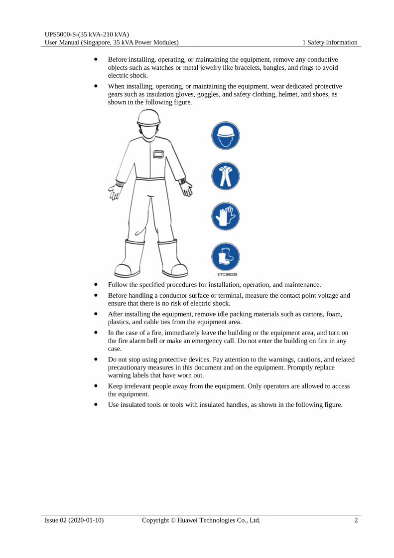
Table 2-5 Indicator description
Indicator Color Status Description
NORMAL Green Steady on This ECM is the active ECM.
Blinking at
0.5 Hz
This ECM is the standby ECM and it is ready.
Off This ECM is not ready or the CPLD of this
ECM is being upgraded.
Blinking at
4 Hz
The DSP of the ECM is being upgraded or not
configured.
ALM Yellow Steady on The ECM has a minor alarm, but it does not
need to be replaced.
Off The ECM has no minor alarm or the DSP of the
ECM is being upgraded.
FAULT Red Steady on The ECM has a critical alarm.
Off The ECM has no critical alarm or the DSP of the
ECM is being upgraded.
Functions As a control interface for the entire system, the ECM communicates with each module
and provides a bus to communicate with the dry contact card. The ECM ensures equalized output currents between modules so that load power is equally shared.
Provides module running information for the MDU.
Controls the running of a single UPS5000 and a parallel system, and reports the UPS5000 status information to other monitoring modules.
The system provides three types of CAN communication: monitoring CAN
communication, intra-rack parallel CAN communication, and inter-rack parallel CAN communication.

UPS5000-S-(35 kVA-210 kVA)
User Manual (Singapore, 35 kVA Power Modules) 2 Overview
Issue 02 (2020-01-10) Copyright © Huawei Technologies Co., Ltd. 31
Figure 2-15 Logical connections for CAN communication
Specifications Hot-swappable
1 U high
2.3.4.3 Dry contact card
Appearance
Figure 2-16 Dry contact card
Table 2-6 Ports on the dry contact card
Silk Screen Description Status Initial Status
BTG Port for detecting battery
grounding faults
Connected: battery
grounding fault
Disconnected: no
battery grounding fault
Disconnected
0V Port for signal ground
GEN Port for detecting diesel
generator (D.G.) mode
Connected: D.G.
mode
Disconnected: non-D.G. mode
Disconnected
0V Port for signal ground

UPS5000-S-(35 kVA-210 kVA)
User Manual (Singapore, 35 kVA Power Modules) 2 Overview
Issue 02 (2020-01-10) Copyright © Huawei Technologies Co., Ltd. 32
Silk Screen Description Status Initial Status
BCB_OL Port for detecting the BCB
box
Grounded: BCB
box connected
Disconnected:
BCB box not connected
Grounded
BCB_STA Port for monitoring the
battery switch
Connected: battery
switch ON
Disconnected:
battery switch OFF
Disconnected
BCB_DRV Controls battery circuit
breaker trip. When the
voltage is +12 V, the circuit
breaker trips.
0 V: battery switch
not tripped
12 V: battery switch tripped
0 V
BCB_0V Port for signal ground
EPO_NO Emergency power-off (EPO)
port
If the normally open
(NO) port is
connected to the
EPO_12V port, EPO is triggered.
Disconnected
EPO_12V +12 V
EPO_NC EPO port If the normally closed
(NC) port is
disconnected from the
EPO_12V port, EPO is triggered.
Connected
EPO_12V +12 V
SWITCH
STATUS_OUT
Port for monitoring the UPS
output circuit breaker
Connected: circuit
breaker ON
Disconnected:
circuit breaker OFF
Connected
SWITCH
STATUS_0V
Port for signal ground
SWITCH
STATUS_MT
Port for monitoring the
maintenance circuit breaker
Disconnected:
circuit breaker ON
Connected: circuit breaker OFF
Disconnected
SWITCH
STATUS_0V
Port for signal ground
SWITCH
STATUS_BP
Port for monitoring the
bypass input circuit breaker
Connected: circuit
breaker ON
Disconnected:
circuit breaker OFF
Connected
SWITCH
STATUS_0V
Port for signal ground
SPD Port for monitoring the input
AC surge protective device (SPD)
Connected: SPD
enabled
Disconnected: SPD disabled
Connected
0V Port for signal ground
UPS5000-S-(35 kVA-210 kVA)
User Manual (Singapore, 35 kVA Power Modules) 2 Overview
Issue 02 (2020-01-10) Copyright © Huawei Technologies Co., Ltd. 33
The dry contact interface card takes effect only after it is set on the monitoring system. Set the
unused dry contact signal to the unused status.
Set the EPO port to NO or NC as required.
When multiple UPSs are paralleled, all dry contact signals to be used need to connect to each UPS.
Single cables require dual-insulated twisted cables. If the length of a power cable is within 25–50 m, its cross-sectional area must be 0.5 mm2 to 1.5 mm2.
Functions
The dry contact card allows the UPS to detect and manage the switch status of the battery
system (including the external battery switch) and implement remote emergency power-off
(EPO).
Specifications Hot-swappable
0.5 U high
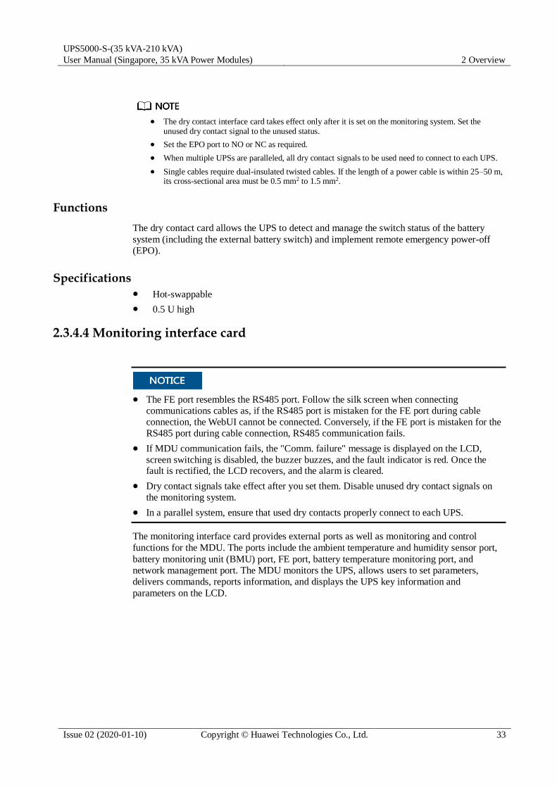
2.3.4.4 Monitoring interface card
The FE port resembles the RS485 port. Follow the silk screen when connecting
communications cables as, if the RS485 port is mistaken for the FE port during cable
connection, the WebUI cannot be connected. Conversely, if the FE port is mistaken for the
RS485 port during cable connection, RS485 communication fails.
If MDU communication fails, the "Comm. failure" message is displayed on the LCD,
screen switching is disabled, the buzzer buzzes, and the fault indicator is red. Once the fault is rectified, the LCD recovers, and the alarm is cleared.
Dry contact signals take effect after you set them. Disable unused dry contact signals on
the monitoring system.
In a parallel system, ensure that used dry contacts properly connect to each UPS.
The monitoring interface card provides external ports as well as monitoring and control
functions for the MDU. The ports include the ambient temperature and humidity sensor port,
battery monitoring unit (BMU) port, FE port, battery temperature monitoring port, and
network management port. The MDU monitors the UPS, allows users to set parameters,
delivers commands, reports information, and displays the UPS key information and
parameters on the LCD.

UPS5000-S-(35 kVA-210 kVA)
User Manual (Singapore, 35 kVA Power Modules) 2 Overview
Issue 02 (2020-01-10) Copyright © Huawei Technologies Co., Ltd. 34
Figure 2-17 Monitoring interface card
DO_1 to DO_4 meet the maximum voltage and current requirements of 30 V DC/1 A or 60 V DC/0.5 A.
Table 2-7 Ports on the monitoring interface card
Port Silk Screen Description
DO_1 NO DO_1 is used to output alarms and
indicates critical alarms by default. It can
be set to indicate minor alarms, bypass
mode, battery mode, or low battery voltage.
COM
DO_2 NO DO_2 is used to output alarms and
indicates minor alarms by default. It can
be set to indicate critical alarms, bypass
mode, battery mode, or low battery voltage.
COM
DO_3 NO DO_3 is used to output alarms and
indicates bypass mode by default. It can
be set to indicate critical alarms, minor
alarms, battery mode, or low battery voltage.
COM
DO_4 NO DO_4 is used to output alarms and
indicates battery mode by default. It can
be set to indicate critical alarms, minor
alarms, bypass mode, or low battery voltage.
COM
DB26 MDU Provides FE, RS485, I2C, and CAN
signals.
Battery temperature
sensor port
B_TEMP Connects to an indoor battery temperature
sensor.
Southbound
communications port 1
COM1 Connects to an ambient temperature and
humidity sensor over two wires.
Southbound COM2 Connects to a southbound device, such as

UPS5000-S-(35 kVA-210 kVA)
User Manual (Singapore, 35 kVA Power Modules) 2 Overview
Issue 02 (2020-01-10) Copyright © Huawei Technologies Co., Ltd. 35
Port Silk Screen Description
communications port 2 a BMU.
Network port FE Connects to the network port on a PC.
Northbound
communications port
RS485 Connects to a northbound network
management device or a third-party
network management device over two wires.
Signal cables must be double-insulated twisted cables. If the cable length is 25–50 m, the cross-
sectional area must be 0.5–1.5 mm2.
RS485 cables and FE cables must be shielded cables.
Figure 2-18 and Figure 2-19 are recommended wiring methods for DO ports.
Figure 2-18 Wiring method 1
Figure 2-19 Wiring method 2
Figure 2-20 and Table 2-8 describe the COM1 pin definitions.

UPS5000-S-(35 kVA-210 kVA)
User Manual (Singapore, 35 kVA Power Modules) 2 Overview
Issue 02 (2020-01-10) Copyright © Huawei Technologies Co., Ltd. 36
Figure 2-20 COM1 pins
Table 2-8 COM1 pin definition
Pin Description
1 GND
2 N/A
3 RS485–
4 RS485+
5 N/A
6 12V_PORT
Figure 2-21 and Table 2-9 describe the COM2 pin definitions.
Figure 2-21 COM2 pins

UPS5000-S-(35 kVA-210 kVA)
User Manual (Singapore, 35 kVA Power Modules) 2 Overview
Issue 02 (2020-01-10) Copyright © Huawei Technologies Co., Ltd. 37
Table 2-9 COM2 pin definition
Pin Description
1 RS485+
2 RS485–
3 N/A
4 RS485+
5 RS485–
6 GND
7 CANH0
8 CANL0
Figure 2-22 and Table 2-10 describe the RS485 pin definitions.
Figure 2-22 RS485 pins
Table 2-10 RS485 pin definition
Pin Description
1 RS485_T+
2 RS485_T–
3 N/A
4 RS485_R+
5 RS485_R–
6 GND
7 N/A

UPS5000-S-(35 kVA-210 kVA)
User Manual (Singapore, 35 kVA Power Modules) 2 Overview
Issue 02 (2020-01-10) Copyright © Huawei Technologies Co., Ltd. 38
Pin Description
8 N/A
If cables are prepared onsite, follow the three methods below:
Connect pin 1 and pin 2. Pin 1 connects to RS485+ and pin 2 connects to RS485–.
Connect pin 4 and pin 5. Pin 4 connects to RS485+ and pin 5 connects to RS485–.
Connect pins 1, 2, 4, and 5. Twist cables to pin 1 and pin 4 into one cable and then connect it to RS485+. Twist cables to pin 2 and pin 5 into one cable and then connect it to RS485–.
2.3.5 MDU
Appearance
Figure 2-23 MDU
(1) Status indicator (2) LCD touchscreen
Table 2-11 Status indicator
Status Color Meaning
On Red A critical alarm has been generated, and the buzzer sounds
continuously.
Yellow A minor alarm has been generated, and the buzzer buzzes at 2 Hz.
Green The UPS is running properly or a warning has been generated.
Off N/A The MDU is powered off.
The indicator on the MDU panel is yellow when the bypass supplies power in non-ECO mode.

UPS5000-S-(35 kVA-210 kVA)
User Manual (Singapore, 35 kVA Power Modules) 2 Overview
Issue 02 (2020-01-10) Copyright © Huawei Technologies Co., Ltd. 39
Figure 2-24 MDU ports
Table 2-12 Description of MDU ports
No. Port Name Description
1 MUS05A
(DB26)
Connects to the MDU and monitoring interface card
2 FE Network port
3 CAN Reserved
4 RS485_1 Reserved
5 USB Host After installing the WiFi module, locally connect to the
UPS over the Service Expert app. Obtain the initial
startup password during deployment. View or obtain
UPS running information during preventive
maintenance.
NOTE
Only Huawei service engineers or authorized service engineers are allowed to use the WiFi module. To ensure security, remove the WiFi module immediately after use.
Insert the USB flash drive, import and export the configuration file, export run logs, and upgrade software.
6 RST Restart switch for the MDU
7 SD Reserved
8 DIP switch Implements specific functions by using the DIP switch and
specific buttons; controls the CAN communication build-out resistor in a parallel system
Functions
The monitor display unit (MDU) allows for general UPS operations, parameter setting,
viewing of running status and alarms, and so on.

UPS5000-S-(35 kVA-210 kVA)
User Manual (Singapore, 35 kVA Power Modules) 2 Overview
Issue 02 (2020-01-10) Copyright © Huawei Technologies Co., Ltd. 40
Specifications
Dimensions (H x W x D): 175 mm x 264 mm x 40 mm
2.4 Typical configurations
Table 2-13 Typical UPS configurations
Configuration Application Scenario
Single UPS Supplies power to common loads.
Parallel system Supplies power to important loads in small- and medium-sized data
centers. It features high availability and strong transient overload
capability.
Dual-bus system The dual-bus system is suitable for scenarios where high availability
requirements are posed for power supply. The dual-bus system
supplies power to important loads in large- and medium-sized equipment rooms and data centers.
In addition to common parallel system advantages, the dual-bus
system also provides outstanding availability and eliminates
bottleneck failures. However, configuration of the dual-bus system is complex.
A 1+1 parallel system is a typical configuration. You can set the number of requisite UPSs and redundant ones on the LCD or WebUI.
2.4.1 Single UPS
This series uses a modular design in which multiple power modules are connected in parallel
to deliver a high loading capacity. If a single power module is faulty, the other power modules
continue working. When the load power is small, even a single UPS can provide redundant
capacity, which ensures high reliability.
2.4.2 Parallel System
In a parallel system, the mains input, bypass input, and AC output terminals between cabinets
are connected in parallel. Energy control modules (ECMs) on each UPS are connected over
parallel cables. The parallel connections synchronize the UPS outputs to supply power to
loads. If one UPS fails, the other UPSs continue supplying power to loads.

UPS5000-S-(35 kVA-210 kVA)
User Manual (Singapore, 35 kVA Power Modules) 2 Overview
Issue 02 (2020-01-10) Copyright © Huawei Technologies Co., Ltd. 41
Figure 2-25 Conceptual diagram of an N+X parallel system
2.4.3 Dual-Bus System
A dual-bus system consists of two independent UPS systems. Each of these UPS systems in
turn consists of one or more UPSs connected in parallel. Of the two UPS systems, one is a
master system, and the other is a slave system. This design makes the dual-bus system highly
reliable and suitable for loads with multiple input terminals. An optional static transfer switch
(STS) can be installed to start the bus synchronization controller (BSC). The UPS systems
work in normal mode or bypass mode.

UPS5000-S-(35 kVA-210 kVA)
User Manual (Singapore, 35 kVA Power Modules) 2 Overview
Issue 02 (2020-01-10) Copyright © Huawei Technologies Co., Ltd. 42
Figure 2-26 Conceptual diagram of a dual-bus system
2.5 Optional Components
Component Model Function Reference Document
BCB-BOX PDU8000-
0125DCV8-BXA001
PDU8000-
0250DCV8-BXA001
PDU8000-
0400DCV8-BXA001
PDU8000-
0630DCV8-BXA001
PDU8000-
0800DCV8-
BXA001
Controls the connection
between battery strings and
the UPS, and supports
overload protection, short-
circuit protection, and remote trip control.
PDU8000-(0125,
0250, 0400, 0630, 0800) DCV8-BXA001
BCB Box User Manual
Battery bus
bar (BBB) box
PDU8000-
0630DCV8-BGA001
PDU8000-
1250DCV8-
BGA001
PDU8000-
Converges the energy from
multiple battery strings.
PDU8000-(0630,
1250, 2000) DCV8-BGA001 BBB Box User Manual

UPS5000-S-(35 kVA-210 kVA)
User Manual (Singapore, 35 kVA Power Modules) 2 Overview
Issue 02 (2020-01-10) Copyright © Huawei Technologies Co., Ltd. 43
Component Model Function Reference Document
2000DCV8-
BGA001
Dry contact
extended card
N/A Provides extended
monitoring ports: five relay
output ports and five input ports.
UPS5000 Dry
Contact Extended Card User Manual (03021RKN)
Backfeed
protection card
N/A Detects mains and bypass
backfeed and provides protection.
UPS5000 Backfeed
Protection Card User Manual (03021KQQ)
Battery
grounding
failure
detector
N/A Detects current leakage and
generates alarms. When
equipped with a remote trip
switch, the detector
protects devices and
prevents fire outbreak.
Detects battery grounding
failures and generates
alarms when the ground
leakage current exceeds the
specified value.
UPS Battery
Grounding Failure
Detector User Manual
Ambient
temperature
and humidity sensor
N/A Monitors the ambient
temperature and humidity,
and can be applied to batteries.
UPS Ambient
Temperature and Humidity Sensor User Manual
BMU N/A Monitors battery cell
voltages, battery
temperatures, and battery
string charge and discharge
currents, and
communicates with the UPS over Modbus.
UPS Battery Monitor
Unit User Manual (02231MNL)
Parallel cable 5 m/10 m/15 m Connects UPSs in parallel. N/A
BSC cable 5 m/10 m/15 m/60
m
Transmits bus
synchronization signals in a dual-bus system.
N/A

UPS5000-S-(35 kVA-210 kVA)
User Manual (Singapore, 35 kVA Power Modules) 3 Installation
Issue 02 (2020-01-10) Copyright © Huawei Technologies Co., Ltd. 44
3 Installation
3.1 Dimensions
Figure 3-1 Dimensions (unit: mm)
(1) Front door (2) Foot (3) Caster (4) Base
(5) Rear panel (6) Base installation hole (7) Beam (8) Side beam

UPS5000-S-(35 kVA-210 kVA)
User Manual (Singapore, 35 kVA Power Modules) 3 Installation
Issue 02 (2020-01-10) Copyright © Huawei Technologies Co., Ltd. 45
3.2 Installation Environment Do not install the UPS in high temperature, low temperature, or damp environments.
Install the UPS away from water sources, heat sources, and flammable or explosive
materials. Keep the UPS away from direct sunlight, dust, volatile gases, corrosive materials, and air dense with salt particles.
Do not install the UPS in environments with conductive metal scraps in the air.
The optimal operating temperatures for valve-regulated lead-acid batteries (VRLA
batteries) are 20–30°C. Operating temperatures higher than 30°C shorten the battery
lifespan and operating temperatures lower than 20°C reduce the battery backup time.
3.3 Installation Clearances Reserve the following clearances around the cabinet to facilitate operations and ventilation:
Reserve at least 800 mm from the front of the cabinet.
Reserve at least 500 mm from the top of the cabinet.
Reserve at least 500 mm from the rear of the cabinet for ventilation. If you need to
perform operations at the rear of the cabinet, reserve at least 800 mm.
Figure 3-2 Reserved clearances (unit: mm)

UPS5000-S-(35 kVA-210 kVA)
User Manual (Singapore, 35 kVA Power Modules) 3 Installation
Issue 02 (2020-01-10) Copyright © Huawei Technologies Co., Ltd. 46
3.4 Tools and Instruments
Insulate installation tools to prevent electric shocks.
Prepare the following tools and meters indicated in Table 3-1 for installation.
Table 3-1 Tools and meters
Tools and Meters
Electric pallet truck Manual pallet truck Ladder Rubber mallet
Hammer drill and
drill bit Φ16
Hand-held electric
drill
Alloy hole saw Heat gun
Diagonal pliers Crimping tools Wire stripper Electric hydraulic
pliers
Clamp meter Multimeter Cable tie Level instrument
Polyvinyl chloride
(PVC) insulation tape
Cotton cloth Label Electrician's knife

UPS5000-S-(35 kVA-210 kVA)
User Manual (Singapore, 35 kVA Power Modules) 3 Installation
Issue 02 (2020-01-10) Copyright © Huawei Technologies Co., Ltd. 47
Tools and Meters
Electrostatic
discharge (ESD) gloves
Protective gloves Insulated gloves Insulation protective
shoes
Torque screwdriver Cable cutter Brush Flat-head
screwdriver
(2–5 mm)
Phillips screwdriver
(M3/M4/M5/M6/M8)
Insulated torque
wrench
(M6/M8/M12/M16)
Heat shrink tubing Insulated adjustable
wrench
Table 3-1 lists only the common tools for installation and cable connection. For more dedicated tools required, see the corresponding component manuals. Prepare tools based on site requirements.
3.5 Preparing Power Cables
The UPS can generate large leakage currents. A circuit breaker that provides leakage
current protection is not recommended.
If multiple UPSs are to be connected in parallel, input and output power cables for each
UPS should have the same length and specifications.
The TN-C system is supported when the input N and PE are connected.
The currents listed in the following table are measured at a rated voltage of 380 V.

UPS5000-S-(35 kVA-210 kVA)
User Manual (Singapore, 35 kVA Power Modules) 3 Installation
Issue 02 (2020-01-10) Copyright © Huawei Technologies Co., Ltd. 48
Table 3-2 Recommended cross-sectional areas for power cables
Item 35 kVA 70 kVA 105 kVA 140 kVA 175 kVA 210 kVA
Mains
input
Mains input current
(A)
91 164 238 311 385 458
Recommended
cross-sectional area (mm2)
L1 4x25 4x50 4x95 4x120 4x150 2x(4x95)
L2
L3
N
PE 25 25 50 70 70 95
Bypass
input
Bypass input current
(A)
54 107 228 304 380 456
Recommended
cross-sectional area (mm2)
L1 4x25 4x50 4x95 4x120 4x150 2x(4x95)
L2
L3
N
PE 25 25 50 70 70 95
Output Output current (A) 54 107 160 213 266 320
Recommended
cross-sectional
area (mm2)
U 4x25 4x25 4x50 4x95 4x120 4x150
V
W
N
PE 25 25 25 50 70 70
Batter
y input
Battery nominal
discharge current (A)
81 162 243 324 404 485
Battery maximum
discharge current (A)
93 185 278 370 462 555
Recommended
cross-sectional
area (mm2)
+ 2x25 2x35 2x70 2x95 2x150 2x185
-
PE 25 25 35 50 70 95
When selecting, connecting, and routing power cables, follow local safety regulations and rules.
When the external conditions change, for example, the cable layout or ambient
temperatures, perform verification in accordance with the IEC-60364-5-52 or the local regulations.

UPS5000-S-(35 kVA-210 kVA)
User Manual (Singapore, 35 kVA Power Modules) 3 Installation
Issue 02 (2020-01-10) Copyright © Huawei Technologies Co., Ltd. 49
If the rated voltage is 400 V, multiply the currents by 0.95. If the rated voltage is 415 V,
multiply the currents by 0.92.
When the primary loads are non-linear loads, increase the cross-sectional areas of the neutral wires 1.5–1.7 times.
The nominal battery discharge current refers to the current at a voltage of 456 V when thirty-eight 12 V batteries are configured.
The maximum battery discharge current refers to the current when thirty-eight 12 V
batteries, that is, two hundred and twenty-eight 2 V battery cells (1.75 V/cell), stop discharging.
The battery cable specifications are selected based on 38 batteries and compatible with application scenarios with 30–50 batteries.
When the mains input and bypass input share a power source, configure input power
cables as mains input power cables. In addition, cables listed in Table 3-2 apply only to
the following conditions:
− 90°C flexible copper power cable. Multi-core cables are recommended for mains
and bypass input and output power cables, and single-core cables are recommended for battery cables.
− Routing mode: Mains and bypass input and output power cables are routed over a
ladder or bracket (E in IEC60364-5-52), and battery cables are routed over a ladder or bracket in a single layer (F in IEC60364-5-52).
− The ambient temperature is 30°C.
− The AC voltage loss is less than 3%, and the DC voltage loss is less than 1%.
− It is recommended that the AC power cable be no longer than 30 meters and the DC power cable be no longer than 40 meters.
Table 3-3 Cabinet power cable terminal requirements
Port Description
Connection Method
Bolt Specifications
Bolt Hole Diameter
Bolt Length Torque
Mains input Crimped OT
terminals
M12 13.5 mm 45 mm 46 N•m
Bypass input Crimped OT
terminals
M12 13.5 mm 45 mm 46 N•m
Battery input Crimped OT
terminals
M12 13.5 mm 45 mm 46 N•m
Output Crimped OT
terminals
M12 13.5 mm 45 mm 46 N•m
PE Crimped OT
terminals
M12 13.5 mm 30 mm 46 N•m

UPS5000-S-(35 kVA-210 kVA)
User Manual (Singapore, 35 kVA Power Modules) 3 Installation
Issue 02 (2020-01-10) Copyright © Huawei Technologies Co., Ltd. 50
Table 3-4 Recommended upstream input and downstream output circuit breakers
UPS Capacity Circuit Breaker Name Specificationsa Protection Current Setting (A)
35 kVA Mains input circuit breaker 160 A/3P 112
Bypass input circuit breaker 100 A/3P 70
Downstream output circuit
breaker
100 A/3P 70
70 kVA Mains input circuit breaker 250 A/3P 200
Bypass input circuit breaker 160 A/3P 144
Downstream output circuit
breaker
160 A/3P 144
105 kVA Mains input circuit breaker 320 A/3P 288
Bypass input circuit breaker 250 A/3P 200
Downstream output circuit
breaker
250 A/3P 200
140 kVA Mains input circuit breaker 400 A/3P 360
Bypass input circuit breaker 320 A/3P 288
Downstream output circuit breaker
320 A/3P 288
175 kVA Mains input circuit breaker 630 A/3P 441
Bypass input circuit breaker 400 A/3P 360
Downstream output circuit
breaker
400 A/3P 360
210 kVA Mains input circuit breaker 630 A/3P 504
Bypass input circuit breaker 400 A/3P 400
Downstream output circuit
breaker
400 A/3P 400
a: recommended model when the short-circuit current where the circuit breaker is located is
less than 36 kA
The upstream input circuit breakers recommended in the table are for reference only.
If multiple loads are connected, specifications for branch circuit breakers must not exceed the recommended specifications.
The circuit breaker selection principle is to protect loads and cables, and the cascading principle is to realize specific protection.

UPS5000-S-(35 kVA-210 kVA)
User Manual (Singapore, 35 kVA Power Modules) 3 Installation
Issue 02 (2020-01-10) Copyright © Huawei Technologies Co., Ltd. 51
3.6 Unpacking and Checking
Context
To prevent the UPS from falling over, secure it to a pallet truck using ropes before moving
it.
To prevent shocks or falls, move the UPS gently. After placing the UPS in the installation
position, unpack it and take care to prevent scratches. Keep the UPS steady during unpacking.
To prevent dust from settling on the UPS, leave the original plastic coat on until
installation is required.
Procedure
Step 1 Use a pallet truck to transport the UPS to the installation position.
Step 2 Check the UPS packing.
Step 3 Hold the sliding plate steady. Cut and remove the binding tapes. Put down the sliding plate
gently.
Figure 3-3 Removing binding tapes
Step 4 Remove packing materials.

UPS5000-S-(35 kVA-210 kVA)
User Manual (Singapore, 35 kVA Power Modules) 3 Installation
Issue 02 (2020-01-10) Copyright © Huawei Technologies Co., Ltd. 52
Figure 3-4 Removing packing materials
Step 5 Remove the plastic bag and take out the fittings box.
Step 6 Check that the UPS is intact.
1. Visually inspect the UPS appearance for shipping damage. If it is damaged, notify the carrier immediately.
2. Check that all fittings comply with the packing list. If some fittings are missing or do not
comply with the packing list, record this information and contact your local Huawei
office immediately.
Step 7 Remove the L-shaped bracket that secures the cabinet and the pallet, and secure the sliding
plate to the pallet by using the two M12 screws that were removed.
Figure 3-5 Removing the L-shaped bracket

UPS5000-S-(35 kVA-210 kVA)
User Manual (Singapore, 35 kVA Power Modules) 3 Installation
Issue 02 (2020-01-10) Copyright © Huawei Technologies Co., Ltd. 53
Tighten the two screws in step 2 in Figure 3-5. Otherwise, the slide plate may move when the UPS is removed.
Step 8 Raise the four anchor bolts to the highest position using an adjustable wrench.
Figure 3-6 Raising anchor bolts
Step 9 Push the cabinet along the sliding plate to the floor.
----End
3.7 Installing a Single UPS
3.7.1 Installing the UPS Cabinet
Floor Installation
Step 1 Determine the cabinet installation position on the floor based on the securing holes of the
cabinet.

UPS5000-S-(35 kVA-210 kVA)
User Manual (Singapore, 35 kVA Power Modules) 3 Installation
Issue 02 (2020-01-10) Copyright © Huawei Technologies Co., Ltd. 54
Figure 3-7 Mounting holes (unit: mm)
Step 2 Use a hammer drill to drill holes for installing the expansion bolts and then install the
expansion sleeves in the holes.
Figure 3-8 Expansion bolt composition
(1) M12 bolt (2) Spring washer (3) Flat washer (4) Expansion sleeve
Ensure the expansion tube of the expansion bolts fits completely into the hole. The expansion
sleeves must be completely buried under the ground to properly facilitate subsequent
installation.

UPS5000-S-(35 kVA-210 kVA)
User Manual (Singapore, 35 kVA Power Modules) 3 Installation
Issue 02 (2020-01-10) Copyright © Huawei Technologies Co., Ltd. 55
Figure 3-9 Installing expansion bolts (unit: mm)
1. Drill holes in the ground by using a hammer drill. The hole depth is 52 mm to 60 mm.
2. Partially tighten the expansion bolt and vertically insert it into the hole. Hit the
expansion bolt using a rubber mallet until the expansion sleeve is fully inserted into the hole.
3. Partially tighten the expansion bolt.
4. Remove the bolt, spring washer, and flat washer.
Step 3 Wheel the cabinet to the installation position.
Step 4 Adjust the four anchor bolts at the bottom of the UPS cabinet until all the four castors at the
bottom hang in the air and the anchor bolts bear all of the cabinet weight.
Step 5 Remove the rear cover from the cabinet and open the front door.
Step 6 Remove the four rubber plugs (two at the front and two at the rear) from the bottom of the
cabinet.

UPS5000-S-(35 kVA-210 kVA)
User Manual (Singapore, 35 kVA Power Modules) 3 Installation
Issue 02 (2020-01-10) Copyright © Huawei Technologies Co., Ltd. 56
Figure 3-10 Removing rubber plugs
Step 7 Insert four M12x115 expansion bolts into the expansion bolt holes in the floor, and tighten the
expansion bolts.
Figure 3-11 Tightening bolts
----End
Channel Steel Installation

UPS5000-S-(35 kVA-210 kVA)
User Manual (Singapore, 35 kVA Power Modules) 3 Installation
Issue 02 (2020-01-10) Copyright © Huawei Technologies Co., Ltd. 57
Huawei does not provide channel steel or expansion bolts used for securing channel steel.
It is recommended that the customer purchase at least 80 mm wide channel steel.
Ensure that the distance between the outer surfaces of channel steels is 850 mm and secure
the channel steels to the floor using expansion bolts.
Align the mounting holes in the cabinet with mounting holes in the channel steels, and secure the cabinet to the channel steels using bolts.
Ensure that the surface of channel steels is smooth.
Step 1 Determine the cabinet installation position on the channel steels based on the securing holes
of the cabinet.
Step 2 Drill mounting holes on the channel steels using a hammer drill.
Step 3 Adjust the four anchor bolts at the bottom of the UPS cabinet until all the four castors at the
bottom hang in the air and the anchor bolts bear all of the cabinet weight.
Step 4 Use a pallet truck to move the cabinet to the installation position.
Step 5 Remove the rear cover from the cabinet and open the front door.
Step 6 Remove the four rubber plugs (two at the front and two at the rear) from the bottom of the
cabinet.
Step 7 Use common M12x75 bolts to secure the cabinet into the mounting holes in the channel steels
and tighten the bolts.
----End
Unsecured Installation
Step 1 Adjust the four anchor bolts at the bottom of the UPS cabinet until all the four castors at the
bottom hang in the air and the anchor bolts bear all of the cabinet weight.
Figure 3-12 Castors hanging in the air
UPS5000-S-(35 kVA-210 kVA)
User Manual (Singapore, 35 kVA Power Modules) 3 Installation
Issue 02 (2020-01-10) Copyright © Huawei Technologies Co., Ltd. 58
Step 2 Check the cabinet levelness using a level. If the cabinet is not level, wrench the anchor bolts.
----End
3.7.2 Installing Batteries
Context
Before installing batteries, read through the battery safety precautions, obtain the delivered battery installation guide, and install batteries as instructed.
Place the batteries in a correct way to prevent vibrations and shocks.
Install the batteries from the lower layer to the upper layer to prevent falling over due to
imbalance.
Procedure
Step 1 Install a battery rack and batteries.
For details, see the battery installation guide delivered along with batteries.
----End
3.7.3 UPS Cable Connection Reference
Context
Keep away from cabinets when preparing cables to prevent cable scraps from entering the
cabinets. Cable scraps may cause ignition during power-on and result in personal injury
and device damage.
After installing cables, clean the cabinet top, bottom, copper bar wiring positions, and other positions. Ensure that there is no dust or scraps inside and around cabinets.
Prepare terminals onsite. The length of the copper wire should be the same as that of the
part of the terminal that covers the conductor.
Procedure
Step 1 Route a cable into the cabinet and bind it to a nearby beam.
Step 2 Pull the cable to the copper bar to which the cable is to be connected, determine the cable
length, and mark the cable at the position where the cable is to be cut.
Step 3 Pull the marked cable out of the cabinet, cut the cable from the marked position, strip the cable, and crimp a terminal.

UPS5000-S-(35 kVA-210 kVA)
User Manual (Singapore, 35 kVA Power Modules) 3 Installation
Issue 02 (2020-01-10) Copyright © Huawei Technologies Co., Ltd. 59
Figure 3-13 Preparing a cable terminal outside the cabinet
Choose an appropriate cabling route based on the actual situation. The figure is for reference only.
Step 4 Connect the cable with a crimped terminal to the corresponding copper bar.
Step 5 Clean foreign matter inside the cabinet.
----End
3.7.4 Routing Cables
Context
When connecting battery cables, you do not need to connect neutral wires.
Procedure
Step 1 Open the front door and remove the cover from the power distribution subrack.

UPS5000-S-(35 kVA-210 kVA)
User Manual (Singapore, 35 kVA Power Modules) 3 Installation
Issue 02 (2020-01-10) Copyright © Huawei Technologies Co., Ltd. 60
Figure 3-14 Removing the cover
Figure 3-15 Removing the cover
(1) Battery input terminals
(+, –)
(2) Bypass input terminals
(2L1–2L3, N)
(3) Mains input terminals
(1L1–1L3, N)
(4) Output terminals (U, V,
W, and N)
(5) Maintenance bypass
switch
Step 2 Determine the cabling mode.
Remove small covers for routing cables.
Take out the cable tray cover for signal cables, and remove small covers from the bottom
based on site requirements.

UPS5000-S-(35 kVA-210 kVA)
User Manual (Singapore, 35 kVA Power Modules) 3 Installation
Issue 02 (2020-01-10) Copyright © Huawei Technologies Co., Ltd. 61
Figure 3-16 Removing small covers from the bottom of the cabinet
Drill holes into the large cover for routing cables.
a. Remove all small covers from the bottom of the cabinet.
b. Remove the two large covers from the rear bottom of the cabinet, drill holes into them, and install them to the positions where the small covers were placed.
Figure 3-17 Hole positions

UPS5000-S-(35 kVA-210 kVA)
User Manual (Singapore, 35 kVA Power Modules) 3 Installation
Issue 02 (2020-01-10) Copyright © Huawei Technologies Co., Ltd. 62
The quantity of holes in the above figure is for reference only.
If holes are drilled for routing cables, attach grommet strips to the hole edges to protect cables.
c. Reinstall the removed two small covers on the holes at the rear bottom of the
cabinet.
Figure 3-18 Installing small covers
Step 3 Connect ground cables.
Figure 3-19 Grounding
: Internal equipotential connection
: Protection ground

UPS5000-S-(35 kVA-210 kVA)
User Manual (Singapore, 35 kVA Power Modules) 3 Installation
Issue 02 (2020-01-10) Copyright © Huawei Technologies Co., Ltd. 63
Step 4 Route power cables.
Dual mains
Remove the copper bars between mains and bypass input terminals.
Figure 3-20 Removing copper bars
Figure 3-21 shows the power cables routed from the bottom of the cabinet.

UPS5000-S-(35 kVA-210 kVA)
User Manual (Singapore, 35 kVA Power Modules) 3 Installation
Issue 02 (2020-01-10) Copyright © Huawei Technologies Co., Ltd. 64
Figure 3-21 Connecting power cables
Single mains
For single mains, the copper bars between the mains and bypass input terminals do not
need to be removed, and bypass input cables do not need to be connected.
Step 5 Route the signal cables on the left side of subracks along the left side of the cabinet and the
cables on the right side of subracks along the right side of the cabinet, and then bind the
cables to the cabinet, as shown in Figure 3-22.

UPS5000-S-(35 kVA-210 kVA)
User Manual (Singapore, 35 kVA Power Modules) 3 Installation
Issue 02 (2020-01-10) Copyright © Huawei Technologies Co., Ltd. 65
Figure 3-22 Connecting signal cables
The number and colors of signal cables in Figure 3-22 are for reference only.
----End
3.7.5 Installing Optional Components
3.7.5.1 Connecting an Ambient T/H Sensor
Procedure
Step 1 Connect the RJ11 port on the ambient T/H sensor to the COM1 port on the monitoring
interface card.
Figure 3-23 Connecting a UPS and an ambient T/H sensor

UPS5000-S-(35 kVA-210 kVA)
User Manual (Singapore, 35 kVA Power Modules) 3 Installation
Issue 02 (2020-01-10) Copyright © Huawei Technologies Co., Ltd. 66
The ambient T/H sensor can be used as a battery temperature sensor.
----End
3.7.5.2 Installing a Battery Grounding Failure Detector
Procedure
Step 1 Install a battery grounding failure detector.
Figure 3-24 Position of a battery grounding failure detector in the UPS
(1) Battery grounding failure detector
----End
3.7.5.3 Connecting a BMU
Procedure
Step 1 Connect a BMU to the COM2 port on the monitoring interface card.

UPS5000-S-(35 kVA-210 kVA)
User Manual (Singapore, 35 kVA Power Modules) 3 Installation
Issue 02 (2020-01-10) Copyright © Huawei Technologies Co., Ltd. 67
Figure 3-25 Connecting the UPS and the BMU
----End
3.7.6 Remote EPO
Huawei does not provide the EPO switch or cable. If the cable is required, the recommended cable is 22 AWG.
Equip the EPO switch with a protective cover to prevent misoperations, and cover the
cable with protective tubing.
Triggering EPO will shut down the rectifier, inverter, charger, and static bypass, but does
not disconnect the UPS mains input. To power off the UPS completely, open the front-end
input switch when triggering EPO.
Connect the requisite EPO switch to UPS dry contacts.
Figure 3-26 shows the cable connections for an NC EPO switch.
Figure 3-27 shows the cable connections for an NO EPO switch.

UPS5000-S-(35 kVA-210 kVA)
User Manual (Singapore, 35 kVA Power Modules) 3 Installation
Issue 02 (2020-01-10) Copyright © Huawei Technologies Co., Ltd. 68
Figure 3-26 Cable connection for an NC EPO switch
Figure 3-27 Cable connection for an NO EPO switch
When the EPO switch is in the NC state, remove the jumper between EPO_NC and EPO_12V
before connection. When the EPO switch is turned off, EPO is triggered.
When the EPO switch is in the NO state, ensure that the jumper is connected between EPO_NC and EPO_12V. When the EPO switch is turned on, EPO is triggered.
3.8 Installing a Parallel System
3.8.1 Mechanical Installation
Procedure
Step 1 Install the UPSs in a parallel system using the single UPS installation method.
Step 2 Install the top connecting kits.

UPS5000-S-(35 kVA-210 kVA)
User Manual (Singapore, 35 kVA Power Modules) 3 Installation
Issue 02 (2020-01-10) Copyright © Huawei Technologies Co., Ltd. 69
Figure 3-28 Installing connecting kits
----End
3.8.2 Routing Cables
Procedure
Step 1 Ground each UPS in a parallel system separately, and connect power cables and battery
cables.
Step 2 Select a parallel connection method to connect cables for the parallel system based on the site
configurations.
The typical scenario of a 1+1 parallel system is used as an example.

UPS5000-S-(35 kVA-210 kVA)
User Manual (Singapore, 35 kVA Power Modules) 3 Installation
Issue 02 (2020-01-10) Copyright © Huawei Technologies Co., Ltd. 70
Figure 3-29 Conceptual diagram of a 1+1 parallel system
Figure 3-30 Cable connections for a 1+1 parallel system
(1) Battery
cables
(2) Bypass input power
cables
(3) Mains input power
cables
(4) Output power
cables
The two subsystems of a bus system are used as an example.

UPS5000-S-(35 kVA-210 kVA)
User Manual (Singapore, 35 kVA Power Modules) 3 Installation
Issue 02 (2020-01-10) Copyright © Huawei Technologies Co., Ltd. 71
Figure 3-31 Conceptual diagram of a dual-bus parallel system
Figure 3-32 Cable connections for a dual-bus parallel system
(1) Battery
cables
(2) Bypass input power
cables
(3) Mains input power
cables
(4) Output power
cables
Step 3 Connect the parallel ports on the UPSs using parallel cables to form a loop.

UPS5000-S-(35 kVA-210 kVA)
User Manual (Singapore, 35 kVA Power Modules) 3 Installation
Issue 02 (2020-01-10) Copyright © Huawei Technologies Co., Ltd. 72
1+1 parallel system
Figure 3-33 Topology for a 1+1 parallel system
Figure 3-34 shows only control modules. Each control module represents a single UPS.
Figure 3-34 Parallel signal cable connections
Dual-bus parallel system
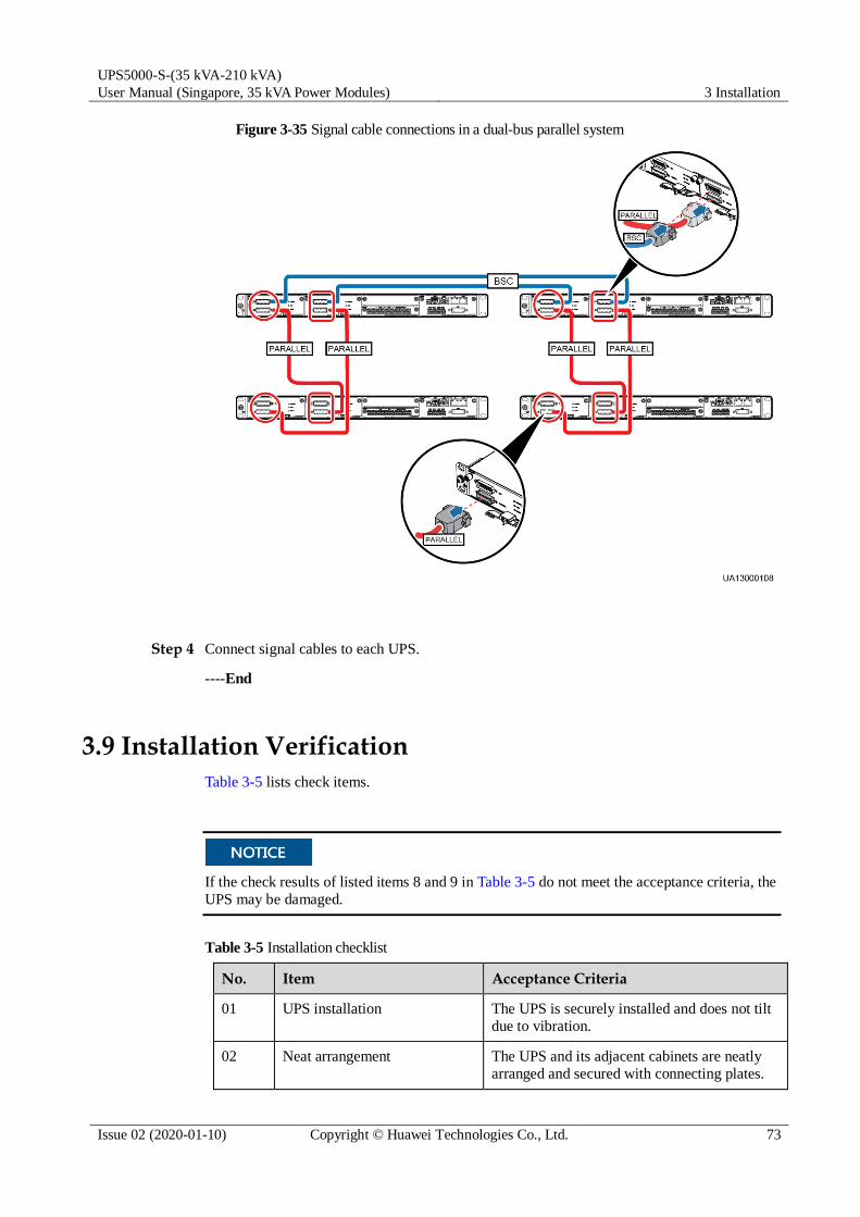
UPS5000-S-(35 kVA-210 kVA)
User Manual (Singapore, 35 kVA Power Modules) 3 Installation
Issue 02 (2020-01-10) Copyright © Huawei Technologies Co., Ltd. 73
Figure 3-35 Signal cable connections in a dual-bus parallel system
Step 4 Connect signal cables to each UPS.
----End
3.9 Installation Verification
Table 3-5 lists check items.
If the check results of listed items 8 and 9 in Table 3-5 do not meet the acceptance criteria, the
UPS may be damaged.
Table 3-5 Installation checklist
No. Item Acceptance Criteria
01 UPS installation The UPS is securely installed and does not tilt
due to vibration.
02 Neat arrangement The UPS and its adjacent cabinets are neatly arranged and secured with connecting plates.

UPS5000-S-(35 kVA-210 kVA)
User Manual (Singapore, 35 kVA Power Modules) 3 Installation
Issue 02 (2020-01-10) Copyright © Huawei Technologies Co., Ltd. 74
No. Item Acceptance Criteria
03 Cable layout Cables are routed properly and cable routing
meets customer requirements.
04 Cable labels Both ends of a cable are labeled. Labels are
concise and easy to understand.
05 Cable ties Cable ties are secured evenly and no burr
exists.
06 Cable connections The input, output, and battery cables are
securely connected. For the cables secured by screws, the spring washers are flattened.
07 Grounding The resistance between the UPS ground bar
and the equipment room ground bar is less than
0.1 ohm.
08 AC phase sequence For a single UPS, the mains input, bypass
input, and output phase sequences are correct.
For a parallel system, the phase sequences of each UPS must be consistent.
09 Battery cable connections The battery strings are correctly connected to
the UPS.
10 Foreign matter cleaning inside
the cabinet
The inside and outside of the cabinet, and other
operating components, are free from conductive dust.
1. There is no foreign matter (such as copper
wires and screws) on the top of the cabinet.
2. There is no foreign matter on the copper
bar terminals.
3. There is no foreign matter around switch
terminals.
4. There is no foreign matter on the bottom
plate of the cabinet.
5. There is no foreign matter on the rear
module subrack.

UPS5000-S-(35 kVA-210 kVA)
User Manual (Singapore, 35 kVA Power Modules) 3 Installation
Issue 02 (2020-01-10) Copyright © Huawei Technologies Co., Ltd. 75
1. In the scenarios where holes are drilled for routing cables or covers are removed for routing cables,
after routing cables and checking cable connections, use sealing putty to fill in the gap between the cables and the cabinet.
2. After verifying the installation, reinstall all the covers.
3. Do not remove the dustproof cover before power-on to prevent dust inside the UPS.
Figure 3-36 Positions for checking foreign matter
(1) Cabinet top (2) Wiring terminal blocks (3) Switches (4) Rear of modules

UPS5000-S-(35 kVA-210 kVA)
User Manual (Singapore, 35 kVA Power Modules) 3 Installation
Issue 02 (2020-01-10) Copyright © Huawei Technologies Co., Ltd. 76
Figure 3-37 Fill the holes with sealing putty
(1) Paper protective film (2) Sealing putty
Figure 3-38 Dustproof cover

UPS5000-S-(35 kVA-210 kVA)
User Manual (Singapore, 35 kVA Power Modules) 4 User Interface
Issue 02 (2020-01-10) Copyright © Huawei Technologies Co., Ltd. 77
4 User Interface
4.1 LCD Interface
4.1.1 Menu Hierarchy
Figure 4-1 shows the LCD menu hierarchy.
Figure 4-1 Menu hierarchy
4.1.2 Main Menu
User interfaces displayed in this document correspond to the MDU version V300R002C02
and are for reference only.

UPS5000-S-(35 kVA-210 kVA)
User Manual (Singapore, 35 kVA Power Modules) 4 User Interface
Issue 02 (2020-01-10) Copyright © Huawei Technologies Co., Ltd. 78
The LCD screen is divided into three parts: status bar, alarm bar and information area.
Figure 4-2 Main menu
Table 4-1 Main screen description
Number Area Function
1 Status bar Displays the UPS model, capacity, configuration, current date
and time, USB flash drive status, and buzzer status.
2 Alarm bar Displays active alarms in a scrolling list and the number of
active alarms based on severity. Tap the alarm icon area to open the active alarm page.
3 Informatio
n area
Displays the power flow as well as key information such as
load and battery information. Tap the Bypass, Mains, Battery, and Load icons to view details.
Table 4-2 Functions of common buttons
Button Function
Returns to the main screen.
Scrolls the page down.
Scrolls the page up.
Returns to the upper-level menu.
Logs a user out.

UPS5000-S-(35 kVA-210 kVA)
User Manual (Singapore, 35 kVA Power Modules) 4 User Interface
Issue 02 (2020-01-10) Copyright © Huawei Technologies Co., Ltd. 79
Table 4-3 LCD user passwords
Default User Preset Password
admin (administrator) 000001
operator (common user) 000001
4.1.3 System Info
Figure 4-3 System info
4.1.3.1 Module Data
On the System Info, tap the UPS picture. On the Module Data screen, select a module to
view its running data. indicates the selected module.
Figure 4-4 Module data
4.1.3.2 Running
On the System Info screen, tap to access the Runn Info screen.
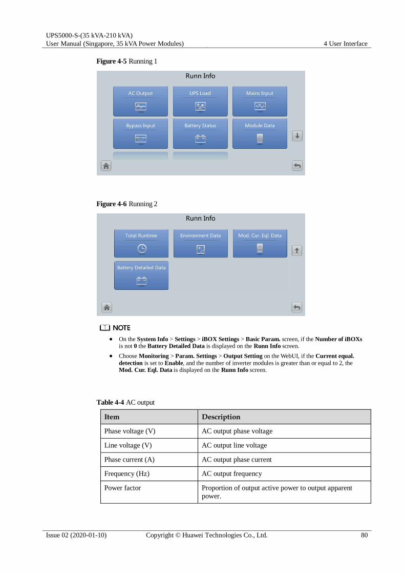
UPS5000-S-(35 kVA-210 kVA)
User Manual (Singapore, 35 kVA Power Modules) 4 User Interface
Issue 02 (2020-01-10) Copyright © Huawei Technologies Co., Ltd. 80
Figure 4-5 Running 1
Figure 4-6 Running 2
On the System Info > Settings > iBOX Settings > Basic Param. screen, if the Number of iBOXs
is not 0 the Battery Detailed Data is displayed on the Runn Info screen.
Choose Monitoring > Param. Settings > Output Setting on the WebUI, if the Current equal.
detection is set to Enable, and the number of inverter modules is greater than or equal to 2, the Mod. Cur. Eql. Data is displayed on the Runn Info screen.
Table 4-4 AC output
Item Description
Phase voltage (V) AC output phase voltage
Line voltage (V) AC output line voltage
Phase current (A) AC output phase current
Frequency (Hz) AC output frequency
Power factor Proportion of output active power to output apparent
power.

UPS5000-S-(35 kVA-210 kVA)
User Manual (Singapore, 35 kVA Power Modules) 4 User Interface
Issue 02 (2020-01-10) Copyright © Huawei Technologies Co., Ltd. 81
Table 4-5 UPS load
Item Description
Active power (kW) Output active power of each phase on the UPS.
Apparent power (kVA) Output apparent power of each phase on the UPS.
Reactive power (kvar) Output reactive power of each phase on the UPS, that is,
square root of the difference between the square of output apparent power and the square of output active power.
Load ratio (%) Load ratio of each phase on the UPS, that is, proportion
of actual power to rated power.
Crest factor Proportion of the peak value of load current to the valid
value.
Hist. Max. Load Ratio (%) Historical maximum load ratio of each phase on the UPS.
Hist. Max. Active Power (kW) Historical maximum active power of each phase on the
UPS.
Hist. Max. Apparent Power
(kVA)
Historical maximum apparent power of each phase on the
UPS.
Table 4-6 Mains input
Item Description
Phase voltage (V) Mains input phase voltage
Line voltage (V) Mains input line voltage
Phase current (A) Mains input phase current
Frequency (Hz) Mains input frequency
Power factor Proportion of the mains input active power to the mains
input apparent power.
Table 4-7 Bypass input
Item Description
Phase voltage (V) Bypass input phase voltage
Line voltage (V) Bypass input line voltage
Phase current (A) Bypass input phase current
Frequency (Hz) Bypass input frequency

UPS5000-S-(35 kVA-210 kVA)
User Manual (Singapore, 35 kVA Power Modules) 4 User Interface
Issue 02 (2020-01-10) Copyright © Huawei Technologies Co., Ltd. 82
Item Description
Power factor Proportion of the bypass input active power to the bypass
input apparent power.
Table 4-8 Battery status
Item Description
Battery Status The value can be Not connected, Equalized charging,
Float charging, Hibernating, discharging, or Not chg.
or dis.
Voltage (V) Voltage of the battery string.
Current (A) Current of the battery string (the current is + when
batteries are being charged and – when discharged).
Temperature (°C) Battery operating temperature (A battery sensor is
required. If the sensor is not installed, N/A is displayed).
Backup time (min) Battery backup time estimated at the current load.
Remaining cap. (%) Remaining battery capacity.
SOH State of health.
Table 4-9 Total runtime
Item Description
Bypass runtime (h) Time for which the UPS runs in bypass mode.
Inv. runtime (h) Time for which the UPS runs in inverter mode.
The value must be an integer. For example:
If the value is less than 1, the value takes 0.
If the value is greater than or equal to 1 and less than 2, the value takes 1.
Table 4-10 Environment data
Item Description
Ambient temperature
(°C)
Temperature measured by the ambient temperature and
humidity sensor. (An ambient temperature and humidity
sensor is required. If no sensor is connected, the ambient temperature sampled by the bypass module is displayed.)
Ambient humid. (%RH) Humidity measured by the ambient temperature and humidity sensor. If the sensor is not installed, N/A is displayed.

UPS5000-S-(35 kVA-210 kVA)
User Manual (Singapore, 35 kVA Power Modules) 4 User Interface
Issue 02 (2020-01-10) Copyright © Huawei Technologies Co., Ltd. 83
Module Data: reflects each data of a module.
Battery Detailed Data - Batt. String Data: reflects the voltage, current, SOC, and SOH data of each battery string.
Battery Detailed Data - String N Battery Data: reflects the temperature, voltage, internal
resistance, current, SOC, and SOH data of a single battery in the battery string.
4.1.3.3 Alarms Screen
Tap on the System Info screen to enter the Alarms screen.
Figure 4-7 Alarms Screen
Active alarms
This screen displays alarm information including the severity, name, ID, location, and
generation time.
Figure 4-8 Active alarms

UPS5000-S-(35 kVA-210 kVA)
User Manual (Singapore, 35 kVA Power Modules) 4 User Interface
Issue 02 (2020-01-10) Copyright © Huawei Technologies Co., Ltd. 84
Historical alarms
This screen displays alarm information including the severity, name, ID, location, generation
time, and clear time.
Figure 4-9 Historical alarms
Buzzer Off
Two buzzer menus are available:
Buzzer On
If this selection is enabled, when a critical alarm, a minor alarm, or a certain warning is generated the buzzer is activated.
Buzzer Off
If this selection is enabled, the buzzer is muted.
If the buzzer is enabled, Buzzer Off is displayed on the operation screen.
4.1.3.4 Settings
On the System Info screen, tap to access the Settings screen.
Figure 4-10 Settings 1

UPS5000-S-(35 kVA-210 kVA)
User Manual (Singapore, 35 kVA Power Modules) 4 User Interface
Issue 02 (2020-01-10) Copyright © Huawei Technologies Co., Ltd. 85
Figure 4-11 Settings 2
Communication Settings
Figure 4-12 Communication settings 1
Figure 4-13 Communication settings 2

UPS5000-S-(35 kVA-210 kVA)
User Manual (Singapore, 35 kVA Power Modules) 4 User Interface
Issue 02 (2020-01-10) Copyright © Huawei Technologies Co., Ltd. 86
Figure 4-14 IP settings
IP address allocation
If the MDU is directly connected to a computer, the IP address can only be allocated
manually. The IP addresses of the MDU and computer must be in the same network
segment, and must be different.
If the MDU is connected to a computer through a LAN switch or router with the DHCP
function, the IP address can be allocated manually or automatically. Manual allocation is used by default.
− Manual: Check that their IP addresses are two different values on the same network
segment. Set the UPS IP address to be in the same subnet as the PC IP address.
Perform the bitwise AND operation for the UPS IP address and the PC IP address
with the subnet mask respectively. If the operation results are the same, the two IP
addresses are in the same subnet.
AND operation rule: 1 AND 1 = 1, 1 AND 0 = 0, 0 AND 1 = 0, 0 AND 0 = 0. That
is when the corresponding bits are both 1, the result is 1. In other cases, the result is 0.
Table 4-11 Bitwise AND operation example
- PC IP address (182.98.225.125)
UPS IP address (182.98.225.112)
PC IP address/UPS IP
address
10110110.01100010.111000
01.01111101
10110110.01100010.111000
01.01110000
Subnet mask
(255.255.255.192)
11111111.11111111.111111
11.11000000
11111111.11111111.111111
11.11000000
Bitwise AND operation
result
10110110.01100010.111000
01.01000000
10110110.01100010.111000
01.01000000
− Automatic: The MDU automatically searches for available IP addresses in the
connected network. Ensure that the MDU and PC are on the same network segment.
After you restart the device, IP address allocation changes back to Manual. The IP address is set to the IP address set previously.

UPS5000-S-(35 kVA-210 kVA)
User Manual (Singapore, 35 kVA Power Modules) 4 User Interface
Issue 02 (2020-01-10) Copyright © Huawei Technologies Co., Ltd. 87
Item Description Default Value Value Range
IP address Specifies the IP address for the
Ethernet.
NOTICE
Ensure that the UPS IP address is unique on the network segment. Otherwise, the WebUI display function may not function properly.
192.168.0.10 1.0.0.0–
223.255.255.255
Subnet mask Specifies the subnet mask of the
Ethernet.
255.255.255.0 0.0.0.0–
255.255.255.255
Gateway Specifies the Ethernet gateway. 192.168.0.1 1.0.0.0–
223.255.255.255
MAC address Defines the physical address of
network equipment and is not
configurable.
- -
NAT mapping NAT means network address
translation. If it is set to Disable,
Internet cannot access IP
addresses in the local area
network (LAN).
Disable Disable, Enable
Figure 4-15 RS485 communication settings
Item Description Default Value Value Range
Address This serial port address is
allocated by the user.
1 1–254
Baud Rate Select a baud rate to match the
user's network management conditions onsite.
9600 9600, 19200,
115200
Parity mode Verify the validity of RS485
communication characters. When a device node adopts RS485
None None, Odd,
Even

UPS5000-S-(35 kVA-210 kVA)
User Manual (Singapore, 35 kVA Power Modules) 4 User Interface
Issue 02 (2020-01-10) Copyright © Huawei Technologies Co., Ltd. 88
Item Description Default Value Value Range
communication, ensure that the
parity modes for the device nodes are set to the same mode.
Stop bit Stop bit in the Modbus
communication frame format.
When the UPS is connected over
the serial port Modbus, set this
parameter based on the frame
format that the upstream device Modbus supports.
1 1–2
Figure 4-16 Modbus TCP settings
Item Description Default Value Value Range
ModbusTCP
encryption
If Modbus TCP is used for
communication, communication
links do not implement
encryption or implement
encryption based on the selected
encryption mode.
Enable Disable, Enable

UPS5000-S-(35 kVA-210 kVA)
User Manual (Singapore, 35 kVA Power Modules) 4 User Interface
Issue 02 (2020-01-10) Copyright © Huawei Technologies Co., Ltd. 89
Figure 4-17 Ambient temperature and humidity sensor
Item Description Default Value Value Range
Start address - 32 32–44
Quantity Number of cascaded ambient
temperature and humidity sensors
0 0–4
Figure 4-18 Battery temperature sensor
Item Description Default Value Value Range
Start address - 16 16–28
Quantity Number of cascaded battery
temperature sensors
0 0–4

UPS5000-S-(35 kVA-210 kVA)
User Manual (Singapore, 35 kVA Power Modules) 4 User Interface
Issue 02 (2020-01-10) Copyright © Huawei Technologies Co., Ltd. 90
Figure 4-19 BMU
Item Description Default Value Value Range
Start address - 112 -
Quantity Number of cascaded BMUs 0 0–12
Figure 4-20 WiFi communication settings
Item Description Default Value Value Range
SSID When using the mobile app for
site setup or inspection, set WiFi
SSID after connecting a WiFi
module over a USB port to
identify the WiFi device to which the mobile phone is connected.
UPS_WIFI +
Last six
characters of the
MAC address
-
Password The password for accessing
WiFi.
Changeme -

UPS5000-S-(35 kVA-210 kVA)
User Manual (Singapore, 35 kVA Power Modules) 4 User Interface
Issue 02 (2020-01-10) Copyright © Huawei Technologies Co., Ltd. 91
System Settings
Figure 4-21 System settings 1
Figure 4-22 System settings 2
Item Description Default Value Value Range
Single/Parallel Specifies whether the UPS works
in single mode or parallel mode.
Single Single, Parallel
Requisite
modules
Matches the system capacity. - -
Redundant
modules
Set this parameter based on load
capacity and redundancy requirements.
0 0–19
Working mode UPS working mode Normal mode Normal mode,
ECO, Self-load
mode, Converter
mode
ECO voltage
range
In ECO mode, when the
difference between the bypass voltage and the rated voltage is
±5% ±5%, ±6%, ±7%,
±8%, ±9%,

UPS5000-S-(35 kVA-210 kVA)
User Manual (Singapore, 35 kVA Power Modules) 4 User Interface
Issue 02 (2020-01-10) Copyright © Huawei Technologies Co., Ltd. 92
Item Description Default Value Value Range
greater than this value, the
system determines that the ECO
voltage is abnormal and transfers
to normal mode.
±10%
BSC mode Set this parameter to
Standard BSC mode for a dual-bus system.
After setting this parameter to
Standard BSC mode, you
need to set the two UPS
systems in the dual-bus
system to BSC master
system and BSC slave
system respectively in the
BSC master/slave system setting. (The two UPS
systems cannot be BSC
master systems or BSC slave
systems at the same time. If
you need to change the
settings in the future, perform
operations under the guidance
of maintenance engineers.)
Non-BSC mode Non-BSC mode,
Standard BSC mode
Altitude (m) Set this parameter based on the
altitude of the place where the rack is used.
≤ 1000 ≤ 1000, 1000–
2000, 2000–
3000, 3000–
4000, 4000–
5000
Air filter
maintenance period (d)
Specifies the rack air filter
maintenance interval. If it is set to 0, there is no reminder.
0 0–365
Intra-rack
power module start delay (s)
These two parameters enable the
UPS to control the interval that
each rack (or module) transfers
from battery mode to normal
mode, which reduces the impact
on the generator or power grid. In
the case of battery undervoltage,
the system automatically shortens
the delay for transferring to
normal mode to 1/8 of the normal
delay to accelerate the transfer
and prevent battery
overdischarge. Intra-rack power
module start delay (s) can be set
to a value ranging from 0.5 to
120. Inter-rack power module
start delay (s) can be set to a
value ranging from 2 to 120. The preset value of Inter-rack power
The default
value of this
parameter
depends on the
default number
of power
modules. The
default value is
2.0, 1.0, and 0.5
for 1–5, 6–10,
and 10–20
power modules respectively.
0.5–120.0
Inter-rack
power module start delay (s)
5 2–120

UPS5000-S-(35 kVA-210 kVA)
User Manual (Singapore, 35 kVA Power Modules) 4 User Interface
Issue 02 (2020-01-10) Copyright © Huawei Technologies Co., Ltd. 93
Item Description Default Value Value Range
module start delay (s) is 5.0.
The start delay of a module in a
rack varies depending on the rack
number and module number. #1
module in rack 1 does not have a start delay.
NTC The short-distance battery
temperature sensor monitors the
ambient temperature near
batteries, and ensures that
batteries work reliably and
securely.
Disable Disable, Enable
Input Settings
Figure 4-23 Input settings
Item Description Default Value Value Range
D.G. mode Set this parameter to Enable
when a D.G. connects to the
input PDC. The UPS enters the
D.G. mode when a D.G. is detected over dry contacts.
Disable Disable, Enable
D.G. power
limiting (kVA)
Set these two parameters to
control the valid input current
and limiting input current, which
prevents load impact and
facilitates better cooperation between the UPS and the D.G.
Depends on the
actual model.
0 kVA to 5000
kVA
D.G. charger
power ratio (%)
0 0%–100%
Input cur.
limiting
Specifies whether to enable or
disable input current limiting to protect generators.
Disable Disable, Enable

UPS5000-S-(35 kVA-210 kVA)
User Manual (Singapore, 35 kVA Power Modules) 4 User Interface
Issue 02 (2020-01-10) Copyright © Huawei Technologies Co., Ltd. 94
Item Description Default Value Value Range
Input cur.
limiting ratio (%)
Limits the input current to protect
the D.G.
200% 50%–200%
Output Settings
Figure 4-24 Output settings
Item Description Default Value Value Range
Output voltage
level
Specifies the system output
voltage level. This parameter is
configurable only after the
inverter shuts down. After you
change the voltage level, the
upper limit of the bypass voltage
restores to the default value. (If
the voltage level is 380 V or 400
V, the default upper limit is
+15%. If the voltage level is 415
V, the default upper limit is +10%.)
400 380, 400, 415
Output volt.
adjustment (V)
The output voltage can be
slightly adjusted based on the
onsite power distribution
condition to ensure a minimum
difference between the output
voltage and the bypass voltage
and facilitate uninterruptible
power supply when the UPS
transfers from normal mode to bypass mode.
The default
value is 220.0,
230.0, and 240.0
when the
voltage level is
380 V, 400 V,
and 415 V respectively.
380 V: 209.0–
231.0
400 V: 218.5–
241.5
415 V: 228.0–252.0
Output frequency (Hz)
Specifies the system output frequency level.
50 Hz 50 Hz, 60 Hz

UPS5000-S-(35 kVA-210 kVA)
User Manual (Singapore, 35 kVA Power Modules) 4 User Interface
Issue 02 (2020-01-10) Copyright © Huawei Technologies Co., Ltd. 95
Item Description Default Value Value Range
Output freq.
track rate (Hz/s)
This parameter can be adjusted
based on site requirements. If
Output freq. track rate (Hz/s) is slow, the inverter frequency is
different from the bypass
frequency when the bypass
frequency changes. If output is
overloaded or the inverter is
faulty, an interruption (less than
20 ms) occurs when the UPS
transfers from normal mode to
bypass mode. If Output freq.
track rate (Hz/s) is fast, the inverter frequency is unstable.
0.6 Hz/s 0.1 Hz/s to 2.0
Hz/s
Bypass Settings
Figure 4-25 Bypass settings
Item Description Default Value Value Range
Maximum
bypass voltage
When the difference between the
bypass voltage and the rated
voltage exceeds the upper
threshold for the bypass voltage,
the system determines that the
bypass voltage is not normal and that the bypass is unavailable.
When the voltage level is 380 V,
the value range is +10%, +15%,
+20%, and +25%. The default value is +15%.
When the voltage level is 400 V,
the value range is +10%, +15%,
and +20%. The default value is +15%.
When the voltage level is 415 V,
the value range is +10% and
+15%. The default value is +10%.
Minimum When the difference between the –20% –10%, –15%, –

UPS5000-S-(35 kVA-210 kVA)
User Manual (Singapore, 35 kVA Power Modules) 4 User Interface
Issue 02 (2020-01-10) Copyright © Huawei Technologies Co., Ltd. 96
Item Description Default Value Value Range
bypass voltage bypass voltage and the rated
voltage exceeds the upper
threshold for the bypass voltage,
the system determines that the
bypass voltage is not normal and that the bypass is unavailable.
20%, –30%, –
40%, –50%, –60%
Bypass
frequency
range (Hz)
When the difference between the
bypass input frequency and the
rated frequency is greater than
the specified value, the system
determines that the bypass
frequency is abnormal, so the
bypass is unavailable. The
frequency range must be greater than the ECO frequency range.
±2 Hz ±0.5 Hz to ±6
Hz
Battery Settings
Battery parameter settings impact battery maintenance, battery lifespan, and UPS discharge time. When you set battery parameters, note the following:
Battery string sharing is unavailable when Single/Parallel is set as Single.
Battery string sharing affects the actual charge current and the estimated discharge time.
An incorrect setting will cause a high or low charge current, which may damage the
batteries. An incorrect estimated discharge time may cause a data backup fault.
When you set parameters, ensure the following: Dis. cur. 0.1C EOD ≥ Dis. cur. 0.3C
EOD ≥ Dis. cur. 0.5C EOD ≥ Dis. cur. 1.0C EOD.
Figure 4-26 Battery settings 1

UPS5000-S-(35 kVA-210 kVA)
User Manual (Singapore, 35 kVA Power Modules) 4 User Interface
Issue 02 (2020-01-10) Copyright © Huawei Technologies Co., Ltd. 97
Figure 4-27 Battery settings 2
Figure 4-28 Battery settings 3
Item Description Default Value Value Range
Battery type Currently, only VRLA batt. is
supported.
- -
Single battery
voltage (V)
Specifies the voltage of each
battery that is connected in the battery string in series.
12 V 2, 6, 12
Single battery
capacity (Ah)
Specifies the capacity of each
battery that is connected in the
battery string in series.
Depends on the
actual model.
5–9999
Batteries in a
battery string
Specifies the number of batteries
in a battery string.
The default
value depends on the model.
The value range
depends on the model.
Number of
battery strings
Specifies the number of battery
strings connected in parallel.
1 1–4
Installation
time
A battery maintenance reminder
is displayed when the maintenance time (counted from
- -

UPS5000-S-(35 kVA-210 kVA)
User Manual (Singapore, 35 kVA Power Modules) 4 User Interface
Issue 02 (2020-01-10) Copyright © Huawei Technologies Co., Ltd. 98
Item Description Default Value Value Range
the installation time) comes.
Maintenance
period (d)
Specifies the interval for
reminding users of battery maintenance.
0 0–365
Chg. cur.
limiting coef. (C10)
The charging current limit is a
multiple of the battery capacity.
0.1C10 0.05C10 to
0.15C10
Cell float
voltage (V/cell)
Specifies the battery float
charging voltage.
2.25 V/cell 2.23 V/cell to
2.30 V/cell
Cell equalized
volt. (V/cell)
Specifies the battery equalized
charging voltage.
2.35 V/cell 2.30 V/cell to
2.40 V/cell
Dis. cur. 0.1C
EOD (V/cell)
Specifies the EOD threshold
when the discharging current is
0.1C, 0.3C, 0.5C, and 1.0C respectively.
1.80 V/cell 1.8–1.9
Dis. cur. 0.3C
EOD (V/cell)
1.80 V/cell 1.8–1.9
Dis. cur. 0.5C
EOD (V/cell)
1.75 V/cell 1.75–1.85
Dis. cur. 1.0C
EOD (V/cell)
1.60 V/cell 1.6–1.75
Sched. shallow
dis. test
When certain conditions are met,
the charger shuts down, and
batteries supply power to loads.
The system records the battery
discharge data as the reference for battery capacity and lifespan.
Disable Disable, Enable
Shallow dis.
test dis. ratio
(%)
Set the proportion of the
discharge capacity to the total
discharge capacity. The value is configurable in any mode.
20% 10%–50%
Dry Contact Settings
Set only the dry contacts that are needed. Otherwise, the UPS may not run properly.
When a dry contact card is disabled, its dry contact signals are disabled.
After a dry contact card is enabled, its dry contact signals can be displayed on the LCD.
Disable all the dry contacts for a dry contact card that is not connected and all the dry contacts that are not used to prevent false alarms.
( ) encloses a unit, and [ ] encloses silk screen.

UPS5000-S-(35 kVA-210 kVA)
User Manual (Singapore, 35 kVA Power Modules) 4 User Interface
Issue 02 (2020-01-10) Copyright © Huawei Technologies Co., Ltd. 99
Specify dry contact settings on the following cards:
Dry contact card (MUE05A): provides dry contact signals for the battery grounding failure detector, D.G., BCB box, and PDCs.
Backfeed protection board (MUE06A): provides backfeed protection signals. This board
can be enabled or disabled.
Monitoring interface card (MUS05A): provides four routes of configurable output dry contact signals.
Dry contact extended card (MUE07A): provides two routes of input signals and one route of output signals.
Figure 4-29 Dry contact settings 1
Figure 4-30 Dry contact settings 2

UPS5000-S-(35 kVA-210 kVA)
User Manual (Singapore, 35 kVA Power Modules) 4 User Interface
Issue 02 (2020-01-10) Copyright © Huawei Technologies Co., Ltd. 100
Figure 4-31 Dry contact settings 3
Figure 4-32 Dry contact settings 4
Figure 4-33 Dry contact settings 5
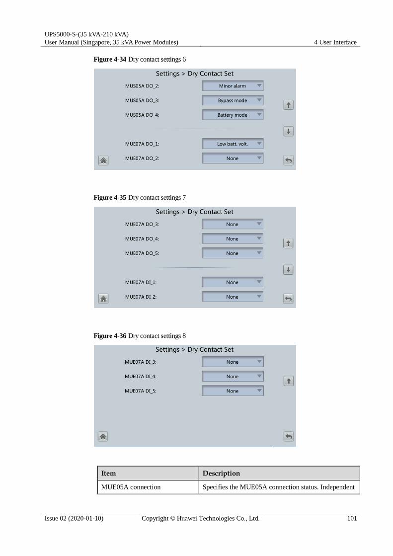
UPS5000-S-(35 kVA-210 kVA)
User Manual (Singapore, 35 kVA Power Modules) 4 User Interface
Issue 02 (2020-01-10) Copyright © Huawei Technologies Co., Ltd. 101
Figure 4-34 Dry contact settings 6
Figure 4-35 Dry contact settings 7
Figure 4-36 Dry contact settings 8
Item Description
MUE05A connection Specifies the MUE05A connection status. Independent
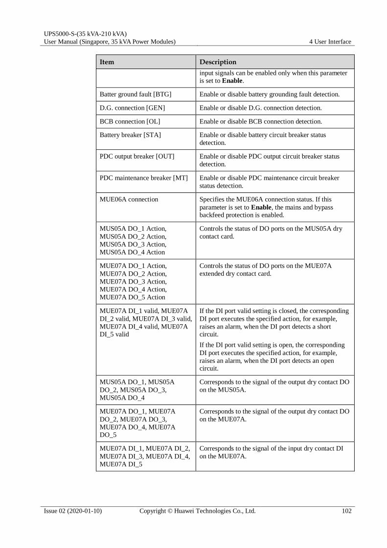
UPS5000-S-(35 kVA-210 kVA)
User Manual (Singapore, 35 kVA Power Modules) 4 User Interface
Issue 02 (2020-01-10) Copyright © Huawei Technologies Co., Ltd. 102
Item Description
input signals can be enabled only when this parameter is set to Enable.
Batter ground fault [BTG] Enable or disable battery grounding fault detection.
D.G. connection [GEN] Enable or disable D.G. connection detection.
BCB connection [OL] Enable or disable BCB connection detection.
Battery breaker [STA] Enable or disable battery circuit breaker status
detection.
PDC output breaker [OUT] Enable or disable PDC output circuit breaker status
detection.
PDC maintenance breaker [MT] Enable or disable PDC maintenance circuit breaker
status detection.
MUE06A connection Specifies the MUE06A connection status. If this
parameter is set to Enable, the mains and bypass backfeed protection is enabled.
MUS05A DO_1 Action,
MUS05A DO_2 Action,
MUS05A DO_3 Action,
MUS05A DO_4 Action
Controls the status of DO ports on the MUS05A dry
contact card.
MUE07A DO_1 Action,
MUE07A DO_2 Action,
MUE07A DO_3 Action,
MUE07A DO_4 Action,
MUE07A DO_5 Action
Controls the status of DO ports on the MUE07A
extended dry contact card.
MUE07A DI_1 valid, MUE07A
DI_2 valid, MUE07A DI_3 valid,
MUE07A DI_4 valid, MUE07A DI_5 valid
If the DI port valid setting is closed, the corresponding
DI port executes the specified action, for example,
raises an alarm, when the DI port detects a short circuit.
If the DI port valid setting is open, the corresponding
DI port executes the specified action, for example,
raises an alarm, when the DI port detects an open circuit.
MUS05A DO_1, MUS05A
DO_2, MUS05A DO_3,
MUS05A DO_4
Corresponds to the signal of the output dry contact DO
on the MUS05A.
MUE07A DO_1, MUE07A
DO_2, MUE07A DO_3,
MUE07A DO_4, MUE07A DO_5
Corresponds to the signal of the output dry contact DO
on the MUE07A.
MUE07A DI_1, MUE07A DI_2,
MUE07A DI_3, MUE07A DI_4,
MUE07A DI_5
Corresponds to the signal of the input dry contact DI
on the MUE07A.

UPS5000-S-(35 kVA-210 kVA)
User Manual (Singapore, 35 kVA Power Modules) 4 User Interface
Issue 02 (2020-01-10) Copyright © Huawei Technologies Co., Ltd. 103
User Settings
Figure 4-37 User settings 1
Figure 4-38 User settings 2
Item Description Default Value Value Range
Language Twelve languages are supported English English,
Chinese,
Spanish, Dutch,
French, German,
Italian, Polish,
Portuguese,
Russian,
Swedish, Turkish
Password - 000001 -
password
complexity check
If the password complexity check
is disabled, the user password is
required to be a string of six to
eight digits. If the password
complexity check is enabled, the
Enable Disable, Enable

UPS5000-S-(35 kVA-210 kVA)
User Manual (Singapore, 35 kVA Power Modules) 4 User Interface
Issue 02 (2020-01-10) Copyright © Huawei Technologies Co., Ltd. 104
Item Description Default Value Value Range
password is required to be a
string of 6–20 characters and
contain at least two types of
characters.
4.1.3.5 Maintenance
On the System Info screen, tap to display the Maintenance screen.
Figure 4-39 Maintenance 1
Figure 4-40 Maintenance 2
On the System Info > Settings > iBOX Settings > Basic Param. screen, if the Number of iBOXs
is not 0 the Maintenance is displayed on the iBOX Control screen.
Choose Monitoring > Param. Settings > System Settings on the WebUI, if the Bus capa. life is set to Enable, the Maintenance is displayed on the Bus Capa. Life screen.

UPS5000-S-(35 kVA-210 kVA)
User Manual (Singapore, 35 kVA Power Modules) 4 User Interface
Issue 02 (2020-01-10) Copyright © Huawei Technologies Co., Ltd. 105
Battery Maint. screen
Perform battery maintenance when no alarm is active on the UPS. Otherwise, the UPS
may supply no power.
A proportion of battery capacity will discharge during battery maintenance. This reduces the discharge time before the next charge.
Do not perform battery maintenance when a D.G. is connected.
Battery maintenance includes Forced Equalized Charging, Shallow Dis. Test, and Capacity
Test.
Figure 4-41 Battery Maint. screen
Item Description
Forced Equalized Charging Forcibly perform equalized charging on batteries.
Shallow Dis. Test Partially discharge batteries. A shallow discharge test can
be conducted to test the battery loop reliability and short-
time discharge capacity when the batteries have not
discharged for a long time.
Capacity Test Fully discharge batteries. A deep discharge test is
conducted to obtain the battery discharge performance data.
USB Operations
You can export Fault Data, and perform Upgrade Software, BSP Upgrade, Export Config.,
and Import Config. with USB.
Multi-brand is used to import the brand information of a partner to the corresponding
WebUI.

UPS5000-S-(35 kVA-210 kVA)
User Manual (Singapore, 35 kVA Power Modules) 4 User Interface
Issue 02 (2020-01-10) Copyright © Huawei Technologies Co., Ltd. 106
Figure 4-42 USB Operations 1
Figure 4-43 USB Operations 2
Starting or Shutting Down the Inverter
Item Description
Inv. ON The Inv. ON screen allows you to start the inverter
manually.
Inv. OFF The Inv. OFF screen allows you to shut down the
inverter manually.
ECM Switchover

UPS5000-S-(35 kVA-210 kVA)
User Manual (Singapore, 35 kVA Power Modules) 4 User Interface
Issue 02 (2020-01-10) Copyright © Huawei Technologies Co., Ltd. 107
Only professional personnel are allowed to use this function.
Clear faults before performing ECM active/standby switchover.
After an ECM is inserted, active and standby switchover is supported only after the ECM
is configured and starts working properly (about 30 seconds).
If the ECM to be maintained is still working, perform ECM active/standby switchover on this
screen (a dialog box is displayed for you to confirm this operation). After performing
active/standby switchover, ensure that this ECM is in standby state (that is, the green indicator
is blinking) and then maintain the ECM.
iBOX control
Reset the specified iBOX and iBAT, and sets the iBAT blinking function or measures the
iBAT internal resistance.
Item Description
Reset Restart an iBAT or an iBOX.
Blink Make the red indicator on the iBAT start or stop blinking super fast.
Internal
resistance
Measure the battery internal resistance. If the condition for measuring
internal resistance is met (batteries are fully charged), you can tap Measure to start measuring the internal resistance of the selected iBAT in an iBOX.
NOTE
The interval between two measurement operations must be greater than 10 minutes.
Bus capacitor life forecast
If the service life of a capacitor is about to end, that is, Module X bus capacitor life (y) is
less than 1.0, contact Huawei technical support to replace the power module.
Wizard Startup
The wizard startup can be used to test the bypass, mains inverter, inverter/bypass switch,
battery inverter, battery charging capability, battery switch tripping and so on.
Perform operations as prompted.
Before starting the wizard, ensure that:
The system is a single UPS system.
No minor or critical alarm occurs.
The UPS works in normal mode with a load ratio fluctuation less than 10%.
The UPS generates no battery overtemperature, overvoltage, or overcurrent alarm. No
generator is connected to the UPS.

UPS5000-S-(35 kVA-210 kVA)
User Manual (Singapore, 35 kVA Power Modules) 4 User Interface
Issue 02 (2020-01-10) Copyright © Huawei Technologies Co., Ltd. 108
The mains, batteries, charger, and discharger are normal. No overload alarm is generated.
SOC > 30%
Figure 4-44 Wizard startup
On the Settings > Dry Contact Set screen, set MUE05A connection to Enable, and set BCB
connection [OL] to Enable. Wizard-based startup can be used to test the battery switch tripping function.
4.1.3.6 About
On the About screen, you can view the model, manufacturer, monitoring version, and power
version.
Figure 4-45 About

UPS5000-S-(35 kVA-210 kVA)
User Manual (Singapore, 35 kVA Power Modules) 4 User Interface
Issue 02 (2020-01-10) Copyright © Huawei Technologies Co., Ltd. 109
4.1.4 System Status
On the System Status to view the mains input, bypass input, load, and battery information.
Figure 4-46 System status
4.1.5 Common Functions
Figure 4-47 Common functions 1

UPS5000-S-(35 kVA-210 kVA)
User Manual (Singapore, 35 kVA Power Modules) 4 User Interface
Issue 02 (2020-01-10) Copyright © Huawei Technologies Co., Ltd. 110
Figure 4-48 Common functions 2
4.2 WebUI
4.2.1 Login
Context
Internet Explorer 11 is used as the example browser.
The system supports Internet Explorer 11 and Firefox 31.0.
Procedure
Step 1 Open the browser and choose Tools > Internet Options.
Step 2 On the Advanced tab page, ensure that Use TLS 1.0, and Use TLS 1.1 are selected and click
OK.

UPS5000-S-(35 kVA-210 kVA)
User Manual (Singapore, 35 kVA Power Modules) 4 User Interface
Issue 02 (2020-01-10) Copyright © Huawei Technologies Co., Ltd. 111
Figure 4-49 Settings in the Internet Options dialog box
Step 3 Enter https://UPS IP address in the address box of the browser, select a language, set User
name and Password, and click Login.
The preset UPS IP address is 192.168.0.10. You can set the UPS Ethernet IP address on the LCD or WebUI. The value range is 1.0.0.0–223.255.255.255.
Table 4-12 User description
Default User Preset Password
User Rights
admin (system
administrator)
Changeme Performs all operations on the LCD and WebUI,
including system running information browsing,
system information exporting, parameter setting,
system control, system configuration, and system
maintenance.
operator
(common user)
Changeme Only browses the system running information, exports
system information, starts/shuts down the inverter,
rectifies faults, and controls the buzzer. Other control
and maintenance functions that may affect system operation are invisible and parameters cannot be set.

UPS5000-S-(35 kVA-210 kVA)
User Manual (Singapore, 35 kVA Power Modules) 4 User Interface
Issue 02 (2020-01-10) Copyright © Huawei Technologies Co., Ltd. 112
Default User Preset Password
User Rights
browser
(browsing user)
- Only browses the system running information.
If an incorrect password is entered five consecutive times, the account will be logged out for 5
minutes.
After a user logs in to the WebUI, if another user logs in with the same user name, the current account will be logged out.
It is advised to change the password after the first login using User Mgmt. on the Config. page to prevent unauthorized access.
----End
4.2.2 Monitoring Page
Figure 4-50 Monitoring page
If NA is displayed for load ratio, the value is invalid or outside the range.
When the message "Don't let this page create more messages" is displayed on the browser, if you select this option, you cannot set parameters or click Start Inverter. In this case, you need to restart the browser.

UPS5000-S-(35 kVA-210 kVA)
User Manual (Singapore, 35 kVA Power Modules) 4 User Interface
Issue 02 (2020-01-10) Copyright © Huawei Technologies Co., Ltd. 113
Table 4-13 Monitoring details
Number Area Function
1 Running status
area
Displays the power flow and UPS running information.
2 Menu bar Displays alarms and real-time data, sets parameters, and
provides control commands.
The Active Alarms page is displayed by default.
3 Information
area
Displays system monitoring information.
The parameters that have been introduced in the LCD section are not described in the WebUI
section.
The information displayed in Active Alarms and Real-time Data is the same as that on the
LCD, so the information is not described in the WebUI section.
4.2.2.1 Active Alarms
On the Active Alarms page, you can view active alarms.
Figure 4-51 Active alarms
4.2.2.2 Real-time Data
On the Real-time Data page, you can view the real-time system running data.
Figure 4-52 Real-time data

UPS5000-S-(35 kVA-210 kVA)
User Manual (Singapore, 35 kVA Power Modules) 4 User Interface
Issue 02 (2020-01-10) Copyright © Huawei Technologies Co., Ltd. 114
4.2.2.3 Parameter Settings
Figure 4-53 Parameter settings
System Settings
Item Description Default Value Value Range
High ambient
temperature
alarm threshold (°C)
An alarm is generated when the
ambient temperature reaches or
exceeds the threshold specified by this parameter.
55 40–60
Low ambient
temperature
alarm threshold
(°C)
An alarm is generated when the
ambient temperature is lower
than the threshold specified by
this parameter.
–10 –20 to 0
EPO detection Indicates whether to enable
emergency power-off (EPO).
EPO is performed only when this
parameter is enabled and the
EPO switch is triggered.
When EPO detection is changed
from Disable to Enable, check
that the EPO cable is connected
correctly.
Enable Disable, Enable
Bus Capa. Life If this parameter is set to Enable,
the UPS detects the bus capacitor lifespan.
Disable Disable, Enable
Paral. sys.
hibernate
When customer loads are light,
enable parallel hibernation to
alternate modules in hibernation
mode, which can prolong their
service life and improve the system efficiency.
Disable Disable, Enable
Module cycle
hiber. period
(d)
Indicates the rotation interval of
modules in hibernation mode.
The default value is 30, which
means that the hibernating module is rotated every 30 days.
30 1–100

UPS5000-S-(35 kVA-210 kVA)
User Manual (Singapore, 35 kVA Power Modules) 4 User Interface
Issue 02 (2020-01-10) Copyright © Huawei Technologies Co., Ltd. 115
Item Description Default Value Value Range
D.G. ECO
Bypass Supply
Indicates whether ECO bypass is
allowed to supply power in D.G.
mode. When the D.G. is
connected to the dry contact
signal GEN:
If this parameter is set to
Enable, the system can enter
ECO bypass mode when the
D.G. supplies power to the
bypass and the ECO function is enabled.
If this parameter is set to
Disable, the system is not
allowed to enter ECO mode
when the D.G. supplies power to the bypass.
Enable Disable, Enable
RAM
verification
Enable or disable the memory
check function. If this parameter
is set to Enable, the control chip
RAM working status is checked
regularly. If this parameter is set
to Disable, regular check is disabled.
Disable Disable, Enable
Record time
after fault
Indicates the time for storing
fault data after the UPS
experiences a fault. The default
value is 0 ms, which means that
the data during 20 ms before the
fault occurs is recorded. If the
value is set to 40 ms, it means
that the data during 20 ms before
the fault occurs and the data
during 40 ms after the fault
occurs are recorded, and the like.
0 ms 0 ms, 20 ms, 40
ms, 60 ms, 80 ms
Collect real-
time site waveform
If this parameter is set to Enable,
one waveform can be stored manually.
Disable Disable, Enable
Input Settings
Item Description Default Value Value Range
Input
adaptability
The value of Input adaptability
can be Strong or Weak. Strong
input adaptability applies to the
D.G. or input sources whose
input current has high frequency oscillation. In this mode, the total
Strong Strong, Weak

UPS5000-S-(35 kVA-210 kVA)
User Manual (Singapore, 35 kVA Power Modules) 4 User Interface
Issue 02 (2020-01-10) Copyright © Huawei Technologies Co., Ltd. 116
Item Description Default Value Value Range
distortion of the input current
waveform (THDi) is poor, but
the system is stable. Weak input
adaptability is suitable for mains and AC input sources.
Output Settings
Item Description Default Value Value Range
No load output
shows zero
If this parameter is set to Enable,
the output current and output
load ratio are displayed as 0 in
the case of no load. If this
parameter is set to Disable, the
output current and output load
ratio are not displayed as 0 in the case of no load.
Enable Disable, Enable
Calib. output
current if no
load
If this parameter is set to Enable,
the current at no load will be
calibrated once automatically.
This function can be used only when the UPS carries no load.
Disable Disable, Enable
Output
interruption
transfer time (ms)
The interruption for the UPS to
transfer from normal mode to
bypass mode is 1–2 ms, and from
bypass mode to normal mode is
0–20 ms. Set this parameter
based on the output interruption time acceptable to loads.
0 0 ms, 40 ms, 60
ms, 80 ms, 100
ms, 120 ms
Max. BPM
transfer times
Cross currents occur during the
transfer between bypass mode
and normal mode, which impacts
the system. This parameter
specifies the number of transfers
between bypass mode and
normal mode within 1 hour, which ensures system security.
5 1–10
Current equal.
detection
Monitors the current differences
between racks or modules. If this
parameter is set to Enable, the
Mod. Cur. Eql. Data can be
viewed on the running information screen.
Disable Disable, Enable
Inverter async.
alarm
Specifies whether an Inverter
asynchronous alarm can be
displayed on the LCD when the inverter cannot track the bypass
Disable Disable, Enable
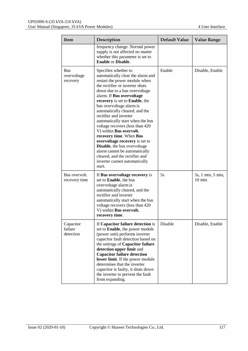
UPS5000-S-(35 kVA-210 kVA)
User Manual (Singapore, 35 kVA Power Modules) 4 User Interface
Issue 02 (2020-01-10) Copyright © Huawei Technologies Co., Ltd. 117
Item Description Default Value Value Range
frequency change. Normal power
supply is not affected no matter
whether this parameter is set to
Enable or Disable.
Bus
overvoltage recovery
Specifies whether to
automatically clear the alarm and
restart the power module when
the rectifier or inverter shuts
down due to a bus overvoltage
alarm. If Bus overvoltage
recovery is set to Enable, the
bus overvoltage alarm is
automatically cleared, and the
rectifier and inverter
automatically start when the bus
voltage recovers (less than 420
V) within Bus overvolt.
recovery time. When Bus
overvoltage recovery is set to
Disable, the bus overvoltage
alarm cannot be automatically
cleared, and the rectifier and
inverter cannot automatically start.
Enable Disable, Enable
Bus overvolt.
recovery time
If Bus overvoltage recovery is
set to Enable, the bus
overvoltage alarm is
automatically cleared, and the
rectifier and inverter
automatically start when the bus
voltage recovers (less than 420
V) within Bus overvolt. recovery time.
5s 5s, 1 min, 5 min,
10 min
Capacitor
failure detection
If Capacitor failure detection is
set to Enable, the power module
(power unit) performs inverter
capacitor fault detection based on
the settings of Capacitor failure
detection upper limit and
Capacitor failure detection lower limit. If the power module
determines that the inverter
capacitor is faulty, it shuts down
the inverter to prevent the fault
from expanding.
Disable Disable, Enable

UPS5000-S-(35 kVA-210 kVA)
User Manual (Singapore, 35 kVA Power Modules) 4 User Interface
Issue 02 (2020-01-10) Copyright © Huawei Technologies Co., Ltd. 118
Bypass Settings
Item Description Default Value Value Range
BPM mode
upon BPM overtemp.
Specifies whether to start bypass
mode when overtemperature occurs.
Enable Disable, Enable
Lightload BPM
cur. eql. Detect
Enable or disable the light load
bypass current imbalance alarm.
If this parameter is set to Enable,
the load is light (less than 30%
load), and the load rate of a
certain rack is less than 10%, the
system will generate a bypass
current imbalance alarm and
cannot enter the ECO mode. If
this parameter is set to Enable,
the preceding detection is not
performed. Whether the bypass
current is imbalanced does not
affect the ECO bypass mode.
Enable Disable, Enable
Battery Settings
Battery parameter settings impact battery maintenance, battery lifespan, and UPS discharge time. When you set battery parameters, note the following:
Retain default settings for Chg. cur. limiting coef. and Cell float voltage. Only
professional maintenance personnel are allowed to change the settings.
When you set parameters, ensure the following: Chg. cur. limiting coef. > Transfer-to-
equalized charging cur. coef.
Single batt. float chg. voltage deviation alarm thres. and Single batt. dis. voltage
deviation alarm thres. are used to check whether the batteries in each battery string have
the same charge voltage and discharge voltage. When a value exceeds the specified range,
an alarm is generated. The calculation formula is (Charge/Discharge voltage – Average
voltage)/Average voltage x 100%. The charge/discharge voltage and average voltage are
obtained from the BMU. If the BMU is not configured, these two parameters do not need
to be set.
Item Description Default Value Value Range
Float volt.
temp. comp.
If this parameter is set to Enable,
the float voltage is calibrated
based on the battery temperature
when a battery temperature
sensor is connected. The
parameter is configurable in any mode.
Enable Disable, Enable

UPS5000-S-(35 kVA-210 kVA)
User Manual (Singapore, 35 kVA Power Modules) 4 User Interface
Issue 02 (2020-01-10) Copyright © Huawei Technologies Co., Ltd. 119
Item Description Default Value Value Range
Float volt.
temp. comp.
coef. (mV/°C·cell)
Calibration coefficient during
float voltage temperature compensation.
3.3 0.0–6.0
Float Chg
Temp Comp
Center (°C)
Indicates the reference
temperature during temperature
compensation of the float charging voltage.
25 20–30
Automatic
equalized charging
If this parameter is set to Enable,
the UPS automatically changes
the battery management status to
equalized charge based on the
charge current and float charge time.
Enable Disable, Enable
Transfer-to-
equalized
charging cur. coef. (C10)
The battery enters equalized
charge state when the battery
current exceeds this parameter value.
0.05 0.02–0.08
SOC to start
equalized charging (%)
If the SOC is lower than the
specified value, batteries start equalized charging.
70 0–100
Scheduled
equalized
charging interval (d)
After batteries transfer from
equalized charging to float
charging, if the batteries do not
discharge, equalized charging
starts only after the float charging
time reaches Equalized
charging protection interval.
After equalized charging is
complete, scheduled equalized
charging starts when the non-
equalized charging time exceeds
Scheduled equalized charging interval.
60 30–180
Equalized
charging
protection
interval (d)
7 0–15
Forced
equalized
charging
protection time (h)
When batteries are continuously
under float charging or
hibernation, enable forced
equalized charging. When the
forced equalized charging time
reaches the value of this
parameter, batteries
automatically transfer to float charging mode.
18 12–24
Max. batt. dis.
time (h)
Set the maximum battery
discharge time. When the
discharge time reaches this value,
the UPS powers off. The battery discharge time can be set only to
24 0–48

UPS5000-S-(35 kVA-210 kVA)
User Manual (Singapore, 35 kVA Power Modules) 4 User Interface
Issue 02 (2020-01-10) Copyright © Huawei Technologies Co., Ltd. 120
Item Description Default Value Value Range
0 hours or a value only in the
range of 16–48 hours. If the time
is set to 0 hours, battery
discharge protection is not implemented.
EOD restart If the mains is not functioning
normally, the UPS will transfer
to battery mode. When batteries
reach the EOD threshold, the
bypass is disabled, and EOD
restart is Enable, the UPS will
restart as soon as the mains resumes.
If EOD restart is disabled, clear
the alarm manually or enable the restart function for the UPS.
Enable Disable, Enable
EOD restart
delay (min)
If EOD restart is set to Enable,
the UPS starts working after the
time set for EOD restart delay
when the input recovers from the power failure upon EOD.
10 1–1440
Undertemp.
alarm thresh. (°C)
Battery temperatures can be
monitored in a timely manner. If
a battery overtemperature alarm
is detected, the charging current
limit decreases to 0.03 CA.
Battery charging stops if a
battery overtemperature
protection alarm (when the
temperature reaches the high
temperature threshold plus 3°C) is generated.
–5°C –20°C to +5°C
Overtemp.
alarm thresh. (°C)
50°C 35°C to 55°C
Single batt.
float chg.
voltage
deviation alarm thres. (%)
Single batt. float chg. voltage
deviation alarm thres. (%) and
Single batt. dis. voltage deviation alarm thres. (%) are
used to check whether the cells in
each battery string have the same
charge voltage and discharge
voltage. When a value exceeds
the specified range, an alarm is generated.
The calculation formula is
(Charge/Discharge voltage –
Average voltage)/Average
voltage x 100%.
10 5–30
Single batt. dis.
voltage
deviation alarm thres. (%)
20 10–30
Batt. charging
capacity mismatch
After this function is enabled, an
alarm is generated if the configured battery capacity
Disable Disable, Enable

UPS5000-S-(35 kVA-210 kVA)
User Manual (Singapore, 35 kVA Power Modules) 4 User Interface
Issue 02 (2020-01-10) Copyright © Huawei Technologies Co., Ltd. 121
Item Description Default Value Value Range
exceeds the charging capacity of the rack.
Bat mode shut In battery mode, the UPS can
automatically power off
according to the preset shutdown
delay time. If the parameter is
disabled, this function is not available.
Disable Disable, Enable
Backup time
warning
An alarm is generated if this
parameter is set to Enable and
the backup time is less than the warning threshold.
Disable Disable, Enable
Remain. cap.
warning
An alarm is generated if this
parameter is set to Enable and
the remaining capacity is less
than the warning threshold.
Disable Disable, Enable
Intelligent
hibernation
If this parameter is set to Enable,
the intelligent battery hibernation function is enabled.
Disable Disable, Enable
Thres. of low
batt. SOC over dry contact (%)
If an output dry contact is set to
Low battery SOC, and the
battery SOC is lower than this
threshold, the output dry contact will output signals.
75 5–80
Thres. of low
batt. volt. over
dry contact
(V/cell)
If an output dry contact is set to
Batt. Volt. Below Threshold,
and the battery voltage is lower
than this threshold, the output dry contact will output signals.
1.70 1.70–2.10
4.2.2.4 Communication Settings
Figure 4-54 Communication settings

UPS5000-S-(35 kVA-210 kVA)
User Manual (Singapore, 35 kVA Power Modules) 4 User Interface
Issue 02 (2020-01-10) Copyright © Huawei Technologies Co., Ltd. 122
4.2.2.5 Control
Figure 4-55 Control
4.2.3 Query
4.2.3.1 Historical Alarms
On the homepage, click the Query tab to open the Historical Alarms page for querying
historical alarms based on severity, generation time, and clear time.
Figure 4-56 Historical alarms
4.2.3.2 Logs
On the Logs page, you can set Log to Historical logs, Cap. test logs, or Common test logs,
and query or export logs.
Historical logs can be exported but not queried.

UPS5000-S-(35 kVA-210 kVA)
User Manual (Singapore, 35 kVA Power Modules) 4 User Interface
Issue 02 (2020-01-10) Copyright © Huawei Technologies Co., Ltd. 123
Figure 4-57 Logs
4.2.4 Config.
4.2.4.1 User Management
On the home page, choose Config. > User Mgmt.
Figure 4-58 User management
On the User Mgmt. page, you can add, modify, delete, lock, or unlock users and change user
passwords.
The WebUI user name cannot exceed 10 characters and can contain only uppercase and lowercase
letters, digits, and underscores. The password contains 6 to 20 characters and at least two types of uppercase letters, lowercase letters, digits, and underscores.
If the LUI password complexity check is disabled, the user password is required to be a string of six to eight digits. If the password complexity check is enabled, the user password is required to be a string of 6–20 characters and contain at least two types of characters.
4.2.4.2 Site Config.
On the home page, choose Config. > Site Config.

UPS5000-S-(35 kVA-210 kVA)
User Manual (Singapore, 35 kVA Power Modules) 4 User Interface
Issue 02 (2020-01-10) Copyright © Huawei Technologies Co., Ltd. 124
Figure 4-59 Site configuration
The NTP parameters are used to set the NTP server address, port number, and synchronization
interval.
The default SNMP version is SNMPv3, and the preset MD5/SHA password is Changeme1, and the preset DES/AES password is Changeme2. Change the password after your first login, preventing unauthorized access.
The standard protocols SNMP V1 and SNMP V2 have security risks. You are advised to use the secure protocol SNMP V3.
The standard encryption algorithms MD5 and DES have security risks. You are advised to use the secure encryption algorithms SHA and AES.
To obtain the MIB file, choose Config. > Site Config. > SNMP > Download HUAWEI_UPS_MIB.
SNMP Trap indicates the IP address of the server configured with network management system (NMS) software. If SNMP Trap is incorrectly set or not set, system information will be lost or not reported in time.
The certificate is used for Secure Sockets Layer (SSL) encryption protection for WebUI login. You need to apply to a third-party institution for the certificate.
Configuration Management is used to upload and export configuration parameters in the monitoring system.
Multi-brand Management is used to import the brand information of a partner to the corresponding WebUI.
Specify Email server IP address, Sender's email, and User account authentication required when sending a mail and click Test to check whether the test email can be received. Configure
Alarm Notification Server is used to configure a server for receiving alarm emails from the monitoring system.
Set Email and Alarm Severity and simulate an alarm. Check that the alarm email can be received. Configure Alarm Notification Email Address is used to configure the email address for receiving alarm emails from the monitoring system.

UPS5000-S-(35 kVA-210 kVA)
User Manual (Singapore, 35 kVA Power Modules) 4 User Interface
Issue 02 (2020-01-10) Copyright © Huawei Technologies Co., Ltd. 125
ModbusTCP Certificate Management: ModbusTCP supports the Transport Layer Security (TLS) secure protocol for encrypted transmission and implements access authentication through the
bidirectional certificate. Customers can replace the UPS certificate with the certificate trusted by them.
ModbusTCP CA Certificate Management: Import a CA certificate to verify the validity of the ModbusTCP access certificate.
ModbusTCP Authentication: Verify the identity legitimacy of both parties to ensure data security for both parties in ModbusTCP communication.
After eUPS certificate management is configured, a certificate can be imported on the WebUI to replace the preset eUPS certificate.
4.2.4.3 RCCMD
RCCMD
RCCMD function is set to Disable by default, as shown in Figure 4-60. If required, set it to
Enable upon first login. After you submit the setting, the page refreshes. The controls such as
SSL Encrypted Transmission and Event Configuration will be displayed on the page, as
shown in Figure 4-61.
Figure 4-60 RCCMD function disabled

UPS5000-S-(35 kVA-210 kVA)
User Manual (Singapore, 35 kVA Power Modules) 4 User Interface
Issue 02 (2020-01-10) Copyright © Huawei Technologies Co., Ltd. 126
Figure 4-61 RCCMD function enabled
SSL Encrypted Transmission
The SSL encrypted transmission set on the page of the UPS5000 monitor display module
(MDU) must be the same as the setting on the RCCMD client.
SSL Encrypted Transmission is set to Enable by default, as shown in Figure 4-62. If it is set
to Disable, the RCCMD certificate controls will not be displayed on the page, as shown in
Figure 4-63. If SSL Encrypted Transmission is set to Disable, a message indicating there is
a risk will be displayed.

UPS5000-S-(35 kVA-210 kVA)
User Manual (Singapore, 35 kVA Power Modules) 4 User Interface
Issue 02 (2020-01-10) Copyright © Huawei Technologies Co., Ltd. 127
Figure 4-62 SSL encrypted transmission enabled by default
Figure 4-63 SSL encrypted transmission disabled
Event Configuration
The MDU supports 17 alarm events, and a maximum of 50 jobs can be added for each event,
as shown in Figure 4-64. Figure 4-64 shows the buttons on the Event Configuration page,
and Table 4-14 describes these buttons.

UPS5000-S-(35 kVA-210 kVA)
User Manual (Singapore, 35 kVA Power Modules) 4 User Interface
Issue 02 (2020-01-10) Copyright © Huawei Technologies Co., Ltd. 128
Figure 4-64 Event configuration page
Number of jobs = Number of RCCMD Shutdown jobs + Number of RCCMD Message jobs + Number of RCCMD Execute jobs + Number of RCCMD TRAP jobs.
Table 4-14 Buttons on the event configuration page
No. Name Description
1 Button for expanding all You can view all jobs of all events by
clicking this button.
2 Button for expanding one event You can view all jobs of the event by
clicking this button.
3 Button for adding one job You can add one job for the event by
clicking this button.
4 Button for adding one job for
events
Select multiple events, and you can add
one job for the selected events at the same
time by clicking this button.
5 Button for deleting all jobs You can delete all jobs of the event by
clicking this button.
Figure 4-65 shows the buttons after one event is expanded and Table 4-15 describes these
buttons.

UPS5000-S-(35 kVA-210 kVA)
User Manual (Singapore, 35 kVA Power Modules) 4 User Interface
Issue 02 (2020-01-10) Copyright © Huawei Technologies Co., Ltd. 129
Figure 4-65 Buttons after one event is expanded
Table 4-15 Buttons after one event is expanded
No. Name Description
1 Button for modifying A dialog box for modifying a job is
displayed after you click this button. You can modify the job.
2 Button for deleting one job You can delete the job by clicking this button.
3 Button for test If you click this button, the job will be
performed and a message showing test
succeeds or fails will be displayed on the page.
Adding one job for one event: Select one event (for example, Inverter on), click the button
for adding one job, and the page for adding a job for the event is displayed.
When adding a job, the job types to be selected are: RCCMD Shutdown, RCCMD Message,
RCCMD Execute, and RCCMD TRAP. RCCMD Shutdown is selected by default. For
different job types, you need to enter different contents.
RCCMD Shutdown: You need to specify the RCCMD client IP address and port. When
the RCCMD client receives the job, it will shut down the computer.

UPS5000-S-(35 kVA-210 kVA)
User Manual (Singapore, 35 kVA Power Modules) 4 User Interface
Issue 02 (2020-01-10) Copyright © Huawei Technologies Co., Ltd. 130
Figure 4-66 RCCMD shutdown
RCCMD Message: Specify the RCCMD client IP address, port, and message to be
conveyed. The RCCMD client will receive the message. For example, enter "This is a
test message".
Figure 4-67 RCCMD message
RCCMD Execute: Specify the RCCMD client IP address, port, and command to be
executed. For example, enter SHUTDOWN, and the RCCMD client will shut down the computer after receiving the command.

UPS5000-S-(35 kVA-210 kVA)
User Manual (Singapore, 35 kVA Power Modules) 4 User Interface
Issue 02 (2020-01-10) Copyright © Huawei Technologies Co., Ltd. 131
Figure 4-68 RCCMD execute
RCCMD TRAP: When the event happens, the MDU will send the TRAP message to all
connected RCCMD clients based on the sending mechanism.
If you want to define the TRAP message by yourself, you can use the TRAP signal to
display the UPS information. For example, if you enter #INVOLT V, the RCCMD client
will receive the UPS input voltage value (for example, single-phase: 220 V; three-phase
A: 220 V, B: 220 V, C: 220 V). Table 4-16 lists the signal names that can be entered.
Figure 4-69 RCCMD TRAP

UPS5000-S-(35 kVA-210 kVA)
User Manual (Singapore, 35 kVA Power Modules) 4 User Interface
Issue 02 (2020-01-10) Copyright © Huawei Technologies Co., Ltd. 132
Table 4-16 RCCMD TRAP signal
Signal Name Description Unit in the UPS
#MODEL Device name N/A
#OUTPOWER Active power kW
#OUTVOLT Output voltage V
#OUTCURR Output current A
#OUTLOAD Output load rate %
#BATTCAP Remaining battery capacity %
#INVOLT Input voltage V
#BYPASSINVOLT Bypass input voltage V
#TEMPDEG Temperature inside the UPS Celsius
#AUTONOMTIME Battery backup time minutes
#STATUS UPS status N/A
#RUNTIME UPS operating time minutes
#BATTVOLT Battery voltage V
#INFREQ Input frequency Hz
#BYPASSINFREQ Bypass input frequency Hz
#OUTFREQ Output frequency Hz
#CNT_PF Power supply failure times N/A
#CNT_BL Low battery voltage times N/A
#INPHASES Input phases N/A
#OUTPHASES Output phases N/A
When you add a job, five sending methods are available. The latter three methods can take
effect only when the event condition is still true after the specified seconds.
Immediately, once: After the event happens, the job will be sent to the RCCMD client immediately.
Scheduled in X seconds: After the event happens, the job will be sent to the RCCMD
client once in X seconds. No matter whether the event disappears or not within X seconds, the job will be sent.
After X seconds, repeat all Y Specify the interval: After the event happens, the job will be sent once in X seconds, and then be sent once every Y seconds.
After X seconds on Battery: After the battery mode is activated for X seconds, the job will be sent to the RCCMD client once.
At X seconds remaining time: When the battery backup time has only X seconds left, the job will be sent to the RCCMD client once.

UPS5000-S-(35 kVA-210 kVA)
User Manual (Singapore, 35 kVA Power Modules) 4 User Interface
Issue 02 (2020-01-10) Copyright © Huawei Technologies Co., Ltd. 133
X and Y are variables and stand for time.
RCCMD Certificate Management
After replacing the certificate on the MDU WebUI, replace the certificate on the RCCMD
client too. Otherwise, communication will fail. For details about the replacing method, see the RCCMD user manual.
The default certificate provided by the system has expired. Replace the certificate
immediately.
After SSL Encrypted Transmission is set to Enable, RCCMD Certificate Management is
displayed. The RCCMD certificate, RCCMD certificate key, and RCCMD CA certificate can
be uploaded, as shown in Figure 4-70. If the RCCMD certificate or RCCMD CA certificate is
not uploaded, the default certificate provided by the system is used for communication. After
the certificate is uploaded successfully, click Submit. The WebUI of the MDU will restart,
and the uploaded certificate will be used for communication.
Figure 4-70 RCCMD certificate management
If the RCCMD certificate key has been encrypted, enable and enter the key password.
4.2.4.4 Managing the UPS by Using the NMS Complying with RFC1628 Standard
Installing the UPS MIB
The MIB is in the MDU. Click Download UPS-RFC1628-MIB on the page of the web
browser to download the MIB file which allows the third-party NMS to manage the UPS remotely.

UPS5000-S-(35 kVA-210 kVA)
User Manual (Singapore, 35 kVA Power Modules) 4 User Interface
Issue 02 (2020-01-10) Copyright © Huawei Technologies Co., Ltd. 134
Figure 4-71 Download the MIB
The UPS-RFC1628-MIB has more alarms than RFC1628. Download the UPS-RFC1628-MIB before using.
Managing the UPS by Using the NMS Applying for Access Rights
To manage the UPS by using the UNMS II of Generex over the MDU, apply to the
system administrator of the MDU for access rights and add the NMS information to the
NMS access list of the MDU. The NMS address and access right settings are used for
adding information about the NMS accessing the MDU, including the NMS address,
access right, and Trap port. For details about how to add an NMS over a web browser, see Figure 4-72.
Figure 4-72 Setting the SNMP Trap
Managing the UPS
Take the UNMS II of Generex for example. The method for managing the UPS by using
the UNMS II is the same as the method for managing other devices by using the UNMS II. For details, see the UNMS II user manual.

UPS5000-S-(35 kVA-210 kVA)
User Manual (Singapore, 35 kVA Power Modules) 4 User Interface
Issue 02 (2020-01-10) Copyright © Huawei Technologies Co., Ltd. 135
4.2.5 Maintenance
Non-professional engineers are not allowed to operate the maintenance page.
Maintenance functions include calibration, variable commissioning, upgrade, and data
download.
Figure 4-73 Calibration
Figure 4-74 Commissioning variables

UPS5000-S-(35 kVA-210 kVA)
User Manual (Singapore, 35 kVA Power Modules) 4 User Interface
Issue 02 (2020-01-10) Copyright © Huawei Technologies Co., Ltd. 136
Figure 4-75 Software upgrade
Figure 4-76 BSP upgrade
Figure 4-77 Downloading data
4.2.6 Protecting the Server by Using the RCCMD Software
4.2.6.1 Introduction to the Software
The RCCMD shutdown software is part of the centralized monitoring system of the Generex
network. The UPS5000 MDU integrates the functions of the Generex RCCMD server:
Sends the shutdown command, notification message, and Trap message to the RCCMD client if the UPS system generates an alarm; executes commands on the RCCMD client.
Receives the message "UPS alive check" sent by the RCCMD client and replies with the system status.
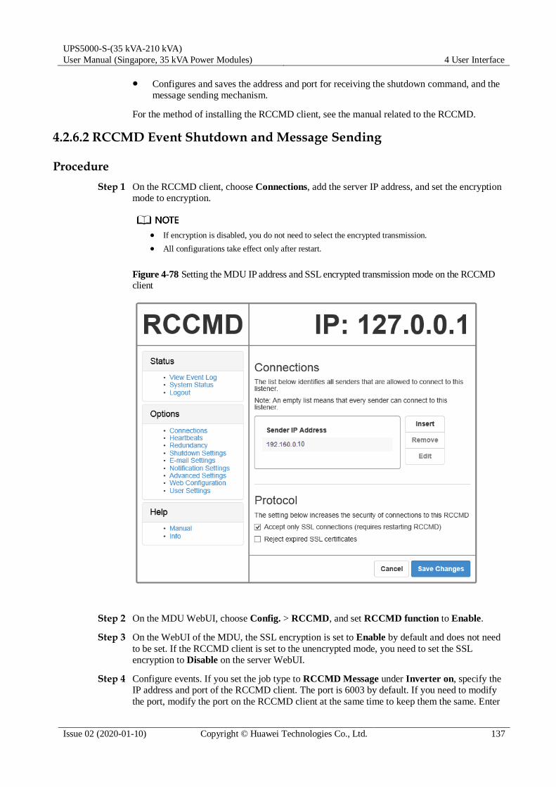
UPS5000-S-(35 kVA-210 kVA)
User Manual (Singapore, 35 kVA Power Modules) 4 User Interface
Issue 02 (2020-01-10) Copyright © Huawei Technologies Co., Ltd. 137
Configures and saves the address and port for receiving the shutdown command, and the
message sending mechanism.
For the method of installing the RCCMD client, see the manual related to the RCCMD.
4.2.6.2 RCCMD Event Shutdown and Message Sending
Procedure
Step 1 On the RCCMD client, choose Connections, add the server IP address, and set the encryption
mode to encryption.
If encryption is disabled, you do not need to select the encrypted transmission.
All configurations take effect only after restart.
Figure 4-78 Setting the MDU IP address and SSL encrypted transmission mode on the RCCMD client
Step 2 On the MDU WebUI, choose Config. > RCCMD, and set RCCMD function to Enable.
Step 3 On the WebUI of the MDU, the SSL encryption is set to Enable by default and does not need
to be set. If the RCCMD client is set to the unencrypted mode, you need to set the SSL
encryption to Disable on the server WebUI.
Step 4 Configure events. If you set the job type to RCCMD Message under Inverter on, specify the IP address and port of the RCCMD client. The port is 6003 by default. If you need to modify
the port, modify the port on the RCCMD client at the same time to keep them the same. Enter

UPS5000-S-(35 kVA-210 kVA)
User Manual (Singapore, 35 kVA Power Modules) 4 User Interface
Issue 02 (2020-01-10) Copyright © Huawei Technologies Co., Ltd. 138
the message to be sent and set the message sending mechanism. For example, set it to
Immediately, once.
Step 5 On the Monitoring > Control page, start the UPS, and the inverter mode will be triggered.
Send the message to the RCCMD client, indicating that the inverter is on.
Step 6 On the RCCMD client, you can view messages through the View Event Log at the upper left
corner.
----End
4.2.6.3 UPS Alive Check Function
Context
Whether the RCCMD SSL encrypted transmission is enabled on the WebUI of UPS5000
MDU and RCCMD client is irrelevant to the heartbeat detection function. Only when the SSL
encryption is enabled on the RCCMD client, the logs recorded by the RCCMD client are
marked with "(SSL...)".
On the RCCMD client, the IP address of the MDU that detects heartbeat needs to be added.
Then the UPS alive check function is supported; the RCCMD can check whether the UPS and
RCCMD communicate properly; the RCCMD can receive messages sent by the MDU.
Procedure
Step 1 On the RCCMD client, add the IP address of the MDU that detects heartbeat, as shown in
Figure 4-79.
Step 2 The UPS5000 MDU supports both ways of heartbeat detection. If the job configured for the
MDU event is set to RCCMD TRAP, the RCCMD client needs to be set to by the use of
CS121/UPSMAN Traps. If by polling CS121/UPSMAN every x seconds... is selected as
the method of detecting heartbeats, set the detection method. The default interval is 1800s and
detection is performed 100 times, as shown in Figure 4-79.

UPS5000-S-(35 kVA-210 kVA)
User Manual (Singapore, 35 kVA Power Modules) 4 User Interface
Issue 02 (2020-01-10) Copyright © Huawei Technologies Co., Ltd. 139
Figure 4-79 Heartbeat detecting mode on the RCCMD client
You can also manually detect heartbeat by clicking Run alive check now....

UPS5000-S-(35 kVA-210 kVA)
User Manual (Singapore, 35 kVA Power Modules) 4 User Interface
Issue 02 (2020-01-10) Copyright © Huawei Technologies Co., Ltd. 140
Figure 4-80 Detecting heartbeat manually
Figure 4-81 Detecting heartbeat manually and successfully
----End

UPS5000-S-(35 kVA-210 kVA)
User Manual (Singapore, 35 kVA Power Modules) 5 Operations
Issue 02 (2020-01-10) Copyright © Huawei Technologies Co., Ltd. 141
5 Operations
5.1 Powering On and Starting the UPS
5.1.1 Powering On the UPS
Prerequisites
Measure the voltage and frequency of the UPS upstream input switch. The line voltage range
is 138–485 V AC, and the frequency range is 40–70 Hz.
Context
The following operations are applicable to a single UPS. For parallel systems, contact Huawei technical support.
Before powering on the UPS, ensure that the UPS has passed all check items in the section "Installation Verification."
Before powering on the UPS, ensure that all the UPS switches and upstream switch are OFF.
Procedure
Step 1 Close the upstream bypass and mains input switches.
After the UPS is powered on, initialization begins. The MDU displays the Huawei logo and
an initialization progress bar.
----End
5.1.2 Starting the Inverter
Table 5-1 UPS system user list
Default User Preset Password
admin (administrator) LCD 000001
WebUI Changeme

UPS5000-S-(35 kVA-210 kVA)
User Manual (Singapore, 35 kVA Power Modules) 5 Operations
Issue 02 (2020-01-10) Copyright © Huawei Technologies Co., Ltd. 142
Default User Preset Password
operator (common user) LCD 000001
WebUI Changeme
browser (browsing user) WebUI N/A
5.1.2.1 Initial Startup
Step 1 After the MDU starts properly, set the language, time and date, network parameters, and
system parameters on the Settings Wizard screen.
Set system parameters with caution because the settings determine normal UPS operation.
Set Single/Parallel after double check. Incorrect setting may affect the normal UPS operation.
Output voltage level refers to the line voltage level. Set it based on site requirements.
Set Output frequency correctly; otherwise, loads may be affected and the UPS may not work properly.
High or low charging power tends to shorten the battery lifespan, or even damages
batteries.

UPS5000-S-(35 kVA-210 kVA)
User Manual (Singapore, 35 kVA Power Modules) 5 Operations
Issue 02 (2020-01-10) Copyright © Huawei Technologies Co., Ltd. 143
Figure 5-1 Settings Wizard
Set the time and date correctly. Incorrect time and date will cause false fault analysis during
maintenance or repair.
After you set network parameters, connect the UPS to the network over a network cable, which enables you to remotely manage the UPS. If you do not need remote management, retain the default network parameter settings.
Step 2 After you set parameters on the Settings Wizard screen, the MDU displays the Bypass mode
and No battery alarms, which do not need to be handled. If there is any other alarm, you need
to rectify the fault.
After you set parameters on the Settings Wizard screen, choose System Info > Settings >
Advanced Param. Check that Requisite modules and Redundant modules match the actual values.
If dry contact signals are connected to the system, choose System Info > Settings > Dry contacts and check that the connected dry contacts have been enabled and that the disconnected dry contacts have been disabled.
Step 3 View the system running diagram on the MDU to check that the UPS is working in bypass
mode.
----End

UPS5000-S-(35 kVA-210 kVA)
User Manual (Singapore, 35 kVA Power Modules) 5 Operations
Issue 02 (2020-01-10) Copyright © Huawei Technologies Co., Ltd. 144
If you do not need to use the app to start the inverter, choose System Info > Maintenance > Inv. ON on the MDU.
The Service Expert app can be downloaded from Google Play and can run on
Android. User interfaces displayed in this document correspond to the app version V100R001C00B055 and are for reference only.
For offline startup, enter the barcode and the verification code on the mobile phone app.
The app automatically generates a startup password for the UPS. Then enter the password
on the MDU screen to start the UPS.
For online startup, activate the startup password on the mobile phone app to start the UPS.
If the initial startup verification passes, startup verification is not required afterwards.
After factory settings are restored, re-verification for startup is required.
Online Startup
Step 1 Insert a WiFi module into the USB port on the MDU.
Step 2 Enable the mobile phone WLAN, search for the UPS WiFi signal, and connect to the WiFi
signal. The default value of WiFi SSID is UPS_WiFi.
The initial WiFi password is Changeme by default. You can change the password by choosing System Info > Settings > Communication > WiFi Password on the MDU.
Step 3 Open the Service Expert app on the mobile phone.
Step 4 On the home screen of the app, tap Power-on password activation to access the Set Startup
screen. After setting parameters, tap Login.
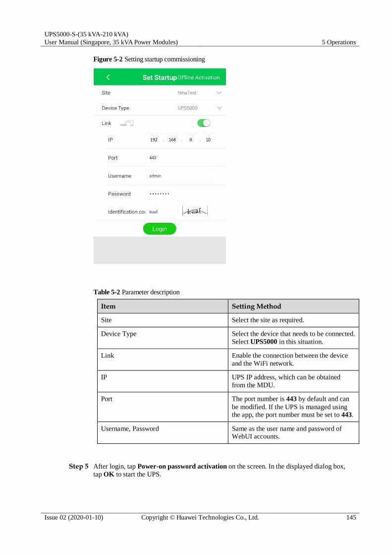
UPS5000-S-(35 kVA-210 kVA)
User Manual (Singapore, 35 kVA Power Modules) 5 Operations
Issue 02 (2020-01-10) Copyright © Huawei Technologies Co., Ltd. 145
Figure 5-2 Setting startup commissioning
Table 5-2 Parameter description
Item Setting Method
Site Select the site as required.
Device Type Select the device that needs to be connected.
Select UPS5000 in this situation.
Link Enable the connection between the device
and the WiFi network.
IP UPS IP address, which can be obtained
from the MDU.
Port The port number is 443 by default and can
be modified. If the UPS is managed using the app, the port number must be set to 443.
Username, Password Same as the user name and password of WebUI accounts.
Step 5 After login, tap Power-on password activation on the screen. In the displayed dialog box,
tap OK to start the UPS.

UPS5000-S-(35 kVA-210 kVA)
User Manual (Singapore, 35 kVA Power Modules) 5 Operations
Issue 02 (2020-01-10) Copyright © Huawei Technologies Co., Ltd. 146
Figure 5-3 Power-on password activation
----End
Offline Startup
Step 1 Open the Service Expert app on the mobile phone.
Step 2 On the home screen of the app, tap Startup to access the Set Startup screen.
Step 3 Set Site and Device Type as required, and tap Offline Activation.

UPS5000-S-(35 kVA-210 kVA)
User Manual (Singapore, 35 kVA Power Modules) 5 Operations
Issue 02 (2020-01-10) Copyright © Huawei Technologies Co., Ltd. 147
Figure 5-4 Offline activation
Step 4 On the MDU, choose System Info > Maintenance > Inv. ON. You can obtain the Bar code
and Verification from the screen, as shown in the following figure.
Figure 5-5 Offline startup
The values of the Bar code and Verification in the figure are for reference only. The actual values prevail.
Step 5 Enter Bar code and Verification code obtained from the MDU on the Offline Activation
screen. Tap Generate PWD to generate a startup password.

UPS5000-S-(35 kVA-210 kVA)
User Manual (Singapore, 35 kVA Power Modules) 5 Operations
Issue 02 (2020-01-10) Copyright © Huawei Technologies Co., Ltd. 148
Figure 5-6 Generating a password
If the entered startup password is incorrect, you need to tap Inv. ON again on the MDU to
obtain a new verification code, and then generate a password on the app.
Step 6 Enter the generated startup password in Figure 5-5 to start the UPS.
----End
5.1.2.2 Non-initial Startup
Starting the UPS on the MDU
Step 1 Choose Common Functions > Inv. ON.
You can also start the inverter by choosing System Info > Maintenance > Inv. ON.
Step 2 In the displayed login screen, select a user name and enter the password.
Step 3 In the displayed dialog box, tap Yes to start the inverter.
----End
Starting the UPS on the WebUI
Step 1 Open a browser (Internet Explorer 11 for example) and choose Tools > Internet Options.

UPS5000-S-(35 kVA-210 kVA)
User Manual (Singapore, 35 kVA Power Modules) 5 Operations
Issue 02 (2020-01-10) Copyright © Huawei Technologies Co., Ltd. 149
Step 2 Click the Advanced tab, check that Use TLS 1.0 and Use TLS 1.1 are selected, and then
click OK.
Figure 5-7 Setting the Internet options
Step 3 In the address box of the browser, enter https://UPS IP address.
Step 4 Enter the correct user name and password and click Login.
Figure 5-8 Logging in to the WebUI
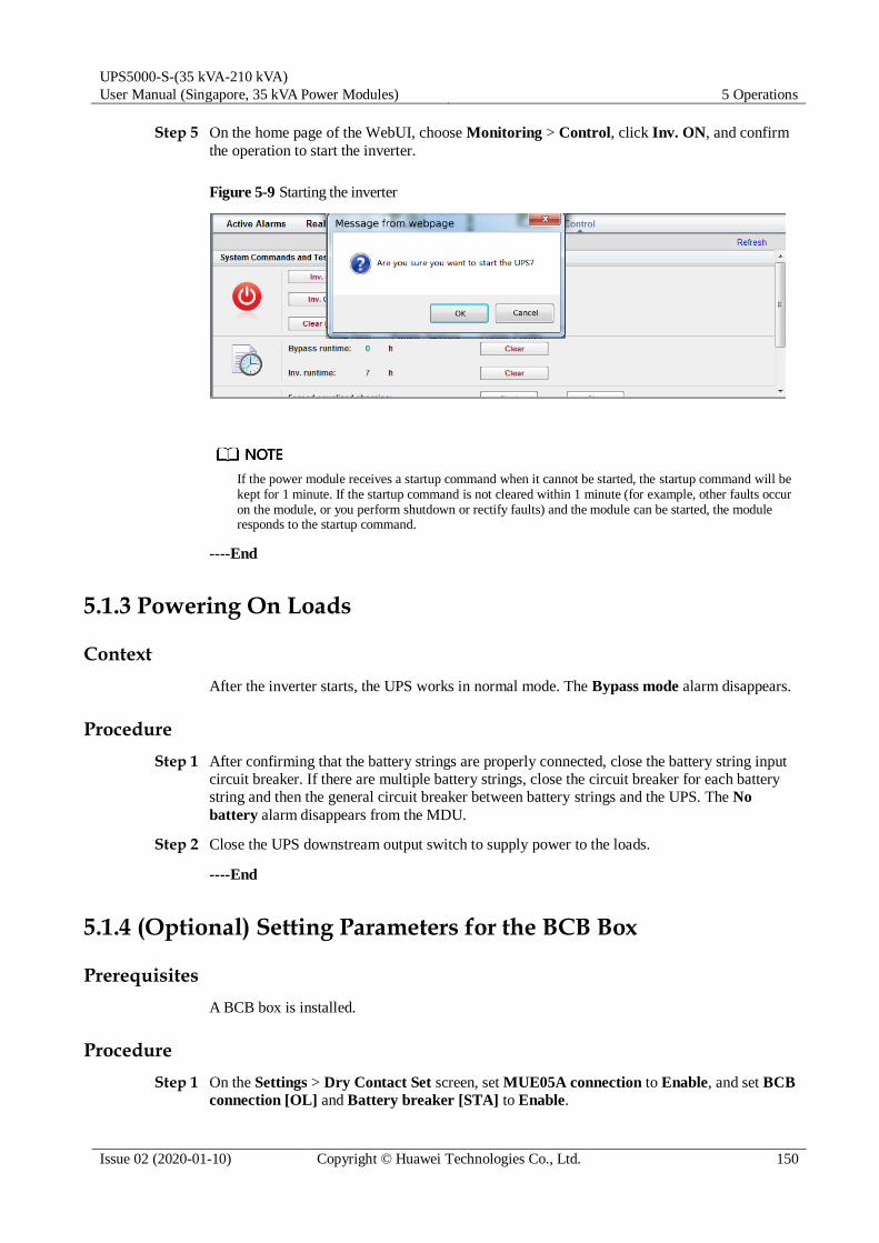
UPS5000-S-(35 kVA-210 kVA)
User Manual (Singapore, 35 kVA Power Modules) 5 Operations
Issue 02 (2020-01-10) Copyright © Huawei Technologies Co., Ltd. 150
Step 5 On the home page of the WebUI, choose Monitoring > Control, click Inv. ON, and confirm
the operation to start the inverter.
Figure 5-9 Starting the inverter
If the power module receives a startup command when it cannot be started, the startup command will be kept for 1 minute. If the startup command is not cleared within 1 minute (for example, other faults occur on the module, or you perform shutdown or rectify faults) and the module can be started, the module responds to the startup command.
----End
5.1.3 Powering On Loads
Context
After the inverter starts, the UPS works in normal mode. The Bypass mode alarm disappears.
Procedure
Step 1 After confirming that the battery strings are properly connected, close the battery string input
circuit breaker. If there are multiple battery strings, close the circuit breaker for each battery
string and then the general circuit breaker between battery strings and the UPS. The No
battery alarm disappears from the MDU.
Step 2 Close the UPS downstream output switch to supply power to the loads.
----End
5.1.4 (Optional) Setting Parameters for the BCB Box
Prerequisites
A BCB box is installed.
Procedure
Step 1 On the Settings > Dry Contact Set screen, set MUE05A connection to Enable, and set BCB
connection [OL] and Battery breaker [STA] to Enable.

UPS5000-S-(35 kVA-210 kVA)
User Manual (Singapore, 35 kVA Power Modules) 5 Operations
Issue 02 (2020-01-10) Copyright © Huawei Technologies Co., Ltd. 151
Figure 5-10 BCB connection setting
----End
5.2 Shutting Down and Powering Off the UPS
Context
After the inverter is shut down, if the bypass is normal, the UPS transfers to bypass mode; if
the bypass is not normal, the UPS supplies no power. Before shutting down the UPS, ensure
that all loads have shut down.
Procedure
Step 1 Shut down the inverter.
On the LCD
On the main screen, tap Common Functions. Tap Inv. OFF.

UPS5000-S-(35 kVA-210 kVA)
User Manual (Singapore, 35 kVA Power Modules) 5 Operations
Issue 02 (2020-01-10) Copyright © Huawei Technologies Co., Ltd. 152
Figure 5-11 Inv. OFF
To shut down the inverter on the Maintenance screen, tap System Info > Maintenance.
On the WebUI
Choose Monitoring > Control, and click Inv. OFF. In the displayed dialog box, click
OK to shut down the inverter.
Figure 5-12 Shutting down the inverter
After the inverter shuts down, the UPS works in bypass mode if the bypass is normal, as
shown in Figure 5-13; the UPS supplies no power and the loads power off if the bypass is
abnormal, as shown in Figure 5-14.

UPS5000-S-(35 kVA-210 kVA)
User Manual (Singapore, 35 kVA Power Modules) 5 Operations
Issue 02 (2020-01-10) Copyright © Huawei Technologies Co., Ltd. 153
Figure 5-13 Normal bypass
After you shut down the inverter, the Bypass mode alarm is displayed on the LCD.
Figure 5-14 Abnormal bypass
If you need to shut down the inverter and transfer the UPS to bypass mode, check that the UPS has not generated an alarm and perform Step 1.
Step 2 After the inverter shuts down, turn off the downstream output switch.
Step 3 Turn off the battery string circuit breaker. If there are multiple battery strings, turn off the
general circuit breaker between battery strings and the UPS and then turn off the circuit
breaker for each battery string.
Step 4 Turn off the upstream mains and bypass input switches.
----End

UPS5000-S-(35 kVA-210 kVA)
User Manual (Singapore, 35 kVA Power Modules) 5 Operations
Issue 02 (2020-01-10) Copyright © Huawei Technologies Co., Ltd. 154
5.3 Starting the UPS in Battery Mode
Procedure
Step 1 Ensure that batteries have been connected properly. Use a multimeter to check that the voltage
of a battery string is greater than a certain value (single battery voltage x number of batteries
in the battery string).
Step 2 Open the upstream mains input and bypass input switches, and close the battery circuit
breaker. If there are multiple battery strings, close the circuit breaker for each battery string
and then the general circuit breaker between battery strings and the UPS.
Step 3 Use a multimeter to check that the voltage of battery strings at the UPS battery input terminal
is greater than a certain value (single battery voltage x number of batteries in the battery
string), which indicates that the batteries are connected properly.
Step 4 Press and hold down the BATT START button on the bypass module for at least 2 seconds.
The system automatically enters the battery cold start status. The LCD displays the Huawei
logo and an initialization progress bar.
Step 5 After LCD initialization, start the inverter.
----End
5.4 Transferring to Bypass Mode
Before shutting down the inverter, ensure that the bypass is normal. If the bypass is not
normal, after the inverter is shut down, the UPS supplies no power, and the loads shut down.
Shut down the UPS inverter. Shut down the inverter on the LCD or WebUI, and the UPS
transfers to bypass mode.
If the inverter is shut down when the input voltage or frequency exceeds the specified threshold, the UPS supplies no power, and the loads shut down.
5.5 Setting ECO Mode
Context The UPS is set to non-ECO mode by default. Set the UPS to ECO mode when energy
saving is required.
In ECO mode, the bypass takes priority over the inverter in supplying power. If the
bypass is disconnected, the UPS transfers to normal mode. The transfer time is less than
4 ms under typical working conditions and less than 20 ms under poor working conditions.
Both a single UPS and the parallel system support the ECO mode for higher efficiency.
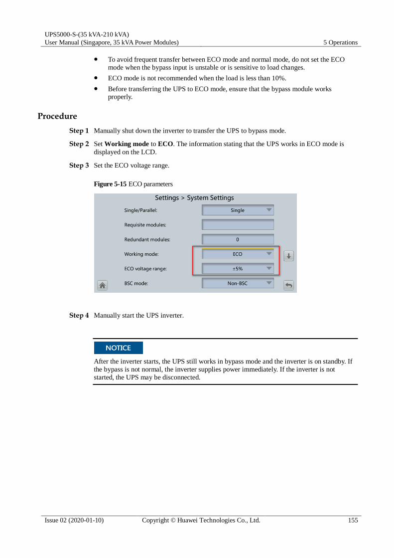
UPS5000-S-(35 kVA-210 kVA)
User Manual (Singapore, 35 kVA Power Modules) 5 Operations
Issue 02 (2020-01-10) Copyright © Huawei Technologies Co., Ltd. 155
To avoid frequent transfer between ECO mode and normal mode, do not set the ECO
mode when the bypass input is unstable or is sensitive to load changes.
ECO mode is not recommended when the load is less than 10%.
Before transferring the UPS to ECO mode, ensure that the bypass module works properly.
Procedure
Step 1 Manually shut down the inverter to transfer the UPS to bypass mode.
Step 2 Set Working mode to ECO. The information stating that the UPS works in ECO mode is
displayed on the LCD.
Step 3 Set the ECO voltage range.
Figure 5-15 ECO parameters
Step 4 Manually start the UPS inverter.
After the inverter starts, the UPS still works in bypass mode and the inverter is on standby. If
the bypass is not normal, the inverter supplies power immediately. If the inverter is not
started, the UPS may be disconnected.

UPS5000-S-(35 kVA-210 kVA)
User Manual (Singapore, 35 kVA Power Modules) 5 Operations
Issue 02 (2020-01-10) Copyright © Huawei Technologies Co., Ltd. 156
Figure 5-16 System status
----End
5.6 Testing Batteries
5.6.1 Forced Equalized Charging Test
Context
Before a forced equalized charging test, ensure that:
The mains input is normal.
Batteries are properly connected.
Batteries are not in the equalized charging state.
Procedure
Step 1 On the home screen of the LCD, choose System Info > Maintenance > Battery Maint.
Step 2 Tap Start next to Forced Equalized Charging to start a forced equalized charging test.

UPS5000-S-(35 kVA-210 kVA)
User Manual (Singapore, 35 kVA Power Modules) 5 Operations
Issue 02 (2020-01-10) Copyright © Huawei Technologies Co., Ltd. 157
Figure 5-17 Starting a forced equalized charging test
The forced equalized charging test automatically stops in any of the following cases:
The forced equalized charging test duration reaches the forced equalized charging protection time (12–24 h, 18 h by default).
The UPS generates a battery overtemperature, overvoltage, or overcurrent alarm.
An alarm is generated.
----End
5.6.2 Shallow Discharge Test
Before performing a shallow discharge test, ensure that:
The UPS works in normal mode with a load ratio fluctuation less than 10%.
The UPS generates no battery overtemperature, overvoltage, or overcurrent alarm. No generator is connected to the UPS.
The mains, batteries, charger, and discharger are normal. No overload alarm is generated.
Automatic Shallow Discharge Test
Step 1 On the home screen of the LCD, choose System Info > Settings > Battery Settings and set
Sched. shallow dis. test to Enable.
Step 2 Set Sched. shallow dis. test time and Sched. shallow dis. test interval as required. After
setting is complete, the system will perform automatic shallow discharge tests based on the
settings.
----End
Manual Shallow Discharge Test
Step 1 On the home screen of the LCD, choose System Info > Maintenance > Battery Maint.

UPS5000-S-(35 kVA-210 kVA)
User Manual (Singapore, 35 kVA Power Modules) 5 Operations
Issue 02 (2020-01-10) Copyright © Huawei Technologies Co., Ltd. 158
Step 2 Tap Start next to Shallow Dis. Test to start a shallow discharge test.
Figure 5-18 Starting a shallow discharge test
When the battery test is complete, the test data is used as common test data. Record the data obtained from the latest five tests.
The shallow discharge test automatically stops in any of the following cases:
The battery discharge capacity reaches the specified value (10%–50%, 20% by default).
The discharge voltage reaches the warning threshold (calculated in real time).
The load ratio fluctuation exceeds 10%.
An alarm is generated.
----End
5.6.3 Capacity Test
Context
Before a capacity test, ensure that:
The UPS is working in normal mode; float charging or hibernation has lasted for 2 hours
after the state of charge (SOC) reaches 100%; and the load ratio fluctuation is less than 10%.
The UPS has generated no battery overtemperature, overvoltage, or overcurrent alarm. No generator is connected to the UPS.
The mains, batteries, charger, and discharger are normal. No overload alarm is generated.
Procedure
Step 1 On the home screen of the LCD, choose System Info > Maintenance > Battery Maint.
Step 2 Tap Start next to Capacity Test to start a capacity test.

UPS5000-S-(35 kVA-210 kVA)
User Manual (Singapore, 35 kVA Power Modules) 5 Operations
Issue 02 (2020-01-10) Copyright © Huawei Technologies Co., Ltd. 159
Figure 5-19 Starting a capacity test
The capacity test automatically stops in any of the following cases:
The battery discharge voltage reaches the end of discharge (EOD) voltage plus 0.01 V.
The load fluctuation exceeds 10%.
An alarm is generated.
When the battery discharge voltage reaches the EOD voltage plus 0.01 V, the test is complete. The test data is used as capacity test data. Save the capacity test data record with the largest discharge capacity in
a month as the capacity test data for the month. A maximum of recent 36 capacity test records can be saved.
----End
5.6.4 Test Data Download
5.6.4.1 Download over the LCD
Procedure
Step 1 Insert a USB flash drive into the USB port on the MDU.
Step 2 On the main screen of the LCD, choose System Info. Tap . The Maintenance screen is
displayed.
Step 3 Choose USB Operations > Export Logs, and select a log download path.

UPS5000-S-(35 kVA-210 kVA)
User Manual (Singapore, 35 kVA Power Modules) 5 Operations
Issue 02 (2020-01-10) Copyright © Huawei Technologies Co., Ltd. 160
Figure 5-20 Downloading logs
Step 4 Tap Next. In the displayed dialog box, tap Yes to download data.
Figure 5-21 Confirming the path
----End
5.6.4.2 Download over the WebUI
Procedure
Step 1 Log in to the WebUI.
Step 2 Choose Query > Logs, select logs from the Log drop-down list box, then click Export to
export logs.

UPS5000-S-(35 kVA-210 kVA)
User Manual (Singapore, 35 kVA Power Modules) 5 Operations
Issue 02 (2020-01-10) Copyright © Huawei Technologies Co., Ltd. 161
Figure 5-22 Logs
----End
5.7 Transferring to Maintenance Bypass Mode
Context
Installing a lock on the maintenance bypass switch is advised. The lock core has a diameter of 5–10 mm.
Strictly observe the following procedure to transfer the UPS to maintenance bypass mode. Otherwise, loads may power off.
In maintenance bypass mode, the mains supplies power to the loads directly over the
maintenance bypass. If the mains is not normal, the loads may power off.
Procedure
Step 1 Transfer the UPS to the bypass mode.
Step 2 Turn on the maintenance bypass switch by rotating the handle clockwise 90 degrees so that
the handle points leftwards.

UPS5000-S-(35 kVA-210 kVA)
User Manual (Singapore, 35 kVA Power Modules) 5 Operations
Issue 02 (2020-01-10) Copyright © Huawei Technologies Co., Ltd. 162
Figure 5-23 Turning on the maintenance bypass switch
After the UPS transfers to maintenance bypass mode, the Maint. breaker closed and Bypass
mode alarms are displayed on the LCD.
----End
5.8 Transferring from Maintenance Bypass Mode to Normal Mode
Context
Before transferring the UPS from maintenance bypass mode to normal mode, ensure that the
bypass input and output are normal.
Procedure
Step 1 Turn off the maintenance bypass switch by rotating the handle counterclockwise 90 degrees
so that the handle points downwards.
The Maint. Breaker closed alarm disappears from the alarm list. Check whether the UPS
works in bypass mode by viewing the system running status diagram on the LCD or WebUI.
Step 2 Start UPS inverters.
----End

UPS5000-S-(35 kVA-210 kVA)
User Manual (Singapore, 35 kVA Power Modules) 5 Operations
Issue 02 (2020-01-10) Copyright © Huawei Technologies Co., Ltd. 163
5.9 Performing EPO
After the EPO button is turned on, the UPS supplies no power and the loads shut down.
In maintenance bypass mode, the UPS continues to supply power even after the EPO
button is turned on.
Press the external EPO switch that connects to the dry contact card or remove the 4-pin
terminal on the EPO port of the dry contact card of the bypass unit.
Figure 5-24 EPO ports
After you press the EPO button, the EPO and No power supplied alarms are displayed on the
LCD.
5.10 Clearing the EPO State
Procedure
Step 1 Clear the EPO state. Ensure that the EPO button connected to the dry contact is not in the
EPO state.
Step 2 Clear the EPO alarm.
On the LCD
On the LCD, choose System Info > Alarms and tap Clear Faults. In the displayed dialog box, tap Yes. The EPO alarm is cleared successfully.
On the WebUI
Choose Monitoring > Control > System Commands and Tests and click Clear Fault.
The EPO alarm is cleared successfully.
Step 3 Check that the EPO alarm is cleared by viewing active alarms. If the system bypass input is
normal, the UPS transfers to bypass mode.
Viewing active alarms on the LCD
Choose System Info > Alarms > Active Alarms to check that the EPO alarm is cleared.
Viewing active alarms on the WebUI

UPS5000-S-(35 kVA-210 kVA)
User Manual (Singapore, 35 kVA Power Modules) 5 Operations
Issue 02 (2020-01-10) Copyright © Huawei Technologies Co., Ltd. 164
Choose Monitoring > Active Alarms to check that the EPO alarm is cleared.
Step 4 Start the inverter.
----End
5.11 Exporting Data
Prerequisites
You have logged in to the WebUI.
Context
The following data can be exported:
Historical alarms
Logs
E-Label
Fault Data
This topic describes how to export historical alarms.
Procedure
Step 1 Choose Query > Historical Alarms, and set Severity, Generated, and Cleared.
Figure 5-25 Querying historical alarms
You do not need to query logs. Choose Query > Logs, click Export, and save the file.
Step 2 Click Query, and you can see the corresponding historical alarms.
Figure 5-26 Exporting historical alarms

UPS5000-S-(35 kVA-210 kVA)
User Manual (Singapore, 35 kVA Power Modules) 5 Operations
Issue 02 (2020-01-10) Copyright © Huawei Technologies Co., Ltd. 165
Step 3 Click Export and save the displayed webpage.
----End

UPS5000-S-(35 kVA-210 kVA)
User Manual (Singapore, 35 kVA Power Modules) 6 Routine Maintenance
Issue 02 (2020-01-10) Copyright © Huawei Technologies Co., Ltd. 166
6 Routine Maintenance
6.1 UPS Maintenance
Only trained personnel are allowed to perform maintenance. Before performing operations
on the UPS, wear electrostatic discharge (ESD) clothes, ESD gloves, and an ESD wrist
strap. Remove conductive objects such as jewelry or watches during operations to avoid electric shocks or burns.
Use insulated tools when maintaining internal devices. Only trained personnel are allowed
to perform maintenance. Customers are not allowed to maintain components behind
protective covers that can be removed only using tools. If the components are to be maintained, contact Huawei technical support.
Only maintenance engineers can maintain power modules and bypass modules.
Maintain UPSs regularly based on the following requirements. Otherwise, the UPSs may
fail to operate properly and the service life may be shortened.
6.1.1 Monthly Maintenance
Table 6-1 Monthly maintenance
Check Item Expected Result Troubleshooting
Operating
environment
Ambient temperature: 0–50°C
Humidity: 0–95% RH (non-condensing)
Rodent-proof measures have
been taken for the equipment room.
The equipment room is airtight.
If the humidity or temperature
is abnormal, check the air
conditioner status.
Put rodent-proof baffle plates
at the door of the UPS equipment room.
Check that the equipment room
is airtight and not in a direct ventilation environment.
Power grid
environment
Input voltage: 380 V AC, 400
V AC, or 415 V AC (line voltage)
If the input voltage is
abnormal, check the power grid status and input cable

UPS5000-S-(35 kVA-210 kVA)
User Manual (Singapore, 35 kVA Power Modules) 6 Routine Maintenance
Issue 02 (2020-01-10) Copyright © Huawei Technologies Co., Ltd. 167
Check Item Expected Result Troubleshooting
Output voltage: 380 V AC, 400
V AC, or 415 V AC (tolerance ± 1%, line voltage)
Frequency: 40–70 Hz
connection.
If the output voltage is
abnormal, check the UPS
running status and check
whether an alarm is generated.
Information on
the LCD
The status icons on the LCD
indicate that all units are operating
properly, all operating parameters
are within their normal ranges, and
no fault or alarm information is displayed.
If an alarm is generated, rectify the
fault by checking the device status and parameters.
6.1.2 Quarterly Maintenance
Table 6-2 Quarterly maintenance
Check Item Expected Result Troubleshooting
Cleanliness Wipe the cabinet surface using a
white paper and the paper does not turn black.
Remove the dust, especially from
the air filter on the front door, or replace the air filter.
Parameter
configuration
The configuration of the output
voltage grade, frequency, number
of batteries, and battery capacity
meets requirements.
Reset the parameters.
Status record Record the three-phase load rate
and output power factor.
If an exception occurs, check the
load status.
Shallow
discharge test (recommended)
Conduct a shallow discharge test
when the UPS is backed up to
verify that the batteries can discharge normally.
If an alarm is generated, refer to
the alarm list.
6.1.3 Annual Maintenance
Table 6-3 Annual maintenance
Check Item Expected Result Troubleshooting
Grounding Check that the ground
cables are connected securely.
Tighten the screws.
Power cables and terminals
(between the UPS and the power distribution cabinet)
The insulation layer of
cables is intact and terminals
are free from black marks
Replace the cables.
Secure the output terminals.

UPS5000-S-(35 kVA-210 kVA)
User Manual (Singapore, 35 kVA Power Modules) 6 Routine Maintenance
Issue 02 (2020-01-10) Copyright © Huawei Technologies Co., Ltd. 168
Check Item Expected Result Troubleshooting
and noticeable sparks.
Cables and circuit breaker
through-current capacity
The circuit breakers and
cables meet load requirements.
The actual cable through-
current capacity is greater
than the circuit breaker specifications.
Replace the circuit
breaker.
Replace the cable.
To prevent system failures caused by the deterioration of some key UPS components, you are
advised to check the key components on a regular basis and replace them within the service
life.
Table 6-4 Service life parameters for replaceable components and recommended replacement
intervals
Key Component Design Service Life Recommended Replacement Interval
Power module 15 years 10 years
Bypass module 15 years 10 years
Fan 15 years 10 years
LCD screen 10 years 8 years
6.2 Battery Maintenance
Before installing batteries, read through the battery user manuals and pay attention to safety precautions and connection methods provided by battery manufacture.
When installing and maintaining batteries, pay attention to the following points:
Wrap tools with insulation tape to prevent electric shock.
Protect your eyes with relevant devices and apply other protective measures.
Wear insulated gloves and a protective coat in case of electrolyte overflow.
When moving batteries, avoid handling the battery upside down, handle batteries gently, and pay attention to personal safety.
Keep the battery switch off when installing or maintaining the batteries.

UPS5000-S-(35 kVA-210 kVA)
User Manual (Singapore, 35 kVA Power Modules) 6 Routine Maintenance
Issue 02 (2020-01-10) Copyright © Huawei Technologies Co., Ltd. 169
6.2.1 Precautions for Battery Maintenance
Before battery maintenance, get the tools, such as handles, insulated. Do not place other objects on the top of batteries.
Never use any organic solvent to clean batteries.
Never try to remove the safety valve or pour anything into batteries.
Never smoke or have an open flame around batteries.
After battery discharge, charge the battery in time to maintain a good service life.
Only professionals are allowed to perform the maintenance tasks.
6.2.2 Monthly Maintenance
Table 6-5 Monthly maintenance
Item Expected Result Troubleshooting
Battery
management alarm
No battery management alarm is
generated.
Identify the cause of an alarm
based on the alarm information.
Battery
appearance
1. The surface is clean and tidy
without stains.
2. The battery terminals are
intact.
3. Batteries are free from damage
and cracks.
4. Batteries are free from acid
leakage.
5. Batteries are not deformed or
bulged.
If the battery appearance is
abnormal, contact Huawei technical support.
Battery
operating temperature
1. The ambient battery
temperature is 25±5°C.
2. The battery operating
temperature is lower than
battery temperature +20°C.
3. Battery charge and discharge
conditions meet the
requirements specified in the
battery specifications.
1. Identify the cause of an
abnormal battery operating
temperature.
2. If the fault persists, contact
Huawei technical support.
Charge voltage
of battery string
Equalized charging voltage:
(2.35 V/cell ±1%) x number of
battery cells
Float charging voltage: (2.25
V/cell ±1%) x number of battery cells
1. If the voltage drop between the
battery string output terminals
and the battery input terminals
at the UPS side is greater than
1% of the battery string
voltage, check whether the
cable between the battery string
and the UPS is excessively
long, or the cable diameter is
excessively small.
2. Check whether the equalized charging voltage and float

UPS5000-S-(35 kVA-210 kVA)
User Manual (Singapore, 35 kVA Power Modules) 6 Routine Maintenance
Issue 02 (2020-01-10) Copyright © Huawei Technologies Co., Ltd. 170
Item Expected Result Troubleshooting
charging voltage are correctly
set for the UPS.
3. If the fault persists, contact
Huawei technical support.
6.2.3 Quarterly Maintenance
Table 6-6 Quarterly maintenance
Item Expected Result Troubleshooting
Battery temperature
sensor measurement
accuracy
The difference between the
temperature measured by the
temperature sensor and the
temperature displayed on the MDU is less than 3°C.
1. Install the temperature
sensor in the correct
position.
2. Replace the battery
temperature sensor.
Battery management
parameter settings
The settings of battery
management parameters meet
the requirements in the user manual.
Set parameters correctly.
Tightness of battery
screws
The location of the signs
marked on battery terminals
indicating tight connections
does not change.
Take photos from multiple
angles and contact Huawei technical support.
Cables between batteries No cable deteriorates and the
insulation layer does not crack.
Replace the faulty cable.
Battery voltage Equalized charging
voltage: 2.35 V/cell ±0.02 V/cell
Float charging voltage:
2.25 V/cell ±0.02 V/cell
1. Check whether the
equalized charging voltage
and float charging voltage
of a battery are normal.
2. If the charging voltage of a
battery exceeds the
specifications requirement,
perform a complete
forcible equalized charging
for the battery, and check
again whether the voltage
is normal.
3. If the fault persists, contact
Huawei technical support.
Shallow discharge test
(recommended)
Conduct a shallow discharge
test when the UPS is backed
up to verify that the batteries
can discharge normally.
1. If the batteries cannot
discharge normally, locate
the fault (for abnormal
alarms, see the alarm list).
2. If the fault persists, contact Huawei technical support.

UPS5000-S-(35 kVA-210 kVA)
User Manual (Singapore, 35 kVA Power Modules) 6 Routine Maintenance
Issue 02 (2020-01-10) Copyright © Huawei Technologies Co., Ltd. 171
6.2.4 Annual Maintenance
Table 6-7 Annual maintenance
Item Expected Result Troubleshooting
Capacity Test When the UPS is backed up,
discharge a battery to the
undervoltage alarm threshold, to refresh the capacity of the battery.
1. Locate the cause when an
exception is identified.
2. If the fault persists, contact
Huawei technical support.
Battery
connection
reliability
1. Each battery terminal is
connected reliably. (When
battery strings are powered
off, check the reliability of
each terminal in the order
from positive terminals to
negative terminals.)
2. The tightening torque of each
battery screw meets the
requirements of the battery
manufacturer. (A torque
wrench is used for checking
the torque. After checking that
the battery screws meet the
requirements, mark the screws
for later check.)
1. Rectify any abnormal
connection.
2. If the fault persists, contact
Huawei technical support.

UPS5000-S-(35 kVA-210 kVA)
User Manual (Singapore, 35 kVA Power Modules) 7 Troubleshooting
Issue 02 (2020-01-10) Copyright © Huawei Technologies Co., Ltd. 172
7 Troubleshooting
If the UPS is faulty, alarm information is displayed on the LCD. Clear critical alarms
before powering on the UPS again. Otherwise, the fault scope expands or the UPS is damaged.
Do not clear alarms by reseating modules.
Remove a faulty module after it is confirmed that the module needs replacing. After
removing the module, do not insert it into the UPS again.
After a UPS finishes troubleshooting and is started, if the LCD continues displaying alarm
information, choose System Info > Alarms > Clear Faults to clear the alarm and then start the inverter.
When batteries reach EOD, the battery switch in the BCB box trips if the BCB box is
configured. To restore battery discharge, close the battery switch in the BCB box (if any) first.
To restore battery discharge after batteries reach EOD, use one of the following methods:
1. Switch to another battery string. Ensure that each battery has a voltage greater than the
EOD voltage and 11.3 V/cell. 2. Restore the mains power supply to start the inverter.
Close the battery switch and charge batteries until each battery has a voltage greater than
the EOD voltage and 11.3 V/cell.
For details about how to rectify common faults, see Table 7-1. If any unmentioned faults
occur, see the alarm list chapter, or contact Huawei technical support.
Table 7-1 Troubleshooting
Case Symptom Possible Cause Measure
The rectifier
is not normal.
The rectifier is not
working, and the bus
voltage is not
The mains voltage
exceeds the upper
threshold 280 V or is less than the lower
Check whether the
mains voltage exceeds
the threshold. If yes, contact the electric

UPS5000-S-(35 kVA-210 kVA)
User Manual (Singapore, 35 kVA Power Modules) 7 Troubleshooting
Issue 02 (2020-01-10) Copyright © Huawei Technologies Co., Ltd. 173
Case Symptom Possible Cause Measure
boosted. threshold 80 V. power company.
PFC soft-startup fails. Replace the power
module.
The power module is
faulty.
Replace the power
module.
The inverter
is not normal.
The buzzer is
activated, the Fault
indicator is on, the
inverter is faulty, and
the UPS transfers to bypass mode.
The UPS is overloaded
or short-circuited.
Reduce load or rectify
short circuits.
The power module is
faulty.
Replace the power
module.
The charger
generates an
alarm.
The buzzer is
activated, the Fault
indicator is on, and
the charging function fails.
The charger fails. Replace the power
module.
The charger experiences
overcurrent.
Replace the power
module.
The charger experiences
undervoltage.
Check whether the
configured number of
batteries is correct. If
the value is correct but
the alarm persists,
replace the power module.
The UPS
works in
bypass mode
and does not
transfer to
inverter
mode.
When the mains is
normal, the UPS
works in bypass
mode and does not
transfer to inverter mode.
Set the UPS working
mode to ECO mode.
Set the working mode
correctly.
The bypass transfer
times reach the upper threshold.
On the LCD, choose
Clear Faults.
The bypass is
not normal.
The buzzer is
activated, and the Fault indicator is on.
The bypass thyristor is
damaged.
Replace the bypass
module.
The bypass module
experiences overtemperature.
Reduce the load, or
improve ventilation.
For details about component replacement and maintenance involved in Troubleshooting and Alarm List, consult Huawei maintenance engineers.

UPS5000-S-(35 kVA-210 kVA)
User Manual (Singapore, 35 kVA Power Modules) 8 Technical Specifications
Issue 02 (2020-01-10) Copyright © Huawei Technologies Co., Ltd. 174
8 Technical Specifications
Table 8-1 Physical specifications
Item Specifications
Cabling mode Cables are routed from the bottom.
Protection level IP42
Communication Supports dry contacts, RS485 ports, and FE ports. Supports
Simple Network Management Protocol (SNMP).
Dimensions (H x W x D) 2000 mm x 600 mm x 850 mm
Weight 515 kg
Table 8-2 Environmental specifications
Item Specifications
Operating temperature 0°C to 50°C
Storage temperature –40°C to +70°C
Relative humidity 0%–95% RH (non-condensing)
Altitude 0–1000 m
When the altitude is greater than 1000 m and less than 4000
m, the rated power should be derated. For details, see the
IEC62040-3.
Table 8-3 Safety and EMC
Item Specifications
Safety
compliance
CE EN62040-1:2013
CB IEC62040-1:2013

UPS5000-S-(35 kVA-210 kVA)
User Manual (Singapore, 35 kVA Power Modules) 8 Technical Specifications
Issue 02 (2020-01-10) Copyright © Huawei Technologies Co., Ltd. 175
Item Specifications
TUV EN62040-1:2013
CCC GB7260.1-2008
TLC YD/T2165-2010
EMC Conducted emission (CE) EN/IEC62040-2
EN50121-5
Radiated emission (RE) EN/IEC62040-2
EN50121-5
Low-frequency signal interference IEC61000-2-2
Electrostatic discharge immunity IEC61000-4-2
EN50121-5
Conducted susceptibility (CS) EN/IEC62040-2
EN/IEC61000-4-6
EN50121-5
Radiated susceptibility (RS) EN/IEC62040-2
EN/IEC61000-4-3
EN50121-5
Electrical fast transient (EFT) EN/IEC62040-2
IEC61000-4-4
EN50121-5
Surge EN/IEC62040-2
IEC61000-4-5
EN50121-5
Power magnetic susceptibility
(PMS)
IEC61000-4-8
EN50121-5
Voltage dip and short interruption IEC61000-4-11
Table 8-4 Mains input electrical specifications
Item Specifications
Output system Three-phase, four-wire, and PE
Rated input voltage 380 V AC/400 V AC/415 V AC (line voltage)
Input voltage 80–280 V AC (phase voltage)
At 0–30°C: not derated when the voltage is 176–280 V
AC; derated to 40% load when the voltage is 176–80 V
AC.

UPS5000-S-(35 kVA-210 kVA)
User Manual (Singapore, 35 kVA Power Modules) 8 Technical Specifications
Issue 02 (2020-01-10) Copyright © Huawei Technologies Co., Ltd. 176
Item Specifications
At 30–40°C: not derated when the voltage is 187–280 V
AC; derated to 40% load when the voltage is 187–80 V AC.
At 40–50°C: derated to 50% load when the voltage is 187–
280 V AC; derated to 20% load when the voltage is 187–80 V AC.
Rated frequency 50 Hz or 60 Hz
Input frequency 40–70 Hz
Input PF 0.99 (full load)
0.98 (half load)
Harmonic current THDi ≤ 3% (full linear load)
THDi ≤ 5% (full non-linear load)
Table 8-5 Bypass input electrical specifications
Item Specifications
Input system Three-phase, four-wire, and PE
Rated input voltage 380 V AC, 400 V AC, or 415 V AC (line voltage)
Rated frequency 50 Hz or 60 Hz
Input frequency 50/60 Hz ±6 Hz (adjustable with the tolerance of 0.5–6 Hz, ±2
Hz by default)
Input system The mains input and bypass input can share a power source or
use different power sources.
Table 8-6 Battery electrical specifications
Item Specifications
Battery voltage 360–600 V DC (12 V batteries, 30–50 batteries, 40 batteries
by default)
38 ≤ Number of batteries ≤ 50: The output power is not derated.
36 ≤ Number of batteries < 38: The output power is derated to 0.9.
30 ≤ Number of batteries < 36: The output power is derated
to 0.8.
Batteries with no neutral
wire
Supported
Cold start When a mains outage occurs, batteries can start the UPS to

UPS5000-S-(35 kVA-210 kVA)
User Manual (Singapore, 35 kVA Power Modules) 8 Technical Specifications
Issue 02 (2020-01-10) Copyright © Huawei Technologies Co., Ltd. 177
Item Specifications
supply power to loads.
Charger output power Under rated conditions, the maximum charge power of a
module is 10.5 kW.
Battery string sharing Battery string sharing is supported in a parallel system. No
battery string is shared by default.
Charging voltage Equalized charging voltage: 2.3–2.4 V/cell. The default
voltage is 2.35 V/cell.
Float charging voltage: 2.23–2.3 V/cell. The default voltage is 2.25 V/cell.
Minimum cell voltage 1.6–1.9 V/cell
Table 8-7 Output electrical specifications
Item Specifications
Output system Three-phase, four-wire, and PE
Voltage 380 V AC/400 V AC/415 V AC (line voltage)
Frequency In normal mode, the frequency is synchronous with the
bypass input frequency.
In battery mode, the frequency is 50 Hz/60 Hz with a tolerance of ±0.05%.
THDv THDv ≤ 1% (full linear load)
THDv ≤ 4% (full non-linear load)
Output PF 1
Transfer time 0 ms (uninterruptible transfer)
≤ 20 ms (interruptible transfer)
Output voltage unbalance Voltage unbalance: ±3%; phase unbalance: ±2°
Output transformer An output Δ/Y isolation transformer can be provided.
Overload capability Inverter overload capability:
100% < load ≤ 110%: transfer to bypass mode after 60 minutes
110% < load ≤ 125%: 0–40°C, transfer to bypass mode
after 10 minutes
125% < load ≤ 150%: 0–40°C, transfer to bypass mode after 1 minute
Load > 150%: transfer to bypass mode after 200 ms
40–50°C: The system capacity is derated to 50%.

UPS5000-S-(35 kVA-210 kVA)
User Manual (Singapore, 35 kVA Power Modules) 8 Technical Specifications
Issue 02 (2020-01-10) Copyright © Huawei Technologies Co., Ltd. 178
Table 8-8 System electrical specifications
Item Specifications
Parallel system reliability Redundant parallel signals
ECO in a parallel system Supported

UPS5000-S-(35 kVA-210 kVA)
User Manual (Singapore, 35 kVA Power Modules) A Short-circuiting the Input N and PE
Issue 02 (2020-01-10) Copyright © Huawei Technologies Co., Ltd. 179
A Short-circuiting the Input N and PE
The recommended cable cross-sectional area is 150 mm2.
The following cable connection is for reference only.
Figure A-1 Connecting the input N and PE

UPS5000-S-(35 kVA-210 kVA)
User Manual (Singapore, 35 kVA Power Modules) B Menu Hierarchy
Issue 02 (2020-01-10) Copyright © Huawei Technologies Co., Ltd. 180
B Menu Hierarchy
B.1 Menus on the LCD
Level-1 Menu
Level-2 Menu Level-3 Menu Level-4 Menu
System Info Runn Info AC Output N/A
UPS Load N/A
Mains Input N/A
Bypass Input N/A
Battery Status N/A
Module Data N/A
Total Runtime N/A
Environment Data N/A
Alarms Active Alarms N/A
Historical Alarms N/A
Buzzer Off N/A
Clear Faults N/A
Settings Comm Settings IP Settings
RS485 Settings
ModbusTCP Settings
Amb T/H Sensor
Batt Temp Sensor
WiFi Settings
System Settings N/A
Input Settings N/A

UPS5000-S-(35 kVA-210 kVA)
User Manual (Singapore, 35 kVA Power Modules) B Menu Hierarchy
Issue 02 (2020-01-10) Copyright © Huawei Technologies Co., Ltd. 181
Level-1 Menu
Level-2 Menu Level-3 Menu Level-4 Menu
Output Settings N/A
Bypass Settings N/A
Battery Settings N/A
iBOX Settings N/A
Dry Contact Set N/A
Settings Wizard N/A
User Settings N/A
Maintenance Battery Maint. N/A
USB Operations Fault data
Upgrade Software
BSP Upgrade
Import Config.
Export Config.
Multi-brand
Remove USB
Inv. ON N/A
Inv. OFF N/A
ECM Switchover N/A
Screen Calib. N/A
About N/A N/A
Common
Functions
AC Output N/A N/A
UPS Load N/A N/A
Mains Input N/A N/A
Inv. ON N/A N/A
Inv. OFF N/A N/A
Buzzer Off N/A N/A
Historical
Alarms
N/A N/A
System Status Bypass N/A N/A
Mains N/A N/A
Load N/A N/A

UPS5000-S-(35 kVA-210 kVA)
User Manual (Singapore, 35 kVA Power Modules) B Menu Hierarchy
Issue 02 (2020-01-10) Copyright © Huawei Technologies Co., Ltd. 182
Level-1 Menu
Level-2 Menu Level-3 Menu Level-4 Menu
Battery N/A N/A
B.2 Menus on the WebUI
Level-1 Menu Level-2 Menu Level-3 Menu
Monitoring Active Alarms N/A
Real-time Data UPS
Module
Param. Settings System Settings
Input Settings
Output Settings
Bypass Settings
Battery Settings
Dry Contacts
Comm. Config. IP Settings
RS485 Settings
ModbusTCP Settings
Amb T/H Sensor
Batt Temp Sensor
WiFi Settings
iBOX Settings Basic Param.
Advanced Param.
Batt. String Config
Control System Commands and Tests
Query Alarm History N/A
Logs N/A
Config. User Mgmt. User Mgmt.
Idle Timeout Logout
Site Config. Time zone
System Date and Time

UPS5000-S-(35 kVA-210 kVA)
User Manual (Singapore, 35 kVA Power Modules) B Menu Hierarchy
Issue 02 (2020-01-10) Copyright © Huawei Technologies Co., Ltd. 183
Level-1 Menu Level-2 Menu Level-3 Menu
System Information
SNMP
SNMP Trap
Certificate Management
Configuration Management
Multi-brand Management
Configure Alarm Notification Server
Configure Alarm Notification Email
Address
ModbusTCP Certificate Management
ModbusTCP CA Certificate Management
ModbusTCP Authentication
eUPS Certificate Management
RCCMD RCCMD
SSL Encrypted Transmission
Event Configuration
RCCMD Certificate Management
Maint. Calib Bypass
Module
ECM
Commissioning Var. Bypass
Module
ECM
Upgrade Software N/A
BSP Upgrade N/A
Download Fault Data
CIM version
E-Label

UPS5000-S-(35 kVA-210 kVA)
User Manual (Singapore, 35 kVA Power Modules) C Alarm List
Issue 02 (2020-01-10) Copyright © Huawei Technologies Co., Ltd. 184
C Alarm List
Alarm ID (Alarm ID-Cause ID)
Alarm Name Severity Cause Solution
0001-1 Mains voltage
abnormal
Minor Cable
connections are incorrect.
The mains is not normal.
The power
module is faulty.
The output or
battery is
incorrectly grounded.
1. Check whether cables to mains are
disconnected, loose, or incorrectly
connected.
2. If cable connections are correct,
measure the mains voltage with a
multimeter. If the mains voltage
exceeds 280 V, the mains input is
not normal; if the mains voltage is
less than 272 V, the sampling
circuit of the power module is not
normal. Replace the faulty module.
3. Check whether the output or
battery is incorrectly grounded.
0001-2 Cable
connections are incorrect.
The mains is not
normal.
The mains input
fuse for the
power module is
blown.
1. Check whether cables to mains are
disconnected, loose, or incorrectly
connected.
2. If cable connections are correct,
measure the mains voltage with a
multimeter. If the mains voltage is
less than 80 V, the mains voltage
is not normal; if the mains voltage
exceeds 88 V, the power module
sampling circuit or fuse may not
be working properly. Replace the
faulty module.
0001-3 The mains is not
normal.
Check the mains.
0004-1 Mains ph.
Reversed
Minor Cable connections
are incorrect.
Verify the cable connections.
0005-1 Mains neutral
absent
Minor Cable connections
are incorrect.
1. Secure or connect the neutral wire
to the cabinet if it is loose or
disconnected.

UPS5000-S-(35 kVA-210 kVA)
User Manual (Singapore, 35 kVA Power Modules) C Alarm List
Issue 02 (2020-01-10) Copyright © Huawei Technologies Co., Ltd. 185
Alarm ID (Alarm ID-Cause ID)
Alarm Name Severity Cause Solution
2. Check that the neutral wire to the
power distribution system is
normal.
0006-1 Mains
undervoltage
Minor The mains is not
normal.
The power
module sampling
circuit is not normal.
Check whether the mains voltage
ranges from 80 V (excluding 80 V) to
176 V. If no, the mains monitoring
circuit for the power module is faulty. Replace the faulty module.
0010-1 Abnormal
bypass voltage
Minor The bypass
voltage range is not correctly set.
The bypass input
voltage is not normal.
1. Check the bypass input voltage or
cable connections with a
multimeter.
2. Check the voltage system and
bypass voltage thresholds
configured on the LCD.
0010-2 The bypass
frequency range
is not correctly set.
The bypass input
frequency is not
normal.
1. Check the bypass input voltage or
cable connections with a
multimeter.
2. Check the bypass input frequency.
Check the rated frequency and
frequency range configured on the
LCD.
0011-1 Bypass phase
reversed
Minor The phase sequence
of the three-phase
bypass input is reversed.
Check whether the cable phase
sequence is correct using a
multimeter. If no multimeter is
available, exchange the positions of
any two cables.
0012-1 Bypass
neutral absent
Minor The neutral wire of
bypass input is not installed properly.
1. Secure or connect the neutral wire
to the cabinet if it is loose or
disconnected.
2. Check that the neutral wire to the
power distribution system is
normal.
0020-1 Battery
connected reversely
Critical Batteries are not
properly installed.
1. Check whether battery polarities
are correctly installed by using a
multimeter. If no, correct the
installation.
2. Check whether the battery input
voltage of the UPS is normal. If
yes, the battery sampling circuit of
the power module is faulty.
Replace the power module.
0021-1 Battery EOD Critical The battery voltage
reaches the EOD
voltage threshold due to continuous
If the BCB box is configured, check
whether the BCB box trips. If it trips, close the BCB box switch.

UPS5000-S-(35 kVA-210 kVA)
User Manual (Singapore, 35 kVA Power Modules) C Alarm List
Issue 02 (2020-01-10) Copyright © Huawei Technologies Co., Ltd. 186
Alarm ID (Alarm ID-Cause ID)
Alarm Name Severity Cause Solution
discharge.
0022-1 No battery Minor There is no
battery string.
The battery string
is not properly installed.
The power
module battery fuse is blown.
1. Check that battery cables are
correctly connected.
2. Check that the battery terminal
voltage is normal.
3. Check that the battery fuse in the
power module is intact.
0025-1 Battery
overvoltage
Minor The configured
number of
batteries is less
than the actual number.
The battery
neutral wire is not installed properly.
1. Check whether battery parameters
are correctly set.
2. If they are correctly set, certain
batteries may be faulty.
3. Check whether the battery neutral
wire is correctly connected.
0026-1 Low battery
voltage
Minor Battery discharge
results in low battery voltage.
The battery
neutral wire is not installed properly.
The charger is faulty.
1. If the low battery voltage alarm is
generated in battery mode, check
whether the mains voltage
recovers. If yes, charge batteries
immediately.
2. Check whether the battery neutral
wire is correctly connected.
3. If this alarm is generated in normal
mode, check whether the battery
switch is ON. If yes, the charger
may be faulty. Replace the related
power module.
0530-1 Battery
ground fault
Critical The battery string
is not properly
grounded.
The battery
ground
monitoring cable is faulty.
The dry contact
board is faulty.
1. Check whether the positive and
negative terminals of the battery
string are grounded or have
sufficient resistance to the ground.
2. Check whether the battery
grounding failure detector is faulty
by replacing it with a new one.
3. If no battery grounding failure
detector is available, check on the
dry contact board whether the
battery grounding failure detector
is enabled. If yes, disable it and
check whether the alarm is cleared.
If the alarm persists, the dry
contact board may be faulty.
Replace the board.
0032-1 Battery
overvoltage
Critical The battery
voltage is greater
1. Check the battery voltage.

UPS5000-S-(35 kVA-210 kVA)
User Manual (Singapore, 35 kVA Power Modules) C Alarm List
Issue 02 (2020-01-10) Copyright © Huawei Technologies Co., Ltd. 187
Alarm ID (Alarm ID-Cause ID)
Alarm Name Severity Cause Solution
protection than the upper threshold.
The configured
number of
batteries is less
than the actual
number.
The actual
number of
batteries does not
meet requirements.
2. Check that the configured number
of batteries matches the actual
number.
3. Check that the actual number of
batteries meets requirements.
0036-2 Battery
maintenance reminder
Warning The time for
maintenance arrives.
Maintain the batteries.
0037-1 Battery
undervoltage
Critical The UPS has
worked in battery
mode for an
extended amount of time.
The charger is
faulty.
1. Check whether the battery voltage
is normal.
2. Check whether the output is
overloaded.
3. Check whether any battery is
damaged. If yes, replace the
battery.
4. Check whether any battery charger
generates an alarm. If yes, replace
the faulty module.
0040-7 Rectifier
abnormal
Critical The fan for the
power module is
not functioning properly.
The air channel
for the power
module is
obstructed.
1. Check that the air channel for the
module is free from blockage.
2. Check whether the fans are
functioning properly. Replace the
power module if the fans are
faulty.
0043-1 Fan abnormal Critical The fan for the
power module is abnormal.
The fan
monitoring cable
for the power
module is not working properly.
Replace the faulty power module.
0043-2 The fan is faulty. Check the fan or replace the bypass
module.
0043-3 The fan is faulty. 1. Replace the fan.

UPS5000-S-(35 kVA-210 kVA)
User Manual (Singapore, 35 kVA Power Modules) C Alarm List
Issue 02 (2020-01-10) Copyright © Huawei Technologies Co., Ltd. 188
Alarm ID (Alarm ID-Cause ID)
Alarm Name Severity Cause Solution
0043-4 The fan
monitoring cable
is faulty.
2. Check the fan monitoring cable.
0047-1 Not ready Critical The ready switch is
OFF.
Close the ready switch.
0060-4 Inverter
abnormal
Critical A load short-
circuit occurs.
A short circuit
occurs inside the
module. (This
fault seldom occurs.)
The output is
incorrectly
grounded.
1. Check load cable distributions.
2. Check whether the output is
grounded.
3. If the load cable connections are
normal and the output is correctly
grounded, replace the power unit
or module.
0061-2 Inverter alarm Minor The I2C bus is
not normal.
The E2PROM is faulty.
1. Rectify the fault and check
whether the alarm is cleared.
2. If the alarm is generated again,
replace the power module.
0061-7 Inverter alarm Minor The bypass
waveform is not normal.
If not all modules generate the
alarm, start the UPS, transfer it to
normal mode, and replace the
faulty module.
If all modules generate the alarm,
open the bypass input circuit
breaker. After the inverter relay is
closed, close the bypass input circuit breaker 10 seconds later.
0564-1 Overload
timeout
Critical The load is
excessive.
Derating reduces
the rated system
power.
The module is damaged.
The output is
incorrectly
grounded.
1. Check that there is no overload.
2. Check that the module power is
not derated due to a fan fault.
3. Check whether the power grid has
a large asymmetric load.
4. Check whether the output is
grounded.
5. If the alarm persists, replace the
power module.
0565-1 Load impact
transfer-to-bypass
Minor A large-power
RCD load is
instantly
connected, or the
output load short-circuits.
1. Check the load.
2. If the load is normal, replace the
power module.

UPS5000-S-(35 kVA-210 kVA)
User Manual (Singapore, 35 kVA Power Modules) C Alarm List
Issue 02 (2020-01-10) Copyright © Huawei Technologies Co., Ltd. 189
Alarm ID (Alarm ID-Cause ID)
Alarm Name Severity Cause Solution
The inverter
bridge short-
circuits.
0566-1 Output
overload
Minor The load is
excessive.
Derating reduces
the rated system power.
The module is
damaged.
1. Check that there is no overload.
2. Check that the module power is
not derated due to a fan fault.
3. If the alarm persists, replace the
power module.
0570-4 BPM module
abnormal
Critical The bypass fan is
not functioning
properly, or the
air channel is
blocked.
The ambient
temperature
exceeds the upper
threshold.
The load is excessive.
1. Check the bypass fan and air
channel. If the fan is faulty,
replace it.
2. Check that the ambient
temperature has not exceeded
40°C.
3. Check that there is no overload.
0583-1 Inter-rack par.
cable abnormal
Critical The inter-rack
parallel system
CAN bus is
disconnected or short-circuited.
Only one rack
works in a
parallel system.
An ECM is faulty.
1. Check the inter-rack parallel
system CAN bus.
2. Rectify the disconnection or short-
circuit fault.
3. Replace the ECM.
0583-4 The inter-rack
industrial frequency
synchronization
cable is broken.
Replace the inter-rack parallel cable.
0583-5 The inter-rack carrier
synchronization cable is broken.
0583-6 The intra-rack
INVBYP cable is broken.
The parallel CAN
bus is broken.

UPS5000-S-(35 kVA-210 kVA)
User Manual (Singapore, 35 kVA Power Modules) C Alarm List
Issue 02 (2020-01-10) Copyright © Huawei Technologies Co., Ltd. 190
Alarm ID (Alarm ID-Cause ID)
Alarm Name Severity Cause Solution
0584-2 Inter-rack par.
cable alarm
Minor The inter-rack
parallel cable is faulty.
Replace the inter-rack parallel cable.
0584-4 The inter-rack
industrial frequency
synchronization cable is broken.
0085-1 EPO Critical The EPO button is
pressed.
Restore the EPO button status. Start
the UPS after the alarm is cleared.
0086-1 Max. number
of BPM
transfers
Minor The system
frequently transfers
to bypass mode due
to overload timeout or load impact.
Check the load.
0087-1 System
transfer-to-
bypass
Warning The neighboring
UPS is not normal,
and transfers to bypass mode.
Check the reason why the neighboring
UPS transfers to bypass mode.
0088-1 Rack address
conflict
Critical The configured rack
address conflicts with another one.
Check the rack address setting.
0089-1 Rack output
overload
Minor The load is
excessive.
The rack capacity
setting is not appropriate.
Check the load and remove some
loads or expand the UPS power
capacity if the UPS is overloaded.
Check that the configured rack capacity meets requirements.
0090-1 Dry contact
board fault
Critical I2C communication
with the dry contact
board MUE05A
fails.
Replace the dry contact board
MUE05A.
0090-2 I2C communication
with the dry contact
board MUE06A fails.
Replace the dry contact board
MUE06A.
0356 Battery Mode Minor The UPS is working
in battery mode.
The running status is displayed. See
details about how to handle other
alarms.
0359 No power
supplied
Warning No power is
supplied.
The running status is displayed. See
details about how to handle other alarms.
0332 Output
disabled
Minor The output is
disabled.
The running status is displayed. See
details about how to handle other

UPS5000-S-(35 kVA-210 kVA)
User Manual (Singapore, 35 kVA Power Modules) C Alarm List
Issue 02 (2020-01-10) Copyright © Huawei Technologies Co., Ltd. 191
Alarm ID (Alarm ID-Cause ID)
Alarm Name Severity Cause Solution
alarms.
0337 PDC bypass
input breaker
open
Critical The bypass input
circuit breaker on the
PDC is OFF.
The running status is displayed. No
further measures are required.
0338 PDC output
breaker open
Critical The output circuit
breaker on the PDC is OFF.
1. Check that all UPS output circuit
breakers are ON.
2. On the LCD, check that PDC
output breaker open alarm has
disappeared. If the alarm persists,
tap the Clear Fault button to clear
the alarm.
0341 PDC Maint.
breaker closed
Minor The maintenance
circuit breaker on the PDC is ON.
The running status is displayed. No
further measures are required.
0342 Mains input
breaker open
Critical The mains input
circuit breaker is
OFF.
The running status is displayed. No
further measures are required.
0343 BPM input
breaker open
Critical The bypass input
circuit breaker is OFF.
The running status is displayed. No
further measures are required.
0340 Maint.
breaker closed
Minor The maintenance
circuit breaker is ON.
The running status is displayed. No
further measures are required.
0335 Generator
connected
Warning The generator is
connected.
The running status is displayed. No
further measures are required.
0594-1 Insufficient
redundant racks
Minor The load is
excessive.
The configured
number of
redundant racks is incorrect.
1. Reduce the load.
2. Decrease the configured number of
redundant racks.
0095-1 Insuffi.
redundancy
Minor The load is
excessive.
The configured
number of
redundant
modules is
incorrect.
1. Reduce the load.
2. Decrease the configured number of
redundant modules.
0096-1 ECO volt.
Abnormal
Minor The ECO bypass
voltage or
frequency is out
of the preset range.
1. Check the bypass input voltage
and frequency.
2. Check that the rated voltage, rated
frequency, ECO bypass voltage

UPS5000-S-(35 kVA-210 kVA)
User Manual (Singapore, 35 kVA Power Modules) C Alarm List
Issue 02 (2020-01-10) Copyright © Huawei Technologies Co., Ltd. 192
Alarm ID (Alarm ID-Cause ID)
Alarm Name Severity Cause Solution
The ECO bypass
voltage or
frequency range is incorrectly set.
The bypass input
sequence is
reverse or the
neutral wire is disconnected.
range, and frequency range are
correctly set.
3. Check that the bypass cables and
circuit breakers are correctly
connected.
0098-1 Bypass
current not
shared
Minor The output and
input circuit
breakers are OFF.
The length of the
bypass input or
output cables is
incorrect.
The bypass SCR open-circuits.
1. Check that the output and bypass
input circuit breakers on each rack
are ON.
2. Check that bypass input and output
power cables on each rack meet
the length requirements.
3. Rectify any bypass SCR open-
circuit.
0150-1 Inverter
asynchronous
Minor The bypass
frequency changes fast.
The output
frequency track
rate is incorrectly set.
1. Check that the bypass output
frequency does not change fast.
2. Check that the Output freq. track
rate is properly set.
0101-1 BSC signal
abnormal
Minor The dual bus
connector is
loose.
Parameters are set incorrectly.
1. Check the dual bus connector.
2. Check the parameter settings.
3. The master BSC system is not
supplying power.
0102-1 Maint.
breaker misoperation
Critical The user operation is
incorrect.
1. Shut down the inverter and then
close the maintenance circuit
breaker.
2. After maintenance, open the
maintenance circuit breaker and
then start the inverter.
0380 In self-check Warning The inverter is in
self-check.
Wait until the inverter self-check is
complete.

UPS5000-S-(35 kVA-210 kVA)
User Manual (Singapore, 35 kVA Power Modules) D Acronyms and Abbreviations
Issue 02 (2020-01-10) Copyright © Huawei Technologies Co., Ltd. 193
D Acronyms and Abbreviations
A
ASIC application-specific integrated circuit
ATS AC transfer switch
AWG American wire gauge
B
BSC bus synchronization controller
BCB-BOX battery circuit breaker box
BBB-BOX battery bus bar box
C
CAN control area network
CE Conformite Europeenne
D
DSP digital signal processing
E
ECO economy control operation
EPO emergency power off
ECM energy control module
EOD end of discharge
F
FE fast Ethernet
I
IEC International Electrotechnical Commission
L
LCD liquid crystal display

UPS5000-S-(35 kVA-210 kVA)
User Manual (Singapore, 35 kVA Power Modules) D Acronyms and Abbreviations
Issue 02 (2020-01-10) Copyright © Huawei Technologies Co., Ltd. 194
M
MDU monitor display unit
N
NC normally closed
NO normally open
NTC negative temperature coefficient
P
PE protective earthing
PDU power distribution unit
R
RS485 Recommend Standard 485
S
SNMP Simple Network Management Protocol
SOC state of charge
SOH state of health
STS static transfer switch
T
THDi total distortion of the input current
waveform
THDv total harmonic distortion of output voltage
U
UPS uninterruptible power system
USB Universal Serial Bus
V
VRLA valve-regulated lead acid battery
Copyright © 2022 FDOKUMEN