UPS2000-G-(15 kVA–20 kVA) Quick Guide Overview
38
1 Issue: 09 Part Number: 31507443 Date: 2022-01-18 UPS2000-G-(15 kVA–20 kVA) Quick Guide Overview UPS Model Represented By Weight Dimensions (H x W x D) UPS2000-G-15KRTL 15 kVA 32 kg 430 mm x 130 mm x 757 mm UPS2000-G-15KRTL-01 UPS2000-G-20KRTL 20 kVA UPS2000-G-20KRTL-01 Front View (15 kVA/20 kVA) 1 2 3 4 5 9 8 7 6 No. Name Description 1 LCD - 2 Mains indicator • On: The UPS is working in normal mode. • Off: The UPS is not working in normal mode. 3 Battery indicator • On: The UPS is working in battery mode. • Off: The UPS is not working in battery mode. • Blinking: The battery capacity is less than 25%. 4 Bypass indicator • On: The UPS is working in bypass mode. • Off: The UPS is not working in bypass mode. 5 Fault indicator/ INFO button • Steady red: The UPS is faulty. • Blinking red: The UPS has generated an alarm. • Green: The UPS is normal. 6 Confirm/ Start button Confirms settings, starts the UPS, mutes the buzzer, or performs a battery self-check. 7 Page Down button - 8 Page Up button - 9 ESC/Shut down button Returns to an upper-level menu, or shuts down the UPS. The UPS is working in ECO mode only if the mains indicator and bypass indicator are both on. Copyright © Huawei Technologies Co., Ltd. 2022. All rights reserved.
-
Upload
khangminh22 -
Category
Documents
-
view
4 -
download
0
Transcript of UPS2000-G-(15 kVA–20 kVA) Quick Guide Overview

1
Issue: 09Part Number: 31507443Date: 2022-01-18
UPS2000-G-(15 kVA–20 kVA) Quick Guide
OverviewUPS Model Represented By Weight Dimensions (H x W x D)
UPS2000-G-15KRTL15 kVA
32 kg 430 mm x 130 mm x 757 mmUPS2000-G-15KRTL-01
UPS2000-G-20KRTL20 kVA
UPS2000-G-20KRTL-01
Front View (15 kVA/20 kVA)
1
2 3 4 5
9 8 7 6
No. Name Description
1 LCD -
2 Mains indicator
• On: The UPS is working in normal mode.
• Off: The UPS is not working in normal mode.
3 Battery indicator
• On: The UPS is working in battery mode.
• Off: The UPS is not working in battery mode.
• Blinking: The battery capacity is less than 25%.
4 Bypass indicator
• On: The UPS is working in bypass mode.
• Off: The UPS is not working in bypass mode.
5 Fault indicator/INFO button
• Steady red: The UPS is faulty.• Blinking red: The UPS has
generated an alarm.• Green: The UPS is normal.
6 Confirm/Start button
Confirms settings, starts the UPS, mutes the buzzer, or performs a battery self-check.
7 Page Down button
-
8 Page Up button
-
9 ESC/Shutdown button
Returns to an upper-level menu, or shuts down the UPS.
The UPS is working in ECO mode only if the mains indicator and bypass indicator are both on.
Copyright © Huawei Technologies Co., Ltd. 2022. All rights reserved.

1 2 3 4 5 6 7 8
9
Rear View (15 kVA/20 kVA)
2
Rear View (UPS2000-G-15KRTL-01/UPS2000-G-20KRTL-01)
(1) Cover for AC input and AC output wiring terminals
(2) Battery terminal cover
(3) Cover for the optional card slot
(4) Battery temperature sensor port
(5) USB port (protected by a security mechanism)
(6) CAN communications ports
(7) Parallel ports (8) Maintenance bypass port
(9) EPO port
1. Carefully read the UPS2000-G-(6 kVA–20 kVA) User Manual prior to installation to get familiar with product information and safety precautions.
2. Use insulated tools during installation.3. Only engineers certified by the manufacturer or its agent are allowed to install, commission, and
maintain the UPS. Otherwise, personal injury or equipment damage may occur, and the resulting UPS faults are beyond the warranty scope of Huawei.
Installing a Single UPS

3
1 Installing Devices
1. Determine the installation dimensions.
UPS (3 U)
Battery pack (optional, 3 U)
Rack-Mounted InstallationScenario 1
Install devices from bottom to top, as shown in the figure.
2. Install mounting ears. M4x8 (8 PCS)1.2 N•m

Method 2: If there are adjustable guide rails, install two adjustable guide rails andtwo floating nuts.
Method 1: If there are no adjustable guide rails, install six floating nuts.
3. Install guide rails using either of the methods.
Adjustable guide rails
Avoid pushing guide rails out of the rack when placing the battery pack, power distribution unit (PDU), and UPS on the rack because the front ends of the guide rails are not screwed. The length of guide rails ranges from 592.37 mm to 807.37 mm, the width is 30 mm, and the height is 87 mm. The guide rails are scalable and support Huawei M-type cabinets.
Floating nut
Front
Rear
M6x16 (4 PCS)
3 N•m
UPS (3 U)
4. Secure the devices.
Battery pack (optional, 3 U)
M6x16 (6 PCS)
3 N•m
4

5
UPS (3 U)
Battery pack (optional, 3 U)
Rubber plug
When you tower-mount the UPS, place devices including the UPS horizontally to facilitate cable installation. Stand the devices upright after cable installation.
Tower-Mounted InstallationScenario 2
2 Installing AC Input and Output Power Cables
1. bL indicates the bypass input, and mL indicates the mains input.2. Connect UPS AC input and output power cables in the same phase sequence. Connect
battery terminals correctly.3. Before connecting cables to the UPS, ensure that the input circuit breaker, output circuit
breaker, and battery circuit breaker are OFF to prevent operations with power on.4. If the input or output wiring has to be changed, contact Huawei technical support if you are
not familiar with the operation. Do not power on the UPS directly.5. If the input or output system is changed, ensure that the short-circuit copper bar status and
cable connections at input and output ports are correct.6. The copper bar and ground screws are M6. Tighten them to 4.8 N·m. The chassis screws are
M5. Tighten them to 2.8 N·m.7. In a single UPS system, connect loads to AC OUTPUT sL and pL terminals. Connect primary
loads to the sL terminal and secondary loads to the pL terminal. For a parallel system, connect loads to the AC OUTPUT pL terminal, instead of the sL terminal.
8. The UPS can generate large leakage currents. A circuit breaker equipped with a residual current device (RCD) is not recommended. If leakage protection is required, select a recommended circuit breaker.
9. When installing short-circuit bars, install the AC INPUT short-circuit bar and cables, and then install the AC OUTPUT short-circuit bar and cables.
10.The cable colors in the figures are for reference only.
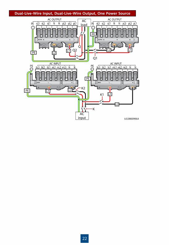
1. If the AC input of the 15 kVA/20 kVA UPS uses two live wires, connect bypass and mains inputs bL1, bL2, bL3, mL1, mL2, and mL3 that are short-circuited with a short-circuit bar to live wire L1, and connect the input N and N with a short-circuit bar to live wire L2.
2. If the AC input and AC output uses two live wires, the input and output must be connected to two-pole circuit breakers provided by the customer.
6
Three-Phase Input, Three-Phase Output, One Power Source (Factory Settings)
Connect cables based on the actual situation.
Wiring Terminal
AC OUTPUT
AC INPUT
PE
External Circuit Breaker
Q1 K1 -
15 kVA: 50 A (D feature); 20 kVA: 63 A (D feature)
15 kVA: 50 A (D feature); 20 kVA: 63 A (D feature)
Residual Current Circuit Breaker
- 300 mA -
Cable Cross-Sectional Area
10 mm2 10 mm2 25 mm2
Terminal Type
OT-10 mm2-M6 terminal
OT-10 mm2-M6 terminal
OT-25 mm2-M6-90°terminal
ACinput
ACload
K1
Q1
If the customer uses 10 mm2 five-core cables for AC input and output, the PE cable is 10 mm2. In this case, connect the cable using an OT-16 mm2-M6-90° terminal delivered with the UPS or an OT-10 mm2-M6-90° terminal prepared by the customer.
Mainsinput
Bypassinput
ACload
Km1
Q1
Kb1
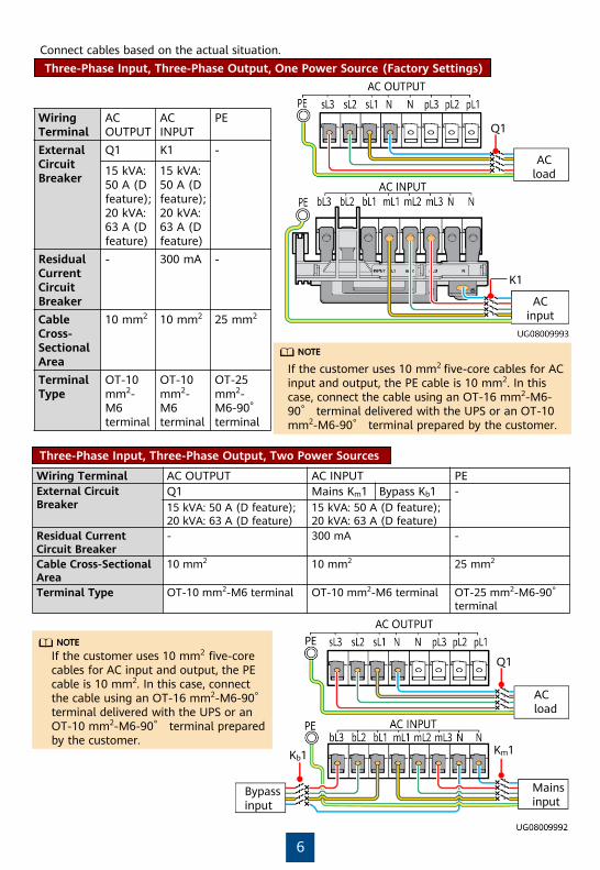
If the customer uses 10 mm2 five-core cables for AC input and output, the PE cable is 10 mm2. In this case, connect the cable using an OT-16 mm2-M6-90°terminal delivered with the UPS or an OT-10 mm2-M6-90° terminal prepared by the customer.
Wiring Terminal AC OUTPUT AC INPUT PEExternal Circuit Breaker
Q1 Mains Km1 Bypass Kb1 -15 kVA: 50 A (D feature); 20 kVA: 63 A (D feature)
15 kVA: 50 A (D feature); 20 kVA: 63 A (D feature)
Residual Current Circuit Breaker
- 300 mA -
Cable Cross-Sectional Area
10 mm2 10 mm2 25 mm2
Terminal Type OT-10 mm2-M6 terminal OT-10 mm2-M6 terminal OT-25 mm2-M6-90°terminal
Three-Phase Input, Three-Phase Output, Two Power Sources

7
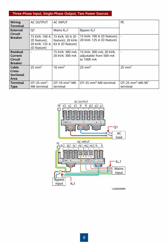
Three-Phase Input, Single-Phase Output, One Power Source
ACload
ACinput
Km1
Kb1
Q1
Wiring Terminal
AC OUTPUT AC INPUT PE
External Circuit Breaker
Q1 Mains Km1 Bypass Kb115 kVA: 100 A (D feature); 20 kVA: 125 A (D feature)
15 kVA: 50 A (D feature); 20 kVA: 63 A (D feature)
15 kVA: 100 A (D feature); 20 kVA: 125 A (D feature)
-
Residual Current Circuit Breaker
- 15 kVA: 300 mA; 20 kVA: 300 mA
15 kVA: 300 mA; 20 kVA: adjustable from 500 mA to 1000 mA
-
Cable Cross-Sectional Area
25 mm2 10 mm2 25 mm2 25 mm2
Terminal Type
OT-25 mm2-M6 terminal
OT-10 mm2-M6 terminal
OT-25 mm2-M6 terminal OT-25 mm2-M6-90°terminal
Mainsinput
Bypassinput
ACload
Km1
Q1
Kb1
8
Wiring Terminal
AC OUTPUT AC INPUT PE
External Circuit Breaker
Q1 Mains Km1 Bypass Kb1
15 kVA: 100 A (D feature); 20 kVA: 125 A (D feature)
15 kVA: 50 A (D feature); 20 kVA: 63 A (D feature)
15 kVA: 100 A (D feature); 20 kVA: 125 A (D feature)
-
Residual Current Circuit Breaker
- 15 kVA: 300 mA; 20 kVA: 300 mA
15 kVA: 300 mA; 20 kVA: adjustable from 500 mA to 1000 mA
-
Cable Cross-Sectional Area
25 mm2 10 mm2 25 mm2 25 mm2
Terminal Type
OT-25 mm2-M6 terminal
OT-10 mm2-M6 terminal
OT-25 mm2-M6 terminal OT-25 mm2-M6-90°terminal
Three-Phase Input, Single-Phase Output, Two Power Sources
9
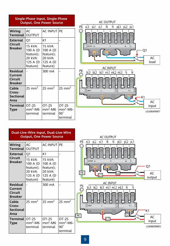
Single-Phase Input, Single-Phase Output, One Power Source
Wiring Terminal
AC OUTPUT
AC INPUT PE
External Circuit Breaker
Q1 K1 -
15 kVA: 100 A (D feature); 20 kVA: 125 A (D feature)
15 kVA: 100 A (D feature); 20 kVA: 125 A (D feature)
Residual Current Circuit Breaker
- 300 mA -
Cable Cross-Sectional Area
25 mm2 25 mm2 25 mm2
Terminal Type
OT-25 mm2-M6 terminal
OT-25 mm2-M6 terminal
OT-25 mm2-M6-90°terminal
ACinput
ACload
Q1
K1
Q1
K1
L1L2PE
L1L2PE
Wiring Terminal
AC OUTPUT
AC INPUT PE
External Circuit Breaker
Q1 K1 -
15 kVA: 100 A (D feature); 20 kVA: 125 A (D feature)
15 kVA: 100 A (D feature); 20 kVA: 125 A (D feature)
Residual Current Circuit Breaker
- 300 mA -
Cable Cross-Sectional Area
25 mm2 25 mm2 25 mm2
Terminal Type
OT-25 mm2-M6 terminal
OT-25 mm2-M6 terminal
OT-25 mm2-M6-90°terminal
Dual-Live-Wire Input, Dual-Live-Wire Output, One Power Source
ACinput
ACoutput

10
1. The UPS2000-G-15KRTL/20KRTL can connect to an external battery string (40 batteries in the standard configuration, and an even number of 32 to 40 batteries are supported). The neutral wire is connected to the middle point of the battery string. For example, if there are 40 batteries, the neutral wire is connected to the negative terminal of the twentieth battery.
2. When an external battery string is connected, install a DC circuit breaker (63 A, 600 V DC) between the battery string and the UPS.
3. When an external battery string is connected, connect positive terminals in series by using the two poles of the DC circuit breaker.
3 Installing Battery Cables
Ground point
External battery string
Battery 1
Battery 20
Battery 40
Wiring Terminal
BATT. ±240 V DC
External Circuit Breaker
63 A
Cable Cross-Sectional Area
16 mm2
Terminal Type
OT-16 mm2-M6-90°terminal
External Battery StringsScenario 1
External Battery PacksScenario 2
1. A 15 kVA/20 kVA UPS with long backup time requires serial connection of two battery packs in each group. A maximum of four groups with eight battery packs can be connected in parallel. If more than two battery packs need to be connected to the 15 kVA/20 kVA UPS with long backup time, the battery packs should be connected in parallel and then connected to the battery input ports of the UPS, as shown in the following figure. Connect battery packs 1 and 2 in series, battery packs 3 and 4 in series, battery packs 5 and 6 in series, and battery packs 7 and 8 in series. Connect battery packs 1, 3, 5, and 7 in parallel and battery packs 2, 4, 6, and 8 in parallel.
2. For more information, see the ESS-240V12-(9AhBPVBA, 7AhBPVBA) Quick Installation Guide and ESS-240V12-(9AhBPVBA04, 7AhBPVBA04) Battery Pack Quick Guide.
3. When battery packs are connected in series or parallel, only battery packs of the same model and specifications can be installed or replaced. Do not use battery packs of different models or specifications together. For details, see the battery pack nameplate.
M6 (5 PCS)
4.8 N•m

11
Battery pack 1 Battery pack 2
Battery pack 3 Battery pack 4
Battery pack 5 Battery pack 6
Battery pack 7 Battery pack 8
4 (Optional) Connecting Cables to Optional Cards
SNMP Card
For details about how to install the SNMP card, dry contact card, and Modbus card, see the RMS-SNMP01A V100R001 Installation Guide, RMS-MODBUS01A User Manual, and RMS-RELAY01A User Manual.
Dry Contact Card
Temperature and humidity
sensor
Ethernet Customer equipment

12
Modbus Card
In the figure, the two UPSs represent two standalone UPS systems.
5 (Optional) Connecting an EPO Switch
1. For UPS2000-G-15KRTL-01/UPS2000-G-20KRTL-01, choose Settings > System Parameters > Other Settings and set EPO Enable to Enable.
2. Connect an external switch to the EPO ports of the UPS. After you turn on the switch in the case of emergency, the inverter stops and the UPS does not transfer to bypass mode. In this way, the UPS stops supplying power immediately.
3. The customer provides the external switch (it can be a common switch) that connects to the EPO ports.
6 Verifying the InstallationNo. Item Result
1If the input or output system is changed, ensure that the short-circuit copper bar status and cable connections at input and output ports are correct.
□ Passed □ Failed
2The phase sequence of the input power is correct. Use a multimeter to check that the input and output are not short-circuited.
□ Passed □ Failed
3 Cables and terminals are securely connected. □ Passed □ Failed
4Battery cables and terminals are connected correctly, and voltages comply with industry standards.
□ Passed □ Failed
5 The UPS is properly connected to battery strings. □ Passed □ Failed6 Input circuit breakers and load circuit breakers are OFF. □ Passed □ Failed7 Power cables and signal cables are correctly identified. □ Passed □ Failed
8The ground cable is reliably connected. The voltage difference between the neutral wire and the ground cable is less than 5 V AC.
□ Passed □ Failed
9The mains input voltage is 120–280 V AC during power-on (80–280 V AC after power-on).
□ Passed □ Failed
10
15 kVA/20 kVA: Use a multimeter to measure the voltages of the positive and negative battery strings. Voltage range: 9.6 V x Number of batteries to 14.4 V x Number of batteries. For example, if both the positive and negative battery strings contain 20 batteries, the voltage of each battery string should range from 192 V (20 x 9.6 V) to 288 V (20 x 14.4 V).
□ Passed □ Failed
Modbus card cascading
UPS 1 UPS 2
RS232-RS485 adapter
RS232 port on the PC

13
User interface (UI) snapshots shown in this document correspond to V100R001C10SPC700 and are for reference only. Ifany UI changes are made, contact Huawei technical support to obtain the latest snapshots.
Symbol Description Remarks
Press A. A and B indicate the operation symbols on the UPS control panel.
Press A and then B.
Indicates omitted screens. -
A
A B
7 Powering On and Starting the UPS
Powering On the UPS7.1
Check that the UPS has passed all check items described in chapter 6 "Verifying the Installation."
Switch on the external battery circuit breaker if any.
Switch on the upstream UPS mains and bypass circuit breakers (K1, Km1, and Kb1) based on site requirements.
Start the UPS in normal or bypass mode?
No: Cold-start the UPS using batteries.
Yes
The initialization screen is displayed.
Press
Switch on the output circuit breakers (Q, Q1, and Q2).

14
When a single 15 kVA/20 kVA UPS contains two battery strings, the maximum charge current must be less than or equal to 1.0 A.
Setting Key Parameters and Starting Inverters7.2
1. Incorrectly setting battery parameters compromises battery safety and battery backup time. For details about parameter settings, see the UPS2000-G-(6 kVA–20 kVA) User Manual.
2. Set system parameters with caution because the settings determine whether the UPS can operate normally.
Parameter Description
LanguageYou can select Chinese, English (default), Spanish, French, or Russian. Set it based on site requirements.
Output mode
The values include Single-phase and Three-phase (default). Set it based on site requirements. If the system uses three-phase input three-phase output, set Output mode to Three-phase. If the system uses three-phase input single-phase output or single-phase input single-phase output, set Output mode to Single-phase.
Voltage levelThe values include 208 V, 220 V (default), 230 V, and 240 V for single-phase output, or 380 V (default), 400 V, and 415 V for three-phase output. Set it based on site requirements.
Frequency level
The values include 50 Hz (default), 60 Hz, and Automatic. Set it based on site requirements. If the value is Automatic, the power-on bypass frequency ranges from 45 Hz to 55 Hz (excluding 55 Hz), and the system output frequency is 50 Hz; if the power-on bypass frequency ranges from 55 Hz to 65 Hz, the system output frequency is 60 Hz.
Positive batteries
The value ranges from 16 to 20. The default value is 0.
Negative batteries
The value ranges from 16 to 20. The default value is 0.
Battery capacityBattery capacity is the sum of all battery capacities, set the parameters based on the actual battery capacity. The value ranges from 7 Ah to 1000 Ah. The default value is 65 Ah.

15
Set LanguageStart Set Output mode.
Set Positive batteries.
Set Negative batteries.
Set Battery capacity.
End
On the default screen, hold down for more than 5 seconds. Release the button when you hear a beep sound. The inverters are started.
Set Frequency level.Set Voltage level.
The following uses three-phase input and three-phase output of the UPS in normal mode as an example.The parameter setting screens are shown as follows.
Set Language (default: English), System Parameters, and Battery Parameters.
Incorrectly setting battery parameters compromises battery safety and battery backup time.For details about parameter settings, see the UPS2000-G-(6 kVA–20 kVA) User Manual.
Scenario 1: Initial Startup

16
1. The preset password is 000001, used to enter the Settingsmenu.
2. The preset feature code is 999999, used to restore the preset password.
Scenario 2: Non-initial Startup
Perform "startup operations": On the standby screen, hold down for more than 5 seconds. Release the button when you hear a beep sound. The startup screen is displayed. After the UPS starts successfully, it enters normal mode. After you ensure that the UPS runs properly, switch on the AC output circuit breaker Q1 of the UPS to start loads.
More than 5 seconds
Perform "shutdown operations" to shut down the UPS: On the default screen, hold down ESCfor more than 5 seconds. Release the button when you hear a beep sound. The inverter shuts down. If the bypass voltage is within the configured range, the UPS transfers to bypass mode. If the bypass voltage is beyond the configured range, the UPS has no output.
8 Shutdown
1. Shut down loads.2. Perform "shutdown operations" on the UPS. The inverter shuts down, and the UPS transfers to
bypass mode. If the bypass voltage is beyond the configured range, the UPS has no output.3. Switch off the AC input circuit breakers (K1, Km1, and Kb1) and output circuit breaker Q1 of the
UPS based on site requirements.4. Switch off the external battery circuit breaker (if any), or disconnect battery cables (if there is
no battery circuit breaker). After all indicators turn off and fans stop, the UPS shuts down and stops supplying power to loads.
1
2
Shutting Down the Inverter to Transfer a Single UPS to Bypass Mode8.1
Powering Off a Single UPS8.2

17
1 Installing Devices
Parallel System
Install devices from bottom to top, as shown in the figure. For details, see the method for installing a single UPS.
• This section describes how to install a 1+1 parallel system.
• Only UPSs of the same model can be connected in parallel.
UPS (3 U)
Battery pack (optional, 3 U)
PDU (optional, 3 U)
Rack-Mounted InstallationScenario 1
When you tower-mount the UPS, place devices including the UPS horizontally to facilitate cable
installation. Stand the devices upright after cable installation.
UPS (3 U)
Battery pack (optional, 3 U)
Rubber plug
Tower-Mounted InstallationScenario 2
PDU (optional, 3 U)

18
2 Installing AC Input and Output Power Cables
1. Ensure that the AC input and output power cables on each UPS are connected in the same phase sequence, battery terminals are connected correctly, and the bypass power cables are connected in the same phase sequence.
2. Before cable connection, switch off all circuit breakers in the parallel system.3. If the input or output wiring has to be changed, contact Huawei technical support if you are
not familiar with the operation. Do not power on the UPS directly.
1. When installing short-circuit bars, install the AC INPUT short-circuit bar and cables, and then install the AC OUTPUT short-circuit bar and cables.
2. If the input or output system is changed, ensure that the short-circuit copper bar status and cable connections at input and output ports are correct.
3. The UPS can generate large leakage currents. A circuit breaker equipped with a residual current device (RCD) is not recommended. If leakage protection is required, select a recommended circuit breaker.
4. Circuit breakers used for cable connection need to be provided by the customer.5. When UPSs are connected in parallel, the output parallel power cables of each UPS must be
at least 1 m long and the length deviation must be less than ±10%. The four cables must be connected at the remote end.
6. If the parallel system uses the TN-C power distribution system, install magnetic rings around the PE cables on each UPS, bind the magnetic rings together using cable ties, and secure the magnetic rings nearby. Magnetic rings are optional. For details about the model and usage, see the UPS2000-G-(6 kVA-20 kVA) User Manual.
1. bL indicates the bypass input, and mL indicates the mains input.2. K indicates the general AC input circuit breaker, Km indicates the general mains input circuit
breaker, and Kb indicates the general bypass input circuit breaker. K1, Km1, and Kb1 indicate UPS 1 input circuit breakers. K2, Km2, and Kb2 indicate UPS 2 input circuit breakers. Q indicates the general AC output circuit breaker. Q1 indicates the UPS 1 output circuit breaker. Q2 indicates the UPS 2 output circuit breaker.
Connect cables based on site requirements. For details about the wiring terminals, external circuit breakers, leakage current breakers, distribution cross-sectional areas, and terminal types, see the method for a single UPS system.

19
Equipped with No PDUScenario 1
Three-Phase Input, Three-Phase Output, One Power Source (Factory Settings)
ACinput
Q1
Q2
Q
KK1
K2
ACload
Three-Phase Input, Three-Phase Output, Two Power Sources
ACload
Mainsinput
Bypassinput
Q1
Q2
Q
Kb
Km
Km2
Km1
Kb2
Kb1

20
Three-Phase Input, Single-Phase Output, One Power Source
ACload
ACinput
Q1
Q2
Q
Km1
Km2
Kb1
Kb2
Km
Kb

21
ACload
ACinput
K
K1
QQ2
Q1
K2
Three-Phase Input, Single-Phase Output, Two Power Sources
ACload
Mainsinput
Bypassinput
Q1
Q2
Q
Kb1Kb
Km1
Kb2
Km2
Km
Single-Phase Input, Single-Phase Output, One Power Source
22
Dual-Live-Wire Input, Dual-Live-Wire Output, One Power Source
ACload
ACinput
K1
QQ2
Q1
K
K2
L2L1
PE
L1 L2PE
L2
L2
L1
L1
PE
PE

23
Equipped with a PDUScenario 2
Three-Phase Input, Three-Phase Output, One Power Source (Factory Settings)
PDC-0038V4ACIOA
Three-Phase Input, Three-Phase Output, Two Power Sources
PDC-0038V4ACIOA
For details about the PDU, see the PDC-0038V4ACIOA Quick Installation Guide orPDC-0091V2ACIOA Quick Installation Guide.

24
Three-Phase Input, Single-Phase Output, One Power Source
Three-Phase Input, Single-Phase Output, Two Power Sources
When connecting cables between PDUs and the mains input of the UPS 1 and UPS 2, connect only L2 and L3. As L1 and N wires do not connect to the UPS, wrap them with insulation tape.
PDC-0091V2ACIOA
PDC-0091V2ACIOA

25
Single-Phase Input, Single-Phase Output, One Power Source
PDC-0091V2ACIOA

26
3 Installing Battery Cables
External Battery StringsScenario 1
Ground point
External Battery Strings
Battery 1 Battery 20 Battery 40
Connect cables based on site requirements. For details about the wiring terminals, external circuit breakers, cable cross-sectional areas, and terminal types, see the method for a single UPS system.
M6 (10 PCS)
4.8 N•m
1. The UPS2000-G-15KRTL/20KRTL can connect to an external battery string (40 batteries in the standard configuration, and an even number of 32 to 40 batteries are supported). The neutral wire is connected to the middle point of the battery string. For example, if there are 40 batteries, the neutral wire is connected to the negative terminal of the twentieth battery.
2. When an external battery string is connected, install a DC circuit breaker (63 A, 600 V DC) between the battery string and the UPS. If a 2+0 or higher parallel system shares a battery string, use a larger-capacity battery circuit breaker accordingly.
3. When an external battery string is connected, connect positive terminals in series by using the two poles of the DC circuit breaker.

27
1. If the 15 kVA/20 kVA UPS parallel system does not share battery packs, the cable connection methods for each UPS and battery pack in the parallel system are the same as those in a single 15 kVA/20 kVA UPS system.
2. If the 15 kVA/20 kVA UPS parallel system shares battery packs, refer to the cable connection methods shown in the following figure. A 15 kVA/20 kVA UPS with long backup time requires serial connection of two battery packs in each group. A maximum of four groups with eight battery packs can be connected in parallel. If the 15 kVA/20 kVA UPS with long backup time connects to more than two battery packs, connect the battery packs in parallel and then to the UPS battery input port. Connect battery packs 1 and 2 in series, battery packs 3 and 4 in series, battery packs 5 and 6 in series, and battery packs 7 and 8 in series. Connect battery packs 1, 3, 5, and 7 in parallel and battery packs 2, 4, 6, and 8 in parallel.
3. For more information, see the ESS-240V12-(9AhBPVBA, 7AhBPVBA) Quick Installation Guide and ESS-240V12-(9AhBPVBA04, 7AhBPVBA04) Battery Pack Quick Guide.
4. When battery packs are connected in series or parallel, only battery packs of the same model and specifications can be installed or replaced. Do not use battery packs of different models or specifications together. For details, see the battery pack nameplate.
External Battery PacksScenario 2
Battery pack 1 Battery pack 2
Battery pack 3 Battery pack 4
Battery pack 5 Battery pack 6
Battery pack 7 Battery pack 8

28
4 (Optional) Connecting Cables to Optional Cards
For details about how to install the SNMP card, dry contact card, and Modbus card, see the RMS-SNMP01A V100R001 Installation Guide, RMS-MODBUS01A User Manual, and RMS-RELAY01A User Manual.
The methods for installing the SNMP card and dry contact card are the same in a parallel system and a single UPS. See the installation method for a single UPS. The following shows how to install cables for the Modbus card.
UPS 1UPS 2
RS232-RS485 adapter
RS232 port on the PC
5 (Optional) Connecting an EPO Switch
1. For UPS2000-G-15KRTL-01/UPS2000-G-20KRTL-01, choose Settings > System Parameters > Other Settings and set EPO Enableto Enable.
2. Connect an external switch to the EPO ports of the UPS. After you turn on the switch in the case of emergency, the inverter stops and the UPS does not transfer to bypass mode. In this way, the UPS stops supplying power immediately.
3. The customer provides the external switch (it can be a common switch) that connects to the EPO ports.
UPS 1UPS 2

29
6 Installing Parallel Cables
UPS 1UPS 2
7 Verifying the Installation1. Check each UPS in the parallel system by following instructions in chapter 6 "Verifying the
Installation."2. Check that parallel cables are properly connected and that the output voltages of all UPSs in
the parallel system are consistent.3. Ensure that the output phases of all UPSs in the parallel system are the same.

30
8 Powering On and Starting the UPS
Do not start loads before the parallel system is started.
Check that the UPS has passed all check items described in chapter 6 "Verifying the Installation."
Switch on the external battery circuit breaker if any.
Switch on the general UPS mains and bypass mains input circuit breakers (K, Km, and Kb), and the branch mains and bypass input circuit breakers (K1, Km1, Kb1, K2, Km2, and Kb2) based on site requirements.
Check that the input voltage is normal.
Check that the initialization screen is displayed, as shown in section 8.2.
Powering On and Starting the UPS8.1
Switch on output circuit breaker Q1 and keep output circuit breaker Q2 open. Check that the voltage difference between the
two ends of output circuit breaker Q2 is within 2 V.
Start the UPS inverter and then shut down the inverter so that the output PL terminal has voltage output.
Switch on output circuit breaker Q2.
Check that the software version used by the UPS is the same.
Set parallel parameters. For details, see section 8.3.
Start inverters for each UPS in sequence.

31
Incorrect battery parameters may cause problems such as battery safety incidents or insufficient power backup capability. Set battery parameters based on site requirements.
1. The preset password is 000001, used to enter the Settings menu.
2. The preset feature code is 999999, used to restore the preset password.
Scenario 2: Non-initial Startup
Set Language (default: English), System Parameters, and Battery Parameters.
Scenario 1: Initial Startup
UPS Initialization and Parameter Settings8.2The following uses three-phase input and three-phase output of the UPS in normal mode as an example.The parameter setting screens are shown as follows.
1. Set Language (default: English), System Parameters, and Battery Parameters for each UPS.

32
1. Set the parallel mode and the number of redundant UPSs.
2. The UPS automatically synchronizes its settings to other UPSs in the parallel system.
4. If no alarm is displayed on the monitoring screen, continue with the subsequent operations. If an alarm is displayed, clear the alarm.
2. Perform "startup operations" on each UPS in the parallel system: On the standby screen, hold down for more than 5 seconds. Release the button when you hear a beep sound. The startup screen is displayed. After the UPS starts successfully, it enters normal mode.
3. After the parallel system runs properly, switch on the general AC output circuit breaker Q for the UPSs and start each load. To prevent triggering overload protection, start the loads with higher power and then loads with lower power.
After you perform "startup operations" on UPS 1 to UPS n one by one, UPS 1 to UPS n are starting. If you do not perform "startup operations" on the other UPSs in 5 minutes, UPS 1 to UPS n enter normal mode, and the other UPSs supply no power.
3. Set battery string sharing for each UPS based on site requirements.
Setting Parallel Parameters8.3
1. Check that the bypass input is normal and the UPS has transferred to bypass mode by viewing the system running status on the LCD.
Starting the Inverters8.4
This step applies only to the UPS2000-G-15KRTL-01 and UPS2000-G-20KRTL-01.

33
9 Shutdown
Perform "shutdown operations" to shut down the UPS: On the default screen, hold down ESCfor more than 5 seconds. Release the button when you hear a beep sound. The inverter shuts down. If the bypass voltage is within the configured range, the UPS transfers to bypass mode. If the bypass voltage is beyond the configured range, the UPS has no output.
1. Perform "shutdown operations" twice on a UPS in the parallel system within 30 seconds. The UPS shuts down and enters the non-output state (the mains, bypass, and battery indicators are off). The other UPSs keep working.
2. Switch off the AC input circuit breakers (K1, Km1, Kb1 or K2, Km2, Kb2) and AC output circuit breaker (Q1 or Q2) of the UPS based on site requirements.
3. Turn off the external battery circuit breakers (if there are), or disconnect battery power cables (if there is no battery circuit breaker). The UPS exits the parallel system. After all indicators turn off and fans stop, the UPS shuts down.
Perform "shutdown operations" on each UPS in the parallel system. The inverters shut down. If the bypass voltage is within the configured range, the UPS transfers to bypass mode. If the bypass voltage is beyond the configured range, the UPS has no output.
1. Shut down loads.2. Perform "shutdown operations" on each UPS in the parallel system. The inverters shut down. If
the bypass voltage is within the configured range, the UPS transfers to bypass mode. If the bypass voltage is beyond the configured range, the UPS has no output.
3. Switch off the AC input circuit breakers (K1, Km1, Kb1, K2, Km2, and Kb2) of each UPS, general input circuit breakers (K, Km, and Kb) of the UPS system, AC output circuit breakers (Q1 and Q2) of each UPS, and general AC output circuit breaker Q of the UPS system based on site requirements.
4. Switch off the external battery circuit breaker for each UPS or the general battery circuit breaker (when all UPSs share a battery string). If no external battery circuit breaker is configured, disconnect battery cables from each UPS. After all indicators turn off and fans stop, the UPS shuts down, and the loads power off.
Shutting Down a Single UPS in the Parallel System9.1
Transferring a Parallel System to Bypass Mode9.2
Powering Off a Parallel System9.3

34
Alarm Name
Alarm ID-Cause ID
Alarm Severity
Clearance Mode
Impact on the System
Handling Suggestion
Abnormal mains volt.
0001-01 Minor Automatic • The rectifier transfers to battery mode, which does not affect the power supply to loads.
• If no battery is installed, the UPS shuts down.
Possible causes:• The mains voltage exceeds
280 V.• The mains voltage is less
than 80 V.• The mains frequency is not
in the range of 40 Hz to 70 Hz.
• The mains fuse is abnormal.Measures:• Check whether the mains
input voltage is less than 272 V. If not, wait until the mains recovers.
• Check whether the mains input voltage is greater than 88 V. If yes, the mains fuse may be abnormal. Replace the faulty device. If no, wait until the mains recovers.
• Check the mains input frequency. If it is abnormal, wait until the mains input recovers.
0001-02 Minor
0001-03 Minor
Abnormal BPS volt.
0010-01 Minor Automatic The UPS cannot transfer to bypass mode. If the UPS is working in bypass mode, it transfers to another working mode.
Possible causes:• The bypass input voltage is
abnormal.• The bypass input frequency
is abnormal.Measures:• Check whether the bypass
input voltage exceeds the configured range. If yes, change the range or wait until the bypass input recovers.
• Check whether the bypass input frequency exceeds the configured range. If yes, change the range or wait until the bypass input recovers.
0010-02 Minor
For more parameters and alarm information, see UPS2000-G-(6 kVA-20 kVA) User Manual.
Alarm Handling

35
Alarm Name
Alarm ID-Cause ID
Alarm Severity
Clearance Mode
Impact on the System
Handling Suggestion
Mains phase reverse
0004-01 Minor Automatic • The rectifier transfers to battery mode, which does not affect the system power supply.
• If no battery is installed, the UPS shuts down.
• The UPS transfers to another working mode or shuts down.
Possible cause: The mains input three-phase sequence is incorrect.Measure: Check that mains input power cables are correctly connected.
BPS phase reverse
0011-01 Minor Automatic • If the inverter has not started, the output keeps disconnected and the inverter is not allowed to start.
• If the inverter has started, the UPS can work in inverter mode properly, but the UPS cannot transfer to bypass mode.
Possible cause: The bypass input three-phase sequence is incorrect.Measure: Check that bypass input power cables are correctly connected.
Batt. overvolt.
0025-01 Minor Automatic An alarm is
displayed, and
the battery
service life may
be shortened.
Possible causes:• The configured number of
batteries is less than the actual number.
• The battery voltage reaches the alarm threshold due to continuous charge.
Measures:• Check battery parameter
settings.• Wait for 2 minutes in battery
charging state. Check whether the alarm is cleared.

36
Alarm Name
Alarm ID-Cause ID
Alarm Severity
Clearance Mode
Impact on the System
Handling Suggestion
Batt. undervolt.
0026-01 Minor Automatic An alarm is displayed, and the system may shut down due to EOD.
Possible cause: The mains is abnormal, and the batteries are overdischarged.Measure: Connect to the mains supply in non-battery test state.
Rectifier fault
0040-04 Critical Manual/Power-off/Automatic
The UPS shuts down.The UPS transfers to another working mode or shuts down.
Possible causes:• The mains has experienced
a transient high voltage.• The output carries special
loads such as inductive and rectification loads.
• The output carries transformer loads but the transformer mode is not enabled.
• The hardware is damaged.Measures:• Rectify the fault and power
on the UPS again.• Check that the loads are
supported by the UPS.• Enable the transformer
mode.• Contact Huawei technical
support.
Internal fault
0042-10 Critical Automatic If the inverter has not started, disable inverter startup.If the inverter has started, the UPS can work in inverter mode properly, but the UPS cannot transfer to bypass mode.
Possible cause: The bypass input cable connection is inconsistent with the output system setting.Measure: Ensure that the bypass input cable connection is consistent with the output system setting.
Fan fault 0043-01 Critical Automatic This alarm does not affect the UPS or the power supply.
Possible cause: The fan is abnormal.Measure: Clean up foreign objects around the fan. If the alarm persists, contact Huawei technical support.
37
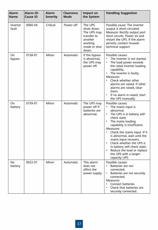
Alarm Name
Alarm ID-Cause ID
Alarm Severity
Clearance Mode
Impact on the System
Handling Suggestion
Inverter fault
0060-04 Critical Power-off The UPS shuts down.The UPS may transfer to another working mode or shut down.
Possible cause: The inverter output is short-circuited.Measure: Rectify output port short circuits. Power on and restart the UPS. If the alarm persists, contact Huawei technical support.
On bypass
0158-01 Minor Automatic If the bypass is abnormal, the UPS may power off.
Possible causes:• The inverter is not started.• The load power exceeds
the rated inverter loading capability.
• The inverter is faulty.Measures:• Check whether other
alarms are raised. If other alarms are raised, clear them.
• If no alarm is raised, start the UPS manually.
On battery
0159-01 Minor Automatic The UPS may power off if batteries are abnormal.
Possible causes:• The mains input is
abnormal.• The UPS is in battery self-
check state.• The mains loading
capability is insufficient.Measures:• Check the mains input. If it
is abnormal, wait until the mains input recovers.
• Check whether the UPS is in battery self-check state.
• Reduce the load or replace the UPS with a larger-capacity UPS.
No battery
0022-01 Minor Automatic This alarm does not affect the power supply.
Possible causes:• Batteries are not
connected.• Batteries are not securely
connected.Measures:• Connect batteries.• Check that batteries are
securely connected.

38
Huawei Technologies Co., Ltd.Huawei Industrial Base, Bantian, Longgang
Shenzhen 518129 People's Republic of Chinawww.huawei.com
Scan here for more documents:
You can also log in to Huawei technical support website:
SupportSupport-E WeChat
HUAWEI AppGallery
Scan here for technical support (enterprise):
Scan here for technical support (carrier):
HUAWEI AppGallery
https://support.huawei.comhttps://support.huawei.com/enterprise