LTE Quick Guide
20
http://www.tutorialspoint.com/lte/lte_quick_g uide.htm Copyright © tutorialspoint.com LTE QUICK GUIDE LTE stands for Long Term Evolution and it was started as a project in 2004 by telecommunication body known as the Third Generation Partnership Project (3GPP). SAE (System Architecture Evolution) is the corresponding evolution of the GPRS/3G packet core network evolution. The term LTE is typically used to represent both LTE and SAE LTE evolved from an earlier 3GPP system known as the Universal Mobile Telecommunication System (UMTS), which in turn evolved from the Global System for Mobile Communications (GSM). Even related specifications were formally known as the evolved UMTS terrestrial radio access (E-UTRA) and evolved UMTS terrestrial radio access network (E-UTRAN). First version of LTE was documented in Release 8 of the 3GPP specifications. A rapid increase of mobile data usag e and emerg ence of new applications such as MMOG (Multimedia Online Gaming ), mobile TV, Web 2.0, streaming contents have motivated the 3rd Generation Partnership Project (3GPP) to work on the Long -Term Evolution (LTE) on the way towards fourth-g eneration mobile. The main g oal of LTE is to provide a hig h data rate, low latency and packet optimized radioaccess technolog y supporting flexible bandwidth deployments. Same time its network architecture has been desig ned with the g oal to support packet-switched traffic with seamless mobility and g reat quality of service. LTE Evolution Year Event Mar 2000 Release 99 - UMTS/WCDMA Mar 2002 Rel 5 - HSDPA Mar 2005 Rel 6 - HSUPA Year 2007 Rel 7 - DL MIMO, IMS (IP Multimedia Subsystem) November 2004 Work started on LTE specification January 2008 Spec finalized and approved with Release 8 2010 Targ eted first deployment Facts about LTE LTE is the successor technology not only of UMTS but also of CDMA 2000. LTE is important because it will bring up to 50 times performance improvement and much better spectral e fficie ncy to ce llular ne tworks. LTE introduced to g et hig her data rates, 300Mbps peak downlink and 75 Mbps peak uplink. In a 20MHz carrier, data rates beyond 300Mbps can be achieved under very g ood sig nal conditions. LTE is an ideal technolog y to support hig h date rates for the services such as voice over IP (VOIP), streaming multimedia, videoconferencing or even a hig h-speed cellular modem. LTE uses both Time Division Duplex (TDD) and Frequency Division Duplex (FDD) mode. In FDD uplink and downlink transmission use d diffe re nt fre que ncy, while in T DD both uplink and downlink use the same carrier and are separated in Time. LTE supports flexible carrier bandwidths, from 1.4 MHz up to 20 MHz as well as both FDD and TDD. LTE desig ned with a scalable carrier bandwidth from 1.4 MHz up to 20 MHz which bandwidth is used depends on the frequency band and the amount of spectrum available with a network operator.
Transcript of LTE Quick Guide

http://www.tuto rialspo int.co m/lte/lte_quick_g uide.htm Copyrig ht © tutorialspoint.com
LTE QUICK GUIDE
LTE stands for Long Term Evolution and it was started as a project in 2004 by telecommunication body knownas the Third Generation Partnership Project (3GPP). SAE (System Architecture Evolution) is the correspondingevolution of the GPRS/3G packet core network evolution. The term LTE is typically used to represent both LTEand SAE
LTE evolved from an earlier 3GPP system known as the Universal Mobile Telecommunication System (UMTS),which in turn evolved from the Global System for Mobile Communications (GSM). Even related specificationswere formally known as the evolved UMTS terrestrial radio access (E-UTRA) and evolved UMTS terrestrialradio access network (E-UTRAN). First version of LTE was documented in Release 8 of the 3GPPspecifications.
A rapid increase of mobile data usag e and emerg ence of new applications such as MMOG (Multimedia OnlineGaming ), mobile TV, Web 2.0, streaming contents have motivated the 3rd Generation Partnership Project(3GPP) to work on the Long -Term Evolution (LTE) on the way towards fourth-g eneration mobile.
The main g oal of LTE is to provide a hig h data rate, low latency and packet optimized radioaccess technolog ysupporting flexible bandwidth deployments. Same time its network architecture has been desig ned with the g oalto support packet-switched traffic with seamless mobility and g reat quality of service.
LTE Evolution
Year Event
Mar 2000 Release 99 - UMTS/WCDMA
Mar 2002 Rel 5 - HSDPA
Mar 2005 Rel 6 - HSUPA
Year 2007 Rel 7 - DL MIMO, IMS (IP Multimedia Subsystem)
November 2004 Work started on LTE specification
January 2008 Spec finalized and approved with Release 8
2010 Targ eted first deployment
Facts about LTE
LTE is the successor technolog y not only of UMTS but also of CDMA 2000.
LTE is important because it will bring up to 50 times performance improvement and much better spectralefficiency to cellular networks.
LTE introduced to g et hig her data rates, 300Mbps peak downlink and 75 Mbps peak uplink. In a 20MHzcarrier, data rates beyond 300Mbps can be achieved under very g ood sig nal conditions.
LTE is an ideal technolog y to support hig h date rates for the services such as voice over IP (VOIP),streaming multimedia, videoconferencing or even a hig h-speed cellular modem.
LTE uses both Time Division Duplex (TDD) and Frequency Division Duplex (FDD) mode. In FDD uplinkand downlink transmission used different frequency, while in TDD both uplink and downlink use the samecarrier and are separated in Time.
LTE supports flexible carrier bandwidths, from 1.4 MHz up to 20 MHz as well as both FDD and TDD.LTE desig ned with a scalable carrier bandwidth from 1.4 MHz up to 20 MHz which bandwidth is useddepends on the frequency band and the amount of spectrum available with a network operator.

All LTE devices have to support (MIMO) Multiple Input Multiple Output transmissions, which allow thebase station to transmit several data streams over the same carrier simultaneously.
All interfaces between network nodes in LTE are now IP based, including the backhaul connection to theradio base stations. This is g reat simplification compared to earlier technolog ies that were initially basedon E1/T1, ATM and frame relay links, with most of them being narrowband and expensive.
Quality of Service (QoS) mechanism have been standardized on all interfaces to ensure that therequirement of voice calls for a constant delay and bandwidth, can still be met when capacity limits arereached.
Works with GSM/EDGE/UMTS systems utilizing existing 2G and 3G spectrum and new spectrum.Supports hand-over and roaming to existing mobile networks.
Advantag es of LTE
Hig h throug hput: Hig h data rates can be achieved in both downlink as well as uplink. This causes hig hthroug hput.
Low latency: Time required to connect to the network is in rang e of a few hundred milliseconds andpower saving states can now be entered and exited very quickly.
FDD and TDD in the same platform: Frequency Division Duplex (FDD) and Time Division Duplex(FDD), both schemes can be used on same platform.
Superior end-user experience: Optimized sig naling for connection establishment and other airinterface and mobility manag ement procedures have further improved the user experience. Reducedlatency (to 10 ms) for better user experience.
Seamless Connection: LTE will also support seamless connection to existing networks such as GSM,CDMA and WCDMA.
Plug and play: The user does not have to manually install drivers for the device. Instead systemautomatically recog nizes the device, loads new drivers for the hardware if needed, and beg ins to workwith the newly connected device.
Simple architecture: Because of Simple architecture low operating expenditure (OPEX).
LTE - QoS Architecture
LTE architecture supports hard QoS, with end-to-end quality of service and g uaranteed bit rate (GBR) forradio bearers. Just as Ethernet and the internet have different types of QoS, for example, various levels of QoScan be applied to LTE traffic for different applications. Because the LTE MAC is fully scheduled, QoS is a naturalfit.
Evolved Packet System (EPS) bearers provide one-to-one correspondence with RLC radio bearers andprovide support for Traffic Flow Templates (TFT). There are four types of EPS bearers:
GBR Bearer: resources permanently allocated by admission control
Non-GBR Bearer no admission control
Dedicated Bearer associated with specific TFT (GBR or non-GBR)
Default Bearer Non GBR, catch-all for unassig ned traffic
LTE BASIC PARAMETERS
This section will summarize the Basic parameters of the LTE:
Parameters Description
Frequency rang e UMTS FDD bands and TDD bands defined in 36.101(v860) Table

5.5.1, g iven below
Duplexing FDD, TDD, half-duplex FDD
Channel coding Turbo code
Mobility 350 km/h
Channel Bandwidth (MHz)1.4
3
5
10
15
20
Transmission BandwidthConfig uration NRB: (1 resourceblock = 180kHz in 1ms TTI )
6
15
25
50
75
100
Coverag e 5 - 100km with slig ht deg radation after 30km
QoS E2E QOS allowing prioritization of different class of service
Latency End-user latency < 10mS
E-UTRA Operating Bands
Following is the table for E-UTRA operating bands taken from LTE Sepecification 36.101(v860) Table 5.5.1:

LTE - NETWORK ARCHITECTURE
The hig h-level network architecture of LTE is comprised of following three main components:
The User Equipment (UE).
The Evolved UMTS Terrestrial Radio Access Network (E-UTRAN).
The Evolved Packet Core (EPC).
The evolved packet core communicates with packet data networks in the outside world such as the internet,private corporate networks or the IP multimedia subsystem. The interfaces between the different parts of thesystem are denoted Uu, S1 and SGi as shown below:
The User Equipment (UE)
The internal architecture of the user equipment for LTE is identical to the one used by UMTS and GSM which isactually a Mobile Equipment (ME). The mobile equipment comprised of the following important modules:
Mobile Termination (MT): This handles all the communication functions.

Terminal Equipment (TE): This terminates the data streams.
Universal Integ rated Circuit Card (UICC): This is also known as the SIM card for LTEequipments. It runs an application known as the Universal Subscriber Identity Module (USIM).
A USIM stores user-specific data very similar to 3G SIM card. This keeps information about the user's phonenumber, home network identity and security keys etc.
The E-UTRAN (The access network)
The architecture of evolved UMTS Terrestrial Radio Access Network (E-UTRAN) has been illustrated below.
The E-UTRAN handles the radio communications between the mobile and the evolved packet core and just hasone component, the evolved base stations, called eNodeB or eNB. Each eNB is a base station that controls themobiles in one or more cells. The base station that is communicating with a mobile is known as its serving eNB.
LTE Mobile communicates with just one base station and one cell at a time and there are following two mainfunctions supported by eNB:
The eBN sends and receives radio transmissions to all the mobiles using the analog ue and dig ital sig nalprocessing functions of the LTE air interface.
The eNB controls the low-level operation of all its mobiles, by sending them sig nalling messag es such ashandover commands.
Each eBN connects with the EPC by means of the S1 interface and it can also be connected to nearby basestations by the X2 interface, which is mainly used for sig nalling and packet forwarding during handover.
A home eNB (HeNB) is a base station that has been purchased by a user to provide femtocell coverag e withinthe home. A home eNB belong s to a closed subscriber g roup (CSG) and can only be accessed by mobiles with aUSIM that also belong s to the closed subscriber g roup.
The Evolved Packet Core (EPC) (The core network)
The architecture of Evolved Packet Core (EPC) has been illustrated below. There are few more componentswhich have not been shown in the diag ram to keep it simple. These components are like the Earthquake andTsunami Warning System (ETWS), the Equipment Identity Reg ister (EIR) and Policy Control and Charg ingRules Function (PCRF).
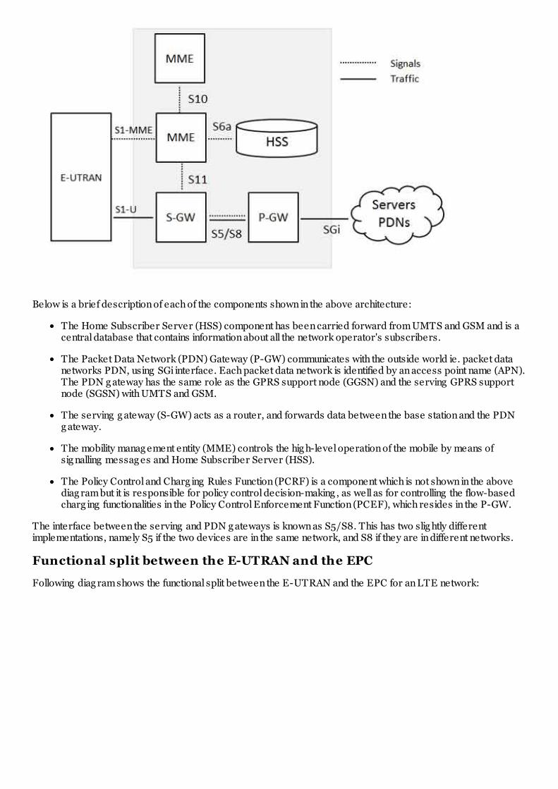
Below is a brief description of each of the components shown in the above architecture:
The Home Subscriber Server (HSS) component has been carried forward from UMTS and GSM and is acentral database that contains information about all the network operator's subscribers.
The Packet Data Network (PDN) Gateway (P-GW) communicates with the outside world ie. packet datanetworks PDN, using SGi interface. Each packet data network is identified by an access point name (APN).The PDN g ateway has the same role as the GPRS support node (GGSN) and the serving GPRS supportnode (SGSN) with UMTS and GSM.
The serving g ateway (S-GW) acts as a router, and forwards data between the base station and the PDNg ateway.
The mobility manag ement entity (MME) controls the hig h-level operation of the mobile by means ofsig nalling messag es and Home Subscriber Server (HSS).
The Policy Control and Charg ing Rules Function (PCRF) is a component which is not shown in the abovediag ram but it is responsible for policy control decision-making , as well as for controlling the flow-basedcharg ing functionalities in the Policy Control Enforcement Function (PCEF), which resides in the P-GW.
The interface between the serving and PDN g ateways is known as S5/S8. This has two slig htly differentimplementations, namely S5 if the two devices are in the same network, and S8 if they are in different networks.
Functional split between the E-UTRAN and the EPC
Following diag ram shows the functional split between the E-UTRAN and the EPC for an LTE network:

2G/3G Versus LTE
Following table compares various important Network Elements & Sig naling protocols used in 2G/3G abd LTE.
2G/3G LTE
GERAN and UTRAN E-UTRAN
SGSN/PDSN-FA S-GW
GGSN/PDSN-HA PDN-GW
HLR/AAA HSS
VLR MME
SS7-MAP/ANSI-41/RADIUS Diameter
DiameterGTPc-v0 and v1 GTPc-v2
MIP PMIP
LTE - ROAMING ARCHITECTURE
A network run by one operator in one country is known as a Public Land Mobile Network (PLMN) and when asubscribed user uses his operator's PLMN then it is said Home-PLMN but roaming allows users to moveoutside their home network and using the resources from other operator's network. This other network is calledVisited-PLMN.
A roaming user is connected to the E-UTRAN, MME and S-GW of the visited LTE network. However,LTE/SAE allows the P-GW of either the visited or the home network to be used, as shown in below:

The home network's P-GW allows the user to access the home operator's services even while in a visitednetwork. A P-GW in the visited network allows a "local breakout" to the Internet in the visited network.
The interface between the serving and PDN g ateways is known as S5/S8. This has two slig htly differentimplementations, namely S5 if the two devices are in the same network, and S8 if they are in different networks.For mobiles that are not roaming , the serving and PDN g ateways can be integ rated into a sing le device, so thatthe S5/S8 interface vanishes altog ether.
LTE Roaming Charg ing
The complexities of the new charg ing mechanisms required to support 4G roaming are much more abundantthan in a 3G environment. Few words about both pre-paid and post-paid charg ing for LTE roaming is g ivenbelow:
Prepaid Charg ing The CAMEL standard, which enables prepaid services in 3G, is not supported inLTE; therefore, prepaid customer information must be routed back to the home network as opposed tobeing handled by the local visited network. As a result, operators must rely on new accounting flows toaccess prepaid customer data, such as throug h their P-Gateways in both IMS and non-IMS environmentsor via their CSCF in an IMS environment.
Postpaid Charg ing - Postpaid data-usag e charg ing works the same in LTE as it does in 3G, usingversions TAP 3.11 or 3.12. With local breakout of IMS services, TAP 3.12 is required.
Operators do not have the same amount of visibility into subscriber activities as they do in home-routingscenarios in case of local breakout scenarios because subscriber-data sessions are kept within the visitednetwork; therefore, in order for the home operator to capture real-time information on both pre- and postpaidcustomers, it must establish a Diameter interface between charg ing systems and the visited network's P-Gateway.
In case of local breakout of ims services scenario, the visited network creates call detail records (CDRs) fromthe S-Gateway(s), however, these CDRs do not contain all of the information required to create a TAP 3.12mobile session or messag ing event record for the service usag e. As a result, operators must correlate the coredata network CDRs with the IMS CDRs to create TAP records.
LTE - NUMBERING & ADDRESSING
An LTE network area is divided into three different types of g eog raphical areas explained below:
S.N. Area and Description
1 The MME pool areas

This is an area throug h which the mobile can move without a chang e of serving MME. Every MMEpool area is controlled by one or more MMEs on the network.
2 The S-GW service areasThis is an area served by one or more serving g ateways S-GW, throug h which the mobile can movewithout a chang e of serving g ateway.
3 The Tracking areasThe MME pool areas and the S-GW service areas are both made from smaller, non-overlappingunits known as tracking areas (TAs). They are similar to the location and routing areas from UMTSand GSM and will be used to track the locations of mobiles that are on standby mode.
Thus an LTE network will comprise of many MME pool areas, many S-GW service areas and lots of trackingareas.
The Network IDs
The network itself will be identified using Public Land Mobile Network Identity (PLMN-ID) which will have athree dig it mobile country code (MCC) and a two or three dig it mobile network code (MNC). For example, theMobile Country Code for the UK is 234, while Vodafone's UK network uses a Mobile Network Code of 15.
The MME IDs
Each MME has three main identities. An MME code (MMEC) uniquely identifies the MME within all the poolareas. A g roup of MMEs is assig ned an MME Group Identity (MMEGI) which works along with MMEC to makeMME identifier (MMEI). A MMEI uniquely identifies the MME within a particular network.
If we combile PLMN-ID with the MMEI then we arrive at a Globally Unique MME Identifier (GUMMEI), whichidentifies an MME anywhere in the world:
The Tracking Area IDs
Each tracking area has two main identities. The tracking area code (TAC) identifies a tracking area within aparticular network and if we combining this with the PLMN-ID then we arrive at a Globally Unique Tracking AreaIdentity (TAI).

The Cell IDs
Each cell in the network has three types of identity. The E-UTRAN cell identity (ECI) identifies a cell within aparticular network, while the E-UTRAN cell g lobal identifier (ECGI) identifies a cell anywhere in the world.
The physical cell identity, which is a number from 0 to 503 and it disting uishes a cell from its immediateneig hbours.
The Mobile Equipment ID
The international mobile equipment identity (IMEI) is a unique identity for the mobile equipment and theInternational Mobile Subscriber Identity (IMSI) is a unique identity for the UICC and the USIM.
The M temporary mobile subscriber identity (M-TMSI) identifies a mobile to its serving MME. Adding the MMEcode in M-TMSI results in a S temporary mobile subscriber identity (S-TMSI), which identifies the mobile withinan MME pool area.
Finally adding the MME g roup identity and the PLMN identity with S-TMSI results in the Globally UniqueTemporary Identity (GUTI).
LTE - RADIO PROTOCOL ARCHITECTURE
The radio protocol architecture for LTE can be separated into control plane architecture and user planearchitecture as shown below:

At user plane side, the application creates data packets that are processed by protocols such as TCP, UDP andIP, while in the control plane, the radio resource control (RRC) protocol writes the sig nalling messag es that areexchang ed between the base station and the mobile. In both cases, the information is processed by the packetdata converg ence protocol (PDCP), the radio link control (RLC) protocol and the medium access control (MAC)protocol, before being passed to the physical layer for transmission.
User Plane
The user plane protocol stack between the e-Node B and UE consists of the following sub-layers:
PDCP (Packet Data Converg ence Protocol)
RLC (radio Link Control)
Medium Access Control (MAC).
On the user plane, packets in the core network (EPC) are encapsulated in a specific EPC protocol and tunneledbetween the P-GW and the eNodeB. Different tunneling protocols are used depending on the interface. GPRSTunneling Protocol (GTP) is used on the S1 interface between the eNodeB and S-GW and on the S5/S8 interfacebetween the S-GW and P-GW.
Packets received by a layer are called Service Data Unit (SDU) while the packet output of a layer is referred toby Protocol Data Unit (PDU) and IP packets at user plane flow from top to bottom layers.
Control Plane

The control plane includes additionally the Radio Resource Control layer (RRC) which is responsible forconfig uring the lower layers.
The Control Plane handles radio-specific functionality which depends on the state of the user equipment whichincludes two states: idle or connected.
Mode Description
Idle The user equipment camps on a cell after a cell selection or reselection process where factorslike radio link quality, cell status and radio access technolog y are considered. The UE alsomonitors a pag ing channel to detect incoming calls and acquire system information. In thismode, control plane protocols include cell selection and reselection procedures.
Connected The UE supplies the E-UTRAN with downlink channel quality and neig hbor cell information toenable the E-UTRAN to select the most suitable cell for the UE. In this case, control planeprotocol includes the Radio Link Control (RRC) protocol.
The protocol stack for the control plane between the UE and MME is shown below. The g rey reg ion of the stackindicates the access stratum (AS) protocols. The lower layers perform the same functions as for the user planewith the exception that there is no header compression function for the control plane.
LTE - PROTOCOL STACK LAYERS
Let's have a close look at all the layers available in E-UTRAN Protocol Stack which we have seen in previouschapter. Below is a more ellaborated diag ram of E-UTRAN Protocol Stack:

Physical Layer (Layer 1)
Physical Layer carries all information from the MAC transport channels over the air interface. Takes care of thelink adaptation (AMC), power control, cell search (for initial synchronization and handover purposes) and othermeasurements (inside the LTE system and between systems) for the RRC layer.
Medium Access Layer (MAC)
MAC layer is responsible for Mapping between log ical channels and transport channels, Multiplexing of MACSDUs from one or different log ical channels onto transport blocks (TB) to be delivered to the physical layer ontransport channels, de multiplexing of MAC SDUs from one or different log ical channels from transport blocks(TB) delivered from the physical layer on transport channels, Scheduling information reporting , Error correctionthroug h HARQ, Priority handling between UEs by means of dynamic scheduling , Priority handling betweenlog ical channels of one UE, Log ical Channel prioritization.
Radio Link Control (RLC)
RLC operates in 3 modes of operation: Transparent Mode (TM), Unacknowledg ed Mode (UM), andAcknowledg ed Mode (AM).
RLC Layer is responsible for transfer of upper layer PDUs, error correction throug h ARQ (Only for AM datatransfer), Concatenation, seg mentation and reassembly of RLC SDUs (Only for UM and AM data transfer).
RLC is also responsible for re-seg mentation of RLC data PDUs (Only for AM data transfer), reordering of RLCdata PDUs (Only for UM and AM data transfer), duplicate detection (Only for UM and AM data transfer), RLCSDU discard (Only for UM and AM data transfer), RLC re-establishment, and protocol error detection (Only forAM data transfer).
Radio Resource Control (RRC)
The main services and functions of the RRC sublayer include broadcast of System Information related to the non-access stratum (NAS), broadcast of System Information related to the access stratum (AS), Pag ing ,establishment, maintenance and release of an RRC connection between the UE and E-UTRAN, Security
functions including key manag ement, establishment, config uration, maintenance and release of point to pointRadio Bearers.
Packet Data Converg ence Control (PDCP)
PDCP Layer is responsible for Header compression and decompression of IP data, Transfer of data (userplane or control plane), Maintenance of PDCP Sequence Numbers (SNs), In-sequence delivery of upper layerPDUs at re-establishment of lower layers, Duplicate elimination of lower layer SDUs at re-establishment oflower layers for radio bearers mapped on RLC AM, Ciphering and deciphering of user plane data and controlplane data, Integ rity protection and integ rity verification of control plane data, Timer based discard, duplicatediscarding , PDCP is used for SRBs and DRBs mapped on DCCH and DTCH type of log ical channels.
Non Access Stratum (NAS) Protocols
The non-access stratum (NAS) protocols form the hig hest stratum of the control plane between the userequipment (UE) and MME.
NAS protocols support the mobility of the UE and the session manag ement procedures to establish and maintainIP connectivity between the UE and a PDN GW.
LTE - LAYERS DATA FLOW
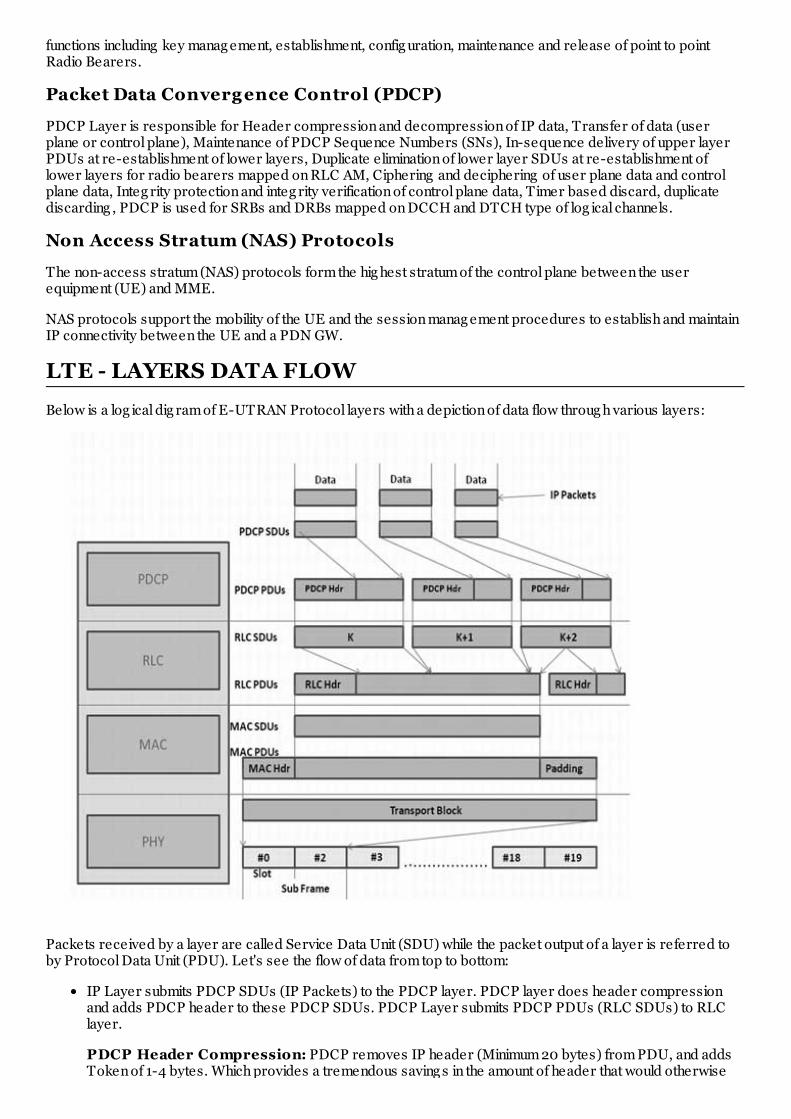
Below is a log ical dig ram of E-UTRAN Protocol layers with a depiction of data flow throug h various layers:
Packets received by a layer are called Service Data Unit (SDU) while the packet output of a layer is referred toby Protocol Data Unit (PDU). Let's see the flow of data from top to bottom:
IP Layer submits PDCP SDUs (IP Packets) to the PDCP layer. PDCP layer does header compressionand adds PDCP header to these PDCP SDUs. PDCP Layer submits PDCP PDUs (RLC SDUs) to RLClayer.
PDCP Header Compression: PDCP removes IP header (Minimum 20 bytes) from PDU, and addsToken of 1-4 bytes. Which provides a tremendous saving s in the amount of header that would otherwise

have to g o over the air.
RLC layer does seg mentation of these SDUS to make the RLC PDUs. RLC adds header based on RLCmode of operation. RLC submits these RLC PDUs (MAC SDUs) to the MAC layer.
RLC Seg mentation: If an RLC SDU is larg e, or the available radio data rate is low (resulting in smalltransport blocks), the RLC SDU may be split among several RLC PDUs. If the RLC SDU is small, or theavailable radio data rate is hig h, several RLC SDUs may be packed into a sing le PDU.
MAC layer adds header and does padding to fit this MAC SDU in TTI. MAC layer submits MAC PDU tophysical layer for transmitting it onto physical channels.
Physical channel transmits this data into slots of sub frame.
LTE - COMMUNICATION CHANNELS
The information flows between the different protocols are known as channels and sig nals. LTE uses severaldifferent types of log ical, transport and physical channel, which are disting uished by the kind of information theycarry and by the way in which the information is processed.
Log ical Channels: : Define whattype of information is transmitted over the air, e.g . traffic channels,control channels, system broadcast, etc. Data and sig nalling messag es are carried on log ical channelsbetween the RLC and MAC protocols.
Transport Channels: Define howis something transmitted over the air, e.g . what are encoding ,interleaving options used to transmit data. Data and sig nalling messag es are carried on transport channelsbetween the MAC and the physical layer.
Physical Channels: Define whereis something transmitted over the air, e.g . first N symbols in the DLframe. Data and sig nalling messag es are carried on physical channels between the different levels of thephysical layer.
Log ical Channels
Log ical channels define what type of data is transferred. These channels define the data-transfer servicesoffered by the MAC layer. Data and sig nalling messag es are carried on log ical channels between the RLC andMAC protocols.
Log ical channels can be divided into control channels and traffic channels. Control Channel can be either commonchannel or dedicated channel. A common channel means common to all users in a cell (Point to multipoint) whilededicated channels means channels can be used only by one user (Point to Point).
Log ical channels are disting uished by the information they carry and can be classified in two ways. Firstly, log icaltraffic channels carry data in the user plane, while log ical control channels carry sig nalling messag es in thecontrol plane. Following table lists the log ical channels that are used by LTE:
Channel Name Acronym Control channel Traffic channel
Broadcast Control Channel BCCH X

Broadcast Control Channel BCCH X
Pag ing Control Channel PCCH X
Common Control Channel CCCH X
Dedicated Control Channel DCCH X
Multicast Control Channel MCCH X
Dedicated Traffic Channel DTCH X
Multicast Traffic Channel MTCH X
Transport Channels
Transport channels define how and with what type of characteristics the data is transferred by the physical layer.Data and sig nalling messag es are carried on transport channels between the MAC and the physical layer.
Transport Channels are disting uished by the ways in which the transport channel processor manipulates them.Following table lists the transport channels that are used by LTE:
Channel Name Acronym Downlink Uplink
Broadcast Channel BCH X
Downlink Shared Channel DL-SCH X
Pag ing Channel PCH X
Multicast Channel MCH X
Uplink Shared Channel UL-SCH X
Random Access Channel RACH X
Physical Channels
Data and sig nalling messag es are carried on physical channels between the different levels of the physical layerand according ly they are divided into two parts:
Physical Data Channels
Physical Control Channels
Physical data channels
Physical data channels are disting uished by the ways in which the physical channel processor manipulates them,and by the ways in which they are mapped onto the symbols and sub-carriers used by Orthog onal frequency-division multiplexing (OFDMA). Following table lists the physical data channels that are used by LTE:
Channel Name Acronym Downlink Uplink
Physical downlink shared channel PDSCH X
Physical broadcast channel PBCH X
Physical multicast channel PMCH X
Physical uplink shared channel PUSCH X
Physical random access channel PRACH X
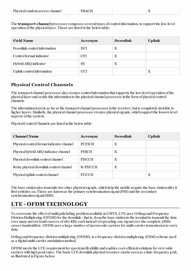
The transport channel processor composes several types of control information, to support the low-leveloperation of the physical layer. These are listed in the below table:
Field Name Acronym Downlink Uplink
Downlink control information DCI X
Control format indicator CFI X
Hybrid ARQ indicator HI X
Uplink control information UCI X
Physical Control Channels
The transport channel processor also creates control information that supports the low-level operation of thephysical layer and sends this information to the physical channel processor in the form of physical controlchannels.
The information travels as far as the transport channel processor in the receiver, but is completely invisible tohig her layers. Similarly, the physical channel processor creates physical sig nals, which support the lowest-levelaspects of the system.
Physical Control Channels are listed in the below table:
Channel Name Acronym Downlink Uplink
Physical control format indicator channel PCFICH X
Physical hybrid ARQ indicator channel PHICH X
Physical downlink control channel PDCCH X
Relay physical downlink control channel R-PDCCH X
Physical uplink control channel PUCCH X
The base station also transmits two other physical sig nals, which help the mobile acquire the base station after itfirst switches on. These are known as the primary synchronization sig nal (PSS) and the secondarysynchronization sig nal (SSS).
LTE - OFDM TECHNOLOGY
To overcome the effect of multi path fading problem available in UMTS, LTE uses Orthog onal FrequencyDivision Multiplexing (OFDM) for the downlink - that is, from the base station to the terminal to transmit the dataover many narrow band careers of 180 KHz each instead of spreading one sig nal over the complete 5MHzcareer bandwidth ie. OFDM uses a larg e number of narrow sub-carriers for multi-carrier transmission to carrydata.
Orthog onal frequency-division multiplexing (OFDM), is a frequency-division multiplexing (FDM) scheme usedas a dig ital multi-carrier modulation method.
OFDM meets the LTE requirement for spectrum flexibility and enables cost-efficient solutions for very widecarriers with hig h peak rates. The basic LTE downlink physical resource can be seen as a time-frequency g rid,as illustrated in Fig ure below:

The OFDM symbols are g rouped into resource blocks. The resource blocks have a total size of 180kHz in thefrequency domain and 0.5ms in the time domain. Each 1ms Transmission Time Interval (TTI) consists of twoslots (Tslot).
Each user is allocated a number of so-called resource blocks in the time.frequency g rid. The more resourceblocks a user g ets, and the hig her the modulation used in the resource elements, the hig her the bit-rate. Whichresource blocks and how many the user g ets at a g iven point in time depend on advanced schedulingmechanisms in the frequency and time dimensions.
The scheduling mechanisms in LTE are similar to those used in HSPA, and enable optimal performance fordifferent services in different radio environments.
Advantag es of OFDM
The primary advantag e of OFDM over sing le-carrier schemes is its ability to cope with severe channelconditions (for example, attenuation of hig h frequencies in a long copper wire, narrowband interferenceand frequency-selective fading due to multipath) without complex equalization filters.
Channel equalization is simplified because OFDM may be viewed as using many slowly-modulatednarrowband sig nals rather than one rapidly-modulated wideband sig nal.
The low symbol rate makes the use of a g uard interval between symbols affordable, making it possible toeliminate inter symbol interference (ISI).
This mechanism also facilitates the desig n of sing le frequency networks (SFNs), where several adjacenttransmitters send the same sig nal simultaneously at the same frequency, as the sig nals from multipledistant transmitters may be combined constructively, rather than interfering as would typically occur in atraditional sing le-carrier system.
Drawbacks of OFDM
Hig h peak-to-averag e ratio
Sensitive to frequency offset, hence to Doppler-shift as well.
SC-FDMA Technolog y
LTE uses a pre-coded version of OFDM called Sing le Carrier Frequency Division Multiple Access (SC-FDMA)in the uplink. This is to compensate for a drawback with normal OFDM, which has a very hig h Peak to Averag ePower Ratio (PAPR).
Hig h PAPR requires expensive and inefficient power amplifiers with hig h requirements on linearity, whichincreases the cost of the terminal and drains the battery faster.
SC-FDMA solves this problem by g rouping tog ether the resource blocks in such a way that reduces the needfor linearity, and so power consumption, in the power amplifier. A low PAPR also improves coverag e and thecell-edg e performance.

LTE - GLOSSARY
Term Description
3GPP 3rd Generation Partnership Project
3GPP2 3rd Generation Partnership Project 2
ARIB Association of Radio Industries and Businesses
ATIS Alliance for Telecommunication Industry Solutions
AWS Advanced Wireless Services
CAPEX Capital Expenditure
CCSA China Communications Standards Association
CDMA Code Division Multiple Access
CDMA2000 Code Division Multiple Access 2000
DAB Dig ital Audio Broadcast
DSL Dig ital Subscriber Line
DVB Dig ital Video Broadcast
eHSPA evolved Hig h Speed Packet Access
ETSI European Telecommunications Standards Institute
FDD Frequency Division Duplex
FWT Fixed Wireless Terminal
GSM Global System for Mobile communication
HSPA Hig h Speed Packet Access
HSS Home Subscriber Server
IEEE Institute of Electrical and Electronics Eng ineers
IPTV Internet Protocol Television
LTE Long Term Evolution
MBMS Multimedia Broadcast Multicast Service
MIMO Multiple Input Multiple Output
MME Mobility Manag ement Entity
NGMN Next Generation Mobile Networks
OFDM Orthog onal Frequency Division Multiplexing
OPEX Operational Expenditure
PAPR Peak to Averag e Power Ratio
PCI Peripheral Component Interconnect

PCRF Policing and Charg ing Rules Function
PDSN Packet Data Serving Node
PS Packet Switched
QoS Quality of Service
RAN Radio Access Network
SAE System Architecture Evolution
SC-FDMA Sing le Carrier Frequency Division Multiple Access
SGSN Serving GPRS Support Node
TDD Time Division Duplex
TTA Telecommunications Technolog y Association
TTC Telecommunication Technolog y Committee
TTI Transmission Time Interval
UTRA Universal Terrestrial Radio Access
UTRAN Universal Terrestrial Radio Access Network
WCDMA Wideband Code Division Multiple Access
WLAN Wireless Local Area Network