PETROL LOG SPLITTER - Rackcdn.com
44
KNOW YOUR PRODUCT INSTRUCTION MANUAL WARNING: Read all safety warnings and instructions before use. Failure to follow the warnings and instructions may result in electric shock, fire and/or serious injury. Save these instructions for future reference. 1217 • 22 TONNE SPLITTING FORCE • 6.5HP BRIGGS & STRATTON ENGINE • HORIZONTAL AND VERTICAL OPERATION PETROL LOG SPLITTER
-
Upload
khangminh22 -
Category
Documents
-
view
0 -
download
0
Transcript of PETROL LOG SPLITTER - Rackcdn.com

KNOW YOUR PRODUCT
INSTRUCTION MANUALWARNING: Read all safety warnings and instructions before use. Failure
to follow the warnings and instructions may result in electric shock, fire and/or serious injury. Save these instructions for future reference.
1217
• 22 TONNE SPLITTING FORCE• 6.5HP BRIGGS & STRATTON ENGINE• HORIZONTAL AND VERTICAL
OPERATION
PETROLLOG SPLITTER

2
SPECIFICATIONS - MODEL NO. FBLS-22T
KNOW YOUR PRODUCT
1
2
11
4
19
18
13
14
12
17
3
5
9 6
7
Engine specifications:
Power: 6.5HP
Type: 4 Stroke, air cooledFuel type: 91 Oct unleaded
Fuel tank capacity: 3.0 litres
Oil capacity: 470-590mlDisplacement: 208cc
Speed: 3,600rpm (max.)
Log splitter specifications:
Splitting force: 22 Tonne
Log length maximum: 600mm
Table size: 610 x 310mmCylinder operating speed: 60mm/s (average cycle time)
Hydraulic cylinder stroke: 610mm
Hydraulic rod diameter: 45mmHydraulic capacity: 14.9 litresWedge size: 190mmHitch coupler: 50mm ball
Towing speed max.: 30km/h
Weight: 227kg
16
10
20
8
15

3
KNOW YOUR PRODUCT (cont.)
1. Control lever2. Hydraulic cylinder3. Hydraulic cylinder handle4. Tow hitch5. Safety chains6. Jockey wheel7. Support leg-front8. Oil drain plug9. B&S Engine10. Engine assembly11. Wheels12. Wheel guard - engine side13. Support leg - rear14. Log table
15. End plate16. Beam assembly17. Wedge cover guard18. Wedge19. Drawbar20. Manual tube21. Wheel guard - right side22. Log cradle - right side 23. Log cradle - engine side24. Axle25. Muffler26. Horizontal beam lock27. Assembly hardware
27
Ø18 x 135 x 11
R-Clip x 1
M10 x 35 x 62
M12 x 35 x 8
12
M12 x 80 x 23
x 1
9
x 1
6 x 40 x 2
M8 x 20 x 2
11
M12 x 40 x 45
Axle Nut & Washer x 14 Split Pin 4 x 50 x 1
x 1
M8 x 20 x 8
10
M10 x 25 x 4
8
Wheel Cap
Roll Pin
U-shaped Lock Pin
Washer & Sping
Pivot pin
M10 x 25 x 27
Axle Nut & Washer x 1
Split Pin 4 x 50 x 1
x 1Wheel Cap6
21
7 12
22 323
1124
14
13
6
25
19
26
2017
4
SPECIFICATIONS....................................................... Page 02
KNOW YOUR PRODUCT........................................... Page 02
INTRODUCTION........................................................ Page 05
SAFETY INSTRUCTIONS........................................... Page 05
ASSEMBLY.................................................................. Page 11
FEATURES AND CONTROLS..................................... Page 24
SETUP AND PREPARATION...................................... Page 27
OPERATION............................................................... Page 31
TRANSPORTING........................................................ Page 34
MAINTENANCE......................................................... Page 36
STORAGE................................................................... Page 38
TROUBLESHOOTING................................................ Page 39
DESCRIPTION OF SYMBOLS..................................... Page 40
CONTENTS................................................................ Page 41
WARRANTY................................................................ Page 44
TABLE OF CONTENTS
5
INTRODUCTION
WARNING! When using this equipment, basic safety precautions, including the following, should always be followed to reduce risk of fire, electric shock, personal injury and material damage.
SAFETY INSTRUCTIONS
Read and understand the manual prior to operating this tool.
Save these instructions and other documents supplied with this tool for future reference.
Congratulations on purchasing a Full Boar petrol log splitter.It has been designed to split wood logs for use as firewood for a wood heater or fireplace. The log splitter will only split logs lengthwise with the grain and is capable of splitting most Australian hardwoods. Supplied pre-filled with premium hydraulic fluid.Do not tow the petrol log splitter on public roads.
Engine manualThe engine manufacturer is responsible for all engine-related issues with regards to performance, power rating, specifications, warranty and service. Please refer to the Engine Manufacturer owner/operator manual, packed separately with your unit, for more information.

6
GENERAL SAFETY WARNINGS
SAVE THESE INSTRUCTIONS Understanding your log splitterRead this manual and labels affixed to the machine to understand its limitations and potential hazards.Be thoroughly familiar with the controls and their proper operation. Know how to stop the machine and disengage the controls quickly.Make sure to read and understand all the instructions and safety precautions as outlined in the Engine Manufacturers manual packed separately with your unit. Do not attempt to operate the machine until you fully understand how to properly operate and maintain the engine and how to avoid accidental injuries and/or property damage.If the unit is to be used by someone other than original purchaser or loaned, rented, or sold, always provide this manual and any needed safety training before operation. The user can prevent and is responsible for accidents or injuries that may occur to themselves, other people, and property.Do not force the machine. Use the correct machine for your application. The correct machine will do the job more efficiently and safer at the rate it was designed.
Personal safetyThis log splitter is not intended for use by persons (including children) with reduced physical, sensory or mental capabilities, or lack of experience and knowledge, unless they have been given supervision or instruction concerning use of the appliance by a person responsible for their safety.Do not permit children to operate this machine at any time.Keep children, pets, and other people not using the unit away from the work area. Be alert and shut off unit if anyone enters work area. Keep children under the watchful care of a responsible adult.Do not operate the machine while under the influence of drugs, alcohol, or any medication that could affect your ability to use it properly.Dress properly. Wear heavy long pants, safety boots, and gloves. Do not operate the machine while barefoot or when wearing sandals or similar lightweight footwear. Wear protective footwear that will protect your feet and improve your footing on slippery surfaces. Safety toe cap boots in accordance with AS/NZS 2210.3. Keep proper footing and balance at all times. Do not wear loose clothing, short pants, or jewellery of any kind. Secure long hair so it is above shoulder level. Keep your hair, clothing, and gloves away from moving parts. Loose clothes, jewellery, or long hair can be caught in moving parts.Protect eyes, face, and head from objects that may be thrown from the unit. Always wear safety goggles or safety glasses with side shields when operating.Wear appropriate hearing protection.Always keep hands and feet away from all moving parts during operation. Moving parts can cut or crush body parts.Always keep hands and feet away from all pinch points.Do not touch parts that might be hot from operation. Allow parts to cool before attempting to maintain, adjust, or service.Stay alert, watch what you are doing, and use common sense when operating the machine.Do not overreach. This enables better control of the machine in unexpected situations.

7
GENERAL SAFETY WARNINGS (cont.)
Inspect your log splitter
Check your machine before starting it. Keep guards in place and in working order. Make sure all nuts, bolts, etc., are securely tightened.
Never operate the machine when it is in need of repair or is in poor mechanical condition. Replace damaged, missing, or failed parts before using it. Check for fuel leaks. Keep the machine in safe working condition.
Do not use the machine if the engine switch does not turn it on or off. Any petrol powered machine that cannot be controlled with the engine switch is dangerous and must be replaced.
Regularly check to see that keys and adjusting wrenches are removed from the machine area before starting it. A wrench or a key that is left attached to moving part of the machine may result in personal injury.
Avoid accidental starting. Be sure the engine is switch is off before transporting the machine or performing any maintenance or service on the unit. Transporting or performing maintenance or service on a machine with its switch on invites accidents.
If the machine should start to vibrate abnormally, stop the engine and check immediately for the cause. Vibration is generally a warning sign of trouble.
Do not tamper with the engine to run it at excessive speeds. The maximum engine speed is preset by the manufacturer and is within safety limits. See engine manual.
Keep a Class B fire extinguisher on hand when operating this log splitter in dry areas as a precautionary measure.
Fuel safety
Fuel is highly flammable, and its vapours can explode if ignited. Take precautions when using to reduce the chance of serious personal injury.
When refilling or draining the fuel tank, use an approved fuel storage container while in a clean, well-ventilated outdoor area. Do not smoke, or allow sparks, open flames, or other sources of ignition near the area while adding fuel or operating the unit. Never fill the fuel tank indoors.
Keep grounded conductive objects, such as tools, away from exposed, live electrical parts and connections to avoid sparking or arcing. These events could ignite fumes or vapours.
Always stop the engine and allow it to cool before filling the fuel tank. Never remove the cap of the fuel tank or add fuel while the engine is running or when the engine is hot. Do not operate the machine with known leaks in the fuel system.
Loosen the fuel tank cap slowly to relieve any pressure in the tank.
Never overfill the fuel tank. Fill the tank to no more than 12mm below the bottom of the filler neck to provide space for expansion as the heat of the engine can cause fuel to expand.
Replace all fuel tank and container caps securely and wipe up spilled fuel. Never operate the unit without the fuel cap securely in place.
Avoid creating a source of ignition for spilled fuel. If fuel is spilled, do not attempt to start the engine but move the machine away from the area of spillage and avoid creating any source of ignition until fuel vapours have dissipated.
When fuel is spilled on yourself or your clothes, wash your skin and change clothes immediately.

8
GENERAL SAFETY WARNINGS (cont.)
Store fuel in containers specifically designed and approved for this purpose.
Store fuel in a cool, well-ventilated area, safely away from sparks, open flames, or other sources of ignition.
Never store fuel or a machine with fuel in the tank inside a building where fumes may reach a spark, open flame, or any other source of ignition, such as a water heater, furnace, or clothes dryer. Allow the engine to cool before storing in any enclosure.
Hydraulic safety system
The hydraulic system of the machine requires careful inspection along with the mechanical parts. Be sure to replace frayed, kinked, cracked, or otherwise damaged hydraulic hoses or hydraulic components.
Hydraulic fluid can result in severe burns. Fluid in the hydraulic system can penetrate skin and result in serious injury or death. Be sure to stop the engine and relieve hydraulic pressure before doing any work on hydraulic parts.
Keep body and hands away from pin holes or nozzles that expel hydraulic fluid when under pressure. Use paper or cardboard, not hands, to search for leaks.
Ensure all hydraulic fluid connections are tight and all hydraulic hoses and lines are in good condition before applying pressure to the system.
Do not remove the cap from the hydraulic tank or reservoir while the machine is running. The tank could contain hot oil under pressure, which could result in serious injury.
Do not adjust the pressure setting on the hydraulic pump or valve.
If injured by escaping fluid, no matter how small the wound is, see a doctor at once. A typical injection injury may be a small wound that does not look serious. However, severe infection or reaction can result if proper medical treatment is not administered immediately by a doctor who is familiar with injection injuries.
9
PETROL LOG SPLITTER SAFETY WARNINGS
IMPORTANT! When using the equipment, a few safety precautions must be observed to avoid injuries and damage. Please read the complete operating manual with due care. Keep this manual in a safe place so that the information is available at all times. If you give the equipment to any other person, give them these operating instructions as well.
The manufacturer cannot accept any liability for damage or accidents which arise due to a failure to follow these instructions and the safety information.
Preparation of the log
Both ends of the log should be cut as square as possible to prevent the log from rotating out of the splitter during operation.
Never split logs greater than the specified log capacity.
Do not operate the log splitter on icy, wet, muddy, or slippery ground. Only operate your log splitter on level ground.
IMPORTANT! Operating on a slope could cause the log splitter to roll over or logs to fall off the equipment, which could result in injury.
Do not move the log splitter over hilly or uneven terrain without a tow vehicle or adequate help.
Keep the work area free of clutter. Remove split wood from around the log splitter immediately after each use to avoid potential tripping.
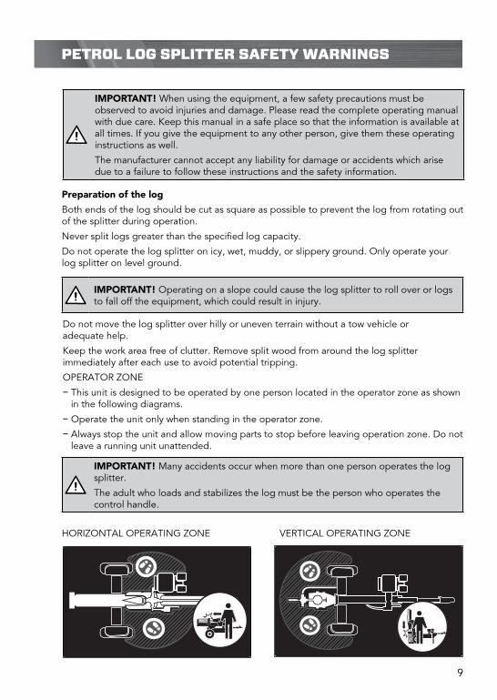
OPERATOR ZONE
− This unit is designed to be operated by one person located in the operator zone as shown in the following diagrams.
− Operate the unit only when standing in the operator zone.
− Always stop the unit and allow moving parts to stop before leaving operation zone. Do not leave a running unit unattended.
IMPORTANT! Many accidents occur when more than one person operates the log splitter.
The adult who loads and stabilizes the log must be the person who operates the control handle.
HORIZONTAL OPERATING ZONE VERTICAL OPERATING ZONE

10
KNOW YOUR PRODUCTPETROL LOG SPLITTER SAFETY WARNINGS (cont.)
Log splitter use and care
Never operate the machine without good visibility or light.
Never attempt to split wood across the grain. The log splitter was not designed for cross grain splitting.
Always block the front and back of both wheels to prevent unintended movement.
Hold the bark side of the logs when loading or positioning, never the ends. Never place your hands or any part of your body between a log and any part of the log splitter.
Do not straddle or step over the log splitter during operation.
Do not reach or bend over the log splitter to pick up a log.
Keep hands clear of splitting zone.
Never attempt to split more than one log at a time.
Do not attempt to load your log splitter when the ram or wedge is in motion.
Use your hand to operate the control lever on the valve. Do not use your foot, a rope, or any extension device.
Do not move the log splitter while the engine is running.
Towing safety
Do not tow the log splitter on public roads.
Before towing the log splitter, check tires for excessive wear, cuts, or damage. Check for proper tire inflation. Add air as required. Do not over inflate tires. Serious injury can result if tires explode.
Check before towing to make sure the log splitter is correctly and securely attached to the towing vehicle and the safety chains are secured to the hitch or bumper of the vehicle with enough slack to allow turning. Always use a class I, 50mm ball with this log splitter.
Make sure the coupler is tight before towing and after towing 100km.
Never transport cargo on the log splitter.
Never allow anyone to ride or sit on the log splitter.
Always stop the engine, lock the beam in the horizontal position, and close the fuel shut-off valve when transporting the unit.
Use extra care when towing the log splitter. Do not exceed 30km/h. Towing the log splitter at a speed greater than 30km/h could result in loss of control, damage to the equipment, serious injury, or death.
Avoid sharp turns and steep angles. Avoid large holes or ditches when towing the equipment. Always be careful when backing up with your log splitter when towing; it could jackknife. Use caution when backing up; a spotter outside the vehicle is highly recommended. Disconnect the log splitter from the towing vehicle before operating it.

11
ASSEMBLY
Fig. 2
Support Leg
ShippingBracket
Tools required (not supplied):
¥ Ring/open end spanner 16mm x 2, Soft face hammer
1. Use assembly hardware 1
2. Disassemble the 3 bolts holding each of the left and right hand side shipping brackets from the beam mount (fig 1)..
Note: Do not disassemble the support leg (7) from the log splitter at this stage.
CAUTION! Some parts are over 16kg, two-person lift is required to avoid injury.
R-Clip
WasherPivot Pit
BeamAssembly
EngineAssembly
It is required that a minimum of two people assemble the log splitter.
Ø18 x 135 x 1R-Clip x 1
M10 x 35 x 6
M12 x 35 x 8
M12 x 80 x 2
x 1
x 1
6 x 40 x 2
M8 x 20 x 2
M12 x 40 x 4
Axle Nut & Washer x 1
Split Pin 4 x 50 x 1
x 1
M8 x 20 x 8
M10 x 25 x 4
Wheel Cap
Roll Pin
U-shaped Lock Pin
Washer & Sping
Pivot pin
M10 x 25 x 2
3. Carefully position the beam assembly (16) so the U-shaped bracket in the beam is locked into the pivot mount on the engine assembly (10) (fig. 2).
Joining the beam and motor assembly
Fig. 1

12
ASSEMBLY (cont.)
R-Clip
WasherPivot Pin
BeamAssembly
EngineAssembly
4. With the hole in the beam pivot bracket aligned with the pivot hole on the pivot mount, insert the pivot pin using a soft face hammer and secure with the washer and R-clip (fig. 3).
5. Disassemble the support leg (7) from the log splitter by removing the 3 bolts and bracket (fig .1).
Control lever1. The lever is shipped hanging from the valve
on the handle link. Remove the pin and split pin from the control lever (1), move the control lever (1) to the vertical Neutral position (fig. 4).
2. Reinstall the pin and split pin to the control lever (1).
50mm
Hydraulic cylinder handleTools required (not supplied):
¥ 16mm Ring/open end spanner.
1. Loosen the two nuts on the cylinder handle (3).
2. Position the cylinder handle (3) horizontally approximately 50mm from the end of the hydraulic cylinder (2) and fully tighten using the 16mm spanner (fig. 5).
50mm
Hydraulic CylinderHandle
Fig. 3
Fig. 4
Fig. 5

13
ASSEMBLY (cont.)
Wedge cover guardTools required (not supplied):
¥ 16mm Socket with ratchet.
1. Use assembly hardware 2
2. Slide hydraulic cylinder (2) backwards and align post mount with cutouts in frame (fig. 6).
Ø18 x 135 x 1R-Clip x 1
M10 x 35 x 6
M12 x 35 x 8
M12 x 80 x 2
x 1
x 1
6 x 40 x 2
M8 x 20 x 2
M12 x 40 x 4
Axle Nut & Washer x 1
Split Pin 4 x 50 x 1
x 1
M8 x 20 x 8
M10 x 25 x 4
Wheel Cap
Roll Pin
U-shaped Lock Pin
Washer & Sping
Pivot pin
M10 x 25 x 2
R-Clip
WasherPivot Pit
Hydraulic Cylinder
EngineAssembly
PostFig. 6
4. Install the wedge cover guard (17) with the six bolts, spring and flat washers (fig. 7).
3. Align the holes with the wedge cover guard (17) and the posts (fig. 7).
Fig. 7

14
ASSEMBLY (cont.)
Drawbar assemblyTools required (not supplied):
¥ 18mm Ring/open end spanner x 2.
1. Use assembly hardware 3
2. Insert the drawbar (19) into the beam bracket. Align the holes in the drawbar (19) and beam bracket. Insert each bolt with washer from one side. Secure in place with flat washers, spring washers, and nuts (fig. 8).
Bolt & WasherBeam Bracket
Ø18 x 135 x 1R-Clip x 1
M10 x 35 x 6
M12 x 35 x 8
M12 x 80 x 2
x 1
x 1
6 x 40 x 2
M8 x 20 x 2
M12 x 40 x 4
Axle Nut & Washer x 1
Split Pin 4 x 50 x 1
x 1
M8 x 20 x 8
M10 x 25 x 4
Wheel Cap
Roll Pin
U-shaped Lock Pin
Washer & Sping
Pivot pin
M10 x 25 x 2
Wheel assembly (First wheel)Tools required (not supplied):
¥ 32mm Socket with ratchet, Long nose pliers, Soft face hammer
1. Use assembly hardware 4
2. Remove the two anti-dust sleeves from the axle (24) (fig. 9).
Sleeves
Split PinBolt & Washer
Nut & Washer
Axle
Upper Bracket
Lower BracketBearing
Anti-dust Washer
Axle Nut
Wheel Cap
Washer
Wheel Axle
Ø18 x 135 x 1R-Clip x 1
M10 x 35 x 6
M12 x 35 x 8
M12 x 80 x 2
x 1
x 1
6 x 40 x 2
M8 x 20 x 2
M12 x 40 x 4
Axle Nut & Washer x 1
Split Pin 4 x 50 x 1
x 1
M8 x 20 x 8
M10 x 25 x 4
Wheel Cap
Roll Pin
U-shaped Lock Pin
Washer & Sping
Pivot pin
M10 x 25 x 2
Fig. 8
Fig. 9

15
ASSEMBLY (cont.)
3. Remove the anti-dust sleeves from a wheel (11) while keeping the bearings and anti-dust washer in place (fig. 10).
4. Slide a wheel (11) with valve stem facing out onto the axle (24) on one side, then place the wheel washer against the bearing. With the 32mm socket tighten the axle nut fully in place (fig. 11).
5. Turn the wheel (11) to ensure the bearing is seated correctly.
AxleTools required (not supplied):
¥ 19mm Socket with ratchet, 18mm ring/open end spanner, 13mm ring/open end spanner x 2
1. Use assembly hardware 5
Split Pin
Bearing
Anti-dust Washer
Axle Nut
Wheel Cap
Washer
Bearing
Anti-dust Washer
Sleeve
Split Pin
Bearing
Anti-dust Washer
Axle Nut
Wheel Cap
Washer
Bearing
Anti-dust Washer
Sleeve
Fig. 10
Fig. 11
6. Loosen the axle nut until it is loose enough to turn the wheel (11) with your fingers, then retighten the axle nut finger tight only.
7. Insert the split pin through the hole in the axle (24). Bend and spread the prongs in opposite directions with long nose pliers so the axle nut will not come off, making sure the wheel (11) spins freely.
8. Align the wheel cap against the wheel hub. Tap lightly with a soft face hammer to ensure the wheel cap is installed on the wheel hub correctly.
Note: Only assemble one wheel (11) at this stage, the other side wheel (11) will be assembled after mounting the axle (24) to the log splitter.
Ø18 x 135 x 1R-Clip x 1
M10 x 35 x 6
M12 x 35 x 8
M12 x 80 x 2
x 1
x 1
6 x 40 x 2
M8 x 20 x 2
M12 x 40 x 4
Axle Nut & Washer x 1
Split Pin 4 x 50 x 1
x 1
M8 x 20 x 8
M10 x 25 x 4
Wheel Cap
Roll Pin
U-shaped Lock Pin
Washer & Sping
Pivot pin
M10 x 25 x 2

16
ASSEMBLY (cont.)
2. Remove two M8 x 45 bolts, washers, and nuts (fig. 12).
3. Hold the beam (16) and carefully move the log splitter until the upper bracket of the wheel axle is against the wooden block (fig. 13).
4.. Hold the hydraulic cylinder handle (3) and slowly stand the beam assembly (16) on the end plate (15) in the vertical position (fig. 14).
M8 x 45
Wooden BlockUpper Bracket of Wheel Axle
Beam Assembly
Fig. 12
M8 x 45
Wooden BlockUpper Bracket of Wheel Axle
Beam Assembly
Fig. 13
M8 x 45
Wooden BlockUpper Bracket of Wheel Axle
Beam Assembly
Fig. 14
17
ASSEMBLY (cont.)
Upper Hole
Lower Hole
Upper Hole
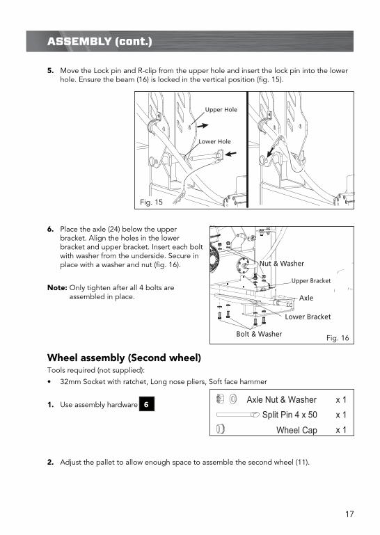
5. Move the Lock pin and R-clip from the upper hole and insert the lock pin into the lower hole. Ensure the beam (16) is locked in the vertical position (fig. 15).
Fig. 15
Sleeves
Split Pin
Bolt & Washer
Nut & Washer
Axle
Upper Bracket
Lower Bracket
Bearing
Anti-dust Washer
Axle Nut
Wheel Cap
Washer
Wheel Axle
6. Place the axle (24) below the upper bracket. Align the holes in the lower bracket and upper bracket. Insert each bolt with washer from the underside. Secure in place with a washer and nut (fig. 16).
Note: Only tighten after all 4 bolts are assembled in place.
Wheel assembly (Second wheel)Tools required (not supplied):
¥ 32mm Socket with ratchet, Long nose pliers, Soft face hammer
1. Use assembly hardware 6
2. Adjust the pallet to allow enough space to assemble the second wheel (11).
Ø18 x 135 x 1R-Clip x 1
M10 x 35 x 6
M12 x 35 x 8
M12 x 80 x 2
x 1
x 1
6 x 40 x 2
M8 x 20 x 2
M12 x 40 x 4
Axle Nut & Washer x 1
Split Pin 4 x 50 x 1
x 1
M8 x 20 x 8
M10 x 25 x 4
Wheel Cap
Roll Pin
U-shaped Lock Pin
Washer & Sping
Pivot pin
M10 x 25 x 2
Fig. 16

18
ASSEMBLY (cont.)
Horizontal beam lock assemblyTools required (not supplied):
¥ 16mm Socket with ratchet.
1. Use assembly hardware 7
2. Align the two holes in the horizontal beam lock (26) and the holes in the underside of the beam (16). Ensure the release handle is opposite side to the engine. Secure in place with bolt, flat washers and spring washers (fig. 18).
Ø18 x 135 x 1R-Clip x 1
M10 x 35 x 6
M12 x 35 x 8
M12 x 80 x 2
x 1
x 1
6 x 40 x 2
M8 x 20 x 2
M12 x 40 x 4
Axle Nut & Washer x 1
Split Pin 4 x 50 x 1
x 1
M8 x 20 x 8
M10 x 25 x 4
Wheel Cap
Roll Pin
U-shaped Lock Pin
Washer & Sping
Pivot pin
M10 x 25 x 2
Sleeves
Split Pin
Bolt & Washer
Nut & Washer
Axle
Upper Bracket
Lower Bracket
Bearing
Anti-dust Washer
Axle Nut
Wheel Cap
Washer
Wheel Axle
3. Follow the same procedure on page 15, step 3 - 8, to assemble the second wheel (11) (fig. 17).
Fig. 17
Fig. 18

19
ASSEMBLY (cont.)
Jockey wheel assembly1. Place the jockey wheel (6) into its bracket on the drawbar (19) (fig. 19).
2. Secure by tightening the locking pin on the bracket (fig. 20).
Support leg (front) assemblyTools required (not supplied):
¥ Long nose pliers and hammer.
1. Use assembly hardware 8
2. Align the front support leg (7) to the upper hole on the beam bracket. Insert the long end of the U-shaped lock pin to hold the support leg (7) in place. (fig. 21).
3. Lift the log splitter by the drawbar (19) to allow the support leg (7) to drop down in position to supporting the log splitter.
Ø18 x 135 x 1R-Clip x 1
M10 x 35 x 6
M12 x 35 x 8
M12 x 80 x 2
x 1
x 1
6 x 40 x 2
M8 x 20 x 2
M12 x 40 x 4
Axle Nut & Washer x 1
Split Pin 4 x 50 x 1
x 1
M8 x 20 x 8
M10 x 25 x 4
Wheel Cap
Roll Pin
U-shaped Lock Pin
Washer & Sping
Pivot pin
M10 x 25 x 2
UpperHole
Fig. 19 Fig. 20
Fig. 21

20
ASSEMBLY (cont.)
5. To secure the U-shaped lock pin, insert the roll pin through the support leg (7) locating hole and into the U-shaped lock pin hole. (fig. 23).
Note: Use the long nose pliers to hold the roll pin while using the hammer to tap in place.
6. Slide the spring then flat washer over the protruding end of the U-shaped lock pin. Secure in place with the remaining roll pin using the soft face hammer (fig. 24).
Roll Pin
Roll Pin
Spring
Washer
4. Fully insert the U-shaped lock pin allowing the short end to pass through the lower hole (fig. 22).
Lower Hole
Fig. 22
Fig. 23
Fig. 24

21
ASSEMBLY (cont.)
Wheel guards assemblyTools required (not supplied):
¥ 13mm Socket with ratchet.
1. Use assembly hardware 9
2. Place a spring washer followed by a flat washer on four bolts. Align the engine side wheel guard (12) to the beam assembly. Insert the same four bolts, and tighten firmly in place (fig. 25).
Note: The reflectors on each wheel guard should face to the rear of the log splitter.
3. Follow the same procedure to assemble the right side wheel guard (21).
Wheel Guard(engine side)
InsideMounting Hole
OutsideMounting Hole
Log Cradle(engine side)
Log Table
Flat Washer
Spring WasherNut
Dome HeadBolts
Ø18 x 135 x 1R-Clip x 1
M10 x 35 x 6
M12 x 35 x 8
M12 x 80 x 2
x 1
x 1
6 x 40 x 2
M8 x 20 x 2
M12 x 40 x 4
Axle Nut & Washer x 1
Split Pin 4 x 50 x 1
x 1
M8 x 20 x 8
M10 x 25 x 4
Wheel Cap
Roll Pin
U-shaped Lock Pin
Washer & Sping
Pivot pin
M10 x 25 x 2
Manual tubeTools required (not supplied):
¥ 13mm Ring/open end spanner
1. Use assembly hardware 10
2. Remove the cap of the manual tube (20). Align the holes in the manual tube (20) with the holes in the drawbar(19), insert and tighten bolts and washers.
3. Reattach the cap (fig. 26).
Note: Store this manual in the manual tube (20) for safe keeping.
Cap
Bolt & Washer
Ø18 x 135 x 1R-Clip x 1
M10 x 35 x 6
M12 x 35 x 8
M12 x 80 x 2
x 1
x 1
6 x 40 x 2
M8 x 20 x 2
M12 x 40 x 4
Axle Nut & Washer x 1
Split Pin 4 x 50 x 1
x 1
M8 x 20 x 8
M10 x 25 x 4
Wheel Cap
Roll Pin
U-shaped Lock Pin
Washer & Sping
Pivot pin
M10 x 25 x 2
Fig. 25
Fig. 26
22
ASSEMBLY (cont.)
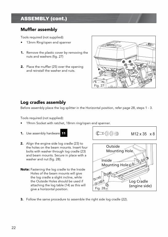
Log cradles assemblyBefore assembly place the log splitter in the Horizontal position, refer page 28, steps 1 - 3.
Tools required (not supplied):
¥ 19mm Socket with ratchet, 18mm ring/open end spanner.
1. Use assembly hardware 11
2. Align the engine side log cradle (23) to the holes on the beam mounts. Insert four bolts with washer through log cradle (23) and beam mounts. Secure in place with a washer and nut (fig. 28).
Note: Fastening the log cradle to the Inside Holes of the beam mounts will give the log cradle a slight incline, while the Outside Holes should be used if attaching the log table (14) as this will give a horizontal position.
3. Follow the same procedure to assemble the right side log cradle (22).
Wheel Guard(engine side)
InsideMounting Hole
OutsideMounting Hole
Log Cradle(engine side)
Log Table
Flat Washer
Spring WasherNut
Dome HeadBolts
Ø18 x 135 x 1R-Clip x 1
M10 x 35 x 6
M12 x 35 x 8
M12 x 80 x 2
x 1
x 1
6 x 40 x 2
M8 x 20 x 2
M12 x 40 x 4
Axle Nut & Washer x 1
Split Pin 4 x 50 x 1
x 1
M8 x 20 x 8
M10 x 25 x 4
Wheel Cap
Roll Pin
U-shaped Lock Pin
Washer & Sping
Pivot pin
M10 x 25 x 2
Muffler assembly
Tools required (not supplied):
¥ 13mm Ring/open end spanner
1. Remove the plastic cover by removing the nuts and washers (fig. 27)
2. Place the muffler (25) over the opening and reinstall the washer and nuts.
Fig. 27
Fig. 28
23
ASSEMBLY (cont.)
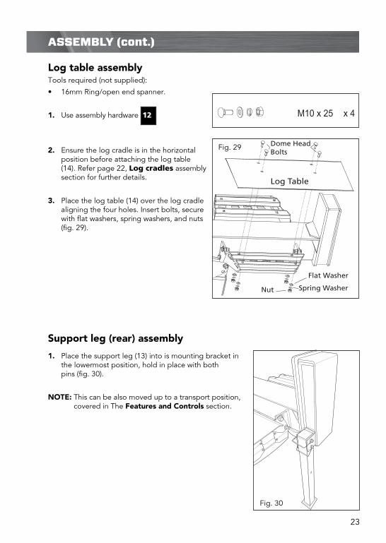
Log table assemblyTools required (not supplied):
¥ 16mm Ring/open end spanner.
1. Use assembly hardware 12
2. Ensure the log cradle is in the horizontal position before attaching the log table (14). Refer page 22, Log cradles assembly section for further details.
3. Place the log table (14) over the log cradle aligning the four holes. Insert bolts, secure with flat washers, spring washers, and nuts (fig. 29).
Wheel Guard(engine side)
InsideMounting Hole
OutsideMounting Hole
Log Cradle(engine side)
Log Table
Flat Washer
Spring WasherNut
Dome HeadBolts
Ø18 x 135 x 1R-Clip x 1
M10 x 35 x 6
M12 x 35 x 8
M12 x 80 x 2
x 1
x 1
6 x 40 x 2
M8 x 20 x 2
M12 x 40 x 4
Axle Nut & Washer x 1
Split Pin 4 x 50 x 1
x 1
M8 x 20 x 8
M10 x 25 x 4
Wheel Cap
Roll Pin
U-shaped Lock Pin
Washer & Sping
Pivot pin
M10 x 25 x 2
Support leg (rear) assembly
1. Place the support leg (13) into is mounting bracket in the lowermost position, hold in place with both pins (fig. 30).
NOTE: This can be also moved up to a transport position, covered in The Features and Controls section.
Fig. 29
Fig. 30

24
FEATURES AND CONTROLS
Log cradle
The log cradles are designed to catch the log after it is split (fig. 31).
2 position function:− The inside hole position is to centre the logs on the beam.− The outside hole position provides a level surface on
which to put logs.
Log table
Mounted directly on the log cradle and provides a flat surface on which to put logs (fig. 32).
Horizontal lock latch
The latch is used to secure the beam in the horizontal position (fig. 33).
Hydraulic cylinder handle
For easy transition from horizontal to vertical position (fig. 34).
Wedge cover guard
Is designed to remove any partially split wood from the wedge. This may occur while splitting large diameter wood or freshly cut wood (fig. 36).
Wheel Guard(engine side)
InsideMounting Hole
OutsideMounting Hole
Log Cradle(engine side)
Log Table
Flat Washer
Spring WasherNut
Dome HeadBolts
Horizontal lock latch
Horizontal lock latch
Fig. 31
Fig. 32
Fig. 33
Fig. 34
Fig. 35
25
FEATURES AND CONTROLS (cont.)
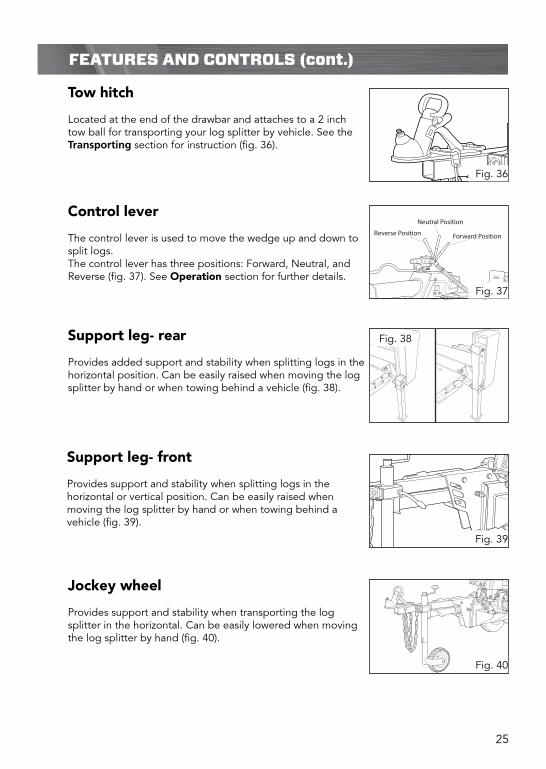
Control lever
The control lever is used to move the wedge up and down to split logs.The control lever has three positions: Forward, Neutral, and Reverse (fig. 37). See Operation section for further details.
Neutral Position
Forward PositionReverse Position
Support leg- rear
Provides added support and stability when splitting logs in the horizontal position. Can be easily raised when moving the log splitter by hand or when towing behind a vehicle (fig. 38).
Fig. 36
Fig. 37
Fig. 38
Tow hitch
Located at the end of the drawbar and attaches to a 2 inch tow ball for transporting your log splitter by vehicle. See the Transporting section for instruction (fig. 36).
Support leg- front
Provides support and stability when splitting logs in the horizontal or vertical position. Can be easily raised when moving the log splitter by hand or when towing behind a vehicle (fig. 39).
Fig. 39
Jockey wheel
Provides support and stability when transporting the log splitter in the horizontal. Can be easily lowered when moving the log splitter by hand (fig. 40).
Fig. 40

26
FEATURES AND CONTROLS (cont.)
Engine on/off switch
The engine switch has two positions (fig. 41),OFF: engine will not start or run. ON: engine will start and run.
Throttle lever
Is used to regulate the rotation speed of the engine (fig. 42 ).¥ Increase engine speed:Move the lever left towards the indicator
¥ Decrease engine speed:Move the lever right towards the indicator
Choke lever
Is used to restrict the flow of air, thereby enriching the fuel-air mixture while starting the engine (fig. 43).
¥ Choke on / start position:Move the lever left, (closed).
¥ Run / (choke off)Move the lever right, (open)
Fuel lever
The fuel lever has two positions (fig. 44).¥ CLOSED: move lever left for service, transport or store the
log splitter.¥ OPEN: move the lever right to run the engine
OFF
ON
Throttle
OFF
ON
Throttle
OFF
ON
Throttle
OFF
ON
ThrottleOFF /Run
ON /Start
FAST SLOW
OFF ON
Fig. 41
Fig. 42
Fig. 43
Fig. 44

27
SETUP & PREPARATION
Horizontal position to vertical position
1. Remove the rear leg (13) from its current position (fig. 45).
2. Release the horizontal lock latch
3. Hold the hydraulic cylinder handle (3) and slowly stand the assembled beam on the end plate in the vertical position (fig. 46).
4. Move the Lock pin and R-clip from the upper hole and insert the lock pin into the lower hole. Ensure the beam is locked in the vertical position (fig. 47).
Horizontal lock latch
Upper Hole
Lower Hole
Upper Hole
Fig. 45
Fig. 46
Fig. 47

28
SETUP & PREPARATION (cont.)
Vertical position to horizontal position
1. Remove the R-clip and lock pin from the lower hole (fig. 48).
2. Hold the hydraulic cylinder handle (3)and slowly lower the beam (fig. 49).
3. Insert the lock pin into the upper hole. Ensure the beam is locked in the horizontal position (fig. 50).
Upper Hole
Lower Hole
Upper Hole
CAUTION! Do not let the beam suddenly drop. Keep hands and fingers clear of pinch points at all times.
Upper Hole
Lower Hole
Upper Hole
Fig. 48
Fig. 49
Fig. 50
29
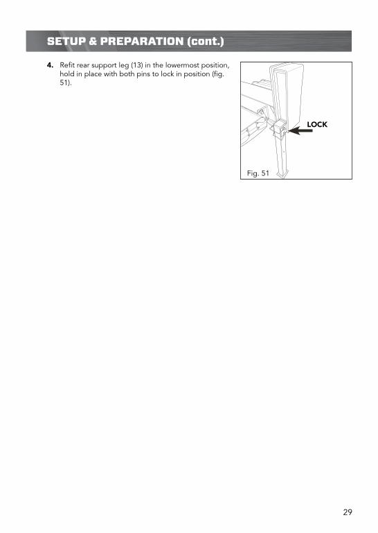
SETUP & PREPARATION (cont.)
4. Refit rear support leg (13) in the lowermost position, hold in place with both pins to lock in position (fig. 51).
LOCK
Fig. 51

30
Adding engine oil
The engine is supplied without oil. It is recommended that SAE-10W-30 (multi viscosity) oils are used at temperatures from 5 to 35¡C and synthetic oils 5W-30 (multi viscosity) is used for temperatures -5 to 5¡C.
1. Make sure the log splitter is on a flat, level surface.
2. Remove the oil fill cap/dipstick from the side of the engine (fig. 53). Clean the dipstick and re-insert without screwing down.
3. Remove the dipstick and ensure the oil lays between the min and max marks (fig. 54).
4. If oil needs to be added, use a funnel and simply pour oil in until the level reaches the max level of the oil gauge (fig. 55). Oil tank capacity is 470-590ml.
5. Ensure dipstick is securely tightened after oil has been added/ topped up.
SETUP & PREPARATION (cont.)
Adding fuel
Only use unleaded 91 RON (Research Octane Number) petrol. Purchase fuel in quantities that can be used every 30 days to prevent gum or foaming inside the container and/or fuel tank (fig. 52).
1. Remove the fuel cap and fill the tank.
2. Fasten the fuel cap and clean any spillage.
HLHL
WARNING! Be sure to stop the engine before refuelling. Allow the engine to cool before adding fuel. Do not smoke while refuelling.
WARNING! Do not over fill the fuel tank.
IMPORTANT! Do not over fill, check engine oil level daily and add as needed.
HLHL
HLHL
Fig. 52
Fig. 53
Fig. 54
Fig. 55

31
Starting the engine
Before starting work, hydraulic pipes and hoses shall be inspected and the stopping devices shall be tested.
The log splitter must be set up on level surface, free from obstructions.
1. Ensure the control lever is in the neutral position.
2. Move the engine on/off switch to the ON position (fig. 56).
3. Move the fuel lever to the right, OPEN position (fig. 57).
4. Move the choke lever to the left, choke (closed) ON position (fig. 58).
Note: If the engine is still hot, closing the choke is not necessary.
5. Move the throttle lever slightly left towards the symbol (fig. 59).
6. Grip the recoil starter and slowly pull until resistance is felt, then pull the recoil starter rapidly. Allow the rope to rewind slowly and if necessary, repeat this procedure until the engine starts (fig. 60).
7. Once started move the choke lever right (open) position and open the throttle lever further left.
OPERATION
OFF
ON
OFF
ON
OFF
ON
OFF
ON
OFF
ON
Fig. 56
Fig. 57
Fig. 58
Fig. 59
Fig. 60

32
OPERATION (cont.)
Stopping the engine
1. Ensure the wedge is in the retracted position and the control lever is in the neutral position.
2. Move the throttle lever fully right towards the .... indicator (fig. 61), move the engine on/off switch to the OFF position (fig. 62) and fuel lever left, closed position (fig.63).
OFF
ON
OFF
ON
OFF
ON
IMPORTANT! Sudden stopping at a high speed under heavy load is not recommended. Engine damage may result.
Control lever (1) (fig 64 & 65)
¥ Neutral position − In this position the cylinder does not move even though the engine is running.
¥ Reverse position − Move the lever in this position to retract the cylinder. Push the lever fully in this direction to lock it return mode. The lever will automatically return to the neutral position once the cylinder fully retracts.
Neutral Position
Forward Position
Reverse Position
Neutral Position
Forward PositionReverse Position
WARNING! Keep hands and fingers away from the splitter wedge and wedge cover guard during cylinder retraction.
¥ Forward position − Move the lever in this direction to extend the cylinder toward the foot plate. Keep pressure on the lever until the log splits. The lever does not lock in this position. Release as soon as the log is split or the cylinder is fully extended.
Note: The splitter wedge (18) is designed to reach the full extension before contacting the end plate.
WARNING! Cracks in logs can close quickly and pinch fingers. Keep fingers away from any cracks that open in partially split logs.
Fig. 61 Fig. 62 Fig. 63
Fig. 64
Fig. 65
WARNING! Never operate through the relief valve for more than 5 seconds.

33
Stuck log procedure
If a log does not split completely and becomes stuck on the wedge (18), never attempt to remove it by modifying the splitter or adding attachments to the splitter. Move the control lever (1) to the Reverse position and allow the cylinder to retract until the stuck log contacts the wedge cover guard (17). Continue to retract the cylinder until the log is dislodged from the wedge (18).
OPERATION (cont.)
IMPORTANT! Do not use the unit if the wedge cover guard (17) is bent or damaged. Bent or damaged cover guard must be repaired or replaced before use.
WARNING! Stand in safe working zone, so feet are not in the path of falling logs.
WARNING! Do not hold wood in position to be split, with any part of your body once the control lever is moved into the forward or reverse position.
¥ The splitting operation of the machine is designed to be activated by one person only.
Log placement (fig. 66 & 67)
¥ Load a log onto the beam and against the end plate (15). Log should be cut as square as possible, to fit properly on the log splitter and against the end plate.
¥ If logs have an uneven end, it is best that the uneven end is placed towards the wedge (18), with the log edge facing down.
Horizontal lock latch
Horizontal lock latch
HORIZONTAL OPERATING ZONE VERTICAL OPERATING ZONE
Fig. 66 Fig. 67
34
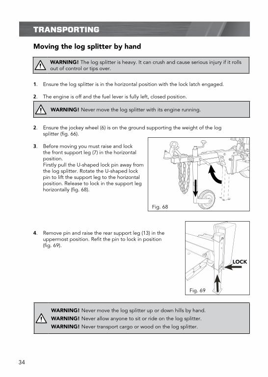
Moving the log splitter by hand
1. Ensure the log splitter is in the horizontal position with the lock latch engaged.
2. The engine is off and the fuel lever is fully left, closed position.
2. Ensure the jockey wheel (6) is on the ground supporting the weight of the log splitter (fig. 66).
3. Before moving you must raise and lock the front support leg (7) in the horizontal position.
Firstly pull the U-shaped lock pin away from the log splitter. Rotate the U-shaped lock pin to lift the support leg to the horizontal position. Release to lock in the support leg horizontally (fig. 68).
4. Remove pin and raise the rear support leg (13) in the uppermost position. Refit the pin to lock in position (fig. 69).
TRANSPORTING
WARNING! The log splitter is heavy. It can crush and cause serious injury if it rolls out of control or tips over.
WARNING! Never move the log splitter with its engine running.
WARNING! Never move the log splitter up or down hills by hand.
WARNING! Never allow anyone to sit or ride on the log splitter.
WARNING! Never transport cargo or wood on the log splitter.
LOCK
Fig. 68
Fig. 69

35
Towing
1. Ensure the log splitter is in the horizontal position with the lock latch engaged.
2. The engine is off and the fuel lever is fully left, closed position.
3. Check the tires to ensure they are at the recommended tyre pressure (30 PSI).
4. Inspect the tow hitch (4) and chains for any damage and ensure they are in good working order.
5. Ensure the jockey wheel (6) is on the ground supporting the weight of the log splitter and the front support leg (7) is raised and locked in the horizontal position.
6. Raise the rear support leg (13) in the uppermost position.
7. Raise the jockey wheel (6) to lower the log splitter down and lock the tow hitch (4) onto the ball hitch. Connect both safety chains (5) to the tow vehicle.
TRANSPORTING (cont.)
WARNING! Never tow log splitter over 30km/h. Faster speeds may result in loss of control.
WARNING! Drive slowly and take extra care when travelling over rough terrain
WARNING! Never allow anyone to sit or ride on the log splitter.
WARNING! Never transport cargo or wood on the log splitter.
8. Lock the front support leg (7) down, vertical position before disconnecting from vehicle.
WARNING! Never operate the log splitter while it is attached to a vehicle.
WARNING! Not for towing on public roads.

36
MAINTENANCE
¥ Inspect and maintain the log splitter before each use. If the log splitter has been used previously, it must be inspected and maintained before each subsequent use.
¥ Always shut off the engine and relieve system pressure before inspecting, cleaning, adjusting, or repairing the splitter. Relieve system pressure by moving the split control lever back and forth several times.
¥ Remove debris from the engine, muffler, and moving parts. Debris on a hot engine can be a fire hazard. Clean debris and chaff from the engine cylinder head, cylinder head fins, blower housing rotating screen, and muffler areas.
¥ After the first 25 hours of use the engine oil requires to be replaced, and then every 50 hours after that. Refer provided engine manual for further engine maintenance procedures.
CAUTION! Avoid contact with hot muffler.
CAUTION! Debris on moving parts can cause excess wear. Clear debris from the slide beam, wedge, and end plate.
Draining and replacing hydraulic oil (fig. 70).
1. Ensure the log splitter is on a flat, level surface.
2. Use a drain pan to aid in the removal of all used oil and particles.
3. Remove oil drain plug (8) to drain oil from the hydraulic transmission system. Examine oil for metal chips as a precaution to future problems.
4. After oil has been completely drained from the machine, reinstall drain plug (8).
5. An oil filter is available as a spare part, replace with a new filter. Location shown in figure 70.
6. Remove the oil dipstick from the oil tank (fig. 71).
¥ Recommended hydraulic oil: 22cSt.
7. Pour oil in until the level reaches the max level of the dipstick (14.9 litres capacity).
Oil drain plug
Oil �lter
HYDRAULIC OIL
FILLING
MAX.
MIN.
CAUTION! Never remove the hydraulic oil dipstick when the engine is running or hot. Hot oil can escape causing severe burns. Allow the log splitter to cool completely before removing the hydraulic oil dipstick.
HYDRAULIC OIL
FILLING
MAX.
MIN.
Fig. 70
Fig. 71

37
MAINTENANCE (cont.)
8. Ensure dipstick is securely tighten after oil has been topped up.
9. Start the engine and use the control lever to extend and retract the wedge five times to remove air from the high pressure lines.
10. With the wedge retracted and engine off, check the oil level again. Fill if necessary.
11. Cycle the cylinder again until it has a constant speed. This indicates that all air has been expelled.

38
STORAGE
Follow the instructions below for storing your log splitter between uses.
1. Retract the wedge completely to keep the rod protected from corrosion.
2. Allow the log splitter to cool before storing.
3. Clear the debris from the beam, wedge, and end plate. Use a damp cloth to clear exterior surfaces of the engine and log splitter. Use a soft bristle brush to remove excess dirt and oil. Use an air compressor (25 PSI) if necessary to clear dirt and small debris. Wipe the beam, wedge, and all metal parts with an oil rag to prevent corrosion.
4. Refer to the engine manual for proper engine storage instructions.
5. Store the log splitter in a location away from corrosive materials, sources of heat, open flames, sparks, or pilot lights.
CAUTION! Never spray the engine or log splitter with a pressure washer. Water can contaminate the fuel system and can enter the engine and damage the engine.
CAUTION! Never store the log splitter inside where there is a source of heat or an open flame, spark, or pilot light, such as a water heater, space heater, furnace, clothes dryer, or other gas appliance. EVEN IF the log splitters fuel tank is empty, residual petrol vapours could ignite.
Never store the log splitter near fertilizer or any other corrosive material.

39
TROUBLESHOOTING
Symptom Possible Cause Suggested Solution
Wedge movement is slow or erratic
Air in the hydraulic oil system
Purge air by extending and retract-ing the wedge several times until motion is smooth
Debris lodged in beam guides
Clear debris from beam
Low hydraulic oil Check oil level and add as needed.
Oil leak from cylinder Faulty cylinder rod seal Contact customer service
Scored or bent cylinder rod
Contact customer service
Loose hydraulic fitting Tighten hydraulic fitting
Faulty combination washer seal on cylinder hydraulic fitting.
Contact customer service
Oil leak from hose connection
Loose hose clamp or hydraulic fitting.
Tighten hose clamp or hydraulic fitting
Wedge will not extend or retract
Faulty control valve Contact customer service
Faulty hydraulic pump Contact customer service
Low hydraulic oil 3. Check oil level and add as needed.
Wedge does not auto-return
Low hydraulic oil Check oil level and add as needed
Faulty control valve Contact customer service
Excessive bouncing while towing
Under inflated Inflate tyres to proper pressure.
Control valve handle does not return to neutral when released from forward position
Hydraulic oil too cold Warm up engine
Hydraulic oil too thick Replace hydraulic fluid
Faulty control valve Contact customer service
Engine will not start Engine switch in OFF position
Move switch to ON position
Fuel shut-off valve in OFF position.
Move valve to ON position
Fuel tank empty Fill fuel tank with fuel
Spark plug disconnected Connect spark plug
Faulty spark plug Replace spark plug
Choke lever in wrong position
Adjust choke lever position
Faulty engine Contact customer service

40
DESCRIPTION OF SYMBOLS
Read these instructions carefully.
Wear protective gloves
HYDRAULIC OIL
FILLING
MAX.
MIN.
REVERSE
FORWARD
N
MAX. 30 KM/H WHEN TOWING
Wear eye protection.Wear hearing protection.
Be aware of thrown objects
Do not remove or tamper with the protection and safety devices.
Don’t stand or sit on the log splitter.
No smoking, sparks, or �ames.
Be sure the engine's switch is o� beforetransporting the machine or performing any maintenance.
Warning
Never remove partially split wood from the wedgewith your hands. Fingers may become trapped between the split wood.
For logs that are not cutsquare, the longest portion of the log shouldbe rotated down and the most square end placed toward the end plate.
Operate the log splitter onlevel surfaces. Stay o� slopesand slippery surfaces.
Do not touch parts that arehot from operation. Seriousburns may result.
Properly dispose of waste oil!
Keep hands and �ngers awayfrom all pinch points.
Always keep body and hands away from pin holes or nozzles that eject hydraulic �uid under pressure. Escaping hydraulic �uid can puncture skin and cause blood poisoning.
Keep children and bystanders o� and away.
Regulator compliance mark
Wear safety footwear
Keep feet away from moving parts.Moving parts can crush or cut.
Follow the direction indicatedto use the control lever.
Maximum towing speed of 30 kmh.
Do not transport with objects on the machine.
Check and �ll hydraulic oil.
Keep hands away from moving parts. Moving parts can crush or cut
41
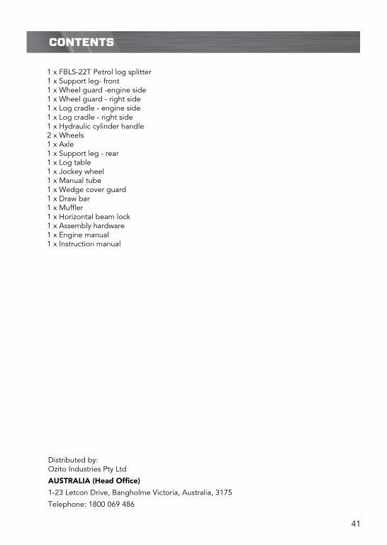
CONTENTS
1 x FBLS-22T Petrol log splitter 1 x Support leg- front 1 x Wheel guard -engine side 1 x Wheel guard - right side 1 x Log cradle - engine side 1 x Log cradle - right side 1 x Hydraulic cylinder handle 2 x Wheels 1 x Axle 1 x Support leg - rear 1 x Log table 1 x Jockey wheel 1 x Manual tube 1 x Wedge cover guard 1 x Draw bar 1 x Muffler 1 x Horizontal beam lock 1 x Assembly hardware 1 x Engine manual 1 x Instruction manual
Distributed by: Ozito Industries Pty Ltd
AUSTRALIA (Head Office)
1-23 Letcon Drive, Bangholme Victoria, Australia, 3175
Telephone: 1800 069 486

42

43

44
WARRANTY EXCLUSIONS
The following actions will result in the warranty being void.
If the tool has been operated on a supply voltage other than that specified on the tool.• If the tool shows signs of damage or defects caused by or resulting from abuse, accidents • or alterations.Failure to perform maintenance as set out within the instruction manual.• If the tool is disassembled or tampered with in any way.The warranty excludes damage resulting from product misuse or product neglect.
•
•
This warranty is given by Ozito Industries Pty Ltd. ABN: 17 050 731 756Ph.1800 069 486Australia/New Zealand (Head Office)1-23 Letcon Drive, Bangholme, Victoria, Australia 3175
FB1
WARRANTY
TO ENSURE A SPEEDY RESPONSE PLEASE HAVE THE MODEL NUMBER AND DATE OF PURCHASE AVAILABLE. A CUSTOMER SERVICE REPRESENTATIVE WILL TAKE YOUR CALL AND ANSWER ANY QUESTIONS YOU MAY HAVE RELATING TO THE WARRANTY POLICY
OR PROCEDURE.
The benefits provided under this warranty are in addition to other rights and remedies whichare available to you under law. The warranty covers manufacturer defects in materials, workmanship and finish under normal use.
1 YEAR WARRANTYYour product is guaranteed for a period of 12 months from the original date of purchase.If a product is defective it will be repaired in accordance with the terms of this warranty.Warranty excludes consumable parts, for example: wheels, bearings.
Our goods come with guarantees that cannot be excluded under Australian Consumer law & Consumer Guarantees Act 1993 (NZ). You are entitled to a replacement or refund for a major failure and to compensation for other reasonably foreseeable loss or damage. You are also entitled to have the goods repaired and replaced if the goods fail to be of acceptable quality and the failure does not amount to a major failure.
`Australia 1800 069 486New Zealand 0508 069 486
YOUR WARRANTY FORM SHOULD BE RETAINED BY YOU AT ALL TIMES. IN ORDER TO MAKE A CLAIM UNDER THIS WARRANTY YOU MUST RETURN THE PRODUCT TO YOUR NEAREST
BUNNINGS WAREHOUSE (see www.bunnings.com.au or www.bunnings.co.nz for store locations) WITH YOUR BUNNINGS REGISTER RECEIPT. PRIOR TO RETURNING YOUR PRODUCT FOR
WARRANTY PLEASE TELEPHONE OUR CUSTOMER SERVICE HELPLINE: