Brush Cutter Attachment - SSBC - Instruction Manual - Honda
44
Brush Cutter Attachment SSBC Instruction Manual Copyright (C) 2012 NIKKARI Co., Ltd. All Rights Reserved For Safe Use of Brush Cutter Attachment ● Be sure to read this manual and the powerhead (separately sold) manual to have a good understanding of the contents before handling the brush cutter. ● If there is no powerhead manual, purchase it from sales agency. ● Keep this manual and the powerhead manual carefully in a readily accessible location. Contents Important Information ························ 2 1. Safety ······································· 4 1.1 Warnings ············································· 4 1.2 General Precautions ······························ 6 1.3 Safety Devices and Protective Guard ······ 13 1.4 Protective Equipment ··························· 14 1.5 Noise ················································ 14 1.6 Vibration ············································ 14 2. Outline ·····································15 2.1 Name of Parts and Their Functions ·····15 2.2 Specification······································· 15 2.3 Attached Material ································ 16 2.4 Option (to be separately sold) ················ 16 2.5 Model and Position of Serial No.············· 17 2.6 Consumables ····································· 17 3. Installation and Adjustment ··········18 3.1 Installation Method ······························ 18 3.2 Installation of blade guard (for Australia only) ······························· 21 3.3 Installation of Nylon Cutter ···················· 22 4. Operation ·································23 4.1 Transporting method ···························· 23 4.2 Pre-operation Check ···························· 25 4.3 Start and Stop ···································· 26 4.4 Precautions for Operation ····················· 27 4.5 Cutting Operation ································ 29 4.6 Releasing Nylon Line ··························· 30 4.7 Actions after Operation ························· 31 5. Maintenance ·····························31 5.1 Daily ················································· 32 5.2 Every 20 Hours or 3 Months ·················· 32 5.3 As Necessary ····································· 33 6. Storing ·····································36 7. Waste Disposal ·························38 8. Installation of Iron Blade (Option) ············ 39 9. Troubleshooting ·························41 10. Service after Sales ·····················42 11. Technical data ··························43 EC Declaration of Conformity (Applies to Europe only) ·········44 Original Instruction
-
Upload
khangminh22 -
Category
Documents
-
view
0 -
download
0
Transcript of Brush Cutter Attachment - SSBC - Instruction Manual - Honda

Brush Cutter Attachment SSBC
Instruction Manual
Copyright (C) 2012 NIKKARI Co., Ltd. All Rights Reserved
For Safe Use of Brush Cutter Attachment ● Be sure to read this manual and the powerhead (separately sold) manual to have a good understanding of the contents before handling the brush cutter.
● If there is no powerhead manual, purchase it from sales agency.
● Keep this manual and the powerhead manual carefully in a readily accessible location.
Contents
Important Information ························ 21. Safety ······································· 4
1.1 Warnings ·············································41.2 General Precautions ······························61.3 Safety Devices and Protective Guard ······ 131.4 Protective Equipment ··························· 141.5 Noise ················································ 141.6 Vibration ············································ 14
2. Outline ·····································152.1 Name of Parts and Their Functions ·····152.2 Specification······································· 152.3 Attached Material ································ 162.4 Option (to be separately sold) ················ 162.5 Model and Position of Serial No. ············· 172.6 Consumables ····································· 17
3. Installation and Adjustment ··········183.1 Installation Method ······························ 183.2 Installation of blade guard (for Australia only) ······························· 213.3 Installation of Nylon Cutter ···················· 22
4. Operation ·································234.1 Transporting method ···························· 234.2 Pre-operation Check ···························· 254.3 Start and Stop ···································· 264.4 Precautions for Operation ····················· 274.5 Cutting Operation ································ 294.6 Releasing Nylon Line ··························· 304.7 Actions after Operation ························· 31
5. Maintenance ·····························315.1 Daily ················································· 325.2 Every 20 Hours or 3 Months ·················· 325.3 As Necessary ····································· 33
6. Storing ·····································367. Waste Disposal ·························388. Installation of Iron Blade (Option) ············ 399. Troubleshooting ·························4110. Service after Sales ·····················4211. Technical data ··························43EC Declaration of Conformity (Applies to Europe only) ·········44
Original Instruction

2
Important InformationIntended PurposeThis product (hereinafter referred to as an attachment) is designed to be attached to the powerhead (to be purchased separately) for cutting grasses, weeds and bushes. The brush cutter is attached to our approved powerhead. Do not use the brush cutter for any other purpose or in any other way.
Brush cutter
Powerhead (Separately sold)
Attachment
Attachment (This product)
General ● This attachment is equipped with the nylon cutter as a standard item. It is also possible to use the nylon cutter attached to the iron blade (option).
● When using the iron blade (option), use a genuine blade kit (designed to be used in Australia) or genuine parts. Before using the iron blade designed to be used in Australia, read the manual of the blade kit designed to be used in Austraia carefully and have a good understanding of the contents.
● In this instruction manual, the word "cutting parts" is used as a general term of blades such as nylon cuttersandironblades(option).Whendescribingthecontentsspecifictotheironblade(option),theword"ironblade(option)"isusedtoidentification.
● Refer to the powerhead manual for further information on handling the powerhead.
● When handling the brush cutter, observe all the applicable safety rules, standards or regulations in the area where the brush cutter is used. This brush cutter is designed and produced according to the standards and regulations applied in the purchase country, assuming that the use is limited to the purchase country only. It will not comply with standards and regulations of other countries. Do not export or resell the brush cutters to any other countries because the languages are different.
● Before use, read this instruction manual and the powerhead manual thoroughly, and have a good understanding of the contents. Do not allow any person who does not understand the contents of this manual to handle this brush cutter.

3
● Do not take any actions other than those described in this manual and the powerhead manual.
Important Cautions for Safe Work ● NIKKARI Co., Ltd. (hereinafter referred to as NIKKARI) cannot foresee all the risks in handling the brush cutter. Therefore, also give consideration to general safety measures not stated in this manual and powerhead manual to prevent accidents when handling the brush cutter.
● The brush cutter is a high-speed cutting tool. To decrease risk of personal injury, special safety precautions must be observed. If it is used carelessly or inappropriately, the blade could get contact with handsorbody,resultinginaseriousorfatalinjurysuchasamputationofhandsorfingers.
Important Cautions for Instruction Manual ● This instruction manual is copyrighted and all rights are reserved. This instruction manual, in whole or part, may not be copied, translated or reproduced to any electronic medium or machine readable without prior written consent from NIKKARI.
● The contents described in this instruction manual and powerhead manual are subject to change without prior notice.
● Illustrationsorfiguresshowninthisinstructionmanualmaypartiallydifferfromyourbrushcutter.
● In case of hand over or rent of the brush cutter, instruct to have a good understanding of the contents of this instruction manual and powerhead manual before starting any work. Be sure to submit the manual of the powerhead to which the attachment is installed to the customer.
● If this instruction manual or powerhead manual is lost or damaged, order from sales agency immediately.
● If you have any questions about descriptions in this manual or powerhead manual, contact the sales agency.

4
1. Safety
1.1 WarningsFor appropriate use of the brush cutter, follow the instructions in this manual. Warning labels are attached to places where there are potential risks or in the periphery. The warning labels in this instruction manual are categorized depending on the degree of risk as shown in the table below.
1.1.1 Warning DescriptionSignal words in this instruction manual are categorized as shown below. If the warning for each signal word is ignored, serious injury or fatal injury may result.
Meanings of signal words
DANGER Indicates an immediately hazardous situation which, if not avoided, will result in death or serious injury.
WARNING Indicates a potentially hazardous situation which, if not avoided, could result in death or serious injury.
CAUTION Indicates a potentially hazardous situation which, if not avoided, could result in mild to moderate injury or property damage.
Note Indicates to emphasize important information or provide helpful information.
Meanings of symbols
Caution Sign
Indicates that hazardous situation may result due to negligence of instructions. The hazards are designed into pictorial indication inside the symbol.
Prohibition Sign
Indicates prohibition of dangerous action. Prohibited actions are designed into pictorial indication inside or by the symbol.
Enforcement Sign
Indicates enforcement of actions. Actions to be enforced are designed into pictorial indication inside the symbol. This action is required to avoid hazard.

5
1.1.2 Warning Labels Cautions for Handling
(a) This brush cutter is provided with warning labels to indicate important cautions. Understand the meanings of the warning labels thoroughly and work in a safe environment without accident or failure.
(b) Do not operate the brush cutter until you have a good understanding of the meanings of the warning labels. If you do not understand well about the meanings, contact the sales agency.
(c) Be sure to observe the warning labels and warning messages in the instruction manual at all times to handle the brush cutter.
(d) Do not remove or damage the warning labels. Also, do not clean the warning labels with solvent.
(e) Do not paint the warning labels when repainting the brush cutter.
(f) If the warning labels become illegible, damaged or removed, purchase new ones from the sales agency,andattachtheminaccordancewiththe“■AttachedLocationandWarningLabels."
Attached Location and Warning Labels
1 32 4 5 6 987 10
1 Carefully check the right warning labels and observe them.
2 Be sure to read the instruction manual and completely understand it before use.
3 Wear personal protective equipment for eyes, ears, and head during operation.
4 Wear protective shoes(sturdy boots with nonslip sole) during operation.
5 Wear gloves during operation.
6 Physically-harmful carbon monoxide is included in exhaust gases. Do not use at the inadequately ventilated place.
7 Take care not to injure your legs with a cutting attachment.
8 Pay attention to the objects scattered by the cutting attachment. Do not use the brush cutter with the blade guard removed.
9 Do not hit the cutting part against something hard. The cutting parts will bounce back.
10 Keep persons and animals out of the area within a radius of 15 meters from the brush cutter during operation.

6
1.2 General Precautions1.2.1 Overall PrecautionsWhen handling the brush cutter, follow the precautions of the powerhead manual in addition to the following precautions.
Do not use for the branch cutting etc.* The cut branches and the brush cutter fall on the head, resulting in injury.
Do not use the brush cutter when you are tired or under the influence of alcohol or other drugs. * You will be distracted or not be able to use the brush cutter appropriately, causing a
serious accident.
Do not use the brush cutter with the blade guard removed.* It could cause a serious accident by the scattered stones, etc.
Make sure that the knob bolt at the connection is tightened when installing the attachment.* The attachment will come off, resulting in a serious accident.
Do not use the brush cutter for any purpose other than the grass cutting.* Otherwise, it could cause unexpected injury, and damage the brush cutter.
Do not allow minors to operate the brush cutter.* It could cause a serious accident.
Do not modify the brush cutter.* It could deteriorate the performance, resulting in a serious accident due to deterioration
on safety.
Do not install any unapproved powerhead to the attachment.* The attachment could come off during use, resulting in a serious accident.
Do not remove the safety devices.* A serious accident could result due to deterioration on safety.
Do not touch the cutting part during operation.* It could cause injury.
When renting or hand over the brush cutter to any third person, attach the instruction manual and attached materials.* Otherwise, a serious accident will happen.
7
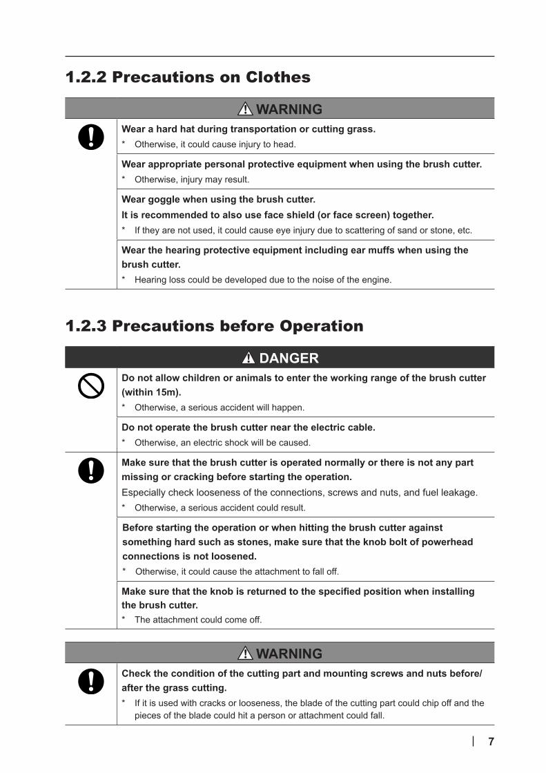
1.2.2 Precautions on Clothes
Wear a hard hat during transportation or cutting grass.* Otherwise, it could cause injury to head.
Wear appropriate personal protective equipment when using the brush cutter.* Otherwise, injury may result.
Wear goggle when using the brush cutter.It is recommended to also use face shield (or face screen) together.* If they are not used, it could cause eye injury due to scattering of sand or stone, etc.
Wear the hearing protective equipment including ear muffs when using the brush cutter.* Hearing loss could be developed due to the noise of the engine.
1.2.3 Precautions before Operation
Do not allow children or animals to enter the working range of the brush cutter (within 15m).* Otherwise, a serious accident will happen.
Do not operate the brush cutter near the electric cable.* Otherwise, an electric shock will be caused.
Make sure that the brush cutter is operated normally or there is not any part missing or cracking before starting the operation. Especially check looseness of the connections, screws and nuts, and fuel leakage.* Otherwise, a serious accident could result.
Before starting the operation or when hitting the brush cutter against something hard such as stones, make sure that the knob bolt of powerhead connections is not loosened.* Otherwise, it could cause the attachment to fall off.
Make sure that the knob is returned to the specified position when installing the brush cutter.* The attachment could come off.
Check the condition of the cutting part and mounting screws and nuts before/after the grass cutting.* If it is used with cracks or looseness, the blade of the cutting part could chip off and the
pieces of the blade could hit a person or attachment could fall.

8
When there is any obstacle (wires, etc.) which cannot be removed near the branches to be cut, cut the branches while taking care so as not to allow the blade to get contact with such obstacle during cutting.* Otherwise, a person could fall down due to the impact and get contact with the blade,
resulting in serious injury. Or the scattered pieces of obstacles could get in your eyes, resulting in injury such as sight loss.
If the edge of the blade is blunt or damaged, do not operate the brush cutter.* Otherwise, it could cause damage to the engine and machine due to overloading.
When working near the car or building, keep the things around away from the working area.Cover the immovable thing with the heavy-duty sheets or do not operate at the area.* If it is operated near the car and the building, scattered gravel stone, etc. could cause
damage.
Check if there is any obstacle (empty cans, wires, pebbles, bands, etc.) or not. If there is any obstacle, remove it before operating the brush cutter. * Scattering of the broken pieces of the damaged blade, etc. could result in injury
accident. Foreign substance such as wires and bands could be caught in the blade, breaking the blade or gears.
1.2.4 Precautions at Start-up
The brush cutter must be started in a non-slippery and firm place.* Otherwise, it will cause falling, resulting in serious injury.
The brush cutter must be started or operated by one person.* If it is operated by more than one person, it could be miss-handled, and it could contact
with a person or objects, resulting in accident.
When starting the brush cutter, make sure that the cutting part is not touching the ground or obstacles.* Otherwise, you could fall down and get severly injured due to contact with the cutting
part. It could also cause the objects to scatter, resulting in injury such as sight loss.

9
1.2.5 Precautions for Operation
Do not operate the brush cutter on insecure footings including a ladder, tree, back of the truck or any other insecure support.* You will fall off the footing, drop the brush cutter or get contact with the cutting part by
inappropriately handling it, resulting in accident.
While cutting grass, put up a KEEP OUT sign in a prominent place to prevent any third person from entering within 15m of the working area.* Otherwise, a serious accident may happen.
Be sure to use cutting parts specified by the manufacturer. * Ifanycuttingpartotherthanthatspecifiedisused,thecuttingpartcouldbedamagedor
it could come off, resulting in injury of the operator.
Do not operate the brush cutter in a closed area.* Exhausted gas affects the health.
Do not operate the brush cutter under poor visibility including after sunset or in the early morning.* It could cause accidents such as contact with some objects or falling off.
Do not use the brush cutter continuously for a long time.* Ifitisoperatedcontinuouslyforalongtime,vibrationinducedwhitefingercouldbe
developed.
Do not operate the brush cutter by one hand.* You could drop the brush cutter or get contact with the cutting part by inappropriate
handling, resulting in accident.
If the cutting part starts moving while idling, do not use the brush cutter.* Otherwise, an accident could happen.
Do not cut grass at the position that is higher than the waist when using the brush cutter.* Otherwise, you may not hold the brush cutter appropriately or trip over, resulting in injury
of head.
Do not hit the cutting part against something hard such as stones, stumps and pillars.* It could kickback and cause an operator or persons around to suffer a bruise or cause
property damage.
Concentrate on the work during the grass cutting without standing talking.When doing the other work out of necessity, stop the engine before performing.* Unless concentrating on the cutting grass work, the operator could be injured
unexpectedly because the concentration becomes loose.
Remove obstacles, and watch your step when operating the brush cutter.* If the footing is insecure, an accident due to tripping over or falling could happen.
10
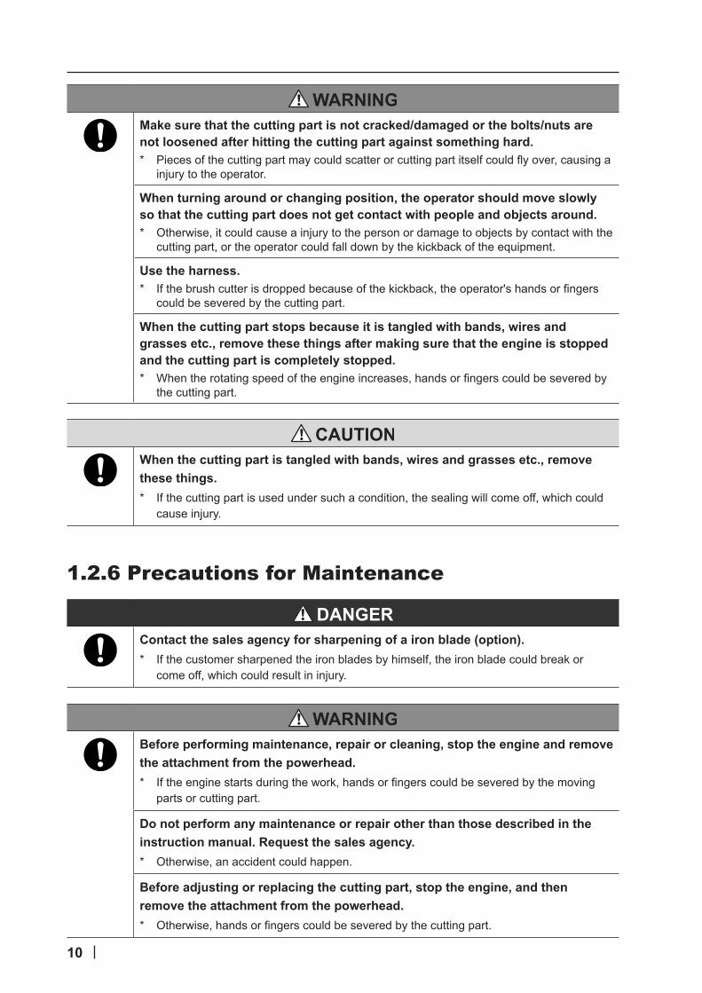
Make sure that the cutting part is not cracked/damaged or the bolts/nuts are not loosened after hitting the cutting part against something hard.* Piecesofthecuttingpartmaycouldscatterorcuttingpartitselfcouldflyover,causinga
injury to the operator.
When turning around or changing position, the operator should move slowly so that the cutting part does not get contact with people and objects around.* Otherwise, it could cause a injury to the person or damage to objects by contact with the
cutting part, or the operator could fall down by the kickback of the equipment.
Use the harness.* Ifthebrushcutterisdroppedbecauseofthekickback,theoperator'shandsorfingers
could be severed by the cutting part.
When the cutting part stops because it is tangled with bands, wires and grasses etc., remove these things after making sure that the engine is stopped and the cutting part is completely stopped.* Whentherotatingspeedoftheengineincreases,handsorfingerscouldbeseveredby
the cutting part.
When the cutting part is tangled with bands, wires and grasses etc., remove these things.* If the cutting part is used under such a condition, the sealing will come off, which could
cause injury.
1.2.6 Precautions for Maintenance
Contact the sales agency for sharpening of a iron blade (option). * If the customer sharpened the iron blades by himself, the iron blade could break or
come off, which could result in injury.
Before performing maintenance, repair or cleaning, stop the engine and remove the attachment from the powerhead. * Iftheenginestartsduringthework,handsorfingerscouldbeseveredbythemoving
parts or cutting part.
Do not perform any maintenance or repair other than those described in the instruction manual. Request the sales agency.* Otherwise, an accident could happen.
Before adjusting or replacing the cutting part, stop the engine, and then remove the attachment from the powerhead.* Otherwise, handsorfingerscouldbeseveredbythecuttingpart.

11
Wear gloves when handling the cutting part during the replacement, etc.* Otherwise,handsorfingerscouldbeseveredbythecuttingparts.
Use a designated grease (JX Nippon Oil & Energy : MOLYNOC No.2). * Otherwise, the gears etc. could be damaged.
1.2.7 Precautions for Troubleshooting
When troubleshooting, stop the engine and then remove the attachment from the powerhead.* Iftheenginestartsduringthework,handsorfingerscouldbeseveredbythemoving
parts or cutting part.
1.2.8 Precautions for Transporting
Do not transport the brush cutter by a bicycle and a motorbike.* When the brush cutter is dropped, it could cause injury to the operator unexpectedly and
damage to the brush cutter.
When transporting the brush cutter, wear appropriate clothes and personal protective equipment.* Otherwise, it could cause injury.
Before transporting the brush cutter, stop the engine, and make the cutting part stopped. For iron blade (option), install the transportation guard (option).* Body,handsorfingerscouldbeseveredorobjectscouldbedamagedbycontactwith
the cutting part.
When transporting the brush cutter, install it to a harness or keep the balance with the shaft tube.* Otherwise, the brush cutter could fall off, resulting in injury or damage of the brush
cutter.
Remove obstacles, and watch your step when transporting the brush cutter.* If the footing is insecure, an accident due to tripping over or falling could happen.
Before transporting the brush cutter put on the back of the truck, etc., remove the attachment from the powerhead, and then fix it so as not to move.* Otherwise, the attachment could fall off the truck, causing injury or damage to the brush
cutter.

12
1.2.9 Precautions for Storing
When storing the attachment with the hook of the pipe cap attached to the pipe, etc., do not pull or swing the attachment.Or,attachittothefixedbarhavingenoughstrength.* Otherwise, it will fall off, causing a serious injury.
For iron blade (option), when storing the attachment, install the transportation guard (option) to the iron blade (option).* Otherwise, it could cause injury to an operator due to contact with the iron blade (option),
or even serious injury by getting contact with the iron blade (option) while the operator is falling down or tumbling.
When storing the attachment, store it in the place out of reach of children and animals.* Otherwise, it could cause injury to an operator due to contact with the iron blade (option),
or even serious injury by getting contact with the iron blade (option) while the operator is falling down or tumbling.
1.2.10 Precautions for Grease
Store the grease in a place out of reach of children. Also, put them in a container so that the grease is not spilled and make them distinguished to understand contents.* When drinking them by mistake, the person will feel physically sick.
Do not discard grease into the river, the sea, or the ground.* Otherwise, it could pollute the environment.

13
1.3 Safety Devices and Protective Guard1.3.1 Safety Devices (Stop Devices)To stop the brush cutter in case of an accident or abnormality, use the stop device below and stop the operation of the cutting part.There are the throttle trigger and start/stop switch on the powerhead as stop devices.Refer to the powerhead manual for details.
1.3.2 Safety Devices (Quick Release)In case of an accident or abnormality, the brush cutter can be released from the harness by using the quick release device.
Refer to the powerhead manual for details.
1.3.3 Protective Guard (Transportation Guard (Option))
For iron blade (option), install the transportation guard to the brush cutter for transporting or storing to prevent an accident due to contact with the iron blade (option).Installtheguardasshownintherightfigure.
Transportation guard
14
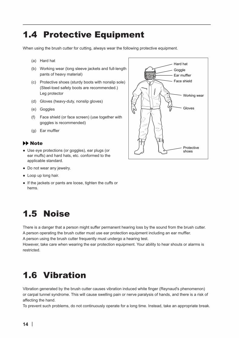
1.4 Protective EquipmentWhen using the brush cutter for cutting, always wear the following protective equipment.
(a) Hard hat
(b) Working wear (long sleeve jackets and full-length pants of heavy material)
(c) Protective shoes (sturdy boots with nonslip sole) (Steel-toed safety boots are recommended.) Leg protector
(d) Gloves (heavy-duty, nonslip gloves)
(e) Goggles
(f) Face shield (or face screen) (use together with goggles is recommended)
(g) Earmuffler
Note ● Use eye protections (or goggles), ear plugs (or ear muffs) and hard hats, etc. conformed to the applicable standard.
● Do not wear any jewelry.
● Loop up long hair.
● If the jackets or pants are loose, tighten the cuffs or hems.
1.5 NoiseThere is a danger that a person might suffer permanent hearing loss by the sound from the brush cutter.Apersonoperatingthebrushcuttermustuseearprotectionequipmentincludinganearmuffler.A person using the brush cutter frequently must undergo a hearing test.However, take care when wearing the ear protection equipment. Your ability to hear shouts or alarms is restricted.
1.6 VibrationVibrationgeneratedbythebrushcuttercausesvibrationinducedwhitefinger(Reynaud'sphenomenon)or carpal tunnel syndrome. This will cause swelling pain or nerve paralysis of hands, and there is a risk of affecting the hand.To prevent such problems, do not continuously operate for a long time. Instead, take an appropriate break.
Hard hat
GoggleEar mufflerFace shield
Working wear
Gloves
Protective shoes

15
2. Outline
2.1 Name of Parts and Their FunctionsThe brush cutter is a device with the attachment installed to the powerhead (separately sold).The following is the structure of the attachment and name and function of each part.
2
5
3
4
1
No. Name Description
1 Nylon cutter Rotates at a high-speed and cuts grasses, weeds and shrubs, etc. by the nylon line. The nylon line rotates counterclockwise as viewed from the operator.
2 Blade holder A part to install the nylon cutter to the gear case.
3 Gear case Connected to the cutting section. Changes the transmission angle of the power from the power transmission shaft to decelerate.
4 Blade guard Guards from objects such as grasses, stones and sands scattered by the nylon cutter. This also cuts nylon lines of the nylon cutter into the same length.
5 Shaft tube It is the main frame. The power transmission shaft is inside this tube.
2.2 Specification■StandardSpecification
Item Specification
Nylon cutter (Attached Material) Diameter (mm) φ420
Iron blade (Blade kit option for Australia) UMBK-425 φ2304T
Iron blade (Blade kit option for Australia) UMBK-435 φ2554T
Iron blade (Option for Europe) φ2553T
Note ● Iron blade and blade kit are separately sold. For genuine parts No., contact the sales agency.
16
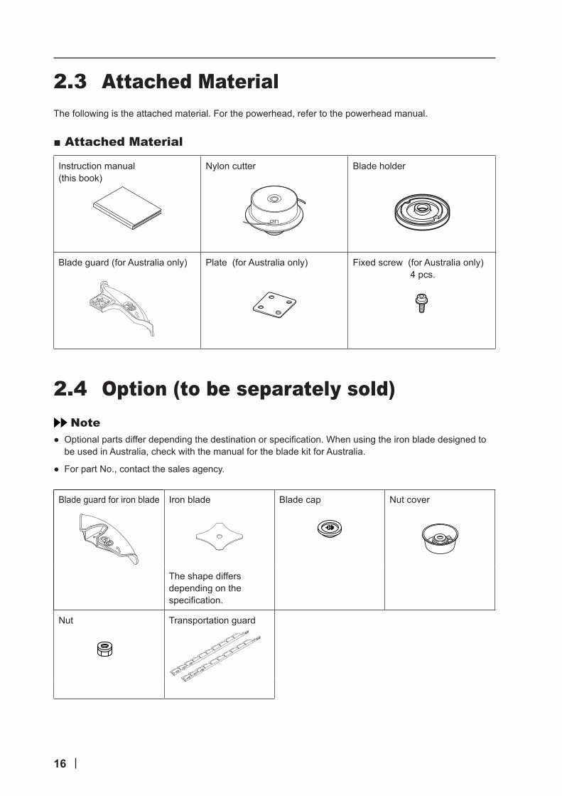
2.3 Attached MaterialThe following is the attached material. For the powerhead, refer to the powerhead manual.
■AttachedMaterial
Instruction manual (this book)
Nylon cutter Blade holder
Blade guard (for Australia only) Plate (for Australia only) Fixed screw (for Australia only) 4 pcs.
2.4 Option (to be separately sold)Note
● Optionalpartsdifferdependingthedestinationorspecification.Whenusingtheironbladedesignedtobe used in Australia, check with the manual for the blade kit for Australia.
● For part No., contact the sales agency.
Blade guard for iron blade Iron blade Blade cap Nut cover
The shape differs depending on the specification.
Nut Transportation guard

17
2.5 Model and Position of Serial No.This instruction manual is for attachment of model in same series.Check the model of your attachment on the nameplate attached to the machine body and read the corresponding sections.Record serial No. (See “10. Service after Sales”). You will need this serial No. when ordering parts, and when making technical or warranty inquiries.
Note ● The model code is 4-digit numeric number for management. The model code is different from the model name.
2.6 ConsumablesThe following is the consumables of this attachment.Contact the sales agency for the replacement.
Cap Cutting knife
(for Australia) (for Europe)
Blade holder Nylon cutter
AAAA;Model code
BBBBBBB;Serial No.

18
3. Installation and Adjustment
3.1 Installation Method
Before installing or removing, stop the engine.* Iftheenginestartsduringthework,handsorfingerscouldbeseveredbythemoving
parts or cutting part.
3.1.1 Combination with Powerhead
Do not install any unapproved powerhead to the attachment.* The attachment could come off during use, resulting in a serious accident.
The attachment can be installed only to our approved equipment (shown below).For detail, refer to the table below.
Manufacturer Our approved powerhead
Thai Honda Manufacturing Co.,Ltd. UMC425E
Thai Honda Manufacturing Co.,Ltd. UMC435E
Thai Honda Manufacturing Co.,Ltd. UMC425U
Thai Honda Manufacturing Co.,Ltd. UMC435U

19
3.1.2 Connecting
Loosen the knob bolt [1] of powerhead connections.
Align the boss (protrusion) [2] at the end of the pipe with the slit of the joint case [3], and insert it to the label [4] position.
Make sure that the positioning knob [5] is lowered to the original position, and then tighten the knob bolt [1] of powerhead connections.
[1]
[4] [3]
1
[2]
[3]
[4]
2
[5]
[1]
3
20
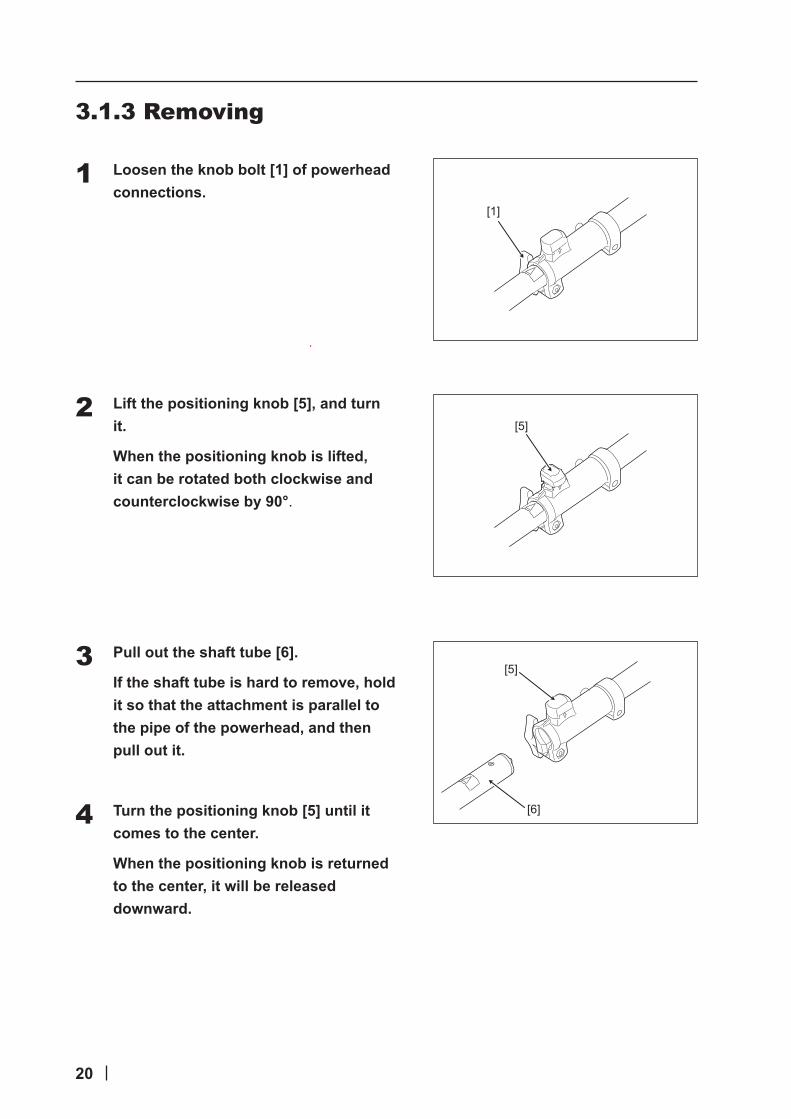
3.1.3 Removing
Loosen the knob bolt [1] of powerhead connections.
Lift the positioning knob [5], and turn it.
When the positioning knob is lifted, it can be rotated both clockwise and counterclockwise by 90°.
Pull out the shaft tube [6].
If the shaft tube is hard to remove, hold it so that the attachment is parallel to the pipe of the powerhead, and then pull out it.
Turn the positioning knob [5] until it comes to the center.
When the positioning knob is returned to the center, it will be released downward.
[1]
1
[5]2
[5]
[6]
3
4

21
3.2 Installation of blade guard (for Australia only)
Follow the procedure below to install the blade guard (for Australia.)If the blades are provided, remove the blades before performing this work.
Note ● In case of the brush cutter attachment for Europe, the blade guard is already installed. Do not remove the scattering prevention cover. If the blade guard is damaged, contact teh sales agency.
Set the start/stop switch to OFF (O side) to stop the engine.
Remove the attachment from the powerhead.
Put on gloves.
Install the blade guard (for Australia) [2] and the plate [3], and fix it to the gear case [1] by tightening with the fixed screw [4] (4pcs.).
1
2
3
[4][3]
[1]
[2]
4

22
3.3 Installation of Nylon Cutter
Be sure to use cutting parts specified by the manufacturer. * Ifanycuttingpartotherthanthatspecifiedisused,thecuttingpartcouldbedamagedor
it could come off, resulting in injury of the operator.
Thoroughly read “1.2 General Precautions” before installing the nylon cutter.Install the nylon cutter and other parts as follows:
Set the start/stop switch to OFF (O side) to stop the engine.
Remove the attachment from the powerhead.
Put on gloves.
Remove the foreign objects such as grasses and stones accumulated in the part A of the gear case [1].
Note ● If the operation is kept with the foreign objects accumulated, the gear case could be damaged, resulting in serious injury.
Put the blade holder [2] on the output shaft [3].
Insert the L type wrench [5] into the hole [6] for fixing gear case and rotate it counterclockwise to tighten.
Note ● The directions for loosening/tightening the nylon cutter [4] are opposite to the ones of general nuts.
1
2
3
[5]
[1]
[4]
[2]
A
[6]
[3]
4
5
6
23
4. Operation
Wear appropriate personal protective equipment when using the brush cutter.* Otherwise, injury may result.
4.1 Transporting method
Do not transport the brush cutter by a bicycle and a motorbike.* When the brush cutter is dropped, it could cause injury to the operator unexpectedly and
damage to the brush cutter.
Before transporting the brush cutter, stop the engine, and make the cutting part stopped. For iron blade (option), install the transportation guard (option).* Body,handsorfingerscouldbeseveredorobjectscouldbedamagedbycontactwith
the cutting part.
When transporting the brush cutter, install it to a harness or keep the balance with the shaft tube.* Otherwise, the brush cutter could fall off, resulting in injury or damage of the brush
cutter.
Remove obstacles, and watch your step when transporting the brush cutter.* If the footing is insecure, an accident due to tripping over or falling could happen.
Before transporting the brush cutter put on the back of the truck, etc., remove the attachment from the powerhead, and then fix it so as not to move.* Otherwise, the attachment could fall off the truck, causing injury or damage to the brush
cutter.

24
Wear protective equipment. For detail about the protective equipment, refer to "1.4 Protective Equipment.
Make sure that the engine is stopped and the cutting part is not moving.
For iron cutter (option), install the transportation guard (option).
<When hand-carrying the brush cuttter> Install it to the harness or use the shaft tube to keep the balance with the shaft tube.
<When transporting by truck, etc.>
(1) Remove the attachment from the powerhead.
(2) Put the brush cutter on the back of the truck, and fix it so as not move.
1
2
When hand-carrying the brush cutter3
4

25
4.2 Pre-operation Check
Make sure that the brush cutter is operated normally or there is not any part missing or cracking before starting the operation. Especially check looseness of the connections, screws and nuts, and fuel leakage.* Otherwise, a serious accident could result.
Before operating the brush cutter, check the following.
(a) Check each part. If there is any faulty part, request a repair.
● Check if there is not any looseness, cracks, bending, and distortion of parts (nuts, screws, etc.)
● Check if the cutting part is not damaged.
(b) Check if the brush cutter is operated appropriately. If it is faulty, contact sales agency for repair.
● Check if the throttle trigger is operated freely (if it is returned to the idling position).
● Check if the start/stop switch functions normally.
(c) Check the handle for dirt, etc. If it is dirty, wipe it off.
● Check if it is kept clean (if there is no oil or resin adhering.)
● Check if it is dried.
(d) Check the idling status. If it is faulty, perform the steps described in the powerhead manual.
● Check if the cutting part does not move during idling.
● Check if the idling is normal.
(e) Tighten the nuts/screws of cutting part. If there is any looseness, it could result in serious injury. For tightening the nuts/screws of cutting part, refer to “3.2 Installation of Nylon Cutter”. For iron blade (option), refer to “8. Installing of Iron Blade (Option). In case of the iron blade designed to be used in Australia, refer to the manual of the blade kit designed to be used in Australia.
(f) Check the nylon cutter. For checking of nylon cutter, refer to the nylon cutter manual”..
(g) In addition to the above, perform the steps described in the powerhead manual.

26
4.3 Start and StopThe brush cutter is operated by the powerhead. Refer to the powerhead manual.
4.3.1 Start
The brush cutter must be started in a non-slippery and firm place.* Otherwise, it will cause falling, resulting in serious injury.
The brush cutter must be started or operated by one person.* If it is operated by more than one person, it could be miss-handled, and it could contact
with a person or objects, resulting in accident.
For starting the brush cutter, refer to the powerhead manual.
4.3.2 StopWhen the throttle trigger is released, the engine power will decrease, and the cutting part will stop operating.However,itwillbeoperatingforawhile(flywheeleffect),andthethrottlewillnotstopimmediately after the throttle trigger is released.
Refer to the powerhead manual for details.

27
4.4 Precautions for OperationWhen operating the brush cutter, observe the following as well as “1.2 General Precautions”.
■General ● If you feel tired during operation, be sure to take a break. If you continue operating without taking a break, the brush cutter could be out of control. Or if you are aggravated by strenuous work, consult a physician (doctor) before operating the brush cutter.
● Thebrushcutterisnotinsulatedagainstelectricshock.Haveapersonqualifiedforelectricworkremovewires and cables which can be removed. If there are still wires or cables not removable, do not operate the brush cutter.
● Do not cut any materials other than grasses, weeds and shrubs.
● Do not rotate the nylon cutter at more than 10,000 r/min.
● Keep the nylon cutter from hitting hard foreign matters such as rocks, concrete, tree stub and bottle etc.
● When using the iron blade (option), avoid stones and stumps. They could bounce back, or the iron blade (option) edge and stones, etc. could be scattered, resulting in injury.
■CheckofBrushcutter ● Make sure that the blade guard is securely installed to the appropriate position before starting the operation.
● Forironblade(option),besuretousethesufficientlygroundironblade(option).Aftergrinding,besureto check if the iron blade (option) is well-balanced.
● Make sure that an appropriate blade guard is installed.
■CheckofWorkArea ● Check if there is no hard object such as metal shard which could damage the cutting part in the work area before starting operation. Pay attention when operating the brush cutter near fences or poles.
● Keep it away from fence edges, cliffs and hard objects.
● Take extreme care when operating in a slippery place. Also watch out for rough ground, stumps, roots, ditches or holes which could cause you to trip or stumble. Do not use the brush cutter when it is raining.
● Topreventfiredisaster,donotusethebrushcutterinaplacewherethereareorganicsediments,fallenleaves or excessive lubricants.
■InEmergency ● If the cutting part is contacted with obstructions, immediately stop the engine. After the cutting part is completely stopped, check if the cutting part is not broken, bent or cracked. If there is any failure, replace the cutting part. Also, check if the shaft tube is not bent, broken or cracked. If there is any failure, contact the sales agency.
● When removing the foreign objects wound around the cutting part, gear case or blade guard, be sure to stop the engine with the stop switch. Do not place your hands, etc. close to the cutting part while the engine is operating even if the cutting part is not rotating. When the throttle cable is gripped accidentally, the cutting part will suddenly start rotating, causing serious injury.

28
● If there is any problem such as a blunt edge of the cutting part, etc., stop the operation immediately, and makesurethatthereisnopartcrackingorlacking.Evenifthecuttingparthassuperficialcracksinsteadof damage or wear, replace the cutting part.
● In case of an accident or abnormality, the brush cutter can be released from the harness or shoulder harness by using the quick release.

29
4.5 Cutting Operation
Do not allow children or animals to enter the working range of the brush cutter (within 15m).* Otherwise, a serious accident will happen.
The brush cutter must be started or operated by one person.* If it is operated by more than one person, it could be miss-handled, and it could contact
with a person or objects, resulting in accident.
When using multiple brush cutters at the same time, each operator must be at least 15 meters away from the others.The following shows examples of use of the brush cutter. In the illustration, the iron blade (option) is installed.
■HoldingMethodofBrushCutter ● Always hold the brush cutter with both hands during operation. To prevent accidents due to inappropriate operation, always support the brush cutter stably during the operation by folding as follows.
Right hand: Grip the control grip.Left hand: Grip the loop handle.(This also applies to left-handers.)
● Always keep the machine away from your body.
■ Operating Method ● Before starting cutting operation raise the revolution speed of the nylon cutter to approximately 5,000 r/min. Low revolution speed makes tension of the nylon lineinsufficientresultinginloweredcuttingefficiency.
● While swinging your body from side to side, cut the grasses from the right side to left side. The cutting part rotates counterclockwise. When a cutting part cuts some articles from the left to the right, the cutting part turning at a high speed could touch hard,uncuttableandheavyfixedarticlessuchasstones,trees, stakes and concrete, and then the cutting part could kicked back towards unexpected directions.
● Appropriate cutting range is as follows : Nylon cutter : Tip of the nylon line Iron blade : Range of 2/3 from the tip
30
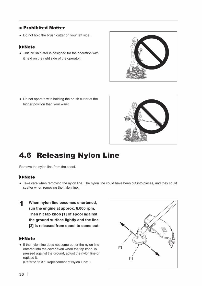
■Prohibited Matter ● Do not hold the brush cutter on your left side.
Note ● This brush cutter is designed for the operation with it held on the right side of the operator.
● Do not operate with holding the brush cutter at the higher position than your waist.
4.6 Releasing Nylon LineRemove the nylon line from the spool.
Note ● Take care when removing the nylon line. The nylon line could have been cut into pieces, and they could scatter when removing the nylon line.
When nylon line becomes shortened, run the engine at approx. 6,000 rpm. Then hit tap knob [1] of spool against the ground surface lightly and the line [2] is released from spool to come out.
Note ● If the nylon line does not come out or the nylon line entered into the cover even when the tap knob is pressed against the ground, adjust the nylon line or replace it. (Refer to "5.3.1 Replacement of Nylon Line".)
[1]
[2]
1

31
4.7 Actions after OperationAfter using the brush cutter, take the following actions.
Set the start/stop switch to OFF (O side) to stop the engine.
Tighten all the nuts, bolts, and screws other than the ones for adjusting the carburetor.
Store the brush cutter according to “6. Storing”.
5. Maintenance
Before performing maintenance, repair or cleaning, stop the engine and remove the attachment from the powerhead. * Iftheenginestartsduringthework,handsorfingerscouldbeseveredbythemoving
parts or cutting part.
Do not perform any maintenance or repair other than those described in the instruction manual. Request the sales agency.* It could cause an accident.
Maintenance items for the attachment are described as follows.For maintenance of the powerhead, refer to the powerhead manual.
■MaintenanceList
Item Daily Every 20 hours or 3 months As necessary Remarks
Inspection of cutting part ○ Refer to 5.1.1
Looseness of screws and nuts ○ Refer to 5.1.2
Removal of foreign objects ○ Refer to 5.1.3
Greasing ○ Refer to 5.2.1
Replacement of nylon line ○ Refer to 5.3.1
1
2
3
32
5.1 Daily5.1.1 Inspection of Cutting PartCheck the following.
● The nylon cutter or iron blade (option) are not broken, chipped off or bent.
● The iron blade (option) edge is not rounded.
● The iron blade (option) is sharp.
● There is no crack or burr on the iron blade (option).
If there is any failure, contact the sales agency.If the cutting performance starts to be degraded, for example, the iron blade (option) is frequently caught in the branches, the iron blade (option) must be ground again or replaced.For grinding again or replacing, request the sales agency.
5.1.2 Looseness of Screws and NutsCheck the screws and nuts for looseness.If any, tighten it securely.
5.1.3 Removal of Foreign ObjectsRemove the foreign objects attached to the part A of gear case (refer to “3.2 Installation of Nylon Cutter”) and the engine.When the cutting part is tangled with bands, wires and grasses etc., remove these things.
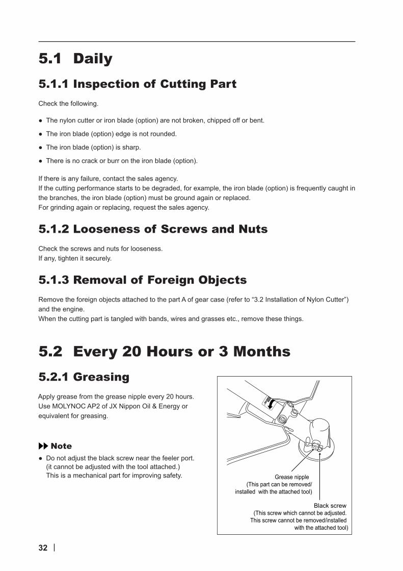
5.2 Every 20 Hours or 3 Months5.2.1 GreasingApply grease from the grease nipple every 20 hours.Use MOLYNOC AP2 of JX Nippon Oil & Energy or equivalent for greasing.
Note ● Do not adjust the black screw near the feeler port. (it cannot be adjusted with the tool attached.) This is a mechanical part for improving safety.
Black screw (This screw which cannot be adjusted.
This screw cannot be removed/installed with the attached tool)
Grease nipple (This part can be removed/
installed with the attached tool)

33
5.3 As Necessary5.3.1 Replacement of Nylon Line
Set the start/stop switch to OFF (O side) to stop the engine.
Put on gloves.
Press retaining pawls [1] (at 2 places) inward and remove cover [2].
Remove spool [3].
When nylon line on the spool is almost exhausted.
(1) Remove remaining line from spool.
(2) Wind new line according to the procedures 7 and beyond.
When the line on the spool is melted and stuck.
(1) Remove the entire line while peeling off the melted and stuck portion.
(2) Wind the removed line anew according to procedures 7 and beyond.
1
2
[1]
[2]
3
[3]
4
5
34
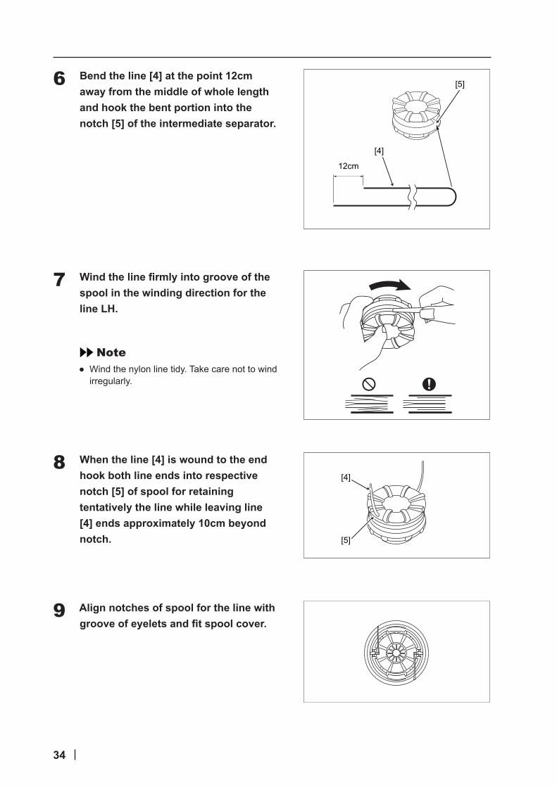
Bend the line [4] at the point 12cm away from the middle of whole length and hook the bent portion into the notch [5] of the intermediate separator.
Wind the line firmly into groove of the spool in the winding direction for the line LH.
Note ● Wind the nylon line tidy. Take care not to wind irregularly.
When the line [4] is wound to the end hook both line ends into respective notch [5] of spool for retaining tentatively the line while leaving line [4] ends approximately 10cm beyond notch.
Align notches of spool for the line with groove of eyelets and fit spool cover.
[5]
[4]
12cm
6
7
[5]
[4]8
9

35
Pull out the line [4] from cover.
(1) Remove the line [4] from respective notch of spool.
(2) Pass it through groove of respective eyelet.
Fit cover and housing together.
(1) Align eyelets of cover with recesses of housing.
(2) Press pawls of housing into respective window [6] of cover until the pawls are firmly fitted into the windows.
Note ● Make sure each outer periphery of pawls of housing spreads almost fully up to the outer periphery of respective widow of cover. Iftheyarelooselyfittedandthecuttingheadisturned,coverorinsidecomponentscanflyoff which is dangerous.
[4]10
11
[6]
36
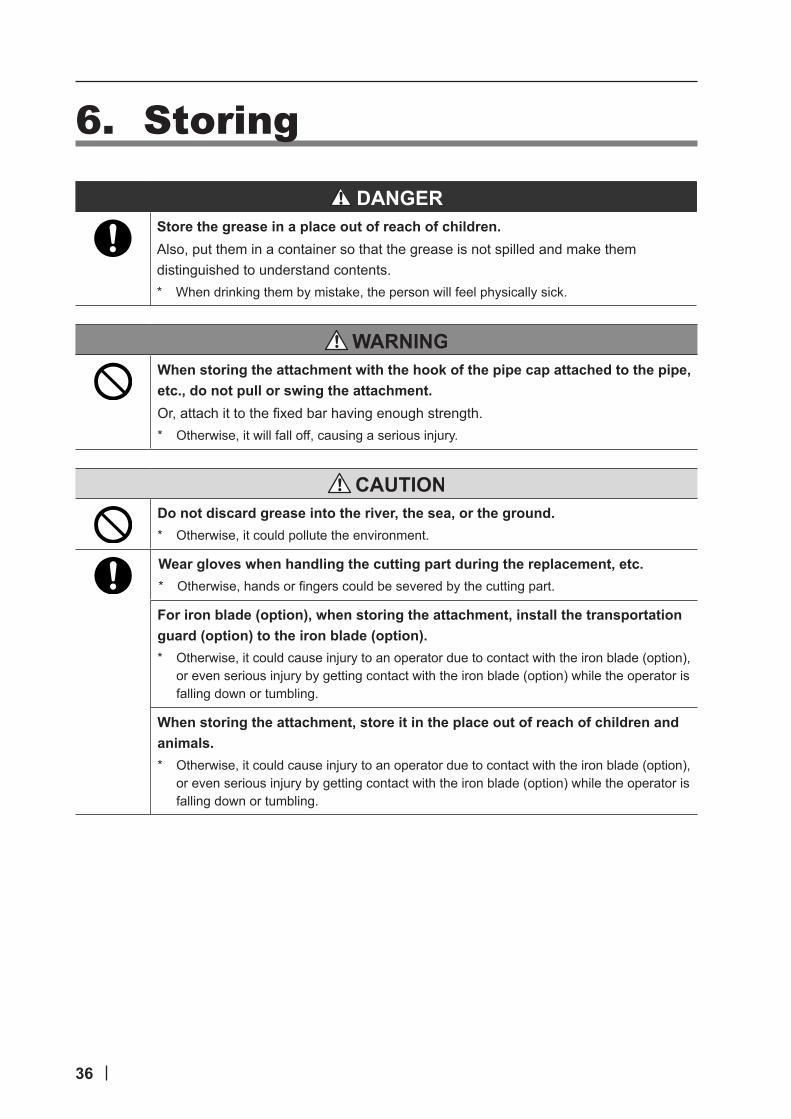
6. Storing
Store the grease in a place out of reach of children. Also, put them in a container so that the grease is not spilled and make them distinguished to understand contents.* When drinking them by mistake, the person will feel physically sick.
When storing the attachment with the hook of the pipe cap attached to the pipe, etc., do not pull or swing the attachment.Or,attachittothefixedbarhavingenoughstrength.* Otherwise, it will fall off, causing a serious injury.
Do not discard grease into the river, the sea, or the ground.* Otherwise, it could pollute the environment.
Wear gloves when handling the cutting part during the replacement, etc.* Otherwise,handsorfingerscouldbeseveredbythecuttingpart.
For iron blade (option), when storing the attachment, install the transportation guard (option) to the iron blade (option).* Otherwise, it could cause injury to an operator due to contact with the iron blade (option),
or even serious injury by getting contact with the iron blade (option) while the operator is falling down or tumbling.
When storing the attachment, store it in the place out of reach of children and animals.* Otherwise, it could cause injury to an operator due to contact with the iron blade (option),
or even serious injury by getting contact with the iron blade (option) while the operator is falling down or tumbling.
37
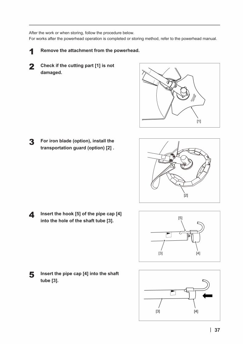
After the work or when storing, follow the procedure below.For works after the powerhead operation is completed or storing method, refer to the powerhead manual.
Remove the attachment from the powerhead.
Check if the cutting part [1] is not damaged.
For iron blade (option), install the transportation guard (option) [2] .
Insert the hook [5] of the pipe cap [4] into the hole of the shaft tube [3].
Insert the pipe cap [4] into the shaft tube [3].
1
[1]
2
[2]
3
[4][3]
[5]4
[4][3]
5

38
Put on gloves before cleaning.
Clean the attachment. Wipe off the dirt or stain with a cloth, etc.
Store the brush cutter in the following place.
(a) Locked place
(b) High place out of reach of children and other unauthorized person
(c) Dried and cool dark place
7. Waste DisposalFor disposal, observe the standards and regulations of your region. If there is any question, contact the sales agency.
6
7
8

39
8. Installation of Iron Blade (Option)The following shows the installation procedure for the iron blade (option).
Note ● Iron blades, blade caps, nut covers and nuts are separately sold. For puchasing, contact the sales agency.
● Be sure to use genuine parts.
● For installation of iron blade designed to be used in Australia, refer to the manual of the blade kit designed to be used in Australia.
Stop the engine, and pull out the brush cutter attachment from the powerhead.
Put on gloves.
Remove the nylon cutter [1].
Loosen the fixed screw for nylon cutter guard [2], and remove the nylon cutter guard [3] from the blade guard [4].
Note ● Thefixedscrewfornyloncutterguard[2]cannotberemoved from the nylon cutter guard [3].
● Store the removed nylon cutter guard [3] carefully.
● Donotremovethefixedscrew[5]forbladeguard.
1
[1]
2
3
[2]
[3]
[5]
[4]4

40
Remove foreign objects such as grasses and stones gathered in "*" part of the gear case [6].
Remove the foreign objects.* If the product is used without removing the foreign objects, it could cause a serious
injury or damage of the gear case.
Align the center hole of the iron blade [A] with the boss of the blade holder [7], and install them to the gear case [6].
Align the center hole of the iron blade with the boss of the blade holder.* Otherwise, a serious injury or damage of the brush cutter could be caused due to
excessive vibration or looseness of the nut .
Install the blade cap [B] and nut cover [C].
Insert the L-wrench [9] into the hole [8] for fixing the gear case [6] to align with the groove or hole of the blade holder [7].
Turn the nut [D] with a combination wrench counterclockwise to fix them to the output shaft.
Note ● Loosening/tightening direction of this nut [D] is opposite to that of the regular nut.
● Removal must be performed in the opposite order of the installation procedure.
5
6
[6]
[8]
[D]
[C]
[A]
[B]
[9]
[7]
[*]
7
8
9

41
9. TroubleshootingIn case of failure, follow the table below.
When troubleshooting, stop the engine and then remove the attachment from the powerhead.* Iftheenginestartsduringthework,handsorfingerscouldbeseveredbythemoving
parts or cutting part.
Phenomena Causes MeasuresThe brush cutter does not start
Fuel runs out or fails. Refuel or replace the fuel by reference to the powerhead manual
Engine fails. Refer to the powerhead manual.Start/stop switch is off. Turn on the start/stop switch to start.
Output is not enough. Throttle cable adjustment is faulty
Refer to the powerhead manual.
Engine fails. Refer to the powerhead manual.Vibration is too large. Poor balance of attachment Contact the sales agency.
Mis-installation of attachment Check the installed status.Looseness of connection of attachment
Contact the sales agency.
Shaft tube is bent. Contact the sales agency.Cutting part is cracked or broken.
Contact the sales agency.
Screws/nuts at the handle mounting parts are loosened
Check the mounting screws/nuts.
Exhaust sound is too large.
Engine fails. Refer to the powerhead manual.
Blade is blunt Iron blade (option) has worn. Request the sales agency for regrinding or purchase a new blade.
Cutting part does not stop even if the engine speed is reduced.
Engine fails. Refer to the powerhead manual.
Cutting part does not move even if the engine speed is increased.
Gear has worn. Contact the sales agency.
The brush cutter does not stop.
Engine fails. Refer to the powerhead manual.

42
10. Service after SalesFor repair, handling method or cleaning, contact the sales agency.
■WhenRequestingforRepairIfthereisanyproblem,tryfindingthecauseandtakemeasuresaccordingto“9.Troubleshooting”.Ifitdoes not solve the trouble, contact the sales agency.
■ContactforRepairContact the sales agency from which you purchased the brush cutter for repair.
Record serial No. (See “2.5 Position of Model Code and Serial No.”) in the space below. You will need this serial No. when ordering parts, and when making technical or warranty inquiries.
Required information
Name of product Brush cutter attachment
Model code & Serial No. SBCE -
SBCU -
Purchased date
Sales agency which you purchased from
Faulty condition (Explain as much detail as possible.)

43
11. Technical data
Model SSBC (Europe) SSBC (Australia)
Powerhead UMC425E UMC435E UMC425U UMC435U
Handle LOOP LOOP LOOP LOOP
a)
Mass (without cutting attachment , guard and powerhead)
kg 1.6 1.4
Length(without cutting attachment , and owerhead)
mm 725 725
Cutting attachments (type, diameter for blades) mm φ420
(Nylon cutter)φ420
(Nylon cutter)
Maximum rotational frequency of the spindle min-1 6900 6900 6900 6900
b)
Measured vibration levels (in accordance with EN ISO 22867)Applies to Europe only
Nylon cutter
Front m/s2 5.8 5.5 - -
Uncertainty 2.3 2.2 - -
Rear m/s2 5.8 6.8 - -
Uncertainty 2.3 2.7 - -
c)Measured sound pressure level (in accordance with 2006/42/EC)Applies to Europe only
Nylon cutter
dB(A) 97 97 - -
Uncertainty 1 1 - -
d)Measured sound power level(in accordance with 2000/14/EC)Applies to Europe only
Nylon cutter
dB(A) 111 110 - -
Uncertainty 1 1 - -
e)
Vibration levels (in accordance with Australian Standard AS3575 amdt1)Applies to Australia only
Nylon cutter
Front m/s2 - - 10 9
Rear m/s2 - - 10 12
Iron blade
Front m/s2 - - 8 9
Rear m/s2 - - 12 11
f)
Sound pressure level (in accordance with Australian Standard AS3575 amdt1)Applies to Australia only
Nylon cutter dB - - 101 101
Iron blade dB - - 95 96
g)
Sound power levelAustralia New South Wales standardApplies to Australia only
Nylon cutter dB - - 75 77
Iron blade dB - - 69 72

44
October , 2012 E1381-0
Manufacturer NIKKARI CO.,LTD. Address 465-1,Saidaiji-Kawaguchi,Higashi-ku,Okayama,704-8125Country JAPAN
Type Brush Cutter Attachment Model SSBCSerial No. SBCE-1000001 ~
Declare, that the following machinery complies with all the essential health and safety Requirements of the EC Directive. 2006/42/EC 2004/108/EC 2000/14/EC amended 2005/88/EC
The following standards have been applied EN ISO 12100:2010 EN ISO 11806-1:2011 EN ISO 14982:2009
Approved Powerhead UMC425E UMC435E
Guaranted sound power level (in accordance with 2000/14/EC) Use with UMC425E 112 dB(A) Use with UMC435E 111 dB(A)
Issued at: Hiroshi Sugimoto, Japanon October 1st 2012Name and position of the person that signs: Hiroshi SugimotoPresidentManufacturer’ s signature
Person authorised to complie the technical file Honda Motor Europe Ltd. Aalst Office Wijngaardveld 1 (Noord V), 9300 Aalst BELGIUM
EC Declaration of Conformity( Applies to Europe only )