L322 5.0 petrol engine system general information - fullfatrr.com
106
PUBLISHED: 03-SEP-2015 2012.0 RANGE ROVER (LM), 303-00 ENGINE SYSTEM - GENERAL INFORMATION ENGINE - V8 N/A 5.0L PETROL/V8 S/C 5.0L PETROL (G1222426) DIAGNOSIS AND TESTING SPECIAL TOOL(S) 303-1451 Oil pressure testing adaptor 303-871 Oil pressure testing gauge PRINCIPLE OF OPERATION For a detailed description of the 5.0L engine, refer to the relevant Description and Operation sections in the workshop manual. REFER to: Engine (303-01C Engine - V8 N/A 5.0L Petrol, Description and Operation), Engine (303-01D Engine - V8 S/C 5.0L Petrol, Description and Operation). INSPECTION AND VERIFICATION 1. Verify the customer concern. 1. Visually inspect for obvious signs of damage and system integrity. Visual Inspection MECHANICAL ELECTRICAL • Coolant leaks • Oil leaks • Fuses • Loose or corroded electrical connectors L322 5.0 petrol engine system general information 15 December 2020 20:14 RANGE ROVER Page 1
-
Upload
khangminh22 -
Category
Documents
-
view
2 -
download
0
Transcript of L322 5.0 petrol engine system general information - fullfatrr.com
PUBLISHED: 03-SEP-2015
2012.0 RANGE ROVER (LM), 303-00
ENGINE SYSTEM - GENERAL INFORMATION
ENGINE - V8 N/A 5.0L PETROL/V8 S/C 5.0L PETROL (G1222426)
DIAGNOSIS AND TESTING
SPECIAL TOOL(S)
303-1451
Oil pressure testing adaptor
303-871
Oil pressure testing gaugePRINCIPLE OF OPERATION
For a detailed description of the 5.0L engine, refer to the relevant Description and Operation sections in the workshop manual. REFER to:
Engine (303-01C Engine - V8 N/A 5.0L Petrol, Description and Operation),Engine (303-01D Engine - V8 S/C 5.0L Petrol, Description and Operation).INSPECTION AND VERIFICATION
1. Verify the customer concern.
1. Visually inspect for obvious signs of damage and system integrity.
Visual Inspection
MECHANICAL ELECTRICAL
• Coolant leaks
• Oil leaks
• Fuses
• Loose or corroded electrical connectors
L322 5.0 petrol engine system general information15 December 2020 20:14
RANGE ROVER Page 1

• Oil leaks
• Leaks in the fuel system
• Visibly damaged or worn parts
• Loose or missing fixings
• Loose or corroded electrical connectors
• Harnesses
• Sensors
1. If an obvious cause for an observed or reported concern is found, correct the cause (if possible) before proceeding to the next step.
1. If the concern is not visually evident, verify the symptom and refer to the Symptom Chart, alternatively check for Diagnostic Trouble Codes (DTCs) and refer to the relevant DTC Index.
SYMPTOM CHART
NOTES:• If an engine is suspect, and the vehicle remains under the Manufacturers warranty refer to the
Warranty Policy and Procedure manual (section B1.2), or determine if any prior approval programme is in operation, prior to the installation of a new engine.
• Due to the possibility of loose carbon, that has become trapped between the valve face and seat, effecting the pressure readings, when carrying out a compression test and some cylinders are found to have low pressures, install the spark plugs, road test the vehicle and re-test the suspect cylinders. If the correct pressures are restored, no further action is required.
SYMPTOM ACTION
All engine related issues • Check ECM for Diagnostic Trouble Codes (DTCs) and refer to DTC Index.
Difficult to start hot and cold • Carry out general engine checks:
• Compression test. Refer to component tests in this section.
• Valve clearances
• Spark plug condition and color
Poor idle • Ensure the air intake system is free from leaks
• Carry out general engine checks:
• Compression test. Refer to component tests in this section.
• Valve clearances
• Spark plug condition and color
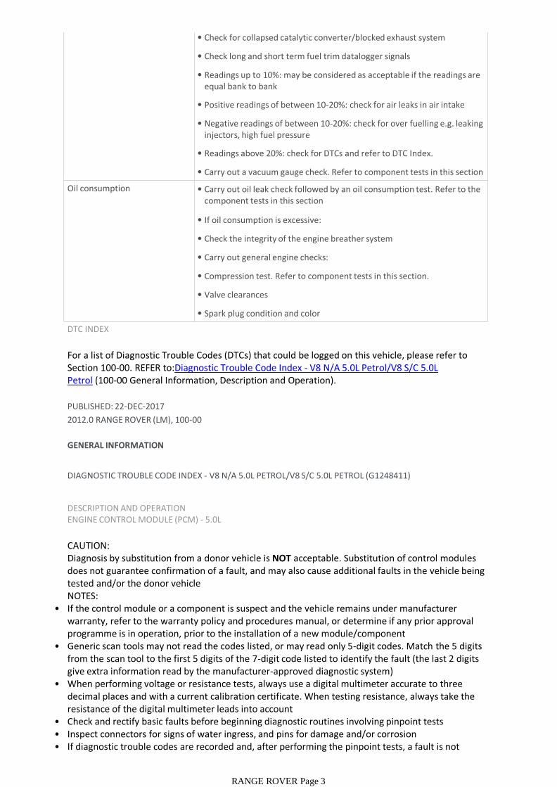
• Check for collapsed catalytic converter/blocked exhaust system
• Check long and short term fuel trim datalogger signals
• Readings up to 10%: may be considered as acceptable if the readings are equal bank to bank
• Positive readings of between 10-20%: check for air leaks in air intake system
• Negative readings of between 10-20%: check for over fuelling e.g. leaking injectors, high fuel pressure
• Readings above 20%: check for DTCs and refer to DTC Index.
• Carry out a vacuum gauge check. Refer to component tests in this section
Insufficient power/Insufficient compression
• Ensure the air intake system is free from leaks
• Carry out general engine checks:
• Compression test. Refer to component tests in this section.
• Valve clearances
• Spark plug condition and color
• Check for collapsed catalytic converter/blocked exhaust system
RANGE ROVER Page 2
• Check for collapsed catalytic converter/blocked exhaust system
• Check long and short term fuel trim datalogger signals
• Readings up to 10%: may be considered as acceptable if the readings are equal bank to bank
• Positive readings of between 10-20%: check for air leaks in air intake system
• Negative readings of between 10-20%: check for over fuelling e.g. leaking injectors, high fuel pressure
• Readings above 20%: check for DTCs and refer to DTC Index.
• Carry out a vacuum gauge check. Refer to component tests in this section
Oil consumption • Carry out oil leak check followed by an oil consumption test. Refer to the component tests in this section
• If oil consumption is excessive:
• Check the integrity of the engine breather system
• Carry out general engine checks:
• Compression test. Refer to component tests in this section.
• Valve clearances
• Spark plug condition and color
DTC INDEX
For a list of Diagnostic Trouble Codes (DTCs) that could be logged on this vehicle, please refer to Section 100-00. REFER to:Diagnostic Trouble Code Index - V8 N/A 5.0L Petrol/V8 S/C 5.0L Petrol (100-00 General Information, Description and Operation).
PUBLISHED: 22-DEC-2017
2012.0 RANGE ROVER (LM), 100-00
GENERAL INFORMATION
DIAGNOSTIC TROUBLE CODE INDEX - V8 N/A 5.0L PETROL/V8 S/C 5.0L PETROL (G1248411)
DESCRIPTION AND OPERATIONENGINE CONTROL MODULE (PCM) - 5.0L
CAUTION:Diagnosis by substitution from a donor vehicle is NOT acceptable. Substitution of control modules does not guarantee confirmation of a fault, and may also cause additional faults in the vehicle being tested and/or the donor vehicleNOTES:
• If the control module or a component is suspect and the vehicle remains under manufacturer warranty, refer to the warranty policy and procedures manual, or determine if any prior approval programme is in operation, prior to the installation of a new module/component
• Generic scan tools may not read the codes listed, or may read only 5-digit codes. Match the 5 digits from the scan tool to the first 5 digits of the 7-digit code listed to identify the fault (the last 2 digits give extra information read by the manufacturer-approved diagnostic system)
• When performing voltage or resistance tests, always use a digital multimeter accurate to three decimal places and with a current calibration certificate. When testing resistance, always take the resistance of the digital multimeter leads into account
• Check and rectify basic faults before beginning diagnostic routines involving pinpoint tests• Inspect connectors for signs of water ingress, and pins for damage and/or corrosion• If diagnostic trouble codes are recorded and, after performing the pinpoint tests, a fault is not
present, an intermittent concern may be the cause. Always check for loose connections and
RANGE ROVER Page 3
present, an intermittent concern may be the cause. Always check for loose connections and corroded terminals
• Where an 'on demand self-test' is referred to, this can be accessed via the 'diagnostic trouble code monitor' tab on the manufacturers approved diagnostic system
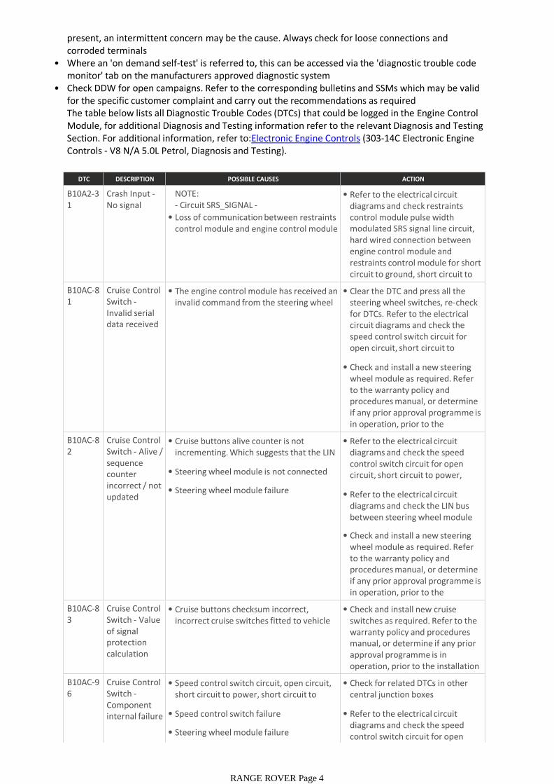
• Check DDW for open campaigns. Refer to the corresponding bulletins and SSMs which may be valid for the specific customer complaint and carry out the recommendations as requiredThe table below lists all Diagnostic Trouble Codes (DTCs) that could be logged in the Engine Control Module, for additional Diagnosis and Testing information refer to the relevant Diagnosis and Testing Section. For additional information, refer to:Electronic Engine Controls (303-14C Electronic Engine Controls - V8 N/A 5.0L Petrol, Diagnosis and Testing).
DTC DESCRIPTION POSSIBLE CAUSES ACTION
B10A2-31
Crash Input -No signal
NOTE:- Circuit SRS_SIGNAL -
• Loss of communication between restraints control module and engine control module
• Refer to the electrical circuit diagrams and check restraints control module pulse width modulated SRS signal line circuit, hard wired connection between engine control module and restraints control module for short circuit to ground, short circuit to power, open circuit. Repair circuit B10AC-8
1Cruise Control Switch -Invalid serial data received
• The engine control module has received an invalid command from the steering wheel switch pack
• Clear the DTC and press all the steering wheel switches, re-check for DTCs. Refer to the electrical circuit diagrams and check the speed control switch circuit for open circuit, short circuit to power, short circuit to ground,
• Check and install a new steering wheel module as required. Refer to the warranty policy and procedures manual, or determine if any prior approval programme is in operation, prior to the installation of a new B10AC-8
2Cruise Control Switch - Alive / sequence counter incorrect / not updated
• Cruise buttons alive counter is not incrementing. Which suggests that the LIN bus is faulty
• Steering wheel module is not connected
• Steering wheel module failure
• Refer to the electrical circuit diagrams and check the speed control switch circuit for open circuit, short circuit to power, short circuit to ground,
• Refer to the electrical circuit diagrams and check the LIN bus between steering wheel module and the CAN gateway
• Check and install a new steering wheel module as required. Refer to the warranty policy and procedures manual, or determine if any prior approval programme is in operation, prior to the installation of a new B10AC-8
3Cruise Control Switch - Value of signal protection calculation incorrect
• Cruise buttons checksum incorrect, incorrect cruise switches fitted to vehicle
• Check and install new cruise switches as required. Refer to the warranty policy and procedures manual, or determine if any prior approval programme is in operation, prior to the installation of a new module/componentB10AC-9
6Cruise Control Switch -Component internal failure
• Speed control switch circuit, open circuit, short circuit to power, short circuit to ground, disconnected
• Speed control switch failure
• Steering wheel module failure
• Check for related DTCs in other central junction boxes
• Refer to the electrical circuit diagrams and check the speed control switch circuit for open circuit, short circuit to power,
RANGE ROVER Page 4
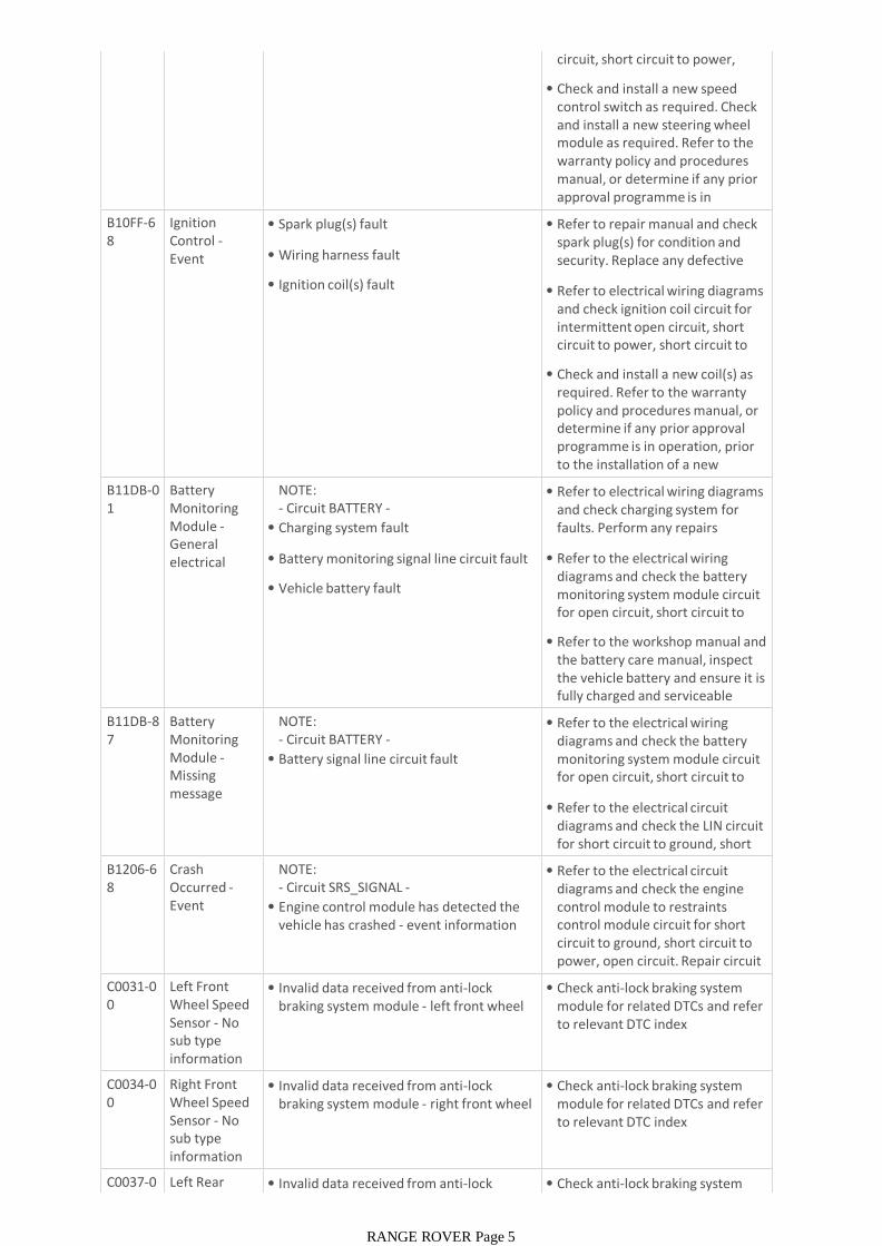
circuit, short circuit to power, short circuit to ground,
• Check and install a new speed control switch as required. Check and install a new steering wheel module as required. Refer to the warranty policy and procedures manual, or determine if any prior approval programme is in operation, prior to the installation B10FF-6
8Ignition Control -Event information
• Spark plug(s) fault
• Wiring harness fault
• Ignition coil(s) fault
• Refer to repair manual and check spark plug(s) for condition and security. Replace any defective components as required
• Refer to electrical wiring diagrams and check ignition coil circuit for intermittent open circuit, short circuit to power, short circuit to ground
• Check and install a new coil(s) as required. Refer to the warranty policy and procedures manual, or determine if any prior approval programme is in operation, prior to the installation of a new module/componentB11DB-0
1Battery Monitoring Module -General electrical failure
NOTE:- Circuit BATTERY -
• Charging system fault
• Battery monitoring signal line circuit fault
• Vehicle battery fault
• Refer to electrical wiring diagrams and check charging system for faults. Perform any repairs required
• Refer to the electrical wiring diagrams and check the battery monitoring system module circuit for open circuit, short circuit to ground, short circuit to power
• Refer to the workshop manual and the battery care manual, inspect the vehicle battery and ensure it is fully charged and serviceable before performing further tests
B11DB-87
Battery Monitoring Module -Missing message
NOTE:- Circuit BATTERY -
• Battery signal line circuit fault
• Refer to the electrical wiring diagrams and check the battery monitoring system module circuit for open circuit, short circuit to ground, short circuit to power
• Refer to the electrical circuit diagrams and check the LIN circuit for short circuit to ground, short circuit to power, open circuit
B1206-68
Crash Occurred -Event information
NOTE:- Circuit SRS_SIGNAL -
• Engine control module has detected the vehicle has crashed - event information DTC only
• Refer to the electrical circuit diagrams and check the engine control module to restraints control module circuit for short circuit to ground, short circuit to power, open circuit. Repair circuit as required, clear the DTC and C0031-0
0Left Front Wheel Speed Sensor - No sub type information
• Invalid data received from anti-lock braking system module - left front wheel speed signal fault
• Check anti-lock braking system module for related DTCs and refer to relevant DTC index
C0034-00
Right Front Wheel Speed Sensor - No sub type information
• Invalid data received from anti-lock braking system module - right front wheel speed signal fault
• Check anti-lock braking system module for related DTCs and refer to relevant DTC index
C0037-00
Left Rear Wheel Speed
• Invalid data received from anti-lock braking system module - left rear wheel
• Check anti-lock braking system module for related DTCs and refer
RANGE ROVER Page 5
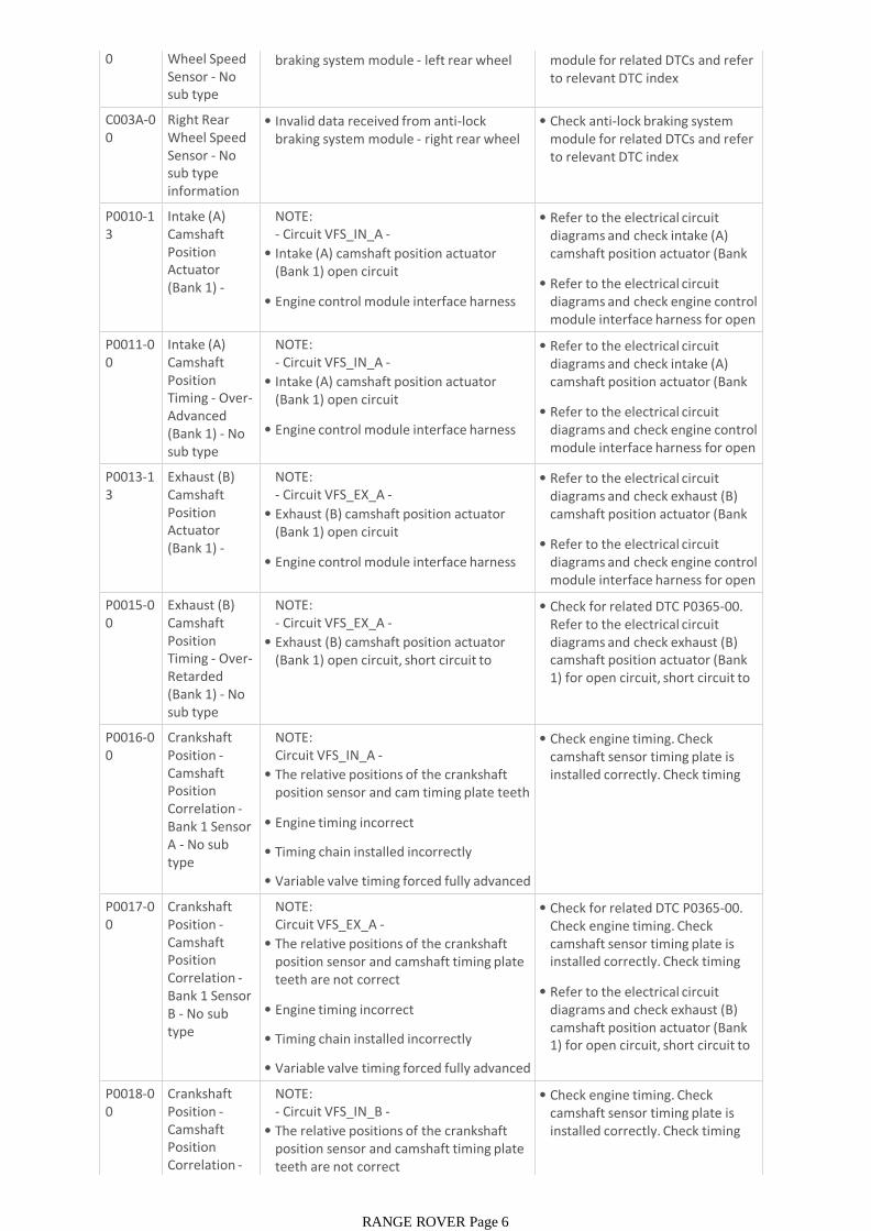
0 Wheel Speed Sensor - No sub type information
• Invalid data received from anti-lock braking system module - left rear wheel speed signal fault
• Check anti-lock braking system module for related DTCs and refer to relevant DTC index
C003A-00
Right Rear Wheel Speed Sensor - No sub type information
• Invalid data received from anti-lock braking system module - right rear wheel speed signal fault
• Check anti-lock braking system module for related DTCs and refer to relevant DTC index
P0010-13
Intake (A) Camshaft Position Actuator (Bank 1) -Circuit open
NOTE:- Circuit VFS_IN_A -
• Intake (A) camshaft position actuator (Bank 1) open circuit
• Engine control module interface harness open circuit
• Refer to the electrical circuit diagrams and check intake (A) camshaft position actuator (Bank 1) circuit for open circuit
• Refer to the electrical circuit diagrams and check engine control module interface harness for open circuit
P0011-00
Intake (A) Camshaft Position Timing - Over-Advanced (Bank 1) - No sub type information
NOTE:- Circuit VFS_IN_A -
• Intake (A) camshaft position actuator (Bank 1) open circuit
• Engine control module interface harness open circuit
• Refer to the electrical circuit diagrams and check intake (A) camshaft position actuator (Bank 1) circuit for open circuit
• Refer to the electrical circuit diagrams and check engine control module interface harness for open circuit
P0013-13
Exhaust (B) Camshaft Position Actuator (Bank 1) -Circuit open
NOTE:- Circuit VFS_EX_A -
• Exhaust (B) camshaft position actuator (Bank 1) open circuit
• Engine control module interface harness open circuit
• Refer to the electrical circuit diagrams and check exhaust (B) camshaft position actuator (Bank 1) circuit for open circuit
• Refer to the electrical circuit diagrams and check engine control module interface harness for open circuit
P0015-00
Exhaust (B) Camshaft Position Timing - Over-Retarded (Bank 1) - No sub type information
NOTE:- Circuit VFS_EX_A -
• Exhaust (B) camshaft position actuator (Bank 1) open circuit, short circuit to ground, short circuit to power
• Check for related DTC P0365-00. Refer to the electrical circuit diagrams and check exhaust (B) camshaft position actuator (Bank 1) for open circuit, short circuit to ground, short circuit to power
P0016-00
Crankshaft Position -Camshaft Position Correlation -Bank 1 Sensor A - No sub type information
NOTE:Circuit VFS_IN_A -
• The relative positions of the crankshaft position sensor and cam timing plate teeth are not correct
• Engine timing incorrect
• Timing chain installed incorrectly
• Variable valve timing forced fully advanced
• Check engine timing. Check camshaft sensor timing plate is installed correctly. Check timing chain is installed correctly
P0017-00
Crankshaft Position -Camshaft Position Correlation -Bank 1 Sensor B - No sub type information
NOTE:Circuit VFS_EX_A -
• The relative positions of the crankshaft position sensor and camshaft timing plate teeth are not correct
• Engine timing incorrect
• Timing chain installed incorrectly
• Variable valve timing forced fully advanced
• Check for related DTC P0365-00. Check engine timing. Check camshaft sensor timing plate is installed correctly. Check timing chain is installed correctly
• Refer to the electrical circuit diagrams and check exhaust (B) camshaft position actuator (Bank 1) for open circuit, short circuit to ground, short circuit to power
P0018-00
Crankshaft Position -Camshaft Position Correlation -Bank 2 Sensor
NOTE:- Circuit VFS_IN_B -
• The relative positions of the crankshaft position sensor and camshaft timing plate teeth are not correct
• Check engine timing. Check camshaft sensor timing plate is installed correctly. Check timing chain is installed correctly
RANGE ROVER Page 6
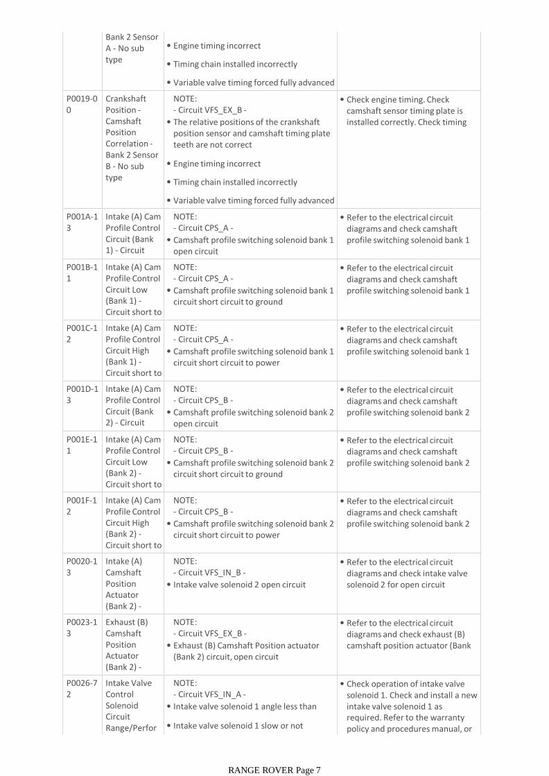
Bank 2 Sensor A - No sub type information
teeth are not correct
• Engine timing incorrect
• Timing chain installed incorrectly
• Variable valve timing forced fully advanced
P0019-00
Crankshaft Position -Camshaft Position Correlation -Bank 2 Sensor B - No sub type information
NOTE:- Circuit VFS_EX_B -
• The relative positions of the crankshaft position sensor and camshaft timing plate teeth are not correct
• Engine timing incorrect
• Timing chain installed incorrectly
• Variable valve timing forced fully advanced
• Check engine timing. Check camshaft sensor timing plate is installed correctly. Check timing chain is installed correctly
P001A-13
Intake (A) Cam Profile Control Circuit (Bank 1) - Circuit open
NOTE:- Circuit CPS_A -
• Camshaft profile switching solenoid bank 1 open circuit
• Refer to the electrical circuit diagrams and check camshaft profile switching solenoid bank 1 for open circuit
P001B-11
Intake (A) Cam Profile Control Circuit Low (Bank 1) -Circuit short to ground
NOTE:- Circuit CPS_A -
• Camshaft profile switching solenoid bank 1 circuit short circuit to ground
• Refer to the electrical circuit diagrams and check camshaft profile switching solenoid bank 1 circuit for short circuit to ground
P001C-12
Intake (A) Cam Profile Control Circuit High (Bank 1) -Circuit short to battery
NOTE:- Circuit CPS_A -
• Camshaft profile switching solenoid bank 1 circuit short circuit to power
• Refer to the electrical circuit diagrams and check camshaft profile switching solenoid bank 1 circuit for short circuit to power
P001D-13
Intake (A) Cam Profile Control Circuit (Bank 2) - Circuit open
NOTE:- Circuit CPS_B -
• Camshaft profile switching solenoid bank 2 open circuit
• Refer to the electrical circuit diagrams and check camshaft profile switching solenoid bank 2 for open circuit
P001E-11
Intake (A) Cam Profile Control Circuit Low (Bank 2) -Circuit short to ground
NOTE:- Circuit CPS_B -
• Camshaft profile switching solenoid bank 2 circuit short circuit to ground
• Refer to the electrical circuit diagrams and check camshaft profile switching solenoid bank 2 circuit for short circuit to ground
P001F-12
Intake (A) Cam Profile Control Circuit High (Bank 2) -Circuit short to battery
NOTE:- Circuit CPS_B -
• Camshaft profile switching solenoid bank 2 circuit short circuit to power
• Refer to the electrical circuit diagrams and check camshaft profile switching solenoid bank 2 circuit for short circuit to power
P0020-13
Intake (A) Camshaft Position Actuator (Bank 2) -Circuit open
NOTE:- Circuit VFS_IN_B -
• Intake valve solenoid 2 open circuit
• Refer to the electrical circuit diagrams and check intake valve solenoid 2 for open circuit
P0023-13
Exhaust (B) Camshaft Position Actuator (Bank 2) -Circuit open
NOTE:- Circuit VFS_EX_B -
• Exhaust (B) Camshaft Position actuator (Bank 2) circuit, open circuit
• Refer to the electrical circuit diagrams and check exhaust (B) camshaft position actuator (Bank 2) circuit for open circuit
P0026-72
Intake Valve Control Solenoid Circuit Range/Performance (Bank
NOTE:- Circuit VFS_IN_A -
• Intake valve solenoid 1 angle less than target
• Intake valve solenoid 1 slow or not operating
• Check operation of intake valve solenoid 1. Check and install a new intake valve solenoid 1 as required. Refer to the warranty policy and procedures manual, or determine if any prior approval
RANGE ROVER Page 7

mance (Bank 1) - Actuator stuck open
policy and procedures manual, or determine if any prior approval programme is in operation, prior to the installation of a new P0026-7
7Intake Valve Control Solenoid Circuit Range/Performance (Bank 1) -Commanded position not
NOTE:- Circuit VFS_IN_A -
• Intake valve solenoid 1 angle greater than target
• Intake valve solenoid 1 not returning to target in time
• Intake valve solenoid 1 stuck advanced
• Check operation of intake valve solenoid 1. Check and install a new intake valve solenoid 1 as required. Refer to the warranty policy and procedures manual, or determine if any prior approval programme is in operation, prior to the installation of a new
P0027-72
Exhaust Valve Control Solenoid Circuit Range/Performance (Bank 1) - Actuator stuck open
NOTE:- Circuit VFS_EX_A -
• Exhaust valve solenoid 1 angle less than target
• Exhaust valve solenoid 1 slow or not operating
• Check operation of exhaust valve solenoid 1. Check and install a new exhaust valve solenoid 1 as required. Refer to the warranty policy and procedures manual, or determine if any prior approval programme is in operation, prior to the installation of a new P0027-7
7Exhaust Valve Control Solenoid Circuit Range/Performance (Bank 1) -Commanded position not
NOTE:- Circuit VFS_EX_A -
• Exhaust valve solenoid 1 angle greater than target
• Exhaust valve solenoid 1 not returning to target in time
• Exhaust valve solenoid 1 stuck advanced
• Check operation of exhaust valve solenoid 1. Check and install a new exhaust valve solenoid 1 as required. Refer to the warranty policy and procedures manual, or determine if any prior approval programme is in operation, prior to the installation of a new
P0028-72
Intake Valve Control Solenoid Circuit Range/Performance (Bank 2) - Actuator stuck open
NOTE:- Circuit VFS_IN_B -
• Intake valve solenoid 2 angle less than target
• Intake valve solenoid 2 slow or not operating
• Check operation of intake valve solenoid 2. Check and install a new intake valve solenoid 2 as required. Refer to the warranty policy and procedures manual, or determine if any prior approval programme is in operation, prior to the installation of a new P0028-7
7Intake Valve Control Solenoid Circuit Range/Performance (Bank 2) -Commanded position not
NOTE:- Circuit VFS_IN_B -
• Intake valve solenoid 2 angle greater than target
• Intake valve solenoid 2 not returning to target in time
• Intake valve solenoid 2 stuck advanced
• Check operation of intake valve solenoid 2. Check and install a new intake valve solenoid 2 as required. Refer to the warranty policy and procedures manual, or determine if any prior approval programme is in operation, prior to the installation of a new
P0029-72
Exhaust Valve Control Solenoid Circuit Range/Performance (Bank 2) - Actuator stuck open
NOTE:- Circuit VFS_EX_B -
• Exhaust valve solenoid 2 angle less than target
• Exhaust valve solenoid 2 slow or not operating
• Check operation of exhaust valve solenoid 2. Check and install a new exhaust valve solenoid 2 as required. Refer to the warranty policy and procedures manual, or determine if any prior approval programme is in operation, prior to the installation of a new P0029-7
7Exhaust Valve Control Solenoid Circuit Range/Performance (Bank 2) -Commanded position not
NOTE:- Circuit VFS_EX_B -
• Exhaust valve solenoid 2 angle greater than target
• Exhaust valve solenoid 2 not returning to target in time
• Exhaust valve solenoid 2 stuck advanced
• Check operation of exhaust valve solenoid 2. Check and install a new exhaust valve solenoid 2 as required. Refer to the warranty policy and procedures manual, or determine if any prior approval programme is in operation, prior to the installation of a new
P0031-11
HO2S Heater Control Circuit Low (Bank 1, Sensor 1) -Circuit short to
NOTES:
• - Circuit HTR_CTRL_A_UPSTREAM -
• LR - Circuit UHEGO HEATER A -
• Pre catalyst oxygen sensor-odd heater
• Using the manufacturer approved diagnostic system check datalogger signal, Oxygen Sensor (O2S) Heater Duty Cycle Bank 1 Sensor 1 (0x03A1)
RANGE ROVER Page 8
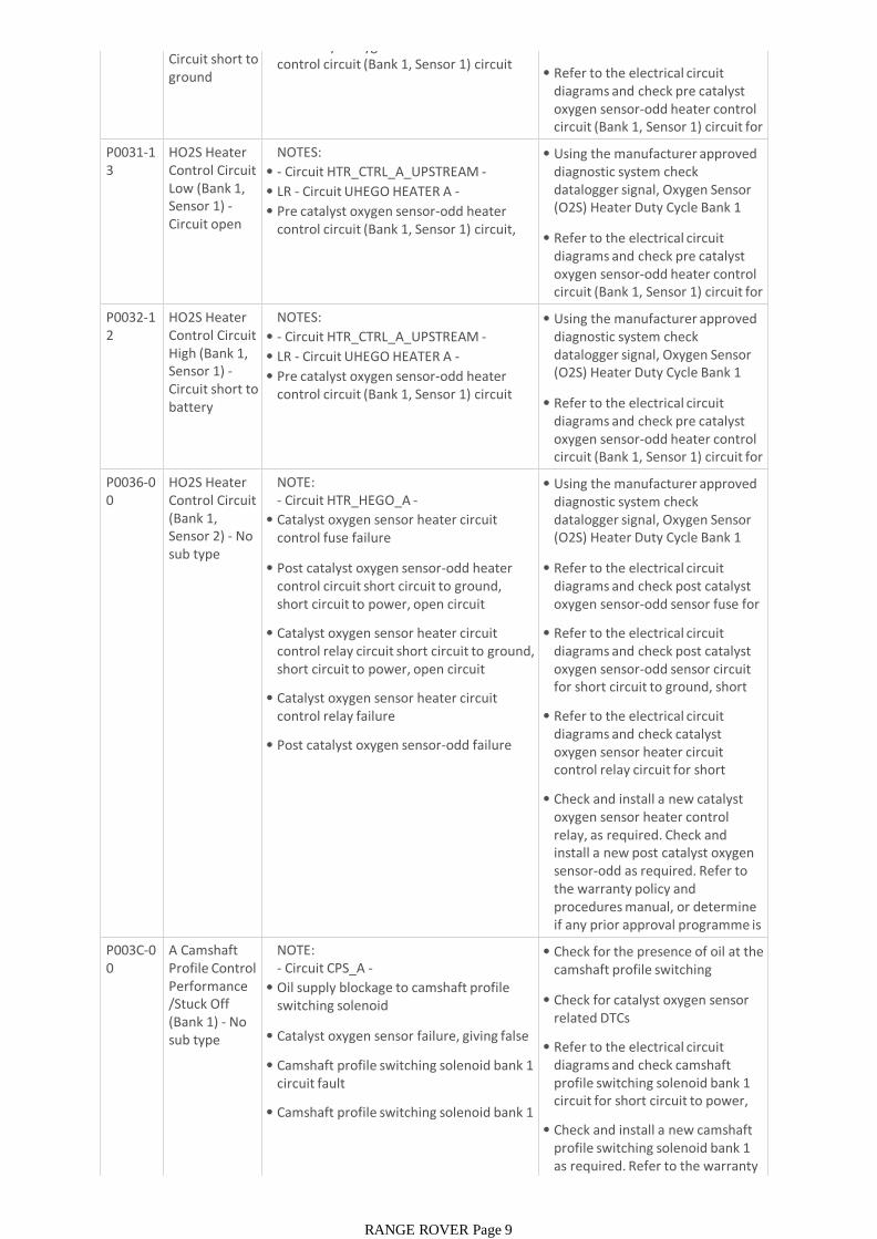
Circuit short to ground
• Pre catalyst oxygen sensor-odd heater control circuit (Bank 1, Sensor 1) circuit short circuit to ground
(O2S) Heater Duty Cycle Bank 1 Sensor 1 (0x03A1)
• Refer to the electrical circuit diagrams and check pre catalyst oxygen sensor-odd heater control circuit (Bank 1, Sensor 1) circuit for short circuit to ground
P0031-13
HO2S Heater Control Circuit Low (Bank 1, Sensor 1) -Circuit open
NOTES:
• - Circuit HTR_CTRL_A_UPSTREAM -
• LR - Circuit UHEGO HEATER A -
• Pre catalyst oxygen sensor-odd heater control circuit (Bank 1, Sensor 1) circuit, open circuit
• Using the manufacturer approved diagnostic system check datalogger signal, Oxygen Sensor (O2S) Heater Duty Cycle Bank 1 Sensor 1 (0x03A1)
• Refer to the electrical circuit diagrams and check pre catalyst oxygen sensor-odd heater control circuit (Bank 1, Sensor 1) circuit for open circuit
P0032-12
HO2S Heater Control Circuit High (Bank 1, Sensor 1) -Circuit short to battery
NOTES:
• - Circuit HTR_CTRL_A_UPSTREAM -
• LR - Circuit UHEGO HEATER A -
• Pre catalyst oxygen sensor-odd heater control circuit (Bank 1, Sensor 1) circuit short circuit to power
• Using the manufacturer approved diagnostic system check datalogger signal, Oxygen Sensor (O2S) Heater Duty Cycle Bank 1 Sensor 1 (0x03A1)
• Refer to the electrical circuit diagrams and check pre catalyst oxygen sensor-odd heater control circuit (Bank 1, Sensor 1) circuit for short circuit to power
P0036-00
HO2S Heater Control Circuit (Bank 1, Sensor 2) - No sub type information
NOTE:- Circuit HTR_HEGO_A -
• Catalyst oxygen sensor heater circuit control fuse failure
• Post catalyst oxygen sensor-odd heater control circuit short circuit to ground, short circuit to power, open circuit
• Catalyst oxygen sensor heater circuit control relay circuit short circuit to ground, short circuit to power, open circuit
• Catalyst oxygen sensor heater circuit control relay failure
• Post catalyst oxygen sensor-odd failure
• Using the manufacturer approved diagnostic system check datalogger signal, Oxygen Sensor (O2S) Heater Duty Cycle Bank 1 Sensor 2 (0x03A2)
• Refer to the electrical circuit diagrams and check post catalyst oxygen sensor-odd sensor fuse for open circuit
• Refer to the electrical circuit diagrams and check post catalyst oxygen sensor-odd sensor circuit for short circuit to ground, short circuit to power, open circuit
• Refer to the electrical circuit diagrams and check catalyst oxygen sensor heater circuit control relay circuit for short circuit to ground, short circuit to
• Check and install a new catalyst oxygen sensor heater control relay, as required. Check and install a new post catalyst oxygen sensor-odd as required. Refer to the warranty policy and procedures manual, or determine if any prior approval programme is in operation, prior to the P003C-0
0A Camshaft Profile Control Performance /Stuck Off (Bank 1) - No sub type information
NOTE:- Circuit CPS_A -
• Oil supply blockage to camshaft profile switching solenoid
• Catalyst oxygen sensor failure, giving false flag
• Camshaft profile switching solenoid bank 1 circuit fault
• Camshaft profile switching solenoid bank 1 fault
• Check for the presence of oil at the camshaft profile switching solenoid
• Check for catalyst oxygen sensor related DTCs
• Refer to the electrical circuit diagrams and check camshaft profile switching solenoid bank 1 circuit for short circuit to power, short circuit to ground, open
• Check and install a new camshaft profile switching solenoid bank 1 as required. Refer to the warranty policy and procedures manual, or
RANGE ROVER Page 9
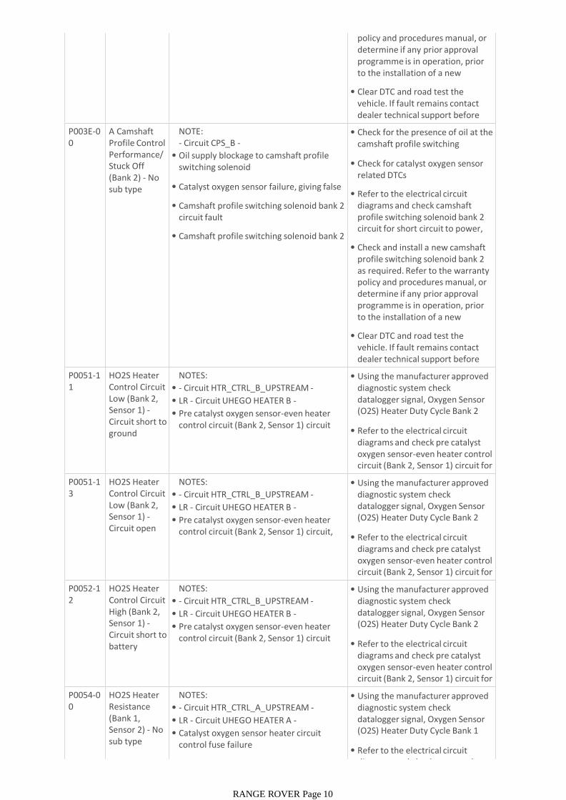
policy and procedures manual, or determine if any prior approval programme is in operation, prior to the installation of a new module/component
• Clear DTC and road test the vehicle. If fault remains contact dealer technical support before carrying out any further work
P003E-00
A Camshaft Profile Control Performance/ Stuck Off (Bank 2) - No sub type information
NOTE:- Circuit CPS_B -
• Oil supply blockage to camshaft profile switching solenoid
• Catalyst oxygen sensor failure, giving false flag
• Camshaft profile switching solenoid bank 2 circuit fault
• Camshaft profile switching solenoid bank 2 fault
• Check for the presence of oil at the camshaft profile switching solenoid
• Check for catalyst oxygen sensor related DTCs
• Refer to the electrical circuit diagrams and check camshaft profile switching solenoid bank 2 circuit for short circuit to power, short circuit to ground, open
• Check and install a new camshaft profile switching solenoid bank 2 as required. Refer to the warranty policy and procedures manual, or determine if any prior approval programme is in operation, prior to the installation of a new module/component
• Clear DTC and road test the vehicle. If fault remains contact dealer technical support before carrying out any further work
P0051-11
HO2S Heater Control Circuit Low (Bank 2, Sensor 1) -Circuit short to ground
NOTES:
• - Circuit HTR_CTRL_B_UPSTREAM -
• LR - Circuit UHEGO HEATER B -
• Pre catalyst oxygen sensor-even heater control circuit (Bank 2, Sensor 1) circuit short circuit to ground
• Using the manufacturer approved diagnostic system check datalogger signal, Oxygen Sensor (O2S) Heater Duty Cycle Bank 2 Sensor 1 (0x03A4)
• Refer to the electrical circuit diagrams and check pre catalyst oxygen sensor-even heater control circuit (Bank 2, Sensor 1) circuit for short circuit to ground
P0051-13
HO2S Heater Control Circuit Low (Bank 2, Sensor 1) -Circuit open
NOTES:
• - Circuit HTR_CTRL_B_UPSTREAM -
• LR - Circuit UHEGO HEATER B -
• Pre catalyst oxygen sensor-even heater control circuit (Bank 2, Sensor 1) circuit, open circuit
• Using the manufacturer approved diagnostic system check datalogger signal, Oxygen Sensor (O2S) Heater Duty Cycle Bank 2 Sensor 1 (0x03A4)
• Refer to the electrical circuit diagrams and check pre catalyst oxygen sensor-even heater control circuit (Bank 2, Sensor 1) circuit for open circuit
P0052-12
HO2S Heater Control Circuit High (Bank 2, Sensor 1) -Circuit short to battery
NOTES:
• - Circuit HTR_CTRL_B_UPSTREAM -
• LR - Circuit UHEGO HEATER B -
• Pre catalyst oxygen sensor-even heater control circuit (Bank 2, Sensor 1) circuit short circuit to power
• Using the manufacturer approved diagnostic system check datalogger signal, Oxygen Sensor (O2S) Heater Duty Cycle Bank 2 Sensor 1 (0x03A4)
• Refer to the electrical circuit diagrams and check pre catalyst oxygen sensor-even heater control circuit (Bank 2, Sensor 1) circuit for short circuit to power
P0054-00
HO2S Heater Resistance (Bank 1, Sensor 2) - No sub type information
NOTES:
• - Circuit HTR_CTRL_A_UPSTREAM -
• LR - Circuit UHEGO HEATER A -
• Catalyst oxygen sensor heater circuit control fuse failure
• Post catalyst oxygen sensor-odd heater
• Using the manufacturer approved diagnostic system check datalogger signal, Oxygen Sensor (O2S) Heater Duty Cycle Bank 1 Sensor 1 (0x03A1)
• Refer to the electrical circuit diagrams and check post catalyst
RANGE ROVER Page 10
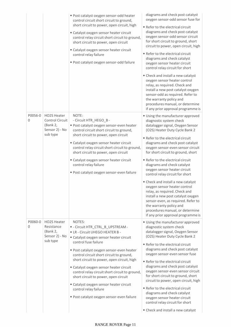
• Post catalyst oxygen sensor-odd heater control circuit short circuit to ground, short circuit to power, open circuit, high resistance
• Catalyst oxygen sensor heater circuit control relay circuit short circuit to ground, short circuit to power, open circuit
• Catalyst oxygen sensor heater circuit control relay failure
• Post catalyst oxygen sensor-odd failure
diagrams and check post catalyst oxygen sensor-odd sensor fuse for open circuit
• Refer to the electrical circuit diagrams and check post catalyst oxygen sensor-odd sensor circuit for short circuit to ground, short circuit to power, open circuit, high resistance
• Refer to the electrical circuit diagrams and check catalyst oxygen sensor heater circuit control relay circuit for short circuit to ground, short circuit to
• Check and install a new catalyst oxygen sensor heater control relay, as required. Check and install a new post catalyst oxygen sensor-odd as required. Refer to the warranty policy and procedures manual, or determine if any prior approval programme is in operation, prior to the P0056-0
0HO2S Heater Control Circuit (Bank 2, Sensor 2) - No sub type information
NOTE:- Circuit HTR_HEGO_B -
• Post catalyst oxygen sensor-even heater control circuit short circuit to ground, short circuit to power, open circuit
• Catalyst oxygen sensor heater circuit control relay circuit short circuit to ground, short circuit to power, open circuit
• Catalyst oxygen sensor heater circuit control relay failure
• Post catalyst oxygen sensor-even failure
• Using the manufacturer approved diagnostic system check datalogger signal, Oxygen Sensor (O2S) Heater Duty Cycle Bank 2 Sensor 2 (0x03A5)
• Refer to the electrical circuit diagrams and check post catalyst oxygen sensor-even sensor circuit for short circuit to ground, short circuit to power, open circuit
• Refer to the electrical circuit diagrams and check catalyst oxygen sensor heater circuit control relay circuit for short circuit to ground, short circuit to
• Check and install a new catalyst oxygen sensor heater control relay, as required. Check and install a new post catalyst oxygen sensor-even, as required. Refer to the warranty policy and procedures manual, or determine if any prior approval programme is in operation, prior to the P0060-0
0HO2S Heater Resistance (Bank 2, Sensor 2) - No sub type information
NOTES:
• - Circuit HTR_CTRL_B_UPSTREAM -
• LR - Circuit UHEGO HEATER B -
• Catalyst oxygen sensor heater circuit control fuse failure
• Post catalyst oxygen sensor-even heater control circuit short circuit to ground, short circuit to power, open circuit, high resistance
• Catalyst oxygen sensor heater circuit control relay circuit short circuit to ground, short circuit to power, open circuit
• Catalyst oxygen sensor heater circuit control relay failure
• Post catalyst oxygen sensor-even failure
• Using the manufacturer approved diagnostic system check datalogger signal, Oxygen Sensor (O2S) Heater Duty Cycle Bank 2 Sensor 2 (0x03A5)
• Refer to the electrical circuit diagrams and check post catalyst oxygen sensor-even sensor fuse for open circuit
• Refer to the electrical circuit diagrams and check post catalyst oxygen sensor-even sensor circuit for short circuit to ground, short circuit to power, open circuit, high resistance
• Refer to the electrical circuit diagrams and check catalyst oxygen sensor heater circuit control relay circuit for short circuit to ground, short circuit to
• Check and install a new catalyst oxygen sensor heater control
RANGE ROVER Page 11
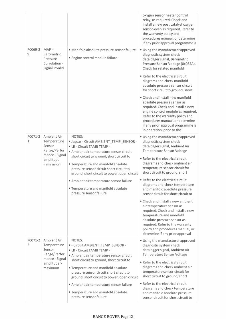
oxygen sensor heater control relay, as required. Check and install a new post catalyst oxygen sensor-even as required. Refer to the warranty policy and procedures manual, or determine if any prior approval programme is in operation, prior to the P0069-2
9MAP -Barometric Pressure Correlation -Signal invalid
• Manifold absolute pressure sensor failure
• Engine control module failure
• Using the manufacturer approved diagnostic system check datalogger signal, Barometric Pressure Sensor Voltage (0x035A). Check for related manifold absolute pressure sensor DTCs
• Refer to the electrical circuit diagrams and check manifold absolute pressure sensor circuit for short circuit to ground, short circuit to power, open circuit
• Check and install new manifold absolute pressure sensor as required. Check and install a new engine control module as required. Refer to the warranty policy and procedures manual, or determine if any prior approval programme is in operation, prior to the installation of a new P0071-2
1Ambient Air Temperature Sensor Range/Performance - Signal amplitude < minimum
NOTES:
• Jaguar - Circuit AMBIENT_TEMP_SENSOR -
• LR - Circuit TAMB TEMP -
• Ambient air temperature sensor circuit short circuit to ground, short circuit to power, open circuit
• Temperature and manifold absolute pressure sensor circuit short circuit to ground, short circuit to power, open circuit
• Ambient air temperature sensor failure
• Temperature and manifold absolute pressure sensor failure
• Using the manufacturer approved diagnostic system check datalogger signal, Ambient Air Temperature Sensor Voltage (0x03BA)
• Refer to the electrical circuit diagrams and check ambient air temperature sensor circuit for short circuit to ground, short circuit to power, open circuit
• Refer to the electrical circuit diagrams and check temperature and manifold absolute pressure sensor circuit for short circuit to ground, short circuit to power,
• Check and install a new ambient air temperature sensor as required. Check and install a new temperature and manifold absolute pressure sensor as required. Refer to the warranty policy and procedures manual, or determine if any prior approval programme is in operation, prior P0071-2
2Ambient Air Temperature Sensor Range/Performance - Signal amplitude > maximum
NOTES:
• - Circuit AMBIENT_TEMP_SENSOR -
• LR - Circuit TAMB TEMP -
• Ambient air temperature sensor circuit short circuit to ground, short circuit to power, open circuit
• Temperature and manifold absolute pressure sensor circuit short circuit to ground, short circuit to power, open circuit
• Ambient air temperature sensor failure
• Temperature and manifold absolute pressure sensor failure
• Using the manufacturer approved diagnostic system check datalogger signal, Ambient Air Temperature Sensor Voltage (0x03BA)
• Refer to the electrical circuit diagrams and check ambient air temperature sensor circuit for short circuit to ground, short circuit to power, open circuit
• Refer to the electrical circuit diagrams and check temperature and manifold absolute pressure sensor circuit for short circuit to ground, short circuit to power,
• Check and install a new ambient
RANGE ROVER Page 12
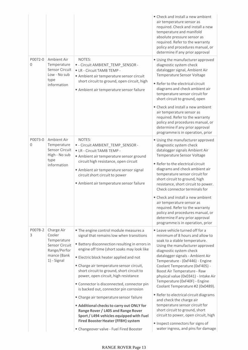
• Check and install a new ambient air temperature sensor as required. Check and install a new temperature and manifold absolute pressure sensor as required. Refer to the warranty policy and procedures manual, or determine if any prior approval programme is in operation, prior P0072-0
0Ambient Air Temperature Sensor Circuit Low - No sub type information
NOTES:
• - Circuit AMBIENT_TEMP_SENSOR -
• LR - Circuit TAMB TEMP -
• Ambient air temperature sensor circuit short circuit to ground, open circuit, high resistance
• Ambient air temperature sensor failure
• Using the manufacturer approved diagnostic system check datalogger signal, Ambient Air Temperature Sensor Voltage (0x03BA)
• Refer to the electrical circuit diagrams and check ambient air temperature sensor circuit for short circuit to ground, open circuit, high resistance
• Check and install a new ambient air temperature sensor as required. Refer to the warranty policy and procedures manual, or determine if any prior approval programme is in operation, prior to the installation of a new P0073-0
0Ambient Air Temperature Sensor Circuit High - No sub type information
NOTES:
• - Circuit AMBIENT_TEMP_SENSOR -
• LR - Circuit TAMB TEMP -
• Ambient air temperature sensor ground circuit high resistance, open circuit
• Ambient air temperature sensor signal circuit short circuit to power
• Ambient air temperature sensor failure
• Using the manufacturer approved diagnostic system check datalogger signals Ambient Air Temperature Sensor Voltage (0x03BA)
• Refer to the electrical circuit diagrams and check ambient air temperature sensor circuit for short circuit to ground, high resistance, short circuit to power. Check connector terminals for corrosion or damage
• Check and install a new ambient air temperature sensor as required. Refer to the warranty policy and procedures manual, or determine if any prior approval programme is in operation, prior to the installation of a new P007B-2
3Charge Air Cooler Temperature Sensor Circuit Range/Performance (Bank 1) - Signal stuck low
• The engine control module measures a signal that remains low when transitions are expected
• Battery disconnection resulting in errors in engine off time (short soaks may look like long soaks)
• Electric block heater applied and not detected
• Charge air temperature sensor circuit, short circuit to ground, short circuit to power, open circuit, high resistance
• Connector is disconnected, connector pin is backed out, connector pin corrosion
• Charge air temperature sensor failure
• Additional checks to carry out ONLY for Range Rover / L405 and Range Rover Sport / L494 vehicles equipped with Fuel Fired Booster Heater (FFBH) system
• Changeover valve - Fuel Fired Booster Heater (FFBH) system failure
• Leave vehicle turned off for a minimum of 8 hours and allow to soak to a stable temperature. Using the manufacturer approved diagnostic system check datalogger signals - Ambient Air Temperature - (0xF446) - Engine Coolant Temperature (0xF405) -Boost Air Temperature - Raw physical value (0x0341) - Intake Air Temperature (0xF40F) - Engine Coolant Temperature #2 (0x0489). All sensors should be within 20
• Refer to electrical circuit diagrams and check the charge air temperature sensor circuit for short circuit to ground, short circuit to power, open circuit, high resistance
• Inspect connectors for signs of water ingress, and pins for damage and/or corrosion
RANGE ROVER Page 13
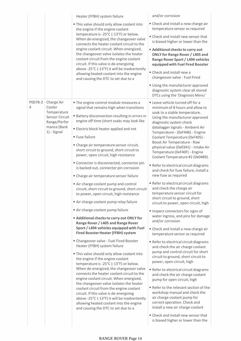
Heater (FFBH) system failure
• This valve should only allow coolant into the engine if the engine coolant temperature is -25°C (-13°F) or below. When de-energized, the changeover valve connects the heater coolant circuit to the engine coolant circuit. When energized, the changeover valve isolates the heater coolant circuit from the engine coolant circuit. If this valve is de-energizing above -25°C (-13°F) it will be inadvertently allowing heated coolant into the engine and causing the DTC to set due to a mismatch between coolant temperature
and/or corrosion
• Check and install a new charge air temperature sensor as required
• Check and install new sensor that is biased higher or lower than the other sensors
• Additional checks to carry out ONLY for Range Rover / L405 and Range Rover Sport / L494 vehicles equipped with Fuel Fired Booster Heater (FFBH) system
• Check and install new a changeover valve - Fuel Fired Booster Heater (FFBH) system
• Using the manufacturer approved diagnostic system clear all stored DTCs using the ‘Diagnosis Menu’ tab and retest
P007B-24
Charge Air Cooler Temperature Sensor Circuit Range/Performance (Bank 1) - Signal stuck high
• The engine control module measures a signal that remains high when transitions are expected
• Battery disconnection resulting in errors in engine off time (short soaks may look like long soaks)
• Electric block heater applied and not detected
• Fuse failure
• Charge air temperature sensor circuit, short circuit to ground, short circuit to power, open circuit, high resistance
• Connector is disconnected, connector pin is backed out, connector pin corrosion
• Charge air temperature sensor failure
• Air charge coolant pump and control circuit, short circuit to ground, short circuit to power, open circuit, high resistance
• Air charge coolant pump relay failure
• Air charge coolant pump failure
• Additional checks to carry out ONLY for Range Rover / L405 and Range Rover Sport / L494 vehicles equipped with Fuel Fired Booster Heater (FFBH) system
• Changeover valve - Fuel Fired Booster Heater (FFBH) system failure
• This valve should only allow coolant into the engine if the engine coolant temperature is -25°C (-13°F) or below. When de-energized, the changeover valve connects the heater coolant circuit to the engine coolant circuit. When energized, the changeover valve isolates the heater coolant circuit from the engine coolant circuit. If this valve is de-energizing above -25°C (-13°F) it will be inadvertently allowing heated coolant into the engine and causing the DTC to set due to a mismatch between coolant temperature
• Leave vehicle turned off for a minimum of 8 hours and allow to soak to a stable temperature. Using the manufacturer approved diagnostic system check datalogger signals - Ambient Air Temperature - (0xF446) - Engine Coolant Temperature (0xF405) -Boost Air Temperature - Raw physical value (0x0341) - Intake Air Temperature (0xF40F) - Engine Coolant Temperature #2 (0x0489). All sensors should be within 20
• Refer to electrical circuit diagrams and check for fuse failure, install a new fuse as required
• Refer to electrical circuit diagrams and check the charge air temperature sensor circuit for short circuit to ground, short circuit to power, open circuit, high resistance
• Inspect connectors for signs of water ingress, and pins for damage and/or corrosion
• Check and install a new charge air temperature sensor as required
• Refer to electrical circuit diagrams and check the air charge coolant pump and control circuit for short circuit to ground, short circuit to power, open circuit, high resistance
• Refer to electrical circuit diagrams and check the air charge coolant pump for open circuit, high resistance
• Refer to the relevant section of the workshop manual and check the air charge coolant pump for correct operation. Check and install a new air charge coolant pump as required
• Check and install new sensor that is biased higher or lower than the other sensors
• Additional checks to carry out
RANGE ROVER Page 14

• Additional checks to carry out ONLY for Range Rover / L405 and Range Rover Sport / L494 vehicles equipped with Fuel Fired Booster Heater (FFBH) system
• Check and install new a changeover valve - Fuel Fired Booster Heater (FFBH) system
• Using the manufacturer approved diagnostic system clear all stored DTCs using the ‘Diagnosis Menu’ tab and retest
P007B-29
Charge Air Cooler Temperature Sensor Circuit Range/Performance (Bank 1) - Signal invalid
• Battery disconnection resulting in errors in engine off time (short soaks may look like long soaks)
• Electric block heater applied and not detected
• Fuse failure
• Charge air temperature sensor circuit, short circuit to ground, short circuit to power, open circuit, high resistance
• Connector is disconnected, connector pin is backed out, connector pin corrosion
• Charge air temperature sensor failure
• Air charge coolant pump and control circuit, short circuit to ground, short circuit to power, open circuit, high resistance
• Air charge coolant pump relay failure
• Air charge coolant pump failure
• Leave vehicle turned off for a minimum of 8 hours and allow to soak to a stable temperature. Using the manufacturer approved diagnostic system check datalogger signals - Ambient Air Temperature - (0xF446) - Engine Coolant Temperature (0xF405) -Boost Air Temperature - Raw physical value (0x0341) - Intake Air Temperature (0xF40F) - Engine Coolant Temperature #2 (0x0489). All sensors should be within 20
• Refer to electrical circuit diagrams and check for fuse failure, install a new fuse as required
• Refer to electrical circuit diagrams and check the charge air temperature sensor circuit for short circuit to ground, short circuit to power, open circuit, high resistance
• Inspect connectors for signs of water ingress, and pins for damage and/or corrosion
• Check and install a new charge air temperature sensor as required
• Refer to electrical circuit diagrams and check the air charge coolant pump and control circuit for short circuit to ground, short circuit to power, open circuit, high resistance
• Refer to electrical circuit diagrams and check the air charge coolant pump for open circuit, high resistance
• Refer to the relevant section of the workshop manual and check the air charge coolant pump for correct operation. Check and install a new air charge coolant pump as required
• Using the manufacturer approved diagnostic system clear all stored DTCs using the ‘Diagnosis Menu’ tab and retest
P007C-00
Charge Air Cooler Temperature Sensor Circuit Low (Bank 1) -No sub type information
• Charge air temperature sensor circuit, short circuit to ground, short circuit to power, open circuit, high resistance
• Connector is disconnected, connector pin is backed out, connector pin corrosion
• Refer to electrical circuit diagrams and check the charge air temperature sensor circuit for short circuit to ground, short circuit to power, open circuit, high resistance
• Inspect connectors for signs of
RANGE ROVER Page 15
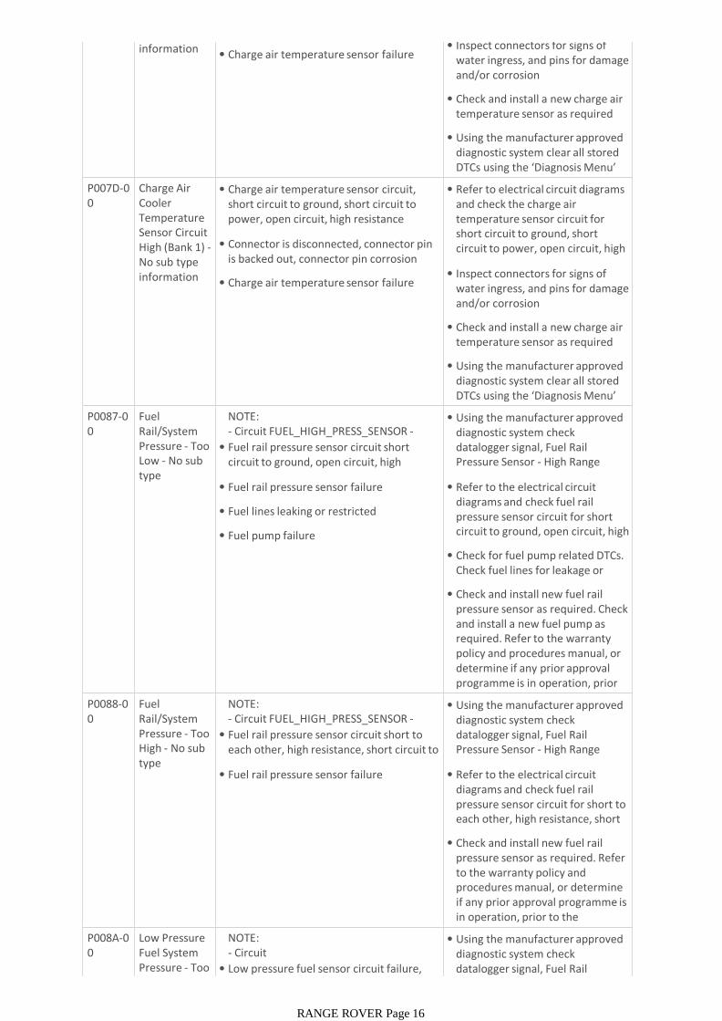
information • Charge air temperature sensor failure• Inspect connectors for signs of
water ingress, and pins for damage and/or corrosion
• Check and install a new charge air temperature sensor as required
• Using the manufacturer approved diagnostic system clear all stored DTCs using the ‘Diagnosis Menu’ tab and retest
P007D-00
Charge Air Cooler Temperature Sensor Circuit High (Bank 1) -No sub type information
• Charge air temperature sensor circuit, short circuit to ground, short circuit to power, open circuit, high resistance
• Connector is disconnected, connector pin is backed out, connector pin corrosion
• Charge air temperature sensor failure
• Refer to electrical circuit diagrams and check the charge air temperature sensor circuit for short circuit to ground, short circuit to power, open circuit, high resistance
• Inspect connectors for signs of water ingress, and pins for damage and/or corrosion
• Check and install a new charge air temperature sensor as required
• Using the manufacturer approved diagnostic system clear all stored DTCs using the ‘Diagnosis Menu’ tab and retest
P0087-00
Fuel Rail/System Pressure - Too Low - No sub type information
NOTE:- Circuit FUEL_HIGH_PRESS_SENSOR -
• Fuel rail pressure sensor circuit short circuit to ground, open circuit, high resistance
• Fuel rail pressure sensor failure
• Fuel lines leaking or restricted
• Fuel pump failure
• Using the manufacturer approved diagnostic system check datalogger signal, Fuel Rail Pressure Sensor - High Range Sensor Voltage (0x0377)
• Refer to the electrical circuit diagrams and check fuel rail pressure sensor circuit for short circuit to ground, open circuit, high resistance
• Check for fuel pump related DTCs. Check fuel lines for leakage or restriction
• Check and install new fuel rail pressure sensor as required. Check and install a new fuel pump as required. Refer to the warranty policy and procedures manual, or determine if any prior approval programme is in operation, prior to the installation of a new P0088-0
0Fuel Rail/System Pressure - Too High - No sub type information
NOTE:- Circuit FUEL_HIGH_PRESS_SENSOR -
• Fuel rail pressure sensor circuit short to each other, high resistance, short circuit to power
• Fuel rail pressure sensor failure
• Using the manufacturer approved diagnostic system check datalogger signal, Fuel Rail Pressure Sensor - High Range Sensor Voltage (0x0377)
• Refer to the electrical circuit diagrams and check fuel rail pressure sensor circuit for short to each other, high resistance, short circuit to power
• Check and install new fuel rail pressure sensor as required. Refer to the warranty policy and procedures manual, or determine if any prior approval programme is in operation, prior to the installation of a new P008A-0
0Low Pressure Fuel System Pressure - Too Low - No sub
NOTE:- Circuit LOW_PRESS_FUEL_PRESS_SENSOR -• Low pressure fuel sensor circuit failure, short circuit to ground, short circuit to
• Using the manufacturer approved diagnostic system check datalogger signal, Fuel Rail Pressure - Low Range Sensor
RANGE ROVER Page 16
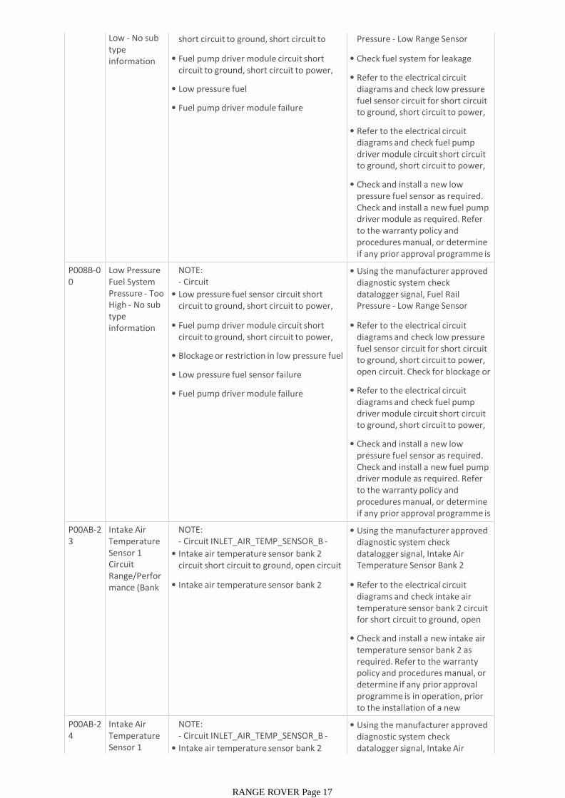
Low - No sub type information
• Low pressure fuel sensor circuit failure, short circuit to ground, short circuit to power, open circuit
• Fuel pump driver module circuit short circuit to ground, short circuit to power, open circuit
• Low pressure fuel
• Fuel pump driver module failure
datalogger signal, Fuel Rail Pressure - Low Range Sensor Voltage (0x0376)
• Check fuel system for leakage
• Refer to the electrical circuit diagrams and check low pressure fuel sensor circuit for short circuit to ground, short circuit to power, open circuit
• Refer to the electrical circuit diagrams and check fuel pump driver module circuit short circuit to ground, short circuit to power, open circuit
• Check and install a new low pressure fuel sensor as required. Check and install a new fuel pump driver module as required. Refer to the warranty policy and procedures manual, or determine if any prior approval programme is in operation, prior to the P008B-0
0Low Pressure Fuel System Pressure - Too High - No sub type information
NOTE:- Circuit LOW_PRESS_FUEL_PRESS_SENSOR -• Low pressure fuel sensor circuit short circuit to ground, short circuit to power, open circuit
• Fuel pump driver module circuit short circuit to ground, short circuit to power, open circuit
• Blockage or restriction in low pressure fuel line
• Low pressure fuel sensor failure
• Fuel pump driver module failure
• Using the manufacturer approved diagnostic system check datalogger signal, Fuel Rail Pressure - Low Range Sensor Voltage (0x0376)
• Refer to the electrical circuit diagrams and check low pressure fuel sensor circuit for short circuit to ground, short circuit to power, open circuit. Check for blockage or restriction in low pressure fuel line
• Refer to the electrical circuit diagrams and check fuel pump driver module circuit short circuit to ground, short circuit to power, open circuit
• Check and install a new low pressure fuel sensor as required. Check and install a new fuel pump driver module as required. Refer to the warranty policy and procedures manual, or determine if any prior approval programme is in operation, prior to the P00AB-2
3Intake Air Temperature Sensor 1 Circuit Range/Performance (Bank 2) - Signal
NOTE:- Circuit INLET_AIR_TEMP_SENSOR_B -
• Intake air temperature sensor bank 2 circuit short circuit to ground, open circuit
• Intake air temperature sensor bank 2 failure
• Using the manufacturer approved diagnostic system check datalogger signal, Intake Air Temperature Sensor Bank 2 (0x0312)
• Refer to the electrical circuit diagrams and check intake air temperature sensor bank 2 circuit for short circuit to ground, open circuit
• Check and install a new intake air temperature sensor bank 2 as required. Refer to the warranty policy and procedures manual, or determine if any prior approval programme is in operation, prior to the installation of a new module/componentP00AB-2
4Intake Air Temperature Sensor 1 Circuit
NOTE:- Circuit INLET_AIR_TEMP_SENSOR_B -
• Intake air temperature sensor bank 2 circuit short circuit to power
• Using the manufacturer approved diagnostic system check datalogger signal, Intake Air
RANGE ROVER Page 17
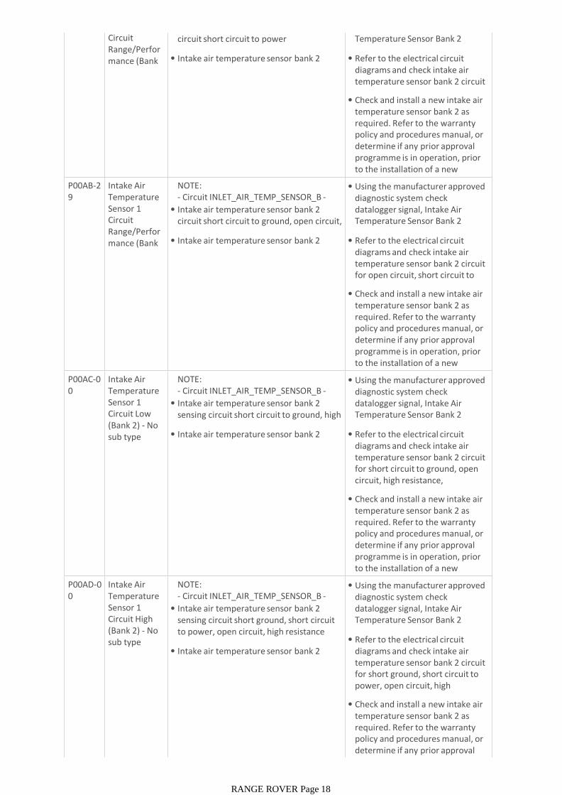
Circuit Range/Performance (Bank 2) - Signal
• Intake air temperature sensor bank 2 circuit short circuit to power
• Intake air temperature sensor bank 2 failure
datalogger signal, Intake Air Temperature Sensor Bank 2 (0x0312)
• Refer to the electrical circuit diagrams and check intake air temperature sensor bank 2 circuit for short circuit to power
• Check and install a new intake air temperature sensor bank 2 as required. Refer to the warranty policy and procedures manual, or determine if any prior approval programme is in operation, prior to the installation of a new module/componentP00AB-2
9Intake Air Temperature Sensor 1 Circuit Range/Performance (Bank 2) - Signal
NOTE:- Circuit INLET_AIR_TEMP_SENSOR_B -
• Intake air temperature sensor bank 2 circuit short circuit to ground, open circuit, short circuit to power
• Intake air temperature sensor bank 2 failure
• Using the manufacturer approved diagnostic system check datalogger signal, Intake Air Temperature Sensor Bank 2 (0x0312)
• Refer to the electrical circuit diagrams and check intake air temperature sensor bank 2 circuit for open circuit, short circuit to ground, short circuit to power
• Check and install a new intake air temperature sensor bank 2 as required. Refer to the warranty policy and procedures manual, or determine if any prior approval programme is in operation, prior to the installation of a new module/componentP00AC-0
0Intake Air Temperature Sensor 1 Circuit Low (Bank 2) - No sub type information
NOTE:- Circuit INLET_AIR_TEMP_SENSOR_B -
• Intake air temperature sensor bank 2 sensing circuit short circuit to ground, high resistance, disconnected
• Intake air temperature sensor bank 2 failure
• Using the manufacturer approved diagnostic system check datalogger signal, Intake Air Temperature Sensor Bank 2 (0x0312)
• Refer to the electrical circuit diagrams and check intake air temperature sensor bank 2 circuit for short circuit to ground, open circuit, high resistance, disconnected connector
• Check and install a new intake air temperature sensor bank 2 as required. Refer to the warranty policy and procedures manual, or determine if any prior approval programme is in operation, prior to the installation of a new module/componentP00AD-0
0Intake Air Temperature Sensor 1 Circuit High (Bank 2) - No sub type information
NOTE:- Circuit INLET_AIR_TEMP_SENSOR_B -
• Intake air temperature sensor bank 2 sensing circuit short ground, short circuit to power, open circuit, high resistance
• Intake air temperature sensor bank 2 failure
• Using the manufacturer approved diagnostic system check datalogger signal, Intake Air Temperature Sensor Bank 2 (0x0312)
• Refer to the electrical circuit diagrams and check intake air temperature sensor bank 2 circuit for short ground, short circuit to power, open circuit, high resistance. Check for backed out or
• Check and install a new intake air temperature sensor bank 2 as required. Refer to the warranty policy and procedures manual, or determine if any prior approval programme is in operation, prior
RANGE ROVER Page 18
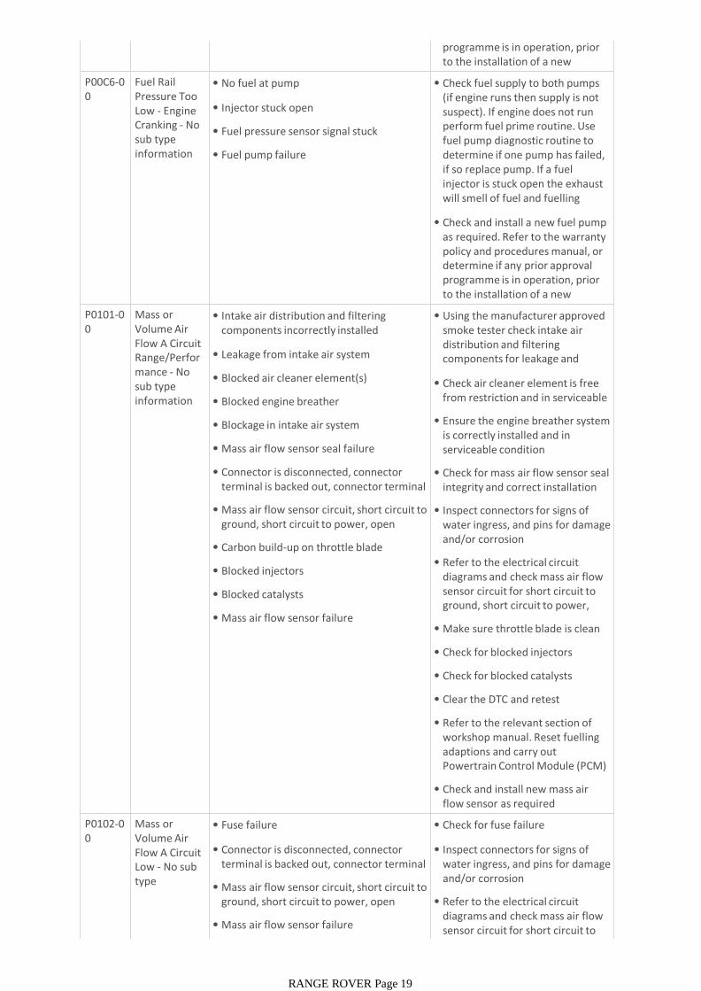
programme is in operation, prior to the installation of a new module/componentP00C6-0
0Fuel Rail Pressure Too Low - Engine Cranking - No sub type information
• No fuel at pump
• Injector stuck open
• Fuel pressure sensor signal stuck
• Fuel pump failure
• Check fuel supply to both pumps (if engine runs then supply is not suspect). If engine does not run perform fuel prime routine. Use fuel pump diagnostic routine to determine if one pump has failed, if so replace pump. If a fuel injector is stuck open the exhaust will smell of fuel and fuelling adaptions may indicate rich shift.
• Check and install a new fuel pump as required. Refer to the warranty policy and procedures manual, or determine if any prior approval programme is in operation, prior to the installation of a new module/componentP0101-0
0Mass or Volume Air Flow A Circuit Range/Performance - No sub type information
• Intake air distribution and filtering components incorrectly installed
• Leakage from intake air system
• Blocked air cleaner element(s)
• Blocked engine breather
• Blockage in intake air system
• Mass air flow sensor seal failure
• Connector is disconnected, connector terminal is backed out, connector terminal corrosion
• Mass air flow sensor circuit, short circuit to ground, short circuit to power, open circuit, high resistance
• Carbon build-up on throttle blade
• Blocked injectors
• Blocked catalysts
• Mass air flow sensor failure
• Using the manufacturer approved smoke tester check intake air distribution and filtering components for leakage and correct installation
• Check air cleaner element is free from restriction and in serviceable condition
• Ensure the engine breather system is correctly installed and in serviceable condition
• Check for mass air flow sensor seal integrity and correct installation
• Inspect connectors for signs of water ingress, and pins for damage and/or corrosion
• Refer to the electrical circuit diagrams and check mass air flow sensor circuit for short circuit to ground, short circuit to power, open circuit, high resistance
• Make sure throttle blade is clean of carbon
• Check for blocked injectors
• Check for blocked catalysts
• Clear the DTC and retest
• Refer to the relevant section of workshop manual. Reset fuelling adaptions and carry out Powertrain Control Module (PCM) Long Drive Cycle Self-Test
• Check and install new mass air flow sensor as required
P0102-00
Mass or Volume Air Flow A Circuit Low - No sub type information
• Fuse failure
• Connector is disconnected, connector terminal is backed out, connector terminal corrosion
• Mass air flow sensor circuit, short circuit to ground, short circuit to power, open circuit, high resistance
• Mass air flow sensor failure
• Check for fuse failure
• Inspect connectors for signs of water ingress, and pins for damage and/or corrosion
• Refer to the electrical circuit diagrams and check mass air flow sensor circuit for short circuit to ground, short circuit to power,
RANGE ROVER Page 19
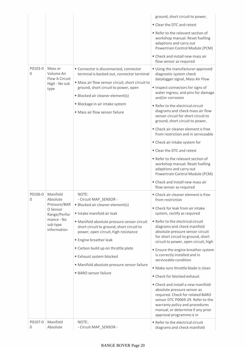
ground, short circuit to power, open circuit, high resistance
• Clear the DTC and retest
• Refer to the relevant section of workshop manual. Reset fuelling adaptions and carry out Powertrain Control Module (PCM) Long Drive Cycle Self-Test
• Check and install new mass air flow sensor as required
P0103-00
Mass or Volume Air Flow A Circuit High - No sub type information
• Connector is disconnected, connector terminal is backed out, connector terminal corrosion
• Mass air flow sensor circuit, short circuit to ground, short circuit to power, open circuit, high resistance
• Blocked air cleaner element(s)
• Blockage in air intake system
• Mass air flow sensor failure
• Using the manufacturer approved diagnostic system check datalogger signal, Mass Air Flow Sensor, Bank 1 (0x0314)
• Inspect connectors for signs of water ingress, and pins for damage and/or corrosion
• Refer to the electrical circuit diagrams and check mass air flow sensor circuit for short circuit to ground, short circuit to power, open circuit, high resistance
• Check air cleaner element is free from restriction and in serviceable condition
• Check air intake system for blockage
• Clear the DTC and retest
• Refer to the relevant section of workshop manual. Reset fuelling adaptions and carry out Powertrain Control Module (PCM) Long Drive Cycle Self-Test
• Check and install new mass air flow sensor as required
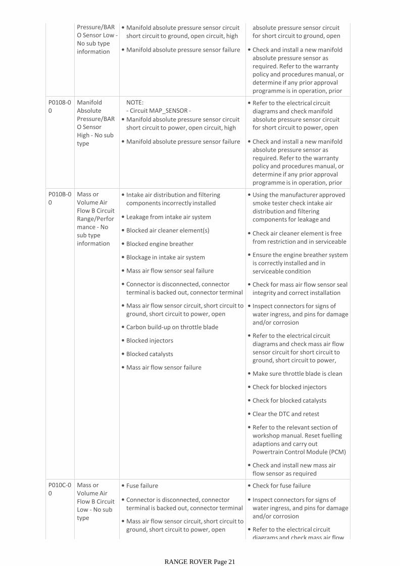
P0106-00
Manifold Absolute Pressure/BARO Sensor Range/Performance - No sub type information
NOTE:- Circuit MAP_SENSOR -
• Blocked air cleaner element(s)
• Intake manifold air leak
• Manifold absolute pressure sensor circuit short circuit to ground, short circuit to power, open circuit, high resistance
• Engine breather leak
• Carbon build up on throttle plate
• Exhaust system blocked
• Manifold absolute pressure sensor failure
• BARO sensor failure
• Check air cleaner element is free from restriction
• Check for leak from air intake system, rectify as required
• Refer to the electrical circuit diagrams and check manifold absolute pressure sensor circuit for short circuit to ground, short circuit to power, open circuit, high resistance
• Ensure the engine breather system is correctly installed and in serviceable condition
• Make sure throttle blade is clean of carbon
• Check for blocked exhaust
• Check and install a new manifold absolute pressure sensor as required. Check for related BARO sensor DTC P0069-29. Refer to the warranty policy and procedures manual, or determine if any prior approval programme is in operation, prior to the installation P0107-0
0Manifold Absolute Pressure/BAR
NOTE:- Circuit MAP_SENSOR -
• Manifold absolute pressure sensor circuit
• Refer to the electrical circuit diagrams and check manifold absolute pressure sensor circuit
RANGE ROVER Page 20
Pressure/BARO Sensor Low -No sub type information
• Manifold absolute pressure sensor circuit short circuit to ground, open circuit, high resistance
• Manifold absolute pressure sensor failure
diagrams and check manifold absolute pressure sensor circuit for short circuit to ground, open circuit, high resistance
• Check and install a new manifold absolute pressure sensor as required. Refer to the warranty policy and procedures manual, or determine if any prior approval programme is in operation, prior to the installation of a new P0108-0
0Manifold Absolute Pressure/BARO Sensor High - No sub type information
NOTE:- Circuit MAP_SENSOR -
• Manifold absolute pressure sensor circuit short circuit to power, open circuit, high resistance
• Manifold absolute pressure sensor failure
• Refer to the electrical circuit diagrams and check manifold absolute pressure sensor circuit for short circuit to power, open circuit, high resistance
• Check and install a new manifold absolute pressure sensor as required. Refer to the warranty policy and procedures manual, or determine if any prior approval programme is in operation, prior to the installation of a new P010B-0
0Mass or Volume Air Flow B Circuit Range/Performance - No sub type information
• Intake air distribution and filtering components incorrectly installed
• Leakage from intake air system
• Blocked air cleaner element(s)
• Blocked engine breather
• Blockage in intake air system
• Mass air flow sensor seal failure
• Connector is disconnected, connector terminal is backed out, connector terminal corrosion
• Mass air flow sensor circuit, short circuit to ground, short circuit to power, open circuit, high resistance
• Carbon build-up on throttle blade
• Blocked injectors
• Blocked catalysts
• Mass air flow sensor failure
• Using the manufacturer approved smoke tester check intake air distribution and filtering components for leakage and correct installation
• Check air cleaner element is free from restriction and in serviceable condition
• Ensure the engine breather system is correctly installed and in serviceable condition
• Check for mass air flow sensor seal integrity and correct installation
• Inspect connectors for signs of water ingress, and pins for damage and/or corrosion
• Refer to the electrical circuit diagrams and check mass air flow sensor circuit for short circuit to ground, short circuit to power, open circuit, high resistance
• Make sure throttle blade is clean of carbon
• Check for blocked injectors
• Check for blocked catalysts
• Clear the DTC and retest
• Refer to the relevant section of workshop manual. Reset fuelling adaptions and carry out Powertrain Control Module (PCM) Long Drive Cycle Self-Test
• Check and install new mass air flow sensor as required
P010C-00
Mass or Volume Air Flow B Circuit Low - No sub type information
• Fuse failure
• Connector is disconnected, connector terminal is backed out, connector terminal corrosion
• Mass air flow sensor circuit, short circuit to ground, short circuit to power, open circuit, high resistance
• Mass air flow sensor failure
• Check for fuse failure
• Inspect connectors for signs of water ingress, and pins for damage and/or corrosion
• Refer to the electrical circuit diagrams and check mass air flow
RANGE ROVER Page 21
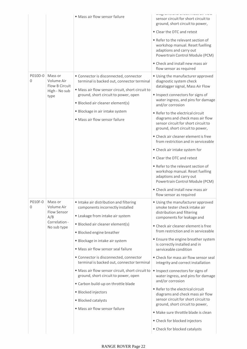
• Mass air flow sensor failurediagrams and check mass air flow sensor circuit for short circuit to ground, short circuit to power, open circuit, high resistance
• Clear the DTC and retest
• Refer to the relevant section of workshop manual. Reset fuelling adaptions and carry out Powertrain Control Module (PCM) Long Drive Cycle Self-Test
• Check and install new mass air flow sensor as required
P010D-00
Mass or Volume Air Flow B Circuit High - No sub type information
• Connector is disconnected, connector terminal is backed out, connector terminal corrosion
• Mass air flow sensor circuit, short circuit to ground, short circuit to power, open circuit, high resistance
• Blocked air cleaner element(s)
• Blockage in air intake system
• Mass air flow sensor failure
• Using the manufacturer approved diagnostic system check datalogger signal, Mass Air Flow Sensor 2 Voltage (0x0503)
• Inspect connectors for signs of water ingress, and pins for damage and/or corrosion
• Refer to the electrical circuit diagrams and check mass air flow sensor circuit for short circuit to ground, short circuit to power, open circuit, high resistance
• Check air cleaner element is free from restriction and in serviceable condition
• Check air intake system for blockage
• Clear the DTC and retest
• Refer to the relevant section of workshop manual. Reset fuelling adaptions and carry out Powertrain Control Module (PCM) Long Drive Cycle Self-Test
• Check and install new mass air flow sensor as required
P010F-00
Mass or Volume Air Flow Sensor A/B Correlation -No sub type information
• Intake air distribution and filtering components incorrectly installed
• Leakage from intake air system
• Blocked air cleaner element(s)
• Blocked engine breather
• Blockage in intake air system
• Mass air flow sensor seal failure
• Connector is disconnected, connector terminal is backed out, connector terminal corrosion
• Mass air flow sensor circuit, short circuit to ground, short circuit to power, open circuit, high resistance
• Carbon build-up on throttle blade
• Blocked injectors
• Blocked catalysts
• Mass air flow sensor failure
• Using the manufacturer approved smoke tester check intake air distribution and filtering components for leakage and correct installation
• Check air cleaner element is free from restriction and in serviceable condition
• Ensure the engine breather system is correctly installed and in serviceable condition
• Check for mass air flow sensor seal integrity and correct installation
• Inspect connectors for signs of water ingress, and pins for damage and/or corrosion
• Refer to the electrical circuit diagrams and check mass air flow sensor circuit for short circuit to ground, short circuit to power, open circuit, high resistance
• Make sure throttle blade is clean of carbon
• Check for blocked injectors
• Check for blocked catalysts
RANGE ROVER Page 22
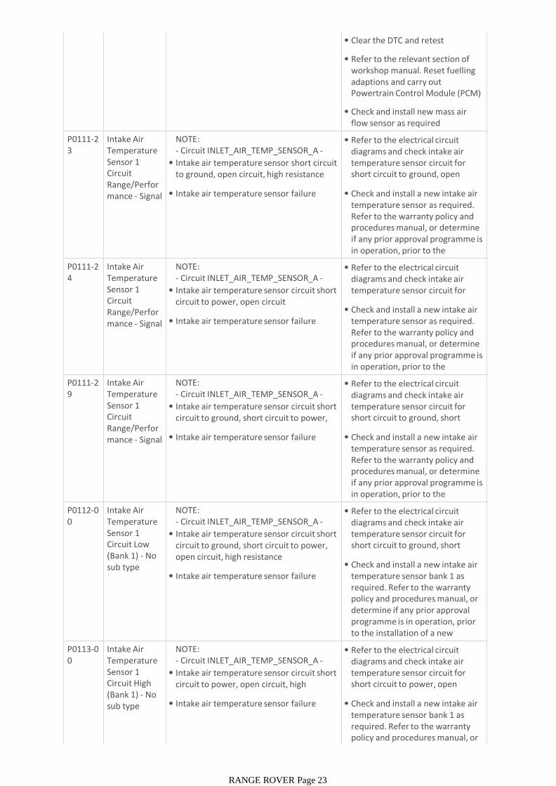
• Clear the DTC and retest
• Refer to the relevant section of workshop manual. Reset fuelling adaptions and carry out Powertrain Control Module (PCM) Long Drive Cycle Self-Test
• Check and install new mass air flow sensor as required
P0111-23
Intake Air Temperature Sensor 1 Circuit Range/Performance - Signal stuck low
NOTE:- Circuit INLET_AIR_TEMP_SENSOR_A -
• Intake air temperature sensor short circuit to ground, open circuit, high resistance
• Intake air temperature sensor failure
• Refer to the electrical circuit diagrams and check intake air temperature sensor circuit for short circuit to ground, open circuit, high resistance
• Check and install a new intake air temperature sensor as required. Refer to the warranty policy and procedures manual, or determine if any prior approval programme is in operation, prior to the installation of a new P0111-2
4Intake Air Temperature Sensor 1 Circuit Range/Performance - Signal stuck high
NOTE:- Circuit INLET_AIR_TEMP_SENSOR_A -
• Intake air temperature sensor circuit short circuit to power, open circuit
• Intake air temperature sensor failure
• Refer to the electrical circuit diagrams and check intake air temperature sensor circuit for short circuit to power, open circuit
• Check and install a new intake air temperature sensor as required. Refer to the warranty policy and procedures manual, or determine if any prior approval programme is in operation, prior to the installation of a new P0111-2
9Intake Air Temperature Sensor 1 Circuit Range/Performance - Signal invalid
NOTE:- Circuit INLET_AIR_TEMP_SENSOR_A -
• Intake air temperature sensor circuit short circuit to ground, short circuit to power, open circuit
• Intake air temperature sensor failure
• Refer to the electrical circuit diagrams and check intake air temperature sensor circuit for short circuit to ground, short circuit to power, open circuit
• Check and install a new intake air temperature sensor as required. Refer to the warranty policy and procedures manual, or determine if any prior approval programme is in operation, prior to the installation of a new P0112-0
0Intake Air Temperature Sensor 1 Circuit Low (Bank 1) - No sub type information
NOTE:- Circuit INLET_AIR_TEMP_SENSOR_A -
• Intake air temperature sensor circuit short circuit to ground, short circuit to power, open circuit, high resistance
• Intake air temperature sensor failure
• Refer to the electrical circuit diagrams and check intake air temperature sensor circuit for short circuit to ground, short circuit to power, open circuit, high
• Check and install a new intake air temperature sensor bank 1 as required. Refer to the warranty policy and procedures manual, or determine if any prior approval programme is in operation, prior to the installation of a new module/componentP0113-0
0Intake Air Temperature Sensor 1 Circuit High (Bank 1) - No sub type information
NOTE:- Circuit INLET_AIR_TEMP_SENSOR_A -
• Intake air temperature sensor circuit short circuit to power, open circuit, high resistance
• Intake air temperature sensor failure
• Refer to the electrical circuit diagrams and check intake air temperature sensor circuit for short circuit to power, open circuit, high resistance
• Check and install a new intake air temperature sensor bank 1 as required. Refer to the warranty policy and procedures manual, or determine if any prior approval
RANGE ROVER Page 23

determine if any prior approval programme is in operation, prior to the installation of a new module/componentP0116-2
3Engine Coolant Temperature Sensor 1 Circuit Range/Performance - Signal
• The engine control module measures a signal that remains low when transitions are expected
• Battery disconnection resulting in errors in engine off time (short soaks may look like long soaks)
• Electric block heater applied and not detected
• Connector is disconnected, connector pin is backed out, connector pin corrosion
• Engine coolant temperature sensor failure
• Additional checks to carry out ONLY for Range Rover / L405 and Range Rover Sport / L494 vehicles equipped with Fuel Fired Booster Heater (FFBH) system
• Changeover valve - Fuel Fired Booster Heater (FFBH) system failure
• This valve should only allow coolant into the engine if the engine coolant temperature is -25°C (-13°F) or below. When de-energized, the changeover valve connects the heater coolant circuit to the engine coolant circuit. When energized, the changeover valve isolates the heater coolant circuit from the engine coolant circuit. If this valve is de-energizing above -25°C (-13°F) it will be inadvertently allowing heated coolant into the engine and causing the DTC to set due to a mismatch between coolant temperature
• Leave vehicle turned off for a minimum of 8 hours and allow to soak to a stable temperature. Using the manufacturer approved diagnostic system check datalogger signals - Ambient Air Temperature - (0xF446) - Engine Coolant Temperature (0xF405) -Boost Air Temperature - Raw physical value (0x0341) - Intake Air Temperature (0xF40F) - Engine Coolant Temperature #2 (0x0489). All sensors should be within 20
• Inspect connectors for signs of water ingress, and pins for damage and/or corrosion
• Refer to the electrical circuit diagrams and check connections are secure and wiring integrity
• Check and install new sensor that is biased higher or lower than the other sensors
• Additional checks to carry out ONLY for Range Rover / L405 and Range Rover Sport / L494 vehicles equipped with Fuel Fired Booster Heater (FFBH) system
• Check and install new a changeover valve - Fuel Fired Booster Heater (FFBH) system
P0116-24
Engine Coolant Temperature Sensor 1 Circuit Range/Performance - Signal
• The engine control module measures a signal that remains high when transitions are expected
• Battery disconnection resulting in errors in engine off time (short soaks may look like long soaks)
• Electric block heater applied and not detected
• Connector is disconnected, connector pin is backed out, connector pin corrosion
• Engine coolant temperature sensor failure
• Additional checks to carry out ONLY for Range Rover / L405 and Range Rover Sport / L494 vehicles equipped with Fuel Fired Booster Heater (FFBH) system
• Changeover valve - Fuel Fired Booster Heater (FFBH) system failure
• This valve should only allow coolant into the engine if the engine coolant temperature is -25°C (-13°F) or below. When de-energized, the changeover valve connects the heater coolant circuit to the engine coolant circuit. When energized, the changeover valve isolates the heater coolant circuit from the engine coolant circuit. If this valve is de-energizing above -25°C (-13°F) it will be inadvertently allowing heated coolant into the engine
• Leave vehicle turned off for a minimum of 8 hours and allow to soak to a stable temperature. Using the manufacturer approved diagnostic system check datalogger signals - Ambient Air Temperature - (0xF446) - Engine Coolant Temperature (0xF405) -Boost Air Temperature - Raw physical value (0x0341) - Intake Air Temperature (0xF40F) - Engine Coolant Temperature #2 (0x0489). All sensors should be within 20
• Inspect connectors for signs of water ingress, and pins for damage and/or corrosion
• Refer to the electrical circuit diagrams and check connections are secure and wiring integrity
• Check and install new sensor that is biassed higher or lower than the other sensors
• Additional checks to carry out ONLY for Range Rover / L405 and Range Rover Sport / L494 vehicles equipped with Fuel Fired Booster Heater (FFBH) system
• Check and install new a changeover valve - Fuel Fired
RANGE ROVER Page 24
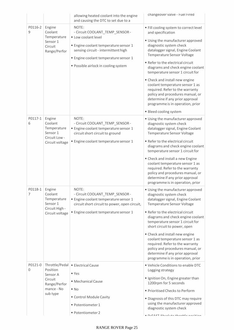
allowing heated coolant into the engine and causing the DTC to set due to a mismatch between coolant temperature
changeover valve - Fuel Fired Booster Heater (FFBH) system
P0116-29
Engine Coolant Temperature Sensor 1 Circuit Range/Performance - Signal
NOTE:- Circuit COOLANT_TEMP_SENSOR -
• Low coolant level
• Engine coolant temperature sensor 1 sensing circuit - intermittent high resistance
• Engine coolant temperature sensor 1 failure
• Possible airlock in cooling system
• Fill cooling system to correct level and specification
• Using the manufacturer approved diagnostic system check datalogger signal, Engine Coolant Temperature Sensor Voltage (0x0357)
• Refer to the electrical circuit diagrams and check engine coolant temperature sensor 1 circuit for intermittent high resistance
• Check and install new engine coolant temperature sensor 1 as required. Refer to the warranty policy and procedures manual, or determine if any prior approval programme is in operation, prior to the installation of a new
• Bleed cooling system
P0117-16
Engine Coolant Temperature Sensor 1 Circuit Low -Circuit voltage below
NOTE:- Circuit COOLANT_TEMP_SENSOR -
• Engine coolant temperature sensor 1 circuit short circuit to ground
• Engine coolant temperature sensor 1 failure
• Using the manufacturer approved diagnostic system check datalogger signal, Engine Coolant Temperature Sensor Voltage (0x0357)
• Refer to the electrical circuit diagrams and check engine coolant temperature sensor 1 circuit for short circuit to ground
• Check and install a new Engine coolant temperature sensor 1 as required. Refer to the warranty policy and procedures manual, or determine if any prior approval programme is in operation, prior to the installation of a new P0118-1
7Engine Coolant Temperature Sensor 1 Circuit High -Circuit voltage above
NOTE:- Circuit COOLANT_TEMP_SENSOR -
• Engine coolant temperature sensor 1 circuit short circuit to power, open circuit, sensor disconnected
• Engine coolant temperature sensor 1 failure
• Using the manufacturer approved diagnostic system check datalogger signal, Engine Coolant Temperature Sensor Voltage (0x0357)
• Refer to the electrical circuit diagrams and check engine coolant temperature sensor 1 circuit for short circuit to power, open circuit, sensor disconnected
• Check and install new engine coolant temperature sensor 1 as required. Refer to the warranty policy and procedures manual, or determine if any prior approval programme is in operation, prior to the installation of a new P0121-0
0Throttle/Pedal Position Sensor A Circuit Range/Performance - No sub type information
• Electrical Cause
• Yes
• Mechanical Cause
• No
• Control Module Cavity
• Potentiometer 1
• Potentiometer 2
• Vehicle Conditions to enable DTC Logging strategy
• Ignition On, Engine greater than 1200rpm for 5 seconds
• Prioritised Checks to Perform
• Diagnosis of this DTC may require using the manufacturer approved diagnostic system check datalogger signals
• 0xF447 Absolute throttle position
RANGE ROVER Page 25
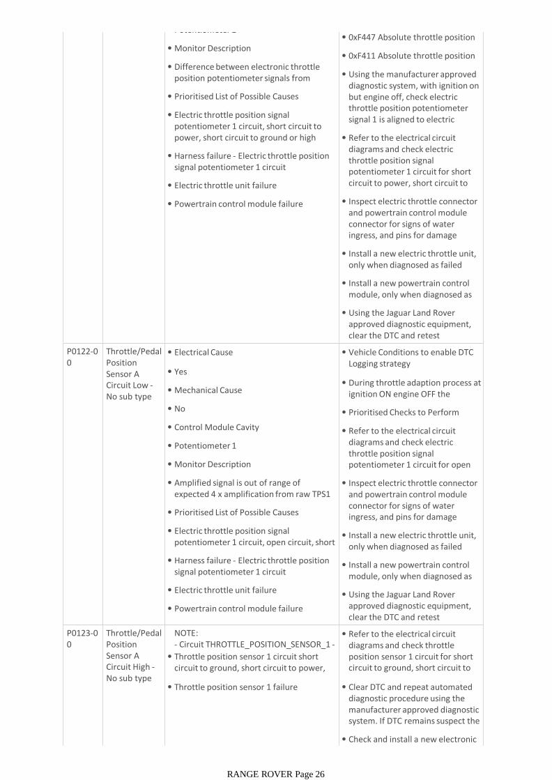
• Potentiometer 2
• Monitor Description
• Difference between electronic throttle position potentiometer signals from sensor 1 and sensor 2
• Prioritised List of Possible Causes
• Electric throttle position signal potentiometer 1 circuit, short circuit to power, short circuit to ground or high resistance
• Harness failure - Electric throttle position signal potentiometer 1 circuit
• Electric throttle unit failure
• Powertrain control module failure
• 0xF447 Absolute throttle position B
• 0xF411 Absolute throttle position
• Using the manufacturer approved diagnostic system, with ignition on but engine off, check electric throttle position potentiometer signal 1 is aligned to electric throttle position potentiometer
• Refer to the electrical circuit diagrams and check electric throttle position signal potentiometer 1 circuit for short circuit to power, short circuit to ground or high resistance
• Inspect electric throttle connector and powertrain control module connector for signs of water ingress, and pins for damage and/or corrosion
• Install a new electric throttle unit, only when diagnosed as failed
• Install a new powertrain control module, only when diagnosed as failed
• Using the Jaguar Land Rover approved diagnostic equipment, clear the DTC and retest
P0122-00
Throttle/Pedal Position Sensor A Circuit Low -No sub type information
• Electrical Cause
• Yes
• Mechanical Cause
• No
• Control Module Cavity
• Potentiometer 1
• Monitor Description
• Amplified signal is out of range of expected 4 x amplification from raw TPS1 input signal
• Prioritised List of Possible Causes
• Electric throttle position signal potentiometer 1 circuit, open circuit, short circuit to ground
• Harness failure - Electric throttle position signal potentiometer 1 circuit
• Electric throttle unit failure
• Powertrain control module failure
• Vehicle Conditions to enable DTC Logging strategy
• During throttle adaption process at ignition ON engine OFF the amplifier is checked
• Prioritised Checks to Perform
• Refer to the electrical circuit diagrams and check electric throttle position signal potentiometer 1 circuit for open circuit, short circuit to ground
• Inspect electric throttle connector and powertrain control module connector for signs of water ingress, and pins for damage and/or corrosion
• Install a new electric throttle unit, only when diagnosed as failed
• Install a new powertrain control module, only when diagnosed as failed
• Using the Jaguar Land Rover approved diagnostic equipment, clear the DTC and retest
P0123-00
Throttle/Pedal Position Sensor A Circuit High -No sub type information
NOTE:- Circuit THROTTLE_POSITION_SENSOR_1 -
• Throttle position sensor 1 circuit short circuit to ground, short circuit to power, open circuit
• Throttle position sensor 1 failure
• Refer to the electrical circuit diagrams and check throttle position sensor 1 circuit for short circuit to ground, short circuit to power, open circuit
• Clear DTC and repeat automated diagnostic procedure using the manufacturer approved diagnostic system. If DTC remains suspect the electronic throttle unit
• Check and install a new electronic throttle unit as required. Refer to
RANGE ROVER Page 26
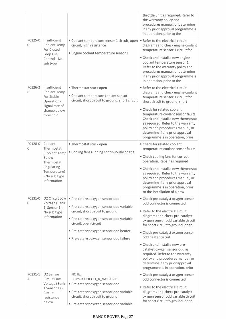
throttle unit as required. Refer to the warranty policy and procedures manual, or determine if any prior approval programme is in operation, prior to the installation of a new P0125-0
0Insufficient Coolant Temp For Closed Loop Fuel Control - No sub type information
• Coolant temperature sensor 1 circuit, open circuit, high resistance
• Engine coolant temperature sensor 1 failure
• Refer to the electrical circuit diagrams and check engine coolant temperature sensor 1 circuit for open circuit, high resistance
• Check and install a new engine coolant temperature sensor 1. Refer to the warranty policy and procedures manual, or determine if any prior approval programme is in operation, prior to the installation of a new P0126-2
6Insufficient Coolant Temp For Stable Operation -Signal rate of change below threshold
• Thermostat stuck open
• Coolant temperature coolant sensor circuit, short circuit to ground, short circuit to power, open circuit
• Refer to the electrical circuit diagrams and check engine coolant temperature sensor 1 circuit for short circuit to ground, short circuit to power, open circuit
• Check for related coolant temperature coolant sensor faults. Check and install a new thermostat as required. Refer to the warranty policy and procedures manual, or determine if any prior approval programme is in operation, prior to the installation of a new P0128-0
0Coolant Thermostat (Coolant Temp Below Thermostat Regulating Temperature) - No sub type information
• Thermostat stuck open
• Cooling fans running continuously or at a high duty
• Check for related coolant temperature coolant sensor faults
• Check cooling fans for correct operation. Repair as required
• Check and install a new thermostat as required. Refer to the warranty policy and procedures manual, or determine if any prior approval programme is in operation, prior to the installation of a new module/componentP0131-0
0O2 Circuit Low Voltage (Bank 1, Sensor 1) -No sub type information
• Pre-catalyst oxygen sensor odd disconnected
• Pre-catalyst oxygen sensor odd variable circuit, short circuit to ground
• Pre-catalyst oxygen sensor odd variable circuit, open circuit
• Pre-catalyst oxygen sensor odd heater fault
• Pre-catalyst oxygen sensor odd failure
• Check pre-catalyst oxygen sensor odd connector is connected
• Refer to the electrical circuit diagrams and check pre-catalyst oxygen sensor odd variable circuit for short circuit to ground, open circuit
• Check pre-catalyst oxygen sensor odd heater circuit
• Check and install a new pre-catalyst oxygen sensor odd as required. Refer to the warranty policy and procedures manual, or determine if any prior approval programme is in operation, prior to the installation of a new P0131-1
AO2 Sensor Circuit Low Voltage (Bank 1 Sensor 1) -Circuit resistance below threshold
NOTE:- Circuit UHEGO_A_VARIABLE -
• Pre-catalyst oxygen sensor odd disconnected
• Pre-catalyst oxygen sensor odd variable circuit, short circuit to ground
• Pre-catalyst oxygen sensor odd variable
• Check pre-catalyst oxygen sensor odd connector is connected
• Refer to the electrical circuit diagrams and check pre-catalyst oxygen sensor odd variable circuit for short circuit to ground, open circuit
RANGE ROVER Page 27
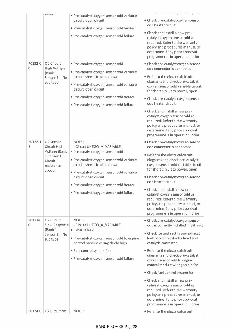
below threshold
• Pre-catalyst oxygen sensor odd variable circuit, open circuit
• Pre-catalyst oxygen sensor odd heater fault
• Pre-catalyst oxygen sensor odd failure
for short circuit to ground, open circuit
• Check pre-catalyst oxygen sensor odd heater circuit
• Check and install a new pre-catalyst oxygen sensor odd as required. Refer to the warranty policy and procedures manual, or determine if any prior approval programme is in operation, prior to the installation of a new P0132-0
0O2 Circuit High Voltage (Bank 1, Sensor 1) - No sub type information
• Pre-catalyst oxygen sensor odd disconnected
• Pre-catalyst oxygen sensor odd variable circuit, short circuit to power
• Pre-catalyst oxygen sensor odd variable circuit, open circuit
• Pre-catalyst oxygen sensor odd heater fault
• Pre-catalyst oxygen sensor odd failure
• Check pre-catalyst oxygen sensor odd connector is connected
• Refer to the electrical circuit diagrams and check pre-catalyst oxygen sensor odd variable circuit for short circuit to power, open circuit
• Check pre-catalyst oxygen sensor odd heater circuit
• Check and install a new pre-catalyst oxygen sensor odd as required. Refer to the warranty policy and procedures manual, or determine if any prior approval programme is in operation, prior to the installation of a new P0132-1
BO2 Sensor Circuit High Voltage (Bank 1 Sensor 1) -Circuit resistance above threshold
NOTE:- Circuit UHEGO_A_VARIABLE -
• Pre-catalyst oxygen sensor odd disconnected
• Pre-catalyst oxygen sensor odd variable circuit, short circuit to power
• Pre-catalyst oxygen sensor odd variable circuit, open circuit
• Pre-catalyst oxygen sensor odd heater fault
• Pre-catalyst oxygen sensor odd failure
• Check pre-catalyst oxygen sensor odd connector is connected
• Refer to the electrical circuit diagrams and check pre-catalyst oxygen sensor odd variable circuit for short circuit to power, open circuit
• Check pre-catalyst oxygen sensor odd heater circuit
• Check and install a new pre-catalyst oxygen sensor odd as required. Refer to the warranty policy and procedures manual, or determine if any prior approval programme is in operation, prior to the installation of a new P0133-0
0O2 Circuit Slow Response (Bank 1, Sensor 1) - No sub type information
NOTE:- Circuit UHEGO_A_VARIABLE -
• Exhaust leak
• Pre-catalyst oxygen sensor odd to engine control module wiring shield high resistance
• Fuel control system fault
• Pre-catalyst oxygen sensor odd failure
• Check pre-catalyst oxygen sensor odd is correctly installed in exhaust manifold
• Check for and rectify any exhaust leak between cylinder head and catalytic converter
• Refer to the electrical circuit diagrams and check pre-catalyst oxygen sensor odd to engine control module wiring shield for high resistance
• Check fuel control system for failure
• Check and install a new pre-catalyst oxygen sensor odd as required. Refer to the warranty policy and procedures manual, or determine if any prior approval programme is in operation, prior to the installation of a new P0134-0
0O2 Circuit No Activity
NOTE:- Circuit UHEGO_A_VARIABLE -
• Refer to the electrical circuit diagrams and check pre-catalyst
RANGE ROVER Page 28
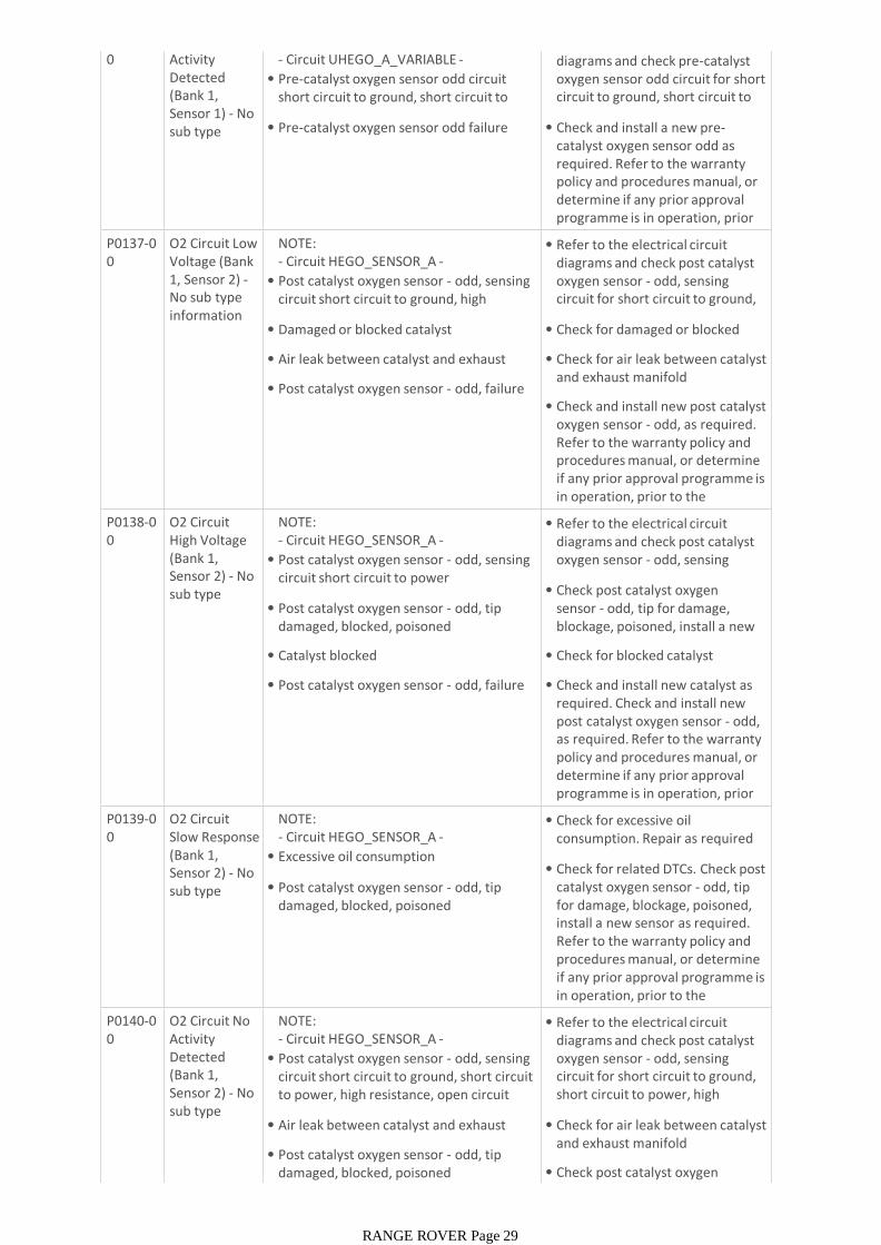
0 Activity Detected (Bank 1, Sensor 1) - No sub type information
- Circuit UHEGO_A_VARIABLE -
• Pre-catalyst oxygen sensor odd circuit short circuit to ground, short circuit to power, open circuit
• Pre-catalyst oxygen sensor odd failure
• Refer to the electrical circuit diagrams and check pre-catalyst oxygen sensor odd circuit for short circuit to ground, short circuit to power, open circuit
• Check and install a new pre-catalyst oxygen sensor odd as required. Refer to the warranty policy and procedures manual, or determine if any prior approval programme is in operation, prior to the installation of a new P0137-0
0O2 Circuit Low Voltage (Bank 1, Sensor 2) -No sub type information
NOTE:- Circuit HEGO_SENSOR_A -
• Post catalyst oxygen sensor - odd, sensing circuit short circuit to ground, high resistance, open circuit
• Damaged or blocked catalyst
• Air leak between catalyst and exhaust manifold
• Post catalyst oxygen sensor - odd, failure
• Refer to the electrical circuit diagrams and check post catalyst oxygen sensor - odd, sensing circuit for short circuit to ground, high resistance, open circuit
• Check for damaged or blocked catalyst
• Check for air leak between catalyst and exhaust manifold
• Check and install new post catalyst oxygen sensor - odd, as required. Refer to the warranty policy and procedures manual, or determine if any prior approval programme is in operation, prior to the installation of a new P0138-0
0O2 Circuit High Voltage (Bank 1, Sensor 2) - No sub type information
NOTE:- Circuit HEGO_SENSOR_A -
• Post catalyst oxygen sensor - odd, sensing circuit short circuit to power
• Post catalyst oxygen sensor - odd, tip damaged, blocked, poisoned
• Catalyst blocked
• Post catalyst oxygen sensor - odd, failure
• Refer to the electrical circuit diagrams and check post catalyst oxygen sensor - odd, sensing circuit for short circuit to power
• Check post catalyst oxygen sensor - odd, tip for damage, blockage, poisoned, install a new sensor as required
• Check for blocked catalyst
• Check and install new catalyst as required. Check and install new post catalyst oxygen sensor - odd, as required. Refer to the warranty policy and procedures manual, or determine if any prior approval programme is in operation, prior to the installation of a new P0139-0
0O2 Circuit Slow Response (Bank 1, Sensor 2) - No sub type information
NOTE:- Circuit HEGO_SENSOR_A -
• Excessive oil consumption
• Post catalyst oxygen sensor - odd, tip damaged, blocked, poisoned
• Check for excessive oil consumption. Repair as required
• Check for related DTCs. Check post catalyst oxygen sensor - odd, tip for damage, blockage, poisoned, install a new sensor as required. Refer to the warranty policy and procedures manual, or determine if any prior approval programme is in operation, prior to the installation of a new P0140-0
0O2 Circuit No Activity Detected (Bank 1, Sensor 2) - No sub type information
NOTE:- Circuit HEGO_SENSOR_A -
• Post catalyst oxygen sensor - odd, sensing circuit short circuit to ground, short circuit to power, high resistance, open circuit
• Air leak between catalyst and exhaust manifold
• Post catalyst oxygen sensor - odd, tip damaged, blocked, poisoned
• Refer to the electrical circuit diagrams and check post catalyst oxygen sensor - odd, sensing circuit for short circuit to ground, short circuit to power, high resistance, open circuit
• Check for air leak between catalyst and exhaust manifold
• Check post catalyst oxygen sensor - odd, tip for damage,
RANGE ROVER Page 29
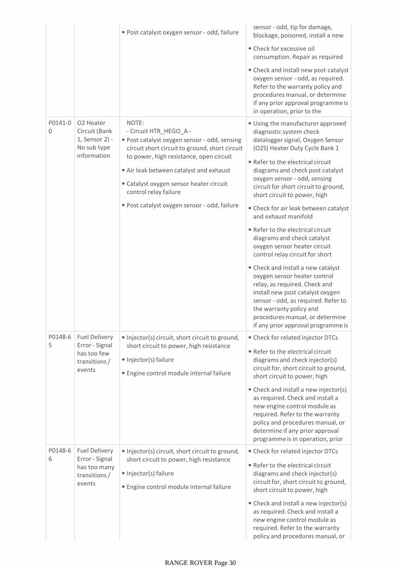
• Post catalyst oxygen sensor - odd, failuresensor - odd, tip for damage, blockage, poisoned, install a new sensor as required
• Check for excessive oil consumption. Repair as required
• Check and install new post catalyst oxygen sensor - odd, as required. Refer to the warranty policy and procedures manual, or determine if any prior approval programme is in operation, prior to the installation of a new
P0141-00
O2 Heater Circuit (Bank 1, Sensor 2) -No sub type information
NOTE:- Circuit HTR_HEGO_A -
• Post catalyst oxygen sensor - odd, sensing circuit short circuit to ground, short circuit to power, high resistance, open circuit
• Air leak between catalyst and exhaust manifold
• Catalyst oxygen sensor heater circuit control relay failure
• Post catalyst oxygen sensor - odd, failure
• Using the manufacturer approved diagnostic system check datalogger signal, Oxygen Sensor (O2S) Heater Duty Cycle Bank 1 Sensor 2 (0x03A2)
• Refer to the electrical circuit diagrams and check post catalyst oxygen sensor - odd, sensing circuit for short circuit to ground, short circuit to power, high resistance, open circuit
• Check for air leak between catalyst and exhaust manifold
• Refer to the electrical circuit diagrams and check catalyst oxygen sensor heater circuit control relay circuit for short circuit to ground, short circuit to
• Check and install a new catalyst oxygen sensor heater control relay, as required. Check and install new post catalyst oxygen sensor - odd, as required. Refer to the warranty policy and procedures manual, or determine if any prior approval programme is in operation, prior to the P0148-6
5Fuel Delivery Error - Signal has too few transitions / events
• Injector(s) circuit, short circuit to ground, short circuit to power, high resistance
• Injector(s) failure
• Engine control module internal failure
• Check for related injector DTCs
• Refer to the electrical circuit diagrams and check injector(s) circuit for, short circuit to ground, short circuit to power, high resistance
• Check and install a new injector(s) as required. Check and install a new engine control module as required. Refer to the warranty policy and procedures manual, or determine if any prior approval programme is in operation, prior to the installation of a new P0148-6
6Fuel Delivery Error - Signal has too many transitions / events
• Injector(s) circuit, short circuit to ground, short circuit to power, high resistance
• Injector(s) failure
• Engine control module internal failure
• Check for related injector DTCs
• Refer to the electrical circuit diagrams and check injector(s) circuit for, short circuit to ground, short circuit to power, high resistance
• Check and install a new injector(s) as required. Check and install a new engine control module as required. Refer to the warranty policy and procedures manual, or determine if any prior approval
RANGE ROVER Page 30
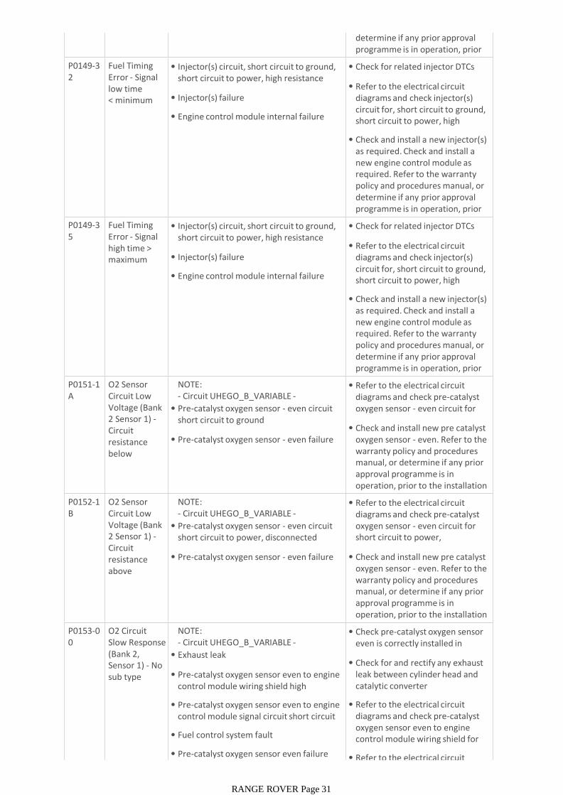
determine if any prior approval programme is in operation, prior to the installation of a new P0149-3
2Fuel Timing Error - Signal low time < minimum
• Injector(s) circuit, short circuit to ground, short circuit to power, high resistance
• Injector(s) failure
• Engine control module internal failure
• Check for related injector DTCs
• Refer to the electrical circuit diagrams and check injector(s) circuit for, short circuit to ground, short circuit to power, high resistance
• Check and install a new injector(s) as required. Check and install a new engine control module as required. Refer to the warranty policy and procedures manual, or determine if any prior approval programme is in operation, prior to the installation of a new P0149-3
5Fuel Timing Error - Signal high time > maximum
• Injector(s) circuit, short circuit to ground, short circuit to power, high resistance
• Injector(s) failure
• Engine control module internal failure
• Check for related injector DTCs
• Refer to the electrical circuit diagrams and check injector(s) circuit for, short circuit to ground, short circuit to power, high resistance
• Check and install a new injector(s) as required. Check and install a new engine control module as required. Refer to the warranty policy and procedures manual, or determine if any prior approval programme is in operation, prior to the installation of a new P0151-1
AO2 Sensor Circuit Low Voltage (Bank 2 Sensor 1) -Circuit resistance below threshold
NOTE:- Circuit UHEGO_B_VARIABLE -
• Pre-catalyst oxygen sensor - even circuit short circuit to ground
• Pre-catalyst oxygen sensor - even failure
• Refer to the electrical circuit diagrams and check pre-catalyst oxygen sensor - even circuit for short circuit to ground
• Check and install new pre catalyst oxygen sensor - even. Refer to the warranty policy and procedures manual, or determine if any prior approval programme is in operation, prior to the installation of a new module/componentP0152-1
BO2 Sensor Circuit Low Voltage (Bank 2 Sensor 1) -Circuit resistance above threshold
NOTE:- Circuit UHEGO_B_VARIABLE -
• Pre-catalyst oxygen sensor - even circuit short circuit to power, disconnected
• Pre-catalyst oxygen sensor - even failure
• Refer to the electrical circuit diagrams and check pre-catalyst oxygen sensor - even circuit for short circuit to power, disconnected
• Check and install new pre catalyst oxygen sensor - even. Refer to the warranty policy and procedures manual, or determine if any prior approval programme is in operation, prior to the installation of a new module/componentP0153-0
0O2 Circuit Slow Response (Bank 2, Sensor 1) - No sub type information
NOTE:- Circuit UHEGO_B_VARIABLE -
• Exhaust leak
• Pre-catalyst oxygen sensor even to engine control module wiring shield high resistance
• Pre-catalyst oxygen sensor even to engine control module signal circuit short circuit to ground
• Fuel control system fault
• Pre-catalyst oxygen sensor even failure
• Check pre-catalyst oxygen sensor even is correctly installed in exhaust manifold
• Check for and rectify any exhaust leak between cylinder head and catalytic converter
• Refer to the electrical circuit diagrams and check pre-catalyst oxygen sensor even to engine control module wiring shield for high resistance
• Refer to the electrical circuit
RANGE ROVER Page 31
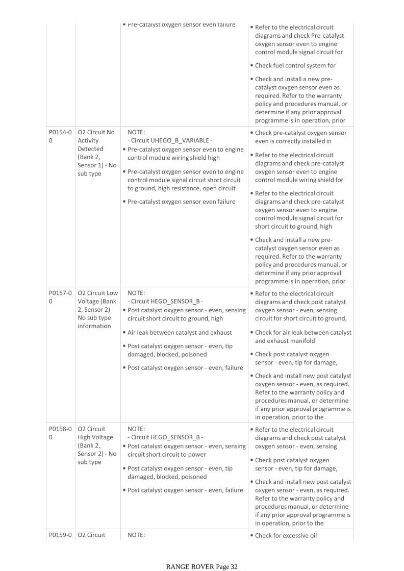
• Pre-catalyst oxygen sensor even failure • Refer to the electrical circuit diagrams and check Pre-catalyst oxygen sensor even to engine control module signal circuit for short circuit to ground
• Check fuel control system for failure
• Check and install a new pre-catalyst oxygen sensor even as required. Refer to the warranty policy and procedures manual, or determine if any prior approval programme is in operation, prior to the installation of a new
P0154-00
O2 Circuit No Activity Detected (Bank 2, Sensor 1) - No sub type information
NOTE:- Circuit UHEGO_B_VARIABLE -
• Pre-catalyst oxygen sensor even to engine control module wiring shield high resistance
• Pre-catalyst oxygen sensor even to engine control module signal circuit short circuit to ground, high resistance, open circuit
• Pre-catalyst oxygen sensor even failure
• Check pre-catalyst oxygen sensor even is correctly installed in exhaust manifold
• Refer to the electrical circuit diagrams and check pre-catalyst oxygen sensor even to engine control module wiring shield for high resistance
• Refer to the electrical circuit diagrams and check pre-catalyst oxygen sensor even to engine control module signal circuit for short circuit to ground, high resistance, open circuit
• Check and install a new pre-catalyst oxygen sensor even as required. Refer to the warranty policy and procedures manual, or determine if any prior approval programme is in operation, prior to the installation of a new P0157-0
0O2 Circuit Low Voltage (Bank 2, Sensor 2) -No sub type information
NOTE:- Circuit HEGO_SENSOR_B -
• Post catalyst oxygen sensor - even, sensing circuit short circuit to ground, high resistance, open circuit
• Air leak between catalyst and exhaust manifold
• Post catalyst oxygen sensor - even, tip damaged, blocked, poisoned
• Post catalyst oxygen sensor - even, failure
• Refer to the electrical circuit diagrams and check post catalyst oxygen sensor - even, sensing circuit for short circuit to ground, high resistance, open circuit
• Check for air leak between catalyst and exhaust manifold
• Check post catalyst oxygen sensor - even, tip for damage, blockage, poisoned
• Check and install new post catalyst oxygen sensor - even, as required. Refer to the warranty policy and procedures manual, or determine if any prior approval programme is in operation, prior to the installation of a new P0158-0
0O2 Circuit High Voltage (Bank 2, Sensor 2) - No sub type information
NOTE:- Circuit HEGO_SENSOR_B -
• Post catalyst oxygen sensor - even, sensing circuit short circuit to power
• Post catalyst oxygen sensor - even, tip damaged, blocked, poisoned
• Post catalyst oxygen sensor - even, failure
• Refer to the electrical circuit diagrams and check post catalyst oxygen sensor - even, sensing circuit for short circuit to power
• Check post catalyst oxygen sensor - even, tip for damage, blockage, poisoned
• Check and install new post catalyst oxygen sensor - even, as required. Refer to the warranty policy and procedures manual, or determine if any prior approval programme is in operation, prior to the installation of a new P0159-0
0O2 Circuit Slow Response
NOTE:- Circuit HEGO_SENSOR_B -
• Check for excessive oil consumption, repair as required
RANGE ROVER Page 32
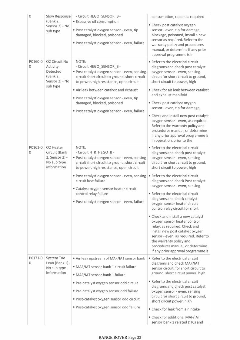
0 Slow Response (Bank 2, Sensor 2) - No sub type information
- Circuit HEGO_SENSOR_B -
• Excessive oil consumption
• Post catalyst oxygen sensor - even, tip damaged, blocked, poisoned
• Post catalyst oxygen sensor - even, failure
• Check for excessive oil consumption, repair as required
• Check post catalyst oxygen sensor - even, tip for damage, blockage, poisoned, install a new sensor as required. Refer to the warranty policy and procedures manual, or determine if any prior approval programme is in operation, prior to the installation P0160-0
0O2 Circuit No Activity Detected (Bank 2, Sensor 2) - No sub type information
NOTE:- Circuit HEGO_SENSOR_B -
• Post catalyst oxygen sensor - even, sensing circuit short circuit to ground, short circuit to power, high resistance, open circuit
• Air leak between catalyst and exhaust manifold
• Post catalyst oxygen sensor - even, tip damaged, blocked, poisoned
• Post catalyst oxygen sensor - even, failure
• Refer to the electrical circuit diagrams and check post catalyst oxygen sensor - even, sensing circuit for short circuit to ground, short circuit to power, high resistance, open circuit
• Check for air leak between catalyst and exhaust manifold
• Check post catalyst oxygen sensor - even, tip for damage, blockage, poisoned
• Check and install new post catalyst oxygen sensor - even, as required. Refer to the warranty policy and procedures manual, or determine if any prior approval programme is in operation, prior to the installation of a new P0161-0
0O2 Heater Circuit (Bank 2, Sensor 2) -No sub type information
NOTE:- Circuit HTR_HEGO_B -
• Post catalyst oxygen sensor - even, sensing circuit short circuit to ground, short circuit to power, high resistance, open circuit
• Post catalyst oxygen sensor - even, sensing circuit fuse failure
• Catalyst oxygen sensor heater circuit control relay failure
• Post catalyst oxygen sensor - even, failure
• Refer to the electrical circuit diagrams and check post catalyst oxygen sensor - even, sensing circuit for short circuit to ground, short circuit to power, high resistance, open circuit
• Refer to the electrical circuit diagrams and check Post catalyst oxygen sensor - even, sensing circuit fuse, replace as required
• Refer to the electrical circuit diagrams and check catalyst oxygen sensor heater circuit control relay circuit for short circuit to ground, short circuit to
• Check and install a new catalyst oxygen sensor heater control relay, as required. Check and install new post catalyst oxygen sensor - even, as required. Refer to the warranty policy and procedures manual, or determine if any prior approval programme is in operation, prior to the P0171-0
0System Too Lean (Bank 1) -No sub type information
• Air leak upstream of MAF/IAT sensor bank 1
• MAF/IAT sensor bank 1 circuit failure
• MAF/IAT sensor bank 1 failure
• Pre-catalyst oxygen sensor odd circuit failure
• Pre-catalyst oxygen sensor odd failure
• Post-catalyst oxygen sensor odd circuit failure
• Post-catalyst oxygen sensor odd failure
• Refer to the electrical circuit diagrams and check MAF/IAT sensor circuit, for short circuit to ground, short circuit power, high resistance, open circuit
• Refer to the electrical circuit diagrams and check post catalyst oxygen sensor - even, sensing circuit for short circuit to ground, short circuit power, high resistance, open circuit
• Check for leak from air intake system
• Check for additional MAF/IAT sensor bank 1 related DTCs and refer to relevant DTC index
RANGE ROVER Page 33
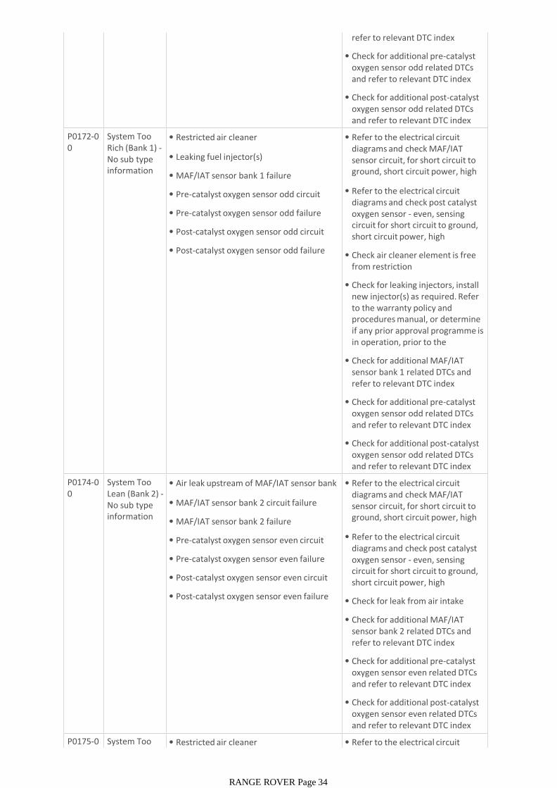
refer to relevant DTC index
• Check for additional pre-catalyst oxygen sensor odd related DTCs and refer to relevant DTC index
• Check for additional post-catalyst oxygen sensor odd related DTCs and refer to relevant DTC index
P0172-00
System Too Rich (Bank 1) -No sub type information
• Restricted air cleaner
• Leaking fuel injector(s)
• MAF/IAT sensor bank 1 failure
• Pre-catalyst oxygen sensor odd circuit failure
• Pre-catalyst oxygen sensor odd failure
• Post-catalyst oxygen sensor odd circuit failure
• Post-catalyst oxygen sensor odd failure
• Refer to the electrical circuit diagrams and check MAF/IAT sensor circuit, for short circuit to ground, short circuit power, high resistance, open circuit
• Refer to the electrical circuit diagrams and check post catalyst oxygen sensor - even, sensing circuit for short circuit to ground, short circuit power, high resistance, open circuit
• Check air cleaner element is free from restriction
• Check for leaking injectors, install new injector(s) as required. Refer to the warranty policy and procedures manual, or determine if any prior approval programme is in operation, prior to the installation of a new
• Check for additional MAF/IAT sensor bank 1 related DTCs and refer to relevant DTC index
• Check for additional pre-catalyst oxygen sensor odd related DTCs and refer to relevant DTC index
• Check for additional post-catalyst oxygen sensor odd related DTCs and refer to relevant DTC index
P0174-00
System Too Lean (Bank 2) -No sub type information
• Air leak upstream of MAF/IAT sensor bank 2
• MAF/IAT sensor bank 2 circuit failure
• MAF/IAT sensor bank 2 failure
• Pre-catalyst oxygen sensor even circuit failure
• Pre-catalyst oxygen sensor even failure
• Post-catalyst oxygen sensor even circuit failure
• Post-catalyst oxygen sensor even failure
• Refer to the electrical circuit diagrams and check MAF/IAT sensor circuit, for short circuit to ground, short circuit power, high resistance, open circuit
• Refer to the electrical circuit diagrams and check post catalyst oxygen sensor - even, sensing circuit for short circuit to ground, short circuit power, high resistance, open circuit
• Check for leak from air intake system
• Check for additional MAF/IAT sensor bank 2 related DTCs and refer to relevant DTC index
• Check for additional pre-catalyst oxygen sensor even related DTCs and refer to relevant DTC index
• Check for additional post-catalyst oxygen sensor even related DTCs and refer to relevant DTC index
P0175-00
System Too Rich (Bank 2) -
• Restricted air cleaner • Refer to the electrical circuit diagrams and check MAF/IAT
RANGE ROVER Page 34
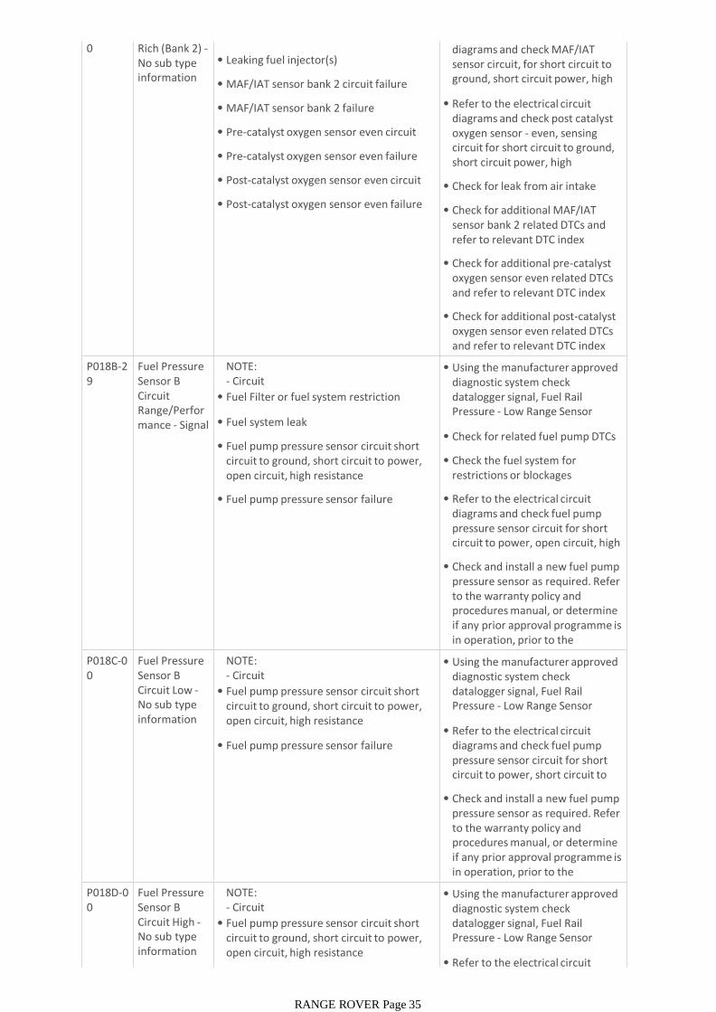
0 Rich (Bank 2) -No sub type information
• Restricted air cleaner
• Leaking fuel injector(s)
• MAF/IAT sensor bank 2 circuit failure
• MAF/IAT sensor bank 2 failure
• Pre-catalyst oxygen sensor even circuit failure
• Pre-catalyst oxygen sensor even failure
• Post-catalyst oxygen sensor even circuit failure
• Post-catalyst oxygen sensor even failure
• Refer to the electrical circuit diagrams and check MAF/IAT sensor circuit, for short circuit to ground, short circuit power, high resistance, open circuit
• Refer to the electrical circuit diagrams and check post catalyst oxygen sensor - even, sensing circuit for short circuit to ground, short circuit power, high resistance, open circuit
• Check for leak from air intake system
• Check for additional MAF/IAT sensor bank 2 related DTCs and refer to relevant DTC index
• Check for additional pre-catalyst oxygen sensor even related DTCs and refer to relevant DTC index
• Check for additional post-catalyst oxygen sensor even related DTCs and refer to relevant DTC index
P018B-29
Fuel Pressure Sensor B Circuit Range/Performance - Signal invalid
NOTE:- Circuit LOW_PRESS_FUEL_PRESS_SENSOR -• Fuel Filter or fuel system restriction
• Fuel system leak
• Fuel pump pressure sensor circuit short circuit to ground, short circuit to power, open circuit, high resistance
• Fuel pump pressure sensor failure
• Using the manufacturer approved diagnostic system check datalogger signal, Fuel Rail Pressure - Low Range Sensor Voltage (0x0376)
• Check for related fuel pump DTCs
• Check the fuel system for restrictions or blockages
• Refer to the electrical circuit diagrams and check fuel pump pressure sensor circuit for short circuit to power, open circuit, high resistance
• Check and install a new fuel pump pressure sensor as required. Refer to the warranty policy and procedures manual, or determine if any prior approval programme is in operation, prior to the installation of a new
P018C-00
Fuel Pressure Sensor B Circuit Low -No sub type information
NOTE:- Circuit LOW_PRESS_FUEL_PRESS_SENSOR -• Fuel pump pressure sensor circuit short circuit to ground, short circuit to power, open circuit, high resistance
• Fuel pump pressure sensor failure
• Using the manufacturer approved diagnostic system check datalogger signal, Fuel Rail Pressure - Low Range Sensor Voltage (0x0376)
• Refer to the electrical circuit diagrams and check fuel pump pressure sensor circuit for short circuit to power, short circuit to ground, open circuit, high
• Check and install a new fuel pump pressure sensor as required. Refer to the warranty policy and procedures manual, or determine if any prior approval programme is in operation, prior to the installation of a new P018D-0
0Fuel Pressure Sensor B Circuit High -No sub type information
NOTE:- Circuit LOW_PRESS_FUEL_PRESS_SENSOR -• Fuel pump pressure sensor circuit short circuit to ground, short circuit to power, open circuit, high resistance
• Using the manufacturer approved diagnostic system check datalogger signal, Fuel Rail Pressure - Low Range Sensor Voltage (0x0376)
• Refer to the electrical circuit
RANGE ROVER Page 35
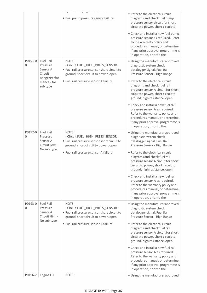
information open circuit, high resistance
• Fuel pump pressure sensor failure• Refer to the electrical circuit
diagrams and check fuel pump pressure sensor circuit for short circuit to power, short circuit to ground, open circuit, high
• Check and install a new fuel pump pressure sensor as required. Refer to the warranty policy and procedures manual, or determine if any prior approval programme is in operation, prior to the installation of a new P0191-0
0Fuel Rail Pressure Sensor A Circuit Range/Performance - No sub type information
NOTE:- Circuit FUEL_HIGH_PRESS_SENSOR -
• Fuel rail pressure sensor short circuit to ground, short circuit to power, open circuit, high resistance
• Fuel rail pressure sensor A failure
• Using the manufacturer approved diagnostic system check datalogger signal, Fuel Rail Pressure Sensor - High Range Sensor Voltage (0x0377)
• Refer to the electrical circuit diagrams and check fuel rail pressure sensor A circuit for short circuit to power, short circuit to ground, high resistance, open circuit, terminal damage or
• Check and install a new fuel rail pressure sensor A as required. Refer to the warranty policy and procedures manual, or determine if any prior approval programme is in operation, prior to the installation of a new P0192-0
0Fuel Rail Pressure Sensor A Circuit Low -No sub type information
NOTE:- Circuit FUEL_HIGH_PRESS_SENSOR -
• Fuel rail pressure sensor short circuit to ground, short circuit to power, open circuit, high resistance
• Fuel rail pressure sensor A failure
• Using the manufacturer approved diagnostic system check datalogger signal, Fuel Rail Pressure Sensor - High Range Sensor Voltage (0x0377)
• Refer to the electrical circuit diagrams and check fuel rail pressure sensor A circuit for short circuit to power, short circuit to ground, high resistance, open circuit, terminal damage or
• Check and install a new fuel rail pressure sensor A as required. Refer to the warranty policy and procedures manual, or determine if any prior approval programme is in operation, prior to the installation of a new P0193-0
0Fuel Rail Pressure Sensor A Circuit High -No sub type information
NOTE:- Circuit FUEL_HIGH_PRESS_SENSOR -
• Fuel rail pressure sensor short circuit to ground, short circuit to power, open circuit, high resistance
• Fuel rail pressure sensor A failure
• Using the manufacturer approved diagnostic system check datalogger signal, Fuel Rail Pressure Sensor - High Range Sensor Voltage (0x0377)
• Refer to the electrical circuit diagrams and check fuel rail pressure sensor A circuit for short circuit to power, short circuit to ground, high resistance, open circuit, terminal damage or
• Check and install a new fuel rail pressure sensor A as required. Refer to the warranty policy and procedures manual, or determine if any prior approval programme is in operation, prior to the installation of a new P0196-2
3Engine Oil Temperature
NOTE:- Circuit OIL_QUALITY_SENSOR -
• Using the manufacturer approved diagnostic system check
RANGE ROVER Page 36
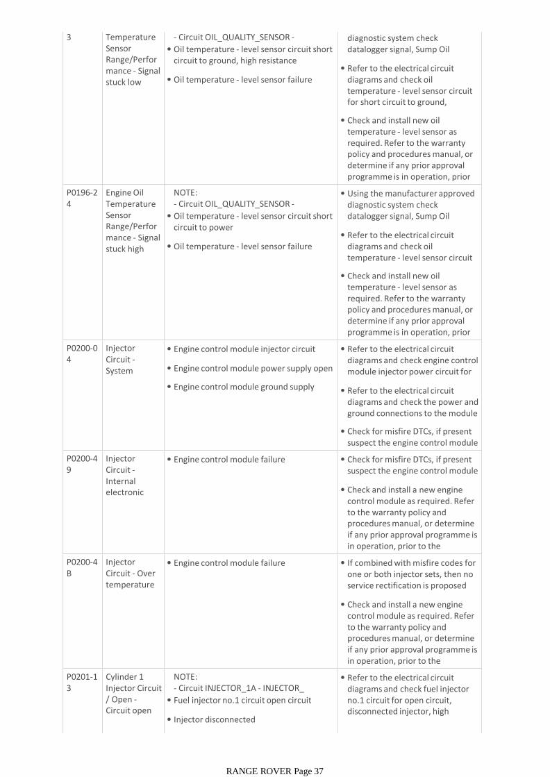
3 Temperature Sensor Range/Performance - Signal stuck low
- Circuit OIL_QUALITY_SENSOR -
• Oil temperature - level sensor circuit short circuit to ground, high resistance
• Oil temperature - level sensor failure
• Using the manufacturer approved diagnostic system check datalogger signal, Sump Oil Temperature - Measured (0x03F3)
• Refer to the electrical circuit diagrams and check oil temperature - level sensor circuit for short circuit to ground, intermittent high resistance
• Check and install new oil temperature - level sensor as required. Refer to the warranty policy and procedures manual, or determine if any prior approval programme is in operation, prior to the installation of a new P0196-2
4Engine Oil Temperature Sensor Range/Performance - Signal stuck high
NOTE:- Circuit OIL_QUALITY_SENSOR -
• Oil temperature - level sensor circuit short circuit to power
• Oil temperature - level sensor failure
• Using the manufacturer approved diagnostic system check datalogger signal, Sump Oil Temperature - Measured (0x03F3)
• Refer to the electrical circuit diagrams and check oil temperature - level sensor circuit for intermittent short circuit to
• Check and install new oil temperature - level sensor as required. Refer to the warranty policy and procedures manual, or determine if any prior approval programme is in operation, prior to the installation of a new P0200-0
4Injector Circuit -System internal
• Engine control module injector circuit power failure
• Engine control module power supply open circuit
• Engine control module ground supply open circuit
• Refer to the electrical circuit diagrams and check engine control module injector power circuit for open circuit
• Refer to the electrical circuit diagrams and check the power and ground connections to the module
• Check for misfire DTCs, if present suspect the engine control module
P0200-49
Injector Circuit -Internal electronic failure
• Engine control module failure • Check for misfire DTCs, if present suspect the engine control module
• Check and install a new engine control module as required. Refer to the warranty policy and procedures manual, or determine if any prior approval programme is in operation, prior to the installation of a new P0200-4
BInjector Circuit - Over temperature
• Engine control module failure • If combined with misfire codes for one or both injector sets, then no service rectification is proposed
• Check and install a new engine control module as required. Refer to the warranty policy and procedures manual, or determine if any prior approval programme is in operation, prior to the installation of a new P0201-1
3Cylinder 1 Injector Circuit / Open -Circuit open
NOTE:- Circuit INJECTOR_1A - INJECTOR_1A_COMMON -• Fuel injector no.1 circuit open circuit
• Injector disconnected
• Injector high resistance
• Refer to the electrical circuit diagrams and check fuel injector no.1 circuit for open circuit, disconnected injector, high resistance
RANGE ROVER Page 37
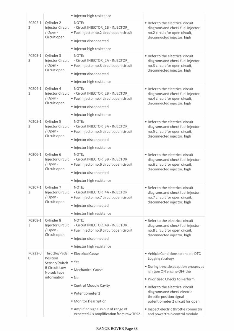
• Injector high resistance
P0202-13
Cylinder 2 Injector Circuit / Open -Circuit open
NOTE:- Circuit INJECTOR_1B - INJECTOR_1B_COMMON -• Fuel injector no.2 circuit open circuit
• Injector disconnected
• Injector high resistance
• Refer to the electrical circuit diagrams and check fuel injector no.2 circuit for open circuit, disconnected injector, high resistance
P0203-13
Cylinder 3 Injector Circuit / Open -Circuit open
NOTE:- Circuit INJECTOR_2A - INJECTOR_2A_COMMON -• Fuel injector no.3 circuit open circuit
• Injector disconnected
• Injector high resistance
• Refer to the electrical circuit diagrams and check fuel injector no.3 circuit for open circuit, disconnected injector, high resistance
P0204-13
Cylinder 4 Injector Circuit / Open -Circuit open
NOTE:- Circuit INJECTOR_2B - INJECTOR_2B_COMMON -• Fuel injector no.4 circuit open circuit
• Injector disconnected
• Injector high resistance
• Refer to the electrical circuit diagrams and check fuel injector no.4 circuit for open circuit, disconnected injector, high resistance
P0205-13
Cylinder 5 Injector Circuit / Open -Circuit open
NOTE:- Circuit INJECTOR_3A - INJECTOR_3A_COMMON -• Fuel injector no.5 circuit open circuit
• Injector disconnected
• Injector high resistance
• Refer to the electrical circuit diagrams and check fuel injector no.5 circuit for open circuit, disconnected injector, high resistance
P0206-13
Cylinder 6 Injector Circuit / Open -Circuit open
NOTE:- Circuit INJECTOR_3B - INJECTOR_3B_COMMON -• Fuel injector no.6 circuit open circuit
• Injector disconnected
• Injector high resistance
• Refer to the electrical circuit diagrams and check fuel injector no.6 circuit for open circuit, disconnected injector, high resistance
P0207-13
Cylinder 7 Injector Circuit / Open -Circuit open
NOTE:- Circuit INJECTOR_4A - INJECTOR_4A_COMMON -• Fuel injector no.7 circuit open circuit
• Injector disconnected
• Injector high resistance
• Refer to the electrical circuit diagrams and check fuel injector no.7 circuit for open circuit, disconnected injector, high resistance
P0208-13
Cylinder 8 Injector Circuit / Open -Circuit open
NOTE:- Circuit INJECTOR_4B - INJECTOR_4B_COMMON -• Fuel injector no.8 circuit open circuit
• Injector disconnected
• Injector high resistance
• Refer to the electrical circuit diagrams and check fuel injector no.8 circuit for open circuit, disconnected injector, high resistance
P0222-00
Throttle/Pedal Position Sensor/Switch B Circuit Low -No sub type information
• Electrical Cause
• Yes
• Mechanical Cause
• No
• Control Module Cavity
• Potentiometer 2
• Monitor Description
• Amplified signal is out of range of expected 4 x amplification from raw TPS2 input signal
• Vehicle Conditions to enable DTC Logging strategy
• During throttle adaption process at ignition ON engine OFF the amplifier is checked
• Prioritised Checks to Perform
• Refer to the electrical circuit diagrams and check electric throttle position signal potentiometer 2 circuit for open circuit, short circuit to ground
• Inspect electric throttle connector and powertrain control module connector for signs of water
RANGE ROVER Page 38
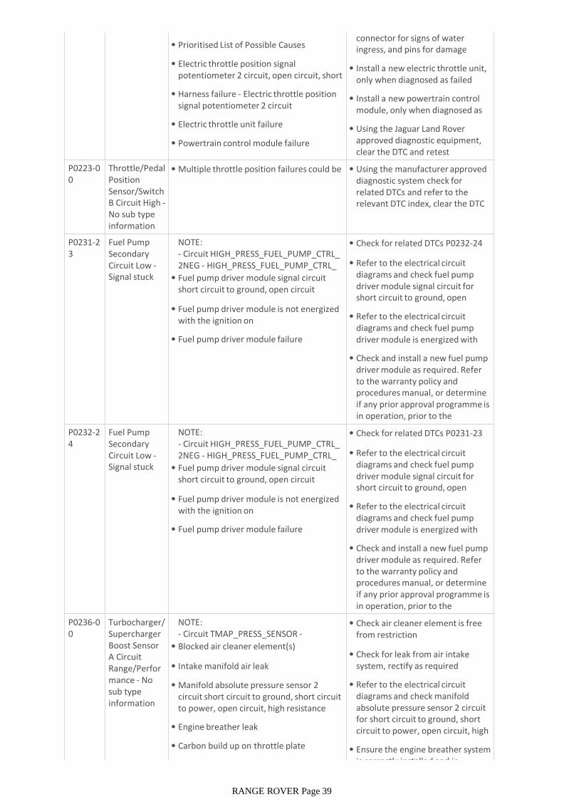
• Prioritised List of Possible Causes
• Electric throttle position signal potentiometer 2 circuit, open circuit, short circuit to ground
• Harness failure - Electric throttle position signal potentiometer 2 circuit
• Electric throttle unit failure
• Powertrain control module failure
connector for signs of water ingress, and pins for damage and/or corrosion
• Install a new electric throttle unit, only when diagnosed as failed
• Install a new powertrain control module, only when diagnosed as failed
• Using the Jaguar Land Rover approved diagnostic equipment, clear the DTC and retest
P0223-00
Throttle/Pedal Position Sensor/Switch B Circuit High -No sub type information
• Multiple throttle position failures could be present
• Using the manufacturer approved diagnostic system check for related DTCs and refer to the relevant DTC index, clear the DTC and retest the system
P0231-23
Fuel Pump Secondary Circuit Low -Signal stuck low
NOTE:- Circuit HIGH_PRESS_FUEL_PUMP_CTRL_2NEG - HIGH_PRESS_FUEL_PUMP_CTRL_2POS -• Fuel pump driver module signal circuit short circuit to ground, open circuit
• Fuel pump driver module is not energized with the ignition on
• Fuel pump driver module failure
• Check for related DTCs P0232-24
• Refer to the electrical circuit diagrams and check fuel pump driver module signal circuit for short circuit to ground, open circuit
• Refer to the electrical circuit diagrams and check fuel pump driver module is energized with the ignition on. Repair as required
• Check and install a new fuel pump driver module as required. Refer to the warranty policy and procedures manual, or determine if any prior approval programme is in operation, prior to the installation of a new P0232-2
4Fuel Pump Secondary Circuit Low -Signal stuck high
NOTE:- Circuit HIGH_PRESS_FUEL_PUMP_CTRL_2NEG - HIGH_PRESS_FUEL_PUMP_CTRL_2POS -• Fuel pump driver module signal circuit short circuit to ground, open circuit
• Fuel pump driver module is not energized with the ignition on
• Fuel pump driver module failure
• Check for related DTCs P0231-23
• Refer to the electrical circuit diagrams and check fuel pump driver module signal circuit for short circuit to ground, open circuit
• Refer to the electrical circuit diagrams and check fuel pump driver module is energized with the ignition on. Repair as required
• Check and install a new fuel pump driver module as required. Refer to the warranty policy and procedures manual, or determine if any prior approval programme is in operation, prior to the installation of a new P0236-0
0Turbocharger/Supercharger Boost Sensor A Circuit Range/Performance - No sub type information
NOTE:- Circuit TMAP_PRESS_SENSOR -
• Blocked air cleaner element(s)
• Intake manifold air leak
• Manifold absolute pressure sensor 2 circuit short circuit to ground, short circuit to power, open circuit, high resistance
• Engine breather leak
• Carbon build up on throttle plate
• Exhaust system blocked
• Check air cleaner element is free from restriction
• Check for leak from air intake system, rectify as required
• Refer to the electrical circuit diagrams and check manifold absolute pressure sensor 2 circuit for short circuit to ground, short circuit to power, open circuit, high resistance
• Ensure the engine breather system is correctly installed and in
RANGE ROVER Page 39
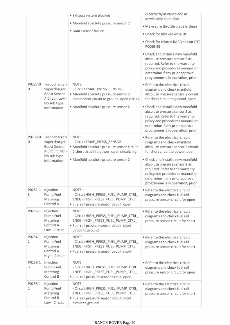
• Exhaust system blocked
• Manifold absolute pressure sensor 2 failure
• BARO sensor failure
is correctly installed and in serviceable condition
• Make sure throttle blade is clean of carbon
• Check for blocked exhaust
• Check for related BARO sensor DTC P0069-29
• Check and install a new manifold absolute pressure sensor 2 as required. Refer to the warranty policy and procedures manual, or determine if any prior approval programme is in operation, prior to the installation of a new P0237-0
0Turbocharger/Supercharger Boost Sensor A Circuit Low -No sub type information
NOTE:- Circuit TMAP_PRESS_SENSOR -
• Manifold absolute pressure sensor 2 circuit short circuit to ground, open circuit, high resistance
• Manifold absolute pressure sensor 2 failure
• Refer to the electrical circuit diagrams and check manifold absolute pressure sensor 2 circuit for short circuit to ground, open circuit, high resistance
• Check and install a new manifold absolute pressure sensor 2 as required. Refer to the warranty policy and procedures manual, or determine if any prior approval programme is in operation, prior to the installation of a new P0238-0
0Turbocharger/Supercharger Boost Sensor A Circuit High -No sub type information
NOTE:- Circuit TMAP_PRESS_SENSOR -
• Manifold absolute pressure sensor circuit 2 short circuit to power, open circuit, high resistance
• Manifold absolute pressure sensor 2 failure
• Refer to the electrical circuit diagrams and check manifold absolute pressure sensor 2 circuit for short circuit to power, open circuit, high resistance
• Check and install a new manifold absolute pressure sensor 2 as required. Refer to the warranty policy and procedures manual, or determine if any prior approval programme is in operation, prior to the installation of a new P0251-1
3Injection Pump Fuel Metering Control A -Circuit open
NOTE:- Circuit HIGH_PRESS_FUEL_PUMP_CTRL_1NEG - HIGH_PRESS_FUEL_PUMP_CTRL_2NEG -• Fuel rail pressure sensor circuit, open circuit
• Refer to the electrical circuit diagrams and check fuel rail pressure sensor circuit for open circuit
P0253-11
Injection Pump Fuel Metering Control A Low - Circuit short to
NOTE:- Circuit HIGH_PRESS_FUEL_PUMP_CTRL_1NEG - HIGH_PRESS_FUEL_PUMP_CTRL_2NEG -• Fuel rail pressure sensor circuit, short circuit to ground
• Refer to the electrical circuit diagrams and check fuel rail pressure sensor circuit for short circuit to ground
P0254-12
Injection Pump Fuel Metering Control A High - Circuit short to
NOTE:- Circuit HIGH_PRESS_FUEL_PUMP_CTRL_1NEG - HIGH_PRESS_FUEL_PUMP_CTRL_2NEG -• Fuel rail pressure sensor circuit, short circuit to power
• Refer to the electrical circuit diagrams and check fuel rail pressure sensor circuit for short circuit to power
P0256-13
Injection Pump Fuel Metering Control B -Circuit open
NOTE:- Circuit HIGH_PRESS_FUEL_PUMP_CTRL_1NEG - HIGH_PRESS_FUEL_PUMP_CTRL_2NEG -• Fuel rail pressure sensor circuit, open circuit
• Refer to the electrical circuit diagrams and check fuel rail pressure sensor circuit for open circuit
P0258-11
Injection Pump Fuel Metering Control B Low - Circuit short to
NOTE:- Circuit HIGH_PRESS_FUEL_PUMP_CTRL_1NEG - HIGH_PRESS_FUEL_PUMP_CTRL_2NEG -• Fuel rail pressure sensor circuit, short circuit to ground
• Refer to the electrical circuit diagrams and check fuel rail pressure sensor circuit for short circuit to ground
P0259-1 Injection NOTE: • Refer to the electrical circuit
RANGE ROVER Page 40
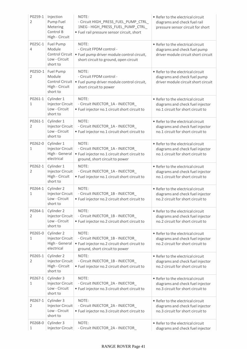
P0259-12
Injection Pump Fuel Metering Control B High - Circuit short to
NOTE:- Circuit HIGH_PRESS_FUEL_PUMP_CTRL_1NEG - HIGH_PRESS_FUEL_PUMP_CTRL_2NEG -• Fuel rail pressure sensor circuit, short circuit to power
• Refer to the electrical circuit diagrams and check fuel rail pressure sensor circuit for short circuit to power
P025C-14
Fuel Pump Module Control Circuit Low - Circuit short to ground or
NOTE:- Circuit FPDM control -
• Fuel pump driver module control circuit, short circuit to ground, open circuit
• Refer to the electrical circuit diagrams and check fuel pump driver module circuit short circuit to ground, open circuit
P025D-12
Fuel Pump Module Control Circuit High - Circuit short to battery
NOTE:- Circuit FPDM control -
• Fuel pump driver module control circuit, short circuit to power
• Refer to the electrical circuit diagrams and check fuel pump driver module circuit short circuit to power
P0261-11
Cylinder 1 Injector Circuit Low - Circuit short to ground
NOTE:- Circuit INJECTOR_1A - INJECTOR_1A_COMMON -• Fuel injector no.1 circuit short circuit to ground
• Refer to the electrical circuit diagrams and check fuel injector no.1 circuit for short circuit to ground
P0261-12
Cylinder 1 Injector Circuit Low - Circuit short to battery
NOTE:- Circuit INJECTOR_1A - INJECTOR_1A_COMMON -• Fuel injector no.1 circuit short circuit to power
• Refer to the electrical circuit diagrams and check fuel injector no.1 circuit for short circuit to power
P0262-01
Cylinder 1 Injector Circuit High - General electrical failure
NOTE:- Circuit INJECTOR_1A - INJECTOR_1A_COMMON -• Fuel injector no.1 circuit short circuit to ground, short circuit to power
• Refer to the electrical circuit diagrams and check fuel injector no.1 circuit for short circuit to ground, short circuit to power
P0262-12
Cylinder 1 Injector Circuit High - Circuit short to battery
NOTE:- Circuit INJECTOR_1A - INJECTOR_1A_COMMON -• Fuel injector no.1 circuit short circuit to power
• Refer to the electrical circuit diagrams and check fuel injector no.1 circuit for short circuit to power
P0264-11
Cylinder 2 Injector Circuit Low - Circuit short to ground
NOTE:- Circuit INJECTOR_1B - INJECTOR_1B_COMMON -• Fuel injector no.2 circuit short circuit to ground
• Refer to the electrical circuit diagrams and check fuel injector no.2 circuit for short circuit to ground
P0264-12
Cylinder 2 Injector Circuit Low - Circuit short to battery
NOTE:- Circuit INJECTOR_1B - INJECTOR_1B_COMMON -• Fuel injector no.2 circuit short circuit to power
• Refer to the electrical circuit diagrams and check fuel injector no.2 circuit for short circuit to power
P0265-01
Cylinder 2 Injector Circuit High - General electrical failure
NOTE:- Circuit INJECTOR_1B - INJECTOR_1B_COMMON -• Fuel injector no.2 circuit short circuit to ground, short circuit to power
• Refer to the electrical circuit diagrams and check fuel injector no.2 circuit for short circuit to ground, short circuit to power
P0265-12
Cylinder 2 Injector Circuit High - Circuit short to battery
NOTE:- Circuit INJECTOR_1B - INJECTOR_1B_COMMON -• Fuel injector no.2 circuit short circuit to power
• Refer to the electrical circuit diagrams and check fuel injector no.2 circuit for short circuit to power
P0267-11
Cylinder 3 Injector Circuit Low - Circuit short to ground
NOTE:- Circuit INJECTOR_2A - INJECTOR_2A_COMMON -• Fuel injector no.3 circuit short circuit to ground
• Refer to the electrical circuit diagrams and check fuel injector no.3 circuit for short circuit to ground
P0267-12
Cylinder 3 Injector Circuit Low - Circuit short to battery
NOTE:- Circuit INJECTOR_2A - INJECTOR_2A_COMMON -• Fuel injector no.3 circuit short circuit to power
• Refer to the electrical circuit diagrams and check fuel injector no.3 circuit for short circuit to power
P0268-01
Cylinder 3 Injector Circuit High - General
NOTE:- Circuit INJECTOR_2A - INJECTOR_2A_COMMON -• Fuel injector no.3 circuit short circuit to
• Refer to the electrical circuit diagrams and check fuel injector
RANGE ROVER Page 41
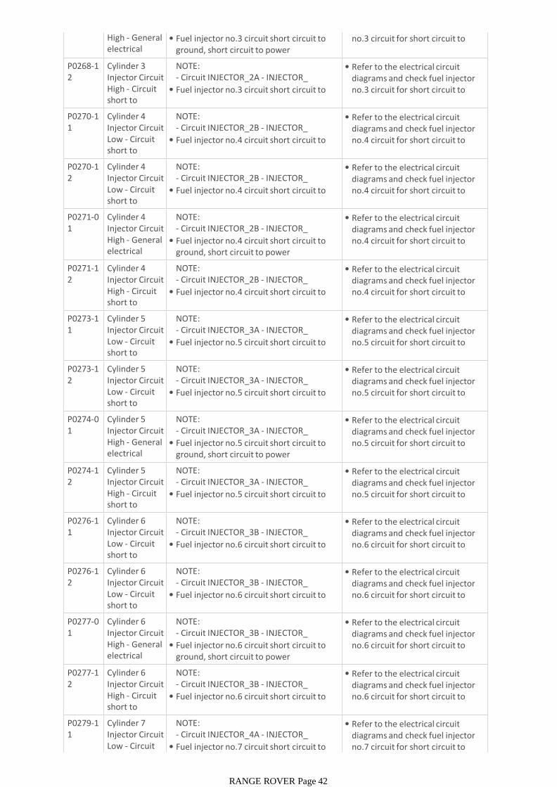
High - General electrical failure
• Fuel injector no.3 circuit short circuit to ground, short circuit to power
diagrams and check fuel injector no.3 circuit for short circuit to ground, short circuit to power
P0268-12
Cylinder 3 Injector Circuit High - Circuit short to battery
NOTE:- Circuit INJECTOR_2A - INJECTOR_2A_COMMON -• Fuel injector no.3 circuit short circuit to power
• Refer to the electrical circuit diagrams and check fuel injector no.3 circuit for short circuit to power
P0270-11
Cylinder 4 Injector Circuit Low - Circuit short to ground
NOTE:- Circuit INJECTOR_2B - INJECTOR_2B_COMMON -• Fuel injector no.4 circuit short circuit to ground
• Refer to the electrical circuit diagrams and check fuel injector no.4 circuit for short circuit to ground
P0270-12
Cylinder 4 Injector Circuit Low - Circuit short to battery
NOTE:- Circuit INJECTOR_2B - INJECTOR_2B_COMMON -• Fuel injector no.4 circuit short circuit to power
• Refer to the electrical circuit diagrams and check fuel injector no.4 circuit for short circuit to power
P0271-01
Cylinder 4 Injector Circuit High - General electrical failure
NOTE:- Circuit INJECTOR_2B - INJECTOR_2B_COMMON -• Fuel injector no.4 circuit short circuit to ground, short circuit to power
• Refer to the electrical circuit diagrams and check fuel injector no.4 circuit for short circuit to ground, short circuit to power
P0271-12
Cylinder 4 Injector Circuit High - Circuit short to battery
NOTE:- Circuit INJECTOR_2B - INJECTOR_2B_COMMON -• Fuel injector no.4 circuit short circuit to power
• Refer to the electrical circuit diagrams and check fuel injector no.4 circuit for short circuit to power
P0273-11
Cylinder 5 Injector Circuit Low - Circuit short to ground
NOTE:- Circuit INJECTOR_3A - INJECTOR_3A_COMMON -• Fuel injector no.5 circuit short circuit to ground
• Refer to the electrical circuit diagrams and check fuel injector no.5 circuit for short circuit to ground
P0273-12
Cylinder 5 Injector Circuit Low - Circuit short to battery
NOTE:- Circuit INJECTOR_3A - INJECTOR_3A_COMMON -• Fuel injector no.5 circuit short circuit to power
• Refer to the electrical circuit diagrams and check fuel injector no.5 circuit for short circuit to power
P0274-01
Cylinder 5 Injector Circuit High - General electrical failure
NOTE:- Circuit INJECTOR_3A - INJECTOR_3A_COMMON -• Fuel injector no.5 circuit short circuit to ground, short circuit to power
• Refer to the electrical circuit diagrams and check fuel injector no.5 circuit for short circuit to ground, short circuit to power
P0274-12
Cylinder 5 Injector Circuit High - Circuit short to battery
NOTE:- Circuit INJECTOR_3A - INJECTOR_3A_COMMON -• Fuel injector no.5 circuit short circuit to power
• Refer to the electrical circuit diagrams and check fuel injector no.5 circuit for short circuit to power
P0276-11
Cylinder 6 Injector Circuit Low - Circuit short to ground
NOTE:- Circuit INJECTOR_3B - INJECTOR_3B_COMMON -• Fuel injector no.6 circuit short circuit to ground
• Refer to the electrical circuit diagrams and check fuel injector no.6 circuit for short circuit to ground
P0276-12
Cylinder 6 Injector Circuit Low - Circuit short to battery
NOTE:- Circuit INJECTOR_3B - INJECTOR_3B_COMMON -• Fuel injector no.6 circuit short circuit to power
• Refer to the electrical circuit diagrams and check fuel injector no.6 circuit for short circuit to power
P0277-01
Cylinder 6 Injector Circuit High - General electrical failure
NOTE:- Circuit INJECTOR_3B - INJECTOR_3B_COMMON -• Fuel injector no.6 circuit short circuit to ground, short circuit to power
• Refer to the electrical circuit diagrams and check fuel injector no.6 circuit for short circuit to ground, short circuit to power
P0277-12
Cylinder 6 Injector Circuit High - Circuit short to battery
NOTE:- Circuit INJECTOR_3B - INJECTOR_3B_COMMON -• Fuel injector no.6 circuit short circuit to power
• Refer to the electrical circuit diagrams and check fuel injector no.6 circuit for short circuit to power
P0279-11
Cylinder 7 Injector Circuit Low - Circuit short to
NOTE:- Circuit INJECTOR_4A - INJECTOR_4A_COMMON -• Fuel injector no.7 circuit short circuit to ground
• Refer to the electrical circuit diagrams and check fuel injector no.7 circuit for short circuit to ground
RANGE ROVER Page 42
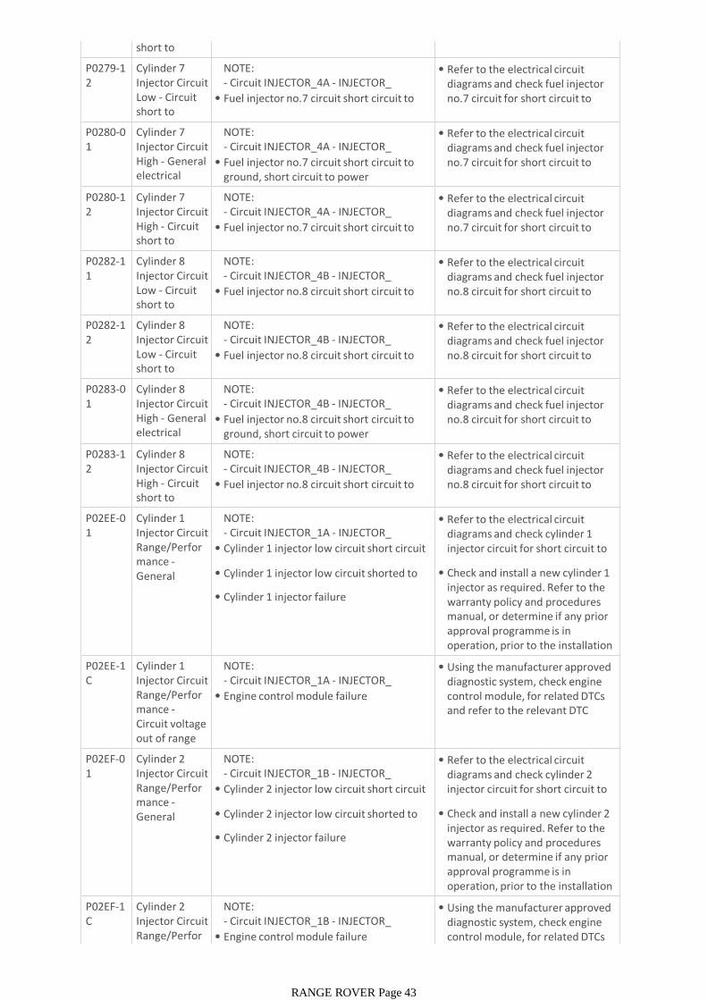
short to ground
• Fuel injector no.7 circuit short circuit to ground
no.7 circuit for short circuit to ground
P0279-12
Cylinder 7 Injector Circuit Low - Circuit short to battery
NOTE:- Circuit INJECTOR_4A - INJECTOR_4A_COMMON -• Fuel injector no.7 circuit short circuit to power
• Refer to the electrical circuit diagrams and check fuel injector no.7 circuit for short circuit to power
P0280-01
Cylinder 7 Injector Circuit High - General electrical failure
NOTE:- Circuit INJECTOR_4A - INJECTOR_4A_COMMON -• Fuel injector no.7 circuit short circuit to ground, short circuit to power
• Refer to the electrical circuit diagrams and check fuel injector no.7 circuit for short circuit to ground, short circuit to power
P0280-12
Cylinder 7 Injector Circuit High - Circuit short to battery
NOTE:- Circuit INJECTOR_4A - INJECTOR_4A_COMMON -• Fuel injector no.7 circuit short circuit to power
• Refer to the electrical circuit diagrams and check fuel injector no.7 circuit for short circuit to power
P0282-11
Cylinder 8 Injector Circuit Low - Circuit short to ground
NOTE:- Circuit INJECTOR_4B - INJECTOR_4B_COMMON -• Fuel injector no.8 circuit short circuit to ground
• Refer to the electrical circuit diagrams and check fuel injector no.8 circuit for short circuit to ground
P0282-12
Cylinder 8 Injector Circuit Low - Circuit short to battery
NOTE:- Circuit INJECTOR_4B - INJECTOR_4B_COMMON -• Fuel injector no.8 circuit short circuit to power
• Refer to the electrical circuit diagrams and check fuel injector no.8 circuit for short circuit to power
P0283-01
Cylinder 8 Injector Circuit High - General electrical failure
NOTE:- Circuit INJECTOR_4B - INJECTOR_4B_COMMON -• Fuel injector no.8 circuit short circuit to ground, short circuit to power
• Refer to the electrical circuit diagrams and check fuel injector no.8 circuit for short circuit to ground, short circuit to power
P0283-12
Cylinder 8 Injector Circuit High - Circuit short to battery
NOTE:- Circuit INJECTOR_4B - INJECTOR_4B_COMMON -• Fuel injector no.8 circuit short circuit to power
• Refer to the electrical circuit diagrams and check fuel injector no.8 circuit for short circuit to power
P02EE-01
Cylinder 1 Injector Circuit Range/Performance -General electrical
NOTE:- Circuit INJECTOR_1A - INJECTOR_1A_COMMON -• Cylinder 1 injector low circuit short circuit to power
• Cylinder 1 injector low circuit shorted to high circuit
• Cylinder 1 injector failure
• Refer to the electrical circuit diagrams and check cylinder 1 injector circuit for short circuit to power, short circuit together
• Check and install a new cylinder 1 injector as required. Refer to the warranty policy and procedures manual, or determine if any prior approval programme is in operation, prior to the installation of a new module/componentP02EE-1
CCylinder 1 Injector Circuit Range/Performance -Circuit voltage out of range
NOTE:- Circuit INJECTOR_1A - INJECTOR_1A_COMMON -• Engine control module failure
• Using the manufacturer approved diagnostic system, check engine control module, for related DTCs and refer to the relevant DTC index
P02EF-01
Cylinder 2 Injector Circuit Range/Performance -General electrical
NOTE:- Circuit INJECTOR_1B - INJECTOR_1B_COMMON -• Cylinder 2 injector low circuit short circuit to power
• Cylinder 2 injector low circuit shorted to high circuit
• Cylinder 2 injector failure
• Refer to the electrical circuit diagrams and check cylinder 2 injector circuit for short circuit to power, short circuit together
• Check and install a new cylinder 2 injector as required. Refer to the warranty policy and procedures manual, or determine if any prior approval programme is in operation, prior to the installation of a new module/componentP02EF-1
CCylinder 2 Injector Circuit Range/Performance -
NOTE:- Circuit INJECTOR_1B - INJECTOR_1B_COMMON -• Engine control module failure
• Using the manufacturer approved diagnostic system, check engine control module, for related DTCs
RANGE ROVER Page 43

mance -Circuit voltage out of range
• Engine control module failure control module, for related DTCs and refer to the relevant DTC index
P02F0-01
Cylinder 3 Injector Circuit Range/Performance -General electrical
NOTE:- Circuit INJECTOR_2A - INJECTOR_2A_COMMON -• Cylinder 3 injector low circuit short circuit to power
• Cylinder 3 injector low circuit shorted to high circuit
• Cylinder 3 injector failure
• Refer to the electrical circuit diagrams and check cylinder 3 injector circuit for short circuit to power, short circuit together
• Check and install a new cylinder 3 injector as required. Refer to the warranty policy and procedures manual, or determine if any prior approval programme is in operation, prior to the installation of a new module/componentP02F0-1
CCylinder 3 Injector Circuit Range/Performance -Circuit voltage out of range
NOTE:- Circuit INJECTOR_2A - INJECTOR_2A_COMMON -• Engine control module failure
• Using the manufacturer approved diagnostic system, check engine control module, for related DTCs and refer to the relevant DTC index
P02F1-01
Cylinder 4 Injector Circuit Range/Performance -General electrical
NOTE:- Circuit INJECTOR_2B - INJECTOR_2B_COMMON -• Cylinder 4 injector low circuit short circuit to power
• Cylinder 4 injector low circuit shorted to high circuit
• Cylinder 4 injector failure
• Refer to the electrical circuit diagrams and check cylinder 4 injector circuit for short circuit to power, short circuit together
• Check and install a new cylinder 4 injector as required. Refer to the warranty policy and procedures manual, or determine if any prior approval programme is in operation, prior to the installation of a new module/componentP02F1-1
CCylinder 4 Injector Circuit Range/Performance -Circuit voltage out of range
NOTE:- Circuit INJECTOR_2B - INJECTOR_2B_COMMON -• Engine control module failure
• Using the manufacturer approved diagnostic system, check engine control module, for related DTCs and refer to the relevant DTC index
P02F2-01
Cylinder 5 Injector Circuit Range/Performance -General electrical
NOTE:- Circuit INJECTOR_3A - INJECTOR_3A_COMMON -• Cylinder 5 injector low circuit short circuit to power
• Cylinder 5 injector low circuit shorted to high circuit
• Cylinder 5 injector failure
• Refer to the electrical circuit diagrams and check cylinder 5 injector circuit for short circuit to power, short circuit together
• Check and install a new cylinder 5 injector as required. Refer to the warranty policy and procedures manual, or determine if any prior approval programme is in operation, prior to the installation of a new module/componentP02F2-1
CCylinder 5 Injector Circuit Range/Performance -Circuit voltage out of range
NOTE:- Circuit INJECTOR_3A - INJECTOR_3A_COMMON -• Engine control module failure
• Using the manufacturer approved diagnostic system, check engine control module, for related DTCs and refer to the relevant DTC index
P02F3-01
Cylinder 6 Injector Circuit Range/Performance -General electrical
NOTE:- Circuit INJECTOR_3B - INJECTOR_3B_COMMON -• Cylinder 6 injector low circuit short circuit to power
• Cylinder 6 injector low circuit shorted to high circuit
• Cylinder 6 injector failure
• Refer to the electrical circuit diagrams and check cylinder 6 injector circuit for short circuit to power, short circuit together
• Check and install a new cylinder 6 injector as required. Refer to the warranty policy and procedures manual, or determine if any prior approval programme is in operation, prior to the installation of a new module/component
RANGE ROVER Page 44
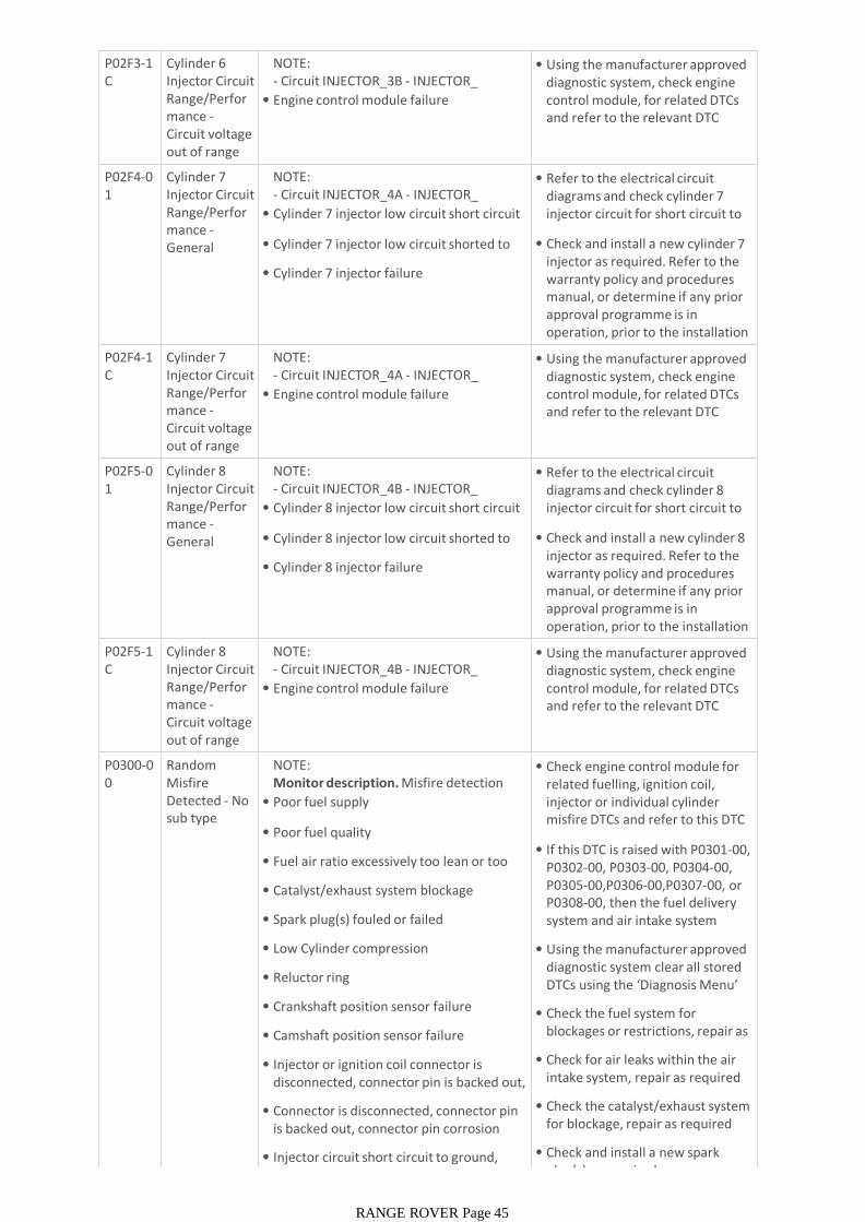
P02F3-1C
Cylinder 6 Injector Circuit Range/Performance -Circuit voltage out of range
NOTE:- Circuit INJECTOR_3B - INJECTOR_3B_COMMON -• Engine control module failure
• Using the manufacturer approved diagnostic system, check engine control module, for related DTCs and refer to the relevant DTC index
P02F4-01
Cylinder 7 Injector Circuit Range/Performance -General electrical
NOTE:- Circuit INJECTOR_4A - INJECTOR_4A_COMMON -• Cylinder 7 injector low circuit short circuit to power
• Cylinder 7 injector low circuit shorted to high circuit
• Cylinder 7 injector failure
• Refer to the electrical circuit diagrams and check cylinder 7 injector circuit for short circuit to power, short circuit together
• Check and install a new cylinder 7 injector as required. Refer to the warranty policy and procedures manual, or determine if any prior approval programme is in operation, prior to the installation of a new module/componentP02F4-1
CCylinder 7 Injector Circuit Range/Performance -Circuit voltage out of range
NOTE:- Circuit INJECTOR_4A - INJECTOR_4A_COMMON -• Engine control module failure
• Using the manufacturer approved diagnostic system, check engine control module, for related DTCs and refer to the relevant DTC index
P02F5-01
Cylinder 8 Injector Circuit Range/Performance -General electrical
NOTE:- Circuit INJECTOR_4B - INJECTOR_4B_COMMON -• Cylinder 8 injector low circuit short circuit to power
• Cylinder 8 injector low circuit shorted to high circuit
• Cylinder 8 injector failure
• Refer to the electrical circuit diagrams and check cylinder 8 injector circuit for short circuit to power, short circuit together
• Check and install a new cylinder 8 injector as required. Refer to the warranty policy and procedures manual, or determine if any prior approval programme is in operation, prior to the installation of a new module/componentP02F5-1
CCylinder 8 Injector Circuit Range/Performance -Circuit voltage out of range
NOTE:- Circuit INJECTOR_4B - INJECTOR_4B_COMMON -• Engine control module failure
• Using the manufacturer approved diagnostic system, check engine control module, for related DTCs and refer to the relevant DTC index
P0300-00
Random Misfire Detected - No sub type information
NOTE:Monitor description. Misfire detection
• Poor fuel supply
• Poor fuel quality
• Fuel air ratio excessively too lean or too rich
• Catalyst/exhaust system blockage
• Spark plug(s) fouled or failed
• Low Cylinder compression
• Reluctor ring
• Crankshaft position sensor failure
• Camshaft position sensor failure
• Injector or ignition coil connector is disconnected, connector pin is backed out, connector pin corrosion
• Connector is disconnected, connector pin is backed out, connector pin corrosion
• Injector circuit short circuit to ground, short circuit to power, open circuit
• Check engine control module for related fuelling, ignition coil, injector or individual cylinder misfire DTCs and refer to this DTC index. Rectify these first
• If this DTC is raised with P0301-00, P0302-00, P0303-00, P0304-00, P0305-00,P0306-00,P0307-00, or P0308-00, then the fuel delivery system and air intake system should be checked and rectified
• Using the manufacturer approved diagnostic system clear all stored DTCs using the ‘Diagnosis Menu’ tab and retest
• Check the fuel system for blockages or restrictions, repair as required
• Check for air leaks within the air intake system, repair as required
• Check the catalyst/exhaust system for blockage, repair as required
• Check and install a new spark plug(s) as required
RANGE ROVER Page 45
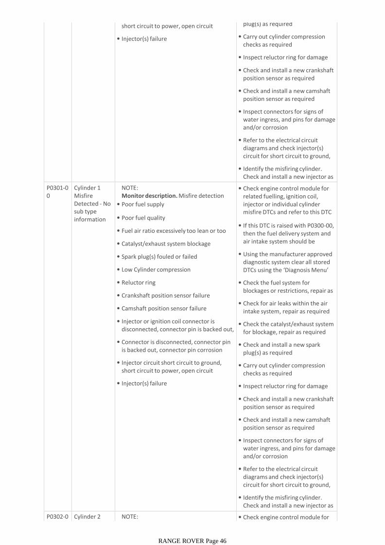
short circuit to power, open circuit
• Injector(s) failure
plug(s) as required
• Carry out cylinder compression checks as required
• Inspect reluctor ring for damage
• Check and install a new crankshaft position sensor as required
• Check and install a new camshaft position sensor as required
• Inspect connectors for signs of water ingress, and pins for damage and/or corrosion
• Refer to the electrical circuit diagrams and check injector(s) circuit for short circuit to ground, short circuit to power, open circuit
• Identify the misfiring cylinder. Check and install a new injector as requiredP0301-0
0Cylinder 1 Misfire Detected - No sub type information
NOTE:Monitor description. Misfire detection
• Poor fuel supply
• Poor fuel quality
• Fuel air ratio excessively too lean or too rich
• Catalyst/exhaust system blockage
• Spark plug(s) fouled or failed
• Low Cylinder compression
• Reluctor ring
• Crankshaft position sensor failure
• Camshaft position sensor failure
• Injector or ignition coil connector is disconnected, connector pin is backed out, connector pin corrosion
• Connector is disconnected, connector pin is backed out, connector pin corrosion
• Injector circuit short circuit to ground, short circuit to power, open circuit
• Injector(s) failure
• Check engine control module for related fuelling, ignition coil, injector or individual cylinder misfire DTCs and refer to this DTC index. Rectify these first
• If this DTC is raised with P0300-00, then the fuel delivery system and air intake system should be checked and rectified first
• Using the manufacturer approved diagnostic system clear all stored DTCs using the ‘Diagnosis Menu’ tab and retest
• Check the fuel system for blockages or restrictions, repair as required
• Check for air leaks within the air intake system, repair as required
• Check the catalyst/exhaust system for blockage, repair as required
• Check and install a new spark plug(s) as required
• Carry out cylinder compression checks as required
• Inspect reluctor ring for damage
• Check and install a new crankshaft position sensor as required
• Check and install a new camshaft position sensor as required
• Inspect connectors for signs of water ingress, and pins for damage and/or corrosion
• Refer to the electrical circuit diagrams and check injector(s) circuit for short circuit to ground, short circuit to power, open circuit
• Identify the misfiring cylinder. Check and install a new injector as requiredP0302-0
0Cylinder 2 Misfire
NOTE:Monitor description. Misfire detection
• Check engine control module for related fuelling, ignition coil,
RANGE ROVER Page 46
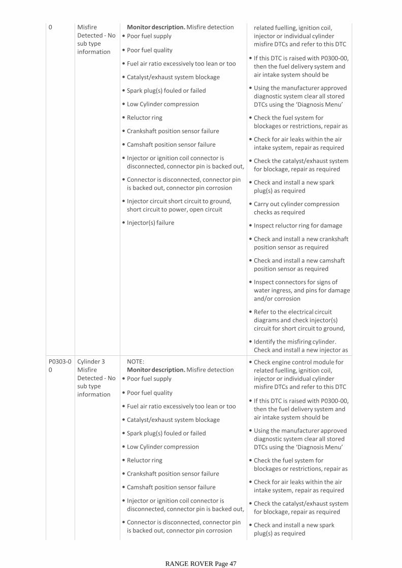
0 Misfire Detected - No sub type information
Monitor description. Misfire detection
• Poor fuel supply
• Poor fuel quality
• Fuel air ratio excessively too lean or too rich
• Catalyst/exhaust system blockage
• Spark plug(s) fouled or failed
• Low Cylinder compression
• Reluctor ring
• Crankshaft position sensor failure
• Camshaft position sensor failure
• Injector or ignition coil connector is disconnected, connector pin is backed out, connector pin corrosion
• Connector is disconnected, connector pin is backed out, connector pin corrosion
• Injector circuit short circuit to ground, short circuit to power, open circuit
• Injector(s) failure
• Check engine control module for related fuelling, ignition coil, injector or individual cylinder misfire DTCs and refer to this DTC index. Rectify these first
• If this DTC is raised with P0300-00, then the fuel delivery system and air intake system should be checked and rectified first
• Using the manufacturer approved diagnostic system clear all stored DTCs using the ‘Diagnosis Menu’ tab and retest
• Check the fuel system for blockages or restrictions, repair as required
• Check for air leaks within the air intake system, repair as required
• Check the catalyst/exhaust system for blockage, repair as required
• Check and install a new spark plug(s) as required
• Carry out cylinder compression checks as required
• Inspect reluctor ring for damage
• Check and install a new crankshaft position sensor as required
• Check and install a new camshaft position sensor as required
• Inspect connectors for signs of water ingress, and pins for damage and/or corrosion
• Refer to the electrical circuit diagrams and check injector(s) circuit for short circuit to ground, short circuit to power, open circuit
• Identify the misfiring cylinder. Check and install a new injector as requiredP0303-0
0Cylinder 3 Misfire Detected - No sub type information
NOTE:Monitor description. Misfire detection
• Poor fuel supply
• Poor fuel quality
• Fuel air ratio excessively too lean or too rich
• Catalyst/exhaust system blockage
• Spark plug(s) fouled or failed
• Low Cylinder compression
• Reluctor ring
• Crankshaft position sensor failure
• Camshaft position sensor failure
• Injector or ignition coil connector is disconnected, connector pin is backed out, connector pin corrosion
• Connector is disconnected, connector pin is backed out, connector pin corrosion
• Injector circuit short circuit to ground,
• Check engine control module for related fuelling, ignition coil, injector or individual cylinder misfire DTCs and refer to this DTC index. Rectify these first
• If this DTC is raised with P0300-00, then the fuel delivery system and air intake system should be checked and rectified first
• Using the manufacturer approved diagnostic system clear all stored DTCs using the ‘Diagnosis Menu’ tab and retest
• Check the fuel system for blockages or restrictions, repair as required
• Check for air leaks within the air intake system, repair as required
• Check the catalyst/exhaust system for blockage, repair as required
• Check and install a new spark plug(s) as required
RANGE ROVER Page 47
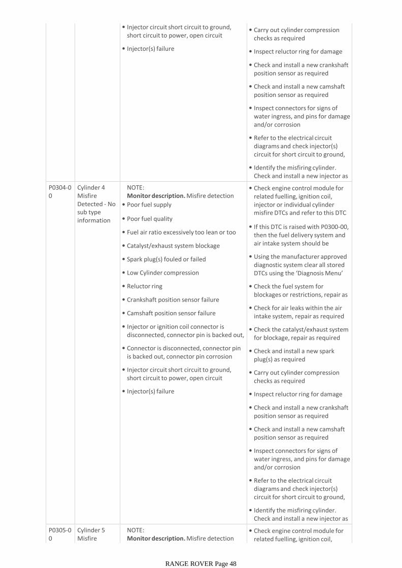
• Injector circuit short circuit to ground, short circuit to power, open circuit
• Injector(s) failure
• Carry out cylinder compression checks as required
• Inspect reluctor ring for damage
• Check and install a new crankshaft position sensor as required
• Check and install a new camshaft position sensor as required
• Inspect connectors for signs of water ingress, and pins for damage and/or corrosion
• Refer to the electrical circuit diagrams and check injector(s) circuit for short circuit to ground, short circuit to power, open circuit
• Identify the misfiring cylinder. Check and install a new injector as requiredP0304-0
0Cylinder 4 Misfire Detected - No sub type information
NOTE:Monitor description. Misfire detection
• Poor fuel supply
• Poor fuel quality
• Fuel air ratio excessively too lean or too rich
• Catalyst/exhaust system blockage
• Spark plug(s) fouled or failed
• Low Cylinder compression
• Reluctor ring
• Crankshaft position sensor failure
• Camshaft position sensor failure
• Injector or ignition coil connector is disconnected, connector pin is backed out, connector pin corrosion
• Connector is disconnected, connector pin is backed out, connector pin corrosion
• Injector circuit short circuit to ground, short circuit to power, open circuit
• Injector(s) failure
• Check engine control module for related fuelling, ignition coil, injector or individual cylinder misfire DTCs and refer to this DTC index. Rectify these first
• If this DTC is raised with P0300-00, then the fuel delivery system and air intake system should be checked and rectified first
• Using the manufacturer approved diagnostic system clear all stored DTCs using the ‘Diagnosis Menu’ tab and retest
• Check the fuel system for blockages or restrictions, repair as required
• Check for air leaks within the air intake system, repair as required
• Check the catalyst/exhaust system for blockage, repair as required
• Check and install a new spark plug(s) as required
• Carry out cylinder compression checks as required
• Inspect reluctor ring for damage
• Check and install a new crankshaft position sensor as required
• Check and install a new camshaft position sensor as required
• Inspect connectors for signs of water ingress, and pins for damage and/or corrosion
• Refer to the electrical circuit diagrams and check injector(s) circuit for short circuit to ground, short circuit to power, open circuit
• Identify the misfiring cylinder. Check and install a new injector as requiredP0305-0
0Cylinder 5 Misfire Detected - No
NOTE:Monitor description. Misfire detection
• Poor fuel supply
• Check engine control module for related fuelling, ignition coil, injector or individual cylinder
RANGE ROVER Page 48
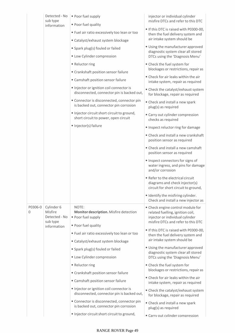
Detected - No sub type information
• Poor fuel supply
• Poor fuel quality
• Fuel air ratio excessively too lean or too rich
• Catalyst/exhaust system blockage
• Spark plug(s) fouled or failed
• Low Cylinder compression
• Reluctor ring
• Crankshaft position sensor failure
• Camshaft position sensor failure
• Injector or ignition coil connector is disconnected, connector pin is backed out, connector pin corrosion
• Connector is disconnected, connector pin is backed out, connector pin corrosion
• Injector circuit short circuit to ground, short circuit to power, open circuit
• Injector(s) failure
related fuelling, ignition coil, injector or individual cylinder misfire DTCs and refer to this DTC index. Rectify these first
• If this DTC is raised with P0300-00, then the fuel delivery system and air intake system should be checked and rectified first
• Using the manufacturer approved diagnostic system clear all stored DTCs using the ‘Diagnosis Menu’ tab and retest
• Check the fuel system for blockages or restrictions, repair as required
• Check for air leaks within the air intake system, repair as required
• Check the catalyst/exhaust system for blockage, repair as required
• Check and install a new spark plug(s) as required
• Carry out cylinder compression checks as required
• Inspect reluctor ring for damage
• Check and install a new crankshaft position sensor as required
• Check and install a new camshaft position sensor as required
• Inspect connectors for signs of water ingress, and pins for damage and/or corrosion
• Refer to the electrical circuit diagrams and check injector(s) circuit for short circuit to ground, short circuit to power, open circuit
• Identify the misfiring cylinder. Check and install a new injector as requiredP0306-0
0Cylinder 6 Misfire Detected - No sub type information
NOTE:Monitor description. Misfire detection
• Poor fuel supply
• Poor fuel quality
• Fuel air ratio excessively too lean or too rich
• Catalyst/exhaust system blockage
• Spark plug(s) fouled or failed
• Low Cylinder compression
• Reluctor ring
• Crankshaft position sensor failure
• Camshaft position sensor failure
• Injector or ignition coil connector is disconnected, connector pin is backed out, connector pin corrosion
• Connector is disconnected, connector pin is backed out, connector pin corrosion
• Injector circuit short circuit to ground, short circuit to power, open circuit
• Check engine control module for related fuelling, ignition coil, injector or individual cylinder misfire DTCs and refer to this DTC index. Rectify these first
• If this DTC is raised with P0300-00, then the fuel delivery system and air intake system should be checked and rectified first
• Using the manufacturer approved diagnostic system clear all stored DTCs using the ‘Diagnosis Menu’ tab and retest
• Check the fuel system for blockages or restrictions, repair as required
• Check for air leaks within the air intake system, repair as required
• Check the catalyst/exhaust system for blockage, repair as required
• Check and install a new spark plug(s) as required
• Carry out cylinder compression
RANGE ROVER Page 49
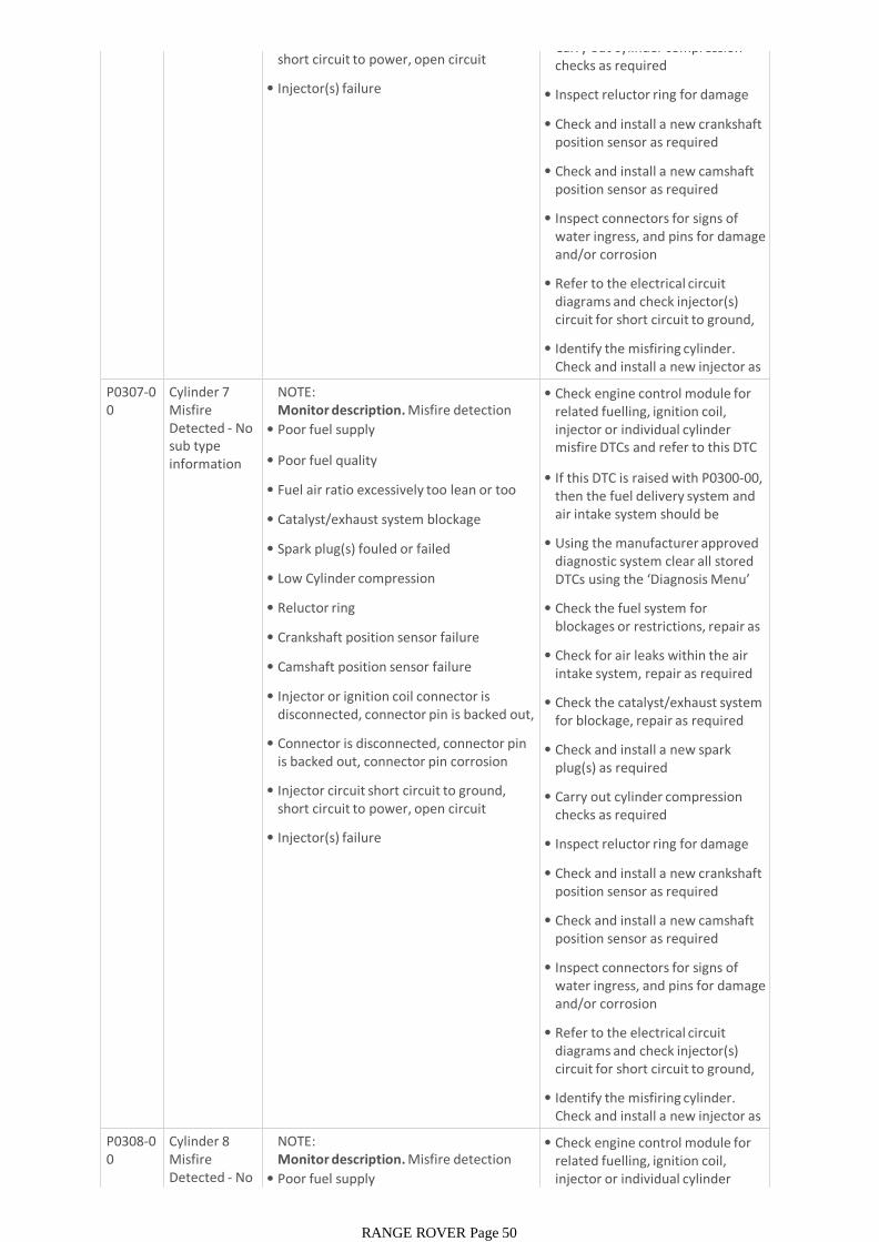
short circuit to power, open circuit
• Injector(s) failure
• Carry out cylinder compression checks as required
• Inspect reluctor ring for damage
• Check and install a new crankshaft position sensor as required
• Check and install a new camshaft position sensor as required
• Inspect connectors for signs of water ingress, and pins for damage and/or corrosion
• Refer to the electrical circuit diagrams and check injector(s) circuit for short circuit to ground, short circuit to power, open circuit
• Identify the misfiring cylinder. Check and install a new injector as requiredP0307-0
0Cylinder 7 Misfire Detected - No sub type information
NOTE:Monitor description. Misfire detection
• Poor fuel supply
• Poor fuel quality
• Fuel air ratio excessively too lean or too rich
• Catalyst/exhaust system blockage
• Spark plug(s) fouled or failed
• Low Cylinder compression
• Reluctor ring
• Crankshaft position sensor failure
• Camshaft position sensor failure
• Injector or ignition coil connector is disconnected, connector pin is backed out, connector pin corrosion
• Connector is disconnected, connector pin is backed out, connector pin corrosion
• Injector circuit short circuit to ground, short circuit to power, open circuit
• Injector(s) failure
• Check engine control module for related fuelling, ignition coil, injector or individual cylinder misfire DTCs and refer to this DTC index. Rectify these first
• If this DTC is raised with P0300-00, then the fuel delivery system and air intake system should be checked and rectified first
• Using the manufacturer approved diagnostic system clear all stored DTCs using the ‘Diagnosis Menu’ tab and retest
• Check the fuel system for blockages or restrictions, repair as required
• Check for air leaks within the air intake system, repair as required
• Check the catalyst/exhaust system for blockage, repair as required
• Check and install a new spark plug(s) as required
• Carry out cylinder compression checks as required
• Inspect reluctor ring for damage
• Check and install a new crankshaft position sensor as required
• Check and install a new camshaft position sensor as required
• Inspect connectors for signs of water ingress, and pins for damage and/or corrosion
• Refer to the electrical circuit diagrams and check injector(s) circuit for short circuit to ground, short circuit to power, open circuit
• Identify the misfiring cylinder. Check and install a new injector as requiredP0308-0
0Cylinder 8 Misfire Detected - No sub type
NOTE:Monitor description. Misfire detection
• Poor fuel supply
• Check engine control module for related fuelling, ignition coil, injector or individual cylinder misfire DTCs and refer to this DTC
RANGE ROVER Page 50

sub type information
• Poor fuel supply
• Poor fuel quality
• Fuel air ratio excessively too lean or too rich
• Catalyst/exhaust system blockage
• Spark plug(s) fouled or failed
• Low Cylinder compression
• Reluctor ring
• Crankshaft position sensor failure
• Camshaft position sensor failure
• Injector or ignition coil connector is disconnected, connector pin is backed out, connector pin corrosion
• Connector is disconnected, connector pin is backed out, connector pin corrosion
• Injector circuit short circuit to ground, short circuit to power, open circuit
• Injector(s) failure
injector or individual cylinder misfire DTCs and refer to this DTC index. Rectify these first
• If this DTC is raised with P0300-00, then the fuel delivery system and air intake system should be checked and rectified first
• Using the manufacturer approved diagnostic system clear all stored DTCs using the ‘Diagnosis Menu’ tab and retest
• Check the fuel system for blockages or restrictions, repair as required
• Check for air leaks within the air intake system, repair as required
• Check the catalyst/exhaust system for blockage, repair as required
• Check and install a new spark plug(s) as required
• Carry out cylinder compression checks as required
• Inspect reluctor ring for damage
• Check and install a new crankshaft position sensor as required
• Check and install a new camshaft position sensor as required
• Inspect connectors for signs of water ingress, and pins for damage and/or corrosion
• Refer to the electrical circuit diagrams and check injector(s) circuit for short circuit to ground, short circuit to power, open circuit
• Identify the misfiring cylinder. Check and install a new injector as requiredP0313-0
0Misfire Detected With Low Fuel - No sub type information
• Poor fuel quality
• Catalyst/exhaust system blockage
• Spark plug(s) fouled or failed
• Coil(s) failure
• Injector(s) circuit short circuit to ground, short circuit to power, open circuit
• Injector(s) failure
• Fuel system excessively too lean or too rich
• Camshaft position sensor failure
• Using the manufacturer approved diagnostic system, check engine control module, for related DTCs and refer to the relevant DTC index
• Check the fuel system for blockages, repair as required
• Check the catalyst/exhaust system for blockage, repair as required
• Check and install a new spark plug(s) as required
• Check and install a new coil(s) as required
• Refer to the electrical circuit diagrams and check injector(s) circuit for short circuit to ground, short circuit to power, open circuit
• Check and install a new injector(s) as required
• Check for air leaks within the intake system
• Check and install a new camshaft position sensor as required
RANGE ROVER Page 51
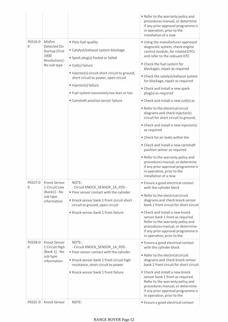
• Refer to the warranty policy and procedures manual, or determine if any prior approval programme is in operation, prior to the installation of a new module/component
P0316-00
Misfire Detected On Startup (First 1000 Revolutions) -No sub type information
• Poor fuel quality
• Catalyst/exhaust system blockage
• Spark plug(s) fouled or failed
• Coil(s) failure
• Injector(s) circuit short circuit to ground, short circuit to power, open circuit
• Injector(s) failure
• Fuel system excessively too lean or too rich
• Camshaft position sensor failure
• Using the manufacturer approved diagnostic system, check engine control module, for related DTCs and refer to the relevant DTC index
• Check the fuel system for blockages, repair as required
• Check the catalyst/exhaust system for blockage, repair as required
• Check and install a new spark plug(s) as required
• Check and install a new coil(s) as required
• Refer to the electrical circuit diagrams and check injector(s) circuit for short circuit to ground, short circuit to power, open circuit
• Check and install a new injector(s) as required
• Check for air leaks within the intake system
• Check and install a new camshaft position sensor as required
• Refer to the warranty policy and procedures manual, or determine if any prior approval programme is in operation, prior to the installation of a new module/component
P0327-00
Knock Sensor 1 Circuit Low (Bank1) - No sub type information
NOTE:- Circuit KNOCK_SENSOR_1A_POS -
• Poor sensor contact with the cylinder block
• Knock sensor bank 1 front circuit short circuit to ground, open circuit
• Knock sensor bank 1 front failure
• Ensure a good electrical contact with the cylinder block
• Refer to the electrical circuit diagrams and check knock sensor bank 1 front circuit for short circuit to ground, open circuit
• Check and install a new knock sensor bank 1 front as required. Refer to the warranty policy and procedures manual, or determine if any prior approval programme is in operation, prior to the installation of a new P0328-0
0Knock Sensor 1 Circuit High (Bank 1) - No sub type information
NOTE:- Circuit KNOCK_SENSOR_1A_POS -
• Poor sensor contact with the cylinder block
• Knock sensor bank 1 front circuit high resistance, short circuit to power
• Knock sensor bank 1 front failure
• Ensure a good electrical contact with the cylinder block
• Refer to the electrical circuit diagrams and check knock sensor bank 1 front circuit for short circuit to power, high resistance
• Check and install a new knock sensor bank 1 front as required. Refer to the warranty policy and procedures manual, or determine if any prior approval programme is in operation, prior to the installation of a new P032C-0
0Knock Sensor 3 Circuit Low
NOTE:- Circuit KNOCK_SENSOR_2A_POS -
• Ensure a good electrical contact with the cylinder block
RANGE ROVER Page 52
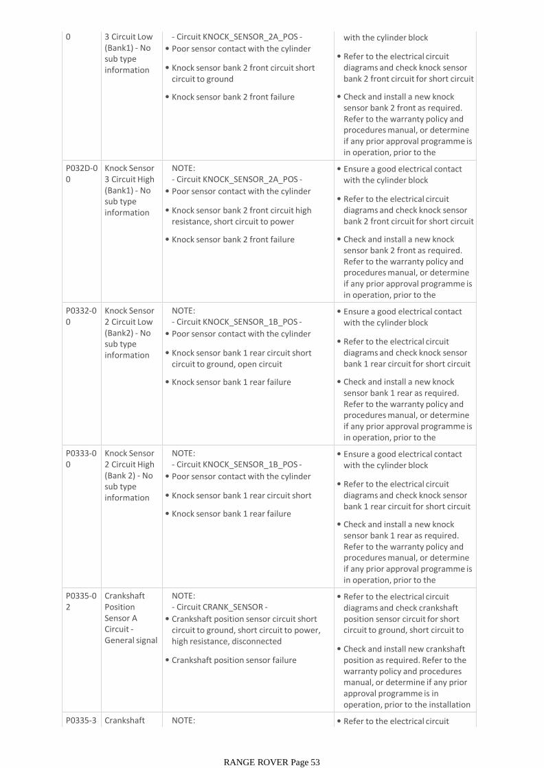
0 3 Circuit Low (Bank1) - No sub type information
- Circuit KNOCK_SENSOR_2A_POS -
• Poor sensor contact with the cylinder block
• Knock sensor bank 2 front circuit short circuit to ground
• Knock sensor bank 2 front failure
• Ensure a good electrical contact with the cylinder block
• Refer to the electrical circuit diagrams and check knock sensor bank 2 front circuit for short circuit to ground
• Check and install a new knock sensor bank 2 front as required. Refer to the warranty policy and procedures manual, or determine if any prior approval programme is in operation, prior to the installation of a new P032D-0
0Knock Sensor 3 Circuit High (Bank1) - No sub type information
NOTE:- Circuit KNOCK_SENSOR_2A_POS -
• Poor sensor contact with the cylinder block
• Knock sensor bank 2 front circuit high resistance, short circuit to power
• Knock sensor bank 2 front failure
• Ensure a good electrical contact with the cylinder block
• Refer to the electrical circuit diagrams and check knock sensor bank 2 front circuit for short circuit to power, high resistance
• Check and install a new knock sensor bank 2 front as required. Refer to the warranty policy and procedures manual, or determine if any prior approval programme is in operation, prior to the installation of a new P0332-0
0Knock Sensor 2 Circuit Low (Bank2) - No sub type information
NOTE:- Circuit KNOCK_SENSOR_1B_POS -
• Poor sensor contact with the cylinder block
• Knock sensor bank 1 rear circuit short circuit to ground, open circuit
• Knock sensor bank 1 rear failure
• Ensure a good electrical contact with the cylinder block
• Refer to the electrical circuit diagrams and check knock sensor bank 1 rear circuit for short circuit to ground, open circuit
• Check and install a new knock sensor bank 1 rear as required. Refer to the warranty policy and procedures manual, or determine if any prior approval programme is in operation, prior to the installation of a new P0333-0
0Knock Sensor 2 Circuit High (Bank 2) - No sub type information
NOTE:- Circuit KNOCK_SENSOR_1B_POS -
• Poor sensor contact with the cylinder block
• Knock sensor bank 1 rear circuit short circuit to power
• Knock sensor bank 1 rear failure
• Ensure a good electrical contact with the cylinder block
• Refer to the electrical circuit diagrams and check knock sensor bank 1 rear circuit for short circuit to power
• Check and install a new knock sensor bank 1 rear as required. Refer to the warranty policy and procedures manual, or determine if any prior approval programme is in operation, prior to the installation of a new P0335-0
2Crankshaft Position Sensor A Circuit -General signal failure
NOTE:- Circuit CRANK_SENSOR -
• Crankshaft position sensor circuit short circuit to ground, short circuit to power, high resistance, disconnected
• Crankshaft position sensor failure
• Refer to the electrical circuit diagrams and check crankshaft position sensor circuit for short circuit to ground, short circuit to power, high resistance,
• Check and install new crankshaft position as required. Refer to the warranty policy and procedures manual, or determine if any prior approval programme is in operation, prior to the installation of a new module/componentP0335-3
1Crankshaft Position
NOTE:- Circuit CRANK_SENSOR -
• Refer to the electrical circuit diagrams and check crankshaft
RANGE ROVER Page 53
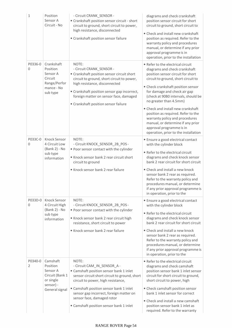
1 Position Sensor A Circuit - No signal
- Circuit CRANK_SENSOR -
• Crankshaft position sensor circuit - short circuit to ground, short circuit to power, high resistance, disconnected
• Crankshaft position sensor failure
• Refer to the electrical circuit diagrams and check crankshaft position sensor circuit for short circuit to ground, short circuit to power, high resistance,
• Check and install new crankshaft position as required. Refer to the warranty policy and procedures manual, or determine if any prior approval programme is in operation, prior to the installation of a new module/componentP0336-0
0Crankshaft Position Sensor A Circuit Range/Performance - No sub type information
NOTE:- Circuit CRANK_SENSOR -
• Crankshaft position sensor circuit short circuit to ground, short circuit to power, high resistance, disconnected
• Crankshaft position sensor gap incorrect, foreign matter on sensor face, damaged teeth on rotor
• Crankshaft position sensor failure
• Refer to the electrical circuit diagrams and check crankshaft position sensor circuit for short circuit to ground, short circuit to power, high resistance,
• Check crankshaft position sensor for damage and check air gap (check at 90B0 intervals, should be no greater than 4.5mm)
• Check and install new crankshaft position as required. Refer to the warranty policy and procedures manual, or determine if any prior approval programme is in operation, prior to the installation of a new module/componentP033C-0
0Knock Sensor 4 Circuit Low (Bank 2) - No sub type information
NOTE:- Circuit KNOCK_SENSOR_2B_POS -
• Poor sensor contact with the cylinder block
• Knock sensor bank 2 rear circuit short circuit to ground
• Knock sensor bank 2 rear failure
• Ensure a good electrical contact with the cylinder block
• Refer to the electrical circuit diagrams and check knock sensor bank 2 rear circuit for short circuit to ground
• Check and install a new knock sensor bank 2 rear as required. Refer to the warranty policy and procedures manual, or determine if any prior approval programme is in operation, prior to the installation of a new P033D-0
0Knock Sensor 4 Circuit High (Bank 2) - No sub type information
NOTE:- Circuit KNOCK_SENSOR_2B_POS -
• Poor sensor contact with the cylinder block
• Knock sensor bank 2 rear circuit high resistance, short circuit to power
• Knock sensor bank 2 rear failure
• Ensure a good electrical contact with the cylinder block
• Refer to the electrical circuit diagrams and check knock sensor bank 2 rear circuit for short circuit to power, high resistance
• Check and install a new knock sensor bank 2 rear as required. Refer to the warranty policy and procedures manual, or determine if any prior approval programme is in operation, prior to the installation of a new P0340-0
2Camshaft Position Sensor A Circuit (Bank 1 or single sensor) -General signal failure
NOTE:- Circuit CAM_IN_SENSOR_A -
• Camshaft position sensor bank 1 inlet sensor circuit short circuit to ground, short circuit to power, high resistance, disconnected
• Camshaft position sensor bank 1 inlet sensor gap incorrect, foreign matter on sensor face, damaged rotor
• Camshaft position sensor bank 1 inlet sensor failure
• Refer to the electrical circuit diagrams and check camshaft position sensor bank 1 inlet sensor circuit for short circuit to ground, short circuit to power, high resistance, disconnected
• Check camshaft position sensor bank 1 inlet sensor for correct installation and damage
• Check and install a new camshaft position sensor bank 1 inlet as required. Refer to the warranty policy and procedures manual, or
RANGE ROVER Page 54

policy and procedures manual, or determine if any prior approval programme is in operation, prior to the installation of a new P0340-3
1Camshaft Position Sensor A Circuit (Bank 1 or single sensor) - No signal
NOTE:- Circuit CAM_IN_SENSOR_A -
• Camshaft position sensor bank 1 inlet sensor circuit short circuit to ground, short circuit to power, high resistance, disconnected
• Camshaft position sensor bank 1 inlet sensor gap incorrect, foreign matter on sensor face, damaged rotor
• Camshaft position sensor bank 1 inlet sensor failure
• Refer to the electrical circuit diagrams and check camshaft position sensor bank 1 inlet sensor circuit for short circuit to ground, short circuit to power, high resistance, disconnected
• Check camshaft position sensor bank 1 inlet sensor for correct installation and damage
• Check and install a new camshaft position sensor bank 1 inlet as required. Refer to the warranty policy and procedures manual, or determine if any prior approval programme is in operation, prior to the installation of a new P0341-0
0Camshaft Position Sensor A Circuit Range/Performance (Bank 1 or single sensor) - No sub type
NOTE:- Circuit CAM_IN_SENSOR_A -
• Camshaft position sensor bank 1 inlet sensor circuit short circuit to ground, short circuit to power, high resistance, disconnected
• Camshaft position sensor bank 1 inlet sensor gap incorrect, foreign matter on sensor face, damaged rotor
• Camshaft position sensor bank 1 inlet sensor failure
• Refer to the electrical circuit diagrams and check camshaft position sensor bank 1 inlet sensor circuit for short circuit to ground, short circuit to power, high resistance, disconnected
• Check camshaft position sensor bank 1 inlet sensor for correct installation and damage
• Check and install a new camshaft position sensor bank 1 inlet as required. Refer to the warranty policy and procedures manual, or determine if any prior approval programme is in operation, prior to the installation of a new P0345-0
2Camshaft Position Sensor A Circuit (Bank 2) - General signal failure
NOTE:- Circuit CAM_IN_SENSOR_B -
• Camshaft position sensor bank 2 inlet sensor circuit short circuit to ground, short circuit to power, high resistance, disconnected
• Camshaft position sensor bank 2 inlet sensor gap incorrect, foreign matter on sensor face, damaged rotor
• Camshaft position sensor bank 2 inlet sensor failure
• Refer to the electrical circuit diagrams and check camshaft position sensor bank 2 inlet sensor circuit for short circuit to ground, short circuit to power, high resistance, disconnected
• Check camshaft position sensor bank 2 inlet sensor for correct installation and damage
• Check and install a new camshaft position sensor bank 2 inlet as required. Refer to the warranty policy and procedures manual, or determine if any prior approval programme is in operation, prior to the installation of a new P0345-3
1Camshaft Position Sensor A Circuit (Bank 2) - No signal
NOTE:- Circuit CAM_IN_SENSOR_B -
• Camshaft position sensor bank 2 inlet sensor circuit - short circuit to ground, short circuit to power, high resistance, disconnected
• Camshaft position sensor bank 2 inlet sensor gap incorrect, foreign matter on sensor face, damaged rotor
• Camshaft position sensor bank 2 inlet sensor failure
• Refer to the electrical circuit diagrams and check camshaft position sensor bank 2 inlet sensor circuit for short circuit to ground, short circuit to power, high resistance, disconnected
• Check camshaft position sensor bank 2 inlet sensor for correct installation and damage
• Check and install a new camshaft position sensor bank 2 inlet as required. Refer to the warranty policy and procedures manual, or determine if any prior approval programme is in operation, prior to the installation of a new P0346-0 Camshaft NOTE: • Refer to the electrical circuit
RANGE ROVER Page 55
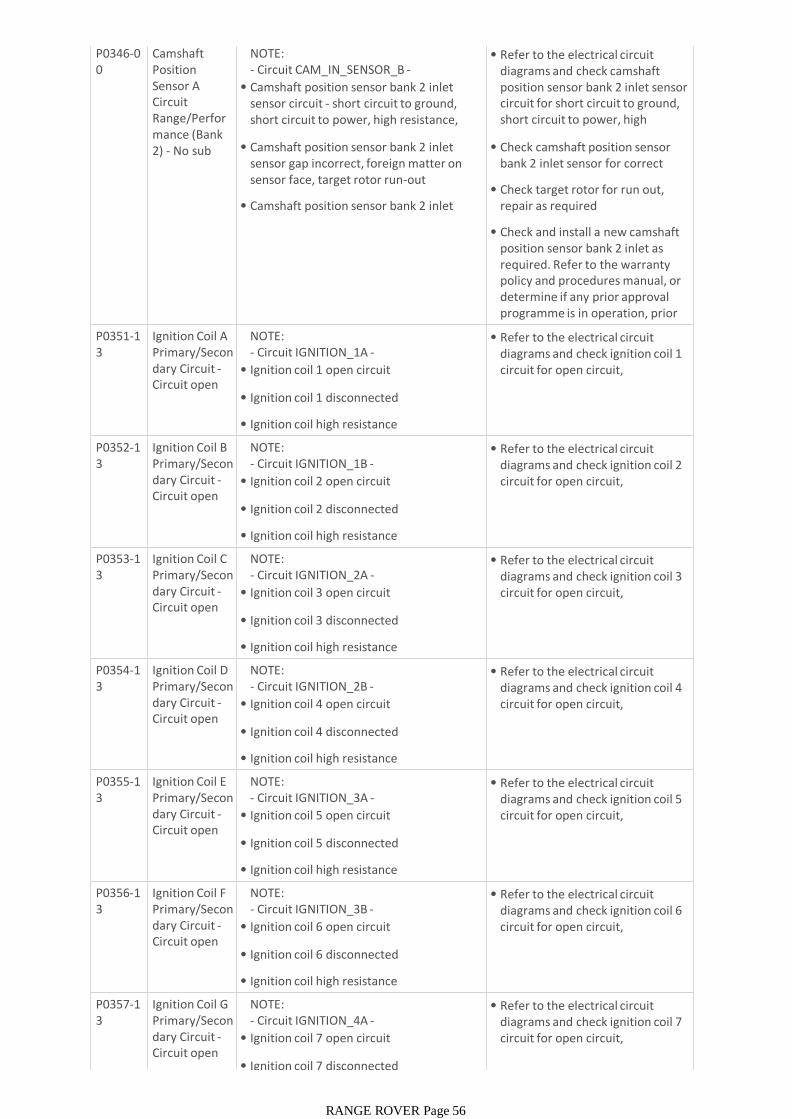
P0346-00
Camshaft Position Sensor A Circuit Range/Performance (Bank 2) - No sub type
NOTE:- Circuit CAM_IN_SENSOR_B -
• Camshaft position sensor bank 2 inlet sensor circuit - short circuit to ground, short circuit to power, high resistance, disconnected
• Camshaft position sensor bank 2 inlet sensor gap incorrect, foreign matter on sensor face, target rotor run-out
• Camshaft position sensor bank 2 inlet sensor failure
• Refer to the electrical circuit diagrams and check camshaft position sensor bank 2 inlet sensor circuit for short circuit to ground, short circuit to power, high resistance, disconnected
• Check camshaft position sensor bank 2 inlet sensor for correct installation and damage
• Check target rotor for run out, repair as required
• Check and install a new camshaft position sensor bank 2 inlet as required. Refer to the warranty policy and procedures manual, or determine if any prior approval programme is in operation, prior to the installation of a new P0351-1
3Ignition Coil A Primary/Secondary Circuit -Circuit open
NOTE:- Circuit IGNITION_1A -
• Ignition coil 1 open circuit
• Ignition coil 1 disconnected
• Ignition coil high resistance
• Refer to the electrical circuit diagrams and check ignition coil 1 circuit for open circuit, disconnected ignition coil, high
P0352-13
Ignition Coil B Primary/Secondary Circuit -Circuit open
NOTE:- Circuit IGNITION_1B -
• Ignition coil 2 open circuit
• Ignition coil 2 disconnected
• Ignition coil high resistance
• Refer to the electrical circuit diagrams and check ignition coil 2 circuit for open circuit, disconnected ignition coil, high
P0353-13
Ignition Coil C Primary/Secondary Circuit -Circuit open
NOTE:- Circuit IGNITION_2A -
• Ignition coil 3 open circuit
• Ignition coil 3 disconnected
• Ignition coil high resistance
• Refer to the electrical circuit diagrams and check ignition coil 3 circuit for open circuit, disconnected ignition coil, high
P0354-13
Ignition Coil D Primary/Secondary Circuit -Circuit open
NOTE:- Circuit IGNITION_2B -
• Ignition coil 4 open circuit
• Ignition coil 4 disconnected
• Ignition coil high resistance
• Refer to the electrical circuit diagrams and check ignition coil 4 circuit for open circuit, disconnected ignition coil, high
P0355-13
Ignition Coil E Primary/Secondary Circuit -Circuit open
NOTE:- Circuit IGNITION_3A -
• Ignition coil 5 open circuit
• Ignition coil 5 disconnected
• Ignition coil high resistance
• Refer to the electrical circuit diagrams and check ignition coil 5 circuit for open circuit, disconnected ignition coil, high
P0356-13
Ignition Coil F Primary/Secondary Circuit -Circuit open
NOTE:- Circuit IGNITION_3B -
• Ignition coil 6 open circuit
• Ignition coil 6 disconnected
• Ignition coil high resistance
• Refer to the electrical circuit diagrams and check ignition coil 6 circuit for open circuit, disconnected ignition coil, high
P0357-13
Ignition Coil G Primary/Secondary Circuit -Circuit open
NOTE:- Circuit IGNITION_4A -
• Ignition coil 7 open circuit
• Ignition coil 7 disconnected
• Refer to the electrical circuit diagrams and check ignition coil 7 circuit for open circuit, disconnected ignition coil, high
RANGE ROVER Page 56
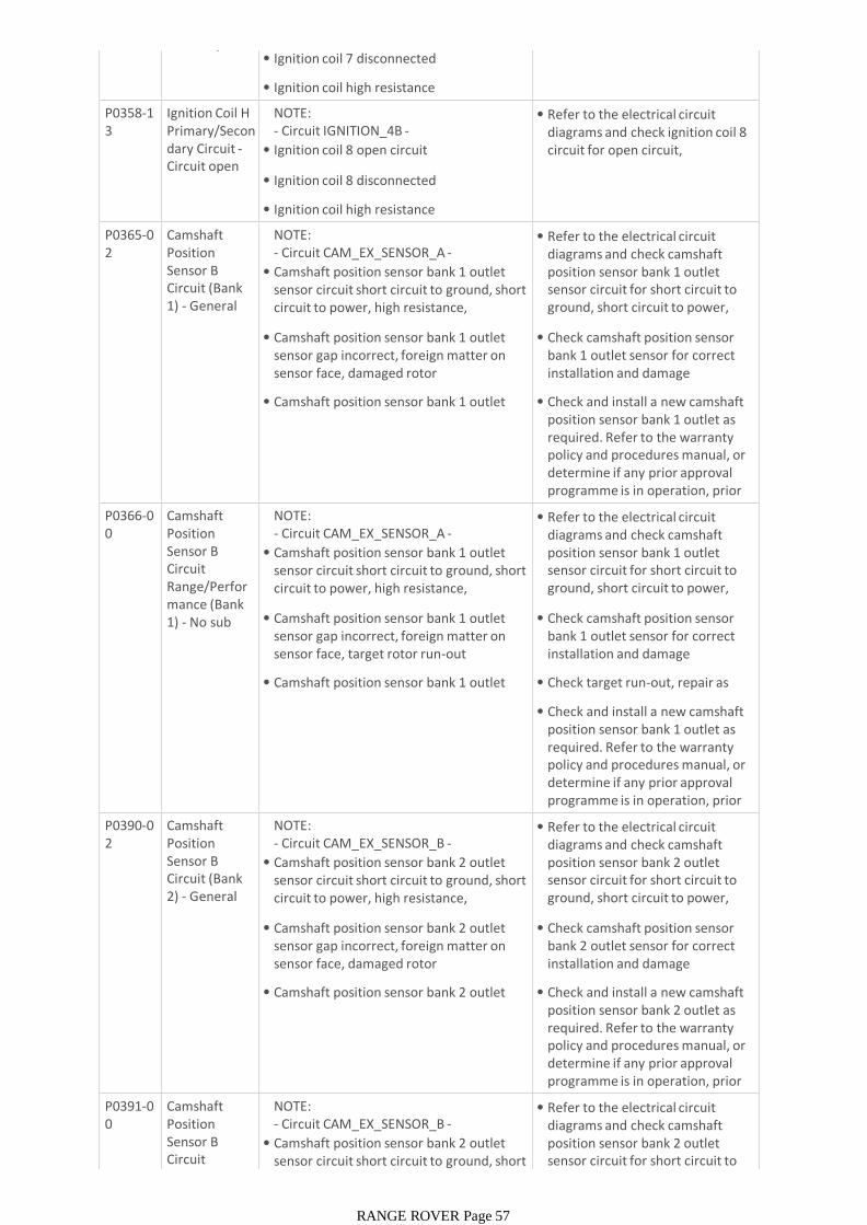
Circuit open• Ignition coil 7 disconnected
• Ignition coil high resistance
P0358-13
Ignition Coil H Primary/Secondary Circuit -Circuit open
NOTE:- Circuit IGNITION_4B -
• Ignition coil 8 open circuit
• Ignition coil 8 disconnected
• Ignition coil high resistance
• Refer to the electrical circuit diagrams and check ignition coil 8 circuit for open circuit, disconnected ignition coil, high
P0365-02
Camshaft Position Sensor B Circuit (Bank 1) - General signal failure
NOTE:- Circuit CAM_EX_SENSOR_A -
• Camshaft position sensor bank 1 outlet sensor circuit short circuit to ground, short circuit to power, high resistance, disconnected
• Camshaft position sensor bank 1 outlet sensor gap incorrect, foreign matter on sensor face, damaged rotor
• Camshaft position sensor bank 1 outlet sensor failure
• Refer to the electrical circuit diagrams and check camshaft position sensor bank 1 outlet sensor circuit for short circuit to ground, short circuit to power, high resistance, disconnected
• Check camshaft position sensor bank 1 outlet sensor for correct installation and damage
• Check and install a new camshaft position sensor bank 1 outlet as required. Refer to the warranty policy and procedures manual, or determine if any prior approval programme is in operation, prior to the installation of a new P0366-0
0Camshaft Position Sensor B Circuit Range/Performance (Bank 1) - No sub type
NOTE:- Circuit CAM_EX_SENSOR_A -
• Camshaft position sensor bank 1 outlet sensor circuit short circuit to ground, short circuit to power, high resistance, disconnected
• Camshaft position sensor bank 1 outlet sensor gap incorrect, foreign matter on sensor face, target rotor run-out
• Camshaft position sensor bank 1 outlet sensor failure
• Refer to the electrical circuit diagrams and check camshaft position sensor bank 1 outlet sensor circuit for short circuit to ground, short circuit to power, high resistance, disconnected
• Check camshaft position sensor bank 1 outlet sensor for correct installation and damage
• Check target run-out, repair as required
• Check and install a new camshaft position sensor bank 1 outlet as required. Refer to the warranty policy and procedures manual, or determine if any prior approval programme is in operation, prior to the installation of a new P0390-0
2Camshaft Position Sensor B Circuit (Bank 2) - General signal failure
NOTE:- Circuit CAM_EX_SENSOR_B -
• Camshaft position sensor bank 2 outlet sensor circuit short circuit to ground, short circuit to power, high resistance, disconnected
• Camshaft position sensor bank 2 outlet sensor gap incorrect, foreign matter on sensor face, damaged rotor
• Camshaft position sensor bank 2 outlet sensor failure
• Refer to the electrical circuit diagrams and check camshaft position sensor bank 2 outlet sensor circuit for short circuit to ground, short circuit to power, high resistance, disconnected
• Check camshaft position sensor bank 2 outlet sensor for correct installation and damage
• Check and install a new camshaft position sensor bank 2 outlet as required. Refer to the warranty policy and procedures manual, or determine if any prior approval programme is in operation, prior to the installation of a new
P0391-00
Camshaft Position Sensor B Circuit Range/Perfor
NOTE:- Circuit CAM_EX_SENSOR_B -
• Camshaft position sensor bank 2 outlet sensor circuit short circuit to ground, short circuit to power, high resistance,
• Refer to the electrical circuit diagrams and check camshaft position sensor bank 2 outlet sensor circuit for short circuit to ground, short circuit to power,
RANGE ROVER Page 57
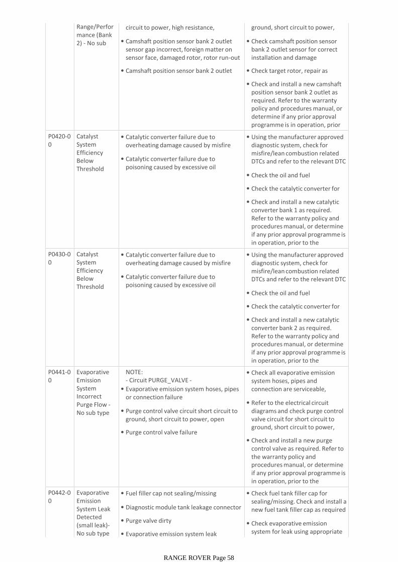
Range/Performance (Bank 2) - No sub type
sensor circuit short circuit to ground, short circuit to power, high resistance, disconnected
• Camshaft position sensor bank 2 outlet sensor gap incorrect, foreign matter on sensor face, damaged rotor, rotor run-out
• Camshaft position sensor bank 2 outlet sensor failure
sensor circuit for short circuit to ground, short circuit to power, high resistance, disconnected
• Check camshaft position sensor bank 2 outlet sensor for correct installation and damage
• Check target rotor, repair as required
• Check and install a new camshaft position sensor bank 2 outlet as required. Refer to the warranty policy and procedures manual, or determine if any prior approval programme is in operation, prior to the installation of a new P0420-0
0Catalyst System Efficiency Below Threshold (Bank 1) - No
• Catalytic converter failure due to overheating damage caused by misfire and/or lean combustion
• Catalytic converter failure due to poisoning caused by excessive oil consumption and/or contaminated fuel
• Using the manufacturer approved diagnostic system, check for misfire/lean combustion related DTCs and refer to the relevant DTC index
• Check the oil and fuel condition/level
• Check the catalytic converter for damage
• Check and install a new catalytic converter bank 1 as required. Refer to the warranty policy and procedures manual, or determine if any prior approval programme is in operation, prior to the installation of a new P0430-0
0Catalyst System Efficiency Below Threshold (Bank 2) - No
• Catalytic converter failure due to overheating damage caused by misfire and/or lean combustion
• Catalytic converter failure due to poisoning caused by excessive oil consumption and/or contaminated fuel
• Using the manufacturer approved diagnostic system, check for misfire/lean combustion related DTCs and refer to the relevant DTC index
• Check the oil and fuel condition/level
• Check the catalytic converter for damage
• Check and install a new catalytic converter bank 2 as required. Refer to the warranty policy and procedures manual, or determine if any prior approval programme is in operation, prior to the installation of a new P0441-0
0Evaporative Emission System Incorrect Purge Flow -No sub type information
NOTE:- Circuit PURGE_VALVE -
• Evaporative emission system hoses, pipes or connection failure
• Purge control valve circuit short circuit to ground, short circuit to power, open circuit, high resistance
• Purge control valve failure
• Check all evaporative emission system hoses, pipes and connection are serviceable, repair/replace as required
• Refer to the electrical circuit diagrams and check purge control valve circuit for short circuit to ground, short circuit to power, open circuit
• Check and install a new purge control valve as required. Refer to the warranty policy and procedures manual, or determine if any prior approval programme is in operation, prior to the installation of a new P0442-0
0Evaporative Emission System Leak Detected (small leak)-No sub type information
• Fuel filler cap not sealing/missing
• Diagnostic module tank leakage connector not sealed
• Purge valve dirty
• Evaporative emission system leak
• Check fuel tank filler cap for sealing/missing. Check and install a new fuel tank filler cap as required
• Check evaporative emission system for leak using appropriate smoke/leak tester
RANGE ROVER Page 58
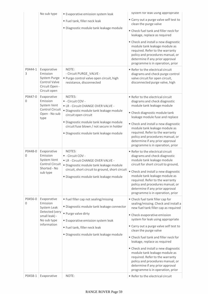
No sub type information
• Evaporative emission system leak
• Fuel tank, filler neck leak
• Diagnostic module tank leakage module failure
system for leak using appropriate smoke/leak tester
• Carry out a purge valve self test to clean the purge valve
• Check fuel tank and filler neck for leakage, replace as required
• Check and install a new diagnostic module tank leakage module as required. Refer to the warranty policy and procedures manual, or determine if any prior approval programme is in operation, prior to the installation of a new P0444-1
3Evaporative Emission System Purge Control Valve Circuit Open -Circuit open
NOTE:- Circuit PURGE_VALVE -
• Purge control valve open circuit, high resistance, disconnected
• Refer to the electrical circuit diagrams and check purge control valve circuit for open circuit, disconnected purge valve, high resistance
P0447-00
Evaporative Emission System Vent Control Circuit Open - No sub type information
NOTES:
• - Circuit COV -
• LR - Circuit CHANGE OVER VALVE -
• Diagnostic module tank leakage module circuit open circuit
• Diagnostic module tank leakage module circuit fuse blown / not secure in holder
• Diagnostic module tank leakage module failure
• Refer to the electrical circuit diagrams and check diagnostic module tank leakage module circuit for open circuit
• Check diagnostic module tank leakage module fuse and replace as required
• Check and install a new diagnostic module tank leakage module as required. Refer to the warranty policy and procedures manual, or determine if any prior approval programme is in operation, prior to the installation of a new P0448-0
0Evaporative Emission System Vent Control Circuit Shorted - No sub type information
NOTES:
• - Circuit COV -
• LR - Circuit CHANGE OVER VALVE -
• Diagnostic module tank leakage module circuit, short circuit to ground, short circuit to power, open circuit
• Diagnostic module tank leakage module failure
• Refer to the electrical circuit diagrams and check diagnostic module tank leakage module circuit for short circuit to ground, short circuit to power, open circuit
• Check and install a new diagnostic module tank leakage module as required. Refer to the warranty policy and procedures manual, or determine if any prior approval programme is in operation, prior to the installation of a new P0456-0
0Evaporative Emission System Leak Detected (very small leak) -No sub type information
• Fuel filler cap not sealing/missing
• Diagnostic module tank leakage connector not sealed
• Purge valve dirty
• Evaporative emission system leak
• Fuel tank, filler neck leak
• Diagnostic module tank leakage module failure
• Check fuel tank filler cap for sealing/missing. Check and install a new fuel tank filler cap as required
• Check evaporative emission system for leak using appropriate smoke/leak tester
• Carry out a purge valve self test to clean the purge valve
• Check fuel tank and filler neck for leakage, replace as required
• Check and install a new diagnostic module tank leakage module as required. Refer to the warranty policy and procedures manual, or determine if any prior approval programme is in operation, prior to the installation of a new P0458-1
1Evaporative Emission
NOTE:- Circuit PURGE_VALVE -
• Refer to the electrical circuit diagrams and check evaporative
RANGE ROVER Page 59
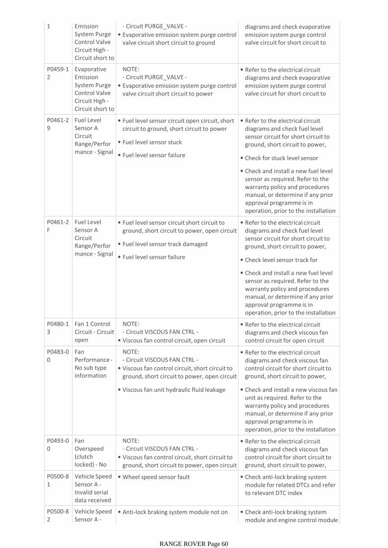
1 Emission System Purge Control Valve Circuit High -Circuit short to ground
- Circuit PURGE_VALVE -
• Evaporative emission system purge control valve circuit short circuit to ground
• Refer to the electrical circuit diagrams and check evaporative emission system purge control valve circuit for short circuit to ground
P0459-12
Evaporative Emission System Purge Control Valve Circuit High -Circuit short to battery
NOTE:- Circuit PURGE_VALVE -
• Evaporative emission system purge control valve circuit short circuit to power
• Refer to the electrical circuit diagrams and check evaporative emission system purge control valve circuit for short circuit to power
P0461-29
Fuel Level Sensor A Circuit Range/Performance - Signal invalid
• Fuel level sensor circuit open circuit, short circuit to ground, short circuit to power
• Fuel level sensor stuck
• Fuel level sensor failure
• Refer to the electrical circuit diagrams and check fuel level sensor circuit for short circuit to ground, short circuit to power, open circuit
• Check for stuck level sensor
• Check and install a new fuel level sensor as required. Refer to the warranty policy and procedures manual, or determine if any prior approval programme is in operation, prior to the installation of a new module/componentP0461-2
FFuel Level Sensor A Circuit Range/Performance - Signal erratic
• Fuel level sensor circuit short circuit to ground, short circuit to power, open circuit
• Fuel level sensor track damaged
• Fuel level sensor failure
• Refer to the electrical circuit diagrams and check fuel level sensor circuit for short circuit to ground, short circuit to power, open circuit
• Check level sensor track for damage
• Check and install a new fuel level sensor as required. Refer to the warranty policy and procedures manual, or determine if any prior approval programme is in operation, prior to the installation of a new module/componentP0480-1
3Fan 1 Control Circuit - Circuit open
NOTE:- Circuit VISCOUS FAN CTRL -
• Viscous fan control circuit, open circuit
• Refer to the electrical circuit diagrams and check viscous fan control circuit for open circuit
P0483-00
Fan Performance -No sub type information
NOTE:- Circuit VISCOUS FAN CTRL -
• Viscous fan control circuit, short circuit to ground, short circuit to power, open circuit
• Viscous fan unit hydraulic fluid leakage
• Refer to the electrical circuit diagrams and check viscous fan control circuit for short circuit to ground, short circuit to power, open circuit
• Check and install a new viscous fan unit as required. Refer to the warranty policy and procedures manual, or determine if any prior approval programme is in operation, prior to the installation of a new module/componentP0493-0
0Fan Overspeed (clutch locked) - No sub type
NOTE:- Circuit VISCOUS FAN CTRL -
• Viscous fan control circuit, short circuit to ground, short circuit to power, open circuit
• Refer to the electrical circuit diagrams and check viscous fan control circuit for short circuit to ground, short circuit to power, open circuit
P0500-81
Vehicle Speed Sensor A -Invalid serial data received
• Wheel speed sensor fault • Check anti-lock braking system module for related DTCs and refer to relevant DTC index
P0500-82
Vehicle Speed Sensor A -Alive /
• Anti-lock braking system module not on bus
• Check anti-lock braking system module and engine control module for related DTCs and refer to
RANGE ROVER Page 60
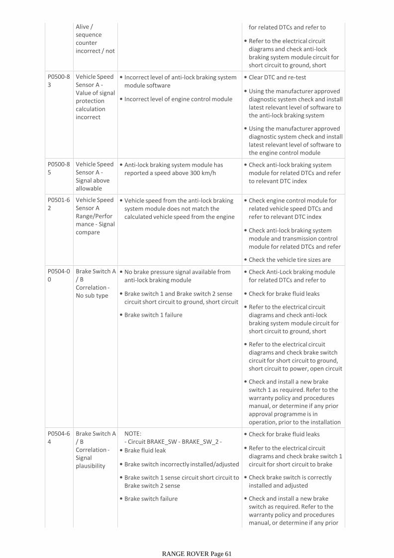
Alive / sequence counter incorrect / not updated
module and engine control module for related DTCs and refer to relevant DTC index
• Refer to the electrical circuit diagrams and check anti-lock braking system module circuit for short circuit to ground, short circuit to power, open circuit
P0500-83
Vehicle Speed Sensor A -Value of signal protection calculation incorrect
• Incorrect level of anti-lock braking system module software
• Incorrect level of engine control module software
• Clear DTC and re-test
• Using the manufacturer approved diagnostic system check and install latest relevant level of software to the anti-lock braking system module
• Using the manufacturer approved diagnostic system check and install latest relevant level of software to the engine control module
P0500-85
Vehicle Speed Sensor A -Signal above allowable range
• Anti-lock braking system module has reported a speed above 300 km/h
• Check anti-lock braking system module for related DTCs and refer to relevant DTC index
P0501-62
Vehicle Speed Sensor A Range/Performance - Signal compare failure
• Vehicle speed from the anti-lock braking system module does not match the calculated vehicle speed from the engine control module
• Check engine control module for related vehicle speed DTCs and refer to relevant DTC index
• Check anti-lock braking system module and transmission control module for related DTCs and refer to relevant DTC index
• Check the vehicle tire sizes are correct
P0504-00
Brake Switch A / B Correlation -No sub type information
• No brake pressure signal available from anti-lock braking module
• Brake switch 1 and Brake switch 2 sense circuit short circuit to ground, short circuit to power, open circuit
• Brake switch 1 failure
• Check Anti-Lock braking module for related DTCs and refer to relevant DTC index
• Check for brake fluid leaks
• Refer to the electrical circuit diagrams and check anti-lock braking system module circuit for short circuit to ground, short circuit to power, open circuit
• Refer to the electrical circuit diagrams and check brake switch circuit for short circuit to ground, short circuit to power, open circuit
• Check and install a new brake switch 1 as required. Refer to the warranty policy and procedures manual, or determine if any prior approval programme is in operation, prior to the installation of a new module/componentP0504-6
4Brake Switch A / B Correlation -Signal plausibility failure
NOTE:- Circuit BRAKE_SW - BRAKE_SW_2 -
• Brake fluid leak
• Brake switch incorrectly installed/adjusted
• Brake switch 1 sense circuit short circuit to Brake switch 2 sense
• Brake switch failure
• Check for brake fluid leaks
• Refer to the electrical circuit diagrams and check brake switch 1 circuit for short circuit to brake switch 2
• Check brake switch is correctly installed and adjusted
• Check and install a new brake switch as required. Refer to the warranty policy and procedures manual, or determine if any prior approval programme is in
RANGE ROVER Page 61
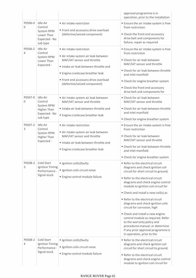
approval programme is in operation, prior to the installation of a new module/componentP0506-0
0Idle Air Control System RPM Lower Than Expected - No sub type information
• Air intake restriction
• Front end accessory drive overload (defective/seized component)
• Ensure the air intake system is free from restriction
• Check the front end accessory drive belt and components for failure, repair as required
P0506-24
Idle Air Control System RPM Lower Than Expected -Signal stuck
• Air intake restriction
• Air intake system air leak between MAF/IAT sensor and throttle
• Intake air leak between throttle and manifold
• Engine crankcase breather leak
• Front end accessory drive overload (defective/seized component)
• Ensure the air intake system is free from restriction
• Check for air leak between MAF/IAT sensor and throttle
• Check for air leak between throttle and inlet manifold
• Check for engine breather system leak
• Check the front end accessory drive belt and components for failureP0507-0
0Idle Air Control System RPM Higher Than Expected - No sub type information
• Air intake system air leak between MAF/IAT sensor and throttle
• Intake air leak between throttle and manifold
• Engine crankcase breather leak
• Check for air leak between MAF/IAT sensor and throttle
• Check for air leak between throttle and inlet manifold
• Check for engine breather system leak
P0507-23
Idle Air Control System RPM Higher Than Expected -Signal stuck
• Air intake restriction
• Air intake system air leak between MAF/IAT sensor and throttle
• Intake air leak between throttle and manifold
• Engine crankcase breather leak
• Ensure the air intake system is free from restriction
• Check for air leak between MAF/IAT sensor and throttle
• Check for air leak between throttle and inlet manifold
• Check for engine breather system leak
P050B-23
Cold Start Ignition Timing Performance -Signal stuck low
• Ignition coil(s)faulty
• Ignition coils circuit noise
• Engine control module failure
• Refer to the electrical circuit diagrams and check ignition coil circuit for short circuit to ground, short circuit to power, open circuit
• Refer to the electrical circuit diagrams and check engine control module to ignition coil circuit for short circuit to power
• Check and install a new coil(s) as required
• Refer to the electrical circuit diagrams and check ignition coils circuit for corrosion, high resistance
• Check and install a new engine control module as required. Refer to the warranty policy and procedures manual, or determine if any prior approval programme is in operation, prior to the installation of a new P050B-2
4Cold Start Ignition Timing Performance -Signal stuck high
• Ignition coil(s)faulty
• Ignition coils circuit noise
• Engine control module failure
• Refer to the electrical circuit diagrams and check ignition coil circuit for short circuit to ground, short circuit to power, open circuit
• Refer to the electrical circuit diagrams and check engine control module to ignition coil circuit for short circuit to power
RANGE ROVER Page 62
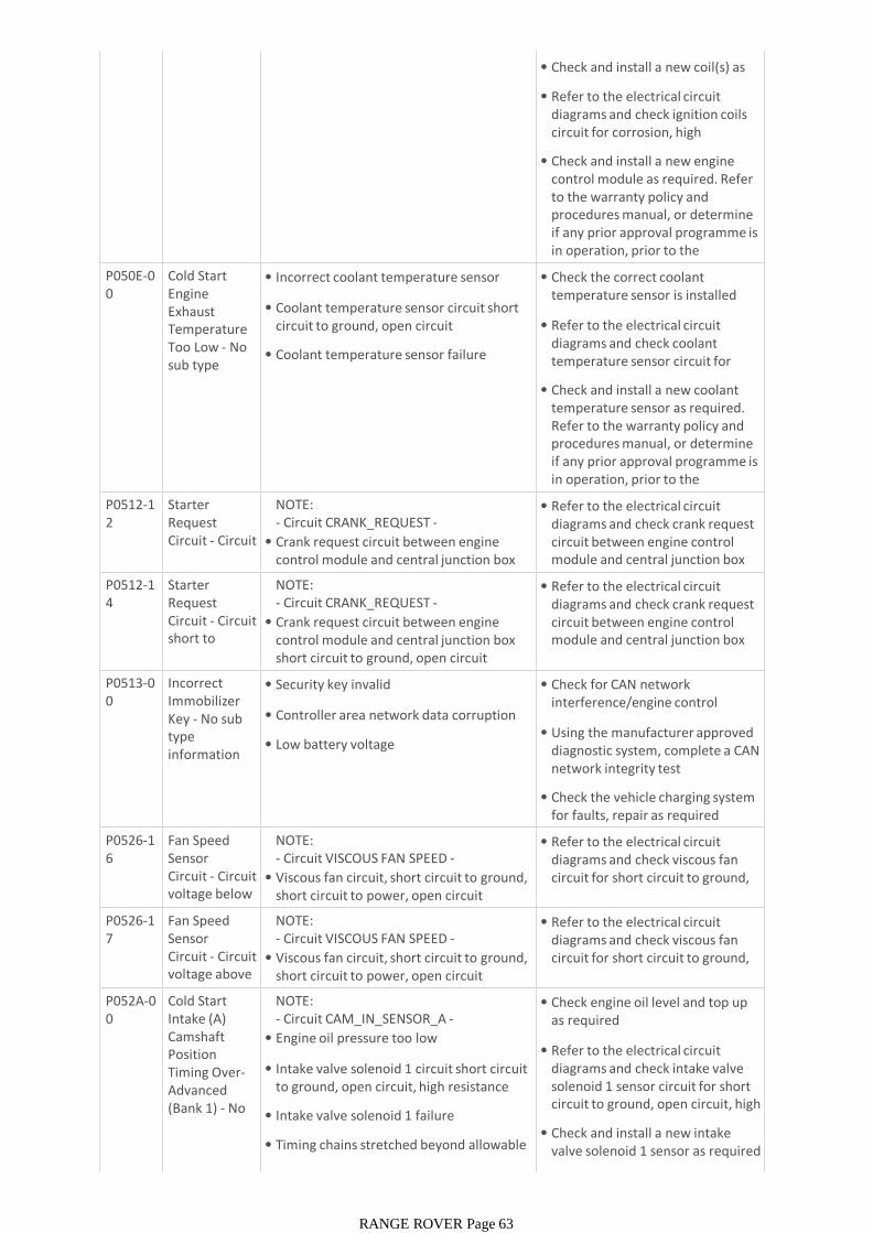
• Check and install a new coil(s) as required
• Refer to the electrical circuit diagrams and check ignition coils circuit for corrosion, high resistance
• Check and install a new engine control module as required. Refer to the warranty policy and procedures manual, or determine if any prior approval programme is in operation, prior to the installation of a new P050E-0
0Cold Start Engine Exhaust Temperature Too Low - No sub type information
• Incorrect coolant temperature sensor installed
• Coolant temperature sensor circuit short circuit to ground, open circuit
• Coolant temperature sensor failure
• Check the correct coolant temperature sensor is installed
• Refer to the electrical circuit diagrams and check coolant temperature sensor circuit for short circuit to ground, open
• Check and install a new coolant temperature sensor as required. Refer to the warranty policy and procedures manual, or determine if any prior approval programme is in operation, prior to the installation of a new P0512-1
2Starter Request Circuit - Circuit short to
NOTE:- Circuit CRANK_REQUEST -
• Crank request circuit between engine control module and central junction box short circuit to power
• Refer to the electrical circuit diagrams and check crank request circuit between engine control module and central junction box for short circuit to power
P0512-14
Starter Request Circuit - Circuit short to ground or
NOTE:- Circuit CRANK_REQUEST -
• Crank request circuit between engine control module and central junction box short circuit to ground, open circuit
• Refer to the electrical circuit diagrams and check crank request circuit between engine control module and central junction box for short circuit to ground, open
P0513-00
Incorrect Immobilizer Key - No sub type information
• Security key invalid
• Controller area network data corruption
• Low battery voltage
• Check for CAN network interference/engine control module related error
• Using the manufacturer approved diagnostic system, complete a CAN network integrity test
• Check the vehicle charging system for faults, repair as required
P0526-16
Fan Speed Sensor Circuit - Circuit voltage below threshold
NOTE:- Circuit VISCOUS FAN SPEED -
• Viscous fan circuit, short circuit to ground, short circuit to power, open circuit
• Refer to the electrical circuit diagrams and check viscous fan circuit for short circuit to ground, short circuit to power, open circuit
P0526-17
Fan Speed Sensor Circuit - Circuit voltage above threshold
NOTE:- Circuit VISCOUS FAN SPEED -
• Viscous fan circuit, short circuit to ground, short circuit to power, open circuit
• Refer to the electrical circuit diagrams and check viscous fan circuit for short circuit to ground, short circuit to power, open circuit
P052A-00
Cold Start Intake (A) Camshaft Position Timing Over-Advanced (Bank 1) - No sub type
NOTE:- Circuit CAM_IN_SENSOR_A -
• Engine oil pressure too low
• Intake valve solenoid 1 circuit short circuit to ground, open circuit, high resistance
• Intake valve solenoid 1 failure
• Timing chains stretched beyond allowable limits
• Check engine oil level and top up as required
• Refer to the electrical circuit diagrams and check intake valve solenoid 1 sensor circuit for short circuit to ground, open circuit, high resistance
• Check and install a new intake valve solenoid 1 sensor as required
• Check service history /mileage
RANGE ROVER Page 63
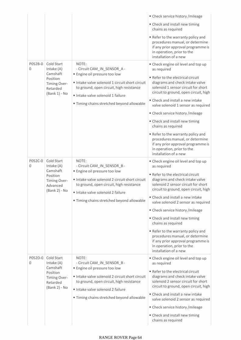
• Check service history /mileage
• Check and install new timing chains as required
• Refer to the warranty policy and procedures manual, or determine if any prior approval programme is in operation, prior to the installation of a new module/componentP052B-0
0Cold Start Intake (A) Camshaft Position Timing Over-Retarded (Bank 1) - No sub type
NOTE:- Circuit CAM_IN_SENSOR_A -
• Engine oil pressure too low
• Intake valve solenoid 1 circuit short circuit to ground, open circuit, high resistance
• Intake valve solenoid 1 failure
• Timing chains stretched beyond allowable limits
• Check engine oil level and top up as required
• Refer to the electrical circuit diagrams and check intake valve solenoid 1 sensor circuit for short circuit to ground, open circuit, high resistance
• Check and install a new intake valve solenoid 1 sensor as required
• Check service history /mileage
• Check and install new timing chains as required
• Refer to the warranty policy and procedures manual, or determine if any prior approval programme is in operation, prior to the installation of a new module/componentP052C-0
0Cold Start Intake (A) Camshaft Position Timing Over-Advanced (Bank 2) - No sub type
NOTE:- Circuit CAM_IN_SENSOR_B -
• Engine oil pressure too low
• Intake valve solenoid 2 circuit short circuit to ground, open circuit, high resistance
• Intake valve solenoid 2 failure
• Timing chains stretched beyond allowable limits
• Check engine oil level and top up as required
• Refer to the electrical circuit diagrams and check intake valve solenoid 2 sensor circuit for short circuit to ground, open circuit, high resistance
• Check and install a new intake valve solenoid 2 sensor as required
• Check service history /mileage
• Check and install new timing chains as required
• Refer to the warranty policy and procedures manual, or determine if any prior approval programme is in operation, prior to the installation of a new module/componentP052D-0
0Cold Start Intake (A) Camshaft Position Timing Over-Retarded (Bank 2) - No sub type
NOTE:- Circuit CAM_IN_SENSOR_B -
• Engine oil pressure too low
• Intake valve solenoid 2 circuit short circuit to ground, open circuit, high resistance
• Intake valve solenoid 2 failure
• Timing chains stretched beyond allowable limits
• Check engine oil level and top up as required
• Refer to the electrical circuit diagrams and check intake valve solenoid 2 sensor circuit for short circuit to ground, open circuit, high resistance
• Check and install a new intake valve solenoid 2 sensor as required
• Check service history /mileage
• Check and install new timing chains as required
•
RANGE ROVER Page 64
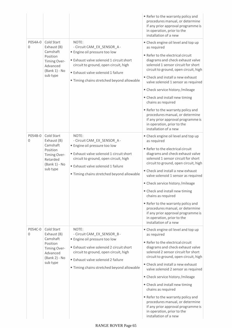
• Refer to the warranty policy and procedures manual, or determine if any prior approval programme is in operation, prior to the installation of a new module/component
P054A-00
Cold Start Exhaust (B) Camshaft Position Timing Over-Advanced (Bank 1) - No sub type information
NOTE:- Circuit CAM_EX_SENSOR_A -
• Engine oil pressure too low
• Exhaust valve solenoid 1 circuit short circuit to ground, open circuit, high resistance
• Exhaust valve solenoid 1 failure
• Timing chains stretched beyond allowable limits
• Check engine oil level and top up as required
• Refer to the electrical circuit diagrams and check exhaust valve solenoid 1 sensor circuit for short circuit to ground, open circuit, high resistance
• Check and install a new exhaust valve solenoid 1 sensor as required
• Check service history /mileage
• Check and install new timing chains as required
• Refer to the warranty policy and procedures manual, or determine if any prior approval programme is in operation, prior to the installation of a new module/componentP054B-0
0Cold Start Exhaust (B) Camshaft Position Timing Over-Retarded (Bank 1) - No sub type information
NOTE:- Circuit CAM_EX_SENSOR_A -
• Engine oil pressure too low
• Exhaust valve solenoid 1 circuit short circuit to ground, open circuit, high resistance
• Exhaust valve solenoid 1 failure
• Timing chains stretched beyond allowable limits
• Check engine oil level and top up as required
• Refer to the electrical circuit diagrams and check exhaust valve solenoid 1 sensor circuit for short circuit to ground, open circuit, high resistance
• Check and install a new exhaust valve solenoid 1 sensor as required
• Check service history /mileage
• Check and install new timing chains as required
• Refer to the warranty policy and procedures manual, or determine if any prior approval programme is in operation, prior to the installation of a new module/componentP054C-0
0Cold Start Exhaust (B) Camshaft Position Timing Over-Advanced (Bank 2) - No sub type information
NOTE:- Circuit CAM_EX_SENSOR_B -
• Engine oil pressure too low
• Exhaust valve solenoid 2 circuit short circuit to ground, open circuit, high resistance
• Exhaust valve solenoid 2 failure
• Timing chains stretched beyond allowable limits
• Check engine oil level and top up as required
• Refer to the electrical circuit diagrams and check exhaust valve solenoid 2 sensor circuit for short circuit to ground, open circuit, high resistance
• Check and install a new exhaust valve solenoid 2 sensor as required
• Check service history /mileage
• Check and install new timing chains as required
• Refer to the warranty policy and procedures manual, or determine if any prior approval programme is in operation, prior to the installation of a new module/component
RANGE ROVER Page 65

P054D-00
Cold Start Exhaust (B) Camshaft Position Timing Over-Retarded (Bank 2) - No sub type information
NOTE:- Circuit CAM_EX_SENSOR_B -
• Engine oil pressure too low
• Exhaust valve solenoid 2 circuit short circuit to ground, open circuit, high resistance
• Exhaust valve solenoid 2 failure
• Timing chains stretched beyond allowable limits
• Check engine oil level and top up as required
• Refer to the electrical circuit diagrams and check exhaust valve solenoid 2 sensor circuit for short circuit to ground, open circuit, high resistance
• Check and install a new exhaust valve solenoid 2 sensor as required
• Check service history /mileage
• Check and install new timing chains as required
• Refer to the warranty policy and procedures manual, or determine if any prior approval programme is in operation, prior to the installation of a new module/componentP0560-1
3System Voltage -Circuit open
NOTE:- Circuit BATTERY -
• Engine control module power supply circuit, open circuit
• Engine control module battery monitor disconnected
• Refer to the electrical circuit diagrams and check engine control module power supply circuit for open circuit
• Refer to the electrical circuit diagrams and check engine control module battery monitor circuit for open circuit
P0562-00
System Voltage Low -No sub type information
NOTE:- Circuit BATTERY -
• Battery circuit high resistance
• Generator circuit open circuit, high resistance
• Generator failure
• Refer to the electrical circuit diagrams and check battery circuit for high resistance
• Refer to the electrical circuit diagrams and check generator circuit for open circuit, high resistance
• Check and install a new generator as required. Refer to the warranty policy and procedures manual, or determine if any prior approval programme is in operation, prior to the installation of a new module/componentP0563-0
0System Voltage High -No sub type information
NOTE:- Circuit BATTERY -
• Battery circuit high resistance
• Generator over charging
• Refer to the electrical circuit diagrams and check battery circuit for high resistance
• Check and install a new generator as required. Refer to the warranty policy and procedures manual, or determine if any prior approval programme is in operation, prior to the installation of a new module/componentP0572-1
7Brake Switch A Circuit Low -Circuit voltage above threshold
NOTE:- Circuit BRAKE_SW -
• Brake switch 2 sense circuit short circuit to ground
• Brake switch incorrectly installed/adjusted
• Customer is driving with foot resting on brake pedal
• Brake switch 2 failure
• Refer to the electrical circuit diagrams and check brake switch 2 circuit for short circuit to ground
• Check brake switch is correctly installed and adjusted
• Ensure customer is not driving with foot resting on brake pedal
• Check and install a new brake switch as required. Refer to the warranty policy and procedures manual, or determine if any prior approval programme is in
RANGE ROVER Page 66
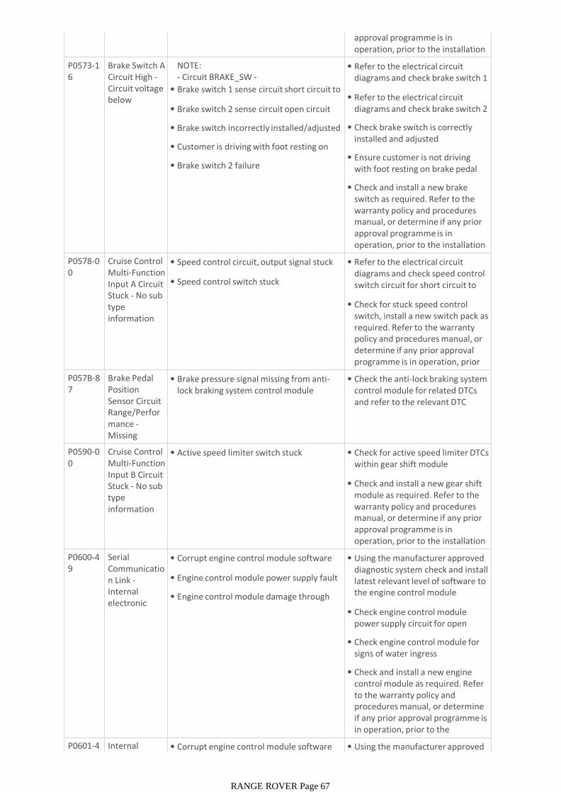
approval programme is in operation, prior to the installation of a new module/componentP0573-1
6Brake Switch A Circuit High -Circuit voltage below threshold
NOTE:- Circuit BRAKE_SW -
• Brake switch 1 sense circuit short circuit to ground
• Brake switch 2 sense circuit open circuit
• Brake switch incorrectly installed/adjusted
• Customer is driving with foot resting on brake pedal
• Brake switch 2 failure
• Refer to the electrical circuit diagrams and check brake switch 1 circuit for open circuit
• Refer to the electrical circuit diagrams and check brake switch 2 circuit for open circuit
• Check brake switch is correctly installed and adjusted
• Ensure customer is not driving with foot resting on brake pedal
• Check and install a new brake switch as required. Refer to the warranty policy and procedures manual, or determine if any prior approval programme is in operation, prior to the installation of a new module/componentP0578-0
0Cruise Control Multi-Function Input A Circuit Stuck - No sub type information
• Speed control circuit, output signal stuck
• Speed control switch stuck
• Refer to the electrical circuit diagrams and check speed control switch circuit for short circuit to ground
• Check for stuck speed control switch, install a new switch pack as required. Refer to the warranty policy and procedures manual, or determine if any prior approval programme is in operation, prior to the installation of a new P057B-8
7Brake Pedal Position Sensor Circuit Range/Performance -Missing message
• Brake pressure signal missing from anti-lock braking system control module
• Check the anti-lock braking system control module for related DTCs and refer to the relevant DTC index
P0590-00
Cruise Control Multi-Function Input B Circuit Stuck - No sub type information
• Active speed limiter switch stuck • Check for active speed limiter DTCs within gear shift module
• Check and install a new gear shift module as required. Refer to the warranty policy and procedures manual, or determine if any prior approval programme is in operation, prior to the installation of a new module/componentP0600-4
9Serial Communication Link -Internal electronic failure
• Corrupt engine control module software
• Engine control module power supply fault
• Engine control module damage through water ingress
• Using the manufacturer approved diagnostic system check and install latest relevant level of software to the engine control module
• Check engine control module power supply circuit for open circuit
• Check engine control module for signs of water ingress
• Check and install a new engine control module as required. Refer to the warranty policy and procedures manual, or determine if any prior approval programme is in operation, prior to the installation of a new P0601-4
3Internal Control
• Corrupt engine control module software flash
• Using the manufacturer approved diagnostic system check and install
RANGE ROVER Page 67
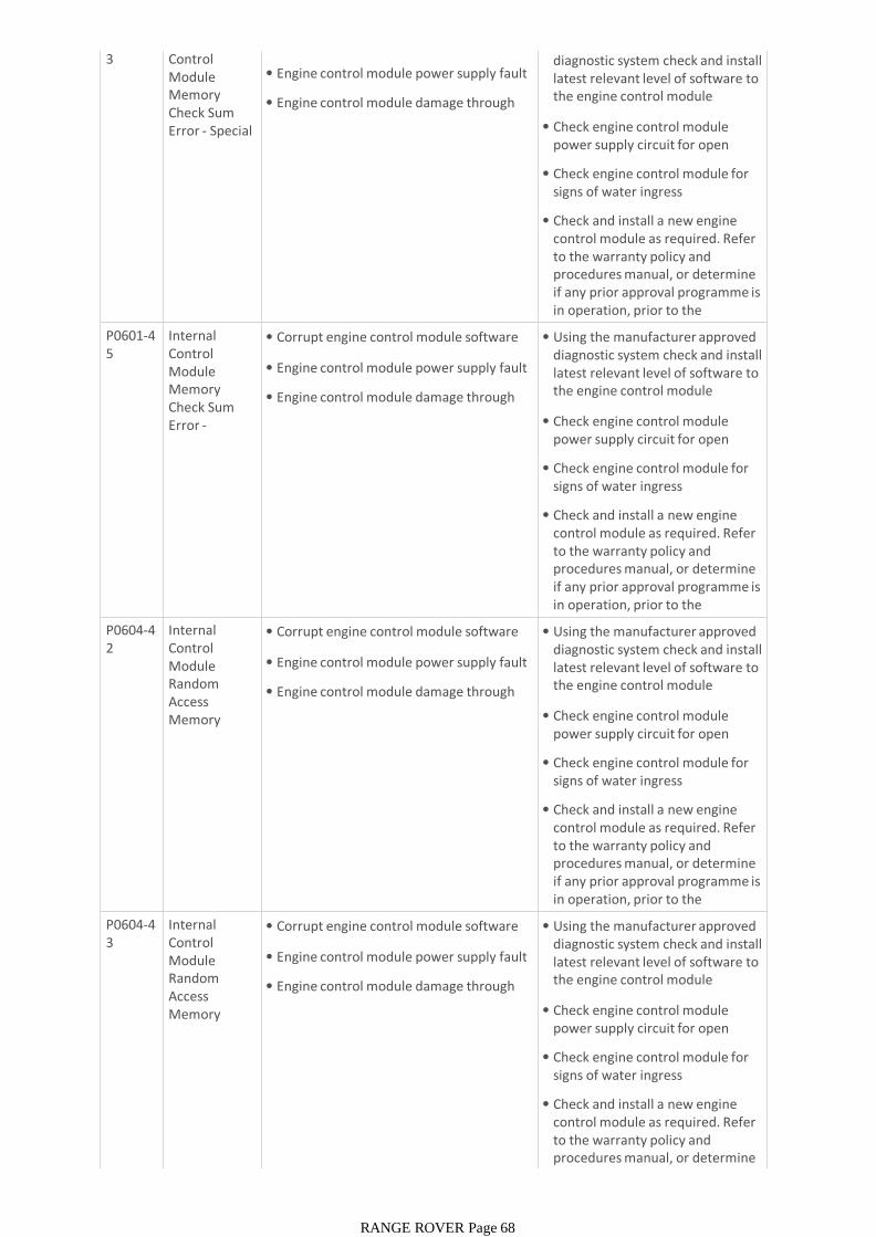
3 Control Module Memory Check Sum Error - Special memory
• Corrupt engine control module software flash
• Engine control module power supply fault
• Engine control module damage through water ingress
• Using the manufacturer approved diagnostic system check and install latest relevant level of software to the engine control module
• Check engine control module power supply circuit for open circuit
• Check engine control module for signs of water ingress
• Check and install a new engine control module as required. Refer to the warranty policy and procedures manual, or determine if any prior approval programme is in operation, prior to the installation of a new P0601-4
5Internal Control Module Memory Check Sum Error -Program
• Corrupt engine control module software flash
• Engine control module power supply fault
• Engine control module damage through water ingress
• Using the manufacturer approved diagnostic system check and install latest relevant level of software to the engine control module
• Check engine control module power supply circuit for open circuit
• Check engine control module for signs of water ingress
• Check and install a new engine control module as required. Refer to the warranty policy and procedures manual, or determine if any prior approval programme is in operation, prior to the installation of a new P0604-4
2Internal Control Module Random Access Memory (RAM) Error -
• Corrupt engine control module software flash
• Engine control module power supply fault
• Engine control module damage through water ingress
• Using the manufacturer approved diagnostic system check and install latest relevant level of software to the engine control module
• Check engine control module power supply circuit for open circuit
• Check engine control module for signs of water ingress
• Check and install a new engine control module as required. Refer to the warranty policy and procedures manual, or determine if any prior approval programme is in operation, prior to the installation of a new P0604-4
3Internal Control Module Random Access Memory (RAM) Error -
• Corrupt engine control module software flash
• Engine control module power supply fault
• Engine control module damage through water ingress
• Using the manufacturer approved diagnostic system check and install latest relevant level of software to the engine control module
• Check engine control module power supply circuit for open circuit
• Check engine control module for signs of water ingress
• Check and install a new engine control module as required. Refer to the warranty policy and procedures manual, or determine if any prior approval programme is
RANGE ROVER Page 68
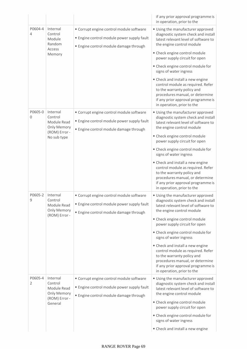
if any prior approval programme is in operation, prior to the installation of a new P0604-4
4Internal Control Module Random Access Memory (RAM) Error -
• Corrupt engine control module software flash
• Engine control module power supply fault
• Engine control module damage through water ingress
• Using the manufacturer approved diagnostic system check and install latest relevant level of software to the engine control module
• Check engine control module power supply circuit for open circuit
• Check engine control module for signs of water ingress
• Check and install a new engine control module as required. Refer to the warranty policy and procedures manual, or determine if any prior approval programme is in operation, prior to the installation of a new P0605-0
0Internal Control Module Read Only Memory (ROM) Error -No sub type information
• Corrupt engine control module software flash
• Engine control module power supply fault
• Engine control module damage through water ingress
• Using the manufacturer approved diagnostic system check and install latest relevant level of software to the engine control module
• Check engine control module power supply circuit for open circuit
• Check engine control module for signs of water ingress
• Check and install a new engine control module as required. Refer to the warranty policy and procedures manual, or determine if any prior approval programme is in operation, prior to the installation of a new P0605-2
9Internal Control Module Read Only Memory (ROM) Error -Signal invalid
• Corrupt engine control module software flash
• Engine control module power supply fault
• Engine control module damage through water ingress
• Using the manufacturer approved diagnostic system check and install latest relevant level of software to the engine control module
• Check engine control module power supply circuit for open circuit
• Check engine control module for signs of water ingress
• Check and install a new engine control module as required. Refer to the warranty policy and procedures manual, or determine if any prior approval programme is in operation, prior to the installation of a new P0605-4
2Internal Control Module Read Only Memory (ROM) Error -General memory
• Corrupt engine control module software flash
• Engine control module power supply fault
• Engine control module damage through water ingress
• Using the manufacturer approved diagnostic system check and install latest relevant level of software to the engine control module
• Check engine control module power supply circuit for open circuit
• Check engine control module for signs of water ingress
• Check and install a new engine control module as required. Refer
RANGE ROVER Page 69
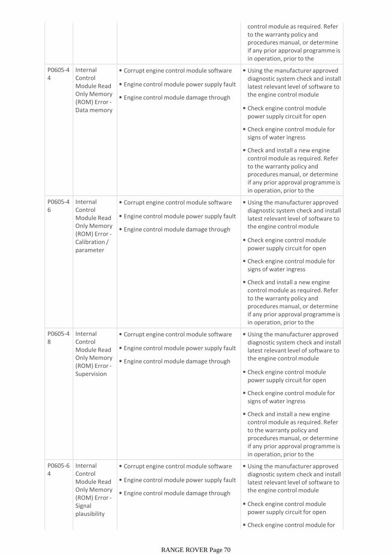
control module as required. Refer to the warranty policy and procedures manual, or determine if any prior approval programme is in operation, prior to the installation of a new P0605-4
4Internal Control Module Read Only Memory (ROM) Error -Data memory failure
• Corrupt engine control module software flash
• Engine control module power supply fault
• Engine control module damage through water ingress
• Using the manufacturer approved diagnostic system check and install latest relevant level of software to the engine control module
• Check engine control module power supply circuit for open circuit
• Check engine control module for signs of water ingress
• Check and install a new engine control module as required. Refer to the warranty policy and procedures manual, or determine if any prior approval programme is in operation, prior to the installation of a new P0605-4
6Internal Control Module Read Only Memory (ROM) Error -Calibration / parameter memory
• Corrupt engine control module software flash
• Engine control module power supply fault
• Engine control module damage through water ingress
• Using the manufacturer approved diagnostic system check and install latest relevant level of software to the engine control module
• Check engine control module power supply circuit for open circuit
• Check engine control module for signs of water ingress
• Check and install a new engine control module as required. Refer to the warranty policy and procedures manual, or determine if any prior approval programme is in operation, prior to the installation of a new P0605-4
8Internal Control Module Read Only Memory (ROM) Error -Supervision software
• Corrupt engine control module software flash
• Engine control module power supply fault
• Engine control module damage through water ingress
• Using the manufacturer approved diagnostic system check and install latest relevant level of software to the engine control module
• Check engine control module power supply circuit for open circuit
• Check engine control module for signs of water ingress
• Check and install a new engine control module as required. Refer to the warranty policy and procedures manual, or determine if any prior approval programme is in operation, prior to the installation of a new P0605-6
4Internal Control Module Read Only Memory (ROM) Error -Signal plausibility failure
• Corrupt engine control module software flash
• Engine control module power supply fault
• Engine control module damage through water ingress
• Using the manufacturer approved diagnostic system check and install latest relevant level of software to the engine control module
• Check engine control module power supply circuit for open circuit
• Check engine control module for signs of water ingress
RANGE ROVER Page 70
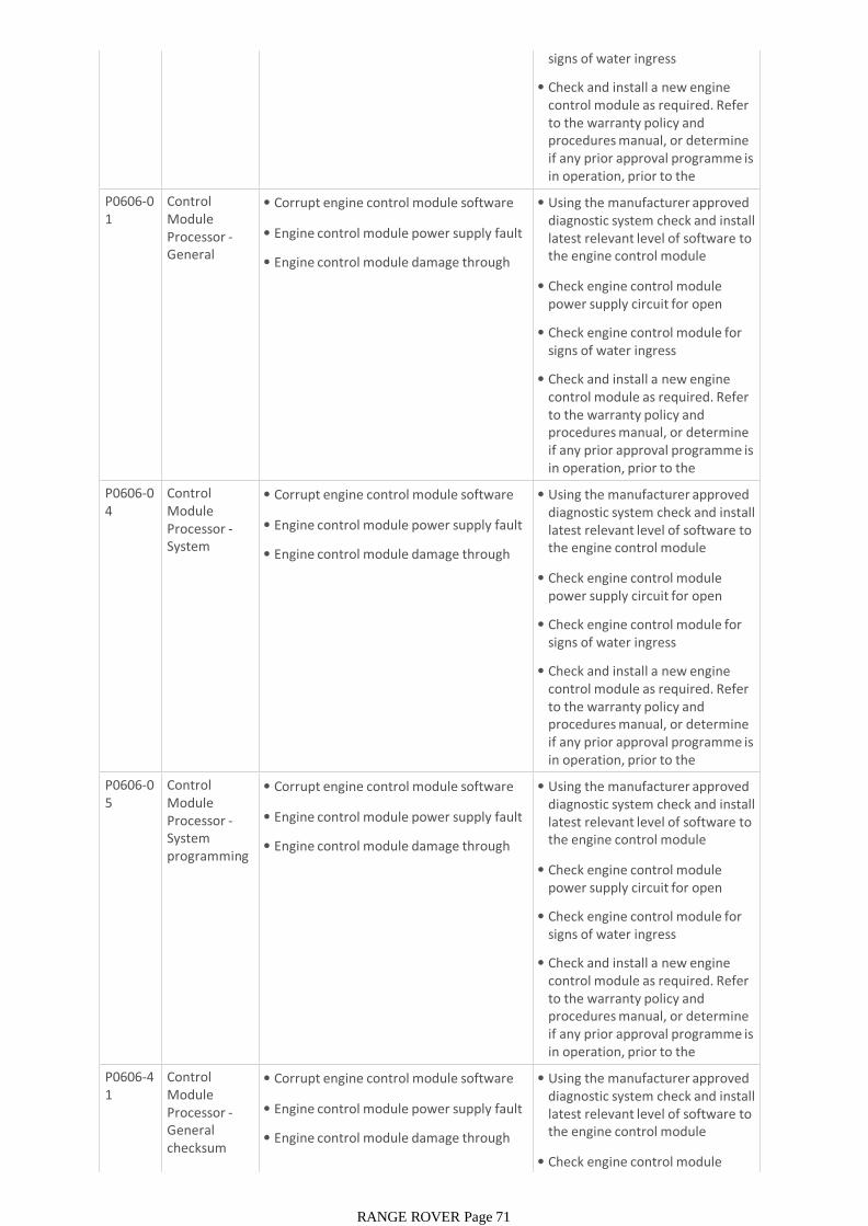
signs of water ingress
• Check and install a new engine control module as required. Refer to the warranty policy and procedures manual, or determine if any prior approval programme is in operation, prior to the installation of a new P0606-0
1Control Module Processor -General electrical
• Corrupt engine control module software flash
• Engine control module power supply fault
• Engine control module damage through water ingress
• Using the manufacturer approved diagnostic system check and install latest relevant level of software to the engine control module
• Check engine control module power supply circuit for open circuit
• Check engine control module for signs of water ingress
• Check and install a new engine control module as required. Refer to the warranty policy and procedures manual, or determine if any prior approval programme is in operation, prior to the installation of a new P0606-0
4Control Module Processor -System internal
• Corrupt engine control module software flash
• Engine control module power supply fault
• Engine control module damage through water ingress
• Using the manufacturer approved diagnostic system check and install latest relevant level of software to the engine control module
• Check engine control module power supply circuit for open circuit
• Check engine control module for signs of water ingress
• Check and install a new engine control module as required. Refer to the warranty policy and procedures manual, or determine if any prior approval programme is in operation, prior to the installation of a new P0606-0
5Control Module Processor -System programming failures
• Corrupt engine control module software flash
• Engine control module power supply fault
• Engine control module damage through water ingress
• Using the manufacturer approved diagnostic system check and install latest relevant level of software to the engine control module
• Check engine control module power supply circuit for open circuit
• Check engine control module for signs of water ingress
• Check and install a new engine control module as required. Refer to the warranty policy and procedures manual, or determine if any prior approval programme is in operation, prior to the installation of a new P0606-4
1Control Module Processor -General checksum failure
• Corrupt engine control module software flash
• Engine control module power supply fault
• Engine control module damage through water ingress
• Using the manufacturer approved diagnostic system check and install latest relevant level of software to the engine control module
• Check engine control module power supply circuit for open
RANGE ROVER Page 71
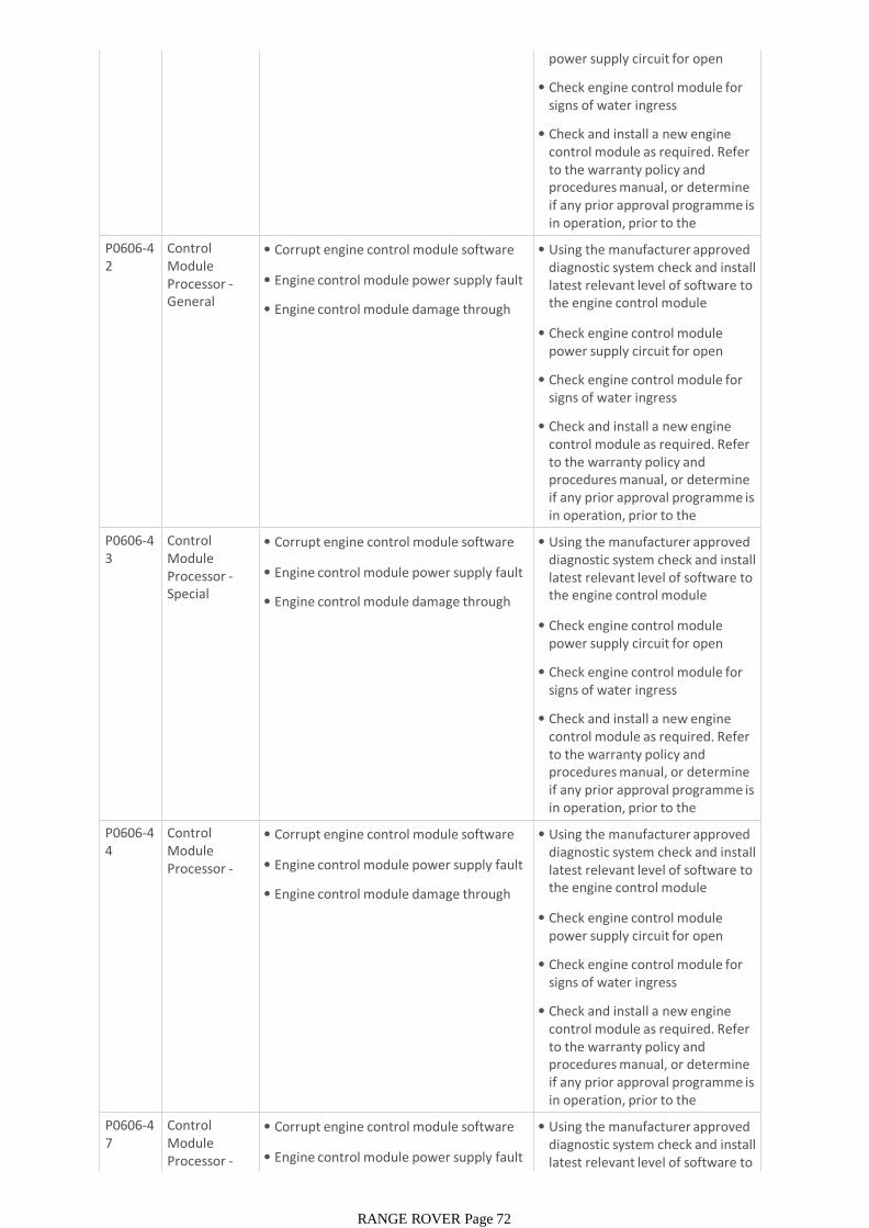
power supply circuit for open circuit
• Check engine control module for signs of water ingress
• Check and install a new engine control module as required. Refer to the warranty policy and procedures manual, or determine if any prior approval programme is in operation, prior to the installation of a new P0606-4
2Control Module Processor -General memory
• Corrupt engine control module software flash
• Engine control module power supply fault
• Engine control module damage through water ingress
• Using the manufacturer approved diagnostic system check and install latest relevant level of software to the engine control module
• Check engine control module power supply circuit for open circuit
• Check engine control module for signs of water ingress
• Check and install a new engine control module as required. Refer to the warranty policy and procedures manual, or determine if any prior approval programme is in operation, prior to the installation of a new P0606-4
3Control Module Processor -Special memory
• Corrupt engine control module software flash
• Engine control module power supply fault
• Engine control module damage through water ingress
• Using the manufacturer approved diagnostic system check and install latest relevant level of software to the engine control module
• Check engine control module power supply circuit for open circuit
• Check engine control module for signs of water ingress
• Check and install a new engine control module as required. Refer to the warranty policy and procedures manual, or determine if any prior approval programme is in operation, prior to the installation of a new P0606-4
4Control Module Processor -Data memory
• Corrupt engine control module software flash
• Engine control module power supply fault
• Engine control module damage through water ingress
• Using the manufacturer approved diagnostic system check and install latest relevant level of software to the engine control module
• Check engine control module power supply circuit for open circuit
• Check engine control module for signs of water ingress
• Check and install a new engine control module as required. Refer to the warranty policy and procedures manual, or determine if any prior approval programme is in operation, prior to the installation of a new P0606-4
7Control Module Processor -Watchdog /
• Corrupt engine control module software flash
• Engine control module power supply fault
• Using the manufacturer approved diagnostic system check and install latest relevant level of software to the engine control module
RANGE ROVER Page 72
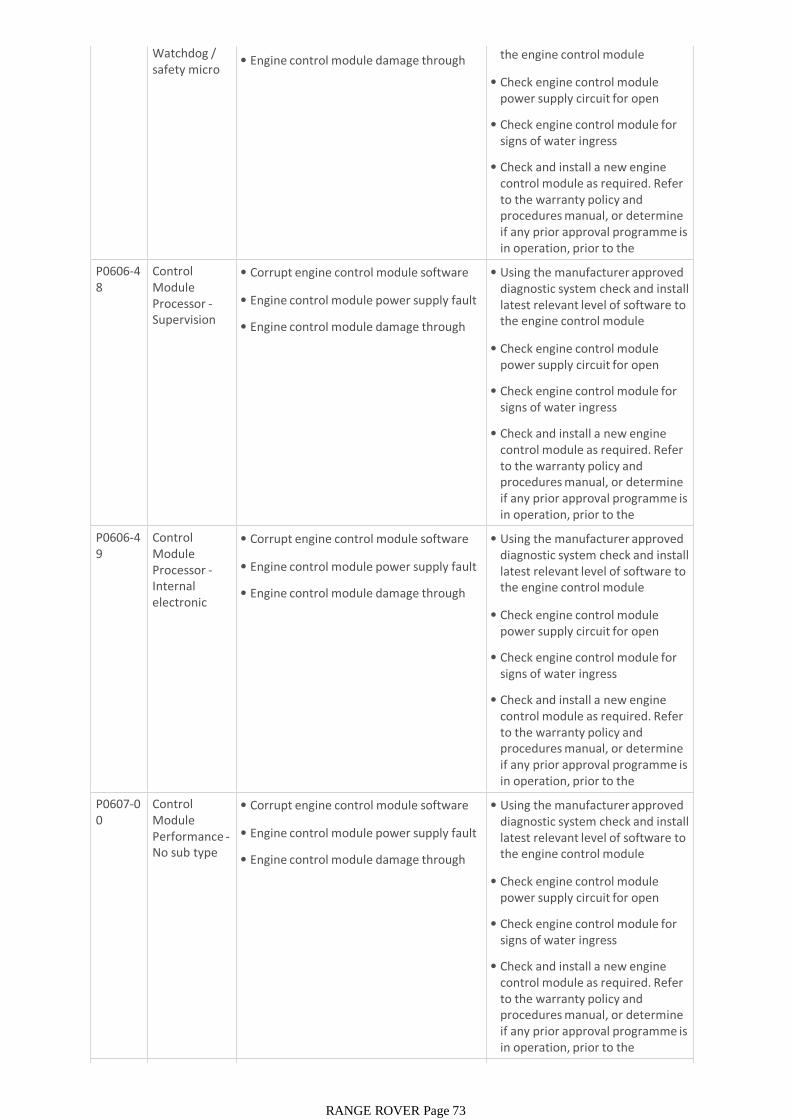
Watchdog / safety micro controller
• Engine control module damage through water ingress
latest relevant level of software to the engine control module
• Check engine control module power supply circuit for open circuit
• Check engine control module for signs of water ingress
• Check and install a new engine control module as required. Refer to the warranty policy and procedures manual, or determine if any prior approval programme is in operation, prior to the installation of a new P0606-4
8Control Module Processor -Supervision software
• Corrupt engine control module software flash
• Engine control module power supply fault
• Engine control module damage through water ingress
• Using the manufacturer approved diagnostic system check and install latest relevant level of software to the engine control module
• Check engine control module power supply circuit for open circuit
• Check engine control module for signs of water ingress
• Check and install a new engine control module as required. Refer to the warranty policy and procedures manual, or determine if any prior approval programme is in operation, prior to the installation of a new P0606-4
9Control Module Processor -Internal electronic failure
• Corrupt engine control module software flash
• Engine control module power supply fault
• Engine control module damage through water ingress
• Using the manufacturer approved diagnostic system check and install latest relevant level of software to the engine control module
• Check engine control module power supply circuit for open circuit
• Check engine control module for signs of water ingress
• Check and install a new engine control module as required. Refer to the warranty policy and procedures manual, or determine if any prior approval programme is in operation, prior to the installation of a new P0607-0
0Control Module Performance -No sub type information
• Corrupt engine control module software flash
• Engine control module power supply fault
• Engine control module damage through water ingress
• Using the manufacturer approved diagnostic system check and install latest relevant level of software to the engine control module
• Check engine control module power supply circuit for open circuit
• Check engine control module for signs of water ingress
• Check and install a new engine control module as required. Refer to the warranty policy and procedures manual, or determine if any prior approval programme is in operation, prior to the installation of a new P0610-4 Control • Corrupt engine control module software • Clear the DTC and re-test
RANGE ROVER Page 73

P0610-43
Control Module Vehicle Options Error -Special
• Corrupt engine control module software flash
• Corrupt rear junction box software flash
• Corrupt central junction box software flash
• Clear the DTC and re-test
• Using the manufacturer approved diagnostic system check and install latest relevant level of software to the engine control module
• Re-configure the rear junction box using the manufacturer approved diagnostic system
• Re-configure the central junction box using the manufacturer approved diagnostic system
P0615-13
Starter Relay Circuit - Circuit open
NOTE:- Circuit STARTER_RELAY_NEG -
• Starter relay control circuit open circuit
• Starter relay failure
• Refer to the electrical circuit diagrams and check starter relay control circuit for open circuit
• Check and install a new starter relay as required. Refer to the warranty policy and procedures manual, or determine if any prior approval programme is in operation, prior to the installation of a new module/componentP0616-1
1Starter Relay Circuit Low -Circuit short to ground
NOTE:- Circuit STARTER_RELAY_NEG -
• Starter relay control circuit short circuit to ground
• Starter relay failure
• Refer to the electrical circuit diagrams and check starter relay control circuit for short circuit to ground
• Check and install a new starter relay as required. Refer to the warranty policy and procedures manual, or determine if any prior approval programme is in operation, prior to the installation of a new module/componentP0617-1
2Starter Relay Circuit High -Circuit short to battery
NOTE:- Circuit STARTER_RELAY_NEG -
• Starter relay control circuit short circuit to power
• Starter relay failure
• Refer to the electrical circuit diagrams and check starter relay control circuit for short circuit to power
• Check and install a new starter relay as required. Refer to the warranty policy and procedures manual, or determine if any prior approval programme is in operation, prior to the installation of a new module/componentP061A-0
0Internal Control Module Torque Performance -No sub type
• Manifold air flow sensor(s) failure
• Electronic throttle unit failure
• Check for related DTCs
• Check manifold air flow sensors are reading correctly
• Check and install a new manifold air flow sensor(s) as required
• Check throttle position sensors are reading the same position
• Check throttle body is clear of any deposits
• Check and install a new electronic throttle unit as required. Refer to the warranty policy and procedures manual, or determine if any prior approval programme is in operation, prior to the installation of a new P061A-0
4Internal Control
• Manifold air flow sensor(s) failure • Check for related DTCs
RANGE ROVER Page 74
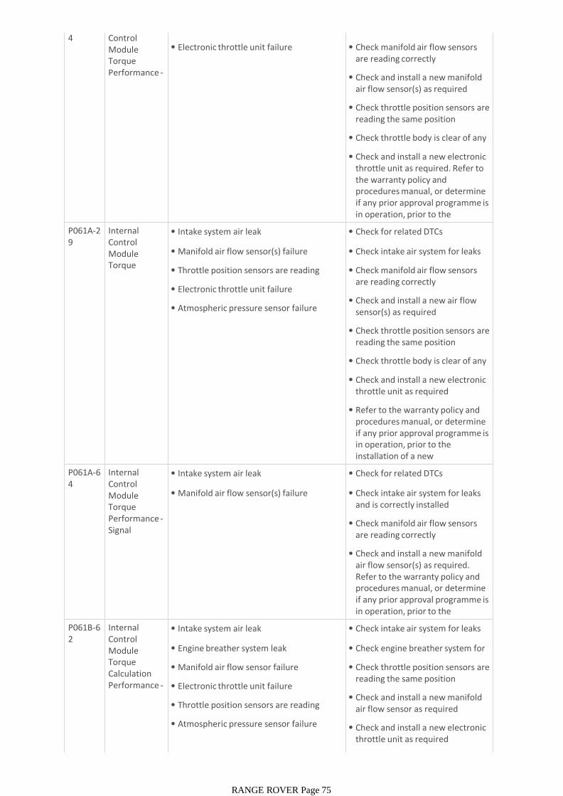
4 Control Module Torque Performance -System
• Manifold air flow sensor(s) failure
• Electronic throttle unit failure
• Check for related DTCs
• Check manifold air flow sensors are reading correctly
• Check and install a new manifold air flow sensor(s) as required
• Check throttle position sensors are reading the same position
• Check throttle body is clear of any deposits
• Check and install a new electronic throttle unit as required. Refer to the warranty policy and procedures manual, or determine if any prior approval programme is in operation, prior to the installation of a new P061A-2
9Internal Control Module Torque Performance -
• Intake system air leak
• Manifold air flow sensor(s) failure
• Throttle position sensors are reading incorrectly
• Electronic throttle unit failure
• Atmospheric pressure sensor failure
• Check for related DTCs
• Check intake air system for leaks
• Check manifold air flow sensors are reading correctly
• Check and install a new air flow sensor(s) as required
• Check throttle position sensors are reading the same position
• Check throttle body is clear of any deposits
• Check and install a new electronic throttle unit as required
• Refer to the warranty policy and procedures manual, or determine if any prior approval programme is in operation, prior to the installation of a new module/component
P061A-64
Internal Control Module Torque Performance -Signal plausibility
• Intake system air leak
• Manifold air flow sensor(s) failure
• Check for related DTCs
• Check intake air system for leaks and is correctly installed
• Check manifold air flow sensors are reading correctly
• Check and install a new manifold air flow sensor(s) as required. Refer to the warranty policy and procedures manual, or determine if any prior approval programme is in operation, prior to the installation of a new P061B-6
2Internal Control Module Torque Calculation Performance -Signal
• Intake system air leak
• Engine breather system leak
• Manifold air flow sensor failure
• Electronic throttle unit failure
• Throttle position sensors are reading incorrectly
• Atmospheric pressure sensor failure
• Check intake air system for leaks
• Check engine breather system for leaks
• Check throttle position sensors are reading the same position
• Check and install a new manifold air flow sensor as required
• Check and install a new electronic throttle unit as required
• Refer to the warranty policy and
RANGE ROVER Page 75
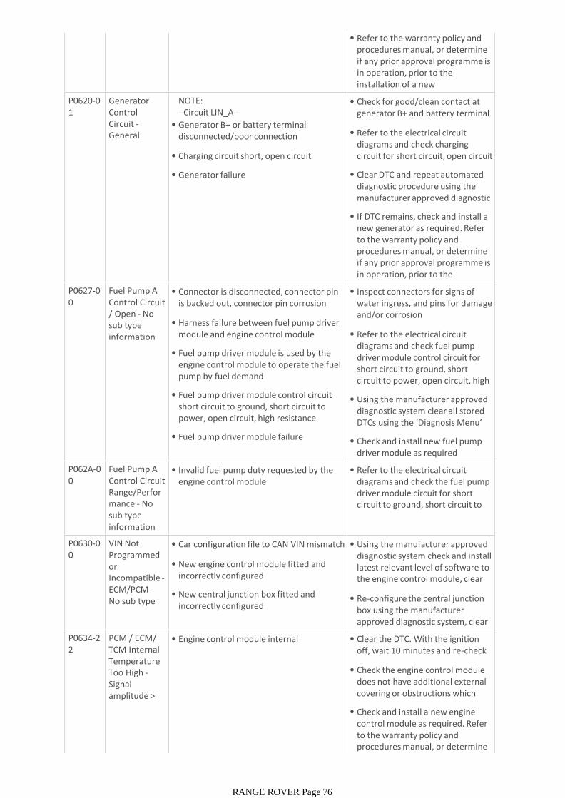
• Refer to the warranty policy and procedures manual, or determine if any prior approval programme is in operation, prior to the installation of a new module/component
P0620-01
Generator Control Circuit -General electrical
NOTE:- Circuit LIN_A -
• Generator B+ or battery terminal disconnected/poor connection
• Charging circuit short, open circuit
• Generator failure
• Check for good/clean contact at generator B+ and battery terminal connectors
• Refer to the electrical circuit diagrams and check charging circuit for short circuit, open circuit
• Clear DTC and repeat automated diagnostic procedure using the manufacturer approved diagnostic system
• If DTC remains, check and install a new generator as required. Refer to the warranty policy and procedures manual, or determine if any prior approval programme is in operation, prior to the installation of a new P0627-0
0Fuel Pump A Control Circuit / Open - No sub type information
• Connector is disconnected, connector pin is backed out, connector pin corrosion
• Harness failure between fuel pump driver module and engine control module
• Fuel pump driver module is used by the engine control module to operate the fuel pump by fuel demand
• Fuel pump driver module control circuit short circuit to ground, short circuit to power, open circuit, high resistance
• Fuel pump driver module failure
• Inspect connectors for signs of water ingress, and pins for damage and/or corrosion
• Refer to the electrical circuit diagrams and check fuel pump driver module control circuit for short circuit to ground, short circuit to power, open circuit, high resistance
• Using the manufacturer approved diagnostic system clear all stored DTCs using the ‘Diagnosis Menu’ tab and retest
• Check and install new fuel pump driver module as required
P062A-00
Fuel Pump A Control Circuit Range/Performance - No sub type information
• Invalid fuel pump duty requested by the engine control module
• Refer to the electrical circuit diagrams and check the fuel pump driver module circuit for short circuit to ground, short circuit to power, open circuit, high
P0630-00
VIN Not Programmed or Incompatible -ECM/PCM -No sub type information
• Car configuration file to CAN VIN mismatch
• New engine control module fitted and incorrectly configured
• New central junction box fitted and incorrectly configured
• Using the manufacturer approved diagnostic system check and install latest relevant level of software to the engine control module, clear DTC and re-test
• Re-configure the central junction box using the manufacturer approved diagnostic system, clear DTC and re-test
P0634-22
PCM / ECM/ TCM Internal Temperature Too High -Signal amplitude > maximum
• Engine control module internal temperature too high
• Clear the DTC. With the ignition off, wait 10 minutes and re-check DTC
• Check the engine control module does not have additional external covering or obstructions which may cause overheating
• Check and install a new engine control module as required. Refer to the warranty policy and procedures manual, or determine if any prior approval programme is
RANGE ROVER Page 76
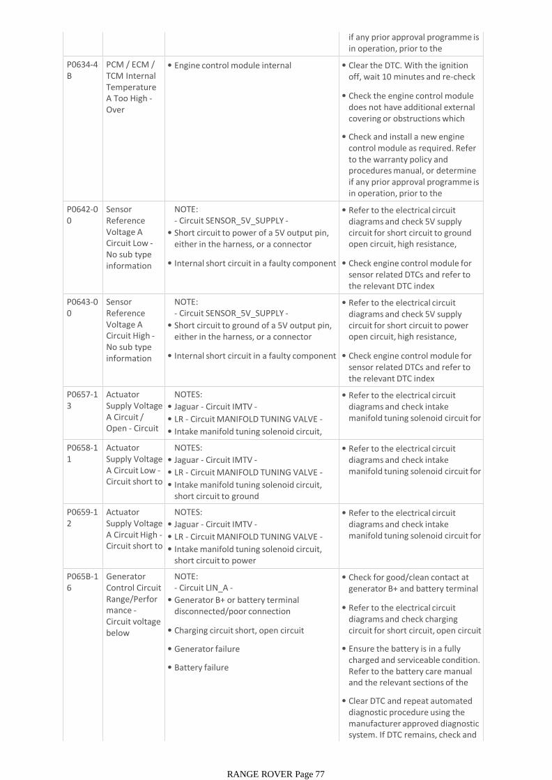
if any prior approval programme is in operation, prior to the installation of a new P0634-4
BPCM / ECM / TCM Internal Temperature A Too High -Over temperature
• Engine control module internal temperature too high
• Clear the DTC. With the ignition off, wait 10 minutes and re-check DTC
• Check the engine control module does not have additional external covering or obstructions which may cause overheating
• Check and install a new engine control module as required. Refer to the warranty policy and procedures manual, or determine if any prior approval programme is in operation, prior to the installation of a new P0642-0
0Sensor Reference Voltage A Circuit Low -No sub type information
NOTE:- Circuit SENSOR_5V_SUPPLY -
• Short circuit to power of a 5V output pin, either in the harness, or a connector
• Internal short circuit in a faulty component
• Refer to the electrical circuit diagrams and check 5V supply circuit for short circuit to ground open circuit, high resistance, terminal damage or corrosion
• Check engine control module for sensor related DTCs and refer to the relevant DTC index
P0643-00
Sensor Reference Voltage A Circuit High -No sub type information
NOTE:- Circuit SENSOR_5V_SUPPLY -
• Short circuit to ground of a 5V output pin, either in the harness, or a connector
• Internal short circuit in a faulty component
• Refer to the electrical circuit diagrams and check 5V supply circuit for short circuit to power open circuit, high resistance, terminal damage or corrosion
• Check engine control module for sensor related DTCs and refer to the relevant DTC index
P0657-13
Actuator Supply Voltage A Circuit / Open - Circuit open
NOTES:
• Jaguar - Circuit IMTV -
• LR - Circuit MANIFOLD TUNING VALVE -
• Intake manifold tuning solenoid circuit, open circuit
• Refer to the electrical circuit diagrams and check intake manifold tuning solenoid circuit for open circuit
P0658-11
Actuator Supply Voltage A Circuit Low -Circuit short to ground
NOTES:
• Jaguar - Circuit IMTV -
• LR - Circuit MANIFOLD TUNING VALVE -
• Intake manifold tuning solenoid circuit, short circuit to ground
• Refer to the electrical circuit diagrams and check intake manifold tuning solenoid circuit for short circuit to ground
P0659-12
Actuator Supply Voltage A Circuit High -Circuit short to battery
NOTES:
• Jaguar - Circuit IMTV -
• LR - Circuit MANIFOLD TUNING VALVE -
• Intake manifold tuning solenoid circuit, short circuit to power
• Refer to the electrical circuit diagrams and check intake manifold tuning solenoid circuit for short circuit to power
P065B-16
Generator Control Circuit Range/Performance -Circuit voltage below threshold
NOTE:- Circuit LIN_A -
• Generator B+ or battery terminal disconnected/poor connection
• Charging circuit short, open circuit
• Generator failure
• Battery failure
• Check for good/clean contact at generator B+ and battery terminal connectors
• Refer to the electrical circuit diagrams and check charging circuit for short circuit, open circuit
• Ensure the battery is in a fully charged and serviceable condition. Refer to the battery care manual and the relevant sections of the workshop manual
• Clear DTC and repeat automated diagnostic procedure using the manufacturer approved diagnostic system. If DTC remains, check and install a new generator as
RANGE ROVER Page 77
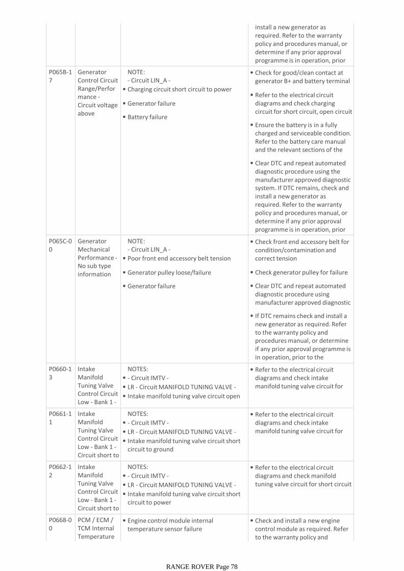
install a new generator as required. Refer to the warranty policy and procedures manual, or determine if any prior approval programme is in operation, prior to the installation of a new P065B-1
7Generator Control Circuit Range/Performance -Circuit voltage above threshold
NOTE:- Circuit LIN_A -
• Charging circuit short circuit to power
• Generator failure
• Battery failure
• Check for good/clean contact at generator B+ and battery terminal connectors
• Refer to the electrical circuit diagrams and check charging circuit for short circuit, open circuit
• Ensure the battery is in a fully charged and serviceable condition. Refer to the battery care manual and the relevant sections of the workshop manual
• Clear DTC and repeat automated diagnostic procedure using the manufacturer approved diagnostic system. If DTC remains, check and install a new generator as required. Refer to the warranty policy and procedures manual, or determine if any prior approval programme is in operation, prior to the installation of a new P065C-0
0Generator Mechanical Performance -No sub type information
NOTE:- Circuit LIN_A -
• Poor front end accessory belt tension
• Generator pulley loose/failure
• Generator failure
• Check front end accessory belt for condition/contamination and correct tension
• Check generator pulley for failure
• Clear DTC and repeat automated diagnostic procedure using manufacturer approved diagnostic system
• If DTC remains check and install a new generator as required. Refer to the warranty policy and procedures manual, or determine if any prior approval programme is in operation, prior to the installation of a new P0660-1
3Intake Manifold Tuning Valve Control Circuit Low - Bank 1 -Circuit open
NOTES:
• - Circuit IMTV -
• LR - Circuit MANIFOLD TUNING VALVE -
• Intake manifold tuning valve circuit open circuit
• Refer to the electrical circuit diagrams and check intake manifold tuning valve circuit for open circuit
P0661-11
Intake Manifold Tuning Valve Control Circuit Low - Bank 1 -Circuit short to ground
NOTES:
• - Circuit IMTV -
• LR - Circuit MANIFOLD TUNING VALVE -
• Intake manifold tuning valve circuit short circuit to ground
• Refer to the electrical circuit diagrams and check intake manifold tuning valve circuit for short circuit to ground
P0662-12
Intake Manifold Tuning Valve Control Circuit Low - Bank 1 -Circuit short to battery
NOTES:
• - Circuit IMTV -
• LR - Circuit MANIFOLD TUNING VALVE -
• Intake manifold tuning valve circuit short circuit to power
• Refer to the electrical circuit diagrams and check manifold tuning valve circuit for short circuit to power
P0668-00
PCM / ECM / TCM Internal Temperature Sensor A
• Engine control module internal temperature sensor failure
• Check and install a new engine control module as required. Refer to the warranty policy and procedures manual, or determine
RANGE ROVER Page 78
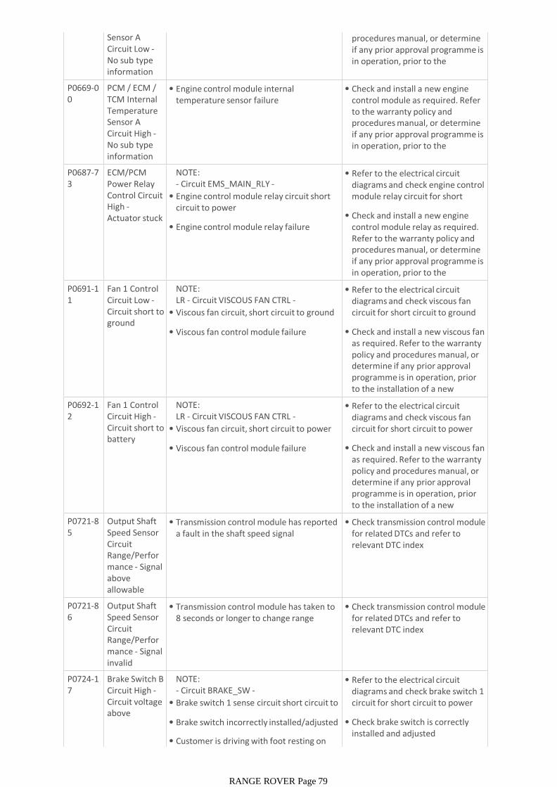
Sensor A Circuit Low -No sub type information
to the warranty policy and procedures manual, or determine if any prior approval programme is in operation, prior to the installation of a new
P0669-00
PCM / ECM / TCM Internal Temperature Sensor A Circuit High -No sub type information
• Engine control module internal temperature sensor failure
• Check and install a new engine control module as required. Refer to the warranty policy and procedures manual, or determine if any prior approval programme is in operation, prior to the installation of a new
P0687-73
ECM/PCM Power Relay Control Circuit High -Actuator stuck closed
NOTE:- Circuit EMS_MAIN_RLY -
• Engine control module relay circuit short circuit to power
• Engine control module relay failure
• Refer to the electrical circuit diagrams and check engine control module relay circuit for short circuit to power
• Check and install a new engine control module relay as required. Refer to the warranty policy and procedures manual, or determine if any prior approval programme is in operation, prior to the installation of a new P0691-1
1Fan 1 Control Circuit Low -Circuit short to ground
NOTE:LR - Circuit VISCOUS FAN CTRL -
• Viscous fan circuit, short circuit to ground
• Viscous fan control module failure
• Refer to the electrical circuit diagrams and check viscous fan circuit for short circuit to ground
• Check and install a new viscous fan as required. Refer to the warranty policy and procedures manual, or determine if any prior approval programme is in operation, prior to the installation of a new module/componentP0692-1
2Fan 1 Control Circuit High -Circuit short to battery
NOTE:LR - Circuit VISCOUS FAN CTRL -
• Viscous fan circuit, short circuit to power
• Viscous fan control module failure
• Refer to the electrical circuit diagrams and check viscous fan circuit for short circuit to power
• Check and install a new viscous fan as required. Refer to the warranty policy and procedures manual, or determine if any prior approval programme is in operation, prior to the installation of a new module/componentP0721-8
5Output Shaft Speed Sensor Circuit Range/Performance - Signal above allowable range
• Transmission control module has reported a fault in the shaft speed signal
• Check transmission control module for related DTCs and refer to relevant DTC index
P0721-86
Output Shaft Speed Sensor Circuit Range/Performance - Signal invalid
• Transmission control module has taken to 8 seconds or longer to change range
• Check transmission control module for related DTCs and refer to relevant DTC index
P0724-17
Brake Switch B Circuit High -Circuit voltage above threshold
NOTE:- Circuit BRAKE_SW -
• Brake switch 1 sense circuit short circuit to power
• Brake switch incorrectly installed/adjusted
• Customer is driving with foot resting on brake pedal
• Refer to the electrical circuit diagrams and check brake switch 1 circuit for short circuit to power
• Check brake switch is correctly installed and adjusted
• Ensure customer is not driving
RANGE ROVER Page 79
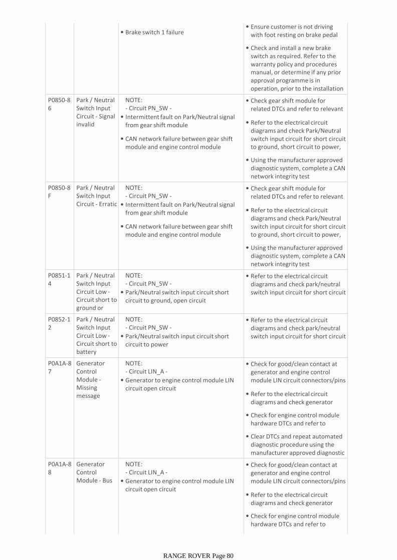
•
• Brake switch 1 failure• Ensure customer is not driving
with foot resting on brake pedal
• Check and install a new brake switch as required. Refer to the warranty policy and procedures manual, or determine if any prior approval programme is in operation, prior to the installation of a new module/componentP0850-8
6Park / Neutral Switch Input Circuit - Signal invalid
NOTE:- Circuit PN_SW -
• Intermittent fault on Park/Neutral signal from gear shift module
• CAN network failure between gear shift module and engine control module
• Check gear shift module for related DTCs and refer to relevant DTC index
• Refer to the electrical circuit diagrams and check Park/Neutral switch input circuit for short circuit to ground, short circuit to power, open circuit
• Using the manufacturer approved diagnostic system, complete a CAN network integrity test
P0850-8F
Park / Neutral Switch Input Circuit - Erratic
NOTE:- Circuit PN_SW -
• Intermittent fault on Park/Neutral signal from gear shift module
• CAN network failure between gear shift module and engine control module
• Check gear shift module for related DTCs and refer to relevant DTC index
• Refer to the electrical circuit diagrams and check Park/Neutral switch input circuit for short circuit to ground, short circuit to power, open circuit
• Using the manufacturer approved diagnostic system, complete a CAN network integrity test
P0851-14
Park / Neutral Switch Input Circuit Low -Circuit short to ground or open
NOTE:- Circuit PN_SW -
• Park/Neutral switch input circuit short circuit to ground, open circuit
• Refer to the electrical circuit diagrams and check park/neutral switch input circuit for short circuit to ground, open circuit
P0852-12
Park / Neutral Switch Input Circuit Low -Circuit short to battery
NOTE:- Circuit PN_SW -
• Park/Neutral switch input circuit short circuit to power
• Refer to the electrical circuit diagrams and check park/neutral switch input circuit for short circuit to power
P0A1A-87
Generator Control Module -Missing message
NOTE:- Circuit LIN_A -
• Generator to engine control module LIN circuit open circuit
• Check for good/clean contact at generator and engine control module LIN circuit connectors/pins
• Refer to the electrical circuit diagrams and check generator circuit for open circuit
• Check for engine control module hardware DTCs and refer to relevant DTC index
• Clear DTCs and repeat automated diagnostic procedure using the manufacturer approved diagnostic system
P0A1A-88
Generator Control Module - Bus off
NOTE:- Circuit LIN_A -
• Generator to engine control module LIN circuit open circuit
• Check for good/clean contact at generator and engine control module LIN circuit connectors/pins
• Refer to the electrical circuit diagrams and check generator circuit for open circuit
• Check for engine control module hardware DTCs and refer to relevant DTC index
• Clear DTCs and repeat automated
RANGE ROVER Page 80
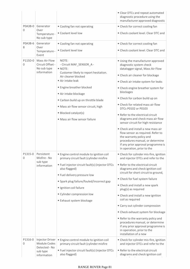
• Clear DTCs and repeat automated diagnostic procedure using the manufacturer approved diagnostic system
P0A3B-00
Generator Over Temperature -No sub type information
• Cooling fan not operating
• Coolant level low
• Check for correct cooling fan operation
• Check coolant level. Clear DTC and re-test
P0A3B-68
Generator Over Temperature -Event information
• Cooling fan not operating
• Coolant level low
• Check for correct cooling fan operation
• Check coolant level. Clear DTC and re-test
P115D-00
Mass Air Flow Circuit Offset -No sub type information
NOTE:- Circuit MAF_SENSOR_A -MAF_SENSOR_B -• NOTE:Customer likely to report hesitation.Air cleaner blocked
• Air intake leak
• Engine breather blocked
• Air intake blockage
• Carbon build up on throttle blade
• Mass air flow sensor circuit, high resistance
• Blocked catalyst(s)
• Mass air flow sensor failure
• Using the manufacturer approved diagnostic system check datalogger signal, Mass Air Flow Sensor 2 Voltage (0x0503)
• Check air cleaner for blockage
• Check air intake system for leaks
• Check engine breather system for blockages
• Check for carbon build up on throttle blade
• Check for related mass air flow DTCs P0102 or P0103
• Refer to the electrical circuit diagrams and check mass air flow sensor circuit for high resistance
• Check and install a new mass air flow sensor as required. Refer to the warranty policy and procedures manual, or determine if any prior approval programme is in operation, prior to the installation of a new P1315-0
0Persistent Misfire - No sub type information
• Engine control module to ignition coil primary circuit fault (cylinder misfire detected DTC also flagged)
• Fuel injector circuit fault(s) (injector DTCs also flagged)
• Fuel delivery pressure low
• Spark plug failure/fouled/incorrect gap
• Ignition coil failure
• Cylinder compression low
• Exhaust system blockage
• Check for cylinder mis-fire, ignition and injector DTCs and refer to the DTC index
• Refer to the electrical circuit diagrams and check ignition coil circuit for short circuit to ground, short circuit to power, open circuit
• Check for fuel system failure
• Check and install a new spark plug(s) as required
• Check and install a new ignition coil as required
• Carry out cylinder compression tests
• Check exhaust system for blockage
• Refer to the warranty policy and procedures manual, or determine if any prior approval programme is in operation, prior to the installation of a new module/component
P1316-00
Injector Driver Module Codes Detected - No sub type information
• Engine control module to ignition coil primary circuit fault (cylinder misfire detected DTC also flagged)
• Fuel injector circuit fault(s) (injector DTCs also flagged)
• Check for cylinder mis-fire, ignition and injector DTCs and refer to the DTC index
• Refer to the electrical circuit diagrams and check ignition coil circuit for short circuit to ground,
RANGE ROVER Page 81

information
• Fuel delivery pressure low
• Spark plug failure/fouled/incorrect gap
• Ignition coil failure
• Cylinder compression low
• Exhaust system blockage
circuit for short circuit to ground, short circuit to power, open circuit
• Check for fuel system failure
• Check and install a new spark plug(s) as required
• Check and install a new ignition coil as required
• Carry out cylinder compression tests
• Check exhaust system for blockage
• Refer to the warranty policy and procedures manual, or determine if any prior approval programme is in operation, prior to the installation of a new module/componentP1593-6
4Cruise Control Monitor Fault - Signal plausibility failure
• Speed control monitor fault. The engine control module performs a independent check of the cruise status
• Using the manufacturer approved diagnostic system check and up-date the car configuration file as required. Clear the DTC and retest. If the problem persists, contact dealer technical support
P1603-00
EEPROM Malfunction -No sub type information
• Corrupt engine control module software flash
• Engine control module power supply fault
• Engine control module damage through water ingress
• Using the manufacturer approved diagnostic system check and install latest relevant level of software to the engine control module
• Refer to the electrical circuit diagrams and check engine control module power supply circuit for open circuit
• Check engine control module for signs of water ingress
• Check and install a new engine control module as required. Refer to the warranty policy and procedures manual, or determine if any prior approval programme is in operation, prior to the installation of a new P2088-1
1A Camshaft Position Actuator Control Circuit Low Bank 1 -Circuit short to ground
NOTE:- Circuit VFS_IN_A -
• Intake valve solenoid 1 short circuit to ground
• Refer to the electrical circuit diagrams and check intake valve solenoid 1 for short circuit to ground
P2089-12
A Camshaft Position Actuator Control Circuit High Bank 1 -Circuit short to battery
NOTE:- Circuit VFS_IN_A -
• Intake valve solenoid 1 short circuit to power
• Refer to the electrical circuit diagrams and check intake valve solenoid 1 for short circuit to power
P2090-11
B Camshaft Position Actuator Control Circuit Low Bank 1 -Circuit short to ground
NOTE:- Circuit VFS_EX_A -
• Exhaust valve solenoid 1 short circuit to ground
• Refer to the electrical circuit diagrams and check exhaust valve solenoid 1 for short circuit to ground
P2091-12
B Camshaft Position Actuator Control Circuit
NOTE:- Circuit VFS_EX_A -
• Exhaust valve solenoid 1 short circuit to power
• Refer to the electrical circuit diagrams and check exhaust valve solenoid 1 for short circuit to power
RANGE ROVER Page 82

Control Circuit High Bank 1 -Circuit short to battery
• Exhaust valve solenoid 1 short circuit to power
solenoid 1 for short circuit to power
P2092-11
A Camshaft Position Actuator Control Circuit Low Bank 2 -Circuit short to ground
NOTE:- Circuit VFS_IN_B -
• Intake valve solenoid 2 short circuit to ground
• Refer to the electrical circuit diagrams and check intake valve solenoid 2 for short circuit to ground
P2093-12
A Camshaft Position Actuator Control Circuit High Bank 2 -Circuit short to battery
NOTE:- Circuit VFS_IN_B -
• Intake valve solenoid 2 short circuit to power
• Refer to the electrical circuit diagrams and check intake valve solenoid 2 for short circuit to power
P2094-11
B Camshaft Position Actuator Control Circuit Low Bank 2 -Circuit short to ground
NOTE:- Circuit VFS_EX_B -
• Exhaust valve solenoid 2 short circuit to ground
• Refer to the electrical circuit diagrams and check exhaust valve solenoid 2 for short circuit to ground
P2095-12
B Camshaft Position Actuator Control Circuit High Bank 2 -Circuit short to battery
NOTE:- Circuit VFS_EX_B -
• Exhaust valve solenoid 2 short circuit to power
• Refer to the electrical circuit diagrams and check exhaust valve solenoid 2 for short circuit to power
P2096-00
Post Catalyst Fuel Trim System Too Lean Bank 1 -No sub type information
NOTE:- Circuit HEGO_SENSOR_A -
• Post catalyst oxygen sensor odd, sensing circuit short circuit to ground, high resistance, open circuit
• Air leak between catalyst and exhaust manifold
• Air leak between the two oxygen sensors
• Post catalyst oxygen sensor odd, failure
• Refer to the electrical circuit diagrams and check post catalyst oxygen sensor - odd, sensing circuit for short circuit to ground, high resistance, open circuit
• Check for air leak between catalyst and exhaust manifold
• Check for air leak between the two oxygen sensors
• Check and install new post catalyst oxygen sensor odd, as required. Refer to the warranty policy and procedures manual, or determine if any prior approval programme is in operation, prior to the installation of a new P2097-0
0Post Catalyst Fuel Trim System Too Rich Bank 1 -No sub type information
NOTE:- Circuit HEGO_SENSOR_A -
• Post catalyst oxygen sensor odd, sensing circuit short circuit to ground, high resistance, open circuit
• Air leak between catalyst and exhaust manifold
• Air leak between the two oxygen sensors
• Post catalyst oxygen sensor odd, failure
• Refer to the electrical circuit diagrams and check post catalyst oxygen sensor - odd, sensing circuit for short circuit to ground, high resistance, open circuit
• Check for air leak between catalyst and exhaust manifold
• Check for air leak between the two oxygen sensors
• Check and install new post catalyst oxygen sensor odd, as required. Refer to the warranty policy and procedures manual, or determine if any prior approval programme is in operation, prior to the installation of a new P2098-0
0Post Catalyst Fuel Trim
NOTE:- Circuit HEGO_SENSOR_B -
• Refer to the electrical circuit diagrams and check post catalyst
RANGE ROVER Page 83

0 Fuel Trim System Too Lean Bank 2 -No sub type information
- Circuit HEGO_SENSOR_B -
• Post catalyst oxygen sensor even, sensing circuit short circuit to ground, high resistance, open circuit
• Air leak between catalyst and exhaust manifold
• Air leak between the two oxygen sensors
• Post catalyst oxygen sensor even, failure
• Refer to the electrical circuit diagrams and check post catalyst oxygen sensor even, sensing circuit for short circuit to ground, high resistance, open circuit
• Check for air leak between catalyst and exhaust manifold
• Check for air leak between the two oxygen sensors
• Check and install new post catalyst oxygen sensor even, as required. Refer to the warranty policy and procedures manual, or determine if any prior approval programme is in operation, prior to the installation of a new P2099-0
0Post Catalyst Fuel Trim System Too Rich Bank 2 -No sub type information
NOTE:- Circuit HEGO_SENSOR_B -
• Post catalyst oxygen sensor even, sensing circuit short circuit to ground, high resistance, open circuit
• Air leak between catalyst and exhaust manifold
• Air leak between the two oxygen sensors
• Post catalyst oxygen sensor even, failure
• Refer to the electrical circuit diagrams and check post catalyst oxygen sensor even, sensing circuit for short circuit to ground, high resistance, open circuit
• Check for air leak between catalyst and exhaust manifold
• Check for air leak between the two oxygen sensors
• Check and install new post catalyst oxygen sensor even, as required. Refer to the warranty policy and procedures manual, or determine if any prior approval programme is in operation, prior to the installation of a new P2105-0
0Throttle Actuator Control System -Forced Engine Shutdown - No sub type information
NOTE:- Circuit THROTTLE_MOTOR_NEG -THROTTLE_MOTOR_POS -
• Engine speed or torque limitation has been activated as a result of engine control module, throttle pedal position sensor, or torque faults
• Check for any DTCs relating to engine control module, throttle pedal position sensor, or torque faults and refer to the DTC index
P2118-19
Throttle Actuator Control Motor Current Range/Performance -Circuit current above
NOTE:- Circuit THROTTLE_MOTOR_NEG -THROTTLE_MOTOR_POS -
• Throttle motor control circuit short circuit to ground, short circuit to power, high resistance
• Engine control module ground circuit fault
• Carbon build-up on throttle blade
• Electronic throttle unit failure
• Refer to the electrical circuit diagrams and check electronic throttle unit circuit for short circuit to ground, short circuit to power, high resistance
• Refer to the electrical circuit diagrams and check engine control module ground circuit for faults
• Make sure throttle blade is clean of carbon
• Check the system is operating correctly and the DTC does not return
• Check and install a new electronic throttle unit as required. Refer to the warranty policy and procedures manual, or determine if any prior approval programme is in operation, prior to the installation of a new P2119-0
0Throttle Actuator Control Throttle Body Range/Perfor
NOTE:- Circuit THROTTLE_MOTOR_NEG -THROTTLE_MOTOR_POS -
• Carbon build-up on throttle blade
• Make sure throttle blade is clean of carbon
• Refer to the electrical circuit diagrams and check engine control module ground circuit for faults
RANGE ROVER Page 84

Range/Performance - No sub type information
• Carbon build-up on throttle blade
• Engine control module ground circuit fault
• Electronic throttle unit return spring faulty
• Electronic throttle unit limp home spring faulty
module ground circuit for faults
• Check the system is operating correctly and the DTC does not return
• Check and install a new electronic throttle unit as required. Refer to the warranty policy and procedures manual, or determine if any prior approval programme is in operation, prior to the installation of a new P2119-2
9Throttle Actuator Control Throttle Body Range/Performance - Signal invalid
NOTE:- Circuit THROTTLE_MOTOR_NEG -THROTTLE_MOTOR_POS -
• Stuck / sticking throttle blade
• Electronic throttle unit failure
• Ensure throttle blade is free of any carbon build-up / other obstructions
• Check the system is operating correctly and the DTC does not return
• Check and install a new electronic throttle unit as required. Refer to the warranty policy and procedures manual, or determine if any prior approval programme is in operation, prior to the installation of a new P2119-6
4Throttle Actuator Control Throttle Body Range/Performance - Signal plausibility failure
NOTE:- Circuit THROTTLE_MOTOR_NEG -THROTTLE_MOTOR_POS -
• Stuck / sticking throttle blade
• Electronic throttle unit failure
• Ensure throttle blade is free of any carbon build-up / other obstructions
• Check the system is operating correctly and the DTC does not return
• Check and install a new electronic throttle unit as required. Refer to the warranty policy and procedures manual, or determine if any prior approval programme is in operation, prior to the installation of a new P2122-0
0Throttle/Pedal Position Sensor/Switch D Circuit Low -No sub type information
• Accelerator pedal position sensor 1 circuit short circuit to ground, open circuit
• Accelerator pedal position sensor 1, VREF circuit open circuit
• Accelerator pedal position sensor 1 failure
• Refer to the electrical circuit diagrams and check accelerator pedal unit, accelerator pedal position sensor 1 circuit for short circuit to ground, open circuit
• Check accelerator pedal unit, VREF circuit for open circuit
• Clear DTC and repeat automated diagnostic procedure using the manufacturer approved diagnostic system
• If DTC remains, check and install a new accelerator pedal unit as required. Refer to the warranty policy and procedures manual, or determine if any prior approval programme is in operation, prior to the installation of a new P2123-0
0Throttle/Pedal Position Sensor/Switch D Circuit High -No sub type information
• Accelerator pedal position sensor 1 circuit short circuit to power
• Accelerator pedal position sensor 1, VREF circuit open circuit
• Accelerator pedal position sensor 1 failure
• Refer to the electrical circuit diagrams and check accelerator pedal unit, accelerator pedal position sensor 1 circuit for short circuit to power
• Check accelerator pedal unit, VREF circuit for open circuit
• Clear DTC and repeat automated diagnostic procedure using the manufacturer approved diagnostic system
• If DTC remains, check and install a
RANGE ROVER Page 85
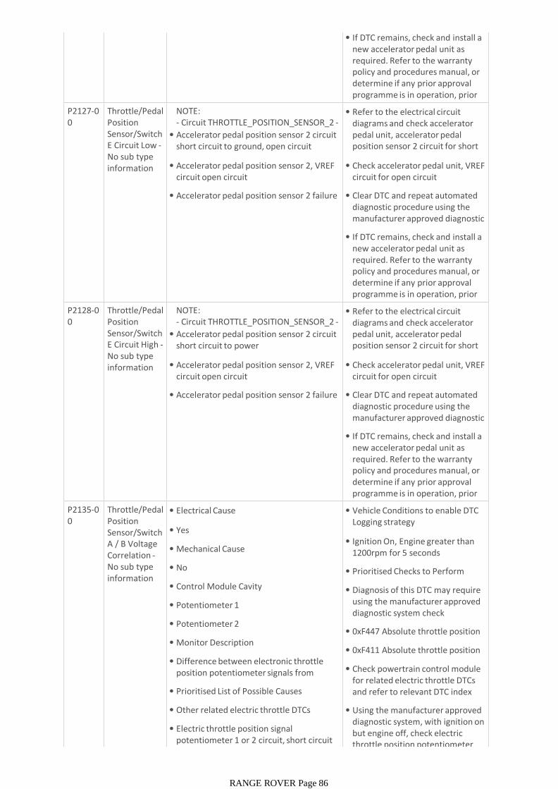
• If DTC remains, check and install a new accelerator pedal unit as required. Refer to the warranty policy and procedures manual, or determine if any prior approval programme is in operation, prior to the installation of a new P2127-0
0Throttle/Pedal Position Sensor/Switch E Circuit Low -No sub type information
NOTE:- Circuit THROTTLE_POSITION_SENSOR_2 -
• Accelerator pedal position sensor 2 circuit short circuit to ground, open circuit
• Accelerator pedal position sensor 2, VREF circuit open circuit
• Accelerator pedal position sensor 2 failure
• Refer to the electrical circuit diagrams and check accelerator pedal unit, accelerator pedal position sensor 2 circuit for short circuit to ground, open circuit
• Check accelerator pedal unit, VREF circuit for open circuit
• Clear DTC and repeat automated diagnostic procedure using the manufacturer approved diagnostic system
• If DTC remains, check and install a new accelerator pedal unit as required. Refer to the warranty policy and procedures manual, or determine if any prior approval programme is in operation, prior to the installation of a new P2128-0
0Throttle/Pedal Position Sensor/Switch E Circuit High -No sub type information
NOTE:- Circuit THROTTLE_POSITION_SENSOR_2 -
• Accelerator pedal position sensor 2 circuit short circuit to power
• Accelerator pedal position sensor 2, VREF circuit open circuit
• Accelerator pedal position sensor 2 failure
• Refer to the electrical circuit diagrams and check accelerator pedal unit, accelerator pedal position sensor 2 circuit for short circuit to power
• Check accelerator pedal unit, VREF circuit for open circuit
• Clear DTC and repeat automated diagnostic procedure using the manufacturer approved diagnostic system
• If DTC remains, check and install a new accelerator pedal unit as required. Refer to the warranty policy and procedures manual, or determine if any prior approval programme is in operation, prior to the installation of a new
P2135-00
Throttle/Pedal Position Sensor/Switch A / B Voltage Correlation -No sub type information
• Electrical Cause
• Yes
• Mechanical Cause
• No
• Control Module Cavity
• Potentiometer 1
• Potentiometer 2
• Monitor Description
• Difference between electronic throttle position potentiometer signals from sensor 1 and sensor 2
• Prioritised List of Possible Causes
• Other related electric throttle DTCs
• Electric throttle position signal potentiometer 1 or 2 circuit, short circuit to power, short circuit to ground or high
• Vehicle Conditions to enable DTC Logging strategy
• Ignition On, Engine greater than 1200rpm for 5 seconds
• Prioritised Checks to Perform
• Diagnosis of this DTC may require using the manufacturer approved diagnostic system check datalogger signals
• 0xF447 Absolute throttle position B
• 0xF411 Absolute throttle position
• Check powertrain control module for related electric throttle DTCs and refer to relevant DTC index
• Using the manufacturer approved diagnostic system, with ignition on but engine off, check electric throttle position potentiometer
RANGE ROVER Page 86

to power, short circuit to ground or high resistance
• Harness failure - Electric throttle position signal potentiometer 1 or 2 circuit
• Electric throttle unit failure
• Powertrain control module failure
throttle position potentiometer signal 1 is aligned to electric throttle position potentiometer
• Refer to the electrical circuit diagrams and check electric throttle position signal potentiometer 1 or 2 circuit for short circuit to power, short circuit to ground or high resistance
• Inspect electric throttle connector and powertrain control module connector for signs of water ingress, and pins for damage and/or corrosion
• Install a new electric throttle unit, only when diagnosed as failed
• Install a new powertrain control module, only when diagnosed as failed
• Using the Jaguar Land Rover approved diagnostic equipment, clear the DTC and retest
P2135-09
Throttle/Pedal Position Sensor/Switch A / B Voltage Correlation -Component Failures
• Throttle pedal position sensor circuit 1 and 2 short circuit to ground, short circuit to power, open circuit
• Refer to the electrical circuit diagrams and check throttle pedal position sensor circuit 1 and 2 for short circuit to ground, short circuit to power, open circuit
P2138-64
Throttle/Pedal Position Sensor/Switch D / E Voltage Correlation -No sub type information
• Accelerator pedal position sensor circuit 1 and 2 short circuit to ground, short circuit to power, open circuit
Refer to the electrical circuit diagrams and check accelerator pedal position sensor circuit 1 and 2 for short circuit to ground, short circuit to power, open circuit
P2169-13
Exhaust Pressure Regulator Vent Solenoid Control Circuit / Open -Circuit open
NOTE:Jaguar - Circuit ACTIVE_EXT_VALVE -
• Active exhaust solenoid valve circuit open circuit
• Refer to the electrical circuit diagrams and check active exhaust solenoid valve circuit for open circuit
P2170-11
Exhaust Pressure Regulator Vent Solenoid Control Circuit Low - Circuit short to ground
NOTE:Jaguar - Circuit ACTIVE_EXT_VALVE -
• Active exhaust solenoid valve circuit short circuit to ground
• Refer to the electrical circuit diagrams and check active exhaust solenoid valve circuit for short circuit to ground
P2171-12
Exhaust Pressure Regulator Vent Solenoid Control Circuit high - Circuit short to battery
NOTE:Jaguar - Circuit ACTIVE_EXT_VALVE -
• Active exhaust solenoid valve circuit short circuit to power
• Refer to the electrical circuit diagrams and check active exhaust solenoid valve circuit for short circuit to power
P2183-23
Engine Coolant Temperature Sensor 2 Circuit Range/Performance - Signal
NOTE:- Circuit COOLANT_TEMP_SENSOR_2 -
• Engine coolant temperature sensor 2 circuit high resistance, open circuit
• Engine coolant temperature sensor 2 failure
• Refer to the electrical circuit diagrams and check engine coolant temperature sensor 2 circuit for high resistance, open circuit
• Check and install a new engine coolant temperature sensor 2 as required. Refer to the warranty
RANGE ROVER Page 87
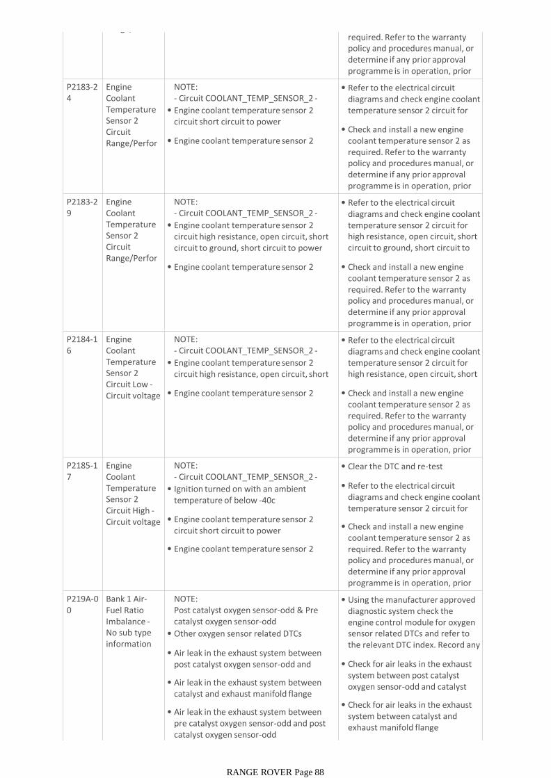
Range/Performance - Signal required. Refer to the warranty
policy and procedures manual, or determine if any prior approval programme is in operation, prior to the installation of a new P2183-2
4Engine Coolant Temperature Sensor 2 Circuit Range/Performance - Signal
NOTE:- Circuit COOLANT_TEMP_SENSOR_2 -
• Engine coolant temperature sensor 2 circuit short circuit to power
• Engine coolant temperature sensor 2 failure
• Refer to the electrical circuit diagrams and check engine coolant temperature sensor 2 circuit for short circuit to power
• Check and install a new engine coolant temperature sensor 2 as required. Refer to the warranty policy and procedures manual, or determine if any prior approval programme is in operation, prior to the installation of a new P2183-2
9Engine Coolant Temperature Sensor 2 Circuit Range/Performance - Signal
NOTE:- Circuit COOLANT_TEMP_SENSOR_2 -
• Engine coolant temperature sensor 2 circuit high resistance, open circuit, short circuit to ground, short circuit to power
• Engine coolant temperature sensor 2 failure
• Refer to the electrical circuit diagrams and check engine coolant temperature sensor 2 circuit for high resistance, open circuit, short circuit to ground, short circuit to power
• Check and install a new engine coolant temperature sensor 2 as required. Refer to the warranty policy and procedures manual, or determine if any prior approval programme is in operation, prior to the installation of a new P2184-1
6Engine Coolant Temperature Sensor 2 Circuit Low -Circuit voltage below
NOTE:- Circuit COOLANT_TEMP_SENSOR_2 -
• Engine coolant temperature sensor 2 circuit high resistance, open circuit, short circuit to ground
• Engine coolant temperature sensor 2 failure
• Refer to the electrical circuit diagrams and check engine coolant temperature sensor 2 circuit for high resistance, open circuit, short circuit to ground
• Check and install a new engine coolant temperature sensor 2 as required. Refer to the warranty policy and procedures manual, or determine if any prior approval programme is in operation, prior to the installation of a new P2185-1
7Engine Coolant Temperature Sensor 2 Circuit High -Circuit voltage above
NOTE:- Circuit COOLANT_TEMP_SENSOR_2 -
• Ignition turned on with an ambient temperature of below -40c
• Engine coolant temperature sensor 2 circuit short circuit to power
• Engine coolant temperature sensor 2 failure
• Clear the DTC and re-test
• Refer to the electrical circuit diagrams and check engine coolant temperature sensor 2 circuit for short circuit to power
• Check and install a new engine coolant temperature sensor 2 as required. Refer to the warranty policy and procedures manual, or determine if any prior approval programme is in operation, prior to the installation of a new P219A-0
0Bank 1 Air-Fuel Ratio Imbalance -No sub type information
NOTE:Post catalyst oxygen sensor-odd & Pre catalyst oxygen sensor-odd
• Other oxygen sensor related DTCs
• Air leak in the exhaust system between post catalyst oxygen sensor-odd and catalyst
• Air leak in the exhaust system between catalyst and exhaust manifold flange
• Air leak in the exhaust system between pre catalyst oxygen sensor-odd and post catalyst oxygen sensor-odd
• Using the manufacturer approved diagnostic system check the engine control module for oxygen sensor related DTCs and refer to the relevant DTC index. Record any available freeze frame data
• Check for air leaks in the exhaust system between post catalyst oxygen sensor-odd and catalyst
• Check for air leaks in the exhaust system between catalyst and exhaust manifold flange
• Check for air leaks in the exhaust
RANGE ROVER Page 88
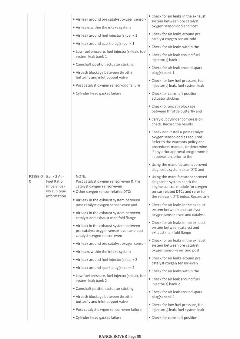
• Air leak around pre catalyst oxygen sensor-odd
• Air leaks within the intake system
• Air leak around fuel injector(s) bank 1
• Air leak around spark plug(s) bank 1
• Low fuel pressure, fuel injector(s) leak, fuel system leak bank 1
• Camshaft position actuator sticking
• Airpath blockage between throttle butterfly and inlet poppet valve
• Post catalyst oxygen sensor-odd failure
• Cylinder head gasket failure
• Check for air leaks in the exhaust system between pre catalyst oxygen sensor-odd and post catalyst oxygen sensor-odd
• Check for air leaks around pre catalyst oxygen sensor-odd
• Check for air leaks within the intake system
• Check for air leak around fuel injector(s) bank 1
• Check for air leak around spark plug(s) bank 1
• Check for low fuel pressure, fuel injector(s) leak, fuel system leak bank 1
• Check for camshaft position actuator sticking
• Check for airpath blockage between throttle butterfly and inlet poppet valve
• Carry out cylinder compression check. Record the results
• Check and install a post catalyst oxygen sensor-odd as required. Refer to the warranty policy and procedures manual, or determine if any prior approval programme is in operation, prior to the installation of a new
• Using the manufacturer approved diagnostic system clear DTC and retestP219B-0
0Bank 2 Air-Fuel Ratio Imbalance -No sub type information
NOTE:Post catalyst oxygen sensor-even & Pre catalyst oxygen sensor-even
• Other oxygen sensor related DTCs
• Air leak in the exhaust system between post catalyst oxygen sensor-even and catalyst
• Air leak in the exhaust system between catalyst and exhaust manifold flange
• Air leak in the exhaust system between pre catalyst oxygen sensor-even and post catalyst oxygen sensor-even
• Air leak around pre catalyst oxygen sensor-even
• Air leaks within the intake system
• Air leak around fuel injector(s) bank 2
• Air leak around spark plug(s) bank 2
• Low fuel pressure, fuel injector(s) leak, fuel system leak bank 2
• Camshaft position actuator sticking
• Airpath blockage between throttle butterfly and inlet poppet valve
• Post catalyst oxygen sensor-even failure
• Cylinder head gasket failure
• Using the manufacturer approved diagnostic system check the engine control module for oxygen sensor related DTCs and refer to the relevant DTC index. Record any available freeze frame data
• Check for air leaks in the exhaust system between post catalyst oxygen sensor-even and catalyst
• Check for air leaks in the exhaust system between catalyst and exhaust manifold flange
• Check for air leaks in the exhaust system between pre catalyst oxygen sensor-even and post catalyst oxygen sensor-even
• Check for air leaks around pre catalyst oxygen sensor-even
• Check for air leaks within the intake system
• Check for air leak around fuel injector(s) bank 2
• Check for air leak around spark plug(s) bank 2
• Check for low fuel pressure, fuel injector(s) leak, fuel system leak bank 2
• Check for camshaft position actuator sticking
RANGE ROVER Page 89
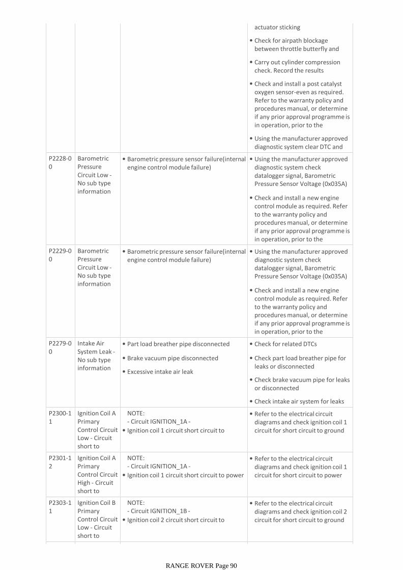
actuator sticking
• Check for airpath blockage between throttle butterfly and inlet poppet valve
• Carry out cylinder compression check. Record the results
• Check and install a post catalyst oxygen sensor-even as required. Refer to the warranty policy and procedures manual, or determine if any prior approval programme is in operation, prior to the installation of a new
• Using the manufacturer approved diagnostic system clear DTC and retestP2228-0
0Barometric Pressure Circuit Low -No sub type information
• Barometric pressure sensor failure(internal engine control module failure)
• Using the manufacturer approved diagnostic system check datalogger signal, Barometric Pressure Sensor Voltage (0x035A)
• Check and install a new engine control module as required. Refer to the warranty policy and procedures manual, or determine if any prior approval programme is in operation, prior to the installation of a new P2229-0
0Barometric Pressure Circuit Low -No sub type information
• Barometric pressure sensor failure(internal engine control module failure)
• Using the manufacturer approved diagnostic system check datalogger signal, Barometric Pressure Sensor Voltage (0x035A)
• Check and install a new engine control module as required. Refer to the warranty policy and procedures manual, or determine if any prior approval programme is in operation, prior to the installation of a new P2279-0
0Intake Air System Leak -No sub type information
• Part load breather pipe disconnected
• Brake vacuum pipe disconnected
• Excessive intake air leak
• Check for related DTCs
• Check part load breather pipe for leaks or disconnected
• Check brake vacuum pipe for leaks or disconnected
• Check intake air system for leaks
P2300-11
Ignition Coil A Primary Control Circuit Low - Circuit short to ground
NOTE:- Circuit IGNITION_1A -
• Ignition coil 1 circuit short circuit to ground
• Refer to the electrical circuit diagrams and check ignition coil 1 circuit for short circuit to ground
P2301-12
Ignition Coil A Primary Control Circuit High - Circuit short to battery
NOTE:- Circuit IGNITION_1A -
• Ignition coil 1 circuit short circuit to power
• Refer to the electrical circuit diagrams and check ignition coil 1 circuit for short circuit to power
P2303-11
Ignition Coil B Primary Control Circuit Low - Circuit short to ground
NOTE:- Circuit IGNITION_1B -
• Ignition coil 2 circuit short circuit to ground
• Refer to the electrical circuit diagrams and check ignition coil 2 circuit for short circuit to ground
P2304-1 Ignition Coil B NOTE: • Refer to the electrical circuit
RANGE ROVER Page 90

P2304-12
Ignition Coil B Primary Control Circuit High - Circuit short to battery
NOTE:- Circuit IGNITION_1B -
• Ignition coil 2 circuit short circuit to power
• Refer to the electrical circuit diagrams and check ignition coil 2 circuit for short circuit to power
P2306-11
Ignition Coil C Primary Control Circuit Low - Circuit short to ground
NOTE:- Circuit IGNITION_2A -
• Ignition coil 3 circuit short circuit to ground
• Refer to the electrical circuit diagrams and check ignition coil 3 circuit for short circuit to ground
P2307-12
Ignition Coil C Primary Control Circuit High - Circuit short to battery
NOTE:- Circuit IGNITION_2A -
• Ignition coil 3 circuit short circuit to power
• Refer to the electrical circuit diagrams and check ignition coil 3 circuit for short circuit to power
P2309-11
Ignition Coil D Primary Control Circuit Low - Circuit short to ground
NOTE:- Circuit IGNITION_2B -
• Ignition coil 4 circuit short circuit to ground
• Refer to the electrical circuit diagrams and check ignition coil 4 circuit for short circuit to ground
P2310-12
Ignition Coil D Primary Control Circuit High - Circuit short to battery
NOTE:- Circuit IGNITION_2B -
• Ignition coil 4 circuit short circuit to power
• Refer to the electrical circuit diagrams and check ignition coil 4 circuit for short circuit to power
P2312-11
Ignition Coil E Primary Control Circuit Low - Circuit short to ground
NOTE:- Circuit IGNITION_3A -
• Ignition coil 5 circuit short circuit to ground
• Refer to the electrical circuit diagrams and check ignition coil 5 circuit for short circuit to ground
P2313-12
Ignition Coil E Primary Control Circuit High - Circuit short to battery
NOTE:- Circuit IGNITION_3A -
• Ignition coil 5 circuit short circuit to power
• Refer to the electrical circuit diagrams and check ignition coil 5 circuit for short circuit to power
P2315-11
Ignition Coil F Primary Control Circuit Low - Circuit short to ground
NOTE:- Circuit IGNITION_3B -
• Ignition coil 6 circuit short circuit to ground
• Refer to the electrical circuit diagrams and check ignition coil 6 circuit for short circuit to ground
P2316-12
Ignition Coil F Primary Control Circuit High - Circuit short to battery
NOTE:- Circuit IGNITION_3B -
• Ignition coil 6 circuit short circuit to power
• Refer to the electrical circuit diagrams and check ignition coil 6 circuit for short circuit to power
P2318-11
Ignition Coil G Primary Control Circuit Low - Circuit short to ground
NOTE:- Circuit IGNITION_4A -
• Ignition coil 7 circuit short circuit to ground
• Refer to the electrical circuit diagrams and check ignition coil 7 circuit for short circuit to ground
P2319-12
Ignition Coil G Primary Control Circuit High - Circuit short to battery
NOTE:- Circuit IGNITION_4A -
• Ignition coil 7 circuit short circuit to power
• Refer to the electrical circuit diagrams and check ignition coil 7 circuit for short circuit to power
P2321-11
Ignition Coil H Primary Control Circuit Low - Circuit
NOTE:- Circuit IGNITION_4B -
• Ignition coil 8 circuit short circuit to ground
• Refer to the electrical circuit diagrams and check ignition coil 8 circuit for short circuit to ground
RANGE ROVER Page 91
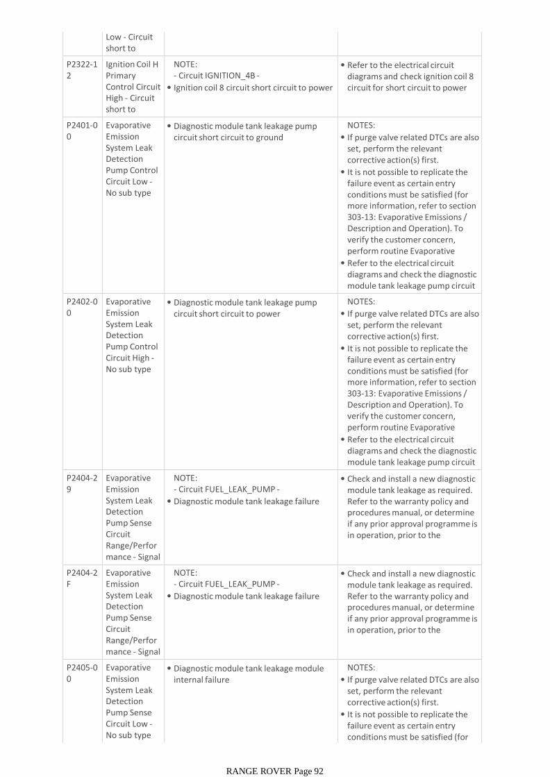
Low - Circuit short to ground
• Ignition coil 8 circuit short circuit to ground
circuit for short circuit to ground
P2322-12
Ignition Coil H Primary Control Circuit High - Circuit short to battery
NOTE:- Circuit IGNITION_4B -
• Ignition coil 8 circuit short circuit to power
• Refer to the electrical circuit diagrams and check ignition coil 8 circuit for short circuit to power
P2401-00
Evaporative Emission System Leak Detection Pump Control Circuit Low -No sub type information
• Diagnostic module tank leakage pump circuit short circuit to ground
NOTES:
• If purge valve related DTCs are also set, perform the relevant corrective action(s) first.
• It is not possible to replicate the failure event as certain entry conditions must be satisfied (for more information, refer to section 303-13: Evaporative Emissions / Description and Operation). To verify the customer concern, perform routine Evaporative System Diagnostic Check and re-• Refer to the electrical circuit diagrams and check the diagnostic module tank leakage pump circuit for short circuit to ground
P2402-00
Evaporative Emission System Leak Detection Pump Control Circuit High -No sub type information
• Diagnostic module tank leakage pump circuit short circuit to power
NOTES:
• If purge valve related DTCs are also set, perform the relevant corrective action(s) first.
• It is not possible to replicate the failure event as certain entry conditions must be satisfied (for more information, refer to section 303-13: Evaporative Emissions / Description and Operation). To verify the customer concern, perform routine Evaporative System Diagnostic Check and re-• Refer to the electrical circuit diagrams and check the diagnostic module tank leakage pump circuit for short circuit to power
P2404-29
Evaporative Emission System Leak Detection Pump Sense Circuit Range/Performance - Signal invalid
NOTE:- Circuit FUEL_LEAK_PUMP -
• Diagnostic module tank leakage failure
• Check and install a new diagnostic module tank leakage as required. Refer to the warranty policy and procedures manual, or determine if any prior approval programme is in operation, prior to the installation of a new
P2404-2F
Evaporative Emission System Leak Detection Pump Sense Circuit Range/Performance - Signal erratic
NOTE:- Circuit FUEL_LEAK_PUMP -
• Diagnostic module tank leakage failure
• Check and install a new diagnostic module tank leakage as required. Refer to the warranty policy and procedures manual, or determine if any prior approval programme is in operation, prior to the installation of a new
P2405-00
Evaporative Emission System Leak Detection Pump Sense Circuit Low -No sub type information
• Diagnostic module tank leakage module internal failure
NOTES:
• If purge valve related DTCs are also set, perform the relevant corrective action(s) first.
• It is not possible to replicate the failure event as certain entry conditions must be satisfied (for more information, refer to section
RANGE ROVER Page 92

more information, refer to section 303-13: Evaporative Emissions / Description and Operation). To verify the customer concern, perform routine Evaporative System Diagnostic Check and re-• Install a new diagnostic module tank leakage module as necessary
P2406-00
Evaporative Emission System Leak Detection Pump Sense Circuit High -No sub type information
• Diagnostic module tank leakage module internal failure
NOTES:
• If purge valve related DTCs are also set, perform the relevant corrective action(s) first.
• It is not possible to replicate the failure event as certain entry conditions must be satisfied (for more information, refer to section 303-13: Evaporative Emissions / Description and Operation). To verify the customer concern, perform routine Evaporative System Diagnostic Check and re-• Install a new diagnostic module tank leakage module as necessary
P240A-00
Evaporative Emission System Leak Detection Pump Heater Circuit / Open - No sub type
• Diagnostic module tank leakage heater circuit open circuit, high resistance
NOTES:
• If purge valve related DTCs are also set, perform the relevant corrective action(s) first.
• It is not possible to replicate the failure event as certain entry conditions must be satisfied (for more information, refer to section 303-13: Evaporative Emissions / Description and Operation). To verify the customer concern, perform routine Evaporative System Diagnostic Check and re-• Refer to the electrical circuit diagrams and check the diagnostic module tank leakage heater circuit for open circuit, high resistance
P240B-00
Evaporative Emission System Leak Detection Pump Heater Circuit Low -No sub type information
• Diagnostic module tank leakage heater circuit short circuit to ground
NOTES:
• If purge valve related DTCs are also set, perform the relevant corrective action(s) first.
• It is not possible to replicate the failure event as certain entry conditions must be satisfied (for more information, refer to section 303-13: Evaporative Emissions / Description and Operation). To verify the customer concern, perform routine Evaporative System Diagnostic Check and re-• Refer to the electrical circuit diagrams and check the diagnostic module tank leakage heater circuit for short circuit to ground
P240C-00
Evaporative Emission System Leak Detection Pump Heater Circuit High -No sub type information
• Diagnostic module tank leakage heater circuit short circuit to power
NOTES:
• If purge valve related DTCs are also set, perform the relevant corrective action(s) first.
• It is not possible to replicate the failure event as certain entry conditions must be satisfied (for more information, refer to section 303-13: Evaporative Emissions /
RANGE ROVER Page 93

303-13: Evaporative Emissions / Description and Operation). To verify the customer concern, perform routine Evaporative System Diagnostic Check and re-• Refer to the electrical circuit diagrams and check the diagnostic module tank leakage heater circuit for short circuit to power
P2450-00
Evaporative Emission Control System Switching Valve Performance/Stuck Open -No sub type
NOTES:
• - Circuit COV -
• LR - Circuit CHANGE OVER VALVE -
• Diagnostic module tank leakage failure
• Check and install a new diagnostic module tank leakage as required. Refer to the warranty policy and procedures manual, or determine if any prior approval programme is in operation, prior to the installation of a new
P2451-00
Evaporative Emission Control System Switching Valve Performance/Stuck Closed -No sub type
NOTES:
• - Circuit COV -
• LR - Circuit CHANGE OVER VALVE -
• Diagnostic module tank leakage failure
• Check and install a new diagnostic module tank leakage as required. Refer to the warranty policy and procedures manual, or determine if any prior approval programme is in operation, prior to the installation of a new
P250C-23
Engine Oil Level Sensor Circuit Low -Signal stuck low
NOTE:- Circuit OIL_QUALITY_SENSOR -
• Oil temperature level sensor circuit short circuit to ground
• Oil temperature level sensor failure
• Using the manufacturer approved diagnostic system check datalogger signal, Sump Oil Temperature - Measured (0x03F3)
• Refer to the electrical circuit diagrams and check oil temperature level sensor circuit for short circuit to ground
• Check and install a new oil temperature level sensor as required. Refer to the warranty policy and procedures manual, or determine if any prior approval programme is in operation, prior to the installation of a new P250D-2
4Engine Oil Level Sensor Circuit High -Signal stuck high
NOTE:- Circuit OIL_QUALITY_SENSOR -
• Oil temperature level sensor circuit short circuit to power
• Oil temperature level sensor failure
• Using the manufacturer approved diagnostic system check datalogger signal, Sump Oil Temperature - Measured (0x03F3)
• Refer to the electrical circuit diagrams and check oil temperature level sensor circuit for short circuit to power
• Check and install a new oil temperature level sensor as required. Refer to the warranty policy and procedures manual, or determine if any prior approval programme is in operation, prior to the installation of a new P2544-6
4Torque Management Request Input Signal A -Signal plausibility failure
• Inappropriate request from anti-lock braking system
• Check for related DTCs within anti-lock braking system module and refer to the relevant DTC index
• Using the manufacturer approved diagnostic system, complete a CAN network integrity test
P2544-92
Torque Management Request Input Signal A -Performance
• Inappropriate request from anti-lock braking system
• Check for related DTCs within anti-lock braking system module and refer to the relevant DTC index
• Using the manufacturer approved
RANGE ROVER Page 94
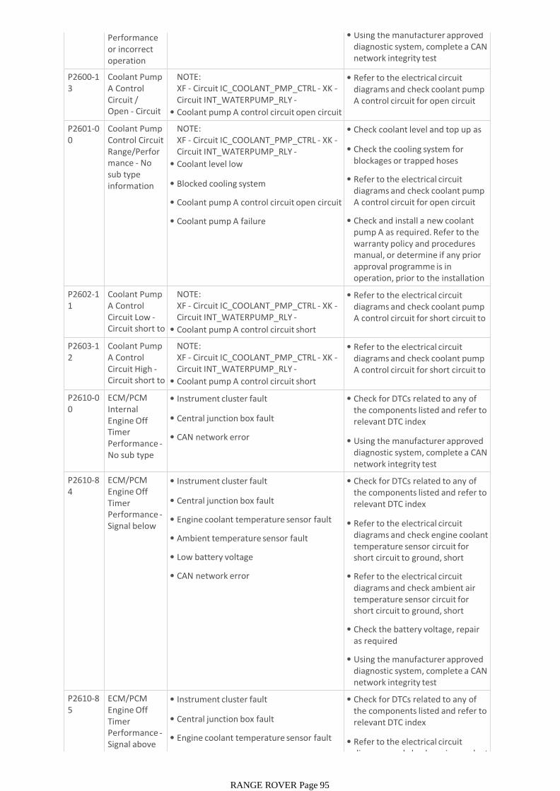
Performance or incorrect operation
• Using the manufacturer approved diagnostic system, complete a CAN network integrity test
P2600-13
Coolant Pump A Control Circuit / Open - Circuit open
NOTE:XF - Circuit IC_COOLANT_PMP_CTRL - XK -Circuit INT_WATERPUMP_RLY -
• Coolant pump A control circuit open circuit
• Refer to the electrical circuit diagrams and check coolant pump A control circuit for open circuit
P2601-00
Coolant Pump Control Circuit Range/Performance - No sub type information
NOTE:XF - Circuit IC_COOLANT_PMP_CTRL - XK -Circuit INT_WATERPUMP_RLY -
• Coolant level low
• Blocked cooling system
• Coolant pump A control circuit open circuit
• Coolant pump A failure
• Check coolant level and top up as required
• Check the cooling system for blockages or trapped hoses
• Refer to the electrical circuit diagrams and check coolant pump A control circuit for open circuit
• Check and install a new coolant pump A as required. Refer to the warranty policy and procedures manual, or determine if any prior approval programme is in operation, prior to the installation of a new module/componentP2602-1
1Coolant Pump A Control Circuit Low -Circuit short to ground
NOTE:XF - Circuit IC_COOLANT_PMP_CTRL - XK -Circuit INT_WATERPUMP_RLY -
• Coolant pump A control circuit short circuit to ground
• Refer to the electrical circuit diagrams and check coolant pump A control circuit for short circuit to ground
P2603-12
Coolant Pump A Control Circuit High -Circuit short to battery
NOTE:XF - Circuit IC_COOLANT_PMP_CTRL - XK -Circuit INT_WATERPUMP_RLY -
• Coolant pump A control circuit short circuit to power
• Refer to the electrical circuit diagrams and check coolant pump A control circuit for short circuit to power
P2610-00
ECM/PCM Internal Engine Off Timer Performance -No sub type information
• Instrument cluster fault
• Central junction box fault
• CAN network error
• Check for DTCs related to any of the components listed and refer to relevant DTC index
• Using the manufacturer approved diagnostic system, complete a CAN network integrity test
P2610-84
ECM/PCM Engine Off Timer Performance -Signal below allowable
• Instrument cluster fault
• Central junction box fault
• Engine coolant temperature sensor fault
• Ambient temperature sensor fault
• Low battery voltage
• CAN network error
• Check for DTCs related to any of the components listed and refer to relevant DTC index
• Refer to the electrical circuit diagrams and check engine coolant temperature sensor circuit for short circuit to ground, short circuit to power, open circuit
• Refer to the electrical circuit diagrams and check ambient air temperature sensor circuit for short circuit to ground, short circuit to power, open circuit
• Check the battery voltage, repair as required
• Using the manufacturer approved diagnostic system, complete a CAN network integrity test
P2610-85
ECM/PCM Engine Off Timer Performance -Signal above allowable
• Instrument cluster fault
• Central junction box fault
• Engine coolant temperature sensor fault
• Ambient temperature sensor fault
• Check for DTCs related to any of the components listed and refer to relevant DTC index
• Refer to the electrical circuit diagrams and check engine coolant
RANGE ROVER Page 95
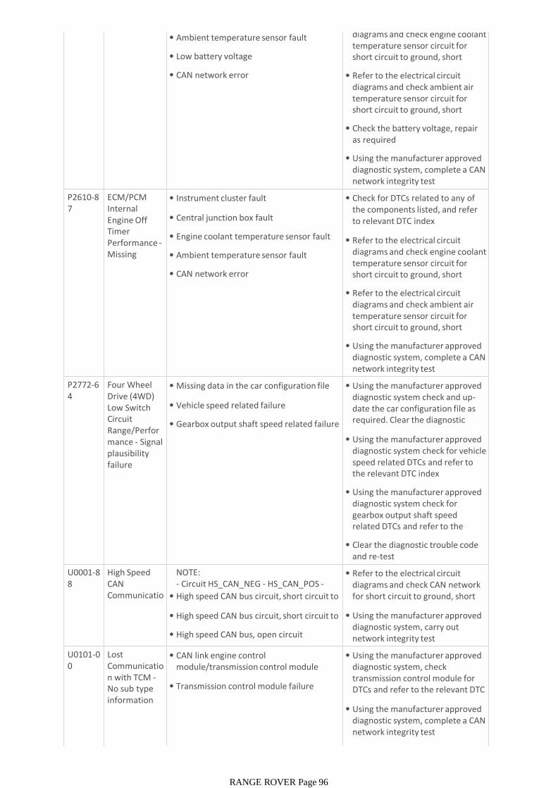
• Ambient temperature sensor fault
• Low battery voltage
• CAN network error
diagrams and check engine coolant temperature sensor circuit for short circuit to ground, short circuit to power, open circuit
• Refer to the electrical circuit diagrams and check ambient air temperature sensor circuit for short circuit to ground, short circuit to power, open circuit
• Check the battery voltage, repair as required
• Using the manufacturer approved diagnostic system, complete a CAN network integrity test
P2610-87
ECM/PCM Internal Engine Off Timer Performance -Missing message
• Instrument cluster fault
• Central junction box fault
• Engine coolant temperature sensor fault
• Ambient temperature sensor fault
• CAN network error
• Check for DTCs related to any of the components listed, and refer to relevant DTC index
• Refer to the electrical circuit diagrams and check engine coolant temperature sensor circuit for short circuit to ground, short circuit to power, open circuit
• Refer to the electrical circuit diagrams and check ambient air temperature sensor circuit for short circuit to ground, short circuit to power, open circuit
• Using the manufacturer approved diagnostic system, complete a CAN network integrity test
P2772-64
Four Wheel Drive (4WD) Low Switch Circuit Range/Performance - Signal plausibility failure
• Missing data in the car configuration file
• Vehicle speed related failure
• Gearbox output shaft speed related failure
• Using the manufacturer approved diagnostic system check and up-date the car configuration file as required. Clear the diagnostic trouble code and retest
• Using the manufacturer approved diagnostic system check for vehicle speed related DTCs and refer to the relevant DTC index
• Using the manufacturer approved diagnostic system check for gearbox output shaft speed related DTCs and refer to the relevant DTC index
• Clear the diagnostic trouble code and re-test
U0001-88
High Speed CAN Communication Bus - Bus off
NOTE:- Circuit HS_CAN_NEG - HS_CAN_POS -
• High speed CAN bus circuit, short circuit to ground
• High speed CAN bus circuit, short circuit to power
• High speed CAN bus, open circuit
• Refer to the electrical circuit diagrams and check CAN network for short circuit to ground, short circuit to power, open circuit
• Using the manufacturer approved diagnostic system, carry out network integrity test
U0101-00
Lost Communication with TCM -No sub type information
• CAN link engine control module/transmission control module network malfunction
• Transmission control module failure
• Using the manufacturer approved diagnostic system, check transmission control module for DTCs and refer to the relevant DTC index
• Using the manufacturer approved diagnostic system, complete a CAN network integrity test
• Refer to the electrical circuit
RANGE ROVER Page 96

• Refer to the electrical circuit diagrams and check transmission control module power and ground circuit for open circuit
• Check CAN harness to transmission control module, repair as necessaryU0102-0
0Lost Communication with Transfer Case Control Module - No sub type information
• CAN harness link between engine control module and transfer box control module network malfunction
• Using the manufacturer approved diagnostic system, check transfer box control module for DTCs and refer to the relevant DTC index
• Using the manufacturer approved diagnostic system, complete a CAN network integrity test
• Refer to the electrical circuit diagrams and check transfer box control module power and ground circuits for open circuit
• Check CAN harness between engine control module and transfer box control module, repair as necessary
U0104-00
Lost Communication With Cruise Control Module - No sub type information
• Vehicle configured for speed control, but speed control module is not installed
• CAN Link engine control module/speed control module network malfunction
• Speed control module power or ground circuit, open circuit
• Check vehicle has correct speed control module installed
• Using the manufacturer approved diagnostic system, check speed control module, anti-lock braking system module for DTCs and refer to the relevant DTC index
• Using the manufacturer approved diagnostic system, complete a CAN network integrity test
• Refer to the electrical circuit diagrams and check speed control module power and ground circuit for open circuit
• Check CAN harness to speed control module, repair as necessaryU0121-0
0Lost Communication With Anti-lock Braking System (ABS) Control Module - No sub type information
• CAN Link engine control module/anti-lock braking system module network malfunction
• Anti-lock braking system module power or ground circuit, open circuit
• Using the manufacturer approved diagnostic system, check anti-lock braking system module for DTCs and refer to the relevant DTC index
• Using the manufacturer approved diagnostic system, complete a CAN network integrity test
• Refer to the electrical circuit diagrams and check anti-lock braking system module power and ground circuit for open circuit
• Check CAN harness to anti-lock braking system module, repair as necessaryU0126-0
0Lost Communication With Steering Angle Sensor Module - No sub type information
• CAN harness link between engine control module and steering angle sensor network malfunction
• Using the manufacturer approved diagnostic system, steering angle sensor for DTCs and refer to the relevant DTC index
• Using the manufacturer approved diagnostic system, complete a CAN network integrity test
• Refer to the electrical circuit diagrams and check steering angle
RANGE ROVER Page 97

diagrams and check steering angle sensor power and ground circuits for open circuit
• Check CAN harness between engine control module and steering angle sensor, repair as necessary
U0128-00
Lost Communication With Park Brake Control Module - No sub type information
• CAN Link engine control module/electronic parking brake signal missing network malfunction
• Refer to the electrical circuit diagrams and check power and ground supplies to electronic parking brake
• Using the manufacturer approved diagnostic system, complete a CAN network integrity test
U0132-00
Lost Communication with Suspension Control Module A - No sub type
• CAN link/suspension control module network malfunction
• Refer to the electrical circuit diagrams and check power and ground supplies to suspension control module
• Using the manufacturer approved diagnostic system, complete a CAN network integrity test
U0133-00
Lost Communication With Active Roll Control Module - No sub type information
• CAN harness link between engine control module and active roll control module network malfunction
• Using the manufacturer approved diagnostic system, check active roll control module for DTCs and refer to the relevant DTC index
• Using the manufacturer approved diagnostic system, complete a CAN network integrity test
• Refer to the electrical circuit diagrams and check active roll control module power and ground circuits for open circuit
• Check CAN harness between engine control module and active roll control module, repair as necessary
U0138-00
Lost Communication with All Terrain Control Module - No sub type information
• CAN harness link between engine control module and center console switch pack network malfunction
• Using the manufacturer approved diagnostic system, check center console switch pack for DTCs and refer to the relevant DTC index
• Using the manufacturer approved diagnostic system, complete a CAN network integrity test
• Refer to the electrical circuit diagrams and check center console switch pack power and ground circuits for open circuit
• Check CAN harness between engine control module and center console switch pack, repair as necessary
U0140-00
Lost Communication With Body Control Module - No sub type information
• CAN harness link between engine control module and central junction box network malfunction
• Using the manufacturer approved diagnostic system, check central junction box for DTCs and refer to the relevant DTC index
• Using the manufacturer approved diagnostic system, complete a CAN network integrity test
• Refer to the electrical circuit diagrams and check central junction box power and ground circuits for open circuit
RANGE ROVER Page 98

• Check CAN harness between engine control module and central junction box, repair as necessary
U0151-00
Lost Communication with Restraints Control Module - No sub type information
• Lost communication with restraints control module over CAN or hardwired link
• Refer to the electrical circuit diagrams and check power and ground supplies to restraints control module
• Using the manufacturer approved diagnostic system, complete a CAN network integrity test
U0151-87
Lost Communication with Restraints Control Module -Missing message
• Lost communication due to restraints control module fault
• Check restraints control module for associated DTCs and refer to relevant DTC index
• Refer to the electrical circuit diagrams and check power and ground supplies to restraints control module
• Using the manufacturer approved diagnostic system, complete a CAN network integrity test
U0155-00
Lost Communication with Instrument Panel Cluster (IPC) - No sub type information
• CAN link between engine control module and instrument cluster fault
• Refer to the electrical circuit diagrams and check power and ground supplies to instrument cluster
• Using the manufacturer approved diagnostic system, complete a CAN network integrity test
U0167-00
Lost Communication with Vehicle Immobilizer Control Module - No sub type information
• Security challenge response timeout
• Battery fault
• Refer to the electrical circuit diagrams and check power and ground supplies to the electric steering column lock
• Check for related CAN DTCs and refer to the relevant DTC index
• Ensure the battery is in a fully charged and serviceable condition. Refer to the battery care manual and the relevant sections of the workshop manual
• Using the manufacturer approved diagnostic system, complete a CAN network integrity test
U0300-00
Internal Control Module Software Incompatibility - No sub type
• Engine control module has incorrect software installed
• The engine control module is in expulsion mode. An incorrect specification engine control module has been installed to the vehicle
• Check and install the correct engine control module software
• Check and install the correct engine control module as required. Refer to the warranty policy and procedures manual, or determine if any prior approval programme is in operation, prior to the installation of a new U0402-0
0Invalid Data Received From Transmission Control Module - No sub type information
• Transmission engine control module request corruption
• Using the manufacturer approved diagnostic system, check transmission control module, for DTCs and refer to the relevant DTC index
• Using the manufacturer approved diagnostic system, complete a CAN network integrity test
• Refer to the electrical circuit diagrams and check high speed
RANGE ROVER Page 99
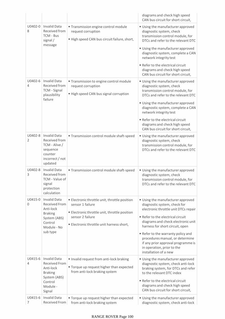
diagrams and check high speed CAN bus circuit for short circuit, open circuit
U0402-08
Invalid Data Received from TCM - Bus signal / message failures
• Transmission engine control module request corruption
• High speed CAN bus circuit failure, short, open circuit
• Using the manufacturer approved diagnostic system, check transmission control module, for DTCs and refer to the relevant DTC index
• Using the manufacturer approved diagnostic system, complete a CAN network integrity test
• Refer to the electrical circuit diagrams and check high speed CAN bus circuit for short circuit, open circuit
U0402-64
Invalid Data Received from TCM - Signal plausibility failure
• Transmission to engine control module request corruption
• High speed CAN bus signal corruption
• Using the manufacturer approved diagnostic system, check transmission control module, for DTCs and refer to the relevant DTC index
• Using the manufacturer approved diagnostic system, complete a CAN network integrity test
• Refer to the electrical circuit diagrams and check high speed CAN bus circuit for short circuit, open circuit
U0402-82
Invalid Data Received from TCM - Alive / sequence counter incorrect / not updated
• Transmission control module shaft-speed faults
• Using the manufacturer approved diagnostic system, check transmission control module, for DTCs and refer to the relevant DTC index
U0402-83
Invalid Data Received from TCM - Value of signal protection calculation incorrect
• Transmission control module shaft-speed faults
• Using the manufacturer approved diagnostic system, check transmission control module, for DTCs and refer to the relevant DTC index
U0415-00
Invalid Data Received From Anti-lock Braking System (ABS) Control Module - No sub type information
• Electronic throttle unit, throttle position sensor 1 failure
• Electronic throttle unit, throttle position sensor 2 failure
• Electronic throttle unit harness short, open circuit
• Using the manufacturer approved diagnostic system, check for electronic throttle unit DTCs repair as necessary
• Refer to the electrical circuit diagrams and check electronic unit harness for short circuit, open circuit
• Refer to the warranty policy and procedures manual, or determine if any prior approval programme is in operation, prior to the installation of a new module/component
U0415-64
Invalid Data Received From Anti-lock Braking System (ABS) Control Module -Signal plausibility
• Invalid request from anti-lock braking system
• Torque up request higher than expected from anti-lock braking system
• Using the manufacturer approved diagnostic system, check anti-lock braking system, for DTCs and refer to the relevant DTC index
• Refer to the electrical circuit diagrams and check high speed CAN bus circuit for short circuit, open circuit
U0415-67
Invalid Data Received From Anti-lock
• Torque up request higher than expected from anti-lock braking system
• Using the manufacturer approved diagnostic system, check anti-lock
RANGE ROVER Page 100
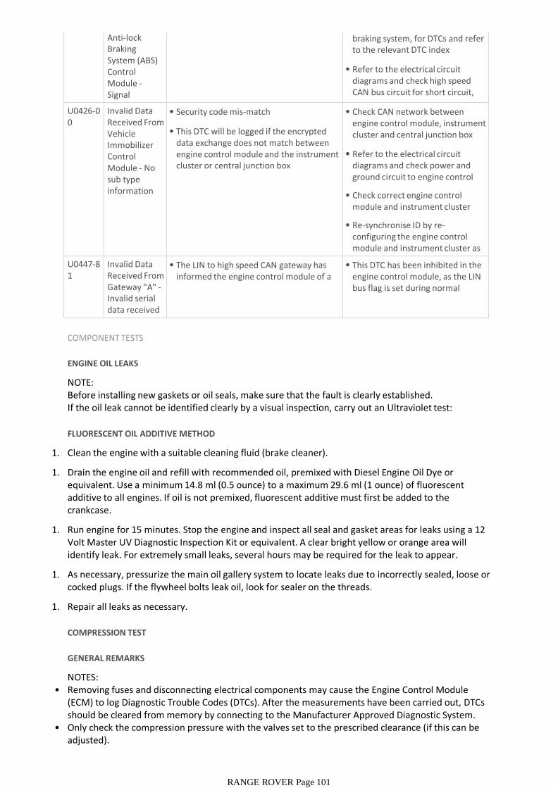
Anti-lock Braking System (ABS) Control Module -Signal incorrect after
from anti-lock braking system diagnostic system, check anti-lock braking system, for DTCs and refer to the relevant DTC index
• Refer to the electrical circuit diagrams and check high speed CAN bus circuit for short circuit, open circuit
U0426-00
Invalid Data Received From Vehicle Immobilizer Control Module - No sub type information
• Security code mis-match
• This DTC will be logged if the encrypted data exchange does not match between engine control module and the instrument cluster or central junction box
• Check CAN network between engine control module, instrument cluster and central junction box
• Refer to the electrical circuit diagrams and check power and ground circuit to engine control module and instrument cluster
• Check correct engine control module and instrument cluster installed
• Re-synchronise ID by re-configuring the engine control module and instrument cluster as new modules
U0447-81
Invalid Data Received From Gateway "A" -Invalid serial data received
• The LIN to high speed CAN gateway has informed the engine control module of a failure
• This DTC has been inhibited in the engine control module, as the LIN bus flag is set during normal operation
COMPONENT TESTS
ENGINE OIL LEAKS
NOTE:Before installing new gaskets or oil seals, make sure that the fault is clearly established.If the oil leak cannot be identified clearly by a visual inspection, carry out an Ultraviolet test:
FLUORESCENT OIL ADDITIVE METHOD
1. Clean the engine with a suitable cleaning fluid (brake cleaner).
1. Drain the engine oil and refill with recommended oil, premixed with Diesel Engine Oil Dye or equivalent. Use a minimum 14.8 ml (0.5 ounce) to a maximum 29.6 ml (1 ounce) of fluorescent additive to all engines. If oil is not premixed, fluorescent additive must first be added to the crankcase.
1. Run engine for 15 minutes. Stop the engine and inspect all seal and gasket areas for leaks using a 12 Volt Master UV Diagnostic Inspection Kit or equivalent. A clear bright yellow or orange area will identify leak. For extremely small leaks, several hours may be required for the leak to appear.
1. As necessary, pressurize the main oil gallery system to locate leaks due to incorrectly sealed, loose or cocked plugs. If the flywheel bolts leak oil, look for sealer on the threads.
1. Repair all leaks as necessary.
COMPRESSION TEST
GENERAL REMARKS
NOTES:• Removing fuses and disconnecting electrical components may cause the Engine Control Module
(ECM) to log Diagnostic Trouble Codes (DTCs). After the measurements have been carried out, DTCs should be cleared from memory by connecting to the Manufacturer Approved Diagnostic System.
• Only check the compression pressure with the valves set to the prescribed clearance (if this can be adjusted).The compression pressure should be checked with the engine at normal operating temperature.
RANGE ROVER Page 101
The compression pressure should be checked with the engine at normal operating temperature.
CHECK THE COMPRESSION PRESSURE
WARNING:Move gear selector lever to 'P' position. Failure to follow this instruction may result in personal injury.
1. Remove the fuel pump relay.
1. Start the engine - the engine will start, run for a few seconds then stall.
1. Remove the spark plugs.
1. Install the compression tester.
1. Install an auxiliary starter switch in the starting circuit. With the ignition switch OFF, using the auxiliary starter switch, crank the engine a minimum of five compression strokes and record the highest reading. Note the approximate number of compression strokes required to obtain the highest reading.
1. Repeat the test on each cylinder, cranking the engine approximately the same number of compression strokes.
1. Install the removed components in reverse order, observing the specified tightening torques.
1. Clear all DTCs from the ECM.
INTERPRETATION OF THE RESULTS
NOTE:Due to the possibility of loose carbon that has become trapped between the valve face and seat effecting the pressure readings, when carrying out a compression test and cylinders are found to have low pressures, install the spark plugs, road test the vehicle and re-test the suspect cylinders. If the correct pressures are restored, no further action is required.The minimum cylinder compression reading recorded must be within 10% of the maximum cylinder compression reading recorded.
If the cylinder pressures are found to be low, carry out a leakdown test to determine the location of the fault (if any leakback can be heard through the engine breather system suspect the piston rings, if any leakback can be heard through the inlet system suspect the inlet valve or seat, if any leakback can be heard through the exhaust manifold suspect the exhaust valve or seat. If the measurements for two cylinders next to each other are both too low then it is very likely that the cylinder head gasket between them is burnt through. This can also be recognized by traces of engine oil in the coolant and/or coolant in the engine oil).
OIL CONSUMPTION TEST
The amount of oil an engine uses will vary with the way the vehicle is driven in addition to normal engine-to-engine variation. This is especially true during the first 16,100 km (10,000 miles) when a new engine is being broken in or until certain internal components become conditioned. Vehicles used in heavy-duty operation may use more oil. The following are examples of heavy-duty operation:
• Trailer towing applications
• Severe loading applications
• Sustained high speed operation
Engines need oil to lubricate the following internal components:
• Cylinder block cylinder walls
• Pistons and piston rings
RANGE ROVER Page 102
• Pistons and piston rings
• Intake and exhaust valve stems
• Intake and exhaust valve guides
• All internal engine components
When the pistons move downward, a thin film of oil is left on the cylinder walls. As the vehicle is operated, some oil is also drawn into the combustion chambers past the intake and exhaust valve stem seals and burned.
The following are examples of conditions that can affect oil consumption rates:
• Engine size
• Operator driving habits
• Ambient temperatures
• Quality and viscosity of oil
• Engine is being run in an overfilled condition (check the oil level at least five minutes after a hot shutdown with the vehicle parked on a level surface. The oil level should not be above the top of the cross-hatched area and the letter "F" in FULL).
Operation under varying conditions can frequently be misleading. A vehicle that has been run for several thousand miles on short trips or in below-freezing ambient temperatures may have consumed a "normal" amount of oil. However, when checking the engine oil level, it may measure up to the full mark on the oil level indicator due to dilution (condensation and fuel) in the engine crankcase. The vehicle then might be driven at high speeds on the highway where the condensation and fuel boil off. The next time the engine oil is checked it may appear that a liter of oil was used in about 160 km (100 miles). Oil consumption rate is about one liter per 2,400 km (1,500 miles).
Make sure the selected engine oil meets Jaguar specification and the recommended API performance category "SG" and SAE viscosity grade as shown in the vehicle Owner's Guide. It is also important that the engine oil is changed at the intervals specified for the typical operating conditions.
The following diagnostic procedure is used to determine the source of excessive oil consumption.
NOTE:Oil use is normally greater during the first 16,100 km (10,000 miles) of service. As mileage increases, oil use decreases. High speed driving, towing, high ambient temperature and other factors may result in greater oil use.
1. Define excessive consumption, such as the number of miles driven per liter of oil used. Also determine customers driving habits, such as sustained high speed operation, towing, extended idle and other considerations.
1. Verify that the engine has no external oil leaks as described under Engine Oil Leaks in this section.
• Run the engine to normal operating temperature. Switch engine OFF and allow oil to drain back for at least five minutes .
• With vehicle parked on level surface, check the engine oil level.
• If required, add engine oil to set level exactly to the FULL mark.
• Record the vehicle mileage.
• Instruct the customer to return for a level check after driving the vehicle as usual for 1,610 km (1000 miles).
1. Carry out an oil consumption test:
RANGE ROVER Page 103
(1000 miles).
• Check the oil level under the same conditions and at the same location as the initial check.
NOTE:If the oil consumption rate is unacceptable go to Step 4.
1. Check the Positive Crankcase Ventilation (PCV) system. Make sure the system is not plugged.
1. Check for plugged oil drain-back holes in the cylinder head and cylinder block.
1. If the condition still exists after carrying out the above tests go to step 9.
1. Carry out a cylinder compression test. Refer to the Compression Test procedure in this section. This can help determine the source of oil consumption such as valves, piston rings or other areas.
1. Check valve guides for excessive guide clearance. Install new valve stem seals after verifying valve guide clearance.
1. Worn or damaged internal engine components can cause excessive oil consumption. Small deposits of oil on the tips of the spark plugs can be a clue to internal oil consumption.
INTAKE MANIFOLD VACUUM TEST
Bring the engine to normal operating temperature. Connect a vacuum gauge or equivalent to the intake manifold. Run the engine at the specified idle speed.
The vacuum gauge should read between 51-74 kPa (15-22 in-Hg) depending upon the engine condition and the altitude at which the test is performed. Subtract 4.0193 kPa (1 in-Hg) from the specified reading for every 304.8 m (1,000 feet) of elevation above sea level.
The reading should be steady. As necessary, adjust the gauge damper control (where used) if the needle is fluttering rapidly. Adjust damper until needle moves easily without excessive flutter.
INTERPRETING VACUUM GAUGE READINGS
A careful study of the vacuum gauge reading while the engine is idling will help pinpoint trouble areas. Always conduct other appropriate tests before arriving at a final diagnostic decision. Vacuum gauge readings, although helpful, must be interpreted carefully.
Most vacuum gauges have a normal band indicated on the gauge face.
The following are potential gauge readings. Some are normal; others should be investigated further.
RANGE ROVER Page 104

1. NORMAL READING: Needle between 51-74 kPa (15-22 in-Hg) and holding steady.
1. NORMAL READING DURING RAPID ACCELERATION: When the engine is rapidly accelerated, the needle will drop to a low (not to zero) reading. When the throttle is suddenly released, the needle will snap back up to a higher than normal figure.
1. NORMAL FOR HIGH-LIFT CAMSHAFT WITH LARGE OVERLAP: The needle will register as low as 51 kPa (15 in-Hg) but will be relatively steady. Some oscillation is normal.
1. WORN RINGS OR DILUTED OIL: When the engine is accelerated, the needle drops to 0 kPa (0 in-Hg). Upon deceleration, the needle runs slightly above 74 kPa (22 in-Hg).
1. STICKING VALVES: When the needle remains steady at a normal vacuum but occasionally flicks (sharp, fast movement) down and back about 13 kPa (4 in-Hg), one or more valves may be sticking.
1. BURNED OR BENT VALVES: A regular, evenly-spaced, downscale flicking of the needle indicates one or more burned or damaged valves. Insufficient hydraulic valve tappet or hydraulic lash adjuster clearance will also cause this reaction.
1. POOR VALVE SEATING: A small but regular downscale flicking can mean one or more valves are not seating correctly.
1. WORN VALVE GUIDES: When the needle oscillates over about a 13 kPa (4 in-Hg) range at idle speed, the valve guides could be worn. As engine speed increases, the needle will become steady if guides are responsible.
1. WEAK VALVE SPRINGS: When the needle oscillation becomes more violent as engine RPM is increased, weak valve springs are indicated. The reading at idle could be relatively steady.
1. LATE VALVE TIMING: A steady but low reading could be caused by late valve timing.
1. IGNITION TIMING RETARDED: Retarded ignition timing will produce a steady but somewhat low reading.
1. INSUFFICIENT SPARK PLUG GAP: When spark plugs are gapped too close, a regular, small pulsation of the needle can occur.
1. INTAKE LEAK: A low, steady reading can be caused by an intake manifold or throttle body gasket leak.
RANGE ROVER Page 105
1. BLOWN HEAD GASKET: A regular drop of fair magnitude can be caused by a blown head gasket or warped cylinder head to cylinder block surface.
1. RESTRICTED EXHAUST SYSTEM: When the engine is first started and is idled, the reading may be normal, but as the engine RPM is increased, the back pressure caused by a clogged muffler, kinked tail pipe or other concerns will cause the needle to slowly drop to 0 kPa (0 in-Hg). The needle then may slowly rise. Excessive exhaust clogging will cause the needle to drop to a low point even if the engine is only idling.
When vacuum leaks are indicated, search out and correct the cause. Excess air leaking into the system will upset the fuel mixture and cause concerns such as rough idle, missing on acceleration or burned valves. If the leak exists in an accessory such as the power brake booster, the unit will not function correctly. Always repair vacuum leaks.
ENGINE OIL PRESSURE CHECK
NOTE:Prior to checking the engine oil pressure, a road test of 6 miles (10 kilometres), must be carried out. Do not attempt to attain engine normal operating temperature by allowing the engine to idle.
1. Disconnect the battery ground cable. Refer to section 414-00 - Charging System - General Information of the workshop manual
WARNINGS:• The spilling of hot engine oil is unavoidable during this procedure, care must be taken to prevent
scalding.• Wear protective gloves.
1. Remove the engine oil filter element REFER to:Oil Filter Element (303-01C Engine - V8 N/A 5.0L Petrol, Removal and Installation).
NOTE:Ensure the oil filter element is not contaminated during this procedure
1. Install the oil filter element into special tool (Oil filter adapter number 303-1451)
1. Install the special tool (Oil filter adapter number 303-1451) to the engine. Torque: 25 Nm
1. Install the special tool (Oil pressure testing gauge, 303-871) and tighten the union
1. Connect the battery ground cable
1. Refer to owner hand book, check and top-up the engine oil if required
1. Start and run the engine
1. Note the oil pressure readings with the engine running at idle and 3500 RPM
1. Turn off the engine
1. Disconnect the battery ground cable
1. Remove the special tools
1. Clean the components
1. Install the engine oil filter element REFER to:Oil Filter Element (303-01C Engine - V8 N/A 5.0L Petrol, Removal and Installation).
NOTE:Ensure the oil filter element is not contaminated during this procedure
1. Connect the battery ground cable
1. Refer to owner hand book, check and top-up the engine oil if required
From <https://topix.jaguar.jlrext.com/topix/service/procedure/167833/ODYSSEY/G1222426/en_US?uid=G1440635>
RANGE ROVER Page 106