Object-Oriented Connector-Component Architectures
27
FESCA 2005 Preliminary Version Object-Oriented Connector-Component Architectures H. Ehrig, B. Braatz, M. Klein 1 Institut f¨ ur Softwaretechnik und Theoretische Informatik, Technische Universit¨ at Berlin, Germany F. Orejas, S. P´ erez, E. Pino 2 Departament de Llenguatges i Sistemes Inform` atics, Universitat Polit` ecnica de Catalunya, Barcelona, Spain Abstract This paper presents an important extension of our contribution to FESCA ’04, which presented a generic framework for connector architectures. These architectures were defined by components, consisting of a body specification and a set of export interfaces, and connectors, consisting of a body specification and a set of import interfaces plus connecting transformations in both cases. A major restriction of this concept was given by the assumption of non-overlapping connector interfaces. In order to make the generic framework for connector architectures more appli- cable, it is enriched by the possibility of handling overlapping connector interfaces. Fortunately, it is possible to extend the main results presented at FESCA ’04 also to the new framework. Moreover, it is shown that the new framework can be applied to UML class diagrams, state machines and sequence diagrams as heterogeneous specification techniques. The resulting connector framework, including a concept for the composition of components and architectural reduction for UML specifica- tions is illustrated by a case study concerning the metadata management in Topic Maps. 1 Introduction The importance of architecture descriptions has become most obvious over the last decade (see e. g. [15,16,7,8,6]). Various formalisms have been proposed to deal with the complexity of large software systems. The idea of dividing computation and coordination in software programs and in the corresponding 1 Email: [ehrig,bbraatz,klein]@cs.tu-berlin.de 2 Email: [orejas,sperezl,pino]@lsi.upc.es This is a preliminary version. The final version will be published in Electronic Notes in Theoretical Computer Science URL: www.elsevier.nl/locate/entcs
-
Upload
independent -
Category
Documents
-
view
0 -
download
0
Transcript of Object-Oriented Connector-Component Architectures
FESCA 2005 Preliminary Version
Object-Oriented Connector-ComponentArchitectures
H. Ehrig, B. Braatz, M. Klein 1
Institut fur Softwaretechnik und Theoretische Informatik,Technische Universitat Berlin, Germany
F. Orejas, S. Perez, E. Pino 2
Departament de Llenguatges i Sistemes Informatics,Universitat Politecnica de Catalunya, Barcelona, Spain
Abstract
This paper presents an important extension of our contribution to FESCA ’04, whichpresented a generic framework for connector architectures. These architectureswere defined by components, consisting of a body specification and a set of exportinterfaces, and connectors, consisting of a body specification and a set of importinterfaces plus connecting transformations in both cases. A major restriction of thisconcept was given by the assumption of non-overlapping connector interfaces.
In order to make the generic framework for connector architectures more appli-cable, it is enriched by the possibility of handling overlapping connector interfaces.Fortunately, it is possible to extend the main results presented at FESCA ’04 also tothe new framework. Moreover, it is shown that the new framework can be appliedto UML class diagrams, state machines and sequence diagrams as heterogeneousspecification techniques. The resulting connector framework, including a conceptfor the composition of components and architectural reduction for UML specifica-tions is illustrated by a case study concerning the metadata management in TopicMaps.
1 Introduction
The importance of architecture descriptions has become most obvious over thelast decade (see e. g. [15,16,7,8,6]). Various formalisms have been proposed todeal with the complexity of large software systems. The idea of dividingcomputation and coordination in software programs and in the corresponding
1 Email: [ehrig,bbraatz,klein]@cs.tu-berlin.de2 Email: [orejas,sperezl,pino]@lsi.upc.es
This is a preliminary version. The final version will be published inElectronic Notes in Theoretical Computer Science
URL: www.elsevier.nl/locate/entcs

Ehrig, Orejas, and others
specifications, mainly motivated by Allen and Garlan in [1], found a wideacceptance in today’s software engineering and research (see e. g. [18]). Inmost of these approaches, the division is realized by the use of componentsas computation units and connectors as coordination units. In our recentpaper [4] we presented a generic approach based on [3] to handle this kind ofarchitectures, including a notion of component composition and a semanticsthat calculated a single component for each architecture. Moreover, we havestudied instantiations to formal specification techniques like Petri Nets andCSP. According to this concept a component consists of a body and a setof export interfaces, and connections between export and body. A connectorconsists of a body and a set of disjoint import interfaces. These connectionsare generic to allow a great variety of instantiations.
This paper has two main aims. The first one is to extend the genericframework by allowing overlapping connector interfaces. The second aim is toapply the new generic concept to object-oriented specification techniques inthe sense of the UML (see [14]).
In order to reach the first aim, we have to relax the requirements forthe parallel extension property, which is used to calculate the compositionof components along connectors. The difference w. r. t. the recent genericframework is, that we require a parallel extension of transformations, if allgiven transformations are compatible with all given embeddings instead ofrequiring complete independence of the embeddings.
The second aim includes an instantiation of the generic concepts to UMLdiagrams, where we consider class diagrams, protocol state machines and se-quence diagrams in this paper. This requires to define transformations, em-beddings, extension and parallel extension for these types of UML diagrams.Compatibility of transformations and embeddings means that all overlappingparts are commonly refined by the given transformations.
The paper is organized as follows. In Section 2 we start with a smallcase study for an object-oriented component architecture. This is an explicitexample of the advanced generic architecture framework presented in Sec-tion 3. Based on that, we define the semantics of connector architectures inSection 4. The main result in Section 4 shows existence and uniqueness ofarchitecture semantics, which is based on compatibility of component com-position in Section 3, within the extended framework allowing overlappingconnector interfaces. Section 5 then presents the instantiation of the genericframework to UML diagrams, which is the concrete framework for our casestudy in Section 2. In Section 6 we conclude with a brief discussion of relatedwork and an outlook to future research.
2 Case Study: Metadata Management in Topic Maps
In this section we will model a small case study concerning the management ofmetadata using an object-oriented connector-component architecture based on
2

Ehrig, Orejas, and others
<<component>>Ontology
<<transform>><<transform>> <<transform>><<transform>>
<<component>>
<<connector>> <<connector>>SrvSrc ManOnt
<<component>>Server
MetadataSystem<<architecture>>
Manager
Fig. 1. Architecture of the example
UML. The corresponding architecture framework for UML is an instantiationof the generic framework for architectures presented in Section 3 and 4. Thisinstantiation will be described in more detail in Section 5.
In our case study we consider an example system for the management ofmetadata in Topic Maps [9], which is an ISO standard for the ‘Semantic Web’.The main notions of Topic Maps are topics and associations between them.For example we want to describe the metadata of music media files. Topics inthis area include medium, track, and artist, which are related by associationslike the release of a medium by an artist, the containment of a track on amedium, or the production of a track by some performer and composer.
It shall be able to exchange the data of arbitrary Topic Maps via the HTTPprotocol (see [12]). This way it shall be possible to share the data on one handin a server based fashion, where a powerful web server processes the queries oflots of clients, and on the other hand in a peer-to-peer fashion, where clientsexchange data directly. As exchange format the standardized XML transfersyntax [10] for Topic Maps shall be applied.
The music metadata shall also be used to manage media like MP3 files.The system shall be able to change the ID3 metadata (see [13]) of existingMP3 files according to the metadata in the Topic Map and move the file intoa media file hierarchy with canonicalized names.
The domain of this example can easily be enhanced to capture other mediaand their metadata. For example the bibliographic data concerning scientificpublications could be modeled this way and used to organize a collection ofbookmarks and electronic versions of these publications.
Architecture of the Example
The requirements are specified in an architecture consisting of compo-nents and connectors as shown in Figure 1, where we use the package stereo-types <<component>> and <<connector>> and the dependency stereotype<<transform>> to identify the notions of the generic architecture framework.The <<architecture>> packages in this abstract view correspond to the ar-chitecture graphs of our generic framework in Section 3. The componentsare Ontology, Server, and Manager representing the three main areas of re-quirements. The are connected via the connectors SrvSrc between Server andthe data model in Ontology and ManOnt between Manager and the domainontology in Ontology.
3

Ehrig, Orejas, and others
ExpDataModel ExpMusicOntology
<<component>>Ontology
<<componentExport>><<componentExport>>
<<access>>
BodOntology<<componentBody>> <<transform>> <<transform>>
DataModel MusicOntology
Fig. 2. Component Ontology
0..*
0..1resource
subjectIdentifiers
DataModel
notation: String = "URI"reference: String
Locator
TopicMapObject
TopicMap
getByIdentifier(uri: String): Topic
0..*associations topics
0..*type0..1
parent1
parent1
TopicAssociation
serialize(): String
roles1..* 0..*
playedRoles0..* 0..*
type0..1
typeplayingTopic
0..1occurrences
1parent
0..1
topicNames
Occurrence
value: String
TopicName
value: String
AssociationRole
contextpost:
TopicMap::getByIdentifier(uri: String): Topicresult.subjectIdentifiers−>exists(reference=uri)
Fig. 3. Data model of the system
We will use the additional package stereotypes <<componentBody>>,<<componentExport>>, <<connectorBody>> and <<connectorImport>>
and the dependency stereotype <<include>> to describe the substructureof components and connectors according to the generic framework. A com-ponent consists of several export packages with transform dependencies to abody package and a connector consists of several import packages with inclu-sion dependencies to a body package.
Ontology Component
The Ontology component consists of the packages DataModel and MusicOn-
tology and corresponding export packages for both of them. The structure ofthe component is depicted in Figure 2. The DataModel package shown in Fig-ure 3 specifies a simplified version of the Topic Maps data model described in[11] by a UML class diagram. Additionally two methods are declared whichwill be used by the Server component below. The first method getByIdentifier
of TopicMap takes a URI as parameter and returns a topic containing thegiven URI as identifier if it exists. This is specified by the OCL constraintfor the method. The second method serialize of Topic shall return an XTM
4

Ehrig, Orejas, and others
Medium
nameUTF8: String
Artist
nameASCII: StringnameUTF8: String
File
getURI(): String
1
getName(): StringgetPerformer(): StringgetComposer(): StringgetAlbum(): String
addMP3File(file: File)
nameASCII: StringnameUTF8: String
Track
getFilename(): StringgetPath(): String
0..1medium
Containment
performer1
Production
MusicOntology
composer0..1
releaserRelease
TopicName
value: String
TopictopicNames0..*
nameASCII: String
contextinv: self.topicNames−>exists(value = nameUTF8)
self.topicNames−>exists(value = nameASCII)
Track
contextinv: self.topicNames−>exists(value = nameUTF8)
self.topicNames−>exists(value = nameASCII)
Medium
contextinv: self.topicNames−>exists(value = nameUTF8)
self.topicNames−>exists(value = nameASCII)
Artist
contextpost: self.occurrences−>exists(resource.reference = file.getURI())
contextpost:
Track::getPath(): Stringresult= if self.medium−>notEmpty() then
self.medium.releaser.nameASCII + "/" + self.medium.nameASCII
self.performer.nameASCIIelse
contextpost:
Track::getFilename(): Stringresult=self.nameASCII
contextpost:
Track::getAlbum(): Stringresult=self.medium.nameUTF8
contextpost:
Track::getComposer(): Stringresult=self.composer.nameUTF8
contextpost:
Track::getPerformer(): Stringresult=self.performer.nameUTF8
context
Track:.addMP3File(file: File)
Track::getName(): Stringresult=self.nameUTF8post:
Fig. 4. Ontology of the system
serialization [10] of the topic. A requirement not specified in the UML modelis the intention that the serialization includes the topic with all non-localoccurrences all topic names and all associations, where the topic plays an as-sociation role. The data model is completely exported in the ExpDataModel
export package in Figure 2 in order for applications to be able to access it. Thedomain ontology itself is specified by the class diagram of the MusicOntology
package in Figure 4. Topics are specialized by the classes Track, Medium, andArtist, which are related by the associations Containment, Release, and Produc-
tion. There are attributes for selected names in UTF8 and ASCII encodingin the topic classes, which are required to be included in the topic names ofthe data model by OCL constraints in the notes attached to the classes inFigure 4. The Track class additionally declares some methods to access thenames of its associates directly and add MP3 files as occurrences to the track.The effects of these methods are again specified by OCL constraints in thenotes of the class diagram. Only the class Track and the used File class areexported in ExpMusicOntology in Figure 2, so that applications can access thedata through the methods of Track.
Server-Source Connector
To connect the Ontology component with an HTTP server to provide thetopic map data to clients we use a generic connector SrvSrc modeling the con-nection from some data server to its underlying data source. This connectoris given in Figure 5. The data server retrieves the resource for a given URI
5

Ehrig, Orejas, and others
ExpDataModel<<componentExport>><<componentExport>>
ExpServer
<<connector>>SrvSrc
<<connectorBody>>
1
getByURI(uri: String): Resource
serialize(): String
DataServer DataSource
Resource
source
sd
srv:DataServer
getByURI(uri)
serialize()
content = serialize
res:Resource
source:DataSource
res = getByURI
<<connectorImport>><<include>>
BodSrvSrc
<<connectorImport>><<include>>
ImpSourceImpServer
<<transform>>conSrv
<<transform>>conSrc
Fig. 5. Connector SrvSrc
<<transform>>
HTTPServer
<<componentExport>>ExpServer
<<componentBody>>BodServer
<<component>>Server
Fig. 6. Component Server
from the data source and afterwards serializes it. This sequence is specifiedby the sequence diagram of the package. The import ImpServer is identical tothe connector body, because a data server component will need all entities de-scribed in the connector. On the other hand the interface ImpSource containsonly the classes DataSource and Resource, since a data source component doesnot need to know about the server. There is a connection conSrc, which is a<<transform>> dependency, between ImpSource and ExpDataModel renamingthe class DataSource with the method getByURI to the class TopicMap withmethod getByIdentifier and the class Resource to Topic (the method serialize
is not renamed). The renamed model is included in ExpDataModel. The con-nection conSrv to the export of the Server component will be described in thenext paragraph.
Server Component
The server component in Figure 6 shall be used to satisfy the ImpServer
import of the connector in the previous paragraph. One of the requirementsof the generic architecture framework in Section 3 is that overlapping partsof imports are identically transformed. So we have to perform the renamings
6

Ehrig, Orejas, and others
serialize(): String
Topic
ServertopicMap
1
getByIdentifier(uri: String): Topic
TopicMap
sd
topic = getByIdentifier
content = serialize
serialize()
getByIdentifier(uri)
topicMap:TopicMap
topic:Topic
srv:Server
[topic<>null]opt
ExpServer<<componentExport>>
Fig. 7. Export package ExpServer
Responseresp:
Responseresp:
response(resp)
serialize(): String
Topic
HTTPServer
uri: String
Request(uri: String)
response(resp: Response)
sd
Request
Client
statusCode: IntegerentityBody: String
Response(status: Integer, body: String)
Response
ServertopicMap
1
cli:Client
getByIdentifier(uri: String): Topic
TopicMap
request(req: Request)
request(req)
topic = getByIdentifier
Response(200,content)
content = serialize
serialize()
Response(404,"Not Found!")
resp = Response
getByIdentifier(req.uri)
topicMap:TopicMap
topic:Topic
srv:Server
[topic<>null]
[topic=null]
alt
Fig. 8. HTTP server requirements
of conSrc also in conSrv. Moreover we restrict the sequence to only use theserialize method if a topic was found by getByIdentifier. These transformationsyield the export of the Server component in Figure 7. This export is furthertransformed to the model of the internal HTTP server and its protocol in theHTTPServer package in Figure 8. This server receives HTTP requests and triesto find a topic which has the requested URI as one of its subject identifiers.It responds with an HTTP response with the serialization of the found topicor a response with status “404 – Not Found” if no topic was found. With thisprotocol it is possible to ask a server for possible information about a subjectidentified by some URI. In a peer-to-peer network this could be used to shareinformation about topics among clients knowing topics for the same subjectidentifier.
Manager-Ontology Connector
In order to connect the ontology to some resource manager, e. g. the MP3file manager in the next paragraph, we define the connector ManOnt shown
7
Ehrig, Orejas, and others
Manager
insertFile(topic: FileTopic, file: File)
File
Tag
metadata: String
exportTo(file: File)
<<connectorBody>>BodManOnt
<<connectorImport>><<include>>
ImpManager<<connectorImport>>
<<include>>
ImpOntology
sm insertFile(topic: FileTopic, file: File)
getMetadata(): String
FileTopic
addFile(file: File)
<<componentExport>>ExpManager
<<transform>>conMan
ExpMusicOntology<<componentExport>>
<<transform>>conOnt
Start
Created Tag
Got Topic Metadata
Exported Metadata
Added File
<<connector>>ManOnt
post:context getFrom(topic: FileTopic)
/tag.exportTo(file)
metadata=topic.getMetadata()
/track.addFile(file)
/tag.getFrom(topic)
getFrom(topic: FileTopic)
/tag: Tag=new(Tag)
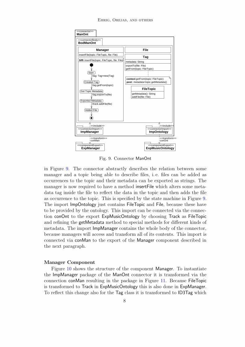
Fig. 9. Connector ManOnt
in Figure 9. The connector abstractly describes the relation between somemanager and a topic being able to describe files, i. e. files can be added asoccurrences to the topic and their metadata can be exported as strings. Themanager is now required to have a method insertFile which alters some meta-data tag inside the file to reflect the data in the topic and then adds the fileas occurrence to the topic. This is specified by the state machine in Figure 9.The import ImpOntology just contains FileTopic and File, because these haveto be provided by the ontology. This import can be connected via the connec-tion conOnt to the export ExpMusicOntology by choosing Track as FileTopic
and refining the getMetadata method to special methods for different kinds ofmetadata. The import ImpManager contains the whole body of the connector,because managers will access and transform all of its contents. This import isconnected via conMan to the export of the Manager component described inthe next paragraph.
Manager Component
Figure 10 shows the structure of the component Manager. To instantiatethe ImpManager package of the ManOnt connector it is transformed via theconnection conMan resulting in the package in Figure 11. Because FileTopic
is transformed to Track in ExpMusicOntology this is also done in ExpManager.To reflect this change also for the Tag class it is transformed to ID3Tag which
8

Ehrig, Orejas, and others
FileManager
<<transform>>
<<componentExport>>
<<component>>Manager
<<componentBody>>BodManager
ExpManager
Fig. 10. Component Manager
File
getURI(): String
ID3Tag
title: Stringperformer: Stringcomposer: Stringalbum: String
importFrom(file: File)exportTo(file: File)
<<componentExport>>ExpManager
sm insertMP3(track: Track, file: File)
Created Tag
Start
Got Topic Metadata
Exported Metadata
Added File
getName(): StringgetPerformer(): StringgetComposer(): StringgetAlbum(): StringgetPath(): StringgetFilename(): String
Track
addMP3File(file: File)
Manager
insertMP3(track: Track, file: File)
post:context getFrom(track: Track)
title=track.getName()
composer=track.getComposer()performer=track.getPerformer()
/tag.exportTo(file)
album=track.getAlbum()
/tag: ID3Tag=new(ID3Tag)
/track.addMP3File(file)
getFrom(track: Track)/tag.getFrom(track)
Fig. 11. Export package ExpManager
represents the metadata in ID3 tags of MP3 files. The export is then furthertransformed to the FileManager package in BodManager shown in Figure 12.In this body the requirement of a canonicalized hierarchy of media files isadditionally considered by adding a Directory class and a move method forfiles and enriching the state machine for insertFile.
Detailed Architecture of the Example
With these components we obtain the detailed architecture of the systemshown in Figure 13. This detailed architecture corresponds to the architecturediagram as defined in the generic architecture framework in Section 3.
In oder to define the semantics of the architecture in Figure 13 the architec-ture framework demands in Section 4 the ability to flatten such architectures.This is done by applying all transformations simultaneously to get one globalbody and then forget the connectors and connected exports which is justi-fied by Theorem 3.11. The instantiation of this requirement to UML will be
9

Ehrig, Orejas, and others
Manager
insertMP3(track: Track, file: File)
getFilename(): String
Track
addMP3File(file: File)
root1
mkpath(path: String): Directory
Directory
FileManager
ID3Tag
title: Stringperformer: Stringcomposer: Stringalbum: String
importFrom(file: File)exportTo(file: File)
move(dest: Directory, name: String)
File
getURI(): String
sm insertMP3(track: Track, file: File)
Created Tag
Start
Got Topic Metadata
Exported Metadata
Created Directory
Moved File
Added File
getName(): StringgetPerformer(): StringgetComposer(): StringgetAlbum(): StringgetPath(): String
context getFrom(track: Track)title=track.getName()performer=track.getPerformer()composer=track.getComposer()
/tag.exportTo(file)
album=track.getAlbum()/track.addMP3File(file)
/file.move(dir, track.getFilename())
/dir: Directory=root.mkpath(track.getPath())
getFrom(track: Track)
/tag.getFrom(track)
post:
/tag: ID3Tag=new(ID3Tag)
Fig. 12. File management requirements
MusicOntology
<<connectorImport>>ImpServer
<<connectorImport>>ImpSource
<<connectorBody>>BodComDat
<<connectorBody>>BodManOnt
<<connectorImport>>ImpManagerImpOntology
<<connectorImport>>
<<connector>>ManOnt
conSrv<<transform>>
conSrc conMan<<transform>>conOnt
<<transform>>
ExpDataModel
<<component>>Ontology
<<componentExport>>
DataModel
BodOntology<<componentBody>>
HTTPServer
<<component>>Manager
<<componentBody>>BodManager
ExpMusicOntology<<componentExport>> <<componentExport>><<componentExport>>
ExpServer
<<componentBody>>BodServer
<<component>>Server
SrvSrc<<connector>>
ExpManager
FileManager
MetadataSystem<<architecture>>
<<transform>>
Fig. 13. Detailed architecture of the example
discussed in Section 5. Applying this complete reduction to the example ar-chitecture yields the component in Figure 14, where the body is given by thepackages DataModel in Figure 3, MusicOntology in Figure 4, HTTPServer inFigure 8, and FileManager in Figure 12 and the dependencies between theminduced by the usage of classes in the connector bodies. Note that in thiscase we have no export packages left in the resulting component, because all
10

Ehrig, Orejas, and others
HTTPServer DataModel MusicOntology
<<component>>
BodExample<<componentBody>>
FileManager
MetadataSystem
Fig. 14. Architecture semantics of the example
exports have been used by the connectors already.
Such complete reductions of architectures to single components will bedefined as the semantics of architectures in Section 4. But first the genericarchiecture framework itself is formally introduced in the next section.
3 The Generic Architecture Framework
In this section we present a generic framework for connector architectures,which is based on the ideas of our framework presented at FESCA ’04 in [4].The new version in this paper, however, is more flexible, because it allowsoverlapping connector interfaces in contrast to non-overlapping ones in [4].The present framework is generic with respect to several parameters. We usea class of specifications (or models, respectively) and classes of correspondingtransformations and embeddings between specifications (or models) that canbe instantiated to concrete specification (modeling) techniques. We only re-quire the following properties, which have to be ensured by the used concretespecification (modeling) technique, when the framework is instantiated.
• Transfomations are closed under composition, i. e. given two transformationst : SP ⇒ SP ′ and t ′: SP ′ ⇒ SP ′′, then there exists a composed transforma-tion t ′ ◦ t : SP ⇒ SP ′′.
• There is a special identity transformation which is neutral with respect tothe composition of transformations. This means for each specification SPwe have a transformation idSP with t ◦ idSP = t = idSP ′ ◦ t for each trans-formation t : SP ⇒ SP ′.
• Embeddings of specifications have to be closed under composition. Giventwo embeddings e1 : SP1 → SP2 and e2 : SP2 → SP3 , then we require a com-posed embedding e2 ◦ e1 : SP1 → SP3 .
• Analog to the transformations we require identic embeddings idSP withe ◦ idSP = e = idSP ′ ◦ e.
• Finally, we have to require that embeddings are a special case of transfor-mations, such that the identities are compatible.
For these generic notions of transformations and embeddings we require thefollowing extension and parallel extension property.
Definition 3.1 (Extension Property) Given an embedding e: SP → SP1
and a transformation t : SP ⇒ SP ′ as depicted in Figure 15, such that e is
11

Ehrig, Orejas, and others
SP
t
��
e //
(1)
SP1
t1��
SP ′e′
// SP ′1
SP
f
��
e //
(2)
SP1
f1
��
SP ′e′
// SP ′1
Fig. 15. Extension diagrams
SPj
tj��
ej //
(3)
SP
t
��SP ′
j e′
j
// SP ′
SPj
fj
��
ej //
(4j )
SP
f
��SP ′
j e′
j
// SP ′
Fig. 16. Parallel Extension Diagrams
consistent with respect to t. Then there is a canonical extension diagram (1)with embedding e′ and tranformation t1. In the special case of t being alsoan embedding f , we have consistency and a unique mutual extension diagram(2), where f1 extends f via e and e′ extends e via f and (2) commutes.
Note that in diagram (1) we do not require equality of the transforma-tions e′ ◦ t and t1 ◦ e, but only equality of the corresponding domain SP andcodomain SP ′
1 . The above mentioned consistency between embeddings andtransformations is generic in the general framework and can be instantiateddifferently for each instantiation. In order to handle multiple interfaces wewill also need the following parallel extension property.
Definition 3.2 (Parallel Extension Property) Given families of transfor-mations tj : SPj ⇒ SP ′
j and embeddings ej : SPj → SP for indices j in somefinite index set J as shown in Figure 16, such that the family of embeddings(ej)j∈J is consistent with respect to the family of transformations (tj)j∈J ,then there is a canonical parallel extension diagram (3) with embeddings e′jand transformation t, such that:
(i) Parallel extension diagrams are closed under vertical composition.
(ii) If all tj are embeddings fj, then we have consistency, the result t is anembedding f and (4j) commutes for all j ∈ J . If additionally for somek ∈ J all other tj with j ∈ J \ {k} are identities, then (4k) is a mutualextension diagram.
Again, the notion of consistency for a family of embeddings w.r.t. a familyof transformations is generic and can be instantiated differently for differentspecification or modeling techniques. Now we are able to define generic com-ponents and connectors.
Definition 3.3 (Component) A component COMP = (B, (ek)k∈K) is givenby the body B and a family of export interfaces Ek with export transforma-tions ek: Ek ⇒ B for k ∈ K.
12

Ehrig, Orejas, and others
Ijbj //
conj
��
B
Ejk(j)
ejk(j)
��
j∈J
Ejkejk +3 Bi k∈Kj\{k(j)}
CONconj1
v~ uuuu
uuuu
u
uuuu
uuuu
uconjn
(JJ
JJJJ
JJJ
JJJJ
JJJJ
J
COMP j1 · · · COMP jn
Fig. 17. Connector Diagram and Connector Graph
I1b1 //
con1
��
B I2b2oo
con2
��
E1k(1)
�'GG
GGGG
GG
GGGG
GGGG
(1) E2k(2)
w� wwww
wwww
wwww
wwww
E1k+3 B1 = B2
k∈K1\{k(1),k(2)}
I1b1 //
con1
��
B I2b2oo
con2
��
E1k(1)
��
(2) E2k(2)
��
E1k+3 B1 = B2 B1 = B2 E2k
ks
k∈K1\{k(1)} k∈K2\{k(2)}
Fig. 18. Noncircular and circular connector diagrams
Definition 3.4 (Connector) A connector CON = (B, (bj)j∈J) is given bythe body B and a family of import interfaces Ij with body embeddings bj: Ij →B for j ∈ J .
Next, we define formally how a connector connects different components.
Definition 3.5 (Connector Diagram and Graph) Given a connectorCON = (B, (bj)j∈J) of arity n = |J | and for each j ∈ J a componentCOMPj = (Bj, (ejk)k∈Kj
) with a connector transformation conj: Ij ⇒ Ejk(j)
with k(j) ∈ K(j), such that (bj)j∈J is consistent with respect to (ejk(j) ◦conj)j∈J , then we obtain the connector diagram in Figure 17 and the connec-tor graph in Figure 17, where the following conditions have to hold:
• A connector diagram consists of n import interface nodes Ij of n + 1 bodynodes Bj and B, and of
∑j∈J |Kj| export interface nodes Ejk, even if some
of the specifications may be equal, e.g. B1 = B2.
• Circular connections as in (2) of Figure 18 are forbidden, unless we dupli-cate the body as in (1) of Figure 18. Otherwise the semantics of such acircular architecture is not defined, as it would cause the identification ofthe export interfaces E1k(1) and E1k(2) of component COMP1 or other kindsof unwanted side effects.
• Note that the interfaces bj: Ij → B for the connector are not required to bedisjoint, but they are allowed to overlap.
Next, we carry the concept of overlapping connector interfaces forward towhole architectures of components and connectors. Similarly to connectors we
13

Ehrig, Orejas, and others
obtain an architecture diagram and an architecture graph. The first describesthe architecture at the level of specifications and the second as a graph, wherenodes are connectors or components.
Definition 3.6 (Architecture diagram) An architecture diagram DA ofarity (k, l) is a diagram built up from the l connector diagrams, the k com-ponent diagrams, and the connection transformations satisfying the followingconditions
(i) Connector Condition: Each import interface I of a connector is connectedby an arrow, labeled with a connection transformation con : I ⇒ E, toexactly one export interface E of one component.
(ii) Component Condition: Each export interface E of a component is con-nected at most to one import interface I of a connector by an arrow fromI to E, labeled with a connection transformation con : I ⇒ E.
(iii) Noncircularity: The architecture diagram DA is connected and noncir-cular aside from the arrows’ direction.
In order to depict whole architectures clearer, we introduce the notion ofarchitecture graphs next, which abstracts from the direct interface connectionsand only reveals, which components are connected by which connectors.
Definition 3.7 (Architecture graph) An architecture graph GA for an ar-chitecture diagram DA is obtained by shrinking each connector diagram inDA to the corresponding connector graph. Hence, it consists of nodes labeledby the connectors and components and arrows in between labeled with thecorresponding connection transformations.
Definition 3.8 (Architecture) An architecture A of arity (k, l) consists of k
components and l connectors, an architecture diagram DA and an architecturegraph GA.
Definition 3.9 (Component Composition) The composition by a connec-tor with index set J is defined as follows: Given the corresponding connectordiagram (see Figure 17) we construct the parallel extension diagram (1) inFigure 19. The result of the composition of the components (COMP j)j∈J bythe connector CON with the connection transformations (con j)j∈J is again acomponent COMP = (B ′, (e′jk: Ejk ⇒ B′)(j,k)∈J⊗K) with J ⊗K = { (j, k) | j ∈J, k ∈ Kj \ {k(j)} } and e′jk := b′j ◦ ejk for all (j, k) ∈ J ⊗ K. In this casewe say that e′jk are extensions of ejk (See Figure 19). In case of binarycomponents and binary connectors we use the following nice infix notationCOMP = COMP1 +CON COMP2 . Otherwise we use the notation
COMP = CON ((COMPj )j∈J , (conj )j∈J ) .
The next theorem states, that the result of two overlapping compositionsvia two connectors is independent of the order the sinlge compositions arecalculated.
14

Ehrig, Orejas, and others
j∈J Ij
conj
��
bj // B
k∈Kj\{k(j)} Ejk(j)
ejk(j)
��Ejk ejk
+3 Bj
Ij
tj=ejk(j)◦conj
��
bj // B
t
��
(1)
Bj
b′
j // B′(j,k)∈J⊗K
Ejke′
jk
+3 B′
Fig. 19. Composition
CONconj
u} rrrrrrrrrr
rrrrrrrrrrconjc
%-RRRRRRRRRRRRR
RRRRRRRRRRRRR
j∈J\{jc}
CON ′
con′
kc
qy lllllllllllll
lllllllllllllcon′
k
"*LLLLLLLLLL
LLLLLLLLLL
k∈K\{kc}
COMPj. . . COMPjc
= COMP ′kc
. . . COMP ′k
Fig. 20. General connectors and components
Theorem 3.10 (Compatibility of Component Composition) Givenan architecture A with arbitrary components and two connectors with the ar-chitecture graph GA in Figure 20, then we have the equality of the followingthree expressions:
(E1) CON ((COMPj )j∈J\{jc},CON ′((COMP ′k)k∈K ))
(E2) CON ′(CON (COMPj∈J ), (COMP ′k)k∈K\{kc})
(E3) CON + CON ′((COMPj )j∈J , (COMPk)k∈K )
where (E1) and (E2) are different sequential compositions and (E3) is a par-allel composition of the components via the two connectors.
In the following we consider the special case of binary connectors andcomponents with two export interfaces each. The proof of this special caseshows how to use the extension and the parallel extension property and canbe extended without problems to the general case of Theorem 3.10 which isneeded in the proof of Theorem 4.5.
Theorem 3.11 (Associativity of Binary Component Composition)Given an architecture A with binary components and binary connectors withthe architecture graph GA in Figure 21, then we have the following associativitylaw:
(E1) (COMP1 +CON1COMP2 ) +CON2
COMP3 =
(E2) COMP1 +CON1(COMP2 +CON2
COMP3 ) =
(E3) COMP1 +CON1COMP2 +CON2
COMP3 ,
where the last expression corresponds to a parallel composition explained below.
Proof. Let us consider the architecture diagram DA in Figure 22 correspond-ing to the architecture graph GA given above. We first present the parallel
15

Ehrig, Orejas, and others
CON1
t| qqqqqqqqqq
"*MMMMM
MMMMMCON3
t| qqqqqqqqqq
"*MMMMM
MMMMM
COMP1 COMP2 COMP3
Fig. 21. Binary connectors and components (GA)
I11b11 //
con11
��
B1 I12b12oo
con12
��
I21b21 //
con21
��
B2 I22b22oo
con22
��
E2
e23
��
E3
e34�"
>>>>
>>>
>>>>
>>>
E4
e44|� �
����
��
����
���
E5
e55
��E1 e13
+3 B3 B4 B5 E6e65ks
Fig. 22. Architecture diagram DA
I11//
con11
��
B1
t1
��
I12oo
con12
��
I21//
con21
��(2)
B2
t2
��
(3)
I22oo
con22
��
E2
��
E3
�"==
====
=
====
===
E4
|� ���
����
����
���
E5
��
E1e13 +3 B3
b0 // B′1
b′
3&&MMMMMMMMMMMMM B4
b′
1oob′
2 //
(1)
B′2
b′
4xxqqqqqqqqqqqqq
B5b5oo E6
e65ks
B′4
Fig. 23. Parallel composition
composition corresponding to the result of expression (E3). Note, that theembeddings (b11, b12) are consistent w. r. t. the transformations (e23 ◦ con11 ,
e34 ◦ con12 ) according to the definition of connector diagrams (see Defini-tion 3.5), which allows to construct the parallel extension diagram in theleft part of Figure 23 with transformation t1: B1 ⇒ B′
1 and embeddingsb0: B3 → B′
1 and b′1: B4 → B′1. For similar reasons we obtain the parallel ex-
tension diagram in the right part of Figure 23 with transformation t2: B2 ⇒ B′2
and embeddings b′2: B4 → B5 and b5: B5 → B′2. From the embeddings b′1 and
b′2 we construct the mutual extension diagram (1) in Figure 23, where we donot need an additional consistency condition by the extension property (seeDefinition 3.1). The composition (COMP1 +CON1
COMP2 ) +CON2COMP3 in
expression (E1) corresponds to the diagram in Figure 24, where the result of
COMP1 +CON1COMP2 is given by (B′
1, E1 ⇒ B3b0→ B′
1, E4 ⇒ B4
b′
1→ B′1) by
Definition 3.9. Now we consider in Figure 24 the same parallel extension dia-gram (2,3) as above in Figure 23 and a new one by (4,5) according to part (ii) ofthe parallel extension property (see Definition 3.2). Using part (i) the verticalcomposition property implies that (2+4, 3+5) is a parallel extension diagramleading to the bottom line in Figure 24 as result of expression (E1). But (4,5)
16
Ehrig, Orejas, and others
I21//
con21
��(2)
B2
t2
��
(3)
I22oo
con22
��
E4
��
E5
��
B4b′
2 //
b′
1
��
(4)
B′2
b4��
(5)
B5b5oo
id5
��
E6e65ks
E1e13 +3 B3
b0 // B′1 b3
// B+2 B5b′
5
oo E6e65ks
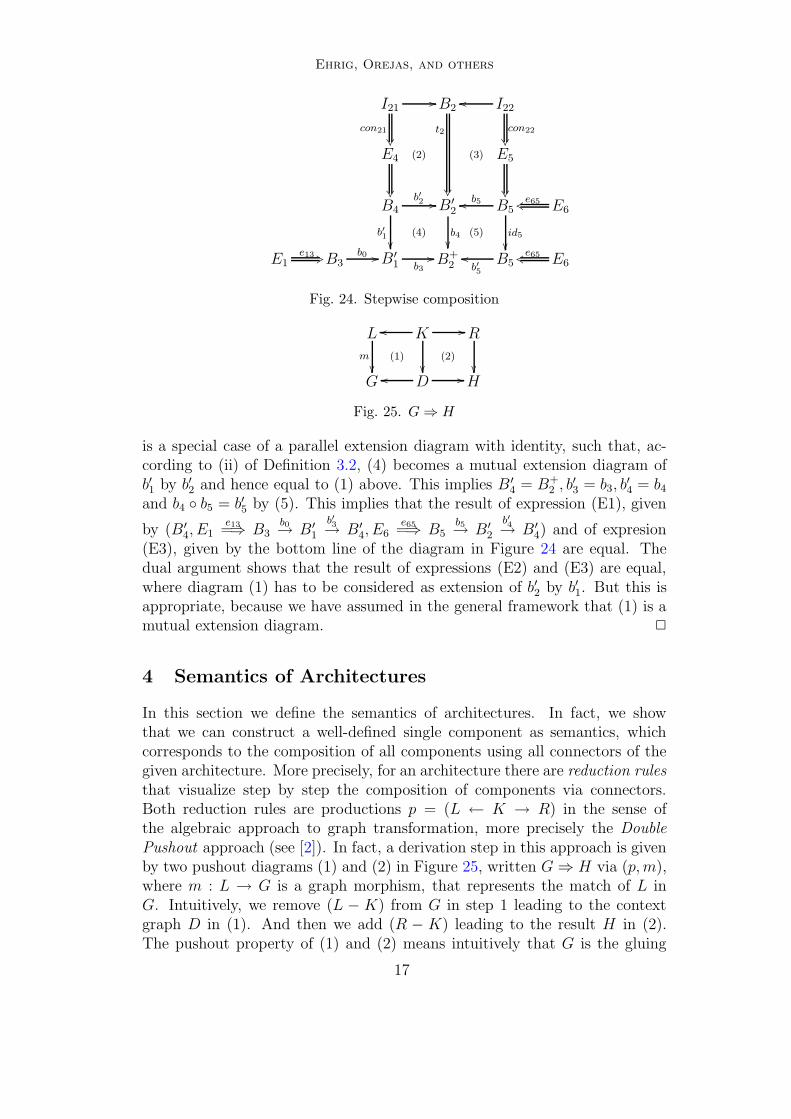
Fig. 24. Stepwise composition
L
m
��(1)
K
��
oo //
(2)
R
��
G Doo // H
Fig. 25. G⇒ H
is a special case of a parallel extension diagram with identity, such that, ac-cording to (ii) of Definition 3.2, (4) becomes a mutual extension diagram ofb′1 by b′2 and hence equal to (1) above. This implies B ′
4 = B+2 , b′3 = b3, b
′4 = b4
and b4 ◦ b5 = b′5 by (5). This implies that the result of expression (E1), given
by (B′4, E1
e13=⇒ B3b0→ B′
1
b′
3→ B′4, E6
e65=⇒ B5b5→ B′
2
b′
4→ B′4) and of expresion
(E3), given by the bottom line of the diagram in Figure 24 are equal. Thedual argument shows that the result of expressions (E2) and (E3) are equal,where diagram (1) has to be considered as extension of b′2 by b′1. But this isappropriate, because we have assumed in the general framework that (1) is amutual extension diagram. 2
4 Semantics of Architectures
In this section we define the semantics of architectures. In fact, we showthat we can construct a well-defined single component as semantics, whichcorresponds to the composition of all components using all connectors of thegiven architecture. More precisely, for an architecture there are reduction rulesthat visualize step by step the composition of components via connectors.Both reduction rules are productions p = (L ← K → R) in the sense ofthe algebraic approach to graph transformation, more precisely the DoublePushout approach (see [2]). In fact, a derivation step in this approach is givenby two pushout diagrams (1) and (2) in Figure 25, written G⇒ H via (p, m),where m : L → G is a graph morphism, that represents the match of L inG. Intuitively, we remove (L − K) from G in step 1 leading to the contextgraph D in (1). And then we add (R − K) leading to the result H in (2).The pushout property of (1) and (2) means intuitively that G is the gluing
17

Ehrig, Orejas, and others
CON D :
Ijbj //
conj
��
B
Ejk(j)
ejk(j)
��
j∈J
Ejkejk +3 Bi k∈Kj\{k(j)} Ejk Ejk
e′
jk +3 B′
lDoo^^^^^ rD //
Fig. 26. Diagram reduction rule
CON G :
CONcon1
v~ uuuu
uuuu
u
uuuu
uuuu
uconn
(II
IIII
III
IIII
IIII
I
COMP 1 · · · COMPn COMP 1 · · · COMPn COMP
lGoo____ rG //____
Fig. 27. Graph reduction rule
of D and L along K in (1), and H is the gluing of D and R along K in (2),respectively.
Definition 4.1 (Diagram Reduction Rule) Given an architecture A withthe architecture diagram DA there is for each connector CON the diagramreduction rule COND , as depicted in Figure 26, where B′ and e′jk = b′j ◦ ejk isdefined by the composition:
COMP =CON ((COMPj )j∈J , (conj )j∈J )
= (B′, (e′jk: Ejk ⇒ B′)(j,k)∈J⊗K)
Definition 4.2 (Graph Reduction Rule) Given an architecture A with thethe architecture graph GA. The corresponding graph reduction rule CON G isshown in Figure 27, where COMP1, . . . ,COMPn are mapped to COMP .
A reduction step CON D: DA ⇒ DA′ and CON G: GA ⇒ GA′, respectively,is given by a derivation step in the Double Pushout approach to graph trans-formations at the level of architecture diagrams or architecture graphs, re-spectively. For both derivation steps we have inclusions for the matches. Notethat rG is neither injective nor label-preserving, nevertheless for the reductionrule CON G: GA ⇒ GA′ the labels of G′
A are well-defined by GA and COMP .
Definition 4.3 (Architecture Reduction Rule) An architecture reductionrule for a given architecture A is a tuple CON = (COND ,CONG) given by adiagram reduction rule COND for the architecture diagram DA and a corre-sponding graph reduction rule CONG for the architecure graph GA.
We can show by an Architecture Reduction Lemma that an architecturereduction rule CON = (COND ,CONG) reduces an architecture A to a well-
18
Ehrig, Orejas, and others
defined smaller architecture A′ with DA′ and GA′ as defined above. The appli-
cation of CON is denoted by ACON=⇒ A′. A′ is smaller than A in the following
sense: If A is of arity (k, l) we can show that A′ is of arity (k − n + 1, l − 1),if CON has arity n.
Given an architecture A consisting of k components and l connectors and acorresponding architecture reduction rule CON = (COND ,CONG) we obtainreductions COND : DA ⇒ DA′, CONG : GA ⇒ GA′ and CON : A⇒ A′, wehreA′ is a new architecture with k−n+1 components, l−1 connectors, architecturediagram DA′ and architecture graph GA′.
The corresponding proof will be presented in [5]. Now we can give the se-mantics of an architecture as the result of as many reduction rules as possible.
Definition 4.4 (Architecure semantics) The semantics of an architectueA is any component COMP obtained by a sequence of architecture reductionsteps from A to COMP ,
A⇒∗ COMP .
The main result given in Theorem 4.5 shows that this semantics alwaysexists and is unique.
Theorem 4.5 (Exist. and Uniqueness of Architecture Semantics)For each architecture A there is a unique component COMP which is the se-mantics of A. COMP is obtained by any reduction sequence, where connectorsof A are reduced in arbitrary order:
A⇒∗ COMP
Proof Idea. This theorem uses the fact that the presented reduction rulessatisfy the Church-Rosser property, i. e. the result of a sequence of reductionsteps is independent from the order of the steps. This can be shown usinga well known local Church-Rosser property for independent graph transfor-mations (see [2]), which are independent reduction steps in our case. For thecase of dependent reduction steps we need Theorem 3.10. The result of thereduction sequence is well-defined and unique, since the maximal number ofnecessary reduction steps is given by the number of connectors and the orderof calculation is not relevant. 2
The full proof of this theorem will be given in the report [5].
5 Instantiation to UML 2.0 Models
In this section we will show, how the abstract connector framework can beapplied to UML diagrams. In this paper, we regard only the concrete graphicalrepresentation of UML diagrams on a more or less intuitive level. This impliesthat also our instantiation can be given only on an intuitive level. In laterstages of our research we want to deal with the corresponding meta-model
19

Ehrig, Orejas, and others
instances as formal abstract syntax, which would enable us to a much moredetailed definition of connector architectures for UML diagrams. Moreover,we could respect the syntactical dependencies between different diagrams, e. g.the case that a statemachine refers to a certain method defined in the classdiagram, which are documented in the UML meta-model instances.
5.1 Transformations and Embeddings of UML Diagrams
We will consider (restricted versions) of the following diagram types: classdiagrams, state machines and sequence diagrams. For a definition of thesediagrams we refer to UML 2.0 (see [14]).
We allow to attach state machines to classes only. This implies that eachstate machine SM refers to a corresponding class diagram cd(SM ) definingthe methods that can be used to label transitions. A sequence diagram SD isalso attached to some class diagram cd(SD) defining the classes for all objectnodes and the methods used by the message edges. In the first step of theinstantiation we will define transformations and embeddings for each of ourtechniques. In the case study in Section 2 these two notions of connectionsbetween UML specifications are referred to as package dependency relationsstereotyped by <<transform>>, <<include>>, respectively.
• A transformation of class diagrams tCD : CD ⇒ CD ′ is given by a mappingof each class cd ∈ CD to a class cd ′ ∈ CD ′, where the image cd ′ has to offerat least the functionality of cd up to consistent signature renaming. Thismeans for example, that an attribute number : Nat of CD may be translatedto an attribute number : Int , if all other occurrences of number : Nat in theclass diagram CD are translated to number : Int . Of course, the imagesof the classes are allowed to have additional functionality with respect totheir preimage. All connections between classes have to be transformed tocorresponding connections of the same type, e. g. associations have to bemapped to associations. Again we allow a renaming of the inscriptions ofthe connections.
• A transformation of a state machine tSM : SM ⇒ SM ′ requires a transfor-mation of the related class diagram first. This transformation is used totranslate the labels of the transitions of the state machine. For each statest ∈ SM we require an image st ′ ∈ SM ′, which maybe renamed. This con-dition is also required for the state transitions, whose labels have to betransformed in accordance with the transformation of the related class di-agram. We allow that the target state machine SM ′ adds new states andtransitions, but we require that all accepted traces of SM are also acceptedby the ’enriched’ state machine SM ′, after they have been translated ac-cording to the class diagram transformation.
• In the case of sequence diagrams, we consider transformations of sets ofdiagrams (where each of them represent a possible scenario) instead of singleones. Transformations tSD : SD ⇒ SD ′ are defined in three steps. First, as
20

Ehrig, Orejas, and others
<<transform>>
S2S1
a
b
S2S1
c
d
c
sm SM
sm SM’
Model A
a():b():
Class A
Model B
c():d():
Class B
Fig. 28. Sample Transformation of State Machine and Class Diagram
in the previous case, a transformation of the related class diagram is neededto translate the labels of the interactions in the diagram. The second stepis to replace lifelines by disjoint sets of lifelines (including the given lifeline)and interactions (l, m, l′) (where l and l′ are lifelines and m is a messagesent from l to l′) by sets of diagrams involving only the lifelines included inthe refinements of l and l′. Finally, each diagram in SD must be includedin a diagram in SD ′.
The idea is that when refining a sequence diagram, we may refine lifelinesand interactions. In particular, the refinement of a lifeline may involve otherlifelines which are considered hidden at a higher level of abstraction. Onthe other hand, a simple interaction may be replaced by a more complexinteraction represented by a set of diagrams.
Now we define embeddings of class diagrams, state machines and sequencediagrams. For sake of simplicity embeddings are inclusions in this paper, whichdo not allow any renamings. Thus, we are enabled to define the followingextension constructions as unions of sets. In both cases, embeddings andtransformations, the target diagram is allowed to have additional elements.
Figure 28 shows a transformation of a state machine SM and the relatedclass diagram cd(SM ) = CD . The transformation of the methods in the sam-ple class, which is not shown explicitly in the figure, renames the methods a():to c(): and b(): to d():. Since there are no designated final states, the statemachine SM accepts (ab)∗, (ab)∗a. This is translated along the transforma-tion to (cd)∗, (cd)∗c, which is a part of the accepted traces of SM ′. Thus, thissample transformation fulfills our requirements for diagram transformationsstated above.
21

Ehrig, Orejas, and others
CD
tCD
��
e // CD1
tCD,1
��
CD ′e′
// CD ′1
Fig. 29. Extension of Class Diagram Transformations
5.2 Extension of Diagram Transformations
In the next step of the instantiation we have to verify the extension prop-erty (see Definition 3.1), i. e. to define the extension of transformations alongembeddings.
• For class diagrams consider Figure 29, where three class diagrams CD , CD ′
and CD1 are given, connected by a transformation tCD : CD ⇒ CD ′ and
an embedding e: CD → CD1 . The transformation arrows CDtCD=⇒ CD ′ and
CD1
tCD,1
=⇒ CD ′1 in Figure 29 represent a UML dependency relation of the
corresponding packages which is stereotyped as <<transform>>.The extension of tCD along e as depicted in Figure 29 is now constructed
as follows: We define CD ′1 by adding CD1 without CD, written CD1 \ CD ,
to the result CD ′ of the transformation tCD . Note that CD1 \ CD is con-structed by removing all classes and class relations from CD1 that are alsopart of CD and thus, embedded by e. This may cause ill formed class rela-tions since their targets might have been removed. The well-formedness isrestored in CD ′
1 , since the loose ends of the class relations are connected tothe tCD images of the deleted classes.
We obtain the extension tCD ,1 , because the elements of CD1 are eitherdirectly included to CD ′
1 or their renamed versions are taken from CD ′.By taking the renaming of the latter elements and the identical embeddingof the former we can construct a renaming transformation. Moreover, weobtain the embedding e ′: CD ′ → CD ′
1 , since CD ′ is a part of CD ′1 .
Note that the construction as described above does only work, if we donot have any name clashes between CD1 \ CD and CD ′. We could drop thisconstraint by defining the construction of CD ′
1 by a pushout construction,which avoids name clashes by suitable renaming.
• The extension of state machine transformations works analogous. Giventhree state machines SM , SM ′, and SM1 connected by a transformationtSM : SM ⇒ SM ′ and an embedding s: SM → SM1 . Since we required re-lated class diagrams for the statemachines we can calculate the correspond-ing class diagram extension. Then we add SM1 \ SM to SM ′. This con-struction ensures that SM ′
1 accepts all valid traces of SM1 , because notransitions are deleted.
• In the case of sets of sequence diagrams, we consider that a set SD isembedded in SD ′ if every diagram in SD is included in some diagram in SD ′.Now, if SD is embedded in SD1 and tSD : SD ⇒ SD ′ is a transformation, wedefine the extension tSD ,1 : SD ⇒ SD ′
1 as follows. First, we replace all the
22
Ehrig, Orejas, and others
<<include>>
<<include>>
S2S1
a
b
S2S1
c
d
c
sm SM
sm SM’
S2S1
a
b
sm SM1
sm SM1’
S2S1
c
e
e
e()succ(x: nat): nat
Model A
Model B
Model A1
Model B1
a():b():
Class A
c():
Class B
d():add(x,y: nat): nat
a():
Class A
c():d():
Class B
b():
c
d
e()succ(x: nat): natadd(x,y: nat): nat
<<transform>><<transform>>
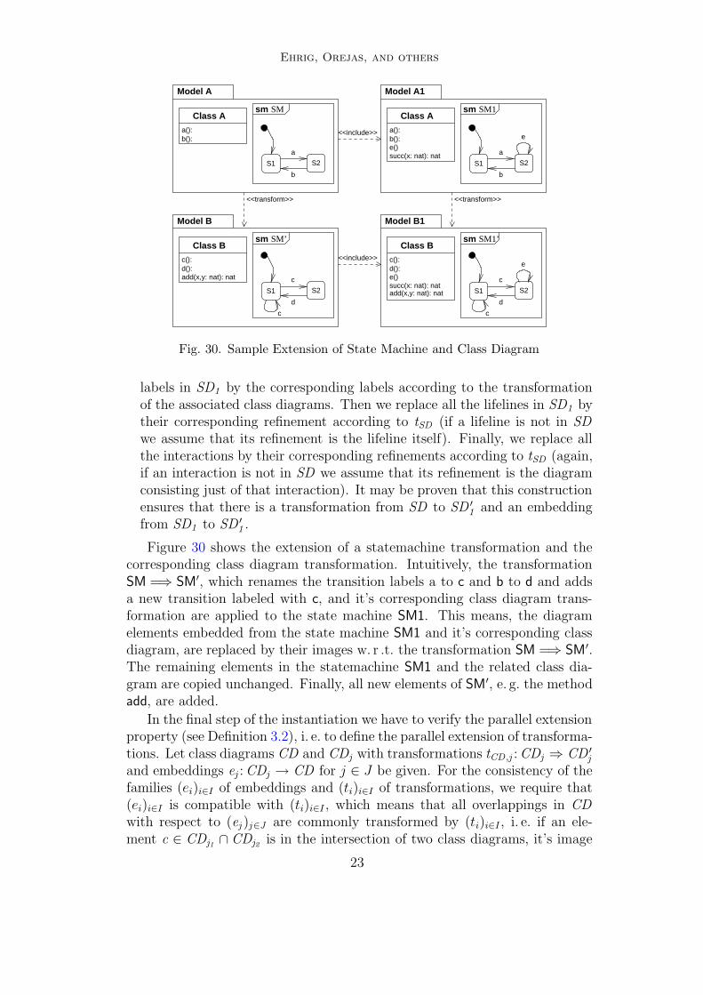
Fig. 30. Sample Extension of State Machine and Class Diagram
labels in SD1 by the corresponding labels according to the transformationof the associated class diagrams. Then we replace all the lifelines in SD1 bytheir corresponding refinement according to tSD (if a lifeline is not in SDwe assume that its refinement is the lifeline itself). Finally, we replace allthe interactions by their corresponding refinements according to tSD (again,if an interaction is not in SD we assume that its refinement is the diagramconsisting just of that interaction). It may be proven that this constructionensures that there is a transformation from SD to SD ′
1 and an embeddingfrom SD1 to SD ′
1 .
Figure 30 shows the extension of a statemachine transformation and thecorresponding class diagram transformation. Intuitively, the transformationSM =⇒ SM′, which renames the transition labels a to c and b to d and addsa new transition labeled with c, and it’s corresponding class diagram trans-formation are applied to the state machine SM1. This means, the diagramelements embedded from the state machine SM1 and it’s corresponding classdiagram, are replaced by their images w. r .t. the transformation SM =⇒ SM′.The remaining elements in the statemachine SM1 and the related class dia-gram are copied unchanged. Finally, all new elements of SM′, e. g. the methodadd, are added.
In the final step of the instantiation we have to verify the parallel extensionproperty (see Definition 3.2), i. e. to define the parallel extension of transforma-tions. Let class diagrams CD and CDj with transformations tCD ,j : CDj ⇒ CD ′
j
and embeddings ej : CDj → CD for j ∈ J be given. For the consistency of thefamilies (ei)i∈I of embeddings and (ti)i∈I of transformations, we require that(ei)i∈I is compatible with (ti)i∈I , which means that all overlappings in CDwith respect to (ej )j∈J are commonly transformed by (ti)i∈I , i. e. if an ele-ment c ∈ CDj1 ∩ CDj2 is in the intersection of two class diagrams, it’s image
23

Ehrig, Orejas, and others
CDj
tCD,j
��
ej // CD
tCD
��CD ′
j e′
j
// CD ′
Fig. 31. Parallel Extension of Class Diagrams
with respect to both transformations, tCD ,j1 and tCD ,j2 , has to be the same inCD ′
j1∩ CD ′
j2.
The result CD ′ of the parallel transformation tCD is constructed as follows.First, we join all CD ′
j for j ∈ J to a single class diagram. In the next step weadd CD \
⋃
j∈J
CDj to the previous result.
The parallel transformation tCD is then defined as follows. If an elementc is an image of any cj ∈ CDj then select the image of cj with respect to thetransformation tj. This selection is well defined since we required commontransformations of the overlappings. Otherwise, i. e. there is no cj ∈ CDj withej(cj) = c, c remains unchanged by the constructed parallel transformationtCD . The embeddings e′j for j ∈ J are directly induced by the constructionof CD ′.
In order to avoid name clashes in CD ′ we require that CD \⋃
j∈J
CDj is
disjoint to⋃
j∈J
CD ′j . As discussed above, this could be avoided by constructing
CD ′ by a suitable colimit construction.
The parallel extension property of statemachines and sequence diagramsis verified in a similar way.
Summarizing we obtain the following result.
Fact 5.1 (Architecture Framework for UML 2.0 Models) Restrictedclass diagrams, state machines and sequence diagrams as considered abovetogether with the corresponding notions of transformations and embeddingsare satisfying the extension property (Definition 3.1) and the parallel extensionproperty (Definition 3.2) of the generic architecture framework in Section 3.
Proof Idea. The construction of extension and parallel extension diagramshas been discussed already above. It remains to show the properties. First ofall, all embeddings preserve the type of the diagram elements and they do notchange any inscriptions. Hence, they are special cases of the defined transfor-mations. Embeddings and transformation are closed under composition andthe extension diagram of two embeddings e : SP → SP1 and f : SP → SP ′
(with SP1 ∩ SP ′ = SP for the simplified construction) is given by the unionSP ′
1 = SP1 ∪ SP ′ and embeddings e ′ : SP ′ → SP ′1 and f ′′ : SP1 → SP ′
1 , whichleads to a mutual extension diagram. The construction of parallel extensiondiagrams above implies that they are closed under vertical composition. More-over, if all transformations ti are embeddings, then also t is an embedding andif in addition all t2, . . . , tn are identities, then 31 in Figure 15 is a mutual
24

Ehrig, Orejas, and others
extension diagram, because embeddings are diagram inclusions and do notmerge any elements (and they do not change any inscriptions in our simplifiedversion). 2
This allows to apply the generic architecture framework to UML 2.0 mod-els, leading to the concept of components, connectors and architecture dia-grams and graphs, architectures, component composition and semantics ofarchitectures as presented in Sections 3 and 4 for UML 2.0 models. Espe-cially, we obtain the main results “Compatibility of Component Composi-tion”(Theorem 3.10) and “Existence and Uniqueness of Architecture Seman-tics”(Theorem 4.5) for the UML 2.0 models considered above.
6 Conclusion
In this paper we have presented object-oriented connector-component archi-tectures of a subset of UML 2.0 diagrams. More precisely, we have extendedour generic framework for connector architectures presented at FESCA ’04 (see[4]) to the case of overlapping connector interfaces which allows to apply itto class diagrams, statemachines and sequence diagrams with suitable restric-tions. In the extended general framework we are able to show as main resultcompatibility of component composition as well as existence and uniquenessof architecture semantics. The third main result shows that this frameworkcan be instantiated to UML 2.0 diagrams as discussed above using suitablenotions of transformations and embeddings. This allows to apply the genericresults to to these UML 2.0 diagrams in general and to an object-orientedconnector-component architecture for a metadata management system as acase study in this paper.
The component concept of the UML 2.0, as well as most programminglanguage oriented component approaches, is orthogonal to our approach inthe following sense. In contrast to our approach, UML 2.0 components as pre-sented in [14] are intended to describe the distribution of executable programpieces. Our approach is concerned with the structuring of the specification ofsystem requirements and system design. Thus, each of our components mightbe realized by a set of these software components. Though it might be pos-sible to understand UML 2.0 components as a special case of our approach.The further examination of this relation would yield a formal foundation forseveral parts and application scenarios of the UML 2.0 component notion.
The approach in this paper is based on an intuitive graphical representationof UML diagrams. In future work we want to deal with the correspondingmeta-model instances as formal abstract syntax, which would allow a muchmore detailed discussion of the instantiation, and we will also consider moregeneral notions of transformations and embeddings. Moreover, it is possibleto consider other UML techniques. Especially with respect to the example inSection 2 it seems senseful to include UML 2.0 profiles to the components.E. g. model the Ontology as class hierarchy in a first step and refine to pre-
25

Ehrig, Orejas, and others
defined instances for a generic topic map API, and finally, use profiles for theplatform-specific Implementation Models).
In view of system evolution, as for example in the sense of [17], it seemspromising to extend the presented framework by means to transform or refine,respectively, not only specifications but whole components and connectors,and thus also by transformations and refinements of component architectures.Refinements of components and connectors can be necessary for different rea-sons. E. g., if a company adds any requirements to their product specificationin the middle of the specification process, the developers might have to adaptcomponent interfaces to meet the new requirements. But component refine-ments should preserve the mutual dependencies with related connectors andconcerned components. Such architecture refinement concepts could also beused to formalize the steps between different stages in a defined software de-velopment process. With respect to the example in Section 2 this could meanto refine the given architecture by an implementation in Java or DotNET.
Acknowledgement
This work is partially supported by the TMR network SEGRAVIS and theSpanish project MAVERISH (TIC2001-2476-C03-01) and by the CIRIT Grupde Recerca Consolidat 2001SGR 00254.
References
[1] Allen, R. and D. Garlan, A formal basis for architectural connection, ACMTransactions on Software Engineering and Methodology (1997).
[2] Ehrig, H., Introduction to the algebraic theory of graph grammars, in: V. Claus,H. Ehrig and G. Rozenberg, editors, 1st Graph Grammar Workshop, LectureNotes in Computer Science 73 (1979), pp. 1–69.
[3] Ehrig, H., F. Orejas, B. Braatz, M. Klein and M. Piirainen, A GenericComponent Concept for System Modeling, in: R.-D. Kutsche and H. Weber,editors, Fundamental Approaches to Software Engineering (FASE 2002),number 2306 in Lecture Notes in Computer Science (2002), pp. 33–48.
[4] Ehrig, H., J. Padberg, B. Braatz, M. Klein, F. Orejas, S. Perez and E. Pino,A Generic Framework for Connector Architectures based on Componentsand Transformations, in: Formal Foundations of Embedded Software andComponent-Based Software Architectures (FESCA), Electronic Notes inTheoretical Computer Science (2004).
[5] Ehrig, H., J. Padberg, B. Braatz, M. Klein, F. Orejas, S. Perez andE. Pino, A Generic Framework for Connector-Component Architectures,Forschungsbericht, Fakultat IV – Elektrotechnik und Informatik, TU Berlin(2005), to appear.
26

Ehrig, Orejas, and others
[6] Garlan, D., R. Monroe and D. Wile, Acme: An Architecture DescriptionInterchange Language, in: Proc. of CASCON’97, 1997, pp. 169–183,http://www.cas.ibm.ca/cascon/cfp.html.
[7] Griffel,F., “Componentware – Konzepte und Techniken eines Softwareparadigmas,”dpunkt Verlag, 1998.
[8] Hofmeister, C., R. Nord and D. Soni, “Describing Software Architecture inUML,” Kluwer Academic Publishers, 1999 pp. 145–159.
[9] International Organization for Standardization, “Topic Maps,” Second edition(2002), ISO/IEC 13250, ISO/IEC JTC 1/SC34 N0322 available fromhttp://www.y12.doe.gov/sgml/sc34/document/0322.htm.
[10] International Organization for Standardization, “The XML Topic Maps Syntax(XTM 1.1),” (2003), ISO/IEC 13250-3, ISO/IEC JTC1/SC34 N0398 availablefrom http://www.y12.doe.gov/sgml/sc34/document/0398.htm.
[11] International Organization for Standardization, “Topic Maps – Data Model,”(2003), ISO/IEC 13250-2, ISO/IEC JTC1/SC34 N0443 available fromhttp://www.y12.doe.gov/sgml/sc34/document/0443.htm.
[12] Internet Engineering Task Force, “Hypertext Transfer Protocol – HTTP/1.1,”(1999), available from http://www.ietf.org/rfc/rfc2616.txt.
[13] Nilsson, M., “ID3 tag version 2.4.0,” id3.org (2000), available fromhttp://www.id3.org/develop.html.
[14] Object Management Group, “Unified Modeling Language – Version 2.0 (UML2.0),” (2004), available from http://www.omg.org/.
[15] Shaw, M., R. Deline, D. V. Klein, T. L. Ross, D. M. Young and G. Zelesnik,Abstractions for Software Architecture and Tools to Support Them, IEEETransactions on Software Engineering 21 (1995), pp. 314–315.
[16] Shaw, M. and D. Garlan, “Software Architecture - Perspectives on an EmergingDiscipline,” Prentice Hall, 1996.
[17] Wermelinger, M. and J. Fiadeiro, A graph transformation approach to softwarearchitecture reconfiguration, Science of Computer Programming 44 (2002),pp. 133–155.
[18] Wermelinger, M. and J. L. Fiadeiro, Connectors for mobile programs, IEEETransactions on Software Engineering 24 (1998), pp. 331–341.
27