A Three-level Component Model in Component Based ...
11
HAL Id: hal-01319811 https://hal.archives-ouvertes.fr/hal-01319811 Submitted on 26 Jun 2016 HAL is a multi-disciplinary open access archive for the deposit and dissemination of sci- entific research documents, whether they are pub- lished or not. The documents may come from teaching and research institutions in France or abroad, or from public or private research centers. L’archive ouverte pluridisciplinaire HAL, est destinée au dépôt et à la diffusion de documents scientifiques de niveau recherche, publiés ou non, émanant des établissements d’enseignement et de recherche français ou étrangers, des laboratoires publics ou privés. A Three-level Component Model in Component Based Software Development Huaxi Yulin Zhang, Lei Zhang, Christelle Urtado, Sylvain Vauttier, Marianne Huchard To cite this version: Huaxi Yulin Zhang, Lei Zhang, Christelle Urtado, Sylvain Vauttier, Marianne Huchard. A Three-level Component Model in Component Based Software Development. ACM SIGPLAN Notices, Association for Computing Machinery (ACM), 2013, 48 (3), pp.70-79. 10.1145/2480361.2371412. hal-01319811
-
Upload
khangminh22 -
Category
Documents
-
view
0 -
download
0
Transcript of A Three-level Component Model in Component Based ...
HAL Id: hal-01319811https://hal.archives-ouvertes.fr/hal-01319811
Submitted on 26 Jun 2016
HAL is a multi-disciplinary open accessarchive for the deposit and dissemination of sci-entific research documents, whether they are pub-lished or not. The documents may come fromteaching and research institutions in France orabroad, or from public or private research centers.
L’archive ouverte pluridisciplinaire HAL, estdestinée au dépôt et à la diffusion de documentsscientifiques de niveau recherche, publiés ou non,émanant des établissements d’enseignement et derecherche français ou étrangers, des laboratoirespublics ou privés.
A Three-level Component Model in Component BasedSoftware Development
Huaxi Yulin Zhang, Lei Zhang, Christelle Urtado, Sylvain Vauttier, MarianneHuchard
To cite this version:Huaxi Yulin Zhang, Lei Zhang, Christelle Urtado, Sylvain Vauttier, Marianne Huchard. A Three-levelComponent Model in Component Based Software Development. ACM SIGPLAN Notices, Associationfor Computing Machinery (ACM), 2013, 48 (3), pp.70-79. �10.1145/2480361.2371412�. �hal-01319811�
A Three-level Component Model in Component BasedSoftware Development
Huaxi (Yulin) ZhangDept. Math/Info
Université Toulouse 2Toulouse, [email protected]
Lei ZhangResearch Center of
AutomationNortheastern University
Shenyang, [email protected]
Christelle UrtadoLGI2P / EMA
Nîmes, FranceChristelle.Urtado@mines-
ales.fr
Sylvain VauttierLGI2P / EMA
Nîmes, FranceSylvain.Vauttier@mines-
ales.fr
Marianne HuchardLirmm, Umr 5506
Cnrs and Univ. Montpellier 2Montpellier, France
ABSTRACTComponent-based development promotes a software devel-opment process that focuses on component reuse. How todescribe a desired component before searching in the repos-itory? How to find an existing component that fulfills therequired functionalities? How to capture the system person-alization based on its constitutive components’ customiza-tion? To answer these questions, this paper claims that com-ponents should be described using three different forms atthree development stages: architecture specification, config-uration and assembly. However, no architecture descriptionlanguage proposes such a detailed description for compo-nents that supports such a three step component-based de-velopment. This paper proposes a three-level Adl, namedDedal, that enables the explicit and separate definitionsof component roles, component classes, and component in-stances.
KeywordsComponent-based development, Software architecture, Ar-chitecture description language
1. INTRODUCTIONComponent-based software development (Cbsd) consists
in two activities: the development of software componentsfor reuse and the development of software applications bycomponent reuse. The first activity can be managed byclassical software development processes, with an analysis,a design and then a coding phase. The produced softwaremodules, encapsulated as component classes, are then stored
Permission to make digital or hard copies of all or part of this work forpersonal or classroom use is granted without fee provided that copies arenot made or distributed for profit or commercial advantage and that copiesbear this notice and the full citation on the first page. To copy otherwise, torepublish, to post on servers or to redistribute to lists, requires prior specificpermission and/or a fee.GPCE’12, September 26–27, 2012, Dresden, Germany.Copyright 2012 ACM 978-1-4503-1129-8/12/09 ...$15.00.
and indexed in repositories to be reused later on. The sec-ond activity corresponds to a more specific and still scarcelystudied development process. We propose an architecture-centric development process that aims at defining the struc-ture of an application as a set of reused components and a setof connections between them, using a dedicated ArchitectureDescription Language (Adl). This process is structured inthree steps, in which architecture definitions are graduallyrefined, from abstract to concrete representations.
1. After a classical analysis step, architecture specifica-tion first captures design decisions as ideal architec-tures imagined by architects to meet the requirements.Specifications do not describe complete component typesbut only component roles (usages). These roles areused to search for matching component classes in repos-itories. Specifications and roles are thus key conceptsto effectively integrate component reuse in the devel-opment process.
2. Architecture configurations are then described to cap-ture implementation decisions, as the architects selectspecific component classes from the repository to im-plement component roles.
3. Finally, architecture assemblies define how componentinstances are created and initialized to customize thedeployment of architectures in different execution con-texts.
Our process is supported by a three-level dedicated Adl,entitled Dedal, which enables the explicit and separate defi-nitions of architecture specifications, configurations and as-semblies. This way, a single abstract architecture definitioncan be refined into many concrete architecture definitions,to foster not only the reuse of components but also of archi-tectures. The refinement relationships between these sep-arate architecture representations — i.e., the relationshipsbetween the component roles, classes and instances they arecomposed of — are proposed to control and verify the globalcoherence of these multi-level architecture definitions.
The remaining of this paper is organized as follows. Sec-tion 2 introduces our proposed architecture-centric, reuse-based development process. Section 3 presents the different
component description levels supported in Dedal, our pro-posed Adl to support this development process. Section 4presents the different architecture description levels whichcan be expressed in Dedal, along with the refinement rela-tions between them. Section 5 introduces the tool suite ofDedal. Section 6 discusses the related works. It studies howexisting Adls are suitable component based software devel-opment. Section 7 concludes with future work directions.
2. SOFTWARE ARCHITECTURES IN CBSD
2.1 A Development Process for Component ReuseCbsd is characterized by its implementation of the “reuse
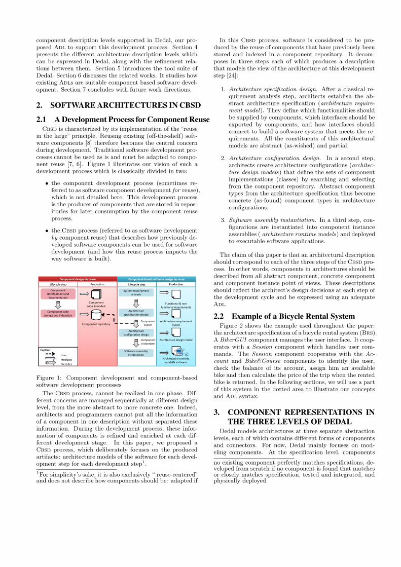
in the large” principle. Reusing existing (off-the-shelf) soft-ware components [8] therefore becomes the central concernduring development. Traditional software development pro-cesses cannot be used as is and must be adapted to compo-nent reuse [7, 6]. Figure 1 illustrates our vision of such adevelopment process which is classically divided in two:
• the component development process (sometimes re-ferred to as software component development for reuse),which is not detailed here. This development processis the producer of components that are stored in repos-itories for later consumption by the component reuseprocess.
• the Cbsd process (referred to as software developmentby component reuse) that describes how previously de-veloped software components can be used for softwaredevelopment (and how this reuse process impacts theway software is built).
Component‐based software design by reuse
Lifecycle step Lifecycle step
Component development and documentation
Component code storage and indexation
Component code & models
Component repository
System requirement analysis
Architecture specification design
Architecture configuration design
Software assembly instantiation
Production
Architecture runtime model& software
Architecture design model
Architecture requirement model
Functional & non functional requirements
Caption:
Component search
Component instantiate
UsesProducesPrecedes
Production
Component design for reuse
Figure 1: Component development and component-basedsoftware development processes
The Cbsd process, cannot be realized in one phase. Dif-ferent concerns are managed sequentially at different designlevel, from the more abstract to more concrete one. Indeed,architects and programmers cannot put all the informationof a component in one description without separated theseinformation. During the development process, these infor-mation of components is refined and enriched at each dif-ferent development stage. In this paper, we proposed aCbsd process, which deliberately focuses on the producedartifacts: architecture models of the software for each devel-opment step for each development step1.
1For simplicity’s sake, it is also exclusively “ reuse-centered”and does not describe how components should be: adapted if
In this Cbsd process, software is considered to be pro-duced by the reuse of components that have previously beenstored and indexed in a component repository. It decom-poses in three steps each of which produces a descriptionthat models the view of the architecture at this developmentstep [24]:
1. Architecture specification design. After a classical re-quirement analysis step, architects establish the ab-stract architecture specification (architecture require-ment model). They define which functionalities shouldbe supplied by components, which interfaces should beexported by components, and how interfaces shouldconnect to build a software system that meets the re-quirements. All the constituents of this architecturalmodels are abstract (as-wished) and partial.
2. Architecture configuration design. In a second step,architects create architecture configurations (architec-ture design models) that define the sets of componentimplementations (classes) by searching and selectingfrom the component repository. Abstract componenttypes from the architecture specification thus becomeconcrete (as-found) component types in architectureconfigurations.
3. Software assembly instantiation. In a third step, con-figurations are instantiated into component instanceassemblies ( architecture runtime models) and deployedto executable software applications.
The claim of this paper is that an architectural descriptionshould correspond to each of the three steps of the Cbsd pro-cess. In other words, components in architectures should bedescribed from all abstract component, concrete componentand component instance point of views. These descriptionsshould reflect the architect’s design decisions at each step ofthe development cycle and be expressed using an adequateAdl.
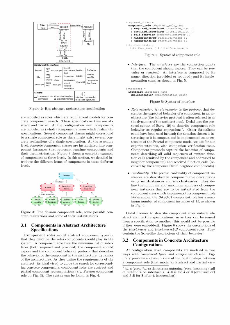
2.2 Example of a Bicycle Rental SystemFigure 2 shows the example used throughout the paper:
the architecture specification of a bicycle rental system (Brs).A BikerGUI component manages the user interface. It coop-erates with a Session component which handles user com-mands. The Session component cooperates with the Ac-count and Bike&Course components to identify the user,check the balance of its account, assign him an availablebike and then calculate the price of the trip when the rentedbike is returned. In the following sections, we will use a partof this system in the dotted area to illustrate our conceptsand Adl syntax.
3. COMPONENT REPRESENTATIONS INTHE THREE LEVELS OF DEDAL
Dedal models architectures at three separate abstractionlevels, each of which contains different forms of componentsand connectors. For now, Dedal mainly focuses on mod-eling components. At the specification level, components
no existing component perfectly matches specifications, de-veloped from scratch if no component is found that matchesor closely matches specification, tested and integrated, andphysically deployed.
6/11/2012
1
:component role :required interface :connection :provided interface
Signatures of the interfaces
AccountOprscheckIDcheckBalancedebit
UQuery findAccount
USave storeAccount
Accountlogin pay
BikefindBrentBreturnB
CourseOprsstartCendC BikeOprs
selectBrentBikerenturnBike
LocOprs findStation
BikeQSfindBikesaveBike
CourseQSQueryCourseSaveCourse
Captions:I
ab
Interface I composed of the a and b signatures
BikerGUI
Session AccountBikeAccountOprs
Bike&Course
AccountDB
Bike&CourseDB
CourseQ
S
BikeQS
UQuery
CourseO
prs
BikeOprs
USave
Account
Figure 2: Brs abstract architecture specification
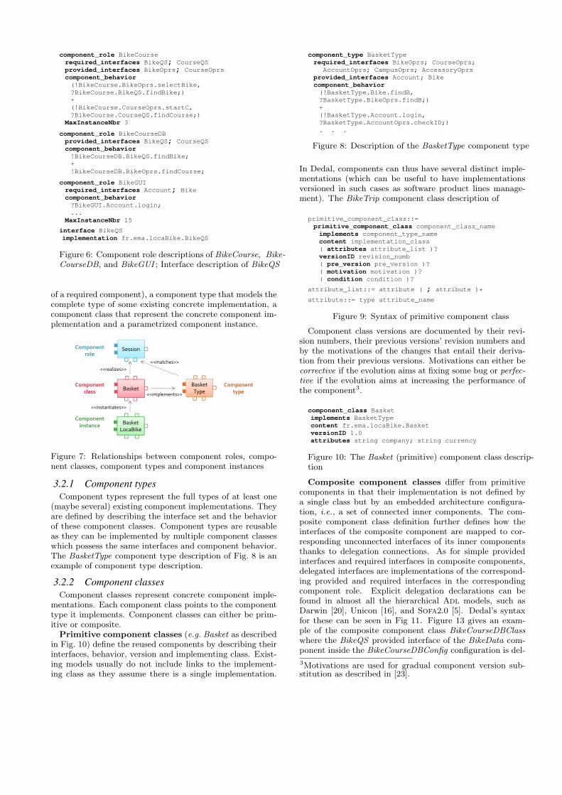
are modeled as roles which are requirement models for con-crete component search. These specifications thus are ab-stract and partial. At the configuration level, componentsare modeled as (whole) component classes which realize thespecifications. Several component classes might correspondto a single component role as there might exist several con-crete realizations of a single specification. At the assemblylevel, concrete component classes are instantiated into com-ponent instances that represent runtime components andtheir parametrization. Figure 3 shows a complete exampleof components at three levels. In this section, we detailed in-troduce the different forms of components in these differentlevels.
6/11/2012
1
Session
Basket Europcar
Persistent Basket
Basket Amazon
Embedded Session
ATM Session
IphoneSession
Basket
Basket LocaBike
<<realizes>>
<<instantiates>>
Figure 3: The Session component role, some possible con-crete realizations and some of their instantiations
3.1 Components in Abstract ArchitectureSpecifications
Component roles model abstract component types inthat they describe the roles components should play in thesystem. A component role lists the minimum list of inter-faces (both required and provided) the component shouldexpose and the component behavior protocol that describesthe behavior of the component in the architecture (dynamicsof the architecture). As they define the requirements of thearchitect (its ideal view) to guide the search for correspond-ing concrete components, component roles are abstract andpartial component representations (e.g. Session componentrole on Fig. 3). The syntax can be found in Fig. 4.
component_role::=component_role component_role_name( required_interfaces interface_list )?( provided_interfaces interface_list )?( role_behavior component_behavior )?( MinInstanceNbr PositiveInteger )?( MaxInstanceNbr PositiveInteger )?
interface_list::=interface_name ( ; interface_name )*
Figure 4: Syntax of component role
• Interface. The interfaces are the connection pointsthat the component should expose. They can be pro-vided or required. An interface is composed by itsname, direction (provided or required) and its imple-mentation class, as shown in Fig. 5.
interface::=interface interface_nameimplementation implementation_class
Figure 5: Syntax of interface
• Role behavior. A role behavior is the protocol that de-scribes the expected behavior of a component in an ar-chitecture (the behavior protocol is often referred to asthe dynamics of the architectures). Dedal uses the pro-tocol syntax of Sofa [19] to describe component rolebehavior as regular expressions2. Other formalismscould have been used instead; the notation chosen is in-teresting as it is compact and is implemented as an ex-tension of the Fractal component model we use for ourexperimentations, with companion verification tools.Component protocols capture the behavior of compo-nents describing all valid sequences of emitted func-tion calls (emitted by the component and addressed toneighbor components) and received function calls (re-ceived by the component from neighbor components).
• Cardinality. The precise cardinality of component in-stances are described in component role descriptionsusing minInstances and maxInstances. They de-fine the minimum and maximum numbers of compo-nent instances that are to be instantiated from thecomponent class which implements this component role.For example, the BikeGUI component role has a max-imum number of component instances of 15, as shownin Fig. 6.
Dedal chooses to describe component roles outside ab-stract architecture specifications, so as they can be reusedfrom a specification to another (this would not be possibleif they were embedded). Figure 6 shows the descriptions ofthe BikeCourse and BikeCourseDB component roles. Theycontain the Sofa-like descriptions of their behavior.
3.2 Components in Concrete ArchitectureConfigurations
At configuration level, components are modeled in twoways with component types and component classes. Fig-ure 7 provides a close-up view of the relationships betweena component role (that model an abstract and partial view
2!i.m (resp. ?i.m) denotes an outgoing (resp. incoming) callof method m on interface i. A+B is for A or B (exclusive or)and A;B for B after A (sequencing).
component_role BikeCourserequired_interfaces BikeQS; CourseQSprovided_interfaces BikeOprs; CourseOprscomponent_behavior(!BikeCourse.BikeOprs.selectBike,?BikeCourse.BikeQS.findBike;)+(!BikeCourse.CourseOprs.startC,?BikeCourse.CourseQS.findCourse;)
MaxInstanceNbr 3
component_role BikeCourseDBprovided_interfaces BikeQS; CourseQScomponent_behavior!BikeCourseDB.BikeQS.findBike;+!BikeCourseDB.BikeOprs.findCourse;
component_role BikeGUIrequired_interfaces Account; Bikecomponent_behavior?BikeGUI.Account.login;...
MaxInstanceNbr 15
interface BikeQSimplementation fr.ema.locaBike.BikeQS
Figure 6: Component role descriptions of BikeCourse, Bike-CourseDB, and BikeGUI ; Interface description of BikeQS
of a required component), a component type that models thecomplete type of some existing concrete implementation, acomponent class that represent the concrete component im-plementation and a parametrized component instance.
Component role
Component class
Component instance
Session
Basket
Basket LocaBike
<<realizes>>
<<instantiates>>
BasketType<<implements>>
<<matches>>
Component type
Figure 7: Relationships between component roles, compo-nent classes, component types and component instances
3.2.1 Component typesComponent types represent the full types of at least one
(maybe several) existing component implementations. Theyare defined by describing the interface set and the behaviorof these component classes. Component types are reusableas they can be implemented by multiple component classeswhich possess the same interfaces and component behavior.The BasketType component type description of Fig. 8 is anexample of component type description.
3.2.2 Component classesComponent classes represent concrete component imple-
mentations. Each component class points to the componenttype it implements. Component classes can either be prim-itive or composite.
Primitive component classes (e.g. Basket as describedin Fig. 10) define the reused components by describing theirinterfaces, behavior, version and implementing class. Exist-ing models usually do not include links to the implement-ing class as they assume there is a single implementation.
component_type BasketTyperequired_interfaces BikeOprs; CourseOprs;
AccountOprs; CampusOprs; AccessoryOprsprovided_interfaces Account; Bikecomponent_behavior(!BasketType.Bike.findB,?BasketType.BikeOprs.findB;)+(!BasketType.Account.login,?BasketType.AccountOprs.checkID;). . .
Figure 8: Description of the BasketType component type
In Dedal, components can thus have several distinct imple-mentations (which can be useful to have implementationsversioned in such cases as software product lines manage-ment). The BikeTrip component class description of
primitive_component_class::=primitive_component_class component_class_nameimplements component_type_namecontent implementation_class( attributes attribute_list )?versionID revision_numb( pre_version pre_version )?( motivation motivation )?( condition condition )?
attribute_list::= attribute ( ; attribute )*
attribute::= type attribute_name
Figure 9: Syntax of primitive component class
Component class versions are documented by their revi-sion numbers, their previous versions’ revision numbers andby the motivations of the changes that entail their deriva-tion from their previous versions. Motivations can either becorrective if the evolution aims at fixing some bug or perfec-tive if the evolution aims at increasing the performance ofthe component3.
component_class Basketimplements BasketTypecontent fr.ema.locaBike.BasketversionID 1.0attributes string company; string currency
Figure 10: The Basket (primitive) component class descrip-tion
Composite component classes differ from primitivecomponents in that their implementation is not defined bya single class but by an embedded architecture configura-tion, i.e., a set of connected inner components. The com-posite component class definition further defines how theinterfaces of the composite component are mapped to cor-responding unconnected interfaces of its inner componentsthanks to delegation connections. As for simple providedinterfaces and required interfaces in composite components,delegated interfaces are implementations of the correspond-ing provided and required interfaces in the correspondingcomponent role. Explicit delegation declarations can befound in almost all the hierarchical Adl models, such asDarwin [20], Unicon [16], and Sofa2.0 [5]. Dedal’s syntaxfor these can be seen in Fig 11. Figure 13 gives an exam-ple of the composite component class BikeCourseDBClasswhere the BikeQS provided interface of the BikeData com-ponent inside the BikeCourseDBConfig configuration is del-
3Motivations are used for gradual component version sub-stitution as described in [23].
egated as a provided interface of the composite componentthat implements the BikeQS interface of the BikeCourseDBcomponent role. Figure 12 shows a graphical representationof the same BikeCourseDBClass component.
composite_component_class::=composite_component_class component_class_nameimplements component_type_namecontent configuration_identifierdelegated_interfaces delegated_interface_list( attributes attribute_list )?versionID revision_numb( pre_version pre_version )( motivation motivation )?( condition condition )?
configuration_identifier::=configuration_name ( revision_numb )
delegated_interface_list::=provided | required inner_interface
as outer_interface( ; provided | required inner_interface
as outer_interface )*
Figure 11: Syntax of the composite component class
Both primitive and composite component classes can ex-port an attribute list (as exemplified on Fig. 10 and 13 ).Attributes are not mandatory but can be declared as ob-servable / visible properties for component classes so as tobe able to set assembly constraints on attribute values inthe instantiated component assembly level.
3.3 Components in Instantiated ComponentAssemblies
Component instances document the real artifacts that areconnected together in an assembly at runtime. They are in-stantiated from the corresponding component classes. Theymight define constraints on components’ attributes that re-flect design decisions impacting component states (attributevalues) over time. They also set the initial component stateby initializing attributes values.
component_instance::=component_instance component_instance_nameinstance_of component_class_identifierinit_state attribute_value_listcurrent_state attribute_value_list
attribute_value_list::=attribute_name = attribute_value( ; attribute_name = attribute_value )*
attribute_value::=
“an attribute value of the correct type”
Figure 14: Syntax of component instance
component_instance BasketLocaBikeinstance_of Basket (1.0)init_state company="LocaBikecurrency";currency=="Euro."
component_instance BikeCourseDBLocainstance_of BikeCourseDBClass (1.0)
Figure 15: Component instance descriptions of BikeTripC1and BikeCourseDBClassC1
By default, component classes can be instantiated intomultiple component instances. When more precise cardinal-ity information is needed, it is expressed in component roledescriptions using minInstances and maxInstances thatdefine the minimum and maximum numbers of component
instances that are permitted to instantiate from the compo-nent class which implements this component role. By thismeans, component classes do not include this configuration-dependent information and remain reusable. In the assem-bly level, assembly constraints that restrain the valid num-ber of instances will be checked against the cardinality infor-mation defined in the component role (in the specificationlevel). There is no rule to constrain the name of componentinstances of a given component class.
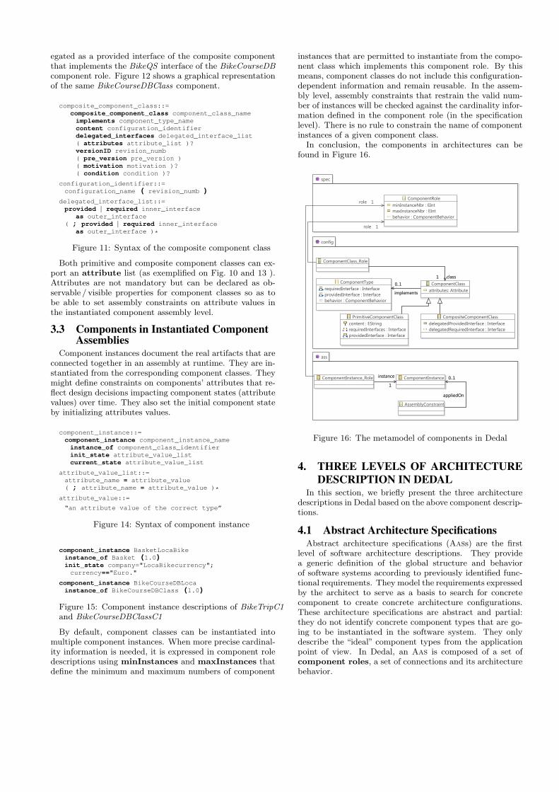
In conclusion, the components in architectures can befound in Figure 16.
spec
ComponentRoleminInstanceNbr : EIntmaxInstanceNbr : EIntbehavior : ComponentBehavior
config
ComponentClassattributes: Attribute
ComponentClass_Role
CompositeComponentClassdelegatedProvidedInterface : InterfacedelegatedRequiredInterface : Interface
ComponentTyperequiredInterface : InterfaceprovidedInterface : Interfacebehavior : ComponentBehavior
PrimitiveComponentClasscontent : EStringrequiredInterfaces : InterfaceprovidedInterface : Interface
ass
ComponentInstance_Role ComponentInstance
AssemblyConstraint
class1
implements
0..1
instance
1
appliedOn
0..1
class1
role 1
instance
1
role 1
implements
0..1
appliedOn
0..1
Figure 16: The metamodel of components in Dedal
4. THREE LEVELS OF ARCHITECTUREDESCRIPTION IN DEDAL
In this section, we briefly present the three architecturedescriptions in Dedal based on the above component descrip-tions.
4.1 Abstract Architecture SpecificationsAbstract architecture specifications (Aass) are the first
level of software architecture descriptions. They providea generic definition of the global structure and behaviorof software systems according to previously identified func-tional requirements. They model the requirements expressedby the architect to serve as a basis to search for concretecomponent to create concrete architecture configurations.These architecture specifications are abstract and partial:they do not identify concrete component types that are go-ing to be instantiated in the software system. They onlydescribe the “ideal” component types from the applicationpoint of view. In Dedal, an Aas is composed of a set ofcomponent roles, a set of connections and its architecturebehavior.
)��������������������)��& �������������
)���������������������������)���"�������������
)����#�����������������
�������)
!� ���-�
���-�
���,�����,�
���!� ���,�!���
• • •
!� ���- �� ��������
������������
����
����������������������
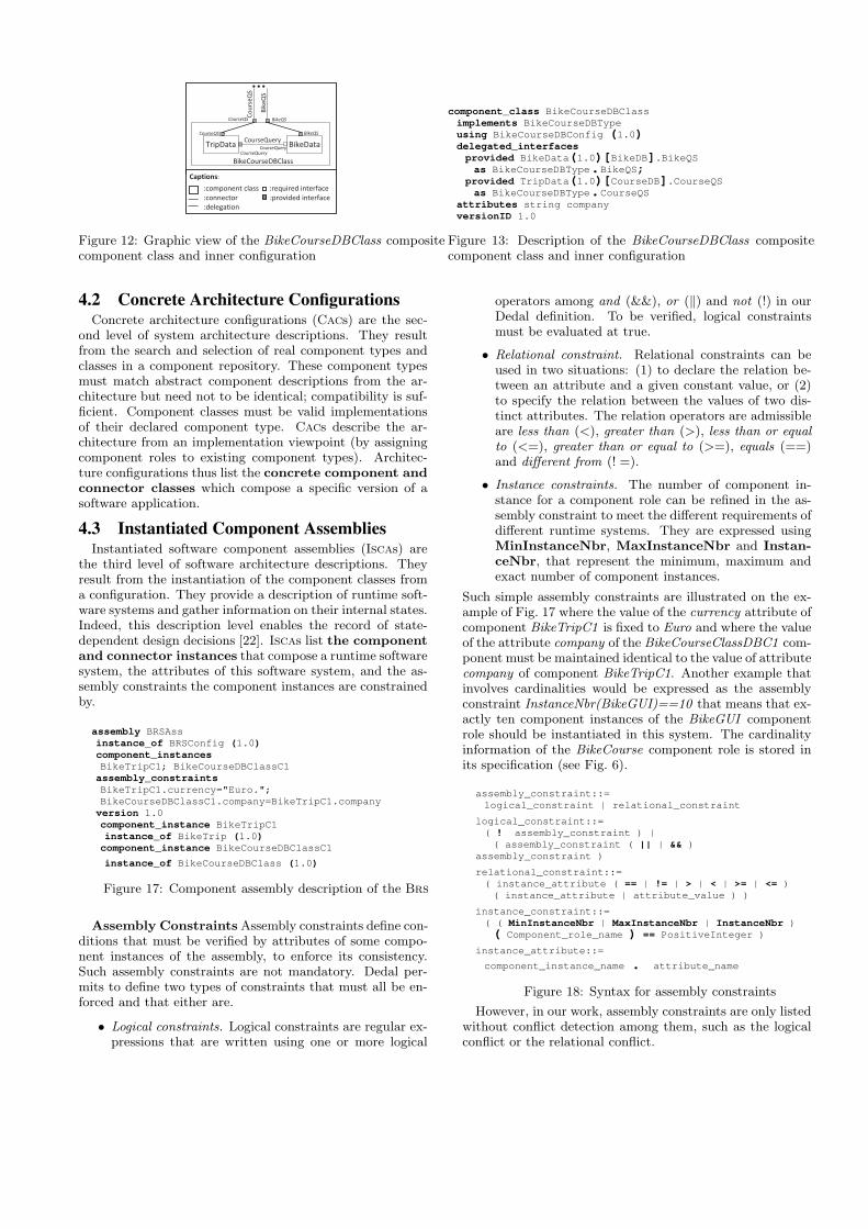
Figure 12: Graphic view of the BikeCourseDBClass compositecomponent class and inner configuration
component_class BikeCourseDBClassimplements BikeCourseDBTypeusing BikeCourseDBConfig (1.0)delegated_interfacesprovided BikeData(1.0)[BikeDB].BikeQSas BikeCourseDBType.BikeQS;
provided TripData(1.0)[CourseDB].CourseQSas BikeCourseDBType.CourseQS
attributes string companyversionID 1.0
Figure 13: Description of the BikeCourseDBClass compositecomponent class and inner configuration
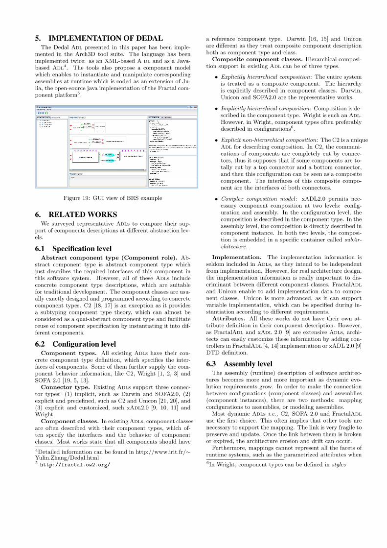
4.2 Concrete Architecture ConfigurationsConcrete architecture configurations (Cacs) are the sec-
ond level of system architecture descriptions. They resultfrom the search and selection of real component types andclasses in a component repository. These component typesmust match abstract component descriptions from the ar-chitecture but need not to be identical; compatibility is suf-ficient. Component classes must be valid implementationsof their declared component type. Cacs describe the ar-chitecture from an implementation viewpoint (by assigningcomponent roles to existing component types). Architec-ture configurations thus list the concrete component andconnector classes which compose a specific version of asoftware application.
4.3 Instantiated Component AssembliesInstantiated software component assemblies (Iscas) are
the third level of software architecture descriptions. Theyresult from the instantiation of the component classes froma configuration. They provide a description of runtime soft-ware systems and gather information on their internal states.Indeed, this description level enables the record of state-dependent design decisions [22]. Iscas list the componentand connector instances that compose a runtime softwaresystem, the attributes of this software system, and the as-sembly constraints the component instances are constrainedby.
assembly BRSAssinstance_of BRSConfig (1.0)component_instancesBikeTripC1; BikeCourseDBClassC1assembly_constraintsBikeTripC1.currency="Euro.";BikeCourseDBClassC1.company=BikeTripC1.companyversion 1.0component_instance BikeTripC1instance_of BikeTrip (1.0)component_instance BikeCourseDBClassC1
instance_of BikeCourseDBClass (1.0)
Figure 17: Component assembly description of the Brs
Assembly Constraints Assembly constraints define con-ditions that must be verified by attributes of some compo-nent instances of the assembly, to enforce its consistency.Such assembly constraints are not mandatory. Dedal per-mits to define two types of constraints that must all be en-forced and that either are.
• Logical constraints. Logical constraints are regular ex-pressions that are written using one or more logical
operators among and (&&), or (‖) and not (!) in ourDedal definition. To be verified, logical constraintsmust be evaluated at true.
• Relational constraint. Relational constraints can beused in two situations: (1) to declare the relation be-tween an attribute and a given constant value, or (2)to specify the relation between the values of two dis-tinct attributes. The relation operators are admissibleare less than (<), greater than (>), less than or equalto (<=), greater than or equal to (>=), equals (==)and different from (! =).
• Instance constraints. The number of component in-stance for a component role can be refined in the as-sembly constraint to meet the different requirements ofdifferent runtime systems. They are expressed usingMinInstanceNbr, MaxInstanceNbr and Instan-ceNbr, that represent the minimum, maximum andexact number of component instances.
Such simple assembly constraints are illustrated on the ex-ample of Fig. 17 where the value of the currency attribute ofcomponent BikeTripC1 is fixed to Euro and where the valueof the attribute company of the BikeCourseClassDBC1 com-ponent must be maintained identical to the value of attributecompany of component BikeTripC1. Another example thatinvolves cardinalities would be expressed as the assemblyconstraint InstanceNbr(BikeGUI)==10 that means that ex-actly ten component instances of the BikeGUI componentrole should be instantiated in this system. The cardinalityinformation of the BikeCourse component role is stored inits specification (see Fig. 6).
assembly_constraint::=logical_constraint | relational_constraint
logical_constraint::=( ! assembly_constraint ) |( assembly_constraint ( || | && )
assembly_constraint )
relational_constraint::=( instance_attribute ( == | != | > | < | >= | <= )( instance_attribute | attribute_value ) )
instance_constraint::=( ( MinInstanceNbr | MaxInstanceNbr | InstanceNbr )( Component_role_name ) == PositiveInteger )
instance_attribute::=
component_instance_name . attribute_name
Figure 18: Syntax for assembly constraints
However, in our work, assembly constraints are only listedwithout conflict detection among them, such as the logicalconflict or the relational conflict.
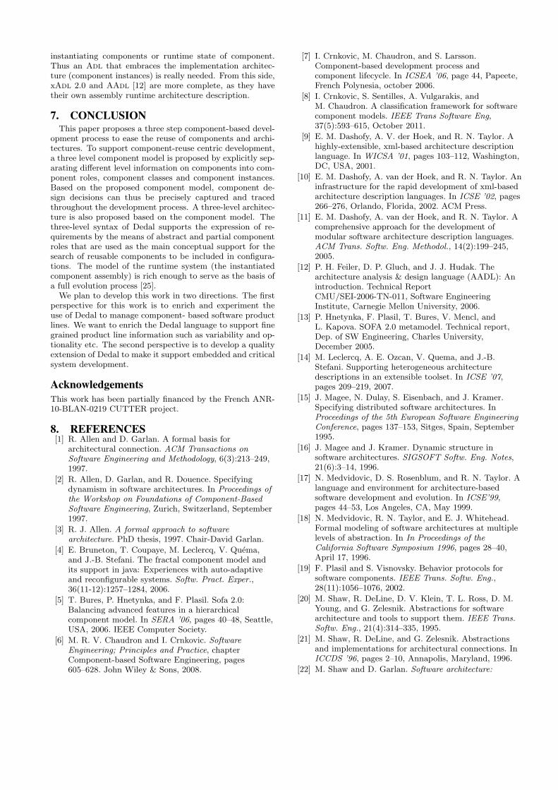
5. IMPLEMENTATION OF DEDALThe Dedal Adl presented in this paper has been imple-
mented in the Arch3D tool suite. The language has beenimplemented twice: as an XML-based A dl and as a Java-based Adl4. The tools also propose a component modelwhich enables to instantiate and manipulate correspondingassemblies at runtime which is coded as an extension of Ju-lia, the open-source java implementation of the Fractal com-ponent platform5.
Figure 19: GUI view of BRS example
6. RELATED WORKSWe surveyed representative Adls to compare their sup-
port of components descriptions at different abstraction lev-els.
6.1 Specification levelAbstract component type (Component role). Ab-
stract component type is abstract component type whichjust describes the required interfaces of this component inthis software system. However, all of these Adls includeconcrete component type descriptions, which are suitablefor traditional development. The component classes are usu-ally exactly designed and programmed according to concretecomponent types. C2 [18, 17] is an exception as it providesa subtyping component type theory, which can almost beconsidered as a quai-abstract component type and facilitatereuse of component specification by instantiating it into dif-ferent components.
6.2 Configuration levelComponent types. All existing Adls have their con-
crete component type definition, which specifies the inter-faces of components. Some of them further supply the com-ponent behavior information, like C2, Wright [1, 2, 3] andSOFA 2.0 [19, 5, 13].
Connector type. Existing Adls support three connec-tor types: (1) implicit, such as Darwin and SOFA2.0, (2)explicit and predefined, such as C2 and Unicon [21, 20], and(3) explicit and customized, such xAdl2.0 [9, 10, 11] andWright.
Component classes. In existing Adls, component classesare often described with their component types, which of-ten specify the interfaces and the behavior of componentclasses. Most works state that all components should have
4Detailed information can be found in http://www.irit.fr/∼Yulin.Zhang/Dedal.html5 http://fractal.ow2.org/
a reference component type. Darwin [16, 15] and Uniconare different as they treat composite component descriptionboth as component type and class.
Composite component classes. Hierarchical composi-tion support in existing Adl can be of three types.
• Explicitly hierarchical composition: The entire systemis treated as a composite component. The hierarchyis explicitly described in component classes. Darwin,Unicon and SOFA2.0 are the representative works.
• Implicitly hierarchical composition: Composition is de-scribed in the component type. Wright is such an Adl.However, in Wright, component types often preferablydescribed in configurations6.
• Explicit non-hierarchical composition: The C2 is a uniqueAdl for describing composition. In C2, the communi-cations of components are completely cut by connec-tors, thus it supposes that if some components are to-tally cut by a top connector and a bottom connector,and then this configuration can be seen as a compositecomponent. The interfaces of this composite compo-nent are the interfaces of both connectors.
• Complex composition model : xADL2.0 permits nec-essary component composition at two levels: config-uration and assembly. In the configuration level, thecomposition is described in the component type. In theassembly level, the composition is directly described incomponent instance. In both two levels, the composi-tion is embedded in a specific container called subAr-chitecture.
Implementation. The implementation information isseldom included in Adls, as they intend to be independentfrom implementation. However, for real architecture design,the implementation information is really important to dis-criminant between different component classes. FractalAdland Unicon enable to add implementation data to compo-nent classes. Unicon is more advanced, as it can supportvariable implementation, which can be specified during in-stantiation according to different requirements.
Attributes. All these works do not have their own at-tribute definition in their component description. However,as FractalAdl and xAdl 2.0 [9] are extensive Adls, archi-tects can easily customize these information by adding con-trollers in FractalAdl [4, 14] implementation or xADL 2.0 [9]DTD definition.
6.3 Assembly levelThe assembly (runtime) description of software architec-
tures becomes more and more important as dynamic evo-lution requirements grow. In order to make the connectionbetween configurations (component classes) and assemblies(component instances), there are two methods: mappingconfigurations to assemblies, or modeling assemblies.
Most dynamic Adls i.e., C2, SOFA 2.0 and FractalAdluse the first choice. This often implies that other tools arenecessary to support the mapping. The link is very fragile topreserve and update. Once the link between them is brokenor expired, the architecture erosion and drift can occur.
Furthermore, mappings cannot represent all the facets ofruntime systems, such as the parametrized attributes when
6In Wright, component types can be defined in styles

ADL Abstract
component type
Component type Component
behavior
Component class Component instance
C2SADEL Conceptual component :
references to external
component type
Conceptual component :
Extensible, component
type.
behavior :
Message-based
protocols.
No concrete type definitions. Component
instances defined with types
---
Wright --- Component : Extensible,
concrete component type.
Computation :
CSP-based behavior.
Component : Concrete component types.
No references to implementations.
---
Darwin --- Component : Extensible,
concrete component type.
--- component : Concrete component types.
No references to implementations.
---
Unicon --- interface : Built-in,
concrete component type.
--- Component : Concrete component types,
with multiple references to
Implementations (variants).
---
SOFA 2.0 --- frame : Extensible,
concrete component type.
protocol : Defined by
behavior protocols
Concrete component types. Support
references to implementations.
---
Fractal
ADL
--- No explicit component
types. Component
definitions reused and
extended in other
definitions
set of client and server
interfaces. Signature
defined
as a reference to an
implemented type
definition : component definition (set of
interfaces). Can be reused to model other
components (as a class of component)
Independent definition. Can
refine a base definition used
as a type
xADL 2.0 componentType :
Extensible, concrete
component type.
componentType :
Concrete component type definition. Can
refer to an implementation
Independent definition.
Contain a reference to
a component type
Table 1: Comparison of components in different Adls
ADL Primitive component
Implementation Attributes Composite component Delegation
C2 instance — — Explicit, non-hierarchical composition Derive from two wrapped connectors. Wright Instance — — Implicit, hierarchical composition: Composite configuration
embedding in computation of component type. Bindings
Darwin instance — — Explicit, hierarchical composition bind Unicon instance Implementation
constraining. — Explicit, hierarchical composition Bind
SOFA 2.0 instance — — architecture: Explicit, hierarchical composition. Delegate and Subsume
Fractal ADL component java class extended Explicit, hierarchical composition. binding
xADL 2.0 component — — subArchitecture: Implicit, hierarchical composition. Embedded in component types for configuration level; Embedded in component instance in assembly.
signatureInterfaceMapping: in component type level; interfaceInstanceMapping: assembly level.
Table 2: The comparison of primitive and composite component in Adls
instantiating components or runtime state of component.Thus an Adl that embraces the implementation architec-ture (component instances) is really needed. From this side,xAdl 2.0 and AAdl [12] are more complete, as they havetheir own assembly runtime architecture description.
7. CONCLUSIONThis paper proposes a three step component-based devel-
opment process to ease the reuse of components and archi-tectures. To support component-reuse centric development,a three level component model is proposed by explicitly sep-arating different level information on components into com-ponent roles, component classes and component instances.Based on the proposed component model, component de-sign decisions can thus be precisely captured and tracedthroughout the development process. A three-level architec-ture is also proposed based on the component model. Thethree-level syntax of Dedal supports the expression of re-quirements by the means of abstract and partial componentroles that are used as the main conceptual support for thesearch of reusable components to be included in configura-tions. The model of the runtime system (the instantiatedcomponent assembly) is rich enough to serve as the basis ofa full evolution process [25].
We plan to develop this work in two directions. The firstperspective for this work is to enrich and experiment theuse of Dedal to manage component- based software productlines. We want to enrich the Dedal language to support finegrained product line information such as variability and op-tionality etc. The second perspective is to develop a qualityextension of Dedal to make it support embedded and criticalsystem development.
AcknowledgementsThis work has been partially financed by the French ANR-10-BLAN-0219 CUTTER project.
8. REFERENCES[1] R. Allen and D. Garlan. A formal basis for
architectural connection. ACM Transactions onSoftware Engineering and Methodology, 6(3):213–249,1997.
[2] R. Allen, D. Garlan, and R. Douence. Specifyingdynamism in software architectures. In Proceedings ofthe Workshop on Foundations of Component-BasedSoftware Engineering, Zurich, Switzerland, September1997.
[3] R. J. Allen. A formal approach to softwarearchitecture. PhD thesis, 1997. Chair-David Garlan.
[4] E. Bruneton, T. Coupaye, M. Leclercq, V. Quema,and J.-B. Stefani. The fractal component model andits support in java: Experiences with auto-adaptiveand reconfigurable systems. Softw. Pract. Exper.,36(11-12):1257–1284, 2006.
[5] T. Bures, P. Hnetynka, and F. Plasil. Sofa 2.0:Balancing advanced features in a hierarchicalcomponent model. In SERA ’06, pages 40–48, Seattle,USA, 2006. IEEE Computer Society.
[6] M. R. V. Chaudron and I. Crnkovic. SoftwareEngineering; Principles and Practice, chapterComponent-based Software Engineering, pages605–628. John Wiley & Sons, 2008.
[7] I. Crnkovic, M. Chaudron, and S. Larsson.Component-based development process andcomponent lifecycle. In ICSEA ’06, page 44, Papeete,French Polynesia, october 2006.
[8] I. Crnkovic, S. Sentilles, A. Vulgarakis, andM. Chaudron. A classification framework for softwarecomponent models. IEEE Trans Software Eng,37(5):593–615, October 2011.
[9] E. M. Dashofy, A. V. der Hoek, and R. N. Taylor. Ahighly-extensible, xml-based architecture descriptionlanguage. In WICSA ’01, pages 103–112, Washington,DC, USA, 2001.
[10] E. M. Dashofy, A. van der Hoek, and R. N. Taylor. Aninfrastructure for the rapid development of xml-basedarchitecture description languages. In ICSE ’02, pages266–276, Orlando, Florida, 2002. ACM Press.
[11] E. M. Dashofy, A. van der Hoek, and R. N. Taylor. Acomprehensive approach for the development ofmodular software architecture description languages.ACM Trans. Softw. Eng. Methodol., 14(2):199–245,2005.
[12] P. H. Feiler, D. P. Gluch, and J. J. Hudak. Thearchitecture analysis & design language (AADL): Anintroduction. Technical ReportCMU/SEI-2006-TN-011, Software EngineeringInstitute, Carnegie Mellon University, 2006.
[13] P. Hnetynka, F. Plasil, T. Bures, V. Mencl, andL. Kapova. SOFA 2.0 metamodel. Technical report,Dep. of SW Engineering, Charles University,December 2005.
[14] M. Leclercq, A. E. Ozcan, V. Quema, and J.-B.Stefani. Supporting heterogeneous architecturedescriptions in an extensible toolset. In ICSE ’07,pages 209–219, 2007.
[15] J. Magee, N. Dulay, S. Eisenbach, and J. Kramer.Specifying distributed software architectures. InProceedings of the 5th European Software EngineeringConference, pages 137–153, Sitges, Spain, September1995.
[16] J. Magee and J. Kramer. Dynamic structure insoftware architectures. SIGSOFT Softw. Eng. Notes,21(6):3–14, 1996.
[17] N. Medvidovic, D. S. Rosenblum, and R. N. Taylor. Alanguage and environment for architecture-basedsoftware development and evolution. In ICSE’99,pages 44–53, Los Angeles, CA, May 1999.
[18] N. Medvidovic, R. N. Taylor, and E. J. Whitehead.Formal modeling of software architectures at multiplelevels of abstraction. In In Proceedings of theCalifornia Software Symposium 1996, pages 28–40,April 17, 1996.
[19] F. Plasil and S. Visnovsky. Behavior protocols forsoftware components. IEEE Trans. Softw. Eng.,28(11):1056–1076, 2002.
[20] M. Shaw, R. DeLine, D. V. Klein, T. L. Ross, D. M.Young, and G. Zelesnik. Abstractions for softwarearchitecture and tools to support them. IEEE Trans.Softw. Eng., 21(4):314–335, 1995.
[21] M. Shaw, R. DeLine, and G. Zelesnik. Abstractionsand implementations for architectural connections. InICCDS ’96, pages 2–10, Annapolis, Maryland, 1996.
[22] M. Shaw and D. Garlan. Software architecture:
perspectives on an emerging discipline. Prentice-Hall,Inc., 1996.
[23] H. Y. Zhang, C. Urtado, and S. Vauttier.Connector-driven process for the gradual evolution ofcomponent-based software. In ASWEC’09, GoldCoast, Australia, April 2009.
[24] H. Y. Zhang, C. Urtado, and S. Vauttier.Architecture-centric component-based developmentneeds a three-level ADL. In M. A. Babar andI. Gorton, editors, ECSA’10, volume 6285 of LNCS,pages 295–310, Copenhagen, Denmark, August 2010.Springer.
[25] H. Y. Zhang, C. Urtado, and S. Vauttier.Architecture-centric development and evolutionprocesses for component-based software. In SEKE’10,Redwood City, USA, July 2010.