Calculation of the DC-bus Capacitors of the Back-to-back NPC Converters
Upload
independentCategory
view
1download
0
European Journal of Scientific Research ISSN 1450-216X Vol.32 No.4 (2009), pp.572-585 © EuroJournals Publishing, Inc. 2009 http://www.eurojournals.com/ejsr.htm
Passivity-Based Control with Dual Lagrangian Model
of Four-Wire Three-Level Three-Phase NPC Voltage-Source Rectifier
Majid Mehrasa Department of Electrical and Computer Engineering Noshirvani
Babol University of Technology Babol Iran E-mail: [email protected]
Saeed Lesan
Department of Electrical and Computer Engineering Noshirvani Babol University of Technology Babol Iran
E-mail: [email protected]
Arash Abedi Department of Electrical and Computer Engineering Tafresh
University of Technology E-mail: [email protected]
Seyed Nima Hoseini Emeni
Department of Electrical and Computer K.N.Toosi University of Technology Tehran Iran
E-mail: [email protected]
Abstract
This paper presents the EL modeling of the four-wire 3-level 3-phase NPC voltage source rectifier (VSR). The load current of the four-wire 3-level 3-phase could be expressed in two forms: the load current involving the current of capacitor C1, and the load current involving the current of capacitor C2. So that two Euler-Lagrange ( EL) models will be obtained for four-wire 3-level 3-phase NPC voltage source rectifier. The models are completely in accordance with kirchoffs circuit theory and superposition law of course. One of the rules is utilized to control the voltage of C1 and the other is used to control the voltage of C2. Transforming the EL model from the abc reference frame to dq reference model will completely retain the energy dissipative properties of two models. Having derived the EL models, the control method combined with the techniques of the energy shaping and damping injection applied to the dq frame EL models of the converter. To study the output regulation problem of C1 and C2, the voltage indirect control method has been applied to the passivity based controller. To regulate the internal dynamics of the output voltages of C1 and C2 an outer loop that consisting PI controller is added to both controller models. To verify the ability of the proposed control method different simulations have been carried out by MATLAM/SIMULINK software. The simulation results clarify the abilities of the new method such as: very low THD, unity power factor, decoupled current loop dynamics, low oscillation in the neutral point potential (NPP).

Passivity-Based Control with Dual Lagrangian Model of Four-Wire Three-Level Three-Phase NPC Voltage-Source Rectifier 573
Keywords: Neutral point clamp (NPC) VSR, Euler-Lagrange equation, passivity based,
three-level three-phase rectifier, energy shaping
1. Introduction Multilevel converters are the most widely used rectifiers in the area of power electronics where dc power supplies are required in high power applications such as: power distribution, power quality and high-voltage high-power adjustable speed drives. The most popular topology of multilevel converters is the neutral point clamp (NPC) converter because of its attractive features such as: High Power Factor, Low harmonic content, low device rating, low switching loses, low switching frequency and capability of bidirectional power flow. However, the most problem of NPC converter is fluctuation of the neutral point potential.
A control law based on Lyapunov stability theory, without linearization and SVPWM switching applied to 3-phase VSR in [1]. In [2], a mathematical model of a VSR is presented which is derived in the stationary and synchronous frames of d-q reference. Ojo and konduro [3] proposed a control scheme based on the utilization of the neutral variables of the system for NPC VSR working under unbalanced conditions. In [4], a new direct power feedback method is obtained for three-level NPC VSR. To solve the NPP imbalance problem in NPCR s, [5] present a controlling method based on a state-space model and designed based on the optimal regulator theory. In [6] and [7], authors applied a new technique based on the symmetrical components theory and controlling the zero sequence current respectively, which makes line currents and neutral point balanced while power factor is unit In [8], the authors proposed a lyapunov-based control for four-wire NPC topology to stabilize large-signal disturbances while improving transient response. Three control techniques apply to 3-phase 3-level NPC VSR to study their perform 1.linear control 2.nonlinear control 3.nonlinear model reference adaptive control which nonlinear MRAC(3) exhibits much better performance in a wide operating rang[9].
T.S.Lee, presented nonlinear differential-geometric techniques and passivity-based control theory of EL systems for designing feedback controller for three-phase PWM boost voltage-source rectifier, [10][11]. in this paper, using the EL model based on the superposition law and the load current expressed in terms of the c1 and c2 capacitor current of the Four-wire 3-level 3-phase NPC VSR, passivity-based controllers synthesizing with the techniques of energy shaping and damping injection inclined to PI controller obtained the proper results such as: zero steady-state error, very low THD, unity power factor, decoupled current-loop dynamics, low oscillation in the neutral point potential (NPP).
2. EL Modeling of the Four-Wire 3-Level 3-Phase NPC Voltage-Source Rectifier 2.1. EL Model in a-b-c Reference Frame
The circuit configuration of the Four-wire 3-level 3-phase NPC VSR with balanced source is shown in fig.1. The output capacitors, line inductors and resistances are considered identical i.e., c1=c2=c, L1=L2=L3=L and R1=R2=R3=R, respectively. Em is the amplitude of the input voltage source. si1, si2, si3 and si4 (i=a, b, c) are switching functions describing the switching status of each phase as given by the following definition:
Sij = i=a,b,c and j=1,2

574 Majid Mehrasa, Saeed Lesan, Arash Abedi and Seyed Nima Hoseini Emeni
Figure 1: Four-wire Three-level three-phase Neutral point clamped VSR
2ci
1ci
Considering electric charges vector q= [qLa qLb qLc qc1 qc2] and currents vector =
[ ] corresponding to three boosting inductors and output capacitors respectively, the lagrangian (q , ) of the system can be defined as:
- V (1) Which T(q , ) and V(q) are magnetic co-energy and electric field energy of the circuit,
respectively. In fig.1, the load current can be written as:
- (2) Or
(3)
With =1-Si2.of course, equation (2) is due to the capacitor c1,and equation (3) is due to the capacitor c2.Considering the load current presented above, the EL parameters describing the EL dynamics of the Four-wire 3-level 3-phase NPC VSR can be written as:
Τ= (4)
V= (5)
(6) Or
(7)
F= (8) In these equations, the functions D and F are Rayleigh dissipation co-faction and the
generalized forcing faction. Considering to the general from of the EL equation:
(9)
And substituting the elements described above, the following equations can be achieved:
(10)
(11)
Passivity-Based Control with Dual Lagrangian Model of Four-Wire Three-Level Three-Phase NPC Voltage-Source Rectifier 575
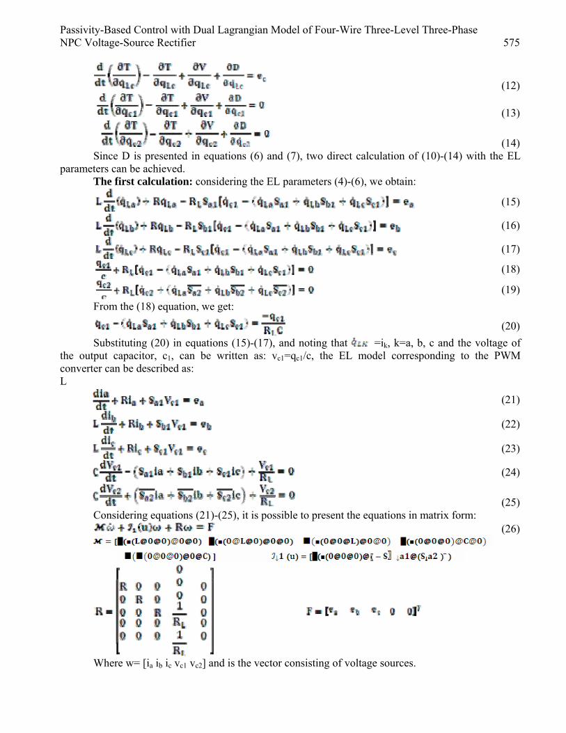
(12)
(13)
(14) Since D is presented in equations (6) and (7), two direct calculation of (10)-(14) with the EL
parameters can be achieved. The first calculation: considering the EL parameters (4)-(6), we obtain:
(15)
(16)
(17)
(18)
(19)
From the (18) equation, we get:
(20)
Substituting (20) in equations (15)-(17), and noting that =ik, k=a, b, c and the voltage of the output capacitor, c1, can be written as: vc1=qc1/c, the EL model corresponding to the PWM converter can be described as: L
(21)
(22)
(23)
(24)
(25) Considering equations (21)-(25), it is possible to present the equations in matrix form:
(26)
Where w= [ia ib ic vc1 vc2] and is the vector consisting of voltage sources.
576 Majid Mehrasa, Saeed Lesan, Arash Abedi and Seyed Nima Hoseini Emeni
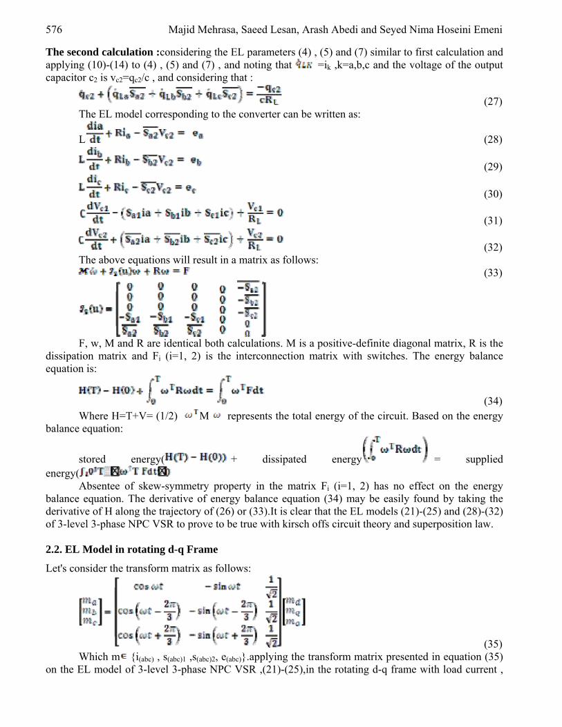
The second calculation :considering the EL parameters (4) , (5) and (7) similar to first calculation and applying (10)-(14) to (4) , (5) and (7) , and noting that =ik ,k=a,b,c and the voltage of the output capacitor c2 is vc2=qc2/c , and considering that :
(27) The EL model corresponding to the converter can be written as:
L (28)
(29)
(30)
(31)
(32) The above equations will result in a matrix as follows:
(33)
F, w, M and R are identical both calculations. M is a positive-definite diagonal matrix, R is the
dissipation matrix and Fi (i=1, 2) is the interconnection matrix with switches. The energy balance equation is:
(34)
Where H=T+V= (1/2) M represents the total energy of the circuit. Based on the energy balance equation:
stored energy( + dissipated energy = supplied
energy( Absentee of skew-symmetry property in the matrix Fi (i=1, 2) has no effect on the energy
balance equation. The derivative of energy balance equation (34) may be easily found by taking the derivative of H along the trajectory of (26) or (33).It is clear that the EL models (21)-(25) and (28)-(32) of 3-level 3-phase NPC VSR to prove to be true with kirsch offs circuit theory and superposition law. 2.2. EL Model in rotating d-q Frame
Let's consider the transform matrix as follows:
(35) Which m {i(abc) , s(abc)1 ,s(abc)2, e(abc)}.applying the transform matrix presented in equation (35)
on the EL model of 3-level 3-phase NPC VSR ,(21)-(25),in the rotating d-q frame with load current ,

Passivity-Based Control with Dual Lagrangian Model of Four-Wire Three-Level Three-Phase NPC Voltage-Source Rectifier 577
involving the current of capacitor c1,we will have :.
(36)
(37)
(38)
(39)
(40) The transformed state equations (36)-(40) can be presented in the following matrix form:
(41) With x=[x1 x2 x3 x4 x5] = [id iq io vc1 vc2] as the state vector and:
=
Also, applying the transform matrix presented in (35) on the EL model of Four-wire 3-level 3-
phase NPC VSR presented in (28)-(32) in the rotating d-q frame with load current involving the current of capacitor c2 , the following equations can be derived :
(42)
(43)
(44)
(45)
(46) With the matrix form as:
(47)
Where x, , , and F are identical to set equations (36)-(40), and:
In the d-q reference frame the total energy becomes H= (1/2)xT x and the energy balance
equation is:
578 Majid Mehrasa, Saeed Lesan, Arash Abedi and Seyed Nima Hoseini Emeni
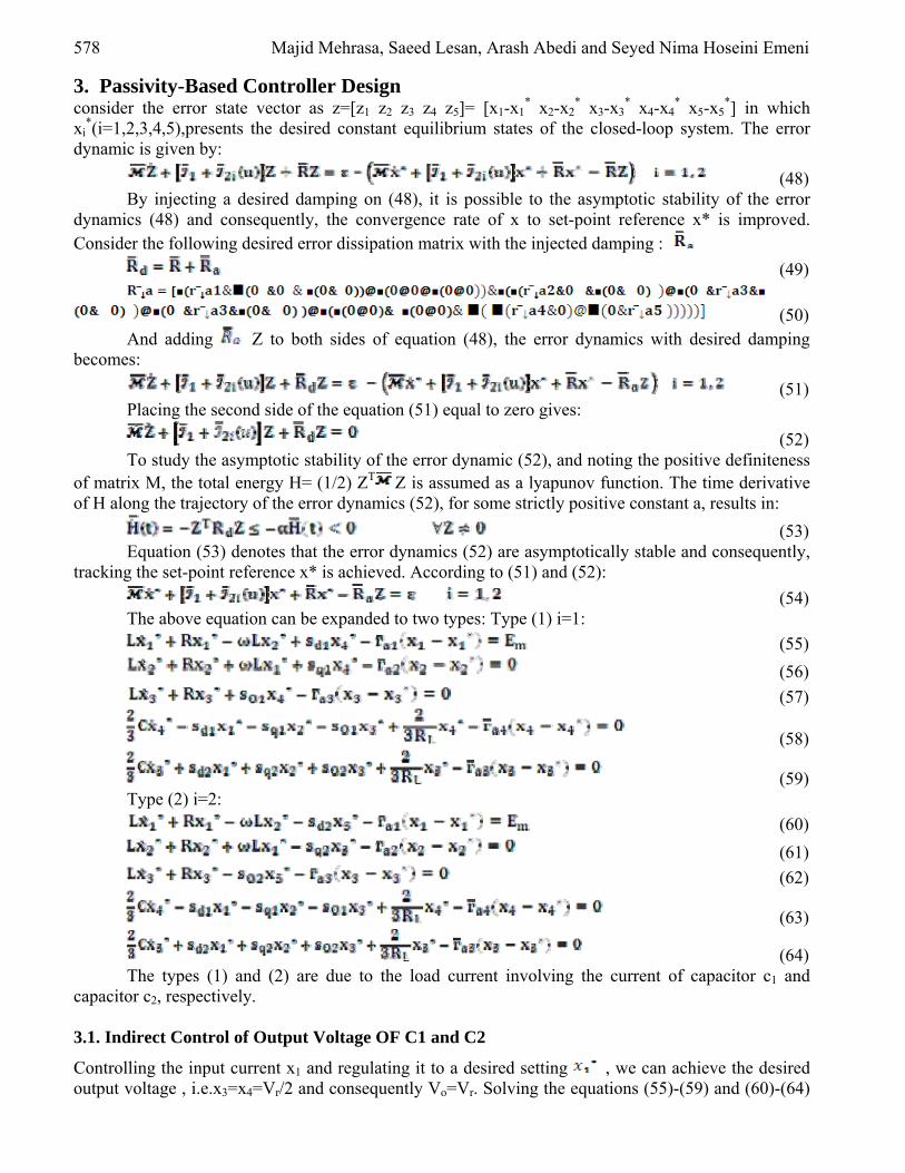
3. Passivity-Based Controller Design consider the error state vector as z=[z1 z2 z3 z4 z5]= [x1-x1
* x2-x2* x3-x3
* x4-x4* x5-x5
*] in which xi
*(i=1,2,3,4,5),presents the desired constant equilibrium states of the closed-loop system. The error dynamic is given by:
(48) By injecting a desired damping on (48), it is possible to the asymptotic stability of the error
dynamics (48) and consequently, the convergence rate of x to set-point reference x* is improved.
Consider the following desired error dissipation matrix with the injected damping :
(49)
(50)
And adding Z to both sides of equation (48), the error dynamics with desired damping becomes:
(51) Placing the second side of the equation (51) equal to zero gives:
(52) To study the asymptotic stability of the error dynamic (52), and noting the positive definiteness
of matrix M, the total energy H= (1/2) ZT Z is assumed as a lyapunov function. The time derivative of H along the trajectory of the error dynamics (52), for some strictly positive constant a, results in:
(53) Equation (53) denotes that the error dynamics (52) are asymptotically stable and consequently,
tracking the set-point reference x* is achieved. According to (51) and (52):
(54) The above equation can be expanded to two types: Type (1) i=1:
(55)
(56)
(57)
(58)
(59) Type (2) i=2:
(60)
(61)
(62)
(63)
(64) The types (1) and (2) are due to the load current involving the current of capacitor c1 and
capacitor c2, respectively. 3.1. Indirect Control of Output Voltage OF C1 and C2
Controlling the input current x1 and regulating it to a desired setting , we can achieve the desired output voltage , i.e.x3=x4=Vr/2 and consequently Vo=Vr. Solving the equations (55)-(59) and (60)-(64)
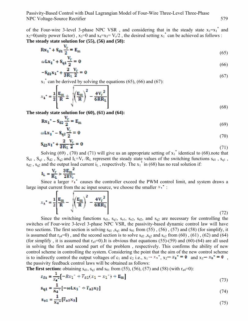
Passivity-Based Control with Dual Lagrangian Model of Four-Wire Three-Level Three-Phase NPC Voltage-Source Rectifier 579
of the Four-wire 3-level 3-phase NPC VSR , and considering that in the steady state x1=x1* and
x2=0(unity power factor) , x3=0 and x4=x5= Vr/2 , the desired setting x1* can be achieved as follows :
The steady state solution for (55), (56) and (58):
(65)
(66)
(67) x1
* can be derived by solving the equations (65), (66) and (67):
(68) The steady state solution for (60), (61) and (64):
(69)
(70)
(71) Solving (69) , (70) and (71) will give us an appropriate setting of x1
* identical to (68).note that Sd1 , Sq1 , Sd2 , Sq2 and IL=Vr /RL represent the steady state values of the switching functions sd1 , sq1 , sd2 , sq2 and the output load current iL , respectively. The x1
* in (68) has no real solution if:
Since a larger causes the controller exceed the PWM control limit, and system draws a
large input current from the ac input source, we choose the smaller :
(72) Since the switching functions sd1, sq1, so1, so2, sd2, and sq2 are necessary for controlling the
switches of Four-wire 3-level 3-phase NPC VSR, the passivity-based dynamic control law will have two sections. The first section is solving sd1 ,sq1 and s01 from (55) , (56) , (57) and (58) (for simplify, it is assumed that ra4=0) , and the second section is to solve sd2 ,sq2 and so2 from (60) , (61) , (62) and (64) (for simplify , it is assumed that ra5=0).It is obvious that equations (55)-(59) and (60)-(64) are all used in solving the first and second part of the problem , respectively. This confirms the ability of new control scheme in controlling the system. Considering the point that the aim of the new control scheme is to indirectly control the output voltages of c1 and c2 i.e., x1 , x2 and x3 , the passivity feedback control laws will be obtained as follows: The first section: obtaining sd1, sq1 and s01 from (55), (56), (57) and (58) (with ra4=0):
(73)
(74)
(75)

580 Majid Mehrasa, Saeed Lesan, Arash Abedi and Seyed Nima Hoseini Emeni
(76) The second Section: obtaining sd2 and sq2 from (60), (61), (62) and (64) (with ra5=0):
(77)
(78)
(79)
(80) In the passivity-based dynamic control law (73)-(80), the desired current command x1
* is obtained from (72).If x4
*=x5*=0, x4
* and x5*can be replaced by a small fixed positive (negative)
constant value so that the equations (73)-(80) remain global .fig.2 shows the block diagram of c1 and c2 output voltages indirect control with the passivity-based dynamic control law. Figure 2: Block diagram of the passivity-based controller with the capacitor output voltages
indirect control for Four-wire 3-level 3-phase NPC VSR
3.2. The c1 and c2 Capacitor Output Voltages Indirect Control with the PI Controller
Presence of parasitic elements in the power circuit and parameter inaccuracies may lead to an indirect , calculated by (68) , and steady state error in dc-bus output voltages x4 , x5 and d-axis current ,
x1.In part A of the control algorithm , the convergent rate for the output voltages depends on the inherent characteristics to approach its steady state and remains uncontrolled. Supposing equal to
in equations (55)-(59) and (73)-(76), and equal to in equations (60)-(64) and (77)-(80) will let us present an effective control method .the new method is able to solve the problems mentioned above .To achieve such control method, the dynamics of output voltages of c1 and c2, i.e. x4, x5, would be considered. In the first stage, substituting the passivity-based current control rules in the d-q equations of Four-wire 3-level 3-phase NPC VSR, presented in (36)-(39). And tracking x1 , x2
* 0 and x3* thoroughly, we will achieve:

Passivity-Based Control with Dual Lagrangian Model of Four-Wire Three-Level Three-Phase NPC Voltage-Source Rectifier 581
(81)
Considering that when t , the controller state will be x4* Vr/2) and:
(82)
(83)
(84) The time constant RLC determines the convergent rate for x4 in equation (83).Time constant,
RC, can be large especially for small dc loads. Controlling the dynamics of the output voltage of c1 in equation (83) will considerably improve the convergent rate. Hence , to achieve good tracking performance with strong robustness , we apply the classical PI controller to regulate the d-axis current command corresponding to load current involved c1 capacitor current .if we consider x3 voltage tracking error as :ev1=(Vr/2)-x4 , then:
(85) The block diagram of the controlled output voltage of c1, (83) and (85), is denoted in fig3 (a).
In the second stage , similar to the first stage , by substituting (77)-(80) into the d-q model (42) , (43) , (44) and (46) of the converter and noting the perfect tracking x1 , x2
* 0 and x3* we get :
(86)
Since, the controller state x5* Vr/2) as t , we obtain:
(87) Or
(88) Where:
(89) Following explanations described in the first stage, and controlling the dynamics of the output
voltage of c1 in (82), the convergent rate for x4 in (88) can significantly increase to approach the desired setting. If we consider x5 voltage tracking error as: ev2= (Vr /2) - x5. We obtain:
(90) The block diagram of the controlled output voltage of c2 in (88) and (90) is denoted in
fig3(b).combining figs 2 , 3(a) and 3(b).we can obtain the overall block diagram of the proposed control system for the Four-wire 3-level 3-phase NPC VSR , shown in fig(4).

582 Majid Mehrasa, Saeed Lesan, Arash Abedi and Seyed Nima Hoseini Emeni
Figure 3: (a) block diagram of the c1 capacitor voltage control loop (b) block diagram of the c2 capacitor voltage control loop
(a) (b)
Figure 4: Block diagram of the proposed overall control system for the Four-wire 3-level 3-phase NPC VSR
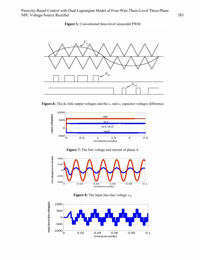
3.3. Three-Level PWM Modulation Method
The switching functions si1 and si2(i=d.q ,o) under rotating d-q frame obtained from fig(4) , transform into switching functions si1 and si2(i=a,b,c,) under static a-b-c frame by equation (35).to perform the traditional three-level SPWM modulation which is a nonlinear one , we need the switching signals vi(i=a,b,c,) , which can be obtained as follows :
Modulation of phase A is denoted in fig(5).Though the three-level SPWM modulation is
nonlinear , it has the advantages of lower switching frequency and easier to be realized.
4. Simulation Results Simulations have been carried out using MATLAB/SIMULINK and performed under the following environments : amplitude of the input voltage source Em =180 volt, input line inductance L=2mH ,
input line resistance r=0.1ohms , output capacitor c1=c2=2200 F , load resistance RL=33.33 ohms ,switching frequency f =2kHz and dc-bus voltage Vr=600volt.fig.6 illustrates the dc-link output voltages and the c1 and c2 capacitor voltages difference.fig.7 shows the line voltage and current of phase A , and it is clear that unity power factor is achieved.
Passivity-Based Control with Dual Lagrangian Model of Four-Wire Three-Level Three-Phase NPC Voltage-Source Rectifier 583
Figure 5: Conventional three-level sinusoidal PWM
Figure.6: The dc-link output voltages and the c1 and c2 capacitor voltages difference
0 0.5 1 1.5 2 2.5-500
0
500
1000
time(seconds)
output voltage
s(v)
vc1
vdc
vc1-vc2
-vc2
Figure 7: The line voltage and current of phase A
0 0.02 0.04 0.06 0.08 0.1-200
-100
0
100
200
time(seconds)
Line
voltage
(v) an
d cu
rren
t(A)
Figure 8: The input line-line voltage vab
0 0.02 0.04 0.06 0.08 0.1-1000
-500
0
500
1000
time(seconds)
Inpu
t lin
e to
line
volta
ge(v
)
584 Majid Mehrasa, Saeed Lesan, Arash Abedi and Seyed Nima Hoseini Emeni
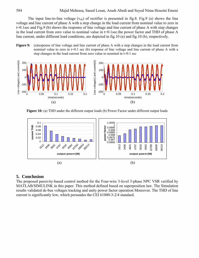
The input line-to-line voltage (vab) of rectifier is presented in fig.8. Fig.9 (a) shows the line voltage and line current of phase A with a step change in the load current from nominal value to zero in t=0.1sec and Fig.9 (b) shows the response of line voltage and line current of phase A with step changes in the load current from zero value to nominal value in t=0.1sec.the power factor and THD of phase A line current, under different load conditions, are depicted in fig.10 (a) and fig.10 (b), respectively. Figure 9: (a)response of line voltage and line current of phase A with a step changes in the load current from
nominal value to zero in t=0.1 sec (b) response of line voltage and line current of phase A with a step changes in the load current from zero value to nominal in t=0.1 sec
0 0.05 0.1 0.15 0.2-200
-100
0
100
200
time(seconds)
Line
vol
tage
(v)
and
curr
ent(
A)
0 0.05 0.1 0.15 0.2-200
-100
0
100
200
time(seconds)Li
ne v
olta
ge(v
) an
d cu
rren
t(A
)
(a) (b)
Figure 10: (a) THD under the different output loads (b) Power Factor under different output loads
0
0.02
0.04
0.06
0.08
0.1
1612
2406
3601
4797
6532
8362
1078
0
1800
0
3621
0
output power(W)
curr
ent
TH
D
0.99650.997
0.99750.998
0.99850.999
0.99951
1.000516
12
2406
3601
4797
6532
8362
1078
0
1800
0
3621
0
output power(W)
po
wer
fac
tor
(a) (b)
5. Conclusion The proposed passivity-based control method for the Four-wire 3-level 3-phase NPC VSR verified by MATLAB/SIMULINK in this paper. This method defined based on superposition law. The Simulation results validated dc-bus voltages tracking and unity power factor operation Moreover. The THD of line current is significantly low, which persuades the CEI 61000-3-2/4 standard.
Passivity-Based Control with Dual Lagrangian Model of Four-Wire Three-Level Three-Phase NPC Voltage-Source Rectifier 585
References [1] H.Komurcugil, O.Kukrer, " Lyapunov-Based Control for Three-Phase PWM AC/DC Voltage-
source Converter," IEEE Transactions On Power Electronics. Vol. 13. No. 5. September 1998, pp.801-813.
[2] V.Blasko, V.Kaura,"A New Mathematical Model and Control of a Three-Phase AC/DC Voltage-Source Converter,",IEEE Transactions on Power Electronics. Vol.12. NO. 1. January 1997, pp. 116-123.
[3] O. Ojo, S.Konduru, "High Porformance Control of Three-Phase Three-Level Rectifier Under Unbalanced Conditions," 1-4244-0714-1/07/$20.00O2007 IEEE, pp. 1102-1108.
[4] L. Wei, F.Li, C.Li,"A Direct Power Feedback Method of a Dual PWM Three-Level Voltage Source Converter System," 0-7803-5421-4/99/$10.00O1999 IEEE. pp. 1089-1094.
[5] S. Fukuda, Y. Matsumoto, A. Sagawa, "Optimal-Regulator-Based Control of NPC Boost Rectifiers for Unity Power Factor and Reduced Neutral-Point-Potential Variations," IEEE Transactions on Industrial Electronics, Vol. 46, No. 3, June 1999, pp. 527-534.
[6] Y. OuneJJar.K.Al-haddad,"New line currents and neutral point balancing technique of three- level three-phase NPC converter,", IEEE ISIE 2006,July 9-12,2006,montreal,Quebec,Canada, pp.1436-1441.
[7] S-K.Lim, J-H.Kim, K.Nam, "A DC-Link Voltage Balancing Algorithm for 3-Level Converter Using the Zero Sequence Current," 0-7803-5421-4/99/$10.00O1999 IEEE, pp. 1083-1088.
[8] M. Yongqing, L. Zheng, S. Chuanwen, S.Yanmin and Y.Ting,"Study on mathematical model and Lyapunov-based control for three-phase Four-wire three-level NPC voltage-source Rectifier,", IEEE ISIE 2005,June 20-23,2005,Dubrovnik,Quebec,Croatia, pp. 669-674.
[9] L. Yacoubi, K.Al-Haddad, L.A.Dessaint, F.Fnaiech,"Linear and Nonlinear Control Techniques for a Three-Phase Three-Level NPC Boost Rectifier," IEEE Transactions on Industrial Electronics. Vol. 53. No.6. December 2006, pp. 1908-1918.
[10] T. S.Lee,"Input-Output Linearization and Zero-Dynamics control of three-phase AC/DC voltage-source converter," , IEEE TRANS on power Electronics, vol.18, No.1, JANUARY 2003, pp. 11-22.
[11] T. S.Lee,"Lagrangian modeling and passivity-based control of three-phase AC/DC voltage-source converters,", IEEE TRANS on industrial Electronics.vol.51, 4, AUGUST 2004, pp. 892-902.
Copyright © 2022 FDOKUMEN