Chapter Sixty-three - IN.gov
166
TABLE OF CONTENTS Table of Contents ............................................................................................................................ 1 List of Figures ................................................................................................................................. 7 63-3A Stress-Strain Diagram for Prestressing Strands ...................................................... 7 63-3B End Span Tendon Trajectory .................................................................................. 7 63-8A Adjacent Box Beams with Transverse Tensioning Rods (section view) ................ 7 63-8B Adjacent Box Beams with Transverse Tensioning Rods (plan view) .................... 7 63-8C Adjacent Box Beam Details .................................................................................... 7 63-11A Dimensioning Precast Concrete Beam On Slope.................................................... 7 63-13A figure deleted .......................................................................................................... 7 63-13A(1) I-Beam Type 1 Section ........................................................................................... 7 63-13A(2) I-Beam Type I Bar Bending Details ....................................................................... 7 63-13A(3) I-Beam Type I Elevations Showing End Reinforcement ........................................ 7 63-13B figure deleted .......................................................................................................... 7 63-13B(1) I-Beam, Type II Section .......................................................................................... 7 63-13B(2) I-Beam, Type II Bar Bending Details ..................................................................... 7 63-13B(3) I-Beam, Type II Elevations Showing End Reinforcement ..................................... 7 63-13C figure deleted .......................................................................................................... 7 63-13C(1) I-Beam Type III section .......................................................................................... 7 63-13C(2) I-Beam Type III Bar Bending Details..................................................................... 7 63-13C(3) I-Beam Type III Elevations Showing End Reinforcement ..................................... 7 63-13D figure deleted .......................................................................................................... 7 63-13D(1) I-Beam Type IV Section ......................................................................................... 7 63-13D(2) I-Beam Type IV Bar Bending Details .................................................................... 7 63-13D(3) I-Beam Type III Elevations Showing End Reinforcement ..................................... 7 63-13E figure deleted .......................................................................................................... 7 63-13F figure deleted .......................................................................................................... 7 63-13G figure deleted .......................................................................................................... 7 63-13H figure deleted .......................................................................................................... 7 63-13 I figure deleted .......................................................................................................... 7 63-13J figure deleted .......................................................................................................... 7 63-13K figure deleted .......................................................................................................... 7 63-13L figure deleted .......................................................................................................... 7 63-14A figure deleted .......................................................................................................... 7 63-14A(1) Bulb-Tee Beam Type BT 1372 x 1220 ................................................................... 7 63-14A(2) Bulb-Tee Beam Type BT 1372 x 1220 Bar Bending Details ................................. 7 63-14B figure deleted .......................................................................................................... 7 63-14B(1) Bulb-Tee Beam Type BT 1524 x 1220 ................................................................... 7 63-14B(2) Bulb-Tee Beam Type BT 1524 x 1220 Bar Bending Details ................................. 7 63-14C figure deleted .......................................................................................................... 7 63-14C(1) Bulb-Tee Beam Type BT 1676 x 1220 ................................................................... 7 2010
-
Upload
khangminh22 -
Category
Documents
-
view
1 -
download
0
Transcript of Chapter Sixty-three - IN.gov

TABLE OF CONTENTS
Table of Contents ............................................................................................................................ 1
List of Figures ................................................................................................................................. 7 63-3A Stress-Strain Diagram for Prestressing Strands ...................................................... 7 63-3B End Span Tendon Trajectory .................................................................................. 7 63-8A Adjacent Box Beams with Transverse Tensioning Rods (section view) ................ 7 63-8B Adjacent Box Beams with Transverse Tensioning Rods (plan view) .................... 7 63-8C Adjacent Box Beam Details .................................................................................... 7 63-11A Dimensioning Precast Concrete Beam On Slope.................................................... 7 63-13A figure deleted .......................................................................................................... 7 63-13A(1) I-Beam Type 1 Section ........................................................................................... 7 63-13A(2) I-Beam Type I Bar Bending Details ....................................................................... 7 63-13A(3) I-Beam Type I Elevations Showing End Reinforcement ........................................ 7 63-13B figure deleted .......................................................................................................... 7 63-13B(1) I-Beam, Type II Section .......................................................................................... 7 63-13B(2) I-Beam, Type II Bar Bending Details ..................................................................... 7 63-13B(3) I-Beam, Type II Elevations Showing End Reinforcement ..................................... 7 63-13C figure deleted .......................................................................................................... 7 63-13C(1) I-Beam Type III section .......................................................................................... 7 63-13C(2) I-Beam Type III Bar Bending Details ..................................................................... 7 63-13C(3) I-Beam Type III Elevations Showing End Reinforcement ..................................... 7 63-13D figure deleted .......................................................................................................... 7 63-13D(1) I-Beam Type IV Section ......................................................................................... 7 63-13D(2) I-Beam Type IV Bar Bending Details .................................................................... 7 63-13D(3) I-Beam Type III Elevations Showing End Reinforcement ..................................... 7 63-13E figure deleted .......................................................................................................... 7 63-13F figure deleted .......................................................................................................... 7 63-13G figure deleted .......................................................................................................... 7 63-13H figure deleted .......................................................................................................... 7 63-13 I figure deleted .......................................................................................................... 7 63-13J figure deleted .......................................................................................................... 7 63-13K figure deleted .......................................................................................................... 7 63-13L figure deleted .......................................................................................................... 7 63-14A figure deleted .......................................................................................................... 7 63-14A(1) Bulb-Tee Beam Type BT 1372 x 1220 ................................................................... 7 63-14A(2) Bulb-Tee Beam Type BT 1372 x 1220 Bar Bending Details ................................. 7 63-14B figure deleted .......................................................................................................... 7 63-14B(1) Bulb-Tee Beam Type BT 1524 x 1220 ................................................................... 7 63-14B(2) Bulb-Tee Beam Type BT 1524 x 1220 Bar Bending Details ................................. 7 63-14C figure deleted .......................................................................................................... 7 63-14C(1) Bulb-Tee Beam Type BT 1676 x 1220 ................................................................... 7
2010
63-14C(2) Bulb-Tee Beam Type BT 1676 x 1220 Bar Bending Details ................................. 8 63-14D figure deleted .......................................................................................................... 8 63-14D(1) Bulb-Tee Beam Type BT 1829 x 1220 ................................................................... 8 63-14D(2) Bulb-Tee Beam Type BT 1829 x 1220 Bar Bending Details ................................. 8 63-14E figure deleted .......................................................................................................... 8 63-14E(1) Bulb-Tee Beam Type BT 1981 x 1220 ................................................................... 8 63-14E(2) Bulb-Tee Beam Type BT 1981 x 1220 Bar Bending Details ................................. 8 63-14F figure deleted .......................................................................................................... 8 63-14F(1) Bulb-Tee Beam Type BT 2134 x 1220 ................................................................... 8 63-14F(2) Bulb-Tee Beam Type BT 2134 x 1220 Bar Bending Details ................................. 8 63-14G figure deleted .......................................................................................................... 8 63-14G(1) Bulb-Tee Beam Type BT 914 x 1245 Sections Showing Prestressing and Mild
Reinforcing Steel ................................................................................................................ 8 63-14G(2) Bulb-Tee Beam Type BT 914 x 1245 Bar Bending Details ................................... 8 63-14H figure deleted .......................................................................................................... 8 63-14H(1) Bulb-Tee Beam Type BT 1067 x 1245 Sections Showing Prestressing and Mild
Reinforcing Steel ................................................................................................................ 8 63-14H(2) Bulb-Tee Beam Type BT 1067 x 1245 Bar Bending Details ................................. 8 63-14 I figure deleted .......................................................................................................... 8 63-14 I(1) Bulb-Tee Beam Type BT 1220 x 1245 Sections Showing Prestressing and Mild
Reinforcing Steel ................................................................................................................ 8 63-14 I(2) Bulb-Tee Beam Type BT 1220 x 1245 Bar Bending Details ................................. 8 63-14J figure deleted .......................................................................................................... 8 63-14J(1) Bulb-Tee Beam Type BT 1372 x 1245 Sections Showing Prestressing and Mild
Reinforcing Steel ................................................................................................................ 8 63-14J(2) Bulb-Tee Beam Type BT 1372 x 1245 Bar Bending Details ................................. 8 63-14K figure deleted .......................................................................................................... 8 63-14K(1) Bulb-Tee Beam Type BT 1524 x 1245 Sections Showing Prestressing and Mild
Reinforcing Steel ................................................................................................................ 8 63-14K(2) Bulb-Tee Beam Type BT 1524 x 1245 Bar Bending Details ................................. 8 63-14L figure deleted .......................................................................................................... 8 63-14L(1) Bulb-Tee Beam Type BT 1676 x 1245 Sections Showing Prestressing and Mild
Reinforcing Steel ................................................................................................................ 8 63-14L(2) Bulb-Tee Beam Type Bt 1676 x 1245 Bar Bending Details .................................. 8 63-14M figure deleted .......................................................................................................... 8 63-14M(1) Bulb-Tee Beam Type BT 1372 x 1524 ................................................................... 8 63-14M(2) Bulb-Tee Beam Type BT 1372 x 1524 Bar Bending Details ................................. 8 63-14N figure deleted .......................................................................................................... 8 63-14N(1) Bulb-Tee Beam Type BT 1524 x 1524 ................................................................... 8 63-14N(2) Bulb-Tee Beam Type BT 1524 x 1524 Bar Bending Details ................................. 8 63-14 O figure deleted .......................................................................................................... 8 63-14 O(1) Bulb-Tee Beam Type BT 1676 x 1524 ................................................................... 8
2010

63-14 O(2) Bulb-Tee Beam Type BT 1552 x 1524 Bar Bending Details ................................. 9 63-14P figure deleted .......................................................................................................... 9 63-14P(1) Bulb-Tee Beam Type BT 1829 x 1524 ................................................................... 9 63-14P(2) Bulb-Tee Beam Type BT 1829 x 1524 Bar Bending Details ................................. 9 63-14Q figure deleted .......................................................................................................... 9 63-14Q(1) Bulb-Tee Beam Type BT 1981 x 1524 ................................................................... 9 63-14Q(2) Bulb-Tee Beam Type BT 1981 x 1524 Bar Bending Details ................................. 9 63-14R figure deleted .......................................................................................................... 9 63-14R(1) Bulb-Tee Beam Type BT 2134 x 1524 ................................................................... 9 63-14R(2) Bulb-Tee Beam Type BT 2134 x 1524 Bar Bending Details ................................. 9 63-14S figure deleted .......................................................................................................... 9 63-14S(1) Bulb-Tee Beam Type BT 914 x 1550 Sections Showing Prestressing and Mild
Reinforcing Steel ................................................................................................................ 9 63-14S(2) Bulb-Tee Beam Type BT 914 x 1550 Bar Bending Details ................................... 9 63-14T figure deleted .......................................................................................................... 9 63-14T(1) Bulb-Tee Beam Type BT 1067 x 1550 Sections Showing Prestressing and Mild
Reinforcing Steel ................................................................................................................ 9 63-14T(2) Bulb-Tee Beam Type BT 1067 x 1550 Bar Bending Details ................................. 9 63-14U figure deleted .......................................................................................................... 9 63-14U(1) Bulb-Tee Beam Type BT 1220 x 1550 Sections Showing Prestressing and Mild
Reinforcing Steel ................................................................................................................ 9 63-14U(2) Bulb-Tee Beam Type BT 1220 x 1550 Bar Bending Details ................................. 9 63-14V figure deleted .......................................................................................................... 9 63-14V(1) Bulb-Tee Beam Type BT 1372 x 1550 Sections Showing Prestressing and Mild
Reinforcing Steel ................................................................................................................ 9 63-14V(2) Bulb-Tee Beam Type BT 1372 x 1550 Bar Bending Details ................................. 9 63-14W figure deleted .......................................................................................................... 9 63-14W(1) Bulb-Tee Beam Type BT 1524 x 1550 Sections Showing Prestressing and Mild
Reinforcing Steel ................................................................................................................ 9 63-14W(2) Bulb-Tee Beam Type BT 1524 x 1550 Bar Bending Details ................................. 9 63-14X figure deleted .......................................................................................................... 9 63-14X(1) Bulb-Tee Beam Type BT 1676 x 1550 Sections Showing Prestressing and Mild
Reinforcing Steel ................................................................................................................ 9 63-14X(2) Bulb-Tee Beam Type BT 1676 x 1550 Bar Bending Details ................................. 9 63-14Y figure deleted .......................................................................................................... 9 63-14Y(1) Bulb-Tee Beam (914 depth) Elevations Showing End Reinforcement .................. 9 63-14Y(2) Bulb-Tee Beam (1067 depth) Elevations Showing End Reinforcement ................ 9 63-14Y(3) Bulb-Tee Beam (1220 depth) Elevations Showing End Reinforcement ................ 9 63-14Y(4) Bulb-Tee Beam (1372 depth) Elevations Showing End Reinforcement ................ 9 63-14Y(5) Bulb-Tee Beam (1524 depth) Elevations Showing End Reinforcement ................ 9 63-14Y(6) Bulb-Tee Beam (1676 depth) Elevations Showing End Reinforcement ................ 9 63-14Y(7) Bulb-Tee Beam (1829 depth) Elevations Showing End Reinforcement ................ 9
2010

63-14Y(8) Bulb-Tee Beam (1981 depth) Elevations Showing End Reinforcement .............. 10 63-14Y(9) Bulb-Tee Beam (2134 depth) Elevations Showing End Reinforcement .............. 10 63-14Z Bulb-Tee Beam Section at End Showing Draped Strands .................................... 10 63-14AA figure deleted ........................................................................................................ 10 63-14BB figure deleted ........................................................................................................ 10 63-14CC figure deleted ........................................................................................................ 10 63-14DD figure deleted ........................................................................................................ 10 63-14EE figure deleted ........................................................................................................ 10 63-15A Box Beam Type CB 305 x 914 ............................................................................. 10 63-15B Box Beam Type CB 432 x 914 ............................................................................. 10 63-15C Box Beam Type CB 533 x 914 ............................................................................. 10 63-15D Box Beam Type CB 686 x 914 ............................................................................. 10 63-15E Box Beam Type CB 838 x 914 ............................................................................. 10 63-15F Box Beam Type CB 1067 x 914 ........................................................................... 10 63-15F(1) figure deleted ........................................................................................................ 10 63-15G Box Beam Type CB 305 x 1220 ........................................................................... 10 63-15H Box Beam Type CB 432 x 1220 ........................................................................... 10 63-15 I Box Beam Type CB 533 x 1220 ........................................................................... 10 63-15J Box Beam Type CB 686 x 1220 ........................................................................... 10 63-15K Box Beam Type CB 838 x 1220 ........................................................................... 10 63-15L Box Beam Type CB 1067 x 1220 ......................................................................... 10 63-15L(1) figure deleted ........................................................................................................ 10 63-15M Box Beam Type WS 305 x 1220 .......................................................................... 10 63-15N Box Beam Type WS 432 x 1220 .......................................................................... 10 63-15 O Box Beam Type WS 533 x 1220 .......................................................................... 10 63-15P Box Beam Type WS 686 x 1220 .......................................................................... 10 63-15Q Box Beam Type WS 838 x 1220 .......................................................................... 10 63-15R Box Beam Type WS 1067 x 1220 ........................................................................ 10 63-16A I-Beam Pier Diaphragm, Section Between Beams ............................................... 10 63-16B I-Beam Pier Diaphragm, Section at Beams .......................................................... 10 63-16C I-Beam Intermediate Diaphragm .......................................................................... 10 63-16D I-Beam Diaphragms .............................................................................................. 10 63-16E I-Beam: End Bent Cap Sizing and Bearing Layout Details ................................. 10 63-16F I-Beam: Pier Cap Sizing and Bearing Layout Details ......................................... 10 63-16G I-Beam: Holes at Pier Diaphragm ........................................................................ 10 63-16H Bulb-Tee Pier Diaphragm, Section Between Beams ............................................ 10 63-16 I Bulb-Tee Pier Diaphragm, Section at Beams ....................................................... 10 63-16J Bulb-Tee Intermediate Diaphragm ....................................................................... 10 63-16K Bulb-Tee Diaphragm ............................................................................................ 10 63-16L Bulb-Tee: End Bent Cap Sizing and Bearing Layout Details.............................. 10 63-16M Bulb-Tee: Pier Cap Sizing and Bearing Layout Details ...................................... 10 63-16N Bulb-Tee: Holes at Pier Diaphragm ..................................................................... 10
2010

63-16 O Box Beam Pier Diaphragm for Spread Beams, Section Between Beams............. 11 63-16P Box Beam Pier Diaphragm for Spread Beams, Section at Beams ........................ 11 63-16Q Box Beam Diaphragm, at Pier .............................................................................. 11 63-16R Box Beam Closure Pour at Pier for Adjacent Beams ........................................... 11 63-16S Box Beam: End Bent Cap Sizing and Bearing Layout Details ............................ 11 63-16T Box Beam: Pier Cap Sizing and Bearing Layout Details for Spread Beams....... 11 63-16U Box Beam: Pier Cap Sizing and Bearing Layout................................................. 11 63-16V Box Beam: Inserts at Pier Diaphragm ................................................................. 11 63-16W Box Beam: Mild Reinforcement for 914-mm Width, Skewed-Beam End (45°
Skew Shown) .................................................................................................................... 11 63-16X Box Beam: Mild Reinforcement for 1220-mm Width, Skewed-Beam End (45°
Skew Shown) .................................................................................................................... 11
Chapter Sixty-three ....................................................................................................................... 12
63-1.0 INTRODUCTION ............................................................................................................ 12
63-2.0 GENERAL........................................................................................................................ 12 63-2.01 Pretensioning ............................................................................................................ 12 63-2.02 Post-Tensioning ........................................................................................................ 13 63-2.03 Partial Prestressing ................................................................................................... 13
63-3.0 BASIC CRITERIA ........................................................................................................... 14 63-3.01 Concrete .................................................................................................................... 14 63-3.02 Prestressing Strands [Revised May 2009] ............................................................... 14 63-3.03 Ducts and Anchorages .............................................................................................. 16 63-3.04 Loss of Prestress ....................................................................................................... 18
63-3.04(01) Elastic Shortening ........................................................................................ 18 63-3.04(02) Shrinkage ..................................................................................................... 20 63-3.04(03) Creep ............................................................................................................ 20 63-3.04(04) Relaxation .................................................................................................... 21 63-3.04(05) Anchorage Set .............................................................................................. 22 63-3.04(06) Friction ......................................................................................................... 23
63-3.05 Strand Transfer and Development Length ................................................................ 23
63-4.0 PRESTRESSED-BEAM SECTIONS .............................................................................. 24 63-4.01 General [Revised May 2009] ................................................................................... 24 63-4.02 AASHTO I-Beam Type I, II, III, or IV [Revised May 2009] ................................. 25 63-4.03 Indiana Bulb-Tee Beam [Revised May 2009] ......................................................... 25 63-4.04 Indiana Composite or Non-Composite Box Beam [Revised May 2009] ................ 26
63-5.0 STRAND CONFIGURATION AND MILD-STEEL REINFORCEMENT .................... 26 63-5.01 General...................................................................................................................... 27 63-5.02 Strand Configuration ................................................................................................ 27 63-5.03 Mild-Steel Reinforcement ........................................................................................ 28
2010

63-6.0 DESIGN OF A PRESTRESSED-CONCRETE BEAM ................................................... 28 63-6.01 General...................................................................................................................... 28 63-6.02 Lateral Stability ........................................................................................................ 29 63-6.03 Stage Loading ........................................................................................................... 29 63-6.04 Flexure ...................................................................................................................... 31
63-6.04(01) General ......................................................................................................... 31 63-6.04(02) Design Procedure ......................................................................................... 31
63-6.05 Web Shear................................................................................................................. 34 63-6.05(01) Design Models ............................................................................................. 34 63-6.05(02) Design Procedure ......................................................................................... 35
63-6.06 Horizontal Interface Shear ........................................................................................ 38 63-6.07 Continuity for Superimposed Loads ......................................................................... 39 63-6.08 Effect of Imposed Deformations .............................................................................. 39
63-7.0 DIAPHRAGMS ................................................................................................................ 41 63-7.01 General...................................................................................................................... 41 63-7.02 Intermediate Diaphragms ......................................................................................... 41
63-7.02(01) Structural-Steel Interior Diaphragms ........................................................... 41 63-7.02(02) Reinforced-Concrete Interior Diaphragms .................................................. 42 63-7.02(03) Reinforced-Concrete Interior Diaphragms Detailed, Structural-Steel Interior
Diaphragms Permitted ................................................................................................ 42 63-7.03 End Diaphragms ....................................................................................................... 43 63-7.04 Interior Pier or Bent Diaphragms ............................................................................. 43
63-8.0 TRANSVERSE CONNECTION OF PRECAST BOX BEAMS..................................... 44
63-9.0 SEGMENTAL CONSTRUCTION .................................................................................. 44
63-10.0 SEMI-LIGHTWEIGHT CONCRETE ........................................................................... 45
63-11.0 DIMENSIONING PRECAST BEAMS ......................................................................... 46
63-12.0 OTHER DESIGN FEATURES ...................................................................................... 47 63-12.01 Skew ....................................................................................................................... 47 63-12.02 Shortening of Superstructure .................................................................................. 48
63-13.0 AASHTO I-BEAMS....................................................................................................... 48
63-14.0 INDIANA BULB-TEE BEAMS .................................................................................... 48
63-15.0 INDIANA COMPOSITE AND NON-COMPOSITE BOX BEAMS ............................ 48
63-16.0 MISCELLANEOUS DETAILS ..................................................................................... 48
2010

LIST OF FIGURES
Figure Title
63-3A Stress-Strain Diagram for Prestressing Strands 63-3B End Span Tendon Trajectory 63-8A Adjacent Box Beams with Transverse Tensioning Rods (section view) 63-8B Adjacent Box Beams with Transverse Tensioning Rods (plan view) 63-8C Adjacent Box Beam Details 63-11A Dimensioning Precast Concrete Beam On Slope 63-13A figure deleted 63-13A(1) I-Beam Type 1 Section 63-13A(2) I-Beam Type I Bar Bending Details 63-13A(3) I-Beam Type I Elevations Showing End Reinforcement 63-13B figure deleted 63-13B(1) I-Beam, Type II Section 63-13B(2) I-Beam, Type II Bar Bending Details 63-13B(3) I-Beam, Type II Elevations Showing End Reinforcement 63-13C figure deleted 63-13C(1) I-Beam Type III section 63-13C(2) I-Beam Type III Bar Bending Details 63-13C(3) I-Beam Type III Elevations Showing End Reinforcement 63-13D figure deleted 63-13D(1) I-Beam Type IV Section 63-13D(2) I-Beam Type IV Bar Bending Details 63-13D(3) I-Beam Type III Elevations Showing End Reinforcement 63-13E figure deleted 63-13F figure deleted 63-13G figure deleted 63-13H figure deleted 63-13 I figure deleted 63-13J figure deleted 63-13K figure deleted 63-13L figure deleted 63-14A figure deleted 63-14A(1) Bulb-Tee Beam Type BT 1372 x 1220 63-14A(2) Bulb-Tee Beam Type BT 1372 x 1220 Bar Bending Details 63-14B figure deleted 63-14B(1) Bulb-Tee Beam Type BT 1524 x 1220 63-14B(2) Bulb-Tee Beam Type BT 1524 x 1220 Bar Bending Details 63-14C figure deleted 63-14C(1) Bulb-Tee Beam Type BT 1676 x 1220
2010

63-14C(2) Bulb-Tee Beam Type BT 1676 x 1220 Bar Bending Details 63-14D figure deleted 63-14D(1) Bulb-Tee Beam Type BT 1829 x 1220 63-14D(2) Bulb-Tee Beam Type BT 1829 x 1220 Bar Bending Details 63-14E figure deleted 63-14E(1) Bulb-Tee Beam Type BT 1981 x 1220 63-14E(2) Bulb-Tee Beam Type BT 1981 x 1220 Bar Bending Details 63-14F figure deleted 63-14F(1) Bulb-Tee Beam Type BT 2134 x 1220 63-14F(2) Bulb-Tee Beam Type BT 2134 x 1220 Bar Bending Details 63-14G figure deleted 63-14G(1) Bulb-Tee Beam Type BT 914 x 1245 Sections Showing Prestressing and Mild Reinforcing Steel 63-14G(2) Bulb-Tee Beam Type BT 914 x 1245 Bar Bending Details 63-14H figure deleted 63-14H(1) Bulb-Tee Beam Type BT 1067 x 1245 Sections Showing Prestressing and Mild Reinforcing Steel 63-14H(2) Bulb-Tee Beam Type BT 1067 x 1245 Bar Bending Details 63-14 I figure deleted 63-14 I(1) Bulb-Tee Beam Type BT 1220 x 1245 Sections Showing Prestressing and Mild Reinforcing Steel 63-14 I(2) Bulb-Tee Beam Type BT 1220 x 1245 Bar Bending Details 63-14J figure deleted 63-14J(1) Bulb-Tee Beam Type BT 1372 x 1245 Sections Showing Prestressing and Mild Reinforcing Steel 63-14J(2) Bulb-Tee Beam Type BT 1372 x 1245 Bar Bending Details 63-14K figure deleted 63-14K(1) Bulb-Tee Beam Type BT 1524 x 1245 Sections Showing Prestressing and Mild Reinforcing Steel 63-14K(2) Bulb-Tee Beam Type BT 1524 x 1245 Bar Bending Details 63-14L figure deleted 63-14L(1) Bulb-Tee Beam Type BT 1676 x 1245 Sections Showing Prestressing and Mild Reinforcing Steel 63-14L(2) Bulb-Tee Beam Type Bt 1676 x 1245 Bar Bending Details 63-14M figure deleted 63-14M(1) Bulb-Tee Beam Type BT 1372 x 1524 63-14M(2) Bulb-Tee Beam Type BT 1372 x 1524 Bar Bending Details 63-14N figure deleted 63-14N(1) Bulb-Tee Beam Type BT 1524 x 1524 63-14N(2) Bulb-Tee Beam Type BT 1524 x 1524 Bar Bending Details 63-14 O figure deleted 63-14 O(1) Bulb-Tee Beam Type BT 1676 x 1524
2010

63-14 O(2) Bulb-Tee Beam Type BT 1552 x 1524 Bar Bending Details 63-14P figure deleted 63-14P(1) Bulb-Tee Beam Type BT 1829 x 1524 63-14P(2) Bulb-Tee Beam Type BT 1829 x 1524 Bar Bending Details 63-14Q figure deleted 63-14Q(1) Bulb-Tee Beam Type BT 1981 x 1524 63-14Q(2) Bulb-Tee Beam Type BT 1981 x 1524 Bar Bending Details 63-14R figure deleted 63-14R(1) Bulb-Tee Beam Type BT 2134 x 1524 63-14R(2) Bulb-Tee Beam Type BT 2134 x 1524 Bar Bending Details 63-14S figure deleted 63-14S(1) Bulb-Tee Beam Type BT 914 x 1550 Sections Showing Prestressing and Mild Reinforcing Steel 63-14S(2) Bulb-Tee Beam Type BT 914 x 1550 Bar Bending Details 63-14T figure deleted 63-14T(1) Bulb-Tee Beam Type BT 1067 x 1550 Sections Showing Prestressing and Mild Reinforcing Steel 63-14T(2) Bulb-Tee Beam Type BT 1067 x 1550 Bar Bending Details 63-14U figure deleted 63-14U(1) Bulb-Tee Beam Type BT 1220 x 1550 Sections Showing Prestressing and Mild Reinforcing Steel 63-14U(2) Bulb-Tee Beam Type BT 1220 x 1550 Bar Bending Details 63-14V figure deleted 63-14V(1) Bulb-Tee Beam Type BT 1372 x 1550 Sections Showing Prestressing and Mild Reinforcing Steel 63-14V(2) Bulb-Tee Beam Type BT 1372 x 1550 Bar Bending Details 63-14W figure deleted 63-14W(1) Bulb-Tee Beam Type BT 1524 x 1550 Sections Showing Prestressing and Mild Reinforcing Steel 63-14W(2) Bulb-Tee Beam Type BT 1524 x 1550 Bar Bending Details 63-14X figure deleted 63-14X(1) Bulb-Tee Beam Type BT 1676 x 1550 Sections Showing Prestressing and Mild Reinforcing Steel 63-14X(2) Bulb-Tee Beam Type BT 1676 x 1550 Bar Bending Details 63-14Y figure deleted 63-14Y(1) Bulb-Tee Beam (914 depth) Elevations Showing End Reinforcement 63-14Y(2) Bulb-Tee Beam (1067 depth) Elevations Showing End Reinforcement 63-14Y(3) Bulb-Tee Beam (1220 depth) Elevations Showing End Reinforcement 63-14Y(4) Bulb-Tee Beam (1372 depth) Elevations Showing End Reinforcement 63-14Y(5) Bulb-Tee Beam (1524 depth) Elevations Showing End Reinforcement 63-14Y(6) Bulb-Tee Beam (1676 depth) Elevations Showing End Reinforcement 63-14Y(7) Bulb-Tee Beam (1829 depth) Elevations Showing End Reinforcement
2010

63-14Y(8) Bulb-Tee Beam (1981 depth) Elevations Showing End Reinforcement 63-14Y(9) Bulb-Tee Beam (2134 depth) Elevations Showing End Reinforcement 63-14Z Bulb-Tee Beam Section at End Showing Draped Strands 63-14AA figure deleted 63-14BB figure deleted 63-14CC figure deleted 63-14DD figure deleted 63-14EE figure deleted 63-15A Box Beam Type CB 305 x 914 63-15B Box Beam Type CB 432 x 914 63-15C Box Beam Type CB 533 x 914 63-15D Box Beam Type CB 686 x 914 63-15E Box Beam Type CB 838 x 914 63-15F Box Beam Type CB 1067 x 914 63-15F(1) figure deleted 63-15G Box Beam Type CB 305 x 1220 63-15H Box Beam Type CB 432 x 1220 63-15 I Box Beam Type CB 533 x 1220 63-15J Box Beam Type CB 686 x 1220 63-15K Box Beam Type CB 838 x 1220 63-15L Box Beam Type CB 1067 x 1220 63-15L(1) figure deleted 63-15M Box Beam Type WS 305 x 1220 63-15N Box Beam Type WS 432 x 1220 63-15 O Box Beam Type WS 533 x 1220 63-15P Box Beam Type WS 686 x 1220 63-15Q Box Beam Type WS 838 x 1220 63-15R Box Beam Type WS 1067 x 1220 63-16A I-Beam Pier Diaphragm, Section Between Beams 63-16B I-Beam Pier Diaphragm, Section at Beams 63-16C I-Beam Intermediate Diaphragm 63-16D I-Beam Diaphragms 63-16E I-Beam: End Bent Cap Sizing and Bearing Layout Details 63-16F I-Beam: Pier Cap Sizing and Bearing Layout Details 63-16G I-Beam: Holes at Pier Diaphragm 63-16H Bulb-Tee Pier Diaphragm, Section Between Beams 63-16 I Bulb-Tee Pier Diaphragm, Section at Beams 63-16J Bulb-Tee Intermediate Diaphragm 63-16K Bulb-Tee Diaphragm 63-16L Bulb-Tee: End Bent Cap Sizing and Bearing Layout Details 63-16M Bulb-Tee: Pier Cap Sizing and Bearing Layout Details 63-16N Bulb-Tee: Holes at Pier Diaphragm
2010

63-16 O Box Beam Pier Diaphragm for Spread Beams, Section Between Beams 63-16P Box Beam Pier Diaphragm for Spread Beams, Section at Beams 63-16Q Box Beam Diaphragm, at Pier 63-16R Box Beam Closure Pour at Pier for Adjacent Beams 63-16S Box Beam: End Bent Cap Sizing and Bearing Layout Details 63-16T Box Beam: Pier Cap Sizing and Bearing Layout Details for Spread Beams 63-16U Box Beam: Pier Cap Sizing and Bearing Layout 63-16V Box Beam: Inserts at Pier Diaphragm 63-16W Box Beam: Mild Reinforcement for 914-mm Width, Skewed-Beam End (45° Skew Shown) 63-16X Box Beam: Mild Reinforcement for 1220-mm Width, Skewed-Beam End (45° Skew Shown)
2010

CHAPTER SIXTY-THREE
PRESTRESSED CONCRETE
63-1.0 INTRODUCTION Prestressed concrete may be the most important structural discovery of the 20th century. Its widespread acceptance testifies to its economy, reliable structural resistance, ductility, and durability. It successfully combines the compressive resistance of concrete with the tensile resistance of high-strength steel. It permits a free manipulation of concrete stresses during and after construction and crack control in both flexural and shear design of beams. For highway-bridge construction, the primary use of prestressed concrete is in precast-concrete beams and segmentally-built superstructures, although prestressing of decks and substructures may become more common. 63-2.0 GENERAL The term prestressing relates to a method of construction in which a steel element is stretched and anchored to the concrete. Upon release of the stretching force, the concrete will largely be under permanent compression and the steel under permanent tension. There are two methods of applying the prestressing force, as discussed below.
63-2.01 Pretensioning
In this method, stressing of the steel strands is done before the concrete is placed. It is practical only in a factory- or mass-production facility, because permanent, external anchorages are required to resist the reaction of the stressed strands. Once the concrete surrounding the steel attains a specified minimum strength, the strands are cut by which the prestressing force is transmitted to the concrete by bond-and-wedge action at the beam ends. The initial prestress is immediately reduced due to the elastic shortening of the concrete. Further losses will occur due to shrinkage and creep of concrete and relaxation of prestressing steel. The term prestress is used to mean pretensioning as opposed to post-tensioning.
2010

63-2.02 Post-Tensioning
In this method, tensioning of the steel is accomplished after the concrete has attained a specified minimum strength. The strands, forming tendons, are pulled or pushed into ducts cast into the concrete. Upon attaining the specified prestressing level, the tendons are anchored to the concrete and the jacks are released. A number of post-tensioning systems and anchorages are used in the United States. The best information may be directly obtained from the manufacturers. Post-tensioned concrete is also susceptible to shrinkage and creep, although at a reduced magnitude, because a significant portion of shrinkage occurs by the time of stressing, and the rate of creep decreases with the age at which the prestress is applied. Upon completion of stressing, the ducts are pressure filled with grout, which protects the tendons against corrosion and assures composite action with the beam by bond. Post-tensioning can be applied in phases to further increase the load-carrying capacity and better match the phased dead loads being applied to the beam. In the United States, where industries are more inclined toward methods of mass production, pretensioning is more popular. Flexibility and economy can justify the sophistication required in the design and construction of a post-tensioned-concrete structure.
63-2.03 Partial Prestressing
In this hybrid design, both mild reinforcement and prestressing strands are present in the tension zone of a beam. The idea of partial prestressing, at least to some extent, originated from a number of research projects which indicated fatigue problems in prestressed beams. Fatigue is a function of the stress range in the strands, which may be reduced by placing mild steel parallel to the strands in the cracked tensile zone to share live-load induced stresses. In the research projects, based on a traditional model, however, the fatigue load was seriously overestimated. The correct fatigue load provided by the LRFD Specifications, and discussed in Chapter Sixty-two, is a single design vehicle with reduced weight which is not likely to cause fatigue problems unless the beam is grossly under-reinforced. The problems relative to partial prestressing are as follows. 1. Partial prestressing results in more tension in the beam at service loads. 2. Tools for accurate analysis are not readily available to accurately predict stress-strain
levels of different steels in the cross section. For these reasons, partial prestressing is not permitted.
2010

63-3.0 BASIC CRITERIA
63-3.01 Concrete
The following will apply to concrete. 1. The allowable design compressive strength of normal-weight concrete at 28 days, cf ′ ,
should be in the range as follows:
a. prestressed box beam: 34 MPa to 48 MPa b. prestressed I-beam: 34 MPa to 48 MPa c. prestressed bulb-tee beam: 41 MPa to 55 MPa
However, specifying a design strength higher than 45 MPa for a box beam or I-beam, or 48 MPa for a bulb-tee beam to make further refinements to the strand pattern is not cost effective and is not recommended.
Exceptions to the above limits will be allowed for a higher strength if the designer can document that a higher strength is of significant benefit to the project, that the higher strength can be effectively produced, and approval is obtained from the Production Management Division’s Structural Services office manager.
2. At release of the prestressing force, the compressive strength of concrete should not be
less than 28 MPa and should not exceed 7 MPa less than the specified 28-day strength. The specified concrete compressive strength at release should be rounded to the next higher 1 MPa.
3. The modulus of elasticity of concrete based on normal-density concrete of 2320 kg/m3
should be taken as 4800 cf ′ . 4. An ultimate strain of concrete in compression of 0.003 mm/mm should be used. 5. The maximum aggregate size should be limited to 19 mm.
63-3.02 Prestressing Strands [Revised May 2009]
Prestressing strands should be of the low-relaxation type with a minimum tensile strength of 1860 MPa. Unless there is a compelling reason to do otherwise, only the following three-strand diameters should be used. 1. Nominal 9.53 mm, As = 54.84 mm2 (0.085 in2), for use in a stay-in-place deck panel.
2010

2. Nominal 12.70 mm, As = 107.74 mm2 (0.167 in2), for use in an I, bulb-tee, or box beam,
or post-tensioned member. 3. Nominal 15.24 mm, As = 140.0 mm2 (0.217 in2), for use in a bulb-tee beam or post-
tensioned member. Figure 63-3A illustrates a typical stress-strain diagram for these strands. The curve can best be approximated as follows: 1. a straight elastic line corresponding to Ep∈p, where the modulus of elasticity Ep = 197
000 MPa (28 500 ksi); 2. a curved transition section, which is small for a low-relaxation strand but large for a
stress-relieved strand; 3. a straight, strain-hardening line corresponding to 1600 + 8275∈p; and 4. a plateau at fpu = 1860 MPa (270 ksi). The plateau is attained only at about ∈p = 0.0317, and the guaranteed fracture strain limit is ∈p = 0.0400. For low-relaxation strands, the transition curve can be neglected in the computations. Yield strength is defined as the stress at ∈p = 0.0100, which should be 0.90fpu = 1674 MPa for low-relaxation strands, or 0.85fpu = 1581 MPa for stress-relieved strands. For either steel, the plateau can only be attained with an under-reinforced section. See LRFD Specifications Table 5.9.3-1 for stress limits for prestressing strands. Strands should have minimum center-to-center distances as shown in LRFD Specifications Table 5-10.3.3.1-1. Top strands in a box beam should be placed near the sides of the beam. Consider placing at least two strands in the top flange of an I-beam. This will reduce the need for debonded strands and will facilitate support of the mild-reinforcement cage. The plans should include a note indicating if these strands are to be cut at the centerline of beam. Draped strands should only be considered in a bulb-tee beam if required by the design. The maximum allowable compressive strengths, tensile strengths, strand debonding, and top strands should be considered when evaluating the need for draped strands. If draped strands are used, the maximum allowable hold-down force per strand should be 17 kN (3.8 kip), with a maximum total hold-down force of 170 kN (38 kip). Prestressing threadbars should have a minimum tensile strength of either 1030 MPa (150 ksi) or 1100 MPa (160 ksi). The diameter of the bars ranges from 26 mm to 36 mm. They are used for grouted construction. If the bars are used for permanent non-grouted construction, the bars
2010

should be epoxy coated. Most bars are available in lengths of up to 18 m. If couplers are used to connect bars for a length of longer than 18 m, they should be enclosed in duct housings long enough to permit the necessary movement. The yield strength should not exceed 80% of the tensile strength. See LRFD Specifications Table 5.9.3-1 for stress limits for deformed high-strength bars.
63-3.03 Ducts and Anchorages
In post-tensioned construction, the free passage of the tendons is ensured by casting tendon ducts into the concrete. Ducts are rigid or semi-rigid, galvanized steel, or polyethylene. LRFD Specifications Article 5.4.6.1 recommends polyethylene for a corrosive environment, such as in a bridge deck or in a substructure element under a joint. The contract documents should indicate the type of duct material to be used. Ducts for a post-tensioned bulb-tee beam should be round, semi-rigid, and galvanized-metal. The wall thickness should not be less than 28 gage. Pre-bending of ducts will be required for a duct radius of less than 900 mm and should be shown on the plans. A radius that requires prebending should be avoided if possible. The minimum radius should not be less than 6000 mm, except in an anchorage zone, where 3600 mm will be permitted. The radius of polyethylene ducts should not be less than 9000 mm. If the bridge is constructed by post-tensioning precast components together longitudinally or transversely by use of a cast-in-place concrete joint, the end of the duct should be extended beyond the concrete interface for not less than 75 mm and not more than 150 mm to facilitate joining the ducts. If necessary, the extension can be in a local blockout at the concrete interface. Joints between sections of ducts should be positive metallic connections, which do not result in angle changes at the joints. Show the offset dimension to a post-tensioning duct trajectory from a fixed surface or clearly-defined reference line at an interval not exceeding 1.5 m. Where the rate of curvature of the duct exceeds 0.5 deg/m, the offset should be shown at an interval not exceeding 750 mm. In a region of tight reverse curvature of short sections of tendons, the offset should be shown at a sufficiently-frequent interval to define the reverse curve. Curved ducts that run parallel to each other or around a void or re-entrant corner should be encased in concrete and reinforced as necessary to avoid radial failure (pull-out into the other duct or void). If the precast beam is stored for a long period of time or if the tendon is to be stored or grouted in freezing weather, a drain hole should be provided at the low points in the duct profile.
2010

For a multiple-strand tendon, the outside diameter of the duct should not be more than 40% of the least gross concrete thickness at the location of the duct. The internal free area of the duct should be at least 2.5 times the net area of the prestressing steel. See LRFD Specifications Article 5.4.6.2. Upon completion of post-tensioning, the ducts must be grouted. The strength of the grout should be comparable to that of the beam concrete. Ducts or anchorage assemblies for post-tensioning should be provided with a pipe or other suitable connection at each end for the injection of grout after prestressing. A duct of over 60 m length should be vented at all high points of the tendon profile. Vents should be 12-mm minimum diameter standard pipe or suitable plastic pipe. Connections to the ducts should be made with metallic or plastic fasteners. Plastic components, if selected and approved, should not react with the concrete or enhance corrosion of the prestressing steel, and should be free of water-soluble chlorides. The vents should be mortar tight, taped as necessary, and should provide means for injection of grout through the vents and for positive sealing of the vents. Ends of steel vents should be removed at least 25 mm below the concrete deck surface (if appropriate) after the grout has set. Ends of plastic vents should be removed to the surface of the concrete after the grout has set. Grout injection pipes should be fitted with positive mechanical shut-off valves. Vents and ejection pipes should be fitted with valves. Caps should not be removed or opened until the grout has set. Although allowed in the LRFD Specifications, bundling of ducts will not be permitted. The clear distance between adjacent ducts should not be less than 38 mm or 1.33 times the maximum size of aggregate. If the distance between anchorages exceeds 100 m, jacking at both ends should be considered. One or two end stressings are to be determined in the design and shown on the plans. Figure 63-3B shows a typical tendon trajectory for a continuous beam end span. The geometry is composed from radius and straight segments as opposed to a parabolic trajectory. The use of simple radii and straight segments is preferred over parabolic trajectories because it is simpler to lay out and is structurally more efficient due to the increased freedom of its geometry. A commercially-available anchorage consists of a steel block with holes or slots in which the strands are individually anchored by friction with wedges. In the vicinity of the anchor block or coupler, the strands are fanned out to accommodate the space requirement. The fanned-out part of the tendon is housed in a transition shield, or trumpet, which can be either steel or polyethylene, regardless of the material for the duct proper. A trumpet with a smooth, tangential transition to the ducts should be used.
2010
The values of the wobble and curvature friction coefficients, and the anchor-set loss assumed for the design should be shown on the plans.
63-3.04 Loss of Prestress
Loss of prestress is defined as the difference between the initial stress in the strands (just after seating of strands in the anchorage) and the effective prestress in the member once concrete stresses are to be calculated. This definition of loss of prestress includes both instantaneous losses and losses that are time-dependent. For a pretensioned member, prestress losses due to elastic shortening, shrinkage, creep of concrete, and relaxation of steel must be considered. This is indicated in LRFD Specifications Equation 5.9.5.1-1. For a post-tensioning application, friction between the tendon and the duct and anchorage seating losses during the post-tensioning operation must be considered in addition to the losses considered for a pretensioned member. This is indicated in LRFD Specifications Equation 5.9.5.1-2. The variables affecting loss of prestress are the concrete modulus of elasticity and creep and shrinkage properties. These variables can be unpredictable for a given concrete mixture and its placement procedure. These conditions are not fully controlled by the designer. Therefore, the estimation of losses should be considered during the design process. Prediction of prestress losses can be determined by means of the approximate lump-sum estimate method, the refined itemized estimate method, or a detailed time-dependent analysis. The LRFD Specifications provides guidance for the first two methods. The refined itemized estimate method should be used for the final design of a nonsegmental prestressed concrete member. For a post-tensioned concrete member with multistage construction or prestressing, the prestress losses should be computed by means of the time-dependent analysis method. The approximate lump-sum estimate method should be used for preliminary design only. Examples for determining prestress losses are shown in Design of Highway Bridges Based on AASHTO LRFD Bridge Design Specifications, Chapter 7, and the PCI Bridge Design Manual, Chapter 8. 63-3.04(01) Elastic Shortening
2010

Once the strands at the ends of a pretensioned member are cut, the prestress force is transferred to and produces compression in the concrete. The compressive force on the concrete causes the member to shorten with an accompanying loss of prestress. The loss in prestress due to elastic shortening in a pretensioned member should be computed by means of LRFD Specifications Equation 5.9.5.2.3a-1. The following modulus of elasticity values should be used. 1. Ep = 197,000 MPa, the modulus of elasticity of the prestressing steel (LRFD Article
5.4.4.2). 2. Eci = the modulus of elasticity of concrete at transfer of the prestressing force (LRFD Eq.
C5.9.5.2.3a). If the centroid of the prestressing force is below the centroid of the concrete member, the member will be lifted upward at transfer, and the self-weight of the member will be activated. The concrete stress at the centroid of the prestressing tendons is identified through the following equation.
c
b
c
i
c
icgp I
eM
I
e)eP(
A
Pf
where: Pi = prestressing force at transfer Ac = area of the concrete beam Ic = moment of inertia of concrete beam e = eccentricity of prestressing steel at midspan Mb = moment at midspan due to self-weight of beam The force Pi will be slightly less than the transfer force because these stresses will be reduced as a result of the elastic shortening of the concrete and the relaxation of tendons between the time of jacking and transfer. This requires the use of a trial-and-error process of design iterations. LRFD Article 5.9.5.2.3a allows Pi to be based on a prestressing tendon stress of 0.70fpu for low-relaxation strands. Strands that are placed in the top flange of the beam for the purpose of reducing the tensile stresses may be neglected for the determination of prestress losses due to elastic shortening. As an alternative to the above method of calculation, PCI Bridge Design Handbook Section 8.6.7.1 provides for an alternative method of calculating elastic-shortening losses.
2010

For a post-tensioned member, there will be no loss of prestress due to elastic shortening if all of the tendons are tensioned simultaneously. No loss occurs because the post-tensioning force compensates for the elastic shortening as the jacking operation progresses. If the tendons are tensioned sequentially, the first tendon anchored will experience a loss due to elastic shortening equal to that specified above for a pretensioned member. Each subsequent tendon that is post-tensioned will experience a fraction of the pretensioned loss, with the last tendon anchored having no loss. The average post-tensioned loss is one-half of the pretensioned loss if the last tendon also has a loss. Because the last tendon does not have a loss, the loss of prestress due to elastic shortening for a post-tensioned member is provided by LRFD Specifications Equation 5.9.5.2.3b-1. 63-3.04(02) Shrinkage Shrinkage of concrete is a time-dependent loss of prestress that is influenced by the curing method used, the volume-to-surface ratio of the member, the water/cement ratio of the concrete mix, and the ambient relative humidity, H. The LRFD Specifications provides expressions for prestress loss due to shrinkage that are a function of average H, and are shown as Equations 5.9.5.4.2-1 and 5.9.5.4.2-2 for a pretensioned and a post-tensioned member, respectively. H may be taken as 70%, which results in a shrinkage loss of 45.0 MPa for a pretensioned member, or 33.5 MPa for a post-tensioned member. For a post-tensioned member, the shrinkage loss in the tendons will be less than that for a pretensioned member because the concrete has additional drying time before the prestress is applied. 63-3.04(03) Creep Creep of concrete is a time-dependent phenomenon in which deformation increases under constant stress due primarily to viscous flow of the hydrated cement paste. Creep depends on the age of the concrete, the type of cement, the hardness of the aggregate, the proportions of the concrete mixture, and the method of curing. The additional long-time concrete strains due to creep can be more than twice the initial strain at the time load is applied. The expression for prestress loss due to creep is a function of the concrete stress at the centroid of the prestressing steel at transfer, fcgp. The change in concrete stress at the centroid of the prestressing steel due to all permanent loads except those present at transfer, ∆fcdp, is shown in LRFD Specifications Equation 5.9.5.4.3-1. Equation 5.9.5.4.3-1 utilizes the same value of fcdp as defined and discussed in LRFD Article 5.9.5.2.3. The value of ∆fcdp is computed by applying the
2010
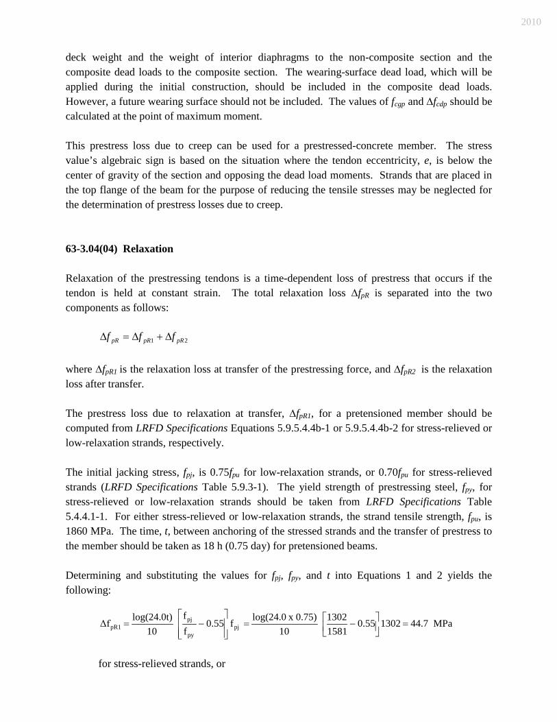
deck weight and the weight of interior diaphragms to the non-composite section and the composite dead loads to the composite section. The wearing-surface dead load, which will be applied during the initial construction, should be included in the composite dead loads. However, a future wearing surface should not be included. The values of fcgp and ∆fcdp should be calculated at the point of maximum moment. This prestress loss due to creep can be used for a prestressed-concrete member. The stress value’s algebraic sign is based on the situation where the tendon eccentricity, e, is below the center of gravity of the section and opposing the dead load moments. Strands that are placed in the top flange of the beam for the purpose of reducing the tensile stresses may be neglected for the determination of prestress losses due to creep. 63-3.04(04) Relaxation Relaxation of the prestressing tendons is a time-dependent loss of prestress that occurs if the tendon is held at constant strain. The total relaxation loss ∆fpR is separated into the two components as follows: 21 pRpRpR fff ∆+∆=∆
where ∆fpR1 is the relaxation loss at transfer of the prestressing force, and ∆fpR2 is the relaxation loss after transfer. The prestress loss due to relaxation at transfer, ∆fpR1, for a pretensioned member should be computed from LRFD Specifications Equations 5.9.5.4.4b-1 or 5.9.5.4.4b-2 for stress-relieved or low-relaxation strands, respectively. The initial jacking stress, fpj, is 0.75fpu for low-relaxation strands, or 0.70fpu for stress-relieved strands (LRFD Specifications Table 5.9.3-1). The yield strength of prestressing steel, fpy, for stress-relieved or low-relaxation strands should be taken from LRFD Specifications Table 5.4.4.1-1. For either stress-relieved or low-relaxation strands, the strand tensile strength, fpu, is 1860 MPa. The time, t, between anchoring of the stressed strands and the transfer of prestress to the member should be taken as 18 h (0.75 day) for pretensioned beams. Determining and substituting the values for fpj, fpy, and t into Equations 1 and 2 yields the following:
for stress-relieved strands, or
MPa44.713020.5515811302
100.75)xlog(24.0f0.55
ff
10log(24.0t)Δf pj
py
pjpR1 =
−=
−=
2010
for low-relaxation strands. The relaxation loss, ∆fpR1, which is small, should be added to the computed elastic shortening loss, ∆fpES, in determining the initial prestress loss used to check beam stresses at transfer. The LRFD Specifications commentary states that relaxation losses prior to transfer are accounted for during fabrication of a prestressed member. However, this is not standard practice. The only adjustments to the prestressing force that are made by beam producers are those required for temperature compensation, bed or form deformation, and chuck seating. The prestress loss due to relaxation after transfer, ∆fpR2, for stress-relieved strands is 138 MPa, which is reduced continually with time as the other prestress losses reduce the tendon stress. The elastic shortening loss, ∆fpES, occurs almost instantaneously so that its effect is largest. The losses due to shrinkage, ∆fpSR, and creep, ∆fpCR, take place over a period of time and have a smaller effect. The losses due to friction, ∆fpF, for a post-tensioned beam, are between the two. The loss in prestress due to relaxation after transfer for stress-relieved strands should be computed from LRFD Specifications Equation 5.9.5.4.4c-1 or 5.9.5.4.4c-2 for a pretensioned and a post-tensioned member, respectively. For low-relaxation strands, use 30% of ∆fpR2 indicated by Equation 1 or 2. 63-3.04(05) Anchorage Set In post-tensioned construction, not all of the stress developed by the jacking force is transferred to the member because the tendons slip slightly as the wedges, plates, shims, etc., seat themselves in the anchorage. The anchorage slip or set ∆A is assumed to produce an average strain over the length of a tendon, L, which results in an anchorage set loss as follows:
LE
f pApa
∆=∆
where Ep is the modulus of elasticity of the prestressing tendon. Anchorage slip or set in a post-tensioning system is specific to a particular stressing system and is a given distance. The range of ∆A varies from 3 to 10 mm with a value of 6 mm assumed for strands. Bar tendons may have a set as low as 2 mm. For long tendons, the anchorage set loss is relatively small, but for short tendons it can become significant. The initial prestress can be increased to compensate for the anchorage slip or set.
MPa12.413950.5516741395
400.75)xlog(24.0f0.55
ff
40log(24.0t)Δf pj
py
pjpR1 =
−=
−=
2010

63-3.04(06) Friction For a pretensioned member with draped strands, friction losses will occur at the hold-down points and should be accounted for by the fabricator in the stressing yard. Because ducts and sheaths are used for post-tensioning, friction occurs where the cable makes contact with the duct. Contact will occur due to deliberate curvature of the duct, or the curvature effect, and also due to unintended wobbling of the duct, or the wobbling effect. The coefficient of friction, µ, between the tendon and duct is an important quantity, as is the angle change of the cable. Design values for µ and the wobble-friction coefficient, K, are shown in LRFD Specifications Table 5.9.5.2.2b-1. These coefficients can vary significantly. The characteristics of the post-tensioning system that is to be used should be known so as to accurately estimate friction losses. Losses due to friction between the internal tendons and duct wall should be determined as described in LRFD Specifications Article 5.9.5.2.2b-1. Anchorage set causes a reversal of the friction effect near the end of the member; i.e., the tendon is sliding the opposite way. Therefore, the cable force will increase from the end of the member to a point where the anchorage set of the cable is achieved. Where a large discrepancy occurs between measured and calculated tendon elongations, in-place friction tests should be performed.
63-3.05 Strand Transfer and Development Length
The transfer length is the length of strand over which the prestress force is transferred to the concrete by means of bond and friction. The transfer length is very small and is in the range of 500 mm to 1000 mm from the end of the prestressed member. The LRFD Specifications indicates that the transfer length may be assumed to be 60 strand diameters. The stress in the strand is assumed to vary linearly from zero at the end of the member, or the point where the strand is bonded if debonding is used, to the full effective prestress force at the end of the transfer length. The development length is the length of strand required to develop the stress in the strand corresponding to the full flexural strength of the member. Strand development length is the length required for bond to develop the strand tension at ultimate flexure. The transfer length is included as part of the development length. LRFD Specifications Equation 5.11.4.2-1 provides the required development length, ld. Prestressing strands should be considered fully bonded beyond the critical section for development length. The development length for debonded (shielded) strands should be in accordance with Article 5.11.4.3. Where debonded (shielded) strands are used, the following guidelines apply.
2010

1. In a bulb-tee beam, not more than 25% of the total number of strands and not more than
40% in each horizontal row should be debonded. The allowable percentage of debonded strands for an AASHTO I-beam or a box beam should be not more than 50% of the total number of strands and of the strands in each horizontal row. Strands placed in the top flange of the beam are not to be included in the above percentages.
2. Exterior strands in each horizontal row should not be debonded. 3. Bonded and debonded strands should preferably alternate both vertically and
horizontally. 4. Debonding termination points should be staggered at intervals of not less than 1 m. . 5. Not more than four strands, or 40% of the total debonded strands, whichever is greater,
should be terminated at one point. 6. See LRFD Specifications Article 5.11.4 for additional guidelines. 7. Consider placing 2 strands in the top of a box beam, 2 or 4 strands in the top flange of an
I-beam, or up to 6 strands in a bulb-tee beam. This can significantly reduce the need for debonded strands in the bottom of the beam. Where strands are placed in the top flange, a note should be shown on the plans indicating that these strands are to be cut at the center of the beam after the bottom strands are released and the pocket is then to be filled with grout. The top strands may not need to be cut if ultimate moment controls the number of strands in the bottom flange.
8. Top strands in a concrete box beam should be placed near the sides of the box. 63-4.0 PRESTRESSED-BEAM SECTIONS
63-4.01 General [Revised May 2009]
The type of beams used in the superstructure should be selected based upon economy and appearance. The following standard prestressed concrete beam sections are used. 1. AASHTO I-beam type I, II, III, or IV; 2. Indiana bulb-tee beams; and 3. Indiana composite and non-composite box beams.
2010

To ensure that the structural system has an adequate level of redundancy, a minimum of four beam lines should be used on an INDOT-route structure. Three beam lines may be used on a local-public-agency-route structure if the designer obtains written approval from the appropriate LPA elected official. Section 61-5.02 provides width criteria for a deck overhang. An alternative prestressed-concrete-beam section may be considered if the designer can justify its use. The use of a beam section not available through local producers will be more expensive if the forms must be purchased or rented for a small number of beams. One or more beam fabricators should be contacted early in project development to determine the most practical and cost-effective alternative beam section for a specific site. A transformed section may be used for the design of prestressed-concrete beams only with the permission of the Production Management Division’s Structural Services manager. If a transformed section is permitted and used for the design of prestressed-concrete beams, a note should be included with the General Plan notes which reads as follows: A transformed section was used for the design of the beams. The Beam Details sheets should include information which indicates the total number of transformed prestressing strands and the final prestress-force loss (not the percent loss).
63-4.02 AASHTO I-Beam Type I, II, III, or IV [Revised May 2009]
See Figures 63-13A(1) through 63-13D(3) for details and section properties. I-beam type IV should not be used unless widening of an existing bridge is required. The 1372-mm-depth bulb-tee beam should be used for a new structure where this member depth and span length is required. See Section 59-3.02(05) for additional information on AASHTO I-beams.
63-4.03 Indiana Bulb-Tee Beam [Revised May 2009]
See Figures 63-14A(1) through 63-14F(2), and 63-14M(1) through 63-14R(2) for details and section properties. For a long-span bridge, bulb-tee beams with a top-flange width of 1524 mm should be considered for improved stability during handling and transporting. Draped strands may be considered for use in a bulb-tee beam, but should only be considered if tensile stresses in the top of the beam near its end are exceeded using straight strands. For additional information on draped strands, see Section 63-5.0. Semi-lightweight concrete may be used for this type of beam if it is economically justified. See Section 63-10.0. For additional information on bulb-tee beams, see Section 59-3.02(06).
2010

Prestressed-concrete bulb-tee members identified as hybrid bulb-tees have been approved for use. One of these sections should be considered if deemed to be the more economical or structurally adequate than an Indiana bulb-tee member. See Figures 63-14G(1) through 63-14L(2), and 63-14S(1) through 63-14X(2) for details and section properties.
63-4.04 Indiana Composite or Non-Composite Box Beam [Revised May 2009]
See Figures 63-15A through 63-15L for details and section properties of composite members. See Figures 63-15M through 63-15R for details and section properties of non-composite members. It is not acceptable to use non-composite box beams for a permanent State highway bridge. The use of the non-composite box beam is limited to a non-Federal-aid local public agency bridge or a temporary bridge. The desirable limit for the end skew is 30 deg. An end skew of over 30 deg should be avoided unless measures have been considered for potential warping or cracking of the beam at its ends and congested reinforcement in the acute angle corner of the beam. For a spread-box-beam structure, diaphragms of 200 mm thickness should be placed within the box section for increased stability and torsion resistance during delivery and erection of the beams. The maximum spacing of the diaphragms is 7.6 m. For an adjacent-box-beams structure, interior diaphragms should be provided to accommodate the transverse tension rods or tendons. Effective means for transferring shear between the box beams should be provided (see Section 63-8.0). Because the longitudinal joints between adjacent box beams have shown a tendency to leak, use of adjacent box beams should be limited to where maintaining a thin construction depth is critical, where construction time is critical, or where substantial life-cycle cost savings can be demonstrated. Each void in a box beam should be equipped with a vertical drainage pipe to prevent accumulation of water and ice therein. The inside diameter of the pipe should be approximately 15 mm. It should be located at the lowest point of the void in the finished structure. If the cost of a superstructure using precast concrete AASHTO I-beams or bulb-tees is close to the cost of precast concrete spread box beams, the I-beam or bulb-tee superstructure is preferred unless other factors such as a thin structure depth are critical. See Section 59-3.02(05) for additional information on spread box beams. See Section 59-3.02(07) for additional information on adjacent box beams. 63-5.0 STRAND CONFIGURATION AND MILD-STEEL REINFORCEMENT
2010
63-5.01 General
Proper detailing of strand configuration and mild reinforcing steel offers an opportunity to contribute to cost savings. Mild reinforcing steel should be detailed to allow its placement after the strands have been tensioned. If the reinforcement is a one-piece bar detailed around the strands, it requires that the strands be threaded through the closed bars. By using two-piece bars that can be placed after the strand is tensioned, the fabrication process is simplified. In specifying concrete cover and spacing of strands and bars, the designer must consider reinforcing-bar diameters and bend radii to avoid conflicts. As indicated in Section 63-3.02, to support the reinforcing steel cage, producers prefer to locate at least two strands in the top of each I-beam or bulb-tee beam below the top transverse bars and between the vertical legs of the web reinforcement.
63-5.02 Strand Configuration
See Sections 63-13.0, 63-14.0, and 63-15.0 for typical strand patterns for standard prestressed beam sections. Other strand patterns may be used if there is reason for deviation from the standard pattern, and the AASHTO criteria for spacing and concrete cover are followed. If 11 strands are placed in a horizontal row in the bottom of a bulb-tee beam, the bending diagram for the vertical stirrup must be modified. The strand pattern shown may be used for nominal 12.70-mm or 15.24-mm diameter strands. Section 63-3.02 provides criteria for the strand diameters used. The strand-pattern configurations shown in Sections 63-13.0, 63-14.0, and 63-15.0 were developed in accordance with the following. 1. Minimum center-to-center spacing of prestressing strands should be 50 mm, instead of
the 51 mm shown in LRFD Specifications Table 5.10.3.3.1-1. 2. Minimum concrete cover for prestressing strands should be 40 mm, which includes the
modification factor of 0.8 for a water/cement ratio equal to or less than 0.40 (LRFD Article 5.12.3).
3. Minimum concrete cover to stirrups and confinement reinforcement should be 25 mm. The strand pattern has been configured so as to maximize the number of vertical rows of strands that can be draped. Due to the relatively thin top flange of a bulb-tee beam, strands placed in the top of the beam should be at least 150 mm from the outside edge of the flange.
2010

63-5.03 Mild-Steel Reinforcement
See Sections 63-13.0, 63-14.0, and 63-15.0 for typical mild-steel reinforcement for the standard prestressed beam sections. The vertical shear reinforcement should be #13 stirrup bars where possible. To fully develop the bar for shear, the ends of the stirrup bar should include a standard 90-deg stirrup hook. The maximum spacing of the vertical stirrups should be in accordance with LRFD Specifications Article 5.8.2.7. The maximum longitudinal spacing of reinforcement for interface shear transfer should be in accordance with LRFD Article 5.8.4.1. A minimum of three horizontal U-shaped #13 bars should be placed in the web of each bulb-tee at the ends of the beam. See Section 63-14.0 for location and spacing of these bars. This reinforcement will help reduce the number and size of cracks, which may appear in the ends of the beams due to the prestress force. LRFD Specifications Article 5.10.10.1 requires that vertical mild reinforcement should be placed in the beam ends within a distance of one fourth of the member depth. This is to provide bursting resistance of the pretensioned anchorage zone. Enough mild reinforcing steel should be provided to resist not less than 4% of the prestress force at transfer. The end vertical bars should be as close to the ends of the beam as possible. The stress in the reinforcing steel should not exceed 140 MPa. Confinement reinforcement (LRFD Article 5.10.10.2) should be placed in the bottom flange of each I-beam or bulb-tee. The reinforcement should be #10 bars spaced at 150 mm for a minimum distance of 1.5 times the depth of the member from the end of the beam or to the end of the strand debonding, whichever is greater. The minimum concrete cover for ties or stirrup bars should be 25 mm. 63-6.0 DESIGN OF A PRESTRESSED-CONCRETE BEAM
63-6.01 General
The general design theory and procedure for precast, prestressed (pre-tensioned) concrete-beam design is described below. For specific design examples, see the PCI Bridge Design Manual, Chapter 9, or Design of Highway Bridges Based on AASHTO LRFD Design Specifications, by Barker and Puckett. The design of a post-tensioned concrete beam will not be addressed in this Chapter. A multi-span bridge using composite beams should be made continuous for live load if possible. The design of the beams for a continuous structure is approximately the same as that for simple spans except that, in the area of negative moments, the member is treated as an ordinary reinforced-concrete section. The members should be assumed to be fully continuous with a
2010

constant moment of inertia in determining both the positive and negative moments due to superimposed loads. The load modifier η should be as specified in LRFD Specifications Article 1.3.2. The limit states (LRFD Article 3.4) to be used for the beam design will consist of satisfying the requirements of Service I, Service III, and Strength I load combinations. Service III specifies a load factor of 0.80 to reduce the effect of live load at the service-limit state. This combination is applicable only in checking allowable tensile stresses in the beam. Service I is used in checking compressive stresses only. The resistance factor ϕ (LRFD Article 5.5.4) should be as follows: 1. For flexure, 1.0. For design of the negative-moment steel in the deck for a structure
made continuous for composite loads only and having a poured-in-place continuity joint between the ends of the beams over the piers, 0.90.
2. For shear and torsion, 0.90 for normal-weight concrete, 0.80 for semi-lightweight
concrete, or 0.70 for lightweight concrete.
63-6.02 Lateral Stability
LRFD Specifications Article 5.5.4.3 indicates that buckling of precast members during handling, transportation, and erection should be investigated. The INDOT Standard Specifications makes the contractor responsible for handling, storing, and erection of beams and other precast elements. For a beam length of over 30 m, the designer should consult with a fabricator to determine whether such beams can be delivered to the project site.
63-6.03 Stage Loading
The loading conditions that affect the design of a prestressed beam are as follows. 1. The strands are tensioned in the bed prior to placement of the concrete. Seating losses,
relaxation of the strands, and temperature changes affect the stress in the strands prior to placement of the concrete. It is the fabricator’s responsibility to consider these factors during the fabrication of the beam and to make adjustments to the initial strand tension to ascertain that the tension prior to release satisfies the design requirements.
2010

2. The strands are released and the force is transferred to the concrete. After release, the beam will camber up and be supported at the beam ends only. Therefore, the region near the end of the member does not receive the benefit of bending stresses due to the dead load of the beam and may develop tensile stresses in the top of the beam large enough to crack the concrete. The critical sections for computing the critical temporary stresses in the top of the beam should be near the end and at all debonding points. If the designer chooses to consider the transfer length of the strands at the end of the beam and at the debonding points, the stress in the strands should be assumed to be zero at the end of the beam or debonding point and should vary linearly to the full transfer of force to the concrete at the end of the strand transfer length.
The methods of relieving excessive tensile stresses near the ends of the beam are as follows: a. debonding, wherein the strands are kept straight but wrapped in plastic over a
predetermined distance; b. adding additional strands in the top of the beam, debonding them in the middle
third, and releasing them at the center of the beam; or
c. draping some of the strands to reduce the strand eccentricity at the end of the beam.
See Section 63-3.0 for additional criteria regarding draping and debonding of strands. The level of effective prestress immediately after release of the strands should include the effects of elastic shortening and the initial strand relaxation loss.
3. This condition occurs several weeks to several months after strand release. Camber
growth and prestress losses are design factors at this stage. If a cast-in-place composite deck is placed, field adjustments to the haunch-fillet thickness are needed to provide the proper vertical grade on the top of deck and to keep the deck thickness uniform. Reliable estimates of deflection and camber are needed to prevent excessive fillet thickness or to avoid significant encroachment of the top of beam into the bottom of the concrete deck. Stresses at this stage are not critical.
Unless other more accurate methods of determining camber are utilized (see PCI Bridge Design Manual, Section 8.7), the beam camber at the time of placement of the composite concrete deck should be assumed to be the initial camber due to prestress minus the deflection due to the dead load of the beam times a multiplier of 1.75.
2010

4. After an extended period of time, all prestress losses have occurred and loads are at their maximum. This is referred to as the maximum service load, minimum prestress stage. The tensile stress in the bottom fibers of the beam at mid-span controls the design.
63-6.04 Flexure
63-6.04(01) General Flexure design starts with the determination of the required prestressing level to satisfy service conditions. All load stages that may be critical during the life of the structure from the time prestressing is first applied should be considered. This is followed by a strength check of the entire member under the influence of factored loads. The strength check should not require additional strands or other design changes. The weight of the future wearing surface, sidewalk (if not poured with the deck), and railings should be included in the design as composite dead loads. The weight of the railing and sidewalks may be distributed equally to all beams unless they are poured with the deck. A 15-mm thickness, non-structural concrete deck wearing surface should be deducted from the composite design. If the 20-mm haunch is considered in the composite section properties, its width should be transformed before it is used in the calculations. The additional dead load of the haunch, intermediate diaphragms, and optional metal deck forms (0.70 kN/m2) should be included in the design of the beam. For checking the allowable stresses in the beam, the following basic assumptions are made. 1. Plain sections remain plain, and strains vary linearly over the entire member depth.
Therefore, composite members consisting of precast-concrete beams and cast-in-place deck must be adequately connected so that this assumption is valid and all elements respond to superimposed loads as one unit.
2. Before cracking, stress is linearly proportional to strain. 3. After cracking, tension in the concrete is neglected. 63-6.04(02) Design Procedure The tensile stresses at mid-span due to full dead and live loads plus effective prestress (after losses) controls the design as follows.
2010

1. Compute the tensile stress due to beam self-weight plus other non-composite loads such as deck, SIP forms, haunches, diaphragms, etc., applied to the beam section only.
2. Compute the tensile stress due to superimposed dead loads plus 80% of the live loads that
are applied to the composite section. 3. Compute the net stress in the beam by subtracting the allowable tensile stress from the
stresses computed in Steps 1 and 2 above. This will be the stress that needs to be offset by the prestressing. To find the prestressing required, solve the following equation for the effective prestress Pse.
+
=
b
cseseb S
ePA
Pf
Where: fb = net stress in the beam ec = strand eccentricity A = beam area Sb = bottom fiber modulus
Pse The estimated number of strands = ( )strandoneofareafP
pe
se
fpe = effective prestress after losses, which may be approximated as 1170 MPa for 1860 MPa (270 ksi) low-relaxation strand.
4. Perform a detailed calculation of prestress losses (see Section 63-3.04) and repeat Step 3
if necessary. 5. Check stresses at the ends, strand debonding points (if applicable), drape points (if
applicable), and mid-span at release and at service loads. Under normal load conditions, stresses at service loads will not govern at debonding points or drape points.
6. Check strength. Approximate formulas for bonded tendons for pretension steel stress for
flanged or rectangular sections at ultimate flexure are shown in LRFD Article 5.7.3.1.1. The approximate formulas are based upon the following assumptions.
a. The compression zone is either rectangular or T-shaped.
b. The compression zone is within only one type of concrete for a composite
member, and it is assumed to be within the deck concrete. Only fully tensioned strands near the tension face of the beam may be used. The top strands should be ignored.
2010

c. The effective pretension is not less than 50% of the ultimate strength of the
strands.
d. Steel content must be below the amount that causes the predicted steel stress to be lower than the yield strength.
e. Because debonded strands require 25% more development length than bonded
strands (LRFD Article 5.11.4), consideration should be given to development length beyond the point of debonding in computing the ultimate strength. The strands are adequately developed, or reductions accounted for, at all critical design sections such as in the maximum moment region.
The factored flexural resistance Mr = ϕMn, where ϕ = resistance factor of 1.00. It is then computed using the equations referenced in LRFD Article 5.7.3.2.3 for a rectangular section or LRFD Article 5.7.3.2.2 for a flanged section. If the beam section is other than a rectangular or flanged section, a general strain compatibility approach should be taken.
Maximum reinforcement should be checked in accordance with LRFD Article 5.7.3.3.1. The minimum reinforcement should be checked in accordance with LRFD Article 5.7.3.3.2 to be certain that the amount of prestressed and non-prestressed reinforcement is enough to develop a factored flexural resistance, Mr, at least equal to the lesser of at least 1.2 times the cracking moment, Mcr, or 1.33 times the factored moment required by the applicable strength load combinations. The 1.2Mcr value controls in the maximum positive-moment regions. In the approximate end one-third of the beam or span, 1.33 times the factored moment will control. Use LRFD Equation 5.7.3.3.2-1 to compute the cracking moment. Mcr = Sc (fr + fcpe) – Mdnc (Sc/Snc – 1) ≤ Scfr
where: Mcr = cracking moment (N-mm) fr = modulus of rupture of concrete as specified in LRFD Article
5.4.2.6 (MPa) 7. If necessary, revise the number of strands and repeat Steps 4 and 5. Loads placed on the bridge after the deck has hardened should be applied as composite loads if a satisfactory bond is provided between the deck and the top of beam. This bond is accomplished
2010

by the use of a roughened concrete surface on the top of the beam and shear stirrups that project out of the top of the beam into the cast-in-place deck. Because the deck concrete is of a lower strength than the precast beam, the deck should be transformed into an equivalent beam by using the modular ratio, n. The effective flange width must be determined in accordance with LRFD Article 4.6.2.6.1. A fatigue check of the strands is not required unless the beam is designed to crack under service loads. Fatigue of concrete in compression is unlikely to occur in actual practice. Fatigue considerations for prestressed concrete components are addressed in LRFD Article 5.5.3.
63-6.05 Web Shear
63-6.05(01) Design Models The AASHTO LRFD Specifications allows two methods of shear design for prestressed concrete, the strut-and-tie model or the sectional-design model. The sectional-design model is appropriate for the design of a girder, slab, or other region of components where the assumptions of traditional beam theory are valid. This theory assumes that the response at a particular section depends only on the calculated values of the sectional force effects such as moment, shear, axial load, and torsion, and does not consider the specific details of how the force effects were introduced into the member. Therefore, only the sectional-model approach will be discussed herein. In a region near a discontinuity, such as an abrupt change in cross section, opening, coped (dapped) end, deep beam, or corbel, the strut-and-tie model should be used. See LRFD Articles 5.6.3 and 5.13.2, and PCI Bridge Design Manual Section 8.12 for more information regarding the strut-and-tie model. LRFD Specifications Article 5.8.3 discusses the sectional-design model. Subsections 1 and 2 describe the applicable geometry required to use this technique to design the web reinforcement. The nominal resistance is taken as the lesser of the following: or,VVVV pscn ++= (LRFD Eq. 5.8.3.3-1)
pvvcn Vdbf0.25V +′= (LRFD Eq. 5.8.3.3-2)
LRFD Eq. 5.8.3.3-2 represents an upper limit of Vn to ensure that the concrete in the web will not crush prior to yield of the transverse reinforcement. The nominal shear resistance provided by tension in the concrete is computed as follows:
2010

vvcc dbfβ0.83V ′= (LRFD Eq. 5.8.3.3-3)
The contribution of the web reinforcement is provided by the following:
s
αsinα)cotθ(cotdfAV vyv
s
+= (LRFD Eq. 5.8.3.3-4),
where the angles θ and α represent the inclination of the diagonal compressive forces measured from the horizontal beam axis and the angle of the web reinforcement relative to the horizontal beam axis, respectively. Where the web shear reinforcement is vertical (α = 90o), Vs simplifies to the following:
s
θcotdfAV vyv
s =
Transverse shear reinforcement should be provided based on the following: Vu > 0.5 Φ (Vc + Vp) (LRFD Eq. 5.8.2.4-1)
Where transverse reinforcement is required, the area of steel should not be less than the following:
y
vcv f
sbf0.83A ′= (LRFD Eq. 5.8.2.5-1)
Where the reaction introduces compression into the end of the member, the critical section for shear is taken as the larger of 0.5dvcot θ, or dv, measured from the face of the support (see LRFD Article 5.8.3.2). For a section including at least the minimum amount of transverse reinforcement specified in LRFD Article 5.8.2.5, the values of β and θ should be taken from Table 5.8.3.4.2-1. For a section that does not satisfy the minimum transverse reinforcement requirements, Table 5.8.3.4.2-2 should be used to determine β and θ. 63-6.05(02) Design Procedure The area and spacing of shear reinforcement must be determined at the tenth points along the span and at the critical section as described above. To design a member for shear, the factored shear should be determined due to applied loads at the section under consideration. The values for bv and dv should be determined. The value of effective shear depth, dv, which is the distance
2010

between the resultants of the tensile and compressive forces due to flexure, can be expressed as follows:
( )
−
+=
2ador
fAfAM
d epspsys
nv
The value of dv need not be less than the greater of 0.9de or 0.72h. The stress contribution from a draped strand, Vp, is then computed. Vp, the component of the effective prestressing force in the direction of the applied shear is the force per strand times the number of draped strands times sinΨ. The angle of drape, Ψ, is measured from the longitudinal axis of the beam. The factored shear stress is calculated using the following:
vv
pu
dΦbΦVV
v−
= (LRFD Eq. 5.8.2.9-1)
The quantity cfv/ ′ is then computed, and a value of θ is assumed. For a prestressed member, a reasonable initial estimate for θ is 30 deg. For a section that includes at least the minimum transverse reinforcement as specified in LRFD Article 5.8.2.5, the strain in the tensile reinforcement is calculated using the following:
0.001)AEA2(E
fAθcot)V0.5(V0.5N)/d(M
pspss
popspuuvux ≤
+
−−++=ε (LRFD Eq. 5.8.3.4.2-1)
If the section includes less than the minimum transverse reinforcement as specified in LRFD Article 5.8.2.5, use LRFD Eq. 5.8.3.4.2-2. If the value of εx from either Eq. 1 or 2 is negative, use LRFD Eq. 5.8.3.4.2-3. The LRFD Specifications indicates that the area of prestressing steel, Aps, must account for the lack of development near the ends of a prestressed beam. Mild reinforcement or strand in the compression zone of the member, which is taken as one-half of the overall depth, h/2, should be neglected in computing As and Aps for use in this calculation. In evaluating a member with draped strands, near the ends of a typical beam, draped strands are near the top of the beam. Because of this, the straight and draped strands should be considered separately in the analysis. The physical location of each strand is significant, and not the centroid of the group. The variable fpo can be taken as the stress in the strands once the concrete is cast around them. The stress in the concrete is zero. Therefore, fpo can be conservatively taken as 0.7fpu for the
2010

usual levels of prestressing. Within the transfer length of the strands at the end of the beam, fpo should be increased linearly from zero at the end of the beam to its full value at the end of the transfer length. LRFD Table 5.8.3.4.2-1 is then entered for a section with minimum transverse reinforcement as specified in Article 5.8.2.5 with the values of cfv/ ′ and εx. The value of θ corresponding to cfv/ ′ and εx is compared to the assumed value of θ. If the values match, Vc is calculated using Eq. 5.8.3.3-3 with the value of β from the Table. If they do not match, the value of θ taken from the Table is used for reiteration. Of the quantities computed thus far, only εx will change with a new value of θ, so the effort required for additional iterations is minor. The same procedure is used for a section with less than the minimum transverse reinforcement, except that Table 5.8.3.4.3-2 is used. After Vc has been computed, Vu must be checked to determine if it is greater than 0.5Ф(Vc + Vp). If Vu exceeds this value, shear reinforcement is required. The quantity of shear steel is calculated using Av = (sVs)/(fydvcot θ). After determining the amount of shear reinforcement needed, the maximum spacing allowed by the LRFD Specifications should be checked as described in Article 5.8.2.7. The size of the shear stirrup should be a #13 bar where possible. The amount of shear reinforcement should be checked to ensure that it is equal to or larger than the minimum value required by Eq. 5.8.2.5-1. To ensure that the concrete in the web of the beam will not crush prior to the yielding of the transverse reinforcement, the LRFD Specifications provides an upper limit of Vn, as follows: pvvcn Vdbf0.25V +′= (LRFD Eq. 5.8.3.3-2)
(Vc + Vs) should be less than or equal to .dbf0.25 vvc′ Using the foregoing procedures, the transverse reinforcement can be determined at the tenth points along the beam and at the critical section. In a region of high shear stress, such as near the support, the longitudinal (flexural) reinforcement must also be able to carry the additional stress due to shear. This is the horizontal component, T, of the diagonal compression field. Therefore, the amount and development of the longitudinal reinforcement must be greater than or equal that provided as follows:
θcot22
−−Φ
+Φ
+Φ
= psuu
v
u VVVN
dM
T (LRFD Eq. 5.8.3.5-1)
This equation should be satisfied, especially near a non-continuous support where a substantial portion of the prestressing strands are either debonded or draped. Draped or debonded strands are not effective in contributing to this longitudinal reinforcement requirement because they are either above the mid-height of the member, h/2, or they are not bonded to the concrete.
2010

LRFD Article 5.8.3.5 requires that the longitudinal reinforcement on the flexural tension side of the member, below h/2, should resist a tensile force of (Vu/φ – 0.5Vs – Vp)cot θ at the inside edge of the bearing area at the simple end supports. The values of Vu, Vs, Vp, and θ, calculated for the critical section 0.5dvcot θ, or dv from the face of the support, may be used. In calculating the tensile resistance of the longitudinal reinforcement, a linear variation of resistance over the transfer length may be assumed.
63-6.06 Horizontal Interface Shear
A cast-in-place concrete deck designed to act compositely with precast-concrete beams must be able to resist the horizontal shearing forces at the interface between the two elements. Vh can be determined as follows: Vh = Vu /de (LRFD Eq. C5.8.4.1-1)
The required strength should be less than or equal to the nominal strength and is as follows: VhAcv ≤ ΦVn
where Vn = cAcv + μ[Avffy + Pc]. Pc, the permanent net compressive force normal to the shear plane, may be conservatively neglected. LRFD Article 5.8.4.2 indicates that for concrete placed against clean hardened concrete with the surface intentionally roughened to an amplitude of 6 mm, the tops of the beams should be scored at 75-mm centers transverse to the top beam flange to a depth of at least 6 mm. c = 0.70 MPa μ = 1.0λ, where λ = 1.0 for normal-density concrete. Therefore, for normal-weight concrete cast against hardened, roughened, normal-weight concrete, the above relationship may be reduced as follows:
+Φ≤
cv
yvfh A
fAV 7.0
where the minimum cv
yvf A
fA
35.0≥ .
The nominal shear resistance, Vn, used in the design should satisfy the following:
2010

or,Af 0.2V cvcn ′≤ (LRFD Eq. 5.8.4.1-2)
cvn A5.5V ≤ (LRFD Eq. 5.8.4.1-3)
If the width of the interface surface is more than 1200 mm, a minimum of four #13 bars should be used for each row with two of the bars, one on each side of the flange, located near the outside edge of the flange. LRFD Article 5.8.4.1 requires that the maximum spacing of horizontal shear stirrups should not exceed 600 mm. For a member such as a partial-depth deck panel, the minimum reinforcement requirement Avf may be waived if Vn/Acv is less than 0.7 MPa.
63-6.07 Continuity for Superimposed Loads
The traditional method of making simply-supported beams continuous is to construct a closure joint between the adjacent beam ends over the pier, conveniently as part of the diaphragm, and to place extra longitudinal steel in the deck over the pier support to resist the negative moment. Spans made continuous for live load are assumed to be treated as prestressed members in the positive-moment zone between supports and as conventionally-reinforced members in the negative-moment zone over the support. The reinforcing steel in the deck should carry all of the tension in the composite section due to the negative moment. The longitudinal reinforcing steel in the deck that makes the girder continuous over an internal support should be designed in accordance with LRFD Article 5.14.1.2.7b. The compressive strength of the beam concrete should be used regardless of the strength of the cast-in-place concrete. Due to lateral restraint of the diaphragm concrete, ultimate negative moment compression failure in the PCA tests as described in PCA Engineering Bulletin, Design of Continuous Highway Bridges with Precast, Prestressed Concrete Girders, August 1969, always occurred in the girder, though the diaphragm-concrete strength was approximately 14 MPa less than that of the girder concrete. The negative-moment reinforcement in the deck should therefore be designed using the compressive strength of the concrete in the precast elements. See LRFD Specifications Article 5.14.1.2.7. No allowable tension limit is imposed on the top-fiber stresses of the beam in the negative-moment region. However, crack width, fatigue, and ultimate strength should be checked. If partial-depth precast, prestressed concrete stay-in-place forms are to be used, such as for an AASHTO I-beam superstructure, only the top mat of longitudinal steel reinforcement should be used to satisfy the negative-moment requirements.
63-6.08 Effect of Imposed Deformations
2010

Potential positive moments at the piers should also be considered in the design of a precast, prestressed concrete beam structure made continuous for live load. Creep of the beams under the net effects of prestressing, self-weight, deck weight, and superimposed dead loads will tend to produce additional upward camber with time. Shrinkage of the deck concrete will tend to produce downward camber of the composite system with time. Loss of prestress due to creep, shrinkage, and relaxation will result in downward camber. Depending on the properties of the concrete materials and the age at which the beams are erected and subsequently made continuous, either positive or negative moments can occur over the continuous supports. Where beams are made continuous at the relatively young age of less than 120 days from time of manufacture, it is more likely that positive moments will develop with time at the supports. These positive restraint moments are the result of the tendency of the beams to continue to camber upwards as a result of ongoing creep strains associated with the transfer of prestress. Shrinkage of the deck concrete, loss of prestress, and creep strains due to self-weight, deck weight, and superimposed dead loads all have a tendency to reduce this positive moment. For a span of over 45 m in length or for concrete whose creep behavior is known to be poor, the designer should make a time-dependent analysis to predict positive restraint moments at the piers. The PCI Bridge Design Manual, Section 8.13.4.3, describes two methods to evaluate restraint moments at the piers. If the designer has experience with similar spans and concrete creep properties, he or she may use the positive-moment-connection details at the piers that have proven successful in the past. Unless positive-moment-connecting steel calculations are made, the minimum number of strands to be used for the positive-moment connection over the pier should be one-half the number of strands in the bottom row of the bottom flange of a bulb-tee or an I-beam. The minimum is 5 strands for a bulb-tee or I-beam type IV, 4 strands for an I-beam type II or III, or 3 strands for I-beam type I. The strands should be extended and bent up without the use of heat to make the positive moment connection. For a box beam, the minimum number of strands to be extended into the positive-moment connection and bent up should be 6 strands for a beam deeper than 686 mm or 4 strands for a beam equal to or less than 686 mm in depth. The strands extended into the positive-moment connection between beams should not be debonded. The strands that are not used for the positive-moment connection should be trimmed back to the beam end to permit ease of beam and concrete placement. The prestressing-strand and concrete strengths should be as indicated in Section 63-3.0. The tensile and compressive stress limits should be as shown in LRFD Article 5.9.4. The LRFD Specifications requires that only 80% of the live-load moment is to be applied in checking the tensile stress at service conditions.
2010

63-7.0 DIAPHRAGMS Reference: LRFD Article 5.13.2.2
63-7.01 General
A multi-girder bridge (except for one with adjacent box beams) should have diaphragms provided at abutments, end bents, and interior piers or bents to resist lateral forces and transmit loads to points of support. For certain span lengths, permanent intermediate diaphragms should be provided to stabilize the beams during construction. To simplify the bill of materials, the longitudinal and transverse reinforcing bars in concrete diaphragms and transverse edge beams, except the #19 threaded bars, may be epoxy coated.
63-7.02 Intermediate Diaphragms
Intermediate diaphragms should be provided for an I-beam or bulb-tee beam superstructure as follows: 1. For a span greater than 25 m but less than or equal to 40 m, provide diaphragms at the
mid-span. 2. For a span greater than 40 m, provide diaphragms at the span third points. For a structure with spans less than or equal to 25 m, a note should be placed on the plans stating the following:
Suitable restraint shall be provided to prevent the rotation of the beams, particularly the outside beam, from construction loads, such as the weight of the concrete deck, finishing machine, forms, etc.
63-7.02(01) Structural-Steel Interior Diaphragms Structural-steel interior diaphragms should be specified if interior diaphragms are required. This use of structural steel instead of concrete does not affect the bridge design. Structural-steel interior diaphragms should be specified on the plans. The quantities in kilograms should be shown in the superstructure bill of materials and on the Bridge Summary sheet.
2010

63-7.02(02) Reinforced-Concrete Interior Diaphragms If the designer determines that cast-in-place concrete interior diaphragms should be used, he or she should provide the Production Management Division’s Structural Services manager with a written justification for the concrete diaphragms. Once the Structural Services manager concurs in the justification, such diaphragms should be detailed on the plans. The required quantities of concrete and reinforcing steel should be incorporated into those for the bridge deck. A note should also be added to the plans stating the following:
Concrete in the intermediate diaphragms shall attain a compressive strength of 21.0 MPa before the deck concrete is poured.
63-7.02(03) Reinforced-Concrete Interior Diaphragms Detailed, Structural-Steel Interior Diaphragms Permitted For a structure with plans at the Final Check Prints stage that show details for concrete interior diaphragms, and the designer has determined that steel diaphragms are acceptable, the diaphragm details should not be changed. The contractor will be permitted to substitute steel diaphragms for the concrete diaphragms. The substitution does not affect the bridge design. A note should be placed under the superstructure bill of materials which reads as follows:
The Contractor will be permitted to substitute structural-steel diaphragms for the reinforced-concrete interior diaphragms. The estimated quantity of structural steel is ______. If the substitution is made, this quantity shall be placed in lieu of ______ of concrete class C in superstructure and ______ of epoxy coated reinforcing steel.
The diaphragms should not be connected to the deck slab to avoid cracking of the deck over the diaphragm. For a skew of less than or equal to 25 deg, the diaphragms should be placed parallel to the skew. For a skew of greater than 25 deg, the diaphragms should be staggered and placed perpendicular to the beams. See Section 63-16.0 for typical details of intermediate cast-in-place concrete diaphragms. A spread-box-beam superstructure having an inside radius of curvature of less than 240 m should have intermediate diaphragms between the individual boxes. The required spacing will depend upon the radius of curvature and the proportions of the webs and flanges. The diaphragms should be placed on the radial lines. Other box beam superstructures do not require intermediate diaphragms.
2010

63-7.03 End Diaphragms
Cast-in-place end diaphragms or edge beams are mandatory, except for an adjacent precast-concrete box-beam superstructure. Integral end bents function as full-depth diaphragms. An end diaphragm serves the purposes as follows: : 1. as a perimeter beam for the deck; 2. supports the deck-joint device; and 3. transfers lateral loads to the end bent. For typical details of an end diaphragm, or transverse edge beam, see Section 61-5.03. For typical details of integral end bents, see Section 67-1.01.
63-7.04 Interior Pier or Bent Diaphragms
Cast-in-place diaphragms are mandatory at all interior piers and bents, except for an adjacent precast concrete box beam superstructure. They serve the purposes as follows: 1. transfer lateral loads to the piers or bents, and 2. for beams made continuous for live load, strengthen the cast-in-place closure placement
by providing lateral restraint. The minimum width of diaphragm for bulb-tee beams should be 900 mm, for I-beams 750 mm, or for spread box beams 600 mm. The clear distance between beam ends should be 150 mm unless otherwise approved. This dimension should always be determined parallel to the longitudinal centerline of the beam. See Section 63-16.0 for typical details of cast-in-place concrete pier and bent diaphragms. The information illustrated in the figures therein is as follows: 1. diaphragm widths; 2. diaphragm reinforcement; 3. cap-keyway details; 4. clear distance between adjacent beam ends; 5. bearing-pad location details; 6. cap-sizing details; and 7. beam threaded-bar-hole/insert location details.
2010

The figures in Section 63-16.0 also show bearing layouts for a skewed structure with I-beams, bulb-tee beams, or box beams. For the same skew angle, the bearing pads are oriented differently in these figures. The ideal orientation of the pads, between the direction of the beams and the normal drawn to the bearing line, is a function of the skew, the length-to-width ratio, the component rigidities, and the position of loads. In reality, the structural significance of the orientation is small and geometric requirements should govern. 63-8.0 TRANSVERSE CONNECTION OF PRECAST BOX BEAMS Adjacent, precast, prestressed box-beam bridge superstructures have been used extensively. The shear keys in this type of superstructure tend to crack and leak with a thin concrete deck placed composite with the beams. Research indicates that these cracks are due to thermal forces and not due to the live load of a vehicle moving across the bridge. Research has shown that the following method is effective to minimize cracking in the shear keys between the beams. 1. Use epoxy grout due to its high bond strength. 2. Use a full-depth shear key to stop the joint from performing like a hinge to prevent the
joint from opening. In past designs, the area below the key was open and free to rotate. With this area grouted, the movement of the joint will be reduced.
3. Apply compression across the joint by means of transverse tensioning rods. This will
help prevent opening of the joint. Figures 63-8A, 63-8B, and 63-8C illustrate methods to minimize cracking in this type of structure. The joints between the beam shear keys, and the recesses for the transverse tensioning rods on the exterior face of the beam, should be grouted with an epoxy grout as shown in the details. After the joints between the beams are grouted, a preliminary tightening of the transverse tensioning rods should be performed. Once this is completed, a final tensioning of the rods should be performed to yield 138 MPa as developed by a torque of 271 N-m. 63-9.0 SEGMENTAL CONSTRUCTION
2010

Designers are continually being challenged to design structures with long spans and low initial cost. Long spans are used to reduce the number of piers required for a water crossing, and for the elimination of piers adjacent to roadway shoulders at an overpass bridge. Prestressed-concrete-beam lengths in the range of 30 m to 40 m are common. For a continuous structure, the girders are fabricated in lengths to span from support to support. A closure pour is then made over the piers to provide continuity for live load and superimposed dead loads. This type of construction is cost effective because the girders can be erected in one piece without falsework. However, if girders are too long or too heavy to be shipped in lengths to accommodate the spans, spliced girders or segmental construction are options. Construction techniques have been developed that reduce the cost and, can make concrete girders competitive with steel girders for spans in excess of 80 m. The most commonly-used techniques are as follows: 1. segmental post-tensioned box girders erected on temporary falsework or by the balanced
cantilever method; and 2. precast-concrete girders spliced at the construction site. These girders can either be
supported on temporary falsework or spliced on the ground and lifted into place on the supports.
Most spliced-girder bridges have bulb-tee beams with post-tensioning. This shape has been chosen due to its lightweight and economical cross section. For staged construction, cambers, deflections, and end rotations of the structural components should be accurately calculated during the stages of construction. For further information, see publications of the Precast/Prestressed Concrete Institute, Post-Tensioning Institute, and the Segmental Concrete Bridge Institute. Another source of information is the AASHTO Guide Specifications for the Design and Construction of Segmental Concrete Bridges. 63-10.0 SEMI-LIGHTWEIGHT CONCRETE Normal-weight concrete has a unit weight of between 2240 kg/m3 and 2400 kg/m3. The use of semi-lightweight concrete, with normal-weight sand mixed with lightweight coarse aggregate, is permitted with a specified density of between 1920 kg/m3 and 2080 kg/m3. Other unit weights may be used if approved by the Production Management Division’s Structural Services manager. This concrete has been used in long-span, bulb-tee beams where weight reduction is important for shipping or handling, and the extra cost of the semi-lightweight concrete is economically justified.
2010

The structural performance of this concrete is equal to that of normal-weight concrete. However, the potential problems that should be addressed are the control of the water content in the lightweight aggregate and the frost-sensitivity of lightweight aggregate for a period of two weeks after casting. Consideration must be given to using mix-design procedures for lightweight concrete as described in ACI 211.2. The modulus of elasticity will be less than that for normal-weight concrete. Creep, shrinkage, and deflection must be appropriately evaluated and accounted for if semi-lightweight concrete is to be used. The designer should request and obtain pertinent data from the Highway Management Division’s Office of Materials Management regarding the shrinkage, creep, modulus of rupture, permeability, coefficient of thermal expansion, and freeze-thaw resistance for a new mix design that the designer does not have experience with. If the formula shown in LRFD Article 5.4.2.6 is used in lieu of physical test values for modulus of rupture, the formula for sand-low-density concrete should be used for semi-lightweight concrete. 63-11.0 DIMENSIONING PRECAST BEAMS If a precast beam is to be placed on a longitudinal slope, its manufactured dimensions should be modified to accommodate the geometric consequences of the grade. The casting bed is always horizontal. Consequently, the out-to-out beam length becomes LCL, as follows: LCL = L/cos θ
where:
θ = arctan (S/100) = angle of slope of the beam L = length of beam as it appears in plan view, m S = slope of beam as shown in elevation view, in percent For example, a beam of 36 m length with a 5% slope will require an additional length LCL – L of 45 mm. Figure 63-11A, Dimensioning Prestressed-Concrete Beam on Slope, should be included as a detail in the plans. Values for dimensions L, LCL, a, and b should be included. The seat surfaces are always horizontal and the end surfaces are always vertical once the beam is in place. Maintaining vertical end surfaces of the in-place beams often only has a minimal effect on the constructability of this type of superstructure, and need only be considered where the dimension b in Figure 63-11A exceeds 40 mm. If the slope of the beam between supports is more than 1.0%, a beveled recess will be required in the bottom of the beam at the supports. For an integral end bent, a steel sole plate cast into the
2010

beam recess will be required. The recess in the bottom flange of the beam should have a minimum recess dimension of 6 mm. The minimum concrete cover over the prestressing strands at the opposite end of the recess should be 25 mm as shown in Figure 63-11A. For a severe grade where use of the minimum 6-mm recess results in less than 25 mm of cover, either the beam seat should be sloped, or the bottom strand clearance should be increased in 6-mm increments until the 25-mm cover is achieved. For a beam length in excess of 25 m, the length of the prestressing strands prior to release should be increased due to the elastic shortening, creep, and shrinkage anticipated to occur prior to casting the deck slab. Due to variables beyond the designer’s control, the beam fabricator is responsible for making this change. To avoid sharp corners which can be damaged during construction due to a skew of 15 deg or greater, a chamfer of at least 75 mm width should be placed at each acute corner of a prestressed box beam. 63-12.0 OTHER DESIGN FEATURES
63-12.01 Skew
The behavior of a skewed bridge is different than that of a square one. The differences are largely proportional to the skew angle. Although normal flexural effects due to live load tend to decrease as the skew angle increases, shear does not. There is a considerable redistribution of shear forces in the end zone due to the development of involuntary negative moments therein. For a skew angle of less than 30 deg, the skew may be ignored, and the bridge may be analyzed as a square structure whose span lengths are equal to the skewed span lengths. LRFD Articles 4.6.2.2.2e and 4.6.2.2.3c provide tabulated assistance to roughly estimate these live-load effects. The factors shown in these tables can be applied to either a simple span or a continuous-spans skewed bridge. The correction factors for shear apply only to support shears at the obtuse corner of an exterior beam. Shear in portions of the beam away from the end supports need not be corrected for skew effects. To obtain a better assessment of skewed-structure behavior and to utilize potential benefits in reduced live-load moments, more sophisticated methods of analysis are required. The refined methods most often used to study skewed-structure behavior are the grillage analysis and the finite element method. The finite element analysis requires the fewest simplifying assumptions in accounting for the greatest number of variables that govern the structural response of the bridge. However, input preparation time and derivation of overall forces for a composite beam can be tedious. Data preparation for the grillage method is simpler, and integration of stresses is not needed.
2010
63-12.02 Shortening of Superstructure
For a long continuous structure, the shortening of the superstructure due to creep, shrinkage, temperature, and post-tensioning (if applicable) should be considered in the design of the beam supports and the substructure. 63-13.0 AASHTO I-BEAMS Figures 63-13A(1) through 63-13D(3) show details and section properties for these beams. 63-14.0 INDIANA BULB-TEE BEAMS Figures 63-14A(1) through 63-14Z show details and section properties for these beams. 63-15.0 INDIANA COMPOSITE AND NON-COMPOSITE BOX BEAMS Figures 63-15A through 63-15R show details and section properties for these beams. 63-16.0 MISCELLANEOUS DETAILS Figures 63-16A through 63-16X show details for diaphragms, closure pours, support cap sizing, and bearing pad layouts for I beams, bulb-tees, and box beams.
2010

2010
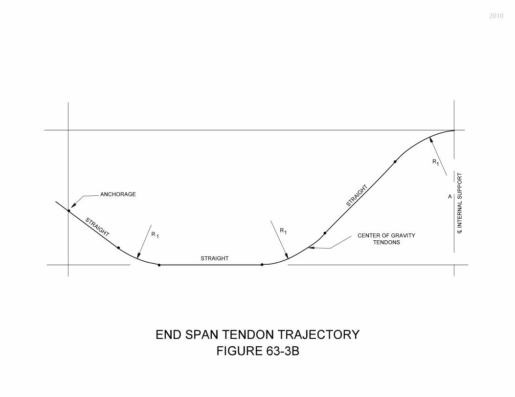
2010

2010

2010
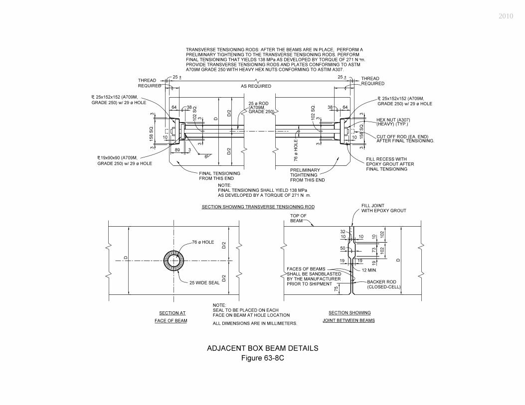
2010

2010

2010

2010

2010

2010
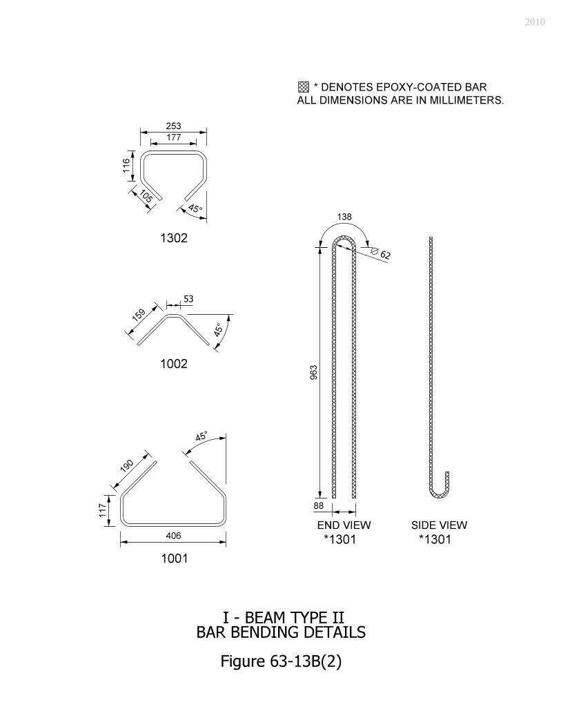
2010

2010

2010

2010

2010
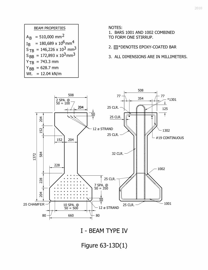
2010

2010

2010

2010
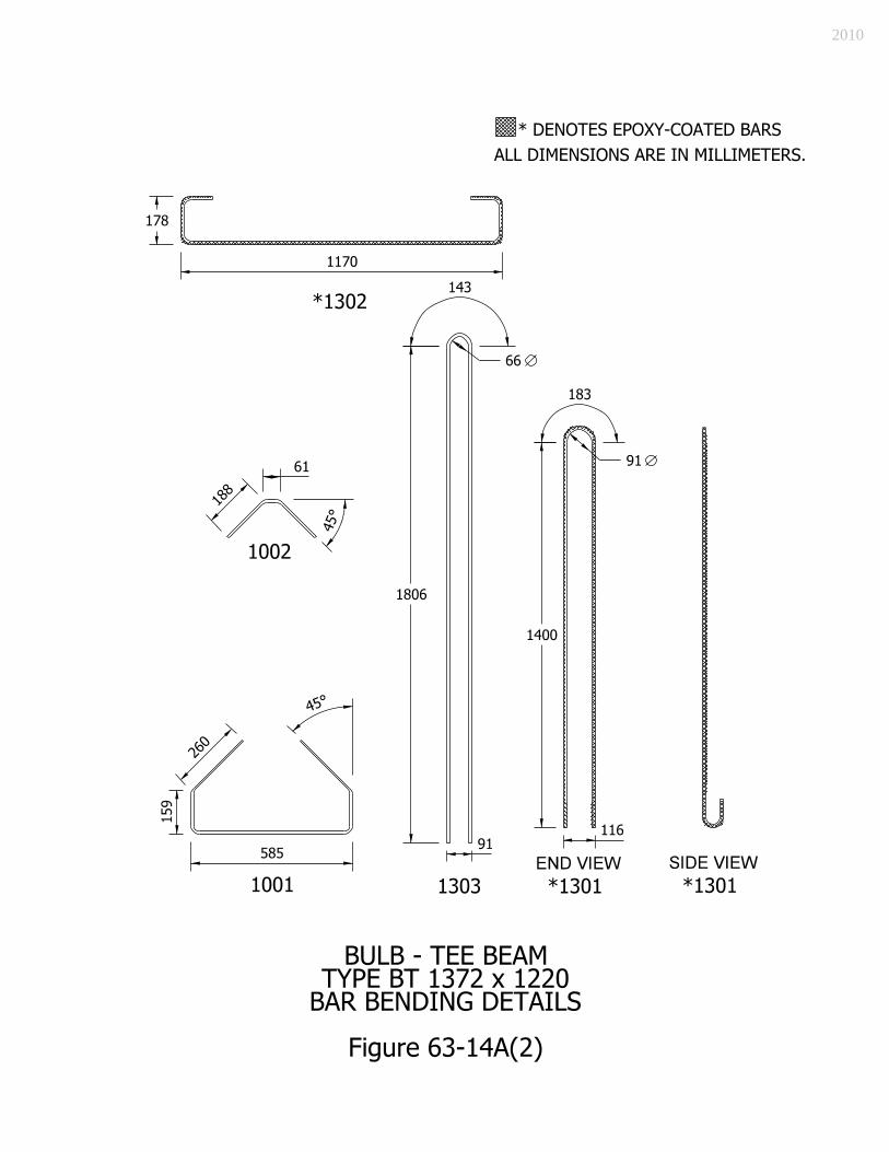
2010

2010

2010

2010

2010

2010

2010

2010

2010

2010

2010

2010

2010

2010
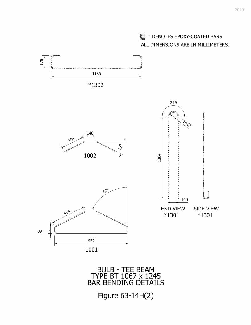
2010

2010

2010

2010
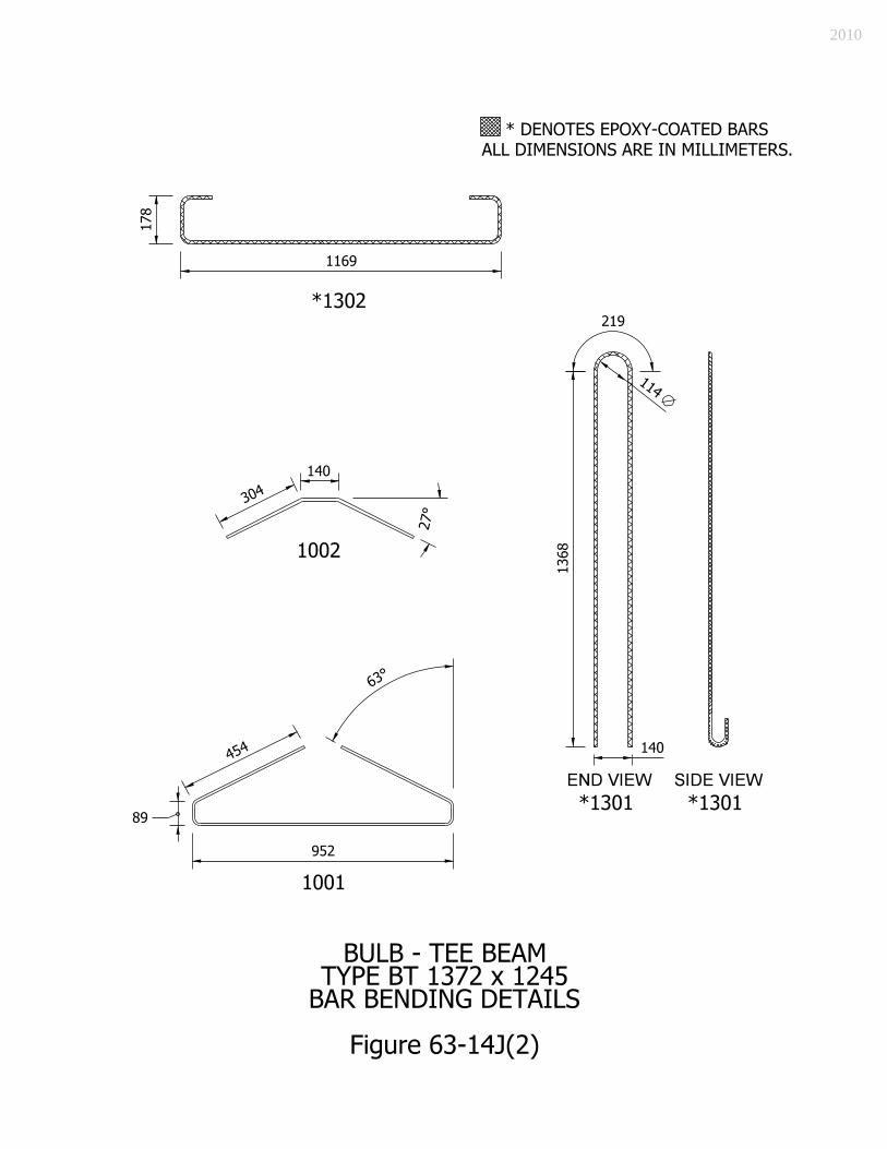
2010

2010

2010

2010
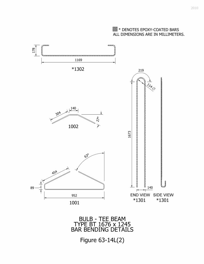
2010

2010
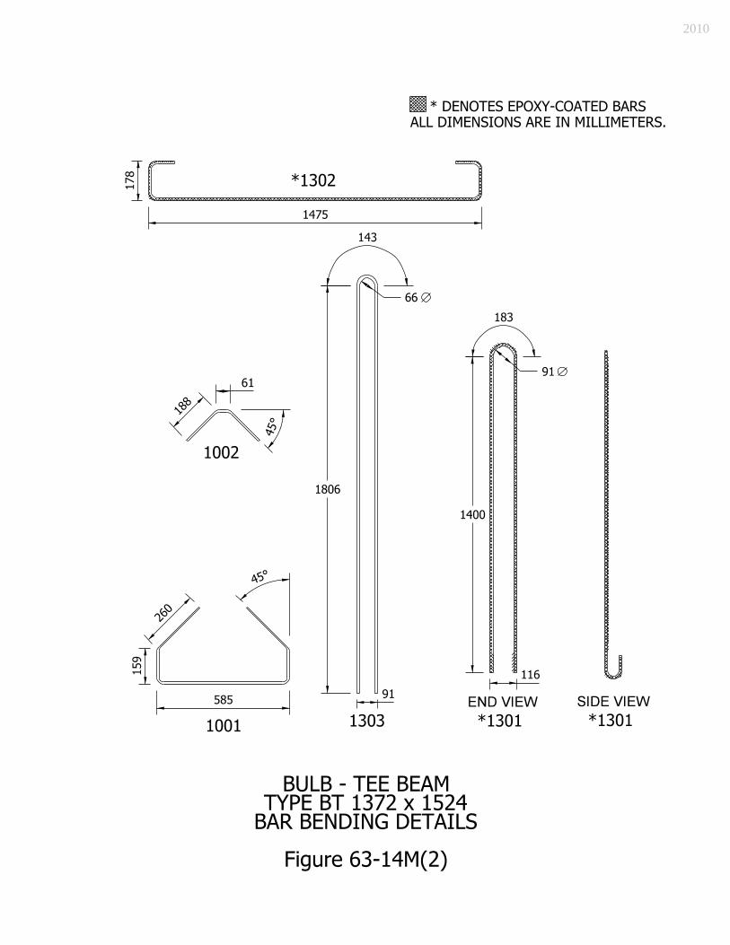
2010

2010

2010

2010
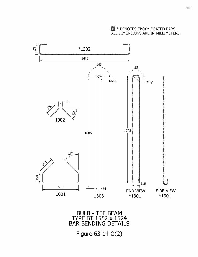
2010

2010

2010

2010

2010

2010

2010

2010

2010

2010

2010

2010

2010
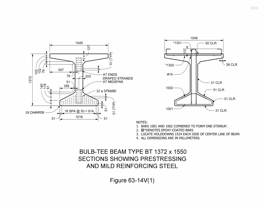
2010

2010

2010

2010
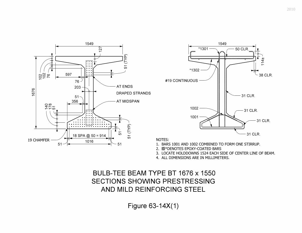
2010

2010

2010

2010

2010

2010

2010

2010

2010

2010

2010

2010

2010

2010

2010

2010

2010

2010

2010
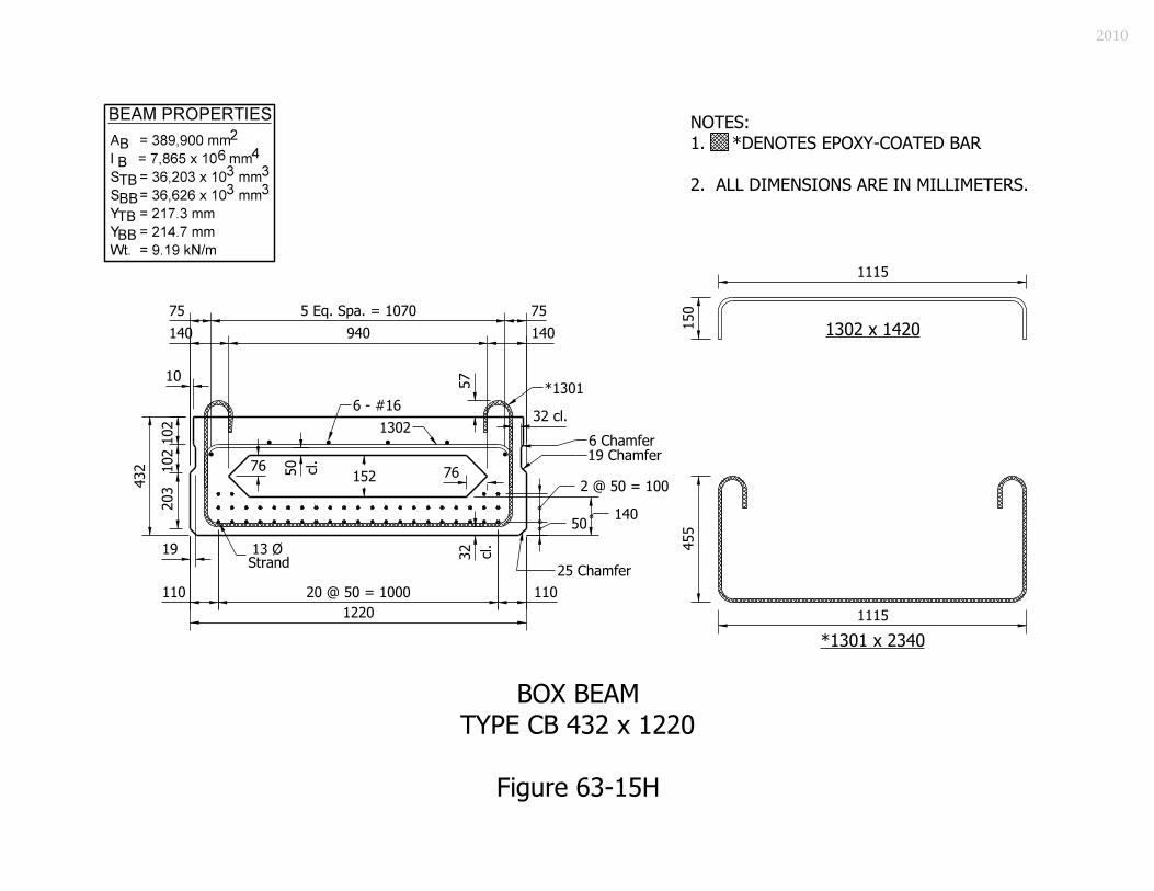
2010
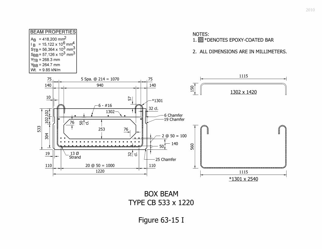
2010
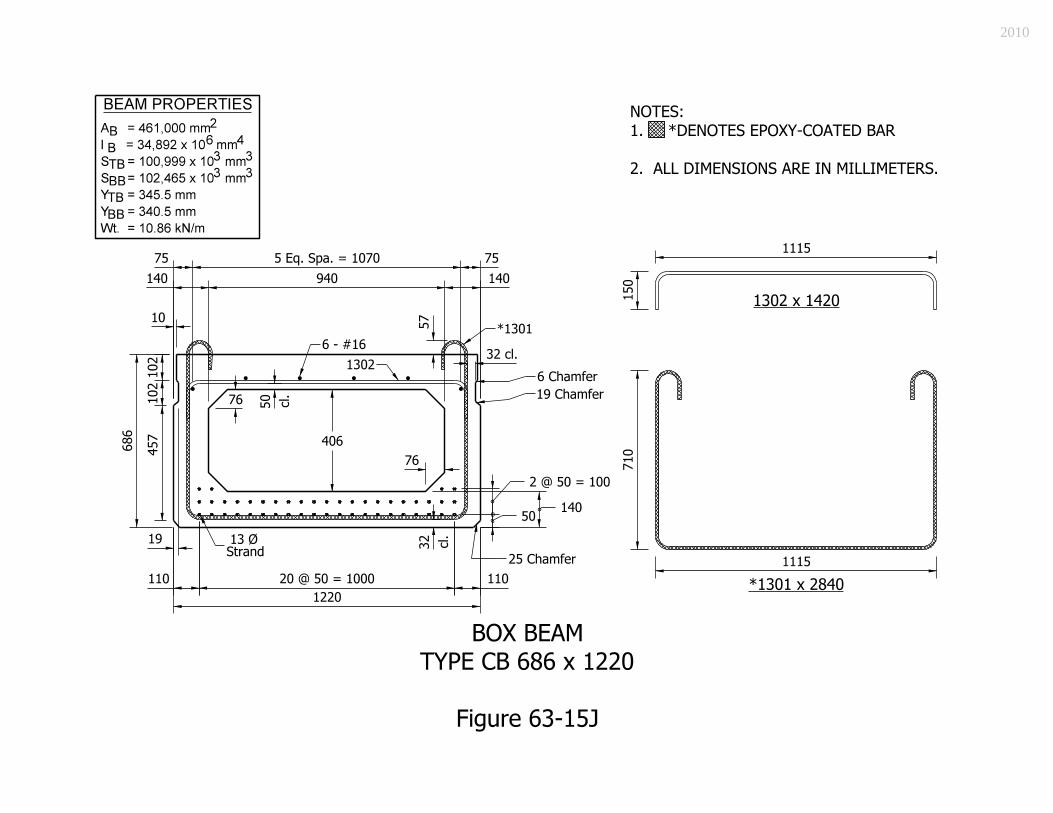
2010

2010

2010

2010

2010

2010

2010

2010
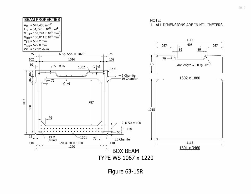
2010

2010
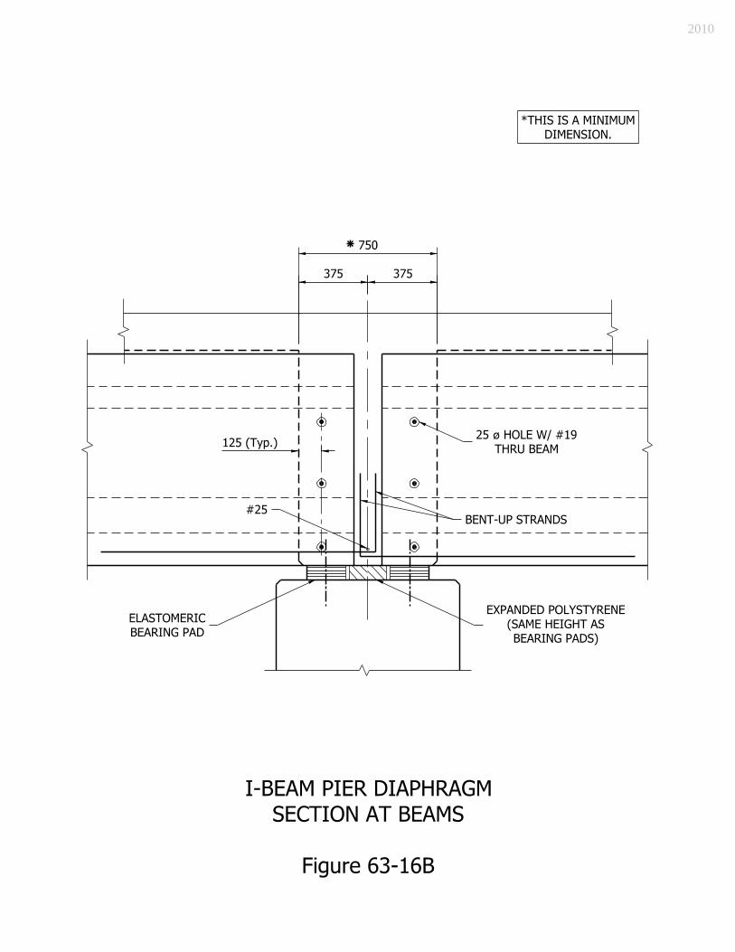
2010

2010

2010

2010
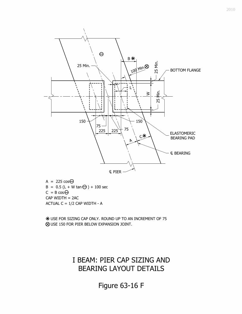
2010

2010

2010

2010

2010

2010

2010

2010

2010

2010
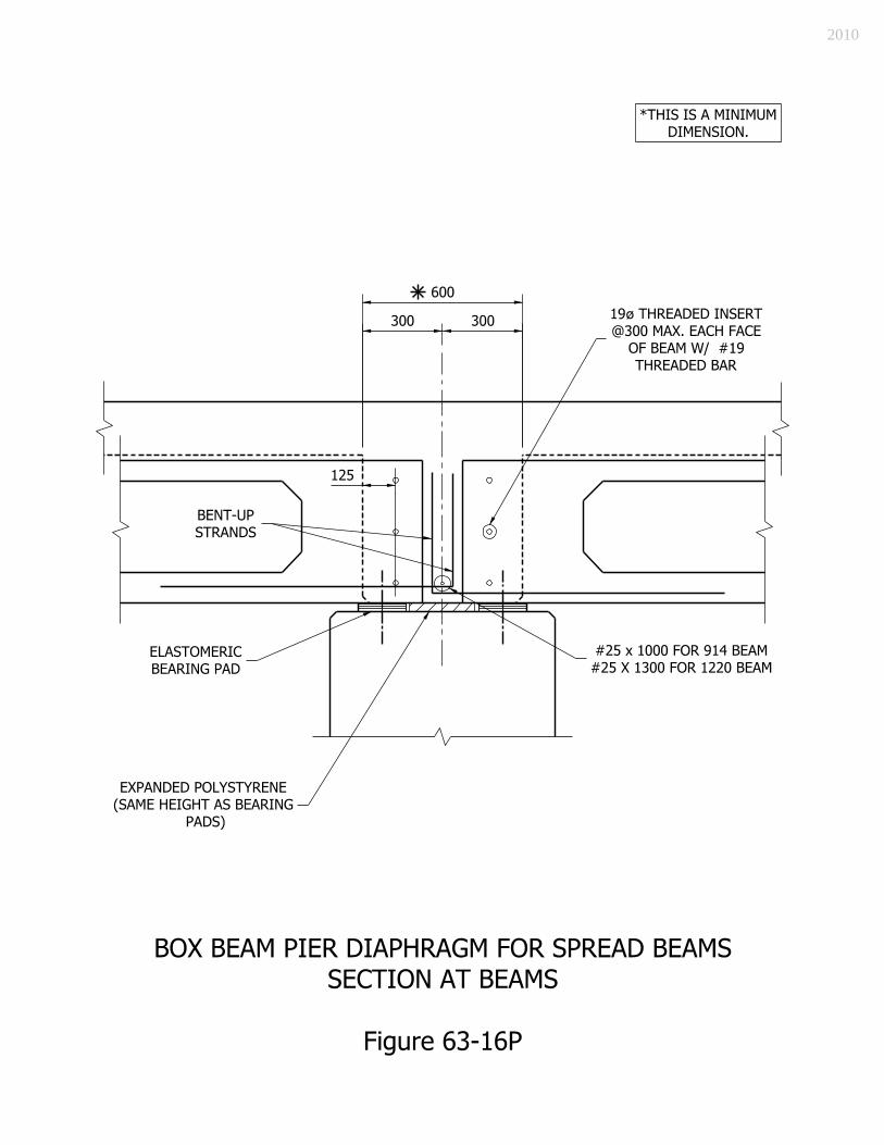
2010

2010

2010
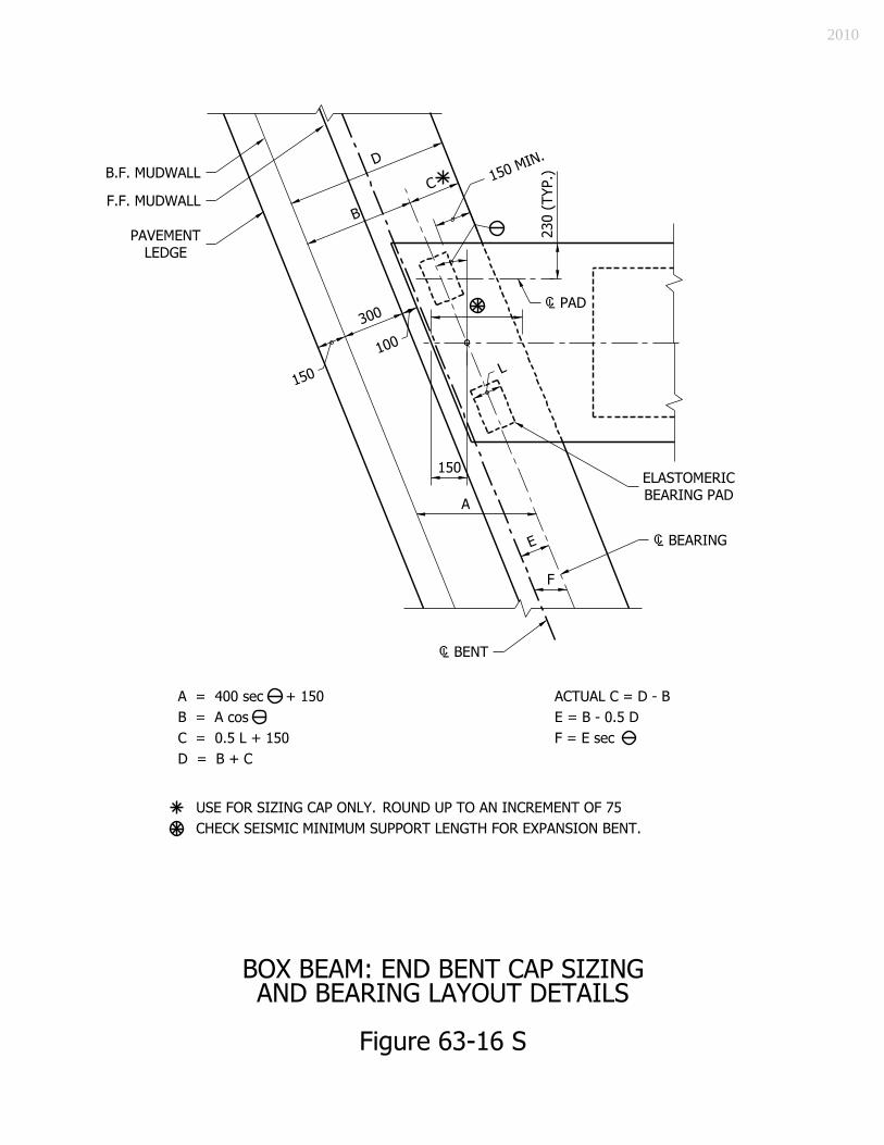
2010

2010

2010

2010
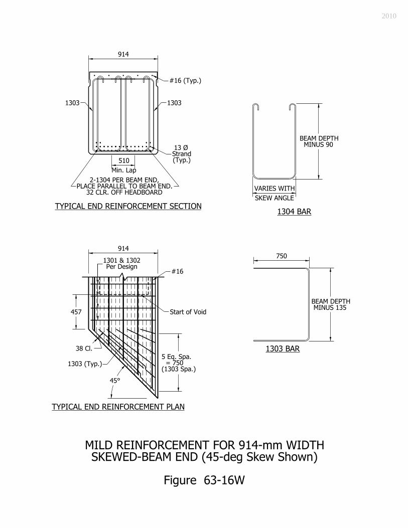
2010

2010