Embedded door access control systems based on face ...
133
University of Wollongong Research Online University of Wollongong esis Collection University of Wollongong esis Collections 2014 Embedded door access control systems based on face recognition Qasim Hasan Mezher Al-shebani University of Wollongong Research Online is the open access institutional repository for the University of Wollongong. For further information contact the UOW Library: [email protected] Recommended Citation Al-shebani, Qasim Hasan Mezher, Embedded door access control systems based on face recognition, Master of Engineering - Research thesis, School of Electrical, Computer and Telecommunications Engineering, University of Wollongong, 2014. hp://ro.uow.edu.au/ theses/4127
-
Upload
khangminh22 -
Category
Documents
-
view
2 -
download
0
Transcript of Embedded door access control systems based on face ...

University of WollongongResearch Online
University of Wollongong Thesis Collection University of Wollongong Thesis Collections
2014
Embedded door access control systems based onface recognitionQasim Hasan Mezher Al-shebaniUniversity of Wollongong
Research Online is the open access institutional repository for theUniversity of Wollongong. For further information contact the UOWLibrary: [email protected]
Recommended CitationAl-shebani, Qasim Hasan Mezher, Embedded door access control systems based on face recognition, Master of Engineering - Researchthesis, School of Electrical, Computer and Telecommunications Engineering, University of Wollongong, 2014. http://ro.uow.edu.au/theses/4127

Department of Electrical, Computer and Telecommunications
Engineering
Faculty of Engineering and Information Sciences
University of Wollongong
Embedded Door Access Control Systems Based on
Face Recognition
Qasim Hasan Mezher Al-shebani
"This thesis is presented as part of the requirements for the
award of the Degree of
Master of Engineering by Research of the
University of Wollongong"
December- 2014

CERTIFICATION
I, Qasim Hasan Mezher Al-shebani, declare that this thesis titled “Embedded Door
Access Control Systems Based on Face Recognition”, submitted in fulfilment of the
requirements for the award of Master of Engineering by research, in the School of
Electrical, Computer and Telecommunication Engineering, University of
Wollongong, is wholly my own work unless otherwise referenced or acknowledged.
The document has not been submitted for qualifications at any other academic
institution.
Qasim Hasan Mezher Al-shebani December 2014

i
ABSTRACT
The implementation of an accurate face recognition system in a hardware device is
very important aspect of various security applications, such as authorisation
identification in cash machines and employee attendance using a door access control
system. Door access control systems based on face recognition is geared towards
simplifying much-difficult face recognition problems in uncontrolled environments.
Such systems are able to control illumination; offer neutral pose and improving the
sagging performance of many face recognition algorithms. While there have been
significant improvements in the algorithms with increasing recognition accuracy,
only few research were conducted on implementing these face recognition in
hardware devices. Most of the previous studies focused on implementing Principal
Component Analysis (PCA) technique in hardware for simplicity with only low
recognition accuracy. The aims of this research are: (1) to investigate the existing
face recognition systems and their hardware implementations, particularly those who
used for developing an embedded door access control system, (2) to select an
appropriate face recognition system and develop a MATLAB code for such system
and (3) to investigate the feasibility of implementing the developed face recognition
system in an FPGA device for a door access control system. Based on current
literature it has been proven that, the accuracy of a face recognition system can be
extremely improved using a hybrid feature extraction technique. It has also found
that the use of K nearest neighbour classification technique based on the City Block
metric is simpler and more accurate than other techniques. Consequently in this
study, a face recognition system is developed using these techniques. In this system,
the facial topographical features are extracted using fixed size input image extraction
ii
technique to extract the eyes, nose and mouth facial regions. Gabor filters of 40
different scales and orientations are applied on these three regions to find the Gabor
representations. The feature vector of these regions is then determined by computing
the maximum intensity of the resulted Gabor representations. In the classification
stage, the Nearest Neighbour method (KNN) is used based on City Block distance to
calculate the distances between the three regions feature vectors and the
corresponding stored vectors. The system results in excellent recognition accuracy
using faces94, FEI and ORL databases. It is observed that, high recognition accuracy
rate can be obtained when the facial images are taken carefully with front pose and
with only slight expression changes.
On the other hand, based on a comparison in an existing literature between different
hardware platforms, Field Programmable Gate Array (FPGA) is found to be more
efficient in the tasks of the hardware implementation of a face recognition system.
FPGA devices have been developed dramatically in a way to allow designers to
select various resources and functions to implement many complex designs. FPGA is
preferable because of its technical characteristics of parallelism, re-programmability
and very high speed, in the implementation of a face recognition system. Therefore,
the feasibility of implementing Gabor filter and nearest neighbour face recognition
algorithms in a FPGA device is investigated using the Xilinx system generator and
ISE project navigator. Distributive arithmetic FIR filter is used to calculate the
required convolution operation between the 40 Gabor filters and each input image.
The forty Gabor filters are stored as matrices and then loaded to the distributive
arithmetic FIR filter using a FDAtool block in the simulation design. The next
simulation contains the design of the required function which computes the
maximum intensity of each FIR filter output using an M-block from the Xilinx block

iii
set. The resulted vector of 40 values represents the feature vector of the input image.
The simulation of the City Block distance between this vector and the stored feature
vectors is designed and the minimum distance is found using an M-block from Xilinx
block set. The resulted minimum distance represents the best match. The simulations
design shows the high improvement of the ability of the current FPGA devices and
the improvement of the supportive programs which are able to simulate, configure
the required design in FPGA devices. This ability can be used to complete the real
time door access control system design.

iv
ACKNOWLEDGEMENTS
I extend my most sincere thanks to my God for everything in my life.
I would like to acknowledge the constant encouragements of both my supervisors, Dr
Prashan Premaratne and Dr Peter Vial. I would also acknowledge the help from the
research student centre staff and the university Librarians for their beneficial
seminars and models which improved my knowledge in many ways such as thesis
writing, referencing using end note, how to use latex, where to publish and finding
the resources. The assistance from the staff of the School of Electrical, Computer and
Telecommunication Engineering (SECTE) and the ICT Research Institute in building
3 is really appreciated as they funded my publications, allowed access to their
laboratories and let me borrow equipments to complete my research. I acknowledge
Mr. Neil Wood for helping me in installing the Xilinx software in my computer. I
would like to acknowledge the assistance of my parents, my siblings and my friends.
Finally, I would appreciate the special encouragements and support from my wife
Ishraq and my three daughters Maryam, Sarah and Ruqia that allowed me to achieve
this progress.

v
TABLE OF CONTENTS
ABSTRACT .................................................................................................................. i
ACKNOWLEDGEMENTS ........................................................................................ iv
TABLE OF CONTENTS ............................................................................................. v
LIST OF FIGURES .................................................................................................. viii
LIST OF TABLES ....................................................................................................... x
Chapter 1: Introduction .......................................................................................... 1
1.1 Face Recognition .......................................................................................... 1
1.1.1 Problem of illumination changes ............................................................. 1
1.1.2 Problem of pose and the background variations ...................................... 2
1.1.3 Problem of facial expression changes ...................................................... 3
1.1.4 Problem of makeup and cosmetic alteration ............................................ 4
1.1.5 Problem of wearing glasses ...................................................................... 5
1.2 Motivation arising from previous research .................................................. 5
1.3 Door Access systems.................................................................................... 6
1.4 Embedded systems ....................................................................................... 9
1.5 The gap of knowledge ................................................................................ 10
1.6 Scope and Methodology ............................................................................. 11
1.7 Aim and Objective ..................................................................................... 11
1.8 Thesis Structure .......................................................................................... 12
1.9 Contributions .............................................................................................. 13
1.10 Publications ................................................................................................ 14
Chapter 2: Literature reveiw ................................................................................ 17
2.1 Introduction ................................................................................................ 17
2.2 Door Access Control System ..................................................................... 17
2.3 Digital image processing ............................................................................ 19
2.4 Face Recognition System ........................................................................... 24
2.4.1 Pre-processing phase .............................................................................. 25
2.4.2 Feature Extraction .................................................................................. 26
A. Holistic Feature Extraction .................................................................... 27
B. Local Feature Extraction ........................................................................ 30
C. Hybrid Feature Extraction ...................................................................... 34

vi
D. Comparison between Holistic, Local and Hybrid Feature Extraction
Algorithms ..................................................................................................... 37
2.4.3 Identification Phase ................................................................................ 39
A. Euclidian distance (ED) ......................................................................... 39
B. Hansdroff distance (HD) ........................................................................ 39
C. Mahalanobis distance (MD) ................................................................... 40
D. Sparse Neighbour Representation (SNR)............................................... 40
E. Neural Network (i.e. ART2 and BP) ...................................................... 40
F. K-nearest neighbour (K-NN) .................................................................. 41
G. A comparison between certain classification techniques....................... 41
2.5 A Comparison between the existed Hardware platforms and the field
programmable gate arrays device (FPGA) ............................................................. 43
2.6 Field Programmable Gate Array (FPGA) .................................................. 47
2.6.1 FPGA memories ..................................................................................... 49
2.6.2 FPGA controlling units .......................................................................... 52
2.6.3 Mathematical and logical functions ....................................................... 52
2.6.4 Input output units and time management ............................................... 54
2.6.5 Fixed-point vs. floating point representation ......................................... 55
2.6.6 Design tools ............................................................................................ 56
2.7 The hardware implementation of face recognition system ........................ 57
2.8 Door access control system limitations ...................................................... 62
2.9 The hardware implementation of a selected face recognition algorithms.. 64
2.9.1 Gabor filter implementation for feature extraction ................................ 65
2.9.2 The hardware implementation of K nearest neighbour technique ......... 65
Chapter 3: The design methedology .................................................................... 67
3.1 Introduction ................................................................................................ 67
3.2 Pre-processing phase .................................................................................. 68
3.3 Hybrid feature extraction ........................................................................... 70
3.3.1 Three region extraction .......................................................................... 70
3.3.2 Gabor filters for Feature Extraction ....................................................... 71
3.4 K-Nearest Neighbour (KNN) ..................................................................... 79
3.5 The implementation of the face recognition system .................................. 82

vii
3.5.1 The feature extraction implementation of Gabor filter using distributive
arithmetic FIR filter............................................................................................ 82
3.5.2 The hardware implementation of KNN technique ................................. 84
Chapter 4: Experments and results ...................................................................... 86
4.1 Introduction ................................................................................................ 86
4.2 Facial databases .......................................................................................... 87
4.2.1 The experimental results of the software design .................................... 89
4.3 The implementation of the face recognition system .................................. 92
4.3.1 Distributed arithmetic FIR filter simulation design ............................... 94
4.3.2 The hardware implementation of the Nearest Neighbour Classifier using
City Block distance ............................................................................................ 99
4.3.3 Results of the hardware simulations .................................................... 102
Chapter 5: The Conclusion ................................................................................ 107
REFERENCES ......................................................................................................... 110
APPENDIX A .......................................................................................................... 116

viii
LIST OF FIGURES
Figure 1.1 The reflection of the light on an object. ...................................................... 2
Figure 1.2 Illumination variation and image appearance taken from Harvard
database. ............................................................................................................... 2
Figure 1.3 Two examples of three diffrent pose [1]..................................................... 3
Figure 1.4 Examples of diffrent expresion changes [1]. .............................................. 4
Figure 1.5 The inflwnces of the makeup on the face appearance details [2] ............... 4
Figure 1.6 The effect of wearing glasses on the eye appearance [3] ........................... 5
Figure 1.7 Door access control system ........................................................................ 7
Figure 1.8 Example of controlling the set distance and the pose of a facial image [16]
.............................................................................................................................. 7
Figure 1.9 Poor Recognition because of using PCA with only 20 Eigen vectors ....... 8
Figure 1.10 Examples of everyday applications that used embedded system ............. 9
Figure 2.1 The common identification techniques ..................................................... 18
Figure 2.2 The Pixel representation of an image ....................................................... 20
Figure 2.3 The three colour channels of an input coloured image ............................. 21
Figure 2.4 A gray space bar ...................................................................................... 22
Figure 2.5 The three stages of a face recognition system .......................................... 25
Figure 2.6 Pre-processing Phase ................................................................................ 25
Figure 2.7 Feature extraction techniques ................................................................... 26
Figure 2.8 Holistic techniques for feature extraction ................................................. 30
Figure 2.9 Frequency distribution caused by applying DWT on an Image ............... 32
Figure 2.10 Local techniques for feature extraction .................................................. 34
Figure 2.11 Hybrid feature extraction approaches ..................................................... 36
Figure 2.12 Feature extraction categories .................................................................. 37
Figure 2.13 A comparison between the resulted accuracy using various identification
techniques ........................................................................................................... 42
Figure 2.14 The Block diagram of a FPGA board [18] ............................................. 48
Figure 2.15 An FPGA device showing the columns of block RAMs [74]. ............... 51
Figure 2.16 A multiply and accumulate unit [76] ...................................................... 53
Figure 2.17 A DSP48E1 Functionality diagram[80].................................................. 54
Figure 2.18 Floating point representation .................................................................. 55

ix
Figure 3.1 Example of the pre-processing results ...................................................... 69
Figure 3.2 Three regions extraction ........................................................................... 70
Figure 3.3 The real part (left) and the imaginary part (right), (sine and cosine). ..... 72
Figure 3.4 Different scales and orientations of Gabor filters ..................................... 74
Figure 3.5 The Gabor representation of an example facial image. ............................ 75
Figure 3.6 An example of 2D convolution................................................................. 76
Figure 3.7 Example of finding the 40 Gabor representation of Eye, Nose and Mouth
regions of an image ............................................................................................ 78
Figure 3.8 An example of classifying two points using the K-NN algorithm and K=3.
............................................................................................................................ 80
Figure 3.9 A parallel DA FIR filter block diagram .................................................... 84
Figure 3.10 A block diagram of the required KNN technique hardware paths ......... 85
Figure 4.1 Examples of ORL database images .......................................................... 87
Figure 4.2 Example from FEI Database images ........................................................ 88
Figure 4.3 Example from faces94 Database images .................................................. 88
Figure 4.4 Two groups from FEI database each group consists the input images in the
upper side and the resulted images in the bottom side ....................................... 89
Figure 4.5 The simulation design of a distributed arithmetic FIR filter .................... 94
Figure 4.6 The ability of Xilinx FIR filter to select a distributed arithmetic
architecture ......................................................................................................... 95
Figure 4.7 FDATool block parameter ........................................................................ 96
Figure 4.8 The simulation design of 40 FIR filters connected in parallel.................. 97
Figure 4.9 The simulation design of the maximum comparator ................................ 98
Figure 4.10 Forty FIR filters connected in parallel to perform a convolution of Gabor
filter .................................................................................................................... 98
Figure 4.11 The simulation design one path of the city block distances. ................ 100
Figure 4.12 The simulation design of commuting the City Block values between the
testing vector and N training paths ................................................................... 101
Figure 4.13 A comparator simulation design ........................................................... 102

x
LIST OF TABLES
Table 2-1 Face Recognition Algorithms where * refers to classification techniques 38
Table 2-2 A comparison between Euclidian, City block and cosine distances for
calculating the distance in KNN technique [63] ................................................ 43
Table 2-3 A comparisons between three current hardware platforms [68] ................. 46
Table 2-4 A comparison between the implementation of different face recognition
algorithms using fixed architecture devices and FPGA’s .................................. 62
Table 4-1 The results of applying the proposed algorithm on different regions ........ 90
Table 4-2 the face recognition accuracy for the current and some previous techniques
............................................................................................................................ 91
Table 4-3 The required hardware resources for each filter ...................................... 103
Table 4-4 The hardware resources of the comparator design .................................. 104
Table 4-5 The utilisation of the comparator design ................................................. 104
Table 4-6 Hardware resources of one path of the city block metric ........................ 105
Table 4-7 The resources utilisation of the comparator simulation design ............... 106

1
CHAPTER 1: INTRODUCTION
1.1 Face Recognition
Face recognition has become an important research area because of its usefulness in
numerous applications. Such a recognition system can be used to allow access to
computers, to control entry into restricted areas and to search for a face in databases
for identification. The general idea of face recognition is to extract certain data from
the region of interest of a human facial image and to compare them to stored data for
identification. Many organisations such as Roads and Maritime Services in Australia
and the Australian Department of Immigration create large facial images databases
for face identification or verification purposes. Face identification identifies an input
image that belongs to a person in a database whereas face verification searches for
the existence of a person’s image in the database. The feature extraction stage
represents the backbone of face recognition systems because of the direct
dependency of the accuracy of any face recognition system on the accuracy of the
extracted facial features. The task of feature extraction is very difficult because of
certain environmental issues.
1.1.1 Problem of illumination changes
The ambient light or artificial illumination issues affect the performance of face
recognition systems. This is because the basic idea of capturing an image depends on
the reflection of the light off an object (Figure 1.1).

2
Figure 1.1 The reflection of the light on an object.
The illumination is important because the higher the amount of illumination the
higher the recognition accuracy. This is manifested in the resulting images using
various illumination rates as shown in Figure 1.2.
Figure 1.2 Illumination variation and image appearance taken from Harvard
database.
1.1.2 Problem of pose and the background variations
Another problem that prevents face recognition (FR) systems from obtaining good
recognition accuracy is the camera angle (pose). The closer the image pose is to the

3
front view, the higher the recognition accuracy is. The reason for this is related to the
main discriminative information of human which is known to be carried by human
faces. The irrelevant information of the image background also affects FR
performance. This information needs to be discarded before the process of extracting
facial features. Figure 1.3 shows certain examples of such problems in obtaining full
view of human faces.
Figure 1.3 Two examples of three diffrent pose [1].
1.1.3 Problem of facial expression changes
Facial expression is a visible manifestation of the affective state, cognitive activity,
intention, personality and psychopathology of a person and it plays a communicative
role in interpersonal relations [1]. For face recognition, the expression changes are
addressed as a problem because of its ability to change personal details such as the
distance between the eyebrows and the iris in case of anger or surprising behaviours
or changing the size of the mouth in case of happiness. Examples of such variations
are shown in Figure 1.4.

4
Figure 1.4 Examples of diffrent expresion changes [1].
1.1.4 Problem of makeup and cosmetic alteration
Simple non-permanent cosmetic alterations, such as make-up tend to slightly modify
the features. These alterations can interfere with contouring techniques used to
perceive facial shape and alter the perceived nose size and shape or mouth size.
Other colour enhancements and eye alterations can convey misinformation such as
the location of eyebrows, eye contrast and cancelling the dark area under the eyes
leading to potential change of appearance of a person as shown in [2]. At the same
time, they have the potential to substantially change appearance as shown in Figure
1.5
Figure 1.5 The inflwnces of the makeup on the face appearance details [2]

5
1.1.5 Problem of wearing glasses
Another FR problem is wearing eye-glasses [3]. Not only because of the useability of
glasses as a remedy for many human vision related problems such as myopia, eye
cornea and iris issues but also because of the increase in the wearing of glasses by
certain healthy people to increase their facial attractiveness. Wearing glasses tends to
hide eyes in which is contained the highest amount of distinctive information. It also
changes the holistic facial appearance of a person
Figure 1.6 The effect of wearing glasses on the eye appearance [3]
1.2 Motivation arising from previous research
Illumination, pose, expression changes, makeup and wearing glasses problems
represent the main challenges of designing any face recognition system. In order to
overcome these problems of face recognition system, various research has been done
either by proposing a pre-processing algorithms to retrieve the input image or by
improving the existing feature extraction techniques. The pre-processing stages of
illumination normalisation and histogram equalisation techniques have been
developed to enhance or retrieve the input image [4], [5], [6], [7], [8]. However,

6
these techniques do not solve the problems of pose and expression changes. Other
studies have focused on improving the feature extraction or classification techniques.
Techniques such as principle component analysis (PCA) [9], [10], independent
component analysis (ICA) [11] and linear discriminative analysis (LDA)[12], [13]are
related to holistic facial appearance while others, such as the Gabor filter [14] and
local feature analysis (LFA) [15] are based on identifying individual features. These
methods, however, require the use of much pre-processing of the input image in
order to solve the problems associated with illumination, pose and expression
changes. Using a door access control system, however, can produce more robust
input data for face recognition and will lead to applications that achieve higher
security levels such as those needed for prisons, airports and to monitor employee
attendance.
1.3 Door Access systems
Door access system represents a good solution to overcome face recognition issues
of illumination, expression and pose changes. The typical door access control system
consists of a camera, illumination source, electronic door lock and the system control
which connects all components together using a human-machine control interface as
shown in Figure 1.7.

7
Figure 1.7 Door access control system
The system operates by controlling the distance between the camera and the person
to control the background, and by fixing the lighting refresh rate and the camera
angle (pose) and requiring the person of interest to pose for a frontal view with a
neutral expression, as shown inFigure1.8.
Figure 1.8 Example of controlling the set distance and the pose of a facial image [16]
8
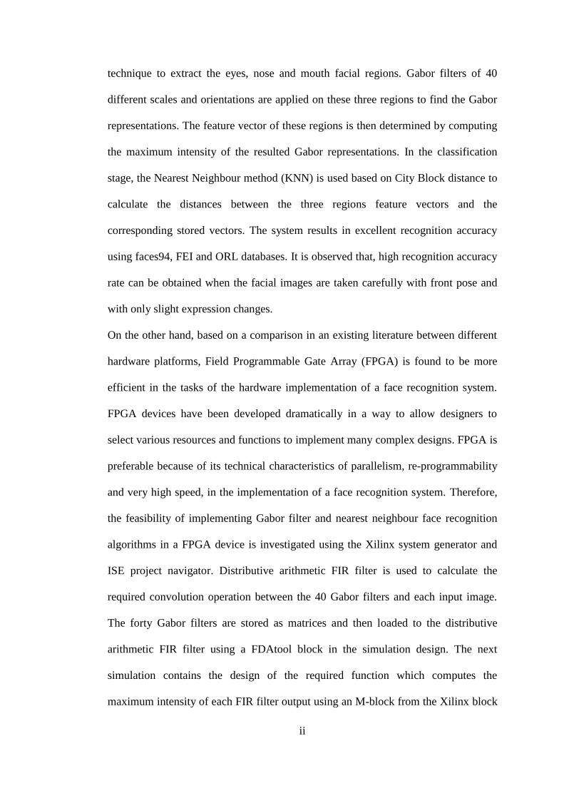
Nevertheless, the existing door access control systems are limited to traditional PCA
feature extraction technique [17]. The PCA works by selecting a number of
eigenvectors from the database as the image information space and the best match is
found by projecting the eigenvectors of the input image onto that space. This
approach naturally leads to missing certain information by selecting only part of the
eignvectors of the database images that result in mismatch as shown in Figure 1.9.
Figure 1.9 Poor Recognition because of using PCA with only 20 Eigen vectors
This has led researchers to find alternative techniques that can be used in designing a
door access control system which obtains higher recognition accuracy than what is
available with PCA. The feasibility of implementing another face recognition
algorithm rather than using PCA in a hardware device represents a new area worth
investigating. A door access control system based on face recognition must be
compact, inexpensive and highly reliable. Embedded systems represent a powerful
option to obtain these requirements.

9
1.4 Embedded systems
The basic definition of a system is a way of working organising or doing one or
many tasks according to a fixed plan, program or set of rules. All system’s units are
arranged to work together according to a plan or program. One example of such
systems is the computer (PC) that is used in daily life usually to serve a number of
purposes: checking email, surfing the internet, listening to music, or word
processing. However, everyday used devices such as washing machine, digital
cameras, lifts and security system are exploiting another sort of systems that need to
be small in size, have lower power consumption, high performance and embedded
architecture. Embedded system is one system that has computer hardware with
software embedded in a device that is implemented for a particular purpose.
Embedded systems are playing important roles in human everyday life, even though
they might not necessarily be visible as shown in Figure1.10.
Figure 1.10 Examples of everyday applications that used embedded system

10
According to the number of hardware resources, the amount of power consumption
and the number of programming tools, embedded systems can be classified as small
scale, medium scale and large scale systems. The selection of each one of these types
is related to the design requirements. For example, systems that require a large
number of hardware resources usually use sophisticated embedded systems.
Improvements on these systems allow designers to achieve complex design with
highly economical processing and elevated performance. There exist many types of
sophisticated embedded systems such as complex programmable logical devices
(CPLD), application specific integrated circuits (ASIC) and field programmable gate
arrays (FPGA). FPGAs are found to be an ideal platform for an embedded computer
running a high-performance control system [18], [19], [20].
1.5 The gap of knowledge
Many researchers have conducted their studies on face recognition to improve it
against certain environmental issues that influence the performance of face
recognition systems in real time applications. However, few of these studies have
been conducted to implement these face recognition techniques in an embedded
system of real time applications such as door access control system which depends
on face recognition to identify individuals. The previous studies focus on improving
the accuracy of the face recognition algorithms against performance limitation
caused by illumination, pose and facial expressions changes especially when it use in
security check systems in the airports. However, in door access control systems the
system can work with some constrains such as: the distance between the camera and
the person, fixing the illumination rate and frontal face pose. In addition most of the

11
previous studies focus on using a PCA algorithm for face recognition for its
simplicity. However, Because of the dependency of PCA algorithm on the Eigen
values which are highly sensitive for precision, it needs to use floating point
operations that are costly and complex in term of hardware. On the other hand, the
performance of the previous hardware devices that used to design door access control
systems vary depending on the ability of such device and so far “to the best of our
knowledge”, there is no optimum design of an embedded door access control system
in terms of hardware selection and implementation. Consequently, the feasibility of
implementing another face recognition algorithm in a hardware device represents a
new area of this field that needs to have more investigation and research.
1.6 Scope and Methodology
In this study, the automated ability of Xilinx system generator and ISE project
navigator to complete the implementation of an FPGA board will be used to study
the feasibility of building an automatic face recognition system for door access
control. The face recognition algorithm is done based on the hybrid compensation of
calculation the local features using Gabor filter of three holistic regions which are
eye, nose and mouth regions. This method for feature extraction is more robust than
PCA-based algorithms for face recognition. The K nearest neighbour technique
based on City Block distance is used for classification.
1.7 Aim and Objective
The purpose of this study is to prove the feasibility of developing and implementing
a face recognition system based on hybrid feature extraction (local Gabor filter and

12
the three holistic facial regions) and the nearest neighbour method for classification
on an FPGA board for a door access control system.
The objectives of this research study are:
1- Develop a MATLAB program for face recognition system which is selected
based on a review for the existing face recognition algorithms and examine
the developed face recognition system on faces using ORL, FEI and Faces94
databases.
2- Investigate the feasibility of implementing the developed program of face
recognition system on a FPGA board to build an embedded door access
control system.
1.8 Thesis Structure
The rest of this thesis is organised as follows:
Chapter 2 presents a comprehensive survey for the existing door access
control systems that used face recognition as identification technique. It also
surveys the common face recognition systems and produces a comparison
between three hardware platforms that can be used for the hardware
implementation of such systems. The existing hardware implementation of
certain face recognition algorithms is also compared in this chapter over two
types of hardware devices (FPGA and Fixed devices).
Chapter 3 contains the theory and the methodology of the design of the
selected face recognition system and the steps of the corresponding
implementation steps for that design.
Chapter 4 shows the experiment steps of designing a face recognition system
based on a hybrid feature extraction algorithm and K nearest neighbour

13
algorithm for classification. The results of the designed face recognition
system are presented using three types of facial databases which are ORL,
Faces94 and FEI. This chapter also presents the results of the hardware
simulation design of the face recognition algorithms in FPGA device using
Xilinx system generator and ISE project navigator.
Chapter 5 concludes the study and presents the future research
recommendations.
1.9 Contributions
The main contributions of this study are:
A comprehensive survey is conducted for the existing door access control
systems that used face recognition as identification technique. The common
face recognition systems are also surveyed. This includes a comparison
between three hardware platforms that can be used for the hardware
implementation of such systems.
Based on the survey, a hybrid feature extraction technique is selected and
implemented using Gabor filter to extract the local features of three extracted
holistic regions of the eye, the nose and the mouth. The K nearest neighbours
technique is used in this design for classification purposes. Then, the
performance of the developed system is examined using three types of facial
databases which are ORL, FEI and Faces94.
A comprehensive frame work for the feasibility of implementing the
developed face recognition system in an FPGA device is done based on
Xilinx simulation platform. Since the hardware has one to one

14
correspondence with the Xilinx simulation platform. The system is ready to
be implemented on hardware. It further highlight that a highly accurate face
recognition system in uncontrolled environments can be implemented on
minimum resources for a door access control system.
1.10 Publications
1- Q. Alshebani, P. Premarante & P. James. Vial, "Embedded door access
control systems based on face recognition: A survey," in Signal
Processing and Communication Systems (ICSPCS), 2013 7th
International Conference on, 2013, pp. 1-7.
Abstract: The implementation of face recognition techniques in an embedded
system is a very important aspect of various security applications, such as
authorization identification in cash machines and door access for employee
attendance. The purpose of this paper is to survey the existing hardware
implementations of a face recognition system, particularly those who used for
developing an embedded door access control system. This includes a brief
discussion about face recognition algorithms and the hardware platforms
outlining the importance of using a Field Programmable Gate Array (FPGA)
device, which can be used to design an embedded door access control system.
It is found that the success of any door access control system depends on the
type of face recognition algorithm in the feature extraction phase of the face
recognition system and the selected hardware device. Based on a comparison
between different feature extraction algorithms, the use of a hybrid feature
extraction technique can improve the accuracy of face recognition system. An
efficient door access control system can be obtained using a FPGA device,

15
which is preferable because of its technical characteristics of parallelism, re-
programmability and very high speed, in the implementation of a face
recognition system.
2- Q. Alshebani, P. Premarante & P. James. Vial, “A Hybrid Feature
Extraction Technique for Face Recognition”, The 2nd International
Conference on Information Technology and Science (ICITS 2014)
IPCSIT, ISSN: 2010-460X, Shanghai, China, 2014.
Abstract: The accuracy of any face recognition is important for many military
and civilian real time applications. Based on current literature it has been
proven that, the accuracy of a face recognition system can be extremely
improved using a hybrid feature extraction technique. This paper presents a
hybrid feature extraction technique to obtain high level of recognition
accuracy. The facial topographical features are extracted using manual
segmentation of facial regions of eyes, nose and mouth. The Gabor transform
of the maximum of these regions are then extracted to calculate the local
representations of these regions. In the classification stage, the Nearest
Neighbour method (KNN) is used to calculate the distances between the three
regions feature vectors and the corresponding stored vectors. The system
results in excellent recognition accuracy using faces94, FEI and ORL
databases. It is observed that, high recognition accuracy rate can be obtained
when the facial images are taken carefully with front pose and with only
slight expression changes. The future work will be on implementing this
system in a FPGA device for a real time application such as a door access
control system.
16
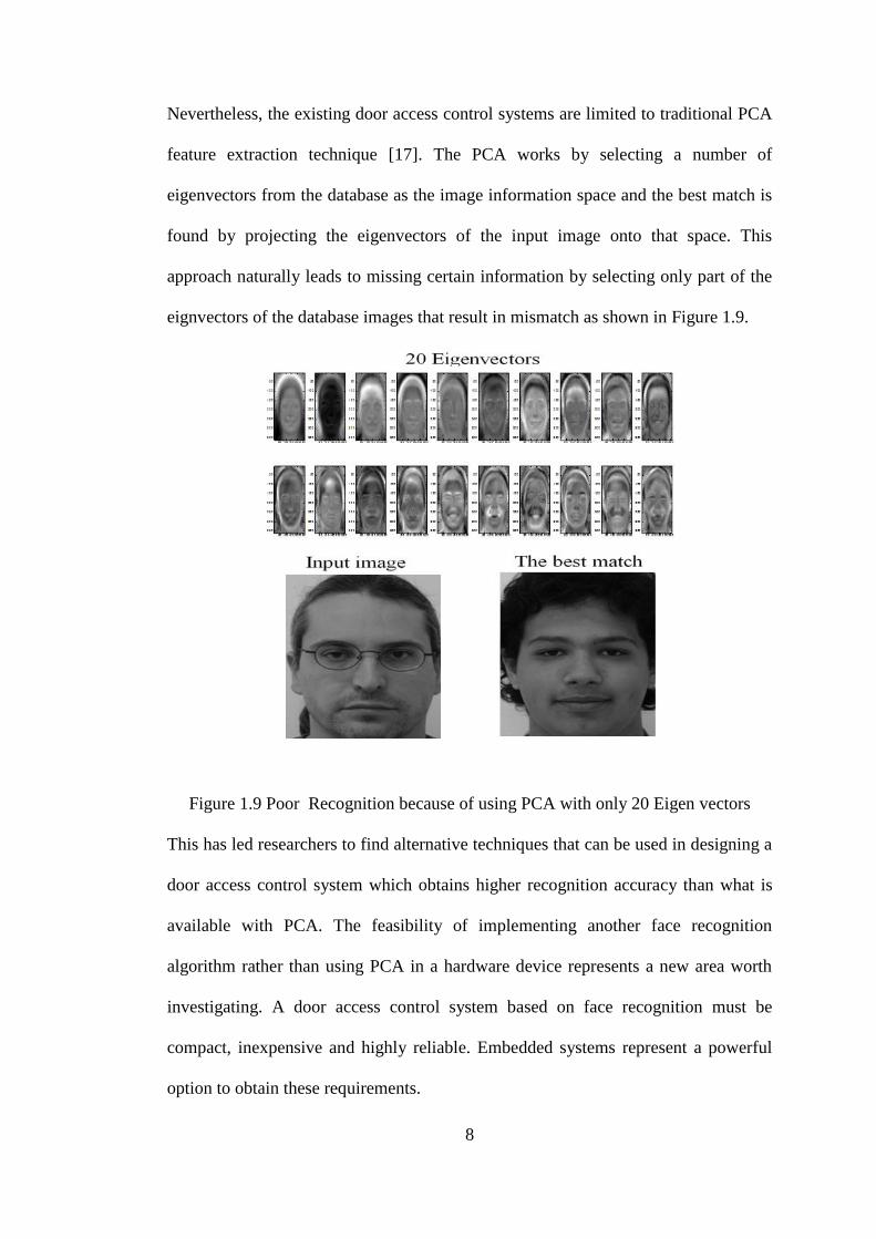
3- Q. Alshebani, P. Premarante & P. James. Vial, “The Feasibility of
Implementing Face Recognition system based on Gabor Filter and
Nearest Neighbour techniques in an FPGA device for a door access
control system”, Journal of Computers, JCP, 2014 (paper is submitted and
currently under review)
Abstract: Door access control systems based on face recognition are
geared towards simplifying difficult face recognition problems in
uncontrolled environments. Such systems are able to control
illumination, offer neutral pose and improve the poor performance of
many face recognition algorithms. While there have been significant
improvements in the algorithms with increasing recognition accuracy,
very little research has been conducted on implementing these in
hardware devices. Most of the previous studies focused on implementing
a simple principal component analysis in hardware with low recognition
accuracy. In contrast, use of a Gabor filter for feature extraction and the
nearest neighbour method for classification were found to be better
alternatives. Dramatic developments in field programmable gate arrays
(FPGAs) have allowed designers to select various resources and
functions to implement many complex designs. The aim of this paper is
to present the feasibility of implementing Gabor filter and nearest
neighbour face recognition algorithms in an FPGA device for face
recognition. Our simulation using Xilinx FPGA platforms verified the
feasibility of such a system with minimum hardware requirements.

17
CHAPTER 2: LITERATURE REVEIW
2.1 Introduction
This Chapter reviews the current hardware implementation of face recognition
systems and briefly discusses the existing face recognition algorithms and hardware
devices that can be used to develop an accurate and efficient door access control
system. The rest of this Chapter is organised as follow: Section 2.2 defines the door
access control system. Section 2.3 presents the digital image processing concepts.
The common face recognition system and its algorithms are presented in Section 2.4.
A comparison between current hardware platforms and field programmable gate
arrays (FPGA) is proposed in Section 2.5. The FPGA device and its features are
presented in Section 2.6. Section 2.7 consists of a review of previous and current
hardware implementation of face recognition algorithms. Section 2.8 presents the
limitations of current door access control systems and finally the hardware
implementation of a selected face recognition algorithm is presented in Section 2.9.
2.2 Door Access Control System
An efficient and accurate embedded access control system is very important for
many security applications such as the authorization identification in cash machines
and employee attendance. An embedded door access control system can work
automatically based on one of the various well developed user identification
techniques. General identification techniques can be classified into non-biometric
and biometric techniques. Non-biometric techniques use the methods of password
and access cards to identify a person, whereas biometric techniques use fingerprint,
iris or face recognition methods for personal identification as shown in Figure 2.1.

18
Figure 2.1 The common identification techniques
Biometric techniques are more efficient in person identification as the non-biometric
techniques are extremely susceptible to rigging and stealing problems. The most
efficient biometric technique is known to be the face recognition approach because
of its ability to overcome the need for user cooperation. This ability gives face
recognition an important advantage over iris and fingerprint biometric techniques to
be used in door access control systems. A door access control system based on face
recognition system basically works on capturing an image of a person who intends to
access a locked door and using the face recognition identification technique, the
system allows door access to authorized people. The advantages of using a face
recognition system in such important application have led researchers to further
investigate the accuracy of face recognition systems and their implementation in
embedded hardware devices.
The types of the face recognition algorithm and the hardware device are important
digital image processing aspects to design a successful door access control system.
The digital image processing consists of many tasks on images such as colour
transformation, enhancement, filtering and feature extraction.

19
2.3 Digital image processing
The basic definition of the digital image processing (DIP) is the manipulation of
images by a digital computer to improve the visual appearance, restore the original
image or to extract useful information. More importantly, DIP has been used to
detect, extract and recognize features of interest from images. This is important
because of the wide range of the applications that exploit images. These include
medical examination that are used in disease diagnosis (X-Ray and Ultrasound
images), security that exploits biometric identification techniques (finger print, iris
and face recognition images) and weather applications (optical, infrared and
microwave images). The digital images can be represented by a matrix of real
numbers such that:
)1,1(.........................)1,0(
....
.
.
.
.
.
.
.
.
.
.
.
.
)0,1(.........................)0,0(
),(
MNIMI
NII
yxI
(2.1)
where, x represents the horizontal coordinate or the column, y represents the vertical
coordinate or the row, N is the width and M is the height of the matrix. The height
and width are used to identify the resolution as well as the total number of pixels of
an image. For example, an image that is 2048 pixels wide and 1536 pixels high
(2048X1536) contains of 3,145,728 pixels (or 3.1 Megapixels). It can be called a
2048X1536 or a 3.1 megapixel image. As the megapixels in the pickup device in a
camera increase, the maximum possible size of an image can be produced. This
means that a 5 megapixel camera is capable of capturing a larger image than a 3
megapixel camera. In Equation (2.1), ),( yxI represent the picture element or the

20
pixel intensity of the image at the position ),( yx . These picture elements for a colour
image is represented in the form of ),,( chnyxI where chn represent the colour
channel number as shown in Figure 2.2.
Figure 2.2 The Pixel representation of an image
Colour is a powerful descriptor for object identification and extraction from a scene
based on one of the common colour models. A colour model is a mathematical
system for representing colours. Since it takes at least three independent
measurements to determine a colour, most colour models are three-dimensional.
Many different colour models such as the RGB, YCbCr and HSI models have been
devised in an effort to categorize the full gamut of possible colours according to
different characteristics. The primary colours are red, green and blue (RGB) and the
other colours are linearly combined from these three colours. A colour image in the
RGB model is made up of pixels, each of which holds three numbers corresponding

21
to the red, green and blue channels at a particular location. These channels make the
colour image into a 3D matrix:
),,( chnyxI , where, ),( yx is the image pixel position and chn is the colour channel
number. A colour image with its three colour channels are presented in Figure 2.3.
1chn Red channel
2chn Green channel
3chn Blue channel
Figure 2.3 The three colour channels of an input coloured image
The value of the image pixels at each channel is arranged between 0 – 255 and each
channel has certain colour, brightness and image energy information. In the YCbCr
colour model, the illumination or the brightness information are stored in the Y
channel, whereas the Cb and Cr channels contain the chromatic information of the
image. This model has the advantages of removing the redundancy and it allows
brightness in the Y channel or the colour in the blue component (Cb) and red

22
component (Cr) to be adjusted. In order to transfer an image from the RGB model
into the YCbCr model the following equation has been developed [21].
B
G
R
Cr
Cb
Y
214.18786.93112
112203.74797.37
966.24553.128481.65
255
1
128
128
16
(2.2)
Processing images with three channels is complex and requires a large number of
calculations as they have a large amount of irrelevant or redundant information.
Therefore, a gray scale transformation has been used in image processing to reduce
the dimensionality and to define one value of image pixels that contains the image
intensity and it is linearly related to the three colour channels RGB as follows:
BGRg *1140.0*5870.0*2989.0 (2.3)
where g is the gray scale image of the three colour components red, green and blue
(RGB) of the colour image [21].
The gray scale image g is made up of pixels, each of which holds a single number
corresponding to the gray level of the image at a particular location. These gray
levels span the full range from black to white in a series of very fine steps, normally
256 different grays. Since the eye can barely distinguish about 200 different gray
levels, this is enough to give the illusion of a step less tonal scale as illustrated in
Figure2.4.
Figure 2.4 A gray space bar

23
For storing and manipulating each pixel in an image, it is required to know what
colour to make that pixel when displaying the image. The black and white image
need only one bit per pixel because its pixels are either black or white. Such images
are sometimes called 1-bit or monochrome images. The value of the bit per pixel
must be able to represent all the image colours. This value is called the image depth.
Suppose there is a number consist of n bits, images which have the depth n are able
to hold n2 colours. Commonly, the depth of the colour image is either 8 or 24. The
use of these two image depths depend on the available storage space.
In addition to image colour transformation, there are certain processes that are used
in many image processing designs such as image enhancement, rotation, scaling and
filtering. The image enhancement process is aimed at obtaining a cleared version of a
distorted or blurred image, whereas the image filtering process is used in many
difficult tasks such as certain noise removing and edge detection based on one of the
two main representation domains, the spatial and frequency domains. The processes
of point operations, linear filtering and non-linear filtering in the spatial domain is
harder than in frequency domain. In the frequency domain, Fourier transformation
has been used in many important image processes such as linear filtering design,
analysis and implementation. Fourier transformation is also used to study the
frequency content of signals and illustrate the frequency response of a linear filter.
The main important properties of Fourier transformation are linearity and
separability. A linearity mean that a linear combination in the spatial domain is
equivalent to a linear combination in the frequency domain, whereas separability
means that it is separable over the x and y axes in the spatial domain and over the u
and v axes in the frequency domain. These properties make the Fourier
transformation a powerful tool in transforming signals from the spatial domain into

24
the frequency domain in many filters such as the low pass filters which are used to
reduce additive Gaussian noise, the high pass filters which are used to sharpens high
frequency components (edges) and the non-linear filters which are used to boost the
frequencies of low amplitude (Root filtering). These types and many others have
been used in many complex research tasks such as identification authorization and
security system designs. Many filters have been developed for the tasks of feature
extraction, data mining and classification to allow more processing of the images
information. One of the most important image processing systems is face
recognition, in which the process of feature extraction and classification are the most
important steps to identify a person. Consequently, studying the existing face
recognition algorithms, their shortcomings and selecting an appropriate technique is
important to obtain a successful door access control system.
2.4 Face Recognition System
Face recognition system is important digital image processing aspect for various real
time applications such as security systems and door access control system. The
common face recognition system has three phases: face detection, feature extraction
and face identification (classification). The face detection phase can be described as
the process that applies to the input image to detect whether there is a face or not.
Next, the feature extraction phase extracts data of some features in the face such as
mouth, nose and eyes to build a unique data set for each person and then this data is
classified and stored in a database for further recognition purposes. The same process
is repeated for feature extraction on the input image and in the identification phase,
this extracted data are compared to those in the database to check whether there is a
match [22]. Nevertheless, in some applications, particularly in door access control

25
systems, there are two main face recognition phases which are: feature extraction and
identification phases. There is also a pre-processing phase prior to the feature
extraction phase as shown in Figure 2.5.
Figure 2.5 The three stages of a face recognition system
2.4.1 Pre-processing phase
In order to increase the accuracy of face recognition systems, researches have
conducted many studies to pre-process images before entering the face recognition
system. Pre-processing phase converts the input colour image into gray scale format,
resize the dimension of the image to predefined values and remove the noise that
enters with input image. It contains also some other important tasks such as
illumination normalisation and expression normalisation [23] as shown in Figure 2.6.
Some of the developed algorithms of pre-processing phase are: the methods of
neighbouring wavelet coefficients (NWC)[4], discrete wavelet transform [5], [23],
combination of retinex and LOG-DCT techniques [7] and histogram equalisation
[24] were used for normalising the illumination. The methods of neutral facial
expression transformation [25], SURF and Gabor were used for expression
normalization.
Figure 2.6 Pre-processing Phase

26
These processes enhance the image quality and remove the redundant information to
prepare the image for further manipulation and feature extraction.
2.4.2 Feature Extraction
Facile image features consist of very important information that can work on identify
a person from others. Extracting these features is very important for the reason that
the best feature extraction is occurred when the unique feature vector is obtained. In
order to obtain high recognition accuracy; the feature extraction algorithm has to be
selected carefully as there are various face recognition feature extraction algorithms
(see Figure 2.7). The feature extraction can be categorised into holistic, local and
hybrid algorithms and each of which uses a different feature extraction technique.
Figure 2.7 Feature extraction techniques

27
A. Holistic Feature Extraction
The holistic feature extraction is one of the common face recognition techniques for
extracting the facial information. The features of the whole facial images or sub
images are extracted in the holistic feature extraction techniques. Considerably good
recognition accuracy can be obtained using holistic-based algorithms for feature
extraction. However, the limitation with holistic methods in face recognition is that
they need to control illumination and they cannot describe local variations [26].
Using holistic algorithms, the global structure of the image is pin-pointed and the
correlation between the images is computed. The main holistic matching techniques
are principle component analysis (PCA) [9], [10], [22], [27], linear discriminate
analysis (LDA)[12], [22], [27] , Bayesian intra/extra personal classifier (BIC) [28],
independent component analysis (ICA) [11],[29] and support vector machine (SVM)
[30], [31], [32]methods. The oldest holistic technique is the PCA technique which
uses the principle components of the extracted feature of the input image and
provides a linear transformation from the original space into Eigen space with lower
dimensionality than the original space. PCA can reduce the dimensionality which
means lower computations especially when the numbers of selected eigenvectors are
chosen to certain prominent values (i.e. the first 20 eigenvectors). However, this
reduction leads to loss of some important information from the discarded
eigenvectors especially in low illumination condition. PCA method has been used for
face recognition system design by many researchers, [9], [27], [22] and [33].
Recently, PCA was employed by [9] to develop a face recognition system that
obtained a high level of recognition accuracy under different facial expression
changes using two specific databases, Indian [34] and Face94 [35]. Although the size

28
of the image has no impact on recognition accuracy, illumination can have a
significant adverse effect.
Another holistic method is the LDA which has been proposed to find a linear
transformation of the feature vector space of facial images by maximizing the
variance between different classes (between images of different individuals) and
minimizing the variance between images of the same class (between images of the
same person). However, in this method the illumination and the database size have to
be controlled. A good example of this method was proposed by[27], a comparison
between the PCA and LDA face recognition methods was conducted using 50
different frontal pose images from the well-known AR database [36] and controlling
illumination. The results of this study were that the method of LDA obtained an
accuracy rate of 88% which was better than PCA method that achieved only 70%
using the same type of database. However, the accuracy of a face recognition system
using the LDA method is affected by the problem of a small sample size (SSS) and
also by the separability criteria. To overcome these problems, a layered-LDA method
was proposed by [37] using the optimization criteria achieved higher recognition
accuracy of 93% using BANCA face database [38] but the main problem of this
method was that it is more complex in terms of processing time than the PCA and
LDA methods, which is impossible in real time applications such as door access
control systems.
The problems of the influence of illumination and the high dimensionality are
addressed on the holistic-based algorithm of independent component analyses (ICA)
[11]. ICA is used to find linear combinations of the facial image features and
preserve class separability for different images. ICA method was employed by [39]
to design a face recognition system. In this study a face recognition accuracy of 89%

29
was obtained using a set of frontal images from FERET database [40]. Support
Vector Machine (SVM) method is another holistic face recognition method which
works based on the concept of decision planes (hyper plane) that define optimal
boundaries to achieve the maximum margin among two different classes (data sets of
different images ) [41]. However, SVM method does not take into consideration the
class distribution and that might cause poor recognition accuracy even in the
modified version as explained in [32]. Others also have demonstrated these problems
as explained in [31]. Bayesian intra/extra personal classifier (BIC) is also holistic-
based technique which exploits the Bayesian decision theory to divide the difference
vectors between pairs of images into two classes: Inter-personal class for the
difference between a pair of images for the same person and extra-personal class for
difference between different people [42]. BIC method was employed by [28] to build
a face recognition system using FERET images database [43] of various expression
and illumination values and it resulted in a high recognition accuracy rate of
94.89%. However, the main problem with BIC is the processing time as it needs a
large amount of computations which is impossible in real time applications. Figure
2.8 shows the recognition accuracy of certain holistic approaches. It shows the low
recognition accuracy of most of the conducted studies based on holistic approaches.

30
Figure 2.8 Holistic techniques for feature extraction
B. Local Feature Extraction
Researchers have used local-based feature extraction techniques to overcome the
drawbacks of holistic-based feature extraction techniques. However, the initial local
appearance approaches of face recognition systems require the detection of silent
features such as eyes, nose and mouth which may not be an easy task and the
continuity of detecting these local features may lead to a drop in performance
accuracy [44]. Nevertheless, the new local feature-based face recognition methods
divide the face into sub regions to alleviate disruptive effects such as illumination
and expression changes. However, the selection of these sub regions does not remove
the redundant small regions such as the hair and the background of the image which
can reduce the discrimination between different people images. The most local
feature methods that are used in face recognition systems are: Gabor wavelet (i.e.
elastic bunch graph matching (EBGM))[14] [45], local feature analysis (LFA)

31
method [15], local binary patterns (LBP) method [42], discrete wavelet transform
(DWT) method [46] and Gabor filter [14] [47] [26].
Elastic bunch graph matching (EBGM) method is a well-known local-based feature
extraction technique which works based on the idea that all people share similar
topological structure. This method makes a graphical representation of facial images
allocating some nodes at specific features, such as eyes, nose and mouth, and
labelling the edges and the distance between the allocated nodes. Each node has five
scales and eight orientations of Gabor wavelet coefficients (40 jets). A set of jets
referring to one fiducially point is called a bunch, such as eye bunch and nose bunch.
Each bunch may include jets from some variations such as gender, age or facial
shape. The recognition of a person’s face depends on the best match that can be
obtained by maximizing a graph similarity between an image graph and face bunch
graph. EBGM was employed by [45] to build a face recognition system which
obtained a face recognition accuracy of 95.5% on FERET data base [48].
Recently, a Gabor filter based on EBGM technique was used by [14] to design a
face recognition system, which resulted in a 94.29% recognition rate for 70 input
images. However, the results show that the recognition rate gradually reduced as the
number of images in the database increased. The other drawback of EBGM
technique is that it produces poor recognition accuracy if the lighting conditions are
not constant during the enrolment and verification process [49].
Local binary patterns (LBP) technique is another local-based feature extraction
technique which takes into account both shape and texture information to represent a
facial image. In this technique, the face image is divided into small regions to
simplify feature extraction process and these features transferred to a histogram
which represents the facial images. LBP technique was employed by [42] to build a

32
face recognition system which obtained some robustness’s against facial expression
changes, illumination and aging problems and it also achieved high recognition
accuracy of 97% on FERET [40] database.
Another local-based technique for feature extraction is discrete wavelet transform
(DWT). DWT is basically applied on the images column after passing on the images
rows to decompose images into four sub images: low-low (LL), low-high (LH), high-
low (HL) and high-high (HH) as shown in Figure 2.9.
Figure 2.9 Frequency distribution caused by applying DWT on an Image
Considerable information of the input image can be retrieved by taking only LL
decomposed image of the DWT and withdraw the other three decompositions can
reduce the dimensionality and the computations. However, this transformation leads
to loss of some important information of the input image.
A comparison between Gabor filter, log Gabor and DWT features extraction
techniques was done by [46] using three subset decomposing of DWT. The results
show that the use of DWT in one sub set can obtain a recognition accuracy of 84.8%
using 95 images as a database. This low recognition accuracy rate is confirm the loss
of some information in each transformation process of the three subset decomposing
of DWT even in the case of applying this technique on a small database of 95
images.

33
Another local feature extraction technique is local feature analysis (LFA) method
that works on defining a local topographic representation of faces in terms of local
features. LFA technique was employed to build a face recognition system by [15]
who obtained a face recognition accuracy of 98.4% and 100% using FERET [40] and
ORL [50] databases respectively. However, these results were obtained by choosing
images with high resolution.
In [46] a recognition accuracy of 92% was achieved based on Gabor filters for
feature extraction on a database of 103 images [30]. This makes it a very efficient
method for feature extraction and that is why Gabor filters are among the most
popular tools for facial feature extraction [47]. The Gabor representation for face
image is simply computed by making convolution between the image and the filter
kernels to obtain different scale and orientations of the extracted image features. This
makes it very efficient method for feature extraction [47]. However, since each of the
produced Gabor representation is of the same dimensionality as the input image, this
procedure results in an inflation of the original pixel space to 40 times its initial size
and the most prominent shortcomings of Gabor filter are the orientational selectivity
and spatial locality [51] . In [46] good recognition accuracy of 92% was obtained
based on Gabor filter for feature extraction on a database of 103 images. Figure
2.10 shows the face recognition results of certain studies that used local feature
extraction approaches.

34
Figure 2.10 Local techniques for feature extraction
C. Hybrid Feature Extraction
In order to take advantage of both Holistic and Local based face recognition
techniques, studies have used both methods creating hybrid techniques avoiding the
drawbacks of both methods. While local-based feature extraction techniques have
drawbacks of high dimensionality, they obtain robustness against the problems of
illumination, expression changes which represent the main drawbacks of the holistic-
based techniques. Since the problems of illumination, expression changes cannot be
described by local variations. In contrast, holistic feature extraction methods are
successful at reducing the dimensionality thereby combining both methods to
produce the best solution to obtain face recognition systems with higher recognition
accuracy and minimum environmental constrains. Studies[51], [52], [53], [54], [55]
have been conducted to propose hybrid-based feature extraction algorithm as
follows:

35
In order to overcome the most prominent shortcomings of Gabor filter which are the
orientational selectivity and spatial locality, an orthonormal linear combination of
Gabor filters was employed by [51] to derive principle Gabor filter. A comparison
among this principle Gabor filter method against the classical Gabor filter and LDA
techniques using the data bases of YalaB [56] and XM2VTS [57] was also conducted
by [51] who concluded that the use of principle Gabor filters achieved the same
results as the normal Gabor filter with lower scales number (lower computations).
However, there are some constraints on the selected images from the YalaB and
XM2VTS databases which include uniform background and controlled illumination
conditions for the set of images that selected from XM2VTS databases. In the YalaB
database, the condition was to use 640 images of frontal pose only which constrained
the pose of the database.
Another hybrid–based feature extraction technique is HDFRS which was proposed
by [52]. HDFRS technique consists of a combination between LBP and dual-tree
discrete wavelet transform (DT-DWT) methods and Euclidean distance for
identification using JAFFE [58] and L-spacek [59] databases obtaining a recognition
accuracy of 100% and 98.4% respectively. However, the computational time in this
method is not mentioned and could be huge which is not possible for door access
systems. The combination of principle component analyses (PCA) and central
moment, eigenvectors and eyes, nose and mouth standard deviation
(PCA+CMEVSD)was employed by [54] to develop a hybrid face recognition system
and this system obtained recognition accuracy of 97%. In this method, a database of
120 images from 8 people was built with different poses, illumination, sizes and
distances to the camera. However, this method required huge pre-processing
operations to remove noise, histogram normalisation and illumination normalisation.

36
The holistic technique of independent component analysis (ICA) was combined with
the local technique of Gabor filter by [55] to build IGF hybrid feature extraction
method. The probabilistic reasoning model (PRM) classification method was also
used for identification purposes and the system obtained a recognition accuracy of
98.5% on FERET database [40] and 100% on ORL database [50]. However, the
authors used manual eye selection method which is impossible in real time automatic
applications. A hybrid face recognition system of Gabor filter and LFA was proposed
by [53], based on a combination of local feature analysis (LFA) and Gabor filter for
feature extraction. A triangle inequality technique was used for identification
purposes on FERET database [40] obtaining a recognition accuracy of 99.1%. This
method can be used in designing a real time face recognition system if the processing
time is practically fast. The recognition accuracy percentages of certain hybrid
techniques are shown in Figure 2.11.
Figure 2.11 Hybrid feature extraction approaches

37
D. Comparison between Holistic, Local and Hybrid Feature
Extraction Algorithms
Based on the findings of the above three sections, the Hybrid-based extraction
techniques are superior to the other two categories in terms of obtaining higher
recognition accuracy with minimum constraints. Figure 2.12 present a comparison
between certain face recognition algorithms from each feature extraction category
(holistic, local and hybrid feature extraction categories).
Figure 2.12 Feature extraction categories
The combination of Gabor filter with LFA technique in [53] and with ICA technique
in [55] obtained the highest level of recognition accuracy of 99.1% and 100%
respectively. This shows the ability of the hybrid technique to improve the
recognition accuracy above individual techniques such as Gabor filter in [46]which

38
obtained a recognition accuracy of only 92% or the ICA technique in [39] which
obtained a recognition accuracy of 89%. Table 2-1 summarises the literature of the
previous algorithms used in the above three categories showing their environmental
constraints and the shortcoming.
Table 2-1 Face Recognition Algorithms where * refers to classification techniques Feature
Extraction
Technique
Method
/ Author
Recognition
Rate
(accuracy)
Database Constraints
Ho
list
ic A
lgorit
hm
s
BIC [28] 94.8% FERET[43]
PCA [27] 70% AR[36] 40 features
LDA [27] 88% AR[36] 40 features
ICA [39] 89% FERET[40] A set of frontal images
ART2* + PCA [60] 96.88% 100 image Depends on the
classification method BP* + PCA [60] 87.28%
ED*+ PCA [60] 82.5%
Local
Fea
ture e
xtr
acti
on
Meth
od
s
EBGM [45] 95.5% ARPA/ARL [48]
LBP [42] 97% FERET[40]
LFA [15] 98.4% FERET[40]
LFA [15] 100% ORL[50] Small data set
Gabor + EBGM [14] 94.29% 70 images
BP* + DWT [60] 89.23%
100 images from ten
individuals for various
illumination and
expressions
Depends on the
classification method ED*+ DWT [60] 84.3%
ART2* +DWT [60] 97.68%
ART2* +WA [60] 79.08%
BP* +WA [60] 78.45%
ED*+WA [60] 76.72%
Gabor filter +PCA*[46] 92% 103 images Small data set
DWT Level 1[46] 84.8 % 95 images
Log Gabor + PCA*[46] 83 % 93 images
SVM*/RBF [30]
97%
15 images for 5
individuals, set of
images from ORL and
Georgiatech facial
databases
Depends on the
classification method
SVM*/polynomial [30] 95.3%
SVM*/Quadratic [30] 91.3%
SVM*/Linear [30] 88.6%
Hy
bri
d F
ea
ture
Ex
tracti
on
Meth
od
s
Gabor + ICA [55] 98.5% FERET (180
features)[40]
Manually eye detection
Gabor + ICA [55] 100% ORL (88 features)[50]
Gabor + LFA [53] 99.1% FERET[40]
PCA+CM [54] 97% 120 images Require a huge pre-
processing processes
DT-DWT+LBP [52] 100% JAFF[58] Time DT-DWT+LBP [52] 98.4% L-Space k[59]

39
2.4.3 Identification Phase
After extracting the features of an input image, a set of data (features vector) for the
input image is resulted. This features vector can be compared to those in the data
base to find the best match. This procedure is done in the identification phase of the
face recognition system. In this phase usually some theoretical techniques are used to
determine a unique distance for each image in the database and the input image and
then apply one of the classification metrics to find the feature vector that hold the
closest distances from the input image features vector. Some of these techniques are:
Euclidian distance (ED) [61], mahalanobis distance (MD) [62], hansdroff distance
(HD) [63], adaptive resonance theory (ART2) [64], back propagation neural
networks (BPNN) [65], sparse neighbour representation (SNR) [66], PCA*[46],
SVM*[23] and K-nearest neighbour technique (K-NN) [67],[68],[69]. The * sample
is used to show that these methods can be used for both feature extraction and for
classification.
A. Euclidian distance (ED)
Euclidian distance (ED) is the summation of the pixel-wise intensity differences.
This method is the traditional distance metric used in image classification .However
it does not take into account the spatial relationships between image pixels [70].
B. Hansdroff distance (HD)
Hansdroff distance (HD) measures the extent to which each point of a model set lies
near some points of an image set and vice versa thus, this distance can be used to
determine the degree of resemblance between two objects which are superimposed
on each other [63]

40
C. Mahalanobis distance (MD)
Mahalanobis distance has proven to be successful metric to determine the proximity
to data set in order to identify a person in face recognition system [62].
D. Sparse Neighbour Representation (SNR)
The key idea of the basic SRC is to search representative elements from the over
complete dictionary consisting of all the training set as a basis that can sparsely
represent a test sample. SNRC is a powerful method for classify data in training set.
it determine the basis of each class of training set for the test sample and employ
these basis to represent the test sample linearly. [66]
E. Neural Network (i.e. ART2 and BP)
Neural network (NN) is another successful classification technique in face
recognition. It is based on a perceptorn as its basic unit which performs a weighted
sum on the NN input. For face recognition, NN applied for each person’s image
features in the database through three layers: Input layer, hidden layer and output
layer. The input image data propagate forward through the NN layers to perform an
output and this output adjusted via the back propagation neural network method [65]
to minimize the error between the obtained output and the targeted output. However,
the determination of the initial topologies of NN is a quite hard in term of time
consumption that makes NN technique not preferable in real time applications. While
adaptive resonance theory (ART) places similar features together in one cluster
without supervision [64]. However, this method is also complicated in term of the
processing time for a real time application particularly, a door access control system.
41
F. K-nearest neighbour (K-NN)
The K-nearest neighbour technique (K-NN) has been used for classification purposes
in many studies [67],[68],[69]. The K-NN is classifying objects based on closest
training examples in the feature space. K-NN is a type of instance-based learning
where the function is only approximated locally and all computations are deferred
until classification. The k-nearest neighbour algorithm is amongst the simplest of all
machine learning algorithms. In this method, an object is classified by a majority
vote of its neighbours with the object being assigned to the class most common
amongst its K nearest neighbours (K is a positive integer, typically small) [67].
G. A comparison between certain classification techniques
A comparison between the use of the above classification techniques is undertaken in
this section as shown in Figure 2.13. The method of wavelet transform was employed
to build a face recognition system by [60] using the low-frequency part of wavelet
transform for the comparison and identification processes. The author has also
conducted a comparison between the use of the classification techniques of
Euclidean distance, back propagation (BP) and adaptive resonance theory (ART2)
over three feature extraction techniques which are: weighted average, DWT and
PCA. The best recognition accuracy of 97.68% was obtained based on ART2
algorithm and DWT feature extraction technique using database of 100 images from
ten individuals for various illumination and expressions [60]. However, these
methods for classification are very complex and require many hardware resources to
be implemented. In another study, the BPNN classification technique was used by
[65] to build a face recognition system, 87% recognition accuracy was achieved by

42
implementing the methods of Gabor filter for feature extraction and random
projection method for dimensionality reduction.
Figure 2.13 A comparison between the resulted accuracy using various identification
techniques
A comparison was done by [46] between applying feature extraction methods of
Gabor filter, log Gabor filter and discrete wavelet transform on a set of 112 images
of different expression and then PCA algorithm is used to classify the results. The
results show that Gabor filter method obtained 92% face recognition accuracy while
only 85.7 % and 84.8% were the recognition rates for approximation retained
(ARDWT) and DWT Level 1 respectively. In their study [30] compared the
classification methods of Polynomial SVM, quadratic SVM and linear SVM by
using ORL database and the accuracy rates of these methods are 95.3 %, 91.3% and

43
88.6% respectively. All of the above techniques are complex and they also obtained
low recognition accuracy. In contrast, a recognition accuracy of 97.5% was obtained
using K-NN technique in [68]. KNN classifier is found to be simpler with better
accuracy performance than other techniques such as Hidden Markov Model and
Kernel method. It is also found to have faster processing time than SVM [67]. In [20]
a comparison was done between the three common matrices of finding the distances
that represent the nearest neighbour in K-NN technique which are Euclidean, City
block and cosine distances. This study shows that the use of City Block metric to
calculate the nearest neighbour distance obtained highest level of recognition
accuracy than the other two metrics as shown in Table 2-2.
Table 2-2 A comparison between Euclidian, City block and cosine distances for
calculating the distance in KNN technique [63]
2.5 A Comparison between the existed Hardware
platforms and the field programmable gate
arrays device (FPGA)
The hardware implementation of face recognition systems is important for its
usefulness in wide real time applications particularly door access control systems.

44
The success of any door access control system design depends on the type of the
selected hardware device which can be chosen from various hardware platforms.
These hardware platforms have improved dramatically over the years allowing
designers to select an appropriate device to do various complex tasks. The most well-
known hardware platforms are: fixed architecture devices (CPU or DSP), application
Specific integrated circuits (ASIC), field programmable gate arrays (FPGA) and
complex programmable logic device (CPLD). Each platform has different
characteristics of power consumption, cost, integrated components and design tools.
The basic components of these platforms are: memory to store the database;
microprocessors to execute software instructions and perform a task; and logical unit
to provide specific functions for different applications, such as data communication,
signal processing and control operations to help designers select one of any of these
platforms. ASIC platform allows implementing analogue circuits and mixed signal
designs. It has several low power techniques such as power gating or clock gating
available to achieve the power target. However, it requires non recurring expenses
(NRE) and sometimes this is very expensive and the time to market is huge. In
contrast, CPLD has relatively few (a few 100's max) large blocks of logic with flip-
flops and combinational logic register with associated logic (AND/OR matrix)
structure. The building block of a CPLD is the macro cell, which contains logic
implementation and more specialized logic operations. CPLD is EEPROM-based and
there is no need to boot a ROM. However, CPLD produces high power consumption.
In contrast, field programmable gate arrays (FPGA) platform has more advantages
than the CPLD and ASIC platforms as shown in Table 2-3. The main advantages of
FPGA device are: there are no upfront NRE expenses and it has field
reprogramability allowing any new bitstream (new person in the door access control

45
system) to be uploaded remotely. Fixed architecture is another hardware platform
which is ideal selections when a cheap and not very high speed device is required
such as, ARM, ZISC, DSP or PIC microprocessor. In contrast, FPGA can be used in
order to obtain higher performance [71]. The reason for this is that FPGA works
better in tasks that need a parallelism [19], and it is more flexible for the design
requirements than DSP [72] which can be used when the design requires a
programmable device using C-program. Therefore, FPGAs offer more logical
flexibility, are more sophisticated, and provide more opportunities for dynamic
reconfiguration of the system. In particular, it has some powerful help tools that can
simplify the design process even for people who do not have much experience in
hardware implementation. Xilinx Company, for instance, provides printout
documents containing a product data sheet, user guide and other helpful documents.
If there are any design faults with FPGA, the hardware description languages (HDL)
code, which defines the behaviour of the system for the device can be changed, and
the bitstream can be reloaded. The size of the embedded FPGA device allows
designers to implement their algorithms producing many systems, and one important
system is the door access control system. FPGAs can be programmed to the desired
application allowing designers the flexibility to change their design at any time of the
design cycle and to also complete the upgrade process remotely[73]. Table 2-3
presents a comparison between the three types of hardware platforms FPGA, CPLD
and ASIC. This comparison shows that the FPGA does not require upfront non
recurring expenses (NRE) which is sometimes very expensive as required in ASIC
devices. FPGA devices has a simple design cycles with many hardware resources
and field reprogramabilty which make it preferable in certain real time application
such as face recognition systems.

46
Table 2-3 A comparisons between three current hardware platforms [68]
FPGA ASIC CPLD
Non
Recurring
Expenses
(NRE)
No upfront NRE expenses There is a NRE
and sometimes
this is very
expensive
-------
Design cycle
It is predictable project and it
has Simple design cycle
In ASIC
Design For
Test (DFT) is
inserted but the
time to market
is huge.
-------
Tools and
resources
It has special built-in
hardware’s such as Block-
RAM, DCM modules, MACs,
memories & a high speed I/O,
embedded CPU, hardware
multipliers for DSPs, memory,
ADC, programmable I/O, IP
cores and microprocessor
cores. Remember Power PC
(hardcore) and Micro-blaze
(soft-core) in Xilinx and ARM
(hardcore) and Nios (soft-core)
in Altera
-------
It consists of blocks
with flip-flops and logic
rigisters with associated
logic (AND/OR matrix)
structure
Design
flexibility
and
reusability
It has field reprogramability
allowing any new bitstream to
be uploaded remotely and the
FPGA is easy to synthesis and
there is no need to floor-
planning
It allows to
implement
analogue
circuits and
mixed signal
designs
The macro cell is the
building block of CPLD
containing the logic
implementation and
more specialized logic
operations
Power
consumption
It consume more Power than
the other platforms since it is
RAM-based device and it
required not only boot Rom but
also it required more power to
download the power up
It contains a
power gaiting
which allows
to saving in the
power
consumption
Although , CPLD are
EEPROM-based and
there is no need for boot
ROM it produce high
power consumption
Applications
Use
It is suitable for many different
designs but it can be consider
mainly for data path
applications
mostly implemented in
control applications

47
2.6 Field Programmable Gate Array (FPGA)
The selection of the appropriate hardware device for the proposed door access
control system is important to achieve higher recognition accuracy and high
performance. FPGA superior the other hardware platforms in terms of its field
reprogram ability, logic flexibility and dynamic reconfiguration. Field programmable
gate array devices (FPGA) have developed dramatically to be used in wide range of
real time applications. One of the most important real time applications is door
access control system based on face recognition. FPGA can be defined as the
programmable semiconductor devices that surround a matrix of Configurable Logic
Blocks (CLBs) and are connected via programmable interconnections. It consists of
three components which are logic blocks, I/O blocks and programmable routing [19].
As shown in Figure2.14, each CLB has two to four slices and each slice contains two
logic cells which are the basic unit in the FPGA. A logic cell contains certain look up
tables (LUT), a register, clock and clock enable, set and reset signal (S/R) and a
multiply and accumulate unit (MAC). FPGA devices offer a range of features to
support various complex designs. In general, the main features of an FPGA device
for any design are: memories for storing data, control units (microcontrollers),
mathematical and logical functions (Adders/subtracters, multipliers, MAC and
DSP48) and input/output units.

48
Figure 2.14 The Block diagram of a FPGA board [18]

49
FPGAs offer more logical flexibility, are more sophisticated, and provide more
opportunities for dynamic reconfiguration of the system. In particular, it has some
powerful help tools that can simplify the design process even for people who do not
have much experience in hardware implementation. Xilinx Company, for instance,
provides printout documents containing the procedure of operating a Xilinx system
generator, ISE project navigator and the compilers and other helpful design tools
such as product data sheet, user guide.
2.6.1 FPGA memories
The memories in general have extremely improved to allow more storage area for
complex designs. This improvement cover the main two types of memories read only
memories (ROM) and random access memories (RAM). The Programmable ROM
(PROM) was built from connecting OR and AND logic planes which are electronic
transistors in accordance with the input addresses and the predefined output values.
The PROM was a onetime programmable logic array over the OR planes with fixed
AND plane. The unused transistors in these ROMs were burned by applying a high
voltage on them. These programmable ROMs have been improved to be erasable
(EPROM) using floating gates which surrounded by insulating materials. These
materials allow an accumulated charge to remain on the gate for a long time until an
ultra-violate light is applied. An electrically erasable programmable ROM
(EEPROM) have been used to reduce the used area based on electrical voltage
instead of the EPROM ultra-violate light which means that they save their internal
data while not powered. EEPROMs have also improved to build flash memories
which are used for saving system configurations. Various sizes of ROM are available
and the popular EPROM is 27xxxseries where xxx represent the size of the memory.
50
For example a EPROM27256 has 256k bit size which arranged into 32k bytes. The
large occupied area of building the AND gates in ROMs make programmable logic
array PLAs to be better alternative with less flexibility and less use of silicon than
ROMs. Both the OR and the AND gates in the PLAs are programmable which
minimise the implemented area. PLAs are mainly used as structured array of
hardware for implementing on chip logic. A configurable array logic PAL is a PLA
but with fixed OR plane which resulted in a significant improvement in the circuit
output. A major advantage of PALs over PLAs and ROM is the capability of
incorporating registers into logic structure. PALs are known as programmable logical
devices (PLDs) in the American Micro Devices. These PLD devices were extended
to produce a complex PLD (CPLD) by making their AND plane larger and having
more microcells. The CPLD devices have three main components which are logical
array blocks, programmable interconnection array and I/O control blocks [74]. This
structure makes CPLD able to implement large and more complex logic circuits. In
order to improve the usability and the flexibility of CPLD devices, field
programmable gate array (FPGA) devices have been implemented in the same
context of CPLD with smaller wiring channels and more number of logic blocks.
Additional enhancement in the FPGA structure is the block memory which can be
configured as a random access memory (RAM) for general purposes.
FPGA devices have powerful storage memories as the efficiency of the system’s
memory increases the performance of the FPGA device which uses them for a range
of tasks such as storing software code or the look up table (LUT) for hardware
accelerators. Memory can be classified as on-chip and external. On-chip memory is
simple and is implemented in the FPGA board without external connections.
Examples of such memory are: Cache, tightly coupled, look up tables and first-in

51
first-out (FIFO) memories. FPGA device has several on-chip storage options for
embedded system design such as embedded block RAM memory (where RAM refer
to random access memory), distributed RAM and SRL16E. Block RAM is useful for
face recognition systems which need mixed- mode configuration. These blocks are
positioned around the periphery of the device, scattered across the face of the chip or
organized into columns, as shown in Figure 2.15.
Figure 2.15 An FPGA device showing the columns of block RAMs [74].
On the other hand, for applications that require a large amount of memory capacity,
on-chip memory may not be efficient. External memory, instead, can perform better.
Stationary RAM (SRAM), Flash memory and stationary dynamic RAM (SDRAM)
are examples of such external memory types. . These provide a larger storage
capacity than on-chip memory. However, they usually are slower because of
connection delays. External memory is used for various applications. Typically, flash
memories is used for persistence system settings such as multiply and accumulate

52
unit (MAC) or FPGA configuration images, whereas SDRAM memory is a better
choice to execute a microprocessor code or to store large blocks of data.
2.6.2 FPGA controlling units
An FPGA device is suitable for fast operations (nanoseconds operations), whereas
operations which work at lower speeds (millisecond operations) need
microcontrollers. There are two types of embedded microcontrollers used with
FPGA: hard core and soft core. The hardcore microcontrollers are implemented as a
dedicated hardware block, such as power-PC processor whereas; the software
microcontrollers are implemented by configuring the generic CLBs using Micro
Blaze processors. Further details about both types can be found in the datasheet of
each microcontrollers which provided with the Xilinx site [75]
2.6.3 Mathematical and logical functions
FPGA devices have many powerful hardware resources to do complex tasks such as
multiply and accumulate (MAC) which is used for many applications such as media
(images and video), communication and digital signal processing. FPGA has two
types of MAC architectures: distributed arithmetic (DA) and residue arithmetic (RA).
The DA MAC (DAMAC) requires all its input operands to be available before
starting the calculation [76]. Thus, it needs a buffer or a register, that is, a chain of
flip flops with a Mux at the data input. On the other hand, RA MAC is generally used
to implement parallel multiplication and addition operations based on a number of
small modules. However, DAMAC is proven to be able to implement an FIR filter in
an FPGA device. ROMs, RAMs and LUTs are involving in DAMAC to store the
filter coefficients. Thus, DAMAC is a suitable technique for reducing the hardware

53
redundancy of the designed MAC. Many studies [77], [78], [76], [79], were
conducted on the hardware implementation of MAC or FIR filters in an FPGA
device based on the DAMAC algorithm. 50% reduction in the hardware resources
used was achieved by [76] using the DA algorithm to design the FIR filter in the
FPGA device. Modern FPGA devices include special hard-wired blocks for some
functions which are slow when connecting or configuring CLBs. An important hard-
wire block is the multiplier and accumulator (MAC, see Figure2.16) which is
necessary for many complex real-time tasks such as an FIR filter (convolution
calculation). MAC supports signed, unsigned and signed fractional operations.
Figure 2.16 A multiply and accumulate unit [76]
FPGA devices have another useful component which is its DSP48 slices [80]. These
slices have some powerful functionality features (see Figure 2.17) such as:
1- A 48 bit accumulator
2- A pre-adder to optimise symmetrical filter applications

54
3- A Signal Instruction Multiple Data (SIMD) arithmetic unit
4- Optional logical unit between two operands
5- Pattern detector and advanced features with optional and dedicated
buses for cascading
Figure 2.17 A DSP48E1 Functionality diagram[80]
These functionality features vary between the DSP48 versions which are DSP48E in
vertix5 FPGA devices, DSP48E1 in vertex 6 and vertex 7 FPGA series and
DSP48A1 in Spartan 6 FPGA devices. The unique advantages of DSPE1 over
DSPA1, however, are its arithmetic logic unit (ALU), SIMD mode and pattern
detector. The pattern detector can be extended to perform a 48 bit dynamic
comparison of two 48-bit fields and this feature makes DSP48E or DSPE1 more
useful than DSP48A1 in terms of doing more complex tasks, such as finding the
maximum value of a sequence.
2.6.4 Input output units and time management
In order to route the signals between the input/output and CLBs, FPGA devices
provides a flexible inter connect-routing in both direction. These interconnection
tasks are hidden from the user in the software design to obtain a significant reduction

55
in the complexity of the design. Current FPGA devices support large number of
input/output standards which allow a powerful bridge interfacing standards grouping
in banks. The banks are able to support a group of input/output standard. In terms of
time management, FPGA devices provide a digital clock management. They also
provide a phase-looped locking for precision clock and jitter reduction. An FPGA
device also has a clock manager and microcontroller, which results in a more
advanced architecture when dealing with many complex tasks, such as those needed
in face recognition systems [75].
2.6.5 Fixed-point vs. floating point representation
Number representation is very important aspect for any hardware design. It plays an
essential role in data processing and the required memory. The data in low level
language is usually fixed-point representation while high level programs such as C or
MATLAB deal with floating point operations which use floating point data.
MATLAB generally uses high precision values with a 64-bit double precision
floating point. IEEE floating point representations (IEEE754) have three basic
components: the sign, the exponent and the mantissa and two formats, single (32
bits) and double (64 bits formats) as shown in Figure 2.18.
Figure 2.18 Floating point representation
These two floating point units solve a number of representation problems but they
are complex and require a significant amount of power. In contrast, fixed point

56
representation can lower the wastefulness of hardware resources but it supports
limited range and precision and it requires attention to quantisation and overflow.
The resulted fixed window representation from the fixed point prevents the system
from representing a large or small numbers. In fixed point representation, the binary
point which separates the integer and the fractional bits is kept at a fixed position.
The fixed point has four types of number representations: signed integer, unsigned
integer, signed non-integer and unsigned non-integer.
Modern companies such as Xilinx and Altra provide certain design tools with their
FPGA devices. These tools help designers to do complex tasks such as simulation,
configuration and place and route tasks more easily. The Xilinx system generator and
the ISE project navigator are very important tools for the design of the whole
simulation and the configuration, place and routing steps as well as all the required
files in the hardware design of an FPGA device.
2.6.6 Design tools
Modern companies like Xilinx and Altra provide certain design tools with their
FPGA devices. These tools help designers to do many complex tasks in an easier
way such as simulation, configuration and place and route tasks. Xilinx system
generator and ISE project navigator are very important tools which allow doing the
whole simulation using MATLAB simulink which compatible with them [81], [78].
An example of this compatibility is that the MATLAB version 2012b is compatible
with Xilinx system generator version 14.4. Xilinx provides some powerful block set
in the MATLAB simulink to do various complex hardware tasks such as FIR
filtering using FIR.5.0 block as shown in [78]. This filter block allows designing a
distributed arithmetic FIR filter which is important in tasks of convolution

57
calculations. The procedure of using Xilinx system generator and ISE project
navigator to complete the design of an FPGA device is as follows:
The model of the required Xilinx blocks with the block of System- Generator is
simulated using the MATLAB simulink. The inserted System- Generator block
activates the Xilinx system generator to generate the required VHDL code of the
model. This code is then synthesised and implemented using ISE project navigator.
The resulted bit stream is downloaded and configured to the FPGA device using an
iMpact.
2.7 The hardware implementation of face recognition
system
As discussed in the previous section, various hardware devices can be used to
implement any face recognition system such as, fixed architecture devices (CPU or
DSP), ASIC, FPGA and CPLD. However, the common hardware devices that have
been used in the implementation of a face recognition system are fixed architecture
and FPGA devices. The compatibility and the influence of these hardware platforms
on certain face recognition algorithms are discussed in this section. The limitations of
the existing hardware implementation using various face recognition algorithms are
also addressed.
Firstly, fixed architecture devices are an ideal choice when an inexpensive and not
very high speed device is acceptable, studies have used fixed architecture devices as
the hardware device to implement a range of face recognition techniques, such as
PCA[82], Ada-boost[83], Gabor Filter [84] and image processing techniques [85].
The results of these studies have shown that the use of fixed architecture devices for
implementing a face recognition algorithm is facing some limitations as they need a
large amount of computational time or the obtained recognition accuracy was not

58
available. One example of designing a fixed architecture device is the embedded face
recognition system that was developed by [83] using a MagicARM2410
microcontroller. This system used an embedded Linux operating system that consists
of three stages: the first stage was face detection using the Ad-boost algorithm that
was originally developed by [86] to find the best haar feature for the face or non-face
classification process. The second stage was feature extraction. In this stage, the
Gabor filter, which was proposed by [87], used scale stretching and angle rotation
operations. In the third stage, the PCA method was used to identify a person’s face
by comparing the captured image with entries in the database using a threshold that
shows the best match. The authors argued that this system recorded good results.
However, they did not present connotative data showing the recognition accuracy of
their system and the problem of using PCA for hardware implementation is the
dependency of PCA algorithm on the Eigen values which are highly sensitive image
appearance, it needs to use floating point operations that are costly and complex in
term of hardware. Another face recognition system was developed by [84] based on
Gabor wavelet encoding scheme. This system implemented a single VLSI chip using
0.18 µm CMOS technology and fast genetic algorithm (FGA). In this system, high
recognition accuracy of 97.27% was obtained which is quite useful for real time
applications. However, the Genetic algorithm needs a large amount of computational
time and the use of fixed architecture device for such algorithm can increase the
processing time. This reduces the possibility of using such a system in real-time
applications, especially a door access control system.
Secondly, as discussed in previous section, FPGAs offer more logical flexibility and
provide more opportunities for dynamic reconfiguration of the system. Studies have
used FPGA as the hardware device to implement a range of face recognition

59
techniques, such as MPCA [88], PCA [89], PCNN [90] and (2D DWT and PCA)
[91]. The results of these studies have shown that the use of FPGA devices for
implementing a face recognition algorithm is more practical than fixed architecture
devices in term of processing time and hardware realization. Some of these studies
and their limitations are further discussed in the following paragraphs:
A modular principle component analysis (MPCA) method for face recognition was
implemented on a FPGA board by [88]. The software modular PCA algorithm
computes the minimum distance between the test image’s weight vector and the
corresponding weight in the database and then recognises the image by comparing
the resulting minimum distance with the threshold value. The hardware
implementation of this system used a EP20K600CB65C7 FPGA device with VHSIC
hardware description language (VHDL) utilization (VHSIC: Very High Speed
Integrated Circuits). The architecture of 4 Processing Elements (PE) obtained a
processing time of 11ms to recognize an image from a database of 1000 images.
Nevertheless, there is no evidence in the published paper that this system is able to
recognize a person with high accuracy which is the main requirement for a door
access control system. Another hardware implementation for a number of digital
signal processing (DSP) algorithms on FPGA board was developed by [89]. The
purpose of using DSP algorithms was to detect, enhance and recognize a face from
an image which was captured via an image sensor and a PCA algorithm was used for
feature extraction. 85.3% recognition accuracy was achieved using their approach.
However, these methods did not produce an acceptable result as they lacked
customisation of algorithms for the target hardware resources due to poor response
time and lack of adaptability. A self-configurable systolic architecture was employed
by [90] using the PCNN systolic face recognition system that was implemented and

60
evaluated on a Xilinx ML403 evaluation platform with Virtex4 FPGA version
Xc4VFX12. Principle component neural network method (PCNN) and generalised
hebbian algorithm (GHA) was employed to build the face recognition system and the
system achieved a recognition performance of 85% on databases of Yale and FRGC.
However, the problem with PCNN usually lies in hardware realisation of PCNN
method as it is not easy to map the process computations to single systolic
architecture and this apparently resulted in the low recognition rate. A hardware
implementation of 2D DWT and PCA face recognition algorithms in FPGA board
was proposed by [91] consisting of four blocks. The first block consists of the tasks
of: input video, scaling and buffering using SAA7114 video decoder from PHILIPS.
In the second block the 2D DWT was computed using 300k gates Spartan-IIE FPGA.
Then, PCA computation block was employed using a multiplier core provided by
Xilinx. The last block was implemented for classification based on a CORDIC core
which is usually used to compute a square root and also employed a comparator. The
2D DWT was used to extract the images features while a PCA was used for
dimensionality reduction purposes. The authors have argued that they obtained high
levels of recognition accuracy of more than 96.7 over range between 20 to 35
eigenvectors. In this study excellent recognition accuracy obtained. However, it
needs to control the illumination and the number of images.
Finally, a comparison between the Fixed Architecture and FPGA hardware platforms
in terms of the recognition accuracy obtained using certain face recognition
algorithms is shown in Table 2-4. From this comparison, it can be clearly seen that
the use of the PCA face recognition algorithm is more likely to result in lower
recognition accuracy than the other face recognition algorithms. High recognition
accuracies rates were obtained using Fixed Architecture devices in the hardware

61
implementation of the hybrid face recognition algorithms of (Gabor filter and FGA)
or (the algorithms of image processing and RBFNN). However, the corresponding
fixed architecture devices that used in these implementations were unable to obtain a
fast processing time and they could not be reprogrammed which makes them
impractical for a door access control system. In contrast, studies using FPGA devices
obtained similar or slightly lower recognition accuracy than in Fixed Architecture
devices. However, the processing time, which is important in the door access control
systems design, is considerably lower than fixed architecture devices. These findings
can be confirmed by looking at the results of [85] who did a comparison between the
hardware implementation of the face recognition techniques of image processing and
radial basis function (RBF) neural network using three different types of hardware
devices which were: field programmable gate array (FPGA), zero instruction set
computer chip (ZISC) and digital signal processer (DSP) TMS320c62. The
experiment of implementing such methods using 8 video sequences and ORL facial
image database shows that the highest recognition rate of 98.2% was achieved using
DSP while 92% was achieved using FPGA and only 85% using ZISC. On the other
hand, the time processing of system that used ZISC obtaind 25 images per second but
only 14 images per second and 4.8 images per second when using FPGA and DSP
respectively. The authors have also recommended that the use of FPGA virtexII can
improve the recognition rate and processing speed of the face recognition system
which means that the accuracy of a face recognition system depends on the type of
hardware device that is used in the implementation of face recognition algorithms.

62
Table 2-4 A comparison between the implementation of different face recognition
algorithms using fixed architecture devices and FPGA’s
Hardware device
Face
Recognition
Algorithm
Recognition
Accuracy
Notes
F
ixed
a
rch
itec
ture
dev
ices
X-Scale PXA255
400
MHz processor
PCA+GUI [82] ------ 1-Manual eye position selection
2-No results
Computer and online
PCA + ANN GUI + C++ [17]
80% requires a dedicated computer
MagicARM2410 microcontroller
Ad-boost + Gabor filter +
PCA [83]
------ 1-ARM is not reprogrammable 2-No results
VLSI chip using 0.18 µm CMOS
technology
Gabor wavelet + FGA [84]
97.27% Genetic algorithm needs large amount of computational time and this reduces
the possibility of using such method in
real-time application especially door access control system.
ZISC
image
processing +RBFNN [85]
85% It has low recognition accuracy but it
has good processing speed (25 images
per second)
DSP 98.2% It has low processing speed 4.8 images per second
FPGA’s
dev
ices
FPGA 92% It has considerably accepted processing
speed of 14 images per second. The author argued that the use of FPGA
vertex-II or DSP TMS320C64 can
improve the recognition rate and processing speed
Spartan-IIE FPGA 2D DWT+
PCA[91]
96.7% It has excellent recognition accuracy but
it needs to control the illumination and the number of images
EP20K600CB65C7
FPGA
MPCA [88] ------ There is no results of recognition
accuracy and they only mentioned the time processing
FPGA DSP + PCA[89]
85.3% Lacked customization of algorithms for
the target hardware resources due to poor response time and lack of
adaptability
Virtex4 FPGA
version Xc4VFX12
PCNN
+GHA[90]
85% The problem of hardware realization of
PCNN method as it is not easy to map
the process computations to single systolic architecture and this apparently
resulted in the low recognition rate
2.8 Door access control system limitations
Door access control system design is important for its ability to reduce problems of a
face recognition system by controlling the illumination, the pose and the expression
of the user. This design then promises a good alternative for the existed approaches
which work on implementing complex pre-processing stages. However, the number

63
of attempted research on designing a door access control system based on face
recognition identification techniques is limited. The following two examples show
the limitation of such design:
One example of such research was proposed in [82], which involved a system
consisting of four parts: the embedded system board, which implements the Principle
Component Analysis (PCA) algorithm for face recognition on Intel PXA255
processor with Intel XScale technology; the IP camera to capture the face images; the
USB memory stick to store the face database and the recognition algorithm; and an
electronic door lock connected via a serial COM port. The system works on the
principle that when a human face is detected and identified as an authorized person,
the door opens. In their study, an optimization process was employed to reduce the
large amount of computational analysis of PCA algorithm for face recognition by
replacing the slow floating point calculations with their fixed point versions.
However, the process of expecting users to use an electronic pen to position their
eyes from their photo in the Graphical User Interface (GUI) screen makes it
impractical in real time applications such as employee attendance. The other problem
of such system is significant influence of any eye selection error on the identification
process.
Another door access control system was implemented by [17] based on the face
recognition technique of Principle Component Analysis (PCA) for feature extraction
and Artificial Neural Networks for classification (identification) process. This system
was implemented using C++, Visual Basic based Graphical User Interface (GUI) and
it consisted of a stand to ensure the distance between the person’s face and the
camera is within 40 to 60cm. The recognition accuracy that was achieved by this
system could reach 80%. However, it required a dedicated computer which might be

64
used in a supervised security access system during working hours but a practical door
access system needs to be unsupervised. These two studies were focussing on
designing a door access control systems and although there were other existing
research dealing with the implementation of face recognition systems in hardware
devices, they were not related to any door access control system. This shows the
limitation of the existing research on designing a door access control system. The
studies that dealt with the hardware implementation of face recognition were
discussed in more details in Section 2.7 above. These implementations have also
faced certain limitations because of their dependency on complex algorithms that
required large amount of competitions or appropriate algorithms that affect the
implementation performance, therefore studying alternative algorithms is important
to investigate their implementation feasibility for a door access control system.
2.9 The hardware implementation of a selected face
recognition algorithms
According to the the above literature, the implementation of a selected face
recognition algorithm in an FPGA device can produce an accurate and efficient door
access control system. The selected face recognition system in this study is the Gabor
filters for feature extraction and K-nearest neighbour for classification. One reason of
selecting these algorithms is the prominent high accuracy achievement and the
simplicity of both algorithms. Another reason is to propose a solution for the
shortcomings of the high dimensionality of the Gabor filter by combine it with a
holistic approach to become a hybrid feature extraction technique as shown in
Chapter 3. In order to achieve the feasibility of the real time implementation of the

65
Gabor filter for feature extraction and the K-nearest neighbour for classification, this
section aims to build a good base for further investigation of the software and the
hardware designs of these algorithms in the following Chapters.
2.9.1 Gabor filter implementation for feature extraction
Gabor filter is an important local feature extraction technique as it provides
robustness against varying brightness and contrast in the image [26]. Face
representation using Gabor filters has attracted considerable attention in various
pattern recognition applications. Gabor filters can exploit salient visual properties
such as spatial localisation, orientation selectivity, and spatial frequency
characteristics [47]. Gabor filter is a complex filter and it requires the tasks of sign
consign, changing the power of a factor during the processing and the complex
exponential. These operations are complex in term of hardware implementation.
Therefore, studies such as [92]work on transforming the Gabor filter into coefficients
to overcome the complexity of the Gabor filter implementation. This method is also
work on reducing the processing time to focus only on the convolution operation
between the Gabor filters and the input image as shown in Chapter 3.
2.9.2 The hardware implementation of K nearest neighbour
technique
K- NN classification technique has been used widely in many applications such as
pattern recognition, data mining and more importantly in face recognition. This
importance comes from its simplicity and accuracy [93]. Many studies have been
conducted analysing the advantages and disadvantages of KNN in practice [34], [41],

66
[42],[43]. For a database with high number of training vectors, the KNN faces a
problem of high computations for the required distances between those vectors and
the testing vector. Therefore, FPGA’s parallelism and pipelining abilities are suitable
for KNN classifier implementation for real-time applications such as face recognition
that require a large amount of computation. Two different architectures of K-NN
classifier implementation were presented by [93] and [94] based on a parameterised
IP core captured in VHDL. A number of linear systolic arrays were used in the IP
core design with various numbers of processing elements (PEs) in the array. The
selectivity of the number (K) allows designers to select the appropriate architecture.
These two architectures were compared with a dynamic partial reconfiguration
(DPR) architecture of a K-NN classifier by [95] who proposed the DPR architecture
to increase the speed of the reconfiguration time of the KNN classifier to five times
that of an FPGA. Another study on the reconfiguration suitability of a nearest
neighbour classifier was presented in [96] with K equal to one, and called the 1-NN
classifier. Euclidian distance was used to compute the distance between the training
set and the unknown feature vector. The hardware implementation of the 1NN was
presented using a number of processing elements executed in parallel to calculate the
Euclidian distance, and a set of comparators was used to find the minimum distance.
The system was tested in both microprocessors and FPGA devices and the same
performance was obtained. In Chapter 3, similar idea of implementing a KNN
technique is done but using different distance metric to improve the recognition
accuracy.

67
CHAPTER 3: THE DESIGN
METHEDOLOGY
3.1 Introduction
As mentioned in the review of the literature, the hardware implementation of a face
recognition system is important in many real time applications, particularly in door
access control systems. It is also implicit that, to obtain a high level of recognition
accuracy, the phases of pre-processing, feature extraction and classification, as well
as the corresponding hardware device have to be selected carefully. Input images
need certain pre-processing prior to any further processes such as colour space
transformation, image resize and image enhancement or filtering. The pre-processed
image is then ready to pass through the face recognition system. A common face
recognition system for real time applications, particularly door access control
systems, have only two main face recognition phases: feature extraction and
identification and to obtain high recognition accuracy, these phases have to be
selected carefully. Based on the review chapter, the hybrid feature extraction
technique can obtain a high level of facial recognition accuracy. To validate these
findings in this study, the local features from three holistic regions (eyes, nose and
mouth regions) of the input image are extracted using a local feature extraction
technique to produce hybrid feature extraction. The Gabor filter is used to find the
local features from these regions. In the classification (identification) phase, the K-
NN classification technique is used based on the city Block distance for its simplicity
and accuracy. Then, the feasibility of implementing these face recognition algorithms
in an FPGA is investigated using the hardware simulation design. The simulation
design is done for all the feature extraction and classification stages using Xilinx
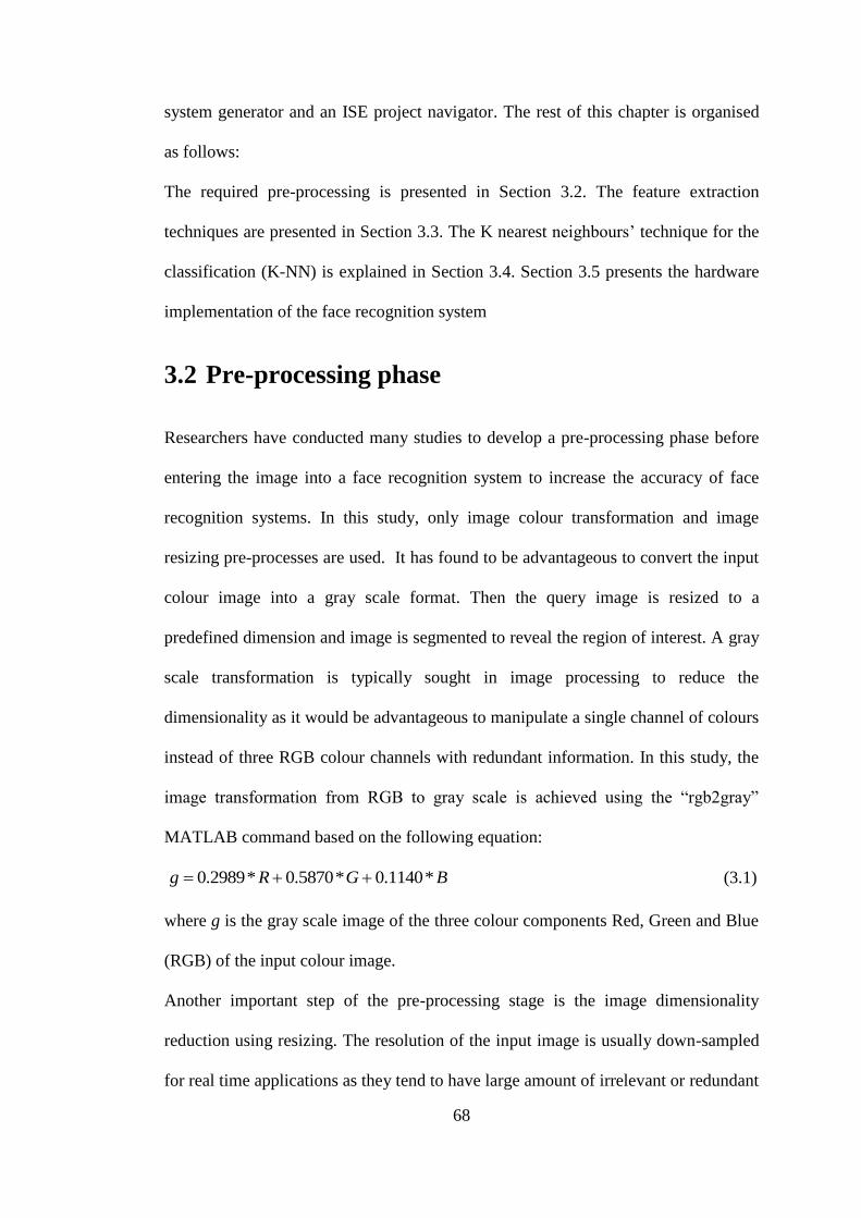
68
system generator and an ISE project navigator. The rest of this chapter is organised
as follows:
The required pre-processing is presented in Section 3.2. The feature extraction
techniques are presented in Section 3.3. The K nearest neighbours’ technique for the
classification (K-NN) is explained in Section 3.4. Section 3.5 presents the hardware
implementation of the face recognition system
3.2 Pre-processing phase
Researchers have conducted many studies to develop a pre-processing phase before
entering the image into a face recognition system to increase the accuracy of face
recognition systems. In this study, only image colour transformation and image
resizing pre-processes are used. It has found to be advantageous to convert the input
colour image into a gray scale format. Then the query image is resized to a
predefined dimension and image is segmented to reveal the region of interest. A gray
scale transformation is typically sought in image processing to reduce the
dimensionality as it would be advantageous to manipulate a single channel of colours
instead of three RGB colour channels with redundant information. In this study, the
image transformation from RGB to gray scale is achieved using the “rgb2gray”
MATLAB command based on the following equation:
BGRg *1140.0*5870.0*2989.0 (3.1)
where g is the gray scale image of the three colour components Red, Green and Blue
(RGB) of the input colour image.
Another important step of the pre-processing stage is the image dimensionality
reduction using resizing. The resolution of the input image is usually down-sampled
for real time applications as they tend to have large amount of irrelevant or redundant

69
information. Such redundancies should be avoided for efficient implementation using
limited hardware resources. The input image dimensions in this study are reduced to
the size (112x92 pixels) in addition to the gray scale transformation. The reduction or
resizing of an input facial image to these dimensions represents the preliminary steps
of the extraction stage. The required image resizing or scaling is obtained in
MATLAB using the function imresize or it can be achieved basically using the
following Equation:
100
00
00
*]1,,[]1,,[ y
x
s
s
zwyx (3.2)
Where Sx and Sy are the scale factors of the transformation, w, z are the input image’s
pixel values and x, y are the corresponding transformed or resized values. Figure 3.1
shows the resulted image after applying the two pre-processing steps above (Colour
transformation and image resize steps).
Figure 3.1 Example of the pre-processing results

70
3.3 Hybrid feature extraction
Hybrid feature extraction technique is used in this research to extract features from
the input image. This selection is based on the findings in the literature chapter which
shows that by combining local and the holistic feature extraction techniques, more
robust feature vector can be achieved than by each method alone. Consequently, in
this study, a hybrid feature extraction technique is developed by computing the local
features of three holistic regions (eye, nose and mouth) using 40 different scales and
orientations of Gabor filter.
3.3.1 Three region extraction
The procedure of extracting the three regions of interest is important because these
regions have the most discriminative data for any facial image. In this step, it is
supposed that, the size of the input image is rescaled as described in the pre-
processing stage. This is important as different images have varying image sizes
especially when using different image databases for testing purposes. The process of
region extraction in MATLAB is performed using the script shown in Figure 3.2:
Figure 3.2 Three regions extraction

71
where I is the input gray scale resized image and the Eye(x,y), Nose(x,y) and
Mouth(x,y) are the eye, nose and mouth regions respectively as shown in Figure3.2.
The selection of these three regions dimensions is tested on different images from the
ORL,FEI and faces94 frontal facial images databases and the same results are
obtained after resizing the input images into (112x92 pixels). These three holistic
regions are entered as separate input images to the local feature extraction algorithm
based on Gabor filters.
3.3.2 Gabor filters for Feature Extraction
Gabor filters are among the most popular tools for facial feature extraction. Their use
in automatic face recognition system is motivated by two major factors: their
computational properties and their biological relevance. Gabor filters represent
Gaussian kernel functions modulated by the centre frequency and orientation of a
complex plane wave. The modulation of the sinusoidal wave (sine /cosine) by the
Gaussian filter is shown in Equations 3.3 and 3.4:
)2cos(2
1)(
2
2
2 xfexg o
x
c
(3.3)
)2sin(2
1)(
2
2
2 xfexg o
x
s
(3.4)
where f0 represents the centre frequency which obtained the greatest response of the
filter. The sum of the positive and the negative responses represents the power
spectrum of the Gabor filter:
222222 )(2)(2)( oo ffff
eefG
(3.5)

72
Gabor filter is complex filter combining real and imaginary parts as shown in
Figure3.3.
Figure 3.3 The real part (left) and the imaginary part (right), (sine and cosine).
The traditional complex Gabor filter was demonstrated by Gabor (1946) as follows:
)()()( xigxgxg sc (3.6)
))2sin()2(cos(2
1 2
2
2 xfixfe oo
x
(3.7)
)22cos(2
1),(
)(2
1 22
yfxfeyxgoo
x
yx
y
yx
yx
c
(3.8)
Equation 3.8 defines the cosine Gabor filter for two dimensions while Equation 3.9
defines the sine Gabor filter.
)22sin(2
1),(
)(2
1 22
yfxfeyxgoo
x
yx
y
yx
yx
s
(3.9)
Where ( ,x yσ σ ) is the spread of the Gaussian filter and ( ,xo yof f ) defines the centre
frequency. The magnitude responses of the Gabor function vary slowly with the
spatial position, and are thus the preferred choice when deriving Gabor filter based
features. The selection of the filter parameters is very important in designing a Gabor
filter for face recognition. Gabor filters with multi-scale and multi-orientation are

73
created to obtain the required feature extraction. The common Gabor filters for
feature extraction have 5 scales and 8 orientations, i.e., u = 0, 1... p – 1 and v = 0, 1...
r – 1, where p = 5 and r = 8. Another representation of the Gabor filter is shown in
Equation 8. This representation has been proven by many studies to achieve an
optimal resolution in the spatial and frequency domains
])2
exp[(**1
),,,(2
2
2
kosmnGK
(3.10)
]2
)(*)/(exp[
2
2222
mnk
(3.11)
),(*exp 2 mnk (3.12)
2
8max *
f
ekk
sj
(3.13)
where the parameters (n, m) are the kernel window dimensions. { , , , , }0 1 2 3 4s and
{ , , , , , , , }0 1 2 3 4 5 6 7o are the scales and the orientations of the Gabor kernel.
( maxk ) is the maximum frequency, f is spatial frequency between the frequency
domain kernels and δ is the standard deviation of the Gaussian in the kernel window.
In this study these parameter values are chosen to be max / 2k π , 2f ,δ π .

74
Figure 3.4 Different scales and orientations of Gabor filters
The Gabor representation for a facial image is simply computed by convolving the
image to obtain different scales and orientations of the extracted image features as
shown in Figure 3.5. This can be obtained using Equation 3.14:
, ,( , ) ( , )* ( , )f θ f θg x y f x y φ x y (3.14)
Where f(x,y) is the input image intensity at x, y coordinates on the gray scale and
, ( , )f θφ x y is the Gabor filter.

75
Figure 3.5 The Gabor representation of an example facial image.
Gabor magnitude responses for the entire filter bank of the 40 Gabor filters are
commonly computed first using a convolution operation of an FIR filter. The
following example shows a simple way of convolving a filter kernel ),( yxh with an
input image ),( yxf . Assuming that the filter is a 3x3 matrix, the output of one
convolution process is given by ( , )g x y as in Equation 3.15.

76
Figure 3.6 An example of 2D convolution.
The kernel ),( yxh must first be rotated by 180o
and then be shifted over the image
so that its centre coincides with pixel ( 00 , yx ). The convolution then is only the sum
of multiplying each kernel value with the pixel value underneath it, as expressed in
Equation 3.15.
)1,1(),1()1,1()1,(),(
)1,()1,1(),1()1,1(),(
3332312322
21131211
jifhjifhjifhjifhjifh
jifhjifhjifhjifhyxg
(3.15)
Equation 3.15 is an FIR filter which is found in many DSP implementations. An FIR
filter hardware implementation can be designed using the following equation:
][][][1
0knxkhnf
N
k
(3.16)
where f[n] is the filter output, x[n-k] is the input data and h[k] is the filter
coefficients. The theoretical expression of the digital FIR filter design was
introduced previously in [97] Based on the Equation 3.16. In their hardware
implementation of FIR filter design, [78] and [98] found that the design of FIR filter
using this equation is highly computationally expensive. In contrast, distributed

77
arithmetic presents a better solution for an FIR filter implementation in an FPGA.
This is because of its high flexibility which permits serial to full-parallel
arrangements. The right balance among versions is tied to specifications for a given
application, and depends on the hardware, cost and throughput requirements.
Assuming the filter coefficients h[n] are constants, Equation 3.16 can be re-written
as:
1
0][][][
N
nnxnhnf (3.17)
The input variables x[n] can be represented in binary representation as follows:
1
02][][
B
b
b
b nxnx }1,0{bx (3.18)
Where bx [n] is the bth
bit of x[n] and B represents the input width.
The final representation of the FIR filter equation can be obtained by substituting
Equation 3.17 in 3.18 as follows:
1
0
1
02][][
B
b
b
b
N
nkxnhf (3.19)
This filter (distributed arithmetic FIR filter) is used in the current research to perform
the required convolution operations. Convolution, using an FIR filter, has to be
performed in the 40 different scales and orientations of the Gabor filter. In this study,
the Gabor filter is applied on each region (eyes, nose and mouth) and 40 different
scale and orientation Gabor representation are obtained as shown in Figure 3.7.

78
Figure 3.7 Example of finding the 40 Gabor representation of Eye, Nose and Mouth
regions of an image
A set of feature points from each region’s Gabor filter at location with the maximum
intensities values are calculated. These points are put in the following three matrices
where each column represents one feature points of one Gabor scale and one
orientation of each region:

79
40,2,1,
40,22,21,2
40,12,11,1
nnn EEE
EEE
EEE
GE
(3.20)
40,2,1,
40,22,21,2
40,12,11,1
nnn NNN
NNN
NNN
GN
(3.21)
40,2,1,
40,22,21,2
40,12,11,1
nnn MMM
MMM
MMM
GM
(3.22)
where GE, GN and GM represent the maximum intensity of the Gabor representation
of the eye, nose and mouth regions respectively.
However, since each of these responses is of the same dimensionality as the input
image, this procedure results in a fortyfold inflation of the original pixel space. To
overcome this shortcoming of the Gabor filter, in this study, the maximum intensity
of each Gabor filter is calculated to obtain only one value from each Gabor
representation. The feature vector of each person then contains only 40 values which
are the maximum intensity of the 40 Gabor filters. This vector will be used in the
identification stage to find the best match.
3.4 K-Nearest Neighbour (KNN)
K- NN classification technique has been proven to obtain higher recognition
accuracy and simpler than many classification techniques as presented in Chapter 2.
KNN classifier is found to be simpler with better accuracy performance than other

80
techniques such as Hidden Markov Model (HMM) and Kernel method. It is also
found to have faster processing time than SVM [67]. The KNN technique is used for
classifying an object (point) in two-dimensional spaces according to the majority of
cluster points within a pre-determined number of points K. To explain this method in
more detail, Figure 3.8 shows the operation of finding the matched cluster for two
different points in a two-dimensional space using K equal to three.
1 1.5 2 2.5 3 3.5 4 4.5 5 5.5 61
2
3
4
5
6
7
8
9
data1
data2
Point 1
Point 2
Two points to be classifyedusing KNN technique with K=3
Figure 3.8 An example of classifying two points using the K-NN algorithm and K=3.
Point 1 is classified as red points because the majority points of the minimum
distance for K=3 are red whereas point 2 is classified as blue points.
In order to classify new points (pink points), as shown in Figure 3.8, using K=3,
commonly, there are three metrics to compute the distance between the testing vector
and the training vectors. These metrics are the City Block distance (dc), the
Euclidean distance (de) and the Cosine distance (dcos) with the following equations:
Ni
i
ii yxyxdc1
),(
(3.23)
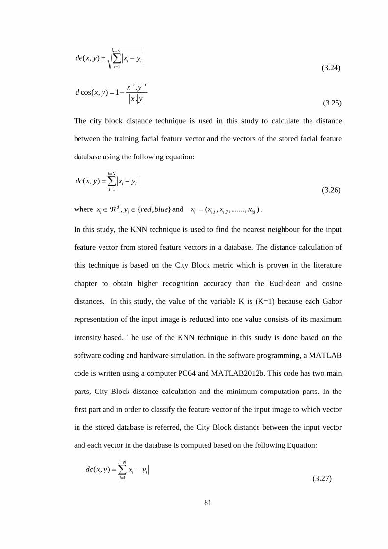
81
Ni
i
ii yxyxde1
),(
(3.24)
yx
yxyxd
.
.1),cos(
(3.25)
The city block distance technique is used in this study to calculate the distance
between the training facial feature vector and the vectors of the stored facial feature
database using the following equation:
Ni
i
ii yxyxdc1
),(
(3.26)
where , { , }d
i ix y red blue and ( , ,......., )1 2i i i idx x x x .
In this study, the KNN technique is used to find the nearest neighbour for the input
feature vector from stored feature vectors in a database. The distance calculation of
this technique is based on the City Block metric which is proven in the literature
chapter to obtain higher recognition accuracy than the Euclidean and cosine
distances. In this study, the value of the variable K is (K=1) because each Gabor
representation of the input image is reduced into one value consists of its maximum
intensity based. The use of the KNN technique in this study is done based on the
software coding and hardware simulation. In the software programming, a MATLAB
code is written using a computer PC64 and MATLAB2012b. This code has two main
parts, City Block distance calculation and the minimum computation parts. In the
first part and in order to classify the feature vector of the input image to which vector
in the stored database is referred, the City Block distance between the input vector
and each vector in the database is computed based on the following Equation:
Ni
i
ii yxyxdc1
),(
(3.27)
82
where fxxxx .....,, 21 is the input vector for test sample with f features and
nyyy .....,, 21 are the input vectors of training samples of size n . Where n is the
number of the stored features vectors in the database and f is the length of the input
testing vector. In the second part of the software programming, the nearest distance is
computed by finding the minimum City Block distance from the resulted distances
vector from part one. The minimum distance is then determined the best match for
the input image by referring to its label.
3.5 The implementation of the face recognition
system
This section aims to study the feasibility of implementing the face recognition
system based on the hybrid feature extraction (local Gabor filter and the holistic three
segmented facial regions) and the nearest neighbour technique for classification in an
FPGA board for a door access control. The concept of the proposed face recognition
system is as follows:
Three regions of the input image are extracted and each extracted region passed
through a Gabor filter to produce 40 hybrid representation of the input image. These
40 representations are reduced into 40 values contains the maximum intensity. Then
the resulted 40 values represent the feature vector of the input region. Nearest
neighbour technique is exploited then to find the best match for the resulted vector
from stored vectors in a database.
3.5.1 The feature extraction implementation of Gabor filter
using distributive arithmetic FIR filter
The Gabor filter requires hardware resources to implement the functions of sine,
cosine and calculating powers of complex exponentials that represent the core

83
problem of such filter. This problem becomes more complex in extracting facial
features with large dimensionality as the input image must be convolved to 40 Gabor
filters with different scales and orientations. Consequently, transforming a Gabor
filter into a matrix with fixed coefficients can tackle this big problem. In this study,
this transformation is done by running the MATLAB code for the Gabor filter and
saving the resulting 40 matrices of Gabor coefficients size 32*32. The representation
of the Gabor coefficients numbers is 64 bit signed double floating point. This is
because of the use of MATLAB to produce these values. Therefore, the required
memory of each Gabor filter coefficients matrix is given by:
Memory size =32*32*64=65536 bits
This equal to 8.192kB and the total memory size for 40 Gabor filters is given by:
8.192kB*40=327.68kB
The next step is to convolve these 40 Gabor filters with the input image. To find one
convolved value of an image pixel, as shown in the previous example of finding the
convolution, there is a large numbers of competitions has to be done including
rotating the filter kernel ),( yxh by 0180 and then shifting it over the image so that its
centre coincides with pixel ).,( 00 yx The convolution then is the sum of multiplying
each kernel value with the pixel value underneath it. This operation has to be
repeated for the entire input image after shifting the Gabor kernel over the image
pixels to find the corresponding convolution values. This means that the convolution
computation using the traditional addition and multiplication is quite complex. FPGA
devices offer alternative tools to compute such enormous task. One of the most
powerful FPGA’s tools is the FIR filter. In order to implement the required
convolution operations, a distributed arithmetic FIR filter is used. As shown in
Figure 3.9, the input sequence ),( yxf is fed into a shift register at the same input

84
sampling rate. The Gabor filter coefficients are stored as the FIR filter coefficients
over 40 FIR executed in parallel.
Figure 3.9 A parallel DA FIR filter block diagram
3.5.2 The hardware implementation of KNN technique
On the hardware feasibility investigation experiment of this study, a simulation
model for each part of the software code is designed using Xilinx system generator
and ISE project navigator design tools which are compatible with MATLAB 2012b.
The model compute the City Block distance using subtractions and adders connected
in a way to do the same task of the City Block distance Equation through N parallel
paths. Each path computes one City Block distance between the input vector and one

85
of the stored vectors. The outputs of these paths are then entered to another block to
calculate the minimum distance as shown in Figure3.10.
Figure 3.10 A block diagram of the required KNN technique hardware paths
86
CHAPTER 4: EXPERMENTS AND
RESULTS
4.1 Introduction
This chapter presents the software programming and the hardware simulations of a
face recognition system. It aims to study the recognition accuracy and the hardware
implementation feasibility of such a system through two parts. In the first part, the
software programming of the face recognition system is developed using
MATLAB2012b. The system consists of three stages: pre-processing, feature
extraction and classification stages. In the pre-processing stage, the input image is
transformed into a gray scale and its size is resized into (112x92). The feature
extraction stage is performed based on a hybrid feature extraction technique. The
hybrid technique is based on extracting the local features of three holistic facial
regions; eyes, nose and mouth using Gabor filter. The last stage of the developed FR
system is the classification stage based on the K nearest neighbour technique. These
stages were discussed in details in the previous chapter. The ORL, FEI and Faces94
databases are discussed in Section 4.2.1. The system results are presented in Section
4.2.2 for the recognition accuracy analysis using those databases.
In the second part of this chapter (Section 4.3), the feasibility of implementing the
developed FR system in an FPGA device is investigated using Xilinx system
generator and ISE project navigator design tools which are compatible with
MATLAB2012b.

87
4.2 Facial databases
In this study, the ORL, the FEI and the faces94 facial images databases are used to
study the behaviour of the proposed face recognition system under various types of
images. The main reason of selecting these databases is related to their consistence of
images with low expression changes, low head movements and constant
illumination. The ORL database [50] (Figure 4.1) which is one of the most extensive
and a popular database of faces is used for training and testing the face recognition
algorithm..
Figure 4.1 Examples of ORL database images

88
It consists of images with slight changes in facial expression, facial details and some
side movements. There are a total of 400 images of 40 people; each person has 10
images with different pose and expressions. In this experiment, only 5 images from
each person are used for training and the remaining five images are used for the
testing phase. This database is chosen because of the availability of various instances
of frontal views for each subject. In addition to ORL database the FEI [99] (see
Figure 4.2) is used to make the testing stage more robust. FEI database was
developed by Artificial Intelligence Laboratory of FEI in São Bernardo do Campo,
São Paulo, Brazil. FEI database consists of frontal pose facial images with different
expression changes (with and without smile) and constant illumination of 100
persons. The face94 (see Figure 4.3) database [35] is also used as it consists of
frontal images for different genders clustered into two groups (male and female). It
has a total of 153 individuals with a little head pose, tilt and slant variations with no
lighting variations.
Figure 4.2 Example from FEI Database images
Figure 4.3 Example from faces94 Database images
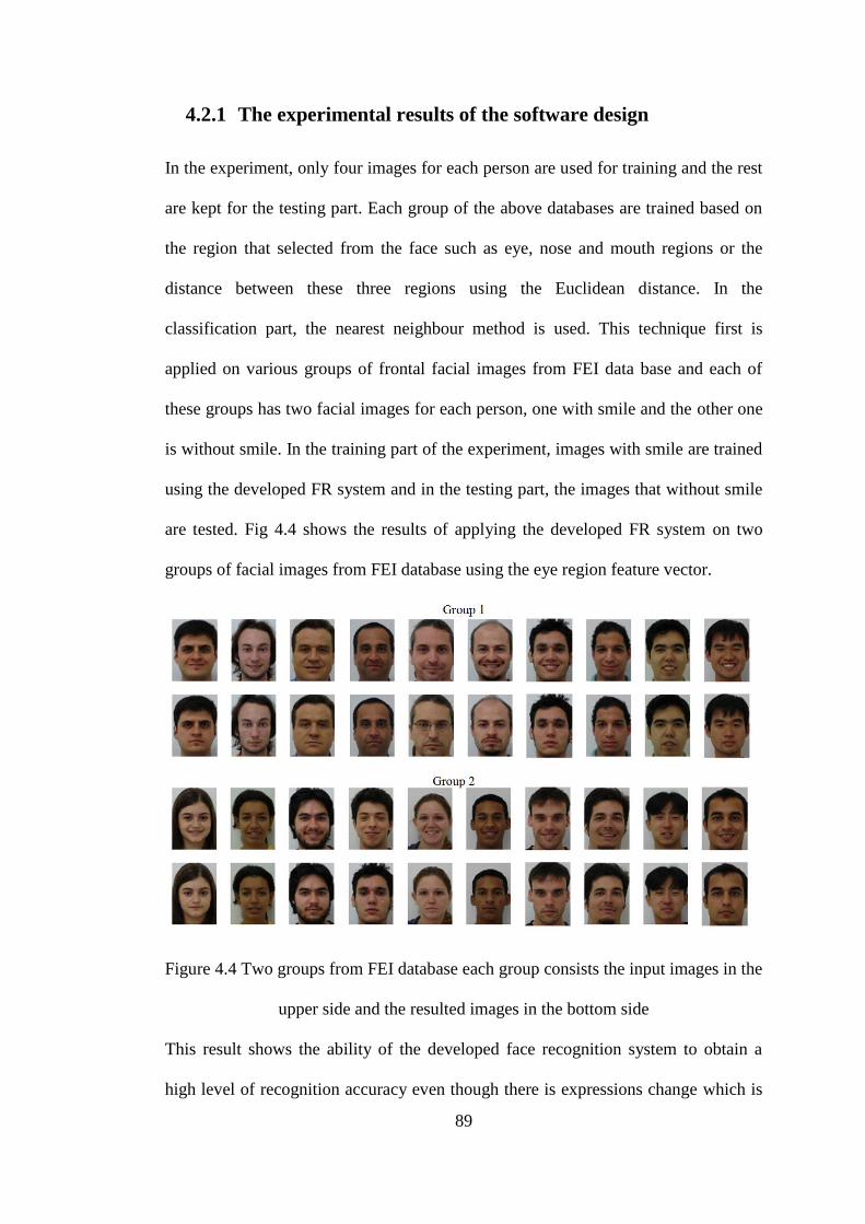
89
4.2.1 The experimental results of the software design
In the experiment, only four images for each person are used for training and the rest
are kept for the testing part. Each group of the above databases are trained based on
the region that selected from the face such as eye, nose and mouth regions or the
distance between these three regions using the Euclidean distance. In the
classification part, the nearest neighbour method is used. This technique first is
applied on various groups of frontal facial images from FEI data base and each of
these groups has two facial images for each person, one with smile and the other one
is without smile. In the training part of the experiment, images with smile are trained
using the developed FR system and in the testing part, the images that without smile
are tested. Fig 4.4 shows the results of applying the developed FR system on two
groups of facial images from FEI database using the eye region feature vector.
Figure 4.4 Two groups from FEI database each group consists the input images in the
upper side and the resulted images in the bottom side
This result shows the ability of the developed face recognition system to obtain a
high level of recognition accuracy even though there is expressions change which is

90
the smile. This finding is confirmed by applying the system on images from the
faces94 database. In this part of the experiment, different groups from the faces94
database are trained and tested. The training stage consists of only 4 images from
each person image gallery and the rest images of that person are tested. The system
results in high recognition accuracy as shown in Figure 4.5 which consists of the
results of one female group.
Figure 4.5 the results of one female group.
Table 4-1 shows the recognition accuracy results for the feature vectors of eyes,
nose, mouth and the distances between their features using images from ORL,
faces94 and FEI databases. It can be clearly seen that images from faces94 database
are superior to the other two databases in terms of obtaining higher recognition
accuracy. A recognition accuracy of 98.88% is obtained based on the eyes region in
the faces94 database whereas 97% and 87% are obtained using FEI and ORL
databases, respectively.
Table 4-1 The results of applying the proposed algorithm on different regions

91
FEI
Face94
ORL
Eye Region 97% 98.88% 87%
Nose Region 85% 100% 77%
Mouth Region 70% 97.77% 78%
Distance( Eye - Nose) 74% 90% 83%
Distance( Eye - Mouth ) 72% 93% 73%
Distance( Nose- Mouth ) 76% 95.5% 75%
The recognition accuracy using faces94 database could reach a 100% on the nose
region while the FEI and ORL could not obtain similar accuracy. The reason for this
is related to the consistence of face94 database of facial images with frontal pose,
lower head movement and expression changes than those in ORL or FEI. These
findings confirm the usefulness of the developed face recognition system to serve in
a door access control system achieving high level of recognition accuracy.
Table 4-2 the face recognition accuracy for the current and some previous techniques
The face recognition techniques Recognition
Accuracy
Facial database and notes
The proposed technique for one
selected region(Nose Region)
100% Faces94 database[35]
Gabor + ICA [55]
100%
ORL (88 features)[50]
EBGM [14]
LFA [15]
94.29%,
100%
face94 [35]
Images with high resolution
from ORL[50]

92
For comparison purposes, the results related to the current study and the previous
techniques are provided in Table 4-2. It was reported that the use of Gabor filter and
the maximum intensity point technique in [14] could obtain a recognition accuracy of
94 % using a group of 70 images from faces94 database. In contrast, the proposed
method of selecting a region of interest is shown to be more robust to obtain higher
recognition accuracy especially for the eyes region or the nose region which is
obtained excellent recognition accuracy using the same database (faces94). This
recognition accuracy is similar to the reported achievement in [55] that used the
Gabor filter and ICA techniques with images of high resolution from ORL database.
The results of the proposed system are also similar to what was obtained by [15] who
used LFA technique with images from ORL database.
However, the number of the selected features in the proposed system is lower than
the number of features in [15]. This can reduce the number of the required hardware
resources in case of implementing this algorithm in a hardware device for real time
application such as a door access control system. The proposed system is expected to
be faster and require lower storage memory than those in [55] and [15].
4.3 The implementation of the face recognition
system
This section studies the feasibility of implementing the face recognition system based
on the hybrid feature extraction (local Gabor filter and the holistic three segmented
facial regions) and the nearest neighbour technique for classification in an FPGA
board for a door access control. The concept of the proposed face recognition system
is as follows:
Three regions of the input image are extracted and each extracted region passed
through a Gabor filter to produce 40 hybrid representation of the input image. These

93
40 representations are reduced into 40 values which contain the maximum intensity.
Then the resulting 40 values represent the feature vector of the input region. Nearest
neighbour technique is used then to find the best match for the resulting vector
among stored vectors in a database. In order to study the feasibility of implementing
these steps in an FPGA device, it is assumed that the input image is already
transformed into gray scale and three regions are extracted in this research to pay
more attention on the hardware implementation of the Gabor filter and the nearest
neighbour techniques. In order to calculate the size of the required memory to store
any image, the following Equation can be used:
Memory size = Image resolution × bit/pixel (4.1)
where the bit/pixel normally is equal to 8 and the image resolution equal to the image
dimensions. For example, the input Eye region image has the dimension of 20×85,
the required memory size will be:
EMemory size=20×85×8=13600bits
It is known that each 8 bits represent one byte and as a result, the memory size in
byte will be 93600 bytes=17 kB
Similarly, the nose and the mouth regions are:
NMemory size=20×56×8=8960bit=1.12kB
MMemory size=18×58×8=8352bit=1.044kB
These images are entered to the feature extraction stage of the face recognition
system. The hardware implementation of the proposed face recognising system is
analysed separately in the following sections.

94
4.3.1 Distributed arithmetic FIR filter simulation design
In order to show the feasibility of designing a Distributed Arithmetic FIR filter, the
Xilinx block set and system generator tools are used in this part. Xilinx block set is
compatible with MATLAB simulink allowing designers to select the appropriate
block for the design. FIR.5.0 block which is one of the most important Xilinx blocks
is used in this research to develop the simulation of distribution arithmetic FIR filter
to obtain the convolution between the input image and the Gabor filter coefficients.
The simulation design of such filter consists of Input unit, output unit and the FIR.5.0
blocks as shown in Figure 4.5.
Figure 4.5 The simulation design of a distributed arithmetic FIR filter
The input data for this simulation design is one of the three regions images which are
already loaded on to the MATLAB work space and stored as matrices. This data is
entered into the simulation using gate-in block which makes the appropriate

95
compatibility between the input data and the Xilinx environment. A FIR.5.0 block is
used in this simulation to obtain an FIR filter. This block allows selecting the
structure of the FIR filter (distributed arithmetic structure as shown in Figure 4.6).
Figure 4.6 The ability of Xilinx FIR filter to select a distributed arithmetic
architecture
The coefficients of one Gabor filter (1 from 40 Gabor filters) are loaded to the
FIR.5.0 block using FDAtool. This tool allows uploading the coefficients vector
from the work space by specifying the filter structure as direct FIR form and the
vector name in the FDAtool block parameter as shown in Figure 4.7.

96
Figure 4.7 FDATool block parameter
After running the simulation design, the system will compute the required FIR
filtering (convolution) between one Gabor filter coefficients which are loaded to the
FIR.5.0 by FDATool and the input image. The output of the system represents the
Gabor features of the input image. Since the feature extraction stage in the proposed
face recognition system consists of 40 Gabor filters, 40 FIR filters (40 paths) are
connected in parallel to compute 40 Gabor representation of an input image as shown
in Figure 4.8.

97
Figure 4.8 The simulation design of 40 FIR filters connected in parallel
The resulting vector from each FIR filter (each path) has the same size as that of the
input image (the input region). This will produce a very high feature’s dimensions.
To overcome this problem, the maximum intensity of each Gabor representation is
computed to produce one value only. The following simulation design is run using an
M-code block provided with Xilinx block set. This block allows fetching a
MATLAB function to compute the required maximum value.

98
Figure 4.9 The simulation design of the maximum comparator
The design in Figure 4.9 is useful for performing comparisons operations (maximum
computations). It can be used to implement the required comparator operation on the
output of each FIR filter resulted in 40 values which represent the facial feature
vector as shown in Figure 4.10.
Figure 4.10 Forty FIR filters connected in parallel to perform a convolution of Gabor
filter

99
where }....,,{ 4021 vvvV is the output vector which consists of the 40 maximum
intensities of the 40 Gabor representation of the input image.
4.3.2 The hardware implementation of the Nearest Neighbour
Classifier using City Block distance
The resulting feature vector of FIR (Gabor) filters which are the facial feature vector
has to be classified according to the nearest neighbour technique to find the best
match using City Block distance metric. The required number of neighbours in this
research is one (K=1) because each filter path will produce one value.
The city block distance is given by:
Ni
i
ii yxyxdc1
),(
(4.2)
where fxxxx ....,, 21 is the testing vector and nyyyy .....,, 21 are the training
vectors where n is the number of the stored features vectors in the database and f
is the length of the input testing vector. The City Block distance metric can be
written as:
)....()()()()()1,( 1144133122111 ff yxyxyxyxyxyxdc
)....()()()()()2,( 2244233222211 ff yxyxyxyxyxyxdc
......................
)....()()()()(),( 44332211 nffnnnn yxyxyxyxyxynxdc (4.3)
The main two steps shown in Equations (4.3) are computing the City Block distance
(using subtraction and addition) and finding the minimum distance of the resulting
vector to find the nearest neighbour. The hardware implementation of these two steps
can be obtained using an FPGA device exploiting its parallelism characteristic. Each

100
value of the unknown vector is subtracted from the corresponding value of the
f training vector and the results are added to each other producing one distance
value. This step can be achieved using Xilinx system generator simulation. The
simulation of one path of the required paths of computing the City Block distance is
shown in Figure 4.11. The input for such simulation is one training vector and the
test vector.
Figure 4.11 The simulation design one path of the city block distances.
The parallelism characteristic of FPGA devices can be used to calculate the City
Block distance by assigning a similar simulation design to each training vector as
shown in Figure 4.12.

101
Figure 4.12 The simulation design of commuting the City Block values between the
testing vector and N training paths
The vector }.....,,{ 21 ndddD consists of the City Block distances between each
feature vector in the training set and the feature vector of the input image. Where n is
the number of the training feature vectors. The size of the database varies between
system and another depending on the number of images that is used in that database.
Suppose the number of images is 100 ( 100n ), the value of the required memory to
store the features vectors of these 100 images is given by:
Memory size= images number×40×64
where the number 40 is the number of the maximum intensities of the resulting
convolution values between each image and 40 Gabor filters. So the size of the
required memory for these 100 images is:
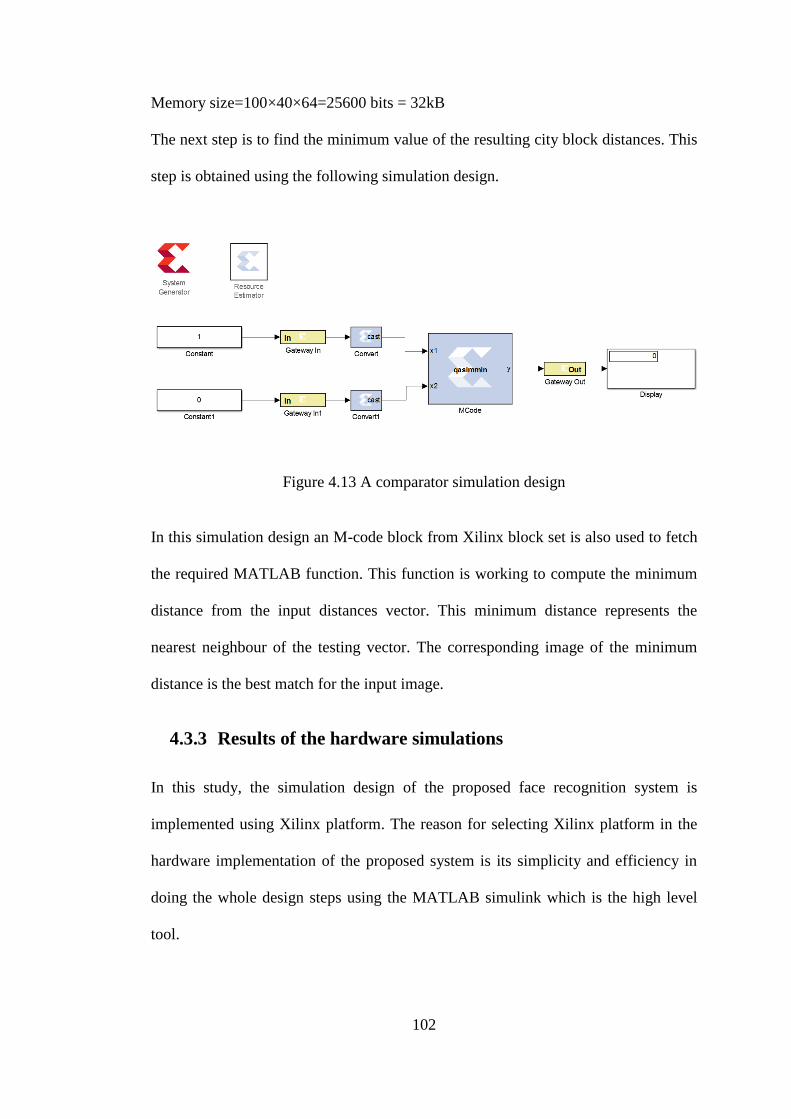
102
Memory size=100×40×64=25600 bits = 32kB
The next step is to find the minimum value of the resulting city block distances. This
step is obtained using the following simulation design.
Figure 4.13 A comparator simulation design
In this simulation design an M-code block from Xilinx block set is also used to fetch
the required MATLAB function. This function is working to compute the minimum
distance from the input distances vector. This minimum distance represents the
nearest neighbour of the testing vector. The corresponding image of the minimum
distance is the best match for the input image.
4.3.3 Results of the hardware simulations
In this study, the simulation design of the proposed face recognition system is
implemented using Xilinx platform. The reason for selecting Xilinx platform in the
hardware implementation of the proposed system is its simplicity and efficiency in
doing the whole design steps using the MATLAB simulink which is the high level
tool.

103
The design of the system pass through four simulation models: convolution
computation, maximum intensity calculation, City Block calculation and the
minimum calculation. In the first model, the simulation design of the distributed FIR
filter is built in the Xilinx simulink. In this simulation, a resources estimator is used
to determine the required hardware resources of implementing such filter in an
FPGA device. The hardware resources of the simulation are shown in Table 4-3.
Table 4-3 The required hardware resources for each filter
The ISE project navigator is used then to complete the required implementation
processes of this simulation. The results in Table 4-3 are for one path (one FIR filter)
and the total number of this path is 40. This is necessary for performing the required
convolution process between the input image and the 40 Gabor filters. Therefore, the
total hardware resources can be estimated by multiplying each component by 40.
In the second model, the simulation design is done using a MATLAB function which
computes the maximum intensity of the FIR filter output sequence. The MATLAB
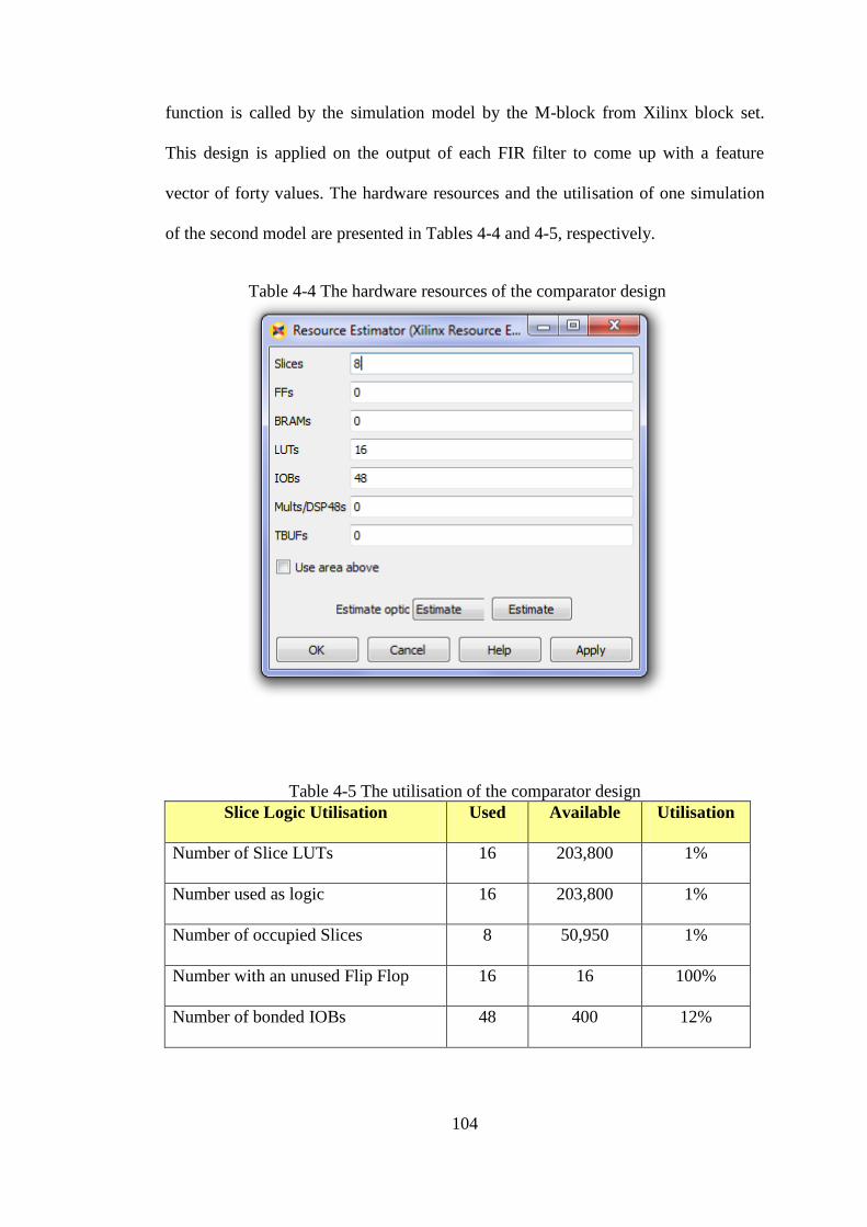
104
function is called by the simulation model by the M-block from Xilinx block set.
This design is applied on the output of each FIR filter to come up with a feature
vector of forty values. The hardware resources and the utilisation of one simulation
of the second model are presented in Tables 4-4 and 4-5, respectively.
Table 4-4 The hardware resources of the comparator design
Table 4-5 The utilisation of the comparator design
Slice Logic Utilisation Used Available Utilisation
Number of Slice LUTs 16 203,800 1%
Number used as logic 16 203,800 1%
Number of occupied Slices 8 50,950 1%
Number with an unused Flip Flop 16 16 100%
Number of bonded IOBs 48 400 12%

105
The resulting vector of the maximum intensity of the 40 FIR filters represents the
feature vector of the input image. This vector is then entering to the classification
stage to find the best match of the input image from existing vectors in a database.
The third simulation is designed to achieve the nearest neighbour by computing the
City Block distance between the testing feature vector and one of the trained vectors.
The simulation design of one path of the required City Block distance is shown in
Table 4-6.
Table 4-6 Hardware resources of one path of the city block metric
The total number of the required paths (the third simulation design) in this stage
depends on the number of the stored vectors in the database. This is because the
nearest neighbour technique is based on finding the nearest City Block distance
between the input vector and the stored vectors in the database.

106
Finally, a simulation is designed using a MATLAB function to find the minimum
City Block distance of the resulted vector. The resources utilisation of this simulation
design is shown in Table 4-7.
Table 4-7 The resources utilisation of the comparator simulation design
Slice Logic Utilisation Used Available Utilisation
Number of Slice Registers 1 407,600 0%
Number of Slice LUTs 31 203,800 1%
Number used as logic 16 203,800 1%
Number of occupied Slices 8 50,950 1%
Number of bonded IOBs 49 400 12%
The best match is then the facial image corresponding to the minimum City Block
distance. All of the above simulations confirm the ability of the Xilinx system
generator and ISE project navigator to complete the required steps of the hardware
implementation. Since the Xilinx platform has a one to one correspondence to the
hardware implementation. The results of these simulations confirm the feasibility of
implementing the proposed face recognition system in an FPGA device.
However, in terms of a real time application such as door access control system, the
first simulation model which is the FIR filter is found to be time consuming. This is
because this filter works on doing the point by point operation to calculate the
required convolutions between the input image and Gabor filter coefficients. To
overcome this problem, the image divider stage must be used to divide the input
image into sub images and the number of these sub images is depending on the
available hardware resources in the FPGA device. The FIR filter is then applied on
these sub-images in parallel which can extremely speed up the processing time.

107
CHAPTER 5: THE CONCLUSION
Numerous studies have been conducted on face recognition algorithms. The majority
of previous research was focused on improving the accuracy of the face recognition
algorithms in light of some problems such as illumination, pose and facial expression
changes. However, only a few of these studies focused on implementing these face
recognition techniques in an embedded system for real time applications, such as a
door access control system. Most of the previous studies’ preference was on
implementing a PCA algorithm for face recognition on hardware devices for its
simplicity and its ability in dimensionality reduction. However, because of the
dependency of the PCA algorithm on the Eigen values, which are highly sensitive to
image appearance, it needs to use floating point operations that are costly and
complex in terms of hardware. Furthermore, problems of high computational time
and high power consumption are also faced by current door access control systems
either supervised or not fully automatic. Based on existing literature, it can be
concluded that higher recognition accuracy can be obtained if the type of the face
recognition algorithm and the hardware device are chosen carefully.
Furthermore, hybrid feature extraction techniques have been proven to be more
powerful methods for extracting image facial features and producing a robust face
recognition system against illumination, facial expression changes and pose. In this
study, a face recognition system was developed based on a hybrid technique for
feature extraction and K nearest neighbour for classification. The hybrid feature
extraction of the system is based on Gabor filters and three facial regions eyes, nose
and mouth. In the classification stage of the system, the minimum City Block
distance is computed to find the best match.

108
The system resulted in very good recognition accuracy for images from ORL, FEI
and face94 facial databases. Based on the results of the FR system, it can be observed
that, high recognition accuracy rate can be obtained when the facial images are taken
carefully with front pose and with minimal changed expressions.
On the other hand, currently, there exist various hardware platforms with various
performance and efficiency for digital signal processing (DSP) tasks. Field
programmable gate arrays (FPGAs) have proven to be more efficient for images and
signal processing tasks. The main reason for this is that FPGAs offered by Xilinx
Corporation can be programmed to the desired application allowing designers to
change their design at any given time of the design cycle and to complete the
upgrading process remotely. The Field Programmable Gate Array (FPGA) device is
an excellent device to deal with different complex tasks, in particular the face
recognition algorithm implementation. In this study, the feasibility of implementing a
face recognition system in an FPGA device was investigated based on Gabor filters
for feature extraction and nearest neighbour technique for classification. The
resulting face recognition design is useful to be used in a door access control system.
In this study, the Xilinx system generator and ISE project navigator were used to
design the required simulation and to produce the hardware implementation reports.
The distributive arithmetic FIR filter was used in the feature extraction stage to
compute the convolution operation between the input image (three regions images)
and each of the 40 Gabor matrix (filter coefficients). In the section on classification
technique, the simulation design of the nearest neighbour technique was attempted
based on the City Block distance. The results of this research show that the process
of converting the MATLAB code of Gabor filters into fixed 40 matrices can reduce
the hardware resources to only a Ram of size 8.192KB for each filter. The results

109
obtained using the simulations did confirm the feasibility of implementing a face
recognition system on an FPGA devise with minimum hardware. Since Xilinx
simulation provides a one-to-one realistic correspondence between simulation and
real implementation, this validates our research and will soon be implemented on a
Xilinx FPGA device. This research will serve as a foundation for future studies and
further improvement in both system reliability and face recognition accuracy leading
to design a door access control system based on face recognition.

110
REFERENCES
[1] P. Hancock. Psychological Image Collection at Stirling (PICS). Available:
http://pics.stir.ac.uk/
[2] R. Aruna, et al. (2013, Impact of Cosmetics onFace Recognition. Available:
http://www.cse.msu.edu/~rossarun
[3] A. V. Nefian. Georgia Tech face database Available:
http://www.anefian.com/research/face_reco.htm
[4] X. Cao, et al., "Illumination invariant extraction for face recognition using
neighboring wavelet coefficients," Pattern Recognition, vol. 45, pp. 1299-
1305, 2012.
[5] H. Hu, "Variable lighting face recognition using discrete wavelet transform,"
Pattern Recognition Letters, vol. 32, pp. 1526-1534, 2011.
[6] A. Abbas, et al., "Expression and illumination invariant preprocessing
technique for Face Recognition," in International Conference on Computer
Engineering & Systems, ICCES, 2008, pp. 59-64.
[7] K. Hardeep and K. Amandeep, "Illumination Invariant Face Recognition,"
International Journal of Computer Applications, vol. 64, 2013.
[8] B. K. Bairagi, et al., "Expressions invariant face recognition using SURF and
Gabor features," in Third International Conference on Emerging Applications
of Information Technology (EAIT), 2012, pp. 170-173.
[9] P. B. Saurabh and D.S.Chaudhari, "Principal Component Analysis for Face
Recognition," International Journal of Engineering and Advanced
Technology, vol. 1, pp. 91-94, 2012.
[10] S. M. Prakash and C. J. Kalpna, "Face Recognition Using PCA,"
International Journal of Artificial Intelligence & Knowledge Discovery, vol.
1, pp. 25-28, 2011.
[11] M. Shen, et al., "Independent component analysis for face recognition based
on two dimension symmetrical image matrix," in 24th Chines Control and
Decision Conference (CCDC), 2012, pp. 4145-4149.
[12] A. Bansal, et al., "Face Recognition Using PCA and LDA Algorithm," in
Second International Conference on Advanced Computing & Communication
Technologies (ACCT), 2012, 2012, pp. 251-254.
[13] M. I. Razzak, et al., "Face Recognition using Layered Linear Discriminant
Analysis and Small Subspace," in 10th International Conference on
Computer and Information Technology (CIT), IEEE, 2010, pp. 1407-1412.
[14] S. Muhammad, et al., "Face Recognition using Gabor Filters," Journal of
Applied Computer Science & Mathematics, vol. 5, pp. 53-57, 2011.
[15] F.-E. Ehsan, et al., "Robust Face Recognition through Local Graph
Matching," Journal of Multimedia, vol. 2, pp. 31-37, 2007.
[16] S. Sint. (2011, Posing the Face. Available: http://stevesint.com/blog/
[17] R. Ibrahim and Z. M. Zin, "Study of automated face recognition system for
office door access control application," in 3rd International Conference on
Communication Software and Networks (ICCSN), IEEE, 2011, pp. 132-136.
111
[18] Q. Al-Shebani, et al., "Embedded door access control systems based on face
recognition: A survey," in 7th International Conference on Signal Processing
and Communication Systems (ICSPCS), IEEE, 2013, pp. 1-7.
[19] W. J. MacLean, "An Evaluation of the Suitability of FPGAs for Embedded
Vision Systems," in Computer Society Conference on Computer Vision and
Pattern Recognition - Workshops, 2005. CVPR Workshops, IEEE, 2005, pp.
131-131.
[20] D. Guru, et al., "Texture features and KNN in classification of flower
images," IJCA, Special Issue on RTIPPR (1), pp. 21-29, 2010.
[21] R. C. Gonzalez and R. E. Woods, Digital image processing. Upper Saddle
River, N.J: Prentice Hall, 2002.
[22] J. Mazanec, et al., "Support vector machines, PCA and LDA in face
recognition," Journal of electrical engineering -electrotechnicky casopis, vol.
59, pp. 203-209, 2008.
[23] D. Shan and R. Ward, "Wavelet-based illumination normalization for face
recognition," in International Conference on Image Processing, 2005. ICIP,
IEEE, 2005, pp. II-954-7.
[24] J. Ajay, et al., "Illumination Invariant Facial Pose Classification,"
International Journal of Computer Applications, vol. 37, pp. 14-19, 2012.
[25] H.-S. Lee and D. Kim, "Expression-invariant face recognition by facial
expression transformations," Pattern Recognition Letters, vol. 29, pp. 1797-
1805, 2008.
[26] C. Ki-Chung, et al., "Face recognition using principal component analysis of
Gabor filter responses," in International Workshop on Recognition, Analysis,
and Tracking of Faces and Gestures in Real-Time Systems, Proceedings,
1999, pp. 53-57.
[27] A. M. Martinez and A. C. Kak, "PCA versus LDA," Pattern Analysis and
Machine Intelligence, IEEE Transactions on, vol. 23, pp. 228-233, 2001.
[28] B. Moghaddam, et al., "Bayesian face recognition," Pattern Recognition, vol.
33, pp. 1771-1782, 2000.
[29] M. S. Bartlett, et al., "Face recognition by independent component analysis,"
Neural Networks, IEEE Transactions on, vol. 13, pp. 1450-1464, 2002.
[30] C. Ashish and M. Om, "Face Recognition Using RBF Kernel Based Support
Vector Machine," International Journal of Future Computer and
Communication, vol. 1, p. 4, 2012.
[31] X. Wang, et al., "On minimum class locality preserving variance support
vector machine," Pattern Recognition, vol. 43, pp. 2753-2762, 2010.
[32] S. Zafeiriou, et al., "Minimum Class Variance Support Vector Machines,"
Image Processing, IEEE Transactions on, vol. 16, pp. 2551-2564, 2007.
[33] P. N. Belhumeur, et al., "Eigenfaces vs. Fisherfaces: recognition using class
specific linear projection," Pattern Analysis and Machine Intelligence, IEEE
Transactions on, vol. 19, pp. 711-720, 1997.
[34] Vidit Jain and Amitabha Mukherjee. (2002, The Indian Face Database
Available: http://vis-www.cs.umass.edu/~vidit/IndianFaceDatabase/
[35] Libor Spacek. (2007, Collection of Facial Images: Faces94. Available:
http://cswww.essex.ac.uk/mv/allfac
[36] A.M. Martinez and R. Benavente, "The AR-face database," June 1998.
[37] M. I. Razzak, et al., "Face Recognition using Layered Linear Discriminant
Analysis and Small Subspace," 2010, pp. 1407-1412.

112
[38] N. Poh. BANCA score database. Available:
http://personal.ee.surrey.ac.uk/Personal/Norman.Poh/web/banca_multi/main.
php?bodyfile=entry_page.html
[39] M. S. Bartlett, et al., "Face recognition by independent component analysis,"
PISCATAWAY, 2002
pp. 1450-1464.
[40] P. J. Phillips, et al., "The FERET database and evaluation procedure for face-
recognition algorithms," Image and Vision Computing, vol. 16, pp. 295-306,
1998.
[41] Z. Ce, et al., "Face recognition from single sample based on human face
perception," in 24th International Conference on Image and Vision
Computing New Zealand, 2009. IVCNZ, 2009, pp. 56-61.
[42] T. Ahonen, et al., "Face recognition with local binary patterns," Lecture
Notes in Computer Science (including subseries Lecture Notes in Artificial
Intelligence and Lecture Notes in Bioinformatics), vol. 3021, pp. 469-481,
2004.
[43] P. J. Phillips, et al., "The FERET evaluation methodology for face-
recognition algorithms," in Computer Society Conference on Computer
Vision and Pattern Recognition, Proceedings, IEEE, 1997, pp. 137-143.
[44] H. K. Ekenel and R. Stiefelhagen, "Analysis of Local Appearance-Based
Face Recognition: Effects of Feature Selection and Feature Normalization,"
in Conference on Computer Vision and Pattern Recognition Workshop,
CVPRW, 2006, pp. 34-34.
[45] L. Wiskott, et al., "Face recognition by elastic bunch graph matching,"
Pattern Analysis and Machine Intelligence, IEEE Transactions on, vol. 19,
pp. 775-779, 1997.
[46] D. Murugan, et al., "Performance Evaluation of Face Recognition Using
Gabor Filter, Log Gabor filter and Discrete Wavelet Transform,"
International Journal of Computer Science & Information Technology, vol. 2,
pp. 125-133, 2010.
[47] L. Shen and L. Bai, "A review on Gabor wavelets for face recognition,"
Pattern Analysis and Applications, vol. 9, pp. 273-292, 2006.
[48] P.J. Phillips, et al., "FERET (Face Recognition Technology) Recognition
Algorithm Development and Test Report," 2800 Powder Mill Road, Adelphi,
Md.Oct.1996.
[49] P. Lo, "Dynamic local feature analysis," Biometric Technology Today, vol.
15, pp. 8-8, 2007.
[50] Andy Harter, et al., "The Anatomy of a Context-Aware Application,"
Wireless Networks, vol. 8, pp. 187-197 2002.
[51] V. Struc, et al., "Principal Gabor filters for face recognition," in 3rd
International Conference on Biometrics: Theory, Applications, and Systems,
BTAS,IEEE, 2009, pp. 1-6.
[52] J. Ravi and K. B. Raja, "Hybrid Domain Based Face Recognition System,"
International Journal of Advanced Networking and Applications, vol. 3, p.
1402, 2012.
[53] E. Fazl-Ersi and J. K. Tsotsos, "Local feature analysis for robust face
recognition," in Symposium on Computational Intelligence for Security and
Defense Applications, CISDA, IEEE, 2009, pp. 1-6.
[54] K. Yesu, et al., "Hybrid features based face recognition method using
Artificial Neural Network," 2012 pp. 40-46.

113
[55] L. Chengjun and H. Wechsler, "Independent component analysis of Gabor
features for face recognition," United States, 2003 pp. 919-928.
[56] A. S. Georghiades, et al., "From Few to Many: Illumination Cone Models for
Face Recognition under Variable Lighting and Pose," IEEE Trans. Pattern
Anal. Mach. Intelligence, vol. 23, pp. 643-660, 2001.
[57] K. Messer, et al., "Xm2vtsdb the extended M2VTS database
" presented at the Second International Conference on Audio and Video-based
Biometric Person Authentication, 1999.
[58] Michael J. Lyons, et al. ( 1997
Japanese Female Facial Expressions (JAFFE). Available:
http://www.kasrl.org/jaffe_info.html
[59] D. Hond and L. Spacek, "Distinctive Descriptions for Face Processing," in
proceedings of the 8th British Machine Vision Conference BMVC97,
Colchester, England, , September 1997, pp. 320-329.
[60] L. Pan and J. Song, "The Research of Embedded Face Recognition System
Design Based on DSP: Automatic Machine Recognition of Face Design and
Implementation," in Symposium on Photonics and Optoelectronic (SOPO),
2010, pp. 1-4.
[61] W. Liwei, et al., "On the Euclidean distance of images," Transactions on
Pattern Analysis and Machine Intelligence, IEEE, vol. 27, pp. 1334-1339,
2005.
[62] J. Yangfeng, et al., "Mahalanobis Distance Based Non-negative Sparse
Representation for Face Recognition," in International Conference on
Machine Learning and Applications, ICMLA,2009, pp. 41-46.
[63] D. P. Huttenlocher, et al., "Comparing images using the Hausdorff distance,"
Pattern Analysis and Machine Intelligence, IEEE Transactions on, vol. 15,
pp. 850-863, 1993.
[64] K. Lankalapalli, et al., "Feature recognition using ART2: a self-organizing
neural network," Journal of Intelligent Manufacturing, vol. 8, pp. 203-214,
1997.
[65] N. B. A. Z. J. K. Anissa Bouzalmat and M. Aicha, "Face Recognition Using
Neural Network Based Fourier Gabor Filters & Random Projection,"
International Journal of Computer Science and Security, vol. 5, pp. 376-386,
2011.
[66] K.-h. Hui, et al., "Sparse neighbor representation for classification," Pattern
Recognition Letters, vol. 33, pp. 661-669, 2012.
[67] V.Vaidehi, et al., "Person Authentication Using Face Detection," Lecture
Notes in Engineering and Computer Science, vol. 2173, pp. 1166-1171, 2008.
[68] H. Ebrahimpour and A. Kouzani, "Face Recognition Using Bagging KNN,"
in International Conference on Signal Processing and Communication
Systems (ICSPCS’2007) Australia, Gold Coast, 2007, pp. 17-19.
[69] S. Wang and Z. Liu, "Infrared face recognition based on histogram and K-
nearest neighbor classification," in 7th International Symposium on Neural
Networks, ISNN 2010, Shanghai, China, June 6-9, 2010, Proceedings, Part
II. vol. 6064, 2 ed: Springer, 2010, pp. 104-111.
[70] L. Wang, et al., "On the Euclidean distance of images," United States, 2005
pp. 1334-1339.
[71] R. W. Peter, Design recipes for FPGAs. GB: Newnes, 2007.

114
[72] G. Hongyan, et al., "Implementation of EKF for Vehicle Velocities
Estimation on FPGA," IEEE Transactions on Industrial Electronics, vol. 60,
p. 3823, 2013.
[73] G. F. Zaki, et al., "Using the hardware/software co-design methodology to
implement an embedded face recognition/verification system on an FPGA,"
in Internatonal Conference on Microelectronics, ICM, 2007, pp. 459-462.
[74] Z. Navabi, Embedded core design with FPGAs. New York: McGraw-Hill,
2007.
[75] Xilinx. Field Programmable Gate Array (FPGA)
Available: http://www.origin.xilinx.com/fpga/
[76] Z. Yajun and S. Pingzheng, "Distributed Arithmetic for FIR Filter
implementation on FPGA," in International Conference on Multimedia
Technology (ICMT), 2011, pp. 294-297.
[77] P. Longa and A. Miri, "Area-Efficient FIR Filter Design on FPGAs using
Distributed Arithmetic," in International Symposium on Signal Processing
and Information Technology, IEEE, 2006, pp. 248-252.
[78] A. Anurag, et al., "FIR Filter Designing using Xilinx System Generator,"
International Journal of Computer Applications, vol. 68, 2013.
[79] M. Kumm, et al., "Reconfigurable FIR filter using distributed arithmetic on
FPGAs," in International Symposium on Circuits and Systems (ISCAS),
IEEE, 2013, pp. 2058-2061.
[80] Xilinx. (August 2013, UG479 7 series DSP48E1 Slice, User Guide
Available: www.xilinx.com
[81] A. Muhammad, et al., "Xilinx System Generator® Based Implementation of
a Novel Method of Extraction of Nonstationary Sinusoids," Journal of Signal
and Information Processing, vol. 4, p. 7, 2013.
[82] K. H. Pun, et al., "A face recognition embedded system," Biometric
Technology for Human Identification II, vol. 5779, 2005.
[83] W. Shimin and Y. Jihua, "Research and implementation of embedded face
recognition system based on ARM9," in International Conference on
Mechanic Automation and Control Engineering (MACE), 2010, pp. 2618-
2621.
[84] K. Dong-Sun, et al., "Embedded face recognition based on fast genetic
algorithm for intelligent digital photography," Consumer Electronics, IEEE
Transactions on, vol. 52, pp. 726-734, 2006.
[85] F. Yang and M. Paindavoine, "Implementation of an RBF neural network on
embedded systems: real-time face tracking and identity verification," IEEE
transactions on neural networks / a publication of the IEEE Neural Networks
Council, vol. 14, p. 1162, 2003.
[86] P. Viola and M. Jones, "Rapid object detection using a boosted cascade of
simple features," in Proceedings of the 2001 IEEE Computer Society
Conference on Computer Vision and Pattern Recognition, CVPR, 2001, pp. I-
511-I-518 vol.1.
[87] L. Jing and Ji-liu. Zhou, "Face recognition based on Gabor features and
kernel discriminant analysis method " Journal of Computer Application, vol.
25, pp. 2131-2133, 2005.
[88] H. T. Ngo, et al., "A flexible and efficient hardware architecture for real-time
face recognition based on eigenface," in Symposium on VLSI, Proceedingsof
IEEE Computer Society Annual, 2005, pp. 280-281.

115
[89] G. F. Zaki, et al., "Using the hardware/software co-design methodology to
implement an embedded face recognition/verification system on an FPGA,"
2007, pp. 459-462.
[90] N. Sudha, et al., "A Self-Configurable Systolic Architecture for Face
Recognition System Based on Principal Component Neural Network," IEEE
Transactions on Circuits and Systems for Video Technology, vol. 21, pp.
1071-1084, 2011.
[91] N. Shams, et al., "Low Cost Fpga-Based Highly Accurate Face Recognition
System using Combined Wavelets with Subspace Methods," in International
Conference on Image Processing, IEEE, 2006, pp. 2077-2080.
[92] S. Chen, et al., "Configurable high speed 2-D convolution processor and
Gabor filter application," Qinghua Daxue Xuebao/Journal of Tsinghua
University, vol. 50, pp. 581-585, 2010.
[93] E. S. Manolakos and I. Stamoulias, "IP-cores design for the kNN classifier,"
in International Symposium on Circuits and Systems (ISCAS), Proceedings of
IEEE, 2010, pp. 4133-4136.
[94] E. S. Manolakos and I. Stamoulias, "Flexible IP cores for the k-NN
classification problem and their FPGA implementation," in International
Symposium on Parallel & Distributed Processing, Workshops and Phd
Forum (IPDPSW), IEEE, 2010, pp. 1-4.
[95] H. M. Hussain, et al., "An adaptive implementation of a dynamically
reconfigurable K-nearest neighbour classifier on FPGA," in NASA/ESA
Conference on Adaptive Hardware and Systems (AHS), 2012, pp. 205-212.
[96] M. A. Tahir and A. Bouridane, "An FPGA based coprocessor for cancer
classification using nearest neighbour classifier," in International Conference
on Acoustics, Speech and Signal Processing, 2006. ICASSP Proceedings,
IEEE, 2006, pp. III-III.
[97] U. Meyer-Baese, Digital signal processing with field programmable gate
arrays. New York: Springer, 2004.
[98] S. Mirzaei, et al., "FPGA implementation of high speed FIR filters using add
and shift method," in International Conference on Computer Design, ICCD ,
2007, pp. 308-313.
[99] C. E. Thomaz. (2012, FEI Face Database Available:
http://fei.edu.br/~cet/facedatabase.html

116
APPENDIX A
qasnn_cw Project Status (02/18/2014 - 15:32:45)
Project File: qasnn_cw.xise Parser Errors: No Errors
Module Name: qasnn_cw Implementation State: Placed and Routed
Target Device: xc7k325t-3fbg676 Errors:
No Errors
Product
Version:
ISE 14.4 Warnings:
196 Warnings (68 new)
Design Goal: Balanced Routing Results:
All Signals Completely
Routed
Design
Strategy:
Xilinx Default
(unlocked)
Timing Constraints: All Constraints Met
Environment: System Settings Final Timing Score:
0 (Timing Report)
Device Utilization Summary [-]
Slice Logic Utilization Used Available Utilization Note(s)
Number of Slice Registers 16 407,600 1%
Number used as Flip Flops 16
Number used as Latches 0
Number used as Latch-thrus 0
Number used as AND/OR logics 0
Number of Slice LUTs 27 203,800 1%
Number used as logic 27 203,800 1%
Number using O6 output only 20

117
Number using O5 output only 0
Number using O5 and O6 7
Number used as ROM 0
Number used as Memory 0 64,000 0%
Number used exclusively as route-thrus 0
Number of occupied Slices 9 50,950 1%
Number of LUT Flip Flop pairs used 27
Number with an unused Flip Flop 18 27 66%
Number with an unused LUT 0 27 0%
Number of fully used LUT-FF pairs 9 27 33%
Number of unique control sets 1
Number of slice register sites lost
to control set restrictions
0 407,600 0%
Number of bonded IOBs 49 400 12%
Number of RAMB36E1/FIFO36E1s 0 445 0%
Number of RAMB18E1/FIFO18E1s 0 890 0%
Number of BUFG/BUFGCTRLs 1 32 3%
Number used as BUFGs 1
Number used as BUFGCTRLs 0
Number of IDELAYE2/IDELAYE2_FINEDELAYs 0 500 0%
Number of ILOGICE2/ILOGICE3/ISERDESE2s 0 500 0%
Number of
ODELAYE2/ODELAYE2_FINEDELAYs
0 150 0%
Number of OLOGICE2/OLOGICE3/OSERDESE2s 0 500 0%

118
Number of PHASER_IN/PHASER_IN_PHYs 0 40 0%
Number of PHASER_OUT/PHASER_OUT_PHYs 0 40 0%
Number of BSCANs 0 4 0%
Number of BUFHCEs 0 168 0%
Number of BUFRs 0 40 0%
Number of CAPTUREs 0 1 0%
Number of DNA_PORTs 0 1 0%
Number of DSP48E1s 1 840 1%
Number of EFUSE_USRs 0 1 0%
Number of FRAME_ECCs 0 1 0%
Number of GTXE2_CHANNELs 0 16 0%
Number of GTXE2_COMMONs 0 4 0%
Number of IBUFDS_GTE2s 0 8 0%
Number of ICAPs 0 2 0%
Number of IDELAYCTRLs 0 10 0%
Number of IN_FIFOs 0 40 0%
Number of MMCME2_ADVs 0 10 0%
Number of OUT_FIFOs 0 40 0%
Number of PCIE_2_1s 0 1 0%
Number of PHASER_REFs 0 10 0%
Number of PHY_CONTROLs 0 10 0%
Number of PLLE2_ADVs 0 10 0%
Number of STARTUPs 0 1 0%

119
Number of XADCs 0 1 0%
Average Fanout of Non-Clock Nets 2.82