Spartan-6 LX9 MicroBoard Embedded Tutorial Spartan-6 LX9 MicroBoard Embedded Tutorial Tutorial 5...
11
Spartan-6 LX9 MicroBoard Embedded Tutorial Spartan-6 LX9 MicroBoard Embedded Tutorial Tutorial 5 Embedded Chipscope Debugging Version 13.1.01
-
Upload
independent -
Category
Documents
-
view
3 -
download
0
Transcript of Spartan-6 LX9 MicroBoard Embedded Tutorial Spartan-6 LX9 MicroBoard Embedded Tutorial Tutorial 5...
Spartan-6 LX9 MicroBoard Embedded Tutorial
Spartan-6 LX9 MicroBoard Embedded Tutorial
Tutorial 5
Embedded Chipscope Debugging
Version 13.1.01

Spartan-6 LX9 MicroBoard Embedded Tutorial
Page 2 of 11
Revision History
Version Description Date
13.1.01 Initial release for EDK 13.1 5/17/2011
Table of Contents
Revision History .............................................................................................................................. 2 Table of Contents ........................................................................................................................... 2 Table of Figures .............................................................................................................................. 2 Overview......................................................................................................................................... 3 Objectives ....................................................................................................................................... 3 Requirements ................................................................................................................................. 4
Software ...................................................................................................................................... 4 Hardware .................................................................................................................................... 4 Recommended Reading ............................................................................................................. 4
I. Adding the ChipScope AXI Monitor Core ................................................................................ 5 II. Create a Bitstream with ChipScope Core and Executable Software Application .................... 5 III. Analyzing the design with ChipScope Pro Analyzer. .......................................................... 6 IV. Getting Help and Support ................................................................................................. 11
Table of Figures
Figure 1 - Hardware Platform ......................................................................................................... 3 Figure 2 - Merging SDK Application with FPGA Bitstream ............................................................. 6 Figure 3 - Configure FPGA from ChipScope .................................................................................. 7 Figure 4 - ChipScope Analyzer Waveform Window ........................................................................ 8 Figure 5 - Address Map of Processor ............................................................................................. 8 Figure 6 – ChipScope Waveform View Showing AXI Transactions ................................................ 9

Spartan-6 LX9 MicroBoard Embedded Tutorial
Page 3 of 11
Overview
This is the fifth tutorial in a series of training material dedicated to introducing engineers to creating their first embedded designs. These tutorials will cover all the required steps for creating a complete MicroBlaze design in the Spartan-6 LX9 MicroBoard. While dedicated to this platform, the information learned here can be used with any Xilinx FPGA. The tutorial is divided into three main steps: Adding ChipScope AXI Monitor Core, creating a bitstream containing the ChipScope core and software application, and finally analyzing the design using ChipScope Analyzer.
Figure 1 - Hardware Platform
Objectives
This tutorial demonstrates how to simulate the embedded system using ISim. The tutorial will show How to add a ChipScope AXI Bus Monitor to our embedded processor Generate a FPGA Bitstream with embedded ChipScope core and SDK software application. How to view and interpret AXI Bus transactions using ChipScope Analyzer.
Spartan-6 LX9 MicroBoard Embedded Tutorial
Page 4 of 11
Requirements
The following items are required for proper completion of this tutorial. Completion of the Adding Custom IP to an Embedded System Tutorial.
Software The following software setup is required to test this reference design:
WindowsXP 32-bit Service Pack 2 Xilinx ISE WebPack with the EDK add-on or ISE Embedded Edition version 13.1 Xilinx ChipScope Pro version 13.1 Installed Digilent Adept and Xilinx 3
rd-party USB Cable driver (see Spartan-6 LX9 MicroBoard
Configuration Guide, listed in Recommended Reading, below) Installed Silicon Labs CP210x USB-to-UART Bridge Driver (see Silicon Labs CP210x USB-to-
UART Setup Guide, listed in Recommended Reading, below) Installation of the Spartan-6 LX9 MicroBoard IPXACT files (Available from Avnet:
http://em.avnet.com/s6microboard)
Hardware The hardware setup used by this reference design includes:
Computer with a minimum of 300-900 MB (depending on O/S) to complete an XC6SLX9 design1
Avnet Spartan-6 LX9 MicroBoard Kit o Avnet Spartan-6 LX9 MicroBoard o USB Extension cable (if necessary) o USB A-to-MicroB cable
Recommended Reading Available from Avnet: http://em.avnet.com/s6microboard
The hardware used on the Spartan-6 LX9 MicroBoard is described in detail in Avnet document, Spartan-6 LX9 MicroBoard User Guide.
An overview of the configuration options available on the Spartan-6 LX9 MicroBoard, as well as Digilent driver installation instructions can be found in the Avnet document, Spartan-6 LX9 MicroBoard Configuration Guide.
Instructions on installing the Silicon Labs CP210x USB-to-UART drivers can be found in the Avnet document, Silicon Labs CP210x USB-to-UART Setup Guide.
Available from Xilinx: http://www.xilinx.com/support/documentation/spartan-6.htm Details on the Spartan-6 FPGA family are included in the following Xilinx documents:
o Spartan-6 Family Overview (DS160) o Spartan-6 FPGA Data Sheet (DS162) o Spartan-6 FPGA Configuration User Guide (UG380) o Platform Studio Help (available in tool menu) o Platform Studio SDK Help (available in tool menu) o MicroBlaze Reference Guide v.13.1 (UG081) o Embedded System Tools Reference Manual v.13.1 (UG111)
1 Refer to www.xilinx.com/ise/products/memory.htm
Spartan-6 LX9 MicroBoard Embedded Tutorial
Page 5 of 11
I. Adding the ChipScope AXI Monitor Core
The AXI Monitor is a wrapper for the ChipScope ILA core. It functions the same way as the ChipScope ILA, except that the wrapper creates a specific ILA for monitoring AXI signals by creating trigger groups designed to be useful for debugging purposes. 1) Start ISE Project Navigator and open the EDK_Tutorial project. 2) Double-click on mb_system_i to open the embedded subsystem. 3) In XPS, Open the Debug Configuration Wizard. Select Debug Debug Configuration. 4) Select Monitor Hardware Signals then click Add ChipScope Peripheral. 5) Click OK to monitor AXI Interconnect signals (adding AXI Monitor)
6) Click OK to exit Debug Configuration.
7) We need to update the design information for ISE. Go to Project > Export Hardware Design to
SDK… Select Export Only.
8) Close XPS.
9) In Project Navigator, click on mb_system_i and select Generate Programming File.
II. Create a Bitstream with ChipScope Core and Executable Software Application
We just created a bitstream with a ChipScope core embedded. However we need to merge our test application with that bitstream so the MicroBlaze has code to execute upon bootup. There are two ways to merge this code with the bitstream; use DATA2MEM in command line mode, or use SDK. For this tutorial we will stick with the GUI and use SDK. 1) Start Xilinx SDK and select the Workspace from EDK_Tutorial.
2) Click the Program FPGA button or select Xilinx Tools Program FPGA.
Spartan-6 LX9 MicroBoard Embedded Tutorial
Page 6 of 11
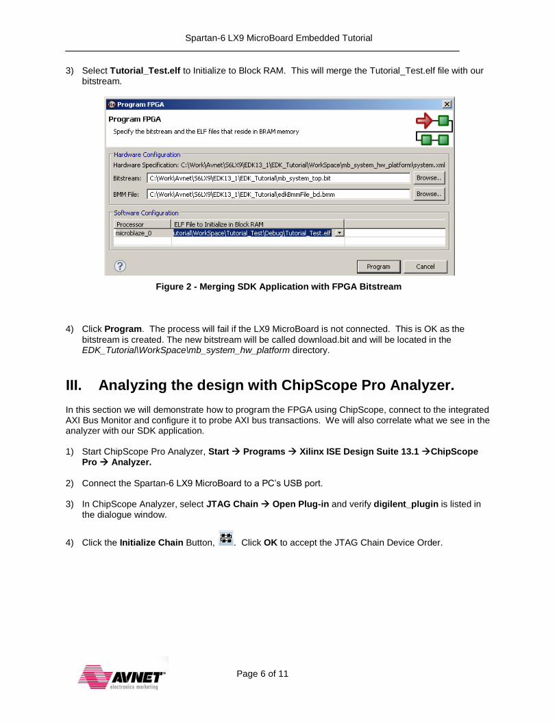
3) Select Tutorial_Test.elf to Initialize to Block RAM. This will merge the Tutorial_Test.elf file with our bitstream.
Figure 2 - Merging SDK Application with FPGA Bitstream
4) Click Program. The process will fail if the LX9 MicroBoard is not connected. This is OK as the
bitstream is created. The new bitstream will be called download.bit and will be located in the EDK_Tutorial\WorkSpace\mb_system_hw_platform directory.
III. Analyzing the design with ChipScope Pro Analyzer.
In this section we will demonstrate how to program the FPGA using ChipScope, connect to the integrated AXI Bus Monitor and configure it to probe AXI bus transactions. We will also correlate what we see in the analyzer with our SDK application.
1) Start ChipScope Pro Analyzer, Start Programs Xilinx ISE Design Suite 13.1 ChipScope
Pro Analyzer. 2) Connect the Spartan-6 LX9 MicroBoard to a PC’s USB port.
3) In ChipScope Analyzer, select JTAG Chain Open Plug-in and verify digilent_plugin is listed in
the dialogue window.
4) Click the Initialize Chain Button, . Click OK to accept the JTAG Chain Device Order.

Spartan-6 LX9 MicroBoard Embedded Tutorial
Page 7 of 11
5) Right-Click on DEV:0 MyDevice(XC6SLX9) and select Configure.
Figure 3 - Configure FPGA from ChipScope
6) Click Select New File and navigate to \EDK_Tutorial\WorkSpace\mb_system_hw_platform and select download.bit. Click OK to program the FPGA.
7) We need to add the CDC file to attach names to the ChipScope signals. Click File Import and click
Select New File. Navigate to the Chipscope AXI Monitor IP directory: \EDK_Tutorial\mb_system\implementation\chipscope_axi_monitor_0_wrapper\ and select: chipscope_axi_monitor_0.cdc.
8) Select the checkbox for Auto-create Buses and click OK.
9) Under UNIT:0 MyILA0 (ILA) double-click Waveform and Trigger Setup. This will open both windows in the viewing area.
10) In the Trigger window, click Trigger Anything button, . This will fill the waveform window
showing activity on the AXI bus signals.
11) Double-click Waveform to open the Waveform Window.
Spartan-6 LX9 MicroBoard Embedded Tutorial
Page 8 of 11
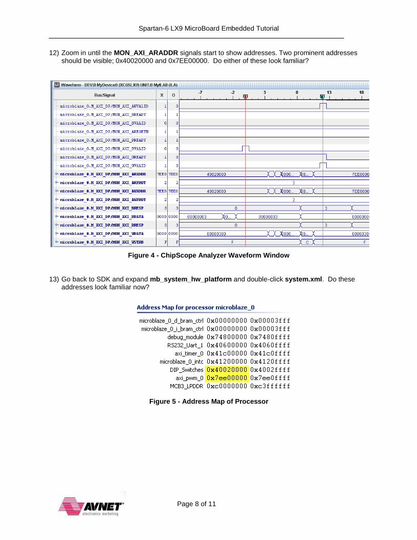
12) Zoom in until the MON_AXI_ARADDR signals start to show addresses. Two prominent addresses should be visible; 0x40020000 and 0x7EE00000. Do either of these look familiar?
Figure 4 - ChipScope Analyzer Waveform Window
13) Go back to SDK and expand mb_system_hw_platform and double-click system.xml. Do these
addresses look familiar now?
Figure 5 - Address Map of Processor

Spartan-6 LX9 MicroBoard Embedded Tutorial
Page 9 of 11
14) The DIP_Switches are read at address 0x40020000. Open Trigger Setup. Configure the Trigger as follows:
In the M0:ARADDR row, change the radix to Hex. Then set the Value to 4002_0000. Expand M7:RDATACONTROL, change MON_AXI_RVALID to 1. Set Position to 512. Double-click Trigger Condition Equation, and enable M0 and M7. Click OK.
15) Go back to the waveform window and Click the Trigger button, . The trigger should now be centered on a valid read transaction from address 0x40020000. The value in MON_AXI_RDATA
should represent the status of the DIP Switches on the board. Change the DIP Switch settings and verify the RDATA value matches the switch settings.
16) Next, look at what data is being written into address 0x7EE00000. This is the shifted data being
written into the AXI_PWM module. Our C code reads the data from the DIP_SWITCHES_BASEADDR, shifts it by 8 bits then pass it to the AXI_PWM_BASEADDR
(0x7EE00000).
Duty_Cycle = (u32 *)XPAR_AXI_PWM_0_BASEADDR;
while (1) {
DIP_Read = XGpio_ReadReg(XPAR_DIP_SWITCHES_BASEADDR, 0);
//Use the DIP Switches value for the duty cycle
*(Duty_Cycle) = DIP_Read << 8;
}
Remember our counter in our PWM only has 12-bits of resolution. The DIP Switches are only 4-bits. Thus we have to shift the DIP_Switches value by 8-bit into the most significant positions. If you look at the next AXI transaction, it’s a write to address 0x7EE00000 with the shifted data on the AXI write port (MON_AXI_WDATA):
Figure 6 – ChipScope Waveform View Showing AXI Transactions

Spartan-6 LX9 MicroBoard Embedded Tutorial
Page 10 of 11
This concludes this tutorial. We’ve learned how to add a ChipScope AXI Bus Monitor to our processor subsystem and analyze bus transactions using ChipScope Pro Analyzer. ChipScope Pro has additional features for debugging your embedded system including:
Monitoring arbitrary system level signals (adding Integrated Logic Analyzer (ILA))
Providing JTAG-based virtual input and output (VIO) See the Help window in the Debug Configuration Wizard in XPS for more info on adding these cores.

Spartan-6 LX9 MicroBoard Embedded Tutorial
Page 11 of 11
IV. Getting Help and Support
Evaluation Kit home page with Documentation and Reference Designs http://em.avnet.com/s6microboard Avnet Spartan-6 LX9 MicroBoard forum: http://community.em.avnet.com/t5/Spartan-6-LX9-MicroBoard/bd-p/Spartan-6LX9MicroBoard
For Xilinx technical support, you may contact your local Avnet/Silica FAE or Xilinx Online Technical Support at www.support.xilinx.com. On this site you will also find the following resources for assistance:
Software, IP, and Documentation Updates
Access to Technical Support Web Tools
Searchable Answer Database with Over 4,000 Solutions
User Forums
Training - Select instructor-led classes and recorded e-learning options Contact Avnet Support for any questions regarding the Spartan-6 LX9 MicroBoard reference designs, kit hardware, or if you are interested in designing any of the kit devices into your next design.
http://www.em.avnet.com/techsupport You can also contact your local Avnet/Silica FAE.