Video Door Button Interface
17
Video Door Button Interface
-
Upload
khangminh22 -
Category
Documents
-
view
0 -
download
0
Transcript of Video Door Button Interface

Video Door Button Interface

Table of Contents
Video Door Button Interface :..........................................................................................................3
How it works :...............................................................................................................................4Figure 1 – Original Version & Version 2.00 ....................................................................................................................4
Figure 2 - Version 2.10. ..................................................................................................................................................5
Wiring the VDBI.............................................................................................................................6
Schematics For Video Door Button Wiring.......................................................................................7Figure 10 – One Video Doorbell and shared transformer. .............................................................................................7
Figure 11 - One Video Doorbell and 2 Transformers......................................................................................................8
Figure 12 – Two Video Doorbells and shared transformer..............................................................................................9
Figure 13 – Two Video Doorbells and three transformers.............................................................................................10
Figure 14 – Two Video Doorbells and one 3way transformer. ......................................................................................11
Schematic For Nest Chime Connector Wiring.................................................................................12Figure 20 – Nest Chime Connector...............................................................................................................................12
Changing Seasons With A Video Doorbell.........................................................................................13
Version 5.0x.............................................................................................................................13Figure 30 – Wire button to dedicated Input 4................................................................................................................13
Earlier Versions.........................................................................................................................14Figure 31 – Version 4.0x. Wire button to Input 1...........................................................................................................14
Figure 32 – Version 4.03. Wire button to Input 2...........................................................................................................15
Figure 33 – Version 4.0x. Two Video Doorbells. Wire button to Input 1........................................................................16
Figure 34 – Version 4.03. Two Video Doorbells. Wire button to Input 2........................................................................17

Video Door Button Interface :
Most video door buttons are designed to actuate a ding dong door chime. This is done bysupplying a large amount of current to the chime for a short period of time. Many video door buttons allow the user to set this period of time using the app on their phone. This is the equivalent of turning on a light with a light switch. The ding dong door chime doesnot receive the power necessary to cause it to chime until the video door button is pressed. The YourBell requires power all of the time. It is capable of playing MP3 files fora few seconds to several minutes. The inputs to a YourBell expect a contact closure like a door button. We bridged this gap with the interface.
We are currently shipping the 2.00 version with 2 white wires and 2 green wires.

How it works :The video door button interface acts like a current sensing solid state relay (SSR) for AC circuits. Most video door buttons draw 100 – 250 milliamps when they are idling. Press the button and the current draw can be ½ to 1 amp. The interface senses the large current flow and closes a SSR. This contact closure is used to actuate the YourBell.
Figure 1 – Original Version & Version 2.00
The sense leads are Red & Black for the Original version and 2 White wires for Version 2.00. The SSR output are White & Green for the Original version and 2 Green wires for Version 2.00

Figure 2 - Version 2.10.
This version is no longer produced.
The interface will only work with video door buttons that are powered by an 16or 24 Vac power source.

Wiring the VDBIThe VDBI will work with a majority of the Video Door Buttons. To date we have confirmed that the Vivint doorbell camera will not work with the VDBI/YourBell. Followingis a list of video door buttons that work with the VDBI/YourBell :
• Nest• Ring• SkyBell• SimpliSafe• Zmodo• August• Arlo
Any video door button that was designed to actuate an electro-mechanical door chime should work with the VDBI/YourBell.
The VDBI will also actuate more than just the YourBell. The solid state relay output is rated to 50Vdc/Vac at ½ Amp.
The input does not require a power kit, chime connector, power accessory or similar device to work with the video door button. In fact the latest version of the Ting Pro Power Kit adversely affects the VDBI. So far we have been able to verify the Nest ChimeConnector will work in conjunction with the VDBI/YourBell.
When sharing the transformer between the Video Doorbell and the YourBell the transformer voltage must be 16Vac. Currently the YourBell will not work long term with a24Vac transformer. The power must be a minimum of 20VA ( Volt * Amps ). Always look at it as each major device added to the transformer requires 10VA. I.E. if you want 2 Video DoorBells connected to the same transformer as the YourBell then the minimum power rating is 3 * 10VA or 30VA.

Schematics For Video Door Button Wiring
Figure 10 – One Video Doorbell and shared transformer.

Figure 11 - One Video Doorbell and 2 Transformers.

Figure 12 – Two Video Doorbells and shared transformer.

Figure 13 – Two Video Doorbells and three transformers.

Figure 14 – Two Video Doorbells and one 3way transformer.
This is the transformer we sell. It is rated 24Vac 30VA, 16Vac 30VA, 8Vac 20VA.
Schematic For Nest Chime Connector Wiring
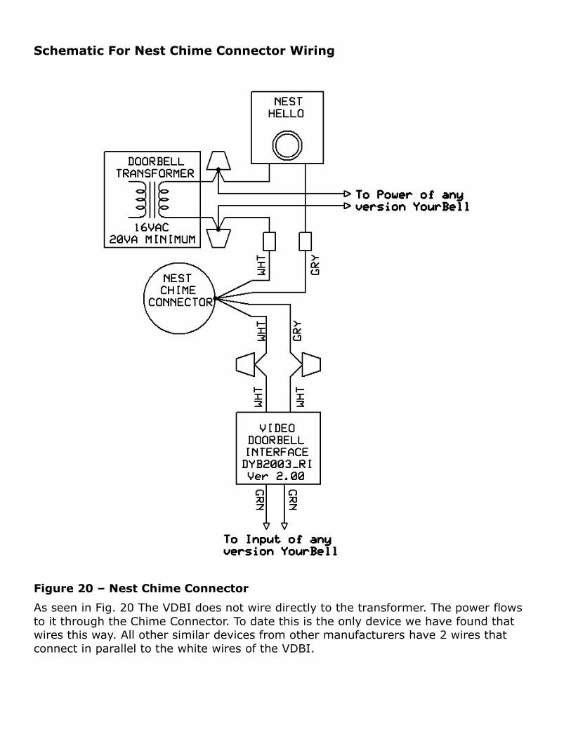
Figure 20 – Nest Chime Connector
As seen in Fig. 20 The VDBI does not wire directly to the transformer. The power flows to it through the Chime Connector. To date this is the only device we have found that wires this way. All other similar devices from other manufacturers have 2 wires that connect in parallel to the white wires of the VDBI.

Changing Seasons With A Video DoorbellThe video doorbell ( VDB ) output pulse is a preset amount of time. This is typically set in the App for the VDB. This makes it nearly impossible to change the seasons using the VDB. The solution will require a regular door button (with or without light) added to the YourBell.
Version 5.0x
Figure 30 – Wire button to dedicated Input 4
Wire the VDBI to any of the 4 inputs. Set the function of that input to Input on the microSD card. Wire the door button to any of the other 3 inputs.. Set the function of that input to Season Select on the microSD card. The video door button will trigger theYourBell normally. The door button can be used to change the seasons. The YourBell ships with IN_1 & IN_2 set as Input and IN_4 set as Season Select

Earlier Versions
Figure 31 – Version 4.0x. Wire button to Input 1
Wire the Video Door Button Interface ( VDBI ) to Input 2. Wire the door button to Input 1. The VDBI will trigger the YourBell normally. The door button can be used to change the seasons. This means the sound files associated with the VDB input will be set for Input 2. In order for the door button to be used to change the seasons at least one sound file will need to be associated with Input 1 for all seasons.

Figure 32 – Version 4.03. Wire button to Input 2
Wire the VDBI to Input 1. Wire the door button to Input 2. The video door button will trigger the YourBell normally. The door button can be used to change the seasons. This means the sound files associated with the video door button input will be set for Input 1.In order for the door button to be used to change the seasons at least one sound file willneed to be associated with Input 2 for all seasons.

Figure 33 – Version 4.0x. Two Video Doorbells. Wire button to Input 1
The VDBI and the Season select button share Input1. This is only possible with a push button that does not have any kind of light.
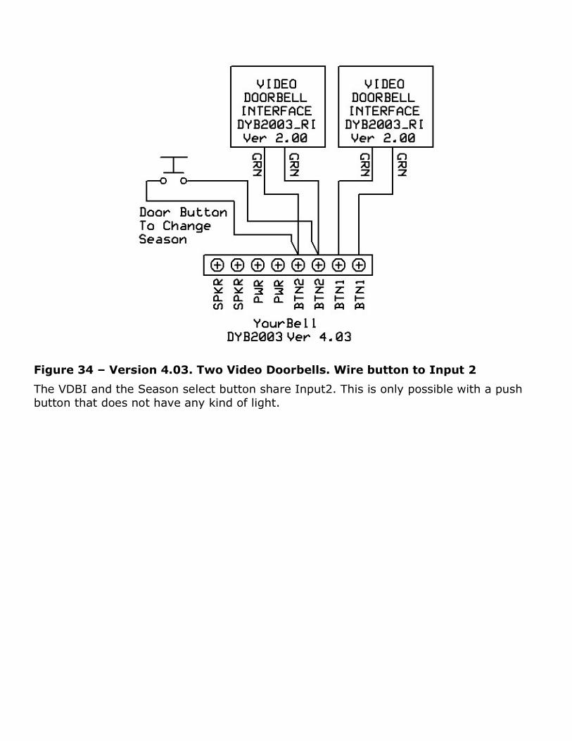
Figure 34 – Version 4.03. Two Video Doorbells. Wire button to Input 2
The VDBI and the Season select button share Input2. This is only possible with a push button that does not have any kind of light.