GB Instructions for use Upright refrigerator-freezer - Gorenje
Upload
khangminh22Category
view
1download
0
inst
alla
tion
&
inst
ruct
ion
man
ual
Serial #:
Installation Date:
Wiring Diagram:
PRO-GSD


2
TABLE OF CONTENTS PAGE:
VERIFICATION OF OPERATOR AND HARDWARE ___________________________ 3
SPECIFICATIONS ___________________________________________________________ 4
SAFETY INSTRUCTIONS ____________________________________________________ 6
INSTALLATION_____________________________________________________________ 7
ELECTRICAL CONNECTIONS AND SETTINGS________________________________ 10
LIMIT SWITCH ADJUSTMENT _______________________________________________ 24
MICANAN PHOTOBEAM INSTALLATION INSTRUCTIONS_____________________ 25
CLUTCH ADJUSTMENT______________________________________________________ 29
BRAKE ADJUSTMENT_______________________________________________________ 30
EMERGENCY MANUAL OPERATION _________________________________________ 31
OPERATOR MAINTENANCE _________________________________________________ 32
MECHANICAL DRAWINGS AND PARTS LISTS ________________________________ 33
ELECTRICAL DIAGRAMS ___________________________________________________ 37
WARRANTY ________________________________________________________________ 46
OPTIONS MP00041-44 #40 Drive Chain * #50 reduction chain and sprockets MP00023 Double V-belt reduction (PRO-SD) MP00045 Cast-iron Pillow block bearings on drive MP00039 High Cycle modification (PRO-SD) PRO-SDW/GSDW___ Waterproof modification PRO-SD4X/GSD4X_ Corrosion proof modification PRO-SDX/GSDX___ Explosion proof modification MP00007 * 115 Volt control circuit MK00061 ** 1.5 sec time delay on reverse MP00001 ** Timer to Close PRO-PL____ Separate control panel MX00005 Bi-parting Option MX00006 Fire Door Option (Single Slide) MX00007 Fire Door Option (Bi-Parting Slide)
* Not available for logic board controls ** Standard feature with logic board controls
WARNING
DO NOT CONNECT TO ELECTRICAL POWER DURING INSTALLATION
OR SERVICING OF OPERATOR
IMPORTANT
FOR ANY QUESTIONS CONCERNING THE SAFETY OR OPERATION OF THIS OPERATOR PLEASE CONTACT
MICANAN SYSTEMS AT 1-877-888-1116 SAVE THESE INSTRUCTIONS

3 Upon delivery of your MICANAN SYSTEMS heavy-duty sliding door operator, please inspect the unit carefully for damage. Verify that operator horsepower, voltage, phase and amperage correspond to available power supply and door application. Check that along with your operator you have received the following standard hardware. 1 x OPEN/CLOSE/STOP 3-button control station: 1 x Set of trolley tracks (door width + 2’6”) 1 x Drive chain package (door width x 2 + 5’ 6” (1.65m) c/w connecting link 1 x Sliding Door Carriage c/w two 3/8” take up bolts 4 x Trolley track end bracket 1 x Front idler c/w 41B12 sprocket 22 x 3/8” x 1” bolts and 22 serrated hex nuts 3/8” 1 x Sliding door disconnect bracket assembly c/w sash chain 4 x Sliding door hanger brackets 1 x Floor level disconnect bracket 1 x Warning sign 1 set of Micanan photocells (supplied when operator ordered with interface module or logic board controls) For Bi-Parting Option: Add 1 extra Floor level Disconnect, 1 extra sliding door disconnect bracket and 1 x Special Bi-parting sliding door carriage
VERIFICATION OF OPERATOR AND HARDWARE

4 PRO-SD and PRO-GSD heavy-duty sliding door operators are designed for industrial sliding doors or sliding fire doors. Model PRO-SD is a belt drive operator. The PRO-GSD is essentially the same as model PRO-SD with the exception that it utilizes a heavy-duty worm gear as its primary reduction. The PRO-GSD is used for larger / heavier sliding door applications. STANDARD OPERATOR WEIGHT: PRO-SD (50-70 Lbs.), PRO-GSD (80 – 120 Lbs.) MOTOR: Continuous duty 1725 RPM industrial type motor. Full overload protection.
- Horsepower: PRO-SD: 1/3HP, 1/2HP, 3/4HP, 1HP (1-phase & 3-phase) PRO-GSD: 1/2HP, 3/4HP, 1HP, 1.5HP (1-phase & 3-phase), 2 HP (3-phase) - Voltage: 115V 1-phase (60Hz) 230V 3-phase (60 Hz) 220V 1-phase (50Hz)
230V 1-phase (60Hz) 460V 3-phase (60Hz) 380V 3-phase (50Hz) 575V 3-phase (60Hz)
REDUCTION: Primary: PRO-SD: (5L) V-belt and pulleys PRO-GSD Heavy duty worm gear 20:1 (standard) or 40:1 reduction Secondary: #41 chain and sprockets OUTPUT SHAFT SPEED: PRO-SD (Single door): 120 RPM DOOR SPEED: 11”- 12”/sec. PRO-SD (Bi-part): 70 RPM 6” - 7”/sec PRO-GSD (Single door): 85 RPM 8” - 9”/sec. PRO-GSD (Bi-part): 45 RPM 4” - 5”/sec. BRAKE : Solenoid actuated drum and brake shoe braking system to prevent coasting and maintain door position. WIRING TYPE (3 OPTIONS): Option 1: Full Feature logic board Smart 10.0 (UL325 (2010) compliant). Note: Micanan compatible primary entrapment
device must be connected for B2, T or TS (momentary or timer activation on close) feature. Option 2: Relay logic controls with Interface Module (UL325 (2010) compliant). C2 Standard factory wiring (constant
pressure on close, momentary contact on open and stop). If momentary contact on close (B2) wiring is desired, move “white” wire from terminal #6 to terminal #3. Note: Micanan compatible primary entrapment device must be connected for B2 (momentary activation on close) or for T (timer to close) feature.
Option 3: Standard relay logic controls (not UL325 (2010) compliant, not available in US) C-2 Wiring constant pressure on close, momentary contact on open and stop. NOTE: If momentary contact on close (B2) wiring is desired, move “white” wire from terminal #5 to terminal #3.
TRANSFORMER: 24VAC control circuit, supplies power to drive logic board or control relays with 15VA power available for external devices.
LIMIT ADJUSTMENT: 4 micro switches that control door travel. These limit switches are activated by fully adjustable screw
type cams.
EMERGENCY DISCONNECT: Quick release floor level disconnect mounted on door to disconnect sliding door disconnect
bracket to allow person to disengage operator drive chain from door for manual operation.
CLUTCH: Adjustable friction clutch to minimize damage to door operator, door or vehicles when obstruction occurs.
PRO-SD, PRO-GSD SPECIFICATIONS


6 - READ AND FOLLOW ALL INSTRUCTIONS - Never allow children to operate or play with door controls. Keep the remote control (where provided) away from children. - Personnel should keep away from a door in motion and keep the moving door in sight until it is completely closed or opened. NO
ONE SHOULD CROSS THE PATH OF A MOVING DOOR. - Test the door’s safety features at least once a month. After adjusting the limit of travel, retest the door operator’s safety features.
Failure to adjust the operator properly may cause severe injury or death. - For products having a manual release, if possible, use the manual release only when the door is closed. - KEEP DOORS PROPERLY OPERATING AND BALANCED. See Door Manufacturer’s Owner’s Manual. An improperly
operating or balanced door could cause severe injury or death. Have trained door systems technician make repairs to door hardware.
- Press the “OPEN” device or use emergency disconnect mechanism if a person is trapped by the sliding door. - SAVE THESE INSTRUCTIONS. The owner or users must understand the safety and operation of door system. Insure that this
installation manual be located close to the door system. - READ AND FOLLOW ALL INSTALLATION INSTRUCTIONS - Commercial door operators are never to be installed on a residential installation - Install the operator only when all openings of the horizontal slide door are guarded or screened from the bottom of the door to a
minimum of 4ft (1.22m) above the ground to prevent a 2-1/4” (57.2mm) diameter sphere from passing through the openings anywhere in the door.
- Install only on a properly operating and balanced door. A door that is operating improperly could cause severe injury. Have
qualified service personnel make repairs to door hardware before installing the operator. - Remove all pull ropes and remove, or make inoperative, all locks (unless mechanically and/or electrically interlocked to the power
unit) that are connected to the door before installing the operator. - Install the door operator at least 8 feet or more above the floor if the operator has exposed moving parts. - Do not connect the operator to the source of power until instructed to do so. - Locate the control station: (a) within sight of the door, (b) at a minimum height of 5 feet so that small children cannot reach it, and
(c) away from all moving parts of the door. - Install the Entrapment Warning Placard next to the control station in a prominent location. - For products having a manual release, instruct the end user on the operation of the manual release. - Install non-contact entrapment protection devices (photocells) and/or contact entrapment protection devices (reversing edges).
Note: photocells should be installed at no more than 6” from the floor. Edges should be installed where the risk of entrapment exists, such as at the leading edge and/or trailing edge of the sliding door.
IMPORTANT SAFETY INSTRUCTIONS
WARNING
TO REDUCE THE RISK OF INJURY OR DEATH:
IMPORTANT INSTALLATION INSTRUCTIONS

7
Note: Installation of operator must be done by a qualified installer. Door must be properly installed and
working smoothly. Remove all door locks prior to installation.
1. Install control station away from all moving door parts, within sight of door and a minimum of 5 ft (1.5 m) from the ground.
2. Install entrapment warning sign next to control station. PREPARATION: 1. Lay out operator and tracks on ground in front of door with door operator motor facing away from door (PRO-SD) or
towards door (PRO-GSD). 2. Install track U-brackets evenly to track assembly. 3. Slide sliding door carriage through end of tracks towards operator. For Bi-part option, also slide the bi-part carriage
through the end of tracks. 4. Install front idler assembly to the second set of holes at the end of trolley tracks. 5. Bolt rail assembly to operator frame using four 3/8” x ¾” bolts and 3/8” serrated hex nuts provided.
PRO-SD (Single door) PRO-GSD (Single door)
PRO-SD (bi-part) PRO-GSD (bi-part)
INSTALLATION INSTRUCTIONS
WARNING
DO NOT INSTALL THIS OPERATOR BEFORE READING THIS MANUAL CAREFULLY.

8 6. Single part door: Attach one end of drive chain to one of the 2 take-up-bolts on carriage using connecting link
provided. Run chain under the u-brackets, around front idler, around drive sprocket and connect to the other take-up-bolt on carriage using connecting link provided. Adjust take-up-bolt so that chain sags approximately 3” (7.5 cm) at midpoint of tracks. Remove links from drive chain if necessary to make proper adjustment.
Bi-part part door: Position the 2 sliding door carriages so as to be approximately 8 inches to the left and
right of centerline of bi-parting door system. Attach one end of drive chain to one of the 2 take-up-bolts on sliding door carriage using connecting link provided. Run chain through the bi-part carriage, under the u-brackets, around front idler, attach chain to bi-parting carriage using the three bolts nylon nuts located on bi-parting carriage (note: do not tighten nylon nuts yet), and round drive sprocket and connect to the other take-up-bolt on sliding door carriage using connecting link provided. Adjust take-up-bolt so that chain sags approximately 3” (7.5 cm) at midpoint of tracks. Remove links from drive chain if necessary to make proper adjustment.
OPERATOR INSTALLATION: 1. Install the 4 hanger brackets to the 4 U-brackets on rail assembly using 3/8” bolts and nuts supplied. Do not tighten the nuts.

9 2. Raise operator and track assembly and secure (but not tighten) the 4 hanger brackets to the wall using appropriate hardware.
Note that the hanger brackets are slotted to allow for depth adjustment of track assembly. 3. Using suitable hardware, install the sliding door disconnect bracket to door as shown below. For bi-part option: install 2
disconnect brackets. Adjust the disconnect bracket(s) as well as the operator and track assembly so as to allow for 1” diameter shaft to align with and engage tube of sliding door carriage. Tighten bolts. At this time make final adjustment of drive chain and tighten 3 nylon nuts on bi-parting carriage.
Single part door Bi-part door
4. Install the floor level disconnect bracket directly below the disconnect bracket at approximately 4’ above the floor. Cut and
attach sash chain to ring of floor level disconnect. When properly adjusted, engagement of the floor level disconnect should pull 1” shaft of disconnect bracket downward so as to clear completely from tube in carriage.
Single part door Bi-part door
5. At this time, check all bolts for tightness. 6. After installation is complete, remove red
activation pin on reducer breather plug (For PRO-GSD).
IMPORTANT

10 THERE ARE 3 POSSIBLE ELECTRICAL CONTROL CONFIGURATIONS FOR THIS OPERATOR:
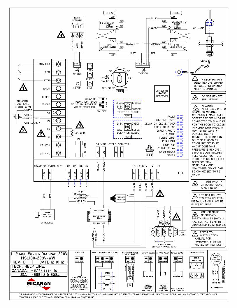
A) Standard relay logic controls (not UL325 (2010) compliant, not available in US). Refer to Section A for electrical connections. Refer to electrical drawings inside your operator control box or generic drawings MS100-WW or MS300-WW in the electrical drawings section at the end of this manual. B) Relay logic controls with Interface Module (UL325 (2010) compliant. Refer to Section B for electrical connections. Refer to electrical drawings inside your operator control box or generic drawings MS100-IM-WW or MS300-IM-WW in the electrical drawings section at the end of this manual. C) Full Feature logic board Smart 10.0 (UL325 (2010) compliant). Refer to Section C for electrical Connections and logic board instructions. Refer to electrical drawings inside your operator control box or generic drawings MSL100-110V-WW, MSL100-220V-WW, MSLC100-WW, MSL300-WW or MSLC300-WW in the electrical drawings section at the end of this manual.
Refer to electrical diagrams inside control box cover or at the end of this manual prior to connection of power supply or control station.
WARNING
TO REDUCE THE RISK OF INJURY OR DEATH:
ALL ELECTRICAL CONNECTIONS SHOULD BE MADE BY A QUALIFIED SERVICE PERSON
DO NOT ATTEMPT TO MAKE ELECTRICAL CONNECTIONS TO OPERATOR UNLESS POWER SUPPLY HAS BEEN DISCONNECTED AT FUSE BOX
OPERATOR MUST BE CONNECTED IN ACCORDANCE TO LOCAL ELECTRICAL CODES
AND GROUNDED TO GREEN GROUND LUG LOCATED INSIDE CONTROL BOX
WARNING
COMPARE AVAILABLE POWER SUPPLY VOLTAGE TO OPERATOR NAMEPLATE PRIOR TO ELECTRICAL CONNECTION. FAILURE TO CONNECT APPROPRIATE POWER SUPPLY
VOLTAGE MAY CAUSE SERIOUS DAMAGE TO OPERATOR.
IMPORTANT
- EACH INDIVIDUAL COMMERCIAL DOOR OPERATOR MUST HAVE IT’S OWN DEDICATED POWER SUPPLY
- MICANAN HIGHLY RECOMMENDS THAT EACH INDIVIDUAL COMMERCIAL
DOOR OPERATOR HAVE AN EXTERNAL CIRCUIT BREAKER OR FUSED DISCONNECT
ELECTRICAL CONNECTIONS

11
SECTION A: PRO-SD, PRO-GSD Standard relay logic controls (not UL325 (2010) compliant, not available in US) POWER WIRING: Use 1-1/8” (2.85 cm) diameter holes for all power wiring. 1. Single phase: Connect single phase power supply to terminals L/L1 (line) and N/L2 on three-pole
power terminal strip. 2. Three-phase: Connect three phase power supply to terminals L1, L2 and L3 on three-pole power
terminal strip.
CONTROL WIRING: Use 7/8” (2.22 cm) diameter holes for all control wiring. Note: Do not run control wires and power wires in same conduit.
- Install control station within clear sight of door but away from all moving parts of door or hardware. Install Entrapment warning sign next to control station. Connect 3-button (open/close/stop) push button station to terminals 2, 3, 4 and 5. Refer to electrical diagram for connection of two 3-button stations. NOTE: After electrical connections are made, manually move door to mid-position and, using the control station press the
“Open” button for several seconds and then press the “Stop” button. If door did not move in correct direction verify wiring control station. For 3-phase operators, if door still moves in wrong direction reverse any two of the three incoming power supply leads to correct rotation.
- Adjust Limit switches as explained in the “Limit switch adjustment section” further in this manual.
CONNECTION OF POWER SUPPLY AND CONTROL STATION
LIMIT SWITCH ADJUSTMENT

12 1. Reversing Edge device (must be normally open contact):
Note: If the door is controlled by any device or wired in such a manner that the door is not controlled by constant pressure on close then an appropriate reversing edge must be installed.
2. External interlock: Remove jumper between terminals 1 and 2 and wire a N.C. interlock contact between these two terminals. 3. Radio control receiver: Wire standard radio receiver to separate radio strip on side of control box or to terminals 7, 8 and 9
on control terminal strip inside control box. 4. Single button open/close device: Wire to terminals 7 and 8 on control terminal strip. 5. Loop detectors, standard photocells (with a N.O. contact) and other reversing devices: Wire to terminals 3 and 6 on
control terminal strip.
6. 24 Volt power: Wire to terminals 1 and 9 on control terminal strip
CONNECTION OF A REVERSING EDGE DEVICE AND CONTROL ACCESSORIES

13
SECTION B: PRO-SD(M), PRO-GSD(M) Relay logic controls with Interface Module (UL325 (2010) compliant)
Operator electrical connections and start-up instructions
Important: Follow these steps carefully and in the order shown
1) Connect Power supply: Single phase: Connect single phase power supply to terminals L/L1 and N/L2 on the 3-pole power terminals strip. 3-phase: Connect 3-phase power supply to terminals L1, L2 and L3 on the 3-pole power terminal strip. 2) Connect Push-button station for installation purposes (single phase or 3-phase): Connect open/close/stop push button station to terminals T2 (stop), T3 (common), T4 (open) and T6 (temporary CP on close). 3) Verify motor direction: After the electrical power connections are made and push button station is connected, manually move the door to mid-position. Press Close button for several seconds and then press stop button. If door did not move in correct direction (or if limit cams not moving in correct direction towards the close limit switch) see below:
NOTE: THIS OPERATOR COMES WITH AN INTERFACE MODULE INTEGRATED INTO THE CONTROL CIRCUIT. THE PURPOSE OF THE INTERFACE MODULE IS TO ALLOW FOR
FAILSAFE MONITORING OF A MICANAN COMPATIBLE SAFETY DEVICE AS PER UL 325 (2010) REQUIREMENTS.

14 Single phase operators: The operators leave the factory with correct motor and limit shaft direction according to standard door installations. However, for special fire door, thru- wall mounting or other special door applications, the motor direction and limit switch direction may need to be reversed. To reverse the motor rotation, interchange black and white wires going to motor on the reversing contactor. 3-phase operators: If door moves in wrong direction, turn off incoming power and reverse any two of the three incoming power supply leads to correct rotation. Press the open button and then activate the open limit to ensure door stops. If door does not stop, interchange grey and red wires on open and close limits. Interchange white and grey wires on advanced open and advanced close limits. Remove blue wire from advanced open limit and place it on N.O pin of advanced close limit. 4) Adjust limit switch cams: Using the open/close/stop push button station move door to fully closed and fully open positions and set limit cams to correct position. (See Limit adjustment section D further in this manual for complete detail on the end of travel limit adjustments). 5) Activate Interface module: After adjusting the open and close limits and verifying the motor rotation, open the door to the full-open position using the open push button (Figure below on left). At this point the close pushbutton wire must now be moved from terminal T6 to T5. Now connect the black wire (with blue label) to terminal T1 as shown in figure below on right. Note: Ensure the door is in the full open position before connecting the black wire. If door is not in full open position and monitored photo-eyes or safety edge are not connected and operational then door will immediately move in the open direction.

15 6) Connect safety devices Failsafe feature: A monitored failsafe safety feature is built into the operator. The operator has provisions to connect one primary monitored safety device as well as one or more non-monitored safety device(s). Primary monitored safety device: MICANAN monitored failsafe photo beams or MICANAN compatible monitored failsafe devices must be connected to terminals P1 and P2 if momentary close on pushbutton is required (B2 mode). If not connected, door can only be closed by constant pressure on close pushbutton. If constant pressure on close pushbutton is removed before door reaches full closed position, then door reverses to full open. Note: Only one monitored failsafe safety device can be connected across terminals P1 and P2. Note: See section E for complete installation instructions for the Micanan N-1 or N-4 photocells or the FRABA photocells. Secondary non-monitored safety device(s): A standard 2-wire safety edge, non-monitored reflective or thru-beam photo eye or any other non-monitored reversing devices with a N.O dry contact can be connected to terminals S1 and S2. Note: More than one secondary non-monitored safety device can be connected to terminals S1 and S2. Important: Do not remove resistor that is factory installed across terminals S1 and S2 unless installing a 4-wire electric edge. 4-wire electric edge Connection A standard 4-wire electric edge can be connected across S1 and S2 terminals as a secondary safety device. Remove the factory installed resistor across terminals S1 and S2 and install resistor across the black and white pair of wires from the electric edge and connect the remaining black and white wire to the S1 and S2 terminals. 7) Select Mode of Operation: C2 mode of operation (momentary on open, constant pressure on close): The operator is wired at the factory for momentary on open and constant pressure on close. For commercial operators, white wire is connected to terminal T6. B2 mode of operation (momentary on open, momentary on close): If momentary on close is required: For commercial operators, remove the white wire from terminal T6 and place it on terminal T3. The operator functions in B2 mode only when the primary monitored safety device is connected and functioning properly. If it is not connected, operator will go into fault mode and door can only be closed by constant pressure on close and if constant pressure on close is removed before door reaches full close position, door reverses to full open.

16
SECTION C: PRO-SD(E), PRO-GSD(E) Full feature logic board Smart 10.0 (UL325 (2010) compliant) Note: The operator is shipped from the factory in the D1 mode setting (constant pressure open and close). The operator should remain in this mode until all connections and limit switch adjustments are completed. POWER WIRING INSTRUCTIONS: Connect primary power supply directly to the separate power terminal strip supplied using any of the 1-1/8” (2.85 cm) diameter holes provided on control box. Do not connect power supply directly to the circuit board. 1. Single phase: Connect single-phase power supply to terminals L/L1 and N/L2 on three-pole power terminal strip (110V
or 220V 1-phase). 2. Three-phase: Connect three-phase power supply to terminals L1, L2 and L3 on three-pole power terminal strip (208V,
230V, 380V, 460V or 575V). ON BOARD O/C/S PBS INSTRUCTIONS: On-board Open, Close and Stop buttons are provided directly on the board for installation and troubleshooting purposes. In order to operate unit by on-board Open, Close, Stop buttons, the factory installed jumper (#1) between the COM and STOP terminals on the terminal strip must remain connected. MOTOR DIRECTION VERIFICATION: Make sure the mode of operation is selected to D1. After electrical power connections are made, manually move door to mid-position. Using the on-board buttons press the “Open” button for several seconds and then press the “Stop” button. If door did not move in correct direction (or if limit cams not moving in correct direction towards the open limit switch) see below: For single-phase operators: The operators leave the factory with correct motor and limit shaft direction according to standard door installations. However, for special fire door, through wall mounting or other special door applications, the motor direction and limit switch direction may need to be reversed. A dipswitch (Dip #1) is provided to reverse direction of motor and limit switch direction. If motor direction is reversed, the open and close limit switches are automatically reversed. However, the advanced close limit switch needs to be manually changed. Disconnect the 2 wires from the advanced closed limit switch and re-connect to the auxiliary limit switch provided. Note: Ensure that when the on-board open button is depressed and the door moves in the correct open direction that activation of the open limit switch illuminates the ‘’OPEN LIMIT” L.E.D and stops the door.

17 For 3-phase operators: If door moves in wrong direction, turn off incoming power and reverse any two of the three incoming power supply leads to correct rotation. Press the on board open button again. If door is going in the correct open direction, activate the open limit switch to ensure door stops. If door does not stop, turn off incoming power and interchange any two incoming power lines once again and slide dipswitch #1 to reverse motor direction. If motor direction is reversed, the open and close limit switches are automatically reversed. However, the advanced close limit switch needs to be manually changed. To do this, disconnect the 2 wires from the advanced limit switch and re-connect to the auxiliary limit switch provided.
Note: Ensure that when the on-board open button is depressed and the door moves in the correct open direction that activation of the open limit switch illuminates the “OPEN LIMIT’’ L.E.D and stops the door.
LIMIT SWITCH ADJUSTMENTS: Once the motor rotation and limit cam direction have been verified, adjust the limit cam settings. Please note that when each limit switch is activated the corresponding LED will light up. Refer to operator installation manual for complete limit switch adjustment instructions. CONNECTION OF EXTERNAL O/C/S PBS: Connect O/C/S PBS as shown in diagram. Note: Jumper #1 must be removed after the external O/C/S PBS has been installed. FAILSAFE FEATURE A safety device failsafe feature is built into the logic board. The logic board has provisions to connect one primary monitored safety device as well as 1 or more secondary non-monitored safety device(s). Primary monitored safety device: MICANAN monitored failsafe photo beams or MICANAN compatible monitored failsafe devices must be connected to terminals P1 and P2 as primary monitored safety device. Primary monitored safety device must be connected if momentary activation on close is required in B2, T and TS modes. If it is not connected in B2, T and Ts modes, door can only be closed by constant pressure on close and if constant pressure is removed before door reaches full close position, door reverses to full open. Note: Only one monitored failsafe device can be connected to terminals P1 and P2.

18 Secondary non-monitored safety device(s): A standard 2-wire safety edge, non-monitored photo beams or any other non-monitored reversing devices with a N.O contact can be connected to terminals S1 and S2 as secondary non-monitored safety device. Note: More than one secondary non-monitored safety device can be connected to terminals S1 and S2. Important: Do not remove the resistor that is factory installed across terminals S1 and S2 unless installing a 4-wire electric edge. 4-wire electric edge: A standard 4-wire electric edge can be connected across S1 and S2 terminals as a secondary safety device. Remove the factory-installed resistor across terminals S1 and S2 when using a 4-wire electric edge CONNECTION OF EXTERNAL SINGLE-BUTTON DEVICE Connect an external single-button as shown in diagram. Please refer to ‘’Modes of operation’’ for the functionality of single-button. MODES OF OPERATION All operators leave the factory in the D1 mode setting; please read all modes of Operation and determine which operational mode is desired B2: (Momentary on open and close) • Open Button: Momentary activation opens the door. When door is closing, momentary activation reverses the door (OPEN OVERRIDE). Momentary contact from mid-stop opens the door to full open position. Constant activation when door is opening, bypass mid-stop if enabled. • Close button: Momentary on close. • Stop button: Momentary activation stops the door. • Single button device and single channel transmitter, 3-channel (1,2,3) transmitter: SEQ FUNCTION: Open/Stop/Close/Reverse. COMMERCIAL FUNCTION: Open/Close/Reverse. • 3-button O/C/S radio transmitter: Same as open, close, stop buttons. • Safety Devices: When door is closing, momentary activation reverses the door. • Timer to close: N/A

19 C2 (Momentary open, constant pressure close) • Open Button: Momentary activation opens the door. When door is closing, momentary activation reverses the door (OPEN OVERRIDE). Momentary contact from mid-stop opens the door to full open position. Constant activation when door is opening, bypass mid-stop if enabled. • Close button: Constant pressure on close. Door will stop when button is released • Stop button: Momentary activation stops the door. • Single button device: SEQUENTIAL FUNCTION: Open/Stop/Constant pressure on close/stop. COMMERCIAL FUNCTION: Open/Constant pressure on close/stop. • Single channel transmitter, 3-channel (1,2,3) transmitter and 3-button O/C/S radio transmitter: Momentary activation opens the door. Momentary contact of OPEN button on 3-button (O/C/S) radio transmitter from mid-stop opens the door to full open position. Cannot close the door. • Safety Devices: When door is closing, momentary activation reverses the door. • Timer to close: N/A D1: (Constant pressure on open and close) • Open Button: Constant pressure opens the door. Door stops when constant pressure is released. Constant pressure from mid-stop opens the door to full open position. • Close button: Constant pressure on close. Door will stop when button is released • Single button device, single channel transmitter, 3-channel (1,2,3) transmitter and 3-button (O/C/S) radio transmitter: N/A • Safety Devices: When door is closing, momentary activation reverses the door. • Timer to close: N/A E2: (Momentary on open, constant pressure on close with roll-back feature) • Open Button: Momentary activation opens the door. When door is closing, momentary activation reverses the door. Momentary contact from mid-stop opens the door to full open position. Constant activation when door is opening, bypass mid-stop if enabled. • Close button: Constant pressure on close. Door reverses to full open when button is released. • Single button: SEQUENTIAL FUNCTION: Open/Stop/Constant pressure on close/Stop. COMMERCIAL FUNCTION: Open/Constant pressure on close/Reverse. • Single channel device, 3-channel (1,2,3) transmitter and 3-button (O/C/S) radio transmitter: Momentary activation opens the door. Momentary contact of OPEN button on 3-button (open/close/stop) radio transmitter from mid-stop opens the door to full open position. Cannot close the door. • Safety Devices: When door is closing, momentary activation reverses the door. • Timer to close: N/A T: (Momentary on open and close, timer to close, SAFETY ACTIVATION & STOP BUTTON DISABLE TIMER) • Open Button: Momentary activation opens the door. When door is closing, momentary activation reverses the door. Momentary contact from mid-stop opens the door to full open position. Momentary contact at full-open refreshes the timer if enabled at full open. Momentary contact at full open position re-activates the timer if timer is disabled previously by stop button or safety device. Constant activation when door is opening, bypass mid-stop if enabled. • Close button: Momentary on close. • Stop button: If door is opening or closing, momentary activation stops the door. Momentary activation while timer is counting at mid-stop or full open de-activates the timer. • Single button device, single channel and 3-channel (1,2,3) radio transmitter: SEQUENTIAL FUNCTION : Open/Stop/Close/Reverse.. COMMERCIAL FUNCTION: Open/Reverse/Refresh timer. • 3-button (O/C/S) transmitter: Same as open, close, stop buttons. • Safety Devices: When door is closing, momentary activation reverses the door to full open AND DISABLES TIMER.

20 • Timer to close: Closes the door from mid-stop or full open. Momentary activation of stop button will de-activate the timer. When door is closing, momentary activation of safety devices will reverse the door to mid-stop (if enabled) or full open and de-activates the timer. Timer resumes its normal operation upon momentary activation of open push button or once the close cycle is completed. If mid-stop is enabled and “Timer from mid-stop only” dip-switch is ON, timer is enabled only from mid-stop and disabled from full open. If mid-stop is enabled and “Timer from mid-stop only” dip-switch is OFF, timer is enabled from full open and mid-stop. TS: (Momentary on open and close, timer to close secure, STOP BUTTON DISABLES TIMER) • Open Button: Momentary activation opens the door. When door is closing, momentary activation reverses the door. Momentary contact from mid-stop opens the door to full open position. Momentary contact at full-open refreshes the timer if enabled at full open. Momentary contact at full open position re-activates the timer if timer has been disabled previously by stop button. Constant activation when door is opening, bypass mid-stop if enabled. • Close button: Momentary on close. • Stop button: If door is opening or closing, momentary activation stops the door. Momentary activation while timer is counting at mid-stop or full open de-activates the timer. • Single button device, single channel transmitter and 3-channel (1,2,3) radio transmitter: SEQUENTIAL FUNCTION: Open/Stop/Close/Reverse. COMMERCIAL FUNCTION: Open/Reverse/Refresh timer. • 3-button O/C/S radio transmitter: Same as open, close, stop buttons. • Safety Devices: When door is closing, momentary activation reverses the door. Momentary activation refreshes the timer to close. • Timer to close: Closes the door from mid-stop or full open. Momentary activation of stop button will de-activate the timer. Timer resumes its normal operation upon momentary activation of open push button or once the close cycle is completed. If mid-stop is enabled and “Timer from mid-stop only” dip-switch is ON, timer is enabled only from mid-stop and disabled from full open. If mid-stop is enabled and “Timer from mid-stop only” dip-switch is OFF, timer is enabled from full open and mid-stop. Warning: When replacing the logic board in a single-phase operator, Make sure that Jumper 2 is installed properly before operating the door. Failure to do this will damage the logic board. PROGRAMMING INSTRUCTIONS: NOTE: ALL PROGRAM FUNCTIONS CAN BE INITIATED BY TURNING THE SELECTOR SWTICH TO THE DESIRED SETTING AT ANY POINT DURING OPERATION EXCEPT FOR THE MID STOP and RUN TIMER MODE,PROGRAMMING MUST START FROM THE FULL CLOSED POSITION. RUN-TIMER SETUP Run-timer is the maximum amount of time the motor will run upon receiving an open or close command. The factory default value for run-timer is 45 seconds. Note: Limits must be set prior to setting run timer. Modify the run-timer from factory default: 1. Close the door to full close position. 2. Set the selector dial to “Run-timer” position. The “Delay On Close Timer” LED should blink. 3. Press open button. Wait until door reaches full open position. The run timer value is set to the time taken for the door to travel from full close position to full open position plus 5 seconds. 4. Set the selector dial to the desired mode of operation. Modify the run-timer to factory default: 1. Close the door to full close position. 2. Set the selector dial to “Run-timer” position. 3. Press stop button. The run-timer is modified to the factory default value. Then set the selector dial to the desired mode
of operation.

21 MID-STOP SETUP: Mid-stop feature can be used to open the door to a preset point prior to full open position. Note: Limits must be set prior to setting mid-stop position. To Activate mid-stop: 1. Close the door to full close position. 2. Set the selector dial to “Mid-stop” position. “Mid-stop” LED starts blinking. 3. Press open push button. Door opens. Once the door reaches the desired mid-stop position, stop the door by activating stop push button. 4. Set the selector dial to the desired mode of operation.
Note: When door opens to the programmed mid-stop position, “Mid-Stop” LED will illuminate. To De-activate the mid-stop position: 1. Close the door to full close position. 2. Set the selector dial to “Mid-stop” position. 3. Press the stop button, Mid-stop is de-activated. Modify mid-stop position: To modify the current mid-stop position, follow the same steps to activate mid-stop. The new mid-stop position will override the old mid-stop position. TIMER TO CLOSE SETUP: Timer to close is enabled only in TS and T modes of operation. To adjust the timer value turn POT1 clockwise to the desired value. The minimum value for timer to close is 3 seconds and the maximum value is 300 seconds. DELAY ON CLOSE SETUP (only for use with optional apartment board): Delay on close timer can be used to delay the closing of the door in B2 and TS modes of operation. This timer is de-activated in C2, D1, E2 and T modes of operation. Delay on close timer is OFF when the “Delay on close” dial is set to OFF position. To adjust this timer, rotate the dial clockwise to the desired value. The minimum value for delay on close timer is 1 second and the maximum value is 60 seconds. It is recommended to use this feature in apartment applications where RED and GREEN traffic lights are used. NOTE: In TS mode, the “Delay on close” timer starts only once the “Timer to close” has finished counting. Unless a delay on close is required this dial should be rotated to the OFF position If left in any other position but OFF, activation of close button will delay to POT2 amount of time. ON-BOARD RECEIVER PROGRAMMING This logic board has a built-in 372 MHz radio receiver and can only be used with MICANAN single button, 3-button (OPEN/CLOSE/STOP) and 3-channel radio transmitters. INSTALLING THE ANTENNA Direct Connection: Attach the antenna when supplied with the operator to the F connector on the control box. For best reception, keep antenna wire straight and away from metal objects. Indirect connection (Mounting the antenna at a remote location): 1. Connect coax extension cable (optional) to the F connector on the control box. 2. Route cable inside metal enclosure. 3. Route and secure cable away from moving parts. 4. Mount antenna holder (not provided) outside enclosure. 5. Attach antenna to extension wire. 6. Position antenna wire straight. For best reception, keep antenna away from metal. Note: Do not route coax cable near any moving parts of the operator. If necessary, secure coax wire away from any moving parts.

22 PROGRAMMING THE ON-BOARD RADIO RECEIVER Warning: During programming, door operator will activate. Keep people and objects away from door. 1. Connect power to door operator. 2. Press and release the learn button once. The receiver’s LED will turn on. 3. To program a single button transmitter, press the button on the transmitter. The receiver’s LED will blink twice indicating a successful programming. 4. Press the button on the transmitter once more to confirm operation of the door operator. 5. To program a 3-channel (1,2,3) transmitter, press any of the 3 buttons on the transmitter. The receiver’s
LED will blink twice indicating a successful programming. Press the same button on the transmitter to confirm operation of the door operator. This button is now associated with that particular receiver. You can repeat the programming process for the other two buttons to control two other receivers.
6. To program a 3-button (O/C/S) transmitter, press OPEN button on the transmitter. The receiver’s LED will blink twice indicating a successful programming. Press the OPEN button on the transmitter to confirm operation of the door operator. OPEN, CLOSE and STOP buttons on the transmitter can be used to open, close and stop the operator respectively.
7. Test range of transmitter. Repositioning antenna may provide greater range. 8. Repeat transmitter-programming steps for additional transmitters. OPERATION: 1. Press and release the button on MICANAN transmitter. 2. Receiver LED will light momentarily and door will cycle. TO ERASE ALL LEARNED TRANSMITTERS: 1. Press and hold down the LEARN button. 2. After 5 seconds, the LED will blink for 5 seconds. 3. Release the LEARN button during the time LED is blinking. 4. After you released the button, the LED will blink 5 times indicating all transmitters are erased from the receiver’s memory. Note: A maximum of 25 transmitters can be programmed for the same receiver. If more than 25 are required, consult factory. REPLACING REMOTE CONTROL BATTERIES: The batteries (lithium, 3V) should produce power for up to 5 years. To replace the battery, open the transmitter by removing the screws on the back of the transmitter. Match the positive and negative terminals of the battery to the positive and negative terminals of the transmitter. Note: The receiver and transmitter comply with part 15 of the FCC rules with RSS-210 of industry Canada. Operation is subject to the following two conditions: (1) this device may not cause harmful interference, and (2) this device must accept any interference received, including interference that may cause undesired operation. Note: If an external radio-receiver (MICANAN or other) is used instead of the built-in radio receiver, it is highly recommended to disconnect the co-axial cable from the logic board. Note: When using any external receiver, the Micanan on-board receiver should not be used.

23 DIPSWITCH SETUP Dip-switch ON OFF NOTE SEQ/COM Single button and
radio in SEQ mode Single button and radio in COM mode
Mid-stop timer
Timer is enabled from mid-stop only
Timer is enabled from both mid-stop and full open
T or TS mode must be selected to enable a timer for mid-stop
Delay on reverse
Delay on reverse is 1.5 seconds
Delay on reverse is 0.5 seconds
Micanan recommends 1.5 sec delay on reverse for all applications
Motor direction
Reverse motor direction
Standard motor direction
See Note ** below
NOTE: If motor direction is reversed, the open and close limit switches are automatically reversed. However, the advanced close limit switch needs to be manually changed. To do this, disconnect the 2 wires from the advanced closed limit switch and re-connect to the auxiliary limit switch provided. STATUS LED
LED Status Cause
Fault ON -Primary safety devices not connected to P1 & P2 or not functioning properly - Safety devices are activated - 10k Ohm resistor (between S1 & S2) removed or faulty
Fault Blinking - Interlock is activated. - Interlock jumper is not connected.
Run-out timer ON - Run-out timer has elapsed
Delay on close timer Blinking - Delay on close timer is counting. - Selector dial is set to Run-timer.
Timer to close Blinking Timer to close is counting.
Safety/Photo ON -Primary safety devices not connected to P1 & P2 or not functioning properly - Safety devices are activated - 10k Ohm resistor (between S1 & S2) removed or faulty
Mid. Stop ON Door is at Mid-stop position.
Close Limit ON Close limit switch is activated. Open Limit ON Open limit switch is activated.
Stop PB ON OFF
- Stop button connected and functioning - Stop push button is activated (or the stop circuit is open).
Close Relay Blinking - Door is closing. - Close relay is activated.
Open Relay Blinking - Door is opening. - Open relay is activated.
Power ON 24 VAC power to logic board is ON.

24 SECTION D: For all operator control types
Adjustment of door travel is done by moving the limit cams on the threaded shaft. The position of the 4 limit switches are factory adjusted and should not be altered. The limit switches are: - “Open” limit switch: End of door travel in the fully open position
- “Closed” limit switch: End of door travel in the fully closed position - “Advanced Open” or “Auxiliary advanced closed” limit switch:
A) For relay logic operators this advanced open limit switch is used for open/close devices or timer to close features. B) For logic board this auxiliary closed limit switch is used for open/close devices used when motor direction is reverse of standard.
- “Advanced Closed” Limit switch: Used to prevent reversing device from reversing door when door is almost fully closed.
To adjust door travel:
1. Open cycle: Depress cam plate and spin “Open” limit cam away from “Open” limit switch to increase door travel or spin “Open” limit cam towards the “Open” limit switch to decrease door travel. After each adjustment ensure that cam plate fully engages in slots of both limit nuts.
2. Adjust “Open” limit cam so that door stops at the desired fully open position.
3. Close cycle: Depress cam plate and spin “Close” limit cam away from “Close” limit switch to increase door travel or spin “Close” limit cam towards the “Close” limit switch to decrease door travel. After each adjustment ensure that cam plate fully engages in slots of both limit nuts.
4. Adjust “Close” limit cam so that door stops at the desired fully closed position.
LIMIT SWITCH ADJUSTMENT
WARNING
TO REDUCE THE RISK OF INJURY OR DEATH:
DO NOT ATTEMPT TO MAKE LIMIT SWITCH ADJUSTMENTS UNLESS POWER HAS BEEN ELECTRICALLY DISCONNECTED

25 SECTION E: For Operators with Interface Modules or Logic boards Installation Safety Precautions WARNING: MICANAN MK00649 NEMA-1, MK00650 NEMA-4 and FRABA MK00697 NEMA 4/4X infrared photo systems are for use only with MICANAN logic board operators or relay logic operators equipped with the Micanan failsafe interface module. Use of this device on other than recommended operators can lead to severe or fatal injury. Follow these instructions carefully. IMPORTANT: For momentary activation on close, the MICANAN photobeams (or a Micanan 2-wire monitored edge), must be installed as part of the operator system. If a Micanan 2-wire monitored edge or the MICANAN infrared photobeam system is not installed (or not operating correctly), the operator will only operate in fault mode (constant pressure to close). READ and FOLLOW all installation instructions. 1. Before installing the photo beam, read the door or gate operator’s instruction manual fully, so you are aware of all of the
unit’s functions and features. 2. Wear protective gloves and eye protection when using tools. 3. Before installing photo beam, disconnect all power to door operator to prevent unintended operation and have the door full
open or close. 4. Do not reconnect power to the door or gate operator until instructed to do so. 5. Only install photobeams on a properly functioning door or gate operator. 6. Installation and wiring must comply with local building and electrical codes. This device is not intended and must not be
installed in an explosive environment. WARNING: Keep fingers and other body parts away from all moving parts of the door and gate operator system while the system is being operated. WARNING: To prevent unintended operation, disconnect power to the door or gate operator prior to installing the photobeam system. MICANAN N-1 PHOTOCELL (MK00649) Note: The MK00649 photocell system has a maximum range of 24 ft. Sun visor protector optional. Installation Note: Photo beams should be mounted as close to the door track inside the door to offer maximum entrapment protection.
Wall installation:
1. Select a location on the wall no more than 6 inches from the floor to install wall mounting brackets on the left and right side of the door. Both brackets must be mounted at the same height for proper alignment.
2. Drill holes in the wall and attach brackets to the wall using screws and nails provided as shown in Fig. 1.
INSTALLATION OF MICANAN N-1 OR N-4 PHOTOCELLS


27
3. Using the 8 phillips head screws, attach the receiver and the transmitter to the two mounting plates (Fig 2A). 4. Using the wing nuts, attach the receiver and the transmitter of the photo system to the mounting L-brackets (with arrow
pointing up) as shown in Fig 2B. Note that the receiver and transmitter can be installed on the left or right side of the door. For applications requiring the photobeams to be further away from the wall, use the extension brackets provided as shown in Fig 2C
5. Adjust the position of the transmitter and receiver on the slot of the brackets and tightly secure the wing nuts 6. Loosen the 4 fastening screws and remove the cover from the photobeam transmitter and receiver housings and insert
electrical wire through the strain relief (Fig 3A). Pair the two white/grey wires together from transmitter and receiver 7. Connect these paired wires to the P1 and P2 terminals on the logic board (or interface module if applicable) as shown
in Fig 3B. Use minimum 18 gauge wires and secure the wires to wall or ceiling. For Micanan Nema-1 and Nema-4 photobeams: Aligning the photo beams:
1. Turn the power on to the operator. If the transmitter and receiver are installed properly, the lights on both the transmitter (red L.E.D.) and receiver (green L.E.D.) will be ON.
2. If the photo beams are not aligned properly, the receiver light (green) is OFF. Adjust the position of the transmitter and/or the receiver on the slot of the mounting bracket until the light on the receiver is ON and then secure to the bracket.
Photo system operation: MICANAN photo beams must be connected for the door to close in momentary mode (unless a MICANAN monitored 2-wire edge is connected). When the photo system is properly installed and aligned, the infrared beam will detect any obstruction in the path of the beam. Upon detecting an obstruction, closing door will stop and reverse to full open. The MICANAN operator control circuit continuously monitors the correct operation of the photo system. If the photo beams are not connected or not functioning properly, the operator will go into fail-safe mode and closing door will reverse to full open. In fail-safe mode door can only be closed by constant pressure on close. To test the photo system:
1. Open the door to full open position. 2. Close the door. 3. When door is closing, obstruct the beam. The door should stop and reverse.

28 FRABA N-4/4X THRU-BEAM PHOTOCELL (MK00697) Note: The MK00697 photocell system has a maximum range of 45 ft. Sun visor protector optional.
1. Select a location on the wall no more than 6 inches from the floor to install wall mounting brackets on the left and right side of the door. Both brackets must be mounted at the same height for proper alignment.
2. Drill holes in the wall and attach brackets to the wall using screws provided as shown in Fig. 1.
Fig.1
3. Plug sensors into flexible adapters as shown in Fig. 2. Please note that the 2 brackets are not identical. The receiver (Rx) must be installed into the receiver adapter and the transmitter (Tx) must be installed into the transmitter adapter (Fig. 3). Fig.2 Fig.3
4. Pair the two black and the two black with white tracer wires together from transmitter and receiver. Connect these paired wires to the P1 and P2 terminals on the logic board (or interface module if applicable) as shown in Fig 4. Use minimum 18 gauge wires and secure the wires to wall or ceiling.
5. Turn the power on to the operator. Align transmitter and receiver by adjusting angle and height of the fixture (Fig. 5A and 5B).
Fig. 5A Angle Adjustment Fig. 5B Height adjustment (Loosen wing nut first)
6. Utilize LEDs on photocells for alignment and trouble shooting. Make sure to tighten screws and wing nuts after photocells are aligned.
• Red LED (ON), Green LED (ON): Normal operation • Red LED (OFF), Green LED (OFF): No power. Verify wiring • Red LED (Blinking twice), Green LED (ON): Bad Alignment, or Obstructed Beam, or Rx defective • Red LED (Blinking twice), Green LED (OFF): Check power and wiring to Rx, or Rx defective • Red LED (Blinking three times), Green LED (ON): Rx receiving sunlight (or interference). Install visor or
interchange position of transmitter and receiver to reduce sunlight affecting receiver. To test the photo system: Open the door to full open position. Close the door. When door is closing, obstruct the beam. The door should stop and reverse.

29 PRO-SD: 1. Remove cotter pin tapped to pulley. 2. Rotate clutch nut CCW (loosen) until there is insufficient tension to permit clutch to drive door. 3. Gradually tighten clutch nut until the tension on belleville washers is sufficient to permit clutch to drive door smoothly but
will allow clutch to slip if door is obstructed. It should be possible to stop moving door by hand if clutch is properly adjusted.
4. Lock clutch nut in place by inserting cotter pin into one of the two adjustment holes provided.
Caution: Do not over-tighten the clutch as this will cause damage to the washers and create adjustment problems. PRO-GSD: 1. Loosen bolts on clutch cover and slide cover towards motor to access clutch. 2. Loosen the two set screws on clutch adjustment nut. 3. Rotate clutch nut counterclockwise (loosen) until there is insufficient tension to permit clutch to drive door.
NOTE: When adjusting nut, make sure to secure input shaft to not allow shaft to rotate when tightening or loosening nut. 4. Gradually tighten clutch nut (adjust ¼ turn at a time) until the tension is sufficient to permit clutch to drive door smoothly
but will allow clutch to slip if door is obstructed. It should be possible to stop moving door by hand if clutch is properly adjusted.
5. Tighten the 2 set screws after each time the unit is tested for clutch adjustment. After adjustment is completed make sure set screws are locked in place. Re-install clutch cover.
CLUTCH ADJUSTMENT

30
The brake adjustment is factory set and should only require minor adjustment after extensive use.
Verify brake adjustment by manually holding in solenoid plunger. When brake is properly adjusted, the brake shoe pads should make complete contact with brake drum with sufficient brake spring tension to stop and maintain door when solenoid is de-energized. When solenoid is energized, brake shoes should release from drum with sufficient clearance to avoid contact between shoes and drum.
To adjust brake tension, tighten (to increase) or loosen (to decrease) nylon lock nut on brake spring bolt. Observe solenoid during electrical testing of brake. Brake spring tension must be adjusted so that solenoid should pull and release smoothly and quietly. Too much or too little tension on brake spring may cause solenoid to burn out.
To adjust individual brake shoes, loosen nut on brake shoe adjustment bolt and adjust bolt. When properly adjusted, there should be a small clearance between adjustment bolt and solenoid bracket when solenoid is de-energized. When solenoid is energized, brake shoes should move away from drum with sufficient clearance to avoid friction between brake shoe pad and drum. After adjustments are made be sure to tighten nuts on brake shoe adjustment bolts.
PRO-SD
PRO-GSD
BRAKE ADJUSTMENT

31
- The operator is equipped with a quick release disconnect system to manually operate door in case of emergency. This feature should not be used to manually operate a malfunctioning door.
1. Pull disconnect lever downwards and lock in place by bending lever around bracket lip as shown. Manually slide door.
2. To return to electrical operation, slide door to re-align shaft of disconnect bracket with tube of carriage and release
(raise) floor level disconnect lever to allow spring loaded shaft to engage the tube.
EMERGENCY MANUAL OPERATION
WARNING
TO REDUCE THE RISK OF INJURY OR DEATH:
DO NOT ATTEMPT TO USE EMERGENCY DISCONNECT SYSTEM WHILE OPERATOR IS RUNNING.
POWER TO THE OPERATOR SHOULD BE TURNED OFF PRIOR
TO OPERATING DOOR MANUALLY.

32
- Inspect manual function of the door every 3-months. Make sure that door runs smoothly. If door does not manually open or close freely, have a qualified service person make repairs. Do not attempt to electrically operate a malfunctioning door.
- Every 3 months: 1. Verify that door area is kept clean. Remove any obstructions that would prevent proper door operation.
2. Check for any excessive slack in chains. If chain adjustment is required verify and adjust limit switches, if necessary.
3. Verify and adjust clutch and brake (Do not lubricate). 4. Lubricate chains, bearings and limit shaft.
5. Verify that motor, solenoid and operator runs smoothly and quietly. Verify that carriage runs smoothly on tracks.
- Every 6 months: 1. Verify tightness of all fasteners and set screws. 2. Verify that operator is properly secured. 3. Inspect manual disconnect. 4. Verify tension and condition of V-belt (PRO-SD) 5. Verify oil level of reducer (PRO-GSD)
- Every 12 months: 1. Perform a complete service check. 2. Verify that inside of control box is clean and that grounding wires, terminations and power terminations do not show signs of corrosion. 3. Verify tightness of all terminal strip screws and electrical connections. 4. Verify power supply, voltage of input terminals during operation.
5. Verify that current consumption of operator corresponds to nameplate information
OPERATOR MAINTENANCE
WARNING
TO REDUCE THE RISK OF INJURY OR DEATH:
DO NOT ATTEMPT TO SERVICE THE OPERATOR UNLESS POWER SUPPLY HAS BEEN DISCONNECTED


notes

HEAD OFFICE1380 St-Regis Dorval, QC CanadaH9P 2T5
Tel: (514) 822 1116Toll Free: 1(877) 888 1116
PHOENIX1236 W. Southern Ave. Suite 104, Tempe, AZ USA85282
Tel: (480) 557 0070Toll Free: 1 (888) 816 8584
ATLANTA2885 N. Berkeley Lake Rd. Suite 7, Duluth, GA USA30096
Tel: (678) 584 2543Toll Free: 1 (800) 798 2543
CHICAGO721 W. Racquet Dr Addison, IL USA 60101
Tel: (630) 501 1909Toll Free: 1 (844) 542 9025
2013
Copyright © 2022 FDOKUMEN