Relief Cartridge Valves - Sun Hydraulics
16
US Shortcut Catalogue #999-901-243 5 Relief Cartridge Valves Cartridge Type Page Pilot Operated, Balanced Piston 6 Direct Acting 7 Direct Acting, Pilot Stage 8 Pilot Operated, Balanced Poppet 9 Pilot Operated, Balanced Poppet, Soft Start 10 Pilot Operated, Kick-down 11 Pilot Operated, Balanced Piston, Air Controlled 12 Electro-proportional Pilot 13 Balanced Piston, Modulating Element with Integral Pilot Control Cavity 14 Balanced Poppet, Modulating Element with Integral Pilot Control Cavity 15 Ventable, Pilot Operated, Balanced Piston 16 Modulating Element with Relief Function 17 Ventable, Pilot Operated, Balanced Poppet 18 Ventable, Pilot Operated, Balanced Piston with External Drain 19 Ventable, Balanced Piston, Modulating Element with External Drain and Integral Pilot Control Element 20
-
Upload
khangminh22 -
Category
Documents
-
view
0 -
download
0
Transcript of Relief Cartridge Valves - Sun Hydraulics

US Shortcut Catalogue #999-901-243 5
Relief Cartridge ValvesCartridge Type Page
Pilot Operated, Balanced Piston 6
Direct Acting 7
Direct Acting, Pilot Stage 8
Pilot Operated, Balanced Poppet 9
Pilot Operated, Balanced Poppet, Soft Start 10
Pilot Operated, Kick-down 11
Pilot Operated, Balanced Piston, Air Controlled 12
Electro-proportional Pilot 13
Balanced Piston, Modulating Element with Integral Pilot Control Cavity 14
Balanced Poppet, Modulating Element with Integral Pilot Control Cavity 15
Ventable, Pilot Operated, Balanced Piston 16
Modulating Element with Relief Function 17
Ventable, Pilot Operated, Balanced Poppet 18
Ventable, Pilot Operated, Balanced Piston with External Drain 19
Ventable, Balanced Piston, Modulating Element with External Drain and Integral Pilot Control Element
20
� �
��
��
� �
� �
� �
��
���������
� �
�
�������
�
�
�������
�
� �
�
��
�
� �
�
� �
��
�
�
� �������
�

Performance Curves
6 US Shortcut Catalogue #999-901-243
Relief Valves
PILOT OPERATED BALANCED PISTON,
RPCC RPEC RPGC RPIC RPKC
Typical Pressure Rise
■ Maximum operating pressure = 5000 psi■ Will accept maximum pressure at Port 2.■ Back pressure on the tank port (port 2) is directly additive at a 1:1 ratio to the valve setting.■ Factory pressure settings established at 4 GPM■ Typical response time 10 ms.■ Maximum leakage = RPCC, RPEC: 2 in3/min./1000 psi, RPGC: 3 in3/min./1000 psi, RPIC: 4
in3/min./1000 psi, RPKC: 5 in3/min./1000 psi.■ RPCC minimum setting for all spring ranges is 75 psi
RP ✱ C – ✱ ✱ ✱
Nominal Control** Adjustment Range SealCapacity
C 12 GPM* $ 31.90 L Standard Screw +$ 0.00 A 100 - 3000 psi +$ 0.00 N Buna-N +$ 0.00
E 25 GPM $ 36.20 C Tamper Resistant +$ 4.10 B 50 - 1500 psi +$ 0.00 V Viton +$ 2.00
G 50 GPM $ 51.80 K Handknob +$ 5.00 C 150 - 6000 psi +$ 2.00
I 100 GPM $ 97.30 N 60 - 800 psi +$ 1.00
K 200 GPM $187.00 Q 60 - 400 psi +$ 1.00
W 150 - 4500 psi +$ 0.00
Adjustment Range Options:A, B, C, and W are standard set at 1000 psi.N Option is standard set at 400 psi.Q Option is standard set at 200 psi.
** See page 162 for information * Minimum setting 75 psi on all ranges.on Control Options Customer may specify pressure setting. +$ 1.10
Cartridge Dimensions
CapacityTypical
CartridgeModel Code
Cavity a bc Installation
Torque(lb. ft.)L C K
12 GPM RPCC – LAN T - 162A 1.22 3/4” 2.11 2.17 2.31 25/30
25 GPM RPEC – LAN T - 10A 1.56 7/8” 2.00 2.06 2.25 30/35
50 GPM RPGC – LAN T - 3A 1.88 1 1/8” 2.12 2.18 2.38 45/50
100 GPM RPIC – LAN T - 16A 2.44 1 1/4” 2.44 2.47 2.69 150/160
200 GPM RPKC – LAN T - 18A 3.13 1 5/8” 2.81 2.94 3.06 350/375
Outlet
Inlet
c
a
LocatingShoulder
Full Adjustment 5 Turns
b
-+
2
1
� �
320 80 160 240
Flow = GPM400
P =
psi
0
2000
3000
4000
5000
1000
10080 20 40 60Flow = GPM
P =
psi
0
2000
3000
4000
5000
1000
160 40 80 120Flow = GPM
200
P =
psi
0
2000
3000
4000
5000
1000
255 10 150
5000
4000
3000
2000
1000
20
Flow = GPM
P =
psi
5040 10 20 30
Flow = GPM
P =
psi
0
2000
3000
4000
5000
1000
Visit www.sunhydraulics.com for detailed and complete technical information on our full line of products.

Performance Curves
US Shortcut Catalogue #999-901-243 7
Relief Valves
DIRECT ACTING
RDBA RDDA RDFA RDHA RDJA
Typical Pressure Rise
■ Maximum operating pressure = 5000 psi■ Cannot be adjusted with pressure at Port 1.■ Will accept maximum pressure at Port 2.■ Back pressure on the tank port (port 2) is directly additive at a 1:1 ratio to the valve setting.■ Factory pressure settings established at 4 GPM■ Typical response time 2 ms.■ Maximum leakage = 10 drops/min. at reseat.■ Reseat exceeds 90% of cracking pressure.
RD ✱ A – ✱ ✱ ✱
Nominal Control** Adjustment Range SealCapacity
B 12 GPM $ 31.90 L Standard Screw +$ 0.00 A 500 - 3000 psi +$ 0.00 N Buna-N +$ 0.00
D 25 GPM $ 34.20 C Tamper Resistant +$ 4.10 B 300 - 1500 psi +$ 0.00 V Viton +$ 2.00
F 50 GPM $ 51.80 C 1000 - 6000 psi
H 100 GPM $ 94.30 D 200 - 800 psi
J 200 GPM $187.00 E 100 - 400 psi
S 50-200 psi
W 1000 - 4500 psi
Adjustment Range Options:A, B, C, and W are standard set at 1000 psi.D Option is standard set at 400 psi.E Option is standard set at 200 psi.
U.S. Patent #4,742,846 ** See page 162 for information S Option is standard set at 100 psi.European Patent Pending on Control Options Customer may specify pressure setting.
Cartridge Dimensions
CapacityTypical
CartridgeModel Code
Cavity a bc Installation
Torque(lb. ft.)L C
12 GPM RDBA – LAN T - 162A 1.22 3/4” 2.11 2.17 25/30
25 GPM RDDA – LAN T - 10A 1.56 7/8” 2.38 2.44 30/35
50 GPM RDFA – LAN T - 3A 1.88 1 1/8” 2.50 2.56 45/50
100 GPM RDHA – LAN T - 16A 2.44 1 1/4” 3.25 3.31 150/160
200 GPM RDJA – LAN T - 18A 3.13 1 5/8” 3.94 4.07 350/375Inlet
b
2
1
c
a
LocatingShoulder
Full Adjustment 5 Turns
Outlet
-+
��
160 40 80 120
Flow = GPM200
P =
psi
0
2000
3000
4000
5000
1000
5040 10 20 30Flow = GPM
P =
psi
0
2000
3000
4000
5000
1000
50 20 30 40Flow = GPM
60P
= p
si0
2000
3000
4000
5000
1000
0 84 6Flow = GPM
P =
psi
5000
4000
3000
2000
1000
10 12 2520 5 10 15
Flow = GPM
P =
psi
0
2000
3000
4000
5000
1000
2
Visit www.sunhydraulics.com for detailed and complete technical information on our full line of products.

Performance Curves
8 US Shortcut Catalogue #999-901-243
Relief Valves
DIRECT ACTING, PILOT STAGE
RBAC RBAA
Typical Pressure Rise
■ Maximum operating pressure = 5000 psi■ Typical response time 2 ms.■ Maximum leakage less than 5 drops/min.■ Back pressure on the tank port (port 2) is directly additive at a 1:1 ratio to the valve setting
RB A ✱ – ✱ ✱ ✱
Nominal Control** Adjustment Range SealCapacity
C 60 in.3/min. $ 37.30 L Standard Screw +$ 0.00 A 25 - 3000 psi +$ 0.00 N Buna-N
A 120 in.3/min.$ 52.20 C Tamper Resistant +$ 4.10 B 25 - 1500 psi +$ 0.00 V Viton
K Handknob +$ 5.00 C 25 - 6000 psi
D 25 - 800 psi
E 25 - 400 psi
W 25 - 4500 psi
Adjustment Range Options:A, B, C, and W are standard set at 1000 psi.D Option is standard set at 400 psi.
** See page 162 for information E Option is standard set at 200 psi.on Control Options Customer may specify pressure setting.
Cartridge Dimensions
CapacityTypical
CartridgeModel Code
Cavity a bc Installation
Torque(lb. ft.)L C K
60 in.3/min. RBAC – LAN T - 10A 1.56 7/8” 2.00 2.06 2.25 30/35
120 in.3/min. RBAA – LAN T - 3A 1.88 1 1/8” 2.12 2.18 2.38 45/50
c
a
1Inlet
LocatingShoulder
Outlet
b
Full Adjustment 5 Turns
2
-+
��
/min.3/3/0 200160 40 80 120
5000
4000
3000
2000
1000
P
5000
4000
3000
2000
1000
0 8060 20 40 100
Flow = in. /min.3/3/
P=
psi
Visit www.sunhydraulics.com for detailed and complete technical information on our full line of products.

Performance Curves
US Shortcut Catalogue #999-901-243 9
Relief Valves
PILOT OPERATED, BALANCED POPPET
RPGS RPIS
Typical Pressure Rise
■ Maximum operating pressure = 5000 psi■ Maximum leakage 10 drops/min. at reseat■ Reseat exceeds 90% of cracking pressure.■ Factory pressure settings established at 4 GPM■ Typical response time 10 ms.■ Back pressure on the tank port (port 2) is directly additive at a 1:1 ratio to the valve setting
RP ✱ S – ✱ ✱ ✱
Nominal Control** Adjustment Range SealCapacity
G 50 GPM $ 61.80 C Tamper Resistant +$ 0.00 A 100 - 3000 psi +$ 0.00 N Buna-N +$ 1.50Factory Set
I 100 GPM $112.30 B 50 - 1500 psi +$ 0.00 V Viton K Handknob
C 150 - 6000 psi L Standard Screw
Adjustment N 60 - 800 psi
Q 60 - 400 psi
W 100 - 4500 psi
Adjustment Range Options:A, B, C, and W are standard set at 1000 psi.N Option is standard set at 400 psi.
** See page 162 for information Q Option is standard set at 200 psi.on Control Options Customer may specify pressure setting.
Cartridge Dimensions
CapacityTypical
CartridgeModel Code
Cavity a bc Installation
Torque(lb. ft.)L C
50 GPM RPGS – LAN T - 3A 1.88 1 1/8” 2.12 2.18 45/50
100 GPM RPIS – LAN T - 16A 2.44 1 1/4” 2.44 2.47 150/160
b
LocatingShoulder
c
a
Outlet2
Inlet 1
� �
10025 50 75Flow = GPM
P =
psi
4000
3000
2000
1000
0 20050 100 150Flow = GPM
P =
psi
4000
3000
2000
1000
0
Visit www.sunhydraulics.com for detailed and complete technical information on our full line of products.

Performance Curves
10 US Shortcut Catalogue #999-901-243
Relief Valves
PILOT OPERATED, BALANCED POPPET, SOFT START
RPGT
■ Maximum operating pressure = 5000 psi■ Will accept maximum pressure at Port 2.■ Factory pressure settings established at 4 GPM■ Shifting time from minimum to maximum setting 250 ms.■ Control pilot flow = 10 to 25 in3/min.
RP G T – ✱ ✱ ✱
Nominal Control** Adjustment Range SealCapacity
G 50 GPM $ 99.00 C Tamper Resistant +$ 4.10 A 2000 - 3000 psi +$ 0.00 N Buna-N Factory Set
C 4500 - 6000 psi +$ 2.00 V Viton L Standard Screw
Adjustment W 3000 - 4500 psi
Adjustment Range Options:Patents: A is standard set at 2000 psi.U.S. #6,039,070; C is standard set at 4500 psi.Germany EP 1 001 197; ** See page 162 for information W is standard set at 3000 psi.Japan #3,119,230 on Control Options Customer may specify pressure setting.
Cartridge Dimensions
CapacityTypical
CartridgeModel Code
Cavity a bc Installation
Torque(lb. ft.)L C
50 GPM RPGT - LAN T - 3A 1.88 1 1/8” 3.38 3.47 45/50
LocatingShoulder
c
a
b
Outlet2
Inlet 1
� �
5010 20 30
Flow = GPM
P =
psi
60005000
3000
1000
0
4000
2000
40 1000200 400 600
Time/ms.
P =
psi
5000
3000
1000
0
4000
2000
800
Typical Pressure Rise Typical Ramp Time
Setting3250 psi e.g.
Thresholdat 3250 psiSetting
Visit www.sunhydraulics.com for detailed and complete technical information on our full line of products.
Performance Curves
US Shortcut Catalogue #999-901-243 11
Relief Valves
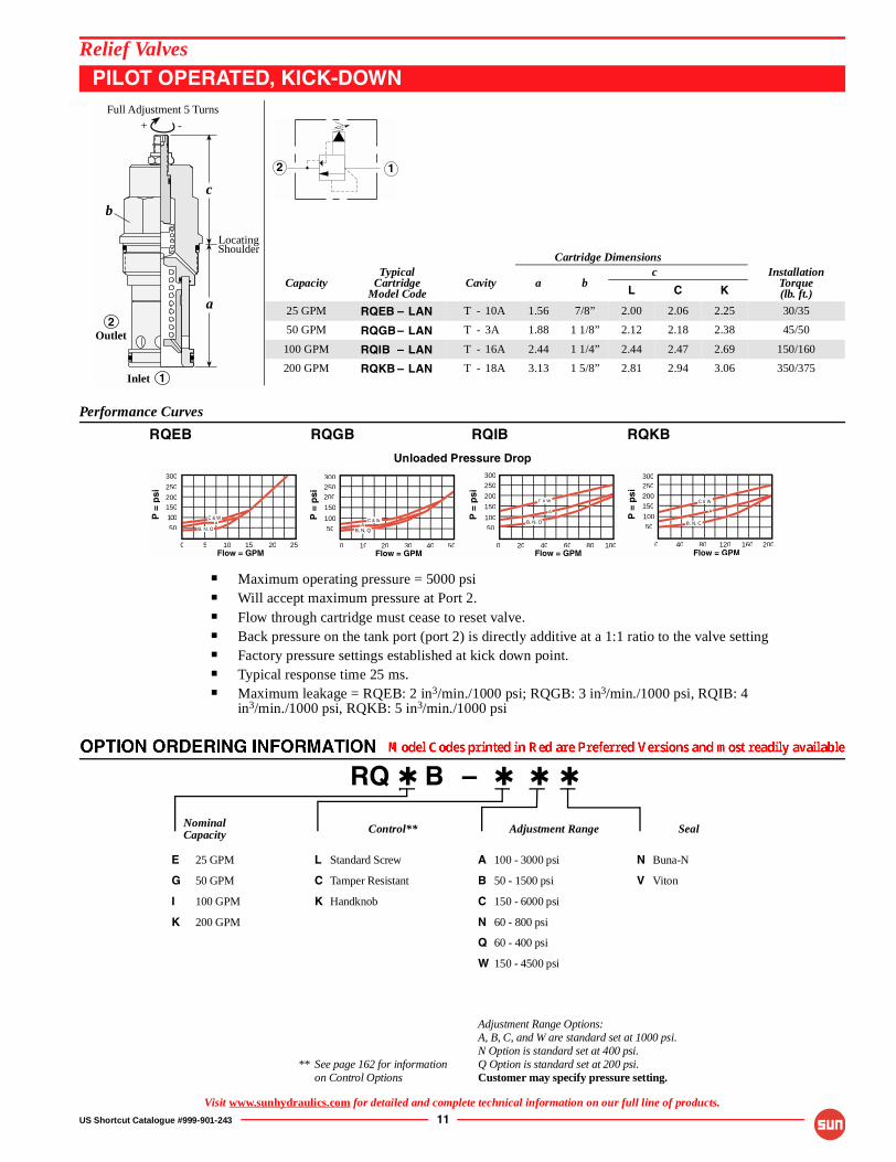
PILOT OPERATED, KICK-DOWN
RQEB RQGB RQIB RQKB
Unloaded Pressure Drop
■ Maximum operating pressure = 5000 psi■ Will accept maximum pressure at Port 2.■ Flow through cartridge must cease to reset valve.■ Back pressure on the tank port (port 2) is directly additive at a 1:1 ratio to the valve setting■ Factory pressure settings established at kick down point.■ Typical response time 25 ms.■ Maximum leakage = RQEB: 2 in3/min./1000 psi; RQGB: 3 in3/min./1000 psi, RQIB: 4
in3/min./1000 psi, RQKB: 5 in3/min./1000 psi
RQ ✱ B – ✱ ✱ ✱
Nominal Control** Adjustment Range SealCapacity
E 25 GPM $ 45.80 L Standard Screw +$ 0.00 A 100 - 3000 psi +$ 0.00 N Buna-N
G 50 GPM $ 63.00 C Tamper Resistant +$ 4.10 B 50 - 1500 psi +$ 0.00 V Viton
I 100 GPM $109.90 K Handknob +$ 5.00 C 150 - 6000 psi
K 200 GPM $208.00 N 60 - 800 psi
Q 60 - 400 psi
W 150 - 4500 psi
Adjustment Range Options:A, B, C, and W are standard set at 1000 psi.N Option is standard set at 400 psi.
** See page 162 for information Q Option is standard set at 200 psi.on Control Options Customer may specify pressure setting.
Cartridge Dimensions
CapacityTypical
CartridgeModel Code
Cavity a bc Installation
Torque(lb. ft.)L C K
25 GPM RQEB – LAN T - 10A 1.56 7/8” 2.00 2.06 2.25 30/35
50 GPM RQGB– LAN T - 3A 1.88 1 1/8” 2.12 2.18 2.38 45/50
100 GPM RQIB – LAN T - 16A 2.44 1 1/4” 2.44 2.47 2.69 150/160
200 GPM RQKB – LAN T - 18A 3.13 1 5/8” 2.81 2.94 3.06 350/375
Outlet
Inlet
b
2
1
c
a
LocatingShoulder
Full Adjustment 5 Turns
-+
� �
0 10080 20 40 60
300
200
100
50
250
150
Flow = GPM
P =
psi
0 200160 40 80 120
300
100
50
250
150
Flow = GPM2520
300
200
100
150
250
50 B, N, QA
C & W
Flow = GPM
P =
psi
0 5 10 15
300
200
150
50
100
250
Flow = GPM50400 10 20 30
B, N, QA
C & W B, N, Q
A
C & W
B, N, Q
A
C & W
Visit www.sunhydraulics.com for detailed and complete technical information on our full line of products.

Performance Curves
12 US Shortcut Catalogue #999-901-243
Relief Valves
PILOT OPERATED, BALANCED PISTON, AIR CONTROLLED
RPGD RPID RPKD
Typical Pressure Rise
■ Maximum operating pressure = 2000 psi■ Will accept maximum pressure at Port 2.■ Maximum air pressure should not exceed 150 psi.■ Pilot ratio, air to hydraulic = 1:20■ Typical response time 10 ms.■ Maximum leakage = RPGD: 3 in3/min./1000, RPID: 4 in3/min./1000 psi, RPKD: 5 in3/min./1000 psi.
RP ✱ D – ✱ ✱ ✱
Nominal Control Adjustment Range SealCapacity
G 50 GPM $121.60 Available for RPGD only B 50 - 1500 psi +$ 0.00 N Buna-N
I 100 GPM $167.20 A 1/4" NPTF +$ 0.00 V Viton Pilot Port at
K 200 GPM $314.00 end of Cartridge*
Available for RPID, RPKD only
B SAE-4 +$ 0.00Pilot Port atend of Cartridge*
* Maximum air pilot pressureshould not exceed 150 psi.
Cartridge Dimensions
CapacityTypical
CartridgeModel Code
Cavity a bc Installation
Torque(lb. ft.)A B
50 GPM RPGD – ABN T - 3A 1.88 1 1/8” 1.31 - 45/50
100 GPM RPID – BBN T - 16A 2.44 1 1/4” - 1.62 150/160
200 GPM RPKD – BBN T - 18A 3.13 1 5/8” - 2.00 350/375
Air Pilot Port
b
Outlet2
1Inlet
c
a
LocatingShoulder
��
���������
Flow = GPM
P =
psi
Flow = GPM
P =
psi
1500
1000
500
Flow = GPM
P =
psi
0 25 50 75 100
2000
2500
1500
1000
500
0 50 100 150 200
2000
2500
1500
1000
500
0 100 200 300 400
2000
2500
Visit www.sunhydraulics.com for detailed and complete technical information on our full line of products.
Performance Curves
US Shortcut Catalogue #999-901-243 13
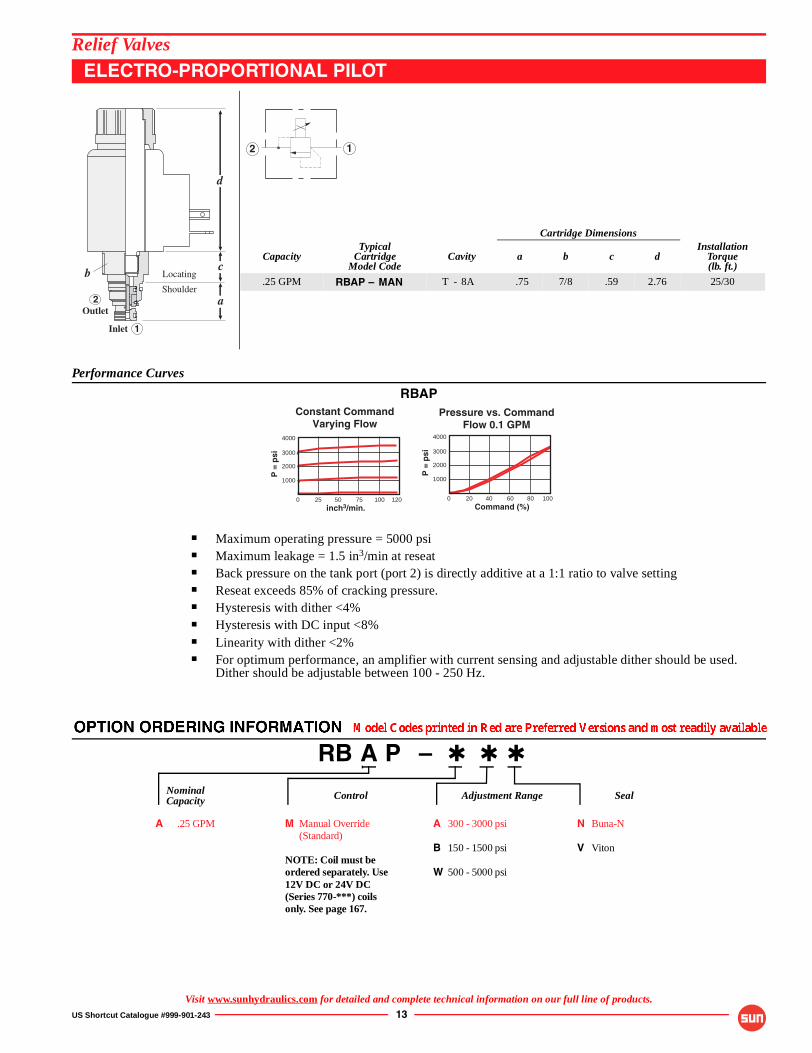
Relief Valves
ELECTRO-PROPORTIONAL PILOT
RBAP
■ Maximum operating pressure = 5000 psi■ Maximum leakage = 1.5 in3/min at reseat ■ Back pressure on the tank port (port 2) is directly additive at a 1:1 ratio to valve setting■ Reseat exceeds 85% of cracking pressure.■ Hysteresis with dither <4%■ Hysteresis with DC input <8%■ Linearity with dither <2%■ For optimum performance, an amplifier with current sensing and adjustable dither should be used.
Dither should be adjustable between 100 - 250 Hz.
RB A P – ✱ ✱ ✱
Nominal Control** Adjustment Range SealCapacity
A .25 GPM $105.00 M Manual Override +$ 0.00 A 300 - 3000 psi +$ 0.00 N Buna-N $(Standard)
B 150 - 1500 psi +$ 0.00 V Viton NOTE: Coil must beordered separately. Use W 500 - 5000 psi 12V DC or 24V DC(Series 770-***) coilsonly. See page 167.
Cartridge Dimensions
CapacityTypical
CartridgeModel Code
Cavity a b c dInstallation
Torque(lb. ft.)
.25 GPM RBAP – MAN T - 8A .75 7/8 .59 2.76 25/30
Outlet2
Inlet 1
Locating
Shoulder
c
a
b
d
� �
12025 50 75
inch3/min.
P =
psi 3000
1000
0
4000
2000
100 10020 40 60
Command (%)
P =
psi 3000
1000
0
4000
2000
80
Pressure vs. CommandFlow 0.1 GPM
Constant CommandVarying Flow
Visit www.sunhydraulics.com for detailed and complete technical information on our full line of products.

14 US Shortcut Catalogue #999-901-243
Relief Valves
BALANCED PISTON, MODULATING ELEMENT WITH INTEGRALPILOT CONTROL CAVITY
RPEC-8 RPGC-8 RPIC-8 RPKC-8
Pressure vs. Flow
■ Maximum operating pressure = 5000 psi■ Will accept maximum pressure at Port 2.■ Back pressure on the tank port (port 2) is directly additive at a 1:1 ratio to the valve setting■ Control pilot flow = RPEC-8: 7 to 10 in3/min., RPGC-8: 10 to 15 in3/min., RPIC, RPKC-8: 15 to
20 in3/min.■ Maximum leakage = RPEC-8: 2 in3/min./1000 psi: RPGC-8: 3 in3/min./1000 psi, RPIC-8:
4 in3/min./1000 psi, RPKC-8: 5 in3/min./1000 psi.■ With the -8 control option, the main stage valve should first be installed to the correct torque value.
The T-8A pilot control valve should then be installed into the main stage valve to its required torque value.
RP ✱ C – 8 ✱ ✱
Nominal Base Control MinimumControl SealCapacity Price Pressure
E 25 GPM +$ 40.20 8 T-8A Cavity in +$ 0.00 D 25 psi + $1.00 N Buna-N hex body for
G 50 GPM +$ 55.80 pilot operation W 100 psi +$ 0.00 V Viton (Pilot valve to
I 100 GPM +$ 101.30 be orderedseparately)
K 200 GPM
Cartridge Dimensions
CapacityTypical
CartridgeModel Code
Cavity a b cInstallation
Torque(lb. ft.)
25 GPM RPEC – 8WN T - 10A 1.56 7/8 .75 30/35
50 GPM RPGC – 8WN T - 3A 1.88 1 1/8” .69 45/50
100 GPM RPIC – 8WN T - 16A 2.44 1 1/4” .97 150/160
200 GPM RPKC – 8WN T - 18A 3.13 1 5/8” 1.18 350/375
Outlet2
Inlet 1
LocatingShoulder
c
a
b �
�������
�
The -8 control option allows a pilot control valve to be incorporated directlyinto the end of the modulating element via the T-8A cavity. These pilot controlcartridges are sold separately and include electro-proportional, solenoid, airpilot, and hydraulic pilot operation. See Pilot Control Cartridges on page 121.
5012.5 25 37.50Flow = GPM
P =
psi
5000
4000
3000
2000
1000
10025 50 750Flow = GPM
P =
psi
5000
4000
3000
2000
1000
20075 100 1500Flow = GPM
P =
psi
5000
4000
3000
2000
1000
400100 200 3000Flow = GPM
P =
psi
5000
4000
3000
2000
1000
Visit www.sunhydraulics.com for detailed and complete technical information on our full line of products.
Performance Curves

US Shortcut Catalogue #999-901-243 15
Relief Valves
BALANCED POPPET, MODULATING ELEMENT WITH INTEGRALPILOT CONTROL CAVITY
RPGS-8 RPIS-8
Typical Pressure Rise
■ Maximum operating pressure = 5000 psi■ Will accept maximum pressure at Port 2.■ Back pressure on the tank port (port 2) is directly additive at a 1:1 ratio to the valve setting.■ Typical response time 10 ms■ Control pilot flow = RPGS-8: 10 to 15 in3/min., RPIS-8: 15 to 20 in3/min.■ Maximum leakage = 10 drops/min. at reseat■ Reseat exceeds 90% of cracking pressure.■ With the -8 control option, the main stage valve should first be installed to the correct torque value.
The T-8A pilot control valve should then be installed into the main stage valve to its required torque value.
RP ✱ S – 8 ✱ ✱
Nominal Base Control** MinimumControl SealCapacity Price Pressure
G 50 GPM $ 65.80 8 T-8A Cavity in +$ 0.00 B 50 psi +$ 1.00 N Buna-N hex body for
I 100 GPM $116.30 pilot operation W 100 psi +$ 0.00 V Viton (Pilot valve tobe orderedseparately)
Cartridge Dimensions
CapacityTypical
CartridgeModel Code
Cavity a b cInstallation
Torque(lb. ft.)
50 GPM RPGS – 8WN T - 3A 1.88 1 1/8” .69” 45/50
100 GPM RPIS – 8WN T - 16A 2.44 1 1/4” .97 150/160
b
LocatingShoulder
c
a
Outlet2
Inlet 1
�
�������
�
The -8 control option allows a pilot control valve to be incorporated directlyinto the end of the modulating element via the T-8A cavity. These pilot controlcartridges are sold separately and include electro-proportional, solenoid, airpilot, and hydraulic pilot operation. See Pilot Control Cartridges on page 121.
10025 50 75Flow = GPM
P =
psi
4000
3000
2000
1000
0 200125 150 175Flow = GPM
P =
psi
4000
3000
2000
1000
0
Performance Curves
Visit www.sunhydraulics.com for detailed and complete technical information on our full line of products.

Performance Curves
16 US Shortcut Catalogue #999-901-243
Relief Valves
VENTABLE, PILOT OPERATED, BALANCED PISTON
RVBA RVCA RVEA RVGA RVIA
Typical Pressure Rise
■ Maximum operating pressure = 5000 psi■ Pressure at port 3 (vent) controls the valve below its setting.■ Back pressure on the tank port (port 2) is directly additive at a 1:1 ratio to the valve setting.■ Control pilot flow = RVBA, RVCA: 7 to10 in3/min.; RVEA: 10 to 15 in3/min.; RVGA, RVIA:
15 to 20 in3/min.■ Factory pressure setting established at 4 GPM■ Typical response time 10 ms.■ Maximum leakage = RVBA, RVCA: 2 in3/min./1000 psi, RVEA: 3 in3/min./ 1000 psi, RVGA:
4 in3/min./1000 psi, RVIA: 5 in3/min./1000 psi ■ RVBA minimum setting for all spring ranges is 75 psi■ Will accept maximum pressure at port 2.
RV ✱ A – ✱ ✱ ✱
Nominal Control** Adjustment Range SealCapacity
B 7.5 GPM* $ 47.70 L Standard Screw +$ 0.00 A 100 - 3000 psi +$ 0.00 N Buna-N
C 15 GPM $ 47.70 C Tamper Resistant +$ 4.10 B 50 - 1500 psi +$ 0.00 V Viton
E 30 GPM $ 65.10 K Handknob +$ 5.00 C 150 - 6000 psi
G 60 GPM $115.20 N 60 - 800 psi
I 120 GPM $232.10 Q 60 - 400 psi
W 150 - 4500 psi
Adjustment Range Options:A, B, C, and W are standard set at 1000 psi.N Option is standard set at 400 psi.Q Option is standard set at 200 psi.
** See page 162 for information * Minimum setting 75 psi on all ranges.on Control Options Customer may specify pressure setting.
Cartridge Dimensions
CapacityTypical
CartridgeModel Code
Cavity a bc Installation
Torque(lb. ft.)L C K
7.5 GPM RVBA – LAN T - 163A 1.22 3/4” 2.55 2.63 2.77 25/30
15 GPM RVCA – LAN T - 11A 1.38 7/8” 2.50 2.56 2.75 30/35
30 GPM RVEA – LAN T - 2A 1.38 1 1/8” 2.81 2.88 3.06 45/50
60 GPM RVGA – LAN T - 17A 1.81 1 1/4” 3.28 3.31 3.53 150/160
120 GPM RVIA – LAN T - 19A 2.50 1 5/8” 3.94 4.09 4.19 350/375Inlet
Vent3
2
1
-+
LocatingShoulder
Full Adjustment 5 Turns
Outlet
c
a
b
� �
�
0 200180 120 140 160Flow = GPM
P =
psi
5000
4000
3000
2000
1000
0 10080 20 40 60Flow = GPM
P =
psi
5000
4000
3000
2000
1000
Flow = GPM
P =
psi
0
2000
3000
4000
5000
2 4 6 8
1000
10 20 5 10 15Flow = GPM
P =
psi
5000
4000
3000
2000
1000
0 25 40 10 20 30Flow = GPM
P =
psi
5000
4000
3000
2000
1000
0 50
Visit www.sunhydraulics.com for detailed and complete technical information on our full line of products.

US Shortcut Catalogue #999-901-243 17
Relief Valves
MODULATING ELEMENT WITH RELIEF FUNCTION
RVBB RVCB RVEB RVGB RVIB
Typical Compensator Differentials
■ Maximum operating pressure = 5000 psi■ Back pressue on the tank port (port 2) is directly additive at a 1:1 ratio to the valve setting.■ Factory pressure setting established at 4 GPM■ Typical response time 10 ms.■ Maximum leakage = RVBB, RVCB: 2 in3/min./1000 psi, RVEB: 3 in3/min./ 1000 psi, RVGB:
4 in3/min./1000 psi, RVIB: 5 in3/min./1000 psi
RV ✱ B – ✱ ✱ ✱
Nominal Control** Adjustment Range SealCapacity
B 2.5 GPM* $ 59.30 L Standard Screw +$ 0.00 A 100 - 3000 psi +$ 0.00 N Buna-N
C 5 GPM $ 59.30 C Tamper Resistant +$ 4.10 B 100 - 1500 psi* +$ 0.00 V Viton
E 10 GPM $ 84.30 K Handknob +$ 5.00 C 100 - 6000 psi
G 20 GPM
I 40 GPM
* For RVCB, the bias pressure is 60 psi.
Adjustment Range Options:A, B, and C are standard set at 1000 psi.
** See page 162 for information * Minimum setting 100 psi on all ranges.on Control Options Customer may specify pressure setting.
Cartridge Dimensions
CapacityTypical
CartridgeModel Code
Cavity a bc Installation
Torque(lb. ft.)L C K
2.5 GPM RVBB – LAN T - 163A 1.22 3/4” 2.55 2.63 2.77 25/30
5 GPM RVCB – LAN T - 11A 1.38 7/8” 2.50 2.56 2.75 30/35
10 GPM RVEB – LAN T - 2A 1.38 1 1/8” 2.81 2.88 3.06 45/50
20 GPM RVGB – LAN T - 17A 1.81 1 1/4” 3.28 3.31 3.53 150/160
40 GPM RVIB – LAN T - 19A 2.50 1 5/8” 3.94 4.09 4.19 350/375
c
a
Inlet
LocatingShoulder
Outlet
Vent
Full Adjustment 5 Turns
b
-+
3
2
1
��
�
Load Pressure (psi)Pre
ssu
re D
iffe
ren
tial
Po
rt 1
to
3 (
psi
)
0
100
200
300
400
0600 1200 1800 2400 3000 3600
Load Pressure (psi)Pre
ssu
re D
iffe
ren
tial
Po
rt 1
to
3 (
psi
)
0
100
200
300
400
0600 1200 1800 2400 3000 3600
Load Pressure (psi)Pre
ssu
re D
iffe
ren
tial
Po
rt 1
to
3 (
psi
)
0
100
200
300
400
0600 1200 1800 2400 3000 3600
Load Pressure (psi)Pre
ssu
re D
iffe
ren
tial
Po
rt 1
to
3 (
psi
)0
100
200
300
400
0600 1200 1800 2400 3000 3600
Load Pressure (psi)Pre
ssu
re D
iffe
ren
tial
Po
rt 1
to
3 (
psi
)
0
100
200
300
400
0600 1200 1800 2400 3000 3600
Bypass FlowPort 1 to 2
120 GPM
60 GPM
80 GPM
Bypass FlowPort 1 to 2
120 GPM
60 GPM
20 GPM
60 GPM
Bypass FlowPort 1 to 2
40 GPM20 GPM10 GPM
Bypass FlowPort 1 to 2
Bypass FlowPort 1 to 2
15 GPM10 GPM
5 GPM
5 GPM
10 GPM
1 GPM
Visit www.sunhydraulics.com for detailed and complete technical information on our full line of products.
Performance Curves

Performance Curves
18 US Shortcut Catalogue #999-901-243
Relief Valves
VENTABLE, PILOT OPERATED, BALANCED POPPET
RVES RVGS
■ Maximum operating pressure = 5000 psi.■ Will accept maximum pressure at port 2■ Pressure at port 3 (vent) controls the valve below its setting.■ Back pressure on the tank port (port 2) is directly additive at a 1:1 ratio to the valve setting.■ Factory pressure setting established at 4 GPM■ Maximum leakage at reseat = 10 drops/min.■ Reseat exceeds 90% of cracking pressure.■ Typical response 10 ms■ Control pilot flow = RVES: 10 to 15 in3/min, RVGS: 15 to 20 in3/min.
RV ✱ S – ✱ ✱ ✱
Nominal Control** Adjustment Range SealCapacity
E 30 GPM +$ 75.10 C Tamper Resistant +$ 4.10 A 100 - 3000 psi +$ 0.00 N Buna-N Factory Set
G 50 GPM +$130.50 B 50 - 1500 psi +$ 0.00 V Viton K Handknob
C 150 - 6000 psi L Standard Screw
Adjustment N 60 - 800 psi
Q 60 - 400 psi
W 100 - 4500 psi
Adjustment Range Options:A, B, C and W are standard set at 1000 psi.N Option is standard set at 400 psi.Q option is standard set at 200 psi.
** See page 162 for informationon Control Options Customer may specify pressure settings.
Cartridge Dimensions
CapacityTypical
CartridgeModel Code
Cavity a bc Installation
Torque(lb. ft.)L C K
30 GPM RVES – LAN T - 2A 1.38 1 1/8” 2.81 2.88 3.06 45/50
50 GPM RVGS – LAN T - 17A 1.81 1 1/4” 3.28 3.31 3.53 150/175
LocatingShoulder
c
a
b
Outlet2
Inlet 1
Vent3
� �
�
Vented Pressure
6015 30 45Flow = GPM
P =
psi
200
150
100
50
00
C, W, A
B
10025 50 75Flow = GPM
P =
psi
4000
3000
2000
1000
00
Typical Pressure Rise
10025 50 75Flow = GPM
P =
psi
4000
3000
2000
1000
00
Typical Pressure Rise Vented Pressure
6015 30 45Flow = GPM
P =
psi
200
150
100
50
00
C, W, A
B
Visit www.sunhydraulics.com for detailed and complete technical information on our full line of products.

US Shortcut Catalogue #999-901-243 19
Relief Valves
VENTABLE, PILOT OPERATED, BALANCED PISTON WITH EXTERNAL DRAIN
RVCD RVED RVGD RVID
■ Maximum operating pressure = 5000 psi■ Pressure at port 4 is directly additive to the valve setting at a 1:1 ratio and should not exceed 5000 psi ■ Pressure at port 3 (vent) controls the valve below its setting.■ Control pilot flow = RVCD: 7 to10 in3/min.; RVED: 10 to 15 in3/min.; RVGD, RVID: 15 to 20 in3/min.■ Factory pressure setting established at 4 GPM■ Typical response time 10 ms.■ Maximum leakage = RVCD: 2 in3/min./1000 psi, RVED: 3 in3/min./1000 psi, RVGD: 4 in3/min./1000
psi, RVID: 5 in3/min./1000 psi.
RV ✱ D – ✱ ✱ ✱
Nominal Control** Adjustment Range SealCapacity
C 15 GPM $ 73.60 L Standard Screw +$ 0.00 A 100 - 3000 psi +$ 0.00 N Buna-N
E 30 GPM $ 102.20 C Tamper Resistant +$ 4.10 B 50 - 1500 psi +$ 0.00 V Viton
G 60 GPM $ 181.00 K Handknob +$ 5.00 C 150 - 6000 psi
I 120 GPM $ 335.50 D 25 - 800 psi
E 25 - 400 psi
W 150 - 4500 psi
Adjustment Range Options:A, B, C, and W are standard set at 1000 psi.D Option is standard set at 400 psi.
**See page 162 for information E Option is standard set at 200 psi.on Control Options Customer may specify pressure setting.
Cartridge Dimensions
CapacityTypical
CartridgeModel Code
Cavity a bc Installation
Torque(lb. ft.)L C K
15 GPM RVCD – LAN T - 21A 1.38 7/8” 3.09 3.15 3.34 30/35
30 GPM RVED – LAN T - 22A 1.38 1 1/8” 3.44 3.50 3.69 45/50
60 GPM RVGD – LAN T - 23A 1.81 1 1/4” 3.93 3.99 4.19 150/160
120 GPM RVID – LAN T - 24A 2.50 1 5/8” 4.78 4.90 5.03 350/375
4
3
2
1
Drain
c
a
Vent
Outlet
Inlet
LocatingShoulder
Full Adjustment 5 Turns
b
-+
� �
��
0 10080 20 40 60
5000
4000
3000
2000
1000
Flow = GPM
P =
psi
0 200160 40 80 120
5000
4000
3000
2000
1000
Flow = GPM
P =
psi
0 400320 80 160 240
5000
4000
3000
2000
1000
Flow = GPMP
= p
si10 20 30
5000
4000
3000
2000
1000
Flow = GPM
P =
psi
0 40 50
Vented Pressure
Typical Pressure Rise
5 10 15
Flow = GPM
P =
psi 150
50
0
200
100
20
C & W
BD & E
A
50 100 150
Flow = GPM
P =
psi 150
50
0
200
100
200
C & W
BD & E
A
25 50 75
Flow = GPM
P =
psi 150
50
0
200
100
100
C & W
BD & E
A
10 20 30
Flow = GPM
P =
psi 150
50
0
200
100
40
C & W
B D & EA
Visit www.sunhydraulics.com for detailed and complete technical information on our full line of products.
Performance Curves

20 US Shortcut Catalogue #999-901-243
Relief Valves
VENTABLE, BALANCED PISTON, MODULATING ELEMENT WITH EXTERNALDRAIN AND INTEGRAL PILOT CONTROL ELEMENT
RVCD-8 RVED-8 RVGD-8 RVID-8
■ Maximum operating pressure = 5000 psi■ Pressure at port 4 is directly additive to the valve setting at a 1:1 ratio and should not exceed 5000 psi ■ Pressure at port 3 (vent) controls the valve below its setting.■ Control pilot flow = RVCD: 7 to10 in3/min.; RVED: 10 to 15 in3/min.; RVGD, RVID: 15 to 20 in3/min.■ Factory pressure setting established at 4 GPM■ Typical response time 10 ms.■ Maximum leakage = RVCD: 2 in3/min./1000 psi, RVED: 3 in3/min./1000 psi, RVGD: 4 in3/min./1000
psi, RVID: 5 in3/min./1000 psi.
RV ✱ D – 8 ✱ ✱
Nominal Base Control Minimum Control SealCapacity Price Pressure
C 15 GPM $ 73.60 8 T-8A Cavity in D 27 psi +$ 1.00 N Buna-N hex body for
E 30 GPM $102.20 pilot operation W 100 psi +$ 0.00 V Viton (Pilot valve to
G 60 GPM $181.00 be orderedseparately)
I 120 GPM
Cartridge Dimensions
CapacityTypical
CartridgeModel Code
Cavity a b cInstallation
Torque(lb. ft.)
15 GPM RVCD – 8WN T - 21A 1.38 7/8 1.78 30/35
30 GPM RVED – 8WN T - 22A 1.38 1 1/8 2.00 45/50
60 GPM RVGD – 8WN T - 23A 1.814 1 1/4 2.59 150/160
120 GPM RVID – 8WN T - 24A 2.50 1 5/8 3.16 350/375
Drain4
Outlet2
Inlet 1
b
Vent3
LocatingShoulder
c
a
�
�
� �������
�
The -8 control option allows a pilot control valve to be incorporated directlyinto the end of the modulating element via the T-8A cavity. These pilot controlcartridges are sold separately and include electro-proportional, solenoid, airpilot, and hydraulic pilot operation. See Pilot Control Cartridges on page 121.
205 10 150Flow = GPM
P =
psi
5000
4000
3000
2000
1000
4010 20 300Flow = GPM
P =
psi
5000
4000
3000
2000
1000
8020 40 600Flow = GPM
P =
psi
5000
4000
3000
2000
1000
16040 80 1200Flow = GPM
P =
psi
5000
4000
3000
2000
1000
Vented Pressure
Typical Pressure Rise
5 10 15
Flow = GPM
P =
psi 150
50
0
200
100
20
C & W
BD & E
A
50 100 150
Flow = GPM
P =
psi 150
50
0
200
100
200
C & W
BD & E
A
25 50 75
Flow = GPM
P =
psi 150
50
0
200
100
100
C & W
BD & E
A
10 20 30
Flow = GPM
P =
psi 150
50
0
200
100
40
C & W
B D & EA
Visit www.sunhydraulics.com for detailed and complete technical information on our full line of products.
Performance Curves