Computational Thermal-Hydraulics Modeling of Twisted Tape ...
Upload
khangminh22Category
view
2download
0
Industrial Hydraulics FAQs
Updated: JS_September2013
FAQ Title: Series Changes in Servo and Proportional Valves Category: Proportional and Servo Valves Sub-Category: Series changes / valve upgrades
Bosch Rexroth Corporation Hydraulics 2315 City Line Road Bethlehem, PA 18017 Tel (847) 645-3600
Question: What documentation is available to aid in the selection of new series proportional or servo valves, to replace previous series, or obsolete products?
Answer: Please review the attachments, which include summary documents comparing serial feature differences and valve/electronic replacement information. To also aid in the selection of new series product, relevant data sheets for old and new series valves, and related components, (amplifier changes, for example) are included. These documents are for servo valves, proportional valves, including directional, pressure, and flow control versions. Attachments: Multiple comparison .pdf’s

DC-IA Sales and Marketing Webletter 2011-12-016 December 2011
newsletter DC-IA /SPI Sales Product Management
Machinery Applications and Engineering
Industrial Hydraulic Controls
Product substitution (Z)DBE(E) 6 series 1X to 2X
Discontinuation:
From January 2012 the (Z)DBE(E)6…1X valves will be set to phase-out control (AL) status. These valves are only to be used as replacement. From April 2012 they will be set to order stop (AS) status.
Announcements:
The start of the new series (Z)DBE(E)6…2X is January 2012.
Advantages of the new series:
No solenoid venting required any more
Maximum set pressure has been increased to 350 bar
Improved damping
Rotatable and/or detachable solenoid coil
With OBE, the current/voltage interface can be selected (see data sheet)
Solenoid current can be tapped at the connector (pin F-C)
Data sheet 29 158
Data sheet 29 258
Technical features
Size 6
Component series 1X
Maximum set pressure: 315 bar
Maximum flow: 30l/min
Technical features
Size 6
Component series 2X
Maximum set pressure: 350 bar
Maximum flow: 30l/min
Theobald Herrmann | Sales Product Management Machinery Applications and Engineering | DC-IA/SPI1 | [email protected] | Ausgabe 12.11 1
Theobald Herrmann | Sales Product Management Machinery Applications and Engineering | DC-IA/SPI1 | [email protected] | Ausgabe 12.11 2
Newsletter | DC-IA/SPI
Sales Product Management – Industrial Hydraulic Controls
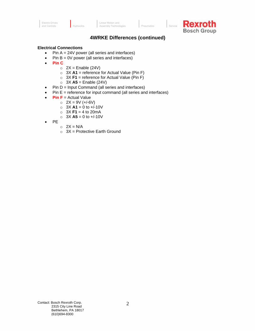
Modification features
As pilot valve, the DBET(E)-6X will be used for all variants.
The valve main stages of both series are identical.
Regarding the connection diagram as well as the hydraulic characteristic values,
valves of series 2X and the current types are interchangeable.
For safety reasons the units of series 6X are designed without manual override.
Version (Z)DBEE6…2X with integrated electronics is 1:1 interchangeable (identical pin assignment).
When variants with external electronics are to be replaced without changing the electronics, characteristic curves and valve response are different. So it is recommended to change the amplifier, too.
Comparison of series 1X and 2X
series 1X series 2X
Valve for limiting a system pressure Valve for limiting a system pressure
Operation with proportional solenoid Operation with rotatable proportional solenoid
For subplate mounting and sandwich plate mounting: Porting pattern according to DIN 24340 form D (without location hole) and ISO 4401 (with location hole), sub plates according to data sheet 45 052
For subplate mounting and sandwich plate mounting: Porting pattern according to ISO 4401, subplates according to data sheet 45052
Valve and electronic control from one source Valve and electronic control from one source
For the control of types DBE and ZDBE:
Analog amplifier type VT 11724 in modular design according to data sheet 29 865
Analog amplifier type VT-VSPA1-1 in Eurocard format according to data sheet 30 111
Digital amplifier type VT-VSPD-1 in Eurocard format according to data sheet 30 123
For the control of types DBE and ZDBE:
Plug-in proportional amplifier type VT-SSPA1-1-1X plug-in amplifier according to data sheet 30 116 connection M12 – 4polig
Analog amplifier type VT-MSPA1-11-1X in modular design according to data sheet 30 223
Analog amplifier type VT-VSPA1-11-1X in Eurocard format according to data sheet 30 100
Digital amplifier type VT-VSPD-2 in Eurocard format according to data sheet 30 523
Type DBEE and ZDBEE with integrated electronics (OBE):
Little manufacturing tolerance of the command value/pressure characteristic curve
Independently adjustable up and down ramp
Type DBEE and ZDBEE with integrated electronics (OBE):
Little manufacturing tolerance of the command value/pressure characteristic curve
Freely selectable voltage interface: A1: 0-10 V F1: 4-20 mA

Contact: Bosch Rexroth Corp. 3/3/2010 2315 City Line Road Rev. 1 Bethlehem, PA 18017 (610)694-8300
1
3DRE(M)(E) 10, 16 Series change from 6X to 7X

Contact: Bosch Rexroth Corp. 3/3/2010 2315 City Line Road Rev. 1 Bethlehem, PA 18017 (610)694-8300
2

Contact: Bosch Rexroth Corp. 7/29/09 2315 City Line Road Bethlehem, PA 18017 (610)694-8300
1
Differences between 4WRA 6,10 Series 1X and 4WRA 6,10 Series 2X RE29054 RE29055
• 4WRA series 1X used rectangular DC proportional solenoids o 1.5A maximum current requirement for size 6 (5.4ohm coil) o 1.5A maximum current requirement for size 10 (10 ohm coil) o Control amplifiers:
Size 6 – VT3013 (RE29937) or VT3017 (RE29934) Size 10 – VT3014 (RE39937) or VT3018 (RE29934) Card Holder – VT-3002-2X/32D (RE29928)
• 4WRA series 2X uses DC proportional solenoids with pole tube
and removable coils o 2.5A maximum current requirement for size 6 and 10 (2ohm coil) o Control amplifiers – available with 1 or 5 ramp times (T1), (T5)
Sizes 6 and 10 – VT-VSPA2-1-2X (RE30110) Card Holder – VT-3002-2X/48F (RE29928) Modular amplifier VT-MSPA2-1-1X (RE30228)
• 4WRA series 2X is available with SO-589
o This option for replacing a 1X valve allows use of existing amplifier. Example: 4WRA 6 E15-2X/G24K4/V-589
o For new applications we recommend using the current valve and amplifier
Solenoid connectors for 4WRA…2X…K4
o A side - R901017010 - gray o B side - R901017011 - black
• Series 2X is available with on-board electronics – 4WRAE 6,10 o 24 volt supply voltage o Command signal options:
+/- 10 volt (A1) 4-20ma (F1) Mating Connector – R900021267 (plastic), R900223890 (metal)

Contact: Bosch Rexroth Corp. 7/29/09 2315 City Line Road Bethlehem, PA 18017 (610)694-8300
2
• Nominal flow rates are different from 1X to 2X o Series 1X Series 2X
Size 6 Size 6 05=(8 lpm) 07=(7 lpm) 10=(13 lpm) 15=(15 lpm) 20=(17 lpm) 30=(26 lpm) Series 1X Series 2X Size 10 Size 10 10=(12 lpm) 30=(30 lpm) 20=(22 lpm) 60=(60 lpm) 40=(42 lpm)
4WRA series 2X has FKM “V” seals standard Mounting bolt length changes 1X to 2X
o Size 6:
1X = M5 x 40 2X = M5 x 50
o Size 10: 1X = M6 x 50 or M6 x 40 (depends on age of valve)
2X = M6 x 40

Contact: Bosch Rexroth Corp. 7/29/09 2315 City Line Road Bethlehem, PA 18017 (610)694-8300
3

7/29/2009 1
4WRA Series 1X Replacement
Series 1X Series 2X Since the release of the 4WRA series 2X valve there have been questions on how to replace a series 1X valve with the 2X. Is it a direct replacement and do we need a new amplifier are some of the more common questions asked. The following will explain the differences that must be taken into consideration when making a change from one series to the other. Although end users may be hesitant at first they must be made aware that the 4WRA series 1X is slated for obsolescence in the very near future. Physical dimensions are very close between the two series. The one dimension to be concerned with would be the height when trying to use a 4WRAE (valve with on board electronics) in place of a 4WRA. Refer to data sheets RE29054 (series 1X) and RE29055 (series 2X) for these dimensions. The mounting bolt length has changed. The 4WRA(E)6 series 2X requires 10-24 X 2” (M5 X 50mm) socket head cap screws where the 4WRA6 series 1X required 10-24 X 1 ½” (M5 X 40). The 4WRA(E)10 series 2X requires ¼-20 X 1 ½” (M6 X 40mm) where the 4WRA10 series 1X required ¼-20 X 2” (M6 X 50mm). Slight differences exist in the flow ratings between the two series. Series 1X Series 2X NG6 NG6 05 (8 LPM) 07 (7 LPM) 10 (13 LPM) 15 (15 LPM) 20 (17 LPM) 30 (26 LPM) NG10 NG10 10 (12 LPM) 30 (30 LPM) 20 (22 LPM) 60 (60 LPM) 40 (42 LPM) When choosing a flow rate in the series 2X valve base your choice on the actual flow rate through the existing valve versus the pressure drop across it. For example let’s say the customer had a 4WRA10E10-1X/24NK4M that they needed to replace. Depending on the maximum percentage of the valve that they are using it would probably be best to use a 4WRA6E15-2X/G24N9K4/V with an adapter plate from D05 to D03. If a 4WRA10E30-2X…. was selected as a replacement control issues possibly could develop due to the fact that only a small percentage of the valve would be needed to match the characteristics of the original valve.

7/29/2009 2
The amplifier is also an important consideration when replacing a series 1X valve with a series 2X valve. The current requirements for the solenoids/coils are different between the two series. The series 2X valve requires 2.5 amps while the series 1X required 1.5 amps. The suggested amplifier for the 4WRA series 2X valve is the VT-VSPA2-1-2X, data sheet RE30110. The amplifier for the series 1X valve was either a VT3013 or a VT3014 depending on the size of the valve, NG6 or NG10, data sheet RE29937. The most noticeable difference between these two amplifiers will be that the VT-VSPA2-1-2X has a 48 pin F connector whereas the VT3013/14 had a 32 pin D connector. This means that a new cardholder, VT3002-2X/48F R900020154 will be needed.
Another possibility for a substitute amplifier is the VT-MSPA2-1 (RE30228) which is a DIN rail mounted amplifier module. The VT-MSPA2-1 requires a 0 to +/-10 volt differential command such as an analog output from a PLC, etc. A solution for customers who do not wish to change their amplifier at this time is SO589. With this SO the valve has coils which have the same current rating (1.5 amps) as the solenoids on the series 1X valve. The customer will be able to use their original amplifier. If environmental conditions warrant its use then the 4WRAE (on board electronics version) can be considered as a replacement. Contact: Product Management Bosch Rexroth Corp. 2315 City Line Road Bethlehem, PA 18017 (610)694-8300

Contact: Bosch Rexroth Corp. 7/29/09 2315 City Line Road Bethlehem, PA 18017 (610)694-8300
1
Differences between 4WRE 6,10 series 1X and 4WRE(E) 6,10 series 2X
• 4WRE series 1X uses rectangular DC proportional solenoids o 1.8A maximum current requirement for size 6; 2.2A for size 10 o Control amplifiers:
Size 6 - VT-5005 RE30095 Size 10 – VT-5006 RE30095 Card Holder – VT-3002-2X/32D RE29928
• 4WRE(E) series 2X uses DC proportional solenoids with pole tube and removable
coils
o Maximum current requirement 2.5A for size 6 and 10 o Control amplifiers - available with 1 or 5 ramp times (T1), (T5) o Plug-in amplifiers for 3 position (2 solenoid) valves only
Size 6 – VT-VRPA2-1-1X RE30119 Size 10 – VT-VRPA2-2-1X RE30119 Card Holder VT-3002-2X/48F RE29928
o Modular amplifiers Size 6 – VT-MRPA2-1-1X (2 solenoids) RE30219
VT-MRPA1-1-1X (1 solenoid) RE30219 Size 10 – VT-MRPA2-2-1X (2 solenoids) RE30219
VT-MRPA1-2-1X (1 solenoid) RE30219

Contact: Bosch Rexroth Corp. 7/29/09 2315 City Line Road Bethlehem, PA 18017 (610)694-8300
2
• Feedback (valves without on-board electronics) o Series 1X uses 3 wire LVDT
Connector – R900013674 o Series 2X uses 4 wire LVDT
Connector – R900023126
• Nominal flow rates are different from 1X to 2X o Series 1X Series 2X
Size 6 Size 6 08=(10 lpm) 08=(8 lpm) 16=(21 lpm) 16=(16 lpm) 32=(32 lpm) 32=(32 lpm) Size 10 Size 10 16=(27 lpm) 25=(25 lpm) 32=(42 lpm) 50=(50 lpm) 64=(62 lpm) 75=(75 lpm)
• Mounting Bolts: o Series 1X size 6 = M5 x 40, Size 10 = M6 x 40 o Series 2X size 6 = M5 x 50, Size 10 = M6 x 40
Series 2X valves are available with on-board electronics – 4WREE 6,10
o 24 volt supply voltage o Command signal options:
o +/- 10 volt (A1) o 4-20mA (F1)
o Pin F – monitor actual feedback value, Pin C ref o Mating Connector – R900021267 (plastic), R900223890 (metal)

Contact: Bosch Rexroth Corp. 7/29/09 2315 City Line Road Bethlehem, PA 18017 (610)694-8300
3

1
4WRKE Differences Between Series 2X and 3X
4WRKE…2X (RE29074) 4WRKE…3X (RE29075)
Physical Appearance
• Series 2X – pilot valve with square solenoid design • Series 3X – pilot valve with round removable coils with pole tubes
Spools
• Design o 2X = cone type o 3X = notch type
• Overlap o 2X = 10% overlap o 3X = 15% overlap
• Flow Characteristic o 2X = 10% fine metering notches to cone type flow characteristic o 3X = no fine metering, linear characteristic
“L” (linear) will be a suitable replacement for the 2X • Nominal Flow Rates
o No changes • Designations
o Changes to “W” spools 2X 3X W W6 W1 W8
o E2 and W2 spools have no direct replacements, consult factory Electrical Connector
• 2X = Z9 (R900013159) 6 pin • 3X = Z31 (R900021267 plastic or R900223890 metal) 7 pin
Electronic Interface Designations
• A1 o Command = 0 to +/-10V o Actual Value = 0 to +/-10V
• F1 o Command = 4 to 20mA o Actual Value = 4 to 20mA
• A5 o Command = 0 to +/-10V o Actual Value = 0 to +/-10V o Pin C = Enable (24V)
Contact: Bosch Rexroth Corp. 2315 City Line Road Bethlehem, PA 18017 (610)694-8300
2
4WRKE Differences (continued)
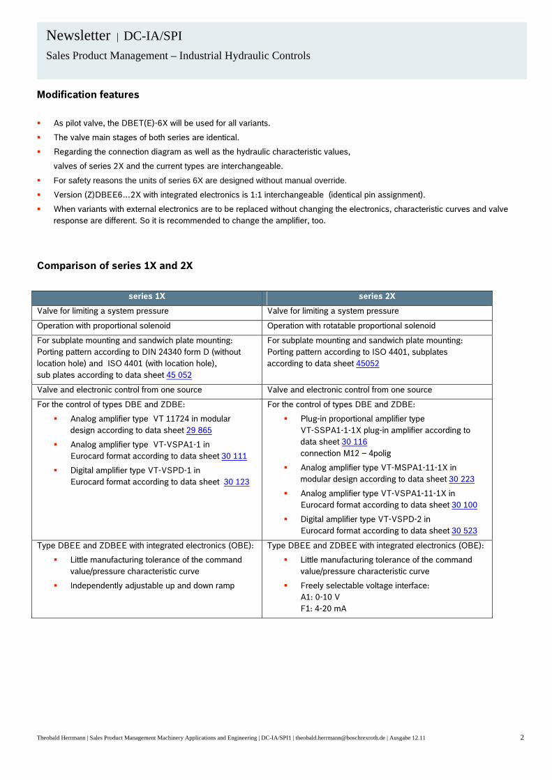
Electrical Connections • Pin A = 24V power (all series and interfaces) • Pin B = 0V power (all series and interfaces) • Pin C
o 2X = Enable (24V) o 3X A1 = reference for Actual Value (Pin F) o 3X F1 = reference for Actual Value (Pin F) o 3X A5 = Enable (24V)
• Pin D = Input Command (all series and interfaces) • Pin E = reference for input command (all series and interfaces) • Pin F = Actual Value
o 2X = 9V (+/-6V) o 3X A1 = 0 to +/-10V o 3X F1 = 4 to 20mA o 3X A5 = 0 to +/-10V
• PE o 2X = N/A o 3X = Protective Earth Ground

4WRTE REPLACEMENT
1
A common question is how to replace a 4WRTE valve, whether it is an older series being replaced by the current series or possibly replacing it with a different type of valve. This document will give you advice on the choices you will need to make.
4WRTE Series 3X to Series 4X
Series 3X Series 4X The most important point to note when doing such an update is that Pin C in the series 3X valve was for a 24 volt enable signal. There are two ways to accommodate this is in the series 4X. One is to order the replacement valve in series 4X with the A5 electronics designation. The A5 in series 4X has the same electrical connections as earlier series such as the 3X. Another option would be to have the end user remove the 24 volt signal from pin C and then the standard A1 electronics could be used on the series 4X valve. Example: 4WRTE10E50L-3X/6BG24Z31/M 4WRTE10E50L-4X/6EG24K31/A5M No changes required by the customer. 4WRTE10E50L-3X/6BG24Z31/M 4WRTE10E50L-4X/6EG24K31/A1M Customer must remove the 24 volt enable signal from pin C. There are other differences to be aware of when converting to series 4X. In the series 3X the designation “6B” meant the pilot valve had wet pin DC solenoids, now in the series 4X the designation “6E” means the pilot has proportional solenoids with removable coils. The mating connector (Z31 designation) was included in older series valves, now in the series 4X (K31 designation) it is not. If needed, it must be ordered separately, part numbers R900021267 (plastic) or R900223890 (metal). Some spool designations have changed. The “W” has become the “W6”, the “W1” has become the “W8” and the “W3” has become the “W9”. For example: 4WRTE16W125L-3X/6BG24Z31/M 4WRTE16W6-125L-4X/6EG24K31/A5M The only change to the size designations was made to the 4WRTE25…..3XH high flow valve. This has become the 4WRTE27 valve. 4WRTE25W500L-3XH/6BG24Z31/M 4WRTE27W6-500L-4X/6EG24K31/A5M

4WRTE REPLACEMENT
2
When converting from an older series to the current series always refer to the data sheets for electrical connections, spool configurations and flow rates. The data sheet for the 4WRTE series 3X valve is RE29082 and the 4WRTE series 4X is RE29083. What other type of valve could possibly be used to replace the 4WRTE ? The 4WRLE can be used to replace the 4WRTE in various applications. It is always recommended that you consult with the particular application group for suggestions or experiences when doing such a conversion.
4WRLE 4WRTE Certain items must be taken into consideration when making such a replacement. The electronics are on different ends from the 4WRTE to the 4WRLE. When making such a replacement please make sure there are no clearance issues on the machine. The 4WRLE has no options for pin C, so if pin C were used as an enable on the 4WRTE valve (A5 on series 4X or series 3X and earlier designs) the enable signal must be removed before using a 4WRLE valve. Pin C is always 0 volt reference for pin F on the 4WRLE valve. Flow rates are somewhat different between these two types of valves but generally are close enough that a substitution is possible. The 4WRTE32 with a 600LPM spool is an example of one flow rate with no obvious substitution available. Flow characteristics are also different which will cause the customer to do some retuning of control loops that are being used. An example of this would be on overlap spools such as the “E” and “W”. The 4WRTE valves have a general overlap of 15% which means a command of +/-1.5 volts is needed to start flow. The 4WRLE has a physical overlap of 20% on the “E” and “W” spools but the on board electronics uses overlap compensation so that a command of +/-0.5 volts is needed for the start of flow. If the controller has the option to select spool overlap you would enter 5% for the 4WRLE valve with the “E” or “W” spool.

4WRTE REPLACEMENT
3
The following diagrams show the flow characteristics of the spools. 4WRTE valve with the “E”, “W” and “V” spools. (V spool is considered 0 overlap)
4WRLE valve with the “E” or “W” spool.

4WRTE REPLACEMENT
4
4WRLE valve with the “V” spool.
The “L” version (Linear) spool is being developed for the 4WRLE and at the present time it is available only in certain sizes. Consult factory for availability. Examples of possible substitutions depending on the application are: 4WRTE16E200L-3X/6BG24K31/A1M 4WRLE16EZ180SJ-3X/G24K0/A1M Customer would be required to remove the 24 enable signal from pin C. The “Z” designation in the 4WRLE model code represents load sense ports “C1 and “C2”. It is not a requirement that these ports be utilized. 4WRTE25W6-350L-4X/6EG24K31/A1M 4WRLE25WZ350SJ-3X/G24K0/A1M Note: Always contact the application group responsible for the market you are working in for advice when making such a substitution. Data sheets for the 4WRLE are RE29088 for the “V” spool version and RE29089 for the “E” and “W” spool versions.

7/29/2009 1
4WRTE Differences Between Series 3X and 4X
4WRTE…3X (RE29082) 4WRTE…4X (RE29083)
Overall Appearance
• Series 3X uses square solenoids • Series 4X uses round detachable coils with pole tubes
Spools
• Design type o Series 3X – cone type o Series 4X – notch type
• Overlap (E & W) o Series 3X – 10% overlap o Series 4X – 15% overlap
• Flow Characteristic – no differences o L (linear) is the preferred version
• V spool (0% overlap) o Series 3X – spring center at loss of electrical power o Series 4X – spring offset (1 to 11% ) P>B A>T at loss of electrical power (please
note for future designs) • Change in Designations
Series 3X Series 4X W W6 W1 W8
• Nominal Flow Rates o No Changes
Housings
• Series 3X o Same housing for all spool designations
• Series 4X o Different housings E, W versus V, Q spools

Contact: Bosch Rexroth Corp. 7/29/2009 2315 City Line Road Bethlehem, PA 18017 (610)694-8300
2
4WRTE Differences (continued)
Electrical Connections Series 3X Series 4X Pin A = +24V power Pin A = +24V power Pin B = 0V power Pin B = 0V power Pin C = Enable (24V) Pin C = 0V reference for actual value (Pin F) Pin D = Command Value Pin D = Command value Pin E = 0V reference for command Pin E = 0V reference for command Pin F = Actual value Pin F = Actual value PE = Protective Earth Ground PE = Protective Earth Ground
• Series 4X A5 designation in model code Pin C becomes Enable (24V) similar to series 3X electrical connections.
New Model Code Designations
• Size o 4WRTE27 formerly 4WRTE25…3XH
• Electronic Interface o A1
Command = 0 to +/-10V Actual Value = 0 to +/-10V
o F1 Command = 4 to 20mA Actual Value = 4 to 20mA
o A5 Command = 0 to +/-10V Actual Value = 0 to +/-10V Pin C = Enable 24V

Contact: Bosch Rexroth Corp. 7/29/09 2315 City Line Road Bethlehem, PA 18017 (610)694-8300
1
4WRZ
Differences between Series 5X, 6X and 7X
• Series 5X, 6X used rectangular DC proportional solenoids o 700mA maximum current required
• Series 7X uses DC proportional solenoids with pole tube and removable coils o 1500mA maximum current required
• Control Amplifiers:
o Series 5X, 6X typically used VT-3000 (RE29935) or VT-3006 (RE29926) o Card Holder VT-3002-2X/32D (RE29928)
o Series 7X uses VT-VSPA2-1-2X/T1 or T5 (RE30110) o Card Holder VT-3002-2X/48F (RE29928) o Or, modular amplifier VT11118-1X (RE30218)
• Replacement option series 7X available with on-board electronics – 4WRZE o No external amplifier needed o Input options:
• A1 = +/- 10volt • F1 = 4-20mA
• Series 7X available with -674 replacement option
o 4WRZ…7X…-674 allows use of existing amplifier for 5X, 6X o Not a direct replacement – valve opening is at 43% command vs 32% on
the 5X, 6X o 750mA needed to achieve maximum shift vs 700 mA in the 5X, 6X o Command value adjustment may compensate for differences

Contact: Bosch Rexroth Corp. 7/29/09 2315 City Line Road Bethlehem, PA 18017 (610)694-8300
2
• “W” spool designations change from 5X, 6X to 7X o 5X, 6X 7X
W (1:1 SPOOL) W6 W1 (2:1 SPOOL) W8 W2 (1:2 SPOOL) not available in 7X W3 (regen) W9
• Nominal flow ratings of spools to be considered when replacing with 7X: o Command values may need to be adjusted

Contact: Bosch Rexroth Corp. 2/8/2011 2315 City Line Road Bethlehem, PA 18017 (610)694-8300
1
Pilot Operated 4 Way Servo Valves Series Differences
4WSE3EE 16 (series 1X) RE29595 4WSE3E 16 (series 2X) RE29620 4WSE3EE 25 (series 2X) RE29595 4WSE3E 25 (series 3X) RE29621 4WSE3EE 32 (series 4X) RE29595 4WSE3E 32 (series 5X) RE29622
The physical dimensions of the old series valves differ from the new series, especially the integrated electronics housing.
The old series valves had a power supply of +/-15 vdc. The new series has the
option of +/-15 vdc or +24 vdc.
The hydraulic connection face (mounting surface) remains the same. However, the mounting bolt length changes (bolts included with valve).
The maximum tank port pressure has been reduced to 250 bar (pilot oil return) in
the new series due to the new main housing material. Operating pressure in P, A, B is increased to 350 bar (excluding size 32).
The electrical connector remains the same. (R900223890 recommended). See RE
data sheet for connections.
2:1 flow ratio spool version (V1) is available in the new series.
FKM seals are standard in the new series.
Failsafe (de-energized) spool position is also optional in the new series:
N = 100% P to B P = 100% P to A Not defined = omit from model code

DC-IA Sales and Marketing Webletter 2011- 11-004 November 2011
Theobald Herrmann | Sales Product Management Machinery, Applications and Engineering | DC-IA/SPI1 | [email protected] | Ausgabe 11.11 1
newsletter DC-IA /SPI Sales Product Management
Machinery, Applications and Engineering
Industrial Hydraulic Controls
Product substitution DRE(M)(E) 10/25 Series 5X to 6X
Discontinuation:
1. As already announced in IH 006-10, the DRE (M)(E)…5X valves will be set to order stop (AS) status in November 2011.
2. The new DRE(E)…6X series without max. pressure limitation has been available since February 2010.
3. The new DREM(E)…6X with max. pressure limitation has been available since February 2011.
Advantages of the new series
No solenoid ventilation required any more
Improved damping
Rotatable and/or detachable solenoid coil
With OBE, the current / voltage interface can be selected (see data sheet)
Solenoid current can be tapped at the connector (pin F-C)
Data sheet 29 176
Data sheet 29 276
Technical features
Size 10 and 25
Component series 5X
Maximum set pressure: 315 bar
Maximum flow:
- 200l/min (size 10)
- 300l/min (size 25)
Technical features
Size 10 and 25
Component series 6X
Maximum set pressure: 315 bar
Maximum flow:
- 200l/min (size 10)
- 300l/min (size 25)

Theobald Herrmann | Sales Product Management Machinery, Applications and Engineering | DC-IA/SPI1 | [email protected] | Ausgabe 11.11 2
Newsletter | DC-IA/SPI
Sales Product Management – Industrial Hydraulic Controls
Modification features
As pilot valve, the DBET(E)-6X is used for all variants.
The valve main stages of both series are identical.
Regarding the connection pattern as well as the hydraulic characteristic values, valves of series 6X and the current types
are interchangeable.
For safety reasons, the units of series 6X are designed without manual override.
Version DRE(M)E with integrated electronics is interchangeable 1:1 (identical pin assignment).
In case of versions with external electronics, valves of series 6X cannot be operated with the electronics of series 5X and
vice-versa.
There is the option of choosing a 800mA coil (G24-8) for valves with external electronics. This type can be used as an
alternative functional replacement of series 5X without changing the amplifier.
Attention: characteristic curves deviate from the old series 5X. See example and data sheet RD 29276.

Theobald Herrmann | Sales Product Management Machinery, Applications and Engineering | DC-IA/SPI1 | [email protected] | Ausgabe 11.11 3
Newsletter | DC-IA/SPI
Sales Product Management – Industrial Hydraulic Controls
Comparison of series 5X and 6X
Serie 5X Serie 6X
Valve for reducing an operating pressure Valve for reducing an operating pressure
Proportional solenoid operation Proportional solenoid operation
For subplate mounting: Porting pattern according to DIN 24340 from D, subplates according to data sheet 45062
For subplate mounting: Porting pattern according to ISO 5781, subplates according to data sheet 45062
Third way A to Y (Ø 6 mm) Third way A to Y (Ø 6 mm)
Minimum set pressure 2 bar with command value zero Minimum set pressure 2 bar with command value zero
Linearized command value/pressure characteristic curve Linearized command value/pressure characteristic curve
Main spool in rest position closed from B to A Main spool in rest position closed from B to A
Good oscillation behaviour Good oscillation behaviour
Optional check valve between A and B Optional check valve between A and B
Optional max. pressure limitation Optional max. pressure limitation
For the control of types DRE and DREM:
Analog amplifier type VT_VSPA1(K)-1 in Eurocard format according to data sheet 30111
Digital amplifier type VT-VSPD-1 in Eurocard format according to data sheet 30123
Analog amplifier type VT 11724 in modular design according to data sheet 29866
For the control of types DREand DREM:
Analog amplifier type VT-MSPA1-11-1X/ in modular design according to data sheet 30 223
Digital amplifier type VT-VSPD-2 in Eurocard format according to data sheet 30 523
Analog amplifier type VT-VSPA1-11-1X/ in Eurocard format according to data sheet 30 100
Plug-in proportional amplifier type VT-SSPA1-1-1X plug-in amplifier according to data sheet 30 116 connection M12 – 4polig
Type DREE und DREME with integrated electronics (OBE):
Little manufacturing tolerance of the command value/pressure characteristic curve
Independently adjustable ramp time for pressure build-up and pressure reduction
Type DREE und DREME with integrated electronics (OBE):
Little manufacturing tolerance of the command value/pressure characteristic curve

DC-IA
Sales and Marketing Webletter
News
Bosch Rexroth AG Editor: DC-IA/MKT31 Seite 7 / 9 Postfach • 97814 Lohr a. Main • Germany
Old New
Data sheet RD29160 Data sheet RE29361 (future)
Data sheet RD29142
Technical features Sizes 10, 25 und 32 Component series 3X and 5X Maximum set pressure: 350 bar Maximum flow: 200L/min – NG 10 400L/min – NG 25 600L/min – NG 32
Technical features Sizes 10, 25 und 32 Component series 7X Maximum set pressure: 350 bar Maximum flow: 275L/min – NG 10 550L/min – NG 25 700L/min – NG 32
Special variant SO 699 series 3X available in NG 10 to 32 up to 500 bar
Subplate mounting and threaded connection
e.g. DBEM(E)…3X/500…SO699
Changes
Valves of series 7X are 1:1 interchangeable with the current types in terms of port pattern, mounting screws and hydraulic data
The electrical interfaces K4 and K31 (OBE) are identical
In series 7X, manual overrides will no longer be available for safety reasons
Series 7X will be available only with maximum pressure relief function
SO 1 (800 mA Version) of the old series can be substituted by G24-8 in series 7X
Compared with the old series, width and length are identical, the height is greater
With sizes 10 and 25 of the new series, the external Y port is located at the same position as with the old series, with size 32, it is positioned 44.5 mm higher.

DC-IA
Sales and Marketing Webletter
News
Bosch Rexroth AG Editor: DC-IA/MKT31 Seite 8 / 9 Postfach • 97814 Lohr a. Main • Germany
Dimensions
NG Height Old (3X/5X) with OBE
Height New (7X) with OBE
Height Old (3X/5X) without OBE
Height New (7X) without OBE
10 142.5mm 206.5mm 145mm 191.5mm
25 143.5mm 206.5mm 146mm 191.5mm
32 172.5mm 206.5mm 174mm 191.5mm
Changes, electrical
With regard to the variant with OBE, no changes must be taken into account
Activation with variant without integrated electronics (without OBE)
With standard coil G24 (1600mA):
Control for type DBE…3X and 5X Analog amplifier VT-VSPA1-1 in Euro-card format to data sheet 30111 Analog amplifier VT 11030 of modular design to data sheet 29741 Digital amplifier VT-VSPD-1 in Euro-card format to data sheet 30123 Analog amplifier VT 11131 of modular design to data sheet 29865
Control for type DBEM…7X Analog amplifier VT-VSPA1-2-1X/V0/… in Euro-card format to data sheet 30115 Analog amplifier VT-MSPA1-1-1X/V0/… of modular design to data sheet 30223 Digital amplifier VT-VSPD-1-2X/V0/.-0-1 to data sheet 30523 Analog amplifier VT-SSPA1-1-1X/V0/0-24 as plug-in amplifier to data sheet 30265
With solenoid coil G24-8 (800 mA):
With this variant, the old control electronics can be maintained. Use as substitute for old series (SO 1, SO 2) with 800mA coil.

DC-IA
Sales and Marketing Webletter
News
Bosch Rexroth AG Editor: DC-IA/MKT31 Seite 9 / 9 Postfach • 97814 Lohr a. Main • Germany
Exemplary comparison of characteristic curves of series 3X/5X and new series 7X (800mA coil)
Contact:
Christoph Gehrig, DC-IA/SPI1, Phone: +49 9352 18-6029, eMail: [email protected]
Theobald Herrmann, DC-IA/SPI1, Phone: +49 9352 18-1423, eMail: [email protected]

Contact: Bosch Rexroth Corp. 2315 City Line Road Bethlehem, PA 18017 (610)694-8300
1
DBET(E) Differences between series 5X and 6X
• Coils: o Series 5X used rectangular DC proportional solenoids
Coil resistance 19.5 ohm / 800mA max current o Series 6X uses pole tube with removable coils
Coil resistance 5.5 ohm / 1600mA max current
• Control Electronics for DBET o Series 5X used VT-VSPA1-1-1X (RE30111) or VT-2000 (RE29904)
Cardholder VT-3002-2X/32D (RE29928) Modular amplifier VT-11030 (RE29741)
o Series 6X uses VT-VSPA1-2-1X (RE30115) Cardholder VT-3002-2X/48F (RE29928) Modular amplifier VT-MSPA1-1-1X (RE30223)
• Ramp function for DBETE:
o 5X – ramp up and ramp down individual adjustments o 6X – no internal ramp functions; if required, an external ramp module
will be needed
• Control Input for DBETE o Series 5X – Pots are used to set minimum and maximum currents
0-10 volt only option o Series 6X – Only maximum current is adjustable
A1 = 0-10 volt F1 = 4-20mA
• Pins F and C for DBETE:
o Series 5X C & F = no connection
o Series 6X C = reference F = actual solenoid current (0 to 1.6V) mV=mA

Contact: Bosch Rexroth Corp. 2315 City Line Road Bethlehem, PA 18017 (610)694-8300
2
• Other points
o Manual override not available on series 6X o SO-1 in series 5X is standard in series 6X (threaded Y port G1/4 thread) o Viton seals are standard on series 6X o External Drain option Y available on both series o Mounting bolts
5X – M5 x 30 6X – M5 x 45
• Size differences DBETE:

Contact: Bosch Rexroth Corp. 2315 City Line Road Bethlehem, PA 18017 (610)694-8300
1
Notice of Series Change for DRE10/20
Effective October 2010 the DRE(E)…5X valves will be obsolete. The replacement DRE(E)…6X will be made available starting February 2010. During this time all new applications should be directed to the DRE(E)…6X valves while only orders for replacements should be taken for the DRE(E)…5X valves. Effective December 2010 the DREM(E)…5X valves will be obsolete. The replacement DREM(E)…6X will be made available starting in July 2010. During this time all new applications should be directed to the DREM(E)…6X while only orders for replacements should be taken for the DREM(E)…5X valves. DRE(M)(E)…5X DRE(M)(E)…6X
RE29176 RE29276 Common features between the series:
o Main stages of both series are identical. o Hydraulic characteristics and connections are comparable between the two
series. o Version DREE with on board electronics is interchangeable between the two
series (identical pin assignment). Differences:
o Rotatable and removable coil design for series 6X. o No manual override option. o DRE(M)…6X valves require a new amplifier (Discussed in detail below). o With OBE version a 4 to 20mA input command option is now available denoted by
F1 in the model code. o Solenoid current can be measured across pins F & C.
Amplifiers Required for Series 6X:
o VT-VSPA1-11-1X/V0/0 (R901152637) data sheet RE30100 with cardholder (R900020154) VT3002-1-2X/48F data sheet RE29928
o VT-MSPA1-11-1X/V0/0 (R901142360) data sheet RE30223

Contact: Bosch Rexroth Corp. 2315 City Line Road Bethlehem, PA 18017 (610)694-8300
2
Notice of Series Change for DRE10/20 (continued)
Electrical Connection Changes:

DC-IA Sales and Marketing Webletter 2011-12-015 December 2011
newsletter DC-IA /SPI Sales Product Management
Machinery Applications and Engineering
Industrial Hydraulic Controls
Product substitution DRE(M)(E) 32 series 4X to 6X
Discontinuation:
From January 2012 the DRE(M)(E)32…4X valves will be set to phase-out control (AL) status. These valves are only to be used as replacement. From April 2012 they will be set to order stop (AS) status.
Announcements:
The start of the new series DRE(M)(E)32…6X is January 2012.
Advantages of the new series:
No solenoid venting required any more
Improved damping
Rotatable and/or detachable solenoid coil
With OBE, the current/voltage interface can be selected (see data sheet)
Solenoid current can be tapped at the connector (Pin F-C)
Data sheet 29 178
Data sheet 29 278
Technical features
Size 32
Component series 4X
Maximum set pressure: 315 bar
Maximum flow: 300l/min
Technical features
Size 32
Component series 6X
Maximum set pressure: 315 bar
Maximum flow: 300l/min
Theobald Herrmann | Sales Product Management Machinery Applications and Engineering | DC-IA/SPI1 | [email protected] | Ausgabe 12.11 1
Theobald Herrmann | Sales Product Management Machinery Applications and Engineering | DC-IA/SPI1 | [email protected] | Ausgabe 12.11 2
Newsletter | DC-IA/SPI
Sales Product Management – Industrial Hydraulic Controls
Modification features
As pilot valve, the DBET(E)-6X will be used for all variants.
The valve main stages of both series are identical.
Regarding the connection diagram as well as the hydraulic characteristic values,
valves of series 6X and the current types are interchangeable.
For safety reasons the units of series 6X are designed without manual override.
Version DREE with integrated electronics is 1:1 interchangeable (identical pin assignment).
In case of versions with external electronics, the valves of series 6X cannot be operated
with the electronics of series 4X and vice-versa.
Characteristic curve of the new series 6X is linearized, as a result modified nominal value / pressure behaviour.
Comparison of series 4X and 6X
series 4X series 6X
Valve for reducing an operating pressure Valve for reducing an operating pressure
Operation with proportional solenoid Operation with proportional solenoid
For subplate mounting: Porting pattern according to DIN 24340 form D, sub plates according to data sheet 45 062
For sub plate mounting: Porting patterns according to DIN 24340 form D, ISO 5781, ISO 5781
Valve and electronic control from one source Valve and electronic control from one source
Optional check valve between A and B Optional check valve between A and B
Optional max. pressure limitation Optional max. pressure limitation
For the control of types DRE und DREM:
Analog amplifier type VT 11030 in modular design according to data sheet 29 741
Analog amplifier type VT-VSPA1(K)-1 in Eurocard format according to data sheet 30 111
Digital amplifier type VT-VSPD-1 in Eurocard format according to data sheet 30 123
For the control of types DRE und DREM:
Plug-in proportional amplifier type VT-SSPA1-1-1X plug-in amplifier according to data sheet 30 116 connection M12 – 4polig
Analog amplifier type VT-MSPA1-11-1X in modular design according to data sheet 30 223
Analog amplifier type VT-VSPA1-11-1X in Eurocard format according to data sheet 30 100
Digital amplifier type VT-VSPD-2 in Eurocard format according to data sheet 30 523
Type DREE und DREME with integrated electronics (OBE):
Little manufacturing tolerance of the command value/pressure characteristic curve
Independently adjustable ramp time for pressure build-up and pressure reduction
Type DREE und DREME with integrated electronics (OBE):
Little manufacturing tolerance of the command value / pressure characteristic curve
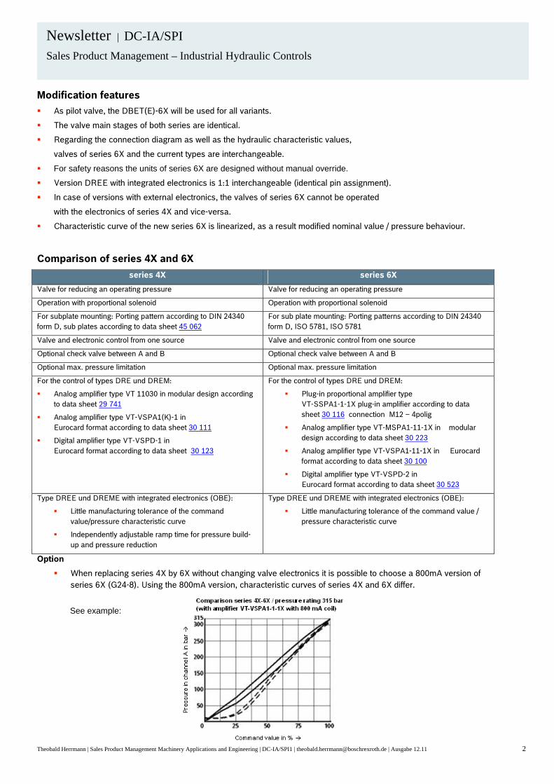
Option
When replacing series 4X by 6X without changing valve electronics it is possible to choose a 800mA version of series 6X (G24-8). Using the 800mA version, characteristic curves of series 4X and 6X differ.
See example:

Contact: Bosch Rexroth Corp. 2315 City Line Road Bethlehem, PA 18017 (610)694-8300
1
Original Valve Data Sheet
Replacement Valve
Data Sheet
Changes Required
FE16C1X/L 29203 FE16C-2X/140L… 29202 Amplifier must change to the VT-VRPA1-50-1X R900952202. The amplifier comes from the factory already setup for the FE16 series 2X valve. The only change required is to install jumper X3 for internal "Enable".
FE16C1X/Q 29203 FE16C-2X/140Q… 29202 Amplifier must change to the VT-VRPA1-50-1X R900952202. The amplifier comes from
the factory already setup for the FE16 series 2X valve. The only change required is to install jumper X3 for internal "Enable".
FE25C1X/L RE29203 FES(E)25CA-
3X/315L RE29209 Amplifier must change to the VT-VRPA1-50-1X R900952202. Jumper for X2, must be
installed across pins 3&4. Jumper X3 must be installed for internal "Enable". The FESE with on board electronics is also an option if environmental conditions
warrant its use.
FE25C1X/Q RE29203 FES(E)25CA-3X/200Q
RE29209 Amplifier must change to the VT-VRPA1-50-1X R900952202. Jumper for X2 must be installed across pins 3&4. Jumper X3 must be installed for internal "Enable".
The FESE with on board electronics is also an option if environmental conditions warrant its use.
FE25C-2X… RE29204 FES(E)25CA-3X… RE29209 Amplifier does not have to change.
The FESE with on board electronics is also an option.

Contact: Bosch Rexroth Corp. 2315 City Line Road Bethlehem, PA 18017 (610)694-8300
2
FE32C-1X/450L RE29204 FES(E)32CA-3X/450L
RE29209 Amplifier must change to the VT-VRPA1-51-1X R900952204. Amplifier is preset from the factory for the FES32. Jumper X3 must be installed for internal "Enable".
The FESE32 with on board electronics is also an option.
FE32C-1X/280Q RE29204 FES(E)32CA-3X/280Q with SO5
RE29209 Amplifier must change to the VT-VRPA1-51-1X R900952204. Amplifier is preset from the factory for the FES32. Jumper X3 must be installed for internal "Enable".
The FESE32 with on board electronics is also an option.
FE40C-1X RE29204 FES(E)40CA-3X RE29209 Amplifier must change to the VT-VRPA1-51-1X R900952204. Jumper for X2 must be installed across pins 3&4. Jumper X3 must be installed for internal :Enable".
The FESE40 with on board electronics is also an option.
FE50C-1X RE29204 FES(E)50CA-3X RE29209 Amplifier must be changed to the VT-VRPA1-52-1X R900952205. Amplifier is preset from the factory for the FES50. Jumper X3 must be installed for internal "Enable".
If the original valve used 7/8 inch UNC bolts then order the FES with SO8 as the replacement.
The FESE50 with on board electronics is also an option.
FE63C-1X RE29204 FES(E)63CA-3X RE29209 Amplifier must change to the VT-VRPA1-52-1X R900952205. Jumper for X2 must be installed across pins 3&4. Jumper X3 must be installed for internal "Enable".
The FESE63 with on board electronics is also an option.
FES(E)-2X RE29208 FES(E)-3X RE29209 Series 3X valves with SO1 will be the replacement for series 2X valves. SO1 is needed if the Z1 port was used on the series 2X valve. The "CC" version is being dropped from the standard product range but it will still be available in the series 3X to use as a replacement for series 2X.
When valves from size 32 to 63 are replaced, their associated amplifier must be replaced also at that time.
For the size 32 the VT5063 is replaced by the VT-VRPA1-51-1X R900952204. The VT-VRPA1-51-1X is preset from the factory for the FES32.
For the size 40, the VT5064 is replaced by the VT-VRPA1-51-1X R900952204. Jumper X2 must be installed across pins 3&4.

Contact: Bosch Rexroth Corp. 2315 City Line Road Bethlehem, PA 18017 (610)694-8300
3
For the size 50, the VT5065 is replaced by the VT-VRPA1-52-1X R900952205. The VT-VRPA1-52-1X is preset from the factory for the FES50.
For the size 63, the VT5066 is replaced by the VT-VRPA1-52-1X R900952205. Jumper X2 must be installed across pins 3&4.

5/14/2010 1
NG10 Servo Valves Differences Between Series 4X and Series 5X
4WS2EM10-4X (RE29586) 4WS2EM10-5X (RE29583)
Feedback Options:
Series 4X o M = Mechanical feedback – standard for valves with separate amplifier o E = Electrical feedback – standard for valves with integrated electronics o B = Barometric feedback – spring centered
Series 5X o M = Mechanical feedback o D = Mechanical & Electrical feedback – only available with integrated electronics
Flow Rate on the 5X series has been increase to 90L/min. Coil Options for valves with non-integrated electronics:
Series 4X o 1 = 5mA / 500 ohms per coil o 2 = 30mA / 40 ohms per coil o 3 = 7.5mA / 200 ohms per coil o 4 = 20mA / 80 ohms per coil o 5 = 50mA / 28 ohms per coil
Series 5X o 11 = 30mA / 85 ohms per coil
Command Options for valves with integrated electronics:
Series 4X o 8 = +/-10mA / 1K ohm o 9 = +/-10V / >50K ohm
Series 5X o 9 = +/-10V o 13 = +/-10mA

Contact: Bosch Rexroth Corp. 5/14/2010 Product Management 2315 City Line Road Bethlehem, PA 18017 (610) 694-8300
2
Input Pressure Range:
Series 4X o Electrical (E) or Barometric (B) versions: 40 / 70 /140 / 210 bar o Mechanical (M) version: 315 bar
Series 5X: o 210 / 315 bar
Mechanical Null:
Series 4X had a mechanical null adjustment which was factory set Series 5X has no mechanical null adjustment
o SO100: 10% offset P>B and A>T o SO102: 10% offset P>A and B>T
Electrical Connections:
Series 4X: o K8 = External Control Electronics o K9 = Integrated Electronics with electrical feedback o K13 = Integrated electronics with Mechanical / Barometric feedback
Series 5X: o K31 = Integrated or non-integrated electronics; K8 avail in some EM models
Spool Overlap: No changes Physical Dimensions: Series 5X is larger than series 4X, consult the appropriate data sheet. Seal Options:
Series 4X was offered in NBR (B) or FKM (V) seals Series 5X is only offered in FKM (V) seals
Port Patterns:
Series 4X with “ET” replaced by series 5X with “ET” o Series 5X requires a minimum mounting surface of 90 X 70mm
Plate R900320784 meets this requirement, bolt length changes by 5mm Plate R978814677 meets the requirement, bolt length changes by 10mm
Series 4X with external “X” port o Use plate R978048324 kit, mounting bolt length changes by 25mm
Mounting Bolts:
Series 4X: M6 X 50mm Series 5X: M6 X 70mm


Contact: Bosch Rexroth Corp. 3/10/2010 2315 City Line Road Rev 1 Bethlehem, PA 18017 (610)694-8300
1
ZDRE(E) 10 Series change from 1X to 2X

Contact: Bosch Rexroth Corp. 3/10/2010 2315 City Line Road Rev 1 Bethlehem, PA 18017 (610)694-8300
2
Copyright © 2022 FDOKUMEN