Parkar - Parker Motion
88
r , ... o .... o o Compumotor Division Parker Hannifin Corporation pIn 88-010841-01 D Parkar
-
Upload
khangminh22 -
Category
Documents
-
view
2 -
download
0
Transcript of Parkar - Parker Motion

r , ... o .... o
o Compumotor Division Parker Hannifin Corporation pIn 88-010841-01 D Parkar

CONTENTS
TABLE OF CONTENTS
TABLE OF CONTENTS ........................................................................ 1 List of Figures ........................................................................................................ .iii List of Tables ......................................................................................................... .iii How To Use This Manual ......................................................................................... v
Assumptions .............................................................................................. v Contents of This Manual.. ............................................................................ v
Application Overview .............................................................................................. vi Developing Your Application ....................................................................... vi Installation Recommendations ..................................................................... vi
Conventions .......................................................................................................... vii Highlighted Text ......................................................................................... v~~ Commands ................................................................................................. Vll
Warnings (Personal Injury) & Cautions (System Damage) ............................... v~~~ 1/0 Levels ................................................................................................... VIII
Related Publications ............................................................................................... viii
Chapter 1. INTRODUCTION ................................................................. 1 Product Description ................................................................................................ 1 Product Features .................................................................................................... 1
Additional Model 72 1/0 Features ................................................................. 2 Theory of Operation ................................................................................................ 2
Chapter 2. GETTING STARTED .. .......................................................... 5 What You Should Have ........................................................................................... 5
Ship Kit Table ............................................................................................. 5 Basic System Configuration ..................................................................................... 5
Verify DIP Switch Settings ........................................................................... 7 Basic System Wiring .................................................................................... 8 Model 72 LEDs ........................................................................................... 8 Verify Proper Operation .............................................................................. 9
Chapter 3. INSTALLATION .................................................................. 11 Environmental Considerations ................................................................................. 11 Electrical System Connections ................................................................................ 11
Wiring Guidelines ........................................................................................ 11 Preparing the Terminal ................................................................................ 1 2 Preparing the AX ........................................................................................ 12 System Configuration ................................................................................. 13 Power ........................................................................................................ 14 Configuring Multiple Units ........................................................................... 15 Assigning Addresses .................................................................................. 16
Testing System Operation ....................................................................................... 16 Model 72/AX Communication ...................................................................... 16
Mounting ............................................................................................................... 18 Inputs & Outputs .................................................................................................... 21
Inputs ........................................................................................................ 21 OPTO-22 Compatible Inputs ....................................................................... 22 PB8 Wiring ................................................................................................. 22 Outputs ..................................................................................................... 23 OPTO-22 Compatible Outputs .................................................................... 24

ii MODEL 72 USER GUIDE
Chapter 4. APPLICATION DESIGN ........................................................ 25 Application Considerations ...................................................................................... 25 Modes of Operation ................................................................................................ 26 Standalone Operation ............................................................................................. 26
Triggers ..................................................................................................... 26 Time Delays ................................................................................................ 27 Loops ........................................................................................................ 27 Programmable Outputs ............................................................................... 2 7 Preset Mode Move Parameters .................................................................... 28 Continuous Mode Move Parameters ............................................................ 28 Daisy Chaining ............................................................................................ 30 Multiple Parameters .................................................................................... 30 Distance Scaling ......................................................................................... 3 0 Selecting Sequences ............................. ~ ................................................... 31
Host Computer Operation ....................................................................................... 31 PLC Operation ....................................................................................................... 32
Move Parameters ........................................................................................ 33 Sequence Run ........................................................................................... 33
Chapter 5. SOFTWARE REFERENCE .................................................... 3 5 Description of Format (Definition of Fields) ................................................................ 35
Execution Time .......................................................................................... 38 Enhanced AX Commands ....................................................................................... 39 Command List ........................................................................................................ 39 Model 72 Commands .............................................................................................. 53
Chapter 6. HARDWARE REFERENCE .................................................... 55 Environmental Specifications ................................................................................. .55 Electrical Specifications ........................................................................................... 55
1/0 Specifications ........................................................................................ 55 Power ........................................................................................................ 55 Terminal Communication ............................................................................. 56 RS-232C Communication ............................................................................ 56 Inputs 1-12 (Model 72-1/0) ...... ..................................................................... 57 OPTO-22 Compatible Inputs 13-20 (Model 72-1/0) ........................................ 57 Outputs 1-4 (Model 72-1/0) .......................................................................... 58 Discrete Outputs 5-12 (Model 72-1/0) ........................................................... 58 Visual Indicators .......................................................................................... 59
Dimensional Drawings ............................................................................................. 59 Chapter 7. TROUBLESHOOTING .......................................................... 61
Spare Parts ............................................................................................................ 61 Troubleshooting ..................................................................................................... 61
Isolating Problems ...................................................................................... 61 Problems & Solutions ................................................................................. 62 RS-232C Communications .......................................................................... 62
Reducing Electrical Noise ........................................................................................ 63 Electrical Noise ........................................................................................... 63 Enclosure Considerations ........................................................................... 64 Sources of Electrical Noise .......................................................................... 64 Externally Conducted Noise ........................................................................ 65 Transmitted Noise ....................................................................................... 65 Ground Loops ............................................................................................ 66 Defeating Noise .......................................................................................... 66 References ................................................................................................ 67
APPENDiCES .................................................................................... 69 Command Listing .................................................................................................... 69 Warranty ................................................................................................................. 70
GLOSSARy ....................................................................................... 73 INDEX .............................................................................................. 77

CONTENTS iii
List of Figures Figure 1-1. Sample Model 72 Configuration ............................................................. 2
Figure 2-1. Location of Model 72 Connections and Thumbwheels ............................ 6 Figure 2-2. Location of Model 72 I/O Connections and Thumbwheels ....................... 6 Figure 2-3. Location of the Model 72's DIP Switches ................................................ 7 Figure 2-4. Basic Model 72 Wiring ........................................................................... S Figure 2-5. Model 72 Response to 112 ...................................................................... 9 Figure 2-6. Model 72 I/O Response to 112 ................................................................. 9
Figure 3-1. RS-232C Connections to AX ................................................................. 14 Figure 3-2. Complete Model 72 Configuration .......................................................... 15 Figure 3-3. Daisy Chain Configuration ...................................................................... 1 5 Figure 3-4. Enclosure Mounting Guidelines ............................................................. 1 9 Figure 3-5. Panel & Door Mounting Guidelines ......................................................... 19 Figure 3-6. Vertical Clearance in Enclosure (Panel Mount) ........................................ 20 Figure 3-7. Door Mount-Front View ....................................................................... 20 Figure 3-S. Model 72 I/O Inputs ............................................................................... 21 Figure 3-9. OPTO-22 Compatible Connector Pinouts ............................................... 22 Figure 3-10. PBS Wiring Diagram ............................................................................. 23 Figure 3-11. Model 72 I/O Outputs .......................................................................... 24 Figure 3-12. OPTO-22 Compatible Output Pinouts .................................................. 24
Figure 4-1. Remove Model 72 Cover ....................................................................... 2 9 Figure 4-2. Location of Jumper JPS on Model 72 ..................................................... 29 Figure 4-3. Model 72 I/O and PLC Operation ............................................................ 32
Figure 6-1. Power Supply ....................................................................................... 55 Figure 6-2. Basic Wiring .......................................................................................... 5 6 Figure 6-3. RS-232C Wiring .................................................................................... 56 Figure 6-4. Inputs 1-12, Input Circuit... ..................................................................... 57 Figure 6-5. Input Pinouts ........................................................................................ 5S Figure 6-6. Outputs 5 - 12, Output Circuit ............................................................... .5 S Figure 6-7. OPTO-22 Pinouts for Outputs 5-12 ........................................................ 59 Figure 6-8. Model 72 Dimensional Drawing .............................................................. 59 Figure 6-9. Model 72 I/O Dimensional Drawing ......................................................... 60
Figure 7-1. Noise Suppression Devices ................................................................... 63
List of Tables Table 2-1. Model 72 Ship Kit List... ........................................................................... 5 Table 2-2. Model 72 I/O Ship Kit List... ...................................................................... 5 Table 2-3. Address Settings ................................................................................... 7
Table 5-1. Thumbwheel Selection Table .................................................................. 36
Table 7-1. Model 72 Problems and Solutions Table .................................................. 62

iv MODEL 72 USER GUIDE
How To Use This Manual
Assumptions
Contents of This Manual
Chapter 1: Introduction
Chapter 2: Getting Started
Chapter 3: Installation
Chapter 4: Application Design
Chapter 5: Software Reference
Chapter 6: Hardware Reference
Chapter 7: Troubleshooting
This user gUide will help you install. develop. and maintain your system. Each chapter beginS with a list of objectives that should be met after you have read the chapter. This section will help you fmd and use the information in this user gUide.
This user guide assumes that you have the skills or understand the information listed below:
• Basic dumb computer terminal experience
• Digital electronics concepts (voltage. switches. current. transistors. etc.)
• Basic motion control concepts (torque. velocity. distance. force. etc.)
• Basic serial communication concepts (specifically RS-232C)
• Basic configuration and operation of the AX Drive
With this basic level of understanding. you will be able to effectively use this manual.
This user gUide contains the following information.
This chapter provides a description of the product and a brief account of its specific features.
This chapter contains a detailed list of items you should have received with your Model 72 shipment. It will help you to become familiar with the system and ensure that the Model 72 functions properly.
This chapter provides instructions for you to properly make all electrical connections and mount the Model 72. Upon completion of this chapter. your unit should be completely
. installed and ready to perform basic operations.
This chapter will help you use the Model 72 to meet your application's needs. Important application considerations are discussed. Sample applications are provided.
This chapter explains the Model 72's programming language in detail. It describes command syntax: and system parameters that affect command usage. An alphabetical listing of all commands. with a syntax and command description for each command. is included.
This chapter contains information on the Model 72's specifications (dimensions and performance). This chapter may be used as a qUick-reference tool for proper switch settings and I/O connections.
This chapter describes Compumotor's recommended system maintenance procedures. It also provides methods for isolating and resolving hardware and software problems.

Application Overview
Developing Your Application
Installation Recommendations
CONTENTS v
To ensure trouble-free operation, you should pay special attention to the environment in which the Model 72 will operate, the layout and mounting, and the wiring and grounding practices used. These recommendations are intended to help you easily and safely integrate the Model 72 into your manufacturing facility. Industrial environments often contain conditions that may adversely affect solid-state equipment. Electrical noise or atmospheric contamination may also affect the unit.
Before you attempt to develop and implement your application, there are several issues that you should consider and address.
1. Clarify the requirements of your application. Clearly define what you expect the system to do.
2. Assess your resources and limitations. This will help you find the most efficient and effective means of developing and implementing your application.
3. Follow the gUidelines and instructions outlined in this user gUide. Do not skip any steps or procedures. Proper installation and implementation can only be ensured if all procedures are completed in the proper sequence.
Before you attempt to install this product, you should complete the following steps:
1. Review this entire user gUide. Become familiar with the user guide's contents so that you can quickly find the information you need.
2. Develop a basic understanding of all system components, their functions, and interrelationships.
3. Complete the basiC system configuration and wiring instructions (in a Simulated environment, not a permanent installation) provided in Chapter 2, Getting Started.
4. Perform as many basic moves and functions as you can with the preliminary configuration. You can only perform this task if you have reviewed the entire manual. You should try to Simulate the task(s) that you expect to perform when you permanently install your application (however, do not attach a load at this time). This will give you a realistic preview of what to expect from the complete configuration.
5. After you have tested all of the system's functions and used or become familiar with all of the system's features. carefully read Chapter 3. Installation.
6. After you have read Chapter 3 and clearly understand what must be done to properly install the system. you should begin the installation process. Do not deviate from the sequence or installation methods provided.

vi MODEL 72 USER GUIDE
Conventions
Highlighted Text
Commands
Thumbwheel Values
7. Before you begin to customize your system. check all of the system functions and features to ensure that you have completed the installation process correctly.
The successful completion of these steps will prevent subsequent performance problems and allow you to isolate and resolve any potential system difficulties before they affect your system's operation.
The conventions used throughout this user guide are explained in this section.
It is important to note that Model 72's features and operations are a subset of the Model 72 I/O's features and operations. The two products are discussed in parallel in this manual. Therefore. whenever the Model 72 is discussed. the information typically applies to the Model 72 I/O as well.
Several methods are used to highlight text. Explanations of special text and the way it is highlighted is presented below.
All commands that you are instructed to enter are displayed (and must be entered) in all capital letters. A one-line explanation of the command is provided next to each example. The command is displayed in boldface. Be sure to add a delimiter (space or carriage return) after each command in a sequence. Refer to the example below.
Command AS VS
01 """ G
Description Sets acceleration to 5 rps2 Sets velocity to 5 rps Sets distance to 1,000 steps Executes the move (Go)
Bold face. quotation marks. or other forms of highlighting are not used for status command responses. Responses are set in all capital letters. as they are on the terminal. An example is provided below.
Command "2
Response *-9999999
(The" is not a control-cTRLcharacter. It is generated by pressing SHIFT-6 on most keyboards. In ASCll, " is 94 decimal). The AX generally ignores command syntax that is not within the valid range for a specific command (valid ranges are prOvided in Chapter 5, Software Reference). The Model 72 may send values to the AX that are not within its range. Compumotor does not guarantee system performance when the system executes commands that contain invalid syntax (outside valid range).
The Model 72 has eight thumbwheels. The first thumbwheel is a + or - character. The next seven thumbwheels are digits o - 9. Refer to the example below.
#1 #2 #3 #4 #5 #6 #7 #8 D[I][I][I][I][I]IT][}J
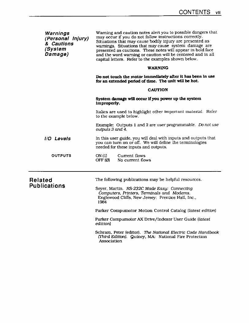
Warnings (Personal Injury) & Cautions (System Damage)
liD Levels
OUTPUTS
Related Publications
CONTENTS vII
Wanting and caution notes alert you to possible dangers that may occur if you do not follow instructions correctly. Situations that may cause bodily injUIy are presented as warnings. Situations that may cause system damage are presented as cautions. These notes will appear in bold face and the word warning or caution will be centered and in all capital letters. Refer to the examples shown below.
WARNING
Do not touch the motor immediately after it has been In use for an extended period of time. The unit will be hot.
CAUTION
System damage will occur if you power up the system improperly.
Italics are used to highlight other important material. Refer to the example below.
Example: Outputs 1 and 2 are user programmable. Do not use outputs 3 and 4.
In this user gUide. you will deal with inputs and outputs that you can turn on or off. We will define the terminologies needed for these inputs and outputs.
ON (1) OFF (0)
Current flows No current flows
The following publications may be helpful resources.
Seyer. Martin. RS-232C Made Easy: Connecting Computers. Printers. Terminals and Modems. Englewood Cliffs. New Jersey: Prentice Hall. Inc., 1984
Parker Compumotor Motion Control Catalog (latest edition)
Parker Compumotor AX.. Drive/Indexer User Guide (latest edition)
Schram. Peter (editor). The National Electric Code Handbook (Third Edition). Quincy. MA: National Fire Protection AsSOCiation
vIII MODEL 72 USER GUIDE
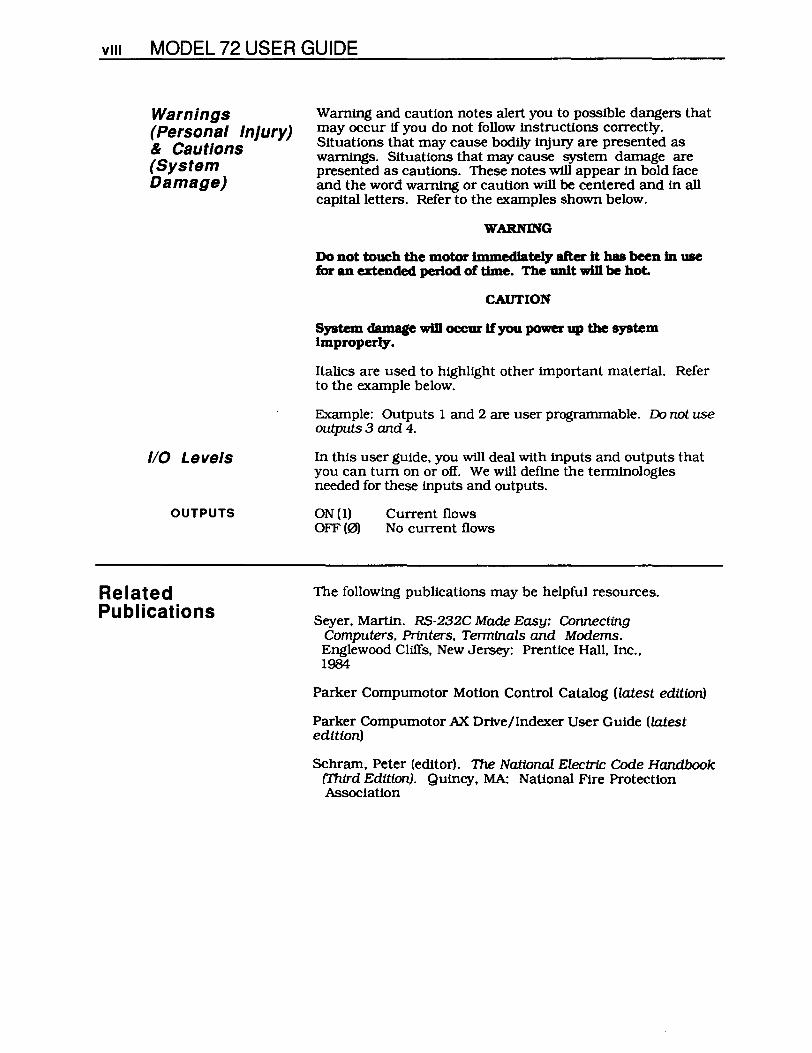
Warnings (Personal Injury) & Cautions (System Damage)
liD Levels
OUTPUTS
Related Publications
Warning and caution notes alert you to possible dangers that may occur if you do not follow instructions correctly. Situations that may cause bodily injury are presented as warnings. Situations that may cause system damage are presented as cautions. These notes will appear in bold face and the word warning or caution will be centered and in all capital letters. Refer to the examples shown below.
WARNING
Do not touch the motor lmmedlately after it has been In use for an extended period of time. The unit win be hot.
CAUTION
Italics are used to highlight other important material. Refer to the example below.
Example: Outputs 1 and 2 are user programmable. Do not use outputs 3 and 4.
In this user gUide. you will deal with inputs and outputs that you can tum on or off. We will define the terminologies needed for these inputs and outputs.
ON(l) OFF (0)
Current flows No current flows
The following publications may be helpful resources.
Seyer. Martin. RS-232C Made Easy: Connecting Computers. Printers. Terminals and Modems. Englewood Cliffs. New Jersey: Prentice Hall. Inc .. 1984
Parker Compumotor Motion Control Catalog (latest edition)
Parker Compumotor AX Drive/Indexer User Guide (latest edition)
Schram. Peter (editor). 111e National Electrtc Code Handbook (Third Edition). Quincy. MA: National Fire Protection AsSOCiation

CHAPTER 1. INTRODUCTION 1
Chapter 1. INTRODUCTION
Chapter Objectives
Product Description
Product Features
The information in this chapter will enable you to:
• Understand the product's basic functions and features
The Model 72 and Model 72-1/0 interface with Compumotor's AX Series Indexer /Drtve via an RS-232C interface. The Model 72 provides adjustable thumbwheel switches to enter and change AX motion program parameters. These switches allow you to set and modify velocity. acceleration. distance. direction. dwell time. loop count. and other parameters.
The Model 72-1/0 differs from the Model 72 in that it provides 20 inputs and 12 outputs for additional control of various machine functions. Eight inputs and eight outputs have flatcable connectors that are compatible with OPTO-22 signal conditioning eqUipment. The remaining 12 inputs and 4 outputs are 5 - 24VDC rated screw tenninal connections.
You can install the Model 72 in a panel-mount or door-mount fashion. You may configure as many as 16 units (daisy chained) to a Single indexer/drive. The Model 72 has two RS-232C ports-one for X-verSion communication (to AX) and one for programming and diagnostics (to terminal).
The Model 72 is only compatible with AX's (and AX-A's) that have a software revision of E or later (F. G. etc.). To use the Model 72, you must have an AX or AX-A of the following revision level or greater:
Product Revision Level AX High-Power 2V AX low-Power 25
AX-A Hioh-Power 1K AX-A low-Power 1K
Contact your local Compumotor Field Application Engineer or Automation Technology Center (ATC) if your unit has an earlier reviSion level.
• Offers a + or - character and 7 digits of thumbwheel data
• Can be panel-mounted or door-mounted
• Allows you to set and modify AX. motion parameters (velOCity. acceleration. distance. direction. etc.)
• Allows you to daisy chain 16 units to one AX or AX-A
• Two RS-232C ports-one for communication to an AX and one for diagnostics and programming

2 MODEL 72 USER GUIDE
Additional Model 72 liD Features
Theory of Operation
AX Indexer/Drive
Ax
Model 72 #1
• Allows you to scale distance in the units used by the application (steps. inches. etc.). This is only valid with Distance (D) commands.
• Equipped with 20 inputs and 12 outputs
• Offers 8 OPTO-22 compatible inputs and 8 OPTO-22 compatible outputs
• 12 inputs and 4 outputs that are 5 - 24VDC compatible (screw terminal connections)
Any command that references the Model 72-I/as outputs or inputs will be ignored by a Model 72.
The Model 72 (or a series of Model 72s) is connected to an AX Indexer /Drive. The AX. while executing a programmed sequence of commands. requests data from the Model 72(s) via its RS-232C port. The Model 72 responds with its current thumbwheel settings or the status of its inputs and outputs. The AX's command language has been modified (Revision E) to allow the indexer/drive to read a variety of motion and control parameters from the Model 72.
Flexible AX programming allows you to select which of the Model 72's thumbwheel digits are used for each parameter. The AX may also use the Model 72-I/O's 20 inputs.
You may daisy chain as many as 16 Model 72 units from a single AX's RS-232C port. You will use modified X Series commands to uniquely address each Model 72 in your system and to request data from each unit.
The Model 72's terminal RS-232C port allows you to connect a terminal to mOnitor and debug the system. This terminal allows you to communicate with the indexer/drive for programming and control tasks. Communication via the terminal port has priority over signals sent from the Model 72's indexer/drive RS-232C port (communication from the first port may be interrupted). Figure 1-1 is a sample Model 72 configuration.
Model 72 (Last in Daisy Chain) Terminal Tx Ax
Tx I ±9999999 I Tx 1±99999991 GND
COM - Ax -Ax LA I Tx -GNO GNO
(25-pin 0 Connector)
L (4-pin 0 Connector)
Figure 1-1. Sample Model 72 Configuration

CHAPTER 1. INTRODUCTION 3
You must connect the last Model 72 in the daisy chain to the tenninal to allow for the tenninal to continue to access and program the.AX. In other words, you do not have to re-connect the terminal to the AX to program it.
/

CHAPTER 2. GETTING STARTED 5
Chapter 2. GETTING STARTED
Chapter Objectives
What You Should Have
Ship Kit Table
Basic System Configuration
The infonnation in this chapter will enable you to:
• Verify that your system has been delivered safely • Ensure that each component functions properly
Inspect your Model 72 or Model 72-1/0 shipment upon receipt for obvious damage to its shipping container. Report any damage to the shipping company immediately. Compumotor cannot be held responsible for damage incurred in shipment. Report any damage to the carrier. The items listed in Table 2-1 and 2-2 should be present and in good condition.
Part Description Part Number Model 72 MODEL 72 Model 72 User Guide 88-010841-01 A 4-Pin Phoenix Plug 43-005560-01 Power Cable w/5-pin phoenix pluQ 71-010511-01
Table 2-1. Model 72 Ship Kit List
Part Description Part Number Model 72 I/O MODEL 72-1/0 Model 72 User Guide 88-010841-01 A 10-Pin Phoenix PluQ (2) 43-005987-01 4-Pin Phoenix PluQ 43-005560-01 Power Cable wl5-pin phoenix 0100 71-010511-01
Table 2-2. Model 72 I/O Ship Kit List
Follow the procedures and instructions in this section to complete the basic system configuration and system test. If you have more than one unit, complete this test for each unit indMdually. Figure 2-1 and 2-2 show the location of the connections and thumbwheels on the Model 72 and the Model 721/0.
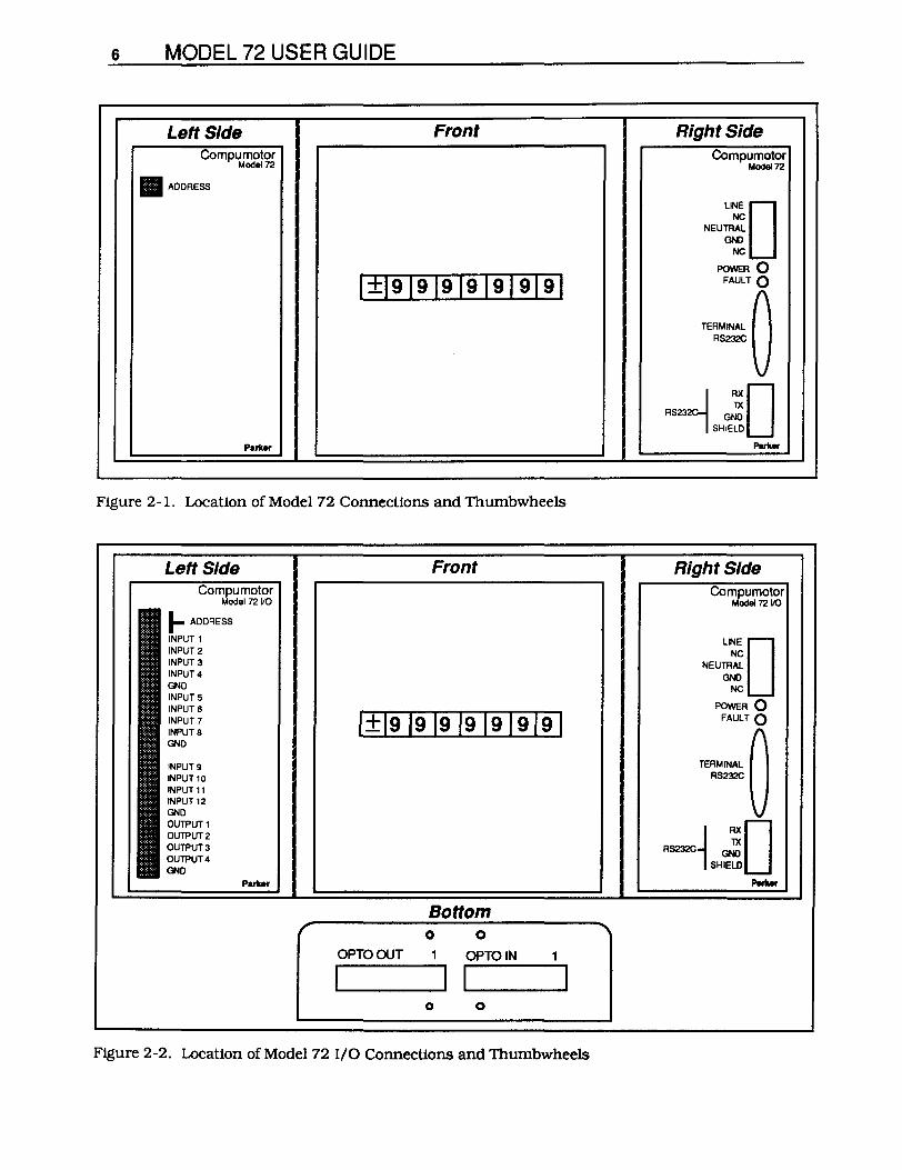
6 MODEL 72 USER GUIDE
Left Side Front Compumotor
1.4008172
• ADDRESS
1+191919191919191
Puk ..
Figure 2-1. Location of Model 72 Connections and Thumbwheels
Left Side Compumotor
1.4009172 VO
I- ADDRESS
INPUT 1 INPUT 2 INPUT 3 INPUT 4 GND INPUT 5 INPUTS INPUT 7 INPUT 8 GND
INPUT 9 INPUT 10 INPUT 11 INPUT 12 GND OUTPUT 1 OUTPUT 2 OUTPUT 3 OUTPUT 4 GND
Front
Bottom 0 0
OPTOOUT OPTOIN
I I 0 0
Figure 2-2. Location of Model 72 I/O Connections and Thumbwheels
Right Side Compumotor
Model 72
'"'0 NEU;
POWER 0 FAULT 0
~"."~ ~ RS232C
"4 G~D SHIELD
PuUr
Right Side Compumotor
Model 72 va
LINED NEU;
POWER 0 FAULT 0
TERMINAL (\
"'=u 1 RXD TX
RS232C GND
SHIELD
PMr.er

Verify DIP Switch Settings
CHAPTER 2. GETIING STARTED 7
Table 2-3 contains the DIP switch settings that you can use to assign unique device addresses to up to 16 Model 72s (when daisy chained to a single AX Indexer jDrive). The DIP Switches are located on the left sIde of the unit (see Figure 2-3).
ADDRESS SW1 SW2 SW3 SW4 ·1 OFF OFF OFF OFF 2 ON OFF OFF OFF 3 OFF ON OFF OFF 4 ON ON OFF OFF 5 OFF OFF ON OFF 6 ON OFF ON OFF 7 OFF ON ON OFF 8 ON ON ON OFF 9 OFF OFF OFF ON
10 ON OFF OFF ON 11 OFF ON OFF ON 12 ON ON OFF ON 13 OFF OFF ON ON 14 ON OFF ON ON 15 OFF ON ON ON 16 ON ON ON ON
"'Default Address Sett/ria
Table 2-3. Address Settings
DIP Switch Location
_ = Switch
P ......
Figure 2-3. Location ofthe Model 72's DIP Switches
For these tests, use the jactory-dejault DIP switch setting jor your unit(s). Thejactory dejault address setting is 1. Rejer to Table 2-2 to set your unit (s). Set each unit to 1. Chapter 3, Installation provides procedures jor setting unique addresses jor applications that use more than one Model 72.

8 MODEL 72 USER GUIDE
Basic System Wiring
STEP 1
STEP 2
Follow the steps below and refer to Figure 2-4 to properly connect the Model 72 and your terminal.
Use a 25-pin 0 connector (cable not provided in the ship kit) to connect the Model 72 to a terminal. You may also connect the Model 72 to a computer's RS-232C port ffyou run a terminal emulation program (converts a computer to a terminal). Refer to Figure 2-4. Your terminal or computer's parameters should be set as follows:
• 9.600 baud rate • 8 data bits • No parity • 1 stop bit
Connect the 5-pin 0 power connector (cable provided in ship kit) to the Model 72. Plug the other end on the cable into a 115VAC power supply. Refer to Figure 2-4. The POWER LED should be green and the FAULT LED should be off.
Right Side of Model 72
Compumotor Model 72
5-Pin D Connector (Cable Provided)
LINE NC
NEUTRAL GND
NC
POWER 0 FAULT 0
TERMINAL RS232C
4 AXO 1)( RS2 GND
SHIELD
Black
White
1 Shield. 25-Pln D Connector (Cable Not Provided)
115V AC Power
2 AX --t-t---- 2TX 3TX 3RX 7GND 7GND
P ...... ---------------.-
~-----------------------------~
Figure 2-4. Basic Model 72 Wiring
Model 72 LEDs The Model 72's green POWER LED should always be on (when power is applied to the system). If it is off. it indicates that there is no internal power. This may be caused by an incorrect power hookup or a blown internal fuse.
If the Model 72 is operating correctly. the unit's red FAULT LED should be off. If the internal microprocessor is faulting or resetting on power up. the light will be on. If the FAULT light stays on. refer to Chapter 7. Troubleshooting for assistance. If the problem persists. call Compumotor's Application Engineering Department (1-800-358-9070).

Verify Proper Operation
STEP 1
STEP 2
9 9 9 9 9 9
t 1W8
CHAPTER 2. GETIING STARTED 9
After you have completed the basic wiring procedure. complete the following steps to ensure the the Model 72 is operating properly. These steps do not test CUIIJ other portion of your system. If you intend to use more than one Model 72 in your application. wire and test each unit individually. Configuring and testing multiple units (daisy chaining) is discussed in Chapter 3, Installation.
You must set the terminal to fu,U-duplex mode to perfoI nt this test. Press any key on the keyboard. The character that you pressed should appear on your mOnitor (this is an echo from the Model 72). If the character appears, RS-232C communication has been established between the Model 72 and your computer or terminal.
If you do not receive an echo from your keyboard, check your wiring and attempt the test again. If the problem persists, refer to Chapter 7. Troubleshooting. After successfully completing step I, try step 2.
Set all seven thumb wheel digits to 9. Set the first thwnbwheel to-.
Type the command 1\2 (This is obtained by pressing SHIFT-6 and 2 on most keyboards. The 1\ is not a control-C1RLcharacter). This command activates a test mode that repetitively displays the state of thumbwheel inputs 1-8. If you are testing the Model 72. the characters you will see on your terminal are shown in Figure 2-5. If you are testing the Model 721/0. you will see the state of inputs 1-12 and OPTO inputs 13-20 on your terminal or computer. Refer to Figure 2-6. To exit this mode, press any key.
J Figure 2-5. Model 72 Response to 1\2
- 9 9 9 9 999 0 0 0 0 0 0 0 0 0 0 0 0 0 0 0 0 000 0
t t t t t t " 1W1 1W8 11 112 113 120
Figure 2-6. Model 72 I/O Response to 1\2
You can change the thumbwheels (after activating the test) and see the value change immediately on the screen. The response to this command is immediately updated.
If you are testing a Model 72 I/O, the values for 113 - 120 may change on the screen (0 or 1). These inputs are floating.
If the Model 72 passes this test. it is performing properly. DIsconnect the RS-232C cable and power down the system. You are now ready to install your system. Turn to Chapter 3. Installation.


CHAPTER 3. INSTALLATION 11
Chapter 3. INSTALLATION
Chapter Objectives
Envi ronmental Considerations
Electrical System Connections
Wiring Guidelines
The information in this chapter will enable you to:
• Ensure that the complete system is installed properly • Mount the unit properly • Perform basic system operations
You must suocesVu11lI complete the steps and prooeduTes described in Chapter 2. Getting Started. bfifore you begin this chapter. Power should rwt be applied to the Model 72.
Parker Compumotor recommends that you operate and store your Model 72 under the following conditions.
• Operating Temperature: 32°F to 122°F (O°C to SOOC) • Storage Temperature: -22°F to 185°F (-30°C to 85°C) • Humidity: OOk to 95% non-condenSing
Do not install the Model 72 in an area that will subject the unit to atmospheric contamination and excess heat.
This section describes the procedures that you must complete to properly wire your system. The following connections will be addressed
• RS-232C To Terminal To AX Indexer/Drive
• Power • Inputs & Outputs
Proper grounding of electrical eqUipment is essential to ensure safety. You can reduce electrical noise caused by electromagnetic interference (EMI) by grounding. All Compumotor eqUipment should be properly grounded. A good source of information on grounding requirements is the National Electrical Code published by the National Fire Protection Association of Boston. MA.
All components and enclosures must be connected to earth ground through a grounding electrode conductor to provide a low-impedance path for ground fault or noise-induced currents. All earth ground connections must be continuous and permanent. Compumotor recommends a single-point grounding setup. You must connect the terminal growuJ on the AC power COJUU!Ctor to the earth growv1

1 2 MODEL 72 USER GUIDE
Preparing the Terminal
Preparing the AX
The parameters for the Model 72's two RS-232C communications ports are fixed at the following settings:
• 9,600 baud rate • 8 data bits • No parity • 1 stop bit
Your terminal or PC must be set to operate at these parameters to communicate with the Model 72. If it is not set to these parameters, refer to your terminal or computer manual to change the communications parameters to comply with the Model 72's settings.
The Model 72 sends thumbwheel and I/O data to the AX Indexer/Drive. The AX uses this data to control motor motion and other external parameters. To operate properly, communication must be established between the AX and the Model 72. Several steps must be taken to ensure proper communication. The follOWing steps must be completed before you connect the Model 72 and AX. Power should not be applied to the AX at this time.
1. Set the Ars address setting to 1. For ease of use, and the purposes of the procedures and tests in this user guide, the AXs address must be set to 1. The AX address is set via DIP switches 6. 7, and 8. Follow the steps below:
A. Remove the cover that shields the AX's DIP switches. If you are faCing the unit. the DIP switches are on the left side of the unit. Refer to the AX User Guide for more information on DIP switch location.
B. Tum switches 6, 7, and 8 on. Refer to the example (the DIP switches are shown upside down because that is the way you will see them if the unit is sitting upright).
~ ~ ~ ~ ~ ~ ~ ~t 8L 9 S v € G ~Q
• - Switch
DIP SwItches 1 - 5 are motor dependent. 1he settings shown here are simply for ezamp1e purpoees. Do not cbange these DIP switches unJesa you have checked the AX User Guide or the product's installation labeL

System Configuration
Connecting the Model 72 to the Terminal
Connecting the Model 72 to the AX
CHAPTER 3. INSTALLATION 1 3
2. WIre the motor, RS-232C terminal. and power to the AX . Refer to the AX User Guide for specific wiring instructions. At this point. only the AX is connECted to the terminaL The Model 72 should not be connected to the terminal yet.
3. Apply power to the AX (turn the unit on). The address is now set to l.
4. Be sure that the AX Is operatlDg with the proper softwaIe version. You must be using software version E or greater (Le., F or G). You can check the software version by Issuing the RV command to the AX:
A. Type lRV.
B. Check the response shown on your terminal. The final character of the response is important. It must be E or greater. A sample response is provided below. Please note the highlighted character.
*92-7212-01E
If you do not have an acceptable version of the software. call Compumotor or your local Automation Technology Center (ATC) for information on software upgrades.
5. Tum the AX's RS-232C echo function off. The AXs echo function must be off for proper communication with the Model 72. Issue the SSAl command to the AX to turn the echo function off. It will be automatically saved in nonvolatile memory. When the echo function is off. the characters you enter you will not be displayed.
The AX accepts only capUalletters. If the echo function is off. you the lR command to get a response. The SSAIIJ command will turn the AX's echo function on.
Use a 25-pin D connector to connect the Model 72 to the RS-232C port on your terminal or computer. You did this before in Chapter 2. Getting Started. You must make this connection again now. If you need help, Refer to Figure 2-4.
Tum the AX s RS-232C eclw junction off prior to connecting the Model 72 to the AX. Use the Model 72's indexer I drive RS-232C port to connect the unit to the AX Indexer IDrtve. Wire the Model 72 to the AX as shown in Figure 3-1.
Complete aU other AX connectJoDS before moviDg 011 to the nmstep.

14 MODEL 72 USER GUIDE
RS-232C
AX Rx----t-~l--___,
Tx ----+-1-+--+-1 COM ---+-+-11--1
INDEXER
ENCODER
n FAN
U POWER
_72
LINE 0 NEUTR~
GND NC
I'()VERO FUT 0
Figure 3-1. RS-232C Connections to AX.
Power Apply 115VAC power to the Model 72. You did this before in Chapter 2. Getting Started. You must make this connection again now. If you need help. Refer to Figure 2-4. Use the power cable (with a 5-pin phoenix connector) to connect the unit to the power source. Follow the instructions provided in Chapter 2 and refer to Figure 2-4 to make this connection properly. The mu:lmum recommended AC Power Cord length Is 25'.
The completion of this step represents the end of the system wiring procedures. The complete system configuration is shown in Figure 3-2. Compare your wiring to the connections shown in Figure 3-2.

AX
Rx ------~~~~ Tx -------+-+-f---+__. COM ---I-II-+-....
INDEXER
D.moo
ENCODER
O FAN
POWER
CHAPTER 3. INSTALLATION 15
115VAC Power
mllllllllllllllll!ll!ll
/I~ ~~"
Figure 3-2. Complete Model 72 Configuration
Configuring Multiple Units
AX Indexer/Drive Model 72 #1
Ax
Tx 1±99999991 Tx
COM Ax GND
You can link as many as 16 Model 72's from a single AX RS-232C port. This configuration is called daisy chaining. Before you attempt to configure a daisy chaJn, you must complete the steps dlscussed In Preparing the AX (earlier In this chapter). After you have completed these steps, configure your system as shown in Figure 3-3. You cannot daisy chain AX Indexer/Drives when you use the Model 72.
Model 72 (Last in Daisy Chain) Terminal Tx Ax
1±99999991 GOO
~ Ax I--
1 Tx I-GND L (25':0 Connoc1or)
L (4-pin 0 Connector)
Figure 3-3. Daisy Chain Configuration
1 6 MODEL 72 USER GUIDE
Assigning Addresses
Testing System Operation
Model 721AX Communication
Note that the terminal must be wired to the last Model 72 in the daisy chain. The last Model 72 in the daisy chain must have its IX connection (from indexer/drive RS-232C port) wired to the Ars RX connection. Thls configuration requirement allows the terminal or PC to read responses from each Model 72 in the daisy chain.
Each Model 72 unit In the daisy chain must have a unique device address. You must assign unique addresses to each Model 72 using the DIP switches. The Model 72 only recognizes changes to its DIP Switches upon power up.
RJifer to Figure 2-3for DIP switch lDcatfon and Table 2-3for address settings.
Use the following procedure to adjust Model 72's DIP switches.
1. Remove AC power from the Model 72.
2. Select DIP switch settings (1 - 16. refer to Table 2-3). Use a narrow instrument (I.e .. a thin. flat screw driver) to adjust the DIP switches.
3. Apply power to the unit. The new address is set.
The Model 72 system must pass the following tests to ensure successful system operation. Before you proceed with the final tests. all of the procedures In this chapter and In Chapter 2. Getting Started. must have been successfully completed. Check the items listed below.
o The AX's echo function must be off (Refer to Preparing the AX earlier In this chapter).
o The AX must be operating with the proper version of software-version E or greater (Refer to Preparing the AX earlier in this chapter).
o If you are using daisy chain configuration. each Model 72 must have a unique device address (Refer to Assigning Addresses earlier In this chapter).
o The terminal's communication parameters must be properly set (Refer to Preparing the Terminal earlier In this chapter).
When you are sure that each of the conditions is met. power up the system and proceed with the following tests.
Test 1
Test 2
CHAPTER 3. INSTALLATION 1 7
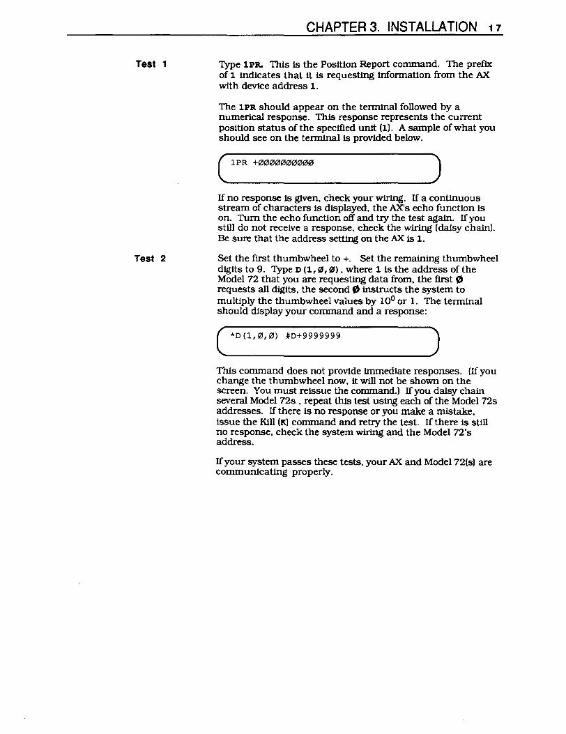
Type 1PR. This is the Position Report command. The prefix of 1 indicates that it is requesting information from the AX with device address 1.
The 1PR should appear on the temtlnal followed by a numerical response. This response represents the current position status of the specified unit (1). A sample of what you should see on the temtlnal is provided below.
C 1PR + ••••• """". )
------If no response is given. check your wiring. If a continuous stream of characters is displayed. the AXs echo function is on. Tum the echo function off and try the test again. If you still do not receive a response. check the wiring (daisy chain). Be sure that the address setting on the.AX is 1.
Set the first thumbwheel to +. Set the remaining thumbwheel digits to 9. Type D (1,","). where 1 is the address of the Model 72 that you are requesting data from. the first" requests all digits. the second 0 instructs the system to multiply the thumbwheel values by 100 or 1. The terminal should display your command and a response:
C *D (1,.,.) iD+ggggggg )
-----This command does not prOvide immediate responses. (If you change the thumbwheel now. it will not be shown on the screen. You must reissue the command.) If you daisy chain several Model 72s . repeat this test using each of the Model 72s addresses. If there is no response or you make a mistake. issue the Kill (It) command and retry the test. If there is still no response. check the system wiring and the Model 72's address.
If your system passes these tests. your.AX and Model 72(s) are communicating properly.

1 8 MODEL 72 USER GUIDE
Mounting Proper mounting and panel layout are essential for troublefree Model 72 operation.
If you mount the Model 72 in an enclosure. observe the following gUidelines:
l. The vertical clearance between the Model 72 and other equipment. or the top or bottom of the enclosure. should be no less than 6 inches (Refer to Figure 3-6).
2. Do not mount large. heat-producing eqUipment directly beneath the Model 72.
3. The maximum allowable ambient temperature directly below the Model 72 is SO'C. Fan cooling may be necessary if adequate air flow is not provided.
You can mount the Model 72 to a panel or to the rear side of a door with access to the thumbwheels through a rectangular hole.
To mount the Model 72 on the rear panel of an enclosure. drill four holes for the mounting tabs as shown in Figure 3-4. To mount the unit to the rear of a panel, drill four holes for the mounting tabs and mount the unit as shown in Figure 3-5 (Panel Mount).
To mount the Model 72 on the inside of a cabinet and have the thumbwheels accessible from the outside. cut a rectangular hole (to expose the thumbwheels) in the door as shown in Figures 3-5 and 3-7 and drill four holes for the mounting tabs. The 72's mounting tabs must be move to the front hole locations for door mounting. For either mounting option. use four #10 screws to secure the unit.
For door mounts. you may want to put a piece of plastic over the hole in the door to protect the thumb wheels from contaminants. This preventive maintenance measure can help to ensure long life and reliable operation for your Model 72.

CHAPTER 3. INSTALLATION. 19
7.00
2.88
o 0
rl
a m
'"
Figure 3-4. Enclosure Mounting Guidelines
a <Xl
.;
Slots for #10 mounting screws
1. Panel Mount 2. Door Mount
Outside of Cabinet Inside of Cabinet
.l. Door ...L
Compumotor Front Compumotor
Model 72
~ Model 72
D D Thumbwheels
~ 0 0 0 =;"1 0
[ ~ ~ ! D
Thumbwheels
D Parker Parker
Mounting ~ rIllE Mounting Tabs I Tabs
Figure 3-5. Panel & Door Mounting Guidelines
..,. e-
e-

20 MODEL 72 USER GUIDE
6"
Inside of Cabinet
Figure 3-6. Vertical Clearance in Enclosure (Panel Mount)
Front of Cabinet
The Model 72 is mounted inside of a cabinet. A hole has been cut in the cabinet door to expose only the thumbwheels. You will have to move the mounting brackets to the front hole positions to perform this mounting.
In the lower part of the figure, please note A, which represents a grounding braid that you should connect between the door and the inner cabinet. Rust from the hinges may cause your system to lose ground or develop ground loops. The grounding braid will prevent this.
Cabinet Door Inside ofcablnet The door is open, the back of the Model 72 is showing.
Figure 3-7. Door Mount-Front View

Inputs & Outputs
Inputs
CHAPTER 3. INSTALLATION 21
ThJs section Is only appUcable for the Model 72 1/0. The following Model 72 I/O inputs and outputs will be discussed:
• Inputs • OPTO-22 compatible inputs • Outputs • OPTO-22 compatible outputs
The Model 72 I/O's inputs 1-12 are internally pulled up. They employ TIL 0 - O.7VDC voltage low and 5-24VDC voltage high. Since Invertecllogtc Is used, you must bring the Input low (by tyiDg it to ground) to represent a logic 1. BrlDgt.ng the Input high represents a logic 0. Use solid-state (optically isolated) relays. This will prevent electrical noise from impairing the perfonnance of your application. Refer to Figure 3-8.
When you enter BCD data, inputs I, 5, and 9 are the most significant bits (MSB) and inputs 4,8, and 12 are the least Significant bits (LSB).
Compumotor Model 72-110
rAddresa
INPUT1} INPUT 2 INPUT 3 INPUT 4 GND
Left Side
Input Specifications o to O.7WDCVoltage Low
:~~~;} INPUT 7 ---+~.
5 to 24VDC Voltage High Current in@ 5V: can sink1~ Current in @ 24V: can sink800~ INPUT 8
GND
INPUT9~ INPUT 10 INPUT 11 INPUT 1 GND OUTPUT 1 OUTPUT2 OUTPUll OUTPUT 4 GND
Parker
Input Circuit +5V
22K
51K Input 0------4_-""""".,---,
'-----'
Figure 3-8. Model 721/0 Inputs
22 MODEL 72 USER GUIDE
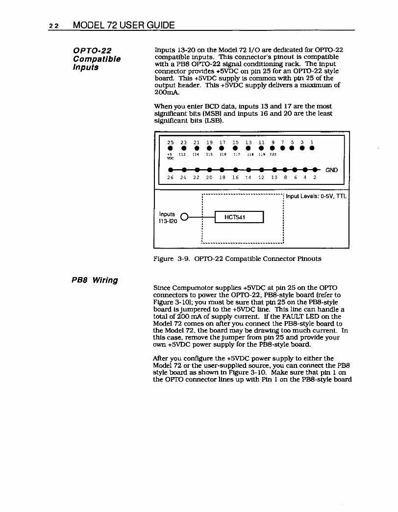
OPTO-22 Compatible Inputs
PB8 Wiring
Inputs 13-20 on the Model 721/0 are dedicated for OPTO-22 compatible inputs. This connector's pinout is compatible with a PB8 OPTO-22 signal conditioning rack. The input connector provides +5VDC on pin 25 for an OPTO-22 style board. This +5VDC supply is common with pin 25 of the output header. This +5VDC supply delivers a maximum of 2oornA.
When you enter BCD data, inputs 13 and 17 are the most significant bits (MSB) and inputs 16 and 20 are the least significant bits (LSB).
25 23 • • +5 IlJ VDC
• • 26 24
Inputs 0 113-120
21 • Il4
• 22
19 17 15 • • • Il5 Il6 Il7
• • • 20 18 16
13 11 9 7 5 3 1
• • • •• • • Il8 Il9 120
• • • • • • • 14 12 10 8 6 4 2
Figure 3-9. OPTO-22 Compatible Connector Pinouts
GND
Since Compumotor supplies +5VDC at pin 25 on the OPTO connectors to power the OPTO-22, PBS-style board (refer to Figure 3-10); you must be sure that pin 25 on the PBS-style board Is jumpered to the +5VDC line. This line can handle a total of 200 rnA of supply current. If the FAULT LED on the Model 72 comes on after you connect the PB8-style board to the Model 72. the board may be drawing too much current. In this case. remove the jumper from pin 25 and provide your own +5VDC power supply for the PB8-style board.
After you configure the +5VDC power supply to either the Model 72 or the user-supplied source, you can connect the PBS style board as shown in Figure 3-10. Make sure that pin 1 on the OPTO connector lines up with Pin 1 on the PBS-style board

CHAPTER 3. INSTALLATION 23
This is the bottom of the Model 72 110. The 25-pin ribbon cable below will plug into the OPTO OUT connector (to
Ie ~~IG>
PBS-Style Board
the left). The 1 on the right side of the connector indicates where pin 1 on the cable should be inserted to line up with pin 1 on the Model 72.
!===:::::Ie ~=~I. :=====:1_
Bottom of Model 72 1/0
o 0
OPTOOUT OPTOIN
~ Connect to Model 72
side view of cable
Connect to PBS-style board
'--____ Ie
!====:::::I(i) ~-=~I.
lii PBS
Figure 3-10. PBS Wiring Diagram
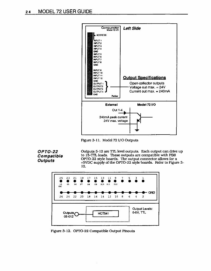
Outputs The Model 72 I/O's outputs 1-4 are open collector outputs. They can sink up to 240mA @5 - 24VDC. If your system cannot use these outputs directly. you will need a pull-up reSistor and an external power supply (5 - 24VDC). Choose a resistor that limits the current through the open-collector output to less than 240mA. Refer to Figure 3-11.
24 MODEL 72 USER GUIDE
OPTO-22 Compatible Outputs
Comoumotor Left Side Model 72·1/0
t ADDRESS
NPUTI INPUT 2 INPUT 3 INPUT 4 GND INPUT 5 INPUTS INPUT 7 INPUTS GND
INPUT 9 INPUT 10 INPUT 11 INPUT 12
GND } OUTPUT 1 OUTPUT2 OUTPUT3 OUTPUT 4 GND
Output Specifications Open-collector outputs
--+--Voltage out max. = 24V Current out max. = 240mA
External
Out 1-4
Model 72 110
240mA peak current 24V max. voltage
Figure 3-11. Model 72 I/O Outputs
Outputs 5-12 are TIL level outputs. Each output can drive up to 15-TIL loads. These outputs are compatible with PBS OPTO-22 style boards. The output connector allows for a +5VDC supply of the OPTO-22 style boards. Refer to Figure 3-12.
25 23 21 19 17 15 13 11 9 7 5 3 1 ••••••••••••• +5 05 06 07 08 09 010 011 012 VDC
••••••••••• •• GND 26 24 22 20 18 16 14 12 10 8 6 4 2
OutputSQ 05-012
1""""""""""""""""1 Output Levels:
: I HCT541 I ! 0-5V, TTL : .. .: • • l.",."""""""""""",.!
Figure 3-12. OPTO-22 Compatible Output Pinouts

CHAPTER 4. APPLICATION DESIGN 25
Chapter 4. APPLICATION DESIGN
Chapter Objectives
Application Considerations
The information in this chapter will enable you to:
• Recognize and understand important considerations that must be addressed before you implement your application
• Understand the capabilities of the system
• Customize the system to meet your requirements
• Use sample applications to develop your application
The Model 72 operates with an AX over a RS-232C serial communication line.
The AX requests information about the Model 72's thumbwheels or inputs, or sets the Model 72's outputs (over the RS-232C line). The Model 72 echoes this command, processes it (Le., thumbwheel input requests). and responds with the proper information.
You must deal with two issues in your application due to data transfer between the AX and the Model 72.
• Execution Time • Electrical Noise
If you use the Model 72. the AX's command execution time will be longer than normal to allow data communication over the RS-232C line. Execution time will exceed a normal AX command by lms multiplied by the number of characters transmitted by the Model 72. For some commands. 20 ms may be required to complete the transmission.
A second Model 72 application consideration is electrical noise. Since data is transmitted over the RS-232C line. the system is susceptible to noise. A high level of electrical noise may cause the system to fault. Compumotor recommends that you shield the RS-232C lines and keep them away from high electrical noise regions.
If you plan to use the Model 72 I/O in an environment with a high level of electrical noise. use optically isolated solid-state relays to condition the signal inputs and outputs from the Model 72 I/O. Compumotor recommends that you optically isolate the I/O in all environments. Refer to Chapter 7. Troubleshooting for more information on electrical noise.

26 MODEL 72 USER GUIDE
Modes of Operation
Standalone Operation
Triggers
There are three modes of operation for the AX and Model 72 system.
• Standalone operation • Host computer operation • Programmable logic controller (PLC) operation
Standalone operation is the most common mode. Only the AX and Model 72(s) are connected and the AX runs stored sequences during operation.
In host computer operation, the host is connected to the Model 72's terminal port to communicate with the Model 72 and the AX.
In PLC mode, a PLC is connected to a Model 72-I/O's inputs and outputs to communicate via I/O or BCD data.
Standalone operation means that an application has no host computer or PLC connected to the AX or Model 72. The AX controls the application. The AX is typically preprogrammed with motion sequences (stored in its nonvolatile memory).
The AX program examples below demonstrate the X Series language enhancements as described in Chapter 5, Software Reference.
The Model 72 I/O's 20 inputs are addressed in groups of four triggers. The enhanced version of the Trigger (TR) command is used in the following example:
Command LD3 A10 V5 MN D1000 TR(1,11,f2J1Xf2J)
G
Description/Response Disables limits if connected. Sets acceleration to 10 rps2. Sets velocity to 5 rps. Sets system to Normal mode. Set distance to 1,000 steps. Waits for input status of device #1's (Model 72) inputs 1-4 to have logic levels, low (0), high (1), don't care (X), low (0) respectively. The Model 72 itO responds with #TR when inputs 1-4 have the levels 01 X0. Execute the move (Go).
If you need a quicker response, Compumotor recommends that you use the AX's trJgger inputs (see the AX User Guide).
You can obtain the status of the Model 72's inputs at any time through the enhanced Trigger Input Status Request (TS) command as can be seen below:
Command TS(1,14)
Description Requests status of inputs 13 - 16 the system responds with: #TSf2J1f2Jf2J.

Time Delays
Loops
Programmable Outputs
CHAPTER 4. APPLICATION DESIGN 27
The next several examples assume that the thumbwheels are set to the following values.
8[I][I][I][I][I]wm The Model 72 allows you to enter time delays through the enhanced Time (T) command.
Command PS A10 V10 MN 010000 T(1,7-8,1)
G C
Qescription/Response Waits for a continue. Sets acceleration to 10 rps2. Sets velocity to 10 rps. Sets system to Normal mode. Sets distance to 10,000 steps. Specifies time delay as the value on thumbwheels 7 & 8. The Model 72 I/O responds with the number of seconds on thumbwheels 7 & 8: #T3. 5. Execute the move (Go). Continue execution.
The.AX waits 3.5 seconds after C is received, then moves 10,000 steps. The.AX calculates the time delay after it receives the Model 72 response. The actual delay is slightly longer due to the command request and Model 72 response time.
You may use the Model 72-1/0 to receive a loop count from input values with the enhanced Loop (L) command.
Command A10 V10 MN 0100 L(1,11,0)
G N
Description/Response Sets acceleration to 10 rps2. Sets velocity to 10 rps. Sets system to Normal mode. Sets distance to 100 steps. Specifies loop count as BCD value on inputs 1 -4. The system responds with the loop number from inputs 1 - 4: #L0. Execute the move (Go). Continue loop.
The Model 72-1/0 has 12 programmable outputs that you can control directly with the Output (0) command.
Command A10 V10 01000 G 0(1,11,0000) 0100 G O(l,ll,llXX)
Description/Response Sets acceleration to 10 rps2. Sets velocity to 10 rps. Sets distance to 1,000 steps. Execute the move (Go). Sets outputs 1-4 low. Sets distance to 100 steps. Executes the Move (Go). Sets outputs 1 & 2 high, outputs 3 & 4 unchanged.
After making the I,OOO-step move, outputs 1-4 are cleared. After making the l00-step-move, outputs 1 and 2 are set high.

28 MODEL 72 USER GUIDE
Preset Mode Move Parameters
Continuous Mode Move Parameters
You can use the Model 72-1/0 to input any or all move parameters (A, v, and D). For example, assume the thumbwheel setting below is in effect and the subsequent commands are issued. Assume BCD value of 3 at inputs 13-16.
Command L112J A(1,14,2)
V(1,7-8,1)
D(1,1-6,2)
G N
Description/Response Sets loop count to 10. Requests BCD Data from inputs 13 - 16. Responds with: #A3. Sets the velocity to the values of thumbwheels 7 & 8. Responds with: #V7. 8. Sets the distance to the values of thumbwheels 1 - 6. Responds with: #D-12345/Zl/Zl. Executes the move (Go). Continues loop.
Each time the AX. executes the loop, it requests new values from the Model 721/0. If you place the move parameters in a loop, you can change the A, v, and D values for the next move. To speed processing, you may minimize the parameters within the loop that contains the movers).
The AX. can change velocity during a Continuous mode move. You define the new velocity and acceleration rate for the Model 72 via the enhanced CV and CA commands respectively. For example, assume the thumbwheel setting below is in effect and the subsequent commands are issued.
Command MC A6/Zl V18 G CL CV(1,4-6,1)
CA(1,7-8,2)
CN
Descriptjon/Response Selects Continuous mode. Sets acceleration to 60 rps2. Sets velocity to 18 rps. Executes the move (go). Initiates a continuous loop. Sets new Continuous mode velocity for thumbwheels 4 - 6 to X1 0-1. Responds with 1.7 rps: #CV1. 7 . Sets new Continuous mode acceleration to thumbwheels 7 & 8. Responds with 25 rps2: #CA25. Ends the continuous loop.
The motor accelerates to 18 rps, at an acceleration rate of 60 rps2. At this point. you can change the continuous acceleration or velocity rates on thefly by changing thumbwheels 4 - 8. In Continuous mode (MC), you cwmot use the Model 72 I/O's inputs. Use the AXs I/O instead.
You can only perfonn on-the-fly velocity and acceleration changes with AX or AX-A software Rev. F and greater and Model 72 software Rev. C and greater.

CHAPTER 4. APPLICATION DESIGN 29
To use the change of acceleration or velocity feature most effeciently in Continuous mode on thejly, you must remove jumper JP8 on the Model 72. Before you remove the Model 72's cover, remove power from the unit (it must be off)! To remove jumper JP8, you must remove the Model 72's cover. Figure 4-1 shows the location of the screws that you must remove to take off the cover. Figure 4-2 shows the location of JP8 on the board.
If you daisy chain Model 72s, only the last unit in the chain must have jumper JP8 removed. With JP8 removed. the Model 72 will not echo data requests back to the AX. This enables the AX to parse connnands more efficently. promoting smoother motor operation.
1 Top T
~
1 Bottom
Remove only the four screws shown.
Figure 4-1. Remove Model 72 Cover
Remove red jumper from pin JP8.
Figure 4-2. Location of Jumper JP8 on Model 72

30 MODEL 72 USER GUIDE
Daisy Chaining
Multiple Parameters
Distance Scaling
You may daisy chain up to 16 Model 72's with one AX. However, AXs may not be daisy chained with the Model 72's connected. Refer to Chapter 3, Installation. In the example below, three Model 72's are on a RS-232C daisy chain. Three moves are to be made repetitively with the thumbwheels. each representing the distance of the move. Assume the folloWing thumbwheel settings:
[ml ~ ffi ffi ffi ffi ffi ffi ffi #2 - 2 2 2 2 2 2 2 #3 - 3 3 3 3 3 3 3
Command AS V5 MN 0(1,O,O)
G 0(2,O,O)
G 0(3,O,/21)
G
Descrjption/Response Sets acceleration to 5 rps2. Sets velocity to 5 rps. Selects Normal mode. Defines distance as value on all 8 thumbwheels of device 1. Responds with the distance from all thumbwheels: #0-1111111. Executes the move (Go). Defines distance as value on all 8 thumbwheels of device 2. Responds with the distance from all thumbwheels: #0-2222222. Executes the move (Go). Define distance as value on all 8 thumbwheels of device 3. Responds with the distance from all thumbwheels: #0-3333333. Executes the move (Go).
A single Model 72 can be used to modify several AX parameters. Assume the following thumbwheel settings:
Command A(1,7-8,2)
V15 0(1,1-5,/21)
L(1,6,/2I)
pescription/Resoonse Sets acceleration to thumbwheel digits 7-8. Responds with #A5. Sets velocity to 15 rps. Sets distance to thumbwheel digits 1-5. Responds with: #0+6379. Sets loop count to thumbwheel digit 6. Responds with: #L4.
The AX can scale the distance specified by the 0 command to a number of steps per least significant digit (us command). This is used to allow distance to be programmed in linear units (inches, mm, etc.).
In the example below, assume the AX (12,800 steps/rev) drives a 5-pitch leadscrew (5 turns/inch). You may want to multiply the distance value by 64 to program distance in thousandths of inches (12,800 x 5 = 64,000 steps/inch, 64 steps = 0.0001 inches). The following thumbwheel setting is in effect.

Selecting Sequences
Host Computer Operation
CHAPTER 4. APPLICATION DESIGN 31
Command uS64 0(1,1-6,O)
G
Description/Response Scales distance to 64 steps/LSD. Defines distance as thumbwheels 1-6. Responds with distance = 3175: #0+3175. Executes the move, (Go) 3.175 inches (3,175 x 64 steps).
The Model 72 allows you to select the AX sequence that you want to execute.
Command XR(1,2)
Description/Response Executes sequence displayed on thumbwheel digit 2. Responds with sequence 3: #XR3.
One possibility for using this command is running a sequence on powerup which contains a Model 72 sequence on request.
A power-up sequence for the AX-A might be programmed as follows.:
Command X040 SSA1 A12 V3 GH-2 MPA XT
Description/Response Downloads power-up sequence. Turns echo function off. Sets acceleration to 12 rps2. Sets velocity to 3 rps. Searches for home position. Selects absolute positioning mode. Ends sequence definition.
Host computer operation refers to a Model 72/AX cluster connected to computer via the last Model 72's terminal port. The host controls the application and issues commands to the AX. The application mayor may not make use of the AX's non-volatile sequence storage.
There are no restrictions on issuing AX commands in this mode, with the exception of the Upload Sequence (xu). All examples discussed in the section on standalone operation will work with host computer operation.
You can download AX motion sequences to the AX or upload them from the AX via the Model 72's terminal port. No restrictions apply to downloading (xo) or running (XR) sequences. Sequence uploading (xu) requires some caution because the AX will issue the sequence and the Model 72 will insert replies to some commands and corrupt the relay to the host. To prevent this problem, turn off the Model 72's echo function (with the Echo ON/OFF IAEJ command).
The host computer must be prepared to handle the Model 72 's echoed responses. The computer must process or purge its RS-232C buffer.

32 MODEL 72 USER GUIDE
PLC Operation
AX
Before you issue a Sequence Upload (xu) command. ensure that the Model 72's echo function is off. The Model 72's echo function is toggled ON or OFF with the hE command. With the echo function off. the uploaded AX sequence passes through the Model 72 to your terminal without echoing back to the AX. You must turn the echo function back ON to allow proper Model 72-to-AX communication.
Uploading verifies the contents of an AX sequence and is not necessarily done by the host computer. In fact. uploading is most often used when a programmer is editing sequences with a terminal.
A PLC can interact in several ways with an AX and Model 72. Figure 4-1 shows the PLC interacting with the AX's I/O, the Model 72 I/O's expanded inputs and outputs. or the Model 72 I/O's terminal RS-232C port.
RS-232C 1±99999991
~ Terminal
Model 72 1/0 RS-232C Port
Expanded 110 20 inputs
AX 1/0 12 outputs 6 inputs 2 outputs
PLC
Figure 4-3. Model 72 I/O and PLC Operation
The following example uses a PLC to select one of two sequences through the AX's XP9 mode (refer to AX User Guide). A parameter is then input via the Model 72 I/O as defined by the PLC. The first sequence uses the PLC to trigger a move of distance supplied by the Model 72 I/O's thumbwheel digits 1 - 6.
Command XP9 XE7 X07 All21 Vll21 0(1,11,1121121121) 0(1,1-6,121) G 0(1,11,121121121121) XT
Descdption Enters Sequence Scan mode. Erases sequence #7. Begins sequence #7 definition. Sets acceleration to 10 rps2. Sets velocity to 10 rps. Turns on output 1. Retdeves distance from thumbwheels 1 - 6. Executes the move (Go). Turns off output 1. Ends sequence #7 definition.

Move Parameters
Sequence Run
CHAPTER 4. APPLICATION DESIGN 33
The second sequence uses the PLC to set a loop count
Command XE6 XD6 0(1,11,1121121121) LD3 All21 Vll21 Dll21l21l21l21 L(1,11-12,12I)
G N 0(1,11,121121121121) XT z
Descdption Erases sequence #6. Begins sequence #6 definition. Turns on output 1. Disables the limits Sets acceleration to 10 rps2. Sets velocity to 10 rps. Retrieves distance from thumbwheels 1 - 6. Reads the loop count from the PLC at input banks 11 and 12, which represents inputs 1 - 8. Executes the move (Go). Ends loops. After completing loops, turns off output 1. Ends sequence #6 definition. Resets the drive.
This completes the programming for the two sequences.
To execute sequence '7, the PLC must verifY that the Model 72 I/O's output 1 is off. This indicates that no sequences are currently being executed. The PLC will then tum on an output that is connected to the AX's sequence # 1 input. This selects sequence #7, turns on the Model 72 I/O's output 1, and executes a move {distance defined by the Model 72's thumbwheels. When the move is complete, output 1 is turned off.
To execute sequence '6, the PLC must verifY that the Model 72 I/O's output 1 is off. The PLC turns on an output that is connected to the AX's sequence #2 input. Output 1 will be turned on and the motor will move 10,000 steps n times (n is the two-digit BCD value at inputs 1 - 8). When the moves are complete. output 1 is cleared.
A PLC can be used to input velocity data and initiate the move.
Command All21 V(1,11,2)
D+1234 TR(1,12,12I121121121)
G
Description/Response Sets acceleration to 10 rps2. Gets velocity from Model 72 I/O. Responds with the velocity of the BCD value at inputs 1 - 4. Sets distance to 1,234 steps. Waits until Model 72 I/O inputs 5-8 are logic 0. Responds with: #TR. Executes the move (Go).
When you use the PLC to enter numerical parameters through the Model 72's inputs, you must set the values 4 ms before the AX. requests information from the Model 72.
A PLC is connected to the Model 72-1/0's inputs 1-5 and will be used to select an AX. sequence
Command TR(1,12,I2IXXX)
XR (1,11)
Description/Response Waits for PLC to set input 5 to logic 0. Responds with: #TR. Runs the sequence corresponding to BCD value on inputs 1-4 from the PLC.


CHAPTER 5. SOFTWARE REFERENCE 35
Chapter 5. SOFTWARE REFERENCE
Chapter Objectives The information in this chapter will enable you to:
Description of Format (Definition of Fields)
0TR ®programrning
®SYNTAX ®UNITS
TR{a, d, n) a = address d = digits
n = trigger or multiplier
data
• Use the Model 72 and Model 72-1/0 in conjunction with an AX.. Drive.
@Trigger ~VALIO Model 72-1/0 only Software Version
0RANGE ®OEFAULT ®ATTRIBUTES
a = 1 - 16 N/A Buffered d = 11 - 15 Independently Saved n = 0 or 1
8AX REQUEST IS *TR(a,d,n)
8MOOEL 72 RESPONSE TO *TR(a,d,n,) IS#TR (if the condition is met)
1. Mnemonic Code
2. Command Type
STATUS
SET-UP
This box contains the command's mnemonic code and the command type. The command types are deSCribed below.
This portion of the box contains the command type. The four command types are listed below.
Status commands respond (report back) with information.
Setup commands define initial conditions and parameters for the application. Setup commands include the following types:
• Homing (Go home acceleration and velocity, etc.) • Input/Output (Lfm1ts, scan time, in-position time, etc.) • General (Set switches, EEPROM storage, return to factory
settings, etc.) • Motion (Positioning mode, encoder parameters, scaling,
etc.)

36 MODEL 72 USER GUIDE
PROGRAMMING
MOTION
3. Full Name
4. Valid Revision Level
5. Syntax (Addressing Matrix)
Programming commands affect programming and program flow. For example. trigger. output. all sequence commands. quote. time delays. pause and continue. enable. loop and end loop. line feed. carnage return. and backspace.
Motion commands affect motor motion (1.e .. acceleration. velocity. distance. go home. stop. direction. mode. etc.).
This field contains the full command name.
This field contains the revision history of the command. It includes the revision of AX software when the command was added or modified. If the revision level of the AX software you are using is equal to or greater than the revision level listed in this field. you are using the proper version of the software. This field also tells you if the command is only valid in the Model 72 I/O. Remember. Model 72 commands are a subset of the Model 72 I/O's commands.
The Model 72 only operates with AX's that have enhanced software (revision E or greater). The enhanced software allows you to address the Model 72 via a new addressing format.
The addressing matrix contains two or three fields that are dMded by commas and set off by parentheses.
a: The first field is the Model 72's device address. If you are using a daisy chain configuration. you must enter a unique Model 72 address in this field.
d: The second field determines which thumbwheel(s) or input(s)/output(s) the command will use.
d Input Output 0 All thumbwheel digits 1 Thumbwheel #1i±J 2 Thumbwheel #2 (MSD) 3 Thumbwheel #3 4 Thumbwheel #4 5 Thumbwheel #5 6 Thumbwheel #6 7 Thumbwheel #7 8 Thumbwheel #8
-10 All 20 Inputs 11 Inputs 1-4 Outputs 1-4 12 Inputs 5-8 Outputs 5-8 13 Inputs 9-12 Outputs 9-12 14 Inputs 13-16 15 Inputs 17-20
Table 5-1. Thumbwheel Selection Table

6. Units
7. Range
8. Default
9. Attributes
10. Request
ll. Model 72 Response
CHAPTER 5. SOFTWARE REFERENCE 37
Refer to the Enhanced AX Command List for examples of the addressing matrix.
The I/O selection values 11. 12. 13. 14. and 15 each address 4 inputs (or outputs). These groups of 4 are referred to as input banks (and output banks). Each bank is referred to by its value. For instance. input bank 11 refers to inputs 1 - 4 (refer to Table 5-1).
n: The third field (for Model 72's only) is the data field. You can use this field for scaling or defining input/output requests.
When the data field is used as a scaling multiplier. the variable n is the exponent (10n) of the scaling factor (1.e .• 0.01 It 10n). The complete scaling mutiplier is shown in parentheses in the UNITS field of each command example.
When the data field is used for trigger and output commands. n represents a bank of four digits. These digits represent the I/O levels of the I/O selected. The variable n maybe O. 1. orx.
This field describes what unit of measurement the parameters in the command represents.
This is the range of valid values that you can specify for n (or any other parameter specified).
The default setting for the command is shown in this box. A command will perform its function with the default setting if you do not provide a value.
This box indicates if the command is immediate or bqlfered. The AX executes immediate commands as soon as it receives them. Buffered commands are executed in the order that they are received with other buffered commands. You can store buffered commands in a sequence and save them in permanent memory.
In all cases. enhanced X commands cause the AX to transmit the command to the Model 72(s) preceded by an asterisk. This transmission follows AX REQUEST IS.
In most cases. the Model 72 provides a response to the AX request. This response is shown in the box after MODEL 72 RESPONSE TO _ IS _ This box will appear only if the system provides a response to the command.
Any software command that addresses the Model 72-1/0'. Inputs or outputs wtII be Ignored by the Model 72. Any Improper software commands are Ipored. by both the Model 72 and Model 72-110. The AX. however, may locIt-up If Model 721/0 COIIUIl8Dds are sent to a Model 72. (You may use the Reset [zl commanc1 or cycle power to unlock the system.

38 MODEL 72 USER GUIDE
Execution Time Execution time is the span of time that passes from the moment you issue a command to the moment the system begins to execute it.
The Model 72 and AX communlcate data and commands over a sertalinterface. Therefore. the processing time for Model 72 commands will be significantly greater than for AX commands. which do not invoke communlcation with the Model 72. For example. the distance (D) command takes less than 2 ms. commands that request all the thumbwheel data will take 23 ms. In this case. the command's execution time is approxttnately 12 times as long as a non-Model 72 command. For smaller data fields. the difference will be less. In some applications. you must consider this delay as you plan your application.
The communication delay between the Model 72 and.AX Is approximately Ims per character transmitted between them.

Enhanced AX Commands
Command List
A Motion
SYNTAX UNITS
A(a, d, n) a = address d = digits
n = multiplier (0.01 X IOn)
AX REQUEST IS *A(a,d n)
CHAPTER 5. SOFTWARE REFERENCE 39
The revised AX. software (rev. E or later) allows you to transfer data between the Model 72 and the AX Only 13 of the X commands are enhanced. These commands are A, CA. C'l'M, CV, 0, H, L, 0, T, TR, TS, v, and XR. The enhancements all use a stmilar fonnat. Thts fonnat adds an addressing matrix suffix to the original X command.
Acceleration VALID AX Software Revision E
RANGE DEFAULT ATTRIBUTES
a = 1 - 16 N/A d = 0 - 15 Buffered
n = 0 - 9
MODEL 72 RESPONSE TO *A (a, d, n) IS #A<digits x .01 x 10 n >
Command
MODEL 72 DESCRIPTION
AX DESCRIPTION
EXAMPLE
This command requires all addressing fields. With n = 0, the least significant thumbwheel digit is one hundredth of an rps2.
The A command specifies the acceleration rate to be used upon executing the next Go (G) command. The acceleration remains set until you change it. You do not need to reissue this command for subsequent G commands. Accelerations beyond the valid range cause the acceleration to remain in the previous valid acceleration setting. The maximum acceleration that the AX. will accept is 999.99 rps2.
Assume the Input banks have the following values: Bank. 11 = BCD 5, Bank 12 = BCD 3. Bank 13 = BCD 7, Bank 14 = BCD 9, Bank. 15 = BCD 0. The thumbwheel setting below is used.
Model 72 AX Request Response Description
A(l,7-8,2) *A(l,7-8,2) #A67 Reads Model 72 #1 and sets the acceleration to the BCD values of thumbwheel digits 7 & 8 (67 rps2).
A(2,13,3) *A(2,13,3) #A70 Reads Model 72 #1 and sets the acceleration to the BCD values on input bank13 multiplied by 1 0 (70 rpS2)

40 MODEL 72 USER GUIDE
CA Change Acceleration VALID Motion AX Software
Revision E
SYNTAX UNITS RANGE DEFAULT ATTRIBUTES
CA(a, d, n) a = address a = 1 - 16 N/A d = digits d = 0 - 15 Buffered
n = multiplier n = 0 - 9 (0.01 X 10n)
AX REQUEST IS *CA(a,d,n)
MODEL 72 RESPONSE TO *CA (a, d, n) IS tCA<digits x .01 x 10 n >
Command
MODEL 72 DESCRIPTION
AX DESCRIPTION
EXAMPLE
AX Request
The Change Acceleration (CA) command requires all addressing fields. With n = O. the least significant thumbwheel digit is one hundredth of an rps2.
The Change Acceleration (CA) command allows you to change the acceleration rate in Continuous mode. at a constant velocity. The maximum acceleration that the AX will accept is 99.99 rps2.
Assume the input banks have the following values: Bank 11 = BCD 5. Bank 12 = BCD 3. Bank 13 = BCD 7. Bank 14 = BCD 9, Bank 15 = BCD 0. The thumbwheel setting below is used.
Model 72 Response Description
CA(1,7-8,2) *CA(1,7-8,2) #CA67 Reads Model 72 #1 and sets the acceleration
CA(2,13,3)
to the BCD values of thumbwheel digits 7 & 8 (67 rps2).
*CA(2,13,3) #CA70 Reads Model 72 #1 and sets the acceleration to the BCD values on input bank13 multiplied by 1 0 (70 rps2)
Refer to Chapter 4. Application Design for examples uses of the CA command with other commands.

CHAPTER 5. SOFTWARE REFERENCE 41
CTM Constant Velocity Time Delay VALID Programming AX Software
Revision E
SYNTAX UNITS RANGE DEFAULT ATTRIBUTES
CTM(a, d, n) a = address a = 1 - 16 N/A Buffered d = input bank d = 0 - 15 n = multiplier n = a - 9
(0.01 X IOn)
AX REQUEST IS *CTM (a d n)
MODEL 72 RESPONSE TO *CTM (a, d, n) IS #CTM<digits x .01 x 10 n >
Command
MODEL 72 DESCRIPTION
AX DESCRIPTION
EXAMPLE
AX Request
The Constant Velocity Time Delay (CTM) command requires all three addressing fields. The variable n = 0. The least significant digit represents one hundredth of a second.
The CTM command causes the indexer to wait the number of seconds that you specify before it executes the next command in the buffer (in Continuous mode at constant velocity).
Assume the input banks have the following values: Bank 11 = BCD 5, Bank 12 = BCD 3, Bank 13 = BCD 7, Bank 14 = BCD 9, Bank 14 = BCD 0. The thumbwheel setting below is used.
Model 72 Response Description
CTM(2,2-4,1) *CTM(2,2-4,1) tCTMI2.3 Changes the time delay to the BCD values of thumbwheel digits 2 -4 multiplied by 0.1 on Model 72 #2 (12.3 seconds)

42 MODEL 72 USER GUIDE
CV Velocity Valid Motion AX Software
Revision E
SYNTAX UNITS RANGE DEFAULT ATTRIBUTES
CV(a, d, n) a = address a = 1 - 16 N/A d = digits d = 10 - 15 Buffered
n = multiplier n = 0-9 (0.01 X 10n)
AX REQUEST IS *CV(a1 d,n)
MODEL 72 RESPONSE TO *CV(a,d,n) IS fCV <digits x .01 x 10n >in rps
Command
MODEL 72 DESCRIPTION
AX DESCRIPTION
EXAMPLE
The Change Velocity (CV) command requires all three addressing fields. The variable n = O. The least significant digit is one hundredth of an rps.
The CV command allows you to change the velocity in Continuous mode. at a constant velocity. The maximum velocity you can define in the AX is 50 rps. The AX will ignore a velocity command greater than 50 rps.
Assume the input banks have the following values: Bank 11 = BCD 5. Bank 12 = BCD 3. Bank 13 = BCD 7. Bank 14 = BCD 9, Bank 15 = BCD 0. The thumbwheel setting below is used.
AX Request Model 72 Response Description
CV(1,2-3,1) *CV(1,2-3,1) tCV1.2 Changes velocity to the thumbwheel values of digits 2 and 3 from Model 72 #1 multiplied by 0.1 (1.2 rps)

CHAPTER 5. SOFTWARE REFERENCE 43
0 Distance VALID Motion AX Software
Revision E
SYNTAX UNITS RANGE DEFAULT ATTRIBUTES
o (a, d, n) a = address a = 1 - 16 N/A Buffered d = digits d = 0 - 15
or input bank n = 0 - 9 n = multiplier
(lOn)
AX REQUEST IS *D (al d L n)
MODEL 72 RESPONSE TO *D (a, d, n,) :IS #D <Digits x 10n>
Command 0{1,12I,12I)
MODEL 72 DESCRIPTION
AX DESCRIPTION
EXAMPLE
AX Request *D(1,0,0)
The Distance (0) command requires all three addressing fields. With n = 0, the least significant digit is in the ones place in steps.
The Distance (0) command defines either the number of steps the motor will move or the absolute position it will seek after a Go (G) command is entered. In Incremental mode (MP:I or FSA0). the value set with the Distance (0) command will be the distance (in steps) the motor will travel on all subsequent Go (G) commands. In absolute mode (MPA or FSA1), the distance moved by the motor will be the difference between the current motor position and the position (referenced to the zero position) set with the 0 command. A distance must be defined with the 0 command before a preset move can be executed.
Assume the input banks have the following values: Bank 11 = BCD 5, Bank 12 = BCD 3, Bank 13 = BCD 7. Bank 14 = BCD 9, Bank 15 = BCD 0. The thumbwheel setting below is used.
Model 72 Response Description *D-1234567 Sets the distance to the values of all
thumbwheel digits (-1234567 steps)
0{4,12-15,2) *D(4,12-15,2) *D379000 Sets distance to BCD value of inputs 12 - 15 multiplied by 100 (379,000 steps)
Note: To make the thumbwheel setting be in familiar user units, use the User Scaling (US) command in conjunction with Distance (0) command. If the command US32 preceded the o (a, d, n) or Onnn command, the distance would be multiplied by 32 to yield the actual number of steps (or position) for the next move.

44 MODEL 72 USER GUIDE
H Set Direction VALID Motion AX Software
Revision E
SYNTAX UNITS RANGE DEFAULT ATTRIBUTES
H(a,l) a = address a = 1 - 16 N/A Buffered
AX REQUEST IS *H (a, 1)
RESPONSE TO *H (a, 1) IS tH±
Command
H(3,1)
MODEL 72 DESCRIPTION
AX DESCRIPTION
EXAMPLE
AX Request
*H(3,1)
The Set Direction (H) command makes the AX request the direction from the Model 72 thumbwheel digit 1 (+/-). The third field is not used with this command.
The Set Direction (H) command changes or defines the direction of the next move that the system will execute. This command does not effect moves already in progress.
H + Sets move to CW direction H - Sets move to CCW direction H Changes direction from the previous setting
In preset moves, a Distance (0) command entered after the Set Direction (H) command overrides the direction set by the H command. In Continuous mode (Me), only the H command can set the direction of motion.
Model 72 1/0 Response Description
tH± Model 72 #3 thumbwheel 1 sets the direction of the move

CHAPTER 5. SOFTWARE REFERENCE 45
L Loop VALID Motion AX Software
Revision E
SYNTAX UNITS RANGE DEFAULT ATTRIBUTES
L(a, d, n) a = address a = 1 - 16 N/A Buffered d = digits d = a - 15
n = multiplier n = 0 - 9
(lOn)
AX REQUEST IS *L (a, d, n, )
MODEL 72 RESPONSE TO *L (a, d, n) IS #L <Digits x IOn>
Command
L(1,6,2)
MODEL 72 DESCRIPTION
AX DESCRIPTION
EXAMPLE
The L command requires all three addressing with fields. With n = 0. the least significant bit is in the ones place.
When you combine the Loop (L) command with the End-ofLoop (N) command. all of the commands between L and N will be repeated the number of times indicated by a direct numerical input or a Model 72's response to an AX. request. If you enter the L command without a value specified for n. or with a 0. subsequent commands will be repeated continuously.
The End-of-Loop command prompts the indexer to proceed with further commands after the designated number of loops have been executed. The Stop Loop (Y) command causes Loop execution to stop. Refer to the AX. User Guide for more information on the Y command. The Immediate Pause (u) command allows you to temporarily halt loop execution. You can use the Continue (e) command to resume loop execution.
Assume the input banks have the following values: Bank 11 = BCD 5. Bank 12 = BCD 3. Bank 13 = BCD 7. Bank 14 = BCD 9, Bank 15 = BCD 0. The thumbwheel setting below is used.
Model 72 AX Request Response Description
*L(1,6,2) U500 Sets the loop count to the thumbwheel digit 6 multiplied by 100 (500 loops).
L(l,11-12,~) *L(1,1l-12,0) #L53 Sets the loop count to the BCD values at inputs 1-4 and 5-8 (53 loopS).

46 MODEL 72 USER GUIDE
0 Prograrruning
SYNTAX UNITS
O(a, d, n) a = address d = output ban~
n = output data
AX REQUEST IS *0 (a, d n)
Command
MODEL 72 1/0 DESCRIPTION
AX DESCRIPTION
EXAMPLE
AX Request
Output VALID AX Software Revision E
Model 72-I/0 only
RANGE DEFAULT ATTRIBUTES
a = 1 - 16 N/A Buffered d = 11 -l3
n = 0,1, or x
The Output (0) command requires all three addressing fields. The third field (n) represents the output data. You must enter one of the following values in this field:
21 = low; current does not flow 1 = high; current flows x = do not change
The output command may only address one bank of four outputs at a time.
The Output (0) command turns the programmable output bits on and off. This is used for signaling remote controllers. turiling on LEDs. or sounding whistles. The output can indicate that the motor is in position. about to begin its move. or is at constant velocity. etc.
Model 72-1/0 Response Description
0(1,11,2121~21) *0(1,11,0000) None Sets outputs 1-4 low at device #1.
0(1,11,XX1X) *0(1,11,XX1X) None Sets output 3 high at device #1

CHAPTER 5. SOFTWARE REFERENCE 47
T Time Delay VALID Programming AX Software
Revision E
SYNTAX UNITS RANGE DEFAULT ATTRIBUTES
T(a, d, n) a = address a = 1 - 16 N/A Buffered d = input bank d = 0 - 15 n = multiplier n = 0 - 9
(0.01 X IOn)
AX REQUEST IS *T (a d, n)
MODEL 72 RESPONSE TO *T (a, d, n) IS fT<digits x .01 x 10n >
Command
MODEL 72 DESCRIPTION
AX DESCRIPTION
EXAMPLE
AX Request
The Time Delay (Tl command requires all three addressing fields. With n = 0. the least significant digit represents one hundredth of a second.
The Time Delay (Tl command causes the indexer to wait the number of seconds that you specify before it executes the next command in the buffer. This command Is useful whenever you need to delay the motor's actions.
Assume the input banks have the following values: Bank 11 = BCD 5. Bank 12 = BCD 3. Bank 13 = BCD 7. Bank 14 = BCD 9, Bank 15 = BCD 0. The thumbwheel setting below is used.
Model 72 Response Description
T(2,2-4,1) *T(2,2-4,1) fT12.3 Sets the time delay to the values of thumbwheel digits 2 -4 multiplied by 0.1 (12.3 seconds).

48 MODEL 72 USER GUIDE
TR Trigger VALID Programming AX Software
Revision E Model 72-I/O only
SYNTAX UNITS RANGE DEFAULT ATTRIBUTES
TR(a, d, n) a = address a = 1 - 16 N/A Buffered d = input bank d = 11 - 15
n = trigger n = 0,1, or x conditions
AX REQUEST IS *TR(a,d,n)
MODEL 72-1/0 RESPONSE TO *TR(a,d,n) IS #"TR (When condition is met)
Command
MODEL 72-1/0 DESCRIPTION
AX DESCRIPTION
EXAMPLE
The TR command uses all three address fields. The third field represents the trigger condition (0 = high. 1 = GND. X = don't care). for the input bank selected by the second field prior to the trigger condition. the AX halts buffered command processing. When the trigger condition occurs. the Model 72-110 response is #TR. This pennits the AX to resume execution. Only one input bank may be addressed per TR command.
Triggers synchronize indexer operations with external events. You can use them to invoke a handshaking function with other devices. The nnn variables are listed below:
1 = Input grounded (ON) o = Input not grounded (OFF) x = Don't care
TRIG 1 TRIG 2 TRIG 3
TR nnn
III When the indexer receives the TR command in a buffer, it waits until the input pattern is matched before going on to the next command.
Model 72-1/0 AX Request Response Description
TR(1,lS,/2J1XX) *TR(1,15,01XX) #TR The AX stops buffered command processing until the Model 72 1I0's inputs 17 & 18 are low and high respectively.

CHAPTER 5. SOFTWARE REFERENCE 49
TS Trigger Status VALID Programming AX Software
Revision E Model 72-I/O
SYNTAX UNITS RANGE DEFAULT ATTRIBUTES
TS (a, d) a = address a = 1 - 16 N/A d = input bank d = 10 - 15 Buffered
AX RESPONSE TO TS (a, d) IS *TS(a",d~
MODEL 72 RESPONSE TO *TS (a, d) IS ITS <input levels 0 or 1>
Command
TS(1,12)
TS (2, 1121)
MODEL 72 DESCRIPTION
AX DESCRIPTION
EXAMPLE
The Trigger Status (TS) command shows the state of the trigger inputs. The TS command does not require the third addressing field. Input level 0 corresponds to a 5-24VDC high and Input level 1 corresponds to a 0 - O.7VDC low.
This command retrieves the state of the trigger inputs. TS command is useful for checking the status of the trigger inputs when it appears as though execution is being halted by a TR command. To ensure that your trigger pattern is met, enter the TS command.
Assume the input banks have the following values: Bank 11 = BCD 5, Bank 12 = BCD 3, Bank 13 = BCD 7, Bank 14 = BCD 9, Bank 15 = BCD 0.
Model 72-1/0 AX Request Response Description
*TS(1,12) tTS0011 Displays the values of inputs 5-8 of device #1 (inputs 5 - 8 have logic levels of .0011).
*TS(2,10) nS001 ... 0 Displays all of the input values 1-20 of device #2.

50 MODEL 72 USER GUIDE
US Programming
SYNTAX UNITS
USn
Command
n = nnn.nnn
MODEL 72 DESCRIPTION
EXAMPLE
Description
User Scaling VALID AX Software Revision E
RANGE DEFAULT ATTRIBUTES
n = .001-999.999 1 Buffered
The User Scaling (us) command allows you to use user units (inches. mm. etc.) with the AX. .Any Distance (D) command that follows a us command wtIl be multiplied by the us value. Fractional parts are rounded to the nearest step.
US132.500 Sets scaling factor to 132.5. A distance of 1 would be multiplied by 132.5--yielding 133 steps.
US52.499 Sets scaling factor to 52.499. A distance of 1 would be multiplied by 52.499-yielding 52 steps.

CHAPTER 5. SOFTWARE REFERENCE 51
V Velocity Valid Motion AX Software
Revision E
SYNTAX UNITS RANGE DEFAULT ATTRIBUTES
V(a, d, n) a = address a = 1 - 16 N/A d = digits d = 10 - 15 Buffered
n = multiplier n = 0-9 (0.01 X IOn)
AX REQUEST IS *V (a, d n)
MODEL 72 RESPONSE TO * V (a, d, n) IS tv <digits x .01 x 10n >in rps
Command
MODEL 72 DESCRIPTION
AX DESCRIPTION
EXAMPLE
AX Request
The Velocity (v) command requires all three addressing fields. With n = 0 as the least significant digit is one hundredth of an rps.
The v command defines the maximum speed at which the motor will run when given the Go (G) command.
The top speed of the motor drive is limited by the size motor and the amount of the load. Entering a velocity higher than the top speed of your AX system will cause the motor to stall.
The maximum velocity you can define in the AX is 50 rps. The AX will ignore a velocity command greater than 50 rps.
Assume the input banks have the following values: Bank 11 = BCD IS. Bank 12 = BCD 3. Bank 13 = BCD 7. Bank 14 = BCD 9, Bank 15 = BCD 0. The thumbwheel setting below is used.
Model 72 Response Description
V(l,2-3,1) *V (1, 2 - 3, 1 ) tV1.2 Sets velocity to values of thumbwheel digits 2 and 3 multiplied by 0.1 (1.2 rps)

52 MODEL 72 USER GUIDE
XR Sequence Run VALID Prograrruning AX Software
Revision E
SYNTAX UNITS RANGE DEFAULT ATTRIBUTES
XR(a, d) a = address a = 1 - 16 N/A Buffered d = digits d = 0 - 15
or input bank
AX REQUEST IS *XR(a,d)
MODEL 72 RESPONSE TO *XR (a, d) IS tXR<digits>
Command
MODEL 72 DESCRIPTION
AX DESCRIPTION
EXAMPLE
AX Request
The Sequence Run (XR) command allows you to use the Model 72 I/O's thumbwheels or inputs to run in a sequence. Only the first two of the addressing fields are required for this command.
This command loads a predefined sequence into the command buffer (clears the buffer first) and executes these commands as a nonnal set of commands. This command automatically recalls the sequence from EEPROM.
An XR command can be used within one sequence to start execution of another sequence; however. all commands in the first sequence following the XR will be ignored (e.g.. XR acts like Gam. not GOSUB). If you are in Continuous mode. the velocity must be 0 rps when you call another sequence. An XR command within a loop will be ignored.
Assume the input banks have the following values: Bank 11 = BCD 5. Bank 12 = BCD 3. Bank 13 = BCD 7. Bank 14 = BCD 9, Bank 15 = BCD 0. The thumbwheel setting below is used.
Model 72 Response Description
XR(2,3-4) *XR (2,3-4) #XR23 Sets the sequence run to the values of thumbwheels 3 & 4 on device #2 (Run Sequence #23).
XR(1,13) *XR (1,13) #XR7 Sets the sequence run to the BCD values of inputs 9-12 on device #1 (Run Sequence '7).
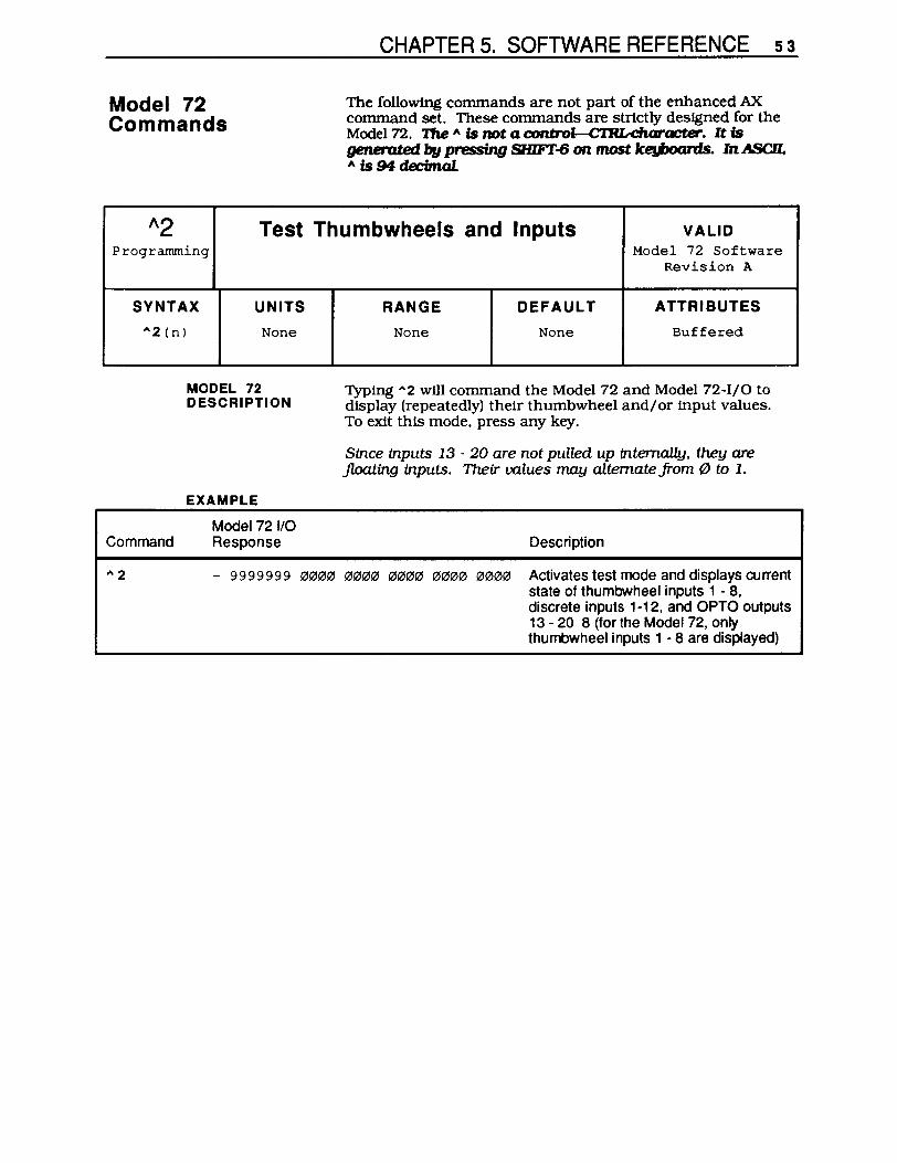
CHAPTER 5. SOFTWARE REFERENCE 53
Model 72 Commands
The following commands are not part of the enhanced AX command set. These commands are strtctly designed for the Model 72. 'I1Ie A is not a control--CTRLcharacter. It is generated by pressing SHIFT-6 on most ke,Jxxuds. In ASCll. A Is 94 decimal.
1\2 Test Thumbwheels and Inputs VALID Programming Model 72 Software
Revision A
SYNTAX UNITS RANGE DEFAULT ATTRIBUTES
.... 2(n)
Command
.... 2
None
MODEL 72 DESCRIPTION
EXAMPLE
Model 72 1/0
None None Buffered
Typing .... 2 will command the Model 72 and Model 72-1/0 to display (repeatedly) their thumbwheel and/or input values. To exit this mode, press any key.
Since inputs 13 - 20 are not pulled up internally, they are floating inputs. Their values may alternate from " to 1.
Response Description
- 9999999 0000 0000 0000 0000 0000 Activates test mode and displays current state of thumbwheel inputs 1 - 8, discrete inputs 1-12, and OPTO outputs 13 - 20 8 (for the Model 72, only thumbwheel inputs 1 - 8 are displayed)

54 MODEL 72 USER GUIDE
"A Programming
SYNTAX UNITS
I\A(n) None
MODEL 72 DESCRIPTION
"E Programming
SYNTAX UNITS
I\E (n) None
MODEL 72 DESCRIPTION
"RV Programming
SYNTAX UNITS
I\RV (n) None
MODEL 72 DESCRIPTION
Address Request VALID Model 72 Software
Revision B
RANGE DEFAULT ATTRIBUTES
None None Buffered
If you enter "'A via the tenninal port. you wUl request an address report back from the Model 72. The Model 72 will respond with its current address (a value between 1 and 16).
Echo ON/OFF VALID Model 72 Software
Revision A
RANGE DEFAULT ATTRIBUTES
None None Buffered
If you enter "'E, the Model 72 wUl toggle the echoes off at each Model 72 port. The 1\ is not a control--CTRLcharacter. It is generated by pressing SHIFT-8 on most k~. In ASCll. 1\ is 94 decimal. Data entered into Port 1 or 2 will be sent out the other port but will not be echoed out the same port where it was entered. To re-enable the echo function. type "'E.
You should use this command when you upload sequences from an AX through a Model 72's terminal port. The Model 72's echo function must be OFF when you upload an AX sequence.
Revision Request VALID Model 72 Software
Revision B
RANGE DEFAULT ATTRIBUTES
None None Buffered
If you enter "'RV via the termInal port. you will request a software revision report back from the Model 72. Model 72s with software levels B and greater will provide the following re,sponse: 92-010649-01XX.

CHAPTER 6. HARDWARE REFERENCE 55
Chapter 6 .. HARDWARE REFERENCE
Chapter Objectives
Environmental Specifications
Electrical Specifications
liD Specifications
Power
The information in this chapter will enable you to:
• Use this chapter as a qUick-reference tool for most system specifications (dimensions & performance)
• Use this chapter as a quick-reference tool for proper I/O connections
Compumotor recommends that you operate and store your Model 72 under the following conditions:
• Operating Temperature: 32°F to 122°F (O°C to 50°C) • Storage Temperature: -22°F to 185°F (-30°C to 85°C) • Humidity: ()o1b to 95% non-condensing
This section refers to the Model 72 and Model 72 I/O's inputs and outputs.
You must supply 115VAC ±10% to the input (see FJgure 6-1).
Right Side of Model 72 Compumotor S.Pin D Connector
Model 72 (Cable Provided)
LINE r-- Black ~
NC White .~ 115VAC PO~
NEUTRAL Gr8«l GND ....
NC 10- I.!. POWER 0
FAULT 0
IT~'~ ~ RS232C
-
=1~D 1)( RS GND
SHIELD
P.1br
FJgure 6-1. Power Supply

56 MODEL 72 USER GUIDE
Terminal Communication
You can communicate with the Model 72 and the AX via the Model 72's tenninal RS-232C port. You must wire the 'IX , RX , and GND (logic ground) inputs as shown in Figure 6-2.
Right Side of Model 72 Compumotor S.Pin D Connector
Model 72 (e.,. PrcMded)
LINE NC
NEUTRAL GND
NC
POWER 0 FAULT 0
TERMINAL RS232C
4 AXO TX RS GND
SHIELD
BlacK
While
1 Shield. 2S.PIn D Connector (Cable No! Provided)
115VAC Power
2 AX --t-+----3TX __ +-+-__ _ 7GND -~-+---
P.rbr
Figure 6-2. Basic Wiring
RS-232C Communication
To allow for communication between the Model 72 and AX, you must wire the 'IX, RX. and GND inputs as shown in Figure 6-3. RS-232C communication parameters are fixed at :
• 9,600 baud rate • 8 data bits • 1 stop bit • No parity
Model 72
Figure 6-3. RS-232C Wiring

Inputs 1-12 (Model 72-110)
OPTO-22 Compatible Inputs 13-20 (Model 72-110)
CHAPTER 6. HARDWARE REFERENCE 57
There are 12 general-purpose inputs, with three I/O grounds. The inputs do not have an internally isolated supply. Input voltage: TIL logic levels 5 - 24VDC (high current IJm1ting resistor not needed).
These inputs are nonnally high or logic O. You must close contact to OV (GND) or sink 220J,.IA to bring the input low or logic 1. The Model 72-1/0 uses negative logic. The input configuration must be stable for 4 ms to be recognized by the Model 72-1/0.
Compumotor Left Side Model n·vo
~Addr_ INPUT1} INPUT 2 INPUT 3 INPUT 4 GNO
INPUT 6 __ ....... _~ INPUTS}
INPUT 7 INPUTS GNO
INPUT9~ INPUT 10 INPUT 11 INPUT 1 GNO OUTPUT 1 OUTPUT2 OUTPUT3 OUTPUT 4 GNO
Parker
Input Circuit
22K
Input Specifications o to O.7WDCVoltage Low 5 to 24VDC Voltage High Current in @ 5V: can sink1J,JA Current in @ 24V: can sink800J,JA
+5V
51K Input o---------"""""',....,.-L...;..;;...;....;;;...;..;...J
Figure 6-4. Inputs 1-12, Input Circuit
There are eight OPTO-22 compatible inputs fITL input levels). They can sink up to 20mA, therefore allowing opto operation. Pin 25 is also configured to supply 5V. The current supplied must be less than l00mA See Figure 6-5 for pinouts

58 MODEL 72 USER GUIDE
Outputs 1-4 (Model 72-110)
Discrete Outputs 5-12 (Model 72-110)
25 23 21 19 17 15 13 11 9 7 5 3 1
• • • • • • • • • •• • • +5 III Il Il5 Il6 I17 Il8 Il9 I20 VDC
• • • • • • • • • • • • • GND 26 24 22 20 IB 16 14 12 10 B 6 4 2
Figure 6-5. Input Pinouts
Outputs 1-4 on the Model 721/0 are open collector. You must supply 5 to 24VDC and a puB-up resistor with a minimum resistance of loon. Refer to Figure 6-6.
ComDumotor Left Side Model 72-VO
ADDRESS INPUT 1 INPUT 2 INPUT 3 INPUT 4 GND INPUT 5 INPUT 6 INPUT 7 INPUT 8 GND
INPUT 9 INPUT 10 INPUT 11
INPUT 12 Outpyt Specifications
E:~; } __ t--_open-Collector outputs OUTPUT3 Voltage out max. = 25V OUTPUT 4 Current out max. = 250mA GND
External
Out 1-4
240mA peak current 24V max. voltage
Model 72
Figure 6-6. Outputs 5 - 12. Output Circuit
These outputs are dedicated for an OPTO-22 compatible PBS header. The outputs are at TIL levels and can drive lO-lb TIL loads. A 5VDC p1n is supplied to power the OPTO board. which can supply l00mA. See Figure 6-7 for p1nouts.

CHAPTER 6. HARDWARE REFERENCE 59
25 23 21 19 17 15 13 11 9 7 5 3 1
• • • • • • • • • •• • • +5 III 11 115 116 117 118 119 I20 we
• • • • • • • • • • • • • GND 26 24 22 20 18 16 14 12 10 8 6 4 2
Figure 6-7. OPTO-22 Pmouts for Outputs 5-12
Visual Indicators Power LED: ON (Green) whenever AC power Is applied Fault LED: OFF when Model 72 is functioning properly
Dimensional Drawings
...L
0
O.l§1]
• ~
" Optional Mounting Tabs
a
The Fault LED will be ON when the following conditions exist:
1. Power on reset 2. Faulted microprocessor (If the microprocessor faults. refer to Chapter 7. Troubleshooting)
7.00
2.88 1.25
r 1 IT I
0"
1- ,~
D !i! ;:!
~ I I • u; ...: • • ~
~ O~I
D u- .. S
1.38 ":.:\ ,... ~
\ Slot lor.10 MountingScr_
[ ::---: I ~ ~ cj
Figure 6-8. Model 72 Dimensional Drawing

60 MODEL 72 USER GUIDE
7.00
2.88 1.25
I ~ r 1
,...\ I"T T ~ ...... .... ~
~
0 ~ ~ •
~ ~ I I • <D .... • o~1 r--
- ~ D o.6!U ..... ~-~ u. • I
... t-'. ~.
4.44 "
.... 1.36 "':
Optional 0
Mounting \ Slot for ,to Tabs MountingScrews
[ I :~-:; I l~ ~ cj
Figure 6-9. Model 72 I/O Dimensional Drawing
CHAPTER 7. TROUBLESHOOTING 61
Chapter 7. TROUBLESHOOTING
Chapter Objectives
Spare Parts
Troubleshooting
Isolating Problems
The information in this chapter will enable you to:
• Maintain the system to ensure smooth. efficient operation • Isolate and resolve system hardware & software problems
If you lose or damage a bracket. you may order repalacement brackets from Compumotor. Call 1-800-358-9070 and order the part using the name and part number shown below.
Mounting Bracket: 53-006007-01
This section discusses methods to identify. isolate. and resolve problems that may occur with your Model 72.
When your system does function properly (or as you expect it to operate). the first thing that you must do is identify and isolate the problem. When you accomplish this. you can effectively begin to resolve the problem.
The first step is to isolate each system component and ensure that each component functions properly when it is run independently. You may have to dismantle your system and put it back together piece by piece to detect the problem. If you have additional units available. you may want to use them to replace existing components in your system to help identify the source of the problem.
Try to determine if the problem is mechanical. electrical. or software-related. Can you repeat or re-create the problem? Do not make quick rationalizations about problems. Random events may appear to be related. but they are not necessarily contributing factors to your problem. You must carefully investigate and decipher the events that occur before the subsequent system problem.
You may be experiencing more than one problem. You must solve one problem at a time. Log (document) all testing and problem isolation procedures. You may need to review and consult these notes later. This will also prevent you from duplicating your testing efforts.
Once you have isolated the problem. take the necessary steps to resolve it. Refer to the problem solutions contained in this chapter. If your system's problem persist. contact Parker Compumotor's Appl1cations Department.

62 MODEL 72 USER GUIDE
Problems & Solutions
Problem Solution The Model 72 does not respond to AX data Check the Model 72's address and the enhanced requests. X command for format vaAditv. No AX request is visible. Check RS-232C wirina. Multiple characters stream across terminal display. Turn the AX's echo function off (SSA1).
The Model 72 does not echo to the terminal. Turn on the Model 72's echo function ("'E). After turning the Model 72's echo function on, the Check the earth ground connection at the power unit is still not echoing to the terminal. supply. Cycle power. The POWER LED is OFF Check the AC power wiring. If voltage is present
and the LED is still off, remove power from the system and check the fuse inside of the Model 72. If the fuse is blown, replace it with a 250V, 1 A, 20 mm long fuse. If the LED will not come on with the new fuse call Compumotor-1-800-358-9070.
The red FAULT light is on or is flickering. Check the AC voltage level. It should be 115VAC ±10%. Ensure that the unit is shielded from noise. If this does not solve the problem, call Compumotor-1-800-358-9070.
Table 7-1. Model 72 Problems and Solutions Table
RS-232C Communications
If you are having problems communicating with the Model 72. try the following procedure to troubleshoot the communications interface.
1. Make certain the transmit of the host is wired to the receive of the peripheral. and receive of the host (terminal or computer) is wired to the transmit of the peripheral.
Try switching the receive and transmit wires on either the host or peripheral if you faU to get any communication.
2. Some serial ports require handshaking. You can establish three-wire communication by connecting RTS to CTS (usually pins 4 & 5) and DSR to DTR (usually pins 6 - 20).
3. Configure the host and peripheral to the same baud rate. number of data bits, number of stop bits. and parity.
4. If you receive double characters. for instance typing A and receiving AA.. your computer is set for half duplex. Change the setup to full duplex.
5. Use DC common or signal ground as your reference. not earth ground.

RedUCing Electrical Noise
Electrical Noise
CHAPTER 7. TROUBLESHOOTING 63
6. Cable lengths should not exceed 50 ft. unless you are using a line driver. optical coupler. or shield. As with any control signal. be sure to shield the cable to earth ground at one end only.
7. To test your tenninal or terminal emulation software for proper three-wire communication, unhook your peripheral device and transmit a character. You should not receive an echoed character. If you do , you are in half duplex mode. Connect the host's transmit and receive lines and send another character. You should receive the echoed character. If not. consult the manufacturer of the host's serial interface for proper pin outs.
This section discusses the sources and methods of suppressing electrical noise.
When you operate the Model 72 in an environment where there is a large amount of electrical nOise, you must take measures to eliminate sources of noise interference. Potential sources of electrical noise include inductive devices such as solenOids. relays. motors. and motor starters when they are operated by a hard contact. Compumotor recommends that you mount the Model 72 in a NEMA enclosure. For further infonnation on avoiding electrical noise. refer to the technical data section of the Compumotor Motion Control Catalog.
Noise suppreSSion devices may be necessary when sources of electrical noise are connected to the same AC power source or are in close proximity to electroniC equipment. You may also need to install noise suppression devices if you have multiple drives attached to the same AC power source. Figure 7-1 shows some recommended suppression devices for most small loads. For best results. install these devices as close as possible to the inductive load.
RC DIODE VARISTOR (MOV)
~ E:D r:~l ~ 1. Can be saved for For DC circuit only Can be used for
both AC and DC both AC and DC circuits . circuits
2. Use 500-1000 ohm for R and 0.1 - 0.2 microF
@200V
Figure 7-1. Noise Suppression Devices
64 MODEL 72 USER GU IDE
Enclosure Considerations
Sources of Electrical Noise
You should install the Model 72 in an enclosure to protect it against atmospheric contaminants such as oil, moisture, and dirt. The National Electrical Manufacturers AssOCiation (NEMA) has established standards that define the degree of protection that electrical enclosures provide. The enclosure should conform to NEMA Type 12 standards if the intended environment is industrial and contains airborne contaminants. Proper layout of components is required to ensure sufficient cooling of equipment within the enclosure.
Noise-related difficulties can range in severity from minor positioning errors to damaged equipment from runaway motors crashing through limit switches. In microprocessorcontrolled eqUipment, the processor constantly retrieves instructions from memory in a controlled sequence. If an electrical disturbance occurs, it may cause the processor to misinterpret an instruction or access the wrong data. This can be catastrophic to the program and force you to reset the processor. Most Compumotor indexers are designed to with a watchdog timer that shuts the system down if the program is interrupted. This prevents the most damaging failures.
Since electrical noise is not visible, it is very difficult to detect. Noise is generated from the following sources:
• Power line disturbances • Externally conducted noise • Transmitted noise • Ground loops
The following electrical devices are particularly apt to generate unwanted electrical noise conditions:
• Coil-driven devices (conducted and power line noise) • SCR-ftred heaters (transmitted and power line noise) • Motors and drives (transmitted and power line noise) • Welders: electric (tranSmitted and power line nOise)
Power line disturbances are usually easy to resolve due to the wide variety of line filtering equipment that is available to the motion control industry. Only the most severe electrical noise problems will require you to use an isolation transformer. You will have to use line filtering equipment when other devices connected to the local power line are switching large amounts of current (especially if the switching occurs at a high frequency).
Any device that has coils is likely to disrupt the power line when it is Switched off. Surge suppressors, like MOVs (General Electric) are capable of limiting this type of electrical noise. A series RC network across the coil is also an effective means of eliminating the problem (resistance: 500 to 1,000 0; capacitance: 0.1 to 0.2 ~). Coil-driven devices (inductive loads) include relays, solenoids, contactors, clutches. brakes. and motor starters.

Externally Conducted Noise
Transmitted Noise
CHAPTER 7. TROUBLESHOOTING 65
Externally-conducted nOise is s1m1lar to power line noise. but the disturbances are created on signal and ground wires that are connected to the indexer. This kind of noise can get into logiC circuit ground or into the processor power supply and scramble the program. The problem in this instance is that control eqUipment often shares a common DC ground wire that may be connected to several devices (such as a DC power supply. programmable controller. remote switches. etc.). When a source of noise like a relay or solenoid is attached to the DC ground. it may cause disturbances within the indexer.
To solve the noise problem caused by DC mechanical relays and solenoids. you must connect a diode backwards across the coil to clamp the induced voltage kick that the coil will produce. The diode should be rated a four times the coil voltage and ten times the coil current. Using solid-state relays is another way to solve this problem. See Figure 7-1.
Multiple devices on the same circuit should be grounded together at a single point.
Furthermore. power supplies and programmable controllers often have DC common tied to Earth (AC power ground). As a rule. it is preferable to have the indexer signal ground or DC common floating with respect to Earth. This prevents sources of electrical noise that are grounded to Earth from sending noise into the indexer. When you cannot float the signal ground. you should make the Earth ground connection at only one point.
In many cases. optical isolation may be required to completely eliminate electrical contact between the indexer and a noisy environment. Solid-state relays provide this type of isolation.
Transmitted noise is picked up by external connections to the indexer. and in severe cases can attack an indexer with no external connections. The indexer enclosure will typically shield the electroniCS from this. but openings in the enclosure for connections and front panel controls may leek. As with all electrical equipment. the indexer chaSSiS should be scrupulously connected to Earth to minimize this effect.
When high current contacts open. they draw an arc. producing a burst of broad spectrum radio frequency noise that can be picked up on indexer limit Switch or other wiring. High current and high voltage wires have an electrical field around them. and may induce nOise on signal wiring. especially when they are tied in the same wiring bundle or conduit.

66 MODEL 72 USER GUIDE
Ground Loops
Defeating Noise
When this kind of problem occurs. it is time to think about shielding signal cables or isolating the signals. A proper shield surrounds the signal wires to intercept electrical fields. but this shield must be tied to Earth to drain the induced voltages. At the very least. wires should be run in twisted pairs to limit straight line antenna effects.
Most Compumotor cables have shields tied to Earth. but in some cases the shields must be grounded at installation time. Installing the indexer in a NEMA electrical enclosure ensures protection from this kind of noise. unless noise producing equipment is also mounted inside the enclosure. Connections external to the enclosure must be shielded.
Even the worst noise problems. in environments near 600 amp welders and 25 kW transmitters have been solved using enclosures. conduit. optical isolation. and single point ground techniques.
Ground Loops are mysterious noise problems. They seem to occur most often in systems where a control computer is using RS-232C communication. Symptoms like garbled transmissions and intermittent operation are typical.
The problem occurs in systems where multiple Earth ground connections exist. particularly when these connections are far apart.
The way to test for. and ultimately eliminate a ground loop. is to lift or cheat Earth ground connections in the system until the symptoms disappear.
The best time to handle electrical noise problems is before they occur. When a motion system is in the design process. the designer should consider the following set of gUidelines for system wiring in order of importance:
1. Put surge suppression components on all electrical coils: ReSistor/capacitor filters. MOVs. Zener and clamping diodes.
2. Shield all remote connection. use twisted pairs. Shield should be tied to Earth at one end.
3. Put all microelectrical components in an enclosure. Keep noisy devices outside. watch internal temperature.
4. Ground signal common wiring at one point. Float this ground from Earth if possible.
5. TIe all mechanical grounds to Earth at one point. Run chaSSiS and motor grounds to the frame. frame to Earth.
6. Isolate remote signals. Solid state relays or opto isolators are recommended.
7. Filter the poser line. Use common RF filters. isolation transformer for worst case.

References
CHAPTER 7. TROUBLESHOOTING 67
A noise problem must be identified before it can be solved. The obvious way to approach a problem situation is to eliminate potential noise sources until the symptoms disappear. as in the case of ground loops. When this is not practical. use the above gUidelines to slwtgun the installation.
Information about the eqUipment referred to may be obtained by calling the numbers listed below.
• Corcom line filters. (312) 680-7400
• OPrO-22 optically isolated relays. (714) 891-5861
• Crydom optically isolated relays. (213) 322-4987
• Potter Brumfield optically isolated relays. (812) 386-1000
• General Electric MOVs (315) 456-3266
• Teal Electronics Corporation-specializing in power line products-(800) 888-TEAL.


APPENDICES 69
APPENDICES
Command Listing
Enhanced AX Commands
A Acceleration CA Change Acceleration CTM Constant Velocity Time Delay cv Change Velocity D Distance H± Set Oi rection I Inputs L Loop 0 Output T Time TR Trigger TS Trigger Status v Velocity us Unit Scaling XT Sequence Termination XR Run Sequence
Model 72 Commands
A E Echo ON/OFF A 2 Test Thumbwheels and Inputs

70 THUMBWHEEL INTERFACE USER GUIDE
warranty
The items described in this document are hereby offered for sale at prices to be established by Parker Hannifin Corporation, its subsidiaries, and its authorized distributors. This offer and its acceptance by any customer ('Buyer') shall be governed by all of the following Terms and Conditions. Buyer's order for any item described in its document, when communicated to Parker Hannifin Corporation, its subsidiary, or an authorized distributor ('Seller') verbally or in writing, shall constitute acceptance of this offer.
1. Terms and Conditions of Sale All descriptions, quotations, proposals, offers, acknowledgements, acceptances, and sales of Seller's products are subject to and shall be governed exclusively by the terms and conditions stated herein. Buyer's acceptance of any offer to sell is limited to these terms and conditions. Any terms or conditions in addition to, or inconsistent with those stated herein, proposed by Buyer in any acceptance of any offer by Seller, are hereby objected to. No such additional, different or inconsistent terms and conditions shall become part of the contract between Buyer and Seller unless expressly accepted in writing by Seller. Seller's acceptance of any offer to purchase by Buyer is expressly conditional upon Buyer's assent to all the terms and conditions stated herein, including any terms in addition to, or inconsistent with those contained in Buyer's offer. Acceptance of Seller'S products shall in all events constitute such assent.
2. Payment Payment shall be made by Buyer net 30 days from the date of delivery of the items purchased hereunder. Amounts not timely paid shall bear interest at the rate of 1-112% for each month or a portion thereof that Buyer is late in making payment. Any claims by Buyer for omissions or shortages in a
shipment shall be waived unless Seller receives notice thereof within 30 days after Buyer's receipt of the shipment.
3. Delivery Unless otherwise provided on the face hereof, delivery shall be made F.O.B.Selier's plant. Regardless of the method of delivery. however. risk of loss shall pass to Buyer upon Seller's delivery to a carrier. Any delivery dates shown are approximate only and Seller shall have no liability for any delays in delivery.
4. Warranty Seller warrants that the items sold hereunder shall be free from defects in material or workmanship for a period of 365 days from the date of shipment to Buyer. THIS WARRANTY COMPRISES THE SOLE AND ENTIRE WARRANTY PERTAINING TO ITEMS PROVIDED HEREUNDER. SELLER MAKES NO OTHER WARRANTY, GUARANTEE. OR REPRESENTATION OF ANY KIND WHATSOEVER. ALL OTHER WARRANTIES. INCLUDING BUT NOT LIMITED TO, MERCHANTABILITY AND FITNESS FOR PURPOSE. WHETHER EXPRESS. IMPLIED. OR ARISING BY OPERATION OF LAW, TRADE USAGE. OR COURSE OF DEALING ARE HEREBY DISCLAIMED. NOTWITHSTANDING THE FOREGOING, THERE ARE NO WARRANTIES WHATSOEVER ON ITEMS BUILT OR ACQUIRED WHOLLY OR PARTIALLY. TO BUYER'S DESIGNS OR SPECIFICATIONS.
5. Limitation of Remedy SELLER'S LIABILITY ARISING FROM OR IN ANY WAY CONNECTED WITH THE ITEMS SOLD OR THIS CONTRACT SHALL BE LIMITED EXCLUSIVELY TO REPAIR OR REPLACEMENT OF THE ITEMS SOLD OR REFUND OF THE PURCHASE PRICE PAID BY BUYER, AT SELLER'S SOLE OPTION. IN NO EVENT SHALL SELLER BE LIABLE FOR ANY
INCIDENTAL, CONSEQUENTIAL. OR SPECIAL DAMAGES OF ANY KIND OR NATURE WHATSOEVER, INCLUDING BUT NOT LIMITED TO LOST PROFITS ARISING FROM OR IN ANY WAY CONNECTED WITH THIS AGREEMENT OR ITEMS SOLD HEREUNDER, WHETHER ALLEGED TO ARISE FROM BREACH OF CONTRACT, EXPRESS OR IMPLIED WARRANTY. OR IN TORT, INCLUDING WITHOUT LIMITATION. NEGLIGENCE, FAILURE TO WARN, OR STRICT LIABILITY.
6. Changes, Reschedules and Cancellations Buyer may request to modify the designs or specifications from the items sold hereunder as well as the quantities and delivery dates thereof. or may request to cancel all or part of this order. however. no such requested modification or cancellation shall become part of the contract between Buyer and Seller unless accepted by Seller in a written amendment to this Agreement. Acceptance of any such requested modification or cancellation shall be at Seller's discretion. and shall be upon such items and conditions as Seller may require.
7. Special Tooling A tooling charge may be imposed for any special tooling. including without limitation. dies, fixtures, molds and patterns. acquired to manufacture items sold pursuant to this contract. Such special tooling shall be and remain Seller's property notwithstanding payment of any charges therefore by Buyer. In no event will Buyer acquire any interest in apparatus belonging to Seller which is utilized in the manufacture of the items sold hereunder. even if such apparatus has been specially converted or adapted for such manufacture and notwithstanding any charges paid by Buyer therefor. Unless otherwise agreed, Seller shall have the right to alter. discard or otherwise dispose of any special

tooling or other property in its sole discretion at any time.
8. Buyer. Property Any designs, tools, patterns, materials, drawings, confidential information, or equipment furnished by Buyer or any other items which become Buyer's property, may be considered obsolete and may be destroyed by Seller after two (2) consecutive years have elapsed without Buyer placing an order for the items which are manufactured using such property. Seller shall not be responsible for any loss or damage to such property while it is in Seller's possession or control.
9. Taxe. Unless otherwise indicated on the face hereof, all prices and changes are exclusive of excise, sales, use, property, occupational or like taxes which may be imposed by any taxing authority upon the manufacture, sale, or delivery of the terms sold hereunder. If any such taxes must be paid by Seller or if Seller is liable for the collection of such tax, the amount thereof shall be in addition to the amount for the items sold. Buyer agrees to pay all such taxes or to reimburse Seller therefore upon receipt of its invoice. If Buyer claims exemption from any sales, use, or other tax imposed by any taxing authority, Buyer shall save Seller harmless from and against any such tax, together with any interest or penalties thereon which may be assessed if the items are held to be taxable.
10. Indemnity for Infringement of Intellectual Property Rights Seller shall have no liability for infringement of any patents, trademarks, copyrights, trade dress, trade secrets, or similar rights except as provided in the Part 10. Seller will defend and indemnify Buyer against allegations of infringement of US patents, US trademarks, copyrights, trade dress, and trade secrets (hereinafter 'Intellectual Property Rights'). Seller will defend at its expense and will pay the cost of any settlement or damages awarded in any action brought against Buyer based on an
allegation that an item sold pursuant to this contract infringes the Intellectual Property Rights of a third party. Seller's obligation to defend and indemnify Buyer is contingent on Buyer notifying Seller within ten (10) days after Buyer becomes aware of such allegations of infringement, and Seller having sole control over the defense of any allegations or actions including all negotiations for settlement or compromise. If an item sold hereunder is subject to a claim that it infringes the Intellectual Property Rights of a third party, Seller may, at his sole expense and option, procure for Buyer the right to continue using said item, replace or modify said item so as to make it non-infringing, or offer to accept return of said item and return the purchase price less a reasonable allowance for depreciation. Notwithstanding the foregoing, Seller shall have no liability for claims of infringement based on information provided by Buyer, or directed to items delivered hereunder for which the designs are specified in whole or part by Buyer, or infringements resulting from the modification, combination, or use in a system of any item sold hereunder. The foregoing provisions of this Part 10 shall constitute Seller's sole and exclusive liability and Buyer's sole and exclusive remedy for infringement of Intellectual Property Rights.
If a claim is based on information provided by Buyer or if the design for an item delivered hereunder is specified in whole or in part by Buyer, Buyer shall defend and indemnify Seller for all costs, expenses, or judgments resulting from any claim that such item infringes any patent, trademark, copyright, trade dress, trade secret, or any similar right. 11. Force Majeur. Seller does not assume the risk of and shall not be liable for delay or failure to perform any of Seller's obligations by reason of circumstances beyond the reasonable control of Seller (hereinafter 'Events of Force Majeure'). Events of Force Majeure shall include without limitation, accidents, acts of God, strikes or
APPENDICES 71
labor disputes, acts, laws, rules or regulations of any government or government agency, fires, floods, delays or failures in delivery of carriers or suppliers, shortages of materials, and any other cause beyond Seller'S control. 12. Entire Agreement IGovernlng Law The terms and conditions set forth herein, together with any amendments, modifications, and any different terms or conditions expressly accepted by Seller in writing, shall constitute the entire Agreement concerning the items sold, and there are no oral or other representations or agreements which pertain thereto. This Agreement shall be governed in all respects by the law of the State of Ohio. No actions arising out of the sale of the items sold hereunder of this Agreement may be brought by either party more than two (2) years after the cause of action accrues.


Absolute Positioning Refers to a motion control system employing position feedback devices (absolute encoders) to maintain a given mechanical location.
Absolute Programming A positioning coordinate reference wherein all positions are specified relative to some reference, or home position. This is different from incremental programming, where distances are specified relative to the current position.
Acceleration The change in velocity as a function of time. Acceleration usually refers to increasing velocity and deceleration describes decreasing velocity.
Accuracy A measure of the difference between expected position and actual position of a motor or mechanical system. Motor accuracy is usually specified as an angle representing the maximum deviation from expected position.
Address Multiple devices, each with a separate address or unit number, can be controlled on the same bus. The address allows the host to communicate individually to each device.
Ambient Temperature The temperature of the cooling medium, usually air, immediately surrounding the motor or another device.
ASCII American Standard Code for Information Interchange. This code assigns a number to each numeral and letter of the alphabet. In this manner, information can be transmitted between machines as a series of binary numbers.
Bandwidth The frequency range in which the magnitude of the system gain expressed in dB is greater than -3 dB.
GLOSSARY
Baud Rate The number of bits transmitted per second. Typical rates include 300; 600;1,200; 2,400; 4,800; 9,600; and 19,200. At a 9,600 baud rate, one character can be sent nearly every millisecond.
BCD Binary Coded Decimal is an encoding technique used to describe the numbers 0 through 9 with four digital (on or off) signal lines. Popular in machine tool equipment, BCD interfaces are now giving way to interfaces requiring fewer wires--5uch as RS-232C.
Bit Abbreviation of Binary Digit, the smallest unit of memory equal to 1 or O.
Block Diagram A simplified schematic representing components and signal flow through a system.
Bode Plot A graph of system gain and phase versus input frequency which graphically illustrates the steady state characteristics of the system.
Break Frequency Frequency(ies) at which the gain changes slope on a Bode plot. (Break frequencies correspond to the poles and zeroes of the system.)
Byte A group of 8 bits treated as a whole, with 256 possible combinations of ones and zeros, each combination representing a unique piece of information.
Closed Loop A broadly applied term relating to any system where the output is measured and compared to the input. The output is then adjusted to reach the desired condition. In motion control, the term is used to describe a system wherein a velocity or position (or both) transducer is used to generate correction signals by comparison to desired parameters.
APPENDICES 73
Critical Damping A system is critically damped when the response to a step change in desired velocity or position is achieved in the minimum possible time with little or no overshoot.
Crossover Frequency The frequency at which the gain intercepts the 0 dB point on a Bode Plot. (Used in reference to the open-loop gain plot.)
Daisy-Chain A term used to describe the linking of several RS-232C devices in sequence such that a single data stream flows through one device and on to the next. Daisy-chained devices usually are distinguished by device addresses, which serve to indicate the desired destination for data in the stream.
Damping An indication of the rate of decay of a signal to its steady state value. Related to settling time.
Damping Ratio Ratio of actual damping to critical damping. Less than one is an underdamped system and greater than one is an overdamped system.
Data Bits Since the ASCII character set consists of 128 characters, computers may transmit only seven bits of data. However, most computers support an eight bit extended ASCII character set.
DCE Data Communications Equipment transmits on pin three and receives on pin two.
Dead Band A range of input signals for which there is no system response.
Decibel A logarithmic measurement of gain. H G is a system gain (ratio of output to input), then 20 log G equals gain in decibels (dB).

74 THUMBWHEEL INTERFACE USER GUIDE
Detent Torque The minimal torque present in an unenergized motor. The detent torque of a Compumotor or step motor is typically about one percent of its static energized torque.
DTE Data Communications Equipment transmits on pin two and receives on pin three.
Duty Cycle For a repetitive cycle, the ratio of on time to total cycle time. Duty Cycle = On Time + On Time + Off Time
Efficiency The ratio of power output to power input.
Encoder A device which translates mechanical motion into electronic signals used for monitoring position or velocity.
Friction A resistance to motion caused by surfaces rubbing together. Friction can be constant with varying speed (Coulomb friction) or proportional to speed (viscous friction).
Full Duplex The terminal will display only received or echoed characters.
Gain The ratio of system output signal to system input signal.
Half Duplex In half duplex mode, a terminal will display every character transmitted. It may also display the received character.
Hand Shaking Signals RST: Request To Send CTS: Clear To Send DSR: Data Set Ready DTR: Data Terminal Ready lOB: Input Data Buffer ODB: Output Data Buffer
Holding Torque Sometimes called static torque, it specifies the maximum external force or torque that can be applied to a stopped, energized motor without causing the rotor to rotate continuously.
Home A reference position in a motion control system, usually derived from a mechanical datum. Often designated as the ·zero· position.
Hysteresis The difference in response of a system to an increasing or a decreasing input signal.
IEEE-488 A digital data communications standard popular in instrumentation electronics. This parallel interface is also known as
GPIB, or General Purpose Interface Bus.
Incremental Motion A motion control term that is used to describe a device that produces one step of motion for each step command (usually a pulse) received.
Incremental Programming A coordinated system where position or distances are specified relative to the current position.
Inertia A measure of an object's resistance to a change in velocity. The larger an object's inertia, the larger the torque that is required to accelerate or decelerate it. Inertia is a function of an object's mass and its shape.
Inertial Match For most efficient operation, the system coupling ratio should be selected so that the reflected inertia of the load is equal to the rotor inertia of the motor.
Lead Compensation Algorithm A mathematical equation implemented by a computer to decrease the delay between the input and output of a system.
LImits Properly designed motion control systems have sensors called limits that alert the control electronics that the physical end of travel is being approached and that motion should stop.
Logic Ground An electrical potential to which all control signals in a particular system are referenced.
Mlcrostepplng An electronic control technique that proportions the current in a step motor's windings to provide additional intermediate positions between poles. Produces smooth rotation over a wide speed range and high positional resolution.
Null Modem A simple device or set of connectors which switches the receive and transmit lines of a three wire RS-232C connector.
Open Collector A term used to describe a signal output that is performed with a transistor. An open collector output acts like a switch closure with one end of the switch at ground potential and the other end of the switch accessible.
Open Loop Refers to a motion control system where no external sensors are used to provide position or velocity correction signals.
OPTO-Isolated A method of sending a signal from one piece of equipment to another without the usual requirement of common ground potentials. The signal is transmitted optically with a light source (usually a Light Emitting Diode) and a light sensor (usually a photosensitive transistor). These optical components provide electrical isolation.
Para lie' Refers to a data communication format wherein many signal lines are used to communicate more than one piece of data at the same time.
Parity An RS-232C error detection scheme which can detect an odd number of transmission errors.
Phase Angle The angle at which the steady state input signal to a system leads the output signal.

Phase Margin The difference between 1800 and the phase angle of a system at its crossover frequency.
Pulse Rate The frequency of the step pulses applied to a motor driver. The pulse rate multiplied by the resolution of the motor/drive combination (in steps per revolution) yields the rotational speed in rps.
Ramping The acceleration and deceleration of a motor. May also refer to the change in frequency of the applied step pulse train.
Rated Torque The torque producing capacity of a motor at a given speed. This is the maximum torque the motor can deliver to a load and is usually specified with a torque/speed curve.
Relative Accuracy Also referred to as Step-to-Step Accuracy, this specification tells how microsteps can change in size. In a perfect system, microsteps would all be exactly the same size, but drive characteristics and the absolute accuracy of the motor cause the steps to expand and contract by an amount up to the relative accuracy figure. The error in not cumulative.
Repeatability The degree to which the positioning accuracy for a given move performed repetitively can be duplicated.
Resolution The smallest positioning increment that can be achieved. Frequently defined as the number of steps required for a motor's shaft to rotate one complete revolution. Ringing Oscillation of a system following a sudden change in state.
RMS Torque For an intermittent duty cycle application, the RMS Torque is equal to the steady state torque which would produce the same amount of motor heating over long periods of time.
Where: Ti - Torque during interval i t .. Time of interval i
RS-232C A data communications standard that encodes a string of information on a single line in a time sequential format. The standard specifies the proper voltage and timing requirements so that different manufacturers' devices are compatible.
Slew In motion control, the portion of a move made at a constant non-zero velocity.
Speed Used to describe the linear or rotational velocity of a motor or other object in motion.
Start Bits RS-232C character transmissions begin with a bit which signals the receiver that data is now being transmitted.
Static Torque The maximum torque available at zero speed.
Step Angle The angle the shaft rotates upon receipt of a single step command.
Stiffness The ability to resist movement induced by an applied torque. Is often specified as a torque displacement curve, indicating the amount a motor shaft will rotate upon application of a known external force when stopped.
Stop Bits When using RS-232C, one or two bits are added to every character to signal the end of a character.
Synchronism A motor rotating at a speed correctly corresponding to the applied step pulse frequency is said to be in synchronism. Load torques in excess of the motor's capacity (rated torque) will cause a loss of synchronism. This condition is not damaging to a step motor.
APPENDICES 75
Text/Echo (OfflOn) This setup allows received characters to be re-transmitted back to the original sending device. Echoing characters can be used to verify or "close the loop· on a transmission.
Torque Force tending to produce rotation.
Torque-to-Inertla Ratio Defined as a motor's holding torque divided by the inertia of its rotor. The higher the ratio, the higher a motor's maximum acceleration capability will be.
TTL Transistor-Transistor Logic. Describes a common digital logic device family that is used in most modern digital electronics. TIL signals have two distinct states that are described with a voltage-a logical" or low is represented by a voltage of less than O.8V and a logical 1 or high is represented by a voltage from 2.S to SV.
XON/XOFF Two ASCII characters supported in some serial communication programs. If supported, the receiving device transmits an XOFF character to the host when its character buffer is full. The XOFF character directs the host to stop transmitting characters to the device. Once the buffer empties the device will transmit an XON character to signal the host to resume transmission.
Zero A frequency at which the transfer function of a system goes to zero.


INDEX 77
INDEX Addressing matrix ...................................... 36 Software ................................................... 13 Ambient temperature ................................... 18 Storage Temperature .................................. 11.55 AX address ............................................... 12
DIP switches ....................................... 12 Terminal ................................................... 8 baud rate ............................................ 8
Basic system configuration .......................... 5 data bits ............................................. 8 parity ................................................. 8
Continuous mode ....................................... 28 stop bit. .............................................. 8 Terminal emulation ...................................... 8
Daisy chaining ........................................... 15.29 Testing ..................................................... 9 DC ground wire ........................................... 65 Time delays ............................................... 27 Device address .......................................... 16 Triggers .................................................... 26 Digital electronics concepts ......................... v DIP switch settings ..................................... 7 Visual Indicators ........................................ 59 Distance Scaling ........................................ 29
Electrical Noise .......................................... 25. 66 Execution Time .......................................... 25. 38
FAULT LED ............................................... 8
Ground Loops ............................................ 66 Grounding ................................................. 11
Humidity ................................................... 11.55
Linear units ............................................... 29 Loop ........................................................ 27
Model 72 1/0 inputs and outputs .................... 21 Inputs 1-12 ......................................... 21 Inputs 13-20 ........................................ 22 Outputs 1-4 ......................................... 23 Outputs 5-12 ....................................... 24
Model 72 1/0 Ship Kit List.. ........................... 5 Model 72 Ship Kit List.. ................................ 5 Modes of operation ..................................... 26
Host computer ..................................... 30 PLC ................................................... 31 Standalone ......................................... 26
Motion control concepts .............................. v Mounting .................................................. 18
Door .................................................. 18 Enclosure ........................................... 18 Panel. ................................................ 18 Vertical clearance ................................ 18
MOVs ...................................................... 64 National Electrical Code ............................... 11
Operating Temperature ................................ ll.55
PB8-style board ......................................... 22 POWER LED ............................................. 8 Preset mode move parameters ...................... 28 Programmable outputs ................................ 27
RS-232C ................................................... 2 Indexerldrive RS-232C port .................... 2 Terminal RS-232C port ........................... 2
Sequence ................................................. 30

INDEX 77
INDEX Addressing matrix ...................................... 36 Software ................................................... 13 Ambient temperature ................................... 18 Storage Temperature .................................. 11,55 AX address ............................................... 12
DIP switches ....................................... 12 Terminal ................................................... 8 baud rate ............................................ 8
Basic system configuration ....................... , .. 5 data bits ............................................. 8 parity ................................................. 8
Continuous mode ....................................... 28 stop bit ............................................... 8 Terminal emulation ...................................... 8
Daisy chaining ........................................... 15, 29 Testing ..................................................... 9 DC ground wire ........................................... 65 Time delays ............................................... 27 Device address .......................................... 16 Triggers .................................................... 26 Digital electronics concepts ......................... v DIP switch settings ..................................... 7 Visual Indicators ........................................ 59 Distance Scaling ........................................ 29
Electrical Noise .......................................... 25, 66 Execution Time .......................................... 25, 38
FAULT LED ............................................... 8
Ground Loops ............................................ 66 Grounding ................................................. 11
Humidity ................................................... 11, 55
Linear units ............................................... 29 Loop ........................................................ 27
Model 72 1/0 inputs and outputs .................... 21 Inputs 1-12 ......................................... 21 Inputs 13-20 ........................................ 22 Outputs 1-4 ......................................... 23 Outputs 5-12 ....................................... 24
Model 72 1/0 Ship Kit List.. ........................... 5 Model 72 Ship Kit List.. ................................ 5 Modes of operation ..................................... 26
Host computer ..................................... 30 PLC ................................................... 31 Standalone ......................................... 26
Motion control concepts .............................. v Mounting .................................................. 18
Door .................................................. 18 Enclosure ........................................... 18 Panel ................................................. 18 Vertical clearance ................................ 18
MOVs ...................................................... 64 National Electrical Code ............................... 11
Operating Temperature ................................ 11, 55
PB8-style board ......................................... 22 POWERLED ............................................. 8 Preset mode move parameters ...................... 28 Programmable outputs ................................ 27
RS-232C ................................................... 2 Indexer/drive RS-232C port .................... 2 Terminal RS-232C port ........................... 2
Sequence ................................................. 30