
March 28, 2017 Parker Hannifin Corporation Jim Schenker ...
416
March 28, 2017 Parker Hannifin Corporation Jim Schenker 6035 Parkland Blvd Cleveland, OH 44124 General Electric Corporation John Uruskyj 319 Great Oaks Blvd Albany, NY 12203 Subject: Old Erie Canal Site #859015 Clyde (V), Wayne (C) Revised Interim Site Management Plan Dear Mr. Schenker and Uruskyj: The New York State Departments of Environmental Conservation and Health (Departments) have reviewed the “Interim Site Management Plan” (ISMP) dated December 20, 2016 and prepared by GHD for the Old Erie Canal Site located in the Village of Clyde, Wayne County. In accordance with 6 NYCRR Part 375-1.6, the Departments have determined that the ISMP, with the following modifications, substantially addresses the requirements of the State Superfund Program. In the Excavation Work Plan, page 9 Section 4.1, soil used for site cover must be analyzed per DER-10 Table 5.4(e)10. Backfill material from the site will be sampled for contaminants of concern which include VOCs, SVOCs, and metals and will be evaluated using DER-10 Appendix 5. Any fill from an offsite source will be characterized for full suite analytes (VOCs, SVOCs, metals, pesticides, and PCBs). Section 3.3.3 Indoor Air Sampling, states that indoor air and sub-slab sampling will be conducted one time as a baseline and that monitoring and reporting of the positive pressure environment will be conducted regularly in lieu of future sampling. This section should be revised to indicate that: o The indoor air sampling results must demonstrate that the positive pressure environment is effective at preventing potential exposure via soil vapor intrusion prior to only relying on monitoring and reporting of the positive pressure environment program. If baseline sample results indicate the positive pressure system is not preventing exposures, additional measures must be taken. o All samples must be analyzed in accordance with a standardized TO-15 analyte list. o If the positive pressure environment ceases in operation, temporary and alternative measures to prevent potential exposure via soil vapor intrusion must be implemented. In addition, another round of indoor air sampling must be conducted after the positive pressure environment resumes to ensure the system is once
-
Upload
khangminh22 -
Category
Documents
-
view
7 -
download
0
Transcript of March 28, 2017 Parker Hannifin Corporation Jim Schenker ...

March 28, 2017
Parker Hannifin Corporation Jim Schenker 6035 Parkland Blvd Cleveland, OH 44124
General Electric Corporation John Uruskyj 319 Great Oaks Blvd Albany, NY 12203
Subject: Old Erie Canal Site #859015 Clyde (V), Wayne (C) Revised Interim Site Management Plan
Dear Mr. Schenker and Uruskyj:
The New York State Departments of Environmental Conservation and Health (Departments) have reviewed the “Interim Site Management Plan” (ISMP) dated December 20, 2016 and prepared by GHD for the Old Erie Canal Site located in the Village of Clyde, Wayne County. In accordance with 6 NYCRR Part 375-1.6, the Departments have determined that the ISMP, with the following modifications, substantially addresses the requirements of the State Superfund Program.
In the Excavation Work Plan, page 9 Section 4.1, soil used for site cover must be analyzedper DER-10 Table 5.4(e)10. Backfill material from the site will be sampled forcontaminants of concern which include VOCs, SVOCs, and metals and will be evaluatedusing DER-10 Appendix 5. Any fill from an offsite source will be characterized for full suiteanalytes (VOCs, SVOCs, metals, pesticides, and PCBs).
Section 3.3.3 Indoor Air Sampling, states that indoor air and sub-slab sampling will beconducted one time as a baseline and that monitoring and reporting of the positivepressure environment will be conducted regularly in lieu of future sampling. This sectionshould be revised to indicate that:
o The indoor air sampling results must demonstrate that the positive pressureenvironment is effective at preventing potential exposure via soil vapor intrusionprior to only relying on monitoring and reporting of the positive pressureenvironment program. If baseline sample results indicate the positive pressuresystem is not preventing exposures, additional measures must be taken.
o All samples must be analyzed in accordance with a standardized TO-15 analytelist.
o If the positive pressure environment ceases in operation, temporary and alternativemeasures to prevent potential exposure via soil vapor intrusion must beimplemented. In addition, another round of indoor air sampling must be conductedafter the positive pressure environment resumes to ensure the system is once

again effective at preventing potential exposure via soil vapor intrusion prior to resuming the implementation of the positive pressure environment program.
With the understanding that the modified ISMP is agreed to, the ISMP is hereby approved. If you choose not to accept these modifications, you are required to notify this office within 15 days after receipt of this letter and prior to the start of field activities. If you have any questions or concerns, please contact me at [email protected] or (585) 226-5349. Prior to the start of field activities, please attach a copy of this letter to the ISMP and distribute a hardcopy to Danielle Miles with an original signature on the certification page. In addition, please provide a copy in the document repository. Sincerely,
Danielle Miles, EIT Environmental Engineer ec: Katherine Galanti, GHD Chris Barton, GHD Bernette Schilling, NYSDEC Frank Sowers, NYSDEC Dudley Loew, NYSDEC Melissa Doroski, NYSDOH Justin Deming, NYSDOH

INTERIM SITEMANAGEMENT PLAN
Old Erie Canal SiteNYSDEC Site No. 859015124 Columbia StreetClyde, New York 14433
Parker Hannifin Corporation&
General Electric Company
GHD | 285 Delaware Avenue, Suite 500, Buffalo NY, 14202
035048 | 31 | **** | Report No 07 | 20 December 2016

GHD | Interim Site Management Plan | 035048 (07) | Page i
Table of Contents
1. Introduction 1
1.1 General Information & Site Description ............................................................................. 1
1.2 Notifications & Change of Use........................................................................................... 2
1.3 Summary of Previous Remedial Investigations & Associated Studies .............................. 4
1.4 Interim Remedial Measures ............................................................................................... 5
1.4.1 Storm Sewer Closures...................................................................................... 51.4.2 Off-Site Soil Vapor Mitigation ........................................................................... 5
2. Off-Site Sub-Slab Depressurization System 5
2.1 General Information ........................................................................................................... 5
2.2 Off-Site System Installation Details ................................................................................... 6
2.3 Operation & Maintenance .................................................................................................. 6
2.4 Monitoring & Reporting ...................................................................................................... 7
3. On-Site Positive Pressure System 7
3.1 General Information ........................................................................................................... 7
3.2 Institutional and Engineering Control Plan......................................................................... 7
3.3 Monitoring & Reporting ...................................................................................................... 8
3.3.1 Monthly Reporting............................................................................................. 83.3.2 Quarterly Reporting .......................................................................................... 83.3.3 Indoor Air Sampling .......................................................................................... 8
4. Excavation Work Plan 9
4.1 Soil Screening Methods ..................................................................................................... 9
4.2 Soil Staging Methods ....................................................................................................... 10
4.3 Materials Excavation & Load-Out .................................................................................... 10
4.4 Materials Transport Off-Site............................................................................................. 11
4.5 Materials Disposal Off-Site .............................................................................................. 11
4.6 Materials Reuse On-Site.................................................................................................. 12
4.7 Fluids Management ......................................................................................................... 12
4.8 Cover System Restoration ............................................................................................... 13
4.9 Backfill from Off-Site Sources .......................................................................................... 13
4.10 Stormwater Pollution Prevention ..................................................................................... 13
4.11 Excavation Contingency Plan .......................................................................................... 13
4.12 Health and Safety Plan & Community Air Monitoring Plan.............................................. 14
4.13 Odor Control Plan ............................................................................................................ 14
4.14 Dust Control Plan............................................................................................................. 15

GHD | Interim Site Management Plan | 035048 (07) | Page ii
Figure IndexFigure 1.1 Site Location Map
Figure 1.1A Site Location Map
Figure 1.2 Site Layout
Figure 1.3 Manufacturing Building Layout
Figure 2.1 Off-Site Sub-Slab Depressurization System Layout
Figure 3.1 Pressure Monitoring Locations
Table Index
Table 1.1 Notifications ....................................................................................................................... 3
Table 1.2 Project Contacts ................................................................................................................ 3
Table 4.1 Soil Sample Quantity Guidelines ....................................................................................... 9
Appendix IndexAppendix A Change of Use Form
Appendix B Sub-Slab Depressurization System Inspection Form
Appendix C Differential Pressure Transducers Guide
Appendix D BACTALK Operator’s Manual
Appendix E Request to Reuse Soil Form
Appendix F Health & Safety Plan


GHD | Interim Site Management Plan | 035048 (07) | Page 1
1. Introduction
This Interim Site Management Plan (ISMP) has been prepared for the Old Erie Canal Site, NewYork State Department of Environmental Conservation (NYSDEC) Site No. 859015 (Site) tomanage contamination in the interim period between submittal of the Remedial Design/RemedialAction RD/RA Work Plan and implementation of remediation activities. In addition, the ISMPprovides operator, maintenance and monitoring guidance for continued operation of existingengineering controls including the off-Site sub slab depressurization system and the on-Site positivepressure system.
1.1 General Information & Site Description
The Old Erie Canal site (Site) is located at 124 Columbia Street in a residential section of theVillage of Clyde, Town of Galen, Wayne County. The Site is approximately 0.25 miles west of theintersection of Columbia Street and State Route 414. Site location maps are attached asFigures 1.1 and 1.1A.
The approximately 10-acre Site includes a manufacturing building operated by AdvancedAtomization Technologies – a Parker Aerospace & GE Aviation Joint Venture (AA Tech), andadjacent parcels to the west and southwest. The properties to the west/southwest are undevelopedand include a filled-in section of the former Erie Canal and a section that was utilized as a bargeturnaround. The Site is bounded to the north by Columbia Street and residential properties, to theeast by a commercial property, and to the west by residential properties. The adjacent residentialproperties are on public water. An active rail line and the New York State Barge Canal border theSite to the south. A drainage channel passes to the west of the manufacturing building andeventually drains to the Barge Canal.
The Site is currently zoned industrial. AA Tech operations are currently active and have recentlyexpanded with the construction of additional parking and a new two-story office wing. The formerbarge turnaround area is undeveloped.
Manufacturing operations have occurred at the Site since the early 1800s. Glass manufacturingdominated Site operations into the early 1930s. The Acme Electric Company (Acme Electric)purchased the property in 1941 for production of transformers. The current facility was built in1941. Acme Electric manufactured electrical equipment, transistors, radar components, andtransformer components for use by the United States Navy during World War II. Thesemanufacturing activities are thought to have generated some chlorinated solvents (volatile organiccompounds – VOCs), spent stripping solutions, plating bath sludges, polychlorinated biphenyl(PCB) capacitors, and paint sludges.
General Electric Corporation (GE) purchased the facility in 1945 for the manufacture of electricalequipment, including fluorescent light ballasts, rectifiers, transistors, and diodes. Parker-HannifinCorporation (P-H) purchased the facility from GE in 1965 initially for the manufacture of automobileair conditioning systems. Historical GE and P-H manufacturing processes included the use of VOCdegreasers as well as miscellaneous metal fabricating activities which would also utilize VOCs. Themanufacturing facility currently manufactures fuel nozzles primarily for commercial aircraft engines.

GHD | Interim Site Management Plan | 035048 (07) | Page 2
The Old Erie Canal was excavated through the southern portion of the Site between 1817 and1825. Initially, the canal was 40 feet wide and 4 feet deep. Between 1836 and 1862, the canal wasenlarged to a width of 70 feet and a depth of 7 feet. The enlarged canal included the former BargeTurnaround located in the southwestern portion of the Site. The present day Barge Canal wasconstructed beginning in 1908 utilizing a portion of the Clyde River south of the Site. The portion ofthe Old Erie Canal adjacent to the Site was abandoned in 1917.
The Old Erie Canal and former Barge Turnaround were used as historical disposal/fill sites. In theVillage of Clyde, local contractors reportedly used the abandoned canal for the disposal ofconstruction and demolition debris. The section of the Old Erie Canal along the southern portion ofthe P-H property was reportedly filled by P-H between 1968 and 1979.
The Village of Clyde sanitary sewer system historically discharged to a septic tank located at theconfluence of the former Barge Turnaround and the Old Erie Canal. Waste was discharged fromthe septic tank to a catch basin located in the unfilled portion of the Old Erie Canal and, ultimately,to the Clyde River. The Village abandoned and subsequently demolished the septic tank as part ofsanitary sewer system improvements completed between 1968 and 1972.
A map showing the Site layout and the manufacturing building layout are provided as Figure 1.2and Figure 1.3, respectively.
1.2 Notifications & Change of Use
Notifications will be submitted by the property owner to the NYSDEC in accordance with NYSDECguidance document DER – 10 for the following reasons:
60-day advance notice of any proposed changes in site use that are required under the termsof the Order of Consent, 6NYCRR Part 375, and/or Environmental Conservation Law.
7-day advance notice of any field activity associated with the remedial program.
15-day advance notice of any proposed ground-intrusive activity pursuant to the ExcavationWork Plan.
Notice within 48-hours of any damage or defect to the foundation, structures or engineeringcontrols (EC) that reduces or has the potential to reduce the effectiveness of an EC, andlikewise, any action to be taken to mitigate the damage or defect.
Verbal notice by noon of the following day of any emergency, such as a fire; flood; orearthquake that reduces or has the potential to reduce the effectiveness of ECs in place at thesite, with written confirmation within 7 days that includes a summary of actions taken, or to betaken, and the potential impact to the environment and the public.
Follow-up status reports on actions taken to respond to any emergency event requiringongoing responsive action submitted to the NYSDEC within 45 days describing anddocumenting actions taken to restore the effectiveness of the ECs.

GHD | Interim Site Management Plan | 035048 (07) | Page 3
Any change in the ownership of the site or in the responsibility for implementing this ISMP willinclude the following notifications:
At least 60 days prior to the change, the NYSDEC will be notified in writing of the proposedchange using the 60-day Advance Notification of Site Change of Use, Transfer of Certificateof Completion, and/or Ownership Form required by 6NYCRR part 375-1.11(d) and 375-1.9(f).This form can be found on the NYSDEC’s website and is located in Appendix A. This willinclude a certification that the prospective purchaser/Remedial Party has been provided with acopy of the Order on Consent, and all approved work plans and reports, including this ISMP.
Within 15 days after the transfer of all or part of the site, the new owner’s name, contactrepresentative, and contact information will be confirmed in writing to the NYSDEC.
The definition and additional information about Change of Use can be found in Part 375 – 3.2(d)of NYSDEC’s regulations. Table 1.1 below includes contact information for the above notification.The information on this table will be updated as necessary to provide accurate contactinformation. A list of Project Contacts is provided in Table 1.2.
Table 1.1 - Notifications
Contact Name e-mail PhoneNYSDEC Project
Manager/EnvironmentalEngineer
Danielle Miles [email protected] 585-226-5349
Table 1.2 - Project Contacts
Contact Name e-mail PhoneNYSDEC Project
ManagerDanielle Miles [email protected] T - 585-226-5349
Site Contact David WrightTechnical Team Leader
[email protected] T - 315-902-5236M - 315-719-8560
Site Contact James KaliniskiSr. Engineering
Technician/MaintenanceCoordinator
[email protected] T - 315-902-5238M - 315-573-0034
Owner Contact John M. UruskyjGeneral Electric
Company
[email protected] T - 518-862-2717M - 518-527-2943
Owner Contact Jim SchenkerParker Hannifin
Corporation
[email protected] T – 216-896-2052M - 216-501-3631

GHD | Interim Site Management Plan | 035048 (07) | Page 4
Contact Name e-mail PhoneProject
ConsultantKatherine Galanti
[email protected] T – 716-856-2142
M – 716-583-5720
NYSDEC SpillsHotline
NA NA 800-457-7362
NationalResponse Center(Pollution/Toxic
Chemical/OilSpills)
NA NA 800-424-8802
Utility Mark Outs Dig Safely NY NA 800-962-7962
1.3 Summary of Previous Remedial Investigations & AssociatedStudies
The NYSDEC and New York State Department of Health (NYSDOH) conducted a number ofenvironmental investigations and sampling rounds at the Site and surrounding residential propertiesbetween 1989 and 1994. These investigations involved collection of surface soil, groundwater,surface water, stormwater, sub-slab soil gas, residential well and basement sump water, andresidential indoor air samples. Samples were analyzed for Target Compound List (TCL) VOCs,semi-volatile organic compounds (SVOCs), pesticides, PCBs, Target Analyte List (TAL) metals, andtotal cyanide. The results of the NYSDEC and NYSDOH investigations were presented in the"Remedial Investigation/Feasibility Study Work Plan," prepared by O’Brien & Gere Engineers, Inc.(OBG) and approved by the NYSDEC in December 2001.
A Remedial Investigation (RI) was conducted by OBG on behalf of GE and P-H between April 2002and January 2005. The results of the RI were reported in the:
1. "Remedial Investigation Report" prepared by OBG and dated November 2003
2. "Remedial Investigation Addendum No. 1 Report" prepared by OBG and dated May 13, 2005
A Supplemental Groundwater Investigation (SGI) was conducted in November/December 2006 togather additional data to be considered in the Feasibility Study (FS). The "SupplementalGroundwater Investigation Summary Report" prepared by OBG and dated March 29, 2007 waspresented as an Appendix to the FS prepared by CRA dated March 30, 2007, updatedFebruary 11, 2008, and amended February 15, 2011.
As stated in the Record of Decision (ROD) issued in April 2013, based on the findings of the RI andSGI, the primary COCs at the Site are:

GHD | Interim Site Management Plan | 035048 (07) | Page 5
Trichloroethene (TCE)
Dichloroethylene (DCE)
Vinyl chloride
Toluene
Xylene (mixed)
Benz(a)anthracene
Benzo(a)pyrene
Benzo(b)fluoranthene
Benzo(k)fluoranthene
Chrysene
Dibenz(a,h)anthracene
Fluoranthene
Indeno(1,2,3-cd)pyrene
Arsenic
Cadmium
The final RD/RA work plan to address Site impacts was submitted to NYSDEC and NYSDOH in October2016 and is currently under review.
1.4 Interim Remedial Measures
The following IRMs have been completed at the Site based on conditions observed during the RI.
1.4.1 Storm Sewer Closures
The results of storm water sampling conducted during the RI revealed the presence of VOCs instormwater discharging to catch basin CB-3 and in two up gradient manholes (MH-3A and MH-3B)on the Site. Based on the results of the stormwater sampling and subsequent evaluations of theSite storm sewers, an IRM was completed in November 2003 consisting of:
Decommissioning of storm sewer lines 3 and 4 by filling them with flowable fill.
Decommissioning of manholes MH-3A and MH-3B and catch basins CB-3E and CB-3 byfilling them with concrete.
Installation of concrete water-stops on abandoned storm sewer lines 3 and 4 to minimizepotential migration of groundwater along the sewer bedding. The water-stops are concretebarriers installed within the drainage system.
Re-grading and paving a portion of the parking lot behind the manufacturing building to directsurface water away from the locations of the abandoned catch basins and storm sewer lines.
1.4.2 Off-Site Soil Vapor Mitigation
As a result of soil vapor intrusion (SVI) investigations, mitigation measures were implemented atone off-Site residence based on the levels of VOCs in the soil vapor samples collected near thestructure and the corresponding indoor air levels at that structure.
2. Off-Site Sub-Slab Depressurization System
2.1 General Information
The objective of the Off-Site Sub-Slab Depressurization System (SSDS) is to prevent any pollutantsthat may travel from the contaminated site via soil vapor from entering the residence located at 155Columbia Street. The SSDS was installed by O’Brien & Gere (OBG) in 2006. OBG prepared an

GHD | Interim Site Management Plan | 035048 (07) | Page 6
O&M plan for the SSDS dated November 2007. The Remedy set forth in the ROD includes thecontinued operation and maintenance (O&M) of the SSDS at the residence located at 155 ColumbiaStreet. The activities outlined in this ISMP are based on the OBG O&M Plan.
2.2 Off-Site System Installation Details
According to the OBG O&M Plan, the following tasks were completed:
1. Sealing of evident wall cracks using caulk.
2. Trenching and installation of perforated piping in the existing basement floor as shown onFigure 2.1.
3. Installation of SSP1 using 4-inch diameter PVC pipe at the location indicated on Figure2.1. The pipe was sealed to the hole in the concrete floor and rises up and penetratesthrough the north wall of the structure. A "tee" fitting was installed to allow for installationof SSP2 to ventilate the inaccessible crawlspace.
4. The SSP1/SSP2 pipe was routed to a Model HP-220 low pressure and high flowcentrifugal fan, located on the northern exterior wall of the building. From this fan unit, adischarge stack was installed to a point one foot above the eave of the roof.
5. The fan unit was hardwired into the circuit breaker panel. The circuit load was tested, anda circuit exhibiting less than 80 percent load was utilized to operate the fan. A lockableswitch (lockable using a tie strap) was installed between the junction box and the fan.
6. Permanent stickers were placed accordingly to identify all piping and electricalconnections. A U-tube manometer was placed on the suction pipe at eye-level so theproperty owner can use it as an operational check of the system. The manometer willcontinuously measure the static pressure (vacuum) in the suction pipe.
7. With the fan on, communication testing was conducted utilizing the communication testpoints (CTP) identified on Figure 2.1. The CTPs yielded negative sub-slab pressurereadings from 0.041"wg to 0.755"wg which were above the acceptable minimum of 0.002"water gauge (w.g.) (as measured with a micro• manometer).
8. Innocuous smoke testing of pipe joints and SSP seal(s) was conducted to verify that noleaks were present in the SSDS. Additionally, smoke testing was used to verify that theSSDS was not creating a back-draft condition on the building's hot water heater.
9. The property owner was instructed on how to check system performance using the U-tubemanometer, and what to do in the event of a system shutdown.
2.3 Operation & Maintenance
The low pressure and high flow centrifugal fan that was installed came with a 5-year manufacturer'swarranty and has a 10-year life expectancy. The current fan is 10 years old and is still functioningwell. Replacement parts/fan motors are readily available if needed. Maintenance personnel fromAA Tech will conduct any electrical or mechanical repairs if needed.
As part of a long-term O&M program, the property owner assumed primary responsibility forverifying SSDS operation through periodic checks of the U-tube manometer installed at each SSP.

GHD | Interim Site Management Plan | 035048 (07) | Page 7
If the owner observes a change in manometer reading, they will contact AA Tech. A telephonenumber was provided to the owner to be used for maintenance requests.
The owner of the building was also asked to notify AA Tech in the event that any remodeling of thestructure, additions to the structure, or updating of heating units is planned. System modificationsand/or re-commissioning may be necessary dependent on the structure change that takes place.These changes will be evaluated on an individual basis by AA Tech, and necessary action shouldbe taken such that the system provides effective depressurization as designed and commissioned.
2.4 Monitoring & Reporting
The off-site sub-slab depressurization system will be inspected annually. This inspection is targetedto be performed during the heating season. A copy of the SSDS inspection form is located inAppendix B. Parker Hannifin and General Electric will prepare a summary report following theinspection for the homeowner documenting the findings and the condition of the system. Thecompleted inspection form will be included in the subsequent monthly progress report.
3. On-Site Positive Pressure System
3.1 General Information
The positive pressure condition in the manufacturing areas will be monitored as an engineeringcontrol (EC) for the Site. The building is maintained at a pressure of 0.004 inches of water columnas a requirement of the manufacturing process.
The indoor air pressure is monitored by 5 manometers in the general zone locations shown onFigure 3.1. The plant is divided into 4 monitoring zones; West, Center, East, and Office. The Eastzone is monitored by two manometers with the second manometer located in the lunch room. Thecurrent equipment used to monitor the air pressure inside the building are Setra differential pressuretransducers Model # 26710R1WB11A1HD. Information for the Setra manometers is provided inAppendix C.
The manometers are tied to a software control program called Envision for BAC Talk, Version 3.0.Technical specifications for the BAC Talk system and transmitter are provided as Appendix D.Each air handling system is controlled using a manometer in the manufacturing area zones to directthe software to increase or decrease the indoor air pressure through activation of the heating orcooling systems. A log of the manometer readings is maintained.
3.2 Institutional and Engineering Control Plan
The sub-slab pressure will be monitored by corresponding manometers to be installed as part of theremedial action. The sub-slab manometers will be co-located with the indoor air manometers andwill be the same make and model as the existing equipment to facilitate accurate monitoring results.
The sub-slab manometers will be tied into the BAC Talk system. Both indoor air pressures andsub-slab pressures will be recorded hourly and reports will be generated weekly.

GHD | Interim Site Management Plan | 035048 (07) | Page 8
Once the sub-slab manometers are tied into the BAC Talk system, the system will be programed toemail an alert to the maintenance manager if the pressure gradient becomes higher in the sub-slabvs. the indoor environment for more than one hour. The one hour timeframe is being used becausethe indoor pressure can fluctuate if shipping doors are open for extended periods. The one hourtimeframe will allow for the indoor air pressures to recover.
3.3 Monitoring & Reporting
3.3.1 Monthly Reporting
The on-site positive pressure system will be checked daily, and the pressure recorded daily. Therecords and notes will be included with a monthly report completed and maintained and availablefor inspection by NYSDEC. The report will also document any system maintenance activities.
3.3.2 Quarterly Reporting
Additional on-site positive pressure system monitoring will be included in the OM&M Plan. Themonitoring will be conducted on a quarterly basis for one year and will include:
measuring/recording the indoor air pressures and comparing to the automated system
measuring/recording the pressure differential at the four existing sub-slab monitoring points(A through D)
PID measurements to monitor total VOCs in the air beneath the floor slab at the four existingmonitoring points
3.3.3 Indoor Air Sampling
Indoor air and sub-slab sampling will be conducted one time as a baseline to show that theconcentrations of the contaminants of concern from beneath the building for SVI are beingeffectively mitigated with the positive pressure environment. The samples will be analyzed for thefollowing VOC contaminants of concern identified in the ROD:
trichlororthene
dichloroethene
vinyl chloride
toluene
xylene
The sampling will be conducted in accordance with the New York State Department of Health(NYSDOH) Guidance for Evaluating Soil Vapor Intrusion in the State of New York, October 2006(SVI Guidance Document). Although the Guidance recommends sampling during the heatingseason, it should be noted that the AA Tech facility normally operates the HVAC system in ACmode through most of the year. This is due to the radiant heat given off by the manufacturingequipment. The HVAC system is only operated in heating mode occasionally during the winter ifperiods of sub-zero temperatures or extreme wind chills are experienced.

GHD | Interim Site Management Plan | 035048 (07) | Page 9
Monitoring and reporting of the positive pressure environment discussed above will be conductedregularly in lieu of future sampling.
4. Excavation Work Plan
The following measures are to be taken during ground intrusive activities at the Site (i.e.underground utility repair; construction).
4.1 Soil Screening Methods
Visual, olfactory, and instrument-based soil screening (e.g., PID screening) will be performed by aqualified environmental professional during intrusive activities. Soil screening will be performedregardless of when the intrusive work is done and will include all excavation and intrusive workperformed during development, such as excavations for foundations and utility work.
Soil or fill that is excavated will be characterized to determine the proper disposition (e.g., use asbackfill, use as Site cover soil, off-Site disposal, etc.). Cover material (i.e., asphalt, concrete) shallbe segregated and reused to the extent practicable.
For excavated soil/fill that requires testing, soil shall be placed in separate stockpiles. Soil sampleswill be collected for analysis of Target Compound List (TCL) volatile organic compounds (VOCs),TCL semi volatile organic compounds (SVOCs), and Target Analyte List (TAL) metals based on thevolume of material as shown below. Soils may be pre-characterized by collecting a representativenumber of samples from the designated work area and analyzing as described above.
Table 4.1 – Soil Sample Quantity Guidelines
Soil Quantity(CY)
Sample Quantity for VOCs(discrete samples)
Sample Quantity for SVOCsand Metals
(5-point composite samples)0-50 1 1
50-100 2 1100-200 3 1200-300 4 2300-400 4 2400-500 5 2500-800 6 2
800-1000 7 2>1000 Add 2 samples for every 1000
CYAdd 1 sample for every1000 CY
Soil that exceeds the 6 NYCRR Part 375-6 (or current regulation) soil cleanup objectives forindustrial use will require off-Site disposal/treatment. All other soil may be eligible to be used asbackfill in the same excavation or stockpiled on-Site with prior NYSDEC approval for each

GHD | Interim Site Management Plan | 035048 (07) | Page 10
occurrence. Excess soil below regulatory thresholds that cannot be used as backfill will requireoff-Site disposal.
If the soil/fill material requires off-site disposal, analysis of additional parameters (e.g., PCBs and/orTCLP) may be required by the disposal facility.
4.2 Soil Staging Methods
Stockpiled soils will be placed on polyethylene sheeting to avoid potential contamination ofunderlying surfaces. Stockpiles will be continuously encircled with silt fence to prevent surfacewater run-off from the stockpiles and surface water run-on from the surrounding ground surface.Hay bales will be used as needed near catch basins, surface water bodies, and other dischargepoints.
Depending on the size of the stockpile, erosion measures may include tarps, commercially availableerosion control mats/blankets, or seeding. The piles will be inspected at a minimum once each weekand after every storm event. Results of inspections will be recorded in a logbook and maintained atthe Site and available for inspection by NYSDEC.
Any conditions identified that could prevent erosion control measures from serving the intendedpurpose will be addressed/corrected immediately.
4.3 Materials Excavation & Load-Out
A qualified environmental professional or person under their supervision will oversee all invasivework and the excavation and load out of all excavated material determined to be unsuitable forreuse on-Site. The Site owner and its contractors are responsible for safe execution of all invasiveand other work performed under this Plan. The presence of utilities and easements on the site willbe investigated by the qualified environmental professional. It will be determined whether a risk orimpediment to the planned work under this ISMP is posed by utilities or easements on the site.
Loaded vehicles leaving the Site will be appropriately lined, tarped, securely covered, manifested,and placarded in accordance with appropriate Federal, State, local, and NYSDOT requirements(and all other applicable transportation requirements).
Locations where vehicles enter or exit the Site shall be inspected daily for evidence of off-site soiltracking. The qualified environmental professional will be responsible for ensuring that all egresspoints for truck and equipment transport from the Site are clean of dirt and other materials derivedfrom the Site during intrusive excavation activities. Cleaning of the adjacent streets will beperformed as needed by the contractor to maintain a clean condition with respect to Site-derivedmaterials.
If work requires trucks to travel through unpaved areas, trucks/tires will be cleaned prior to leavingSite. The qualified environmental professional will be responsible for ensuring that all outboundtrucks are clean before leaving the site until the activities performed under this section are complete.

GHD | Interim Site Management Plan | 035048 (07) | Page 11
4.4 Materials Transport Off-Site
All transport of excavated soil will be performed by licensed haulers in accordance with appropriatelocal, State, and Federal regulations, including 6 NYCRR Part 364, consistent with the materialbeing hauled. Haulers will be appropriately licensed and trucks properly placarded.
Excavated soil transported by trucks exiting the Site will be secured with tight-fitting covers.Loose-fitting canvas-type truck covers will be prohibited. If loads contain wet material capable ofproducing free liquid, truck liners will be used.
Unless a truck route is used that prevents the truck's tires and undercarriages from coming incontact with contaminated soil, trucks will be cleaned prior to leaving the Site.
The truck transport route is as follows:
Upon exiting the Site, trucks shall travel east on Columbia Street to Route 414 Route 414 is a designated truck route with direct access to Interstate I-90 and other local
truck routes
All trucks loaded with Site materials will enter and exit the Site using only this approved truck route.This is the most appropriate route and takes into account:
1. Limiting transport through residential areas and past sensitive areas2. Use of city mapped truck routes3. Prohibiting off-Site queuing of trucks entering the facility4. Limiting total distance to major highways5. Promoting safety in access to highways6. Overall safety in transport
Trucks will be prohibited from stopping and idling on the roadways surrounding the project Site.Egress points for truck and equipment transport from the Site will be kept clean of dirt and othermaterials during the work. Queuing of trucks will be performed on-Site or in pre-designated areas inorder to minimize off-Site disturbance.
4.5 Materials Disposal Off-Site
All soil/fill/solid waste excavated and removed from the Site will be treated as contaminated andregulated material (unless otherwise determined through appropriate testing or knowledge) and willbe transported and disposed in accordance with all local, State (including 6NYCRR Part 360), andFederal regulations. If, based on analytical testing, disposal of soil/fill from this Site is proposed forunregulated off-Site use (i.e., clean soil removed for development purposes); a request will be madeto the NYSDEC. Unregulated off-Site management of materials from this Site will not occur withoutNYSDEC approval.

GHD | Interim Site Management Plan | 035048 (07) | Page 12
Off-Site disposal locations for excavated soil will be identified in the pre-excavation notification. Thiswill include estimated quantities and a breakdown by class of disposal facility if appropriate(i.e., hazardous waste disposal facility, solid waste landfill, petroleum treatment facility,construction/demolition recycling facility, etc.). Actual disposal quantities and associateddocumentation will be reported to the NYSDEC. This documentation will include: waste profiles,test results, facility acceptance letters, manifests, bills of lading, and facility receipts.
Non-hazardous historic fill and contaminated soil taken off-Site will be handled, at a minimum, as aMunicipal Solid Waste per 6NYCRR Part 360-1.2. Material that does not meet Part 375 unrestrictedsoil cleanup objectives (SCOs) is prohibited from being taken to a New York State recycling facility(6NYCRR Part 360-16 Registration Facility).
4.6 Materials Reuse On-Site
Excavated soil will be segregated based on previous environmental data and screening results intomaterial that requires testing and material for potential off-Site disposal, material that can bereturned to the subsurface, and material that can be used as cover soil (the top 1-foot of material)based on sample results and in accordance with NYSDEC DER-10 - Section 5.4(e). Soil stockpileswill be managed in accordance with Section 4.2.
The qualified environmental professional will ensure that procedures defined for material to bereused in this Plan are followed and that unacceptable material does not remain on-Site.Contaminated material, including historic fill and contaminated soil, that is acceptable for reuseon-Site will be placed below a demarcation layer or impervious surface, and will not be reusedwithin a cover system as part of the remedy for the Site, within landscaping berms, or as backfill forsubsurface utility lines.
Any demolition material proposed for re-use on-site will be sampled for asbestos and the results willbe reported to NYSDEC for acceptance. Concrete crushing or processing on-Site will not beperformed without prior NYSDEC approval. Organic matter (wood, roots, stumps, etc.) or othersolid waste derived from clearing and grubbing of the Site will not be reused on-Site.
4.7 Fluids Management
All liquids to be removed from the site, including but not limited to, excavation dewatering,decontamination waters and groundwater monitoring well purge and development waters, will behandled, transported and disposed in accordance with applicable local, State, and Federalregulations. Dewatering, purge and development fluids will not be recharged back to the landsurface or subsurface of the site, and will be managed off-site, unless prior approval is obtainedfrom NYSDEC.
Discharge of water generated during large-scale construction activities to surface waters (i.e. a localpond, stream or river) will be performed under a State Pollution Discharge Elimination System(SPDES) permit.

GHD | Interim Site Management Plan | 035048 (07) | Page 13
4.8 Cover System Restoration
This section will be completed once remedial construction is complete.
4.9 Backfill from Off-Site Sources
All materials proposed for import onto the site will be approved by the qualified environmentalprofessional and will be in compliance with provisions in this ISMP prior to receipt at the site. ARequest to Import/Reuse Fill or Soil form can be found on NYSDEC’s website and is also located inAppendix E. This form will be prepared and submitted to the NYSDEC project manager allowing aminimum of 5 business days for review.
Material from industrial sites, spill sites, or other environmental remediation sites or potentiallycontaminated sites will not be imported to the site.
All imported soils will meet the backfill and cover soil quality standards established in 6NYCRR 375-6.7(d). Based on an evaluation of the land use, protection of groundwater and protection ofecological resources criteria, the resulting soil quality standards are listed in 6NYCRR Part 375-6.8(b). Soils that meet ‘exempt’ fill requirements under 6 NYCRR Part 360, but do not meet backfillor cover soil objectives for this site, will not be imported onto the site without prior approval byNYSDEC. Solid waste will not be imported onto the site.
Trucks entering the site with imported soils will be securely covered with tight fitting covers.Imported soils will be stockpiled separately from excavated materials and covered to prevent dustreleases.
4.10 Stormwater Pollution Prevention
Barriers and hay bale checks will be installed and inspected once a week and after every stormevent. Results of inspections will be recorded in a logbook and maintained at the site and availablefor inspection by the NYSDEC. All necessary repairs shall be made immediately.
Accumulated sediments will be removed as required to keep the barrier and hay bale checkfunctional. All undercutting or erosion of the silt fence toe anchor shall be repaired immediately withappropriate backfill materials.
4.11 Excavation Contingency Plan
If underground tanks or other previously unidentified contaminant sources are found during post-remedial subsurface excavations or development related construction, excavation activities will besuspended until sufficient equipment is mobilized to address the condition.
Sampling will be performed on product, sediment and surrounding soils, etc. as necessary todetermine the nature of the material and proper disposal method. Chemical analysis will beperformed for a full list of analytes (TAL metals; TCL volatiles and semi-volatiles, TCL pesticidesand PCBs), unless the site history and previous sampling results provide sufficient justification tolimit the list of analytes. In this case, a reduced list of analytes will be proposed to the NYSDEC forapproval prior to sampling.

GHD | Interim Site Management Plan | 035048 (07) | Page 14
Identification of unknown or unexpected contaminated media identified by screening during invasivesite work will be promptly communicated by phone to NYSDEC’s Project Manager. Reportablequantities of petroleum product will also be reported to the NYSDEC spills hotline. These findingswill be also included in the monthly progress report.
4.12 Health and Safety Plan & Community Air Monitoring Plan
The owner of the property and its contractors are solely responsible for safe execution of all workperformed under this Plan. The contractor will prepare a Site-Specific Health and Safety Plan(HASP) for the work on the Site based on the contaminants likely to be encountered at the Site.The HASP shall document that all employees conducting intrusive work received the OSHAHAZCOM training and have been notified of the potential to encounter Site contaminants.
The Community Air Monitoring Plan (CAMP) requires real-time monitoring for VOCs andparticulates (i.e., dust) at the Site property boundary downwind of each designated work area whenintrusive and certain non-intrusive activities are in progress.
A copy of the HASP and CAMP will be kept on-Site during construction activities. Exceedances ofaction levels presented in the CAMP will be reported to the NYSDEC Project Manager.
The HASP including the CAMP is provided as Appendix F.
4.13 Odor Control Plan
This odor control plan is capable of controlling emissions of nuisance odors off-site. Specific odorcontrol methods to be used on a routine basis will include limiting the size of open excavations andintrusive activities. If nuisance odors are identified at the site boundary, or if odor complaints arereceived, work will be halted and the source of odors will be identified and corrected. Work will notresume until all nuisance odors have been abated. NYSDEC and NYSDOH will be notified of allodor events and of any other complaints about the project. Implementation of all odor controls,including the halt of work, is the responsibility of the project’s qualified environmental professional,and any measures that are implemented will be discussed in the monthly progress report.
All necessary means will be employed to prevent on- and off-site nuisances. At a minimum, thesemeasures will include limiting the area of open excavations and size of soil stockpiles, andshrouding open excavations with tarps and other covers.
If odors develop and cannot be otherwise controlled, additional means to eliminate odor nuisanceswill include
Direct load-out of soils to trucks for off-site disposal
Use of chemical odorants in spray or misting systems
Using foams to cover exposed odorous soil
Use of staff to monitor odors in surrounding neighborhoods
If nuisance odors develop during intrusive work that cannot be corrected, or where the control ofnuisance odors cannot otherwise be achieved due to on-site conditions or close proximity tosensitive receptors, odor control will be achieved by sheltering the excavation and handling areas ina temporary containment structure equipped with appropriate air venting/filtering systems.

GHD | Interim Site Management Plan | 035048 (07) | Page 15
4.14 Dust Control Plan
A dust suppression plan that addresses dust management during invasive on-site work will include,at a minimum, the items listed below:
• Clearing and grubbing of larger sites will be done in stages to limit the area of exposed,unvegetated soils vulnerable to dust production.
• Gravel will be used on roadways to provide a clean and dust-free road surface.
• On-site roads will be limited in total area to minimize the area required for water truck sprinkling.
• Dust suppression will be achieved through the use of a dedicated on-site water truck for roadwetting. The truck will be equipped with a water cannon capable of spraying water directly onto off-road areas including excavations and stockpiles.

GHD | Interim Site Management Plan | 035048 (07) | Page 16
Figures

GHD | Interim Site Management Plan | 035048 (07) | Page 17
Appendices

GHD | Interim Site Management Plan | 035048 (07) | Page 16
Figures

0 1000 3000ft
SITE
PUBLIC WATER SUPPLY WELL
SOURCE:USGS, USC&GS,TVA, NEW YORKQUADRANGLE, DATED 1953
figure 1.1SITE LOCATION MAP
OLD ERIE CANAL SITE
35048-00(005)GN-BU001 OCT 14/2014

SOURCE:USGS, USC&GS,TVA, NEW YORKQUADRANGLE, DATED 1953
SITE
0 1000ft500
figure 1.1ASITE LOCATION MAP
OLD ERIE CANAL SITE
35048-00(005)GN-BU002 OCT 14/2014

SA
SA
SA
SA
SA
CB
CB
CB
HYD
HYD
X
X
X
X
X
X
X
X
X
X
X
X
X
SA
N
SAN
SAN
W
V
C
O
LU
M
B
IA
S
TR
E
E
T
S
I
B
L
E
Y
S
T
R
E
E
T
COLUMBIA STREET
ELM
S
TR
EE
T (F
AC
TO
RY
S
TR
EE
T)
NYSEG146
NYSEG151
NYSEG641 150
NYSEG 148
200 C
SA
MH2
SA
MH1
SA
MH-PAVEOVER
CB
C.B.
SA
MH3
SA
MH-4
SA
MH5
SA
MH6
S
A
N
6INCH
6INCH 6INCH
6INCH
6INCH
6INCH 6INCH
6INCH
6INCH
L.S.
OE
OE
OE
OE
OE
6" S
TM
UE
UE
6" S
TM
SA
MH-7
EMW-2
MW-14S
OLD ERIE CANAL
APPROX LIMIT
OF WETLANDS
WETLANDS
AREA
figure 1.2
SITE LAYOUT
OLD ERIE CANAL SITE
Clyde, New York
35048-00(007)GN-BU001 NOV 18/2016
FENCE LINE
SITE BOUNDARY
EASEMENT
LEGEND
PARKER - HANNIFIN
PROPERTY BOUNDARY
WETLANDS BOUNDARY
X
155 COLUMBIA STREET - LOCATION OFOFF-SITE DEPRESSURIZATION SYSTEM

figure 1.3
MANUFACTURING BUILDING LAYOUT
OLD ERIE CANAL SITE
Clyde, New York
35048-00(005)GN-BU017 MAR 24/2016
PRODUCTION AREA
MAINTENANCE
COMPUTER
ROOM
POWER
ROOM
BATH
ROOM
BATH
ROOM
TOOL
CRIB
TOOL
CRIB
TOOL
CRIB
GAGE
ROOM
GAGE
ROOM
DEVELOPMENT
TOOL
ROOM
WELD
CRIB
NON-PRODUCTION AREA
PRODUCTION AREA
GYM
ADMINISTRATIVE
OFFICES
AREA BEING CONVERTED TO
PRODUCTION

figure 2.1
OFF-SITE SUB-SLAB DEPRESSURIZATION SYSTEM LAYOUT
OLD ERIE CANAL SITE
CLYDE, NEW YORK
35048-00(007)GN-BU003 NOV 18/2016
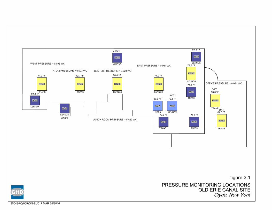
figure 3.1
PRESSURE MONITORING LOCATIONS
OLD ERIE CANAL SITE
Clyde, New York
35048-00(005)GN-BU017 MAR 24/2016
RTU-1
71.3 °F
TRANE
RTU-2
72.7 °F
TRANE
RTU-3
74.8 °F
LENNOX
RTU-4
74.0 °F
LENNOX
RTU-5
72.8 °F
LENNOX
RTU-2
58.6 °F
TRANE
RTU-1
64.3 °F
TRANE
AC-8
74.6 °F
LENNOX
AC-6
72.5 °F
LENNOX
AC-4
71.4 °F
TRANE
AC-5
71.1 °F
TRANE
AC-3
73.0 °F
TRANE
AC-9
72.3 °F
LENNOX
AC-1
69.2 °F
LENNOX
AC-7
69.9 °F
YORK
AC-2
72.5 °F
LENNOX
AVG
WEST PRESSURE > 0.003 WC
RTU-2 PRESSURE > 0.003 WC
CENTER PRESSURE > 0.029 WC
EAST PRESSURE > 0.061 WC
OFFICE PRESSURE > 0.031 WC
LUNCH ROOM PRESSURE > 0.029 WC
DAT
DAT

GHD | Interim Site Management Plan | 035048 (07) | Page 17
Appendices

GHD | Document Title | xxxxxxxx (x)
Appendix AChange of Use Form


GHD | Document Title | xxxxxxxx (x)
Appendix BSub-Slab Depressurization System Inspection
Form

35048 Page 1 of 1 Rev.1, 10/181/16
GHD Project No. 035048Old Erie Canal Site, Clyde, New York
SUBSTRUCTURE DEPRESSURIZATION SYSTEM INSPECTION FORM
Address:
Structure ID:
Yes No1. Was the owner interviewed to discuss satisfaction with system?1a. Is the owner satisfied with the system? (If no, indicate issues below)2. Is the integrity of the concrete floor vapor barrier intact?3. Is the integrity of the concrete wall vapor barrier intact?4. Has the system been modified since the original installation?5. Is the unit connected and operating/running?6. Check the U-tube manometer to ensure the system is under vacuum.6a. Indicate the U-tube reading (inches of water)7. Check the motor fan – is there any noise or vibration?7a. Is the fan securely mounted?8. Are the electrical connections secure?9. Are the labels on the system in place and intact?10. Are pipes sealed at concrete penetration points?11. Is the system exhaust free from obstructions?11a. Have any intakes been located near the exhaust?
Notes:
Inspection PerformedBy: Date:

GHD | Document Title | xxxxxxxx (x)
Appendix CDifferential Transducers Guide
d

Installation Guide
1-800-257-3872 Toll Free1-978-264-0292 Fax
www.setra.com Web Site
Model 267 and 267MRDifferential Pressure Transducers
159 Swanson Road, Boxborough, MA 01719-1304 Tel: 800-257-3872/978-263-1400
SS2039 Rev.F 07/26/2011

Model 264 For Static Duct and Flow Measurement
Model 265 Smaller Size 10 PSI Overpressure
Model 230 Wet/Wet Differential Pressure Measurement
Model 209 Rugged Low Cost Gauge Pressure Measurement from 0-5 to 0-1000 PSIG
Setra offers a complete line ofHVAC Products

Table of Contents1.0 GENERAL INFORMATION ................................................................................................1
2.0 MECHANICAL INSTALLATION ........................................................................................2 2.1 Media Compatibility ............................................................................................2 2.2 Environment ..........................................................................................................2 2.3 Pressure Fittings ...................................................................................................2
3.0 ELECTRICAL INSTALLATION ...........................................................................................2 3.1 Voltage Output Units
1/2”Conduit Opening, PG9, PG-13.5 Electrical Termination ................2 3.2 Voltage Output Units
9 Pin D-sub Connector Electrical Termination ..........................................3 3.3 Current Output Units
1/2” Conduit Opening, PG9, PG-13.5 Electrical Termination ................4 3.4 Current Output Units
9 Pin D-sub Connector Electrical Termination .........................................5 3.5 4-20 mA Circuit Diagram ...................................................................................5 3.6 EMC Certification ...................................................................................................5
4.0. CALIBRATION ......................................................................................................................6 4.1 Voltage Output Zero Adjustment...................................................................6 4.2 Voltage Output Span Adjustment .................................................................6 4.3 Current Output Zero Adjustment ..................................................................7 4.4 Current Output Span Adjustment ..................................................................7
5.0 MODEL 267 OPTIONAL LCD DISPLAy .........................................................................7
6.0 MODEL 267MR MULTI-RANGE OPERATION ..............................................................8 7.0 MODEL 267 & 267MR PERFORMANCE SPECIFICATIONS .....................................9
8.0 RETURNING PRODUCTS FOR REPAIR ....................................................................... 10
9.0 WARRANTy AND LIMITATION OF LIABILITy .......................................................... 10
10
8.0 RETURNING PRODUCTS FOR REPAIRPlease contact a Setra application engineer (800-257-3872, 978-263-1400) before returning unit for repair to review information relative to your application. Many times only minor field adjustments may be necessary. When returning a product to Setra, the material should be carefully packaged and shipped prepaid to:
Setra Systems, Inc. 159 Swanson Road Boxborough, MA 01719-1304 Attn: Repair Department
To assure prompt handling, please supply the following information and include it inside the package or returned material:
1. Name and phone number of person to contact. 2. Shipping and billing instructions. 3. Full description of the malfunction. 4. Identify any hazardous material used with product.
Notes: Please remove any pressure fittings and plumbing that you have installed and enclose any required mating electrical connectors and wiring diagrams.
Allow approximately 3 weeks after receipt at Setra for the repair and return of the unit.Non-warranty repairs will not be made without customer approval and a purchase order to cover repair charges.
Calibration ServicesSetra maintains a complete calibration facility that is traceable to the National Institute of Standards & Technology (NIST). If you would like to recalibrate or recertify your Setra pressure transducers or transmitters, please call our Repair Department at 800-257-3872 (978-263-1400) for scheduling.
9.0 WARRANTy AND LIMITATION OF LIABILITySETRA warrants its products to be free from defects in materials and workmanship, subject to the following terms
and conditions: Without charge, SETRA will repair or replace products found to be defective in materials or workmanship within the warranty period; provided that:
a) the product has not been subjected to abuse, neglect, accident, incorrect wiring not our own, im-proper installation or servicing, or use in violation of instructions furnished by SETRA;
b) the product has not been repaired or altered by anyone except SETRA or its authorized service agen-cies;
c) the serial number or date code has not been removed, defaced, or otherwise changed; andd) examination discloses, in the judgment of SETRA, the defect in materials or workmanship developed
under normal installation, use and service;e) SETRA is notified in advance of and the product is returned to SETRA transportation prepaid.
Unless otherwise specified in a manual or warranty card, or agreed to in writing and signed by a SETRA officer, SETRA pressure and acceleration products shall be warranted for one year from date of sale.
The foregoing warranty is in lieu of all warranties, express, implied or statutory, including but not limited to, any implied warranty of merchantability for a particular purpose.
SETRA’s liability for breach of warranty is limited to repair or replacement, or if the goods cannot be repaired or replaced, to a refund of the purchase price. SETRA’s liability for all other breaches is limited to a refund of the purchase price. In no instance shall SETRA be liable for incidental or consequential damages arising from a breach of warranty, or from the use or installation of its products.
No representative or person is authorized to give any warranty other than as set out above or to assume for SETRA any other liability in connection with the sale of its products.
For all CE technical questions, contact Setra Systems, USA. EU customers may contact our EU representative Hengstler GmbH, Uhlandstr. 49, 78554 Aldingen, Germany (Tel: +49-7424-890, Fax: +49-7424-89500).

7.0 MODEL 267 & 267MR PERFORMANCE SPECIFICATIONS Accuracy RSS* (at constant temperature.) ±1.0% FS Non-Linearity, BFSL ±0.98% FS Hysteresis 0.2% FS Non-Repeatability 0.1% FS *RSS of Non-Linearity, Non-Repeatability and Hysteresis.
Thermal Effects Compensated Range °F(°C) +40 to +150 (+5 to +65) Zero/Span Shift %FS/°F(°C) 0.033 (0.06) Maximum Line Pressure 10 psi Overpressure 10 psi in positive or negative
direction Warm-up Shift ±0.1% FS total
Position Effects (Unit is factory calibrated at 0g effect in the vertical position) Range Zero Offset (%FS/G) 0 to 1” WC 2.1 0 to 1” WC .22 0 to 5” WC .14
TABLE-2 RANGE SWITCHING INSTRUCTIONS FOR PASCAL RANGES MR5 MR6 MR7 MR8 MR9 SWITCH SWITCH SWITCH RANGE RANGE RANGE RANGE RANGE SETTINGS SETTINGS SETTINGS 0-5V 0-10V 4-20mA OUTPUT OUTPUT OUTPUT
Factory Default Setting 0-25Pa 0-200Pa 0-1000Pa 0-2500Pa 0-7500Pa
0-100Pa 0-500Pa 0-1250Pa 0-3750Pa
0-50Pa 0-250Pa 0-625Pa 0-1875Pa
±12.5Pa ±100Pa ±500Pa ±1250Pa ±3750Pa
±50Pa ±250Pa ±625Pa ±1875Pa
±25Pa ±125Pa ±312Pa ±937Pa
9

Setra SystemsModel 267 and Model 267MR
1.0 GENERAL INFORMATION Every Model 267 and Model 267MR (Multi-Range) has been tested and cali-
brated before shipment. Specific performance specifications are listed on Page 9 of this Guide.
The Model 267 is single range only. The Model 267MR has field selectable
range capability. The 267MR is factory calibrated for the highest pressure range. The range label on the cover of the unit indicates the factory-calibrat-ed range. Should the 267MR be re-ranged in the field, other Multi-Range labels are included.
Setra Systems 267 and 267MR pressure transducers sense differential or gauge (static) pressure and convert this pressure difference to a proportional high level analog output for both unidirectional and bidirectional pressure ranges. Two output versions are offered: A configurable voltage output of 0 to 5 VDC or 0 to 10 VDC, and a current output of 4 to 20 mA.
Sections 1 through 4 and 7 through 9 of this Guide apply to both Models 267 and 267MR. Section 5 refers to the Model 267 only. Section 6 refers to the Model 267MR only.
1
TABLE-1 RANGE SWITCHING INSTRUCTIONS FOR IN.WC MR1 MR2 MR3 MR4 SWITCH SWITCH SWITCH RANGE RANGE RANGE RANGE SETTINGS SETTINGS SETTINGS 0-5V 0-10V 4-20MA OUTPUT OUTPUT OUTPUT
0–0.1“ 0–1” 0–5” 0–30”
0–.5” 0–2.5” 0-15”
0–.25” 0–1.25” 0–7.5”
±0.05” ±.5” ±2.5” ±15”
±.25 ±1.25” ±7.5”
±.125” ±.625” ±3.75”
If it is a 0-5 VDC output, the switches are set:
To change the range to 0 to .25” W.C. with a 0-10 VDC output, change the switches to:
ON
8
ON
1 2 3 4 5
6.0 MULTI-RANGE OPERATION - MODEL 267MR ONLy
The 267MR is re-rangeable by accessing the switches located internal to the transducer housing. To access the “Dip” switches, remove the screws on the top of the case and lift off the cover. The “Dip” switches are located on the electronics board as shown in Diagrams 1 and 5. The voltage output version has 5 switches. The current version has 4. The location of these switches, “on” (up position) or “off” (down position), determine what range has been selected. See Table 1 or 2 below for switch positions for in.WC or Pascals.
Multi-Range units are factory set to the highest range. As an example, an MR2 range is factory set to 0 to 1” W.C.
If the 267MR Range is re-configured from the factory calibration, place the correct range label (enclosed) on the cover label, over the area indicating the factory default range.Notes: Voltage output is set based upon ordering code.
See switch settings below to confirm voltage output. The 4-20 mA current version has only 4 switches.
Factory Default Setting

2.0 MECHANICAL INSTALLATION
2.1 Media Compatibility
Model 267 and 267MR transducers are designed to be used with air or noncon-ducting gases. Use with liquids or corrosive gases will damage the unit.
2.2 Environment
The operating temperature limits of the 267 and 267MR are as follows:
Operating Temperature 0°F to +150°F (-18°C to +65°C) Compensated Temperature Range +40°F to +150°F (+5°C to +65°C) 2.3 Pressure Fittings
The Model 267 and 267MR can be supplied with three different pressure fitting configurations:
A. 3/16” O.D. Barbed Brass Pressure Fittings – Typically installed with 1/4” push-on tubing
B. 1/4”NPT Brass Pressure Fittings – Typically installed with mating NPT male fitting.
C. Static Pressure Probe – Installed on the duct by drilling a 7/16” hole in the duct at the desired mounting location, inserting the pressure probe into the duct, and mounting the 267 onto the duct with the mounting tabs.
For the 3/16” O.D. and 1/4” NPTF pressure fittings, both the positive (high) pres-sure port and the reference (low) pressure port are located on the bottom of the unit, labeled “HIGH” and “LOW” respectively. For best results (shortest response times), 3/16” I.D. tubing is suggested for tubing lengths up to 100 feet long, 1/4” I.D. for tubing lengths up to 300 feet, and 3/8” I.D. for tubing lengths up to 900 feet.
The static pressure probe is the positive (high) pressure port located on the back of the unit. The reference (low) pressure port is located on the bottom of the unit and can be used for differential pressure measurements.
3.0 ELECTRICAL INSTALLATION
Wiring is through a 1/2” conduit opening or factory installed PG-9, PG-13.5 or 9 pin D-sub connector. (See Section 3.2 for instructions on wiring the 9 pin D-sub connector.) Both current and voltage output units are reverse wiring protect-ed.
3.1 Voltage Output Units - 1/2” Conduit Opening, PG9 or PG-13.5 Elec-trical Termination
Wiring terminations are identified on the circuit board below the terminal strip (see Section 3.1 for voltage output units or Section 3.3 for current units). To access the terminal strip, turn the screws on top of the case counter clockwise until the cover can be removed. The screws are captured and will be secured in the top of the case.
2
With full range pressure applied to the high pressure port (reference port open to atmosphere), the span may be adjusted by turning the SPAN adjustment screw. (See Diagram 1 for location of SPAN adjustment.) Factory settings are:
Unidirectional Pressure Ranges Bidirectional Pressure Ranges Span Adjustment Output Span Adjustment Output 5.0 VDC (±25 mV) 0-5 VDC 2.5 VDC (±25 mV) 0-5 VDC 10 VDC (±50 mV) 0-10 VDC 5 VDC (±50 mV) 0-10 VDC
Example 1: Unidirectional pressure range of 0 to 1” W.C. with 0 to 5 VDC output Apply 1.00” W.C., adjust span to 5 VDC (± mv) Example 2: Bidirectional pressure range of ±5” W.C. with 0 to 5VDC output Apply 5.00” W.C., adjust span to 5 VDC (±25 mV)
4.3 Current Output Zero Adjustment
While monitoring the current output , and with both pressure ports open to atmosphere, the zero may be adjusted by turning the zero adjustment screw. (See Diagram 3 for location of zero adjustment) Factory settings are:
Unidirectional Pressure Ranges Bidirectional Pressure Ranges Zero Adjustment Output Zero Adjustment Output 4mA (0.08 mA) 4-20 mA 12 mA (0.08 mA) 4-20 mA
4.4 Current Output Span Adjustment
Span or full scale output adjustments should only be performed by using an ac-curate pressure standard (electronic manometer, digital pressure gauge, etc.) with at least comparable accuracy to the 267 or 267MR transducer (<±1% FS). With full range pressure applied to the high pressure port (reference port open to atmo-sphere), the span may be adjusted by turning the SPAN adjustment screw. (See Diagram 1 for location of SPAN adjustment.) Factory settings are:
Unidirectional Pressure Ranges Bidirectional Pressure Ranges Span Adjustment Output Span Adjustment Output 20mA (0.08 mA) 4-20 mA 20 mA (0.08 mA) 4-20 mA
Example 1: Unidirectional pressure range of 0 to 1” W.C. with 4 to 20 mA output Apply 1.00” W.C., adjust span to 20 mA (±0.08mA) Example 2: Bidirectional pressure range of 5” W.C. with 4 to 20 mA output
Apply 5.00” W.C., adjust span to 20 mA (±0.08 mA)
5.0 MODEL 267 OPTIONAL LCD DISPLAy
The Model 267 is available with an optional 3 1/2 digit LCD display. The LCD display is adjusted at the factory prior to shipment. The LCD is connected to the zero and span adjustment potentiometers. Therefore, adjustment of the zero and span ac-cording to Section 4 adjusts the LCD display.
7

The Model 267 and 267MR voltage output is a 3-wire circuit, with three ter-
minals available for wiring (see Diagram 1). The -Excitation and -Output are commoned on the circuit (see Diagram 2). The excitation/output specifications are:
Excitation Output
9 to 30 VAC / 11.5 to 42 VDC 0 to 5 VDC 12 to 30 VAC / 13 to 42 VDC 0 to 10 VDC
The 267MR has a field selectable 0 - 5 or 0 - 10 VDC output. (See Section 6.0 for
switch settings to determine whether the voltage output is set to 0-5 or 0-10 VDC.) The 267 has either a 0-5 VDC or 0-10 VDC output, calibrated at the Fac-
tory.
Voltage Circuit Diagram
+EXC Connected to positive terminal of DC or AC power supply GND Connect as the reference for power supply and output signal + SIG Connect to positive terminal of control or pressure monitor
3
2. If unshielded cable is used, an earth grounded metal conduit fitting can be used to replace the shielded cable.
3. For a sensor with a metal body or enclosure, the body/enclosure must be grounded to earth. If a protective metal housing is used, the metal housing should be grounded to earth
4. If a protective plastic housing is used, the housing must be able to with-stand at least 2 KV from the housing to earth ground, without damaging the circuit.
5. The unit shall be installed or operated in a controlled electromagnetic environment.
4.0. CALIBRATION
The 267 and 267MR transducer is factory calibrated and should require no field adjustment. Generally, the mounting position will have a zero shift effect on ranges below 1” WC. Whenever possible, any zero and/or span offsets should be corrected by software adjustment in the user’s control system. However, both zero and span adjustments are accessible under the cover of the unit, below and to the right of the terminal strip. The 267 and 267MR transducer is calibrated in the vertical position at the factory (mounting tabs vertical).
4.1 Voltage Output Zero Adjustment
While monitoring the voltage between the positive output (+SIG) and common (GND), and with both pressure ports open to atmosphere, the zero may be ad-justed by turning the zero adjustment screw. (See Diagram 1 for location of zero adjustment.) Factory settings are:
Unidirectional Pressure Ranges Bidirectional Pressure Ranges Zero Adjustment Output Zero Adjustment Output 0.05 VDC (±25 mV) 0-5 VDC 2.5 VDC (±25 mV) 0-5 VDC 0.05 VDC (±50 mV) 0-10 VDC 5 VDC (±50 mV) 0-10 VDC
4.2 Voltage Output Span Adjustment (Complete the zero adjustment before setting span.)
Span or full scale output adjustments should only be performed by using an accurate pressure standard (electronic manometer, digital pressure gauge, etc.), with at least comparable accuracy to the 267 or 267MR transducer (<±1% FS).
6
+EXC
GND Model 267MR
Power Supply
Readoutor
DAS
Diagram 2
+SIG
Electrical Connections
Range Select Switches (267MR version only)
+EXC GND +SIG
Zero
Span
Diagram 1

*Pins 8 and 9 are internally commoned together, user can connect to either pin.
3.3 Current Output Units - 1/2’’ Conduit Opening, PG9 or PG-13.5Electrical Termination
The Model 267 and 267MR is a two-wire loop-powered 4 to 20mA current
output unit (see Diagram 5). The current flows into +EXC. terminal and returns back to the power supply through the -EXC. terminal (see Diagram 6). The power supply must be a DC voltage source with a voltage range between 9 and 30 measured between terminal +EXC. and -EXC. The unit is calibrated with a 24VDC loop supply voltage and a 250 ohm load.
4
Electrical Connections
Range Select Switches (267MR version only)
Diagram 5
+EXC -Span
Zero
Diagram 6
5
Diagram 7 Diagram 8
NOITCENNOC rotcennoCbus-Dnip9
NOITATICXE+ 4
NOITATICXE- 9
PIN 4
NOITCENNOCrotcennoCbus-Dnip9
noitanimreTlacirtcelE
NOITATICXE+ 4
TUPTUO+ 1
NOMMOC 9
DNGESAC LLEHS
Diagram 4
Diagram 3 Excitation Output 9 to 30 VAC / 11.5 to 42 VDC 0 to 5 VDC 12 to 30 VAC / 13 to 42 VDC 0 to 10 VDC
PINS 8, 9*Common
PIN 4+ EXC
PIN 1+ Output
3.2 Voltage Output Units - 9 pin D-sub Connector Electrical Termination The Model 267 and 267MR voltage output is a 3-wire circuit, with three pins avail-
able for wiring (see Diagram 3). The voltage output pin designations are shown in Diagram 4:
267MR9 to 30 VDC
+
_
Current Monitor Devce
30Loop Supply Voltage (Vdc)
OperatingRange
9
Loop
Res
ista
nce
(Ohm
s)0
Diagram 9
8, 9
3.4 Current Output Untis – 9 pin D-sub Connector Electrical Termination
The Model 267 and 267MR is a two-wire loop-powered 4 to 20mA current out-put unit (see Diagram 6). The current flows into +EXC. Pin 4 (+EXC) and returns back to the power supply through Pin 9 (-EXC) (see Diagram 7). The power supply must be a DC voltage source with a voltage range between 9 and 30 measured between Pin 4 and Pin 9 (-EXC). The unit is calibrated with a 24VDC loop supply voltage and a 250 ohm load. The current output 9 pin D-sub connector pin designations are shown in Diagram 8.
3.5 4-20 mA Circuit Diagram
Minimum Supply Voltage (VDC) = 9 + 0.02 x (resistance of receiver plus line) Maximum Supply Voltage (VDC) = 30 + 0.004 x (resistance of receiver plus line). If the current loop has a current limiter, the threshold should be adjusted to 35 mA minimum (see Diagram 9).
Loop Power Supply vs.Loop Resistance for 4 to 20 mA Current Transducers
3.6 EMC Compliance
This product complies with EN61326-1:2006 in accordance with EN61326-2-3:2006 to be used in Controlled EM Immunity and Class B Emission environment. Special cautions must be take to fully meet EU EMC compliance:
1. Shielded cable must be used, and the shield must be tied to earth ground (not power supply ground) on at least one end of the cable shield/drain wire. The shield must be maintained all the way from sensor to the power supply.
PIN 9- EXC
+ EXC

GHD | Document Title | xxxxxxxx (x)
Appendix DBACTALK Operator’s Manual

© Honeywell LTBT-OP-EBT30 Rev. 05
Envision for BACtalk
Operator’s Manual

User agreement and limited warrantyIMPORTANT - PURCHASE OF ALERTON PRODUCTS OR USE OF SOFTWARE, FIRMWARE AND / OR ACCOMPANYING DOCUMENTATION (DEFINED BELOW) IS SUBJECT TO LICENSE RESTRICTIONS AND LIMITED WARRANTY. CAREFULLY READ THIS AGREEMENT BEFORE USING ALERTON PRODUCTS, SOFTWARE, FIRMWARE AND/OR DOCUMENTATION.This is a legal "Agreement," concerning the purchase of Products and use of Software, Firmware and/or Documentation, between you, the "User" (either individually or as an authorized representative of the company that is purchasing, has purchased, or is using the Products, Software, Firmware or Documentation) and Honeywell, 6670 - 185th Avenue NE, Redmond, Washington 98052 USA. ("Honeywell").PURCHASE OF ALERTON PRODUCTS OR USE OF SOFTWARE, FIRMWARE AND / OR ACCOMPANYING DOCUMENTATION INDICATES USER'S COMPLETE AND UNCONDITIONAL ACCEPTANCE OF THE TERMS AND CONDITIONS SET FORTH IN THIS AGREEMENT.
Honeywell provides Alerton products ("Products"), software programs ("Software"), firmware, e.g., protocols, software program code, device drivers and related hardware ("Firmware") and accompanying documentation ("Documentation") and grants a non-exclusive and non-transferable license ("License") to User to use the Software and the Firmware only on the following terms and conditions. Taken together, Products, licensed Software, licensed Firmware and accompanying Documentation are collectively defined as "Alerton Product(s)" in this Agreement.
1. Copyright. The Software, Firmware and Documentation are copyrighted and protected by United States copyright laws and international treaty provisions and laws, contain valuable proprietary products, information and trade secrets, and shall remain the property of Honeywell. User may not and shall not copy or otherwise reproduce or make available to any other party any part or all of the Software, Firmware or Documentation nor decompile, disassemble, reverse engineer, manufacture or modify any portion of the Products, Software, Firmware, Documentation or any portion of the same for any purpose or otherwise attempt to determine the underlying source code of the Software or Firmware or permit any such action; provided however, User may either (a) make one (1) copy of the Software solely for backup or archival purposes, or (b) transfer one (1) image of the Software to a single hard disk, CD or other comparable media, provided User keeps the original solely for backup or archival purposes.
2. License. User is hereby licensed to use one (1) copy of the Software for User's own use in operating the Products. User may not rent, lease or otherwise assign or transfer all or any part of the Software, Firmware or Documentation. In addition, User may not sublicense, assign or transfer this License or Agreement, or any part thereof. Any attempt to do so shall terminate this License and User's right to use the Software and Firmware and shall subject User to liability for damages to Honeywell. LICENSING TO USER OF THE SOFTWARE AND FIRMWARE COMMENCES WHEN USER USES THE SOFTWARE, FIRMWARE AND / OR ACCOMPANYING DOCUMENTATION.3. Copies, Modification or Merger. Except as specifically set forth in Paragraph 1, User may not copy, modify, transfer all or any portion of the Software, Firmware or Documen-tation or merge it or them into another program, unless expressly authorized in advance in writing by Honeywell. User must, as a condition of this License, reproduce and include the identifying marks, copyright and proprietary notices on any permitted copy of the Software, Firmware and Documentation. "Copies" shall include, without limitation, any complete or partial duplication on any media, adaptations, translations, compilations, partial copies within modifications, mergers with other material from whatever source and updated works. User will use its best efforts to prevent any unauthorized copying or other activity with respect to the Software, Firmware and Documentation.
4. Third-Party Beneficiary. For any software or other technology under this Agreement licensed by Honeywell from Microsoft( or other licensors, Microsoft or the applicable licensor is a third party beneficiary of this Agreement with the right to enforce the obligations set forth in this Agreement.
5. Warranty. Honeywell warrants Honeywell manufactured or produced Alerton Products to be materially free from defects and to substantially conform to Honeywell's pub-lished specifications for a period of twenty-four (24) months from date of shipment from Honeywell (the "Product Warranty Period"). This entire Section 5 is defined as the "Warranty."
Honeywell also warrants Alerton Products that it has previously repaired or replaced for the greater of ninety (90) days from the date of their shipment from Honeywell or the remainder of the Product Warranty Period of the originally shipped Alerton Product (the "Repair/Replacement Warranty Period").During the Product Warranty or Repair/Replacement Warranty Period, Honeywell will repair or replace the applicable Alerton Products without charge and will add applicable engineering changes and upgrades.
This Warranty only applies to defective materials and workmanship of Alerton Products and excludes defects that result from misuse, neglect, improper installation, unauthor-ized repair or alteration, damage during or after shipping, accident and/or misapplication of such products. This Warranty does not apply to parts, equipment, software, firm-ware, components, documentation or any other item that Honeywell does not manufacture or produce. This Warranty is also voided by removal or alteration of Alerton Product identification labels. Honeywell's sole responsibility with respect to Alerton Products shall be, within the applicable Product Warranty Period, to furnish a replacement Alerton Product (FOB fac-tory) or, at the option of Honeywell, to repair and return (FOB Factory) the defective Alerton Product. HONEYWELL HEREBY EXCLUDES ALL IMPLIED WARRANTIES OF MERCHANTABILITY AND FITNESS FOR A PARTICULAR PURPOSE AND ALL OTHER EXPRESS OR IMPLIED WARRANTIES WHATSOEVER WITH RESPECT TO ALERTON PRODUCTS. In no event shall Honeywell be liable for personal injury, loss of profit, loss of production, loss of business or goodwill, business interruption, loss of business information or data, loss due to delays, any other pecuniary loss, any cost or liability of Users or any other parties, to themselves or to others, increased or uncovered operating or fixed costs, inefficiency, or any other special, exemplary, consequential, incidental, indirect or remote damages in any manner, directly or indirectly, related to design, manufacturing, supply, installation or use of, or inability to use, Alerton Products, or any other act or failure to act by Honeywell or its agents or contractors.
HONEYWELL MAKES NO CLAIMS OR WARRANTIES WITH RESPECT TO THE SOFTWARE OR THE FIRMWARE AND SPECIFICALLY DISCLAIMS ANY IMPLIED WAR-RANTIES OF MERCHANTABILITY OR FITNESS FOR A PARTICULAR PURPOSE AND EXPRESS OR IMPLIED WARRANTIES THAT THE OPERATION OF THE SOFT-WARE OR FIRMWARE OR ANY PORTION THEREOF WILL BE INTERRUPTION OR ERROR FREE. Notwithstanding anything to the contrary contained in this Warranty, Honeywell shall not be liable to Users or any other parties for any damages, including, but not limited to consequential, incidental, indirect, special, exemplary remote or pecu-niary damages and any stated or express warranties set forth in this warranty are in lieu of all obligations or liability for any damages arising out of or in connection with the use or performance of, or inability to use, Alerton Products and the licensed Software and Firmware.
User's exclusive remedy and Honeywell's entire liability arising from or in connection with the Alerton Products, Software, Firmware, Documentation and/or this License and Agreement (including, without limitation, any breach of any warranty, express or implied) shall be, at Honeywell's option, the repair or replacement of the Products or Software or Firmware as applicable, as stated above. ACCORDINGLY, HONEYWELL AND ITS DESIGNATED DEALERS AND THEIR DESIGNATED ASSOCIATE DEALERS HAVE EXCLUDED AND DISCLAIM ANY AND ALL IMPLIED WARRANTIES OF MERCHANTABILITY OR FITNESS FOR A PARTICULAR PURPOSE AND ALL OTHER WARRAN-TIES, EXPRESS OR IMPLIED, WHATSOEVER, WITH RESPECT TO THE PRODUCTS, THE SOFTWARE, THE FIRMWARE, THE DOCUMENTATION AND/OR THE LICENSE. USER HEREBY ACKNOWLEDGES THE SAME.
6. Remedies of Honeywell. IF USER BREACHES THIS AGREEMENT, USER'S LICENSE HEREUNDER SHALL BE AUTOMATICALLY TERMINATED. Upon termination, User shall return the Software, Firmware and all Documentation to Honeywell and destroy any copies of the Software, Firmware and the Documentation or any portions thereof which have not been returned to Honeywell, including copies resident on electronic or digital media. If User breaches this Agreement, Honeywell shall be entitled to all damages suffered by Honeywell resulting from such breach and Honeywell shall be entitled to equitable and injunctive relief in addition to all other remedies at law. In this regard, User acknowledges that its breach of any provision of this Agreement will cause Honeywell immediate and irreparable injury for which there are inadequate remedies at law. The prevailing party in any dispute concerning this Agreement shall be entitled to the costs of collection and enforcement, including but not limited to reasonable attor-neys' fees, court costs and all necessary expenses, regardless of whether litigation is commenced.
7. Export. Alerton Products are subject to regulation by local laws and United States government agencies, which prohibit export or diversion of certain products, information about the products, and direct products of the products to certain countries and certain persons. User agrees that User will not export in any manner any Alerton Product or direct product of Alerton Product, without first obtaining all necessary approval from appropriate local and United States government agencies.
8. RESTRICTED RIGHTS NOTICE. Alerton Products, Software, Firmware and Documentation have been developed entirely at private expense and are commercially pro-vided with RESTRICTED RIGHTS. Use, duplication or disclosure by the U.S. Government or a U.S. Government subcontractor is subject to the restrictions pursuant to DFARS 227.72013 (October 1988) and DFARS 52.227-19 (June 1987), as amended and as applicable. Manufacturer, licensor and publisher is Honeywell, 6670 - 185th Ave-nue NE, Redmond, Washington 98052 USA.
9. Statute of Limitations. No action for any breach of a warranty, if any, deemed or actual, may be commenced more than one (1) year following the expiration of such warranty.10. Other. User further agrees that this Agreement is the complete and exclusive statement of the agreement between User and Honeywell and supersedes any proposal or prior agreement or any other communications between Honeywell or any of its representatives and User relating to the use of the Software, Firmware, Documentation and purchase of the Products. This Agreement may only be modified by a physically signed writing between User and Honeywell. Waiver of terms or excuse of breach must be in writing and shall not constitute subsequent consent, waiver or excuse. If any provision of this Agreement is finally determined to be unenforceable, the remaining provisions shall remain in effect. The laws of the State of Washington and the United States, including U.S. copyright laws, shall govern this Agreement. Venue in the event of any suit, proceeding or claim shall be in the courts located in King County, Washington, USA. If User has any questions regarding this Agreement, User may contact Honeywell by writ-ing Honeywell at the above address.
This Agreement shall inure to the benefit of and be binding upon the parties and their successors, administrators, heirs and permitted assigns. Notwithstanding any termina-tion of this Agreement and not in limitation of any other provision of this Agreement, User shall specifically continue to be fully obligated to comply with all of the requirements of paragraphs one (1) through four (4), as if the Agreement were not terminated and all remedy provisions hereunder shall apply to any breach of such obligations.

Chapter 1 |
© Honeywell LTBT-OP-EBT30 Rev. 05 1
Chapter 1: Before you begin 3Using the Envision for BACtalk documentation set 4
Envision for BACtalk Operator’s Manual (this manual) 4Readme file 5Online Help 5Installation and Startup Guide (LTBT-TM-ADMIN) 5Display Developer’s Guide (LTBT-TM-DSPDV) 5BACtalk Systems Programmer’s Guide and Reference(LTBT-TM-PRGRMR) 5BACtalk Systems Design Guide (LTBT-TM-SYSDSGN) 5Your site documentation 6Version information 6
What you need to know 7BACtalk BAS architecture and components 7About the BACnet Standard 8
About BACnet objects, properties, and services 10BACnet objects 10BACnet properties 10BACnet services 10Specifying an ID for a property 11Binary objects (BIs, BOs, BVs) 11Analog objects (AIs, AOs, AVs) 12Inputs and outputs (AIs, AOs, BIs, and BOs) 12Values (AVs and BVs) 12Multistate objects (MIs, MOs, MVs) 12
New in Envision for BACtalk 13
Chapter 2: Data displays 17About data displays 17
Viewing and navigating displays 18Using pushbuttons to navigate displays 18Using the View menu to navigate displays 19Working with multiple display windows 19
Identifying and working with items on a display 21Improved graphics editing 21Feedback items 21Commanding system parameters with control items 22
Using shortcut menus to access automation features 26Setting up an alarm, schedule, or trendlog for an item from a data display 26
Interpreting status messages and alarms on displays 27
Chapter 3: Zones 29Benefits 29
Quick start–zone setup 31How zones work 32
Why use zones? 32What makes a zone? 33How zones work with schedules and optimum start 33How zones work with tenant activity 33

Operator’s Manual | Envision for BACtalk
2 LTBT-OP-EBT30 Rev. 05 © Honeywell
How zones are saved and run 33Setting up a zone 36
Defining a zone 37Defining advanced zone settings 39Setting optimum start references 41Setting the tenant override reference 42
Working with zones 43Editing a zone setup 43Deleting a zone 44Copying a zone setup 44Options for scheduling a zone 44Setting up and adjusting a zone’s optimum start settings 45
Chapter 4: Alarms 47Benefits 47
Quick start–alarm setup 49How alarms work 50
About the monitored property 50About the alarm setup 51About the alarm handler 51The importance of alarm descriptions and alarm messages 54About alarm delays 54Types of alarms 55How alarms are saved and run 61
Setting up alarms 62Using the shortcut menu on a data display 62Using Point Alarms on the BACtalk menu 63Using the New Alarm Wizard 63Setting up fixed limit analog alarms 69Setting up a URL notified or display linked alarm 70Setting up floating limit analog alarms 72Setting up binary (on/off) alarms 74Setting up a command fail alarm for binary points 76Setting up alarm handlers 77Using Alarm Setup at an operator workstation 87
Working with alarms 90Reading BACtalk alarm messages 90Working with Current Alarms view 92Working with alarm histories 93Auto-archiving alarm history data 95Using remote alarm history 95Auto-archiving remote alarm history data 96Alarm history database files 96Sorting records and printing 97Working with Custom Process IDs 97
Chapter 5: Schedules 101Benefits 101
Quick start–schedule setup 102How schedules work 103

Chapter 1 |
© Honeywell LTBT-OP-EBT30 Rev. 05 3
How schedules write to zones and points 103Setting up schedules with the schedule wizards 106
Using the New Schedule Wizard 107Using the Time Schedule Wizard 107Setting the schedule date and hours of operation 110Editing a scheduled command 112Deleting a scheduled command 112Jumping to an existing holiday or event schedule 112Customizing the appearance of the timetable 115
Editing schedule sets and point assignments 116Changing the points or zones that a schedule set controls 116Replacing a schedule in a schedule set 117
Chapter 6: Optimum start 119Benefits 119
Quick start–optimum start setup and adjustment 121How optimum start works 122
About automatic and manual modes of operation 122How an optimum start program is saved and runs 127
Setting up and adjusting optimum start values 130Selecting the zone you want to work with 131Setting or confirming optimum start references for the zone 132Editing optimum start settings 133
Temporarily disabling optimum start 138Strategies and tips for checking optimum start operation 139
Chapter 7: Tenant activity 141Benefits 141
Quick start–tenant activity setup 143How tenant activity works 144
Tenants and property managers 144Tenant override in a zone 145The tenant activity log versus the tenant bill 146Where tenant activity information is stored and how tenant activity runs 147
Setting up tenant activity 148Setting up zones 148 Setting up property manager profiles 149Setting up tenant profiles 150
Viewing tenant activity and billing tenants 157Using the Tenant Activity Log 157Generating tenant bills 159Setting up email billing 161Viewing the Tenant Activity Diagnostic Log 162
Chapter 8: Trendlogs 163Benefits 163
Quick start–trendlog setup 165How trendlog samples are gathered and saved 166
Trendlog database files 168

Operator’s Manual | Envision for BACtalk
4 LTBT-OP-EBT30 Rev. 05 © Honeywell
Setting up a trendlog 169Using the multiple trendlog builder 173Using variables for trendlog descriptions 177Advanced trendlog options 178
Viewing trendlogs 181Table view 181Graph view 183Event view 184Adding companion logs 184Updating trendlog data while viewing 184
Archiving trendlog data 185Auto-archive 186Replacing or appending to previously archived data 187Archiving all entries 188
Purging trendlog data 188Printing a trendlog view or list 189Using the Enhanced Trendlog Viewer 190
About Enhanced Trendlog Viewer 190Configuring Enhanced Trendlog Viewer 190Starting Enhanced Trendlog Viewer 191Setting the time frame 191Loading data 192Selecting trendlogs 192Viewing data on the charts 194Panning and zooming 197Copying URLs 198For touchscreen users 199
Chapter 9: Energy Logs 201Benefits 201
Quick start–energy log setup 202How energy logs work 203
About meters 204Where an energy log is saved 204
Setting up an energy log 205Using custom energy log units 207Setting up meters 207
Working with energy log data 211Viewing energy log data 211Archiving energy log data 211Purging energy log data 212
Chapter 10: Demand Limiting 213Benefits 213
Quick start–demand limiter setup 216How demand limiting works 217
About energy meters 217How the demand limiter calculates average demand 218How the demand limiter calculates ramp values 221How a demand limiter sheds and restores loads 223

Chapter 1 |
© Honeywell LTBT-OP-EBT30 Rev. 05 5
Where a demand limiter is stored and how it runs 225Working with demand limiters 227
Adding or editing demand limiters 227Setting the demand limiter name and description 228Setting up meters 229Setting up load references 231Setting ramp control parameters 237Working with demand limiter status 239
Chapter 11: File Transfer 241Benefits 241
Quick start–file transfer setup 242Setting up file transfer 243
Setting up the server 243 Setting up File Transfer privileges 246
Working with File Transfer 247
Chapter 12: Energy Dashboards 253Benefits 254
Quick start–dashboard setup 255Setting up a dashboard 256
Setting up user privileges 256Running multiple dashboards 258
Acquiring additional dashboard licenses 258Installing Multiple Building Dashboard 258About drop-in management 259
Launching Energy Dashboard Editor 260Using the dashboard list 261Editing energy dashboards 262
Resources page 264Pages page 266Entities page 271Compare To page 278Equivalents page 280Variable Data page 282Weather Data page 283Miscellaneous page 285Auto Rotation page 287Image Gallery page 288Error Log page 291User Activity page 292
Importing historical data 293Preparing historical data 293Creating the xml file 293Copying data to the server 293Viewing imported data 294
Localizing energy dashboards 295Before you begin 295About localization 295About lexicon files 295

Operator’s Manual | Envision for BACtalk
6 LTBT-OP-EBT30 Rev. 05 © Honeywell
Search order 295Procedures 296Limitations 297
Chapter 13: Setup Reports 299Running reports 299Setting up reports 301
Chapter 14: System Administration 315Device Manager 316
Enabling device communication failure alarms 317Using Device Scan 317Automatically downloading a ROC file to controllers 318Enabling MS/TP proxy 319Backing up and restoring devices 319Restarting and controlling device communication 319Viewing device statistics 319Sending to and saving from BACtalk controllers 320
General System Setup 323Identification 323Network 323Time Sync 326Preferences 326Startup/Shutdown 327Email Setup 328
User and Group management 330Creating user profiles 331Creating group profiles 336Editing user or group profiles 342Using Group Filter 342Viewing user activity 343
About BACtalk reports 347Viewing the list of reports 348Setting up a BACtalk report 348
Working with remote sites in Envision for BACtalk 351Capabilities using a remote connection 351Hardware requirements and options for remote connections 351Setting up and connecting to a remote site 353Transferring point data to a remote site 356Scheduling BACtalk to dial remote sites and gather trendlog data 357
Backup and restore 359Running a manual backup and scheduling regular backups 359Restoring job data 361Maintaining database files 361
Advanced features 363Override Points 363Raw editors 363Object Scanner 366Event Notification Monitor 368

Chapter 1 |
© Honeywell LTBT-OP-EBT30 Rev. 05 7
Event Summary 370BACtalk Object Explorer 371
Glossary 377
Index 387

Operator’s Manual | Envision for BACtalk
8 LTBT-OP-EBT30 Rev. 05 © Honeywell

Chapter 1 | Before you begin
© Honeywell LTBT-OP-EBT30 Rev. 05 3
Before you begin 1
Envision for BACtalk is an operator workstation software package for BACnet-compliant systems. Envision, which runs on a Windows personal computer, enables BACtalk operators and developers to monitor and control BACnet-compliant devices in their building automation system (BAS). The Envision for BACtalk operator workstation communicates with BACnet-compliant field equipment using BACnet over local area networks (LANs) and wide area networks (WANs).
From the Envision for BACtalk operator workstation, operators can access any BAS data made available on the network using the BACnet protocol standard—even if it originates in another manufacturer’s device. Developers can use the Envision for BACtalk operator workstation to program custom direct digital control (DDC) sequences that run locally in BACtalk controllers. They can also configure other site operational details.
In addition to the Envision for BACtalk operator workstation, Alerton offers a complete line of BACnet-compliant equipment controllers (VLCs) and global controllers (BTI, BTI-100, and BACtalk control modules). All BACtalk products exchange messages in compliance with the BACnet protocol and communicate on LANs as specified in ASHRAE Standard 135-2001, BACnet.

Operator’s Manual | Envision for BACtalk
4 LTBT-OP-EBT30 Rev. 05 © Honeywell
Using the Envision for BACtalk documentation setDocumentation for Envision for BACtalk is provided in several forms and formats. It is designed to meet the needs of different users who work with the system in a variety of contexts. This section describes the documentation set and the audience and purpose of each piece.
Envision for BACtalk Operator’s Manual (this manual)This guide focuses on information for BACtalk system users who use the operator workstation to monitor and command their building automation and control system. It provides conceptual information about working with features: zones, schedules, tenant activity, optimum start, demand limiting, alarms, trendlogs, and other features likely to be used in building operations.
The operator’s manual uses a sample job, located on a campus setting at State University, to illustrate how you can incorporate these features into your own BACtalk job. Use this manual when you want the “big picture” about how a feature works and runs or when you need reference information for the best way to set up a feature.
How chapters are organizedChapters in this operator’s manual are organized as follows:
• Feature overview Describes the feature and its benefits in broad terms.
• Quick start A step-by-step overview of feature setup with cross-references to other locations where you can find information.
• How the feature works and runs Detailed information about how setup parameters work together and how the system carries out the feature.
• Setting up the feature Guidelines and instructions for setting up the feature, with screen shots of feature configuration and in-depth information about settings.
• Maintaining or monitoring operation Instructions and tips for working with the feature after it is set up.
Using “examples”Throughout this manual, you will find information under the heading “Example.” These sections typically include sample values to help reinforce your understanding of the concepts discussed. For example, if a feature uses a particular equation, the “example” would demonstrate how the equation works using specific values.
Using “practical applications”You will also find a number of sections with the heading “Practical application.” These sections illustrate how a feature might be implemented and used in the context of the State University sample job. The practical applications are designed to put features in a “real-world” context that you can leverage for your own site.

Chapter 1 | Before you begin
© Honeywell LTBT-OP-EBT30 Rev. 05 5
Note Use the Envision for BACtalk online Help while using the software to find detailed information and procedural instructions related to setting up and using BACtalk features.
Readme fileThis file, Readme.rtf, displays during Envision for BACtalk installation and is saved in the installation under the System folder and on the DVD. It addresses late-breaking operational and installation issues that could not be included in other documentation.
Online HelpOnline Help in Envision for BACtalk provides detailed information and procedural steps for setting up and using BACtalk features. Help is designed to answer your questions while you are working with the Envision for BACtalk software.
Installation and Startup Guide (LTBT-TM-ADMIN)This guide provides critical information and step-by-step instructions for those responsible for installing or upgrading an Envision for BACtalk system. In addition to detailed installation information, it provides guidelines and instructions for job setup and engineering.
Display Developer’s Guide (LTBT-TM-DSPDV)This guide provides information for those responsible for designing and developing data displays for a particular site. It provides guidelines for good design and tips on display strategies. The guide also provides detailed instructions about using display and template editors.
BACtalk Systems Programmer’s Guide and Reference(LTBT-TM-PRGRMR)
This guide is intended for those responsible for programming Envision for BACtalk systems. It provides an introduction to the VisualLogic development tool and offers guidelines for effective programming techniques and strategies. This guide also includes a reference for all available DDC functions.
BACtalk Systems Design Guide (LTBT-TM-SYSDSGN)This guide provides information for those responsible for planning and installing a building automation system (BAS) with Alerton’s BACnet-compliant BACtalk products. This guide provides essential information to use as a reference when planning, designing, and configuring a BAS internetwork with BACtalk products.
This guide focuses on strategies for interconnecting BACtalk products. See specific documentation for the product of interest to find installation and LAN configuration instructions.

Operator’s Manual | Envision for BACtalk
6 LTBT-OP-EBT30 Rev. 05 © Honeywell
Your site documentationSite documentation typically includes job-specific information, including controller device numbers, equipment device numbers, network types and numbers, riser diagrams, and point lists. The site documentation is a critical information resource used for the ongoing operation, maintenance, and upgrading of the building automation system.
Version informationInformation in this manual applies to Envision for BACtalk 3.0. VLCs, building controllers, and global controllers may have operating characteristics specific to firmware or real-time operating code (ROC) version. See the device documentation for details.

Chapter 1 | Before you begin
© Honeywell LTBT-OP-EBT30 Rev. 05 7
What you need to knowThose who work with Envision for BACtalk should have a thorough understanding of the following topics before they start using the software:
• Working with a Windows personal computer (see your computer’s documentation for more information)
• Your site’s building automation system (BAS) configuration: its equipment, setup, maintenance, and capabilities
• A basic understanding of how your BAS represents data and control points as BACnet objects and properties
BACtalk BAS architecture and componentsTo understand the BACtalk system architecture, it is helpful to describe it using the four levels of components shown in the following illustration.
Management levelThe Envision for BACtalk software and operator workstations are representative of the management level. These easy-to-use, graphical tools provide access to real-time data and energy management features. The management level is where you set up, monitor, and control how your building works.
Figure 1.1 BACtalk system architecture. Note: The global controller can be a BTI, BTI-100, or group of BACtalk control modules (BCMs).

Operator’s Manual | Envision for BACtalk
8 LTBT-OP-EBT30 Rev. 05 © Honeywell
Integration levelComponents such as global controllers and building controllers reside at this level. These intelligent BACnet programmable devices work with the components at the management level to implement control strategies for an entire facility or multiple sites.
Field controller levelAlerton field controllers (VLCs) are native BACnet logic controllers. These programmable devices support a range of applications to control equipment such as air handling units, terminal units such as VAV boxes, heat pumps, and air conditioning units.
Sensor/actuator levelThis level includes devices, such as sensors, which can serve as both tenant control centers and field service tools. Alerton’s Microset is one example of this type of device. The BACtalk system also supports traditional sensors and actuators commonly used in building automation.
About the BACnet StandardBACnet is the common term for a communication protocol standard created by the American Society of Heating, Refrigeration, and Air-conditioning Engineers (ASHRAE). BACnet stands for Building Automation and Control Network, a non-proprietary protocol standard for the building automation industry, which enables devices to communicate and exchange information regardless of manufacturer.
BACnet prescribes a set of rules for representing and transmitting data between building automation and control devices on a network. The protocol specifies a common “language” that computer-based devices can use to communicate.
The standard prescribes an object-oriented method of representing system data and processes. It also prescribes the physical method of data transmission, relying on existing standards (Ethernet, for example) and standards created with the special needs of a control system in mind.
HistoryA committee of industry experts, vendors, designers, and users working under the auspices of ASHRAE, first published the standard in 1995. It was adopted by the American National Standards Institute (ANSI) later that year. The standard was updated and then republished as ASHRAE Standard 135-2001 in 2001. It was adopted by the International Standards Organization (ISO) in 2003 as ISO Standard 16484-5. In 2004 the standard was updated and republished as Standard 135-2004.

Chapter 1 | Before you begin
© Honeywell LTBT-OP-EBT30 Rev. 05 9
A standard, open protocol such as BACnet enables building owners, facility managers, and specifying engineers to choose from a broader range of products and design options. Past systems were often confined to a single manufacturer’s products, or developers had to invest in expensive gateways to exchange information between systems. With BACnet, products can be individually evaluated and compared for cost, features, performance, and function.
If you want more detailed information about the BACnet standard, see the following publications and resources:
• The Alerton website–www.alerton.com
• The BACnet website–www.bacnet.org
• The ASHRAE website–www.ashrae.org
• The BACnet Standard–ASHRAE STD 135-2001(Available from ASHRAE in print or on CD, this is the standard itself. Intended for programmers and system developers, this document includes highly technical information about the data structures and architectures that comprise the standard.)
From ASHRAE Standard 135-2001, BACnet
"This standard defines data communication services and protocol forcomputer equipment used for monitoring and control of HVAC & R andother building systems. [It defines], in addition, an abstract,object-oriented representation of information communicated betweensuch equipment, thereby facilitating the application and use of digitalcontrol technology in buildings ...
This protocol models each building automation and control computer asa collection of data structures called "objects," the properties of whichrepresent various aspects of the hardware, software, and operation ofthe device. These objects provide a means of identifying and accessinginformation without requiring knowledge of the details of the device'sinternal design or configuration."
Operator’s Manual | Envision for BACtalk
10 LTBT-OP-EBT30 Rev. 05 © Honeywell
About BACnet objects, properties, and servicesIf you are familiar with BACnet and how it represents system data, you can skip this section.
BACnet objectsBACnet identifies all information in terms of properties and objects. An object might represent a physical input or output, or it may represent something more abstract, such as a setpoint. And each property of the object provides data to describe something about it. All data in a BACnet system is identified in this way. The most important property of almost all objects is the present-value.
The property of an object is equivalent to what is traditionally known in control systems as a data point.
Three elements identify the source of a data point in a BACnet system:
• Device instance
• Object ID
• Property
Each object has an instance number that, along with its type, forms the object ID. For example, AI-1, represents Analog Input 1. This object ID, together with the device instance, allows the BACnet system to identify and use data. For example, in a VAV-SD (a VAV box controller), AI-1 is a physical input. Its most important property is the present-value, which represents the room temperature because AI-1 connects to the physical sensor. Other properties of the object convey more information: the units property tells the system that the value is in degrees F; the device-type property indicates that the hardware is a 10k ohm thermistor; and the description property shows that it is space temperature. All objects have some required properties and some that are optional. You can examine the device’s protocol information conformance statement (PICS) to determine which objects a device supports.
BACnet propertiesObjects are monitored and controlled only through their properties. BACnet specifies 123 properties of objects. Three properties–object-identifier, object-name, and object-type–must be present in every object. BACnet may also require that certain objects support specific additional properties. The type of object and the type of device in which that object resides determine which properties are present. Some properties can accept writes and others can only be read.
BACnet servicesWhen a property is read or written to, that act is known as a service. Services are how one BACnet device gets information from another device, commands a device to perform certain actions (through its objects and properties), or lets other devices know that something has happened. The only service that all devices must support is the read-property service. There are a total of 32 standard services.

Chapter 1 | Before you begin
© Honeywell LTBT-OP-EBT30 Rev. 05 11
Specifying an ID for a propertyThe Object Specification dialog box appears in Envision for BACtalk whenever you need to specify a data point.
BACnet identifies data points in a control system by object and property. The following elements uniquely identify each property.
Binary objects (BIs, BOs, BVs)The present-value of binary object types is one of two states: ACTIVE (ON) or INACTIVE (OFF). You will find that the most often used and referenced binary data are the present-value properties of binary inputs (BIs), binary outputs (BOs), and binary values (BVs).
Figure 1.2 Object Specification dialog box
Table 1.1 Guidelines for setting up data points
Item Description
Device Instance The numerical identifier of a physical device where the property originates.
Template check boxes The Template check box for Device ID is available when you place an item on a template. Select this check box if you want the pushbutton that summons the template to specify the device instance.
Similarly, the Template check box for Object Type and Instance is available only for object templates. Select this check box if you want the pushbutton that summons the template to specify the object type and instance.
Object Type and Instance Select an object type from the list. See section 12 of ASHRAE SPC-135P for a listing of object types and their properties. Also see the object and properties table for the device referenced in Device ID.
Property Select a property of the object from the list. Only properties relevant to the selected object type appear.

Operator’s Manual | Envision for BACtalk
12 LTBT-OP-EBT30 Rev. 05 © Honeywell
Analog objects (AIs, AOs, AVs)Analog objects in BACtalk devices have present-value properties representing real numbers, depending on the type of object. Analog values (AVs) store data, analog inputs (AIs) are directly associated with physical inputs, and analog outputs (AOs) are directly associated with physical outputs. The following are BACnet-defined ranges for AIs, AOs, and AVs.
Inputs and outputs (AIs, AOs, BIs, and BOs)Inputs (AIs and BIs) are directly associated with physical electrical input connections to the VLC. As such, they will never have values written to them and will appear only on the input side of a DDC function.
Outputs (AOs and BOs) are directly associated with physical electrical output connections to the VLC. Outputs can appear on the input or the output side of a DDC function.
Values (AVs and BVs)AVs and BVs in a VLC or global controller are used for calculated values, setpoints, timers, and lockouts—virtually any value not directly associated with a physical input or output.
Multistate objects (MIs, MOs, MVs)Multistate objects in BACtalk have present-value properties representing different states of operation. For example, a fan may have four (or more) states of operation: low, medium, high, and NULL.
AI An unsigned real number in the range 0–4095
AO An unsigned real number in the range 0–100
AV A real number in the range + 3.4 X 1038

Chapter 1 | Before you begin
© Honeywell LTBT-OP-EBT30 Rev. 05 13
New in Envision for BACtalkEnvision for BACtalk v3.0 supports the following added features and functionality:
• New Energy Dashboard Energy awareness dashboard Visually provides energy consumption data on an easy-to-understand dashboard display using a web browser. This educational dashboard shows energy consumption compared to historical or other building data and visually displays it. Studies show visually presenting this information can reduce energy use by more than 5%. It integrates real-time building resource data with Envision for BACtalk. The user-friendly design meets site needs with customizable displays. Dashboard controls can be easily navigated using a touchscreen monitor. This dashboard is ideal for displaying in a lobby or other high-traffic area so visitors and other occupants can see how energy is being used in the building.
• BACtalk Software License Key Eliminates the hardware key.
• Energy Logs Energy log meter data is now updated at 15-minute intervals. Envision for BACtalk polls trendlogs assigned as meters every 15 minutes to display real-time data on the new energy dashboard.
• Enhanced Reporting New reports easily gather site data to be used as site documentation. Device settings can also be exported in report format for future use during troubleshooting. Now supports Crystal Reports 2008 RPT file format. When a file is saved, the generated report uses a system-specified filename. Enhanced Reporting is a mechanism

Operator’s Manual | Envision for BACtalk
14 LTBT-OP-EBT30 Rev. 05 © Honeywell
that allows the installation of new reports without a new release of BACtalk. Version 3.0 ships with the new Trendlog List Report.
• Multiple Trendlog Viewer Now supports wild card searches for improved search results.
• VisualLogic v3.0 Enhanced user interface and toolkit. Compatible with existing DDC drawings. Use with Visio 2007 or later. Visio 2010* recommended. New features include:
• New Toolkit combines all tools into a dockable window that supports auto-hide and is available on every drawing page—reduces DDC development and testing time.
• New Compare feature allows you to compare two DDC drawings and print a report of the differences—saving critical time for troubleshooting warranty issues and service calls.
• New Auto Sequence DDC feature automatically sequences DDC as you place functions on the drawing—saving DDC development time
• New Auto Connect DDC feature automatically connects functions as you place functions on the drawing —saving time in developing DDC
• New Auto Edit DDC feature automatically opens function for editing parameters when you place functions on the drawing—saving DDC development time
• New Auto Propagate DDC feature automatically propagates parameters when you connect DDC functions on a drawing—saving DDC development time
• New Find and Replace feature saves DDC editing time
• Cross Reference Table can be sorted by columns—saving DDC editing and troubleshooting time
• Cross Reference Table supports Object Name property —saving DDC editing and troubleshooting time (BD6 DDC file only)
• Cross Reference Table object description column displays the point description and the point type-instance. The format is <BACnet point description property> (<point type-instance>). For example, Space

Chapter 1 | Before you begin
© Honeywell LTBT-OP-EBT30 Rev. 05 15
Temp (AI-0)—saving DDC editing and troubleshooting time (BD4 DDC file only)
• Cross-Reference Table automatically updates after editing a DDC function—saving DDC development time
• Send DDC and Save DDC Options can now be saved for each drawing—saving DDC development and commissioning time
• Error checking now delineates between warnings and errors—saving DDC development time and providing an option to report multiple writes in the Options dialog box
• Statistics displays the size of DDC comments separately from geometric info (BD6 DDC only)—saving DDC development time
• New enhanced VLC/VLCA Device Settings dialog box
• Propagate and update all drawing tabs with I/O references from connected DDC functions page—saving DDC development and editing time
• Collect point descriptors from drawing I/O tabs and populate Point Setup descriptions page—saving DDC development and editing time
• Send point descriptors from Point Setup and populate drawing I/O tabs page—saving DDC development and editing time
• Export all point setup parameters to Excel spreadsheet—saves time in maintaining a library of applications
• Import all point setup parameters from Excel spreadsheet—saving DDC development time
• Export and Import Microset Field Service Setup data (BD6 DDC Only)
• Visio 2010*
• Ribbon toolbar buttons repeat all menu functionality for convenience.
• Customize the ribbon toolbar to align tabs and save time during device configuration.
As with all upgrades, reading and following these instructions will substantially ease the upgrade.

Operator’s Manual | Envision for BACtalk
16 LTBT-OP-EBT30 Rev. 05 © Honeywell

Chapter 2 | Data displays
© Honeywell LTBT-OP-EBT30 Rev. 05 17
Data displays 2
Your site's data displays are unique. These data displays were customized for your job so that you can easily access site data. Data displays in Envision for BACtalk are very similar to Web pages. You use push buttons on a data display to navigate from one display to another within Envision for BACtalk, just as you would use links on a Web page. The top display is the display that first appears when you start Envision for BACtalk. This is like a home page. The top display provides access to all other data displays.
Use data displays to control and monitor BACtalk system parameters and equipment. You can point and click to start equipment, adjust a setpoint, set up a schedule, launch an application, and so on.
About data displaysData displays are fairly straightforward—items on a display graphically depict equipment operation, provide user feedback and control of operating parameters, or provide access to other data displays or templates. Data displays are typically used to depict campus layouts, risers, floor plans, and central systems.
All displays consist of a background, which can be either a solid color or a graphics file, and the items placed on the background. Displays function in two distinct modes: user mode and edit mode. Displays cannot be altered in user mode. However, you can change values and command parameters for which you have sufficient privileges. For information about editing or creating a custom data display, see your Envision for BACtalk Display Developer’s Guide (LTBT-TM-DSPDV).
Envision for BACtalk displays are saved in the rep/job folder specified in General System Setup. For information about defining this folder, see “System Administration” on page 315.
IMPORTANT! A rep/job name cannot start with a number. Use letters when creating a rep name.

Operator’s Manual | Envision for BACtalk
18 LTBT-OP-EBT30 Rev. 05 © Honeywell
Viewing and navigating displaysWhen you start Envision for BACtalk, the top display appears in a window that you can move, size, and minimize. Pushbuttons on the display enable you to view other displays and navigate site information. The top display generally serves as a gateway to other displays. You use this network of data displays to manage your site’s equipment and view status.
CAUTION When you finish working with data displays, close the display windows. This will help your system performance. Data displays poll the system frequently to update dynamic items, and leaving displays open can cause system performance to degrade because of network usage.
Using pushbuttons to navigate displaysYou navigate displays by clicking pushbuttons that the system developer added to the display. Pushbuttons typically have labels that tell you what type of data or what zone they lead to. If you do not have a security level sufficient to use a pushbutton, the pushbutton does not appear on the display.
Usually, a Previous push button enables you to quickly backtrack to the display you last viewed. If a Previous push button does not appear, use the Alt+left arrow keys to backtrack through displays.
You can also navigate between displays by clicking a data display pushbutton once.
Use a Launch Application pushbutton to start other software applications from within Envision for BACtalk software. This pushbutton works like a Windows shortcut on your desktop. You can start another software program or a specific file with just a mouse click.
See your Envision for BACtalk Display Developer’s Guide (LTBT-TM-DSPDV) and Envision for BACtalk Help for more information about setting up pushbuttons.
Click a pushbutton once to view a different display

Chapter 2 | Data displays
© Honeywell LTBT-OP-EBT30 Rev. 05 19
Using the View menu to navigate displaysYou can use commands on the View menu to quickly view the top display or the display viewed just previously to the current one.
Working with multiple display windowsEnvision for BACtalk enables you to have multiple display windows open at once. This can be useful for simultaneously checking the status of related pieces of equipment, or for checking a piece of equipment along with a related zone or some other status information.
You can open as many display windows as your computer’s memory will allow.

Operator’s Manual | Envision for BACtalk
20 LTBT-OP-EBT30 Rev. 05 © Honeywell
When you open additional displays (View>Display>New Display), a new instance of the top display appears.
Figure 2.1 Envision for BACtalk with three displays open simultaneously. To switch between displays, click the title bar of an inactive window.

Chapter 2 | Data displays
© Honeywell LTBT-OP-EBT30 Rev. 05 21
Identifying and working with items on a displayIn addition to push buttons and text labels to help you navigate and understand what you are viewing, Envision for BACtalk presents site data with feedback and control items. These items have special features and are the real power of your BACtalk system. Identifying them will help you take advantage of your system’s capabilities.
In most cases, the only difference between a control item and a feedback item is the setup when the system was programmed. A pilot light, for example, can be set up as read-only (feedback) or commandable (control).
Improved graphics editingStarting with v2.5, Envision for BACtalk has an improved graphics editing environment to save on design time. Display items can be copied and then instantly lined up and centered using the new Align menu (Edit> Format>Align). For example, create a push button, copy it 20 times, select all 20 items, align them all along the left side and space them all evenly and simultaneously. The result is twenty new push-button created in seconds. Display items can be created, copied, modified and perfectly positioned with greater ease and efficiency. Development time is drastically reduced and the overall look of data displays is more professional.
Feedback itemsFeedback items can appear as graphical simulations of equipment operation or as text. When you double-click a feedback item, Envision for BACtalk shows a dialog box with the device, object, and property where the data originates. Feedback items are also referred to as “read-only” items because you can not use them to command equipment operation or change parameters.
A spinning fan, a value that tells you the fan is operating at 30% of maximum speed, a half open valve, a modulating thermometer, and a temperature reading

Operator’s Manual | Envision for BACtalk
22 LTBT-OP-EBT30 Rev. 05 © Honeywell
are all examples of feedback items. The following data display demonstrates several different types of feedback and control items.
Commanding system parameters with control itemsControl items appear as virtual, on-screen controls for starting equipment or setting system parameters. Switches, pilot lights, prompted items, and check boxes are all examples of control items.
Prompted itemsPrompted items are the most common type of control on a data display. You use prompted items to enter system values. They can affect the status of either analog or binary values. Each has a command button, which you click to change the value. When you click the command button, the Edit Property dialog box appears, where you can type a new value or select a different status. Click a prompted item’s command button or use the spinner arrows to change a value in the Edit Property dialog box.
Figure 2.2 Data display for device 110101
Command button
Spinner arrows

Chapter 2 | Data displays
© Honeywell LTBT-OP-EBT30 Rev. 05 23
If you click the command button, the Edit Property dialog box opens. You can use this dialog box to type a new value or select an appropriate value from a list. Options depend on the controlled data point.
Note BACtalk controllers use floating point math to calculate values, giving them the ability to handle very large and very small numbers. For these numbers, the value in the Edit Property dialog box is represented in scientific notation. The number appears on the display in traditional notation and you can enter values without using scientific notation.
Graphical control itemsGraphical control items, such as switches and pilot lights, are set up to affect binary property types. You click the graphical control to toggle the status from OFF to ON or vice versa. Graphical items may be set up for you to confirm a change after you make it. Click a graphical item once to toggle its status.
Check boxesCheck boxes on a data display also affect binary data points. Usually, the data point assigned to a check box controls an operating mode.
Like a graphical control item, you click a check box once to toggle the status of the data point. A check mark appears in the box when the data point is ACTIVE (ON). Click a check box once to toggle its status.
Commanding AOs, BOs, BVs from a data displayBecause a number of commands may be issued simultaneously for a present-value property–for instance, an operator may command a fan ON while a schedule calls for it to be OFF–a scheme for prioritizing commands is necessary. This is achieved with the priority-array property.

Operator’s Manual | Envision for BACtalk
24 LTBT-OP-EBT30 Rev. 05 © Honeywell
The present-value of AOs and BOs in VLCs and building controllers results from the object’s priority-array. The same is true of BVs in a global controller. BACtalk uses the priority-array to prioritize commands for these objects.
When you command one of these items from a data display, you actually write a value to the object’s priority-array at a particular index, rather than writing directly to the present-value. The value displayed for the AO, BO, or BV, however, is the present-value. If a control item is in effect with a higher priority level, you may issue a command with a prompted item and see no effect on the value.
Your developer chose a priority-array index when your displays were created. The priority for each item can be customized. When you open the Edit Property dialog box for an AO, BO, or global controller BV, Envision for BACtalk lists the priority-array index written from the display as the New command priority.
Note For AO items, you can type NULL for the AO value in the Edit Property dialog box to relinquish command to lower priority items. For BOs and BVs, you can select NULL as an option.

Chapter 2 | Data displays
© Honeywell LTBT-OP-EBT30 Rev. 05 25
Commanding MOs, MIs, and MVs from a data displayMultistate objects in BACtalk have present-value properties representing different states of operation. For example, a fan may have three (or more) states of operation: low, medium, and high. The NULL value is used to relinquish command to lower priority items of the same property. When the present-value of a multistate object is combined with a state-text property, the special multistate Edit Property dialog box displays a number value with the text label for each state of operation.
If you click the command button, the Edit Property dialog box opens. You can use this dialog box to type a new value or select an appropriate value from a list. Options depend on the controlled data point.
When the present-value property has a priority array, NULL is displayed at the top of the New command drop down list.
If an MI, MO, or MV object is not associated with a state-text property, only the number values are displayed in the Edit Property dialog box. For example, LOW, MEDIUM, and HIGH would not be displayed.
Menu items for MI, MO, and MV properties are displayed in context menus when you right-click a data display item that has a multistate object associated with it. Selecting the Properties item will open the properties data display.
Figure 2.3 The present-value property 1 combined with the state-text property LOW can be used for a fan operating in low mode. The present-value property 3 combined with the state-text property HIGH can be used for a fan operating in high mode.

Operator’s Manual | Envision for BACtalk
26 LTBT-OP-EBT30 Rev. 05 © Honeywell
Using shortcut menus to access automation featuresDepending on how your data displays are set up, you may be able to right-click a feedback or control item to access alarms, schedules, trendlogs, or operator activity for the property that the item references. You may also be able to view a property status sheet for the device where the property originates.
When you right-click an item set up with the feature enabled, a shortcut menu appears. The shortcut menu and available commands are set up on an item-by-item basis. Not all menu items may appear.
Note For details about setting up and using alarms, schedules, trendlogs, operator activity, and input, output, value, or device properties, see the appropriate chapter in this manual.
Setting up an alarm, schedule, or trendlog for an item from a data displayRight-click an item to see a context or pop-up menu of all the features you can set up for it through the data display. Only the available options for the selected item are shown. Click the menu command you want to start setting up the option.
Note The Zone option only appears for data points associated with a zone controller. See “Zones” on page 29 for more information.

Chapter 2 | Data displays
© Honeywell LTBT-OP-EBT30 Rev. 05 27
Interpreting status messages and alarms on displaysIn addition to giving you control and visibility of your site data, feedback and control items provide messages that reveal the status of communications. Also, graphical items may be set up to show an alarm image if the referenced property is set up with an alarm and enters an alarm state. See “Alarms” on page 47 for more information about alarms.
Table 2.1 Status and alarm messages on data displays
Message Description
75...
ACTIVE...
[ellipsis after value]
Prompted items only. Ellipses indicate that the command is being written to the data point (or to its priority-array). When the ellipses disappear, the value has been read back from the device.
NR No response from unit. Communications with the device could not be established.
NR<val> No response from unit, with <val> equal to the last known value of the property, which is buffered at the operator workstation.
NR NULL No response from unit, with no known value in the buffer.
(waiting) Attempting to establish communications with the unit.
Unsupported character set Appears only for properties that return text string values. Indicates that the character string contains unrecognizable characters.
Unknown property The property referenced does not exist in the object referenced.
*Unknown object* The object does not exist in the device.
*no datum* Indicates that the device referenced does not support the read-property-multiple service. To correct this, disable the service in the Advanced Network Settings dialog box (click General System Setup on the Tools menu, click the Network tab, click Advanced, and then select Disable Read/Write Property Multiple).
*no entry* Indicates that the device associated with the requested property is not defined in the Device Manager table.
*Communications error* Indicates that BACtalk could not establish communications to obtain the property status referenced.
*Err(services, other)* Miscellaneous error condition.

Operator’s Manual | Envision for BACtalk
28 LTBT-OP-EBT30 Rev. 05 © Honeywell

Chapter 3 | Zones
© Honeywell LTBT-OP-EBT30 Rev. 05 29
Zones 3
A zone is a defined space in a building that is controlled by the BACtalk system. Zones provide a convenient mechanism to monitor, manage, and arbitrate multiple Envision features, such as schedules, optimum start, and tenant activity. The optimum start and tenant activity features (see “Optimum start” on page 119 and “Tenant activity” on page 141) require a zone setup.
You can define zones to accommodate the specific needs of a building. For example, a zone may represent one floor of a building, multiple floors, a particular room or area within a floor, a hallway, foyer, or stairwell. How you define and use zones depends on how space is used and how you want to control the environment or equipment in a space. Typically, a zone is an area serviced by a single terminal unit, such as a variable air volume (VAV) box or a fan-coil unit.
Look at the areas of the building and how they are used before you define your zones. Consider how you want to control each zone. Is this an area that will be controlled by schedules? Is this an area where you want to use optimum start to warm or cool the space before it is occupied? Will you monitor and bill tenants for after-hours energy use in this zone? Like all Envision features and functionality, careful evaluation and planning will help ensure more effective results.
BenefitsConvenient Set up a zone and then assign it to other Envision features: schedules, tenant activity, and optimum start. A zone simplifies operation.
Efficient Set up a zone once and forget it. Copy the zone to set up scheduling, optimum start, and tenant activity for any number of similar controllers.
Reliable Set up a zone and system operation will remain reliable over time.

Operator’s Manual | Envision for BACtalk
30 LTBT-OP-EBT30 Rev. 05 © Honeywell
Practical application
George, the Facilities Manager at State University, wants to use optimum start in the Health Sciences building. This will help ensure that classrooms are comfortable when the first class of the day arrives, no matter how early or late that is. The administration is also thinking about charging individual department budgets for after-hours energy use in their respective buildings. George has suggested using the Health Sciences building as a trial run for the tenant activity feature. Both of these features require that the space be set up in zones.
Health Sciences is a four-story building with 30 VAV controllers on each floor, controlling the conditioning in classrooms, labs, and offices. George will use these VAV controllers to define 120 zones in the Health Sciences building. He can then set up schedules for each zone based on the expected occupancy. For example, standard classroom schedules are Monday, Wednesday, and Friday from 8:00 AM to 2:00 PM. Labs are typically in use on Tuesdays and Thursdays from 8:00 to 10:00 AM and 1:00 to 3:00 PM. Office hours are Monday through Friday from 8:00 AM to 5:00 PM. Defining these zones and schedules are the first steps in setting up optimum start and tenant activity.

Chapter 3 | Zones
© Honeywell LTBT-OP-EBT30 Rev. 05 31
Quick start–zone setupUse the following table to help you set up zones in Envision for BACtalk. The key steps for creating a zone are listed in order.
Table 3.1 Tasks for setting up a zone
Task See
1 Identify the areas of your building you want to set up as zones.
• Site documentation
2 Identify the device instance of the field controller that controls the zone’s equipment.
• Site documentation
3 Identify the control point that reliably represents the occupied command for that zone. Typically BV-40 for Alerton standard applications.
• Site documentation
4 Identify the global controller or BCM that you want to host the zone.
• Site documentation
5 Use the information you have gathered to set up information on the General tab for the zone. Specify the Advanced Output Settings if the zone device uses multistate objects.
• page 37
6 If you will use optimum start and you will use Celsius, specify this on the Advanced tab.
• page 39
7 If you will use optimum start, on the Optimum Start References tab, set up optimum start data point references for warmup and cooldown commands, heating and cooling setpoints, outside air temperature, and zone space temperature.
• page 41
8 If you will use tenant activity, on the Tenants tab, specify the data point that indicates after-hours override in the zone.
• page 42
9 Save the zone. • page 33
10 If you will use optimum start or tenant activity, set up a schedule set for the zone.
• page 44
11 Identify similar zones that you want to have the same setup. Use Copy to create multiple zone setups quickly and easily.
• page 44

Operator’s Manual | Envision for BACtalk
32 LTBT-OP-EBT30 Rev. 05 © Honeywell
How zones workFacilities are typically divided into manageable areas called zones. A zone is associated with a single field controller and terminal unit device. In a BACtalk system, each zone must have an occupied command point in that controller.
Why use zones?Envision for BACtalk specifically requires zones for the optimum start and tenant activity features. You can also assign a schedule set to a zone to control device operations based on the time of day, holidays, and special events.
In the context of a building, a zone is any area you want to control. Within the context of a BACtalk system, a zone is an Alerton-defined object with an associated set of properties. See the BACtalk Systems Programmer’s Guide and Reference (LTBT-TM-PRGRMR) for more information about objects and properties.
A zone object pulls together the individual properties and references required to support optimum start or tenant activity in a single object. It handles the user-defined inputs specified during the zone setup to monitor and control schedules, optimum start, and tenant activity.
Figure 3.1 Zone object inputs and outputs
Zone Object
Scheduling
Optimum Start
Tenant Activity
Zone Device Reference
Zone Description
Host Device Instance
Standard Schedule
Holiday Schedule
Event Schedule
Zone Temperature
OA Temperature
Target Heating Setpoint
Target Cooling Setpoint
Humidity
Occupied Command
Warmup Command
Cooldown Command
Tenant Override
Inputs Outputs

Chapter 3 | Zones
© Honeywell LTBT-OP-EBT30 Rev. 05 33
What makes a zone?Each zone is defined by a zone device reference and an occupied command reference. The zone device reference identifies the field controller for the equipment that conditions the zone. The occupied command reference indicates whether the zone is occupied or unoccupied; this reference must be a data point within the zone device.
How zones work with schedules and optimum startWhen you set up a zone and assign a schedule set to it, the schedules write to properties on the zone object, instead of the command points of the BACnet device controlling the actual hardware. See Figure 3.1 on page 32.
A point may be controlled by one zone or by one schedule, but not both. If you assign a schedule to a zone, do not schedule any of the points that the zone writes to. For example, warmup and cooldown command references are points of control, so they have this restriction.
When you assign a schedule set to control a zone, it writes to the individual properties of the zone, such as the occupied command. This allows Envision for BACtalk to determine which schedule (standard, holiday, or event) controls the zone. In other words, the occupied command is not scheduled directly; the zone controls the occupied command, which in turn is used to help calculate optimum start times.
How zones work with tenant activityIn much the same way that the occupied command associates a zone with optimum start, the tenant override command associates a zone with the tenant activity feature. When you define a zone, you can identify a tenant-override property. The host device detects when this property indicates after-hours activity in a zone and records these events. You can then view or generate bills based on this information.
Zones are a component of the tenant profile. When you define a tenant profile, you assign one or more zones to a tenant. For example, a tenant may occupy two floors of a building and each floor may be divided into several zones. See “Tenant activity” on page 141 for more information about setting up and using the tenant activity feature.
How zones are saved and runZones are Alerton objects that are saved in global controllers. This allows features that rely on zones, such as schedules and optimum start, to run even if the operator workstation is offline.
Note The tenant activity feature requires that the Envision for BACtalk server be running to log tenant activity events.
The zone object incorporates all the information that defines a zone, including references to the physical BACnet device controlling the zone and references to the schedules controlling the zone. The zone object manages the various schedule inputs (standard, holiday, and event) that control the physical device. See the BACtalk Systems Programmer’s Guide and Reference (LTBT-TM-PRGRMR) for information about the objects and properties.

Operator’s Manual | Envision for BACtalk
34 LTBT-OP-EBT30 Rev. 05 © Honeywell
Synchronizing zone dataWhen you add or edit a zone definition and click OK, the settings are saved to the BACtalk server and to the host device if it is online. You can also send zone settings to devices from Device Manager. When you use the Send feature, Envision for BACtalk displays an option to resynchronize and verify all zone and schedule dependencies. To ensure a complete resynchronization, it is good practice to send all schedules and zones at the same time.
Note If you view the User Request Monitor after choosing to synchronize zone data, you will see that Envision for BACtalk automatically sends all schedules before sending zone data.
Because a point cannot be controlled by both a zone and a schedule set, conflicts may occur. Envision displays an error message if you try to assign a zone to a point that is already controlled by a schedule or vice versa. However, other advanced Envision features can inadvertently create conflicts. For example, conflicts will occur if you back up a job and restore it to a job that does not have exactly the same objects stored in the controller. You will also experience errors if you dial-up a non-server based site without first performing reverse engineering upon connection. Use the Status information in the Zones dialog box to help you identify the devices where conflicts exist. See “Working with zone status information” on page 43 for more information.
CAUTION Be careful when assigning a point to a zone. If DDC is trying to write to a point that the zone is trying to control, no conflict will be apparent.
Example
Health Sciences is a four-story building, which has 30 VAV controllers per floor. These are the field controllers for each of 120 zones in this building. The zones use the same standard application and same data points (for example, BV-40 is the occupied command reference). They also use the same schedule set. You can set up one of the zones, and then copy that setup to the other 119 zone objects in the other zones’ global controllers to automatically create the rest of the zones. See “Copying a zone setup” on page 44 for more information.
Practical application
George, the Facilities Manager, has identified all the zones in the Health Sciences building where he wants to use optimum start. For now, he is limiting it to the classrooms and labs because that is where the most people are affected if the room is too warm or too cold for the first class or lab of the day.
Currently, all of the classrooms are controlled by data points and occupied commands. George wants to convert the classrooms to zones so he can enable optimum start. After reviewing the data displays for several of the classrooms, George realizes that they are all engineered in the same way—they use the same schedule set, the same occupied command reference in each device, and so on. George opens the schedule used for the classrooms in the Time Schedule Wizard and selects a data point from the Controlled Points list for a Health Sciences classroom, Dev 310101, BV-40. He right-clicks the point, and then uses the

Chapter 3 | Zones
© Honeywell LTBT-OP-EBT30 Rev. 05 35
Create Zone from Point option on the shortcut menu to quickly create a zone based on the current data point settings.
George deletes all the other points to be converted from the Time Schedule Wizard’s Controlled Points list (Dev 310102, BV 40 - Dev 310106, BV 40). He clicks OK to save the new schedule and synchronize the zone with the schedule. He then goes to the Zones list (BACtalk>Zones) and selects the new zone controlling Dev 310101. George uses the Copy button to create zones for the rest of the points (Dev 310102, BV 40 - Dev 310106, BV 40), using the same settings.

Operator’s Manual | Envision for BACtalk
36 LTBT-OP-EBT30 Rev. 05 © Honeywell
Setting up a zoneZones enable you to monitor and control environmental conditions within specified areas in a facility. Once you have defined a zone, you may not have to modify the zone setup again. You can assign tenants to existing zones and generate tenant bills for after-hours energy use through tenant activity. You can also link schedules and optimum start functionality to existing zones so that Envision calculates when to start HVAC equipment to reach a zone’s desired setpoint temperature by scheduled occupancy.
See the Schedules, Tenant Activity, and Optimum Start chapters in this manual or Envision for BACtalk Help for more information about using these features with zones.
When you select the Zones option, Envision displays a list of the zones that have been created. The Zones dialog box displays the zone description, the associated output point, and the status of the zone definition. See “Working with zone status information” on page 43 for more information.
Figure 3.2 Use the Zones dialog box to add, edit, delete, or copy the selected zone’s properties. You can also set up schedules and optimum start for the selected zone from this dialog box.
Click Add to set up a new zone.
Click Edit to modify the selected zone.
Click Delete to remove the selected zone.
Click Copy to create new zones based on the settings of the selected zone.
Click Schedule to assign a schedule set to the selected zone or to modify the schedule set currently assigned to the selected zone.
Click Optimum Start to set up the selected zone to use the optimum start feature.
All defined zones are listed here. Use the Status column to determine if the zone definition is complete.

Chapter 3 | Zones
© Honeywell LTBT-OP-EBT30 Rev. 05 37
There are a number of ways you can define zones, depending on how you work with Envision for BACtalk and your objectives. The following lists various strategies you can use:
• Define all zones, then define schedules, optimum start, and tenant activity settings for each different zone as appropriate.
• Define a single zone and all features that you want to use with the zone, such as optimum start and tenant activity. Copy the zone setup for all similar controllers and edit those setups as needed.
• The optimum start and tenant activity features both allow you to define a zone when you define the settings for the feature. For example, if you select Energy Management and then Optimum Start from the BACtalk menu, the Select Zone for Optimum Start dialog box appears. You can select a zone from the list or create a new zone.
• You can also create a zone from the Time Schedule Wizard. Right-click the Controlled Points list and click Add Zone to define a new zone, or select a point from the list and click Create Zone from Point to create a zone based on a scheduled point.
Note In the User Setup dialog box, Add, Delete, and Configure Zones must be selected privileges in your user profile to allow you to create or edit zones.
Defining a zoneWhen you click Add on the Zones dialog box, the Edit Zone dialog box is displayed.
Note Zone references automatically update to Alerton Standard applications. That is why certain AVs are always automatically assigned during the zone setup process. These default values are fixed and are not based on device type. For example, outside air temperature default reference is AV-103, present-value. For more information about zone references or Alerton Standard applications, see the BACtalk Systems Programmer’s Guide and Reference (LTBT-TM-PRGRMR).
General tabUse the General tab to specify the host where the zone information will be stored, the field controller that controls the zone equipment, and the occupied command property. These references on the General tab define the zone.
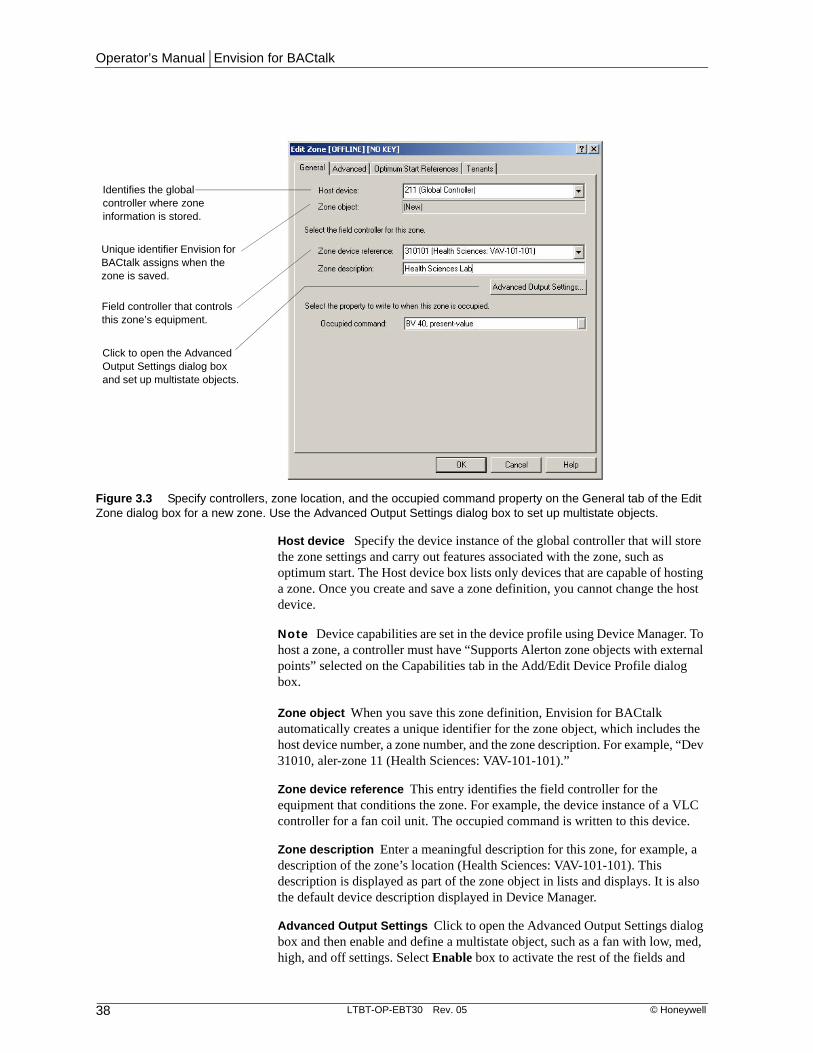
Operator’s Manual | Envision for BACtalk
38 LTBT-OP-EBT30 Rev. 05 © Honeywell
Host device Specify the device instance of the global controller that will store the zone settings and carry out features associated with the zone, such as optimum start. The Host device box lists only devices that are capable of hosting a zone. Once you create and save a zone definition, you cannot change the host device.
Note Device capabilities are set in the device profile using Device Manager. To host a zone, a controller must have “Supports Alerton zone objects with external points” selected on the Capabilities tab in the Add/Edit Device Profile dialog box.
Zone object When you save this zone definition, Envision for BACtalk automatically creates a unique identifier for the zone object, which includes the host device number, a zone number, and the zone description. For example, “Dev 31010, aler-zone 11 (Health Sciences: VAV-101-101).”
Zone device reference This entry identifies the field controller for the equipment that conditions the zone. For example, the device instance of a VLC controller for a fan coil unit. The occupied command is written to this device.
Zone description Enter a meaningful description for this zone, for example, a description of the zone’s location (Health Sciences: VAV-101-101). This description is displayed as part of the zone object in lists and displays. It is also the default device description displayed in Device Manager.
Advanced Output Settings Click to open the Advanced Output Settings dialog box and then enable and define a multistate object, such as a fan with low, med, high, and off settings. Select Enable box to activate the rest of the fields and
Figure 3.3 Specify controllers, zone location, and the occupied command property on the General tab of the Edit Zone dialog box for a new zone. Use the Advanced Output Settings dialog box to set up multistate objects.
Identifies the global controller where zone information is stored.
Field controller that controls this zone’s equipment.
Unique identifier Envision for BACtalk assigns when the zone is saved.
Click to open the Advanced Output Settings dialog box and set up multistate objects.

Chapter 3 | Zones
© Honeywell LTBT-OP-EBT30 Rev. 05 39
then select points to write to and values to write for each state (for example, low, medium, and high) that the device supports. Contact the device vendor to obtain the specific points and values to use. Clear the Enable check box to disable the advanced output settings.
Note Saved changes on the Advanced Output Settings dialog box affect settings in the Edit Zone dialog box. For example, the Occupied command field on all tabs is disabled and displays “Advanced output mode.” All other fields on the Edit Zone tabs display the current settings until the user changes them. The Warmup command and Cooldown command fields on the Optimum Start References tab are also disabled (see Figure 3.6 on page 41).
Occupied command The occupied-command property indicates when the zone is occupied or unoccupied. This must be a property on the zone device.
Note The Occupied command field is dimmed and reads “Advanced output mode” when multistate object support is enabled. See “Advanced Output Settings” on page 38 for more information.
WARNING By default, the zone object uses BV-40 for the occupied command and BV-41 and BV-42 for the warmup and cooldown functions used in optimum start calculations whether your system uses the optimum start feature or not.
Defining advanced zone settings
Advanced tabThe settings on the Advanced tab determine how the BACtalk system processes zone data. These settings seldom need to be changed.
WARNING Only change the default Advanced tab settings if you have a specific need to do so. While changing the Write Command Every rate and the Refresh rate values from the default to a lower value will increase accuracy and
Figure 3.4 Enable multistate objects and define the points to write to and the values to write for multistate objects on the Advanced Output Settings dialog box.
Select when using a multistate object.
Description of the zone controlled by the multistate object.
These settings are device-dependent and are supplied by the device vendor.

Operator’s Manual | Envision for BACtalk
40 LTBT-OP-EBT30 Rev. 05 © Honeywell
response times of zones, it will also have a negative effect on BACtalk network traffic due to the increased number of property reads and writes.
Write command every This setting determines how often, in seconds, the host controller updates the zone’s output control points (for example, occupied command and optimum start references, if enabled). The minimum setting is 60 seconds; the maximum is 300 seconds. When the check box is cleared, outputs are updated when conditions change instead of regular intervals.
Command priority This setting assigns a priority to the zone. This is the priority-array index that the zone object writes to in commandable BACtalk properties, such as occupied command, warmup command, and cooldown command. Valid index values are 1-16. See your BACtalk Systems Programmer’s Guide and Reference (LTBT-TM-PRGRMR) for more information.
Refresh rate This setting determines how frequently, in seconds, that Envision for BACtalk polls the field controller for data about this zone (space temperature, outside air temperature, target heating and cooling setpoints, and humidity, if defined). Data is refreshed at least every 15 minutes by default. Users can set this rate anywhere between 10 and 900 seconds.
Fahrenheit/Celsius Specify whether your system uses Fahrenheit or Celsius for temperature calculations and references. Changing this setting automatically converts the Outside air limit value on the Optimum Start dialog box to the same units.
Figure 3.5 Use the Advanced tab of the Edit Zone dialog box to specify how BACtalk will process zone data.
The rate at which the output control points of the zone are updated. A zero value disables regular updates of the output control points. Maximum is 300 seconds.
This number (1-16) determines the index at which Envision for BACtalk writes to the priority-array.
This option determines if the referenced property values are still valid. Envision for BACtalk waits this amount of time before recalculating optimum start.
Select the temperature units to use when calculating optimum start.
Note The Occupied command field is dimmed out and reads “Advancedoutput mode” if multistate object support has been enabled on the Advanced Output Settings dialog box (General tab>Advanced Output Settings).

Chapter 3 | Zones
© Honeywell LTBT-OP-EBT30 Rev. 05 41
Setting optimum start references
Optimum Start References tabUse the Optimum Start References tab to define the reference points or values used for optimum start calculations for this zone. For more information about how optimum start calculations work, see “Optimum start” on page 119. You do not need to change the default settings if optimum start is disabled.
Optimum start is a self-tuning feature that uses a set of calculations to determine when to begin heating or cooling operations to reach the desired setpoint by the time the zone is occupied. As a result, the calculations and daily adjustments are more accurate when data point references are used. However, if they are unavailable, you can specify values for each of the references. For more information about how these values are used in optimum start calculations, see “Optimum start” on page 119.
Outside air temperature Select the data point to monitor or enter a value for the temperature of the air outside the facility.
Zone temperature Select the data point to monitor or enter a value for the space temperature for the zone.
Target heating setpoint Select the data point that provides the target heating setpoint for this zone. This is the temperature you want the zone warmed to by the next scheduled occupancy. Typically, this is set to a data point that represents the zone’s occupied heating setpoint. Alternately, this may be set to a data value.
Target cooling setpoint Select the data point that provides the target cooling setpoint for this zone. This is the temperature you want the zone cooled to by the
Figure 3.6 Use the Optimum Start References tab to specify the data points and values that this zone uses for optimum start calculations.
The property that indicates outside air temperature.
The property that indicates current zone temperature.
The reference that identifies the zone’s heating setpoint.
The reference that identifies the zone’s cooling setpoint.
The property to use to initiate a cooling operation.
The property to use to initiate a warming operation.
Note The Occupied, Warmup, and Cooldown command fields are dimmed out and read “Advanced output mode” if multistate object support has been enabled.
These points are now user-defined on the Advanced Output Settings dialog box (General tab).

Operator’s Manual | Envision for BACtalk
42 LTBT-OP-EBT30 Rev. 05 © Honeywell
next scheduled occupancy. Typically, this is set to a data point that represents the zone’s occupied cooling setpoint. Alternately, this may be set to a data value.
Warmup command Select the data point that optimum start writes to when heating is called for in preparation for scheduled occupancy. Envision assumes heating is required when the zone temperature is less than the target heating setpoint - 0.5 degrees Fahrenheit. If a data point is not specified (None is selected), optimum start will not begin warming the zone prior to scheduled occupancy.
Cooldown command Select the data point that optimum start writes to when cooling is called for in preparation for scheduled occupancy. Envision assumes cooling is required when the zone temperature is greater than the target cooling setpoint + 0.5 degrees Fahrenheit. If a data point is not specified (None is selected), optimum start will not begin cooling the zone prior to scheduled occupancy.
Setting the tenant override reference
Tenants tabUse the Tenants tab if you will be setting up the tenant activity feature for the selected zone.
Tenant override Select the data point to monitor to determine when the zone is in tenant override mode. If you are not using tenant activity in this zone, you can select None for this property.
See the “Tenant Activity” chapter in this manual or Envision for BACtalk Help for more information about setting up and using Tenant Activity.
Figure 3.7 Specify the data point that BACtalk will monitor to determine if a zone is in tenant override mode.
The property that will indicate tenant override activity in this zone. For example, in Alerton Standard applications, this is the present-value property of BV-66.
Displays a list of all tenants assigned to this zone.
Note The Occupied command field is dimmed out and reads “Advanced output mode” if multistate object support has been enabled on the Advanced Output Settings dialog box (General tab).

Chapter 3 | Zones
© Honeywell LTBT-OP-EBT30 Rev. 05 43
Working with zonesAfter you have set up a zone, you can adjust the settings, if necessary, or use an existing zone to set up another zone with similar settings. From the Zones dialog box, you can also edit, copy, add, or modify schedules, or enable or adjust optimum start settings for the selected zone. See page 36 for an example of the Zones dialog box.
Editing a zone setupThe zone setup is basically a set-and-forget task, but over time you may want to adjust zone settings. For example, the building where the zone is located may be remodeled and the zone’s description may no longer be accurate. You may decide at a later time that you want to use the optimum start feature in a zone and need to set up the references used in optimum start calculations.
Note Once you save a zone definition, you cannot edit the host device. If you need to edit a zone’s host device, you must delete the zone and recreate it using the new host device.
Working with zone status informationThe Zones dialog box provides useful information about the status of a zone definition. This information can help you determine if additional edits or settings need to be defined for the zone.
The Status column in the Zones dialog box provides the following information.
Table 3.2 Zone status information
Status Description Recommended action
C Conflict with another zone or schedule. Only one zone or schedule can control a single command point.
Check other zones and schedules to make sure that only this zone is controlling the data point for a given device.
I Incomplete control point information. Check to make sure all data points are defined for this zone. This status may occur if a point has been removed from a zone.
S Incomplete schedule information. Check the schedule set for this zone and verify that standard, holiday, and event schedules are assigned to it.
N No tenants assigned to this zone. Optional: Ignore this status code if you are not monitoring tenant activity. To use the tenant activity feature in this zone, you must assign a tenant to the zone on the Zones tab of the Edit Tenant Profile dialog box.
O Tenants assigned, but no tenant override property.
Optional: Ignore this status code if you are not monitoring tenant activity. To use the tenant activity feature, you must specify a tenant override property for this zone on the Tenants tab of the Edit Zone dialog box.

Operator’s Manual | Envision for BACtalk
44 LTBT-OP-EBT30 Rev. 05 © Honeywell
Deleting a zoneYou may decide that a zone is no longer needed or that a particular zone setup is inaccurate and you would like to set it up all over again. Select the unwanted zone from the Zones list in the Zones dialog box, and then click Delete.
WARNING Deleting a zone permanently removes that zone from Envision for BACtalk. Make certain the zone is no longer needed, for example, no tenants are assigned to the zone, before deleting it.
Copying a zone setupIf you are setting up zones for a large site, using the copy feature can save a lot of time. For example, you can define all the settings for one zone, and then copy those settings to create zone definitions for areas with similar controllers. When you create zones using the copy feature, keep these guidelines in mind:
• Set up the first zone according to how you want all other zones to be set up, including schedules and optimum start settings.
• If you will be using tenant activity or optimum start, configure those options and enable optimum start before you copy the zone. Note: Tenant assignments are not copied.
• When you click Copy in the Zones dialog box, select all the devices that you want to copy the zone setup to. The devices you select should be the field controllers for each zone. Their device instances will appear as the zone device reference in the zone definition.
• Verify that all devices have descriptions in Device Manager.
• All the data references for the zone are copied to the new zones. For example, if the original zone uses BV-40 in the field controller for its occupied command, the new zones will each use BV-40 in their respective field controllers as the occupied command reference. If you entered fixed values, those values are copied to the new zones.
• The copied zones use the same schedule set as the original zone.
Options for scheduling a zoneZones use schedules to determine when to begin and end operations in the zone. When you link schedules to a zone, you select a standard schedule, a holiday schedule, and an event schedule. Features, such as optimum start, use these schedules to calculate when to begin warming or cooling operations in the zone. See “Schedules” on page 101.
There are several ways to schedule a zone in Envision for BACtalk:
• In the Zones dialog box, select the zone you want to schedule, and then click Schedule.
• From a data display, right-click a data point and, from the shortcut menu, click Zone, and then click Schedule.
• In the Time Schedule Wizard, right-click under Controlled Points, and then click Add Zone.

Chapter 3 | Zones
© Honeywell LTBT-OP-EBT30 Rev. 05 45
Setting up and adjusting a zone’s optimum start settingsYou can set up or edit optimum start settings from the Zones dialog box. Select the zone you want to work with, and then click Optimum Start to open the Edit Optimum Start dialog box. For details on configuring optimum start, see “Optimum start” on page 119.

Operator’s Manual | Envision for BACtalk
46 LTBT-OP-EBT30 Rev. 05 © Honeywell

Chapter 4 | Alarms
© Honeywell LTBT-OP-EBT30 Rev. 05 47
Alarms 4
Envision for BACtalk alarms help you efficiently manage your buildings. Alarms monitor data points in the BACtalk system for conditions you specify, and then generate alarm messages when the condition is met. For example, you might monitor the temperature of a zone, the status (ON/OFF) of a piece of equipment, or compare a command to an actual operating status.
When you set up an alarm, you also set up or select an alarm handler, which tells the system where and how to annunciate the alarm. The system can annunciate the alarm in a number of ways:
• Data display items referencing the data point in alarm can show alarm status
• Operator workstations can email an alarm
• Operator workstations can display a popup alarm message indicating the alarm
• The alarm can display a link to a specified URL or a BACtalk display or template when it is annunciated
• The alarm can dial out information to a pager
• The alarm can dial out information to be logged at a remote site
• The Envision for BACtalk server can record an entry in the Alarm History file
See “Reading BACtalk alarm messages” on page 90 for more information about reading and working with alarm messages.
BenefitsEfficient Get critical information about your system while at an operator workstation or on the road.
Customizable Set up your own alarm messages for different alarms. Have alarms sent to pagers, operator workstations, remote systems, or email.
Flexible Use alarm handlers to change alarm recipients without having to edit individual alarms.

Operator’s Manual | Envision for BACtalk
48 LTBT-OP-EBT30 Rev. 05 © Honeywell
Practical application
Marc is the lead facilities engineer for the Administration building at State University and responsible for the regular maintenance of all equipment in the facility. For example, he ensures filters are changed, equipment is tuned, and air ducts are cleaned. Marc also is the “first line of defense” if there is a problem with mechanical equipment. He is usually on site from 8:00 AM to 7:00 PM Monday through Thursday and on-call for emergencies during off-hours. He has a pager so that his night crew, and the system, can contact him for emergencies.
Many alarms were set up for the system when it was turned over to the facilities staff, but Marc quickly learned that alarms help him keep tabs on his building. He occasionally sets up new alarms to annunciate at operator workstations, pagers, remote sites, or email when equipment requires some sort of maintenance.

Chapter 4 | Alarms
© Honeywell LTBT-OP-EBT30 Rev. 05 49
Quick start–alarm setupUse the following table to help you set up an alarm in Envision for BACtalk. The key steps for defining an alarm are listed in order.
Table 4.1 Tasks for setting up an alarm
Task See
1 Identify the foundation of the alarm setup:
• What kind of conditions do you want to define alarms for?
• Who should receive the alarms and how should they receive them?
• What kinds of alarm conditions require acknowledgement?
• What kinds of messages do you want to use for alarms?
• Which data points (present-value of AI, AV, AO, BI, BV, BO) do you want to monitor for an alarm state?
• What alarm type best suits the objective of each alarm condition?
• What global controller do you want to host the alarm setup?
• Site documentation
• page 54
• page 55
2 Select the data point you want to monitor for an alarm. Use the Alarm Wizard, Point Alarm Setup, or right-click an item on a display.
• page 62
3 Define alarm setup parameters based on the type of alarm and your decisions from step 1.
• page 69 (fixed limit)
• page 72 (floating limit)
• page 74 (binary)
• page 75 (command fail)
4 Do you want to pop up a data display, template, or Web page?
• page 71
5 Do you want to email an alarm? • page 84
6 Select an alarm handler for the alarm, or set up a new alarm handler. Verify the recipients of the alarm or set up new recipients.
• page 77
7 Define global alarm settings. • page 87

Operator’s Manual | Envision for BACtalk
50 LTBT-OP-EBT30 Rev. 05 © Honeywell
How alarms workThere are three items at the core of any alarm in Envision for BACtalk:
• The monitored property, which is the status or value that the alarm watches for an alarm state.
• The alarm setup (in BACnet, technically known as an event-enrollment object), which is saved in a global or building controller. It watches the monitored point to generate an alarm.
• The alarm handler (in BACnet, technically known as a notification-class object), which determines what operator workstations, pagers, remote sites, and email accounts are notified when an alarm occurs.
This method of generating alarms—with three components working in tandem—is efficient and flexible.
About the monitored propertyThe monitored property is usually the present-value of an AV, BV, AI, BI, AO, or BO. Although an alarm can monitor any property of any object, these data points are most likely to indicate an alarm condition in your system. The monitored property can originate anywhere in the system, but it is good practice to have the global controller closest to the monitored property host the alarm setup.
Figure 4.1 BACtalk components work together to generate alarms. Global controllers include: BTI, BTI-100, and BCMs (which act like global controllers in the BACtalk system).
BTI
Set up alarms at the Envision for BACtalk server and download the alarm setup to the host device.
The host device stores the alarm, which watches the monitored property for an alarm condition.
If an alarm occurs, the alarm handler (also stored in the host device) sends the alarm to designated devices throughout the system.
Global Controller
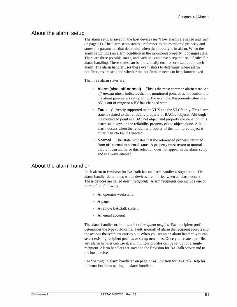
Chapter 4 | Alarms
© Honeywell LTBT-OP-EBT30 Rev. 05 51
About the alarm setupThe alarm setup is saved in the host device (see “How alarms are saved and run” on page 61). The alarm setup stores a reference to the monitored property and stores the parameters that determine when the property is in alarm. When the alarm setup finds an alarm condition in the monitored property, it changes state. There are three possible states, and each one can have a separate set of rules for alarm handling. These states can be individually enabled or disabled for each alarm. The alarm handler uses these event states to determine where alarm notifications are sent and whether the notification needs to be acknowledged.
The three alarm states are:
• Alarm (also, off-normal) This is the most common alarm state. An off-normal alarm indicates that the monitored point does not conform to the alarm parameters set up for it. For example, the present-value of an AV is out of range or a BV has changed state.
• Fault Currently supported in the VLX and the VLCP only. This alarm state is related to the reliability property of BACnet objects. Although the monitored point is a BACnet object and property combination, this alarm state keys on the reliability property of the object alone. A fault alarm occurs when the reliability property of the monitored object is other than No Fault Detected.
• Normal This state indicates that the referenced property returned from off-normal to normal status. A property must return to normal before it can alarm, so this selection does not appear in the alarm setup and is always enabled.
About the alarm handlerEach alarm in Envision for BACtalk has an alarm handler assigned to it. The alarm handler determines which devices are notified when an alarm occurs. These devices are called alarm recipients. Alarm recipients can include one or more of the following:
• An operator workstation
• A pager
• A remote BACtalk system
• An email account
The alarm handler maintains a list of recipient profiles. Each recipient profile determines the type (off-normal, fault, normal) of alarm the recipient accepts and the actions the recipient carries out. When you set up an alarm handler, you can select existing recipient profiles or set up new ones. Once you create a profile, any alarm handler can use it, and multiple profiles can be set up for a single recipient. Alarm handlers are saved to the Envision for BACtalk server and to the host device.
See “Setting up alarm handlers” on page 77 or Envision for BACtalk Help for information about setting up alarm handlers.

Operator’s Manual | Envision for BACtalk
52 LTBT-OP-EBT30 Rev. 05 © Honeywell
Practical application
As the lead facilities engineer in the Administration building, Marc has four technicians working for him. Marc himself is on site four 10-hour days, 8 AM to 7 PM, with Friday through Sunday off, and he is on call the rest of the time. Marc’s daytime technicians work five days a week, 8 AM to 5 PM, Monday through Friday. Night crew technicians work 9 PM to 6 AM Wednesday through Sunday.
Marc has an on-call pager he uses off site. Marc also has his own operator workstation, which also functions as the Envision for BACtalk server. The technicians share two operator workstations, one in the facilities offices and the other in the central plant. There is also a roaming pager, which Marc carries when he is on site, and the shift lead carries otherwise.
Marc uses the alarm handlers and recipient profiles he sets up for all these devices to manage alarm annunciation and ensure that alarms get appropriate coverage.

Chapter 4 | Alarms
© Honeywell LTBT-OP-EBT30 Rev. 05 53
Figure 4.2 The alarm setup and alarm handler work together to monitor alarms and send out notifications.
Global Controller(Device 110000)
VLC (Device 110107)
AV-101Present Value: 78°F
Monitored Property(Device 110107, AV-101)
Alarm Setup (Event Enrollment Object)[Enroll 1 (Device 110107, AV-101)]
Monitored Point: Device 110107, AV-101, Present ValueHigh Limit: 74°FLow Limit: 66°FDeadband: 2Delay (sec): 60Enabled Alarms: Alarms/Fault/NormalAlarm Messages: [Miscellaneous]Handler: NotClass 1 (Routine Alarm Handler)
Operator Terminal 2000
"Dialout through Controller" in alarm
pager setup
Alarm Handler (Notification Class Object)[NotClass 1 (Routine Alarm Handler)]
Recipients: Central Office Alarm Logger, Dev 2000, Maint. Supervisor pagerAcknowledgments Popup MessagesTo-offnormal (alarm): YesTo-normal: YesReturn to normal: NoSchedule availability (set for each recipient)Valid Days: Mon~SunValid Times: Entire DayConfirmed: YesHandled Events (set for each operator terminal)To-offnormal (alarm): YesTo-normal: YesReturn to normal: NoActions (set for each operator terminal)?Log in Alarm History: YesAnnunciate (show a popup message): YesPrint NoEmail YesPager Details (description, phone number, message, dialout through controller)Remote Site Details (description, phone number, remote workstation device instance, dialout through controller, virtual device instance, local virtual network number, PTP password)
BTI-MDM
"Dialout through Controller" in remote BACtalk alarm dialout
setup
BTI-MDM
operato
(PubTN
Central Office Alarm Logger – Any time (remote BACtalk system)Dev 200000 – Any time (annunciate, log, print, email)Maint. Supervisor Pager – Any time (pager)

Operator’s Manual | Envision for BACtalk
54 LTBT-OP-EBT30 Rev. 05 © Honeywell
The importance of alarm descriptions and alarm messagesAn alarm description is the name for the alarm setup and the alarm message is the text that is transmitted along with this description when an alarm occurs. Understanding the difference between these items and how to use them is an important aspect of alarm setup.
Alarm descriptionsThe alarm description appears in parentheses in listings of alarms, in alarm history records, and in Envision for BACtalk alarm messages.
In every case, the alarm description should include a pointer to the device and object where the alarm originates (for example, “Device 110114, AI 1”). In certain circumstances, the alarm description may be the only way to find the true source of the alarm.
Note In the Alarm Wizard, Envision for BACtalk calls this the Event Enroll Object Description. Because of the importance of the alarm source information, the Alarm Wizard allows you to use variables for the device instance and object ID. See “Using variables for alarm descriptions and messages” on page 67 for more information.
Alarm messagesAlarm messages appear in alarm histories, BACnet Alarm Message dialog boxes, and email alarm notifications. Use alarm messages to characterize the alarm and to indicate in plain language where the alarm is coming from. Different alarm types have different messages you can set up for them. For example, analog alarms include high and low alarm text, and binary alarms have off-normal, fault, and normal alarm text.
Note The Alarm Wizard also lets you use variables for alarm messages. See “Using variables for alarm descriptions and messages” on page 67.
About alarm delaysEach alarm setup includes the option for an alarm delay in seconds. When you set up an alarm delay, the alarm condition must exist for this period of time for an alarm to occur. If the alarm returns to normal within the delay time, no alarm occurs. For more information about using alarm delays, see “Use a Delay” on page 67.

Chapter 4 | Alarms
© Honeywell LTBT-OP-EBT30 Rev. 05 55
Types of alarmsThere are five types of BACtalk alarms. The type of alarm you use depends on whether the monitored property is analog or binary.
• Communications alarms, which the BACtalk system automatically generates if a controller goes off-line
• Binary alarms, which occur on a simple change of state (ON-to-OFF, for example)
• Command fail alarms, which occur when two binary point values do not match
• Fixed limit alarms, which occur when an analog value is above or below fixed high or low limits
• Floating limit alarms, which occur when an analog value varies from a setpoint value by a certain amount
About communications alarmsCommunications alarms in Envision for BACtalk occur when the operator workstation attempts to communicate with a BACtalk device and the device does not respond.
Note See “Enabling device communication failure alarms” on page 317 for information about alarm annunciation when communication is lost between the operator workstation and a device.
The communications alarm returns to normal when another communication attempt with the device is successful.
Note Normal display update operations do not cause communications alarms. Activities such as background trendlog processing, saving and sending objects, and other processing operations prompt communications alarms if the device of interest is offline.
Alarm descriptions for communications errors in Envision for BACtalk use the following syntax:
Dev <HostDev>, device <OfflineDI> [<DevDesc>] (Communications Error)
Where:
<HostDev> The alarm monitoring host device.
<OfflineDI> The device instance for the device that was offline and caused the communications alarm.
<DevDesc> The device description (from Device Manager) for the offline device.

Operator’s Manual | Envision for BACtalk
56 LTBT-OP-EBT30 Rev. 05 © Honeywell
Example
Operator workstation 200000 reports a communications error with Device 110000, a BTI, with the description “BTI 110000 - Admin Bldg 11” set in Device Manager:
Dev 200000, device 110000 BTI 110000 - Admin Bldg 11 (Communications Error)
Operator workstation 200000 reports a communications error with Device 110101, a VLC, with the description “Admin Bldg: VAV-11-101” set in Device Manager:
Dev 200000, device 110101 Admin Bldg: VAV-11-101 (Communications Error)
About binary alarmsFor binary properties, the most common alarm condition to monitor is a change of state from active (ON) to inactive (OFF) or vice versa. You select the transition state that causes the alarm. This is listed as Type in the Alarm Wizard and as Alarm under Parameters in the Binary Alarm Properties dialog box.
Practical application
Each air handling unit controller on campus has DDC associated with a differential pressure transducer. If the differential pressure across a filter is too great, a change filter alarm, BV-201, turns ON in DDC.
Marc has set up an alarm for each BV-201 to annunciate to the operator workstations when they occur. Because this is not a critical alarm, he does not assign his pager to the alarm handler for this alarm.

Chapter 4 | Alarms
© Honeywell LTBT-OP-EBT30 Rev. 05 57
About command fail alarmsA command fail alarm checks if a monitored property matches a command reference property. The reference property is called a Command reference property in the Alarm Wizard and Cmd point in the Command Fail Alarm Properties dialog box.
The properties to compare must originate from the same device.
Practical application
The main parking garage at State U is located under the Administration building. It has 10 single-speed exhaust fans. Each fan is controlled by a VLC-550, numbered 110001 through 110010. A scheduled or manual fan ON command turns BO-1 on the VLC-550 ON. Each fan has a proof switch wired to input BI-1, and the proof switch is ON as long as the fan is actually operating.
Using the Alarm Wizard, Marc sets up a command fail alarm for each of the 10 BI-1s, and sets the command reference for each as BO-1. He sets up a delay of 60 seconds, and assigns a high-priority alarm handler to them so that he and the on-site technician get paged when the alarm occurs.
About fixed limit analog alarmsFor analog properties, the most commonly configured alarm type is an analog (fixed limit) alarm. For example, an alarm can occur if a space temperature goes above 74 degrees F (high limit) or below 66 (low limit) degrees F. An alarm occurs when the value of the monitored property exceeds the high limit or drops below the low limit.
Two factors further affect when the alarm is generated: a delay and a deadband. The monitored property must be in an alarm condition for the time indicated by the Delay setting before an alarm is generated. The deadband is subtracted from
Figure 4.3 Command Fail Alarm Parameters dialog box

Operator’s Manual | Envision for BACtalk
58 LTBT-OP-EBT30 Rev. 05 © Honeywell
the high limit and added to the low limit to control when the alarm returns to normal.
Practical application
Marc showed his technician how the space temperature for the Registration Office within the Administration building might be set up as a fixed limit alarm and how the deadband setting worked for that type of alarm. He used a diagram to help explain the relationship between alarm settings and system performance.
Marc’s diagram is shown in Figure 4.4. It shows a deadband setting of 2 with high and low limits of 74 degrees F and 66 degrees F, respectively. Marc also mentioned that this alarm had a delay of 60 seconds. When the temperature exceeds 74 degrees F, an alarm occurs (provided it remains there for at least 60 seconds). Because of the deadband, the alarm remains until the temperature is less than 72 degrees F. The same applies to the low limit: the alarm occurs at less than 66 and will return to normal only when the temperature is greater than 68. Marc stepped through the diagram from left to right, discussing each of the points called out in the diagram, to show the tech how the alarm generation was based on the monitored property and whether the temperature was moving up or down.
About floating limit analog alarmsA floating limit alarm compares a monitored analog property to an analog reference property, which is called the Setpoint reference property in the Alarm Wizard (SP Reference in the Analog Alarm Properties dialog box). If the
Figure 4.4 Understanding fixed limit analog alarms
Time
Temp
6869
7071
7273
7475
7677
7879
8081
82
6263
6465
6667
4. Low limit alarm triggers
High limit =74
Low limit = 66
Deadband = 2
1. High limit alarm triggers
3. Return to normal
2. Doesn't yet restoreto normal (must dropbelow deadband)
Monitored property (temp.)

Chapter 4 | Alarms
© Honeywell LTBT-OP-EBT30 Rev. 05 59
monitored property varies above or below the setpoint-reference property by the high limit offset or low limit offset values you specify, an alarm occurs.
The high limit offset is added to the value of the setpoint-reference property; the low limit offset is subtracted from it. A deadband value determines when the alarm returns to normal. The deadband value is added to the low limit equation and subtracted from the high limit equation.
The following equations describe offset and deadband logic.
Where:
MP = Monitored property
SP = Setpoint
HL = High limit offset
LL = Low limit offset
DB = Deadband
• If MP > SP + HL, a high limit alarm occurs.
• If MP < SP - LL, a low limit alarm occurs.
• If a high limit alarm has occurred and the value of MP subsequently changes such that MP < SP + HL - DB, the alarm returns to normal.
• If a low limit alarm has occurred and the value of MP subsequently changes such that MP > SP - LL + DB, the alarm returns to normal.
Practical application
For the five biggest zones located in the Administration building, Marc has floating limit alarms set up that compare the actual space temperature in each zone to the setpoint. When showing one of his technicians how to set up a floating limit alarm, he found it hard to explain the high limit offset, low limit offset, and deadband and how they affect when an alarm occurs and when it returns to normal. The changing of the temperature and the setpoint were even getting him confused.
Once Marc created another diagram based on the equations, it became clear to him, and his tech got it right away. Marc’s diagram is presented in Figure 4.5. He used the alarm setup for the space temperature in the Registration Office as his example.
The monitored property is set up as the space temperature for the Registration Office (Dev 110107, AV-101, present-value) and the setpoint reference property represents the space temperature setpoint (Dev 110107, AV-90, present-value). In the alarm setup, the high limit offset is set to 2 and the low limit offset is set to 4. The deadband is set to 0.5. Marc stepped through the diagram from left to right, discussing each of the points called out in the diagram, to show the tech how the alarm generation was based on the setpoint and whether the temperature was moving up or down.

Operator’s Manual | Envision for BACtalk
60 LTBT-OP-EBT30 Rev. 05 © Honeywell
Figure 4.5 Understanding floating limit analog alarms
6. High limit alarm triggers
1. High limit alarm triggers
Time
Temp
6869
7071
7273
7475
7677
7879
8081
82
6263
6465
6667 4. Low limit
alarmtriggers
3. Return to normal
5. Return to normal
7. Return to normal
Temperature
Setpoint (SP) Reference
High Limit Offset = 2
Low Limit Offset = 4
Deadband (DB) = 0.52. Doesn't yet restore to
normal (must dropbelow deadband)

Chapter 4 | Alarms
© Honeywell LTBT-OP-EBT30 Rev. 05 61
How alarms are saved and runWhen you create an alarm, the setup is saved to the Envision for BACtalk server and to the global controller that you select to host the alarm. Technically, BACnet identifies the alarm setup as an event-enrollment object. So when you see the alarm listed, its entry appears as Enroll <num> (<desc>), where <num> is a sequential number that the system automatically assigns and <desc> is the description you enter for the alarm.
When you create a new alarm, you select a global controller or building controller as the host device. The host device saves the event-enrollment object (the alarm setup) and the notification-class object (alarm handler) associated with it.
Note Envision for BACtalk can automatically assign a host device to a controller when you set up an alarm from a data display. Use the Preferences tab in Device Manager (BACtalk>Device Manager>[select device]>Edit>Preferences) to assign a default host for alarms to the selected controller.

Operator’s Manual | Envision for BACtalk
62 LTBT-OP-EBT30 Rev. 05 © Honeywell
Setting up alarmsEnvision for BACtalk offers three ways to set up an alarm:
• Right-click a dynamic item on a data display, and click Alarms on the shortcut menu. Use this when you are working with data displays.
• Click Point Alarms on the BACtalk >Alarms menu. Use this when you know the point whose alarm you want to set up or edit, but do not necessarily know where it is.
• Click New Alarm Wizard on the BACtalk >Alarms menu. Use this when you want to set up a range of alarms that are identical except for their addresses. This is usually used during initial system setup.
Using the shortcut menu on a data displayThis is the most common way to set up an alarm in Envision for BACtalk. You do not need to know the ID of the object and property you want to monitor to set it up. All you need to do is right-click the item on a data display.
Note Right-click functionality for a display item must be enabled when the data display is edited and the item placed on it. If the Alarms selection does not appear on the shortcut menu when you right-click an item, this feature is not enabled for the item. see “Using shortcut menus to access automation features” on page 26 for more information on right-click functionality.
Figure 4.6 Right-click an item to display the shortcut menu.
Right-click a dynamic item to view the shortcut menu.
Point to Alarms, and then click New Alarm to set up a new alarm for the property. If other alarm setups exist, they are listed by description.
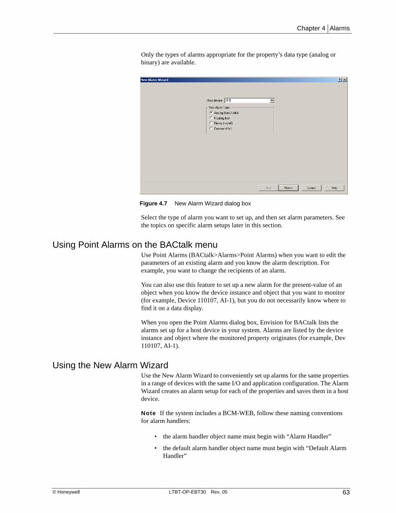
Chapter 4 | Alarms
© Honeywell LTBT-OP-EBT30 Rev. 05 63
Only the types of alarms appropriate for the property’s data type (analog or binary) are available.
Select the type of alarm you want to set up, and then set alarm parameters. See the topics on specific alarm setups later in this section.
Using Point Alarms on the BACtalk menuUse Point Alarms (BACtalk>Alarms>Point Alarms) when you want to edit the parameters of an existing alarm and you know the alarm description. For example, you want to change the recipients of an alarm.
You can also use this feature to set up a new alarm for the present-value of an object when you know the device instance and object that you want to monitor (for example, Device 110107, AI-1), but you do not necessarily know where to find it on a data display.
When you open the Point Alarms dialog box, Envision for BACtalk lists the alarms set up for a host device in your system. Alarms are listed by the device instance and object where the monitored property originates (for example, Dev 110107, AI-1).
Using the New Alarm WizardUse the New Alarm Wizard to conveniently set up alarms for the same properties in a range of devices with the same I/O and application configuration. The Alarm Wizard creates an alarm setup for each of the properties and saves them in a host device.
Note If the system includes a BCM-WEB, follow these naming conventions for alarm handlers:
• the alarm handler object name must begin with “Alarm Handler”
• the default alarm handler object name must begin with “Default Alarm Handler”
Figure 4.7 New Alarm Wizard dialog box

Operator’s Manual | Envision for BACtalk
64 LTBT-OP-EBT30 Rev. 05 © Honeywell
Select the host device where alarm setups will be saved The host device is the global controller where you want the alarm setups saved when you finish. For Marc, this is the BTI with device instance 110000. If the controller appears in Device Manager, its device instance appears in the list (see Figure 4.9 on page 65); otherwise, you can type the device instance directly in the box.
See “How alarms are saved and run” on page 61 for more information.
If a host device does not appear in the list of available devices, the capabilities in Device Manager may not be set up correctly. For more information about device capabilities, see Help and the Envision for BACtalk Installation and Startup Guide (LTBT-TM-ADMIN26).
The following practical application illustrates how to use the New Alarm Wizard to create alarms for several devices at once.
Practical application
State U’s Administration building has 90 identical VAV boxes. Each has a controller set up with the same I/O and application configuration. Marc needs to create alarms for each of them so that an alarm triggers if the current (actual) airflow varies from the desired airflow by more than 40 cfm. This tells him that the VAV damper is not performing to expectations. He wants these alarms sent to his operator workstation and logged in Alarm History. Setting up each alarm in
Figure 4.8 Specify the host device and the type of alarm you want to set up on the New Alarm Wizard dialog box.

Chapter 4 | Alarms
© Honeywell LTBT-OP-EBT30 Rev. 05 65
the Point Alarms dialog box or through data displays takes time so Marc uses the New Alarm Wizard. Marc gathers the following information before he begins:
• Each floor has 30 VAV box controllers (floors 1 through 3).
• VAV box controllers have device instances in the range 110101-110130 (floor 1), 110201-110230 (floor 2), and 110301-110330 (floor 3). Device instances increment by ones (110101, 110102, . . . , 110130).
• All VAV boxes have a global controller with device instance 110000 as their host device.
• In all VAV boxes, the current airflow is read as the present-value of AI-10.
• In all VAV boxes, the desired airflow is written in the application as AV-4.
When Marc starts the New Alarm Wizard, he first selects the type of alarm to set up. Because he needs to compare one analog value to another, he selects Floating limit under New Alarm Type (Figure 4.7 on page 63).
Select the range of devices to monitor The Floating Limit Alarm Parameters dialog box appears. In the Starting device instance and Ending device instance boxes, Marc types the range of devices that he wants to monitor for an alarm condition. For the Starting Device Instance, he types 110101. For the Ending Device Instance, he types 110130 (floor 1 only). The Spacing value is the number by which the device instances increment, in this case, 1. (The default is 1.)
Figure 4.9 Floating Limit Alarm Parameters dialog box of the New Alarm Wizard
Type the range of devices that you want to monitor for an alarm condition.
The host device where the alarm setups are saved.
Select the alarm handler to use for alarms of this type.
Select the monitored property and the setpoint reference property.

Operator’s Manual | Envision for BACtalk
66 LTBT-OP-EBT30 Rev. 05 © Honeywell
Select an alarm handler that sends an alarm message to the operator workstation Marc wants the alarms sent to his operator workstation. He clicks the small button beside the Alarm Handler box to select an alarm handler that is stored in the host device (see Figure 4.9).
If an alarm handler already exists that sends a message to Marc’s operator workstation, he can select it from the Handlers list, and the operator workstation will appear under Recipients of the current handler. If one does not exist, he can create a new alarm handler. See “Setting up alarm handlers” on page 77 for more information.
Select the monitored property and the setpoint-reference property The monitored property is the current airflow, which is AI-10. The setpoint reference is the desired airflow, which is AV-4. Marc clicks the small button beside each box, and then selects the properties in the Object Specification dialog box (see Figure 4.9 on page 65).
Select offset values Offsets determine how far the monitored property must vary from the setpoint reference for an alarm to occur. This is 40 cfm both above and below the desired airflow, so Marc types 40 in each of the boxes, leaving the deadband at 0.
Use variables for the description The Event enroll object description is the alarm description. This is what will appear in alarm listings for each of the alarms. The Alarm Wizard allows variables to represent the device instance and property because these references may not be static (“Device 110101,” for example, will not apply to all 90 devices). Marc leaves the default of %3, %4. See “Using variables for alarm descriptions and messages” on page 67 for a description of variables you can use. See Figure 4.11 on page 67.
Figure 4.10 Select offset values for the alarm.
Deadband Determines when the alarm returns to normal. The deadband is subtracted from the high limit and added to the low limit.
Low limit offset The monitored property must be less than the value of the setpoint reference minus this number for a low limit alarm to occur.
High limit offset The monitored property must be greater than the value of the setpoint reference plus this number for a high limit alarm to occur.

Chapter 4 | Alarms
© Honeywell LTBT-OP-EBT30 Rev. 05 67
Use a Delay The alarm condition must exist for a minimum number of seconds (called the delay) before an alarm occurs. Marc types a delay of 60 seconds to prevent nuisance alarms when airflow anomalies exist. He leaves Notify on alarm and Notify on fault checked. Clearing Notify on alarm effectively disables the alarm.
Type alarm text Marc types the alarm text to appear under alarm (off-normal) conditions. He also types the high and low limit alarm text. Like the description, he can use variables in these alarm messages. See the following section for more information.
When Envision for BACtalk creates the alarm setups, it also saves them in the host device (BTI global controller 110000 in this case). Marc can use the Point Alarms dialog box to confirm creation of the alarms. They are named according to the monitored device instances and objects.
Using variables for alarm descriptions and messagesThe Alarm Wizard can build multiple alarms for multiple objects and properties in multiple devices. For this reason, static alarm descriptions and alarm messages that include a device instance or property will not apply. For example, if you use the Alarm Wizard to set up a return air alarm for seven fan-coil controllers numbered 110001 through 110007, and type an alarm description of “Device 110001, AI-3, Return Air Alarm,” it will not be accurate for devices 110002 through 110007.
Figure 4.11 Type alarm description (or variables) and set a delay for your alarm.
Notify on fault Enables fault alarms.
Notify on alarm Enables off-normal alarms.
Delay Time delay in seconds. If an alarm condition occurs and returns to normal within this delay time, no alarm occurs.
Event-enrollment object description Each alarm needs a unique description. You can use variables to represent device and property specifics. Click Help for more information. Make sure the alarm description includes information about the property that caused the alarm.

Operator’s Manual | Envision for BACtalk
68 LTBT-OP-EBT30 Rev. 05 © Honeywell
To help you set up multiple alarms, the Alarm Wizard provides variables you can use in alarm descriptions and alarm messages. By using these variables, you can write a description or message for a range of alarms and include vital information about the origin of the alarm, without having to edit each alarm setup individually. You can mix variables and plain text.
Table 4.2 Variables for use in alarm descriptions and messages
Variable Adds this to each alarm description or message
%1 The device instance of the monitored property. Example: 110006.
%2 The monitored object, property, and the description of the property in parentheses. Example: AI 3, present-value (return air temp).
%3 The device instance of the monitored property, preceded by the word “Device” and followed by the device's description in parentheses. Example: Device 110006 (Fan-Coil 6 Controller). Included in the default description.
%4 The monitored property without the property's description. Example: AI 4, present-value. Included in the default description.
%5 The device description of the monitored property. Example: Fan-Coil 6 Controller. If the description is empty, returns Device <device instance>. For example, Device 110006.
%6 The description of the object containing the monitored property. Example: return air temp. If the description is empty, returns the monitored object and property. Example: AI 5, present-value.

Chapter 4 | Alarms
© Honeywell LTBT-OP-EBT30 Rev. 05 69
Setting up fixed limit analog alarmsSet up a fixed limit alarm to ensure that the value of a monitored property stays within a defined range. If the monitored property exceeds the high limit or drops below the low limit, an alarm occurs. See page 58 for an example of how fixed limit alarms can be used.
PointThe monitored point is the status or value that the alarm watches for an alarm state. This is the point you selected from a data display or from the Point Alarms dialog box.
Event objectEnvision for BACtalk automatically assigns this description of the event-enrollment object when a new alarm setup is saved. See “How alarms work” on page 50 for more information about the event-enrollment object.
Figure 4.12 Analog (fixed limit) Alarm Properties dialog box set up so the alarm will display a link to a STATE_U job data display.
Click here to select an alarm handler or create a new alarm handler.
Type the parameters that determine when an alarm is generated.
Enter the message text for each alarm condition.
Clear these check boxes to temporarily disable the alarm.
Select to display a link to a URL or a data display when the alarm is annunciated.

Operator’s Manual | Envision for BACtalk
70 LTBT-OP-EBT30 Rev. 05 © Honeywell
DescriptionThe alarm description you type here appears in lists and alarm messages. See “The importance of alarm descriptions and alarm messages” on page 54 for more information.
HandlerEvery alarm must be assigned an alarm handler. The alarm handler controls where the alarm is sent, for example, to an operator workstation or a pager. See “Setting up alarm handlers” on page 77 for more information about alarm handlers and recipients.
ParametersThese parameters determine when the alarm occurs. See “About fixed limit analog alarms” on page 57 for details.
High limit If the monitored point value goes above this limit, a high limit alarm occurs. If a delay is set, the alarm does not occur until the delay time has passed and only then if the alarm condition still exists.
Low limit If the monitored point value goes below this limit, a low limit alarm occurs. If a delay is set, the alarm does not occur until the delay time has passed and only then if the alarm condition still exists.
Deadband Type a deadband value here to establish a range in which no change occurs. The deadband value is subtracted from the high limit and added to the low limit to determine when the alarm returns to normal. For example, if the high limit is 85 and the deadband is 5, the alarm returns to normal at 79. Between 80 and 85, no change occurs.
Delay This setting represents the number of seconds an alarm condition must exist before an alarm occurs. Use the delay to prevent alarms from occurring too frequently due to operating anomalies.
Alarm notificationsAs a general rule, leave both of these check boxes enabled. To temporarily disable an alarm, you can clear both check boxes.
Alarm messagesType the alarm messages you want to appear when an off-normal alarm occurs, when a fault alarm occurs, and when the alarm returns to normal. Use high- and low-limit alarm text for analog alarms. See “The importance of alarm descriptions and alarm messages” on page 54 for details.
Setting up a URL notified or display linked alarmSet up alarms (global feature in the Alarm Setup and in each alarm) to display a link to a specified URL or BACtalk display or template when the alarm is annunciated. For example, display a URL to a camera view of a door or zone that is in an alarm state to visually check out the alarm condition before travelling to the location. Use the Alarm Properties dialog box (BACtalk>Alarms>Point Alarms) to select either a URL link or a link to a data display (this option is cleared by default). Then use the Select Display or Template dialog box to set up

Chapter 4 | Alarms
© Honeywell LTBT-OP-EBT30 Rev. 05 71
the link that will display when the alarm is annunciated at an operator workstation.
Note URL notified alarms can also be set up using the New Alarm Wizard (BACtalk>Alarms>New Alarm Wizard) or the Event Enrollment Editor (Tools>Advanced >Event Enrollment>General tab).
Working with URL notified alarmsEnvision for BACtalk processes URLs with an http prefix only until you select an option in the Alarm Setup dialog box (BACtalk>Alarms>Alarm Setup) that instructs the system to process all URLs. You can also select an option to automatically open the specified URL associated with an alarm when it is annunciated, instead of just displaying the link.
Note Selecting “Automatically open URL links when alarm messages are processed” on the Alarm Setup dialog box opens alarms in a browser window outside the control of Envision for BACtalk. Therefore, you must explicitly close the browser window when you are done viewing it.
Note See page 87 for more information about using the Alarm Setup dialog box.
Figure 4.13 This alarm will display a link to the Health Sci Zones data display when it is annunciated at the BACtalk operator workstation.

Operator’s Manual | Envision for BACtalk
72 LTBT-OP-EBT30 Rev. 05 © Honeywell
Setting up floating limit analog alarmsSet up a floating limit alarm to compare a monitored analog property to a setpoint reference property. See page 59 for an example of how floating limit alarms can be used.
PointThe monitored point is the status or value that the alarm watches for an alarm state. This is the point you selected from a data display or from the Point Alarms dialog box.
Event objectEnvision for BACtalk automatically assigns the description of the event-enrollment object when a new alarm setup is saved. See “How alarms work” on page 50 for more information about the event-enrollment object.
Figure 4.14 Analog (floating limit) Alarm Properties dialog box set up so the alarm will display a link to a STATE_U job data display.
Click here to select an alarm handler or to create a new alarm handler.
Type the parameters that determine when an alarm is generated.
Clear these check boxes to temporarily disable the alarm.
Enter the message text for each alarm condition.
Select to display a link to a URL or a data display when the alarm is annunciated.
Default setup for the source file location.

Chapter 4 | Alarms
© Honeywell LTBT-OP-EBT30 Rev. 05 73
DescriptionThe alarm description you type here appears in lists and alarm messages. See “The importance of alarm descriptions and alarm messages” on page 54 for more information.
HandlerEvery alarm must be assigned an alarm handler. The alarm handler controls where the alarm is sent, for example, to an operator workstation or a pager. See “Setting up alarm handlers” on page 77 for more information about alarm handlers and recipients.
ParametersThese parameters determine when the alarm occurs. See “About floating limit analog alarms” on page 58 for details.
Setpoint (SP) reference Select the setpoint-reference property you want to compare to the monitored analog property. If the monitored property varies above or below this setpoint reference by the values specified for the high limit or low limit offsets, an alarm occurs. You can specify an external device point for SP reference when the alarm host supports BACnet event-enrollment objects.
High limit offset Type the value to add to the setpoint-reference property to determine if the monitored property is out of the desired range. If the monitored point value goes above this limit, a high limit alarm occurs. If a delay is set, the alarm does not occur until the delay time has passed and only then if the alarm condition still exists.
Low limit offset Type the value to subtract from the setpoint-reference property to determine if the monitored property is out of the desired range. If the monitored point value goes below this limit, a low limit alarm occurs. If a delay is set, the alarm does not occur until the delay time has passed and only then if the alarm condition still exists.
Deadband The deadband value establishes a range in which no change occurs. The deadband value is added to the low limit equation and subtracted from the high limit equation to determine when the alarm returns to normal.
Delay This setting represents the number of seconds an alarm condition must exist before an alarm occurs. Use the delay to prevent alarms from occurring too frequently due to operating anomalies.
Alarm notificationsAs a general rule, leave both of these check boxes enabled. To temporarily disable an alarm, you can clear both check boxes.
Alarm messagesType the alarm messages you want to appear when an off-normal alarm occurs, when a fault alarm occurs, and when the alarm returns to normal.
Note See “Working with URL notified alarms” on page 71 for more information about setting up a URL-notified or display linked alarm.

Operator’s Manual | Envision for BACtalk
74 LTBT-OP-EBT30 Rev. 05 © Honeywell
Setting up binary (on/off) alarmsSet up a binary alarm to monitor the status of a binary point. See page 56 for an example of how this type of alarm might be used.
PointThe monitored point is the status or value that the alarm watches for an alarm state. This is the point you selected from a data display or from the Point Alarms dialog box.
Event objectEnvision for BACtalk automatically assigns the description of the event-enrollment object when a new alarm setup is saved. See “How alarms work” on page 50 for more information about the event-enrollment object.
DescriptionThe alarm description you type here appears in lists and alarm messages. See “The importance of alarm descriptions and alarm messages” on page 54 for more information.
HandlerEvery alarm must be assigned an alarm handler. The alarm handler controls where the alarm is sent, for example, to an operator workstation or a pager. See
Figure 4.15 Binary Alarm Properties dialog box set up so the alarm will display a link to a STATE_U job data display.
Click here to select an alarm handler or to create a new alarm handler.
Type the parameters that determine when an alarm is generated.
Clear these check boxes to temporarily disable the alarm.
Enter the message text for each alarm condition.
Select to display a link to a URL or a data display when the alarm is annunciated.

Chapter 4 | Alarms
© Honeywell LTBT-OP-EBT30 Rev. 05 75
“Setting up alarm handlers” on page 77 for more information about alarm handlers and recipients.
ParametersThese parameters determine when the alarm occurs. See “About binary alarms” on page 56 for details.
Alarm Select the change of state that causes an alarm. Options are OFF (inactive) to ON (active) or ON to OFF.
Delay This setting represents the number of seconds an alarm condition must exist before an alarm occurs. Use the delay to prevent alarms from occurring too frequently due to operating anomalies.
Alarm notificationsAs a general rule, leave both of these check boxes enabled. To temporarily disable an alarm, you can clear both check boxes.
Alarm messagesType the alarm messages you want to appear when an off-normal alarm occurs, when a fault alarm occurs, and when the alarm returns to normal. See “The importance of alarm descriptions and alarm messages” on page 54.
Note See “Working with URL notified alarms” on page 71 for more information about setting up a URL-notified or display linked alarm.
Setting up a command fail alarm for binary pointsSet up a command fail alarm to compare the value of the monitored property (point) to a command-reference property value. If they don't match, an alarm

Operator’s Manual | Envision for BACtalk
76 LTBT-OP-EBT30 Rev. 05 © Honeywell
occurs. See page 57 for an example of how this type of alarm might be used.
PointThe monitored point is the status or value that the alarm watches for an alarm state. This is the point you selected from a data display or from the Point Alarms dialog box.
Event objectEnvision for BACtalk automatically assigns the description of the event-enrollment object when a new alarm setup is saved. See “How alarms work” on page 50 for more information about the event-enrollment object.
DescriptionThe alarm description you type here appears in lists and alarm messages. See “The importance of alarm descriptions and alarm messages” on page 54 for more information.
HandlerEvery alarm must be assigned an alarm handler. The alarm handler controls where the alarm is sent, for example, to an operator workstation or a pager. See the next section for more information about alarm handlers and recipients.
Figure 4.16 Command Fail Alarm Properties dialog box set up so the alarm will display a link to a STATE_U job data display.
Click here to select an alarm handler or to create a new alarm handler.
Type the parameters that determine when an alarm is generated.
Clear these check boxes to temporarily disable the alarm.
Enter the message text for each alarm condition.
Select to display a link to a URL or a data display when the alarm is annunciated.

Chapter 4 | Alarms
© Honeywell LTBT-OP-EBT30 Rev. 05 77
ParametersThese parameters determine when the alarm occurs. See “About command fail alarms” on page 57 for details.
Cmd point Select the command point to which you want to compare the value of the monitored point. When they do not match, an alarm occurs. You can specify an external device point for Cmd points when the alarm host supports BACnet event-enrollment objects.
Delay This setting represents the number of seconds an alarm condition must exist before an alarm occurs. Use the delay to prevent alarms from occurring too frequently due to operating anomalies.
Alarm notificationsAs a general rule, leave both of these check boxes enabled. To temporarily disable an alarm, you can clear both check boxes. Currently, the Fault setting is inconsequential. See “About the alarm setup” on page 51 for details.
Alarm messagesType the alarm messages you want to appear when an off-normal alarm occurs, when a fault alarm occurs, and when the alarm returns to normal. See “The importance of alarm descriptions and alarm messages” on page 54 for details.
Setting up alarm handlersAlarm handlers maintain a list of recipient profiles and provide a centralized method of setting up and configuring alarm recipients. Alarm handlers determine how alarm messages are broadcast, how alarm printing happens, and how alarm logging happens.
Note Because you can assign an alarm handler to any number of alarms, it makes sense to set up a limited number of alarm handlers for different classes of alarms.
There are three ways you can start the Alarm Handlers module to edit alarm recipients:
• On the BACtalk menu, point to Alarms, and then click Alarm Handlers. Select or type the device instance of the controller where the alarm handler is saved. You can create a new alarm handler or select an existing handler to edit.
CAUTION If you edit alarm handlers this way, make sure you know which alarms the alarm handler is assigned to. Otherwise, you may inadvertently change how an alarm is handled.
• In the Alarm Properties dialog box, click Handlers, and then select an existing alarm or set up a new binary alarm from the Point Alarms dialog box (BACtalk>Alarms>Point Alarms).

Operator’s Manual | Envision for BACtalk
78 LTBT-OP-EBT30 Rev. 05 © Honeywell
• Create or edit alarm handlers as a step in the Alarm Wizard. For more information, see “Using the New Alarm Wizard” on page 63.
Figure 4.17 Binary Alarm Properties dialog box

Chapter 4 | Alarms
© Honeywell LTBT-OP-EBT30 Rev. 05 79
Use the Edit Alarm Handler dialog box to edit an alarm handler and its recipients.
The Handlers list shows available alarm handlers; the New Handler and Delete Handler buttons enable you to manage alarm handler setups. This list and these buttons are available only if you edit alarm handlers using the New Alarm Wizard or Point Alarms dialog box (a Select button also appears instead of a Done button). Otherwise, use the Alarm Handler Editor dialog box to manage alarm recipients and popup message acknowledgments.
Reading an alarm handler’s recipient listAfter you select an alarm handler to work with, its recipients appear in the Recipients of current handler list. You can select a recipient profile from the list and edit its setup. You can also create new profiles.
The recipient listing shows:
• The type of recipient (pager, operator workstation, remote BACtalk system, or email).
• The description of the recipient profile. For operator workstations, this is the description assigned in the Device Manager. For pagers, remote systems, and email, this description is assigned in the recipient setup.
• The availability of the recipient (for example: any time or Mon...Fri, 8:00AM...5:00PM).
• For Envision for BACtalk front ends, the actions performed at the operator workstation (annunciate, log, or print).
Figure 4.18 Edit Alarm Handler dialog box
Recipients assigned to this Alarm Handler, the time of day the recipient is available, and the recipient type. Recipients can be workstations, pagers, remote systems dialed by modem, and email.
Select events that generate alarm messages at local operator workstations and remote sites. The Envision for BACtalk alarm must have the correct event type enabled.

Operator’s Manual | Envision for BACtalk
80 LTBT-OP-EBT30 Rev. 05 © Honeywell
Choosing alarm messaging options for an alarm handlerSelect these check boxes if you want Envision for BACtalk alarm messages to appear at recipient operator workstations and remote operator workstations. (You must also enable the acknowledge action in the recipient profile.) By default, the Return to normal acknowledge check box is cleared so no alarm messages appear when an alarm returns to normal.
Setting a single recipient to be available at different timesTo make a single recipient available on different days or at different times of the day, you create multiple recipient profiles for the same alarm recipient. For each recipient profile, you set a unique schedule. You can also set up different handling details.
Setting a recipient to be available at different times for different types of alarmsTo create different handling for different alarm states, you create multiple recipient profiles. Within each profile, you set up the types of events the recipient handles. You can combine schedules and handled events to create powerful alarm strategies.
Setting up operator workstation recipientsUse the recipient profile for an operator workstation to set up how an onsite operator workstation treats alarms (BACtalk>Alarms>Alarm Handlers>Add/Edit>Add Recipient>Local workstation). You set up the alarm states and notifications that the operator workstation receives, the actions the operator workstation takes upon receipt, and its scheduled availability.
For operator workstations, each profile for each alarm handler is unique. Edits to one profile do not affect others. You can set up multiple recipient profiles for a single operator workstation (even within a single alarm handler) depending on
Figure 4.19 Edit Alarm Handler dialog box
Select these check boxes if you want alarm messages to appear at recipient operator workstations and remote operator workstations.

Chapter 4 | Alarms
© Honeywell LTBT-OP-EBT30 Rev. 05 81
how you want the operator workstation to handle different alarms. Handled events include: alarm (to-offnormal), fault, and return to normal.
On the Workstation Setup dialog box under Actions, select the actions you want the operator workstation to perform when it receives an alarm.
Setting up pager recipientsThe recipient profile for a pager enables you to set up an alphanumeric or digital pager to receive alarms (Alarm Handlers>Add/Edit>Add Recipient>Pager). Each recipient profile is unique. You can set up multiple profiles for a single device (even within a single alarm handler) depending on how you want the device to handle different alarms. Edits to one profile do not affect others.
Note If you set up two or more pagers in the Alarm Pager Setup dialog box to dial out through two or more different controllers, and then switch between the
Figure 4.20 Workstation Setup dialog box with default options selected.
Table 4.3 Possible workstation responses to an alarm
Select To
Log into alarm history Log the alarm in the operator workstation’s alarm history database. See “Working with alarm histories” on page 93 for details about the contents of a log entry.
Annunciate if user ACK required
Display an alarm message at the operator workstation. Make sure you also select the types of alarms (off-normal, fault, or return to normal) for which you want an alarm message to appear (see “Setting up alarm handlers” on page 77). See “How alarms work” on page 50 for details about the elements of an Envision for BACtalk alarm message.
Print Prints the contents of the alarm message. The same information that appears on an Envision for BACtalk alarm message is printed.
The Main Alarm Setup at the recipient operator workstation (see “Using Alarm Setup at an operator workstation” on page 87) must have printing enabled and a printer selected.
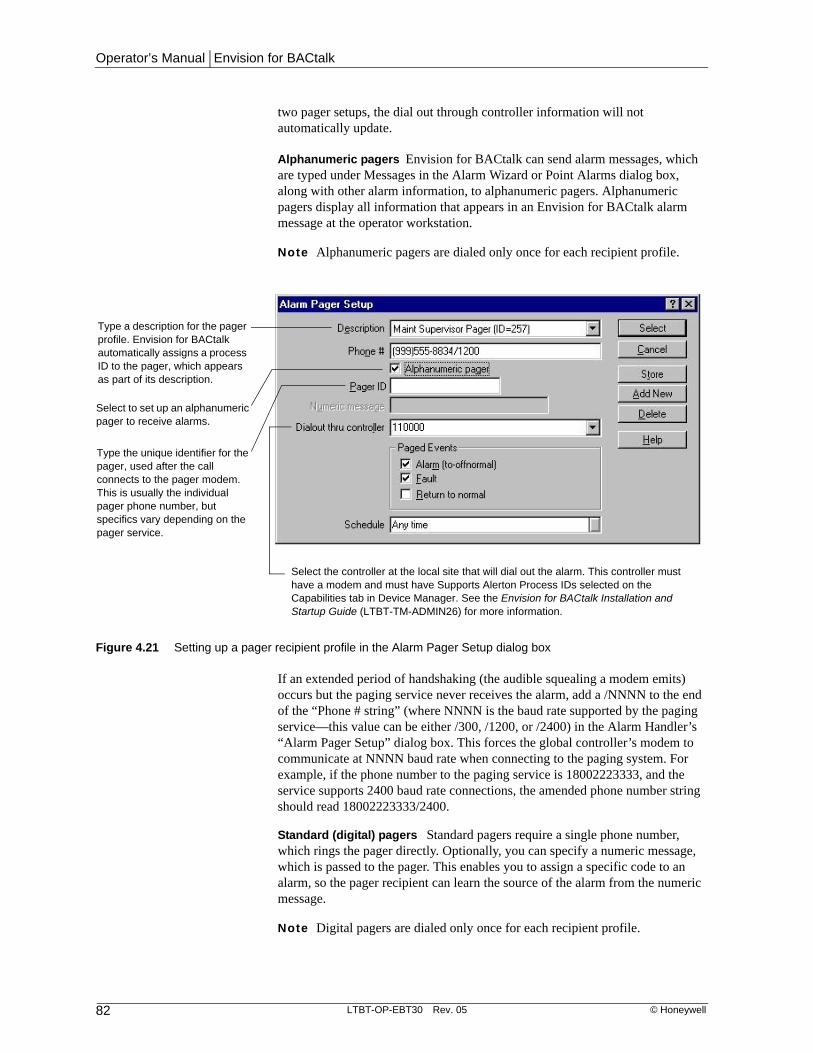
Operator’s Manual | Envision for BACtalk
82 LTBT-OP-EBT30 Rev. 05 © Honeywell
two pager setups, the dial out through controller information will not automatically update.
Alphanumeric pagers Envision for BACtalk can send alarm messages, which are typed under Messages in the Alarm Wizard or Point Alarms dialog box, along with other alarm information, to alphanumeric pagers. Alphanumeric pagers display all information that appears in an Envision for BACtalk alarm message at the operator workstation.
Note Alphanumeric pagers are dialed only once for each recipient profile.
If an extended period of handshaking (the audible squealing a modem emits) occurs but the paging service never receives the alarm, add a /NNNN to the end of the “Phone # string” (where NNNN is the baud rate supported by the paging service—this value can be either /300, /1200, or /2400) in the Alarm Handler’s “Alarm Pager Setup” dialog box. This forces the global controller’s modem to communicate at NNNN baud rate when connecting to the paging system. For example, if the phone number to the paging service is 18002223333, and the service supports 2400 baud rate connections, the amended phone number string should read 18002223333/2400.
Standard (digital) pagers Standard pagers require a single phone number, which rings the pager directly. Optionally, you can specify a numeric message, which is passed to the pager. This enables you to assign a specific code to an alarm, so the pager recipient can learn the source of the alarm from the numeric message.
Note Digital pagers are dialed only once for each recipient profile.
Figure 4.21 Setting up a pager recipient profile in the Alarm Pager Setup dialog box
Select to set up an alphanumeric pager to receive alarms.
Type a description for the pager profile. Envision for BACtalk automatically assigns a process ID to the pager, which appears as part of its description.
Type the unique identifier for the pager, used after the call connects to the pager modem. This is usually the individual pager phone number, but specifics vary depending on the pager service.
Select the controller at the local site that will dial out the alarm. This controller must have a modem and must have Supports Alerton Process IDs selected on the Capabilities tab in Device Manager. See the Envision for BACtalk Installation and Startup Guide (LTBT-TM-ADMIN26) for more information.

Chapter 4 | Alarms
© Honeywell LTBT-OP-EBT30 Rev. 05 83
Setting up remote site recipientsYou can set up an alarm to dial out from a global controller modem at an originating BACtalk site to a global controller modem at a recipient site (BACtalk>Alarms>Alarm Handlers>Edit>Add Recipient>Remote BACtalk system thru controller modem). An operator workstation at the remote site logs alarm messages to the remote alarm history. You can print alarms from within the alarm history. The remote operator workstation cannot annunciate or print the alarm on receipt.
This arrangement enables a single operator workstation at a centralized, remote location to log alarms from a number of geographically dispersed sites. The operator workstation at the remote site must be on and running Envision for BACtalk.
Note Envision for BACtalk supports such connections only between global controller modems—a global controller at the originating site dials a global controller modem at the remote site, which then forwards the alarm to the operator workstation at the remote site.
Each recipient profile is unique. You can set up multiple profiles for a single device (even within a single alarm handler) depending on how you want the device to handle different alarms. Edits to one profile do not affect others.
Figure 4.22 Alarm Pager Setup dialog box
Type a numeric message that the recipient pager can display to identify the source of the alarm.
Type the dialing string to be sent to the outbound modem. Typically, modems ignore parentheses and dashes, and interpret commas as pauses.
Select the controller at the local site that will dial out the alarm. This controller must have a modem and must have Supports Alerton process IDs selected on the Capabilities tab in Device Manager. See the Envision for BACtalk Installation and Startup Guide (LTBT-TM-ADMIN26) for more information.

Operator’s Manual | Envision for BACtalk
84 LTBT-OP-EBT30 Rev. 05 © Honeywell
Setting up email recipientsYou can set up a BACtalk workstation to email an alarm notification to one or more email recipients. Emailed alarm messages include the type of alarm and other text that appears in pop-up alarm notifications. Setting up email alarm notifications involves setting up the alarm, configuring the alarm handler, and specifying an email server.
Setting up an alarm To configure an alarm for email notifications, on the Alarm Setup page (BACtalk>Alarms>Alarm Setup), select Send email to email recipients. Click Email Settings... and then specify the From, CC, and BCC email addresses. Use commas between email addresses when setting up multiple recipients. The From email address appears as the sender of alarm notifications. CC and BCC recipients will receive copies of all email notifications. BCC recipients’ email addresses will not be visible to other recipients.
Configuring an alarm handler To configure the alarm handler, open the Edit Alarm Handler dialog box (see “Setting up alarm handlers” on page 77), click Add Recipient, and then select Email. The Email Alarm Setup dialog box appears. Type the recipient email address(es) separated by commas. Define the BACtalk workstation that will send out email alarms. Select a workstation with
Figure 4.23 Remote BACtalk Alarm Dialout Setup dialog box
Device instance of the remote site operator workstation that will log the alarm.
Device instance the outbound controller uses when it connects to the remote site. No device at the remote site can have this same device instance.
Network number the outbound controller uses when it connects to the remote site. This must be a unique number.
Required to access the remote site. This password must precisely match the one set for the controller at the remote site.
Select the controller at the local site that will dial out the alarm. This controller must have a modem and must have Supports Alerton process IDs selected on the Capabilities tab in Device Manager. See the Envision for BACtalk Installation and Startup Guide (LTBT-TM-ADMIN26) for more information.

Chapter 4 | Alarms
© Honeywell LTBT-OP-EBT30 Rev. 05 85
network connectivity to an SMTP email server. Select the events for which alarms will be generated. Specify the schedule for alarm notifications.
Specifying an email server To specify an email server, click General System Setup on the Tools menu and then select the Email Setup tab. Type a server host name or IP address and then specify a time-out. You may need to consult with site IT professionals to get these settings. Specify authentication settings and test the connection. See the associated online Help for more detail.
Practical application
Marc has three alarm handlers set up for the State University Administration building. One of these handlers is assigned to each alarm. He is organized them by severity and named the alarm handlers accordingly:
• Emergency alarm handler
• High-priority alarm handler
• Routine alarm handler
By doing this, Marc can change assignments within an alarm handler and have it carried out for all alarms of that type. This is handy if something in the system changes. For example, Marc got a new pager, and he now has to update the system to dial it. He also just installed a new technician’s operator workstation in the mechanical room, and he needs to set it up to receive high-priority and routine alarms.
For emergency alarms, Marc wants his pager dialed during off hours. He also wants the on-site pager dialed at all times, an alarm message to pop up on all
Figure 4.24 Set up for sending email alarms to the facilities group at State U
Alarm handler description.
The email addresses for anyone who should receive all email alarms. Separate email addresses with commas. Use of spaces after commas depends on the type of email server used. This field can hold a maximum of 1023 characters.
The device instance of the workstation on the local site that will receive alarm notifications from the BACtalk system and email them to other defined alarm recipients. The workstation must have network connectivity to the configured SMTP server.
Schedule alarm notifications. Specify the day(s) and time range when alarm notifications will be emailed to defined and enabled alarm recipients.
Select which types of alarms you want to email. Options include: to-offnormal, fault, and return to normal.
Click to set up a new alarm handler.

Operator’s Manual | Envision for BACtalk
86 LTBT-OP-EBT30 Rev. 05 © Honeywell
operator workstations, the server to send out email alarm notifications, and the alarm logged to the alarm history file on the server.
For high-priority alarms, Marc wants the on-site pager dialed at all times, an alarm message to pop up on all operator workstations, the server to send out email alarm notifications, and the alarm logged to the alarm history file.
For routine alarms, Marc wants alarm messages to appear at the two technician operator terminals and the alarm logged to the alarm history file so he can follow up at the end of the week.
To do this, Marc sets up the following recipient profiles:
• A recipient profile for his pager
• A recipient profile for the on-site pager
• A recipient profile for the server (Device Instance 200000)
• A recipient profile for the office tech workstation (Device Instance 200001)
• A recipient profile for the mechanical tech workstation (Device Instance 200002).
About alarm dialoutFor each pager or remote site recipient to be dialed, the BACtalk system dials only once. The system pauses two minutes before dialing the next recipient on the list. All recipients on the list are dialed each time an alarm occurs until the alarm is acknowledged.
Figure 4.25 Alarm Pager Setup dialog box

Chapter 4 | Alarms
© Honeywell LTBT-OP-EBT30 Rev. 05 87
Using Alarm Setup at an operator workstationYou use the Alarm Setup dialog box (BACtalk>Alarms>Alarm Setup) to set up the following alarm items for an operator workstation. These are global settings that apply to all alarms as appropriate.
• The site description passed to alarm pagers and remote-site alarm loggers (if alarm dialout is set up)
• Alarm printing specifics (if the operator workstation will host alarm printing)
• Order for alarm display on the operator workstation: oldest on top or newest on top
• Default handling for inbound alarms that have no handling specified
• Alarm set up for displaying a link to a URL or a data display
Site descriptionThe site description is sent along with alarm information when BACtalk dials an alarm to an alphanumeric pager or a remote BACtalk system. Make sure you choose a description that uniquely identifies the site for transmitted alarms. If no alarms dial out, you can leave the site description blank.
Figure 4.26 Alarm Setup dialog box

Operator’s Manual | Envision for BACtalk
88 LTBT-OP-EBT30 Rev. 05 © Honeywell
Alarm printingUse the items under Alarm Printing to designate the printer that Envision for BACtalk uses to print alarms.
Printer Click the arrow and then select a printer from the list. Only printers set up through the Printers utility in the Windows Control Panel are available (see Microsoft Windows documentation for more information).
Print user acknowledgements Select this check box if you want Envision for BACtalk to print alarm messages when they are acknowledged by the user (see “Reading BACtalk alarm messages” on page 90). The recipient profile and type of alarm are irrelevant in this case.
Enable printing Select this check box if you want Envision for BACtalk to print alarms received at this operator workstation upon receipt. The recipient profile used to transmit the alarm must have printing enabled as well.
Print only when the following point is active Select this check box to use a data point to control printer availability. Click the command button to select the point, typically a BV. This point can be scheduled or manually controlled. Alarms print when the point is active (ON) or when the point cannot be read.
Printer test Be sure your printer is connected and online, and then click this button to test your printer options and setup.
Alarm displayingUse this check box to set the stacking order of alarm popup windows. When the box is selected, the most recent alarm is displayed behind older alarms that have not yet been acknowledged. If the box is cleared, the most recent alarms are displayed on top. After selecting an option, the active alarm messages are resorted accordingly.
Generic/default alarm and event handlingMost alarms and events broadcast with some sort of handling specified (using a BACnet notification class). However, alarms and events occasionally may arrive without handling instructions. Specify what you want the operator workstation to do when this happens.
Table 4.4 Alarm Setup dialog box—user-specified alarm handling options
Item Remarks
Log into alarm history (only applies to alarms)
Select to log all alarms with no handling specified into alarm history
Print Select to print all alarms that have no handling specified.
Annunciate alarm/event if acknowledgement required
Select to annunciate events that have the “ack required” flag set.

Chapter 4 | Alarms
© Honeywell LTBT-OP-EBT30 Rev. 05 89
Note See “Working with URL notified alarms” on page 71 for more information about setting up URL-notified or data display linked alarms.
Enable email alarms Select Send Alarm to Email Recipients, and then click Email Settings to open the Email Setup for Alarms dialog box. Specify how the alarm origination information should be displayed, and then specify the email addresses where you want alarm notifications to be emailed. Note that the email recipients entered here are in addition to recipients set up in the Alarm Handler setup (
Specify the To: email addresses of all the users you want to receive the emailed alarm. Specify the From: email address, and email that will always be carbon copied (cc:). Blind copy (bcc:) users you want to receive alarms but whose email information you do not want displayed. Use commas between email addresses when setting up multiple recipients.
Email settings for alarms must be configured (BACtalk>Alarms>Alarm Setup), email must be added as an alarm recipient (BACtalk>Alarms>Alarm Handlers>Add/Edit>Add Recipient>Email) before alarms can be successfully emailed.
Annunciate alarm even if acknowledgement not required
Select to annunciate all events even if the “ack required” flag is not set. Applies only to alarms that do not use a BACtalk alarm handler (that is, with process IDs in the range 0-7 or 10-127).
Process all URL links in alarm messages
Select to translate URL text into live links.
Automatically open URL links when alarm messages are processed
Select to go to a URL when the alarm is processed.
Send alarm to email recipients
Select to email an alarm message to specified and configured recipients.
Table 4.4 Alarm Setup dialog box—user-specified alarm handling options
Item Remarks

Operator’s Manual | Envision for BACtalk
90 LTBT-OP-EBT30 Rev. 05 © Honeywell
Working with alarmsAlarms are an important component of your BACtalk system. You need to be able to recognize and read alarms to use this powerful feature effectively.
Reading BACtalk alarm messagesMost alarms are set up to require a user acknowledgment at an operator workstation through an alarm message. The alarm message can appear when an alarm or fault occurs, or when an alarm returns to normal.
The following conditions must be met for an alarm message to appear at an operator workstation:
• The monitored property must go into a state that triggers an alarm, as determined by the alarm setup. See “How alarms work” on page 50 for more information about alarm components.
• The alarm setup must have the corresponding alarm state enabled: Off-normal, Fault, or Normal.
• The alarm handler must be set up to require a user acknowledgment for the alarm state that occurs.
• The alarm handler for the alarm must have the operator workstation listed as a recipient.
• The operator workstation’s recipient profile must be set up to handle the alarm state that occurs and to annunciate it.
An alarm message conveys substantial information about when, where, and why an alarm occurred.
Figure 4.27 BACtalk alarm message
Indicates the transition that caused the alarm. The former state (in this example, normal) is followed by an arrow and the present alarm state (in this case, off-normal).
Displays a brief text string included with the alarm in all instances. This echoes the description of the alarm. This example alarm is identified as a communications error.
Displays the process ID used for alarm handling and the actions associated with that process.
Note: URL notified alarms will display a URL link or data display link below the Unit Message line. See page 71 for more information about working with URL notified alarms.

Chapter 4 | Alarms
© Honeywell LTBT-OP-EBT30 Rev. 05 91
Buttons along the bottom of the alarm message allow you to manage active alarm messages.
WARNING Acknowledging an alarm in no way ensures that the alarm condition has returned to normal. Use alarm history to check if an alarm condition still exists. If the alarm has not returned to normal, no entry appears in the “End” column. See Figure 4.29 on page 93.
Alarm notices on data displaysIn addition to the alarm message at an operator workstation, alarm notices appear on your site displays for properties that are in alarm. The alarm message appears enclosed in asterisks after the current (or last obtained) value or status of the data point. By default, most alarm notices appear in red; however, the system developer selects the color when setting up the item.
Analog data point alarms on a data display
Binary data point alarms on a data display
Table 4.5 Alarm message buttons
Button Function
Acknowledge Acknowledges the present alarm. This can be either the most recent or least recent alarm, depending on how the alarm display feature is set up. see “Using Alarm Setup at an operator workstation” on page 87 for more information. This acknowledges the alarm at this operator workstation only.
Acknowledge All Acknowledges all alarms at once. This closes all alarm messages without allowing the user to read the message.
Previous Scrolls back through the alarm messages. This can be an earlier or later alarm, depending on how the alarm display feature is set up. see “Using Alarm Setup at an operator workstation” on page 87 for more information.
Next Scrolls forward through the alarm messages. This can be a later alarm or earlier alarm, depending on how the alarm display feature is set up. see “Using Alarm Setup at an operator workstation” on page 87 for more information.
Options Opens the Main Alarm Setup dialog box. You can set the printing, display, logging, and annunciation of alarms and events here. see “Using Alarm Setup at an operator workstation” on page 87 for more information.
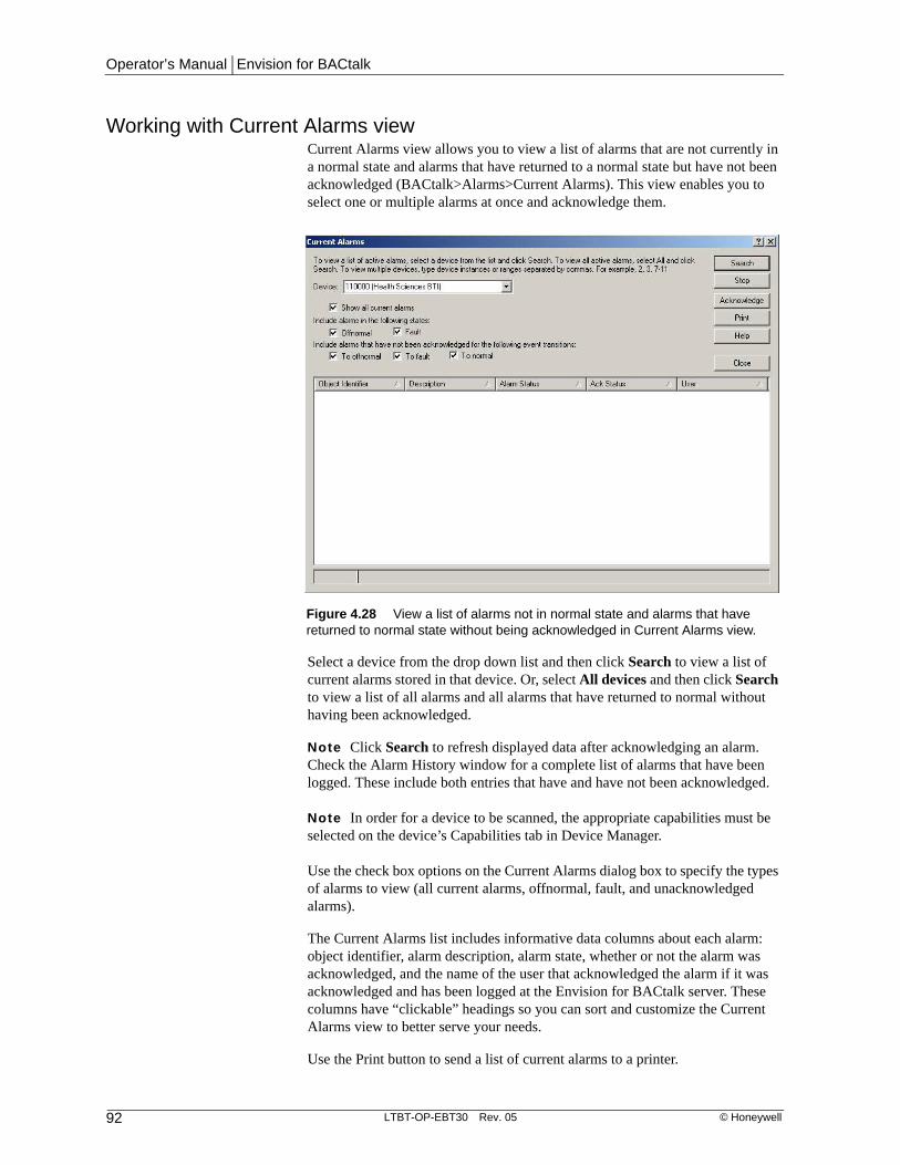
Operator’s Manual | Envision for BACtalk
92 LTBT-OP-EBT30 Rev. 05 © Honeywell
Working with Current Alarms viewCurrent Alarms view allows you to view a list of alarms that are not currently in a normal state and alarms that have returned to a normal state but have not been acknowledged (BACtalk>Alarms>Current Alarms). This view enables you to select one or multiple alarms at once and acknowledge them.
Select a device from the drop down list and then click Search to view a list of current alarms stored in that device. Or, select All devices and then click Search to view a list of all alarms and all alarms that have returned to normal without having been acknowledged.
Note Click Search to refresh displayed data after acknowledging an alarm. Check the Alarm History window for a complete list of alarms that have been logged. These include both entries that have and have not been acknowledged.
Note In order for a device to be scanned, the appropriate capabilities must be selected on the device’s Capabilities tab in Device Manager.
Use the check box options on the Current Alarms dialog box to specify the types of alarms to view (all current alarms, offnormal, fault, and unacknowledged alarms).
The Current Alarms list includes informative data columns about each alarm: object identifier, alarm description, alarm state, whether or not the alarm was acknowledged, and the name of the user that acknowledged the alarm if it was acknowledged and has been logged at the Envision for BACtalk server. These columns have “clickable” headings so you can sort and customize the Current Alarms view to better serve your needs.
Use the Print button to send a list of current alarms to a printer.
Figure 4.28 View a list of alarms not in normal state and alarms that have returned to normal state without being acknowledged in Current Alarms view.

Chapter 4 | Alarms
© Honeywell LTBT-OP-EBT30 Rev. 05 93
Working with alarm historiesAlarm history records (BACtalk>Alarms>Alarm History) show critical information about the alarms that have occurred in your system. To refresh alarm history records, press F5. Select the alarm types you want to view from the Display Filter list, and then select the date range to view under Alarms Time Range. To clear records or print the history, use the File menu.
To be logged in alarm history, the alarm handler for the alarm must be set up to broadcast to this operator workstation. Select Log Into Alarm History under Actions. See Figure 4.20 on page 81 for more information.
Display filterSelect the types of alarms to view. Only the selected types will be displayed.
Viewing Current or Archived DataView current alarm data or select an archive record from the drop-down menu to display it.
Note Archived files are saved to the server.
Alarm history view time intervalType in a new date and time range to view other archived data. Refresh the window to update the display window.
DescriptionThis column lists both the device instance (usually a global controller) where the alarm is stored, and the alarm description set up when the alarm was created. For communications alarms, the origin and logging device are recorded.
Figure 4.29 The Alarm History dialog box displays a description of the device in alarm, the date and time the alarm occurred, when it returned to a normal state, and when and by whom the alarm was acknowledged.

Operator’s Manual | Envision for BACtalk
94 LTBT-OP-EBT30 Rev. 05 © Honeywell
AlarmThis column lists the date and time the alarm occurred with the alarm type immediately below it. This same information appears in the Envision for BACtalk Alarm Message box (if applicable). See Table 4.6 on page 94 for more information.
EndThe time that the original event state that caused the alarm changed—either returned to normal or to some other state.
Note If the End field is blank, the original alarm condition still exists.
Ack (Local alarm history only)The time that the operator clicked Acknowledge on the Envision for BACtalk alarm message box and the user ID of the operator. If blank, the alarm was either set up with no acknowledgment or has yet to be acknowledged.
Site: rep/job, description (Remote alarm history only)These fields identify the source of the alarm. The site description is established in the Main Alarm Setup at the remote site, and the rep and job further pinpoint the source.
Practical application
Marc uses the alarm history each Thursday to check alarms that have been acknowledged and to ensure that no alarms remain unresolved. He sorts on the “End” column to look at alarms by status. He knows that any alarms that have nothing listed in the “End” column have not been resolved and may still be active alarms. He uses this as a convenient checklist to follow up.
Marc could also have used the Current Alarms View to quickly check alarm status.
Table 4.6 Alarm types and when they occur
Alarm Type Remarks
Off-normal The most common type of alarm. Generated when an alarm status changes from normal to off-normal (called an event transition).
Fault Generated when the alarm finds the monitored data point's reliability property to be in a fault state (other than No Fault Detected).
High/Low Limit Applies to analog values. High limit indicates the present-value of the object has exceeded its assigned high limit. Low limit indicates the present-value of the object dropped below its assigned low limit.

Chapter 4 | Alarms
© Honeywell LTBT-OP-EBT30 Rev. 05 95
Auto-archiving alarm history dataUse the auto-archive feature to set BACtalk to automatically archive alarm history records (BACtalk> Alarms> Alarm History> File> Archive Data). Records can be archived daily, weekly, twice a month, monthly, quarterly, twice a year, and yearly. Archived files are saved to the server.
Using remote alarm historyRemote Alarm History entries (BACtalk>Alarms>Remote Alarm History) appear only if this operator workstation is set up to receive alarms from a remote site using a modem. BACtalk creates a record of alarm information in the file Remote Alarm Log.mdb, which is saved in the current rep/job folder.
Note Do not attempt to open an MDB file that is already in use by BACtalk. For example, do not click Archive Now for a selected file when BACtalk is already using that file.
Display filterSelect the types of alarms to view. Only the selected types will be displayed.
Viewing Current or Archived DataView current remote alarm data or select an archive record from the drop-down menu to display it.
Remote alarm history view time intervalType in a new date and time range to view other archived data. Refresh the window to update the display window.
Site rep/jobIdentifies the rep/job of the operator workstation at the remote site where the alarm originated.
Figure 4.30 Archive Alarm History dialog box set to auto-archive every month

Operator’s Manual | Envision for BACtalk
96 LTBT-OP-EBT30 Rev. 05 © Honeywell
DescriptionThe alarm description set up when the alarm was created. Usually, this includes the device, object, and property that generated the alarm. For communications alarms, the origin and logging device are recorded.
AlarmLists the date and time the alarm occurred, followed by the event state that caused the alarm to occur, typically off-normal or fault.
EndThe date and time that the alarm returned to normal or to some other state, and the state it returned to. If blank, the alarm condition still exists, except for communication alarms.
Auto-archiving remote alarm history dataUse the auto-archive feature to set BACtalk to automatically archive remote alarm history records (BACtalk> Alarms> Remote Alarm History> File> Archive Data). Records can be archived daily, weekly, twice a month, monthly, quarterly, twice a year, and yearly. Archived files are saved to the server.
Note Do not attempt to open an MDB file that is already in use by BACtalk. For example, do not click Archive Now for a selected file when BACtalk is already using that file.
Alarm history database filesAlarm history records are saved in databases in the appropriate rep/job folder of the Envision for BACtalk root directory.
The database file for alarm history records is Alarms.mdb and the database file for the Remote Alarm History module is Remote Alarm Log.mdb.

Chapter 4 | Alarms
© Honeywell LTBT-OP-EBT30 Rev. 05 97
Sorting records and printing You can use the Display Filter control to change how you view and print data. Only the records that match the criteria you select display.
Working with Custom Process IDsWhen an alarm is broadcast to all devices, every device must handle it the same way. For example, you can not configure some devices to print the alarm and other devices to annunciate the alarm with a URL link displayed. Set up a
Figure 4.31 Alarm History dialog box using a display filter

Operator’s Manual | Envision for BACtalk
98 LTBT-OP-EBT30 Rev. 05 © Honeywell
custom process ID to broadcast an alarm to all BACnet devices, including those that are not Alerton devices (BACtalk>Alarms>Custom Process IDs).
Use the Custom Process ID dialog box to add, edit, and delete process IDs. The Edit Custom Process ID dialog box opens when you click Add or Edit.
The Process ID is a numerical value assigned to a process ID that identifies it from other process IDs. Default custom process IDs are predefined in the range 129-135. Each predefined ID has a unique combination of annunciation, logging, and printing enabled. These custom process IDs can be user-edited.
Specify how you want the alarm to be handled once this custom process ID is broadcast to all communicating BACnet devices on the network for an alarm. The Log in Alarm History and Annunciate options are selected by default.
You can delete one or multiple custom process IDs at a time. When multiple IDs are selected for deletion, a confirmation message prompts you to verify that you want to delete more than one ID. This is a security measure to prevent the loss of
Figure 4.32 The Custom Process ID dialog box where new process IDs can be added and existing ones can be selected and then edited or deleted.
Add a new custom process ID
Modify an existing custom process ID
Delete an existing custom process ID
View Help topic about custom process IDs
Close this dialog box
Text entry describing this custom process ID. For example, this ID broadcasts an alarm and instructs communicating BACnet devices to annunciate, log, and print the alarm with the Custom Process ID identified as number 135.
Log in Alarm History and Annunciate are selected by default for all new custom process IDs

Chapter 4 | Alarms
© Honeywell LTBT-OP-EBT30 Rev. 05 99
wanted data. Only one ID can be modified at a time so the Edit button is disabled when multiple IDs are selected.
Custom process ID versus a non-custom process IDWhen Envision for BACtalk processes an event that is configured as an unconfirmed event notification, it processes the ID based on the definition for a matching custom process ID. Otherwise, Envision for BACtalk uses a specific process ID.

Operator’s Manual | Envision for BACtalk
100 LTBT-OP-EBT30 Rev. 05 © Honeywell

Chapter 5 | Schedules
© Honeywell LTBT-OP-EBT30 Rev. 05 101
Schedules 5
Envision for BACtalk schedules enable you to plan building operations based on the time of day, holidays, and special events. Schedules can control zones and binary objects (ON or OFF) that support the priority-array property.
A schedule set, which you assign to a point or zone, consists of a standard schedule, a holiday schedule, and an event schedule. This scheduling structure allows you to control day-to-day zone operations with the standard schedule. The holiday schedule controls days or times when a facility is typically unoccupied. The events schedule controls time periods outside normal occupied times. The holiday schedule overrides the standard schedule, and the event schedule overrides the holiday and standard schedules within a schedule set.
BenefitsEfficient Scheduling data points and relying on the BACtalk system to turn equipment ON and OFF frees you to focus your attention on other areas of system operation.
Convenient Set up a schedule and then share it to control any number of points. Use the Time Schedule Wizard to view scheduled status at a glance.
Easy Right-click an item on a data display, and then click Schedules to edit the schedules or set up a new schedule set if the point is not yet scheduled.
Fast Set up times for one day of the week and then copy the settings to other days.
Practical application
The Administration building at State University is open Monday through Friday from 8:00 AM until 5:00 PM. This building is closed on state and federal holidays. Occasionally, special events in the conference room of the Administration building require a special schedule. For instance, on Monday, January 20, 2003 from noon to 3 PM, the building will be open for a special luncheon honoring Martin Luther King, Jr.
Marc is responsible for scheduling operations in the Administration building. He will use schedules in Envision for BACtalk to do it.

Operator’s Manual | Envision for BACtalk
102 LTBT-OP-EBT30 Rev. 05 © Honeywell
Quick start–schedule setupUse the following table to help you set up schedules. The key steps for creating schedules are listed in order.
Note It is good practice to name schedules according to their hours of operation (for example, M-F, 7AM-5PM, ON) rather than by the controlled equipment or zone so that the schedule remains flexible.
See “Zones” on page 29 and “Optimum start” on page 119 or Envision for BACtalk Help for more information about setting up and working with these features.
Table 5.1 Tasks for setting up a schedule
Task See
1 Identify the zone or data point in your system that you want to schedule. Must be a BV in a global controller, a BO in a VLC, or BV-40 in VLC 2.04 and later.
• Site documentation
• “Zones” on page 29
• “How schedules work” on page 103
2 If working with a data point, add a new scheduled point to the Point List in the Schedules dialog box (BACtalk>Schedule Points).
If working with a zone, select the zone from the Zones list (BACtalk>Zones), and then click Schedule. Or, use the Schedule List (BACtalk> Schedules> Schedule List).
• “Zones” on page 29
3 Specify the host device that will store and run the schedules
• Site documentation
4 For each of the three schedules–standard, holiday, and event–that control the point or zone, specify whether you want to create a new schedule, copy an existing schedule, or share an existing schedule.
• “Using the New Schedule Wizard” on page 107
• Refer to this year’s holiday and event schedules to help you plan next year’s holiday and event schedules.
5 Set up time blocks for ON and OFF commands.
• “Setting the schedule date and hours of operation” on page 110

Chapter 5 | Schedules
© Honeywell LTBT-OP-EBT30 Rev. 05 103
How schedules workWhen you set up schedules to control a data point or zone, it is important to understand the relationship of the schedules in the schedule set and how to use each one.
• Standard schedule Use standard schedules to control equipment with ON and OFF commands during routine hours of operation. This schedule may contain ON commands for operating hours or an all day ON command.
• Holiday schedule Use holiday schedules to override standard schedules for an entire day, usually with an all day OFF command. You can then schedule ON times within the holiday. This schedule overrides the standard schedule for the entire day.
Note Holiday schedules automatically write a 12:00 AM OFF time, which is in effect until the first scheduled ON command of the day occurs.
• Event schedule Use event schedules to override standard and holiday schedules with ON and OFF commands for time blocks in a day. Event time blocks are only in effect for the duration of the scheduled event and can not run through midnight.
How schedules write to zones and pointsIf you use zones in your system, you do not need to be as concerned about the technical details of how the system arbitrates for control of the point. The zone object resolves commands from the standard, holiday, and event schedules. The only concern: ensure that the occupied command you specify in the zone setup is not being written to by DDC. The occupied command data point is usually BV-40 in a VLC.
To fully understand how schedules operate with data points, it helps to understand the BACnet priority array. The BACtalk system uses the BACnet priority-array to manage the hierarchy of schedules.
CAUTION A data point must support the priority-array property to be scheduled. BVs in Alerton global and building controllers support the priority array. VLC versions 2.04 and later support the priority array. BOs in VLCs support the priority array.
Figure 5.1 The schedule set hierarchy—event schedules override holiday and standard schedules, holiday schedules override standard schedules.
Event Schedule(ON or OFF for a specified time)
Holiday Schedule(OFF for whole days with optional ON times)
Standard Schedule(Day-to-day ON and OFF)

Operator’s Manual | Envision for BACtalk
104 LTBT-OP-EBT30 Rev. 05 © Honeywell
See “Zones” on page 29 or Envision for BACtalk Help for information about using zones.
See the BACtalk Systems Programmer’s Guide and Reference (LTBT-TM-PRGRMR) for information about the priority array.
• Standard schedules write to data points at priority-array index 16. If the standard schedule is not writing an ON or OFF command, it is NULL.
• Holiday schedules write to data points at priority-array index 15. For days when a holiday schedule is in effect, an OFF command is written from 12:00 AM to 11:59:99.99 PM. On non-holiday days, the holiday schedule is NULL.
• Event schedules write to data points at priority-array index 13. If the event schedule is not writing an ON or OFF command for a time block, it is NULL.
Usually, the data points that schedules write to are reserved for scheduling. When a schedule set is assigned to a zone, the schedules write to the occupied command referenced for the zone (see “Zones” on page 29). Be careful that nothing else (such as DDC applications) writes to points that are scheduled.
There are essentially three methods for scheduling data points:
• BV-40 method
• Global controller BV method
• Direct BO control method
BV-40 methodSchedules control the occupied command in a VLC directly through BV-40. This enables you to directly schedule the occupied command in the VLC by assigning schedules to BV-40.
CAUTION Use this method only with VLC versions 2.04 because they support a priority-array for BV-40. Do not use this method for earlier VLC versions.
Global controller BV methodWith this method, a schedule set controls the present-value of a global controller BV. DDC in the global controller then transfers the present-value to a VLC BV. Each global controller typically has a BV devoted to scheduling. Likewise, each zone controller has a BV in DDC assigned for scheduling (BV-40 in most applications). Most system developers write subroutine DDC in the global controller to transfer the scheduled global controller BV to each respective zone controller BV. Subroutine DDC is usually already present to transfer other data, such as outside air temperature.
This scheduling method has a couple of advantages. Alerton Standard applications do not need to be edited for schedules. Also, VLC and building controller BOs can have the out-of-service property set to true, and schedules will still control the BO using DDC. One disadvantage is that global controller DDC must transfer the scheduled global controller BV to the appropriate VLC or building controller BVs.

Chapter 5 | Schedules
© Honeywell LTBT-OP-EBT30 Rev. 05 105
Direct BO control methodYou can directly control a BO in a VLC or VLX by assigning a schedule set to it. Right-click a prompted item on a data display that is set up as the present-value of a VLC BO, and then click Schedules. The schedule set then commands the priority-array of the BO. When you use this scheduling method, the most important consideration is that internal DDC running in the VLC writes commands at priority-array index 14, and will override the standard and holiday schedules.
One advantage of this approach is that there is no global controller DDC to write or maintain for schedules. Another advantage is the ease of scheduling a BO (right-click an item on a display).
The greatest disadvantage of this approach is that you must edit and monitor VLC DDC so that it does not conflict with schedules. If you do not modify DDC, conflicts may occur, and the data point will appear to not respond to schedule control.

Operator’s Manual | Envision for BACtalk
106 LTBT-OP-EBT30 Rev. 05 © Honeywell
Setting up schedules with the schedule wizardsThe New Schedule Wizard and the Time Schedule Wizard enable you to efficiently set up reliable schedules for BACtalk data points and zones.
You can access both schedule wizards from the Schedules dialog box. The Schedules dialog box includes a Point List of all properties that have a schedule set assigned to them. If you click Add to create a schedule set for a data point not listed, the New Schedule Wizard appears. If you click Edit to modify an existing schedule set for a selected point, the Time Schedule Wizard is displayed.
You can also access both schedule wizards from the Zones dialog box. If you select a zone with an “S” in the status column, and then click Schedules, the New Schedule Wizard appears. (S in the Status column indicates that the zone does not have a complete schedule set.) If you select a zone that does have a schedule set assigned, and then click Schedules, the Time Schedule Wizard appears.
See “Zones” on page 29 for more information about using the Zones dialog box.
Figure 5.2 Schedules dialog box
Click Add to create a new schedule for a property not listed.
Click Edit to modify the existing schedule for the selected point.
Click Delete to permanently remove the schedule for the selected point.

Chapter 5 | Schedules
© Honeywell LTBT-OP-EBT30 Rev. 05 107
Using the New Schedule WizardThe New Schedule Wizard enables you to schedule a data point or zone. For the standard, holiday, and event schedules, you can choose to create a new schedule, copy an existing schedule, or share an existing schedule with other zones or points.
Using the Time Schedule WizardThe Time Schedule Wizard provides a calendar-based tool where you can create, edit, and delete schedules. The majority of BACtalk schedules are edited and configured using the Time Schedule Wizard. The wizard’s easy-to-use format graphically displays the standard, holiday, and event schedules—the schedule set—that combine to control a point.
When you work with the wizard, you start with the property you want to schedule. BACtalk assigns a standard schedule, holiday schedule, and event schedule to the data point according to your instructions. You use a calendar and timetable to edit commands, and BACtalk sets up the appropriate schedules for you. The schedules are saved to the global controller and to your workstation hard disk when you save your work.
There are three ways to start the Time Schedule Wizard:
• Data points Select Schedules from the BACtalk menu, select a data point, and then click Edit.
• Zones Select Zones from the BACtalk menu, select a zone, and then click Schedule. (If the Zone has not been scheduled, the New Schedule Wizard appears first, followed by the Time Schedule Wizard.)
• Data display access Right-click a data display item and click Point Schedules. If the data point belongs to a zone, point to Zones first and then click Schedule.
Figure 5.3 Use the New Schedule Wizard to set up schedule control for a data point or zone.
Note The New Scheduled Point dialog box only appears when you select Schedules from the BACtalk menu.
Make New Create a new schedule set to control this point.Make a copy... Make a copy of an existing schedule set, give it a unique name, and use it to control this point.
Share... Use an existing schedule to control this point.

Operator’s Manual | Envision for BACtalk
108 LTBT-OP-EBT30 Rev. 05 © Honeywell
Time blocks on the Time Schedule Wizard timetable represent ON or OFF commands by hour of the day. Blocks are color coded for easy identification. Each column shows time blocks for the corresponding schedule.
The Time Schedule Wizard’s interactive calendar and timetable make it easy to add and remove scheduled commands. Use the timetable to edit a scheduled command, edit schedule properties, or delete a schedule command. Use the calendar to jump to existing holiday and event schedules.
Figure 5.4 The Time Schedule Wizard
About the example shown This is a common setup for a holiday, Martin Luther King Jr. day, on which a special luncheon will be held from 12-3 PM. The standard schedule is set up for Monday through Friday (using the recurrence feature) 8 AM to 5 PM ON. An OFF command for the entire day is set up in the holiday schedule. From 12 to 3, the event schedule issues an ON command for the luncheon event.
The calendar Shows dates, with holidays and events assigned in bold. Click a day on the calendar to set up scheduled times on that day. The active day appears highlighted. To quickly jump to a different month or year, click the month or year in the header and then select the one you want.
The schedules listing Shows the description of the schedules in this schedule set and enables you to change assignments and descriptions.
The timetable Graphically shows ON and OFF times for each schedule for the selected day. It also lets you easily edit and add scheduled commands. Double-click a time slot in the appropriate column to set up a new scheduled time block. To delete a scheduled event, right-click anywhere on the command block and click Delete. To edit a time, click the block and drag its edges until it occupies the appropriate time slots.
The timeline Right-click anywhere along the timeline to change displayed increments (60 min, 30 min, 15 min, or 10 min).
The point status bar Shows the resulting status of the point based on the combination of standard, holiday, and event schedules. (Colors are configurable. Right-click the status bar to change the ON and OFF colors.)
The Controlled Points list Shows the points and zones the selected schedule controls. Right-click a point or zone to delete it (and remove schedule control) or to add a new point or zone.
The data point you are working with.
Click to jump to today’s schedule.

Chapter 5 | Schedules
© Honeywell LTBT-OP-EBT30 Rev. 05 109
Setting the schedule effective period and propertiesIn rare cases, you may want to change the description of a schedule in a schedule set. Envision for BACtalk also enables you to change the period of time that a schedule in a schedule set is effective. This feature enables you to have a schedule control the assigned points only during a certain period that you specify. Because of the complexity using this feature introduces, it is rarely used and not recommended.
Click the command button to the right of each schedule type field, click the schedule header, or from the Edit menu, point to Properties and then click the Schedule you want to change to open the Edit Standard (Holiday, Event) Schedule Properties dialog box.
Use the Edit Standard (Holiday, Event) Schedule Properties dialog box to specify the time period that this standard (holiday, event) schedule will be in effect during the year. Specify the month, day, and year or the day of the week that this schedule will start and stop controlling the data point. Leave the date fields blank if you want this schedule to always be enabled.
Click to open the Edit Standard Schedule Properties dialog box.
Click to open the Edit Holiday Schedule Properties dialog box.
Click to open the Edit Event Schedule Properties dialog box.
Click to open the Edit Standard Schedule Properties dialog box.
Click to open the Edit Holiday Schedule Properties dialog box.
Click to open the Edit Event Schedule Properties dialog box.

Operator’s Manual | Envision for BACtalk
110 LTBT-OP-EBT30 Rev. 05 © Honeywell
Setting the schedule date and hours of operation
Standard scheduleUse the Edit Schedule Wizard to set the days of the week and the hours your standard schedule will be enabled.
Note Envision for BACtalk recognizes many date formats to suit your preferences. For example, typing 5 = 5:00 AM, 17 = 5:00 PM, 6P = 6:00 PM, and 5:20P = 5:20 PM.
There are two ways to open the Edit Schedule Wizard:
• Select a time slot, right-click the selection, and then click New.
• Double-click a time slot.
Note BACtalk applies the schedule command to the next occurrence of the scheduled day. For example, if you select a start time of Monday at 8:00 AM and then subsequently choose a Tuesday start, the command appears on the next occurring Monday.
Figure 5.5 This 8 to 5 Standard Schedule will be effective from January 1, 2003 through December 31, 2003.
Figure 5.6 This standard schedule will be enabled on Fridays from 8:00 AM to 5:00 PM.
Leave blank for this schedule component to be enabled at all times. Otherwise, type a date range. The schedule component only sends commands during that date range.

Chapter 5 | Schedules
© Honeywell LTBT-OP-EBT30 Rev. 05 111
To make the schedule command recur on a range of dates, click the Recurrence button and then select the days you want the command to occur.
There is no “clear all” feature on the Schedule Repeats Options dialog box. Individually clear the check box in front of each day of the week for which you do not want to schedule an event.
Holiday scheduleUse the Edit Holiday Wizard to set a day or time block when the holiday schedule will be in effect.
There are two ways to open the Edit Holiday Wizard:
• Select a time slot, right-click the selection, and then click New.
• Double-click a time slot and navigate through the calendar until you locate the date you want to schedule.
IMPORTANT! If you clear the All Day check box, remember that holiday schedules always start with a 12 AM OFF time. So, if you schedule a 2:00 PM to 3:00 PM ON time for a holiday, all other times on that day will be OFF.
Figure 5.7 This schedule will be in effect Monday through Friday.
Figure 5.8 This holiday schedule will command the equipment OFF all day for Martin Luther King, Jr. Day, January 20, 2003.
Use the Monday->Friday button to quickly select all five days at once.

Operator’s Manual | Envision for BACtalk
112 LTBT-OP-EBT30 Rev. 05 © Honeywell
Event scheduleUse the Edit Event Wizard to set a day or time block when the event schedule will be in effect.
There are two ways to open the Edit Event Wizard:
• Select a time slot, right-click the selection, and then click New.
• Double-click a time slot.
Editing a scheduled commandOnce you have created a schedule, it is easy to go back and modify its command parameters. Click anywhere on the time block to select the time period for editing. Position the mouse pointer on the edge of the time block you want to change so it appears as a double-headed arrow and drag it to the new starting or ending time.
Note You can also right-click anywhere in the time block and then click Open on the shortcut menu to edit a scheduled command.
Deleting a scheduled commandSelect a scheduled point from the Schedules dialog box, and then click Delete to permanently remove a schedule from the data point. If you are already working with the Time Schedule Wizard, right-click anywhere on the time block and then click Delete.
Jumping to an existing holiday or event scheduleUse the View menu in the Time Schedule Wizard to quickly move to an existing holiday or event schedule. Click Dates from the View menu, and then click
Figure 5.9 This event schedule will command equipment ON from 12:00 PM to 3PM for the luncheon honoring Martin Luther King, Jr. Note Event schedules override holiday schedules.

Chapter 5 | Schedules
© Honeywell LTBT-OP-EBT30 Rev. 05 113
Holiday or Event schedule. A list of dates for which holidays or events are scheduled is displayed (depending on your selection). Select the date you want to open and click OK.
Practical application
The Administration building at State U has a single global controller, a BTI with device instance 110000. There are numerous zones within the building, such as: university administrative staff offices, the university president’s office and conference room, the provost’s office, Academic Records, Student Registration, Cashier, Academic Scholarships, faculty payroll, university accounting, Alumni Services, Graduation Services, small conference room, medium conference room, large conference room, and restrooms and lobby.
Regularly scheduled operating hours are from 8 AM to 5 PM every weekday. Marc has the Administration building zones set up to share the same standard schedule, which he named “8 to 5 Standard Schedule.” When the university administration changed hours from the old 7 AM to 4 PM schedule last year, it was easy for Marc to update the schedule. He simply changed the time block and the schedule object description on a standard schedule for one of the zones and all zones that use this schedule were updated to the new operating hours.
Each year around late November, the provost releases the business holidays for the following year. Because the business holidays are different from the school holidays, the Administration building needs its own holiday schedule, “Business Holiday Schedule.” Holidays are set up on this schedule to be OFF all day.
Marc set up each zone in the Administration building with its own event schedule. This way, an event in one of the zones does not cause equipment in the other zones to come ON.
Early tomorrow, a disciplinary hearing is being held in the university president’s conference room, from 7:00 AM to 8:00 AM. Marc adds a 7:00 AM ON time block to the event schedule for the following day. Because the zones have different event schedules, it affects only the university president’s conference room.
Figure 5.10 This is a list of existing holiday schedules assigned to the selected point.

Operator’s Manual | Envision for BACtalk
114 LTBT-OP-EBT30 Rev. 05 © Honeywell
For the luncheon on Martin Luther King Jr. day, Marc modifies the holiday schedule. This way, he can affect all zones in the building. MLK day is already selected as an All Day OFF holiday. Marc navigates to the calendar, right-clicks the Holiday column, and selects Open. He then clears the All Day check box. Marc then adds an event schedule for 12:00 PM to 3:00 PM and clicks the ON option button. The holiday schedule still issues an 12:00 AM off command, but there is now a single ON command for the luncheon.
Notice how the point status bar in the image above still indicates that the entire day is set to OFF, except 12 PM to 3 PM. When Marc sets up the single time for the ON holiday, the building is set to ON for the specified event and remains set to OFF for the rest of the day. If he wants to add a second ON time for the holiday, Marc can add the ON time to the holiday schedule or use the event schedule.
Right-click the point status bar to view/edit schedule status colors.
Shows that the holiday schedule is in effect so Administration building equipment is scheduled OFF. Use the color settings to help you understand which schedules are active or inactive. This image shows the Holiday column and the point status bar are the same color. Shows that the event schedule is in effect from 12 PM to 3
PM. Note Event schedules override holiday schedules.

Chapter 5 | Schedules
© Honeywell LTBT-OP-EBT30 Rev. 05 115
Customizing the appearance of the timetableYou can customize the appearance of the timetable in the Time Schedule Wizard to better meet your needs.
Changing schedule color settingsYou can change the color associated with each of three types of schedules for easy recognition while setting up and working with schedules. Right-click the point status bar, and then click Edit.
A color box appears in the Schedule Color Settings dialog box for each schedule type and command state–Active (ON) or Inactive (OFF). Use the arrow next to the schedule and command state you want to change, and then select a color from the palette.
Changing the time increments displayed on the timelineBy default, the timeline along the left side of the timetable is displayed in 1-hour increments. Right-click anywhere on the timeline and then select the time increment you want. A check mark appears next to the selected increment.
You can change the time increments in the timeline to either 60, 30, 15, or 10 minutes. Default is 30 minutes.
Changing the Time Schedule Wizard dialog box sizeYou can adjust the size of the Time Schedule Wizard dialog box to suit your needs. Click Size on the View menu, and then click either Large or Small. By default, the size of the Time Schedule Wizard dialog box is set to Small. Selecting Large allows you to view more hours in the timetable and enlarges the Controlled Points list area.

Operator’s Manual | Envision for BACtalk
116 LTBT-OP-EBT30 Rev. 05 © Honeywell
Editing schedule sets and point assignmentsYou can easily change the operation of a schedule set once it is defined. You can add and remove data points and zones, exchange a standard, holiday, or event schedule for another one, and change the description and effective date of a schedule component.
Changing the points or zones that a schedule set controlsYou may need a schedule set to control a different property as time passes. For example, a tenant may expand their operations to another floor and they have a different work schedule than the previous tenant. With the occupied mode for the zone specified, BACtalk makes it easy to remove the properties from the old schedule set and assign them to a new one.
Removing a property from a schedule setEither through the BACtalk menu or by right-clicking a data display, select the scheduled point that you want to work with from the Point List in the Schedules dialog box. To permanently remove the assigned schedule set from the selected point, click Delete.
Assigning additional points to a schedule setYou may also want to assign the same schedule set to additional points. Open the Time Schedule Wizard for the schedule set you want to use, and then right-click anywhere on the Controlled Points list to display the shortcut menu.
Click Add point and specify the device instance of the global controller and point information.
Assigning additional zones to a schedule setYou may also want to assign the same schedule set to additional zones. Open the Time Schedule Wizard for the schedule set you want to use, and then right-click anywhere on the Controlled Points list to display the shortcut menu.
Click Add Zone and select an existing zone or create a new one to assign to this schedule set.
See “Zones” on page 29 or Envision for BACtalk Help for more information about working with zones.

Chapter 5 | Schedules
© Honeywell LTBT-OP-EBT30 Rev. 05 117
Replacing a schedule in a schedule setOccasionally, you may need to replace a schedule in one schedule set with a schedule from another schedule set. For example, you may find that a holiday or event schedule for one zone may not be appropriate for another zone.
CAUTION When you edit a schedule set in this way, all properties assigned to the schedule set are affected. Check the Controlled Points list in the Time Schedule Wizard for a schedule set to confirm that you want to make the change.
Replace a standard, holiday, or event schedule in a schedule set with another by opening the Time Schedule Wizard for the point whose schedule you want to edit. To avoid changing the wrong schedule set, verify that only the points you want to edit appear in the Controlled Points list. Use the arrow to select the schedule you want to work with.
Note The drop-down arrow is only available when more than one schedule has been created.

Operator’s Manual | Envision for BACtalk
118 LTBT-OP-EBT30 Rev. 05 © Honeywell

Chapter 6 | Optimum start
© Honeywell LTBT-OP-EBT30 Rev. 05 119
Optimum start 6
How do you decide when to start equipment to prepare a zone for occupancy? Start too late, and occupants might be too hot or too cold for a while when they are first in the zone. Start too early, and you waste energy conditioning unoccupied zones. You may also need to frequently adjust the start schedule for seasonal and building factors. Instead, use optimum start to do the work for you. With optimum start, you schedule only the occupied time for the zone. Your BACtalk system reliably calculates how far in advance to start equipment to meet the desired temperature by scheduled occupancy.
BenefitsEfficient Equipment only works when necessary to condition the space and keep occupants comfortable.
Saves labor You schedule occupied times and the system calculates when equipment actually needs to start. No additional programming or manual adjustments are required.
Intelligent Optimum start learns every time it runs, self-adjusting to ensure maximum efficiency and comfort.

Operator’s Manual | Envision for BACtalk
120 LTBT-OP-EBT30 Rev. 05 © Honeywell
Practical application
Joe, a facilities engineer at the State University Health Sciences building, is getting complaints again that the main lecture hall is too cold in the morning. The first class of the day arrives at 8:00 AM, and the lecture hall is scheduled for occupancy at the same time. This schedule is set up every November. Joe suspects that the hall does not actually warm up to the occupied setpoint until about a half hour later now that the weather is colder. So he checks trendlogs to confirm this. After evaluating the trendlogs, he decides to adjust the schedule to start equipment a half-hour earlier for every occupied time. It works, but he knows he may have to adjust again when the weather gets even colder, then again in spring, and again in summer as the weather gets warmer.
The main lecture hall is a good candidate to use optimum start. Optimum start will look at the lecture hall’s scheduled occupied time and then calculate how much earlier equipment needs to start. The feature then monitors how well it did and adjusts the next start time, continuously improving and optimizing. The system will find the optimum time to start equipment based on many factors, including the temperature outside and its past performance.
Joe sets up a zone for the main lecture hall (see “Zones” on page 29) and then sets up optimum start for the zone. The BACtalk system now automatically warms up or cools down the space for its occupied times. From time to time, Joe checks trendlogs of key points to ensure the feature is functioning as expected.

Chapter 6 | Optimum start
© Honeywell LTBT-OP-EBT30 Rev. 05 121
Quick start–optimum start setup and adjustmentUse the table to determine the order of tasks to perform when you set up optimum start. The table also lists references in this document and elsewhere where you can get more information.
CAUTION Adjusting optimum start settings without sufficient knowledge can cause undesirable results and may inadvertently overwrite BACtalk’s self-tuning operations. Before adjusting automatic mode settings, it is recommended that you take values and run them through the equations to try to predict their effect.
Table 6.1 Tasks for setting up optimum start
Task See
1 Identify the zone you need to work with or set up a new zone.
• “Optimum start” on page 119
• Site documentation
2 Confirm that the zone has a schedule set assigned to it and that the occupied times are correct. Edit the schedule set if necessary.
• “Zones” on page 29
• “Schedules” on page 101
3 Confirm that the zone has optimum start references. If necessary, verify that the references are correct.
• “Zones” on page 29
• “Setting or confirming optimum start references for the zone” on page 132
4 For zones with existing optimum start, make sure to update the data.
• “Saving data from the controller to the Envision for BACtalk server” on page 128
5 Select the optimum start mode. • “Choosing manual or automatic mode” on page 135
6 Set your parameters. • “Editing optimum start settings” on page 133
• Site documentation

Operator’s Manual | Envision for BACtalk
122 LTBT-OP-EBT30 Rev. 05 © Honeywell
How optimum start worksThis section first provides the equations and logic that optimum start uses to calculate equipment advance time. Advance time is the amount of time before occupancy that the BACtalk system begins warmup or cooldown to get a zone to target heating and cooling setpoints for occupancy. This chapter then provides information about how an optimum start program is saved, how it runs, and the other BACtalk features it interacts with.
This information may be helpful if you are setting up optimum start for a zone (See “Zones” on page 29) or if you need to determine if optimum start is doing its job as expected. (Also, see “Strategies and tips for checking optimum start operation” on page 139.) Most readers can skip this section.
About automatic and manual modes of operationOptimum start has two modes of operation: manual mode and automatic mode. The mode is selected when optimum start is set up.
Manual modeManual mode offers a simple method to implement optimum start for zones where heating and cooling operations are very predictable, regardless of the time of day, the temperature outside, or other building factors. You simply specify how many degrees per hour you expect equipment to heat up or cool down a zone prior to occupancy. You also specify the maximum advance time for equipment. Use the maximum advance time as a fail-safe of sorts. The maximum advance ensures that the system will not start warmup or cooldown operations too early under error conditions (for example, if a sensor fails or a unit is offline).
The calculations in manual mode are straightforward.
Warmup calculation AdvanceMinutes = (HtgSP–Temp) X 60/HtgRate
Where:
AdvanceMinutes = The amount of warmup time optimum start calculates to be necessary before occupancy
HtgSP = The occupied heating setpoint for the zone
HtgRate = The heating rate set up for optimum start (degrees per hour)
Cooldown calculation AdvanceMinutes = (Temp–ClgSP) X 60/ClgRate
Where:
AdvanceMinutes = The amount of cooldown time optimum start calculates to be necessary before occupancy
ClgSP = The occupied cooling setpoint for the zone
ClgRate = The cooling rate set up for optimum start (degrees per hour)

Chapter 6 | Optimum start
© Honeywell LTBT-OP-EBT30 Rev. 05 123
Example
A manual optimum start program is set up for a zone with a heating rate of 5 degrees F, a cooling rate of 4 degrees F, and a maximum advance time of 120 minutes. The zone is scheduled for two occupied times during the weekday, one at 8:00 AM and the other at 4:30 PM. The zone has an occupied heating setpoint of 68 degrees F and an occupied cooling setpoint of 74 degrees F.
The BACtalk system monitors the zone space temperature and sees it holding at 63 degrees. Optimum start calculates an advance time of 60 minutes [60 = (68 – 63) * 60/5], and will start warmup at 7:00 AM. At 1:30 PM the space temperature is 84 degrees F. Optimum start calculates an advance time of 150 minutes, but does not start equipment [150 = (84 – 74) X 60/4) until 2:30 because 120 minutes is the maximum advance time allowed.
Practical application
The basement classrooms in the Health Sciences building heat and cool at a very predictable rate. In warmup mode, the HVAC system heats the classrooms at a rate of 5 degrees F per hour and cools at a rate of 10 degrees F per hour. It does not matter if it is August or November, 100 degrees F or 10 degrees F outside, 3:00 AM or 3:00 PM. Also, they have never needed more than 10 degrees heating or cooling.
Because this zone of classrooms is so predictable, Joe, the facilities engineer, has set up manual mode optimum start for it. The heating rate is set to 5 degrees per hour and the cooling rate is set to 4 degrees per hour. Because it never varies from the setpoint by more than about 10 degrees, Joe sets the maximum advance time to 240 minutes. This ensures that the system never starts warmup or cooldown more than 2 hours before scheduled occupancy.
Automatic modeAutomatic mode offers an intelligent and adaptive algorithm to control warmup and cooldown operations for a zone. Setup is more complex for automatic mode responding to environmental and historical conditions dynamically, but its behavior is also much more advanced and adaptive than manual mode.
CAUTION Adjusting automatic mode settings requires a solid understanding of their effect on the optimum start calculations. Adjusting these settings without sufficient knowledge can cause undesirable results and may inadvertently overwrite BACtalk’s self-tuning operations. Before adjusting automatic mode settings, it is recommended that you take values and run them through the equations to try to predict their effect.
Use automatic mode when you want warmup and cooling operations to intelligently adapt to changing conditions.

Operator’s Manual | Envision for BACtalk
124 LTBT-OP-EBT30 Rev. 05 © Honeywell
Initial warmup calculation AdvanceMinutes = WrmFctr X (OADelta + BldgMass X (HtgSP–Temp)) X 2
Where:
AdvanceMinutes = The amount of warmup time optimum start calculates to be necessary before occupancy.
WrmFctr = An automatically adjusted warmup factor. Maximum value is 10. Minimum is 0. The greater the warmup factor, the greater the advance time.
OADelta = The difference between the outside air limit—a value that you specify in the optimum start setup—and the actual outside air temperature. If the result is less than zero, optimum start uses zero.
BldgMass = A value that you specify in the optimum start setup that can be equal to 3, 4, or 5. Larger numbers correspond to greater interior building mass (including heavy bookcases, thick walls, glass walls, and lots of oversized office equipment), increasing the effect of zone temperature within the equation. Smaller numbers correspond to less interior building mass, increasing the effect of outside air temperature within the equation.
HtgSP = The occupied heating setpoint for the zone.
Temp = The zone space temperature.
Initial cooldown calculation AdvanceMinutes = ClFctr X (Temp – ClgSP) X BldgMass X 2
Where:
ClFctr = An automatically adjusted cooldown factor. Maximum value is 10. Minimum is 0. The greater the cooling factor, the greater the advance time.
Temp = The zone space temperature.
ClgSP = The occupied cooling setpoint for the zone.
BldgMass = A value that you specify in the optimum start setup that can be equal to 3, 4, or 5. Larger numbers correspond to greater interior building mass, increasing the effect of zone temperature within the equation. Smaller numbers correspond to less interior building mass, increasing the effect of outside air temperature within the equation.
Heating and cooling factor adjustments Optimum start adjusts warmup and cooldown factors based on the performance of optimum start. Adjustments occur at the end of an optimum start operation (that is, after scheduled occupancy).
When adjusting warmup and cooldown factors, optimum start uses a self-tuning factor that you specify. This value ranges from 0.0 to 1.0. Use the self-tuning factor to adjust how aggressively optimum start tunes. When the factor is set to 1, the most recent optimum start performance has the maximum effect on the adjustment. When set to 0.1 it has the minimum effect. When set to 0, automatic adjustment is disabled.

Chapter 6 | Optimum start
© Honeywell LTBT-OP-EBT30 Rev. 05 125
Note If the previously calculated advance time exceeded the maximum advance time defined in the Optimum Start dialog box, optimum start does not further adjust the heating and cooling factors.
If optimum start fails to reach the setpoint by the scheduled occupied time, optimum start compares the ratio of desired temperature change to actual temperature change to calculate an adjustment to the heating or cooling factor.
FctrAdjustment = (SP - StartTemp) / (ResultTemp - StartTemp)
Where:
SP = The occupied heating or cooling setpoint as appropriate.
StartTemp = The zone space temperature measured at the time optimum start began warmup or cooldown (the scheduled occupied time less the advance time).
ResultTemp = The zone space temperature measured at the scheduled occupied time.
If the zone reached the setpoint too early, optimum start uses the ratio of actual time to achieve desired temperature to planned time to achieve the temperature to calculate an adjustment to the heating or cooling factor.
FctrAdjustment = (ActualMinutesToSP / CalculatedAdvanceMinutes)
After optimum start calculates the adjustment to the heating or cooling factor, it uses the adjustment to calculate a new heating or cooling factor as follows.
NewFctr = OldFctr + OldFctr X (FctrAdjustment - 1.0) X TuningFactor
Where:
NewFctr = The new heating or cooling factor as appropriate.
OldFctr = The previously used heating or cooling factor.
FctrAdjustment = The factor adjustment that optimum start calculated (see earlier equations). The greater the adjustment, the greater the difference between the old factor and the new factor.
TuningFactor = The tuning factor, which you specify in the optimum start setup, varies from 0.1 to 1.0. The greater the tuning factor, the greater the difference between the old factor and the new factor. A tuning factor of 1.0 causes heating and cooling factors to tune the most aggressively. A tuning factor of 0.1 causes them to adjust least aggressively. A tuning factor of 0 disables factor adjustments.

Operator’s Manual | Envision for BACtalk
126 LTBT-OP-EBT30 Rev. 05 © Honeywell
Example
An automatic optimum start program is set up for a zone with the following settings:
Self-tuning factor: 0.5
Outside air limit: 65 degrees F
Building mass: 4.0
Warmup factor: 1
Maximum advance: 120 minutes
The zone is scheduled for occupancy at 9:00 AM and has an occupied heating setpoint of 68 degrees F. When the BACtalk system monitors the zone to calculate optimum start, the space temperature is 58 degrees F. The outside air temperature is 50 degrees F.
Optimum start calculates an advance time of 110 minutes and will start warmup up at 7:10 AM, using the initial warmup equation (see See “Initial warmup calculation” on page 124 for more information):
AdvanceMinutes = WrmFctr X (OADelta + BldgMass X (HtgSP–Temp)) X 2110 = 1 X (15 + 4 X (68 - 58)) X 2
At 9:00 AM, the zone temperature has reached only 65 degrees F, so optimum start makes the necessary adjustments to reach the heating setpoint earlier next time. First, a factor adjustment of 1.4 is calculated, using the following equation:
FctrAdjustment = (SP - StartTemp) / (ResultTemp - StartTemp)1.4 = (68 - 58) / (65 - 58)
Next, the factor adjustment is used to determine a new warmup factor of 1.2:
NewFctr = OldFctr + OldFctr X (FctrAdjustment - 1.0) X TuningFactor1.2 = 1 + 1 X (1.4 - 1.0) x 0.5
Finally, a new advance time of 132 minutes is calculated for the next day:
132 = 1.2 x (15 + 4 X (68 - 58)) X 2
Practical application
The main lecture hall in the Health Sciences building has lots of windows so Joe, a facilities engineer, sets up optimum start for this zone with a light building mass of 3. This zone is located on the third floor where the windows are not shaded by trees or other buildings so it gets lots of sunshine and is very susceptible to time-of-day and seasonal temperature changes. Joe raises the self-tuning factor for this zone to 0.8 to account for its physical location. He also sets up and checks trendlogs to help him verify that optimum start is performing as expected and to help him determine when he needs to tweak optimum start factors as environmental conditions change.

Chapter 6 | Optimum start
© Honeywell LTBT-OP-EBT30 Rev. 05 127
Automatic mode with humidityHumidity can play a significant role in cooling a zone because it takes longer to cool a space with higher humidity. If the optimum start mode is set to automatic, and the relative humidity is known, the following algorithm is used to calculate advance minutes when the zone requires cooling:
AdvanceMinutes=Cooling_Factor X (Enthalpy(ZoneTemp, ZoneHumidity)-Enthalpy(CoolingSP,50)) X 12
Where ZoneHumidity has a minimum of 30% and the ZoneTemp is limited between 40°F and 100°F for the Enthalpy calculations. If the humidity is below 30%, then the value 30% is used. If the temperature is outside the range 40°F through 100°F, the nearest value inside the range is used.
Enthalpy can be approximated by the following:
Td= dry bulb temp in degrees FRH= the relative humidity, 0 through 100, in percent
Partial pressure of water vapor at saturation Pws= -0.104 + 0.00869 X Td - 0.0001395 X Td^2 + 0.000001581 X Td^3
Partial pressure Pw at humidity RHPw=RH X Pws/100
Humidity Ratio W= 0.622 X Pw/(p-Pw) (p=atmospheric pressure=14.7 at sea level)
Enthalpyh=0.24 X Td + W X (1061 + 0.444 X Td)
How an optimum start program is saved and runsOptimum start is a feature associated directly with a zone. When you set up an optimum start program, the information, configuration, and settings are stored and run as part of a zone object. Optimum start then works along with the schedule assigned to the zone.
For this reason, before you set up optimum start, you must set up a zone and assign a schedule to that zone. Data for optimum start is available as properties of the zone object. For a reference of properties related to optimum start, see the BACtalk Systems Programmer’s Guide and Reference (LTBT-TM-PRGRMR).
See the Zones chapter or Envision for BACtalk Help for more information about setting up and working with zones.
Saving and restoring optimum start settings, and automatically calculated valuesOptimum start settings and standard optimum start calculation values are stored in a database on the Envision for BACtalk server. They are also saved in the global controller. When the BACtalk system self-tunes the values used in optimum start calculations, those values are saved in the global controller. Also, if you adjust values from a data display, the values are adjusted in the global controller.
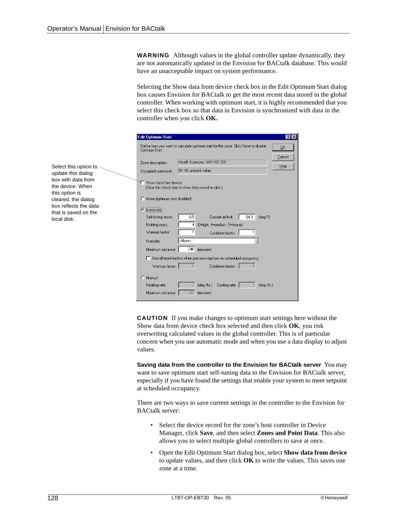
Operator’s Manual | Envision for BACtalk
128 LTBT-OP-EBT30 Rev. 05 © Honeywell
WARNING Although values in the global controller update dynamically, they are not automatically updated in the Envision for BACtalk database. This would have an unacceptable impact on system performance.
Selecting the Show data from device check box in the Edit Optimum Start dialog box causes Envision for BACtalk to get the most recent data stored in the global controller. When working with optimum start, it is highly recommended that you select this check box so that data in Envision is synchronized with data in the controller when you click OK.
CAUTION If you make changes to optimum start settings here without the Show data from device check box selected and then click OK, you risk overwriting calculated values in the global controller. This is of particular concern when you use automatic mode and when you use a data display to adjust values.
Saving data from the controller to the Envision for BACtalk server You may want to save optimum start self-tuning data to the Envision for BACtalk server, especially if you have found the settings that enable your system to meet setpoint at scheduled occupancy.
There are two ways to save current settings in the controller to the Envision for BACtalk server:
• Select the device record for the zone’s host controller in Device Manager, click Save, and then select Zones and Point Data. This also allows you to select multiple global controllers to save at once.
• Open the Edit Optimum Start dialog box, select Show data from device to update values, and then click OK to write the values. This saves one zone at a time.
Select this option to update this dialog box with data from the device. When this option is cleared, the dialog box reflects the data that is saved on the local disk.

Chapter 6 | Optimum start
© Honeywell LTBT-OP-EBT30 Rev. 05 129
Restoring data from Envision for BACtalk to the controller You may need to restore optimum start settings if a user has changed descriptions or values through a data display or conditions have changed such that the values stored in the controller are no longer acceptable.
To restore current settings from Envision for BACtalk to the global controller, you have two options:
• Select the device record for the zone’s host controller in Device Manager, click Send, and then select Zones and Point Data.
• Open the Edit Optimum Start dialog box, clear the Show data from device check box to show only values in the Envision for BACtalk database, and then click OK. This overwrites the values in the controller.

Operator’s Manual | Envision for BACtalk
130 LTBT-OP-EBT30 Rev. 05 © Honeywell
Setting up and adjusting optimum start valuesOptimum start uses both zone and scheduled occupancy during the optimum start calculation to determine the best time to start operating in warmup or cool-down mode. It monitors when a zone is scheduled to be occupied, uses building and environmental factors to estimate how far in advance to start heating or cooling, examines how well optimum start performed the last time, and then adjusts to do better the next time.
Once you have zones and schedules set up and the optimum start feature pointing to the right data, you typically do not have to modify the optimum start setup again.
See the Zones and Schedules chapters in this manual or Envision for BACtalk Help for more information about setting up and using these features.
CAUTION Do not adjust optimum start settings unless you have a thorough understanding of both the feature and the operation of your system. Adjusting optimum start settings without sufficient knowledge can cause undesirable results and may inadvertently overwrite BACtalk’s self-tuning operations.
You can access zone and optimum start configuration through a data display. Open a device data display and right-click a field. Point to Zone, and then click Optimum Start to access data for the selected zone.
Figure 6.1 Access optimum start for the 1st floor main lecture hall by right-clicking the location field.

Chapter 6 | Optimum start
© Honeywell LTBT-OP-EBT30 Rev. 05 131
Selecting the zone you want to work withOptimum start works hand-in-hand with schedules to determine when to start equipment to achieve the setpoint temperature by the time occupants are scheduled to arrive. When setting up optimum start, make sure the zone you are working with has a schedule assigned to it. Do not select a zone with an “S” in the status column because these zones do not have schedules assigned to them. Zones may be set up differently depending on your site’s design and needs.
See the Zones chapter or Envision for BACtalk Help for more information about setting up zones.
It is very important to use a meaningful and unique description for each zone you set up so that users can easily locate the zone. You may want to describe the physical location of the zone in relation to the rest of your job or describe the type of equipment located in the zone. For example, if the job has only one big chiller, you may decide to describe the zone where it is located as “Big Chiller Zone.” The State University job has been set up so that the zone description depicts the building (Health Sciences), device type (VAV) building number (101), floor number (1), and device instance (01).

Operator’s Manual | Envision for BACtalk
132 LTBT-OP-EBT30 Rev. 05 © Honeywell
Setting or confirming optimum start references for the zoneUse the Optimum Start References tab on the Edit Zone dialog box to set up how optimum start will be used in the selected zone. The selected zone and the occupied command for the selected zone appear at the top of the tab. Envision for BACtalk automatically fills in this data from the information you provided on the General tab.
There are three areas on the Optimum Start References tab that you must fill in to complete the optimum start setup. Specify the properties you want BACtalk to use for each of the following: outside air and zone temperature, target heating and cooling setpoints, and warmup and cooldown operation initialization.
Figure 6.2 Use the Zones dialog box to add, edit, delete, or copy a zone. You can also set up optimum start settings and schedules through the Zones dialog box.
Click to open the Edit Zone dialog box to set up a new zone.
Click to open the Edit Zone dialog box to modify an existing zone’s setup parameters.
Click to permanently remove an existing zone profile.
Click to create one or more zones using the currently selected zone as the default configuration. All zone configuration information, including scheduling andoptimum start settings, are copied.
Click to display the optimum start settings for the selected zone.
Click to display the schedules for the selected zone.
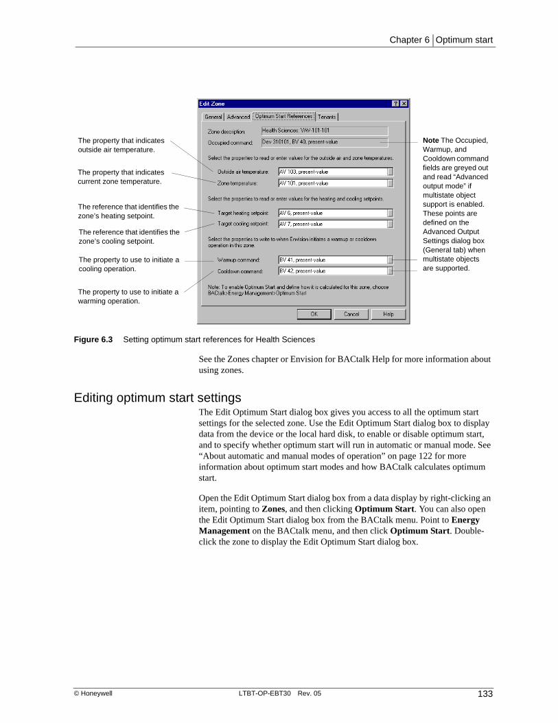
Chapter 6 | Optimum start
© Honeywell LTBT-OP-EBT30 Rev. 05 133
See the Zones chapter or Envision for BACtalk Help for more information about using zones.
Editing optimum start settingsThe Edit Optimum Start dialog box gives you access to all the optimum start settings for the selected zone. Use the Edit Optimum Start dialog box to display data from the device or the local hard disk, to enable or disable optimum start, and to specify whether optimum start will run in automatic or manual mode. See “About automatic and manual modes of operation” on page 122 for more information about optimum start modes and how BACtalk calculates optimum start.
Open the Edit Optimum Start dialog box from a data display by right-clicking an item, pointing to Zones, and then clicking Optimum Start. You can also open the Edit Optimum Start dialog box from the BACtalk menu. Point to Energy Management on the BACtalk menu, and then click Optimum Start. Double-click the zone to display the Edit Optimum Start dialog box.
Figure 6.3 Setting optimum start references for Health Sciences
The property that indicates outside air temperature.
The property that indicates current zone temperature.
The reference that identifies the zone’s heating setpoint.
The reference that identifies the zone’s cooling setpoint.
The property to use to initiate a cooling operation.
The property to use to initiate a warming operation.
Note The Occupied, Warmup, and Cooldown command fields are greyed out and read “Advanced output mode” if multistate object support is enabled. These points are defined on the Advanced Output Settings dialog box (General tab) when multistate objects are supported.

Operator’s Manual | Envision for BACtalk
134 LTBT-OP-EBT30 Rev. 05 © Honeywell
CAUTION Be careful not to overwrite warmup and cooldown factors automatically calculated by optimum start. Self-tuning calculations are stored at the local device and the optimum start object is stored in a database at the Envision for BACtalk server. Before clearing the Show data from device check box, it is recommended that you back up self-tuning values to the server database to prevent overwriting them.
See “Temporarily disabling optimum start” on page 138 for more information about saving changes made to optimum start settings and recovering if optimum start settings are lost.
Zone description BACtalk automatically updates the zone description from the user-defined information provided on the General tab of the Edit Zone dialog box (BACtalk>Zones>Edit). Use a meaningful and unique description for this zone so that users know exactly where this zone is located or what type of equipment is controlled in it. For example, “Health Sciences: VAV-101-301.” Health Sciences and 101 describe the physical building where this zone is located. VAV is the device type, and 301 is the first device instance on the 3rd floor.
Occupied command BACtalk automatically updates the occupied command for the selected zone from the user-defined information provided on the General tab of the Edit Zone dialog box. The occupied command is the property you want BACtalk to write to when the zone is occupied.
Figure 6.4 Use the Edit Optimum Start dialog box to enable optimum start and to set either automatic or manual operational mode.
Select to disable optimum start.
Name and location description of the zone you are working with.
Select to set optimum start to automatically adjust start time calculations.
Select to set optimum start to adjust start time calculations according to user-defined rates.
Click to set humidity as a value or reference.
Select to update this dialog box with data from the device instead of data stored on the local disk.

Chapter 6 | Optimum start
© Honeywell LTBT-OP-EBT30 Rev. 05 135
Show data from device By default, the Edit Optimum Start dialog box displays the data currently saved on the local hard disk. If you select the Show data from device check box, Envision for BACtalk will update the optimum start feature with data saved at the device instead. The data on the device may be different due to the self-tuning capability.
Choosing manual or automatic modeBACtalk uses optimum start settings to calculate what time of day it has to start equipment to meet a zone’s temperature setpoint by the time occupants are scheduled to arrive. If equipment is started too early, money and energy is wasted. If equipment is started too late, occupants arrive to a cold zone. You specify whether you want BACtalk to make this calculation automatically based on previous performance, or manually based on values you calculate and provide.
Use automatic mode when you want warmup and cooling operations to intelligently adapt to changing conditions. Automatic mode is very powerful, but the setup is a bit more complex. Use automatic mode to get the most from the optimum start feature’s ability to adapt.
Use manual mode when equipment operation has a very predictable effect on a zone—essentially, when you know the zone heats up or cools down at the same rate regardless of other factors. You can also use manual mode if you do not have access to outside air temperature, you do not want the system to self-tune, or you prefer to keep your system very simple.
See “How optimum start works” on page 122 for more information about using optimum start.
Automatic mode settingsIt is important to understand that the BACtalk system automatically adjusts automatic mode settings. In nearly all cases, manually changing these settings will not be necessary. Also, before you change these settings, make sure that they are up-to-date. See “Temporarily disabling optimum start” on page 138.

Operator’s Manual | Envision for BACtalk
136 LTBT-OP-EBT30 Rev. 05 © Honeywell
Table 6.2 Automatic mode settings
Item Remarks
Self-tuning factor Use the self-tuning factor to control how aggressively optimum start adjusts based on previous warmup and cooldown efforts. Range is 0.0 to 1.0. 1.0 is most aggressive. 0.1 is least aggressive. 0 disables adjustment. Adjusting the self-tuning factor rather than warmup and cooldown factors directly is recommended.
Outside air limit Used only in warmup calculations. Set this to approximate the average space temperature of the zone when warmup begins. The greater the difference between this and the outside air temperature, the greater the advance time.
Building mass A number that corresponds to interior building mass. 3.0 corresponds to the lightest interior mass. 5.0 corresponds to the heaviest interior mass. Larger numbers increase the effect of zone temperature on the advance time. Smaller numbers increase the effect of outside air temperature on advance time.
Warmup factor Important! Automatically adjusted by optimum start.
Cooldown factor Important! Automatically adjusted by optimum start.
Humidity Usually left to <none>. Type a value corresponding to the relative humidity commonly experienced in the space or reference a data point that reports humidity in the zone. If humidity is specified, optimum start uses it in the advance time calculation. Increased humidity will increase the advance time.
Maximum advance The maximum number of minutes allowed before the next scheduled occupied time to begin an optimum start operation.
Use different factors check box (warmup or cooldown)
Optional. Set different warmup and cooldown factors when the zone was scheduled to be unoccupied the previous day. These factors are independent of the primary warmup and cooldown factors.

Chapter 6 | Optimum start
© Honeywell LTBT-OP-EBT30 Rev. 05 137
Manual mode settingSelect manual mode when you do not have a way to read outside air temperature or do not want your system to self-tune. You might also select manual mode when you have set fixed warming and cooling rates and want to implement them. Manual mode is easier to set up, but automatic mode is recommended because you will need to tweak manual mode settings yourself as operational and environmental conditions change. Automatic mode implements adjustments to optimum start calculations for you.
Table 6.3 Manual mode settings
Item Remarks
Heating/cooling rate Type the rate (in degrees per hour) that you want to change the temperature of the zone. For example, if you set the heating rate to 3.0, the temperature in the zone cannot increase by more than 3.0 degrees per hour. Valid entries are in the range of 0 through 20.0. Default value is 3.0.
Maximum advance The maximum number of minutes allowed before the next scheduled occupied time to begin an optimum start operation.

Operator’s Manual | Envision for BACtalk
138 LTBT-OP-EBT30 Rev. 05 © Honeywell
Temporarily disabling optimum startYou can temporarily disable the optimum start feature for a zone whenever necessary. When you do this, the most recent optimum start settings for automatic or manual mode are retained. Only optimum start calculations are disabled. Schedules are not affected, so the assigned schedule still controls heating and cooling operations in the zone.
To disable optimum start for a zone
1. From the BACtalk menu, select Energy Management and then click Optimum Start.
The Select Zone for Optimum Start dialog box opens.
2. Select the zone you want from the list and then click Optimum Start.
3. Select None (optimum start disabled) and then click OK.
Click to turn off Optimum Start in this zone.

Chapter 6 | Optimum start
© Honeywell LTBT-OP-EBT30 Rev. 05 139
Strategies and tips for checking optimum start operationPeriodically you may need to check optimum start performance. You may want to verify that the current advance time setting is bringing space temperature to setpoint at the time of occupancy–not too early or too late. Setting up trendlogs for optimum start data points can tell you if a tenant has a valid complaint due to a system operational issue or if they just need to adjust their personal work space or put on a sweater. Trendlogs can also help you decide how to adjust current optimum start settings to accommodate for seasonal changes occurring outside the building.
You can also adjust raw optimum start values and manually calculate how your changes will affect optimum start performance. It is recommended that you manually calculate the outcome of your changes before actually making changes to the optimum start settings in the software to prevent an adverse outcome to your system. See “How optimum start works” on page 122 for more information about calculating optimum start.
For example, set up trendlogs for your system for time periods when optimum start is first enabled, and then disable optimum start and trend system performance the next day. Compare the separate trendlogs to get a clear picture of the operational differences of your system with and without optimum start enabled. If you have set up optimum start correctly, the trendlog for the time period when this feature was enabled should show that your system came within 2 degrees, for example, of the zone setpoint by scheduled occupancy time. See “Trendlogs” on page 163.
See Envision for BACtalk Help for more detailed information about setting up and working with optimum start.

Operator’s Manual | Envision for BACtalk
140 LTBT-OP-EBT30 Rev. 05 © Honeywell

Chapter 7 | Tenant activity
© Honeywell LTBT-OP-EBT30 Rev. 05 141
Tenant activity 7
Envision for BACtalk allows you to monitor when tenants use facilities after hours. After-hours activity occurs when a tenant initiates a tenant override, causing equipment in the zone to return to occupied mode when the space would otherwise be unoccupied. A tenant override is usually a manual process—for example, the tenant presses a button on the Microset in a room.
Because conditioning a zone for occupancy typically requires more energy resources than conditioning when the space is unoccupied, you may want to track this after-hours activity or bill the tenant for it. The tenant activity feature in Envision for BACtalk enables you to do this.
Envision for BACtalk relies on zone setups for tenant activity. See “Zones” on page 29 for more information.
BenefitsAutomated Automatically detect and log after-hours override activity in a zone. Use these logged events to generate tenant bills.
Flexible Review events and billing amounts before bills are generated. Modify or delete events. Change the billing rate. Add surcharges or seasonal billing factors.
Convenient Define how you want to send bills to each tenant. You can print and mail bills. You can generate files and print bills from another program, such as Excel or Word. You can generate files and email them to tenants.
Powerful For large sites, this feature makes it easy to set up multiple tenants and multiple zones and quickly generate bills. You can create one tenant profile and copy it to define multiple tenants. Once you have set up billing rates and other parameters, Envision for BACtalk automatically calculates billing amounts, making it easy to generate bills each month.
Tighter facility management You can control who is billed for what type of after-hours activity. Tenant activity shows you where after-hours usage is occurring—whether you bill for it or not. You can also modify bills before they are generated to ensure that tenants are not billed inappropriately.

Operator’s Manual | Envision for BACtalk
142 LTBT-OP-EBT30 Rev. 05 © Honeywell
Practical application
The State University administration wants to charge individual department budgets for after-hours use of classrooms and labs. Before instituting this practice campus-wide, they have decided to conduct a trial run in the Health Sciences building, using Envision for BACtalk’s tenant activity feature.
George, the Facilities Manager, has already defined zones in the Health Sciences building. So to begin tracking after-hours activities in this building, he needs to set up a tenant profile for the Health Sciences department and assign zones to that tenant.
Once tenant activity is set up and running, George can use the tenant activity log to see which classrooms and labs are used after-hours, when they are used, and for how long. He can also generate monthly bills that go to the Accounting office to charge against the department budget and to the head of Health Sciences for information.

Chapter 7 | Tenant activity
© Honeywell LTBT-OP-EBT30 Rev. 05 143
Quick start–tenant activity setupUse the following table to help you set up tenant activity in Envision for BACtalk. The key steps for defining tenant activity are listed in order.
Table 7.1 Tasks for setting up tenant activity
Task See
1 Set up zones for the areas where you want to track after-hours tenant activity. In doing so, identify (on the Tenants tab) the data point that reliably indicates a tenant override in the zone.
• “Setting up zones” on page 148
• Site documentation
• “Zones” on page 29
2 Define the property manager contact information. • “Setting up property manager profiles” on page 149
3 Create a new tenant and define the tenant contact information.
• “Setting up tenant contact information” on page 152
4 Define tenant billing information. • “Setting up billing parameters” on page 153
5 Assign zones to tenants. • “Linking zones to a tenant” on page 155

Operator’s Manual | Envision for BACtalk
144 LTBT-OP-EBT30 Rev. 05 © Honeywell
How tenant activity worksTo set up and use tenant activity in Envision for BACtalk, you create a tenant profile, which includes contact and billing information for the tenant, and identifies the zones the tenant occupies. You also define the billing party, or property manager, whose name will appear on all bills you generate. Envision uses the tenant-override property associated with a particular zone to determine if the zone is operating in after-hours mode.
For more information about zones, see “Zones” on page 29.
All after-hours activity for a tenant is recorded in the tenant activity log. You can use this log to view which zones are used after-hours, when they are used, and for how long. You can also generate bills using the information in the tenant activity log. You can edit events listed in the tenant activity log before generating the bill. You can also use seasonal multipliers or surcharges to make adjustments to calculated billing amounts.
Tenants and property managersA tenant is any occupant whose after-hours activity in a zone you may want to monitor. You can log tenant activity in any zone with one or more tenants assigned to it. You can log this activity without billing for it. For example, you may simply want to track how much an area or its equipment is used outside of its scheduled occupied hours.
The tenant profile identifies all the relevant information about a tenant, including contact information, billing information, and the zones that the tenant occupies. See “Setting up tenant profiles” on page 150 for more information.
A key component of the tenant profile is the property manager. This is the person or company who appears as the entity sending the bill to the tenant. Most buildings typically have only one property manager. Each tenant must be assigned a property manager to generate a bill.
Note It is possible for multiple tenants to share the same zone. For example, tenants A and B share the medium conference room in the Health Sciences building. Tenant A uses it from 8 AM to 12 PM and tenant B uses it from 1 PM to 5 PM.
Zone 1 Zone 2
Tenant A
Zone 3 Zone 4
Tenant B
Property Manager

Chapter 7 | Tenant activity
© Honeywell LTBT-OP-EBT30 Rev. 05 145
Tenant override in a zoneA manual action by the tenant, such as pressing a Microset override button, usually triggers a tenant override. it is also possible to have an automatic action initiate a tenant override, such as a motion detector or feedback from an access control system.
To use tenant activity in a zone, there must be a system data point that is ACTIVE (ON) for as long as the tenant zone is in override and that is INACTIVE (OFF) when the zone is no longer in override. Envision for BACtalk references this data point to calculate override time. As long as the point is ACTIVE, override time accrues.
The data point that indicates an after-hours tenant override is assigned on the Tenants tab of the Edit Zone dialog box (BACtalk>Zones>Edit). For Alerton field controllers, this data point is usually the present-value of BV-66.
Tenant override operation depends on the operating mode set up for the controller and the requirements of the space. See your site documentation to determine if a data point such as BV-66 is available to indicate override status.
What causes a tenant override to end?Again, the programming of the field controller for the zone is critical. The following events are likely to cause the tenant override reference to turn OFF.
• The tenant cancels the override
• The override timer expires
• The space reaches a scheduled occupied time
• Optimum start begins conditioning the space
Example
A room is scheduled for occupancy from 8:00 AM to 5:00 PM. Based on this schedule, heating and cooling equipment operate to maintain a temperature between 69 and 73 degrees F. During unoccupied hours (5:00 PM to 8:00 AM), the setpoint is maintained between 55 and 80 degrees F.
The field controller for the zone has device instance 310101. Programming in the field controller uses the present-value of BV-66 as an override status. This data point is ACTIVE whenever a tenant override is in effect.
The room is set up as a zone in Envision for BACtalk. The zone device reference is set up as device instance 310101. In the zone setup, BV-66, present-value is referenced as the tenant override property on the Tenants tab. BV-40, present-value is referenced as the occupied command. A schedule set is assigned to the zone so that during the week it is scheduled for 8:00 AM to 5:00 PM occupancy.

Operator’s Manual | Envision for BACtalk
146 LTBT-OP-EBT30 Rev. 05 © Honeywell
Practical application
Professor Wang has a lecture in his classroom on Tuesday morning at 9:00 AM. He arrives around 7:00 AM to prepare. Since the lecture hall is not scheduled to be occupied at that time, it is a little bit too warm and stuffy when he arrives—78 degrees F, in fact. He pushes the right up button on the Microset II in the classroom until 2:00 appears to get 2 hours of override. He then presses the left down button to drive the setpoint down as low as it will go, to 69 degrees F.
The HVAC equipment in the classroom starts cooling and ventilating the space almost right away to achieve the 69 degree F setpoint.
As soon as Professor Wang pressed the override button on the Microset, programming in the field controller turned the present-value of BV-66 ON. Because BV-66 is referenced as the tenant override data point, this started an override event. The override event ended at 9:00 AM when the zone was scheduled for occupancy. The override event was entered into the tenant activity log at 9 AM when it ended.
The tenant activity log versus the tenant billThe tenant activity log displays each override event. This display lets you monitor when tenants are using zones after hours. You can view events and manually change override times. You can also choose to include or exclude events from the bill. This gives you control over what the tenant is billed for.
From the tenant activity log, you can access the tenant bill. The tenant bill lists the billing amounts for each override event. You cannot edit events from the tenant bill, but you can change the seasonal multiplier or surcharge amounts (if selected on the Billing tab in the Edit Tenant Profile dialog box), and then recalculate the total. You generate bills from this display.
Override time versus billed timeDepending on how tenant activity billing rules are set up, the actual override time may not be the same as the billed time. Based on these rules, you may see an override event in the log that is greater or less than the billed time in the tenant bill.
In the tenant profile, you define the minimum amount of time that a zone must be in override mode before the tenant is billed for override activity. For example, you may not want to track or bill for override events of only a few minutes. In addition, the tenant profile defines the minimum amount of time the tenant is billed for when an after-hours activity “qualifies” as an override event. And finally, you define the maximum amount of time a tenant will be charged for a single override event.
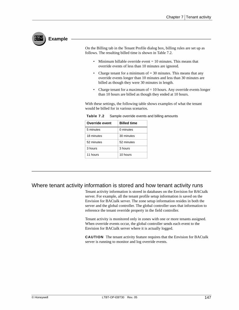
Chapter 7 | Tenant activity
© Honeywell LTBT-OP-EBT30 Rev. 05 147
Example
On the Billing tab in the Tenant Profile dialog box, billing rules are set up as follows. The resulting billed time is shown in Table 7.2.
• Minimum billable override event = 10 minutes. This means that override events of less than 10 minutes are ignored.
• Charge tenant for a minimum of = 30 minutes. This means that any override events longer than 10 minutes and less than 30 minutes are billed as though they were 30 minutes in length.
• Charge tenant for a maximum of = 10 hours. Any override events longer than 10 hours are billed as though they ended at 10 hours.
With these settings, the following table shows examples of what the tenant would be billed for in various scenarios.
Where tenant activity information is stored and how tenant activity runsTenant activity information is stored in databases on the Envision for BACtalk server. For example, all the tenant profile setup information is saved on the Envision for BACtalk server. The zone setup information resides in both the server and the global controller. The global controller uses that information to reference the tenant override property in the field controller.
Tenant activity is monitored only in zones with one or more tenants assigned. When override events occur, the global controller sends each event to the Envision for BACtalk server where it is actually logged.
CAUTION The tenant activity feature requires that the Envision for BACtalk server is running to monitor and log override events.
Table 7.2 Sample override events and billing amounts
Override event Billed time
5 minutes 0 minutes
18 minutes 30 minutes
52 minutes 52 minutes
3 hours 3 hours
11 hours 10 hours
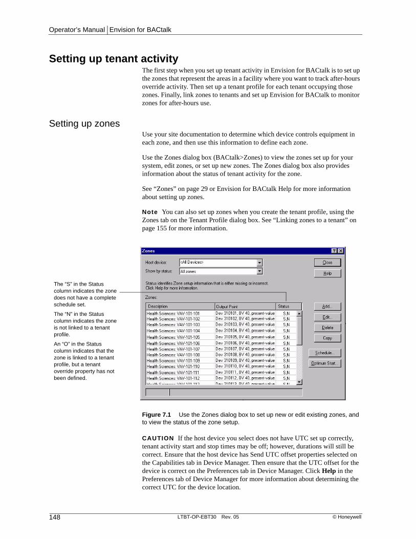
Operator’s Manual | Envision for BACtalk
148 LTBT-OP-EBT30 Rev. 05 © Honeywell
Setting up tenant activityThe first step when you set up tenant activity in Envision for BACtalk is to set up the zones that represent the areas in a facility where you want to track after-hours override activity. Then set up a tenant profile for each tenant occupying those zones. Finally, link zones to tenants and set up Envision for BACtalk to monitor zones for after-hours use.
Setting up zonesUse your site documentation to determine which device controls equipment in each zone, and then use this information to define each zone.
Use the Zones dialog box (BACtalk>Zones) to view the zones set up for your system, edit zones, or set up new zones. The Zones dialog box also provides information about the status of tenant activity for the zone.
See “Zones” on page 29 or Envision for BACtalk Help for more information about setting up zones.
Note You can also set up zones when you create the tenant profile, using the Zones tab on the Tenant Profile dialog box. See “Linking zones to a tenant” on page 155 for more information.
CAUTION If the host device you select does not have UTC set up correctly, tenant activity start and stop times may be off; however, durations will still be correct. Ensure that the host device has Send UTC offset properties selected on the Capabilities tab in Device Manager. Then ensure that the UTC offset for the device is correct on the Preferences tab in Device Manager. Click Help in the Preferences tab of Device Manager for more information about determining the correct UTC for the device location.
Figure 7.1 Use the Zones dialog box to set up new or edit existing zones, and to view the status of the zone setup.
The “S” in the Status column indicates the zone does not have a complete schedule set.
The “N” in the Status column indicates the zone is not linked to a tenant profile.
An “O” in the Status column indicates that the zone is linked to a tenant profile, but a tenant override property has not been defined.

Chapter 7 | Tenant activity
© Honeywell LTBT-OP-EBT30 Rev. 05 149
Tenant information is set up on the Tenants tab in the Edit Zone dialog box. Use the Tenants tab to see the tenants assigned to this zone and to view and assign the tenant override data point.
Setting up property manager profilesThe property manager is identified on each tenant’s bill as the originator of the bill. Property managers are essential to tenants. Before you save a tenant profile, you must first link it to a property manager. You must assign a property manager to a tenant to generate the tenant’s bill.
A property manager can, and usually does, have more than one tenant assigned to it, but a tenant can have only one property manager.
Note Emailed bills originate from only one billing email address. Therefore, if you will email a tenant their bill, it is recommended that you set up only one property manager profile on each Envision for BACtalk server and use that property manager’s email address in the tenant activity email setup. For more information, see “Setting up email billing” on page 161.
Figure 7.2 Use the Tenant tab on the Edit zone dialog box to assign a tenant override and view tenant assignments for a zone.
Select the property that will indicate tenant override activity in this zone. For example, in Alerton standard applications, this is the present-value property of BV-66.
List of all tenants currently assigned to this zone.
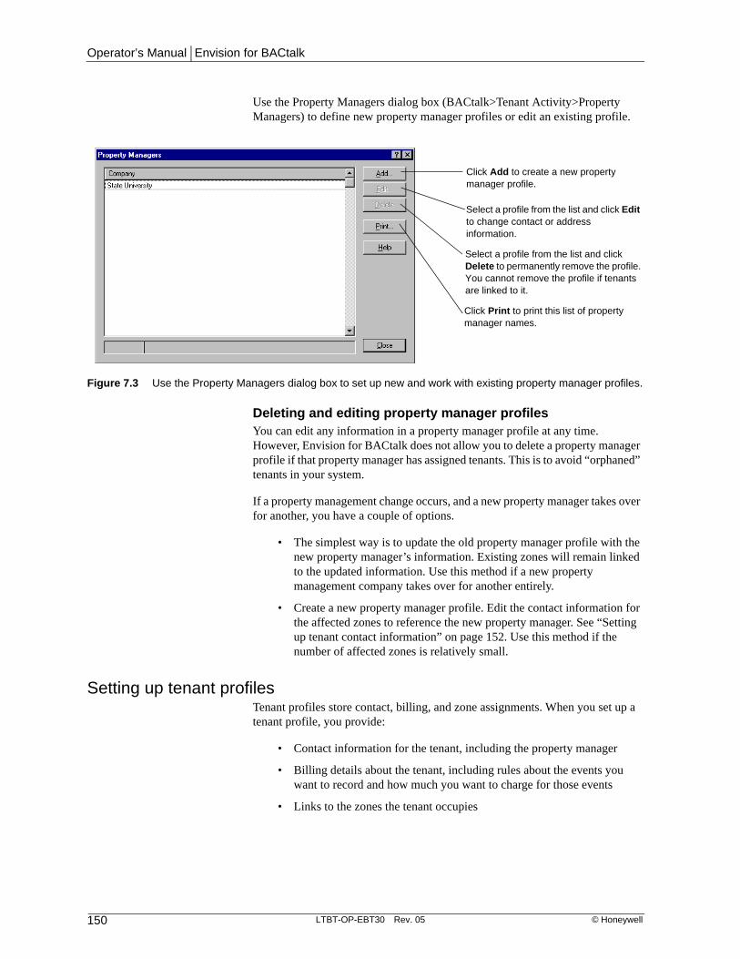
Operator’s Manual | Envision for BACtalk
150 LTBT-OP-EBT30 Rev. 05 © Honeywell
Use the Property Managers dialog box (BACtalk>Tenant Activity>Property Managers) to define new property manager profiles or edit an existing profile.
Deleting and editing property manager profilesYou can edit any information in a property manager profile at any time. However, Envision for BACtalk does not allow you to delete a property manager profile if that property manager has assigned tenants. This is to avoid “orphaned” tenants in your system.
If a property management change occurs, and a new property manager takes over for another, you have a couple of options.
• The simplest way is to update the old property manager profile with the new property manager’s information. Existing zones will remain linked to the updated information. Use this method if a new property management company takes over for another entirely.
• Create a new property manager profile. Edit the contact information for the affected zones to reference the new property manager. See “Setting up tenant contact information” on page 152. Use this method if the number of affected zones is relatively small.
Setting up tenant profilesTenant profiles store contact, billing, and zone assignments. When you set up a tenant profile, you provide:
• Contact information for the tenant, including the property manager
• Billing details about the tenant, including rules about the events you want to record and how much you want to charge for those events
• Links to the zones the tenant occupies
Figure 7.3 Use the Property Managers dialog box to set up new and work with existing property manager profiles.
Click Add to create a new property manager profile.
Select a profile from the list and click Edit to change contact or address information.
Select a profile from the list and click Delete to permanently remove the profile. You cannot remove the profile if tenants are linked to it.
Click Print to print this list of property manager names.

Chapter 7 | Tenant activity
© Honeywell LTBT-OP-EBT30 Rev. 05 151
Use the Tenants dialog box (BACtalk>Tenant Activity>Tenants) to add or edit tenant profiles.
Figure 7.4 Use the Tenants dialog box to add, edit, delete, or copy tenant profiles and to view the activity log for a selected tenant.
Click Add to create a new tenant profile.
Select a tenant profile and click Edit to change contact or billing information or to assign
Select a tenant profile and click Delete to permanently remove the profile from Envision for BACtalk.
Select a tenant profile and click Copy to make a copy of the selected tenant profile and add it to the list. The copy contains all of the original tenant profile information except the name and associated tenant zones.
Select a tenant profile, and then click here to open the Tenant Activity Log for that tenant.
Click Print to print this list of tenants.

Operator’s Manual | Envision for BACtalk
152 LTBT-OP-EBT30 Rev. 05 © Honeywell
Setting up tenant contact informationThe tenant contact information enables you to effectively communicate with the tenant, handle billing inquiries in a timely fashion, and ensure that tenant bills are sent to the correct location. Both the company name and address appear on all bills, as does the property manager from whom the bill originates.
Figure 7.5 Set up tenant contact information in the Edit Tenant Profile dialog box.
Type a description that quickly identifies the tenant. For example, describe the tenant by the zone they occupy in the building.
Select the property manager responsible for this tenant. Select <new> to set up a new property manager from here.

Chapter 7 | Tenant activity
© Honeywell LTBT-OP-EBT30 Rev. 05 153
Setting up billing parametersTenant bills are generated according to the method of delivery and billing parameters you set up on the Billing tab of the tenant profile.
Billing template This specifies the report template that Envision uses to create the tenant bill. Unless you create additional custom templates, only the default template appears in this list. The template file (Bttenactdef.rpt) is located in <BACtalk root>\<rep>\<job>\Reports\. In most circumstances, the default template will fulfill your billing needs. If you need to customize the default template or create different ones, you can use Crystal Reports 8. If you create additional *.rpt files and place them in the Reports folder, you may need to type the custom template name the first time you reference it in a tenant profile.
Billing rate The billing rate is the amount per hour the tenant is charged for after-hours activity. You can charge a different rate for different tenants, if appropriate. Typically, the billing rate is based on utility rates, size of the space, amount of equipment, and any special fees the property manager wants to include for after-hours usage.
Figure 7.6 The Billing tab of the Edit Tenant Profile dialog box

Operator’s Manual | Envision for BACtalk
154 LTBT-OP-EBT30 Rev. 05 © Honeywell
Billing adjustments The Billing Adjustments area enables you to add a seasonal multiplier and a surcharge amount to the tenant bill if necessary.
• Seasonal multiplier This allows a property manager to adjust tenant billing for seasonally-variant costs, such as the cost of a kilowatt hour of electrical energy, which may be more expensive during peak seasons. The seasonal multiplier is only applied when computing the billing amount and is listed on the bill itself. The subtotal is multiplied by the seasonal multiplier.
• Surcharge This enables you to add a fixed cost to a bill that is not dependent on a tenant’s energy usage. For example, a tenant might pay a surcharge to cover the monthly rental fee for the vending machines in the break room or the equipment in the exercise room. A surcharge may also be a monthly processing fee, a late payment penalty, or a credit to the customer. Use a negative number to apply a credit to the customer’s bill. The surcharge is applied after the seasonal multiplier.
Example
Because October through May is not a peak electrical use season, after-hours usage is billed from the electrical provider at $8. The bill is set up with a billing rate of $8. A tenant has 50 hours of after-hours usage during May and the tenant bill shows $8 x 50. During the peak electrical use season, June through September, kWh rates increase by 20%. The seasonal multiplier in the tenant profile is modified to 1.2 in June. The tenant also uses 50 hours in August, peak cooling, and thus electrical use, season. In August, after-hours usage is billed at $8 x 1.2, or $9.60 per hour.
Billing rules Use the options in the Billing Rules area to specify event billing parameters.
• Minimum billable override event Set this to the amount of time that must accrue before the tenant is billed. For example, a setting of 00:10 prevents tenant activity from billing for events less than 10 minutes. Though not billed for these events, the event still appears in the tenant activity log.
• Charge tenant for a minimum of Set this to a value that indicates the least amount of time the tenant is billed for. For example, setting this to 00:15 means that the tenant is billed for no less than 15 minutes for any valid override event.
• Charge tenant for a maximum of Set this value to the maximum time that a tenant can be billed for an override event. You can use this value as a system overflow check of sorts to prevent billing a tenant for more after-hours use than is possible. For example, if you know that occupied hours are 6 am to 6 pm seven days a week, you know that more than 12 hours of override billing will never occur, so you could set this value to 12:00.
• Consolidate zones in bill If a tenant has more than one zone in override, the billing rate will be the highest of the zone billing rates.
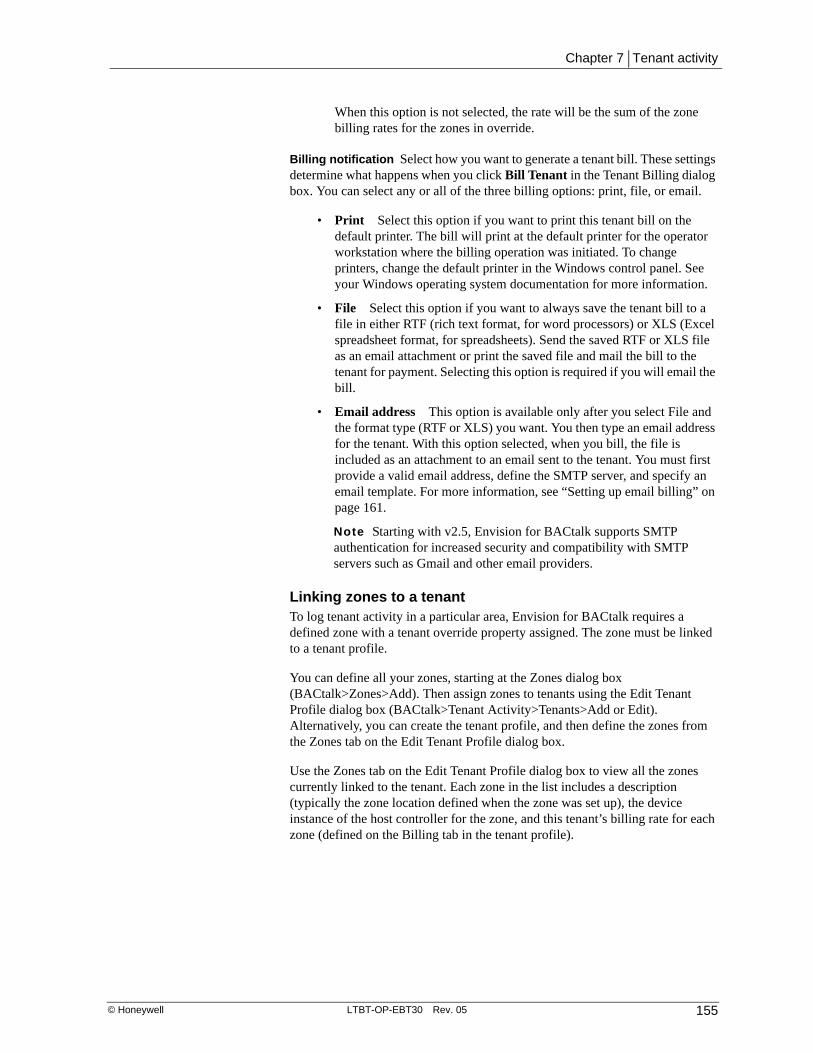
Chapter 7 | Tenant activity
© Honeywell LTBT-OP-EBT30 Rev. 05 155
When this option is not selected, the rate will be the sum of the zone billing rates for the zones in override.
Billing notification Select how you want to generate a tenant bill. These settings determine what happens when you click Bill Tenant in the Tenant Billing dialog box. You can select any or all of the three billing options: print, file, or email.
• Print Select this option if you want to print this tenant bill on the default printer. The bill will print at the default printer for the operator workstation where the billing operation was initiated. To change printers, change the default printer in the Windows control panel. See your Windows operating system documentation for more information.
• File Select this option if you want to always save the tenant bill to a file in either RTF (rich text format, for word processors) or XLS (Excel spreadsheet format, for spreadsheets). Send the saved RTF or XLS file as an email attachment or print the saved file and mail the bill to the tenant for payment. Selecting this option is required if you will email the bill.
• Email address This option is available only after you select File and the format type (RTF or XLS) you want. You then type an email address for the tenant. With this option selected, when you bill, the file is included as an attachment to an email sent to the tenant. You must first provide a valid email address, define the SMTP server, and specify an email template. For more information, see “Setting up email billing” on page 161.
Note Starting with v2.5, Envision for BACtalk supports SMTP authentication for increased security and compatibility with SMTP servers such as Gmail and other email providers.
Linking zones to a tenantTo log tenant activity in a particular area, Envision for BACtalk requires a defined zone with a tenant override property assigned. The zone must be linked to a tenant profile.
You can define all your zones, starting at the Zones dialog box (BACtalk>Zones>Add). Then assign zones to tenants using the Edit Tenant Profile dialog box (BACtalk>Tenant Activity>Tenants>Add or Edit). Alternatively, you can create the tenant profile, and then define the zones from the Zones tab on the Edit Tenant Profile dialog box.
Use the Zones tab on the Edit Tenant Profile dialog box to view all the zones currently linked to the tenant. Each zone in the list includes a description (typically the zone location defined when the zone was set up), the device instance of the host controller for the zone, and this tenant’s billing rate for each zone (defined on the Billing tab in the tenant profile).

Operator’s Manual | Envision for BACtalk
156 LTBT-OP-EBT30 Rev. 05 © Honeywell
Practical application
The Health Sciences building is being used for the trial run of tenant activity at State U. So, in this case, there is only one tenant for all zones of the building. However, the Facilities Manager wants to monitor after-hours activity only in classrooms and labs, not in the offices or other areas. George has already defined the zones for all the spaces in the Health Sciences building. Now he sets up the tenant profile for the Health Sciences department. On the Zones tab, he clicks Assign Zones to display a list of all defined zones. He can select all the zones associated with classrooms and labs in the Health Sciences building and link them to the tenant profile in one operation.
Figure 7.7 Use the Zones tab on the Edit Tenant Profile dialog box to link the tenant to the zones they occupy.
Select a zone and then click Edit Rate to override the tenant’s default billing rate.
(Default) is shown when the rate used for the zone matches the default billing rate defined in the tenant’s profile.
Displays the Select Zones to Assign to Tenant Profile dialog box. From the Zones list, select existing zones to link to this tenant and then click OK. Or click Add to create a new zone.
Displays all zones that are currently linked to this tenant profile.
Select a zone and click Remove to delete the link to the tenant profile.
Click here to print a list of all the zones that are currently linked to this tenant profile.

Chapter 7 | Tenant activity
© Honeywell LTBT-OP-EBT30 Rev. 05 157
Viewing tenant activity and billing tenantsUse the Tenant Activity Log and the Tenant Billing dialog boxes to review billing information, make adjustments if necessary, and generate tenant bills.
You can review override events by tenant to determine whether or not you want to change or delete them.
Using the Tenant Activity LogThe Tenant Activity Log is a detailed list of all recorded override events that took place in the selected zone for the specified billing period. You can use it to view events before you generate a bill and to edit events, if necessary.
The log includes the start time of the event, the zone where the event occurred, the duration of the event, and the billed time. The duration and billed time may be different depending on how the billing rules were set up. See “Override time versus billed time” on page 146 for more information.
Manually editing an event or excluding it from the billWhen you select an event from the Tenant Activity Log and click Edit Event, you have the option to change the override time or exclude the override from the bill. If you select Exclude amount on bill, the word “Excluded” appears in the Status column of the Tenant Activity Log. See Figure 7.9 on page 158 for more information.
Figure 7.8 Use the Tenant Activity Log to view, edit, delete, or print tenant events.

Operator’s Manual | Envision for BACtalk
158 LTBT-OP-EBT30 Rev. 05 © Honeywell
Example
After-hours maintenance occurred during the billing period and you want to adjust the corresponding event in the tenant activity log. You can view the log for the appropriate tenant, locate the event, and modify or delete it. After you make all necessary adjustments in the tenant activity log, you can generate and send the tenant bill.
Practical application
The Health Sciences department logged 9 hours and 10 minutes of override time in all zones. However, their bill is for only 4 hours.
George manually excluded a 5 hour, 30 minute event from the bill because he knows this event was the night that a maintenance crew was in the referenced zone, and the override event can be attributed to them, not the Health Sciences department. He opened the tenant activity log, edited the event, and then chose Exclude amount on bill. In addition, a 10-minute override event was logged as 30 minutes of billed time based on the billing rules in the tenant profile.
Figure 7.9 Edit an event in the Tenant Activity Log to manually change the override time of an event or to exclude it from the bill.

Chapter 7 | Tenant activity
© Honeywell LTBT-OP-EBT30 Rev. 05 159
Generating tenant billsAfter you have reviewed the Tenant Activity Log and made any necessary adjustments to tenant events, you can use the Tenant Billing dialog box to generate bills for single tenants. Or, use the Multiple Tenant Billing dialog box to set up billing for multiple tenants at once (BACtalk> Tenant Activity> Multiple Tenant Billing). Use the Beginning On and Ending On dates to set the billing period if necessary.
Note Starting with Envision for BACtalk v2.5, the Tenant Billing dialog box opens in the current month for convenience.
Figure 7.10 Use the Tenant Billing dialog box to view and adjust tenant activity event records and billing information.
Figure 7.11 Use the Multiple Tenant Billing dialog box to set up bills for multiple tenants at once
The Seasonal Multiplier and Surcharge amounts are not editable here. This indicates that they were not enabled in the tenant’s profile.
Checked by default. Filters out tenants who do not need to pay.
Dialog box opens with current month displayed.

Operator’s Manual | Envision for BACtalk
160 LTBT-OP-EBT30 Rev. 05 © Honeywell
Practical application
The head of the Health Sciences department contacted the Accounting office three months ago and arranged for a special billing rate for a charity event that just took place in the current billing period. Accounting agreed to charge only half for any override time for this event.
Accounting did not contact Facilities about this arrangement, and the Health Sciences department complained about the 4-hour charge on their bill at full cost.
George opens the tenant activity log, locates the event, and edits the event, adjusting the override time to 2:00. When he displays the Tenant Billing dialog box, next month’s bill already appears. He changes the Beginning on and Ending on dates for last month’s bill. The corrected amount appears on the bill, so he re-bills the Health Sciences department for the correct amount.

Chapter 7 | Tenant activity
© Honeywell LTBT-OP-EBT30 Rev. 05 161
Setting up email billingTenant bills are emailed to tenants if you specify the email billing method in the Tenant Profile dialog box (for more information, see “Setting up tenant profiles” on page 150). You must set up the email notification to enable Envision for BACtalk to email bills to your tenants. Use the Tenant Activity Email Setup dialog box to set up email delivery for tenant bills.
The information you provide on the Email Setup dialog box applies to all emailed tenant bills. This means that each tenant that is set up to receive bills through email sees the same subject and message text. See “Setting up billing parameters” on page 153 for more information about billing tenants.
You also need to have the Email tab in the General System Setup dialog box (Tools>General System Setup) set correctly for your network environment.
Note The SMTP server must be addressed and set up correctly in General System Setup to send bills by email. Envision for BACtalk v2.5 and later supports SMTP authentication for increased security and compatibility with SMTP servers like Gmail and other email providers. Contact your IT department if you need assistance.
Figure 7.12 You must complete the tenant activity Email Setup before you can email bills to tenants.
Type a valid email address that recipients can use to contact you. This information appears on tenant bills and serves as an important customer service tool. When tenants have questions about their billing statement, they can contact you quickly and easily for more information.
Email recipients listed here receive a “carbon copy” of all tenant bills. Use commas to separate email addresses. These addresses appear on the bill.
Email recipients listed here receive a “blind carbon copy” of all tenant bills. Use commas to separate email addresses. These addresses do not appear on the bill.

Operator’s Manual | Envision for BACtalk
162 LTBT-OP-EBT30 Rev. 05 © Honeywell
Viewing the Tenant Activity Diagnostic LogThe Tenant Activity Diagnostic Log (BACtalk>Tenant Activity>Diagnostic Log) displays an historical record that shows how tenant activity itself is functioning. This log includes any errors that occur while generating bills at the server.
If the tenant activity log lists override events that do not seem to make sense, you can use the information in the diagnostic log to help troubleshoot the problem.
Figure 7.13 Use the Tenant Activity diagnostic log if the tenant activity feature is not working as expected.
Chapter 8 | Trendlogs
© Honeywell LTBT-OP-EBT30 Rev. 05 163
Trendlogs 8
Trendlogs help you troubleshoot problem areas and identify critical operating trends in your system. BACtalk trendlogs sample data values from any data point at a regular interval. The Envision for BACtalk server saves sampled values in records that you can view, print, and export. You can view historical data as a list or graph, and choose to view one trendlog side-by-side with another. Global and building controllers buffer samples in memory so that if the server is offline, samples are still gathered.
Trendlog data can also be analyzed using the Enhanced Trendlog Viewer application. Enhanced Trendlog Viewer provides a dynamic graphic display of trendlog data. See “Using the Enhanced Trendlog Viewer” on page 190.
Trendlogs are an essential component of energy logs, which provide historical energy demand and consumption data. See “Energy Logs” on page 201 or Envision for BACtalk online Help for more information about using energy logs.
Note If an Envision for BACtalk v1.2 or later client attempts to access trendlog data from a server running Envision for BACtalk v1.1 or earlier, a communications error will occur. If an Envision for BACtalk v1.1 or earlier client attempts to access trendlog data from an Envision for BACtalk v1.2 or later server, unsupported data types (bitstring and null) are filtered out of the display data. As a general rule, when the server and client are running different versions of Envision for BACtalk, avoid operations that impact databases (creating or editing schedules, trendlogs, or alarms, for example).
BenefitsEasy to use View trendlogs in table or graph format to easily spot trends and analyze information. Display trendlog data in order by time stamp or in the order recorded.
Powerful You can set up trendlogs for virtually any data point in your system, and use this information to troubleshoot problems or find opportunities to improve system performance.
Flexible Define trendlogs based on what you need to know. Specify start and end times for collecting trendlog samples. Compare trendlogs side-by-side. Modify existing trendlog setups to get a different view of system performance or problem areas. Work with archived trendlogs.

Operator’s Manual | Envision for BACtalk
164 LTBT-OP-EBT30 Rev. 05 © Honeywell
Practical application
As part of a statewide initiative to reduce energy expenditures by 30%, State University needs to cut its energy bill. To do this, the Facilities Department is considering a demand limiting program. they have decided a good candidate for a pilot program is the Student Union Building (SUB).
Before they implement demand limiting, they need to understand their energy demand and consumption profile in the SUB. Jacob, the SUB’s lead engineer, will use energy logs to compile the historical data he needs to inform the demand limiting effort.
Jacob needs to set up a trendlog for the kWh meter in the SUB, which is Device 111101, AI-1, present-value. This trendlog will then be used as the meter reference in the energy log setup.

Chapter 8 | Trendlogs
© Honeywell LTBT-OP-EBT30 Rev. 05 165
Quick start–trendlog setupUse the following table as a guide when setting up trendlogs. The key steps for defining trendlogs are listed in order.
IMPORTANT! You must correctly set UTC offset for your BACtalk system in order to time sync trendlogs and graph trendlog data accurately for your time zone. See the Envision for BACtalk Installation and Startup Guide (LTBT-TM-ADMIN) for more information about setting the UTC offset.
Table 8.1 Tasks for setting up trendlogs
Task See
1 Identify the devices and data points that you want to track with a trendlog.
• Site documentation
2 Set up a trendlog handler, if necessary. • page 170
3 Select a host device for the trendlog. • page 170
4 Customize trendlog setup, if necessary. • page 178
Operator’s Manual | Envision for BACtalk
166 LTBT-OP-EBT30 Rev. 05 © Honeywell
How trendlog samples are gathered and savedWhen you set up a trendlog, you create an Alerton-log object in a global controller or building controller. Trendlogs in global controllers can track values from any manufacturer's BACnet-compliant device. However, the Alerton-log object is a proprietary object that can only be created or modified by Alerton software. For global controllers, the monitored property can be local to the global controller or can be a property from other controllers. For building controllers, only local properties can be trendlogged. For example, you cannot use a trendlog in a VLX to monitor a property in a VLC.
The host device stores information about the log—the device instance, object type and instance, and the property of the trended point; the name of the trendlog; and the description of the trendlog.
In addition, each trendlog sample record contains:
• The time the sample was gathered (time stamp)
• Data value of the sample, if available
• An event state returned in lieu of datum (for example, NR—no response from unit or device error code.)
When you set up a trendlog, you select a trend interval. This determines how frequently the host device gathers information from, or “polls,” the device where the trended data point is.
After the host device gathers trend samples, it stores them in a memory buffer until the trend samples can be sent to an Envision for BACtalk server. You can specify this buffer size when you set up the trendlog. See “Advanced trendlog options” on page 178 for more information about setting the buffer size.
Two things cause the Envision for BACtalk server to gather samples from the controller:
• An operator chooses to view a trendlog or updates a trendlog while viewing it.
• The Envision for BACtalk server is running and receives a notification from a log handler that it should gather data.
Whenever the server gets samples to update its database, it looks in its records for the most recent sample in the trendlog. It then retrieves recent records from the controller, adding the samples to its database.
The host device uses a log handler (technically, a notification-class object in BACnet) to tell selected operator workstations when to gather a trendlog’s records. When the host device has gathered the number of samples that you define in the trendlog setup as the notification threshold, it sends a notification to the operator workstation to get samples.
CAUTION In most cases, the default settings for buffer size and notification threshold are appropriate. Setting the size of the notification threshold relative to the buffer size is a critical consideration when you set up a trendlog. Correct settings will help ensure that samples are not lost. For more information, see “Advanced trendlog options” on page 178.

Operator’s M
anual | Trendlogs
© H
oneywell
LTBT-OP
-EBT30
Rev. 05
167 Figure 8.1 Trendlog data flow
Global Controller
Client operator workstations (optional)
Buffer size
Monitoredproperty
SampleSet 1
(oldest)
SampleSet 2
SampleSet 3
(newest)
Oldest data deletedAs buffer fills, the controller deletes theoldest samples to make room for new data.
Oldest data deletedAs buffer fills, the controller deletes theoldest samples to make room for new data.
New samplerecord
New samplerecord
Log Handler (notification-class object)Each time the buffer gathers notificationthreshold number of samples since the lastnotification, the Alerton-log object transitions tooff-normal, triggering the log handler to notify thelog recipient (the server) to gather samples.
Log Handler (notification-class object)Each time the buffer gathers notificationthreshold number of samples since the lastnotification, the Alerton-log object transitions tooff-normal, triggering the log handler to notify thelog recipient (the server) to gather samples.
Trendlog buffer in host global/building controllerThe Alerton-log object in the global controller or buildingcontroller gathers data from the monitored property at regularintervals and stores sample data in buffer.
Trendlog buffer in host global/building controllerThe Alerton-log object in the global controller or buildingcontroller gathers data from the monitored property at regularintervals and stores sample data in buffer.
Shared databaseWhen a user at a client operator workstationviews or modifies trendlogs, data in theEnvision for BACtalk server is accessed acrossthe network. No trendlog data is stored at theclient.
Shared databaseWhen a user at a client operator workstationviews or modifies trendlogs, data in theEnvision for BACtalk server is accessed acrossthe network. No trendlog data is stored at theclient.
Database files in<BACtalk root>\<Rep>\<Job>
store trendlog records.
Notificationthreshold
Each client operator worskstationreferences the database files on theEnvision for BACtalk server.
Envision for BACtalk serverGathers samples from the controller buffer when notified, when a trendlogis opened, or when you refresh data. Retrieves any sample from thecontroller with a time stamp more recent than the most recent one in itsdatabase. On refresh (F5), the server retrieves data if the To date is morerecent than the most recent sample in the database.
Envision for BACtalk serverGathers samples from the controller buffer when notified, when a trendlogis opened, or when you refresh data. Retrieves any sample from thecontroller with a time stamp more recent than the most recent one in itsdatabase. On refresh (F5), the server retrieves data if the To date is morerecent than the most recent sample in the database.

Operator’s Manual | Envision for BACtalk
168 LTBT-OP-EBT30 Rev. 05 © Honeywell
Trendlog database filesThe database files for a trendlog are saved in the job folder on the Envision for BACtalk server, this is usually a folder on the operator workstation hard disk (<bactalk root>\Alerton\ BACtalk\<version>\ <repname>\<jobname>).
Table 8.2 Trendlog database files
File Name Description
Bactalk.mdb Contains a single table that stores general information about each trendlog. This is the master list of trendlogs. This file stores no sample records.
Trendlog_<device instance>_<trendlog instance>.mdb
These files store the sample records for trendlogs. Each trendlog has an associated database file. Device Instance is 7 characters long and Trendlog Instance is 10 characters long. Both are 0 padded.
For example, the filename for Device 9999’s trendlog 37 would be Trendlog_0009999_0000000037.mdb.

Chapter 8 | Trendlogs
© Honeywell LTBT-OP-EBT30 Rev. 05 169
Setting up a trendlogIf an item on a data display is set up with the right-click trendlog option, you can right-click the item to work with trendlogs. If no trendlog is set up for the referenced property, Envision for BACtalk displays the Edit Trendlog dialog box. If a trendlog is already set up, you immediately view log data for that property.
If you know the object and property ID of the data value you want to trend, you can select Trendlog Management>Trendlogs from the BACtalk menu. This displays the Trendlogs dialog box, which lists any trendlogs that have been defined. From here, you can add new trendlogs and edit, print, or view existing trendlogs. To create one trendlog, click Add, and then click Single Trendlog. To create several similar trendlogs, click Multiple Trendlogs to display the Multiple Trendlog Builder. See “Using the multiple trendlog builder” on page 173 for more information.
Figure 8.2 Use the Edit Trendlog dialog box to set up a single trendlog.

Operator’s Manual | Envision for BACtalk
170 LTBT-OP-EBT30 Rev. 05 © Honeywell
Use the guidelines in the following table to set up a single trendlog.
Table 8.3 Trendlog properties
Item Description
Logged property The property whose value you want to log. After initial setup, the selection is fixed and cannot be changed. This is usually the present-value of an AV, BV, AO, BO, AI, or BI.
Log object name Envision for BACtalk assigns a default log object name based on the logged property. We recommended that you do not change this object name. Valid names are 1–40 characters.
Log description Type text that further identifies the trendlog. This text appears as the sample data heading in the trendlog view window. An example is “VAV-5 Room Temp.” Valid descriptions are 1–40 characters.
You can save time by using variables in the Log Description field. See “Using variables for trendlog descriptions” on page 177.
Units If desired, select a unit of measure to display when viewing trendlog data and to use if an energy log uses this trendlog (see “Setting up meters” on page 207).
Host device On initial setup, select a global or building controller where the trendlog setup is stored. After you select a host device on initial setup, the selection cannot be changed.
Building controllers can host trendlogs only for their local properties. The host device defaults to the host defined in Device Manager for the device where the logged property originates.
Trendlog handler On initial setup, select a trendlog handler, which determines the operator workstation that gathers trendlog data from the controller. After initial setup, this selection cannot be changed.
Typically, one trendlog handler is set up for each controller. The recipient is the Envision for BACtalk server, and it is assigned by default.
If a trendlog handler does not exist in the host device, Envision for BACtalk automatically creates one during the trendlog setup.
If the system includes a BCM-WEB, the trendlog handler object name must begin with “Log Handler”.
Trendlog instance The trendlog instance is a unique number that identifies the trendlog in the BACtalk system. By default, Envision for BACtalk auto-generates the trendlog instance using the next available trendlog instance for the selected host device.
If you need to enter a custom trendlog instance, clear the Auto-generate trendlog instance check box and type a number between 0 and 4,194,302.
Note: You cannot change an existing trendlog instance.
Auto-generate trendlog instance
Selected by default so that Envision for BACtalk automatically creates the trendlog instance using the next available trendlog instance for the selected host device.
Clear this check box to activate the Trendlog Instance field and customize the trendlog instance.
Change of value (COV) options (VLCA-1688 only)
Use COV sampling
Logs samples when the value of the monitored property changes.
NOTE: If the selected device or property do not support COV trendlogs, the Change of value (COV) options area does not appear.

Chapter 8 | Trendlogs
© Honeywell LTBT-OP-EBT30 Rev. 05 171
COV increment (deadband)
The degree of change required to cause a sample to be logged. For example, if you are monitoring a temperature in degrees Fahrenheit and want to log only changes of one degree or more, you would set this to 1. Type a positive number.
Use caution when setting the increment. Small increments can dramatically increase the amount of data gathered and slow system performance.
Log on COV and every n seconds
In addition to logging samples when the value has changed, samples are also logged at regular intervals. Select the check box and type a number between 1 and 86,400 (inclusive). This sets the trendlog resubscription interval. Each time the log resubscribes, it logs a sample, so the value entered here in effect becomes the Trend interval.
Buffer size Determines the total number of samples that the host device can retain before samples are lost. See “Advanced trendlog options” on page 178.
Trend interval The frequency, in seconds, with which the logged property is sampled. The trendlog records a sample for the logged property at each interval. Default is 60 seconds. Use a 60-second trend interval when trending an energy log.
Use the maximum interval that meets your trendlog objectives. Stated minimum is 10 seconds, but this assumes best-case network conditions, which rarely exist. The practical minimum depends on network and site-specific conditions. A greater number of logged points, more network traffic, a slower network connection, or a greater physical distance between the property and the host device require less-frequent trend intervals.
Begin with the least frequent trend interval that is reasonable for your application, and then check your trendlogs for gaps and “Sample Interval Too Frequent” messages. Adjust your trend interval upwards if gaps or errors appear. There is no applicable maximum for trend interval.
Notification threshold
Type a notification threshold value in number of samples. When the host device gathers this many samples, it sends notification to the Envision for BACtalk server to gather the sampled data. This value should be significantly less than the buffer size to minimize the possibility of data loss. See “Advanced trendlog options” on page 178.
Trendlog view options
Show text for binary values
Select this check box if you want the trendlog view window to display text, such as ACTIVE and INACTIVE, for binary values. Clear the check box to display 1s and 0s.
Decimal Places for analog values
Enter the number of digits you want to appear to the right of the decimal point for analog values in the trendlog view window.
Max samples The number of samples the database at the Envision for BACtalk server saves before it deletes the oldest data. Allowable range is 5,000 to 50,000 samples. The default is 10,000 samples. Smaller values help performance—Envision for BACtalk will read the database more quickly, but you must archive data more frequently.
Sample times
Table 8.3 Trendlog properties
Item Description

Operator’s Manual | Envision for BACtalk
172 LTBT-OP-EBT30 Rev. 05 © Honeywell
Practical application
Jacob can not remember the device instance of the controller for the SUB kWh meter (it has a bunch of 1s in it) but he knows how to get to it on his site data displays. He navigates to the consumption meter value on a display, and then right-clicks to bring up the shortcut menu. He selects Trendlog Management. Because no trendlog already exists for this point, the Edit Trendlog dialog box appears.
Jacob confirms that it is the correct data point, Device 111101, AI-1. A trendlog host has been assigned to Device 111101, a VLC-550, in Device Manager. So the correct BTI, device instance 111000, appears as the host device in the trendlog setup. Also, the trendlog handler selection defaults to “NotClass 1,” which was
Run trendlog indefinitely
Clear this check box to enter the date and time that trendlog sampling should begin and end. These fields are disabled if the “Supports BACnet Trendlog” capability is not selected in the Device Profile for the host device. Default is to run trendlogs indefinitely.
Database settings
Max samples The maximum number of samples to be stored in the database. A large number here may impact system performance.
Compress database samples
Logs samples only when the sample is different from the previous sample. This differs from COV logging because it samples at regular intervals and only records variations. COV logging logs a sample each time the value changes.
Samples gathered before this feature is activated will be unaffected.
Archive Settings
Archive period Daily, weekly, twice a month, monthly, quarterly, twice a year, yearly.
Auto archive Select the check box to enable auto-archive. Otherwise, a user must manually click Archive Now to archive trendlog data. Archived files are saved to the server.
Note: Do not attempt to open an MDB file that is already in use by BACtalk. For example, do not click Archive Now for a selected file when BACtalk is already using that file.
Archive format Save archived data as an Excel (.csv) file or an Access (.mdb) file.
Replace previously archived logs from the same period
Overwrites Excel (.csv) trendlog data files for the same period to save database space. Or, appends Access (.mdb) files for the same period.
Remove all but the most recent periods from the log when archiving
Purge old data from the database and specify the maximum periods of data that should be stored in the database.
Archive all entries in log when archiving
To avoid any data loss, archive all trendlog data in the database.
Table 8.3 Trendlog properties
Item Description

Chapter 8 | Trendlogs
© Honeywell LTBT-OP-EBT30 Rev. 05 173
already set up for another trendlog. Jacob clicks Trendlog Handler and verifies that the server is designated as the trendlog recipient.
He knows this trendlog will eventually be used as a meter input to an energy log, so he makes sure he selects the right units: kW or kWh? it is a consumption meter so he selects kWh. (See “Setting up meters” on page 207.)
He leaves the log object name the same, but types in a description, “SUB kWh meter,” so that he will know what the trendlog is when he sees it in listings.
He does not adjust the buffer size or the notification threshold. He also decides to leave the trend interval at the default 60 seconds because he will be using it later with energy logs.
Jacob thinks about the maximum samples setting. He knows there are 1440 minutes in a day. So to keep a month’s worth of samples in the database, he needs to set Max Samples to at least 44,640 (31 days X 1440). He sets it to the maximum, 50,000, knowing that there is plenty of hard disk space on the server. He knows that such a big database will slow the performance in BACtalk, but since he will mostly be using the data in Excel anyway, it does not matter.
He leaves the decimal places displayed to 1, and he ignores the setting for showing text for binary values.
Using the multiple trendlog builderEnvision for BACtalk enables you to quickly set up a number of similar trendlogs for a range of controllers at one time. This is useful for sites with a large number of VLCs or other unitary devices performing essentially the same application task with the same I/O configuration—VAV controllers, for example.
You can set up trendlogs for space temperature and supply air temperature all at the same time for all the controllers. The device instance of controllers must be sequential (110101, 110102, 110103...for example), and it is best that the controllers have the same I/O configuration—for example, AI-0 is space temperature in all controllers.
The Multiple Trendlog Builder is also useful if you have more than one trendlog to set up in a single device.
In the global controller defined as the host device, Envision for BACtalk creates a trendlog for each of the properties in each device. For example, you can build identical logs for the present-value of AI-0 and AI-2 in controllers 110101 through 110130.

Operator’s Manual | Envision for BACtalk
174 LTBT-OP-EBT30 Rev. 05 © Honeywell
Use the following guidelines to set up multiple trendlogs.
Figure 8.3 Multiple Trendlog Builder dialog box
Table 8.4 Parameters for setting up multiple trendlogs
Item Description
Start/End Device Instance
Type the device instance of the first and last device in which you want to log data. Trendlogs are built for properties in devices from the Start Device Instance to the End Device Instance.
Logged Property The property whose value you want to log. After initial setup, the selection cannot be changed. This is usually the present-value of an AV, BV, AO, BO, AI, or BI.
Description Type text that further identifies the trendlog and appears as the sample data heading in the trendlog view window. An example is “Room Temp.” Valid descriptions are 1–40 characters.
You can save time by using variables in the Description field. See “Using variables for trendlog descriptions” on page 177.
Units If desired, select a unit of measure to display when viewing trendlog data and to use if an energy log uses this trendlog (see “Setting up meters” on page 207).
Set the Trendlog interval to 60 seconds if the job uses energy logs.

Chapter 8 | Trendlogs
© Honeywell LTBT-OP-EBT30 Rev. 05 175
Interval (seconds) The frequency, in seconds, that the logged property is sampled. The trendlog records a sample for the logged property at each interval. Default is 60 seconds.
Always use the maximum interval that meets your trendlog objectives. Stated minimum is 10 seconds, but this assumes best-case network conditions, which rarely exist. The practical minimum depends on network and site-specific conditions. A greater number of logged points, more network traffic, a slower network connection, or a greater physical distance between the property and the host device requires a less frequent trend interval.
Begin with the least frequent trend interval that is reasonable for your application, and then check your trendlogs for gaps and “Sample Interval Too Frequent” messages. Adjust your trend interval upwards if gaps or errors appear. There is no applicable maximum for trend interval.
Decimal Places Enter the number of digits you want to appear to the right of the decimal point for analog values in the trendlog view window.
Show BV Text Select this check box if you want the trendlog viewer to display text, such as ACTIVE and INACTIVE, for binary values. Clear the check box to display 1s and 0s.
Compress database samples
Select this check box to filter out trendlog samples so that only samples that are different from the previous sample get logged. Database records that exist before Log on COV is activated remain in the database and do not get altered. All logged records in the database are displayed.
Host Device On initial setup, select a global or building controller where the trendlog setup is stored. After you select a host device on initial setup, the selection cannot be changed.
Building controllers can host trendlogs only for their local properties. The host device defaults to the host established in Device Manager for the device where the logged property originates.
Trendlog Handler On initial setup, click the command button, and then select a trendlog handler, which determines the operator workstation that gathers trendlog data from the controller. After initial setup, this selection cannot be changed. Typically, one trendlog handler is set up for each controller and the recipient is the Envision for BACtalk server. If a trendlog handler does not exist in the host device, Envision for BACtalk prompts you to create one.
Notification Threshold Type a value in number of samples. When the host device gathers this many samples, it sends notification to the operator workstation to gather the sampled data. This value should be significantly less than the buffer size to minimize the possibility of data loss. See “Advanced trendlog options” on page 178 for more information.
Buffer Size Determines the total number of samples that the host device can retain before samples are lost. See “How trendlog samples are gathered and saved” on page 166 for more information.
Table 8.4 Parameters for setting up multiple trendlogs
Item Description

Operator’s Manual | Envision for BACtalk
176 LTBT-OP-EBT30 Rev. 05 © Honeywell
Practical application
Mario, the lead engineer in the Health Sciences building, wants a weekly report showing space temperature trends, in graph format for every 24 hours in 15-minute increments, for every zone in the Health Sciences building as part of an evaluation of the optimum start program there. Joe, a facilities engineer, is responsible for setting up the trendlogs. Mario wants the graphs shown alongside the cooldown command status for the zone.
After looking at the site documentation, Joe sees that all the VAV boxes in the Health Sciences building are set up with sequential device instances, 310101- 310130 (floor 1), 310201-310230 (floor 2), 310301-310330 (floor 3), and all have the same references for space temperature, AI-0. Fortunately, all of these VAV controllers also have the same cooldown command, BV-42.
Joe decides this is a great application for the multiple trendlog builder. He opens up the Trendlogs dialog box from the BACtalk menu and clicks Add to create multiple trendlogs for the Health Sciences building. He specifies the starting device instance for the Health Sciences VAV on the first floor that he wants to set up a trendlog for; it is a VLC with device instance 310101. The ending device instance is VLC 310130. Then Joe sets the logged properties that he wants to trend, AI-0, present-value. He types in a description that can be used for all these trendlogs. Joe uses “Heath Sci: VAV Space Temp.” He sets up the cooldown command for BV-42 and labels it “Health Sci: Cooldown Command.” Joe also
Max Samples The number of samples the database at the operator workstation saves before it deletes the oldest data. Allowable range is 5,000 to 50,000 samples. The default is 10,000 samples. Smaller values help performance—Envision for BACtalk will read the database more quickly, but you must archive data more frequently.
Run trendlog indefinitely Select to enter the date and time that trendlog sampling should begin and end. These fields are disabled if the “Supports BACnet Trendlog” capability is not selected in the Device Profile for the host device.
Archive period Daily, weekly, twice a month, monthly, quarterly, twice a year, yearly.
Auto archive Select the check box to enable auto-archive. Otherwise, a user must manually click Archive Now to archive trendlog data.
Archive format Save archived data as an Excel (.csv) file or an Access (.mdb) file.
Replace previously archived logs from the same period
Overwrites Excel (.csv) trendlog data files for the same period to save database space. Or, appends Access (.mdb) files for the same period.
Remove all but the most recent periods from the log when archiving
Purge old data from the database and specify the maximum periods of data that should be stored in the database.
Number of logs Assigned = number of logs already in the host deviceTo Build = number of additional logs this build will createBuilt = number of logs built so far for the current build requestTotal logs = sum of existing and new trendlogs in host device
Table 8.4 Parameters for setting up multiple trendlogs
Item Description

Chapter 8 | Trendlogs
© Honeywell LTBT-OP-EBT30 Rev. 05 177
changes the Interval setting to 900 seconds. Like Jacob over in the SUB, Joe sets the Max Samples value to the maximum limit of 50,000.
When Joe finishes setting up both series of trendlogs, he views each of the space temperature logs, right-clicks the column heading for each one, selects Add companion log, selects the corresponding BV from the list, and then clicks Select. Joe can now see the two trendlogs side by side in the Trendlog View dialog box.
Using variables for trendlog descriptionsWhen setting up trendlogs, typing descriptions can be time consuming - especially when creating multiple trendlogs. Variables streamline this task by retrieving information from the Envision for BACtalk server and placing it in the description field of the trendlog(s).
To use variables, type the variable in the description field. When you build the trendlog(s), the returned values will be shown in the description field. In Multiple Trendlog Builder, two variables (%3 and %4)are placed in the description field by default. Table 8.5 lists all of the variables.
Figure 8.4 Multiple Trendlog Builder dialog box setup for the first floor of the Health Sciences building
Table 8.5 Trendlog description variables
Variable Description Example
%1 The device instance of the device that hosts the monitored property.
“702”
%2 The monitored object, property, and the description of the property in parentheses.
“AI 3, present-value (return air temp)”
50,000 samples is the system limit.
900 seconds is equal to 15 minutes.

Operator’s Manual | Envision for BACtalk
178 LTBT-OP-EBT30 Rev. 05 © Honeywell
Advanced trendlog optionsFor most trendlogs, the defaults in the trendlog setup dialog boxes (Edit Trendlog and Multiple Trendlog Builder) are adequate. This topic is intended for advanced users. This information is useful if you experience gaps in trendlog data or if you have unusual trendlog or site circumstances.
Calculating the buffer sizeWhen you set a buffer size for a trendlog, consider how many trendlogs the controller hosts, or is planned to host, and the number of other objects (such as schedules and calendars) the controller hosts. The amount of memory a trendlog occupies depends on the buffer size, expressed in samples, that you select for a trendlog. For example, each BTI has approximately 6.2 MB reserved for object memory, and the BCM-ETH has about 2.5 MB reserved for object memory. Leaving ten percent of available memory free is a good rule of thumb for all controllers.
When you set a large buffer size for a trendlog and combine it with a relatively small notification threshold, you are less likely to lose data if the operator workstation can not gather samples for some reason (for example, it is shut off or Envision for BACtalk is not running). However, your global controller will not be able to support as many trendlogs.
Use the following equation to calculate how much host controller memory a trendlog will occupy based on buffer size:
n + 194 + ([1 + int(s/128)] 1160) = Bytes for Trendlog
s = value of buffer size in samplesn = number of characters in object name and object description
Note int(s/128) indicates to use the integer portion of s/128. For example, if s/128 = 8.59, int(8.59) = 8. If s/128 = 0.78, int(0.78) = 0. This portion of the equation accounts for the controller’s assigning of trendlog memory in 128-byte blocks.
%3 The device instance of the monitored property, preceded by the word “Device” and followed by the device's description in parentheses. Included in the default description.
“Device 110006 (Fan-Coil 6 Controller)”
%4 The monitored property without the property's description. Included in the default description.
“AI 4, present-value”
%5 The device description of the monitored property. Fan-Coil 6 Controller. If the description is empty, returns “Device <device instance>”.
“Fan-Coil 6 Controller” or “Device 702”
%6 The description of the object containing the monitored property. If the description is empty, returns the monitored object and property.
“return air temp” or “AI 5, present-value”
Table 8.5 Trendlog description variables
Variable Description Example

Chapter 8 | Trendlogs
© Honeywell LTBT-OP-EBT30 Rev. 05 179
Example
Buffer Size (s) = 288Object Name = Alerton Log Object 54 (21 characters)Object Description = Outside Air Temp. (17 characters)(n) = 21 + 17 = 38.
38 + 194 + ([1 + int(288/128)] 1160) = 3712 bytes
Choosing a notification threshold The notification threshold determines when the notification-class object alerts an operator workstation to gather trendlog data. The smaller your notification threshold relative to your buffer size, the more secure your data is—there is more room to store data in the buffer if a notification is not effective. The buffer size minus the notification threshold is called slack.
An excessively small notification threshold (especially for a number of trendlogs) might burden your network with rapidly repeating notifications. A good notification threshold value for critical trendlogs is approximately 30% of the buffer size, which allows for three notifications before data begins to drop out of the buffer. Also consider the trend interval when you set the buffer size and notification threshold. A smaller trend interval might warrant a larger buffer size and a smaller notification threshold, and a larger interval just the opposite.

Operator’s Manual | Envision for BACtalk
180 LTBT-OP-EBT30 Rev. 05 © Honeywell
Calculating slack timeAn important calculation is slack time. This is the amount of time that the recipient operator workstation can be offline before the oldest samples in the trendlog are deleted. If slack time is exceeded, gaps in trendlog data appear.
Equation for determining slack time in minutes(Buffer Size – Notification Threshold) X (Trend Interval/60) = Slack Time
This equation can be useful for:
• Stand-alone applications, when determining how often to connect to gather log data.
• For applications where the recipient operator workstation may be offline for some time.
Example
Trend Interval = 30 sec.Buffer Size =256Notification Threshold = 80
(256 - 80) x (30/60) 88
Using this example, the notification threshold is reached roughly every 40 minutes (Trend Interval X Notification Threshold)/60, and then the Envision for BACtalk server is notified to gather data. The server has roughly 88 minutes to gather data before samples are lost. This process is just a way of converting the number of samples to a time value.
Note The global controller only notifies the Envision for BACtalk server when the notification threshold, or a multiple of the threshold, is reached (80 samples, 160 samples, 240 samples, for example). If the Envision for BACtalk server is offline when the 80, 160, and 240 notifications are sent, and it comes back online at 250 samples, it will not process the log until it receives the 320 sample notification. If the buffer size was set to 256 samples, 64 samples will have been lost by the time the Envision for BACtalk server receives the 320 sample notification (320 - 256 = 64).

Chapter 8 | Trendlogs
© Honeywell LTBT-OP-EBT30 Rev. 05 181
Viewing trendlogsThe trendlog view function enables you to view trendlog samples in tabular or chart format. This topic provides instructions for viewing trendlog data, updating trendlog data while you are viewing, and customizing how you view trendlog data.
An advanced viewer is available. See “Using the Enhanced Trendlog Viewer” on page 190.
Note If you do not update the From and To settings or there are no samples for the most recent day, no data appears in the trendlog viewer. Change the From and To dates, and then press F5 to update data. See “Updating trendlog data while viewing” on page 184 for information.
When you open a trendlog to view (BACtalk>Trendlog Management>Trendlogs>[select a trendlog]>View), Envision for BACtalk displays the data in table view by default. You can also view data in graph view, which plots the data visually for you, or event view, which is useful mostly for trendlog and system troubleshooting.
Note It is good practice to close the trendlog window when you are finished working with trendlog data. Leaving the trendlog window open, especially if you have Auto Update selected from the Options menu, can increase network traffic.
Table viewThis view appears by default with the default sort order being by Time. For the Time column, you can select ascending or descending order and the last ascending/descending sort order selected is retained the next time Trendlog View is opened. Use table view to display trendlog data side-by-side.
Figure 8.5 Trendlog viewer–table view
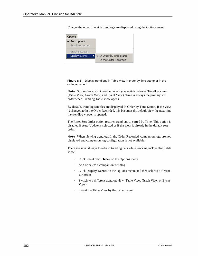
Operator’s Manual | Envision for BACtalk
182 LTBT-OP-EBT30 Rev. 05 © Honeywell
Change the order in which trendlogs are displayed using the Options menu.
Note Sort orders are not retained when you switch between Trendlog views (Table View, Graph View, and Event View). Time is always the primary sort order when Trendlog Table View opens.
By default, trendlog samples are displayed In Order by Time Stamp. If the view is changed to In the Order Recorded, this becomes the default view the next time the trendlog viewer is opened.
The Reset Sort Order option restores trendlogs to sorted by Time. This option is disabled if Auto Update is selected or if the view is already in the default sort order.
Note When viewing trendlogs In the Order Recorded, companion logs are not displayed and companion log configuration is not available.
There are several ways to refresh trendlog data while working in Trendlog Table View:
• Click Reset Sort Order on the Options menu
• Add or delete a companion trendlog
• Click Display Events on the Options menu, and then select a different sort order
• Switch to a different trendlog view (Table View, Graph View, or Event View)
• Resort the Table View by the Time column
Figure 8.6 Display trendlogs in Table View in order by time stamp or in the order recorded

Chapter 8 | Trendlogs
© Honeywell LTBT-OP-EBT30 Rev. 05 183
Graph viewUse this view to display trendlog data graphically. Drag the mouse across the graph to zoom in on a specific portion of the graph.
Note When you view data as a line graph, Envision for BACtalk compresses the X axis to view all the samples in the date/time range you specify in the From and To boxes. In bar graph view, the display is limited to approximately 45 samples at a time, and Envision for BACtalk displays samples beginning with the From date. If you switch back to line graph mode, only those first samples are displayed. Right-click anywhere on the graph and then click Zoom Out on the shortcut menu to return to the compressed view.
Figure 8.7 Trendlog viewer–graph view

Operator’s Manual | Envision for BACtalk
184 LTBT-OP-EBT30 Rev. 05 © Honeywell
Event view The event view can be useful when troubleshooting to see if any error events were transmitted along with the data sample. If you see a strange data sample or group of samples, you may want to check event view to see if Envision for BACtalk recorded an error event.
Note If companion logs are included, they are hidden while event view is active.
Adding companion logsCompanion logs enable you to view multiple data sets together. Data from the logs appear side-by-side with the primary log. You can view up to 10 data sets at once. You set up companion logs in table view. Once you set up companion logs, you can switch to graph view. Until companion logs are deleted, they are displayed when their primary logs are displayed.
Note When viewing trendlogs In the Order Recorded, companion logs are not displayed and companion log configuration is not available.
To add a companion log to table view
1. On the BACtalk menu, click Trendlog Management and then click Trendlogs.
2. Select the trendlog you want to view, and then click View.
3. Right-click the heading for the trendlog, and then click Add Companion Log.
4. In the list of trendlogs, click the companion logs you want to view, and then click Select.
The companion log appears to the right of the currently selected trendlog.
Updating trendlog data while viewingWhen you view trendlog data, you view samples from the database at the Envision for BACtalk server. When you first open a trendlog, Envision for
Figure 8.8 Trendlog viewer–event view

Chapter 8 | Trendlogs
© Honeywell LTBT-OP-EBT30 Rev. 05 185
BACtalk retrieves the most recent samples from the global controller or building controller.
Select Auto Update on the Options menu (BACtalk>Trendlog Management>Trendlogs>View) to ensure that the data in the trendlog viewer updates whenever the server retrieves samples from the controller. See “How trendlog samples are gathered and saved” on page 166 for more information.
There are essentially three ways that the trendlog database can be updated with samples from the controller while you are viewing a trendlog:
• Change the To date and time to a time more recent than the most recent sample in the database and then press F5.
• Close the trendlog viewer and re-open it.
• With Auto Update selected, wait for the Envision for BACtalk server to receive log data at the interval established in the log handler.
Archiving trendlog dataEnvision for BACtalk enables you to archive trendlog data as a comma-separated values (*.csv) file or an Access (*.mdb) file. These files are saved on the Envision for BACtalk server in the server’s Archive directory. Specify the Archive directory using the Site Configuration dialog box (General System Setup>Network>Site Configuration).
Most spreadsheet and database programs can read .csv files. This is useful for exploring trendlog data for sophisticated analysis.
The Access (*.mdb) file format supports viewing archived data in the trendlog viewer. This is the option selected by default.
From the list of trendlogs (BACtalk>Trendlog Management>Trendlogs), select the trendlogs you want to archive. Use Shift+click to select a range and then Ctrl+click to add or remove a trendlog. Click Archive to archive your selected trendlogs.
Use the auto-archive feature to set the BACtalk server to automatically archive trendlog data (BACtalk>Trendlog Management>Trendlogs). You can archive records daily, weekly, twice a month, monthly, quarterly, twice a year, and yearly.

Operator’s Manual | Envision for BACtalk
186 LTBT-OP-EBT30 Rev. 05 © Honeywell
Archive trendlog data from the BACtalk server or client workstations. However, archived data is always stored on the server.
Envision for BACtalk displays the trendlog list you have selected.
The current archive settings for the displayed trendlogs are also shown. Where settings are different between trendlogs, the setting is blank or gray. Changing a setting forces that setting to be used by all the selected trendlogs.
The Archive Now area controls the actual date range to be used when manually archiving trendlogs. Select the date range you want and then click Archive Now to immediately send the data to the server for archiving in the Archive directory. View the archive operation’s progress in the User Request Monitor.
Note If you change the archive settings to do Archive Now but do not want to permanently change the settings used for auto-archiving, click Cancel after the Archive Now operation is complete. Otherwise, the updated archive settings you last used for Archive Now are saved to the database and they will be used for all subsequent auto-archive operations.
Auto-archiveSelecting the “Auto-archive” check box causes the selected trendlogs to automatically archive starting at midnight following the selected archive period. For example, a log that is archived Monthly will archive the previous month’s data at midnight on the first of each month. As part of the auto-archive operation,
Figure 8.9 Archive Trendlogs dialog box

Chapter 8 | Trendlogs
© Honeywell LTBT-OP-EBT30 Rev. 05 187
the latest trendlog data from the host device is gathered and stored in the database prior to archiving.
Auto-archiving occurs according to the following schedule. Weeks are defined as Sunday through Saturday. Therefore, weekly auto-archiving happens on Sunday morning at midnight for the previous week ending Sunday night at 23:59:59. All times are local time.
Replacing or appending to previously archived dataIf you create an archive file using “Archive Now” and then decide to set up a log for auto-archiving, perform auto-archiving and BACtalk will add new data to your existing archive file. If the default “Replace/append to previously archived logs from the same period” setting is checked, .csv files get overwritten if they exist and .mdb files get appended if they exist.
If this check box is not checked and the archive file for the selected period already exists, then the archive operation is skipped.
Data for each archive period is saved with a unique file name. For example, monthly archive data for February 2008 is saved in a different file than monthly archive data for Mar 2008. File names are also different based on the archive period. For example, weekly archive data will have different file names than monthly archive data.
Removing old log entriesThe “Remove all but the most recent ___ periods from the log when archiving” option allows you to clear out old data from the current database during an archive operation. Data from the selected period is archived, and then any old data is removed from the current database. The age of data to be removed is controlled by the number of periods entered. The default number of periods is 9999 to prevent inadvertent loss of data in case the check box is accidentally checked. For example, if you have “Monthly” selected and check the “Remove all but the most recent ___ periods from the log when archiving” option with the number of periods set to 12, all but the most recent 12 months’ worth of data will be removed from the current database once the archive operation completes.
If you have “Daily” selected and check the “Remove” check box with the number of periods set to 365, all but the most recent 365 day’s worth of data gets removed from the current database after the archive operation completes.
Table 8.6 Auto-archive scheduling
Auto-archive period
Scheduled start time
Daily At 12:00:00 midnight for the previous day
Weekly Sunday at midnight for the previous week
Semi-monthly The 1st and 16th of each month at midnight for the previous period
Monthly The 1st of each month at midnight for the previous month
Quarterly The 1st of January, April, July, October at midnight for the previous quarter
Semi-annual The 1st of January and July at midnight for the previous half-year
Annual The 1st of January at midnight for the previous year

Operator’s Manual | Envision for BACtalk
188 LTBT-OP-EBT30 Rev. 05 © Honeywell
Note If an error occurs during the archive operation, no data will be removed. This prevents inadvertent data loss.
Archiving all entriesIf you check “Archive all entries in the log when archiving” check box, all data in the current database gets copied to the appropriate archive file when archiving, regardless of the selected archive period. However, the file name(s) for the archived data will be based on the selected archive time period.
This option is especially useful for “Archive Now” operations the first time you set up your system for auto-archiving. By selecting those trendlogs you want to auto-archive and performing an “Archive Now” operation with the “Archive all entries in the log when archiving” check box checked, you will essentially create an on-line backup copy of all of your old trendlog data to which you can refer once you start removing old data (using the “Remove all but the most recent _____ periods from the log when archiving” option) as a part of the auto-archiving operation.
You probably do NOT want to check this option for auto-archiving, since you will end up with additional copies of the entire database on the server disk each time auto-archive runs. This can fill up the disk rapidly, especially for frequent archives, such as Daily or Weekly.
Purging trendlog dataPurging trendlog data clears all samples from the Envision for BACtalk server and from the controller, at your discretion, but retains the trendlog setup.
From the list of trendlogs (BACtalk>Trendlog Management>Trendlogs), select the trendlogs you want to purge. Use Shift+click to select a range and Ctrl+click to add or remove a trendlog from a selection. Then click the Purge button.
The options to purge from global controller memory or from workstation hard disk apply to all selected trendlogs.
Figure 8.10 Purge Trendlog dialog box

Chapter 8 | Trendlogs
© Honeywell LTBT-OP-EBT30 Rev. 05 189
Printing a trendlog view or listOnce you have trendlog samples sorted and displayed the way you want in table, graph, or event view, click Print on the File menu. You can then select a printer connected to the local operator workstation from the Windows print manager.
If you need to print a listing of all the trendlogs set up in your system, click the Print button in the Trendlogs dialog box.

Operator’s Manual | Envision for BACtalk
190 LTBT-OP-EBT30 Rev. 05 © Honeywell
Using the Enhanced Trendlog Viewer
About Enhanced Trendlog ViewerEnhanced Trendlog Viewer extends Envision for BACtalk’s built-in trendlog viewing functionality. It helps you troubleshoot the behavior of a building control system and allows you to see how data from one trendlog relates to other trendlog data. It shows data from as many as ten trendlogs on an interactive line graph.
See the Enhanced Trendlog Viewer Installation Instructions (LTBT-TM-TLVINST) for information about installing Enhanced Trendlog Viewer.
Configuring Enhanced Trendlog ViewerBefore you begin using Enhanced Trendlog Viewer, consider limiting the size of search results. If your network includes a NAT firewall, you must add an entry to bactalk.ini to enable communication across the firewall.
Limiting the size of search resultsLarge search results can consume network bandwidth and take a long time to process. Limiting the number of trendlogs returned by a search can minimize network traffic and reduce the time required to display results.
The Max Trendlogs to Display text box on the Trendlog Selection dialog box allows the user to set the maximum number of trendlogs returned. If the number of trendlogs that meet the search criteria exceeds the limit, Enhanced Trendlog Viewer shows an error message.
You can limit the number the user can enter in Max Trendlogs to Display by setting the MaxTrendlogSearchResults entry in the bactalk.ini file.
To set MaxTrendlogSearchResults
1. Open bactalk.ini in a text editor such as Notepad. The default location of bactalk.ini is C:\Alerton\BACtalk\3.0.
2. In the TrendlogViewer section, set MaxTrendlogSearchResults to the desired value. The default value is 5000.
3. Save your changes and close bactalk.ini.
4. Refresh the Enhanced Trendlog Viewer page.
NAT firewall issuesIf there is a NAT firewall between the Envision for BACtalk server and an Envision for BACtalk client, you must edit the client’s bactalk.ini file to ensure the client can communicate with the server.
To configure clients in a NAT environment
1. On the client computer, open the bactalk.ini file. The default location is C:\Alerton\BACtalk\3.0.
2. In the [Niagara] section, add two entries - PublicHostName and PublicHttpPort.

Chapter 8 | Trendlogs
© Honeywell LTBT-OP-EBT30 Rev. 05 191
3. If the client is separated from the server by a NAT firewall, use the server’s public hostname and port (as assigned by the network administrator) to populate the PublicHostName and PublicHttpPort entries in the bactalk.ini file.
Note If the client is not separated from the server, it uses the server’s local hostname and port to populate the PublicHostName and PublicHttpPort entries in the bactalk.ini file. You do not need to change these entries.
4. Save the changed bactalk.ini file and then refresh the Enhanced Trendlog Viewer page.
Starting Enhanced Trendlog ViewerStarting Enhanced Trendlog Viewer requires a valid Envision for BACtalk user profile. When you start Enhanced Trendlog Viewer, it opens in the default web browser.
To start Enhanced Trendlog Viewer from a server
1. Log in to Envision for BACtalk.
2. On the BACtalk menu, select Trendlog Management and then click Enhanced Trendlog Viewer.
Setting the time frameThis is where you select the time frame for the data that is retrieved and how much of that data is displayed on the charts. The range is shown just above the main chart.
Figure 8.11 Enhanced Trendlog Viewer user interface
Main chart. See page 195.
Select time frame. See page 191.
Load data from the Envision for BACtalk server. See page 192.
Select trendlogs. See page 192.
Legend. See page 195.
Summary chart. See page 194.

Operator’s Manual | Envision for BACtalk
192 LTBT-OP-EBT30 Rev. 05 © Honeywell
ViewsTrendlog data is shown in one of four views - 2-Hour/10-Minute, Day/2-Hour, Week/Day, and Week/Month. Views are named to reflect the date/time ranges shown in the summary and main charts.
When you select a view, the application retrieves more data than it shows on the charts. You can view the additional data by panning. You can also view a subset of the displayed data by zooming.
2 Hour/10 Minutes When you select 2-Hour/10-Minute view, Enhanced Trendlog Viewer retrieves data for the 24 hours preceding the End date/time. It displays two hours of data in the summary chart and ten minutes of data in the main chart.
1 Day/2 Hour When you select Day/2-Hour view, Enhanced Trendlog Viewer retrieves data for the two days preceding the End date/time. It displays one day of data in the summary chart and two hours of data in the main chart.
1 Week/1 Day When you select Week/Day view, Enhanced Trendlog Viewer retrieves data for the two weeks preceding the End date/time. It displays one week of data in the summary chart and one day of data in the main chart.
1 Month/1 Week When you select Month/Week view, Enhanced Trendlog Viewer retrieves data for one month preceding the End date/time. It displays one month of data in the summary chart and one week of data in the main chart.
Set to Current Date/TimeThis button sets the End Date and End Time to the present date/time on the Envision for BACtalk server and then retrieves data based on the view selected.
End Date/TimeUse the date picker or type the date of the latest data you want to retrieve from the server. Type an end time and then click Load.
Loading dataWhen you select a principal trendlog, Enhanced Trendlog Viewer loads data for that trendlog and up to three associated trendlogs. When you select a new view or click Set to Current Date/Time, Enhanced Trendlog Viewer loads data. If you change the date or time, or if you change the associated trendlog selections, you must click Load Data to load data from the server.
Selecting trendlogsSelect a principal trendlog and, optionally, associated trendlogs to show in the charts.
Principal trendlogThe principal trendlog will appear in the summary chart and the main chart.
To select a principal trendlog
1. Click the selection button. The Trendlog Selection dialog box appears.

Chapter 8 | Trendlogs
© Honeywell LTBT-OP-EBT30 Rev. 05 193
2. Type part of a trendlog name or description and then click Search. You can search without typing search criteria, but this will return all trendlogs and the list may be difficult to sort through.
3. If the search returns more trendlogs than the number set in the Max Trendlogs to Display field, a message appears. Refine your search criteria or increase the Max Trendlogs to Display.
4. If you are using a touchscreen device, click the selector arrow to display the list of trendlogs.
5. Select a trendlog and then click OK.Enhanced Trendlog Viewer retrieves data for the trendlog and displays it in the charts.
If the principal trendlog has companion logs configured in Envision for BACtalk, Enhanced Trendlog Viewer shows up to nine of them as associated trendlogs and displays data for the first three.
Associated trendlogsAssociated trendlogs appear only in the main chart and can be toggled ON or OFF.
Do not confuse associated trendlogs with companion logs. Associated trendlogs are associated with a principal trendlog only for the duration of the Enhanced Trendlog Viewer session. See Envision for BACtalk online Help for information about companion logs.
To select associated trendlogs
1. Click the selection button. The Trendlog Selection dialog box appears.
2. Type part of a trendlog name or description and then click Search. You can search without typing search criteria, but this will return all trendlogs and the list may be large.
3. If the search returns more trendlogs than the number set in the Max Trendlogs to Display field, a message appears. Refine your search criteria or increase the Max Trendlogs to Display.
4. If you are using a touchscreen device, tap the selector arrow to display the list of trendlogs.
5. Select a trendlog and then click OK.Enhanced Trendlog Viewer retrieves data for the trendlog and displays it in the main chart.
To remove an associated trendlog from the main chart, clear the check box next to it. The associated line disappears from the chart and the trendlog name and description appear dimmed.
Color selectionWhen Enhanced Trendlog Viewer loads trendlog data, each trendlog is represented in a different color. If a color is associated with the trendlog in Envision for BACtalk, that color is used. Otherwise, Enhanced Trendlog Viewer assigns a color.
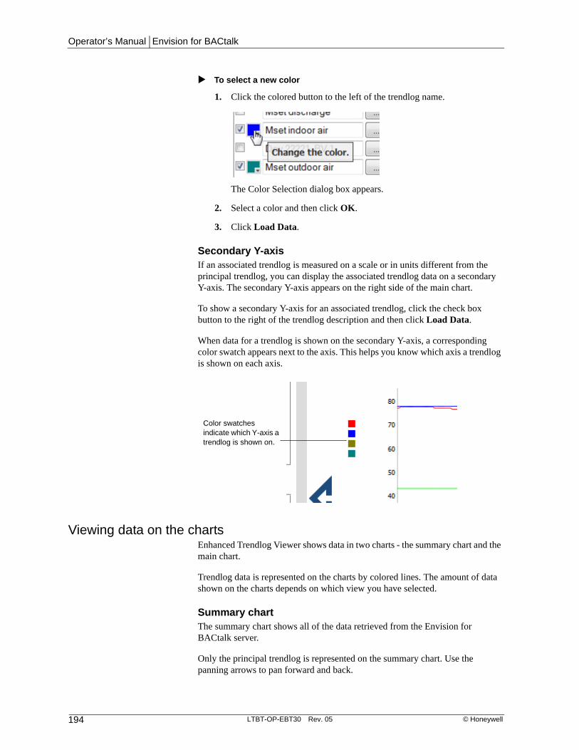
Operator’s Manual | Envision for BACtalk
194 LTBT-OP-EBT30 Rev. 05 © Honeywell
To select a new color
1. Click the colored button to the left of the trendlog name.
The Color Selection dialog box appears.
2. Select a color and then click OK.
3. Click Load Data.
Secondary Y-axisIf an associated trendlog is measured on a scale or in units different from the principal trendlog, you can display the associated trendlog data on a secondary Y-axis. The secondary Y-axis appears on the right side of the main chart.
To show a secondary Y-axis for an associated trendlog, click the check box button to the right of the trendlog description and then click Load Data.
When data for a trendlog is shown on the secondary Y-axis, a corresponding color swatch appears next to the axis. This helps you know which axis a trendlog is shown on each axis.
Viewing data on the chartsEnhanced Trendlog Viewer shows data in two charts - the summary chart and the main chart.
Trendlog data is represented on the charts by colored lines. The amount of data shown on the charts depends on which view you have selected.
Summary chartThe summary chart shows all of the data retrieved from the Envision for BACtalk server.
Only the principal trendlog is represented on the summary chart. Use the panning arrows to pan forward and back.
Color swatches indicate which Y-axis a trendlog is shown on.

Chapter 8 | Trendlogs
© Honeywell LTBT-OP-EBT30 Rev. 05 195
A shaded area on the summary chart indicates the time frame of the data shown in the main chart. You can click and drag this highlighted area to pan through data.
Main chartThe main chart shows a subset of the data shown on the summary chart in greater detail.
You can zoom in on specific areas of the chart and then pan forward and backward through the data (see “Panning and zooming” on page 197). Each selected trendlog is represented on the main chart.
Chart range Shows the date/time range of the data displayed in the main chart.
Legend The chart legend, located below the summary chart, shows the date/time and trendlog values based on the location of the cursor in the main chart. Trendlog names/descriptions and values are shown in their associated colors.
The legend shows blank values until the cursor moves onto the main chart. Then it shows the date/time and values as the cursor moves across the chart. Small dots appear on the lines in the main chart to indicate the date/time being shown.
When the cursor is moved off of the main chart, the legend shows the values that were shown at the time the cursor was moved off.
Figure 8.12 Enhanced Trendlog Viewer chart range
Figure 8.13 Enhanced Trendlog Viewer legend
The chart range shows the beginning and ending dates/times of data on the main chart.
The legend shows values based on the location of the cursor.

Operator’s Manual | Envision for BACtalk
196 LTBT-OP-EBT30 Rev. 05 © Honeywell
ToolsUse the tools above the main chart to enable or disable min/max values, copy URLs, toggle tooltips on or off, and to export data.
Show Min-Max Values The line that represents trendlog data on the main chart is an averaged value. When Show Min-Max Values is selected, the minimum and maximum values are displaced as shadows below and above the trendlog line. Not selected by default.
Show Tooltips When this option is selected and you hover the mouse cursor over a button or check box, a tooltip is displayed that explains the function of that button or check box. Show Tooltips is selected by default.
NOTE: Tooltips are not supported on touchscreen devices.
Copying URLs If you want to link to a particular trendlog view, you can copy the URL to your computer's clipboard. Then you can paste it into an email, create a link on a graphic display, or paste the URL into a web browser and bookmark it.
When you copy an Enhanced Trendlog Viewer URL, the URL includes information about the view and the trendlogs you have selected. It also includes any secondary Y-axis selections and whether secondary trendlogs are selected for display on the main chart.
URLs do not include end date/time data.
Users must have view privileges for the trendlogs or Enhanced Trendlog Viewer will not display the data.
To copy a URL
1. Click the Copy URL icon at the top of the main chart area.
The Copy URL dialog box opens.
2. Ensure the URL is selected (highlighted).
3. Press Ctrl+C.
4. Click OK.
Figure 8.14 Enhanced Trendlog Viewer tools
The tools at the top of the main chart allow you to show min/max values, toggle tooltips, copy URLs, and export data.

Chapter 8 | Trendlogs
© Honeywell LTBT-OP-EBT30 Rev. 05 197
5. Navigate to where you want to use the URL and then press Ctrl+V to paste the URL.
Exporting to CSV If you want to view trendlog data in another program, you can export the data to a comma separated value (CSV) file. Select the trendlogs
and time frame you want to export and click the export icon.
If you select a large data set that will takes a long time to export, Enhanced Trendlog Viewer will ask you to confirm the operation.
Note The Export to CSV function is not available on touchscreen devices.
Panning and zoomingNavigate the data by panning through the summary and main charts and by zooming in on the main chart.
Panning
Use the panning arrows to move backward and forward through the data. You can also pan by clicking and dragging the shaded area in the summary chart
Main chart panning You can only pan across the main chart after you have zoomed in. See “Zooming” on page 197.
When you click a panning arrow next to the main chart, Enhanced Trendlog Viewer moves the selected data by 25% of the selected date/time range. Selected data is shown as a shaded area in the summary chart. When you are zoomed in, the date/time range shown in the main chart is represented as a darker shaded area within the shaded area on the summary chart.
Summary chart panning
When you click a panning arrow next to the summary chart, Enhanced Trendlog Viewer moves the selected date/time range according to the view you have selected.
ZoomingSelect a subset of data to view by clicking and dragging in the main chart. The main chart will refresh to show the range of data selected. The axis labels on the chart will reflect the values of the zoomed view.
Horizontal zooming Zoom in on a date/time range by clicking and dragging in the main chart.
Table 8.7 Panning behavior of Enhanced Trendlog Viewer
If you are in this view: Enhanced Trendlog Viewer will move:
2-Hour / 10-Min 10 minutes
Day / 2-Hour 2 hours
Week / Day One day
Month / Week One week

Operator’s Manual | Envision for BACtalk
198 LTBT-OP-EBT30 Rev. 05 © Honeywell
You can zoom in multiple times. To return to the un-zoomed view, double-click
the main chart or click the zoom out icon.
On a touchscreen device, use standard touchscreen actions to zoom.
When you zoom in horizontally, the summary chart shows the zoomed-in time frame as a dark area in the context of the currently selected view.
Vertical zooming Zoom in on a subset of data by clicking the desired starting point and dragging your mouse up or down to the desired end point.
You can zoom in multiple times. To return to the un-zoomed view, double-click
the main chart or click the zoom out icon.
On a touchscreen device, use standard touchscreen actions to zoom.
Copying URLsIf you want to link to a particular trendlog view, you can copy the URL to your computer's clipboard. Then you can paste it into an email, create a link on a graphic display, or paste the URL into a web browser and bookmark it.
When you copy an Enhanced Trendlog Viewer URL, the URL includes information about the view and the trendlogs you have selected. It also includes any secondary Y-axis selections and whether secondary trendlogs are selected for display on the main chart. URLs do not include end date/time data.
Users must have view privileges for the trendlogs or Enhanced Trendlog Viewer will not display the data.
To copy a URL
1. Click the Copy URL icon at the top of the main chart area.
2. The Copy URL dialog box opens.
3. Ensure the URL is selected (highlighted).
4. Press Ctrl+C.
5. Click OK.
6. Navigate to where you want to use the URL and then press Ctrl+V to paste the URL.
Figure 8.15 Summary chart showing zoomed-in view
The darker shading in the summary chart indicates the subset of data displayed on the main chart.

Chapter 8 | Trendlogs
© Honeywell LTBT-OP-EBT30 Rev. 05 199
For touchscreen usersWhen viewed on a touchscreen device, the Enhanced Trendlog Viewer interface has a few differences from the PC interface:
• To start Enhanced Trendlog Viewer, you must type the URL in a web browser.
• Tooltips are not supported on touchscreen devices.
• CSV export is not supported on touchscreen devices.
• In the trendlog selection dialog box, after you search for trendlogs you
must click the down arrow to see the trendlog list. On a PC the list is populated automatically.

Operator’s Manual | Envision for BACtalk
200 LTBT-OP-EBT30 Rev. 05 © Honeywell

GHD | Document Title | xxxxxxxx (x)
Appendix ERequest to Reuse Soil Form

NEW YORK STATE DEPARTMENT OF ENVIRONMENTAL CONSERVATION
Request to Import/Reuse Fill or Soil
*This form is based on the information required by DER-10, Section 5.4(e). Use of this form is not a substitute for reading the applicable Technical Guidance document.*
SECTION 1 – SITE BACKGROUND The allowable site use is: Have Ecological Resources been identified? Is this soil originating from the site? How many cubic yards of soil will be imported/reused? If greater than 1000 cubic yards will be imported, enter volume to be imported:
SECTION 2 – MATERIAL OTHER THAN SOIL Is the material to be imported gravel, rock or stone? Does it contain less than 10%, by weight, material that would pass a size 80 sieve? Is this virgin material from a permitted mine or quarry? Is this material recycled concrete or brick from a DEC registered processing facility?
SECTION 3 - SAMPLING
Provide a brief description of the number and type of samples collected in the space below: ------------------------------------------------------------------------------------------------------------------------------------------------------------------ Example Text: 5 discrete samples were collected and analyzed for VOCs. 2 composite samples were collected and analyzed for SVOCs, Inorganics & PCBs/Pesticides. If the material meets requirements of DER-10 section 5.5 (other material), no chemical testing needed.
Revised August 2014

SECTION 3 CONT’D - SAMPLING
Provide a brief written summary of the sampling results or attach evaluation tables (compare to DER-10, Appendix 5): ------------------------------------------------------------------------------------------------------------------------------------------------------------------ Example Text: Arsenic was detected up to 17 ppm in 1 (of 5) samples; the allowable level is 16 ppm. If Ecological Resources have been identified use the “If Ecological Resources are Present” column in Appendix 5.
SECTION 4 – SOURCE OF FILL Name of person providing fill and relationship to the source: Location where fill was obtained: Identification of any state or local approvals as a fill source: If no approvals are available, provide a brief history of the use of the property that is the fill source: Provide a list of supporting documentation included with this request:
Revised August 2014

The information provided on this form is accurate and complete. _________________________________ _______________
Signature Date
_________________________________ Print Name
_________________________________ Firm
Revised August 2014

GHD | Report for Parker-Hannifin and General Electric-Remedial Design/Remedial Action Work Plan | 035048 (5)
Appendix B Health and Safety Plan
(on CD)

APPENDIX B
HEALTH AND SAFETY PLAN REMEDIAL DESIGN / REMEDIAL ACTION (RD/RA) ACTIVITIES OLD ERIE CANAL SITE CLYDE, NEW YORK
OCTOBER 2014 REF. NO. 035048 (5)
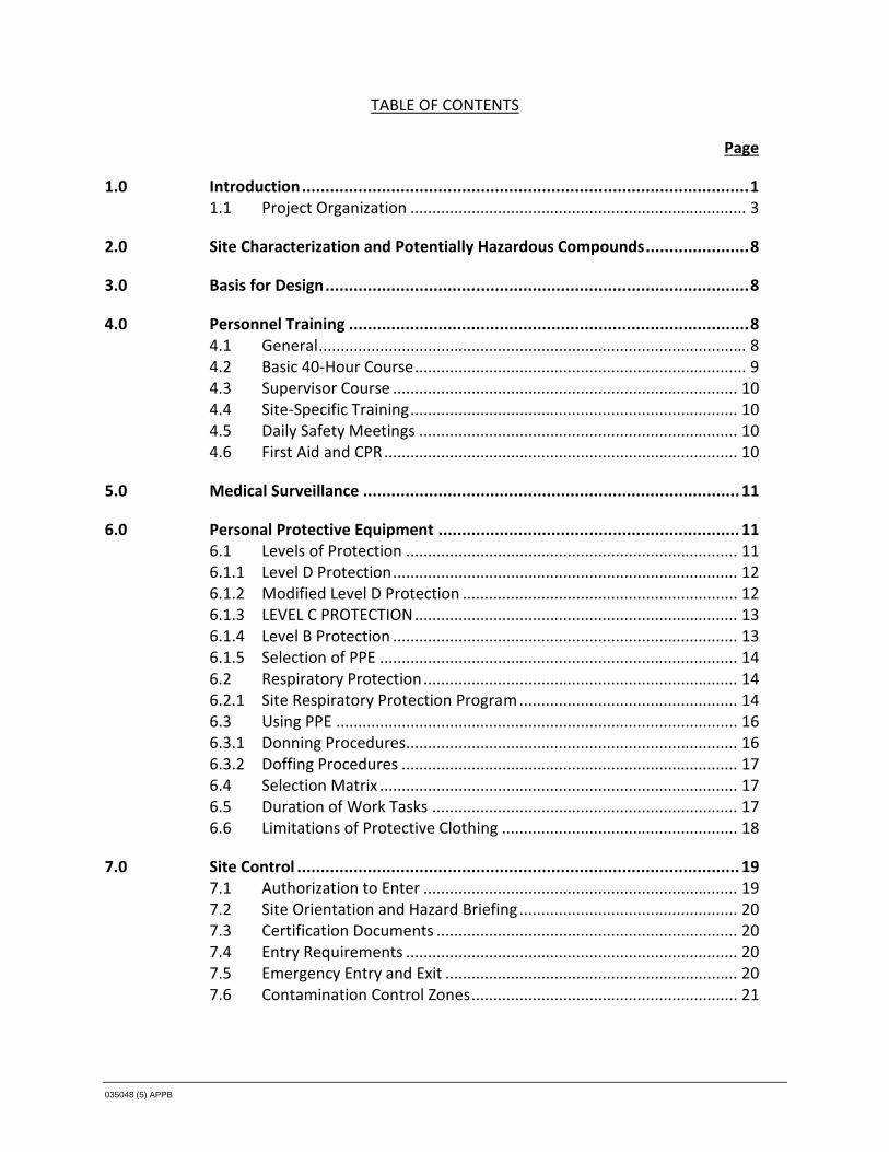
035048 (5) APPB
TABLE OF CONTENTS
Page
1.0 Introduction...............................................................................................11.1 Project Organization ............................................................................. 3
2.0 Site Characterization and Potentially Hazardous Compounds......................8
3.0 Basis for Design..........................................................................................8
4.0 Personnel Training .....................................................................................84.1 General.................................................................................................. 84.2 Basic 40-Hour Course............................................................................ 94.3 Supervisor Course ............................................................................... 104.4 Site-Specific Training........................................................................... 104.5 Daily Safety Meetings ......................................................................... 104.6 First Aid and CPR................................................................................. 10
5.0 Medical Surveillance ................................................................................11
6.0 Personal Protective Equipment ................................................................ 116.1 Levels of Protection ............................................................................ 116.1.1 Level D Protection............................................................................... 126.1.2 Modified Level D Protection ............................................................... 126.1.3 LEVEL C PROTECTION.......................................................................... 136.1.4 Level B Protection ............................................................................... 136.1.5 Selection of PPE .................................................................................. 146.2 Respiratory Protection........................................................................ 146.2.1 Site Respiratory Protection Program .................................................. 146.3 Using PPE ............................................................................................ 166.3.1 Donning Procedures............................................................................ 166.3.2 Doffing Procedures ............................................................................. 176.4 Selection Matrix .................................................................................. 176.5 Duration of Work Tasks ...................................................................... 176.6 Limitations of Protective Clothing ...................................................... 18
7.0 Site Control .............................................................................................. 197.1 Authorization to Enter ........................................................................ 197.2 Site Orientation and Hazard Briefing.................................................. 207.3 Certification Documents ..................................................................... 207.4 Entry Requirements ............................................................................ 207.5 Emergency Entry and Exit ................................................................... 207.6 Contamination Control Zones............................................................. 21

035048 (5) APPB
TABLE OF CONTENTS
Page
7.7.1 Exclusion Zone (EZ) ............................................................................. 217.7.2 Contamination Reduction Zone (CRZ) ................................................ 217.7.3 Support Zone (SZ)................................................................................ 21
8.0 Activity Hazard/Risk Analysis and General Safety Practices ....................... 218.1 General Practices ................................................................................ 228.1.1 Buddy System...................................................................................... 238.1.2 Sanitation ............................................................................................ 248.1.3 Break Area........................................................................................... 248.1.4 Potable Water ..................................................................................... 248.1.5 Washing Facilities................................................................................ 248.1.6 Lavatory............................................................................................... 248.1.7 Trash Collection .................................................................................. 248.2 Chemical Exposure.............................................................................. 258.3 Heat Stress .......................................................................................... 278.4 Sun Exposure....................................................................................... 308.5 Cold Stress........................................................................................... 318.6 Earthwork - Excavation and Trenching ............................................... 338.7 Heavy Equipment Safety..................................................................... 368.8 Noise ................................................................................................... 378.9 Electrical Hazards ................................................................................ 378.10 Material Handling ............................................................................... 398.11 Manual Lifting ..................................................................................... 418.12 Hand and Power Tools ........................................................................ 418.13 Adverse Weather Conditions.............................................................. 428.14 Fall Hazards ......................................................................................... 428.15 Biological Hazards ............................................................................... 448.15.1 Vegetation Overgrowth ...................................................................... 448.15.2 Tick-Borne Diseases ............................................................................ 458.15.3 Poisonous Plants ................................................................................. 458.15.4 Insects ................................................................................................. 468.15.4.1 Poisonous Spiders ......................................................................... 488.15.5 Threatening Dogs................................................................................ 488.15.6 Rodents ............................................................................................... 49
9.0 Air Monitoring Program ...........................................................................509.1 Site Air Monitoring.............................................................................. 519.1.1 Real-Time VOC Monitoring ................................................................. 529.1.2 Particulate Monitoring........................................................................ 529.1.3 Oxygen, Combustible Gas, and Carbon Monoxide Monitoring.......... 529.1.4 Personal Air Sampling Program .......................................................... 53

035048 (5) APPB
TABLE OF CONTENTS
Page
10.0 Decontamination Procedures ...................................................................5310.1 Equipment Decontamination Procedures .......................................... 5410.2 Personnel Decontamination Procedures............................................ 54
11.0 Emergency Response and Contingency Procedures ...................................5511.1 Accident, Injury and Illness Reporting ................................................ 5611.2 Emergency Contacts ........................................................................... 5611.3 Additional Emergency Numbers ......................................................... 5711.4 Emergency and First Aid Equipment................................................... 5711.5 Project Personnel Responsibilities during Emergencies..................... 5711.6 Medical Emergencies .......................................................................... 5811.7 Fire or Explosion.................................................................................. 5811.8 Spill Control and Countermeasures .................................................... 59
12.0 Recordkeeping ......................................................................................... 60

035048 (5) APPB
LIST OF FIGURES(Following Text)
FIGURE B11.1 HOSPITAL ROUTE MAP
LIST OF TABLES(Following Text)
TABLE B2.1 CHEMICAL COMPOUNDS HISTORICALLY DETECTED ANDRANGE OF CONCENTRATIONS IN GROUNDWATER, SOILS AND DRAINAGESWALE SOILS
TABLE B2.2 EXPOSURE ROUTES AND EXPOSURE LEVELS FOR THE CHEMICALCOMPOUNDS HISTORICALLY DETECTED AT THE SITE
TABLE B8.1 ON-SITE AIR MONITORING PROGRAM ACTION LEVELS
LIST OF ATTACHMENTS(Following Text)
ATTACHMENT A JOB SAFETY ANALYSIS (JSA) FORMS
ATTACHMENT B PROJECT SAFETY FORMS
ATTACHMENT C COMMUNITY AIR MONITORING PLAN

035048 (5) APPB 1
1.0 Introduction
This Health and Safety Plan (HASP) describes the health and safety procedures and emergencyresponse guidelines that will be implemented during the Remedial Design / Remedial Action(RD/RA) activities at the Old Erie Canal Site (Site) in Clyde, New York. An Emergency ResponsePlan and Community Air Monitoring Plan are included as part of this HASP. This HASP shall beimplemented and adhered to during all RDRA activities that are presented in the Work Plan.Figures presenting the Site Location and Site Plan are also included in the Work Plan.
This HASP will be provided to the Contractor selected to perform the RD/RA activities. Theselected Contractor will be required to develop and implement a HASP, which at a minimummeets all the requirements set forth in this document.
The scope of work to be completed by the selected contractor(s) during the RD/RA activitiesincludes the following:
i) Mobilization and demobilization of labor, materials, and equipment to and from theSite, which include Site preparation/setup and Site restoration activities
ii) Surveying activities
iii) Installation of silt fencing
iv) Surface water sampling of the Erie Canal
v) Installation of groundwater monitoring wells
vi) Groundwater sampling activities
vii) Groundwater pump testing activities
viii) Potential soil sampling activities
ix) Excavation activities for the installation of sewer pipe
x) Installation of sewer pipe to extend an existing sewer line
xi) Installation of a cap over the newly installed sewer line
xii) Installation of a sub-slab Depressurization System
xiii) The mixing and injection of In-Situ Enhanced Biodegradation Products
viii) Equipment and personnel decontamination activities
During a portion of these activities, personnel may come in contact with waste materials,chemicals, debris, soils, groundwater, surface water, sediment, and wash waters, which maycontain hazardous substances. This HASP has been developed to minimize direct contact byproject personnel with materials potentially having chemical presence by ensuring:

035048 (5) APPB 2
i) That project personnel are not adversely exposed to the compounds of concern
ii) That public health and the environment are not adversely impacted by materials withelevated chemical presence that may potentially migrate outside of the work zoneduring project activities at the Site
iii) Compliance with applicable governmental and non-governmental (American Conferenceof Governmental Industrial Hygienists [ACGIH]) regulations and guidelines. In particular,the amended rules of the Occupational Safety and Health Administration (OSHA) forPart 1926, of Title 29 Code of Federal Regulations (CFR). Part 1926.65 will beimplemented for all Site work where project personnel may come into contact with thehealth and safety hazards that are present at the Site
iv) Initiation of proper emergency response procedures to minimize the potential for anyadverse impact to project personnel, the general public, or the environment
A vital element of the selected contractor’s Health and Safety Program will be theimplementation of a site-specific HASP for all project work activities. This HASP requires thefollowing measures:
i) The communication of the contents of this HASP to project personnel
ii) The elimination of unsafe conditions. Efforts shall be initiated to identify conditions thatcan contribute to an accident and to remove exposure to these conditions
iii) The review all activities before beginning the task/job, after an incident, and/or anyunusual circumstances. Stop activities to think about the task, analyze the task hazards,determine methods to reduce risk, and review the results with affected personnel
iv) The review of existing and the development of new Job Safety Analysis (JSA) forms foreach project work activity. Supervisors and affected personnel are responsible for thedevelopment and any on-going revisions of project JSAs. JSAs for all known workactivities are presented Attachment A
v) The reduction of unsafe acts. Project personnel shall make a conscious effort to worksafely. A high degree of safety awareness must be maintained so those safety factorsinvolved in a task become an integral part of the task. Supervisory personnel shallensure that project personnel committing unsafe acts are held accountable viacounseling, mentoring, and, if necessary, reprimand
vi) The frequent inspection of project activities. Regular safety inspections of the work site,materials, and equipment by qualified persons ensure early detection of unsafeconditions. Safety and health deficiencies shall be corrected as soon as possible, andproject activities shall be temporarily suspended until the appropriate corrective actions

035048 (5) APPB 3
are taken. Documentation of the daily inspections and corrective actions taken shouldbe kept with the project files.
For the purpose of this HASP, activities performed at the Site involving contact with materials,which potentially have an elevated chemical presence will be considered contaminatedoperations requiring the use of Personal Protective Equipment (PPE). A detailed description ofthe required PPE is presented in Section 6.1 and is also identified on each JSA form.
The applicability of this HASP extends to all project personnel who will be on Site, includingState and Federal Agency personnel, contractor personnel, subcontractor personnel, andvisitors to the Site.
All project activities at the Site will be conducted in accordance with the provisions of anapproved Site-specific HASP. A copy of the Site-specific HASP and employer-specific StandardOperating Procedures (SOPs) will be maintained on Site whenever activities are in progress.This HASP shall be used in conjunction with the selected contractor's Safety and HealthProgram.
1.1 Project Organization
All personnel conducting activities on Site must conduct their activities in compliance with allapplicable Safety and Health standards as specified by OSHA including, but not limited to, theOSHA 29 CFR 1910, 29 CFR 1926. Project personnel must also be familiar with the proceduresand requirements in their approved Site-specific HASP and the applicable procedures foundwithin their company’s SOP’s and Safety and Health Policy Manual. In the event of anyconflicting safety procedures/requirements, personnel shall implement those safety practices,which afford the highest level of safety and protection.
Project Management and Safety Organization
Project Manager Contractor – (to be determined)The Project Manager (PM) shall be responsible for the overall implementation of the HASP, andfor ensuring that all health and safety responsibilities are carried out in conjunction with thisproject. This shall include, but is not limited to, review and approval of the HASP;qualifying/directing subcontractors relative to safety and health performance; coordinating allsafety and health submittals; providing the appropriate technical information to writesubmittals; and consultation with the selected contractor's Corporate Safety and HealthManager with regards to appropriate changes to the HASP.

035048 (5) APPB 4
Site Safety & Health Officer (SHO) Contractor – (to be determined)The SHO is the person who, under the supervision of the PM and the contractor's CorporateSafety and Health Manager, shall be responsible for the communication of the Siterequirements to project personnel and any subcontractor personnel. The SHO will have priorexperience in working at hazardous waste sites and is responsible for carrying out the healthand safety responsibilities by making sure that:
i) He/she is onsite at all times during the project work activities
ii) All necessary clean-up and maintenance of safety equipment is conducted by projectpersonnel
iii) Emergency services are contacted when necessary
iv) A Site-specific Hazard Communication (HAZCOM) Program is maintained on Site
v) Project safety forms attached to the HASP are correctly completed and filed
vi) A pre-entry briefing is conducted, which will serve to familiarize project personnel withthe procedures, requirements, and provisions of this HASP
vii) All necessary records are maintained in the project files (e.g., air monitoring results,calibration log sheets, incident reports, daily toolbox meeting sheets, daily safetylogbook entries, training certificates and/or certifications, etc.). The selected contractormay use either their employer-specific safety forms or the forms that are provided inAttachment B
viii) Daily safety meetings are held and documented
ix) Safe work practices for project personnel are enforced
x) Safety of any visitors who enter the Site is ensured
xi) Communication is maintained with the PM
xii) Orders the immediate shutdown of project activities in the case of a medicalemergency, unsafe condition, or unsafe practice
xiii) Designates work areas and define minimum PPE requirements
xiv) Provides the safety equipment, PPE, and other items necessary for project personnel
xv) Conducts the required worker and community air monitoring programs
xvi) Enforces the use of required safety equipment, PPE, and other items necessary forproject personnel safety
xvii) Ensures that there is a competent person in place who will be supervising excavationwork
xviii) Ensures that a licensed electrician qualified according to the National Fire ProtectionAgency (NFPA) 70E standards performs all electrical-required work

035048 (5) APPB 5
xix) Conducts job Site inspections with the Construction Superintendent (CS) or SiteSupervisor (SS) as a part of quality assurance for safety and health
xx) Reports safety and health concerns to the selected contractor’s management asnecessary
Emergency Coordinator (EC)The SHO or his/her designate will act as the EC. The EC shall be able to implement theemergency procedures and is responsible for implementing the following activities in the eventof an emergency:
i) The EC shall immediately respond to all imminent or actual emergency situations. TheEC shall notify all project personnel and emergency response agencies, identify theproblem, assess the health or environmental hazards, and take all reasonable measuresto stabilize the situation
ii) The EC shall take all reasonable measures necessary to ensure that fire, explosion,emission or discharge does not occur, re-occur, or spread. These measures may includestopping operations, collecting and containing released materials, and/or removing orisolating containers
iii) The EC shall develop Emergency Evacuation Routes on a daily bases and communicatethem to all project personnel
iv) The EC shall also be responsible for follow-up activities after any incident such as thecleanup of the affected area, maintenance and decontamination of emergencyequipment, and completion and submission of an incident report
Construction Superintendent (CS) /Site Supervisor (SS) - Contractor (to be determined)Health and safety is a line management responsibility, and as such, the CS and/or SS willimplement and support the overall onsite direction and enforcement of the health and safetyfor this project. The CS and/or SS must meet the requirements of the "competent person" asper the OSHA regulations. The CS and/or SS will report to the PM for this project.
The CS and/or SS is the person who, under the supervision of the PM, shall be responsible forthe communication of the Site requirements to project personnel and subcontractors, and isresponsible for carrying out the health and safety responsibilities by making sure that:
i) All underground utilities have been properly located prior to initiating work activities
ii) Each work area is secured with fencing at the end of each day

035048 (5) APPB 6
iii) All necessary cleanup and maintenance of safety equipment is conducted by projectpersonnel
iv) JSA forms are developed, reviewed, and revised accordingly
v) Project personnel stop, think about, act accordingly and review the work activities thatthey are about to start before initiating activities
vi) Project safety forms attached to the HASP are properly completed and then filed
vii) A pre-entry briefing is conducted for all project personnel, which will serve to familiarizeeveryone with the procedures, requirements, and provisions of this HASP
viii) Orders the immediate shutdown of project activities in the case of a medicalemergency, unsafe condition, or unsafe practice
ix) Provides the safety equipment, PPE, and other items necessary for project personnel
x) Enforces the use of required safety equipment, PPE, and other items necessary forpersonnel or community safety
xi) Conducts job site inspections as a part of quality assurance for safety and health
xii) Reports safety and health concerns to the selected contractor's PM as necessaryxiii) Is responsible for the overall implementation of the HASP, and ensuring that all health
and safety responsibilities are carried out during the project work activities. This shallinclude, but is not limited to, review and approval of any subcontractor HASPs,communication of Site requirements to Subcontractor personnel, and consultation withthe PM regarding appropriate changes to the HASP
xiv) The CS and/or SS also have the responsibility for enforcing safe work practices for allproject personnel
xv) A competent person oversees all excavation and trenching work to ensure that work iscompleted in accordance with the OSHA Standards presented in 1926 Subpart P
xvi) The CS and/or SS watch all personnel for any ill effects, especially those symptomscaused by heat stress and/or chemical exposure
xvii) The CS and/or SS oversee the safety of any visitors who enter the Site
Corporate Safety & Health Manager (CSHM) Contractor – (to be determined)The CSHM is an individual who is trained as a health and safety professional, works full-time forthe selected contractor in a health and safety role, and who serves in a consulting role to thePM, SHO, and CS and/or SS regarding potential health and safety issues.
Equipment OperatorsAll equipment operators are responsible for the safe operation of heavy equipment. Operatorsare responsible for inspecting their equipment on a daily basis to ensure safe performance.Brakes, hydraulic lines, backup alarms, and fire extinguishers must be inspected routinely

035048 (5) APPB 7
throughout the project. Documentation of daily inspections will be required via an equipmentinspection checklist. Heavy equipment inspections will be submitted to the CS for review andsubsequently placed in the project files. Unsafe conditions/acts are to be immediately reportedto the CS. Equipment will be taken out of service if an unsafe condition occurs.
Project Personnel Safety ResponsibilitiesProject personnel are responsible for their own safety as well as the safety of those aroundthem and shall use any equipment provided in a safe and responsible manner, as directed bytheir supervisor. Project personnel will follow the policies set forth in this HASP and those intheir employer-specific SOPs and Safety and Health Program.
Project personnel are directed to take the following actions when appropriate:
i) Review all activity hazards and preventative measurers before initiating work
ii) Assist in the development/revision of JSA forms that are appropriate to their currentwork activities
iii) Suspend any operations that may cause an imminent health hazard to project personnel
iv) Inspect tools and other equipment before each use or as the manufacturer and/or OSHAmandates
v) Correct job site hazards when possible without endangering life or health
vi) Report safety and health concerns to the SHO CS and/or SS
SubcontractorsSelected subcontractor(s) will be responsible for providing a CS and/or SS ("competent person")and a SHO to direct their activities and to meet all applicable OSHA Regulations. This may bethe same individual if so qualified. These individuals will be responsible for ensuring that allcontract specifications are met, including those related to project health and safety. The namesof these individuals will be presented in the subcontractor Site-specific HASP.
The selected contractor will review any subcontractor HASP prior to the subcontractor'smobilization to the Site. Subcontractors will be responsible for the health and safety of theirpersonnel, which includes following all applicable OSHA Regulations and the subcontractors'Site-specific HASP. Subcontractors will be required to attend an initial Site briefing put on bythe selected contractor and subsequent daily safety meetings.
Authorized VisitorsAuthorized Visitors shall be provided with all known information with respect to the projectoperations and hazards, as applicable to the purpose of their visit.

035048 (5) APPB 8
2.0 Site Characterization and Potentially Hazardous Compounds
Section 1.0 of the Work Plan provides detailed information on the Site background and acharacterization of the Site.
Table B2.1 presents a historical listing of all of the Chemical Compounds that have beendetected in Site groundwater, subsurface soils and in drainage swale soils at the Site. This tablealso identifies the maximum detected concentrations of these chemicals in the groundwater(µg/L) and soils (µg/kg). The exposure routes and regulatory Time Weighted Average (TWA)exposure levels for these chemicals are presented in Table B2.2. These levels are set to protectthe health of workers.
It has been determined that the following list of chemicals represent the Chemicals ofConcern (COC) at the site. Trichloroethene (TCE), Arsenic, Benz(A)Anthracene,Benzo(A)Pyrene, Benzo(B)Fluoranthene, Benzo(K)Fluoranthene, Chrysene, Fluoranthene,Indeno(1,2,3-CD)Pyrene, Cadmium, Dichloroethylene, Vinyl Chloride, Toluene, Xylenes, andDibenz(A,H)Anthracene.
3.0 Basis for Design
Regulations set forth by OSHA in Title 29, CFR, Parts 1910 and 1926 (29 CFR 1910 and 1926)form the basis of this HASP. Emphasis is placed on Section 1926.65 (Hazardous WasteOperations and Emergency Response), 1910 Subpart I (Personal Protective Equipment),1910 Subpart Z (Toxic and Hazardous Substances), 1926 Subpart O (Motor Vehicles,Mechanized Equipment, and Marine Operations), and 1926 Subpart F (Excavations). Some ofthe specifications within this section are in addition to the OSHA regulations, and reflect thepositions of U.S. EPA, and the National Institute for Occupational Safety and Health (NIOSH),regarding safe operating procedures at hazardous waste sites.
The health and safety of the public and Site personnel and the protection of the environmentwill take precedence over cost and scheduling considerations for all project work.
4.0 Personnel Training
4.1 General
Project personnel shall complete hazardous waste operations and emergency response training(HAZWOPER), as required by the OSHA Standard 29 CFR 1926.65. Project personnel shall alsoinitially receive a minimum of 3 days of actual field experience under the direct supervision of a

035048 (5) APPB 9
trained, experienced supervisor. Personnel who completed their training more than 12 monthsprior to the start of this project shall have also completed an 8-hour HAZWOPER refreshercourse within the past 12 months. The CS and or SS shall complete the additional 8 hours oftraining that is required for managers and/or supervisors along with any "competent persons"training that may be needed for required work.
Additional safety training for specific tasks/activities may include safety training for excavationsafety. Further safety training may also be required based on the scheduled scope of work.This safety training is to be conducted and documented before any tasks that require additionaltraining are initiated. It is the responsibility of the SHO and CS and/or SS to ensure thatpersonnel have the necessary training and skills prior to activity assignment. Task safetytraining requirements are included on each JSA form.
4.2 Basic 40-Hour Course
The following is a list of the topics typically covered in a 40-hour training course:
i) General safety procedures
ii) Physical hazards (fall protection, noise, heat stress, cold stress)
iii) Names and job descriptions of key personnel responsible for Site health and safety
iv) Safety, health, and other hazards typically present at hazardous waste sites
v) Use, application, and limitations of PPE
vi) Work practices by which employees can minimize risks from hazards
vii) Safe use of engineering controls and equipment on site
viii) Medical surveillance requirements
ix) Recognition of symptoms and signs, which might indicate overexposure to hazards
x) Worker right-to-know (Hazard Communication OSHA 1926.59/1910.1200)
xi) Routes of exposure to contaminants
xii) Engineering controls and safe work practices that may be implemented
xiii) Components of a project HASP
xiv) Decontamination practices for personnel and equipment
xv) Confined space entry proceduresxvi) General emergency response procedures

035048 (5) APPB 10
4.3 Supervisor Course
Management and supervisors (i.e., the CS and SS), who work at the Site are required to receivean additional 8 hours of training in topics that are pertinent to the management of hazardouswaste operations, which typically includes:
i) Instruction in detailed project safety and health procedures dealing with emergencies
ii) PPE programs
iii) The implementation of specialized emergency response proceduresiv) Air monitoring techniques
4.4 Site-Specific Training
All project personnel attending the initial safety meeting will accomplish the project-specifictraining on the contents of this HASP before work begins. The review will include a discussionof the chemical, physical, and biological hazards that may be present at the Site, the protectiveequipment and safety procedures to be used and followed, and emergency procedures that willbe implemented at the Site. The Training Acknowledgment Form that project personnel willsign off on is presented in Attachment B (Project Safety Forms).
4.5 Daily Safety Meetings
Daily safety meetings (tailgate safety talks) will be held to cover the work that is anticipated tobe accomplished each day, the associated hazards, the protective clothing and proceduresrequired to minimize exposure to these hazards, and the required emergency responseprocedures. The CS, SS and/or SHO will present these meetings prior to beginning the day'sfieldwork. No work will be performed in an Exclusion Zone (EZ) before the daily safety meetinghas been held. Additional safety meetings shall also be held prior to initiating new tasks, andrepeated if new hazards are encountered. The form for documenting the daily safety meetingsis also found in Attachment B.
4.6 First Aid and CPR
At least one individual current in First Aid/CPR will be assigned to the work crew for every10 individuals working at the Site and will be immediately available during all field activities toprovide assistance as necessary. Refresher training in First Aid and CPR is required to keep thecertificate current. These individuals must also receive training regarding the precautions andprotective equipment necessary to protect against exposure to blood-borne pathogens.Blood-borne pathogen training should be included as part of the First Aid/CPR training coursedelivered by the training provider.

035048 (5) APPB 11
5.0 Medical Surveillance
In accordance with the requirements detailed in 29 CFR 1926.65 and 29 CFR 1910.134, allproject personnel who will come in contact with potentially contaminated materials will havereceived medical surveillance by a licensed physician or physician's group.
Medical records for all project personnel will be maintained by their respective employers. Themedical records will detail the tests that were taken and will include a copy of the consultingphysician's statement regarding the tests and the individual's suitability for work as per theemployer's medical surveillance program which is to be in accordance with 29 CFR 1926.65.
The medical records will be available to the employee or his designated representative uponwritten request, as outlined in 29 CFR 1910.1020.
If it becomes necessary to use subcontractors, they will also provide certifications to the SHOshowing that their personnel involved in Site activities have all necessary medical examinationsprior to commencing work. The certifications will show proof of medical surveillance andrespiratory fit testing. Personnel not obtaining medical certification will not perform workwithin contaminated areas.
Interim medical surveillance will be completed if an individual exhibits poor health or highstress responses due to any project activity or when accidental exposure to elevatedconcentrations of contaminants occur.
6.0 Personal Protective Equipment
PPE will be required to safeguard project personnel from various hazards. Varying levels ofprotection may be used depending on the level of contaminants and the degree of any physicalhazard. This section presents the various levels of personal protection and defines theconditions of use for each level. Subcontractor Site-specific HASPs, if required, will adequatelyaddress PPE concerns for each specific task activity based on their proposed scope of work.
6.1 Levels of Protection
Protection levels are determined based upon chemical and physical hazards present in the workarea. The specific protection levels to be employed at the Site for each work task are presentedon each JSA form, which are presented in Attachment A.
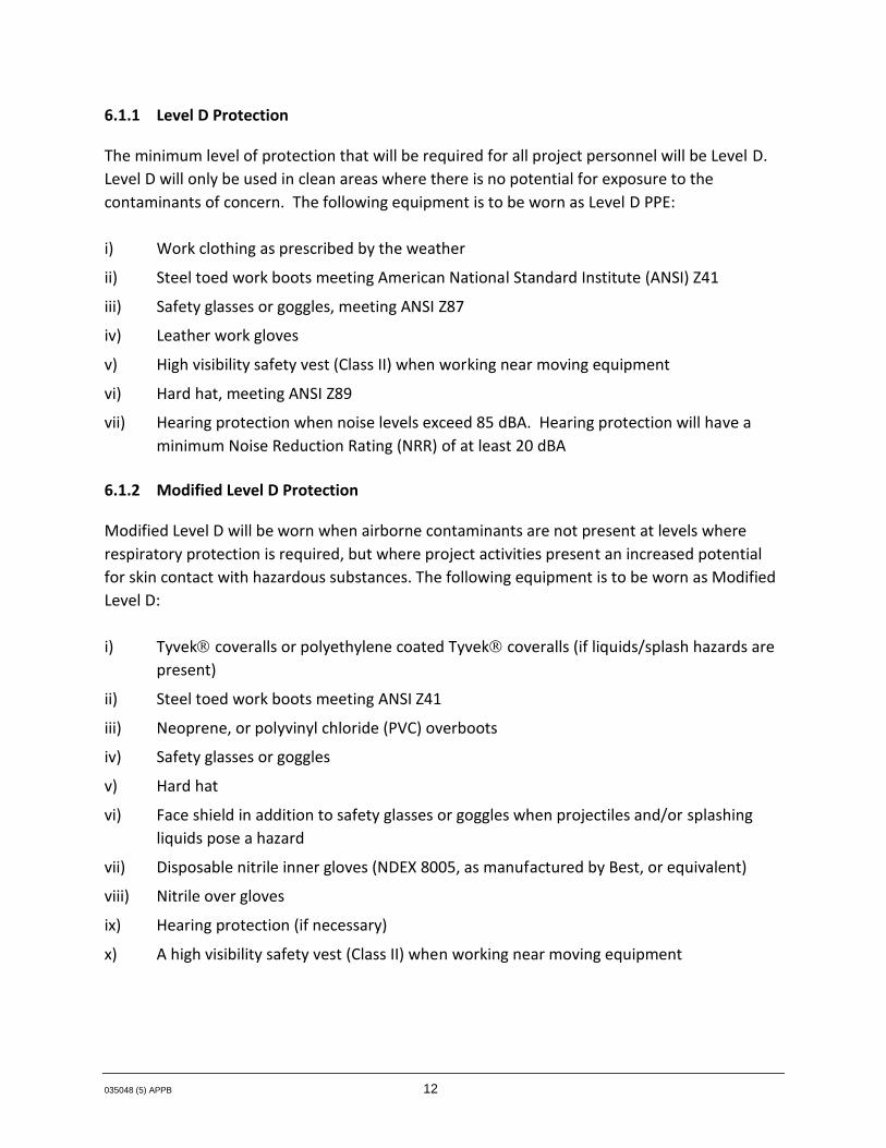
035048 (5) APPB 12
6.1.1 Level D Protection
The minimum level of protection that will be required for all project personnel will be Level D.Level D will only be used in clean areas where there is no potential for exposure to thecontaminants of concern. The following equipment is to be worn as Level D PPE:
i) Work clothing as prescribed by the weather
ii) Steel toed work boots meeting American National Standard Institute (ANSI) Z41
iii) Safety glasses or goggles, meeting ANSI Z87
iv) Leather work gloves
v) High visibility safety vest (Class II) when working near moving equipment
vi) Hard hat, meeting ANSI Z89
vii) Hearing protection when noise levels exceed 85 dBA. Hearing protection will have aminimum Noise Reduction Rating (NRR) of at least 20 dBA
6.1.2 Modified Level D Protection
Modified Level D will be worn when airborne contaminants are not present at levels whererespiratory protection is required, but where project activities present an increased potentialfor skin contact with hazardous substances. The following equipment is to be worn as ModifiedLevel D:
i) Tyvek coveralls or polyethylene coated Tyvek coveralls (if liquids/splash hazards arepresent)
ii) Steel toed work boots meeting ANSI Z41
iii) Neoprene, or polyvinyl chloride (PVC) overboots
iv) Safety glasses or goggles
v) Hard hat
vi) Face shield in addition to safety glasses or goggles when projectiles and/or splashingliquids pose a hazard
vii) Disposable nitrile inner gloves (NDEX 8005, as manufactured by Best, or equivalent)
viii) Nitrile over gloves
ix) Hearing protection (if necessary)
x) A high visibility safety vest (Class II) when working near moving equipment

035048 (5) APPB 13
6.1.3 LEVEL C PROTECTION
Level C protection will be required when the airborne concentration of suspected contaminantsare present in the worker's breathing zone at sustained levels of greater than 1 part per million(ppm) of organic vapor as measured with a photoionization detector (PID) or 5mg/m3 ofparticulate as measured by a particulate monitor.
The following equipment will be used for Level C protection:
i) Full-face air purifying respirator (APR) with organic vapor/acid gas cartridges incombination with particulate filters (P-100) which are NIOSH approved (MSA GME P100cartridges or equivalent)
ii) Polyethylene coated Tyvek or Saranex hooded suit (if liquids/splash hazards arepresent) or Tyvek coveralls, ankles, and cuffs taped to boots and gloves
iii) nitrile over glove, as manufactured by Best or equivalent
iv) inner nitrile disposable gloves (NDEX 8005, as manufactured by Best, or equivalent)
v) safety toe work boots, ANSI approved
vi) chemical resistant neoprene or rubber boots with steel toes, or latex/PVC booties oversafety toe shoes
vii) hard hat, ANSI approved
viii) hearing protection (if necessary)
ix) a high visibility safety vest (Class 2)
6.1.4 Level B Protection
Level B protection is not expected to be worn but would be required if sustained airborneconcentrations of suspended organic vapors are greater than 1 ppm in the presence of vinylchloride or 50 ppm in the absence of vinyl chloride. The action level necessitating Level Bprotection may be revised subject to determination of the compounds triggering the Level Bprotection requirement.
The following equipment will be used for Level B protection:
i) Supplied air respirator (NIOSH approved). Respirators may be positive pressure-demandself-contained breathing apparatus (SCBA), or positive pressure-demand airlinerespirator (with 5-minute escape bottle for immediately dangerous to life and health(IDLH) situations)

035048 (5) APPB 14
ii) Polyethylene coated Tyvek or Saranex hooded coverall with ankles and cuffs tapedto boots and gloves (NOTE: Kimberly Clark Kleenguard A80 Hazard-Gard II Saranexcoveralls or equivalent)
iii) Nitrile over gloves, as manufactured by Best or equivalent
iv) Inner nitrile disposable gloves (NDEX 8005, as manufactured by Best, or equivalent)
v) Safety toe work boots, ANSI approved
vi) Chemical resistant neoprene or rubber boots with steel toes, or latex/PVC booties oversafety toe shoes
vii) Hard hat, ANSI approved
viii) Hearing protection (if necessary)
ix) A high visibility safety vest (Class 2) if exposed to moving heavy equipment
6.1.5 Selection of PPE
Equipment for personal protection will be selected based on the potential for contact, Siteconditions, ambient air quality, and the judgement of the PM, CS, SS, SHO and the CSHM. ThePPE used will be chosen to be effective against the compound(s) present on the Site.
6.2 Respiratory Protection
Respiratory protection is an integral part of personnel health and safety at sites with potentialairborne contamination.
6.2.1 Site Respiratory Protection Program
The Site respiratory protection program will consist of the following:
i) All project personnel who may use respiratory protection will have an assignedrespirator
ii) All project personnel who may use respiratory protection will have been fit tested andtrained in the use of a full-facepiece APR within the past 12 months
iii) All project personnel who may use respiratory protection must, within the past year,have been medically certified as being capable of wearing a respirator. Documentationof the medical certification must be provided to the SHO prior to commencement of Sitework
iv) Only cleaned, maintained, NIOSH approved respirators are to be used on this Site

035048 (5) APPB 15
v) If respirators are used, the respirator cartridge is to be properly disposed of at the endof each work shift, prior to expected breakthrough or when breathing becomes labored(filter load-up occurs)
vi) Contact lenses may be worn with a full-face respirator
vii) All project personnel who may use respiratory protection must be clean-shaven.Mustaches and sideburns are permitted, but they must not interfere with the sealingsurface of the respirator
viii) Respirators will be inspected and a negative pressure test performed prior to each useix) After each use, the respirator will be wiped with a disinfectant cleansing wipe or washed
during a formal respirator cleaning procedure. When used, the respirator will bethoroughly cleaned at the end of the work shift. The respirator will be stored in a cleanplastic bag, away from direct sunlight in a clean, dry location, in a manner that will notdistort the facepiece.
Respiratory protection may be required during some of the project activities. This is to ensureworker protection from potentially contaminated particulates, SVOCs, and VOCs. It is expectedthat Modified Level D personal protection will be worn during the majority of the projectactivities involving the handling of impacted materials. However, the SHO will make thedetermination of the acceptable level of protection based upon the results of the air-monitoring program.
A photoionization detector (PID) with an 11.7 or greater eV lamp will be used to determine iforganic vapors are present. A background reading will be established prior to commencingwork activities at each active work area. When VOCs are detected in the worker breathingzones, colorimetric tubes will be used to determine if vinyl chloride is present. If vinyl chlorideis present, then project personnel shall be monitored for their potential exposure to vinylchloride in accordance to the OSHA Standard (see Section 9.1.4) and the work activities willonly be continued with the increased level of personal protection (Level B). The results of theair sampling will be reviewed to ensure that the proper respiratory protection procedures arebeing implemented.
Action levels to determine the level of respiratory protection necessary for organic vapors arebased on the sustained (15-minute) concentration of Site contaminants measured within thebreathing zone. The action levels and appropriate respiratory protection are referenced inTable B8.1 of this document. The PID action levels have been set based on the presence of theknown VOCs, which have been identified at the Site. However, if the ambient concentrations oforganic vapors are due to identifiable substances, the level of respiratory protection may bealtered by the SHO.

035048 (5) APPB 16
The appropriate air purifying respirator cartridges to be used at the Site are a combinationorganic vapor/acid gas and P-100 cartridge. The cartridge must be of the same manufacturer asthe respirator face piece.
A personal aerosol monitor (e.g., MIE® Personal DataRam or equivalent) will also be utilized todetermine airborne dust/particulate concentrations. Action levels to determine the level ofrespiratory protection necessary for dust levels are based on the concentration of Sitecontaminants that may potentially be attached to the dust that are measured within thebreathing zone. The action levels and appropriate respiratory protection for particulates areincluded in Table B8.1 of this document.
6.3 Using PPE
Depending upon the level of protection selected for this project, specific donning and doffingprocedures may be required. The procedures presented in this section are mandatory if Level Bor Level C PPE is used.
All personnel entering the EZ must put on the required PPE in accordance with therequirements of this plan. When leaving the EZ, PPE will be removed in accordance with theprocedures listed, to minimize the spread of contamination.
6.3.1 Donning Procedures
These procedures are mandatory only if Level B or Level C PPE is used on the project:
i) Remove bulky outerwear. Remove street clothes and store in clean location
ii) Put on work clothes or coveralls
iii) Put on the required chemical protective coveralls
iv) Put on the required chemical protective boots or boot covers
v) Tape the legs of the coveralls to the boots with duct tape
viii) Put on the required chemical protective gloves
ix) Tape the wrists of the protective coveralls to the gloves
x) Don the required respirator and perform appropriate fit check
xi) Put hood or head covering over head and respirator straps and tape hood to facepiece
xii) Check and secure all seamsxiii) Don remaining PPE, such as hard hat.

035048 (5) APPB 17
When these procedures are instituted, one person (bottle watch/decon attendant) mustremain outside the work area to ensure that each person entering has the proper protectiveequipment.
6.3.2 Doffing Procedures
The following procedures are only mandatory if Level B or C PPE is required for this project.Whenever a person leaves a Level B or C work site, the following decontamination sequencewill be followed:
i) Upon entering the Contamination Reduction Zone (CRZ) rinse contaminated materialsfrom the boots or remove contaminated boot covers
ii) Clean reusable protective equipment
iii) Remove protective garments, equipment, and respirator. All disposable clothing shouldbe placed in a covered container, which is labeled
iv) Clean the respirator using the appropriate method as determined by the SHO
v) Wash hands, face, and neck and shower as soon as possible at the end of the day
vi) Proceed to clean area and dress in clean clothingvii) Clean and disinfect respirator for next use
All disposable equipment garments, and PPE must be placed in covered containers and labeledfor disposal. See Section 10.0 for detailed information on decontamination procedures.
6.4 Selection Matrix
The level of personal protection selected will be based upon real-time air monitoring of thework environment and an assessment by the SHO and CS and/or SS of the potential for skincontact with contaminated materials. The PPE selection matrix is given in each JSA form that ispresented in Attachment A. This matrix is based upon information available at the time thisplan was written.
6.5 Duration of Work Tasks
The duration of activities involving the usage of PPE will be established by the SHO based uponambient temperature and weather conditions, the capacity of personnel to work in thedesignated level of PPE (heat stress, see Section 8.3) and the limitations of the protectiveequipment (i.e., ensemble permeation rates, life expectancy of air purifying respiratorcartridges, etc.).

035048 (5) APPB 18
All rest breaks will be taken in the Support Zone (SZ) after full decontamination and PPEremoval. Rest breaks will be observed based upon the heat stress monitoring guidelinespresented in Section 8.3.
6.6 Limitations of Protective Clothing
PPE ensembles have been selected to provide protection against contaminants at anticipatedconcentrations. However, no protective garment, glove, or boot is chemical-proof, nor will itafford protection against all chemical types. Permeation of a given chemical through PPE is acomplex process governed by contaminant concentrations, environmental conditions, physicalcondition of the protection garment, and the resistance of a garment to a specific contaminant.Chemical permeation may continue even after the source of contamination has been removedfrom the garment.
In order to obtain optimum usage from PPE, the following procedures are to be followed by allSite personnel using PPE:
i) When using disposable coveralls, don a clean, new garment after each rest break or atthe beginning of each shift
ii) Inspect all clothing, gloves, and boots both prior to and during use for:
a) imperfect seams
b) non-uniform coatings
c) tears
d) poorly functioning closures
iii) Inspect reusable garments, boots, and gloves both prior to and during use for:
a) visible signs of chemical permeation
b) swelling
c) discoloration
d) stiffness
e) brittleness
f) cracks
g) any sign of puncture
h) any sign of abrasion

035048 (5) APPB 19
Reusable gloves, boots, or coveralls exhibiting any of the characteristics listed above will bediscarded. PPE used in areas known or suspected to exhibit elevated concentrations ofcontaminants will not be reused.
Project personnel also carry certain responsibilities for their own health and safety, and arerequired to observe the following safe work practices:
i) Familiarize themselves with this HASP
ii) Use the "buddy system" when working in exclusion zones
iii) Use the safety equipment in accordance with training received, labeling instructions,and common sense
iv) Maintain safety equipment in good condition and proper working order
v) Refrain from activities that would create additional hazards (e.g., smoking, eating, etc.,in restricted areas, leaning against dirty, contaminated surfaces)
vi) Smoking, eating, and drinking will be prohibited except in designated areas. Thesedesignated areas may change during the duration of the project to maintain adequateseparation from the active work area(s). Designation of these areas will be theresponsibility of the SHO
vii) Soiled disposable outerwear shall be removed and placed into a covered container priorto washing hands and face, eating, using lavatory facilities, or leaving the Site
7.0 Site Control
Site control is provided by the implementation of the following measures:
i) The PM, SHO, CS and/or SS are to be advised of the dates and purpose of all fieldactivities
ii) All visitors must sign in and sign out each time they pass the Site access gate
iii) The selected contractor will ensure that a secure fence is in place around each activework area during the project activities
7.1 Authorization to Enter
All personnel working in exclusion zones (EZs) must have completed hazardous wasteoperations initial training as defined under OSHA Regulation 29 CFR 1926.65. They shall alsohave completed their training or refresher training within the past 12 months, and have beencertified by a physician as fit for hazardous waste operations in order to enter a Site area

035048 (5) APPB 20
designated as an EZ or contaminant reduction zone (CRZ). Personnel without such training ormedical certification may enter the designated support zone (SZ) only. The SHO will maintain alist of authorized persons; only personnel on the authorized list will be allowed within the EZ orCRZ.
7.2 Site Orientation and Hazard Briefing
No person will be allowed in the general work area during project activities without first beinggiven a Site orientation and hazard briefing. This orientation will be presented by the SHO, andwill consist of attending an initial safety meeting. This training will cover the chemical, physical,and biological hazards, protective equipment, safe work procedures, and emergencyprocedures for the project. A Training Acknowledgment Form for documentation purposes ispresented in Attachment B. In addition to this meeting, daily safety meetings will be held eachday before work begins. All individuals on Site, including visitors, must document theirattendance to this briefing as well as to each daily safety meeting on the form that is alsoincluded in Attachment B.
7.3 Certification Documents
A training and medical certification file will be established for the project and kept on Siteduring all project activities. The 40-hour training, update, and respirator fit test certificates, aswell as current medical clearance for all project field personnel will be maintained within thatfile. Subcontractor personnel, if needed, will provide a copy of their training, respirator fit test,and medical certification to the selected contractor’s SHO prior to the start of fieldwork.
7.4 Entry Requirements
In addition to the authorization, hazard briefing and certification requirements listed above, noperson will be allowed to enter the Site unless he/she is wearing the minimum SZ PPE asdescribed in Section 6.0. Personnel entering the EZ or CRZ must wear the required PPE forthose locations as identified on each JSA form.
7.5 Emergency Entry and Exit
Individuals who must enter the Site on an emergency basis will be briefed of the hazards by theSHO. All hazardous activities will cease in the event of an emergency and any sources ofemissions will be controlled, if possible.
Individuals exiting the Site because of an emergency will gather in a safe area, as determined bythe SHO for a head count. The SHO is responsible for ensuring that all individuals who entered

035048 (5) APPB 21
the work area have exited in the event of an emergency. See Section 11.0 of this HASP foradditional information.
7.6 Contamination Control Zones
Contamination control zones are maintained to prevent the spread of contamination and toprevent unauthorized people from entering hazardous areas.
7.7.1 Exclusion Zone (EZ)
The EZ consists of the specific work area, or may be the entire area of suspected contamination.All employees entering the EZ must use the required PPE, and must have the appropriatetraining and medical clearance for hazardous waste work. The EZ is the defined area wherethere is a possible respiratory and/or contact health hazard. Barrier tape, fencing, or otherappropriate means will identify the location of each EZ.
7.7.2 Contamination Reduction Zone (CRZ)
The CRZ or transition area will be established to perform decontamination of personnel andequipment and to provide a buffer zone around the EZ. All personnel entering or leaving the EZwill pass through this area to prevent any cross-contamination. Tools, equipment, andmachinery will be decontaminated in the CRZ (or a separate CRZ decontamination area) thatmay be set up to better address equipment decontamination. The decontamination of allpersonnel will be performed on Site in the CRZ that is adjacent to each EZ. Personal protectiveouter garments and respiratory protection will be removed in the CRZ and prepared forcleaning or disposal. This zone is the only appropriate corridor between the EZ and the SZ.
7.7.3 Support Zone (SZ)
The SZ is a clean area outside of the CRZ located to prevent project personnel from exposure tohazardous substances. Eating and drinking will be permitted in the support area only afterproper decontamination. Smoking will not be allowed in any portion of the SZ.
8.0 Activity Hazard/Risk Analysis and General Safety Practices
This section identifies and evaluates the potential chemical, physical, and biological hazards,which may be encountered while conducting project activities. Specific JSA forms(see Attachment A) have been developed to address the hazards associated with anticipatedproject activities, which are outlined in Section 1.0 of this HASP.

035048 (5) APPB 22
NOTE: If a non-routine task or previously unidentified task becomes necessary then a JSA thataddresses the new task shall be developed and implemented before initiating the new activity.
In addition to the chemical hazards identified in Table B2.1 of this HASP, physical and biologicalhazards may exist at the Site including: potential heat/cold stress; hazards presented by the useof heavy equipment; underground/overhead utility hazards; hazards presented byexcavations/trenches; fall hazards; biological hazards including, poison ivy, mosquitoes, ticks,bees, wasps, snakes; uneven terrain and slippery surfaces; electrical and other hazardousenergy sources, hazards presented by undertaking hot work and the use of decontaminationequipment. It will be the responsibility of the SHO and all project personnel to identify thephysical and/or biological hazards posed by the various project activities that they are partakingin and implement all necessary preventative measurers.
8.1 General Practices
Additional general safety practices to be implemented are as follows:
i) A copy of the HASP must be at the project Site, in a location readily available to allpersonnel
ii) All project personnel must use the buddy system (working in pairs or teams)
iii) Food, beverages, or tobacco products must not be present or consumed in the EZ andCRZ. Cosmetics must not be applied within these zones
iv) Emergency equipment such as eyewash, fire extinguishers, etc., must be removed fromstorage areas and staged in readily accessible locations
v) Contaminated waste, debris, and clothing must be properly contained and legible andunderstandable precautionary labels must be affixed to the containers
vi) Removing contaminated soil or waste debris from protective clothing and/or equipmentusing compressed air, shaking, or any other means that disperses contaminants into theair is prohibited
vii) Containers must be moved only with the proper equipment, and must be secured toprevent dropping or loss of control during transport
viii) Visitors to the Site must be instructed to stay outside of the EZ and CRZ and remainwithin the SZ during the extent of their stay. Visitors must be cautioned to avoid skincontact with surfaces, which are contaminated or suspected to be contaminated

035048 (5) APPB 23
8.1.1 Buddy System
All project personnel shall use the buddy system. Visual contact must be maintained betweenproject team members at all times, and personnel must observe each other for signs ofchemical exposure and heat stress. Indications of adverse effects include, but are not limitedto:
i) Changes in complexion and skin coloration
ii) Changes in coordination
iii) Excessive salivation and papillary response
iv) Changes in speech pattern
Team members must also be aware of potential exposure to possible safety hazards, unsafeacts, or noncompliance with safety procedures. Personnel shall inform their partners, fellowteam members, SHO, CS and/or the SS of non-visible effects of exposure to toxic materials. Thesymptoms of such exposure may include:
i) Headaches
ii) Dizziness
iii) Nausea
iv) Blurred vision
v) Cramps
vi) Irritation of eyes, skin, or respiratory tract
If protective equipment or noise levels impair communications, pre-arranged hand signals mustbe used for communication. Personnel must stay within line of sight of another team member.Downrange field teams in conjunction with the "buddy" system will use the following handsignals. These signals are very important when working with heavy equipment. The entire fieldteam shall know them before operations commence.
Signal Meaning
Hand Gripping Throat Out of Air; Can't Breathe
Grip Partner's Wrist Leave Area Immediately
Hands on Top of Head Need Assistance
Thumbs Up Ok, I'm All Right, I Understand
Thumbs Down No, Negative

035048 (5) APPB 24
8.1.2 Sanitation
Sanitation at the Site will be maintained according to OSHA and Department of Healthrequirements.
8.1.3 Break Area
Breaks must be taken in the SZ, away from the active work area after project personnel gothrough decontamination procedures. There will be no eating, drinking, or chewing gum in anyarea other than the SZ.
8.1.4 Potable Water
The following rules apply for all project field operations:
i) An adequate supply of potable water will be provided in each CRZ. Potable water mustbe kept away from hazardous materials, contaminated clothing, and contaminatedequipment
ii) Portable containers used to dispense drinking water must be capable of being tightlyclosed, and must be equipped with a tap dispenser. Water must not be drunk directlyfrom the container, nor dipped from the container
iii) Containers used for drinking water must be clearly marked and not used for any otherpurpose
iv) Disposable cups must be supplied, and both a sanitary container for unused cups and areceptacle for disposing of used cups must be provided
8.1.5 Washing Facilities
Access to facilities for washing ones hands, face and neck before eating, drinking, or smokingwill be provided.
8.1.6 Lavatory
If permanent toilet facilities are not available, an adequate number of portable chemical toiletswill be provided.
8.1.7 Trash Collection
Trash collected from the CRZ will be separated as potentially contaminated waste. Trashcollected in the support and break areas will be disposed of as non-hazardous waste. Trashreceptacles will be set up in the CRZ and in the SZ.

035048 (5) APPB 25
8.2 Chemical Exposure
Preventing exposure to toxic chemicals is a primary concern. Chemical substances can enterthe unprotected body by inhalation, skin absorption, ingestion, or through a puncture wound(injection). A contaminant can cause damage at the point of contact or can act systematically,causing a toxic effect at a part of the body distant from the point of initial contact. The SiteChemical Contaminants of Concern and Their Properties are identified in Table B2.1
Chemical exposures are generally divided into two categories: acute and chronic. Symptomsresulting from acute exposures usually occur during or shortly after exposure to a sufficientlyhigh concentration of a contaminant. The concentration required to produce such effectsvaries widely from chemical to chemical. The term "chronic exposure" generally refers toexposures to "low" concentrations of a contaminant over a long period of time. The "low"concentrations required to produce symptoms of chronic exposure depend upon the chemical,the duration of each exposure, and the number of exposures. For a given contaminant, thesymptoms of an acute exposure may be completely different from those resulting from chronicexposure.
For either chronic or acute exposure, the toxic effect may be temporary and reversible, or maybe permanent (disability or death). Some chemicals may cause obvious symptoms such asburning, coughing, nausea, tearing eyes, or rashes. Other chemicals may cause health damagewithout any such warning signs (this is a particular concern for chronic exposures to lowconcentrations). Health effects such as cancer or respiratory disease may not become evidentfor several years or decades after exposure. In addition, some toxic chemicals may be colorlessand/or odorless, may dull the sense of smell, or may not produce any immediate or obviousphysiological sensations. Thus, a worker's senses or feelings cannot be relied upon in all casesto warn of potential toxic exposure.
The effects of exposure not only depend on the chemical, its concentration, route of entry, andduration of exposure, but may also be influenced by personal factors such as the individual'ssmoking habits, alcohol consumption, medication use, nutrition, age, and sex.
An important exposure route of concern at the Site is inhalation. The lungs are extremelyvulnerable to chemical agents. Even substances that do not directly affect the lungs may passthrough lung tissue into the bloodstream, where they are transported to other vulnerable areasof the body. Some toxic chemicals present in the atmosphere may not be detected by humansenses (e.g., they may be colorless, odorless, and their toxic effects may not produce anyimmediate symptoms). Respiratory protection is therefore extremely important if there is apossibility that the work site atmosphere may contain such hazardous substances. Chemicalscan also enter the respiratory tract through punctured eardrums. Where this is a hazard,

035048 (5) APPB 26
individuals with punctured eardrums should be medically evaluated specifically to determine ifsuch a condition would place them at an unacceptable risk and preclude their working at thetask in question.
Direct contact of the skin and eyes by hazardous substances is another important route ofexposure. Some chemicals directly injure the skin. Some pass through the skin into thebloodstream where they are transported to vulnerable organs. Abrasions, cuts, heat, andmoisture enhance skin absorption. The eye is particularly vulnerable because airbornechemicals can dissolve in its moist surface and be carried to the rest of the body through thebloodstream (capillaries are very close to the surface of the eye). Wearing protectiveequipment, not using contact lenses in contaminated atmospheres (since they may trapchemicals against the eye surface), keeping hands away from the face, and minimizing contactwith liquid and solid chemicals can help protect against skin and eye contact.
Although ingestion should be the least significant route of exposure at the Site, it is importantto be aware of how this type of exposure can occur. Deliberate ingestion of chemicals isunlikely; however, personal habits such as chewing gum or tobacco, drinking, eating, smokingcigarettes, and applying cosmetics at the Site may provide a route of entry for chemicals.
The last primary route of chemical exposure is injection, whereby chemicals are introduced intothe body through puncture wounds (e.g., by stepping or tripping and falling onto contaminatedsharp objects). Wearing safety shoes, avoiding physical hazards, and taking common senseprecautions are important protective measures against injection.
Chemical Hazard Controls
Airborne exposure or contact with the contaminants of concern at the Site shall be controlledby:
i) Skin contact with chemicals may be controlled by use of the proper PPE and goodhousekeeping procedures. The proper PPE (e.g., polycoated Tyvek®, gloves) asdescribed in Section 6.0 of this HASP shall be worn for all activities where contact withpotentially harmful media or materials is anticipated
ii) Monitoring air concentrations for volatile organic chemicals and particulates shall beconducted in the breathing zone with a PID with an 11.7 eV lamp or greater and aparticulate monitor, as discussed in Section 9.0
iii) Dust control measures, such as wetting the immediate area, shall be employed whenvisible dust is generated in active work areas
iv) Contact the CSHM for additional information regarding a particular product's oractivity's exposure hazards

035048 (5) APPB 27
v) Using respiratory protection as appropriate, in areas known to have concentrationsabove the specified action level
Hazard Communication
Personnel required to handle or to use hazardous materials as part of their job duties will betrained and educated in accordance with the Hazard Communication Standard. The trainingshall include instruction on the safe usage, and handling procedures of hazardous materials,how to read and access Material Safety Data Sheets (MSDSs), and the proper labelingrequirements.
The MSDSs for those chemicals in use at the Site will be available to project personnel. TheSHO will be responsible for maintaining a copy of all MSDSs on Site.
8.3 Heat Stress
Heat stress is caused by a number of interacting factors including environmental conditions,clothing, workload, etc., as well as the physical and conditioning characteristics of theindividual. Since heat stress is one of the most common illnesses associated with heavyoutdoor work conducted with direct solar load, and in particular, because wearing PPE canincrease the risk of developing heat stress, workers must be capable of recognizing the signsand symptoms of heat-related illnesses. Personnel must be aware of the types and causes ofheat-related illnesses and be able to recognize the signs and symptoms of these illnesses inboth themselves and their co-workers.
Heat Rashes: Are one of the most common problems in hot work environments. Commonlyknown as prickly heat, a heat rash is manifested as red papules and usually appears in areaswhere the clothing is restrictive. As sweating increases, these papules give rise to a pricklingsensation. Prickly heat occurs in skin that is persistently wetted by unevaporated sweat, andheat rash papules may become infected if they are not treated. In most cases, heat rashes willdisappear when the affected individual returns to a cool environment.
Heat Cramps: Are usually caused by performing hard physical labor in a hot environment.These cramps have been attributed to an electrolyte imbalance caused by sweating. It isimportant to understand that cramps can be caused both by too much and too little salt.
Cramps appear to be caused by the lack of water replenishment. Because sweat is a hypotonicsolution (plus or minus 0.3 percent NaCl), excess salt can build up in the body if the water lostthrough sweating is not replaced. Thirst cannot be relied on as a guide to the need for water;instead, water must be taken every 15 to 20 minutes in hot environments.

035048 (5) APPB 28
Under extreme conditions, such as working for six to eight hours in heavy protective gear, a lossof sodium may occur. Drinking commercially available carbohydrate-electrolyte replacementliquids is effective in minimizing physiological disturbances during recovery.
Heat Exhaustion: Occurs from increased stress on various body organs due to inadequate bloodcirculation, cardiovascular insufficiency, or dehydration. Signs and symptoms include pale,cool, moist skin, heavy sweating, dizziness, nausea, headache, vertigo, weakness, thirst, andgiddiness. Fortunately, this condition responds readily to prompt treatment.
Heat exhaustion should not be dismissed lightly, however, for several reasons. One is that thefainting associated with heat exhaustion can be dangerous because the victim may beoperating machinery or controlling an operation that should not be left unattended; moreover,the victim may be injured when he or she faints. Also, the signs and symptoms seen in heatexhaustion are similar to those of heat stroke, which is a medical emergency.
Workers suffering from heat exhaustion should be removed from the hot environment, begiven fluid replacement, and be encouraged to get adequate rest.
Heat Stroke: Is the most serious form of heat stress. Heat stroke occurs when the body'ssystem of temperature regulation fails and the body's temperature rises to critical levels. Thiscondition is caused by a combination of highly variable factors, and its occurrence is difficult topredict.
Heat stroke is a medical emergency. The primary signs and symptoms of heat stroke areconfusion, irrational behavior, loss of consciousness, convulsions, a lack of sweating (usually),hot, dry skin, and an abnormally high body temperature, e.g., a rectal temperature of 41°C(105.8°F). If body temperature is too high, it causes death. The elevated metabolictemperatures caused by a combination of workload and environmental heat load, both ofwhich contribute to heat stroke, are also highly variable and difficult to predict.
If a worker shows signs of possible heat stroke, professional medical treatment should beobtained immediately. The worker should be placed in a shady area and the outer clothingshould be removed. The worker's skin should be wetted and air movement around the workershould be increased to improve evaporative cooling until professional methods of cooling areinitiated and the seriousness of the condition can be assessed. Fluids should be replaced assoon as possible. The medical outcome of an episode of heat stroke depends on the victim'sphysical fitness and the timing and effectiveness of first aid treatment.

035048 (5) APPB 29
Regardless of the worker's protestations, no employee suspected of being ill from heat strokeshould be sent home or left unattended unless a physician has specifically approved such anorder.
Proper training and preventive measures will help avert serious illness and loss of workproductivity. Preventing heat stress is particularly important because once someone suffersfrom heat stroke or exhaustion, that person may be predisposed to additional heat injuries.
Heat Stress Safety Precautions: Heat stress monitoring and work rest cycle implementationshould commence when the ambient adjusted temperature exceeds 72°F. A minimum workrest regimen and procedures for calculating ambient adjusted temperature are describedbelow.
AdjustedTemperature(1)
Work-Rest RegimenNormal Work Ensemble(2)
Work-Rest RegimenImpermeable Ensemble
90°C (32.°C)or above After each 45 minutes of work After each 15 minutes of work
87.5° to 90°F(30.8°C to 32.2°C) After each 60 minutes of work After each 30 minutes of work
82.5° to 87.5°F(28.1° to 30.8°C) After each 90 minutes of work After each 60 minutes of work
77.5° to 82.5°F(25.3° to 28.1°C) After each 120 minutes of work After each 90 minutes of work
72.5° to 77.5°F(30.8° to 32.2°C) After each 150 minutes of work After each 120 minutes of work
Notes:(1) Calculate the adjusted air temperature (ta adj) by using this equation:
ta adj °F=ta °F + (13 x percent sunshine). Measure air temperature (ta) with a standardthermometer, with the bulk shielded from radiant heat. Estimate percent sunshine by judgingwhat percent time the sun is not covered by clouds that are thick enough to produce a shadow(100 percent sunshine = no cloud cover and a sharp, distinct shadow; 0 percent sunshine = noshadows).
(2) A normal work ensemble consists of cotton coveralls or other cotton clothing with long sleeves andpants.
In order to determine if the work rest cycles are adequate for the personnel and specific Siteconditions, additional monitoring of individual heart rates will be conducted during the restcycle. To check the heart rate, count the radial pulse for 30 seconds at the beginning of the restperiod. If the heart rate exceeds 110 beats per minute, shorten the next work period byone-third and maintain the same rest period.

035048 (5) APPB 30
Additionally, one or more of the following control measures can be used to help control heatstress and are mandatory if any Site worker has a heart rate (measure immediately prior to restperiod) exceeding 115 beats per minute:
i) Project personnel will be encouraged to drink plenty of water and electrolytereplacement fluids throughout the day
ii) On-Site drinking water will be kept cool (50 to 60°F)
iii) A work regimen that will provide adequate rest periods for cooling down will beestablished, as required
iv) All personnel will be advised of the dangers and symptoms of heat stroke, heatexhaustion, and heat cramps
v) Cooling devices such as vortex tubes or cooling vests should be used when personnelmust wear impermeable clothing in conditions of extreme heat
vi) Project personnel shall be instructed to monitor themselves and co-workers for signs ofheat stress and to take additional breaks as necessary
vii) A shaded rest area must be provided. All breaks should take place in the shaded restarea
viii) Project personnel must not be assigned to other tasks during breaks
ix) Project personnel must remove impermeable garments during rest periods. Thisincludes Tyvek garments
x) All project personnel must be informed of the importance of adequate rest, acclimation(usually takes about 2 hours/day for 1-2 weeks to become acclimated), and proper dietin the prevention of heat stress disorders
8.4 Sun Exposure
Overexposure to sunlight is a common concern when field activities occur during warm weatherconditions. Overexposure can occur on clear, sunny days as well as on overcast and cloudydays. Ultraviolet (UV) rays from the sun can cause skin damage or sunburn, but can also resultin vision problems, allergic reactions, and other skin concerns. Two types of UV rays areemitted from the sun: UVA and UVB rays.
UVB rays cause sunburn, skin cancer, and premature aging of the skin. UVB rays stimulatetanning but are also linked to other problems such as impaired vision, skin rashes, and someallergic and other reactions to certain drugs. Extra care should be taken if activities are to beconducted on or near water. Sunlight reflected off the surface of the water is intensifiedresulting in accelerated effects. The following steps should be taken to protect againstoverexposure to sunlight:

035048 (5) APPB 31
i) Always use sunscreen: Apply a broad-spectrum sunscreen with Sun Protection Factor(SPF) of at least 15 or higher liberally on exposed skin. Reapply every 2 hours or more.Even waterproof sunscreen can come off when you towel off or sweat
ii) Cover up: Wearing tightly woven, loose-fitting, and full-length clothing is a good way toprotect your skin from UV rays
iii) Wear a hat: A hat with a wide brim offers good sun protection to your eyes, ears, face,and the back of your neck – areas particularly prone to overexposure to the sun
iv) Wear sunglasses that block 99 to 100 percent of UV radiation: Sunglasses that provide99 to 100 percent UVA and UVB protection will greatly reduce sun exposure that canlead to cataracts and other eye damage. Check the label when buying sunglasses
v) Seek shade: Shade is a good source of protection, but keep in mind that shadestructures (e.g., trees, umbrellas, canopies) do not offer complete sun protection
vi) Limit time in the midday sun: The sun's rays are strongest between 10 a.m. and 4 p.m.Whenever possible, limit exposure to the sun during these hours
8.5 Cold Stress
Cold stress is similar to heat stress in that it is caused by a number of interacting factorsincluding environmental conditions, clothing, workload, etc., as well as the physical andconditioning characteristics of the individual. Fatal exposures to cold have been reported inindividuals failing to escape from low environmental air temperatures or from immersion in lowtemperature water. Hypothermia, a condition in which the body's deep core temperature fallssignificantly below 98.6F (37C), can be life threatening. A drop in core temperature to 95F(35C) or lower must be prevented.
Air temperature is not sufficient to determine the cold hazard of the work environment. Thewind chill must be considered as it contributes to the effective temperature and insulatingcapabilities of clothing. The equivalent chill temperature should be used when estimating thecombined cooling effect of wind and low air temperatures on exposed skin or whendetermining clothing insulation requirements to maintain the body's core temperature.
The body's physiologic defense against cold includes constriction of the blood vessels, inhibitionof the sweat glands to prevent loss of heat via evaporation, glucose production, and involuntaryshivering to produce heat by rapid muscle contraction.
The frequency of accidents increases with cold temperature exposures as the body's nerveimpulses slow down, individuals react sluggishly, and numb extremities make for increased

035048 (5) APPB 32
clumsiness. Additional safety hazards include ice, snow blindness, reflections from snow, andpossible skin burns from contact with cold metal.
Pain in the extremities may be the first early warning of danger to cold stress. During exposureto cold, maximum severe shivering develops when the body temperature has fallen to 95F(35C). This must be taken as a sign of danger to the individuals on site, and cold exposuresshould be immediately terminated for any individual when severe shivering becomes evident.Useful physical or mental work is limited when severe shivering occurs.
Predisposing Factors for Cold Stress
There are certain predisposing factors that make an individual more susceptible to cold stress.It is the responsibility of the project team members to inform the SHO/SS to monitor anindividual, if necessary, or use other means of preventing/reducing the individual's likelihood ofexperiencing a cold related illness or disorder.
Predisposing factors that will increase an individual's susceptibility to cold stress are listedbelow:
Dehydration: The use of diuretics and/or alcohol, or diarrhea can cause dehydration.Dehydration reduces blood circulation to the extremities
Fatigue during Physical Activity: Exhaustion reduces the body's ability to constrict bloodvessels. This results in the blood circulation occurring closer to the surface of the skin andthe rapid loss of body heat
Age: Some older and very young individuals may have an impaired ability to sense cold
Poor Circulation: Vasoconstriction of peripheral vessels reduces blood flow to the skinsurface
Heavy Work Load: Heavy workloads generate metabolic heat and make an individualperspire even in extremely cold environments. If perspiration is absorbed by theindividual's clothing and is in contact with the skin, cooling of the body will occur
The Use of PPE: PPE usage that traps sweat inside the PPE may increase an individual'ssusceptibility to cold stress
Lack of Acclimatization: Acclimatization, the gradual introduction of workers into a coldenvironment, allows the body to physiologically adjust to cold working conditions
History of Cold Injury: Previous injury from cold exposures may result in increased coldsensitivity

035048 (5) APPB 33
Prevention of Cold Stress
There are a variety of measures that can be implemented to prevent or reduce the likelihood ofindividuals developing cold related ailments and disorders. These include acclimatization, fluidand electrolyte replenishment, eating a well balanced diet, wearing warm clothing, theprovision of shelter from the cold, thermal insulation of metal surfaces, adjusting workschedules, and personnel education.
Acclimatization: Acclimatization is the gradual introduction of workers into the coldenvironment to allow their bodies to physiologically adjust to cold working conditions.However, the physiological changes are usually minor and require repeateduncomfortably cold exposures to induce them
Fluid and Electrolyte Replenishment: Cold, dry air can cause individuals to lose significantamounts of water through the skin and lungs. Dehydration affects the flow of blood tothe extremities and increases the risk of cold injury. Warm, sweet, caffeine-free,non-alcoholic drinks and soup are good sources to replenish body fluids
Eating a Well Balanced Diet: Restricted diets including low salt diets can deprive the bodyof elements needed to withstand cold stress. Eat high-energy foods throughout the day
Warm Clothing: It is beneficial to maintain air space between the body and outer layersof clothing in order to retain body heat. However, the insulating effect provided by suchair spaces is lost when the skin or clothing is wet
Work/Rest Regimes: Schedule work during the warmest part of the day, if possible.Rotate personnel and adjust the work/rest schedule to enable individuals to recover fromthe effects of cold stress
The parts of the body most important to keep warm are the feet, hands, head, and face. Asmuch as 40 percent of body heat can be lost when the head is exposed.
8.6 Earthwork - Excavation and Trenching
Project activities will involve excavation work. Prior to initiating excavation activities, the CS isresponsible for making sure that the following conditions are in place:
i) Ensure that all above and underground utilities have been properly located prior toinitiating work activities
ii) Ensure that approved protective shoring devices are available for use at the Site if thismeans of protection is going to be used

035048 (5) APPB 34
iii) Ensure that the Safety Inspection Checklist for Excavations has been completed prior toallowing project personnel to enter any excavation
iv) Ensure that the proper fencing materials are available to secure each active work area
The selected contractor's competent person shall observe all excavation and trenchingoperations where project personnel will enter. The competent person shall be responsible forevaluating, classifying and inspecting excavation and trenching operations to prevent possiblecave-in and entrapment, and to avoid other hazards presented by excavation activities.
It is the responsibility of the CS and SHO to implement the following components of theselected contractor’s Excavation and Trenching Safety Program as they relate to projectactivities:
i) Ensure that all excavations are completed in accordance with the approved Excavationand Trenching Safety Program
ii) Ensure that the proper protective materials and equipment are available and being usedto complete the excavation and/or trenching procedures
iii) Ensure that the necessary inspections of the excavation are completed as required.
Personnel who are required to enter or work in excavations greater than 5 feet in depth mustbe protected from the hazards of cave-ins. This requires the use of sloping and/or shoringsystems that comply with State and Federal OSHA standards. Excavation and trenchingoperations require pre-planning to develop appropriate designs for such systems. The selectedcontractor will make the appropriate plans.
The estimated location of all underground installations shall be determined before diggingbegins. If there are any nearby buildings, walls, sidewalks, trees, or roads that may bethreatened or undermined by the excavation, where the stability of any of these items may beendangered by the excavation, they must be removed or supported by adequate shoring,bracing, or underpinning.
Excavations may not go below the base of footings, foundations, or retaining walls, unless theyare adequately supported or a person who is registered as a PE has determined that they willnot be affected by the soil removal. OSHA recommends using civil engineers or those withlicenses in a related discipline and experience in the design and use of sloping and shoringsystems. PE qualifications shall be documented in writing and available at the Site.

035048 (5) APPB 35
The selected contractor's Excavation and Trenching Safety Program and the OSHA ExcavationStandard (29 CFR 1926 Subpart P) will be followed during all excavation activities and providedetailed information regarding such activities.
Access and Egress
Personnel access and egress from trench and/or excavations are as follows:
i) A stairway, ladder, ramp, or other means of egress must be provided in excavationsgreater than four feet deep and for every 25 feet of lateral travel
ii) All ladders shall extend three feet above the top of the excavation
Atmosphere Monitoring and Testing
Air quality is measured by the following three parameters:i) Oxygen concentrationii) Flammabilityiii) Organic vapors
There is a potential for hazardous atmospheres to exist in each proposed excavation. As such,project personnel will not be allowed to be exposed to any hazardous atmosphere. Wheneverpotentially hazardous atmospheres are suspected in excavations, the competent person shalltest the atmosphere. A gas monitor capable of measuring the oxygen level, lower explosivelimit (LEL) and toxicity will be used to take readings prior to and while workers are in anyexcavation. A hazardous atmosphere is defined as one that could contain less than19.5 percent of oxygen, concentrations of hazardous substances greater than their permissibleexposure level (PEL) including carbon monoxide and a LEL reading greater than ten percent. Aforced air ventilator will first be used to pump fresh air into the excavation and to push out(purge) any potentially contaminated air.
In the event that an unusual odor or liquid is suspected in excavations, the competent personshall stop work and arrange for air quality assessment and mitigation, if necessary.
Daily Inspections
The competent person shall perform daily inspections of excavations, the adjacent areas, andall protective systems for situations that could potentially result in slope failure.
The competent person shall inspect, evaluate, and document (a form is provided inAttachment B) the inspection of the excavation on an Excavation Inspection Checklist at thefollowing intervals:

035048 (5) APPB 36
i) Prior to the start of work, after each extended halt in work, and as needed throughoutthe shift as new sections of the excavation is opened
ii) After every rainstorm and other natural or man-made event that may increase the loadon the walls of the excavation, or otherwise affect their stability
The competent person shall stop the work and instruct all project personnel to leave theexcavation when any potential hazards are detected. The competent person has the authorityto immediately suspend work if any unsafe condition is detected.
8.7 Heavy Equipment Safety
Personnel operating heavy equipment (such as backhoes) and personnel working in the vicinityof heavy equipment shall adhere to the following practices:
i) Heavy equipment is to be inspected when equipment is initially mobilized/delivered to ajob site or after it is repaired and returned to service to ensure that it meets allmanufacturer and OSHA specifications
iii) Heavy equipment is to be inspected on a daily basis. Documentation of this dailypre-operational inspection is to be filed with the project files
iv) Heavy equipment is only to be operated by authorized, competent operators
v) Seat belts are to be provided on heavy equipment that is not designed for stand upoperation
vi) Equipment/vehicles whose payload is loaded by a crane, excavator, loader, etc. will havea cab shield and/or canopy to protect the operator
vii) Personnel will not be raised/lowered in buckets
viii) Personnel will not ride on fender steps or any place outside the cab
ix) Before leaving the equipment controls, ensure that the equipment is in its safe restingposition. For a backhoe, apply the parking brake, put the front loader bucket down onground level, and ensure that the rear excavator bucket is locked in the travel position.Bulldozers and scraper blades, loader buckets, dump bodies, and similar equipment willbe fully lowered or blocked when not in use
x) Before raising any booms, buckets, etc., check for overhead obstructions
xi) Project personnel involved in the operation shall not wear any loose-fitting clothing,which has the potential to be caught in moving machinery
xii) Personnel shall wear high visibility safety vests, steel-toed shoes, safety glasses, hearingprotection, and hard hats during heavy equipment operations

035048 (5) APPB 37
xiii) When moving heavy equipment or when working in tight quarters, a spotter will beused
Overhead Electrical Clearances: If excavation work is conducted in the vicinity of overheadpower lines, the power to the lines must be shut off or the equipment must be positioned andblocked such that no part, including cables, can come within the minimum clearances asfollows:
Nominal System Voltage Minimum Required Clearance
0 to 50 kV 10 Feet51 to 100 kV 12 Feet
101 to 200 kV 15 Feet201 to 300 kV 20 Feet301 to 500 kV 25 Feet501 to 750 kV 35 Feet
751 to 1,000 kV 45 Feet
8.8 Noise
Exposure to noise over the OSHA action level can cause temporary impairment of hearing;prolonged and repeated exposure can cause permanent damage to hearing. The risk andseverity of hearing loss increases with the intensity and duration of exposure to noise. Inaddition to damaging hearing, noise can impair voice communication, thereby increasing therisk of accidents on Site. The selected contractor’s Hearing Conservation Program will beimplemented for affected project personnel.
Control: All personnel must wear hearing protection with a Noise Reduction Rating (NRR) of atleast 20 when noise levels exceed 85 dBA. When it is difficult to hear a co-worker at normalconversation distance, the noise level is approaching or exceeding 85 dBA, and hearingprotection is necessary. All Site personnel who may be exposed to noise must also receivebaseline and annual audiograms and training as to the causes and prevention of hearing loss.
Whenever possible, equipment that does not generate excessive noise levels will be selectedfor this project. If the use of noisy equipment is unavoidable, barriers or increased distance willbe used to minimize worker exposure to noise, if feasible.
8.9 Electrical Hazards
Electricity may pose a particular hazard to project personnel due to the use of portableelectrical equipment. When electrical work is needed, a qualified electrician must perform it.

035048 (5) APPB 38
General electrical safety requirements include:
i) All electrical wiring and equipment must be a type listed by Underwriters Laboratory(UL), Factory Mutual Engineering Corporation (FM), or other recognized testing or listingagency
ii) All installations must comply with the National Electrical Safety Code (NESC), theNational Electrical Code (NEC), or United States Coast Guard regulations
iii) A multi-conductor cord having an identified grounding conductor and a multi-contactpolarized plug-in receptacle must ground portable and semi-portable tools andequipment
iv) Tools protected by an approved system of double insulation, or its equivalent, need notbe grounded. Double insulated tools must be distinctly marked and listed by UL or FM
v) Live parts of wiring or equipment must be guarded to prevent persons or objects fromtouching them
vi) Electric wire or flexible cord passing through work areas must be covered orelevated to protect it from damage by foot traffic, vehicles, sharp corners, projections,or pinching
vii) All circuits must be protected from overload
viii) Temporary power lines, switch boxes, receptacle boxes, metal cabinets, and enclosuresaround equipment must be marked to indicate the maximum operating voltage
ix) Plugs and receptacles must be kept out of water unless of an approved submersibleconstruction
x) All extension outlets must be equipped with ground fault circuit interrupters (GFCIs)
xi) Attachment plugs or other connectors must be equipped with a cord grip and beconstructed to endure rough treatment
xii) Extension cords or cables must be inspected prior to each use, and replaced if worn ordamaged. Cords and cables must not be fastened with staples, hung from nails, orsuspended by bare wire
xiii) Flexible cords must be used only in continuous lengths without splice, with theexception of molded or vulcanized splices made by a qualified electrician
xiv) The OSHA requirements for electrical safety will be adhered to as minimumrequirements to be followed by all Site personnel, including subcontractors. Electricalinspections are to occur during initial Site setup and monthly thereafter. Theseinspections are to be documented via either the CS's and/or the SS's logbook, the SiteSHO's logbook, or on specific forms that the selected contractor may have as part oftheir Electrical Safety Program.

035048 (5) APPB 39
8.10 Material Handling
Material handling operations to be conducted at the project Site will include manual lifting ofmaterials to and from trucks and the setup/maintenance of storage areas. It may also involvethe handling of super sacks (very large bags) of chemical additives.
Hoisting and Rigging
Wire ropes, chains, ropes, and other rigging equipment will be inspected prior to each use andas necessary during use to assure their safety. Defective rigging equipment will be immediatelyremoved from service.
Rigging will not be used unless the weight of the load falls within the rigging's safe workoperating range. The authorized rigger prior to any "pick" or lifting operation must verify this.
Only personnel trained in safe rigging procedures will be authorized to engage in riggingprocedures. Additionally, the rigger must understand and use recognized crane signals.
Job or shop hooks and links and other makeshift fasteners will not be used. When U-bolts areused for eye splices, the U-bolt will be applied so the "U" section is in contact with the dead endof the rope.
Wire ropes, chains, ropes, and other rigging equipment will be stored where they will remainclean, dry, and protected from the weather and corrosive fumes.
The proper length of rope or chain slings will be used to avoid wide-angle lifts and dangerousslack. Knotted ropes or lengths of ropes reduced by bolts, knots, or other keepers will not beused.
General Storage Practices
The basic safety requirement for storage areas is that the storage of materials and supplies shallnot create a hazard. Additional general storage area practices include the following:
i) Bags, containers, bundles, etc. stored in tiers shall be stacked, blocked, interlocked, andlimited in height so that they are stable and secure against sliding or collapse
ii) All stacked materials, cargo, etc. shall be examined for sharp edges, protrusions, signs ofdamage, or other factors likely to cause injury to persons handling these objects.Defects should be corrected as they are detected.
iii) Storage areas shall be kept free from accumulation of materials that constitute hazardsfrom tripping, fire, explosion, or pest harborage

035048 (5) APPB 40
iv) Storage areas shall have provisions to minimize manual lifting and carrying. Aisles andpassageways shall provide for the movement of mechanical lifting and conveyancedevices
v) "NO SMOKING" signs shall be conspicuously posted as needed in areas wherecombustible or flammable materials are stored and handled
Special Precautions for Hazardous or Incompatible Materials Storage
Generally, materials are considered hazardous if they are ignitable, corrosive, reactive, or toxic.Manufacturers and suppliers of these materials must provide the recipient with MSDSs, whichdescribe their hazardous characteristics, and give instructions for their safe handling andstorage.
Many hazardous materials are incompatible, which means they form mixtures that may havehazardous characteristics not described on the individual MSDSs. The following specialprecautions shall be followed regarding the storage of hazardous materials:
i) Based on the information available on the MSDSs, incompatible materials shall be keptin separate storage areas
ii) Warning signs shall be conspicuously posted, as needed, in areas where hazardousmaterials are stored
Hand Protection
Hand protection is the most important form of PPE when handling materials manually. TheSHO will select the appropriate hand protection for the task/activity. Gloves are often reliedupon to prevent against abrasions, cuts and burns during material handling activities and manytypes of gloves actually improve your grip factor. Therefore, it is most important that the mostappropriate glove (leather, cotton, kevlar, metal mesh, nitrile, etc.) is selected for the givensituation. The following table presents protection factors for commonly used gloves.
Type of Glove ProtectionRubber Acids, bases, alcohol – moderate resistance to cuts.Canvas or cloth Dirt, wood slivers, sharp edges – some resistance to cuts.
Metal mesh or kevlar Highly resistant to cuts and scratches and caught betweenhazards (crushing, etc.)
Insulated Electrical charges
Cuffed Protects against liquids trickling into glove and protects thewrist/forearm area from cuts and abrasions.
Leather Moderate resistance to cuts and abrasions and caughtbetween hazards.

035048 (5) APPB 41
It is important to wash hands frequently when wearing gloves to prevent the build-up of sweatand dirt on the hands. Check gloves regularly for cracks, holes and rips/tears. Keep glovesclean and dry as much as possible.
8.11 Manual Lifting
When lifting objects, use the following proper lifting techniques:
i) Feet must be parted, with one foot alongside the object being lifted and one footbehind. When the feet are comfortably spread, a more stable lift can occur and the rearfoot is in a better position for the upward thrust of the lift
ii) Do not lift more than 50 pounds without the assistance of another individual
iii) Use the squat position and keep the back straight - but remember that straight does notmean vertical. A straight back keeps the spine, back muscles, and organs of the body incorrect alignment. It minimizes the compression of the guts that can cause a hernia
iv) Grip is one of the most important elements of correct lifting. The fingers and the handare extended around the object you're going to lift - using the full palm. Fingers havevery little power - use the strength of your entire hand
v) The load must be drawn close, and the arms and elbows must be tucked into the side ofthe body. Holding the arms away from the body increases the strain on the arms andelbows. Keeping the arms tucked in helps keep the body weight centered
vi) The body must be positioned so that the weight of the body is centered over the feet.This provides a more powerful line of thrust and also ensures better balance. Start thelift with a thrust of the rear foot. Do not twist your back while lifting or moving heavyobjects
8.12 Hand and Power Tools
Hand Tools Requirements:
i) Hand tools must meet the manufacturer's safety standards
ii) Hand tools must not be altered in any way
iii) At a minimum, eye protection must be used when working with hand tools
iv) Wrenches (including adjustable, pipe, end, and socket wrenches) must not be usedwhen jaws are sprung to the point that slippage occurs
v) Impact tools (such as drift pins, wedges, and chisels) must be kept free of mushroomheads
vi) Wooden handles must be free of splinters or cracks and secured tightly to the tool

035048 (5) APPB 42
Power Tools Requirements:
i) All power tools must be inspected regularly and used in accordance with themanufacturer's instructions and the tool's capabilities
ii) Electric tools must not be used in areas subject to fire or explosion hazards, unless theyare approved for that purpose
iii) Portable electric tools must be connected to a Ground Fault Circuit Interrupter (GFCI)when working in wet areas
iv) Proper eye protection must be used when working with power tools
v) Personnel must be trained in the proper use of each specific tool
vi) Any damaged or defective power tools must be immediately tagged and removed fromservice
8.13 Adverse Weather Conditions
The SHO, CS and/or SS shall decide on the continuation or discontinuation of work based oncurrent and pending weather conditions. Electrical storms, tornado warnings, and strong winds(approximately 40 mph) are examples of conditions that would call for the discontinuation ofwork and evacuation of site. Strong winds can generate hazardous conditions during thehandling of materials.
In addition, no work with elevated super structures (e.g., operation of excavators etc.) will bepermitted during any type of electrical storm or during wind events that have wind speedsexceeding 25 mph.
8.14 Fall Hazards
Personnel that will use ladders and have the potential hazard of working on elevated surfacesor platforms of 6 feet or greater during project activities shall follow their employer-specificprogram for fall protection and procedures for using aerial lifts.
An aerial lift device is any vehicle-mounted device, telescoping or articulating, which is used toposition personnel. Aerial lifts include the following: extendible boom platforms, aerialladders, articulating boom platforms, vertical towers, and a combination of the above.
The following will be considered when using aerial lifts:
Lift controls will be tested each day prior to use to verify they are in a safe workingcondition

035048 (5) APPB 43
Only proficient operators will operate an aerial lift Personal fall protection (e.g., harness and lanyard) will be worn and attached to an
appropriate anchorage while in the aerial lift basket Personnel must always stand firmly on the floor of the basket Boom and load limits specified by the manufacturer will not be exceeded Vehicle brakes, outriggers, and wheel chocks should be used when required and/or
available The aerial lift truck will not be moved when the boom is elevated with personnel in the
basket unless the aerial lift is designed to do so (i.e., controls to move truck are located inand may be operated while in the basket). In these cases, the movement of the lift truckwill be for work positioning only and not for movement from one work location toanother
A proficient operator is specifically required to operate a powered platform, manlift, andvehicle-mounted platform in accordance with the OSHA standard. This standard states,"working platforms will be operated only by persons who are proficient in the operation, safeuse, and inspection of the particular working platform to be operated." This means that trainedand knowledgeable individuals will be selected to operate work platforms.
To become a proficient operator for a powered platform, manlift, or vehicle-mounted platform,the individual must understand the following concepts:
Operating parameters of the device Weight limitations Maximum boom length in the fully extended position Maximum slope allowed for safe operation Safe operating distances from overhead obstructions, including electrical lines Operation of the outriggers and their load limits
Powered platforms, manlifts, or vehicle mounted platforms and their components will beinspected for visible defects before every use and after any occurrence that could affect theplatform's structural integrity. A maintenance inspection or test will be conducted followingthe procedures established by the manufacturer of the equipment. Inspections will beconducted and documented by the use of a Manlift Daily Equipment Checklist.
Rental equipment (platforms and manlifts) will undergo a visual inspection at time of delivery,before each use, and after any occurrence which will affect structural integrity. An example ofa manlift checklist inspection form is provided in Attachment B. Maintenance inspections willbe conducted on rental equipment or requested of the equipment owner if the equipment iskept on site for extended use.

035048 (5) APPB 44
An emergency rescue plan shall be developed and written out prior to project personnelwearing personal fall arrest equipment (e.g., harness, lanyard etc.) The plan shall becommunicated to all personnel working at the site so that they will be able to take theappropriate action in an emergency.
8.15 Biological Hazards
Biological hazards may include poison ivy, snakes, thorny bushes, ticks, mosquitoes, and otherpests.
8.15.1 Vegetation Overgrowth
Overgrown weeds, bushes, trees, grass and other vegetation are fire and safety hazards. Thereare a number of hidden hazards not immediately recognized due to the overgrowth ofvegetation in areas where field activities may occur, including discarded junk, litter, and debris.Construction materials such as boards, nails, concrete, and other debris may be hidden beneathblades of tall grass, weeds, and bushes. Other hazards may include steep slopes, potholes,trenches, soft spots, dips, etc.; all dangerously concealed from the view of the individualwalking or operating motorized equipment in the area. Additionally, there are biologicalhazards such as snakes, ticks, chiggers, and mosquitoes that breed in overgrowth conditions.
Here are some simple actions you can take:
i) Assess the work area and determine if the area requires vegetation clearance. Considerthat overgrowth that extends above the lowest level of motorized equipment(i.e., bumper or fender) or 6 inches above your ankle has hidden hazards that you willnot be able to readily identify
ii) Determine if the area is safe to walk or whether you need motorized equipment.Consider the limitations of the equipment
iii) Identify slip, trip, and fall hazards and remove from the general work area. Rememberto give adequate clearance so that the items being removed do not pose future hazards
iv) Adequately protect yourself against the hazards by wearing boots that protect theankles, long pants, and using insecticides
v) Consider the limitations of manual or mechanical equipment for the clearance ofovergrowth, particularly the safety hazards when using sling blades, machetes, weedeaters, bush hogs, or other brush removing equipment

035048 (5) APPB 45
Before taking any action, determine whether there any ecological issues that would affect orprevent the removal of overgrowth in protected areas such as wetlands, wildlife habitats, orsanctuaries for endangered and/or protected species.
8.15.2 Tick-Borne Diseases
Lyme Disease, Erlichiosis, and Rocky Mountain Spotted Fever (RMSF) are diseases transmittedby ticks and occur throughout the United States during spring, summer, and fall.
Lyme Disease: The disease commonly occurs in summer and is transmitted by the bite ofinfected ticks. "Hot spots" in the United States include New York, New Jersey, Pennsylvania,Massachusetts, Connecticut, Rhode Island Minnesota, and Wisconsin. Few cases have beenidentified in other states.
Erlichiosis: The disease also commonly occurs in summer and is transmitted by the bite ofinfected ticks. "Hot spots" in the United States include New York, Massachusetts, Connecticut,Rhode Island Minnesota, and Wisconsin. Few cases have been identified in other states.
Primarily the Deer Tick transmits these diseases, which is smaller and redder than the commonWood Tick. The disease may be transmitted by immature ticks, which are small and hard tosee. The tick may be as small as a period on this page.
Symptoms of Lyme disease include a rash or a peculiar red spot, like a bull's eye, which expandsoutward in a circular manner. The victim may have headache, weakness, fever, a stiff neck,swelling and pain in the joints, and eventually, arthritis. Symptoms of Erlichiosis include muscleand joint aches, flu-like symptoms, but there is typically no skin rash.
Control: Tick repellent containing diethyltoluamide (DEET) should be used in tick- infestedareas, and pants legs should be tucked into boots. In addition, workers should search the entirebody every three or four hours for attached ticks. Ticks should be removed promptly andcarefully without crushing, since crushing can squeeze the disease-causing organism into theskin. A gentle and steady pulling action should be used to avoid leaving the head or mouthparts in the skin. Hands should be protected with surgical gloves when removing ticks.
8.15.3 Poisonous Plants
Common Poison Ivy (Rhus radicans) grows as a small plant, a vine, and a shrub. Poison Ivyoccurs in every state. The leaves always consist of three glossy leaflets. Poison Sumac (Rhusvernix) grows as a woody shrub or small tree 5 to 25 feet tall. It usually contains nine leaves,with eight paired leaves and one on top, and is common in swampy areas. The plants are

035048 (5) APPB 46
potent sensitizers and can cause a mild to severe allergic reaction. This reaction is calledcontact dermatitis.
Dermatitis, in Rhus-sensitive persons, can result from contact with the milky sap found in theroots, stems, leaves, and fruit. The sap may retain its potency for months or years in a dryatmosphere, and can occur during any time of the year. The sap may also be carried byanimals, equipment or apparel.
The best form of prevention is to avoid contact. This can occur by wearing long sleeves andgloves if necessary. Disposable clothing, such as Tyvek, is recommended in high-risk areas toavoid exposure from contaminated apparel. Barrier creams and cleaners are alsorecommended.
8.15.4 Insects
Construction work presents many opportunities to be exposed to a variety of insects. Manythese insects may present health and safety hazards. Wasps, bees, spiders, and mosquitoespresent the bulk of these hazards.
Bees and wasps present problems to people working outdoors due to being stung and havingadverse reactions to the venom injected during the sting. Mosquitoes on the other hand causehazards by transmitting disease(s) from other infected animals and humans.
It is important to recognize the venomous spiders (spiders dangerous to humans) that arepresent in your work environment. Inspect boots, clothing and other areas beforeusing/entering, as spiders tend to hide in dark places. Many spiders are nocturnal.
Preventing Exposure
Preventing exposure to insects can be accomplished by the following:
i) Wearing proper clothing and PPE
ii) Inspecting work areas for wasp or bee nests prior to conducting work activities
iii) Awareness of regional insects and their behavioral habits
iv) Shaking out clothing and shoes and inspecting areas for spiders
v) Using repellants

035048 (5) APPB 47
Proper Clothing
While working outdoors it is important to wear proper clothing and PPE. Insects tend to beattracted to bright colors, floral, prints, black, white, green, tan and khaki colors. Also it isimportant to wear long pants and if possible a long-sleeved shirt. Personnel should tuck thepant bottoms into the tops of boots and use insect proof work gloves (leather, thick cloth, etc).
Repellants
It is important to ensure that there is an adequate supply of insect repellent. Use insectrepellent, which contains DEET. Apply it to any exposed skin as per the manufacturer'sdirections.
Reaction to insect bites can range from mild reactions to severe allergic reactions. In addition,mosquitoes may carry life-threatening diseases such as West Nile virus.
Bee (and Wasp) Stings
Reaction to bee stings may range from painful swelling, redness, itching all the way to shock.Swelling, redness, and itching should stop hurting within a day or two. Treatment for theseitems can be done at home. The treatment will involve initially removing any stinger left in theskin by scraping away from the skin and towards the venom sac (thus preventing one fromsqueezing more venom into the wound). Afterwards apply ice and anti-histamine cream. Ifirritation, swelling and/or pain persist seek medical attention.
If the victim of a bee sting is aware that they are allergic to bees, or if they begin to exhibit signssuch as difficulty swallowing, difficulty breathing, abdominal cramps, nausea then they may begoing into anaphylactic shock and will require medical treatment.
If personnel know that they are allergic to insects then they will be required to carry their owninsect sting kit as directed by their personal physician. The victim must be taken to the hospitalimmediately.
Mosquito Bites
Mosquito bites can range from mild skin irritation to severe viral infections. One of the mostcommon viruses that mosquitoes carry is the West Nile virus. West Nile virus can causeencephalitis (swelling of the brain) and meningitis (swelling of the spinal cord).
First symptoms are as follows: rapid onset of headaches, dizziness, difficulty swallowing, deepmuscle aches, nausea, stiff neck, high-fever, high fever, confusion, muscle weakness. Once anyof these symptoms are exhibited seek medical attention.

035048 (5) APPB 48
8.15.4.1 Poisonous Spiders
Black Widow
Black Widow spiders are not usually deadly (especially to adults) and only the female isvenomous. The female spider is shiny black, usually with a reddish hourglass shape on theunderside of her spherical abdomen. Her body is about 1.5 inches long while the adult male's isapproximately half that. The spider's span ranges between 1 to 3 inches. The adult males areharmless, have longer legs, and usually have yellow and red bands and spots over their back,and the young black widows are colored orange and white. The bite of a black widow is oftennot painful and may go unnoticed. However, the poison injected by the spider's bite can causesevere reactions in certain individuals.
Symptoms
Spider bites can range from mild skin irritation to severe infections and tissue damagedepending on the type of spider. New York State has only one spider that is considereddangerous to humans (the black widow). Symptoms that may be experienced includeabdominal pain, profuse sweating, swelling of the eyelids, pains to muscles or the soles of thefeet, salivation and dry-mouth (alternating), and paralysis of the diaphragm. If a person isbitten, they should seek immediate medical attention. Clean the area of the bite with soap andwater. Apply a cool compress to the bite location. Keep effected limb elevated to about heartlevel. Ask doctor if Tylenol or aspirin can be taken to relieve minor symptoms. Additionalinformation can be obtained from the Poison Center (1-800-222-1222). Black widows arefound throughout the tropics, U.S. and Canada.
8.15.5 Threatening Dogs
If you are approached by a frightened or menacing dog:
i) Do not attempt to run and don't turn your back
ii) Stay quiet, and remember to breathe
iii) Be still, with arms at sides or folded over chest with hands in fists
iv) Slowly walk away sideways
v) Don't stare a dog in the eyes, as this will be interpreted as a threat
vi) Avoid eye contact
vii) If you have a jacket, you could wrap it around your arm and should he snap, take thebite harmlessly
viii) Try calling its bluff. Yell, "sit!" "stay!" or "go home!" You might convince the dog thatyou are the stronger in the situation

035048 (5) APPB 49
8.15.6 Rodents
Rodentia: (rats, mice, beavers, squirrels, guinea pigs, capybaras, coypu)
Rodents, or Rodentia, are the most abundant order of mammals. There are hundreds ofspecies of rats; the most common being the black and brown rat.
The Brown Rat has small ears, blunt nose, and short hair. It is approximately 14 to 18 incheslong (with tail). They frequently infest garbage/rubbish, slaughterhouses, domestic dwellings,warehouses, shops, super-markets; in fact, anywhere there is an easy meal and potentialnesting sites.
The Black Rat can be identified by its' tail, which is always longer than the combined length ofthe head and body. It is also slimmer and more agile than the Norwegian or Brown rat. Its sizevaries according to its environment and food supply.
The House Mouse has the amazing ability to adapt and it now occurs more or less in humandwellings. In buildings, mice will live anywhere and they are very difficult to keep out. Mice arealso totally omnivorous; in other words, they will eat anything.
Rats and mice often become a serious problem in cold winter months when they seek food andwarmth inside buildings. They may suddenly appear in large numbers when excavation workdisturbs their in-ground nesting locations or their food source is changed.
There are six major problems caused by rats and mice:
i) They eat food and contaminate it with urine and excrement
ii) They gnaw into materials such as paper, books, wood, or upholstery, which they use asnest material. They also gnaw plastic, cinder blocks, soft metals such as lead andaluminum, and wiring, which may cause a fire hazard
iii) Rats occasionally bite people and may kill small animals
iv) They, or the parasites they carry (such as fleas, mites, and worms), spread manydiseases such as salmonella, trichinosis, rat bite fever, Hantavirus, Weils disease, andthe bubonic plague
v) Rats can damage ornamental plants by burrowing among the roots or feeding on newgrowth or twigs. They also eat some garden vegetables, such as corn and squash
vi) Rats and mice are socially unacceptable. These rodents have been a problem forcenturies, chiefly because they have an incredible ability to survive and are so difficult toeliminate. In addition, they are extremely compatible with human behavior and needs

035048 (5) APPB 50
9.0 Air Monitoring Program
This section of the HASP presents the requirements for conducting air monitoring at the Site.The air-monitoring program is designed to ensure protection for personnel working on Site aswell as the surrounding community. The on-Site monitoring program will be conducted by theSHO or designee (i.e., Environmental Monitoring Technician) and will consist of monitoringproject personnel exposures to VOCs and dust/particulate matter. A Community AirMonitoring Plan will also be conducted at the Site and is presented in Attachment C. The airmonitoring program will be completed with the use of real-time direct reading instruments.
Inhalation hazards are caused from the intake of vapors and contaminated dust. Air monitoringshall be performed during ground intrusive activities and during the handling and movement ofall soils (both potentially impacted and clean). The purpose of air monitoring is to identify andquantify airborne contaminants in order to determine the level of worker protection needed.Initial screening for identification is often qualitative, but the determination of its concentration(quantification) must wait subsequent testing. Two principle approaches are available foridentifying and/or quantifying airborne contaminants:
i) The use of real-time (on-Site) reading instruments (i.e., photoionization detector [PID])
ii) Laboratory analysis of air samples obtained by the use of various sampling equipmentand methods
Direct reading instruments may be used to rapidly detect VOCs, and dusts. They are theprimary tools of initial site characterization. The information provided by direct readinginstruments could be used to institute appropriate measures (i.e., PPE, evacuation), anddetermine the most appropriate equipment for future monitoring. All direct readinginstruments have inherent constraints in their ability to detect hazards. It is imperative thatdirect reading instruments are operated, and the data interpreted by qualified individuals whoare thoroughly familiar with the particular devices, operating principles and limitations. Athazardous waste sites, where unknown and multiple contaminants are the rule rather than theexception, instrument readings should be interpreted conservatively. The following guidelinesmay facilitate accurate recording and interpretation:
i) Calibrate instruments according to the manufacturer's instruction before and after eachuse
ii) Develop chemical response curves if the instrument manufacturer does not providethese. Response curves/response factors are necessary to adapt PID action levels toactual PID readings when a specific contaminant of concern is detected via air samplingand/or colorimetric evaluation

035048 (5) APPB 51
iii) Remember that the instrument readings have limited value where contaminants areunknown. When reading unknown contaminants, report them as "needle deflection",or "positive instruments response", or "units", rather than a specific concentration(i.e., PPM). Conduct additional monitoring at any location where a positive responseoccurs
iv) A reading of zero should be reported as "no instrument response" rather than "clean"because quantities of the chemicals may be present that are not detectable by theinstrument
v) The survey should be repeated with several detection systems to maximize the numberof chemicals detected
The data collected throughout the monitoring effort shall be used to determine the appropriatelevels of protection.
9.1 Site Air Monitoring
The SHO or designee (i.e., Environmental Monitoring Technician) will perform air monitoring toevaluate the exposure of project personnel to chemical and physical hazards, verify theeffectiveness of engineering controls, evaluate the effectiveness of Site control measures, andto determine the proper level of PPE. During the progress of remedial activities, the SHO willmonitor the levels of VOCs and particulate levels on an hourly basis or more frequently asnecessary based on Site conditions. The following monitoring equipment will be used for thispurpose:
i) A PID equipped with an 11.7 or greater eV lamp
ii) A combination oxygen, combustible gas and carbon monoxide instrument (for enteringexcavations)
iii) A particulate monitor
An EZ perimeter air monitoring program will be implemented. PID and particulate monitoringwill be conducted on an hourly basis or more frequently as necessary at the perimeter of the EZin order to evaluate the effectiveness of Site control measures and verifies the integrity of theSite's clean areas. If necessary, the SHO in conjunction with the SS will adjust the EZ and CRZboundaries.
In the event that an EZ perimeter air sample identifies readings that are above backgroundconditions then air monitoring readings will also be taken at the Site perimeter. The SHO willevaluate all air sampling results and modify operating conditions on the Site as necessary toensure all potentially exposed receptors are within safe limits.

035048 (5) APPB 52
All instruments will be calibrated on a daily basis in accordance with the manufacturer'sguidelines. Records of all calibrations and real-time measurements will be kept in a bound fieldlogbook or documented via air monitoring and calibration log sheets. All air monitoring datacollected by SHO will be filed and made available upon request.
9.1.1 Real-Time VOC Monitoring
The SHO or designee will continuously monitor for the presence of VOCs during the handling ofimpacted materials and intrusive activities. PID readings will be taken in and around all EZs. Inaddition, a combination oxygen, combustible gas and carbon monoxide instrument will be usedto monitor the air in any excavation prior to and during personnel entry into the excavation.Action levels for upgrading or downgrading of PPE have been established and Table B8.1presents the action levels for the on-Site Air Monitoring Program.
An action level is a point at which increased protection or cessation of activities is required dueto the concentration of contaminants in the work area. Most activities shall be initiated inModified Level D. The appropriate actions will be taken at designated action levels.
In addition to the action levels, an upgrade to Level C or evacuation of the immediate area isrequired if:
i) Any symptoms occur
ii) Sustained readings (15 minutes or greater) occur in the worker's breathing zone that areabove the applicable action levels
iii) Requested by an individual performing the task
iv) Any irritation to eye, nose, throat, or skin occurs
9.1.2 Particulate Monitoring
The particulate action levels are located in Table B8.1. Dust control measures (water spray,etc.) should be implemented at the Site to control visible dust emissions. All readings should betaken in the worker's breathing zone.
9.1.3 Oxygen, Combustible Gas, and Carbon Monoxide Monitoring
Air monitoring for oxygen, combustible gas, and carbon monoxide will also be conducted duringexcavation and during other activities where oxygen deficient, elevated carbon monoxidereadings, and/or flammable atmospheres may be encountered. The point of excavation andthe immediate work area around these activities must be monitored to ensure that an

035048 (5) APPB 53
adequate level of oxygen is present, and to determine if a flammable atmosphere exists,especially prior to and during any entry into an excavation. All work activity must stop wheremonitoring indicates the flammable vapor concentration is 10 percent of the lower explosivelimit (LEL) at a location with a potential ignition source. Such an area must be ventilated toreduce the concentration to an acceptable level.
Action levels for combustible gases, oxygen, and carbon monoxide are provided in Table B8.1.
9.1.4 Personal Air Sampling Program
The selected contractor shall implement a personnel air sampling program for those projectpersonnel who have the highest risk of potential for exposure to chemicals present on Site.This monitoring will be done in compliance with 1926.65(h). OSHA has also developed specificstandards that deal with employee exposure levels for arsenic (1926.1118), cadmium(1926.1127), and vinyl chloride (1910.1017) that the selected contractor will need to complywith. These chemical compounds may be present in Site soils and groundwater. Samples willbe collected during the startup of those project activities where personnel face potentialexposure. The SHO and PM will determine if any additional chemicals will be sampled for andthe number and frequency of sampling events. Appropriate National Institute of OccupationalSafety and Health (NIOSH) methodology will be followed and all samples would be sent to anAmerican Industrial Hygiene Association (AIHA) accredited laboratory. Results for anypersonnel air sampling event will be provided to all project personnel for review.
10.0 Decontamination Procedures
In general, everything that enters the EZ at this Site must either be decontaminated or properlydiscarded upon exit from the EZ. All personnel, including any State and local officials mustenter and exit the EZ through the CRZ. Prior to demobilization, potentially contaminatedequipment will be decontaminated on a wash pad (decontamination pad) which has a built insump and the equipment will be inspected by the SHO before it is moved into the clean zone. Adecontamination facility complete with water supply and sump for collection of wash water willbe constructed at the Site. Any material that is generated by decontamination procedures willbe collected and stored in a designated area in the EZ until disposal arrangements are made.
The type of decontamination solution to be used is dependent on the type of chemical hazards.The decontamination solution for heavy equipment and for any reusable PPE isAlconox/Liqui-nox soap. The MSDSs for Liqui-nox and any other chemical containing productsbrought to the Site will be maintained on Site by the SHO.

035048 (5) APPB 54
10.1 Equipment Decontamination Procedures
All equipment that comes in contact with waste material must be decontaminated within theCRZ by high-pressure water cleaner upon exit from the EZ. Decontamination procedures willinclude knocking soil/mud from machines; water brush scrubbing using a solution of water andLiqui-nox; and a final water rinse. Personnel shall wear Level C or Modified Level D protection,as determined by the SHO, when decontaminating equipment. All decontamination washwater and residues will be carefully collected and disposed of in accordance with theappropriate environmental regulations. Following decontamination and prior to exiting fromthe EZ, the SHO shall be responsible for ensuring that the item has been sufficientlydecontaminated. This inspection shall be included in the Site log.
10.2 Personnel Decontamination Procedures
Procedures for decontamination must be followed to prevent the spread of contamination andto eliminate the potential for chemical exposure. Personnel decontamination will becompleted in accordance with the procedures that are presented below. Potentiallycontaminated PPE and trash will be stored in covered and labeled containers until disposalarrangements are made. It will be kept separate from trash generated in clean areas of theSite.
All disposable equipment shall be doffed before meal breaks and at the conclusion of theworkday and replaced with new equipment prior to commencing work. Spent PPE will be keptin covered containers.
Personnel - Decontamination will take place upon exiting the contaminated work area in theCRZ.
Modified Level D decontamination procedures are as follows:
Step 1 - Remove all visible contamination and loose debris by washing with clean water.Step 2 - Remove all outer clothing that came in contact with the contamination (i.e., boot covers and outer
gloves) and either dispose of in disposable container or wash in detergent solution and rinse.Step 3 - Remove protective clothing; dispose of in disposable container.Step 4 -Remove inner gloves, dispose of in disposable container.Step 5 - Wash and rinse hands.
Level C decontamination procedures to be utilized as follows:
Step 1 - Remove all visible contamination and loose debris by washing with clean water.

035048 (5) APPB 55
Step 2 - Remove all outer clothing that came in contact with the contamination (i.e., boot covers and outergloves) and either dispose of in disposable container or wash in detergent solution and rinse.
Step 3 - Remove protective clothing; dispose of in disposable container.Step 4 - Remove respirator, sanitize prior to reuse.Step 5 - Remove inner gloves; dispose of in disposable container.Step 6 - Wash and rinse hands with soap and water.
11.0 Emergency Response and Contingency Procedures
It is essential that project personnel be prepared in the event of an emergency. Emergenciescan take many forms; illnesses or injuries, chemical exposure, fires, explosions, spills, leaks,releases of harmful contaminants, or sudden changes in the weather. The following sectionsoutline the general procedures for emergencies.
Emergency information should be posted as appropriate. Radios will be provided for contactpurposes. All emergencies will be reported to the appropriate emergency responders. Theymay give the selected contractor further direction as to the responsibilities during anyemergency situation. In general, project personnel will shut down equipment and evacuate toa safe pre-determined meeting area (rally point) during Site emergencies.
The SHO will contact and meet on-Site with local emergency response agencies (e.g., firedepartment, police department, etc.) prior to initiating construction activities. The purpose ofthis meeting is to inform these local authorities of the nature of the work and potential risks, toensure that these responders are equipped to respond to a Site emergency, and to identify andresolve any potential problems, concerns, or conflicts.
The SHO will be informed of Site hazards and activities prior to project initiation so thoseemergency situations can be handled most efficiently. A general orientation meeting to discussemergency response procedures is to be held prior to initiating project activities.
In case of an emergency, an evacuation alarm would sound, which means that all the personnelshould evacuate the area and proceed to a rally point for further instruction.
The SHO will notify all project personnel of the emergency through radio/cell phonecommunications. Radios and cell phones will be taken to the rally point to enable furtherreceipt of instruction(s) from the SHO.

035048 (5) APPB 56
11.1 Accident, Injury and Illness Reporting
Any work-related incident, accident, injury, illness, exposure, or property loss shall beimmediately reported to your supervisor, the SHO and the SS. The SS and/or SHO will reportthe accident details to the CSHM and will submit a completed accident report form to theproject engineering firm. A sample Incident Reporting Form is provided in Attachment B. Theselected contractor may use their own company-specific form if they so choose. The reportmust be filed for the following circumstances:
i) Accident, injury, illness, or exposure to project personnelii) Injury to any subcontractor personneliii) Damage, loss, or theft of property; and/oriv) Any motor vehicle accident regardless of fault, which involves a company vehicle, rental
vehicle, or personal vehicle while the individual is acting in the course of employment
The SHO and PM will investigate occupational accidents resulting in employee injury or illness.This investigation will focus on determining the cause of the accident and modifying futurework activities to eliminate the hazard.
All project personnel have the obligation and right to report unsafe work conditions, previouslyunrecognized safety hazards, or safety violations of others. If you wish to make such a report, itmay be made orally to your supervisor or other member or management, or you may submityour concern in writing, either signed or anonymously.
11.2 Emergency Contacts
Fire Department 911Police Department 911Ambulance 911Hospital: Newark Wayne Community Hospital 315-332-2022
See Figure B11.1 – Hospital Route Map Directions to the Hospital.
Communication between work areas and the command post, located within the CZ, will be viaverbal communication, auto horn, or two-way radio. The SHO will use a mobile telephone tocommunicate with outside emergency and medical facilities.
The following signals shall be established for use with auto or compressed air-type horns:
i) 3 Blasts: evacuate exclusion zones and meet at the designated evacuation area
ii) An "All Clear" will be conveyed by radio communication

035048 (5) APPB 57
11.3 Additional Emergency Numbers
National Response Center (NRC) 800-424-8802
Poison Information 800-764-7661
Utility Locating Commission (One Call Nationwide) 811
Agency for Toxic Substances & Disease Registry (24 Hours) 404-488-4100
U.S. EPA Emergency Response 800-424-8802
State of New York Emergency Response Commission 513-457-9996
Engineering Project Manager (Katherine Galanti) 716-856-2142
NYSDEC Site Representative (Matt Gillette) 585-226-5308
Contractor Corporate Safety and Health Manager TO BE DETERMINED
Contractor Site Superintendent TO BE DETERMINED
Contractor Safety and Health Officer TO BE DETERMINED
11.4 Emergency and First Aid Equipment
Emergency safety equipment will be available for use by project personnel and will be locatedand maintained on Site. The safety equipment will include, but is not limited to, the following:
i) Portable emergency eye wash and drench shower (pressurized)
ii) Two 20-pound ABC type dry chemical fire extinguishers
iii) Field eye wash/flush bottles
iv) Approved first-aid kit for a minimum of twenty personnel
v) Fire blanket
vi) Spill response kit containing absorbent materials (booms/socks, pads, and earth/clay),overpack drum, shop vacuum, and hand tools (shovel, rake/hoe, etc.)
vii) Two Self Contained Breathing Apparatus (SCBA) units
viii) Portable air horn
11.5 Project Personnel Responsibilities during Emergencies
SAFETY AND HEALTH OFFICER (SHO)
As the administrator of the HASP, the SHO has primary responsibility for responding to andcorrecting emergency situations. The SHO will:

035048 (5) APPB 58
i) Take appropriate measures to protect personnel including: posting of acceptable Siteevacuation routes, withdrawal from the EZ, total evacuation and securing of the Site orupgrading or downgrading the level of protective clothing and respiratory protection
ii) Take appropriate measures to protect the public and the environment includingisolating and securing the Site, preventing runoff to surface waters, and ending orcontrolling the emergency to the extent possible
iii) Ensure that appropriate Federal, State, and local agencies are informed, and emergencyresponse plans are coordinated. In the event of fire or explosion, the local firedepartment should be summoned immediately. In the event of an air release of toxicmaterials, the local authorities should be informed in order to assess the need forevacuation. In the event of a spill, sanitary districts and drinking water systems mayneed to be alerted
iv) Ensure that appropriate decontamination treatment or testing for exposed or injuredpersonnel is obtained
v) Determine the cause of the incident and make recommendations to prevent thereoccurrence
vi) Ensure that all required reports have been prepared
11.6 Medical Emergencies
Any person who becomes ill or injured in the EZ must be decontaminated to the maximumextent possible. If the injury or illness is minor, full decontamination should be completed andfirst aid administered prior to transport. If the patient's condition is serious, at least partialdecontamination should be completed as much as possible without causing further harm to thepatient. First aid should be administered while awaiting an ambulance or paramedics. Allinjuries and illnesses must immediately be reported to the SHO, SS and PM.
Any person transporting an injured/exposed person to a clinic or hospital for treatment shouldtake with them directions to the hospital and a copy of the identified chemicals on Site to whichthey may have been exposed.
Any vehicle used to transport contaminated personnel, will be cleaned or decontaminated asnecessary.
11.7 Fire or Explosion
In the event of a fire or explosion, the local fire department should be summoned immediately.Upon their arrival, the SHO or designated alternate will advise the fire commander of thelocation, nature, and identification of the hazardous materials on Site.
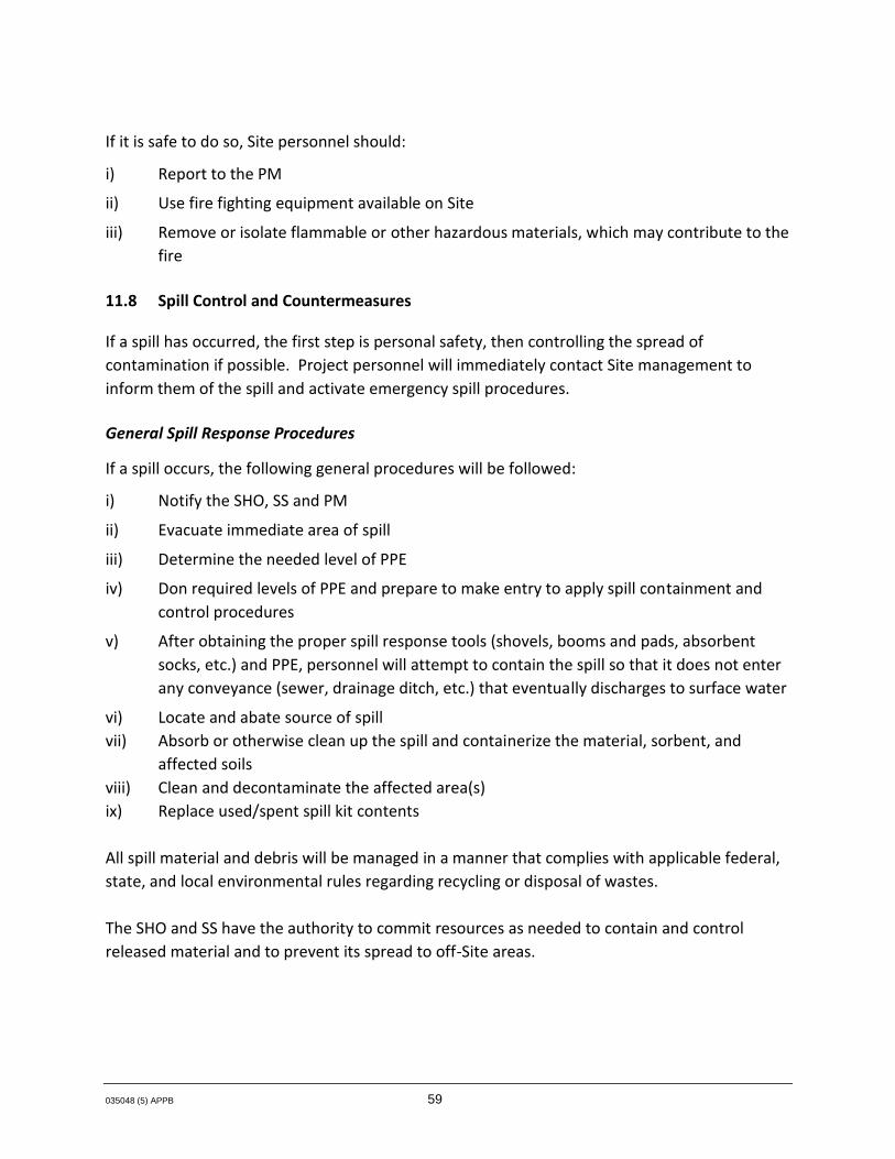
035048 (5) APPB 59
If it is safe to do so, Site personnel should:
i) Report to the PM
ii) Use fire fighting equipment available on Site
iii) Remove or isolate flammable or other hazardous materials, which may contribute to thefire
11.8 Spill Control and Countermeasures
If a spill has occurred, the first step is personal safety, then controlling the spread ofcontamination if possible. Project personnel will immediately contact Site management toinform them of the spill and activate emergency spill procedures.
General Spill Response Procedures
If a spill occurs, the following general procedures will be followed:
i) Notify the SHO, SS and PM
ii) Evacuate immediate area of spill
iii) Determine the needed level of PPE
iv) Don required levels of PPE and prepare to make entry to apply spill containment andcontrol procedures
v) After obtaining the proper spill response tools (shovels, booms and pads, absorbentsocks, etc.) and PPE, personnel will attempt to contain the spill so that it does not enterany conveyance (sewer, drainage ditch, etc.) that eventually discharges to surface water
vi) Locate and abate source of spillvii) Absorb or otherwise clean up the spill and containerize the material, sorbent, and
affected soilsviii) Clean and decontaminate the affected area(s)ix) Replace used/spent spill kit contents
All spill material and debris will be managed in a manner that complies with applicable federal,state, and local environmental rules regarding recycling or disposal of wastes.
The SHO and SS have the authority to commit resources as needed to contain and controlreleased material and to prevent its spread to off-Site areas.

035048 (5) APPB 60
12.0 Recordkeeping
The SHO shall establish and maintain records of all necessary and prudent monitoring activitiesas described below:
i) Name and job classification of the employees involved on specific tasks
ii) Records of fit testing and medical surveillance results for project personnel
iii) Records of all OSHA and other applicable safety training certifications for projectpersonnel
iv) Records of daily Site safety inspections
v) Records of training acknowledgment forms and daily safety meetings
vi) Emergency report sheets describing any incidents or accidents
vii) Air monitoring equipment calibrations
viii) Air monitoring data

035048 (5) APPB
FIGURES

SOURCE:USGS, USC&GS,TVA, NEW YORKQUADRANGLE, DATED 1953
0 7000ft3500
figure B11.1ROUTE TO THE HOSPITAL
OLD ERIE CANAL SITE
35048-01(005)GN-BU001 OCT 02/2014
1. HEAD NORTHWEST ON COLUMBIA ST. TOWARD REESE ST.2. TAKE THE 1ST RIGHT ONTO REESE ST.
4. TURN RIGHT ONTO N MAIN ST.5. TURN LEFT ONTO STUERWALD AVE.6. TAKE THE 1ST RIGHT ONTO DRIVING PARK AVE. 1200 DRIVING PARK AVE. WILL BE ON THE LEFT
SITE
HOSPITAL
3. TAKE THE 1ST LEFT ONTO NY-31 W/STATE HWY 31 W/ W GENESEE ST. CONTINUE TO FOLLOW NY-31 W/ STATE HWY 31 W

035048 (5) APPB
TABLES

Page 1 of 2
035048 (4)
OF THE CHEMICAL COMPOUNDS OF CONCERN
Compounds Maximum Detected Maximum DetectedConcentrations in Concentrations in
Groundwater Subsurface Soil andSoil in the Drainage
Swale (ug/L) (mg/kg)
VOC's1,1-Dichloroethylene 210 NDcis 1,2-Dichloroethylene 240,000 10Jtrans 1,2-Dichloroethylene 478J ND1,1,2-Trichloroethane 6.5J ND2-Butanone ND 0.15JAcetone ND .63JBenzene 23J NDChloroform 14 NDEthylbezene 360.0 NDMethylene Chloride 1200 0Napthlene 30J NDTetrachloroethene 17.3J NDToluene 24,900 4.3Trichloroethene 580,000J 130JVinyl Chloride 73,200 .56JXylenes (total) 1,600 ND
Semi-Volatiles 2-Methylphenol 13 ND4-Methylphenol 66 NDBenzo(a)anthracene ND 88JBenzo(a)pyrene ND 97JBenzo(b) Fluoranthene ND 130JBenzo(k) Fluoranthene ND 78JBis(2-ethylhexyl)Phthalate 9J NDChrysene ND 100JDibenzo(a, h)anthracene ND 16JFluoranthene ND 230Jindeno (1,2,3 cd) Pyrene ND 38JPhenol 5J NDPhenanthrene ND 120JPyrene ND 140J
TABLE B2.1
MAXIMUM DETECTED CONCENTRATION
OLD ERIE CANAL SITECLYDE, NEW YORK
IN GROUNDWATER, SOILS AND DRAINAGE SWALE SOILS

OF THE CHEMICAL COMPOUNDS OF CONCERN
Compounds Maximum Detected Maximum DetectedConcentrations in Concentrations in
Groundwater Subsurface Soil andSoil in the Drainage
Swale (ug/L) (mg/kg)
TABLE B2.1
MAXIMUM DETECTED CONCENTRATION
OLD ERIE CANAL SITECLYDE, NEW YORK
IN GROUNDWATER, SOILS AND DRAINAGE SWALE SOILS
Metals Antimony 3.6 NDArsenic ND 113JBarium ND 464JCadmium ND 85.7JChromium ND 209JCopper ND 609JIron 59500J NDLead ND 1,480Magnesium 110000J NDManganese 3970J 3230JMercury ND 0.889JNickel ND 78.7JSodium 568000 ND
Pesticides4,4'DDD ND 0.0584,4'DDE ND 0.0794,4'DDT ND 0.580
Key ND - Non Detect
J - Estimated ConcentrationE - Estimated / Above the Calibration Range

Page 1 of 4
035048 (5)
AcceptableIonization Exposure Exposure
Chemical Compound Potential Routes Levels in Air
MetalsAntimony NA Inhalation, Ingestion 0.5 mg/m3 (1) (2)
50 mg/m3 (3)
Arsenic NA Inhalation, Ingestion, 0.01 mg/m3 (1) (2)Human Carcinogen 10 mg/m3 (3)
Baruim NA Inhalation, Ingestion 0.05 mg/m3 (1) (2)50 mg/m3 (3)
Cadmium NA Inhalation, Ingestion, 0.01 mg/m3 (1) Suspected Human Carcinogen 0.005 mg/m3 (2)
9 mg/m3 (3)
Chromium NA Inhalation, Ingestion 0.5 mg/m3 (1) (2)25 mg/m3 (3)
Copper NA Inhalation, Ingestion 1 mg/m3 (1) (2)100 mg/m3 (3)
Iron NA Inhalation, Ingestion 5 mg/m3 (1)10 mg/m3 (2)
2500 mg/m3 (3)
Lead NA Inhalation, Ingestion, 0.05 mg/m3 (1) (2)Animal Carcinogen 100 mg/m3 (3)
Magnesium NA Inhalation, Ingestion NE
Manganese NA Inhalation, Ingestion 0.2 mg/m3 (1)500 mg/m3 (3)
Mercury NA Inhalation, Ingestion, 0.025 mg/m3 (1)Skin Absorption 10 mg/m3 (3)
Nickel NA Inhalation, Ingestion 1.5 mg/m3 (1)
EXPOSURE ROUTES AND EXPOSURE LEVELS FOR THE
TABLE B2.2
CLYDE, NEW YORKOLD ERIE CANAL SITE
CHEMICAL COMPOUNDS OF CONCERN

Page 2 of 4
035048 (5)
AcceptableIonization Exposure Exposure
Chemical Compound Potential Routes Levels in Air
EXPOSURE ROUTES AND EXPOSURE LEVELS FOR THE
TABLE B2.2
CLYDE, NEW YORKOLD ERIE CANAL SITE
CHEMICAL COMPOUNDS OF CONCERN
1 mg/m3 (2)10 mg/m3 (3)
Sodium NA Inhalation, Ingestion NE
Semi-Volatiles2-Methylphenol NI Inhalation, Ingestion 22 mg/m3 (1) (2)
Skin Absorption
4-Methylphenol NI Inhalation, Ingestion 22 mg/m3 (1) (2)Skin Absorption
Benzo(a)anthracene NA Inhalation, Ingestion NE
Benzo(a)pyrene NA Inhalation, Ingestion, 0.2 mg/m3 (2)Suspected Human Carcinogen
Benzo(b) Fluoranthene NA Inhalation, Ingestion 0.2 mg/m3 (2)
Benzo(k) Fluoranthene NA Inhalation, Ingestion NE
Bis(2-ethylhexyl) phthalate NA Inhalation, Ingestion NE
Chrysene NA Inhalation, Ingestion, 0.2 mg/m3 (1) (2)Human Carcinogen 80 mg/m3 (3)
Dibenzo(a, h) Anthracene NA Inhalation, Ingestion NE
Fluoranthene NA Inhalation, Ingestion NE
indeno (1,2,3 cd) Pyrene NA Inhalation, Ingestion NE
Phenol 8.69 Inhalation, Ingestion 19 mg/m3 (1) (2)Skin Absorption 250 mg/m3 (3)
Phenanthrene NA Inhalation, Ingestion, NESuspected Human Carcinogen

Page 3 of 4
035048 (5)
AcceptableIonization Exposure Exposure
Chemical Compound Potential Routes Levels in Air
EXPOSURE ROUTES AND EXPOSURE LEVELS FOR THE
TABLE B2.2
CLYDE, NEW YORKOLD ERIE CANAL SITE
CHEMICAL COMPOUNDS OF CONCERN
Pyrene NA Inhalation, Ingestion NE
VOCs1,1-Dichloroethylene 10.8 Inhalation, Ingestion 5 ppm(1)
cis 1,2-Dichloroethylene 9.8 Inhalation, Ingestion, 200 ppm (1)and trans 200 ppm (2)
1000 ppm (3)
1,1,2-Trichloroethane 11 Inhalation, Ingestion 10 ppm(1)Skin Absorption 10 ppm(2)
100 ppm(3)
9.54 Inhalation, Ingestion 200 ppm (1) (2) (Methyl Ethyl Ketone) 3000 ppm (3)
Acetone 9.69 Inhalation, Ingestion 500 ppm (1)1000 ppm (2)2500 ppm (3)
Benzene 9.2 Inhalation, Ingestion, 0.5 ppm (1)Skin Absorption, Human Carcinogen 1 ppm (2)
500 ppm (3)
Chloroform 11.37 Inhalation, Ingestion, Skin 10 ppm (1)Absorption, Animal Carcinogen 50 ppm (ceiling)
500 ppm (3)
Ethylbenzene 8.8 Inhalation, Ingestion 100 ppm (1) (2)800 ppm (3)
Methylene Chloride 11.3 Inhalation, Ingestion, 50 ppm (1)Animal Carcinogen 25 ppm (2)
2300 ppm (3)
Naphthalene 8.12 Inhalation, Ingestion 10 ppm (1) (2)250 ppm (3)
Tetrachloroethene 9.32 Inhalation, Ingestion, 25 ppm (1)
2-Butanone

Page 4 of 4
035048 (5)
AcceptableIonization Exposure Exposure
Chemical Compound Potential Routes Levels in Air
EXPOSURE ROUTES AND EXPOSURE LEVELS FOR THE
TABLE B2.2
CLYDE, NEW YORKOLD ERIE CANAL SITE
CHEMICAL COMPOUNDS OF CONCERN
50 ppm (2)150 ppm (3)
Toluene 8.8 Inhalation, Ingestion, 50 ppm (1)Skin Absorption 200 ppm (2)
500 ppm (3)
Trichloroethene 9.5 Inhalation, Ingestion 50 ppm (1)100 ppm (2)
1000 ppm (3)
Vinyl Chloride 9.99 Inhalation, Ingestion, 1 ppm (1) (2)Suspected Human Carcinogen
Xylenes 8.5 Inhalation, Ingestion 100 ppm (1) (2) 900 ppm (3)
Notes:(1) 2014 Values, American Conference of Governmental Industrial Hygienists (ACGIH)
Threshold Limit Values (TLVs).(2) Federal Occupational Safety and Health Administration (OSHA) Permissible Exposure Limit (PEL).(3) Immediately Dangerous to Life and Health (IDLH).ppm Parts Per Million.mg/m3 Milligrams per Cubic Meter.NA Not Applicable.NE Not Established.

Page 1 of 1
035048 (5)
TABLE B.8.1
ON-SITE AIR MONITORING PROGRAM ACTION LEVELSOLD ERIE CANAL SITE
CLYDE, NEW YORK
Monitoring Device Action Level Action
Combustible Gas Indicator >10 Percent LEL Cease operations and move to a safe place.Notify CSHO. Do not continue workinguntil conditions are constantly below10 percent LEL.
Oxygen Meter <19.5 Percent or >23.5 Percent Cease operations and move to a safe place.Notify CSHO. Do not continue workinguntil oxygen levels are between19.5 and 23.5 percent.
Note: When oxygen levels are outsidethis range, percent LEL readingsare not reliable.
11.7 or greater eV lamp < 1.0 ppm or Background Full-Face Respirator Available
> 1.0 ppm and < 50 ppm Full-face air purifying respiratorLevel C PPE
>50 ppm and < 500 ppm Supplied air respirator Level B PPE.Implement additional engineering controls
> 500 ppm Shut down activities. Notify CSHO.Implement additional engineering controls
< 5.0 mg/m³ (respirable fraction) Full-Face Respirator Available
> 5.0 mg/m³ Wear Full-Face Respirator - Level C PPE
Carbon Monoxide >35 ppm Shut down activities. Notify CSHO. Implement additional engineeringcontrols
Notes:
CSHO Contractor Safety and Health OfficerLEL Lower Explosive Limit.PPE Personal Protection Equipment.ppm Parts Per Million.
Dust / Particulate - (Impacted Soils) (for worker protection)
Note: Due to the presence of certain chemical compounds at the Site that have poor warning properties, the action levels are subject to change based on results of air sampling that will be conducted and the potential use of colorimetric tubes.
Photoionization Detector (PID)

035048 (5) APPB
ATTACHMENT A
JOB SAFETY ANALYSIS (JSA) FORMS

JOB SAFETY ANALYSIS (JSA)
OVERSIGHT OF CONSTRUCTION ACTIVITIES
035048 (5) JSA Oversight of Construction Activities 1 of 3
Field staff must review job-specific work plan and coordinate with project manager to verify that all up-front logistics are completed prior to starting work including, but not limited to, permitting, access agreements, and notification to required contacts (e.g., site managers, inspectors, clients, subcontractors, etc.). Additionally, a tailgate safety meeting must be performed and documented at the beginning of each workday. Stop, Think, Act, Review (STAR) must be used prior to any activity. All personnel must possess the appropriate training prior to initiating scheduled tasks. Also consider weather conditions. All project personnel have the authority and responsibility to use Stop Work Authority (SWA).
Date Issued/Revised October 2014 JSA Type Oversight of Construction Activities
Work Type Construction Client
Work Activity Oversight of Construction Activities
Work Site The Old Erie Canal Site Clyde, New York
Key Equipment NA
Task-specific Training Safety Introduction/Briefing, 40-HR (initial) and 8-HR Refresher HAZWOPER training, Hazard Communication Training, Personal Protective Equipment, Confined Space Entry, Mobil Equipment Safety Awareness training and Fall Protection training
MINIMUM REQUIRED PERSONAL PROTECTIVE EQUIPMENT (see job steps for task-specific requirements)
Reflective Vest Goggles Gloves* Supplied Air APR Hard Hat Face Shield* Coveralls* SCBA Full Face APR Particulate Organic Vapor Lifeline/Harness* Hearing Protection* PPE Clothing* Airline Respirator (attach description) Half Mask APR Particulate/Organic Vapor Combined Safety Glasses Safety-toed Boots Acid Gas
Other* Personal Fall Arrest Equipment as may be required Other* Air Monitoring Equipment (LEL/O2 and a PID) Other*
ADDITIONAL PPE (*provide specific type(s) or descriptions of this item below) Reflective Vest -Class II Air Monitoring Equipment to be provided by the contractor
Gloves – Leather Lifeline/Harness (Personal Fall Arrest Equipment) – As required by OSHA’s Fall Protection Standard
Development Team Position/Title Reviewed By Position/Title Date

JOB SAFETY ANALYSIS (JSA)
OVERSIGHT OF CONSTRUCTION ACTIVITIES
035048 (5) JSA Oversight of Construction Activities 2 of 3
Job Steps(1) Task Activity Potential Hazard(s)(2) Corrective Measure(s)(3) Person Responsible
1 • Discuss STAR (Stop Think Act & Review) and Stop Work Authority (SWA)
• Near Loss, Injury, and even Death
• Identify any hazards. Modify the JSA accordingly. Discuss the task and expectations of the task to all personnel. Have all applicable personnel sign off on this JSA prior to starting work.
• Project team to discuss the importance of and documentation procedures for SWA during pre-job safety meeting. Use SWA to stop any work that is unsafe.
Site Representative
2 • General inspection of contractor’s work activities
• Slip/Trip/Falls • Injury from Heat/Cold
Stress or Inclement Weather
• Working From Elevated Heights Greater Than 6 Feet
• Noise • Biological Hazards • Lifting Heavy Objects • Exposure to Vehicular
traffic and Heavy Equipment
• Potential Hazards in Excavations including potential falls, being trapped, changing conditions (i.e., water accumulation, changing atmospheric hazards, communication issues etc.)
• Failure to identify and remove all hazards including atmospheric hazards, water, electrical, biological and items falling into the confined space from above
• Electrical hazards and potential physical injury from exposure to hazardous energy (i.e., hydraulic, pneumatic etc.)
• Walk work area first, especially when view of ground surface is covered. • Keep area free of excess materials and debris. • Remove all travel path hazards by keeping materials/objects organized and out of
walkways. • Note and communicate areas of slick or uneven ground. • Take breaks as needed by monitoring the Daily Heat Index, as outlined in the HASP • Consume adequate food/beverages. Personnel should consume at least 8 ounces of cool
water or electrolyte replacement drinks every 20-30 minutes. • Observe work-rest schedule to manage heat/cold stresses • When warranted, stay alert for rain, lightning, and high wind hazards, perform work in such
weather as outlined in the HASP. • Fall protection is required when working adjacent to work areas are 6 ft. or greater • Do not stand directly next to open excavations > 6-ft. without fall protection • Access ladders must be available to enter into and out of any excavation • Perform pre-entry air monitoring to verify acceptable conditions • Complete and Sign off on the Confined Space Entry Permit when required • Perform continuous air monitoring while the inspector is in any confined space • Remain vigilant and maintain communications between the Attendant and the Entrant • Use a powerful flashlight to provide adequate light • Attendant is not to leave the opening at the Confined Space. • The Attendant will maintain a cell phone and keep it available during the inspection
activities. • Keep supplies away from the edge of the opening for any confined space. • Hearing protection required when working within 20’ of operating equipment or units, if
levels are suspected to be >85 dBA, or for personal comfort. • Determine that object is within weight limit. • Check for contact hazards such as other boxes/objects in the vicinity as well as other
people/equipment in the area. Check there is ample room to squat, lift, turn, or maneuver without twisting the back or other muscles or joints.
• Check travel path for, and remove, slip hazards such as tools puddles, and debris. • Wear Reflective Safety Vest in areas near moving traffic and operating equipment • Maintain eye contact with equipment operators and do not walk into their path unless the
operator motions for you to move. • Review any applicable energy control procedures as necessary. • Perform Lock Out/Tag Out (LOTO) as necessary. • Close/turn off appropriate valves and switches.
Site Representative
(1) Each Job or Task consists of a set of steps. Be sure to list all the steps in the sequence that they are performed. Specify the equipment or other details to set the basis for the potential
(associated) hazards.

JOB SAFETY ANALYSIS (JSA)
OVERSIGHT OF CONSTRUCTION ACTIVITIES
035048 (5) JSA Oversight of Construction Activities 3 of 3
(2) A hazard is a potential danger. What can go wrong? How can someone get hurt? Consider, but do not limit, the analysis to: Contact - victim is struck by or strikes an object; Caught - victim is caught on, caught in or caught between objects; Fall - victim falls to ground or lower level (includes slips and trips); Exertion - excessive strain or stress/ergonomics/lifting techniques; Exposure - inhalation/skin hazards. Specify the hazards and do not limit the description to a single word such as "Caught".
(3) Aligning with the Job Steps, Task Activity Description, and Potential Hazard columns, describe what actions or procedures are necessary to eliminate or minimize the hazards. Be clear, concise and specific. Use objective, observable, and quantified terms. Avoid subjective general statements such as "be careful" or "use as appropriate".

JOB SAFETY ANALYSIS (JSA)
Boating Safety
035048 (5) 035048 (5) APPB-ATTA-JSA-Boating Safety 1 of 3
Field staff must review job-specific work plan and coordinate with project manager to verify that all up-front logistics are completed prior to starting work including, but not limited to, permitting, access agreements, and notification to required contacts (e.g., site managers, inspectors, clients, subcontractors, etc.). Additionally, a tailgate safety meeting must be performed and documented at the beginning of each workday. Stop, Think, Act, Review (STAR) must be used prior to any activity. All personnel must possess the appropriate training prior to initiating scheduled tasks. Also consider weather conditions. All project personnel have the authority and responsibility to use Stop Work Authority (SWA).
Date Issued/Revised: October 2014 JSA Type: Boating Safety
Work Type: Environmental Client:
Work Activity: Surface Water Sampling
Work Site: The Old Erie Canal Site Clyde, New York
Key Equipment: Boat
Task-specific Training: Towing and Trailering, Boating Safety and PPE
MINIMUM REQUIRED PERSONAL PROTECTIVE EQUIPMENT (see job steps for task-specific requirements)
Reflective Vest Goggles Gloves* Supplied Air APR Hard Hat Face Shield* Coveralls* SCBA Full Face APR Particulate Organic Vapor Lifeline/Harness* Hearing Protection* PPE Clothing* Airline Respirator (attach description) Half Mask APR Particulate/Organic Vapor Combined Safety Glasses Safety-toed Boots Acid Gas
Other* CSA approved Life Jacket or PFD Other* Other*
ADDITIONAL PPE (*provide specific type(s) or descriptions of this item below) Sunglasses; sunscreen
Personal Flotation Device
Project Development Team Position/Title Modified By Reviewed By Position/Title Date
Name

JOB SAFETY ANALYSIS (JSA)
Boating Safety
035048 (5) 035048 (5) APPB-ATTA-JSA-Boating Safety 2 of 3
Job Steps(1) Task Activity Potential Hazard(s)(2) Corrective Measure(s)(3) Person Responsible
1 Perform the STAR Process (Stop Think Act Review) and discuss Stop Work Authority (SWA)
• Slips, trips, falls; • Situational risks; • Use STAR;
• Ensure that the project team understands and discusses the STAR process and SWA and the importance of using them
• Verify that project personnel have all of the required training. • Provide any additional hands on training as may be necessary • Maintain neutral posture; refer to the HASP for additional lifting information • Take breaks; stay hydrated; be able to recognize the signs of heat stress in
yourself and others; wear sunscreen as may be necessary
Technicians
2 Mob equipment to boat launch
• Overloading boat capacity • Inclement weather • Potential to encounter a bull that may
be running loose in a farmer’s field • Lifting hazards • Manual material handling • Back injury • Pinch points • Moving or flying projectiles inside
vehicle while transporting equipment • Slip/trip/fall hazards • Fuel spill • Biological Hazards
• Review boat capacity and complete weight survey including personnel and gear • Monitor weather forecasts • Distribute the load evenly on the boat • Make sure grip is adequate; wear leather/cotton gloves • Heightened awareness of wasps, ants, bees, spiders, and poison plants • Stretch affected muscles (triceps, back, neck, and shoulder) prior to/during/after
activity • Avoid repetitive motions and overhead lifts; use proper lifting techniques • Size up the load; if the object is too large or odd shaped OR is in excess of
50 pounds then assistance (mechanical or a buddy lift) will be required • Use a two-person lift or mechanical assistance for handling objects in excess of
50 pounds • Ensure all equipment is properly secured during transport • Lift with the legs (bend at the knees and use the leg muscles) to protect the lower
back and keep lower back in a neutral position • Avoid one-handed carrying if possible; maintain awareness of footing • Refuel in appropriate location, no sparks or static buildup • Practice STAR • Maintain neutral posture; refer to the HASP for additional lifting information • Take breaks; stay hydrated; be able to recognize the signs of heat stress in
yourself and others; wear sunscreen as may be necessary
Technicians
3 Launch boat • Lifting hazards • Manual material handling • Back injury • Pinch points • Moving or flying projectiles inside
vehicle while transporting equipment • Slip/trip/fall hazards • Fuel spill • Drowning
• Practice STAR • Make sure grip is adequate; wear leather/cotton gloves • Size up the load; if the object is too large or odd shaped OR is in excess of
50 pounds then assistance (mechanical or a buddy lift) will be required • Lift with the legs (bend at the knees and use the leg muscles) to protect the lower
back and keep lower back in a neutral position • Avoid one-handed carrying if possible; maintain awareness of footing • Review JSA for proper fuelling • Wear the PPE that is identified in this JSA along with a PFD • Bring boating safety kit
Technicians
4 Navigate boat to the sampling site
• Causing unnecessary wake • Running aground • Disturbing others • Drowning
• Practice STAR • Wear the PPE that is identified in this JSA along with a PFD • Bring boating safety kit • Remain seated • Keep an eye out for changing weather
Technicians

JOB SAFETY ANALYSIS (JSA)
Boating Safety
035048 (5) 035048 (5) APPB-ATTA-JSA-Boating Safety 3 of 3
5 Perform sampling activities
• Tipping boat • Wet equipment • Drowning
• Remain seated when operating; If the boat tips over, remain with the boat • Keep equipment dry by storing in waterproof storage containers during transport • Be aware of surroundings, verify water depth in shallow waters • Wear the PPE that is identified in this JSA along with a PFD
Technicians
(1) Each Job or Task consists of a set of steps. Be sure to list all the steps in the sequence that they are performed. Specify the equipment or other details to set the basis for the potential
(associated) hazards. (2) A hazard is a potential danger. What can go wrong? How can someone get hurt? Consider, but do not limit, the analysis to: Contact - victim is struck by or strikes an object; Caught - victim is
caught on, caught in or caught between objects; Fall - victim falls to ground or lower level (includes slips and trips); Exertion - excessive strain or stress/ergonomics/lifting techniques; Exposure - inhalation/skin hazards. Specify the hazards and do not limit the description to a single word such as "Caught".
(3) Aligning with the Job Steps, Task Activity Description, and Potential Hazard columns, describe what actions or procedures are necessary to eliminate or minimize the hazards. Be clear, concise and specific. Use objective, observable, and quantified terms. Avoid subjective general statements such as "be careful" or "use as appropriate".

JOB SAFETY ANALYSIS (JSA)
Bolting Pipe and Valve Activities
035048 (5) JSA Bolting Pipe and Valve Activities 1
Field staff must review job-specific work plan and coordinate with project manager to verify that all up-front logistics are completed prior to starting work including, but not limited to, permitting, access agreements and notification to required contacts (e.g., site managers, inspectors, clients, subcontractors, etc.). Additionally, a tailgate safety meeting must be performed and documented at the beginning of each workday. Stop, Think, Act, Review (STAR) must be used prior to any activity. All personnel must possess the appropriate training prior to initiating scheduled tasks. Also consider weather conditions. All project personnel have the authority and responsibility to use Stop Work Authority.
Date Issued/Revised October 2014 JSA Type Bolting Pipe and Valve Activities
Work Type Construction Client
Work Activity Bolting Pipe & Valves
Work Site The Old Erie Canal Site Clyde, New York
Key Equipment Hand Tools
Task-specific Training 40 HR and 8 HR HAZWOPER, PPE, Hand & Power Tool Safety, PPE
MINIMUM REQUIRED PERSONAL PROTECTIVE EQUIPMENT (SEE JOB STEPS FOR TASK-SPECIFIC REQUIREMENTS)
REFLECTIVE VEST* GOGGLES APR: ________________* GLOVES*
HARD HAT FACE SHIELD* SUPPLIED AIR RESPIRATOR* COVERALLS*
LIFELINE / HARNESS* HEARING PROTECTION* PPE CLOTHING* OTHER*
SAFETY GLASSES STEEL TOED BOOTS OTHER* _____________________________ OTHER* ____________________________
ADDITIONAL PPE: * Provide specific type(s) or descriptions of this item below
Reflective Vest - Class II
Gloves - Leather
Development Team Position/Title Reviewed By Position/Title Date

JOB SAFETY ANALYSIS (JSA)
Bolting Pipe and Valve Activities
035048 (5) JSA Bolting Pipe and Valve Activities 2
JOB STEPS (1) TASK ACTIVITY POTENTIAL HAZARD(S) (2) CORRECTIVE MEASURE(S)(3) Person Responsible 1 Discuss STAR and SWA • Site personnel not aware
of STAR and SWA • Project team to discuss the importance of and documentation
procedures for SWA during pre-job safety meeting • Use SWA to stop any work that is unsafe
Construction personnel
2 Assess work area • Uneven ground • Overhead obstruction • Slip/trip/fall hazards
• Level ground if required • Place signs indicating overhead obstructions; use marking tape to
identify hazards within close proximity • Police and remove any item for potential slip/trip/fall
Construction personnel
3 Gather tools and materials • Lifting hazards • Back injury • Manual material handling • Heavy equipment • Hoisting lifting
• Make sure grip is adequate. Wear leather/cotton gloves. • Size up the load; if the object is too large or odd shaped OR is in excess
of 50 pounds then assistance (mechanical or a buddy lift) will be required
• Lift with the legs (bend at the knees and use the leg muscles) to protect the lower back and keep lower back in a neutral position
• Avoid one-handed carrying if possible; maintain awareness of footing • Refer to HASP for further lifting techniques • Watch for tool/material carrier; make eye contact with operator before
approaching • Use straps and shackles that have been inspected for hoisting/lifting and
carrying • Stay clear of loads • Use tag lines to minimize swing
Construction personnel
4 Alignment • Hoisting/lifting • Splinters • Pinch points • Back injury • Manual material handling
• Refer to step 3 and the HASP for additional lifting information • Watch for lifting equipment; make eye contact with operator before
approaching • Use straps and shackles that have been inspected • Wear leather gloves for placement of skids • Use tools to align joints; keep fingers and hands from between joints
Construction personnel
5 Connection • Cuts • Attention to work
• Wear leather gloves to prevent cuts form burrs on nuts and bolts • Keep tools within reach or on person • Use appropriate tools
Construction personnel
6 Clean up work area • Slip/trip/fall hazards • Police area for unused material; pick up and place in storage area Construction personnel
¹ Each Job or Task consists of a set of steps. Be sure to list all the steps in the sequence that they are performed. Specify the equipment or other details to set the basis for the potential (associated) hazards. ² A hazard is a potential danger. What can go wrong? How can someone get hurt? Consider, but do not limit, the analysis to: Contact - victim is struck by or strikes an object; Caught - victim is caught on, caught in or caught between objects; Fall - victim falls to ground or lower level (includes slips and trips); Exertion - excessive strain or stress / ergonomics / lifting techniques; Exposure - inhalation/skin hazards. Specify the hazards and do not limit the description to a single word such as "Caught" ³ Aligning with the Job Steps, Task Activity Description, and Potential Hazard columns, describe what actions or procedures are necessary to eliminate or minimize the hazards. Be clear, concise and specific. Use objective, observable and quantified terms. Avoid subjective general statements such as, "be careful" or "use as appropriate".

Job Safety Analysis (JSA) CLEARING ACTIVITIES - BULLDOZER
035048 (5) JSA Clearing Activities – Bulldozer 1 of 2
Field staff must review job-specific work plan and coordinate with project manager to verify that all up-front logistics are completed prior to starting work including, but not limited to, permitting, access agreements, and notification to required contacts (e.g., site managers, inspectors, clients, subcontractors, etc.). Additionally, a tailgate safety meeting must be performed and documented at the beginning of each workday. Stop, Think, Act, Review (STAR) must be used prior to any activity. All personnel must possess the appropriate training prior to initiating scheduled tasks. Also consider weather conditions. All project personnel have the authority and responsibility to use Stop Work Authority (SWA).
Date Issued/Revised October 2014 JSA Type Clearing Activities – Bulldozer
Work Type Construction Client
Work Activity Clearing Activities – Bulldozer
Work Site The Old Erie Canal Site Clyde, New York
Key Equipment Bulldozer
Task-specific Training 40 HR and 8 HR HAZWOPER, PPE and Mobile Equipment Operations
MINIMUM REQUIRED PERSONAL PROTECTIVE EQUIPMENT (see job steps for task-specific requirements)
Reflective Vest Goggles Gloves* Supplied Air APR Hard Hat Face Shield* Coveralls* SCBA Full Face APR Particulate Organic Vapor Lifeline/Harness* Hearing Protection* PPE Clothing* Airline Respirator (attach description) Half Mask APR Particulate/Organic Vapor Combined Safety Glasses Safety-toed Boots Acid Gas
Other* Other* Other*
ADDITIONAL PPE (*provide specific type(s) or descriptions of this item below) Gloves - Leather
Reviewed By Position/Title Date Reviewed By Position/Title Date

Job Safety Analysis (JSA) CLEARING ACTIVITIES - BULLDOZER
035048 (5) JSA Clearing Activities – Bulldozer 2 of 2
Job Steps(1) Task Activity Potential Hazard(s)(2) Corrective Measure(s)(3) Person Responsible
1 Perform the STAR Process (Stop Think Act Review) and discuss Stop Work Authority (SWA) -
• Slips, trips, falls; • Situational risks - use STAR;
• Verify that personnel training is sufficient for scheduled task(s). Is Job Instruction (hands-on) Training necessary?
All Project Personnel
2 Inspect heavy equipment and PPE • Equipment failure; • PPE failure; • Slip/trip/fall hazards; • Pinch points; • Hot surfaces; • Fuel (fire hazard)
• Don all necessary PPE: o Hearing protection o Hard hat o Safety boots
• Training on inspection procedures • Inspect travel path for weather related hazards (i.e., wet,
puddles, mud, obstacles); • Use three points of contact; do not jump off of equipment; • Equipment must pass inspection prior to operation. If not,
remove from service until repaired and report problem(s) to supervisor;
Bulldozer Operator and Laborer
3 Completion of daily inspection report while inspecting machine
• Equipment problems • PPE failure
• Don all necessary PPE • Trained on inspection procedures
Bulldozer Operator
4 Transporting equipment to the work area
• Backing into or running over objects • Walk around the equipment or use a spotter when necessary Bulldozer Operator
5 Clearing Activities -Operating equipment after making sure area is cleared of all unnecessary personnel; pulling out stuck equipment
• Cable or shackle breaks (becomes a flying projectile)
• Bulldozer becomes stuck • Cuts • Pinched fingers/limbs • Struck by flying objects or falling trees
• Don all necessary PPE • After hooking up cables, let all personnel retreat to a safe
area • Inspect cables and shackles before hooking up each time • Use a qualified operator
Bulldozer Operator and Laborer
6 Shutdown and exiting of equipment • Slip/trip/fall hazards • Situational risks
• Keep the blade on the ground when the machine is not running
• Maintain three points of contact when entering or exiting
Bulldozer Operator
(1) Each Job or Task consists of a set of steps. Be sure to list all the steps in the sequence that they are performed. Specify the equipment or other details to set the basis for the potential
(associated) hazards. (2) A hazard is a potential danger. What can go wrong? How can someone get hurt? Consider, but do not limit, the analysis to: Contact - victim is struck by or strikes an object; Caught - victim is
caught on, caught in or caught between objects; Fall - victim falls to ground or lower level (includes slips and trips); Exertion - excessive strain or stress/ergonomics/lifting techniques; Exposure - inhalation/skin hazards. Specify the hazards and do not limit the description to a single word such as "Caught".
(3) Aligning with the Job Steps, Task Activity Description, and Potential Hazard columns, describe what actions or procedures are necessary to eliminate or minimize the hazards. Be clear, concise and specific. Use objective, observable, and quantified terms. Avoid subjective general statements such as "be careful" or "use as appropriate".

Job Safety Analysis (JSA)
ENHANCED BIODEGRADATION PRODUCT MIXING, STORAGE AND INJECTION ACTIVITIES
035048 (5) APPB-ATTA-JSA-Enhanced Biodegradation Product Mixing, Storage and Injection Activities Activities 1 of 3
Field staff must review job-specific work plan and coordinate with project manager to verify that all up-front logistics are completed prior to starting work including, but not limited to, permitting, access agreements, and notification to required contacts (e.g., site managers, inspectors, clients, subcontractors, etc.). Additionally, a tailgate safety meeting must be performed and documented at the beginning of each workday. Stop, Think, Act, Review (STAR) must be used prior to any activity. All personnel must possess the appropriate training prior to initiating scheduled tasks. Also consider weather conditions. All project personnel have the authority and responsibility to use Stop Work Authority (SWA).
Date Issued/Revised October 2014 JSA Type Enhanced Biodegradation Product Mixing, Storage and injection Activities
Work Type Remediation Client
Work Activity Enhanced Biodegradation Product Mixing, Storage and injection Activities
Work Site The Old Erie Canal Site
Key Equipment Hand and Power Tools
Task-specific Training 40 HR and 8 HR HAZWOPER, PPE, Mobile Equipment Operations, Hearing Conservation and Hazard Communication
MINIMUM REQUIRED PERSONAL PROTECTIVE EQUIPMENT (SEE JOB STEPS FOR TASK-SPECIFIC REQUIREMENTS)
REFLECTIVE VEST* GOGGLES APR: Full Face/Particulate Crtdgs* GLOVES*
HARD HAT FACE SHIELD* SUPPLIED AIR RESPIRATOR* COVERALLS*
LIFELINE / HARNESS* HEARING PROTECTION* PPE CLOTHING* OTHER*
SAFETY GLASSES STEEL TOED BOOTS OTHER* _____________________________ OTHER* ____________________________
ADDITIONAL PPE: * Provide specific type(s) or descriptions of this item below
Reflective Vest - Class II Face Shield – Full Face Shield
Gloves - Leather for moving equipment, Nitrile when handling chemical solution
Development Team Position/Title Reviewed By Position/Title Date

Job Safety Analysis (JSA)
ENHANCED BIODEGRADATION PRODUCT MIXING, STORAGE AND INJECTION ACTIVITIES
035048 (5) APPB-ATTA-JSA-Enhanced Biodegradation Product Mixing, Storage and Injection Activities Activities 2 of 3
Job Steps(1)
Task Activity Potential Hazard(s)(2) Corrective Measure(s)(3) Person Responsible
1 Discuss STAR (Stop Think Act & Review) and Stop Work Authority (SWA)
• Site personnel not aware of STAR & SWA
• Project team to discuss the importance of and documentation procedures for SWA during pre-job safety meeting. Use SWA to stop any work that is unsafe.
Technicians
2 Storage of dry biodegradation product
• Slip/trip/fall hazard when placing 5-gallon pails of product in temporary storage boxes or other lined storage pads
• Lifting hazards • Manual material
handling • Back injury • Incompatibility with other
chemicals • Release to environment
and human exposure
• Inspect work areas before access for obstructions, moisture, and clear pathways • Pick up pails of product and position them for storage • Line storage area with durable plastic sheeting with upturned sides to contain potential
releases • Carefully step into plastic lined area, and do not carry pails across threshold without both
feet on the plastic and stable • Keep containers of product closed when not in use • Initiate in Level D with leather gloves • Make sure grip is adequate; Use gloves to enhance grip when necessary • Size up the load; if the object is too large or odd shaped OR is in excess of 50 pounds then
assistance (mechanical or a buddy lift) will be required • Lift no more than one pail of product at a time and keep it close to your body • Carry with two hands in front of you to avoid back stress, or get assistance • Lift pail to carrying position using heavy lifting techniques, keeping back vertical and straight,
lifting with leg muscles as opposed to back muscles • Refer to the HASP for additional lifting information • Store in cool, dry, ventilated location away from greases, oils, heat, or ignition sources • Do not store in close proximity to water, acids, organics • Do not store on or near wood, metal salts, peroxides, or reducing agents
Technicians
3 Preparation of solution from dry product and decontamination of equipment, personnel, and soil
• Slip/trip/fall hazard when placing 5-gallon pails of product in temporary storage area
• Lifting hazards • Manual material
handling • Back injury • Incompatibility with other
chemicals • Release to environment
and human exposure
• Inspect work areas before access for obstructions, moisture, and clear pathways • Area used for liquid solution preparation must be lined with plastic sheeting to prevent
spillage onto soil • Carefully step into plastic lined area, and do not carry pails across threshold without both
feet on the plastic and stable • Initiate in Level D with leather gloves • Refer to step 1 and the HASP for additional lifting information • Keep 5-gallon pails of the product tightly closed when not opened for mixing • Do not open containers of product or preparing liquid solution in windy conditions • When opening containers, ensure all personnel within 25 feet of mixing activity are wearing
a full face shield or Level C PPE if determined necessary and are ready to work • Open no more than one 5-gallon pail at a time • Wear a full face shield or Level C protection when mixing or adding more product. When
handling dry product, wear nitrile gloves,Tyvek® coveralls, and full-face respirator • After being mixed into solution, close container and revert to Modified Level D. • Allow no more than one person in product mixing area if possible.
Technicians

Job Safety Analysis (JSA)
ENHANCED BIODEGRADATION PRODUCT MIXING, STORAGE AND INJECTION ACTIVITIES
035048 (5) APPB-ATTA-JSA-Enhanced Biodegradation Product Mixing, Storage and Injection Activities Activities 3 of 3
Job Steps(1)
Task Activity Potential Hazard(s)(2) Corrective Measure(s)(3) Person Responsible
4 Injection of solution into subsurface
• Pressurized line rupture, spillage
• Disconnection drips and associated releases
• All personnel within proximity (50 feet) of pumps, lines, rig, drill-string and probe should wear Modified Level D PPE including a full-face splash shields, polycoated Tyvek® coveralls over boots and nitrile gloves
• Depressurize and bleed lines to buckets before depressurizing injection system • Stop injection if excessive pressure (>25 psi) is experienced or releases are evident, or if
any other unusual condition is observed • Inspect all fittings and lines from solution batch tank to drill-string probe prior to use
Technicians
(1) Each Job or Task consists of a set of steps. Be sure to list all the steps in the sequence that they are performed. Specify the equipment or other details to set the basis for the potential
(associated) hazards. (2) A hazard is a potential danger. What can go wrong? How can someone get hurt? Consider, but do not limit, the analysis to: Contact - victim is struck by or strikes an object; Caught - victim is
caught on, caught in or caught between objects; Fall - victim falls to ground or lower level (includes slips and trips); Exertion - excessive strain or stress/ergonomics/lifting techniques; Exposure - inhalation/skin hazards. Specify the hazards and do not limit the description to a single word such as "Caught".
(3) Aligning with the Job Steps, Task Activity Description, and Potential Hazard columns, describe what actions or procedures are necessary to eliminate or minimize the hazards. Be clear, concise and specific. Use objective, observable, and quantified terms. Avoid subjective general statements such as "be careful" or "use as appropriate".

Job Safety Analysis (JSA)
EQUIPMENT FUELING ACTIVITIES
035048 (5) JSA 035048 (5) APPB-ATTA-JSA-Equipment FuelingActivities 1 of 2
Field staff must review job-specific work plan and coordinate with project manager to verify that all up-front logistics are completed prior to starting work including, but not limited to, permitting, access agreements and notification to required contacts (e.g., site managers, inspectors, clients, subcontractors, etc.). Additionally, a tailgate safety meeting must be performed and documented at the beginning of each workday. Stop, Think, Act, Review (STAR) must be used prior to any activity. All personnel must possess the appropriate training prior to initiating scheduled tasks. Also consider weather conditions. All project personnel have the authority and responsibility to use Stop Work Authority.
Date Issued/Revised October 2014 JSA Type: Equipment Fueling Activities
Work Type Construction Client:
Work Activity Pumping fuel into equipment
Work Site The Old Erie Canal Site Clyde, New York
Key Equipment Pickup Truck w/ Fuel Tank and Temporary fuel storage tank w/ secondary containment
Task-specific Training HAZCOM, PPE, Mobile Equipment Operations
MINIMUM REQUIRED PERSONAL PROTECTIVE EQUIPMENT (SEE JOB STEPS FOR TASK-SPECIFIC REQUIREMENTS)
REFLECTIVE VEST* GOGGLES APR: ________________* GLOVES*
HARD HAT FACE SHIELD* SUPPLIED AIR RESPIRATOR* COVERALLS*
LIFELINE / HARNESS* HEARING PROTECTION* PPE CLOTHING* OTHER*
SAFETY GLASSES STEEL TOED BOOTS OTHER* _____________________________ OTHER*
ADDITIONAL PPE: * Provide specific type(s) or descriptions of this item below
Reflective Vest - Class II
Reviewed By Position/Title Date Reviewed By Position/Title Date

Job Safety Analysis (JSA)
EQUIPMENT FUELING ACTIVITIES
035048 (5) JSA 035048 (5) APPB-ATTA-JSA-Equipment FuelingActivities 2 of 2
JOB STEPS (1)
TASK ACTIVITY POTENTIAL HAZARD(S) (2) CORRECTIVE MEASURE(S)(3) Person Responsible
1 Perform the STAR Process (Stop Think Act Review) and discuss Stop Work Authority (SWA) -
• Slips, trips, falls; • Situational risks - use
STAR;
• Verify that personnel training is sufficient for scheduled task(s). Is Job Instruction (hands-on) Training necessary?
Fueling Technician
2 Refer to the equipment manufacturer’s operating manual before using any machinery. Place Nozzle in tank
• Property damage and personal injury from fire;
• Fire potential from static/ contact spark
• No cell phones allowed on site. No cell phones in fueling areas. No smoking. No fueling during storm events. Determine appropriate area for fueling. Have two 20lb fire extinguishers within 25 feet of the fueling area. Use a bonding wire to establish a connection between the two tanks.
Fueling Technician
3 Turn on pump and dispense fuel into equipment
• Property damage and personal injury from fire;
• Fire potential from static/ contact spark;
• Personal injury due to skin /eye contact with fuel due to splash/ spills of fuel
• No cell phones allowed on site. No cell phones in fueling areas. No smoking. No fueling during storm events. Determine appropriate area for fueling. Have two 20lb fire extinguishers within 25 feet of the fueling area. Ensure the end of the nozzle is secured in the tank before turning on the pump and dispensing fuel. Wear the proper PPE. Stay upwind when fueling equipment. Remain in attendance of the nozzle at all times during fueling. Avoid overfilling of the equipment. Use a bonding wire to establish a connection between the two tanks.
Fueling Technician
4 Turn off pump and return nozzle to the fuel tank
• Property damage and personal injury from fire;
• Fire potential from static/ contact spark;
• Slips/ trips/ falls; pinch points
• No cell phones allowed on site. No cell phones in fueling areas. No smoking. No fueling during storm events. Determine appropriate area for fueling. Have two 20lb fire extinguishers within 25 feet of the fueling area. Ensure the end of the nozzle is secured in the tank before turning on the pump and dispensing fuel. Wear the proper PPE. Stay upwind when fueling equipment. Remain in attendance of the nozzle at all times during fueling. Avoid overfilling of the equipment. Pay Attention to surroundings. Pick up tools, equipment, and trash in the fueling area. Pay attention to the surroundings. Wear gloves. Do not rush.
Fueling Technician
(1) Each Job or Task consists of a set of steps. Be sure to list all the steps in the sequence that they are performed. Specify the equipment or other details to set the basis for the potential
(associated) hazards. (2) A hazard is a potential danger. What can go wrong? How can someone get hurt? Consider, but do not limit, the analysis to: Contact - victim is struck by or strikes an object; Caught - victim is
caught on, caught in or caught between objects; Fall - victim falls to ground or lower level (includes slips and trips); Exertion - excessive strain or stress / ergonomics / lifting techniques; Exposure - inhalation/skin hazards. Specify the hazards and do not limit the description to a single word such as "Caught"
(3) Aligning with the Job Steps, Task Activity Description, and Potential Hazard columns, describe what actions or procedures are necessary to eliminate or minimize the hazards. Be clear, concise and specific. Use objective, observable and quantified terms. Avoid subjective general statements such as, "be careful" or "use as appropriate".

Job Safety Analysis (JSA) EXCAVATION ACTIVITIES
035048 (5) JSA 035048 (5) APPB-ATTA-JSA-Excavation Activities 1 of 3
Field staff must review job-specific work plan and coordinate with project manager to verify that all up-front logistics are completed prior to starting work including, but not limited to, permitting, access agreements and notification to required contacts (e.g., site managers, inspectors, clients, subcontractors, etc.). Additionally, a tailgate safety meeting must be performed and documented at the beginning of each workday. Stop, Think, Act, Review (STAR) must be used prior to any activity. All personnel must possess the appropriate training prior to initiating scheduled tasks. Also consider weather conditions. All project personnel have the authority and responsibility to use Stop Work Authority.
Date Issued/Revised October 2014 JSA Type: Excavation Activities
Work Type Construction Client:
Work Activity Excavation Activities
Work Site The Old Erie Canal Site Clyde, New York
Key Equipment Excavator; air monitoring equipment (PID and 4-gas); Excavation Safety Checklist
Task-specific Training 40 HR and 8 HR HAZWOPER, PPE, Mobile Equipment Operations, Excavation Safety Training; Excavation Competent Person (for supervisors); Heavy Equipment Safety
MINIMUM REQUIRED PERSONAL PROTECTIVE EQUIPMENT (SEE JOB STEPS FOR TASK-SPECIFIC REQUIREMENTS)
REFLECTIVE VEST* GOGGLES APR: Full-Facepiece* GLOVES*
HARD HAT FACE SHIELD* SUPPLIED AIR RESPIRATOR* COVERALLS*
LIFELINE / HARNESS* HEARING PROTECTION* PPE CLOTHING* OTHER*
SAFETY GLASSES STEEL TOED BOOTS OTHER* _____________________________ OTHER* ____________________________
ADDITIONAL PPE: * Provide specific type(s) or descriptions of this item below
Reflective Vest- Class II Gloves - Leather
APR –Full-Facepiece equipped with organic vapor and particulate cartridges
Reviewed By Position/Title Date Reviewed By Position/Title Date

Job Safety Analysis (JSA) EXCAVATION ACTIVITIES
035048 (5) JSA 035048 (5) APPB-ATTA-JSA-Excavation Activities 2 of 3
JOB STEPS (1) TASK ACTIVITY POTENTIAL HAZARD(S) (2) CORRECTIVE MEASURE(S)(3) Person Responsible 1 Perform the STAR Process (Stop Think
Act Review) and discuss Stop Work Authority (SWA) -
• Slips, trips, falls; • situational risks - use
STAR;
• Verify personnel training is sufficient for scheduled task(s). Is Job Instruction (hands-on) Training necessary?
All Affected Personnel
2 Verify Utility Clearance procedures completed (overhead and underground); verify excavation trench layout
• Underground utility strike • Overhead utilities
• Clear all underground utilities • Utility Locate Ticket number on file within 10 days of excavation startup? • Mark work area and safe distances for overhead lines • use spotter as necessary
Site Supervisor Project Manager
3 Setup necessary work area and traffic controls
• Fall-in • Caught-between and
struck-by hazards
• Demarcate site and work areas to ensure that personnel and truck/equipment traffic is maintained safely and smoothly
• Stockpile and laydown area are setup properly
Site Supervisor Laborers
4 Hand digging and pot holing activities conducted (where/if necessary based on utility locates)
• Underground utility strike • Use preventive techniques • Maintain proper utility clearances with heavy equipment and use hand
digging/pot holing when necessary
Site Supervisor Laborers Operator
5 Heavy equipment operations to excavate and handle soils and spoils
• Caught-between and struck-by hazards
• Underground/overhead utilities
• Stay out of swing radius • Use spotters to verify clear route of travel and work area; maintain eye
contact with operator and/or signal operator; keep soil 2 feet from edges • Inspect heavy equipment – document inspection • Ensure above utility clearances and safe work protocols are followed
All Affected Personnel
6 Excavation Activities • Soil cave-in; noise • Struck-by/against • Encountering impacted
soils
• Keep proper distances from edge of excavation • Limit equipment operations in trench area • Keep work area free of trip hazards • Perform necessary soil classification • Use hearing protection as necessary • Follow air monitoring protocols • Contact site supervisor if odors and/or discolored soils are encountered
Operator Laborers
Site Supervisor
7 Entry into an Excavation • Soil cave-in • Struck-by/against • Encountering slag • Hazardous atmospheres • Slip/trip/fall hazards • Emergency egress
• Keep proper distances from edge of excavation • Limit equipment operations in trench area • Keep work area free of trip hazards • Perform necessary soil classification • Use daily inspection form to document/meet competent person
inspection requirements • Inspect trench after any change in conditions (rain, equipment vibrations,
etc.) • Utilize trench box properly; ensure that tabulated data sheet is on site
(as required) • Use 4-gas monitor and PID to screen excavation air prior to and during
entry • Ladder safety and proper slope of ladder • If necessary based on air monitoring and/or other site conditions use
harness and lifeline when entering trenches over 5 feet deep
Site Supervisor Operators Laborers
(1) Each Job or Task consists of a set of steps. Be sure to list all the steps in the sequence that they are performed. Specify the equipment or other details to set the basis for the potential (associated) hazards.

Job Safety Analysis (JSA) EXCAVATION ACTIVITIES
035048 (5) JSA 035048 (5) APPB-ATTA-JSA-Excavation Activities 3 of 3
(2) A hazard is a potential danger. What can go wrong? How can someone get hurt? Consider, but do not limit, the analysis to: Contact - victim is struck by or strikes an object; Caught - victim is caught on, caught in or caught between objects; Fall - victim falls to ground or lower level (includes slips and trips); Exertion - excessive strain or stress / ergonomics / lifting techniques; Exposure - inhalation/skin hazards. Specify the hazards and do not limit the description to a single word such as "Caught"
(3) Aligning with the Job Steps, Task Activity Description, and Potential Hazard columns, describe what actions or procedures are necessary to eliminate or minimize the hazards. Be clear, concise and specific. Use objective, observable and quantified terms. Avoid subjective general statements such as, "be careful" or "use as appropriate".

Job Safety Analysis (JSA)
EXCAVATOR OPERATION ACTIVITIES
035048 (5) JSA 035048 (5) APPB-ATTA-JSA-Excavator Operation Activities 1 of 3
Field staff must review job-specific work plan and coordinate with project manager to verify that all up-front logistics are completed prior to starting work including, but not limited to, permitting, access agreements and notification to required contacts (e.g., site managers, inspectors, clients, subcontractors, etc.). Additionally, a tailgate safety meeting must be performed and documented at the beginning of each workday. Stop, Think, Act, Review (STAR) must be used prior to any activity. All personnel must possess the appropriate training prior to initiating scheduled tasks. Also consider weather conditions. All project personnel have the authority and responsibility to use Stop Work Authority.
Date Issued/Revised October 2014 JSA Type Loading Soil and/or Waste Material
Work Type Construction Client
Work Activity Excavator Operation Activities
Work Site The Old Erie Canal Site Clyde, New York
Key Equipment Excavator
Task-specific Training 40 HR and 8 HR HAZWOPER, PPE, Mobile Equipment Operations, Excavation Safety Training; Heavy Equipment Safety
MINIMUM REQUIRED PERSONAL PROTECTIVE EQUIPMENT (SEE JOB STEPS FOR TASK-SPECIFIC REQUIREMENTS)
REFLECTIVE VEST* GOGGLES APR: Full Facepiece* GLOVES*
HARD HAT FACE SHIELD* SUPPLIED AIR RESPIRATOR* COVERALLS*
LIFELINE / HARNESS* HEARING PROTECTION* PPE CLOTHING* OTHER*
SAFETY GLASSES STEEL TOED BOOTS OTHER* _____________________________ OTHER* ____________________________
ADDITIONAL PPE: * Provide specific type(s) or descriptions of this item below
Reflective Vest - Class II Gloves - Leather
Reviewed By Position/Title Date Reviewed By Position/Title Date

Job Safety Analysis (JSA)
EXCAVATOR OPERATION ACTIVITIES
035048 (5) JSA 035048 (5) APPB-ATTA-JSA-Excavator Operation Activities 2 of 3
JOB STEPS (1) TASK ACTIVITY POTENTIAL HAZARD(S) (2) CORRECTIVE MEASURE(S)(3) Person Responsible 1 Perform the STAR Process (Stop Think
Act Review) and discuss Stop Work Authority (SWA) -
• Slips, trips, falls; • Situational risks - use
STAR;
• Verify personnel training is sufficient for scheduled task(s). Is Job Instruction (hands-on) Training necessary?
Site Supervisor on all
2 Inspect equipment • Equipment malfunction or damage
• Hydraulic fluid, fuel, oil leaks/spills
• Loss of steering, loss of brakes, etc.; accidents, decreased visibility
• Fire • Slip/trip/fall hazards • Unexpected operation of
equipment • Swing radius signage
missing
• Follow Equipment Inspection Form/Tag Out if malfunction found • Grease moving parts • Check all fluids • Ensure that fluids are not too low or too full • Walk around equipment and look for leaking fluids • Ensure that tracks are acceptable (no unacceptable wear and no objects
present) • Ensure that windows and mirrors are clean. Adjust mirrors! • Remove trash or other debris from cab • Ensure that back up alarm and horn are operational • Correct any problems immediately and inform supervisor • If equipment appears as though it has been tampered with or
vandalized, do not start it • Ensure that fire extinguisher is in place and functioning • Inspect the fire extinguisher monthly • Use three point mount/dismount at all times • Be cautious of where you step and be aware of your surroundings • Ensure that ignition key is in your pocket, equipment is in neutral and
parking brake is engaged • Use interlock safety mechanism any time equipment is not conducting a
productive and/or controlled activity
Site Supervisor and Operator
3 Entering equipment • Reduced visibility • Uncomfortable seating -
back strain • Debris on floor getting
stuck under pedals • Unexpected movement of
excavator
• Adjust seat and mirrors so that you are able to see where traveling • Adjust controls and seat to your comfort and safety • Ensure that all materials inside cab are secured • Be cautious of where you step and be aware of your surroundings • Ensure steps are clear of water, mud, and other debris • Ensure parking brake is engaged and gear is in neutral • Use interlock safety mechanism any time equipment is not conducting a
productive and/or controlled activity
Site Supervisor and Operator
4 Configure controls and seating • Ergonomics/unnecessary physical stress/ back injury
• Incapable of reaching controls
• Visual blocks
• Upon sitting, adjust seat fully to accommodate reach and comfort zone • Fasten seat belt • Make certain all controls are set in neutral positions • Adjust mirrors
Site Supervisor and Operator
5 Starting and warming up • Unanticipated rolling or movement, engine fire, or mechanical/electrical faults
• Review operator’s manual if new to this particular machine • Start engine and check controls to ensure all are in working conditions • Allow a minimum of 2 minutes to warm up
Site Supervisor and Operator

Job Safety Analysis (JSA)
EXCAVATOR OPERATION ACTIVITIES
035048 (5) JSA 035048 (5) APPB-ATTA-JSA-Excavator Operation Activities 3 of 3
JOB STEPS (1) TASK ACTIVITY POTENTIAL HAZARD(S) (2) CORRECTIVE MEASURE(S)(3) Person Responsible 6 Moving equipment work area • Other equipment,
personnel, or objects in work area
• Uneven terrain
• Perform STAR – be aware of surroundings • Know the daily task and other people and equipment in the area • Make eye contact with other operators and site personnel in the
immediate vicinity • Inspect pathway prior to moving equipment to ensure clear pathway
Site Supervisor and Operator
7 Performing tasks • Other equipment (collision) • Slopes, ground conditions
possible injuries to personnel and equipment, buried obstacles, underground and overhead utilities
• Dust
• Perform STAR • Know where utilities are located – know where your bucket is in relation
to any underground utilities at all times • Be aware of the scope of work to be performed • Use a spotter • Know the paths of other equipment or persons entering and leaving your
work area • Communicate with supervisors and other operators throughout the day
with any questions • Stop work immediately and contact a supervisor if you are uncertain of
your task, experience equipment failure, or personal injury or near loss • Wear dust mask if conditions warrant
Site Supervisor and Operator
8 Stopping at end of day • Slip/trip/fall hazards • Overnight parking of
equipment
• Be cautious of where you step and be aware of your surroundings • Park in designated area • Set brake/control locks • Idle for 2 minutes if engine is hot • Lower bucket to ground – zero energy state • Turn equipment off; remove keys • Use three-point dismount • Secure inside equipment (i.e., fire extinguisher)
Site Supervisor and Operator
(1) Each Job or Task consists of a set of steps. Be sure to list all the steps in the sequence that they are performed. Specify the equipment or other details to set the basis for the potential
(associated) hazards. (2) A hazard is a potential danger. What can go wrong? How can someone get hurt? Consider, but do not limit, the analysis to: Contact - victim is struck by or strikes an object; Caught - victim is
caught on, caught in or caught between objects; Fall - victim falls to ground or lower level (includes slips and trips); Exertion - excessive strain or stress / ergonomics / lifting techniques; Exposure - inhalation/skin hazards. Specify the hazards and do not limit the description to a single word such as "Caught"
(3) Aligning with the Job Steps, Task Activity Description, and Potential Hazard columns, describe what actions or procedures are necessary to eliminate or minimize the hazards. Be clear, concise and specific. Use objective, observable and quantified terms. Avoid subjective general statements such as, "be careful" or "use as appropriate".

Job Safety Analysis (JSA) HDPE PIPE WELDING ACTIVITIES
035048 (5) JSA HDPE Pipe Welding Activities 1
Field staff must review job-specific work plan and coordinate with project manager to verify that all up-front logistics are completed prior to starting work including, but not limited to, permitting, access agreements and notification to required contacts (e.g., site managers, inspectors, clients, subcontractors, etc.). Additionally, a tailgate safety meeting must be performed and documented at the beginning of each workday. Stop, Think, Act, Review (STAR) must be used prior to any activity. All personnel must possess the appropriate training prior to initiating scheduled tasks. Also consider weather conditions. All project personnel have the authority and responsibility to use Stop Work Authority.
Date Issued/Revised October 2014 JSA Type Construction
Work Type Construction Client
Work Activity HDPE Pipe Welding
Work Site The Old Erie Canal Site Clyde, New York
Key Equipment HDPE Fusion Welder / Material Handling-Lifting Equipment / Generator
Task-specific Training HDPE Fusion welding operations; task specific training; 40 HR and 8 HR HAZWOPER training, HAZCOM, PPE, Excavation Safety Awareness
MINIMUM REQUIRED PERSONAL PROTECTIVE EQUIPMENT (SEE JOB STEPS FOR TASK-SPECIFIC REQUIREMENTS)
REFLECTIVE VEST* GOGGLES APR: ________________* GLOVES*
HARD HAT FACE SHIELD* SUPPLIED AIR RESPIRATOR* COVERALLS*
LIFELINE / HARNESS* HEARING PROTECTION* PPE CLOTHING* OTHER* ____________________________
SAFETY GLASSES STEEL TOED BOOTS OTHER* _____________________________ OTHER* ____________________________
ADDITIONAL PPE: * Provide specific type(s) or descriptions of this item below
Reflective Vest - Class II
Gloves - Leather
Development Team Position/Title Reviewed By Position/Title Date

Job Safety Analysis (JSA) HDPE PIPE WELDING ACTIVITIES
035048 (5) JSA HDPE Pipe Welding Activities 2
JOB STEPS (1) TASK ACTIVITY POTENTIAL HAZARD(S) (2) CORRECTIVE MEASURE(S)(3) Person Responsible
1
Perform the STAR Process and discuss Stop Work Authority (SWA)
Site personnel not aware of STAR & SWA
• Project team discusses importance of and documentation procedures for SWA during pre-job safety meeting. Use SWA to stop any work that is unsafe. Project Personnel
2 Inspect Equipment Equipment Malfunction Electrical Shock
• Perform Walk Around inspection for loose wires, cracks in frame, safety guards are in place, cords are in good condition
• Inspect Controls and gauges for proper operation • Moveable parts move without binding
Project Personnel
3 Assess Work Area Uneven Ground Slip / Trip / Fall
• Level ground if required. • Place barricades around work area to prevent people from entering work
area. • Police area for obstructions and remove to provide clean work area Project Personnel
4 Equipment and Material Staging Back / Hand / Body injuries from Lifting Pinch Points
• Assess weight of object prior to any lifting • Use proper lifting techniques and lift with legs and not back, keeping object
close to body. • Seek assistance when lifting heavy (>50 lbs) or bulky items • Move along predetermined travel routes • Use inspected slings and shackles
Project Personnel
5 Heavy Equipment (Ground Personnel)
Pinch Points Crushing / Striking
• Stay clear of the equipment swing radius • Enter work zone only if eye contact is made with the operator and the
machine has been idled down • Ground personnel shall never position themselves between a fixed object and
operating equipment • Designate one person to give hand signals to operator
Project Personnel
6 Heavy Equipment (Operator)
Pinch Points Crushing / Striking Slip / Trip / Fall
• Use 3 point contact to enter / exit machine • Always were seatbelt • No Passengers • Set brakes when not in use • No phone or radio use while operating
Project Personnel

Job Safety Analysis (JSA) HDPE PIPE WELDING ACTIVITIES
035048 (5) JSA HDPE Pipe Welding Activities 3
JOB STEPS (1) TASK ACTIVITY POTENTIAL HAZARD(S) (2) CORRECTIVE MEASURE(S)(3) Person Responsible
7 HDPE Welding (Pipe Alignment)
Pinch Points Heavy Lifting Strains Slip / Trip / Fall Lacerations
• Establish work zone so personnel appendages are not allowed to enter potential pinch point zones
• Utilize positioning block to properly space HDPE pie ends • Use lifting handle to lower and lift cutting blade • Clean shavings within work area to prevent tripping hazard • Watch for moving equipment on the HDPE Welding Machine • Watch for moving material handling equipment
Project Personnel
8 HDPE Welding (Welding)
Burns Pinch Points
• Use lifting handle to lower and lift heating element • Keep hands, fingers, arms away while heating and cutting
Project Personnel
9 Pipe Removal Pinch Points Crushing / Striking Heavy Equipment
• Raise rollers on Fusion welder to bring pipe above brackets to prevent binding
• Stay clear as pipe is pulled to weld next joint • Stay clear of heavy equipment travel path Project Personnel
¹ Each Job or Task consists of a set of steps. Be sure to list all the steps in the sequence that they are performed. Specify the equipment or other details to set the basis for the potential (associated) hazards. ² A hazard is a potential danger. What can go wrong? How can someone get hurt? Consider, but do not limit, the analysis to: Contact - victim is struck by or strikes an object; Caught - victim is caught on, caught in or caught between objects; Fall - victim falls to ground or lower level (includes slips and trips); Exertion - excessive strain or stress / ergonomics / lifting techniques; Exposure - inhalation/skin hazards. Specify the hazards and do not limit the description to a single word such as "Caught" ³ Aligning with the Job Steps, Task Activity Description, and Potential Hazard columns, describe what actions or procedures are necessary to eliminate or minimize the hazards. Be clear, concise and specific. Use objective, observable and quantified terms. Avoid subjective general statements such as, "be careful" or "use as appropriate".

Job Safety Analysis (JSA) HEAVY EQUIPMENT DECONTAMINATION – PRESSURE STEAM HEAT
035048 (5) APPB-ATTA-JSA-Heavy Equipment Decontamination-Pressure Steam Heat 1 of 4
Field staff must review job-specific work plan and coordinate with project manager to verify that all up-front logistics are completed prior to starting work including, but not limited to, permitting, access agreements, and notification to required contacts (e.g., site managers, inspectors, clients, subcontractors, etc.). Additionally, a tailgate safety meeting must be performed and documented at the beginning of each workday. Stop, Think, Act, Review (STAR) must be used prior to any activity. All personnel must possess the appropriate training prior to initiating scheduled tasks. Also consider weather conditions. Project personnel have the authority and responsibility to use Stop Work Authority (SWA).
Date Issued/Revised October 2014 JSA Type Heavy Equipment Decontamination – Pressure Steam Heat
Work Type Construction Client
Work Activity Heavy Equipment Decontamination – Pressure Steam Heat
Work Site The Old Erie Canal Site Clyde, New York
Key Equipment Steam Cleaner, brushes Liquinox
Task-specific Training 40 HR and 8 HR HAZWOPER, PPE, Mobile Equipment Operations and Hazard Communication
MINIMUM REQUIRED PERSONAL PROTECTIVE EQUIPMENT (see job steps for task-specific requirements)
Reflective Vest Goggles Gloves* Supplied Air APR Hard Hat Face Shield* Coveralls* SCBA Full Face APR Particulate Organic Vapor Lifeline/Harness* Hearing Protection* PPE Clothing* Airline Respirator (attach description) Half Mask APR Particulate/Organic Vapor Combined Safety Glasses Safety-toed Boots Acid Gas
Other* Other* Other*
ADDITIONAL PPE (*provide specific type(s) or descriptions of this item below) Splash shield, poly coated Tyvek®, rubber neoprene gloves
Gloves – Outer Nitrile Gloves
Reviewed By Position/Title Date Reviewed By Position/Title Date

Job Safety Analysis (JSA) HEAVY EQUIPMENT DECONTAMINATION – PRESSURE STEAM HEAT
035048 (5) APPB-ATTA-JSA-Heavy Equipment Decontamination-Pressure Steam Heat 2 of 4
Job Steps(1) Task Activity Potential Hazard(s)(2) Corrective Measure(s)(3) Person
Responsible 1 Discuss STAR and SWA • Site personnel not aware of STAR
and SWA • Property damage • Personal injury • Cross contamination
• Project team to discusses importance of and documentation procedures for SWA during pre-job safety meeting
• Use SWA if unsafe conditions exist • Discuss all potential hazards based on location, utilities, terrain, and waste water
disposal
Site Supervisor All personnel involved with
the Task.
2 Review manufacturer’s Operation and Maintenance Manual (prior to initial operations of pressure washer)
• Improper inspection procedures • Lack of recognition/ knowledge of
specific manufactured model • High pressure (>2,000 psi)
• Review manufacturer’s Operation and Maintenance Manual • Utilize the STAR process and discuss with site supervisor on the operations of
the equipment • Make sure rental company provides a copy of the manual or have them illustrate
proper operating procedures including daily checks • Important: Read manufacturer's warning labels on the pressure unit itself for
step by step operations (DOs and DON’Ts)
Site Supervisor Operator
3 Inspect equipment • Equipment malfunction
• Leaks • Missing/broken components • Personal injury • Property damage • Spills
• Complete a daily equipment checklist − Report all NR (Needs Repair) or items in question to your site supervisor − Do not use until repairs/parts have been completed
• Thoroughly check hose, hose fitting, pressure wand, o-rings, leaks, pressure tips, engine oil, fuel type, etc.
• Reference Manufacturer’s Operation and Maintenance Manual for specific daily checks
• Wear hand protection • Review site JSA on Fueling Operations • Avoid overfilling and immediately clean up spills using absorbent pads, towels
and shovel or combination of all three and dispose of properly • Review Haz. Com. (MSDS) on type of fuel used in unit (i.e., Flammable,
Combustible and Health risks). • Use an approved OSHA safety can (red or yellow) for dispensing needs; remove
can from service if severely dented, missing, or broken components; tag out of service immediately
• Keep gasoline can away from any heat sources; place in OSHA- approved storage cabinet or in a fenced-off secondary spill containment area with signage and labeled
Operator
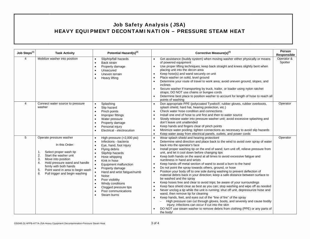
Job Safety Analysis (JSA) HEAVY EQUIPMENT DECONTAMINATION – PRESSURE STEAM HEAT
035048 (5) APPB-ATTA-JSA-Heavy Equipment Decontamination-Pressure Steam Heat 3 of 4
Job Steps(1) Task Activity Potential Hazard(s)(2) Corrective Measure(s)(3) Person
Responsible 4 Mobilize washer into position • Slip/trip/fall hazards
• Back strain • Property damage • Unsecured • Uneven terrain • Heavy lifting
• Get assistance (buddy system) when moving washer either physically or means of powered equipment
• Use proper lifting techniques; keep back straight and knees slightly bent when placing unit into the decon area
• Keep hose(s) and wand securely on unit • Place washer on solid, level ground • Determine your route of travel to work area; avoid uneven ground, slopes, and
inclines • Secure washer if transporting by truck, trailer, or loader using nylon ratchet
straps; DO NOT use chains or bungee cords • Determine best place to position washer to account for length of hose to reach all
points of washing
Operator & Spotter
4 Connect water source to pressure washer
• Splashing • Slip hazard • Pinch points • Improper fittings • Water pressure • Property damage • Personal injury • Electrical - electrocution
• Don appropriate PPE (polycoated Tyveks®, rubber gloves, rubber overboots, splash shield, hard hat, hearing protection, etc.)
• Check water hose condition and connections • Install one end of hose to unit first and then to water source • Slowly release water into pressure washer unit; avoid excessive splashing and
don’t leave unit unattended • Keep hands and fingers clear of pinch points • Minimize water pooling; tighten connections as necessary to avoid slip hazards • Keep water away from electrical panels, outlets, and power cords
Operator
5 Operate pressure washer
In this Order:
1. Select proper wash tip 2. Start the washer unit 3. Move into position 4. Hold pressure wand and handle
firmly with both hands 5. Point wand in area to begin wash 6. Pull trigger and begin washing
• High pressure (>2,000 psi) • Infections - bacteria • Eye, hand, foot Injury • Flying debris • Slip/trip hazards • Hose whipping • Kink in hose • Equipment malfunction • Property damage • Hand and wrist fatigue/numb • Noise • Poor visibility • Windy conditions • Clogged pressure tips • Poor communications • Steam burns
• Wear splash shield and hearing protection! • Determine wind direction and place back to the wind to avoid over spray of water
back into the operator’s face • Install proper washing tip on the end of wand; turn unit off, relieve pressure from
unit, and let it cool down before changing tips • Keep both hands on the wand at all times to avoid excessive fatigue and
numbness in hand and wrists • Keep hands off metal section of wand to avoid a burn to the hand • Do not point the spray towards others, ground, or hose • Position your body off to one side during washing to prevent deflection of
material debris back in your direction; keep a safe distance between surface to be washed and the spray
• Keep hoses free and clear to avoid trips; be aware of your surroundings • Keep face shield clear as best as you can; stop washing and wipe off as needed • Never unclog a tip while the unit is running; shut off unit, depressurize hose and
wand, then remove tip for cleaning • Keep hands, feet, and eyes out of the “line of fire” of the spray
− High pressure can cut through gloves, boots, and severely and cause bodily injury; infections can occur if cut into the skin
• DO NOT use steam washer to remove debris from clothing (PPE) or any parts of the body!
Operator

Job Safety Analysis (JSA) HEAVY EQUIPMENT DECONTAMINATION – PRESSURE STEAM HEAT
035048 (5) APPB-ATTA-JSA-Heavy Equipment Decontamination-Pressure Steam Heat 4 of 4
Job Steps(1) Task Activity Potential Hazard(s)(2) Corrective Measure(s)(3) Person
Responsible 6 End of task
1. Relieve pressure 2. Turn off water supply to unit and
disconnect 3. Shut off pressure washer 4. Allow to cool down 5. Storage
• Burns (muffler) • Hose damage • Equipment damage • Theft • Slips • Back strain
• Doff PPE and dispose of properly • Relieve pressure on hose and drain the water from hose and unit • Avoid placing hands on muffler section of washer unit; allow unit to cool down
before handling and or filling with gasoline • Drain hose and wrap up to unit; inspect hose for excessive wear or blistering • During cold temperatures, winterize unit using environmentally safe anti-freeze • Secure unit inside connex trailer or use chain and padlock to prevent theft • Check unit over and make sure all components (tips, wand, hose) are in good
condition • Turn gasoline valve to off/close when not in use or in storage • Use proper lifting techniques when moving unit and get assistance (buddy
system)
Operator and Spotter
7 Collect a wipe sample (if necessary) • Cross contamination • Liability
• Confirm with site supervisor if a wipe sample is needed prior to demobilization of equipment from the site
Project Manager and
Site Supervisor (1) Each Job or Task consists of a set of steps. Be sure to list all the steps in the sequence that they are performed. Specify the equipment or other details to set the basis for the potential
(associated) hazards. (2) A hazard is a potential danger. What can go wrong? How can someone get hurt? Consider, but do not limit, the analysis to: Contact - victim is struck by or strikes an object; Caught - victim is
caught on, caught in or caught between objects; Fall - victim falls to ground or lower level (includes slips and trips); Exertion - excessive strain or stress/ergonomics/lifting techniques; Exposure - inhalation/skin hazards. Specify the hazards and do not limit the description to a single word such as "Caught".
(3) Aligning with the Job Steps, Task Activity Description, and Potential Hazard columns, describe what actions or procedures are necessary to eliminate or minimize the hazards. Be clear, concise and specific. Use objective, observable, and quantified terms. Avoid subjective general statements such as "be careful" or "use as appropriate".

Job Safety Analysis (JSA)
HEAVY EQUIPMENT OPERATION DOZER/LOADER
035048 (5) JSA 035048 (5) APPB-ATTA-JSA-Heavy Equipment Operation Dozer-Loader Activities 1 of 3
Field staff must review job-specific work plan and coordinate with project manager to verify that all up-front logistics are completed prior to starting work including, but not limited to, permitting, access agreements and notification to required contacts (e.g., site managers, inspectors, clients, subcontractors, etc.). Additionally, a tailgate safety meeting must be performed and documented at the beginning of each workday. Stop, Think, Act, Review (STAR) must be used prior to any activity. All personnel must possess the appropriate training prior to initiating scheduled tasks. Also consider weather conditions. All project personnel have the authority and responsibility to use Stop Work Authority.
Date Issued/Revised October 2014 JSA Type Construction
Work Type Construction Client
Work Activity Heavy Equipment Operation: Dozer / Loader
Work Site The Old Erie Canal Site Clyde, New York
Key Equipment Dozer and or Loader
Task-specific Training 40 HR and 8 HR HAZWOPER, Heavy equipment operation; Mobile Equipment Operations, HAZCOM, PPE
MINIMUM REQUIRED PERSONAL PROTECTIVE EQUIPMENT (SEE JOB STEPS FOR TASK-SPECIFIC REQUIREMENTS)
REFLECTIVE VEST* GOGGLES APR: Full-Facepiece* GLOVES*
HARD HAT FACE SHIELD* SUPPLIED AIR RESPIRATOR* COVERALLS*
LIFELINE / HARNESS* HEARING PROTECTION* PPE CLOTHING* OTHER* Fire Extinguisher
SAFETY GLASSES STEEL TOED BOOTS OTHER* OTHER* ____________________________
ADDITIONAL PPE: * Provide specific type(s) or descriptions of this item below
Gloves - Leather Hearing Protection - NNR 20 Reflective Vest - Class 2
Reviewed By Position/Title Date Reviewed By Position/Title Date

Job Safety Analysis (JSA)
HEAVY EQUIPMENT OPERATION DOZER/LOADER
035048 (5) JSA 035048 (5) APPB-ATTA-JSA-Heavy Equipment Operation Dozer-Loader Activities 2 of 3
JOB STEPS (1) TASK ACTIVITY POTENTIAL HAZARD(S) (2) CORRECTIVE MEASURE(S)(3) Person Responsible 1 Perform the STAR Process and discuss
Stop Work Authority (SWA) Perform Review “General Site Activities” JSA.
• Failing to identify hazardous conditions resulting in losses or near losses.
• Perform the STAR Process STAR. • Assess the risks and verify personnel training is sufficient for scheduled
task(s). • Determine the hazards of performing the task and survey the work area. • Consider weather conditions such as fog that could reduce visibility. • Always consider the worst case scenario. • Analyze the hazards determined. • Decide a plan of action to eliminate or reduce the hazards and act on it.
Construction Superintendent and
Operator
2 Inspect Equipment • Equipment malfunction or damage.
• Hydraulic fluid, fuel, oil leaks/spills
• Loss of steering, loss of brakes, etc. – accidents decreased visibility.
• Fire. • Slips, trips, falls. • Unexpected operation
of equipment.
• Follow equipment inspection form/tag out if malfunction found. • Grease moving parts. • Check all fluids. • Ensure that fluids are not too low or too full. • Walk around equipment and look for leaking fluids. • Ensure that dozer tracks are acceptable (no unacceptable wear and no objects present). Check loader tires • Ensure that windows and mirrors are clean. • Remove trash or other debris from cab. • Ensure that back up alarm and horn are operational. • Correct any problems immediately and inform supervisor. • If equipment appears as though it has been tampered with or vandalized, do not start it • Ensure that fire extinguisher is in place and functioning. • Inspect the fire extinguisher monthly. • Use three point mount/dismount at all times. • Be cautious of where you step and be aware of your surroundings. • Ensure that ignition key is in your pocket, equipment is in neutral and parking brake is engaged.
Construction Superintendent and
Operator
3 Entering Equipment • Reduced visibility, uncomfortable seating-back strain.
• Debris on floor getting stuck under pedals.
• Unexpected movement of truck.
• Unexpected movement of truck.
• Adjust seat and mirrors so that you are able to see where traveling. • Adjust controls and seat to your comfort and safety. • Ensure that all materials inside cab are secured. • Be cautious of where you step and be aware of your surroundings. • Ensure steps are clear of water, mud and other debris • Ensure parking brake is engaged and gear is in neutral.
Construction Superintendent and
Operator
4 Configure controls and seating. • Ergonomics / unnecessary physical stress.
• Incapable of reaching controls.
• Visual blocks.
• Upon sitting, adjust seat fully to accommodate reach and comfort zone. • Fasten seat belt • Make certain all controls are set in neutral positions. • Adjust mirrors.
Construction Superintendent and
Operator

Job Safety Analysis (JSA)
HEAVY EQUIPMENT OPERATION DOZER/LOADER
035048 (5) JSA 035048 (5) APPB-ATTA-JSA-Heavy Equipment Operation Dozer-Loader Activities 3 of 3
JOB STEPS (1) TASK ACTIVITY POTENTIAL HAZARD(S) (2) CORRECTIVE MEASURE(S)(3) Person Responsible 5 Starting and warming up. • Unanticipated rolling or
movement, • engine fire, or
mechanical/electrical faults
• Review operator’s manual if new to this particular machine. • Start engine and check controls to ensure all are in working conditions. • Allow a minimum of two minutes to warm up.
Construction Superintendent and
Operator
6 Moving equipment work area. • Other equipment, personnel, or objects in work area.
• Uneven terrain.
• Perform the STAR Process. • Know the daily task and other people and equipment in the area. • Make eye contact with other operators and site personnel in the immediate vicinity. • Inspect pathway prior to moving equipment to ensure clear pathway.
Construction Superintendent and
Operator
7 Performing tasks. • Other equipment (collision),
• slopes, ground conditions
• possible injuries to personnel and equipment,
• buried obstacles, underground and overhead utilities.
• Organic Vapors/Dust.
• Perform the STAR Process • Know where utilities are located. Be aware of the scope of work to be performed. • Know the paths of other equipment or persons entering and leaving your work area. • Communicate with supervisors and other operators throughout the day with any questions. • Stop work immediately and contact a supervisor if you are uncertain of your task, experience equipment failure, or personal injury or near loss. • Wear respirator if conditions warrant.
Construction Superintendent and
Operator
8 Stopping at end of day. • Slips, trips and falls. • Overnight parking of
equipment.
• Be cautious of where you step and be aware of your surroundings. • Park in designated area. • Set brake/control locks. • Idle for two minutes if engine is hot. • Lower blade or bucket to ground. • Turn equipment off. • Use 3-point dismount. • Secure inside instruments (i.e., fire extinguisher).
Construction Superintendent and
Operator
(1) Each Job or Task consists of a set of steps. Be sure to list all the steps in the sequence that they are performed. Specify the equipment or other details to set the basis for the potential
(associated) hazards. (2) A hazard is a potential danger. What can go wrong? How can someone get hurt? Consider, but do not limit, the analysis to: Contact - victim is struck by or strikes an object; Caught - victim is
caught on, caught in or caught between objects; Fall - victim falls to ground or lower level (includes slips and trips); Exertion - excessive strain or stress / ergonomics / lifting techniques; Exposure - inhalation/skin hazards. Specify the hazards and do not limit the description to a single word such as "Caught"
(3) Aligning with the Job Steps, Task Activity Description, and Potential Hazard columns, describe what actions or procedures are necessary to eliminate or minimize the hazards. Be clear, concise and specific. Use objective, observable and quantified terms. Avoid subjective general statements such as, "be careful" or "use as appropriate".

Job Safety Analysis (JSA)
MATERIAL HANDLING ACTIVITIES – RIGGING AND PLACEMENT OF MATERIALS
035048 (5) JSA 035048 (5) APPB-ATTA-JSA-Material Handling Activities 1 of 3
Field staff must review job-specific work plan and coordinate with project manager to verify that all up-front logistics are completed prior to starting work including, but not limited to, permitting, access agreements and notification to required contacts (e.g., site managers, inspectors, clients, subcontractors, etc.). Additionally, a tailgate safety meeting must be performed and documented at the beginning of each workday. Stop, Think, Act, Review (STAR) must be used prior to any activity. All personnel must possess the appropriate training prior to initiating scheduled tasks. Also consider weather conditions. All project personnel have the authority and responsibility to use Stop Work Authority.
Date Issued/Revised October 2014 JSA Type Material Handling Activities
Work Type Construction Client
Work Activity Rigging and Placement of Materials
Work Site The Old Erie Canal Site Clyde, New York
Key Equipment Excavator, Backhoe, or Crane
Task-specific Training Rigging; lifting signals; heavy equipment safety; use of taglines; proper use of load charts; 40 HR and 8 HR HAZWOPER, HAZCOM, PPE, Mobile Equipment Operations
MINIMUM REQUIRED PERSONAL PROTECTIVE EQUIPMENT (SEE JOB STEPS FOR TASK-SPECIFIC REQUIREMENTS)
REFLECTIVE VEST* GOGGLES APR: ________________* GLOVES*
HARD HAT FACE SHIELD* SUPPLIED AIR RESPIRATOR* COVERALLS*
LIFELINE / HARNESS* HEARING PROTECTION* PPE CLOTHING* OTHER* ____________________________
SAFETY GLASSES STEEL TOED BOOTS OTHER* _____________________________ OTHER* ____________________________
ADDITIONAL PPE: * Provide specific type(s) or descriptions of this item below
Reflective Vest - Class II
Gloves - Leather
Reviewed By Position/Title Date Reviewed By Position/Title Date

Job Safety Analysis (JSA)
MATERIAL HANDLING ACTIVITIES – RIGGING AND PLACEMENT OF MATERIALS
035048 (5) JSA 035048 (5) APPB-ATTA-JSA-Material Handling Activities 2 of 3
JOB STEPS (1) TASK ACTIVITY POTENTIAL HAZARD(S) (2) CORRECTIVE MEASURE(S)(3) Person Responsible 1 Perform the STAR Process and discuss
Stop Work Authority (SWA) Equipment Inspection
• Hydraulic failure • Inspect equipment lines and fluid reservoirs Operator
2 Rigging components – Inspection of load and rigging
• Attachment point failure • Inspect attachment hook/ring for fractures, dents or abuse. • Certify load capability of attachment point.
Operator, Qualified Rigger and all field personnel involved in the operation
3 Rigging components – Continue inspection of load, rigging, and material to be lifted
• Rigging assembly failure • Inspect rigging chains, wire rope, cables, hooks, slings, d-rings, splitters, spreaders and all other components for unusual shape, fractures, fraying, dents, abuse or abnormalities.
• Insure components used have annual certification, proper load rating and are implemented as recommended by training and the manufacturer.
Operator, Labor and all field personnel involved in operation.
4 Rigging components • Improper component attachment, lifting point usage, incorrect balance or component orientation
• Use the manufacturer’s recommended lifting attachment points, slots or cable points to secure load to be rigged.
• Use proper rigging components to assure load is evenly distributed, proper balance is achieved and place hoisting equipment and rigged components in proper orientation to assure placement logistics are correct.
Operator, Labor and all field personnel involved in operation.
5 Tag lines – Proper placement of taglines to ensure control of load. No one is to work under a suspended load
• Lift control failure • Use of tag lines, as a lifting control measure is mandatory as appropriate for correct placement of rigged component.
• Personnel assisting rigging or lift should never physically be in contact with rigged or lifted components as a measure of component control.
Operator, Labor and all field personnel involved in operation.
6 Pre-plan the lift and prepare the landing zone
• Objects/personnel in swing radius path;
• Lifting outside of equipment’s load safe load radius
• Pre-plan the lift to ensure swing radius does not impact other operations. • Ensure that load and load path stays within load radius of lifting
equipment.
Rigger, And Operator
7 Component placement – Pick the load and place the item in the correct position.
• Improper preparation of location receiving rigged or lifted component resulting in need for multiple lifts.
• Preparation of the area receiving the rigged or lifted component to avoid and necessary re-lift or multiple lifts.
Operator, Labor and all field personnel involved in operation.
8 Maintain Control of Area • Unauthorized personnel or equipment in rigging or lifting exclusion zone
• Area marking and clearance of all personnel and equipment to prevent interference during rigging or lifting activities.
• Spotter action to terminate rigging or lifting if situational changes occur putting personnel or equipment at risk.
Operator, Labor and all field personnel involved in operation.
9 Control of communication between task personnel
• Multiple signals interfering with operator
• During lifting or rigging activities, a communication order must be established previous to any attempt to hoist load.
• Spotters communicate to one load controller; load controller communicates to operator.
• Operator must maintain visual contact with load controller at all times. • All operations are controlled by ground controller.
Operator, Labor and all field personnel involved in operation.
10 Trench entry in order to place materials and piping – see JSA for Excavation Activities
• Excavation Hazards (review of that JSA)
• Follow JSA for Excavation. All Affected Personnel

Job Safety Analysis (JSA)
MATERIAL HANDLING ACTIVITIES – RIGGING AND PLACEMENT OF MATERIALS
035048 (5) JSA 035048 (5) APPB-ATTA-JSA-Material Handling Activities 3 of 3
(1) Each Job or Task consists of a set of steps. Be sure to list all the steps in the sequence that they are performed. Specify the equipment or other details to set the basis for the potential (associated) hazards.
(2) A hazard is a potential danger. What can go wrong? How can someone get hurt? Consider, but do not limit, the analysis to: Contact - victim is struck by or strikes an object; Caught - victim is caught on, caught in or caught between objects; Fall - victim falls to ground or lower level (includes slips and trips); Exertion - excessive strain or stress / ergonomics / lifting techniques; Exposure - inhalation/skin hazards. Specify the hazards and do not limit the description to a single word such as "Caught"
(3) Aligning with the Job Steps, Task Activity Description, and Potential Hazard columns, describe what actions or procedures are necessary to eliminate or minimize the hazards. Be clear, concise and specific. Use objective, observable and quantified terms. Avoid subjective general statements such as, "be careful" or "use as appropriate".

Job Safety Analysis (JSA) MOBILE EQUIPMENT OPERATION ACTIVITIES
035048 (5) JSA 035048 (5) APPB-ATTA-JSA-Mobile Equipment Operation and Soil Stabilization Activities 1 of 2
Field staff must review job-specific work plan and coordinate with project manager to verify that all up-front logistics are completed prior to starting work including, but not limited to, permitting, access agreements and notification to required contacts (e.g., site managers, inspectors, clients, subcontractors, etc.). Additionally, a tailgate safety meeting must be performed and documented at the beginning of each workday. Stop, Think, Act, Review (STAR) must be used prior to any activity. All personnel must possess the appropriate training prior to initiating scheduled tasks. Also consider weather conditions. All project personnel have the authority and responsibility to use Stop Work Authority.
Date Issued/Revised October 2014 JSA Type: Mobile Equipment Operation Activities
Work Type Construction Client:
Work Activity Mobile Equipment Operation Activities
Work Site The Old Erie Canal Site Clyde, New York
Key Equipment Excavator; Dozer, Loader, Skidsteer, Compactor, Grader, Off-road Dump Truck, Pickup Trucks
Task-specific Training 40 HR and 8 HR HAZWOPER, PPE and Mobile Equipment Operations
MINIMUM REQUIRED PERSONAL PROTECTIVE EQUIPMENT (SEE JOB STEPS FOR TASK-SPECIFIC REQUIREMENTS)
REFLECTIVE VEST* GOGGLES APR: _with organic vapor and P-100 cartridges for stabilization activities_* GLOVES*
HARD HAT FACE SHIELD* SUPPLIED AIR RESPIRATOR* COVERALLS*
LIFELINE / HARNESS* HEARING PROTECTION* PPE CLOTHING* OTHER*
SAFETY GLASSES STEEL TOED BOOTS OTHER* _____________________________ OTHER* ____________________________
ADDITIONAL PPE: * Provide specific type(s) or descriptions of this item below
Reflective Vest- Class II Gloves – Outer Leather
Reviewed By Position/Title Date Reviewed By Position/Title Date

Job Safety Analysis (JSA) MOBILE EQUIPMENT OPERATION ACTIVITIES
035048 (5) JSA 035048 (5) APPB-ATTA-JSA-Mobile Equipment Operation and Soil Stabilization Activities 2 of 2
JOB STEPS (1)
TASK ACTIVITY POTENTIAL HAZARD(S) (2) CORRECTIVE MEASURE(S)(3) Person Responsible
1 Perform the STAR Process (Stop Think Act Review) and discuss Stop Work Authority (SWA) -
• Slips, trips, falls; • Situational risks
• Verify that personnel training is sufficient for scheduled task(s). Is Job Instruction (hands-on) Training necessary?
Operator
2 Perform daily (pre-shift) equipment inspection include area around the equipment and PPE and perform a complete walk around inspection
• Equipment failure • PPE failure
• Don all necessary PPE • Provide training to personnel on inspection procedures • Document daily inspection • Defects must be corrected before operating unit
Operator
3 Mount/dismount the equipment
• Slip/trip/fall hazards • Sprains/Strains • Potential injury
• Use three points of contact • Never jump from the machine • Clear tracks and personnel access points of debris and mud as necessary • Only a trained operator will be allowed on equipment • Never carry riders unless unit is so designed
Operator
4 Starting heavy/mobile equipment
• Struck-by • Caught between • Equipment failure
• Perform inspection (see Task 2) • Check to be certain all workers and equipment are a safe distance from unit • All operators manuals should be available for each piece of equipment and used in
employee training • Allow proper warm-up and wait for gauges to register properly • Raise the blade, cable and chokers, boom, grapple, or other attachments before moving
the unit
Operator
5 Operation of heavy/mobile equipment
• Struck-by/Caught In • Overhead/underground utilities • Flying debris • Rollover • Fire • Broken and/or frayed cables
• Appropriate guarding (according to machine type and use) shall be in place at all times unit is in operation
• Backup alarms shall be functional • Seat belts shall be provided and their use enforced • Fire extinguishers and first aid kits shall be provided on each unit • Fire extinguishers shall be inspected for functionality on a daily basis • Do not operate equipment unless you have been trained to safely operate the equipment
Operator
6 Perform equipment maintenance • Equipment failure/loss • Sharp objects • Pinch points
• Use STAR process • Follow equipment manufacturer's preventive maintenance procedures and instructions • Only qualified individuals should perform maintenance activities on equipment
Operator
7 Cleaning and housekeeping of equipment
• Fire • Slip/trip/fall hazards • Equipment failure
• Remove loose items and all trash from the operator's compartment • Clean equipment as necessary to prevent buildup of debris that may cause fire
Operator
(1) Each Job or Task consists of a set of steps. Be sure to list all the steps in the sequence that they are performed. Specify the equipment or other details to set the basis for the potential
(associated) hazards. (2) A hazard is a potential danger. What can go wrong? How can someone get hurt? Consider, but do not limit, the analysis to: Contact - victim is struck by or strikes an object; Caught - victim is
caught on, caught in or caught between objects; Fall - victim falls to ground or lower level (includes slips and trips); Exertion - excessive strain or stress / ergonomics / lifting techniques; Exposure - inhalation/skin hazards. Specify the hazards and do not limit the description to a single word such as "Caught"
(3) Aligning with the Job Steps, Task Activity Description, and Potential Hazard columns, describe what actions or procedures are necessary to eliminate or minimize the hazards. Be clear, concise and specific. Use objective, observable and quantified terms. Avoid subjective general statements such as, "be careful" or "use as appropriate".

Job Safety Analysis (JSA)
MOBILIZATION AND DEMOBILIZATION ACTIVITIES
035048 (5) JSA Mobilization and Demobilization Activities 1 of 3
Field staff must review job-specific work plan and coordinate with project manager to verify that all up-front logistics are completed prior to starting work including, but not limited to, permitting, access agreements and notification to required contacts (e.g., site managers, inspectors, clients, subcontractors, etc.). Additionally, a tailgate safety meeting must be performed and documented at the beginning of each workday. Stop, Think, Act, Review (STAR) must be used prior to any activity. All personnel must possess the appropriate training prior to initiating scheduled tasks. Also consider weather conditions. All project personnel have the authority and responsibility to use Stop Work Authority.
Date Issued/Revised October 2014 JSA Type Mobilization and Demobilization Activities
Work Type Construction Client
Work Activity Mobilization of Equipment and Supplies to and from the job site
Work Site The Old Erie Canal Site, New York
Key Equipment Pickup trucks and trailers
Task-specific Training PPE, HAZCOM, Motor Vehicle Safety, Mobile Equipment Operations
MINIMUM REQUIRED PERSONAL PROTECTIVE EQUIPMENT (SEE JOB STEPS FOR TASK-SPECIFIC REQUIREMENTS)
REFLECTIVE VEST* GOGGLES APR: ________________* GLOVES*
HARD HAT FACE SHIELD* SUPPLIED AIR RESPIRATOR* COVERALLS*
LIFELINE / HARNESS* HEARING PROTECTION* PPE CLOTHING* OTHER* ____________________________
SAFETY GLASSES STEEL TOED BOOTS OTHER* _____________________________ OTHER* ____________________________
ADDITIONAL PPE: * Provide specific type(s) or descriptions of this item below
Reflective Vest - Class II
Gloves - Leather
Reviewed By Position/Title Date Reviewed By Position/Title Date

Job Safety Analysis (JSA)
MOBILIZATION AND DEMOBILIZATION ACTIVITIES
035048 (5) JSA Mobilization and Demobilization Activities 2 of 3
JOB STEPS (1) TASK ACTIVITY POTENTIAL HAZARD(S) (2) CORRECTIVE MEASURE(S)(3) Person Responsible 1 Discuss STAR (Stop Think Assess &
Review) and Stop Work Authority (SWA)
• Site personnel not aware of STAR & SWA
• Project team to discuss the importance of and documentation procedures for SWA during pre-job safety meeting. Use SWA to stop any work that is unsafe.
Personnel Taking Part in this Activity
2 Check weather
• Unexpected storm; Fog; Rain; Snow; Lightening/Thunder;
• Heat/Cold stress
• Check local weather forecast. • Discuss weather issues and precautions to take while driving and on-site
during the pre-job safety meeting. If weather conditions (e.g., fog, rain, snow, etc.) impair the ability/vision of the driver, exit at nearest safe location and assess the situation.
• While on-site, at first sign of lightening/thunder utilize SWA and assess weather conditions. In extreme temperatures, ensure all personnel have proper clothing, hydration, and heat/cold protection (e.g., canopy, fan, and glove warmers).
Personnel Taking Part in this Activity
3 Load equipment into vehicle
• Back strain; • Cuts; • Pinch points; • Hand/Foot injury; • Forgotten equipment; • Damaged equipment
• Use proper lifting techniques and buddy system if needed. • Wear leather/cotton gloves and avoid placing hands/fingers in pinch
point locations. Wear steel toe boots. • Verify requested equipment against warehouse form. • Load equipment in an organized manner to prevent shifting during
transport or use cargo netting.
Personnel Taking Part in this Activity
4 Complete Daily Operator Vehicle Checklist
• Damaged vehicle lights, tires, windows, mirrors, horn; Inadequate vehicle documents and/or safety items
• Check for fluid leaks under vehicle. • Test operation of headlights, front/rear turn signals, backup lights, brake
lights, and emergency flashers. Visually check the pressure/wear of tires. Ensure the vehicle has a spare tire. Assure windshield and window glass is clean and free from obstructions. Test the windshield wipers and horn. Verify vehicle registration, insurance card, and inspection sticker is present and valid.
• Ensure the vehicle contains a first aid kit, fire extinguisher, and road hazard kit.
Personnel Taking Part in this Activity
5 Check and adjust seat, steering wheel, headrest, and mirrors
• Back/body strain; • Blind spots; impaired
vision.
• Adjust seat, headrest, and steering wheel height so body is fully supported/comfortable and pedals are within easy reach. Ensure mirrors are properly adjusted.
Personnel Taking Part in this Activity
6 Fasten seat belt(s) and ensure passenger(s) seat belts are fastened
• Serious injury, ejection, or death from collision and/or traffic citation
• Verify driver and passenger(s) seat belts are in good condition and properly latched.
Personnel Taking Part in this Activity
7 Ensure vehicle doors are locked
• Serious injury, ejection, or death from collision;
• Unwanted intrusion; Lost equipment
• Manually lock all doors to vehicle. Personnel Taking Part in this Activity
8 Start engine and check gauges and warning lights
• Vehicle breakdown
• Verify sufficient fuel and other hazard lamps (e.g., battery, oil, and temperature) are not lit.
Personnel Taking Part in this Activity

Job Safety Analysis (JSA)
MOBILIZATION AND DEMOBILIZATION ACTIVITIES
035048 (5) JSA Mobilization and Demobilization Activities 3 of 3
JOB STEPS (1) TASK ACTIVITY POTENTIAL HAZARD(S) (2) CORRECTIVE MEASURE(S)(3) Person Responsible 9 Mobilize to site
• Arriving late; • Collision; • Injury or Death to
occupants or other parties
• Do not use cell phones or perform other distracting activities while vehicle is in motion.
• Constantly scan intersections, move eyes, check mirrors, and assess traffic lights (fresh vs. stale).
• Maintain safety cushion around vehicle (front, sides, and rear) and 4 second following distance.
• Utilize all driving defensive techniques.
Personnel Taking Part in this Activity
10 Arrive at site
• Pedestrian injury; • Collision
• Maintain awareness of pedestrian/vehicular traffic when entering site and traveling to work zone.
Personnel Taking Part in this Activity
11 Park vehicle
• Pedestrian injury; • Collision; • Property damage
• Maintain awareness of pedestrian/vehicular traffic. • Park vehicle in pull-through parking space or facing the exit. • Use caution and mirrors/spotter when backing vehicle.
Personnel Taking Part in this Activity
12 Demobilization
• Collision; • Injury or Death to
occupants or other parties
• Perform perimeter vehicle check. • Maintain awareness of pedestrian/vehicular traffic when exiting site. • Utilize defensive driving techniques. • Complete post-departure checklist and report vehicle problems to
company vehicle maintenance manager or rental car agency.
Personnel Taking Part in this Activity
(1) Each Job or Task consists of a set of steps. Be sure to list all the steps in the sequence that they are performed. Specify the equipment or other details to set the basis for the
potential (associated) hazards. (2) A hazard is a potential danger. What can go wrong? How can someone get hurt? Consider, but do not limit, the analysis to: Contact - victim is struck by or strikes an object;
Caught - victim is caught on, caught in or caught between objects; Fall - victim falls to ground or lower level (includes slips and trips); Exertion - excessive strain or stress / ergonomics / lifting techniques; Exposure - inhalation/skin hazards. Specify the hazards and do not limit the description to a single word such as "Caught"
(3) Aligning with the Job Steps, Task Activity Description, and Potential Hazard columns, describe what actions or procedures are necessary to eliminate or minimize the hazards. Be clear, concise and specific. Use objective, observable and quantified terms. Avoid subjective general statements such as, "be careful" or "use as appropriate".

JOB SAFETY ANALYSIS
OVERSIGHT OF DRILLING ACTIVITIES AND WELL INSTALLATIONS
035048 (5) JSA Subcontractor Oversight of Drilling Activities 1
Field staff must review job-specific work plan and coordinate with project manager to verify that all up-front logistics are completed prior to starting work including, but not limited to, permitting, access agreements and notification to required contacts (e.g., site managers, inspectors, clients, subcontractors, etc.). Additionally, a tailgate safety meeting must be performed and documented at the beginning of each workday. Stop, Think, Act, Review (STAR) must be used prior to any activity. All personnel must possess the appropriate training prior to initiating scheduled tasks. Also consider weather conditions. All project personnel have the authority and responsibility to use Stop Work Authority.
Date Issued/Revised October 2014 JSA Type Oversight of Drilling Activities and Well Installation
Work Type Field Construction Client
Work Activity Oversight of Drilling Activities and Well Installation
Work Site The Old Erie Canal Site Clyde, New York
Key Equipment Safety cones/fencing/barricades;
Task-specific Training PPE, Drilling Safety and Mobile Equipment Operations
MINIMUM REQUIRED PERSONAL PROTECTIVE EQUIPMENT (SEE JOB STEPS FOR TASK-SPECIFIC REQUIREMENTS)
REFLECTIVE VEST* GOGGLES APR: ________________* GLOVES*
HARD HAT FACE SHIELD* SUPPLIED AIR RESPIRATOR* COVERALLS*
LIFELINE / HARNESS* HEARING PROTECTION* PPE CLOTHING* OTHER* ____________________________
SAFETY GLASSES STEEL TOED BOOTS OTHER* _____________________________ OTHER* ____________________________
ADDITIONAL PPE: * Provide specific type(s) or descriptions of this item below
Reflective vest/class II, hearing protection/NRR 20, glove/leather glove
Development Team Position/Title Reviewed By Position/Title Date

JOB SAFETY ANALYSIS
OVERSIGHT OF DRILLING ACTIVITIES AND WELL INSTALLATIONS
035048 (5) JSA Subcontractor Oversight of Drilling Activities 2
JOB STEPS (1) TASK ACTIVITY POTENTIAL HAZARD(S) (2) CORRECTIVE MEASURE(S)(3) Person Responsible
1 Mark out of underground utilities.
Property damage; Explosion; Electrocution; Injury; Death
• Call public underground utility agency (One-Call) at least 5 or more days prior to work activities; Review State Law pertaining to underground pipe line safety and have private utility mark-out performed.,
• Expose lines if warranted (i.e., hand dig, test pit or daylight)
Site Representative
2
Conduct site walk, identify unsafe conditions, and determine sample point locations
Traffic; Slips/trips/falls; Biological hazard; Overhead/underground hazards
• Maintain awareness of on-site traffic and walking surfaces. • When selecting soil boring locations, be aware of biological hazards
(e.g. ants, poison ivy, wasps) and overhead/underground hazards (e.g. overhead utilities, concrete scarring, station canopy).
Site Representative and the Subcontractor’s Supervisor
3 Inspection of equipment
Pinch points; Injury; Property damage; Lost time due to damaged equipment/parts
• Discuss pinch points on equipment (e.g. drill rig, air knife, pressure washer, etc.).
• Familiarize all personnel with location/operation of fire extinguisher(s) and kill switch on drill rig.
• Visually inspect equipment/parts for damage; document inspections.
Subcontractor Personnel
4 Set up work zone for drilling
Traffic; Slips/trips/falls; Property damage; Overhead hazards; Environmental impact
• Maintain awareness of on-site traffic, work zones, walking surfaces, overhead hazards (e.g. canopy and low hanging overhead lines). Utilize barricades/cones/caution tape to define work zone and direct traffic.
• Wear leather gloves when setting up barricades. • Be aware of any potential sensitive receptors and verify all personnel
are aware of the location of spill kit.
Subcontractor Personnel
5 Set up staging area
Traffic; Slips/trips/falls; Back strain; Injury; Pinch points; Heat/Cold stress
• Maintain awareness of on-site traffic and walking surfaces. Utilize barricades/cones/caution tape to define work zone and direct traffic.
• Wear leather gloves when setting up barricades. • Utilize proper lifting techniques and use buddy system if needed. • Avoid placing hands/fingers in pinch point locations. • In extreme temperatures, ensure all personnel have proper clothing,
hydration, and heat/cold protection (e.g. canopy, fan, glove warmers).
Subcontractor Personnel
6 Contractor oversight/ management of hole clearance/drilling activities
Traffic; Slips/trips/falls; Back strain; Injury; Underground utilities; Contaminant exposure; Heat/Cold stress; Pinch Points; Entanglement
• Maintain awareness of on-site traffic and practice good house keeping. • Ensure personnel don proper PPE (e.g. face shield, leather gloves,
hearing protection) and utilize proper lifting techniques. • If non-native material (e.g. pea gravel, sand, fill material) or
underground utilities are observed, utilize SWA and assess situation. • Monitor safe drill movement / Positional set-up • Lower the mast before moving the drill rig. • Monitor all personnel for signs and symptoms of heat/cold stress and
refer to HASP for recommendations. • Ensure that safe hoisting and material handling practices are followed. • Ensure that personnel use proper augering and auger handling
techniques.
Site Representative and Subcontractor Personnel

JOB SAFETY ANALYSIS
OVERSIGHT OF DRILLING ACTIVITIES AND WELL INSTALLATIONS
035048 (5) JSA Subcontractor Oversight of Drilling Activities 3
JOB STEPS (1) TASK ACTIVITY POTENTIAL HAZARD(S) (2) CORRECTIVE MEASURE(S)(3) Person Responsible
7 Site / Drilling and Well Installation Security
Traffic; Injury; Slips/trips/falls; Back strain
• Wear leather gloves when moving barricades. • Maintain awareness of on-site traffic and walking surfaces. • Use proper lifting techniques and buddy system if needed. Ensure
area is clean of debris. • Secure boring location if open overnight.
Subcontractor Personnel
¹ Each Job or Task consists of a set of steps. Be sure to list all the steps in the sequence that they are performed. Specify the equipment or other details to set the basis for the potential (associated) hazards. ² A hazard is a potential danger. What can go wrong? How can someone get hurt? Consider, but do not limit, the analysis to: Contact - victim is struck by or strikes an object; Caught - victim is caught on, caught in or caught between objects; Fall - victim falls to ground or lower level (includes slips and trips); Exertion - excessive strain or stress / ergonomics / lifting techniques; Exposure - inhalation/skin hazards. Specify the hazards and do not limit the description to a single word such as "Caught" ³ Aligning with the Job Steps, Task Activity Description, and Potential Hazard columns, describe what actions or procedures are necessary to eliminate or minimize the hazards. Be clear, concise and specific. Use objective, observable and quantified terms. Avoid subjective general statements such as, "be careful" or "use as appropriate".

Job Safety Analysis (JSA) ASPHALT/CONCRETE SAW CUTTING ACTIVITIES
035048 (5) JSA Asphalt/Concrete Saw Cutting Activities 1
Field staff must review job-specific work plan and coordinate with project manager to verify that all up-front logistics are completed prior to starting work including, but not limited to, permitting, access agreements and notification to required contacts (e.g., site managers, inspectors, clients, subcontractors, etc.). Additionally, a tailgate safety meeting must be performed and documented at the beginning of each workday. Stop, Think, Act, Review (STAR) must be used prior to any activity. All personnel must possess the appropriate training prior to initiating scheduled tasks. Also consider weather conditions. All project personnel have the authority and responsibility to use Stop Work Authority.
Date Issued/Revised October 2014 JSA Type Construction
Work Type Construction Client
Work Activity Asphalt/Concrete Saw Cutting
Work Site The Old Erie Canal Site Clyde, New York
Key Equipment Walk behind cut saw/ hand held cut saw
Task-specific Training 40 HR and 8 HR HAZWOPER, Hand and Power Tool Safety, PPE, HAZCOM
MINIMUM REQUIRED PERSONAL PROTECTIVE EQUIPMENT (SEE JOB STEPS FOR TASK-SPECIFIC REQUIREMENTS)
REFLECTIVE VEST* GOGGLES APR: ________________* GLOVES*
HARD HAT FACE SHIELD* SUPPLIED AIR RESPIRATOR* COVERALLS*
LIFELINE / HARNESS* HEARING PROTECTION* PPE CLOTHING* OTHER* ____________________________
SAFETY GLASSES STEEL TOED BOOTS OTHER* _____________________________ OTHER* ____________________________
ADDITIONAL PPE: * Provide specific type(s) or descriptions of this item below
Gloves - Leather Face Shield - Full
Reflective Vest - Class II Hearing Protection - NRR 20
Development Team Position/Title Reviewed By Position/Title Date

Job Safety Analysis (JSA) ASPHALT/CONCRETE SAW CUTTING ACTIVITIES
035048 (5) JSA Asphalt/Concrete Saw Cutting Activities 2
JOB STEPS (1) TASK ACTIVITY POTENTIAL HAZARD(S) (2) CORRECTIVE MEASURE(S)(3) Person Responsible
1
Perform the STAR Process and discuss Stop Work Authority (SWA). Refer to the specific saw’s operation manual before using equipment.
Slips, Trips, Falls: Situational risks
• Verify personnel’s training is sufficient for the scheduled task(s). • Is job instruction training (hands-on) training necessary? • Employees should remove finger rings, necklaces, or jewelry which may
be hazardous in equipment operation
Assigned Laborer
2 Equipment Safety Checklist Faulty hose connections; Damaged hoses and fittings
• Replace worn or damaged hoses and fittings • Replace hose connections with operation connections. • Perform an overall inspection of the equipment for any defects or signs of
damage.
Assigned Laborer
3 Verify Utility Clearance procedures completed. Verify excavation layout
Property damage and personal injury from hitting buried utilities. Fire potential from static/contact spark
• Utility Locate Ticket number on file • Mark work area and safe distances
Assigned Laborer
4 Saw and Water hose set up
Slip, Trip, Fall: Uneven terrain; Wet, Icy and muddy conditions; Material Handling – Back sprains and strains; Struck-by and line of fire; Pinch points.
• Be aware of your surroundings (footing, weather conditions, etc.) • Use proper lifting techniques; “straight back-bent knee” lifting approach.
Have a “buddy” assist with the lift. • Use gloves to ensure a secure grip. • Grab the Equipment only on the designated handles or if none are
available, at location where the hands and fingers will not get caught in the equipment or smashed.
• Test the weight of the equipment before lifting • Straighten out the hoses before connection and keep them out of high
traffic areas. • Be aware of “stored energy” hazards presented by hoses
Assigned Laborer
5 Equipment Fueling/Refueling Fires; Explosion; Chemical Hazard
• Turn off equipment before fueling. • No smoking while fueling • Do not use cell phones while fueling • Store fuel in proper safety containers only. • If transferring fuel from large vessels into portable cans, use proper
grounding or bonding techniques. • Do fuel the equipment when it is hot. • Wear gloves and wash hands after fueling
Assigned Laborer
6 Starting the Saw Back Strains; Slippery Conditions
• Make sure starting cord is free pulling. Test the cord before pulling • Be aware of your surrounding conditions. Make sure Slip/Trip/Fall
hazards were properly identified and corrected. Assigned Laborer
7 Saw Operation Hot surfaces; Noise; Exposure to particles
• Inspect saw blade. Remove worn, dull or damaged blades & replace • Keep hands away from the exhaust or hot components of the equipment • Be aware of any unguarded moving parts on the equipment • Use dust masks, respirators to prevent breathing of particles. • Use wet methods as much as possible
Assigned Laborer
¹ Each Job or Task consists of a set of steps. Be sure to list all the steps in the sequence that they are performed. Specify the equipment or other details to set the basis for the potential (associated) hazards.

Job Safety Analysis (JSA) ASPHALT/CONCRETE SAW CUTTING ACTIVITIES
035048 (5) JSA Asphalt/Concrete Saw Cutting Activities 3
² A hazard is a potential danger. What can go wrong? How can someone get hurt? Consider, but do not limit, the analysis to: Contact - victim is struck by or strikes an object; Caught - victim is caught on, caught in or caught between objects; Fall - victim falls to ground or lower level (includes slips and trips); Exertion - excessive strain or stress / ergonomics / lifting techniques; Exposure - inhalation/skin hazards. Specify the hazards and do not limit the description to a single word such as "Caught" ³ Aligning with the Job Steps, Task Activity Description, and Potential Hazard columns, describe what actions or procedures are necessary to eliminate or minimize the hazards. Be clear, concise and specific. Use objective, observable and quantified terms. Avoid subjective general statements such as, "be careful" or "use as appropriate".

Job Safety Analysis (JSA) SILT FENCE INSTALLATION
035048 (5) JSA 035048 (5) APPB-ATTA-JSA-Silt Fence Installation Activities Activities 1 of 2
Field staff must review job-specific work plan and coordinate with project manager to verify that all up-front logistics are completed prior to starting work including, but not limited to, permitting, access agreements and notification to required contacts (e.g., site managers, inspectors, clients, subcontractors, etc.). Additionally, a tailgate safety meeting must be performed and documented at the beginning of each workday. Stop, Think, Act, Review (STAR) must be used prior to any activity. All personnel must possess the appropriate training prior to initiating scheduled tasks. Also consider weather conditions. All project personnel have the authority and responsibility to use Stop Work Authority.
Date Issued/Revised October 2014 JSA Type Construction
Work Type Construction Client
Work Activity Silt Fence Installation Activities
Work Site The Old Erie Canal Site, New York
Key Equipment Skidsteer, Sledge Hammer, Shovel
Task-specific Training Mobile Equipment Operations, PPE, Hand and Power Tool Safety
MINIMUM REQUIRED PERSONAL PROTECTIVE EQUIPMENT (SEE JOB STEPS FOR TASK-SPECIFIC REQUIREMENTS)
REFLECTIVE VEST* GOGGLES APR* GLOVES*
HARD HAT FACE SHIELD* SUPPLIED AIR RESPIRATOR* COVERALLS*
LIFELINE / HARNESS* HEARING PROTECTION* PPE CLOTHING* OTHER* ____________________________
SAFETY GLASSES STEEL TOED BOOTS OTHER* _____________________________ OTHER* ____________________________
ADDITIONAL PPE: * Provide specific type(s) or descriptions of this item below
Reflective Vest - Class II Gloves - Leather
Reviewed By Position/Title Date Reviewed By Position/Title Date

Job Safety Analysis (JSA) SILT FENCE INSTALLATION
035048 (5) JSA 035048 (5) APPB-ATTA-JSA-Silt Fence Installation Activities Activities 2 of 2
JOB STEPS (1) TASK ACTIVITY POTENTIAL HAZARD(S) (2) CORRECTIVE MEASURE(S)(3) Person Responsible 1 Perform the STAR Process and discuss
Stop Work Authority (SWA) Equipment Inspection
• Hydraulic failure • Instrument/monitor failure
• Inspect equipment lines and fluid reservoirs – document inspection. • Calibrate instrument prior to use – document calibration.
Personnel involved in this activity
2 Underground Utilities • Impact, breach or rupture of underground utilities
• Inspect area. • Call underground utility locator and monitor locator during locating
activities. • Verify all markings, locations and procedures prior to installation work.
Personnel involved in this activity
3 Installation zone inspection • Underground Insects, nests and hives;
• Poisonous plants; • Stinging/biting insects • Chemical hazards
• Visually inspect area of fence installation for any activity regarding hornets, yellow jackets, bees, fire ants or termites. A slow walk or drive along the fence path prior to excavation to inspect for insects flying in and out or ground, ant humps or mounds and trails.
Personnel involved in this activity
4 Silt fence trough (pathway) excavation • Struck-by/against; • Utilities; • Chemical hazards; • Cross-contamination
• Setup safe work area. Use a spotter when moving equipment. • Use a spotter when digging to assist with observing for underground
installations. Spotter will be used when working near overhead lines to assist equipment operator and keep machine away/out of lines.
• Control areas where excavator will travel. Attempt to keep excavator tires out of impacted spoils and areas. Employees are to setup work area access to minimize spread of contamination.
Personnel involved in this activity
5 Hand tool use • Improper hammer/tool selection;
• Improper stapler use • Potential cuts/abrasions • Chemical hazards
• Use only a hammer of a weight and handle length appropriate to individual laborers’ capability. Inspect every post and hammer for signs of metal fatigue/fractures. Inspect stapler for correct staple installation. Inspect stapler and test operation for gauging correct drive pressure. Use staples of a length needed for the job. Safety glasses and awareness of installer hand location during use of a hammer or staple gun.
• Ensure that all hand tools (fence post driver, shovel, etc.) are in good working condition.
• Wear proper PPE such as stout leather gloves to prevent trauma to hands.
• Use work practices that do not generate visible dust levels.
Personnel involved in this activity
6 Fence layout activities • Back or muscle strain • Use the ‘buddy system’ during fence installation. 100’ fence rolls require a coordinated two-man effort to place fence correctly and according to Mfg. requirements.
Personnel involved in this activity
(1) Each Job or Task consists of a set of steps. Be sure to list all the steps in the sequence that they are performed. Specify the equipment or other details to set the basis for the potential
(associated) hazards. (2) A hazard is a potential danger. What can go wrong? How can someone get hurt? Consider, but do not limit, the analysis to: Contact - victim is struck by or strikes an object; Caught - victim
is caught on, caught in or caught between objects; Fall - victim falls to ground or lower level (includes slips and trips); Exertion - excessive strain or stress / ergonomics / lifting techniques; Exposure - inhalation/skin hazards. Specify the hazards and do not limit the description to a single word such as "Caught"
(3) Aligning with the Job Steps, Task Activity Description, and Potential Hazard columns, describe what actions or procedures are necessary to eliminate or minimize the hazards. Be clear, concise and specific. Use objective, observable and quantified terms. Avoid subjective general statements such as, "be careful" or "use as appropriate".

Job Safety Analysis (JSA) SOIL AND GROUNDWATER SAMPLING ACTIVITIES
035048 (5) JSA Soil and Groundwater Sampling Activities 1 of 3
Field staff must review job-specific work plan and coordinate with project manager to verify that all up-front logistics are completed prior to starting work including, but not limited to, permitting, access agreements and notification to required contacts (e.g., site managers, inspectors, clients, subcontractors, etc.). Additionally, a tailgate safety meeting must be performed and documented at the beginning of each workday. Stop, Think, Act, Review (STAR) must be used prior to any activity. All personnel must possess the appropriate training prior to initiating scheduled tasks. Also consider weather conditions. All project personnel have the authority and responsibility to use Stop Work Authority.
Date Issued/Revised October 2014 JSA Type: Soil and Groundwater Sampling Activities
Work Type Construction Client: Commander Oil – Great Neck, New York Site
Work Activity Soil and Groundwater Sampling Activities
Work Site The Old Erie Canal site, New York
Key Equipment
Task-specific Training 40 HR and 8 HR HAZWOPER, PPE, Hand and Power tool Safety and Hazard Communication
MINIMUM REQUIRED PERSONAL PROTECTIVE EQUIPMENT (see job steps for task-specific requirements)
Reflective Vest Goggles Gloves* Supplied Air APR Hard Hat Face Shield* Coveralls* SCBA Full Face APR Particulate Organic Vapor Lifeline/Harness* Hearing Protection* PPE Clothing* Airline Respirator (attach description) Half Mask APR Particulate/Organic Vapor Combined Safety Glasses Safety-toed Boots Acid Gas
Other* Other* Other*
ADDITIONAL PPE (*provide specific type(s) or descriptions of this item below) Gloves – nitrile for sampling. Light duty mechanic style gloves for moving equipment and supplies around the site
Reviewed By Position/Title Date Reviewed By Position/Title Date

Job Safety Analysis (JSA) SOIL AND GROUNDWATER SAMPLING ACTIVITIES
035048 (5) JSA Soil and Groundwater Sampling Activities 2 of 3
Job Steps(1) Task Activity Potential Hazard(s)(2) Mitigating Measure(s)(3) Person Responsible
1 Perform the STAR Process (Stop Think Act Review) and discuss Stop Work Authority (SWA) -
• Site personnel not aware of STAR and SWA
• Project team to discusses importance of and documentation procedures for SWA during pre-job safety meeting
• Use SWA to stop any work that is unsafe
Site Personnel
2 Inspect and calibrate sampling and monitoring equipment
• Lost time from improperly functioning equipment
• Incorrect sampling procedures/ collection due to malfunctioning equipment
• Ensure all equipment is functioning properly • Wear light duty mechanic style gloves
Sampling Technician
3 Prepare to collect soil and/or groundwater samples
• Lifting hazards • Back injury • Manual material handling • Pinch points • Cuts • Punctures • Sample misidentification • Electrical Shock Hazards
• Wear Ndex nitrile gloves over light duty mechanic style gloves • Size up the load; if the object is too large or odd shaped OR is in excess of
50 pounds then assistance (mechanical or a buddy lift) will be required • Lift with the legs (bend at the knees and use the leg muscles) to protect the
lower back and keep lower back in a neutral position • Avoid one-handed carrying if possible; maintain awareness of footing • No bending or twisting while under load • Refer to the HASP for additional lifting information • Avoid placing hands/fingers in pinch point locations • Use proper tools when opening container packaging • Do not use fixed open blade knives when opening boxes or containers • Ensure the sample id label matches sample location with site plan site
supervisor/subcontractor
Sampling Technician
4 Sample collection • Contaminant exposure • Cuts from container breakage • Sample misidentification
• Wear Ndex nitrile gloves over light duty mechanic style • Inspect glass bottles for breaks/cracks • Do not attempt to use any suspect containers • Close glass sample containers carefully to avoid breakage • Check sample labels for accuracy prior to placing in cooler
Sampling Technician
5 Headspace screening of soil samples
• Contaminant exposure • Incorrect headspace readings
• Wear Ndex nitrile gloves over light duty mechanic style • Ensure proper calibration of equipment
Sampling Technician
6 Sample selection • Bottle breakage • Contaminant exposure • Pinch points • Lost time due to incorrect sample
selection
• Wear Ndex nitrile gloves over light duty mechanic style • Confirm selected samples are correct based on work plan selection criteria,
PID readings, and soil boring logs • Avoid placing hands/fingers in pinch point locations (e.g., between cooler
and lid)
Sampling Technician

Job Safety Analysis (JSA) SOIL AND GROUNDWATER SAMPLING ACTIVITIES
035048 (5) JSA Soil and Groundwater Sampling Activities 3 of 3
Job Steps(1) Task Activity Potential Hazard(s)(2) Mitigating Measure(s)(3) Person Responsible
7 Packing samples in cooler(s)
• Bottle breakage • Contaminant exposure • Cuts • Pinch points • Lifting hazards • Back injury • Manual material handling • Lost time due to incorrect sample
packaging or hold time exceedances
• Wear Ndex nitrile gloves over light duty mechanic style • Pack glass containers in bubble wrap • Check COC against sample labels for accuracy before shipping • Avoid placing hands/fingers in pinch point locations (e.g., between cooler
and lid) • Use proper lifting techniques as discussed in step 3 • If possible use a dolly or cart if cooler is heavy or has to be moved over a
long distance • Ensure equipment and supplies are loaded correctly and do not shift during
transport
Sampling Technician
8 Investigation derived waste (IDW) management
• Contaminant exposure • Lifting hazards • Back injury • Manual material handling • Pinch points • Slips/trips/fall hazards • Mislabeled waste
• Wear Ndex nitrile gloves over light duty mechanic style • Use proper lifting techniques as discussed in step 3 • Avoid placing hands/fingers in pinch point locations • Maintain awareness of walking surfaces • Label IDW with generator, a contact number, identification of contents, and
site location • Specify IDW as either hazardous or non-hazardous material
Sampling Technician
(1) Each Job or Task consists of a set of steps. Be sure to list all the steps in the sequence that they are performed. Specify the equipment or other details to set the basis for the potential
(associated) hazards. (2) A hazard is a potential danger. What can go wrong? How can someone get hurt? Consider, but do not limit, the analysis to: Contact - victim is struck by or strikes an object; Caught - victim is
caught on, caught in or caught between objects; Fall - victim falls to ground or lower level (includes slips and trips); Exertion - excessive strain or stress/ergonomics/lifting techniques; Exposure - inhalation/skin hazards. Specify the hazards and do not limit the description to a single word such as "Caught".
(3) Aligning with the Job Steps, Task Activity Description, and Potential Hazard columns, describe what actions or procedures are necessary to eliminate or minimize the hazards. Be clear, concise and specific. Use objective, observable, and quantified terms. Avoid subjective general statements such as "be careful" or "use as appropriate".

Job Safety Analysis (JSA)
SURFACE WATER SAMPLING
035048 (5) APPB-ATTA-JSA-Surface Water Sampling Activities 1 of 3
Field staff must review job-specific work plan and coordinate with project manager to verify that all up-front logistics are completed prior to starting work including, but not limited to, permitting, access agreements and notification to required contacts (e.g., site managers, inspectors, clients, subcontractors, etc.). Additionally, a tailgate safety meeting must be performed and documented at the beginning of each workday. Stop, Think, Act, Review (STAR) must be used prior to any activity. All personnel must possess the appropriate training prior to initiating scheduled tasks. Also consider weather conditions. All project personnel have the authority and responsibility to use Stop Work Authority.
Date Issued/Revised October 2014 JSA Type Surface Water Sampling
Work Type Construction Client
Work Activity Surface Water Sampling
Work Site The Old Erie Canal Site Clyde, New York
Key Equipment Sampling Equipment and supplies and potentially a boat
Task-specific Training 40 HR and 8 HR HAZWOPER, PPE and Hazard Communication
MINIMUM REQUIRED PERSONAL PROTECTIVE EQUIPMENT (see job steps for task-specific requirements)
Reflective Vest Goggles Gloves* Supplied Air APR Hard Hat Face Shield* Coveralls* SCBA Full Face APR Particulate Organic Vapor Lifeline/Harness* Hearing Protection* PPE Clothing* Airline Respirator (attach description) Half Mask APR Particulate/Organic Vapor Combined Safety Glasses Safety-toed Boots
and/or hip waders Acid Gas
Other* Sunscreen and a Personal Flotation Device if a boat is used Other* Other*
ADDITIONAL PPE (*provide specific type(s) or descriptions of this item below) Gloves – Nitrile
Reviewed By Position/Title Date Reviewed By Position/Title Date

Job Safety Analysis (JSA)
SURFACE WATER SAMPLING
035048 (5) APPB-ATTA-JSA-Surface Water Sampling Activities 2 of 3
Job Steps(1) Task Activity Potential Hazard(s)(2) Corrective Measure(s)(3) Person Responsible
1 Perform the STAR Process (Stop Think Act Review) and discuss Stop Work Authority (SWA)
• Slips, trips, falls; • Situational risks - use STAR;
• Verify that personnel training is sufficient for scheduled task(s). Is Job Instruction (hands-on) Training necessary?
Sampling Technician
2 Inspection and setup of sampling equipment including on boat
• Lost time from improperly functioning equipment
• Incorrect sampling procedures/ collection due to malfunctioning equipment
• Potential Drowning • Potential back injuries
• Ensure all PPE is worn including PFD for each person • Ensure all equipment is functioning properly; complete Quality Control
documents • Ensure boat sufficiently stable for retrieval of samples • Obtain training in boating safety • Do not lift more than 50 pounds without getting assistance. • Practice good lifting procedures that are presented in the HASP
Sampling Technician
3 Prepare to lower sampler into water
• Lifting hazards • Back injury • Manual material handling • Pinch points • Cuts • Punctures • Sample misidentification
• Reduce travel distance when there is a need to carry/lift materials • Make sure grip is adequate; wear leather gloves • Size up the load; if the object is too large or odd shaped OR is in excess of
50 pounds then assistance (mechanical or a buddy lift) will be required • Lift with the legs (bend at the knees and use the leg muscles) to protect the
lower back and keep lower back in a neutral position • Avoid one-handed carrying if possible; maintain awareness of footing • Sampler will be heavier when raised; take breaks to rest arms/shoulders • Avoid placing hands/fingers in pinch point locations • Use proper tools when opening container packaging • Do not use fixed open blade knives when opening boxes or containers • Ensure the sample id label matches sample location with site plan Site
Supervisor/subcontractor
Sampling Technician
4 Retrieve sampler when sample collected
• Cuts due to sharp edges of sample sleeve; Contaminant exposure
• Lifting hazards • Back injury • Manual material handling • Cuts from sharp objects retrieved by
sampler • Contamination hazards
• Refer to step 3 and the HASP for additional lifting information • Wear nitrile gloves • Maintain awareness of sharp edges from objects that may be in sampler
Sampling Technician
5 Sieving sample collection using mesh sieve (if applicable)
• Contaminant exposure • Cuts from container breakage • Sample misidentification • Chemical exposure to reagent if
used
• Wear nitrile gloves and replace between samples • Inspect glass bottles for breaks/cracks; do not attempt to use any suspect
containers • Close glass sample containers carefully to avoid breakage • Check sample labels for accuracy prior to placing in cooler
Sampling Technician
6 Headspace screening of samples (if applicable)
• Contaminant exposure • Incorrect headspace readings
• Wear nitrile gloves • Ensure proper calibration of equipment
Sampling Technician

Job Safety Analysis (JSA)
SURFACE WATER SAMPLING
035048 (5) APPB-ATTA-JSA-Surface Water Sampling Activities 3 of 3
Job Steps(1) Task Activity Potential Hazard(s)(2) Corrective Measure(s)(3) Person Responsible
7 Sample selection • Bottle breakage • Contaminant exposure • Pinch points • Lost time due to incorrect sample
selection
• Wear nitrile gloves when handling sample containers • Confirm selected samples are correct based on work plan selection criteria, PID
readings, and soil boring logs • Avoid placing hands/fingers in pinch point locations (e.g., between cooler and
lid)
Sampling Technician
8 Packing samples in cooler(s)
• Bottle breakage • Contaminant exposure • Cuts • Pinch points • Lifting hazards • Back injury • Manual material handling • Lost time due to incorrect sample
packaging or hold time exceedances
• Wear nitrile gloves when handling sample containers • Pack glass containers in bubble wrap • Check COC against sample labels and SSOW for accuracy before shipping • Avoid placing hands/fingers in pinch point locations (e.g., between cooler and
lid) • Refer to step 3 and the HASP for additional lifting information • Ensure equipment and supplies are loaded correctly and do not shift during
transport
Sampling Technician
9 Investigation derived waste (IDW) management
• Contaminant exposure • Heavy lifting • Pinch points • Slips/trips/fall hazards • Mislabeled waste
• Wear nitrile gloves when handling IDW • Use proper lifting techniques to transport/dispose of IDW into drums and use
buddy system if needed • Avoid placing hands/fingers in pinch point locations • Maintain awareness of walking surfaces • Label IDW with generator, a contact number, identification of contents, and site
location • Specify IDW as either hazardous or non-hazardous material
Sampling Technician
(1) Each Job or Task consists of a set of steps. Be sure to list all the steps in the sequence that they are performed. Specify the equipment or other details to set the basis for the potential
(associated) hazards. (2) A hazard is a potential danger. What can go wrong? How can someone get hurt? Consider, but do not limit, the analysis to: Contact - victim is struck by or strikes an object; Caught - victim is
caught on, caught in or caught between objects; Fall - victim falls to ground or lower level (includes slips and trips); Exertion - excessive strain or stress/ergonomics/lifting techniques; Exposure - inhalation/skin hazards. Specify the hazards and do not limit the description to a single word such as "Caught".
(3) Aligning with the Job Steps, Task Activity Description, and Potential Hazard columns, describe what actions or procedures are necessary to eliminate or minimize the hazards. Be clear, concise and specific. Use objective, observable, and quantified terms. Avoid subjective general statements such as "be careful" or "use as appropriate".

Job Safety Analysis (JSA)
SURVEYING AND COMMUNITY AIR MONITORING ACTIVITIES
035048 (5) 035048 (5) APPB-ATTA-JSA-Surveying and Community Air Monitoring Activities 1 of 3
Field staff must review job-specific work plan and coordinate with project manager to verify that all up-front logistics are completed prior to starting work including, but not limited to, permitting, access agreements and notification to required contacts (e.g., site managers, inspectors, clients, subcontractors, etc.). Additionally, a tailgate safety meeting must be performed and documented at the beginning of each workday. Stop, Think, Act, Review (STAR) must be used prior to any activity. All personnel must possess the appropriate training prior to initiating scheduled tasks. Also consider weather conditions. All project personnel have the authority and responsibility to use Stop Work Authority.
Date Issued/Revised October 2014 JSA Type Surveying and Community Air Monitoring Activities
Work Type Construction Client
Work Activity Surveying and Community Air Monitoring Activities
Work Site The Old Erie Canal Site, New York
Key Equipment GPS Unit, Grade Rod, Stakes, Hammer, Wood Lathe, Ribbon, Tripods, Air Monitoring Equipment
Task-specific Training Flagger safety; Traffic control devices; PPE, Mobile Equipment Operations
MINIMUM REQUIRED PERSONAL PROTECTIVE EQUIPMENT (SEE JOB STEPS FOR TASK-SPECIFIC REQUIREMENTS)
REFLECTIVE VEST* GOGGLES APR: ________________* GLOVES* Leather
HARD HAT FACE SHIELD* SUPPLIED AIR RESPIRATOR* COVERALLS*
LIFELINE / HARNESS* HEARING PROTECTION* PPE CLOTHING* OTHER*
SAFETY GLASSES STEEL TOED BOOTS OTHER* _____________________________ OTHER* ____________________________
ADDITIONAL PPE: * Provide specific type(s) or descriptions of this item below
Reflective Vest – Class II
Gloves - Leather gloves for mobilization and demobilization equipment
Reviewed By Position/Title Date Reviewed By Position/Title Date

Job Safety Analysis (JSA)
SURVEYING AND COMMUNITY AIR MONITORING ACTIVITIES
035048 (5) 035048 (5) APPB-ATTA-JSA-Surveying and Community Air Monitoring Activities 2 of 3
JOB STEPS (1) TASK ACTIVITY
POTENTIAL HAZARD(S) (2) CORRECTIVE MEASURE(S)(3) Person Responsible
1 Perform the STAR Process and discuss Stop Work Authority (SWA) Perform Review “General Site Activities” JSA.
• Failing to identify hazardous conditions resulting in losses or near losses.
• Perform the STAR Process STAR. • Assess the risks. • Determine the hazards of performing the task and survey the work area. • Consider weather conditions such as fog that could reduce visibility. • Always consider the worst case scenario. • Analyze the hazards determined. • Decide a plan of action to eliminate or reduce the hazards and act on it.
Survey or Air Monitoring Technician
2 Mob equipment to surveying area
• Potential back Injuries loading equipment; • Pinch points; • Moving or flying projectiles inside vehicle
while transporting equipment; • Slip/trip/fall; • Biological hazards. • Struck by moving vehicles
• Follow proper lifting procedure identified in the HASP; • Wear leather gloves when moving equipment around; • Review JSA and HASP; • Practice STAR; • Properly secure all equipment inside the vehicle. • Contact the owner of any public roadway (State or City) to determine requirements
for surveying on or along their roadway. • Develop a Temporary Traffic Control Plan (TTCP) if surveying activities will be taking
place on or along the shoulder of a public highway. • Set up a Temporary Traffic Control Zone (TTCZ) if surveying activities will be taking
place on or along the shoulder of a public highway. The TTCP will describe the set up of the TTCZ.
Survey or Air Monitoring Technician
3 Setup in work zone
• Struck by oncoming traffic/heavy equipment;
• Slip/trip/fall; • Biological hazards; • Potential back injuries from moving
equipment; • Heat/Cold Stress; • Struck by moving vehicles
• Communication with other personnel/heavy equipment operators to notify them of survey team presence;
• Position a company truck with flashers on for added protection and to aid in the protection of the survey crew as they set up the TTCZ;
• Follow hot/cold stress procedures presented in the HASP. Ensure fluid intake and clothing/PPE is appropriate for conditions.
Survey or Air Monitoring Technician

Job Safety Analysis (JSA)
SURVEYING AND COMMUNITY AIR MONITORING ACTIVITIES
035048 (5) 035048 (5) APPB-ATTA-JSA-Surveying and Community Air Monitoring Activities 3 of 3
JOB STEPS (1) TASK ACTIVITY
POTENTIAL HAZARD(S) (2) CORRECTIVE MEASURE(S)(3) Person Responsible
4 Conduct survey activities
• Struck by oncoming traffic; • Slip/trip/fall; • Potential injuries from misuse of tools or
use of tools in disrepair; • Splinters, eye injuries from broken stakes; • Utility strikes; • Biological hazards; • Weather • Struck by moving vehicles
• Wear hi-visibility safety vest, steel-toed boots, safety glasses, and hard hat; • Do not use old or faded PPE; • Make sure that proper PPE is being worn; • Notify nearby equipment of changes in you activities/movement through work area; • Inspect tools; • Repair/replace tools as necessary; • Visually inspect stakes prior to driving into ground. Do not use stakes that are
cracked, split, have large knots, etc; • Perform utility clearance to with clients representative to verify presence of
underground utilities to avoid driving grade stakes through any underground obstructions;
• Watch for snakes, insects, animals, etc; avoid walking though tall grass and shrubs as much as possible;
• Check weather prior to entering work area; • Should conditions be windy, wear spoggles (safety glass goggles) to prevent dirt and
debris from getting into the eyes; • Wear sunscreen, as required; • If thunder is heard o lightning seen, leave work area immediately and take shelter; do
not re-enter work area until 30 minutes after last lightning strike is seen
Survey or Air Monitoring Technician
5 Exit work zone • Struck by oncoming traffic; • Slip/trip/fall; • Biological hazards; • Weather • Struck by moving vehicles
• Walk through clear paths, especially when carrying equipment; watch for and avoid rough terrain as much as possible;
• Note traffic patterns, make sure path to vehicle is clear and notify nearby equipment you are moving through their path;
• Watch for snakes, insects, animals, etc; avoid walking though tall grass and shrubs as much as possible;
• Check weather prior to entering work area; • Should conditions be windy, wear spoggles (safety glass goggles) to prevent dirt and
debris from getting into the eyes; • Wear sunscreen, as required; • If thunder is heard o lightning seen, leave work area immediately and take shelter; do
not re-enter work area until 30 minutes after last lightning strike is seen.
Survey or Air Monitoring Technician
(1) Each Job or Task consists of a set of steps. Be sure to list all the steps in the sequence that they are performed. Specify the equipment or other details to set the basis for the potential
(associated) hazards. (2) A hazard is a potential danger. What can go wrong? How can someone get hurt? Consider, but do not limit, the analysis to: Contact - victim is struck by or strikes an object; Caught - victim
is caught on, caught in or caught between objects; Fall - victim falls to ground or lower level (includes slips and trips); Exertion - excessive strain or stress / ergonomics / lifting techniques; Exposure - inhalation/skin hazards. Specify the hazards and do not limit the description to a single word such as "Caught"
(3) Aligning with the Job Steps, Task Activity Description, and Potential Hazard columns, describe what actions or procedures are necessary to eliminate or minimize the hazards. Be clear, concise and specific. Use objective, observable and quantified terms. Avoid subjective general statements such as, "be careful" or "use as appropriate".

JOB SAFETY ANALYSIS (JSA)
Bolting Pipe and Valve Activities
035048 (5) JSA Welding Activities 1
Field staff must review job-specific work plan and coordinate with project manager to verify that all up-front logistics are completed prior to starting work including, but not limited to, permitting, access agreements and notification to required contacts (e.g., site managers, inspectors, clients, subcontractors, etc.). Additionally, a tailgate safety meeting must be performed and documented at the beginning of each workday. Stop, Think, Act, Review (STAR) must be used prior to any activity. All personnel must possess the appropriate training prior to initiating scheduled tasks. Also consider weather conditions. All project personnel have the authority and responsibility to use Stop Work Authority.
Date Issued/Revised October 2014 JSA Type Construction
Work Type Construction Client
Work Activity Welding Activities
Work Site The Old Erie Canal Site Clyde, New York
Key Equipment Welder; fire extinguisher; LEL/gas monitor; Hot Work Permit
Task-specific Training 40 HR and 8 HR HAZWOPER, PPE, Hand & Power Tool Safety, Welding Safety
MINIMUM REQUIRED PERSONAL PROTECTIVE EQUIPMENT (SEE JOB STEPS FOR TASK-SPECIFIC REQUIREMENTS)
REFLECTIVE VEST* GOGGLES APR: ________________* GLOVES*
HARD HAT FACE SHIELD* SUPPLIED AIR RESPIRATOR* COVERALLS*
LIFELINE / HARNESS* HEARING PROTECTION* PPE CLOTHING* OTHER*
SAFETY GLASSES STEEL TOED BOOTS OTHER* _____________________________ OTHER* ____________________________
ADDITIONAL PPE: * Provide specific type(s) or descriptions of this item below
Reflective Vest - Class II
Gloves - Leather
Development Team Position/Title Reviewed By Position/Title Date

JOB SAFETY ANALYSIS (JSA)
Bolting Pipe and Valve Activities
035048 (5) JSA Welding Activities 2
JOB STEPS (1) TASK ACTIVITY POTENTIAL HAZARD(S) (2) CORRECTIVE MEASURE(S)(3) Person Responsible 1 Review JSA and perform STAR • Personal injuries
• Property and/or equipment damage resulting from failing to review JSA or performing STAR
• Always assess all risk and hazards associated with this task • Act to ensure that you will be able to perform this task safely to yourself
and all others
All
2 Communication of hazards to others – assign fire watch responsibilities to dedicated person
• Personal injuries to others • Damage to other pieces of
equipment caused by not communicating hazards associated with work
• Do not work until all personal are aware of work being performed • Always be prepared to use your SWA should behaviors or conditions
cause this task to become unsafe for anyone on site
Welder
3 Obtaining permit • Personal injury • Equipment damage
resulting from failing to review JSA or performing STAR
• Before beginning this task obtain a hot work permit Site Supervisor
4 Inspection of work area • Personal injury • Property and/ or
equipment damage caused by working in an unsafe area
• Explosions
• Remove all trip hazards and unnecessary items from the work area • Make sure that no welding cables will be exposed to or placed in and
around water or wet areas • Inspect and place fire extinguishers no more then 25 feet from where
you are welding • Remove all combustible materials from the work area • Do not work in an area if product odors are encountered; verify source of
odors prior to beginning work
Welder/Labor
5 Inspection of equipment/setup • Personal injury • Equipment damage
resulting from improper inspection
• Check all fluids, hoses, and connections • Inspect all welding cables to ensure that there are no cracks or breaks • Replace damaged or unsafe cables or equipment • Transport tanks and equipment with mechanical means such as a cart or
dolly • Maintain two-hand contact on the cart or dolly when transporting • If mechanical means to transport equipment to work area, a two-man lift
(buddy) will be used • Lift with the legs (bend at the knees and use the leg muscles) to protect
the lower back and keep lower back in a neutral position • Refer to HASP for further lifting techniques
Welder
6 Inspection of and donning PPE • Personal injury resulting from not wearing proper PPE and/or wearing it incorrectly
• PPE includes cotton, long-sleeved shirt or jacket, welding helmet, leather welding gloves
• Inspect all PPE for damage • Wear the correct PPE for each task • Wear the PPE correctly to ensure your safety
All

JOB SAFETY ANALYSIS (JSA)
Bolting Pipe and Valve Activities
035048 (5) JSA Welding Activities 3
JOB STEPS (1) TASK ACTIVITY POTENTIAL HAZARD(S) (2) CORRECTIVE MEASURE(S)(3) Person Responsible 7 Welding • Personal injury
• Equipment damage • Property damage • Fire due to improper
welding techniques • Burns • Explosions
• Make sure that materials that you are welding are clean and secured • Attach the ground cable to a clean and rust-free area • Before welding, lower your welding hood to avoid eye damage • Follow safe welding procedures • Fire watch should not become distracted or engage in any other
activities • Assign fire watch • Do not work in an area if product odors are encountered; verify source of
odors prior to beginning work
Welder
8 Job completion • Fire which could result in personal injury, equipment damage, and property damage
• Monitor the area for 30 minutes after welding is completed • Verify that welds have cooled so that no-one gets burned or that no fire
can start after leaving the area • Stop Hot Work Permit
Welder/Labor
¹ Each Job or Task consists of a set of steps. Be sure to list all the steps in the sequence that they are performed. Specify the equipment or other details to set the basis for the potential (associated) hazards. ² A hazard is a potential danger. What can go wrong? How can someone get hurt? Consider, but do not limit, the analysis to: Contact - victim is struck by or strikes an object; Caught - victim is caught on, caught in or caught between objects; Fall - victim falls to ground or lower level (includes slips and trips); Exertion - excessive strain or stress / ergonomics / lifting techniques; Exposure - inhalation/skin hazards. Specify the hazards and do not limit the description to a single word such as "Caught" ³ Aligning with the Job Steps, Task Activity Description, and Potential Hazard columns, describe what actions or procedures are necessary to eliminate or minimize the hazards. Be clear, concise and specific. Use objective, observable and quantified terms. Avoid subjective general statements such as, "be careful" or "use as appropriate".

035048 (5) APPB
ATTACHMENT B
PROJECT SAFETY FORMS
• HASP TRAINING ACKNOWLEDGEMENT FORM
• DAILY SAFETY MEETING FORM
• INCIDENT REPORTING FORM
• SAFETY INSPECTION CHECKLIST FOR EXCAVATIONS
• SAFETY INSPECTION CHECKLIST FOR MOBILE EQUIPMENT
• HOT WORK PERMIT AND CHECKLIST
• MANLIFT DAILY EQUIPMENT CHECKLIST

035048 (5) APPB ATTB
DAILY SAFETY MEETING FORM PROJECT: Old Erie Canal Site
LOCATION: Clyde, New York
DATE/TIME: 1. Safety Issues or Topics Discussed:
2. Work Summary and Physical/Chemical Hazards of Concern: Planned Activities:
Physical hazards:
Biological hazards:
Chemicals onsite:
3. Protective Equipment/Procedures:
4. Emergency Procedure: MUSTERING POINT:
5. Signatures of Attendees (Handwriting must be legible):

035048 (5) APPB ATTB
HASP ACKNOWLEDGMENT FORM This is to certify that I have received a pre-entry briefing regarding this HASP for the Old Erie Canal Site - Clyde, New York and I understand its contents. My failure to follow and comply with the requirements contained in this plan may result in disciplinary action and/or removal from the Site.
Print Name Signature Company Date

035048 (5) APPB ATTB 1
HOT WORK PERMIT AND HOT WORK CHECKLIST
Location (facility, well name, rig, etc.):
Description of Hot Work: I have reviewed the proposed work, agree that hot work is necessary and may proceed without unreasonable risk. Initial authorization: Date: Expiration time:
The following precautions must be taken to complete the work safely (attach details of specific procedures or checklist if appropriate).
Check Yes NA Check Yes NA Check Yes NA All lines depressurized? Area/space gas free? Standby man/fire watch?
All liquids drained? Combustibles removed? Pre-job safety meeting complete?
Space cleaned and purged? Continuous atmosphere monitoring? Emergency procedure established?
Space properly ventilated? Fire extinguisher/water available? Special PPE required?
Lockout/tagout complete? Respiratory protection required?
Positive Isolation NA Blind Double Block and Bleed Disconnect Full thickness Skillet
Electric lighting and equipment properly rated for hazardous area location
Yes No NA
Communication Method NA Hand signal Voice Radio Horn
PPE Rescue Equipment Emergency Phone Numbers Head: Hardhat Emergency Response Plan? Ambulance/EMS:
Other: Yes No NA Eye/Face: Safety glasses w/side shields If no, notify outside rescue services Rescue Services:
Face shield Goggles GPS Coordinates: Other: Air Rescue:
Arms/ Hands: Leather gloves Full body harness Leather gloves w/long sleeves Lifeline Fire Department: Other: Personnel basket
Footwear: Leather Boots Rigid stretcher Other: Clothing: Flame-resistant clothing Mechanical lift for >5 degrees vertical Atmospheric Testing Acceptable Conditions Time
Results : AM/PM
Results : AM/PM
Results : AM/PM
Results : AM/PM
Results : AM/PM
Oxygen 19.5% to 23.5% Flammability <10% LEL H2S <10 ppm Norm <50 Micrograms Vessel Temperature <100ºF (43ºC) Tester Signature: X Initials Initials Initials Initials Initials Direct Reading Monitor Model and Unit Number: Calibration Date: / /
This permit is approved for ____ hours on this date ____/______/___ Signature of person(s) performing Hot Work: Signature of On-site Supervisor: X X Start Time: : X Only the On-site Supervisor may extend the permit time (Max. 12 hours) Time was extended to: hours. X Rep. Initials: Time: : Permit start time shall be the same as the initial test time. X Cancellation of Permit Signature of Fire Watch: Signature of On-site Supervisor: Date: ____/______/___ X X Signature of Contract Supervisor: Permit Retention: 1 year or until audited X Distribution: Original - Client Representative and Work Site Copy - Initial Authorization

035048 (5) APPB ATTB 2
HOT WORK CHECKLIST
Signature All welding machines shall be located in an unclassified area while in use (for offshore welding, machines must be 3 m or 10 feet away from a well-bay or production area and 0.5 m or 18 inches or away from deck drains – refer to Electrical Area Classification drawing).
Welding machines with AC power convenience receptacles shall be labeled as AC power and shall be used with ground fault circuit interrupter (GFCI) adapters. The adapters should be placed as close to the welding machine as possible.
Welding machines with DC power convenience receptacles shall be removed or otherwise disabled and must not be used.
Welding machines used offshore shall be equipped with drip pans, shut down devices, and spark arresters.
All welding leads shall be grounded as close as possible to the work area.
All welding leads and extension cords shall be completely insulated, UL rated, and in good working condition.
Welding rods shall not be left in the electrode holder when laid down on steel decks. The stud ends shall be put into a container – not on the floor or deck.
Oxygen and acetylene bottles shall be separated by a or 5-foot high metal barrier, secured in a rack. Acetylene bottles shall be kept in an upright position.
Regulators shall be equipped with properly operating gauges.
Oxygen and acetylene hoses shall be leak-free and routed to prevent mechanical damage.
Oxygen and acetylene hoses shall not be hung on cylinders when in use.
Oxygen and acetylene shall be turned off at the cylinder valve and hoses bled anytime the equipment is not in use. Regulators shall be removed and protective cylinder caps put in place anytime cylinders are to be moved.
Acetylene pressure downstream of the regulator shall be kept at or below 15 psi.
Check valves/flame arresters shall be installed on the torch and the regulator.
Only friction spark devices shall be used for ignition of cutting torches. Due to a potential ignition source, friction sparkers shall not be permitted to be carried throughout the facility.
When lighting the cutting torch, the fuel gas valve shall be opened before opening the oxygen valve.
Equipment containing hydrocarbons or other flammable substances has been relocated at least 35 feet horizontally from the hot work site. Similar equipment located at a lower elevation where slag, sparks, or other burning material could fall has been relocated at least 35 feet from the point of impact. When relocation is impractical, the equipment has been either shielded or the contents rendered inert.
Fire resistant blankets (if used) shall be of a good quality and should be installed in a manner that does not create pockets or folds.
Instrument gas systems and devices isolated or shielded.
On-Site Supervisor: Date:
Welder: Date:

035048 (5) APPB ATTB
INCIDENT REPORTING FORM Report all accidents immediately to the Safety and Health Officer
Instructions: For Personal Injuries, Property Damage, and Near Miss Reports, Complete Sections 1 and 2.
For Vehicle Accidents, Complete Sections 1, 2, and 4. Form must be completed within 24 hours.
SECTION 1 A. Employee Identification ( ) Employee ( ) Temporary Employee ( ) Subcontractor Employee No. Last Name First Name Middle Name/Initial M or F
Area Code Telephone Number ( )
Address (Street, City, State, Province, Zip Code)
Date of Hire / /
Position/Title Supervisor Employee’s Company/Office Location
B. General Information Where did the accident occur? ( ) Office ( ) Project Site
Type of Occurrence ( ) Near Miss ( ) Employee Injury ( ) Vehicle Accident ( ) Property Damage Only
Date and Hour of Accident Date and Hour Reported to Employer Date and Hour Last Worked Time Employee Began Work a.m. p.m.
Month Day Year
a.m. p.m.
Month Day Year
a.m. p.m.
Month Day Year
a.m. p.m.
Normal Work Hours on Last Day Worked Witnesses? ( ) ( ) Yes No
Witness Name and Telephone Number From: To:
a.m. p.m.
C. Project Information (Project Related Accidents/Near Misses Only) Project #
Project Name Project Manager Site Telephone Number ( )
Employee Cell Number ( )
Was the Client Advised of the Accident? ( ) Yes ( ) No
Project Address (Street, City, State, Province, Zip Code)
Name: Specific Location of Accident
SECTION 2
A. Details of the Accident/Near Miss 1. What job/task was being performed when the accident occurred? 2. Describe the employee’s specific activities at the time of the accident. Include details of equipment/materials being used, including the size and
weights of objects being handled. 3. For injuries, identify the part of body injured, and specify left or right side. 4. Identify the object or substance that directly injured employee and how. 5. Identify Property Damaged (include owner of property, nature and source of damage, model and serial number, if appropriate). B. Health Care/Medical Treatment Employee received health care? ( ) Yes ( ) No
Identify the type of health care provided and where it was performed. (Check all that apply). ( ) First Aid ( ) Medical treatment other than first aid (sutures, etc.) ( ) Hospitalized ( ) Clinic ( ) Hospital emergency room ( ) On location by self or co-worker) ( ) On site by EMT
Name of Health Care Provider, Physician’s Name, Address (Street, City, Province/State, and Postal/Zip Code)

035048 (5) APPB ATTB
Section 2 (Continued) C. Accident Investigation H&S plan prepared and on site? ( ) Yes ( ) Not applicable
Did the safety plan identify and provide safety procedures for the specific tasks the employee was conducting when injured? ( ) Yes ( ) No If no, why not? (Explain).
Did the employee have the proper safety training to conduct these tasks or use the equipment? ( ) Yes ( ) No If not, why not? Identify all of the potential contributing factors and how they led to the occurrence of the accident. (Lack of attention, wrong use of equipment, lack of training, etc.) What contributing factor above was the underlying root cause of the accident. Is any training or retraining recommended? If yes, describe. What actions have been or will be taken to correct this accident from reoccurring? Additional information: Attach photos, accident diagrams, as applicable. Report Date Month Day Year
Report Prepared by: (please print) Report Prepared by: (signature)

035048 (5) APPB ATTB
VEHICLE ACCIDENT SECTION (Complete this Section for all Vehicle Accidents)
SECTION 4 A. Vehicle License Plate No. State Police Department City State Vehicle Year/Make/Model
Odometer Reading at Time of Accident Police Report Number Weather Conditions
Name of Person Operating Vehicle “x” IN AREA OF VEHICLE DAMAGE
Address City State/Province Zip Code Telephone: Area Code ( ) Vehicle Type: ( ) Personal ( ) Rental ( ) Company-Owned Description of Vehicle Damage: B. Other Vehicles Involved Name of Owner Address City/State/Zip
Area Code and Telephone Number ( )
Operator’s Name (if different from above) Address City/State/Zip
Area Code and Telephone Number ( )
Year/Make/Model Description of Property Damage:
“x” IN AREA OF VEHICLE DAMAGE
Insurance Co. Name & Telephone License Plate No./State/Province
C. Injured Persons
Name Address Street, City, State/Zip Code
Phone Number
Nature of Injury Indicate if Injured was a Vehicle Driver/ Passenger, Employee, Other, or Pedestrian
1.
2.
3. D. Witnesses
Name Address Street, City, State/Prov./Zip Code
Area Code and Telephone Number
1. ( )
2. ( ) E. Description of Accident
Was Ticket Issued: Reason: _____________________________________________ Other Operator _____________________________________________ Company Operator _____________________________________________ _____________________________________________
Report Date Month Day Year
Report Prepared by: (please print)
Report Prepared by: (signature)
Note: If Additional Space is Required to Complete this Report, Use Separate Sheet of Paper and Attach.
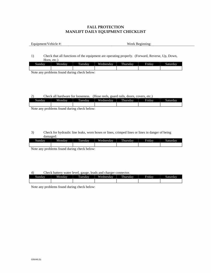
035048 (5)
FALL PROTECTION MANLIFT DAILY EQUIPMENT CHECKLIST
Equipment/Vehicle #: Week Beginning: 1) Check that all functions of the equipment are operating properly. (Forward, Reverse, Up, Down,
Horn, etc.) Sunday Monday Tuesday Wednesday Thursday Friday Saturday
Note any problems found during check below: 2) Check all hardware for looseness. (Hose reels, guard rails, doors, covers, etc.)
Sunday Monday Tuesday Wednesday Thursday Friday Saturday Note any problems found during check below: 3) Check for hydraulic line leaks, worn hoses or lines, crimped lines or lines in danger of being
damaged: Sunday Monday Tuesday Wednesday Thursday Friday Saturday
Note any problems found during check below: 4) Check battery water level, gauge, leads and charger connector.
Sunday Monday Tuesday Wednesday Thursday Friday Saturday
Note any problems found during check below:

005048 (5) APPB ATTB 1
SAFETY INSPECTION CHECKLIST FOR EXCAVATIONS REFERENCED BY OSHA STANDARDS
This checklist is to be completed by the competent person at the start of work and as needed throughout the shift (i.e., after rain events, etc.). (A competent person has been trained in the current OSHA excavation standard, is knowledgeable about soil analysis and protective systems, and has the authority to shut down the job.)
Site Location: Project #: Date: Time: Competent Person: Were visual soil tests made? If Yes, what type? YES NO Type: Were manual soil tests made? If yes, what type? YES NO
Type:
Soil Type: Signature: Soil Classification: Excavation Depth: Excavation Width: Protective System Used:
In the following table, please place a Y for Yes, N for No, or N/A for Not Applicable in the right hand column for each item. If No, place the date of correction.
Subject Y, N, or NA
Date Corrected
GENERAL INSPECTION OF THE JOB SITE 1. Does the competent person have the authority to remove employees from the excavation
immediately?
2. ARE SURFACE OBSTRUCTIONS REMOVED OR SUPPORTED? 3. Are employees protected from loose rock or soil that could pose a hazard by falling or
rolling into the excavation?
4. Are hard hats worn by all employees? 5. Are excavated soil, materials, and equipment placed at least 2 feet from the edge of the
excavation?
6. Are walkways and bridges over excavations 4 feet or more in depth equipped with standard guardrails and toe-boards?
7. Are warning vests or other highly visible clothing provided and worn by all employees exposed to public vehicular traffic?
8. Are employees required to stand away from vehicles being loaded or unloaded? 9. Is a warning system established and used when mobile equipment operates near the
edge of the excavation?
10. Are employees prohibited from going beneath suspended loads? 11. Are employees prohibited from working on the faces of sloped or benched excavations
above other employees?
UTILITIES 12. Were utility companies contacted and/or utilities located? 13. Are the exact locations of the utilities marked? 14. Are underground installations protected, supported, or removed when excavation is
opened?
MEANS OF ENTERING AND EXITING THE TRENCH 15. Is the distance along the trench to an exit no greater than 25 feet in excavations 4 feet or
more in depth?
16. IS A SUPPORT SYSTEM, SUCH AS UNDERPINNING, BEING USED? 17. Are ladders used in excavations secured and extended 3 feet above edge of the trench?

005048 (5) APPB ATTB 2
Subject Y, N, or NA
Date Corrected
18. Are structural ramps used by employees designed by a competent person? 19. Are structural ramps used for equipment designed by a registered professional
engineer?
20. Are employees protected from cave-ins when entering or exiting the excavation? WET CONDITIONS 21. Is water removal equipment monitored by a competent person? 22. Is surface water or run-off diverted or controlled to prevent accumulation in the
excavation?
23. Are inspections made after every rainstorm or other hazard-increasing occurrence? HAZARDOUS ATMOSPHERE 24. Is the atmosphere within the excavation tested where there is a reasonable possibility of
an oxygen deficiency, combustible, or other harmful contaminant exposing employees to a hazard?
25. Are adequate precautions taken to protect employees from exposure to an atmosphere containing less than 19.5% oxygen and/or other hazardous atmospheres?
26. Is ventilation provided to prevent employee exposure to an atmosphere containing flammable gas 10% above the lower explosive limit of a gas?
27. Is testing conducted often to ensure that the atmosphere remains safe? 28. Is emergency equipment, such as breathing apparatus, safety harness and lifeline,
and/or basket stretcher readily available where hazardous atmospheres could or do exist?
SUPPORT SYSTEMS 29. Are materials and/or equipment for support systems selected based on soil analysis,
trench depth, and expected loads?
30. Are materials and equipment used for protective systems inspected and in good condition?
31. Are protective systems installed without exposing employees to the hazards of cave-ins (including end walls), collapses, or threat of being struck by materials or equipment?
32. Are excavations below the level of the base, or footing supported, approved by a registered professional engineer?
33. Does the removal of support systems progress from the bottom and members are released slowly? Note any indication of possible failure.
34. Is the excavation of material a level no greater than 2 feet below the bottom of the support system and only if the system is designed to support the loads calculated for the full depth?
35. Is there a shield system placed to prevent lateral movement?

035048 (5) APPB ATTB
SAFETY INSPECTION CHECKLIST – MOBILE EQUIPMENT SAFETY
Week Ending: Job No.: Equipment:
(This form is to be completed daily by the operator. Deficiencies should be addressed immediately.) Superintendent: ______________________________
Date: Mon. Tues. Wed. Thurs. Fri. Sat. Sun. Comments Equipment Hours: Start:
Stop: Fluid Levels: Oil Hydraulic Transmission Radiator Grease Fittings Fuel Safety Checks: Fire Extinguisher Seat and Safety Belts Warning Devices (backup alarms, lights, etc.) Housekeeping Brakes Mirrors Windshield and Wipers Steering Horn Lights Tires Guards Instruments Exhaust System Accessories: Boom or Mast Controls Level Indicators Tracks Other Sign-Off: Operator's Initials Supervisor's Initials
Additional Comments: (Please write any additional comments here. Use the back of this form if necessary.)
√ = OK NR = Needs Repair NA = Not Applicable

035048 (5) APPB
ATTACHMENT C
COMMUNITY AIR MONITORING PLAN

035048 (5) APPB ATTC 1
COMMUNITY AIR MONITORING PLAN FOR THE OLD ERIE CANAL SITE – CLYDE, NEW YORK
DEVELOPED IN ACCORDANCE WITH THE NEW YORK STATE DEPARTMENT OF HEALTH'S GENERIC COMMUNITY AIR MONITORING PLAN
Overview This site-specific Community Air Monitoring Plan (CAMP) requires real-time monitoring for volatile organic compounds (VOCs) and particulates (i.e., dust) at the downwind perimeter of each designated work area when certain activities are in progress at contaminated sites. The CAMP is not intended for use in establishing action levels for worker respiratory protection. Rather, its intent is to provide a measure of protection for the downwind community (i.e., off-site receptors including residences and businesses and on-site workers not directly involved with the subject work activities) from potential airborne contaminant releases as a direct result of remedial work activities. The action levels specified herein require increased monitoring and corrective actions to abate emissions, and/or work shutdown. Additionally, the CAMP will help to confirm that work activities do not spread contamination off site through the air. Designated air monitoring station locations will be established around the perimeter of the site for use as monitoring locations. The site-specific CAMP presented below will be implemented during the soil handling activities at the site which include excavation activities. Each day that this activity is in progress one upwind and two downwind air monitoring stations will be set up to collect data. The instruments that will be used to collect the air monitoring data will have data logging capabilities. The data will be downloaded periodically, stored electronically and will be available to agency personnel for their review. Reliance on this CAMP should not preclude simple, common sense measures to keep VOCs, dust, and odors at a minimum around the work areas. Community Air Monitoring Plan Real-time air monitoring for VOCs and particulate levels at the perimeter of the site will be necessary, as described below. Continuous monitoring will be required during all soil handling at the Site including excavation activities.

035048 (5) APPB ATTC 2
Periodic monitoring for VOCs will be required during non-intrusive activities such as the collection of soil samples (if completed). Periodic monitoring during sample collection might reasonably consist of taking a reading upon arrival at a sample location, monitoring while overturning soil and then taking a reading prior to leaving a sample location. VOC Monitoring, Response Levels, and Actions VOCs will be monitored at the downwind perimeter of the site on a continuous basis. Upwind concentrations should be measured at the start of each workday and periodically thereafter to establish background conditions, particularly if wind direction changes. The specific type of air monitoring equipment that will be used at the site for VOC monitoring will be a MiniRae 3000, or equivalent. The equipment will be calibrated in accordance with the manufacturer's guidelines. The equipment will be capable of calculating 15-minute running average concentrations, which will be compared to the levels specified below. 1. If the ambient air concentration of VOCs at the downwind perimeter of the site exceeds
5 parts per million (ppm) above background for the 15-minute average, work activities must be temporarily halted and monitoring continued. If the total organic vapor level readily decreases (per instantaneous readings) below 5 ppm over background, work activities can resume with continued monitoring.
2. If total organic vapor levels at the downwind perimeter of the site persist at levels in excess of 5 ppm over background but less than 25 ppm, work activities must be halted, the source of vapors identified, corrective actions taken to abate emissions, and monitoring continued. After these steps, work activities can resume provided that the total organic vapor level 200 feet downwind of the designated work area or half the distance to the nearest potential receptor or residential/commercial structure, whichever is less - but in no case less than 20 feet, is below 5 ppm over background for the 15-minute average.
3. If the organic vapor level is above 25 ppm at the perimeter of the site, activities must be shutdown.
4. All 15-minute readings must be recorded and be available for State (New York State Department of Environmental Conservation [NYSDEC] and the New York State Department of Health [NYSDOH]) personnel to review. Instantaneous readings, if any, used for decision purposes will also be recorded.
Particulate/Fugitive Dust Monitoring, Response Levels, and Actions Particulate concentrations will be monitored continuously at one upwind and two downwind monitoring stations on the site perimeter. The particulate monitoring will be performed using

035048 (5) APPB ATTC 3
real-time monitoring equipment capable of measuring particulate matter less than 10 micrometers in size (PM-10) and capable of integrating over a period of 15 minutes (or less) for comparison to the airborne particulate action level. The particulate monitor that will be used will be a TSI 8520 DustTrak, or equivalent. The equipment will be equipped with an audible and/or visible alarm to indicate exceedance of the action level. In addition, fugitive dust migration should be visually assessed during all work activities. 1. If the downwind PM-10 particulate level is 100 micrograms per cubic meter (mcg/m3)
greater than background (upwind perimeter) for the 15-minute period or if airborne dust is observed leaving the designated work area, then dust suppression techniques must be employed. Work may continue with dust suppression techniques provided that downwind PM-10 particulate levels do not exceed 150 mcg/m3 above the upwind level and provided that no visible dust is migrating from the designated work area.
2. If, after implementation of dust suppression techniques, downwind PM-10 particulate levels are greater than 150 mcg/m3 above the upwind level, work must be stopped and a re-evaluation of activities initiated. Work can resume provided that dust suppression measures and other controls are successful in reducing the downwind PM-10 particulate concentration to within 150 mcg/m3 of the upwind level and in preventing visible dust migration.
3. All readings must be recorded and be available for State (NYSDEC and NYSDOH) personnel to review.
The following fugitive dust suppression and corrective procedures will be employed at the site. 1. Reasonable fugitive dust suppression techniques will be employed during all remedial
activities, which may generate fugitive dust.
2. The following techniques are generally effective for the controlling of the generation and migration of dust during construction activities and may be employed as necessary:
(a) Applying water on haul roads
(b) Wetting equipment and excavation faces
(c) Spraying water on buckets during excavation and dumping
(d) Hauling materials in properly tarped or watertight containers
(e) Restricting vehicle speeds to 10 mph
(f) Covering excavated areas and material after excavation activity ceases
(g) Reducing the excavation size and/or number of excavations

035048 (5) APPB ATTC 4
When techniques involving water application are used, care must be taken not to use excess water, which can result in unacceptably wet conditions. Using atomizing sprays will prevent overly wet conditions, conserve water, and provide an effective means of suppressing the fugitive dust.