CONSTRUCTION HYDRAULIC CYLINDERS The Power of ...
36
CONSTRUCTION HYDRAULIC CYLINDERS The Power of Hydraulic Force EP700-B1706 High Pressure Hydraulic Cylinders specially for:- • Construction Applications • Prestressing Specialists • Heavy Load Lifters
-
Upload
khangminh22 -
Category
Documents
-
view
0 -
download
0
Transcript of CONSTRUCTION HYDRAULIC CYLINDERS The Power of ...

CONSTRUCTION HYDRAULIC CYLINDERS
The Power of Hydraulic Force
EP700-B1706
High Pressure Hydraulic Cylinders specially for:-
• Construction Applications• Prestressing Specialists• Heavy Load Lifters

EURO POWER HYDRAULICS offers a full range of quality E-POWER 700 high pressure hydraulic cylinders, pumps, pullers, tools & systems to meet the most demanding hydraulic application requirements, serving virtually all industrial & construction industries; and marketing through its authorised network of stocking distributors in many locations – products, parts & service availability.
E-POWER 700 products are widely used by customers in industries such as manufacturers, construction, bridge equipment manufacturers, energy, oil & gas, mining, rigging, quarrying, steel & rolling mills, shipbuilding & repairing, offshore marine, power plants, maintenance & repair (MRO), aerospace, railroads, transportation and many other industries requiring hydraulic power.
EURO POWER HYDRAULICS are committed to continued quality improvement and expanding its offering of standard, custom & special products, ensuring continuous customer satisfaction.
The POWER of Hydraulic Force• Innovative Products• Reliable Performance• High Quality Standards• Safety• Product Availability• Service Support• Application Solutions• Project & System Design
Industrial Applications• Lifting, Supporting & Lowering• Pushing, Pulling & Positioning• Assembly & Manufacturing • Metal Fabrication• Maintenance & Repairs• Clamping & Holding• Pressing & Bending• Straightening & Spreading• Load & Tension Measurement• Research & Development• Quality Control
E-POWER 700 Delivery VanAt Your Service!
WWW.EUROPOWER700.COM

HY
DR
AU
LIC
CY
LIN
DER
SPU
MPS
& S
YST
EMS
VALV
ES A
ND
AC
CES
SOR
IES
Professional High
Pressure Hydraulic
Cylinders, Pumps,
Pullers, Tools and
Systems to fulfil
virtually all Industrial
& Construction
Application needs.
HYDRAULICCYLINDERS
Page 3 - 24
PUMPS & SYSTEMS
Page 25 – 31
VALVES AND ACCESSORIES
Page 32 - 33
More
Hydraulic Tools Available
Ask for ourINDUSTRIAL HYDRAULIC TOOLS
Catalogue Now
INDUSTRIAL HYDRAULIC TOOLS
The Power of Hydraulic Force
EP700-C1705
Professional
High Pressure
Hydraulic Cylinders,
Pumps, Pullers,
Tools and Systems
For the Professionals For the SpecialistsFor the Experts
WWW.EUROPOWER700.COM 1

2
HY
DR
AU
LIC
CY
LIN
DER
S
2 WWW.EUROPOWER700.COM
TABLE OF CONTENTS PAGE
HYDRAULIC CYLINDERS / JACKS (‘E’ Series Construction Range)
EGS : High Tonnage Hydraulic Cylinders, Single-acting, Load Return ...................................... 4 - 7
EGG : Lock Nut Hydraulic Cylinders, Single-acting, Load Return ............................................ 8 - 11
EGR : Lock Nut, Pancake Hydraulic Cylinders, Single-acting, Load Return .................................. 13
EOS : High Tonnage Hydraulic Cylinders, Double-acting, Oil Return ................................... 14 - 17
EOF : Hollow Piston High Tonnage Cylinders, Double-Acting, Oil Return ............................ 18 - 19
ESF : Single-strand (Front Grip) Hydraulic Stressing Jacks, Double-Acting, Oil Return................. 20
ESR : Single-strand (Rear Grip) Hydraulic Stressing Jacks, Double-Acting, Oil Return .................. 20
ESM : Multi-strand Stressing Hydraulic Jacks, Double-acting, Oil Return ..................................... 21
ELM : Low To Mid Pressure Range, Industrial Hydraulic Cylinders ............................................... 22
EMS : Single-axis Mechanical Screw Jacks, Hydraulically-operated .............................................. 23
UL : Hydraulic Load Cells ........................................................................................................ 24
PUMPS & SYSTEMS
PS & PV : Steel Hand Pumps ................................................................................................ 26
ME / MM-PP : Modular Hydraulic Power Pumps for Geotechnical Structural Tests ....................... 27
MM : Modular Hydraulic Power Pumps with Single-Phase Electric Motor ....................... 28
ME : Modular Hydraulic Power Pumps with 3-Phase Electric Motor .............................. 29
SPLIT FLOW : Hydraulic Power Pumps for Synchronous Lifting Systems ...................................... 30
SYN-LIFT : PLC Synchronous Lifting and Lowering Systems .................................................... 31
VALVES & ACCESSORIES
G, K & S : Gauges, Gauge Blocks, Couplers & Hoses ............................................................ 32
VR & R : Regulating Valves, Manifolds & Fittings ............................................................... 33
Every care and effort have been taken to prepare this catalogue to ensure the accuracy of all data and information at the time of printing. Due to the continuous improvement and evolution of the factory production range, EURO POWER HYDRAULICS reserves the right to modify or discontinue any product without any prior notice. All information and any published specification contained in this catalogue can be changed due to product improvements without prior notice.
All illustrations, performance specifications and dimensions may have slight variations due to manufacturing tolerances.Please contact EURO POWER HYDRAULICS if final dimensions are critical.
© Copyright 2017, EURO POWER HYDRAULICS and E-POWER 700. All rights reserved.E-POWER 700 is the tradename & trademark of EURO POWER HYDRAULICS PTE LTD.Any copying in any form or other use of the contents in this catalogue (text, illustrations, drawings, photos) without the express prior written consent of EURO POWER HYDRAULICS PTE LTD is prohibited.

3
HY
DR
AU
LIC
CY
LIN
DER
S
3WWW.EUROPOWER700.COM
Example:
1 Product Type
E - Construction Cylinders / Jacks (‘E’ Series)
2 Cylinder Type
GS - Single-acting, Load Return, High Tonnage Hydraulic Cylinder
GG - Single-acting, Load Return, Lock Nut Hydraulic Cylinder
GR - Single-acting, Load Return, Lock Nut, Pancake Hydraulic Cylinder
OS - Double-acting, Oil Return, High Tonnage Hydraulic Cylinder
OF - Double-acting, Oil Return, Hollow Piston High Tonnage Hydraulic Cylinder
SF - Double-acting, Oil Return, Single-strand (Front Grip) Hydraulic Stressing Jack
SR - Double-acting, Oil Return, Single-strand (Rear Grip) Hydraulic Stressing Jack
SM - Double-acting, Oil Return, Multi-strand Stressing Hydraulic Jack
TW* - Double-acting, Oil Return, Tube Wedge Hydraulic Positioning Jack
MS - Single-axis Mechanical Screw Jack, Hydraulically-operated
MM* - Mechanical Screw Jack
* Available Upon Request.
HYDRAULIC CYLINDERS (Construction Range)
Ordering Matrix
Product Type
E
EOS500150S
1
Cylinder Type
OS
2
Tonnage
500
(Tonnes)
3
Option
S
*Integral Tilt Saddle
5
Stroke
150
(mm)
4
* Integral Tilt Saddle for EGS, EGG, EGR & EOS Series Hydraulic Cylinders only.

HY
DR
AU
LIC
CY
LIN
DER
S
4 WWW.EUROPOWER700.COM
• Extremely solid robust cylinders.• Hardened radial grooved integral tilt saddle is bolted on piston rod end improves load grip and reduces any off-centre loading.• Piston wiper reduces contamination and prolong cylinder life.• Plated piston provides corrosion and wear resistance.• Integral stop ring protects piston from over stroke.• Base mounting holes are standard on all models.• Suitable for use in construction & general industries for lifting & lowering heavy loads, pile or foundation testing etc.
Nominal value shown in ’Tonnes’, see kN for the exact force @700bar.
Force(PUSH) Stroke
Oil Volume
Clo
sed
He
igh
t
Clo
sed
He
igh
t w
ith
Inte
gra
l Tilt
Sa
dd
le
Tonnes mm Amm
in cm2 cm3
CHARTEffective
Area
50
100
150
200
250
300
50
100
150
200
250
300
50
100
150
200
250
300
50
100
150
200
250
300
132.7
132.7
132.7
132.7
132.7
132.7
198.6
198.6
198.6
198.6
198.6
198.6
265.6
265.6
265.6
265.6
265.6
265.6
366.1
366.1
366.1
366.1
366.1
366.1
664
1328
1992
2653
3317
3981
994
1987
2981
3970
4963
5957
1329
2658
3987
5310
6639
7968
1832
3664
5496
7319
9151
10983
182
232
282
332
382
432
196
246
296
346
396
446
216
266
316
366
416
466
235
285
335
385
435
485
A1mm
100
150
200
250
2
4
6
8
10
12
2
4
6
8
10
12
2
4
6
8
10
12
2
4
6
8
10
12
EGS10050S
EGS100100S
EGS100150S
EGS100200S
EGS100250S
EGS100300S
EGS15050S
EGS150100S
EGS150150S
EGS150200S
EGS150250S
EGS150300S
EGS20050S
EGS200100S
EGS200150S
EGS200200S
EGS200250S
EGS200300S
EGS25050S
EGS250100S
EGS250150S
EGS250200S
EGS250250S
EGS250300S
Capacity:
100 - 1500 tonnes
Stroke:
50 - 300 mm
Maximum Operating Pressure:
700 bar (10,000 psi)
kN
929
1390
1859
2563
MODEL
211
261
311
361
411
461
227
277
327
377
427
477
251
301
351
401
451
501
281
331
381
431
481
531
SELECTION CHART
With IntegralTilt Saddle
Single-acting, Load Return, High Tonnage Hydraulic Cylinders
EGS Series

HY
DR
AU
LIC
CY
LIN
DER
S
5WWW.EUROPOWER700.COM
PC
D M
ou
nti
ng
Ho
les
We
igh
t
Bo
re D
ia.
Pis
ton
Ro
d D
ia.
Ou
tsid
e D
ia.
Co
up
ler
He
igh
t
(Ba
se t
o A
dv
an
ce
Po
rt)
Ba
se M
ou
nti
ng
Ho
les/
Ho
les
De
pth
Inte
gra
l Tilt
Sa
dd
le
Dia
.
Ro
d P
rotr
usi
on
wit
h In
teg
ral T
ilt
Sa
dd
le
Dmm
Emm
Fmm
Hmm
Jmm
K1mm
Umm
V/Zmm
kg
EGS10050S
EGS100100S
EGS100150S
EGS100200S
EGS100250S
EGS100300S
EGS15050S
EGS150100S
EGS150150S
EGS150200S
EGS150250S
EGS150300S
EGS20050S
EGS200100S
EGS200150S
EGS200200S
EGS200250S
EGS200300S
EGS25050S
EGS250100S
EGS250150S
EGS250200S
EGS250250S
EGS250300S
20
30
41
51
62
73
41
54
67
80
94
107
59
77
95
113
132
150
94
117
141
165
188
212
Cylinders with non standard force and
stroke can be supplied upon request.
Female 3/8”
Coupler Included.
Integral Tilt Saddle standard on EGS Series Cylinders• To reduce the effects of any off-centred loads.• Tilts up to 5°• Grooved saddle to reduce any load slippage.
165
205
235
275
130
159
184
216
95
114
133
165
54
61
67
73
73
90
118
142
29
31
35
46
95
130
165
190
2 x M12
22
2 x M12
22
3 x M12
22
3 x M12
22
MODEL
With IntegralTilt Saddle
F
Single-acting, Load Return, High Tonnage Hydraulic Cylinders
EGS Series

HY
DR
AU
LIC
CY
LIN
DER
S
6 WWW.EUROPOWER700.COM
Nominal value shown in ’Tonnes’, see kN for the exact force @700bar.
Clo
sed
He
igh
t
Clo
sed
He
igh
t w
ith
Inte
gra
l Tilt
Sa
dd
le
Tonnes mm Amm
in cm2 cm3 A1mm
kN
3193
3919
5115
5987
8238
10262
15443
With IntegralTilt Saddle
SELECTION CHART
300
400
500
600
800
1000
1500
50
100
150
200
250
300
50
100
150
200
250
300
50
100
150
200
250
300
50
100
150
200
250
300
50
100
150
200
250
300
50
100
150
200
250
300
150
456.2
456.2
456.2
456.2
456.2
456.2
559.9
559.9
559.9
559.9
559.9
559.9
730.6
730.6
730.6
730.6
730.6
730.6
855.3
855.3
855.3
855.3
855.3
855.3
1176.9
1176.9
1176.9
1176.9
1176.9
1176.9
1466.1
1466.1
1466.1
1466.1
1466.1
1466.1
2206.2
2283
4565
6848
9119
11402
13685
2801
5603
8404
11192
13993
16795
3656
7312
10968
14605
18261
21917
4280
8559
12839
17097
21377
25656
5889
11778
17667
23526
29415
35304
7336
14672
22008
29306
36642
43978
33093
2
4
6
8
10
12
2
4
6
8
10
12
2
4
6
8
10
12
2
4
6
8
10
12
2
4
6
8
10
12
2
4
6
8
10
12
6
EGS30050S
EGS300100S
EGS300150S
EGS300200S
EGS300250S
EGS300300S
EGS40050S
EGS400100S
EGS400150S
EGS400200S
EGS400250S
EGS400300S
EGS50050S
EGS500100S
EGS500150S
EGS500200S
EGS500250S
EGS500300S
EGS60050S
EGS600100S
EGS600150S
EGS600200S
EGS600250S
EGS600300S
EGS80050S
EGS800100S
EGS800150S
EGS800200S
EGS800250S
EGS800300S
EGS100050S
EGS1000100S
EGS1000150S
EGS1000200S
EGS1000250S
EGS1000300S
EGS1500150S
312
362
412
462
512
562
374
424
474
524
574
625
419
469
519
569
619
669
429
479
529
579
629
679
474
524
574
624
674
724
564
614
664
714
764
814
730
373
423
473
523
573
623
425
475
525
575
625
676
482
532
582
632
682
732
505
555
605
655
705
755
549
599
649
699
749
799
657
707
757
807
857
907
855
Force(PUSH)
StrokeOil
VolumeEffective
Area MODEL
Single-acting, Load Return, High Tonnage Hydraulic Cylinders
EGS Series

HY
DR
AU
LIC
CY
LIN
DER
S
7WWW.EUROPOWER700.COM
PC
D M
ou
nti
ng
Ho
les
We
igh
t
Bo
re D
ia.
Ou
tsid
e D
ia.
Co
up
ler
He
igh
t
(Ba
se t
o A
dv
an
ce
Po
rt)
Ba
se M
ou
nti
ng
Ho
les/
Ho
les
De
pth
Inte
gra
l Tilt
Sa
dd
le
Dia
.
Ro
d P
rotr
usi
on
wit
h In
teg
ral T
ilt
Sa
dd
le
Dmm
Emm
Fmm
Hmm
Jmm
K1mm
Umm
V/Zmm
kg
MODEL
With IntegralTilt Saddle
EGS30050S
EGS300100S
EGS300150S
EGS300200S
EGS300250S
EGS300300S
EGS40050S
EGS400100S
EGS400150S
EGS400200S
EGS400250S
EGS400300S
EGS50050S
EGS500100S
EGS500150S
EGS500200S
EGS500250S
EGS500300S
EGS60050S
EGS600100S
EGS600150S
EGS600200S
EGS600250S
EGS600300S
EGS80050S
EGS800100S
EGS800150S
EGS800200S
EGS800250S
EGS800300S
EGS100050S
EGS1000100S
EGS1000150S
EGS1000200S
EGS1000250S
EGS1000300S
EGS1500150S
198
222
246
269
295
317
290
320
350
380
411
441
420
460
499
539
578
618
499
544
590
635
681
726
776
839
903
960
1034
1093
1112
1187
1263
1338
1414
1489
2045
310
350
400
430
505
560
690
241
267
305
330
387
432
530
197
216
248
267
317
343
430
101
114
114
114
149
174
215
160
193
228
241
287
314
410
61
51
63
76
75
93
125
180
205
250
275
330
375
480
3 x M16
36
3 x M16
36
3 x M24
38
3 x M24
38
3 x M24
38
3 x M24
38
3 x M3045
Pis
ton
Ro
d D
ia.
Single-acting, Load Return, High Tonnage Hydraulic Cylinders
EGS Series

HY
DR
AU
LIC
CY
LIN
DER
S
8 WWW.EUROPOWER700.COM
Single-acting, Load Return, Lock Nut Hydraulic Cylinders
EGG Series
• Safety Lock Nut provides positive mechanical load holding supporting lifted load for extended long period with hydraulic pressure released. • Extremely solid robust cylinders. • Hardened radial grooved integral tilt saddle is bolted on piston rod end improves load grip and reduces any off-centre loading. • Overflow port stroke limiter prevents piston from overextension under load. • Plated piston provides corrosion and wear resistance. • Base mounting holes are optional & available upon request. • Suitable for use in construction & general industries for lifting & supporting heavy loads for extended period.
Nominal value shown in ’Tonnes’, see kN for the exact force @700bar.
Clo
sed
He
igh
t
Clo
sed
He
igh
t w
ith
Inte
gra
l Tilt
Sa
dd
le
Tonnes mm Amm
in cm2 cm3
CHART
50
100
150
200
250
300
50
100
150
200
250
300
50
100
150
200
250
300
50
100
150
200
250
300
70.9
70.9
70.9
70.9
70.9
70.9
132.7
132.7
132.7
132.7
132.7
132.7
198.6
198.6
198.6
198.6
198.6
198.6
265.6
265.6
265.6
265.6
265.6
265.6
355
710
1064
1417
1772
2127
664
1328
1992
2653
3317
3981
994
1987
2981
3970
4963
5957
1329
2658
3987
5310
6639
7968
164
214
264
314
364
414
187
237
287
337
387
437
209
259
309
359
409
459
243
293
343
393
443
493
A1mm
50
100
150
200
2
4
6
8
10
12
2
4
6
8
10
12
2
4
6
8
10
12
2
4
6
8
10
12
EGG5050S
EGG50100S
EGG50150S
EGG50200S
EGG50250S
EGG50300S
EGG10050S
EGG100100S
EGG100150S
EGG100200S
EGG100250S
EGG100300S
EGG15050S
EGG150100S
EGG150150S
EGG150200S
EGG150250S
EGG150300S
EGG20050S
EGG200100S
EGG200150S
EGG200200S
EGG200250S
EGG200300S
Capacity:
50 - 1000 tonnes
Stroke:
50 - 300 mm
Maximum Operating Pressure:
700 bar (10,000 psi)
kN
496
929
1390
1859
188
238
288
338
388
438
211
261
311
361
411
461
229
279
329
379
429
479
263
313
363
413
463
513
SELECTION CHART
With IntegralTilt Saddle
Force(PUSH) Stroke
Oil Volume
EffectiveArea MODEL

HY
DR
AU
LIC
CY
LIN
DER
S
9WWW.EUROPOWER700.COM
Single-acting, Load Return, Lock Nut Hydraulic Cylinders
EGG Series
Lock
Nu
t T
hic
kne
ss
We
igh
t
Bo
re D
ia.
Ou
tsid
e D
ia.
Co
up
ler
He
igh
t
(Ba
se t
o A
dv
an
ce
Po
rt)
Inte
gra
l Tilt
Sa
dd
le
Dia
.
Ro
d P
rotr
usi
on
wit
h In
teg
ral T
ilt
Sa
dd
le
Dmm
Emm
Fmm
Hmm
Jmm
K1mm
Tmm
kg
EGG5050S
EGG50100S
EGG50150S
EGG50200S
EGG50250S
EGG50300S
EGG10050S
EGG100100S
EGG100150S
EGG100200S
EGG100250S
EGG100300S
EGG15050S
EGG150100S
EGG150150S
EGG150200S
EGG150250S
EGG150300S
EGG20050S
EGG200100S
EGG200150S
EGG200200S
EGG200250S
EGG200300S
17
21
26
31
36
41
32
41
49
58
66
75
55
68
81
94
107
120
87
105
122
139
157
175
Cylinders with non standard force and
stroke can be supplied upon request.
Female 3/8”
Coupler Included.
Integral Tilt Saddle standard on EGG Series Cylinders• To reduce the effects of any off-centred loads.• Tilts up to 5°• Grooved saddle to reduce any load slippage.
125
165
205
235
95
130
159
184
Tr 95 x 4
Tr 130 x 6
Tr 159 x 6
Tr 184 x 6
30
30
39
50
71
71
130
130
24
24
20
20
36
44
44
50
MODEL
With IntegralTilt Saddle
5P
isto
n R
od
Dia
.
(Th
rea
de
d)
T
Base mounting holes
optional

HY
DR
AU
LIC
CY
LIN
DER
S
10 WWW.EUROPOWER700.COM
Single-acting, Load Return, Lock Nut Hydraulic Cylinders
EGG Series
Nominal value shown in ’Tonnes’, see kN for the exact force @700bar.
Clo
sed
He
igh
t
Clo
sed
He
igh
t
wit
h In
teg
ral
Tilt
Sad
dle
Tonnes mm Amm
in cm2 cm3 A1mm
kN
2563
3193
3919
5115
5987
8238
10262
With IntegralTilt Saddle
SELECTION CHART
250
300
400
500
600
800
1000
50
100
150
200
250
300
50
100
150
200
250
300
50
100
150
200
250
300
50
100
150
200
250
300
50
100
150
200
250
300
50
100
150
200
250
300
50
100
150
200
250
300
366.1
366.1
366.1
366.1
366.1
366.1
456.2
456.2
456.2
456.2
456.2
456.2
559.9
559.9
559.9
559.9
559.9
559.9
730.6
730.6
730.6
730.6
730.6
730.6
855.3
855.3
855.3
855.3
855.3
855.3
1176.9
1176.9
1176.9
1176.9
1176.9
1176.9
1466.1
1466.1
1466.1
1466.1
1466.1
1466.1
1832
3664
5496
7319
9151
10983
2283
4565
6848
9119
11402
13685
2801
5603
8404
11192
13993
16795
3656
7312
10968
14605
18261
21917
4280
8559
12839
17097
21377
25656
5889
11778
17667
23526
29415
35304
7336
14672
22008
29306
36642
43978
2
4
6
8
10
12
2
4
6
8
10
12
2
4
6
8
10
12
2
4
6
8
10
12
2
4
6
8
10
12
2
4
6
8
10
12
2
4
6
8
10
12
EGG25050S
EGG250100S
EGG250150S
EGG250200S
EGG250250S
EGG250300S
EGG30050S
EGG300100S
EGG300150S
EGG300200S
EGG300250S
EGG300300S
EGG40050S
EGG400100S
EGG400150S
EGG400200S
EGG400250S
EGG400300S
EGG50050S
EGG500100S
EGG500150S
EGG500200S
EGG500250S
EGG500300S
EGG60050S
EGG600100S
EGG600150S
EGG600200S
EGG600250S
EGG600300S
EGG80050S
EGG800100S
EGG800150S
EGG800200S
EGG800250S
EGG800300S
EGG100050S
EGG1000100S
EGG1000150S
EGG1000200S
EGG1000250S
EGG1000300S
249
299
349
399
449
499
295
345
395
445
495
545
335
385
435
485
535
585
375
425
475
525
575
625
395
445
495
545
595
645
455
505
555
605
655
705
495
545
595
645
695
745
270
320
370
420
470
520
370
420
470
520
570
620
420
470
520
570
620
670
466
516
566
616
666
716
491
541
591
641
691
741
578
628
678
728
778
828
631
681
731
781
831
881
StrokeOil
VolumeEffective
Area MODELForce(PUSH)

HY
DR
AU
LIC
CY
LIN
DER
S
11WWW.EUROPOWER700.COM
Single-acting, Load Return, Lock Nut Hydraulic Cylinders
EGG Series
We
igh
t
Bo
re D
ia.
Ou
tsid
e D
ia.
Co
up
ler
He
igh
t
(Bas
e t
o
Ad
van
ce P
ort
)
Inte
gra
l Tilt
Sad
dle
Dia
.
Ro
d P
rotr
usi
on
wit
h In
teg
ral
Tilt
Sad
dle
Dmm
Emm
Fmm
Hmm
Jmm
K1mm
Tmm
kg
MODEL
With IntegralTilt Saddle
EGG25050S
EGG250100S
EGG250150S
EGG250200S
EGG250250S
EGG250300S
EGG30050S
EGG300100S
EGG300150S
EGG300200S
EGG300250S
EGG300300S
EGG40050S
EGG400100S
EGG400150S
EGG400200S
EGG400250S
EGG400300S
EGG50050S
EGG500100S
EGG500150S
EGG500200S
EGG500250S
EGG500300S
EGG60050S
EGG600100S
EGG600150S
EGG600200S
EGG600250S
EGG600300S
EGG80050S
EGG800100S
EGG800150S
EGG800200S
EGG800250S
EGG800300S
EGG100050S
EGG1000100S
EGG1000150S
EGG1000200S
EGG1000250S
EGG1000300S
121
145
168
191
215
239
187
217
247
277
307
337
271
309
347
385
423
461
397
447
496
547
597
647
506
544
602
661
719
777
779
859
940
1020
1100
1180
1049
1145
1241
1338
1434
1530
275
310
350
400
430
505
560
216
241
267
305
330
387
432
Tr 216 x 6
Tr 241 x 6
Tr 266 x 6
Tr 305 x 6
Tr 330 x 6
Tr 387 x 6
Tr 432 x 6
50
59
70
80
85
100
110
150
195
225
250
275
320
360
21
75
85
91
96
123
136
56
60
70
80
85
100
110
Pis
ton
Ro
d D
ia.
(Th
read
ed
)
Lock
Nu
t
Th
ickn
ess

HY
DR
AU
LIC
CY
LIN
DER
S
12 WWW.EUROPOWER700.COM
CONSTRUCTION APPLICATIONS
LOAD TESTSResistance and inflexion tests carried out on slabs or beams
by using single- or double-acting cylinders.
ALIGNMENT SYSTEMSAlignment system made up of special Lock Nut cylinders
for the particles detector at the end of the new LHC
accelerator ring.
Strengthening of a motorway
viaduct with a test on a 1000
mm diameter cement pile
with an induced load of about
700 tonne.
Load tests made on a cut off wall in the bearing structure of
a building foundation.
LIFTINGSLifting and precision levelling of the suspended floors
during rebuilding works.
SYNCHRONIZED LIFTINGSSynchronous lifting of mine digger’s cabin P&H 4100 and
P&H 2800 for periodic
maintenance on cabin’s
thrust block and turntable.
Lifting of a cylindrical shell used to build a reactor for the
oil sector. Cylinders were operated by a Split Flow power
pump.

HY
DR
AU
LIC
CY
LIN
DER
S
13WWW.EUROPOWER700.COM
Single-acting, Load Return, Lock Nut, Pancake Hydraulic Cylinders
Capacity:
60 - 500 tonnes
Stroke:
45 - 50 mm
Maximum Operating Pressure:
700 bar (10,000 psi)
Integral Tilt Saddle standard on EGR Series Cylinders• To reduce the effects of any off-centred loads.• Tilts 3° to 5°• Grooved saddle to reduce any load slippage.
Cylinders with non standard force and
stroke can be supplied upon request.
Female 3/8”
Coupler Included.
Forc
e (P
USH
)
Stro
ke
Oil
Vo
lum
e
We
igh
t
Bo
re D
ia.
Pis
ton
Ro
d D
ia.
(Th
rea
de
d)
Ou
tsid
e D
ia.
Clo
sed
He
igh
t w
ith
In
teg
ral T
ilt S
ad
dle
Inte
gra
l Tilt
Sa
dd
le
Dia
.
Ro
d P
rotr
usi
on
wit
hIn
teg
ral T
ilt S
ad
dle
mmD
mmE
mmF
mmJ
mm
Lock
Nu
t T
hic
kne
ss
Tmm
K1mm
in kgcm2 cm3
Effec
tive
Are
a
50
45
45
45
45
45
45
86.6
143.1
231.5
285.9
366.4
559.9
730.6
433
644
1042
1287
1649
2520
3288
125
137
149
155
159
178
192
140
175
220
245
275
350
400
104
135
171
190
216
267
305
Tr 104 x 4
Tr 136 x 6
Tr 171 x 6
Tr 190 x 6
Tr 216 x 6
Tr 266 x 6
Tr 305 x 6
96
125
160
178
200
255
290
Co
up
ler
He
igh
t(B
ase
to
Ad
va
nce
P
ort
)
Hmm
19
21
27
30
32
39
48
6
8
9
10
11
11
10
28
31
40
43
44
55
62
14
24
41
57
71
127
181
Sad
dle
Max
Tilt
An
gle
Rº
5º
5º
5º
5º
5º
4º
3º
EGR6050S
EGR10045S
EGR16045S
EGR20045S
EGR25045S
EGR40045S
EGR50045S
2
1.77
1.77
1.77
1.77
1.77
1.77
A1mm
Tonnes(kN)
60(606)
100(1002)
160(1621)
200(2001)
250(2565)
400(3919)
500(5114)
Nominal value shown in ’Tonnes’, see kN for the exact force @700bar.
• Safety Lock Nut provides positive mechanical load holding supporting lifted load for extended long period with hydraulic pressure released. • Compact and solid robust cylinders for use where working space is confined and limited. • Hardened radial grooved integral tilt saddle is bolted on piston rod end improves load grip and reduces any off-centre loading. • Overflow port stroke limiter prevents piston from overextension under load. • Plated piston provides corrosion and wear resistance. (Optional QPQ-coated surface on piston and cylinder body available upon request. It provides higher resistance to abrasion and reduce friction, extending cylinder life & its quality) • Suitable for use in construction industries for lifting & supporting heavy loads for extended period, bridge maintenance and industrial maintenance where working space is limited.
oR
MODEL
With IntegralTilt Saddle
SELECTION CHART
EGR Series

HY
DR
AU
LIC
CY
LIN
DER
S
14 WWW.EUROPOWER700.COM
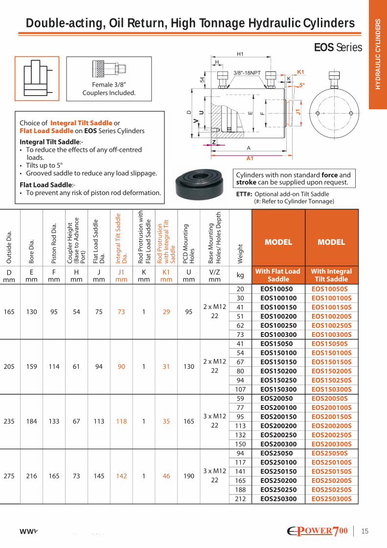
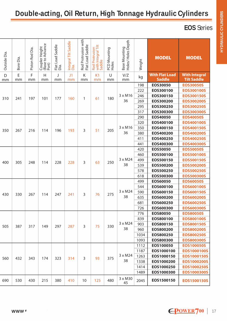
Double-acting, Oil Return, High Tonnage Hydraulic Cylinders
EOS Series
• Extremely solid robust cylinders. • Hardened radial grooved saddle is bolted on piston rod end improves load grip Integral tilt saddle reduces any off-centre loading (Add-on tilt saddle available upon request). • Piston wiper reduces contamination and prolong cylinder life. • Plated piston provides corrosion and wear resistance. • Integral stop ring protects piston from over stroke. • Double-acting for fast & positive retraction. • Safety relief valve in retract chamber of cylinder prevents any damage in the event of any accidental over-pressurisation. • Base mounting holes are standard on all models. • Suitable for use in construction & general industries for lifting, holding & lowering heavy loads, pile or foundation testing etc.
Nominal value shown in ’Tonnes’, see kN for the exact force @700bar.
Force (PUSH) Stroke
Oil
Vo
lum
e(P
USH
)
Oil
Vo
lum
e(P
ULL
)
Effec
tive
Are
a(P
USH
)
Clo
sed
He
igh
t w
ith
Fla
t Lo
ad
Sa
dd
le
Clo
sed
He
igh
t w
ith
Inte
gra
l Tilt
Sa
dd
le
Tonnesmm A
mmin cm2 cm3 cm3
50
100
150
200
250
300
50
100
150
200
250
300
50
100
150
200
250
300
50
100
150
200
250
300
132.7
132.7
132.7
132.7
132.7
132.7
198.6
198.6
198.6
198.6
198.6
198.6
265.6
265.6
265.6
265.6
265.6
265.6
366.1
366.1
366.1
366.1
366.1
366.1
664
1328
1992
2653
3317
3981
994
1987
2981
3970
4963
5957
1329
2658
3987
5310
6639
7968
1832
3664
5496
7319
9151
10983
310
619
929
1237
1546
1856
483
966
1449
1929
2412
2895
635
1271
1906
2538
3173
3809
763
1527
2290
3050
3814
4577
182
232
282
332
382
432
196
246
296
346
396
446
216
266
316
366
416
466
235
285
335
385
435
485
A1mm
100
150
200
250
2
4
6
8
10
12
2
4
6
8
10
12
2
4
6
8
10
12
2
4
6
8
10
12
EOS10050S
EOS100100S
EOS100150S
EOS100200S
EOS100250S
EOS100300S
EOS15050S
EOS150100S
EOS150150S
EOS150200S
EOS150250S
EOS150300S
EOS20050S
EOS200100S
EOS200150S
EOS200200S
EOS200250S
EOS200300S
EOS25050S
EOS250100S
EOS250150S
EOS250200S
EOS250250S
EOS250300S
Capacity:
100 - 1500 tonnes
Stroke:
50 - 300 mm
Maximum Operating Pressure:
700 bar (10,000 psi)
(kN)
(929)
(1390)
(1859)
(2563)
211
261
311
361
411
461
227
277
327
377
427
477
251
301
351
401
451
501
281
331
381
431
481
531
d improves load grip il ddl il bl )
MODEL
With Flat Load Saddle
MODEL
With IntegralTilt Saddle
SELECTION CHART
EOS10050
EOS100100
EOS100150
EOS100200
EOS100250
EOS100300
EOS15050
EOS150100
EOS150150
EOS150200
EOS150250
EOS150300
EOS20050
EOS200100
EOS200150
EOS200200
EOS200250
EOS200300
EOS25050
EOS250100
EOS250150
EOS250200
EOS250250
EOS250300
HY
DR
AU
LIC
CY
LIN
DER
S
15WWW.EUROPOWER700.COM
Double-acting, Oil Return, High Tonnage Hydraulic Cylinders
EOS Series
PC
D M
ou
nti
ng
H
ole
s
Bo
re D
ia.
Pis
ton
Ro
d D
ia.
Ou
tsid
e D
ia.
Co
up
ler
He
igh
t
(B
ase
to
Ad
va
nce
P
ort
)
Ba
se M
ou
nti
ng
Ho
les/
Ho
les
De
pth
Ro
d P
rotr
usi
on
wit
h
Fla
t Lo
ad
Sa
dd
le
Inte
gra
l Tilt
Sa
dd
le
Dia
.
Fla
t Lo
ad
Sa
dd
le
Dia
.
Ro
d P
rotr
usi
on
w
ith
Inte
gra
l Tilt
S
ad
dle
Dmm
Emm
Fmm
Hmm
Jmm
K1mm
Umm
V/Zmm
We
igh
t
kg
20
30
41
51
62
73
41
54
67
80
94
107
59
77
95
113
132
150
94
117
141
165
188
212
165
205
235
275
130
159
184
216
95
114
133
165
54
61
67
73
75
94
113
145
J1mm
73
90
118
142
29
31
35
46
Kmm
1
1
1
1
95
130
165
190
2 x M12
22
2 x M12
22
3 x M12
22
3 x M12
22
EOS10050
EOS100100
EOS100150
EOS100200
EOS100250
EOS100300
EOS15050
EOS150100
EOS150150
EOS150200
EOS150250
EOS150300
EOS20050
EOS200100
EOS200150
EOS200200
EOS200250
EOS200300
EOS25050
EOS250100
EOS250150
EOS250200
EOS250250
EOS250300
EOS10050S
EOS100100S
EOS100150S
EOS100200S
EOS100250S
EOS100300S
EOS15050S
EOS150100S
EOS150150S
EOS150200S
EOS150250S
EOS150300S
EOS20050S
EOS200100S
EOS200150S
EOS200200S
EOS200250S
EOS200300S
EOS25050S
EOS250100S
EOS250150S
EOS250200S
EOS250250S
EOS250300S
MODEL
With Flat Load Saddle
MODEL
With IntegralTilt Saddle
Cylinders with non standard force and stroke can be supplied upon request.
ETT#: Optional add-on Tilt Saddle (#: Refer to Cylinder Tonnage)
Female 3/8”
Couplers Included.
Choice of Integral Tilt Saddle orFlat Load Saddle on EOS Series Cylinders
Integral Tilt Saddle:-• To reduce the effects of any off-centred loads.• Tilts up to 5°• Grooved saddle to reduce any load slippage.
Flat Load Saddle:-• To prevent any risk of piston rod deformation.

HY
DR
AU
LIC
CY
LIN
DER
S
16 WWW.EUROPOWER700.COM
Double-acting, Oil Return, High Tonnage Hydraulic Cylinders
EOS Series
Nominal value shown in ’Tonnes’, see kN for the exact force @700bar.
Oil
Vo
lum
e(P
USH
)
Oil
Vo
lum
e(P
ULL
)
Effec
tive
Are
a(P
USH
)
Clo
sed
He
igh
t w
ith
Fla
t Lo
ad
Sa
dd
le
Clo
sed
He
igh
t w
ith
Inte
gra
l Tilt
Sa
dd
le
Tonnesmm A
mmin cm2 cm3 cm3
A1mm
300
400
500
600
800
1000
1500
(kN)
(3193)
(3919)
(5115)
(5987)
(8238)
(10262)
(15443)
MODEL
With Flat Load Saddle
MODEL
With IntegralTilt Saddle
SELECTION CHART
312
362
412
462
512
562
374
424
474
524
574
625
419
469
519
569
619
669
429
479
529
579
629
679
474
524
574
624
674
724
564
614
664
714
764
814
740
373
423
473
523
573
623
425
475
525
575
625
676
482
532
582
632
682
732
505
555
605
655
705
755
549
599
649
699
749
799
657
707
757
807
857
907
865
50
100
150
200
250
300
50
100
150
200
250
300
50
100
150
200
250
300
50
100
150
200
250
300
50
100
150
200
250
300
50
100
150
200
250
300
150
456.2
456.2
456.2
456.2
456.2
456.2
559.9
559.9
559.9
559.9
559.9
559.9
730.6
730.6
730.6
730.6
730.6
730.6
855.3
855.3
855.3
855.3
855.3
855.3
1176.9
1176.9
1176.9
1176.9
1176.9
1176.9
1466.1
1466.1
1466.1
1466.1
1466.1
1466.1
2206.2
2283
4565
6848
9119
11402
13685
2801
5603
8404
11192
13993
16795
3656
7312
10968
14605
18261
21917
4280
8559
12839
17097
21377
25656
5889
11778
17667
23526
29415
35304
7336
14672
22008
29306
36642
43978
33092
757
1515
2272
3026
3783
4540
968
1936
2904
3868
4836
5804
1239
2477
3716
4948
6187
7426
1478
2956
4435
5905
7384
8862
1937
3873
5810
7737
9673
11610
2711
5422
8132
10829
13540
16251
11309
2
4
6
8
10
12
2
4
6
8
10
12
2
4
6
8
10
12
2
4
6
8
10
12
2
4
6
8
10
12
2
4
6
8
10
12
6
EOS30050
EOS300100
EOS300150
EOS300200
EOS300250
EOS300300
EOS40050
EOS400100
EOS400150
EOS400200
EOS400250
EOS400300
EOS50050
EOS500100
EOS500150
EOS500200
EOS500250
EOS500300
EOS60050
EOS600100
EOS600150
EOS600200
EOS600250
EOS600300
EOS80050
EOS800100
EOS800150
EOS800200
EOS800250
EOS800300
EOS100050
EOS1000100
EOS1000150
EOS1000200
EOS1000250
EOS1000300
EOS1500150
EOS30050S
EOS300100S
EOS300150S
EOS300200S
EOS300250S
EOS300300S
EOS40050S
EOS400100S
EOS400150S
EOS400200S
EOS400250S
EOS400300S
EOS50050S
EOS500100S
EOS500150S
EOS500200S
EOS500250S
EOS500300S
EOS60050S
EOS600100S
EOS600150S
EOS600200S
EOS600250S
EOS600300S
EOS80050S
EOS800100S
EOS800150S
EOS800200S
EOS800250S
EOS800300S
EOS100050S
EOS1000100S
EOS1000150S
EOS1000200S
EOS1000250S
EOS1000300S
EOS1500150S
Force (PUSH) Stroke
HY
DR
AU
LIC
CY
LIN
DER
S
17WWW.EUROPOWER700.COM
Double-acting, Oil Return, High Tonnage Hydraulic Cylinders
EOS Series
PC
D M
ou
nti
ng
H
ole
s
Bo
re D
ia.
Pis
ton
Ro
d D
ia.
Ou
tsid
e D
ia.
Co
up
ler
He
igh
t
(B
ase
to
Ad
va
nce
P
ort
)
Ba
se M
ou
nti
ng
Ho
les/
Ho
les
De
pth
Ro
d P
rotr
usi
on
wit
h
Fla
t Lo
ad
Sa
dd
le
Inte
gra
l Tilt
Sa
dd
le
Dia
.
Fla
t Lo
ad
Sa
dd
le
Dia
.
Ro
d P
rotr
usi
on
w
ith
Inte
gra
l Tilt
S
ad
dle
Dmm
Emm
Fmm
Hmm
Jmm
K1mm
Umm
V/Zmm
We
igh
t
kg
198
222
246
269
295
317
290
320
350
380
411
441
420
460
499
539
578
618
499
544
590
635
681
726
776
839
903
960
1034
1093
1112
1187
1263
1338
1414
1489
2045
241
267
305
330
387
432
530
197
216
248
267
317
343
430
101
114
114
114
149
174
215
177
196
228
247
297
323
380
J1mm
160
193
228
241
287
314
410
61
51
63
76
75
93
125
Kmm
1
3
3
3
3
3
10
180
205
250
275
330
375
480
EOS30050
EOS300100
EOS300150
EOS300200
EOS300250
EOS300300
EOS40050
EOS400100
EOS400150
EOS400200
EOS400250
EOS400300
EOS50050
EOS500100
EOS500150
EOS500200
EOS500250
EOS500300
EOS60050
EOS600100
EOS600150
EOS600200
EOS600250
EOS600300
EOS80050
EOS800100
EOS800150
EOS800200
EOS800250
EOS800300
EOS100050
EOS1000100
EOS1000150
EOS1000200
EOS1000250
EOS1000300
EOS1500150
EOS30050S
EOS300100S
EOS300150S
EOS300200S
EOS300250S
EOS300300S
EOS40050S
EOS400100S
EOS400150S
EOS400200S
EOS400250S
EOS400300S
EOS50050S
EOS500100S
EOS500150S
EOS500200S
EOS500250S
EOS500300S
EOS60050S
EOS600100S
EOS600150S
EOS600200S
EOS600250S
EOS600300S
EOS80050S
EOS800100S
EOS800150S
EOS800200S
EOS800250S
EOS800300S
EOS100050S
EOS1000100S
EOS1000150S
EOS1000200S
EOS1000250S
EOS1000300S
EOS1500150S
MODEL
With Flat Load Saddle
MODEL
With IntegralTilt Saddle
3 x M16
36
3 x M16
36
3 x M24
38
3 x M24
38
3 x M24
38
3 x M24
38
3 x M3045
310
350
400
430
505
560
690

HY
DR
AU
LIC
CY
LIN
DER
S
18 WWW.EUROPOWER700.COM
Double-acting, Oil Return, Hollow Piston High Tonnage Hydraulic Cylinders
EOF Series
• Hollow Piston design provides both push and pull forces. • Smooth hollow saddle is threaded on piston rod end to prevent it from any deformation. • Piston wiper reduces contamination and prolong cylinder life. • Plated piston provides corrosion and wear resistance. • Integral stop ring protects piston from over stroke. • Double-acting for fast & positive retraction. • Safety relief valve in retract chamber of cylinder prevents any damage in the event of any accidental over-pressurisation. • Collar threads and base mounting holes are optional & available upon request. • Suitable for use in construction & general industries for pulling & tensioning applications.
Capacity:
150 - 1300 tonnes
Stroke:
100 - 300 mm
Maximum Operating Pressure:
700 bar (10,000 psi)
Cylinders with non standard force and stroke can be supplied upon request.Female 3/8”
Couplers Included.
Smooth Hollow Saddle standard on EOF Series
Cylinders:-
• To prevent any risk of
piston rod deformation.
any deformation.
Collar Threads & Base Mounting Holes Optional.

HY
DR
AU
LIC
CY
LIN
DER
S
19WWW.EUROPOWER700.COM
Double-acting, Oil Return, Hollow Piston High Tonnage Hydraulic Cylinders
EOF Series
Nominal value shown in ’Tonnes’, see kN for the exact force @700bar.
Force(PUSH)
Stroke
Clo
sed
Hei
gh
t
Bore
Dia
.
Pist
on
Ro
d D
ia.
Ou
tsid
e D
ia.
Co
up
ler H
eig
ht
(Bas
e to
Ad
van
ce
Port
)
Cen
tre
Ho
le D
ia.
Wei
gh
t
Tonnes mm
148.44
148.44
148.44
148.44
230.32
230.32
230.32
230.32
230.32
298.45
298.45
298.45
298.45
298.45
371.49
371.49
371.49
371.49
371.49
431.97
431.97
431.97
431.91
510.31
510.31
510.31
510.31
584.14
584.14
584.14
584.14
734.54
734.54
734.54
734.54
1014.73
1014.73
1014.73
1014.73
1431.19
1431.19
1431.19
1431.19
1899.68
1899.68
1899.68
1899.68
594
1188
2227
3711
2303
3455
4606
5758
6910
2985
4477
5969
7461
8954
3715
5572
7430
9287
11145
6480
8639
10799
12957
7655
10206
12758
15309
8762
11683
14604
17524
11018
14691
18364
22036
15221
20295
25368
30442
21468
28624
35780
42936
28495
37994
47492
56990
292
584
1096
1826
1225
1838
2450
3063
3676
1689
2533
3377
4222
5066
1924
2886
3848
4811
5773
2886
3848
4811
7192
4050
5400
6750
8099
4665
6220
7776
9331
5552
7402
9253
11104
6105
8141
10176
12211
6105
14487
18109
21731
15940
21253
26566
31880
245
285
355
455
323
373
423
473
523
330
380
430
480
530
340
390
440
490
540
402
452
502
552
423
473
523
573
430
480
530
580
440
490
540
590
485
535
585
635
550
600
650
700
635
685
735
785
57
67
85
110
124
145
165
186
206
155
180
205
230
254
201
233
264
296
327
301
341
381
421
386
435
484
533
440
495
550
605
537
603
669
736
814
906
999
1091
1423
1567
1711
1855
2107
2294
2480
2667
100
150
200
250
300
350
400
500
700
1000
1300
216
276
305
343
390
435
460
503
594
750
855
170
215
240
270
305
340
360
395
465
585
670
140
175
190
220
250
285
300
330
380
500
560
40
45
50
60
67
75
80
85
100
130
150
79.2
100
110
125
150
175
182
195
230
310
355
1039
1612
2089
2600
3024
3572
4089
5142
7103
10018
13298
EOF10040
EOF10080
EOF100150
EOF100250
EOF150100
EOF150150
EOF150200
EOF150250
EOF150300
EOF200100
EOF200150
EOF200200
EOF200250
EOF200300
EOF250100
EOF250150
EOF250200
EOF250250
EOF250300
EOF300150
EOF300200
EOF300250
EOF300300
EOF350150
EOF350200
EOF350250
EOF350300
EOF400150
EOF400200
EOF400250
EOF400300
EOF500150
EOF500200
EOF500250
EOF500300
EOF700150
EOF700200
EOF700250
EOF700300
EOF1000150
EOF1000200
EOF1000250
EOF1000300
EOF1300150
EOF1300200
EOF1300250
EOF1300300
4
6
8
12
4
6
8
10
12
4
6
8
10
12
4
6
8
10
12
6
8
10
12
6
8
10
12
6
8
10
12
6
8
10
12
6
8
10
12
6
8
10
12
6
8
10
12
Amm
Dmm
Emm
Fmm
Hmm
Ymm kgin cm2 cm3 cm3
Effec
tive
Area
(PU
SH)
Oil
Volu
me
(PU
SH)
Oil
Volu
me
(PU
LL)
kN
MODEL
40
80
150
250
100
150
200
250
300
100
150
200
250
300
100
150
200
250
300
150
200
250
300
150
200
250
300
150
200
250
300
150
200
250
300
150
200
250
300
150
200
250
300
150
200
250
300
SELECTION CHART
HY
DR
AU
LIC
CY
LIN
DER
S
20 WWW.EUROPOWER700.COM
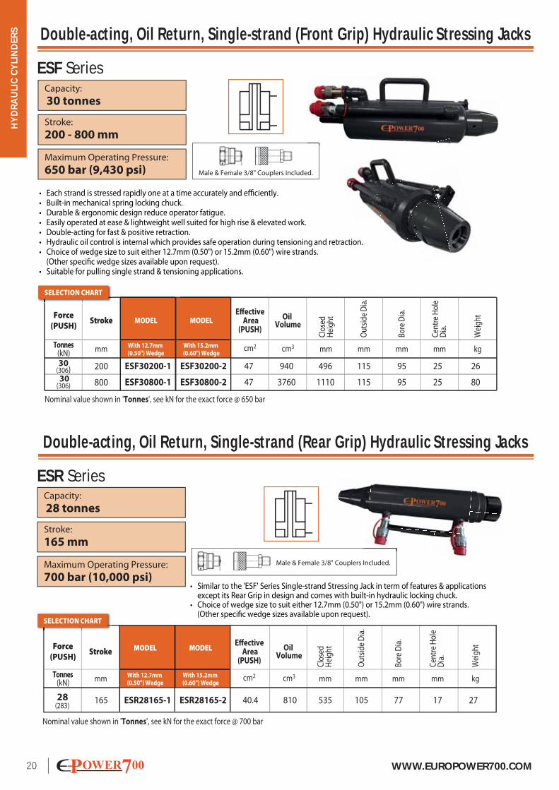
Double-acting, Oil Return, Single-strand (Front Grip) Hydraulic Stressing Jacks
Double-acting, Oil Return, Single-strand (Rear Grip) Hydraulic Stressing Jacks
ESF Series
ESR Series
• Similar to the 'ESF' Series Single-strand Stressing Jack in term of features & applications except its Rear Grip in design and comes with built-in hydraulic locking chuck. • Choice of wedge size to suit either 12.7mm (0.50") or 15.2mm (0.60") wire strands. (Other specific wedge sizes available upon request).
Capacity:
28 tonnes
Stroke:
165 mm
Maximum Operating Pressure:
700 bar (10,000 psi)
Male & Female 3/8" Couplers Included.
Force(PUSH)
StrokeEffective
Area(PUSH)
Oil Volume
MODEL
With 12.7mm (0.50") Wedge
MODEL
With 15.2mm (0.60") Wedge
Tonnes mm
165 40.4 810 535 105 17 27ESR28165-1 ESR28165-2 28 (283)
mmcm2 cm3
Clo
sed
Hei
ght
mm
Out
side
Dia
.
77
mm
Bore
Dia
.
mm
Cen
tre
Hol
e D
ia.
kg
Wei
ght
(kN)
SELECTION CHART
Nominal value shown in 'Tonnes', see kN for the exact force @ 700 bar
• Each strand is stressed rapidly one at a time accurately and efficiently. • Built-in mechanical spring locking chuck. • Durable & ergonomic design reduce operator fatigue. • Easily operated at ease & lightweight well suited for high rise & elevated work. • Double-acting for fast & positive retraction. • Hydraulic oil control is internal which provides safe operation during tensioning and retraction. • Choice of wedge size to suit either 12.7mm (0.50") or 15.2mm (0.60") wire strands. (Other specific wedge sizes available upon request). • Suitable for pulling single strand & tensioning applications.
Capacity:
30 tonnes
Stroke:
200 - 800 mm
Maximum Operating Pressure:
650 bar (9,430 psi) Male & Female 3/8" Couplers Included.
n.
MODEL
With 12.7mm (0.50") Wedge
MODEL
With 15.2mm (0.60") Wedge
Force(PUSH)
Stroke
Tonnes mm
200
800
47
47
940
3760
496
1110
115
115
95
95
25
25
ESF30200-1
ESF30800-1
ESF30200-2
ESF30800-2
30(306) 30(306)
mmcm2 cm3
Effective Area
(PUSH)
Oil Volume
Clo
sed
Hei
ght
mm
Out
side
Dia
.
Bore
Dia
.
mm
Cen
tre
Hol
e D
ia.
mm
26
80
kg
Wei
ght
(kN)
SELECTION CHART
Nominal value shown in 'Tonnes', see kN for the exact force @ 650 bar

HY
DR
AU
LIC
CY
LIN
DER
S
21WWW.EUROPOWER700.COM
Double-acting, Oil Return, Multi-strand Stressing Hydraulic Jacks
ESM Series
cm3
Male & Female 3/8"
Couplers Included.
Capacity:
75 - 1000 tonnes
Stroke:
200 - 300 mm
Maximum Operating Pressure:
600 bar (8,700 psi)
M
MODEL
With 12.7mm (0.50") Wedge
MODEL
With 15.2mm (0.60") Wedge
Force (PUSH)
Stroke
Tonnes mm
200
200
200
250
300
300
200
200
2356
3240
6350
11905
18927
23556
21940
31338
1319
1948
3456
5994
10185
13572
16211
24976
530
530
555
600
700
720
740
790
205
225
320
390
460
500
590
730
155
175
245
305
365
400
470
580
75
80
112
145
185
200
230
300
100
115
245
370
590
710
1010
1700
117.8
162.0
317.5
476.2
630.9
785.2
1097.0
1566.9
ESM75200-1
ESM100200-1
ESM200200-1
ESM300250-1
ESM400300-1
ESM500300-1
ESM700200-1
ESM1000200-1
ESM75200-2
ESM100200-2
ESM200200-2
ESM300250-2
ESM400300-2
ESM500300-2
ESM700200-2
ESM1000200-2
75 (707)
100(972)
200(1905)
300(2857)
400(3785)
500(4711)
700(6582)
1000(9401)
cm2 cm3
Effec
tive
Area
(PU
SH)
Oil
Volu
me
(PU
SH)
Oil
Volu
me
(PU
LL)
Clo
sed
Hei
ght
mm mm mm
Out
side
Dia
.
Bore
Dia
.
mm
Cen
tre
Hol
e D
ia.
kg
Wei
ght
(kN)
SELECTION CHART
Nominal value shown in 'Tonnes', see kN for the exact force @ 600 bar
• All strands in a cable are stressed simultaneously, rapidly and efficiently with great accuracy. • Built-in hydraulic locking chuck. • Heat treated increases material hardenability and durability prolonging jack service life. • Electroplated provides corrosion and abrasion resistance. • Easily operated at ease. • Double-acting for fast & positive retraction. • Standard models available. Custom build sizes, capacities and stressing chucking heads design to suit specific requirements are optional and available upon request. • Choice of wedge size to suit either 12.7mm (0.50") or 15.2mm (0.60") wire strands. (Other specific wedge sizes available upon request). • Jack holding frame is optional and custom build to requirement. • Safety relief valve in retract chamber of cylinder prevents any damage in the event of any accidental over-pressurisation. (Retract pressure set at 210 bar) • Suitable for pulling multi-strands & tensioning applications.
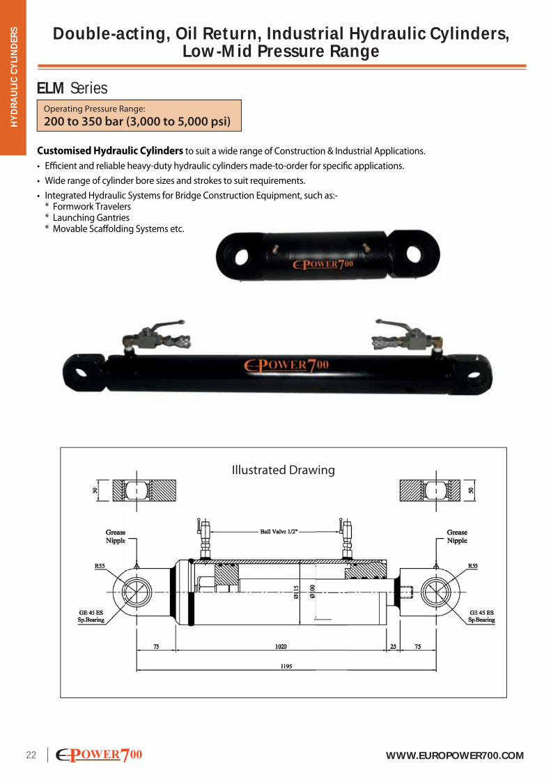
Double-acting, Oil Return, Industrial Hydraulic Cylinders, Low-Mid Pressure Range
HY
DR
AU
LIC
CY
LIN
DER
S
22 WWW.EUROPOWER700.COM
ELM SeriesOperating Pressure Range:
200 to 350 bar (3,000 to 5,000 psi)
Customised Hydraulic Cylinders to suit a wide range of Construction & Industrial Applications.
• Efficient and reliable heavy-duty hydraulic cylinders made-to-order for specific applications.
• Wide range of cylinder bore sizes and strokes to suit requirements.
• Integrated Hydraulic Systems for Bridge Construction Equipment, such as:- * Formwork Travelers * Launching Gantries * Movable Scaffolding Systems etc.
Illustrated Drawing

HY
DR
AU
LIC
CY
LIN
DER
S
23WWW.EUROPOWER700.COM
Single-axis Mechanical Screw Jacks, Hydraulically-operated
EMS Series
Female 3/8"
Coupler Included.
Capacity:
100 - 350 tonnes
Stroke:
150 mm
Maximum Operating Pressure:
700 bar (10,000 psi)
MODEL
Single-axis
Force (PUSH)
Stroke
Tonnes mm
150
150
150
150
150
150
143.1
213.8
283.5
363.1
433.7
510.7
2147
3207
4253
5446
6506
7661
450
500
560
580
580
600
300 x 300
300 x 300
350 x 350
400 x 400
400 x 400
400 x 400
135
165
190
215
235
255
108
146
200
230
265
322
EMS100150
EMS150150
EMS200150
EMS250150
EMS300150
EMS350150
100 (1002)
150(1497)
200(1985)
250(2541)
300(3036)
350(3575)
mmcm2 cm3
Effec
tive
Area
(PU
SH)
Oil
Volu
me
(PU
SH)
Clo
sed
Hei
ght
mm mm
Plat
e A
rea
Bore
Dia
.
kg
Wei
ght
(kN)
Nominal value shown in 'Tonnes', see kN for the exact force @ 700 bar
• 'EMS' Series Single-axis, single-acting jack design.
• Durable & high strength screw design.
• Force is generated by mechanical screw enabling jack to sustain its hydraulic pressure
• Support load with mechanical screw lock.
• Easily accessible for use where working space is confined.
SELECTION CHART

HY
DR
AU
LIC
CY
LIN
DER
S
24 WWW.EUROPOWER700.COM
Load Cells
UL SeriesCapacity:
5500 to 23000 kg.
Accuracy:
± 2.5% of full scale
For Load Cell complete with 1m flexible hose
– Add suffix ‘F’.
* Higher capacity load cells available upon request.
FEATURES
‘UL’ Series Self-contained Hydraulic Load Cells are
fully nitrided to provide high resistance to corrosion.
Available in 2 versions:-
• UL – With Solid Rod
(Fitted with a spherical push saddle for off-centre
load alignment)
• ULF – With Hollow Rod
(To insert threaded rods or tie bars)
Pressure Gauge scale marked in kilogram (kg) and
equipped with a maximum indicating pointer to
measure maximum peak load.
Degree of Accuracy: ±2.5% of full scale.
Application:-
Measurement of force and load.
* Capacity Dimensions(mm)
We
igh
t
kg A B C D E F G H kg
550085 80
217 118
45 2 x M6 65 - 3,711000
23000 93 105 65 2 x M8 90 - 6,5
15000
UL05
UL10
UL23
ULF15 80 130 80 4 x M8 100 50 7,0
UL - 05 #
Load Cell- with Solid Rod
F with Hollow RodCapacity in Tonnes F with 1m tube
MODEL CODE
MODEL
SELECTION CHART

PUM
PS &
SY
STEM
S
25WWW.EUROPOWER700.COM
Valves and Accessories for Hydraulic Systems,
Refer Pages: 32 - 33
Hand pump with side mounted gauge
Hand pump with front mounted gauge
Power pump with G10 gauge mounted on valve
G106L gauge
G10 gauge
ZPF12
SN# hose, 3/8” NPT
RP50 gauge block
RP502 gauge block
VRF384 four-way needle valve
RM387 manifold
RK383 radial manifold
VRU38
VRF38 needle valve
RN38 nipple
K73F female coupler
K73M male coupler
K73C female dust cap
K73D male dust cap
Single-acting cylinder
Double-acting cylinder
1 12
2 13
3
4
14
5
15
6
16
7
17
8
18
9
19
10
20
11
21
Components of a Hydraulic System

PUM
PS &
SY
STEM
S
26 WWW.EUROPOWER700.COM
Reservoir Capacity:
0,42 to 0,8 litres
Oil Delivery at Rated Pressure:
1,0 – 2,3 cu.cm./stroke
Maximum Operating Pressure:
400 – 700 – 1000 bar
• All steel construction for long lasting operation.• ¼” NPT side port to mount G106L gauge. • Externally adjustable pressure relief valve.• Handle locking mechanism for ease of carrying.• Can be used vertically with pump head facing down.• Feature wide feet for ease of pump mounting.• Ideal for use with small hydraulic tools &/or single-acting cylinders that requires lesser oil.
Max
Pre
ssur
e
Oil
Del
iver
y pe
r Str
oke
Han
dle
Effor
t
For u
se w
ith
Cylin
der T
ool
Rese
rvoi
r Ca
paci
ty
Usa
ble
Oil
Vol
ume
MO
DEL Dimensions
(mm)
Wei
gh
t
bar N A B D F H J L1 R V Y kg
700 1,0 280
Single-
acting
420 300PS100
340
95 80 9
280
130 1/4“ NPT 50 32,5 32,53,21000 380 PS10010
4002,3
350 420 300 PS10004 340 280
700 390 800 700 PS101 565 505 4,5
SELECTION CHART
Pum
p Ty
pe
(Spe
ed)
Sing
le
G106L Gauge
(Optional)
MO
DEL Dimensions
(mm)
We
igh
t w
ith
ou
t O
il
We
igh
t w
ith
O
il
bar bar N litres litres A B E G H J K M V kg kg
20 700 125 4,8 450
Single-acting9,3 7,7 PV1810
763
261
245
750 315 257 290 180 194 20,9 29
19,4 16 PV1820 - 650 245 278 168 182 23,1 40
Double-acting9,3 7,7 PV2810
313
750 315 257 290 180 194 20,9 29
19,4 16 PV2820 - 650 245 278 168 182 23,1 40Double-acting
with controlled check valve
9,3 7,7 PV4810 750 315 257 290 180 194 20,9 29
19,4 16 PV4820 - 650 245 278 168 182 23,1 40
SELECTION CHART
Pre
ssu
re
1st
sta
ge
Pre
ssu
re
2n
d s
tag
e
Oil
De
liv
ery
pe
r S
tro
ke
1
st s
tag
e
Oil
De
liv
ery
pe
r S
tro
ke
2
nd
sta
ge
Ha
nd
le E
ffo
rt
Pu
mp
Ty
pe
(S
pe
ed
)Tw
o
Fo
r u
se w
ith
Cy
lin
de
r T
oo
l
Re
serv
oir
C
ap
aci
ty
Usa
ble
O
il V
olu
me
Reservoir Capacity:
9,3 to 19,4 litres
Oil Delivery at Rated Pressure:
4,8 cu.cm./stroke
Maximum Operating Pressure:
700 bar (10,000 psi)
• All steel construction for long lasting operation.
• ½” BSP connection for direct gauge connection.
• Externally adjustable pressure relief valve.
• Carrying Handle.
G10 Gauge
(Optional)
Steel Hand Pumps (Single-Speed)
Steel Hand Pumps with Large Oil Delivery (Two-Speed)
PS Series
PV Series

PUM
PS &
SY
STEM
S
27WWW.EUROPOWER700.COM
Reservoir Capacity:
10 to 40 litres
Oil Delivery at Rated Pressure:
0,9 litre/min.
Motor Size:
1,1 – 1,5 kW (1,5 – 2 hp)
Maximum Operating Pressure:
700 bar (10,000 psi)
M
Product shown as illustrated
MODEL
*Oil Delivery TEFC Induction MotorPressureReservoir
Capacity
Usable Oil
VolumeDimensions
(mm)1st Stage
2nd Stage
1st
Stage2nd
Stage Voltage Power Speed
l/min l/min bar bar kW rpm litres litres A B H
MEH11M52PP
2,4 0,9 85 700
400V-50Hz
(3-phase)1,1
1400
10 7,7 700 520 522
MEH20M52PP 20 17,7 700 520 650
MEH40M52PP 40 35,8 710 700 650
MMH11M52PP230V-50Hz
(Single-phase)1,5
10 7,7 700 520 522
MMH20M52PP 20 17,7 700 520 650
MMH40M52PP 40 35,8 710 700 650
Del
iver
y
Pressure
Pump
FEATURES
Through many years of experience in the geotechnical field, in particular test piles, a complete pump with special features has been developed to meet this sector requirements.
• Digital Display – Programmed for the desired pressure values.• Automatic Pressure Restore – In case of structural yielding.• Hysteresis System Cycle Setting.• Automatic or Manual Control.• Possibility to conduct test cycles by decreasing pressure.• For use with either single-acting or double-acting cylinders.• Externally adjustable pressure setting (50 to 700 bar range).• Available in Single- or 3-phase electric motor.• Two stage pump delivers high oil volume for rapid cylinder piston advance without load and shifts to high pressure, low volume stage when under load.• Manual 4-way, 3-position valve with pilot check to guard against pressure loss when shifting manual valve position.• Equipped with Analog 100mm diameter pressure gauge. • Starts at full load.• Available in 10, 20 and 40 litre reservoir tank.• Oil level indicator.• Protective and transport cage.
Application
Non-destructive tests on concrete structures, construction material trials and geotechnical experiments both on site and in laboratory.
Foundation load cap and pile testing.
* Two Speed Pump Version
Product shown as i
OPERATING CHARACTERISTICS
Modular Hydraulic Power Pumps for Geotechnical Structural Tests
ME / MM - PP Series

PUM
PS &
SY
STEM
S
28 WWW.EUROPOWER700.COM
FEATURES• Designed in modular concept for complete interchangeability
of components and ensure customising options.
• Electric Motors are equipped with magneto-thermal cut-out.
• Class IP54 enclosure protection
• Motors are totally enclosed fan-cooled (TEFC) Induction Type.
• Pressure Relief Valves are externally adjustable on all pumps.
• Choice of Manual or Electric Solenoid Directional Control Valve
for single-acting & double-acting cylinder or tool operations.
Reservoir Capacity:
5 to 40 litres
Oil Delivery at Rated Pressure:
Reservoir Capacity:
0,45 – 0,9 litre/min.
Motor Size:
0,75 – 1,5 kW (1 – 2 hp)
Maximum Operating Pressure:
700 bar (10,000 psi)
Picture illustrated with
optional accessories.
1 Add 48 mm for model MMC, MMH. 2 For power packs with 5 l and 10 l high tanks with remote control model R or F only.
Reservoir Capacity Usable Oil Volume Dimensions(mm)
litres litres A A1 2 B B1 C D E F G H 1 I
5370 470 245 270
129315 250 170
M8
410
1010 high 227 508
10 low447
-360
378 129410 320 270
410
20- 257 9 538 40
40
3,8
8,8
7,7
17,7
35,8 462 600 440 350 510
DIMENSIONS
* Two Speed Pump Version † 110V/60Hz/Single phase motors available upon request.
*OilDeliveryFor Use
withCylinder
Tool
Pressure† Motor
230V – 50Hz(Single-phase)
1st
Stage2nd
Stage1st
Stage2nd
Stage Power Speed
l/min l/min bar bar kW rpm
Usable
Oil
VolumePoles
litres
Valve ControlMODEL
SELECTION CHART
0,9 0,45 100 700 0,75 1400 8,8
Single-
acting
Double-
acting
3-Way Manual Valve with Check
3-Way Solenoid Valve with Remote Control
4-Way Manual Valve with Check
4-Way Solenoid Valve with Check & Remote Control
MMA10M32
MMA10E31R
MMA10M42
MMA10E42R
4
4,7 850,45 700 0,75 1400 8,84
2
Single-
acting
Double-
acting
3-Way Manual Valve with Check
3-Way Solenoid Valve with Remote Control
4-Way Manual Valve with Check
4-Way Solenoid Valve with Check & Remote Control
MMB10M32
MMB10E31R
MMB10M42
MMB10E42R
Single-acting
Double-acting
Single-acting
Double-acting
3-Way Manual Valve with Check
4-Way Manual Valve with Check
MMD20M32
MMD20M420,9 1,51,8 100 2700 17,72800
17,73-Way Manual Valve with Check
4-Way Manual Valve with Check
MME20M32
MME20M42859,4 0,9 1,5700 2800
Modular Hydraulic Power Pumps with Single-Phase Electric Motor
MM Series

PUM
PS &
SY
STEM
S
29WWW.EUROPOWER700.COM
Reservoir Capacity:
5 to 50 litres
Oil Delivery at Rated Pressure:
0,45 – 2,5 litre/min.
Motor Size:
0,75 – 3 kW (1 – 4 hp)
Maximum Operating Pressure:
700 bar (10,000 psi)
FEATURES• Designed in modular concept for complete interchangeability of components and ensure customising options. • Electric Motors are equipped with magneto-thermal cut-out.• Class IP54 enclosure protection • Motors are totally enclosed fan-cooled (TEFC) Induction Type.• Pressure Relief Valves are externally adjustable on all pumps.• Choice of Manual or Electric Solenoid Directional Control Valve for single-acting & double-acting cylinder or tool operations.
Picture illustrated with
optional accessories.
1 Add 16 mm for models MEC, MEH; add 40 mm for models MEL, MEF, MEG, and MET.2 For power packs with 5 l and 10 l high tanks with remote control model R or F only.
Reservoir Capacity Usable Oil VolumeDimensions
(mm)
litres litres A A1 B B1 C D E F G H I L
5 3,8370 470 245 270
129315 250 170
M8
390 1
1040
10 high 8,8 227 488 1
10 low 7,7447
-
360378 129
410 320 270390 1
-
20 17,7
-
257
9
518 1
40
40 35,8 462 600 440 350 510
MEK 30 22447 360
343410 320 270
640
MEV 30 20307 634
MEV 50 32 462 600 440 350 510
DIMENSIONS
MEK power packs are particularly indicated for intensive use or when a very noiseless product is required.
2
* Two Speed Pump Version † Motors with higher power and different voltage available upon request.
*Oil DeliveryFor Use
withCylinder
Tool
Pressure †Motor 400V – 50Hz (3-phase)
1st Stage 2nd Stage 1st Stage 2nd Stage Power Speed
l/min l/min bar bar kW rpm
UsableOil
VolumePoles
litres
Valve ControlMODEL
10 85
4,7 1,8 85 700 2,2 2800 17,7
Single-acting
Double-acting
3-Way ManualValve with Check
3-Way Solenoid Valvewith Remote Control
4-Way ManualValve with Check
4-Way Solenoid Valve with Check & Remote Control
MEG20M32
MEG20E31R
MEG20M42
MEG20E42R
2,5 700 3 1400 32
11,6 701,6 700 2,2 1400 22
2
4
4
Single-acting
Double-acting
Single-acting
Double-acting
3-Way ManualValve with Check
4-Way Manual Valvewith Check
3-Way Manual Valvewith Check
4-Way Manual Valve with Check
MEK30M32
MEK30M42
MEV50M32
MEV50M42
SELECTION CHART
Modular Hydraulic Power Pumps with 3-Phase Electric Motor
ME Series

PUM
PS &
SY
STEM
S
30 WWW.EUROPOWER700.COM
Reservoir Capacity:
10 to 40 litres
Oil Delivery at Rated Pressure:
0,45 – 0,9 litre/min.
Motor Size:
2,2 kW (3 hp)
Maximum Operating Pressure:
700 bar (10,000 psi)
FEATURES
The SPLIT FLOW Hydraulic Power Pump has 2 or 4 independent valve outlets delivering a constant amount of oil, even if the pressure in each line is not the same. Flows and pressures of each pump are independent regardless of the load.
They are equipped with:-
• One 3-phase electric motor.• 2 or 4 independent hydraulic pumps with choice of Single- or 2-speed version.• 2 or 4 (one for each port) 4-way, 3-position manual control valves with piloted check and 150 bar pressure setting on ‘B’ return port.• 2 or 4 flow control valves (one for each port) for controlled load lowering.• 2 or 4 pressure gauges (one for each port).• Reservoir tank capacity of 10, 20 & 40 litres.
ApplicationThis pumps offered efficient and economical solution to lift up to a maximum of 4 cylinders with different loads or uneven load distribution. Pump configuration is based on equal geometrical pressure lines, without any external control on the actual stroke, this Split Flow power pump provides accurate ±3% synchronous lifting with visual control of the operation. It also allow synchronous load lowering operations under load when using with double-acting cylinders. For automatic control of the down stroke speed without pressure oscillations & load chattering, use VRB38 Counterbalance Valve.
MODEL
No. Outlets Oil Delivery Pressure TEFC Induction Motor
1st stage 2nd stage 1st stage 2nd stage Voltage Power Speed
l/min l/min bar bar kW rpm
MEM -0,9
-
700 400V-50Hz
(3-phase)2,2 2800MEN
MEM20M52GU
MEQ40M52GU
2,2 85
MEQ
2
2
4 - 0,45 -
OPERATIONAL CHARACTERISTICS ACCORDING TO THE CHOSEN PUMP
Reservoir Capacity Usable Oil Volume Dimensions (mm)
litres litres A A1 B B1 C D E F G H I
10 low 7,7555
700360
378 129410 320 270
M8 410 1020 17,7
- 257 9 518 4040 35,8 570 600 440 350 510
ME # # M52 G U
Motor Type Pump Type Reservoir Capacity Valve Type Pressure GaugeUnidirectional Flow
Regulator
MODEL CODING
MODEL
2
4
20 litres
40 litres
0,9 l/min
0,45 l/min700 bar 400V-50Hz
(3-phase)
No. Outlets Oil Delivery Pressure Motor Voltage Reservoir Capacity
Hydraulic Power Pumps for Synchronous Lifting System
ME - SPLIT FLOW Series

PUM
PS &
SY
STEM
S
31WWW.EUROPOWER700.COM
Positional Accuracy:
± 2mm full scale
Maximum Operating Pressure:
700 bar (10,000 psi)
FEATURES
• PLC Controller with Touch Screen Panel.• Control 4 to 48 lift points.• Up to 1000 tonnes capacity hydraulic cylinder on each lift point.• Positional Accuracy of ±2mm full scale.• Load & Pressure Display on control panel.• Stroke Displacement Display on control panel.• Optional: Linkage to Data Logger and Printer.• Programmable System equipped with failsafe monitoring on stroke sensors & pressure transducers and emergency safety alarm features with automatic stop.• Optional Heat Exchanger for continuous operation.
PLC Synchronous Lifting & Lowering System reduces the risk of tilting, bending & twisting due to uneven load distribution or shifting of load between lift points.
Application:Precise lifting & lowering controlled of hydraulic movement of Heavy Structural Loads, Oil Rig Modules, Vessels, Bridges, Machineries etc.
PLC Controller with Touch Screen Panel
Consult our Project Engineer for best technical & operational solution.
The PLC controls the oil flow to each cylinder, maintaining accurate positional control monitored by stroke sensors & pressure transducers, activated by set of electric solenoid-controlled valves. This provides precise & safe control of lifting and lowering of uneven load distribution.
1 Hydraulic Power Pump
(Manifolds & Control Valves)
2 Electrical Junction Box
3 PLC Controller
(Touch Screen Panel Type)
4 Hydraulic Cylinders
5 Stroke Sensors
6 High Pressure Hoses
7 Sensor Cables
8 Structure to be Lifted
PLC Synchronous Lifting & Lowering System
SYN-LIFT Series

VALV
ES A
ND
AC
CES
SOR
IES
32 WWW.EUROPOWER700.COM
MODE
RP52
RP50
RP501
RP502
* Dual Scale: bar & psi
Max Working Pressure
* Full Scale
Dial Diameter
Precision Class
DIN16005
Scale Indexing Thread Mounting MODEL
Dimensions(mm)
Weight
bar bar mm % bar E A B C D kg
700 1000 63 1,6 50 1/4” NPTRadial FitLower FitLower Fit
G106L68 54 32 13 0,2
G106
1000 1000 100 1,0 20 1/2” BSP Swivel G10 101 98 49 15,5 0,8
LMax Wor ing
Pressureauge
ConnectionIn/Out
ConnectionA
DimensionWeight
bar mm kg
1000
1/4” NPT
3/8” NPT
100 0,40
1/2” BSP
60 0,28
90 0,33
140 0,42
LRP52
RP50
RP501
RP502
Male Half
Female Half
Working Pressure
Coupling Type
ThreadType Coupler Type
K73M
K73F
MODELDimensions
(mm) Weight
bar D A B C g
700 Screw
K73
K73M
K73F
K73X
K73C
K73D
Complete (K73M+K73F+K73C+K73D)
Male Half with female thread
Female Half with male thread
Female Half with female thread
Cap for female (plastic)
Cap for male (plastic)
- - - -
40,5 36 32 120
72 35,5 24 200
76 35,5 24 210
- - - -
- - - -
3/8” NPT
(High-Flow)
MODELMax.
WorkingPressure
Fitting ThreadLength
Scre
w
Co
up
lin
g
barmetre
1000
3/8” NPT - 3/8” NPT
male
-
700
2,8 6,4
Min
. Bu
rst
Pre
ssu
re
Sa
fety
Fa
cto
r @
70
0 b
ar
Saf
ety
Fac
tor
@1
00
0 b
ar
Inte
rna
l D
iam
ete
r
Min
imu
m
Be
nd
ing
R
ad
ius
Oil
Vo
lum
e
We
igh
t
bar mm mm cm3/m kg/m
4 32,22800 70 0,32
SN10
SN20
SN30
SN60SN120
SN150
SN10M
SN20M
SN30M
1
1,8
3
612
15
1
1,8
3
K73M
ki li
SELECTION CHART FOR QUICK COUPLERS: 700BAR
SELECTION CHART FOR 700 - 1000 BAR HYDRAULIC HOSES
SELECTION CHART FOR 1000 BAR GAUGE BLOCKS TO BE MOUNTED IN INE
PRESSURE GAUGE SELECTION CHART: 700 – 1000 BAR (GLYCERINE-FILLED)
Gauges, Gauge Blocks, Couplers & Hoses

33WWW.EUROPOWER700.COM
MODEL Symbol
VRF38Needle valve.
To shut off the flow.
VRU38
One-way flow control valve.
It permits controlled load lowering.
VRH38
One-way flow control valve
with fine regulation.
It permits controlled load lowering.
VRF382Double outlet needle valve.
To split the flow in two separate ways.
A= 90
VRF384
Needle valve with four outlets.
To split the flow in four separate ways.
A= 210
Description
Type MODELNo. of
Female Ports
A Bmm mm
Multi Level
Manifold
RB386 6 - -
Single Level
Manifold
RM387 7 260 110
RM389 9 400 180
Radial
Manifold
RK383 3 45 -
RK385 5 55 -
RK387 7 65 -
Type MODELDimensions
A B C D
Plug -RC38
Coupling RS38
Nipple
RN38
RN381
3/8”NPT
3/8”NPT
10.5 -
34 24
17
41
RN382 120
3/8” NPT
3/8” NPT
3/8” NPT 70
REGULATING VALVES 1000 BAR
MANIFOLDS 1000 BAR
FITTINGS 1000 BAR
Regulating Valves, Manifolds & Fittings
VALV
ES A
ND
AC
CES
SOR
IES