VIBRATION CHARACTERISTICS OF THIN CIRCULAR CYLINDERS
12
Journal of Sound and Vibration (1979) 63(4), 581-592 VIBRATION CHARACTERISTICS OF THIN CIRCULAR CYLINDERS C. B. SHARMA Department of Mathematics, University of Manchester Institute of Science and Technology, Manchester A460 lQD, England (Received 17 May 1978, and in revisedform 27 December 1978) In this paper an unified treatment is given to the problems of vibration characteristics of thin circular cylindrical shells with various end conditions with the aid of the kinematic relations of the first-order shell theory of Sanders. A simple variational technique is applied to give a cubic frequency equation. This cubic is reduced to two simple linear relations for the frequency parameter by incorporating an engineering approximation relating deflec- tions in two different ways: (i) in general (ii) in the inertia components only. It is shown that the linear formula obtained by (ii) is much superior to that obtained by (i) and also to the much more complicated cubic equation to some extent. Expressions for evaluating mode shapes are also given. Results found by using the present technique are compared with some previous exact analysis results. Frequencies calculated in the case of a given cylinder are shown to be in good agreement with some available observed results. 1. INTRODUCTION A variational technique was employed by the author [ 11 to discuss the vibration character- istics of cantilever circular cylindrical shells. This approach is extended here to give an unified treatment to the vibration problems of circular cylindrical shells with various end conditions. A fairly complete bibliographic sketch on this important topic is given in a recent survey [2]. The theory of Budiansky and Sanders [3], which is claimed to be the “best”, is used in this paper. Their equations [3] are claimed to be the “best” for the following reasons: (i) they can be written in a general tensor notation for arbitrary shell geometry; (ii) the prin- ciple of virtual work, the minimum energy principle and reciprocal relations all apply; (iii) six stress measures are available that satisfy equations of equilibrium exactly: (iv) the stress and strain measures obey the uncoupled relations first given by Love. Most of the other existing thin shell theories do not satisfy all the above points simultaneously. It may. however, be remarked that in spite of these shortcomings, various theories have done. and are still doing, a great service in providing excellent results, which not only agree with each other, but also compare well with the experimental results. Still it appears to be useful to analyse this immensely important problem with a shell theory which is claimed to be the “best” so far of the linear shell theories. This helps to establish the adequacy of other shell theories, which, in itself, is quite reassuring. In chapter 2 of reference [2] one can find a fine survey of vibration problems of thin circular cylindrical shells. The problems with differing end conditions can be found dis- cussed by use of various shell theories in different sections. Because of its importance in applications the need was felt to find an unified approach which can deal with different boundary conditions and to get some common simplified frequency relations where the effect of the edge conditions can be introduced in some parametric form. These relations 581 0022-460X/79/080581 + 12 $02.00/o 0 1979 Academic Press Inc. (London) Limited
-
Upload
independent -
Category
Documents
-
view
0 -
download
0
Transcript of VIBRATION CHARACTERISTICS OF THIN CIRCULAR CYLINDERS

Journal of Sound and Vibration (1979) 63(4), 581-592
VIBRATION CHARACTERISTICS OF THIN CIRCULAR CYLINDERS
C. B. SHARMA
Department of Mathematics, University of Manchester Institute of Science and Technology,
Manchester A460 lQD, England
(Received 17 May 1978, and in revisedform 27 December 1978)
In this paper an unified treatment is given to the problems of vibration characteristics of thin circular cylindrical shells with various end conditions with the aid of the kinematic relations of the first-order shell theory of Sanders. A simple variational technique is applied to give a cubic frequency equation. This cubic is reduced to two simple linear relations for the frequency parameter by incorporating an engineering approximation relating deflec- tions in two different ways: (i) in general (ii) in the inertia components only. It is shown that the linear formula obtained by (ii) is much superior to that obtained by (i) and also to the much more complicated cubic equation to some extent. Expressions for evaluating mode shapes are also given. Results found by using the present technique are compared with some previous exact analysis results. Frequencies calculated in the case of a given cylinder are shown to be in good agreement with some available observed results.
1. INTRODUCTION
A variational technique was employed by the author [ 11 to discuss the vibration character- istics of cantilever circular cylindrical shells. This approach is extended here to give an unified treatment to the vibration problems of circular cylindrical shells with various end conditions. A fairly complete bibliographic sketch on this important topic is given in a recent survey [2].
The theory of Budiansky and Sanders [3], which is claimed to be the “best”, is used in this paper. Their equations [3] are claimed to be the “best” for the following reasons: (i) they can be written in a general tensor notation for arbitrary shell geometry; (ii) the prin- ciple of virtual work, the minimum energy principle and reciprocal relations all apply; (iii) six stress measures are available that satisfy equations of equilibrium exactly: (iv) the stress and strain measures obey the uncoupled relations first given by Love. Most of the other existing thin shell theories do not satisfy all the above points simultaneously. It may. however, be remarked that in spite of these shortcomings, various theories have done. and are still doing, a great service in providing excellent results, which not only agree with each other, but also compare well with the experimental results. Still it appears to be useful to analyse this immensely important problem with a shell theory which is claimed to be the “best” so far of the linear shell theories. This helps to establish the adequacy of other shell theories, which, in itself, is quite reassuring.
In chapter 2 of reference [2] one can find a fine survey of vibration problems of thin circular cylindrical shells. The problems with differing end conditions can be found dis- cussed by use of various shell theories in different sections. Because of its importance in applications the need was felt to find an unified approach which can deal with different boundary conditions and to get some common simplified frequency relations where the effect of the edge conditions can be introduced in some parametric form. These relations
581 0022-460X/79/080581 + 12 $02.00/o 0 1979 Academic Press Inc. (London) Limited

582 C. B. SHARMA
can then be used at will to calculate frequencies for various end conditions by specifying the parameters involved.
The effect of various end conditions is incorporated by a choice of modal forms where the longitudinal dependence is kept in general form. A variational technique is then applied to get a cubic frequency equation. A linear formula is then obtained by introducing the assumption of zero hoop and shear strain in the energy expressions. The approach adopted here is parallel to that followed in reference [ 11. The results from this linear equation tend to be higher than the cubic results. This increase is attributed to a substantial increase in the stretching part of the strain energy due to the additional constraints imposed by the above assumption, and constraints of any kind, in general, exaggerate apparent stiffness. A second linear formula results due to an effort to avoid increase in the stretching part of strain energy, by constraining only the kinetic energy expression by the zero hoop and shear strain assumption. This simple idea to avoid undue increase in the stretching strain energy was first exploited in references [4] and [S]. This second linear formula gives results which are very close to the cubic results, and in some cases underestimate them, especially for higher axial wave numbers and low circumferential wave numbers. The comparisons between the results of the cubic and two linear formulas and to experimental results in a particular case [6] are given in graphical forms. The accuracy of the two linear formulas, as compared to the cubic for various end conditions, is given in a tabular form. A table is also given to compare the results from the linear formulas and the cubic with those of an exact analysis given in reference [7] for a wide range of geometries of cantilever cylindrical shells.
2. VARIATIONAL FORMULATION
The present analysis is based upon the consistent first-order shell theory of Rudiansky and Sanders [3]. The strain-displacement relationships provided by this theory, for a circular cylindrical shell with the co-ordinate system given in Figure 1, are given, as in reference [8], by
Figure I. Co-ordinate system and shell geometry

VIBRATION OF THIN CIRCULAR CYLINDERS 583
where x, 0 and z are axial, circumferential and radial co-ordinates, respectively, and u, 1) and w are in-plane and radial or normal displacements as in Figure 1 (a list of symbols is given in the Appendix). The two dimensional strain energy functional is
Ea L 2n ss s hi2
U= 2(1 - v2) 0 0 IX + 2vs,,e0, + E,& + 2(1 - v)e$] dz dfI ds. (2)
-h/2
Upon making use of linear strain-displacement relationships (I) in the expression for the strain energy (2)? one obtains
QJ2 + 2vw,&hl - yg)
The first and second integrals correspond to the stretching and bending actions respectively. The kinetic energy expression for the vibrating shell may be written in the following form :
L
ss
2rr
T = $pah [ti” + ti2 + ti’] dfI dx. (4) 0 0
For the vibration of circular cylindrical shells the middle surface displacements u, 1’. u‘ can be assumed to have spatial dependence of the forms
(u, 0, w) = (A&.( x cos no, B4l(x) sin no, C4l.(x) cos no). 1 (51
Upon substitution of the modal forms (5) into the energy expressions (3) and (4) and applying a variational procedure, one obtains as a consequence, a system of homogeneous linear simultaneous equations for the coefficients A, B and C. Writing down the condition for the existence of a non-trivial solution set to this system (i.e., letting the determinant of coefficients vanish), one obtains a cubic in the frequency parameter A (= pa2( I - ?)w2,‘E):
det[Aij - kAcSij] = det[aij] = 0, i,,j = 1, 2, 3. (6)
In equation (6), Jij denotes the Kronecker delta, and the parameter k = I, (an integral involving characteristic orthogonal functions 4,(x)) for the first row and unity for the second and third rows of the symmetric matrix [Aij - kAaij]. The expressions for the A ;,‘s are as follows:
A 11 = I.: + $1 - v)(4 + fl)n’Z,, Al2 = n&{vl, - 31 - v)(4 - 3/?)1,‘,.
A 13 = vA,.l, + $1 - v)jbz21rZ2, A,, = (1 + p, n2 + $1 - v)(4 + 9j?iifr,.
A 23 = n(1 + /?n’) -/3/nlf{vI, - $(l - v)l,}.
A 33 = I +p[A,” +n4 +2n2Rz{-vl, + (I, - vU,)]. (7) Here the 2,‘s represent the eigenvalue properties of the functions $Jx) and the integrals I, and I, involving the functions 4,(x) and its derivatives (with respect to the argument x) are given by
I, = ; s
L &‘(x)$(x) dx, I, = ; s’ {&}” dx. 0 0
(8)

584 C. B. SHARMA
Equation (6) yields for each pair of axial and circumferential wave numbers, m and 11, three frequency factors that correspond to motion that is predominantly radial (the lowest frequency parameter), predominantly axial or predominantly circumferential. As the radial frequency is much lower than the other two, and as most shell vibrations include radial excitation, it is the lowest of the triplet of frequencies that is of most structural interest, both to the analyst and to the designer. It is possible to solve the cubic exactly for the three roots and pick out the lowest. However, it is of great interest to deduce and examine linear approximations to the minimum frequency, both for the sake of any desired ad hoc cal- culations, and possible implications that may be deduced for the thin shell theory itself.
The cubic frequency equation (6) may be reduced tn a simple linear form if assumptions are made a priori about the inter-relationships of deflect eons. If the engineering approxima- tion of zero circumferential and shear strain is assumed, i.e.,
u,, + w = 0 and au,, + u,, = 0, (9)
then these combined with expressions (5) give simplified deflection forms, which, upon using in the variational formulation, yield the following linear approximation for the frequency parameter, denoted by d 1 :
d 1
= n; + j?nQ;{nQ,2 - 2vnZ(n2 - l)Z, + 2(1 - v)(r? - l)?,} + /?n4(n2 - 1)2 $I, + n2(n2 + 1) (10)
The approximations (9) introduce additional constraints which exaggerate the fre- quencies given by equation (6), especially in the case of short shells. This has been attri- buted to the overestimation of the stretching part of the strain energy [9] for cantilever shells. To avoid this introduction of a restriction in the membrane flexibility, the assump- tions (9) are then used in the inertia components only. This results in a frequency equation of the form (6) which is now linear in the frequency factor because the parameter k, in this case, is zero for the first and second rows and for the third row it is given by
k = (~y,f~2 + n2 + n”)/n” = tx (say). (11)
Simplifying this determinantal equation one gets a second linear approximation for the frequency parameter, denoted this time by A, (to distinguish it from the linear form (lo)),
A2 = det[Aij]l(a det[AP41), (12)
where the subscripts i, j = 1,2,3 and p, q = 1,2, the symmetric elements of the matrices are given by equation (7), and the value of M: is provided by equations (11).
To study the displacement patterns or mode shapes, the ratios of the axial and circum- ferential displacement amplitudes to the radial amplitude can be examined. These ratios are calculated from any two of the three linear algebraic equations that are antecedents of the frequency equation (6). It is easy to see that these ratios are given by
B/C = @,,4, + ‘3342 - a,,u,,u,, - u12”13u23)/(u23(u11u22 - 42))’ (13)
where the uij’s are given by equations (6) and (7). (These values are given here because of their importance in the calculations of displacement patterns for the higher frequencies and also in calculating strain energies due to membrane and bending action, if needed, although no computations involving these quantities are carried out in the present paper.)

VIBRATION OF THIN CIRCULAR CYLINDERS 585
3. BOUNDARY CONDITIONS
The choice of modal functions b,(x) is made to satisfy a prescribed set of end conditions. For this purpose the characteristic beam vibration functions are introduced in a general form,
F,.(p,,x) = cash p,.x - cos p,.x - c,.(sinh pr_‘c - sin p,.x) II41
where the properties and the numerical values of F,.(p,.x), p,. and c,. can be found tabulated in reference [IO] for various boundary conditions. Now in the modal forms (5) 4,. = F, for clampedclamped, clamped-free, clamped-supported end conditions and 4,. = F’;’ (the dash denotes differentiation with respect to the argument p,.x) for free-free and free -sup- ported end conditions. It may, however, be remarked that these general form choices for 4,. in equations (5) are satisfactory within certain limitations inherent in the variational procedure.
The values of the integrals I, and I, involving beam functions are of particular interest and are derived by the method given in reference [I I]. Expressions for the integrals I, and I, for the various end conditions are as follows:
End conditions I, =; I
‘4:.‘&.d.x I, =; s
L i&J” d.r; 0 d 0
clamped+lamped ($2 - p,.Lc,.)/pJ c,.(p,.Lc,. - 2)jp,.L
free-free c,.(2 - P,.LC,.)lPl.L c,.(p,.Lc,. + 6)/p,.L
clamped-free c,/2 - P,LC,.YP,L c,.Cp).Lc, + 2)/p,.L
clamped-supported c,lt - P,Lq.YP,.L c,.(p,Lc,. - 1 )(p,.L
free-supported c,.(t - PLC,.)/P,.L c,.(pJc,. + 3)/p,.L,
4. DISCUSSION OF RESULTS
In Figures 2-6 the material properties of the shell are the same as in reference [6]: i.e.. the Young’s modulus E = 68.95 x IO9 Nmm2, density p = 2714.5 kgmd3, and Poisson’s ratio v = 0315. As for the geometrical parameters, the radius a = 0.2423 m, thickness h = 0648 x toe3 m and the length L = 0.6096 m for the clamped-clamped case. L = @6382 m for the free-free case and L = 0.6255 m for the clamped-free, clamped-supported, free-supported cases.
Figure 2 compares frequency versus circumferential wave number for the cubic, iinear 1 (A,) and linear 2 (d,) cases when the axial wave number m takes the values 1-3. The linear 2 curve is very near to the cubic and underestimates it for low n-values, whereas, for this shell of comparatively small L/a (N 2.52), the linear 1 results are far higher and this over- estimation increases with m and decreases with II. Experimental results of reference [6] tie in very well with the cubic and linear 2 results. Figure 3 corresponds to the free-fret shell for m = 2,3 (since for m = 1 simpler longitudinal dependence of modal forms could be found). The pattern of Figure 2 is repeated with experimental results being quite close to the cubic and linear 2 results. Similar behaviour is seen in Figure 4, for the cantilever cy- lindrical shell; the linear 2 and cubic results cluster round each other and compare very well with the available experimental frequencies, but the linear 1 results are once again sub-

586 C. B. SHARMA
l-5-
;; I -L )r g I.O- s E -
I;
0.5 -
Figure 2. Experimental and various analytical frequencies (cubic, linear 1, linear 2) of clampedclamped cylindrical shells. Theory: -, cubic; -. -, linear 1; ------, linear 2. Experiments [6]: 0, m = 1 : 0, M = 2; a, m = 3. Shell geometry: radius, a = 0.2423 m; thickness, h = 0648 x 10m3 m; length, L = @6096 m.
4 6 8 10 12 14
Circumferential wave number. n
Figure 3. Experimental and various analytical frequencies (cubic, linear 1, linear 2) of free-free cylindrical shells. Theory: ~ cubic; __ .-, linear 1; ------, linear 2. Experiments [6]: 0, m = 2; A, m = 3. Shell geometry: radius,‘0 = 0.2423 m; thickness, h = 0.648 x 10e3 m; length, L = 0.6382 m.

VIBRATION OF THIN CIRCULAR CYLINDERS
t
I.5
I
587
Circumferential vme number, n
Figure 4. Experimental and various analytical frequencies (cubic, linear I, linear 2) of clamped-free cylindrical shells. Theory: -, cubic; -p.-, linear; ----PP-. linear 2. Experiments 161: 0, m = 1; ;I, m = 2; A, m = 3. Shell geometry: radius, a = 0.2423 m; thickness, h = 0648 x IO-’ m; length, L = 0.6255 m.
I.5 -
T f -
G c I.0 -
2 - ? LL
0.5 -
Clrcumferentlal wwe number, n
Figure 5. Various analytical frequencies (cubic, linear 1, linear 2) of clamped-supported cylindrical shells. Theory: -, cubic; -.-, linear 1; ---, linear 2. Shell geometry; radius, a = 0.2423 m: thickness. h = 0648 x IO-’ m; length, L = 0.6255 m.

TAB
LE
1
Com
pari
son
oj’th
e th
ree
appr
oxim
ate
freq
uenc
ies
wit
h th
e ex
act
resu
lts
of r
efer
ence
[7
] fo
r a
clam
ped-
free
sh
ell;
Pois
son’
s ra
tio
= 0.
3 a/
h =
100
n 2
4 6
8 r
m
A 1
x 10
-4
I x
10-4
15
x
10-j
8 x
10-z
c 1
77 x
10
-j 19
x
10-4
I
c x
10-Z
1
x 10
-2
14 x
10
-3
r33
x 10
-3
37 x
10
-j‘
Lla
10.9
5.
30
2.16
1.
18
et
1.69
5.
89
12.8
3 19
.87
e,
2.14
9.
52
34.4
8 84
,85
e2
1.68
5.
71
10.7
7 9.
30
Lla
21.3
13
.3
5.41
3.
00
e 1.
30
5.07
16
.10
26.0
1 e1
2.
28
9.09
34
.0 I
78.2
3 e2
1.
32
5.12
14
75
15.5
1
Lla
45.6
22
.3
9.28
5.
29
e 1.
01
3.58
8.
95
13.4
6 e1
2.
41
8.74
28
.18
63.4
4 e2
1.
04
3.65
8.
01
6.22
10.1
4.
34
1.39
4.
05
1.22
2.
13
1.01
01
5 0.
60
7.10
0.
33
2.40
0.
51
1.54
0.
15
0.69
19
.08
0.33
4.
33
0.57
1.
96
0.15
05
9 7.
43
0.33
2.
35
0.57
1.
53
32.5
Il.
3 3.
49
13.5
3.
17
7.12
2.
83
004
034
961
011
2.09
0.
21
0.85
00
5 0.
50
19.0
4 01
2 3.
57
0.22
1 .
OP
0.05
0.
35
9.49
0.
11
2.09
0.
21
0.85
55.2
18
.9
5.93
23
.0
5.31
12
.1
4.71
0.
02
0.19
5.
37
0.06
1.
26
0.1
1 04
7 0.
03
0.41
15
.88
0.06
3.
07
0.12
0.
78
O-0
2 02
0 5.
29
0.06
1.
26
0.1
1 0.
48 -
Cl!l
I = 2
0
n 2
4 ,
m
A 15
6 x
IO-’
‘2
x
lO-3
1
x lO
-2
95
x 10
m3
445
x 1O
-4
47
x 10
m3
6 x
lo-’
1 Ll
a 10
.2
5.80
26
2 1.
14
4.49
2.
44
1.37
et
0.
44
1.74
8.
16
17.0
9 0.
55
1.07
2.
84
el
0.47
2.
43
20.3
7 81
.86
0.57
1.
15
4.7-
l e2
0.
44
1.67
7.
08
6.01
0.
57
1.06
2.
60
Lla
21.2
e
0.15
eI
0.
30
e2
0.19
Lia
45.5
e
0.06
el
0.
25
e2
0.10
148
656
2.88
16
.3
7.18
3.
73
1.17
IO
.31
2444
01
6 0.
50
2.04
2.
18
20.7
9 77
.57
0.21
0.
63
3.25
1.
24
9-81
13
.05
0.19
0.
55
2.00
248
11.2
5.
07
28.0
12
.0
6.24
0.
67
5.21
12
.51
0.07
0.
23
I .08
1.
98
16.8
3 63
.64
0.12
0.
39
2.57
0.
76
4.89
45
0 0.
10
0.29
1.
07
t e,
e,
and
e2 d
enot
e th
e pe
rcen
tage
er
rors
in
the
cu
bic,
lin
ear
1 an
d lin
ear
2 ap
prox
imat
ions
, re
spec
tivel
y,
with
re
spec
t to
the
exa
ct
frequ
ency
pa
ram
eter
s of
ref
eren
ce
[7].

VIBRATION OF THIN CIRCULAR CYLINDERS 589
stantially higher than either of these results, especially for the lower circumferential modes. All the three kinds of theoretical results approach each other with increasing values of n.
Figure 5 corresponds to the clamped-supported case (m = 1, 2, 3) and Figure 6 to the free-supported case (m = 2, 3) and both of them repeat the pattern of the cubic, linear 1 and linear 2 frequencies exhibited in Figures 2-4. Experimental results were unavailable for the last two cases.
I.5 -
P r u” s I-0 -
& I=
0.5-
Figure 6. Various analytical frequencies (cubic, linear 1, linear 2) of freeesupported cylindrical shells. Theorq : p-, cubic; -‘-, linear 1; ----, linear 2. Shell geometry; radius, a = 0.2423 m; thickness, h = 0.648 x 10 J m; length, L = 0.6255 m.
In Table 1 the frequency factors calculated by the use of the cubic equation (6) and the linear equations (10) and (12) are compared to the corresponding results of the exact theory of reference [7] for cantilever circular cylindrical shells. The geometrical parameter L/a has been allowed to take wide ranging values for the parameter u/h = 100 and 20. This variation allows the coverage of all sorts of shell geometries. A number of features are worth pointing out. The linear 2 results compare very well with the corresponding exact values and are better than the cubic or linear 1 results in almost all the cases. The linear 2 results appear to be especially useful for the low values of L/a where the linear 1 results become excessively high, for the low n-values in particular. The linear 1 results are really unsuitable for short shells. For example, in the case of a/h = 100, L/a = 1.8, WI = 1 and n = 2, linear 2, cubic and linear 1 results are respectively 9.3, 19.9 and 84.9 per cent higher than the corresponding exact results. It is obvious that the linear 2 formula (12) gives accurate approximation in most of the different cases of shell geometries and is easy to use due to its simplicity. A similar comparison is also seen for u/h = 20. In this case, for a particularly short shell of length-to-radius of l-14, m = 1 and it = 2, the linear 2, cubic and linear 1 results are respectively 6.01, 17.09 and 81.86 per cent higher than the exact results. For higher values of n all the three approximate results tend to the exact results. The case for
TAB
LE
2
Com
pari
son
of t
he t
wo
linea
rfor
mul
as
wit
h th
e cu
bic;,
freq
uenc
y de
pend
ence
on
the
end
con
diti
ons
and
the
para
met
ers
m, n
, L/a
a/h
= 31
5 C
lam
pedx
lam
ped
\ m
-
Free
-fre
e
Y---
--?
Cla
mpe
d-fr
ee
A
s 2’
-1
2 te
l 45
9.2
13.6
15
5.3
24.9
te
, -2
1.5
-0.0
-5
0.6
-0.5
3 e,
29
93
65
560.
7 12
.8
ez
-8.6
0.
0 -2
2.3
-0.0
4 et
20
05
2.6
387.
4 I.6
e2
-3
.1
0.0
- 9.
6 0.
0
5 el
14
2.1
0.6
274.
4 3.
8 ez
-1
.3
0.0
-4.5
00
6 el
10
6.2
0.1
2027
1.
4 e2
-
0.6
0.0
-2.3
00
7 el
81
.4
@O
15
5.2
0.4
el
-@3
0.0
- 1.
3 0.
0
8 er
63
.1
0.0
122.
0 0.
1 ez
-0
2 0.
0 -0
.7
0.0
9 el
48
.5
0.0
97.4
0.
0 e2
-0
.1
@O
-
0.4
0.0
10
e1
36.3
0.
0 78
.3
@O
e2
-@
I @
O
-0.3
0.
0
198.
4 3.
9 41
5.6
10.9
-5
1.8
-0.0
-6
4.7
- 0.
7
139.
5 2.
2 38
5.6
6.2
-23.
0 0.
0 -
36.1
-0
.0
88.5
1.
1 27
5.4
4.0
-9.5
00
-
17.8
0.
0
57.1
0.
3 19
00
2.2
-4.0
0.
0 -
8.9
0.0
38.6
0.
1 13
3.2
0.9
-1.8
0.
0 -4
.7
00
21.3
0.
0 96
2 @
3 -0
8 O
-0
-2.6
0.
0
19.8
0.
0 71
.5
0.1
- 0.
4 0.
0 -
1.5
0.0
14.6
0.
0 54
.3
0.0
- 0.
2 0.
0 ~
0.9
00
1@5
0.0
41.8
00
-0
1 00
-0
.6
0.0
69.6
-1
2.4 38.8
-
2.6
23.3
-0
7 15.0
-0
.2 9.9
-01 6.
1 -0
.0 3.2
- 0.
0 1.5
-0.0
@6
1.1
255.
7 5.
7 -0
.0
-44.
3 -0
.0
0.2
173.
0 3.
1 -@
O
-17.
5 0.
0
0.0
1102
1.
4 -
0.0
-6.9
0.
0
0.0
73.0
0.
4 -0
.0
-2.9
0.
0
0.0
51.0
0.
1 -0
.0
-1.3
0.
0
0.0
37.1
0.
0 -@
O
-0.6
0.
0
0.0
27.6
0.
0 0.
0 -@
3 0.
0
0.0
2@7
0.0
@O
-0
.2
0.0
0.0
15.2
0.
0 00
-0
1 0.
0
Cla
mpe
d-su
ppor
ted
A
(1
2’
Y--
z n
297.
7 8.
4 61
7.3
18.8
-2
64
0.1
-49.
3 -
0.3
186.
9 4.
4 44
91
10.1
-8
.0
0.0
-21.
4 0.
0
121.
1 1.
5 -
2.x
0.0
83.7
0.
3 -
1.1
0.0
60.9
0.
1 -@
5 0.
0
45.6
00
-0
.2
0.0
34.3
0.
0 -0
.1
00
305.
0 6.
2 66
.6
-9.1
0.
0 -
5.5
2129
-
4.2
155.
3 -2
.1
2.9
0.0 1.0
0.0
43.1
-2
.1
29.7
-@
8
117.
6 ~
1.1
91.5
-
0.7
D3
0.0
0.1
0.0
21.5
-@
4
15.8
0.
0 64
6 D
l -0
.2
@O
-1
.0
@O
11.5
@
O
49.6
0.
0 -0
1 0.
0 -
0.6
0.0
8.1
00
38.6
0.
0 -0
0 0.
0 -@
3 0.
0
25.3
00
72
.3
0.0
-@O
0.
0 -
0.4
0.0
17-8
0.
0 57
.4
0.0
-0.0
0.
0 -0
2 0.
0
Free
-sup
porte
d A
‘2
3’
r1
10 ,
r ’
\ 1
10
169.
6 -4
1.1
108.
6 -
15.2
4.5
469.
9 0.
1 -5
8.0
2.8
359.
1 0.
0 -2
8.8
1.1
245.
5 0.
0 -
13.2
0.3
167.
0 0.
0 -6
3
01
117.
5 0.
0 -
3.2
0.0
85.8
0.
0 -
1.8
11.8
-0
.3 6.9
0.0
4.5
0.0
2.3
0.0
0.8
@O
0.3
0.0
t e,
an
d e2
rep
rese
nt
perc
enta
ge
erro
rs
(as
com
pare
d to
the
cu
bic)
in
the
lin
ear
1 an
d lin
ear
2 fo
rmul
as,
resp
ectiv
ely
VIBRATION OF THIN CIRCULAR CYLINDERS 591
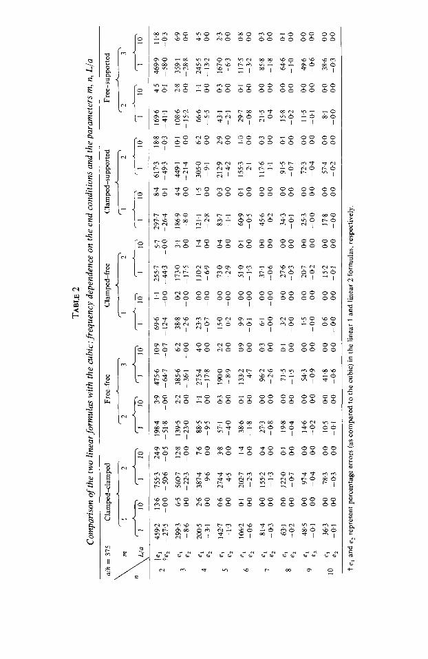
higher values of L/a is similar. From Table 1 a trend can be inferred: that the linear 2 results always slightly overestimate the corresponding exact values. On the basis of the pattern shown in Figures 2-6 similar behaviour as given above for the clamped-free case can be expected to exist for other boundary conditions as well.
Table 2 displays the percentage errors in linear 1 (A,) and linear 2 (d,) approximations as compared to cubic results for various end conditions. Two typical values of L/a ( 1 and 10) are considered to cover short as well as tall shells. As is evident, the linear 1 results are very much more unreliable for short shells and increasing m but are quite comparable to the cubic results for tall shells and large n-values. Linear 2 results are all very good, and in some cases, as can be seen for the low n-values underestimate the cubic results (thus becoming close to the exact results as seen in Table 1). This perhaps, may be attributed to increase in the values of inertia for low n-values. In fact, linear 2 results can be relied upon in almost all the cases. Some other self-evident conclusions may be drawn by looking at this table.
To conclude, some general remarks may be made about the value of A, in equation (JO) as compared to the corresponding approximation given by equation (1) of reference [ 51, in which Fli.igge’s thin shell theory was used. The only difference is in the coefficient of the term fi:A,” in the numerator, which is n ’ here instead of (n2 + 2) in reference [5]. This results in a very slight increase in the frequency parameters calculated by Fliigge’s theory as compared with those obtained by using the present analysis.
5. CONCLUDING REMARKS
An unified free vibration analysis is presented for thin circular cylindrical shells with various end conditions within the framework of the “best” first order shell theory of Budian- sky and Sanders. Choice of mode shapes is kept general and the inclusion of different boundary conditions is made possible by approximating the axial dependence with the appropriate characteristic beam vibrating functions. The variational formulation gives a cubic frequency equation. The engineering assumption of zero hoop and shear strain is then incorporated to yield a highly simplified linear formula for the frequency parameter. The inclusion of this assumption has been found to introduce a constraint on membrane flexibility, thereby increasing the stretching part of the strain energy without any significant change in the bending part. This exaggerates the natural frequencies, in some cases quite substantially. To avoid incurring this excessive inaccuracy in the stretching terms, these inter-relationships between the deflections are used in the kinetic energy expression only. Now the application of the variational procedure results in a second linear formula for the frequency parameter. The results of this modified linear formula are shown to be better than not only the previous linear relation but also, in some critical cases, the more complicated cubic frequency equation, as it underestimates them and thus becomes closer to the exact results (which it always overestimates). Successful comparison of analytical results is made with some existing experimental observations, and also among the results of the three different frequency equations.
It may be concluded that the applications of the above analysis are manifold : for example, (i) explicit and simple formulas for frequency calculations, where various boundary con- ditions can be included by a straight insertion of beam data, (ii) apparent ease in calcula- tions, (iii) the simple linear 2 formula gives improved accuracy as compared to exact results, (iv) comparison of other thin shell theories with the “best” thin shell theory of Budiansky and Sanders, etc.

592 C. B. SHARMA
REFERENCES
1. C. B. SHARMA and D. J. JOHNS 1970 Loughborough University of Technology, Report TT 7001. Vibration characteristics of clamped/free and clamped/ring stiffened circular cylindrical shells: a theoretical analysis.
2. A. W. LEISSA 1973 NASA SP-288. Vibration of shells. 3. B. BUDIANSKY and J. L. SANDERS JR. 1963 in Progress in Applied Mechanics, The Prager
Anniversary Volume, 129-140. New York: Macmillan. On the “best” first order linear shell theory.
4. L. K. SHAYO and C. H. ELLEN 1978 Journal of Sound and Vibration 56, 582-585. A simple approximate expression for the natural frequencies of circular cross-section cantilever pipes.
5. C. B. SHARMA 1977 Journal of Sound and Vibration 55, 467471. Simple linear formulas for critical frequencies for cantilever circular cylindrical shells.
6. J. L. SEWALL and E. C. NAUMANN 1968 NASA TND-4705. An experimental and analytical vibration study of thin cylindrical shells with and without longitudinal stiffeners.
7. G. B. WARBURTON and J. HIGGS 1970 Journal of Sound and Vibration 11, 335-338. Natural frequencies of thin cantilever cylindrical shells.
8. Ho CHUNG 1974 Ph.D. Thesis, Tufts University. A general method of solution for vibrations of cylindrical shells.
9. C. B. SHARMA 1974 Journal of Sound and Vibration 35, 55-76. Calculation of natural frequencies of fixed-free circular cylindrical shells.
IO. R. E. D. BISHOP and D. C. JOHNSON 1960 The Mechanics of Vibration. Cambridge University Press. See pp. 375-387.
II. C. B. SHARMA 1978 Journal of Soundand Vibration 56,475480. Calculation of integrals involving characteristic beam functions.
APPENDIX: LIST OF SYMBOLS
:.. A;B, C
h II,I,
k L m n p, u u, v, w
shell radius elements of frequency determinant generalized co-ordinates in modal forms eigenvalue properties of a beam Young’s modulus characteristic beam vibration func- tions shell thickness integrals involving characteristic beam functions a parameter shell length axial wave number circumferential wave number eigenvalues of a vibrating beam strain energy of shell longitudinal, circumferential and radial components of the shell mid- surface, respectively longitudinal, circumferential and radial co-ordinates
&Cd longitudinal dependence function in modal forms
B h2/12a2 1, parameter dependent on beam eigen-
values ( = p,a) V Poisson’s ratio P shell density
k natural frequency (rad/s) frequency parameter (= pa2( 1 - v’) w’/E)
R strain components Subscript r refers to the rth axial mode, subscripts i, j = I, 2, 3 and p, q = I, 2. A comma followed by a subscript denotes differentiation with respect to that subscript: e.g., u,, = au/ax, dxe = a201axae, etc. A dot above a variable denotes time deriva- tive of the variable: e.g., ti = au/at, etc. Dashes denote differentiation with respect to the argument.