Chimney Sweeping Robot Based on a Pneumatic Actuator
17
applied sciences Article Chimney Sweeping Robot Based on a Pneumatic Actuator Peter Ján Sinˇ cák 1 , Ivan Virgala 1 , Michal Kelemen 1, * , Erik Prada 1 , Zdenko Bobovský 2 and Tomáš Kot 2 Citation: Sinˇ cák, P.J.; Virgala, I.; Kelemen, M.; Prada, E.; Bobovský, Z.; Kot, T. Chimney Sweeping Robot Based on a Pneumatic Actuator. Appl. Sci. 2021, 11, 4872. https://doi.org/ 10.3390/app11114872 Academic Editor: Alessandro Gasparetto Received: 15 April 2021 Accepted: 24 May 2021 Published: 26 May 2021 Publisher’s Note: MDPI stays neutral with regard to jurisdictional claims in published maps and institutional affil- iations. Copyright: © 2021 by the authors. Licensee MDPI, Basel, Switzerland. This article is an open access article distributed under the terms and conditions of the Creative Commons Attribution (CC BY) license (https:// creativecommons.org/licenses/by/ 4.0/). 1 Department of Mechatronics, Faculty of Mechanical Engineering, Technical University of Košice, 04200 Košice, Slovakia; [email protected] (P.J.S.); [email protected] (I.V.); [email protected] (E.P.) 2 Faculty of Mechanical Engineering, VSB-Technical University of Ostrava, 708 00 Ostrava, Czech Republic; [email protected] (Z.B.); [email protected] (T.K.) * Correspondence: [email protected] Abstract: The need of improving the quality of professions led to the idea of simplification of processes during chimney sweeping. These processes have been essentially the same for tens of years. The goal of this paper is to bring an automation element into the chimney sweeping process, making the job easier for the chimney sweeper. In this paper, an essentially in-pipe robot is presented, which uses brushes to move while simultaneously cleaning the chimney or pipeline. The problem of the robot motion was reduced using an in-pipe robot due to the environments and obstacles that the robot has to face. An approach of using a pneumatic actuator for motion is presented along with the mechanical design. The next part of this paper is focused on the mathematical model of the robot motion, as well as its simulation and testing in the experimental pipeline. The simulations were compared with the experimental measurements and a few analyses were conducted describing the simulation model and its differences with the real robot, as well as considering certain parameters and their impact on the performance of the robot. The results are discussed at the end of the paper. Keywords: chimney; cleaning; in-pipe robot; pneumatic actuator; simulation 1. Introduction The increasing trend of automation, the introduction of robotic systems into vari- ous professions, is on its way across all fields. However, one of the professions that has remained unchanged since its very beginning is the chimney-cleaning profession. The pro- cess of chimney sweeping has been essentially the same since the 18th century. Nowadays, the main concerns of the chimney-cleaning process are the safety of the chimney cleaner and the fact that it is a physically demanding process. This knowledge led to the idea of designing a system for locomotion inside the chimney as well as cleaning it, thereby im- proving the whole process. To start off, the problem was generalized into an in-pipe robotic system, due to the similarities of the environments that the robot is going to move in. In the following sections of this paper, a brief overview of the related works that inspired our design process is presented. These works represent innovations in the area of in-pipe robots. In the subsequent section, the paper focuses on the principle of motion that is used for the actuation of this robotic system. Further, the mechanical design is developed, as well as a mathematical model that describes the forces involved in the actuation process of this robot. To prove the concept of this robot, a computer simulation was created, determining travel distance at certain frequencies of the actuation. To evaluate the created simulations, the verification of the proposed robotic system was carried out, and the results were evaluated in the conclusion of this paper. 2. Related Works The problem of robots that are able to move inside of a chimney is very similar to the problem of in-pipe robots. Throughout the years, there have been many different approaches to the design of these kinds of robots. Appl. Sci. 2021, 11, 4872. https://doi.org/10.3390/app11114872 https://www.mdpi.com/journal/applsci
-
Upload
khangminh22 -
Category
Documents
-
view
4 -
download
0
Transcript of Chimney Sweeping Robot Based on a Pneumatic Actuator
applied sciences
Article
Chimney Sweeping Robot Based on a Pneumatic Actuator
Peter Ján Sincák 1 , Ivan Virgala 1 , Michal Kelemen 1,* , Erik Prada 1 , Zdenko Bobovský 2
and Tomáš Kot 2
�����������������
Citation: Sincák, P.J.; Virgala, I.;
Kelemen, M.; Prada, E.; Bobovský, Z.;
Kot, T. Chimney Sweeping Robot
Based on a Pneumatic Actuator. Appl.
Sci. 2021, 11, 4872. https://doi.org/
10.3390/app11114872
Academic Editor:
Alessandro Gasparetto
Received: 15 April 2021
Accepted: 24 May 2021
Published: 26 May 2021
Publisher’s Note: MDPI stays neutral
with regard to jurisdictional claims in
published maps and institutional affil-
iations.
Copyright: © 2021 by the authors.
Licensee MDPI, Basel, Switzerland.
This article is an open access article
distributed under the terms and
conditions of the Creative Commons
Attribution (CC BY) license (https://
creativecommons.org/licenses/by/
4.0/).
1 Department of Mechatronics, Faculty of Mechanical Engineering, Technical University of Košice,04200 Košice, Slovakia; [email protected] (P.J.S.); [email protected] (I.V.); [email protected] (E.P.)
2 Faculty of Mechanical Engineering, VSB-Technical University of Ostrava, 708 00 Ostrava, Czech Republic;[email protected] (Z.B.); [email protected] (T.K.)
* Correspondence: [email protected]
Abstract: The need of improving the quality of professions led to the idea of simplification ofprocesses during chimney sweeping. These processes have been essentially the same for tens of years.The goal of this paper is to bring an automation element into the chimney sweeping process, makingthe job easier for the chimney sweeper. In this paper, an essentially in-pipe robot is presented, whichuses brushes to move while simultaneously cleaning the chimney or pipeline. The problem of therobot motion was reduced using an in-pipe robot due to the environments and obstacles that therobot has to face. An approach of using a pneumatic actuator for motion is presented along with themechanical design. The next part of this paper is focused on the mathematical model of the robotmotion, as well as its simulation and testing in the experimental pipeline. The simulations werecompared with the experimental measurements and a few analyses were conducted describing thesimulation model and its differences with the real robot, as well as considering certain parametersand their impact on the performance of the robot. The results are discussed at the end of the paper.
Keywords: chimney; cleaning; in-pipe robot; pneumatic actuator; simulation
1. Introduction
The increasing trend of automation, the introduction of robotic systems into vari-ous professions, is on its way across all fields. However, one of the professions that hasremained unchanged since its very beginning is the chimney-cleaning profession. The pro-cess of chimney sweeping has been essentially the same since the 18th century. Nowadays,the main concerns of the chimney-cleaning process are the safety of the chimney cleanerand the fact that it is a physically demanding process. This knowledge led to the idea ofdesigning a system for locomotion inside the chimney as well as cleaning it, thereby im-proving the whole process. To start off, the problem was generalized into an in-pipe roboticsystem, due to the similarities of the environments that the robot is going to move in.
In the following sections of this paper, a brief overview of the related works thatinspired our design process is presented. These works represent innovations in the areaof in-pipe robots. In the subsequent section, the paper focuses on the principle of motionthat is used for the actuation of this robotic system. Further, the mechanical design isdeveloped, as well as a mathematical model that describes the forces involved in theactuation process of this robot. To prove the concept of this robot, a computer simulationwas created, determining travel distance at certain frequencies of the actuation. To evaluatethe created simulations, the verification of the proposed robotic system was carried out,and the results were evaluated in the conclusion of this paper.
2. Related Works
The problem of robots that are able to move inside of a chimney is very similar tothe problem of in-pipe robots. Throughout the years, there have been many differentapproaches to the design of these kinds of robots.
Appl. Sci. 2021, 11, 4872. https://doi.org/10.3390/app11114872 https://www.mdpi.com/journal/applsci
Appl. Sci. 2021, 11, 4872 2 of 17
Previous research in our Cognitics Lab in this area was focused on monitoring andinspection tasks in pipelines. On the one hand, we developed an in-pipe bristle-basedmechanisms [1] for narrow pipelines. On the other hand, we developed several snake robotsfor a more complex type of pipeline, such as [2], where the travelling wave locomotion wasexperimentally analyzed. The concertina locomotion of the snake robot was experimentallyanalyzed using the digital image correlation method in [3], for the pipes with a rectangularand circular cross-section. Considering in-pipe locomotion, snake robots have manyadvantages in comparison with wheeled or bristled mechanisms, due to their kinematicredundancy [4], which may be used for optimization tasks [5].
One of the notable in-pipe robots is AIRO-II, which stands for multi-link articulatedinspection robot, as presented in [6]. Its unique design consists of four units that areconnected by spring joints, along with five sets of wheels, of which two are hemisphericaland not actuated and three are so-called omni-directional wheels. Two sets of omni-directionalwheels are actuated, and one set is passive. Because of the spring joints, the whole robotis in a zigzag shape, which pushes the wheels against the walls of the pipeline, allowingthe robot to move both horizontally and vertically. AIRO was designed to be used indust-, gas-, and water-filled environments; therefore, it is well protected against outerinfluences. The robot is also equipped with various sensors and cameras that are used forthe inspection of the pipeline. Another novel approach was introduced in [7], using anelectromagnetic linear actuator. In this paper, the authors proposed a micro robotic systemactuated by the electromagnetic actuator. The system consists of the main body, head,and fins or legs. The novel approach of this system relies on its unique tubular linearpermanent magnet actuator. In this actuator, the permanent magnets are in the center,moving in one axis, back and forth, according to the applied voltage that is being suppliedinto the coil, which is static and is around the permanent magnets. The coil does notmove and is positioned on the stator. The principle of the movement is based on thecontraction of the bellows seal, which is contracting as the actuator is moving, therebymoving the robot in the desired direction. In [8], a device without external moving partswas introduced. The proposed robot was based on a capsule robot with the actuator placedinside of a capsule. The actuator was based on a controlled motion of mass inside thecapsule. The main feature of this actuator lies in the collision of the inner mass and thecapsule of the robot. As the mass moves, it collides with the capsule and creates the energynecessary for overcoming the friction force between the robot and the ground or pipeline.A similar type of robot was also analyzed in [9]. In this paper, the authors focused on asmall bristled robot, where they analyzed its movement. The actuation of this robot wasbased on vibration and its frequency. The authors created a model where they analyzed thefrequencies of these vibrations that actuated the robot and were able to determine at whichfrequencies the robot switches the direction of the movement. The bristle type of robot isalso analyzed in [10]. In this paper, a miniature bristle robot is introduced. The actuation ofthis robot is based on the inertial stepping principle. The actuator consists of a permanentmagnet, electromagnet, and a spring. The locomotion is divided into three phases, wherethe permanent magnet is repelled from the electromagnet and compresses the bottomspring. After this phase, the electromagnet is turned off and the permanent magnet travelsin the opposite direction, as before. In the last phase, the permanent magnet collides withthe drive body and creates an energy that is greater than the frictional force between thebristles and walls of the pipeline, thus enabling the movement of the robot. An in-pipeinspection robot was also presented in paper [11]. Here, the authors presented the robotfor visual and non-destructive testing of the pipeline networks, based on a pneumaticactuator. The robot structure consisted of a pneumatic actuator, elastic elements to holdthe robot in the pipeline, and a damper. Since the pneumatic actuator was being actuatedwith the compressed air, it caused the vibration of the robot as it was being stopped by thedamper. These vibrations caused the robot’s movement in the pipeline. Another approachof an in-pipe robot, that is, using compressed air, was introduced in the [12]. As describedin [12], there are several general types of in-pipe robots. In that paper, the introduced
Appl. Sci. 2021, 11, 4872 3 of 17
robot used the mechanism of both inchworm and wall press types of robot. The robotconsisted of two clamping devices, one on top and one on the bottom, and a pneumaticcylinder between them. When the clamping devices were actuated, they were pushedagainst the walls of the pipeline, holding the robot in place. The translation movement ofthe robot inside the pipeline was arranged by the pneumatic valve using the inchwormprinciple. A similar application of compressed air was also presented in [13]. In paper [13],an application of bristle-based robots was presented. The proposed motion principle isbased on the pneumatic cylinder that was connected to two brushes, each on one end ofthe cylinder. As the pneumatic actuator was actuated, the brush moved with the cylinder,causing the robot to move in the desired direction based on differential friction. In thispaper, a bristle traction model was extensively studied and tested. At the end, the proposedprinciple of the movement was tested on several robots. Three of the robots were tested insewer pipelines with different diameters of brushes, and one modified robot with guidancewheels was tested in the gas pipeline. The aim of the proposed robots was to demonstratethe flexibility and adaptability of the bristle robots in ill-constraint pipelines and to helpwith the inspection process. The adaptability of the robot was also considered in [14]. In thepresented paper, the MIRINSPECT V robot was introduced. The aim of this robot was tomove in pipelines and adapt its control to the shapes of the pipelines. It was designed forpipelines with an 8-inch inner diameter, and it consisted of three driving units responsiblefor locomotion and one center unit connecting the driving units. The driving unit wascomprised of four wheels, clutch, gears, and an electric motor. The focus in this paper wason the selective drive mechanism, which allowed the robot to use as many electric motors asit needed, depending on the situation. This algorithm therefore increased power efficiencyand improved the ability to pass difficult spots in certain situations. Another approach toan in-pipe robot was presented in [15]. The proposed system consisted of three tracks thatwere distributed equally around the main body of the robot. By pressing the tracks againstthe walls, the robot finds enough traction to move forward. In order to determine thecorrect pressing force, an algorithm was created along with the PD controller, which helpedin adapting the force to the variable pipe diameter. The experimentation was carried out ina horizontal, 30-degree-slope pipeline. In paper [16], a similar approach to the design ofan in-pipe inspection robot was presented. In this paper, a robot for the inspection of oilpipelines was created. The presented robot therefore moved in large-diameter pipelines.It consisted of six sets of wheels that pressed against the walls and the center part carryingbatteries and the control box with microcontroller as well as other circuitry required forthe control of the robot and the inspection of the pipeline. The inspection was carriedout via a camera unit and laser detection device recording the geometrical dimensions.The proposed robot was tested in the actual oil pipeline on various slopes. The importanceof the inspection of oil and gas lines has led to the creation of devices or robots called‘pigs’. Pigs are robots or devices specifically developed for various applications suchas cleaning and inspecting large-diameter oil and gas pipelines, but also other specificapplications. The construction of each robot can be different; however, they have somecommon traits. The general construction of such robots consists of a main body and sealingdiscs [17–22]. The main body houses the equipment necessary for the inspection and thediscs are important for the movement of the robot. In general, these robots do not useany kind of actuators for locomotion; they use the fluids that are inside of the pipelinesto move them [20]. The purpose of these robots is cleaning and inspection of the pipeline.Because the number of the sensors used can be too much for one unit to handle, they canbe composed for several units [22].
The above-mentioned studies led to the idea behind this paper. In this paper, the focusis on essentially in-pipe robots, whose main objective is to clean chimneys. Since the cross-section of the chimney is circular, the problems that in-pipe robots face are fairly similar.Due to the existence of soot in the chimney, the idea of robots with wheels or tracks [6,14–16]was abandoned. Seeing successful prototypes, using fins or bristles in [1,7–11], led to theidea of using chimney brushes instead. The brushes allow the robot to move and clean
Appl. Sci. 2021, 11, 4872 4 of 17
at the same time. By simply changing the size of the brushes, the robot can adapt to avariety of chimney diameters and be more modular. More in-depth analysis of the robot ispresented in the following section.
The contributions of this paper are as follows. First is the development of a robotwith a new concept, based on a single-acting pneumatic actuator, for chimney-cleaningand monitoring purposes. The principle of motion is based on pneumatic piston crash. Be-sides the utilization of compressed air for actuation, it can be also used for soot removal byhigh-pressure air. The next contribution of this paper is a numerical simulation model withan analysis of individual parameters for an optimal robot design. The experimental analy-sis proves the numerical simulation and verifies the functionality of the developed robot.To the best of our knowledge, the presented contributions have not been yet published.
3. Development of Chimney Robot
The following section introduces the principle of robot motion and its mechanical design.
3.1. Principle of Motion
The main principle of the motion of this robot relies on the inertial stepping principle.The main characteristic of this principle is based on the mass that is connected to a mechan-ical capacitor that pulls/pushes the mass. The mass subsequently collides with anothermass or element that is connected to the body of the robot. Collision in the desired directionof the robot’s motion is the key moment in the motion of the robot. At this moment,the required energy for the motion is translated into the robot, enabling the translationmotion of the whole robot.
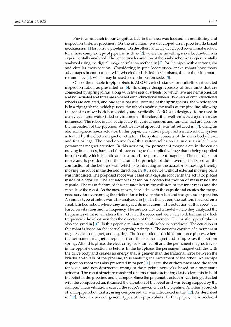
For the proposed robot, there were several configurations of the actuator, and usinga pneumatic actuator was one of them. Based on the inertial stepping principle, thereare several possible configurations of the actuator that were tested. This can be seen inFigure 1, where the pneumatic actuator hits the surface in front of it. The question raisedduring the initial testing of this idea was where to position the collision insert in orderto achieve sufficient energy for the movement of the robot, at the contact of the collisioninsert and the actuator end mass. The number of different distances between the collisioninsert and end piece were tested and, as the result, the travel distance of 23.5 mm waschosen. This distance was chosen based on a number of criteria such as the travel time ofthe piston, the frequency of the supplied air, and the motion of the robot with the chosentravel distance.
Appl. Sci. 2021, 11, x FOR PEER REVIEW 4 of 17
[1,7–11], led to the idea of using chimney brushes instead. The brushes allow the robot to move and clean at the same time. By simply changing the size of the brushes, the robot can adapt to a variety of chimney diameters and be more modular. More in-depth analysis of the robot is presented in the following section.
The contributions of this paper are as follows. First is the development of a robot with a new concept, based on a single-acting pneumatic actuator, for chimney-cleaning and monitoring purposes. The principle of motion is based on pneumatic piston crash. Besides the utilization of compressed air for actuation, it can be also used for soot removal by high-pressure air. The next contribution of this paper is a numerical simulation model with an analysis of individual parameters for an optimal robot design. The experimental analysis proves the numerical simulation and verifies the functionality of the developed robot. To the best of our knowledge, the presented contributions have not been yet published.
3. Development of Chimney Robot The following section introduces the principle of robot motion and its mechanical design.
3.1. Principle of Motion The main principle of the motion of this robot relies on the inertial stepping principle.
The main characteristic of this principle is based on the mass that is connected to a me-chanical capacitor that pulls/pushes the mass. The mass subsequently collides with an-other mass or element that is connected to the body of the robot. Collision in the desired direction of the robot’s motion is the key moment in the motion of the robot. At this mo-ment, the required energy for the motion is translated into the robot, enabling the trans-lation motion of the whole robot.
For the proposed robot, there were several configurations of the actuator, and using a pneumatic actuator was one of them. Based on the inertial stepping principle, there are several possible configurations of the actuator that were tested. This can be seen in Figure 1, where the pneumatic actuator hits the surface in front of it. The question raised during the initial testing of this idea was where to position the collision insert in order to achieve sufficient energy for the movement of the robot, at the contact of the collision insert and the actuator end mass. The number of different distances between the collision insert and end piece were tested and, as the result, the travel distance of 23.5 mm was chosen. This distance was chosen based on a number of criteria such as the travel time of the piston, the frequency of the supplied air, and the motion of the robot with the chosen travel distance.
The principle of motion is shown in Figure 1. The motion consists of three phases. During the first phase, the cylinder extends until it hits the collision insert. The collision of these two objects represents the second phase. During this phase, the robot moves for-ward due to the impact force caused by collision. The red dashed line represents the initial position of the robot. During the third phase, the cylinder moves to its initial position. By repeating these three phases at a certain frequency, the robot moves forward.
Figure 1. Motion phases of the proposed robot.
3.2. Mechanical Design In the previous section, the main principle of the robot motion was introduced. Here,
the overall design of the proposed robot will be introduced. The basic structure of the robot consists of the actuator unit and the robot’s body with brushes. The overall scheme of the robot can be seen in Figure 2.
Figure 1. Motion phases of the proposed robot.
The principle of motion is shown in Figure 1. The motion consists of three phases.During the first phase, the cylinder extends until it hits the collision insert. The collision ofthese two objects represents the second phase. During this phase, the robot moves forwarddue to the impact force caused by collision. The red dashed line represents the initialposition of the robot. During the third phase, the cylinder moves to its initial position.By repeating these three phases at a certain frequency, the robot moves forward.
3.2. Mechanical Design
In the previous section, the main principle of the robot motion was introduced. Here,the overall design of the proposed robot will be introduced. The basic structure of the robotconsists of the actuator unit and the robot’s body with brushes. The overall scheme of therobot can be seen in Figure 2.

Appl. Sci. 2021, 11, 4872 5 of 17Appl. Sci. 2021, 11, x FOR PEER REVIEW 5 of 17
Figure 2. The robot’s configuration.
As seen in Figure 2, at the top of the robot is a cap that could be made of plastic or aluminum, for the purpose of weight reduction, whose main job is to keep the robot straight during the motion. Since the service entrance of the chimney is often under the area where other appliances might be connected to the main chimney, the robot could derail and get stuck. Hence, the cap’s job is to slide the brushes or the robot back to the mainline and, at the same time, to reject any excessive weight to the robot’s body. The cap could be printed by a 3D printer. Immediately under the cap is a chimney brush, which is a regular chimney brush with a nut welded to the centre part of the brush so that the brush could be attached to the robot. It is then screwed to the end piece, which is connected to the body of the robot with fasteners. The purpose of this plug is to hold the brush and encapsulate the actuator so that it is shielded from any debris that is released from the walls of the chimney during the movement of the robot. Below that is a collision insert. The main purpose of this collision insert is in the actuation of the robot. This collision insert collides with the actuator end mass, and, during this process, the energy necessary for the motion is created. It is connected to the robot body with the fasteners in order to ensure stabil-ity. The actuator end mass is screwed on the end of the pneumatic actuator shaft that is moving according to the supplied pressure. As mentioned before, it collides with the collision insert and actuates the robot. Another part, as can be seen in Figure 2, is the holding piece 1 and 2. These pieces hold the pneumatic actuator in place so that it does not move during its actuation. Both of these pieces are again connected to the robot body with fasteners.
When it comes to brushes, it is assumed that the regular chimney brushes that are com-mercially available could be used, with some slight alterations such as welding the nut to them or, if required, cutting the length of the bristle. The assumption of using these brushes was made in regard to the overall price of the device because brushes are widely available in all different sizes. After the nut is welded onto the bottom part of the brush, the brush can be screwed onto the end piece that seals the main body. Another advantage of using regular, widely available chimney brushes is that they come in different sizes; therefore, by swapping the brushes, the robot could be used in various diameters of the pipelines or chimneys.
In the design of the robot, there are two end pieces, one at each end of the robot’s body, so that the actuator inside is shielded away from the debris in the chimney. Both of the end pieces are 8 mm tall and 44 mm in diameter. Their other function is to hold the brushes attached to the robot’s body. For that, there are four holes opposite each other on the sides of the end pieces in order for the fasteners to connect them with the main body and to keep them in place. Both of the end pieces were printed on a 3D printer with a 60% infill of the material to make them more rigid. The material used for printing was ST-PLA, which is a strengthened PLA. The body of the robot is printed with a 3D printer using the
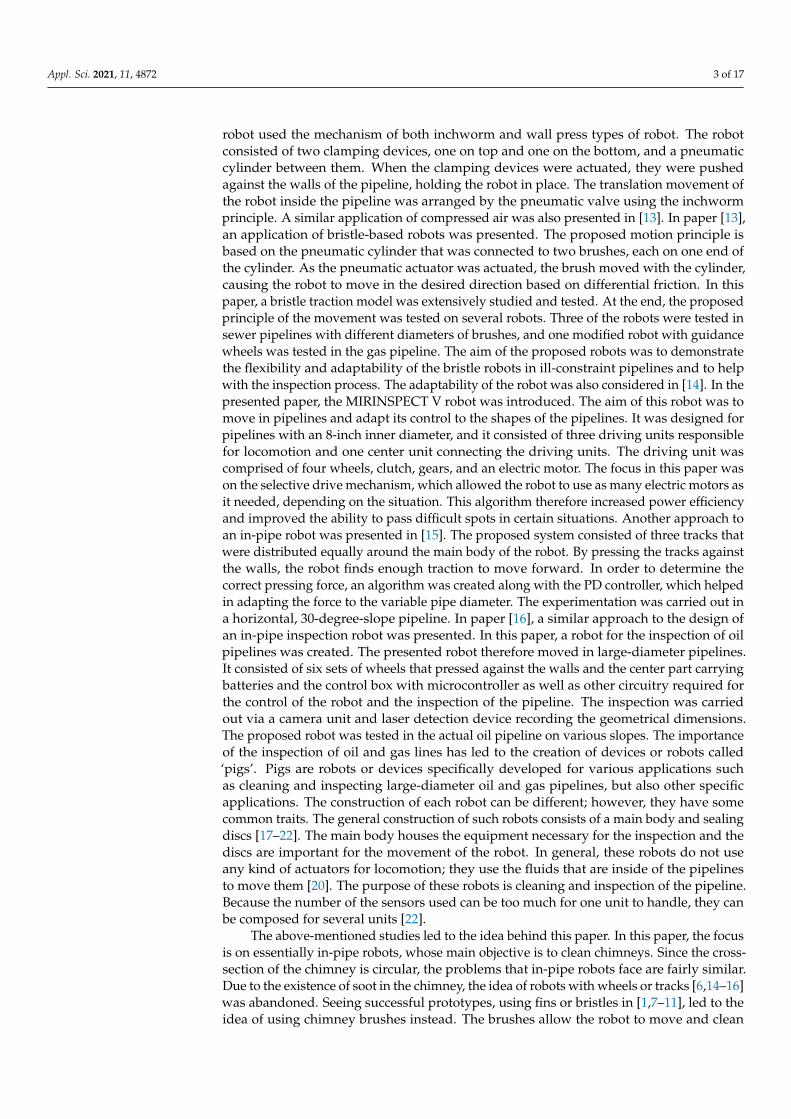
Figure 2. The robot’s configuration.
As seen in Figure 2, at the top of the robot is a cap that could be made of plasticor aluminum, for the purpose of weight reduction, whose main job is to keep the robotstraight during the motion. Since the service entrance of the chimney is often under thearea where other appliances might be connected to the main chimney, the robot couldderail and get stuck. Hence, the cap’s job is to slide the brushes or the robot back to themainline and, at the same time, to reject any excessive weight to the robot’s body. The capcould be printed by a 3D printer. Immediately under the cap is a chimney brush, which isa regular chimney brush with a nut welded to the centre part of the brush so that the brushcould be attached to the robot. It is then screwed to the end piece, which is connected tothe body of the robot with fasteners. The purpose of this plug is to hold the brush andencapsulate the actuator so that it is shielded from any debris that is released from thewalls of the chimney during the movement of the robot. Below that is a collision insert.The main purpose of this collision insert is in the actuation of the robot. This collisioninsert collides with the actuator end mass, and, during this process, the energy necessaryfor the motion is created. It is connected to the robot body with the fasteners in order toensure stability. The actuator end mass is screwed on the end of the pneumatic actuatorshaft that is moving according to the supplied pressure. As mentioned before, it collideswith the collision insert and actuates the robot. Another part, as can be seen in Figure 2,is the holding piece 1 and 2. These pieces hold the pneumatic actuator in place so that itdoes not move during its actuation. Both of these pieces are again connected to the robotbody with fasteners.
When it comes to brushes, it is assumed that the regular chimney brushes that arecommercially available could be used, with some slight alterations such as welding thenut to them or, if required, cutting the length of the bristle. The assumption of using thesebrushes was made in regard to the overall price of the device because brushes are widelyavailable in all different sizes. After the nut is welded onto the bottom part of the brush,the brush can be screwed onto the end piece that seals the main body. Another advantageof using regular, widely available chimney brushes is that they come in different sizes;therefore, by swapping the brushes, the robot could be used in various diameters of thepipelines or chimneys.
In the design of the robot, there are two end pieces, one at each end of the robot’sbody, so that the actuator inside is shielded away from the debris in the chimney. Both ofthe end pieces are 8 mm tall and 44 mm in diameter. Their other function is to hold thebrushes attached to the robot’s body. For that, there are four holes opposite each other onthe sides of the end pieces in order for the fasteners to connect them with the main bodyand to keep them in place. Both of the end pieces were printed on a 3D printer with a 60%
Appl. Sci. 2021, 11, 4872 6 of 17
infill of the material to make them more rigid. The material used for printing was ST-PLA,which is a strengthened PLA. The body of the robot is printed with a 3D printer usingthe same ST-PLA, as it is the case with the other parts. The body is 50 mm in diameter,with 3 mm thick walls and 45% infill of the material. The holes for connecting all theinner parts were drilled afterwards and were not made during 3D printing. The only otherhole that was also drilled was the service hole for connecting the pneumatic line with thepneumatic actuator.
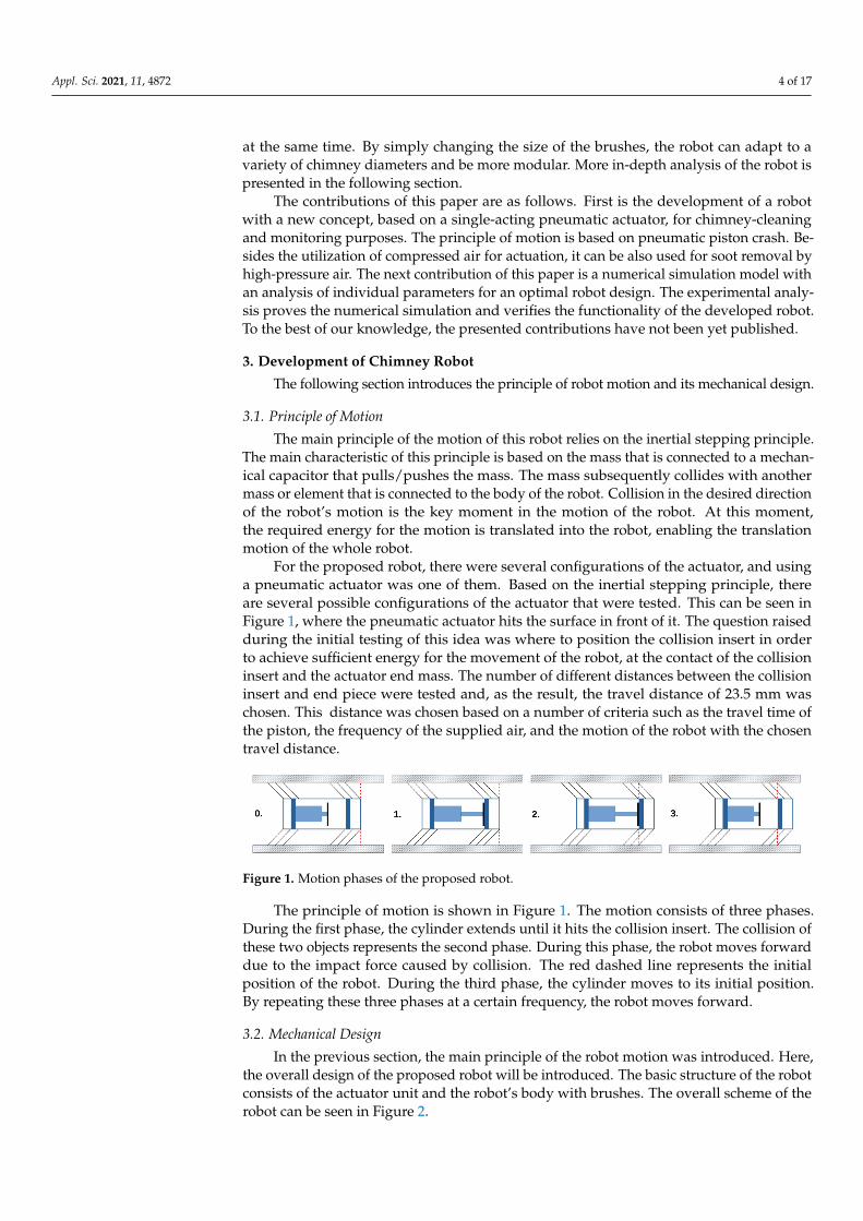
The whole motion of this robot relies on the pneumatic actuator, which is insidethe robot’s body. It is held in place with two holding pieces, printed on a 3D printer.The pneumatic actuator used in this robot is an SMC CD85E10-50s-B. This pneumaticactuator is a single-acting actuator, where the piston is pushed out by the supplied air andpushed back by the spring inside of the actuator. At the end of the moving piston of thisactuator, there is a 3D printed part that is pushed repetitively against the collision inset,which is connected to the main body of the robot, hence conducting the motion of the robot.
The pneumatic scheme of the proposed chimney robot is shown in Figure 3. The robotuses polyurethane pipelines with an inner diameter of 4 mm and an electromagnetic valvecontrolled by PLC.
Appl. Sci. 2021, 11, x FOR PEER REVIEW 6 of 17
same ST-PLA, as it is the case with the other parts. The body is 50 mm in diameter, with 3 mm thick walls and 45% infill of the material. The holes for connecting all the inner parts were drilled afterwards and were not made during 3D printing. The only other hole that was also drilled was the service hole for connecting the pneumatic line with the pneumatic actuator.
The whole motion of this robot relies on the pneumatic actuator, which is inside the robot’s body. It is held in place with two holding pieces, printed on a 3D printer. The pneumatic actuator used in this robot is an SMC CD85E10-50s-B. This pneumatic actuator is a single-acting actuator, where the piston is pushed out by the supplied air and pushed back by the spring inside of the actuator. At the end of the moving piston of this actuator, there is a 3D printed part that is pushed repetitively against the collision inset, which is connected to the main body of the robot, hence conducting the motion of the robot.
The pneumatic scheme of the proposed chimney robot is shown in Figure 3. The ro-bot uses polyurethane pipelines with an inner diameter of 4 mm and an electromagnetic valve controlled by PLC.
Figure 3. Pneumatic scheme of the robot.
3.3. Concept of the Proposed System The concept of the proposed robot system is based on the premise of improving the
chimney-sweeping process that has been stagnant for quite some time. By implementing a robotic system into this process, new data could be gained. The proposed robot is in-tended to carry a camera and make a recording that could help evaluate the condition of the chimney. A comprehensive concept of the developed system is shown in Figure 4.
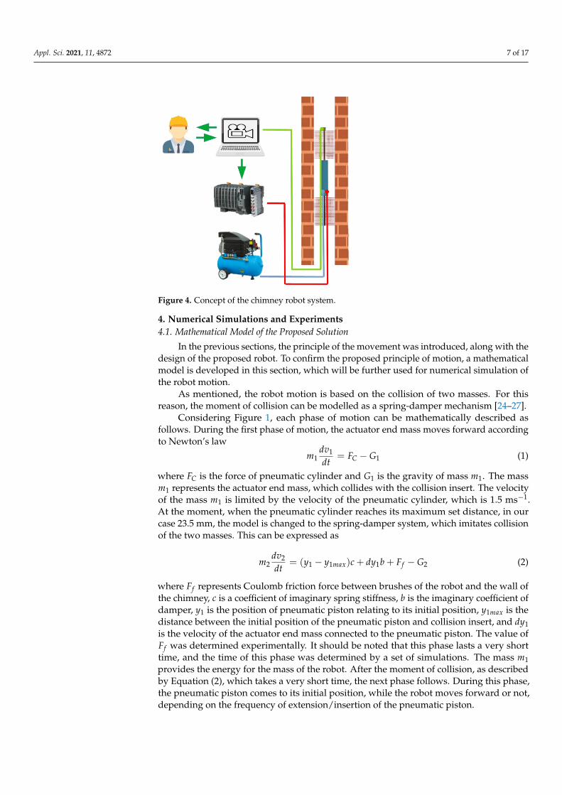
Figure 4. Concept of the chimney robot system.
Figure 3. Pneumatic scheme of the robot.
3.3. Concept of the Proposed System
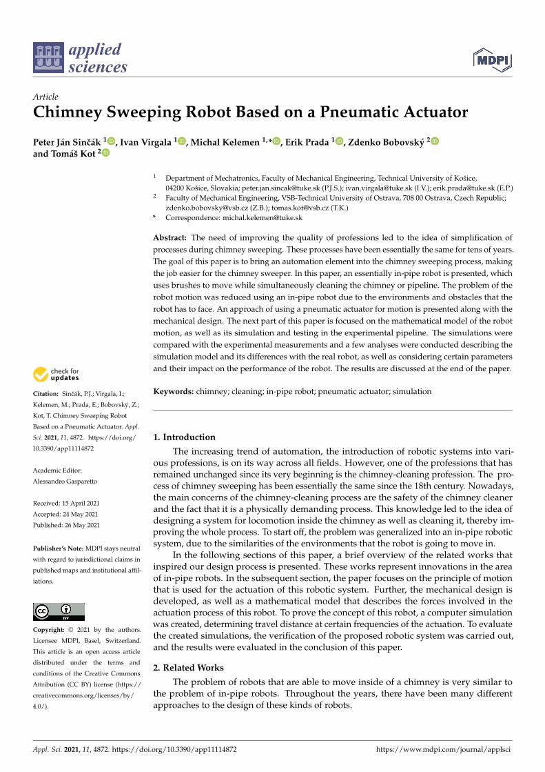
The concept of the proposed robot system is based on the premise of improving thechimney-sweeping process that has been stagnant for quite some time. By implementing arobotic system into this process, new data could be gained. The proposed robot is intendedto carry a camera and make a recording that could help evaluate the condition of thechimney. A comprehensive concept of the developed system is shown in Figure 4.
The robot can be connected to a remote computer, where the operator can monitorthe operation of the robot system and the camera feed from the robot. By using suitablesensors, the robot can become diagnosable, which is an important point of mechatronicsystems [23]. This inspection process can also be important for insurance purposes becausethe recording can prove the condition of the chimney. Another important part of thisconcept is the cleaning of the chimney. Cleaning is an intentional collateral process ofthe movement of the robot. Another collateral process that is also helping to clean thechimney is the exhausting air from the pneumatic actuator. The use of compressed aircan be also implemented on the top or bottom of the robot, where it can blow air andfacilitate the cleaning process. The design of the robot system allows the interchangeabilityof the brushes, which can affect the cleaning performance but also the speed of the robotsystem and several parameters. This modularity is also an advantage when it comes toadaptability to different diameters of the chimneys.
Appl. Sci. 2021, 11, 4872 7 of 17
Appl. Sci. 2021, 11, x FOR PEER REVIEW 6 of 17
same ST-PLA, as it is the case with the other parts. The body is 50 mm in diameter, with 3 mm thick walls and 45% infill of the material. The holes for connecting all the inner parts were drilled afterwards and were not made during 3D printing. The only other hole that was also drilled was the service hole for connecting the pneumatic line with the pneumatic actuator.
The whole motion of this robot relies on the pneumatic actuator, which is inside the robot’s body. It is held in place with two holding pieces, printed on a 3D printer. The pneumatic actuator used in this robot is an SMC CD85E10-50s-B. This pneumatic actuator is a single-acting actuator, where the piston is pushed out by the supplied air and pushed back by the spring inside of the actuator. At the end of the moving piston of this actuator, there is a 3D printed part that is pushed repetitively against the collision inset, which is connected to the main body of the robot, hence conducting the motion of the robot.
The pneumatic scheme of the proposed chimney robot is shown in Figure 3. The ro-bot uses polyurethane pipelines with an inner diameter of 4 mm and an electromagnetic valve controlled by PLC.
Figure 3. Pneumatic scheme of the robot.
3.3. Concept of the Proposed System The concept of the proposed robot system is based on the premise of improving the
chimney-sweeping process that has been stagnant for quite some time. By implementing a robotic system into this process, new data could be gained. The proposed robot is in-tended to carry a camera and make a recording that could help evaluate the condition of the chimney. A comprehensive concept of the developed system is shown in Figure 4.
Figure 4. Concept of the chimney robot system. Figure 4. Concept of the chimney robot system.
4. Numerical Simulations and Experiments4.1. Mathematical Model of the Proposed Solution
In the previous sections, the principle of the movement was introduced, along with thedesign of the proposed robot. To confirm the proposed principle of motion, a mathematicalmodel is developed in this section, which will be further used for numerical simulation ofthe robot motion.
As mentioned, the robot motion is based on the collision of two masses. For thisreason, the moment of collision can be modelled as a spring-damper mechanism [24–27].
Considering Figure 1, each phase of motion can be mathematically described asfollows. During the first phase of motion, the actuator end mass moves forward accordingto Newton’s law
m1dv1
dt= FC − G1 (1)
where FC is the force of pneumatic cylinder and G1 is the gravity of mass m1. The massm1 represents the actuator end mass, which collides with the collision insert. The velocityof the mass m1 is limited by the velocity of the pneumatic cylinder, which is 1.5 ms−1.At the moment, when the pneumatic cylinder reaches its maximum set distance, in ourcase 23.5 mm, the model is changed to the spring-damper system, which imitates collisionof the two masses. This can be expressed as
m2dv2
dt= (y1 − y1max)c + dy1b + Ff − G2 (2)
where Ff represents Coulomb friction force between brushes of the robot and the wall ofthe chimney, c is a coefficient of imaginary spring stiffness, b is the imaginary coefficient ofdamper, y1 is the position of pneumatic piston relating to its initial position, y1max is thedistance between the initial position of the pneumatic piston and collision insert, and dy1is the velocity of the actuator end mass connected to the pneumatic piston. The value ofFf was determined experimentally. It should be noted that this phase lasts a very shorttime, and the time of this phase was determined by a set of simulations. The mass m1provides the energy for the mass of the robot. After the moment of collision, as describedby Equation (2), which takes a very short time, the next phase follows. During this phase,the pneumatic piston comes to its initial position, while the robot moves forward or not,depending on the frequency of extension/insertion of the pneumatic piston.
Appl. Sci. 2021, 11, 4872 8 of 17
4.2. Numerical Simulation
In this part, the focus is on the implementation of the mathematical background of therobot (mentioned in the previous section) into the numerical simulation and comparingthe simulation with the real robot motion. For the simulation, MATLAB R2019b softwarewas used.
The robot motion can be described by the following Algorithm 1.
Algorithm 1 Numerical simulation
1: Initialization of variables and constants2: FOR cycle = 1 TO Number of required cycles BY 13: FOR i = 0 TO T BY dt // Forward motion of pneumatic piston4: IF (i > valveDelay) THEN5: FC = Fmax6: END7: Computation of mass 1 acceleration, velocity, position8: IF (contact < ρ) AND (y1 > y1max) THEN9: contact++10: FR = (y1 − y1max)c + dy1b11: ELSEIF (contact== ρ) AND (y1 > y1max) THEN12: FC = FR = dv1 = dy1 = 013: ELSEIF (contact==0) AND (y1 < y1max) THEN14: FR = 015: END16: m2
dv2dt = FR + Ff − G2
17: Computation of mass 2 acceleration, velocity, position18: END19: FOR i = 0 TO T BY dt // Backward motion of pneumatic piston20: IF (i > valveDelay) THEN21: FC = Fmax22: END23: Computation of mass 1 acceleration, velocity, position24: IF (y1 ≤ 0) THEN25: dv1 = dy1 = y1 = 026: END27: Computation of mass 2 acceleration, velocity, position28: END29: END
The algorithm is divided into two parts. The first part deals with the extension of thepneumatic piston, and the second part deals with the insertion of the piston. The algorithmuses mathematical background, which is described in the previous section. The constantvalveDelay is the value from the datasheet of the pneumatic valve. It is the time delayof the used pneumatic valve. The force Fmax represents the maximal force of the usedpneumatic cylinder, which is given by the datasheet. As can be seen from the algorithm,there is variable contact, which stands for the simulation of the time period in which twomasses are in contact. The value of this variable was empirically determined as constant ρ.The simulations use the constants given in the Table 1.
Choosing the correct damping and stiffness coefficients is very important for a success-ful simulation. In our case, the spring and damper do not represent the actual springs anddampers; hence, the theoretical approach of determining the values was chosen. Followingthe approach in [25], the stiffness of the contact can be calculated with the following equation:
c = 4π2 f 2m (3)
Appl. Sci. 2021, 11, 4872 9 of 17
The damping coefficient b1 is also selected by a similar approach [26]. In this equation,the recommended value of β lies between 0.1 and 0.4.
b = 2β√
km (4)
Table 1. Simulation constants.
Parameter Value (Units)
Mass 1 0.05 (kg)Mass 2 1 (kg)
Maximum piston speed 1.5 (ms−1)Maximum piston extension 0.0235 (m)
Maximum piston force 62.8 (N)Time delay of valve 0.005 (s)
Time step 0.0001 (s)Spring stiffness 800 (Nm−1)
Damping coefficient 240 (Nm−1s)Time period of impact 0.0006 (s)
Forward friction coefficient 0.8 × 50 (N)Backward friction coefficient 50 (N)
The calculated stiffness and damping coefficient have to be checked with the simula-tion and, if necessary, adjusted. Note that the higher the stiffness of the contact is, the slowerthe calculations in the simulations will be. This means that the goal here is to choose theproper constant as low as possible while keeping the plausibility of the simulation.
In the first cycle, the algorithm starts with the calculations of the acceleration andvelocity of the moving mass at the end of the pneumatic piston, which is changes as thepiston extends toward the point of contact between the moving mass and the collisioninsert that is connected to the robot’s body. The next step in the first cycle is the simulationof the contact between the moving mass and the collision insert. This contact is representedin the mathematical model with the damper and spring. The collision that happens issimulated by creating an impulse contact force that is the sum of the forces created bythe spring and the damper, as described in Section 4.1. Initially, before the robot startsthe motion, the gravitational force that pulls the robot down equals the friction force ofthe brushes and walls of the chimney/pipeline, which is why the robot stands still anddoes not fall toward the ground. The impulse force created at the contact triggers the startof the robot motion, as the equilibrium between the forces is disrupted by this impulse.In the last step of this cycle, the acceleration of the robot is calculated using Equation (2).From here, the velocity and the displacement of the robot can be calculated numericallybased on the Euler integration method as well. The next part of the last step of this cycle isthe calculation of the friction force that is acting between the brushes and the walls of thechimney/pipeline. This force is calculated using the following equation:
Ff = −µFf maxsign(dy2) (5)
Of course, the Coulomb friction model is dependent on the velocity direction. This istaken into consideration by the algorithm, and the force is switched accordingly. In theforward direction of the motion, toward the top of the chimney, the actual friction forceis slightly lower than in the opposite direction, due to the angle of the brushes that isnaturally caused by the motion. The friction force in the opposite direction uses the sameEquation (5), although with the coefficient µ = 1.
In the second cycle, the algorithm looks very similar. However, there is no contactbetween the moving mass and the collision insert. The moving mass travels in a reverseddirection compared to the previous cycle because the pneumatic piston is being retracted.After this, the whole process starts again and is repeated until it reaches the overallpredefined time of the simulation.
Appl. Sci. 2021, 11, 4872 10 of 17
4.3. Experiments
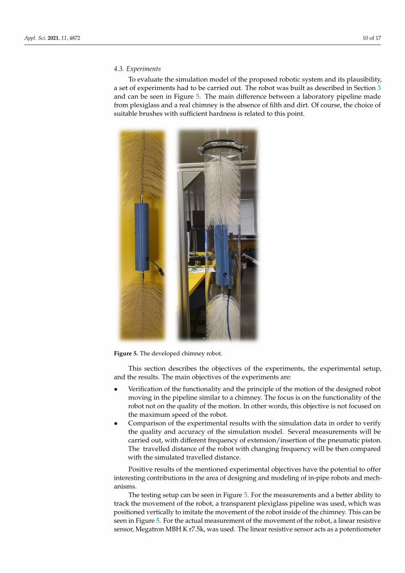
To evaluate the simulation model of the proposed robotic system and its plausibility,a set of experiments had to be carried out. The robot was built as described in Section 3and can be seen in Figure 5. The main difference between a laboratory pipeline madefrom plexiglass and a real chimney is the absence of filth and dirt. Of course, the choice ofsuitable brushes with sufficient hardness is related to this point.
Appl. Sci. 2021, 11, x FOR PEER REVIEW 10 of 17
4.3. Experiments To evaluate the simulation model of the proposed robotic system and its plausibility,
a set of experiments had to be carried out. The robot was built as described in Section 3 and can be seen in Figure 5. The main difference between a laboratory pipeline made from plexiglass and a real chimney is the absence of filth and dirt. Of course, the choice of suit-able brushes with sufficient hardness is related to this point.
This section describes the objectives of the experiments, the experimental setup, and the results. The main objectives of the experiments are: • Verification of the functionality and the principle of the motion of the designed robot
moving in the pipeline similar to a chimney. The focus is on the functionality of the robot not on the quality of the motion. In other words, this objective is not focused on the maximum speed of the robot.
• Comparison of the experimental results with the simulation data in order to verify the quality and accuracy of the simulation model. Several measurements will be car-ried out, with different frequency of extension/insertion of the pneumatic piston. The travelled distance of the robot with changing frequency will be then compared with the simulated travelled distance. Positive results of the mentioned experimental objectives have the potential to offer
interesting contributions in the area of designing and modeling of in-pipe robots and mechanisms.
Figure 5. The developed chimney robot.
The testing setup can be seen in Figure 5. For the measurements and a better ability to track the movement of the robot, a transparent plexiglass pipeline was used, which was positioned vertically to imitate the movement of the robot inside of the chimney. This can be seen in Figure 5. For the actual measurement of the movement of the robot, a linear
Figure 5. The developed chimney robot.
This section describes the objectives of the experiments, the experimental setup,and the results. The main objectives of the experiments are:
• Verification of the functionality and the principle of the motion of the designed robotmoving in the pipeline similar to a chimney. The focus is on the functionality of therobot not on the quality of the motion. In other words, this objective is not focused onthe maximum speed of the robot.
• Comparison of the experimental results with the simulation data in order to verifythe quality and accuracy of the simulation model. Several measurements will becarried out, with different frequency of extension/insertion of the pneumatic piston.The travelled distance of the robot with changing frequency will be then comparedwith the simulated travelled distance.
Positive results of the mentioned experimental objectives have the potential to offerinteresting contributions in the area of designing and modeling of in-pipe robots and mech-anisms.
The testing setup can be seen in Figure 5. For the measurements and a better ability totrack the movement of the robot, a transparent plexiglass pipeline was used, which waspositioned vertically to imitate the movement of the robot inside of the chimney. This can beseen in Figure 5. For the actual measurement of the movement of the robot, a linear resistivesensor, Megatron MBH K r7.5k, was used. The linear resistive sensor acts as a potentiometer
Appl. Sci. 2021, 11, 4872 11 of 17
with a slider. The output of this sensor was fed right into the MATLAB/Simulink softwarethrough the measuring card Humusoft MF634; by creating the calibration characteristics ofthis sensor, it was possible to gain the travelled distance of the robot, in mm, as the resultof the measurement.
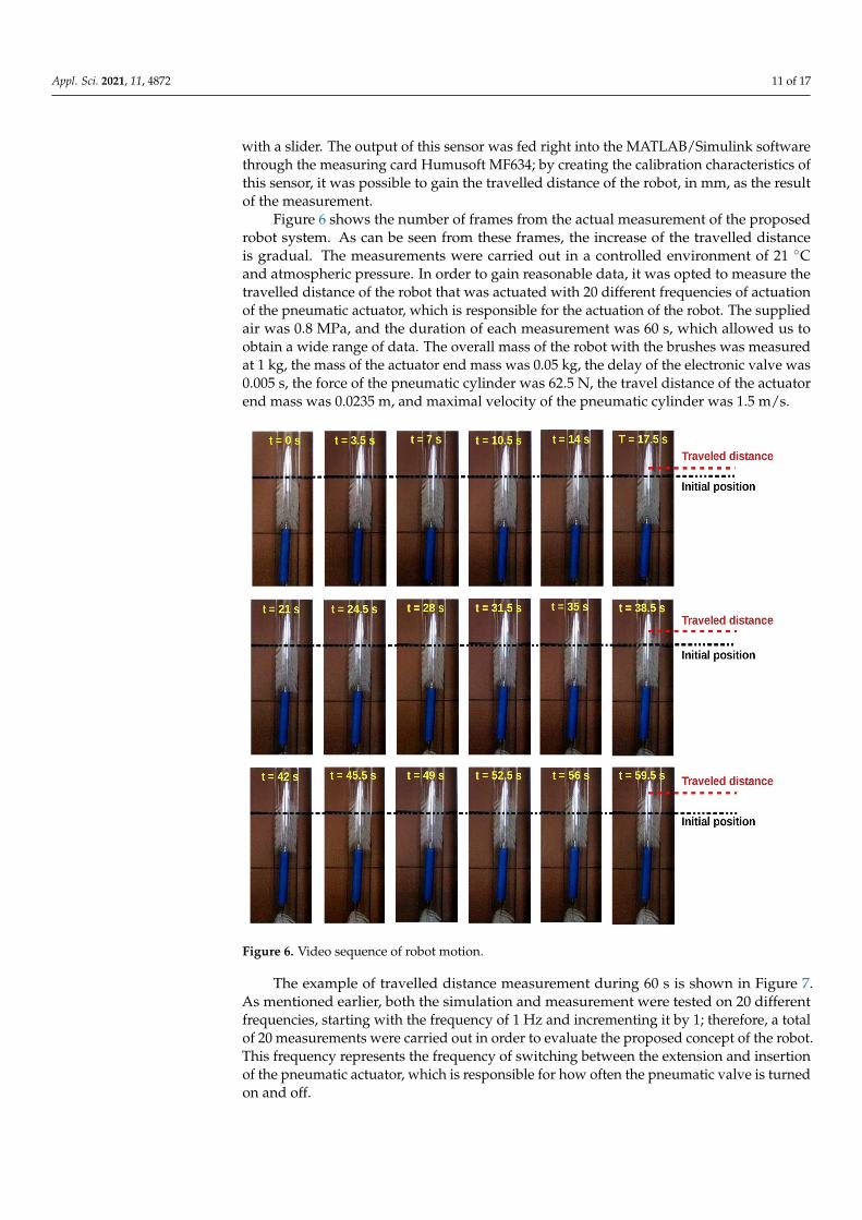
Figure 6 shows the number of frames from the actual measurement of the proposedrobot system. As can be seen from these frames, the increase of the travelled distanceis gradual. The measurements were carried out in a controlled environment of 21 ◦Cand atmospheric pressure. In order to gain reasonable data, it was opted to measure thetravelled distance of the robot that was actuated with 20 different frequencies of actuationof the pneumatic actuator, which is responsible for the actuation of the robot. The suppliedair was 0.8 MPa, and the duration of each measurement was 60 s, which allowed us toobtain a wide range of data. The overall mass of the robot with the brushes was measuredat 1 kg, the mass of the actuator end mass was 0.05 kg, the delay of the electronic valve was0.005 s, the force of the pneumatic cylinder was 62.5 N, the travel distance of the actuatorend mass was 0.0235 m, and maximal velocity of the pneumatic cylinder was 1.5 m/s.
Appl. Sci. 2021, 11, x FOR PEER REVIEW 11 of 17
resistive sensor, Megatron MBH K r7.5k, was used. The linear resistive sensor acts as a potentiometer with a slider. The output of this sensor was fed right into the MATLAB/Simulink software through the measuring card Humusoft MF634; by creating the calibration characteristics of this sensor, it was possible to gain the travelled distance of the robot, in mm, as the result of the measurement.
Figure 6 shows the number of frames from the actual measurement of the proposed robot system. As can be seen from these frames, the increase of the travelled distance is gradual. The measurements were carried out in a controlled environment of 21 °C and atmospheric pressure. In order to gain reasonable data, it was opted to measure the trav-elled distance of the robot that was actuated with 20 different frequencies of actuation of the pneumatic actuator, which is responsible for the actuation of the robot. The supplied air was 0.8 MPa, and the duration of each measurement was 60 s, which allowed us to obtain a wide range of data. The overall mass of the robot with the brushes was measured at 1 kg, the mass of the actuator end mass was 0.05 kg, the delay of the electronic valve was 0.005 s, the force of the pneumatic cylinder was 62.5 N, the travel distance of the actuator end mass was 0.0235 m, and maximal velocity of the pneumatic cylinder was 1.5 m/s.
Figure 6. Video sequence of robot motion.
The example of travelled distance measurement during 60 s is shown in Figure 7. As mentioned earlier, both the simulation and measurement were tested on 20 different fre-quencies, starting with the frequency of 1 Hz and incrementing it by 1; therefore, a total of 20 measurements were carried out in order to evaluate the proposed concept of the robot. This frequency represents the frequency of switching between the extension and insertion of the pneumatic actuator, which is responsible for how often the pneumatic valve is turned on and off.
Figure 6. Video sequence of robot motion.
The example of travelled distance measurement during 60 s is shown in Figure 7.As mentioned earlier, both the simulation and measurement were tested on 20 differentfrequencies, starting with the frequency of 1 Hz and incrementing it by 1; therefore, a totalof 20 measurements were carried out in order to evaluate the proposed concept of the robot.This frequency represents the frequency of switching between the extension and insertionof the pneumatic actuator, which is responsible for how often the pneumatic valve is turnedon and off.
Appl. Sci. 2021, 11, 4872 12 of 17Appl. Sci. 2021, 11, x FOR PEER REVIEW 12 of 17
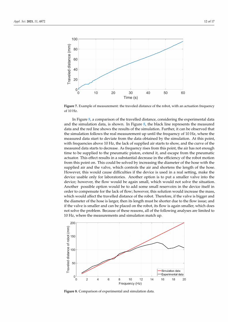
Figure 7. Example of measurement: the traveled distance of the robot, with an actuation frequency of 10 Hz.
In Figure 8, a comparison of the travelled distance, considering the experimental data and the simulation data, is shown. In Figure 8, the black line represents the measured data and the red line shows the results of the simulation. Further, it can be observed that the simulation follows the real measurement up until the frequency of 10 Hz, where the measured data start to deviate from the data obtained by the simulation. At this point, with frequencies above 10 Hz, the lack of supplied air starts to show, and the curve of the measured data starts to de-crease. As frequency rises from this point, the air has not enough time to be supplied to the pneumatic piston, extend it, and escape from the pneumatic actuator. This effect results in a substantial decrease in the efficiency of the robot motion from this point on. This could be solved by increasing the diameter of the hose with the supplied air and the valve, which con-trols the air and shortens the length of the hose. However, this would cause difficulties if the device is used in a real setting, make the device usable only for laboratories. Another option is to put a smaller valve into the device; however, the flow would be again small, which would not solve the situation. Another possible option would be to add some small reservoirs in the device itself in order to compensate for the lack of flow; however, this solution would increase the mass, which would affect the travelled distance of the robot. Therefore, if the valve is big-ger and the diameter of the hose is larger, then its length must be shorter due to the flow issue; and if the valve is smaller and can be placed on the robot, its flow is again smaller, which does not solve the problem. Because of these reasons, all of the following analyses are limited to 10 Hz, where the measurements and simulation match up.
Figure 8. Comparison of experimental and simulation data.
Figure 7. Example of measurement: the traveled distance of the robot, with an actuation frequencyof 10 Hz.
In Figure 8, a comparison of the travelled distance, considering the experimental dataand the simulation data, is shown. In Figure 8, the black line represents the measureddata and the red line shows the results of the simulation. Further, it can be observed thatthe simulation follows the real measurement up until the frequency of 10 Hz, where themeasured data start to deviate from the data obtained by the simulation. At this point,with frequencies above 10 Hz, the lack of supplied air starts to show, and the curve of themeasured data starts to decrease. As frequency rises from this point, the air has not enoughtime to be supplied to the pneumatic piston, extend it, and escape from the pneumaticactuator. This effect results in a substantial decrease in the efficiency of the robot motionfrom this point on. This could be solved by increasing the diameter of the hose with thesupplied air and the valve, which controls the air and shortens the length of the hose.However, this would cause difficulties if the device is used in a real setting, make thedevice usable only for laboratories. Another option is to put a smaller valve into thedevice; however, the flow would be again small, which would not solve the situation.Another possible option would be to add some small reservoirs in the device itself inorder to compensate for the lack of flow; however, this solution would increase the mass,which would affect the travelled distance of the robot. Therefore, if the valve is bigger andthe diameter of the hose is larger, then its length must be shorter due to the flow issue; andif the valve is smaller and can be placed on the robot, its flow is again smaller, which doesnot solve the problem. Because of these reasons, all of the following analyses are limited to10 Hz, where the measurements and simulation match up.
Appl. Sci. 2021, 11, x FOR PEER REVIEW 12 of 17
Figure 7. Example of measurement: the traveled distance of the robot, with an actuation frequency of 10 Hz.
In Figure 8, a comparison of the travelled distance, considering the experimental data and the simulation data, is shown. In Figure 8, the black line represents the measured data and the red line shows the results of the simulation. Further, it can be observed that the simulation follows the real measurement up until the frequency of 10 Hz, where the measured data start to deviate from the data obtained by the simulation. At this point, with frequencies above 10 Hz, the lack of supplied air starts to show, and the curve of the measured data starts to de-crease. As frequency rises from this point, the air has not enough time to be supplied to the pneumatic piston, extend it, and escape from the pneumatic actuator. This effect results in a substantial decrease in the efficiency of the robot motion from this point on. This could be solved by increasing the diameter of the hose with the supplied air and the valve, which con-trols the air and shortens the length of the hose. However, this would cause difficulties if the device is used in a real setting, make the device usable only for laboratories. Another option is to put a smaller valve into the device; however, the flow would be again small, which would not solve the situation. Another possible option would be to add some small reservoirs in the device itself in order to compensate for the lack of flow; however, this solution would increase the mass, which would affect the travelled distance of the robot. Therefore, if the valve is big-ger and the diameter of the hose is larger, then its length must be shorter due to the flow issue; and if the valve is smaller and can be placed on the robot, its flow is again smaller, which does not solve the problem. Because of these reasons, all of the following analyses are limited to 10 Hz, where the measurements and simulation match up.
Figure 8. Comparison of experimental and simulation data. Figure 8. Comparison of experimental and simulation data.
Appl. Sci. 2021, 11, 4872 13 of 17
4.4. Results of the Simulations and Analyses
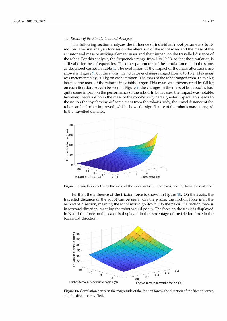
The following section analyzes the influence of individual robot parameters to itsmotion. The first analysis focuses on the alteration of the robot mass and the mass of theactuator end mass or striking element mass and their impact on the travelled distance ofthe robot. For this analysis, the frequencies range from 1 to 10 Hz so that the simulation isstill valid for these frequencies. The other parameters of the simulation remain the same,as described earlier in Table 1. The evaluation of the impact of the mass alterations areshown in Figure 9. On the y axis, the actuator end mass ranged from 0 to 1 kg. This masswas incremented by 0.01 kg on each iteration. The mass of the robot ranged from 0.5 to 5 kgbecause the mass of the robot is inevitably larger. This mass was incremented by 0.5 kgon each iteration. As can be seen in Figure 9, the changes in the mass of both bodies hadquite some impact on the performance of the robot. In both cases, the impact was notable;however, the variation in the mass of the robot’s body had a greater impact. This leads tothe notion that by shaving off some mass from the robot’s body, the travel distance of therobot can be further improved, which shows the significance of the robot’s mass in regardto the travelled distance.
Appl. Sci. 2021, 11, x FOR PEER REVIEW 13 of 17
4.4. Results of the Simulations and Analyses The following section analyzes the influence of individual robot parameters to its
motion. The first analysis focuses on the alteration of the robot mass and the mass of the actuator end mass or striking element mass and their impact on the travelled distance of the robot. For this analysis, the frequencies range from 1 to 10 Hz so that the simulation is still valid for these frequencies. The other parameters of the simulation remain the same, as described earlier in Table 1. The evaluation of the impact of the mass alterations are shown in Figure 9. On the y axis, the actuator end mass ranged from 0 to 1 kg. This mass was incremented by 0.01 kg on each iteration. The mass of the robot ranged from 0.5 to 5 kg because the mass of the robot is inevitably larger. This mass was incremented by 0.5 kg on each iteration. As can be seen in Figure 9, the changes in the mass of both bodies had quite some impact on the performance of the robot. In both cases, the impact was notable; however, the variation in the mass of the robot’s body had a greater impact. This leads to the notion that by shaving off some mass from the robot’s body, the travel dis-tance of the robot can be further improved, which shows the significance of the robot’s mass in regard to the travelled distance.
Figure 9. Correlation between the mass of the robot, actuator end mass, and the travelled distance.
Further, the influence of the friction force is shown in Figure 10. On the z axis, the trav-elled distance of the robot can be seen. On the y axis, the friction force is in the backward di-rection, meaning the robot would go down. On the x axis, the friction force is in forward di-rection, meaning the robot would go up. The force on the y axis is displayed in N and the force on the x axis is displayed in the percentage of the friction force in the backward direction.
Figure 9. Correlation between the mass of the robot, actuator end mass, and the travelled distance.
Further, the influence of the friction force is shown in Figure 10. On the z axis, thetravelled distance of the robot can be seen. On the y axis, the friction force is in thebackward direction, meaning the robot would go down. On the x axis, the friction force isin forward direction, meaning the robot would go up. The force on the y axis is displayedin N and the force on the x axis is displayed in the percentage of the friction force in thebackward direction.
Appl. Sci. 2021, 11, x FOR PEER REVIEW 13 of 17
4.4. Results of the Simulations and Analyses The following section analyzes the influence of individual robot parameters to its
motion. The first analysis focuses on the alteration of the robot mass and the mass of the actuator end mass or striking element mass and their impact on the travelled distance of the robot. For this analysis, the frequencies range from 1 to 10 Hz so that the simulation is still valid for these frequencies. The other parameters of the simulation remain the same, as described earlier in Table 1. The evaluation of the impact of the mass alterations are shown in Figure 9. On the y axis, the actuator end mass ranged from 0 to 1 kg. This mass was incremented by 0.01 kg on each iteration. The mass of the robot ranged from 0.5 to 5 kg because the mass of the robot is inevitably larger. This mass was incremented by 0.5 kg on each iteration. As can be seen in Figure 9, the changes in the mass of both bodies had quite some impact on the performance of the robot. In both cases, the impact was notable; however, the variation in the mass of the robot’s body had a greater impact. This leads to the notion that by shaving off some mass from the robot’s body, the travel dis-tance of the robot can be further improved, which shows the significance of the robot’s mass in regard to the travelled distance.
Figure 9. Correlation between the mass of the robot, actuator end mass, and the travelled distance.
Further, the influence of the friction force is shown in Figure 10. On the z axis, the trav-elled distance of the robot can be seen. On the y axis, the friction force is in the backward di-rection, meaning the robot would go down. On the x axis, the friction force is in forward di-rection, meaning the robot would go up. The force on the y axis is displayed in N and the force on the x axis is displayed in the percentage of the friction force in the backward direction.
Figure 10. Correlation between the magnitude of the friction forces, the direction of the friction forces,and the distance travelled.
Appl. Sci. 2021, 11, 4872 14 of 17
This was caried out due to the fact that the forward friction force is smaller due tothe slope of the bristles, which are forced to bend into an angle due to the direction ofthe robot motion. The parameters of the simulation remain the same as in the previousanalyses. In this figure, it can be observed that, in the given time, the smaller the forwardfriction is, the further the robot travels. This observation can be also confirmed in themathematical model because the friction force is acting against the direction of the robotmotion. Therefore, by decreasing it, the driving force has more influence over the travelleddistance of the robot. The friction in the forward direction is highly influenced by theaforementioned slope of the bristles and by the material of the bristles and the wall. Ofcourse, friction has also another purpose, which is to hold the robot in place and to stop itfrom falling when the robot is not being actuated. For these reasons, it cannot be smallerthan the gravitational force pulling the robot down.
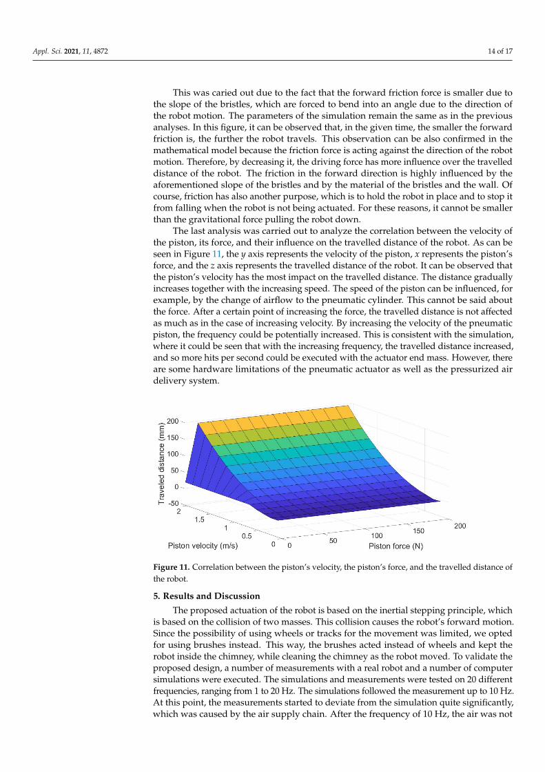
The last analysis was carried out to analyze the correlation between the velocity ofthe piston, its force, and their influence on the travelled distance of the robot. As can beseen in Figure 11, the y axis represents the velocity of the piston, x represents the piston’sforce, and the z axis represents the travelled distance of the robot. It can be observed thatthe piston’s velocity has the most impact on the travelled distance. The distance graduallyincreases together with the increasing speed. The speed of the piston can be influenced, forexample, by the change of airflow to the pneumatic cylinder. This cannot be said aboutthe force. After a certain point of increasing the force, the travelled distance is not affectedas much as in the case of increasing velocity. By increasing the velocity of the pneumaticpiston, the frequency could be potentially increased. This is consistent with the simulation,where it could be seen that with the increasing frequency, the travelled distance increased,and so more hits per second could be executed with the actuator end mass. However, thereare some hardware limitations of the pneumatic actuator as well as the pressurized airdelivery system.
Appl. Sci. 2021, 11, x FOR PEER REVIEW 14 of 17
Figure 10. Correlation between the magnitude of the friction forces, the direction of the friction forces, and the distance travelled.
This was caried out due to the fact that the forward friction force is smaller due to the slope of the bristles, which are forced to bend into an angle due to the direction of the robot motion. The parameters of the simulation remain the same as in the previous anal-yses. In this figure, it can be observed that, in the given time, the smaller the forward friction is, the further the robot travels. This observation can be also confirmed in the mathematical model because the friction force is acting against the direction of the robot motion. Therefore, by decreasing it, the driving force has more influence over the travelled distance of the robot. The friction in the forward direction is highly influenced by the aforementioned slope of the bristles and by the material of the bristles and the wall. Of course, friction has also another purpose, which is to hold the robot in place and to stop it from falling when the robot is not being actuated. For these reasons, it cannot be smaller than the gravitational force pulling the robot down.
The last analysis was carried out to analyze the correlation between the velocity of the piston, its force, and their influence on the travelled distance of the robot. As can be seen in Figure 11, the y axis represents the velocity of the piston, x represents the piston’s force, and the z axis represents the travelled distance of the robot. It can be observed that the piston’s velocity has the most impact on the travelled distance. The distance gradually increases together with the increasing speed. The speed of the piston can be influenced, for example, by the change of airflow to the pneumatic cylinder. This cannot be said about the force. After a certain point of increasing the force, the travelled distance is not affected as much as in the case of increasing velocity. By increasing the velocity of the pneumatic piston, the frequency could be potentially increased. This is consistent with the simula-tion, where it could be seen that with the increasing frequency, the travelled distance in-creased, and so more hits per second could be executed with the actuator end mass. How-ever, there are some hardware limitations of the pneumatic actuator as well as the pres-surized air delivery system.
Figure 11. Correlation between the piston’s velocity, the piston’s force, and the travelled distance of the robot.
5. Results and Discussion The proposed actuation of the robot is based on the inertial stepping principle, which
is based on the collision of two masses. This collision causes the robot’s forward motion. Since the possibility of using wheels or tracks for the movement was limited, we opted for using brushes instead. This way, the brushes acted instead of wheels and kept the robot inside the chimney, while cleaning the chimney as the robot moved. To validate the pro-posed design, a number of measurements with a real robot and a number of computer
Figure 11. Correlation between the piston’s velocity, the piston’s force, and the travelled distance ofthe robot.
5. Results and Discussion
The proposed actuation of the robot is based on the inertial stepping principle, whichis based on the collision of two masses. This collision causes the robot’s forward motion.Since the possibility of using wheels or tracks for the movement was limited, we optedfor using brushes instead. This way, the brushes acted instead of wheels and kept therobot inside the chimney, while cleaning the chimney as the robot moved. To validate theproposed design, a number of measurements with a real robot and a number of computersimulations were executed. The simulations and measurements were tested on 20 differentfrequencies, ranging from 1 to 20 Hz. The simulations followed the measurement up to 10 Hz.At this point, the measurements started to deviate from the simulation quite significantly,which was caused by the air supply chain. After the frequency of 10 Hz, the air was not
Appl. Sci. 2021, 11, 4872 15 of 17
supplied quick enough, and the flow of the air was limited. This resulted in the differencebetween the values that were measured and the ones that were simulated. To furthervalidate the robot and the simulations, analyses of certain attributes were carried out,and their impact on the robot’s travelled distance was investigated. One of the analyseswas focused on the general mass of the robot, and the mass of the striking end mass.The analysis resulted in the conclusion that the variation in the robot’s mass had a greaterimpact on the robot’s performance compared with the variation in the mass of the strikingend mass. This means that if the mass was further reduced, the performance could beimproved. The following analysis investigates the influence of the friction force in bothdirections and their influence on the travelled distance of the robot. By decreasing thefriction force in the forward direction, the travelled distance increases. This force cannot bedecreased infinitely, because too small a friction force would result in the robot’s falling.This force has to be at least at the level of the gravitational force that is acting on the robot;these two forces would cancel each other out, and the robot would stand still when it is notbeing actuated. The last analysis investigates the correlation of the piston force, its velocity,and the travelled distance. It shows that the importance of maximizing the piston’s velocityis much higher than the importance of increasing the piston’s force.
This paper contributed to the improvement of chimney sweeping using in-pipe robots.The novelty and contributions of this paper are as follows. As presented in the paper, therobot system based on a new concept, by using compressed air, has the ability to movevertically while at the same time cleaning the pipeline or a chimney. Having considered theprevious works, as described in Section 2, one of the novelties of this paper is the principleof motion. Other robots’ motion, as we have mentioned, is based on electromagneticactuating with body impact; smooth piston extrusion without body impact and frictiondifference; wheel-based actuating; SMA-based actuating; and snake robot locomotion.However, our robot uses the impact of the bodies caused by a single-acting pneumaticcylinder. It uses the friction difference of the brushes to keep the robot in the chimney.Of course, the brushes also serve as cleaners of the chimney during the robot motion.
The next contribution of the paper is a model of numerical simulation. Some of theprevious works introduced a mathematical model for the robot motion. However, a detailedview on the simulation model was absent. Our paper offers a detailed algorithm ofnumerical simulation, which was also experimentally verified. Thanks to the numericalsimulation model, many of the analyses can be carried out without the need to of havingan experimental model.
The next contribution of the paper is the provided analyses, which are based on thenumerical simulation model. The analyses offer a deeper insight into the designing ofchimney sweeping robots, showing the influence of individual parameters of the robot onits final motion properties.
The last contribution of the paper is an experimentally verified prototype of a proposedrobot that is able to move vertically inside of the chimney/pipeline.
6. Conclusions
The paper investigates a chimney-robot’s motion in the pipeline. We introduced anovel design of the robot, whose motion is ensured by single-acting pneumatic cylinder.Due to the impacting of the robot’s collision insert by pneumatic piston, the robot performsa forward motion while it simultaneously cleans the chimney/pipeline. The paper alsooffers a detailed algorithm of the numerical simulation model, by which several analysesof the robot motion have been presented. Moreover, the influence of the robot mass andactuator end mass on the speed of the robot has been shown. The analyses also offer a viewon the influence of friction and piston speed/force on the robot’s final travelled distanceper time. The experimental analysis proved, on the one hand, the functionality of thedeveloped robot. On the other hand, it showed the accuracy of the developed numericalsimulation model. The weakest element of the robot is between the pneumatic valve andthe pneumatic cylinder. If the valve is placed in the robot, it needs to be small, which also
Appl. Sci. 2021, 11, 4872 16 of 17
causes a small air flow through it. Due to this fact, the pneumatic cylinder cannot workwith the high frequency of piston extension/insertion, resulting in a slow robot speed.On the other hand, if the pneumatic valve has a high air flow, it needs to be outside of therobot (out of the chimney). For this reason, the pneumatic pipeline from the valve to thecylinder needs to be sufficiently long (especially in the case of a high chimney). This, again,results in the low frequency of piston extension/insertion.
The future work of this robot lies in the improvement of the air supply system, whichgreatly influences performance. By improving this part of the system, greater frequenciescould be achieved, which should result in better performance. Another interesting areaof research could be the ability to influence the friction force between the brushes andthe walls of the chimney/pipeline. Being able to adjust the slope of the brushes could beanother important area of improvement. Our next aim is also to secure the reverse motionof the robot.
Author Contributions: Conceptualization, I.V., P.J.S., and M.K.; methodology, I.V. and P.J.S.; software,I.V.; validation, P.J.S.; formal analysis, P.J.S. and T.K.; investigation, E.P., Z.B., and M.K.; resources,M.K., I.V., and E.P.; writing—original draft preparation, P.J.S. and I.V.; supervision, I.V.; projectadministration, I.V. All authors have read and agreed to the published version of the manuscript.
Funding: This research was funded by Slovak Grant Agency VEGA 1/0389/18 “Research on kine-matically redundant mechanisms”. This work was also supported by the European Regional De-velopment Fund in the Research Centre of Advanced Mechatronic Systems project, project numberCZ.02.1.01/0.0/0.0/16_019/0000867 within the Operational Programme Research, Developmentand Education.
Data Availability Statement: Data sharing is not applicable to this article.
Acknowledgments: The authors would like to thank the Slovak Grant Agency VEGA 1/0389/18“Research on kinematically redundant mechanisms” and KEGA 030TUKE-4/2020 “Transfer ofknowledge from the field of industrial automation and robotics to the education process in theteaching program mechatronics” They would also like to thank to the European Regional Devel-opment Fund in the Research Centre of Advanced Mechatronic Systems project, project numberCZ.02.1.01/0.0/0.0/16_019/0000867 within the Operational Programme Research, Developmentand Education.
Conflicts of Interest: The authors declare no conflict of interest. The funders had no role in the designof the study; in the collection, analyses, or interpretation of data; in the writing of the manuscript; orin the decision to publish the results.
References1. Ostertag, O.; Ostertagová, E.; Kelemen, M.; Kelemenová, T.; Buša, J.; Virgala, I. Miniature Mobile Bristled In-Pipe Machine. Int. J.
Adv. Robot. Syst. 2014, 11, 189. [CrossRef]2. Virgala, I.; Kelemen, M.; Prada, E.; Sukop, M.; Kot, T.; Bobovský, Z.; Varga, M.; Ferencík, P. A snake robot for locomotion in a pipe
using trapezium-like travelling wave. Mech Mach. Theory 2020, 158, 1–21.3. Virgala, I.; Kelemen, M.; Božek, P.; Bobovský, Z.; Hagara, M.; Prada, E.; Ošcádal, P.; Varga, M. Investigation of Snake Robot
Locomotion Possibilities in a Pipe. Symmetry 2020, 12, 939. [CrossRef]4. Kelemen, M.; Virgala, I.; Lipták, T.; Miková, L’.; Filakovský, F.; Bulej, V. A Novel Approach for a Inverse Kinematics Solution of a
Redundant Manipulator. Appl. Sci. 2018, 8, 2229. [CrossRef]5. Virgala, I.; Kelemen, M.; Varga, M.; Kuryło, P. Analyzing, Modeling and Simulation of Humanoid Robot Hand Motion. Procedia
Eng. 2014, 96, 489–499. [CrossRef]6. Kakogawa, A.; Ma, S. Design of a multilink-articulated wheeled inspection robot for winding pipelines: AIRo-II. In Proceedings
of the 2016 IEEE/RSJ International Conference on Intelligent Robots and Systems (IROS), Daejeon, Korea, 9–14 October 2016;pp. 2115–2121. [CrossRef]
7. Lu, H.; Zhu, J.; Lin, Z.; Guo, Y. An inchworm mobile robot using electromagnetic linear actuator. Mechatronics 2009, 19, 1116–1125.[CrossRef]
8. Ivanov, A.P. Analysis of an impact-driven capsule robot. Int. J. Non. Linear. Mech. 2020, 119, 103257. [CrossRef]9. Cicconofri, G.; DeSimone, A. Motility of a model bristle-bot: A theoretical analysis. Int. J. Non. Linear. Mech. 2015, 76, 233–239.
[CrossRef]10. Yum, Y.-J.; Hwang, H.; Kelemen, M.; Maxim, V.; Frankovský, P. In-pipe micromachine locomotion via the inertial stepping
principle. J. Mech. Sci. Technol. 2014, 28, 3237–3247. [CrossRef]
Appl. Sci. 2021, 11, 4872 17 of 17
11. Ragulskis, K.; Bogdevicius, M.; Mištinas, V. Behavior of Dynamic Processes in Self-Exciting Vibration of an Inpipe Robot.J. Vibroengineering 2008, 10. [CrossRef]
12. Kim, Y.; Yoon, K.; Park, Y. Development of the inpipe robot for various sizes. In Proceedings of the 2009 IEEE/ASME InternationalConference on Advanced Intelligent Mechatronics, Singapore, 14–17 July 2009; pp. 1745–1749. [CrossRef]
13. Wang, Z.; Gu, H. A Bristle-Based Pipeline Robot for Ill-Constraint Pipes. IEEE/ASME Trans. Mechatron. 2008, 13, 383–392.[CrossRef]
14. Roh, S.; Kim, D.W.; Lee, J.S.; Moon, H.; Choi, H.R. In-pipe robot based on selective drive mechanism. Int. J. Control. Autom. Syst.2009, 7, 105–112. [CrossRef]
15. Kim, D.; Park, C.; Kim, H.; Kim, S. Force adjustment of an active pipe inspection robot. In Proceedings of the 2009 ICCAS-SICE,Fukuoka, Japan, 18–21 August 2009; IEEE: Piscataway, NJ, USA, 2009; pp. 3792–3797.
16. Li, H.; Li, R.; Zhang, J.; Zhang, P. Development of a Pipeline Inspection Robot for the Standard Oil Pipeline of China NationalPetroleum Corporation. Appl. Sci. 2020, 10, 2853. [CrossRef]
17. Zhu, X.; Zhang, S.; Wang, D.; Wang, W.; Liu, S. The impact of pipeline bend on bi-directional pig and the theories for the optimalpig design. In Proceedings of the 2013 IEEE International Conference on Mechatronics and Automation, Takamatsu, Japan, 4–7August 2013; pp. 87–92. [CrossRef]
18. Guibin, T.; Shimin, Z.; Xiaoxiao, Z.; Liyun, S.; Qingbao, Z. Research on Bypass-valve and its Resistance Characteristic of SpeedRegulating PIG in Gas Pipeline. In Proceedings of the 2011 Third International Conference on Measuring Technology andMechatronics Automation, Shanghai, China, 6–7 January 2011; pp. 1114–1117. [CrossRef]
19. Alnaimi, F.B.I.; Mazraeh, A.A.; Sahari, K.S.M.; Weria, K.; Moslem, Y. Design of a multi-diameter in-line cleaning and faultdetection pipe pigging device. In Proceedings of the 2015 IEEE International Symposium on Robotics and Intelligent Sensors(IRIS), Langkawi, Malaysia, 18–20 October 2015; pp. 258–265. [CrossRef]
20. Xinyu, Z.; Bo, Z.; Yuanzhang, J.; Bo, L.; Rui, L.; Lin, Z.; Qiao, S.; Xiaoli, Z. Analysis of rotation of pigs during pigging in gaspipeline. In Proceedings of the 2015 International Conference on Fluid Power and Mechatronics (FPM), Harbin, China, 5–7August 2015; pp. 892–895. [CrossRef]
21. Xingping, X.; Hai, W.; Fuzheng, X.; Bin, W. Study of the Drive and Speed Governing Control for a Pipeline Pig. In Proceedings ofthe 2018 10th International Conference on Modelling, Identification and Control (ICMIC), Guiyang, China, 2–4 July 2018; pp. 1–6.[CrossRef]
22. Wang, Z.; Cao, Q.; Luan, N.; Zhang, L. Development of new pipeline maintenance system for repairing early-built offshore oilpipelines. In Proceedings of the 2008 IEEE International Conference on Industrial Technology, Chengdu, China, 21–24 April 2008;pp. 1–6. [CrossRef]
23. Božek, P.; Nikitin, Y.; Krenický, T. Diagnostics of Mechatronic Systems (Studies in Systems, Decision and Control, 345); Springer:Berlin/Heidelberg, Germany, 2021; ISBN 978-3030670542.
24. Sentyakov, K.; Peterka, J.; Smirnov, V.; Bozek, P.; Sviatskii, V. Modeling of Boring Mandrel Working Process with VibrationDamper. Materials 2020, 13, 1931. [CrossRef] [PubMed]
25. Son, L.; Bur, M.; Rusli, M.; Matsuhisa, H.; Yamada, K.; Utsuno, H. Fundamental Study of Momentum Exchange Impact DamperUsing Pre-straining Spring Mechanism. Int. J. Acoust. Vib. 2017, 2, 422–430. [CrossRef]
26. Jönsson, A.; Bathelt, J.; Broman, G. Implications of Modelling One-Dimensional Impact by Using a Spring and Damper Element.Proc. Inst. Mech. Eng. Part. K J. Multi-Body Dyn. 2005, 219, 299–305. [CrossRef]
27. Kuinian, L. Antony Darby. Modelling a buffered impact damper system using a spring-damper model of impact. In StructuralControl and Health Monitoring; Wiley-Blackwell: Hoboken, NJ, USA, 2009; Volume 16, pp. 287–302. [CrossRef]