Thermal management of a symmetrically heated channel–chimney system
13
International Journal of Thermal Sciences 48 (2009) 475–487 www.elsevier.com/locate/ijts Thermal management of a symmetrically heated channel–chimney system Assunta Andreozzi a,∗ , Bernardo Buonomo b , Oronzio Manca b a Dipartimento di Energetica, Termofluidodinamica applicata e Condizionamenti ambientali, Università degli Studi di Napoli Federico II, Piazzale Tecchio 80, 80125 Napoli, Italy b Dipartimento di Ingegneria Aerospaziale e Meccanica, Seconda Università degli Studi di Napoli, Via Roma 29, 81031 Aversa (CE), Italy Received 25 July 2007; received in revised form 20 March 2008; accepted 21 March 2008 Available online 24 April 2008 Abstract A parametric analysis of natural convection in air, in a channel–chimney system, symmetrically heated at uniform heat flux, obtained by means of a numerical simulation, is carried out. The analyzed regime is two-dimensional, laminar and steady-state. Results are presented in terms of wall temperature profiles in order to show the more thermally convenient configurations which correspond to the channel–chimney system with the lowest maximum wall temperature. For the considered Rayleigh number, the difference between the highest and the lowest maximum wall temperatures increases with increasing the channel aspect ratio. The optimal expansion ratio values depend strongly on the Rayleigh number and extension ratio values and slightly on the channel aspect ratio. Correlations for dimensionless mass flow rate, maximum wall temperature and average Nusselt number, in terms of Rayleigh number and dimensionless geometric parameters are presented in the ranges: 5 Ra ∗ 2.0 × 10 4 , 1.5 L/L h 4.0 and 1.0 B/b 4.0. © 2008 Elsevier Masson SAS. All rights reserved. Keywords: Thermal management; Natural convection; Vertical channel–chimney system; Thermal optimization; Thermal design 1. Introduction Natural convection between heated vertical parallel plates, due to its several engineering applications, such as thermal con- trol in electronic equipments, nuclear reactors, solar collectors and chemical vapor deposition reactors, has been extensively studied both experimentally and numerically [1–3]. More re- cent trends in natural convection research are to find new con- figurations to improve the heat transfer parameters or to analyze standard configurations to carry out optimal geometrical pa- rameters for a better heat transfer rate [3–10]. A particularly interesting geometry of modified channel configurations is ob- tained by placing of adiabatic extensions downstream of the heated channel, the channel–chimney system. As shown in [8], some optimal configurations of this system can enhance the heat transfer up to 20% and reduce the maxi- mum wall temperature significantly. The optimal configurations * Corresponding author. Tel.: +39 0817682645; fax: +39 081 2390364. E-mail address: [email protected] (A. Andreozzi). depend on the dimensionless geometrical parameters, such as the expansion ratio (the distance between the adiabatic exten- sions, B , over the distance between the heated plates, b), the extension ratio (the total length of the channel–chimney system, L, over the channel length, L h ), the channel aspect ratio (the channel length, L h , over the channel gap b) and the Rayleigh number. A parametric analysis of the channel–chimney system is necessary in order to carry out a correct thermal manage- ment of this configuration. In fact, an in-depth study allows to evaluate the optimal configurations and to avoid geometrical parameter values which determine a reduction of the chimney effect due to a cold inflow in the system from the outlet section of the adiabatic extensions. In the following, a short review on the channel–chimney system is given. The chimney effect, due to a parallel-wall adiabatic channel, with heat sources at the channel inlet was studied for the first time in [11]. The channel with straight adiabatic downstream extensions was numerically investigated in [12–14]. A vertical channel with isothermal parallel walls was analyzed for natural convection in air in [12]. A vertical 1290-0729/$ – see front matter © 2008 Elsevier Masson SAS. All rights reserved. doi:10.1016/j.ijthermalsci.2008.03.017
-
Upload
independent -
Category
Documents
-
view
3 -
download
0
Transcript of Thermal management of a symmetrically heated channel–chimney system

International Journal of Thermal Sciences 48 (2009) 475–487www.elsevier.com/locate/ijts
Thermal management of a symmetrically heatedchannel–chimney system
Assunta Andreozzi a,∗, Bernardo Buonomo b, Oronzio Manca b
a Dipartimento di Energetica, Termofluidodinamica applicata e Condizionamenti ambientali, Università degli Studi di Napoli Federico II,Piazzale Tecchio 80, 80125 Napoli, Italy
b Dipartimento di Ingegneria Aerospaziale e Meccanica, Seconda Università degli Studi di Napoli, Via Roma 29, 81031 Aversa (CE), Italy
Received 25 July 2007; received in revised form 20 March 2008; accepted 21 March 2008
Available online 24 April 2008
Abstract
A parametric analysis of natural convection in air, in a channel–chimney system, symmetrically heated at uniform heat flux, obtained by meansof a numerical simulation, is carried out. The analyzed regime is two-dimensional, laminar and steady-state. Results are presented in terms ofwall temperature profiles in order to show the more thermally convenient configurations which correspond to the channel–chimney system withthe lowest maximum wall temperature. For the considered Rayleigh number, the difference between the highest and the lowest maximum walltemperatures increases with increasing the channel aspect ratio. The optimal expansion ratio values depend strongly on the Rayleigh number andextension ratio values and slightly on the channel aspect ratio. Correlations for dimensionless mass flow rate, maximum wall temperature andaverage Nusselt number, in terms of Rayleigh number and dimensionless geometric parameters are presented in the ranges: 5 � Ra∗ � 2.0 × 104,1.5 � L/Lh � 4.0 and 1.0 � B/b � 4.0.© 2008 Elsevier Masson SAS. All rights reserved.
Keywords: Thermal management; Natural convection; Vertical channel–chimney system; Thermal optimization; Thermal design
1. Introduction
Natural convection between heated vertical parallel plates,due to its several engineering applications, such as thermal con-trol in electronic equipments, nuclear reactors, solar collectorsand chemical vapor deposition reactors, has been extensivelystudied both experimentally and numerically [1–3]. More re-cent trends in natural convection research are to find new con-figurations to improve the heat transfer parameters or to analyzestandard configurations to carry out optimal geometrical pa-rameters for a better heat transfer rate [3–10]. A particularlyinteresting geometry of modified channel configurations is ob-tained by placing of adiabatic extensions downstream of theheated channel, the channel–chimney system.
As shown in [8], some optimal configurations of this systemcan enhance the heat transfer up to 20% and reduce the maxi-mum wall temperature significantly. The optimal configurations
* Corresponding author. Tel.: +39 0817682645; fax: +39 081 2390364.E-mail address: [email protected] (A. Andreozzi).
1290-0729/$ – see front matter © 2008 Elsevier Masson SAS. All rights reserved.doi:10.1016/j.ijthermalsci.2008.03.017
depend on the dimensionless geometrical parameters, such asthe expansion ratio (the distance between the adiabatic exten-sions, B , over the distance between the heated plates, b), theextension ratio (the total length of the channel–chimney system,L, over the channel length, Lh), the channel aspect ratio (thechannel length, Lh, over the channel gap b) and the Rayleighnumber. A parametric analysis of the channel–chimney systemis necessary in order to carry out a correct thermal manage-ment of this configuration. In fact, an in-depth study allows toevaluate the optimal configurations and to avoid geometricalparameter values which determine a reduction of the chimneyeffect due to a cold inflow in the system from the outlet sectionof the adiabatic extensions.
In the following, a short review on the channel–chimneysystem is given. The chimney effect, due to a parallel-walladiabatic channel, with heat sources at the channel inlet wasstudied for the first time in [11]. The channel with straightadiabatic downstream extensions was numerically investigatedin [12–14]. A vertical channel with isothermal parallel wallswas analyzed for natural convection in air in [12]. A vertical
476 A. Andreozzi et al. / International Journal of Thermal Sciences 48 (2009) 475–487
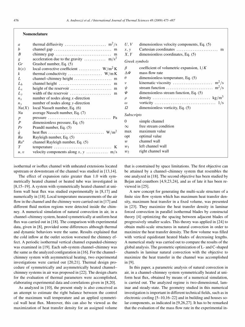
Nomenclature
a thermal diffusivity . . . . . . . . . . . . . . . . . . . . . . . m2/sb channel gap . . . . . . . . . . . . . . . . . . . . . . . . . . . . . . . . mB chimney gap . . . . . . . . . . . . . . . . . . . . . . . . . . . . . . . mg acceleration due to the gravity . . . . . . . . . . . . m/s2
Gr Grashof number, Eq. (5)h(x) local convective coefficient . . . . . . . . . . . . W/m2 Kk thermal conductivity . . . . . . . . . . . . . . . . . . . W/m KL channel–chimney height . . . . . . . . . . . . . . . . . . . . . mLh channel height . . . . . . . . . . . . . . . . . . . . . . . . . . . . . mLx height of the reservoir . . . . . . . . . . . . . . . . . . . . . . . mLy width of the reservoir . . . . . . . . . . . . . . . . . . . . . . . mnx number of nodes along x-directionny number of nodes along y-directionNu(X) local Nusselt number, Eq. (6)Nu average Nusselt number, Eq. (7)p pressure . . . . . . . . . . . . . . . . . . . . . . . . . . . . . . . . . . . PaP dimensionless pressure, Eq. (5)Pr Prandtl number, Eq. (5)q̇ heat flux . . . . . . . . . . . . . . . . . . . . . . . . . . . . . . . W/m2
Ra Rayleigh number, Eq. (5)Ra∗ channel Rayleigh number, Eq. (5)T temperature . . . . . . . . . . . . . . . . . . . . . . . . . . . . . . . . Ku,v velocity components along x, y . . . . . . . . . . . . m/s
U,V dimensionless velocity components, Eq. (5)x, y Cartesian coordinates . . . . . . . . . . . . . . . . . . . . . . . mX,Y dimensionless coordinates, Eq. (5)
Greek symbols
β coefficient of volumetric expansion, 1/K
�Ψ mass flow rateθ dimensionless temperature, Eq. (5)ν kinematic viscosity . . . . . . . . . . . . . . . . . . . . . . m2/sψ stream function . . . . . . . . . . . . . . . . . . . . . . . . . . m2/sΨ dimensionless stream function, Eq. (5)ρ density . . . . . . . . . . . . . . . . . . . . . . . . . . . . . . . . kg/m3
ω vorticity . . . . . . . . . . . . . . . . . . . . . . . . . . . . . . . . . . 1/sΩ dimensionless vorticity, Eq. (5)
Subscripts
0 simple channel∞ free stream conditionmax maximum valueopt optimal valuew channel wallw1 left channel wallw2 right channel wall
isothermal or isoflux channel with unheated extensions locatedupstream or downstream of the channel was studied in [13,14].
The effect of expansion ratio greater than 1.0 with sym-metrically heated channel or heated tube was investigated in[8,15–19]. A system with symmetrically heated channel at uni-form wall heat flux was studied experimentally in [8,17] andnumerically in [18]. Local temperature measurements of the airflow in the channel and the chimney were carried out in [17] anddifferent fluid motion regions were detected inside the chim-ney. A numerical simulation of natural convection in air, in achannel–chimney system, heated symmetrically at uniform heatflux was carried out in [18]. The comparison with experimentaldata, given in [8], provided some differences although thermaland dynamic behaviors were the same. Results explained thatthe cold inflow at the outlet section worsened the chimney ef-fect. A periodic isothermal vertical channel expanded-chimneywas examined in [19]. Each sub-system channel–chimney wasthe same as the analyzed configuration in [16]. For the channel–chimney system with asymmetrical heating, two experimentalinvestigations were carried out [20,21]. Thermal design pro-cedure of symmetrically and asymmetrically heated channel–chimney systems in air was proposed in [22]. The design chartsfor the evaluation of thermal parameters were accomplished,elaborating experimental data and correlations given in [8,20].
As analyzed in [10], the present study is also conceived asan attempt to estimate the right balance between the controlof the maximum wall temperature and an applied symmetri-cal wall heat flux. Moreover, this can also be viewed as themaximization of heat transfer density for an assigned volume
that is constrained by space limitations. The first objective canbe attained by a channel–chimney system that resembles theone analyzed in [18]. The second objective has been studied byBejan and coauthors [4,9,23,24], and as of late it has been re-viewed in [25].
A new concept for generating the multi-scale structure of afinite size flow system which has maximum heat transfer den-sity, maximum heat transfer in a fixed volume, was presentedin [23]. They maximize the heat transfer density in laminarforced convection in parallel isothermal blades by constructaltheory [4] optimizing the spacing between adjacent blades ofprogressively smaller scales. This theory was applied in [24] toobtain multi-scale structures in natural convection in order tomaximize the heat transfer density. The flow volume was filledwith vertical equidistant heated blades of decreasing lengths.A numerical study was carried out to compare the results of theglobal analysis. The geometric optimization of L- and C-shapedchannels in laminar natural convection with the objective tomaximize the heat transfer in the channel was accomplishedin [9].
In this paper, a parametric analysis of natural convection inair, in a channel–chimney system symmetrically heated at uni-form heat flux, obtained by means of a numerical simulation,is carried out. The analyzed regime is two-dimensional, lam-inar and steady-state. The geometry studied in this numericalinvestigation is important in different technical fields, such as inelectronic cooling [5–10,16–22] and in building and houses so-lar components, as indicated in [9,26,27]. It has to be remarkedthat the evaluation of the mass flow rate in the experimental in-

A. Andreozzi et al. / International Journal of Thermal Sciences 48 (2009) 475–487 477
vestigation in natural convection is not easy. Then, by means ofa numerical procedure, it is simpler to give this information alsoin terms of correlation as a function of the Rayleigh numberand dimensionless geometrical parameters. It seems that thisis not available in open literature about the channel–chimneysystems [8,16,18,19,22]. The present investigation enlarges theresults given in [18] taking into account the effect of the chan-nel aspect ratio on the natural convective heat transfer parame-ters in channel–chimney systems. Moreover, the optimal valueof expansion ratio corresponding to the highest average Nus-selt number and dimensionless mass flow rate and the lowestdimensionless maximum wall temperature are evaluated anda correlation in terms of Rayleigh number and extension ra-tio is proposed. These information extend the results of theexperimental investigation [8] and the thermal design proce-dure [22]. Results are presented in terms of wall temperatureprofiles in order to show the more thermally convenient con-figurations which correspond to the channel–chimney systemwith the lowest maximum wall temperature. Geometric optimalconfigurations, for assigned Rayleigh number and aspect ratio,are estimated as a function of the extension ratio. For theseoptimal configurations, the global thermal and fluid dynamicbehaviors are evaluated and correlated as a function of the ex-tension ratio. The analysis is obtained for different Rayleighnumbers, channel aspect ratios and extension and expansionratios. Correlations for dimensionless mass flow rate, maxi-mum wall temperature and average Nusselt number in termsof Rayleigh number, channel aspect ratio, extension and expan-sion ratios are presented in the ranges: 5 � Ra∗ � 2.0 × 104,1.5 � L/Lh � 4.0 and 1.0 � B/b � 4.0.
2. Problem formulation
The aim of this paper is the numerical analysis of naturalconvection in air in a symmetrically heated vertical channel,considering the presence of two downstream adiabatic exten-sions to enhance the “chimney effect”. In the following, theheated part is indicated as channel and the unheated part aschimney. The investigated geometry is depicted in Fig. 1(a).
It is made up of a vertical channel with two parallel plates,heated at uniform heat flux q̇; the height of the channel platesis Lh whereas the distance between them is b. On the top ofthe channel, there is a chimney made of two insulated paralleland vertical plates; their height is (L−Lh) and the distance be-tween them is B . An enlarged computational domain has beenchosen. It is made up of the geometry described previouslyand of two reservoirs of height Lx and width Ly , which areplaced upstream of the channel and downstream of the chim-ney. The reservoirs are important because they simulate thethermal and fluid dynamic behaviors far away the inflow andoutflow regions. The employed computational domain is shownin Fig. 1(b); in this figure the solid lines and the dotted lines in-dicate the walls and the open-boundaries, respectively.
The governing equations, in terms of stream-function andvorticity, which are defined as:
u = ∂ψ ; v = −∂ψ ; ω = ∂v − ∂u(1)
∂y ∂x ∂x ∂y
(a)
(b)
Fig. 1. Geometry of the problem: (a) Physical configuration, (b) Computationaldomain.
are, in dimensionless form:
∂(UΩ)
∂X+ ∂(V Ω)
∂Y= ∂2Ω
∂X2+ ∂2Ω
∂Y 2− Gr
∂θ
∂Y(2)
∂2Ψ
∂X2+ ∂2Ψ
∂Y 2= −Ω (3)
∂(Uθ)
∂X+ ∂(V θ)
∂Y= 1
Pr
(∂2θ
∂X2+ ∂2θ
∂Y 2
)(4)
where the dissipative term and that involving the materialderivative of the pressure were neglected, according to [1].Eqs. (2)–(4) were derived under the hypotheses of laminar,two-dimensional flow, steady-state regime and taking the ther-mophysical properties to be constant with temperature exceptfor the density, as suggested by the Boussinesq approximation.

478 A. Andreozzi et al. / International Journal of Thermal Sciences 48 (2009) 475–487
Table 1Boundary conditions
Ψ Ω θ Zone
∂2Ψ
∂X2 = 0 ∂Ω∂X
= 0 θ = 0 AR
∂2Ψ
∂Y 2 = 0 ∂Ω∂Y
= 0 θ = 0 AB and QR
Ψ = Ψw1∂Ψ∂X
= 0 ∂θ∂X
= 0 BC, DE and FG
Ψ = Ψw2∂Ψ∂X
= 0 ∂θ∂X
= 0 PQ, NO and LM
Ψ = Ψw1∂Ψ∂Y
= 0 ∂θ∂Y
= −1 CD
Ψ = Ψw2∂Ψ∂Y
= 0 ∂θ∂Y
= 1 OP
Ψ = Ψw1∂Ψ∂Y
= 0 ∂θ∂Y
= 0 EF
Ψ = Ψw2∂Ψ∂Y
= 0 ∂θ∂Y
= 0 MN
∂2Ψ
∂Y 2 = 0 ∂Ω∂Y
= 0 ∂θ∂Y
= 0 GH and IL
∂2Ψ
∂X2 = 0 ∂Ω∂X
= 0 ∂θ∂X
= 0 HI
The employed dimensionless variables are:
X = x
b, Y = y
b, U = ub
ν
V = vb
ν, P = (p − p∞)b2
ρν2
θ = (T − T∞)k
q̇b, Ψ = ψ
ν, Ω = ωb2
ν
Gr = gβq̇b4
kν2, Pr = ν
a
Ra = Gr Pr, Ra∗ = Ra(b/Lh) (5)
Eqs. (2)–(4) were solved by imposing the boundary condi-tions shown in Table 1. They are uniform heat flux and no-slipcondition on the channel plates; adiabatic wall and no-slip con-dition on the other solid walls; boundary at ambient temperatureand normal component of the velocity gradient equal to zero onthe lower reservoir and adiabatic boundary and normal compo-nent of the velocity gradient equal to zero on upper reservoir.
The local convective coefficient can be computed with thelocal Nusselt number, for the heated region as:
Nu(X) = h(x)b
k= 1
θw(X)(6)
The average value can be written as:
Nu = b
Lh
Lh/b∫0
Nu(X)dX (7)
In order to evaluate the optimal geometrical configurationsin terms of expansion ratio B/b, dimensionless parameters,such as average Nusselt number, dimensionless maximumwall temperature and mass flow rate are referred to the cor-respondent values for simple channel Nu0, θw,max 0 and �Ψ0.The optimal B/b values are graphically evaluated where themaximum values of Nu/Nu0 and �Ψ/�Ψ0 or the minimumθw,max/θw,max 0 are attained. The dependences of the three ra-tios, Nu/Nu0,�Ψ/�Ψ0 and θw,max/θw,max 0 are in terms ofRa∗, B/b and L/Lh. For assigned Ra∗ and L/Lh the exis-tence of the optimal geometrical configuration is established
Table 2Average Nusselt number, Nu, and dimensionless mass flow rate, �Ψ , as a func-tion of nx for ny = 21 and as a function of ny for nx = 71, for Ra = 104,Lh/b = 10, L/Lh = 2.0 and B/b = 2.0
ny = 21 nx = 71
nx Nu �Ψ ny Nu �Ψ
35 3.796 170.0 11 3.829 170.051 3.841 168.3 15 3.863 168.461 3.864 168.2 19 3.878 168.271 3.883 168.1 21 3.883 168.181 3.897 168.1 25 3.889 168.191 3.909 168.0 27 3.891 168.0
111 3.927 167.9
in [8,18,22]. The values of the three ratios are evaluated withthe numerical model here proposed. This similar procedurewas employed in many investigations and it is very use-ful in complex geometries in natural and forced convection[4,5,9,10,18,23–25].
3. Numerical scheme
The numerical computation was carried out with the controlvolume approach, using rectangular cells with constant meshspacing. The vorticity and energy equations, Eqs. (2), (4), weresolved with the Alternating Direction Implicit (ADI) methodwith the false transient procedure [28]. The second-order up-wind scheme [29] was employed to discretize the convectivederivatives, whereas the diffusive derivatives were discretizedby the classical central three-point scheme. The numerical pro-cedure was described in detail in [18].
Preliminary tests were carried out to verify the accuracy ofthe numerical solution. Two global variables, �Ψ and Nu, weremonitored to analyze the numerical solution independence ofthe mesh spacing, as reported in [18] and shown in Table 2. The�Ψ represents the induced mass flow rate through the channeland, in dimensionless terms, under the hypothesis of incom-pressible flow, the mass flow rate �Ψ is coincident with thevolumetric flow rate. In the table, nx is the number of nodes inthe channel along x-direction and ny is the number of nodesin the channel along y-direction. By means of this analysis a71 × 21 grid inside the channel ensured a good compromisebetween the machine computational time and the accuracy re-quirements. For the chimney and the two reservoirs, a grid withthe same constant cell aspect ratio of the channel has beenemployed; this choice does not affect the numerical accuracybecause in these regions the lowest temperature gradients arepresent.
Other tests were made to calculate the minimum vertical,Lx , and horizontal, Ly , reservoir dimensions, which do not al-ter the dynamic and thermal fields inside the channel with aprescribed accuracy (10−4). In the numerical procedure, a ver-tical reservoirs dimension Lx equal to twice the channel heightwas employed, whereas a horizontal reservoirs dimension Ly
equal to eleven times the channel width, b, was chosen.A comparison between the average Nusselt number obtained
experimentally and numerically is shown in Fig. 2. For Ra =

A. Andreozzi et al. / International Journal of Thermal Sciences 48 (2009) 475–487 479
(a)
(b)
Fig. 2. Comparison between present numerical and experimental [8] averageNusselt numbers: (a) at Ra = 3300, for Lh/b = 10 and L/Lh = 1.5; (b) com-parison with correlation given in [8].
3300, Lh/b = 10 and L/Lh = 1.5, Fig. 2(a), the difference be-tween the numerical results and the experimental ones is lessthan 12% and their behavior is the same. In Fig. 2(b), a com-parison between the numerical average Nusselt number valuesand an experimental correlation, given in [8], is reported. Thecorrelation is:
Nu =(
L
Lh
)0.268{[0.259
(Ra∗ B
b
)0.399]−2.02
+[
1.42
(Ra∗ B
b
)0.150]−2.02}−1/2.02
(8)
Discrepancies between the correlation obtained by meansof experimental results and the numerical results are observed.These discrepancies are higher for the lower Ra∗(B/b) values.There is good agreement between the experimental and nu-merical data and this agreement is as better as the higher theRa∗(B/b) values and the lower L/Lh values are.
The discrepancies between the numerical and experimentalresults are due to the conduction phenomenon inside the heatedwalls of the channel plates present in the experimental study.
4. Results and discussion
Results for the parametric analysis are carried out for air,Pr = 0.71, in the Rayleigh number range from 102 to 105 andfor a channel aspect ratio Lh/b = 5,10 and 20. The expansionratio, B/b, is in the range [1.0–4.0] and the extension ratio,L/Lh, ranges from 1.5 to 4.0. No local flow separation aroundthe entrance corner was found in all considered cases.
The analyzed configuration is applied in electronic cooling.Typical geometrical dimensions are referred to Lh = 100 mm,with L − Lh = 0–300 mm, b is in the range 5.0–40 mm and,consequently, B changes from 5.0 to 160 mm. Heat flux rangesbetween 3.0 and 500 W/m2. Two actual limit cases are: b =5.0 mm and a heat flux equal to about 50 W/m2 and the cor-responding Rayleigh number is equal to 100 and b = 40 mmwith a heat flux of about 10 W/m2 and Ra = 105. The high-est considered heat flux, 500 W/m2 and related to Ra = 105, isattained for b equal to about 15.5 mm.
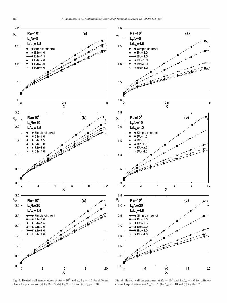
Wall temperature profiles for Ra = 102 and 105 and forL/Lh = 1.5 and 4.0 are shown in Figs. 3–6 with Lh/b = 5,10and 20 and for different expansion ratio values. In all cases thehighest value of maximum wall temperature is attained for thesimple channel configuration. These profiles allow the evalua-tion of the different thermal behaviors of the channel–chimneysystem in terms of the channel aspect ratio. In all tempera-ture profiles, the maximum wall temperature is not attained atthe channel outlet section but at a slightly lower value of theaxial coordinate due to the diffusive effects, according to ex-perimental results given in [8,17,20,21]. The value Xmax of thesection at which the maximum wall temperature is attained de-pends on the geometrical parameters and Ra values. In fact, forthe simple channel configuration, the point Xmax is the lowestamong the various configurations for assigned Ra and Lh/b,as shown in all Figs. 3–6; this effect is more evident for thelowest Ra, in Figs. 3–4. The Xmax value, for the same chan-nel length, increases with increasing Lh/b value because thedecreasing diffusive effects toward the external ambient. More-over, increasing the Rayleigh number, the Xmax value increasesbecause of the decreasing diffusive effects, as it is noted com-paring Fig. 3 with Fig. 5 and Fig. 4 with Fig. 6. A sharp decreaseof wall temperature in the outlet section zone is present due toalso the cold inflow inside the chimney, which reaches the out-let section of the channel.
For the lowest Rayleigh number, Ra = 102, and L/Lh = 1.5,Fig. 3, wall temperatures decrease with increasing expansionratio up to B/b between 2.0 and 3.0 and, for higher B/b val-ues, wall temperatures increase again. Moreover, the decreasein the wall temperature at the outlet region for B/b � 3.0 islower than the one for the simple channel. For B/b = 4.0, thisdecrease is almost equal to the one for the simple channel dueto a cold inflow from the outlet section of the chimney. The coldinflow in the chimney was observed in [8,15,17–21] and a fluidstream flows down along the adiabatic extensions. It reaches the
480 A. Andreozzi et al. / International Journal of Thermal Sciences 48 (2009) 475–487
Fig. 3. Heated wall temperatures at Ra = 102 and L/Lh = 1.5 for differentchannel aspect ratios: (a) Lh/b = 5; (b) Lh/b = 10 and (c) Lh/b = 20.
Fig. 4. Heated wall temperatures at Ra = 102 and L/Lh = 4.0 for differentchannel aspect ratios: (a) Lh/b = 5; (b) Lh/b = 10 and (c) Lh/b = 20.

A. Andreozzi et al. / International Journal of Thermal Sciences 48 (2009) 475–487 481
Fig. 5. Heated wall temperatures at Ra = 105 and L/Lh = 1.5 for differentchannel aspect ratios: (a) Lh/b = 5; (b) Lh/b = 10 and (c) Lh/b = 20.
Fig. 6. Heated wall temperatures at Ra = 105 and L/Lh = 4.0 for differentchannel aspect ratios: (a) Lh/b = 5; (b) Lh/b = 10 and (c) Lh/b = 20.

482 A. Andreozzi et al. / International Journal of Thermal Sciences 48 (2009) 475–487
horizontal wall of the chimney, mixes with the hot plume-jetand goes out of the channel. A consequence of the cold in-flow or downflow is a reduction of chimney effect, which getsstronger increasing aspect ratio as indicated in Fig. 3 (b) and (c).The evaluation of cold inflow or downflow has been obtained,following the analysis proposed by Modi and Torrance [30], es-timating the position along the adiabatic wall of the chimneywhere the vorticity goes to 0. As general result, it is observedthat the number of configurations with a complete downflowincreases at increasing Ra value whereas the number of config-urations with a partial separation from the wall decreases. Theseparation is present for B/b = 2.0 only when L/Lh is equal to1.5 at Ra � 104 whereas, for Ra = 105, only a complete down-flow is observed. Some possible guidelines to evaluate criticalconditions related to the beginning of flow separation and com-plete downflow will be provided by means Figs. 7–11. In fact,after the optimal conditions, thermal and fluid dynamics trendsindicate a worsening of the chimney effect. However, this in-vestigation, although obtained for steady state, is in agreementwith what was suggested in the numerical analysis carried outin [30], but it is remarked that a complete description of the coldinflow or downflow is not possible due to the unsteady natureof this phenomenon, as observed in [30,31].
The difference between the maximum values of the walltemperature for the simple channel and for B/b = 2.0 increaseswith increasing Lh/b, just as the increasing difference betweenthe maximum values of the wall temperature for the simplechannel and for B/b = 4.0. It is possible to affirm that increas-ing Lh/b allows to enhance the channel–chimney system heattransfer with respect to the simple channel, particularly for theconfigurations with B/b > 1.5.
For L/Lh = 4.0, Fig. 4, the absolute differences strongly in-crease with respect to the previous case (L/Lh = 1.5) and thisshows that the chimney effect remarkably improves. Moreover,these differences increase with increasing the channel aspect ra-tio, Lh/b. The configuration with B/b = 4.0 shows the lowestwall temperature values, but it has to be underlined that the de-crease of the maximum wall temperature is significant even forB/b =1.5, whereas the reduction from the configuration withB/b = 1.5 to the configuration with B/b = 4.0 is reasonablylower. In fact, the percentage variations of the maximum walltemperature between the configuration with B/b = 1.5 and thesimple channel, in reference to the value pertinent to the config-uration with B/b = 1.5, is almost 60%, whereas the variationbetween the configuration with B/b = 4.0 and the one withB/b = 1.5 is almost 19% for Lh/b = 5. Therefore increasingthe channel aspect ratio enhances the thermal behavior of thechannel–chimney system for both low L/Lh values and largeL/Lh values, for low Rayleigh number values.
For the largest Rayleigh number value here considered, Ra =105, Figs. 5 and 6, the wall temperatures are lower than thosefor the configurations pertinent to Ra = 102. For L/Lh = 1.5,Fig. 5, the configuration with B/b = 1.5 shows the lowest max-imum wall temperature values, whereas the configuration withB/b = 4.0 has wall temperature values similar to the ones per-tinent to the simple channel, for all the analyzed Lh/b val-ues. In this configuration the downflow is already present for
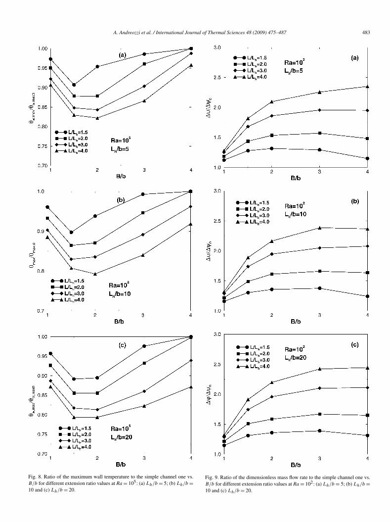
Fig. 7. Ratio of the maximum wall temperature to the simple channel one vs.B/b for different extension ratio values at Ra = 102: (a) Lh/b = 5; (b) Lh/b =10 and (c) Lh/b = 20.
A. Andreozzi et al. / International Journal of Thermal Sciences 48 (2009) 475–487 483
Fig. 8. Ratio of the maximum wall temperature to the simple channel one vs.B/b for different extension ratio values at Ra = 105: (a) Lh/b = 5; (b) Lh/b =10 and (c) Lh/b = 20.
Fig. 9. Ratio of the dimensionless mass flow rate to the simple channel one vs.B/b for different extension ratio values at Ra = 102: (a) Lh/b = 5; (b) Lh/b =10 and (c) Lh/b = 20.

484 A. Andreozzi et al. / International Journal of Thermal Sciences 48 (2009) 475–487
Fig. 10. Ratio of the dimensionless mass flow rate to the simple channel one vs.B/b for different extension ratio values at Ra = 105: (a) Lh/b = 5; (b) Lh/b =10 and (c) Lh/b = 20.
Fig. 11. Ratio of the average Nusselt number to the simple channel one vs. B/b
for different extension ratio values and Lh/b = 10: (a) Ra = 102; (b) Ra = 105.
B/b = 2.0. This is due to the larger velocity of the hot jet com-ing out the channel, which determines the fluid separation fromthe adiabatic chimney wall. Also in this case, the Lh/b increaseproduces an enhancement of the channel–chimney system withrespect to the simple channel, as observed in Fig. 5.
For Ra = 105 and L/Lh = 4.0, Fig. 6, the lowest wall tem-peratures are obtained for B/b = 2.0. This shows that, by alsoincreasing the chimney height remarkably, the cold inflow ispresent, causing a decrease in the chimney effect. In fact, forLh/b = 5, Fig. 6(a), it is observed that the wall temperature de-creases up to B/b = 2.0 and then it increases again for B/b �3.0. For the highest analyzed Lh/b values, Fig. 6 (b) and (c),it is observed that the difference between the wall temperaturevalues for B/b = 2.0 and the ones for the simple channel in-creases. An increase in the chimney effect, when the channelaspect ratio increases, for the highest Rayleigh number for allthe analyzed L/Lh values, is also present. For Ra = 105 thecold inflow determines optimal configurations for B/b � 2.0for the highest extension ratio.
A. Andreozzi et al. / International Journal of Thermal Sciences 48 (2009) 475–487 485
To obtain quantitative values and furnish a better analysisof the thermal behavior of the system, the values of the ra-tio θw,max/θw,max 0 between the maximum temperature of thechannel–chimney system and the one of the simple channel asa function of the expansion ratio are reported in Figs. 7 and 8,for L/Lh from 1.5 to 4.0.
At Ra = 102, Fig. 7, the ratio θw,max/θw,max 0 is less than 1for all the analyzed configurations. In agreement with the walltemperature profiles, the ratio decreases, attaining a minimumvalue, and then it increases for L/Lh = 1.5 for all Lh/b values,whereas for Lh/b = 5 the ratio θw,max/θw,max 0 attains a min-imum value as well as for the configuration with L/Lh = 2.0,as observed in Fig. 7(a). For the other analyzed L/Lh valuesthe ratio θw,max/θw,max 0 profile does not show a minimum ora maximum value in the considered interval. It is interesting toobserve that the difference between the ratio θw,max/θw,max 0 forL/Lh = 1.5 and that for L/Lh = 4.0 increases when the expan-sion ratio increases, for a fixed B/b value. In fact, it goes from0.102 to 0.307. For Lh/b = 10, Fig. 7(b), the values of the ratioθw,max/θw,max 0 are always lower than the ones correspondingto the configuration with Lh/b = 5. Moreover, the differencesbetween the values at L/Lh = 1.5 and at L/Lh = 4.0 still in-crease and for B/b = 1.0 the value is about 0.105, whereas it isabout 0.345 for B/b = 4.0. For Lh/b = 20 the values are veryclose to those for Lh/b = 10 and the differences are the same.
At Ra = 105, Fig. 8, the optimal configurations, such as theconfigurations for which the θw,max/θw,max 0 value is minimum,are those with the expansion ratio value, B/b, between 1.5and 2.0 for all the considered extension ratios. Moreover, forL/Lh = 1.5 and 2.0, the configuration with B/b = 4.0 showsa channel thermal behavior equal to the simple channel one forall the analyzed channel aspect ratio values, the θw,max/θw,max 0ratio being equal to 1.0. This is due to the downflow which ispresent for these configurations. Moreover, the θw,max/θw,max 0values decrease with increasing Lh/b whereas the differencesbetween the values at L/Lh = 1.5 and L/Lh = 4.0 increase.In fact, at B/b = 1.0, the differences are 0.068 for Lh/b =5,0.075 for Lh/b = 10 and 0.087 for Lh/b = 20, whereas atB/b = 4.0 they are 0.041, 0.083 and 0.128, respectively.
The values of the ratio �Ψ/�Ψ0 of the mass flow rate ofthe channel–chimney system on the simple channel system,as a function of the expansion ratio, are reported in Figs. 9and 10, for L/Lh ranging from 1.5 to 4.0, for Ra = 102 andRa = 105, respectively. The values of the ratio �Ψ/�Ψ0 are al-ways greater than 1.0, showing that the mass flow rate in thechannel–chimney system is always greater than the one in thesimple channel, except for Ra = 105 at the lower L/Lh values.In fact, for these configurations at B/b = 4.0, �Ψ/�Ψ0 is al-most equal to 1.0 for all the Lh/b values. For Ra = 102, Fig. 9,it is observed that the mass flow rate, pertinent to the channel–chimney system, is about two and half times that pertinent tothe simple channel when B/b � 3.0 for L/Lh = 4.0 and forall Lh/b values. The differences between the �Ψ/�Ψ0 ratiosfor B/b = 1.0 for the different analyzed extension ratios are farlower than the same differences for B/b = 4.0. This shows that,for a fixed and low extension ratio, the increase in the expansionratio produces variations significantly lower than those perti-
nent to the higher L/Lh values. In most configurations with afixed L/Lh value, the maximum values of �Ψ/�Ψ0 are presentfor B/b in the range [1.5–4.0].
For Ra = 105, in Fig. 10, the maximum values of �Ψ/�Ψ0ratio are always obtained for B/b � 2.0 and they depend onLh/b more significantly than for Ra = 102, especially whenL/Lh = 3.0 and L/Lh = 4.0. These results confirm the chim-ney effect worsening for the channel–chimney system when thedownflow is present in the chimney and they allow for a quan-titative evaluation of the decrease in the mass flow rate. More-over, comparing the configurations for Ra = 102, Fig. 9, withthose for Ra = 105, Fig. 10, it is observed that, for B/b = 1.0,increase in L/Lh determines a larger increase in �Ψ/�Ψ0 ratiofor Ra = 105 for all the analyzed Lh/b values.
Analogous trends are obtained for the Nu/Nu0 ratio, whereNu is the average Nusselt number pertinent to the channel–chimney system and Nu0 is the one pertinent to the simplechannel. The values of the ratio Nu/Nu0 as a function of the ex-pansion ratio are reported in Figs. 11 (a) and (b), for L/Lh from1.5 to 4.0 and Lh/b = 10, for Ra = 102 and Ra = 105, respec-tively. The trends and the dependence on Lh/b are qualitativelyvery similar to those shown in Figs. 9 and 10 whereas the dif-ferences are strong between the ratios pertinent to Ra = 102, inFig. 11(a), and to Ra = 105, in Fig. 11(b). In fact, for Ra = 102,Nu/Nu0 reaches a maximum value of about 1.8, whereas forRa = 105 the maximum value is slightly higher than 1.2. Thisindicates that, for the lowest considered Ra value, the heat trans-fer enhances more significantly in the channel–chimney system,whereas, for the highest considered Ra value, the heat trans-fer enhancement due to the employment of chimney is largerthan 20% with respect to the simple channel. The maximumwall temperature, average Nusselt number and mass flow rateratio, for smaller L/Lh, present their minimum and maximumvalue, respectively, at B/b = 1.5 and, for higher B/b value,θw,max/θw,max 0 increases and Nu/Nu0 and �Ψ/�Ψ0 decreasedue to the cold inflow presence, which determines a decreaseof the chimney effect. For L/Lh > 1.5, the cold inflow startsat higher B/b value and, at B/b = 2.0, θw,max/θw,max 0 attainsthe minimum value whereas Nu/Nu0 and �Ψ/�Ψ0 present themaximum value.
This observation is more evident in Fig. 12, where the max-imum values of the ratio Nu/Nu0 are reported for differentL/Lh, Ra and Lh/b values. For Lh/b = 20, there is always anenhancement of a thermal behavior of the system and the ratio(Nu/Nu0)max increases when L/Lh increases. For Ra = 102,with L/Lh passing from 1.5 to 4.0 value, the percentage in-crease of the ratio (Nu/Nu0)max is about 40–45%, whereas forRa = 105 it is about 12%.
In the following, correlations of the dimensionless mass flowrate, the dimensionless maximum wall temperature and the av-erage Nusselt number as a function of the channel Rayleighnumber and of the expansion and extension ratios are reported.Correlations are in the form: f (Ra∗B/b,B/b,L/Lh). In partic-ular, for the mass flow rate, the following equation is proposed:
�Ψ = 3.590Ra0.2323(
Lh
)0.7323(B
)−0.2677(L
)0.4823
(9)
b b Lh
486 A. Andreozzi et al. / International Journal of Thermal Sciences 48 (2009) 475–487
Fig. 12. Maximum values of Nu/Nu0 vs. L/Lh for different Lh/b and Ra val-ues: (a) Ra = 102; (b) Ra = 105.
with r2 = 0.977 in the ranges: 5 � Ra∗ � 2.0 × 10⁴, 1.5 �L/Lh � 4.0 and 1.0 � B/b � 4.0.
For the average Nusselt number, the following equation isproposed:
Nu =(
B
b
)−0.250(L
Lh
)0.150{[0.570
(Ra∗ B
b
)0.306]−11
+[
1.155
(Ra∗ B
b
)0.161]−11}−1/11
(10)
with r2 = 0.984 in the ranges: 5 � Ra∗ � 2.0 × 10⁴, 1.5 �L/Lh � 4.0 and 1.0 � B/b � 4.0. It is interesting to ob-serve that the average Nusselt number increases when L/Lh
increases, even if it is raised to the power of 0.150.For the dimensionless maximum wall temperature the fol-
lowing equation is proposed:
θw,max =(
B
b
)0.250(L
Lh
)−0.30{[2.02
(Ra∗ B
b
)−0.199]1.30
+[
8.79
(Ra∗ B
)−0.757]1.30}1/1.30
(11)
bwith r2 = 0.983 in the ranges: 5 � Ra∗ � 2.0 × 10⁴, 1.5 �L/Lh � 4.0 and 1.0 � B/b � 4.0. The θw,max variations, withrespect to the considered independent variables, are the inverseof those pertinent to Nu.
The values of optimal expansion ratio (B/b)opt, for each an-alyzed extension ratio, are evaluated. These values correspondto the minimum value of the θw,max/θw,max 0 ratio for all theconsidered Ra values. The following correlation is obtained:
(B
b
)opt
= 2.13(Ra∗)−0.065(
L
Lh
)0.468
(12)
with r2 = 0.984 in the ranges: 5 � Ra∗ � 2.0 × 10⁴ and1.5 � L/Lh � 4.0. The (B/b)opt value increases with increas-ing L/Lh and it decreases when Ra∗ is slightly decreased.
5. Conclusions
A parametric study on a channel–chimney system was ac-complished in this numerical investigation in order to evaluatesome geometric optimal configurations in terms of significantdimensionless geometric and thermal parameters. In the sys-tem, the channel walls are symmetrically heated at uniform heatflux.
Temperature wall profiles, as a function of axial coordi-nate, suggested the evaluation of thermal performances of thechannel–chimney system in terms of maximum wall tempera-tures for different expansion ratios, as a function of the channelaspect ratio. For considered Rayleigh number values, the differ-ence between the highest and the lowest maximum wall tem-peratures increased with increasing channel aspect ratio. Thisbehavior was as greater as the extension ratio was. These dif-ferences decreased significantly for the highest Rayleigh num-ber value. Optimal configurations for assigned L/Lh and Lh/b
were evaluated in terms of B/b corresponding to the minimumvalue of maximum wall temperatures. The optimal B/b valuesdepended strongly on Ra and L/Lh values and slightly on thechannel aspect ratio. A more significant increase of maximumaverage Nusselt number referred to the simple channel valuewas obtained for the lowest considered Ra value, Ra = 102,Lh/b = 20 and L/Lh = 4.0 and it was about 80%, whereasfor Ra = 105 this increase was about 24% for the same Lh/b
and L/Lh values.Correlations for dimensionless mass flow rate, maximum
wall temperature and average Nusselt numbers, in terms ofRayleigh number and dimensionless geometrical parameters,were proposed in the following ranges: 102 � Ra � 105, 1.0 �B/b � 4.0, 1.5 � L/Lh � 4.0 and 5 � Lh/b � 20. Also a cor-relation for (B/b)opt in terms of Ra, L/Lh and Lh/b was givenin the same intervals.
Acknowledgements
This research is supported by Seconda Università degli Studidi Napoli and Regione Campania with a Legge 5 2005 researchgrant.

A. Andreozzi et al. / International Journal of Thermal Sciences 48 (2009) 475–487 487
References
[1] B. Gebhart, Y. Jaluria, R. Mahajan, B. Sammakia, Buoyancy-InducedFlows and Transport, Hemisphere Publ. Corp., Washington, 1988.
[2] O. Manca, B. Morrone, S. Nardini, V. Naso, Natural Convection in OpenChannels, in: B. Sunden, G. Comini (Eds.), Computational Analysis ofConvection Heat Transfer, WIT Press, Southampton, UK, 2000, pp. 235–278.
[3] S.J. Kim, S.W. Lee, Air Cooling Technology for Electronic Equipment,CRC Press, Boca Raton, FL, 1996.
[4] A. Bejan, Shape and Structure from Engineering to Nature, CambridgeUniversity Press, New York, 2000.
[5] G.A. Ledezma, A. Bejan, Optimal geometric arrangement of staggeredvertical plates in natural convection, ASME J. Heat Transfer 119 (1997)700–708.
[6] S. Sathe, B. Sammakia, A review of recent developments in some practi-cal aspects of air-cooled electronic packages, ASME J. Heat Transfer 120(1998) 830–839.
[7] A. Bejan, A.K. da Silva, S. Lorente, Maximal heat transfer density in ver-tical morphing channels with natural convection, Numer. Heat TransferA 45 (2004) 135–152.
[8] A. Auletta, O. Manca, B. Morrone, V. Naso, Heat transfer enhancement bythe chimney effect in a vertical isoflux channel, Int. J. Heat Mass Trans-fer 44 (2001) 4345–4357.
[9] A.K. da Silva, L. Gosselin, Optimal geometry of L- and C-shaped channelsfor maximum heat transfer rate in natural convection, Int. J. Heat MassTransfer 48 (2005) 609–620.
[10] A. Andreozzi, A. Campo, O. Manca, Compounded natural convectionenhancement in a vertical parallel-plate channel, Int. J. Thermal Sci-ences 47 (6) (2008) 742–748.
[11] S.E. Haaland, E.M. Sparrow, Solutions for the channel plume and theparallel-walled chimney, Numer. Heat Transfer 6 (1983) 155–172.
[12] P.H. Oosthuizen, A numerical study of laminar free convective flowthrough a vertical open partially heated plane duct, ASME HTD—Fundamentals of Natural Convection—Electronic Equipment Cooling 32(1984) 41–48.
[13] K.T. Lee, Natural convection in vertical parallel plates with an unheatedentry or unheated exit, Numer. Heat Transfer A 25 (1994) 477–493.
[14] A. Campo, O. Manca, B. Morrone, Numerical analysis of partially heatedvertical parallel plates in natural convective cooling, Numer. Heat TransferA 36 (1999) 129–151.
[15] Y. Asako, H. Nakamura, M. Faghri, Natural convection in a vertical heatedtube attached to a thermally insulated chimney of a different diameter,ASME J. Heat Transfer 112 (1990) 790–795.
[16] A.G. Straatman, J.D. Tarasuk, J.M. Floryan, Heat transfer enhancementfrom a vertical, isothermal channel generated by the chimney effect,ASME J. Heat Transfer 115 (1993) 395–402.
[17] A. Auletta, O. Manca, Heat and fluid flow resulting from the chimneyeffect in a symmetrically heated vertical channel with adiabatic extensions,Int. J. Thermal Sciences 41 (2002) 1101–1111.
[18] A. Andreozzi, B. Buonomo, O. Manca, Numerical study of natural con-vection in vertical channels with adiabatic extensions downstream, Numer.Heat Transfer A 47 (2005) 1–22.
[19] G.A. Shahin, J.M. Floryan, Heat transfer enhancement generated by thechimney effect in systems of vertical channel, ASME J. Heat Transfer 121(1999) 230–232.
[20] O. Manca, M. Musto, V. Naso, Experimental analysis of asymmetricalisoflux channel–chimney systems, Int. J. Thermal Sciences 42 (2003) 837–846.
[21] O. Manca, M. Musto, V. Naso, Experimental investigation of natural con-vection in an asymmetrically heated vertical channel with an asymmetricchimney, ASME J. Heat Transfer 127 (2005) 888–896.
[22] A. Auletta, O. Manca, M. Musto, S. Nardini, Thermal design of sym-metrically and asymmetrically heated channel–chimney systems in naturalconvection, Appl. Thermal Engrg. 23 (2003) 605–621.
[23] A. Bejan, Y. Fautrelle, Constructal multi-scale for maximal heat transferdensity, Acta Mech. 163 (2003) 39–49.
[24] A.K. da Silva, A. Bejan, Constructal multi-scale structure for maximalheat transfer density in natural convection, Int. J. Heat Fluid Flow 26(2005) 34–44.
[25] A.K. da Silva, S. Lorente, A. Bejan, Constructal multi-scale structures formaximal heat transfer density, Energy 31 (2006) 620–635.
[26] D.J. Harris, N. Helwig, Solar chimney and building ventilation, Appl. En-ergy 84 (2007) 135–146.
[27] E. Bacharoudis, M.G. Vrachopoulos, M.K. Koukou, D. Margaris, A.E.Filios, S.A. Mavrommatis, Study of the natural convection phenomenainside a wall solar chimney with one wall adiabatic and one wall undera heat flux, Appl. Thermal Engrg. 27 (2007) 2266–2275.
[28] J.P. Roache, Fundamentals of Computational Fluid Dynamics, HermosaPubl., Albuquerque, NM, 1998.
[29] K.E. Torrance, Numerical methods in heat transfer, in: W.M. Rohsenow,J.P. Hartnett, Y.I. Cho (Eds.), Handbook of Heat Transfer, third ed.,McGraw-Hill, New York, 1998.
[30] V. Modi, K.E. Torrance, Experimental and numerical studies of cold in-flow at the exit of buoyant channel flows, J. Heat Transfer 109 (1987)392–404.
[31] S. Kazansky, V. Dubovsky, G. Ziskind, R. Letan, Chimney-enhanced nat-ural convection from a vertical plate: Experiments and numerical simula-tions, Int. J. Heat Mass Transfer 46 (2003) 497–512.