Hotine _ Indirect Heated Water Heaters
12
Indirect Heated Water Heaters
-
Upload
khangminh22 -
Category
Documents
-
view
2 -
download
0
Transcript of Hotine _ Indirect Heated Water Heaters

Indirect Heated Water Heaters
Indirect Heated Storage calorifiers are one of the easiest method of generating hot water for both domestic and industrial applications. Storage calorifiers are installed in hospitals, hotels, sports centers and general residential buildings. PRECISION Calorifiers can be used in sites where a dedicated plant producing steam for laundry or hot water boiler is available.
Storage CalorifierStorage calorifers are sized to meet the peak demand period with recovery periods varying from one to four hours.
Advantages• Electric power is not required, hence no big investments in Transformer etc.
• Heating coil duty is high.
• No frequent shutdown due to short circuit etc.
• No need of higher inventory electric spares.
StandardsASME Code construction:- All tanks are constructed in accordance with ASME code section IV Stamped and labelled for 125 PSI (8.6 BAR) Standard.
Precision also design High Capacity Water Heaters / Calorifiers as per British Standard BS 853:1996 or BS 5500:1997 or in accordance with Art 3.3 of the European Directive EEC/97/23 for pressure equipment.
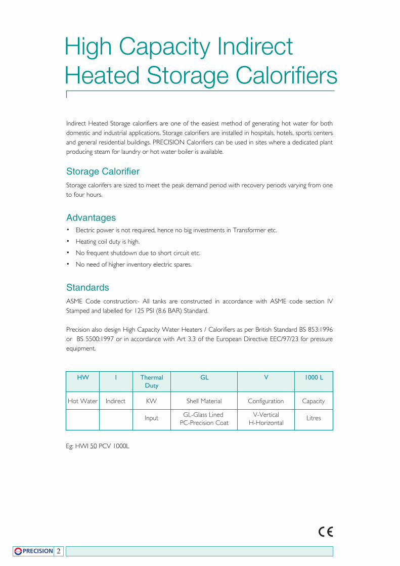
Hot Water Indirect KW Shell Material Configuration Capacity
High Capacity IndirectHeated Storage Calorifiers
HW I Thermal GL V 1000 L Duty
2
Input LitresV-VerticalH-Horizontal
GL-Glass Lined PC-Precision Coat
Eg: HWI 50 PCV 1000L
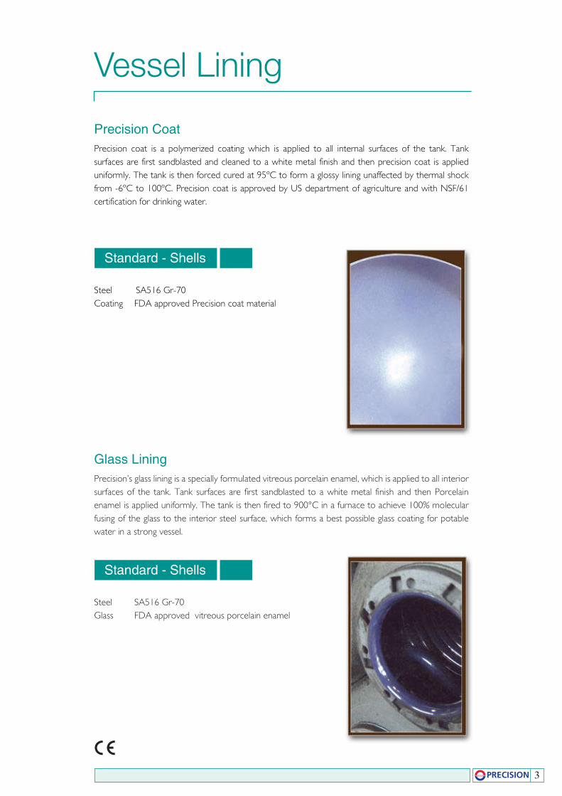
Precision CoatPrecision coat is a polymerized coating which is applied to all internal surfaces of the tank. Tank surfaces are first sandblasted and cleaned to a white metal finish and then precision coat is applied uniformly. The tank is then forced cured at 95ºC to form a glossy lining unaffected by thermal shock from -6ºC to 100ºC. Precision coat is approved by US department of agriculture and with NSF/61 certification for drinking water.
Glass LiningPrecision’s glass lining is a specially formulated vitreous porcelain enamel, which is applied to all interior surfaces of the tank. Tank surfaces are first sandblasted to a white metal finish and then Porcelain enamel is applied uniformly. The tank is then fired to 900°C in a furnace to achieve 100% molecular fusing of the glass to the interior steel surface, which forms a best possible glass coating for potable water in a strong vessel.
Vessel Lining
Standard - Shells
Steel SA516 Gr-70Coating FDA approved Precision coat material
Standard - Shells
Steel SA516 Gr-70Glass FDA approved vitreous porcelain enamel
3
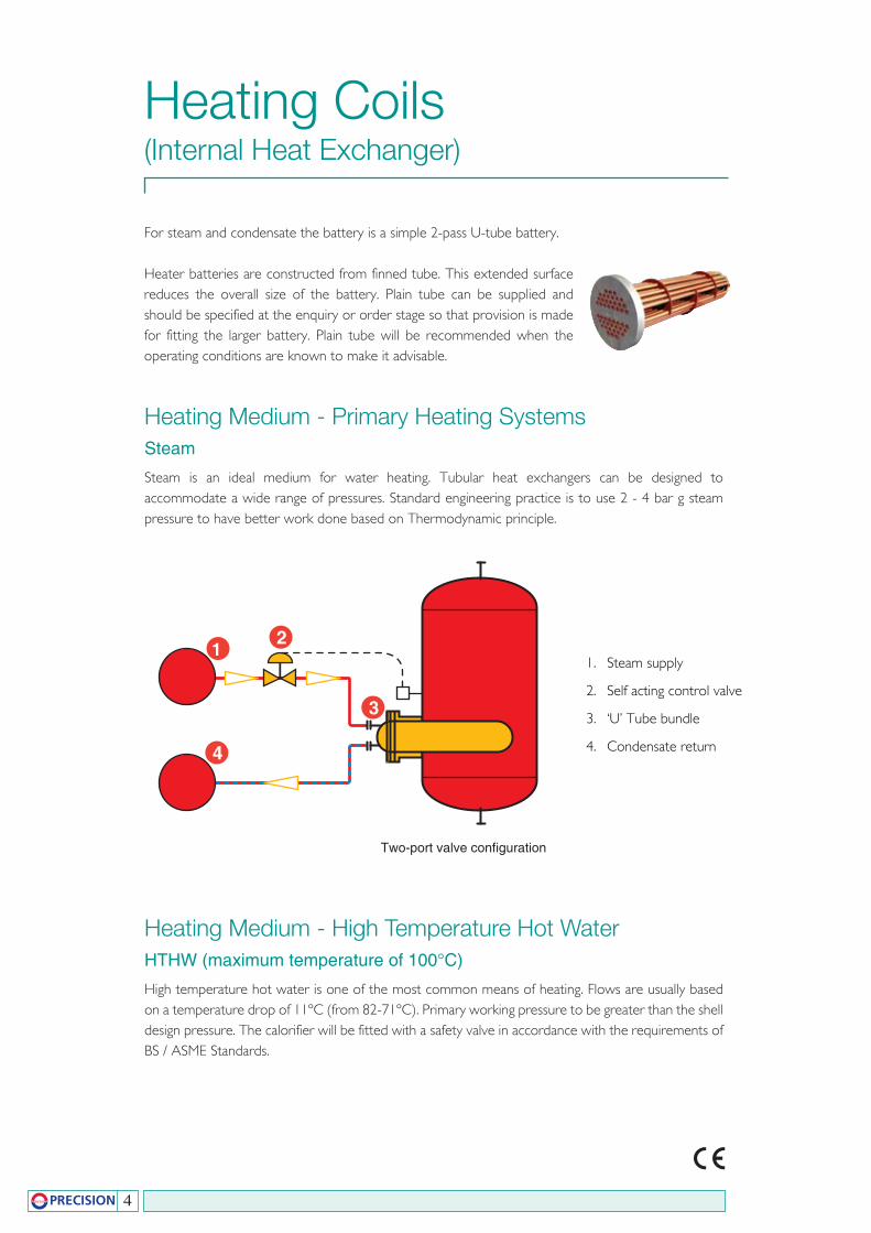
For steam and condensate the battery is a simple 2-pass U-tube battery.
Heater batteries are constructed from finned tube. This extended surface reduces the overall size of the battery. Plain tube can be supplied and should be specified at the enquiry or order stage so that provision is made for fitting the larger battery. Plain tube will be recommended when the operating conditions are known to make it advisable.
Heating Medium - High Temperature Hot WaterHTHW (maximum temperature of 100°C)
High temperature hot water is one of the most common means of heating. Flows are usually based on a temperature drop of 11ºC (from 82-71ºC). Primary working pressure to be greater than the shell design pressure. The calorifier will be fitted with a safety valve in accordance with the requirements of BS / ASME Standards.
Heating Medium - Primary Heating SystemsSteam
Steam is an ideal medium for water heating. Tubular heat exchangers can be designed to accommodate a wide range of pressures. Standard engineering practice is to use 2 - 4 bar g steam pressure to have better work done based on Thermodynamic principle.
Heating Coils(Internal Heat Exchanger)
4
12
3
4
Two-port valve configuration
1. Steam supply
2. Self acting control valve
3. ‘U’ Tube bundle
4. Condensate return

Chilled WaterChilled water can also be used in the tubular heat exchanger to cool domestic water from any desired temperatures.
5
Specifying Indirect Heated Storage CalorifiersHigh capacity water heaters shall be model --------- with --------- litre storage capacity rated at ---------litres and with thermal duty -------- kW. Heaters are to be insulated and jacketed for vertical installations. The water heater tank shall be constructed in accordance with ASME Boiler and pressure vessel code requirements stamped and registered with the national Board of Boilers and Pressure vessel inspectors. The tank shall have 125 Psi (8.6 bar) working pressure as standard. For others please specify.
The tube heating, element shall be constructed and stamped according to section VIII of ASME code. The tubes bundles shall be constructed of ¾: OD 20 GA, deoxidized drawn copper tubing. The heating coils shall be installed in the tank by bolted connection to the collar flange and tube head. The water to water generator shall be equipped with an isolation valve, direct sense self actuated temperature control valve, tank temperature sensor and an inlet Y stainer. A jacket mounted temperature and pressure gauge shall be provided. Primary temperatures supplied will be either High temperature water @ 90 ºC and the return temperature to be 80 ºC or in case of steam the primary steam pressure to be 2 - 4 barg.
The storage tanks shall be supplied with a ASME temperature and pressure relief valve.
The interior of the storage tank shall be glass lined and fired to 900 ºC to ensure a molecular fusing of glass and steel or precision coat and furnished with magnesium anodes to provide protection against corrosion.
The storage tank shall be furnished with a factory installed heavy steel jacket finished with a baked acrylic enamel finish. The storage tanks shall be completely encased in 2” thick fibre glass or rockwool insulation to meet the energy efficiency requirements of the ASHRAE standards. The tank shall be supplied with lifting lugs.
Secondary connections shall be screwed to BS 21 or flanged to BS 4504 or equivalent ASTM Standards with following connections:-Secondary flow outlet, Secondary return inlet, Cold feed inlet. Each tank shall be furnished with magnesium anodes to protect tanks against corrosion. The tank shall be fitted with screwed connection for safety valve, thermostats, Pressure gauge.
21 3
4
6
Three-port valve configuration
5
BOILER
1. Primary hot water source
2. Primary flow pipe
3. Primary control valve three port. Diverting one inlet two outlets
4. ‘U’ tube heat exchanger
5. Primary circulation pump
6. Primary return pipe
6
Selection & Sizing
Solution
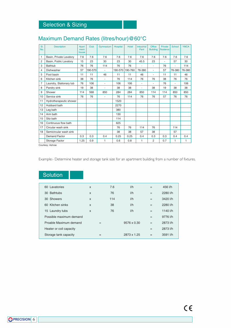
Sl. Description Apart Club Gymnasium Hospital Hotel industrial Office Private School YMCA No. ment Pant Building Residence house
1 Basin, Private Lavatory 7.6 7.6 7.6 7.6 7.6 7.6 7.6 7.6 7.6 7.6
2 Basin, Public Lavatory 15 23 30 23 30 45.5 23 - 57 30
3 Bathtub 76 76 114 76 76 - - 76 - 114
4 Dishwasher 57 190-570 - 190-570 190-760 76-380 - 57 76-380 76-380
5 Foot basin 11 11 46 11 11 46 - 11 11 46
6 Kitchen sink 38 76 - 76 114 76 76 38 76 76
7 Laundry, Stationary tub 76 106 - 106 106 - - 76 - 106
8 Pandry sink 19 38 - 38 38 - 38 19 38 38
9 Shower 114 568 850 284 284 850 114 114 850 850
10 Service sink 76 76 - 76 114 76 76 57 76 76
11 Hydrotherapeutic shower 1520
12 Hubbard bath 2270
13 Leg bath 380
14 Arm bath 130
15 Sitz bath 114
16 Continuous flow bath 625
17 Circular wash sink 76 76 114 76 114
18 Semicircular wash sink 38 38 57 38 57
Demand Factor 0.3 0.3 0.4 0.25 0.25 0.4 0.3 0.3 0.4 0.4
Storage Factor 1.25 0.9 1 0.6 0.8 1 2 0.7 1 1
Maximum Demand Rates (litres/hour)@60°C
Courtesy: Ashrae
Example:- Determine heater and storage tank size for an apartment building from a number of fixtures.
60 Lavatories x 7.6 l/h = 456 l/h
30 Bathtubs x 76 l/h = 2280 l/h
30 Showers x 114 l/h = 3420 l/h
60 Kitchen sinks x 38 l/h = 2280 l/h
15 Laundry tubs x 76 l/h = 1140 l/h
Possible maximum demand = 9776 l/h
Proable Maximum demand = 9576 x 0.30 = 2873 l/h
Heater or coil capacity = 2873 l/h
Storage tank capacity = 2873 x 1.25 = 3591 l/h
7
10 1
2
3 11
4
5
67 8
9
10
10
8
A
B
C
D
A
D
D
B
1
2
3
4
5
6 7
8
10
109
11
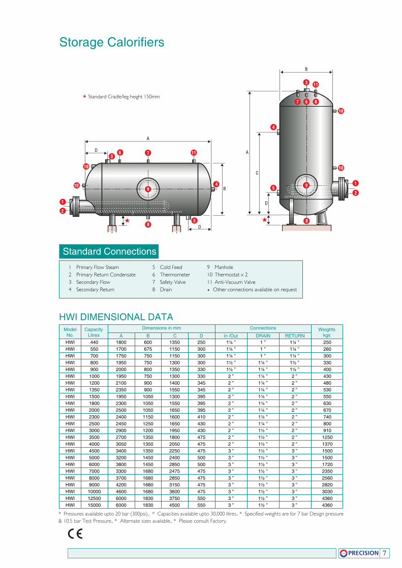
Storage Calorifiers
Standard Connections1 Primary Flow Steam2 Primary Return Condensate3 Secondary Flow4 Secondary Return
ModelNo.
HWI 440 1800 600 1350 250 1¼ ” 1 ” 1¼ ” 250 HWI 550 1700 675 1150 300 1¼ ” 1 ” 1¼ ” 260 HWI 700 1750 750 1150 300 1¼ ” 1 ” 1¼ ” 300 HWI 800 1950 750 1300 300 1½ ” 1¼ ” 1½ ” 330 HWI 900 2000 800 1350 330 1½ ” 1¼ ” 1½ ” 400 HWI 1000 1950 750 1300 330 2 ” 1¼ ” 2 ” 430 HWI 1200 2100 900 1400 345 2 ” 1¼ ” 2 ” 480 HWI 1350 2350 900 1550 345 2 ” 1¼ ” 2 ” 530 HWI 1500 1950 1050 1300 395 2 ” 1¼ ” 2 ” 550 HWI 1800 2300 1050 1550 395 2 ” 1¼ ” 2 ” 630 HWI 2000 2500 1050 1650 395 2 ” 1¼ ” 2 ” 670 HWI 2300 2400 1150 1600 410 2 ” 1¼ ” 2 ” 740 HWI 2500 2450 1250 1650 430 2 ” 1¼ ” 2 ” 800 HWI 3000 2900 1200 1950 430 2 ” 1½ ” 2 ” 910 HWI 3500 2700 1350 1800 475 2 ” 1½ ” 2 ” 1250 HWI 4000 3050 1350 2050 475 2 ” 1½ ” 2 ” 1370 HWI 4500 3400 1350 2250 475 3 ” 1½ ” 3 ” 1500 HWI 5000 3200 1450 2400 500 3 ” 1½ ” 3 ” 1500 HWI 6000 3800 1450 2850 500 3 ” 1½ ” 3 ” 1720 HWI 7000 3300 1680 2475 475 3 ” 1½ ” 3 ” 2350 HWI 8000 3700 1680 2850 475 3 ” 1½ ” 3 ” 2560 HWI 9000 4200 1680 3150 475 3 ” 1½ ” 3 ” 2820 HWI 10000 4600 1680 3600 475 3 ” 1½ ” 3 ” 3030 HWI 12500 6000 1830 3750 550 3 ” 1½ ” 3 ” 4360 HWI 15000 6000 1830 4500 550 3 ” 1½ ” 3 ” 4360
CapacityLitres
Weightskgs
Dimensions in mm Connections
A B C D in /Out DRAIN RETURN
HWI DIMENSIONAL DATA
* Pressures available upto 20 bar (300psi)., * Capacities available upto 30,000 litres., * Specified weights are for 7 bar Design pressure & 10.5 bar Test Pressure., * Alternate sizes available., * Please consult Factory.
5 Cold Feed6 Thermometer7 Safety Valve8 Drain
9 Manhole10 Thermostat x 211 Anti-Vacuum Valve Other connections available on request
Standard Cradle/leg height 150mm
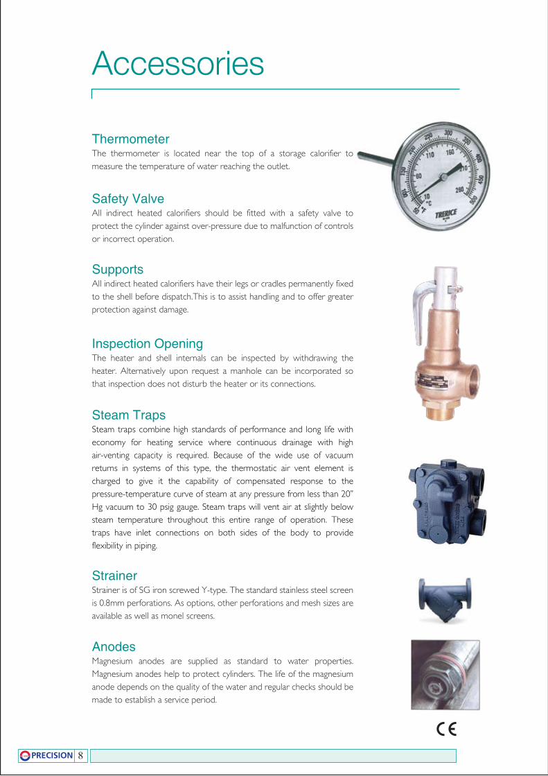
ThermometerThe thermometer is located near the top of a storage calorifier to measure the temperature of water reaching the outlet.
Safety ValveAll indirect heated calorifiers should be fitted with a safety valve to protect the cylinder against over-pressure due to malfunction of controls or incorrect operation.
SupportsAll indirect heated calorifiers have their legs or cradles permanently fixed to the shell before dispatch.This is to assist handling and to offer greater protection against damage.
Inspection OpeningThe heater and shell internals can be inspected by withdrawing the heater. Alternatively upon request a manhole can be incorporated so that inspection does not disturb the heater or its connections.
Steam TrapsSteam traps combine high standards of performance and long life with economy for heating service where continuous drainage with high air-venting capacity is required. Because of the wide use of vacuum returns in systems of this type, the thermostatic air vent element is charged to give it the capability of compensated response to the pressure-temperature curve of steam at any pressure from less than 20” Hg vacuum to 30 psig gauge. Steam traps will vent air at slightly below steam temperature throughout this entire range of operation. These traps have inlet connections on both sides of the body to provide flexibility in piping.
AnodesMagnesium anodes are supplied as standard to water properties. Magnesium anodes help to protect cylinders. The life of the magnesium anode depends on the quality of the water and regular checks should be made to establish a service period.
StrainerStrainer is of SG iron screwed Y-type. The standard stainless steel screen is 0.8mm perforations. As options, other perforations and mesh sizes are available as well as monel screens.
Accessories
8
9
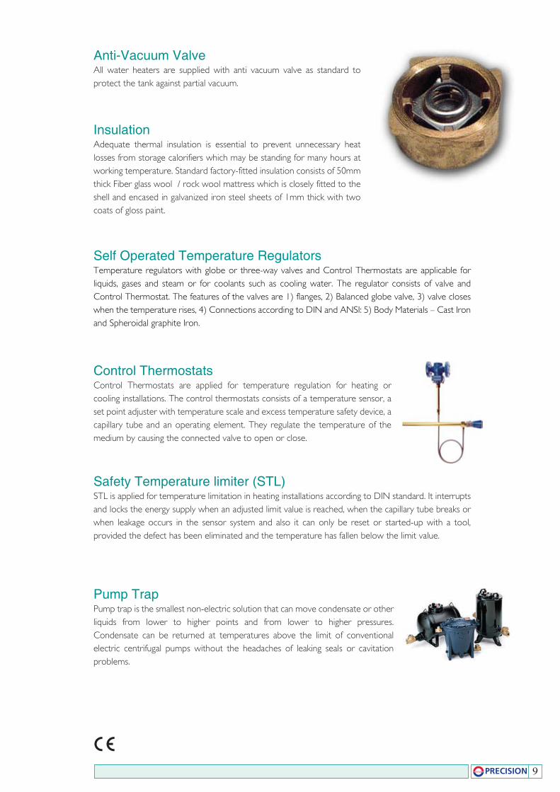
Anti-Vacuum ValveAll water heaters are supplied with anti vacuum valve as standard to protect the tank against partial vacuum.
InsulationAdequate thermal insulation is essential to prevent unnecessary heat losses from storage calorifiers which may be standing for many hours at working temperature. Standard factory-fitted insulation consists of 50mm thick Fiber glass wool / rock wool mattress which is closely fitted to the shell and encased in galvanized iron steel sheets of 1mm thick with two coats of gloss paint.
Self Operated Temperature RegulatorsTemperature regulators with globe or three-way valves and Control Thermostats are applicable for liquids, gases and steam or for coolants such as cooling water. The regulator consists of valve and Control Thermostat. The features of the valves are 1) flanges, 2) Balanced globe valve, 3) valve closes when the temperature rises, 4) Connections according to DIN and ANSI: 5) Body Materials – Cast Iron and Spheroidal graphite Iron.
Control ThermostatsControl Thermostats are applied for temperature regulation for heating or cooling installations. The control thermostats consists of a temperature sensor, a set point adjuster with temperature scale and excess temperature safety device, a capillary tube and an operating element. They regulate the temperature of the medium by causing the connected valve to open or close.
Safety Temperature limiter (STL)STL is applied for temperature limitation in heating installations according to DIN standard. It interrupts and locks the energy supply when an adjusted limit value is reached, when the capillary tube breaks or when leakage occurs in the sensor system and also it can only be reset or started-up with a tool, provided the defect has been eliminated and the temperature has fallen below the limit value.
Pump TrapPump trap is the smallest non-electric solution that can move condensate or other liquids from lower to higher points and from lower to higher pressures. Condensate can be returned at temperatures above the limit of conventional electric centrifugal pumps without the headaches of leaking seals or cavitation problems.
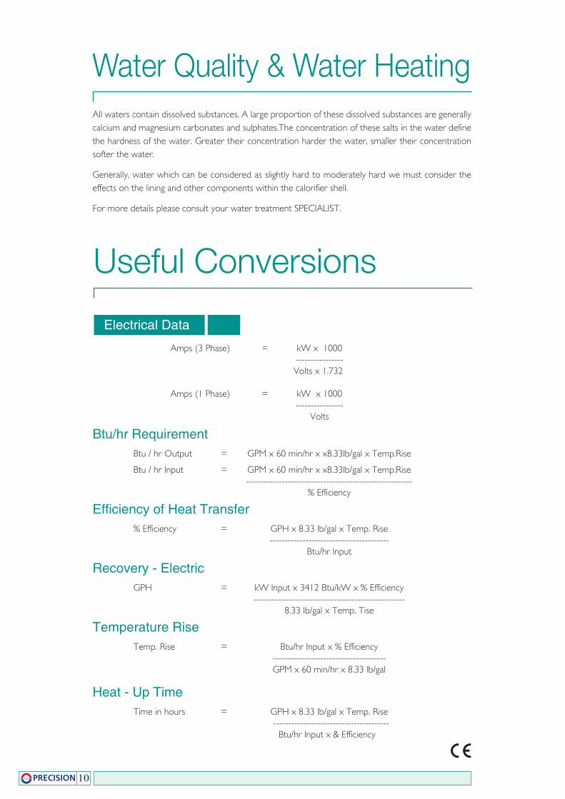
Useful Conversions
Amps (3 Phase) = kW x 1000 ---------------- Volts x 1.732
Amps (1 Phase) = kW x 1000 ---------------- Volts
Btu/hr RequirementBtu / hr Output = GPM x 60 min/hr x x8.33lb/gal x Temp.Rise
Btu / hr Input = GPM x 60 min/hr x x8.33lb/gal x Temp.Rise -------------------------------------------------------- % Efficiency
Efficiency of Heat Transfer% Efficiency = GPH x 8.33 lb/gal x Temp. Rise ---------------------------------------- Btu/hr Input
Recovery - ElectricGPH = kW Input x 3412 Btu/kW x % Efficiency --------------------------------------------------- 8.33 lb/gal x Temp. Tise
Temperature RiseTemp. Rise = Btu/hr Input x % Efficiency -------------------------------------- GPM x 60 min/hr x 8.33 lb/gal
Heat - Up TimeTime in hours = GPH x 8.33 lb/gal x Temp. Rise --------------------------------------- Btu/hr Input x & Efficiency
Electrical Data
10
Water Quality & Water HeatingAll waters contain dissolved substances. A large proportion of these dissolved substances are generally calcium and magnesium carbonates and sulphates.The concentration of these salts in the water define the hardness of the water. Greater their concentration harder the water, smaller their concentration softer the water.
Generally, water which can be considered as slightly hard to moderately hard we must consider the effects on the lining and other components within the calorifier shell.
For more details please consult your water treatment SPECIALIST.

% Hot Water Required to provide Mixed Water at a lower Temperature
Temp.Mixed Water F - Temp. Cold Water F % of the Hot water required in mixure = ------------------------------------------------------- Temp. Mixed Hot F - Temp. Cold Water F
m x C v x ∆T KW = ------------------------------------- 860 x No. of Hours
11
Notes

HEAT EXCHANGER PACKAGE
AIR RECEIVER
STEAM ACCUMULATORS
INDIRECT HEATED STORAGE CALORIFIERS
FEED TANKS & CONDENSATE RECEIVERS
BLOWDOWN VESSEL
ELECTRIC WATER HEATERS
BUFFER VESSELS
RANGE OF PRODUCTS
email: [email protected]
Precision Storage Vessels Pvt. Ltd.Kalpadi, P.O.
Kalpadi, K. K. Dist.Tamil Nadu, India
Tel : 0091 4651 237730Fax: 0091 4651 238585
www.precisionstoragevessels.com
Precision Storage Tanks LLP3rd Floor 82 King Street
Manchester MZYWQUnited Kingdom
www.precisionstorage.co.uk
EN ISO 9001: 2000