
Cartridge Heaters Cartouches chauffantes - IndustrialHeat
29
Cartridge Heaters Cartouches chauffantes H L P
-
Upload
khangminh22 -
Category
Documents
-
view
1 -
download
0
Transcript of Cartridge Heaters Cartouches chauffantes - IndustrialHeat

Cartridge HeatersCartouches chauffantes
HLP

2
HIGH PERFORMANCE CARTRIDGE HEATERSCARTOUCHES CHAUFFANTES
General Informations / Informations générales
Applications/ Applications
Construction / Construction
Technical Data / Données techniques
Limit Values / Caractéristiques maxima
HLP Stock type heaters (metric) / Résistances HLP en stock (métriques)
HLP Stock type heaters (inch) / Résistances HLP en stock (en pouces)
Heated zones / Zones chauffantes
Dual voltage types / Multirésistances
HLP T with thermocouple / avec thermocouple
HLP T with PT 100/NTC / avec PT 100/CTN
PMV lightly compacted HLP / HLP à moyenne charge
HLPK conical shape/ de forme conique
HLP for low voltage / à basse tension
HLPR self-regulating / autorégulante
HLPR for radiators / pour radiateurs
For expansion screws / pour chauffe-boulons
Connection types / types de connexion
Advice for the installation / Recommandations pour le montage
3
3
4
4
5
6
8
9
9
10
11
12
13
15
17
18
19
21
28
www.diracindustries.com

GENERAL INFORMATIONINFORMATIONS GÉNÉRALES
DescriptionHigh performance cartridge heaters type HLP represent the latest development of cartridge heaters of conventio-nal design which T+H have manufactured for more than 40 years.The special construction renders possible an extremely high surface loading and thus a large power in a smallarea. In this way the element assembly opens an enlarged field of applications for electric heating to the designengineer.DIN 44921, page 2, specifies the standard diameters, lengths and sheath material of high performance cartridgeheaters. Our standard range of high performance cartridge heaters includes all the diameters specified in theDIN standard. As far as length is concerned it includes all those specified in the DIN standard plus many more.
DescriptionLes cartouches chauffantes comprimées à haute charge, de la série HLP, résultent d’un perfectionnement descartouches chauffantes conventionelles que nous fabriquons depuis plus que 40 ans.Leur construction fortement comprimée autorise une grande charge superficielle et par suite l’installation de puis-sances élevées dans un espace restreint.Ces résistances ouvrent à l’ingénieur de nouvelles perspectives d’application du chauffage électrique.La norme DIN 44921, page 2, spécifie les diamètres standards, les longueurs et les matériaux de la gaine des car-touches à haute puissance. Notre grande gamme de résistances HLP comprend tous les diamètres spécifiés dansla norme. En ce qui concerne les longueurs, il y a toutes celles de la norme et bien d´autres encore.
www.diracindustries.com
APPLICATIONSAPPLICATIONS
ApplicationsPlastics industry Nozzle heaters for extrusion dies, hot runner systems, filter changing
equipmentShoe machine industry Vulcanising press and mould heating, joining machines, hot stamping
devicesFoundries Core moulds and ingot moulds, die casting machines, vacuum furnace
heatingApparatus construction Hot plates, industrial baths, distillations plants, soldering baths, oil sumpand laboratories heating, sterilising baths, oil economisersWoodworking machinery Hot adhesive - melting- and depositing devices, hot stampingPacking machine industry Stamping- sealing- and welding bar heating, carton closure machine, tube
filling & closure machineryMedical technology Inhaling devices & sterilisers, polymerisation devices, dialysis equipmentGeneral machine construction Small air heater, expansion screw heating, bookbinding machines, cold
compressors
ApplicationsIndustrie du plastique Chauffage des outillages, buses, canaux chauds, extrusion, marquage à
chaudIndustrie de la chaussure Vulcanisation, chauffage de moules et machines diversesFonderie Machines à mouler, chauffage des coquilles, des moules a noyaux etc.Matériel et équipement de laboratoire Plaques chauffantes, appareils de distillation et de stérilisation, bains diversMachines à bois Presses, machines à coller, hot melts, marquage à chaudIndustrie du papier et machine Machines à former et coller les cartons, machines diversesd’emballageMatériel médical Appareils d’inhalation et de stérilisation, appareils pour dentistes,
appareils pour la dialyseIndustrie mécanique Echangeur de chaleur, chauffe- boulons, chauffage d’huile, chauffage
d’outillages divers
3

CONSTRUCTIONCONSTRUCTION
Compacted cartridge heaters type HLP have a supporting core which iscentrally located very close to the outer sheath.
The heating conductor made of the heatproof alloy NiCr 8020 is wound inone layer, around the supporting cores.
The interspace is filled with pure magnesium oxide and is highly compres-sed.
The bottom end of the cartridge heater is gastight welded; the covering isground for precision tolerance.
High performance cartridge heaters can also be supplied with VDE appro-ved connection according to the illustrations on page 24.
Les résistances HLP se composent d’un noyau en céramique et d´un fil derésistance en alliage nickel- chrome 80/20 bobiné autour.
Ce noyau central est localisé très près de la gaine métallique, l’intervalleétant rempli d’oxyde de magnésium.
L’ensemble est ensuite fortement comprimé par rétreint de la gaine.
Le fond de la cartouche est soudé étanche, la surface est rectifiée et cali-brée.
Les cartouches chauffantes à haute charge peuvent aussi être fourniesavec des fils de connexion selon les illustrations de la page 24 et avec-marquage VDE.
www.diracindustries.com
GENERAL TECHNICAL DATACARACTERISTIQUES GENERALES
Connections: see page 21 continued.
Unheated ends: connection side 7-15 mm; far end 4-11 mm depen-ding on the type, other dimensions upon request.
Thermocouple: optional for all HLP type heaters
Cartridge covering: CrNi-steel , material no. 1.4541
Heating conductor: NiCr 8020, material no. 2.4869
Heating conductor support: Pure magnesium oxide, highly compressed
Final Test: individual test according to DIN EN 60335 (VDE 0700)
Limit valuesVoltage: upto 400 VDiameters: metric and imperial dimensions see type listCapacity: minimum and maximum values depend on the
dimensions of the cartridgeLeckage current: < 0,5 mASurface load: up to 50 W/cm2 (on the sheath)Working temperature: upto 750°C (on the sheath)
TolerancesDiameters: -0.02 mm to -0.08 mm of the ground covering
in metric dimensions+0.05 mm of the nominal diameter for imperialdimensions
Length: ±1,5%; at least however ±2 mmCapacity: ±10%
other tolerances upon request
Connexions: voir à la page 21 et suivantes
Parties non chauffantes: Selon le diamètre, les parties non- chauffantesvarient de 7-15 mm vers la connexion et de 4-11mm vers le fond
Thermocouple: sur demande pour toutes les cartouches chauf-fantes type HLP
Matériau de la gaine: acier inox, no. de matériau 1.4541
Fil chauffant: alliage NiCr 80/20
Noyau: en oxyde de magnésium, fortement comprimé
Contrôle final: contrôle individuel conformément à la norme DIN EN 60335 (VDE 0700)
Caractéristiques maximaTension: jusqu’à 400 VDiamètre: métrique ou en pouces, selon les typesPuissance: Minima et maxima dépendent des dimensions
de la cartoucheCourant de fuite: < 0,5 mACharge de surface: 50 W/cm2 maxi. sur la gaineTempérature de service: environ 750°C sur la gaine
TolérancesDiamétre: -0,02 mm à -0,08 mm du diamètre nominal
pour les cartouches de dimensions métriques+0,05 mm du diamètre nominal pour les car-touches de dimensions en pouces
Longueur: ±1,5% avec un minimum de ±2 mmPuissance: ±10%
Autres tolérances sur demande
4

LIMIT VALUES HLPCARACTÉRISTIQUES MAXIMA HLP
Nominal diameter Diameter tolerance max. length max. power max. currentDiamètre nominal Tolérance du diamétre Longueur maxi. Puissance maxi. courrant maxi.(mm) (mm) (mm)
A 3W 057000144
A 4W 0001000155
A 5W 052100025,65,6
A 01W 0003005288
A 51W 000300520101
A 02W 000500535,215,21
16 16 3500 10000 W 40 A
20 20 3500 10000 W 50 A
25 25 3500 10000 W 50 A
-0,02-0,06
-0,02-0,06
-0,02-0,08
-0,02-0,08
-0,02-0,08
-0,02-0,08
-0,02-0,08
-0,02-0,08
-0,02-0,08
Other diameters or tolerances upon requestAutres diamètres et tolérances sur demande
Nominal diameter Diameter tolerance max. length max. power max. currentDiamètre nominal Tolérance du diamétre Longueur maxi. Puissance maxi. courrant maxi.(Inch) (mm) (Inch) (mm)
1/8 ” 3,10 40 1000 300 W 1,5 A
1/4 ” 6,22 80 2000 1250 W 5 A
5/16 ” 7,87 100 2500 3000 W 10 A
3/8 ” 9,40 100 2500 3000 W 15 A
1/2 ” 12,57 140 3500 5000 W 20 A
5/8 ” 15,75 140 3500 10000 W 40 A
3/4 ” 18,93 140 3500 10000 W 50 A
1 ” 25,28 140 3500 10000 W 50 A
+0,05
+0,05
+0,05
+0,05
+0,05
+0,05
+0,05
+0,05
METRIC DIMENSIONS DIMENSIONS MÉTRIQUES
Other diameters or tolerances upon requestAutres diamètres et tolérances sur demande
IMPERIAL SIZES DIAMETRES EN POUCES
www.diracindustries.com
5

STOCK TYPE HEATERSRESISTANCES EN STOCK
METRIC DIMENSIONS DIMENSIONS MÉTRIQUES
Heaters ex-stock can also be supplied complete withaccessories (see page 24 cont.) at short notice.
La plupart des cartouches chauffantes figurant dans letableau suivant sont disponibles sur stock avec les con-nexions indiquées (voir à la page 24 et suivantes).
Ømm
8
6,5
10
≈30 mm3-5 mm
L
Ø D
Ø 6,5
Ø 8
Ø 10
Length Power Group Article Longueur Puissance Groupe Article
bei/at/à 230 V
L Watt W/cm2 No./No.
40 100 II 120000125 III 120001160 IV 120002175 IV 120003200 V 120004
50 100 II 120005160 III 120006200 IV 120007250 V 120008
60 125 II 120009200 III 120010250 IV 120011315 V 120012
80 125 I 120013180 II 120014280 III 120015350 IV 120016
100 160 I 120017220 II 120018350 III 120019
40 100 II 120020160 III 120021200 IV 120022250 V 120023
50 125 II 120024200 III 120025250 IV 120026315 V 120027
60 100 I 120028140 II 120029220 III 120030280 IV 120031350 V 120032
80 160 I 120033200 II 120034315 III 120035400 IV 120036
100 180 I 120037280 II 120038400 III 120039
130 250 I 120040400 II 120041
40 100 I 120042125 II 120043200 III 120044250 IV 120045315 V 120046
50 100 I 120047160 II 120048250 III 120049315 IV 120050400 V 120051
60 125 I 120052180 II 120053315 III 120054400 IV 120055500 V 120056
80 160 I 120057250 II 120058400 III 120059500 IV 120060630 V 120061
100 220 I 120062350 II 120063560 III 120064700 IV 120065850 V 120066
130 315 I 120067500 II 120068800 III 120069
160 400 I 120070630 II 120071
Load groups Surface load W/cm2
Groupe de charge Charge de surface W/cm2
11 … 8I91 … 21II
III 20 … 24IV 25 … 29V 30 … 35
www.diracindustries.com
6

METRIC DIMENSIONS DIMENSIONS MÉTRIQUES
16
20
Ø 20
Ø 12,5
Ø 16
Length Power Group Article Longueur Puissance Groupe Article
at/à 230 V
L Watt W/cm2 No./No.
40 100 I 120072160 II 120073250 III 120074315 IV 120075400 V 120076
50 100 I 120077200 II 120078315 III 120079400 IV 120080500 V 120081
60 125 I 120082200 II 120083315 III 120084400 IV 120085500 V 120086
80 200 I 120087315 II 120088500 III 120089630 IV 120090800 V 120091
100 250 I 120092400 II 120093630 III 120094800 IV 120095
1000 V 120096
130 400 I 120097630 II 120098
1000 III 1200991250 IV 120100
160 500 I 120101800 II 120102
1250 III 120103
200 630 I 120104900 II 120105
40 100 II 120106250 III 120107315 IV 120108400 V 120109
50 160 I 120110250 II 120111400 III 120112500 IV 120113630 V 120114
60 160 I 120115250 II 120116400 III 120117500 IV 120118630 V 120119
80 280 I 120120
400 II 120121630 III 120122800 IV 120123
1000 V 120124
100 350 I 120125500 II 120126800 III 120127
1000 IV 1201281250 V 120129
130 500 I 120130700 II 120131
1100 III 1201321400 IV 1201331800 V 120134
160 630 I 120135900 II 120136
1600 III 1201371800 IV 120138
200 800 I 1201391250 II 1201402000 III 120141
250 1000 I 1201421600 II 120143
300 1250 I 1201441800 II 120145
60 200 I 120146315 II 120147500 III 120148630 IV 120149800 V 120150
80 350 I 120151500 II 120152800 III 120153
1000 IV 1201541250 V 120155
100 450 I 120156630 II 120157
1000 III 1201581400 IV 1201591600 V 120160
130 630 I 120161900 II 120162
1400 III 1201631800 IV 1201642200 V 120165
160 800 I 1201661100 II 1201671800 III 1201682200 IV 120169
200 1000 I 1201701600 II 1201712500 III 120172
250 1250 I 1201732000 II 120174
300 1600 I 1201752200 II 120176
12,5
Ømm
www.diracindustries.com
7

STOCK TYPE HEATERS (INCH)RESISTANCES EN STOCK (EN POUCES)
IMPERIAL DIMENSIONS DIMENSIONS EN POUCES
1/4
5/16
1/2
5/8
3/8
Ø 1/4
Ø 5/16
Ø 3/8
Ø 5/8
Lenght Power Group Article Longueur Puissance Groupe Article
at/à 230 VInch Watt W/cm 2 No./No.
1 1/2 100 II 125 179125 III 125 180160 IV 125 181175 IV 125 182200 V 125 183
2 100 II 125 184160 III 125 185200 IV 125 186250 V 125 187
2 1/2 125 II 125 188200 III 125 189250 IV 125 190315 V 125 191
3 1/4 125 I 125 192180 II 125 193280 III 125 194350 IV 125 195
4 160 I 125 196220 II 125 197350 III 125 198
1 1/2 100 II 125 199160 III 125 200200 IV 125 201250 V 125 202
2 125 II 125 203200 III 125 204250 IV 125 205315 V 125 206
2 1/2 100 I 125 207140 II 125 208220 III 125 209280 IV 125 210350 V 125 211
3 1/4 160 I 125 212200 II 125 213315 III 125 214400 IV 125 215
4 180 I 125 216280 II 125 217400 III 125 218
5 1/4 250 I 125 219400 II 125 220
1 1/2 100 I 125 221125 II 125 222200 III 125 223250 IV 125 224315 V 125 225
2 100 I 125 226160 II 125 227250 III 125 228315 IV 125 229400 V 125 230
2 1/2 125 I 125 231180 II 125 232315 III 125 233400 IV 125 234500 V 125 235
3 1/4 160 I 125 236250 II 125 237400 III 125 238500 IV 125 239630 V 125 240
4 220 I 125 241350 II 125 242560 III 125 243700 IV 125 244850 V 125 245
5 1/4 315 I 125 246500 II 125 247800 III 125 248
6 1/2 400 I 125 249630 II 125 250
Ø 1/21 1/2 100 I 125 251
160 II 125 252250 III 125 253315 IV 125 254400 V 125 255
2 100 I 125 256200 II 125 257315 III 125 258400 IV 125 259500 V 125 260
2 1/2 125 I 125 261200 II 125 262315 III 125 263400 IV 125 264500 V 125 265
3 1/4 200 I 125 266315 II 125 267500 III 125 268630 IV 125 269800 V 125 270
4 250 I 125 271400 II 125 272630 III 125 273800 IV 125 274
1000 IV 125 275
5 1/4 400 I 125 276630 II 125 277
1000 III 125 2781250 IV 125 279
6 1/2 500 I 125 280800 II 125 281
1250 III 125 282
8 630 I 125 283900 II 125 284
1 1/2 100 II 125 285250 III 125 286315 IV 125 287400 V 125 288
2 160 I 125 289250 II 125 290400 III 125 291500 IV 125 293
2 1/2 160 I 125 294250 II 125 295400 III 125 296500 IV 125 297630 V 125 298
3 1/4 280 I 125 299400 II 125 300630 III 125 302
1000 V 125 303
4 350 I 125 304500 II 125 305800 III 125 306
1000 IV 125 3071250 V 125 308
5 1/4 500 I 125 309700 II 125 310
1100 III 125 3111400 IV 125 3121800 V 125 313
6 1/2 630 I 125 314900 II 125 315
1600 II 125 3161800 IV 125 317
8 800 I 125 3181250 II 125 3192000 III 125 320
10 1000 I 125 3211600 II 125 322
12 1250 I 125 3231800 II 125 324
ØInch
www.diracindustries.com
8

HEATED ZONES ZONES DE CHAUFFAGE
Standard heat distributionRépartition du chauffage standard
Unheated zone on connection side and/or far endZone non-chauffante côté connexion ou au bout
Reinforced power distribution on one or both endsPuissance renforcée aux extrémités
Unheated in the middle of the heaterZone non-chauffante au milieu de la cartouche
DUAL VOLTAGE TYPESMULTIRÉSISTANCES
L1L2N
L1N
NL2
L1L2
NL3
Version 1 (2 switchable zones / 3 connection leads)Version1 (2 résistances / 3 fils de connexion)
Version 3 (3 switchable zones / 4 connections leads)Version 3 (3 résistances / 4 fils de connexion)
Version 2 (2 switchable zones / 4 connection leads)Version 2 (2 résistances / 4 fils de connexion)
� possible for all HLP and HLP/T type heaters� not available ex-stock
� possible pour toutes les cartouches chauffantes types HLP ou HLP/T� hors stock
� allows separate heating of zones � not available ex-stock
� permet le chauffage de zonesdifférentes
� hors stock
www.diracindustries.com
9

Diameter Length W at 230 V Power Article-No.Diamètre Longueur en W à 230 V Puissance No. d’article
6,5 mm 40 mm 100 120 90050 mm 200 120 905100 mm 350 120 910
10,0 mm 40 mm 200 120 91550 mm 250 120 92060 mm 400 120 92580 mm 250 120 930160 mm 400 120 935
1/4“ 1 1/2“ 100 120 9502“ 200 120 9554“ 350 120 960
3/8“ 1 1/2“ 200 120 9652“ 250 120 970
2 1/2“ 315 120 9753 1/4“ 400 120 980
4“ 350 120 985
STOCK TYPE HEATERS RÉSISTANCES EN STOCK
HLP T with TC/avec TC
HLP T WITH THERMOCOUPLEHLP T AVEC THERMOCOUPLE
L
Ø D
L 1L 2
F
General informationAll HLP type heaters can be supplied with an integrated thermocouple.Heaters mentioned in the table on page 13 are available ex-stock. Highperformance cartridge heaters are especially suitable for internally heatednozzles and heated torpedos where, due to space considerations, a sepa-rate thermocouple cannot be installed. The thermocouple is fixed in positi-on, compacted and potential free insulated from the sheath or alternativelyconnected with the heater sheath.
ExecutionCompensating leads can be connected to specified requirements. Thethermocouple is galvanically separated from the cartridge sheath unlessotherwise specified at the time of ordering. HLPT can also be suppliedwith an electrical connection between the thermocouple and the cartridgesheath, if so desired.
Informations généralesToutes les cartouches chauffantes types HLP peuvent être fournies avecun thermocouple incorporé. Les résistances indiquées dans le tableau à lapage 13 sont disponibles sur stock.Ces cartouches avec thermocouple Fe-CuNi ou NiCr-Ni incorporé sont utilisées pour le chauffage de petites pièces pour lesquelles l’implantationd’un thermocouple séparé pose un problème d’encombrement. Elles trou-vent ainsi une application intéressante pour le chauffage de busettes outorpilles chauffantes utilisées dans l’injection des matières plastiques.
ExécutionLes fils de compensation peuvent être fournis selon la spécification du cli-ent. Si non spécifié, le thermocouple est normalement isolé de la masse(à la masse sur demande).
Abbreviated designation Fe-Konst (Fe-CuNi) NiCr-Niof thermocouple DIN 43713 DIN 43713
Désignation abrégédu thermocouple
plus leg Iron Nickel-Chromiumemorhc-lekciNreFfitisop lif
lekciNnatnatsnoCgel sunimfil négatif Constantan
Measuring temperature Basic values permissible deviation Basic value permissible deviation
Température Caractéristiques déviation Caractéristiques déviation de mesure de base admissible de base admissible
°C mV °K % mV °K %
0 0 - - 0 - -
01,473,5001
200 10,95 3 - 8,13 3
12,2165,61003
04,6161,22004
56,0258,72005
600 33,67 - 0,75 24,91 - 0,75
41,92007
permissible deviation in °K or in % related from the measuring temperature. Reference temperature 0 °C.déviation admissible en °K ou en % en fonction de la température de mesure. Température de référence 0 °C.
www.diracindustries.com
10

Technical DataConstructionAs per the types HLP butThermocoupleType J Fe-CuNi according to DIN 43713 (colours red/blue)Type K NiCr-Ni according to DIN 43713 (colours red/green)If required by the market thermocouples can be supplied to IEC 584.Type J Fe-CuNi (colours black/white)Type K NiCr-NiAl (colours green/white)
Type listHigh performance heating elements type HLPT can be supplied in diame-ters from 6,5 to 25 mm and in the corresponding imperial dimensions.
Long cartridge heaters type HLPL with incorporated thermocouple typeFe-CuNi (J-type) can be supplied with the thermocouple measuring pointlocated apart from the bottom end.
The stock type heaters are equipped with a Fe-CuNi-thermocouple andleads with glass fibre insulation type LETEF and compensation leads typeLEAUS both with a length of 1000 mm.
Caractéristiques techniquesConstructionIdentiques aux HLP maisThermocouple:Type J en Fe-CuNi selon la norme DIN 43713 (couleurs rouge/bleu)Type K en NiCr-Ni selon la norme DIN 43713 (couleurs rouge/vert)Sur demande du marché les thermocouples peuvent être fournis aussiselon la norme IEC 584.Type J en Fe-CuNi (couleurs noir/blanc) Type K en NiCr-NiAl (couleurs vert/blanc)
Modèles standardLes cartouches chauffantes type HLPT peuvent être fournies dans lesdiamètres de 6,5 mm à 25 mm, également les diamètres en pouces équivalents.
Le thermocouple est normalement situé au bout de la cartouche, sur demande il est possible de le placer ailleurs qu’à l’extrémité.
Les cartouches HLPT disponibles sur stock sont fournies avec des thermo-couples Fe-CuNi, connexion des fils avec isolation fibre de verre type LETEF et avec des fils de compensation type LEAUS longueur des fils 1000 mm.
HLP T WITH PT 100/NTCHLP T AVEC PT 100/CTN
General informationAll HLP type heaters can be manufactured with an integrated temperaturesensor i.a.w. DIN EN 60751 (PT 100) or with an integrated NTC-sensor(negative temperature coefficient) for precise temperature measurement.Typical fields of application therefore are within the car industry, electro-domestical appliances, air conditioning devices, for general machineryand medical technique appliances.
Informations généralesToutes les résistances type HLP peuvent être fournies avec un capteur PT100 selon la norme DIN EN 60751 integré dans la cartouche ou avec uncapteur CTN (coéfficient de température négative) permettant unemesure de température de haute précision. Les domaines d`application pour de telles résistances se trouvent dans l`industrie d´automobile, les appareils eléctroménagers, la climatisationd´air, et les dispositifs pour l´industrie mécanique et techniques médicales.
Advantages- High precision over a wide temperature range- High reliability- Materials of the connection leads can be freely
chosen other than for thermocouple wires
Avantages- Haute précision de mesurement- Haute fiablilité technique- Les fils de connexion ne sont
pas des fils de thermocouple
www.diracindustries.com
11

TYPE PMV (LIGHTLY COMPACTED)TYPE PMV (À MOYENNE CHARGE)
CharacteristicsThe lightly compacted cartridge heaters of this series distinguish themsel-ves by a higher immunity against mechanical shock, and by a substantiallylonger useful life as compared with noncompacted metal sheathed cartrid-ge heaters of the same surface load. They are suitable for heating liquids,gaseous and solid media and resist arduous service conditions in industri-al applications.
Technical Datasimilar to the high performance cartridge heaters type HLP, however:
Maximum surface load: approx. 6,5 W/cm2 (on the sheath)Tolerances: Diameter: +0,2 mm of the groundless covering.
Upon request these can be ground to finer tolerances -0,02 to 0,08 mm
Length: ±1.5% at least, however ±2 mmCapacity: ±10%
Please noteCartridge heaters type PMV are only produced in stock types.
CaractéristiquesLes cartouches chauffantes PMV se différencient des cartouches bassescharges non comprimées par rétreint, par une plus grande robustessemécanique et à charge égale, par une longévité bien meilleure. Elles sontemployées pour le chauffage de solides, gaz ou liquides. Construites selonla technique employée pour les hautes charges mais avec des puissancesmoindres, elles supportent les conditions de travail les plus dures.
Caractéristiques techniques identiques aux cartouches chauffantes HLP mais:
Charge de surface maxi.: environ 6,5 W/cm2 (sur la gaine)Tolérances: diamètre: +0,2 mm non calibrée ni rectifiée, sur demande
rectifiée avec tolérances -0,02 à -0,08 mmLongueur: ± 1,5%, avec un minimum de ± 2 mmPuissance: ± 10%
AvisLes cartouches chauffantes PMV sont disponibles sur stock.
www.diracindustries.com
STOCK TYPE HEATERS RÉSISTANCES EN STOCKDiameter Length Power in Articel-No.
W at 230 V
Diamètre Longueur Puissance No. d’articleen W à 230 V
10 mm 100 125 120 421130 200 120 422160 250 120 432
12,5 mm 100 160 120 424130 220 120 425160 315 120 426200 400 120 427
16,0 mm 100 200 120 428
130 280 120 429160 350 120 430200 450 120 431250 560 120 432300 800 120 433
20,0 mm 100 250 120 434130 400 120 435160 500 120 436200 630 120 437250 800 120 438300 1000 120 439≈30 mm
3-5 mm
L
Ø D
Installation guidanceThe installation is easier than for the high performance heaters due to thelower surface load. Nevertheless please observe the installation instruc-tions (see page 31) given for the HLP type heaters.
Recommandations pour le montageLe montage des cartouches à moyenne charge PMV est moins contraig-nant que celui des cartouches à haute charge HLP. Mais pour obtenir unemeilleure longévité veuillez vous rapporter aux recommandations pour lemontage indiquées à la page 31.
Nominal diameter/Diamètre nominal
10 mm 12,5 mm 16 mm 20 mm
10,2+ 0,1 12,7+ 0,1 mm 16,2+ 0,1 mm 20,2+ 0,1 mm
Recommended bore hole Diamètre d’alésage recommandé
12

CONICAL SHAPE, TYPE HLPKFORME CONIQUE, TYPE HLPK
ApplicationsHeating of founding tanks, die- and mold making, cigarette-machines,machines for shoe production.
Installation hintsThe workpart is provided with a pass or a blind bore according to the car-tridge heater. Suitable tooling is available ex-stock.
We recommend the usage of the high temperature resistant lubricantNEVER SEEZ.
The disassembly of the cartridge heater is especially simplified by its coni-cal sheath shape. A special pull out tool (Art No. 600090) facilitates thepull off process and preserves the workpiece and the cartridge heaterfrom being damaged.
ApplicationsChauffage d’outillages pour les fonderies, chauffage de moules, chauffagepour les machines à cigarettes et pour l’industrie des chaussures.
Recommandations pour le montageLe perçage se fait avec un foret conique, la finition se fait avec un alésoirspécial conique.Ces outillages sont disponibles sur notre stock.
Pour le montage des cartouches HLPK nous vous recommandons aussil’utilisation du produit anti-friction NEVER SEEZ résistant à des hautestempératures et facilitant le démontage.
Pour le démontage des cartouches coniques nous recommandons notreoutil spécial de démontage (no. d’article 600090).
6
Ø 12,5 mm+0,01-0,04
Kegel/taper ratio/cone 1:50lead length to customer specificationlongueur de fil sur demande
optional/sur demande M 20 x 1,5
L
CharacteristicsThe high performance cartidge heater type HLPK has a conically taperedsheath with a taper ratio 1:50 i.a.w. DIN 1 for standard taper pins.The conical shape of the cartridge heater guarantees an exact force fit inthe workpiece. In the case of accurately reamed bores, there is an excel-lent fit, as the cartridge heater in this case takes a slightly deeper installa-tion depth.An excellent heat distribution results from the exact fit and, thus, the dan-ger of overheating the cartridge heater is kept low. In order to get an eventemperature profile, the cartridge heaters type HLPK are equipped withreinforced performance zones on both sides.
CaractéristiquesLes cartouches chauffantes type HLPK à forme conique se composentd’une gaine avec une conicité de 1:50 selon la norme DIN 1 pour lesgoupilles coniques.La forme conique garantit un très bon ajustement avec la pièce, la cartou-che étant montée dedans. De cette facon on peut obtenir un excellenttransfert thermique, et le risque de surchauffe de la résistance est amoin-dri. Pour permettre une bonne répartition de la chaleur, les cartouchesHLPK ont des zones de puissance renforcées aux extrémités.
13

TECHNICAL DATA
TYPE LIST MODELES STANDARD
Length Connection end Performance Article No.Longueur Côté connexion Puissance No. d’article
L Ø (W) ±5%
60 13,7 160 121 000250 121 001
80 14,1 250 121 004400 121 005
100 14,5 250 121 008400 121 009
130 15,1 350 121 012500 121 013800 121 014
160 15,7 400 121 017630 121 018800 121 019
Twist drill, conical 12,5 x 180 280 034Foret conique
Reamer, conical 12,5 x 200 280 035Alésoir conique
090 006loot tuo-lluPOutil spécial de démontage
Connections: glass fibre insulated leads fastened fromoutside, standard lengths 250, 500, 800 or 1000 mm
Executions: with or without threaded ring M 20 x 1,5 as disassembly aid
Leakage current: max. 0,5 mATest: tested according to VDE 0721
DONNÉES TECHNIQUES:
Connexion: fils avec isolement fibre de verre sertis endehors de la cartouche, longueurs standards250, 500, 800 ou 1000 mm
Exécution: avec ou sans bague filetée M 20 x 1,5 pour le démontage
Courant de fuite: 0,5 mA maxi.Contrôle: selon la norme VDE 0721
Twist drill and reamer, conicalForet et alésoir, coniques
Pull-out toolOutil spécial dedémontage
Diameter: far end 12,5 mm, connection end from 13,7 to 15,7 mm
Taper ratio: 1:50Length: according to type list 60-160 mmPower: according to type list, tolerance ±10%Voltage: 230 VSheath of the cartridge: CrNi-steel,
material no. 1.4541 (AISI 321), max. allowable sheath temperature 750°C.
Diamètre: au bout 12,5 mm, côté connexion de 13,7 mm à 15,7 mm
Conicité: 1:50Longueur: selon modèles standards de 60 à 160 mmPuissance: selon modèles standards, tolérance ±10%Tension: 230 VGaine: acier inox
no. de matériau 1.4541(AISI 321), températu-re maxi. admissible 750°C
www.diracindustries.com
14

HLP FOR LOW VOLTAGESHLP POUR BASSES TENSIONS
General InformationThese highly compacted heating elements have been developed primarilyfor the heating of small parts. The sheath is made of chrome-nickel steel,material no. 1.4541 and serves as a return conductor. Therefore the highperformance cartridge heaters type HLP 2.8; HLP 4.5 and HLP 5.0 mayonly be used for operation at low voltages upto 42 V max.
Technical DataThe sheath of the cartridge heaters for low voltages is not ground (diame-ter 2.8 mm -0.1 mm; 4.5 mm ±0.1 mm and 5.0 mm ±0.1 mm) . The bot-tom end is welded gas and liquid tight. The maximum sheath temperaturefor the Ø 2.8 mm and Ø 4.5 mm heaters is approx. 500°C and 750°C forthe Ø 5.0 mm cartridges. The connection cable for the low voltage car-tridge heater with diameter 2.8 and 4.5 mm consists of a 100 mm longtwisted wire which is insulated by a teflon hose. The teflon insulation canwithstand temperatures upto 300°C at short time use and 250°C for per-manent use. The connection end of the Ø 5.0 mm heating elements con-sists of a Ø 2 mm connection bolt with a length of 20 mm.
Caractéristiques généralesLes cartouches chauffantes HLP à basse tension fortement comprimée ontété dévéloppées pour le chauffage des petites pièces. La gaine est fabri-quée en acier inox (no. de matériau 1.4541). Elle sert de conducteur decourant vers la masse. C’est pourquoi ces cartouches chauffantes sontréservées aux basses tensions jusqu’à 42 V maximum.
Description techniqueLa gaine des cartouches chauffantes pour basses tensions est non-rec-tifiée (tolérances pour diamètres 2.8 mm -0.1 mm; 4.5 mm ±0.1 mm et5.0 mm ±0.1 mm). Le fond des cartouches est soudé étanche. La temp-érature maximum admissible sur la gaine est environ 500°C pour les car-touches en diamètre 2,8 mm et 4,5 mm, et environ 750°C pour les car-touches en diamètre 5,0 mm. La connexion pour les diamètres 2,8 mm et4,5 mm est fabriquée d’un fil d´une longueur d’environ 100 mm isoléd’une gaine téflon. Pour une courte durée, cette gaine résiste à destempératures jusqu’à 300°C. En continu, la température admissible est de250°C. La connexion des éléments de 5 mm de diamètre se composed’une tige lisse de Ø 2 mm avec une longueur de 20 mm isolée dans dela magnésie pur.
www.diracindustries.com
15

HLP 2,8
Length Performance at 24 VLongueur Puissance à 24 V(mm) (W)
40 20 – 6050 30 – 8060 40 – 8080 40 – 80
100 40 – 80130 50 – 100160 50 – 100200 60 – 120
Surface load / Charge de surface
W/cm2 5 – 20
Length Performance at 24 VLongueur Puissance à 24 V(mm) (W)
40 20 50 80 12550 30 63 100 16060 40 80 125 20080 50 100 160
100 63 125 200130 80 160160 100 200200 125
Surface load / Charge de surface
W/cm2 6–11 12–20 21–28 29–35
Length Performance at 24 VLongueur Puissance à 24 V(mm) (W)
40 40 80 12550 50 100 16060 63 125 20080 63 125 200
100 80 160 250130 100 200160 100 200200 125 250
Surface load / Charge de surface
W/cm2 4–8 9–16 17–28
HLP 4,5
HLP 5
Type listHigh performance cartridge heaters type HLP 2.8, HLP 4.5 and HLP 5 arenot available ex-stock. The heating elements are produced to order with-in the limits shown in the tables beside.
Please noteOther lengths, voltages and powers can be supplied too.The use of high performance cartridge heaters type HLP 2.8, HLP 4.5 withsurface loading ≥20 W/cm2 is only permissible when there is a verygood heat transfer . Cartridge heaters with a low surface load at 24 V canalso be used for 42 V operation but it has to be considered that thepower rating is more than 3 times higher.High performance cartridge heaters designed for 24 V operation can alsobe used for 12 V operation but the power rating will then be reduced to aquarter of the nominal rating at 24 V.
Maximum current 8 A
Modèles standardLes cartouches chauffantes type HLP 2,8, HLP 4,5 et HLP 5 ne sont pasdisponibles du stock. Elles sont fabriquées selon spécification du client.
AvisL’utilisation des cartouches chauffantes type HLP 2,8 et 4,5 avec descharges de surface supérieures à 20 W/cm2 est seulement admise avecun transfert thermique excéllent. Les cartouches à basse charge de cetype, avec une tension de 24 V, peuvent être utilisées aussi en 42 V (lapuissance nominale étant multipliée par 3,1).Les cartouches à haute charge avec une tension de 24 V peuvent êtreutilisées avec une tension de 12 V (la puissance étant diminuée à unquart de la puissance nominale).
Intensité maximum 8 A
www.diracindustries.com
16
SELFREGULATING CARTRIDGE HEATER TYPE HLPRCARTOUCHES CHAUFFANTES AUTORÉGULANTES HLPR
STOCK SUR STOCK
Length 65 / 100 mmLongueur
Diameter 10 mm Diamètre
Final test DIN EN 60 335-1 (VDE 0700)Contrôle final
Performance (in rotated water) depending on sheath temp. approx. 50 to 200 W at 200 - 250 VPuissance (dans de l’eau agitée) dépendant de la temp. sur la gaine de 50 à 200 W pour 200 - 250 V
Voltages 200 - 250 VTensions
Dielectric strength 1250 VRigidité diélectrique
max. allowable temperature 290°CTempérature maxi.
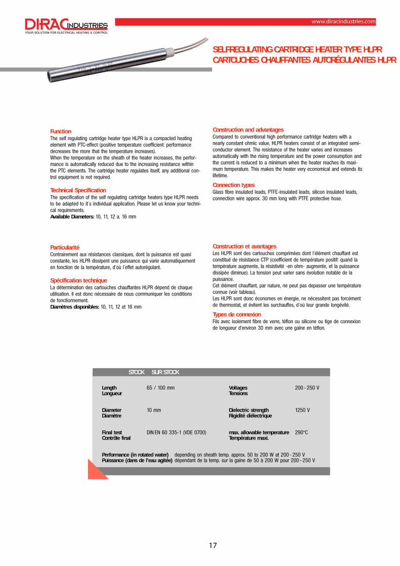
Construction and advantagesCompared to conventional high performance cartridge heaters with anearly constant ohmic value, HLPR heaters consist of an integrated semi-conductor element. The resistance of the heater varies and increasesautomatically with the rising temperature and the power consumption andthe current is reduced to a minimum when the heater reaches its maxi-mum temperature. This makes the heater very economical and extends itslifetime.
Connection typesGlass fibre insulated leads, PTFE-insulated leads, silicon insulated leads,connection wire approx. 30 mm long with PTFE protective hose.
Construction et avantagesLes HLPR sont des cartouches comprimées dont l´élément chauffant estconstitué de résistance CTP (coefficient de température positif: quand latempérature augmente, la résistivité -en ohm- augmente, et la puissancedissipée diminue). La tension peut varier sans évolution notable de lapuissance.Cet élément chauffant, par nature, ne peut pas depasser une températureconnue (voir tableau).Les HLPR sont donc économes en énergie, ne nécessitent pas forcémentde thermostat, et évitent les surchauffes, d´où leur grande longévité.
Types de connexionFils avec isolement fibre de verre, téflon ou silicone ou tige de connexionde longueur d’environ 30 mm avec une gaine en téflon.
FunctionThe self regulating cartridge heater type HLPR is a compacted heating element with PTC-effect (positive temperature coefficient: performancedecreases the more that the temperature increases). When the temperature on the sheath of the heater increases, the perfor-mance is automatically reduced due to the increasing resistance withinthe PTC elements. The cartridge heater regulates itself, any additional con-trol equipment is not required.
Technical SpecificationThe specification of the self regulating cartridge heaters type HLPR needsto be adapted to it`s individual application. Please let us know your techni-cal requirements.Available Diameters: 10, 11, 12 a. 16 mm
ParticularitéContrairement aux résistances classiques, dont la puissance est quasiconstante, les HLPR dissipent une puissance qui varie automatiquementen fonction de la température, d´où l´effet autorégulant.
Spécification techniqueLa détermination des cartouches chauffantes HLPR dépend de chaque utilisation. Il est donc nécessaire de nous communiquer les conditions de fonctionnement. Diamètres disponibles: 10, 11, 12 et 16 mm
www.diracindustries.com
17

HLPR FOR RADIATORSHLPR POUR RADIATEURS
Advantages- no switches which are subject to mechanical wear- the allowable maximum temperatures will not be exceeded
at any time due to the physical properties of the PTC-element- the heaters are not sensitive to variations in voltage
they can be run from 200 V through 265 V- dielectric strength 4000 V
Connection types- Cable with connector- Cable without connector- Normal connection leads
Avantages- pas d´ interrupteur qui peut vieillir mécaniquement- même avec un radiateur partiellement rempli de liquide il n´y a pas
de surchauffe grâce au principe de fonctionnement de l’élément CTP- les résistances peuvent être utilisées entre 200 V et 265 V- Rigidité diélectrique 4000 V
Types de connexion- Cable avec connecteur- Cable sans connecteur- Fils d´alimention standards
FunctionThis self regulating HLPR type heater with a long shaft has been developped especially for the use within radiators.
ParticularitéLe développement de cette cartouche HLPR a été spécifique aux radiateurs domestiques type sèche-serviette, radiateurs de salle de bain.
PREFERABLE TYPES MODÈLES PRÉFÉRÉS
Length Diameter Performance at 60°C watertemp. VoltagesLongueur Diamètre Puissance à 60°C température d’eau Tension
V 052 – 002W 0053,0± mm 21mm 065V 052 – 002W 0573,0± mm 21mm 097V 052 – 002W 00013,0± mm 21mm 0201V 052 – 002W 05213,0± mm 21mm 0021V 052 – 002W 00513,0± mm 21mm 0831
Other types upon requestAutres executions sur demande
www.diracindustries.com
18

HEATING OF EXPANSION SCREWSCHAUFFE-BOULONS
TECHN. DATA COORDONNÉES TECHN.
Diameter Ø 10 mm - Ø 36 mmDiamètre
max. Length 2500 mmLongeur maxi.
unheated length min. 200 mmLongeur non-chauffante
Voltage bis/upto/maxi. 400 VTension
max. Performance 15 000 W at 48 VPuissance maxi. 15 000 W avec 48 V
Execution optionally straight or bentExecution sur demande droite ou coudée
Special type HLP heaters for the heating of expansion screwsor other special applications
DescriptionExpansion screws are always used where the tightening of the screw hasto assure a long lasting and solid connection. This is mostly used for largeelectrical machines like turbines and generators or for large diesel enginese.g. for ships. The tightening of the screw serves to assure that the hou-sing halves of the machines are safely fitted and that they can withstandthe mechanical load during operation such as vibration or pressure. Thescrews can also be used for the fixation of the machines to a socket. Theuse of expansion screws is based on the elongation of the steel shaft wit-hin certain limits which is proportional to the applied heat. Expansionscrews return back to the same length when cooling down to ambienttemperature.
Application of expansion screwsIt is very important to only heat the screws within the shaft portion.
Installation guidanceIn order not to overheat the cartridge heaters and to achieve a good heattransfer we highly recommend the use of our installation aid NEVER SEEZ.Before the installation the heated zone of the cartridge heater should becovered throughout with a layer of this compound.
Important for orderingHeated length, unheated length, voltage, performance, connection type.It is useful to provide the heaters with an unheated length of about150 mm to 200 mm at the connection side to prevent the connectionfrom being thermally damaged during the heating process.
Cartouches chauffantes spéciales pour le chauffage des bou-lons, tirants ou d’autres applications spéciales
UtilisationPour permettre le serrage d´écrou sur des tiges filetées de grandesdimensions.Par example pour l´assemblage de carters sur des turbines, générateursélectriques, moteurs marins, ou tirants de fondations, on profitera del´allongement provoqué par le chauffage des tiges pour reserrer lesécrous. Après refroidissement, le serrage est effectué.
Application Le chauffage s´applique dans la partie non filetée, dans les limites detempérature imposées par l´acier ou ses traitements, afin que le métalconserve ultérieurement, ses caractéristiques d´origine.
Recommandations pour le montage Pour ne pas surcharger les cartouches chauffantes et pour obtenir un bontransfert de chaleur nous vous recommandons l’utilisation de notre produitanti-friction NEVER SEEZ. Il faut appliquer une couche de cette pâte surtoute la surface chauffante de la cartouche.
Important en cas de commande Longueur chauffante, longueur non-chauffante, tension, puissance, type deconnexion. Pour empêcher la cartouche d’être surchargée dans la partienon-chauffante nous vous recommandons de prévoir une longueur non-chauffante de 150 mm à 200 mm vers la côté connexion.
www.diracindustries.com
19

Low Voltage up to 48 VBasse tension jusqu’ à 48 V
Standard voltage up to 400 VTension standard jusqu’à 400 V
400 V Three phase current400 V Triphasé
Executions- welded connection sleeve with handles- 4 or 5 core cable - CEE- connector can be supplied upon request- ring for the adjustment of the immersion depth
Exécution- douille de connexion avec poignées- cable à 4 ou 5 fils- connecteur CEE disponible sur demande- bague pour l’ajustement de la longueur plongeante
Executions- dimensions A, B, C, D and heated length to customer specification- connector (easy to unplug)- insulated leads 25-120 mm2 depending on current- ring for the adjustment of the immersion depth
Exécutions- dimensions A, B, C, D et longueur non-chauffante selon spécifications
du client- connecteur (facile à débrancher)- fils isolés de section 25-120 mm2 dépendant du courant- bague pour l’ajustement de la longueur plongeante
HLP standard types can also be used for the heating of expansion screws.
Les cartouches chauffantes HLP standards peuvent aussi être utiliséespour le chauffage des boulons.
A
ConnectorConnecteur
R 50
B heated/chauffant20
D for bore hole H 11D pour alésage H 11
CAdjustent RingBague d'ajustement
heated/chauffanteRubber insulated cable4 or 5 coreCâble avec isolement caout-chouc avec 4 ou 5 filsConnection sleeve
Douille de connexion
HandlePoignée
Adjustment RingBague d'ajustement
Ø D
waterproof sealedétanche à l'eau
L
unheated/non chauffante
unheatednon chauffante
www.diracindustries.com
20

OVERVIEW CONNECTION TYPESSOMMAIRE DES CONNEXIONS
Connection typesTypes de connexion
Connection leadsFils de connexion
LETEM
temp. resistant glassfibre leads fils fibre de verre résistant à deshautes temp. 400°C/600°C*
Protective hosesGaines de protection
DRGSL
wire mesh hosegaine tressée
SSL/WSL/DRGSL
internally fixed connection sleevetube de conn. monté à l’intérieur
Additional optionsOptions supplémentaires
Normanschluß NA
leads connected outside fils sertis en dehors
ISAN
insulated connectionsconnexion isolée
DIRFLEX
leads directly coming out fils sertis dans la cartouche
LEGLS
glassfibre insulated leadsfils isolés fibre de verre250°C/350°C*
LESIL°C
silicon insul. leads upto 200°Cfils isolés silicone 200°C maxi.
LEPE
ceramic beads upto 650°C perles en céramique 650°C maxi.
LETEF
PTFE-insul. leads upto 260°Cfils isolés téflon 260°C maxi.
KASIL
with silicon insulated cablecable isolé silicone
SSL
protective hosegaine spiralée
WSL
corrugated hose (stainless steel)gaine ondulée (acier inox)
EN
threaded nipple raccord fileté
ROWI
tubular anglesortie coude rond
tab connector or receptacles cosse plate, mâle ou femelle
AE
coreend shellsemboût de câble
SERD
earth leadfil de terre
HLP
without any confectioningsans connexion
permanent / *short time temperaturetemp. permanente/ *temp. à courte durée
WAN
angular connectionsortie coude cubique
www.diracindustries.com
21

CONNECTION TYPESTYPES DE CONNEXION
Ø (mm) LEGLS LETEF LESIL LETEM SERD Length
Longueur ISAN NA ISAN NA ISAN NA ISAN NA
6,5 250 210500 210001 210520 211000 210780 - 210880 210800 210160500 210501 210003 210521 211001 210781 - 210881 210801 210161800 210633 210004 210535 211002 210782 - 210882 210802 210162
1000 210634 210005 210536 211003 210783 - 210883 210803 2101631500 210656 210084 210532 211004 210784 - 210884 210804 2101642000 210570 210085 210672 211005 210785 - 210885 210805 210165
8/10 250 210504 210007 210522 210796 211068 210714 210844 210806 210160500 210505 210009 210523 210797 211083 210715 210845 210807 210161800 210625 210010 210660 210798 211084 210716 210846 210808 210162
1000 210626 210011 210538 210799 211085 210717 210847 210809 2101631500 210640 210086 210534 210792 210938 210718 210848 210810 2101642000 210679 210087 210651 210794 211086 210719 210849 210811 210165
12,5 250 210506 210013 210524 211091 210540 210720 210850 210812 210172500 210507 210015 210525 210955 210541 210721 210851 210813 210173800 210619 210016 210737 210970 210703 210722 210852 210814 210174
1000 210620 210017 210537 211114 210704 210723 210853 210815 2101751500 210685 210088 210539 210978 210705 210724 210854 210816 2101762000 210661 210089 210738 210992 210706 210725 210855 210817 210177
16 250 210508 210019 210526 210742 210542 210726 210856 210818 210178500 210509 210021 210527 211012 210543 210352 210857 210819 210179800 210584 210022 210739 210744 210549 210727 210858 210820 210180
1000 210618 210023 210740 210743 210707 210728 210859 210821 2101811500 210689 210090 210675 210745 210708 210729 210860 210822 2101822000 210684 210091 210676 210746 210709 210730 210861 210823 210183
20 250 210510 210025 210528 210103 210544 210731 210862 210824 210184500 210511 210027 210530 210104 210545 210732 210863 210825 210185800 210616 210028 210974 210105 210710 210733 210864 210826 210186
1000 210617 210029 210975 210106 210711 210734 210865 210827 2101871500 210610 210092 210531 210107 210712 210735 210866 210828 2101882000 210611 210093 210533 210108 210713 210736 210867 210829 210189
Connection leads in accordance with temperature loadsLEGLS Impregnated glassfibre insulated leads upto max. 250°C
permanent temperatureLETEM Temperature resistant glassfibre insulated leads
upto 400°C permanentlyLEPE Ceramic beads up to 650°C, only for HLP from Ø 10 mmLETEF PTFE-insulated leads upto about 260°C LESIL Silicon insulated leads upto 200°C SERD Earth leads
Fils de connexion et leur tenue à la températureLEGLS fils avec isolement fibre de verre, impregné de silicone jusqu’à
250°C température permanenteLETEM fils avec isol. fibre de verre, pour hautes temp., jusqu’à 400°CLEPE perles en céramique, jusqu’à 650°C, seulement pour cartouches
≥ Ø 10 mmLETEF fils avec isolement de téflon, jusqu’à 260°CLESIL fils avec isolement de silicone, jusqu’à 200°CSERD fil de terre
Please noteThe heating elements type HLP and PMV can be equipped with differentconnection leads. The standard lengths listed in the table below are deli-verable from stock. Their cross sections refer to the respective cartridgediameter. Bare lead ends can be furnished with coreend shells, cablesockets M4, or tab connectors or receptacles and other accessories uponrequest.
AvisLes cartouches chauffantes type HLP et PMV peuvent être fournies avecdifférents fils de connexion.Les longueurs standards indiquées dans le tableau ci- dessous sont dis-ponibles sur stock, les sections des fils dépendant du diamètre de la car-touche.Les extremités des fils sont dénudées et peuvent être equipées avec desemboûts de cable, des cosses rondes ou des cosses plates mâles oufemelles; autres accessoires sur demande.
www.diracindustries.com
22

EN
Threaded nippleRaccord fileté
Description:The heating elements type HLP and PMV can be equipped with a threa-ded nipple made of brass or stainless steel. Brass nipples will be solderedto the cartridge, stainless steel nipples will be welded. Heaters with thenipple dimensions indicated beside can be delivered at short notice.
Description:Les cartouches HLP et PMV peuvent être fournies avec un raccord filetéen laiton ou en acier inox. Les raccords en laiton sont brasés sur la gaine,ceux en acier inox sont soudés.Le tableau indique les raccords qui sont disponibles sur stock.
Ø A 6,5 8 10 12,5 16 20B 6 6 6,5 6,5 8,5 12C 3 4 4,5 4,5 5,5 6
Cartridge-Ø Designation Brass nipple Stainless steelØ de la cartouche Désignation Laiton Acier inox
6,5 mm M 10 x 1,0 SW 12 610 073 610 0848,0 mm M 12 x 1,0 SW 14 610 074 610 082
10,0 mm M 14 x 1,5 SW 17 610 075 610 08312,5 mm M 16 x 1,5 SW 19 610 076 610 07916,0 mm M 20 x 1,5 SW 24 610 077 610 08020,0 mm M 26 x 1,5 SW 30 610 078 610 081
ISAN
Insulated connectionConnexion isolée
Description:The available stock programme of compacted heating elements can alsobe equipped with flexible connection leads being insulated and led outdirectly from the cartridge. The protruding height of the ceramic discsfrom the sheath is 7-14 mm. Upon request this execution can also beprotected against ingress of liquids. This execution is VDE approved.
Description:Les cartouches chauffantes disponibles sur stock peuvent être équipéesavec des fils de connexion dont le raccordement est fait à l’intérieur de lapièce en céramique. La longueur de la céramique varie de 7 à 14 mm dehauteur selon les diamètres. Les cartouches qui en sont équipées ontreçues le label VDE.
Ø A 6,5 8 10 12,5 16 20B 7 7 9 11,5 12,5 14
Ø C 6 7,5 9 10,5 12,5 16
NA
Standard connection Connexion standard
DescriptionLeads connected outside of the heater
DescriptionSertissage des fils hors de la cartouche
Ø A 6,5 8 10 12,5 16 20B 3 4 4 4,5 4,5 5C 45 45 45 45 45 45
B
A
C
B
A C
BC
A
www.diracindustries.com
23

SSL
Protective hose type SSL Gaine spiralée type SSL
Description: Protective hose made of spirally shaped, wound, galvanisedstell ribbon for cartridge heaters from Ø 6.5 mm through Ø 20 mm. Thishose protects the connections from mechanical damage but cannot beused when the heaters are subject to a lot of movement. A connectiontube joins the cartridge heater to the protective hose. The hose is moun-ted into the tube or around its outer diameter and welded.Usage
:
Protecion against mechanical damage, strain relief
Description: La gaine spiralée se compose d’un ruban en acier zinguébobiné utilisable pour les cartouches de 6,5 mm à 20 mm. La gaineprotège les connexions mais ne peut pas être utilisée pour des cartou-ches en mouvement permanent. La gaine est reliée avec la cartouchepar un emboût en acier inox soudé. Utilisation: Protection contre les charges mécaniques
Ø A 6,5 8 10 12,5 16 20B 32 38 38 38 38 38
Ø C 7,5 9 11,5 14 18 22Ø D 6 8 10 10 14 14
KASIL
Silicon insulated cableCâble avec isolement de silicone
Description: Cartridge heaters with silicon insulated cables type KASIL asa connection cable with waterproof connection. Heaters with Ø 6,22 andØ 6,5 mm are equipped with a two core cable. Heating elements with dia-meters ≥ 8 mm are equipped with a three core cable (additional groundconnection green/yellow). Usage: wet rooms or under humidity
Description: Les cartouches chauffantes avec câble de connexion typeKASIL sont fournies étanche à l’eau. Les résistances en Ø 6,22 et Ø 6,5mm sont équipées avec des câbles à 2 fils, celles en Ø ≥ 8 mm avecdes câbles à 3 fils ( fil de terre jaune/vert incorporé).Utilisation: dans une ambiance humide
Ø A 6,5 8 10 12,5 16 20B 32 38 38 38 38 38
Ø C 7,5 9 11,5 14 18 22Ø D 7 8 8 8 9 9
PROTECTIVE HOSESGAINES DE PROTECTION
B
CAD
B
CA
D
www.diracindustries.com
24

SSL, WSL, DRGSL
Protective hose inside the cartridge Gaine de protection à l’intérieur de la cartouche
Description: possible for SSL, WSL, DRGSL for heaters with diameter ≥ Ø 10 mm
Usage: recommended for applications where the connection mustbe passed totally through a bore hole
Description: possible pour SSL, WSL, DRGSL pour les cartouches endiamètre ≥ Ø 10 mm
Utilisation: recommandé pour les applications où il faut enfiler lesrésistances entièrement dans un alésage
WSL
Corrugated hose Gaine ondulée
Description: Corrugated hose made of stainless steel for cartridge heatersfrom Ø 6.5 mm through Ø 20 mm. The corrugated hose is soldered tightinto a connection tube which again is soldered or welded tight onto theconnection end.Usage: Protection against mechanical damage, waterproof
Description: La gaine ondulée est fabriquée en acier inox et peut être uti-lisée pour toutes les cartouches de Ø 6.5 mm à Ø 20 mm. Elle est braséeétanche sur un emboût en acier inox, qui, lui - même est brasé sur lacartouche.Utilisation: Protection contre les charges mécaniques, étanche à l’eau
DRGSL
Wire mesh hoseGaine tressée
Description: Wire mesh hose made of galvanised wire netting for cartrid-ge heaters with diameters from 6.5 mm through 20 mm. The connectiontube for the wire mesh hose protrudes over the cartridge diameter.Usage: recommended for moving parts
Description: La gaine tressée est fabriquée en acier galvanisé et peutêtre utilisée pour les cartouches chauffantes de Ø 6.5 mm à Ø 20 mm.L’emboût de connexion pour la fixation de la gaine recouvre la cartouche-sur 3 mm.Utilisation: recommandé pour les pièces en mouvement
Ø A 6,5 8 10 12,5 16 20B 32 38 38 38 38 38
Ø C 7,5 9 11,5 14 18 22Ø D 9 9 10 10 12,5 12,5
Ø A 6,5 8 10 12,5 16 20B 32 38 38 38 38 38
Ø C 7,5 9 11,5 14 18 22Ø D 6,2 6,2 10,2 10,2 10,2 10,2
Ø A 10 12,5 16 20B 35 35 35 35
Ø C 8,5 11 14 18Ø D SSL 8 10 10 14Ø D WSL 9 10 10 12,5Ø D DRGSL 6,2 10,2 10,2 10,2
B
CA
D
B
CAD
B
CAD
www.diracindustries.com
25

WAN
Angular connection type WAN with or without metallic protective hoseConnex. coudée type WAN avec ou sans gaine de protection métallique
1. Protective hose WAN SSL2. Corrugated hose WAN WSL3. Wire mesh hose WAN DRGSL4. angular connection WAN
1. Gaine spiralée WAN SSL2. Gaine ondulée WAN WSL3. Gaine tressée WAN DRGSL4. sans gaine WAN
ROWI
Tubular angle connection type ROWI with or without protective hoseConnexion coudée tubulaire type ROWI avec ou sans gaine de protection métallique
Deliverable for all cartridges with ≥ Ø 10 mm.Peut être fournie pour toutes les cartouches ≥ Ø 10 mm.
1. Protective hose ROWI SSL2. Corrugated hose ROWI WSL3. Wire mesh hose ROWI DRGSL4. Tubular angle ROWI
1. Gaine spiralée ROWI SSL2. Gaine ondulée ROWI WSL3. Gaine tressée ROWI DRGSL4. sans gaine ROWI
ANGULAR CONNECTIONSCONNEXIONS COUDÉES
Ø A 6,5 8 10 12,5 16 20B 32 38 38 38 38 38
Ø C 7,5 9 11,5 14 18 22Ø D see page 27/28 voir page 27/28
E 8 10 12 14 18 22
Ø A 10 12,5 16 20B 38 38 38 38
Ø C 11,5 14 18 22Ø D see page 27/28 voir page 27/28
E 19 23 27 32
B
C
A
D
E
B
C
A
D
E
Please noteCombined executions and variations of connection and fixation of metallichoses are possible. For higher ordering quantities apart from the abovementioned connection types a large quantity of special types can besupplied.
AvisLes combinaisons d’exécution entre les différentes connexions et fixationsdes gaines sont possibles. Nous consulter pour les quantités élevées et lechoix parmi les nombreuses possibilités offertes.
As a special type a cylindrically shaped angular connection canbe supplied.
Comme exécution spécialeil est possible de fournir un coude rond de formecylindrique.
www.diracindustries.com
26

FURTHER CONNECTION TYPESAUTRES TYPES DE CONNEXION
INSTALLATION AIDPRODUIT ANTI-FRICTION
If requested we can supply furtherspecial connection types too.
Sur demande nous pouvons fourniraussi d’autres types de connexionspéciales.
www.diracindustries.comOrdering Commande
Never Seez, Typ NSB 4, 100 g, ex-stock Artikel-Nr. 650205Never Seez, Typ NSB 4, 100 g, sur stock
For the insertion of compacted cartridge heaters into drilled holes with atight tolerance we recommend the use of the high temperature constantlubricant NEVER SEEZ. It is not poisonous and neutral. It can be used in atemperature range from -180°C to +1200°C.
The lubricant should be applied over the sheath of the cartridge heater orin the drilled hole before inserting the heating element. It reduces frictionand thus facilitates insertion. Furthermore it prevents the seizing of thecartridge heater and simplifies their removal.
Pour le montage des cartouches chauffantes à haute puissance dans lesalésages à tolérance précise, nous vous recommandons l’utilisation denotre produit anti-friction NEVER SEEZ. Le produit est non toxique et denature neutre. Il peut être appliqué pour les températures de -180°C à+1200°C.
Il faut appliquer le produit sur toute la gaine de la cartouche ou dansl’alésage avant montage. La friction sera réduite et le montage descartouches facilité. En plus, il empêche le grippage dans l’alésage etla corrosion, facilitant le démontage.
www.diracindustries.com
27
INSTALLATION GUIDANCERECOMMANDATIONS POUR LE MONTAGE
12 points to be observed when using highly compacted heating elements
� For cartridge heaters with surface loads upto 20 W/cm2 the receiving holemust be drilled according to ISA H7 with peak to valley height as small aspossible.
� For cartridge heaters with surface loads exceeding 20 W/cm2 a sliding fit isnecessary which can be obtained by individual attention beeing paid to eachcartridge heater.
� The drilled receiving bores of cartridge heaters must be cylindrical. Crossingbores and shrinkages cause a localisation of heat and shorten the useful lifeof the heating elements.
� To facilitate the insertion and the removal of the heating elements the recei-ving bores should be drilled in a continuous motion (to avoid a steppedbore).
� The maximum working temperature of the cartridge heaters stated in theleaflet does not apply to the connection leads. These must be selectedaccording to the operating conditions.
� The lubricant NEVER SEEZ beeing resistant to temperature facilitates the ins-ertion and removal of the heating elements in bores with small tolerances.
� When using several cartridge heaters the distance between two consecuti-ve cartridges should be at least equal to the cartridge diameter.
� The end of the cartridge heater with the connection leads should be pro-tected against liquid and pasty media (lubricants, oil, synthetic materials,etc.) as well as their vapours because otherwise leakage currents and, pos-sibly flashover could occur at the outlet connection terminals.
� The connection leads should be protected against mechanical vibrationsclose to the outlet of the cartridge heater. If they are heated with the car-tridge, the resulting vapour must have the ability to escape.
� If possible, control of the operating temperature should be achieved bymeans of continuous regulators, controllers with pulse width modulation orelectronic power control devices. A control system with long timelag oftencauses thermal overload of the heating elements. For this reason also thetemperature sensor must be fitted in close proximity to the cartridge heater(about 10 mm apart).
� If heating elements are to be stored for long periods they should be housedin absolutely dry rooms or enclosed in plastic bags which are hermeticallysealed. If cartridge heaters are moist, they can be dried by heating at 180°Cfor 8 hours.
� If the heaters are not supplied with a separate earth lead the installationhas to provide a safe ground connection.
12 points importants concernant le montage des cartouches chauffantes
� Pour les cartouches avec charge jusqu’à 20 W/cm2, prévoir un alésage<<H7>> avec un bon état de surface.
� Pour les cartouches dont la charge dépasse 20 W/cm2 ,prévoir un ajuste-ment <<coulissant juste>> en fonction du diamétre des cartouches.
� L’alésage recevant la cartouche doit être parfaitement cylindrique sans trouni retassure qui provoqueraient une surchauffe locale de la cartouche.
� Le trou doit être si possible débouchant pour faciliter l’introduction ou leretrait de la cartouche. A l’extremité, le trou débouchant pouvant être d’undiamétre plus petit.
� Lors de l’utilisation de plusieurs cartouches côte à côte, la distance entrechacune d’elles doit être au moins égale à un diamétre.
� Notre produit anti-friction NEVER SEEZ résistant à la chaleur, facilite le mon-tage et le démontage des cartouches. Il améliore également le transfertthermique.
� Les températures indiquées pour l’utilisation des cartouches chauffantes nesont pas applicables pour les fils de connexion. Il faut toujours choisir le typede fil en fonction des conditions d’utilisation.
� Les câbles de raccordement électrique doivent être protégés contre les flui-des, eau, huile, matière plastique, etc...., qui pourraient provoquer des cou-rants de fuite ou des amorçages à la sortie des conducteurs.
� Les cables doivent être protégés contre les vibrations et les chocs, à la sor-tie de la cartouche, pour éviter leur détérioration.
� Le contrôle de la température doit être assuré par un bon régulateur detempérature, si possible à action modulée ou par tout autre systéme élec-tronique de contrôle de puissance. Pour éviter une trop grande inertie ther-mique, pouvant provoquer une surchauffe de la résistance, prévoir la sondede régulation à environ 10 mm de la cartouche.
� Le stockage des cartouches chauffantes doit se faire dans un local absolu-ment sec, ou dans des sacs en matiére plastique étanches hermétiquementclos. Des cartouches humides doivent être sechées à 180°C pendant 8 heures.
� Si les cartouches chauffantes ne sont pas equipées de fil de terre la con-nexion à la masse doit être assurée par l’installation.
www.diracindustries.com
28

We highly recommend to you our established wide range of products aswell as our latest developments in the field of electric heating elements.
Nous vous proposons une large gamme complète de produits ainsi quenotre expérience dans les nouvelles techniques du chauffage électrique.
Tubular cartridge heater type RPRésistances Formables RP
Tubular heaters type RHKRésistances blindées RHK
Flat tubular heaters type RKFRésistances plates RKF
Immersion heaters type EHKThermoplongeurs EHK
TECH
NISC
HE W
IJZI
GING
EN V
OORB
EHOU
DEN
YOUR COMPETENT PARTNERVOTRE PARTENAIRE COMPETENT
ADVICEAVIS
WarrantyWe cannot take responsibility for any defect caused by improper installati-on or any advice given for the use of our heaters.
GarantieNous ne pouvons pas prendre en garantie les conséquences résultantd´une mauvaise utilisation, d´une mauvaise installation, ou d´un non res-pect de nos recommandations, ainsi que des réparations ou modificationsapportées par le client.
Removal of heatersWhen removing catridge heaters, please take care not to damage the borehole. If there is a through hole use a punch in tube form that fits into thering groove at the bottom end of the cartridge. In this way you can avoidpuncturing the cartridge bottom. Removal of the cartridge heater by pullingthem off the bore hole by the connection leads or the ceramic head isnot possible in most cases.
Démontage des cartouches chauffantesPour enlever une cartouche de son logement il faut, si celui-ci estdébauchant, utiliser comme chasse-goupille un profilé rond de mêmediamètre que la cartouche et prenant appui sur le fond de celle-ci. Si letrou est borgne, tirer sur les fils de connexion ou la pièce en céramiqueest très aléatoire.
J.B. Bosmansstraat 2 - BE 1600 Sint-Pieters-LeeuwPhone: +32 2 376 51 29 - Fax: +32 2 376 16 95
www.diracindustries.com - [email protected]
www.diracindustries.com