Heater Test Bench for Webasto Heaters
32
Operating Instructions (Standard Version) (Premium Version) Heater Test Bench for Webasto Heaters (all versions)
-
Upload
khangminh22 -
Category
Documents
-
view
1 -
download
0
Transcript of Heater Test Bench for Webasto Heaters
Operating Instructions
(Standard Version) (Premium Version)
Heater Test Bench
for
Webasto Heaters (all versions)

2
Notes

3
List of Contents
o General information o Intended application
o Safety advice
o Initial operation
o Control panel
o Basics of heater testing
o Testing Thermo Top / T
o Testing Thermo Top E / C/Z / P / S / 50
o Testing Air Top 2000 Diagnosis / S / ST / 12 and 24 V
o Testing Air Top 3500 / 5000 / ST / VP / ECO /12 and 24 V
o Testing DW 80 / Thermo 90 / S / 12 and 24 V
o Thermo 90 ST / 12 and 24 V
o Testing DBW 2010 / 2016 / 12 and 24 V
o Testing components o Technical specifications

4
General
Dear Customer, thank you for selecting this heater test bench for Webasto heaters. With this test bench you have chosen a product that has been designed and manufactured in line with state-of-the-art technology and which complies with all current health and safety regulations. (DEKRA test report no. DR 57/2623/05-17942) Provided this product is used correctly, a manufacturer’s warranty of 12 months applies from the date of invoice. The use of this test bench requires expert and in-depth knowledge of Webasto heaters. Please read these operating instructions carefully. The product warranty will automatically lapse in the case of damage resulting from a failure to follow these operating instructions. There is also a risk of injury as a result of failing to follow these operating instructions! The manufacturer will assume no liability for damage resulting from a failure to observe these operating instructions or for incorrect operation. Please keep these operating instructions in a safe place.

5
Intended Application
This heater test bench has been designed solely for the testing of Webasto heaters. To date, the following heaters have been tested and approved:
o BBW / DBW 46 (with special adapter)
o Thermo Top / Thermo Top T up to series number 299 999
o Thermo Top / Thermo Top T from series number 300 000
o Thermo Top E / C/Z / P / S all versions
o Thermo 50
o Air Top 2000 Diagnosis / S / ST / 12 and 24 V
o Air Top 3500 / 5000 / S / ST / VP / ECO / 12 and 24 V
o DW 80 / Thermo 90 / S * / 12 and 24 V
o Thermo 90 ST * / 12 and 24 V
o DBW 2010 / 2016 * / 12 and 24 V
* Only with test bench Premium The manufacturer reserves the right to approve further Webasto heaters for testing with this test bench. The heaters may only be operated with an adapter cable harness acquired from the manufacturer. The heater test bench may only be operated using an external DC supply (12V and / or 24V). As regards the power supply, please ensure that a stabilised and divided voltage is available. A commercially-available battery charger is not suitable.

6
Safety Advice The heater test bench may only be operated with petrol or diesel that complies with current ISO standards. There should be no power going to the test bench when filling with fuel. The test bench must be sufficiently earthed before operation. The liquid required for testing water heaters must have the following composition: - 65 % tap water - 35 % ethylglycol-based anti-freeze For safety reasons, arbitrary alterations or modifications to the heater test bench are not permitted. Please ensure the correct operation of the heater test bench. Please adhere to these operating instructions. In industrial facilities, the health and safety regulations set out by the relevant authorities are to be adhered to. It is vital that the exhaust pipe be fitted correctly as very high temperatures can ensue during heater operation which could lead to injury on contact.

7
Initial Operation
Please check that the test bench supplied is complete:
o Bracket Thermo Top o Bracket Air Top and Thermo Top E / C/Z / P / S o Bracket DW 80 / Thermo 90 / S / ST * o Bracket DBW 2010 / 2016 * o Bracket drive motor** o Adapter drive motor waterproof plug** o Adapter cable dosing pump test, incl. fuel pipe and measuring jug (where dosing pump test has been ordered with the test bench). o Adapter plug Diagnosis o Exhaust pipe Ø 24 o Adapter Ø 24 to Ø 22 o 2 water pipes incl. gate valve o Water drip tray o Buffer tank 30 l * o Adapter cable Telestart** * Only with test bench Premium
** Only for test benches with integrated component testing (optional). Place the test bench on a firm underlay.
Fill the water tank with the required amount of liquid. (Total quantity: approx. 10 l with the standard and approx. 40 l with Premium).
Fill the intended and labelled fuel tanks with the required level of fuel, having first disconnected the power supply.
Only cover plates supplied by the manufacturer may be used. Follow the test instructions for the heater to be tested as set out in these operating instructions.
Cover plate water tank
Fuel tank Petrol
Fuel tank Diesel

8
Control Panel
* Only with test benches with ADR package (optional) ** Only with test benches with integrated component test (optional) *** Only with test bench Premium
13 14
2
3 4 6
7
8
10
11
11a
12
24* 26*
1
22*
15
16
17
11b
11c
18
19 20
21*
23* 28 29 31
27 30 25*
2a**
4a***
9 5
11d
11e
19a**
26a** 27a**
4b**
20b***
20a***

9
Legend for Control Panel:
Pos. Name 1 Switch for fan power settings 2 Operation indicator for water pump
2a** Output 12 V for component inspection 3 Control lamp fuel pump diesel 4 Switch for fuel pumps diesel / petrol
4a*** Water volume changeover switch (10 l / 40 l test quantity) 4b** Switch component test
5 Control lamp fuel pump petrol 6 Main switch Air Top 2000, 3500, 5000 7 Control lamp Thermo Top Start with PIN 1 8 Main switch Thermo Top, 0 = Start W-Bus 9 Operation indicator 12 / 24 V
10 Central connector for adapter cable harness 11 Fuse box
11a Fuse F1 12 V (20A) 11b Fuse F2 24 V (20A) 11c Fuse F3 fan blower (10A Standard) (30A Premium) 11d** Fuse F4 component inspection 12 V (1A – 30A) 11e** Fuse F5 component inspection 24 V (1A – 30A)
12 Diagnosis connection k-line (Standard) 13 Diagnosis connection w-bus (data bus control unit) 14 Power input 12 V 15 Power input mass 16 Power input 24 V 17 Power output diagnosis mass 18 Power output diagnosis 12/24 V 19 Ground socket
19a** Indicator component inspection 12 / 24 V 20 Control lamp Thermo Top Start with PIN 3
20a*** Control lamp temperature coding Thermo 90 20b*** Switch temperature coding Thermo 90
21* Control lamp D+ simulation (ADR / TRS) 22* Switch D+ Simulation (ADR / TRS) 23* Switch ADR (TRS) 24* Control lamp ADR (TRS) 25* Switch rollover sensor (Air Top ST heaters) 26* Control lamp rollover sensor (Air Top ST heaters)
26a** Connection fuel pump for component test 27 Changeover switch heating / ventilating (Thermo Top and
Air Top) 27a** Output 24 V for component inspection
28 Switch for CO2-regulation Air Top 3500/5000 29 Switch water pump 30 Pushbutton for fuel (to fill Thermo Top/T) 31 Switch fan blower for manual start
* Only for test benches with ADR package (optional) ** Only for test bench with integrated component test (optional). *** Only with test bench Premium

10
General Information on Heater Testing
1. Please refer to the relevant manual for information on the heater connections.
2. Connect (14, 15, 16) the separate power supplies (12 / 24V)
Ensure that all switches are at ’0’-setting, before switching on the power supply
3. The integrated blower heat exchanger(s) is (are) always factory-set to level
1. Please select other levels manually (1)
4. If the water connection(s) is (are) connected to each other, the blower heat exchanger(s) can be connected to each other in order to cool down the water circuit (for example, in order to test further heaters).
5. The exhaust pipe must be fitted correctly and without contact. Sufficient
ventilation for the exhaust must be ensured.
6. The inlet silencer is to be fitted before each test, depending on the heater type.
7. The integrated water pump is intended for testing the Thermo Top Z and
for ventilating and cooling the water circuit.
8. Ensure that the test cable harness is securely connected to the central connector and to heater.
9. The illustrations with each test manual show the functions and switches
required for the test.

11
Testing ThermoTop / T / S (only Thermo Top S without watertight connector)
1. Attach the heater bracket for the particular heater type to the test bench and mount the heater on the bracket.
2. Connect the adapter cable harness to the central connector (10) and to
the heater. In the case of Thermo Top/ T up to serial nr. 299 999 do not connect the connector with the cable colours purple/blue.
This connector is for the fuel pump activation for Thermo Top S.
3. Secure water pipes with clamps, open gate valves.
4. Connect fuel pipe with the correct adapter to the fuel supply line. The return line will remain free for tank ventilation.
5. Select fuel type using switch (4)
6. Fill heater fuel tank using switch (30)
7. Connect pc diagnostic device to sockets provided (12,17,18)
8. Switch on heater using main switch (8)
9. Thermo Top and Thermo Top T with watertight plugs can only
be started via the diagnostic device
10. Carry out heater test as per workshop manual
4 8
30
10
12
17 18

12
Testing Thermo Top E, C/Z, P, S, 50
1. Attach the heater bracket for the particular heater type to the test bench and mount the heater onto the bracket.
2. Connect the adapter cable harness to the central connector (10) and to
the heater
3. Secure the water pipes with clamps, open the gate valves.
4. Connect fuel line
5. Select fuel type using switch (4)
6. Connect pc diagnostic device to sockets provided (12, 13, 17, 18)
7. Depending on the type, switch on the heater using the main switch (8) o PIN 3 Thermo Top Z (switch on water pump manually (29) o Switch to 0 Thermo Top C with digital control unit and
diagnostics via w- bus o PIN 1 and PIN 3 Thermo Top C Motor home o PIN 1 Thermo Top E / C (analogue) / S o With Thermo 50 the control lamp (9) will light up
With Thermo Top Z and Thermo Top C with digital control unit, the fan blower must be switched on manually (31, 1), as there is no signal from the control unit.
8. Carry out the heater test as per the workshop manual
13 2 4 7 8 12
1
17 20 29 31
9
18
10

13
Testing Air Top 2000 Diagnosis / S / ST
1. Attach the heater bracket for the particular heater type to the test bench and mount the heater on it.
2. Remove the upper casing in accordance with the workshop manual
3. Connect the adapter cable harness to the central connector (10) and to the heater. Remove the connector X2 (dosing pump) from the control unit and put it to one side. Replace it with the small, black connector from the adapter cable harness.
4. Replace the upper casing
5. Connect fuel line
6. Select fuel type using switch (4)
7. Connect pc diagnostic device to sockets provided (12,13,17,18)
8. Switch on heater using main switch (6) and select set temperature
9. Test heating/ventilating with switch (27) (Air Top 2000 ST only)
10. Switch 25* only for Air Top 2000 ST (see workshop manual)
Switch 22* and 23* only for ADR (TRS) test 11. Carry out heater test as per workshop manual
4 10 6
25* 22* 23* 28 27
13 12
17
18

14
Testing Air Top 3500 / 5000 (all versions)
1. Attach the heater bracket for the particular heater type to the test bench and
mount the heater on the bracket.
2. Connect adapter cable harness to the central connector (10) and to the heater
3. Connect fuel line
4. Select fuel type using switch (4)
5. Connect pc diagnostic device to jack sockets provided (12,13,17,18)
6. Switch on heater with main switch (6) and select set temperature
7. Test heating/ventilating with switch (27)
8. Switches 22* and 23* only for ADR (TRS) test
9. Carry out heater test as per workshop manual
10. Select CO2 setting with switch (28) and set prescribed exhaust value as per workshop manual.
4 10 6
25* 22* 23*
28 27
13 12
17
18

15
Testing DW 80 / Thermo 90
1. Attach the heater bracket for the particular heater type to the test bench and mount the heater onto the bracket.
2. Connect the adapter cable harness to the central connector (10) and to the
heater
3. Connect the Webasto diagnostic adapter to the diagnostic connection on the control unit
4. Connect fuel line
5. Select fuel type at switch (4)
6. Connect pc diagnostic device to the jack sockets provided (control
unit,17,18)
7. In the case of 24 V heaters it is vital that both a 12 V and 24 V power supply is going to the test bench
8. Switch on heater using main switch (6) and select temperature coding (20a,
20b). (Upper switch 80°LED red, middle switch 72°LED off, lower switch 65°LED green, Only Thermo 90, see workshop manual)
9. Switches 22* and 23* only for ADR (TRS) testing
10. Carry out heater test as per workshop manual
2 4 7 8
Diagnosis directly from control unit
17 29 31
9
18
10
23* 22* 20b***
20a***
1 4a***
16
Testing Thermo 90 S / ST
1. Attach the heater bracket for the particular heater type to the test bench and
mount the heater onto the bracket.
2. Connect the adapter cable harness to the central connector (10) and to the heater
3. Connect fuel line
4. Select fuel type using switch
5. Connect pc diagnostic device to socket provided (12(S), 13(ST), 17,18)
6. In the case of 24 V heaters it is vital that both a 12 V and 24 V power
supply is going to the test bench
7. Switch 22* for temperature coding Off – 80°, On – 72° (only possible with version ADR(TRS) !)
8. Switch 23* only for ADR (TRS) testing
9. Carry out heater test as per workshop manual.
2 4 7 8 12
17 29 31
9
18
10
23* 22*
1 13 4a***

17
Testing DBW 2010 / 2016
1. Attach the heater bracket for the particular heater type to the test bench and mount the heater onto the bracket.
2. Connect the adapter cable harness to the central connector (10) and the
control unit
3. For heaters with ADR function, connect a separate control unit to adapter cable harness
4. For versions with external blower activation, connect cable gn / ws to fan
blower thermostat at heater
5. Switch-on blower manually ( 1 )(only for versions without external blower activation)
6. Take fuel from a separate fuel container (e.g. fuel can, not supplied)
7. In the case of 24 V heaters it is vital that both a 12 V and 24 V power
supply is going to the test bench
8. Carry out heater test as per workshop manual
8
1 23* 22*
10

18
Testing Components**
1. Testing Fan Blower Motor Air Top Heaters 1. Mount the blower motor bracket onto the test bench and secure the blower
motor on the bracket
(With all versions of AT 3500 / 5000 use a suitable clamp at pos. 5) For blower motors with waterproof plugs, use adapter included
A red and a black cable (see photo) are required for the test (not supplied) An adjustable mains adapter with stabilised and divided output voltage is an absolute requirement. Before applying the test voltage, check the drive motor for winding short circuit and ground mass.
Pos.5
19
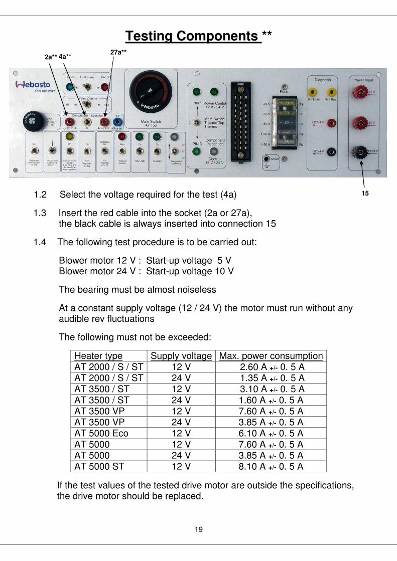
Testing Components **
1.2 Select the voltage required for the test (4a)
1.3 Insert the red cable into the socket (2a or 27a), the black cable is always inserted into connection 15
1.4 The following test procedure is to be carried out:
Blower motor 12 V : Start-up voltage 5 V Blower motor 24 V : Start-up voltage 10 V
The bearing must be almost noiseless
At a constant supply voltage (12 / 24 V) the motor must run without any audible rev fluctuations
The following must not be exceeded:
Heater type Supply voltage Max. power consumption AT 2000 / S / ST 12 V 2.60 A +/- 0. 5 A AT 2000 / S / ST 24 V 1.35 A +/- 0. 5 A AT 3500 / ST 12 V 3.10 A +/- 0. 5 A AT 3500 / ST 24 V 1.60 A +/- 0. 5 A AT 3500 VP 12 V 7.60 A +/- 0. 5 A AT 3500 VP 24 V 3.85 A +/- 0. 5 A AT 5000 Eco 12 V 6.10 A +/- 0. 5 A AT 5000 12 V 7.60 A +/- 0. 5 A AT 5000 24 V 3.85 A +/- 0. 5 A AT 5000 ST 12 V 8.10 A +/- 0. 5 A
If the test values of the tested drive motor are outside the specifications, the drive motor should be replaced.
15
4a** 27a**
2a**

20
Testing Components ** 2. Testing set point adjuster Air Top
Do not connect the adapter cable harness to the central connector (10) Connect the control element to the 4-pole Air Top plug 2.1 Test On-Off Switch:
Connect the digital multimeter to red and black sockets Pay attention to polarity!!
Test range: Diode test Set point after switch-on: 1.77 V (+/- 0.15 V) Display: if OL is displayed after switch-on: set point adjuster is faulty

21
Testing Components **
2.2 Testing a Potentiometer:
Connect digital multimeter to sockets ws and bl. Test resistance values as per the following table:

22
Testing Components **
Test data Potentiometer Air Top
Control range 5° corresponds to 150 Ohm or below
Control range 35° corresponds to 2000 Ohm or above Temperature Resistance
(`C) (Ohm)
5. 150.0
6. 211.7
7. 273.3
8. 335.0
9. 396.7
10. 458.3
11. 520.0
12. 581.7
13. 643.3
14. 705.0
15. 766.7
16. 828.3
17. 890.0
18. 951.7
19. 1013,3
20. 1075.0
21. 1136.7
22. 1198.3
23. 1260.0
24. 1321.7
25. 1383.3
26. 1445.0
27. 1506.7
28. 1568.3
29. 1630.0
30. 1691.7
31. 1753.3
32. 1815.0
33. 1876.7
34. 1938.3
35. 2000.0
36. 2061.7
37. 2123.3
38. 2185.0
39. 2246.7
40. 2308.3

23
Testing Components** 2.3 Testing set point adjuster digital timer 1531
Test as per set point adjuster test control elements (page 20) Please use table on page 21

24
Testing Components**
3. Testing digital timer 1531 (all versions): 3.1 Connect adapter cable harness to central connector (10)
3.2 Test for vehicles without ADR (TRS):
Switch on (control-LED (24*) lights up) ADR (TRS) (23*) switch
Connect timer 1531 to the grey 12-pole connector (12 V or 24 V). Display flashes, as with initial operation Carry out timer function test as per operating instructions Switch-on signal is indicated when the operation indicator (9) lights up.
3.2.1 Test for vehicles with ADR (TRS): Do not switch on ADR (TRS) (23*) switch Connect timer 1531 to grey 12-pole connector (12 V or 24 V) Display does not flash, as with initial operation Carry out timer function test as per operating instructions Switch-on signal is indicated when the operation indicator (9) lights up
9
23*

25
Testing Components**
4. Testing timer 1529: 4.1 Connect adapter cable harness to central connector (10) Switch on main switch (8) to PIN 1 4.2 Connect timer 1529 to black 8-pole connector (12 V or 24 V) Display flashes, as with initial operation Carry out timer function test as per operating instructions Start-up signal is indicated when the operation indicator (9) lights up Timer 1529 is not approved for ADR (TRS) operation!
9 7 8

26
Testing Components**
5. Testing timer 1530 (Thermo Top angular): 5.1 Connect adapter cable harness to central connector (10)
Connect timer to 4-pole connector ‘timer’
Display flashes, as with initial operation Carry out timer function test as per operating instructions Start-up signal is indicated when the operation indicator (9) lights up
9

27
Testing Components** 6. Testing timer 1533 (Thermo Top oval) 6.1 Connect adapter cable harness to central connector (10)
Connect socket 2a** and red socket adapter cable harness with test lead
Set component test switch (4b**) to 12 V (control lamp 19a** lights up red)
Switch on main Air Top switch
Connect timer to 4-pole connector ‘timer’
Display flashes, as with initial operation
Carry out timer function test as per operating instructions
The start-up signal heating is indicated when the operation indicator (9) lights up
W-bus signal is indicated by 5 flashes of the LED in the main switch Air Top
With the function test ‘Ventilating’, the operation indicator light (9) stays on and the LED in the main switch Air Top flashes twice
9 6 2a** 4b**
19a**

28
Testing Components**
7. Testing Telestart from T 70
7.1 Connect adapter cable harness to central connector (10)
Connect socket 2a** and red socket adapter cable harness with test lead
Set component test switch (4b**) to 12 V (control lamp 19a** lights up red)
Switch on main switch Air Top
Connect adapter cable Telestart (32) to 4-pole connector ‘timer’
Carry out Telestart function test as per operating instructions (see Data Top)
The start-up signal heating is indicated when the operation indicator (9) lights up
W-bus signal (where present) is indicated by 5 flashes of the LED in the main switch Air Top
With the function test ’ventilating’ the operation indicator light (9) and the LED in the main switch Air Top stay on. On switching off, the LED flashes twice
Diagnosis w-bus can be used to program the comfort levels (T 100)
9 6 2a** 4b**
19a**
32

29
Testing Components**
8. Testing Thermo Call
This test can only be carried out using a Thermo Call cable harness (not supplied with component test!)
8.1 Connect adapter cable harness to central connector (10)
Connect socket 2a** and red socket adapter cable harness using test lead
Set component test switch (4b**) to 12 V (control lamp 19a** lights up red)
Switch on main switch Air Top
Connect socket from Thermo Call cable harness to 4-pole connector ‘timer’
Carry out function test for Thermo Call as per operating instructions (see Data Top)
The start-up signal heating is indicated when the operation indicator (9) lights up
W-bus signal (where present; TC 2) is indicated by 5 flashes of the LED in the main switch Air Top
With the function test ’ventilating’, the operation indicator light (9) and the LED in the main switch Air Top stay on. On switching off, the LED flashes twice
9 6 2a** 4b**
19a**

30
Testing Components**
9. Testing the dosing pump:
Connect the dosing pump to be tested to sockets 15 (black plug) and 26a** (blue plug) using the adapter cable supplied
Supply input power from the pump to be tested to the test bench Set switch 4b** to the voltage of the pump to be tested
Connect fuel line component test (petrol or Diesel, depending on the pump version to be tested)
Connect the supplied fuel line with the pump and the measuring jug (see photo above right) Venting:
Press Start Button on test adapter (photo above left) until fuel entering measuring jug is bubble-free. End procedure using Stop Button. Empty measuring jug and replace fuel line.
If the pump does not work after pressing the Start Button, check it for winding short circuit and ground fault. Measurement: Press Start Button at test adapter. Measuring procedure runs automatically and will switch off itself after 256 pulses.
Evaluation:
Set point: 14.5 to 17.5 ml (18.5 with DP30, diesel pump without Banderole)
If the test results are outside the specified set points, the fuel pump should be replaced
Test adapter for dosing pumps
15
4b** 26a**
19a**

31
Technical Specifications
Model: Stationery and mobile test bench for vehicle auxiliary heaters.
DEKRA Testing programme no.:
DR 57/2623/05-17942
Dimensions:
W x L x H(in mm): 510x530x380 (Standard) W x L x H(in mm): 510x680x380 (Premium)
Weight:
Approx. 25 Kg without operating resources (Standard) Approx. 35 Kg without operating resources (Premium) Approx. 39 Kg with operating resources (Standard) Approx. 79 Kg with operating resources (Premium)
Operating voltage:
max.28 V
Nominal voltage:
12 / 24 V
Coolant:
65% water / 35% ethyglycol-based anti-freeze
Coolant temperature:
max. +83° C
Coolant pressure:
max. 0.2 bar
Fuel:
Petrol / Diesel

32
Webasto Product International B.V. Constructieweg 47 NL-8263 BC Kampen The Netherlands Tel.:+31 (0)38 337 11 37 Fax +31 (0)38 3372 51 81 E-mail: [email protected] Internet:www.webasto.comTechnical Extranet: http://dealers.webasto.com