WDF Direct-Fired Gas Heaters - FPG
28
A COST-EFFECTIVE, RELIABLE HEATING SOLUTION FOR COMMERCIAL, INSTITUTIONAL, AND INDUSTRIAL APPLICATIONS WDF Direct-Fired Gas Heaters Technical Guide TGWDF-2
-
Upload
khangminh22 -
Category
Documents
-
view
0 -
download
0
Transcript of WDF Direct-Fired Gas Heaters - FPG

A COST-EFFECTIVE, RELIABLE HEATING SOLUTION FOR COMMERCIAL, INSTITUTIONAL, AND INDUSTRIAL APPLICATIONS
WDF Direct-Fired Gas HeatersTTeecchhnniiccaall GGuuiiddee
TGWDF-2

2
4830 Transport Drive, Dallas, TX 75247 Tel. (214) 638-6010 Fax (214) 905-0806www.ljwing.com
In the interest of product improvement, L.J. Wing reserves the right to make changes without notice.
Since 1875, L.J. Wing has been providingcost effective, reliable heating solutions. Our
proven WDF series of direct-fired heaters addwarm, fresh and clean air to your workenvironment for greater comfort and productivity.This technical guide will help you select theproper WDF heater for your application. If youhave questions, please contact your local L.J.Wing representative; he will be glad to assistyou.

3
TABLE OF CONTENTS
Selection and Model Number Description . . . . . . . . . . . . . . . . . . . . . . . . . . . . . . . . . . . . . . . . . . . . . . .4Performance . . . . . . . . . . . . . . . . . . . . . . . . . . . . . . . . . . . . . . . . . . . . . . . . . . . . . . . . . . . . . . . . . . .5-7Dimensions . . . . . . . . . . . . . . . . . . . . . . . . . . . . . . . . . . . . . . . . . . . . . . . . . . . . . . . . . . . . . . . . . . .8-13Control Systems . . . . . . . . . . . . . . . . . . . . . . . . . . . . . . . . . . . . . . . . . . . . . . . . . . . . . . . . . . . . . .14-17Electrical . . . . . . . . . . . . . . . . . . . . . . . . . . . . . . . . . . . . . . . . . . . . . . . . . . . . . . . . . . . . . . . . . . . . .18-19Electrical and Cabinet Arrangements . . . . . . . . . . . . . . . . . . . . . . . . . . . . . . . . . . . . . . . . . . . . . . . . . .20Gas Piping . . . . . . . . . . . . . . . . . . . . . . . . . . . . . . . . . . . . . . . . . . . . . . . . . . . . . . . . . . . . . . . . . . . . . .21Weights . . . . . . . . . . . . . . . . . . . . . . . . . . . . . . . . . . . . . . . . . . . . . . . . . . . . . . . . . . . . . . . . . . . . .22-24Specifications . . . . . . . . . . . . . . . . . . . . . . . . . . . . . . . . . . . . . . . . . . . . . . . . . . . . . . . . . . . . . . . . .25-26Typical Schedule . . . . . . . . . . . . . . . . . . . . . . . . . . . . . . . . . . . . . . . . . . . . . . . . . . . . . . . . . . . . . . . . .27Sequence of Operation- Return Air Unit . . . . . . . . . . . . . . . . . . . . . . . . . . . . . . . . . . . . . . . . . . . . . . .27

4
SELECTION AND MODEL DESCRIPTION
1. Determine the required amount of replacement air in SCFM by computing thetotal volume of air being exhausted. (Note: For restaurant applications, it is recommended that the unit be sized for 90% of the exhaust air to minimize food odors.)
2. Determine the static pressure losses from any accessories and the burner from the AirPressure Drop Tables on page 6.
3. Add the result of Step 2 to the given air external static pressure loss for any attached ducts to obtain the total external air static pressure loss for the unit.
4. Enter Air Delivery Table with SCFM of step1 and the total external air static pressure loss for the unit of step 3 to select the modelsize and motor HP required.
5. Calculate the required air temperature rise,ATR, through the unit by subtracting the winter design temperature, WDT, from the desired indoor temperature, DIT: ATR = DIT – EAT
6. Calculate the required burner heat input rate, MBH Input, using the Burner Performance tables of page 7 or use the following formula:MBH = (0.6210 x SCFM x ATR)/(460 + ATR+ WDT)
7. Choose cabinet arrangement from page 16.8. Develop unit model number using
description shown below.
Example:Select WDF unit for:SCFM = 3000 WDT = -10 degrees F DIT = 70 degrees FDuct static pressure loss = 0.75 inches w.c.Accessories: Filter section with 1” pleated filters
Solution:1. SCFM = 3000 as given.2. From Air Pressure Drop Tables, air static
pressure loss are: For 1” pleated filter = 0.15 inches w.c.For burner: 0.680 inches w.c.
3. Total external air static pressure loss = 0.75 + 0.15 + 0.68 = 1.58 inches w.c.
4. From Air Delivery Table at SCFM = 3000 and Total Static Pressure loss = 1.58 inchesw.c., select Model 035 with 3 HP motor.
5. ATR = 70 – (-10) = 80 degrees F.6. Calculate required burner heat input rate:
Using formula:MBH input = (0.6210 x 3000 x 80)/(460 + 80 + (-10)) = 281 Using tables:Base rate for –40 degrees F: 298 MBH Correction factor for WDT = -10 and ATR =70: BICF = 0.943.MBH input = 298 x 0.943 = 281
7. Cabinet arrangement HRS is selected.8. Model number is WDF-035-HRS.
Selection Procedure and Example
Model Number Description
- -
HLS = Horizontal Unit, Left Hand, End Discharge
HLB = Horizontal Unit, Left Hand, Bottom Discharge
HRS = Horizontal Unit, Right Hand, End Discharge
HRB = Horizontal Unit, Right Hand, Bottom Discharge
VLT = Vertical Unit, Left Hand, Top Discharge
VRT = Horizontal Unit, Right Hand, Top Discharge
Wing Direct Fired
WDF 070 HLS
Nominal Size: 035
or 070

21/4’’—233355
—55555
71/2
——————————————555
71/2
71/2
71/2
71/2
Motor HP at Total Static Pressure (inches w.c.)
SCFM20002250250027503000325035003750400042504500475050005250550057506000625065006750700037504000425045004750500052505500575060006250650067507000
UnitModel
Model 03510 x 10 Wheel
12 x 12 Wheel
15 x 15 Wheel
13/4’’11/2
11/2
2333333555
——————————————5555555
71/2
71/2
11/2’’11/2
11/2
223333335
——————————————335555555
71/2
2’’—223335335555
——————————————55555
71/2
71/2
71/2
23/4’’——33555
———55
71/2
71/2
71/2
71/2
——————————————71/2
71/2
71/2
71/2
71/2
3’’———3555
———5
71/2
71/2
71/2
71/2
71/2
————————————————71/2
71/2
10
21/2’’——33355
——5555
71/2
71/2
71/2
——————————————71/2
71/2
71/2
71/2
71/2
31/4’’———5555
———71/2
71/2
71/2
71/2
71/2
——————————————————1010
035 & 070 Models
11/4’’1
11/2
11/2
22333333
——————————————3333555555
31/2’’———5555
————71/2
71/2
71/2
71/2
———————————————————10
Model 070
Model 070
5
PERFORMANCE
Air Delivery Table C00026

6
PERFORMANCE
Air Pressure Drop Table C00026

7
SCFM200022502500275030003250350037504000425045004750500052505500575060006250650067507000
UnitSize
Model 035
Model 070
70° F 177 200 222 244 266 288 311 333 355 377 399 421 444 466 488 510 532 554 577 599 621
80° F 199 224 248 273 298 323 348 373 397 422 447 472 497 522 546 571 596 621 646 671 696
90° F 219 247 274 301 329 356 384 411 438 466 493 521 548 575 603 630 658 685 712 740 767
100° F 239 269 299 328 358 388 418 448 478 508 537 567 597 627 657 687 717 746 776 806 836
110° F 258 290 322 354 387 419 451 483 516 548 580 612 644 677 709 741 773 806 838 870 902
120° F 276 311 345 380 414 449 483 518 552 587 621 656 690 725 759 794 828 863 897 932 966
130° F 294 330 367 404 440 477 514 550 587 624 661 697 734 771 807 844 881 917 954 9911027
PERFORMANCE
Burner Performance Table C00026
srotcaF noitcerroC etaR tupnI taeH renruBTDW
031021011001090807F .ged04- 000.1000.1000.1000.1000.1000.1000.103- 289.0289.0189.0189.0189.0089.0089.002- 569.0469.0469.0369.0269.0269.0169.001- 849.0749.0649.0549.0449.0349.0249.0
0 239.0139.0039.0929.0729.0629.0529.001 719.0519.0419.0219.0119.0909.0709.002 209.0009.0898.0798.0598.0398.0198.0
meT riA p ed - esiR erutare g F seer
Burner Heat Input Rate (MBH) at Air Temperature Rise (degrees F)

8
C
687676
N
401/16
501/16
501/16
Filters Hood Qty - Size
2) 20” x 25”
6) 16” x 20”
J
11/411/411/4
K
15/16
15/16
15/16
035
070
035
070
F
131/8155/8185/8
Q
277/16
4113/16
4113/16
DimensionsModel
10” x 10”12” x 12”15” x 15”
10” x 10”12” x 12”15” x 15”
A
364040
L
147/16
183/16
1611/16
H
27371/2371/2
S
167/16
173/16
135/16
E
113/8137/16
157/8
P
255/8305/8305/8
NOTE: All dimensions in inches subject to manufacturing tolerances.
B
425252
M
8 1/89 5/16
1011/16
G
251/2301/4301/4
R7/8
7/8
7/8
ModelDimensions
BlowerSize
BlowerSize
UNIT COMPONENTS 1. Centrifugal supply fan 2. Fan motor 3. Line burner
4. Control cabinet 5. Hinged control cabinet access door 6. Observation port
7. Access door 8. Lifting lug 9. Unit base
10. Manifold compartment11. Gas connection12. Electrical connection
DIMENSIONS
Horizontal Base Unit without V-Bank C00026C000506

9
2) 20” x 25”
6) 16” x 20”
L
147/16
183/16
1611/16
N
401/16
501/16
501/16
P
255/8305/8305/8
Q
277/16
4113/16
4113/16
R7/8
7/8
7/8
UNIT COMPONENTS 1. Centrifugal supply fan 2. Fan motor 3. Line burner 4. Control cabinet
5. Hinged control cabinet access door 6. Observation port
7. Access door 8. Lifting lug 9. Unit base
10. Manifold compartment11. Gas connection12. Electrical connection
C
100108108
J
11/4
11/4
11/4
K
15/16
15/16
15/16
035
070
035
070
F
131/8155/8185/8
DimensionsModel
10” x 10”12” x 12”15” x 15”
10” x 10”12” x 12”15” x 15”
A
364040
H
27371/2371/2
E
113/8137/16
157/8
NOTE:All dimensions in inches subject to manufacturing tolerances.
B
425252
G
251/2301/4301/4
ModelDimensions
BlowerSize
BlowerSize
4) 20” x 20”
6) 16” x 25”
Filter Hood Qty - SizeM
8 1/89 5/16
1011/16
S
167/16
173/16
135/16
Filter V-Bank Qty - Size
DIMENSIONS
Horizontal Base Unit with V-Bank C00026C000505

2) 20” x 25”
6) 16” x 20”
N
401/16
501/16
501/16
Q
277/16
4113/16
4113/16
R7/8
7/8
7/8
S
167/16
173/16
135/16
T
187/8187/8187/8
UNIT COMPONENTS 1. Centrifugal supply fan 2. Fan motor 3. Line burner
4. Control cabinet 5. Hinged access door 6. Observation port
7. Electrical connection 8. Lifting lug 9. Unit base
10. Manifold compartment11. Gas connection12. Airflow station
C
100108108
J
11/411/411/4
K
15/16
15/16
15/16
035
070
035
070
F
131/8155/8185/8
DimensionsModel
10” x 10”12” x 12”15” x 15”
10” x 10”12” x 12”15” x 15”
A
364040
H
27371/2371/2
E
113/8137/16
157/8
Notes:1. All dimensions in inches subject to manufacturing tolerances.2. Canadian standards do not allow recirculation on direct-fired heaters.
B
425252
G
251/2301/4301/4
ModelDimensions
BlowerSize
BlowerSize
4) 20” x 20”
6) 16” x 25”
Filter Hood Qty - SizeP
255/8305/8305/8
U
267/8377/8377/8
Filter V-Bank Qty - Size
M
8 1/89 5/16
1011/16
L
147/16
183/16
1611/16
W
273838
V
191919
10
DIMENSIONS
Horizontal Base Unit with V-Bank and Mixing Dampers C00026C000544

12
12
E
103/16
1315/16
127/16
B
131/8
155/8
185/8
18
18
035
070
D
103/16
1315/16
127/16
Dimensions
Model
10” x 10”12” x 12”15” x 15”
A
113/8
137/16
15 7/8
C
3 7/8
5 1/16
6 7/16
BlowerSize
F2
OptionalHeight
F1
StandardHeight
G
267/8
377/8
W2
331/2
431/2
H
187/8
187/8
W1
331/2
431/2
L 1
591/2
671/2
L3
911/2
991/2
W3
331/2
431/2
035
070
10” x 10”12” x 12”15” x 15”
Model
Dimensions
BlowerSize
L2
911/2
991/2
Base Unitw/V-Bank & Return Air
Base Unitw/V-Bank
Base UnitOnly
Note: All dimensions in inches subject to manufacturing tolerances.
11
DIMENSIONS
Roof Curbs C00026C000507

12
B
425252
E
113/8
137/16
157/8
035
070
C
106124124
DimensionsModel
10” x 10”12” x 12”15” x 15”
A
364040
D
768484
BlowerSize
UNIT COMPONENTS 1. Centrifugal supply fan 2. Fan motor 3. Line burner
4. Control cabinet 5. Hinged access door 6. Observation port
7. Electrical connection 8. Lifting lug 9. Support stand
10. Manifold compartment11. Gas connection
J
304040
Filters V-Bank Qty - Size
4) 20” x 20”
6) 16” x 25”
035
070
L
147/16
183/16
16
10” x 10”12” x 12”15” x 15”
F
131/8
155/8
18
M
8 1/8
9 5/16
1011/
ModelDimensionsBlower
Size
5/8 1611/16
NOTE: All dimensions in inches subject to manufacturing tolerances.
DIMENSIONS
Vertical Base Unit with V-Bank C00026C000547

E
113/8137/16
157/8
F
131/8155/8185/8
J
304040
035
070
C
106124124
DimensionsModel
10” x 10”12” x 12”15” x 15”
B
425252
D
768484
BlowerSize
UNIT COMPONENTS 1. Centrifugal supply fan 2. Fan motor 3. Line burner
4. Control cabinet 5. Hinged access door 6. Observation port
7. Electrical connection 8. Lifting lug 9. Support stand
10. Manifold compartment11. Gas connection12. Airflow station
A
364040
Filters V-Bank Qty - Size
4) 20” x 20”
6) 16” x 25”
035
070
10” x 10”12” x 12”15” x 15”
ModelDimensionsBlower
Size W
273838
V
191919
L
14 7/16
183/16
1611/16
T
201/2201/2201/2
U
281/2391/2391/2
M
8 1/89 5/16
1011/16
Notes:1. All dimensions in inches subject to manufacturing tolerances.2. Canadian standards do not allow recirculation on direct-fired heaters.
13
DIMENSIONS
Vertical Base Unit with V-Bank and Mixing Dampers C00026C000548

14
CONTROL SYSTEMS
MDT Control System C00026C000634
NET +
NET -
SHIELD
SENSE+12VRNCT+RNCT-GND
GNDRNET+RNET-+12V
TE
NR
0
98
7654
3 2 1
LOCAL ACCESS
GND
INPUTS 1&205V,THERM OR DRY
INPUTS 3 & 4THERM OR DRY
GND
IN-5
IN-6
LED
INPUTS 5 & 6THERM DRY or LStat
CLASS 224 Vac. 50/60 CYCLE2Ova, 0.83AUSE COPPERCONDUCTORS ONLY.
CAUTION:To Reduce The Risk of Fire or or Electrical Shock, Do NotInterconnect Outputs of Different Class 2 Circuits
I/O ZONE 583
BT485Rx
Tx
+-
Batt
CR2032
Communications Selection
sneT
senO
mm
oC
Gnd
Hot
Format
LStat Rnet
Short PinsL StatIN-5 24 V ac
Power
Run
Error
IN-7
+3V
Gnd
IN-8
Pot.Only
Thermistor/Dry Contact0-5 vdc
On4321
EIA-485
BACnetover ARC 156
Comm SelectorDIP Switch
BAUD Rates SW1 SW2 PROTOCOLS SW1 SW2950019.2 K38.4K76.8 K
OFFOffOnOn
OffOnOffOn
BACnetMS/TPN2Modbus
Off
OnOff
Off
OffOn
Gnd
A0-3
Gnd
A0-2
A0-1
Gnd
DO-2
DO-1BUSPower for D.O.s
0-10vdc5ma Max.
BACnet
FormatJumper
LStat / Rnet PortSelector Jumper
Gain 1Jumper
CommunicationSelection Jumper
DO-3
DO-4
DO-5
GND
IN-4
IN-2
IN-3
IN-1
GND +
-
+
-
+
-
}
AO:
GND
0
98
7653 2 1
4
54
12
3
6
Discharge TemperatureSET Here
Includes:
Discharge air sensor 5 mounted in unit discharge with remote mounted4 x 4 box cover 6 including manual potentiometer to enable unit andadjust temperature setpoint, Fan On Light, Burner On Light and Cool OnLight. Additional potentiometer is provided if optional return air dampersection for manual or mixed air control is ordered.
Application:
Modulating Discharge Temperature Control
COMPONENT I.D.1. Unit DDC Controller2. Signal Conditioner3. Modulating Gas Valve4. Inlet Air Sensor5. Discharge Air Sensor6. Room Control Station

15
CONTROL SYSTEMS
MRT Control System C00026C000635
NET +
NET -
SHIELD
SENSE+12VRNCT+RNCT-GND
GNDRNET+RNET-+12V
TE
NR
0
98
7654
3 2 1
LOCAL ACCESS
GND
INPUTS 1&205V,THERM OR DRY
INPUTS 3 & 4THERM OR DRY
GND
IN-5
IN-6
LED
INPUTS 5 & 6THERM DRY or LStat
CLASS 224 Vac. 50/60 CYCLE2Ova, 0.83AUSE COPPERCONDUCTORS ONLY.
CAUTION:To Reduce The Risk of Fire or or Electrical Shock, Do NotInterconnect Outputs of Different Class 2 Circuits
I/O ZONE 583
BT485Rx
Tx
+-
Batt
CR2032
Communications Selection
sneT
senO
mm
oC
Gnd
Hot
Format
LStat Rnet
Short PinsL StatIN-5 24 V ac
Power
Run
Error
IN-7
+3V
Gnd
IN-8
Pot.Only
Thermistor/Dry Contact0-5 vdc
On4321
EIA-485
BACnetover ARC 156
Comm SelectorDIP Switch
BAUD Rates SW1 SW2 PROTOCOLS SW1 SW2950019.2 K38.4K76.8 K
OFFOffOnOn
OffOnOffOn
BACnetMS/TPN2Modbus
Off
OnOff
Off
OffOn
Gnd
A0-3
Gnd
A0-2
A0-1
Gnd
DO-2
DO-1BUSPower for D.O.s
0-10vdc5ma Max.
BACnet
FormatJumper
LStat / Rnet PortSelector Jumper
Gain 1Jumper
CommunicationSelection Jumper
DO-3
DO-4
DO-5
GND
IN-4
IN-2
IN-3
IN-1
GND +
-
+
-
+
-
}
AO:
GND
0
98
7653 2 1
4
54
12
3
6
Discharge TemperatureSET Here
Includes:
Discharge air sensor 5 mounted in unit discharge with remote mounted 4 x 4 box cover 7 including manual potentiometer to enable unit andadjust temperature setpoint, Fan On Light, Burner On Light and Cool OnLight. Also includes RS-std room sensor 6 (does not allow remote roomsetpoint adjustment). Additional potentiometer is provided if optionalreturn air damper section for manual or mixed air control is ordered.
Application:
Modulating Room Temperature Control
COMPONENT I.D.1. Unit DDC Controller2. Signal Conditioner3. Modulating Gas Valve4. Inlet Air Sensor5. Discharge Air Sensor6. Room Control Station

16
CONTROL SYSTEMS
MRT Pro Control System C00026C000633
MANUAL ON
INFO
WARMER
COOLER
68 F
NET +
NET -
SHIELD
SENSE+12VRNCT+RNCT-GND
GNDRNET+RNET-+12V
TE
NR
0
98
765
4
3 2 1
LOCAL ACCESS
GND
INPUTS 1&205V,THERM OR DRY
INPUTS 3 & 4THERM OR DRY
GND
IN-5
IN-6
LED
INPUTS 5 & 6THERM DRY or LStat
CLASS 224 Vac. 50/60 CYCLE2Ova, 0.83AUSE COPPERCONDUCTORS ONLY.
CAUTION:To Reduce The Risk of Fire or or Electrical Shock, Do NotInterconnect Outputs of Different Class 2 Circuits
I/O ZONE 583
BT485Rx
Tx
+-
Batt
CR2032
Communications Selection
sne
Tse
nO
mm
oC
Gnd
Hot
Format
LStat Rnet
Short Pins
L StatIN-5 24 V ac
Power
Run
Error
IN-7
+3V
Gnd
IN-8
Pot.Only
Thermistor/Dry Contact0-5 vdc
On4321
EIA-485
BACnetover ARC 156
Comm SelectorDIP Switch
BAUD Rates SW1 SW2 PROTOCOLS SW1 SW2950019.2 K38.4K76.8 K
OFFOffOnOn
OffOnOffOn
BACnetMS/TPN2Modbus
Off
OnOff
Off
OffOn
Gnd
A0-3
Gnd
A0-2
A0-1
Gnd
DO-2
DO-1BUSPower for D.O.s
0-10vdc5ma Max.
BACnet
FormatJumper
LStat / Rnet PortSelector Jumper
Gain 1Jumper
CommunicationSelection Jumper
DO-3
DO-4
DO-5
GND
IN-4
IN-2
IN-3
IN-1
GND +
-
+
-
+
-
}
AO:
GND
0
98
7653 2 1
4
54
12
6
3
Space TemperatureSET And SENSED Here
Includes:
Discharge air sensor 5 mounted in unit discharge with remotemounted RS-Pro room sensor 6 with push buttons for roomsetpoint adjustment and digital temperature readout. On units withoptional return air damper section a remote mounted 4 x 4 box coveris provided with potentiometer for manual or mixed air control.
Application:
Modulating Room Temperature Control withRS-Pro room sensorallowing after hours unitenable, room setpointajustment, and digitaltemperature readout.
COMPONENT I.D.1. Unit DDC Controller2. Signal Conditioner3. Modulating Gas Valve4. Inlet Air Sensor5. Discharge Air Sensor6. Room Thermostat

17
CONTROL SYSTEMS
MRT Expert Control System C00026C000632
NET +
NET -
SHIELD
SENSE+12VRNCT+RNCT-GND
GND
RNET+RNET-+12V
TE
NR
0
98765
432 1
LOCAL ACCESS
GND
INPUTS 1&205V,THERM OR DRY
INPUTS 3 & 4THERM OR DRY
GND
IN-5
IN-6
LED
INPUTS 5 & 6THERM DRY or LStat
CLASS 224 Vac. 50/60 CYCLE2Ova, 0.83AUSE COPPERCONDUCTORS ONLY.
CAUTION:To Reduce The Risk of Fire or or Electrical Shock, Do NotInterconnect Outputs of Different Class 2 Circuits
I/O ZONE 583
BT485Rx
Tx
+-
Batt
CR2032
Communications Selection
sneT
senO
mmo
C
Gnd
Hot
Format
LStat Rnet
Short Pins
L StatIN-5 24 V ac
Power
Run
Error
IN-7
+3V
Gnd
IN-8
Pot.Only
Thermistor/Dry Contact0-5 vdc
On4321
EIA-485
BACnetover ARC 156
Comm SelectorDIP Switch
BAUD Rates SW1 SW2 PROTOCOLS SW1 SW2950019.2 K38.4K76.8 K
OFFOffOnOn
OffOnOffOn
BACnetMS/TPN2Modbus
Off
OnOff
Off
OffOn
Gnd
A0-3
Gnd
A0-2
A0-1
Gnd
DO-2
DO-1BUSPower for D.O.s
0-10vdc5ma Max.
BACnet
FormatJumper
LStat / Rnet PortSelector Jumper
Gain 1Jumper
CommunicationSelection Jumper
DO-3
DO-4
DO-5
GND
IN-4
IN-2
IN-3
IN-1
GND +
-
+
-
+
-
}
AO:
GND
0
98765
32 1
4
54
12
6
3
7
Space TemperatureSET Here
Space TemperatureSENSED Here
Includes:
Discharge air sensor 5 mounted in unit discharge with remotemounted BACview controller 7 to set space temperature, operatingschedules, and optional damper control setpoints. Service information,operating feedback and alarm status can also be monitored. Alsoincludes a RS-std room sensor 6 .
Application:
Modulating Room Temperature Control with BACview controllerallowing after hours unitenable, room setpointadjustment, operatingfeedback, monitoring ofalarm status and digitaltemperature readoutwith RS-std room sensor.
COMPONENT I.D.1. Unit DDC Controller2. Signal Conditioner3. Modulating Gas Valve4. Inlet Air Sensor5. Discharge Air Sensor6. Room Thermostat7. BACView Interface

18
ELECTRICAL
Typical Wiring Diagram - Make-Up Unit C00026
NET +
NET -
SHIELD
SENSE+12VRNCT+RNCT-GND
GNDRNET+RNET-+12V
TE
NR
0
98
765
4
3 2 1
LOCAL ACCESS
GND
INPUTS 1&205V,THERM OR DRY
INPUTS 3 & 4THERM OR DRY
GND
IN-5
IN-6
LED
INPUTS 5 & 6THERM DRY or LStat
CLASS 224 Vac. 50/60 CYCLE2Ova, 0.83AUSE COPPERCONDUCTORS ONLY.
CAUTION:To Reduce The Risk of Fire or or Electrical Shock, Do NotInterconnect Outputs of Different Class 2 Circuits
I/O ZONE 583
BT485Rx
Tx
+-
Batt
CR2032
Communications Selection
sneT
senO
mmo
C
Gnd
Hot
Format
LStat Rnet
Short PinsL StatIN-5 24 V ac
Power
Run
Error
IN-7
+3V
Gnd
IN-8
Pot.Only
Thermistor/Dry Contact0-5 vdc
On4321
EIA-485
BACnetover ARC 156
Comm SelectorDIP Switch
BAUD Rates SW1 SW2 PROTOCOLS SW1 SW2950019.2 K38.4K76.8 K
OFFOffOnOn
OffOnOffOn
BACnetMS/TPN2Modbus
Off
OnOff
Off
OffOn
Gnd
A0-3
Gnd
A0-2
A0-1
Gnd
DO-2
DO-1
BUSPower for D.O.s
0-10vdc5ma Max.
BACnet
FormatJumper
LStat / Rnet PortSelector Jumper
Gain 1Jumper
CommunicationSelection Jumper
DO-3
DO-4
DO-5
GND
IN-4
IN-2
IN-3
IN-1
GND +
-
+
-
+
-
}
AO:
GND
0
98
7653 2 1
4
68 F
C000628

ELECTRICAL
Typical Wiring Diagram - Return Air Unit C00026
+
-
NET +
NET -
SHIELD
SENSE+12VRNCT+RNCT-GND
GNDRNET+RNET-+12V
TE
NR
0
98
765
4
3 2 1
LOCAL ACCESS
GND
INPUTS 1&205V,THERM OR DRY
INPUTS 3 & 4THERM OR DRY
GND
IN-5
IN-6
LED
INPUTS 5 & 6THERM DRY or LStat
CLASS 224 Vac. 50/60 CYCLE2Ova, 0.83AUSE COPPERCONDUCTORS ONLY.
CAUTION:To Reduce The Risk of Fire or or Electrical Shock, Do NotInterconnect Outputs of Different Class 2 Circuits
I/O ZONE 583
BT485Rx
Tx
+-
Batt
CR2032
Communications Selection
sneT
senO
mmo
C
Gnd
Hot
Format
LStat Rnet
Short PinsL StatIN-5 24 V ac
Power
Run
Error
IN-7
+3V
Gnd
IN-8
Pot.Only
Thermistor/Dry Contact0-5 vdc
On4321
EIA-485
BACnetover ARC 156
Comm SelectorDIP Switch
BAUD Rates SW1 SW2 PROTOCOLS SW1 SW2950019.2 K38.4K76.8 K
OFFOffOnOn
OffOnOffOn
BACnetMS/TPN2Modbus
Off
OnOff
Off
OffOn
Gnd
A0-3
Gnd
A0-2
A0-1
Gnd
DO-2
DO-1
BUSPower for D.O.s
0-10vdc5ma Max.
BACnet
FormatJumper
LStat / Rnet PortSelector Jumper
Gain 1Jumper
CommunicationSelection Jumper
DO-3
DO-4
DO-5
GND
IN-4
IN-2
IN-3
IN-1
GND
O
C
E
+
-
+
-
+
-
}
AO:
GND
0
98
7653 2 1
4
+
-
O
C
E
68 F
+
-
O
C
E
C000629
NOTE: DDC Control package includes burner control with room temperature sensor and high and low discharge limits, inlet on-off ductstat, and timed freeze protection. 19

20
ELECTRICAL AND CABINET ARRANGEMENTS
Amp Draw Table
The standard WDF unit is furnished with a timer thatallows the fan to run for ten seconds prior to burneractivation. This “pre-purge” timer permits purging ofany combustible gases that may have accumulated inthe unit. The standard timer is suitable for all unitswithout inlet ducts.
If an inlet duct is attached to the WDF unit, then ANSIrequirements stipulate that a purge timer must beprovided and set to purge four times the inlet ductvolume prior to trial for ignition.
Motor HPAMPS for 115V 1 Ph.AMPS for 230V 1 Ph.AMPS for 208V 3 Ph.AMPS for 230V 3 Ph.AMPS for 460V 3 Ph.AMPS for 575V 3 Ph.
112.46.23.12.81.41.1
ITEM
A
B
332.016.08.78.04.03.2
5NANA
13.713.26.65.3
AMPS
To size optional disconnect switch, add amps from ITEM A and B from above table, then muliply by 1.15
BlowerMotor
Allow 2 AMPS MaximumControls
20NANA
61.250.025.020.0
10NANA
28.228.014.011.0
71/ 2
NANA
22.221.610.88.2
15NANA
44.840.620.316.2
11/ 2
18.09.04.54.22.11.7
224.012.05.95.62.82.2
SOURCE
VLT
Pre-Purge TimingDepending on the duct size, more than ten secondscould be required for adequate purging. To calculatethe required purge time for a given inlet duct use:
Purge time (seconds) = 240 x L x W x H/SCFM Where: L = duct length in feet; W = duct width in feet; and H = duct height in feet.
If the calculated purge time exceeds ten seconds,then either decrease the duct size or consult factoryfor an additional timer.
Cabinet Arrangements
For all arrangements shown,controls are on near side.
VRT
HRS HRB
HLS HLB

21
Schematic Component Diagrams C00026C000504
GAS PIPING

22
InletHood
(No Filters)
253
311
65
120
D
150Red204White
C
141Red192White
B
195White260White
A
199White256White
035
070
Base Unit without V-BankModel
ShippingCrate
NOTE:Color shown under corner weights indicates proper optional hanger isolator.
Horizontal Unit Weights (Approximate) C00026C000508
WEIGHTS

InletHood
(No Filters)
316
402
65
120
D
185Red251White
C
183White242White
B
259White334White
A
235White314White
D
173Red234White
C
183White242White
B
259White334White
A
223White297White
035
070
Base Unit with V-BankModel
ShippingCrate
Base Unit with V-Bank & Return Damper
NOTE: Color shown under corner weights indicates proper optional hanger isolator.
23
Horizontal Unit Weights (Approximate) C00026C000508
WEIGHTS

24
Vertical Unit Weights (Approximate) C00026C000508
WEIGHTS
36”Stand
(See Note)
316402
178183
H
180272
G
164271
F
219346
E
239363
H
180264
G
151263
F
214337
E
234354
035
070
Base Unit with V-BankModel
ShippingCrate
Base Unit with V-Bank & Return Damper
NOTE:Multiply times following factors for other heights: 42” - 1.17, 48” - 1.33, 54” - 1.50, 60” - 1.67
25
SCHEDULE AND RETURN AIR UNIT OPERATION SEQUENCE
Sequence of Operation - Return Air Units C00026P000621
RE
TURN
AI R
P-000621
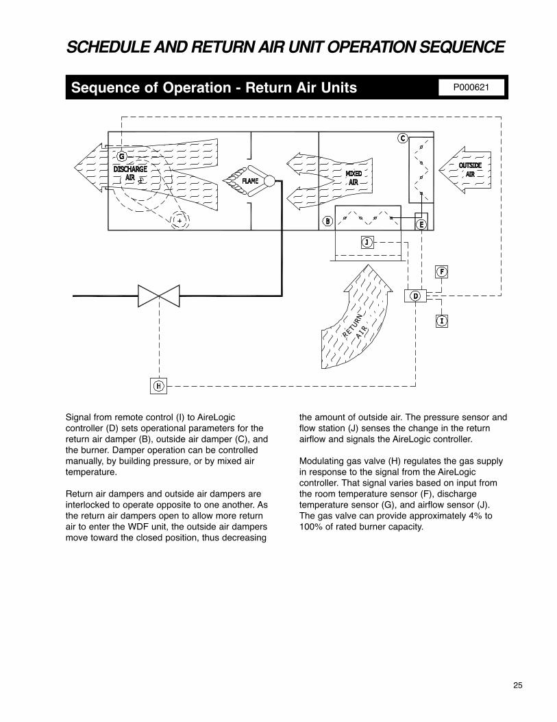
Signal from remote control (I) to AireLogiccontroller (D) sets operational parameters for thereturn air damper (B), outside air damper (C), andthe burner. Damper operation can be controlledmanually, by building pressure, or by mixed airtemperature.
Return air dampers and outside air dampers areinterlocked to operate opposite to one another. Asthe return air dampers open to allow more returnair to enter the WDF unit, the outside air dampersmove toward the closed position, thus decreasing
the amount of outside air. The pressure sensor andflow station (J) senses the change in the returnairflow and signals the AireLogic controller.
Modulating gas valve (H) regulates the gas supplyin response to the signal from the AireLogiccontroller. That signal varies based on input fromthe room temperature sensor (F), dischargetemperature sensor (G), and airflow sensor (J).The gas valve can provide approximately 4% to100% of rated burner capacity.

SPECIFICATIONS
Typical Unit Specification
Unit CasingUnit casing and accessories shall be fabricatedfrom heavy-gauge galvanized steel. The base ofthe unit shall be constructed of rigidly formed 12gauge galvanized steel with built-in curb adapter(horizontal units only). All casings shall be airtightand weatherproof. Roof panels shall be convex toprevent standing water, and designed with astanding seam to prevent water entrainment.Cabinet shall be designed with roof eaves toprevent water from getting into wall panels.Complete access shall be provided to allcomponents through gasketed, hinged accessdoors. This includes the motor, blower, burner,electrical components and manifold sections.
Blower sectionEach unit shall be supplied with centrifugal forwardcurved, DWDI fan rated in accordance with AMCAstandards. The fan shall be mounted on a heavy-duty polished steel shaft designed for a maximumoperating speed not to exceed 75% ofits first critical speed. Bearings are to be heavy-dutyindustrial prelubricated type. Blowers are to bedriven by a V-belt package sized with a capacity of25% greater than the motor horsepower. Multiplebelt applications will be matched sets. Drives are tobe (fixed)(adjustable). Motor is to be mounted onan adjustable slide base. Door safety interlock shallbe provided for protection when the blower accessdoor is opened.
Control EnclosureThe unit(s) shall be supplied with a controlcompartment and all controls mounted within thiscompartment are to be wired to a numberedterminal strip. All wiring is to be color-coded inaccordance with the NEC. A circuit diagram is to belaminated to the inside of the control cabinet door.All electrical components shall bear a recognizedlabel.
Controls1. Main fan starters and overloads2. Control circuit fuse3. High temperature limit switch4. Flame rod sensor5. Ignition module6. Main gas automatic shut-off valves7. MDT control system8. Air proving differential switches9. Factory wired motorized inlet damper complete
with end switch10. Control transformer11. Remote control panel
Furnish as base bid L.J. Wing model WDFmake–up air units designed for outdoor applicationas shown in the schedule. The unit discharge shallbe designed for easy adaptation to external ductsor optional accessories. The unit shall be capableof delivering the required heating performance atthe scheduled airflow and external static pressureusing not more than the scheduled horsepower.
Burner SectionThe standard ETL listed unit will meet ANSI, FM,and IRI requirements. Both burner and blower shallbe compensated for the altitude as shown in theschedule. Manifold to be located outside of airstream and shielded from atmospheric conditionsby means of a protective compartment with hingedaccess. An observation port shall be located toprovide view of main flame.
Unit shall be supplied with a wide range burner witha modulating turndown ratio of 25:1. Adjustableprofile plates shall be provided and sized tomaintain the required velocity across the lineburner. The operation of the burner shall beprogrammed through the ignition controller withtimed pre-purge and flame-sensed by means of aflame rod The burner assembly and gas manifoldshall be completely pre-piped and factory testedprior to shipment.
The unit shall be controlled by the AireLogic DDCcontrol module with full BACnet compatibility. Unitshall have (MDT Modulating DischargeTemperature control system)(MRT ModulatingRoom Temperature Control system)(MRT-ProModulating Room Pro Temperature ControlSystem)(MRT-Expert Modulating Room ExpertTemperature Control System). The Airelogic DDCcontrol system shall include but not be limited to thefollowing controls required for standard operation:
• Electronic time clock with normal, holiday, and override schedules. (Not available on MDT or MRT Control Systems).
• Timed freeze protection to prevent heater from discharging unheated air into the building
• Inlet on-off ductstat that will turn the burner off when the inlet temperature equals the desired discharge air temperature as fuel saving mode.
• On-off night setback thermostat for lower operating temperatures in unoccupied mode as fuel savings mode. (Not available on MDT or MRT Control Systems),
26

SPECIFICATIONS
Typical Unit Specification, continued
above the setpoint more outside air will be introduced.
• Building Pressure Mode: Provides automatic building pressure control by modulating the O.A.damper and return air damper to maintain the indoor building pressure setpoint. As the building pressure decreases below the setpoint more outside air will be introduced.
BACview Controller Display (optional)The remote keypad display for the AireLogic DDCcontrol system shall have a minimum of two lines,sixteen characters shown which shall include but notbe limited to the following:• Return air temperature• Outside air temperature• Discharge air temperature• Mixed air temperature• Maximum allowable temperature rise• Actual temperature rise• Current percent of outside air• Current building pressure (optional)• Current damper input voltage (optional)• Current burner input voltage• Fan operating hours since last rest• Fan start cycle count since last reset• Burner operating hours since last reset• Burner start cycle count since last rest• Cooling interlock operating hours since last
reset• Cooling interlock cycle count since last reset• Critical alarm conditions;� Airflow switch failure� Unit on, fan off� Unit off, fan on� Low discharge temperature� Safety circuit open� Burner jumped
The control settings available on the remote keypaddisplay for the AireLogic DDC control system shallinclude, but not be limited to, the following:• Heating setpoint• Cooling setpoint• Economizer options• Setback setpoint• Freeze protection setpoint• Maximum discharge air setpoint• Minimum discharge air setpoint• Minimum ventilation option and setpoint• Time of day schedule selection and setpoints� Normal 5/7 schedule� Holiday schedule� Manual override
Optional Accessories: 1. V-bank filter box with filters2. Inlet hood and birdscreen with or without filters3. Insulation4. Full perimeter roof curb (horizontal unit only)5. Vibration hangers6. Clogged filter switch7. Disconnect switch8. Twenty gauge cabinet liner9. High pressure regulator (required over 1/2 psig)10. Vertical arrangement with support stand and
inlet birdscreen11. Mixing dampers with return air flow station12. Internal blower/motor isolation (horizontal units only)13. Discharge nozzles14. Firestat15. 115 volt service receptacle16. BACview controller
Mixing Dampers with return Air flow Station(optional)Unit shall have outside air and return air damperswith modulating actuator controlled by a AireLogicDDC control system. The AireLogic DDC controlsystem shall have capability to digitally control theoutside air quantity from a nominal minimum of 20%to 100% with integrated gas valve control at all roomconcentrations of CO2.
The return air inlet shall include a self-calibratingflow measuring station with a grid of velocitypressure probes with spacing no greater than 12”over the entire face of the return air opening andsampled every two seconds. Samples will be addedto a twenty-five point rolling average to providesmooth accurate data that is delivered to theAireLogic DDC control system every two seconds.The DDC control system shall be capable ofelectronically displaying the return air/outside airratio within 5% accuracy at all damper positions.
The AireLogic DDC control module shall have fullBACNET compatibility. Display shall have aminimum of two line, sixteen character display.
The AireLogic DDC control system shall be capableof controlling mixing dampers in the following modesof operation:• Manual Mode: Allows manual positioning of the
outside air (O.A.) damper and return air (R.A.) damper by changing the damper position setpoint.
• Mixed Air Temperature Mode: Shall provide automatic control of the mixed air temperature by modulating the O.A. damper and R.A. damper to maintain the mixed air temperature setpoint. As the mixed air temperature increases
27

28
SCHEDULE
Typical Schedule:4 egap no elpmaxe morF
latoT renruBriA retniW lacirtcelErotoMcitatStupnI.pmeTngiseDwolfriA
ecivreSrewopesroHerusserPetaResiR.pmeTetaR ledoM)zH/.hp/tlov()PH().c.w sehcni()HBM()F seerged()F seerged()MFCS(.on
06/3/032385.11820801-000,3SRH-530-FDW
4830 Transport Drive, Dallas, TX 75247Tel. (214) 638-6010 Fax (214) 905-0806
www.ljwing.comPrinted in USACopyright USA, 2006