
monte carlo simulation of pulverized coal-fired power plants ...
Upload
khangminh22Category
view
0download
0
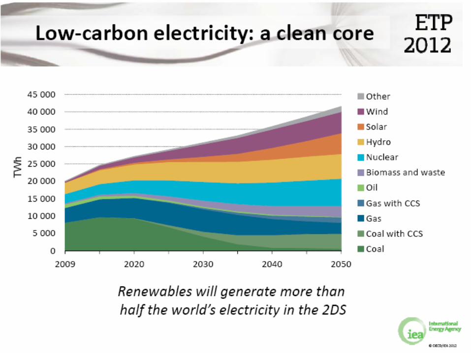
CO2 Capture for Coal Fired Power Plant The Challenges Ahead...
Stanley Santos IEA Greenhouse Gas R&D Programme
Cheltenham, UK
CCS Opportunities in CCOP Region CCOP-EPPM Workshop (Indonesia)
September 2012

2
IEA GHG Introduction
• IEA Greenhouse Gas R&D Programme (IEA GHG) • What is programme’s relation to the
International Energy Agency (IEA)? • What the Programme does? • Who are the members? • What role do we play in a global CCS
context?

3
International Energy Agency
• The International Energy Agency (IEA) is an intergovernmental organisation which acts as energy policy advisor to 28 member countries in their effort to ensure reliable, affordable and clean energy for their citizens.
• Founded during the oil crisis of 1973-74, the IEA’s initial role was to co-ordinate measures in times of oil supply emergencies. • 1st Implementing Agreement under IEA is the IEA Clean
Coal Centre

4
IEA Greenhouse Gas R&D Programme Our Relation to the International Energy Agency
IEA GHG is one of 40 organisations having
an implementing agreement with IEA

5
IEA Greenhouse Gas R&D Programme • A collaborative research programme founded in 1991 as
an IEA Implementing Agreement fully financed by its members • Aim: Provide members with definitive information on the role that
technology can play in reducing greenhouse gas emissions. • Scope: All greenhouse gases, all fossil fuels and comparative
assessments of technology options. • Focus: On CCS in recent years
• Producing information that is: • Objective, trustworthy, independent • Policy relevant but NOT policy prescriptive • Reviewed by external Expert Reviewers • Subject to review of policy implications by Members

6
Members and Sponsors

7
IEAGHG Activities • Task 1: Evaluation of technology options
• Based on a standard methodology to allow direct comparisons and are peer reviewed
• Task 2: Facilitating implementation • Provision of “evidence based information”
• Task 3: Facilitating international cooperation • Knowledge transfer from existing, laboratory, pilot
and commercial scale CCS projects globally • Task 4:To disseminate the results as
widely as possible.

8
Specific Area of Focus for CO2 Capture Technology • Power Sector
o Coal, Natural Gas and Biomass
• Industrial sectors o Gas production o Oil Refining & Petrochemicals o Cement sector o Iron & Steel Industry
• Cross cutting issues o Policy/Regulations o Health & Safety o Transport & System Infrastructure

9
Global Policy Context
• National/Corporate policy setting
• National/Corporate research programmes
• Implementation actions
• International Policy Setting

10
Dissemination

11
Over the past 20 years... Growth in Interest in CCS has been significant
0
200
400
600
800
1000
1200
1400
1600
1800
Conference Attendees
0
200
400
600
800
1000
1200
Papers Received
GHGT-11 18th-22nd Nov. 2012 Kyoto, Japan www.ghgt.info
• 1220 Abstracts submitted • a new record
• Registration now open…

12
Overview
• Why we need CO2 capture and storage? • An Overview to CO2 CaptureTechnologies
• Post Combustion CO2 Capture • Oxyfuel Combustion with CO2 Capture • Pre-Combustion CO2 Capture
• Some of the Challenges, Key Issues and Direction of Research
• Concluding Remarks

13
WHY WE NEED CO2 CAPTURE AND STORAGE
Introduction

14

15
16
17

18
CO2 CAPTURE TECHNOLOGY FOR POWER GENERATION -AN OVERVIEW
Introduction

19
What is CCS?
Capture Transport
Storage
85-95%
• Post Combustion • Pre Combustion • Oxy fuel
• Pipelines • Ships
• Coal seams • Oil and gas fields • Deep saline aquifers • Basalt/ Organic-rich
Shales

20
EPRI 2007
CO2 Capture Options

21
CO2 Abatement from Coal Fired Power Plants Requires a Twin Track Approach…

22
POST COMBUSTION CO2 CAPTURE TECHNOLOGY FOR COAL FIRED POWER GENERATION

23
Post-Combustion Capture
Fuel Boiler or gas turbine
Solvent scrubbing
(FGD)
Air
Power CO2 to storage
N2, O2, H2O to atmosphere
Steam turbine
Steam
CO2 compression
Capture Power generation

24
CO2 Based Solvent Scrubbing • Use of Amine scrubbing to capture CO2 is the
most mature among the 3 mostly considered capture technology options for the power generation.
• Amine based solvent is currently the commonly used for CO2 capture • widely used in food processing (ie. carbonated drinks)
and chemical industries (ie. Urea plant) • Large scale demonstration (> 1 MT/yr of scale) – mostly
in oil and gas fields applications • For example in Sleipner and In Salah • New projects such as Gorgon ( ~ 3 MT/yr in scale) using
parallel train of post-capture gas treatment plant

25
Representation of CO2 removal from natural gas processing

26
Representation of CO2 removal from flue gas

27
Challenges to Post CO2 Combustion Capture
• Low total flue gas pressure • Low CO2 concentrations • Very high flow rates (Huge columns) • High energy demand in the reboiler
(25-35% of power plant output) • Impurities cause solvent
degradation, loss of performance and equipment corrosion
• Solvent losses and waste products • Emissions from CO2 capture plant
Picture: Mongstad Large Scale Pilot (TCM)

28
Issues for Post Combustion Capture
• Issues to be addressed in the development of Post Combustion Technologies: Increase in cost of electricity Reduction in Power Plant Efficiency
• Solvent Process break-through required Energy requirements Reaction rates Contactor improvements Liquid capacities Chemical stability/corrosion Desorption process improvements
• Integration with power plant Heat integration with other process plant Concepts for “capture readiness”

29
CO2 Capture Plant (Conventional Absorber Column Configuration)

30
CO2 Capture Plant (Split Flow and Inter-cooling Configuration)

<Experience and R&D Facilities> MHI’s Evolution Development of Flue Gas CO2 Recovery Plant
00 01
Commercial Plant
Enlargement
Coal Fired Flue Gas
Application
09 08 07 06 05 04 03 02 99 98 97 96 95 94 93 92 91 90 Evolution
1 Ton/Day Pilot Test Completed
Long Term Demo. Plant
3000 Tonnes /Day Design Completed
6000 Tonnes/Day Design Completes
Large Scale Demonstration Plant Design Ready
Nanko Pilot Plant (2 Tonnes/day)
Malaysia Kedah (200 Tonnes/day)
R&D for Process Improvement
Japan, Chemical Company (330 Tonnes/day)
India, Fertilizer Company (450 Tonnes/day x 2) Abu Dhabi, Fertilizer Company
(400 Tonnes/day)
1 Ton/Day Pilot Plant Test Starts
330 Tonnes/day Plant
Long Term Demo. Plant
3000 Tonnes /Day Plant Large Scale Test Plant
FGD Experience
Start of Development
Malaysia kedah Plant

32
Post Combustion Capture Development Process Concept Example Developers Conventional MEA Econamine + Fluor, ABB
Ammonia Chilled Ammonia Alstom
Hindered Amines KS-1, AMP, … MHI, EXXON,
Tertiary Amines MDEA BASF, DOW
Amino Acid Salts CORAL TNO, Siemens, BASF
Potassium Carbonate
K2CO3 CO2CRC, Uni Texas
Piperazine Uni Texas
HiCapt, DMX Mixture IFP
Integrated SO2/CO2 Amines Cansolv/Shell
Amine Aker Clean Carbon
Chemical solvents DEAB, KoSol, Calcium based, HTC, Uni Regina, KEPRI, NTNU, SINTEF, CSIRO, KEPRI, EnBW
Ionic liquids Univ of Leoben
Adsorbents MOFs, Immobilized amine sorbents, HMS, regenerable sorbents
NETL
Membrane Selective, FTM, Module TPS, TNO, NETL,

33
Post Combustion: Where to Focus
• Novel solvents: Higher capacity, lower reaction enthalpy, stable and cheaper
• Smart process concepts and heat integration
• Capture environmental impact
• Cheaper equipments (absorber > 45% of CAPEX)
• Membranes, adsorbents and other processes have the potential as 2nd/3rd generation
Source: Figueroa et al., 2008

34
What’s Next
Nanko Pilot Plant (2t/d)
Pilot Plants
Commercial Scale Demonstration
MHI Large Scale Demo Unit
Boundary Dam – Under Construction
Castor Pilot Plant (2t/d)

35
OXYFUEL COMBUSTION CO2 CAPTURE TECHNOLOGY FOR COAL FIRED POWER GENERATION

36
Fuel Boiler Purification/ compression
Cooling (+FGD)
Air separation
Air
Power
Oxygen
CO2
Vent Recycled flue gas
Steam turbine
Steam
Oxy-Coal Combustion Technology

37 37
Oxy-Combustion Technology • Use of oxygen instead of air in a boiler –
“Oxy-Combustion” is a feasible option for power plant with CO2 capture. With continuous demonstration of this technology... It is catching up!!!
• 3 key development issues • Boiler and burner development • Air Separation Unit – “Cost of Oxygen production” • CO2 processing – What could be a viable purity for
storage ???

38
Oxyfuel Combustion Overall Schematic Diagram

39
HP HEATER
MILL
HP PUMP
LP HEATER
STACK (START
UP)
ESP
ID FAN DEAERATOR
COAL
HP
IP
LP
CONDENSOR
COLD FD FAN
LP PUMP
AIR IN
ADVANCED SUPERCRITICAL BOILER
FGD
Radiant Section of the Boiler • heat transfer profile • slagging issue • fireside corrosion issue
Convective Section of the boiler • heat transfer profile • ash deposition and fouling issue
Burner design issue • Ignition • flame stability • devolatilisation & char burnout
Prior to any retrofit of carbon capture technology, it is essential to repower
the plant in order to achieve the highest possible efficiency

40
HP HEATER
MILL
3
HP PUMP
LP HEATER
1 - IP STEAM BLEED 2 - HEAT FROM ASU ADIABATIC MAC 3 - CO2 COMPRESSOR STAGE HEAT 4 – FLUE GAS FEEDWATER HEATING
4
GAS DRIER
STACK (START
UP)
ESP
AIR INTAKE
START UP
ID FAN
FD / RECYCLE
FAN
GAS
/
GAS
DEAERATOR
COAL
NITROGEN
AIR
ASU
ADVANCED SUPERCRITICAL BOILER
HP
IP
LP
CONDENSOR
COLD PA FAN
SECONDARY RECYCLE
LP PUMP
GAS COOLER & WATER REMOVAL
CO2 PRODUCT FOR COMPRESSION
PRIMARY RECYCLE
OXYGEN
4
1 2 3 4
3 4
CO2 PURIFICATION
INERTS
2
3
Gas / Gas
Heater

41
ANL - EERC Study World’s 1st Oxy-Coal Combustion Industrial Pilot Scale Study Tower Furnace (~ 3MWth)

42
Today... There are 3 Major Full Scale PC Burner Testing Facilities Worldwide Retrofitted for Oxyfuel
• Babcock and Wilcox (B&W) 30MWth CEDF
• Barberton, Ohio, USA • Start of Operation: Oct. 2008 • Wall Fired Burner
Development
42
• Doosan Babcock – 40MWth in 90MWth MBTF
• Renfrew, Scotland, UK • Start of Operation: Jun. 2009 • Wall Fired Burner
Development
• Alstom Power Plant Lab. – 15MWth in 30MWth BSF
• Windsor, Connecticut, USA • Start of Operation: Nov. 2009 • T-Fired Burner Development
Courtesy of Alstom, B&W and Doosan Babcock

43
Oxygen Production
• As of today, the only available technology for oxygen production in large quantities is cryogenic air separation.
• Advances and Development in ASU could result to 25% less energy consumption. • These design would be based on either a
3 column design or dual reboiler design.

Bey/L/092009/Cottbus.ppt Linde AG Engineering Division 44
Cryogenic Air Separation – Capacity Increase
1902 : 5 kg/h (0,1 ton/day)
2006 : 1,250 Mio kg/h (30.000 ton/day)

45
Points for Discussion… • ~10,000 TPD of O2 is required for a 500MWe (net)
oxy-coal power plant with CCS. • This means that you will need 2 single trains of 5000 TPD O2
• Largest operating ASU today (single train) ~4000 TPD O2.
• Some of the Engineering Considerations • What could be the maximum capacity of oxygen production
per train? • Operation flexibility (i.e. load following, etc…) • What will you do about the large volume of Nitrogen
produced from this ASU?
45

46
Challenges to CO2 Processing Unit • The CO2 processing unit could be very
competitive business (an important growth area) for industrial gas companies.
• Challenges are: • Demand of the quality requirements of the CO2 from the
power plant for transport and storage. What are the Required Specification?
• Further recovery of CO2 from the vent will make oxyfuel more competitive if high recovery of CO2 is required!
• Need a large scale demonstration of the CO2 processing unit using impure CO2 as refrigerant.

47
72%mol CO228% inerts(~ 5 - 6% O2)
99.999%mol CO2
0.001% inerts(~ .0005% O2)
25%mol CO2
75% inerts (~ 15% O2)
76%mol CO224% inerts (~ 5 - 6% O2)
96%mol CO24% inerts (~ 0.95% O2)
25%mol CO275% inerts (~ 15% O2)
72%mol CO2
28% inerts(~ 5 - 6% O2)
98%mol CO2
2% inerts(~ 0.6% O2)
25%mol CO2
75% inerts(~ 19% O2)
72%mol CO2
28% inerts(~ 5 - 6% O2)
99.95%mol CO2
0.05% inerts(~ .01% O2)
25%mol CO2
75% inerts(~ 15% O2)

1980’s
ANL/Battelle/EERC completed the first industrial scale pilot plant
1990 - 1995
EC Joule Thermie Project - IFRF / Doosan Babcock / Int’l Combustion NEDO / IHI / Jcoal Project
First large scale 35MWt Oxy-Coal Burner Retrofit
Test done by International Combustion
1998 – 2001
CANMET US DOE Project / B&W / Air Liquide
2003 - 2005
Vattenfall (ENCAP ++) CS Energy / IHI Callide Project
B&W CEDF 2008 30MWth Coal Alstom Alstom CE 2010 15MWth Coal Doosan Babcock DBEL - MBTF 2009 40MWth Coal
Alstom Schwarze Pumpe 2008 30MWth Lignite Hitachi Babcock Schwarze Pumpe 2010 30MWth Lignite IHI Callide 2011 30MWe Alstom / AL Lacq 2009 30MWth Gas/Oil? CIUDEN El Bierzo CFB Facility 2011 30MWth Coal
El Bierzo PC Facility 2011 20MWth Coal
Coal
CIUDEN
2007
B&W CEDF (30MWt) large scale burner testing started
Updated by S. Santos (20/08/12)
2008
World’s FIRST 30 MWt full chain demonstration at Schwarze Pumpe Pilot
Plant
By the end of 2010/2011, Users (i.e. Power Plant
Operators) will have 6 burner manufacturers fully
demonstrating “Utility Size Large Scale Burners” which should give a high level of confidence
toward demonstration
2009 – Lacq – World’s first 30MWt retrofitted Oxy-NG
boiler 2011 – CIUDEN –
World’s first 30MWt Oxy-CFB Pilot Plant
2011 – Callide – World’s first
30MWe retrofitted Oxy-coal power
plant
By 2014-2018
Demonstration of 50– 300MWe full scale power plant.
Target : “Commercialised by 2020”
KEPCO/KOSEP - Yongdong (PC - 100MWe) FutureGen2 - Illinois (PC - 168MWe)
Endesa/CIUDEN - El Bierzo (CFB - 300MWe) - ???
China: 3 Oxyfuel Projects – in progress UK: Drax Power Plant Oxyfuel


51
CIUDEN CO2 Capture Programme. • First oxyfuel pilot plant that will
demonstrate in large scale the Oxy-CFB technology.
• Oxy-PC facility is very complimentary to Vattenfall’s and Callide’s facilities.
• Could be in a unique position to provide information related to the burner – burner interaction (in smaller scale).
• 1st facility to investigate Anthracite (this would be first in the world), Petcoke and Biomass.

52
CS Energy/IHI Burner Testing Programme at Callide A Power Station
• Callide A Project – would be the world’s 1st oxyfuel retrofitted power station. • First oxyfuel pilot plant that will actually
produce electricity. • Installation of 2 new Wall Fired Burners • A unique position to provide information
related to the burner – burner interaction • Project Scope (2-4 years operation):
o Oxygen plant (nominal 2 x 330 tpd ASUs) o Boiler refurbishment and oxy-fuel retrofit (1 x 30
MWe Unit) o CO2 compression & purification (75 tpd process
plant from a 20% side stream) o Road transport and geological storage (~ 30 tpd
liquid CO2)
52
Courtesy of CS Energy, IHI

53
• Awarded US$ 1 billion AARA funding (September 2010) • Meredosia Power Plant (Originally owned by Ameren)
• Oil fired power plant (200MWe) – build in 1975 • Boiler will be replaced to fire Illinois Coal (3.2% S)
• Morgan County for Storage Site • 32 miles from the Meredosia • Deep Saline Formation at a depth of 4500 ft (~1,375 m)
FUTUREGEN2 Project (Pictures from B&W)

54
PRE COMBUSTION CO2 CAPTURE TECHNOLOGY FOR COAL FIRED POWER GENERATION

55 55
Pre-Combustion Capture
Coal Gasification Acid gas removal
Shift conversion
Air separation
Combined cycle
Air
Fuel gas (mainly H2)
Nitrogen Power
Oxygen
CO2 CO2 compression
Sulphur
Air
H2S
Air
CO+H2O→H2+CO2
• IGCC with CO2 capture
Sulphur recovery
56
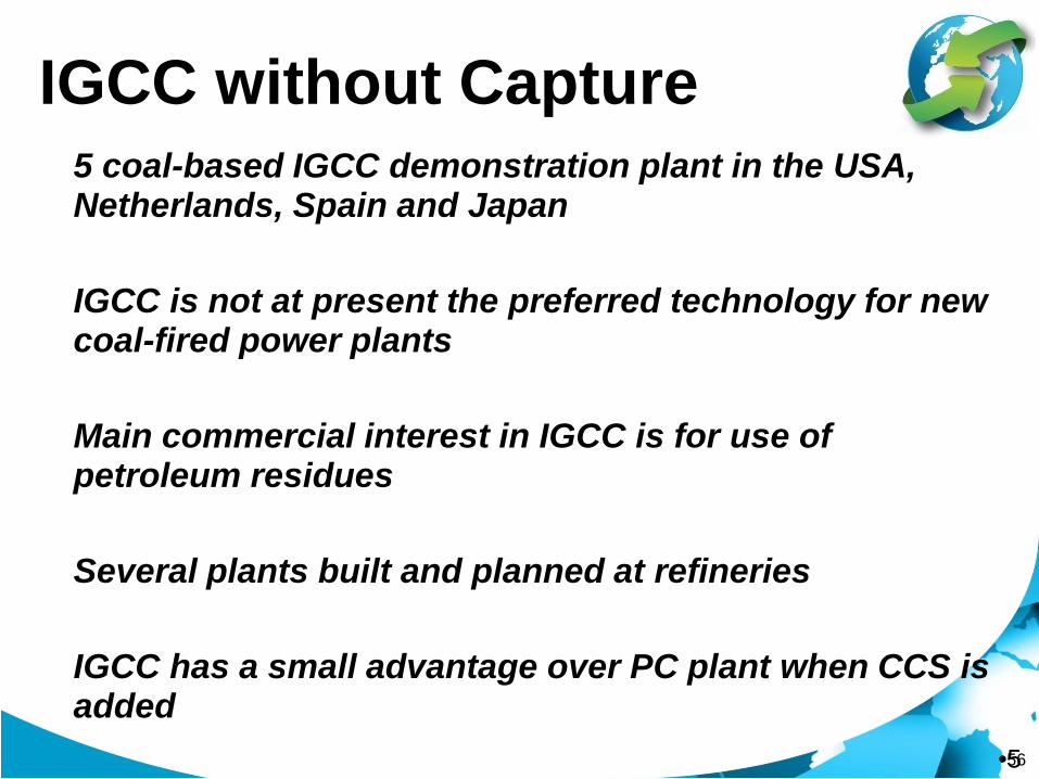
IGCC without Capture • 5 coal-based IGCC demonstration plant in the USA,
Netherlands, Spain and Japan • IGCC is not at present the preferred technology for new
coal-fired power plants
• Main commercial interest in IGCC is for use of petroleum residues
• Several plants built and planned at refineries
• IGCC has a small advantage over PC plant when CCS is added
•5

57
Coal IGCC in Operation Worldwide
•5

58
IGCC – Currently in Operation Nuon – Buggenum 250 MWel
JPower – Fukushima 250 MWel

59
GREENGEN IGCC Laboratory (Under Commission and Fully Operational by 2012)
Data and Information from China Huaneng Group (2011)
60
Overview of Pre-Combustion Technology
• Pre-combustion capture process is not a new concept • Primarily based on production of synthetic gas, separating the CO2
and using the decarbonised syngas as fuel for the gas turbine
• One of the main elements is the gasification of the fuel feedstock to produce syngas
• Gasification technologies could produce a waste gas stream, which has high concentration of CO2
• This offers an opportunity to capture CO2 at low cost
• It should be noted that CO2 capture is not a process requirement, but could be easily implemented if warranted

61
62
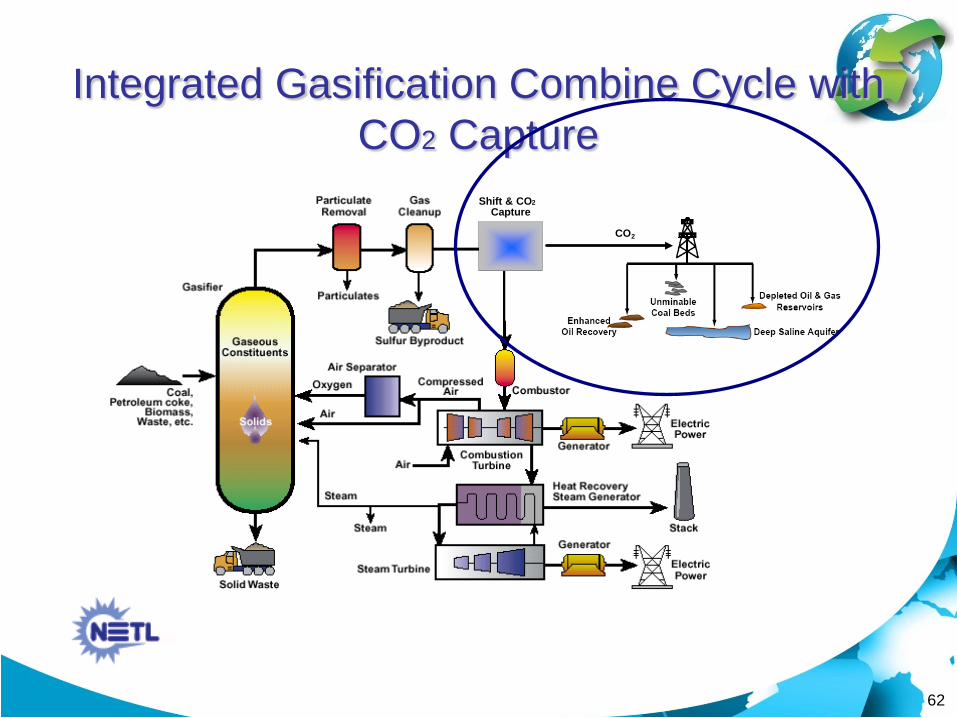
Integrated Gasification Combine Cycle with CO2 Capture
Shift & CO 2 Capture
CO 2
Shift & CO2 Capture
CO 2

63
Shift Reactor
Shift conversion CO+H2O→H2+CO2
Steam
syngas from the gasifier island
Shifted Syngas
Most Important Operating Parameter: Catalyst will determine the type of syngas processing required!

64
CO2 Capture via Physical Absorption
• Separation is primarily based on Henry’s Law • Due to high partial pressure of CO2
• The absorption capacity of organic or inorganic solvents for CO2 increases with increasing pressure and decreasing temperature.
• Absorption of CO2 occurs at high partial pressures of CO2 and low temperatures. The solvents are then regenerated by either heating or pressure reduction.
• Most well known commercial processes/solvents • Selexol (dimethylether of polyethylene glycol) • Rectisol (cold methanol)

65
Rectisol Units of Dakota Gasification Plant

66 66
Pre-Combustion Capture: Key Barrier
• Will reliability hinders the deployment of IGCC?
• Record for IGCC’s availability has been poor but improving.
• Complexity of the plant could be a turn off to prospective investors or power generation company
• Cost is another issue Source: EPRI

67 •6
Pre-Combustion Capture: Key Development Area
• Development in Gasifier Technology • Adaptation of the Gasifier for CO2 capture...
• Development in Air Separation Units
• Membrane Technology???
• Development in Shift Reactor • Choice of Sour vs Sweet Shift Reaction
• Development in Separation of CO2 using Physical
Absorption technology

68
Uhde Prenflo Design Modification for CO2 capture application...

69
Development in Gas Turbine Technology: Horizontal Silo
Air Inlet
Expansion Turbine
COMPRESSOR
Combustion Chamber (2)
Combustion Chamber (2)

70
Development in Gas Turbine Technology: Annular Combustor

71
Kemper County IGCC Project (Data and Pictures from SECARB Review Presentation)

72
SUMMARY AND KEY MESSAGES Concluding Remarks

73 73
Concluding Remarks • CCS will play an important role in reducing greenhouse
gas emissions from the power generation sector. • Several activities have been initiated worldwide in the
development of Carbon Capture for Power Generation industry.
• There are two set of horse race among the three options for newly build and retrofit plant. There is no leader at the moment!
• We need large scale demonstration of the carbon capture technology to build the confidence necessary for a rapid deployment.
• We need to overcome the challenges that CCS should face toward its path to commercialisation.

75
Power Generation Efficiency
0
10
20
30
40
50
60
Post-comb
IGCCslurry
IGCC dry Oxyfuel Post-comb
Oxyfuel
Without capture With capture
75
Efficiency, % LHV
Source: IEA GHG studies
Coal Natural gas

76
Capital Cost
0
200
400
600
800
1000
1200
1400
1600
1800
2000
PostFluor
PostMHI
IGCCslurry
IGCCdry
Oxyfuel PostFluor
PostMHI
Oxyfuel
Without capture With capture
76
Source: IEA GHG studies
US $/kW
Coal Natural gas
Based on 1 US $/Euro

77
Cost of Capture and Storage
0
2
4
6
8
10
0 1 2 3 4 5 6
Fuel cost, $/GJ (LHV)
PF-CCS
IGCC-CCS
NGCC-CCS
PF
IGCC
NGCC
77
Electricity cost, US c/kWh
Basis: 10% DCF, 25 year life, 85% load factor, $8/t CO2 stored
Copyright © 2022 FDOKUMEN