Comparison of CO2 capture by ex-situ accelerated carbonation and in in-situ naturally weathered coal...
10
This article appeared in a journal published by Elsevier. The attached copy is furnished to the author for internal non-commercial research and education use, including for instruction at the authors institution and sharing with colleagues. Other uses, including reproduction and distribution, or selling or licensing copies, or posting to personal, institutional or third party websites are prohibited. In most cases authors are permitted to post their version of the article (e.g. in Word or Tex form) to their personal website or institutional repository. Authors requiring further information regarding Elsevier’s archiving and manuscript policies are encouraged to visit: http://www.elsevier.com/authorsrights
-
Upload
geoscience -
Category
Documents
-
view
0 -
download
0
Transcript of Comparison of CO2 capture by ex-situ accelerated carbonation and in in-situ naturally weathered coal...
This article appeared in a journal published by Elsevier. The attachedcopy is furnished to the author for internal non-commercial researchand education use, including for instruction at the authors institution
and sharing with colleagues.
Other uses, including reproduction and distribution, or selling orlicensing copies, or posting to personal, institutional or third party
websites are prohibited.
In most cases authors are permitted to post their version of thearticle (e.g. in Word or Tex form) to their personal website orinstitutional repository. Authors requiring further information
regarding Elsevier’s archiving and manuscript policies areencouraged to visit:
http://www.elsevier.com/authorsrights

Author's personal copy
Comparison of CO2 capture by ex-situ accelerated carbonationand in in-situ naturally weathered coal fly ash
Grace N. Muriithi a,*, Leslie F. Petrik a, Olanrewaju Fatoba a, Wilson M. Gitari b,Frédéric J. Doucet c, Jaco Nel d, Sammy M. Nyale a, Paul E. Chuks a
a Environmental Nano Sciences Group, Chemistry Department, University of the Western Cape, South AfricabDepartment of Ecology and Resource Management, School of Environmental Studies, University of Venda, South Africac Industrial Mineralogy Laboratory, Council for Geoscience, Pretoria, South AfricadUNESCO Chair in Hydrogeology, Department of Earth Sciences, University of the Western Cape, South Africa
a r t i c l e i n f o
Article history:Received 23 October 2012Received in revised form7 March 2013Accepted 15 May 2013Available online
Keywords:Ash damFly ashWeathered ashEx-situ mineral carbonationCO2 capture
a b s t r a c t
Natural weathering at coal power plants ash dams occurs via processes such as carbonation, dissolution,co-precipitation and fluid transport mechanisms which are responsible for the long-term chemical,physical and geochemical changes in the ash. Very little information is available on the natural carboncapture potential of wet or dry ash dams. This study investigated the extent of carbon capture in a wet-dumped ash dam and the mineralogical changes promoting CO2 capture, comparing this natural phe-nomenon with accelerated ex-situ mineral carbonation of fresh fly ash (FA). Significant levels of traceelements of Sr, Ba and Zr were present in both fresh and weathered ash. However Nb, Y, Sr, Th and Bawere found to be enriched in weathered ash compared to fresh ash. Mineralogically, fresh ash is made upof quartz, mullite, hematite, magnetite and lime while weathered and carbonated ashes containedadditional phases such as calcite and aragonite. Up to 6.5 wt % CO2 was captured by the fresh FA with a60% conversion of calcium to CaCO3 via accelerated carbonation (carried out at 2 h, 4Mpa, 90 �C, bulk ashand a S/L ratio of 1). On the other hand 6.8 wt % CO2 was found to have been captured by naturalcarbonation over a period of 20 years of wet disposed ash. Thus natural carbonation in the ash dumps issignificant and may be effective in capturing CO2.
� 2013 Elsevier Ltd. All rights reserved.
1. Introduction
Owing to the heavy reliance on fossil fuels for power generationin the world today, the level of carbon emissions has risen leadingto enhanced global warming which is accompanied by climatechange in various parts of the world (IPCC, 2007). Globally coalcombustion accounts for over 42% of the carbon emissions while inSouth Africa, the electricity generating industry produced 230.3 Mtof CO2 in 2011 (Eskom, 2011). Curtailing the CO2 emissions fromcoal combustion is thus vital in climate change mitigation. Variousmechanisms are being sought to deal with carbon emissionsreduction and global warming mitigation. Among these are carboncapture and storage (CCS) in geological formations (e.g. deep salinereservoirs, unminable coal beds, depleted oil/gas reservoirs,basaltic rocks, enhanced coal bed methane, enhanced oil recoveryetc.). Mineral carbonation is an increasingly promising optionwithin the CCS portfolio (Doucet, 2011) and demonstration plants
of up to 1 Mt CO2 per annum may be operational as early as 2020(Zevenhoven et al., 2011). There are large deposits of natural silicateminerals that can be used for mineral carbonation, in addition toalkaline waste materials such as FA, steel furnace slag, cement slagand mine tailings.
One of the advantages of mineral carbonation over geo-sequestration is the stability of the formed carbonated productsover extended periods of time. Thus there would be little need tomonitor the disposal sites and the associated risks would be verylow. Eskom, the main power generator in South Africa, consumed124.7 Mt of coal producing 36.2 Mt of FA in 2011 (Eskom, 2011).Only 5% of generated ash is recycled in the form of building ma-terials such as bricks and as a cement extender while the unused FAis disposed in ash handling dams which require maintenance andeventual rehabilitation. Water requirements are high in powergeneration; for instance the Sasol Secunda plant (South Africa) uses255Ml/day of freshwater for steam generation, process cooling andas feedwater for its coal to liquid fuel and other chemical processes.
Pre-treatmentof rawwater (consistingof90%minewaterand10%cooling water blow down) by desalination leads to the formation of
* Corresponding author. Tel.: þ27 219593873; fax: þ27 219593878.E-mail addresses: [email protected], [email protected] (G.N. Muriithi).
Contents lists available at SciVerse ScienceDirect
Journal of Environmental Management
journal homepage: www.elsevier .com/locate/ jenvman
0301-4797/$ e see front matter � 2013 Elsevier Ltd. All rights reserved.http://dx.doi.org/10.1016/j.jenvman.2013.05.027
Journal of Environmental Management 127 (2013) 212e220

Author's personal copy
waste brines. These are highly saline solutions usually containingtotal dissolved solids (TDS) of over 35,000 mg/L and enriched in Ca,Na, K, SO4, Cl andMg (Petrik et al., 2007). Also present are traces of Fe,Mn, Cr, V, Ti, P, Si and Al (Mooketsi et al., 2007). In Secunda forinstance, the brine streams are used for the hydraulic transport of FAusually in the form of a slurry which is then stockpiled in ash dams.Ingress of atmospheric CO2 is believed to influence the weatheringand maturation of FA. Basic oxides such as lime, portlandite andpericlase present in FA are expected to convert to their respectivecarbonate forms with time (Yeheyis et al., 2009).
Accelerated mineral carbonation which mimics natural weath-ering processes in which calcium or magnesium silicates are trans-formed into carbonates could be significant in the proximity of theemission sources without the need of storing the gas into geologicalreservoirs. Several authors have noted that carbonation is effective inminimizing build-up of calcium in the leachate of landfills thuscarbonationmay reduce themobility of tracemetals in alkaline FA atelevatedpHvalues (Reddyetal.,1994;Meimaetal., 2002;Ecke,2003;Kim et al., 2003). Carbonation has also been investigated as a tech-nology for the stabilization of municipal solid waste incineration(MSWI) ash prior to disposal (Ecke (2003); Ecke et al. (2002); Wu-Jang et al. (2007) and Rendek et al. (2006)). Various authors(Montes-Hernandez et al. (2009); Soong et al. (2006) and Muriithiet al. (2011)) have studied the carbonation potential of coal com-bustion FA. They suggested that carbonation occurs in two successivereactions, firstly the irreversible hydration of lime present in the ashand secondly the spontaneous carbonation of the calciumhydroxidesuspension. This paper seeks to investigate natural carbonation as astabilization reaction during environmental weathering and as a CO2capture process, probing themineralogical changes occurring and tocompare this with accelerated carbonation. The novelty of this studywasfirst to investigate thepotential of ashdams to capture CO2 in thenatural set-up as well as to compare the CO2 capture capacity of theash dams to accelerated ex-situmineral carbonation in terms of timefactor and the resultant changes in the carbonated ash and weath-ered ash. It is envisaged that this study will form a basis for furtherstudies involving natural carbonationphenomena in the ashdisposalsites.
2. Materials and methods
2.1. Sample collection, preparation and characterization
Both fresh and weathered coal FA was obtained from Secundapower plant owned by Sasol Synfuels (the petro-chemical companyin South Africa).
For the weathered ash, a combination of air flush coring anddirect circulation air percussion drilling were used to drill the
boreholes at the ash dam while fresh ash was obtained directlyfrom the precipitators. Air flush coring uses a conventional drillingrig and compressor with a specialized drill bit that cores the ashwithout the need for water or lubrication for cooling of the drill bit(Fig. 1 below).
The advantage of using this air drilling technique is that thecoring method does not use water to cool down the drill bits as innormal rock coring. The samples therefore remain chemically un-changed and physically intact. An initial starter hole was drilledusing air percussion through the overburden, to the top of the ashdam. The air flush coring technique was then used further down tothe bottom of the ash (Akinyemi et al., 2012). Fresh FA was char-acterized and used in the carbonation experiments in the labora-tory while weathered ash was characterized and evaluated for CO2capture potential. The power plant applies wet disposal techniquefor its ash disposal and the specific site cored has an approximateage of 20 years. During wet disposal, FA is mixed with brine efflu-ents from the water circulation system to form a slurry which istransferred to the disposal site via pipes. The slurry is then stackedin a “pancake-like layering” as each layer is left to settle for sometime before the next layer can be dumped. The ash settles and thebrine percolates into clear effluent dams where the salty water isrecycled. A schematic of the ash handling system at the powerstation is shown in Fig. 2.
An Abem SAS 1000 terrameter and ES 464 switching unit wereused for geophysics survey. The electrical resistivity method wasapplied to establish variations in ash characteristics, salt depositionand water level distribution in the subsurface. Four multicore ca-bles and stainless steel pegs were used with the “roll-along”surveying method. Measurement of the ground resistivity wascarried out by transmitting a controlled current (I) between twoelectrodes pushed into the ground, while measuring the potential(V) between two other electrodes. The resistance (R) was calculatedusing Ohm’s law. The profile was surveyed using a 10 m electrodeseparation with the Schlumberger protocol up to a depth ofapproximately 80 m.
The elemental and mineralogical compositions of fresh andcarbonated FA samples were analysed using XRF (Philips PW 1480X-ray fluorescence spectrometer equipped with a chromium tubeoperating at 40 kV and 50 mA for major elements and at 50 kV and40 mA for trace elements) and XRD (PANanalytical X’Pert Propowder diffractometer with X’Celerator detector and variabledivergence and receiving slits with Fe filtered Co-Ka radiation)respectively. Morphological analysis of fly ash samples was per-formed using high vacuum SEM (Hitachi X-650 Scanning ElectronMicroanalyser equipped with a CDU- lead detector at 25 kV and atungsten filament). Anions in the brine were analyzed using aDionex DX-120 ion chromatograph with an Ion Pac AS14A column
Fig. 1. Air flush core barrel and core inside the barrel.
G.N. Muriithi et al. / Journal of Environmental Management 127 (2013) 212e220 213

Author's personal copy
and AG14-4 mm guard column. Major cations on the other handwere analyzed using a Varian Radial ICP-OES, while trace cationswere analyzed on an Agilent 7500ce ICP-MS, using a High MatrixIntroduction (HMI) accessory and He as collision gas. The totalcarbon content of weathered ash was determined by carbon andsulfur analysis (C&S) (Eltra CS 800 Double Dual Range systemequipped with four infrared absorption detectors), while theircarbonate content was obtained using Chittick tests according toDreimanis (1962). The Chittick tests were done by reacting FAsuspensions (1.70 g of FA suspended in a 1-L solution containing100 g of NaCl, 1 g of NaHCO3, 2 ml of methyl orange, where suffi-cient H2SO4 was added to turn the solution a deep pink color) with20 ml of 6 N HCl and recording the amount of CO2 evolved byreading the displacement of the reservoir fluid. The displacement ofthe colored liquid in the burette by evolving CO2 was read after1 min and after 20 min. The reading at 1 min was recorded as R1while that at 20 min was recorded as R20. A schematic represen-tation of the Chittick test set-up is illustrated in Fig. 3.
Correction factors were calculated for each reading and used todetermine the % CaCO3. This was done by reacting 0.10 g of pureCaCO3 through the same process as for the FA samples. The factor isgiven as:
f ¼ W*T1:22*V
(1)
where:
W ¼ weigh of pure CaCO3 (g)T ¼ temperature of measurement (�K)V ¼ volume of CO2 produced (ml)
The above correction factor was used to calculate the % CaCO3
(based on 1.7 g of dried FA) as follows:
E ¼ CR � ð0:04ÞðCR20 � CR1Þ (2)
where
CR1 ¼ reading at 1 min *fCR20 ¼ reading at 20 min *f
%CaCO3 ¼ 0:232E (3)
2.2. Accelerated mineral carbonation
Four parameters were investigated in the accelerated carbon-ation experiments. These include particle size (<20 mm,<150 mm,>150 mmand bulk ash), temperature (30 �C or 90 �C), pressure (1Mpaor4Mpa) and solid (FA) to liquid (brine) ratio (S/L; 0.1, 0.5or1). 80mlof brine was used in all the experiments. The FA/brine dispersionswere carbonated in a high-pressure Parr reactor with an internalvolume of 600 ml, maximum pressure of 34.5 Mpa and maximumtemperature of 350 �C. A statistical design was utilized to generatethe experiments by inputting the various levels of the chosen pa-rameters and generating a D-Optimal model. A table of the inputfactors considered in the statistical design is given in Table 1.
Fig. 2. Waste handling process at Secunda (Mahlaba, 2007).
Fig. 3. Picture of the Chittick test apparatus used.
G.N. Muriithi et al. / Journal of Environmental Management 127 (2013) 212e220214
Author's personal copy
The FA/brine dispersion was placed inside the Teflon liner in ahigh-pressure vessel. Following the sealing of the pressure vessel,the body of the reactor was placed in the heater assembly and thethermocouple, magnetic stirrer drive system, and water coolantsupply controlled by a solenoid valve were put in place. The gassupply connection for the CO2 feed line was then attached. Thesystemwas then purged three timeswith CO2 at 0.05Mpa to ensurethat all the air was expelled. After the final purge, the heating of thesystem began. When the specified temperature was reached, CO2(technical grade) was charged into the reactor to achieve thespecified testing pressure. The FA/brine/CO2 mixture was thenstirred at 600 rpm for 2 h. At the end of the experiment, the reactor
was removed from the heating system and was quenched in coldwater. The reaction cell was depressurized for 15 min during thewater cooling period. Upon cooling to room temperature, thereactor was disassembled, and the solid product was separated bycentrifugation (30 min at 6000 rpm), thereafter the supernatantsolutions were decanted. Finally, the solid product was dried in anoven for 8 h at 90 �C.
3. Results and discussions
3.1. Geophysical mapping of the dam
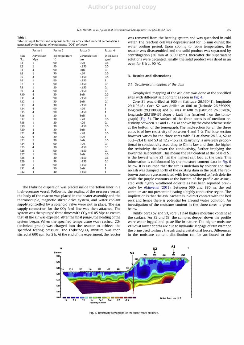
Geophysical mapping of the ash dam was done at the specifiedsites with different salt content as seen in Fig. 4.
Core S1 was drilled at 960 m (latitude 26.560411, longitude29.119348), Core S2 was drilled at 800 m (latitude 26.559099,longitude 29.119039) and S3 was at 600 m (latitude 26.557826,longitude 29.118943) along a fault line (marked f on the tomo-graph) (Fig. 5). The surface of the three cores is of medium re-sistivity between 9.3 and 12.2U as shown by the color scheme scaleat the bottom of the tomograph. The mid-section for all the threecores is of low resistivity of between 4 and 7 U. The base sectionhowever varies for the three cores with S1 at above 28.3 U, S2 at16.2e21.4 U and S3 at 12.2e16.2 U. Resistivity is inversely propor-tional to conductivity according to Ohms law and thus the higherthe resistivity the lower the conductivity, further implying thelower the salt content. This means the salt content at the base of S1is the lowest while S3 has the highest salt load at the base. Thisinformation is collaborated by the moisture content data in Fig. 6below. It is assumed that the site is underlain by dolerite and thatno ash was dumped north of the existing dam in the past. The red-brown contours are associatedwith less weathered to fresh doleritewhile the purple contours at the bottom of the profile are associ-ated with highly weathered dolerite as has been reported previ-ously by Akinyemi (2011). Between 560 and 880 m, the redcontours are not present indicating a highly conductive region. Theimplication is that the ash leachate is in direct contact with the bedrock and hence there is potential for ground water pollution. Aninvestigation of the moisture content in the three cores is givenbelow.
Unlike cores S2 and S3, core S1 had higher moisture content atthe surface. For S2 and S3, the samples deeper down the profilewere water logged and paste like in nature. The higher moisturevalues at lower depths are due to hydraulic seepage of rainwater orthe brine used to slurry the ash and gravitational forces. Differencesin the moisture content distribution can be attributed to the
Table 1Table of input factors and response factor for accelerated mineral carbonation asgenerated by the design of experiments (DOE) software.
Factor 1 Factor 2 Factor 3 Factor 4
Run A:Pressure B:Temperature C:Particle size D:S/L ratioNo. Mpa �C mm g/mlR1 1 90 <20 0.5R2 1 90 <150 0.5R3 4 90 Bulk 0.1R4 1 30 <20 0.5R5 4 90 >150 0.5R6 1 90 <150 1R7 1 90 >150 0.1R8 1 30 <150 0.1R9 4 90 <150 0.1R10 4 30 Bulk 0.5R11 4 90 <150 0.1R12 1 30 Bulk 0.1R13 4 30 <150 1R14 4 90 <20 1R15 4 90 >150 1R16 1 30 Bulk 1R17 1 30 <20 0.5R18 1 30 <20 0.1R19 1 30 >150 0.5R20 4 30 Bulk 1R21 4 90 <20 0.5R22 4 30 <20 1R23 1 30 Bulk 0.5R24 4 90 <20 0.1R25 4 30 >150 0.1R26 1 90 <150 0.1R27 1 90 Bulk 0.5R28 4 30 <150 0.5R29 1 30 >150 0.1R30 1 90 >150 1R31 4 90 Bulk 1R32 4 30 >150 1
Fig. 4. Resistivity tomograph of the three cores obtained.
G.N. Muriithi et al. / Journal of Environmental Management 127 (2013) 212e220 215

Author's personal copy
uneven preferential flow paths due to inconsistent placementconditions or variations in ambient weather conditions duringplacement. The high water content in the ash dam leads to theflushing out of the soluble elements in the ash down the depthprofile.
3.2. Brine analysis
Analysis of the brine solutions used for the carbonation is givenin Table 2 below.
The solutions can be classified as NaSO4 waters from the maincations and anions present. Major elements present in the brine areSO4, Na, Cl, Mg and K; minors are Sr, NO3, Si, Ni and Pb, while thetraces comprise of V, B, Ba, Cu, As, Fe, Se, Mn, Mo, Ti, Zn, Cr, Al andCo. Elements such as Ca, SO4 and Mg can be transformed intocalcite, gypsum and magnesite respectively, although reports ofgypsum and magnesite formation during carbonation of FA arelimited in the literature. Gitari et al. (2009) observed mobilizationof species such as Se, As, B, Mo and Cr from ash which was incontact with brine. They thus concluded that the presence of theseelements will influence the chemistry of ash in contact with brine.Conversion of Ca present in brine solutions used in this study (asshown in Table 2 above) would lead to 0.021 wt % of CaCO3 beingformed. This value is lower than the values obtained by both C&S
analysis as well as Chittick test. Moreover, Ca from both brine andthe dissolution of CaO in FA are expected to take part in this con-version. It is estimated that the ash dam has been exposed to anestimated 117.65 billion liters of brine over the 20 year period of itsexistence.
3.3. Chemical characterization of fresh and weathered ash
A comparison of the chemical composition of fresh, weatheredand carbonated ash is given in Table 3.
Enrichment of Nb, Y, Sr, Th and Ba with weathering is observed.It’s important to note that weathered and carbonated ash havecome into contact with brine which is a source of some of the el-ements such as Sr and Ba. Mahlaba et al. (2011) postulated that theincrease of some elements such as Na is from the brine which isused to transport the ash. The waste brine is usually rich in ele-ments such as Na, Cl, SO4, K, Sr, Ba etc. (Nyamhingura, 2010) andthis may explain the increase of some of these elements in theweathered ash. On the other hand a reduction in Rb, Pb, Ni, Co, Vand Zr is observed with weathering which is consistent withleaching over time. Calcite has been known to bind some heavymetals such as Pb, Cd, Cu, Ni and Zn via chemical fixation (Bertoset al., 2004; Meima and Comans, 1999). According to Sweeneyet al. (1999), carbonating solidified waste before landfilling
Fig. 5. Percentage moisture content of the three cores (n ¼ 3).
Fig. 6. XRD spectra of fresh, weathered and carbonated fly ash; M ¼ mullite; Q ¼ quartz; C ¼ calcite; H ¼ hematite; Mt ¼ magnetite; A ¼ aragonite; L ¼ lime.
G.N. Muriithi et al. / Journal of Environmental Management 127 (2013) 212e220216

Author's personal copy
reduces the alkalinity from the pH range of 11e12 to a range of 8e9where the waste is in equilibrium with the atmosphere. This cor-responds with the minimum solubility of metals such as Al, Ca, Cd,Cu, Fe, Mn, Ni, Pb and Zn, hence their immobilization. Yeheyis et al.(2009), observed that trace metals such as Cu, Fe, Co, Mn, Mo, Ni, Pband Zn are usually co-precipitated with hydroxides of Fe and Al aswell as neo-formed clay minerals in weathered municipal solidwaste incineration (MSWI) ash. They further argued that thecementitious and precipitated minerals could serve as a physicalbarrier to the constituents of the disposed FA by clogging the poresof the ash and hence preventing mobilization. Calcite is the pre-dominant newly formed mineral during ash maturation, combinedwith aluminum hydroxides and various sulfates (Freyssinet et al.,2002). For all the ashes, SiO2, Al2O3, Fe2O3 and CaO are the majoroxides thus they can be classified as class F since the sum of thepercentage composition of SiO2, Al2O3 and Fe2O3 is greater than70% according to the American Society for Testing and Materials(ASTM 618-1993). Furthermore, the CaO content is lower than10% which is also a grading criterion for class F FA.
Calcium-containing minerals such as CaO in fresh FA control thealkalinity of waste materials (Meima and Comans, 1999). Asweathering occurs, processes such as leaching, sedimentation,oxidation, carbonation and pH reduction are prevalent. This leadsto the conversion of lime and portlandite to more stable carbonate
forms as pH of the ash stabilizes to about 8, at which level calcite isin equilibriumwith the atmosphere. This phenomenon can explainthe observed CaO decrease with weathering.
Accelerated carbonation has lower levels of CaO thanweatheredash. The carbonation efficiency for this protocol was calculated tobe 75.54% (reader referred to Muriithi et al., 2011), moreover, theconversion of CaO to CaCO3 is at increased kinetics since higherpressures and temperatures are used as opposed to naturalcarbonation. Quenching of the ash with brine before and at thedisposal site converts CaO to Ca(OH)2, CaSO4.2H2O and Ca6Al2(-SO4)3(OH)12.26H2O (in the presence of sufficient Al and SO4). MgOis another alkalinity impacting mineral in fresh FA and its behavioris thus expected to be similar to that of CaO. Al, Fe, K and P contentremained fairly similar for all three samples.
3.4. Mineralogical characterization using XRD
The mineralogical composition of the fresh, carbonated andnaturally-weathered FAwas determined to identify the presence ofcarbonate minerals (Fig. 6).
The major phases present in the three different ashes are quartzand mullite, and to a lesser extend hematite and magnetite. Limewas present in the FA, but not in the weathered ash and carbonatedash which contained calcite, and calcite and aragonite respectively.A tabulation of the mineral phases present in the ash is shownbelow (Table 4).
Transformation of lime to calcite and its various polymorphswith carbonation has been reported by other researchers (Mlamboet al., 2011; Perez-Lopez et al., 2008; Rendek et al., 2006). Accordingto Bertos et al. (2004), vaterite and aragonite can be formed firstand then they transform to the most stable form of CaCO3 which iscalcite. Vaterite was however not identified in our study.
3.5. Morphological characterization of fresh, weathered andcarbonated ash
SEM analysis was carried out in order to understand themorphological changes occurring as the fresh ash was carbonatedas well as its variation fromweathered ash as shown in Fig.7 below.
Fresh ash (Fig. 8A) is mainly characterized by spherical particles,with a proportion of cenospheres (hollow sphere filled with N2/CO2that gives FA its light weight characteristics (Fenelov et al., 2010)).The spherical shape is an indication that the particles were formedunder un-crowded free-fall conditions and a relatively suddencooling, which helps tomaintain the spherical shape (Li et al., 2003;Saikia et al., 2006).
Carbonated FA (Fig. 8B) is made up of acicular particles of calciteand some aragonite, the two polymorphs of CaCO3 observed in theXRD analysis (Fig. 7) and previously reported by Fairchild andThatcher (2000). The calcite particles are clearly observed around
Table 2Major, minor and trace ion analysis of the raw brine solutions(n ¼ 3).
Elements Concentration (ppm)
SO4 11,704 � 14.28Na 3355 � 25.46Cl 1365 � 7.78Ca 210.2 � 10.47Mg 111.85 � 0.07K 78.75 � 2.05Sr 11.06 � 0.18NO3 6.5 � 1.44Si 2.54 � 0.03Ni 2.5 � 0.02Pb 1.6 � 0.01V 0.4898 � 0.04B 0.154 � 0.01Ba 0.15 � 0.01Cu 0.118As 0.076 � 0.01Fe 0.068 � 0.02Se 0.058 � 0.01Mn 0.057 � 0.01Mo 0.037Ti 0.029Zn 0.028Cr 0.023Al 0.023Co 0.020
Table 3XRF analysis of fresh, weathered (at 20 m depth of the dam) and ex-situ mineral carbonation product. (NB: n ¼ 3, Weathered ash value is from the average of the 3 cores).
Majors (wt %) Fresh ash Weathered ash Carbonated ash Traces (ppm) Fresh ash Weathered ash Carbonated ash
SiO2 51.23 � 1.64 44.28 � 0.42 47.83 � 0.05 Nb 35.30 � 0.79 149.43 � 2.15 33.50 � 0.42TiO2 1.55 � 0.09 1.76 � 0.07 1.50 Zr 638.80 � 21.60 598.32 � 9.16 485 � 9.45Al2O3 26.00 � 1.65 25.49 � 0.75 25 � 0.08 Y 81.12 � 0.95 171.28 � 0.93 80.50 � 0.74Fe2O3 2.43 � 0.06 2.59 � 0.08 2.17 � 0.11 Sr 4059.27 � 48.76 4659.54 � 20 3409 � 37.58MgO 2.44 � 0.71 2.73 � 0.04 1.68 � 0.06 Th 52.76 � 2.18 186.11 � 1.11 21 � 3.62CaO 9.20 � 0.85 5.41 � 0.91 3.87 � 0.35 Rb 33.14 � 0.93 6.86 � 0.75 24.50 � 2.89Na2O 0.46 � 0.01 2.53 � 0.57 0.47 � 0.13 Pb 30.00 � 0.08 14.48 � 0.58 13 � 0.92K2O 0.79 � 0.02 0.81 � 0.02 0.79 � 0.01 Ni 43.29 � 0.79 32.78 � 2.05 65 � 4.75P2O5 0.70 � 0.03 0.94 � 0.04 0.85 � 0.01 Co 36.78 � 1.89 11.18 � 1.64 86 � 2.30SO3 0.36 � 0.01 0.09 � 0.01 NA V 138.23 � 3.64 59.89 � 0.34 147 � 0.03
Ba 2290.65 � 29.15 3207.61 � 1.0 2315 � 31.35
G.N. Muriithi et al. / Journal of Environmental Management 127 (2013) 212e220 217

Author's personal copy
a bigger spherical particle. Bertos et al. (2004) reported thismorphology of calcite characterized by small tightly packed crystals<3 mm in size. Accelerated carbonation thus leads to changes in theash morphology due to the formation of secondary phases such ascalcite and aragonite. Similar morphologies of carbonated FA havebeen previously reported (Perez-Lopez et al., 2008; Montes-Hernandez et al., 2009; Fernandez et al., 2004), although thesestudies identified calcite as the only polymorph of CaCO3 formedduring the carbonation process. However SEM can only providequalitative information and thus cannot be used to quantify theamount of CaCO3 formed in the carbonation process.
Irregularly shaped particles and agglomerates are observed inthe weathered ash (Fig. 8C). This transformation occurs as the ashmatures through processes such as hydration, carbonation and co-precipitation. Major alteration reactions reported during weath-ering of fly ash are dissolution/precipitation of salts, glass corrosion,hydration of anhydrite to bassanite and gypsum, oxidation re-actions of metals or metal oxides, slaking of lime and hardeningreactions (cementation and carbonation of reactive lime and peri-clase by air). The reported alteration/weathering products areanhydrite, ettringite, gypsum, bassanite, calcite, iron oxides andhydroxides as well as gibbsite (Speiser et al., 2000; Vassilev andVassileva, 2007).
3.6. Carbonation potential of the ash dams
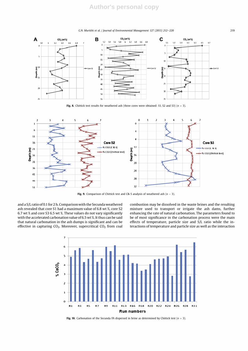
The natural carbonation potential of the ash damswas evaluatedby titrating the weathered Secunda ashes using the Chittick testprocedure. Fig. 8 shows the calcite content variation along thedepth profile in the ash dam.
For all three cores, the surface sample has the highest CO2content with core S1 having a value of 6.8%, core S2 a value of 6.7and core S3 a value of 6.5%. The three values have a standard errorof 0.158 and hence not significantly different from one another.Interestingly, the CO2 concentration profile in core S1 is similar toits moisture content profile (Fig. 6) with highest concentration atthe surface and lowest value down the depth profile. No correlationis observed for cores S2 and S3 however. Core S2 had the lowestvalue of 5.3 wt %, which was recorded at a depth of 22 m. A “zigzag”
trend is observed for all three cores. This is due to the fact that afterdisposal, the ash is allowed to settle while the excess brine drainsvia the penstock and toe drain into the clear ash effluent dams forre-circulation before the next layer of ash slurry is applied. As aresult, the ash dams are characterized by stacking of “pancake-likelayering”. This stacking allows for a period of interaction with theatmosphere and hence the zigzag pattern implies the longer theexposure to the atmosphere the higher the CO2 content. Yeheyiset al. (2009) also found that carbonation was predominant at thesurface of one of the sites they cored (DFA-I) with additional phaseformation of ettringite in the other two cores they used (DFA-II andDFA-III). They further argued that metals in the FA are immobilizedin the dump site. Some components of the disposed ash may beconverted to less soluble hydroxide and carbonate minerals viaadsorption, co-precipitation and/or physical encapsulation. Thisimplies a lower concentration of elements such as Cu, Fe, Co, Mn,Mo, Ni, Pb and Zn, which is confirmed in the XRF analysis reportedin Table 2.
3.7. Evaluation of CO2 capture by Chittick test and C&S analysis
To authenticate the amount of CaCO3 formed during acceleratedcarbonation process, Chittick test results were compared to C&Sanalysis results obtained for cores S2 and S3 (Fig. 9).
In both cores, C&S analysis gave lower values than the Chitticktest. This could be due to the fact that Chittick test involves titrationwith a high concentration of acid (6 N HCl) and thus both theorganic and inorganic carbon are easily released. On the other handC&S analysis involves combustion of the ash in oxygen and thesubsequent detection of the evolved CO2.
A comparable trend is clear in core S2 but missing in core S3.Interestingly, the highest CO2 concentration by C&S analysis is noton the surface as can be seen for Chittick test. For core S2 thehighest value obtained was 4.568% CO2 at a depth of 33 mwhile forcore S3 the highest value was 6.517% CO2 at a depth of 28.5 m. Thediscrepancy between these two analytical techniques has not beendemonstrated before and thus should be investigated further.
3.8. CO2 capture via accelerated ex-situ mineral carbonation
It was important to evaluate how the CO2 capture in disposed,weathered ash via natural carbonation processes compared withaccelerated mineral carbonation carried out in the laboratory. Agraphical representation of the CO2 formed in wt. % for the variousfactor combinations as stipulated in Table 1 is given in Fig. 10.
The highest CO2 content upon accelerated carbonation was6.5 wt %; this experiment was conducted at 4 Mpa, 90 �C using bulkash at a S/L ratio of 1 for 2 h. The lowest content on the other handwas found tobe 2.75wt% andwasobtained at 1Mpa, 30 �C,>150mm
Table 4Tabulation of the mineral phases present in fresh, weathered and carbonated ash.
Fresh ash Weathered ash Carbonated ash
Mullite Mullite MulliteQuartz Quartz QuartzHematite Calcite CalciteMagnetite Magnetite HematiteLime Hematite Magnetite
Aragonite
Fig. 7. SEM micrographs of fresh ash (A), carbonated ash (B) and weathered ash (C).
G.N. Muriithi et al. / Journal of Environmental Management 127 (2013) 212e220218
Author's personal copy
anda S/L ratio of 0.1 for 2h. Comparisonwith theSecundaweatheredash revealed that core S1 had a maximum value of 6.8 wt %, core S26.7 wt % and core S3 6.5 wt %. These values do not vary significantlywith the accelerated carbonationvalue of 6.5wt %. It thus can be saidthat natural carbonation in the ash dumps is significant and can beeffective in capturing CO2. Moreover, supercritical CO2 from coal
combustion may be dissolved in the waste brines and the resultingmixture used to transport or irrigate the ash dams, furtherenhancing the rate of natural carbonation. The parameters found tobe of most significance in the carbonation process were the maineffects of temperature, particle size and S/L ratio while the in-teractions of temperature and particle size as well as the interaction
Fig. 8. Chittick test results for weathered ash (three cores were obtained: S1, S2 and S3) (n ¼ 3).
Fig. 9. Comparison of Chittick test and C& S analysis of weathered ash (n ¼ 3).
Fig. 10. Carbonation of the Secunda FA dispersed in brine as determined by Chittick test (n ¼ 3).
G.N. Muriithi et al. / Journal of Environmental Management 127 (2013) 212e220 219

Author's personal copy
of temperature with S/L ratio were also found to be significant(Muriithi et al., 2012).
4. Conclusions
Natural carbonation occurs in the ash disposal site althoughlonger time scales are required to achieve the same results as 2 h ofacceleratedmineral carbonation. This could imply that supercriticalCO2 can be used to slurry the ash before disposal thus using upsome of the waste CO2 emissions from power stations. This can beapplied at a plant like Secunda where the CO2 is already highlyconcentrated (90e98%). The morphology of the ash changes fromsphero-particles in fresh ash to acicular particles in carbonated ashand finally to irregular shaped particles as weathering processtakes place at the dumping site. Some elemental forms remainunchanged in concentration as fresh ash weathers. Others areenriched (e.g. Ti, Fe, Mg, Na, K, Nb, Y, Ba and Sr) while some aredepleted in the weathered ash. These include Ca, S, Zr, U, Rb, Pb, Ni,Co and V. Analytical techniques such as C&S and Chittick test can beapplied in the evaluation of carbonates in carbonated ash.
Acknowledgments
The authors would like to acknowledge the financial assistanceof ESKOM and SASOL.
References
Akinyemi, S.A., 2011. Geochemical andMineralogical Evaluationof ToxicContaminantsMobility in Weathered Coal Fly Ash: As a Case Study, Tutuka Dump Site, SouthAfrica. University of theWestern Cape, South Africa. Unpublished PhD thesis.
Akinyemi, S.A., Akinlua, A., Gitari, W.M., Khuse, N., Eze, P., Akinyeye, R.O., Petrik, L.F.,2012. Natural weathering in dry disposed ash dump: insight from chemical,mineralogical and geochemical analysis of fresh and unsaturated drilled cores.Journal of Environmental Management 102, 96e107.
American Society for Testing and Materials, 1993. ASTM 618: standard speciationfor fly ash and raw or calcined natural pozzolan for uses as a mineral admixturein Portland cement concrete. American Society for Testing and Materials,Philadelphia, Pennsylvania.
Bertos, M.Fernandez, Simons, S.J.R., Hills, C.D., Carey, P.J., 2004. A review of accel-erated carbonation technology in the treatment of cement-based materials andsequestration of CO2. Journal of Hazardous Materials B112, 193e205.
Doucet, F.J., 2011. Scoping Study on CO2 Mineralization Technologies, South AfricanCentre for Carbon Capture and Storage. Report no. CGS-2011-007. Available at:http://www.sacccs.org.za/wp-content/uploads/2011/011/Scoping_study_on_CO2_ mineralization_technologies_report.pdf.
Dreimanis, A., 1962. Quantitative gasometric determination of calcite and dolomiteby using Chittick apparatus. Journal of Sedimentary Petrology 32, 20e529.
Ecke, H., 2003. Sequestration of metals in carbonated municipal solid wasteincineration (MSWI) fly ash. Waste Management 23, 631e640.
Ecke, H., Menad, N., Lagerkvist, A., 2002. Treatment oriented characterization of dryscrubber residue from municipal solid waste (MSWI). Journal of Materials Cy-cles and Waste Management 4 (2), 117e126.
Eskom, 2011. Partnering for a Sustainable Future. Integrated report (obtained from:www.eskom.co.za. on 23rd August, 2012.
Fairchild, H.G., Thatcher, L.R., 2000. Acicular Calcite and Aragonite Calcium Car-bonate. US Patent, no. 6071336. Date of filing June 6th.
Fenelov, V.B., Melgunov, M.S., Parmon, V.N., 2010. The properties of cenospheresand the mechanism of their formation during high temperature coal combus-tion at thermal power plants. KONA Powder and Particle Journal 28, 189e208.
Fernandez, M.B., Li, X., Simons, S.J.R., Hills, C.D., Carey, P.J., 2004. Investigation ofaccelerated carbonation for the stabilization of MSW incinerator ashes and thesequestration of CO2. Green Chemistry 6, 428e436.
Freyssinet, P., Piantone, P., Azaroual, M., Itard, Y., Clozel-Leloup, B., Guyonnet, D.,Baubron, J.C., 2002. Chemical changes and leachatemass balance ofmunicipal solidwaste bottom ash submitted to weathering. Waste Management 22 (2), 159e172.
Gitari, M.W., Fatoba, O.O., Nyamhingura, A., Petrik, L.F., Vadapalli, V.R.K., Nel, J.,October, A., Dlamini, L., Gericke, G., Mahlaba, J.S., 2009. Chemical weathering ina dry ash dump: an insight from physicochemical and mineralogical analysis of
drilled cores. In: World of Coal Ash (WOCA) Conference, May 4e7, Lexington,Kentucky, USA. Available at: http://www.flyash.info/.
Intergovernmental Panel on Climate Change, 2007. Climate Change SynthesisReport. IPCC Plenary XXVII. Valencia, Spain.
Kim, Sang-Yul, Matsuto, Toshihiko, Tanaka, Nobutoshi, 2003. Evaluation of pre-treatment methods for landfill disposal of residues from municipal solidwaste incineration. Waste Management and Research 21 (5), 416e423.
Li, M., Hu, S., Xiang, J., Sun, L.S., Li, P.S., Su, S., Sun, X., 2003. Characterization of flyashes from two Chinese municipal solid waste incinerators. Energy and Fuels 17(6), 1487e1491.
Mahlaba, J.S., 2007. Evaluation of Paste Technology to Co-dispose of Ash and Brinesat Sasol Synfuels Complex. University of Witwatersrand, South Africa. Unpub-lished Msc (Eng.) thesis.
Mahlaba, J.S., Kearsley, P.E., Kruger, A.R., 2011. Physical, chemical and mineralogicalcharacterization of hydraulically disposed fine coal ash from Sasol Synfuels.Fuel 90, 2491e2500.
Meima, J.A., Comans, R.N.J., 1999. The leaching of trace elements from municipalsolid waste incinerator bottom ash at different stages of weathering. AppliedGeochemistry 14, 159e171.
Meima, J.A., van der Weijden, R.D., Eighmy, T.T., Comans, R.N.J., 2002. Carbonationprocesses in municipal solid waste incinerator bottom ash and their effect onthe leaching of copper and molybdenum. Applied Geochemistry 17 (12), 1503e1513.
Mlambo, T.K., Doucet, F.J., van der Merwe, E.M., Altermann, W., Atanasova, M.,Richard, A.K., 2011. The injection of fly ash slurries in deep geological reservoirsfor improved reservoir integrity and safe CO2 sequestration. In: Wold of CoalAsh (WOCA) Conference, May 9e12, Denver, Co, USA. Available at: http://www.flyash.info/.
Montes-Hernandez, G., Pérez-López, R., Renard, F., Nieto, J.M., Charlet, L., 2009.Mineral sequestration of CO2 by aqueous carbonation of coal combustion fly-ash. Journal of Hazardous Materials 161, 1347e1354.
Mooketsi, I.O., Ginster, M., Matjie, H.R., Riedel, J.K., 2007. Leachate characteristics ofash residues from a laboratory scale brine encapsulation simulation process. In:World of Coal Ash (WOCA) Conference, May 7e10, Northern Kentucky, USA.Available at: http://www.flyash.info/.
Muriithi, G.N., Gitari, W.M., Petrik, L.F., Ndung’u, P.G., 2011. Carbonation of brineimpacted coal fly ash: implications for CO2 sequestration. Journal of Environ-mental Management 92, 655e664.
Muriithi, N.G., Gitari, M.W., Petrik, F.L., 2012. Statistical testing of input factors in thecarbonation of brine impacted fly ash. Journal of Environmental Science andHealth, Part A 47, 245e259.
Nyamhingura, A., 2010. Characterization and Chemical Speciation Modelling ofSaline Effluents at Sasol Synthetic Fuels Complex- Secunda and Tutuka PowerStations. Unpublished Msc thesis. University of the Western Cape, South Africa.
Perez-Lopez, R., Montes-Hernandez, G., Nieto, J.M., Renard, F., Charlet, L., 2008.Carbonation of alkaline paper mill waste to reduce CO2 greenhouse gas emis-sions into the atmosphere. Applied Geochemistry 23, 2292e2300.
Petrik, L., Lewis, A.E., Hendry, B.A., 2007. Brine Treatment and Disposal. CoaltechReport, South Africa.
Reddy, K.J., Gloss, S.P., Wang, L., 1994. Reaction of CO2 with alkaline solid wastes toreduce contaminant mobility. Water Resources 28 (6), 1377e1382.
Rendek, E., Ducom, G., Germain, P., 2006. Influence of organic matter on municipalsolid waste incineration bottom ash carbonation. Chemosphere 64, 1212e1218.
Saikia, N., Kato, S., Kojima, T., 2006. Compositions and leaching behaviours ofcombustion residues. Fuel 85 (2), 264e271.
Soong, Y., Fauth, D.L., Howard, B.H., Jones, J.R., Harrison, D.K., Goodman, A.L.,Frommell, E.A., 2006. CO2 sequestration with brine solutions and fly ashes.Energy Conversion and Management 47, 1676e1685.
Speiser, C., Baumann, T., Niessner, R., 2000. Morphological and chemical charac-terization of calcium-hydrate phases formed in alteration processes of depos-ited municipal solid waste incineration waste bottom. Environmental Scienceand Technology 34, 5030e5037.
Sweeney, R.E.H., Hills, C.D., Buenfeld, N., 1999. Acid neutralization capacity ofcarbonated solidified waste. In: International Conference on Waste Stabilizationand Environment. Societ’ Alpine de Publications, Grenoble, pp. 121e125.
Vassilev, S.V., Vassileva, C.G., 2007. A new approach for the classification of coal flyashes based on their origin, composition, properties and behaviour. Fuel 86,1490e1512.
Wu-Jang, H., Min-Hsiu, S., Feng-Hung, T., 2007. Stabilization of lead in MSWIbaghouse ashes by steam enhanced carbonation reaction. Journal of Materialsin Civil Engineering Management 17 (2), 123e128.
Yeheyis, B.Muluken, Shang, Q.Julie, Yanful, K.Ernest, 2009. Chemical and mineral-ogical transformation of coal fly ash after landfilling. In: World of Coal Ash(WOCA) Conference, May 4e7, Lexington, Kentucky, USA. Available at: http://www.flyash.info/.
Zevenhoven, Ron, Fagerlund, Johan, Songok, Kibiwot Joel, 2011. CO2 mineralsequestration: developments toward large-scale application. Greenhouse GasesScience and Technology 1, 48e57.
G.N. Muriithi et al. / Journal of Environmental Management 127 (2013) 212e220220