
Physical activity in type 2 diabetes care - Over de Kennisbank ...
Upload
khangminh22Category
view
5download
0
Author: Sander Grummels Date: 14-4-2021 REV: 0.0
Vortex-Heater Design Report
2
Author: Sander Grummels Date: 14-4-2021 REV: 0.0
Table of contents 1 | Introduction ...................................................................................................................... 4
2 | Background information ................................................................................................... 5
2.1 Rocket-stove basics .................................................................................................... 5
2.1.1 How does a rocket-stove work .............................................................................. 5
2.1.2 Conclusion ............................................................................................................ 5
3 | Rocket stove types ........................................................................................................... 6
3.1 (Outdoor) Cooking rocket-stoves ................................................................................. 6
3.1.1 L-shape ................................................................................................................. 6
3.1.2 V-shape ................................................................................................................ 6
3.1.3 Apostol rocket-stove .............................................................................................. 7
3.2 Rocket-(mass)-heater .................................................................................................. 7
3.3 Vortex (/Himalayan) rocket-stove ................................................................................. 8
3.4 Batch-box rocket-stove ................................................................................................ 8
3.5 What’s not a rocket stove ............................................................................................ 9
4 | Concept-phase ............................................................................................................... 10
4.1 Design intentions ....................................................................................................... 10
4.2 Inspiration .................................................................................................................. 10
4.3 Design concept .......................................................................................................... 11
5 | Detail design .................................................................................................................. 12
5.1 Design substantiation ................................................................................................ 12
5.2 Design description ..................................................................................................... 13
5.2.1 Accessories ......................................................................................................... 14
5.3 Operation................................................................................................................... 15
5.3.1 Stove base .......................................................................................................... 15
5.3.2 Heat-exchanger .................................................................................................. 16
5.4 Dimensioning ............................................................................................................. 17
5.4.1 Dimensioning explanation ................................................................................... 17
5.4.2 Conclusion .......................................................................................................... 18
6 | Execution ....................................................................................................................... 19
6.1 Parts .......................................................................................................................... 19
6.2 Building ..................................................................................................................... 19
7 | Final result ..................................................................................................................... 21
8 | Conclusion & Recommendation ..................................................................................... 22
8.1 Conclusion ................................................................................................................. 22
8.1.1 Setbacks ............................................................................................................. 22
8.2 Recommendations ..................................................................................................... 22

3
Author: Sander Grummels Date: 14-4-2021 REV: 0.0
9 | Bibliography ................................................................................................................... 23
9.1.1 List of figures .......................................................................................................... 24

4
Author: Sander Grummels Date: 14-4-2021 REV: 0.0
1 | Introduction This is a design report concerning a Vortex-Heater. It’s a step by step approach, starting with
basic elements and resulting to a final personal design. Secondly it describes the making of
this Vortex-Heater in real. The building process directly confronted practical issues towards
the designed model. At last the execution resulted in some expected vortex principles but
not all items were successful. To complete this design report, drawings and additional files
are added.
Sander Grummels

5
Author: Sander Grummels Date: 14-4-2021 REV: 0.0
2 | Background information
2.1 Rocket-stove basics Rocket-stoves are more efficient types of woodstoves (which make use of small wood)
because of a better burn process (& better insulation) which are used for cooking efficiently.
The (L-shape) rocket stove was founded by Dr.Larry Winiarski in the ’80s as an efficient
solution for people in developing countries who rely heavily on woodfired cooking. The
rocket stove is about twice as efficient as open woodfires. Because of the burn process, they
reduce smoke and harmful emissions. The stove does also a much better job at transferring
heat to cooking pots.
2.1.1 How does a rocket-stove work The geometry of a rocket stove consists of L-
shape tube. (See Figure 1) In the horizontal part
of the tube (wood) sticks are placed on a fuel
shelve. The sticks are burned behind where the
vertical section begins.
The most important part of a rocket stove is the
(insulated) chimney/heat-riser. It produces a very
strong draft (hot air wants to rise). Which allows
lots of air drawn into the stove. This intensifies
the burn (like a blower on fire) and more heat is
created. The air is sucked from below the wood
and is pre-heated. This limits the amount of cold
air that gets in the combustion process.
The L-shape in combination with the insulation is
a very important factor in the efficiency of the
rocket stove. First, primary combustion takes (at
the tips of the sticks) place. This will heat the stove and keep the process going. Due to the
abrupt turn from horizontal to vertical flow, a turbulent flow is created. Oxygen gets well
mixed with the combustible gases, in combination with the heat concentration in the
insulated chimney. Secondary combustion will take place which generates an extra dose of
heat.
Another key principle is that the wood is only getting burned at its tips. It is burned bit by bit
(in the case of an L-shape, the wood has to be pushed in by hand), it limits the amount of
wood that is heated (also due to the draft) and reduces the amount of volatile wood oils
being generated. This creates a very constant burn. The burn process will not get
overloaded all the wood can be burned cleanly.
2.1.2 Conclusion All in all, the heat in combination with lots of oxygen drawn into the system is the perfect
recipe for an efficient and clean combustion.
(Appropedia, 2021) (Hill, 2017) (Lebel, 2017)
Figure 1 Schematic view of a L-shape rocket-stove
6
Author: Sander Grummels Date: 14-4-2021 REV: 0.0
3 | Rocket stove types
3.1 (Outdoor) Cooking rocket-stoves
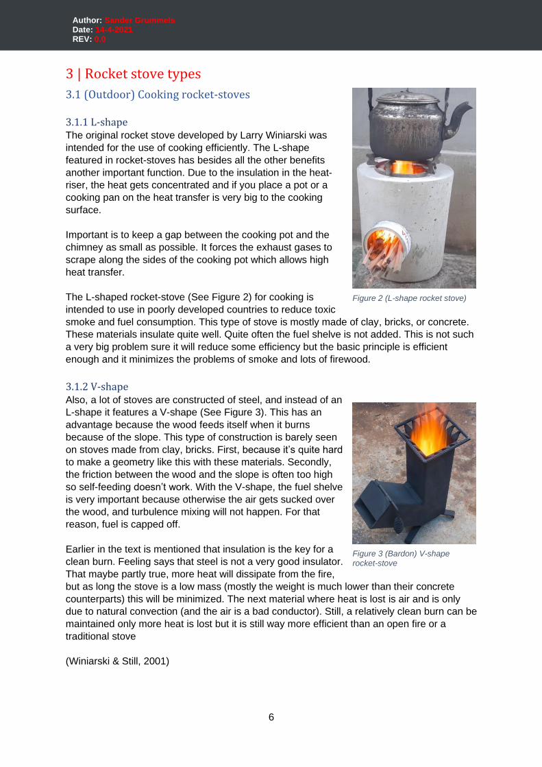
3.1.1 L-shape The original rocket stove developed by Larry Winiarski was
intended for the use of cooking efficiently. The L-shape
featured in rocket-stoves has besides all the other benefits
another important function. Due to the insulation in the heat-
riser, the heat gets concentrated and if you place a pot or a
cooking pan on the heat transfer is very big to the cooking
surface.
Important is to keep a gap between the cooking pot and the
chimney as small as possible. It forces the exhaust gases to
scrape along the sides of the cooking pot which allows high
heat transfer.
The L-shaped rocket-stove (See Figure 2) for cooking is
intended to use in poorly developed countries to reduce toxic
smoke and fuel consumption. This type of stove is mostly made of clay, bricks, or concrete.
These materials insulate quite well. Quite often the fuel shelve is not added. This is not such
a very big problem sure it will reduce some efficiency but the basic principle is efficient
enough and it minimizes the problems of smoke and lots of firewood.
3.1.2 V-shape Also, a lot of stoves are constructed of steel, and instead of an
L-shape it features a V-shape (See Figure 3). This has an
advantage because the wood feeds itself when it burns
because of the slope. This type of construction is barely seen
on stoves made from clay, bricks. First, because it’s quite hard
to make a geometry like this with these materials. Secondly,
the friction between the wood and the slope is often too high
so self-feeding doesn’t work. With the V-shape, the fuel shelve
is very important because otherwise the air gets sucked over
the wood, and turbulence mixing will not happen. For that
reason, fuel is capped off.
Earlier in the text is mentioned that insulation is the key for a
clean burn. Feeling says that steel is not a very good insulator.
That maybe partly true, more heat will dissipate from the fire,
but as long the stove is a low mass (mostly the weight is much lower than their concrete
counterparts) this will be minimized. The next material where heat is lost is air and is only
due to natural convection (and the air is a bad conductor). Still, a relatively clean burn can be
maintained only more heat is lost but it is still way more efficient than an open fire or a
traditional stove
(Winiarski & Still, 2001)
Figure 2 (L-shape rocket stove)
Figure 3 (Bardon) V-shape rocket-stove
7
Author: Sander Grummels Date: 14-4-2021 REV: 0.0
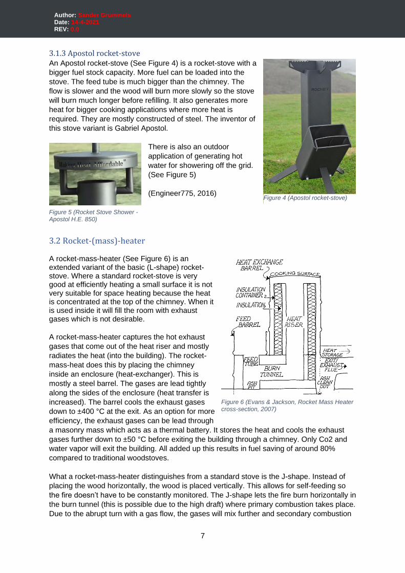
3.1.3 Apostol rocket-stove An Apostol rocket-stove (See Figure 4) is a rocket-stove with a
bigger fuel stock capacity. More fuel can be loaded into the
stove. The feed tube is much bigger than the chimney. The
flow is slower and the wood will burn more slowly so the stove
will burn much longer before refilling. It also generates more
heat for bigger cooking applications where more heat is
required. They are mostly constructed of steel. The inventor of
this stove variant is Gabriel Apostol.
There is also an outdoor
application of generating hot
water for showering off the grid.
(See Figure 5)
(Engineer775, 2016)
3.2 Rocket-(mass)-heater A rocket-mass-heater (See Figure 6) is an extended variant of the basic (L-shape) rocket-stove. Where a standard rocket-stove is very good at efficiently heating a small surface it is not very suitable for space heating because the heat is concentrated at the top of the chimney. When it is used inside it will fill the room with exhaust gases which is not desirable.
A rocket-mass-heater captures the hot exhaust
gases that come out of the heat riser and mostly
radiates the heat (into the building). The rocket-
mass-heat does this by placing the chimney
inside an enclosure (heat-exchanger). This is
mostly a steel barrel. The gases are lead tightly
along the sides of the enclosure (heat transfer is
increased). The barrel cools the exhaust gases
down to ±400 °C at the exit. As an option for more
efficiency, the exhaust gases can be lead through
a masonry mass which acts as a thermal battery. It stores the heat and cools the exhaust
gases further down to ±50 °C before exiting the building through a chimney. Only Co2 and
water vapor will exit the building. All added up this results in fuel saving of around 80%
compared to traditional woodstoves.
What a rocket-mass-heater distinguishes from a standard stove is the J-shape. Instead of
placing the wood horizontally, the wood is placed vertically. This allows for self-feeding so
the fire doesn’t have to be constantly monitored. The J-shape lets the fire burn horizontally in
the burn tunnel (this is possible due to the high draft) where primary combustion takes place.
Due to the abrupt turn with a gas flow, the gases will mix further and secondary combustion
Figure 4 (Apostol rocket-stove)
Figure 5 (Rocket Stove Shower - Apostol H.E. 850)
Figure 6 (Evans & Jackson, Rocket Mass Heater cross-section, 2007)

8
Author: Sander Grummels Date: 14-4-2021 REV: 0.0
takes place in the heat riser. This is much better than in a standard rocket-stove and it will
burn more efficiently. The most important to the rocket-mass-heater is its heavy insulation.
The stove burns at around 1000 °C. These temperatures are needed to burn all the volatile
compounds and extract all the heat from the wood.
A disadvantage of the rocket-mass-heater is that it is only capable of burning small wood so
a lot of wood chopping is needed. Also, it burns very fiercely so it has to be filled quite often.
For a better understanding of a rocket-mass-heater reading the book
“Rocket Mass Heaters” from Ianto Evans & Leslie Jackson is recommended.
(See Appendix E.1)
(Evans & Jackson, Rocket Mass Heaters, 2007)
3.3 Vortex (/Himalayan) rocket-stove The fundamentals of a vortex rocket-stove are the same as for
a normal rocket-stove (Rocket-mass-heater variant or cooking
variant). The difference is that the heat-riser is round and a
narrowing is made from the burn tunnel to the heat-riser. This
narrowing ensures that the gases will flow faster (Bernoulli
effect). The narrowing is placed at the left or the right side of
the heat-riser (not in the middle). This creates a vortex (See
Figure 7). Due to the vortex, the flame path is extended which
allows longer heating of the flame and results in better
combustion.
The vortex creates an air layer between the fire (which acts as
natural insulation) and the heat-riser, what makes insulation not
very crucial for maintaining a clean burn.
(Takeshi Ueno, n.d.) (Frequently Asked Questions, n.d.)
3.4 Batch-box rocket-stove A batch-box rocket-stove is a rocket-mass-heater with a big firebox
(See Figure 8) that allows loading more wood for a longer burn. It
is intended to burn a pile of wood in one go and store all the heat
(in the mass).
The batch box rocket-stove uses also the principle of the extended
flame path but the narrowing is applied in the middle and no natural
insulation is created (See Figure 9). So
good insulation is very important.
(Berg, Workings, how and why, n.d.)
For a more extensive explanation of the
Batch-box rocket-stove is suggest reading Appendix E.2.
Figure 7 (Top view vortex in heat-riser)
Figure 8 (Berg, Open Batch-box rocket-stove)
Figure 9 (Berg, Top view
heat-riser)

9
Author: Sander Grummels Date: 14-4-2021 REV: 0.0
3.5 What’s not a rocket stove On the internet, a lot of types of K-shape called rocket-stoves
show up (see Figure 10). It has 2 tubes connecting to the
chimney, one for the wood supply and one for the air supply.
It is mostly classified as a rocket-stove but it isn’t. Air gets
sucked from a separate channel as the wood. So the air will
not preheat and an adequate level of turbulence will not be
achieved. So secondary combustion will not take place and it
will not burn clean. It is a fire at the bottom of the chimney.
(Berg, Rocket stove van stalen koker, 2019)
Figure 10 (sjoerdb, 2019)
10
Author: Sander Grummels Date: 14-4-2021 REV: 0.0
4 | Concept-phase
4.1 Design intentions The design idea is to make an efficient woodstove for use in the garden. It should be
efficiently easy to construct and easy to demount. Also, it should be easily movable.
Further, it is desirable to see as much as possible from the fire.
4.2 Inspiration The inspiration from the concept design came from different rocket stove ideas from the
internet. All the ideas come from YouTube videos.
The first inspiration is a vortex stove design made by Takeshi
Ueno. He has made a vortex rocket-stove where the fire can be
seen on the top of the heat riser (See Figure 11). That is done by
adding tertiary-air at the top of the heat-riser. (secondary-air is
added at the bottom of the heat-riser) Further, the vortex rocket-
stove is a good option it is easy to construct from only steel which
keeps also the weight relatively low. Also, the vortex principle
ensures that insulation is not very important for good combustion.
Adding insulation is optional the combustion will become better but
the steel will slowly corrode away because it can’t handle
temperatures above 800° very well.
The second inspiration (See Figure 12) is from
“Gaetanproductions”. They made a rocket-mass heater from steel
but the heat exchanger is made from a gas bottle. It looks sturdy
and easy to construct from only steel but it is also movable
because there is no masonry mass added.
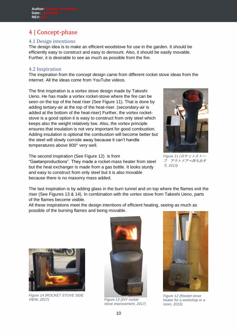
The last inspiration is by adding glass in the burn tunnel and on top where the flames exit the
riser (See Figures 13 & 14). In combination with the vortex stove from Takeshi Ueno, parts
of the flames become visible.
All these inspirations meet the design intentions of efficient heating, seeing as much as
possible of the burning flames and being movable.
Figure 11 (ロケットストーブ アウトドアへ持ち出そ
う, 2013)
Figure 12 (Rocket stove heater for a workshop or a room, 2015)
Figure 13 (DIY rocket
stove improvement, 2017)
Figure 14 (ROCKET STOVE SIDE VIEW, 2017)
11
Author: Sander Grummels Date: 14-4-2021 REV: 0.0
4.3 Design concept
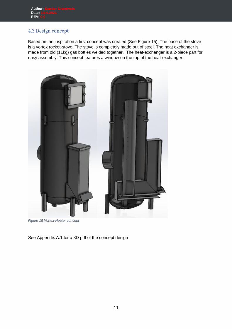
Based on the inspiration a first concept was created (See Figure 15). The base of the stove
is a vortex rocket-stove. The stove is completely made out of steel, The heat exchanger is
made from old (11kg) gas bottles welded together. The heat-exchanger is a 2-piece part for
easy assembly. This concept features a window on the top of the heat-exchanger.
See Appendix A.1 for a 3D pdf of the concept design
Figure 15 Vortex-Heater concept
12
Author: Sander Grummels Date: 14-4-2021 REV: 0.0
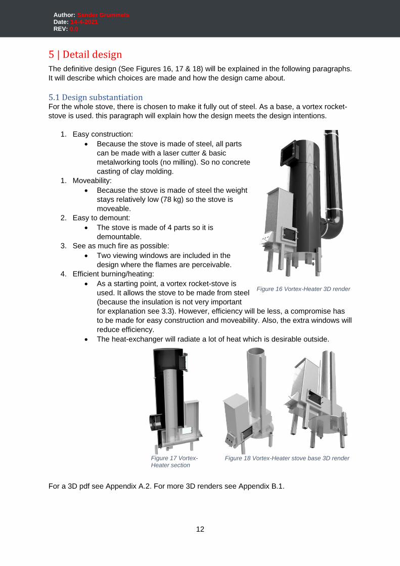
5 | Detail design The definitive design (See Figures 16, 17 & 18) will be explained in the following paragraphs.
It will describe which choices are made and how the design came about.
5.1 Design substantiation For the whole stove, there is chosen to make it fully out of steel. As a base, a vortex rocket-
stove is used. this paragraph will explain how the design meets the design intentions.
1. Easy construction:
• Because the stove is made of steel, all parts
can be made with a laser cutter & basic
metalworking tools (no milling). So no concrete
casting of clay molding.
1. Moveability:
• Because the stove is made of steel the weight
stays relatively low (78 kg) so the stove is
moveable.
2. Easy to demount:
• The stove is made of 4 parts so it is
demountable.
3. See as much fire as possible:
• Two viewing windows are included in the
design where the flames are perceivable.
4. Efficient burning/heating:
• As a starting point, a vortex rocket-stove is
used. It allows the stove to be made from steel
(because the insulation is not very important
for explanation see 3.3). However, efficiency will be less, a compromise has
to be made for easy construction and moveability. Also, the extra windows will
reduce efficiency.
• The heat-exchanger will radiate a lot of heat which is desirable outside.
For a 3D pdf see Appendix A.2. For more 3D renders see Appendix B.1.
Figure 16 Vortex-Heater 3D render
Figure 18 Vortex-Heater stove base 3D render Figure 17 Vortex-Heater section

13
Author: Sander Grummels Date: 14-4-2021 REV: 0.0
5.2 Design description
The Vortex-Heater consists of 4 main parts:
• Stove base (vortex rocket-stove)
• Bottom part heat-exchanger
• Top part heat-exchanger
• Chimney
For an overview of all characteristic parts of the stove see Figure 19
On the stove base, the bottom part heat-exchanger gets mounted. On top of the bottom part
heat-exchanger, the top part heat-exchanger gets mounted. At the exit-port of the bottom
part heat-exchanger the chimney gets mounted.
Secondly, in the design two windows are included. One is mounted in the burn-tunnel and
one in the top of the heat-exchanger. The windows are attached with bolts and are pressed
against a heat-resistant seal cord. Also between all the 4 main parts heat resistant seal
cords are added for a good air-tight sealing.
Besides, the top part of the heat-exchanger is removable, this makes it possible to add
insulation around the heat-riser (vermiculite for example). Take into account that insulation
will result in a better burn, but because the temperature will rise it goes to temperatures
where the steel can corrode away slowly and the life expectancy of the stove will be shorter.
Further, the whole stove is made from standard mild steel (S235) except for the heat
exchanger that is made from stainless steel (SS316). (In contradiction to the concept there
are no gas bottles used for the heat-exchanger.
Finally, all the main parts are coated with heat-resistant paint for corrosion resistance related
to outside weather conditions.
Figure 19 Vortex-Heater distinctive parts
14
Author: Sander Grummels Date: 14-4-2021 REV: 0.0
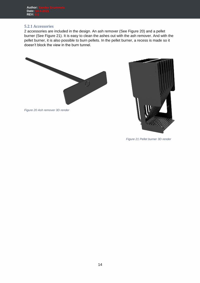
5.2.1 Accessories 2 accessories are included in the design. An ash remover (See Figure 20) and a pellet
burner (See Figure 21). It is easy to clean the ashes out with the ash remover. And with the
pellet burner, it is also possible to burn pellets. In the pellet burner, a recess is made so it
doesn’t block the view in the burn tunnel.
Figure 20 Ash remover 3D render
Figure 21 Pellet burner 3D render
15
Author: Sander Grummels Date: 14-4-2021 REV: 0.0
5.3 Operation
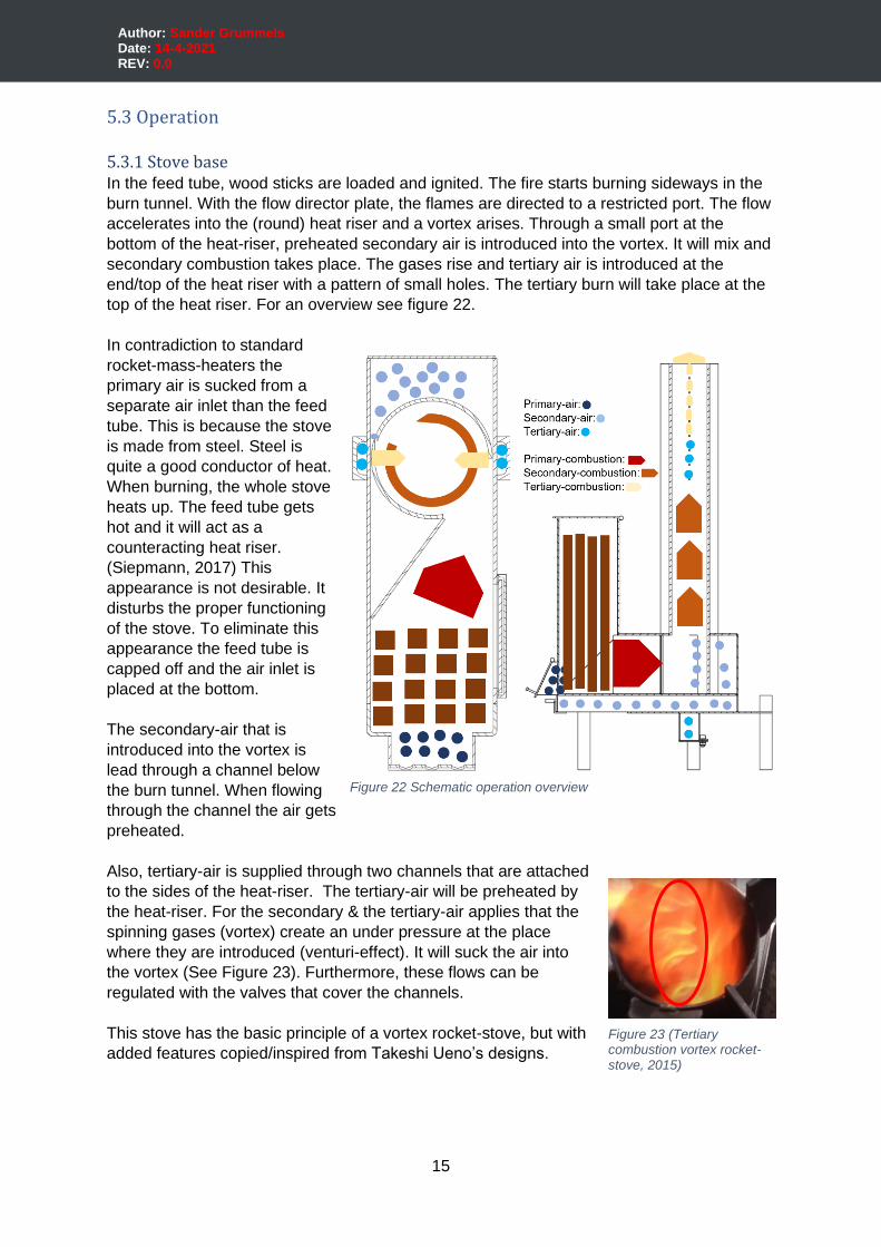
5.3.1 Stove base In the feed tube, wood sticks are loaded and ignited. The fire starts burning sideways in the
burn tunnel. With the flow director plate, the flames are directed to a restricted port. The flow
accelerates into the (round) heat riser and a vortex arises. Through a small port at the
bottom of the heat-riser, preheated secondary air is introduced into the vortex. It will mix and
secondary combustion takes place. The gases rise and tertiary air is introduced at the
end/top of the heat riser with a pattern of small holes. The tertiary burn will take place at the
top of the heat riser. For an overview see figure 22.
In contradiction to standard
rocket-mass-heaters the
primary air is sucked from a
separate air inlet than the feed
tube. This is because the stove
is made from steel. Steel is
quite a good conductor of heat.
When burning, the whole stove
heats up. The feed tube gets
hot and it will act as a
counteracting heat riser.
(Siepmann, 2017) This
appearance is not desirable. It
disturbs the proper functioning
of the stove. To eliminate this
appearance the feed tube is
capped off and the air inlet is
placed at the bottom.
The secondary-air that is
introduced into the vortex is
lead through a channel below
the burn tunnel. When flowing
through the channel the air gets
preheated.
Also, tertiary-air is supplied through two channels that are attached
to the sides of the heat-riser. The tertiary-air will be preheated by
the heat-riser. For the secondary & the tertiary-air applies that the
spinning gases (vortex) create an under pressure at the place
where they are introduced (venturi-effect). It will suck the air into
the vortex (See Figure 23). Furthermore, these flows can be
regulated with the valves that cover the channels.
This stove has the basic principle of a vortex rocket-stove, but with
added features copied/inspired from Takeshi Ueno’s designs.
Figure 23 (Tertiary combustion vortex rocket-stove, 2015)
Figure 22 Schematic operation overview
16
Author: Sander Grummels Date: 14-4-2021 REV: 0.0
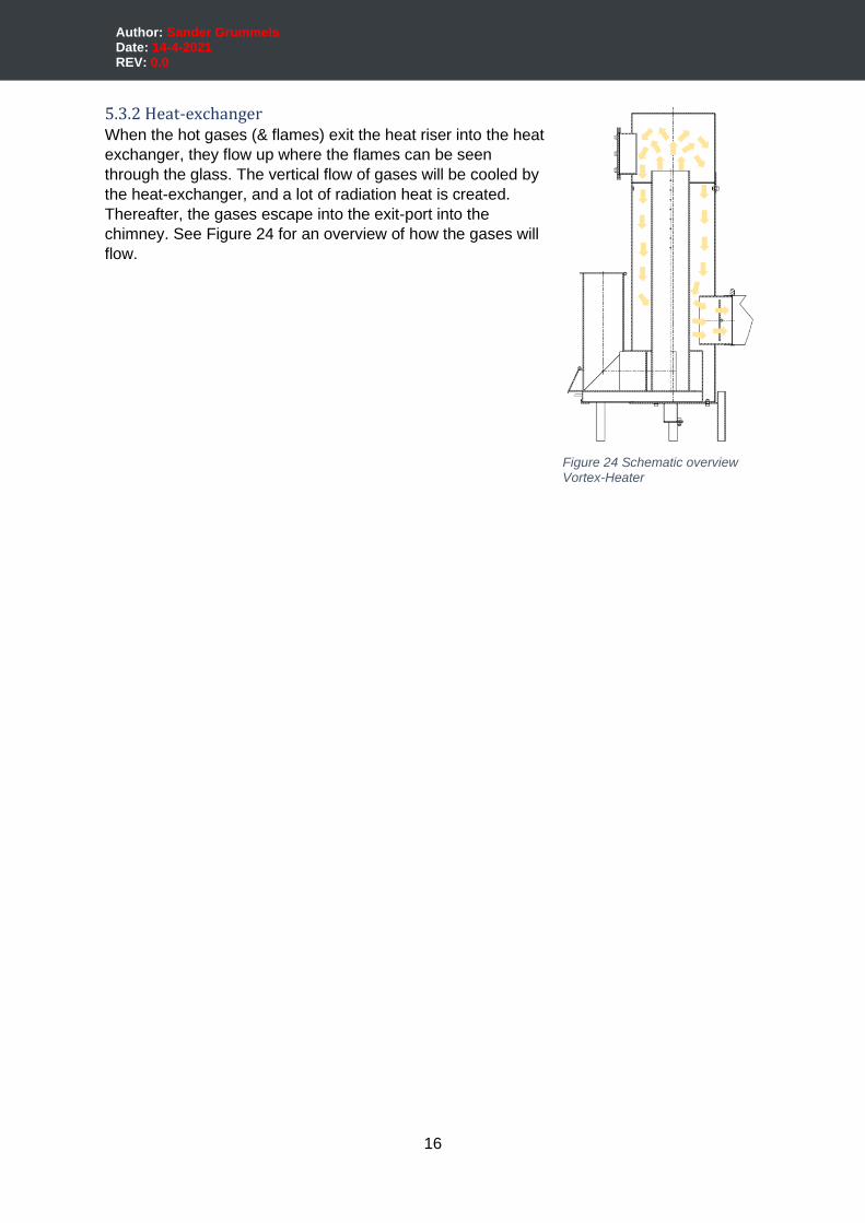
5.3.2 Heat-exchanger When the hot gases (& flames) exit the heat riser into the heat
exchanger, they flow up where the flames can be seen
through the glass. The vertical flow of gases will be cooled by
the heat-exchanger, and a lot of radiation heat is created.
Thereafter, the gases escape into the exit-port into the
chimney. See Figure 24 for an overview of how the gases will
flow.
Figure 24 Schematic overview Vortex-Heater
17
Author: Sander Grummels Date: 14-4-2021 REV: 0.0
5.4 Dimensioning
For vortex rocket-stoves there are no clear design rules how to dimension a kind of stove.
The inspiration from this stove came from Takeshi Ueno. By analyzing his stoves dimension
estimations have been done and applied on this design.
As a starting point, a round tube Ø139,7x4mm is used for the heat-riser. Based on these
dimensions all the other dimensions are determined.
Ianto Evans describes in his book “Rocket Mass Heaters” page 35 & 36: (See Appendix E.1)
some key dimensions and proportions for dimensioning. When dimensioning these basic
rocket-stove these design principles were taken into account.
(Evans & Jackson, Rocket Mass Heaters, 2007)
5.4.1 Dimensioning explanation
J-shape dimensions
The basic length proportions for a J-shape should be as followed designed, 1:2:4
(feed-tube:burn-tunnel:heat-riser). These proportions are relative to the system size1 and are
measured from center to center. This is just a rule of thumb.
Important is that the length of the heat riser is at least twice as long (longer = better) as the
burn tunnel to provide a good draft. Also, the heat-riser should be at least 4 times the length
of the feed tube to prevent a counter draft from the feed tube. This last rule doesn’t apply to
this design because the feed tube is capped off and the primary air gets sucked from a
separate inlet.
Air-inlet
The dimensions of the air-inlet are important because the right amount of air has to be
introduced. Too much air and the fire cools too much and not all the volatile gases will burn,
too little air won't provide enough oxygen for a clean burn. For a calculation of the sizing of
the air-inlet see Appendix C.
Burn tunnel
A design principle is that in the whole system the burn tunnel needs to have the smallest
cross-section. For this design, this doesn’t count because the restricted port replaces this
function (of mixing). The restriction has the smallest cross-section area in the system.
Further is stated that the burn tunnel should be as short as possible but a horizontal part is
needed for the mixing.
Restricted port
The restricted port is a restriction from the burn tunnel into the heat-riser. It accelerates the
gases into the heat-riser and spins into a vortex. There are no clear rules for the width of the
restriction but mostly the width varies between 30% to 50% of the internal diameter of the
1 Diameter or square dimension of the cross section of the (heat riser) J-shape. No distinction is made between square and round tube. A square tube has a larger surface than a round tube, but it’s skin surface is larger, which provides more resistance. So this equals each other out.
18
Author: Sander Grummels Date: 14-4-2021 REV: 0.0
heat-riser. In this design width of 40% of the total internal diameter is applied (estimated
from the design of Takeshi Ueno).
Secondary- and tertiary-air inlets
The secondary and tertiary-air port/holes are dimensioned also by an estimation.
Exit-port
For a good flow in the stove and to ensure that no accumulation of gases takes place, the
cross-sectional area of the exit port needs to be bigger than that of the cross-sectional area
of the heat riser.
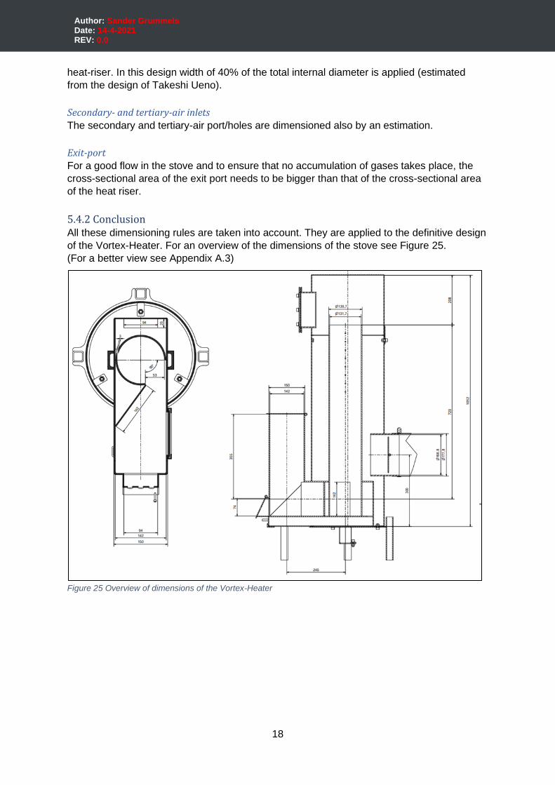
5.4.2 Conclusion All these dimensioning rules are taken into account. They are applied to the definitive design
of the Vortex-Heater. For an overview of the dimensions of the stove see Figure 25.
(For a better view see Appendix A.3)
Figure 25 Overview of dimensions of the Vortex-Heater
19
Author: Sander Grummels Date: 14-4-2021 REV: 0.0
6 | Execution From the 3d model design, full detailed 2D drawings are made to make the Vortex-Heater.
The stove is build based on the 2D drawings (See Appendix D.1). During building, mistakes
in the drawings have been adjusted. In the following paragraphs, the building of the stove is
shortly explained. For building a full part list & cut list are added to build the stove (See
Appendix D.2 & D.3). Also, production files (STEP and DXF) are added of every part and
weldment (See Appendix D.4 & D.5).
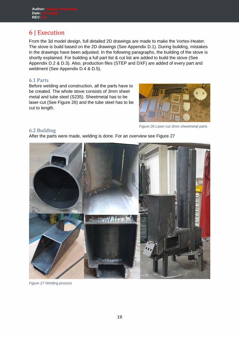
6.1 Parts Before welding and construction, all the parts have to
be created. The whole stove consists of 3mm sheet
metal and tube steel (S235). Sheetmetal has to be
laser-cut (See Figure 26) and the tube steel has to be
cut to length.
6.2 Building After the parts were made, welding is done. For an overview see Figure 27
Figure 26 Laser-cut 3mm sheetmetal parts
Figure 27 Welding process
20
Author: Sander Grummels Date: 14-4-2021 REV: 0.0
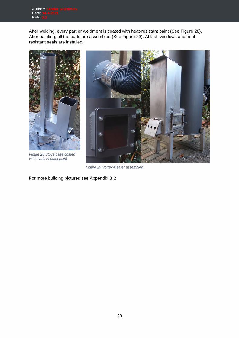
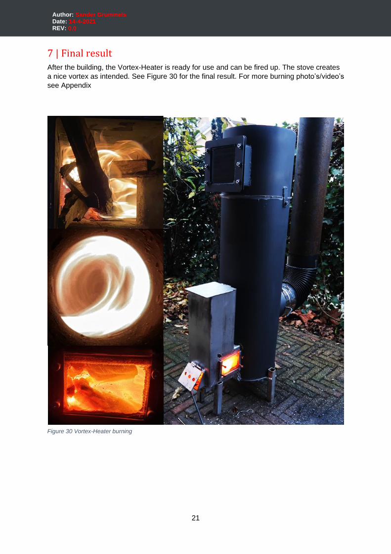
After welding, every part or weldment is coated with heat-resistant paint (See Figure 28).
After painting, all the parts are assembled (See Figure 29). At last, windows and heat-
resistant seals are installed.
For more building pictures see Appendix B.2
Figure 28 Stove base coated with heat resistant paint
Figure 29 Vortex-Heater assembled
21
Author: Sander Grummels Date: 14-4-2021 REV: 0.0
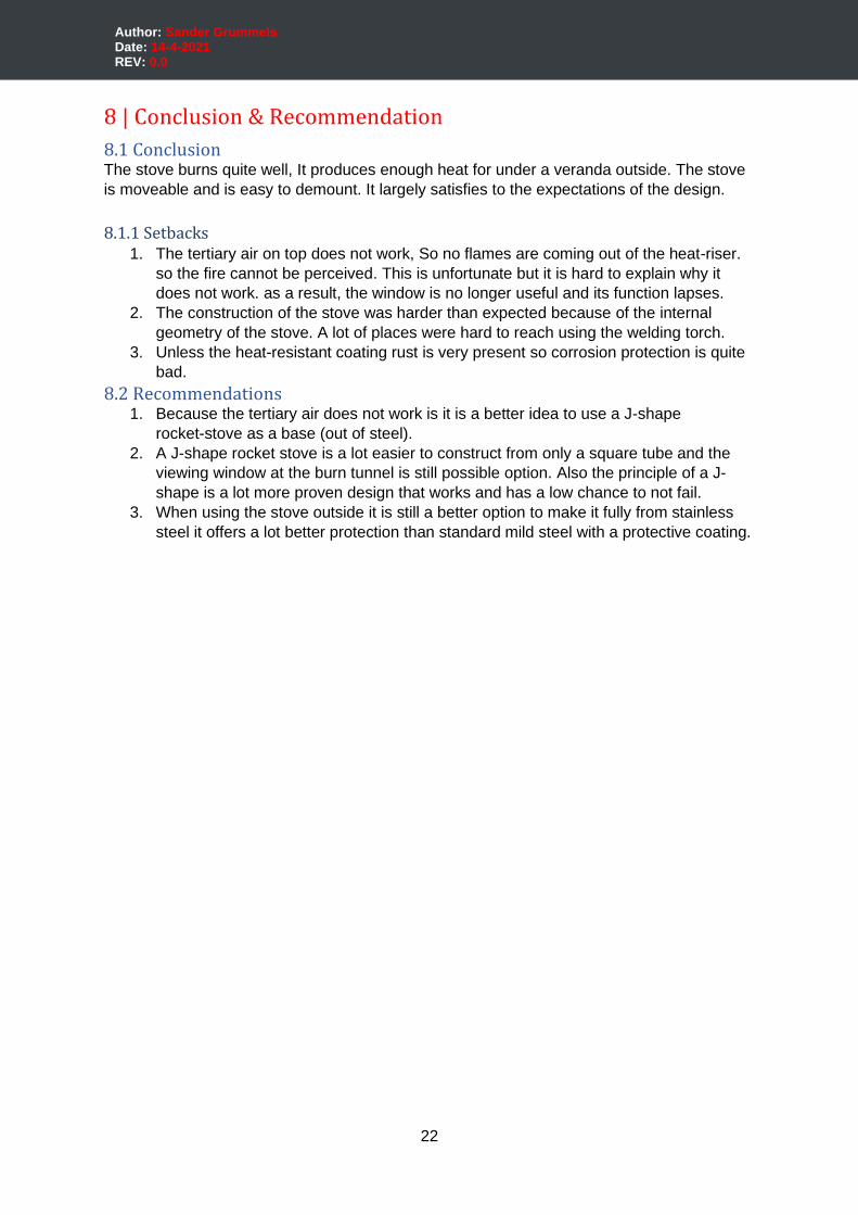
7 | Final result After the building, the Vortex-Heater is ready for use and can be fired up. The stove creates
a nice vortex as intended. See Figure 30 for the final result. For more burning photo’s/video’s
see Appendix
Figure 30 Vortex-Heater burning
22
Author: Sander Grummels Date: 14-4-2021 REV: 0.0
8 | Conclusion & Recommendation
8.1 Conclusion The stove burns quite well, It produces enough heat for under a veranda outside. The stove
is moveable and is easy to demount. It largely satisfies to the expectations of the design.
8.1.1 Setbacks 1. The tertiary air on top does not work, So no flames are coming out of the heat-riser.
so the fire cannot be perceived. This is unfortunate but it is hard to explain why it
does not work. as a result, the window is no longer useful and its function lapses.
2. The construction of the stove was harder than expected because of the internal
geometry of the stove. A lot of places were hard to reach using the welding torch.
3. Unless the heat-resistant coating rust is very present so corrosion protection is quite
bad.
8.2 Recommendations 1. Because the tertiary air does not work is it is a better idea to use a J-shape
rocket-stove as a base (out of steel).
2. A J-shape rocket stove is a lot easier to construct from only a square tube and the
viewing window at the burn tunnel is still possible option. Also the principle of a J-
shape is a lot more proven design that works and has a low chance to not fail.
3. When using the stove outside it is still a better option to make it fully from stainless
steel it offers a lot better protection than standard mild steel with a protective coating.
23
Author: Sander Grummels Date: 14-4-2021 REV: 0.0
9 | Bibliography (n.d.).Rocket Stove Shower - Apostol H.E. 850. Water heating rocket-stove. Retrieved March
27, 2021, from https://www.dailymotion.com/video/x2mw5gs (n.d.).(L-shape) Rocket-stove. Diagram of Rocket stove. Boiling Point. Retrieved from
http://www.stoves.bioenergylists.org/stovesdoc/Still/BoilingPoint47/BP47Still.pdf
(n.d.).Apostol rocket-stove. The Aposto Rocket 2016. Retrieved from
https://www.pinterest.cl/pin/447193437982249388/
Appropedia. (2012). Retrieved from https://www.appropedia.org/File:Rocket_stoveNF.png
Appropedia. (2021, 2 5). Rocket stoves. Retrieved from appropedia:
https://www.appropedia.org/Rocket_stoves
Bardon, S. (n.d.). V-shape rocket stove. Homemade wood burning Rocket stove. Youtube.
Retrieved from https://www.youtube.com/watch?v=9-r4VLHQRlM
Berg, P. v. (2019, December 11). Rocket stove van stalen koker. Retrieved March 28, 2021,
from https://www.ecologieforum.eu/viewtopic.php?t=7286
Berg, P. v. (n.d.). Open Batch-box rocket-stove. Batchrocket. Retrieved from
https://batchrocket.eu/en/workings
Berg, P. v. (n.d.). Top view heat-riser. Batchrocket. Retrieved from
https://batchrocket.eu/en/workings
Berg, P. v. (n.d.). Workings, how and why. Retrieved March 30, 2021, from Batchrocket:
https://batchrocket.eu/en/workings
(2017, 5 5).DIY rocket stove improvement. Retrieved from
https://www.youtube.com/watch?v=i06uJTSeBDo&t=25s
Engineer775. (2016, February 2). Apostol Rocket Stove. Retrieved March 27, 2021, from
https://www.youtube.com/watch?v=VsvKknmNqLQ&t=367s
Evans, I., & Jackson, L. (2007). Rocket Mass Heater cross-section. Cross-Section of a
Typical Rocket Mass Heater.
Evans, I., & Jackson, L. (2007). Rocket Mass Heaters. Cob Cottage. doi:0966373847
Frequently Asked Questions. (n.d.). Retrieved March 30, 2021, from himalayanrocketstove:
https://himalayanrocketstove.com/faq/
Hill, H. (2017, August 2). Rocket Stoves: Tips for Designing Your Own. Retrieved from
Treehugger: https://www.treehugger.com/rocket-stoves-tips-for-designing-your-own-
4863645
Lebel, J. (2017, March 4). Fires of the future: Meet the Oregon innovators fighting global
pollution with rocket stoves. Retrieved from Planetforward:
https://www.planetforward.org/idea/fires-of-the-future-meet-the-oregon-innovators-
fighting-global-pollution-with-rocket-stoves
(n.d.).L-shape rocket stove. How To Make A Concrete Rocket Stove Easily At Home ? #3.
Thang TV - Creative Craft Ideas. Retrieved from
https://www.youtube.com/watch?v=064ZtmvgytA
(2015).Rocket stove heater for a workshop or a room. Retrieved from
https://www.youtube.com/watch?v=7DXp1G5DySE
(2017, 9 13).ROCKET STOVE SIDE VIEW. Retrieved from Youtube:
https://www.youtube.com/watch?v=5JaG1m0Q8fo&list=PLZVB2p0QpOb0CIjsnkmRx
UvtEKfG7RMVf
Siepmann, R. (2017). Help required with mini rocket stove. Retrieved 4 12, 2021, from
https://permies.com/t/60398/required-mini-rocket-stove
sjoerdb. (2019). K-shape rocket-stove. Retrieved from
https://www.ecologieforum.eu/viewtopic.php?t=7286
Takeshi Ueno. (n.d.). CYCLONE BAZOOKA X. Retrieved March 30, 2021, from firecyclone:
http://firecyclone.jp/cyclonebazookax.html
24
Author: Sander Grummels Date: 14-4-2021 REV: 0.0
(2015).Tertiary combustion vortex rocket-stove. Tertiary combustion vortex rocket stove.
Takeshi Ueno. Retrieved April 5, 2021, from
https://www.youtube.com/watch?v=NJENCc3o_-Y&t=76s
(n.d.).Top view vortex in heat-riser. fyrecyclone. Retrieved from f:
http://firecyclone.jp/cyclonebazookax.html
Winiarski, L., & Still, D. (2001). Increasing fuel efficiency and reducing harmful emissions in.
Aprovecho Research Center. Orego: Boiling Point No 47 Autumn 2001.
(2013, 11 1).ロケットストーブ アウトドアへ持ち出そう. Retrieved from
https://www.youtube.com/watch?v=2EdmPWI-8M4
In appendix F source files are attached
9.1.1 List of figures Figure 1 Schematic view of a L-shape rocket-stove .............................................................. 5 Figure 2 (L-shape rocket stove) ............................................................................................ 6 Figure 3 (Bardon) V-shape rocket-stove................................................................................ 6 Figure 4 (Apostol rocket-stove) ............................................................................................. 7 Figure 5 (Rocket Stove Shower - Apostol H.E. 850) .............................................................. 7 Figure 6 (Evans & Jackson, Rocket Mass Heater cross-section, 2007) ................................. 7 Figure 7 (Top view vortex in heat-riser) ................................................................................. 8 Figure 8 (Berg, Open Batch-box rocket-stove) ...................................................................... 8 Figure 9 (Berg, Top view heat-riser) ...................................................................................... 8 Figure 10 (sjoerdb, 2019) ...................................................................................................... 9
Figure 11 (ロケットストーブ アウトドアへ持ち出そう, 2013) ......................................... 10
Figure 12 (Rocket stove heater for a workshop or a room, 2015) ........................................ 10 Figure 13 (DIY rocket stove improvement, 2017) ................................................................ 10 Figure 14 (ROCKET STOVE SIDE VIEW, 2017) ................................................................. 10 Figure 15 Vortex-Heater concept ........................................................................................ 11 Figure 16 Vortex-Heater 3D render ..................................................................................... 12 Figure 17 Vortex-Heater section ......................................................................................... 12 Figure 18 Vortex-Heater stove base 3D render ................................................................... 12 Figure 19 Vortex-Heater distinctive parts ............................................................................ 13 Figure 20 Ash remover 3D render ....................................................................................... 14 Figure 21 Pellet burner 3D render ....................................................................................... 14 Figure 22 Schematic operation overview............................................................................. 15 Figure 23 (Tertiary combustion vortex rocket-stove, 2015) .................................................. 15 Figure 24 Schematic overview Vortex-Heater ..................................................................... 16 Figure 25 Overview of dimensions of the Vortex-Heater ..................................................... 18 Figure 26 Laser-cut 3mm sheetmetal parts ......................................................................... 19 Figure 27 Welding process ................................................................................................. 19 Figure 28 Stove base coated with heat resistant paint ........................................................ 20 Figure 29 Vortex-Heater assembled .................................................................................... 20 Figure 30 Vortex-Heater burning ......................................................................................... 21
Copyright © 2022 FDOKUMEN