DESIGNER'S GUIDE COPPER-FIN® WATER HEATER
24
DESIGNER’S GUIDE COPPER-FIN ® WATER HEATER 495,000 – 2,065,000 Btu/hr
-
Upload
khangminh22 -
Category
Documents
-
view
1 -
download
0
Transcript of DESIGNER'S GUIDE COPPER-FIN® WATER HEATER
DESIGNER’S GUIDE COPPER-FIN® WATER HEATER4 9 5 , 0 0 0 – 2 , 0 6 5 , 0 0 0 B t u / h r
Dear Specifier/Project Manager,
At Lochinvar, we have long recognized the importance of innovation to any
product or service. Those who enter into business must also accept the challenge
of meeting constantly changing needs.
The designer’s guide you are now holding has been designed to make it more
convenient for you to select the perfect Lochinvar water heater for your projects
and provide correct specifications for your teams.
All information has been organized and presented in a succinct, easy-to-use
manner, so you can use and share information confidently and with minimal
effort.
However, it is important to remember that this guide is not intended to replace our
installation manual. Installers should still refer to our installation manual for
specific installation instructions.
We hope this manual will make your work easier and more productive. As always,
we greatly appreciate your input on additional improvements for the future.
Thanks once again for specifying the Lochinvar family of quality standard
and custom-built water heaters and boilers.
Sincerely,
Lochinvar Corporation
N a s h v i l l e , T N • 6 1 5 - 8 8 9 - 8 9 0 0 • F a x : 6 1 5 - 5 4 7 - 1 0 0 0
L o c h i n v a r D E S I G N E R’ S G U I D E C O P P E R - F I N W A T E R H E A T E R 6 1 5 - 8 8 9 - 8 9 0 0 1
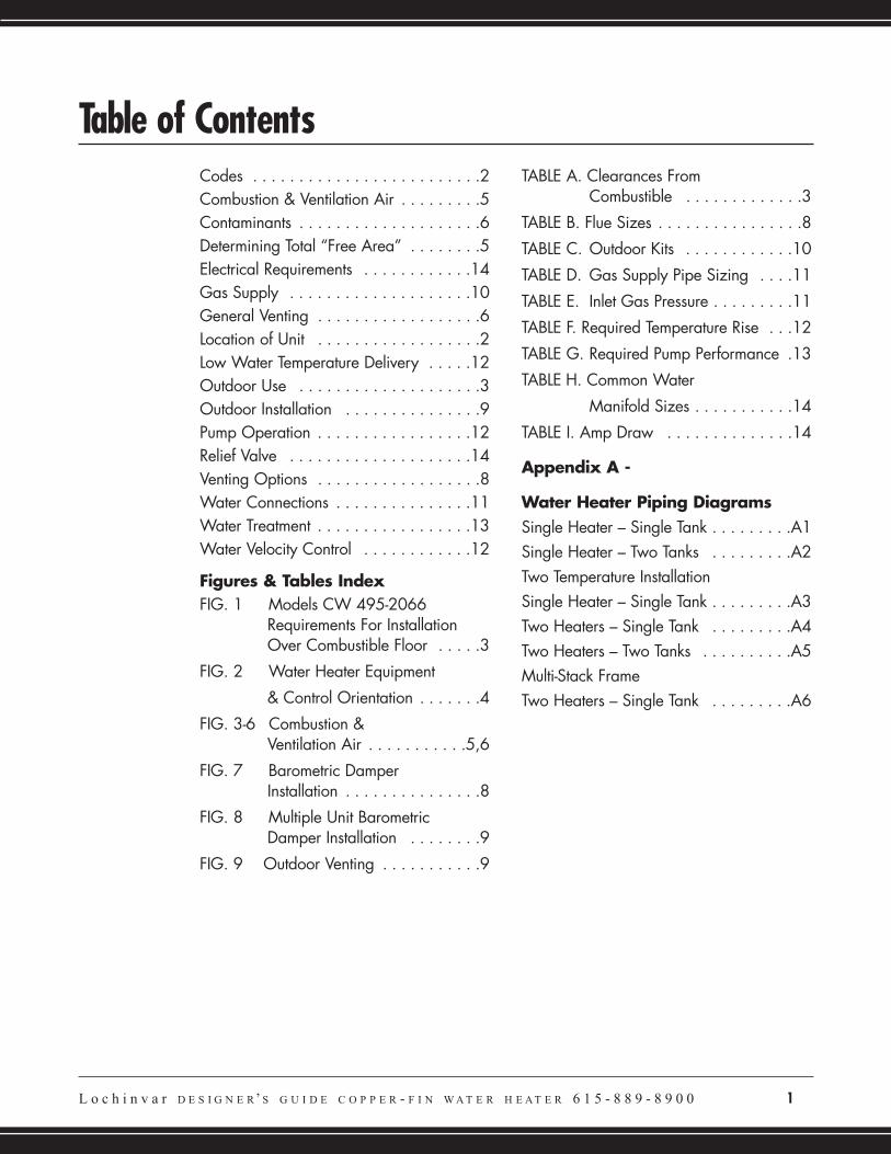
Codes . . . . . . . . . . . . . . . . . . . . . . . . .2Combustion & Ventilation Air . . . . . . . . .5Contaminants . . . . . . . . . . . . . . . . . . . .6Determining Total “Free Area” . . . . . . . .5Electrical Requirements . . . . . . . . . . . .14Gas Supply . . . . . . . . . . . . . . . . . . . .10General Venting . . . . . . . . . . . . . . . . . .6Location of Unit . . . . . . . . . . . . . . . . . .2Low Water Temperature Delivery . . . . .12Outdoor Use . . . . . . . . . . . . . . . . . . . .3Outdoor Installation . . . . . . . . . . . . . . .9Pump Operation . . . . . . . . . . . . . . . . .12Relief Valve . . . . . . . . . . . . . . . . . . . .14Venting Options . . . . . . . . . . . . . . . . . .8Water Connections . . . . . . . . . . . . . . .11Water Treatment . . . . . . . . . . . . . . . . .13Water Velocity Control . . . . . . . . . . . .12
Figures & Tables IndexFIG. 1 Models CW 495-2066
Requirements For Installation Over Combustible Floor . . . . .3
FIG. 2 Water Heater Equipment
& Control Orientation . . . . . . .4
FIG. 3-6 Combustion &Ventilation Air . . . . . . . . . . .5,6
FIG. 7 Barometric DamperInstallation . . . . . . . . . . . . . . .8
FIG. 8 Multiple Unit BarometricDamper Installation . . . . . . . .9
FIG. 9 Outdoor Venting . . . . . . . . . . .9
TABLE A. Clearances FromCombustible . . . . . . . . . . . . .3
TABLE B. Flue Sizes . . . . . . . . . . . . . . . .8
TABLE C. Outdoor Kits . . . . . . . . . . . .10
TABLE D. Gas Supply Pipe Sizing . . . .11
TABLE E. Inlet Gas Pressure . . . . . . . . .11
TABLE F. Required Temperature Rise . . .12
TABLE G. Required Pump Performance .13
TABLE H. Common Water
Manifold Sizes . . . . . . . . . . .14
TABLE I. Amp Draw . . . . . . . . . . . . . .14
Appendix A -
Water Heater Piping DiagramsSingle Heater – Single Tank . . . . . . . . .A1Single Heater – Two Tanks . . . . . . . . .A2Two Temperature InstallationSingle Heater – Single Tank . . . . . . . . .A3Two Heaters – Single Tank . . . . . . . . .A4Two Heaters – Two Tanks . . . . . . . . . .A5Multi-Stack FrameTwo Heaters – Single Tank . . . . . . . . .A6
Table of Contents
CODESThe equipment shall be installed inaccordance with those installationregulations in effect in the local area wherethe installation is to be made. These shallbe carefully followed in all cases. Authoritieshaving jurisdiction shall be consulted beforeinstallations are made.
In the absence of such requirements, theinstallation shall conform to the latest edition ofthe National Fuel Gas Code, ANSI Z223.1.Where required by the authority havingjurisdiction, the installation must conform toAmerican Society of Mechanical EngineersSafety Code for Controls and Safety Devicesfor Automatically Fired Boilers, ASME CSD-1.Where required by the authority havingjurisdiction, the installation must comply withthe Canadian Association Code, CAN/CGA-B149.1 and/or B149.2 and/or local codes.
LOCATION OF UNITLocate the unit so that if water connectionsshould leak, water damage will not occur.When such locations cannot be avoided, itis recommended that a suitable drain pan,adequately drained, be installed under theunit. The pan must not restrict combustionair flow.
2 L o c h i n v a r D E S I G N E R’ S G U I D E C O P P E R - F I N W A T E R H E A T E R 6 1 5 - 8 8 9 - 8 9 0 0
1.
Lochinvar
o Water Velocity(See page 12 for Required Degree
Rise chart.)
o Factory Supplied Pump Capacity(See page 12 for Pump Operation.)
o Manifold Pipe SizeWhen using more than one heater(See page 14 for Common Water
Manifold Size for Multiple Water
Heater Installation Table.)
o Storage Tank Circulating Tappings(See page 14 for Manifold Pipe
Size.)
o Placement of Cold WaterInlet and Building Return(See Appendix A for Water Heater
Piping Diagrams.)
o Water Hardness(See page 13 for Water Treatment
Information.)
In designinga water heater system,pay special attention to:
Under no circumstances is themanufacturer to be held responsiblefor water damage in connectionwith this unit or any of itscomponents.
The indoor units must be installed so thatthe ignition system components areprotected from water (dripping, spraying,rain, etc.) during appliance operation andservice (circulator replacement, controlreplacement, etc.).
The appliance must be installed on a level, non-combustible floor.Concrete over wood is not considered anon-combustible floor. Maintain requiredclearances from combustible surfaces.
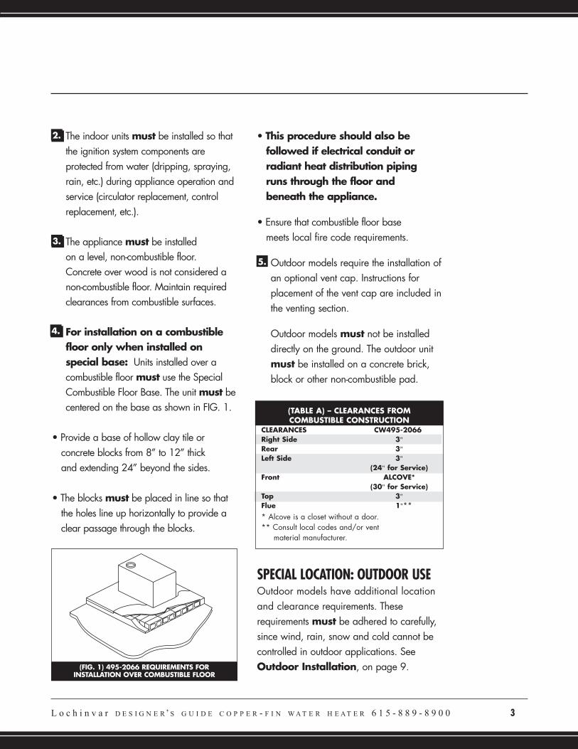
For installation on a combustiblefloor only when installed onspecial base: Units installed over acombustible floor must use the SpecialCombustible Floor Base. The unit must becentered on the base as shown in FIG. 1.
• Provide a base of hollow clay tile or concrete blocks from 8” to 12” thick and extending 24” beyond the sides.
• The blocks must be placed in line so that the holes line up horizontally to provide a clear passage through the blocks.
• This procedure should also befollowed if electrical conduit orradiant heat distribution pipingruns through the floor and beneath the appliance.
• Ensure that combustible floor basemeets local fire code requirements.
Outdoor models require the installation ofan optional vent cap. Instructions forplacement of the vent cap are included inthe venting section.
Outdoor models must not be installeddirectly on the ground. The outdoor unitmust be installed on a concrete brick,block or other non-combustible pad.
SPECIAL LOCATION: OUTDOOR USEOutdoor models have additional locationand clearance requirements. Theserequirements must be adhered to carefully,since wind, rain, snow and cold cannot becontrolled in outdoor applications. SeeOutdoor Installation, on page 9.
2.
4.
3.
L o c h i n v a r D E S I G N E R’ S G U I D E C O P P E R - F I N W A T E R H E A T E R 6 1 5 - 8 8 9 - 8 9 0 0 3
(FIG. 1) 495-2066 REQUIREMENTS FORINSTALLATION OVER COMBUSTIBLE FLOOR
5.
(TABLE A) – CLEARANCES FROMCOMBUSTIBLE CONSTRUCTION
CLEARANCES CW495-2066Right Side 3"
Rear 3"
Left Side 3"
(24" for Service)Front ALCOVE*
(30" for Service)Top 3"
Flue 1"*** Alcove is a closet without a door. ** Consult local codes and/or vent
material manufacturer.
4 L o c h i n v a r D E S I G N E R’ S G U I D E C O P P E R - F I N W A T E R H E A T E R 6 1 5 - 8 8 9 - 8 9 0 0
Lochinvar
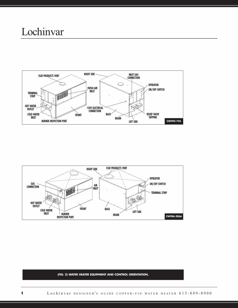
(FIG. 2) WATER HEATER EQUIPMENT AND CONTROL ORIENTATION.
RIGHT SIDEFLUE PRODUCTS VENT
TERMINALSTRIP
HOT WATEROUTLET
COLD WATERINLET
BURNER INSPECTION PORT
FRONT
GASCONNECTION
HOT WATEROUTLET
COLD WATERINLET BURNER
INSPECTION PORT
FRONT
AIRINLET
FRESH AIRINLET
RIGHT SIDE FLUE PRODUCTS VENT
BACK
DRAINLEFT SIDE
BACK
120V ELECTRICALCONNECTION
OPERATORON/OFF SWITCH
OPERATOR
TERMINAL STRIP
ON/OFF SWITCH
LEFT SIDEDRAIN
RELIEF VALVETAPPING
INLET GASCONNECTION
CW495-745
CW986-2066
L o c h i n v a r D E S I G N E R’ S G U I D E C O P P E R - F I N W A T E R H E A T E R 6 1 5 - 8 8 9 - 8 9 0 0 5
COMBUSTION & VENTILATION AIRProvisions for combustion and ventilation airmust be in accordance with Section 5.3, Air for Combustion and Ventilation, of thelatest edition of the National Fuel GasCode, ANSI Z223.1; in Canada, the latestedition of CGA Standard B149 InstallationCode for Gas Burning Appliances andEquipment; or applicable provisions of thelocal building codes.
The equipment room must be provided withproperly sized openings to assure adequatecombustion air and proper ventilation whenthe unit is installed with conventional ventingor sidewall venting.
If air is taken directly from outsidethe building with no duct, provide twopermanent openings:
A. Combustion air opening with aminimum free area of one square inch per4000 Btu input (5.5 cm2 per kW).
This opening must be located within 12”(30 cm) of the bottom of the enclosure.
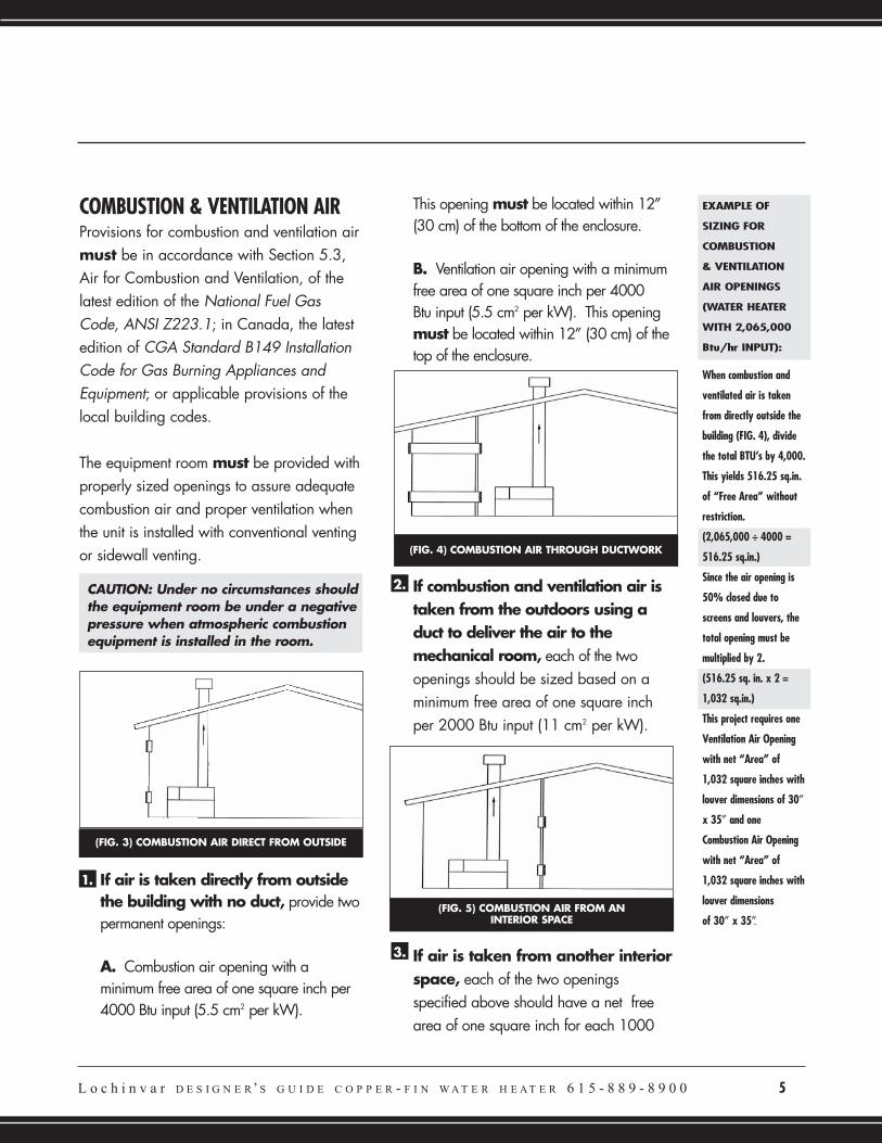
B. Ventilation air opening with a minimumfree area of one square inch per 4000 Btu input (5.5 cm2 per kW). This openingmust be located within 12” (30 cm) of thetop of the enclosure.
If combustion and ventilation air istaken from the outdoors using aduct to deliver the air to themechanical room, each of the twoopenings should be sized based on aminimum free area of one square inchper 2000 Btu input (11 cm2 per kW).
If air is taken from another interiorspace, each of the two openingsspecified above should have a net freearea of one square inch for each 1000
(FIG. 3) COMBUSTION AIR DIRECT FROM OUTSIDE
(FIG. 4) COMBUSTION AIR THROUGH DUCTWORK
(FIG. 5) COMBUSTION AIR FROM AN INTERIOR SPACE
CAUTION: Under no circumstances shouldthe equipment room be under a negativepressure when atmospheric combustionequipment is installed in the room.
1.
2.
3.
EXAMPLE OF
SIZING FOR
COMBUSTION
& VENTILATION
AIR OPENINGS
(WATER HEATER
WITH 2,065,000
Btu/hr INPUT):
When combustion and
ventilated air is taken
from directly outside the
building (FIG. 4), divide
the total BTU’s by 4,000.
This yields 516.25 sq.in.
of “Free Area” without
restriction.
(2,065,000 ÷ 4000 =
516.25 sq.in.)
Since the air opening is
50% closed due to
screens and louvers, the
total opening must be
multiplied by 2.
(516.25 sq. in. x 2 =
1,032 sq.in.)
This project requires one
Ventilation Air Opening
with net “Area” of
1,032 square inches with
louver dimensions of 30”
x 35” and one
Combustion Air Opening
with net “Area” of
1,032 square inches with
louver dimensions
of 30” x 35”.
6 L o c h i n v a r D E S I G N E R’ S G U I D E C O P P E R - F I N W A T E R H E A T E R 6 1 5 - 8 8 9 - 8 9 0 0
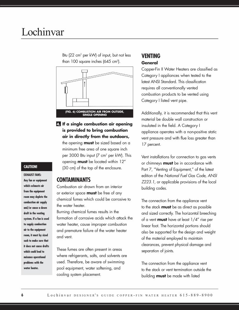
Btu (22 cm2 per kW) of input, but not lessthan 100 square inches (645 cm2).
If a single combustion air openingis provided to bring combustionair in directly from the outdoors,the opening must be sized based on aminimum free area of one square inchper 3000 Btu input (7 cm2 per kW). Thisopening must be located within 12”(30 cm) of the top of the enclosure.
CONTAMINANTSCombustion air drawn from an interior or exterior space must be free of anychemical fumes which could be corrosive tothe water heater. Burning chemical fumes results in theformation of corrosive acids which attack thewater heater, cause improper combustionand premature failure of the water heaterand vent.
These fumes are often present in areaswhere refrigerants, salts, and solvents areused. Therefore, be aware of swimmingpool equipment, water softening, andcooling system placement.
VENTING GeneralCopper-Fin II Water Heaters are classified asCategory I appliances when tested to thelatest ANSI Standard. This classificationrequires all conventionally ventedcombustion products to be vented usingCategory I listed vent pipe.
Additionally, it is recommended that this ventmaterial be double wall construction orinsulated in the field. A Category Iappliance operates with a non-positive staticvent pressure and with flue loss greater than17 percent.
Vent installations for connection to gas ventsor chimneys must be in accordance withPart 7, “Venting of Equipment,” of the latestedition of the National Fuel Gas Code, ANSIZ223.1, or applicable provisions of the localbuilding codes.
The connection from the appliance vent to the stack must be as direct as possibleand sized correctly. The horizontal breechingof a vent must have at least 1/4” rise perlinear foot. The horizontal portions shouldalso be supported for the design and weightof the material employed to maintainclearances, prevent physical damage andseparation of joints.
The connection from the appliance vent to the stack or vent termination outside thebuilding must be made with listed
Lochinvar
4.
(FIG. 6) COMBUSTION AIR FROM OUTSIDE, SINGLE OPENING
CAUTION!
EXHAUST FANS:
Any fan or equipment
which exhausts air
from the equipment
room may deplete the
combustion air supply
and/or cause a down
draft in the venting
system. If a fan is used
to supply combustion
air to the equipment
room, it must by sized
such to make sure that
it does not cause drafts
which could lead to
nuisance operational
problems with the
water heater.
Category I double wall vent (or equivalent)connectors and sized according to ventsizing tables (FAN column) in the latestedition of the National Fuel Gas Code.
The Category I vent and accessories, such asfirestop spacers, thimbles, caps, etc., mustbe installed in accordance with the ventmanufacturer’s listing. The vent connector andfirestop must provide correct spacing tocombustible surfaces and seal to the ventconnector on the upper and lower sides ofeach floor or ceiling through which the ventconnector passes.
Any improper operation of the commonventing system in an existing building shouldbe corrected when new equipment isinstalled, so the installation conforms to thelatest edition of the National Fuel Gas Code,ANSI Z223.1.
When resizing any portion of the commonventing system, it should be resized toapproach the minimum size as determinedusing the appropriate tables in the NationalFuel Gas Code.
The weight of the venting system must notrest on the water heater. The venting systemmust be adequately supported incompliance with local codes and otherapplicable codes.
Vent TerminationsThe vent terminal should be vertical andexhaust outside the building at least 2 feet(0.6 m) above the highest point of the roofwhen within a 10 foot (3.05 m) radius.
Additionally, vertical terminations must be aminimum of 3 feet (0.9 m) above the roofline, and when less than 10 feet (3.05 m)from a parapet wall must be a minimum of2 feet (0.61 m) higher than the parapet wall.
Vent caps should have a minimum clearanceof 4 feet (1.2 m) horizontally from, and in nocase above or below [unless a 4 feet (1.2 m)horizontal distance is maintained], electricmeters, gas meters, regulators and reliefequipment.
Maintain a distance of at least 3 feet(0.9 m) above any forced air inlet within 10 feet (3.05 m) and a distance of atleast 4 feet (1.2 m) below, 4 feet (1.2 m)horizontally from, or 1 foot (30 cm) aboveany door, window or gravity air inlet.
Do not terminate the vent in a window well,stairwell, alcove, courtyard or other recessedarea. The vent can not terminatebelow grade. The bottom of the ventterminal shall be located at least 12 inches(30 cm) above grade and clear of snow,ice, leaves or other debris.
The distance of the vent terminal fromadjacent public walkways, adjacentbuildings, windows, and building openings
L o c h i n v a r D E S I G N E R’ S G U I D E C O P P E R - F I N W A T E R H E A T E R 6 1 5 - 8 8 9 - 8 9 0 0 7
8 L o c h i n v a r D E S I G N E R’ S G U I D E C O P P E R - F I N W A T E R H E A T E R 6 1 5 - 8 8 9 - 8 9 0 0
must be consistent with the National FuelGas Code Z223.1 or in Canada, the latestedition of CGA Standard B149 InstallationCode for Gas Burning Appliances andEquipment.
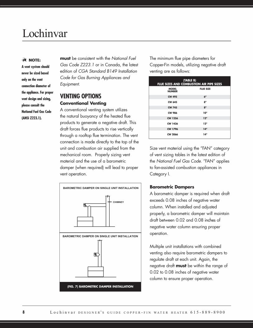
VENTING OPTIONSConventional VentingA conventional venting system utilizes the natural buoyancy of the heated flueproducts to generate a negative draft. Thisdraft forces flue products to rise verticallythrough a rooftop flue termination. The ventconnection is made directly to the top of theunit and combustion air supplied from themechanical room. Properly sizing ventmaterial and the use of a barometricdamper (when required) will lead to propervent operation.
The minimum flue pipe diameters forCopper-Fin models, utilizing negative draftventing are as follows:
Size vent material using the “FAN” categoryof vent sizing tables in the latest edition ofthe National Fuel Gas Code. “FAN” appliesto fan-assisted combustion appliances inCategory I.
Barometric DampersA barometric damper is required when draftexceeds 0.08 inches of negative watercolumn. When installed and adjustedproperly, a barometric damper will maintaindraft between 0.02 and 0.08 inches ofnegative water column ensuring properoperation.
Multiple unit installations with combinedventing also require barometric dampers toregulate draft at each unit. Again, thenegative draft must be within the range of0.02 to 0.08 inches of negative watercolumn to ensure proper operation.
Lochinvar
(FIG. 7) BAROMETRIC DAMPER INSTALLATION
(TABLE B)FLUE SIZES AND COMBUSTION AIR PIPE SIZES
MODEL FLUE SIZENUMBER
CW 495 6"
CW 645 8"
CW 745 8"
CW 986 10"
CW 1256 12"
CW 1436 12"
CW 1796 14"
CW 2066 14"
NOTE:
A vent system should
never be sized based
only on the vent
connection diameter of
the appliance. For proper
vent design and sizing,
please consult the
National Fuel Gas Code
(ANSI Z223.1).

For this type of installation, it is best to use adraft control for each water heater locatedon the riser between the vent outlet and thebreeching - Location “A”. When this riser istoo short to permit the installation of a draftcontrol, locate a separate control for eachwater heater on the main breeching asillustrated in Location “B”. If, because ofgeneral crowding or other reasons, neitherof these locations are possible, use a singlelarge control in the breeching between thewater heater nearest the chimney and thechimney, as shown in Location “C”.
All draft readings are made while unit is instable operation (approximately 5 minutesrunning time).
Masonry ChimneyA masonry chimney must be properly sizedfor the installation of a high efficiency gasfired appliance. Exterior masonry chimneys,with one or more sides exposed to coldoutdoor temperatures, are more likely tohave venting problems. The temperature ofthe flue products from a high efficiencyappliance may not be able to sufficientlyheat the masonry structure of the chimney togenerate proper draft. This will result in
condensing of flue products, damage of themasonry flue/tile, insufficient draft andpossible spillage of flue products into anoccupied living space.
Carefully inspect all chimney systems duringthe project design phase. If there is any doubtabout the sizing or condition of a masonrychimney, it is prudent to reline the chimneywith a properly sized and approved chimneyliner system. Metallic liner systems (Type “B”doublewall or flexible or rigid metallic liners)are recommended. Consult with local codeofficials to determine code requirements or theadvisability of using or relining a masonrychimney.
OUTDOOR INSTALLATION
Units are self venting and can be usedoutdoors when installed with the optionalOutdoor Cap. This cap mounts directly tothe top of the water heater and covers theflue outlet and combustion air inlet openingson the jacket. No additional vent piping isrequired. Maintain a minimum clearance of3” (76mm) to combustible surfaces and aminimum of 3” (76 mm) clearance to the airinlet.
L o c h i n v a r D E S I G N E R’ S G U I D E C O P P E R - F I N W A T E R H E A T E R 6 1 5 - 8 8 9 - 8 9 0 0 9
NOTE:
Common venting
systems may be too
large when an existing
unit is removed. Be
careful to resize any
common venting system
when new appliances
are installed or existing
appliances are replaced.
NOTE:
Flue gases will form a
white plume in winter.
Plume could obstruct
window view. Flue gas
condensate can freeze
on exterior surfaces or
on the vent cap. Flue
gas condensate can
cause discoloration of
exterior building
surfaces. Adjacent brick
or masonry surfaces
should be protected with
a rust resistant sheet
metal plate.
(FIG. 8) MULTIPLE UNIT BAROMETRICDAMPER INSTALLATION
(FIG. 9) OUTDOOR VENTING
NOTE:
Venting of a high
efficiency appliance into
a cold or oversized
masonry chimney can
result in operational and
safety problems.
10 L o c h i n v a r D E S I G N E R’ S G U I D E C O P P E R - F I N W A T E R H E A T E R 6 1 5 - 8 8 9 - 8 9 0 0
An outdoor unit should not be located sothat high winds can deflect off of adjacentwalls, buildings or shrubbery causingrecirculation. Recirculation of flue productsmay cause operational problems, badcombustion or damage to controls. The unitshould be located at least 3 feet (0.91m)from any wall or vertical surface to preventadverse wind conditions from affectingperformance.
Multiple unit outdoor installations require48” (1.22 m) clearance between each ventcap. The outdoor cap must be located 4feet (1.22 m) below and 4 feet (1.22 m)horizontally from any window, door,walkway or gravity air intake.
The combustion air inlet of the outdoor capmust be located at least one foot (0.30 m)above grade and above normal snowlevels. The water heater must be at least 10feet (3.05 m) away from any forced air inletand at least 3 feet (0.91 m) outside anyoverhang.
Do not install in locations where rain frombuilding runoff drains will spill onto thewater heater.
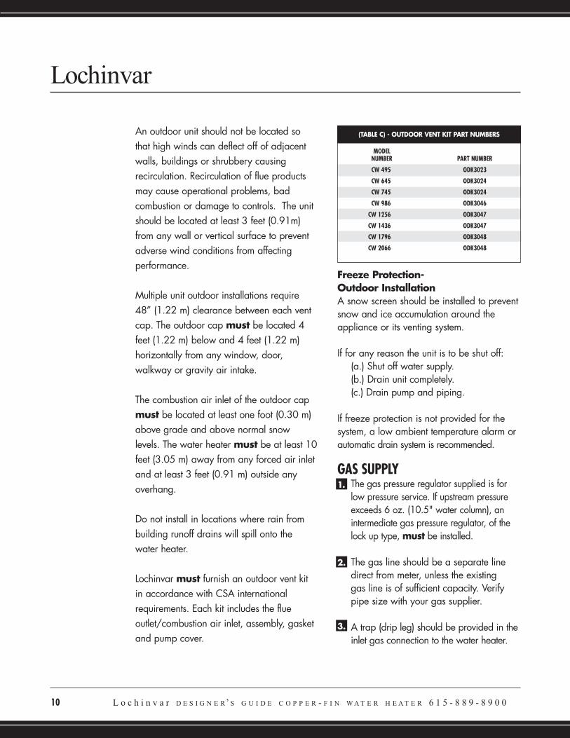
Lochinvar must furnish an outdoor vent kitin accordance with CSA internationalrequirements. Each kit includes the flueoutlet/combustion air inlet, assembly, gasketand pump cover.
Freeze Protection- Outdoor InstallationA snow screen should be installed to preventsnow and ice accumulation around theappliance or its venting system.
If for any reason the unit is to be shut off:(a.) Shut off water supply.(b.) Drain unit completely.(c.) Drain pump and piping.
If freeze protection is not provided for thesystem, a low ambient temperature alarm orautomatic drain system is recommended.
GAS SUPPLYThe gas pressure regulator supplied is forlow pressure service. If upstream pressureexceeds 6 oz. (10.5" water column), anintermediate gas pressure regulator, of thelock up type, must be installed.
The gas line should be a separate line direct from meter, unless the existing gas line is of sufficient capacity. Verify pipe size with your gas supplier.
A trap (drip leg) should be provided in theinlet gas connection to the water heater.
Lochinvar
(TABLE C) - OUTDOOR VENT KIT PART NUMBERS
MODEL NUMBER PART NUMBER
CW 495 ODK3023
CW 645 ODK3024
CW 745 ODK3024
CW 986 ODK3046
CW 1256 ODK3047
CW 1436 ODK3047
CW 1796 ODK3048
CW 2066 ODK3048
1.
2.
3.
A manual main gas shutoff valve is provided outside the jacket, upstream of the main gas valve.
In Canada, derated10% from 2,000 -4,500 ft., over 4,500 ft. derate must bein accordance with local authorities.Consult factory for installations athigher elevations.
High Altitude ApplicationsAtmospheric pressure decreases as theheight above sea level increases. At anyaltitude above sea level, a cubic foot willcontain less gas than a cubic foot at sealevel. Thus, the heating value of a cubic footof fuel gas will decrease as height abovesea level increases.
Specific gravity of a gas with respect to sealevel also decreases with altitude. Thesechanges in heating value and specificgravity tend to offset each other.
However, as elevation above sea level isincreased, there is less oxygen per cubic foot
of air. Therefore, heat input rate should bereduced in an appliance above 2000 feet.Ratings should be reduced at the rate of 4percent for each 1000 feet above sea level.
WATER CONNECTIONSInlet and Outlet Water ConnectionsFor ease of service, install unions on inlet andoutlet of the water heater.
The connection on the unit marked “Inlet”should be used for return water from thestorage tank. The connection on the headermarked “Outlet” should be connected to theinlet of the storage tank. (See Appendix A forWater Heater Piping Diagrams).
L o c h i n v a r D E S I G N E R’ S G U I D E C O P P E R - F I N W A T E R H E A T E R 6 1 5 - 8 8 9 - 8 9 0 0 1 1
4.
5.
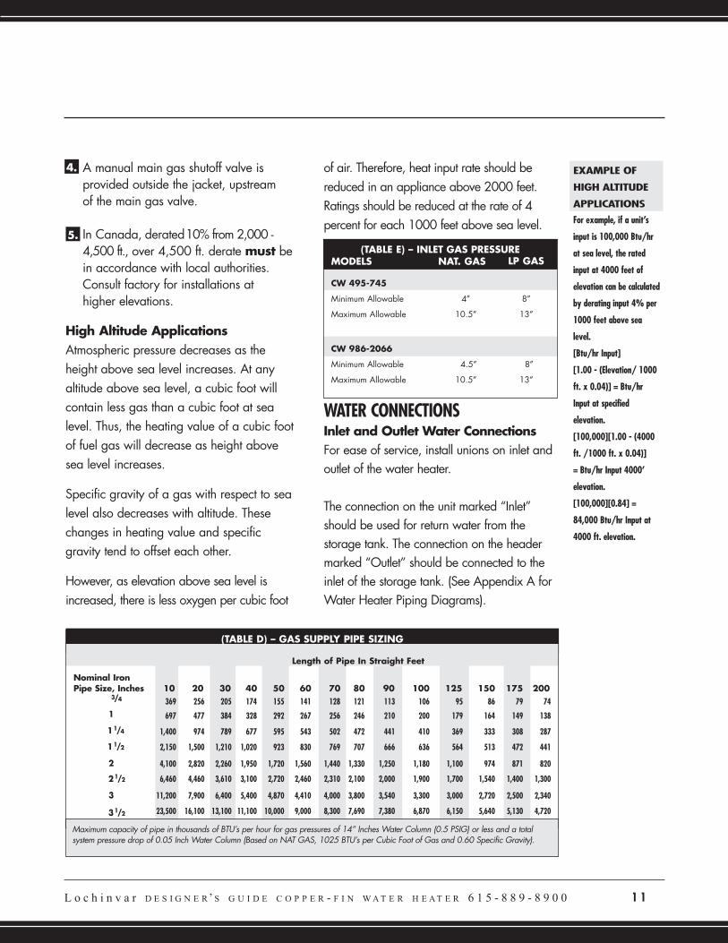
(TABLE D) – GAS SUPPLY PIPE SIZING
Length of Pipe In Straight Feet
Nominal IronPipe Size, Inches 10 20 30 40 50 60 70 80 90 100 125 150 175 200
369 256 205 174 155 141 128 121 113 106 95 86 79 74
697 477 384 328 292 267 256 246 210 200 179 164 149 138
1,400 974 789 677 595 543 502 472 441 410 369 333 308 287
2,150 1,500 1,210 1,020 923 830 769 707 666 636 564 513 472 441
4,100 2,820 2,260 1,950 1,720 1,560 1,440 1,330 1,250 1,180 1,100 974 871 820
6,460 4,460 3,610 3,100 2,720 2,460 2,310 2,100 2,000 1,900 1,700 1,540 1,400 1,300
11,200 7,900 6,400 5,400 4,870 4,410 4,000 3,800 3,540 3,300 3,000 2,720 2,500 2,340
23,500 16,100 13,100 11,100 10,000 9,000 8,300 7,690 7,380 6,870 6,150 5,640 5,130 4,720
Maximum capacity of pipe in thousands of BTU’s per hour for gas pressures of 14” Inches Water Column (0.5 PSIG) or less and a totalsystem pressure drop of 0.05 Inch Water Column (Based on NAT GAS, 1025 BTU’s per Cubic Foot of Gas and 0.60 Specific Gravity).
11/4
3/4
11/2
1
21/2
31/2
3
2
(TABLE E) – INLET GAS PRESSUREMODELS NAT. GAS LP GAS
CW 495-745
Minimum Allowable 4” 8”
Maximum Allowable 10.5” 13”
CW 986-2066
Minimum Allowable 4.5” 8”
Maximum Allowable 10.5” 13”
EXAMPLE OF
HIGH ALTITUDE
APPLICATIONS
For example, if a unit’s
input is 100,000 Btu/hr
at sea level, the rated
input at 4000 feet of
elevation can be calculated
by derating input 4% per
1000 feet above sea
level.
[Btu/hr Input]
[1.00 - (Elevation/ 1000
ft. x 0.04)] = Btu/hr
Input at specified
elevation.
[100,000][1.00 - (4000
ft. /1000 ft. x 0.04)]
= Btu/hr Input 4000’
elevation.
[100,000][0.84] =
84,000 Btu/hr Input at
4000 ft. elevation.
LOW WATER TEMPERATURE DELIVERYA number of water heating applications mayrequire delivered water temperature in asystem below 140°F. Systems such as nursinghomes and hospitals would be examples ofthis type of system.
A water heating system that will be operatedat less than 140°F must use a mixing valveon the outlet side of the storage tank in orderto ensure that the products of combustion donot condense inside the combustion chamberof the water heater.
The mixing valve allows the water heater tooperate above 140°F to protect fromcondensation, while still allowing a delivery ofcolder water to the system fixtures. Alsoinherent in this design is the protection ofoccupants from water containing bacteriasuch as Legionella. Legionella can besignificantly reduced in the water storagevessel by heating the water to a minimum of140°F. (See Appendix A for piping details.)
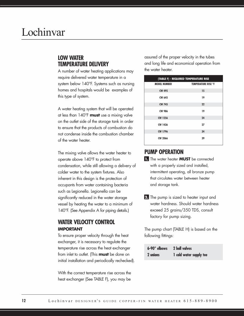
WATER VELOCITY CONTROLIMPORTANTTo ensure proper velocity through the heatexchanger, it is necessary to regulate thetemperature rise across the heat exchangerfrom inlet to outlet. (This must be done oninitial installation and periodically rechecked).
With the correct temperature rise across theheat exchanger (See TABLE F), you may be
assured of the proper velocity in the tubesand long life and economical operation fromthe water heater.
PUMP OPERATIONThe water heater MUST be connectedwith a properly sized and installed,intermittent operating, all bronze pumpthat circulates water between heaterand storage tank.
The pump is sized to heater input andwater hardness. Should water hardnessexceed 25 grains/350 TDS, consultfactory for pump sizing.
The pump chart (TABLE H) is based on thefollowing fittings:
6-90° elbows 2 ball valves2 unions 1 cold water supply tee
Lochinvar
12 L o c h i n v a r D E S I G N E R’ S G U I D E C O P P E R - F I N W A T E R H E A T E R 6 1 5 - 8 8 9 - 8 9 0 0
(TABLE F) - REQUIRED TEMPERATURE RISE
MODEL NUMBER TEMPERATURE RISE °F
CW 495 15
CW 645 19
CW 745 22
CW 986 19
CW 1256 24
CW 1436 27
CW 1796 34
CW 2066 39
1.
2.
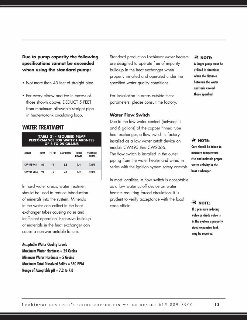
Due to pump capacity the followingspecifications cannot be exceededwhen using the standard pump:
• Not more than 45 feet of straight pipe.
• For every elbow and tee in excess of those shown above, DEDUCT 5 FEET from maximum allowable straight pipe in heater-to-tank circulating loop.
WATER TREATMENT
In hard water areas, water treatment should be used to reduce introductionof minerals into the system. Minerals in the water can collect in the heatexchanger tubes causing noise andinefficient operation. Excessive build-up of materials in the heat exchanger cancause a non-warrantable failure.
Acceptable Water Quality LevelsMaximum Water Hardness = 25 GrainsMinimum Water Hardness = 5 GrainsMaximum Total Dissolved Solids = 350 PPMRange of Acceptable pH = 7.2 to 7.8
Standard production Lochinvar water heatersare designed to operate free of impuritybuild-up in the heat exchanger whenproperly installed and operated under thespecified water quality conditions.
For installation in areas outside theseparameters, please consult the factory.
Water Flow SwitchDue to the low water content (between 1and 6 gallons) of the copper finned tubeheat exchanger, a flow switch is factoryinstalled as a low water cutoff device onmodels CW495 thru CW2066.The flow switch is installed in the outletpiping from the water heater and wired inseries with the ignition system safety controls.
In most localities, a flow switch is acceptableas a low water cutoff device on waterheaters requiring forced circulation. It isprudent to verify acceptance with the localcode official.
L o c h i n v a r D E S I G N E R’ S G U I D E C O P P E R - F I N W A T E R H E A T E R 6 1 5 - 8 8 9 - 8 9 0 0 1 3
NOTE:
Care should be taken to
measure temperature
rise and maintain proper
water velocity in the
heat exchanger.
NOTE:
A larger pump must be
utilized in situations
when the distance
between the water
and tank exceed
those specified.
NOTE:
If a pressure reducing
valve or check valve is
in the system a properly
sized expansion tank
may be required.
(TABLE G) – REQUIRED PUMPPERFORMANCE FOR WATER HARDNESS
OF 5 TO 25 GRAINS
MODEL GPM FT. HD AMP DRAW HORSE VOLTAGE/POWER PHASE
CW 495-745 60 10 5.8 1/4 120/1
CW 986-2066 90 15 7.4 1/2 120/1
14 L o c h i n v a r D E S I G N E R’ S G U I D E C O P P E R - F I N W A T E R H E A T E R 6 1 5 - 8 8 9 - 8 9 0 0
Relief ValveThis water heater is supplied withtemperature and pressure relief valve(s)sized in accordance with ASME Boiler andPressure Vessel Code, Section IV “HeatingBoilers.”
ELECTRICAL REQUIREMENTS(North America)The appliance is wired for 120 volts.
All wiring between the unit and fieldinstalled devices shall be made of typeT wire [63°F (35°C) rise].
The pump must be wired to runcontinuously when unit is firing.
It is recommended that the water heaterand pump be wired on separate circuitswith properly sized breakers.
Lochinvar
NOTE:
When the unit is
installed in Canada, it
must conform to the
CAE C22.1, Canadian
Electrical Code, Part 1,
and/or local Electrical
Codes.
NOTE:
Incorrect piping
of the cold water
supply to the
system will result
in condensate formation
on the heat exchanger
and operational
problems. Higher water
temperatures reduce
condensate formation.
Refer to drawings in
Appendix A.
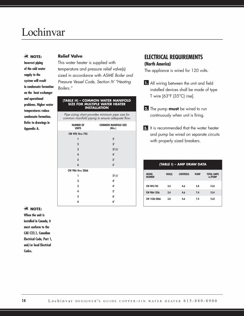
(TABLE H) – COMMON WATER MANIFOLDSIZE FOR MULTIPLE WATER HEATER
INSTALLATION
Pipe sizing chart provides minimum pipe size forcommon manifold piping to ensure adequate flow.
NUMBER OF COMMON MANIFOLD SIZEUNITS (Min.)
CW 495 thru 745
1 2”
2 3”
3 31/2”
4 4”
5 5”
6 5”
CW 986 thru 2066
1 21/2”
2 4”
3 4”
4 5”
5 6”
6 6”
2.
1.
3.
(TABLE I) – AMP DRAW DATA
MODEL FAN(S) CONTROLS PUMP TOTAL AMPSNUMBER w/PUMP
CW 495-745 3.4 4.6 5.8 13.8
CW 986-1256 3.4 4.6 7.4 15.4
CW 1436-2066 3.8 4.6 7.4 15.8
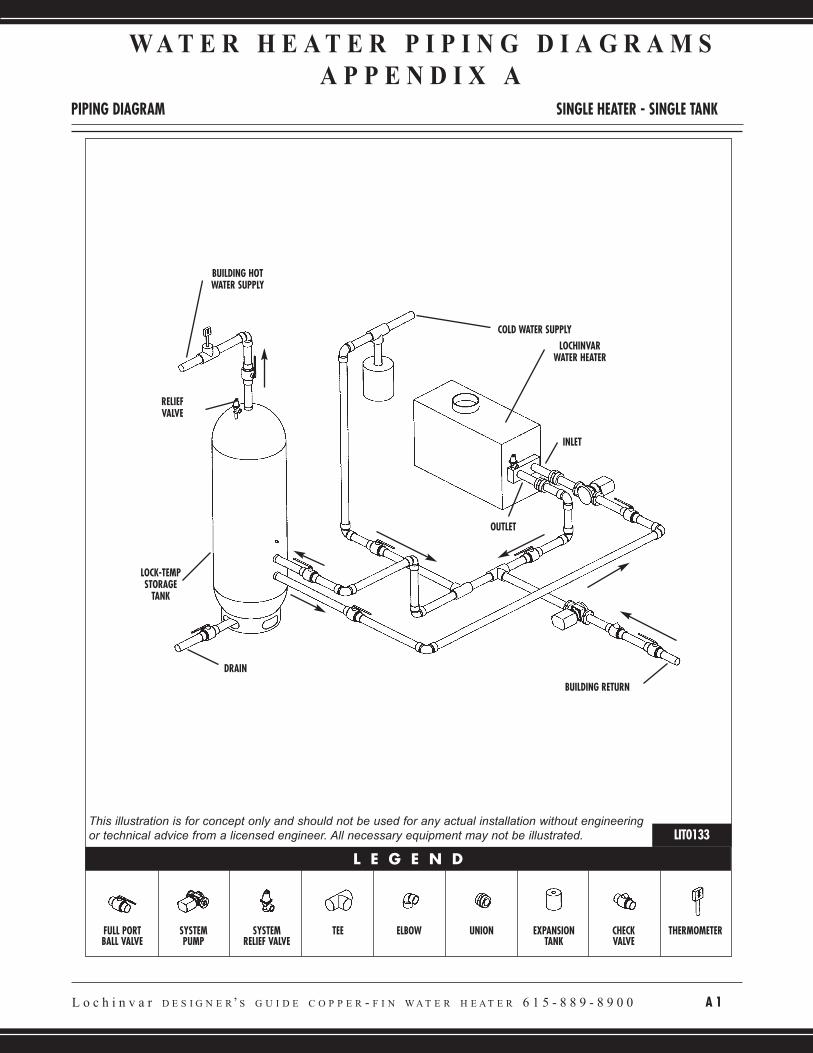
L o c h i n v a r D E S I G N E R’ S G U I D E C O P P E R - F I N W A T E R H E A T E R 6 1 5 - 8 8 9 - 8 9 0 0 A 1
W A T E R H E A T E R P I P I N G D I A G R A M S
A P P E N D I X A
PIPING DIAGRAM SINGLE HEATER - SINGLE TANK
BUILDING HOTWATER SUPPLY
RELIEFVALVE
LOCK-TEMPSTORAGE
TANK
DRAIN
FULL PORTBALL VALVE
SYSTEMPUMP
SYSTEMRELIEF VALVE
TEE ELBOW UNION EXPANSIONTANK
CHECKVALVE
THERMOMETER
COLD WATER SUPPLY
BUILDING RETURN
INLET
OUTLET
LOCHINVARWATER HEATER
L E G E N D
LIT0133This illustration is for concept only and should not be used for any actual installation without engineeringor technical advice from a licensed engineer. All necessary equipment may not be illustrated.
A2 L o c h i n v a r D E S I G N E R’ S G U I D E C O P P E R - F I N W A T E R H E A T E R 6 1 5 - 8 8 9 - 8 9 0 0
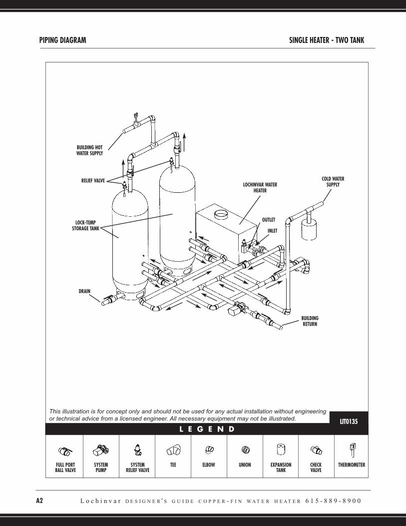
PIPING DIAGRAM SINGLE HEATER - TWO TANK
FULL PORTBALL VALVE
SYSTEMPUMP
SYSTEMRELIEF VALVE
TEE ELBOW UNION EXPANSIONTANK
CHECKVALVE
THERMOMETER
L E G E N D
BUILDING HOTWATER SUPPLY
LOCHINVAR WATERHEATER
COLD WATERSUPPLY
BUILDINGRETURN
LOCK-TEMPSTORAGE TANK
RELIEF VALVE
DRAIN
OUTLET
INLET
LIT0135
This illustration is for concept only and should not be used for any actual installation without engineeringor technical advice from a licensed engineer. All necessary equipment may not be illustrated.
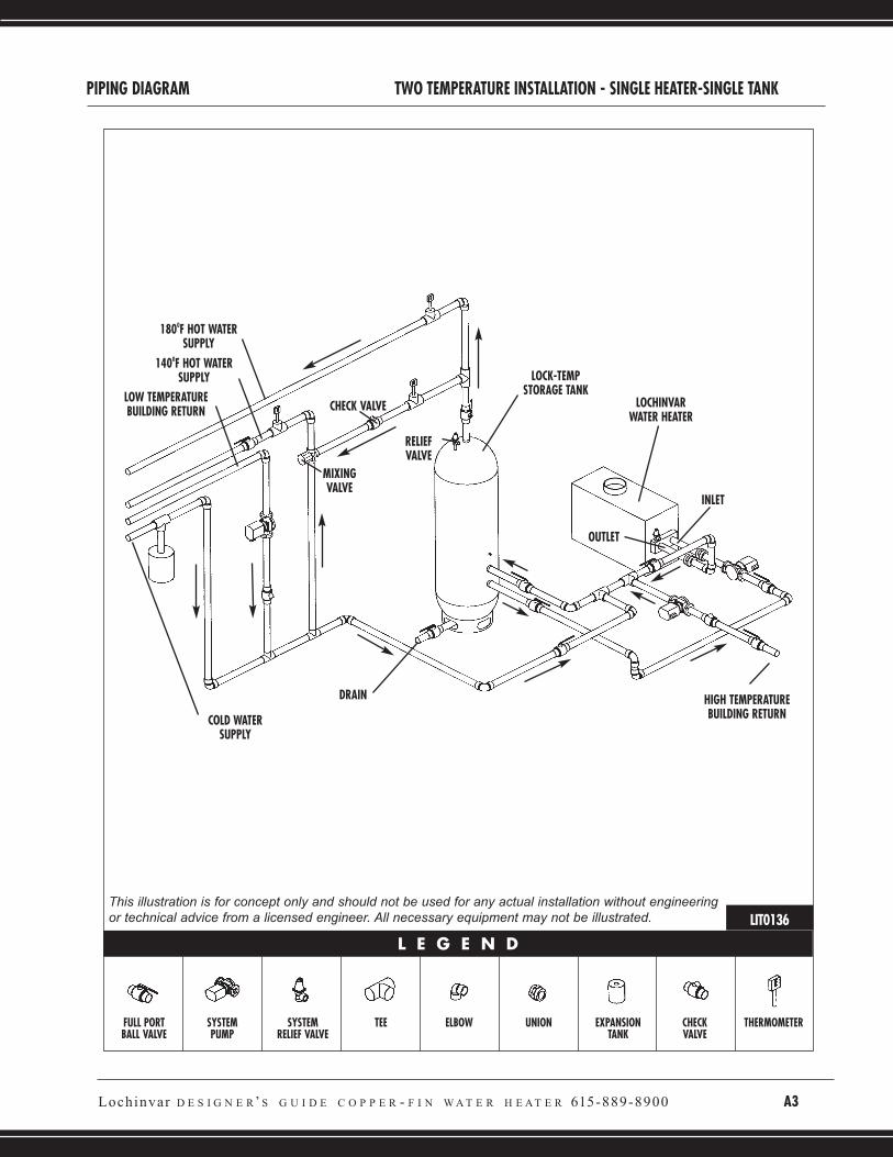
FULL PORTBALL VALVE
SYSTEMPUMP
SYSTEMRELIEF VALVE
TEE ELBOW UNION EXPANSIONTANK
CHECKVALVE
THERMOMETER
L E G E N D
PIPING DIAGRAM TWO TEMPERATURE INSTALLATION - SINGLE HEATER-SINGLE TANK
HIGH TEMPERATUREBUILDING RETURN
LOW TEMPERATUREBUILDING RETURN
DRAIN
INLET
RELIEFVALVE
OUTLET
COLD WATERSUPPLY
1400F HOT WATERSUPPLY
1800F HOT WATERSUPPLY
LOCK-TEMPSTORAGE TANK
LOCHINVARWATER HEATER
MIXINGVALVE
CHECK VALVE
LIT0136This illustration is for concept only and should not be used for any actual installation without engineeringor technical advice from a licensed engineer. All necessary equipment may not be illustrated.
Lochinvar D E S I G N E R’ S G U I D E C O P P E R - F I N W A T E R H E A T E R 615-889-8900 A3
A4 L o c h i n v a r D E S I G N E R’ S G U I D E C O P P E R - F I N W A T E R H E A T E R 6 1 5 - 8 8 9 - 8 9 0 0
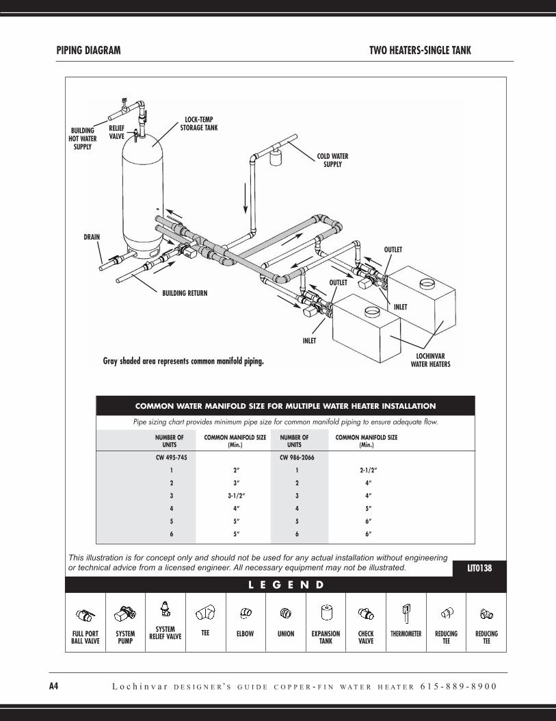
PIPING DIAGRAM TWO HEATERS-SINGLE TANK
FULL PORTBALL VALVE
SYSTEMPUMP
SYSTEMRELIEF VALVE TEE ELBOW UNION EXPANSION
TANKCHECKVALVE
THERMOMETER REDUCINGTEE
REDUCINGTEE
L E G E N D
LOCHINVARWATER HEATERS
INLET
INLET
OUTLET
RELIEFVALVE
OUTLET
BUILDING RETURN
DRAIN
LOCK-TEMPSTORAGE TANK
COLD WATERSUPPLY
BUILDINGHOT WATER
SUPPLY
LIT0138This illustration is for concept only and should not be used for any actual installation without engineeringor technical advice from a licensed engineer. All necessary equipment may not be illustrated.
COMMON WATER MANIFOLD SIZE FOR MULTIPLE WATER HEATER INSTALLATION
Pipe sizing chart provides minimum pipe size for common manifold piping to ensure adequate flow.
NUMBER OF COMMON MANIFOLD SIZE NUMBER OF COMMON MANIFOLD SIZEUNITS (Min.) UNITS (Min.)
CW 495-745 CW 986-2066
1 2” 1 2-1/2”
2 3” 2 4”
3 3-1/2” 3 4”
4 4” 4 5”
5 5” 5 6”
6 5” 6 6”
Gray shaded area represents common manifold piping.
Lochinvar D E S I G N E R’ S G U I D E C O P P E R - F I N W A T E R H E A T E R 615-889-8900 A5
FULL PORTBALL VALVE
SYSTEMPUMP
SYSTEMRELIEF VALVE
TEE ELBOW UNION EXPANSIONTANK
CHECKVALVE
REDUCINGTEE
REDUCINGTEE
L E G E N D
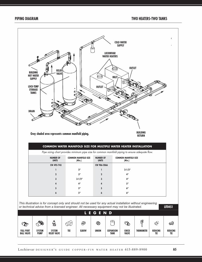
PIPING DIAGRAM TWO HEATERS-TWO TANKS
BUILDINGRETURN
LOCHINVARWATER HEATERS
COLD WATERSUPPLY
LOCK-TEMPSTORAGE
TANKS
DRAIN
INLET
OUTLET
OUTLETRELIEFVALVEBUILDING
HOT WATERSUPPLY
LIT0451
THERMOMETER
This illustration is for concept only and should not be used for any actual installation without engineeringor technical advice from a licensed engineer. All necessary equipment may not be illustrated.
COMMON WATER MANIFOLD SIZE FOR MULTIPLE WATER HEATER INSTALLATION
Pipe sizing chart provides minimum pipe size for common manifold piping to ensure adequate flow.
NUMBER OF COMMON MANIFOLD SIZE NUMBER OF COMMON MANIFOLD SIZEUNITS (Min.) UNITS (Min.)
CW 495-745 CW 986-2066
1 2” 1 2-1/2”
2 3” 2 4”
3 3-1/2” 3 4”
4 4” 4 5”
5 5” 5 6”
6 5” 6 6”
Gray shaded area represents common manifold piping.
A6 L o c h i n v a r D E S I G N E R’ S G U I D E C O P P E R - F I N W A T E R H E A T E R 6 1 5 - 8 8 9 - 8 9 0 0
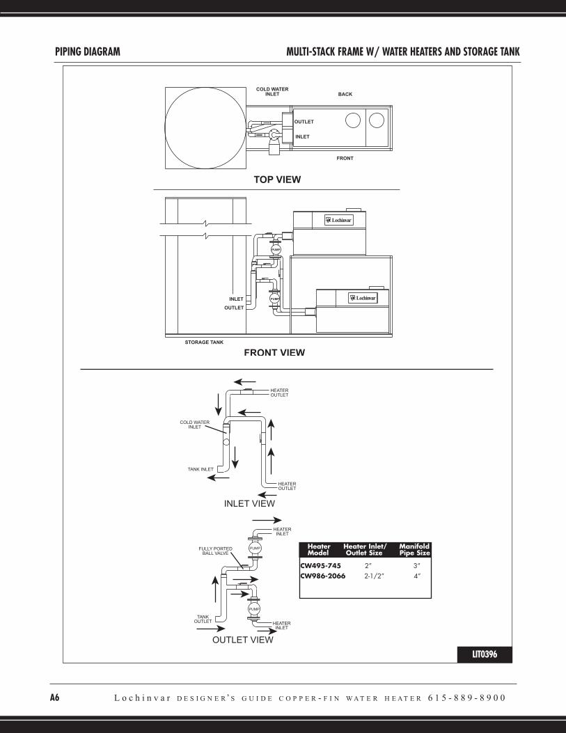
PIPING DIAGRAM MULTI-STACK FRAME W/ WATER HEATERS AND STORAGE TANK
LIT0396
Heater Heater Inlet/ ManifoldModel Outlet Size Pipe Size
CW495-745 2” 3”CW986-2066 2-1/2” 4”


Lochinvar Corporation • Lebanon, TN • 615-889-8900 / Fax: 615-547-1000
www.Lochinvar.com
CW-DG-05 (Replaces CW-DG-04 6/05) 1/07-Printed in U.S.A.