PROJECT MANUAL Domestic Water Heater Replacement NW ...
181
PROJECT MANUAL Domestic Water Heater Replacement NW Regional Youth Center Kansas City, Missouri DESIGNED BY: Lankford and Associates Consulting Engineers, Inc. dba Lankford Fendler and Associates 1730 Walnut St. Kansas City, MO 64108 DATE ISSUED: 10/22/2019 PROJECT NO.: H1905-01 FOR: State of Missouri Office of Administration Division of Facilities Management, Design and Construction
-
Upload
khangminh22 -
Category
Documents
-
view
0 -
download
0
Transcript of PROJECT MANUAL Domestic Water Heater Replacement NW ...

PROJECT MANUAL
Domestic Water Heater Replacement NW Regional Youth Center
Kansas City, Missouri
DESIGNED BY: Lankford and Associates Consulting Engineers, Inc. dba Lankford Fendler and Associates
1730 Walnut St. Kansas City, MO 64108
DATE ISSUED: 10/22/2019
PROJECT NO.: H1905-01
FOR: State of Missouri Office of Administration Division of Facilities Management, Design and Construction

PROFESSIONAL SEALS AND CERTIFICATIONS 00107 - 1
SECTION 000107 - PROFESSIONAL SEALS AND CERTIFICATIONS
PROJECT NUMBER: H1905-01
THE FOLLOWING DESIGN PROFESSIONALS HAVE SIGNED AND SEALED THE ORIGINAL PLANS
AND SPECIFICATIONS FOR THIS PROJECT, WHICH ARE ON FILE WITH THE DIVISION OF
FACILITIES MANAGEMENT, DESIGN AND CONSTRUCTION:
Alan W. Lankford, PE
#E-24224

SECTION 000110 – TABLE OF CONTENTS 07/16
1
TABLE OF CONTENTS SECTION TITLE NUMBER OF PAGES
DIVISION 00 – PROCUREMENT AND CONTRACTING INFORMATION
000000 INTRODUCTORY INFORMATION 000101 Project Manual Cover 1 000107 Professional Seals and Certifications 1 000110 Table of Contents 2 000115 List of Drawings 1
001116 INVITATION FOR BID (IFB) 3
002113 INSTRUCTIONS TO BIDDERS (Includes MBE/WBE/SDVE Information) 8 003144 MBE/WBE/SDVE Directory 1
**The following documents may be found on MissouriBUYS at https://missouribuys.mo.gov/**
004000 PROCUREMENT FORMS & SUPPLEMENTS 004113 Bid Form * 004336 Proposed Subcontractors Form * 004337 MBE/WBE/SDVE Compliance Evaluation Form * 004338 MBE/WBE/SDVE Eligibility Determination *
Form for Joint Ventures 004339 MBE/WBE/SDVE Good Faith Effort (GFE) *
Determination Forms 004340 SDVE Business Form * 004541 Affidavit of Work Authorization *
005000 CONTRACTING FORMS AND SUPPLEMENTS 005213 Construction Contract 3 005414 Affidavit for Affirmative Action 1 006113 Performance and Payment Bond 2 006325 Product Substitution Request 2 006519.16 Final Receipt of Payment and Release Form 1 006519.18 MBE/WBE/SDVE Progress Report 1 006519.21 Affidavit of Compliance with Prevailing Wage Law 1
007000 CONDITIONS OF THE CONTRACT 007213 General Conditions 20 007300 Supplementary Conditions 1 007346 Wage Rate – Clay County 4
DIVISION 1 - GENERAL REQUIREMENTS 011000 Summary of Work 2 012600 Contract Modification Procedures 3 013100 Coordination 4 013200 Schedules 4 013300 Submittals 5 013513.22 Site Security and Health Requirements (DYS) 3 015000 Construction Facilities and Temporary Controls 3 017400 Cleaning 2
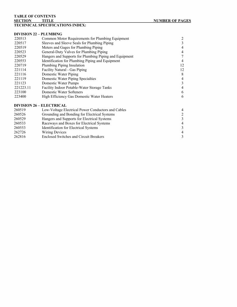
TABLE OF CONTENTS SECTION TITLE NUMBER OF PAGES TECHNICAL SPECIFICATIONS INDEX:
DIVISION 22 – PLUMBING Common Motor Requirements for Plumbing Equipment 2
Sleeves and Sleeve Seals for Plumbing Piping 3 Meters and Gages for Plumbing Piping 4 General-Duty Valves for Plumbing Piping 4
Hangers and Supports for Plumbing Piping and Equipment 7 Identification for Plumbing Piping and Equipment 4 Plumbing Piping Insulation 12 Facility Natural - Gas Piping 12
Domestic Water Piping 8 Domestic Water Piping Specialties 4 Domestic Water Pumps 3 Facility Indoor Potable-Water Storage Tanks 4 Domestic Water Softeners 6
220513 220517 220519 220523 220529 220553 220719 221114 221116 221119 221123 221223.11 223100 223400 High Efficiency Gas Domestic Water Heaters 6
DIVISION 26 – ELECTRICAL 260519 Low-Voltage Electrical Power Conductors and Cables 4 260526 Grounding and Bonding for Electrical Systems 2 260529 Hangers and Supports for Electrical Systems 3 260533 Raceways and Boxes for Electrical Systems 4 260553 Identification for Electrical Systems 3 262726 Wiring Devices 4 262816 Enclosed Switches and Circuit Breakers 3

LIST OF DRAWINGS 000115 - 1
SECTION 000115 – LIST OF DRAWINGS
PART 1 - GENERAL
1.1 RELATED DOCUMENTS
A. Drawings and general provisions of the Contract including General and Supplementary Conditions, Bid Form, and other Division 1 Specification Sections apply to this Section.
1.2 SUMMARY
A. This Section provides a comprehensive list of the drawings that comprise the Bid Documents for this project.
PART 2 - PRODUCTS (NOT APPLICABLE)
PART 3 - EXECUTION
3.1 LIST OF DRAWINGS
A. The following list of drawings is a part of the Bid Documents:
TITLE SHEET # DATE CAD #
1. Cover Sheet Sheet G-001 10/22/2019 G-GEN-01
2. Plumbing Plans Sheet P-101 10/22/2019 P-PLB-01
3. Plbg Gen. Notes, Sheet P-201 10/22/2019 P-PLB-02
Symbols, Details, & Schedules.
4. Electrical Plans Sheet E-101 10/22/2019 E-ELEC-01
END OF SECTION 000115

SECTION 001116 – INVITATION FOR BID 1/2/20
Page 1 of 2
SECTION 001116 - INVITATION FOR BID
1.0 OWNER: A. The State of Missouri
Office of Administration, Division of Facilities Management, Design and Construction Jefferson City, Missouri
2.0 PROJECT TITLE AND NUMBER:
A. Domestic Water Heater Replacement NW Regional Youth Center Kansas City, Missouri
Project No.: H1905-01
3.0 BIDS WILL BE RECEIVED:
A. Until: 1:30 PM, February 13, 2020.
B. Only electronic bids on MissouriBUYS shall be accepted: https://missouribuys.mo.gov. Bidder must be registered to bid.
4.0 DESCRIPTION:
A. Scope: The project includes replacing the entirety of the domestic hot water system.
B. Estimate: $130,700 to $179,800
C. MBE/WBE/SDVE Goals: MBE 10.00%, WBE 10.00%, & SDVE 3.00%. NOTE: Only MBE/WBE firms certified by a State of Missouri public entity as of the date of bid opening, or SDVE(s) meeting the requirements of Section 34.074, RSMo and 1 CSR 30-5.010, can be used to satisfy the MBE/WBE/SDVE participation goals for this project.
D. **NOTE: Bidders are provided new Good Faith Effort (GFE) forms on MissouriBUYS.
5.0 PRE-BID MEETING:
A. Place/Time: February 3, 2020 @ 2:00 p.m., NW Regional Youth Center, 4901 Northeast Barry Rd., Kansas City, MO 64156.
B. Access to State of Missouri property requires presentation of a photo ID by all persons
6.0 HOW TO GET PLANS & SPECIFICATIONS:
A. View Only Electronic bid sets are available at no cost or paper bid sets for a deposit of $30 from American Document Solutions (ADS). MAKE CHECKS PAYABLE TO: American Document Solutions. Mail to: American Document Solutions, 1400 Forum Blvd., Suite 7A, Columbia, Missouri 65203. Phone 573-446-7768, Fax 573-355-5433, https://www.adsplanroom.net. NOTE: Prime contractors will be allowed a maximum of two bid sets at the deposit rate shown above. Other requesters will be allowed only one bid set at this rate. Additional bid sets or parts thereof may be obtained by any bidder at the cost of printing and shipping by request to American Document Solutions at the address shown above. Bidder must secure at least one bid set to become a planholder.
B. Refunds: Return plans and specifications in unmarked condition within 15 working days of bid opening to American Document Solutions, 1400 Forum Blvd., Suite 7A, Columbia, Missouri 65203. Phone 573-446-7768, Fax 573-355-5433. Deposits for plans not returned within 15 working days shall be forfeited.
C. Information for upcoming bids, including downloadable plans, specifications, Invitation for Bid, bid tabulation, award, addenda, and access to the ADS planholders list, is available on the Division of Facilities Management, Design and Construction’s web site:
https://oa.mo.gov/facilities/bid-opportunities/bid-listing-electronic-plans.
7.0 POINT OF CONTACT:
A. Designer: Lankford and Associates Consulting Engineers, Inc dba Lankford Fendler and Associates, Robert Franklin, phone # 816-221-1411, fax # 816-221-1429.
B. Project Manager: Jared Cook, phone # 573-690-6733, fax # 573-751-7277
8.0 GENERAL INFORMATION:
A. The State reserves the right to reject any and all bids and to waive all informalities in bids. No bid may be withdrawn for a period of 20 working days subsequent to the specified bid opening time. The contractor shall pay not less than the prevailing hourly rate of wages for work of a similar character in the locality in which the work is performed, as determined by the Missouri Department of Labor and Industrial Relations and as set out in the detailed plans and specifications.
B. Bid results will be available at https://oa.mo.gov/facilities/bid-opportunities/bid-listing-electronic-plans after it is verified that at least one bid is awardable and affordable.
SECTION 001116 – INVITATION FOR BID 1/2/20
Page 2 of 2
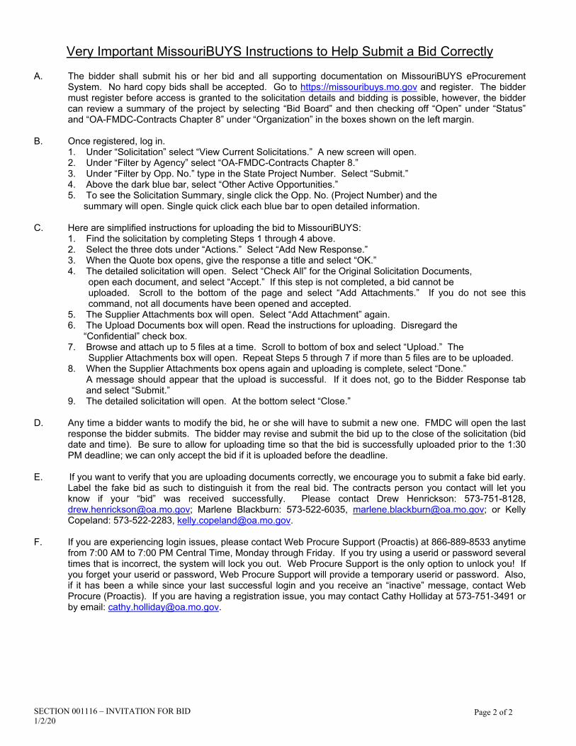
Very Important MissouriBUYS Instructions to Help Submit a Bid Correctly A. The bidder shall submit his or her bid and all supporting documentation on MissouriBUYS eProcurement
System. No hard copy bids shall be accepted. Go to https://missouribuys.mo.gov and register. The bidder must register before access is granted to the solicitation details and bidding is possible, however, the bidder can review a summary of the project by selecting “Bid Board” and then checking off “Open” under “Status” and “OA-FMDC-Contracts Chapter 8” under “Organization” in the boxes shown on the left margin.
B. Once registered, log in. 1. Under “Solicitation” select “View Current Solicitations.” A new screen will open. 2. Under “Filter by Agency” select “OA-FMDC-Contracts Chapter 8.” 3. Under “Filter by Opp. No.” type in the State Project Number. Select “Submit.” 4. Above the dark blue bar, select “Other Active Opportunities.” 5. To see the Solicitation Summary, single click the Opp. No. (Project Number) and the summary will open. Single quick click each blue bar to open detailed information. C. Here are simplified instructions for uploading the bid to MissouriBUYS: 1. Find the solicitation by completing Steps 1 through 4 above. 2. Select the three dots under “Actions.” Select “Add New Response.” 3. When the Quote box opens, give the response a title and select “OK.” 4. The detailed solicitation will open. Select “Check All” for the Original Solicitation Documents,
open each document, and select “Accept.” If this step is not completed, a bid cannot be uploaded. Scroll to the bottom of the page and select “Add Attachments.” If you do not see this command, not all documents have been opened and accepted.
5. The Supplier Attachments box will open. Select “Add Attachment” again. 6. The Upload Documents box will open. Read the instructions for uploading. Disregard the “Confidential” check box.
7. Browse and attach up to 5 files at a time. Scroll to bottom of box and select “Upload.” The Supplier Attachments box will open. Repeat Steps 5 through 7 if more than 5 files are to be uploaded.
8. When the Supplier Attachments box opens again and uploading is complete, select “Done.” A message should appear that the upload is successful. If it does not, go to the Bidder Response tab and select “Submit.”
9. The detailed solicitation will open. At the bottom select “Close.” D. Any time a bidder wants to modify the bid, he or she will have to submit a new one. FMDC will open the last
response the bidder submits. The bidder may revise and submit the bid up to the close of the solicitation (bid date and time). Be sure to allow for uploading time so that the bid is successfully uploaded prior to the 1:30 PM deadline; we can only accept the bid if it is uploaded before the deadline.
E. If you want to verify that you are uploading documents correctly, we encourage you to submit a fake bid early.
Label the fake bid as such to distinguish it from the real bid. The contracts person you contact will let you know if your “bid” was received successfully. Please contact Drew Henrickson: 573-751-8128, [email protected]; Marlene Blackburn: 573-522-6035, [email protected]; or Kelly Copeland: 573-522-2283, [email protected].
F. If you are experiencing login issues, please contact Web Procure Support (Proactis) at 866-889-8533 anytime
from 7:00 AM to 7:00 PM Central Time, Monday through Friday. If you try using a userid or password several times that is incorrect, the system will lock you out. Web Procure Support is the only option to unlock you! If you forget your userid or password, Web Procure Support will provide a temporary userid or password. Also, if it has been a while since your last successful login and you receive an “inactive” message, contact Web Procure (Proactis). If you are having a registration issue, you may contact Cathy Holliday at 573-751-3491 or by email: [email protected].

SECTION 001116 – INVITATION FOR BID Page 3 of 3 1/2/20
IMPORTANT INFORMATION REGARDING REQUIREMENT FOR OEO CERTIFICATION
SPECIFICATION CHANGES: A. SECTION 002113 – INSTRUCTIONS TO BIDDERS: Article 14.0, Section B.1. (bottom of page 6 of 8): Delete: “an MBE or WBE must be certified by the State of Missouri, Office of Equal Opportunity and”. To allow MBE, WBE, or MBE/WBE contractors, subcontractors, and suppliers to have ample time to register with the Office of Equal Opportunity, this requirement will not take effect until July 1, 2020. Until then, we will continue to accept certifications from the Office of Equal Opportunity and other Missouri certifying agencies.

SECTION 002113 – INSTRUCTIONS TO BIDDERS Page 1 of 8 10/21/19
SECTION 002113 – INSTRUCTIONS TO BIDDERS 1.0 - SPECIAL NOTICE TO BIDDERS
A. If awarded a contract, the Bidder’s employees, and the employees of all subcontractors, who perform the work on the project, will be required to undergo a fingerprint background check and obtain a State of Missouri identification badge prior to beginning work on site. The Bidder should review the information regarding this requirement in Section 013513 – Site Security and Health Requirements prior to submitting a bid.
B. The Bidder’s prices shall include all city, state, and federal sales, excise, and similar taxes that may lawfully be assessed in connection with the performance of work, and the purchased of materials to be incorporated in the work. THIS PROJECT IS NOT TAX EXEMPT.
2.0 - BID DOCUMENTS
A. The number of sets obtainable by any one (1) party may be limited in accordance with available supply.
B. For the convenience of contractors, sub-contractors and suppliers, copies of construction documents are on file at the office of the Director, Division of Facilities Management, Design and Construction and on the Division’s web site - https://oa.mo.gov/facilities/bid-opportunities/bid-listing-electronic-plans.
3.0 - BIDDERS' OBLIGATIONS
A. Bidders must carefully examine the entire site of the work and shall make all reasonable and necessary investigations to inform themselves thoroughly as to the facilities available as well as to all the difficulties involved in the completion of all work in accordance with the specifications and the plans. Bidders are also required to examine all maps, plans and data mentioned in the specifications. No plea of ignorance concerning observable existing conditions or difficulties that may be encountered in the execution of the work under this contract will be accepted as an excuse for any failure or omission on the part of the contractor to fulfill in every detail all of the requirements of the contract, nor accepted as a basis for any claims for extra compensation.
B. Under no circumstances will contractors give their plans and specifications to another contractor. Any bid
received from a contractor whose name does not appear on the list of plan holders may be subject to rejection.
4.0 - INTERPRETATIONS
A. No bidder shall be entitled to rely on oral interpretations as to the meaning of the plans and specifications or the acceptability of alternate products, materials, form or type of construction. Every request for interpretation shall be made in writing and submitted with all supporting documents not less than five (5) working days before opening of bids. Every interpretation made to a bidder will be in the form of an addendum and will be sent as promptly as is practicable to all persons to whom plans and specifications have been issued. All such addenda shall become part of the contract documents.
B. Approval for an “acceptable substitution” issued in the form of an addendum as per Paragraph 4A above, and as per Article 3.1 of the General Conditions; ACCEPTABLE SUBSTITUTIONS shall constitute approval for use in the project of the product.
C. An “acceptable substitution” requested after the award of bid shall be approved if proven to the satisfaction of the Owner and the Designer as per Article 3.1, that the product is acceptable in design, strength, durability, usefulness, and convenience for the purpose intended. Approval of the substitution after award is at the sole discretion of the Owner.
D. A request for “Acceptable Substitutions” shall be made on the Section 006325 Substitution Request Form. The request shall be sent directly to the project Designer. A copy of said request should also be mailed to the Owner, Division of Facilities Management, Design and Construction, Post Office Box 809, Jefferson City, Missouri 65102.
5.0 - BIDS AND BIDDING PROCEDURE
A. Bidders shall submit all submission forms and accompanying documents listed in SECTION 004113 – BID FORM, Article 5.0, ATTACHMENTS TO BID by the stated time or their bid will be rejected for being non-responsive.

SECTION 002113 – INSTRUCTIONS TO BIDDERS Page 2 of 8 10/21/19
Depending on the specific project requirements, the following is a GENERIC list of all possible bid forms that may be due with bid submittals and times when they may be due. Please check for specific project requirements on the proposal form (Section 004113). Not all of the following bid forms may be required to be submitted.
Bid Submittal – due before stated date and time of bid opening (see IFB): 004113 Bid Form (all pages are always required) 004322 Unit Prices Form 004336 Proposed Subcontractors Form 004337 MBE/WBE/SDVE Compliance Evaluation Form 004338 MBE/WBE/SDVE Eligibility Determination for Joint Ventures
004339 MBE/WBE/SDVE GFE Determination 004340 SDVE Business Form 004541 Affidavit of Work Authorization
B. All bids shall be submitted without additional terms and conditions, modification or reservation on the bid forms with each space properly filled. Bids not on these forms will be rejected.
C. All bids shall be accompanied by a bid bond executed by the bidder and a duly authorized surety company, certified check, cashier's check or bank draft made payable to the Division of Facilities Management, Design and Construction, State of Missouri, in the amount indicated on the bid form, Section 004113. Failure of the contractor to submit the full amount required shall be sufficient cause to reject his bid. The bidder agrees that the proceeds of the check, draft or bond shall become the property of the State of Missouri, if for any reason the bidder withdraws his bid after closing, or if on notification of award refuses or is unable to execute tendered contract, provide an acceptable performance and payment bond, provide evidence of required insurance coverage and/or provide required copies of affirmative action plans within ten (10) working days after such tender.
D. The check or draft submitted by the successful bidder will be returned after the receipt of an acceptable performance and payment bond and execution of the formal contract. Checks or drafts of all other bidders will be returned within a reasonable time after it is determined that the bid represented by same will receive no further consideration by the State of Missouri. Bid bonds will only be returned upon request.
6.0 - SIGNING OF BIDS
A. A bid from an individual shall be signed as noted on the Bid Form.
B. A bid from a partnership or joint venture shall require only one signature of a partner, an officer of the joint venture authorized to bind the venture or an attorney-in-fact. If the bid is signed by an officer of a joint venture or an attorney-in-fact, a document evidencing the individual's authority to execute contracts should be included with the bid form.
C. A bid from a limited liability company (LLC) shall be signed by a manager or a managing member of the LLC.
D. A bid from a corporation shall have the correct corporate name thereon and the signature of an authorized officer of the corporation manually written. Title of office held by the person signing for the corporation shall appear, along with typed name of said individual. Corporate license number shall be provided and, if a corporation organized in a state other than Missouri, a Certificate of Authority to do business in the State of Missouri shall be attached. In addition, for corporate proposals, the President or Vice-President should sign as the bidder. If the signator is other than the corporate president or vice president, the bidder must provide satisfactory evidence that the signator has the legal authority to bind the corporation.
E. A bid should contain the full and correct legal name of the Bidder. If the Bidder is an entity registered with
the Missouri Secretary of State, the Bidder’s name on the bid form should appear as shown in the Secretary of State’s records.
F. The Bidder should include its corporate license number on the Bid Form and, if the corporation is organized in a state other than Missouri, a Certificate of Authority to do business in the State of Missouri shall be attached to the bid form.

SECTION 002113 – INSTRUCTIONS TO BIDDERS Page 3 of 8 10/21/19
7.0 - RECEIVING BID SUBMITTALS
A. It is the bidder’s sole responsibility to assure receipt by Owner of bid submittals by the date and time
specified in the Invitation for Bid. Bids received after the date and time specified shall not be considered by the Owner.
B. Bids must be submitted through the MissouriBUYS statewide eProcurement system
(https://www.missouribuys.mo.gov/) in accordance with the instructions for that system. The Owner shall only accept bids submitted through MissouriBUYS. Bids received by the Owner through any other means, including hard copies, shall not be considered and will be discarded by the Owner unopened.
C. To respond to an Invitation for Bid, the Bidder must first register with MissouriBUYS by going
through the MissouriBUYS Home Page (https://www.missouribuys.mo.gov/), clicking the “Register” button at the top of the page, and completing the Vendor Registration. Once registered, the Bidder accesses its account by clicking the “Login” button at the top of the MissouriBUYS Home Page. Enter your USERID and PASSWORD, which the Bidder will select. Under Solicitations, select “View Current Solicitations.” A new screen will open. Under “Filter by Agency” select “OA-FMDC-Contracts Chapter 8.” Under “Filter by Opp. No.” type in the State Project Number. Select “Submit.” Above the dark blue bar, select “Other Active Opportunities.” To see the Solicitation Summary, single click the Opp. No. (Project Number) and the summary will open. Single quick click each blue bar to open detailed information. The Bidder must read and accept the Original Solicitation Documents and complete all identified requirements. The Bidder should download and save all of the Original Solicitation Documents on its computer so that the Bidder can prepare its response to these documents. The Bidder should upload its completed response to the downloaded documents as an attachment to the electronic solicitation response.
D. Step-by-step instructions for how a registered vendor responds to a solicitation electronically are
provided in Section 001116 – Invitation For Bid. E. The Bidder shall submit its bid on the forms provided by the Owner on MissouriBUYS with each space fully and properly completed, including all amounts required for alternate bids, unit prices, cost accounting data, etc. The Owner may reject bids that are not on the Owner’s forms or that do not contain all requested information.
F. No Contractor shall stipulate in his bid any conditions not contained in the specifications or standard bid form contained in the contract documents. To do so may subject the Contractor’s bid to rejection.
G. The completed forms shall be without interlineations, alterations or erasures.
8.0 - MODIFICATION AND WITHDRAWAL OF BIDS
A. Bidder may withdraw his bid at any time prior to scheduled closing time for receipt of bids, but no bidder may withdraw his bid for a period of twenty (20) working days after the scheduled closing time for receipt of bids.
B. The Bidder shall modify his or her original bid by submitting a revised bid on MissouriBUYS.
9.0 - AWARD OF CONTRACT
A. The Owner reserves the right to reject any and/or all bids and further to waive all informalities in bidding when deemed in the best interest of the State of Missouri.
B. The Owner reserves the right to let other contracts in connection with the work, including but not by way of limitation, contracts for the furnishing and installation of furniture, equipment, machines, appliances and other apparatus.
C. In awarding the contract the Owner may take into consideration the bidder's skill, facilities, capacity, experience, responsibility, previous work record, financial standing and the necessity of prompt and efficient completion of work herein described. Inability of any bidder to meet the requirements mentioned above may be cause for rejection of his bid. However, no contract will be awarded to any individual,

SECTION 002113 – INSTRUCTIONS TO BIDDERS Page 4 of 8 10/21/19
partnership or corporation, who has had a contract with the State of Missouri declared in default within the preceding twelve months.
D. Award of alternates, if any, will be made in numerical order unless all bids received are such that the order of acceptance of alternates does not affect the determination of the low bidder.
E. No bid shall be considered binding upon the Owner until the written contract has been properly executed, a satisfactory bond has been furnished, evidence of required insurance coverage, submittal of executed Section 004541, Affidavit of Work Authorization form, documentation evidencing enrollment and participation in a federal work authorization program has been received and an affirmative action plan submitted. Failure to execute and return the contract and associated documents within the prescribed period of time shall be treated, at the option of the Owner, as a breach of bidder's obligation and the Owner shall be under no further obligation to bidder.
F. If the successful bidder is doing business in the State of Missouri under a fictitious name, he shall furnish to Owner, attached to the Bid Form, a properly certified copy of the certificate of Registration of Fictitious Name from the State of Missouri, and such certificate shall remain on file with the Owner.
G. Any successful bidder which is a corporation organized in a state other than Missouri shall furnish to the Owner, attached to the Bid Form, a properly certified copy of its current Certificate of Authority to do business in the State of Missouri, such certificate to remain on file with the Owner. No contract will be awarded by the Owner unless such certificate is furnished by the bidder.
H. Any successful bidder which is a corporation organized in the State of Missouri shall furnish at its own cost to the Owner, if requested, a Certificate of Good Standing issued by the Secretary of State, such certificate to remain on file with the Owner.
I. Transient employers subject to Sections 285.230 and 285.234, RSMo, (out-of-state employers who temporarily transact any business in the State of Missouri) may be required to file a bond with the Missouri Department of Revenue. No contract will be awarded by the Owner unless the successful bidder certifies that he has complied with all applicable provisions of Section 285.230-234.
J. Sections 285.525 and 285.530, RSMo, require business entities to enroll and participate in a federal work authorization program in order to be eligible to receive award of any state contract in excess of $5,000. Bidders should submit with their bid an Affidavit of Work Authorization (Section 004541) along with appropriate documentation evidencing such enrollment and participation. Section-004541, Affidavit of Work Authorization is located on the MissouriBUYS solicitation for this project. Bidders must also submit an E-Verify Memorandum before the Owner may award a contract to the Bidder. Information regarding a E-Verify is located at https://www.uscis.gov/e-verify/. The contractor shall be responsible for ensuring that all subcontractors and suppliers associated with this contract enroll in E-Verify.
10.0 - CONTRACT SECURITY
A. The successful bidder shall furnish a performance/payment bond as set forth in General Conditions Article 6.1 on a condition prior to the State executing the contract and issuing a notice to proceed.
11.0 - LIST OF SUBCONTRACTORS
A. If required by “Section 004113 – Bid Form,” each bidder must submit as part of their bid a list of subcontractors to be used in performing the work (Section 004336). The list must specify the name of the single designated subcontractor, for each category of work listed in “Section 004336 - Proposed Subcontractors Form.” If work within a category will be performed by more than one subcontractor, the bidder must provide the name of each subcontractor and specify the exact portion of the work to be done by each. Failure to list the Bidder’s firm, or a subcontractor for each category of work identified on the Bid Form or the listing of more than one subcontractor for any category without designating the portion of work to be performed by each shall be cause for rejection of the bid. If the bidder intends to perform any of the designated subcontract work with the use of his own employees, the bidder shall make that fact clear, by listing his own firm for the subject category. If any category of work is left vacant, the bid shall be rejected.
12.0 - WORKING DAYS
A. Contract duration time is stated in working days and will use the following definition in determining the actual calendar date for contract completion:

SECTION 002113 – INSTRUCTIONS TO BIDDERS Page 5 of 8 10/21/19
1. Working days are defined as all calendar days except Saturdays, Sundays and the following State of Missouri observed holidays: New Year’s Day, Martin Luther King, Jr. Day, Lincoln Day, Washington’s Birthday, Truman Day, Memorial Day, Independence Day, Labor Day, Columbus Day, Veterans Day, Thanksgiving Day and Christmas Day.
13.0 - AMERICAN AND MISSOURI - MADE PRODUCTS AND FIRMS
A. By signing the bid form and submitting a bid on this project, the Bidder certifies that it will use American
and Missouri products as set forth in Article 1.7 of the General Conditions. Bidders are advised to review those requirements carefully prior to bidding.
B. A preference shall be given to Missouri firms, corporations or individuals, or firms, corporations or individuals that maintain Missouri offices or places of business, when the quality of performance promised is equal or better and the price quoted is the same or less.
C. Pursuant to Section 34.076, RSMo, a contractor or Bidder domiciled outside the boundaries of the State of
Missouri shall be required, in order to be successful, to submit a bid the same percent less than the lowest bid submitted by a responsible contractor or Bidder domiciled in Missouri as would be required for such a Missouri domiciled contractor or Bidder to succeed over the bidding contractor or Bidder domiciled outside Missouri on a like contract or bid being let in the person's domiciliary state and, further, the contractor or Bidder domiciled outside the boundaries of Missouri shall be required to submit an audited financial statement as would be required of a Missouri domiciled contractor or Bidder on a like contract or bid being let in the domiciliary state of that contractor or Bidder.
14.0 - MBE/WBE/SDVE INSTRUCTIONS A. Definitions:
1. “MBE” means a Minority Business Enterprise. 2. “MINORITY” has the same meaning as set forth in 1 C.S.R. 10-17.010.
3. “MINORITY BUSINESS ENTERPRISE” has the same meaning as set forth in section 37.020, RSMo.
4. “WBE” means a Women’s Business Enterprise.
5. “WOMEN’S BUSINESS ENTERPRISE” has the same meaning as set forth in section 37.020, RSMo.
6. “SDVE” means a Service-Disabled Veterans Enterprise.
7. “SERVICE-DISABLED VETERAN” has the same meaning as set forth in section 34.074, RSMo. 8. “SERVICE-DISABLED VETERAN ENTERPRISE” has the same meaning as “Service-Disabled Veteran Business” set forth in section 34.074, RSMo.
B. MBE/WBE/SDVE General Requirements:
1. For all bids greater than $100,000, the Bidder shall obtain MBE, WBE and SDVE participation in
an amount equal to or greater than the percentage goals set forth in the Invitation for Bid and the Bid Form, unless the Bidder is granted a Good Faith Effort waiver by the Director of the Division, as set forth below. If the Bidder does not meet the MBE, WBE and SDVE goals, or make a good faith effort to do so, the Bidder shall be non-responsive, and its bid shall be rejected.
2. The Bidder should submit with its bid all of the information requested in the MBE/WBE/SDVE Compliance Evaluation Form for every MBE, WBE, or SDVE subcontractor or material supplier the Bidder intends to use for the contract work. The Bidder is required to submit all appropriate

SECTION 002113 – INSTRUCTIONS TO BIDDERS Page 6 of 8 10/21/19
MBE/WBE/SDVE documentation before the stated time and date set forth in the Invitation for Bid. If the Bidder fails to provide such information by the specified date and time, the Owner shall reject the bid.
3. The Director reserves the right to request additional information from a Bidder to clarify the Bidder’s proposed MBE, WBE, and/or SDVE participation. The Bidder shall submit the clarifying information requested by the Owner within two (2) Working Days of receiving the request for clarification.
4. Pursuant to section 34.074, RSMo, a Bidder that is a SDVE doing business as Missouri firm, corporation, or individual, or that maintains a Missouri office or place of business, shall receive a three-point bonus preference in the contract award evaluation process. The bonus preference will be calculated and applied by reducing the bid amount of the eligible SDVE by three percent of the apparent low responsive bidder’s bid. Based on this calculation, if the eligible SDVE’s evaluation is less than the apparent low responsive bidder’s bid, the eligible SDVE’s bid becomes the apparent low responsive bid. This reduction is for evaluation purposes only, and will have no impact on the actual amount(s) of the bid or the amount(s) of any contract awarded. In order to be eligible for the SDVE preference, the Bidder must complete and submit with its bid the Missouri Service Disabled Veteran Business Form, and any information required by the form. The form is available on the MissouriBUYS solicitation for this project.
A. Computation of MBE/WBE/SDVE Goal Participation:
1. A Bidder who is a MBE, WBE, or SDVE may count 100% of the contract towards the MBE, WBE
or SDVE goal, less any amounts awarded to another MBE, WBE or SDVE. (NOTE: A MBE firm that bids as general contractor must obtain WBE and SDVE participation; a WBE firm that bids as a general contractor must obtain MBE and SDVE participation; and a SDVE firm that bids as general contractor must obtain MBE and WBE participation.) In order for the remaining contract amount to be counted towards the MBE, WBE or SDVE goal, the Bidder must complete the MBE/WBE/SDVE Compliance Evaluation Form (Section 004337) identifying itself as an MBE, WBE or SDVE.
2. The total dollar value of the work granted to a certified MBE, WBE or SDVE by the Bidder shall be counted towards the applicable goal.
3. Expenditures for materials and supplies obtained from a certified MBE, WBE, or SDVE supplier or
manufacturer may be counted towards the MBE, WBE and SDVE goals, if the MBE, WBE, or SDVE assumes the actual and contractual responsibility for the provision of the materials and supplies.
4. The total dollar value of the work granted to a second or subsequent tier subcontractor or a supplier may be counted towards a Bidder’s MBE, WBE and SDVE goals, if the MBE, WBE, or SDVE properly assumes the actual and contractual responsibility for the work.
5. The total dollar value of work granted to a certified joint venture equal to the percentage of the ownership and control of the MBE, WBE, or SDVE partner in the joint venture may be counted towards the MBE/WBE/SDVE goals.
6. Only expenditures to a MBE, WBE, or SDVE that performs a commercially useful function in the
work may be counted towards the MBE, WBE and SDVE goals. A MBE, WBE, or SDVE performs a commercially useful function when it is responsible for executing a distinct element of the work and carrying out its responsibilities by actually performing, managing and supervising the work or providing supplies or manufactured materials.
B. Certification of MBE/WBE/SDVE Subcontractors:
1. In order to be counted towards the goals, an MBE or WBE must be certified by the State of Missouri, Office of Equal Opportunity and an SDVE must be certified by the State of Missouri, Office of Administration, Division of Purchasing and Material Management or by the Department of Veterans Affairs.

SECTION 002113 – INSTRUCTIONS TO BIDDERS Page 7 of 8 10/21/19
2. The Bidder may determine the certification status of a proposed MBE or WBE subcontractor or
supplier by referring to the Office of Equal Opportunity (OEO)’s online MBE/WBE directory (https://apps1.mo.gov/oeo/). The Bidder may determine the eligibility of a SDVE subcontractor or supplier by referring to the Division of Purchasing and Materials Management’s online SDVE directory (http://oa.mo.gov/purchasing/vendor-information/missouri-service-disabled-veteran-business-enterprise-sdve-information) or the Department of Veterans Affairs’ directory (https://www.vip.vetbiz.gov/).
3. Additional information, clarifications, etc., regarding the listings in the directories may be obtained by calling the Division at (573)751-3339 and asking to speak to the Contract Specialist of record as shown in the Supplementary Conditions (Section 007300).
C. Waiver of MBE/WBE/SDVE Participation:
1. If a Bidder has made a good faith effort to secure the required MBE, WBE and/or SDVE
participation and has failed, the Bidder shall submit with its bid the information requested in MBE/WBE/SDVE Good Faith Effort (GFE) Determination form. The GFE forms are located on the MissouriBUYS solicitation for this project. The Director will determine if the Bidder made a good faith effort to meet the applicable goals. If the Director determines that the Bidder did not make a good faith effort, the bid shall be rejected as being nonresponsive to the bid requirements. Bidders who demonstrate that they have made a good faith effort to include MBE, WBE, and/or SDVE participation will be determined to be responsive to the applicable participation goals, regardless of the percent of actual participation obtained, if the bid is otherwise acceptable.
2. In determining whether a Bidder has made a good faith effort to obtain MBE, WBE and/or SDVE participation, the Director may evaluate the factors set forth in 1 CSR 30-5.010(6)(C) and the following:
a. The amount of actual participation obtained;
b. How and when the Bidder contacted potential MBE, WBE, and SDVE subcontractors and
suppliers;
c. The documentation provided by the Bidder to support its contacts, including whether the Bidder provided the names, addresses, phone numbers, and dates of contact for MBE/WBE/SDVE firms contacted for specific categories of work;
d. If project information, including plans and specifications, were provided to MBE/WBE/SDVE subcontractors;
e. Whether the Bidder made any attempts to follow-up with MBE, WBE or SDVE firms prior to bid;
f. Amount of bids received from any of the subcontractors and/or suppliers that the Bidder contacted;
g. The Bidder’s stated reasons for rejecting any bids;
3. If no bidder has obtained any participation in a particular category (MBE/WBE/SDVE) or made a good faith effort to do so, the Director may waive that goal rather than rebid.
D. Contractor MBE/WBE/SDVE Obligations
1. If awarded a contract, the Bidder will be contractually required to subcontract with or obtain
materials from the MBE, WBE, and SDVE firms listed in its bid, in amounts equal to or greater than the dollar amount bid, unless the amount is modified in writing by the Owner.
2. If the Contractor fails to meet or maintain the participation requirements contained in the Contractor’s bid, the Contractor must satisfactorily explain to the Director why it cannot comply

SECTION 002113 – INSTRUCTIONS TO BIDDERS Page 8 of 8 10/21/19
with the requirement and why failing meeting the requirement was beyond the Contractor's control. If the Director finds the Contractor's explanation unsatisfactory, the Director may take any appropriate action including, but not limited to:
a. Declaring the Contractor ineligible to participate in any contracts with the Division for up
to twelve (12) months (suspension); and/or
b. Declaring the Contractor be non-responsive to the Invitation for Bid, or in breach of contract and rejecting the bid or terminating the contract.
3. If the Contractor replaces an MBE, WBE, or SDVE during the course of this contract, the Contractor
shall replace it with another MBE, WBE, or SDVE or make a good faith effort to do so. All MBE, WBE and SDVE substitutions must be approved by the Director.
4. The Contractor shall provide the Owner with regular reports on its progress in meeting its MBE/WBE/SDVE obligations. At a minimum, the Contractor shall report the dollar-value of work completed by each MBE, WBE, or SDVE during the preceding month and the cumulative total of work completed by each MBE, WBE or SDVE to date with each monthly application for payment. The Contractor shall also make a final report, which shall include the total dollar-value of work completed by each MBE, WBE, and SDVE during the entire contract.

SECTION 003144 – MBE/WBE/SDVE DIRECTORY Page 1 of 1 07/16
STATE OF MISSOURI DIVISION OF FACILITIES MANAGEMENT,
DESIGN AND CONSTRUCTION MBE/WBE/SDVE DIRECTORY
The MBE/WBE Directory for goods and services is maintained by the Office of Equal Opportunity (OEO). The current Directory can be accessed at the following web address:
https://apps1.mo.gov/MWBCertifiedFirms/
Please note that you may search by MBE, WBE, or both as well as by region, location of the business by city or state, as well as by commodity or service.
The SERVICE DISABLED VETERAN ENTERPRISE (SDVE) Directory (s) may be accessed at the following web addresses:
https://oa.mo.gov/sites/default/files/sdvelisting.pdf https://www.vip.vetbiz.va.gov

SECTION 005213 – CONSTRUCTION CONTRACT 1 07/16
THIS AGREEMENT, made (DATE) by and between:
Contractor Name and Address
hereinafter called the "Contractor,"
and the State of Missouri, hereinafter called the "Owner", represented by the Office of Administration, Division of Facilities Management, Design and Construction, on behalf of the Department of Social Services.
WITNESSETH, that the Contractor and the Owner, for the consideration stated herein agree as follows:
ARTICLE 1. STATEMENT OF WORK
The Contractor shall furnish all labor and materials and perform all work required for furnishing and installing all labor, materials, equipment and transportation and everything necessarily inferred from the general nature and tendency of the plans and specifications for the proper execution of the work for:
Domestic Water Heater Replacement NW Regional Youth Center Kansas City, Missouri
Project Number: H1905-01
in strict accordance with the Contract Documents as enumerated in Article 7, all of which are made a part hereof.
ARTICLE 2. TIME OF COMPLETION
The contract performance time is 70 working days from the transmittal date of this agreement. The contract completion date is MONTH, DAY, YEAR. This time includes ten (10) working days for the Contractor to receive, sign and return the contract form along with required bonding and insurance certificates. Failure of the Contractor to provide correct bonding and insurance within the ten (10) working days shall not be grounds for a time extension. Receipt of proper bonding and insurance is a condition precedent to the formation of the contract and if not timely received, may result in forfeiture of the Contractor's bid security. Work may not commence until the Owner issues a written Notice to Proceed and must commence within seven (7) working days thereafter.
ARTICLE 3. LIQUIDATED DAMAGES
Whenever time is mentioned in this contract, time shall be and is of the essence of this contract. The Owner would suffer a loss should the Contractor fail to have the work embraced in this contract fully completed on or before the time above specified. THEREFORE, the parties hereto realize in order to adjust satisfactorily the damages on account of such failure that it might be impossible to compute accurately or estimate the amount of such loss or damages which the Owner would sustain by reason of failure to complete fully said work within the time required by this contract. The Contractor hereby covenants and agrees to pay the Owner, as and for liquidated damages, the sum of $500 per day for each and every day, Sunday and legal holidays excepted, during which the work remains incomplete and unfinished. Any sum which may be due the Owner for such damages shall be deducted and retained by the Owner from any balance which may be due the Contractor when said work shall have been finished and accepted. But such provisions shall not release the Bond of the Contractor from liability according to its terms. In case of failure to complete, the Owner will be under no obligation to show or prove any actual or specific loss or damage.
State of Missouri Construction Contract
Project Name:

SECTION 005213 – CONSTRUCTION CONTRACT 2 07/16
ARTICLE 4. CONTRACT SUM
The Owner shall pay the Contractor for the prompt, faithful and efficient performance of the conditions and undertakings of this contract, subject to additions, and deductions as provided herein, in current funds the sum of:
Base Bid: $
TOTAL CONTRACT AMOUNT: ($CONTRACT AMOUNT)
UNIT PRICES: The Owner accepts the following Unit Prices:
For changing specified quantities of work from those indicated by the contract drawings and specifications, upon written instructions of Owner, the following unit prices shall prevail. The unit prices include all labor, overhead and profit, materials, equipment, appliances, bailing, shoring, shoring removal, etc., to cover the finished work of the several kinds of work called for. Only a single unit price shall be given and it shall apply for either MORE or LESS work than that shown on the drawings and called for in the specifications or included in the Base Bid. In the event of more or less units than so indicated or included, change orders may be issued for the increased or decreased amount.
INSERT UNIT PRICE DESCRIPTIONS AND QUANTITY INCLUDED IN THE BASE BID FROM SECTION 01026
OR
IF NO Unit Prices are used, type “NOT APPLICABLE”
ARTICLE 5. PREVAILING WAGE RATE
It is understood and agreed by and between the parties that not less than the prevailing hourly rate of wages shall be paid for work of a similar character in the locality in which the work is performed, and not less than the prevailing hourly rate of wages for legal holiday and overtime work in the locality in which the work is performed, both as determined by the Department of Labor and Industrial Relations or as determined by the court on appeal, to all workmen employed by or on behalf of the Contractor or any subcontractor, exclusive of maintenance work. Only such workmen as are directly employed by the Contractor or his subcontractors, in actual construction work on the site shall be deemed to be employed.
When the hauling of materials or equipment includes some phase of the construction other than the mere transportation to the site of the construction, workmen engaged in this dual capacity shall be deemed to be employed directly on the project and entitled to the prevailing wage.
ARTICLE 6. MINORITY/WOMEN/SERVICE DISABLED VETERAN BUSINESS ENTERPRISE PARTICIPATION
The Contractor has been granted a waiver of the 10% MBE and 10% WBE and 3% SDVE participation goals. The Contractor agrees to secure the MBE/WBE/SDVE participation amounts for this project as follows: (OR) The Contractor has met the MBE/WBE/SDVE participation goals and agrees to secure the MBE/WBE/SDVE participation amounts for this project as follows: MBE/WBE/SDVE Firm: Subcontract Amt:$ MBE/WBE/SDVE Firm: Subcontract Amt:$ MBE/WBE/SDVE Firm: Subcontract Amt:$ Total $ MBE/WBE/SDVE assignments identified above shall not be changed without a Contract Change signed by the Owner.

SECTION 005213 – CONSTRUCTION CONTRACT 3 07/16
The Director of the Division of Facilities Management, Design and Construction or his Designee shall be the final authority to resolve disputes and disagreements between the Contractor and the MBE/WBE/SDVE firms listed above when such disputes impact the subcontract amounts shown above.
ARTICLE 7. CONTRACT DOCUMENTS
Contract documents shall consist of the following component parts:
1. Division 0, with executed forms 2. Division 1 3. Executed Construction Contract Form 4. The Drawings 5. The Technical Specifications 6. Addenda 7. Contractor's Proposal as accepted by the Owner
By signature below, the parties hereby execute this contract document. APPROVED:
________________________________________ __________________________________________ Mark Hill, P.E., Director Contractor’s Authorized Signature Division of Facilities Management, Design and Construction
DELETE IF PRIVATE OR PARTNERSHIP
I, Corporate Secretary, certify that I am Secretary of the corporation named above and that (CONTRACTOR NAME), who signed said contract on behalf of the corporation, was then (TITLE) of said corporation and that said contract was duly signed for and in behalf of the corporation by authority of its governing body, and is within the scope of its corporate powers.
__________________________________________ Corporate Secretary

SECTION 005414 – AFFIDAVIT FOR AFFIRMATIVE ACTION 05/18 Page 1 of 1
STATE OF MISSOURI OFFICE OF ADMINISTRATION DIVISION OF FACILITIES MANAGEMENT, DESIGN AND CONSTRUCTION AFFIDAVIT FOR AFFIRMATIVE ACTION
PROJECT NUMBER
NAME
First being duly sworn on oath states: that
he/she is the sole proprietor partner officer or manager or managing member of
NAME
a sole proprietorship partnership
limited liability company (LLC)
or corporation, and as such, said proprietor, partner, or officer is duly authorized to make this
affidavit on behalf of said sole proprietorship, partnership, or corporation; that under the contract known as
PROJECT TITLE
Less than 50 persons in the aggregate will be employed and therefore, the applicable Affirmative Action
requirements as set forth in Article 1.4 of the General Conditions of the State of Missouri have been met.
PRINT NAME & SIGNATURE
DATE
NOTARY INFORMATION
NOTARY PUBLIC EMBOSSER SEAL
STATE OF
COUNTY (OR CITY OF ST. LOUIS)
USE RUBBER STAMP IN CLEAR AREA BELOW
SUBSCRIBED AND SWORN BEFORE ME, THIS
DAY OF YEAR NOTARY PUBLIC SIGNATURE
MY COMMISSION EXPIRES
NOTARY PUBLIC NAME (TYPED OR PRINTED)
MO 300-1401 (05/18) FILE/Construction Contract

Section 006113 - PERFORMANCE AND PAYMENT BOND Page 1 of 2 07/16
Bond No.______________
SECTION 006113 - PERFORMANCE AND PAYMENT BOND FORM
KNOW ALL MEN BY THESE PRESENTS, THAT we ____________________________________________________
as principal, and ___________________________________________________________________________________
_____________________________________________________________as Surety, are held and firmly bound unto the STATE OF MISSOURI. in the sum of ___________________________________ Dollars ($ )
for payment whereof the Principal and Surety bind themselves, their heirs, executors, administrators and successors, jointly
and severally, firmly by these presents.
WHEREAS, the Principal has, by means of a written agreement dated the ______________________________________
day of_______________________________________, 20_________, enter into a contract with the State of Missouri for
_________________________________________________________________________________________________
_________________________________________________________________________________________________
_________________________________________________________________________________________________
(Insert Project Title and Number)
NOW, THEREFORE, if the Principal shall faithfully perform and fulfill all the undertakings, covenants, terms, conditions and
agreements of said contract during the original term of said contract and any extensions thereof that may be granted by the State of
Missouri, with or without notice to the Surety and during the life of any guaranty required under the contract; and shall also faithfully
perform and fulfill all undertakings, covenants, terms, conditions and agreements of any and all duly authorized modifications of said
contract that may hereafter be made with or without notice to the Surety; and shall also promptly make payment for materials
incorporated, consumed or used in connection with the work set forth in the contract referred to above, and all insurance premiums,
both compensation and all other kinds of insurance, on said work, and for all labor performed on such work, whether by subcontractor
or otherwise, at not less than the prevailing hourly rate of wages for work of a similar character (exclusive of maintenance work) in the
locality in which the work is performed and not less than the prevailing hourly rate of wages for legal holiday and overtime work
(exclusive of maintenance work) in the locality in which the work is performed both as determined by the Department of Labor and
Industrial Relations or determined by the Court of Appeal, as provided for in said contract and in any and all duly authorized
modifications of said contract that may be hereafter made, with or without notice to the Surety, then, this obligation shall be void and
of no effect, but it is expressly understood that if the Principal should make default in or should fail to strictly, faithfully and
efficiently do, perform and comply with any or more of the covenants, agreements, stipulations, conditions, requirements or
undertakings, as specified in or by the terms of said contract, and with the time therein named, then this obligation shall be valid and
binding upon each of the parties hereto and this bond shall remain in full force and effect; and the same may be sued on at the instance
of any material man, laborer, mechanic, subcontractor, individual, or otherwise to whom such payment is due, in the name of the State
of Missouri, to the use of any such person.

Section 006113 - PERFORMANCE AND PAYMENT BOND Page 2 of 2 07/16
AND, IT IS FURTHER specifically provided that any modifications which may hereinafter be made in the terms of the contract or in
the work to be done under it or the giving by the Owner of any extension of the time for the performance of the contract or any other
forbearance on the part of either the Owner or the Principal to the other, shall not in any way release the Principal and the Surety, or
either or any of them, their heirs, executors, administrators and successors, from their liability hereunder, notice to the Surety of any
such extension, modifications or forbearance being hereby waived.
IN WITNESS WHEREOF, the above bounden parties have executed the within instrument this __________________ day of ___________________________, 20 ____. AS APPLICABLE: AN INDIVIDUAL
Name: ______________________________________
Signature: ______________________________________
A PARTNERSHIP
Name of Partner: _____________________________________
Signature of Partner: _____________________________________
Name of Partner: _____________________________________
Signature of Partner: _____________________________________
CORPORATION
Firm Name: ____________________________________
Signature of President: ____________________________________
SURETY
Surety Name: _____________________________________
Attorney-in-Fact: _____________________________________
Address of Attorney-in-Fact: _____________________________________
_____________________________________
Telephone Number of Attorney-in-Fact: _____________________________________
Signature Attorney-in-Fact: _____________________________________ NOTE: Surety shall attach Power of Attorney
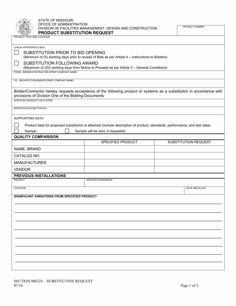
SECTION 006325 – SUBSTITUTION REQUEST 07/16 Page 1 of 2
STATE OF MISSOURI OFFICE OF ADMINISTRATION DIVISION OF FACILITIES MANAGEMENT, DESIGN AND CONSTRUCTION PRODUCT SUBSTITUTION REQUEST
PROJECT NUMBER
PROJECT TITLE AND LOCATION
CHECK APPROPRIATE BOX
SUBSTITUTION PRIOR TO BID OPENING (Minimum of (5) working days prior to receipt of Bids as per Article 4 – Instructions to Bidders)
SUBSTITUTION FOLLOWING AWARD (Maximum of (20) working days from Notice to Proceed as per Article 3 – General Conditions)
FROM: BIDDER/CONTRACTOR (PRINT COMPANY NAME)
TO: ARCHITECT/ENGINEER (PRINT COMPANY NAME)
Bidder/Contractor hereby requests acceptance of the following product or systems as a substitution in accordance with provisions of Division One of the Bidding Documents: SPECIFIED PRODUCT OR SYSTEM
SPECIFICATION SECTION NO.
SUPPORTING DATA
Product data for proposed substitution is attached (include description of product, standards, performance, and test data)
Sample Sample will be sent, if requested
QUALITY COMPARISON
SPECIFIED PRODUCT SUBSTITUTION REQUEST
NAME, BRAND
CATALOG NO.
MANUFACTURER
VENDOR
PREVIOUS INSTALLATIONS PROJECT
ARCHITECT/ENGINEER
LOCATION
DATE INSTALLED
SIGNIFICANT VARIATIONS FROM SPECIFIED PRODUCT

SECTION 006325 – SUBSTITUTION REQUEST 07/16 Page 2 of 2
REASON FOR SUBSTITUTION
DOES PROPOSED SUBSTITUTION AFFECT OTHER PARTS OF WORK?
YES NO
IF YES, EXPLAIN
SUBSTITUTION REQUIRES DIMENSIONAL REVISION OR REDESIGN OF STRUCTURE OR A/E WORK
YES NO
BIDDER’S/CONTRACTOR’S STATEMENT OF CONFORMANCE OF PROPOSED SUBSTITUTION TO CONTRACT REQUIREMENT: We have investigated the proposed substitution. We believe that it is equal or superior in all respects to specified product, except as stated above; that it will provide the same Warranty as specified product; that we have included complete implications of the substitution; that we will pay redesign and other costs caused by the substitution which subsequently become apparent; and that we will pay costs to modify other parts of the Work as may be needed, to make all parts of the Work complete and functioning as a result of the substitution.
BIDDER/CONTRACTOR DATE
REVIEW AND ACTION
Resubmit Substitution Request with the following additional information:
Substitution is accepted.
Substitution is accepted with the following comments:
Substitution is not accepted. ARCHITECT/ENGINEER DATE

SECTION 006519.16 - FINAL RECEIPT OF PAYMENT AND RELEASE FORM 07/16 Page 1 of 1
STATE OF MISSOURI OFFICE OF ADMINISTRATION DIVISION OF FACILITIES MANAGEMENT, DESIGN AND CONSTRUCTION FINAL RECEIPT OF PAYMENT AND RELEASE
PROJECT NUMBER
KNOW ALL MEN BY THESE PRESENT THAT: hereinafter called “Subcontractor” who heretofore entered into an
agreement with hereinafter called “Contractor”, for the performance of work and/or furnishing of material for the
construction of the project entitled
(PROJECT TITLE, PROJECT LOCATION, AND PROJECT NUMBER)
at (ADDRESS OF PROJECT)
for the State of Missouri (Owner) which said subcontract is by this reference incorporated herein, in consideration of such
final payment by Contractor.
DOES HEREBY:
1. ACKNOWLEDGE that they have been PAID IN FULL all sums due for work and materials contracted or done by
their Subcontractors, Material Vendors, Equipment and Fixture Suppliers, Agents and Employees, or otherwise in
the performance of the Work called for by the aforesaid Contract and all modifications or extras or additions
thereto, for the construction of said project or otherwise.
2. RELEASE and fully, finally, and forever discharge the Owner from any and all suits, actions, claims, and demands
for payment for work performed or materials supplied by Subcontractor in accordance with the requirements of
the above referenced Contract.
1. REPRESENT that all of their Employees, Subcontractors, Material Vendors, Equipment and Fixture Suppliers,
and everyone else has been paid in full all sums due them, or any of them, in connection with performance of
said Work, or anything done or omitted by them, or any of them in connection with the construction of said
improvements, or otherwise.
DATED this day of , 20 .
NAME OF SUBCONTRACTOR
BY (TYPED OR PRINTED NAME)
SIGNATURE
TITLE
ORIGINAL: FILE/Closeout Documents

SECTION 006519.18 - MBE/WBE/SDVE Progress Report 07/16 Page 1 of 1
STATE OF MISSOURI OFFICE OF ADMINISTRATION DIVISION OF FACILITIES MANAGEMENT, DESIGN AND CONSTRUCTION MBE/WBE/SDVE PROGRESS REPORT SUBMIT WITH ALL INVOICES: (PLEASE CHECK APPROPRIATE BOX BELOW)
CONSULTANT CONSTRUCTION
INVOICE NO.
PROJECT NUMBER
CHECK IF FINAL
FINAL
DATE
PROJECT TITLE
PROJECT LOCATION
FIRM
TOTAL CONTRACT AMOUNT
$
THE PERCENTAGE AND DOLLAR AMOUNT OF THIS PROJECT THAT ARE TO BE MBE/WBE/SDVE AS INDICATED IN THE ORIGINAL CONTRACT: % and $ .
CHECK MBE WBE SDVE
ITEM OF
WORK
TOTAL AMOUNT OF
SUBCONTRACT
$ AMOUNT & % COMPLETE
(PAID-TO-DATE)
CONSULTANT/SUBCONSULTANT OR CONTRACTOR/SUBCONTRACTOR/SUPPLIER
NAME, ADDRESS, CONTACT, AND PHONE NUMBER
MBE $ $ WBE
SDVE % - -
MBE $ $ WBE
SDVE % - -
MBE $ $
WBE
SDVE % - -
MBE $ $
WBE
SDVE % - -
MBE $ $
WBE
SDVE % - -
ORIGINAL: Attach to ALL Progress and Final Payments

SECTION 006519.21 - Affidavit of Compliance with Prevailing Wage Law 07/16 Page 1 of 1
STATE OF MISSOURI OFFICE OF ADMINISTRATION DIVISION OF FACILITIES MANAGEMENT, DESIGN AND CONSTRUCTION AFFIDAVIT – COMPLIANCE WITH PREVAILING WAGE LAW
PROJECT NUMBER
Before me, the undersigned Notary Public, in and for the County of
State of personally came and appeared
(NAME)
of the
(POSITION) (NAME OF THE COMPANY)
(a corporation) (a partnership) (a proprietorship) and after being duly sworn did depose and say that all provisions
and requirements set out in Chapter 290, Sections 290.210 through and including 290.340, Missouri Revised
Statutes, pertaining to the payment of wages to workmen employed on public works project have been fully satisfied
and there has been no exception to the full and completed compliance with said provisions and requirements
and with Wage Determination No: issued by the
Department of Labor and Industrial Relations, State of Missouri on the day of 20
in carrying out the contract and working in connection with
(NAME OF PROJECT)
Located at in County
(NAME OF THE INSTITUTION)
Missouri, and completed on the day of 20
SIGNATURE
NOTARY INFORMATION NOTARY PUBLIC EMBOSSER OR BLACK INK RUBBER STAMP SEAL
STATE
COUNTY (OR CITY OF ST. LOUIS)
SUBSCRIBED AND SWORN BEFORE ME, THIS USE RUBBER STAMP IN CLEAR AREA BELOW
DAY OF YEAR NOTARY PUBLIC SIGNATURE
MY COMMISSION EXPIRES
NOTARY PUBLIC NAME (TYPED OR PRINTED)
FILE: Closeout Documents

SECTION 007213 - GENERAL CONDITIONS Page 1 of 20 07/19
GENERAL CONDITIONS
INDEX
ARTICLE:
1. General Provisions
1.1. Definitions
1.2. Drawings and Specifications
1.3. Compliance with Laws, Permits, Regulations and Inspections
1.4. Nondiscrimination in Employment
1.5. Anti-Kickback
1.6. Patents and Royalties
1.7. Preference for American and Missouri Products and Services
1.8. Communications
1.9. Separate Contracts and Cooperation
1.10. Assignment of Contract
1.11. Indemnification
1.12. Disputes and Disagreements
2. Owner/Designer Responsibilities
3. Contractor Responsibilities
3.1. Acceptable Substitutions
3.2. Submittals
3.3. As-Built Drawings
3.4. Guaranty and Warranties
3.5. Operation and Maintenance Manuals
3.6. Other Contractor Responsibilities
3.7. Subcontracts
4. Changes in the Work
4.1. Changes in the Work
4.2. Changes in Completion Time
5. Construction and Completion
5.1. Construction Commencement
5.2. Project Construction
5.3. Project Completion
5.4. Payments
6. Bond and Insurance
6.1. Bond
6.2. Insurance
7. Termination or Suspension of Contract
7.1. For Site Conditions
7.2. For Cause
7.3. For Convenience

SECTION 007213 - GENERAL CONDITIONS Page 2 of 20 07/19
SECTION 007213 - GENERAL CONDITIONS
A. These General Conditions apply to each section of these specifications. The Contractor is subject to the provisions contained herein.
B. The General Conditions are intended to define the relationship of the Owner, the Designer and the Contractor thereby establishing certain rules and provisions governing the operation and performance of the work so that the work may be performed in a safe, orderly, expeditious and workmanlike manner.
ARTICLE 1 – GENERAL PROVISIONS
ARTICLE 1.1 - DEFINITIONS
A. As used in these contract documents, the following terms shall have the meanings and refer to the parties designated in these definitions.
1. "COMMISSIONER": The Commissioner of the Office of Administration.
2. “CONSTRUCTION DOCUMENTS”: The “Construction Documents” shall consist of the Project Manual, Drawings and Addenda.
3. "CONSTRUCTION
REPRESENTATIVE:” Whenever the term "Construction Representative" is used, it shall mean the Owner’s Representative at the work site.
4. "CONTRACTOR": Party or parties who have entered into a contract with the Owner to furnish work under these specifications and drawings.
5. "DESIGNER": When the term "Designer" is used herein, it shall refer to the Architect, Engineer, or Consultant of Record specified and defined in Paragraph 2.0 of the Supplemental Conditions, or his duly authorized representative. The Designer may be either a consultant or state employee.
6. "DIRECTOR": Whenever the term "Director" is used, it shall mean the Director of the Division of Facilities Management, Design and Construction or his Designee, representing the Office of Administration, State of Missouri. The Director is the agent of the Owner.
7. "DIVISION": Shall mean the Division of Facilities Management, Design and Construction, State of Missouri.
8. “INCIDENTAL JOB BURDENS”: Shall mean those expenses relating to the cost of work, incurred either in the home office or on the job-site, which are necessary in the course of doing business but are incidental to the job. Such costs include office supplies and equipment, postage, courier services, telephone expenses including long distance, water and ice and other similar expenses.
9. "JOINT VENTURE": An association of two (2) or more businesses to carry out a single business enterprise for profit for which purpose they combine their property, capital, efforts, skills and knowledge.
10. "OWNER”: Whenever the term “Owner” is used, it shall mean the State of Missouri.
11. “PROJECT”: Wherever the term “Project” is used, it shall mean the work required to be completed by the construction contract.
12. “PROJECT MANUAL”: The “Project Manual” shall consist of Introductory Information, Invitation for Bid, Instructions to Bidders, Bid Documents, Additional Information, Standard Forms, General Conditions, Supplemental General Conditions, General Requirements and Technical Specifications.
13. "SUBCONTRACTOR": Party or parties who contract under, or for the performance of part or this entire Contract between the Owner and Contractor. The subcontract may or may not be direct with the Contractor.
14. "WORK": Labor, material, supplies, plant and equipment required to perform and complete the service agreed to by the Contractor in a safe, expeditious, orderly and workmanlike manner so that the project shall be complete and finished in the best manner known to each respective trade.
15. “WORKING DAYS”: are all calendar days except Saturdays, Sundays and the following holidays: New Year’s Day, Martin Luther King, Jr. Day, Lincoln Day, Washington’s Birthday (observed), Truman Day, Memorial Day, Independence Day, Labor Day, Columbus Day, Veterans Day (observed), Thanksgiving Day, Christmas Day.
ARTICLE 1.2 DRAWINGS AND
SPECIFICATIONS
A. In case of discrepancy between drawings and specifications, specifications shall govern. Should discrepancies in architectural drawings, structural drawings and mechanical drawings occur, architectural drawings shall govern and, in case of

SECTION 007213 - GENERAL CONDITIONS Page 3 of 20 07/19
conflict between structural and mechanical drawings, structural drawings shall govern.
B. Specifications are separated into titled divisions for convenience of reference only and to facilitate letting of contracts and subcontracts. The Contractor is responsible for establishing the scope of work for subcontractors, which may cross titled divisions. Neither the Owner nor Designer will establish limits and jurisdiction of subcontracts.
C. Figured dimensions take precedence over scaled measurements and details over smaller scale general drawings. In the event of conflict between any of the documents contained within the contract, the documents shall take precedence and be controlling in the following sequence: addenda, supplementary general conditions, general conditions, division 1 specifications, technical division specifications, drawings, bid form and instructions to bidders.
D. Anything shown on drawings and not mentioned in these specifications or vice versa, as well as any incidental work which is obviously necessary to complete the project within the limits established by the drawings and specifications, although not shown on or described therein, shall be performed by the Contractor at no additional cost as a part of his contract.
E. Upon encountering conditions differing materially from those indicated in the contract documents, the Contractor shall promptly notify the Designer and Construction Representative in writing before such conditions are disturbed. The Designer shall promptly investigate said conditions and report to the Owner, with a recommended course of action. If conditions do materially differ and cause an increase or decrease in contract cost or time required for completion of any portion of the work, a contract change will be initiated as outlined in Article 4 of these General Conditions.
E. Only work included in the contract documents is authorized, and the Contractor shall do no work other than that described therein or in accordance with appropriately authorized and approved contract changes.
ARTICLE 1.3 - COMPLIANCE WITH LAWS,
PERMITS, REGULATIONS AND INSPECTIONS
A. Since the Owner is the State of Missouri, municipal or political subdivisions, zoning ordinances, construction codes (other than licensing of trades), and other like ordinances are not applicable to construction on Owner’s property, and Contractor will not be required to submit drawings and specifications to any municipal or political subdivision, authority, obtain construction permits or any other licenses (other
than licensing of trades) or permits from or submit to inspections by any municipality or political subdivision relating to the construction for this project. All permits or licenses required by municipality or political subdivision for operation on property not belonging to Owner shall be obtained by and paid for by Contractor. Each Contractor shall comply with all applicable laws, ordinances, rules and regulations that pertain to the work of this contract.
B. Contractors, subcontractors and their employees engaged in the businesses of electrical, mechanical, plumbing, carpentry, sprinkler system work, and other construction related trades shall be licensed to perform such work by the municipal or political subdivision where the project is located, if such licensure is required by local code. Local codes shall dictate the level (master, journeyman, and apprentice) and the number, type and ratio of licensed tradesmen required for this project within the jurisdiction of such municipal or political subdivision.
C. Equipment and controls manufacturers and their authorized service and installation technicians that do not maintain an office within the jurisdiction of the municipal or political subdivision but are a listed or specified contractor or subcontractor on this project are exempt from Paragraph 1.3 B above.
D. The Contractor shall post a copy of the wage determination issued for the project and included as a part of the contract documents, in a prominent and easily accessible location at the site of construction for the duration of the project.
E. Any contractor or subcontractor to such contractor at any tier signing a contract to work on this project shall provide a ten-hour Occupational Safety and Health Administration (OSHA) construction safety program for their on-site employees which includes a course in construction safety and health approved by OSHA or a similar program approved by the Department of Labor and Industrial Relations which is at least as stringent as an approved OSHA program. The contractor shall forfeit as a penalty to the public body on whose behalf the contract is made or awarded, two thousand five hundred dollars plus one hundred dollars for each employee employed by the contractor or subcontractor, for each calendar day, or portion thereof, such employee is employed without the required training.
ARTICLE 1.4 - NONDISCRIMINATION IN
EMPLOYMENT
A. The Contractor and his subcontractors will not discriminate against individuals based on race, color, religion, national origin, sex, disability, or

SECTION 007213 - GENERAL CONDITIONS Page 4 of 20 07/19
age, but may use restrictions which relate to bona fide occupational qualifications. Specifically, the Contractor and his subcontractors shall not discriminate:
1. Against recipients of service on the basis of race, color, religion, national origin, sex, disability or age.
2. Against any employee or applicant, for employment on the basis of race, color, religion, national origin, sex or otherwise qualified disability status.
3. Against any applicant for employment or employee on the basis of age, where such applicant or employee is between ages 40 and 70 and where such Contractor employs at least 20 persons.
4. Against any applicant for employment or employee on the basis of that person's status as a disabled or Vietnam-era veteran.
The Contractor and his Subcontractors will take affirmative action to insure applicants for employment and employees are treated equally without regard to race, color, religion, national origin, sex, disability, or age. Such action shall include, but not be limited to, the following: employment, upgrading, demotion and transfer; recruitment or recruitment advertising; and selection for training, including apprenticeship. The Contractor and his Subcontractors will give written notice of their commitments under this clause to any labor union with which they have bargaining or other agreements.
B. The Contractor and his Subcontractors shall develop, implement, maintain and submit in writing to the Owner an affirmative action program if at least fifty (50) persons in the aggregate are employed under this contract. If less than fifty (50) persons in the aggregate are to be employed under this contract, the Contractor shall submit, in lieu of the written affirmative action program, a properly executed Affidavit for Affirmative Action in the form included in the contract specifications. For the purpose of this section, an "affirmative action program" means positive action to influence all employment practices (including, but not limited to, recruiting, hiring, promoting and training) in providing equal employment opportunity regardless of race, color, sex, national origin, religion, age (where the person affected is between age 40 and 70), disabled and Vietnam-era veteran status, and disability. Such "affirmative action program" shall include:
1. A written policy statement committing the total organization to affirmative action and
assigning management responsibilities and procedures for evaluation and dissemination;
2. The identification of a person designated to handle affirmative action;
3. The establishment of non-discriminatory selection standards, objective measures to analyze recruitment, an upward mobility system, a wage and salary structure, and standards applicable to lay-off, recall, discharge, demotion and discipline;
4. The exclusion of discrimination from all collective bargaining agreements; and
5. Performance of an internal audit of the reporting system to monitor execution and to provide for future planning.
In the enforcement of this non-discrimination clause, the Owner may use any reasonable procedures available, including, but not limited to: requests, reports, site visits and inspection of relevant documents of contractors and subcontractors.
C. In the event of the Contractor's or his subcontractor's noncompliance with any provisions of this Article of the Contract, the Owner may cancel this contract in whole or in part or require the Contractor to terminate his contract with the subcontractor.
ARTICLE 1.5 - ANTI-KICKBACK
A. No employee of the division, shall have or acquire any pecuniary interest, whether direct or indirect, in this contract or in any part hereof. No officer, employee, designer, attorney, or administrator of or for the Owner who is authorized in such capacity and on behalf of the Owner to exercise any legislative, executive, supervisory or other similar functions in connection with the construction of the project, shall have or acquire any pecuniary interest, whether direct or indirect, in this contract, any material supply contract, subcontract, insurance contract, or any other contract pertaining to the project.
ARTICLE 1.6 - PATENTS AND ROYALTIES
A. The Contractor shall hold and save the Owner and its officers, agents, servants and employees harmless from liabilities of any nature or kind, including cost and expenses, for, or on account of, any patented or unpatented invention, process, article or appliance manufactured or used in the performance of this contract, including its use by the Owner, unless otherwise specifically stipulated in the contract documents.
B. If the Contractor uses any design, device or materials covered by letters, patent or copyright,

SECTION 007213 - GENERAL CONDITIONS Page 5 of 20 07/19
the Contractor shall provide for such use by suitable agreement with the Owner of such patented or copyrighted design, device or material. It is mutually agreed and understood, without exception, that the contract prices shall include all royalties or costs arising from the use of such design, device or materials, in any way involved in the work. The Contractor and/or his sureties shall indemnify and save harmless the Owner of the project from any and all claims for infringement by reason of the use of such patented or copyrighted design, device or materials or any trademark or copyright in connection with work agreed to be performed under this contract and shall indemnify the Owner for any cost, expense or damage it may be obliged to pay by reason of such infringement at any time during the prosecution of the work or after completion of the work.
ARTICLE 1.7 - PREFERENCE FOR AMERICAN
AND MISSOURI PRODUCTS AND SERVICES
A. By virtue of statutory authority a preference will be given to Missouri labor and to products of mines, forests and quarries of the state of Missouri when they are found in marketable quantities in the state, and all such materials shall be of the best quality and suitable character that can be obtained at reasonable market prices, all as provided for in Section 8.280, Missouri Revised Statutes and Cumulative Supplements.
B. Furthermore, pursuant to Section 34.076 Missouri Revised Statutes and Cumulative Supplements, a preference shall be given to those persons doing business as Missouri firms, corporations, or individuals, or which maintain Missouri offices or places of business, when the quality of performance promised is equal or better and the price quoted is the same or less. In addition, in order for a non-domiciliary bidder to be successful, his bid must be that same percentage lower than a domiciliary Missouri bidder's bid, as would be required for a Missouri bidder to successfully bid in the non-domiciliary state.
C In accordance with the Missouri Domestic Products Procurement Act Section 34.350 RSMo and Cumulative Supplements any manufactured goods or commodities used or supplied in the performance of this contract or any subcontract thereto shall be manufactured, assembled or produced in the United States, unless the specified products are not manufactured, assembled or produced in the United States in sufficient quantities to meet the agency's requirements or cannot be manufactured, assembled or produced in the United States within the necessary time in sufficient quantities to meet the contract requirements, or if obtaining the specified products manufactured, assembled or produced in the
United States would increase the cost of this contract for purchase of the product by more than ten percent.
ARTICLE 1.8 - COMMUNICATIONS
A. All notices, requests, instructions, approvals and claims must be in writing and shall be delivered to the Designer and copied to the Construction Representative for the project except as required by Article 1.12 Disputes and Disagreements, or as otherwise specified by the Owner in writing as stated in Section 012600. Any such notice shall be deemed to have been given as of the time of actual receipt.
B. The Contractor shall attend on-site progress and coordination meetings, as scheduled by the Construction Representative, no less than once a month.
C. The Contractor shall ensure that major subcontractors and suppliers shall attend monthly progress meetings as necessary to coordinate the work, and as specifically requested by the Construction Representative.
ARTICLE 1.9 - SEPARATE CONTRACTS AND
COOPERATION
A. The Owner reserves the right to let other contracts in connection with this work. The Contractor shall afford other contractors reasonable opportunity for the introduction and storage of their materials and the execution of their work and shall properly connect and coordinate his work with theirs.
B. The Contractor shall consult the drawings for all other contractors in connection with this work. Any work conflicting with the above shall be brought to the attention of the Owner’s Representative before the work is performed. If the Contractor fails to do this, and constructs any work which interferes with the work of another contractor, the Contractor shall remove any part so conflicting and rebuild same, as directed by the Owner’s Representative at no additional cost to the Owner.
C. Each contractor shall be required to coordinate his work with other contractors so as to afford others reasonable opportunity for execution of their work. No contractor shall delay any other contractor by neglecting to perform contract work at the proper time. If any contractor causes delay to another, they shall be liable directly to that contractor for such delay in addition to any liquidated damages which might be due the Owner.
D. Should the Contractor or project associated subcontractors refuse to cooperate with the instructions and reasonable requests of other Contractors or other subcontractors in the overall

SECTION 007213 - GENERAL CONDITIONS Page 6 of 20 07/19
coordinating of the work, the Owner may take such appropriate action and issue directions, as required, to avoid unnecessary and unwarranted delays.
E. Each Contractor shall be responsible for damage done to Owner's or other Contractor's property by him/her or workers in his employ through their fault or negligence.
F. Should a Contractor sustain any damage through any act or omission of any other Contractor having a contract with the Owner, the Contractor so damaged shall have no claim or cause of action against the Owner for such damage, but shall have a claim or cause of action against the other Contractor to recover any and all damages sustained by reason of the acts or omissions of such Contractor. The phrase "acts or omissions" as used in this section shall be defined to include, but not be limited to, any unreasonable delay on the part of any such contractors.
ARTICLE 1.10 - ASSIGNMENT OF CONTRACT
A. No assignment by Contractor of any amount or any part of this contract or of the funds to be received there under will be recognized unless such assignment has had the written approval of the Director and the surety has been given due notice of such assignment and has furnished written consent thereto. In addition to the usual recitals in assignment contracts, the following language must be set forth: "It is agreed that the funds to be paid to the assignee under this assignment are subject to performance by the Contractor of this contract and to claims or liens for services rendered or materials supplied for the performance of the work called for in said contract in favor of all persons, firms or corporations rendering such services or supplying such materials."
ARTICLE 1.11 - INDEMNIFICATION
A. Contractor agrees to indemnify and save harmless Owner and its respective commissioners, officers, officials, agents, consultants and employees and Designer, their agents, servants and employees, from and against any and all liability for damage arising from injuries to persons or damage to property occasioned by any acts or omissions of Contractor, any subcontractors, agents, servants or employees, including any and all expense, legal or otherwise, which may be incurred by Owner or Designer, its agents, servants or employees, in defense of any claim, action or suit.
B. The obligations of the Contractor under this paragraph shall not extend to the liability of the Designer, his agents or employees, arising out of (1) the preparation or approval of maps, drawings, opinions, reports, surveys, contract changes, design or specifications, or (2) giving of or the failure to
give directions or instructions by the Designer, his agents or employees as required by this contract documents provided such giving or failure to give is the primary cause of the injury or damage.
ARTICLE 1.12 - DISPUTES AND
DISAGREEMENTS
A. It is hereby expressly agreed and understood that in case any controversy or difference of opinion arises during construction, best efforts will be given to resolution at the field level. Should those efforts be unsuccessful, the Contractor has the right to appeal in writing, the decision of the Director’s Designee to the Director at Room 730 Truman Building, P.O. Box 809, Jefferson City, Missouri 65102. The decision of the Director shall be final and binding on all parties.
ARTICLE 2 -- OWNER/DESIGNER
RESPONSIBILITIES
A. The Owner shall give all orders and directions contemplated under this contract relative to the execution of the work. During progress of work the Owner will be represented at the project site by the Construction Representative and/or Designer, whose responsibilities are to see that this contract is properly fulfilled.
B. The Owner shall at all times have access to the work whenever it is in preparation or progress. The Contractors shall provide proper facilities for such access and for inspection and supervision.
C. All materials and workmanship used in the work shall be subject to the inspection of the Designer and Construction Representative, and any work which is deemed defective shall be removed, rebuilt or made good immediately upon notice. The cost of such correction shall be borne by the Contractor. Contractor shall not be entitled to an extension of the contract completion date in order to remedy defective work. All rejected materials shall be immediately removed from the site of the work.
D. If the Contractor fails to proceed at once with the correction of rejected defective materials or workmanship, the Owner may, by separate contract or otherwise, have the defects remedied or rejected. Materials removed from the site and charge the cost of the same against any monies which may be due the Contractor, without prejudice to any other rights or remedies of the Owner.
E. Failure or neglect on the part of Owner to observe faulty work, or work done which is not in accordance with the drawings and specifications shall not relieve the Contractor from responsibility

SECTION 007213 - GENERAL CONDITIONS Page 7 of 20 07/19
for correcting such work without additional compensation.
F. The Owner shall have the right to direct the Contractor to uncover any completed work.
1. If the Contractor fails to adequately notify the Construction Representative and/or Designer of an inspection as required by the Contract Documents, the Contractor shall, upon written request, uncover the work. The Contractor shall bear all costs associated with uncovering and again covering the work exposed.
2. If the Contractor is directed to uncover work, which was not otherwise required by the Contract Documents to be inspected, and the work is found to be defective in any respect, no compensation shall be allowed for this work. If, however, such work is found to meet the requirements of this contract, the actual cost of labor and material necessarily involved in the examination and replacement plus 10% shall be allowed the Contractor.
G. The Designer shall give all orders and directions contemplated under this contract relative to the scope of the work and shall give the initial interpretation of the contract documents.
H. The Owner may file a written notice to the Contractor to dismiss immediately any subcontractors, project managers, superintendents, foremen, workers, watchmen or other employees whom the Owner may deem incompetent, careless or a hindrance to proper or timely execution of the work. The Contractor shall comply with such notice as promptly as practicable without detriment to the work or its progress.
I. If in the Owner’s judgment it becomes necessary at any time to accelerate work, when ordered by the Owner in writing, the Contractor shall redirect resources to such work items and execute such portions of the work as may be required to complete the work within the current approved contract schedule.
ARTICLE 3 -- CONTRACTOR
RESPONSIBILITIES
ARTICLE 3.1 -- ACCEPTABLE SUBSTITUTIONS
A. The Contractor may request use of any article, device, product, material, fixture, form or type of construction which in the judgment of the Owner and Designer is equal in all respects to that named. Standard products of manufacturers other than those specified will be accepted when, prior to the ordering or use thereof, it is proven to the satisfaction of the Owner and Designer that they are equal in design, strength, durability, usefulness and convenience for the purpose intended.
B. Any changes required in the details and dimensions indicated on the drawings for the substitution of products other than those specified shall be properly made at the expense of the Contractor requesting the substitution or change.
C. The Contractor shall submit a request for such substitutions in writing to the Owner and Designer within twenty (20) working days after the date of the "Notice to Proceed." Thereafter no consideration will be given to alternate forms of accomplishing the work. This Article does not preclude the Owner from exercising the provisions of Article 4 hereof.
D. Any request for substitution by the Contractor shall be submitted in accordance with SECTION 002113 - INSTRUCTIONS TO BIDDERS.
E. When a material has been approved, no change in brand or make will be permitted unless:
1. Written verification is received from the manufacturer stating they cannot make delivery on the date previously agreed, or
2. Material delivered fails to comply with contract requirements.
ARTICLE 3.2 -- SUBMITTALS
A. The Contractor’s submittals must be submitted with such promptness as to allow for review and approval so as not to cause delay in the work. The Contractor shall coordinate preparation and processing of submittals with performance of construction activities.
Coordinate each submittal with fabrication, purchasing, testing, delivery, other submittals, and related activities that require sequential activity.
Submit four (4) copies to the Designer and additional copies as required for the subcontractors and material suppliers. Also provide copies to meet the requirements for maintenance manuals.
B. All subcontractors' shop drawings and schedules shall be submitted by the Contractor and shall bear evidence that Contractor has received, reviewed, and approved them. Any shop drawings and schedules submitted without this evidence will be returned to the Contractor for resubmission.
C. The Contractor shall include with the shop drawing, a letter indicating any and all deviations from the drawings and/or specifications. Failure to notify the Designer of such deviations will be grounds for subsequent rejection of the related work or materials. If, in the opinion of the Designer, the deviations are not acceptable, the Contractor will be required to furnish the item as specified and indicated on the drawings.

SECTION 007213 - GENERAL CONDITIONS Page 8 of 20 07/19
D. The Designer shall check shop drawings and schedules with reasonable promptness and approve them only if they conform to the design concept of the project and comply with the information given in the contract documents. The approval shall not relieve the Contractor from the responsibility to comply with the drawings and specifications, unless the Contractor has called the Designer's attention to the deviation, in writing, at the time of submission and the Designer has knowingly approved thereof. An approval of any such modification will be given only under the following conditions:
1. It is in the best interest of the Owner
2. It does not increase the contract sum and/or completion time
3. It does not deviate from the design intent
4. It is without prejudice to any and all rights under the surety bond.
E. No extension of time will be granted because of the Contractor's failure to submit shop drawings and schedules in ample time to allow for review, possible resubmission, and approval. Fabrication of work shall not commence until the Contractor has received approval. The Contractor shall furnish prints of approved shop drawings and schedules to all subcontractors whose work is in any way related to the work under this contract. Only prints bearing this approval will be allowed on the site of construction
F. The Contractor shall maintain a complete file on-site of approved shop drawings available for use by the Construction Representative.
ARTICLE 3.3 – AS-BUILT DRAWINGS
A. The Contractor shall update a complete set of the construction drawings, shop drawings and schedules of all work monthly by marking changes, and at the completion of their work (prior to submission of request for final payment) note all changes and turn the set over to the Construction Representative. The updates shall show all addenda, all field changes that were made to adapt to field conditions, changes resulting from contract changes or supplemental instructions, and all locations of structures, buried installations of piping, conduit, and utility services. All buried and concealed items both inside and outside shall be accurately located as to depth and referenced to permanent features such as interior or exterior wall faces and dimensions shall be given in a neat and legible manner in a contrasting colored pencil or ink. If approved by the Designer, an electronic file format may be provided.
ARTICLE 3.4 – GUARANTY AND
WARRANTIES
A. General Guaranty
1. Neither the final certificate of payment nor any provision in the contract documents nor partial use or occupancy of the premises by the Owner shall constitute an acceptance of work not done in accordance with contract requirements.
2. The Contractor or surety shall remedy any defects in the work and pay for any damage to property resulting there from which shall appear within a period of one (1) year from the date of substantial completion unless a longer period is otherwise specified or a differing guaranty period has been established in the substantial completion certificate. The Owner will give notice of observed defects with reasonable promptness.
3. In case of default on the part of the Contractor in fulfilling this part of this contract, the Owner may correct the work or repair the damage and the cost and expense incurred in such event shall be paid by or recoverable from the Contractor or surety.
4. The work will be free from defects not inherent in the quality required or permitted, and that the Work will conform to the requirements of the Contract Documents. Work not conforming to these requirements, including substitutions not properly approved and authorized, may be considered defective. The Contractor's guaranty excludes remedy for damage or defect caused by abuse, modifications not executed by the Contractor, improper or insufficient maintenance, improper operation, or normal wear and tear under normal usage. If required by the Owner, the Contractor shall furnish satisfactory evidence as to the kind and quality of materials and equipment
B. Extended Warranty
Manufacturer's certificates of warranty shall be obtained for all major equipment. Warranty shall be obtained for at least one year. Where a longer period is offered at no additional cost or called for in the specific equipment specifications, the longer period shall govern.
ARTICLE 3.5 -- OPERATION AND
MAINTENANCE MANUALS
A. Immediately after equipment submittals are approved and no later than ten (10) working days prior to the substantial completion inspection, the Contractor shall provide to the Designer three (3)
SECTION 007213 - GENERAL CONDITIONS Page 9 of 20 07/19
copies of operating instructions and service manuals, containing the following: 1. Start-up and Shut-down Procedures: Provide
a step-by-step write up of all major equipment. When manufacturer’s printed start-up, trouble shooting and shut-down procedures are available; they may be incorporated into the operating manual for reference.
2. Operating Instructions: Written operating instructions shall be included for the efficient and safe operation of all equipment.
3. Equipment List: List of all major equipment as installed shall be prepared to include model number, capacities, flow rate, name place data, shop drawings and air and water balance reports.
4. Service Instructions: Provide the following information for all pieces of equipment.
a. Recommended spare parts including catalog number and name of local supplier or factory representative.
b. Belt sizes, types, and lengths.
c. Wiring diagrams.
5. Manufacturer's Certificate of Warranty as described in Article 3.4.
6. Prior to the final payment, furnish to the Designer three (4) copies of parts catalogs for each piece of equipment furnished by him/her on the project with the components identified by number for replacement ordering.
B. Submission of operating instructions shall be done in the following manner.
1. Manuals shall be in quadruplicate, and all materials shall be bound into volumes of standard 8½" x 11" hard binders. Large drawings too bulky to be folded into 8½" x 11" shall be separately bound or folded and in envelopes, cross referenced and indexed with the manuals.
2. The manuals shall identify project name, project number, and include the name and address of the Contractor, subcontractors and manufacturers who were involved with the activity described in that particular manual.
3. Internally subdivide the binder contents with permanent page dividers, logically organized with tab titles clearly printed under reinforced laminated plastic tabs.
4. Contents: Prepare a Table of Contents for each volume, with each product or system description identified.
ARTICLE 3.6 – OTHER CONTRACTOR
RESPONSIBILITIES
A. The Contractor shall keep on site, during progress of the work, a competent superintendent satisfactory to the Construction Representative. The superintendent shall represent the Contractor and all agreements made by the superintendent shall be binding. The superintendent shall carefully study and compare all drawings, specifications and other instructions and shall promptly notify the Construction Representative and Designer, in writing, any error, inconsistency or omission which may be discovered. The superintendent shall coordinate all work on the project. Any change of the superintendent shall be approved by the Construction Representative.
B. Contractor shall, at all times, enforce strict discipline and good order among his employees, and shall not employ on the work any unfit person or anyone not skilled in the work assigned to him/her.
C. The Contractor shall supply sufficient labor, material, plant and equipment and pay when due any laborer, subcontractor or supplier for supplies furnished and otherwise prosecute the work with diligence to prevent work stoppage and insure completion thereof within the time specified.
D. The Contractor and each of his subcontractors shall submit to the Construction Representative, through the Designer such schedules of quantities and costs, progress schedules, payrolls, reports, estimates, records and other data as the Owner may request concerning work performed or to be performed under this contract.
E. The Contractor, subcontractors, and material suppliers shall upon written request, give the Owner access to all time cards, material invoices, payrolls, estimates, profit and loss statements, and all other direct or indirect costs related to this work.
F. The Contractor shall be responsible for laying out all contract work such as layout of architectural, structural, mechanical and electrical work, which shall be coordinated with layouts of subcontractors for general construction work. The Contractor is also responsible for unloading, uncrating and handling of all materials and equipment to be erected or placed by him/her, whether furnished by Contractor or others. No extra charges or compensation will be allowed as a result of failure to verify dimensions before ordering materials or fabricating items.
G. The Contractor must notify the Construction Representative at least one working day before
SECTION 007213 - GENERAL CONDITIONS Page 10 of 20 07/19
placing concrete or burying underground utilities, pipelines, etc.
H. Contractors shall prearrange time with the Construction Representative for the interruption of any facility operation. Unless otherwise specified in these documents, all connections, alterations or relocations as well as all other portions of the work will be performed during normal working hours.
I. The Contractor shall coordinate all work so there will not be prolonged interruptions of existing equipment operation. Any existing plumbing, heating, ventilating, air conditioning or electrical disconnections necessary for the project, which affect portions of this construction or building or any other building must be scheduled with the Construction Representative to minimize or avoid any disruption of facility operations. In no case, unless previously approved in writing by the Construction Representative, shall utilities be left disconnected at the end of a work day or over a weekend. Any interruption of utilities either intentionally or accidentally shall not relieve the Contractor responsible for the interruption from the responsibility to repair and restore the utility to normal service. Repairs and restoration shall be made before the workers responsible for the repair and restoration leave the job.
J. Contractors shall limit operations and storage of materials to the area within the project, except as necessary to connect to existing utilities, and shall not encroach on neighboring property. The Contractor shall be responsible for repair of their damage to property on or off the project site occurring during construction of project. All such repairs shall be made to the satisfaction of the property owner.
K. Unless otherwise permitted, all materials shall be new and both workmanship and materials shall be of the best quality.
L. Unless otherwise provided and stipulated within these specifications, the Contractor shall furnish, construct, and/or install and pay for materials, devices, mechanisms, equipment, all necessary personnel, utilities including, but not limited to water, heat, light and electric power, transportation services, applicable taxes of every nature, and all other facilities necessary for the proper execution and completion of the work.
M. Contractor shall carefully examine the plans and drawings and shall be responsible for the proper fitting of his material, equipment and apparatus into the building.
N. The Contractor or subcontractors shall not overload, or permit others to overload, any part of
any structure during the performance of this contract.
O. All temporary shoring, bracing, etc., required for the removal of existing work and/or for the installation of new work shall be included in this contract. The Contractor shall make good, at no cost to the Owner, any damage caused by improper support or failure of shoring in any respect. Each Contractor shall be responsible for shoring required to protect his work or adjacent property and improvements of Owner and shall be responsible for shoring or for giving written notice to adjacent property owners. Shoring shall be removed only after completion of permanent supports.
P. The Contractor shall provide at the proper time such material as is required for support of the work. If openings are required, whether shown on drawings or not, the Contractor shall see that they are properly constructed.
Q. During the performance of work the Contractor shall be responsible for providing and maintaining warning signs, lights, signal devices, barricades, guard rails, fences and other devices appropriately located on site which will give proper and understandable warning to all persons of danger of entry onto land, structure or equipment.
R. The Contractor shall be responsible for protection, including weather protection, and proper maintenance of all equipment and materials.
S. The Contractor shall be responsible for care of the finished work and shall protect same from damage or defacement until substantial completion by the Owner. If the work is damaged by any cause, the Contractor shall immediately begin to make repairs in accordance with the drawings and specifications. Contractor shall be liable for all damage or loss unless attributable to the acts or omissions of the Owner or Designer. Any claim for reimbursement shall be submitted in accordance with Article 4. After substantial completion the Contractor will only be responsible for damage resulting from acts or omissions of the Contractor or subcontractors through final warranty.
T. In the event the Contractor encounters an unforeseen hazardous material, the Contractor shall immediately stop work in the area affected and report the condition to the Owner and Designer in writing. The Contractor shall not be required, pursuant to Article 4, to perform, any work relating to hazardous materials.
U. In an emergency affecting safety of persons or property, the Contractor shall act, at the Contractor's discretion, to prevent threatened damage, injury or loss. Additional compensation

SECTION 007213 - GENERAL CONDITIONS Page 11 of 20 07/19
or extension of time claimed by the Contractor on account of an emergency shall be determined as provided in Article 4.
V. Before commencing work, Contractors shall confer with the Construction Representative and facility representative and review any facility rules and regulations which may affect the conduct of the work.
W. Project signs will only be erected on major projects and only as described in the specifications. If no sign is specified, none shall be erected.
ARTICLE 3.7 -- SUBCONTRACTS
A. Subcontractor assignments as identified in the bid form shall not be changed without written approval of the Owner. The Owner will not approve changes of a listed subcontractor unless the Contractor documents, to the satisfaction of the Owner that the subcontractor cannot or will not perform the work as specified.
B. The Contractor is fully responsible to the Owner for the acts and omissions of all subcontractors and of persons either directly or indirectly employed by them.
C. Every subcontractor shall be bound by the applicable terms and provisions of these contract documents, but no contractual relationship shall exist between any subcontractor and the Owner unless the right of the Contractor to proceed with the work is suspended or this contract is terminated as herein provided, and the Owner in writing elects to assume the subcontract.
D. The Contractor shall upon receipt of "Notice to Proceed" and prior to submission of the first payment request, notify the Designer and Construction Representative in writing of the names of any subcontractors to be used in addition to those identified in the bid form and all major material suppliers proposed for all parts of the work.
ARTICLE 4 -- CHANGES IN THE WORK
4.1 CHANGES IN THE WORK
A. The Construction Representative, without giving notice to the surety and without invalidating this contract, may order extra work or make changes by altering, adding to or deducting from the work, this contract sum being adjusted accordingly. All such work shall be executed under the conditions of the original contract. A claim for extension of time caused by any change must be adjusted at the time of ordering such change. No future request for time will be considered.
B. Each Contract Change shall include all costs required to perform the work including all labor,
material, equipment, overheads and profit, delay, disruptions, or other miscellaneous expenses. No subsequent requests for additional compensation including claims for delay, disruption, or reduced efficiency as a result of each change will be considered. Values from the Schedule of Values will not be binding as a basis for additions to or deductions from the contract price.
C. The amount of any adjustment in this contract price for authorized changes shall be agreed upon before such changes become effective and shall be determined, through submission of a request for proposal, as follows:
1. By an acceptable fixed price proposal from the Contractor. Breakdowns shall include all takeoff sheets of each Contractor and subcontractor. Breakdown shall include a listing of each item of material with unit prices and number of hours of labor for each task. Labor costs per hour shall be included with labor burden identified, which shall be not less than the prevailing wage rate, etc. Overhead and profit shall be shown separately for each subcontractor and the Contractor.
2. By a cost-plus-fixed-fee (time and material) basis with maximum price, total cost not to exceed said maximum. Breakdown shall include a listing of each item of material with unit prices and number of hours of labor for each task. Labor costs per hour shall be included with labor burden identified, which shall be not less than the prevailing wage rate, etc. Overhead and profit shall be shown separately for each subcontractor and the Contractor.
3. By unit prices contained in Contractor's original bid form and incorporated in the construction contract.
D. Overhead and Profit on Contract Changes shall be applied as follows:
1. The overhead and profit charge by the Contractor and all subcontractors shall be considered to include, but is not limited to: incidental job burdens, small truck (under 1 ton) expense, mileage, small hand tools, warranty costs, company benefits and general office overhead. Project supervision including field supervision and job site office expense shall be considered a part of overhead and profit unless a compensable time extension is granted.
2. The percentages for overhead and profit charged on Contract Changes shall be negotiated, and may vary according to the nature, extent, and complexity of the work

SECTION 007213 - GENERAL CONDITIONS Page 12 of 20 07/19
involved. However, the overhead and profit for the Contractor or subcontractor actually performing the work shall not exceed 14%. When one or more tiers of subcontractors are used, in no event shall any Contractor or subcontractor receive as overhead and profit more than 3% of the cost of the work performed by any of his subcontractors. In no case shall the total overhead and profit paid by the Owner on any Contract Changes exceed twenty percent (20%) of the cost of materials, labor and equipment (exclusive of Contractor or any Subcontractor overhead and profit) necessary to put the contract change work in place.
3. The Contractor will be allowed to add the cost of bonding and insurance to their cost of work. This bonding and insurance cost shall not exceed 2% and shall be allowed on the total cost of the added work, including overhead and profit.
4. On proposals covering both increases and decreases in the amount of this contract, the application of overhead and profit shall be on the net change in the cost of the work.
5. The percentage for overhead and profit to be credited to the Owner on Contract Changes that are solely decreases in the quantity of work or materials shall be negotiated, and may vary according to the nature, extent and complexity of the work involved, but in no case shall be less than ten percent (10%). If the percentage for overhead and profit charged for work added by Contract Changes for this contract has been negotiated to less than 10%, the negotiated rate shall then apply to credits as well.
E. No claim for an addition to this contract sum shall be valid unless authorized as aforesaid in writing by the Owner. In the event that none of the foregoing methods are agreed upon, the Owner may order the Contractor to perform work on a time and material basis. The cost of such work shall be determined by the Contractor's actual labor and material cost to perform the work plus overhead and profit as outlined herein. The Designer and Construction Representative shall approve the Contractor's daily time and material invoices for the work involved.
F. If the Contractor claims that any instructions involve extra cost under this contract, the Contractor shall give the Owner’s Representative written notice thereof within a reasonable time after the receipt of such instructions, and in any event before proceeding to execute the work. No
such claim shall be valid unless so made and authorized by the Owner, in writing.
G. In an emergency affecting the safety of life or of the structure or of adjoining property, the Contractor, without special instruction or authorization from the Construction Representative, is hereby permitted to act at their discretion to prevent such threatened loss or injury. The Contractor shall submit a claim for compensation for such emergency work in writing to the Owner’s Representative.
ARTICLE 4.2 – CHANGES IN COMPLETION
TIME
A. Extension of the number of work days stipulated in the Contract for completion of the work with compensation may be made when:
1. The contractor documents that proposed Changes in the work, as provided in Article 4.1, extends construction activities critical to contract completion date, OR
2. The Owner suspends all work for convenience of the Owner as provided in Article 7.3, OR
3. An Owner caused delay extends construction activities critical to contract completion (except as provided elsewhere in these General Conditions). The Contractor is to review the work activities yet to begin and evaluate the possibility of rescheduling the work to minimize the overall project delay.
B. Extension of the number of work days stipulated in the Contract for completion of the work without compensation may be made when:
1. Weather-related delays occur, subject to provisions for the inclusion of a specified number of "bad weather" days when provided for in Section 012100-Allowances, OR
2. Labor strikes or acts of God occur, OR
3. The work of the Contractor is delayed on account of conditions which were beyond the control of the Contractor, subcontractors or suppliers, and were not the result of their fault or negligence.
C. No time extension or compensation will be provided for delays caused by or within the control of the Contractor, subcontractors or suppliers and for concurrent delays caused by the Owner.
D. The Contractor shall notify the Owner promptly of any occurrence or conditions which in the Contractor's opinion results in a need for an extension of time. The notice shall be in writing and shall include all necessary supporting materials with details of any resultant costs and be submitted in time to permit full investigation and

SECTION 007213 - GENERAL CONDITIONS Page 13 of 20 07/19
evaluation of the Contractor's claim. The Owner shall promptly acknowledge the Contractor's notice and, after recommendation from the Owner’s Representative and/or Designer, shall provide a decision to the Contractor. Failure on the part of the Contractor to provide such notice and to detail the costs shall constitute a waiver by the Contractor of any claim. Requests for extensions of time shall be for working days only.
ARTICLE 5 - CONSTRUCTION AND
COMPLETION
ARTICLE 5.1 – CONSTRUCTION
COMMENCEMENT
A. Upon receipt of the "Intent to Award" letter, the Contractor must submit the following properly executed instruments to the Owner:
1. Contract;
2. Performance/payment bond as described in Article 6.1;
3. Certificates of Insurance, or the actual policies themselves, showing that the Contractor has obtained the insurance coverage required by Article 6.2.
4. Written Affirmative Action Plans as required in Article 1.4.
Above referenced items must be received by the Owner within ten (10) working days after the effective date of the contract. If not received, the Owner may treat the failure to timely submit them as a refusal by the Contractor to accept a contract for this work and may retain as liquidated damages the Contractor's bid bond, cashier's check or certified check as provided in the Instructions to Bidders. Upon receipt the Owner will issue a “Notice to Proceed” with the work to the Contractor.
B. Within the time frame noted in Section 013200 - Schedules, following receipt of the "Notice to Proceed", the Contractor shall submit to the Owner a progress schedule and schedule of values, showing activities through the end of the contract period. Should the Contractor not receive written notification from the Owner of the disapproval of the schedule of values within fifteen (15) working days, the Contractor may consider it approved for purpose of determining when the first monthly Application and Certification for Payment may be submitted.
C. The Contractor may commence work upon receipt of the Division of Facilities Management, Design and Construction’s "Notice to Proceed" letter. Contractor shall prosecute the work with faithfulness and energy, and shall complete the
entire work on or before the completion time stated in the contract documents or pay to the Owner the damages resulting from the failure to timely complete the work as set out within Article 5.4.
ARTICLE 5.2 -- PROJECT CONSTRUCTION
A. Each Contractor shall submit for the Owner's approval, in reproducible form, a progress schedule showing the rate of progress and the order of the work proposed to carry on various phases of the project. The schedule shall be in conformance with the requirements outlined in Section 013200 – Schedules.
B. Contractor shall employ and supply a sufficient force of workers, material, and equipment and shall pay when due, any worker, subcontractor or supplier and otherwise prosecute the work with such diligence so as to maintain the rate of progress indicated on the progress schedule, prevent work stoppage, and insure completion of the project within the time specified.
ARTICLE 5.3 -- PROJECT COMPLETION
A. Substantial Completion. A Project is substantially complete when construction is essentially complete and work items remaining to be completed can be done without interfering with the Owner’s ability to use the Project for its intended purpose.
1. Once the Contractor has reached what they believe is Substantial Completion, the Contractor shall notify the Designer and the Construction Representative of the following:
a. That work is essentially complete with the exception of certain listed work items. The list shall be referred to as the “Contractor’s Punch.”
b. That all Operation and Maintenance Manuals have been assembled and submitted in accordance with Article 3.5A.
c. That the Work is ready for inspection by the Designer and Construction Representative. The Owner shall be entitled to a minimum of ten working days notice before the inspection shall be performed.
2. If the work is acceptable, the Owner shall issue a Certificate of Substantial Completion, which shall set forth the responsibilities of the Owner and the Contractor for utilities, security, maintenance, damage to the work and risk of loss. The Certificate shall also identify those remaining items of work to be

SECTION 007213 - GENERAL CONDITIONS Page 14 of 20 07/19
performed by the Contractor. All such work items shall be complete within 30 working days of the date of the Certificate, unless the Certificate specifies a different time. If the Contractor shall be required to perform tests that must be delayed due to climatic conditions, it is understood that such tests and affected equipment will be identified on the Certificate and shall be accomplished by the Contractor at the earliest possible date. Performance of the tests may not be required before Substantial Completion can be issued. The date of the issuance of the Certificate of Substantial Completion shall determine whether or not the work was completed within the contract time and whether or not Liquidated Damages are due.
3. If the work is not acceptable, and the Owner does not issue a Certificate of Substantial Completion, the Owner shall be entitled to charge the Contractor with the Designer’s and Owner’s costs of re-inspection, including time and travel.
B. Partial Occupancy. Contractor agrees that the Owner shall be permitted to occupy and use any completed or partially completed portions of the Project, when such occupancy and use is in the Owner’s best interest. Owner shall notify Contractor of its desire and intention to take Partial Occupancy as soon as possible but at least ten (10) working days before the Owner intends to occupy. If the Contractor believes that the portion of the work the Owner intends to occupy is not ready for occupancy, the Contractor shall notify the Owner immediately. The Designer shall inspect the work in accordance with the procedures above. If the Contractor claims increased cost of the project or delay in completion as a result of the occupancy, he shall notify the Owner immediately but in all cases before occupancy occurs.
C. Final Completion. The Project is finally complete when the Certificate of Substantial Completion has been issued and all work items identified therein as incomplete have been completed, and when all administrative items required by the contract have been completed. Final Completion entitles the Contractor to payment of the outstanding balance of the contract amount including all change orders and retainage. Within five (5) working days of the date of the Certificate of Substantial Completion, the Contractor shall identify the cost to complete any outstanding items of work. The Designer shall review the Contractor’s estimate and either approve it or provide an independent estimate for all such items. If the Contractor fails to complete the remaining items within the time specified in the Certificate, the Owner may terminate the
contract and go to the surety for project completion in accordance with Article 7.2 or release the contract balance to the Contractor less 150% of the approved estimate to complete the outstanding items. Upon completion of the outstanding items, when a final cost has been established, any monies remaining shall be paid to the Contractor. Failure to complete items of work does not relieve the Contractor from the obligation to complete the administrative requirements of the contract, such as the provisions of Article 5.3 FAILURE TO COMPLETE ALL ITEMS OF WORK UNDER THE CONTRACT SHALL BE CONSIDERED A DEFAULT AND BE GROUNDS FOR CONTRACT TERMINATION AND DEBARMENT.
D. Liquidated Damages. Contractor agrees that the Owner may deduct from the contract price and retain as liquidated damages, and not as penalty or forfeiture, the sum stipulated in this contract for each work day after the Contract Completion Day on which work is not Substantially Complete. Assessment of Liquidated Damages shall not relieve the Contractor or the surety of any responsibility or obligation under the Contract. In addition, the Owner may, without prejudice to any other rights, claims, or remedies the Owner may have including the right to Liquidated Damages, charge the Contractor for all additional expenses incurred by the Owner and/or Designer as the result of the extended contract period through Final Completion. Additional Expenses shall include but not be limited to the costs of additional inspections.
E. Early Completion. The Contractor has the right to finish the work before the contract completion date; however, the Owner assumes no liability for any hindrances to the Contractor unless Owner caused delays result in a time extension to the contract completion date. The Contractor shall not be entitled to any claims for lost efficiencies or for delay if a Certificate of Substantial Completion is given on or before the Contract Completion Date.
ARTICLE 5.4 -- PAYMENT TO CONTRACTOR
A. Payments on account of this contract will be made monthly in proportion to the work which has been completed. Request for payment must be submitted on the Owner's forms. No other pay request will be processed. Supporting breakdowns must be in the same format as Owner’s forms and must provide the same level of detail. The Designer will, within 5 working days from receipt of the contractor’s request for payment either issue a Certificate for Payment to the Owner, for such amount as the Designer determines is properly due, or notify the Contractor in writing of reasons for withholding a Certificate. The Owner shall make
SECTION 007213 - GENERAL CONDITIONS Page 15 of 20 07/19
payment within 30 calendar days after the "Application and Certification for Payment" has been received and certified by the Designer. The following items are to be attached to the contractor’s pay request:
1. Updated construction schedule
2. Certified payrolls consisting of name, occupation and craft, number of hours worked and actual wages paid for each individual employee, of the Contractor and all subcontractors working on the project
B. The Owner shall retain 5 percent of the amount of each such payment application, except as allowed by Article 5.4, until final completion and acceptance of all work covered by this contract.
C. Each payment made to Contractor shall be on account of the total amount payable to Contractor and all material and work covered by paid partial payment shall thereupon become the sole property of Owner. This provision shall not be construed as relieving Contractor from sole responsibility for care and protection of materials and work upon which payments have been made or restoration of any damaged work or as a waiver of the right of Owner to require fulfillment of all terms of this contract.
D. Materials delivered to the work site and not incorporated in the work will be allowed in the Application and Certification for Payment on the basis of one hundred (100%) percent of value, subject to the 5% retainage providing that they are suitably stored on the site or in an approved warehouse in accordance with the following requirements:
1. Material has previously been approved through submittal and acceptance of shop drawings conforming to requirements of Article 3.2 of General Conditions.
2. Delivery is made in accordance with the time frame on the approved schedule.
3. Materials, equipment, etc., are properly stored and protected from damage and deterioration and remain so - if not, previously approved amounts will be deleted from subsequent pay applications.
4. The payment request is accompanied by a breakdown identifying the material equipment, etc. in sufficient detail to establish quantity and value.
E. The Contractor shall be allowed to include in the Application and Certification for Payment, one hundred (100%) of the value, subject to retainage, of major equipment and material stored off the site if all of the following conditions are met:
1. The request for consideration of payment for materials stored off site is made at least 15 working days prior to submittal of the Application for Payment including such material. Only materials inspected will be considered for inclusion on Application for Payment requests.
2. Materials stored in one location off site are valued in excess of $25,000.
3. That a Certificate of Insurance is provided indicating adequate protection from loss, theft conversion or damage for materials stored off site. This Certificate shall show the State of Missouri as an additional insured for this loss.
4. The materials are stored in a facility approved and inspected, by the Construction Representative.
5. Contractor shall be responsible for, Owner costs to inspect out of state facilities, and any delays in the completion of the work caused by damage to the material or for any other failure of the Contractor to have access to this material for the execution of the work.
F. The Owner shall determine the amount, quality and acceptability of the work and materials which are to be paid for under this contract. In the event any questions shall arise between the parties, relative to this contract or specifications, determination or decision of the Owner or the Construction Representative and the Designer shall be a condition precedent to the right of the Contractor to receive any money or payment for work under this contract affected in any manner or to any extent by such question.
G. Payments Withheld: The Owner may withhold or nullify in whole or part any certificate to such extent as may be necessary to protect the Owner from loss on account of:
1. Defective work not remedied. When a notice of noncompliance is issued on an item or items, corrective action shall be undertaken immediately. Until corrective action is completed, no monies will be paid and no additional time will be allowed for the item or items. The cost of corrective action(s) shall be borne by the Contractor.
2. A reasonable doubt that this contract can be completed for the unpaid balance.
3. Failure of the Contractor to update as-built drawings monthly for review by the Construction Representative.
4. Failure of the Contractor to update the construction schedule.
SECTION 007213 - GENERAL CONDITIONS Page 16 of 20 07/19
When the Construction Representative is satisfied the Contractor has remedied above deficiencies, payment shall be released.
H. Final Payment: Upon receipt of written notice from the Contractor to the Designer and Project Representative that the work is ready for final inspection and acceptance, the Designer and Project Representative, with the Contractor, shall promptly make such inspection. If the work is acceptable and the contract fully performed, the Construction Representative shall complete a final acceptance report and the Contractor will be directed to submit a final Application and Certification for Payment. If the Owner approves the same, the entire balance shall be due and payable, with the exception of deductions as provided for under Article 5.4.
1. Where the specifications provide for the performance by the Contractor of (certain tests for the purpose of balancing and checking the air conditioning and heating equipment and the Contractor shall have furnished and installed all such equipment in accordance with the specifications, but said test cannot then be made because of climatic conditions, such test shall may be considered as required under the provisions of the specifications, Section 013300 and this contract may be substantial Full payment will not be made until the tests have been made and the equipment and system is finally accepted. If the tests are not completed when scheduled, the Owner may deduct 150% of the value of the tests from the final payment.
2. The final payment shall not become due until the Contractor delivers to the Construction Representative: a) A complete file of releases, on the
standard form included in the contract documents as "Final Receipt of Payment and Release Form", from subcontractors and material suppliers evidencing payment in full for services, equipment and materials, as the case may require, if the Owner approves, or a consent from the Surety to final payment accepting liability for any unpaid amounts.
b) An Affidavit of Compliance with Prevailing Wage Law, in the form as included in this contract specifications, properly executed by each subcontractor, and the Contractor
c) Certified copies of all payrolls
d) As-built drawings
3. If any claim remains unsatisfied after all payments are made, the Contractor shall refund to the Owner all monies that the latter may be compelled to pay in discharging such a claim including all costs and a reasonable attorney's fee.
4. Missouri statute requires prompt payment from the Owner to the Contractor within thirty calendar days and from the Contractor to his subcontractors within fifteen calendar days. Failure to make payments within the required time frame entitles the receiving party to charge interest at the rate of one and one half percent per month calculated from the expiration of the statutory time period until paid.
5. The value of all unused unit price allowances and/or 150% of the value of the outstanding work items, and/or liquidated damages may be deducted from the final pay request without executing a Contract Change. Any unit price items which exceed the number of units in the contract may be added by Contract Change.
ARTICLE 6 -- INSURANCE AND BONDS
ARTICLE 6.1 -- BOND
A. Contractor shall furnish a performance/payment bond in an amount equal to 100% of the contract price to guarantee faithful performance of the contract and 100% of the contract price to guarantee the payment of all persons performing labor on the project and furnishing materials in connection therewith under this contract as set forth in the standard form of performance and payment bond included in the contract documents. The surety on such bond shall be issued by a surety company authorized by the Missouri Department of Insurance to do business in the state of Missouri.
B. All Performance/Payment Bonds furnished in response to this provision shall be provided by a bonding company with a rating of B+ or higher as established by A.M. Best Company, Inc. in their most recent publication.
ARTICLE 6.2 – INSURANCE
A. The successful Contractor shall procure and maintain for the duration of the contract issued a policy or policies of insurance for the protection of both the Contractor and the Owner and their respective officers, officials, agents, consultants and employees. The Owner requires certification of insurance coverage from the Contractor prior to commencing work.
B. Minimum Scope and Extent of Coverage

SECTION 007213 - GENERAL CONDITIONS Page 17 of 20 07/19
1. General Liability
Commercial General Liability, ISO coverage form number or equivalent CG 00 01 ("occurrence" basis), or I-SO coverage form number CG 00 02, or ISO equivalent.
If ISO equivalent or manuscript general liability coverage forms are used, minimum coverage will be as follows: Premises/Operations;Independent Contractors; Products/Completed Operations; personal Injury; Broad Form Property Damage including Completed Operations; Broad Form Contractual Liability Coverage to include Contractor's obligations under Article 1.11 Indemnification and any other Special Hazards required by the work of the contract.
2. Automobile Liability
Business Automobile Liability Insurance, ISO Coverage form number or equivalent CA 00 01 covering automobile liability, code 1 "ANY AUTO".
3. Workers' Compensation and Employer's Liability
Statutory Workers' Compensation Insurance for Missouri and standard Employer's Liability Insurance, or the authorization to self-insure for such liability from the Missouri Division of Workers’ Compensation.
4. Builder's Risk or Installation Floater Insurance
Insurance upon the work and all materials, equipment, supplies, temporary structures and similar items which may be incident to the performance of the work and located at or adjacent to the site, against loss or damage from fire and such other casualties as are included in extended coverage in broad "All Risk" form, including coverage for Flood and Earthquake, in an amount not less than the replacement cost of the work or this contact price, whichever is greater, with loss payable to Contractor and Owner as their respective interests may appear.
Contractor shall maintain sufficient insurance to cover the full value of the work and materials as the work progresses, and shall furnish Owner copies of all endorsements. If Builder's Risk Reporting- Form of Endorsement is used, Contractor shall make all reports as required therein so as to keep in force an amount of insurance which will equal the replacement cost of the work, materials, equipment, supplies, temporary structures, and other property covered thereby; and if, as a result of Contractor's failure to make any such
report, the amount of insurance so recoverable shall be less than such replacement cost, Contractor's interest in the proceeds of such insurance, if any, shall be subordinated to Owner's interest to the end that Owner may receive full reimbursement for its loss.
C. Minimum Limits of Insurance
1. General Liability
Contractor
$2,000,000 combined single limit per occurrence for bodily injury, personal injury, and property damage
$2,000,000 annual aggregate
2. Automobile Liability
$2,000,000 combined single limit per occurrence for bodily injury and property damage
3. Workers'Compensation and Employers Liability
Workers' Compensation limits as required by applicable State Statutes (generally unlimited) and minimum of $1,000,000 limit per accident for Employer's Liability.
General Liability and Automobile Liability insurance may be arranged under individual policies for the full limits required or by a combination of underlying policies with the balance provided by a form-following Excess or Umbrella Liability policy.
D. Deductibles and Self-Insured Retentions
All deductibles, co-payment clauses, and self-insured retentions must be declared to and approved by the Owner. The Owner reserves the right to request the reduction or elimination of unacceptable deductibles or self-insured retentions, as they would apply to the Owner, and their respective officers, officials, agents, consultants and employees. Alternatively, the Owner may request Contractor to procure a bond guaranteeing payment of losses and related investigations, claims administration, and defense expenses.
E. Other Insurance Provisions and Requirements
The respective insurance policies and coverage, as specified below, must contain, or be endorsed to contain the following conditions or provisions:
1. General Liability
The Owner, and its respective commissioners, officers, officials, agents, consultants and employees shall be endorsed as additional insured’s by ISO form CG 20 26 Additional

SECTION 007213 - GENERAL CONDITIONS Page 18 of 20 07/19
Insured - Designated Person or Organization. As additional insured’s, they shall be covered as to work performed by or on behalf of the Contractor or as to liability which arises out of Contractor's activities or resulting from the performance of services or the delivery of goods called for by the Contract.
Contractor's insurance coverage shall be primary with respect to all additional insured’s. Insurance of self-insurance programs maintained by the designated additional -insured’s shall be excess of the Contractor's insurance and shall not contribute with it.
Additionally, the Contractor and Contractor's general liability insurer shall agree to waive all rights of subrogation against the Owner and any of their respective officers, officials, agents, consultants or employees for claims, losses, or expenses which arise out of Contractor's activities or result from the performance of services or the delivery of goods called for by the Contract.
Contractor's failure to comply with the terms and conditions of these insurance policies shall not affect or abridge coverage for the Owner, or for any of their officers, officials, agents, consultants or employees.
2. Automobile Insurance
The Owner, and their respective officers, officials, agents, consultants and employees shall be endorsed as additional insured’s by ISO form CG 20 26 - Additional Insured Designated Person or Organization. As additional insured’s, they shall be covered as to work performed by or on behalf of the Contractor or as to liability which arises out of Contractor's activities or resulting from the performance of services or the delivery of goods called for by the Contract.
Contractor's insurance coverage shall be primary with respect to all additional insured’s. Insurance or self-insurance programs maintained by the designated additional insured’s shall be in excess of the Contractor's insurance and shall not contribute with it.
Additionally, the Contractor and Contractor's automobile insurer shall agree to waive all rights of subrogation against the Owner and any of their respective officers, officials, agents, consultants or employees for claims, losses, or expenses which arise out of Contractor's activities or result from the
performance of services or the delivery of goods called for by the Contract.
Contractor's failure to comply with the terms and conditions of these insurance policies shall not affect or abridge coverage for the Owner or for any of its officers, officials, agents, consultants or employees.
3. Workers' Compensation/Employer's Liability
Contractor's workers' compensation insurance shall be endorsed with NCCI form WC 00 03 01 A - Alternative Employer Endorsement. The Alternative Employer Endorsement shall designate the Owner as "alternate employers."
4. All Coverages
Each insurance policy required by this section of the Contract shall contain a stipulation, endorsed if necessary, that the Owner will receive a minimum of a thirty (30) calendar day advance notice of any policy cancellation. Ten (10) calendar days advance notice is required for policy cancellation due to non-payment of premium.
F. Insurer Qualifications and Acceptability
Insurance required hereunder shall be issued by an A.M. Best, “B+” rated, Class IX insurance company approved to conduct insurance business in the state of Missouri.
G. Verification of Insurance Coverage
Prior to Owner issuing a Notice to Proceed, the Contractor-shall furnish the Owner with Certificate(s) of Insurance and with any applicable original endorsements evidencing the required insurance coverage. The insurance certificates and endorsements are to be signed by a person authorized by that insurer to bind coverage on its behalf. All certificates and endorsements received by the Owner are subject to review and approval by the Owner. The Owner reserves the right to require certified copies of all required policies at any time. If the scope of this contract will exceed one (1) year - or, if any of Contractor's applicable insurance coverage expires prior to completion of the work or services required under this contract - the Contractor will provide a renewal or replacement certificate before continuing work or services hereunder. If the Contractor fails to provide documentation of required insurance coverage, the Owner may issue a stop work order and no additional contract completion time and/or compensation shall be granted as a result thereof.

SECTION 007213 - GENERAL CONDITIONS Page 19 of 20 07/19
ARTICLE 7 – SUSPENSION OR TERMINATION
OF CONTRACT
ARTICLE 7.1 - FOR SITE CONDITIONS
A. When conditions at the site of the proposed work are considered by the Owner to be unsatisfactory for prosecution of the work, the Contractor may be ordered in writing to suspend the work or any part thereof until reasonable conditions exist. When such suspension is not due to fault or negligence of the Contractor, time allowed for completion of such suspended work will be extended by a period of time equal to that lost due to delay occasioned by ordered suspension. This will be a no cost time extension.
ARTICLE 7.2 - FOR CAUSE
A. Termination or Suspension for Cause:
1. If the Contractor shall file for bankruptcy, or should make a general assignment for the benefit of the creditors, or if a receiver should be appointed on account of insolvency, or if the contractor should persistently or repeatedly refuse or fail to supply enough properly skilled workers or proper materials, or if the contractor should fail to make prompt payment to subcontractors or for material or labor, or persistently disregard laws, ordinances or the instructions of the Owner, or otherwise be guilty of a substantial violation of any provision of this contract, then the Owner may serve notice on the Contractor and the surety setting forth the violations and demanding compliance with this contract. Unless within ten (10) consecutive calendar days after serving such notice, such violations shall cease and satisfactory arrangements for correction be made, the Owner may suspend the Contractor's right to proceed with the work or terminate this contract.
2. In the event the Owner suspends Contractor's right to proceed with the work or terminates the contract, the Owner may demand that the Contractor's surety take over and complete the work on this contract, after the surety submits a written proposal to the Owner and receives written approval and upon the surety's failure or refusal to do so within ten (10) consecutive calendar days after demand therefore, the Owner may take over the work and prosecute the same to completion by bid or negotiated contract, or the Owner may elect to take possession of and utilize in completing the work such materials, supplies, appliances and plant as may be on the site of the work, and all subcontractors, if the Owner elects, shall be bound to perform their contracts.
B. The Contractor and its surety shall be and remain liable to the Owner for any excess cost or damages occasioned to the Owner as a result of the actions above set forth.
C. The Contractor in the event of such suspension or termination shall not be entitled to receive any further payments under this contract until the work is wholly finished. Then if the unpaid balance under this contract shall exceed all expenses of the Owner as certified by the Director, such excess shall be paid to the Contractor; but, if such expenses shall exceed the unpaid balance as certified by the Director, the Contractor and their surety shall be liable for and shall pay the difference and any damages to the Owner.
D. In exercising Owner's right to secure completion of the work under any of the provisions hereof, the Director shall have the right to exercise Owner's sole discretion as to the manner, methods and reasonableness of costs of completing the work.
E. The rights of the Owner to suspend or terminate as herein provided shall be cumulative and not exclusive and shall be in addition to any other remedy provided by law.
F. The Contractor in the event of such suspension or termination may be declared ineligible for Owner contracts for a minimal period of twelve (12) months. Further, no contract will be awarded to any Contractor who lists in their bid form any subcontractor whose prior performance has contributed, as determined by the Owner, to a breach of a contract. In order to be considered for state-awarded contracts after this period, the Contractor/subcontractor will be required to forward acceptance reports to the Owner regarding successful completion of non-state projects during the intervening twelve (12) months from the date of default. No contracts will be awarded to a subcontractor/Contractor until the ability to perform responsibly in the private sector has been proven to the Owner.
ARTICLE 7.3 -- FOR CONVENIENCE
A. The Owner may terminate or suspend the Contract or any portion of the Work without cause at any time, and at the Owner's convenience. Notification of a termination or suspension shall be in writing and shall be given to the Contractor and their surety. If the Contract is suspended, the notice will contain the anticipated duration of the suspension or the conditions under which work will be permitted to resume. If appropriate, the Contractor will be requested to demobilize and re-mobilize and will be reimbursed time and costs associated with the suspension.
B. Upon receipt of notification, the Contractor shall:

SECTION 007213 - GENERAL CONDITIONS Page 20 of 20 07/19
1. Cease operations when directed.
2. Take actions to protect the work and any stored materials.
3. Place no further subcontracts or orders for material, supplies, services or facilities except as may be necessary to complete the portion of the Contract that has not been terminated. No claim for payment of materials or supplies ordered after the termination date shall be considered.
4. Terminate all existing subcontracts, rentals, material, and equipment orders.
5. Settle all outstanding liabilities arising from termination with subcontractors and suppliers.
6. Transfer title and deliver to the Owner, work in progress, completed work, supplies and other material produced or acquire for the work terminated, and completed or partially completed plans, drawings information and other property that, if the Contract had been completed, would be required to be furnished to the Owner.
C. For termination without cause and at the Owner's convenience, in addition to payment for work completed prior to date of termination, the Contractor may be entitled to payment of other documented costs directly associated with the early termination of the contract. Payment for anticipated profit and unapplied overhead will not be allowed.

SECTION 007300 – SUPPLEMENTARY CONDITIONS 07/16 Page 1 of 1
SECTION 007300 - SUPPLEMENTARY CONDITIONS 1.0 GENERAL: A. These Supplementary General Conditions clarify, add, delete, or otherwise modify standard terms and
conditions of DIVISION 0, BIDDING AND CONTRACTING REQUIREMENTS.
2.0 CONTACTS:
Designer: Robert Franklin Lankford and Associates Consulting Engineers, Inc dba Lankford Fendler and Associates 1730 Walnut St. Kansas City, MO 64108 Telephone: 816-221-1411; Fax: 816-221-1429 Email: [email protected]
Construction Representative: Ricky Howard Division of Facilities Management, Design and Construction 836 North Scott, Belton MO 64063 Telephone: 816-728-0385; Fax: {BidPackages.Udf_CAFaxNum} Email: [email protected]
Project Manager: Jared Cook Division of Facilities Management, Design and Construction 301 West High Street, Room 730 Jefferson City, Missouri 65102 Telephone: 573-690-6733; Fax: 573-751-7277 Email: [email protected]
Contract Specialist: Drew Henrickson Division of Facilities Management, Design and Construction 301 West High Street, Room 730 Jefferson City, Missouri 65102 Telephone: 573-751-8128; Fax: 573-751-7277 Email: [email protected]
3.0 NOTICE: ALL BID MATERIALS ARE DUE AT THE TIME OF BID SUBMITTAL. THERE IS NO SECOND SUBMITTAL FOR THIS PROJECT.
4.0 FURNISHING CONSTRUCTION DOCUMENTS:
A. The Owner will furnish the Contractor with approximately 10 complete sets of drawings and specifications at no charge.
B. The Owner will furnish the Contractor with approximately 10 sets of explanatory or change drawings at no charge.
C. The Contractor may make copies of the documents as needed with no additional cost to the Owner.
5.0 ILLEGAL IMMIGRATION REFORM AND IMMIGRANT RESPONSIBILITY ACT
The Contractor understands and agrees that by signing a contract for this project, they certify the following: A. The Contractor shall only utilize personnel authorized to work in the United States in accordance with
applicable federal and state laws. This includes but is not limited to the Illegal Immigration Reform and Immigrant Responsibility Act (IIRIRA) and INA Section 274A.
B. If the Contractor is found to be in violation of this requirement or the applicable laws of the state, federal and local laws and regulations, and if the State of Missouri has reasonable cause to believe that the Contractor has knowingly employed individuals who are not eligible to work in the United States, the state shall have the right to cancel the contract immediately without penalty or recourse and suspend or debar the contractor from doing business with the state.
C. The Contractor agrees to fully cooperate with any audit or investigation from federal, state or local law enforcement agencies.
6.0 SAFETY REQUIREMENTS
Contractor and subcontractors at any tier shall comply with RSMo 292.675 and Article 1.3, E, of Section 007213, General Conditions.


SUMMARY OF WORK 011000 - 1
SECTION 011000 – SUMMARY OF WORK
PART 1 - GENERAL
1.1 RELATED DOCUMENTS
A. Drawings and general provisions of the Contract including General and SupplementaryConditions and Division 1 Specification Sections apply to this Section.
1.2 WORK COVERED BY CONTRACT DOCUMENTS
A. The Project consists of providing documents necessary to replace the Domestic HotWater System.
1. Project Location: NW Regional Youth Center, 4901 NE Barry Road Kansas City,MO 64156.
2. Owner: State of Missouri, Office of Administration, Division of FacilitiesManagement, Design and Construction, Harry S Truman State Office Building,Post Office Box 809, 301 West High Street, Jefferson City, Missouri 65102.
B. Contract Documents, dated October 22nd, 2019 were prepared for the Project byLankford Fendler + associates, 1730 Walnut St Kansas City, MO 64108.
C. The Work consists of replacing the entirety of the Domestic Hot Water System.
1. The Work includes replacing water heaters, storage tanks, expansion tanks, piping,valves, circulating pumps, controls, insulation, supports, and appurtenances. New water heaters and storage tanks are designed around Lochinvar water boilers.
D. The Work will be constructed under a single prime contract.
1.3 DESIGNER’S ESTIMATE OF CONSTRUCTION COSTS
A. The project designer has prepared this cost estimate. It is intended to provide anindication of the relative amounts of work by division and section only. The State ofMissouri makes no guarantee regarding the accuracy of the values contained herein nordoes the State of Missouri intend to imply that the values associated with anyspecification section are accurate or in any way reflect actual costs required to performthe work represented by the specifications and drawings. The contractor should not relyon this estimate in any way while preparing a bid for this project or otherwise.
1.4 WORK SEQUENCE
A. The Work will be conducted in two (2) single phases.
1. Phase 1: Install new domestic boilers and storage tanks as indicated on drawings. New equipment shall be completely installed and ready for connection to existing piping before demolition of existing equipment takes place to minimize interruptions and maintain hot water supply to facility.
2. Phase 2: New water softener and all associated piping, valves, and accessories shall be installed upstream of new domestic hot water system.

SUMMARY OF WORK 011000 - 2
1.5 CONTRACTOR USE OF PREMISES
A. General: During the construction period the Contractor shall have full use of the premises for construction operations, including use of the site. The Contractor’s use of the premises limited only by the Owner’s right to perform work or to retain other contractors on portions of the Project.
B. Use of the Site: Limit use of the premises to work in areas indicated. Confine operations to areas within contract limits indicated. Do not disturb portions of the site beyond the areas in which the Work is indicated.
1. Owner Occupancy: Allow for Owner occupancy and use by the public.
2. Driveways and Entrances: Keep driveways and entrances serving the premises clear and available to the Owner, the Owner’s employees, and emergency vehicles at all times. Do not use these areas for parking or storage of materials. Schedule deliveries to minimize space and time requirements for storage of materials and equipment on-site.
C. Use of the Existing Building: Maintain the existing building in a weathertight condition throughout the construction period. Repair damage cause by construction operations. Take all precautions necessary to protect the building and its occupants during the construction period.
1.6 OCCUPANCY REQUIREMENTS
A. Full Owner Occupancy: The Owner will occupy the site and existing building during the entire construction period. Cooperate with the Owner during construction operations to minimize conflicts and facilitate owner usage. Perform the Work so as not to interfere with the Owner’s operations.
PART 2 - PRODUCTS (Not Applicable)
PART 3 - EXECUTION
3.1 SCHEDULE OF PRODUCTS ORDERED IN ADVANCE
END OF SECTION 011000

CONTRACT MODIFICATION PROCEDURES 012600 - 1
SECTION 012600 – CONTRACT MODIFICATION PROCEDURES
PART 1 - GENERAL
1.1 RELATED DOCUMENTS
A. Drawings and general provisions of the Contract including General and Supplementary Conditions and other Division 1 Specification Sections apply to this Section.
1.2 SUMMARY
A. This Section specifies administrative and procedural requirements for handling and processing Contract Modifications.
B. Related Sections include the following:
1. Division 0, Section 007213, Article 3.1 "Acceptable Substitutions" for administrative procedures for handling Requests for Substitutions made after Contract award.
2. Division 0, Section 007213, Article 4.0 "Changes in the Work" for Contract Change requirements.
1.3 REQUESTS FOR INFORMATION
A. In the event that the Contractor or Subcontractor, at any tier, determines that some portion of the Drawings, Specifications, or other Contract Documents requires clarification or interpretation, the Contractor shall submit a “Request for Information” (RFI) in writing to the Designer. A RFI may only be submitted by the Contractor and shall only be submitted on the RFI forms provided by the Owner. The Contractor shall clearly and concisely set forth the issue for which clarification or interpretation is sought and why a response is needed. In the RFI, the Contractor shall set forth an interpretation or understanding of the requirement along with reasons why such an understanding was reached.
B. Responses to RFI shall be issued within ten (10) working days of receipt of the Request from the Contractor unless the Designer determines that a longer time is necessary to provide an adequate response. If a longer time is determined necessary by the Designer, the Designer will, within five (5) working days of receipt of the request, notify the Contractor of the anticipated response time. If the Contactor submits a RFI on a time sensitive activity on the current project schedule, the Contractor shall not be entitled to any time extension due to the time it takes the Designer to respond to the request provided that the Designer responds within the ten (10) working days set forth above.
C. Responses from the Designer will not change any requirement of the Contract Documents. In the event the Contractor believes that a response to a RFI will cause a change to the requirements of the Contract Document, the Contractor shall give written notice to the Designer requesting a Contract Change for the work. Failure to give such written notice within ten (10) working days, shall waive the Contractor’s right to seek additional time or cost under Article 4, “Changes in the Work” of the General Conditions.
CONTRACT MODIFICATION PROCEDURES 012600 - 2
1.4 MINOR CHANGES IN THE WORK
A. Designer will issue supplemental instructions authorizing Minor Changes in the Work, not involving adjustment to the Contract Amount or the Contract Time, on ”Designer’s Supplemental Instructions” (DSI).
1.5 PROPOSAL REQUESTS
A. The Designer or Owner Representative will issue a detailed description of proposed Changes in the Work that may require adjustment to the Contract Amount or the Contract Time. The proposed Change Description will be issued using the “Request for Proposal” (RFP) form. If necessary, the description will include supplemental or revised Drawings and Specifications.
1. Proposal Requests issued by the Designer or Owner Representative are for information only. Do not consider them instructions either to stop work in progress or to execute the proposed change.
2. Within ten (10) working days after receipt of Proposal Request, submit a proposal for the cost adjustments to the Contract Amount and the Contract Time necessary to execute the Change. The Contractor shall submit his proposal on the appropriate Contract Change Detailed Breakdown form. Subcontractors may use the appropriate Contract Change Detailed Breakdown form or submit their proposal on their letterhead provided the same level of detail is included. All proposals shall include:
a. A detailed breakdown of costs per Article 4.1 of the General Conditions.
b. If requesting additional time per Article 4.2 of the General Conditions, include an updated Contractor's Construction Schedule that indicates the effect of the Change including, but not limited to, changes in activity duration, start and finish times, and activity relationship.
1.6 CONTRACT CHANGE PROCEDURES
A. On Owner's approval of a Proposal Request, the Designer or Owner Representative will issue a Contract Change for signatures of Owner and Contractor on the “Contract Change” form.
PART 2 - PRODUCTS (Not Used)
PART 3 - EXECUTION
3.1 REFERENCED FORMS
A. The following forms can be found on our website at https://oa.mo.gov/facilities/vendor-links/architectengineering-forms or https://oa.mo.gov/facilities/vendor-links/contractor-forms:
1. Request for Information
2. Designer’s Supplemental Instructions
3. Request for Proposal
4. Contract Change
5. Contract Change Detailed Breakdown – SAMPLES

CONTRACT MODIFICATION PROCEDURES 012600 - 3
6. Contract Change Detailed Breakdown – General Contractor (GC)
7. Contract Change Detailed Breakdown – Subcontractor (SUB)
END OF SECTION 012600

COORDINATION 013100 - 1
SECTION 013100 – COORDINATION
PART 1 - GENERAL
1.1 RELATED DOCUMENTS
A. Drawings and general provisions of the Contract including General and Supplementary Conditions and other Division 1 Specification Sections apply to this Section.
1.2 SUMMARY
A. This Section includes administrative provisions for coordinating construction operations on Projects including, but not limited to, the following:
1. Coordination Drawings.
2. Administrative and supervisory personnel.
3. Project meetings.
B. Each Contractor shall participate in coordination requirements. Certain areas of responsibility will be assigned to a specific Contractor.
C. Related Sections include the following:
1. Division 1, Section 013200 "Schedules" for preparing and submitting Contractor's Construction Schedule.
2. Articles 1.8.B and 1.8.C of Section 007213 "General Conditions" for coordinating meetings onsite.
3. Article 5.4.H of Section 007213 "General Conditions" for coordinating Closeout of the Contract.
1.3 COORDINATION
A. Coordination: Coordinate construction operations included in different Sections of the Specifications to ensure efficient and orderly installation of each part of the Work. Coordinate construction operations included in different Sections, which depend on each other for proper installation, connection, and operation.
B. Coordination: Each Contractor shall coordinate its construction operations with those of other contractors and entities to ensure efficient and orderly installation of each part of the Work. Each Contractor shall coordinate its operations with operations included in different Sections that depend on each other for proper installation, connection, and operation.
1. Schedule construction operations in sequence required to obtain the best results where installation of one part of the Work depends on installation of other components, before or after its own installation.
2. Coordinate installation of different components with other Contractors to ensure maximum accessibility for required maintenance, service, and repair.
3. Make adequate provisions to accommodate items scheduled for later installation.
4. Where availability of space is limited, coordinate installation of different components to ensure maximum performance and accessibility for required
COORDINATION 013100 - 2
maintenance, service, and repair of all components including mechanical and electrical.
C. Prepare memoranda for distribution to each party involved outlining special procedures required for coordination. Include such items as required notices, reports, and list of attendees at meetings.
1. Prepare similar memoranda for Owner and separate Contractors if coordination of their Work is required.
D. Administrative Procedures: Coordinate scheduling and timing of required administrative procedures with other construction activities and activities of other Contractors to avoid conflicts and to ensure orderly progress of the Work. Such administrative activities include, but are not limited to, the following:
1. Preparation of Contractor's Construction Schedule.
2. Preparation of the Schedule of Values.
3. Installation and removal of temporary facilities and controls.
4. Delivery and processing of submittals.
5. Progress meetings.
6. Preinstallation conferences.
7. Startup and adjustment of systems.
8. Project Closeout activities.
E. Conservation: Coordinate construction activities to ensure that operations are carried out with consideration given to conservation of energy, water, and materials.
1. Salvage materials and equipment involved in performance of, but not actually incorporated into, the Work. Refer to other Sections for disposition of salvaged materials that are designated as Owner's property.
1.4 SUBMITTALS
A. Coordination Drawings: Prepare Coordination Drawings if limited space availability necessitates maximum utilization of space for efficient installation of different components or if coordination is required for installation of products and materials fabricated by separate entities.
B. Key Personnel Names: Within fifteen (15) work days of starting construction operations, submit a list of key personnel assignments including superintendent and other personnel in attendance at Project site. Identify individuals and their duties and responsibilities; list addresses and telephone numbers including home and office telephone numbers. Provide names, addresses, and telephone numbers of individuals assigned as standbys in the absence of individuals assigned to Project.
1. Post copies of list in Project meeting room, in temporary field office, and by each temporary telephone. Keep list current at all times.
1.5 PROJECT MEETINGS
A. The Owner’s Construction Representative will schedule a Pre-Construction Meeting prior to beginning of construction. The date, time, and exact place of this meeting will be determined after Contract Award and notification of all interested parties. The

COORDINATION 013100 - 3
Contractor shall arrange to have the Job Superintendent and all prime Subcontractors present at the meeting. During the Pre-Construction Meeting, the construction procedures and information necessary for submitting payment requests will be discussed and materials distributed along with any other pertinent information.
1. Minutes: Designer will record and distribute meeting minutes.
B. Progress Meetings: The Owner’s Construction Representative will conduct Monthly Progress Meetings as stated in Articles 1.8.B and 1.8.C of Section 007213 “General Conditions”.
1. Minutes: Designer will record and distribute to Contractor the meeting minutes.
C. Preinstallation Conferences: Contractor shall conduct a preinstallation conference at Project site before each construction activity that requires coordination with other construction.
1. Attendees: Installer and representatives of Manufacturers and Fabricators involved in or affected by the installation and its coordination or integration with other materials and installations that have preceded or will follow, shall attend the meeting. Advise Designer and Construction Representative of scheduled meeting dates.
2. Agenda: Review progress of other construction activities and preparations for the particular activity under consideration including requirements for the following:
a. Contract Documents
b. Options
c. Related RFIs
d. Related Contract Changes
e. Purchases
f. Deliveries
g. Submittals
h. Review of mockups
i. Possible conflicts
j. Compatibility problems
k. Time schedules
l. Weather limitations
m. Manufacturer's written recommendations
n. Warranty requirements
o. Compatibility of materials
p. Acceptability of substrates
q. Temporary facilities and controls
r. Space and access limitations
s. Regulations of authorities having jurisdiction
t. Testing and inspecting requirements

COORDINATION 013100 - 4
u. Installation procedures
v. Coordination with other Work
w. Required performance results
x. Protection of adjacent Work
y. Protection of construction and personnel
3. Contractor shall record significant conference discussions, agreements, and disagreements including required corrective measures and actions.
4. Reporting: Distribute minutes of the meeting to each party present and to parties who should have been present.
5. Do not proceed with installation if the conference cannot be successfully concluded. Initiate whatever actions are necessary to resolve impediments to performance of the Work and reconvene the conference at earliest feasible date.
6. Revise paragraph below if Project requires holding progress meetings at different intervals. Insert special intervals such as "every third Tuesday" to suit special circumstances.
7. Project name
8. Name and address of Contractor
9. Name and address of Designer
10. RFI number including RFIs that were dropped and not submitted
11. RFI description
12. Date the RFI was submitted
13. Date Designer's response was received
14. Identification of related DSI or Proposal Request, as appropriate
PART 2 - PRODUCTS (Not Used)
PART 3 - EXECUTION (Not Used)
END OF SECTION 013100
SCHEDULES – BAR CHART 013200 - 1
SECTION 013200 – SCHEDULE – BAR CHART
PART 1 - GENERAL
1.1 RELATED DOCUMENTS
A. Drawings and general provisions of the Contract including General and Supplementary Conditions, Bid Form, and other Division 1 Specification Sections apply to this Section.
1.2 SUMMARY
A. This Section includes requirements for a Bar Chart Schedule for the project construction activities, schedule of submittals, and schedule for testing.
PART 2 - PRODUCTS – (Not Applicable)
PART 3 - EXECUTION
3.1 SUBMITTAL PROCEDURES
A. The Contractor shall submit to the Designer, within ten (10) working days following the Notice to Proceed, a Progress Schedule including Schedule of Values showing the rate of progress the Contractor agrees to maintain and the order in which he proposed to carry out the various phases of Work. No payments shall be made to the Contractor until the Progress Schedule has been approved by the Owner.
B. The Contractor shall submit an updated Schedule for presentation at each Monthly Progress Meeting. The Schedule shall be updated by the Contractor as necessary to reflect the current Schedule and its relationship to the original Schedule. The updated Schedule shall reflect any changes in the logic, sequence, durations, or completion date. Payments to the Contractor shall be suspended if the Progress Schedule is not adequately updated to reflect actual conditions.
C. The Contractor shall submit Progress Schedules to Subcontractors to permit coordinating their Progress Schedules to the general construction Work. The Contractor shall coordinate preparation and processing of Schedules and reports with performance of other construction activities.
3.2 CONSTRUCTION PROGRESS SCHEDULE – BAR CHART SCHEDULE
A. Bar-Chart Schedule: The Contractor shall prepare a comprehensive, fully developed, horizontal bar chart-type Contractor’s Construction Schedule. The Contractor for general construction shall prepare the Construction Schedule for the entire Project. The Schedule shall show the percentage of work to be completed at any time, anticipated monthly payments by Owner, as well as significant dates (such as completion of excavation, concrete foundation work, underground lines, superstructure, rough-ins, enclosure, hanging of fixtures, etc.) which shall serve as check points to determine compliance with the approved Schedule. The Schedule shall also include an activity for the number of “bad” weather days specified in Section 012100 – Allowances.
1. The Contractor shall provide a separate time bar for each significant construction activity. Provide a continuous vertical line to identify the first working day of each week.
SCHEDULES – BAR CHART 013200 - 2
a. If practical, use the same Schedule of Values breakdown for schedule time bars.
2. The Contractor shall provide a base activity time bar showing duration for each construction activity. Each bar is to indicate start and completion dates for the activity. The Contractor is to place a contrasting bar below each original schedule activity time for indicating actual progress and planned remaining duration for the activity.
3. The Contractor shall prepare the Schedule on a minimal number of separate sheets to readily show the data for the entire construction period.
4. Secure time commitments for performing critical elements of the Work from parties involved. Coordinate each element on schedule with other construction activities. Include minor elements involved in the overall sequence of the Work. Show each activity in proper sequence. Indicate graphically the sequences necessary for completion of related portions of the Work.
5. Coordinate the Contractor’s Construction Schedule with the Schedule of Values, list of subcontracts, Submittal Schedule, progress reports, payment requests, and other required schedules and reports.
6. Indicate the Intent to Award and the Contract Substantial Completion dates on the schedule.
B. Phasing: Provide notations on the schedule to show how the sequence of the Work is affected by the following:
1. Requirement for Phased completion
2. Work by separate Contractors
3. Work by the Owner
4. Pre-purchased materials
5. Coordination with existing construction
6. Limitations of continued occupancies
7. Un-interruptible services
8. Partial Occupancy prior to Substantial Completion
9. Site restrictions
10. Provisions for future construction
11. Seasonal variations
12. Environmental control
C. Work Stages: Use crosshatched bars to indicate important stages of construction for each major portion of the Work. Such stages include, but are not necessarily limited to, the following:
1. Subcontract awards
2. Submittals
3. Purchases
4. Mockups
5. Fabrication

SCHEDULES – BAR CHART 013200 - 3
6. Sample testing
7. Deliveries
8. Installation
9. Testing
10. Adjusting
11. Curing
12. Startup and placement into final use and operation
D. Area Separations: Provide a separate time bar to identify each major area of construction for each major portion of the Work. For the purposes of this Article, a “major area” is a story of construction, a separate building, or a similar significant construction element.
1. Indicate where each construction activity within a major area must be sequenced or integrated with other construction activities to provide for the following:
a. Structural completion.
b. Permanent space enclosure
c. Completion of mechanical installation
d. Completion of the electrical portion of the Work
e. Substantial Completion
3.3 SCHEDULE OF SUBMITTALS
A. Upon acceptance of the Construction Progress Schedule, prepare and submit a complete schedule of submittals. Coordinate the submittal schedule with Section 013300 SUBMITTALS, the approved Construction Progress Schedule, list of subcontracts, Schedule of Values and the list of products.
B. Prepare the schedule in chronological order. Provide the following information
1. Scheduled date for the first submittal
2. Related Section number
3. Submittal category
4. Name of the Subcontractor
5. Description of the part of the Work covered
6. Scheduled date for resubmittal
7. Scheduled date for the Designer’s final release or approval
C. Distribution: Following the Designer’s response to the initial submittal schedule, print and distribute copies to the Designer, Owner, subcontractors, and other parties required to comply with submittal dates indicated.
1. Post copies in the Project meeting room and temporary field office.
2. When revisions are made, distribute to the same parties and post in the same locations. Delete parties from distribution when they have completed their assigned part of the Work and are no longer involved in construction activities.

SCHEDULES – BAR CHART 013200 - 4
D. Schedule Updating: Revise the schedule after each meeting or other activity where revisions have been recognized or made. Issue the updated schedule concurrently with the report of each meeting.
3.4 SCHEDULE OF INSPECTIONS AND TESTS
A. Prepare a schedule of inspections, tests, and similar services required by the Contract Documents. Submit the schedule with (15) days of the date established for commencement of the Contract Work. The Contractor is to notify the testing agency at least (5) working days in advance of the required tests unless otherwise specified.
B. Form: This schedule shall be in tabular form and shall include, but not be limited to, the following:
1. Specification Section number
2. Description of the test
3. Identification of applicable standards
4. Identification of test methods
5. Number of tests required
6. Time schedule or time span for tests
7. Entity responsible for performing tests
8. Requirements for taking samples
9. Unique characteristics of each service
C. Distribution: Distribute the schedule to the Owner, Architect, and each party involved in performance of portions of the Work where inspections and tests are required.
END OF SECTION 013200
SUBMITTALS 013300 - 1
SECTION 013300 - SUBMITTALS
PART 1 - GENERAL
1.1 RELATED DOCUMENTS
A. Drawings and general provisions of the Contract including General and Supplementary Conditions, Bid Form, and other Division 1 Specification Sections apply to this Section.
1.2 SUMMARY
A. This Section includes administrative and procedural requirements for submittals required for performance of the Work including the following:
1. Shop Drawings2. Product Data3. Quality Assurance Submittals4. Operating and Maintenance Manuals5. Warranties
B. Administrative Submittals: Refer to General and Supplementary Conditions other applicable Division 1 Sections and other Contract Documents for requirements for administrative submittals. Such submittals include, but are not limited to, the following:
1. Construction Progress Schedule including Schedule of Values2. Performance and Payment Bonds3. Insurance Certificates4. Applications for Payment5. Certified Payroll Reports6. Partial and Final Receipt of Payment and Release Forms7. Affidavit – Compliance with Prevailing Wage Law8. Record Drawings9. Notifications, Permits, etc.
C. The Contractor is obliged and responsible to check all shop drawings and schedules to assure compliance with contract plans and specifications. The Contractor is responsible for the content of the shop drawings and coordination with other contract work. Shop drawings and schedules shall indicate, in detail, all parts of an Item or Work including erection and setting instructions and integration with the Work of other trades.
D. The Contractor shall at all times make a copy, of all approved submittals, available on site to the Construction Representative.
1.3 SUBMITTAL PROCEDURES
A. The Contractor shall comply with the General and Supplementary Conditions and other applicable sections of the Contract Documents. The Contractor shall submit, with such promptness as to cause no delay in his work or in that of any other contractors, all required submittals indicated in Part 3.1 of this section and elsewhere in the Contract Documents. Coordinate preparation and processing of submittals with performance of construction activities. Transmit each submittal sufficiently in advance of performance of related construction activities to avoid delay.

SUBMITTALS 013300 - 2
1. Coordinate each submittal with fabrication, purchasing, testing, delivery, other submittals, and related activities that require sequential activity.
2. Coordinate transmittal of different types of submittals for related elements of the Work so processing will not be delayed by the need to review submittals concurrently for coordination.
a. The Designer reserves the right to withhold action on a submittal requiring coordination with other submittals until all related submittals are received.
B. Each drawing and/or series of drawings submitted must be accompanied by a letter of transmittal giving a list of the titles and numbers of the drawings. Each series shall be numbered consecutively for ready reference and each drawing shall be marked with the following information:
1. Date of Submission2. Name of Project3. Location4. Section Number of Specification5. State Project Number6. Name of Submitting Contractor7. Name of Subcontractor8. Indicate if Item is submitted as specified or as a substitution
1.4 SHOP DRAWINGS
A. Modify below to suit each project.
B. Comply with the General Conditions, Article 3.2.
C. The Contractor shall submit newly prepared information drawn accurately to scale. Highlight, encircle, or otherwise indicate deviations from the Contract Documents. Do not reproduce Contract Documents or copy standard information as the basis of Shop Drawings. Standard information prepared without specific reference to the Project is not a Shop Drawing.
D. Shop Drawings include fabrication and installation drawings, setting diagrams, schedules, patterns, templates, and similar drawings including the following information:
1. Dimensions2. Identification of products and materials included by sheet and detail number3. Compliance with specified standards4. Notation of coordination requirements5. Notation of dimensions established by field measurement6. Sheet Size: Except for templates, patterns and similar full-size Drawings, submit Shop
Drawings on sheets at least 8½”x11” but no larger than 36”x48”.
1.5 PRODUCT DATA
A. Modify below to suit each Project. Comply with Owner’s requirements and office policy.
B. The Contractor shall comply with the General Conditions, Article 3.2.
C. The Contractor shall collect Product Data into a single submittal for each element of construction or system. Product Data includes printed information, such as manufacturer’s installation

SUBMITTALS 013300 - 3
instructions, catalog cuts, standard color charts, roughing-in diagrams and templates, standard wiring diagrams, and performance curves.
1. Mark each copy to show applicable choices and options. Where printed Product Dataincludes information on several products that are not required, mark copies to indicate theapplicable information including the following information:
a. Include the following information as applicable. Amplify list below as necessary tosuit Project.
b. Manufacturer’s printed recommendationsc. Compliance with Trade Association standardsd. Compliance with recognized Testing Agency standardse. Application of Testing Agency labels and sealsf. Notation of dimensions verified by field measurementg. Notation of coordination requirements
2. Do not submit Product Data until compliance with requirements of the Contract Documentshas been confirmed.
1.6 QUALITY ASSURANCE DOCUMENTS
A. The Contractor shall comply with the General Conditions, Article 3.2
B. The Contractor shall submit quality control submittals including design data, certifications,manufacturer’s instructions, manufacturer’s field reports, and other quality-control submittals asrequired under other Sections of the Specifications.
C. Certifications: Where other Sections of the Specifications require certification that a product,material, or installation complies with specified requirements, submit a notarized certificationfrom the Manufacturer certifying compliance with specified requirements.
1. Signature: Certification shall be signed by an officer of the Manufacturer or other individualauthorized to contractually bind the Company.
D. Inspection and Test Reports: The Contractor shall submit the required inspection and test reportsfrom independent testing agencies as specified in this Section and in other Sections of the ContractDocuments.
1.7 OPERATING AND MAINTENANCE MANUALS AND WARRANTIES
A. The Contractor shall submit all required manufacturer’s operating instructions,maintenance/service manuals, and warranties in accordance with the General Conditions, Article3.5, and Supplementary Conditions along with this and other Sections of the Contract Documents.
PART 2 - PRODUCTS (Not Applicable)
PART 3 - EXECUTION
3.1 REQUIRED SUBMITTALS
A. Contractor shall submit the following information for materials and equipment to be providedunder this contract.

SUBMITTALS 013300 - 4
TYPE OF SUBMITTAL
SECTION DESCRIPTION
Sh
op
Dra
win
gs/
Co
ord
inati
on
Dra
win
gs
Pro
du
ct D
ata
/Sch
edu
le
Key
Per
son
nel
Nam
es
Cer
tifi
cati
on
s
Manufacturer’s
Tes
t re
po
rt
Insp
ecti
on
Rep
ort
Wir
ing
Dia
gra
ms
Ba
r –
Ch
art
/Co
nst
ruct
ion
Sch
edu
le
Ma
inte
na
nce
Da
ta
Op
erati
ng
In
stru
ctio
n
Wa
rra
nty
013100 Coordination X X
013200 Schedule – Bar Chart X
013300 Submittals X X
013513.22 Site Security and Health
Requirements (DYS) X X X
220519 Meters and Gages for Plumbing
Piping X X X X
220523 General-Duty Valves for
Plumbing Piping X X
220529 Hangers and Supports for
Plumbing Piping and Equipment X
220553 Identification for Plumbing
Piping and Equipment X
220719 Plumbing Piping Insulation X
221114 Facility Natural-Gas Piping X X X
221116 Domestic Water Piping X X X
221119 Domestic Water Piping
Specialties X X X
221123 Domestic Water Pumps X X X X
221223.11 Facility Indoor Potable-Water
Storage Tanks X X X X
223100 Domestic Water Softeners X X X X X X X X X

SUBMITTALS 013300 - 5
223400 Fuel-Fired, Domestic-Water
Heaters X X X X X X X X X
260519 Low-Voltage Electrical
Power Conductors and
Cables X
260526 Grounding and Bonding for
Electrical Systems X
END OF SECTION 013300

SITE SECURITY AND HEALTH REQUIREMENTS (DYS) 013513.22 - 1
SECTION 013513.22 – SITE SECURITY AND HEALTH REQUIREMENTS (DYS)
PART 1 - GENERAL
1.1 RELATED DOCUMENTS
A. Drawings and general provisions of the Contract including General and Supplementary Conditions, Bid Form, and other Division 1 Specification Sections apply to this Section.
1.2 SUBMITTALS
A. List of required submittals:1. Materials Safety Data Sheets for all hazardous materials to be brought onsite.2. Schedule of proposed shutdowns, if applicable.3. Submit names, date of birth, and social security numbers for all personnel for
security clearance checks.
PART 2 - PRODUCTS (Not Applicable)
PART 3 - EXECUTION
3.1 GENERAL RULES OF THE FACILITY
A. The Contractor shall be aware that the youth center residents are circulating upon the grounds at all times. The Contractor shall take necessary steps to prevent the residents from having unauthorized contact with equipment, tools, or work areas.
B. Prior to commencing with any work, the Contractor shall consult with the Construction Representative and facility representative regarding aspects of completion of this work in relation to resident’s safety and to establish the procedures for the controlled entry of construction personnel, equipment, and materials into the work area
C. Materials, tools, and construction apparatus shall be kept inaccessible to residents during non-working hours. During working hours, these items shall be under the Contractor’s observation or in personal possession at all times.
D. The Facility will not be responsible for the Contractor’s tools, equipment, or materials. The Contractor shall report any missing tools or materials to the facility immediately.
E. No firearms or other weapons, explosives, intoxicating beverages, narcotics or other controlled substances shall be carried on or used on the Youth Center property.
F. No prescription drugs above one day’s supply shall be carried on the Youth Center property.
G. Construction personnel shall not fraternize with the youths.
H. All Contractor’s vehicles shall be locked at all times and shall have keys removed from the vehicles.
I. Any vehicle or individual will be subject to search at any time while on the Facility grounds.

SITE SECURITY AND HEALTH REQUIREMENTS (DYS) 013513.22 - 2
J. Smoking is not permitted in State-operated buildings. Smoking on grounds shall be in accordance with the local facility regulations.
K. The Contractor shall establish regular working hours with Facility officials. Working hour changes or overtime are to be reported and approved (48) hours ahead of time. Emergency overtime is to be reported as soon as it is evident that overtime is needed. All work after dark must receive special approval.
L. The Contractor shall provide the name and phone number of the individual(s) who is in charge on-site and who can be contacted in case of an emergency. This individual(s) must be able to furnish names and addresses of all construction personnel upon request.
3.2 FIRE PROTECTION, SAFETY AND HEALTH CONTROLS
A. The Contractor shall be responsible and take all necessary precautions to guard against and eliminate possible fire hazards. On site burning is prohibited.
B. Store all flammable or hazardous materials in proper container located outside the buildings or offsite, if possible.
C. Provide and maintain in good order, during construction, all fire extinguishers as required by the National Fire Protection Association. In areas of flammable liquids, asphalt, or electrical hazards, extinguishers of the 15-pound carbon dioxide type or 20-pound chemical type shall be provided.
D. Fire exits, alarm systems, and sprinkler systems shall remain fully operational at all times unless written approval is received from the Construction Representative and the appropriate Facility Representative at least (24) hours in advance. The Contractor shall submit a written time schedule for any proposed shutdowns.
E. Conduct operations and removal of debris to ensure minimum interference with roads, streets, walks, and other adjacent facilities. Do not obstruct streets or walks without permission from the facility.
F. Construction personnel shall not exceed the facility speed limit of 15mph unless otherwise posted.
G. Take all necessary reasonable measures to reduce air and water pollution by any material or equipment use during construction. Keep volatile wastes in covered containers. Do not dispose of volatile wastes or oils in storm or sanitary drains.
H. Keep project neat, orderly, and in a safe condition at all times. Immediately remove all hazardous waste. Do not allow rubbish to accumulate. Provide on-site containers for collection of rubbish and dispose of it at frequent intervals during progress of work.
I. For all hazardous materials brought onsite, Material Safety Data Sheets shall be on site and readily available upon request at least a day before delivery.
J. Intoxicating beverages or narcotics shall not be brought upon the premises nor shall Contractor’s personnel be under the influence of these substances while on the premises.

SITE SECURITY AND HEALTH REQUIREMENTS (DYS) 013513.22 - 3
3.3 REQUIRED CRIMINAL BACKGROUND AND WANTS & WARRANTS CHECK
A. Each employee of the General Contractor, of the Subcontractor(s), supplier, testing agencies, etc. that need to enter or access the construction site, inside and / or outside shall be required to have a criminal background check completed that is no more than 30 days old prior to accessing the construction site.
B. The General Contractor shall be responsible for submitting all employees names (individually) to the Missouri State Highway Patrol on-line system known as the Missouri Automated Criminal History System, or “MACHS”; and shall include payment of $13.00 for each employee submission. The system can be accessed at:
https://www.machs.mshp.dps.mo.gov/MocchWebInterface/home.html.
C. The Contractor will receive results immediately for individuals without a record, and within no more than 5 days for anyone who has a criminal history. The Contractor shall forward the results of the background check via e-mail to [email protected] at the Division of Facilities Management, Design & Construction (FMDC), and will also include: Full legal name as displayed on their Drivers License Full Social Security number Driver’s license number Driver’s license state of issuance
D. Upon receipt of this information, Paula Jacobs will process a “Wants and Warrants” check and will notify the Project Manager via e-mail when the Contractor’s employees are approved to access the State facilities. Upon approval, individuals are cleared for access for a period of one year only. Time periods in excess of one year require repeating the process, as this is an annual requirement.
E. If an issue is discovered as part of the background or wants & warrants check that precludes any person from entering or accessing the construction site, the Facility shall be notified by FMDC. It shall be the discretion of Facility as to what person(s) will be prohibited from entering or accessing the site.
3.4 DISRUPTION OF UTILITIES
A. The Contractor shall give minimum (72) hours written notice to the Construction Representative and Facility Representative before disconnecting electric, gas, water, fire protection, or sewer service to any building.
B. The contractor shall give minimum (72) hours written notice to the Construction Representative and Facility Representative before closing any access drives and shall make temporary access available if possible. Do not obstruct streets, walks, or parking.
END OF SECTION 013513.22

CONSTRUCTION FACILITIES AND TEMPORARY CONTROLS 015000 - 1
SECTION 015000 – CONSTRUCTION FACILITIES AND TEMPORARY CONTROLS
PART 1 - GENERAL
1.1 RELATED DOCUMENTS
A. Drawings and general provisions of the Contract including General and Supplementary Conditions, Bid Form, and other Division 1 Specification Sections apply to this Section.
1.2 SUMMARY
A. This Section includes requirements for construction facilities.
B. Support facilities include, but are not limited to, the following:
1. Field offices and storage sheds2. Construction aids and miscellaneous services and facilities
1.3 QUALITY ASSURANCE
A. Regulations: Comply with industry standards and applicable laws and regulations including, but not limited to, the following:
1. Building code requirements2. Health and safety regulations3. Utility company regulations4. Police, fire department, and rescue squad rules5. Environmental protection regulations
B. Standards: Comply with NFPA 241 “Standard for Safeguarding Construction, Alterations, and Demolition Operations”. ANSI A10 Series standards for “Safety Requirements for Construction and Demolition”, and NECA Electrical Design Library “Temporary Electrical Facilities”.
1. Electrical Service: Comply with NEMA, NECA, and UL standards and regulations for temporary electric service. Install service in compliance with NFPA 70 “National Electric Code”.
C. Inspections: Arrange for authorities having jurisdiction to inspect and test each temporary utility before use. Obtain required certifications and permits.
1.4 PROJECT CONDITIONS
A. Conditions of Use: Keep facilities clean and neat in appearance. Operate in a safe and efficient manner. Do not overload facilities or permit them to interfere with progress. Take necessary fire-prevention measures. Do not allow hazardous, dangerous, or unsanitary conditions, or public nuisances to develop or persist onsite.
PART 2 - PRODUCTS
2.1 MATERIALS
A. General: Provide new materials. If acceptable to the Designer, the Contractor may use undamaged, previously used materials in serviceable condition. Provide materials suitable for use intended.

CONSTRUCTION FACILITIES AND TEMPORARY CONTROLS 015000 - 2
2.2 EQUIPMENT
A. General: Provide new equipment. If acceptable to the Designer, the Contractor may use undamaged, previously used equipment in serviceable condition. Provide equipment suitable for use intended.
B. Electrical Power Cords: Provide grounded extension cords. Use hard-service cords where exposed to abrasion and traffic. Provide waterproof connectors to connect separate lengths of electric cords if single lengths will not reach areas where construction activities are in progress. Do not exceed safe length-voltage rating.
C. for temporary offices and similar spaces. In other locations, provide hand-carried, portable, UL-rated, Class ABC, dry-chemical extinguishers, or a combination of extinguishers of NFPA-recommended classes for the exposures.
1. Comply with NFPA 10 and NFPA 241 for classification, extinguishing agent, and size required by location and class of fire exposure.
PART 3 - EXECUTION
3.1 SUPPORT FACILITIES INSTALLATION
A. Storage Facilities: The Owner will provide storage onsite as designated by the Facility Representative or the Construction Representative. Areas for use by the Contractor for storage will be identified at the Pre-Bid Meeting.
B. Construction Parking: Parking at the site will be provided in the areas designated at the Pre-Construction Meeting.
C. Construction Parking: Contractors must be prepared to discuss their storage and parking needs at the Pre-Bid Meeting. Parking for construction personnel cannot be provided onsite. All parking will be offsite. The Contractor will have to park on the street, in city-owned lots, or in commercial lots. Under no circumstances will any vehicle be parked in a fire lane. Parking on lawns shall be prohibited.
D. Project Identification and Temporary Signs: Prepare project identification and other signs of size indicated. Install signs where indicated to inform the public and persons seeking entrance to the Project. Support on posts or framing of preservative-treated wood or steel. Do not permit installation of unauthorized signs.
1. Project Identification Signs: Engage an experienced sign painter to apply graphics. Comply with details indicated.
2. Temporary Signs: Prepare signs to provide directional information to construction personnel and visitors.
E. Collection and Disposal of Waste: Collect waste from construction areas and elsewhere daily. Comply with requirements of NFPA 241 for removal of combustible waste material and debris. Enforce requirements strictly. Do not hold materials more than seven (7) days during normal weather or three (3) days when the temperature is expected to rise above 80°F (27°C). Handle hazardous, dangerous, or unsanitary waste materials separately from other waste by containerizing properly. Dispose of material lawfully.

CONSTRUCTION FACILITIES AND TEMPORARY CONTROLS 015000 - 3
3.2 SECURITY AND PROTECTION FACILITIES INSTALLATION
A. Barricades, Warning Signs, and Lights: Comply with standards and code requirements for erection of structurally adequate barricades. Paint with appropriate colors, graphics, and warning signs to inform personnel and the public of the hazard being protected against. Where appropriate and needed, provide lighting including flashing red or amber lights.
3.3 OPERATION, TERMINATION AND REMOVAL
A. Supervision: Enforce strict discipline in use of temporary facilities. Limit availability of temporary facilities to essential and intended uses to minimize waste and abuse.
B. Maintenance: Maintain facilities in good operating condition until removal.
END OF SECTION 015000

Cleaning 17400 - 1
SECTION 017400 - CLEANING
PART 1 - GENERAL
1.1 RELATED DOCUMENTS
A. Drawings and general provisions of the Contract including General and Supplementary Conditions, Bid Form, and other Division 1 Specification Sections apply to this Section.
1.2 SUMMARY
A. This Section includes administrative and procedural requirements for cleaning during the Project.
B. Environmental Requirements: Conduct cleaning and waste-disposal operations in compliance with local laws and ordinances. Comply fully with federal and local environmental and anti-pollution regulations.
1. Do not dispose of volatile wastes such as mineral spirits, oil, or paint thinner in storm or sanitary drains.
2. Burning or burying of debris, rubbish, or other waste material on the premises is not permitted.
PART 2 - PRODUCTS
2.1 MATERIALS
A. Cleaning Agents: Use cleaning materials and agents recommended by the manufacturer or fabricator for the surface to be cleaned. Do not use cleaning agents that are potentially hazardous to health or property or that might damage finished surfaces.
PART 3 - EXECUTION
3.1 PROGRESS CLEANING
A. General:
1. Retain all stored items in an orderly arrangement allowing maximum access, not impending drainage or traffic, and providing the required protection of materials.
2. Do not allow the accumulation of scrap, debris, waste material, and other items not required for construction of this Work.
3. At least once each month, and more often if necessary, completely remove all scrap, debris, and waste material from the jobsite.
4. Provide adequate storage for all items awaiting removal from the jobsite, observing all requirements for fire protection and protection of the ecology.
B. Structures:
1. Daily, inspect the structures and pick up all scrap, debris, and waste material. Remove all such items to the place designated for their storage.
2. Weekly, sweep all interior spaces clean. “Clean” for the purposes of this paragraph, shall be interpreted as meaning free from dust and other material capable of being removed by use of reasonable effort and handheld broom.

Cleaning 17400 - 2
3. In preparation for installation of succeeding materials, clean the structures or pertinentportions thereof to the degree of cleanliness recommended by the manufacturer of thesucceeding material, using all equipment and materials required to achieve the requiredcleanliness.
3.2 FINAL CLEANING
A. General: Provide final cleaning operations when indicated. Employ experienced workers orprofessional cleaners for final cleaning. Clean each surface or unit of Work to the conditionexpected from a commercial building cleaning and maintenance program. Comply withmanufacturer’s instructions.
B. Complete the following cleaning operations before requesting inspection for certification ofSubstantial Completion for the entire Project or a portion of the Project.
1. Clean the Project Site in areas disturbed by construction activities including rubbish,waste material, litter, and foreign substances.
2. Remove tools, construction equipment, machinery, and surplus material from the site.3. Broom clean concrete floors in unoccupied spaces.4. Remove labels that are not permanent labels.5. Touch up and otherwise repair and restore marred, exposed finishes and surfaces.
Replace finishes and surfaces that cannot be satisfactorily repaired or restored or thatalready show evidence of repair or restoration.
a. Do not paint over “UL” and similar labels, including mechanical and electricalnameplates.
6. Wipe surfaces of mechanical and electrical equipment, elevator equipment, and similarequipment. Remove excess lubrication, paint and mortar droppings, and other foreignsubstances.
7. Leave the Project clean and ready for occupancy.
C. Removal of Protection: Remove temporary protection and facilities installed duringconstruction to protect previously completed installations during the remainder of theconstruction period.
D. Compliances: Comply with governing regulations and safety standards for cleaning operations.Remove waste materials from the site and dispose of lawfully.
1. Where extra materials of value remain after Final Acceptance by the Owner, they becomethe Owner’s property.
END OF SECTION 017400

COMMON MOTOR REQUIREMENTS FOR PLUMBING EQUIPMENT 220513 - 1
SECTION 220513 - COMMON MOTOR REQUIREMENTS FOR
PLUMBING EQUIPMENT
PART 1 - GENERAL
1.1 SUMMARY
A. Section includes general requirements for single-phase and polyphase, general-purpose,
horizontal, small and medium, squirrel-cage induction motors for use on ac power systems up to
600 V and installed at equipment manufacturer's factory or shipped separately by equipment
manufacturer for field installation.
1.2 COORDINATION
A. Coordinate features of motors, installed units, and accessory devices to be compatible with the
following:
1. Motor controllers.
2. Torque, speed, and horsepower requirements of the load.
3. Ratings and characteristics of supply circuit and required control sequence.
4. Ambient and environmental conditions of installation location.
PART 2 - PRODUCTS
2.1 GENERAL MOTOR REQUIREMENTS
A. Comply with NEMA MG 1 unless otherwise indicated.
2.2 MOTOR CHARACTERISTICS
A. Duty: Continuous duty at ambient temperature of 40 deg C and at altitude of 3300 feet
(1000 m) above sea level.
B. Capacity and Torque Characteristics: Sufficient to start, accelerate, and operate connected loads
at designated speeds, at installed altitude and environment, with indicated operating sequence,
and without exceeding nameplate ratings or considering service factor.
1. Motors.
2.3 SINGLE-PHASE MOTORS
A. Motors larger than 1/20 hp shall be one of the following, to suit starting torque and
requirements of specific motor application:
1. Permanent-split capacitor.
2. Split phase.
3. Capacitor start, inductor run.
4. Capacitor start, capacitor run.
B. Multispeed Motors: Variable-torque, permanent-split-capacitor type.
C. Bearings: Prelubricated, antifriction ball bearings or sleeve bearings suitable for radial and
thrust loading.
D. Motors 1/20 HP and Smaller: Shaded-pole type.

COMMON MOTOR REQUIREMENTS FOR PLUMBING EQUIPMENT 220513 - 2
E. Thermal Protection: Internal protection to automatically open power supply circuit to motor
when winding temperature exceeds a safe value calibrated to temperature rating of motor
insulation. Thermal-protection device shall automatically reset when motor temperature returns
to normal range.
PART 3 - EXECUTION (Not Applicable)
END OF SECTION 220513

SLEEVES AND SLEEVE SEALS FOR PLUMBING PIPING 220517 - 1
SECTION 220517 - SLEEVES AND SLEEVE SEALS FOR PLUMBING PIPING
PART 1 - GENERAL
1.1 SUMMARY
A. Section Includes:
1. Sleeves.
2. Sleeve-seal systems.
3. Grout.
1.2 ACTION SUBMITTALS
A. Product Data: For each type of product indicated.
PART 2 - PRODUCTS
2.1 SLEEVES
A. Cast-Iron Wall Pipes: Cast or fabricated of cast or ductile iron and equivalent to ductile-iron
pressure pipe, with plain ends and integral waterstop unless otherwise indicated.
B. Galvanized-Steel Wall Pipes: ASTM A 53/A 53M, Schedule 40, with plain ends and welded
steel collar; zinc coated.
C. Galvanized-Steel-Pipe Sleeves: ASTM A 53/A 53M, Type E, Grade B, Schedule 40, zinc
coated, with plain ends.
D. PVC-Pipe Sleeves: ASTM D 1785, Schedule 40.
E. Galvanized-Steel-Sheet Sleeves: 0.0239-inch minimum thickness; round tube closed with
welded longitudinal joint.
2.2 SLEEVE-SEAL SYSTEMS
A. Manufacturers: Subject to compliance with requirements, provide products by one of the
following:
1. Advance Products & Systems, Inc.
2. CALPICO, Inc.
3. Metraflex Company (The).
4. Pipeline Seal and Insulator, Inc.
5. Proco Products, Inc.
B. Description: Modular sealing-element unit, designed for field assembly, for filling annular
space between piping and sleeve.
1. Sealing Elements: EPDM-rubber or NBR interlocking links shaped to fit surface of pipe.
Include type and number required for pipe material and size of pipe.
2. Pressure Plates: Carbon steel.
3. Connecting Bolts and Nuts: Carbon steel, with corrosion-resistant coating, of length
required to secure pressure plates to sealing elements.

SLEEVES AND SLEEVE SEALS FOR PLUMBING PIPING 220517 - 2
2.3 GROUT
A. Standard: ASTM C 1107/C 1107M, Grade B, post-hardening and volume-adjusting, dry,
hydraulic-cement grout.
B. Characteristics: Nonshrink; recommended for interior and exterior applications.
C. Design Mix: 5000-psi, 28-day compressive strength.
D. Packaging: Premixed and factory packaged.
PART 3 - EXECUTION
3.1 SLEEVE INSTALLATION
A. Install sleeves for piping passing through penetrations in floors, partitions, roofs, and walls.
B. For sleeves that will have sleeve-seal system installed, select sleeves of size large enough to
provide 1-inch annular clear space between piping and concrete slabs and walls.
1. Sleeves are not required for core-drilled holes.
C. Install sleeves in concrete floors, concrete roof slabs, and concrete walls as new slabs and walls
are constructed.
1. Cut sleeves to length for mounting flush with both surfaces.
a. Exception: Extend sleeves installed in floors of mechanical equipment areas or
other wet areas 2 inches above finished floor level.
2. Using grout, seal the space outside of sleeves in slabs and walls without sleeve-seal
system.
D. Fire-Barrier Penetrations: Maintain indicated fire rating of walls, partitions, ceilings, and floors
at pipe penetrations. Seal pipe penetrations with firestop materials. Comply with requirements
for firestopping specified in Section 078413 "Penetration Firestopping."
3.2 SLEEVE-SEAL-SYSTEM INSTALLATION
A. Install sleeve-seal systems in sleeves in exterior concrete walls and slabs-on-grade at service
piping entries into building.
B. Select type, size, and number of sealing elements required for piping material and size and for
sleeve ID or hole size. Position piping in center of sleeve. Center piping in penetration,
assemble sleeve-seal system components, and install in annular space between piping and
sleeve. Tighten bolts against pressure plates that cause sealing elements to expand and make a
watertight seal.
3.3 SLEEVE AND SLEEVE-SEAL SCHEDULE
A. Use sleeves and sleeve seals for the following piping-penetration applications:
1. Exterior Concrete Walls above Grade:
a. Piping Smaller Than NPS 6: Cast-iron wall sleeves or Galvanized-steel-pipe
sleeves.

SLEEVES AND SLEEVE SEALS FOR PLUMBING PIPING 220517 - 3
B. PVC Sleeves may NOT be used in plenum spaces used for air movement.
END OF SECTION 220517

METERS AND GAGES FOR PLUMBING PIPING 220519 - 1
SECTION 220519 - METERS AND GAGES FOR PLUMBING PIPING
PART 1 - GENERAL
1.1 RELATED DOCUMENTS
A. Drawings and general provisions of the Contract, including General and Supplementary
Conditions and Division 01 Specification Sections, apply to this Section.
1.2 SUMMARY
A. Section Includes:
1. Bimetallic-actuated thermometers.
2. Thermowells.
3. Dial-type pressure gages.
4. Gage attachments.
1.3 ACTION SUBMITTALS
A. Product Data: For each type of product.
1.4 INFORMATIONAL SUBMITTALS
A. Product Certificates: For each type of meter and gage.
1.5 CLOSEOUT SUBMITTALS
A. Operation and Maintenance Data: For meters and gages to include in operation and maintenance
manuals.
PART 2 - PRODUCTS
2.1 BIMETALLIC-ACTUATED THERMOMETERS
A. Manufacturers: Subject to compliance with requirements, provide products by one of the
following:
1. Ashcroft Inc.
2. Ernst Flow Industries.
3. Marsh Bellofram.
4. Trerice, H. O. Co.
5. Watts Regulator Co.; a div. of Watts Water Technologies, Inc.
6. Weiss Instruments, Inc.
B. Standard: ASME B40.200.
C. Case: Liquid-filled and sealed type(s); stainless steel with 5-inch nominal diameter.
D. Dial: Nonreflective aluminum with permanently etched scale markings and scales in deg F and
deg C.
E. Connector Type(s): Union joint, adjustable angle, with unified-inch screw threads.
F. Connector Size: 1/2 inch, with ASME B1.1 screw threads.

METERS AND GAGES FOR PLUMBING PIPING 220519 - 2
G. Stem: 0.25 or 0.375 inch in diameter; stainless steel.
H. Window: Plain glass or plastic.
I. Ring: Stainless steel.
J. Element: Bimetal coil.
K. Pointer: Dark-colored metal.
L. Accuracy: Plus or minus 1 percent of scale range.
2.2 THERMOWELLS
A. Thermowells:
1. Standard: ASME B40.200.
2. Description: Pressure-tight, socket-type fitting made for insertion into piping tee fitting.
3. Material for Use with Copper Tubing: CNR or CUNI.
4. Material for Use with Steel Piping: CSA.
5. Type: Stepped shank unless straight or tapered shank is indicated.
6. External Threads: NPS 1/2, NPS 3/4, or NPS 1, ASME B1.20.1 pipe threads.
7. Internal Threads: 1/2, 3/4, and 1 inch, with ASME B1.1 screw threads.
8. Bore: Diameter required to match thermometer bulb or stem.
9. Insertion Length: Length required to match thermometer bulb or stem.
10. Lagging Extension: Include on thermowells for insulated piping and tubing.
11. Bushings: For converting size of thermowell's internal screw thread to size of
thermometer connection.
B. Heat-Transfer Medium: Mixture of graphite and glycerin.
2.3 PRESSURE GAGES
A. Direct-Mounted, Metal-Case, Dial-Type Pressure Gages:
1. Manufacturers: Subject to compliance with requirements, provide products by one of the
following:
a. Ashcroft Inc.
b. Ernst Flow Industries.
c. Marsh Bellofram.
d. Trerice, H. O. Co.
e. Watts Regulator Co.; a div. of Watts Water Technologies, Inc.
f. Weiss Instruments, Inc.
2. Standard: ASME B40.100.
3. Case: Liquid-filled Sealed type(s); cast aluminum or drawn steel; 4-1/2-inch nominal
diameter.
4. Pressure-Element Assembly: Bourdon tube unless otherwise indicated.
5. Pressure Connection: Brass, with NPS 1/4 or NPS 1/2, ASME B1.20.1 pipe threads and
bottom-outlet type unless back-outlet type is indicated.
6. Movement: Mechanical, with link to pressure element and connection to pointer.
7. Dial: Nonreflective aluminum with permanently etched scale markings graduated in psi
and kPa.

METERS AND GAGES FOR PLUMBING PIPING 220519 - 3
8. Pointer: Dark-colored metal.
9. Window: Plain glass or plastic.
10. Ring: Stainless steel.
11. Accuracy: Grade A, plus or minus 1 percent of middle half of scale range.
2.4 GAGE ATTACHMENTS
A. Snubbers: ASME B40.100, brass; with NPS 1/4 or NPS 1/2, ASME B1.20.1 pipe threads and
piston-type surge-dampening device. Include extension for use on insulated piping.
B. Valves: Brass ball, with NPS 1/4 or NPS 1/2, ASME B1.20.1 pipe threads.
PART 3 - EXECUTION
3.1 INSTALLATION
A. Install thermowells with socket extending a minimum of 2 inches into fluid or one-third of pipe
diameter and in vertical position in piping tees.
B. Install thermowells of sizes required to match thermometer connectors. Include bushings if
required to match sizes.
C. Install thermowells with extension on insulated piping.
D. Fill thermowells with heat-transfer medium.
E. Install direct-mounted thermometers in thermowells and adjust vertical and tilted positions.
F. Install remote-mounted thermometer bulbs in thermowells and install cases on panels; connect
cases with tubing and support tubing to prevent kinks. Use minimum tubing length.
G. Install direct-mounted pressure gages in piping tees with pressure gage located on pipe at the
most readable position.
H. Install remote-mounted pressure gages on panel.
I. Install valve and snubber in piping for each pressure gage for fluids.
J. Install thermometers in the following locations:
1. Inlet and outlet of each water heater.
2. Inlet and outlet of each domestic hot-water storage tank.
K. Install pressure gages in the following locations:
1. Suction and discharge of each domestic water pump.
2. Compound pressure gages are allowed.
L. Install meters and gages adjacent to machines and equipment to allow service and maintenance
of meters, gages, machines, and equipment.
M. Adjust faces of meters and gages to proper angle for best visibility.

METERS AND GAGES FOR PLUMBING PIPING 220519 - 4
3.2 THERMOMETER SCHEDULE
A. Thermometers at inlet and outlet of each domestic water heater shall be the following:
1. Liquid-filled Sealed, bimetallic-actuated type.
2. Metal case, industrial-style, liquid-in-glass type.
B. Thermometers at inlet and outlet of each domestic hot-water storage tank shall be the following:
1. Liquid-filled Sealed, bimetallic-actuated type.
2. Metal case, industrial-style, liquid-in-glass type.
C. Thermometer stems shall be of length to match thermowell insertion length.
3.3 THERMOMETER SCALE-RANGE SCHEDULE
A. Scale Range for Domestic Cold-Water Piping: 0 to 100 deg F and minus 20 to plus 50 deg C.
B. Scale Range for Domestic Hot-Water Piping: 20 to 240 deg F and 0 to 150 deg C.
3.4 PRESSURE-GAGE SCHEDULE
A. Pressure gages at suction and discharge of each domestic water pump shall be the following:
1. Liquid-filled Sealed, direct-mounted, metal case.
2. Test plug with EPDM self-sealing rubber inserts.
3.5 PRESSURE-GAGE SCALE-RANGE SCHEDULE
A. Scale Range for Water Service Piping: 0 to 160 psi and 0 to 1100 kPa.
B. Scale Range for Domestic Water Piping: 0 to 100 psi and 0 to 600 kPa.
END OF SECTION 220519

GENERAL-DUTY VALVES FOR PLUMBING PIPING 220523 - 1
SECTION 220523 - GENERAL-DUTY VALVES FOR PLUMBING PIPING
PART 1 - GENERAL
1.1 SUMMARY
A. Section Includes:
1. Bronze ball valves.
2. Bronze swing check valves.
B. Related Sections:
1. Section 220553 "Identification for Plumbing Piping and Equipment" for valve tags and
schedules.
2. Section 221116 "Domestic Water Piping" for valves applicable only to this piping.
3. Section 221114 “Facility Natural-Gas Piping
1.2 ACTION SUBMITTALS
A. Product Data: For each type of valve indicated.
1.3 QUALITY ASSURANCE
A. ASME Compliance:
1. ASME B1.20.1 for threads for threaded end valves.
2. ASME B16.10 and ASME B16.34 for ferrous valve dimensions and design criteria.
3. ASME B16.18 for solder-joint connections.
4. ASME B31.9 for building services piping valves.
B. NSF Compliance: NSF 61 for valve materials for potable-water service.
PART 2 - PRODUCTS
2.1 GENERAL REQUIREMENTS FOR VALVES
A. Refer to valve schedule articles for applications of valves.
B. Bronze valves shall be made with dezincification-resistant materials. Bronze valves made with
copper alloy (brass) containing more than 15 percent zinc are not permitted.
C. Valve Pressure and Temperature Ratings: Not less than indicated and as required for system
pressures and temperatures.
D. Valve Sizes: Same as upstream piping unless otherwise indicated.
E. Valve Actuator Types:
1. Gear Actuator: For quarter-turn valves NPS 8 and larger.
2. Hand lever: For quarter-turn valves NPS 6 and smaller except plug valves.
F. Valves in Insulated Piping:
1. With 2-inch stem extensions

GENERAL-DUTY VALVES FOR PLUMBING PIPING 220523 - 2
2. Ball Valves: With extended operating handle of non-thermal-conductive material, and
protective sleeve that allows operation of valve without breaking the vapor seal or
disturbing insulation.
3. Butterfly Valves: With extended neck.
G. Valve-End Connections:
1. Flanged: With flanges according to ASME B16.1 for iron valves.
2. Solder Joint: With sockets according to ASME B16.18.
3. Threaded: With threads according to ASME B1.20.1.
a. Port: Full.
H. Valve Bypass and Drain Connections: MSS SP-45
2.2 BRONZE BALL VALVES
A. Two-Piece, Full-Port, Lead Free Bronze Ball Valves with Stainless Steel Trim:
1. Manufacturers: Subject to compliance with requirements, provide products by one of the
following:
a. Conbraco Industries, Inc.; Apollo Valves.
b. Crane Co.; Crane Valve Group; Crane Valves.
c. Hammond Valve.
d. Milwaukee Valve Company.
e. NIBCO INC.
f. Watts Regulator Co.; a division of Watts Water Technologies, Inc.
2. Description:
a. Standard: MSS SP-110.
b. SWP Rating: 150 psig.
c. CWP Rating: 600 psig.
d. Body Design: Two piece.
e. Body Material: Lead Free Bronze.
f. Ends: Threaded.
g. Seats: PTFE or TFE.
h. Stem: Stainless Steel.
i. Ball: Stainless Steel.
j. Port: Full.
2.3 BRONZE SWING CHECK VALVES
A. Class 125, Lead Free Bronze Swing Check Valves with Bronze Disc:
1. Manufacturers: Subject to compliance with requirements, provide products by one of the
following:
a. American Valve, Inc.
b. Crane Co.; Crane Valve Group; Crane Valves.
c. Crane Co.; Crane Valve Group; Jenkins Valves.
d. Crane Co.; Crane Valve Group; Stockham Division.
e. Hammond Valve.
f. Milwaukee Valve Company.
g. NIBCO INC.
h. Watts Regulator Co.; a division of Watts Water Technologies, Inc.
2. Description:
a. Standard: MSS SP-80, Type 3.
GENERAL-DUTY VALVES FOR PLUMBING PIPING 220523 - 3
b. CWP Rating: 200 psig.
c. Body Design: Horizontal flow.
d. Body Material: ASTM B 62, Lead Free Bronze.
e. Ends: Threaded.
f. Disc: Lead Free Bronze.
PART 3 - EXECUTION
3.1 VALVE INSTALLATION
A. Install valves with unions or flanges at each piece of equipment arranged to allow service,
maintenance, and equipment removal without system shutdown.
B. Locate valves for easy access and provide separate support where necessary.
C. Install valves in horizontal piping with stem at or above center of pipe.
D. Install valves in position to allow full stem movement.
E. Install swing check valves for proper direction of flow and in horizontal position with hinge pin
level.
3.2 ADJUSTING
A. Adjust or replace valve packing after piping systems have been tested and put into service but
before final adjusting and balancing. Replace valves if persistent leaking occurs.
3.3 GENERAL REQUIREMENTS FOR VALVE APPLICATIONS
A. If valve applications are not indicated, use the following:
1. Shutoff Service: Ball, butterfly valves.
2. Throttling Service: ball, or butterfly valves.
3. Pump-Discharge Check Valves:
a. NPS 2 and Smaller: Bronze swing check valves with bronze disc.
B. If valves with specified SWP classes or CWP ratings are not available, the same types of valves
with higher SWP class or CWP ratings may be substituted.
C. Select valves, except wafer types, with the following end connections:
1. For Copper Tubing, NPS 2 and Smaller: Threaded ends except where solder-joint valve-
end option is indicated in valve schedules below.
2. For Copper Tubing, NPS 2-1/2 to NPS 4: Flanged ends except where threaded valve-end
option is indicated in valve schedules below.
3. For Copper Tubing, NPS 5 and Larger: Flanged ends.
4. For Steel Piping, NPS 2 and Smaller: Threaded ends.
5. For Steel Piping, NPS 2-1/2 to NPS 4: Flanged ends except where threaded valve-end
option is indicated in valve schedules below.
6. For Steel Piping, NPS 5 and Larger: Flanged ends.
3.4 DOMESTIC, HOT- AND COLD-WATER VALVE SCHEDULE
A. Pipe NPS 2 and Smaller:

GENERAL-DUTY VALVES FOR PLUMBING PIPING 220523 - 4
1. Bronze Valves: May be provided with solder-joint ends instead of threaded ends.
2. Bronze Angle Valves: Class 125, bronze disc.
3. Ball Valves: Two-piece, full port, bronze with bronze trim.
4. Bronze Swing Check Valves: Class 125, bronze disc.
END OF SECTION 220523
HANGERS AND SUPPORTS FOR PLUMBING PIPING AND EQUIPMENT 220529 - 1
SECTION 220529 - HANGERS AND SUPPORTS FOR PLUMBING PIPING AND
EQUIPMENT
PART 1 - GENERAL
1.1 SUMMARY
A. Section Includes:
1. Metal pipe hangers and supports.
2. Trapeze pipe hangers.
3. Thermal-hanger shield inserts.
4. Fastener systems.
1.2 PERFORMANCE REQUIREMENTS
A. Structural Performance: Hangers and supports for plumbing piping and equipment shall
withstand the effects of gravity loads and stresses within limits and under conditions indicated
according to ASCE/SEI 7.
1. Design supports for multiple pipes capable of supporting combined weight of supported
systems, system contents, and test water.
2. Design equipment supports capable of supporting combined operating weight of
supported equipment and connected systems and components.
1.3 ACTION SUBMITTALS
A. Product Data: For each type of product indicated.
1.4 INFORMATIONAL SUBMITTALS
A. Welding certificates.
1.5 QUALITY ASSURANCE
A. Structural Steel Welding Qualifications: Qualify procedures and personnel according to
AWS D1.1/D1.1M, "Structural Welding Code - Steel."
B. Pipe Welding Qualifications: Qualify procedures and operators according to ASME Boiler and
Pressure Vessel Code.
PART 2 - PRODUCTS
2.1 METAL PIPE HANGERS AND SUPPORTS
A. Carbon-Steel Pipe Hangers and Supports:
1. Description: MSS SP-58, Types 1 through 58, factory-fabricated components.
2. Galvanized Metallic Coatings: Pregalvanized or hot dipped.
3. Nonmetallic Coatings: Plastic coating, jacket, or liner.
4. Hanger Rods: Continuous-thread rod, nuts, and washer made of carbon steel.
B. Copper Pipe Hangers:

HANGERS AND SUPPORTS FOR PLUMBING PIPING AND EQUIPMENT 220529 - 2
1. Description: MSS SP-58, Types 1 through 58, copper-coated-steel, factory-fabricated
components.
2. Hanger Rods: Continuous-thread rod, nuts, and washer made of copper-coated steel.
2.2 TRAPEZE PIPE HANGERS
A. Description: MSS SP-69, Type 59, shop- or field-fabricated pipe-support assembly made from
structural carbon-steel shapes with MSS SP-58 carbon-steel hanger rods, nuts, saddles, and U-
bolts.
2.3 THERMAL-HANGER SHIELD INSERTS
A. Insulation-Insert Material for Cold Piping: ASTM C 552, Type II cellular glass with 100-psig
or ASTM C 591, Type VI, Grade 1 polyisocyanurate with 125-psig minimum compressive
strength and vapor barrier.
B. Insulation-Insert Material for Hot Piping: ASTM C 552, Type II cellular glass with 100-psig or
ASTM C 591, Type VI, Grade 1 polyisocyanurate with 125-psig minimum compressive
strength.
C. For Trapeze or Clamped Systems: Insert and shield shall cover entire circumference of pipe.
D. For Clevis or Band Hangers: Insert and shield shall cover lower 180 degrees of pipe.
E. Insert Length: Extend 2 inches beyond sheet metal shield for piping operating below ambient
air temperature.
2.4 FASTENER SYSTEMS
A. Mechanical-Expansion Anchors: Insert-wedge-type, zinc-coated steel anchors, for use in
hardened portland cement concrete; with pull-out, tension, and shear capacities appropriate for
supported loads and building materials where used.
2.5 EQUIPMENT SUPPORTS
A. Description: Welded, shop- or field-fabricated equipment support made from structural carbon-
steel shapes.
2.6 MISCELLANEOUS MATERIALS
A. Structural Steel: ASTM A 36/A 36M, carbon-steel plates, shapes, and bars; black and
galvanized.
B. Grout: ASTM C 1107, factory-mixed and -packaged, dry, hydraulic-cement, nonshrink and
nonmetallic grout; suitable for interior and exterior applications.
1. Properties: Nonstaining, noncorrosive, and nongaseous.
2. Design Mix: 5000-psi, 28-day compressive strength.

HANGERS AND SUPPORTS FOR PLUMBING PIPING AND EQUIPMENT 220529 - 3
PART 3 - EXECUTION
3.1 HANGER AND SUPPORT INSTALLATION
A. Metal Pipe-Hanger Installation: Comply with MSS SP-69 and MSS SP-89. Install hangers,
supports, clamps, and attachments as required to properly support piping from the building
structure.
B. Metal Trapeze Pipe-Hanger Installation: Comply with MSS SP-69 and MSS SP-89. Arrange
for grouping of parallel runs of horizontal piping, and support together on field-fabricated
trapeze pipe hangers.
1. Pipes of Various Sizes: Support together and space trapezes for smallest pipe size or
install intermediate supports for smaller diameter pipes as specified for individual pipe
hangers.
2. Field fabricate from ASTM A 36/A 36M, carbon-steel shapes selected for loads being
supported. Weld steel according to AWS D1.1/D1.1M.
C. Thermal-Hanger Shield Installation: Install in pipe hanger or shield for insulated piping.
D. Fastener System Installation:
1. Install mechanical-expansion anchors in concrete after concrete is placed and completely
cured. Install fasteners according to manufacturer's written instructions.
E. Install hangers and supports complete with necessary attachments, inserts, bolts, rods, nuts,
washers, and other accessories.
F. Equipment Support Installation: Fabricate from welded-structural-steel shapes.
G. Install hangers and supports to allow controlled thermal and seismic movement of piping
systems, to permit freedom of movement between pipe anchors, and to facilitate action of
expansion joints, expansion loops, expansion bends, and similar units.
H. Install lateral bracing with pipe hangers and supports to prevent swaying.
I. Install building attachments within concrete slabs or attach to structural steel. Install additional
attachments at concentrated loads, including valves, flanges, and strainers, NPS 2-1/2 and larger
and at changes in direction of piping. Install concrete inserts before concrete is placed; fasten
inserts to forms and install reinforcing bars through openings at top of inserts.
J. Install piping NPS 4 and larger from top chord of steel joists only.
K. Load Distribution: Install hangers and supports so that piping live and dead loads and stresses
from movement will not be transmitted to connected equipment.
L. Pipe Slopes: Install hangers and supports to provide indicated pipe slopes and to not exceed
maximum pipe deflections allowed by ASME B31.9 for building services piping.
M. Insulated Piping:
1. Attach clamps and spacers to piping.

HANGERS AND SUPPORTS FOR PLUMBING PIPING AND EQUIPMENT 220529 - 4
a. Piping Operating above Ambient Air Temperature: Clamp may project through
insulation.
b. Piping Operating below Ambient Air Temperature: Use thermal-hanger shield
insert with clamp sized to match OD of insert.
c. Do not exceed pipe stress limits allowed by ASME B31.9 for building services
piping.
2. Install MSS SP-58, Type 39, protection saddles if insulation without vapor barrier is
indicated. Fill interior voids with insulation that matches adjoining insulation.
a. Option: Thermal-hanger shield inserts may be used. Include steel weight-
distribution plate for pipe NPS 4 and larger if pipe is installed on rollers.
3. Install MSS SP-58, Type 40, protective shields on cold piping with vapor barrier. Shields
shall span an arc of 180 degrees.
a. Option: Thermal-hanger shield inserts may be used. Include steel weight-
distribution plate for pipe NPS 4 and larger if pipe is installed on rollers.
4. Shield Dimensions for Pipe: Not less than the following:
a. NPS 1/4 to NPS 3-1/2: 12 inches long and 0.048 inch thick.
b. NPS 4: 12 inches long and 0.06 inch thick.
c. NPS 5 and NPS 6: 18 inches long and 0.06 inch thick.
5. Thermal-Hanger Shields: Install with insulation same thickness as piping insulation.
3.2 EQUIPMENT SUPPORTS
A. Fabricate structural-steel stands to suspend equipment from structure overhead or to support
equipment above floor.
B. Grouting: Place grout under supports for equipment and make bearing surface smooth.
C. Provide lateral bracing, to prevent swaying, for equipment supports.
3.3 METAL FABRICATIONS
A. Cut, drill, and fit miscellaneous metal fabrications for trapeze pipe hangers and equipment
supports.
B. Fit exposed connections together to form hairline joints. Field weld connections that cannot be
shop welded because of shipping size limitations.
C. Field Welding: Comply with AWS D1.1/D1.1M procedures for shielded, metal arc welding;
appearance and quality of welds; and methods used in correcting welding work; and with the
following:
1. Use materials and methods that minimize distortion and develop strength and corrosion
resistance of base metals.
2. Obtain fusion without undercut or overlap.
3. Remove welding flux immediately.
4. Finish welds at exposed connections so no roughness shows after finishing and so
contours of welded surfaces match adjacent contours.

HANGERS AND SUPPORTS FOR PLUMBING PIPING AND EQUIPMENT 220529 - 5
3.4 ADJUSTING
A. Hanger Adjustments: Adjust hangers to distribute loads equally on attachments and to achieve
indicated slope of pipe.
B. Trim excess length of continuous-thread hanger and support rods to 1-1/2 inches.
3.5 PAINTING
A. Touchup: Clean field welds and abraded areas of shop paint. Paint exposed areas immediately
after erecting hangers and supports. Use same materials as used for shop painting. Comply
with SSPC-PA 1 requirements for touching up field-painted surfaces.
1. Apply paint by brush or spray to provide a minimum dry film thickness of 2.0 mils.
B. Touchup: Cleaning and touchup painting of field welds, bolted connections, and abraded areas
of shop paint on miscellaneous metal are specified in Section 099113 "Exterior Painting." Or
Section 099123 "Interior Painting."
C. Galvanized Surfaces: Clean welds, bolted connections, and abraded areas and apply
galvanizing-repair paint to comply with ASTM A 780.
3.6 HANGER AND SUPPORT SCHEDULE
A. Specific hanger and support requirements are in Sections specifying piping systems and
equipment.
B. Comply with MSS SP-69 for pipe-hanger selections and applications that are not specified in
piping system Sections.
C. Use hangers and supports with galvanized metallic coatings for piping and equipment that will
not have field-applied finish.
D. Use nonmetallic coatings on attachments for electrolytic protection where attachments are in
direct contact with copper tubing.
E. Use carbon-steel pipe hangers and supports and metal trapeze pipe hangers and attachments for
general service applications.
F. Use copper-plated pipe hangers and copper attachments for copper piping and tubing.
G. Use thermal-hanger shield inserts for insulated piping and tubing.
H. Horizontal-Piping Hangers and Supports: Unless otherwise indicated and except as specified in
piping system Sections, install the following types:
1. Adjustable, Steel Clevis Hangers (MSS Type 1): For suspension of non-insulated or
insulated, stationary pipes NPS 1/2 to NPS 30.
2. Carbon- or Alloy-Steel, Double-Bolt Pipe Clamps (MSS Type 3): For suspension of
pipes NPS 3/4 to NPS 36, requiring clamp flexibility and up to 4 inches of insulation.
3. Adjustable, Steel Band Hangers (MSS Type 7): For suspension of non-insulated,
stationary pipes NPS 1/2 to NPS 8.
4. U-Bolts (MSS Type 24): For support of heavy pipes NPS 1/2 to NPS 30.

HANGERS AND SUPPORTS FOR PLUMBING PIPING AND EQUIPMENT 220529 - 6
5. Pipe Saddle Supports (MSS Type 36): For support of pipes NPS 4 to NPS 36, with steel-
pipe base stanchion support and cast-iron floor flange or carbon-steel plate.
6. Pipe Stanchion Saddles (MSS Type 37): For support of pipes NPS 4 to NPS 36, with
steel-pipe base stanchion support and cast-iron floor flange or carbon-steel plate, and
with U-bolt to retain pipe.
7. Single-Pipe Rolls (MSS Type 41): For suspension of pipes NPS 1 to NPS 30, from two
rods if longitudinal movement caused by expansion and contraction might occur.
8. Complete Pipe Rolls (MSS Type 44): For support of pipes NPS 2 to NPS 42 if
longitudinal movement caused by expansion and contraction might occur but vertical
adjustment is not necessary.
I. Vertical-Piping Clamps: Unless otherwise indicated and except as specified in piping system
Sections, install the following types:
1. Extension Pipe or Riser Clamps (MSS Type 8): For support of pipe risers NPS 3/4 to
NPS 24.
2. Carbon- or Alloy-Steel Riser Clamps (MSS Type 42): For support of pipe risers NPS 3/4
to NPS 24 if longer ends are required for riser clamps.
J. Hanger-Rod Attachments: Unless otherwise indicated and except as specified in piping system
Sections, install the following types:
1. Steel Turnbuckles (MSS Type 13): For adjustment up to 6 inches for heavy loads.
2. Steel Clevises (MSS Type 14): For 120 to 450 deg F piping installations.
K. Building Attachments: Unless otherwise indicated and except as specified in piping system
Sections, install the following types:
1. Steel or Malleable Concrete Inserts (MSS Type 18): For upper attachment to suspend
pipe hangers from concrete ceiling.
2. Top-Beam C-Clamps (MSS Type 19): For use under roof installations with bar-joist
construction, to attach to top flange of structural shape.
3. Side-Beam or Channel Clamps (MSS Type 20): For attaching to bottom flange of beams,
channels, or angles.
4. Center-Beam Clamps (MSS Type 21): For attaching to center of bottom flange of beams.
5. Welded Beam Attachments (MSS Type 22): For attaching to bottom of beams if loads
are considerable and rod sizes are large.
6. C-Clamps (MSS Type 23): For structural shapes.
7. Welded-Steel Brackets: For support of pipes from below, or for suspending from above
by using clip and rod. Use one of the following for indicated loads:
a. Light (MSS Type 31): 750 lb.
b. Medium (MSS Type 32): 1500 lb.
c. Heavy (MSS Type 33): 3000 lb.
8. Side-Beam Brackets (MSS Type 34): For sides of steel or wooden beams.
9. Plate Lugs (MSS Type 57): For attaching to steel beams if flexibility at beam is required.
L. Saddles and Shields: Unless otherwise indicated and except as specified in piping system
Sections, install the following types:
1. Steel-Pipe-Covering Protection Saddles (MSS Type 39): To fill interior voids with
insulation that matches adjoining insulation.
2. Protection Shields (MSS Type 40): Of length recommended in writing by manufacturer
to prevent crushing insulation.
3. Thermal-Hanger Shield Inserts: For supporting insulated pipe.

HANGERS AND SUPPORTS FOR PLUMBING PIPING AND EQUIPMENT 220529 - 7
M. Spring Hangers and Supports: Unless otherwise indicated and except as specified in piping
system Sections, install the following types:
1. Spring Cushions (MSS Type 48): For light loads if vertical movement does not exceed
1-1/4 inches.
2. Spring-Cushion Roll Hangers (MSS Type 49): For equipping Type 41, roll hanger with
springs.
3. Variable-Spring Base Supports (MSS Type 52): Preset to indicated load and limit
variability factor to 25 percent to allow expansion and contraction of piping system from
base support.
N. Comply with MSS SP-69 for trapeze pipe-hanger selections and applications that are not
specified in piping system Sections.
O. Use mechanical-expansion anchors instead of building attachments where required in concrete
construction.
P. Use pipe positioning systems in pipe spaces behind plumbing fixtures to support supply and
waste piping for plumbing fixtures.
END OF SECTION 220529

IDENTIFICATION FOR PLUMBING PIPING AND EQUIPMENT 220553 - 1
SECTION 220553 - IDENTIFICATION FOR PLUMBING PIPING AND EQUIPMENT
PART 1 - GENERAL
1.1 SUMMARY
A. Section Includes:
1. Equipment labels.
2. Warning signs and labels.
3. Pipe labels.
1.2 ACTION SUBMITTALS
A. Product Data: For each type of product indicated.
PART 2 - PRODUCTS
2.1 EQUIPMENT LABELS
A. Metal Labels for Equipment:
1. Manufacturers: Subject to compliance with requirements, provide products by one of the
following:
a. Brady Corporation.
b. Carlton Industries, LP.
c. Champion America.
d. Craftmark Pipe Markers.
e. LEM Products Inc.
f. Marking Services, Inc.
g. Seton Identification Products.
2. Material and Thickness: Brass, 0.032-inch or aluminum, 0.032-inch minimum thickness,
and having predrilled or stamped holes for attachment hardware.
3. Letter Color: White.
4. Background Color: Blue.
5. Minimum Label Size: Length and width vary for required label content, but not less than
2-1/2 by 3/4 inch.
6. Minimum Letter Size: 1/4 inch for name of units if viewing distance is less than 24
inches, 1/2 inch for viewing distances up to 72 inches, and proportionately larger lettering
for greater viewing distances. Include secondary lettering two-thirds to three-quarters the
size of principal lettering.
7. Fasteners: Stainless-steel rivets or self-tapping screws.
8. Adhesive: Contact-type permanent adhesive, compatible with label and with substrate.
B. Plastic Labels for Equipment:
1. Manufacturers: Subject to compliance with requirements, provide products by one of the
following:
a. Brady Corporation.
b. Carlton Industries, LP.
c. Champion America.

IDENTIFICATION FOR PLUMBING PIPING AND EQUIPMENT 220553 - 2
d. Craftmark Pipe Markers.
e. LEM Products Inc.
f. Marking Services, Inc.
g. Seton Identification Products.
2. Material and Thickness: Multilayer, multicolor, plastic labels for mechanical engraving,
1/8 inch thick, and having predrilled holes for attachment hardware.
3. Letter Color: White.
4. Background Color: Blue.
5. Maximum Temperature: Able to withstand temperatures up to 160 deg F.
6. Minimum Label Size: Length and width vary for required label content, but not less than
2-1/2 by 3/4 inch.
7. Minimum Letter Size: 1/4 inch for name of units if viewing distance is less than 24
inches, 1/2 inch for viewing distances up to 72 inches, and proportionately larger lettering
for greater viewing distances. Include secondary lettering two-thirds to three-quarters the
size of principal lettering.
8. Fasteners: Stainless-steel rivets or self-tapping screws.
9. Adhesive: Contact-type permanent adhesive, compatible with label and with substrate.
C. Label Content: Include equipment's Drawing designation or unique equipment number,
Drawing numbers where equipment is indicated (plans, details, and schedules), and the
Specification Section number and title where equipment is specified.
D. Equipment Label Schedule: For each item of equipment to be labeled, on 8-1/2-by-11-inch bond
paper. Tabulate equipment identification number, and identify Drawing numbers where
equipment is indicated (plans, details, and schedules) and the Specification Section number and
title where equipment is specified. Equipment schedule shall be included in operation and
maintenance data.
2.2 WARNING SIGNS AND LABELS
A. Manufacturers: Subject to compliance with requirements, provide products by one of the
following:
1. Brady Corporation.
2. Carlton Industries, LP.
3. Champion America.
4. Craftmark Pipe Markers.
5. LEM Products Inc.
6. Marking Sevices Inc.
7. Seton Identification Products.
B. Material and Thickness: Multilayer, multicolor, plastic labels for mechanical engraving, 1/8
inch thick, and having predrilled holes for attachment hardware.
C. Letter Color: White.
D. Background Color: Red.
E. Maximum Temperature: Able to withstand temperatures up to 160 deg F.
F. Minimum Label Size: Length and width vary for required label content, but not less than 2-1/2
by 3/4 inch.

IDENTIFICATION FOR PLUMBING PIPING AND EQUIPMENT 220553 - 3
G. Minimum Letter Size: 1/4 inch for name of units if viewing distance is less than 24 inches, 1/2
inch for viewing distances up to 72 inches, and proportionately larger lettering for greater
viewing distances. Include secondary lettering two-thirds to three-quarters the size of principal
lettering.
H. Fasteners: Stainless-steel rivets or self-tapping screws.
I. Adhesive: Contact-type permanent adhesive, compatible with label and with substrate.
J. Label Content: Include caution and warning information plus emergency notification
instructions.
2.3 PIPE LABELS
A. Manufacturers: Subject to compliance with requirements, provide products by one of the
following:
1. Brady Corporation.
2. Carlton Industries, LP.
3. Champion America.
4. Craftmark Pipe Markers.
5. LEM Products Inc.
6. Marking Sevices Inc.
7. Seton Identification Products.
B. General Requirements for Manufactured Pipe Labels: Preprinted, color-coded, with lettering
indicating service, and showing flow direction.
C. Pretensioned Pipe Labels: Precoiled, semirigid plastic formed to partially cover circumference
of pipe and to attach to pipe without fasteners or adhesive.
D. Self-Adhesive Pipe Labels: Printed plastic with contact-type, permanent-adhesive backing.
E. Pipe Label Contents: Include identification of piping service using same designations or
abbreviations as used on Drawings; also include pipe size and an arrow indicating flow
direction.
1. Flow-Direction Arrows: Integral with piping-system service lettering to accommodate
both directions or as separate unit on each pipe label to indicate flow direction.
2. Lettering Size: At least 1/2 inch for viewing distances up to 72 inches and
proportionately larger lettering for greater viewing distances.
PART 3 - EXECUTION
3.1 EQUIPMENT LABEL INSTALLATION
A. Install or permanently fasten labels on each major item of mechanical equipment.
B. Locate equipment labels where accessible and visible.
3.2 PIPE LABEL INSTALLATION
A. Piping Color Coding: Painting of piping is specified in Section 099123 "Interior Painting."

IDENTIFICATION FOR PLUMBING PIPING AND EQUIPMENT 220553 - 4
B. Pipe Label Locations: Locate pipe labels where piping is exposed or above accessible ceilings
in finished spaces; machine rooms; accessible maintenance spaces such as shafts, tunnels, and
plenums; and exterior exposed locations as follows:
1. Near each valve and control device.
2. Near each branch connection, excluding short takeoffs for fixtures and terminal units.
Where flow pattern is not obvious, mark each pipe at branch.
3. Near penetrations and on both sides of through walls, floors, ceilings, and inaccessible
enclosures.
4. At access doors, manholes, and similar access points that permit view of concealed
piping.
5. Near major equipment items and other points of origination and termination.
6. Spaced at maximum intervals of 50 feet along each run. Reduce intervals to 25 feet in
areas of congested piping and equipment.
7. On piping above removable acoustical ceilings. Omit intermediately spaced labels.
C. Pipe Label Color Schedule:
1. Domestic Water Piping
a. Background: Safety green.
b. Letter Colors: White.
2. Natural Gas Piping:
a. Background Color: Safety Yellow
b. Letter Color: Black.
END OF SECTION 220553

PLUMBING PIPING INSULATION 220719 - 1
SECTION 220719 - PLUMBING PIPING INSULATION
PART 1 - GENERAL
1.1 SUMMARY
A. Section includes insulating the following plumbing piping services:
1. Domestic cold-water piping.
2. Domestic hot-water piping.
3. Domestic recirculating hot-water piping.
1.2 ACTION SUBMITTALS
A. Product Data: For each type of product indicated.
1.3 INFORMATIONAL SUBMITTALS
A. Field quality-control reports.
1.4 QUALITY ASSURANCE
A. Surface-Burning Characteristics: For insulation and related materials, as determined by testing
identical products according to ASTM E 84 by a testing agency acceptable to authorities having
jurisdiction. Factory label insulation and jacket materials and adhesive, mastic, tapes, and
cement material containers, with appropriate markings of applicable testing agency.
1. Insulation Installed Indoors: Flame-spread index of 25 or less, and smoke-developed
index of 50 or less.
2. Insulation Installed Outdoors: Flame-spread index of 75 or less, and smoke-developed
index of 150 or less.
B. Comply with the following applicable standards and other requirements specified for
miscellaneous components:
1. Supply and Drain Protective Shielding Guards: ICC A117.1.
PART 2 - PRODUCTS
2.1 INSULATION MATERIALS
A. Comply with requirements in "Piping Insulation Schedule, General," "Indoor Piping Insulation
Schedule," "Outdoor, Aboveground Piping Insulation Schedule article for where insulating
materials shall be applied.
B. Products shall not contain asbestos, lead, mercury, or mercury compounds.
C. Products that come in contact with stainless steel shall have a leachable chloride content of less
than 50 ppm when tested according to ASTM C 871.
D. Insulation materials for use on austenitic stainless steel shall be qualified as acceptable
according to ASTM C 795.
E. Foam insulation materials shall not use CFC or HCFC blowing agents in the manufacturing
process.

PLUMBING PIPING INSULATION 220719 - 2
F. Flexible Elastomeric Insulation: Closed-cell, sponge- or expanded-rubber materials. Comply
with ASTM C 534, Type I for tubular materials.
1. Manufacturers: Subject to compliance with requirements, provide products by one of the
following:
a. Aeroflex USA, Inc.
b. Armacell LLC.
c. K-Flex USA.
G. Mineral-Fiber, Preformed Pipe Insulation:
1. Manufacturers: Subject to compliance with requirements, provide products by one of the
following:
a. Johns Manville; a Berkshire Hathaway company.
b. Knauf Insulation.
c. Manson Insulation Inc.
d. Owens Corning.
2. Type I, 850 Deg F Materials: Mineral or glass fibers bonded with a thermosetting resin.
Comply with ASTM C 547, Type I, Grade A, with factory-applied ASJ. Factory-applied
jacket requirements are specified in "Factory-Applied Jackets" Article.
2.2 INSULATING CEMENTS
A. Mineral-Fiber, Hydraulic-Setting Insulating and Finishing Cement: Comply with ASTM C 449.
1. Manufacturers: Subject to compliance with requirements, provide products by the
following:
a. Ramco Insulation, Inc.
2.3 ADHESIVES
A. Materials shall be compatible with insulation materials, jackets, and substrates and for bonding
insulation to itself and to surfaces to be insulated, unless otherwise indicated.
B. Flexible Elastomeric Adhesive: Comply with MIL-A-24179A, Type II, Class I.
1. Manufacturers: Subject to compliance with requirements, provide products by one of the
following:
a. Aeroflex USA, Inc.
b. Armacell LLC.
c. Foster Brand; H. B. Fuller Construction Products.
d. K-Flex USA.
C. Mineral-Fiber Adhesive: Comply with MIL-A-3316C, Class 2, Grade A.
1. Manufacturers: Subject to compliance with requirements, provide products by one of the
following:
a. Childers Brand; H. B. Fuller Construction Products.

PLUMBING PIPING INSULATION 220719 - 3
b. Eagle Bridges - Marathon Industries.
c. Foster Brand; H. B. Fuller Construction Products.
d. Mon-Eco Industries, Inc.
D. ASJ Adhesive, and FSK Jacket Adhesive: Comply with MIL-A-3316C, Class 2, Grade A for
bonding insulation jacket lap seams and joints.
1. Manufacturers: Subject to compliance with requirements, provide products by one of the
following:
a. Childers Brand; H. B. Fuller Construction Products.
b. Eagle Bridges - Marathon Industries.
c. Foster Brand; H. B. Fuller Construction Products.
d. Mon-Eco Industries, Inc.
E. PVC Jacket Adhesive: Compatible with PVC jacket.
1. Manufacturers: Subject to compliance with requirements, provide products by one of the
following:
a. Dow Corning Corporation.
b. Johns Manville; a Berkshire Hathaway company.
c. P.I.C. Plastics, Inc.
d. Speedline Corporation.
2.4 MASTICS
A. Materials shall be compatible with insulation materials, jackets, and substrates; comply with
MIL-PRF-19565C, Type II.
B. Vapor-Barrier Mastic: Water based; suitable for indoor use on below-ambient services.
1. Manufacturers: Subject to compliance with requirements, provide products by one of the
following:
a. Childers Brand; H. B. Fuller Construction Products.
b. Foster Brand; H. B. Fuller Construction Products.
c. Knauf Insulation.
d. Vimasco Corporation.
2. Water-Vapor Permeance: ASTM E 96/E 96M, Procedure B, 0.013 perm at 43-mil dry
film thickness.
3. Service Temperature Range: Minus 20 to plus 180 deg F.
4. Solids Content: ASTM D 1644, 58 percent by volume and 70 percent by weight.
5. Color: White.
C. Breather Mastic: Water based; suitable for indoor and outdoor use on above-ambient services.
1. Manufacturers: Subject to compliance with requirements, provide products by one of the
following:
a. Childers Brand; H. B. Fuller Construction Products.
b. Eagle Bridges - Marathon Industries.
c. Foster Brand; H. B. Fuller Construction Products.
PLUMBING PIPING INSULATION 220719 - 4
d. Knauf Insulation.
e. Mon-Eco Industries, Inc.
f. Vimasco Corporation.
2. Water-Vapor Permeance: ASTM F 1249, 1.8 perms at 0.0625-inch dry film thickness.
3. Service Temperature Range: Minus 20 to plus 180 deg F.
4. Solids Content: 60 percent by volume and 66 percent by weight.
5. Color: White.
2.5 SEALANTS
A. FSK and Metal Jacket Flashing Sealants:
1. Manufacturers: Subject to compliance with requirements, provide products by one of the
following:
a. Childers Brand; H. B. Fuller Construction Products.
b. Eagle Bridges - Marathon Industries.
c. Foster Brand; H. B. Fuller Construction Products.
d. Mon-Eco Industries, Inc.
2. Materials shall be compatible with insulation materials, jackets, and substrates.
3. Fire- and water-resistant, flexible, elastomeric sealant.
4. Service Temperature Range: Minus 40 to plus 250 deg F.
5. Color: Aluminum.
B. ASJ Flashing Sealants, and Vinyl, PVDC, and PVC Jacket Flashing Sealants:
1. Manufacturers: Subject to compliance with requirements, provide products by the
following:
a. Childers Brand; H. B. Fuller Construction Products.
2. Materials shall be compatible with insulation materials, jackets, and substrates.
3. Fire- and water-resistant, flexible, elastomeric sealant.
4. Service Temperature Range: Minus 40 to plus 250 deg F.
5. Color: White.
2.6 FACTORY-APPLIED JACKETS
A. Insulation system schedules indicate factory-applied jackets on various applications. When
factory-applied jackets are indicated, comply with the following:
1. ASJ: White, kraft-paper, fiberglass-reinforced scrim with aluminum-foil backing;
complying with ASTM C 1136, Type I.
2. ASJ-SSL: ASJ with self-sealing, pressure-sensitive, acrylic-based adhesive covered by a
removable protective strip; complying with ASTM C 1136, Type I.
3. FSK Jacket: Aluminum-foil, fiberglass-reinforced scrim with kraft-paper backing;
complying with ASTM C 1136, Type II.
2.7 FIELD-APPLIED FABRIC-REINFORCING MESH
A. Woven Polyester Fabric: Approximately 1 oz./sq. yd. with a thread count of 10 strands by 10
strands/sq. in., in a Leno weave, for pipe.
PLUMBING PIPING INSULATION 220719 - 5
1. Manufacturers: Subject to compliance with requirements, provide products by one of the
following:
a. Foster Brand; H. B. Fuller Construction Products.
b. Vimasco Corporation.
2.8 TAPES
A. ASJ Tape: White vapor-retarder tape matching factory-applied jacket with acrylic adhesive,
complying with ASTM C 1136.
1. Manufacturers: Subject to compliance with requirements, provide products by one of the
following:
a. Avery Dennison Corporation, Specialty Tapes Division.
b. Compac Corporation.
c. Ideal Tape Co., Inc., an American Biltrite Company.
d. Knauf Insulation.
e. Venture Tape.
2. Width: 3 inches.
3. Thickness: 11.5 mils.
4. Adhesion: 90 ounces force/inch in width.
5. Elongation: 2 percent.
6. Tensile Strength: 40 lbf/inch in width.
7. ASJ Tape Disks and Squares: Precut disks or squares of ASJ tape.
B. FSK Tape: Foil-face, vapor-retarder tape matching factory-applied jacket with acrylic adhesive;
complying with ASTM C 1136.
1. Manufacturers: Subject to compliance with requirements, provide products by one of the
following:
a. Avery Dennison Corporation, Specialty Tapes Division.
b. Compac Corporation.
c. Ideal Tape Co., Inc., an American Biltrite Company.
d. Knauf Insulation.
e. Venture Tape.
2. Width: 3 inches.
3. Thickness: 6.5 mils.
4. Adhesion: 90 ounces force/inch in width.
5. Elongation: 2 percent.
6. Tensile Strength: 40 lbf/inch in width.
7. FSK Tape Disks and Squares: Precut disks or squares of FSK tape.
C. PVC Tape: White vapor-retarder tape matching field-applied PVC jacket with acrylic adhesive;
suitable for indoor and outdoor applications.
1. Manufacturers: Subject to compliance with requirements, provide products by one of the
following:
a. Compac Corporation.
b. Ideal Tape Co., Inc., an American Biltrite Company.

PLUMBING PIPING INSULATION 220719 - 6
c. Venture Tape.
2. Width: 2 inches.
3. Thickness: 6 mils.
4. Adhesion: 64 ounces force/inch in width.
5. Elongation: 500 percent.
6. Tensile Strength: 18 lbf/inch in width.
2.9 SECUREMENTS
A. Aluminum Bands: ASTM B 209, Alloy 3003, 3005, 3105, or 5005; Temper H-14, 0.020 inch
thick, 3/4 inch wide with wing seal or closed seal.
1. Manufacturers: Subject to compliance with requirements, provide products by one of the
following:
a. ITW Insulation Systems; Illinois Tool Works, Inc.
b. RPR Products, Inc.
B. Staples: Outward-clinching insulation staples, nominal 3/4-inch-wide, stainless steel or Monel.
C. Wire: 0.080-inch nickel-copper alloy 0.062-inch or soft-annealed, stainless steel.
1. Manufacturers: Subject to compliance with requirements, provide products by the
following:
a. C & F Wire.
2.10 PROTECTIVE SHIELDING GUARDS
A. Protective Shielding Pipe Covers, refer to plumbing fixture schedule:
1. Manufacturers: Subject to compliance with requirements, provide products by one of the
following:
a. Buckaroos, Inc.
b. Engineered Brass Company.
c. Insul-Tect Products Co.
d. McGuire Manufacturing.
e. Plumberex Specialty Products, Inc.
f. Truebro.
g. Zurn Industries, LLC.
2. Description: Manufactured plastic wraps for covering plumbing fixture hot- and cold-
water supplies and trap and drain piping. Comply with Americans with Disabilities Act
(ADA) requirements.
PART 3 - EXECUTION
3.1 PREPARATION
A. Surface Preparation: Clean and dry surfaces to receive insulation. Remove materials that will
adversely affect insulation application.

PLUMBING PIPING INSULATION 220719 - 7
B. Coordinate insulation installation with the trade installing heat tracing. Comply with
requirements for heat tracing that apply to insulation.
C. Mix insulating cements with clean potable water; if insulating cements are to be in contact with
stainless-steel surfaces, use demineralized water.
3.2 GENERAL INSTALLATION REQUIREMENTS
A. Install insulation materials, accessories, and finishes with smooth, straight, and even surfaces;
free of voids throughout the length of piping including fittings, valves, and specialties.
B. Install insulation materials, forms, vapor barriers or retarders, jackets, and thicknesses required
for each item of pipe system as specified in insulation system schedules.
C. Install accessories compatible with insulation materials and suitable for the service. Install
accessories that do not corrode, soften, or otherwise attack insulation or jacket in either wet or
dry state.
D. Install insulation with longitudinal seams at top and bottom of horizontal runs.
E. Install multiple layers of insulation with longitudinal and end seams staggered.
F. Do not weld brackets, clips, or other attachment devices to piping, fittings, and specialties.
G. Keep insulation materials dry during application and finishing.
H. Install insulation with tight longitudinal seams and end joints. Bond seams and joints with
adhesive recommended by insulation material manufacturer.
I. Install insulation with least number of joints practical.
J. Where vapor barrier is indicated, seal joints, seams, and penetrations in insulation at hangers,
supports, anchors, and other projections with vapor-barrier mastic.
1. Install insulation continuously through hangers and around anchor attachments.
2. For insulation application where vapor barriers are indicated, extend insulation on anchor
legs from point of attachment to supported item to point of attachment to structure. Taper
and seal ends at attachment to structure with vapor-barrier mastic.
3. Install insert materials and install insulation to tightly join the insert. Seal insulation to
insulation inserts with adhesive or sealing compound recommended by insulation
material manufacturer.
4. Cover inserts with jacket material matching adjacent pipe insulation. Install shields over
jacket, arranged to protect jacket from tear or puncture by hanger, support, and shield.
K. Apply adhesives, mastics, and sealants at manufacturer's recommended coverage rate and wet
and dry film thicknesses.
L. Install insulation with factory-applied jackets as follows:
1. Draw jacket tight and smooth.
2. Cover circumferential joints with 3-inch-wide strips, of same material as insulation
jacket. Secure strips with adhesive and outward clinching staples along both edges of
strip, spaced 4 inches o.c.

PLUMBING PIPING INSULATION 220719 - 8
3. Overlap jacket longitudinal seams at least 1-1/2 inches. Install insulation with
longitudinal seams at bottom of pipe. Clean and dry surface to receive self-sealing lap.
Staple laps with outward clinching staples along edge at 2 inches o.c.
a. For below-ambient services, apply vapor-barrier mastic over staples.
4. Cover joints and seams with tape, according to insulation material manufacturer's written
instructions, to maintain vapor seal.
5. Where vapor barriers are indicated, apply vapor-barrier mastic on seams and joints and at
ends adjacent to pipe flanges and fittings.
M. Cut insulation in a manner to avoid compressing insulation more than 75 percent of its nominal
thickness.
N. Finish installation with systems at operating conditions. Repair joint separations and cracking
due to thermal movement.
O. Repair damaged insulation facings by applying same facing material over damaged areas.
Extend patches at least 4 inches beyond damaged areas. Adhere, staple, and seal patches similar
to butt joints.
P. For above-ambient services, do not install insulation to the following:
1. Vibration-control devices.
2. Testing agency labels and stamps.
3. Nameplates and data plates.
4. Cleanouts.
3.3 PENETRATIONS
A. Insulation Installation at Roof Penetrations: Install insulation continuously through roof
penetrations.
1. Seal penetrations with flashing sealant.
2. For applications requiring only indoor insulation, terminate insulation above roof surface
and seal with joint sealant. For applications requiring indoor and outdoor insulation,
install insulation for outdoor applications tightly joined to indoor insulation ends. Seal
joint with joint sealant.
B. Insulation Installation at Underground Exterior Wall Penetrations: Terminate insulation flush
with sleeve seal. Seal terminations with flashing sealant.
C. Insulation Installation at Aboveground Exterior Wall Penetrations: Install insulation
continuously through wall penetrations.
1. Seal penetrations with flashing sealant.
2. For applications requiring only indoor insulation, terminate insulation inside wall surface
and seal with joint sealant. For applications requiring indoor and outdoor insulation,
install insulation for outdoor applications tightly joined to indoor insulation ends. Seal
joint with joint sealant.
D. Insulation Installation at Interior Wall and Partition Penetrations (That Are Not Fire Rated):
Install insulation continuously through walls and partitions.
E. Insulation Installation at Fire-Rated Wall and Partition Penetrations: Install insulation
continuously through penetrations of fire-rated walls and partitions.

PLUMBING PIPING INSULATION 220719 - 9
1. Comply with requirements in Section 078413 "Penetration Firestopping" for firestopping
and fire-resistive joint sealers.
F. Insulation Installation at Floor Penetrations:
1. Pipe: Install insulation continuously through floor penetrations.
2. Seal penetrations through fire-rated assemblies. Comply with requirements in
Section 078413 "Penetration Firestopping."
3.4 GENERAL PIPE INSULATION INSTALLATION
A. Requirements in this article generally apply to all insulation materials except where more
specific requirements are specified in various pipe insulation material installation articles.
B. Insulation Installation on Fittings, Valves, Strainers, Flanges, and Unions:
1. Install insulation over fittings, valves, strainers, flanges, unions, and other specialties with
continuous thermal and vapor-retarder integrity unless otherwise indicated.
2. Insulate pipe elbows using preformed fitting insulation or mitered fittings made from
same material and density as adjacent pipe insulation. Each piece shall be butted tightly
against adjoining piece and bonded with adhesive. Fill joints, seams, voids, and irregular
surfaces with insulating cement finished to a smooth, hard, and uniform contour that is
uniform with adjoining pipe insulation.
3. Insulate tee fittings with preformed fitting insulation or sectional pipe insulation of same
material and thickness as used for adjacent pipe. Cut sectional pipe insulation to fit. Butt
each section closely to the next and hold in place with tie wire. Bond pieces with
adhesive.
4. Insulate valves using preformed fitting insulation or sectional pipe insulation of same
material, density, and thickness as used for adjacent pipe. Overlap adjoining pipe
insulation by not less than two times the thickness of pipe insulation, or one pipe
diameter, whichever is thicker. For valves, insulate up to and including the bonnets, valve
stuffing-box studs, bolts, and nuts. Fill joints, seams, and irregular surfaces with
insulating cement.
5. Insulate strainers using preformed fitting insulation or sectional pipe insulation of same
material, density, and thickness as used for adjacent pipe. Overlap adjoining pipe
insulation by not less than two times the thickness of pipe insulation, or one pipe
diameter, whichever is thicker. Fill joints, seams, and irregular surfaces with insulating
cement. Insulate strainers so strainer basket flange or plug can be easily removed and
replaced without damaging the insulation and jacket. Provide a removable reusable
insulation cover. For below-ambient services, provide a design that maintains vapor
barrier.
6. Insulate flanges and unions using a section of oversized preformed pipe insulation.
Overlap adjoining pipe insulation by not less than two times the thickness of pipe
insulation, or one pipe diameter, whichever is thicker.
7. Cover segmented insulated surfaces with a layer of finishing cement and coat with a
mastic. Install vapor-barrier mastic for below-ambient services and a breather mastic for
above-ambient services. Reinforce the mastic with fabric-reinforcing mesh. Trowel the
mastic to a smooth and well-shaped contour.
8. For services not specified to receive a field-applied jacket except for flexible elastomeric
and polyolefin, install fitted PVC cover over elbows, tees, strainers, valves, flanges, and
unions. Terminate ends with PVC end caps. Tape PVC covers to adjoining insulation
facing using PVC tape.
9. Stencil or label the outside insulation jacket of each union with the word "union." Match
size and color of pipe labels.

PLUMBING PIPING INSULATION 220719 - 10
C. Insulate instrument connections for thermometers, pressure gages, pressure temperature taps,
test connections, flow meters, sensors, switches, and transmitters on insulated pipes. Shape
insulation at these connections by tapering it to and around the connection with insulating
cement and finish with finishing cement, mastic, and flashing sealant.
D. Install removable insulation covers at locations indicated. Installation shall conform to the
following:
1. Make removable flange and union insulation from sectional pipe insulation of same
thickness as that on adjoining pipe. Install same insulation jacket as adjoining pipe
insulation.
2. When flange and union covers are made from sectional pipe insulation, extend insulation
from flanges or union long at least two times the insulation thickness over adjacent pipe
insulation on each side of flange or union. Secure flange cover in place with stainless-
steel or aluminum bands. Select band material compatible with insulation and jacket.
3. Construct removable valve insulation covers in same manner as for flanges, except divide
the two-part section on the vertical center line of valve body.
4. When covers are made from block insulation, make two halves, each consisting of
mitered blocks wired to stainless-steel fabric. Secure this wire frame, with its attached
insulation, to flanges with tie wire. Extend insulation at least 2 inches over adjacent pipe
insulation on each side of valve. Fill space between flange or union cover and pipe
insulation with insulating cement. Finish cover assembly with insulating cement applied
in two coats. After first coat is dry, apply and trowel second coat to a smooth finish.
3.5 INSTALLATION OF FLEXIBLE ELASTOMERIC INSULATION
A. Seal longitudinal seams and end joints with manufacturer's recommended adhesive to eliminate
openings in insulation that allow passage of air to surface being insulated.
B. Insulation Installation on Pipe Flanges:
1. Install pipe insulation to outer diameter of pipe flange.
2. Make width of insulation section same as overall width of flange and bolts, plus twice the
thickness of pipe insulation.
3. Fill voids between inner circumference of flange insulation and outer circumference of
adjacent straight pipe segments with cut sections of sheet insulation of same thickness as
pipe insulation.
4. Secure insulation to flanges and seal seams with manufacturer's recommended adhesive
to eliminate openings in insulation that allow passage of air to surface being insulated.
C. Insulation Installation on Pipe Fittings and Elbows:
1. Install mitered sections of pipe insulation.
2. Secure insulation materials and seal seams with manufacturer's recommended adhesive to
eliminate openings in insulation that allow passage of air to surface being insulated.
D. Insulation Installation on Valves and Pipe Specialties:
1. Install preformed valve covers manufactured of same material as pipe insulation when
available.
2. When preformed valve covers are not available, install cut sections of pipe and sheet
insulation to valve body. Arrange insulation to permit access to packing and to allow
valve operation without disturbing insulation.
3. Install insulation to flanges as specified for flange insulation application.

PLUMBING PIPING INSULATION 220719 - 11
4. Secure insulation to valves and specialties and seal seams with manufacturer's
recommended adhesive to eliminate openings in insulation that allow passage of air to
surface being insulated.
3.6 INSTALLATION OF MINERAL-FIBER PREFORMED PIPE INSULATION
A. Insulation Installation on Straight Pipes and Tubes:
1. Secure each layer of preformed pipe insulation to pipe with wire or bands and tighten
bands without deforming insulation materials.
2. Where vapor barriers are indicated, seal longitudinal seams, end joints, and protrusions
with vapor-barrier mastic and joint sealant.
3. For insulation with factory-applied jackets on above-ambient surfaces, secure laps with
outward clinched staples at 6 inches o.c.
4. For insulation with factory-applied jackets on below-ambient surfaces, do not staple
longitudinal tabs. Instead, secure tabs with additional adhesive as recommended by
insulation material manufacturer and seal with vapor-barrier mastic and flashing sealant.
B. Insulation Installation on Pipe Flanges:
1. Install preformed pipe insulation to outer diameter of pipe flange.
2. Make width of insulation section same as overall width of flange and bolts, plus twice the
thickness of pipe insulation.
3. Fill voids between inner circumference of flange insulation and outer circumference of
adjacent straight pipe segments with mineral-fiber blanket insulation.
4. Install jacket material with manufacturer's recommended adhesive, overlap seams at least
1 inch, and seal joints with flashing sealant.
C. Insulation Installation on Pipe Fittings and Elbows:
1. Install preformed sections of same material as straight segments of pipe insulation when
available.
2. When preformed insulation elbows and fittings are not available, install mitered sections
of pipe insulation, to a thickness equal to adjoining pipe insulation. Secure insulation
materials with wire or bands.
D. Insulation Installation on Valves and Pipe Specialties:
1. Install preformed sections of same material as straight segments of pipe insulation when
available.
2. When preformed sections are not available, install mitered sections of pipe insulation to
valve body.
3. Arrange insulation to permit access to packing and to allow valve operation without
disturbing insulation.
4. Install insulation to flanges as specified for flange insulation application.
3.7 FINISHES
A. Insulation with ASJ, Glass-Cloth, or Other Paintable Jacket Material: Paint jacket with paint
system identified below and as specified in Section 099113 "Exterior Painting" and
Section 099123 "Interior Painting."
1. Flat Acrylic Finish: Two finish coats over a primer that is compatible with jacket
material and finish coat paint. Add fungicidal agent to render fabric mildew proof.

PLUMBING PIPING INSULATION 220719 - 12
a. Finish Coat Material: Interior, flat, latex-emulsion size.
B. Flexible Elastomeric Thermal Insulation: After adhesive has fully cured, apply two coats of
insulation manufacturer's recommended protective coating.
C. Color: Final color as selected by Architect. Vary first and second coats to allow visual
inspection of the completed Work.
D. Do not field paint aluminum or stainless-steel jackets.
3.8 FIELD QUALITY CONTROL
A. Perform tests and inspections.
B. Tests and Inspections:
1. Inspect pipe, fittings, strainers, and valves, randomly selected by Architect, by removing
field-applied jacket and insulation in layers in reverse order of their installation. Extent of
inspection shall be limited to three locations of straight pipe, three locations of threaded
fittings, three locations of welded fittings, two locations of threaded strainers, two
locations of welded strainers, three locations of threaded valves, and three locations of
flanged valves for each pipe service defined in the "Piping Insulation Schedule, General"
Article.
C. All insulation applications will be considered defective Work if sample inspection reveals
noncompliance with requirements.
3.9 PIPING INSULATION SCHEDULE, GENERAL
A. Acceptable preformed pipe and tubular insulation materials and thicknesses are identified for
each piping system and pipe size range. If more than one material is listed for a piping system,
selection from materials listed is Contractor's option.
B. Items Not Insulated: Unless otherwise indicated, do not install insulation on the following:
1. Drainage piping located in crawl spaces.
2. Underground piping.
3. Chrome-plated pipes and fittings unless there is a potential for personnel injury.
3.10 INDOOR PIPING INSULATION SCHEDULE
A. Domestic Cold Water: Insulation shall be one of the following:
1. Flexible Elastomeric: 1/2inch thick.
2. Mineral-Fiber, Preformed Pipe Insulation, Type I: 1 inch thick.
B. Domestic Hot and Recirculated Hot Water: Insulation shall be one of the following:
1. Flexible Elastomeric: 3/4 inch thick.
2. Mineral-Fiber, Preformed Pipe Insulation, Type I: 1 inch thick.
END OF SECTION 220719

FACILITY NATURAL-GAS PIPING 221114 - 1
SECTION 221114 - FACILITY NATURAL-GAS PIPING
PART 1 - GENERAL
1.1 RELATED DOCUMENTS
A. Drawings and general provisions of the Contract, including General and Supplementary
Conditions and Division 01 Specification Sections, apply to this Section.
1.2 SUMMARY
A. Section Includes:
1. Pipes, tubes, and fittings.
2. Piping specialties.
3. Piping and tubing joining materials.
4. Valves.
5. Pressure regulators.
1.3 DEFINITIONS
A. Finished Spaces: Spaces other than mechanical and electrical equipment rooms, furred spaces,
pipe and duct shafts, unheated spaces immediately below roof, spaces above ceilings,
unexcavated spaces, crawlspaces, and tunnels.
B. Exposed, Interior Installations: Exposed to view indoors. Examples include finished occupied
spaces and mechanical equipment rooms.
C. Exposed, Exterior Installations: Exposed to view outdoors or subject to outdoor ambient
temperatures and weather conditions. Examples include rooftop locations.
1.4 PERFORMANCE REQUIREMENTS
A. Minimum Operating-Pressure Ratings:
1. Piping and Valves: 100 psig minimum unless otherwise indicated.
2. Service Regulators: 65 psig minimum unless otherwise indicated.
3. Minimum Operating Pressure of Service Meter: 2 psig.
B. Natural-Gas System Pressure within Buildings: 0.5 psig or less.
1.5 ACTION SUBMITTALS
A. Product Data: For each type of the following:
1. Piping specialties.
2. Corrugated, stainless-steel tubing with associated components.
3. Valves. Include pressure rating, capacity, settings, and electrical connection data of
selected models.
4. Piping and fittings.
5. Pressure regulators. Indicate pressure ratings and capacities.
6. Dielectric fittings.

FACILITY NATURAL-GAS PIPING 221114 - 2
1.6 INFORMATIONAL SUBMITTALS
A. Welding certificates.
B. Field quality-control reports.
1.7 CLOSEOUT SUBMITTALS
A. Operation and Maintenance Data.
1.8 QUALITY ASSURANCE
A. Steel Support Welding Qualifications: Qualify procedures and personnel according to
AWS D1.1/D1.1M, "Structural Welding Code - Steel."
B. Pipe Welding Qualifications: Qualify procedures and operators according to ASME Boiler and
Pressure Vessel Code.
C. Electrical Components, Devices, and Accessories: Listed and labeled as defined in NFPA 70,
by a qualified testing agency, and marked for intended location and application.
1.9 DELIVERY, STORAGE, AND HANDLING
A. Handling Flammable Liquids: Remove and dispose of liquids from existing natural-gas piping
according to requirements of authorities having jurisdiction.
B. Deliver pipes and tubes with factory-applied end caps. Maintain end caps through shipping,
storage, and handling to prevent pipe end damage and to prevent entrance of dirt, debris, and
moisture.
C. Store and handle pipes and tubes having factory-applied protective coatings to avoid damaging
coating, and protect from direct sunlight.
D. Protect stored PE pipes and valves from direct sunlight.
PART 2 - PRODUCTS
2.1 PIPES, TUBES, AND FITTINGS
A. Steel Pipe: ASTM A 53/A 53M, black steel, Schedule 40, Type E or S, Grade B.
1. Malleable-Iron Threaded Fittings: ASME B16.3, Class 150, standard pattern.
2. Wrought-Steel Welding Fittings: ASTM A 234/A 234M for butt welding and socket
welding.
3. Unions: ASME B16.39, Class 150, malleable iron with brass-to-iron seat, ground joint,
and threaded ends.
4. Forged-Steel Flanges and Flanged Fittings: ASME B16.5, minimum Class 150,
including bolts, nuts, and gaskets of the following material group, end connections, and
facings:
a. Material Group: 1.1.
b. End Connections: Threaded or butt welding to match pipe.
c. Lapped Face: Not permitted underground.

FACILITY NATURAL-GAS PIPING 221114 - 3
d. Gasket Materials: ASME B16.20, metallic, flat, asbestos free, aluminum o-rings,
and spiral-wound metal gaskets.
e. Bolts and Nuts: ASME B18.2.1, carbon steel aboveground and stainless steel
underground.
5. Mechanical Couplings:
a. Manufacturers: Subject to compliance with requirements, provide products by one
of the following:
1) Dresser Piping Specialties; Division of Dresser, Inc.
2) Smith-Blair, Inc.
3) Viega
b. Steel flanges and tube with epoxy finish.
c. Buna-nitrile seals.
d. Steel bolts, washers, and nuts.
e. Coupling shall be capable of joining PE pipe to PE pipe, steel pipe to PE pipe, or
steel pipe to steel pipe.
f. Steel body couplings installed underground on plastic pipe shall be factory
equipped with anode.
2.2 PIPING SPECIALTIES
A. Appliance Flexible Connectors:
1. Indoor, Fixed-Appliance Flexible Connectors: Comply with ANSI Z21.24.
2. Indoor, Movable-Appliance Flexible Connectors: Comply with ANSI Z21.69.
3. Outdoor, Appliance Flexible Connectors: Comply with ANSI Z21.75.
4. Corrugated stainless-steel tubing with polymer coating.
5. Operating-Pressure Rating: 0.5 psig.
6. End Fittings: Zinc-coated steel.
7. Threaded Ends: Comply with ASME B1.20.1.
8. Maximum Length: 72 inches
B. Quick-Disconnect Devices: Comply with ANSI Z21.41.
1. Copper-alloy convenience outlet and matching plug connector.
2. Nitrile seals.
3. Hand operated with automatic shutoff when disconnected.
4. For indoor or outdoor applications.
5. Adjustable, retractable restraining cable.
C. Y-Pattern Strainers:
1. Body: ASTM A 126, Class B, cast iron with bolted cover and bottom drain connection.
2. End Connections: Threaded ends for NPS 2 and smaller; flanged ends for NPS 2-1/2 and
larger.
3. Strainer Screen: 40-mesh startup strainer, and perforated stainless-steel basket with 50
percent free area.
4. CWP Rating: 125 psig.
D. Weatherproof Vent Cap: Cast- or malleable-iron increaser fitting with corrosion-resistant wire
screen, with free area at least equal to cross-sectional area of connecting pipe and threaded-end
connection.
FACILITY NATURAL-GAS PIPING 221114 - 4
2.3 JOINING MATERIALS
A. Joint Compound and Tape: Suitable for natural gas.
B. Welding Filler Metals: Comply with AWS D10.12/D10.12M for welding materials appropriate
for wall thickness and chemical analysis of steel pipe being welded.
C. Brazing Filler Metals: Alloy with melting point greater than 1000 deg F complying with
AWS A5.8/A5.8M. Brazing alloys containing more than 0.05 percent phosphorus are
prohibited.
2.4 MANUAL GAS SHUTOFF VALVES
A. See "Aboveground Manual Gas Shutoff Valve Schedule" Articles for where each valve type is
applied in various services.
B. General Requirements for Metallic Valves, NPS 2 and Smaller: Comply with ASME B16.33.
1. CWP Rating: 125 psig.
2. Threaded Ends: Comply with ASME B1.20.1.
3. Dryseal Threads on Flare Ends: Comply with ASME B1.20.3.
4. Tamperproof Feature: Locking feature for valves indicated in "Underground Manual Gas
Shutoff Valve Schedule" and "Aboveground Manual Gas Shutoff Valve Schedule"
Articles.
5. Listing: Listed and labeled by an NRTL acceptable to authorities having jurisdiction for
valves 1 inch and smaller.
6. Service Mark: Valves 1-1/4 inches to NPS 2 shall have initials "WOG" permanently
marked on valve body.
C. General Requirements for Metallic Valves, NPS 2-1/2 and Larger: Comply with
ASME B16.38.
1. CWP Rating: 125 psig.
2. Flanged Ends: Comply with ASME B16.5 for steel flanges.
3. Tamperproof Feature: Locking feature for valves indicated in "Underground Manual Gas
Shutoff Valve Schedule" and "Aboveground Manual Gas Shutoff Valve Schedule"
Articles.
4. Service Mark: Initials "WOG" shall be permanently marked on valve body.
D. Two-Piece, Full-Port, Bronze Ball Valves with Bronze Trim: MSS SP-110.
1. Manufacturers: Subject to compliance with requirements, provide products by one of the
following:
a. BrassCraft Manufacturing Company; a Masco company.
b. Conbraco Industries, Inc.; Apollo Div.
c. Lyall, R. W. & Company, Inc.
d. McDonald, A. Y. Mfg. Co.
e. Perfection Corporation; a subsidiary of American Meter Company.
2. Body: Bronze, complying with ASTM B 584.
3. Ball: Chrome-plated bronze.
4. Stem: Bronze; blowout proof.
5. Seats: Reinforced TFE; blowout proof.
6. Packing: Threaded-body packnut design with adjustable-stem packing.

FACILITY NATURAL-GAS PIPING 221114 - 5
7. Ends: Threaded, flared, or socket as indicated in "Underground Manual Gas Shutoff
Valve Schedule" and "Aboveground Manual Gas Shutoff Valve Schedule" Articles.
8. CWP Rating: 600 psig.
9. Listing: Valves NPS 1 and smaller shall be listed and labeled by an NRTL acceptable to
authorities having jurisdiction.
10. Service: Suitable for natural-gas service with "WOG" indicated on valve body.
E. Bronze Plug Valves: MSS SP-78.
1. Manufacturers: Subject to compliance with requirements, provide products by one of the
following:
a. Lee Brass Company.
b. McDonald, A. Y. Mfg. Co.
2. Body: Bronze, complying with ASTM B 584.
3. Plug: Bronze.
4. Ends: Threaded, socket, or flanged as indicated in "Underground Manual Gas Shutoff
Valve Schedule" and "Aboveground Manual Gas Shutoff Valve Schedule" Articles.
5. Operator: Square head or lug type with tamperproof feature where indicated.
6. Pressure Class: 125 psig.
7. Listing: Valves NPS 1 and smaller shall be listed and labeled by an NRTL acceptable to
authorities having jurisdiction.
8. Service: Suitable for natural-gas service with "WOG" indicated on valve body.
F. Valve Boxes:
1. Cast-iron, two-section box.
2. Top section with cover with "GAS" lettering.
3. Bottom section with base to fit over valve and barrel a minimum of 5 inches in diameter.
4. Adjustable cast-iron extensions of length required for depth of bury.
5. Include tee-handle, steel operating wrench with socket end fitting valve nut or flat head,
and with stem of length required to operate valve.
2.5 PRESSURE REGULATORS
A. General Requirements:
1. Single stage and suitable for natural gas.
2. Steel jacket and corrosion-resistant components.
3. Elevation compensator.
4. End Connections: Threaded for regulators NPS 2 and smaller; flanged for regulators
NPS 2-1/2 and larger.
B. Line Pressure Regulators: Comply with ANSI Z21.80.
1. Manufacturers: Subject to compliance with requirements, provide products by one of the
following:
a. Actaris.
b. American Meter Company.
c. Eclipse Combustion, Inc.
d. Fisher Control Valves and Regulators; Division of Emerson Process Management.
e. Invensys.
f. Maxitrol Company.
g. Richards Industries; Jordan Valve Div.

FACILITY NATURAL-GAS PIPING 221114 - 6
2. Body and Diaphragm Case: Cast iron or die-cast aluminum.
3. Springs: Zinc-plated steel; interchangeable.
4. Diaphragm Plate: Zinc-plated steel.
5. Seat Disc: Nitrile rubber resistant to gas impurities, abrasion, and deformation at the
valve port.
6. Orifice: Aluminum; interchangeable.
7. Seal Plug: Ultraviolet-stabilized, mineral-filled nylon.
8. Single-port, self-contained regulator with orifice no larger than required at maximum
pressure inlet, and no pressure sensing piping external to the regulator.
9. Pressure regulator shall maintain discharge pressure setting downstream, and not exceed
150 percent of design discharge pressure at shutoff.
10. Overpressure Protection Device: Factory mounted on pressure regulator.
11. Atmospheric Vent: Factory- or field-installed, stainless-steel screen in opening if not
connected to vent piping.
12. Maximum Inlet Pressure: 2 psig.
C. Appliance Pressure Regulators: Comply with ANSI Z21.18.
1. Manufacturers: Subject to compliance with requirements, provide products by one of the
following:
a. Canadian Meter Company Inc.
b. Eaton Corporation; Controls Div.
c. Harper Wyman Co.
d. Maxitrol Company.
e. SCP, Inc.
2. Body and Diaphragm Case: Die-cast aluminum.
3. Springs: Zinc-plated steel; interchangeable.
4. Diaphragm Plate: Zinc-plated steel.
5. Seat Disc: Nitrile rubber.
6. Seal Plug: Ultraviolet-stabilized, mineral-filled nylon.
7. Factory-Applied Finish: Minimum three-layer polyester and polyurethane paint finish.
8. Regulator may include vent limiting device, instead of vent connection, if approved by
authorities having jurisdiction.
9. Maximum Inlet Pressure: 1 psig.
2.6 DIELECTRIC FITTINGS
A. General Requirements: Assembly of copper alloy and ferrous materials with separating
nonconductive insulating material. Include end connections compatible with pipes to be joined.
B. Dielectric Unions:
1. Manufacturers: Subject to compliance with requirements, provide products by one of the
following:
a. Capitol Manufacturing Company.
b. Central Plastics Company.
c. Hart Industries International, Inc.
d. Jomar International Ltd.
e. Matco-Norca, Inc.
f. McDonald, A. Y. Mfg. Co.
g. Watts Regulator Co.; a division of Watts Water Technologies, Inc.
h. Wilkins; a Zurn company.

FACILITY NATURAL-GAS PIPING 221114 - 7
2. Description:
a. Standard: ASSE 1079.
b. Pressure Rating: 125 psig minimum at 180 deg F.
c. End Connections: Solder-joint copper alloy and threaded ferrous.
C. Dielectric Flanges:
1. Manufacturers: Subject to compliance with requirements, provide products by one of the
following:
a. Capitol Manufacturing Company.
b. Central Plastics Company.
c. Matco-Norca, Inc.
d. Watts Regulator Co.; a division of Watts Water Technologies, Inc.
e. Wilkins; a Zurn company.
2. Description:
a. Standard: ASSE 1079.
b. Factory-fabricated, bolted, companion-flange assembly.
c. Pressure Rating: 125 psig minimum at 180 deg F.
d. End Connections: Solder-joint copper alloy and threaded ferrous; threaded solder-
joint copper alloy and threaded ferrous.
D. Dielectric-Flange Insulating Kits:
1. Manufacturers: Subject to compliance with requirements, provide products by one of the
following:
a. Advance Products & Systems, Inc.
b. Calpico, Inc.
c. Central Plastics Company.
d. Pipeline Seal and Insulator, Inc.
2. Description:
a. Nonconducting materials for field assembly of companion flanges.
b. Pressure Rating: 150 psig.
c. Gasket: Neoprene or phenolic.
d. Bolt Sleeves: Phenolic or polyethylene.
e. Washers: Phenolic with steel backing washers.
2.7 LABELING AND IDENTIFYING
A. Detectable Warning Tape: Acid- and alkali-resistant, PE film warning tape manufactured for
marking and identifying underground utilities, a minimum of 6 inches wide and 4 mils thick,
continuously inscribed with a description of utility, with metallic core encased in a protective
jacket for corrosion protection, detectable by metal detector when tape is buried up to 30 inches
deep; colored yellow.
PART 3 - EXECUTION
3.1 EXAMINATION
A. Examine roughing-in for natural-gas piping system to verify actual locations of piping
connections before equipment installation.

FACILITY NATURAL-GAS PIPING 221114 - 8
B. Proceed with installation only after unsatisfactory conditions have been corrected.
3.2 PREPARATION
A. Close equipment shutoff valves before turning off natural gas to premises or piping section.
B. Inspect natural-gas piping according to NFPA 54 and the International Fuel Gas Code to
determine that natural-gas utilization devices are turned off in piping section affected.
C. Comply with NFPA 54 and the International Fuel Gas Code requirements for prevention of
accidental ignition.
3.3 INDOOR PIPING INSTALLATION
A. Comply with NFPA 54 and the International Fuel Gas Code for installation and purging of
natural-gas piping.
B. Drawing plans, schematics, and diagrams indicate general location and arrangement of piping
systems. Indicated locations and arrangements are used to size pipe and calculate friction loss,
expansion, and other design considerations. Install piping as indicated unless deviations to
layout are approved on Coordination Drawings.
C. Arrange for pipe spaces, chases, slots, sleeves, and openings in building structure during
progress of construction, to allow for mechanical installations.
D. Install piping in concealed locations unless otherwise indicated and except in equipment rooms
and service areas.
E. Install piping indicated to be exposed and piping in equipment rooms and service areas at right
angles or parallel to building walls. Diagonal runs are prohibited unless specifically indicated
otherwise.
F. Install piping above accessible ceilings to allow sufficient space for ceiling panel removal.
G. Locate valves for easy access.
H. Install natural-gas piping at uniform grade of 2 percent down toward drip and sediment traps.
I. Install piping free of sags and bends.
J. Install fittings for changes in direction and branch connections.
K. Verify final equipment locations for roughing-in.
L. Comply with requirements in Sections specifying gas-fired appliances and equipment for
roughing-in requirements.
M. Drips and Sediment Traps: Install drips at points where condensate may collect, including
service-meter outlets. Locate where accessible to permit cleaning and emptying. Do not install
where condensate is subject to freezing.
1. Construct drips and sediment traps using tee fitting with bottom outlet plugged or capped.
Use nipple a minimum length of 3 pipe diameters, but not less than 3 inches long and
same size as connected pipe. Install with space below bottom of drip to remove plug or
cap.

FACILITY NATURAL-GAS PIPING 221114 - 9
N. Extend relief vent connections for service regulators, line regulators, and overpressure
protection devices to outdoors and terminate with weatherproof vent cap.
O. Conceal pipe installations in walls, pipe spaces, utility spaces, above ceilings, below grade or
floors, and in floor channels unless indicated to be exposed to view.
P. Concealed Location Installations: Except as specified below, install concealed natural-gas
piping and piping installed under the building in containment conduit constructed of steel pipe
with welded joints as described in Part 2. Install a vent pipe from containment conduit to
outdoors and terminate with weatherproof vent cap.
1. Above Accessible Ceilings: Natural-gas piping, fittings, valves, and regulators may be
installed in accessible spaces without containment conduit.
2. In Floors: Install natural-gas piping with welded or brazed joints and protective coating
in cast-in-place concrete floors. Cover piping to be cast in concrete slabs with minimum
of 1-1/2 inches of concrete. Piping may not be in physical contact with other metallic
structures such as reinforcing rods or electrically neutral conductors. Do not embed
piping in concrete slabs containing quick-set additives or cinder aggregate.
3. In Floor Channels: Install natural-gas piping in floor channels. Channels must have
cover and be open to space above cover for ventilation.
4. In Walls or Partitions: Protect tubing installed inside partitions or hollow walls from
physical damage using steel striker barriers at rigid supports.
a. Exception: Tubing passing through partitions or walls does not require striker
barriers.
5. Prohibited Locations:
a. Do not install natural-gas piping in or through circulating air ducts, clothes or trash
chutes, chimneys or gas vents (flues), ventilating ducts, or dumbwaiter or elevator
shafts.
b. Do not install natural-gas piping in solid walls or partitions.
Q. Use eccentric reducer fittings to make reductions in pipe sizes. Install fittings with level side
down.
R. Connect branch piping from top or side of horizontal piping.
S. Install unions in pipes NPS 2 and smaller, adjacent to each valve, at final connection to each
piece of equipment. Unions are not required at flanged connections.
T. Do not use natural-gas piping as grounding electrode.
U. Install strainer on inlet of each line-pressure regulator and automatic or electrically operated
valve.
V. Install pressure gage downstream from each line regulator. Pressure gages are specified in
Section 220519 "Meters and Gages for Plumbing Piping."
W. Install sleeves for piping penetrations of walls, ceilings, and floors. Comply with requirements
for sleeves specified in Section 220517 "Sleeves and Sleeve Seals for Plumbing Piping."
X. Install sleeve seals for piping penetrations of concrete walls and slabs. Comply with
requirements for sleeve seals specified in Section 220517 "Sleeves and Sleeve Seals for
Plumbing Piping."

FACILITY NATURAL-GAS PIPING 221114 - 10
Y. Install escutcheons for piping penetrations of walls, ceilings, and floors. Comply with
requirements for escutcheons specified in Section 220518 "Escutcheons for Plumbing Piping."
3.4 VALVE INSTALLATION
A. Install manual gas shutoff valve for each gas appliance ahead of corrugated stainless-steel
tubing, aluminum, or copper connector.
B. Install underground valves with valve boxes.
C. Install regulators and overpressure protection devices with maintenance access space adequate
for servicing and testing.
D. Install anode for metallic valves in underground PE piping.
3.5 PIPING JOINT CONSTRUCTION
A. Ream ends of pipes and tubes and remove burrs.
B. Remove scale, slag, dirt, and debris from inside and outside of pipe and fittings before
assembly.
C. Threaded Joints:
1. Thread pipe with tapered pipe threads complying with ASME B1.20.1.
2. Cut threads full and clean using sharp dies.
3. Ream threaded pipe ends to remove burrs and restore full inside diameter of pipe.
4. Apply appropriate tape or thread compound to external pipe threads unless dryseal
threading is specified.
5. Damaged Threads: Do not use pipe or pipe fittings with threads that are corroded or
damaged. Do not use pipe sections that have cracked or open welds.
D. Welded Joints:
1. Construct joints according to AWS D10.12/D10.12M, using qualified processes and
welding operators.
2. Bevel plain ends of steel pipe.
3. Patch factory-applied protective coating as recommended by manufacturer at field welds
and where damage to coating occurs during construction.
E. Flanged Joints: Install gasket material, size, type, and thickness appropriate for natural-gas
service. Install gasket concentrically positioned.
F. Flared Joints: Cut tubing with roll cutting tool. Flare tube end with tool to result in flare
dimensions complying with SAE J513. Tighten finger tight, then use wrench. Do not
overtighten.
3.6 HANGER AND SUPPORT INSTALLATION
A. Comply with requirements for pipe hangers and supports specified in Section 220529 “Hangers
and Supports for Plumbing Piping.”
B. Install hangers for horizontal steel piping with the following maximum spacing and minimum
rod sizes:

FACILITY NATURAL-GAS PIPING 221114 - 11
1. NPS 1 and Smaller: Maximum span, 96 inches; minimum rod size, 3/8 inch.
2. NPS 1-1/4: Maximum span, 108 inches; minimum rod size, 3/8 inch.
3. NPS 1-1/2 and NPS 2: Maximum span, 108 inches; minimum rod size, 3/8 inch.
3.7 CONNECTIONS
A. Connect to utility's gas main according to utility's procedures and requirements.
B. Install natural-gas piping electrically continuous, and bonded to gas appliance equipment
grounding conductor of the circuit powering the appliance according to NFPA 70.
C. Install piping adjacent to appliances to allow service and maintenance of appliances.
D. Connect piping to appliances using manual gas shutoff valves and unions. Install valve within
72 inches of each gas-fired appliance and equipment. Install union between valve and
appliances or equipment.
E. Sediment Traps: Install tee fitting with capped nipple in bottom to form drip, as close as
practical to inlet of each appliance.
3.8 LABELING AND IDENTIFYING
A. Comply with requirements in Section 220553 "Identification for Plumbing Piping and
Equipment" for piping and valve identification.
3.9 PAINTING
A. Comply with requirements in Section 099123 "Interior Painting" for painting interior natural-
gas piping.
B. Paint exposed, interior metal piping, valves, service regulators, service meters and meter bars,
earthquake valves, and piping specialties, except components, with factory-applied paint or
protective coating.
1. Latex Over Alkyd Primer System: MPI INT 5.1Q.
a. Prime Coat: Quick-drying alkyd metal primer.
b. Intermediate Coat: Interior latex matching topcoat.
c. Topcoat: Interior latex (satin).
d. Color: Gray.
C. Damage and Touchup: Repair marred and damaged factory-applied finishes with materials and
by procedures to match original factory finish.
3.10 FIELD QUALITY CONTROL
A. Perform tests and inspections.
B. Tests and Inspections:
1. Test, inspect, and purge natural gas according to NFPA 54 and the International Fuel Gas
Code and authorities having jurisdiction.
C. Natural-gas piping will be considered defective if it does not pass tests and inspections.
D. Prepare test and inspection reports.

FACILITY NATURAL-GAS PIPING 221114 - 12
3.11 INDOOR PIPING SCHEDULE FOR SYSTEM PRESSURES LESS THAN 0.5 PSIG
A. Aboveground, branch piping NPS 1 and smaller shall be the following:
1. Steel pipe with malleable-iron fittings and threaded joints.
B. Aboveground, distribution piping shall be one of the following:
1. Steel pipe with malleable-iron fittings and threaded joints.
2. Steel pipe with wrought-steel fittings and welded joints.
C. Containment Conduit: Steel pipe with wrought-steel fittings and welded joints. Coat pipe and
fittings with protective coating for steel piping.
D. Containment Conduit Vent Piping: Steel pipe with malleable-iron fittings and threaded or
wrought-steel fittings with welded joints. Coat underground pipe and fittings with protective
coating for steel piping.
3.12 ABOVEGROUND MANUAL GAS SHUTOFF VALVE SCHEDULE
A. Distribution piping valves for pipe sizes NPS 2 and smaller shall be one of the following:
1. Two-piece, full-port, bronze ball valves with bronze trim.
2. Bronze plug valve.
B. Valves in branch piping for single appliance shall be one of the following:
1. One-piece, bronze ball valve with bronze trim.
2. Two-piece, full-port, bronze ball valves with bronze trim.
3. Bronze plug valve.
END OF SECTION 221114

DOMESTIC WATER PIPING 221116 - 1
SECTION 221116 - DOMESTIC WATER PIPING
PART 1 - GENERAL
1.1 SUMMARY
A. Section Includes:
1. Copper tube and fittings.
2. Piping joining materials.
3. Transition fittings.
4. Dielectric fittings.
1.2 ACTION SUBMITTALS
A. Product Data: For transition fittings and dielectric fittings.
1.3 INFORMATIONAL SUBMITTALS
A. System purging and disinfecting activities report.
B. Field quality-control reports.
PART 2 - PRODUCTS
2.1 PIPING MATERIALS
A. Comply with requirements in "Piping Schedule" Article for applications of pipe, tube, fitting
materials, and joining methods for specific services, service locations, and pipe sizes.
B. Potable-water piping and components shall comply with NSF 14 and NSF 61 Annex G. Plastic
piping components shall be marked with "NSF-pw."
C. Comply with NSF Standard 372 for low lead.
2.2 COPPER TUBE AND FITTINGS
A. Hard Copper Tube: ASTM B 88, Type L water tube, drawn temper.
B. Soft Copper Tube: ASTM B 88, Type K water tube, annealed temper.
C. Cast-Copper, Solder-Joint Fittings: ASME B16.18, pressure fittings.
D. Wrought-Copper, Solder-Joint Fittings: ASME B16.22, wrought-copper pressure fittings.
E. Bronze Flanges: ASME B16.24, Class 150, with solder-joint ends.
F. Copper Unions:
1. MSS SP-123.
2. Cast-copper-alloy, hexagonal-stock body.
3. Ball-and-socket, metal-to-metal seating surfaces.
4. Solder-joint or threaded ends.
G. Copper Pressure-Seal-Joint Fittings:

DOMESTIC WATER PIPING 221116 - 2
1. Fittings for NPS 2 and Smaller: Wrought-copper fitting with EPDM-rubber, O-ring seal
in each end.
2. Fittings for NPS 2-1/2 to NPS 4: Cast-bronze or wrought-copper fitting with EPDM-
rubber, O-ring seal in each end.
2.3 PIPING JOINING MATERIALS
A. Pipe-Flange Gasket Materials:
1. AWWA C110/A21.10, rubber, flat face, 1/8 inch thick or ASME B16.21, nonmetallic
and asbestos free unless otherwise indicated.
2. Full-face or ring type unless otherwise indicated.
B. Metal, Pipe-Flange Bolts and Nuts: ASME B18.2.1, carbon steel unless otherwise indicated.
C. Solder Filler Metals: ASTM B 32, lead-free alloys.
D. Flux: ASTM B 813, water flushable.
E. Brazing Filler Metals: AWS A5.8M/A5.8, BCuP Series, copper-phosphorus alloys for general-
duty brazing unless otherwise indicated.
2.4 DIELECTRIC FITTINGS
A. General Requirements: Assembly of copper alloy and ferrous materials with separating
nonconductive insulating material. Include end connections compatible with pipes to be joined.
B. Dielectric Unions:
1. Standard: ASSE 1079.
2. Pressure Rating: 125 psig minimum at 180 deg F.
3. End Connections: Solder-joint copper alloy and threaded ferrous.
C. Dielectric Flanges:
1. Standard: ASSE 1079.
2. Factory-fabricated, bolted, companion-flange assembly.
3. Pressure Rating: 125 psig minimum at 180 deg F.
4. End Connections: Solder-joint copper alloy and threaded ferrous; threaded solder-joint
copper alloy and threaded ferrous.
D. Dielectric-Flange Insulating Kits:
1. Nonconducting materials for field assembly of companion flanges.
2. Pressure Rating: 150 psig.
3. Gasket: Neoprene or phenolic.
4. Bolt Sleeves: Phenolic or polyethylene.
5. Washers: Phenolic with steel backing washers.
E. Dielectric Nipples:
1. Standard: IAPMO PS 66.
2. Electroplated steel nipple complying with ASTM F 1545.
3. Pressure Rating and Temperature: 300 psig at 225 deg F.

DOMESTIC WATER PIPING 221116 - 3
4. End Connections: Male threaded or grooved.
5. Lining: Inert and noncorrosive, propylene.
PART 3 - EXECUTION
3.1 EARTHWORK
A. Comply with requirements in Section 312000 "Earth Moving" for excavating, trenching, and
backfilling.
3.2 PIPING INSTALLATION
A. Drawing plans, schematics, and diagrams indicate general location and arrangement of domestic
water piping. Indicated locations and arrangements are used to size pipe and calculate friction
loss, expansion, and other design considerations. Install piping as indicated unless deviations to
layout are approved on coordination drawings.
B. Install copper tubing under building slab according to CDA's "Copper Tube Handbook."
C. Install ductile-iron piping under building slab with restrained joints according to AWWA C600
and AWWA M41.
D. Install shutoff valve, hose-end drain valve, strainer, pressure gage, and test tee with valve inside
the building at each domestic water-service entrance. Comply with requirements for pressure
gages in Section 220519 "Meters and Gages for Plumbing Piping" and with requirements for
drain valves and strainers in Section 221119 "Domestic Water Piping Specialties."
E. Install shutoff valve immediately upstream of each dielectric fitting.
F. Install water-pressure-reducing valves downstream from shutoff valves. Comply with
requirements for pressure-reducing valves in Section 221119 "Domestic Water Piping
Specialties."
G. Install domestic water piping level without pitch and plumb.
H. Rough-in domestic water piping for water-meter installation according to utility company's
requirements.
I. Install seismic restraints on piping. Comply with requirements for seismic-restraint devices in
Section 220548 "Vibration and Seismic Controls for Plumbing Piping and Equipment."
J. Install piping concealed from view and protected from physical contact by building occupants
unless otherwise indicated and except in equipment rooms and service areas.
K. Install piping indicated to be exposed and piping in equipment rooms and service areas at right
angles or parallel to building walls. Diagonal runs are prohibited unless specifically indicated
otherwise.
L. Install piping above accessible ceilings to allow sufficient space for ceiling panel removal, and
coordinate with other services occupying that space.
M. Install piping to permit valve servicing.

DOMESTIC WATER PIPING 221116 - 4
N. Install nipples, unions, special fittings, and valves with pressure ratings the same as or higher
than the system pressure rating used in applications below unless otherwise indicated.
O. Install piping free of sags and bends.
P. Install fittings for changes in direction and branch connections.
Q. Install unions in copper tubing at final connection to each piece of equipment, machine, and
specialty.
R. Install pressure gages on suction and discharge piping for each plumbing pump and packaged
booster pump. Comply with requirements for pressure gages in Section 220519 "Meters and
Gages for Plumbing Piping."
S. Install thermostats in hot-water circulation piping. Comply with requirements for thermostats in
Section 221123 "Domestic Water Pumps."
T. Install thermometers on outlet piping from each water heater. Comply with requirements for
thermometers in Section 220519 "Meters and Gages for Plumbing Piping."
3.3 JOINT CONSTRUCTION
A. Ream ends of pipes and tubes and remove burrs. Bevel plain ends of steel pipe.
B. Remove scale, slag, dirt, and debris from inside and outside of pipes, tubes, and fittings before
assembly.
C. Threaded Joints: Thread pipe with tapered pipe threads according to ASME B1.20.1. Cut
threads full and clean using sharp dies. Ream threaded pipe ends to remove burrs and restore
full ID. Join pipe fittings and valves as follows:
1. Apply appropriate tape or thread compound to external pipe threads.
2. Damaged Threads: Do not use pipe or pipe fittings with threads that are corroded or
damaged.
D. Brazed Joints for Copper Tubing: Comply with CDA's "Copper Tube Handbook," "Brazed
Joints" chapter.
E. Soldered Joints for Copper Tubing: Apply ASTM B 813, water-flushable flux to end of tube.
Join copper tube and fittings according to ASTM B 828 or CDA's "Copper Tube Handbook."
F. Pressure-Sealed Joints for Copper Tubing: Join copper tube and pressure-seal fittings with tools
recommended by fitting manufacturer.
G. Flanged Joints: Select appropriate asbestos-free, nonmetallic gasket material in size, type, and
thickness suitable for domestic water service. Join flanges with gasket and bolts according to
ASME B31.9.
H. Joints for Dissimilar-Material Piping: Make joints using adapters compatible with materials of
both piping systems.
3.4 DIELECTRIC FITTING INSTALLATION
A. Install dielectric fittings in piping at connections of dissimilar metal piping and tubing.

DOMESTIC WATER PIPING 221116 - 5
B. Dielectric Fittings for NPS 2 and Smaller: Use dielectric couplings or nipples or unions.
C. Dielectric Fittings for NPS 2-1/2 to NPS 4: Use dielectric flanges or nipples.
D. Dielectric Fittings for NPS 5 and Larger: Use dielectric flange kits.
3.5 HANGER AND SUPPORT INSTALLATION
A. Comply with requirements for seismic-restraint devices in Section 220548 "Vibration and
Seismic Controls for Plumbing Piping and Equipment."
B. Comply with requirements for pipe hanger, support products, and installation in Section 220529
"Hangers and Supports for Plumbing Piping and Equipment."
1. Vertical Piping: MSS Type 8 or 42, clamps.
2. Individual, Straight, Horizontal Piping Runs:
a. 100 Feet and Less: MSS Type 1, adjustable, steel clevis hangers.
b. Longer Than 100 Feet: MSS Type 43, adjustable roller hangers.
c. Longer Than 100 Feet if Indicated: MSS Type 49, spring cushion rolls.
3. Multiple, Straight, Horizontal Piping Runs 100 Feet or Longer: MSS Type 44, pipe rolls.
Support pipe rolls on trapeze.
4. Base of Vertical Piping: MSS Type 52, spring hangers.
C. Support vertical piping and tubing at base and at each floor.
D. Rod diameter may be reduced one size for double-rod hangers, to a minimum of 3/8 inch.
E. Install hangers for copper tubing with the following maximum horizontal spacing and minimum
rod diameters:
1. NPS 3/4 and Smaller: 60 inches with 3/8-inch rod.
2. NPS 1 and NPS 1-1/4: 72 inches with 3/8-inch rod.
3. NPS 1-1/2 and NPS 2: 96 inches with 3/8-inch rod.
F. Install supports for vertical copper tubing every 10 feet.
G. Install hangers for ductile iron piping with the following maximum horizontal spacing and
minimum rod diameters:
1. NPS 1-1/4 and Smaller: 84 inches with 3/8-inch rod.
2. NPS 1-1/2: 108 inches with 3/8-inch rod.
3. NPS 2: 10 feet with 3/8-inch rod.
H. Install supports for vertical ductile iron piping every 15 feet.
I. Support piping and tubing not listed in this article according to MSS SP-58 and manufacturer's
written instructions.
3.6 CONNECTIONS
A. Drawings indicate general arrangement of piping, fittings, and specialties.

DOMESTIC WATER PIPING 221116 - 6
B. When installing piping adjacent to equipment and machines, allow space for service and
maintenance.
C. Connect domestic water piping to water-service piping with shutoff valve; extend and connect
to the following:
1. Domestic Water Booster Pumps: Cold-water suction and discharge piping.
2. Water Heaters: Cold-water inlet and hot-water outlet piping in sizes indicated, but not
smaller than sizes of water heater connections.
3. Plumbing Fixtures: Cold- and hot-water-supply piping in sizes indicated, but not smaller
than that required by plumbing code.
4. Equipment: Cold- and hot-water-supply piping as indicated, but not smaller than
equipment connections. Provide shutoff valve and union for each connection. Use flanges
instead of unions for NPS 2-1/2 and larger.
3.7 IDENTIFICATION
A. Identify system components. Comply with requirements for identification materials and
installation in Section 220553 "Identification for Plumbing Piping and Equipment."
B. Label pressure piping with system operating pressure.
3.8 FIELD QUALITY CONTROL
A. Perform the following tests and inspections:
1. Piping Inspections:
a. Do not enclose, cover, or put piping into operation until it has been inspected and
approved by authorities having jurisdiction.
b. During installation, notify authorities having jurisdiction at least one day before
inspection must be made. Perform tests specified below in presence of authorities
having jurisdiction:
1) Roughing-in Inspection: Arrange for inspection of piping before concealing
or closing in after roughing in and before setting fixtures.
2) Final Inspection: Arrange for authorities having jurisdiction to observe tests
specified in "Piping Tests" Subparagraph below and to ensure compliance
with requirements.
c. Reinspection: If authorities having jurisdiction find that piping will not pass tests
or inspections, make required corrections and arrange for reinspection.
d. Reports: Prepare inspection reports and have them signed by authorities having
jurisdiction.
2. Piping Tests:
a. Fill domestic water piping. Check components to determine that they are not air
bound and that piping is full of water.
b. Test for leaks and defects in new piping and parts of existing piping that have been
altered, extended, or repaired. If testing is performed in segments, submit a
separate report for each test, complete with diagram of portion of piping tested.

DOMESTIC WATER PIPING 221116 - 7
c. Leave new, altered, extended, or replaced domestic water piping uncovered and
unconcealed until it has been tested and approved. Expose work that was covered
or concealed before it was tested.
d. Cap and subject piping to static water pressure of 50 psig above operating pressure,
without exceeding pressure rating of piping system materials. Isolate test source
and allow it to stand for two hours. Leaks and loss in test pressure constitute
defects that must be repaired.
e. Repair leaks and defects with new materials, and retest piping or portion thereof
until satisfactory results are obtained.
f. Prepare reports for tests and for corrective action required.
B. Domestic water piping will be considered defective if it does not pass tests and inspections.
C. Prepare test and inspection reports.
3.9 ADJUSTING
A. Perform the following adjustments before operation:
1. Close drain valves, hydrants, and hose bibbs.
2. Open shutoff valves to fully open position.
3. Open throttling valves to proper setting.
4. Adjust balancing valves in hot-water-circulation return piping to provide adequate flow.
a. Manually adjust ball-type balancing valves in hot-water-circulation return piping
to provide hot-water flow in each branch.
b. Adjust calibrated balancing valves to flows indicated.
5. Remove plugs used during testing of piping and for temporary sealing of piping during
installation.
6. Remove and clean strainer screens. Close drain valves and replace drain plugs.
7. Remove filter cartridges from housings and verify that cartridges are as specified for
application where used and are clean and ready for use.
8. Check plumbing specialties and verify proper settings, adjustments, and operation.
3.10 CLEANING
A. Clean and disinfect potable domestic water piping as follows:
1. Purge new piping and parts of existing piping that have been altered, extended, or
repaired before using.
2. Use purging and disinfecting procedures prescribed by authorities having jurisdiction; if
methods are not prescribed, use procedures described in either AWWA C651 or
AWWA C652 or follow procedures described below:
a. Flush piping system with clean, potable water until dirty water does not appear at
outlets.
b. Fill and isolate system according to either of the following:
1) Fill system or part thereof with water/chlorine solution with at least 50 ppm
of chlorine. Isolate with valves and allow to stand for 24 hours.
2) Fill system or part thereof with water/chlorine solution with at least
200 ppm of chlorine. Isolate and allow to stand for three hours.

DOMESTIC WATER PIPING 221116 - 8
c. Flush system with clean, potable water until no chlorine is in water coming from
system after the standing time.
d. Repeat procedures if biological examination shows contamination.
e. Submit water samples in sterile bottles to authorities having jurisdiction.
B. Prepare and submit reports of purging and disinfecting activities. Include copies of water-
sample approvals from authorities having jurisdiction.
C. Clean interior of domestic water piping system. Remove dirt and debris as work progresses.
3.11 PIPING SCHEDULE
A. Transition and special fittings with pressure ratings at least equal to piping rating may be used
in applications below unless otherwise indicated.
B. Flanges and unions may be used for aboveground piping joints unless otherwise indicated.
C. Fitting Option: Extruded-tee connections and brazed joints may be used on aboveground copper
tubing.
D. Aboveground domestic water piping, NPS 2 and smaller, shall be one of the following:
1. Hard copper tube, ASTM B 88, Type L; cast- or wrought-copper, solder-joint fittings;
and solder joints.
2. Hard copper tube, ASTM B 88, Type L; copper pressure-seal-joint fittings; and pressure-
sealed joints.
END OF SECTION 221116

DOMESTIC WATER PIPING SPECIALTIES 221119 - 1
SECTION 221119 - DOMESTIC WATER PIPING SPECIALTIES
PART 1 - GENERAL
1.1 SUMMARY
A. Section Includes:
1. Balancing valves.
2. Temperature-actuated, water mixing valves.
3. Strainers.
4. Drain valves.
5. Water-hammer arresters.
B. Related Requirements:
1. Section 220519 "Meters and Gages for Plumbing Piping" for thermometers, pressure
gages, and flow meters in domestic water piping.
2. Section 221116 "Domestic Water Piping" for water piping
1.2 ACTION SUBMITTALS
A. Product Data: For each type of product.
1.3 INFORMATIONAL SUBMITTALS
A. Field quality-control reports.
1.4 CLOSEOUT SUBMITTALS
A. Operation and maintenance data.
PART 2 - PRODUCTS
2.1 GENERAL REQUIREMENTS FOR PIPING SPECIALTIES
A. Potable-water piping and components shall comply with NSF 61 Annex G and NSF 14.
2.2 PERFORMANCE REQUIREMENTS
A. Minimum Working Pressure for Domestic Water Piping Specialties: 125 psig unless otherwise
indicated.
2.3 BALANCING VALVES
A. Memory-Stop Calibrated Orifice Balancing Valves:
1. Manufacturers: Subject to compliance with requirements, provide products by one of the
following:
a. Armstrong Pumps, Inc.
b. Bell & Gossett Domestic Pump.
c. Taco.
d. Tour & Andersson; available through Victaulic Company
DOMESTIC WATER PIPING SPECIALTIES 221119 - 2
2. Standard: MSS SP-110 for two-piece, copper-alloy ball valves.
3. Pressure Rating: 400-psig minimum CWP.
4. Size: NPS 2 or smaller.
5. Body: Lead free brass or Copper alloy.
6. Port: Standard or full port.
7. Ball: Chrome-plated brass or stainless steel.
8. Seats and Seals: Replaceable EPDM.
9. End Connections: Threaded.
10. Handle: Vinyl-covered steel with memory-setting device.
2.4 TEMPERATURE-ACTUATED, WATER MIXING VALVES
A. Primary, Thermostatic, Water Mixing Valves:
1. Manufacturers: Subject to compliance with requirements, provide products by one of the
following:
a. Armstrong International, Inc.
b. Lawler Manufacturing Company, Inc.
c. Leonard Valve Company.
d. Powers; a division of Watts Water Technologies, Inc.
e. Symmons Industries, Inc.
2. Standard: ASSE 1017.
3. Pressure Rating: 125 psig minimum unless otherwise indicated.
4. Type: Exposed-mounted, thermostatically controlled, water mixing valve.
5. Material: Bronze body with corrosion-resistant interior components.
6. Connections: Threaded or union inlets and outlet.
7. Accessories: Manual temperature control, check stops on hot- and cold-water supplies,
and adjustable, temperature-control handle.
8. Tempered-Water Setting: As indicated.
9. Tempered-Water Design Flow Rate: As indicated or required
10. Selected Valve Pressure drop: as indicated.
11. Finish: Rough bronze in mechanical or service spaces.
12. Piping Finish: Copper.
2.5 STRAINERS FOR DOMESTIC WATER PIPING
A. Y-Pattern Strainers:
1. Pressure Rating: 125 psig minimum unless otherwise indicated.
2. Body: Bronze for NPS 2 and smaller; cast iron with interior lining that complies with
AWWA C550 or that is FDA approved, epoxy coated and for NPS 2-1/2 and larger.
3. End Connections: Threaded for NPS 2 and smaller; flanged for NPS 2-1/2 and larger.
4. Screen: Stainless steel with round perforations unless otherwise indicated.
5. Perforation Size:
a. Strainers NPS 2 and Smaller: 0.033 inch.
b. Strainers NPS 2-1/2 to NPS 4: 0.045 inch.
6. Drain: Factory-installed, hose-end drain valve.

DOMESTIC WATER PIPING SPECIALTIES 221119 - 3
2.6 DRAIN VALVES
A. Ball-Valve-Type, Hose-End Drain Valves:
1. Standard: MSS SP-110 for standard-port, two-piece ball valves.
2. Pressure Rating: 400-psig minimum CWP.
3. Size: NPS 3/4.
4. Body: Copper alloy.
5. Ball: Chrome-plated brass.
6. Seats and Seals: Replaceable.
7. Handle: Vinyl-covered steel.
8. Inlet: Threaded or solder joint.
9. Outlet: Threaded, short nipple with garden-hose thread complying with ASME B1.20.7
and cap with brass chain.
2.7 WATER-HAMMER ARRESTERS
A. Water-Hammer Arresters:
1. Manufacturers: Subject to compliance with requirements, provide products by one of the
following:
a. AMTROL, Inc.
b. Josam Company.
c. MIFAB, Inc.
d. Precision Plumbing Products, Inc.
e. Sioux Chief Manufacturing Company, Inc.
f. Smith, Jay R. Mfg. Co.; Division of Smith Industries, Inc.
g. Tyler Pipe; Wade Div.
h. Watts Drainage Products.
i. Zurn Industries, LLC; Plumbing Products Group; Specification Drainage Products.
2. Standard: ASSE 1010 or PDI-WH 201.
3. Type: Copper tube with piston.
4. Size: ASSE 1010, Sizes AA and A through F, or PDI-WH 201, Sizes A through F.
PART 3 - EXECUTION
3.1 INSTALLATION
A. Install backflow preventers in each water supply to mechanical equipment and systems and to
other equipment and water systems that may be sources of contamination. Comply with
authorities having jurisdiction.
1. Locate backflow preventers in same room as connected equipment or system.
2. Install drain for backflow preventers with atmospheric-vent drain connection with air-gap
fitting, fixed air-gap fitting, or equivalent positive pipe separation of at least two pipe
diameters in drain piping and pipe-to-floor drain. Locate air-gap device attached to or
under backflow preventer. Simple air breaks are unacceptable for this application.
3. Do not install bypass piping around backflow preventers.
B. Install water regulators with inlet and outlet shutoff valves and bypass with memory-stop
balancing valve for mechanical equipment makeup water. Install pressure gages on inlet and
outlet.

DOMESTIC WATER PIPING SPECIALTIES 221119 - 4
C. Install balancing valves in locations where they can easily be adjusted.
D. Install temperature-actuated, water mixing valves with check stops or shutoff valves on inlets
and with shutoff valve on outlet.
E. Install Y-pattern strainers for water on supply side of each water pressure-reducing valve,
solenoid valve and pump.
F. Install water-hammer arresters in water piping according to PDI-WH 201.
G. Install supply-type, trap-seal primer valves with outlet piping pitched down toward drain trap a
minimum of 1 percent, and connect to floor-drain body, trap, or inlet fitting. Adjust valve for
proper flow.
3.2 CONNECTIONS
A. Comply with requirements for ground equipment in Section 260526 "Grounding and Bonding
for Electrical Systems."
B. Fire-retardant-treated-wood blocking is specified in Section 260519 "Low-Voltage Electrical
Power Conductors and Cables" for electrical connections.
3.3 FIELD QUALITY CONTROL
A. Perform the following tests and inspections:
1. Test each atmospheric vacuum breaker, pressure vacuum breaker, reduced-pressure-
principle backflow preventer, double-check backflow-prevention assembly and double-
check, detector-assembly backflow preventer according to authorities having jurisdiction
and the device's reference standard.
B. Domestic water piping specialties will be considered defective if they do not pass tests and
inspections.
C. Prepare test and inspection reports.
3.4 ADJUSTING
A. Set field-adjustable flow set points of balancing valves.
B. Set field-adjustable temperature set points of temperature-actuated, water mixing valves.
END OF SECTION 221119

DOMESTIC WATER PUMPS 221123 - 1
SECTION 221123 - DOMESTIC WATER PUMPS
PART 1 - GENERAL
1.1 SUMMARY
A. Section Includes:
1. Horizontally mounted, in-line, close-coupled centrifugal pumps.
1.2 ACTION SUBMITTALS
A. Product Data: For each type of product indicated.
1.3 CLOSEOUT SUBMITTALS
A. Operation and maintenance data.
1.4 QUALITY ASSURANCE
A. Electrical Components, Devices, and Accessories: Listed and labeled as defined in NFPA 70, by
a qualified testing agency, and marked for intended location and application.
B. UL Compliance: Comply with UL 778 for motor-operated water pumps.
PART 2 - PRODUCTS
2.1 HORIZONTALLY MOUNTED, IN-LINE, CLOSE-COUPLED CENTRIFUGAL PUMPS
A. Manufacturers: Subject to compliance with requirements, provide products by one of the
following:
1. Armstrong Pumps Inc.
2. Bell & Gossett Domestic Pump; ITT Corporation.
3. Grundfos Pumps Corporation, U.S.A.
4. Pentair Pump Group; Aurora Pump.
5. TACO Incorporated.
B. Description: Factory-assembled and -tested, in-line, single-stage, close-coupled, overhung-
impeller centrifugal pumps designed for installation with pump and motor shaft mounted
horizontal.
C. Pump Construction:
1. Casing: Radially split with threaded companion-flange connections for pumps with
NPS 2 pipe connections and flanged connections for pumps with NPS 2-1/2 pipe
connections.
2. Impeller: Statically and dynamically balanced, closed, and keyed to shaft.
3. Shaft and Shaft Sleeve: Steel shaft with deflector, with copper-alloy shaft sleeve. Include
water slinger on shaft between motor and seal.
4. Seal: Mechanical, carbon on silicon carbide, stainless-steel spring, ceramic seat, and
rubber bellows and gasket.
5. Bearings: Permanently lubricated ball bearing.

DOMESTIC WATER PUMPS 221123 - 2
6. Shaft Coupling: Flexible, capable of absorbing torsional vibration and shaft
misalignment.
D. Motor: Single speed, with grease-lubricated ball bearings; and resiliently or rigidly mounted to
pump casing.
E. Capacities and Characteristics:
1. Capacity and operating characteristics: As indicated on drawings.
2. Casing Material: Bronze.
3. Impeller Material: Noryl, ASTM B 584, cast bronze or stainless steel.
4. Minimum Working Pressure: 150 psig.
5. Pump Control: Thermostat and Timer.
2.2 MOTORS
A. Comply with NEMA designation, temperature rating, service factor, enclosure type, and
efficiency requirements for motors specified in Section 220513 "Common Motor Requirements
for Plumbing Equipment."
1. Motor Sizes: Minimum size as indicated. If not indicated, large enough so driven load
will not require motor to operate in service factor range above 1.0.
2.3 CONTROLS
A. Thermostats: Electric; adjustable for control of hot-water circulation pump.
1. Type: Water-immersion temperature sensor, for installation in piping.
2. Range: 50 to 125 deg F.
3. Enclosure: NEMA 250, Type 4X.
4. Operation of Pump: On or off.
5. Transformer: Provide if required.
6. Power Requirement: 120 V, ac.
7. Settings: Start pump at 105 deg F and stop pump at 120 deg F.
B. Timers: Electric, for control of hot-water circulation pump.
1. Type: Programmable, seven-day clock with manual override on-off switch.
2. Enclosure: NEMA 250, Type 1, suitable for wall mounting.
3. Operation of Pump: On or off.
4. Transformer: Provide if required.
5. Power Requirement: 120-V ac.
6. Programmable Sequence of Operation: Up to two on-off cycles each day for seven days.
PART 3 - EXECUTION
3.1 PUMP INSTALLATION
A. Comply with HI 1.4.
B. Install in-line centrifugal pumps with shaft horizontal unless otherwise indicated.
C. Install horizontally mounted, in-line, close-coupled centrifugal pumps with shaft horizontal.

DOMESTIC WATER PUMPS 221123 - 3
D. Install continuous-thread hanger rods and isolators of size required to support pump weight.
1. Comply with requirements for vibration isolation devices specified in Section 220548.13
"Vibration Controls for Plumbing Piping and Equipment." Fabricate brackets or supports
as required.
2. Comply with requirements for hangers and supports specified in Section 220529
"Hangers and Supports for Plumbing Piping and Equipment."
E. Install thermostats in hot-water return piping.
F. Install timers adjacent to pump or as noted on the drawings.
3.2 CONNECTIONS
A. Comply with requirements for piping specified in Section 221116 "Domestic Water Piping."
Drawings indicate general arrangement of piping, fittings, and specialties.
B. Install piping adjacent to pumps to allow service and maintenance.
C. Connect domestic water piping to pumps. Install suction and discharge piping equal to or
greater than size of pump nozzles.
1. Install flexible connectors adjacent to pumps in suction and discharge piping of the
following pumps:
a. Horizontally mounted, in-line, close-coupled centrifugal pumps.
b. Comply with requirements for flexible connectors specified in Section 221116
"Domestic Water Piping."
2. Install shutoff valve and strainer on suction side of each pump, and check, shutoff, and
throttling valves on discharge side of each pump. Install valves same size as connected
piping. Comply with requirements for valves specified in Section 220523” General Duty
Valves for Plumbing Piping," and comply with requirements for strainers specified in
Section 221119 "Domestic Water Piping Specialties."
3. Install pressure gage and snubber at suction of each pump and pressure gage and snubber
at discharge of each pump or a compound gage may be used in lieu of 2 gages.. Install at
integral pressure-gage tappings where provided or install pressure-gage connectors in
suction and discharge piping around pumps. Comply with requirements for pressure
gages and snubbers specified in Section 220519 "Meters and Gages for Plumbing
Piping."
D. Connect thermostats and timers to pumps that they control.
3.3 ADJUSTING
A. Adjust domestic water pumps to function smoothly, and lubricate as recommended by
manufacturer.
B. Adjust initial temperature set points.
C. Set field-adjustable switches and circuit-breaker trip ranges as indicated.
END OF SECTION 221123

FACILITY INDOOR POTABLE-WATER STORAGE TANKS 221223.11 - 1
SECTION 221223 - FACILITY INDOOR POTABLE-WATER STORAGE TANKS
PART 1 - GENERAL
1.1 SUMMARY
A. Section Includes:
1. Insulated, steel, potable-water storage tanks.
1.2 ACTION SUBMITTALS
A. Product Data: For each type of product indicated.
1.3 INFORMATIONAL SUBMITTALS
A. Product certificates.
B. Source quality-control reports.
C. Purging and disinfecting reports.
1.4 QUALITY ASSURANCE
A. ASME Compliance for Steel Tanks: Fabricate and label steel, ASME-code, potable-water
storage tanks to comply with ASME Boiler and Pressure Vessel Code: Section VIII, "Pressure
Vessels," Division 1.
B. Comply with NSF 61 Annex G, "Drinking Water System Components - Health Effects," for
potable-water storage tanks. Include appropriate NSF marking.
PART 2 - PRODUCTS
2.1 INSULATED, STEEL, POTABLE-WATER STORAGE TANKS
A. Manufacturers: Subject to compliance with requirements, provide products by one of the
following:
1. A.O. Smith Corporation
2. Lochinvar, LLC
3. PVI; A WATTS Brand
4. State Industries
B. Description: Steel, vertical, pressure-rated tank with cylindrical sidewalls.
C. Construction: ASME code, steel, constructed with nontoxic welded joints, for 150-psig
working pressure.
D. Tappings: Factory-fabricated steel, welded to tank before testing and labeling.
1. NPS 2 and Smaller: ASME B1.20.1, with female thread.
2. NPS 2-1/2 and Larger: ASME B16.5, flanged.
E. Specialties and Accessories: Include tappings in tank and the following:

FACILITY INDOOR POTABLE-WATER STORAGE TANKS 221223.11 - 2
1. Pressure relief valve.
2. Pressure gage.
3. Thermometer.
4. Air-charging connection.
5. Gage glass, brass fittings, compression stops, and gage-glass guard.
F. Vertical Tank Supports: Factory-fabricated steel legs or steel skirt, welded to tank before testing
and labeling.
G. Tank Interior Finish: Materials and thicknesses complying with NSF 61 Annex G barrier
materials for potable-water tank linings. Extend finish into and through tank fittings and outlets.
1. Lining Material: Glass.
H. Insulation: Factory-installed fiberglass or polyurethane foam; surrounding entire tank except
connections and other openings; suitable for tank operating temperature; and complying with
ASHRAE/IESNA 90.1.
I. Jacket: Steel, with manufacturer's standard finish unless otherwise indicated.
2.2 SOURCE QUALITY CONTROL
A. Test and inspect potable-water storage tanks according to the following tests and inspections
and prepare test reports:
1. Pressure Testing for ASME-Code, Potable-Water Storage Tanks: Hydrostatically test to
ensure structural integrity and freedom from leaks. Fill tanks with water, vent air,
pressurize to 1-1/2 times tank pressure rating, disconnect test equipment, hold pressure
for 30 minutes with no drop in pressure, and check for leaks.
2. Pressure Testing for Non-ASME-Code, Pressure, Potable-Water Storage Tanks:
Hydrostatically test to ensure structural integrity and freedom from leaks at pressure of
50 psig above system operating pressure, but not less than 150 psig. Fill tanks with water,
vent air, pressurize tanks, disconnect test equipment, hold pressure for two hours with no
drop in pressure, and check for leaks.
3. Testing for Nonpressure, Potable-Water Storage Tanks: Fill tanks to water operating level
to ensure structural integrity and freedom from leaks. Hold water level for two hours with
no drop in water level.
B. Repair or replace tanks that fail test with new tanks, and repeat until test is satisfactory.
PART 3 - EXECUTION
3.1 INSTALLATION
A. Install water storage tanks on concrete bases, level and plumb, firmly anchored. Arrange so
devices needing servicing are accessible.
B. Anchor tank supports and tanks to substrate.
C. Install thermometers and pressure gages on water storage tanks and piping if indicated.
Thermometers and pressure gages are specified in Section 220519 "Meters and Gages for
Plumbing Piping."
D. Install the following devices on tanks where indicated:

FACILITY INDOOR POTABLE-WATER STORAGE TANKS 221223.11 - 3
1. Pressure relief valves.
2. Temperature and pressure relief valves.
3. Vacuum relief valves.
4. Tank vents on nonpressure tanks.
5. Connections to accessories.
E. After installing tanks with factory finish, inspect finishes and repair damages to finishes.
3.2 CONNECTIONS
A. Piping installation requirements are specified in Section 221116 "Domestic Water Piping."
Drawings indicate general arrangement of piping, fittings, and specialties.
B. Install piping adjacent to potable-water storage tanks to allow service and maintenance.
C. Connect water piping to water storage tanks with unions or flanges and with shutoff valves.
Connect tank drains with shutoff valves and discharge over closest floor drains.
1. General-duty valves are specified in Section 220523.12 "Ball Valves for Plumbing
Piping," Section 220523.13 "Butterfly Valves for Plumbing Piping," and
Section 220523.15 "Gate Valves for Plumbing Piping."
a. Valves NPS 2 and Smaller: Gate or ball.
b. Drain Valves: NPS 3/4 gate or ball valve. Include outlet with, or nipple in outlet
with, ASME B1.20.7, 3/4-11.5NH thread for garden-hose service, threaded cap,
and chain.
2. Water Piping Connections: Make connections to dissimilar metals with dielectric fittings.
Dielectric fittings are specified in Section 221116 "Domestic Water Piping."
3. Connect air piping to hydropneumatic tanks with unions or flanges and gate or ball
valves. Make connections to dissimilar metals with dielectric fittings, which are specified
in Section 221513 "General-Service Compressed-Air Piping."
3.3 IDENTIFICATION
A. Identify system components. Comply with requirements for identification specified in
Section 220553 "Identification for Plumbing Piping and Equipment."
3.4 FIELD QUALITY CONTROL
A. Perform the following final checks before filling:
1. Verify that air precharge in precharged tanks is correct.
2. Test operation of tank accessories and devices.
3. Verify that pressure relief valves have correct setting.
a. Manually operate pressure relief valves.
b. Adjust pressure settings.
4. Verify that vacuum relief valves are correct size.
a. Manually operate vacuum relief valves.
b. Adjust vacuum settings.
FACILITY INDOOR POTABLE-WATER STORAGE TANKS 221223.11 - 4
B. Filling Procedures: Follow manufacturer's written procedures. Fill tanks with water to operating
level.
3.5 CLEANING
A. Clean and disinfect potable-water storage tanks.
B. Use purging and disinfecting procedure prescribed by authorities having jurisdiction or, if
method is not prescribed, use procedure described in AWWA C652 or as described below:
1. Purge water storage tanks with potable water.
2. Disinfect tanks by one of the following methods:
a. Fill tanks with water-chlorine solution containing at least 50 ppm of chlorine.
Isolate tanks and allow to stand for 24 hours.
b. Fill tanks with water-chlorine solution containing at least 200 ppm of chlorine.
Isolate tanks and allow to stand for three hours.
3. Flush tanks, after required standing time, with clean, potable water until chlorine is not
present in water coming from tank.
4. Submit water samples in sterile bottles to authorities having jurisdiction. Repeat
procedure if biological examination made by authorities having jurisdiction shows
evidence of contamination.
C. Prepare written reports for purging and disinfecting activities.
END OF SECTION 221223
DOMESTIC WATER SOFTENERS 223100 - 1
SECTION 223100 - DOMESTIC WATER SOFTENERS
PART 1 - GENERAL
1.1 SUMMARY
A. Section Includes:
1. Water softeners.
2. Chemicals.
3. Water-testing sets.
1.2 ACTION SUBMITTALS
A. Product Data: For each type of product.
B. Shop Drawings:
1. Include diagrams for power, signal, and control wiring.
1.3 INFORMATIONAL SUBMITTALS
A. Source quality-control reports.
B. Field quality-control reports.
C. Sample warranty.
1.4 CLOSEOUT SUBMITTALS
A. Operation and maintenance data.
1.5 COORDINATION
A. Coordinate sizes and locations of concrete bases with actual equipment provided.
1.6 WARRANTY
A. Special Warranty: Manufacturer agrees to repair or replace components of water softeners that
fail in materials or workmanship within specified warranty period.
1. Water Softeners, Warranty Period: From date of Substantial Completion.
a. Mineral Tanks: Five years.
b. Brine Tanks: 10 years.
c. Control Valve: One year(s).
PART 2 - PRODUCTS
2.1 PERFORMANCE REQUIREMENTS
A. Drinking Water System Components - Health Effects and Drinking Water System Components
- Lead Content Compliance: NSF 61 and NSF 372.
1. The term "withstand" means "the unit will remain in place without separation of any parts
from the device when subjected to the seismic forces specified."
B. Capacities and Characteristics:

DOMESTIC WATER SOFTENERS 223100 - 2
1. Refer to Drawings.
2.2 WATER SOFTENERS
A. Manufacturers: Subject to compliance with requirements, provide products by one of the
following:
1. 3M
2. Culligan International Company
3. WATTS
B. Description: Factory-assembled, pressure-type water softener.
1. Configuration: Single unit with one mineral tank and one brine tank.
2. Wetted Components: Suitable for water temperatures from 40 to at least 120 deg F.
3. Mineral Tanks: FRP, pressure-vessel quality.
a. Construction: Non-ASME code.
b. Pressure Rating: 100 psig minimum.
c. Freeboard: 50 percent minimum for backwash expansion above normal resin bed
level.
d. Support Legs or Skirt: Constructed of structural steel, welded to tank.
e. Upper Distribution System: Single, point type, fabricated from galvanized-steel
pipe and fittings.
f. Lower Distribution System: Hub and radial-arm or header-lateral type; fabricated
from nonmetallic pipe and fittings with individual, fine-slotted, nonclogging
plastic strainers, and arranged for even flow distribution through resin bed.
g. Liner: PE, ABS, or other material suitable for potable water.
4. Controls: Automatic; 120 V; factory wired and factory mounted on unit.
a. Adjustable duration of various regeneration steps.
b. Push-button start and complete manual operation.
c. Electric time clock and switch for automatic operation except for manual return to
service.
d. Sequence of Operation: Multiport pilot-control valve automatically pressure-
actuates main operating valve through steps of regeneration.
e. Pointer on pilot-control valve shall indicate cycle of operation.
f. Includes means of manual operation of pilot-control valve if power fails.
5. Main Operating Valves: Industrial, automatic, multiport, diaphragm type with the
following features:
a. Slow opening and closing, nonslam operation.
b. Diaphragm guiding on full perimeter from fully open to fully closed.
c. Isolated, dissimilar metals within valve.
d. Self-adjusting, internal, automatic brine injector that draws brine and rinses at
constant rate independent of pressure.
e. Valve for single mineral-tank unit with internal automatic bypass of raw water
during regeneration.
f. Sampling cocks for soft water.
g. Special tools are not required for service.
DOMESTIC WATER SOFTENERS 223100 - 3
6. Flow Control: Automatic, to control backwash and flush rates over wide variations in
operating pressure; does not require field adjustments.
a. Meter Control: Each mineral tank is equipped with signal-register-head water
meter that produces electrical signal indicating need for regeneration on reaching
hand-set total in gallons. Signal will continue until reset.
b. Demand-Initiated Control: Single mineral tank is equipped with automatic-reset-
head water meter that electrically activates cycle controller to initiate regeneration
at preset total in gallons. Head automatically resets to preset total in gallons for
next service run.
c. Demand-Initiated Control: Each mineral tank of twin mineral-tank unit is equipped
with automatic-reset-head water meter that electrically activates cycle controllers
to initiate regeneration at preset total in gallons. Head automatically resets to preset
total in gallons for next service run. Electrical lockout prevents simultaneous
regeneration of both tanks.
d. Demand-Initiated Control: Each twin mineral-tank unit is equipped with
automatic-reset-head water meter, in common outlet header, that electrically
activates cycle controller to automatically regenerate one mineral tank at preset
total in gallons and divert flow to other tank. Automatically repeats with other
tank. Electrical lockout prevents simultaneous regeneration of both tanks.
7. Brine Tank: Combination measuring and wet-salt storing system.
a. Tank and Cover Material: Fiberglass, 3/16 inch thick; or molded PE, 3/8 inch
thick.
b. Brine Valve: Float operated and plastic fitted for automatic control of brine
withdrawal and freshwater refill.
c. Size: Large enough for at least four regenerations at full salting.
8. Factory-Installed Accessories:
a. Piping, valves, tubing, and drains.
b. Sampling cocks.
c. Main-operating-valve position indicators.
d. Water meters.
2.3 CHEMICALS
A. Mineral: High-capacity, sulfonated-polystyrene, ion-exchange resin that is stable over entire pH
range with good resistance to bead fracture from attrition or shock.
1. Exchange Capacity: 119,000 grains/cu. ft. of calcium carbonate of resin when
regenerated with 15 lb of salt.
B. Salt for Brine Tanks: High-purity sodium chloride, free of dirt and foreign material. Rock and
granulated forms are unacceptable.
1. Form: Processed, food-grade salt pellets.
2.4 WATER-TESTING SETS
A. Description: Manufacturer's standard water-hardness testing apparatus and chemicals with
testing procedure instructions. Include metal container suitable for wall mounting.
DOMESTIC WATER SOFTENERS 223100 - 4
2.5 SOURCE QUALITY CONTROL
A. Electrical Components, Devices, and Accessories: Listed and labeled as defined in NFPA 70, by
an NRTL, and marked for intended location and application.
B. ASME Compliance for Steel Tanks: Fabricate and label mineral tanks to comply with ASME
Boiler and Pressure Vessel Code: Section VIII, Division 1, where indicated.
C. ASME Compliance for FRP Tanks: Fabricate and label mineral tanks to comply with ASME
Boiler and Pressure Vessel Code: Section X, where indicated.
D. UL Compliance: Fabricate and label water softeners to comply with UL 979, "Water Treatment
Appliances."
E. Hydrostatically test mineral tanks before shipment to a minimum of one and one-half times the
pressure rating.
F. Prepare test and inspection reports.
PART 3 - EXECUTION
3.1 WATER SOFTENER INSTALLATION
A. Equipment Mounting:
1. Install water softeners on cast-in-place concrete equipment base(s).
B. Install brine lines and fittings furnished by equipment manufacturer, but not specified to be
factory installed.
C. Prepare mineral-tank distribution system and underbed for minerals and place specified mineral
into mineral tanks.
D. Install water-testing sets mounted on wall, unless otherwise indicated, and near water softeners.
3.2 PIPING CONNECTIONS
A. Comply with requirements for piping specified in Section 221116 "Domestic Water Piping."
Drawings indicate general arrangement of piping, fittings, and specialties.
B. Where installing piping adjacent to equipment, allow space for service and maintenance.
C. Install shutoff valves on raw-water inlet and soft-water outlet piping of each mineral tank, and
on inlet and outlet headers.
1. Metal general-duty valves are specified in Section 220523 “General Duty Valves”.
2. Exception: Water softeners with factory-installed shutoff valves at locations indicated.
D. Install pressure gauges on raw-water inlet and soft-water outlet piping of each mineral tank.
Pressure gauges are specified in Section 220519 "Meters and Gauges for Plumbing Piping."
1. Exception: Water softeners with factory-installed pressure gauges at locations indicated.
2. Exception: Household water softeners.
3. Exception: Water softeners in hot-water service.
E. Install valved bypass in water piping around water softeners.

DOMESTIC WATER SOFTENERS 223100 - 5
1. Metal general-duty valves are specified in Section 220523 “General Duty Valves”.
2. Water piping is specified in Section 221116 "Domestic Water Piping."
3. Exception: Water softeners in hot-water service.
F. Install indirect wastes to spill into open drains or pit with drain.
3.3 ELECTRICAL CONNECTIONS
A. Install electrical devices furnished by manufacturer, but not factory mounted, according to
NFPA 70 and NECA 1.
3.4 IDENTIFICATION
A. Identify system components. Comply with requirements for identification specified in
Section 220553 "Identification for Plumbing Piping and Equipment."
3.5 FIELD QUALITY CONTROL
A. Testing Agency: Owner will engage a qualified testing agency to perform tests and inspections.
B. Testing Agency: Engage a qualified testing agency to perform tests and inspections.
C. Perform tests and inspections with the assistance of a factory-authorized service representative.
D. Tests and Inspections:
1. Leak Test: After installation, charge system and test for leaks. Repair leaks and retest
until no leaks exist.
2. Operational Test: After electrical circuitry has been energized, start units to confirm
proper unit operation.
3. Test and adjust controls and safeties. Replace damaged and malfunctioning controls and
equipment.
E. Water softeners will be considered defective if they do not pass tests and inspections.
F. Prepare test and inspection reports.
3.6 STARTUP SERVICE
A. Engage a factory-authorized service representative to perform startup service.
1. Complete installation and startup checks according to manufacturer's written instructions.
B. Add water to brine tanks and fill with the following form of salt:
1. Water Softeners: Processed, plain salt pellets.
C. Sample water softener effluent after startup and at three consecutive seven-day intervals (total
of four samples), and prepare certified test reports for required water performance
characteristics. Comply with the following:
1. ASTM D859, "Test Method for Silica in Water."
2. ASTM D1067, "Test Methods for Acidity or Alkalinity of Water."
3. ASTM D1068, "Test Methods for Iron in Water."
4. ASTM D1126, "Test Method for Hardness in Water."
DOMESTIC WATER SOFTENERS 223100 - 6
5. ASTM D1129, "Terminology Relating to Water."
6. ASTM D3370, "Practices for Sampling Water from Closed Conduits."
3.7 MAINTENANCE SERVICE
A. Initial Maintenance Service: Beginning at Substantial Completion, maintenance service shall
include 12 months' full maintenance by skilled employees of water softener Installer. Include
quarterly preventive maintenance, repair or replacement of worn or defective components,
cleaning, and adjusting as required for proper water softener operation at rated capacity. Parts
and supplies shall be manufacturer's authorized replacement parts and supplies.
B. Continuing Maintenance Proposal: From Installer to Owner, in the form of a standard yearly (or
other period) maintenance agreement, starting on date initial maintenance service is concluded.
State services, obligations, conditions, and terms for agreement period and for future renewal
options.
3.8 DEMONSTRATION
A. Engage a factory-authorized service representative to train Owner's maintenance personnel to
adjust, operate, and maintain domestic water softeners.
END OF SECTION 223100

HIGH EFFICIENCY GAS DOMESTIC WATER HEATERS 223400 - 1
SECTION 223400 – HIGH EFFICIENCY GAS DOMESTIC WATER HEATERS
PART 1 - GENERAL
1.1 RELATED DOCUMENTS
A. Drawings and general provisions of the Contract apply to this Section, including General and
Supplementary Conditions and Division 01 Specification Sections.
1.2 SUMMARY
A. This Section includes packaged, factory-fabricated and assembled, gas-fired, high efficiency
condensing domestic water heaters, trim and accessories for generating hot potable water.
1.3 SUBMITTALS
A. Product Data: Include performance data, operating characteristics, furnished specialties and
accessories.
B. Shop Drawings:
1. Elevations, sections, details.
2. Wiring Diagrams for power.
C. Operation and Maintenance Data: Data to be included in water heater emergency, operation and
maintenance manuals.
D. Warranty: Standard warranty specified in this Section.
E. Made in America Certification.
F. Other Informational Submittals:
1. ASME Stamp Certification and Report.
1.4 QUALITY ASSURANCE
A. ASME Compliance: Condensing water heaters must be constructed in accordance with ASME
Water heater and Pressure Vessel Code, Section IV (HLW) Potable Water Heaters.
B. CO Emission Standards. When installed and operated in accordance with manufacturer’s
instructions.
1.5 COORDINATION
A. Coordinate size and location of installation on wall.
1.6 WARRANTY
A. Standard Warranty: Water heaters shall include manufacturer's standard form in which
manufacturer agrees to repair or replace components of water heaters that fail in materials or
workmanship within specified warranty period.
1. Warranty Period for Condensing Water heaters:

HIGH EFFICIENCY GAS DOMESTIC WATER HEATERS 223400 - 2
a. The heat exchanger shall carry a 5 year, limited warranty against defects in
materials or workmanship and failure due to thermal shock.
b. Manufacturer will repair or replace any part of the product in the event of defect in
materials or workmanship for 12 months.
PART 2 - PRODUCTS
2.1 MANUFACTURERS
A. Basis-of-Design Product: Subject to compliance with requirements, provide Lochinvar
AWN286PM or a comparable product by one of the following:
1. AERCO.
2. PVI.
2.2 CONSTRUCITON
A. General: The water heating plant shall have a recovery of 332 GPH, at a 100°F temperature rise.
Each water heater shall be ASME HLW coded and stamped and shall incorporate a negative
Pressure gas valve on each exchanger capable of full fire operation at of 4” WC of Gas pressure.
Each unit shall be capable of full modulation firing down to 20% of rated input with turn down
ratio of 5:1. Water Heaters Model: AWN286PM.
1. (2) AWN286PM, each with an input of 286 MBH, 332 GPH, at 40-140F when fired with
natural gas, turndown ratio 5:1.
B. Description: Water heater shall be certified by C.S.A. International under the latest edition of
the harmonized ANSI Z21.10.3 test standard for the US and Canada. The Water heater shall
comply with the energy efficiency requirements of the latest edition of the ASHRAE 90.1
Standard. The Water heater shall be AHRI certified to 96% thermal efficiency. There shall be
no banding material, bolts, gaskets or “O” rings in the header configuration. The stainless steel
combustion chamber shall be designed to drain condensation to the bottom of the heat
exchanger assembly. A built-in trap shall allow condensation to drain from the heat exchanger
assembly.
C. Combustion chamber shall be sealed and completely enclosed, independent of the outer jacket
assembly, so that integrity of the outer jacket does not affect a proper seal. A burner/flame
observation port shall be provided. The burner shall be a premix design and constructed of high
temperature stainless steel with a woven metal fiber outer covering to provide modulation firing
rates. The Water heater shall be supplied with a gas valve designed with negative pressure
regulation and be equipped with a variable speed blower system, to precisely control the fuel/air
mixture to provide modulation firing rates for maximum efficiency.
D. The Water Heater shall utilize a 24 VAC control circuit and components. The control system
shall have an electronic display for water heater set-up, water heater status and water heater
diagnostic. All components shall be easily accessed and serviceable from the front and top of
the jacket. Shall be equipped with a high limit temperature control certified to UL353, ASME
certified pressure relief valve, outlet water temperature sensor, inlet water temperature sensor, a
UL 353 certified flue temperature sensor, low water flow protection and built-in freeze
protection. The manufacturer shall verify proper operation of the burner, all controls and the
heat exchanger by connection to water and venting for a factory fire test prior to shipping.
HIGH EFFICIENCY GAS DOMESTIC WATER HEATERS 223400 - 3
2.3 CONTROLS
A. Water heater shall feature the “Smart System” control with a Multi-Colored Graphic LCD
display with Navigation Dial and Soft Keys, password security, pump delay with freeze
protection, pump exercise, and USB PC port connection. The Water heater shall feature night
setback for the domestic hot water tank and shall be capable of controlling a building
recirculation pump while utilizing the night setback schedule for the building recirculation
pump. The Water Heater shall have the capability to accept a 0-10VDC input connection for
BMS control of modulation or setpoint and enable/disable of the water heater, and a 0-10VDC
output of water heater modulation rate. The Water heater shall have a built-in cascading
sequencer with modulation logic options of “lead lag” or “efficiency optimized”. Both
modulation logic options should be capable of rotation while maintaining modulation of up to
eight water heaters without utilization of an external controller. Supply voltage shall be 120
Volt/ 60 hertz/ single phase.
2.4 ELECTRICAL POWER
A. Water Heater shall be equipped with two terminal strips for electrical connection. A low
voltage connection board with data points for safety and operation controls. A high voltage
terminal strip shall be provided for supply voltage. The high voltage terminal strip plus integral
relays are provided for independent control of the Domestic Hot Water Pump and Building re-
circulation pump.
B. Electrical Characteristics:
1. Voltage: 120 V
2. Phase: Single
3. Frequency: 60 Hz
4. Full-Load Current 4.5 Amps
2.5 CONDENSATE
A. Condensate traps, manufactured from only non-corrosive materials.
2.6 VENTING
A. The exhaust vent must be PVC, CPVC, Polypropylene, Stainless Steel (AL29-4C) compatible
with positive pressure, condensing flue gas service.
B. The minimum exhaust vent duct size for each water heater is four-inch diameter.
C. Combustion-Air Intake: Water heaters shall be capable of drawing combustion air from the
outdoors via a metal or PVC duct connected between the water heater and the outdoors.
D. The minimum sealed combustion air duct size for each water heater is 4” diameter.
2.7 DOMESTIC WATER CIRCULATING PUMP
A. Shall be stainless steel and operate on a 120Volt, 60 cycle, 1 phase power supply. The pump
shall be wired to run with intermittent pump operation.
HIGH EFFICIENCY GAS DOMESTIC WATER HEATERS 223400 - 4
2.8 STORAGE TANK
A. Shall be vertical Lochinvar RGA0257 Lock-Temp Energy Saver tanks having a storage capacity
of 257 gallons each. Tank shall be constructed with an inner chamber designed to receive all
circulation to and from the water heater to eliminate turbulence in the tank. The baffled tank
shall supply 80% of tank capacity without a drop in outlet temperature.
1. (2): RGA0257 Lochinvar Storage Tanks, 257-gallon capacity each.
B. ASME construction
C. 125 psi working pressure
D. Glass lined
E. 5-year limited warranty
F. Insulated and Jacketed with high density insulation to meet efficiency requirements of latest
edition of ASHRAE 90.1
G. Mounted on “I” beam skids to facilitate handling and installation
2.9 SOURCE QUALITY CONTROL
A. Burner and Hydrostatic Test: Factory adjust burner to eliminate excess oxygen, carbon dioxide,
oxides of nitrogen emissions and carbon monoxide in flue gas, and to achieve combustion
efficiency.
B. Live-fire Test and inspect factory-assembled water heaters, before shipping.
PART 3 - EXECUTION
3.1 EXAMINATION
A. Before water heater installation, examine roughing-in for concrete equipment bases, anchor-bolt
sizes and locations. Examine piping and electrical connections to verify actual locations, sizes
and other conditions affecting water heater performance, maintenance and operations.
1. Final water heater locations indicated on Drawings are approximate. Determine exact
locations before roughing-in for piping and electrical connections.
B. Examine mechanical spaces for suitable conditions where water heaters will be installed.
C. Proceed with installation only after unsatisfactory conditions have been corrected.
3.2 WATER HEATER INSTALLATION
A. Install gas-fired water heaters securely.
B. Install gas-fired water heaters in accordance with:
1. Local, states, provincial and national codes, laws, regulations, and ordinances.
2. National Fuel Gas Code, ANSI Z223.1/NFPA 54 – latest edition.
3. National Electrical Code, ANSI/NFPA 70 - latest edition.
4. Canada only: CAN/CGA B149 Installation Code and CSA C22.1 CEC Part 1.

HIGH EFFICIENCY GAS DOMESTIC WATER HEATERS 223400 - 5
5. Manufacturer’s installation instructions, including required service clearances and
venting guidelines.
C. Assemble and install water heater trim.
D. Install electrical devices furnished with water heater but not specified to be factory mounted.
E. Install control wiring to field-mounted electrical devices.
3.3 CONNECTIONS
A. Piping installation requirements are specified in other Division 23 sections. Drawings indicate
general arrangement of piping, fittings and specialties.
B. Install piping adjacent to water heater to permit service and maintenance.
C. Install piping from equipment drain connection to nearest floor drain. Piping shall be at least
full size of connection. Provide an isolation valve if required.
D. Connect gas piping to water heater gas valve with unions. Piping shall be at least full size of gas
train connection. Provide a reducer if required.
E. Connect hot-water piping to supply and return water heater tappings with shutoff valve and
union or flange at each connection.
F. Multiple heaters shall be piped such that all cold water entering the system will go through the
heat exchanger first. A series of approved piping installation examples are shown in the
installation and maintenance manuals provided with the unit. Each water heater shall have
individual isolation valves for servicing and a hot water hose connection for start-up and field
testing.
G. Install piping from safety relief valves to nearest floor drain.
H. Water heater Venting:
1. Install flue venting kit and combustion-air intake.
2. Connect venting full size to water heater connections. Comply with requirements in
Division 23 Section "Breechings, Chimneys and Stacks."
I. Ground equipment according to Division 26 Section "Grounding and Bonding for Electrical
Systems."
J. Connect wiring according to Division 26 Section "Low-Voltage Electrical Power Conductors
and Cables."
3.4 FIELD QUALITY CONTROL
A. Perform tests and inspections and prepare test reports:
1. Manufacturer's Field Service: Engage a factory-authorized service representative to
inspect components, assemblies and equipment installations, including connections, and
to assist in testing.
B. Tests and Inspections:

HIGH EFFICIENCY GAS DOMESTIC WATER HEATERS 223400 - 6
1. Installation and Startup Test: Perform installation and startup checks according to
manufacturer's written instructions.
2. Leak Test: Perform hydrostatic test. Repair leaks and retest until no leaks exist.
3. Operational Test: Start units to confirm proper motor rotation and unit operation. Adjust
air-fuel ratio and combustion, if necessary.
4. Controls and Safeties: Test and adjust controls and safeties. Replace damaged and
malfunctioning controls and equipment.
a. Check and adjust initial operating set points and high- and low-limit safety set
points of fuel supply, water level and water temperature.
b. Set field-adjustable switches and circuit-breaker trip ranges as indicated.
C. Remove and replace malfunctioning units and retest as specified above.
END OF SECTION 22 34 00

LOW-VOLTAGE ELECTRICAL POWER CONDUCTORS AND CABLES 260519 - 1
SECTION 260519 - LOW-VOLTAGE ELECTRICAL POWER CONDUCTORS AND
CABLES
PART 1 - GENERAL
1.1 SUMMARY
A. Section Includes:
1. Copper building wire rated 600 V or less.
2. Metal-clad cable, Type MC, rated 600 V or less.
3. Connectors, splices, and terminations rated 600 V and less.
1.2 ACTION SUBMITTALS
A. Product Data: For each type of product.
B. Product Schedule: Indicate type, use, location, and termination locations.
1.3 QUALITY ASSURANCE
A. Testing Agency Qualifications: Member company of NETA.
1. Testing Agency's Field Supervisor: Certified by NETA to supervise on-site testing.
PART 2 - PRODUCTS
2.1 COPPER BUILDING WIRE
A. Description: Flexible, insulated and uninsulated, drawn copper current-carrying conductor with
an overall insulation layer or jacket, or both, rated 600 V or less.
B. Standards:
1. Listed and labeled as defined in NFPA 70, by a qualified testing agency, and marked for
intended location and use.
2. RoHS compliant.
3. Conductor and Cable Marking: Comply with wire and cable marking according to UL's
"Wire and Cable Marking and Application Guide."
C. Conductors: Copper, complying with ASTM B3 for bare annealed copper and with ASTM B8
for stranded conductors.
D. Conductor Insulation:
1. Type THHN and Type THWN-2: Comply with UL 83.
2.2 METAL-CLAD CABLE, TYPE MC
A. Description: A factory assembly of one or more current-carrying insulated conductors in an
overall metallic sheath.
B. Standards:

LOW-VOLTAGE ELECTRICAL POWER CONDUCTORS AND CABLES 260519 - 2
1. Listed and labeled as defined in NFPA 70, by a qualified testing agency, and marked for
intended location and use.
2. Comply with UL 1569.
3. RoHS compliant.
4. Conductor and Cable Marking: Comply with wire and cable marking according to UL's
"Wire and Cable Marking and Application Guide."
C. Circuits:
1. Single circuit.
D. Conductors: Copper, complying with ASTM B3 for bare annealed copper and with ASTM B8
for stranded conductors.
E. Ground Conductor: Insulated.
F. Conductor Insulation:
1. Type TFN/THHN/THWN-2: Comply with UL 83.
G. Armor: Steel, interlocked.
H. Jacket: PVC applied over armor.
2.3 CONNECTORS AND SPLICES
A. Description: Factory-fabricated connectors, splices, and lugs of size, ampacity rating, material,
type, and class for application and service indicated; listed and labeled as defined in NFPA 70,
by a qualified testing agency, and marked for intended location and use.
B. Jacketed Cable Connectors: For steel and aluminum jacketed cables, zinc die-cast with set
screws, designed to connect conductors specified in this Section.
C. Lugs: One piece, seamless, designed to terminate conductors specified in this Section.
1. Material: Copper.
PART 3 - EXECUTION
3.1 CONDUCTOR MATERIAL APPLICATIONS
A. Branch Circuits: Copper. Solid for No. 10 AWG and smaller; stranded for No. 8 AWG and
larger.
3.2 CONDUCTOR INSULATION AND MULTICONDUCTOR CABLE APPLICATIONS
AND WIRING METHODS
A. Exposed Branch Circuits, Including in Crawlspaces: Type THHN/THWN-2, single conductors
in raceway.
3.3 INSTALLATION OF CONDUCTORS AND CABLES
A. Complete raceway installation between conductor and cable termination points according to
Section 260533 "Raceways and Boxes for Electrical Systems" prior to pulling conductors and
cables.

LOW-VOLTAGE ELECTRICAL POWER CONDUCTORS AND CABLES 260519 - 3
B. Use manufacturer-approved pulling compound or lubricant where necessary; compound used
must not deteriorate conductor or insulation. Do not exceed manufacturer's recommended
maximum pulling tensions and sidewall pressure values.
C. Use pulling means, including fish tape, cable, rope, and basket-weave wire/cable grips, that will
not damage cables or raceway.
D. Install exposed cables parallel and perpendicular to surfaces of exposed structural members, and
follow surface contours where possible.
E. Support cables according to Section 260529 "Hangers and Supports for Electrical Systems."
3.4 CONNECTIONS
A. Tighten electrical connectors and terminals according to manufacturer's published torque-
tightening values. If manufacturer's torque values are not indicated, use those specified in
UL 486A-486B.
B. Make splices, terminations, and taps that are compatible with conductor material and that
possess equivalent or better mechanical strength and insulation ratings than unspliced
conductors.
C. Wiring at Outlets: Install conductor at each outlet, with at least 12 inches (300 mm) of slack.
3.5 IDENTIFICATION
A. Identify and color-code conductors and cables according to Section 260553 "Identification for
Electrical Systems."
3.6 FIELD QUALITY CONTROL
A. Perform tests and inspections.
1. Perform each of the following visual and electrical tests:
a. Inspect exposed sections of conductor and cable for physical damage and correct
connection according to the single-line diagram.
b. Test bolted connections for high resistance using one of the following:
1) A low-resistance ohmmeter.
2) Calibrated torque wrench.
3) Thermographic survey.
c. Inspect compression-applied connectors for correct cable match and indentation.
d. Inspect for correct identification.
e. Inspect cable jacket and condition.
f. Insulation-resistance test on each conductor for ground and adjacent conductors.
Apply a potential of 500-V dc for 300-V rated cable and 1000-V dc for 600-V
rated cable for a one-minute duration.
g. Continuity test on each conductor and cable.
h. Uniform resistance of parallel conductors.
B. Cables will be considered defective if they do not pass tests and inspections.
C. Prepare test and inspection reports to record the following:
1. Procedures used.

LOW-VOLTAGE ELECTRICAL POWER CONDUCTORS AND CABLES 260519 - 4
2. Results that comply with requirements.
3. Results that do not comply with requirements, and corrective action taken to achieve
compliance with requirements.
END OF SECTION 260519

GROUNDING AND BONDING FOR ELECTRICAL SYSTEMS 260526 - 1
SECTION 260526 - GROUNDING AND BONDING FOR ELECTRICAL SYSTEMS
PART 1 - GENERAL
1.1 SUMMARY
A. Section includes grounding and bonding systems and equipment.
1.2 ACTION SUBMITTALS
A. Product Data: For each type of product indicated.
1.3 QUALITY ASSURANCE
A. Testing Agency Qualifications: Certified by NETA.
PART 2 - PRODUCTS
2.1 SYSTEM DESCRIPTION
A. Electrical Components, Devices, and Accessories: Listed and labeled as defined in NFPA 70, by
a qualified testing agency, and marked for intended location and application.
B. Comply with UL 467 for grounding and bonding materials and equipment.
2.2 CONDUCTORS
A. Insulated Conductors: Copper wire or cable insulated for 600 V unless otherwise required by
applicable Code or authorities having jurisdiction.
B. Bare Copper Conductors:
1. Solid Conductors: ASTM B3.
2. Stranded Conductors: ASTM B8.
3. Bonding Cable: 28 kcmil, 14 strands of No. 17 AWG conductor, 1/4 inch in diameter.
4. Bonding Conductor: No. 4 or No. 6 AWG, stranded conductor.
5. Bonding Jumper: Copper tape, braided conductors terminated with copper ferrules; 1-5/8
inches wide and 1/16 inch thick.
2.3 CONNECTORS
A. Listed and labeled by an NRTL acceptable to authorities having jurisdiction for applications in
which used and for specific types, sizes, and combinations of conductors and other items
connected.
B. Bus-Bar Connectors: Compression type, copper or copper alloy, with two wire terminals.
C. Beam Clamps: Mechanical type, terminal, ground wire access from four directions, with dual,
tin-plated or silicon bronze bolts.
D. Cable-to-Cable Connectors: Compression type, copper or copper alloy.
E. Conduit Hubs: Mechanical type, terminal with threaded hub.

GROUNDING AND BONDING FOR ELECTRICAL SYSTEMS 260526 - 2
PART 3 - EXECUTION
3.1 APPLICATIONS
A. Conductors: Install solid conductor for No. 8 AWG and smaller, and stranded conductors for
No. 6 AWG and larger unless otherwise indicated.
B. Grounding Conductors: Green-colored insulation with continuous yellow stripe.
C. Conductor Terminations and Connections:
1. Pipe and Equipment Grounding Conductor Terminations: Bolted connectors.
3.2 EQUIPMENT GROUNDING
A. Install insulated equipment grounding conductors with all feeders and branch circuits.
3.3 INSTALLATION
A. Grounding Conductors: Route along shortest and straightest paths possible unless otherwise
indicated or required by Code. Avoid obstructing access or placing conductors where they may
be subjected to strain, impact, or damage.
B. Bonding Straps and Jumpers: Install in locations accessible for inspection and maintenance
except where routed through short lengths of conduit.
1. Bonding to Equipment Mounted on Vibration Isolation Hangers and Supports: Install
bonding so vibration is not transmitted to rigidly mounted equipment.
C. Connections: Make connections so possibility of galvanic action or electrolysis is minimized.
Select connectors, connection hardware, conductors, and connection methods so metals in direct
contact are galvanically compatible.
1. Use electroplated or hot-tin-coated materials to ensure high conductivity and to make
contact points closer in order of galvanic series.
2. Make connections with clean, bare metal at points of contact.
3. Coat and seal connections having dissimilar metals with inert material to prevent future
penetration of moisture to contact surfaces.
3.4 FIELD QUALITY CONTROL
A. Perform tests and inspections.
B. Tests and Inspections:
1. Inspect physical and mechanical condition. Verify tightness of accessible, bolted,
electrical connections with a calibrated torque wrench according to manufacturer's
written instructions.
C. Grounding system will be considered defective if it does not pass tests and inspections.
END OF SECTION 260526
HANGERS AND SUPPORTS FOR ELECTRICAL SYSTEMS 260529 - 1
SECTION 260529 - HANGERS AND SUPPORTS FOR ELECTRICAL SYSTEMS
PART 1 - GENERAL
1.1 RELATED DOCUMENTS
A. Drawings and general provisions of the Contract, including General and Supplementary
Conditions and Division 01 Specification Sections, apply to this Section.
1.2 SUMMARY
A. Section Includes:
1. Steel slotted support systems.
2. Conduit and cable support devices.
3. Mounting, anchoring, and attachment components, including powder-actuated fasteners,
mechanical expansion anchors, concrete inserts, clamps, through bolts, toggle bolts, and
hanger rods.
PART 2 - PRODUCTS
2.1 SUPPORT, ANCHORAGE, AND ATTACHMENT COMPONENTS
A. Steel Slotted Support Systems: Preformed steel channels and angles with minimum 13/32-inch-
diameter holes at a maximum of 8 inches o.c. in at least one surface.
1. Standard: Comply with MFMA-4 factory-fabricated components for field assembly.
2. Material for Channel, Fittings, and Accessories: Galvanized steel.
3. Channel Width: Selected for applicable load criteria.
4. Metallic Coatings: Hot-dip galvanized after fabrication and applied according to MFMA-
4.
B. Conduit and Cable Support Devices: Steel hangers, clamps, and associated fittings, designed
for types and sizes of raceway or cable to be supported.
C. Structural Steel for Fabricated Supports and Restraints: ASTM A36/A36M steel plates, shapes,
and bars; black and galvanized.
D. Mounting, Anchoring, and Attachment Components: Items for fastening electrical items or their
supports to building surfaces include the following:
1. Powder-Actuated Fasteners: Threaded-steel stud, for use in hardened portland cement
concrete, steel, or wood, with tension, shear, and pullout capacities appropriate for
supported loads and building materials where used.
2. Mechanical-Expansion Anchors: Insert-wedge-type, zinc-coated steel, for use in
hardened portland cement concrete, with tension, shear, and pullout capacities
appropriate for supported loads and building materials where used.
3. Concrete Inserts: Steel or malleable-iron, slotted support system units are similar to MSS
Type 18 units and comply with MFMA-4 or MSS SP-58.
4. Clamps for Attachment to Steel Structural Elements: MSS SP-58 units are suitable for
attached structural element.
5. Through Bolts: Structural type, hex head, and high strength. Comply with
ASTM F3125/F3125M, Grade A325.
6. Toggle Bolts: All-steel springhead type.

HANGERS AND SUPPORTS FOR ELECTRICAL SYSTEMS 260529 - 2
7. Hanger Rods: Threaded steel.
PART 3 - EXECUTION
3.1 APPLICATION
A. Comply with the following standards for application and installation requirements of hangers
and supports, except where requirements on Drawings or in this Section are stricter:
1. NECA 1.
2. NECA 101
B. Comply with requirements for raceways and boxes specified in Section 260533 "Raceways and
Boxes for Electrical Systems."
C. Maximum Support Spacing and Minimum Hanger Rod Size for Raceways: Space supports for
EMT, IMC, and RMC as required by NFPA 70. Minimum rod size shall be 1/4 inch in
diameter.
D. Multiple Raceways or Cables: Install trapeze-type supports fabricated with steel slottedsupport
system, sized so capacity can be increased by at least 25 percent in future without exceeding
specified design load limits.
1. Secure raceways and cables to these supports with two-bolt conduit clamps.
3.2 SUPPORT INSTALLATION
A. Comply with NECA 1 and NECA 101 for installation requirements except as specified in this
article.
B. Strength of Support Assemblies: Where not indicated, select sizes of components so strength
will be adequate to carry present and future static loads within specified loading limits.
Minimum static design load used for strength determination shall be weight of supported
components plus 200 lb.
C. Mounting and Anchorage of Surface-Mounted Equipment and Components: Anchor and fasten
electrical items and their supports to building structural elements by the following methods
unless otherwise indicated by code:
1. To Masonry: Approved toggle-type bolts on hollow masonry units and expansion anchor
fasteners on solid masonry units.
2. To Existing Concrete: Expansion anchor fasteners.
3. Instead of expansion anchors, powder-actuated driven threaded studs provided with lock
washers and nuts may be used in existing standard-weight concrete 4 inches thick or
greater. Do not use for anchorage to lightweight-aggregate concrete or for slabs less than
4 inches thick.
4. To Steel: Beam clamps (MSS SP-58, Type 19, 21, 23, 25, or 27), complying with
MSS SP-69.
D. Drill holes for expansion anchors in concrete at locations and to depths that avoid the need for
reinforcing bars.

HANGERS AND SUPPORTS FOR ELECTRICAL SYSTEMS 260529 - 3
3.3 PAINTING
A. Galvanized Surfaces: Clean welds, bolted connections, and abraded areas and apply
galvanizing-repair paint to comply with ASTM A780.
END OF SECTION 260529

RACEWAYS AND BOXES FOR ELECTRICAL SYSTEMS 260533 - 1
SECTION 260533 - RACEWAYS AND BOXES FOR ELECTRICAL SYSTEMS
PART 1 - GENERAL
1.1 SUMMARY
A. Section Includes:
1. Metal conduits and fittings.
2. Boxes, enclosures, and cabinets.
1.2 DEFINITIONS
A. IMC: Intermediate metal conduit.
PART 2 - PRODUCTS
2.1 METAL CONDUITS AND FITTINGS
A. Metal Conduit:
1. Listing and Labeling: Listed and labeled as defined in NFPA 70, by a qualified testing
agency, and marked for intended location and application.
2. IMC: Comply with ANSI C80.6 and UL 1242.
3. EMT: Comply with ANSI C80.3 and UL 797.
4. FMC: Comply with UL 1; zinc-coated steel.
B. Metal Fittings:
1. Comply with NEMA FB 1 and UL 514B.
2. Listing and Labeling: Listed and labeled as defined in NFPA 70, by a qualified testing
agency, and marked for intended location and application.
3. Fittings, General: Listed and labeled for type of conduit, location, and use.
4. Fittings for EMT:
a. Material: Steel.
b. Type: Setscrew.
5. Expansion Fittings: PVC or steel to match conduit type, complying with UL 651, rated
for environmental conditions where installed, and including flexible external bonding
jumper.
C. Joint Compound for IMC, GRC, or ARC: Approved, as defined in NFPA 70, by authorities
having jurisdiction for use in conduit assemblies, and compounded for use to lubricate and
protect threaded conduit joints from corrosion and to enhance their conductivity.
2.2 BOXES, ENCLOSURES, AND CABINETS
A. General Requirements for Boxes, Enclosures, and Cabinets: Boxes, enclosures, and cabinets
installed in wet locations shall be listed for use in wet locations.
B. Sheet Metal Outlet and Device Boxes: Comply with NEMA OS 1 and UL 514A.
C. Small Sheet Metal Pull and Junction Boxes: NEMA OS 1.
D. Box extensions used to accommodate new building finishes shall be of same material as
recessed box.

RACEWAYS AND BOXES FOR ELECTRICAL SYSTEMS 260533 - 2
E. Device Box Dimensions: 4 inches square by 2-1/8 inches deep.
F. Gangable boxes are prohibited.
PART 3 - EXECUTION
3.1 RACEWAY APPLICATION
A. Indoors: Apply raceway products as specified below unless otherwise indicated:
1. Exposed, Not Subject to Physical Damage: EMT.
2. Exposed and Subject to Severe Physical Damage: IMC. Raceway locations include the
following:
a. Loading dock.
b. Corridors used for traffic of mechanized carts, forklifts, and pallet-handling units.
c. Mechanical rooms.
d. Gymnasiums.
3. Connection to Vibrating Equipment (Including Transformers and Hydraulic, Pneumatic,
Electric Solenoid, or Motor-Driven Equipment): FMC, except use LFMC in damp or wet
locations.
4. Damp or Wet Locations: IMC.
5. Boxes and Enclosures: NEMA 250, Type 1, except use NEMA 250, Type 3R in damp or
wet locations.
B. Minimum Raceway Size: 3/4-inch trade size.
C. Raceway Fittings: Compatible with raceways and suitable for use and location.
1. Rigid and Intermediate Steel Conduit: Use threaded rigid steel conduit fittings unless
otherwise indicated. Comply with NEMA FB 2.10.
2. EMT: Use setscrew, steel fittings. Comply with NEMA FB 2.10.
3. Flexible Conduit: Use only fittings listed for use with flexible conduit. Comply with
NEMA FB 2.20.
D. Install surface raceways only where indicated on Drawings.
3.2 INSTALLATION
A. Comply with requirements in Section 260529 "Hangers and Supports for Electrical Systems"
for hangers and supports.
B. Comply with NECA 1 and NECA 101 for installation requirements except where requirements
on Drawings or in this article are stricter. Comply with NECA 102 for aluminum conduits.
Comply with NFPA 70 limitations for types of raceways allowed in specific occupancies and
number of floors.
C. Do not install raceways or electrical items on any "explosion-relief" walls or rotating
equipment.
D. Do not fasten conduits onto the bottom side of a metal deck roof.
E. Keep raceways at least 6 inches away from parallel runs of flues and steam or hot-water pipes.
Install horizontal raceway runs above water and steam piping.
F. Complete raceway installation before starting conductor installation.

RACEWAYS AND BOXES FOR ELECTRICAL SYSTEMS 260533 - 3
G. Arrange stub-ups so curved portions of bends are not visible above finished slab.
H. Install no more than the equivalent of three 90-degree bends in any conduit run except for
control wiring conduits, for which fewer bends are allowed. Support within 12 inches of
changes in direction.
I. Make bends in raceway using large-radius preformed ells. Field bending shall be according to
NFPA 70 minimum radii requirements. Use only equipment specifically designed for material
and size involved.
J. Support conduit within 12 inches of enclosures to which attached.
K. Threaded Conduit Joints, Exposed to Wet, Damp, Corrosive, or Outdoor Conditions: Apply
listed compound to threads of raceway and fittings before making up joints. Follow compound
manufacturer's written instructions.
L. Raceway Terminations at Locations Subject to Moisture or Vibration: Use insulating bushings
to protect conductors including conductors smaller than No. 4 AWG.
M. Terminate threaded conduits into threaded hubs or with locknuts on inside and outside of boxes
or cabinets. Install bushings on conduits up to 1-1/4-inch trade size and insulated throat metal
bushings on 1-1/2-inch trade size and larger conduits terminated with locknuts. Install insulated
throat metal grounding bushings on service conduits.
N. Install raceways square to the enclosure and terminate at enclosures with locknuts. Install
locknuts hand tight plus 1/4 turn more.
O. Do not rely on locknuts to penetrate nonconductive coatings on enclosures. Remove coatings in
the locknut area prior to assembling conduit to enclosure to assure a continuous ground path.
P. Cut conduit perpendicular to the length. For conduits 2-inch trade size and larger, use roll cutter
or a guide to make cut straight and perpendicular to the length.
Q. Install pull wires in empty raceways. Use polypropylene or monofilament plastic line with not
less than 200-lb tensile strength. Leave at least 12 inches of slack at each end of pull wire. Cap
underground raceways designated as spare above grade alongside raceways in use.
R. Surface Raceways:
1. Install surface raceway with a minimum 2-inch radius control at bend points.
2. Secure surface raceway with screws or other anchor-type devices at intervals not
exceeding 48 inches and with no less than two supports per straight raceway section.
Support surface raceway according to manufacturer's written instructions. Tape and glue
are not acceptable support methods.
S. Flexible Conduit Connections: Comply with NEMA RV 3. Use a maximum of 72 inches of
flexible conduit forequipment subject to vibration, noise transmission, or movement; and for
transformers and motors.
1. Use LFMC in damp or wet locations subject to severe physical damage.
T. Mount boxes at heights indicated on Drawings. If mounting heights of boxes are not
individually indicated, give priority to ADA requirements. Install boxes with height measured to
top of box unless otherwise indicated.
U. Locate boxes so that cover or plate will not span different building finishes.

RACEWAYS AND BOXES FOR ELECTRICAL SYSTEMS 260533 - 4
V. Fasten junction and pull boxes to or support from building structure. Do not support boxes by
conduits.
3.3 PROTECTION
A. Protect coatings, finishes, and cabinets from damage and deterioration.
1. Repair damage to galvanized finishes with zinc-rich paint recommended by
manufacturer.
END OF SECTION 260533

IDENTIFICATION FOR ELECTRICAL SYSTEMS 260553 - 1
SECTION 260553 - IDENTIFICATION FOR ELECTRICAL SYSTEMS
PART 1 - GENERAL
1.1 RELATED DOCUMENTS
A. Drawings and general provisions of the Contract, including General and Supplementary
Conditions and Division 01 Specification Sections, apply to this Section.
1.2 SUMMARY
A. Section Includes:
1. Color and legend requirements for raceways, conductors, and warning labels and signs.
2. Labels.
3. Fasteners for labels and signs.
PART 2 - PRODUCTS
2.1 PERFORMANCE REQUIREMENTS
A. Comply with ASME A13.1.
B. Comply with NFPA 70.
C. Comply with 29 CFR 1910.144 and 29 CFR 1910.145.
D. Comply with ANSI Z535.4 for safety signs and labels.
E. Adhesive-attached labeling materials, including label stocks, laminating adhesives, and inks
used by label printers, shall comply with UL 969.
2.2 COLOR AND LEGEND REQUIREMENTS
A. Color-Coding for Phase- and Voltage-Level Identification, 600 V or Less: Use colors listed
below for ungrounded branch-circuit conductors.
1. Color shall be factory applied.
2. Colors for 208/120-V Circuits:
a. Phase A: Black.
b. Phase B: Red.
c. Phase C: Blue.
3. Color for Neutral: White.
4. Color for Equipment Grounds: Green.
B. Warning Label Colors:
1. Identify system voltage with black letters on an orange background.
C. Warning labels and signs shall include, but are not limited to, the following legends:
1. Workspace Clearance Warning: "WARNING - OSHA REGULATION - AREA IN
FRONT OF ELECTRICAL EQUIPMENT MUST BE KEPT CLEAR FOR 36 INCHES."

IDENTIFICATION FOR ELECTRICAL SYSTEMS 260553 - 2
D. Equipment Identification Labels:
1. Black letters on a white field.
2.3 LABELS
A. Self-Adhesive Labels: Vinyl, thermal, transfer-printed, 3-mil-thick, multicolor, weather- and
UV-resistant, pressure-sensitive adhesive labels, configured for intended use and location.
1. Minimum Nominal Size:
a. 1-1/2 by 6 inches for raceway and conductors.
b. 3-1/2 by 5 inches for equipment.
c. As required by authorities having jurisdiction.
2.4 MISCELLANEOUS IDENTIFICATION PRODUCTS
A. Paint: Comply with requirements in painting Sections for paint materials and application
requirements. Retain paint system applicable for surface material and location (exterior or
interior).
B. Fasteners for Labels and Signs: Self-tapping, stainless-steel screws or stainless-steel machine
screws with nuts and flat and lock washers.
PART 3 - EXECUTION
3.1 PREPARATION
A. Self-Adhesive Identification Products: Before applying electrical identification products, clean
substrates of substances that could impair bond, using materials and methods recommended by
manufacturer of identification product.
3.2 INSTALLATION
A. Verify and coordinate identification names, abbreviations, colors, and other features with
requirements in other Sections requiring identification applications, Drawings, Shop Drawings,
manufacturer's wiring diagrams, and operation and maintenance manual. Use consistent
designations throughout Project.
B. Verify identity of each item before installing identification products.
C. Coordinate identification with Project Drawings, manufacturer's wiring diagrams, and operation
and maintenance manual.
D. Apply identification devices to surfaces that require finish after completing finish work.
E. Install signs with approved legend to facilitate proper identification, operation, and maintenance
of electrical systems and connected items.
F. Accessible Fittings for Raceways: Identify the covers of each junction and pull box of the
following systems with the wiring system legend and system voltage. System legends shall be
as follows:
1. "POWER."

IDENTIFICATION FOR ELECTRICAL SYSTEMS 260553 - 3
G. Self-Adhesive Labels:
1. On each item, install unique designation label that is consistent with wiring diagrams,
schedules, and operation and maintenance manual.
2. Unless otherwise indicated, provide a single line of text with 1/2-inch-high letters on 1-
1/2-inch-high label; where two lines of text are required, use labels 2 inches high.
3.3 IDENTIFICATION SCHEDULE
A. Install identification materials and devices at locations for most convenient viewing without
interference with operation and maintenance of equipment. Install access doors or panels to
provide view of identifying devices.
B. Identify conductors, cables, and terminals in enclosures and at junctions, terminals, pull points,
and locations of high visibility. Identify by system and circuit designation.
C. Accessible Fittings for Raceways and Cables within Buildings: Identify the covers of each
junction and pull box of the following systems with self-adhesive labels containing the wiring
system legend and system voltage. System legends shall be as follows:
1. "POWER."
D. Instructional Signs: Self-adhesive labels, including the color code for grounded and ungrounded
conductors.
E. Operating Instruction Signs: Self-adhesive labels.
F. Equipment Identification Labels:
1. Indoor Equipment: Self-adhesive label.
2. Equipment to Be Labeled:
a. Enclosures and electrical cabinets.
b. Access doors and panels for concealed electrical items.
c. Enclosed switches.
d. Enclosed controllers.
e. Push-button stations.
f. Contactors.
END OF SECTION 260553

WIRING DEVICES 262726 - 1
SECTION 262726 - WIRING DEVICES
PART 1 - GENERAL
1.1 RELATED DOCUMENTS
A. Drawings and general provisions of the Contract, including General and Supplementary
Conditions and Division 01 Specification Sections, apply to this Section.
1.2 SUMMARY
A. Section Includes:
1. Standard-grade receptacles, 125 V, 20 A.
2. Toggle switches, 120/277 V, 20 A.
3. Wall plates.
1.3 DEFINITIONS
A. Pigtail: Short lead used to connect a device to a branch-circuit conductor.
PART 2 - PRODUCTS
2.1 GENERAL WIRING-DEVICE REQUIREMENTS
A. Wiring Devices, Components, and Accessories: Listed and labeled as defined in NFPA 70, by a
qualified testing agency, and marked for intended location and use.
B. Comply with NFPA 70.
C. RoHS compliant.
D. Comply with NEMA WD 1.
E. Devices that are manufactured for use with modular plug-in connectors may be substituted
under the following conditions:
1. Connectors shall comply with UL 2459 and shall be made with stranding building wire.
2. Devices shall comply with requirements in this Section.
F. Device Color:
1. Wiring Devices Connected to Normal Power System: Black unless otherwise indicated
or required by NFPA 70 or device listing.
G. Wall Plate Color: For plastic covers, match device color.
H. Source Limitations: Obtain each type of wiring device and associated wall plate from single
source from single manufacturer.
2.2 STANDARD-GRADE RECEPTACLES, 125 V, 20 A
A. Duplex Receptacles, 125 V, 20 A:

WIRING DEVICES 262726 - 2
1. Manufacturers: Subject to compliance with requirements, provide products by one of the
following:
a. Eaton (Arrow Hart).
b. Hubbell Incorporated (Commercial and Industrial Group - Wiring Device-
Kellems).
c. Leviton Manufacturing Co., Inc.
d. Pass & Seymour/Legrand (Pass & Seymour).
2. Description: Two pole, three wire, and self-grounding.
3. Configuration: NEMA WD 6, Configuration 5-20R.
4. Standards: Comply with UL 498 and FS W-C-596.
2.3 TOGGLE SWITCHES, 120/277 V, 20 A
A. Single-Pole Switches, 120/277 V, 20 A:
1. Manufacturers: Subject to compliance with requirements, provide products by one of the
following:
a. Eaton (Arrow Hart).
b. Hubbell Incorporated (Commercial and Industrial Group - Wiring Device-
Kellems).
c. Leviton Manufacturing Co., Inc.
d. Pass & Seymour/Legrand (Pass & Seymour).
2. Standards: Comply with UL 20 and FS W-S-896.
3. Horsepower rated.
2.4 WALL PLATES
A. Single Source: Obtain wall plates from same manufacturer of wiring devices.
B. Single and combination types shall match corresponding wiring devices.
1. Plate-Securing Screws: Metal with head color to match plate finish.
2. Material for Unfinished Spaces: Galvanized steel.
PART 3 - EXECUTION
3.1 INSTALLATION
A. Comply with NECA 1, including mounting heights listed in that standard, unless otherwise
indicated.
B. Coordination with Other Trades:
1. Protect installed devices and their boxes. Do not place wall finish materials over device
boxes, and do not cut holes for boxes with routers that are guided by riding against
outside of boxes.
2. Keep outlet boxes free of plaster, drywall joint compound, mortar, cement, concrete, dust,
paint, and other material that may contaminate the raceway system, conductors, and
cables.
3. Install wiring devices after all wall preparation, including painting, is complete.

WIRING DEVICES 262726 - 3
C. Conductors:
1. Do not strip insulation from conductors until right before they are spliced or terminated
on devices.
2. Strip insulation evenly around the conductor using tools designed for the purpose. Avoid
scoring or nicking of solid wire or cutting strands from stranded wire.
3. The length of free conductors at outlets for devices shall comply with NFPA 70,
Article 300, without pigtails.
4. Existing Conductors:
a. Cut back and pigtail, or replace all damaged conductors.
b. Straighten conductors that remain and remove corrosion and foreign matter.
c. Pigtailing existing conductors is permitted, provided the outlet box is large enough.
D. Device Installation:
1. Replace devices that have been in temporary use during construction and that were
installed before building finishing operations were complete.
2. Keep each wiring device in its package or otherwise protected until it is time to connect
conductors.
3. Do not remove surface protection, such as plastic film and smudge covers, until the last
possible moment.
4. Connect devices to branch circuits using pigtails that are not less than 6 inches in length.
5. When there is a choice, use side wiring with binding-head screw terminals. Wrap solid
conductor tightly clockwise, two-thirds to three-fourths of the way around terminal
screw.
6. Use a torque screwdriver when a torque is recommended or required by manufacturer.
7. When conductors larger than No. 12 AWG are installed on 15- or 20-A circuits, splice
No. 12 AWG pigtails for device connections.
8. Tighten unused terminal screws on the device.
9. When mounting into metal boxes, remove the fiber or plastic washers used to hold
device-mounting screws in yokes, allowing metal-to-metal contact.
E. Receptacle Orientation:
1. Install ground pin of vertically mounted receptacles down, and on horizontally mounted
receptacles to the right.
F. Device Plates: Do not use oversized or extra-deep plates. Repair wall finishes and remount
outlet boxes when standard device plates do not fit flush or do not cover rough wall opening.
3.2 IDENTIFICATION
A. Comply with Section 260553 "Identification for Electrical Systems."
B. Identify each receptacle with panelboard identification and circuit number. Use hot, stamped, or
engraved machine printing with black-filled lettering on face of plate, and durable wire markers
or tags inside outlet boxes.
3.3 FIELD QUALITY CONTROL
A. Test Instrument for Receptacles: Digital wiring analyzer with digital readout or illuminated
digital-display indicators of measurement.

WIRING DEVICES 262726 - 4
B. Perform the following tests and inspections:
1. Test Instrument for Receptacles: Digital wiring analyzer with digital readout or
illuminated digital-display indicators of measurement.
C. Tests for Receptacles:
1. Line Voltage: Acceptable range is 105 to 132 V.
2. Percent Voltage Drop under 15-A Load: A value of 6 percent or higher is unacceptable.
3. Ground Impedance: Values of up to 2 ohms are acceptable.
4. Using the test plug, verify that the device and its outlet box are securely mounted.
5. Tests shall be diagnostic, indicating damaged conductors, high resistance at the circuit
breaker, poor connections, inadequate fault-current path, defective devices, or similar
problems. Correct circuit conditions, remove malfunctioning units and replace with new
ones, and retest as specified above.
D. Wiring device will be considered defective if it does not pass tests and inspections.
END OF SECTION 262726

ENCLOSED SWITCHES AND CIRCUIT BREAKERS 262816 - 1
SECTION 262816 - ENCLOSED SWITCHES AND CIRCUIT BREAKERS
PART 1 - GENERAL
1.1 RELATED DOCUMENTS
A. Drawings and general provisions of the Contract, including General and Supplementary
Conditions and other Division 01 Specification Sections, apply to this Section.
1.2 SUMMARY
A. Section Includes:
1. Nonfusible switches.
2. Enclosures.
1.3 QUALITY ASSURANCE
A. Testing Agency Qualifications: Accredited by NETA.
1. Testing Agency's Field Supervisor: Currently certified by NETA to supervise on-site
testing.
1.4 WARRANTY
A. Manufacturer's Warranty: Manufacturer and Installer agree to repair or replace components that
fail in materials or workmanship within specified warranty period.
1. Warranty Period: One year(s) from date of Substantial Completion.
PART 2 - PRODUCTS
2.1 GENERAL REQUIREMENTS
A. Source Limitations: Obtain enclosed switches and circuit breakers, overcurrent protective
devices, components, and accessories, within same product category, from single manufacturer.
B. Electrical Components, Devices, and Accessories: Listed and labeled as defined in NFPA 70, by
an NRTL, and marked for intended location and application.
C. Comply with NFPA 70.
2.2 NONFUSIBLE SWITCHES
A. Manufacturers: Subject to compliance with requirements, provide products by one of the
following:
1. ABB (Electrification Products Division).
2. Eaton.
3. Siemens Industry, Inc., Energy Management Division.
4. Square D; by Schneider Electric.
B. Type HD, Heavy Duty, Three Pole, Single Throw, 240-V ac, 1200 A and Smaller: UL 98 and
NEMA KS 1, horsepower rated, lockable handle with capability to accept three padlocks, and
interlocked with cover in closed position.

ENCLOSED SWITCHES AND CIRCUIT BREAKERS 262816 - 2
C. Accessories:
1. Equipment Ground Kit: Internally mounted and labeled for copper and aluminum ground
conductors.
2. Neutral Kit: Internally mounted; insulated, capable of being grounded and bonded;
labeled for copper and aluminum neutral conductors.
3. Lugs: Mechanical type, suitable for number, size, and conductor material.
2.3 ENCLOSURES
A. Enclosed Switches and Circuit Breakers: UL 489, NEMA KS 1, NEMA 250, and UL 50, to
comply with environmental conditions at installed location.
B. Enclosure Finish: The enclosure shall be gray baked enamel paint, electrodeposited on cleaned,
phosphatized steel (NEMA 250 Type 1).
C. Operating Mechanism: The circuit-breaker operating handle shall be externally operable with
the operating mechanism being an integral part of the box, not the cover. The cover interlock
mechanism shall have an externally operated override. The override shall not permanently
disable the interlock mechanism, which shall return to the locked position once the override is
released. The tool used to override the cover interlock mechanism shall not be required to enter
the enclosure in order to override the interlock.
PART 3 - EXECUTION
3.1 EXAMINATION
A. Examine elements and surfaces to receive enclosed switches and circuit breakers for compliance
with installation tolerances and other conditions affecting performance of the Work.
B. Proceed with installation only after unsatisfactory conditions have been corrected.
1. Commencement of work shall indicate Installer's acceptance of the areas and conditions
as satisfactory.
3.2 PREPARATION
A. Interruption of Existing Electric Service: Do not interrupt electric service to facilities occupied
by Owner or others unless permitted under the following conditions and then only after
arranging to provide temporary electric service according to requirements indicated:
1. Notify Owner no fewer than 14 days in advance of proposed interruption of electric
service.
2. Do not proceed with interruption of electric service without Owner's written permission.
3. Comply with NFPA 70E.
3.3 ENCLOSURE ENVIRONMENTAL RATING APPLICATIONS
A. Enclosed Switches and Circuit Breakers: Provide enclosures at installed locations with the
following environmental ratings.
1. Indoor, Dry and Clean Locations: NEMA 250, Type 1.

ENCLOSED SWITCHES AND CIRCUIT BREAKERS 262816 - 3
3.4 INSTALLATION
A. Coordinate layout and installation of switches, circuit breakers, and components with equipment
served and adjacent surfaces. Maintain required workspace clearances and required clearances
for equipment access doors and panels.
B. Install individual wall-mounted switches and circuit breakers with tops at uniform height unless
otherwise indicated.
C. Temporary Lifting Provisions: Remove temporary lifting of eyes, channels, and brackets and
temporary blocking of moving parts from enclosures and components.
D. Comply with NFPA 70 and NECA 1.
3.5 IDENTIFICATION
A. Comply with requirements in Section 260553 "Identification for Electrical Systems."
1. Identify field-installed conductors, interconnecting wiring, and components; provide
warning signs.
2. Label each enclosure.
3.6 FIELD QUALITY CONTROL
A. Perform tests and inspections.
B. Tests and Inspections for Switches:
1. Visual and Mechanical Inspection:
a. Inspect physical and mechanical condition.
b. Inspect anchorage, alignment, grounding, and clearances.
c. Verify that the unit is clean.
d. Verify blade alignment, blade penetration, travel stops, and mechanical operation.
e. Verify lubrication of moving current-carrying parts and moving and sliding
surfaces.
C. Enclosed switches and circuit breakers will be considered defective if they do not pass tests and
inspections.
D. Prepare test and inspection reports.
1. Test procedures used.
2. Include identification of each enclosed switch and circuit breaker tested and describe test
results.
3. List deficiencies detected, remedial action taken, and observations after remedial action.
3.7 ADJUSTING
A. Adjust moving parts and operable components to function smoothly, and lubricate as
recommended by manufacturer.
END OF SECTION 262816