Absorption Chiller & Heater
43
ISO 14001 KEC-0314 ISO 9001 KOC-3011 www.century.co.kr - www.centurynpp.com Century Products CHILLER UNIT / AIR HANDLING UNIT MARINE & INDUSTRIAL EQUIPMENT NUCLEAR HVAC SYSTEM AIR CONDITIONER / Other Products We strive in building a better environment for the future. Two Stage Direct Fired Absorption Chiller & Heater
-
Upload
khangminh22 -
Category
Documents
-
view
0 -
download
0
Transcript of Absorption Chiller & Heater

ISO 14001
KEC-0314
ISO 9001
KOC-3011
www.century.co.kr - www.centurynpp.com
Century ProductsCHILLER UNIT / AIR HANDLING UNIT MARINE & INDUSTRIAL EQUIPMENTNUCLEAR HVAC SYSTEM AIR CONDITIONER / Other Products
We strive in building a better environment for the future.
Two Stage Direct Fired AbsorptionChiller & Heater

We
are
mak
ing
for
bett
er li
fe &
env
iron
men
t
Century is a company that specializes in refrigeration and air conditioning. Century has beendeveloping through independent domestic technology during the last forty years and is stillstrengthening its position as a leading manufacturer of refrigeration and air conditioning equipmentthrough continuous research, development and the application of cutting-edge technology.
Thanks to the strong commitment in its field, Century has become a great partner to its clients invarious sectors, such as refrigeration, air conditioning, industrial machineries, cooling/heatingsystems and nuclear power plants. Century is also developing as an eco-friendly company withexpertise that has developed throughout the years. Century accomplishes this on its specializedtechnology and environmental factors.
Century Corporation has been supplying various nuclear power related HVAC systems, radioactivewaste systems and other types of plants for about twenty nuclear power plants (nuclear fuelmanufacturing plant, research institutes and others). These facilities, built and operating in Korea, aswell as internationally, for the past 25 years, also expanding to equipment supply related engineering,inspections, testing, commissioning and construction areas.
About Us...

302Century 03Century
Two Stage Direct FiredAbsorption Chiller & Heater
<ProductLine-Up> 1. UltraHighEfficiencyType - GS2 Type: 100 ~ 1,000 USRT(1.35) / GS1 Type: 100 ~ 1,000 USRT (1.31)2. HighEfficiencyType- GE1 Type: 100~1,000 USRT(1.2)3. StandardType- G3~G5 Type: 125~1,500 USRT(1.0)
※HighHeatingValve(10,400 kcal/Nm3)

Two Stage Direct Fired Absorption Chiller & Heater
Water (refrigerant) is vaporized in low temperatures in lowpressures.
In higher mountains, water is vaporized in temperatures lower than 100oC. Inother words, as the pressure of water decreases, water will be vaporized inlower temperatures. The absorption chiller is manufactured by using suchprinciple.
LiBr water solution (the absorbing solution) has theabsorption property similar to that of salt.
As shown in the picture, when the vessel containing the refrigerant and thevessel containing the LiBr water solution are connected with each other, thevaporized refrigerant is absorbed into the LiBr water solution, allowing thevessel containing the refrigerant to stay in a constant pressure.
Vaporization action of the evaporator
As shown in the above picture, the heat transfer tube is installed inside an air-tight container that contains the refrigerant (water), and the chilled water isallowed to flow through the tube and the inside of the container is kept at thevacuum level of 6.5mmHg, then, it is possible for the refrigerant to bevaporized in 5oC and, for the resultant vaporization heat to chill the chilledwater inside the heat transfer tube.
Absorption action of the absorber
When vaporization continues in the evaporator, the steam partial pressure goes up gradually, causing the vaporizationtemperature to increase also. When the container (the absorber) which contains the LiBr water solution is connected tothe evaporator, the vaporized refrigerant is absorbed into the LiBr water solution, subsequently allowing the vaporizationpressure and temperature to stay at a constant level. In order to remove the absorption heat generated during theabsorption of the vaporized refrigerant, the heat transfer tube is installed inside the absorber to allow the cooling water toflow inside it.
Product Feature
Absolutepressure
Temperature
Vacuum
Water saturation
Refrigerant(Water)
LiBr watersolution
Heat transfer tube
Refrigerant pump
Refrigerant
Chilledwater
Coolingwater
Evaporator Absorber
Heat transfer tube
Refrigerantpump
Refrigerant Solution pump LiBr watersolution

5Century 0504
Generation of the thin solution (High and low temperature generators)
When the absorption action continues, the concentration of the LiBr water solution becomes thinner and, subsequently,incapable of absorbing continuously any more. So, it needs to be concentrated as below. The thin solution of the absorberneeds to be allowed to flow separately into the high temperature generator and the low temperature generator. The thinsolution flowing into the high temperature generator is heated up by the combustion unit, and, as a result of it, generatesthe high temperature refrigerant steam, and gets concentrated. The high temperature refrigerant steam, generated inthe high temperature generator, flows through the heat transfer tube, installed inside the low temperature generator,and heats up and condenses the thin solution that is sent into the low temperature generator. In other words, the lowtemperature generator plays the role of a condenser for the high temperature refrigerant steam generated in the hightemperature generator, and is also heated up by the latent heat of condensation of the high temperature refrigerantsteam. Thus concentrated thicker solution goes back to the absorber and continues its absorption action.
Condensation action of the vaporized refrigerant (Condenser)
Both the refrigerant steam generated in the low temperature generator and the refrigerant condensed inside the heattransfer tube of the low temperature generator flow into the condenser to be completely chilled and condensed due to thecooling water that flows through the heat transfer tube of the condenser, before going back to the evaporator. Therefrigerant solution, thus recovered into the evaporator, is vaporized again to keep the chilling action going on.
Low temperature generator High temperature generator
Evaporator Absorber Flowing from theabsorber
Mediumconcentration
solution
Cooling water
Condenser Low temperaturegenerator
High temperaturegenerator
Vaporizedrefrigerant
Heating by the refrigerantsteam heat
Heating by the combustion unit

Design that adopts high efficiency heat transfer tubes and optimizes heat tubes
Special high performance heat transfer tubes are adopted for individualpurposes of absorbers, evaporators, condensers and low temperaturegenerators, while the arrangement of the heat transfer tubes areoptimized to acquire miniaturization and high performance.
Use of high efficiency and high performance heat exchangers
The low temperature heat exchanger and the high temperature heat exchanger adopt the high efficiency and highperformance BPHE, which enhances the efficiency of the chilling and heating unit.
Improvement of solution flow
The way of allowing the flow of solution is diversified to enhance efficiency, while the solution pump uses an inverter toincrease the partial load factor efficiency.
Refrigerant solution heat exchanger
The refrigerant solution heat exchanger is installed to recover the heat ofthe refrigerant drain to the solution in order to reduce the calorie to bewasted for the cooling water and subsequently improve efficiency.
Two Stage Direct Fired Absorption Chiller & Heater
Realization of efficiency improvement and miniaturization
Through high performance of heat transfer tubes, optimization of tube arrangement, use of high efficiency solution heatexchanger, adoption of refrigerant solution heat exchanger, and improvement of solution flow, it is made compact in a waythat reduces the area for installation by 17% and the weight by 10%, compared with the company’s previous models, whilethe COP of the model with higher level of efficiency is 1.32 and the COP of the model with extra high level of efficiency is1.43, which is a world class.
Installation area and operation costs are reduced.
Product Feature
Dilute solution
Concentratedsolution
Concentratedsolution
Dilute solution

Conveniently usable high performance control panel
Realization of the stable temperature of the chilled water
Compensation based control method is supplemented to the existing PI based control to increase the capacity in responseto the variation in load in order to control the volume of incineration promptly, making it possible to respond to thedemands of air-conditioning systems by maintaining the temperatures at the outlet for the chilled water stably even whenthe load is fluctuating severely.
Color touch screen display
Large size color touch screen display indicates the operational datasuch as temperatures of chilled water and cooling water in order toallow the status of the operation to be identified easily, while menuselection method is adopted to make it simple to operate the systemto inspect the operational information, alarm signals, information ofabnormalities and service functions, in order to allow operation,management and repair to be carried out conveniently.
Prediction and diagnosis of abnormalities
The predictive function, capable of preventing the over-freezing of chilled water and the crystallization of solution andpredicting abnormality with the temperature of cooling water, can provide control to help the system stay in a stableoperational status for itself before it reaches an abnormal condition. When an abnormal situation occurs, the predictivefunction provides diagnosis of abnormalities and storage of history of abnormalities, making it possible to identify theabnormalities promptly.
Prediction and diagnosis of abnormalities
- More efficient under the partial load operating condition by combining the property of the PID control and absorptionliquid inverter.- Working condition: KS B 6271 Partial load condition (based on HHV)
7Century 0706

Two Stage Direct Fired Absorption Chiller & Heater
Features of Double Effect Absorption Chiller & Heater
Structure of absorption chiller & heater
Evaporator, Absorber, Low temp generator, Condenser, Heat exchanger, Refrigerant/liquid pump, High temp generator, Hotwater heat exchanger (Option), Combustor, Auto capacity controller, Purge system, Control panel, High temp generatorprotection unit, Cold water and refrigerant anti-freezing unit, Liquid anti-crystallization unit and Combustion safety unit
Other safety unitsTemp switch for liquid and refrigerant pump motor, OCR for liquid and refrigerant pump, OCR for blower motor, Cold/Hot water and chilledwater pump interlock contact point, Hydraulic drawdown switch (For only oil), OCR for fuel spray pump motor (For only oil)
- Product model: 100-1,000 usRT- Double effect heat transfer pipe adopted- More efficient, compact size and light weight- Absorption liquid pump inverter adopted- Double effect plate heat exchanger- Color touch screen display- Refrigerant, liquid heat reclaimer and exhaust gas heat reclaimer
COP1.2
- Product model: 100-1,000 usRT- Double effect heat transfer tube- More efficient, compact size and light weight- Absorption liquid pump inverter- Double effect plate heat exchanger- Color touch screen display- Refrigerant, liquid heat reclaimer and exhaust gas heat reclaimer- Liquid chilled absorption unit
COP1.3
or
abov
e

09Century08
Reinforced preventive operation for anti-crystallization
1. Heat input control against chilled water tempFuel heat input is controlled depending on the chilledwater inlet temp to control double effect operation andprevent the crystallization by chilled water temp.
2. Control of high concentration of absorption liquidConcentration of absorption liquid is calculated throughthe self cycle monitoring system for cooling operation.1st and 2nd preventive operation is performed dependingon the concentration condition to prevent the absorptionliquid from crystallizing by high concentration.
3.Control of absorption liquid level and temp for hightemp regeneratorAbsorption liquid level and temp for high tempregenerator are controlled to control heat input amountand prevent the absorption liquid from crystallizing byhigh temp when the temp rises to a certain degree.
4.Operation against power failureAn alarm message “Operation standby after the powerfailure” is displayed after the auto dilution operation incase of the power failure.
5. Control of absorption liquid pump inverterVariable control (intelligent control) is possible dependingon the load for absorption liquid pump RPM to control thecirculation amount of the absorption liquid to be fed fromabsorption unit to the high temp regenerator ensuringbetter efficiency of the partial load while reducing therated reaching time at initial start.
6. Soft start of the absorption liquid pumpRPM is slowly increased when running absorption liquidpump to minimize the impact and noise generated fromthe start to protect absorption liquid pump and enhancethe durability of the pipe, etc.
7. Other safety dev icesSafety devices such as temp sensor for high tempregenerator, pressure S/W, level sensor and exhaust gastemp sensor will help make it better to be free fromcrystallization, maintaining stable operation enough tohandle any problems that may be caused by differentoperating conditions.
8. Installation of Over Flow Line for RefrigerantEnough to control initial crystallization and quick changeof the absorption liquid level that may be caused bydifferent operating conditions, preventing fromcrystallization at high concentration.
9. Economic value and environmental effect-Better effect and compact size-High-end heat transfer tube and double effect heattransfer tube-Optimization of the tube arrangement-Double effect liquid heat exchanger and refrigerantliquid heat exchanger-Enhanced liquid flow-Environment-friendly by reduction of CO2 dischargeamount with the double effect system
Reduced installation space (Easy to access with compact size)
Algorithm for optimal high function control (Prediction of abnormality and reinforcedpreventive operation)
General type Ultradouble effect type
Installation space
General type Highdouble effect type
Ultradoubleeffect type
Operating cost
General type Highdouble effect type
Approx. 20% saved
Reduction of CO2discharge amount

Two Stage Direct Fired Absorption Chiller & Heater
Ultr
a H
igh
Effic
ienc
yH
igh
Effi
cien
cyS
tand
ard
100 120 150 180 210 240
352 422 527 633 738 844
216,700 260,000 325,100 390,100 455,100 520,100
308 370 463 555 648 740
12 →7 / 55.6 →60
60.5 72.6 90.7 109 127 145
7.2 7.2 7.1 7.1 7.2 7.0
100 125
32 →37
100 120 150 180 210 240
6.4 6.6 9.8 10.1 9.9 10.0
125 150
9.6 10.4 11.6 12.3 12.3
1.2 + 1.2 1.5 + 1.2 2.0 + 1.2
0.3
0.4
0.75 1.5 2.2
21.7 26.0 32.5 39.1 45.6 52.1
23.7 28.4 35.5 42.6 49.7 56.8
200 ~ 4,000
40
400 x 232 485 x 290 600 x 290
2,906 3,926 3,943
1,958 2,110 2,073
2,404 2,404 2,668
5.2 5.5 5.7 6.8 8.8 9.0
6.2 6.5 6.8 8.1 10.4 10.6
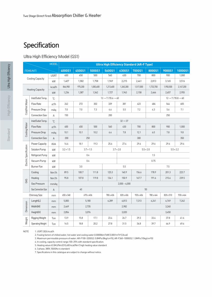
Specification
100GS2 120GS2 150GS2 180GS2 210GS2 240GS2
Ultra High Efficiency Standard (AR-F Type)
NOTE 1. USRT:3024 kcal/h2. Fouling factorsof chilledwater, hotwaterandcoolingwater:0.000086m2kW(0.0001m2hOC/kcal)3. Maximumpermissiblepressureofwater: AR-F100~320GS2: 0.8MPa (8kg/cm2G), AR-F360~1000GS2:1.0MPa (10kg/cm2G)4. In cooling, capacity control range:100~25% withstandardspecification.5. Heating value:43.5MJ/Nm3(10,400 kcal/Nm3) highheating valuestandard6. 3 phase, 380V, 50/60hz is standard7. Specifications in this cataloguearesubject to changewithoutnotice.
Ultra High Efficiency Model (GS2)
Cooling Capacity
Heating Capacity
Cold/Hot Water
Cooling Water
Electric Specification
GAS
Dimension
Weight
Chimney Size
Inlet/Outlet Temp.
Flow Rate
Pressure Drop
Connection Size
Inlet/Outlet Temp.
Flow Rate
Pressure Drop
Connection Size
Power Capacity
Solution Pump
Refrigerant Pump
Vacuum Pump
Burner Fan
Cooling
Heating
Gas Pressure
Gas Connection Size
Length(L)
Width(W)
Height(H)
Rigging Weight
Operating Weight
USRT
kW
kcal/h
kW
/h
mAq
A
/h
mAq
A
KVA
kW
kW
kW
kW
Nm3/h
Nm3/h
mmAq
A
mm
mm
mm
mm
Ton
Ton
MODEL
ITEM(UNIT)

1110Century 11Century
Ultr
a H
igh
Effic
ienc
yH
igh
Effi
cien
cyS
tand
ard
Cooling Capacity
Heating Capacity
Cold/Hot Water
Cooling Water
Electric Specification
GAS
Dimension
Weight
Chimney Size
Inlet/Outlet Temp.
Flow Rate
Pressure Drop
Connection Size
Inlet/Outlet Temp.
Flow Rate
Pressure Drop
Connection Size
Power Capacity
Solution Pump
Refrigerant Pump
Vacuum Pump
Burner Fan
Cooling
Heating
Gas Pressure
Gas Connection Size
Length(L)
Width(W)
Height(H)
Rigging Weight
Operating Weight
USRT
kW
kcal/h
kW
/h
mAq
A
/h
mAq
A
KVA
kW
kW
kW
kW
Nm3/h
Nm3/h
mmAq
A
mm
mm
mm
mm
Ton
Ton
280 320 360 400 450 500
985 1,125 1,266 1,407 1,582 1,758
606,800 693,500 780,200 866,900 975,200 1,083,600
863 987 1,110 1,234 1,387 1,542
12 →7 / 55.6 →60
169 194 218 242 272 302
7.2 7.0 7.3 7.0 7.0 7.3
150 200
32 →37
280 320 360 400 450 500
10.0 10.0 10.0 10.1 10.1 10.2
200 250
13.9 14.5 16.6 16.6 18.1 19.3
2.4 + 1.5 3.2 + 1.5 3.7 + 1.5
0.4
0.4
2.2 3.0
60.8 69.4 78.1 86.8 97.6 108.5
66.3 75.8 85.2 94.7 106.6 118.4
2,000 ~ 4,000
40
600 x 290 650 x 348 670 x 406
5,037 5,083 5,180
2,127 2,469 2,735
2,668 2,854 3,076
10.3 10.9 13.8 14.2 16.2 17.4
12.2 12.9 16.3 16.8 19.2 20.5
NOTE 1. USRT:3024 kcal/h2. Fouling factorsof chilledwater, hotwaterandcoolingwater:0.000086m2kW(0.0001m2hOC/kcal)3. Maximumpermissiblepressureofwater: AR-F100~320GS2: 0.8MPa (8kg/cm2G), AR-F360~1000GS2:1.0MPa (10kg/cm2G)4. In cooling, capacity control range:100~25% withstandardspecification.5. Heating value:43.5MJ/Nm3(10,400 kcal/Nm3) highheating valuestandard6. 3 phase, 380V, 50/60hz is standard7. Specifications in this cataloguearesubject to changewithoutnotice.
280GS2 320GS2 360GS2 400GS2 450GS2 500GS2
Ultra High Efficiency Standard (AR-F Type)
Ultra High Efficiency Model (GS2)
MODEL
ITEM(UNIT)

Two Stage Direct Fired Absorption Chiller & Heater
Ultr
a H
igh
Effic
ienc
yH
igh
Effi
cien
cyS
tand
ard
Specification
560GS2 630GS2 700GS2 800GS2 900GS2 1000GS2
Ultra High Efficiency Standard (AR-F Type)
NOTE 1. USRT:3024 kcal/h2. Fouling factorsof chilledwater, hotwaterandcoolingwater:0.000086m2kW(0.0001m2hOC/kcal)3. Maximumpermissiblepressureofwater: AR-F100~320GS2: 0.8MPa (8kg/cm2G), AR-F360~1000GS2:1.0MPa (10kg/cm2G)4. In cooling, capacity control range:100~25% withstandardspecification.5. Heating value:43.5MJ/Nm3(10,400 kcal/Nm3) highheating valuestandard6. 3 phase, 380V, 50/60hz is standard7. Specifications in this cataloguearesubject to changewithoutnotice.
Ultra High Efficiency Model (GS2)
USRT
kW
kcal/h
kW
/h
mAq
A
/h
mAq
A
KVA
kW
kW
kW
kW
Nm3/h
Nm3/h
mmAq
A
mm
mm
mm
mm
Ton
Ton
MODEL
ITEM(UNIT)
560 630 700 800 900 1,000
1,969 2,215 2,461 2,813 3,165 3,516
1,213,600 1,365,300 1,517,000 1,733,700 1,950,500 2,167,200
1,727 1,943 2,158 2,466 2,657 2,955
12 →7 / 55.6 →60 12 →7 / 55.8 →60
339 381 423 484 544 605
4.6 5.5 7.2 4.3 5.6 7.1
200 250
32 →37
560 600 700 800 900 1,000
6.4 7.8 9.8 6.0 7.8 12.4
300 350
25.6 27.4 29.6 29.6 29.6 29.6
3.7 + 2.0 5.5 + 2.0 5.5 + 2.2
0.4 1.5
0.4 0.75
5.5 7.5
121.5 136.7 151.9 173.6 195.3 217.0
132.6 149.2 165.8 189.4 213.1 236.8
2,000 ~ 4,000
50
780 x 406 820 x 406 930 x 406 780 x 464 820 x 464 930 x 464
6,289 6,813 7,313 6,241 6,749 7,262
2,982 3,240
3,020 3,450
23.4 26.7 29.3 33.4 37.8 41.6
37.8 31.5 34.8 39.7 44.9 49.4
Cooling Capacity
Heating Capacity
Cold/Hot Water
Cooling Water
Electric Specification
GAS
Dimension
Weight
Chimney Size
Inlet/Outlet Temp.
Flow Rate
Pressure Drop
Connection Size
Inlet/Outlet Temp.
Flow Rate
Pressure Drop
Connection Size
Power Capacity
Solution Pump
Refrigerant Pump
Vacuum Pump
Burner Fan
Cooling
Heating
Gas Pressure
Gas Connection Size
Length(L)
Width(W)
Height(H)
Rigging Weight
Operating Weight

1312Century 1312Century
Ultr
a H
igh
Effic
ienc
yH
igh
Effi
cien
cyS
tand
ard
100GS1 120GS1 150GS1 180GS1 210GS1 240GS1 280GS1 320GS1 360GS1
Ultra High Efficiency Standard (AR-F Type)
NOTE 1. USRT:3024 kcal/h2. Fouling factorsof chilledwater, hotwaterandcoolingwater:0.000086m2kW(0.0001m2hOC/kcal)3. Maximumpermissiblepressureofwater: AR-F100~320GS2: 0.8MPa (8kg/cm2G), AR-F360~1000GS2:1.0MPa (10kg/cm2G)4. In cooling, capacity control range:100~25% withstandardspecification.5. Heating value:43.5MJ/Nm3(10,400 kcal/Nm3) highheating valuestandard6. 3 phase, 380V, 50/60hz is standard7. Specifications in this cataloguearesubject to changewithoutnotice.
Ultra High Efficiency Model (GS1)
USRT
kW
kcal/h
kW
/h
mAq
A
/h
mAq
A
KVA
kW
kW
kW
kW
Nm3/h
Nm3/h
mmAq
A
mm
mm
mm
mm
Ton
Ton
MODEL
ITEM(UNIT)
100 120 150 180 210 240 280 320 360
352 422 527 633 738 844 985 1,125 1,266
216,700 260,000 325,100 390,100 455,100 520,100 606,800 693,500 780,200
308 370 463 555 648 740 863 987 1,110
12 → 7 / 55.6 → 60
60.5 72.6 90.7 109 127 145 169 194 218
7.2 7.2 7.1 7.1 7.2 7.0 7.2 7.0 7.3
100 125 150
32 → 37
100 120 150 180 210 240 280 320 360
6.4 6.6 9.8 10.1 9.9 10.0 10.0 10.0 10.0
125 150 200
9.6 10.4 11.6 12.3 12.3 13.9 14.5 16.6
1.2 + 1.2 1.5 + 1.2 2.0 + 1.2 2.4 + 1.5 3.2 + 1.5
0.3 0.4
0.4
0.75 1.5 2.2 3.0
22.4 26.8 33.6 40.3 47.0 53.7 62.6 71.6 80.5
24.0 28.7 35.9 43.1 50.3 57.5 67.1 76.6 86.2
200 ~ 4,000 2,000 ~ 4,000
40
400 × 232 485 × 290 600 × 290 650 × 348
2,906 3,926 3,943 5,037 5,083
1,958 2,110 2,073 2,127 2,469
2,404 2,404 2,668 2,668 2,854
5.1 5.4 5.6 6.7 8.6 8.8 10.1 10.7 13.5
6.1 6.4 6.7 8.0 10.2 10.4 12.0 12.7 16.0
Cooling Capacity
Heating Capacity
Cold/Hot Water
Cooling Water
Electric Specification
GAS
Dimension
Weight
Chimney Size
Inlet/Outlet Temp.
Flow Rate
Pressure Drop
Connection Size
Inlet/Outlet Temp.
Flow Rate
Pressure Drop
Connection Size
Power Capacity
Solution Pump
Refrigerant Pump
Vacuum Pump
Burner Fan
Cooling
Heating
Gas Pressure
Gas Connection Size
Length(L)
Width(W)
Height(H)
Rigging Weight
Operating Weight
Two Stage Direct Fired Absorption Chiller & Heater
Ultr
a H
igh
Effic
ienc
yH
igh
Effi
cien
cyS
tand
ard
Ultra High Efficiency Model (GS1)
Specification
USRT
kW
kcal/h
kW
/h
mAq
A
/h
mAq
A
KVA
kW
kW
kW
kW
Nm3/h
Nm3/h
mmAq
A
mm
mm
mm
mm
Ton
Ton
400 450 500 560 630 700 800 900 1,000
1,407 1,582 1,758 1,969 2,215 2,461 2,813 3,165 3,516
866,900 975,200 1,083,600 1,213,600 1,365,300 1,517,000 1,733,700 1,950,500 2,167,200
1,234 1,387 1,542 1,727 1,943 2,158 2,466 2,657 2,955
12 →7 / 55.6 →60 12 →7 / 55.8 →60
242 272 302 339 381 423 484 544 605
7.0 7.0 7.3 4.6 5.5 7.2 4.3 5.6 7.1
150 200 250
32 →37
400 450 500 560 630 700 800 900 1,000
10.1 10.1 10.2 6.4 7.8 12.1 6.0 7.8 9.8
200 250 300 350
16.6 18.1 19.3 25.6 27.4 29.6 29.6 29.6 29.6
3.2 + 1.5 3.7 + 1.5 3.7 + 2.0 5.5 + 2.0 5.5 + 2.2
0.4 1.5
0.4 0.75
3.0 5.5 7.5
89.5 100.7 111.8 125.3 140.9 156.6 178.9 201.3 223.7
95.8 107.8 119.8 134.1 150.9 167.7 191.6 215.6 239.5
2,000 ~ 4,000
40 50
650 x 348 670 x 406 780 x 406 820 x 406 930 x 406 780 x 464 820 x 510 930 x 464
5,083 5,180 6,289 6,813 7,313 6,241 6,749 7,262
2,469 2,735 2,982 3,240
2,854 3,076 3,020 3,450
13.9 15.8 17.1 23.4 26.7 29.3 33.4 37.8 41.6
16.5 18.8 20.2 27.8 31.5 34.8 39.7 44.9 49.4
400GS1 450GS1 500GS1 560GS1 630GS1 700GS1 800GS1 900GS1 1000GS1
Ultra High Efficiency Standard (AR-F Type)
NOTE 1. USRT:3024 kcal/h2. Fouling factorsof chilledwater, hotwaterandcoolingwater:0.000086m2kW(0.0001m2hOC/kcal)3. Maximumpermissiblepressureofwater: AR-F100~320GS2: 0.8MPa (8kg/cm2G), AR-F360~1000GS2:1.0MPa (10kg/cm2G)4. In cooling, capacity control range:100~25% withstandardspecification.5. Heating value:43.5MJ/Nm3(10,400 kcal/Nm3) highheating valuestandard6. 3 phase, 380V, 50/60hz is standard7. Specifications in this cataloguearesubject to changewithoutnotice.
MODEL
ITEM(UNIT)
Cooling Capacity
Heating Capacity
Cold/Hot Water
Cooling Water
Electric Specification
GAS
Dimension
Weight
Chimney Size
Inlet/Outlet Temp.
Flow Rate
Pressure Drop
Connection Size
Inlet/Outlet Temp.
Flow Rate
Pressure Drop
Connection Size
Power Capacity
Solution Pump
Refrigerant Pump
Vacuum Pump
Burner Fan
Cooling
Heating
Gas Pressure
Gas Connection Size
Length(L)
Width(W)
Height(H)
Rigging Weight
Operating Weight

15Century
Ultr
a H
igh
Effic
ienc
yH
igh
Effi
cien
cyS
tand
ard
14
100 120 150 180 210 240 280 320 360
352 422 527 633 738 844 985 1,125 1,266
216,700 260,000 325,100 390,100 455,100 520,100 606,800 693,500 780,200
308 370 463 555 648 740 863 987 1,110
12 → 7 / 55.6 → 60
60.5 72.6 90.7 109 127 145 169 194 218
4.3 4.3 4.7 4.7 4.7 4.6 4.7 4.4 5.4
100 125 150
32 → 37.2
100 120 150 180 210 240 280 320 360
4.9 4.9 7.2 7.2 6.8 6.8 8.3 8.4 8.6
125 150 200
9.6 10.4 11.6 12.3 13.3 14.5 15.6 17.8
1.2 + 1.2 1.5 + 1.2 2.0 + 1.2 2.4 + 1.5 3.2 + 1.5
0.3 0.4
0.4
0.75 1.5 2.2 3.0
24.2 29.1 36.3 43.6 50.9 58.2 67.8 77.5 87.2
24.2 29.1 36.3 43.6 50.9 58.2 67.8 77.5 87.2
200 ~ 4,000
40
400 × 232 485 × 290 600 × 290 650 × 348
2,808 3,844 3,860 4,727 4,923
2,136 2,087 2,171 2,136 2,469
2,349 2,349 2,545 2,545 2,768
4.8 5.1 5.3 6.3 8.1 8.3 9.5 10.1 12.7
5.8 6.1 6.4 7.6 9.7 9.9 11.4 12.1 15.2
100GE1 120GE1 150GE1 180GE1 210GE1 240GE1 280GE1 320GE1 360GE1
High Efficiency Standard (AR-F Type)
NOTE 1. USRT:3024 kcal/h2. Fouling factorsof chilledwater, hotwaterandcoolingwater:0.000086m2kW(0.0001m2hOC/kcal)3. Maximumpermissiblepressureofwater: AR-F100~320GS2: 0.8MPa (8kg/cm2G), AR-F360~1000GS2:1.0MPa (10kg/cm2G)4. In cooling, capacity control range:100~25% withstandardspecification.5. Heating value:43.5MJ/Nm3(10,400 kcal/Nm3) highheating valuestandard6. 3 phase, 380V, 50/60hz is standard7. Specifications in this cataloguearesubject to changewithoutnotice.
High Efficiency Model (GE1)
USRT
kW
kcal/h
kW
/h
mAq
A
/h
mAq
A
KVA
kW
kW
kW
kW
Nm3/h
Nm3/h
mmAq
A
mm
mm
mm
mm
Ton
Ton
MODEL
ITEM(UNIT)
Cooling Capacity
Heating Capacity
Cold/Hot Water
Cooling Water
Electric Specification
GAS
Dimension
Weight
Chimney Size
Inlet/Outlet Temp.
Flow Rate
Pressure Drop
Connection Size
Inlet/Outlet Temp.
Flow Rate
Pressure Drop
Connection Size
Power Capacity
Solution Pump
Refrigerant Pump
Vacuum Pump
Burner Fan
Cooling
Heating
Gas Pressure
Gas Connection Size
Length(L)
Width(W)
Height(H)
Rigging Weight
Operating Weight

Two Stage Direct Fired Absorption Chiller & Heater
Ultr
a H
igh
Effic
ienc
yH
igh
Effi
cien
cyS
tand
ard
Specification
400 450 500 560 630 700 800 900 1,000
1,407 1,582 1,758 1,969 2,215 2,461 2,813 3,165 3,516
866,900 975,200 1,083,600 1,213,600 1,365,300 1,517,000 1,733,700 1,950,500 2,167,200
1,234 1,387 1,542 1,727 1,943 2,158 2,466 2,657 2,955
12 →7 / 55.6 →60 12 →7 / 55.8 →60
242 272 302 339 381 423 484 544 605
5.1 7.0 7.3 4.6 5.5 7.2 4.3 5.6 7.1
150 200 250
32 →37.2
400 450 500 560 630 700 800 900 1,000
8.7 10.1 10.2 6.4 7.8 12.1 6.0 7.8 9.8
200 250 300 350
17.8 19.3 23.6 25.3 27.5 30.1 30.3
3.2 + 1.5 3.7 + 1.5 3.7 + 2.0 5.5 + 2.0 5.5 + 2.2
0.4 1.5
0.4 0.75
3.0 5.5 7.5
96.9 109.0 121.2 135.7 152.7 169.6 193.8 218.1 242.3
96.9 109.0 121.2 135.7 152.7 169.6 193.8 218.1 242.3
40 50
2,000 ~ 4,000
650 x 348 670 x 406 780 x 406 820 x 406 930 x 406 780 x 464 820 x 464 930 x 464
4,923 4,995 6,288 6,813 7,315 6,199 6,708 7,265
2,469 2,735 2,946 3,260
2,768 2,977 2,940 3,376
13.1 14.9 16.1 22.1 25.2 27.6 31.5 35.7 39.2
15.7 17.9 19.2 26.5 30.0 33.1 37.8 42.8 47.0
400GE1 450GE1 500GE1 560GE1 630GE1 700GE1 800GE1 900GE1 1000GE1
High Efficiency Standard (AR-F Type)
NOTE 1. USRT:3024 kcal/h2. Fouling factorsof chilledwater, hotwaterandcoolingwater:0.000086m2kW(0.0001m2hOC/kcal)3. Maximumpermissiblepressureofwater: AR-F100~320GS2: 0.8MPa (8kg/cm2G), AR-F360~1000GS2:1.0MPa (10kg/cm2G)4. In cooling, capacity control range:100~25% withstandardspecification.5. Heating value:43.5MJ/Nm3(10,400 kcal/Nm3) highheating valuestandard6. 3 phase, 380V, 50/60hz is standard7. Specifications in this cataloguearesubject to changewithoutnotice.
High Efficiency Model (GE1)
USRT
kW
kcal/h
kW
/h
mAq
A
/h
mAq
A
KVA
kW
kW
kW
kW
Nm3/h
Nm3/h
mmAq
A
mm
mm
mm
mm
Ton
Ton
MODEL
ITEM(UNIT)
Cooling Capacity
Heating Capacity
Cold/Hot Water
Cooling Water
Electric Specification
GAS
Dimension
Weight
Chimney Size
Inlet/Outlet Temp.
Flow Rate
Pressure Drop
Connection Size
Inlet/Outlet Temp.
Flow Rate
Pressure Drop
Connection Size
Power Capacity
Solution Pump
Refrigerant Pump
Vacuum Pump
Burner Fan
Cooling
Heating
Gas Pressure
Gas Connection Size
Length(L)
Width(W)
Height(H)
Rigging Weight
Operating Weight

17Century
Ultr
a H
igh
Effic
ienc
yH
igh
Effi
cien
cyS
tand
ard
16
Specification
F40G3 F50G3 F60G3 F70G3 F80G3 F90G3 F100G3
General Efficiency Standard (AR-F Type)
NOTE 1. USRT:3024 kcal/h2. Fouling factorsof chilledwater, hotwaterandcoolingwater:0.000086m2kW(0.0001m2hOC/kcal)3. Maximumpermissiblepressureofwater: AR-F100~320GS2: 0.8MPa (8kg/cm2G), AR-F360~1000GS2:1.0MPa (10kg/cm2G)4. In cooling, capacity control range:100~25% withstandardspecification.5. Heating value:43.5MJ/Nm3(10,400 kcal/Nm3) highheating valuestandard6. 3 phase, 380V, 50/60hz is standard7. Specifications in this cataloguearesubject to changewithoutnotice.
Standard Model
USRT
kW
kcal/h
kW
/h
mAq
A
/h
mAq
A
KVA
kW
kW
kW
kW
Nm3/h
Nm3/h
mmAq
A
mm
mm
mm
mm
Ton
Ton
40 50 60 70 80 90 100
141 176 211 246 281 316 352
110,400 138,000 165,600 193,200 220,800 248,400 276,000
128 160 193 225 257 289 321
12 → 7 / 55.4 → 60
24 30 36 42 48 54 60
6.0 6.5 7.9 4.9 4.1 7.3 5.8
65 80 100
32 → 37
45.6 57 68.4 79.8 91.2 102.6 114
11.5 14 15 7.8 7.8 6.4 7.9
100 125
4.9 7.5
0.75 1.1 + 0.4
0.2 0.4
0.4
0.4 0.75
12.3 15.3 18.4 21.5 24.5 27.6 30.7
12.3 15.3 18.4 21.5 24.5 27.6 30.7
200 ~ 4,000
25 40
394 × 420 470 × 520
2,158 2,900
1,592 1,835
1,872 2,046
3.0 3.1 3.3 4.4 4.5 4.5 4.5
3.1 3.2 3.4 4.6 4.7 4.7 4.7
MODEL
ITEM(UNIT)
Cooling Capacity
Heating Capacity
Cold/Hot Water
Cooling Water
Electric Specification
GAS
Dimension
Weight
Chimney Size
Inlet/Outlet Temp.
Flow Rate
Pressure Drop
Connection
Size Inlet/Outlet Temp.
Flow Rate
Pressure Drop
Connection Size
Power Capacity
Solution Pump
Refrigerant Pump
Vacuum Pump
Burner Fan
Cooling
Heating
Gas Pressure
Gas Connection Size
Length(L)
Width(W)
Height(H)
Rigging Weight
Operating Weight

Direct Fired Double effect Absorption Chiller & Heater
Ultr
a H
igh
Effic
ienc
yH
igh
Effi
cien
cyS
tand
ard
H40G3 H50G3 H60G3 H70G3 H80G3 H90G3 H100G3
General Efficiency Standard (AR-F Type)
NOTE 1. USRT:3024 kcal/h2. Fouling factorsof chilledwater, hotwaterandcoolingwater:0.000086m2kW(0.0001m2hOC/kcal)3. Maximumpermissiblepressureofwater: AR-F100~320GS2: 0.8MPa (8kg/cm2G), AR-F360~1000GS2:1.0MPa (10kg/cm2G)4. In cooling, capacity control range:100~25% withstandardspecification.5. Heating value:43.5MJ/Nm3(10,400 kcal/Nm3) highheating valuestandard6. 3 phase, 380V,50/ 60hz is standard7. Specifications in this cataloguearesubject to changewithoutnotice.
Standard Model
USRT
kW
kcal/h
kW
/h
mAq
A
/h
mAq
A
kVA
kW
kW
kW
kW
N/h
N/h
mmAq
A
mm
mm
mm
mm
Ton
Ton
40 50 60 70 80 90 100
141 176 211 246 281 316 352
144,000 180,000 190,800 252,000 288,000 297,000 330,000
167 209 222 293 335 345 384
12 → 7
54 →60 54.7 →60 54 →60 54.5 →60
24 30 36 42 48 54 60
6.0 6.5 7.9 4.9 4.1 7.3 5.8
65 80 100
32 → 37
45.6 57 68.4 79.8 91.2 102.6 114
11.5 14.0 15.0 7.8 7.8 6.4 7.9
100 125
4.9 7.5
0.75 1.1 + 0.4
0.2 0.4
0.4
0.4 0.75
12.3 15.3 18.4 21.5 24.5 27.6 30.7
16.1 20.0 21.2 28.1 32.2 33.2 36.8
200 ~ 4,000
25 40
394 × 420 470 × 520
2,200 2,963
1,592 1,835
1,872 2,046
3.1 3.2 3.4 4.5 4.6 4.6 4.6
3.2 3.3 3.5 4.7 4.8 4.8 4.8
MODEL
ITEM(UNIT)
Specification
Cooling Capacity
Heating Capacity
Inlet Temp
Outlet Temp
Flow Rate
Pressure Drop
Connection
Size Inlet/Outlet Temp.
Flow Rate
Pressure Drop
Connection Size
Power Capacity
Solution Pump
Refrigerant Pump
Vacuum Pump
Burner Fan
Cooling
Heating
Gas Pressure
Gas Connection Size
Length(L)
Width(W)
Height(H)
Rigging Weight
Operating Weight
Cold/Hot Water
Cooling Water
Electric Specification
GAS
Dimension
We ig ht
Chimney Size

19Century
Ultr
a H
igh
Effic
ienc
yH
igh
Effi
cien
cyS
tand
ard
18
Specification
125G4 150G4 180G4 210G4 240G4 280G4 320G4 360G4 400G4
General Efficiency Standard (AR-F Type)
NOTE 1. USRT:3024 kcal/h2. Fouling factorsof chilledwater, hotwaterandcoolingwater:0.000086m2kW(0.0001m2hOC/kcal)3. Maximumpermissiblepressureofwater: AR-F100~320GS2: 0.8MPa (8kg/cm2G), AR-F360~1000GS2:1.0MPa (10kg/cm2G)4. In cooling, capacity control range:100~25% withstandardspecification.5. Heating value:43.5MJ/Nm3(10,400 kcal/Nm3) highheating valuestandard6. 3 phase, 380V,50/ 60hz is standard7. Specifications in this cataloguearesubject to changewithoutnotice.
Standard Model
USRT
kW
kcal/h
kW
/h
mAq
A
/h
mAq
A
kVA
kW
kW
kW
kW
N/h
N/h
mmAq
A
mm
mm
mm
mm
Ton
Ton
125 150 180 210 240 280 320 360 400
440 527 633 738 844 985 1,125 1,266 1,407
320.900 385,400 462,300 540,100 617,000 719,600 822,100 925,500 1,028,100
440 527 633 738 844 985 1,125 1,266 1,407
12 →7 / 55 →60
75.6 90.7 108.9 127.0 145.2 169.3 193.5 217.7 241.9
5.4 3.8 5.1 9.2 12.0 6.3 8.3 3.6 4.5
100 125 150
32 →37.4
130.0 156.0 187.2 218.4 249.6 291.2 332.8 374.4 416.0
7.1 5.7 8.9 6.3 8.2 3.6 4.7 6.7 8.3
125 150 200
11.2 16.4 17.3 17.3 18.1
2.2 + 1.5 3.7 + 1.5 4.5 + 2.2
0.4 0.8
0.4
0.75 1.5 2.2
36.3 43.6 52.3 61.1 69.8 81.4 93.0 104.7 116.3
36.3 43.6 52.3 61.1 69.8 81.4 93.0 104.7 116.3
200 ~ 4,000 500 ~ 4,000
40
470 x 520 480 x 530 600 x 600
3,039 3,121 3,483 3,946 4,071 4,641
1,679 1,775 1,960 2,062
2,031 2,061 2,454
5.4 5.9 6.5 7.6 7.6 9.9 9.9 11.5 11.5
5.7 6.3 8.1 8.1 8.1 10.7 10.7 12.4 12.4
MODEL
ITEM(UNIT)
Cooling Capacity
Heating Capacity
Cold/Hot Water
Cooling Water
Electric Specification
GAS
Dimension
Weight
Chimney Size
Inlet/Outlet Temp.
Flow Rate
Pressure Drop
Connection
Size Inlet/Outlet Temp.
Flow Rate
Pressure Drop
Connection Size
Power Capacity
Solution Pump
Refrigerant Pump
Vacuum Pump
Burner Fan
Cooling
Heating
Gas Pressure
Gas Connection Size
Length(L)
Width(W)
Height(H)
Rigging Weight
Operating Weight

Direct Fired Double effect Absorption Chiller & Heater
Ultr
a H
igh
Effic
ienc
yH
igh
Effi
cien
cyS
tand
ard
General Efficiency Standard (AR-F Type)
NOTE 1. USRT:3024 kcal/h2. Fouling factorsof chilledwater, hotwaterandcoolingwater:0.000086m2kW(0.0001m2hOC/kcal)3. Maximumpermissiblepressureofwater: AR-F100~320GS2: 0.8MPa (8kg/cm2G), AR-F360~1000GS2:1.0MPa (10kg/cm2G)4. In cooling, capacity control range:100~25% withstandardspecification.5. Heating value:43.5MJ/Nm3(10,400 kcal/Nm3) highheating valuestandard6. 3 phase, 380V, 50/60hz is standard7. Specifications in this cataloguearesubject to changewithoutnotice.
Standard Model
450G5 500G5 560G5 630G5 700G5 800G5 900G5 1000G 1200G 1500G
USRT
kW
kcal/h
kW
/h
mAq
A
/h
mAq
A
kVA
kW
kW
kW
kW
N/h
N/h
mmAq
A
mm
mm
mm
mm
Ton
Ton
450 500 560 630 700 800 900 1,000 1,200 1,500
1,582 1,758 1,969 2,215 2,461 2,813 3,165 3,516 4,220 5,274
1,138,500 1,265,000 1,416,800 1,593,900 1,771,000 2,032,800 2,284,800 2,541,000 3,049,200 3,809,400
1,324 1,471 1,647 1,853 2,059 2,364 2,657 2,955 3,546 4,430
12 →7 / 55.8 →60
272 302 339 381 423 484 544 605 726 907
6.6 6.6 4.9 5.5 7.2 6.5 10.4 13.2 8.0 10.0
200 250 300
32 →37.5
450 500 560 630 700 800 900 1,000 1,200 1,500
8.1 8.7 4.9 6.8 9.1 13.4 17.0 21.0 12.0 15.0
250 300 350 400
17.5 29.9 35.1 46.5 52.6
5.5 13.0
0.4 1.5
0.4 0.75
3 5.5 7.5 11.0 15 18.5
129.6 143.9 161.2 181.4 201.5 230.3 259.1 287.9 345.5 431.8
129.6 143.9 161.2 181.4 201.5 230.3 259.1 287.9 345.5 431.8
2,000 ~ 4,000
40 50 65
315 × 416 356 × 506 402 × 626 900 × 400
4,993 5,375 5,895 6,544 6,660 6,729 7,139 7,150 7,550
2,440 2,940 2,912 3,330 3,449 4,380 4,690
2,926 3,122 3,437 3,750 3,800
11.6 12.5 15.1 17.6 18.9 29.5 32.6 35.6 43.5 52.8
14.7 15.6 20.8 24.5 26.1 36.5 37.5 39.6 48.5 59.0
MODEL
ITEM(UNIT)
Specification
Cooling Capacity
Heating Capacity
Cold/Hot Water
Cooling Water
Electric Specification
GAS
Dimension
Weight
Chimney Size
Inlet/Outlet Temp.
Flow Rate
Pressure Drop
Connection
Size Inlet/Outlet Temp.
Flow Rate
Pressure Drop
Connection Size
Power Capacity
Solution Pump
Refrigerant Pump
Vacuum Pump
Burner Fan
Cooling
Heating
Gas Pressure
Gas Connection Size
Length(L)
Width(W)
Height(H)
Rigging Weight
Operating Weight

2120Century 21Century
Ultr
a H
igh
Effic
ienc
yH
igh
Effi
cien
cyS
tand
ard
Dimension
AR-F100~1000GS1/F100~1000GS2 (UltraHighEfficiency Model)
Length(A)Width(B)Height(C)
Conection Piping(S)Installment Area(L)Weight(TON)
2,697 2,697 3,717 3,717 3,696 3,696 4,714 4,714 4,760
1,958 1,958 2,110 2,110 2,073 2,073 2,127 2,127 2,469
2,404 2,404 2,404 2,404 2,668 2,668 2,668 2,668 2,854
209 209 209 209 247 247 323 323 323
2,100 2,100 3,100 3,100 3,100 3,100 4,100 4,100 4,100
5.2 5.5 5.7 6.8 8.8 9.0 10.3 10.9 13.8
100GS1100GS2
120GS1120GS2
150GS1150GS2
180GS1180GS2
210GS1210GS2
240GS1240GS2
280GS1280GS2
320GS1320GS2
360GS1360GS2
Model (AR-F)
4,784 4,784 5,814 6,338 6,838 6,241 6,749 7,262
2,735 2,735 2,982 2,982 2,982 3,240 3,240 3,240
3,076 3,076 3,020 3,020 3,020 3,450 3,450 3,450
396 396 475 475 475 - - -
4,100 4,100 5,200 5,700 6,200 5,200 5,700 6,200
16.2 17.4 23.4 26.7 29.3 33.4 37.8 41.6
4,760
2,469
2,854
323
4,100
14.2
400GS1400GS2
450GS1450GS2
500GS1500GS2
560GS1560GS2
630GS1630GS2
700GS1700GS2
800GS1800GS2
900GS1900GS2
1000GS11000GS2
Model (AR-F)
Length(A)Width(B)Height(C)
Conection Piping(S)Installment Area(L)Weight(TON)

Two Stage Direct Fired Absorption Chiller & Heater
Ultr
a H
igh
Effic
ienc
yH
igh
Effi
cien
cyS
tand
ard
Dimension
AR-F100~1000GE1 (HighEfficiency Model)
Length(A)Width(B)Height(C)
Conection Piping(S)Installment Area(L)Weight(TON)
2,561 2,561 3,635 3,635 3,613 3,613 4,403 4,403 4,600
2,136 2,136 2,087 2,087 2,171 2,171 2,136 2,136 2,469
2,349 2,349 2,349 2,349 2,545 2,545 2,545 2,545 2,768
209 209 209 209 247 247 324 324 323
2,100 2,100 3,100 3,100 3,100 3,100 4,100 4,100 4,100
4.8 5.1 5.3 6.3 8.1 8.3 9.5 10.1 12.7
100GE1 120GE1 150GE1 180GE1 210GE1 240GE1 280GE1 320GE1 360GE1Model (AR-F)
Length(A)Width(B)Height(C)
Conection Piping(S)Installment Area(L)Weight(TON)
4,599 4,599 5,813 6,338 6,840 6,199 6,708 7,265
2,735 2,735 2,946 2,946 2,946 3,260 3,260 3,260
2,997 2,997 2,940 2,940 2,940 3,376 3,376 3,376
396 396 475 475 475 - - -
4,100 4,100 5,200 5,700 6,200 5,200 5,700 6,200
14.9 16.1 22.1 25.2 27.6 31.5 35.7 39.2
400GE1 450GE1 500GE1 560GE1 630GE1 700GE1 800GE1 900GE1 1000GE1Model (AR-F)4,600
2,469
2,768
323
4,100
13.1

2322Century
Ultr
a H
igh
Effic
ienc
yH
igh
Effi
cien
cyS
tand
ard
AR-F40~100G3 (Standard)
2,158 2,158 2,158 2,900 2,900 2,900 2,900
1,592 1,592 1,592 1,835 1,835 1,835 1,835
1,872 1,872 1,872 2,046 2,046 2,046 2,046
1,300 1,300 1,300 1,500 1,500 1,500 1,500
3.0 3.1 3.3 4.4 4.5 4.5 4.5
3.0 3.1 3.3 4.4 4.5 4.5 4.5
Length(A)Width(B)Height(C)
Installment Area(L)
Weight(TON)
Gas
Oil
40G3 50G3 60G3 70G3 80G3 90G3 100G3Model (AR-F)
AR-H40~100G3
2,200 2,200 2,200 2,963 2,963 2,963 2,963
1,592 1,592 1,592 1,835 1,835 1,835 1,835
1,872 1,872 1,872 2,046 2,046 2,046 2,046
1,300 1,300 1,300 1,500 1,500 1,500 1,500
3.1 3.2 3.4 4.5 4.6 4.6 4.6
3.1 3.2 3.4 4.5 4.6 4.6 4.6
Length(A)Width(B)Height(C)
Installment Area(L)
Weight(TON)
GasOil
40G3 50G3 60G3 70G3 80G3 90G3 100G3Model (AR-F)

Direct Fired Double effect Absorption Chiller & Heater
Ultr
a H
igh
Effic
ienc
yH
igh
Effi
cien
cyS
tand
ard
Dimension
Length(A)Width(B)Height(C)
Installment Area(L)
Weight(TON)
GasOil
3,039 3,121 3,483 3,946 3,946 4,071 4,071 4,641 4,641
1,679 1,679 1,679 1,775 1,775 1,960 1,960 2,062 2,062
2,031 2,031 2,031 2,061 2,061 2,454 2,454 2,454 2,454
1,800 2,200 2,500 3,000 3,000 2,980 2,980 3,580 3,580
5.4 5.9 6.5 7.6 7.6 9.9 9.9 11.5 11.5
5.4 5.9 6.5 7.6 7.6 9.9 9.9 11.5 11.5
125G4 150G4 180G4 210G4 240G4 280G4 320G4 360G4 400G4
AR-F125~F400G4 (Standard)
Model (AR-F)
Length(A)Width(B)Height(C)
Conection Piping(S)Installment Area(L)
Weight(TON)
Gas
Oil
AR-F450~F1000G5
4,594 4,890 5,410 6,060 6,116 6,162 6,572
2,440 2,940 2,912 3,300 3,449 3,449
2,926 3,122 3,122 3,437 3,437 3,437
399 485 484 544 567 567
4,100 4,000 4,500 4,850 4,300 5,100 6,200
11.6 12.5 15.1 17.6 18.9 29.5 32.6 35.6
11.6 12.5 15.1 17.6 18.9 29.5 32.6 35.6
450G5 500G5 560G5 630G5 700G5 800G5 900G5 1000G5Model (AR-F)

25Century
Ultr
a H
igh
Effic
ienc
yH
igh
Effi
cien
cyS
tand
ard
24
AR-F1200~1500G5 (Standard)
7,150 7,550
4,380 4,690
3,750 3,800
6,200 6,700
43.5 53.0
43.5 53.0
Model (AR-F) 1200G5 1500G5Length(A)Width(B)Height(C)
Installment Area(L)
Weight(TON)GasOil

Two Stage Direct Fired Absorption Chiller & Heater
Ultr
a H
igh
Effic
ienc
yH
igh
Effi
cien
cyS
tand
ard
(Ultra) High Efficiency Model(GE1/GS1/GS2)
F100 F120 F150 F180 F210 F240 F280 F320 F360 TypeA 2,366 2,366 3,386 3,386 3,386 3,386 4,406 4,406 4,406
B 250 250 250 250 300 300 300 300 300
C 1,340 1,340 1,340 1,340 1,420 1,420 1,420 1,420 1,600
D 990 990 990 990 1,030 1,030 1,030 1,030 1,104
E 670 670 670 670 710 710 710 710 735
F 450 450 450 450 450 450 450 450 525
G 1,300 1,500 1,554 1,754 1,804 2,004 2,304 2,556 2,254
H 900 900 900 900 900 900 900 900 1,040
I 225 225 225 225 225 225 225 225 225
J 2,100 2,100 3,100 3,100 3,100 3,100 4,100 4,100 4,100
F400 F450 F500 F560 F630 F700 F800 F900 F1000TypeA 4,406 4,406 4,406 5,446 5,971 6,471 5,446 5,970 6,471
B 300 300 300 300 300 300 300 300 300
C 1,600 1,760 1,760 1,840 1,840 1,840 1,920 1,920 1,920
D 1,104 1,309 1,309 1,420 1,420 1,420 1,584 1,584 1,584
E 735 880 880 920 920 920 960 960 960
F 525 600 600 670 670 670 760 760 760
G 2,454 2,554 2,754 2,514 2,714 2,914 3,000 3,300 3,500
H 1,040 1,200 1,200 1,340 1,340 1,340 1,520 1,520 1,520
I 225 250 250 250 250 250 300 300 250
J 4,100 4,100 4,100 5,200 5,700 6,200 5,200 5,700 6,200
Installation & Application Data (Foundation)
1. Install drainage around the chiller.2. Horizontal level of the chiller must be within 0.5mm / 1000mm.3. Concrete foundation surface must be flat and leveled.4. Chain line (------) stands for the center line of the chiller.

27Century
Ultr
a H
igh
Effic
ienc
yH
igh
Effi
cien
cyS
tand
ard
26
A 1,463.5 1,800 1,463.5 1,800
B 215 150 215 150
C 150 150 150 150
D 1,670 1,900 1,670 1,900
E` 822 959 822 959
F 1,300 1,500 1,300 1,500
F40G3~60G3 F70G3~100G3 H40G3~60G3 H70G3~100G3Type
StandardModel(G3)
StandardModel (G4)
A 2,234 2,634 2,934 3,484 3,484 3,430 3,430 4,030 4,030
B 200 200 200 225 225 225 225 225 225
C 1,762 1,687 1,687 1,844.5 1,844.5 1,952 1,952 2,130 2,130
D 436 398.5 398.5 398.5 398.5 458 458 458 458
E 883.5 846 846 931 931 979 979 1,090 1,090
F 442.5 442.5 442.5 515 515 515 515 582 582
G 1,710 2,110 2,410 2,067 2,067 2,439 2,439 2,439 2,439
H 872 797 797 797 797 916 916 916 916
I 885 885 885 1,030 1,030 1,030 1,030 1,164 1,164
J 1,800 2,200 2,500 3,000 3,000 2,980 2,980 3,580 3,580
F125G4 F150G4 F180G4 F210G4 F240G4 F280G4 F320G4 F360G4 F400G4Type
1. Install drainage around the chiller.2. Horizontal level of the chiller must be within 0.5mm / 1000mm.3. Concrete foundation surface must be flat and leveled.4. Chain line (------) stands for the center line of the chiller.
1. Install drainage around the chiller.2. Horizontal level of the chiller must be within 0.5mm / 1000mm.3. Concrete foundation surface must be flat and leveled.4. Chain line (------) stands for the center line of the chiller.

Direct Fired Double effect Absorption Chiller & Heater
Ultr
a H
igh
Effic
ienc
yH
igh
Effi
cien
cyS
tand
ard
StandardModel(G5)
A 4,498 4,498 4,418 4,938 5,360 4,948 5,482 5,992
B 350 350 300 300 250300("B"SIDE)
300 300371("A"SIDE)
C 1,700 1,700 1,600 1,600 1,600 1,620 1,620 1,620
D 1,171 1,171 1,412 1,412 1,412 1,578 1,728 1,728
E 850 850 800 800 800 810 810 810
F 700 700 670 670 670 760 760 760
G 2,654 2,854 2,514 2,714 2,814 3,142 3,300 3,600
H 1,400 1,400 1,340 1,340 1,340 1,520 1,520 1,520
I 275 275 250 250 200 250 300 300
J 4,100 4,100 4,000 4,500 4,850 4,300 5,100 6,200
F450 F500 F560 F630 F700 F800 F900 F1000Type
Installation & Application Data (Foundation)
1. Install drainage around the chiller.2. Horizontal level of the chiller must be within 0.5mm / 1000mm.3. Concrete foundation surface must be flat and leveled.4. Chain line (------) stands for the center line of the chiller.

2928CenturyCentury
Ultr
a H
igh
Effic
ienc
yH
igh
Effi
cien
cyS
tand
ard
Installation & Application Data
(Ultra) High Efficiency Model

Direct Fired Double effect Absorption Chiller & Heater
Ultr
a H
igh
Effic
ienc
yH
igh
Effi
cien
cyS
tand
ard
Standard Model
Installation & Application Data

3130Century 31Century
Ultr
a H
igh
Effic
ienc
yH
igh
Effi
cien
cyS
tand
ard
1. Heat insulation material: Rock wool or equivalent (50mm). Cold insulation material: High density rubber sponge or equivalent (20mm)
2. Heat insulation and cold insulation space includes the piping space.
3. The product will be delivered after anti-corrosion painting applied and also top coating will be applied after processing heat insulation
and cold insulation.
4. Cautions
1) Do not use any fire-retardant materials for heat and cold insulation.
2) Use only adhesive, steel wire and band to install heat and cold insulation materials and do not use tap processing or welding.
3) For external and flange parts, always make it easy to remove and install heat/cold insulation material for easy maintenance.
4) Make it easy to open/close the operation valve.
5) Heat/cold insulation is not required for check-up display, pressure meter, thermometer RTD, protection device RTD and pump
motor, etc.
Type(AR-F) 100GE1/GS1/GS2 120GE1/GS1/GS2 150GE1/GS1/GS2 180GE1/GS1/GS2 210GE1/GS1/GS2 240GE1/GS1/GS2Hot Surface (m2) 13.6 14.6 16.2 16.7 18.1 18.5
Cold Surface (m2) 5.3 5.3 6.7 6.7 7.3 7.3
Type(AR-F) 280GE1/GS1/GS2 320GE1/GS/GS2 360GE1/GS/GS2 400GE1/GS1/GS2 450GE1/GS1/GS2 500GE1/GS1/GS2Hot Surface (m2) 21.9 22.7 23.8 26.2 29.4 30.5
Cold Surface (m2) 8.9 8.9 10.4 10.4 11.8 11.8
Type(AR-F) 560GE1/GS1/GS2 630GE1/GS1/GS2 700GE1/GS1/GS2 800GE1/GS1/GS2 900GE1/GS1/GS2 1000GE1/GS1/GS2Hot Surface (m2) 36.4 38.0 41.2 42.8 46.2 49.9
Cold Surface (m2) 15.6 16.8 18.0 18.5 20.7 22.2
Heat & Cold Insulation Tip
Heat & cold insulation space (High efficiency & ultra high efficiency)
보온
보냉
Heat Insulation
Cold Insulation

Direct Fired Double effect Absorption Chiller & Heater
Ultr
a H
igh
Effic
ienc
yH
igh
Effi
cien
cyS
tand
ard
보온부분
보냉부분
보온부분
보냉부분
1. Heat insulation material: Rock wool or equivalent (50mm). Cold insulation material: High density rubber sponge or equivalent (20mm)
2. Heat insulation and cold insulation space includes the piping space.
3. The product will be delivered after anti-corrosion painting applied and also top coating will be applied after processing heat insulation
and cold insulation.
4. Cautions
1) Do not use any fire-retardant materials for heat and cold insulation.
2) Use only adhesive, steel wire and band to install heat and cold insulation materials and do not use tap processing or welding.
3) For external and flange parts, always make it easy to remove and install heat/cold insulation material for easy maintenance.
4) Make it easy to open/close the operation valve.
5) Heat/cold insulation is not required for check-up display, pressure meter, thermometer RTD, protection device RTD and pump
motor, etc.
G3/G4 TypeHeat & Cold Insulation Tip G5 TypeHeat & Cold Insulation Tip
Heat & cold insulation space (General type)
Type(AR-F) 40G3 50G3 60G3 70G3 80G3 90G3 100G3 125G4 150G4 180G4Hot Surface (m2) 10 10 10 12 12 12 12 10 11 12
Cold Surface (m2) 7 7 7 7 7 7 7 6 6.6 7.6
Type(AR-F) 210G4 240G4 280G4 320G4 360G4 400G4 450G5 500G5 560G5 630G5Hot Surface (m2) 14 14 16.4 16.4 19.1 19.1 31.4 32.0 33.8 36.8
Cold Surface (m2) 8.6 8.6 9.9 9.9 11.3 11.3 10.9 10.9 15.2 17.2
Type(AR-F) 700G5 800G5 900G5 1000G5 1200G5 1500G5Hot Surface (m2) 39.1 41.9 44.5 47.1 60 65
Cold Surface (m2) 17.5 20.3 21.5 22.9 21 23
Heat & Cold Insulation Tip
Heat InsulationCold Insulation
Heat Insulation
Cold Insulation

33Century 3332Century
Ultr
a H
igh
Effic
ienc
yH
igh
Effi
cien
cyS
tand
ard
Cycle_Ultra High Efficiency model (AR-F100~1000GS1)
AirConditioningDistributionDiagram
HeatingDistributionDiagram

Two Stage Direct Fired Absorption Chiller & Heater
Ultr
a H
igh
Effic
ienc
yH
igh
Effi
cien
cyS
tand
ard
Cycle_High Efficiency model(AR-F100~1000GE1)
AirConditioningDistributionDiagram
HeatingDistributionDiagram

3534Century
Ultr
a H
igh
Effic
ienc
yH
igh
Effi
cien
cyS
tand
ard
Cycle_Standard model (AR-F40~200G3)
AirConditioningDistributionDiagram
HeatingDistributionDiagram

Direct Fired Double effect Absorption Chiller & Heater
Ultr
a H
igh
Effic
ienc
yH
igh
Effi
cien
cyS
tand
ard
Cycle_Standard model (AR-F125~400G4)
AirConditioningDistributionDiagram
HeatingDistributionDiagram

37Century
Ultr
a H
igh
Effic
ienc
yH
igh
Effi
cien
cyS
tand
ard
36
Cycle_Standard model (AR-F450~1500G5)
AirConditioningDistributionDiagram
HeatingDistributionDiagram

Two Stage Direct Fired Absorption Chiller & Heater
Other DataWater quality control for chilled water
Since the chilled water is open to the air in cooling tower, polluted substances in the air are dissolved making the waterquality worsened slowly. Poor water quality in chilled water makes scale inside the heat transfer tube, so it must becareful as the operating condition will not be good causing water penetration into the machine.In order to increase the efficiency of the chiller and its life span , the water quality of the chilled water must be controlledaccording to the following criteria:
Water piping tip
1. Century scope of supply2.To insure and correct flow from the chiller, balancing valves should be installed at the chilled (hot)water and cooling water outlets. Be sure to installpressure and temperature gauges referring to this schematics.3.Be sure to install drain valves at the lowest part of the chilled water, hot water, cooling water pipings in order to be able to exhaust the water of thepipings, and connect drain valves with suitable drain discharge ditches.4.Be sure to install air vent valves at the higher water and hot water pipings than water chambers of the machine.5.Expansion tank must be installed in chilled water and hot water piping line if closed water cycle is adopted.6.Be sure to install a 10 mesh strainer on the inlet side of the piping for chilled water, hot water and cooling water.7.Effective supports are necessary for water and gas pipings not to put those weight on the machine.8.Arrange the piping considering the space for extracting the tubes and for opening the water chamber9.Cooling tower must be installed at the place where is free from pollutants in atmospheric air. (Such as sulfurous acid gas contained in sootysmoke fromchimney, ammonia and hydrogen sulfide exhausted from ventilation fans of buildings, sewage treatment plants and chemical plant.)10. Cooling water inlet temperature should be kept above 20oC by cooling tower fan capacity control or by providing bypass water line like as above pipingschematics.
11. Maximum permissible pressure of water circuit AR-F40G3~60G3:5kg/cm2gAR-F70G3- 1500G3: 8kg/cm2G
PH (25) 6.5~8.0 6.0~8.0Conductivity (25) (uΩ/) Below 800 Below 200Chloride ion Cl- (mgCl-/ℓ) Below 200 Below 50Sulfate ion SO4
2- (mgSO42-/ ℓ) Below 200 Below 50
Acid consumption (PH4.8) (mgCaCO3/ℓ) (M Alkalinity) Below 100 Below 50Total hardness (mg CaCO3/ℓ) Below 200 Below 50Fe (mg Fe/ℓ) Below 1.0 Below 30Sulphur ion S2- (mg S2-/ℓ) Should not be detected. Should not be detected.Ammonium ion NH4
- (mg NH-/ℓ) Below 1.0 Below 0.2SiO2 (mgSiO2/ℓ) Below 50 Below 30
Item
Standarditems
Referenceitems
Chilled water Make-up waterTrend
Corrosion Scale generationStandard value Standard
P
T
T
T
T
T
T
T
P
P

39Century38
Other DataTemp control of chilled water
For cooling operation
Cooling tower fan is run or stop to control the temp not todrop down the chilled water inlet temp at below 20.However, it does not matter even if it reaches at below20 from start up to normal operation.
Thermostat setting parameter - OFF : 20 ON : 25
Recommended thermostat
For cold/hot water supply simultaneously
It is recommended to control chilled water inlet temp at27 - 32.Please control in following ways: (1) 3-way valve, (2) start-stop for cooling tower fan, or control (1) and (2) at thesame time.
Thermostat setting parameterA. For 3-way valve: Set the proportional band at 4 to AB direction atabove 31and AC direction at below 27.
B. For cooling tower fan – OFF: 25ON : 27
Recommended thermostat (For 3-way valve)SWS-2050 SAGINOMIYA 5~50OC 2~5.6OC SPDT× 1
Y675A YAMATAKE -15~35OC 1.7~5.6OC SPDT× 1HONEYWELL
Type Maker Temp range DIFFERENIAL SWITCH
TDK-7034 SAGINOMIYA -10~35OC 3~6OC
TPP-1A YAMATAKE -15~35OC 1.7~19OCHONEYWELL
Type Maker Temp range Proportional band
* Thermostat for cooling tower fan is the same as that of cooling operation.

Two Stage Direct Fired Absorption Chiller & Heater
Other DataPositioning
Cautions
1. Wind up both side of the machine with wire rope once.Then, make sure that the wire rope angle should notexceed 60°.
2. For positioning by sloping, (A) position must beupward.
3. Be careful not to give impact on the machine.4.Avoid any load on the pipe not to damage the pipe.
AR-F40G4~200G3 AR-F220G4~1250G3
Work scope
Items Concerned party RemarksOur company End-user
Manufacture/delivery of chiller/heater unit O External painting is included.Ceiling hook installation & foundation work O Refer to the foundation dimension.Machine transportation O To be delivered to the installation place or foundation place.Machine installation O Refer to the foundation dimension.Piping work O Refer to cooling water, chilled water, hot water, fuel, chimney and pipe system.Electric wiring work O Wiring up to control panel terminal.Heat/Cold insulation work O Refer to heat/cold insulation tip.Pump interlock wiring Refer to interlocking operation tip.Recovery from change of the building when positioning OCommissioning & adjustment O Please provide electric power, cold/hot water and chilled water fuel.Instruciton of operation O One time
Supply scope
Item RemarksMain body of chiller/heater unit Evaporator, absorbing unit, low temp regenerator, condenser and all low pressure copper pipesHigh temp regenerator One timeCombustor Burner, blower, shut-off valve / other safety devices, etc.Various pumps Liquid, refrigerant and other pumpsPurge system 1 setAuto capacity controller 1 setAuto safety device 1 setControl panel and instruments 1 setLiquids and refrigerant Installation and filling for commissioningPipes and wires in the machine 1 setCleaning brush for heat transfer tube Nylon wireFlange for water pipes Gasket includedOil for purge pump 1 LOthers Thermometer 1 set for cold/hot water and chilled water

41Century 41Century
Ultr
a H
igh
Effic
ienc
yH
igh
Effi
cien
cyS
tand
ard
40
Electric Data_Ultra High Efficiency model
NOTE 1. The data is based on Gas Type.2. The solution and refrigerant pump is a close type and it is based on worst operating conditions. Please note that the transformer issubject to large capacity due to low efficiency and power factor.
3. The performance and data of various motors are different depending on makers, please note that the capacity of MCCB and transformeris based on the lowest capacity by each maker.4. The above capacity of the transformer is not nominal capacity, so please be cautious when selecting the transformer.
AR-F100GS1/GS2 6.2 23.3 9.8 40 1 6 4AR-F120GS1/GS2 7.0 26.3 11.0 40 1 6 4AR-F150GS1/GS2 7.5 28.0 11.7 40 1 6 4AR-F180GS1/GS2 7.5 28.0 11.7 40 1 6 4AR-F210GS1/GS2 7.8 29.2 12.3 40 1 6 4AR-F240GS1/GS2 8.4 31.5 13.3 40 1 6 4AR-F280GS1/GS2 9.3 34.8 14.6 60 1 10 6AR-F320GS1/GS2 9.3 34.8 14.6 60 1 10 6AR-F360GS1/GS2 11.4 42.8 18.0 60 1 10 6AR-F400GS1/GS2 13.9 52.7 21.8 75 1 16 10AR-F450GS1/GS2 14.8 56.1 23.2 75 1 16 10AR-F500GS1/GS2 14.8 56.1 23.2 75 1 16 10AR-F560GS1/GS2 15.1 57.3 23.7 100 1 25 16AR-F630GS1/GS2 17.4 65.2 27.3 100 1 25 16AR-F700GS1/GS2 18.8 70.4 29.5 125 1 35 16AR-F800GS1/GS2 19.2 71.9 30.1 125 1 35 16AR-F900GS1/GS2 19.3 72.4 30.3 125 1 35 16AR-F1000GS1/GS2 19.3 72.4 30.3 125 1 35 16AR-F100GS1/GS2 6.2 13.5 9.8 20 1 4 2.5AR-F120GS1/GS2 7.0 15.2 11.0 20 1 4 2.5AR-F150GS1/GS2 7.5 16.2 11.7 40 1 6 4AR-F180GS1/GS2 7.5 16.2 11.7 40 1 6 4AR-F210GS1/GS2 7.8 17.0 12.3 40 1 6 4AR-F240GS1/GS2 8.4 18.4 13.3 40 1 6 4AR-F280GS1/GS2 9.3 20.2 14.6 40 1 6 4AR-F320GS1/GS2 9.3 20.2 14.6 40 1 6 4AR-F360GS1/GS2 11.4 24.8 18.0 40 1 6 4AR-F400GS1/GS2 13.9 30.1 21.8 40 1 6 4AR-F450GS1/GS2 14.8 32.1 23.2 60 1 10 6AR-F500GS1/GS2 14.8 32.1 23.2 60 1 10 6AR-F560GS1/GS2 15.1 32.8 23.7 60 1 10 6AR-F630GS1/GS2 17.4 37.7 27.3 75 1 16 10AR-F700GS1/GS2 18.8 40.7 29.5 75 1 16 10AR-F800GS1/GS2 19.2 41.6 30.1 75 1 16 10AR-F900GS1/GS2 19.3 41.9 30.3 75 1 16 10AR-F1000GS1/GS2 19.3 41.9 30.3 75 1 16 10
PowerItem(Unit)
ModelConsumption Electric Power
(kW)Rated Current
(A)Transformer Size
(kVA) (A) Q’tyWire Size(Main Power)
(mm2)Earth wireSize
(mm2)
3Ph220V50Hz
3Ph380V50Hz
MCCB Size

Electric Data_High Efficiency model
Sta
ndar
dH
igh
Effi
cien
cyU
ltra
Hig
h Ef
ficie
ncy
Two Stage Direct Fired Absorption Chiller & Heater
NOTE 1. The data is based on Gas Type.2. The solution and refrigerant pump is a close type and it is based on worst operating conditions. Please note that the transformer issubject to large capacity due to low efficiency and power factor.
3. The performance and data of various motors are different depending on makers, please note that the capacity of MCCB and transformeris based on the lowest capacity by each maker.4. The above capacity of the transformer is not nominal capacity, so please be cautious when selecting the transformer.
AR-F100GE1 6.2 23.3 9.8 40 1 6 4AR-F120GE1 7.0 26.3 11.0 40 1 6 4AR-F150GE1 7.5 28.0 11.7 40 1 6 4AR-F180GE1 7.5 28.0 11.7 40 1 6 4AR-F210GE1 7.8 29.2 12.3 40 1 6 4AR-F240GE1 8.4 31.5 13.3 40 1 6 4AR-F280GE1 9.3 34.8 14.6 60 1 10 6AR-F320GE1 9.3 34.8 14.6 60 1 10 6AR-F360GE1 11.4 42.8 18.0 60 1 10 6AR-F400GE1 13.9 52.7 21.8 75 1 16 10AR-F450GE1 14.8 56.1 23.2 75 1 16 10AR-F500GE1 14.8 56.1 23.2 75 1 16 10AR-F560GE1 15.1 57.3 23.7 100 1 25 16AR-F630GE1 17.4 65.2 27.3 100 1 25 16AR-F700GE1 18.8 70.4 29.5 125 1 35 16AR-F800GE1 19.2 71.9 30.1 125 1 35 16AR-F900GE1 19.3 72.4 30.3 125 1 35 16AR-F1000GE1 19.3 72.4 30.3 125 1 35 16AR-F100GE1 6.2 13.5 9.8 20 1 4 2.5AR-F120GE1 7.0 15.2 11.0 20 1 4 2.5AR-F150GE1 7.5 16.2 11.7 40 1 6 4AR-F180GE1 7.5 16.2 11.7 40 1 6 4AR-F210GE1 7.8 17.0 12.3 40 1 6 4AR-F240GE1 8.4 18.4 13.3 40 1 6 4AR-F280GE1 9.3 20.2 14.6 40 1 6 4AR-F320GE1 9.3 20.2 14.6 40 1 6 4AR-F360GE1 11.4 24.8 18.0 40 1 6 4AR-F400GE1 13.9 30.1 21.8 40 1 6 4AR-F450GE1 14.8 32.1 23.2 60 1 10 6AR-F500GE1 14.8 32.1 23.2 60 1 10 6AR-F560GE1 15.1 32.8 23.7 60 1 10 6AR-F630GE1 17.4 37.7 27.3 75 1 16 10AR-F700GE1 18.8 40.7 29.5 75 1 16 10AR-F800GE1 19.2 41.6 30.1 75 1 16 10AR-F900GE1 19.3 41.9 30.3 75 1 16 10AR-F1000GE1 19.3 41.9 30.3 75 1 16 10
PowerItem(Unit)
ModelConsumption Electric Power
(kW)Rated Current
(A)Transformer Size
(kVA) (A) Q’tyWire Size(Main Power)
(mm2)Earth wireSize
(mm2)
3Ph220V50Hz
3Ph380V50Hz
MCCB Size

42
Electric Data_Standard model
Sta
ndar
dH
igh
Effi
cien
cyU
ltra
Hig
h Ef
ficie
ncy
Century 43
NOTE 1. The data is based on Gas Type.2. It is based on large capacity motor out of Corona, Heungkuk, Sookook and Baltur.3. The solution and refrigerant pump is a close type and it is based on worst operating conditions. Please note that the transformer issubject to large capacity due to low efficiency and power factor.
4. The performance and data of various motors are different depending on makers, please note that the capacity of MCCB and transformeris based on the lowest capacity by each maker.
5. The above capacity of the transformer is not nominal capacity, so please be cautious when selecting the transformer.
AR-F40G3 2.86 11.1 4.9 20 1 4 2.5AR-F50G3 2.86 11.1 4.9 20 1 4 2.5AR-F60G3 2.86 11.1 4.9 20 1 4 2.5AR-F70G3 4.52 20.3 7.5 40 1 6 4AR-F80G3 4.52 20.3 7.5 40 1 6 4AR-F90G3 4.52 20.3 7.5 40 1 6 4AR-F100G3 4.52 20.3 7.5 40 1 6 4AR-F125G4 7.88 29.6 12.4 40 1 6 4AR-F150G4 7.88 29.6 12.4 40 1 6 4AR-F180G4 10.5 39.1 16.4 60 1 10 6AR-F210G4 11.0 41.3 17.3 60 1 10 6AR-F240G4 12.4 46.5 19.5 60 1 10 6AR-F280G4 12.4 46.5 19.5 60 1 10 6AR-F320G4 12.4 46.5 19.5 60 1 10 6AR-F360G4 14.9 55.8 23.4 125 1 35 16AR-F400G4 14.9 55.8 23.4 125 1 35 16AR-F450G5 11.1 41.7 17.5 60 1 10 6AR-F500G5 11.1 41.7 17.5 60 1 10 6AR-F560G5 14.7 54.9 23.0 125 1 35 16AR-F600G5 14.7 54.9 23.0 125 1 35 16AR-F700G5 14.7 54.9 23.0 125 1 35 16AR-F800G5 15.8 59.2 24.8 125 1 35 16AR-F900G5 15.8 59.2 24.8 125 1 35 16AR-F1000G5 20.0 75.1 31.5 125 1 35 16AR-F1250G5 34.6 129.7 54.4 225 1 70 25AR-F1500G5 38.8 142.7 59.8 225 1 70 25AR-F40G3 2.86 6.2 4.9 20 1 4 2.5AR-F50G3 2.86 6.2 4.9 20 1 4 2.5AR-F60G3 2.86 6.2 4.9 20 1 4 2.5AR-F70G3 4.52 9.8 7.5 40 1 6 4AR-F80G3 4.52 9.8 7.5 40 1 6 4AR-F90G3 4.52 9.8 7.5 40 1 6 4AR-F100G3 4.52 9.8 7.5 40 1 6 4AR-F125G4 7.88 17.1 12.4 40 1 6 4AR-F150G4 7.88 17.1 12.4 40 1 6 4AR-F180G4 10.5 22.7 16.4 40 1 6 4AR-F210G4 11.0 23.9 17.3 40 1 6 4AR-F240G4 12.4 27.0 19.5 40 1 6 4AR-F280G4 12.4 27.0 19.5 40 1 6 4AR-F320G4 12.4 27.0 19.5 40 1 6 4AR-F360G4 14.9 32.3 23.4 75 1 16 10AR-F400G4 14.9 32.3 23.4 75 1 16 10AR-F450G5 11.1 24.1 17.5 40 1 6 4AR-F500G5 11.1 24.1 17.5 40 1 6 4AR-F560G5 14.7 31.8 23.0 75 1 16 10AR-F600G5 14.7 31.8 23.0 75 1 16 10AR-F700G5 14.7 31.8 23.0 75 1 16 10AR-F800G5 15.8 34.3 24.8 75 1 16 10AR-F900G5 15.8 34.3 24.8 75 1 16 10AR-F1000G5 20.0 43.5 31.5 75 1 16 10AR-F1250G5 34.6 75.1 54.4 125 1 35 16AR-F1500G5 38.8 82.6 59.8 125 1 35 16
PowerItem(Unit)
ModelConsumption Electric Power
(kW)Rated Current
(A)Transformer Size
(kVA) (A) Q’tyWire Size(Main Power)
(mm2)Earth wireSize
(mm2)
3Ph220V50Hz
3Ph380V50Hz
MCCB Size