Water heater formulas and terminology/ pdf - Waterheatertimer ...
97
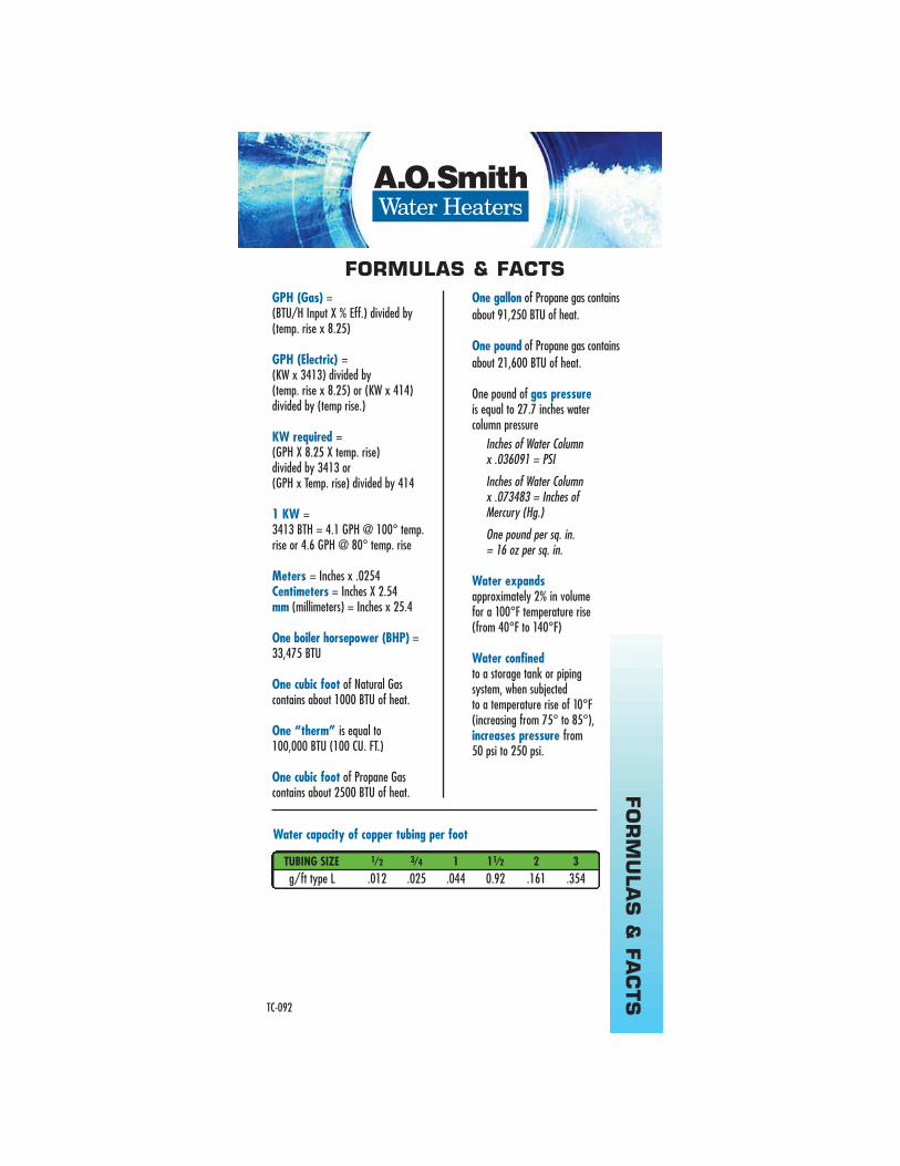
FORMULAS & FACTS BTU (British Thermal Unit) is the heat required to raise 1 pound of water 1°F 1 BTU = 252 cal = 0.252 kcal 1 cal = 4.187 Joules BTU X 1.055 = Kilo Joules BTU divided by 3,413 = Kilowatt (1 KW) One gallon of 120°F (49°C) water weighs approximately 8.25 pounds. Pounds x .45359 = Kilogram Gallons x 3.7854 = Liters % of hot water = (Mixed Water Temp. – Cold Water Temp.) divided by (Hot Water Temp. – Cold Water Temp.) % thermal efficiency = (GPH recovery X 8.25 X temp. rise X 1.0) divided by BTU/H Input BTU output (Gas) = GPH recovery x 8.25 x temp. rise x 1.0 BTU output (Electric) = BTU Input (Not exactly true due to minimal flange heat loss.) Capacity of a cylindrical tank – 1 / 2 diameter (in inches) x 3.146 x length. (in inches) Divide by 231 for gallons. Doubling the diameter of a pipe will increase its flow capacity (approximately) 5.3 times. Linear expansion of pipe – in inches per 100 Ft. Grain – 1 grain per gallon = 17.1 Parts Per million (measurement of water hardness) FAHRENHEIT CENTIGRADE 32 0 41 5 60.8 16 120.2 49 140 60 180 82 212 100 To convert from Fahrenheit to Celsius: (°F – 32) x 5/9 or .556 = °C. TEMP °F RISE STEEL COPPER 50° 0.38˝ 0.57˝ 100° .076˝ 1.14˝ 125° .092 ˝ 1.40˝ 150° 1.15˝ 1.75˝ TC-092 FORMULAS & FACTS http://waterheatertimer.org/9-ways-to-save-with-water-heater.html http://waterheatertimer.org/Figure-Volts-Amps-Watts-for-water-heater.html http://waterheatertimer.org/pdf/Fundamentals-of-water-heating.pdf More resources
-
Upload
khangminh22 -
Category
Documents
-
view
0 -
download
0
Transcript of Water heater formulas and terminology/ pdf - Waterheatertimer ...

FO
RM
ULA
S&
FA
CTS
BTU (British Thermal Unit) is the heat required to raise 1 pound of water 1°F
1 BTU = 252 cal = 0.252 kcal1 cal = 4.187 JoulesBTU X 1.055 = Kilo JoulesBTU divided by 3,413 = Kilowatt (1 KW)
One gallon of 120°F (49°C) waterweighs approximately 8.25 pounds.
Pounds x .45359 = KilogramGallons x 3.7854 = Liters
% of hot water =(Mixed Water Temp. – Cold WaterTemp.) divided by (Hot Water Temp.– Cold Water Temp.)
% thermal efficiency =(GPH recovery X 8.25 X temp. rise X1.0) divided by BTU/H Input
BTU output (Gas) = GPH recovery x 8.25 x temp. rise x 1.0
BTU output (Electric) = BTU Input (Not exactly true due to minimal flange heat loss.)
Capacity of a cylindrical tank – 1 ⁄ 2 diameter (in inches)x 3.146 x length. (in inches)Divide by 231 for gallons.
Doubling the diameter of a pipe will increase its flowcapacity (approximately) 5.3 times.
Linear expansion of pipe– in inches per 100 Ft.
Grain – 1 grain per gallon = 17.1 Parts Per million (measurement of water hardness)
FAHRENHEIT CENTIGRADE
32 041 560.8 16120.2 49140 60180 82212 100
To convert from Fahrenheit to Celsius: (°F – 32) x 5/9 or .556 = °C .
TEMP °F RISE STEEL COPPER
50° 0.38˝ 0.57˝
100° .076˝ 1.14˝
125° .092˝ 1.40˝
150° 1.15˝ 1.75˝
TC-092
FORMULAS & FACTS
http://waterheatertimer.org/9-ways-to-save-with-water-heater.html
http://waterheatertimer.org/Figure-Volts-Amps-Watts-for-water-heater.html
http://waterheatertimer.org/pdf/Fundamentals-of-water-heating.pdf
More resources
FO
RM
ULA
S&
FA
CTS
GPH (Gas) =(BTU/H Input X % Eff.) divided by(temp. rise x 8.25)
GPH (Electric) =(KW x 3413) divided by (temp. rise x 8.25) or (KW x 414)divided by (temp rise.)
KW required =(GPH X 8.25 X temp. rise) divided by 3413 or (GPH x Temp. rise) divided by 414
1 KW =3413 BTH = 4.1 GPH @ 100° temp.rise or 4.6 GPH @ 80° temp. rise
Meters = Inches x .0254Centimeters = Inches X 2.54mm (millimeters) = Inches x 25.4
One boiler horsepower (BHP) =33,475 BTU
One cubic foot of Natural Gas contains about 1000 BTU of heat.
One “therm” is equal to 100,000 BTU (100 CU. FT.)
One cubic foot of Propane Gas contains about 2500 BTU of heat.
One gallon of Propane gas containsabout 91,250 BTU of heat.
One pound of Propane gas containsabout 21,600 BTU of heat.
One pound of gas pressureis equal to 27.7 inches water column pressure
Inches of Water Column x .036091 = PSI
Inches of Water Column x .073483 = Inches of Mercury (Hg.)
One pound per sq. in. = 16 oz per sq. in.
Water expandsapproximately 2% in volume for a 100°F temperature rise (from 40°F to 140°F)
Water confinedto a storage tank or piping system, when subjected to a temperature rise of 10°F(increasing from 75° to 85°),increases pressure from 50 psi to 250 psi.
TUBING SIZE 1⁄2 3⁄4 1 11⁄2 2 3
g/ft type L .012 .025 .044 0.92 .161 .354
Water capacity of copper tubing per foot
TC-092
FORMULAS & FACTS
CO
MM
ON
TER
MS
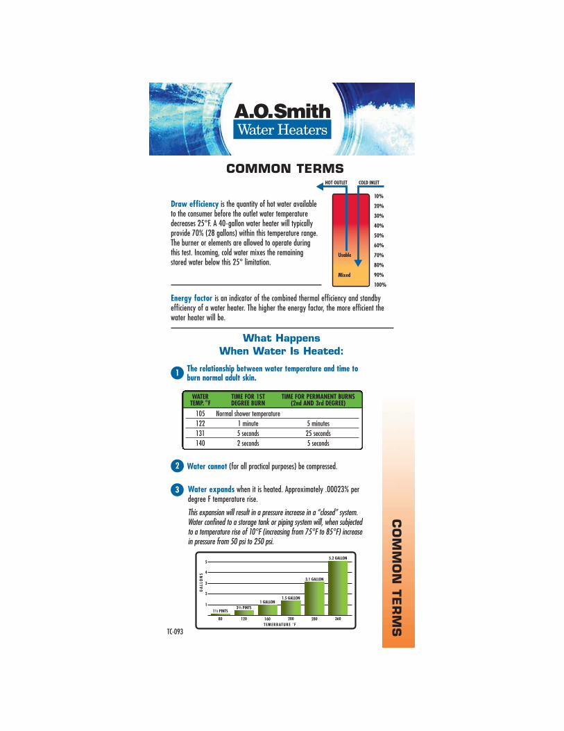
Draw efficiency is the quantity of hot water availableto the consumer before the outlet water temperaturedecreases 25°F. A 40-gallon water heater will typicallyprovide 70% (28 gallons) within this temperature range. The burner or elements are allowed to operate during this test. Incoming, cold water mixes the remaining stored water below this 25° limitation.
Energy factor is an indicator of the combined thermal efficiency and standby efficiency of a water heater. The higher the energy factor, the more efficient thewater heater will be.
The relationship between water temperature and time to burn normal adult skin.
WATER TIME FOR 1ST TIME FOR PERMANENT BURNSTEMP. °F DEGREE BURN (2nd AND 3rd DEGREE)
105 Normal shower temperature
122 1 minute 5 minutes
131 5 seconds 25 seconds
140 2 seconds 5 seconds
1
What Happens
When Water Is Heated:
Water cannot (for all practical purposes) be compressed.2
TC-093
COMMON TERMS
Water expands when it is heated. Approximately .00023% perdegree F temperature rise.
This expansion will result in a pressure increase in a “closed” system.Water confined to a storage tank or piping system will, when subjected to a temperature rise of 10°F (increasing from 75°F to 85°F) increase in pressure from 50 psi to 250 psi.
3

CO
MM
ON
TER
MS
Gases in the water will separate from the water as temperature rises.4
Water boils at 212°F – at sea level – unless it is contained underpressure. At 52 psi gauge pressure, water would not boil until itexceeded 300° F.
5
Minerals in the water will separate from the water as temperature is added.This may lead to a much faster scaling rate in the tank.
Ex: 10 grains hardness; 2700 gallons of hot water per day.Water stored at 140°F in the tank may accumulate 19 lbs. of lime per year.
160°F in the tank may accumulate 85 lbs. of lime per year.180°F in the tank may accumulate 135 lbs. of lime per year.
6
Adding heat to water may make it more corrosive.
Water may be 2 times more corrosive at 160°F than at 140°F.Water may be 2 times more corrosive at 180°F than at 160°F.
7
TC-093
COMMON TERMS
The closed system illustrated requires the thermal expansion tank because of the preceding #2 and #3 facts.

CO
MM
ON
TER
MS
For insulating purposes “R” value is a measure of the resistance of a substance to heat flow.
Recovery rate is the amount of water that is heated to a specific temperaturerise, per hour. An example might be that a water heater has a recovery rate of 30 gallons of water per hour at 80° F temperature rise.
Thermal efficiency is approximately the percentage of generated BTUthat enters the stored water. A percentage of the total BTU input passes out through the vent piping.
Temperature rise is the increase in the temperature from its coldest “inlet” water temperature to the desired hot (outlet) setting. Typically this is assumed to be 40° entering water; 120° desired stored water or 80° “temperature rise.”
Standby efficiency is the water heater’s ability to contain heat in the tank. A minimum of tank water heat loss per hour is desired.
Sample: temperature change per hour = BTU/H loss/square foot of tank surface“R” value
Water hammer is a concussion of moving water against the sides of a containing pipe or vessel on a sudden stoppage of flow.
Ex: 1/2 ˝ copper pipe, 5GPM flow (7.2ft/sec.) – stop. Pressure rise of approximately 412 psi
3/4˝ copper pipe, 5GPM flow (3.3ft/sec) – stop. Pressure rise of approximately 188 psi
Polarity – Verify that an electrical socket has correct “polarity.” Verify that the “Neutral” (typically white on a 120V circuit) wire has no power to ground and that the “Hot” (typically black wire on a 120V circuit) has 115 – 125V to ground.
Watts divided by Volts = Amps (single phase)
(Watts x .557) divided by (Volts) = Amps (3 phase)
TC-093
COMMON TERMS
Volts x amps = watts.
Volts divided by amps= ohms (resistance)

RELIANCE Water Heater Company Technical Training Department �
2006 Ashland City, TN
28
(Amps) (1 phase) divided by Volts
(3 phase) = (Watts X .577) divided by Volts
= (GPH X 8.25 X Temp. Rise X 1.0) divided by (3413)
= Volts divided by Amperes
is equal to 1000 watts
is equal to 3,413 BTU
= (KW X 3413) divided by (Temp. Rise X 8.25)
= (KW X 3413) divided by (GPH X 8.25)
or breakers should be sized at least 125% of expected heater amperage.
8.25 pounds per gallon at 120 F (49 C).
water = (Mixed temp. – Cold) divided by (Hot temp. – Cold)
This style water heater will have one or two electric, heating elements immersed in the tank. One element will always be located low in the tank; a second element is commonly located down about 1/3 of the tank height from the top of the tank. These elements will seldom be wired to operate at the same time. (If they operate at the same time, amperage draw doubles, wire gauge size increases, fuse size increases and little is gained in heat recovery.)
http://waterheatertimer.org/How-to-troubleshoot-electric-problems-with-water-heater.html
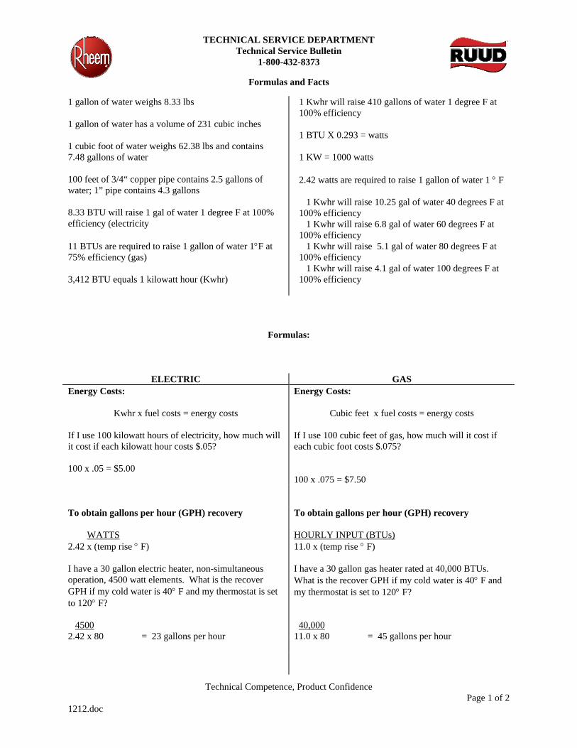
TECHNICAL SERVICE DEPARTMENT Technical Service Bulletin
1-800-432-8373
Formulas and Facts
Technical Competence, Product Confidence Page 1 of 2
1212.doc
1 gallon of water weighs 8.33 lbs 1 gallon of water has a volume of 231 cubic inches 1 cubic foot of water weighs 62.38 lbs and contains 7.48 gallons of water 100 feet of 3/4“ copper pipe contains 2.5 gallons of water; 1” pipe contains 4.3 gallons 8.33 BTU will raise 1 gal of water 1 degree F at 100% efficiency (electricity 11 BTUs are required to raise 1 gallon of water 1°F at 75% efficiency (gas) 3,412 BTU equals 1 kilowatt hour (Kwhr)
1 Kwhr will raise 410 gallons of water 1 degree F at 100% efficiency 1 BTU X 0.293 = watts 1 KW = 1000 watts 2.42 watts are required to raise 1 gallon of water 1 ° F 1 Kwhr will raise 10.25 gal of water 40 degrees F at 100% efficiency 1 Kwhr will raise 6.8 gal of water 60 degrees F at 100% efficiency 1 Kwhr will raise 5.1 gal of water 80 degrees F at 100% efficiency 1 Kwhr will raise 4.1 gal of water 100 degrees F at 100% efficiency
Formulas:
ELECTRIC GAS Energy Costs:
Kwhr x fuel costs = energy costs If I use 100 kilowatt hours of electricity, how much will it cost if each kilowatt hour costs $.05? 100 x .05 = $5.00
Energy Costs:
Cubic feet x fuel costs = energy costs If I use 100 cubic feet of gas, how much will it cost if each cubic foot costs $.075? 100 x .075 = $7.50
To obtain gallons per hour (GPH) recovery WATTS 2.42 x (temp rise ° F) I have a 30 gallon electric heater, non-simultaneous operation, 4500 watt elements. What is the recover GPH if my cold water is 40° F and my thermostat is set to 120° F? 4500 2.42 x 80 = 23 gallons per hour
To obtain gallons per hour (GPH) recovery HOURLY INPUT (BTUs) 11.0 x (temp rise ° F) I have a 30 gallon gas heater rated at 40,000 BTUs. What is the recover GPH if my cold water is 40° F and my thermostat is set to 120° F? 40,000 11.0 x 80 = 45 gallons per hour
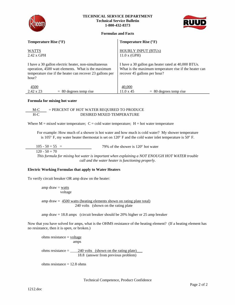
TECHNICAL SERVICE DEPARTMENT Technical Service Bulletin
1-800-432-8373
Formulas and Facts
Technical Competence, Product Confidence Page 2 of 2
1212.doc
Temperature Rise (°F) WATTS 2.42 x GPH I have a 30 gallon electric heater, non-simultaneous operation, 4500 watt elements. What is the maximum temperature rise if the heater can recover 23 gallons per hour? 4500 2.42 x 23 = 80 degrees temp rise
Temperature Rise (°F) HOURLY INPUT (BTUs) 11.0 x (GPH) I have a 30 gallon gas heater rated at 40,000 BTUs. What is the maximum temperature rise if the heater can recover 45 gallons per hour? 40,000 11.0 x 45 = 80 degrees temp rise
Formula for mixing hot water
M-C = PERCENT OF HOT WATER REQUIRED TO PRODUCE H-C DESIRED MIXED TEMPERATURE
Where M = mixed water temperature; C = cold water temperature; H = hot water temperature
For example: How much of a shower is hot water and how much is cold water? My shower temperature is 105° F, my water heater thermostat is set on 120° F and the cold water inlet temperature is 50° F.
105 - 50 = 55 = 79% of the shower is 120° hot water 120 - 50 = 70 This formula for mixing hot water is important when explaining a NOT ENOUGH HOT WATER trouble
call and the water heater is functioning properly. Electric Working Formulas that apply to Water Heaters To verify circuit breaker OR amp draw on the heater: amp draw = watts voltage amp draw = 4500 watts (heating elements shown on rating plate total)
240 volts (shown on the rating plate amp draw = 18.8 amps (circuit breaker should be 20% higher or 25 amp breaker Now that you have solved for amps, what is the OHMS resistance of the heating element? (If a heating element has no resistance, then it is open, or broken.) ohms resistance = voltage amps ohms resistance = ____240 volts (shown on the rating plate)___ 18.8 (answer from previous problem) ohms resistance = 12.8 ohms

TECHNICAL SERVICE DEPARTMENT Technical Service Bulletin
1-800-432-8373
Estimated Annual Cost of Operation
Technical Competence, Product Confidence Page 1 of 1
1230.doc
You can calculate the estimated yearly cost of operation for a water heater by using one of the following formulas:
For natural gas or propane (LP) gas:
41045 Btu EF X Unit Cost of Fuel$ per Btu X 365 = Estimated Annual Cost of Operation
For Example: Assuming a natural gas unit with an EF of .57 and fuel costs of $.904 per therm -
41045 Btu .57 X $.00000904 X 365 = $237 estimated annual cost of operation
Unit cost of fuel = $.904 per therm or $.904 per 100,000 Btu or $.00000904 per Btu
For electricity:
12.03kWh EF X Unit Cost of Fuel$ per kWh X 365 = Estimated Annual Cost of Operation
For Example: Assuming an electric water heater with an EF of .88 and electric costs of $.0817 per kWh -
12.03kWh .88 X $.0817 X 365 = $407 estimated annual cost of operation
Definitions:
Energy Factor Energy factor is a measure of the overall efficiency rating of a water heater. The higher the EF number, the more efficient the water heater.
First Hour Rating (1st Hour Rating) First hour rating is the amount of hot water that the water heater can supply in the first 60 minutes of operation. It is a combination of how much water is stored in the water heater and how quickly the water heater can reheat cold water to the desired temperature.
Fuel Conversions:
1 therm of natural gas = 100,000 Btu 1 gallon of LP gas = 91,333 Btu 1 kWh (kilowatt hour) = 3,412 Btu
National average unit fuel costs as determined by the Department of Energy, Winter 2001 have been used in these calculations.
See the complete GAMA book and web site at: www.gamanet.org
Check for fuel data and prices at the Dept of Energy website at: www.energy.gov/dataandprices/index.html
TECHNICAL SERVICE DEPARTMENT Technical Service Bulletin
1-800-432-8373
Recovery Rating on the Residential Gas Water Heaters Labeling
Technical Competence, Product Confidence Page 1 of 1
1421.DOC
The formula and computations for the amount of hot water a gas water heater can produce are different based on the authority of the label. The American National Standards Institute (ANSI) regulates the rating plate and has their formula; the Department of Energy (DOE) regulates the yellow energy guide and has their formula; and the specification sheet Gallons Per Hour (GPH) recovery is an industry accepted mathematical formula that has been in use for years.
Effective with the ANSI Standard Z21.10.1a-2002; CSA 4.1-2001, all residential gas water heaters must have the recovery rating listed on the manufacturer’s rating label. By ANSI definition, this recovery is listed in gallons per hour and is the result of the formula:
Manufacturer’s input rating in Btu per hour 1179 BTU/Gallon
To show how this works, lets use an example of a 42V40-40F. This is a 40,000 BTU input 40-gallon capacity water heater.
�� 40-gallon tank �� 40.4 GPH recovery at 90 degree rise per the specification sheet and industry accepted formula �� 33.9 gallons recovery per ANSI formula on the rating plate �� 70 gallons first hour delivery per DOE on the yellow energy guide label
As you can see, there is a wide range of delivery capacities notes on the water heater’s labeling.
Below is a table that will show you some normal BTU input results using the ANSI formula:
ManufacturersInput Rating in
BTU/hr
ANSIConstant
ANSI Recovery Rating
ManufacturersInput Rating in
BTU/hr
ANSIConstant
ANSI Recovery Rating
26000 1179 22.1 52000 1179 44.1 28000 1179 23.7 54000 1179 45.8 30000 1179 25.4 56000 1179 47.5 32000 1179 27.1 58000 1179 49.2 34000 1179 28.8 60000 1179 50.9 36000 1179 30.5 62000 1179 52.6 38000 1179 32.2 64000 1179 54.3 40000 1179 33.9 66000 1179 56.0 42000 1179 35.6 68000 1179 57.7 44000 1179 37.3 70000 1179 59.4 46000 1179 39.0 72000 1179 61.1 48000 1179 40.7 74000 1179 62.8 50000 1179 42.4
This recovery number may be different from the First Hour Deliver computation on the yellow Energy Guide Label attached to your water heater. The First Hour Deliver rating includes recovery, PLUS storage available and the units ability to reheat water while being consumed. Therefore, the First Hour Deliver number will be higher than on the manufacturer’s rating plate.
TECHNICAL SERVICE DEPARTMENT Technical Service Bulletin
1-800-432-8373
Technical Competence, Product Confidence Page 1 of 1
1408.doc
Recovery Rates in Gallons per Hour - Gas Water Heaters
Temperature Rise - Degrees Fahrenheit 400 500 600 700 800 900 1000 1100 1200 1300 1400
INPUT BTU 20,000 45 36 30 26 23 20 18 17 15 14 13 26,000 59 47 39 34 30 26 24 21 20 18 17 28,000 64 51 42 36 32 28 25 23 21 20 18 30,000 68 55 45 39 34 30 27 25 23 21 19 32,000 73 58 48 42 36 32 29 26 24 22 21 34,500 78 63 52 45 39 35 31 29 26 24 22 36,000 82 65 55 47 41 36 33 30 27 25 23 37,000 84 67 56 48 42 37 34 31 28 26 24 40,000 91 73 61 52 45 40 36 33 30 28 26 50,000 114 91 76 65 57 51 45 41 38 35 32 57,000 130 104 86 74 65 58 52 47 43 40 37 60,000 136 109 91 78 68 61 55 50 45 42 39 69,000 157 125 105 90 78 70 63 57 52 48 45 75,000 170 136 114 97 85 76 68 62 57 52 49 98,000 223 178 148 127 111 99 89 81 74 69 64 100,000 227 182 152 130 114 101 91 83 76 70 65 114,000 259 207 173 148 130 115 104 94 86 80 74 156,000 355 284 236 203 177 158 142 129 118 109 101 160,000 364 291 242 208 182 162 145 132 121 112 104 180,000 409 327 273 234 205 182 164 149 136 126 117 199,900 454 363 303 260 227 202 182 165 151 140 130 250,000 568 455 379 325 284 253 227 207 189 175 162 270,000 614 491 409 351 307 273 245 223 205 189 175 300,000 682 545 455 390 341 303 273 248 227 210 195 360,000 818 655 545 468 409 364 327 298 273 252 234 399,900 909 727 606 519 454 404 364 330 303 280 260 500,000 1136 909 758 649 568 505 455 413 379 350 325
To figure recovery by hand and you know the BTU input: Hourly input (BTUs)____ 11.0 x (temperature rise ° F)

123456789011234567890112345678901123456789011234567890112345678901123456789011234567890112345678901123456789011234567890112345678901123456789011234567890112345678901123456789011234567890112345678901123456789011234567890112345678901123456789011234567890112345678901123456789011234567890112345678901123456789011234567890112345678901123456789011234567890112345678901123456789011234567890112345678901123456789011234567890112345678901123456789011234567890112345678901123456789011234567890112345678901123456789011234567890112345678901123456789011234567890112345678901123456789011234567890112345678901123456789011234567890112345678901123456789011234567890112345678901123456789011234567890112345678901123456789011234567890112345678901123456789011234567890112345678901123456789011234567890112345678901123456789011234567890112345678901123456789011234567890112345678901123456789011234567890112345678901123456789011234567890112345678901123456789011234567890112345678901123456789011234567890112345678901123456789011234567890112345678901123456789011234567890112345678901123456789011234567890112345678901123456789011234567890112345678901
2
l. Introduction To Commercial Water Heating PagesParameters .................................................................................................................................... 2-3What is Hot Water? ........................................................................................................................ 3-4Evaluating Water ............................................................................................................................ 4
ll. Principles of SizingHot Water Demand ........................................................................................................................ 5Profiles of Operation ...................................................................................................................... 5-6
lll. Equipment PerformanceRecovery Capacity Tables .............................................................................................................. 6-7Storage Capacity And Tank Efficiency ............................................................................................ 7Gas and Oil - Fired Tank Type Heaters .......................................................................................... 8Electric Tank Type Heaters ............................................................................................................. 8Auxiliary Tank (Unfired) ................................................................................................................... 8Heater Recovery Plus Storage Tank Equals Demand .................................................................. 8Heater Recovery And Storage Tank Performance Comparison ................................................... 9When Using Electricity to Heat Water ............................................................................................ 10Estimating Water Heating Costs ................................................................................................... 10
lV. System Types And ApplicationDesign Objectives .......................................................................................................................... 11System Types ................................................................................................................................. 11Tank Type Water Heater Systems Using Gas, Oil and Electricity .................................................. 11-12Creating The Successful System .................................................................................................. 13Sizing Without Prepared Information ............................................................................................. 13-14One Temperature System .............................................................................................................. 14Two Temperature System .............................................................................................................. 15Field Assistance ............................................................................................................................. 15
This guide is different than most produced by the water heating industry. Instead of just referring youto prepared sizing information the guide shows you how it’s done. Then, when new model heaters are
Index
Foreword introduced or applications are different, you will have the information necessary to proceed onyour own with confidence.
You will learn how to evaluate water characteristics which could affect system life andperformance, develop a profile of system operation to establish demand and recovery periods,size energy and storage requirements to meet system demands and, all told, create asuccessful commercial water heating system.
I. Introduction to Commercial Water heatingParameters
A water heater is an appliance for supplying hot water for residential or commercial use other thanspace heating. The maximum outlet water temperature for a water heater is 210°F ( 98.5°C).
Water heaters are sometimes called boilers and may be so labeled. This is because the galloncapacity of the tank and/or the energy input is above a level for which some codes require ASME(American Society of Mechanical Engineers) construction. Essentially the requirement applieswhen the water-containing capacity is in excess of 120 gallons or the heat input is above 200,000Btuh (58.6 kw). Caution, some local inspectors interpret the code to mean including 120 gallonsand 200,000 Btuh. The “boiler” requirement can cause cost escalation or system rejection if nottaken into consideration by the system designer. One way that more expensive heater costs areoften avoided is by combining several “smaller” heaters into a system instead of one large unit.
The term water heater and water heating system is used interchangeably in this technical guide.The water heating system may consist of one or more water heaters installed individually atpoints-of-use or manifolded together to form a central system. Some systems are comprised ofwater heater(s), with or without storage, hot water storage tanks, circulating pump, related pipingand controls.
123456789011234567890112345678901123456789011234567890112345678901123456789011234567890112345678901123456789011234567890112345678901123456789011234567890112345678901123456789011234567890112345678901123456789011234567890112345678901123456789011234567890112345678901123456789011234567890112345678901123456789011234567890112345678901123456789011234567890112345678901123456789011234567890112345678901123456789011234567890112345678901123456789011234567890112345678901123456789011234567890112345678901123456789011234567890112345678901123456789011234567890112345678901123456789011234567890112345678901123456789011234567890112345678901123456789011234567890112345678901123456789011234567890112345678901123456789011234567890112345678901123456789011234567890112345678901123456789011234567890112345678901123456789011234567890112345678901123456789011234567890112345678901123456789011234567890112345678901123456789011234567890112345678901123456789011234567890112345678901123456789011234567890112345678901123456789011234567890112345678901123456789011234567890112345678901123456789011234567890112345678901123456789011234567890112345678901
3
What is Hot Water?
Hot water is water to which heat energy has been added . . .as more heat is added the water becomeshotter. This water temperature guide shows typical water heating system design temperatures.
In practice, the system designer will establish the temperature or temperatures of hot water neededfor the various activities through consultation with the user or their representative. It is also necessaryfor the system designer to know the coldest entering water temperature in order to determine temperaturerise.
The major objective of this presentation is to promote the design of energy-efficient commercial waterheating systems through proper sizing, equipment recommendations and system selection. Properlydesigned commercial and industrial water heating systems are essential to the health and well being ofthe community. Some activities would have to suspend operations or risk serious health and comfortproblems if they do not have the quantity of hot water at the temperature needed during the time it isrequired.
QUANTITYTEMPERATURETIME & SPACE
Therefore, the key to proper waterheating system design is to identifythe quantity, temperature and timecharacteristics of the hot waterrequirement. Also, space availablefor equipment should be noted.
But first, a knowledge of water andits characteristics is necessary inorder to effectively design a waterheating system.
SYSTEM CONCEPTS
* The average temperature of the hot and cold water mixture applied to the body. The hot water being normally obtained from the commercial water heating system at 140°F.
123456789011234567890112345678901123456789011234567890112345678901123456789011234567890112345678901123456789011234567890112345678901123456789011234567890112345678901123456789011234567890112345678901123456789011234567890112345678901123456789011234567890112345678901123456789011234567890112345678901123456789011234567890112345678901123456789011234567890112345678901123456789011234567890112345678901123456789011234567890112345678901123456789011234567890112345678901123456789011234567890112345678901123456789011234567890112345678901123456789011234567890112345678901123456789011234567890112345678901123456789011234567890112345678901123456789011234567890112345678901123456789011234567890112345678901123456789011234567890112345678901123456789011234567890112345678901123456789011234567890112345678901123456789011234567890112345678901123456789011234567890112345678901123456789011234567890112345678901123456789011234567890112345678901123456789011234567890112345678901123456789011234567890112345678901123456789011234567890112345678901123456789011234567890112345678901123456789011234567890112345678901123456789011234567890112345678901
4
Evaluating Water
The coldest water inlet temperature experienced during the year should be the base from whichthe maximum system temperature rise is established. Your water supplier can provide thisinformation. Surface water sources such as lakes and rivers tend to fluctuate as the seasonschange. Well water remains relatively constant in temperature year round. A water heatingsystem supplied with varying incoming water temperatures will only provide adequate hot water ifthe lowest cold water temperature encountered is used in the temperature rise calculation.
Other characteristics of the water supply which should be determined and evaluated by the systemdesigner include supply pressure, water hardness and the presence of silt. These facts may beobtained by contacting your water supplier.
High water supply pressure (above the rated working pressure of the heater) should be reducedby a water pressure reducing valve set to about 50 psig. This will also reduce water consumptionbut, more important, will bring the water pressure well within the working pressure range of theheater. It is then possible to provide proper relief valve protection on the heater.
It is also necessary to provide water pressure reducing valves on the 180°F rinse lines ofdishwashers.
Hardness is the term applied to the compounds of calcium and magnesium present in hardwater. So common are these two minerals in water that practically no supply can be found thatdoes not contain at least 1 or 2 grains per gallon. Hardness is also stated in parts per million.One grain of hardness is equal to 17.1 parts per million. Water containing less than 1 grain pergallon of dissolved calcium and magnesium hardness minerals is considered soft water.
The significance of hardness is that the heat transfer surfaces of the water heater will becomecoated or blocked with the mineral deposits. Depending upon the type of heater, less hot water,noisy operation, increased energy costs and premature equipment failure are some of theproblems which may result from “hard” water. The system designer should select water heatingequipment which is capable of being delimed or repaired when used in hard water areas.
If the water supply contains silt or sediment, the water heating equipment should be capable ofbeing flushed (and have sediment risers installed in horizontal storage tanks) to extend heaterlife and minimize energy expense.
The effects of hard water and silt upon the heating equipment can be minimized by loweringwater temperature, controlling flow, leakage and waste. For example, fixture and shower headflow controls are a must to minimize hot water consumption and regulate the flow to systemdesign.
Energy saving fixtures benefit the user by reducing water and sewerage charges, energy andmaintenance costs. Reducing consumption through flow control is the one way initial cost,operating costs and the space to be occupied by a new water heating system can be dramaticallyreduced.
SUPPLY WATERTEMPERATURE
PRESSUREHARDNESS
INTRODUCTION
A. O. Smith residential water heaters are produced in alarge variety of tank sizes and heat inputs to permit theselection of the one best suited to do the job. Ideally thisheater would have a combination of storage and heat in-put equal to the usage.
In addition to the design factors and the sizingexamples which follow, a glossary section provides de-tailed explanations of selected terminology. This is doneto avoid expanding the content of thesizing procedure.
RESIDENTIAL SIZING
3. Storage tank size selection:
NOTE: The draw efficiency of a gas or electric waterstorage tank is considered to be 70%.
• 30 gallon size (21 gallon draw) for one bath resi-dence.
• 40 gallon size (28 gallon draw) for two bath resi-dence -or- one bath with an automatic clotheswasher.
• 50 gallon size (35 gallon draw) for three bath resi-dence -or- two baths with an automatic clotheswasher.
• When a whirlpool tub is part of the home equip-ment, it is suggested that the heater storage tankcapacity, or the sum total of an additional auxiliarystorage tank and heater, be sized in accordancewith the following table. This method of tank sizing,will in most cases, cancel all previous statementsas noted above concerning tank sizing.
4. Heat input VS recovery capacity.
Gas water heater recovery table (calculated at 75%recovery efficiency).
GALLONS
STORAGE HEAT INPUT+ =WATERAVAILABLETO MEETUSAGE
DESIGN FACTORS
These design factors are the result of combining A.O.Smith engineering test data and practicalexperience to form a usable guide for the selection ofminimum water heater tank sizes and heatinputs. As stated previously, the factors may beadjusted to suit individual needs.
1. Two hour peak usage period.
Residential peak usage, based on accepted prac-tice, is the two hour period during the day when theheaviest draw of hot water will occur.
For example, from 7:00 to 9:00 A.M.
2. Gallons of 140°F hot water required:
• 20 gallons per person for the first twopersons.
• 5 gallons per person for each person over the firsttwo.
• 10 gallons for each full bath over the first bath.
• 10 gallons for an automatic dishwasher.
• 20 gallons for an automatic clothes washer.
Tub Capacity To Overflow 80 90 100 110 120 130 140 150 Outlet
(@ 140°F Water) Min. Stored Water Capacity 65 71 80 89 98 108 117 125
(@ 160°F Water*) Min. Stored Water Capacity 54 59 66 74 82 90 97 104
* A mixing valve is recommended to be installed in heater or auxiliary tank hot water outlet piping.
Based on a tub water temperature of 105°F.
Revised April 1997 (Reviewed May 1999) B 201.0June 2007RJune 2010R AOSSG88150
®
211543 AOSSG88150 1 5/22/09 2:09:28 PM

Notes on element operation:
(a) Two element water heaters, simultaneous elementoperation; figure the upper element recovery at 1/3*the GPH shown for wattage, figure lower element atthe GPH shown.
* The bottom element contributes to the heat at the topof the tank. This tends to shut off the top element.Metered tests indicate the upper element operatesabout 1/3 of the time.
(b) Two element water heaters, non-simultaneous (in-terlocking) element operation; figure the largestwattage element recovery only – at the GPH shown.
(c) Single element water heaters; figure the recovery atthe GPH shown.
5. Storage VS input.
Water heater selection is best made on the basis ofhot water usage. However, calculations may lead to acombination of tank size and heat input which doesn'texist. In this case, the tank size and/or heat inputmust be balanced to achieve the desired result.
Therefore, it is necessary to understand that heatinput provides hot water, at the hourly recovery rate,hour after hour. The storage tank represents instanthot water at greater-than-heater recovery.
The supply of hot water in the storage tank cannot bereplenished until the peak usage period has endedand heater recovery is available for this purpose.
Having enough storage tank capacity isimportant when large quantities of hot water are re-quired in a short period of time. If the peak usageperiod is for an extended period of time (more thantwo hours), the heater recovery capacity assumesmajor importance.
DESIGN EXAMPLES
GIVEN: Family of four personsTwo full bathsAutomatic dishwasherAutomatic clothes washer
HOT WATER REQUIRED:
B 202.0
Electric Water Heater Recovery Table(Calculated at 100% Recovery Efficiency)
Heating GPH Recovery At Indicated
Element Temperature Rise
Wattage 60° 70° 80° 90° 100° 750 5.1 4.4 3.8 3.4 3.11000 6.8 5.8 5.1 4.6 4.11250 8.5 7.3 6.4 5.7 5.11500 10.2 8.8 7.7 6.8 6.12000 13.7 11.7 10.2 9.1 8.22250 15.4 13.2 11.5 10.2 9.22500 17.1 14.6 12.8 11.4 10.23000 20.5 17.5 15.4 13.6 12.33500 23.9 20.5 17.9 15.9 14.34000 27.3 23.4 20.5 18.2 16.44500 30.7 26.3 23.0 20.5 18.45000 34.1 29.2 25.6 22.7 20.55500 37.6 32.2 28.2 25.0 22.56000 41.0 35.1 30.7 27.3 24.6
Gas Water Heater Recovery Table(Calculated at 75% Recovery Efficiency)
Input GPH Recovery At Indicated
Rating Temperature Rise
Btuh 60° 70° 80° 90° 100° 30,000 45.5 39.0 34.1 30.3 27.3 33,000 50.0 42.9 37.5 33.3 30.0 35,000 53.0 45.5 39.8 35.4 31.8 40,000 60.6 51.9 45.5 40.4 36.4 43,000 65.2 55.8 48.9 43.4 39.1 50,000 75.8 64.9 56.8 50.5 45.5 60,000 90.9 77.9 68.2 60.6 54.5 70,000 106.1 90.9 79.5 70.7 63.6 80,000 121.2 103.9 90.9 80.8 72.7 90,000 136.4 116.9 102.3 90.9 81.8100,000 151.51 129.9 113.6 101.0 90.9
*This means 45 gallons of hot water per hour, for two hours, must be provided by theA. O. Smith water heater through storage and heat input.
Two persons @ 20 gallons/perso ................ 40 gallonsTwo persons @ 5 gallons/person ................10 gallonsSecond full bath ...........................................10 gallonsAutomatic dishwasher ..................................10 gallonsAutomatic clothes washer ............................20 gallonsTotal two hour peak hot water usage ...........90 gallons
177829 AO Smith B2010.indd 2 6/4/07 10:16:14 AM
AOSSG88150
211543 AOSSG88150 2211543 AOSSG88150 2 5/22/09 2:09:29 PM5/22/09 2:09:29 PM

Storage Tank Size:
According to design factor 3, the storage tank size is 50gallons.
The draw efficiency of the storage tank is considered tobe 70%. Therefore, 35 gallons of "usable" hot water isavailable from the tank.
Storage VS Input:
90 gallons two hour peak hot water usage-35 gallons of hot water from storage tank 55 gallons of hot water to be produced by heat input during two hour peak.
This means 27.5 gallons of hot water per hour must beprovided by heat input at the accepted temperature riseused in the locale.
GAS WATER HEATER SELECTION
From the gas water heater recovery table it is foundthat, at 90° temperature rise, 27,225 Btuh willproduce 27.5 GPH.
An A. O. Smith gas water heater with at least a 50 gallonstorage tank and at least 27,225 Btuh input is requiredto meet the peak usage requirements. Consult A. O.Smith water heater specification sheets to determinemodel needed.
ELECTRIC WATER HEATER SELECTION
NOTE: In the following example the fuel used is elec-tricity instead of gas. This does not changethe amount of hot water required by the familyof four. It may mean a change in the ratio of
tank storage versus heat input to reflect theavailability or amount of electricity which isobtainable during the peak usage period.
Two element, non-simultaneous operation:
Upper element – 4500 wattsLower element – 4500 watts
90 gallons two hour peak hot water usage-35 gallons of hot water from storage tank 55 gallons of hot water to be produced by heat input during two hour peak.
Figure recovery of one element ... the one with largestwattage. In this example both elements are of same watt-age.
20.5 GPH recovery x 2 hours = 41.0 gallons availablefrom element recovery. This is less than the amount ofrecovery needed.
55.0 gallons of hot water needed from heat input (using 50 gallon storage tank)-41.0 from two hour recovery of (1) 4500 watt element*11.0 gallons of hot water "short" two hour peak
It is necessary to increase the size of the storage tankand/or element wattages to satisfy the calculated peakusage. Check your local utility for maximum allowablewattage permitted for water heating. They may also havea minimum storage tank size requirement. Consult A. O.Smith water heater specification sheets to determinemodel needed.
* To allow for draw efficiency, divide the "shortage" by .7 when increasing tank size.
FOR GLOSSARY REFER TO FOLLOWING PAGE AOSSG88150
B 203.0
177829 AO Smith B2010.indd 3 6/4/07 10:16:15 AM
AOSSG88150
FOR GLOSSARY REFER TO FOLLOWING PAGE AOSSG88150
177829 AO Smith B2010.indd 3 6/4/07 10:16:15 AM211543 AOSSG88150 3211543 AOSSG88150 3 5/22/09 2:09:29 PM5/22/09 2:09:29 PM

GLOSSARY
The following provides detailed explanations of selectedterminology used in the sizing procedure. This is to pro-mote a greater understanding of water heating terms, for-mula and theory.
• BTU...abbreviation for the British thermal unit, which isthe amount of heat required to raise the temperature ofone pound of water one degree Fahrenheit.
Stated another way, 8.25 Btu will raise the temperature ofone gallon of water one degree.
A Btu may be sensed and visualized as about the amountof heat produced by burning one wooden match. Onewatt-hour of electricity produces 3.413 Btu.
This is the formula for determining the Btu required toheat a given quantity of water a certain number of de-grees:
Gallons x 8.25 x 1.0 x temp. rise = Btu
Where..gallons =Total gallons of hot water required8.25 = Weight of one gallon of water1.0 = Specific heat of water (See Specific
heat)Temp. Rise = Difference in degrees between lowest
incoming water temperature and desiredhot water temperature.
Btu = Gas water heaters; divide answer by.75 (recovery efficiency) to obtainequivalent gas input in Btu.Electric water heaters; multiply by0.293 to obtain element wattage equiva-lent.In actual practice a combination of stor-age and input is used to assure theavailability of hot water.
• Draw efficiency is considered to be 70% in this report.When using storage type heaters it is common practiceto assume 70% of the storage capacity of the heatertank may be drawn before dilution by incoming cold wa-ter lowers the hot water temperature below an accept-able level under normal draw conditions. For example, a40 gallon storage tank would deliver about 28 gallons ofusable hot water.
• Input rating...The amount of fuel in British thermal units(Btu) consumed by a gas or oil water heater in an hour.In an electric water heater input is usually expressed inwatts or kilowatts. Consuming one watt-hour of electric-ity produces 3.413 Btu.
• Interlocking...(See Non-Simultaneous)
• Non-Simultaneous (Interlocking) element operation iswhere both of the heating elements in an electric waterheater are not permitted to operate at the same time.The electrical circuit is interlocked through the upperthermostat to prevent simultaneous operation.
• Recovery (capacity), the amount of water in gallonsper hour, raised at a given recovery efficiency and Btuhinput. Refer to Recovery Table.
This is the formula for determining recovery capacity:
Input x efficiency = Recovery in GPH (See Btu)8.25 x temp. rise
Efficiency = .75 for gas-fired water heaters1.0 for electric water heaters(also see Recovery efficiency)
• Recovery efficiency...The ratio of the heat in the waterdelivered at the heater outlet to the heat input of theheating unit. Also see Btu.
Gas-fired residential water heaters are generally con-sidered to have a 75% recovery efficiency. This means75% of the total heat produced by the burner isabsorbed into the water in the tank. The remaining 25%of the heat is used to move the products ofcombustion through the flue to the outdoors.
Electric residential water heaters are generallyconsidered to have a 100% recovery efficiency. This isbecause immersion style elements place all the heat intothe water and there is no flue.
• Simultaneous element operation is where both of theheating elements in an electric water heater are permit-ted to operate at the same time if necessary. The actualoperation of each element is individually controlled byits own thermostat.
• Specific heat, the amount of heat required to raise thetemperature of a given weight of a substance one de-gree as compared with the amount of heat required toraise the temperature of the same weight of water 1° atsome specified temperature.
• Storage tank, used for storing hot water in advance ofneeds. Properly sized, the tank permits large volumes ofhot water to be drawn from the system at flow rates ex-ceeding the recovery capacity of the heater. Also seeDraw efficiency.
• Temperature rise, the amount of temperature differ-ence (between incoming and outgoing water) in degreesFahrenheit.
• Draw efficiency, the amount of water that can be drawnfrom a storage tank, at a 3 gpm flow rate, before thetemperature drops 30°F. Heater outlet water tempera-tures below 110°F is generally not considered as satis-factory or usable.
B 204.0 © A. O. Smith Corp., 1997 Printed in U.S.A.
177829 AO Smith B2010.indd 4 6/4/07 10:16:15 AM
AOSSG88150 © A. O. Smith Corp., 2009
®
A.O. SMITH500 Tennessee Waltz ParkwayAshland City, Tn 37015www.hotwater.com1.800.527.1953
211543 AOSSG88150 4211543 AOSSG88150 4 5/22/09 2:09:30 PM5/22/09 2:09:30 PM
123456789011234567890112345678901123456789011234567890112345678901123456789011234567890112345678901123456789011234567890112345678901123456789011234567890112345678901123456789011234567890112345678901123456789011234567890112345678901123456789011234567890112345678901123456789011234567890112345678901123456789011234567890112345678901123456789011234567890112345678901123456789011234567890112345678901123456789011234567890112345678901123456789011234567890112345678901123456789011234567890112345678901123456789011234567890112345678901123456789011234567890112345678901123456789011234567890112345678901123456789011234567890112345678901123456789011234567890112345678901123456789011234567890112345678901123456789011234567890112345678901123456789011234567890112345678901123456789011234567890112345678901123456789011234567890112345678901123456789011234567890112345678901123456789011234567890112345678901123456789011234567890112345678901123456789011234567890112345678901123456789011234567890112345678901123456789011234567890112345678901123456789011234567890112345678901123456789011234567890112345678901123456789011234567890112345678901
5
Hot Water Demand
The major determination in sizing and the basis of all computations is establishing the probable demandfor hot water. In addition, any unusual conditions which might relate to hot water consumption mustalso be recognized and planned for. Unusual conditions will be described under Profiles of Operation.
Sources of hot water demand information include the ASHRAE (American Society of Heating,Refrigerating and Air Conditioning Engineers) Guide, and hot water using equipment manufacturerssuch as dishwasher and washing machine makers. Government agencies may also require demandcriteria be met.
Profiles of Operation
The system designer should draw a profile of the proposed system hot water usage demand period.The profile will also include the recovery period available before the next demand. Demand andrecovery periods can be measured in seconds, minutes or hours.
Any unusual needs for hot water during the demand or recovery periods are identified in order toprovide additional tank and/or recovery capacity. An unusual need could be a lesser, but significanthot water requirement appearing just after the demand period. For example, a motel could have alaundry operation which begins in mid-morning, after the guest shower load is over. If not taken intoconsideration there many be no hot water available for the washing machines.
An oversimplification of system design is to say that systems are either for intermittent use or continuoususe as shown in the following profiles.
.
This example shows two demand and recovery periods within a day.
• A combination of heater recovery and hot water storage capacity should be selected to handle thedemands.
• The demands are separated by an 8 and a 12 hour recovery period.
• The heater recovery capacity of the shortest recovery period must be sufficient to heat all the waterin storage.
• Short demands usually mean placing emphasis on tank size. Heater recovery capacity is emphasizedon longer demands.
• The dividing line between long and short demands is about 3 to 4 hours.
• In this example storage is most important.-The purpose of the storage tank is to permit relatively low heater recovery capacity while still
maintaining adequate hot water supply during the demand period.
II. Principles of Sizing
Intermittent Use Profile

123456789011234567890112345678901123456789011234567890112345678901123456789011234567890112345678901123456789011234567890112345678901123456789011234567890112345678901123456789011234567890112345678901123456789011234567890112345678901123456789011234567890112345678901123456789011234567890112345678901123456789011234567890112345678901123456789011234567890112345678901123456789011234567890112345678901123456789011234567890112345678901123456789011234567890112345678901123456789011234567890112345678901123456789011234567890112345678901123456789011234567890112345678901123456789011234567890112345678901123456789011234567890112345678901123456789011234567890112345678901123456789011234567890112345678901123456789011234567890112345678901123456789011234567890112345678901123456789011234567890112345678901123456789011234567890112345678901123456789011234567890112345678901123456789011234567890112345678901123456789011234567890112345678901123456789011234567890112345678901123456789011234567890112345678901123456789011234567890112345678901123456789011234567890112345678901123456789011234567890112345678901123456789011234567890112345678901
6
• This example could represent an industrial process which is operated for two continuous shiftsa day.
• Hot water is used at a maximum rate of 3.3 gpm or 198 gph. (It is important to establishmaximum flow rate and water temperature rise in order to select a heater model.)
• In this example heater recovery is most important as the system for all practical purposes is aninstantaneous one. That is, it heats the water at the rate it is being used.
• If a tank type water heater is used, the tank size is minimum . . . just large enough to put theheat into the water.
Recovery Capacity Tables
Recovery capacity tables are the published results of laboratory tests which establish the ability ofa heater to raise the temperature of a given volume of water a certain number of degrees within agiven time period.
Recovery tables are prepared for all State commercial water heaters regardless of the type fuelused. In each instance the thermal efficiency of the particular type heater has been taken intoconsideration.
The tables shown here are representative for the types of heaters produced by State using avariety of fuels. In this publication, for electricity, recovery at 1 kW for various temperature rises isshown. The table can then be used without regard to model number as all electric heaters areconsidered 100% thermal efficient.
III. Equipment Performance
Continuous Use Profile
Recovery CapacityCalculated at
Thermal Efficiency of@ 94%
@100%
Recovery Capacities Electric Tank TypeKilowatts* Btu TemperatureRise-Degrees F - Gallons Per Hour
(kW) Produce 30 40 50 60 70 80 90 100 110 120 130 1401.0 3,413 13.6 10.3 8.1 6.8 5.8 5.1 4.5 4.1 3.7 3.5 3.3 3.0
*1 KW = 1000 Watts
Recovery Capacities Gas Tank TypeApprox. Input Rating
Gal. Btu/Hour TemperatureRise-Degrees F - Gallons Per HourModel Cap. Nat. & Prop. 30 40 50 60 70 80 90 100 110 120 130 140
SUF100-150 100 150,000 570 427 342 285 244 214 190 171 155 142 131 122
123456789011234567890112345678901123456789011234567890112345678901123456789011234567890112345678901123456789011234567890112345678901123456789011234567890112345678901123456789011234567890112345678901123456789011234567890112345678901123456789011234567890112345678901123456789011234567890112345678901123456789011234567890112345678901123456789011234567890112345678901123456789011234567890112345678901123456789011234567890112345678901123456789011234567890112345678901123456789011234567890112345678901123456789011234567890112345678901123456789011234567890112345678901123456789011234567890112345678901123456789011234567890112345678901123456789011234567890112345678901123456789011234567890112345678901123456789011234567890112345678901123456789011234567890112345678901123456789011234567890112345678901123456789011234567890112345678901123456789011234567890112345678901123456789011234567890112345678901123456789011234567890112345678901123456789011234567890112345678901123456789011234567890112345678901123456789011234567890112345678901123456789011234567890112345678901123456789011234567890112345678901123456789011234567890112345678901
7
When used at altitudes of 2000’ or more above sea level, gas-fired heater recovery capacities must bederated 4% for each 1000’ above sea level in order to reflect actual recovery.
Recovery Capacity means hot water at the heater recovery rate minute after minute, hour after hour. Ifthe hot water demand period is more than 3 or 4 hours, recovery capacity usually becomes moreimportant than storage capacity.
Heater recovery capacity plus usable storage capacity must be sufficient to supply the amount of hotwater consumed during the peak demand period.
CAUTION: Many tables refer only to gallons per hour recovery. Be certain that the heater willalso meet your gallons per minute requirements.
Storage Capacity and Tank Efficiency
The heater tank provides a source of instant hot water, over and above the heater recovery rate. However,the supply of hot water in the tank cannot be replenished until the recovery capacity of the heaterexceeds the demand upon the system. This is usually after the peak hot water demand period hasended.
Obviously the actual availability and temperature drop of any system will depend upon the hot waterdemand flow rate and piping concept.
The potential for hot water temperature drop during the demand period must be kept in mind by thesystem designer when establishing the tank temperature. For example, while the hot water temperatureguide, page 3, lists showers at 105°F, the system temperature is actually set for 140°F. A mixing valvewould limit hot water temperature supplied to person use fixtures to 120°F. In this way the ability tohandle a 30°F drop during the demand period is built into a design. The water temperature at the endof the demand would still be above that required by the use . . . about 110°F. Were the systemtemperature designed to 105°F, the tank size would have to be about half again as large because there
Tank size is usually more important than recovery capacity when large quantitiesof hot water are required in a short period of time . . . less than3 or 4 hours.
All of the stored hot water is not available from the tank at the desired systemtemperature. This is because hot water is pushed from the system by enteringcold water, resulting in temperature dilution of the water in storage.
The term usable storage is employed to indicate the quantity of water whichmust be available from the tank before dilution reduces temperature to anunusable level. Therefore, tank size should be increased by a percentage tocover the expected loss of hot water temperature so enough usable waterwill be available.
When a specific drop off characteristic for a system is unknown or tank efficiency isnot given, 70% availability within a 30° F temperature drop during the demand periodmay be applied to the tank of a heater or system. For systems requiring precisedelivered temperatures, figure 60% availability from the tank.
would be no “extra” heat in the waterto “stretch” the tank contents. Thewater temperature would also dropbelow that required by the use. Soheating water above the neededtemperature in systems employingtanks is common as it reduces tanksize through the added heat energyavailable in the stored water.

123456789011234567890112345678901123456789011234567890112345678901123456789011234567890112345678901123456789011234567890112345678901123456789011234567890112345678901123456789011234567890112345678901123456789011234567890112345678901123456789011234567890112345678901123456789011234567890112345678901123456789011234567890112345678901123456789011234567890112345678901123456789011234567890112345678901123456789011234567890112345678901123456789011234567890112345678901123456789011234567890112345678901123456789011234567890112345678901123456789011234567890112345678901123456789011234567890112345678901123456789011234567890112345678901123456789011234567890112345678901123456789011234567890112345678901123456789011234567890112345678901123456789011234567890112345678901123456789011234567890112345678901123456789011234567890112345678901123456789011234567890112345678901123456789011234567890112345678901123456789011234567890112345678901123456789011234567890112345678901123456789011234567890112345678901123456789011234567890112345678901123456789011234567890112345678901123456789011234567890112345678901123456789011234567890112345678901
8
State commercial tank type water heaters, hot water storage tanks and water heating systems usingtanks have assigned tank efficiencies as follows:
Gas and Oil-Fired Tank Type Heaters
• Use 70% tank draw efficiency for all one and two temperature applications. For example, a gasfired Ultra Force® SUF100-150 model has an 100 gallon tank:
• 100 x .70 = 70.0 usable gallons of hot water available within 30°F temperature drop during thedemand period.
• Conversely, if 70.0 gallons of usable hot water were needed from the tank over the demandperiod, the minimum purchased tank size would be:
70.0 ÷ .7 = 100 gallons
Note: Storing water below 140°F may require more storage capacity.
• If the input of the heater is satisfactory for recovery purposes but the tank size is not, anauxiliary hot water storage tank may be piped into the system to increase the amount of availablehot water during the demand period. State instruction manuals show the details.
Electric Tank Type Heaters
• Use 70% tank draw efficiency for all two temperature applications. For example, a model CSB- 52 has a 52 gallon tank:
52 x .70 = 36.4 usable gallons of hot water availablewithin 30°F temperature drop during the demand period.
• Conversely, if 36.4 gallons of usable hot water wereneeded from the tank over the demand period, theminimum purchased tank size would be:
36.4 ÷ .7 = 52 gallons
• Use 80% tank draw efficiency for one temperaturesystems in the same manner as described for two temperature.
• As in the example of gas and oil-fired tank type heaters,and auxiliary tank can be used to supplement the heater capacityif necessary. However, it should be noted that State commercialelectric water heaters are available in tank sizes to 120gallons. Booster size heaters may also be connected toauxiliary tanks of any size. This would permit fuel conversionat a later date by heater substitution.
.
.
Auxiliary Tank (Unfired)
• As explained previously, auxiliary tanks are used to increase the hot water storage potential of
.
.
gas and oil-fired an electric tank type heaters. Also, auxiliary tanks are used with gas copperheat exchanger type heaters in applications requiring stored hot water.
• Use 70% tank draw efficiency for all two temperature applications.
• Use 80% tank draw efficiency for all one temperature applications piped according to Stateinstruction manuals.
Heater Recovery Plus Storage Tank Equals Demand
As previously explained, select maximum recovery and minimum storage if the hot water demandperiod is longer than 3 or 4 hours. Storage must be sufficient to handle any peaks within thedemand period.
•
123456789011234567890112345678901123456789011234567890112345678901123456789011234567890112345678901123456789011234567890112345678901123456789011234567890112345678901123456789011234567890112345678901123456789011234567890112345678901123456789011234567890112345678901123456789011234567890112345678901123456789011234567890112345678901123456789011234567890112345678901123456789011234567890112345678901123456789011234567890112345678901123456789011234567890112345678901123456789011234567890112345678901123456789011234567890112345678901123456789011234567890112345678901123456789011234567890112345678901123456789011234567890112345678901123456789011234567890112345678901123456789011234567890112345678901123456789011234567890112345678901123456789011234567890112345678901123456789011234567890112345678901123456789011234567890112345678901123456789011234567890112345678901123456789011234567890112345678901123456789011234567890112345678901123456789011234567890112345678901123456789011234567890112345678901123456789011234567890112345678901123456789011234567890112345678901123456789011234567890112345678901123456789011234567890112345678901
9
Eight hour demand period,per hour capacity.
171 gph recovery Storage:+ 8 gal storage179 gal/8 hour 100 gallon tankRecovery provides 96% x 70% tank efficiencyof demand. = 70 usable gallons over 8 hours
70.0 _ 8 = 7.8 or 8 usable gallons per hour
Here’s how it’s figured: 171 gph recovery + 8 gallons storage per hour =179 gallons of hot water available per hour for 8 hours.
Thereafter, until the tank is reheated, only the heater recovery of 171 gph is available. Theheater recovery obviously provides the hot water in a long, continuous demand period. Withoutany use of hot water during the recovery period the tank contents should be reheated withinabout 25 minutes (70.0 ÷ 171 = .41 hour).
Select minimum recovery and maximum storage if the hot water demand period is less than 3 or 4hours. Heater recovery must be sufficient to reheat the entire tank contents before the next demandperiod.
To summarize:
“Short” Demand: “Long” Demand• Min. recovery • Max. recovery• Max. storage • Min. storage
Check for the possibility of any hot water needs occurring during the recovery period which could affectthe reheating of the system. Add heater recovery and/or storage tank capacity as necessary to handleunusual conditions.
Equipment sizing calculations may lead to a combination of heater recovery and storage tank which isnot made. If so, both factors may be “adjusted” to favor one or the other as desired. Here’s how:
1. Where it is important that hot water temperature be maintained (as opposed to “within a 30°F drop”being o.k.) increase recovery capacity in preference to increasing tank size. This will aid in maintainingsystem temperature. Also, assume 10% less draw efficiency than if the 30°F drop was acceptable.
2. Where it is important to maintain water volume (for demands possibly in excess of heater recovery)increase tank size in order to provide “instant” hot water.
Heater Recovery and Storage Tank Performance Comparison
These examples demonstrate the roles that heater recovery and storage tank capacity play over a demandperiod. For example, a Model SUF 100 -150 which has an 100 gallon tank, when used for a one or an eighthour demand provides:
One hour demand period
171 gph recovery Storage:+70 gal storage 100 gallon tank241 gal/1 hour x 70% tank efficiency
Storage provides 30% of demand = 70.0 usable gallons
Here’s how it’s figured: 171 gph recovery + 70.0 gallons storage = 241gallons of hot water available for one hour.
Thereafter, until the tank is reheated, only the heater recovery of 171 gph is available, Theheater tank obviously provides a good portion of the hot water in a short, intermittentdemand period. Without any use of hot water during the recovery period the tank contentsshould be reheated within about 25 minutes (20 ÷ 171 = .41)

123456789011234567890112345678901123456789011234567890112345678901123456789011234567890112345678901123456789011234567890112345678901123456789011234567890112345678901123456789011234567890112345678901123456789011234567890112345678901123456789011234567890112345678901123456789011234567890112345678901123456789011234567890112345678901123456789011234567890112345678901123456789011234567890112345678901123456789011234567890112345678901123456789011234567890112345678901123456789011234567890112345678901123456789011234567890112345678901123456789011234567890112345678901123456789011234567890112345678901123456789011234567890112345678901123456789011234567890112345678901123456789011234567890112345678901123456789011234567890112345678901123456789011234567890112345678901123456789011234567890112345678901123456789011234567890112345678901123456789011234567890112345678901123456789011234567890112345678901123456789011234567890112345678901123456789011234567890112345678901123456789011234567890112345678901123456789011234567890112345678901123456789011234567890112345678901123456789011234567890112345678901123456789011234567890112345678901
10
When Using Electricity To Heat Water
The system designer may want to modify the preceding heater recovery and storage tank capacityinformation when using electricity to heat water.
This is because electricity for commercial use, including water heating, is often sold on a demandrate basis. This means, in addition to the energy charge (measured in kWh), there is a charge forthe demand (measured in kW) that a customer imposes upon the electrical service. Your powercompany will provide and explain rate information upon request.
kWh= ENERGY USED(HEATS WATER, COSTS PENNIES)
kW= DEMAND(DOESN’T HEAT WATER, COSTS DOLLARS)
The presence of a demand rate means the system designer should minimize recovery (heater kwrating) and maximize storage capacity (heater tank size.) Demand charges can greatly increasethe cost of using electricity to heat water.
Another approach to minimize electric demand is to provide enough hot water storage to allow theelements to be turned off during periods of peak electrical usage. This may be done with alocally obtained time clock or through demand limiting equipment supplied by State or others inthe energy control business. Working with the customer, power company, heater supplier andelectrician can often result in significant power cost savings by providing control over the electricaldemand.
Estimating Water Heating Costs
Occasionally the system designer may want to project energy expense and make fuel costcomparisons as a part of the system design project.
If so, use this formula and the example as a guide.
Cost = (Gallons per time period) x (8.25) x (temp. rise) x (cost of fuel per sale unit(Btu content of fuel per sale unit) x (Heater efficiency)
Cost example of heating 50 gallons of water with electricity:
Cost = (50)x(8.25)x(100)x(.08) Notes: (3413) x (1)
Cost = 2062.5 8.25 - Weight of gallon of water 3413
8.00¢ per kwh assumed
Cost = 96 cents based on 100% efficiency, plus 1 kW = 3413 Btu/h demand and fuel adjustment charges
if applicable. Efficiency = 1 (100%)

123456789011234567890112345678901123456789011234567890112345678901123456789011234567890112345678901123456789011234567890112345678901123456789011234567890112345678901123456789011234567890112345678901123456789011234567890112345678901123456789011234567890112345678901123456789011234567890112345678901123456789011234567890112345678901123456789011234567890112345678901123456789011234567890112345678901123456789011234567890112345678901123456789011234567890112345678901123456789011234567890112345678901123456789011234567890112345678901123456789011234567890112345678901123456789011234567890112345678901123456789011234567890112345678901123456789011234567890112345678901123456789011234567890112345678901123456789011234567890112345678901123456789011234567890112345678901123456789011234567890112345678901123456789011234567890112345678901123456789011234567890112345678901123456789011234567890112345678901123456789011234567890112345678901123456789011234567890112345678901123456789011234567890112345678901123456789011234567890112345678901123456789011234567890112345678901123456789011234567890112345678901123456789011234567890112345678901
11
IV. System Types and ApplicationDesign Objective
The objectives in the design of commercial water heating systems are numerous and varied. The majorconsiderations which the system designer should include in the planning stages are:
1. The heater and related system components and their installation must comply with all applicablecodes and requirements.
• ASME construction and NSF (National Sanitation Foundation) labelling are two examplesof requirements which may have to be met.
2. Water heating system performance must promote the health, welfare and safety of the public.
• Often times exact water temperatures over a long period of time are required in order toprovide sanitation. This quality must be built into the system in the design stages.
3. Efficiently utilize energy to achieve the least possible operating costs.
• Electricity is an example of a fuel which must be applied thoughtfully to avoid unnecessarydemand charges.
4. Provide the quality and features needed to attain the desired results at least cost.
• Least cost means not only initial cost but operating costs as well. Often times higher initialcost can be offset by lower operating costs achieved by using State energy-saving waterheater models.
System Types
Water heating systems may be divided into two basic types. The types depicted in State instructionmanuals are either one temperature or two temperature systems. Of course the customer, throughfixture adjustment, may obtain a variety of temperatures to serve their needs.
• One Temperature systems produce only one temperature of hot water to satisfy the demand.
• Two Temperature systems produce two temperatures of hot water and are usually associated with food service functions. The higher temperature water is used for dishwasher sanitizingrinse. Two temperatures may be produced by a single water heater with a mixing valve or bytwo water heaters set at two different temperatures.
Within each division are numerous system names which should be understood and used by the systemdesigner. It is important to correctly identify a system so the plumber and electrician will follow theproper instructions and diagrams. The following describes the system nomenclature used by State asit applies to the various types of heaters and fuels in use.
Tank Type Water Heater Systems Using Gas, Oil And Electricity.
One Temperature
1. One Temperature and Booster are the names of one temperature water heating system.
• One Temperature implies that the one temperature hot water produced in theheater is for general purpose use.
• Traditionally, a Booster system receives hot water (usually at 140°F) andraises it to 180°F for use in the dishwasher final rinse. The Booster is thereforea one temperature water heating system. The tank type heater is the properchoice for a Booster system serving a stationary rack type dishwasherbecause of their intermittent use of 180°F final rinse water. A combination ofheater recovery and storage tank capacity is the rule for a stationary racktype dishwasher.
• One-temperature• Booster.
123456789011234567890112345678901123456789011234567890112345678901123456789011234567890112345678901123456789011234567890112345678901123456789011234567890112345678901123456789011234567890112345678901123456789011234567890112345678901123456789011234567890112345678901123456789011234567890112345678901123456789011234567890112345678901123456789011234567890112345678901123456789011234567890112345678901123456789011234567890112345678901123456789011234567890112345678901123456789011234567890112345678901123456789011234567890112345678901123456789011234567890112345678901123456789011234567890112345678901123456789011234567890112345678901123456789011234567890112345678901123456789011234567890112345678901123456789011234567890112345678901123456789011234567890112345678901123456789011234567890112345678901123456789011234567890112345678901123456789011234567890112345678901123456789011234567890112345678901123456789011234567890112345678901123456789011234567890112345678901123456789011234567890112345678901123456789011234567890112345678901123456789011234567890112345678901123456789011234567890112345678901123456789011234567890112345678901
12
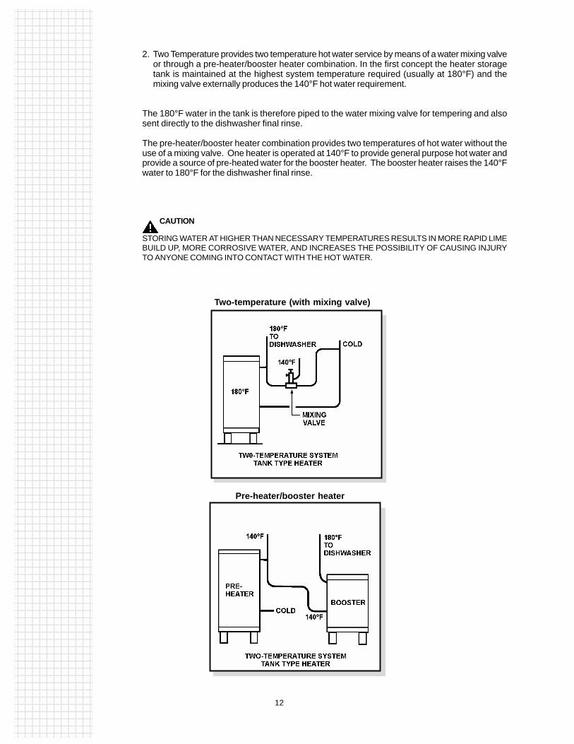
2. Two Temperature provides two temperature hot water service by means of a water mixing valveor through a pre-heater/booster heater combination. In the first concept the heater storagetank is maintained at the highest system temperature required (usually at 180°F) and themixing valve externally produces the 140°F hot water requirement.
The 180°F water in the tank is therefore piped to the water mixing valve for tempering and alsosent directly to the dishwasher final rinse.
The pre-heater/booster heater combination provides two temperatures of hot water without theuse of a mixing valve. One heater is operated at 140°F to provide general purpose hot water andprovide a source of pre-heated water for the booster heater. The booster heater raises the 140°Fwater to 180°F for the dishwasher final rinse.
CAUTION
STORING WATER AT HIGHER THAN NECESSARY TEMPERATURES RESULTS IN MORE RAPID LIMEBUILD UP, MORE CORROSIVE WATER, AND INCREASES THE POSSIBILITY OF CAUSING INJURYTO ANYONE COMING INTO CONTACT WITH THE HOT WATER.
Pre-heater/booster heater
Two-temperature (with mixing valve)

123456789011234567890112345678901123456789011234567890112345678901123456789011234567890112345678901123456789011234567890112345678901123456789011234567890112345678901123456789011234567890112345678901123456789011234567890112345678901123456789011234567890112345678901123456789011234567890112345678901123456789011234567890112345678901123456789011234567890112345678901123456789011234567890112345678901123456789011234567890112345678901123456789011234567890112345678901123456789011234567890112345678901123456789011234567890112345678901123456789011234567890112345678901123456789011234567890112345678901123456789011234567890112345678901123456789011234567890112345678901123456789011234567890112345678901123456789011234567890112345678901123456789011234567890112345678901123456789011234567890112345678901123456789011234567890112345678901123456789011234567890112345678901123456789011234567890112345678901123456789011234567890112345678901123456789011234567890112345678901123456789011234567890112345678901123456789011234567890112345678901123456789011234567890112345678901123456789011234567890112345678901123456789011234567890112345678901
13
Creating the Successful System
Creating the successful commercial water heating system is a joint venture involving many personsand skills.
In order to select the right system using either tank type or copper type heaters, one shouldunderstand the role that each of the persons concerned with the installation plays.
The following chart summarizes the responsibilities for each of the roles.
Remember, your customer’s success or profit may depend upon the continued availability of hotwater . . . and you will achieve that goal through proper system selection and sizing.
IDENTITY RESPONSIBILITY
Customer Must define his needs
System designer* Designs a water heating system to satisfythe customer’s needs. Acts as an interfacebetween all involved parties.
Water Heater Supplier Furnishes the equipment to meet the system and/or specifications. May aid the designer in Manufacturer equipment selection or specifications with
his knowledge of product performanceand availability.
Plumbing and Electrical Must understand system concept to provide Installation Contractors installation, startup and customer instruction.
Also provide maintenance and service forcontinued satisfaction.
Energy Supplier Advises characteristics of energy availableat job site and how to achieve best use.Particularly important when electricity isthe fuel.
Water Supplier Advises characteristics of water, lowesttemperature, maximum pressure andhardness. May influence heater selection anduse of a pressure reducing valve.
*The system designer may be the architect, engineer, installing contractor or water heater supplier.
Sizing Without Prepared Information
The following procedures will establish heater recovery and storage tank capacities for intermittentuse systems.
Continuous use systems are sized so that heater recovery equals or exceeds demand. Thereforethe size of the tank (when proposing a tank type heater system) is unimportant.
The procedures for one and two temperature systems are essentially the same:
1. Establish the hourly 1 / hot water demand in gallons and the maximum temperature rise.
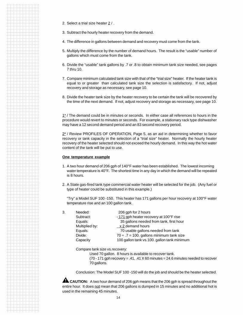
123456789011234567890112345678901123456789011234567890112345678901123456789011234567890112345678901123456789011234567890112345678901123456789011234567890112345678901123456789011234567890112345678901123456789011234567890112345678901123456789011234567890112345678901123456789011234567890112345678901123456789011234567890112345678901123456789011234567890112345678901123456789011234567890112345678901123456789011234567890112345678901123456789011234567890112345678901123456789011234567890112345678901123456789011234567890112345678901123456789011234567890112345678901123456789011234567890112345678901123456789011234567890112345678901123456789011234567890112345678901123456789011234567890112345678901123456789011234567890112345678901123456789011234567890112345678901123456789011234567890112345678901123456789011234567890112345678901123456789011234567890112345678901123456789011234567890112345678901123456789011234567890112345678901123456789011234567890112345678901123456789011234567890112345678901123456789011234567890112345678901123456789011234567890112345678901123456789011234567890112345678901123456789011234567890112345678901
14
2. Select a trial size heater 2 / .
3. Subtract the hourly heater recovery from the demand.
4. The difference in gallons between demand and recovery must come from the tank.
5. Multiply the difference by the number of demand hours. The result is the “usable” number ofgallons which must come from the tank.
6. Divide the “usable” tank gallons by .7 or .8 to obtain minimum tank size needed, see pages7 thru 10.
7. Compare minimum calculated tank size with that of the “trial size” heater. If the heater tank isequal to or greater than calculated tank size the selection is satisfactory. If not, adjustrecovery and storage as necessary, see page 10.
8. Divide the heater tank size by the heater recovery to be certain the tank will be recovered bythe time of the next demand. If not, adjust recovery and storage as necessary, see page 10.
1* / The demand could be in minutes or seconds. In either case all references to hours in theprocedure would revert to minutes or seconds. For example, a stationary rack type dishwashermay have a 12 second demand period and an 83 second recovery period.
2* / Review PROFILES OF OPERATION, Page 5, as an aid in determining whether to favorrecovery or tank capacity in the selection of a “trial size” heater. Normally the hourly heaterrecovery of the heater selected should not exceed the hourly demand. In this way the hot watercontent of the tank will be put to use.
One temperature example
1. A two hour demand of 206 gph of 140°F water has been established. The lowest incomingwater temperature is 40°F. The shortest time in any day in which the demand will be repeatedis 8 hours.
2. A State gas-fired tank type commercial water heater will be selected for the job. (Any fuel ortype of heater could be substituted in this example.)
“Try” a Model SUF 100 -150. This heater has 171 gallons per hour recovery at 100°F watertemperature rise and an 100 gallon tank.
3. Needed: 206 gph for 2 hoursSubtract: - 171 gph heater recovery at 100°F riseEquals: 35 gallons needed from tank, first hourMultiplied by: x 2 demand hoursEquals: 70 usable gallons needed from tankDivide: 70 ÷ .7 = 100. gallons minimum tank sizeCapacity 100 gallon tank vs.100. gallon tank minimum
Compare tank size vs.recovery:Used 70 gallon. 8 hours is available to recover tank.(70 - 171 gph recovery = .41, .41 X 60 minutes = 24.6 minutes needed to recover70 gallons.
Conclusion: The Model SUF 100 -150 will do the job and should be the heater selected.
CAUTION: A two hour demand of 206 gph means that the 206 gph is spread throughout theentire hour. It does not mean that 206 gallons is dumped in 15 minutes and no additional hot isused in the remaining 45 minutes.

123456789011234567890112345678901123456789011234567890112345678901123456789011234567890112345678901123456789011234567890112345678901123456789011234567890112345678901123456789011234567890112345678901123456789011234567890112345678901123456789011234567890112345678901123456789011234567890112345678901123456789011234567890112345678901123456789011234567890112345678901123456789011234567890112345678901123456789011234567890112345678901123456789011234567890112345678901123456789011234567890112345678901123456789011234567890112345678901123456789011234567890112345678901123456789011234567890112345678901123456789011234567890112345678901123456789011234567890112345678901123456789011234567890112345678901123456789011234567890112345678901123456789011234567890112345678901123456789011234567890112345678901123456789011234567890112345678901123456789011234567890112345678901123456789011234567890112345678901123456789011234567890112345678901123456789011234567890112345678901123456789011234567890112345678901123456789011234567890112345678901123456789011234567890112345678901123456789011234567890112345678901123456789011234567890112345678901
15
Two temperature example
1. A one hour demand of 75 gallons of 180°F water and 110 gallons of 140°F water has beenestablished. The lowest incoming water temperature is 40°F. The shortest time in any day in whichthe demand will be repeated is 3 hours.
2. Convert the 180° water requirement into the equivalent of a 140°F water requirement to avoid w o r k i n gwith two different temperature rises.
Converting to a single temperature rise:
• Multiply the 180°F requirement by 1.4 in 100°F temperature rise applications.
a) This means 1.4 more water can be raised from 40°F to 140°F than 40°F to 180°F with the same amount of energy.
b) Multiplier formula:
Hot - Cold——————— = multiplierMixed - Cold
Example:
180 - 40 140————— = ——— = 1.4140 - 40 100
c) 75 gallons 180°F water requiredx 1.4 105 equivalent gallons of 140°F water
• Add the converted 180°F water requirement to the 140°F requirement and proceed with heaterselection.
a) 105 + 110 gallons of 140°F water = 215 equivalent gallons of hot water requiredat 100°F water temperature rise.
3. A State electric tank type commercial water heater will be selected for the job. (Any fuel or type ofheater could be substituted in this example.
Review SYSTEM TYPES AND APPLICATION beginning on page 11.
“Try” a CSB -120 with 24 kw input. This heater has 98 gallons per hour recovery at 100°F watertemperature rise and a 119 gallon tank. The heater will be operated at 180°F and equipped with a watermixing valve set at 140°F.
4. Needed: 215 gallons for one hourSubtract: -98 gph heater recovery at 100°F riseEquals 117 usable gallons needed from tank
Comparetank 119 gallon tank vs. 117 gallon tank minimumcapacity:
NOTE: The 119 gallon tank capacity at 70% tank efficiency is equal to 83 gallons of usable hotw a t e r .However, it is 83 gallons of 180°F water and therefore has the heat content equivalent of 83 x 1.4 = 116 gallons of 140°F water. Therefore the tank size is adequate (only 1 gallon short).
Compare tank size 1.21 hours vs 3 hours available.vs recovery: (119 ÷ 98 = 1.21 hour)
Conclusion: The model CSB -120 with 24 kw input will do the job and should be the heater selected.
Field Assistance
Please contact your local State distributor, sales representative or the technical information center (See:www.statewaterheaters.com for phone and fax numbers) if you need help designing a water heating system or selectingthe proper equipment for the job.

INTRODUCTION
A. O. Smith residential water heaters are produced in alarge variety of tank sizes and heat inputs to permit theselection of the one best suited to do the job. Ideally thisheater would have a combination of storage and heat in-put equal to the usage.
In addition to the design factors and the sizingexamples which follow, a glossary section provides de-tailed explanations of selected terminology. This is doneto avoid expanding the content of thesizing procedure.
RESIDENTIAL SIZING
3. Storage tank size selection:
NOTE: The draw efficiency of a gas or electric waterstorage tank is considered to be 70%.
• 30 gallon size (21 gallon draw) for one bath resi-dence.
• 40 gallon size (28 gallon draw) for two bath resi-dence -or- one bath with an automatic clotheswasher.
• 50 gallon size (35 gallon draw) for three bath resi-dence -or- two baths with an automatic clotheswasher.
• When a whirlpool tub is part of the home equip-ment, it is suggested that the heater storage tankcapacity, or the sum total of an additional auxiliarystorage tank and heater, be sized in accordancewith the following table. This method of tank sizing,will in most cases, cancel all previous statementsas noted above concerning tank sizing.
4. Heat input VS recovery capacity.
Gas water heater recovery table (calculated at 75%recovery efficiency).
GALLONS
STORAGE HEAT INPUT+ =WATERAVAILABLETO MEETUSAGE
DESIGN FACTORS
These design factors are the result of combining A.O.Smith engineering test data and practicalexperience to form a usable guide for the selection ofminimum water heater tank sizes and heatinputs. As stated previously, the factors may beadjusted to suit individual needs.
1. Two hour peak usage period.
Residential peak usage, based on accepted prac-tice, is the two hour period during the day when theheaviest draw of hot water will occur.
For example, from 7:00 to 9:00 A.M.
2. Gallons of 140°F hot water required:
• 20 gallons per person for the first twopersons.
• 5 gallons per person for each person over the firsttwo.
• 10 gallons for each full bath over the first bath.
• 10 gallons for an automatic dishwasher.
• 20 gallons for an automatic clothes washer.
Tub Capacity To Overflow 80 90 100 110 120 130 140 150 Outlet
(@ 140°F Water) Min. Stored Water Capacity 65 71 80 89 98 108 117 125
(@ 160°F Water*) Min. Stored Water Capacity 54 59 66 74 82 90 97 104
* A mixing valve is recommended to be installed in heater or auxiliary tank hot water outlet piping.
Based on a tub water temperature of 105°F.
Revised April 1997 (Reviewed May 1999) B 201.0June 2007RJune 2010R AOSSG88150
®
211543 AOSSG88150 1 5/22/09 2:09:28 PM

Notes on element operation:
(a) Two element water heaters, simultaneous elementoperation; figure the upper element recovery at 1/3*the GPH shown for wattage, figure lower element atthe GPH shown.
* The bottom element contributes to the heat at the topof the tank. This tends to shut off the top element.Metered tests indicate the upper element operatesabout 1/3 of the time.
(b) Two element water heaters, non-simultaneous (in-terlocking) element operation; figure the largestwattage element recovery only – at the GPH shown.
(c) Single element water heaters; figure the recovery atthe GPH shown.
5. Storage VS input.
Water heater selection is best made on the basis ofhot water usage. However, calculations may lead to acombination of tank size and heat input which doesn'texist. In this case, the tank size and/or heat inputmust be balanced to achieve the desired result.
Therefore, it is necessary to understand that heatinput provides hot water, at the hourly recovery rate,hour after hour. The storage tank represents instanthot water at greater-than-heater recovery.
The supply of hot water in the storage tank cannot bereplenished until the peak usage period has endedand heater recovery is available for this purpose.
Having enough storage tank capacity isimportant when large quantities of hot water are re-quired in a short period of time. If the peak usageperiod is for an extended period of time (more thantwo hours), the heater recovery capacity assumesmajor importance.
DESIGN EXAMPLES
GIVEN: Family of four personsTwo full bathsAutomatic dishwasherAutomatic clothes washer
HOT WATER REQUIRED:
B 202.0
Electric Water Heater Recovery Table(Calculated at 100% Recovery Efficiency)
Heating GPH Recovery At Indicated
Element Temperature Rise
Wattage 60° 70° 80° 90° 100° 750 5.1 4.4 3.8 3.4 3.11000 6.8 5.8 5.1 4.6 4.11250 8.5 7.3 6.4 5.7 5.11500 10.2 8.8 7.7 6.8 6.12000 13.7 11.7 10.2 9.1 8.22250 15.4 13.2 11.5 10.2 9.22500 17.1 14.6 12.8 11.4 10.23000 20.5 17.5 15.4 13.6 12.33500 23.9 20.5 17.9 15.9 14.34000 27.3 23.4 20.5 18.2 16.44500 30.7 26.3 23.0 20.5 18.45000 34.1 29.2 25.6 22.7 20.55500 37.6 32.2 28.2 25.0 22.56000 41.0 35.1 30.7 27.3 24.6
Gas Water Heater Recovery Table(Calculated at 75% Recovery Efficiency)
Input GPH Recovery At Indicated
Rating Temperature Rise
Btuh 60° 70° 80° 90° 100° 30,000 45.5 39.0 34.1 30.3 27.3 33,000 50.0 42.9 37.5 33.3 30.0 35,000 53.0 45.5 39.8 35.4 31.8 40,000 60.6 51.9 45.5 40.4 36.4 43,000 65.2 55.8 48.9 43.4 39.1 50,000 75.8 64.9 56.8 50.5 45.5 60,000 90.9 77.9 68.2 60.6 54.5 70,000 106.1 90.9 79.5 70.7 63.6 80,000 121.2 103.9 90.9 80.8 72.7 90,000 136.4 116.9 102.3 90.9 81.8100,000 151.51 129.9 113.6 101.0 90.9
*This means 45 gallons of hot water per hour, for two hours, must be provided by theA. O. Smith water heater through storage and heat input.
Two persons @ 20 gallons/perso ................ 40 gallonsTwo persons @ 5 gallons/person ................10 gallonsSecond full bath ...........................................10 gallonsAutomatic dishwasher ..................................10 gallonsAutomatic clothes washer ............................20 gallonsTotal two hour peak hot water usage ...........90 gallons
177829 AO Smith B2010.indd 2 6/4/07 10:16:14 AM
AOSSG88150
211543 AOSSG88150 2211543 AOSSG88150 2 5/22/09 2:09:29 PM5/22/09 2:09:29 PM
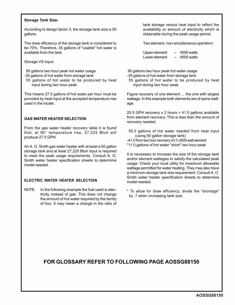
Storage Tank Size:
According to design factor 3, the storage tank size is 50gallons.
The draw efficiency of the storage tank is considered tobe 70%. Therefore, 35 gallons of "usable" hot water isavailable from the tank.
Storage VS Input:
90 gallons two hour peak hot water usage-35 gallons of hot water from storage tank 55 gallons of hot water to be produced by heat input during two hour peak.
This means 27.5 gallons of hot water per hour must beprovided by heat input at the accepted temperature riseused in the locale.
GAS WATER HEATER SELECTION
From the gas water heater recovery table it is foundthat, at 90° temperature rise, 27,225 Btuh willproduce 27.5 GPH.
An A. O. Smith gas water heater with at least a 50 gallonstorage tank and at least 27,225 Btuh input is requiredto meet the peak usage requirements. Consult A. O.Smith water heater specification sheets to determinemodel needed.
ELECTRIC WATER HEATER SELECTION
NOTE: In the following example the fuel used is elec-tricity instead of gas. This does not changethe amount of hot water required by the familyof four. It may mean a change in the ratio of
tank storage versus heat input to reflect theavailability or amount of electricity which isobtainable during the peak usage period.
Two element, non-simultaneous operation:
Upper element – 4500 wattsLower element – 4500 watts
90 gallons two hour peak hot water usage-35 gallons of hot water from storage tank 55 gallons of hot water to be produced by heat input during two hour peak.
Figure recovery of one element ... the one with largestwattage. In this example both elements are of same watt-age.
20.5 GPH recovery x 2 hours = 41.0 gallons availablefrom element recovery. This is less than the amount ofrecovery needed.
55.0 gallons of hot water needed from heat input (using 50 gallon storage tank)-41.0 from two hour recovery of (1) 4500 watt element*11.0 gallons of hot water "short" two hour peak
It is necessary to increase the size of the storage tankand/or element wattages to satisfy the calculated peakusage. Check your local utility for maximum allowablewattage permitted for water heating. They may also havea minimum storage tank size requirement. Consult A. O.Smith water heater specification sheets to determinemodel needed.
* To allow for draw efficiency, divide the "shortage" by .7 when increasing tank size.
FOR GLOSSARY REFER TO FOLLOWING PAGE AOSSG88150
B 203.0
177829 AO Smith B2010.indd 3 6/4/07 10:16:15 AM
AOSSG88150
FOR GLOSSARY REFER TO FOLLOWING PAGE AOSSG88150
177829 AO Smith B2010.indd 3 6/4/07 10:16:15 AM211543 AOSSG88150 3211543 AOSSG88150 3 5/22/09 2:09:29 PM5/22/09 2:09:29 PM

GLOSSARY
The following provides detailed explanations of selectedterminology used in the sizing procedure. This is to pro-mote a greater understanding of water heating terms, for-mula and theory.
• BTU...abbreviation for the British thermal unit, which isthe amount of heat required to raise the temperature ofone pound of water one degree Fahrenheit.
Stated another way, 8.25 Btu will raise the temperature ofone gallon of water one degree.
A Btu may be sensed and visualized as about the amountof heat produced by burning one wooden match. Onewatt-hour of electricity produces 3.413 Btu.
This is the formula for determining the Btu required toheat a given quantity of water a certain number of de-grees:
Gallons x 8.25 x 1.0 x temp. rise = Btu
Where..gallons =Total gallons of hot water required8.25 = Weight of one gallon of water1.0 = Specific heat of water (See Specific
heat)Temp. Rise = Difference in degrees between lowest
incoming water temperature and desiredhot water temperature.
Btu = Gas water heaters; divide answer by.75 (recovery efficiency) to obtainequivalent gas input in Btu.Electric water heaters; multiply by0.293 to obtain element wattage equiva-lent.In actual practice a combination of stor-age and input is used to assure theavailability of hot water.
• Draw efficiency is considered to be 70% in this report.When using storage type heaters it is common practiceto assume 70% of the storage capacity of the heatertank may be drawn before dilution by incoming cold wa-ter lowers the hot water temperature below an accept-able level under normal draw conditions. For example, a40 gallon storage tank would deliver about 28 gallons ofusable hot water.
• Input rating...The amount of fuel in British thermal units(Btu) consumed by a gas or oil water heater in an hour.In an electric water heater input is usually expressed inwatts or kilowatts. Consuming one watt-hour of electric-ity produces 3.413 Btu.
• Interlocking...(See Non-Simultaneous)
• Non-Simultaneous (Interlocking) element operation iswhere both of the heating elements in an electric waterheater are not permitted to operate at the same time.The electrical circuit is interlocked through the upperthermostat to prevent simultaneous operation.
• Recovery (capacity), the amount of water in gallonsper hour, raised at a given recovery efficiency and Btuhinput. Refer to Recovery Table.
This is the formula for determining recovery capacity:
Input x efficiency = Recovery in GPH (See Btu)8.25 x temp. rise
Efficiency = .75 for gas-fired water heaters1.0 for electric water heaters(also see Recovery efficiency)
• Recovery efficiency...The ratio of the heat in the waterdelivered at the heater outlet to the heat input of theheating unit. Also see Btu.
Gas-fired residential water heaters are generally con-sidered to have a 75% recovery efficiency. This means75% of the total heat produced by the burner isabsorbed into the water in the tank. The remaining 25%of the heat is used to move the products ofcombustion through the flue to the outdoors.
Electric residential water heaters are generallyconsidered to have a 100% recovery efficiency. This isbecause immersion style elements place all the heat intothe water and there is no flue.
• Simultaneous element operation is where both of theheating elements in an electric water heater are permit-ted to operate at the same time if necessary. The actualoperation of each element is individually controlled byits own thermostat.
• Specific heat, the amount of heat required to raise thetemperature of a given weight of a substance one de-gree as compared with the amount of heat required toraise the temperature of the same weight of water 1° atsome specified temperature.
• Storage tank, used for storing hot water in advance ofneeds. Properly sized, the tank permits large volumes ofhot water to be drawn from the system at flow rates ex-ceeding the recovery capacity of the heater. Also seeDraw efficiency.
• Temperature rise, the amount of temperature differ-ence (between incoming and outgoing water) in degreesFahrenheit.
• Draw efficiency, the amount of water that can be drawnfrom a storage tank, at a 3 gpm flow rate, before thetemperature drops 30°F. Heater outlet water tempera-tures below 110°F is generally not considered as satis-factory or usable.
B 204.0 © A. O. Smith Corp., 1997 Printed in U.S.A.
177829 AO Smith B2010.indd 4 6/4/07 10:16:15 AM
AOSSG88150 © A. O. Smith Corp., 2009
®
A.O. SMITH500 Tennessee Waltz ParkwayAshland City, Tn 37015www.hotwater.com1.800.527.1953
211543 AOSSG88150 4211543 AOSSG88150 4 5/22/09 2:09:30 PM5/22/09 2:09:30 PM
AOSSG88260 PG 1 of 2
May 2009R
MISCELLANEOUS WATER USAGE DATA
The above table is based on 40° incoming water temperature and a temperature rise of 100° (temperature usage 140°) --- when the delivered water temperature is other than 140°, multiply the volume of water required by the temperature usage factor shown above.
W ash sink water consumption rate
Bradley Wash Sinks GPM @ 105°F GPM @ 140°F 54" circular sink 5 3.25 36" circular sink 2 1.3 54" semi-circular sink 3 1.95 36" semi-circular sink 1-1/4 to 3.0 .81 to 1.95
15.1ouDCounter type 1.5 1 Bradley shower heads 2.5 to 3.0 1.6 to 1.95
General purpose hot water consumption guide for various kitchen usages
Application Consumption (GPH) V 54knis elbatege
03knis top elgniSDouble pot sink 60 T 09knis top elpirPre-scrapper (open type) 180 Pre-flush (hand operated) 45 Pre-flush (closed type) 240 Recirculating pre-flush 40
03knis raBLavatories (each) 5
02knis pols/poM
T emperature factors - hot water
If Temperature Multiply Hot Water Required Is Load By
03.0°07 04.0°08 05.0°09 06.0°001 07.0°011 08.0°021 09.0°031 00.1°041 01.1°051 02.1°061 03.1°071 04.1°081
T emperature factors - cold water
When Incoming Multiply Hot Water Cold Water Is Load By
09.0°05 08.0°06 07.0°07
Rinse water (180°F) requirements for typical dishwasher flow pressure at dishwashers assumed to be 20 psi
HPG/noitpmusnoCMPG/etaR wolFeziS dnA epyT / rehsawhsiD 9649.6kcar sehcni 61 x 61 7876.8kcar sehcni 81 x 81epyt rood 4014.01kcar sehcni 02 x 02 075epyt retnuocrednu 61449.6knat elgnis 74387.5talf sehsidknat elpitlumepyt royevnoc
dishes inclined 4.62 277 silver washers 7 45 utensil washers 8 75
93113.2sepyt royevnoc niatrec no F°081/stnemeriuqer retaw pu-ekam
NSF standard no. 5 - 100% mechanical capacity
April 2010RJune 2010R
226356_AOSSG88260.indd 1226356_AOSSG88260.indd 1 6/24/10 4:31 PM6/24/10 4:31 PM
http://waterheatertimer.org/How-to-install-gas-water-heater.html
http://waterheatertimer.org/How-to-install-electric-water-heater.html

© A. O. Smith Corp. Printed in U.S.A.
Formula For Mixing Hot and Cold Water
M–C % of hot water required to produce H–C desired mixed temperature
Where M = Mixed water temperature C = Cold water temperature H = Hot water temperature
MISCELLANEOUS WATER USAGE DATA
=
Proper Flow and Pressure Required During Flow For Different Fixtures
Flow Flow Fixture Pressure* GPM
Ordinary basin faucet ....................... 8 3.0 Self-closing basin faucet ................. 12 2.5 Sink faucet - 3/8 inch ....................... 10 4.5 Sink faucet - 1/2 inch ....................... 5 4.5
Bathtub Faucet ................................ 5 6.0 Laundry tub cock - 1/4 inch ............. 5 5.0 Shower water saver ......................... 12 2.5 Ball-cock for closet .......................... 15 3.0
Flush valve for closet ....................... 10-20 15-40 Flush valve for urinal ........................ 15 15.0 Garden hose, 50 ft., and still cock ... 30 5.0
* Flow pressure is the pressure psig in the pipe at the entrance to the particular fixture considered. Wide range due to variation in design and type of flush-valve closets.
W ater Capacities Of Copper Tubes
T ube Size 1/4" 3/8" 1/2" 7/8" 1" 1 1/4"
Gallon/Ft.
T ype K .004 .006 .011 .023 .040 .063 T ype L .004 .006 .012 .025 .044 .065
T ube Size 1 1/2" 2" 2 1/2" 3" 4" 5"
Gallon/Ft.
T ype K .089 .157 .242 .345 .607 .940
T ype L .092 .161 .247 .354 .623 .971
W ater Capacities Per Foot Of Pipe
Pipe Size 1/2" 3/4" 1" 1 1/4" 1 1/2" 2"
Gallons Per Foot .016 .023 .040 .063 .102 .17
Pipe Size 2 1/2" 3" 3 1/2" 4" 5" 6"
Gallons Per Foot .275 .39 .53 .69 1.1 1.5
AOSSG88260 PG 2 of 2
220613AOSSG88260 2 1/21/10 9:54 AM
A. O. Smith Corp., 2010
226356_AOSSG88260.indd 2226356_AOSSG88260.indd 2 6/24/10 4:31 PM6/24/10 4:31 PM

http://waterheatertimer.org/Figure-Volts-Amps-Watts-for-water-heater.html
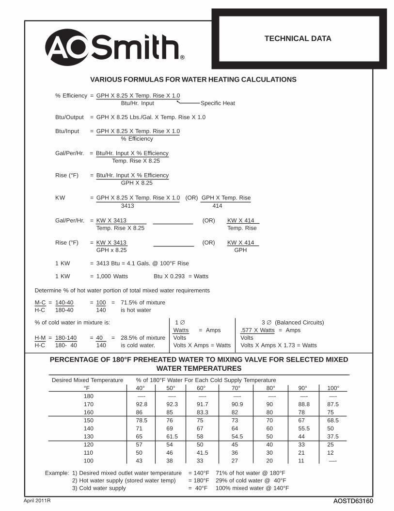
VARIOUS FORMULAS FOR WATER HEATING CALCULATIONS
% Efficiency = GPH X 8.25 X Temp. Rise X 1.0Btu/Hr. Input Specific Heat
Btu/Output = GPH X 8.25 Lbs./Gal. X Temp. Rise X 1.0
Btu/Input = GPH X 8.25 X Temp. Rise X 1.0% Efficiency
Gal/Per/Hr. = Btu/Hr. Input X % Efficiency Temp. Rise X 8.25
Rise (°F) = Btu/Hr. Input X % EfficiencyGPH X 8.25
KW = GPH X 8.25 X Temp. Rise X 1.0 (OR) GPH X Temp. Rise414 3143
414 X WK)RO( 3143 X WK=.rH/reP/laGesiR .pmeT52.8 X esiR .pmeT
414 X WK)RO( 3143 X WK=)F°( esiRHPG 52.8 x HPG
1 KW = 3413 Btu = 4.1 Gals. @ 100°F Rise
1 KW = 1,000 Watts Btu X 0.293 = Watts
Determine % of hot water portion of total mixed water requirements
M-C = 140-40 = 100 = 71.5% of mixtureH-C 180-40 140 is hot water
1 :si erutxim ni retaw dloc fo % ∅ 3 ∅ (Balanced Circuits)Watts = Amps .577 X Watts = Amps
H-M = 180-140 = 40 = 28.5% of mixture Volts VoltsH-C 180- 40 140 is cold water. Volts X Amps = Watts Volts X Amps X 1.73 = Watts
PERCENTAGE OF 180°F PREHEATED WATER TO MIXING VALVE FOR SELECTED MIXEDWATER TEMPERATURES
Desired Mixed Temperature % of 180°F Water For Each Cold Supply Temperature°F 40° 50° 60° 70° 80° 90° 100°180 —- —- —- —- —- —- —-170 92.8 92.3 91.7 90.9 90 88.8 87.5160 86 85 83.3 82 80 78 75150 78.5 76 75 73 70 67 68.5140 71 69 67 64 60 55.5 50130 65 61.5 58 54.5 50 44 37.5120 57 54 50 45 40 33 25110 50 46 41.5 36 30 21 12100 43 38 33 27 20 11 —-
Example: 1) Desired mixed outlet water temperature = 140°F 71% of hot water @ 180°F2) Hot water supply (stored water temp) = 180°F 29% of cold water @ 40°F
F°041 @ retaw dexim %001F°04 = ylppus retaw dloC )3
C 031.0
TECHNICAL DATA
Revised October 1986 (Reviewed October 1997)April 2011R AOSTD63160
®
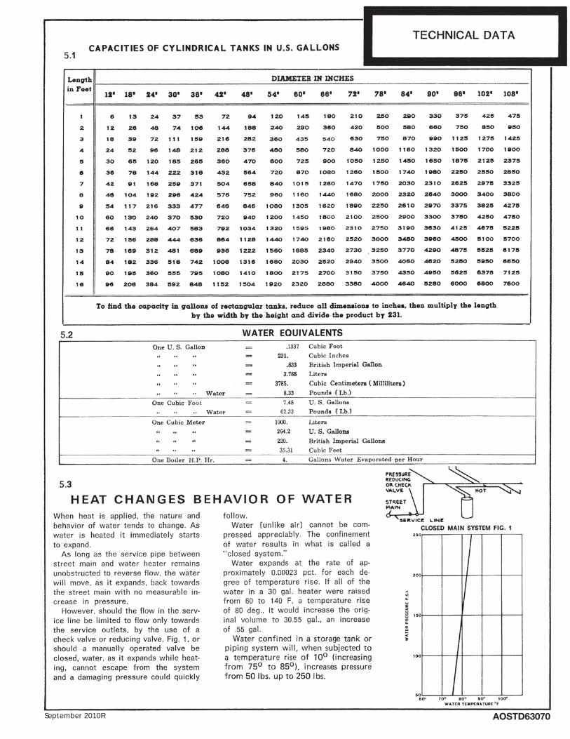
April 2010R AOSTD63070September 2010R
229044_AOSTD63070.indd 1229044_AOSTD63070.indd 1 9/17/10 4:51 PM9/17/10 4:51 PM
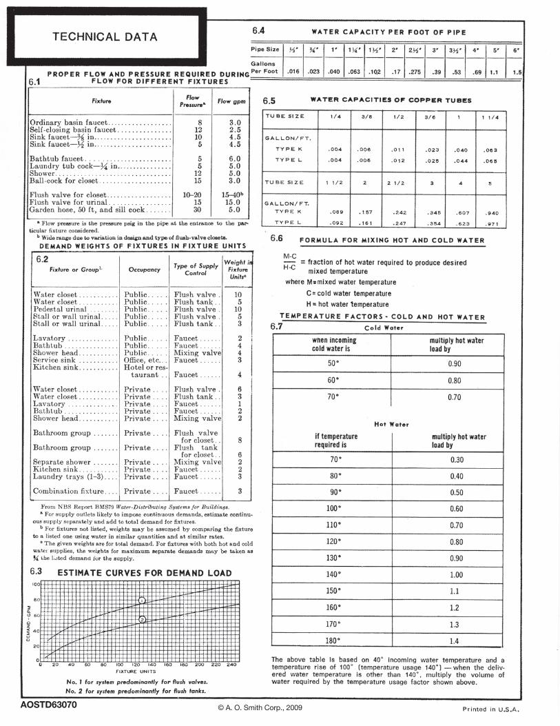
AOSTD63070 © A. O. Smith Corp., 2009
218205 AOSTD63070 2 11/10/09 11:10 AM229044_AOSTD63070.indd 2229044_AOSTD63070.indd 2 9/17/10 4:51 PM9/17/10 4:51 PM

Fundamentalsof WaterHeating
MANUALTraining
®
Fundamentals of Water Heating Training Manual
Table of Contents
INTRODUCTION . . . . . . . . . . . . . . . . . . . . . . . . . . . . . . . . . . . . . . . . . . . . . . . . . . . . . . . . . . . . . . . . . . . . . . .3WATER HEATER SAFETY . . . . . . . . . . . . . . . . . . . . . . . . . . . . . . . . . . . . . . . . . . . . . . . . . . . . . . . . . . . . . . . .3WATER CHEMISTRY . . . . . . . . . . . . . . . . . . . . . . . . . . . . . . . . . . . . . . . . . . . . . . . . . . . . . . . . . . . . . . . . . . .5ANODE RODS AND CATHODIC PROTECTION . . . . . . . . . . . . . . . . . . . . . . . . . . . . . . . . . . . . . . . . . . . . . . . . .9MILKY WATER AND DISSOLVED GASSES . . . . . . . . . . . . . . . . . . . . . . . . . . . . . . . . . . . . . . . . . . . . . . . . . . .11SMELLY WATER AND THE ROTTEN EGG ODOR . . . . . . . . . . . . . . . . . . . . . . . . . . . . . . . . . . . . . . . . . . . . . . 12CHLORINATION OF WATER HEATER TANKS . . . . . . . . . . . . . . . . . . . . . . . . . . . . . . . . . . . . . . . . . . . . . . . . . 13DIAGNOSING YOUR WATER PROBLEM . . . . . . . . . . . . . . . . . . . . . . . . . . . . . . . . . . . . . . . . . . . . . . . . . . . . . . 14OPEN AND CLOSED WATER HEATER SYSTEMS . . . . . . . . . . . . . . . . . . . . . . . . . . . . . . . . . . . . . . . . . . . . . . 15THERMAL EXPANSION . . . . . . . . . . . . . . . . . . . . . . . . . . . . . . . . . . . . . . . . . . . . . . . . . . . . . . . . . . . . . . . . . 16TEMPERATURE AND PRESSURE RELIEF (T&P) VALVES . . . . . . . . . . . . . . . . . . . . . . . . . . . . . . . . . . . . . . . . 18PLUMBING CROSS OVER . . . . . . . . . . . . . . . . . . . . . . . . . . . . . . . . . . . . . . . . . . . . . . . . . . . . . . . . . . . . . . . 20HOT WATER AVAILABILITY AND CONSUMPTION FACTORS . . . . . . . . . . . . . . . . . . . . . . . . . . . . . . . . . . . . . . 21DRAW TEST AND FLOW RATES . . . . . . . . . . . . . . . . . . . . . . . . . . . . . . . . . . . . . . . . . . . . . . . . . . . . . . . . . . 23FIRST HOUR DELIVERY . . . . . . . . . . . . . . . . . . . . . . . . . . . . . . . . . . . . . . . . . . . . . . . . . . . . . . . . . . . . . . . 24SIZING OF A RESIDENTIAL WATER HEATER . . . . . . . . . . . . . . . . . . . . . . . . . . . . . . . . . . . . . . . . . . . . . . . . 26ENERGY FACTOR . . . . . . . . . . . . . . . . . . . . . . . . . . . . . . . . . . . . . . . . . . . . . . . . . . . . . . . . . . . . . . . . . . . . 28VACATIONS AND LONG TERM IDLE TIME . . . . . . . . . . . . . . . . . . . . . . . . . . . . . . . . . . . . . . . . . . . . . . . . . . 28SUBMERGED WATER HEATERS . . . . . . . . . . . . . . . . . . . . . . . . . . . . . . . . . . . . . . . . . . . . . . . . . . . . . . . . . . 29INSTALLATION - SERIES AND PARALLEL . . . . . . . . . . . . . . . . . . . . . . . . . . . . . . . . . . . . . . . . . . . . . . . . . . . 29SERIES INSTALLATION . . . . . . . . . . . . . . . . . . . . . . . . . . . . . . . . . . . . . . . . . . . . . . . . . . . . . . . . . . . . . . . . . 30PARALLEL INSTALLATION . . . . . . . . . . . . . . . . . . . . . . . . . . . . . . . . . . . . . . . . . . . . . . . . . . . . . . . . . . . . . . 31PERCENTAGE OF HOT AND COLD WATER MIX . . . . . . . . . . . . . . . . . . . . . . . . . . . . . . . . . . . . . . . . . . . . . . 32FORMULAS AND FACTS . . . . . . . . . . . . . . . . . . . . . . . . . . . . . . . . . . . . . . . . . . . . . . . . . . . . . . . . . . . . . . . . 34GLOSSARY . . . . . . . . . . . . . . . . . . . . . . . . . . . . . . . . . . . . . . . . . . . . . . . . . . . . . . . . . . . . . . . . . . . . . . . . . 37
Index of Figures
FIG 1 - SCALDING WARNING . . . . . . . . . . . . . . . . . . . . . . . . . . . . . . . . . . . . . . . . . . . . . . . . . . . . . . . . . . . . .3FIG 2 - FLAMMABLE VAPORS WARNING . . . . . . . . . . . . . . . . . . . . . . . . . . . . . . . . . . . . . . . . . . . . . . . . . . . .4FIG 3 - WATER HARDNESS . . . . . . . . . . . . . . . . . . . . . . . . . . . . . . . . . . . . . . . . . . . . . . . . . . . . . . . . . . . . . .6FIG 4 - SEDIMENT BUILD-UP . . . . . . . . . . . . . . . . . . . . . . . . . . . . . . . . . . . . . . . . . . . . . . . . . . . . . . . . . . . . .7FIG 5 - NEW ANODE ROD . . . . . . . . . . . . . . . . . . . . . . . . . . . . . . . . . . . . . . . . . . . . . . . . . . . . . . . . . . . . . . .9FIG 6 - PARTIALLY SACRIFICED ANODE ROD . . . . . . . . . . . . . . . . . . . . . . . . . . . . . . . . . . . . . . . . . . . . . . . 10FIG 7 - FULLY SACRIFICED ANODE ROD . . . . . . . . . . . . . . . . . . . . . . . . . . . . . . . . . . . . . . . . . . . . . . . . . .11FIG 8 - TANK WITH BULGED BOTTOM . . . . . . . . . . . . . . . . . . . . . . . . . . . . . . . . . . . . . . . . . . . . . . . . . . . . 16FIG 9 - THERMAL EXPANSION TANKS . . . . . . . . . . . . . . . . . . . . . . . . . . . . . . . . . . . . . . . . . . . . . . . . . . . . . 17FIG 10 - TEMPERATURE & PRESSURE RELIEF VALVE . . . . . . . . . . . . . . . . . . . . . . . . . . . . . . . . . . . . . . . . . 18FIG 11 - T&P VALVE CUTAWAY VIEW . . . . . . . . . . . . . . . . . . . . . . . . . . . . . . . . . . . . . . . . . . . . . . . . . . . . 19FIG 12 - PROPER T&P VALVE LOCATIONS FOR RESIDENTIAL OR COMMERCIAL WATER HEATERS . . . . . . . . . 19FIG 13 - SERIES INSTALLATION . . . . . . . . . . . . . . . . . . . . . . . . . . . . . . . . . . . . . . . . . . . . . . . . . . . . . . . . . . 30FIG 14 - PARALLEL INSTALLATION . . . . . . . . . . . . . . . . . . . . . . . . . . . . . . . . . . . . . . . . . . . . . . . . . . . . . . . 31
Fundamentals Training Manual (Rev 1.)
1
Index of Tables
TABLE 1 - SCALDING . . . . . . . . . . . . . . . . . . . . . . . . . . . . . . . . . . . . . . . . . . . . . . . . . . . . . . . . . . . . . . . . . .3TABLE 2 - PRESSURE BUILD UP IN A CLOSED SYSTEM . . . . . . . . . . . . . . . . . . . . . . . . . . . . . . . . . . . . . . . . . 16TABLE 3 - SHOWER TIME AVAILABLE . . . . . . . . . . . . . . . . . . . . . . . . . . . . . . . . . . . . . . . . . . . . . . . . . . . . . 23TABLE 4 - DRAW TEST AND FLOW RATES . . . . . . . . . . . . . . . . . . . . . . . . . . . . . . . . . . . . . . . . . . . . . . . . . . 24TABLE 5 - WATER HEATER RECOVERY RATES IN GALLONS PER HOUR . . . . . . . . . . . . . . . . . . . . . . . . . . . . 25TABLE 6 - SAMPLE PEAK HOUR DEMAND CALCULATION . . . . . . . . . . . . . . . . . . . . . . . . . . . . . . . . . . . . . . 26TABLE 7 - PEAK HOUR DEMAND CALCULATION BLANK WORKSHEET . . . . . . . . . . . . . . . . . . . . . . . . . . . . . 27TABLE 8 - PERCENTAGE OF HOT AND COLD WATER MIX . . . . . . . . . . . . . . . . . . . . . . . . . . . . . . . . . . . . . . 32
Question, comments, or suggestions for this manual maybe directed to the Technical TrainingAdministrator.
Copyright 88 2000, Rheem Manufacturing Company, Water Heater Division.
Before inspecting, diagnosing, repairing or operating any water heater, be sure to exam-ine all of the safety and warning labels on the tank. Follow the instruction on these warninglabels. Read and understand the Use and Care Manual that was shipped with the water heater.Failure to do so can result in unsafe operation of the water heater resulting in property damage,bodily injury, or death. Should you have any problems reading or following the instructions inthe Use and Care Manual, seek the help of a licensed and qualified professional.
Fundamentals Training Manual (Rev 1.)
2
! ! Warnings and Cautions ! !
RHEEMMANUFACTURINGCOMPANY
WATERHEATERDIVISION
Technical Support LineService Department1-800-HEATER31-800-432-8373
2600 Gunter Park Drive EastMontgomery, AL 36109-1413FAX (334) 260-1341Email:[email protected]

INTRODUCTION
This is a training manual, not a job site service manual; nor a parts manual. The intentof this manual is to train users of residential or commercial water heaters using gas or electrici-ty as a fuel source. This manual does not assume any particular user liability, skill level, expe-rience or expertise. The terms and component parts used in this manual are current manufac-tured items or vendor provided items used in Rheem water heaters. Finally, we encourage allusers to exercise good common sense and check your local plumbing, gas and electrical codes.
WATER HEATER SAFETY
Here are some important safety issues to consider when servicing or repairing a water heater.
ScaldingWater temperatures over 125 degrees Fahrenheit
can cause severe burns instantly or death from scalds. Children,disabled and elderly are at the highest risk of being scalded andmay require a thermostat setting of 120 degrees or lower to pre-vent contact with "HOT" water. Safety and energy conservationare factors to be considered when selecting the water temperaturesetting of a water heaters thermostat. It will take less than fiveseconds to produce a serious burn if the water temperature is 140degrees. Maximum water temperatures occur just after the waterheater has recovered (heated all the water in the tank to the ther-mostat setting). To find the hot water temperature being deliv-ered, turn on a hot water faucet, place a thermometer in the hotwater stream and read the temperature on the thermometer. Youmay also consider installing thermostatically controlled showerand tub valves which reduce the water temperature to a saferlevel of 115 degrees or less.
Table 1 - Scalding
Fig 1 - Scalding Warning
Table courtesy of Shriner’sBurn Institute
Fundamentals Training Manual (Rev 1.)
3
125° F 1 1/2 to 2 minutes
Temperature Time to Scald
130° F About 30 seconds
135° F About 10 seconds
140° F Less than 5 seconds
145° F Less than 3 seconds
150° F About 1 1/2 seconds
155° F About 1 second
Water temperature over 1250Fcan cause severe burns instantlyor death from scalds.
Children, disabled and elderlyare at highest risk of beingscalded.
See Instruction manual beforesetting temperature at waterheater.
Feel water before bathing orshowering.
Temperature limiting valves areavailable, see manual.
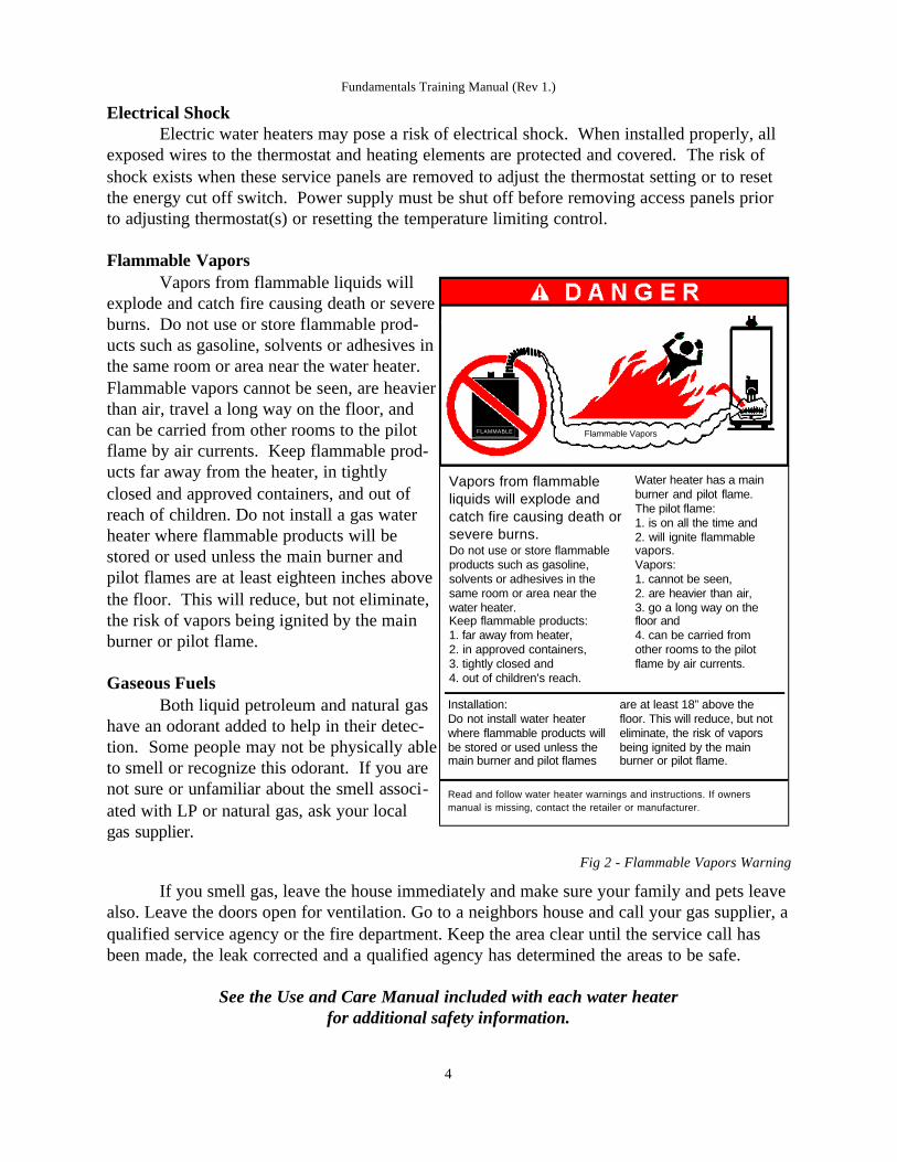
Electrical ShockElectric water heaters may pose a risk of electrical shock. When installed properly, all
exposed wires to the thermostat and heating elements are protected and covered. The risk ofshock exists when these service panels are removed to adjust the thermostat setting or to resetthe energy cut off switch. Power supply must be shut off before removing access panels priorto adjusting thermostat(s) or resetting the temperature limiting control.
Flammable VaporsVapors from flammable liquids will
explode and catch fire causing death or severeburns. Do not use or store flammable prod-ucts such as gasoline, solvents or adhesives inthe same room or area near the water heater.Flammable vapors cannot be seen, are heavierthan air, travel a long way on the floor, andcan be carried from other rooms to the pilotflame by air currents. Keep flammable prod-ucts far away from the heater, in tightlyclosed and approved containers, and out ofreach of children. Do not install a gas waterheater where flammable products will bestored or used unless the main burner andpilot flames are at least eighteen inches abovethe floor. This will reduce, but not eliminate,the risk of vapors being ignited by the mainburner or pilot flame.
Gaseous FuelsBoth liquid petroleum and natural gas
have an odorant added to help in their detec-tion. Some people may not be physically ableto smell or recognize this odorant. If you arenot sure or unfamiliar about the smell associ-ated with LP or natural gas, ask your localgas supplier.
Fig 2 - Flammable Vapors Warning
If you smell gas, leave the house immediately and make sure your family and pets leavealso. Leave the doors open for ventilation. Go to a neighbors house and call your gas supplier, aqualified service agency or the fire department. Keep the area clear until the service call hasbeen made, the leak corrected and a qualified agency has determined the areas to be safe.
See the Use and Care Manual included with each water heaterfor additional safety information.
Fundamentals Training Manual (Rev 1.)
4
Vapors from flammableliquids will explode andcatch fire causing death orsevere burns.Do not use or store flammableproducts such as gasoline,solvents or adhesives in thesame room or area near thewater heater.Keep flammable products:1. far away from heater,2. in approved containers,3. tightly closed and4. out of children’s reach.
Water heater has a mainburner and pilot flame.The pilot flame:1. is on all the time and2. will ignite flammablevapors.Vapors:1. cannot be seen,2. are heavier than air,3. go a long way on thefloor and 4. can be carried fromother rooms to the pilotflame by air currents.
Installation:Do not install water heaterwhere flammable products willbe stored or used unless themain burner and pilot flames
are at least 18” above thefloor. This will reduce, but noteliminate, the risk of vaporsbeing ignited by the mainburner or pilot flame.
Read and follow water heater warnings and instructions. If ownersmanual is missing, contact the retailer or manufacturer.
FLAMMABLE Flammable Vapors

WATER CHEMISTRY
All of the water that we use in our homes comes fromeither a ground water source or a surface water source. Groundwater sources include a well; surface water sources include lakes,streams or reservoirs. According to the U.S. Geological Surveyin 1990, about 44% of domestic water comes from groundsources. The remaining 56% comes from a surface water source.
Each person uses an average of about 100 gallons of waterper day. This includes baths, showers, cooking, clothes and dish washing, grooming and wastedisposal. The largest user of household water is the toilet followed by the shower.
Toilets 35 gallons Baths/showers 28 gallonsClothes washing 18 gallons Faucets 13 gallonsDishwashing 3 gallons
With the exception of the toilet flush, all of the these activities either use hot water orhave the potential to use hot water. That means that 64% of our average water usage involvesthe hot water heating system in our homes.
Hot water is a complex environment that enhances the existing capability of naturallyoccurring minerals to cause corrosion, scale deposits and odor problems. These minerals arealready present in the cold water supply. When water is heated, it acts differently than coldwater. For example:
Water changes volume (expands) when heated, and it is virtual-ly incompressible. We all know that when water freezes, it expandsand may burst household plumbing fixtures and pipes. Water alsoexpands when it is heated. That is why water heaters have aTemperature and Pressure Relief valve installed. One of the commoneffects of such expansion is that hot water backs into the cold watersupply lines of the water heater or causes the T&P valve to dribble ifthe system is closed.
Heating water releases gasses present in the water. Water naturally contains dissolvedgasses such as oxygen, chlorine, carbon dioxide and hydrogen sulfide. At a given pressure,such as a normal 40 PSI household, the amount of gas that water can hold is less as the temper-ature increases. This is exactly what happens inside a water heater. With a normal householdpressure, the water is heated. The heated water releases the gas causing the faucet to ‘spit’when there is a hot water draw. One of the common occurrences may be a complaint of ‘milkywater’ from the tap. Allowing the water to stand for several minutes will cause the bubbles torise into the atmosphere and the water will turn clear. The analogy is to boil a pot of water. Asthe cold water is heated, air bubbles form on the side of the pot. These air bubbles are the
Fundamentals Training Manual (Rev 1.)
5

gasses formed by the application of heat to the water. The same thing happens, on a smallerscale, inside a water heater.
Heating water causes existing minerals to settlefaster and in larger quantities. As the water is heated, itbecomes lighter and less dense. The naturally occurringsolids, although not visible to the eye, will settle at a fasterrate. The result is sediment collecting at the bottom of thetank. Routine draining maintenance will help reduce thecollection of sediment. If a homeowner does not periodi-cally drain and flush the tank, the sediment will harden onthe bottom the tank. The result is a clogged drain valveand reduced efficiency of the heater, especially in gaswater heaters.
Hot water is more corrosive than cold water.Water is a universal solvent and will naturally corrode (ordissolve) most materials. This corrosion is nothing morethan a chemical reaction (steel + water + oxygen = rust).Chemical reactions are usually accelerated with the appli-cation of heat. This is also true of corrosion reactions inhot water. The rate of corrosion approximately doublesfrom 140° F to 160° F; and doubles again from 160° F to180° F. With these few ideas in mind, lets investigate themore common complaints in a hot water system.
Fig 3 - Water Hardness
pH Acidity vs Alkalinity
The term "pH" is used to indicate acidity or alkalinity of a given solution. It is not ameasure of the quantity of acid or alkali, but rather a measure of the relationship of the acid tothe alkali. The pH value of a solution describes its hydrogen-ion activity. The pH scale rangesbetween 0 and 14.
Acidic [ 0 ]=========[ 7 ]==========[ 14 ] Alkaline
Typically all natural waters fall within the range of 6.0 to 8.0 pH. A value of 7.0 is con-sidered to be a neutral pH. Values below 7.0 are acidic and values above 7.0 are alkaline. Waterwith a pH value of 3.5 or below, generally contains mineral acids such as sulfuric or hydrochlo-ric acid.
Water HardnessHard water is found in more than 85% of the United States. Water hardness is due to the
presence of two dissolved minerals - calcium and magnesium. So common are these two min-erals in water that practically no supply can be found that does not contain at least one or two
Fundamentals Training Manual (Rev 1.)
6
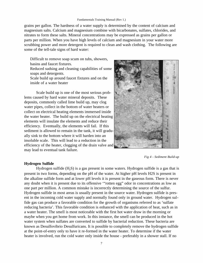
grains per gallon. The hardness of a water supply is determined by the content of calcium andmagnesium salts. Calcium and magnesium combine with bicarbonates, sulfates, chlorides, andnitrates to form these salts. Mineral concentrations may be expressed as grains per gallon orparts per million. When you have high levels of calcium and magnesium in your water morescrubbing power and more detergent is required to clean and wash clothing. The following aresome of the tell-tale signs of hard water:
Difficult to remove soap scum on tubs, showers,basins and faucet fixtures.Reduced sudsing and cleaning capabilities of somesoaps and detergents.Scale build up around faucet fixtures and on theinside of a water heater
Scale build up is one of the most serious prob-lems caused by hard water mineral deposits. Thesedeposits, commonly called lime build up, may clogwater pipes, collect in the bottom of water heaters orcollect on electrical heating elements immersed insidethe water heater. The build up on the electrical heatingelements will insulate the elements and reduce theirefficiency. Eventually, the elements will fail. If thissediment is allowed to remain in the tank, it will gradu-ally sink to the bottom where it will harden into aninsoluble scale. This will lead to a reduction in theefficiency of the heater, clogging of the drain valve andmay lead to eventual tank failure.
Fig 4 - Sediment Build-up
Hydrogen SulfideHydrogen sulfide (H2S) is a gas present in some waters. Hydrogen sulfide is a gas that is
present in two forms, depending on the pH of the water. At higher pH levels H2S is present inthe alkaline sulfide form and at lower pH levels it is present in the gaseous form. There is neverany doubt when it is present due to its offensive ‘“rotten egg” odor in concentrations as low asone part per million. A common mistake is incorrectly determining the source of the sulfur.Hydrogen sulfide in most areas is usually present in the source water. Hydrogen sulfide is pres-ent in the incoming cold water supply and normally found only in ground water. Hydrogen sul-fide gas can produce a favorable condition for the growth of organisms referred to as ‘sulfatereducing bacteria’. This favorable condition is enhanced with the application of heat, such as ina water heater. The smell is most noticeable with the first hot water draw in the morning ormaybe when you get home from work. In this instance, the smell can be produced in the hotwater system when sulfates are converted to sulfide by bacterial reduction. These bacteria areknown as Desulfovibrio Desulfuricans. It is possible to completely remove the hydrogen sulfideat the point-of-entry only to have it re-formed in the water heater. To determine if the waterheater is involved, run the cold water only inside the house - preferably in a shower stall. If no
Fundamentals Training Manual (Rev 1.)
7

odor is detected, turn off the cold water and run the hot water only. The presence of sulfur inthe hot water, but not the cold, indicates that bacterial activity is the cause of the sulfur smell.
IronIron is a common element in nature. It is not surprising that most surface or ground
water contains some iron. Natural iron usually occurs as an insoluble oxide, but the groundwater recharge process collects iron in a soluble form that is dissolved in water. The water isclear when drawn but turns cloudy when it comes in contact with air. The air oxidizes the fer-rous iron and converts it to ferric iron. Ferric iron, or ferric hydroxide, is visible in the waterwhen drawn; hence the name "red water iron". Heme iron is organically bound iron complexedwith decomposed vegetation. The organic materials complexed with the iron are called tanninsor lignins. These organics cause the water to have a weak tea or coffee color. Certain types ofbacteria use iron as an energy source. They oxidize the iron from its ferrous state to its ferricstate and deposit it in the slimy gelatinous material which surround them. These bacteria growin stringy clumps and are found in most iron bearing waters.
At 0.3 parts per million or greater concentrations, iron can produce brown or red stainson plumbing fixtures, laundry or masonry surfaces. In higher concentrations, it can produce anunpleasant metallic taste in the water. Iron can also produce favorable conditions for thegrowth of “iron bacteria”. Left untreated, these bacteria results in a jelly-like slimy mass. Thismass can cause clogged pipes and filter screens and produce a foul tasting water. Other indica-tions of the presence of iron are:
Black or rust colored particles that settle to the bottom of a container.Water appears rusty or has a red or yellow color when drawn from a faucet.Slimy brown or red film in plumbing fixtures, especially inside a toilet tank.
Service tip: Check the inside of a porcelain toilet tank for colored stains. The color of the stains may indicate the mineral content of the water.
ManganeseManganese is rarely found alone in a water source, but is usually paired with iron. At
concentrations of 0.05 parts per million, manganese can cause black staining of fixtures, laun-dry or masonry. It is hard to treat because of the complexes it can form which are dependent onthe oxidation state, pH, bicarbonate-carbonate-OH ratios, and the presence of other minerals,particularly iron. Concentrations higher than 0.05 mg/l cause manganese deposits and stainingof clothing and plumbing fixtures. The stains are dark brown to black in nature. The use ofchlorine bleach in the laundry will cause the stains to set. The chemistry of manganese in wateris similar to that of iron. High levels of manganese in the water produces an unpleasant odorand taste. Organic materials can tie up manganese in the same manner as they do iron, thereforedestruction of the organic matter is a necessary part of manganese removal. Deposits of man-ganese can collect in plumbing systems and produce a dark brown or black sediment and blackturbidity (suspension of particles) in the water. Like iron, manganese can also produce favor-able growth conditions for “manganese bacteria” and clog screens and plumbing lines.Together with iron, manganese bacteria cause a general deterioration or water quality by creat-ing taste, odor and staining problems.
Fundamentals Training Manual (Rev 1.)
8

TurbidityTurbidity is the term given to anything that is suspended in a water supply. It is found in
most surface waters, but usually doesn't exist in ground waters except in shallow wells andsprings after heavy rains. Turbidity gives the water a cloudy appearance or shows up as dirtysediment. Undissolved materials such as sand, clay, silt or suspended iron contribute to turbidi-ty. Turbidity can cause the staining of sinks and fixtures as well as the discoloring of fabrics.Turbidity can be particles in the water consisting of finely divided solids, larger than molecules,but not visible by the naked eye.
Odors & TasteTaste and odor problems of many different types can be encountered in water that is
heated. Troublesome compounds may result from biological growth or industrial activities. Thetastes and odors may be produced in the water supply, in the water treatment plant from reac-tions with treatment chemicals, in the distribution system, or in the plumbing of consumers.Tastes and odors can be caused by mineral contaminants in the water, such as the "salty" tasteof water when large quantities of chlorides are present, or the "rotten egg" odor caused byhydrogen sulfide. Moderate concentrations of algae in the water can cause it to have a "grassy","musty" or "spicy" odor. Decaying vegetation is probably the most common cause for taste andodor in surface water supplies. In treated water supplies chlorine can react with organics andcause odor problems.
ANODE RODS AND CATHODIC PROTECTION
Corrosion can be defined as the destructive attack of a metal by an electrochemical reac-tion with its environment. Steel exposed to moisture and oxygen will rust and corrode.Corrosion is defined as the ‘eating away’ of metal by electrochemical means. There are fourmain factors affecting water’s ability to corrode:
1. Acidity - Water is made acidic by naturally occurring dissolved gasessuch as carbon dioxide and hydrogen sulfide.2. Temperature - Temperature speeds up the corrosive process. Chemistshave a rule of thumb that for every 49°F increase in temperature, chemicalreactions increase two fold. 3. Electrical conductivity - The more dissolved mineral solids in thewater, the greater its ability to carry electrical current. When dissimilarmetals are in the water:Electrical current flows between metalsOne of the metals gradually corrodes faster than the other
4. Amount of dissolved oxygen - Free oxygen dissolved in the water pro-motes corrosion.
Fig 5 - New Anode Rod
Fundamentals Training Manual (Rev 1.)
9
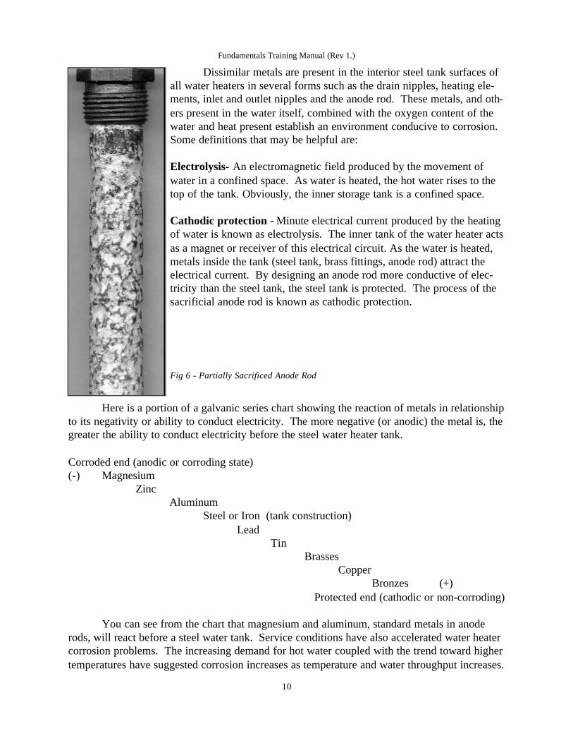
Dissimilar metals are present in the interior steel tank surfaces ofall water heaters in several forms such as the drain nipples, heating ele-ments, inlet and outlet nipples and the anode rod. These metals, and oth-ers present in the water itself, combined with the oxygen content of thewater and heat present establish an environment conducive to corrosion.Some definitions that may be helpful are:
Electrolysis- An electromagnetic field produced by the movement ofwater in a confined space. As water is heated, the hot water rises to thetop of the tank. Obviously, the inner storage tank is a confined space.
Cathodic protection - Minute electrical current produced by the heatingof water is known as electrolysis. The inner tank of the water heater actsas a magnet or receiver of this electrical circuit. As the water is heated,metals inside the tank (steel tank, brass fittings, anode rod) attract theelectrical current. By designing an anode rod more conductive of elec-tricity than the steel tank, the steel tank is protected. The process of thesacrificial anode rod is known as cathodic protection.
Fig 6 - Partially Sacrificed Anode Rod
Here is a portion of a galvanic series chart showing the reaction of metals in relationshipto its negativity or ability to conduct electricity. The more negative (or anodic) the metal is, thegreater the ability to conduct electricity before the steel water heater tank.
Corroded end (anodic or corroding state)(-) Magnesium
ZincAluminum
Steel or Iron (tank construction)Lead
TinBrasses
CopperBronzes (+)
Protected end (cathodic or non-corroding)
You can see from the chart that magnesium and aluminum, standard metals in anoderods, will react before a steel water tank. Service conditions have also accelerated water heatercorrosion problems. The increasing demand for hot water coupled with the trend toward highertemperatures have suggested corrosion increases as temperature and water throughput increases.
Fundamentals Training Manual (Rev 1.)
10

In a water heater, corrosion is protected by a glass (actually a porcelain enamel) liningin the steel tank, and the use of auxiliary anode rods. During the manufacturing process, theinside water tank and both the top and bottom heads are sprayed with a liquid glass material.Glass technology allows the glass to adhere to the steel interior, and is accomplished by apply-ing a precise thickness of glass mixture to the tank and heating for a precise time period. Thismaterial is fired in a furnace, and when cooled, resembles a porcelain lining. This glass pro-vides a long life to the steel tank; otherwise the tank would fail or corrode in a relatively shorttime. Every glasslined water tank, no matter how carefully it is manufactured, has some baremetal exposed. This is due to the inability to effectively cover sharp corners and the radiusaround the fittings. There is a chance that a crack or chip in the porce-lain lining will allow the water to come in contact with the steel tank.Over time, water, a universal solvent that becomes more aggressive withtemperature, breaks down the interior tank lining. This will create con-ditions for corrosion, pin holes in the tank and finally tank failure.
Cathodic protection is accomplished in the glasslined waterheater through the use of an auxiliary magnesium anode with a patentedRheem resistor. Due to the relative position of magnesium to steel in theelectromotive series of metals, magnesium will corrode producing anabundance of electrons which flow (much the same as an electrical cur-rent) to the exposed steel surface and maintaining it in the electro-nega-tive state. As current flow takes place, the anode rod attracts the electromagnetic current and reacts chemically to corrode at a rate faster thanthe steel inner tank. This process stops tank corrosion by substitutingthe sacrificial magnesium anode rod in place of the steel tank. As longas the magnesium anode rod remains in the tank, in an active state,there will be no corrosion of the minute areas of exposed steel insidethe tank.
The life of the anode, in turn, depends on water temperature,amount of water used, and the quality of the glass lining. However, themost important factor in the life of the anode rod is the water chemistryand the hardness or softness of the water. Also check the manufactureand installation date of the water heater. If the heater is more than five(5) years old, and the anode rod has not been replaced, inspect theanode rod. The anode should be replaced when there is six (6) inchesor more exposed core wire at either end.
Fig 7 - Fully Sacrificed Anode Rod
MILKY WATER AND DISSOLVED GASSES
Gasses such as oxygen, chlorine, carbon dioxide, hydrogen sulfide and others are solu-ble in water. In fact, water is made up of two gasses, Hydrogen and Oxygen (H2O). The amountof gas that water can hold is decreased as the temperature of the water increases. For example, apot of cold water is placed on a stove to boil. When the pot is first put on the stove, there are no
Fundamentals Training Manual (Rev 1.)
11
bubbles. As the water is heated, bubbles form on the bottom and sides of the pot. This is theperfect example of gasses, naturally present in the water, being released as the temperature ofthe water increases.
Another point that is noteworthy is that hot water from a faucet may also expel thesenaturally occurring gasses. One of the more common occurrences is the phenomenon calledmilky water. The hot water, when drawn into a clear glass, may appear discolored or chalky.Allow the glass to stand for a few minutes and the water becomes clear. By allowing the waterto stand for several minutes, the small gas bubbles, that give the appearance of milky water,will dissipate and the condition will clear. Aerated faucets may help in reducing the likelihoodof this happening.
In the plumbing field, we should also be aware of a couple of other effects of this gasrelease. As pressure inside a plumbing system increases, the waters ability to retain dissolvedgasses increases. The higher the pressure, the more dissolved gasses in the water. Significantpressure drops may occur at the inner radius of elbows and fittings under high pressure. Thisrapid pressure drop may release gas bubbles. These gas bubbles have an abrasive effect on pip-ing and are an important factor in corrosion-erosion.
The release of dissolved gas also creates air pockets and air locks in plumbing systems.The spurts of air or gas when opening a hot water faucet can be attributed to the release of dis-solved gasses in the water. Other gasses, such as hydrogen, can be a by-product of severe corro-sion activity in a plumbing system.
SMELLY WATER AND THE ROTTEN EGG ODOR
The incidence of rotten egg odor or black water in hot water lines is due to the reactionof sulfates and micro-organisms in the water. This condition is a water problem, rather than awater heater problem. A quick check for the cause of the odor is to draw enough hot water tonotice the odor. Then move to another faucet, or wait until the smell dissipates, and draw coldwater. The source of the odor may be in the cold water supply, such as untreated rural watersystems or well water.
For many years the regular magnesium anode was and is the standard anode for use inwater heater tanks. In general, it is a very good anode, however, the performance is dependenton water chemistry. In waters where the conductivity is low, the anode operates at very lowcurrent levels. Conversely, where the water conductivity is high, an excessive amount of cur-rent is produced with inefficient operation. In addition, some of these waters have excessivesulfate content along with various strains of sulfate reducing bacteria. These bacteria, harmlessto health, will grow in the presence of the highly active magnesium anode and will producehydrogen sulfide gas, utilizing the hydrogen ion from the anode cathode reaction. The greateractivity of the anode, the greater amount of the hydrogen ion and hydrogen sulfide gas. Thesebacteria can be killed with adequate additions of chlorine and or ozone. This will usually elimi-nate the odor problem.
Fundamentals Training Manual (Rev 1.)
12

Although there is very little literature associating odors and sulfate reduction with mag-nesium, there is reference to sulfate-reducing bacteria known as desulfovibrio. These bacteriacannot grow in the presence of atmospheric oxygen, which may account for their not beingnoticed in cold water supplies. When the same water is heated, they become noticeable.
There are two ways to eliminate an odor or black water problem. They are listed in theorder of preference.
1. Chlorination - by means of a continuous chlorine feeder; or periodic flushing with a com-mon household bleach. This process is 100% effective only if a continuous chlorine feederis installed.2. Install a new R-TECH anode rod after the water heater has been flushed with householdbleach. This process may not be 100% effective because bacteria is still allowed to growinside the tank.
CHLORINATION OF WATER HEATER TANKS
1. Turn off the manual electrical switch or shut off the gas supply.2. Close the cold water inlet valve at the heater.3. Open a nearby hot water faucet and the T&P valve to relieve tank pressure.4. Drain the heater of enough water to compensate for the bleach. Use a hose connected tothe drain valve if an open drain is not adjacent to the heater.5. Remove relief valve, anode rod or disconnect the hot water outlet pipe from the heater.6. Pour one gallon of bleach for every 30 gallons of water heater tank capacity. Use therelief valve, anode rod or hot water outlet pipe opening. Re-pipe the heater and close theT&P valve.7. Open the cold water inlet valve at the heater and fill the tank with water. Observe thewater level through the closest hot water faucet. Close inlet valve when the tank is full.8. Leave the bleach mixture in the heater for one hour.9. After one hour, open all the hot water faucets and allow the bleach mixture to clean thehot water supply pipes. Drain the remaining bleach mixture from the tank through theheater drain valve.10. Close the heater drain valve, make sure the cold water inlet valve is open, and com-pletely fill the tank with fresh water. Leave the water in the tank for 15 minutes. 11. After 15 minutes, purge the hot water supply lines and drain the water from the tankthrough the heater drain valve. Close the drain valve. Check anode rod for serviceability;replace with a new R-TECH anode rod if there are signs of deterioration.12. Make sure you purge all the air from the hot water lines from the open hot waterfaucets. Close the hot water faucet after all the air is out of the system. 13. Check for water leaks at all fittings used; repair as necessary.14. Turn on the manual electrical switch or gas supply from step 1 above.15. Check for normal water heater operation.
Fundamentals Training Manual (Rev 1.)
13
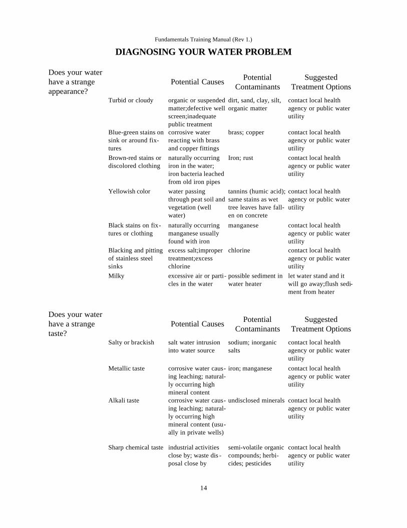
DIAGNOSING YOUR WATER PROBLEM
Fundamentals Training Manual (Rev 1.)
14
Does your waterhave a strangeappearance?
Potential Causes PotentialContaminants
SuggestedTreatment Options
Turbid or cloudy organic or suspendedmatter;defective wellscreen;inadequatepublic treatment
dirt, sand, clay, silt,organic matter
contact local healthagency or public waterutility
Does your waterhave a strangetaste?
Potential Causes PotentialContaminants
SuggestedTreatment Options
Salty or brackish salt water intrusioninto water source
sodium; inorganicsalts
contact local healthagency or public waterutility
Metallic taste corrosive water caus-ing leaching; natural-ly occurring highmineral content
iron; manganese contact local healthagency or public waterutility
Alkali taste corrosive water caus-ing leaching; natural-ly occurring highmineral content (usu-ally in private wells)
undisclosed minerals contact local healthagency or public waterutility
Sharp chemical taste industrial activitiesclose by; waste dis -posal close by
semi-volatile organiccompounds; herbi-cides; pesticides
contact local healthagency or public waterutility
Blue-green stains onsink or around fix-tures
corrosive waterreacting with brassand copper fittings
brass; copper contact local healthagency or public waterutility
Brown-red stains ordiscolored clothing
naturally occurringiron in the water;iron bacteria leachedfrom old iron pipes
Iron; rust contact local healthagency or public waterutility
Yellowish color water passingthrough peat soil andvegetation (wellwater)
tannins (humic acid);same stains as wettree leaves have fall-en on concrete
contact local healthagency or public waterutility
Black stains on fix-tures or clothing
naturally occurringmanganese usuallyfound with iron
manganese contact local healthagency or public waterutility
Blacking and pittingof stainless steelsinks
excess salt;impropertreatment;excesschlorine
chlorine contact local healthagency or public waterutility
Milky excessive air or parti-cles in the water
possible sediment inwater heater
let water stand and itwill go away;flush sedi-ment from heater

OPEN AND CLOSED WATER HEATER SYSTEMS
Water heater systems may be installed as either an ‘open’ or ‘closed’ system. Water inan ordinary water heater tank is under a certain pressure depending on the supply pressure inthe system (the cold water supply pressure to the residence). As this water is heated, its volumeincreases. If there is no check valve, pressure reducing valve or other obstruction in the coldwater line, the system is open and water pressure will back up into the cold water supply line.If enough pressure exists inside the water heater, the pressure will force water back into themunicipal supply system. Therefore, in an open system, the water pressure in the water heatertank will always be equal to the supply pressure. Some municipalities are introducing codes thatprevent this return to the city main system.
The presence of a check valve, backflow preventer, water pressure reducing valve, orclosing the shut-off valve in the cold water line makes the plumbing system a closed system.
Fundamentals Training Manual (Rev 1.)
15
Does your waterhave a strangeodor?
Potential Causes PotentialContaminants
SuggestedTreatment Options
Musty or earthy algae; vegetation organic matter suchas leaves
contact local healthagency or public waterutility
Chlorine excess chlorine orinadequate de-chlori-nation
chlorine contact local healthagency or public waterutility
Detergent septic discharge intowater supply
detergents contact local healthagency or public waterutility
Rotten eggs sewage; sulfatereducing bacteria
hydrogen sulfidegas;sulfates
contact local healthagency or public waterutility
Fishy, sweet or per-fume
industrial chemicals;waste
volatile organics;semi-volatile organ-ics
contact local healthagency or public waterutility
Oil or gas gasoline or oil leaksinto water supply
gasoline, oil, benzene contact local healthagency or public waterutility
Does your waterhave a strangetexture?
Potential Causes PotentialContaminants
SuggestedTreatment Options
Gritty or abrasive defective wellscreen; inadequatepublic treatment
fine sand, grit contact local healthagency or public waterutility
Scum or whitedeposits
elevated levels ofcalcium and magne-sium salts
hard water contact local healthagency or public waterutility;water softener

In this situation, the increased water pressure istrapped inside the heater tank and cannot back up orequalize into the cold water supply line. Beingtrapped, the pressure will become increasingly greater.Eventually, the pressure inside the water heater willexceed the limits of the Temperature & Pressure relief(T&P) valve and the valve will discharge. If the T&Pvalve is not installed or not operating an even moreserious condition could develop. If the pressure insidethe tank is not released, the tank may split a weld seamor rupture.
Fig 8 - Tank with Bulged Bottom
The following figures are from an actual test conducted expressly to point out the dan-ger of what happens to water pressure when heated a closed system.
Water Temperature °F Tank Pressure P.S.I74 8075 8576 10578 12580 14582 17585 22588 27590 31095 400100 520
Table 2 - Pressure build up in a Closed System
Rheem water heater tanks are manufactured and tested to withstand a test pressure of300 PSI and a working pressure of 150 PSI. A bulged bottom immediately indicates that thetank has been subjected to a pressure in excess of 300 PSI and is not covered by warranty.
THERMAL EXPANSION
When water is heated it expands. Reacting to physical law, water expands in volume asits temperature rises. In a 40 gallon water heater, water being heated to its thermostat settingwill end up expanding to about 40.53 gallons when the desired temperature is reached. Theextra volume created by this expansion must go somewhere.
Before the advent of cross connection control, expanded water that exceeded the capaci-ty of the tank flowed back to the city main where it was easily dissipated. It was ‘open’ at thecity side of the supply system. Today, with back flow preventers, water meter check valves and
Fundamentals Training Manual (Rev 1.)
16
T&P actuates about here
At this point the tank bottom willstart to reverse and eventually
break a weld and leak.

pressure reducing valves without a bypass being installed, expanded water from a water heatercannot return to the city supply. It is now a ‘closed’ system and the expanding water has noplace to go. Dangerous conditions exist during thermal expansion long before the temperatureand pressure relief valve operates. Internal pressures repeatedly occurring during recovery peri-ods can ‘stress’ the tank causing the tank welds and fitting connections to the tank to weaken.
Remember - water + heat + pressure + closed system = potential explosion !
As a result, the expanding watercreates a rapid and dangerous pressure
increase in the water heater and system piping inside theresidence. Eventually, the combination of temperature,pressure and the closed system will activate the T&Pvalve. The setting on the safety relief is quickly
reached and the relief valve opens, losing heater water downthe drain.....or all over the floor. Even though the T&P valve operates dur-ing each recovery period, internal high pressures occurring over and overagain can accelerate tank leakage and shorten water heater life. A goodindication of thermal expansion is when the T&P valve releases about onecup of water for each ten gallons of heater capacity with each heatingcycle.
The best solution to thermal expansion is to control the pressure the heat-ed water generates within normal, safe operating range, well below theemergency setting of a T&P valve. This will allow thermal expansion tooccur, but without causing a dangerous increase in pressure. This isaccomplished by adding an expansion tank. As the water temperature
increases, the expanded water is received by the expansion tank. As the temperature and pres-sure reaches its maximum, the diaphragm flexes against the air cushion (air is compressible) toallow for increased water expansion. By adding aRheem THERM-X-GUARDTM thermal expansion tankwith a sealed in compressible air cushion, space isprovided to store and hold the additional expandedwater volume. When the water is heated the expand-ed volume is consumed by the expansion tank. Whenhot water is used in the system, the expansion tankreturns the water back into the system for use.
Fig 9 - Thermal Expansion Tanks
Service Tip: Thermal expansion tank pressure must be 10-15 psi above service pressure.There are sizing issues when selecting the proper expansion tank.
Consult the expansion tank manufactures specifications.
Fundamentals Training Manual (Rev 1.)
17

TEMPERATURE AND PRESSURE RELIEF (T&P) VALVES
Temperature and Pressure Relief Valves, also called T&P valves, areemergency safety limit devices that will prevent or relieve overheated water andpressure. Without a T&P valve during an unsafe condition, the pressure insidethe tank would rise to the point the tank may rupture or explode. This wouldcause potential damage to both people and property. Rheem water heaters arepressure tested to 300 pounds per square inch (PSI) and have a working pres-sure of 150 PSI. The T&P valve is designed to open when the pressure insidethe tank exceeds 150 PSI, allowing pressure to vent safely. The T&P valve willalso open if the water temperature reaches 210° F. The valve will remain openallowing cold water into the tank until the unsafe condition is over.
Why is hot water over 212° F dangerous? The containment vessel or stor-age tank used to store the hot water causes the danger. This tank is under pres-sure - the normal working pressure caused by the cold water supply. As water isheated under pressure, the boiling point rises. For example, with a nominalincoming supply pressure of 50 PSI, water will not boil under pressure until thetemperature reaches approximately 297° F. The energy potential in the superheated water is called latent heat energy and will flash to steam when exposedto normal atmospheric pressure. This flash to steam has the explosive potentialof over two million foot-pounds of energy.
Fig 10 - Temperature & Pressure Relief Valve
The Temperature and Pressure Relief Valve is the safety device that prevents these con-ditions from happening. It is a 2-in-1 device that responds to both pressure increases and tem-perature increases. When actuating by pressure, the T&P valve will open and allow the tanksinternal pressure to drop below 150PSI. Generally, when you see a T&P valve weeping or drib-bling, it is due to pressure (thermal expansion) or foreign material such as calcium buildup inthe valve seat. This material on the valve seat will prevent the valve from closing tightly. If thevalve is discharging large quantities of water, then the release is due to temperature. Rememberthe T&P is installed in the top six inches of the tank. If the temperature probe on the T&P sens-es water temperatures of 210° F, it will open the valve. The valve will stay open until the tem-perature probe cools. With cold water entering the bottom area of the tank, you can see a largevolume of water (gallons) will be dischargedbefore the temperature probe cools.
T&P valves should be inspected andtested on every service call. When checking thevalve, also check the rating plate on the valve.Many changes may take place in a plumbingsystem after the original installation. Through asystemic reinspection program, we can insurethat the safety device is working properly. The
Fundamentals Training Manual (Rev 1.)
18

T&P Valve must be capable of discharging more BTUs than the heateris capable of putting into the water.
Installation of a temperature and pressure relief valve is critical tothe safe operation of a water heater. The basic rule is that the T&Pvalve must be installed so that the temperature-sensing probe isimmersed in the hottest water - which is in the top six inches of thetank. All water heaters manufactured by Rheem - Ruud have a separateand special connection designed for the T&P valve. When checking thevalve also check the rating plate on the valve. The BTU rating of thevalve must equal or exceed the BTU rating of the water heater.
Fig 11 - T&P Valve Cutaway View
Here are some common T&P valve errors
No T&P installed or pressure only relief valve installedNon-code or insufficient rating T&P valve installedT&P installed in the cold water lineT&P installed a distance from the tank, such as in the hot outlet lineT&P has been altered, repaired, plugged or restricted
Tips for the Temperature and Pressure Relief drain line
Run to a safe place of disposal (floor drain or outside)Drain piping should be the same size as the valve discharge through its entire lengthPitch downward from the valve and terminate 6 inches above the floor drainNo longer than 30 feet. Do not use more than four elbowsDo not install a shut off valve in the drain line and terminate unthreaded
Discharge of the T&P indicates the existence of an unsafe temperature or pressure condition.
Fig 12 - Proper T&P Valve locations for residential or commercial water heaters
Fundamentals Training Manual (Rev 1.)
19
PLUMBING CROSS OVER
A plumbing cross over is a condition whereby cold water is allowed to flow into the hotwater system. The plumbing system in a home is divided into two sub-systems, the hot watersupply and the cold water supply.
The modern home, or a remodeled older home, will most likely have at least one mixingor single handle type faucet installed. Most homes today have an automatic laundry washingmachine. Both of these are examples of appliances and fixtures that have a mixing valve. Anymixing valve can allow a cross-over to occur should they become defective. A defective mix-ing valve will allow a cross-over of hot and cold water, even though there are no visible signsof trouble or leak.
Plumbing cross overs can cause a complaint such as ‘water not hot enough’. Testing thehot plumbing system for a cross over can be accomplished by using the following procedure.
1. Close the cold water shut off valve supplying cold water to the heater.2. Using a faucet with separate HOT and COLD spigots, open the hot faucet only.3. With the cold water to the heater shut off, once the pressure is relieved, the water shouldstop running completely. Should the water continue to flow, but at a slower than normalrate, you have one of two conditions. If the slower flow continues but stays HOT, the coldwater shut off valve is defective and the test will not be valid. Replace the cold water shutoff valve and continue the test. If the water turns COLD, you have cold water crossing overto the hot water plumbing system.4. To locate the cross-over, first shut off the hose bibb (service valves) to the laundry wash-er. If the water stops flowing at your hot faucet, the washing machine mixing valve is caus-ing the cross-over.5. If the flow does not stop, then you must check, by feel, each of the feed lines to each ofthe single handle faucets. If you find one faucet where both feed lines are equally cold, thatfaucet is allowing an internal cross-over to occur and should be rebuilt or replaced.6. If none of the above resolve the cross-over, a direct cross-over exists in the plumbingsomewhere. This means the hot water sub-system and the cold water sub-system are direct-ly tied together after the water heater.
When performing this test in a home that has only mixing (single spigot) faucets, thetest must be done twice. Each test must be done using a different faucet. The faucet used forthe first test may be causing the problem and should be tested in the off position.
In a house with all double handle faucets, you may find a shower head with a built inshut off (shut off valve is connected directly to the shower head). If the user shuts the showerhead valve off but leaves the double handle tub facets open, this would allow a direct cross-over to occur.
Fundamentals Training Manual (Rev 1.)
20
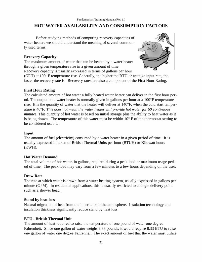
HOT WATER AVAILABILITY AND CONSUMPTION FACTORS
Before studying methods of computing recovery capacities ofwater heaters we should understand the meaning of several common-ly used terms.
Recovery CapacityThe maximum amount of water that can be heated by a water heaterthrough a given temperature rise in a given amount of time.Recovery capacity is usually expressed in terms of gallons per hour(GPH) at 100° F temperature rise. Generally, the higher the BTU or wattage input rate, thefaster the recovery rate is. Recovery rates are also a component of the First Hour Rating.
First Hour RatingThe calculated amount of hot water a fully heated water heater can deliver in the first hour peri-od. The output on a water heater is normally given in gallons per hour at a 100°F temperaturerise. It is the quantity of water that the heater will deliver at 140°F, when the cold start temper-ature is 40°F. This does not mean the water heater will provide hot water for 60 continuousminutes. This quantity of hot water is based on initial storage plus the ability to heat water as itis being drawn. The temperature of this water must be within 10° F of the thermostat setting tobe considered usable.
InputThe amount of fuel (electricity) consumed by a water heater in a given period of time. It isusually expressed in terms of British Thermal Units per hour (BTUH) or Kilowatt hours(KWH).
Hot Water DemandThe total volume of hot water, in gallons, required during a peak load or maximum usage peri-od of time. The peak load may vary from a few minutes to a few hours depending on the user.
Draw RateThe rate at which water is drawn from a water heating system, usually expressed in gallons perminute (GPM). In residential applications, this is usually restricted to a single delivery pointsuch as a shower head.
Stand by heat lossNatural migration of heat from the inner tank to the atmosphere. Insulation technology andinsulation thickness significantly reduce stand by heat loss.
BTU - British Thermal UnitThe amount of heat required to raise the temperature of one pound of water one degreeFahrenheit. Since one gallon of water weighs 8.33 pounds, it would require 8.33 BTU to raiseone gallon of water one degree Fahrenheit. The exact amount of fuel that the water must utilize
Fundamentals Training Manual (Rev 1.)
21

in order to actually transfer the 8.33 BTU into the water is determined by the efficiency of thewater heater in question. Electric water heaters are considered to be 95% efficient; that is 95%of the energy is transferred as heat into the water. Therefore, we can divide the standard BTUby the efficiency rating of the water heater to determine actual amount of BTU (energy). Theformula would look like this:
8.33.95 = 8.77 BTU
Cold Inlet TemperatureThe temperature of outside water coming into a water heating system. Throughout most of theU.S. this temperature is considered to be 40°F. (during the coldest months).
Peak PeriodPeak period refers to the time during the day when the water heating system experiences itsgreatest draw (demand). With the exception of applications that require continuous hot waterdraw, tests have shown that the peak period of hot water usage will occur once or twice a day inresidential applications. Peak periods for commercial applications are dramatically different.By contrast, a peak period in a school gymnasium shower may occur ever hour!
Temperature RiseThe difference in temperature between the desired hot water and the incoming cold water,expressed in degrees Fahrenheit. For example, the desired temperature at the faucet is 120° Fand the incoming cold water is 70° F. The required temperature rise is 50° F (120° - 70° =50°). Temperature rise is the number of degrees Fahrenheit that the water must be raised eitherfrom the inlet water temperature or a pre-heat water temperature. In short, the temperature riseis the difference between existing water temperature and desired water temperature.
Another factor in proper sizing is recovery time. A smaller gallon capacity heater witha high recovery time (heats water faster) may prove as effective as a larger capacity heater witha nominal recovery time.
N O T E S
_____________________________________________________________________________
_____________________________________________________________________________
_____________________________________________________________________________
_____________________________________________________________________________
_____________________________________________________________________________
Fundamentals Training Manual (Rev 1.)
22

Table 3 - Shower Time Available
* gallons available is initially slightly higher than the 70% rule due to the heating action of theheating elements during usage. Eventually demand will consume the hot water faster than theelements can heat.
The chart above shows the actual amount of hot water available at 40 PSI system pres-sure during the first hour of delivery and what that amount means in terms of shower time. Ahigher system pressure will reduce shower time.
A common problem is the complaint of ‘not enough hot water’. Earlier in this manualthere was some diagnostics for mechanical failures that can cause this problem. As you cansee, the source of the problem may not be mechanical; it may be consumption. Demand ratemay also be another source of problem. For example, a shower head distributing 9 gallons perminute (GPM) will have less shower time than a shower head with 3 gallons per minute. Thelower the GPM, the more hot water available.
DRAW TEST AND FLOW RATES
Testing show head flow rate
Flow rate is simply the gallons per minute (GPM) of water a faucet will allow at fullforce. Flow rate of a shower head or other faucet fixture is important in determining the con-sumption patterns of a user. Using a bucket and a watch with a second hand, draw cold showerwater at full volume for 15 seconds. Using the draw test table and a quart measure, determinethe number of quarts drawn in the 15 second period.
For example, a homeowner has a 40 gallon water heater set to 120° F. That will allowapproximately 36 gallons of hot shower water at 110°. If the homeowner has a conservativeflow rate of 3 GPM, the shower will last 12 minutes. If the homeowner has a wasteful flow
Fundamentals Training Manual (Rev 1.)
23
30 21 27 9 4 1/2 340 28 36 12 6 450 35 45 15 7 1/2 566 46 59 20 10 6 2/380 56 72 24 12 8120 84 108 36 18 12
Water HeaterGallons
Gallons of hotwater availableat 120 degrees
*Gallons avail-able within 10
degrees ofthermostat
Shower Time AvailableBased of gallons per minute flow of shower
head3 GPM 6 GPM 9 GPM
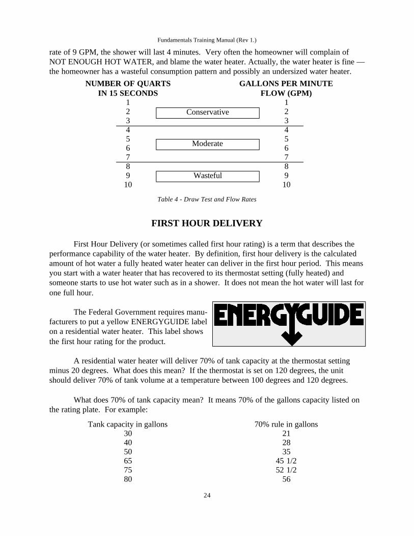
rate of 9 GPM, the shower will last 4 minutes. Very often the homeowner will complain ofNOT ENOUGH HOT WATER, and blame the water heater. Actually, the water heater is fine —the homeowner has a wasteful consumption pattern and possibly an undersized water heater.
Table 4 - Draw Test and Flow Rates
FIRST HOUR DELIVERY
First Hour Delivery (or sometimes called first hour rating) is a term that describes theperformance capability of the water heater. By definition, first hour delivery is the calculatedamount of hot water a fully heated water heater can deliver in the first hour period. This meansyou start with a water heater that has recovered to its thermostat setting (fully heated) andsomeone starts to use hot water such as in a shower. It does not mean the hot water will last forone full hour.
The Federal Government requires manu-facturers to put a yellow ENERGYGUIDE labelon a residential water heater. This label showsthe first hour rating for the product.
A residential water heater will deliver 70% of tank capacity at the thermostat settingminus 20 degrees. What does this mean? If the thermostat is set on 120 degrees, the unitshould deliver 70% of tank volume at a temperature between 100 degrees and 120 degrees.
What does 70% of tank capacity mean? It means 70% of the gallons capacity listed onthe rating plate. For example:
Fundamentals Training Manual (Rev 1.)
24
NUMBER OF QUARTSIN 15 SECONDS
GALLONS PER MINUTE FLOW (GPM)
1 12 23 34 45 56 67 78 89 910 10
Tank capacity in gallons 70% rule in gallons30 2140 2850 3565 45 1/275 52 1/280 56
Conservative
Moderate
Wasteful

Why only 70% of the tank capacity? Simple, cold water is entering the heater as the hotwater is being used. This cold water mixes with the hot water in the tank. Much the same ascooling off a hot beverage with a little cold water, the water heater works on the same principle.
As a hot water faucet is turned on, the dip tube, attached on the cold water inlet side ofthe heater, delivers the cold water to the bottom of the tank. The pressure of the incoming coldwater pushes the hot water out of the tank. Once enough cold water has entered the tank andmixed with the hot water, this will cause the water to turn warm, then tepid, then cold. This ishow we calculate the 70% rule. Once you have used the 70% of available hot water, the waterwill quickly become cold.
As hot water is being used, the thermostat(s) on the heater will demand heat and the unitwill start to recover. This means it will heat water, even while hot water is being used. Therecovery capabilities of a water heater are standard characteristics and are factored in with the70% rule to determine first hour delivery. To determine the 'ballpark' first hour delivery use thefollowing formula:
(tank capacity) x .70 + (recovery) = first hour delivery
For instance: You have a 40 gallon, 40,000 BTU gas water heater -
40 x .7 + 36 = 64 gallons first hour delivery
You can find the recovery rate in gallons per hour for your heater in the followingcharts. Check the rating plate of your water heater for the input in watts (electrical) or BTUs(gas).
Table 5 - Water Heater Recovery Rates in Gallons per Hour
Fundamentals Training Manual (Rev 1.)
25
Water Heater Recovery Rates in Gallons per HourDegrees F Rise
Input KW BTUs1,000 3,413
400 500 600 700 800 900 1000 1100 1200
10 8 7 6 5 5 4 4 31,500 5,120 16 12 10 9 8 7 6 6 52,000 6,826 21 17 14 12 10 9 8 8 72,500 8,533 26 21 17 15 13 12 10 10 93,000 10,239 31 25 21 18 16 14 12 11 103,500 11,946 36 29 24 21 18 16 15 13 124,000 13,652 41 33 28 24 21 18 17 15 144,500 15,359 47 37 31 27 23 21 19 17 165,000 17,065 52 41 34 30 26 23 21 19 175,500 18,722 57 46 38 33 28 25 23 21 196,000 20,478 62 49 41 35 31 27 25 22 219,000 30,717 92 74 61 53 46 41 37 34 3112,000 40,956 123 98 82 70 61 55 49 45 41

SIZING OF A RESIDENTIAL WATER HEATER
Like any household appliance, the water heater has a very specific job to perform and itmust do its job to the homeowner’s complete satisfaction 24 hours a day, every day, for yearsand years. Water heating requirements for the home have increased steadily. As a result, thelast water heater purchased by the homeowner now may be too small to satisfy householdneeds. In addition, rising energy costs have become a concern. Operating costs now can bejust as important in making the buying decision as the initial price of the new water heateritself!
How many family members will routinely take a shower in any given hour. Forinstance, if all four of the children take a shower between 7 - 8 PM daily to get ready for bed,you may have a high usage demand. If both parents take their showers in the morning, Momgets a load of clothes in the washing machine and turns the dish washer on before everyoneleaves for school and work, you may have a high usage demand. Focus on the customer’susage pattern and consumption factors.
Peak Hour Demand is the key. Peak hour demand is the busiest one-hour usage period.This may be in the morning, evening or some other time during the day. Accurate calculation ofthe demand is essential to proper water heater sizing. Look at the following sample of a typicalpeak hour demand for this family of three.
Table 6 - Sample Peak Hour Demand Calculation
Fundamentals Training Manual (Rev 1.)
26
Avg Gallonsper activityHousehold Activity
Times perhour
Total HotWater used
20Shower or bath 3 60
2Shave 1 2
4Washing hands or face
4Shampoo hair 1 4
4Washing dishes by hand 1 4
14Automatic dishwasher
5Food preparation for a meal
32Automatic clothes washer
Total Peak Hour Demand 70 gallons
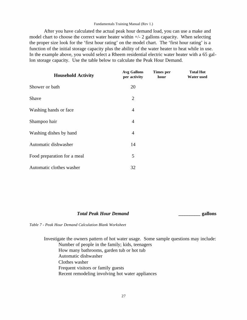
After you have calculated the actual peak hour demand load, you can use a make andmodel chart to choose the correct water heater within +/- 2 gallons capacity. When selectingthe proper size look for the ‘first hour rating’ on the model chart. The ‘first hour rating’ is afunction of the initial storage capacity plus the ability of the water heater to heat while in use.In the example above, you would select a Rheem residential electric water heater with a 65 gal-lon storage capacity. Use the table below to calculate the Peak Hour Demand.
Table 7 - Peak Hour Demand Calculation Blank Worksheet
Investigate the owners pattern of hot water usage. Some sample questions may include:Number of people in the family; kids, teenagersHow many bathrooms, garden tub or hot tubAutomatic dishwasherClothes washerFrequent visitors or family guestsRecent remodeling involving hot water appliances
Fundamentals Training Manual (Rev 1.)
27
Avg Gallonsper activityHousehold Activity
Times perhour
Total HotWater used
20Shower or bath
2Shave
4Washing hands or face
4Shampoo hair
4Washing dishes by hand
14Automatic dishwasher
5Food preparation for a meal
32Automatic clothes washer
Total Peak Hour Demand _________ gallons
ENERGY FACTOR
Energy Factor is a relative number that is a standard measure for storage water heatingproducts. It is determined through a Department of Energy (DOE) standard test procedure. Thisprocedure involves a water heater that is put through a 24 hour simulated use test. The simulat-ed use test is used by all water heater manufacturers. All of the test procedures are mandated bythe DOE. Test procedures include the length of the test; the thermostat setting; the water tem-perature of the cold water delivered into the water heater; and the quantity of hot water drawnfrom the heater during the 24 hours of testing.
The final number is displayed in a decimal equivalent. It is not meant to be a percent-age. This number, called the Energy Factor (EF) represents the efficiency of the water heater.The higher the EF, the more efficient the unit. The Energy Factor represents two major condi-tions when determining water heater efficiency:
How efficiently the unit uses fuel (gas or electric)How efficiently the unit retains heat during 'stand-by'
How useful is the Energy Factor?
The EF aids the consumer is making comparison shopping easier. When shopping for anew water heater, the consumer can compare the EF rating of the unit against like units. 'Likeunits' is not a relative term. When comparing the EF, consumers must compare water heaterswith the same fuel source, gas or electric, and the same water storage capacity. Comparing theEF between a natural gas unit and an electric unit is not comparison shopping. Comparing 50gallon electric units to each other is comparison shopping.
VACATIONS AND LONG TERM IDLE TIME
If the water heater is to remain idle for an extended period to time (such as a week longvacation), the power and the water to the water heater should be turned off to conserve energy.Water heaters that have been idle for a long time are a safety hazard.
Hydrogen gas can be produced in a hot water system that has not been used for a longperiod of time (generally two weeks or more). Hydrogen gas is extremely flammable! To dis-sipate hydrogen gas from a heater, it is recommended that the hot water faucet be opened forseveral minutes at the kitchen sink before using any electrical appliance connected to the hotwater system. If hydrogen gas is present, there will probably be an unusual noise such as airescaping through the pipe as the water begins to flow. Do not smoke or use an open flame nearthe faucet at the time it is open.
Fundamentals Training Manual (Rev 1.)
28

SUBMERGED WATER HEATERS
If your water heater(s), gas or electric, has been submerged in water, DO NOTATTEMPT to repair, install, or operate the product. Due to the conductivity of water alongwith its corrosive properties all the operational controls are rendered unsafe. As for the insula-tion properties of the product, it would have become saturated with water which cannot beremoved resulting in exterior corrosion and failure of the product.
The affected water heater(s) should be removed, made unusable, and, replaced with anew unit. As a further note, warranties on our products will not be applied when the product hasbeen damaged, among other things, by flood. Any claims made will be declined if it is deter-mined the cause of failure is the product being damaged as a result of flood.
INSTALLATION - SERIES AND PARALLEL
The installation drawings in this section are typical. Check local code requirements forvacuum breaker devices and cold water inlet check valves. If you install a check valve in anyof these systems, you must install a thermal expansion tank.
The majority of commercial water heater installations involve the delivery of water atone temperature only. The exceptions, or two temperature systems, are restaurants, convales-cent homes and special process applications. In most of these general purpose applications, thewater heater thermostats are adjusted to deliver water at a temperature ranging from 1300 F to1500 F. The simplest of the single temperature systems is one using a single, free standingwater heater. This design uses an automatic storage (tank type) water heater and is pipeddirectly with a cold in and hot out. The heated water is delivered directly to its point of use andis mixed at the sink, tub or faucet.
In many cases a single water heater may not have enough capacity to handle the hotwater demand. In this case, two or more heaters can be piped together in a piping arrangementcalled manifolding. Manifolding multiple heaters or a heater with storage tanks will increasethe quantity of hot water available or will allow for dual delivery temperature requirements.The only aspect of the heater that will make the unit heat water faster is the BTU input rating.
The second method of installation is to manifold more than one water heater or storagetank in series or parallel. Manifold means to pipe together with several apertures that makemultiple connections. That is what manifolding is all about. With commercial water heaters,you may manifold one heater to two or more storage tanks; or you may manifold two, three orfour water heaters together. There are two methods of manifold installation: series and parallel.
Fundamentals Training Manual (Rev 1.)
29

SERIES INSTALLATION
Series installation uses heaters that are not identical in both BTU input and storagecapacity. An example might be when a commercial business expands or adds on a facility thatwill require additional hot water. The existing system will not handle the demand and a newwater heater must be installed. The new heater is not identical to the existing heater. In thisexample, series installation may be appropriate. When installing water heaters in series, theheater with the largest BTU input should be the first heater in the series, at the cold water inletside of the system.
Series installation draws hot water from one tank at a time. As hot water is drawn, it istaken from the last heater in the series. For every gallon of hot water drawn, preheated water isintroduced into the last heater in the series and cold water is introduced into the first heater inthe series. In a series configuration, the first heater, piped to the cold water inlet, will do themajority of the work. The second (or remainder) heaters will not work as hard because theyreceive preheated water, not cold water. The last heater in the series will do very little work.
In the example, the commercial installation shows a series system with a booster heater.The larger tank type heater is supplying the 1200 to 1400 hot water demands to sinks and lavato-ries. The booster heater is supplying hot water to a dishwasher that requires 1800 water for thesanitizing rinse. If the dishwasher consumes less than the recovery capability of the boosterheater, the booster heater is considered to be an ‘instantaneous’ heater.
Fig 13 - Series Installation
Fundamentals Training Manual (Rev 1.)
30
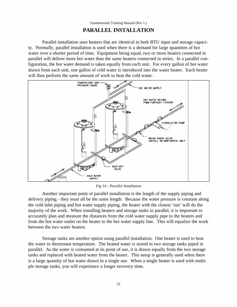
PARALLEL INSTALLATION
Parallel installation uses heaters that are identical in both BTU input and storage capaci-ty. Normally, parallel installation is used when there is a demand for large quantities of hotwater over a shorter period of time. Equipment being equal, two or more heaters connected inparallel will deliver more hot water than the same heaters connected in series. In a parallel con-figuration, the hot water demand is taken equally from each unit. For every gallon of hot waterdrawn from each unit, one gallon of cold water is introduced into the water heater. Each heaterwill then perform the same amount of work to heat the cold water.
Fig 14 - Parallel Installation
Another important point of parallel installation is the length of the supply piping anddelivery piping - they must all be the same length. Because the water pressure is constant alongthe cold inlet piping and hot water supply piping, the heater with the closest ‘run’ will do themajority of the work. When installing heaters and storage tanks in parallel, it is important toaccurately plan and measure the distances from the cold water supply pipe to the heaters andfrom the hot water outlet on the heater to the hot water supply line. This will equalize the workbetween the two water heaters.
Storage tanks are another option using parallel installation. One heater is used to heatthe water to thermostat temperature. The heated water is stored in two storage tanks piped inparallel. As the water is consumed at its point of use, it is drawn equally from the two storagetanks and replaced with heated water from the heater. This setup is generally used when thereis a large quantity of hot water drawn in a single use. When a single heater is used with multi-ple storage tanks, you will experience a longer recovery time.
Fundamentals Training Manual (Rev 1.)
31
PERCENTAGE OF HOT AND COLD WATER MIX
Many consumers do not realize how much hot water they are using in a given draw. This chartshows the percentage of hot water used given the thermostat setting, the cold water inlet tem-perature, and the temperature of the hot water. For example:A water heater with a thermostatsetting of 120° F and the cold water inlet temperature is 50° F and the shower temperature is110° F would use 86% HOT water and 14% COLD water.
Table 8 - Percentage of Hot and Cold Water Mix
Fundamentals Training Manual (Rev 1.)
32
Cold Inlet
Thermostat
400
Mixed Temperature1000 1050 1100 1150 1200
75% 81% 88% 94% 100%450 73% 80% 87% 93% 100%500 75% 81% 88% 94% 100%550 73% 80% 87% 93% 100%600 75% 81% 88% 94% 100%650 73% 80% 87% 93% 100%700 75% 81% 88% 94% 100%750 73% 80% 87% 93% 100%
1200
Cold Inlet
Thermostat
400
Mixed Temperature1000 1050 1100 1150 1200 1250
71% 76% 82% 88% 94% 100%450 69% 75% 81% 88% 94% 100%500 67% 73% 80% 87% 93% 100%550 64% 71% 79% 86% 93% 100%600 62% 69% 77% 85% 92% 100%650 58% 67% 75% 83% 92% 100%700 55% 64% 73% 82% 91% 100%750 50% 60% 70% 80% 90% 100%
1250
Cold Inlet
Thermostat
400
Mixed Temperature1000 1050 1100 1150 1200 1250
67% 72% 78% 83% 89% 94%450 65% 71% 76% 82% 88% 94%500 63% 69% 75% 81% 88% 94%550 60% 67% 73% 80% 87% 93%600 57% 64% 71% 79% 86% 93%650 54% 62% 69% 77% 85% 92%700 50% 58% 67% 75% 83% 92%750 45% 55% 64% 73% 82% 91%
1300
1300
100%100%100%100%100%100%100%100%
Commercial
Temperatures
Fundamentals Training Manual (Rev 1.)
33
Cold Inlet
Thermostat
400
Mixed Temperature1000 1050 1100 1150 1200 1250
63% 68% 74% 79% 84% 89%450 61% 67% 72% 78% 83% 89%500 59% 65% 71% 76% 82% 88%550 56% 63% 69% 75% 81% 88%600 53% 60% 67% 73% 80% 87%650 50% 57% 64% 71% 79% 86%700 46% 54% 62% 69% 77% 85%750 42% 50% 58% 67% 75% 83%
1350
1350
100%100%100%100%100%100%100%100%
1300
95%94%94%94%93%93%92%92%
Mixed Temperature1500
Cold Inlet
Thermostat
400
Mixed Temperature1000 1050 1100 1150 1200 1250
60% 65% 70% 75% 80% 85%450 58% 63% 68% 74% 79% 84%500 56% 61% 67% 72% 78% 83%550 53% 59% 65% 71% 76% 82%600 50% 56% 63% 69% 75% 81%650 47% 53% 60% 67% 73% 80%700 43% 50% 57% 64% 71% 79%750 38% 46% 54% 62% 69% 77%
1400
1350
95%95%94%94%94%93%93%92%
1400
100%100%100%100%100%100%100%100%
1300
90%89%89%88%88%87%86%85%
Cold Inlet
Thermostat1000 1100 1200 1300 1400 1500
500 50% 60% 70% 80% 90% 100%600 44% 56% 67% 78% 89% 100%700 38% 50% 63% 75% 88% 100%
400 55% 64% 73% 82% 91% 100%
Mixed Temperature1600
Cold Inlet
Thermostat1000 1100 1200 1300 1400 1500
500 45% 55% 64% 73% 82% 91%600 40% 50% 60% 70% 80% 90%700 33% 44% 56% 67% 78% 89%
1600
100%100%
400 50% 58% 67% 75% 83% 92% 100%
100%Mixed Temperature1700
Cold Inlet
Thermostat1000 1100 1200 1300 1400 1500
500 42% 50% 63% 67% 75% 83%600 36% 45% 59% 64% 73% 82%700 30% 40% 55% 60% 70% 80%
1700
100%100%100%
1600
92%91%
400 46% 54% 62% 69% 77% 85% 100%92%
90%Mixed Temperature1800
Cold Inlet
Thermostat1000 1100 1200 1300 1400 1500
500 38% 46% 52% 62% 69% 77%600 33% 42% 48% 58% 67% 75%700 27% 36% 43% 55% 64% 73%
1700
92%92%91%
1800
100%100%100%
1600
85%83%
400 43% 50% 57% 64% 71% 79% 93% 100%86%
82%

FORMULAS AND FACTS
1 gallon of water weighs 8.33 lbs
1 gallon of water has a volume of 231 cubic inches
1 cubic foot of water weighs 62.38 lbs and contains 7.48 gallons of water
100 feet of 3/4“ copper pipe contains 2.5 gallons of water; 1” pipe contains 4.3 gallons
8.33 BTU will raise 1 gal of water 1°F at 100% efficiency (electricity)
11 BTUs are required to raise 1 gallon of water 1°F at 70% efficiency (gas)
3,412 BTU equals 1 kilowatt hour (Kwhr)
1 Kwhr will raise 410 gallons of water 1°F at 100% efficiency
1 BTU X 0.293 = watts
1 KW = 1000 watts
2.42 watts are required to raise 1 gallon of water 1°F
1 Kwhr will raise 10.25 gal of water 40 degrees F at 100% efficiency1 Kwhr will raise 6.8 gal of water 60 degrees F at 100% efficiency1 Kwhr will raise 5.1 gal of water 80 degrees F at 100% efficiency1 Kwhr will raise 4.1 gal of water 100 degrees F at 100% efficiency
Formula for mixing hot water
M-CH-C = Percent of hot water required to produce desired mixed temperature.
Where M = mixed water temperature; C = cold water temperature; H = hot water temperature
For example: How much of a shower is hot water and how much is cold water? Myshower temperature is 105° F, my water heater thermostat is set on 120° F and the coldwater inlet temperature is 50° F.
105 - 50 = 55 120 - 50 = 70 = 79% of the shower is 120° hot water This formula for mixinghot water is important when explaining a NOT ENOUGH HOT WATER trouble calland the water heater is functioning properly.
Fundamentals Training Manual (Rev 1.)
34
Fahrenheit to Centigrade(°F - 32) * .556
For example: Convert my water heater thermostat setting of 120° F to Celsius
(120° - 32) *.556(88) *.556
49° C
Centigrade to Fahrenheit(°C*1.8) + 32
For example: Convert the outside temperature of 49° C to Fahrenheit
(49° * 1.8) +32(88.2) + 32
120° F
Fundamentals Training Manual (Rev 1.)
35
Electric Gas
Energy Costs:Kwhr x fuel costs = energy costs
If I use 100 kilowatt hours of electricity, howmuch will it cost if each kilowatt hour costs$.05?
100 x .05 = $5.00
Energy Costs:Cubic feet x fuel costs = energy costs
If I use 100 cubic feet of gas, how much will itcost if each cubic foot costs $.075?
100 x .075 = $7.50
Electric Gas
To obtain gallons per hour (GPH) recovery
WATTS2.42 x (temp rise ° F)
I have a 30 gallon electric heater, non-simulta-neous operation, 4500 watt elements. What isthe recover GPH if my cold water is 40° F andmy thermostat is set to 120° F?
45002.42 x 80 = 23 gallons per hour
To obtain gallons per hour (GPH) recovery
HOURLY INPUT (BTUs)11.0 x (temp rise ° F)
I have a 30 gallon gas heater rated at 40,000BTUs. What is the recover GPH if my coldwater is 40° F and my thermostat is 120° F?
40,00011.0 x 80 = 45 gallons per hour

N O T E S
_____________________________________________________________________________
_____________________________________________________________________________
_____________________________________________________________________________
_____________________________________________________________________________
_____________________________________________________________________________
_____________________________________________________________________________
_____________________________________________________________________________
_____________________________________________________________________________
_____________________________________________________________________________
_____________________________________________________________________________
_____________________________________________________________________________
_____________________________________________________________________________
_____________________________________________________________________________
Fundamentals Training Manual (Rev 1.)
36
Electric Gas
Temperature Rise (°F)
WATTS2.42 x GPH
I have a 30 gallon electric heater, non-simulta-neous operation, 4500 watt elements. What isthe maximum temperature rise if the heater canrecover 23 gallons per hour?
45002.42 x 23 = 80 degrees temp rise
Temperature Rise (°F)
HOURLY INPUT (BTUs)11.0 x (GPH)
I have a 30 gallon gas heater rated at 40,000BTUs. What is the maximum temperature riseif the heater can recover 45 gallons per hour?
40,00011.0 x 45 = 80 degrees temp rise

GLOSSARYAerated PilotPilots which inject primary air through an air intake opening and mix the air and gas beforeburning.
A.G.A. (American Gas Association)The association which governs the testing and certification to the ANSI Z21.10.1 standards ofresidential natural and LP gas fired water heaters. AGA is funded primarily from the gas utili-ties and their mission is to support these utilities and manufacturers in the promotion of gas,and gas consuming appliances. With the exception of the mobile home direct vent model whichis U.L. certified, all residential gas water heaters are AGA certified.
Air ShutterMeans by which the size of the primary air opening may be varied to control the amount of pri-mary air intake.
Alternating Current (A.C.)Electrical supply in which the polarity of the hot wire (whether wire is positive or negative)reverses rapidly. A.C. is the normal electrical supply in all parts of the United States.
Ambient TemperatureThe ambient temperature is the average temperature of the atmosphere in the vicinity of theappliance. Performance of water heaters is generally checked with reference to ambient tem-perature rather than a fixed temperature, to allow for a statement of performance which willhold true for summer and winter performance.
AMP or AMPERE (amp)A measure of flow of electric current. An electrical circuit or electrical wiring is designed totake a certain maximum current load, and this should not be exceeded. The amps flowingthrough an appliance are calculated by dividing the watts loading by the voltage.
AnodeThe positive electrode of an electrical cell is called the cathode. An anode may be in the formof an expendable electrode used to reduce or prevent corrosion (see under "galvanic action") oras a source of material in electroplating.
Annual Cost of OperationAn estimate of the yearly operating cost for residential gas and electric water heaters. The U.S.averages for gas and electric fuel rates are provided yearly by the Department of Energy andthis information is used to compute the yearly operating cost data which appears on the EnergyGuide label.
Anode RodThe active metal within a steel glass lined tank which sacrifices itself in order to prevent any
Fundamentals Training Manual (Rev 1.)
37

exposed steel ("cathode") from corrosion. The patented "R-Tech" anode rod used by Rheem ismade of magnesium and is designed to last longer, and offer greater tank protection than thoseused by other manufacturers.
ANSI Z21.10.1 (American National Standards Institute)The testing and safety standards which govern all residential gas fired water heaters up to 100gallon capacity and up to 75,000 BTU's.
Anti-Siphon HoleA small hole located in the dip tube approximately six inches from the top. The anti-siphonhole is designed to prevent the siphoning of water through the cold water line in the event of areverse water flow or siphon condition.
ASHRAE (American Society of Heating, Refrigeration, and Air Conditioning Engineers)An association which recommends standards and test methods used today, primarily for com-mercial water heaters. Prior to the NAECA law which now governs residential water heaters,the ASHRAE Standard 90A-1980 was used as a standard for high efficiency water heaters.While no longer applicable, residential water heaters continue to meet this standard.
ASME (American Society of Mechanical Engineers)May be required on commercial water heaters over 120 gallons or over 200,000 BTUs. TheASME code is generally adopted on a state by state basis.
Automatic Storage Commercial HeaterA water heater that heats and stores water within the appliance at a thermostatically controlledtemperature for delivery on demand, and which has an input rating of less than 4,000 BTU perhour per gallon of stored water. Input rating is above 75,000 BTUH.
Backflow Device - Backflow PreventerA device (valve) which allows water to flow in only one direction. In order to comply with theprovisions of the Safe Water Drinking Act, Municipal Water Systems or local plumbing codesmay require these devices to be installed in the cold water inlet line to prevent water from back-ing up into the central main. Backflow devices cause a closed-loop system which can become apotentially dangerous situation due to the effects of thermal expansion. (See: Check-valve,thermal expansion, expansion tank)
Boiling PointThe boiling point refers to the temperature at which a liquid changes to vapor by the addition ofheat. The boiling point depends on the pressure at which the liquid is held; and it increases asthe pressure increases.
BTU (British Thermal Unit) A measure of energy used to determine the input ratings for natural and LP water heaters. Theamount of energy required to raise one pound of water, one degree Fahrenheit.
Fundamentals Training Manual (Rev 1.)
38

Carbon MonoxideA by-product of gas combustion which is generated as the result of the burning of fossil fuels(natural and LP gas). For safety purposes, the ANSI Z21 standards set specific limits for theamount of carbon monoxide that can be emitted from gas burning water heaters.
Cast Iron BurnerA burner made of cast iron material, used today on the higher input water heaters of 60,000BTU's up to 75,500 BTU's. Previously, cast iron was the preferred burner material used on LPwater heaters until the development of stainless steel burners in the mid-80's.
Catch PanA pan (usually metal) placed under the water heater to help prevent water damage in the eventthe water heater should begin to leak. Most catch pans have either a side or bottom drain fittingwhich should be piped to a suitable floor drain or piped to the outside of the home. Localcodes may govern the type of catch pan required and how it is to be piped.
CathodeThe negative electrode or an electrical cell - the opposite to anode. See also under "galvanicAction".
Check ValveAlso know as a non-return valve, a check valve is intended to allow a fluid to flow in only onedirection in a pipe. Should conditions occur which might lead to flow in the reverse directionthe valve automatically closes.
Chemical RinseA chemical sanitation rinse used in some dishwashers which allows the maximum rinse watertemperature to be 140°F, instead of 180°F.
Circulating Tank HeatersThere are two types as follows:
a. Automatic Circulating Tank Water Heater: A water heater which furnishes hot water tobe stored in a separate vessel. Storage tank temperatures are controlled by means of a ther-mostat installed on the water heater. Circulation may be either gravity or forced.b. Non-automatic Circulating Tank Water Heater: A water heater which furnishes hot waterto be stored in a separate vessel. Storage tank temperatures are controlled by means of athermostat installed in the storage vessel. (The Non-automatic is normally a tube type ofheater).
Circulating Tank SystemA water heating system in which a water heater is connected to a separate storage tank so thatlarge amounts of hot water may be built up for use during relatively short periods of peakdemand. The ratio of recovery to storage is approximately 1 GPH recovery (100°F Rise) togallon stored.
Fundamentals Training Manual (Rev 1.)
39

Coaxial VentA vent system which provides for both outside air for combustion as well as venting of thecombustion exhaust gases in a single vent system. Combustion air enters through the outer airtube and flows to the combustion chamber. Flue gases are discharged through the inner exhausttube and released outside the building. (See also Direct Vent)
Cold Inlet TemperatureThe temperature of outside water coming into a water heating system. Throughout most of theU.S. this temperature is considered to be 40°F. (during the coldest months).
CombustionCombustion takes place when gaseous, liquid or solid fuels react at an elevated temperaturewith oxygen by burning, thus releasing heat. For good combustion an adequate supply of oxy-gen must be available, and all the carbon in the fuel will be converted to carbon dioxide and allthe hydrogen to water vapor. The presence of carbon monoxide in the flue gases and/or sootingindicates imperfect combustion.
CondensationCondensation can form on the tank when it is first filled with water. The condensation mightalso occur with a heavy water draw and very cold inlet water. Drops of water falling on theburner can produce a sizzling or pinging sound, and water may also be seen beneath the heater.This condition is not unusual, and will disappear after the water in the heater becomes heated.Undersized water heaters can result in excessive water condensation.
Convertible Thermostat ControlThe type of control used on manufactured housing (mobile home) gas water heaters. This con-trol is designed so it can use either natural gas or liquid petroleum (LP) gas as its fuel source.This type of control is not permitted on standard gas water heaters.
CycleThe number of times per second that a conductor carrying AC returns to the same polarity.Generally, 60 cycle AC is supplied. The cycles do not affect heating elements, but may effectauxiliary equipment such as solenoids or coils. Synchronous motors, as used in clocks and tim-ing mechanisms, are directly affected by changes in cycle (see also "Hertz").
D.C. (Direct Current)Electrical supply in which the polarity of the two wires (whether wire is positive or negative)does not change. Batteries produce DC. DC supply is also found in railway use, on boardsome ships and in older types of generating equipment. While elements will operate equally onDC or AC auxiliary equipment such as thermostats, motors etc., do not, and special arrange-ments have to be made to enable an appliance designed for AC to operate on DC.
D.O.E. (Department of Energy)Regulates the efficiency standards of all residential gas and electric water heaters with capaci-ties from 20 to 120 gallons and inputs up to 75,000 BTU. The current NAECA standards are
Fundamentals Training Manual (Rev 1.)
40

administered by the Department of Energy which is required to review and recommend changesto the efficiency standards.
Dielectric unionsGenerally a plastic lined nipple used in water systems of dissimilar metals to break the galvaniccircuit such as that created by copper and galvanized steel. In most modern homes where cop-per piping is used throughout, the use of dielectric unions is not necessary.
Dip TubeA non-metallic tube extending from the cold water inlet to a predetermined area near the bot-tom of the tank that feeds cold water into the water heater The length of the dip tube will varybased on the tank dimensions, and efficiency of the heater. The length of the tube is preciselymeasured in order to prevent excessively high temperatures at the top of the tank (stacking)during short draws of water.
Direct VentDesigned to use outside air for combustion rather than the inside air from within a home orbuilding. The term "balanced flue" refers to the fact they draw in the same amount of air asthey exhaust. Two types of direct vent products are offered. A horizontal direct vent whichhandles both combustion air and discharge gases through a single, coaxial vent. The mobilehome direct vent brings in combustion air from below the floor and discharges combustionproducts vertically through a roof jack.
DisplacementHot water is much less dense than cold water and this is used in the displacement principle onwhich most storage water heaters operate. If cold water is fed into the bottom of a tank full ofhot water it will displace an equal quantity of hot water out of the top of the tank and if theheater is correctly designed, the hot water will float on the cold water for a considerable timewithout mixing.
Draft Diverter (vent hood)Capping device that connects the water heater to the venting system. The draft diverter aids inthe venting by providing a higher ambient air pressure and assists in the updraft movement ofcombustion gases. Draft Hood equipped water heaters operate under a non-positive type ventpressure. The heat of the flue products provides the thermal lift to achieve a draft in the vent,with cold air entering the combustion chamber to replace the hotter air rising. The draft hoodalso functions as a relief opening in the event that the flue becomes blocked or experiences adown draft.
Drain ValveValve used primarily to drain the hot water when performing periodic cleaning or replacing apart.
Draw RateThe rate at which water is drawn from a water heating system, usually expressed in gallons per
Fundamentals Training Manual (Rev 1.)
41
minute (GPM). In residential applications, this is usually restricted to a single delivery pointsuch as a shower head.
Dry FiringRefers to the condition of supplying power to an element in a water heater that is not complete-ly full of water. Power supplied to an element not submerged in water can cause the element to"burn out" and fail to operate.
ECO - Energy Cut-OffA safety cut-off switch built into the thermostat of a water heater to shut off the flow of gas orelectricity before temperatures reach unsafe levels. The ECO will trip off at approximately 170degrees Fahrenheit (electric) or 190 degrees Fahrenheit (gas).
EfficiencyEfficiency is a measure of performance expressing the results obtained as a percentage of effortput in. On this basis, thermal efficiency is the percentage of the potential heat content of a fuelwhich becomes available as hot water (or hot air in the case of a space heater). Thermal effi-ciency is a measure of performance under stated conditions, and the efficiency will vary as con-ditions are varied. Accordingly, official or test thermal efficiencies should not be quoted orused unless the circumstances are comparable to the method of test. See also "Pipe Losses".
Electronic IgnitionAlso called intermittent ignition system. The ignition system of the residential power ventwater heater. Helps reduce standby losses by igniting the pilot only during the burner cycle.Also prevents nuisance pilot outage due to down draft conditions.
Energy FactorA measure of the overall efficiency rating of a water heater... the higher the number the moreefficient the water heater.
EverKleenTM
Specially developed inlet tube that creates a high-velocity spiraling water stream which helpsdislodge sediment and prevent buildup in the tank. It also creates better mixing throughout thewater heater tank which reduces the effects of stacking.
Expansion TankA tank with a sealed-in compressible air cushion which will compress as thermal expansionoccurs...providing a space to hold and store the additional expanded water volume. Expansiontanks are used when check valves, back flow preventers, or pressure reducing valves areinstalled in a water system to deal with the effects of a "closed loop" condition.
First Hour RatingThe calculated amount of hot water a fully heated water heater can deliver in the first hour peri-od.
Fundamentals Training Manual (Rev 1.)
42

FatigueJust as the human body can break down if exposed to an adverse environment or repeatedstress, so can materials fail due to fatigue. A material can fail by repeated exposure to a stresswell below its normal breaking point purely by cycling the stress on and off. Water heaters canbe exposed to repeated pressure fluctuations during their life and must be designed to resist theeffects of fatigue.
Flow Control ValveThese are devices that are installed between the supply pipe and the plumbing fixture (showerhead, faucet, etc.) to reduce the flow of water to a constant level. They are highly recommend-ed for large shower installations because they can often reduce the flow of water more than halfwithout disturbing the spray pattern. This, of course, results in a savings of water and the ener-gy required to heat the water.
Flow RateFlow rate is the amount of water in gallons flowing in a plumbing fixture or pipe over a periodof time, normally minutes. Flow rate is normally given in gallons per minute. (GPM)
Flue BaffleA device inside the flue that restricts the flow of the heated combustible air to allow for betterheat transfer between the flue and water inside the tank.
GPH (Gallons per Hour) The term used to measure the recovery rate of a water heater. A water heater at a certain inputrate will recover "x" amount of gallons per hour at a certain temperature rise. The higher thetemperature rise needed, the less a water heater will supply in GPH.
GPM (Gallons per Minute)This stands for gallons per minute and refers to the amount of water flowing through a plumb-ing fixture or pipe.
Galvanic ActionIf two unlike metals are immersed in an electrolyte, an electrical potential will exist betweenthem. If the two are in electrical contact, an electrical current will flow. The metal whichbecomes the anode of this cell will corrode and dissolve, while the cathode will be protectedfrom corrosion. The two metals do not have to be vastly different for this effect to take place,It can occur with copper and a copper alloy. It can even occur with two different parts of thesame sheet, tube or rod.
Glass-linedA coating of enamel bonded to the inside of the tank to help protect the tank from corrosive ele-ments in the water. This is a coating of vitreous enamel bonded to an iron or steel surface byfiring at red heat. The enamel is a special formulation resistant of hot water and is not the sametype of glass as that used in windows and glassware. Glass lined heater may be referred to as'glass enamel lined', 'glass enameled', 'vitreous enameled' or 'bonded vitreous enamel'.
Fundamentals Training Manual (Rev 1.)
43
GrainA measure of weight. There are 7,000 grains in one pound.
Hardness (of water)Natural waters contain impurities in various proportions. Some of these impurities affect thelathering of soap in such water. The main impurities are the soluble slats of magnesium andcalcium. The hardness of a water is its difficulty in raising a lather. Hardness is measured interms of the equivalent amount of calcium carbonate in a solution which would cause equal dif-ficulty in lathering. It may be quoted as 'grains per gallon' or 'parts per million' or 'parts per100,000'. The hardness is generally determined by finding the quantity of a specially preparedsoap solution. It is necessary to add to a known quantity of the water in order to establish apermanent lather. To convert parts per million to grains per gallon, divide by 17. A generalclassification of waters would be:
Type Hardness Grains per GallonSoft 0 - 49 ppm 0 - 3 grainsFairly soft 50 -99 ppm 3 - 6 grainsFairly Hard 100 - 149 ppm 6 - 9 grainsHard 150 - 249 ppm 9 - 14.5 grainsVery Hard 250 (plus) ppm 14.5 (plus) grains
Heat LossA hot body looses heat by the combined effects of conduction, convection and radiation.
Heat Trap FittingsA device that helps reduce heat transfer from the water heater to the pipes. It contains a ther-moplastic ball that seat themselves in place to help restrict heat transfer when hot water is notrunning. A Teflon ball (heavier than water) seats to trap standby heat on the hot outlet fitting.Similarly, a polypropylene ball (lighter than water) in the cold water inlet fitting floats up toseat during the standby mode.
Heat UnitA measure of heat energy. In English speaking countries, it is the BTU (British Thermal Unit).In Europe, it is the calorie (also spelled Calorie or Kalorie).
Hertz (Hz)A measure of frequency. One Hertz equals one cycle per second. 60 cycles AC is also called60 Hertz AC.
High AltitudeAs related to water heaters, the orifice is changed to help aerate the gas supply to the heater sothat it will operate properly in areas of higher altitude (thinner air). Standard water heaters aredesigned to operate safely up to 2,000 ft. Per the requirements of ANSI and the National FuelGas Code, the de-rate above this level is 4% per 1,000 feet altitude. Rheem generally de-ratesgas products to a 5,000 ft elevation which results in a 20% reduction in BTU input.
Fundamentals Training Manual (Rev 1.)
44

High Watt Density ElementThe watt density of an element is the amount of heat transferred from any point on the surfaceof the element of the water. A high watt density element has less surface area of heating ele-ment than a low watt density element, but is transferring the same amount of energy into thewater.
Input RateA measure of heat input to a water heater; BTU's per hour of gas, WATTS per hour of electrici-ty. The higher the input rate, the more hot water it will produce.
Input RatingThe gas-burning capacity of a water heater in BTU's per hour. Water heater input ratings arebased on sea level operation and need not be changed for operation up to 2,000 feet elevation.For operation at elevations above 2,000 feet, input rating should be reduced at a rate of 4% foreach 1,000 feet above sea level. For instance, a gas heater with a 40,000 BTU input ratinginstalled at 4,000 feet above sea level would have a reduced BTU rating of 33,600 BTU's.
Instantaneous Water HeaterA water heater which has an input rating or at least 4,000 BTU per hour per gallon of storedwater.
Intermittent IgnitorAlso referred to as an I.I.D. (Intermittent Ignition device). The ignition system of the residen-tial power vent water heater. This is used to light the pilot during the heating cycle.
Junction BoxThe place in electric water heaters where the power supply is connected to the water heater.Water heaters wired for 3-phase operation will require a separate external junction box.
Kilowatt (kW)A measure of the rate of supply of energy or power and is equal to 1,000 watts. A kilowattequals 3,412 BTU per hour.
LifeguardTM ElementA trade marked registered heating element offered by Rheem. The element has a stainless steelouter sheath of INCOLY® 800, the same material found in electric range elements. The LIFE-GUARDTM element is a low watt density design and contains a small resistor built into the ele-ment to reduce cathodic reaction with the water inside the tank. This effectively will prolongthe anode life and protect the tank for a longer period, especially in areas with aggressive waterconditions.
Lime BuildupMineral deposits usually found in hard water. (See sediment build up)
Fundamentals Training Manual (Rev 1.)
45
Lint ScreenRemoves lint and dirt from primary air before it enters the primary air opening. Also traps par-ticles on the inlet side of a gas control valve.
Low NoxTerm that refers to natural gas water heaters required in select areas of California which arebuilt with a special burner to help reduce or limit the amount of nitrous oxides (Nox) releasedduring the combustion process.
Low Watt Density ElementThe watt density of an element is the amount of heat transferred from any point on the surfaceof the element of the water. A low watt density element has more surface area of heating ele-ment than a high watt density element, but is transferring the same amount of energy into thewater. A low watt density element will generally last longer than a high watt density element.
Maintenance Rate (Stand-by losses)The maintenance rate is the rate which heat or energy has to be supplied to an appliance tomaintain its temperature at the required level when the unit is not being used. In the case of astorage heater, it is the heat input required to hold the unit at the required temperature (general-ly 80°F above ambient on gas heaters and 100°F above ambient on electric heaters). The main-tenance rate may be measure in BTU per hour for gas or kilowatts per 24 hours for electricity.The temperature above ambient must always be quoted.
Multiple Heater InstallationThis is an installation where a number of heaters are used to supply the total building hot waterrequirements. The heaters are manifolded together in one location and the installation can bedefined as a 'central water heating system'. This is one of the easiest systems to service andmaintain. When one heater is being serviced, the remaining heater(s) will continue to supplyhot water.
Multi-Watt ElementAn element that has the capability to function at two different wattages. The Multi-Watt ele-ment offered by Rheem is convertible from 3800 to 5500 watts.
NAECANational Appliance Energy Conservation Act of 1987... The Federal Law enacted by Congresswhich sets minimum energy efficiency standards for residential water heaters and other prod-ucts. Effective with water heaters produced on or after January 1, 1990. NAECA supersedesall previous state and local energy efficiency requirements.
NPT (National Pipe Thread)
NipplesCan be made of various materials. Used to connect the water heater to the piping system.
Fundamentals Training Manual (Rev 1.)
46

Nitrous OxideBy-product produced in the combustion process of natural gas water heaters.
Off-Peak MeteringRequired by some electric utilities to reduce excessive electricity demands during peak periods.Radio controlled or timed meters are the most common method of off-peak metering.
OrificeDevice on the burner assembly that controls the flow of gas to the burner.
OutputThe output on a water heater is normally given in gallons per hour at a 100°F temperature rise.It is the quantity of water that the heater will deliver at 140°F, when the cold start temperatureis 40°F. All water heaters are stamped with this output rating in gallons per hour.
PVC Venting3" PVC (or ABS) schedule 40 pipe can be used to vent Power Vent water heaters.
Peak PeriodPeak period refers to the time during the day when the water heating system experiences itgreatest draw (demand). With the exception of applications that require continuous hot waterdraw, tests have shown that the peak period of hot water usage will occur once or twice a day inresidential applications. Peak periods for commercial applications are dramatically different. Apeak period in a school gymnasium shower may occur ever hour!
PhaseFor ease of production and distribution, AC is distributed in what is known as 3 phase supplyusing three active wires and one neutral wire. On a 240/480 volt supply, the voltage betweenany one active wire and the neutral wire is 240 volts. The voltage between any two activewires is 480 volts.
Pilot BracketThe means by which the pilot is mounted to the burner. The bracket also holds the thermocou-ple or sensor in fixed relationship to the pilot burner ports
Pilot LightThe flame designed to be continuously lit that ignites the main burner when the thermostatdemands heat.
Pilot OrificeA cup shaped part in the pilot which contains precisely sized openings which control theamount of gas to the pilot.
Pilot PortsThe openings through which the gas or gas and air mixture passes before burning.
Fundamentals Training Manual (Rev 1.)
47

Pipe LossesCertification tests of a water heater are carried out on an isolated heater - not connected to hotor cold water lines. (Note: Stand-by losses determined do not apply to the installed heater.)Additional losses take place when installed. These are called 'pipe losses' and are made up of:
1) Conduction of heat along the hot and cold water pipes. This effect is generally limited inextent.2) Convection of water in the hot water line above the heater. This effect can be quite large,but can be reduced considerably by introducing a 'heat trap' in the hot water line at theheater.3) Radiation from the hot water pipes and fittings. These are reduced by insulating.4) Between uses, the water in the hot water line gets cold. This has to be run off before hotwater can be drawn from the fixture.
The overall effect is reduced by the following means:1) Fit a heat trap in the hot water lines.2) Use small diameter pipe.3) Use short runs of pipe.4) Insulate hot water pipes, particularly the section nearest the heater.
Pre-heated WaterThis is the water that has been heated in one water heater before going to another water heaterto be raised to an even higher temperature. For instance, in restaurants there will often be oneheater that will heat incoming water to 140°F (general purpose water). This pre-heated waterwill go into a booster heater to be heated to 180°F for the sanitizing rinse cycle of some dish-washers.
Pressure Reducing ValveA valve which automatically reduces inlet water pressure to a specified value at its outlet, understatic cold water conditions.
Primary Air IntakeThe hole or opening through which air is drawn to mix with a gas for burning.
Polyurethane Foam InsulationThe foam used to insulate the water heaters for high energy efficiency.
POWERGLOTM
Name given to ignition system on Rheem power vent products.
Power VentGas water heater that uses a blower to vent the flue gases out of the heater. The power ventwater heater can be vented horizontally rather than vertically as required by conventionalatmospheric water heaters. This allows you to vent directly outside through a wall. May alsorefer to an after-market blower kit that may be attached to a natural draft gas heater.
Fundamentals Training Manual (Rev 1.)
48

R-FoamTM InsulationRigid polyurethane foam insulation has been proven to be a more effective insulating materialin reducing the standby loss through the jacket than previously used fiberglass. Generally, withregard to electric heaters, the more insulation, the more efficient the heater becomes. Today'sfoam material utilizes an HCFC blowing agent which is environmentally friendly.
R-TechTM AnodePatented anode design that reduces current draw and results in a longer anode life. Works inconjunction with the resistered heating element and is also effective with aggressive water areaswhich produce hydrogen sulfide (smelly water).
R-ValueA measure of insulating value. Generally, the higher the R-Value, the greater the resistance toheat loss.
RecoveryGallons of water per hour a water heater can raise the temperature of by 90°. Generally, thehigher the BTU input rate, the faster the recovery rate is. Recovery rates are also a componentof the First Hour Rating.
Recovery Efficiency %The percent of heat value transferred from its fuel source. The better the recovery efficiency,the more energy efficient a water heater is. Electric water heaters are assumed to be 98% effi-cient as virtually all the electric energy is transferred to the water. Gas water heaters can haverecovery efficiency rates of 76% up to over 90%. This is only one measure of efficiency... theENERGY FACTOR is the best overall measure of a water heaters efficiency.
Recovery RatingAll certified commercial water heaters are required to be stamped with this information. It isthe quantity of water obtained by dividing the manufacturer's input rating in BTU per hour by1100 BTU per gallon. This is based on a 100°F temperature rise, 75 percent thermal efficiencyand a nominal specific heat for water of 8.25 BTU per gallon per °F.
Resistored ElementElement available from Rheem that has a small resistor built into the element to reduce cathod-ic reaction with the water inside the tank. ALL electric water heater elements supplied byRheem are resistered.
Roof Jack VentUsed with manufactured housing gas water heaters, the roof jack is the venting system from thewater heater to the outside air. It is adjustable to accommodate different roof thickness andpitches. A roof jack supplied by Rheem is required on any mobile home direct vent waterheater.
Fundamentals Training Manual (Rev 1.)
49

SCAQMD (South Coast Air Quality Management District)Required by the Environment Protection Agency to limit the amount of nitrous oxides (Nox)emissions from residential natural gas water heaters up to 75,000 BTU. The SCAQMDrequirements are enforced in various areas of California.
Safety Shut-off ValveA device on a gas appliance which shuts off the gas supply to the appliance to prevent a haz-ardous situation. A flame failure safety shut off (or safety pilot) operates when the actuatingflame becomes extinguished. A "100%" shutoff valve cuts off all gas including main and pilotburners. Other types may cut off only the supply to main burners.
Sanitizing Water (180°F)Sanitization means the effective bactericidal treatment of dishes and utensils. Sanitization isbased on the principle of heat build up at the surface of dishware. Temperatures at the surfaceof the clean dishes must be hot enough (180°F) in the final rinse cycle of dishwashers to com-plete effective sanitation, that is, destruction of harmful microorganisms or germs. Further,180°F rinse temperature effectively air dries chinaware, glassware and utensils.
Sediment Build-UpSediment or scale build up is one of the most serious problems caused by hard water mineraldeposits. These deposits, commonly called lime build up, may clog water pipes, collect in thebottom of water heaters and collect on electrical heating elements immersed inside the waterheater. The build up on the electrical heating elements will insulate the elements and reducetheir efficiency. Eventually, the elements will fail. If this sediment is allowed to remain in thetank, it will gradually sink to the bottom where it will harden into an insoluble scale. This willlead to a reduction in the efficiency of the heater, clogging of the drain valve and may lead toeventual tank failure.
Self Contained Commercial Storage HeaterA water heater that heats and stores water at a thermostatically controlled temperature for deliv-ery on demand. Input rating above 75,000 BTUH. They are ideally suited for applicationswhere there are several short peak period draws. Basically they can re-heat a volume of waterequal to their storage capacity 1 ½ to 2 ½ times each hour.
Simultaneous WiringA double element heater may be wired for simultaneous operation. This means both elementswill heat at the same time during the initial fill or during heavy water draws.. This can be use-ful when there is a requirement for a rapid recovery time. This does not mean that both ele-ments will always fire simultaneously. During normal water draws, only the bottom elementwill fire, similar to a non-simultaneous heater.
Smelly WaterHydrogen sulfide (H2S) is a gas present in some waters. There is never any doubt when it ispresent due to its offensive '"rotten egg" odor in concentrations as low as one part per million.Hydrogen sulfide is present in the incoming cold water supply and normally found only in
Fundamentals Training Manual (Rev 1.)
50

ground water. Hydrogen sulfide gas can produce a favorable condition for the growth of organ-isms referred to as 'sulfate reducing bacteria'. This favorable condition is enhanced with theapplication of heat, such as in a hot water heater. The smell is most noticeable with the first hotwater draw in the morning or maybe when you get home from work.
StackingOccurs when frequent small draws of water create different temperatures throughout the tankresulting in increased peak temperatures at the top of the tank. ANSI /AGA certification testingsets specific limits as to the temperature differential between the bottom and top of the tank.One of the benefits of The EverKleenTM system is that it greatly reduces peak temperatures andstacking effects, thus increases first hour deliverability.
Stand KitRaises gas water heater 18" above floor level as required by many codes.
Standby LossThe heat energy lost during standby mode operation of the water heater. Most standby loss ingas water heaters occurs through the flue system. Electric water heaters standby loss occursthrough the exterior jacket.
Storage Water HeaterA water heater incorporating a storage tank such that water can be heated whether water isflowing through the heater or not (as contrast to instantaneous Water Heater).
System TemperatureThis refers to the temperature of the water actually in the water heater, i.e., 140°F, 180°F,180°F, etc. This is as opposed to the inlet temperature (water coming into heater) or the usetemperature ( the water as it is used from the heater, either at heater temperature or mixed withcold).
TemperatureThis is a measure of "hotness" or "coldness” or the ability to transmit heat outward or receiveheat inward. Heat and Temperature can be compared to water and heights. As water will flownaturally down hill, so heat flows from the higher temperature to the lower. The flow in thereverse direction requires the application of energy in some way. Temperature is normallymeasured in Fahrenheit degrees (°F) but in scientific literature it may be quoted as Celsius (°C).
Temperature and Pressure (T&P) Relief ValveSafety device that vents extreme pressure and excessively hot water outside the tank to preventtank rupture and explosion. Commonly called the T&P valve, it is designed to operate atapproximately 150 PSI or 210° F.
Temperature RiseThe difference in temperature between the desired hot water and the incoming cold water,expressed in degrees Fahrenheit. If the desired temperature at the faucet is 120° F and the
Fundamentals Training Manual (Rev 1.)
51

incoming cold water is 70° F, the required temperature rise is 50° F (120° - 70° = 50°).Temperature rise is the number of degrees Fahrenheit that the water must be raised either fromthe inlet water temperature or a pre-heat water temperature. In short, the temperature rise is thedifference between existing water temperature and desired water temperature.
Thermal ExpansionWhen water is heated it expands. However, water is not compressible. Therefore, the expandedwater along with a "closed" water system creates a dangerous pressure in the water heater andsystem piping. The "closed" condition is usually due to a check valve or "backflow preventer"installed in the system. This pressure will cause the T&P valve to open at approximately 150PSI. The T&P, however, is not designed to open on a regular basis and could eventually fail.If the T&P does not function properly, there is a potential safety hazard. Expansion tanks arethe most widely used device to deal with the effects of thermal expansion. On being heated, allsolids and liquids expand, the exact amount of expansion varying with different materials. Theexpansion of metals is used to operate solid stem thermostats where two materials of differentexpansion characteristics are coupled. The different expansion rates of the two materials canoperate a valve or switching mechanism. The expansion of liquids on heating has three effects.First, there is an increase in volume. This increase has to be allowed for by provision of a reliefvalve which allows the extra volume of water to leave the storage cylinder. The second effectis that expansion with heat makes the liquid less dense, making heated water lighter than coldwater, and causing it to rise by means of "convection currents". This effect is used in circulatingwater heaters which are used with storage tanks fitted with hot and cold connections. In theseinstallations the hot water rises from the heating unit up the hot outlet to the storage tank, andcold water flow from the tank down the cold inlet to the heating unit. The third effect is that hotwater, being less dense than cold water, will float on top of cold water without much mixing forsome time. This principle is used in all displacement water heaters and allows cold water toenter the tank (while hot water is taken from the top) without mixing with the hot water.
Thermal InputThe rate at which heat energy is supplied to an appliance. The Nominal Thermal Input (N.T.I.)is the basic or nominal input at which the unit was tested and to which published performancefigures apply. For gas units, the N.T.I. should be measured in BTU per hour. Orifice size sup-plied and published gas pressure at the orifice give N.T.I. on one particular gas only, and adjust-ment may be needed on other gas types. Electrical appliances are rated in Kilowatts or Watts,(1 Kilowatt equals 1000 watts). Again this applies only to the voltage for which the element isdesigned.
ThermocoupleBi-metal device that, when heated by the pilot flame, carries millivolt current to the magnetassembly inside the gas control valve. Typically seen on residential applications
ThermopileServes same function as a thermocouple; however, it contains a group of thermocouples built in'series' and has a larger diameter than a thermocouple. Typically seen on commercial applica-tions.
Fundamentals Training Manual (Rev 1.)
52
ThermostatA device which automatically maintains a predetermined temperature in an appliance.Thermostats can be of the "immersion" type where the actuating components are immersed inthe fluid whose temperature is to be controlled or of the "surface mounted" type where the actu-ating components sense the fluids temperature through the wall of the tank. Thermostats can be"snap acting" i.e. operate from full-on to full-off and vice versa or "modulating" operating grad-ually from full-on to a minimum by-pass flow and vice versa. Some thermostats combine amodulating function from full-on to low-fire then snap action to off. The "differential" of asnap action thermostat is the temperature difference between the opening and closing functions.
TransformerUsed in PowerVent water heaters and UniversalTM commercial gas water heaters to activate theelectrical components.
Two Temperature SystemThis is a system that uses one heater to supply two different water temperature requirementswith the use of a mixing valve. The way it works is that the application requiring the hottestwater is fed directly from the heater, while water for the lower temperature application goesthrough a mixing valve to be combined with cold water to achieve the desired lower tempera-ture. This is most often found in food service applications.
U.B.C. (Uniform Building Code)
U.L. (Underwriters Laboratory)An independent laboratory for testing and listing products which meet standards set by UL andthe American National Standards Institute.
U.L. 307bThe standard which govern the Direct Vent Mobile Home product
UnventedAs applied to most gas appliances, this means that the unit is not connected to a secondary flue.As applied specifically to water heaters this means that there is no open exhaust or vent pipe inthe hot water system open to atmosphere at all times.
Use TemperatureThis is the temperature of the water as it is actually used. For instance, water for showers maybe stored in the heater at 140°F but is mixed with cold near the point of use to arrive at usetemperature of 95°F to 110°F.
Vacuum SwitchOr pressure switch. Used in power vented water heaters. The vacuum switch verifies that thevent motor is running, after which gas is allowed to flow to the main burner.
Fundamentals Training Manual (Rev 1.)
53

Volts (V)The voltage is a measure of the electrical pressure between two conductors. Open circuit volt-age is the voltage measured between two conductors when no appliance or other load is con-nected to them. Closed circuit voltage is the voltage as measured across the terminals of anappliance with the appliance is turned on and is operating. Generally speaking, the closed cir-cuit voltage will be lower than the open circuit voltage.
Water HammerA loud pounding usually caused by high water pressure when a faucet is turned off or washervalve is closed.
WattsA measure of the rate of consumption of energy. Watts are calculated from volts and amps (sin-gle phase only) as follows: Watts = volts x amps.
Weeping T&PThe Temperature and Pressure relief valve opening due to high pressure (150 PSI) or high tem-perature (210°F).
N O T E S
_____________________________________________________________________________
_____________________________________________________________________________
_____________________________________________________________________________
_____________________________________________________________________________
_____________________________________________________________________________
_____________________________________________________________________________
_____________________________________________________________________________
_____________________________________________________________________________
_____________________________________________________________________________
_____________________________________________________________________________
_____________________________________________________________________________
Fundamentals Training Manual (Rev 1.)
54

N O T E S
_____________________________________________________________________________
_____________________________________________________________________________
_____________________________________________________________________________
_____________________________________________________________________________
_____________________________________________________________________________
_____________________________________________________________________________
_____________________________________________________________________________
_____________________________________________________________________________
_____________________________________________________________________________
_____________________________________________________________________________
_____________________________________________________________________________
_____________________________________________________________________________
_____________________________________________________________________________
_____________________________________________________________________________
_____________________________________________________________________________
_____________________________________________________________________________
_____________________________________________________________________________
_____________________________________________________________________________
_____________________________________________________________________________
_____________________________________________________________________________
Fundamentals Training Manual (Rev 1.)
56
_____________________________________________________________________________
Fundamentals Training Manual (Rev 1.)
55

®
WATER HEATERSPRINTED IN U.S.A. 08/02 WP FORM NO. SVC100 REV. 1
Rheem® Water HeatersRuud® Water Heaters2600 Gunter Park Drive EastMontgomery, AL 36109-1413
1-800-HEATER3www.rheem.com