MCS Microprocessor Manual - Schaub Chiller Service
73
MCS Microprocessor Manual Drake Refrigeration Inc. 2/19/2015 Rev. 1
-
Upload
khangminh22 -
Category
Documents
-
view
1 -
download
0
Transcript of MCS Microprocessor Manual - Schaub Chiller Service

MCS Microprocessor Manual
Drake Refrigeration Inc. 2/19/2015
Rev. 1

Table of Contents
1. Using the keypad 2. How to Connect to a PC with MCS-Connect 3. Basic Start-up Procedure 4. Troubleshooting
Drake Refrigeration Inc. 2/19/2015
Rev. 1

Using the Keypad
Drake Refrigeration Inc. 2/19/2015
Rev. 1

1
Magnum Keypad / Display Rev 2.0 (HVAC 8.00 & Higher)
The MCS Commitment
Our commitment is to provide practical solutions for the industries needs and to be both a leader and a partner in the effective use of microprocessor controls.
Micro Control Systems, Inc. 5877 Enterprise Parkway Fort Myers, Florida 33905
PH: (239) 694-0089 FAX: (239) 694-0031 www.mcscontrols.com
(Our Website contains product descriptions, manuals, software releases, troubleshooting
aids, training videos, case studies, etc.)
Information contained in this manual has been prepared by Micro Control Systems, Inc. and is company confidential and copyright © protected 2006. Copying or distributing this document is prohibited unless expressly approved by MCS.
Drake Refrigeration Inc. 2/19/2015
Rev. 1

5
3. Keypad / Display specifications
3.1. Cable Connection
6 wire (3 twisted pairs) shielded cable 10’ length
+12V
SC
L 485+G
ND
SD
A 485-
+12V SCL 485+GND SDA 485-
BLA
CK
PU
RP
LE
BR
OW
N
BLU
E
YE
LLO
W
RE
D
YELLOW
BROWN
PURPLE
BLACK
RED
BLUE
KEYPAD / DISPLAY
KEYPAD / LCD
MAGNUM
Drake Refrigeration Inc. 2/19/2015
Rev. 1

MAGNUM VERS
4. MagThe following and MCS-Con
4.1.
The cscreeaddit
09
WT 0
09
AM1138
09:5-Sta-Out-Inp-Ala-Gra Hel
SION 8 MANUAL
gnum Disis an examina
nnect program
. Magnum
M4.1.1.
The main ACTUAL D
In4.1.2.
current status en. This followional informati
U4.1.3.
ACTUAL D
U4.1.4.
If tonnage ACTUAL D
The abovecalculation
9:55 UnUNIT IS
025TD ACT WTD0 0 40TARGET=45. P
9:55 UnUNIT IS
025MP&VLT KW&0.0A 73.88.0V 47
P
55 Main atus -tputs -puts -arms -aphs -lp
splay Suation of all the
m.
m keypad
Menu Scree
menu is acces
DISPLAY
ntroduction
of the unit andwing screen wil
ion on each co
Unit status
DISPLAY
Unit Tonnag
/KW informatio
DISPLAY
e screen is basn are displayed
nit 45/5S UNLOADED :42:33 D% DLY RO0% 180 0.0 (ADJ +0.0PG P
nit 60/6S UNLOADED :42:33 &TON KW/T8K 0.1579T PG PG
Menu Setpoints Serv Tools Lckout RST Lckout ALM Passwords LARGE
ummary information sc
and displa
en
ssed by press
n to Status
d compressorsl be displayedompressor.
ge and KW
on is available
sed upon flowd on the scree
54
OC 0 0) G
HH WAN#ST
65
TON 5
G
HH AMP Am Vo
HH:M-Con-Rela-Sen-Alar-GrapMenu
0
creens that ca
ay
ing the “Menu
s Screens
s is displayed . By pressing
W Informatio
e the following
w of 230 GPM aen.
:MM NTED ACTUTEPS #STE TARG
:MM PandVLT Kmps oltage
M trol Status Dis
ay and Analogsor Input Dispm Display ph Display u Navigation Hel
n be accessed
u” key.
DESCR
by selecting ththe PG or PG
DESCR
on
screen is add
DESCR
and power fac
CHILL CURRENT CON TIME IN CURUAL WANTEPS ACTUGET SETPOINT PAGE
CHILL CURRENT CON TIME IN CURKWandTON KW Tons PAGE
Main splay g Output Displaplay
lp Screen
d through both
RIPTION
he “Status” opG function ke
RIPTION
ded to the statu
RIPTION
ctor (PF) of 1.
LER UNIT NTROL STATE RRENT STATE TED% DELAUAL% NEXT T + TARGET RE UP
LER UNIT NTROL STATE RRENT STATE KW/TON KW/TON wit
E UP
Menu -Setpoint D
ay -Service To-Lockout Re-Lockout Al-Password Enlarged Co
REV
h the Magnum
ption from the “eys you will ge
us screens:
All other valu
LEV/ AY SLOP CHG DIRECRESET PAGE
LEV/ENT th 2 decimal
PAGE
isplay
ools Display eset Display arms DisplayDisplay ntrol On Display
VISION 3.1
m keypad
“Menu” et
es in the
/ENT
PE CTION
DOWN
T TMP
ls
DOWN
y
Drake Refrigeration Inc. 2/19/2015
Rev. 1

MAGNUM VERS
09
SUC 66 55
09
SST 38
09
VLV 27
09
ARO0.00.0
09
SUC 20
SION 8 MANUAL
P4.1.5.
ACTUAL D
C4.1.6.
ACTUAL D
ACTUAL D
4.1.7.
ACTUAL D
4.1.8.
ACTUAL D
:56 CMP CMP OF000:
CT DISC 6P 190P 5F 177F PG
:55 CMP CMP OF000:
T SSH 8 16.9
PG
:55 EXV IS HO000:3
V% DELAY 7 60 PG
:55 CMP CMP OF000:
OC LROC 0A 0.0P 0A 0.0P PG
:55 PRG A-PR
000:00:42 C-LT FLOA0F NORM
PG
Purge Statu
DISPLAY
Compresso
DISPLAY
DISPLAY
Comp
DISPLAY
EXV s
DISPLAY
#1 45/5FF/READY 00;30 OPD MOTO 134P 0% ---- OKG PG
#1 45/5FF/READY 00:42 SCT DSH 97 79.2
G PG
#1 45/5LDING 36:42 SPHT RO 12.2 0G PG
#1 45/5FF/READY 00:42 CNT LIFT 0c 45F 0c 0.8FG PG
1 45/54RG OFF
MODE COOAT 24TMR MAL 27mi
G PG
us Screen (
r status
pressor sta
status
54
OR % K G
54
2
G
HH S PrTem
HH SATTem
54
OC .0 G
HH VLVPer
54
T F F G
HH AROCurAmpLasAmp
4
OL
G
HH SUCTemsuc
0
(only if Purg
atus (only C
:MM SUCTION Dressure mperature T
:MM T.SUCTION Smperature T
:MM V OPEN% TIrcent De Nex
:MM OC rrent Comp. p R.O.C. st Comp. p R.O.C.
:MM TIME IN CURC-LT mperature ofction line
ge cycles a
DESCR
DESCR
DESCR
CENT)
DESCR
DESCR
COM CURRENT CON TIME IN CURDISCHARGE Pressure Temperature PAGE
COM CURRENT CON TIME IN CURSUCT SHEAT Temperature
PAGE
ELECTRONIC CURRENT CON TIME IN CURIME DELAY elay To xt Change PAGE
COMPR CURRENT CON TIME IN CUR LROC Current Am Lift R.O.C Last Lift R.O.C PAGE
Purge Ci CURRENT PURRRENT STATE FLOAf Safety Sta PAGE
are active)
RIPTION
RIPTION
RIPTION
RIPTION
RIPTION
MPRESSOR NTROL STATE RRENT STATE OIL DIFFERE Pressure ---- E UP
MPRESSOR NTROL STATE RRENT STATE SAT.COND Temperatu
E UP
C EXP VLV NTROL STATE RRENT STATE SUCT SHEAT Temperatur E UP
RESSOR NTROL STATE RRENT STATE CNT mp Lift C. Count Lift C. Count E UP
ircuit RGE STATE UNAT y Float atus in UP
REV
LEV/ENT ENTIAL MOTe Am Sta PAGE
LEV/ENT D. DISC S.ure Tempera
PAGE
LEV/ENT T ROC re Rate Of Change PAGE
LEV/ENT LIFT Current L
Lift Rati PAGE
LEV/ENT
NIT MODE 24 T Purge Run Tn last 24 ho PAGE D
VISION 3.1
T TMP
TOR mp % atus DOWN
T TMP
.HEAT ature
DOWN
T TMP
f DOWN
T TMP
Lift
io DOWN
TMP
TMR Time ours DOWN
Drake Refrigeration Inc. 2/19/2015
Rev. 1

4. Screen Layouts
4.1. MENU KEY
4.2. HELP F1
4.3. LARGE F3
Select ‘F 1’ (Help)
Pressing the Menu Key
Results in displaying the 10 available Menu items. The highlight is on the Status display.
To select any item use the ▲ ▼ ◄ ► arrow keys to position the highlight and press ↲.
To understand the options select F1 for help.
For a LARGE display of the current chillers performance press F3.
Select ‘Menu’ then F3 (LARGE)
Pressing the F1 (Help) Key
By selecting the Help function you get a short description of the control keys.
The 3 function keys change depending on the screen.
Notice that only the numbers (lower bottom left of keys) 1 thru 8 is available from the keypad.
From here you need to return back to the Menu key to make another selection.
Next Select ‘Menu’
Pressing the F3 (Large) key
To get to Large you can only do so from the Menu display.
Once positioned at the menu key press the function key F3 which says LARGE.
The display shows the controlling sensor first in large characters.
The refrigerant type is displayed at the bottom of the display.
Drake Refrigeration Inc. 2/19/2015
Rev. 1

4.4. MENU (STATUS)
4.5. UNIT STATUS (WTD/ACT)
4.6. UNIT STATUS (KW/TON)
Press ↲
Pressing the Menu Key
Results in displaying the 10 available Menu items. The highlight is on the Status display.
To select any item use the ▲ ▼ ◄ ► arrow keys to position the highlight and press ↲.
To understand the options select F1 for help.
To display the current Status Screens press the Enter Key.
Unit Status WTD/ACT
On the top line right chiller out & chiller in is displayed rounded to a whole number.
The second line shows system status.
The third line shows mode & time in that mode.
The next two lines show the following: -Steps wanted on -Steps actually on -Wanted capacity % -Integration delay -Rate of change.
The next line shows the current target.
Press F3 PG
Unit Status KW/TON
On the top line right chiller out & chiller in is displayed rounded to a whole number.
The second line shows Unit status.
The third line shows time in that mode.
The next two lines show the following:
-Current amps -Current voltage -Current KW -Current tons -Current KW/Ton
This information is only available if the sensors are provided.
Press F3 PG
Drake Refrigeration Inc. 2/19/2015
Rev. 1
4.7. COMPRESSOR1 STATUS (PSI & Temp)
4.8. COMPRESSOR1 STATUS (Superheats)
4.9. COMPRESSOR1 STATUS (EXV or LLS)
Press F3 PG
Press F3 PG
Compressor 1 PSI & Temp
On the top line right chiller out & chiller in is displayed rounded to a whole number.
The second line shows Circuit status.
The third line shows time in that mode.
The next two lines show the following:
-Suct psi -Suct temp -Disc psi -Disc temp -Oil psi differential -Oil temp -Motor % -Motor temp
Compressor 1 Superheats
On the top line right chiller out & chiller in is displayed rounded to a whole number.
The second line shows Circuit status.
The third line shows time in that mode.
The next line shows the following:
-Sat Suct Tmp -Suct Superheat -Sat Cond Tmp -Disc Superheat
The function keys F1 & F2 allow paging up or down.
Press F3 PG
Compressor 1 EXV or LLS
On the top line right chiller out & chiller in is displayed rounded to a whole number.
The line also shows EXV or LLS status.
The third line shows time in that mode.
The display shows information for the EXV or LLS for circuit 1. If EXV the information is as follows:
-Valve % open -Delay till next chg -Curr Suct SH -Slope of SH
Drake Refrigeration Inc. 2/19/2015
Rev. 1

4.10. COMPRESSOR2 STATUS (PSI & Temp)
4.11. COMPRESSOR2 STATUS (Superheats)
4.12. COMPRESSOR2 STATUS (EXV or LLS)
Press F3 PG
Press F3 PG
Compressor 2 PSI & Temp
On the top line right chiller out & chiller in is displayed rounded to a whole number.
The second line shows circuit status.
The third line shows time in that mode..
The next two lines show the following:
-Suct psi -Suct temp -Disc psi -Disc temp -Oil psi differential -Oil temp -Motor % -Motor temp
Compressor 2 Superheats
On the top line right chiller out & chiller in is displayed rounded to a whole number.
The second line shows circuit status.
The third line shows time in that mode.
The next two lines show the following:
-Sat Suct Tmp -Suct Superheat -Sat Cond Tmp -Disc Superheat
The function keys F2 & F3 allow paging up or down.
Press ‘Menu’
Compressor 2 EXV or LLS
On the top line right chiller out & chiller in is displayed rounded to a whole number.
The line also shows EXV or LLS status.
The third line shows time in that mode.
The display shows information for the EXV or LLS for circuit 2. If EXV the information is as follows:
-Valve % open -Delay till next chg -Curr Suct SH -Slope of SH
Drake Refrigeration Inc. 2/19/2015
Rev. 1

4.13. MENU (Outputs)
4.14. RELAY OUTPUTS (Status)
4.15. RELAY OUTPUTS (Last ON)
To scroll right Press ►
Pressing the Menu Key
Results in displaying the 10 available Menu items. The highlight is on the Outputs.
To select any item use the ▲ ▼ ◄ ► arrow keys to position the highlight and press ↲.
To understand the options select F1 for help.
For a LARGE display of the current chillers performance press F3.
Select ‘Outputs’ & Press ↲
Relay Outputs Status
On the top line shows Outputs & ◄► which allows you to move screen left to right.
The second line shows column headings.
The third through sixth line shows up to four relays and their status.
The bottom line shows function keys with current values.
Pressing F1 moves you to Analog outputs.
Pressing F2 or F3 pages the current screen up or down for additional outputs.
Relay Last On
On the top line shows Outputs & ◄► which allows you to move screen left to right.
The second line shows column headings.
The third through sixth line shows up to four relays & last time turned on.
The bottom line shows function keys with current values.
Pressing F1 moves you to Analog outputs.
Pressing F2 or F3 pages the current screen up or down for additional outputs. To scroll right Press ►
Drake Refrigeration Inc. 2/19/2015
Rev. 1

4.16. RELAY OUTPUTS (Last Off)
4.17. RELAY OUTPUTS (Run TDY)
4.18. RELAY OUTPUTS (Cycles TDY)
To scroll right Press ►
To scroll right Press ►
To scroll right Press ►
Relay Outputs Last Off
On the top line shows Outputs & ◄► which allows you to move screen left to right.
The second line shows column headings.
The third through sixth line shows up to four relays & last time turned off.
The bottom line shows function keys with current values.
Pressing F1 moves you to Analog outputs.
Pressing F2 or F3 pages the current screen up or down for additional outputs.
Relay Outputs Run TDY
On the top line shows Outputs & ◄► which allows you to move screen left to right.
The second line shows column headings.
The third through sixth line shows up to four relays & run time today.
The bottom line shows function keys with current values.
Pressing F1 moves you to Analog outputs.
Pressing F2 or F3 pages the current screen up or down for additional outputs.
Relay Outputs Cyclt TDY
On the top line shows Outputs & ◄► which allows you to move screen left to right.
The second line shows column headings.
The third through sixth line shows up to four relays & cycles today.
The bottom line shows function keys with current values.
Pressing F1 moves you to Analog outputs.
Pressing F2 or F3 pages the current screen up or down for additional outputs.
Drake Refrigeration Inc. 2/19/2015
Rev. 1
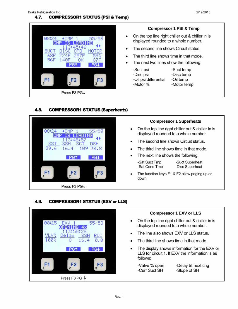
4.19. RELAY OUTPUTS (Run YDY)
4.20. RELAY OUTPUTS (Cycles YDY)
4.21. RELAY OUTPUTS (TTL Run HR)
To scroll right Press ►
Relay Outputs Run YDY
On the top line shows Outputs & ◄► which allows you to move screen left to right.
The second line shows column headings.
The third through sixth line shows up to four relays & run time yesterday.
The bottom line shows function keys with current values.
Pressing F1 moves you to Analog outputs.
Pressing F2 or F3 pages the current screen up or down for additional outputs.To scroll right Press ►
Relay Outputs Cycles YDY
On the top line shows Outputs & ◄► which allows you to move screen left to right.
The second line shows column headings.
The third through sixth line shows up to four relays & cycles yesterday.
The bottom line shows function keys with current values.
Pressing F1 moves you to Analog outputs.
Pressing F2 or F3 pages the current screen up or down for additional outputs. To scroll right Press ►
Relay Outputs TTL Run HR
On the top line shows Outputs & ◄► which allows you to move screen left to right.
The second line shows column headings.
The third through sixth line shows up to four relays & total run hours.
The bottom line shows function keys with current values.
Pressing F1 moves you to Analog outputs.
Pressing F2 or F3 pages the current screen up or down for additional outputs.
Drake Refrigeration Inc. 2/19/2015
Rev. 1
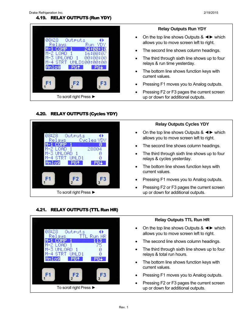
4.22. RELAY OUTPUTS (TTL Cycles)
4.23. ANALOG OUTPUTS (Status)
4.24. ANALOG OUTPUTS (Max TDY)
Relay Outputs TTL Cycles
On the top line shows Outputs & ◄► which allows you to move screen left to right.
The second line shows column headings.
The third through sixth line shows up to four relays & total cycles.
The bottom line shows function keys with current values.
Pressing F1 moves you to Analog outputs.
Pressing F2 or F3 pages the current screen up or down for additional outputs. Select F1 for Anlog
Analog Outputs Status
On the top line shows Outputs.
The second line shows column headings.
The third through fifth line shows up to four analog outputs.
The bottom line shows function keys with current values.
Pressing F1 moves you to Relay Outputs.
Pressing F2 or F3 pages the current screen up or down for additional outputs.
To scroll right Press ►
Analog Outputs Max TDY
On the top line shows Outputs.
The second line shows column headings.
The third through sixth line shows up to four relays & max value today.
The bottom line shows function keys with current values.
Pressing F1 moves you to Relay Outputs.
Pressing F2 or F3 pages the current screen up or down for additional outputs.
To scroll right Press ►
Drake Refrigeration Inc. 2/19/2015
Rev. 1

4.25. ANALOG OUTPUTS (Min TDY)
4.26. ANALOG OUTPUTS (Avg TDY)
4.27. ANALOG OUTPUTS (Max YDY)
To scroll right Press ►
Analog Outputs Min TDY
On the top line shows Outputs.
The second line shows column headings.
The third through sixth line shows up to four analog outputs & minimum value seen today.
The bottom line shows function keys with current values.
Pressing F1 moves you to Relay Outputs.
Pressing F2 or F3 pages the current screen up or down for additional outputs.
To scroll right Press ►
Analog Outputs AVG TDY
On the top line shows Outputs.
The second line shows column headings.
The third through sixth line shows up to four analog outputs & average value today.
The bottom line shows function keys with current values.
Pressing F1 moves you to Relay Outputs.
Pressing F2 or F3 pages the current screen up or down for additional outputs.
To scroll right Press ►
Analog Outputs Max YDY
On the top line shows Outputs.
The second line shows column headings.
The third through sixth line shows up to four analog outputs & maximum yesterday.
The bottom line shows function keys with current values.
Pressing F1 moves you to Relay Outputs.
Pressing F2 or F3 pages the current screen up or down for additional outputs.
Drake Refrigeration Inc. 2/19/2015
Rev. 1
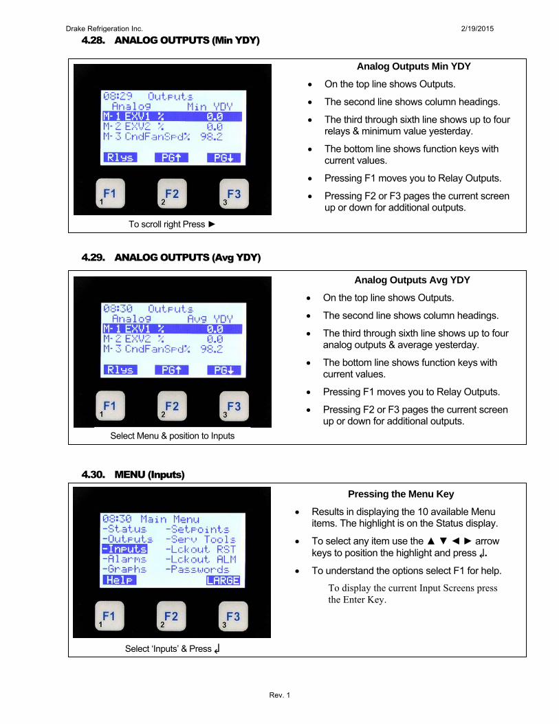
4.28. ANALOG OUTPUTS (Min YDY)
4.29. ANALOG OUTPUTS (Avg YDY)
4.30. MENU (Inputs)
To scroll right Press ►
Analog Outputs Min YDY
On the top line shows Outputs.
The second line shows column headings.
The third through sixth line shows up to four relays & minimum value yesterday.
The bottom line shows function keys with current values.
Pressing F1 moves you to Relay Outputs.
Pressing F2 or F3 pages the current screen up or down for additional outputs.
Analog Outputs Avg YDY
On the top line shows Outputs.
The second line shows column headings.
The third through sixth line shows up to four analog outputs & average yesterday.
The bottom line shows function keys with current values.
Pressing F1 moves you to Relay Outputs.
Pressing F2 or F3 pages the current screen up or down for additional outputs.
Select Menu & position to Inputs
Pressing the Menu Key
Results in displaying the 10 available Menu items. The highlight is on the Status display.
To select any item use the ▲ ▼ ◄ ► arrow keys to position the highlight and press ↲.
To understand the options select F1 for help.
To display the current Input Screens press the Enter Key.
Select ‘Inputs’ & Press ↲
Drake Refrigeration Inc. 2/19/2015
Rev. 1

4.31. SENSOR INPUTS (Value)
4.32. SENSOR INPUTS (Type)
4.33. SENSOR INPUTS (Last on)
To scroll right Press ►
Sensor Inputs Value
On the top line shows Inputs.
The second line shows column headings.
The third through sixth line shows up to four sensor inputs & their current value.
The bottom line shows function keys with current values.
Pressing F2 or F3 pages the current screen up or down for additional inputs.
To scroll right Press ►
Sensor Inputs Last On
On the top line shows Inputs.
The second line shows column headings.
The third through sixth line shows up to four sensor inputs & Last On. (If Digital).
The bottom line shows function keys with current values.
Pressing F2 or F3 pages the current screen up or down for additional inputs.
To scroll right Press ►
Sensor Inputs Type
On the top line shows Inputs.
The second line shows column headings.
The third through sixth line shows up to four sensor inputs & the sensor type.
The bottom line shows function keys with current values.
Pressing F1 moves you to Relay Outputs.
Pressing F2 or F3 pages the current screen up or down for additional inputs.
Drake Refrigeration Inc. 2/19/2015
Rev. 1
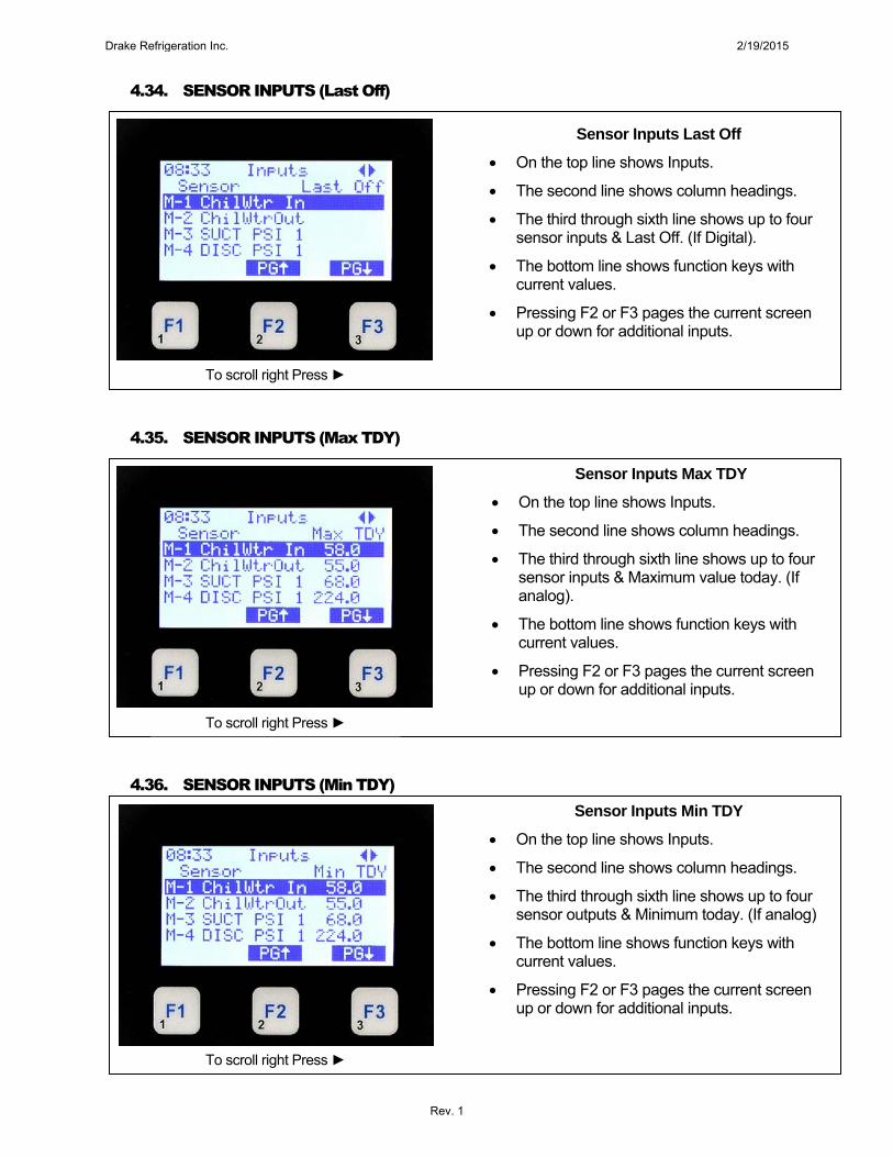
4.34. SENSOR INPUTS (Last Off)
4.35. SENSOR INPUTS (Max TDY)
4.36. SENSOR INPUTS (Min TDY)
To scroll right Press ►
Sensor Inputs Last Off
On the top line shows Inputs.
The second line shows column headings.
The third through sixth line shows up to four sensor inputs & Last Off. (If Digital).
The bottom line shows function keys with current values.
Pressing F2 or F3 pages the current screen up or down for additional inputs.
To scroll right Press ►
Sensor Inputs Max TDY
On the top line shows Inputs.
The second line shows column headings.
The third through sixth line shows up to four sensor inputs & Maximum value today. (If analog).
The bottom line shows function keys with current values.
Pressing F2 or F3 pages the current screen up or down for additional inputs.
To scroll right Press ►
Sensor Inputs Min TDY
On the top line shows Inputs.
The second line shows column headings.
The third through sixth line shows up to four sensor outputs & Minimum today. (If analog)
The bottom line shows function keys with current values.
Pressing F2 or F3 pages the current screen up or down for additional inputs.
Drake Refrigeration Inc. 2/19/2015
Rev. 1

4.37. SENSOR INPUTS (Run TDY)
4.38. SENSOR INPUTS (AVG TDY)
4.39. SENSOR INPUTS (Cycles TDY)
To scroll right Press ►
Sensor Inputs Run TDY
On the top line shows Inputs.
The second line shows column headings.
The third through sixth line shows up to four sensor inputs & run hours today. (If Digital)
The bottom line shows function keys with current values.
Pressing F2 or F3 pages the current screen up or down for additional inputs.
To scroll right Press ►
Sensor Inputs Avg TDY
On the top line shows Inputs.
The second line shows column headings.
The third through sixth line shows up to four sensor inputs & average today. (If analog).
The bottom line shows function keys with current values.
Pressing F2 or F3 pages the current screen up or down for additional inputs.
To scroll right Press ►
Sensor Inputs Cycles TDY
On the top line shows Inputs.
The second line shows column headings.
The third through sixth line shows up to four sensor inputs & cycles today. (If digital).
The bottom line shows function keys with current values.
Pressing F2 or F3 pages the current screen up or down for additional inputs.
Drake Refrigeration Inc. 2/19/2015
Rev. 1
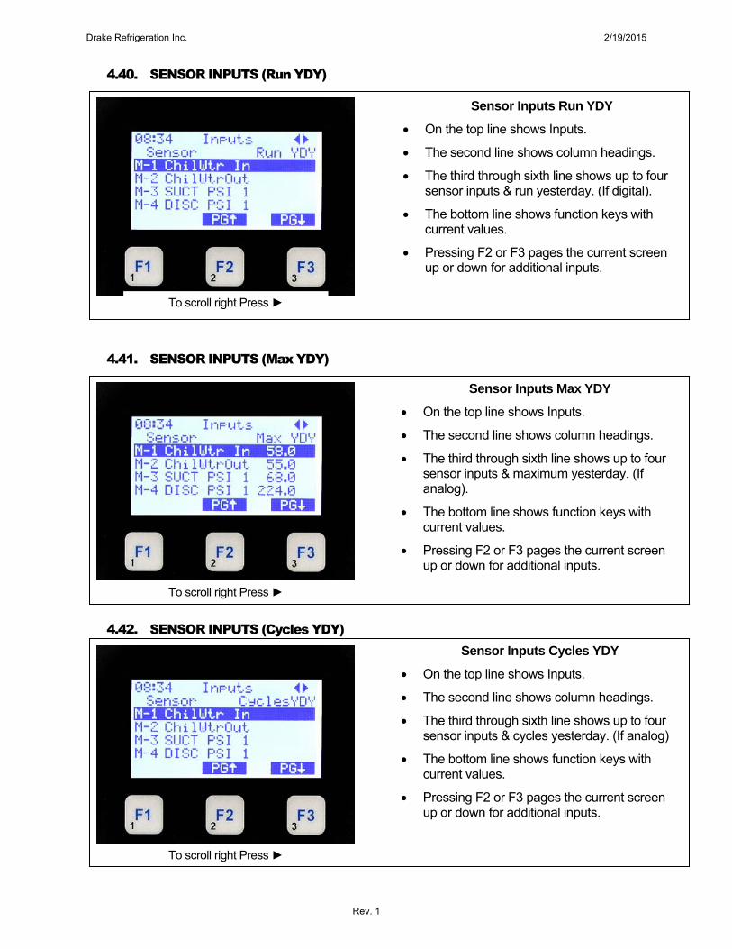
4.40. SENSOR INPUTS (Run YDY)
4.41. SENSOR INPUTS (Max YDY)
4.42. SENSOR INPUTS (Cycles YDY)
To scroll right Press ►
Sensor Inputs Run YDY
On the top line shows Inputs.
The second line shows column headings.
The third through sixth line shows up to four sensor inputs & run yesterday. (If digital).
The bottom line shows function keys with current values.
Pressing F2 or F3 pages the current screen up or down for additional inputs.
To scroll right Press ►
Sensor Inputs Max YDY
On the top line shows Inputs.
The second line shows column headings.
The third through sixth line shows up to four sensor inputs & maximum yesterday. (If analog).
The bottom line shows function keys with current values.
Pressing F2 or F3 pages the current screen up or down for additional inputs.
To scroll right Press ►
Sensor Inputs Cycles YDY
On the top line shows Inputs.
The second line shows column headings.
The third through sixth line shows up to four sensor inputs & cycles yesterday. (If analog)
The bottom line shows function keys with current values.
Pressing F2 or F3 pages the current screen up or down for additional inputs.
Drake Refrigeration Inc. 2/19/2015
Rev. 1
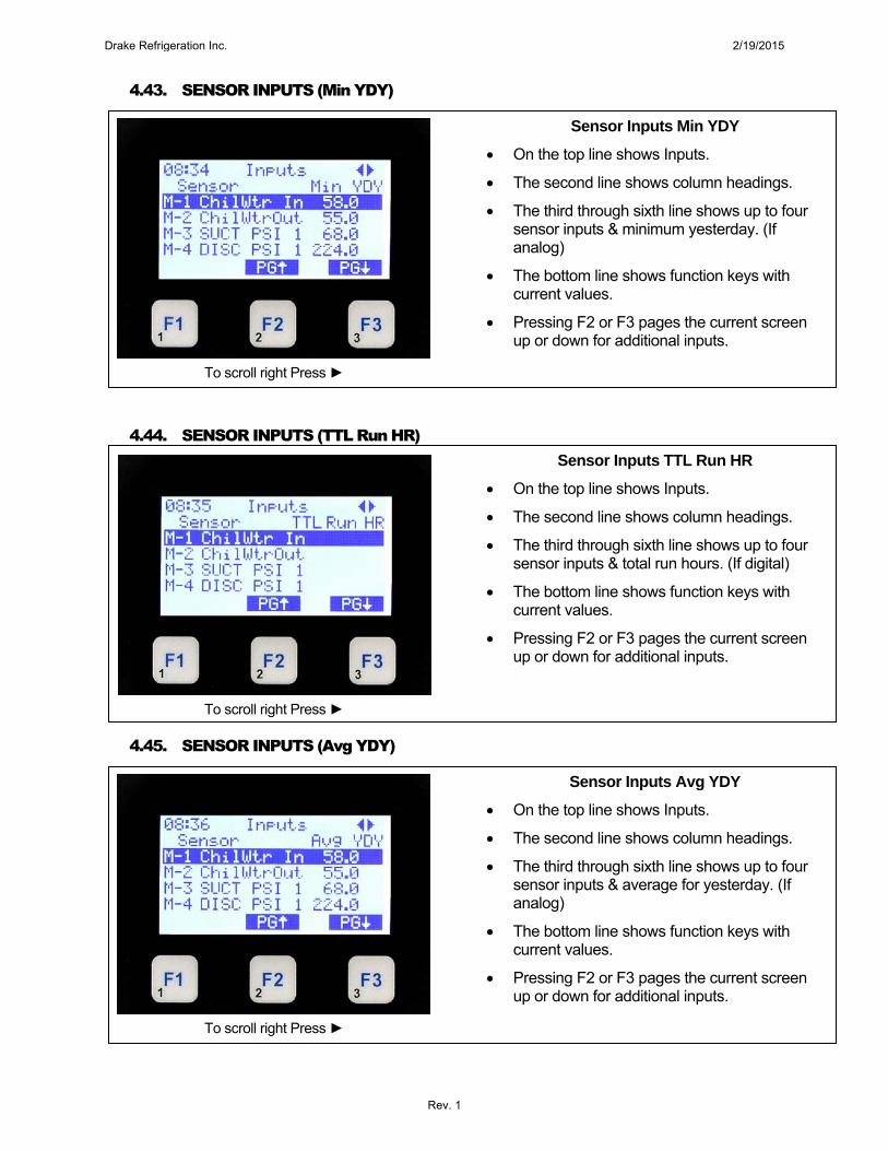
4.43. SENSOR INPUTS (Min YDY)
4.44. SENSOR INPUTS (TTL Run HR)
4.45. SENSOR INPUTS (Avg YDY)
To scroll right Press ►
Sensor Inputs Min YDY
On the top line shows Inputs.
The second line shows column headings.
The third through sixth line shows up to four sensor inputs & minimum yesterday. (If analog)
The bottom line shows function keys with current values.
Pressing F2 or F3 pages the current screen up or down for additional inputs.
To scroll right Press ►
Sensor Inputs TTL Run HR
On the top line shows Inputs.
The second line shows column headings.
The third through sixth line shows up to four sensor inputs & total run hours. (If digital)
The bottom line shows function keys with current values.
Pressing F2 or F3 pages the current screen up or down for additional inputs.
Sensor Inputs Avg YDY
On the top line shows Inputs.
The second line shows column headings.
The third through sixth line shows up to four sensor inputs & average for yesterday. (If analog)
The bottom line shows function keys with current values.
Pressing F2 or F3 pages the current screen up or down for additional inputs.
To scroll right Press ►
Drake Refrigeration Inc. 2/19/2015
Rev. 1
4.46. SENSOR INPUTS (TTL Cycles)
4.47. MENU (Alarms)
4.48. ALARMS
Select Menu & Press ↲
Select Alarms & Press ↲
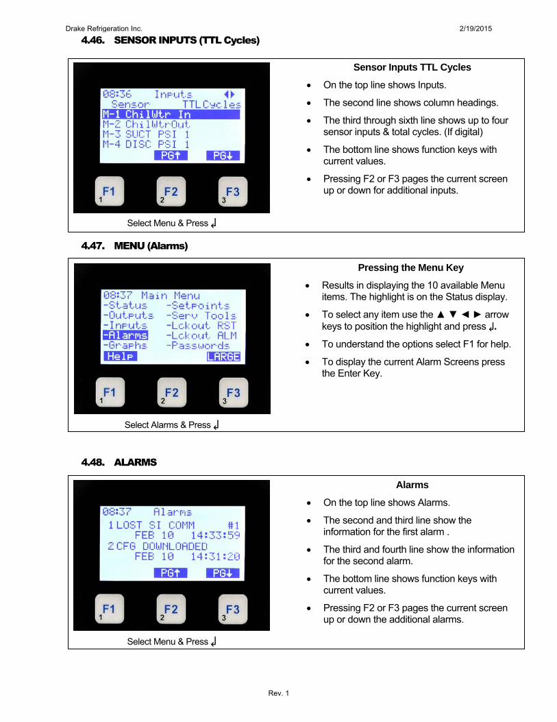
Sensor Inputs TTL Cycles
On the top line shows Inputs.
The second line shows column headings.
The third through sixth line shows up to four sensor inputs & total cycles. (If digital)
The bottom line shows function keys with current values.
Pressing F2 or F3 pages the current screen up or down for additional inputs.
Pressing the Menu Key
Results in displaying the 10 available Menu items. The highlight is on the Status display.
To select any item use the ▲ ▼ ◄ ► arrow keys to position the highlight and press ↲.
To understand the options select F1 for help.
To display the current Alarm Screens press the Enter Key.
Alarms
On the top line shows Alarms.
The second and third line show the information for the first alarm .
The third and fourth line show the information for the second alarm.
The bottom line shows function keys with current values.
Pressing F2 or F3 pages the current screen up or down the additional alarms.
Select Menu & Press ↲
Drake Refrigeration Inc. 2/19/2015
Rev. 1

4.49. MENU (Graphs)
4.50. GRAPHS (Relay or Sensor)
4.51. GRAPHS (Edit)
Select Menu & Press ↲
Pressing the Menu Key
Results in displaying the 10 available Menu items. The highlight is on the Status display.
To select any item use the ▲ ▼ ◄ ► arrow keys to position the highlight and press ↲.
To understand the options select F1 for help.
To display the current Graphs Screens press the Enter Key.
Graphs Relay or Sensor
On the top line shows Graph and Sensor being displayed.
The next lines layout the graph based on the scale required.
At the bottom of the graph the graph time frame is shown.
Pressing F1 displays sample time for editing
Pressing F2 or F3 selects relays or analog outputs for display.
Select Function F1
Graphs (Edit)
The background shows the graph.
The pop up window shows the current sample rate.
By pressing ↲ you may change the sample time.
Pressing F2 or F3 pages the current screen up or down the current selection.
Select Menu & Press ↲
Drake Refrigeration Inc. 2/19/2015
Rev. 1
4.52. MENU (Setpoints)
4.53. SETPOINTS (Value)
4.54. MENU (Serv Tools)
Select Serv Tools & Press ↲
Select Menu & Press ↲
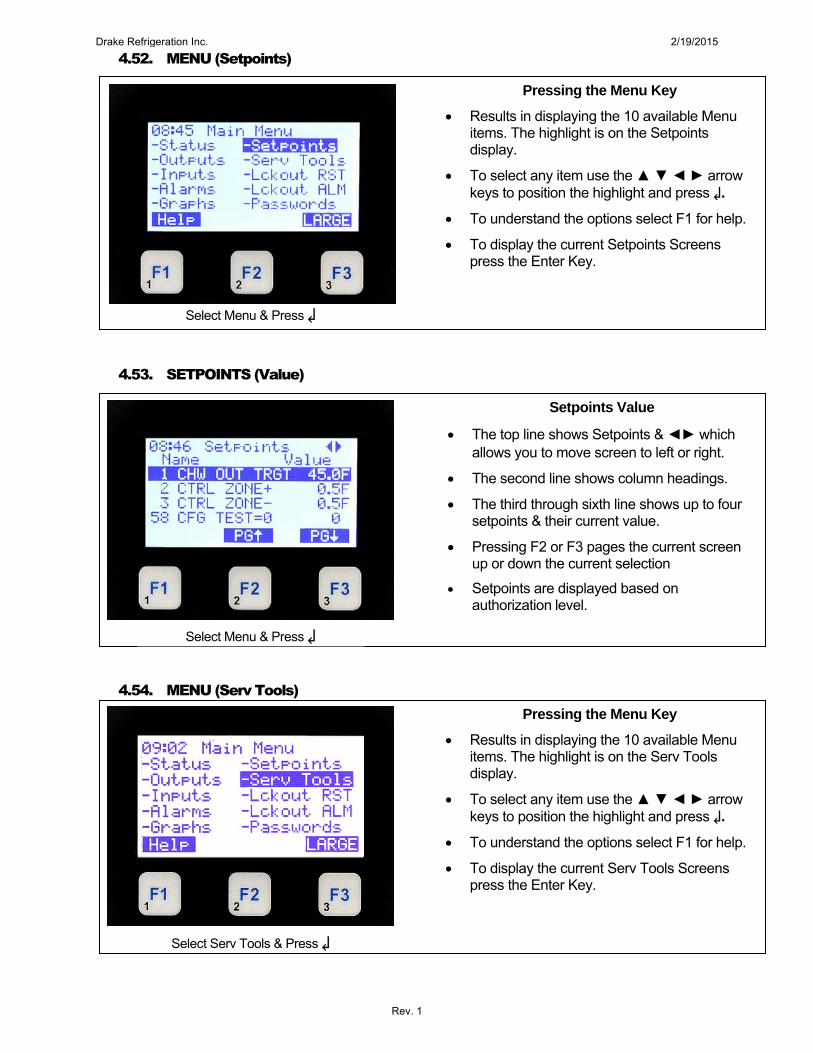
Pressing the Menu Key
Results in displaying the 10 available Menu items. The highlight is on the Setpoints display.
To select any item use the ▲ ▼ ◄ ► arrow keys to position the highlight and press ↲.
To understand the options select F1 for help.
To display the current Setpoints Screens press the Enter Key.
Setpoints Value
The top line shows Setpoints & ◄► which allows you to move screen to left or right.
The second line shows column headings.
The third through sixth line shows up to four setpoints & their current value.
Pressing F2 or F3 pages the current screen up or down the current selection
Setpoints are displayed based on authorization level.
Select Menu & Press ↲
Pressing the Menu Key
Results in displaying the 10 available Menu items. The highlight is on the Serv Tools display.
To select any item use the ▲ ▼ ◄ ► arrow keys to position the highlight and press ↲.
To understand the options select F1 for help.
To display the current Serv Tools Screens press the Enter Key.
Drake Refrigeration Inc. 2/19/2015
Rev. 1

4.55. SERVICE TOOLS (RS485 Network)
4.56. SERVICE TOOLS (RS485 Setup)
4.57. SERVICE TOOLS (Ethernet Network)
Press F1 (Back)
RS485 Network
The top line shows Service Tools.
The next 5 lines identify the first five options available under Service Tools.
The bottom line shows function keys with current values.
Pressing F2 or F3 pages the current screen up or down the current selection.
RS485 Setup
The top line shows RS485 Setup
The next 3 lines identify the current protocol, current address & the current baud rate.
The bottom line shows function keys with current values.
Pressing F1 takes you back to the previous screen.
Select RS485 Network & Press ↲
Ethernet Network
The top line shows Service Tools.
The next 5 lines identify the first five options available under Service Tools.
The bottom line shows function keys with current values.
Pressing F2 or F3 pages the current screen up or down the current selection.
Select Ethernet Network & Press ↲
Drake Refrigeration Inc. 2/19/2015
Rev. 1
4.58. SERVICE TOOLS (Ethernet Setup)
4.59. SERVICE TOOLS (Subnet Mask)
4.60. SERVICE TOOLS (MCS Port)
Select F1 Back
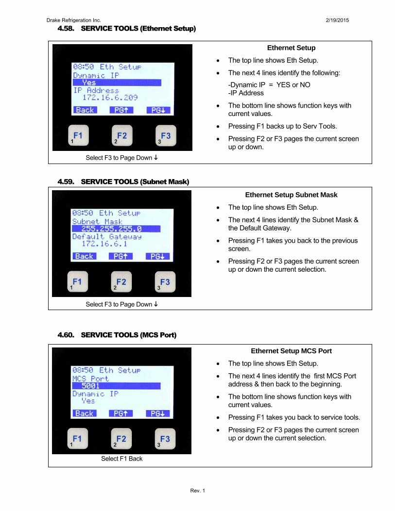
Ethernet Setup
The top line shows Eth Setup.
The next 4 lines identify the following:
-Dynamic IP = YES or NO -IP Address
The bottom line shows function keys with current values.
Pressing F1 backs up to Serv Tools.
Pressing F2 or F3 pages the current screen up or down.
Select F3 to Page Down
Ethernet Setup Subnet Mask
The top line shows Eth Setup.
The next 4 lines identify the Subnet Mask & the Default Gateway.
Pressing F1 takes you back to the previous screen.
Pressing F2 or F3 pages the current screen up or down the current selection.
Select F3 to Page Down
Ethernet Setup MCS Port
The top line shows Eth Setup.
The next 4 lines identify the first MCS Port address & then back to the beginning.
The bottom line shows function keys with current values.
Pressing F1 takes you back to service tools.
Pressing F2 or F3 pages the current screen up or down the current selection.
Drake Refrigeration Inc. 2/19/2015
Rev. 1
4.61. SERVICE TOOLS (System Info)
4.62. SERVICE TOOLS (Firmware & Cfg)
4.63. SERVICE TOOLS (Company name & Model #)
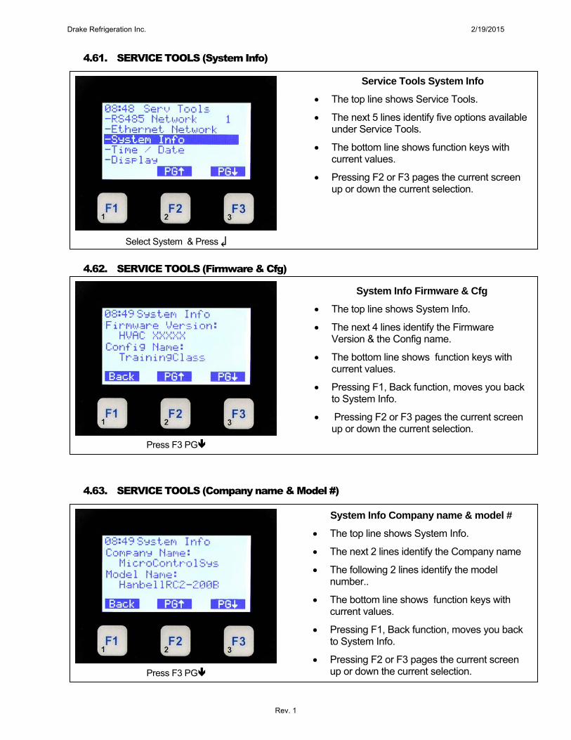
Service Tools System Info
The top line shows Service Tools.
The next 5 lines identify five options available under Service Tools.
The bottom line shows function keys with current values.
Pressing F2 or F3 pages the current screen up or down the current selection.
System Info Firmware & Cfg
The top line shows System Info.
The next 4 lines identify the Firmware Version & the Config name.
The bottom line shows function keys with current values.
Pressing F1, Back function, moves you back to System Info.
Pressing F2 or F3 pages the current screen up or down the current selection.
Select System & Press ↲
Press F3 PG
Press F3 PG
System Info Company name & model #
The top line shows System Info.
The next 2 lines identify the Company name
The following 2 lines identify the model number..
The bottom line shows function keys with current values.
Pressing F1, Back function, moves you back to System Info.
Pressing F2 or F3 pages the current screen up or down the current selection.
Drake Refrigeration Inc. 2/19/2015
Rev. 1

4.64. SYSTEN INFO (Unit Serial Number & Install Date)
4.65. SYSTEM INFO (Config Version & Date)
4.66. SYSTEM INFO (Bootloader & HW Serial Number)
Press F3 PG
System Info Unit serial number & Install Date
The top line shows System Info.
The next 2 lines identify the unit serial number.
The following 2 lines identify the install date.
The bottom line shows function keys with current values.
Pressing F1, Back function, moves you back to System Info.
Pressing F2 or F3 pages the current screen up or down the current selection.
System Info Config Version & Date
The top line shows System Info.
The next 2 lines identify the Config version
The following 2 lines identify the Config date..
The bottom line shows function keys with current values.
Pressing F1, Back function, moves you back to System Info
Pressing F2 or F3 pages the current screen up or down the current selection.
Press F3 PG
System Info Bootloader & HW Serial Number
The top line shows System Info.
The next 2 lines identify the Bootloader version & the following 2 lines identify the hardware serial number.
The bottom line shows function keys with current values.
Pressing F1, Back function, moves you back to System Info
Pressing F2 or F3 pages the current screen up or down the current selection.
Press F3 PG
Drake Refrigeration Inc. 2/19/2015
Rev. 1

4.67. SYSTEM INFO (Phy Mac Addr & I/O Types)
4.68. SYSTEM INFO (Display)
4.69. DISPLAY (Contrast &Reverse Background)
Select Display & Press ↲
System Info Physical Mac Address & Type I/O
The top line shows System Info.
The next 2 lines identify the Physical MAC address & the following 2 lines identify the type of I/O boards used.
The bottom line shows function keys with current values.
Pressing F1, Back function, moves you back to System Info
Pressing F2 or F3 pages the current screen up or down the current selection.
Select F1 Back
Service Tools Display
The top line shows Service Tools.
The next 5 lines identify five options available under Service Tools.
The bottom line shows function keys with current values.
Pressing F2 or F3 pages the current screen up or down the current selection.
Display Contrast & Reverse Background
The top line shows Display.
The next line allows changing the contrast.
The following line allows reversing the background from light to dark or dark to light.
Pressing F1 allows you to go back to the Serv Tools menu.
Press ↲tochangecontrast
Drake Refrigeration Inc. 2/19/2015
Rev. 1

4.70. DISPLAY (Contrast)
4.71. DISPLAY (Reverse Background)
4.72. DISPLAY (Background Reversed)
Select Menu Key
Press ▲or▼topositionYesorNothen↲
Display Change Contrast
The top line shows Display.
Select item to change. (Contrast)
The pop up box shows current contrast level..
Use ▲ or ▼ to adjust.
Press ↲tochange.
Press ▲or▼tochangecontrastthen↲
Display Reverse Background
The top line shows Display.
Select item to change. (Reverse Background)
The pop up box asks if to want to reverse background.
Use ▲ or ▼ to select.
Press ↲tochange.
Display Background Reversed
The top line shows Display.
The background is now reversed from light to dark.
Use F1 (Back) to return to Service Tools sub menu.
Drake Refrigeration Inc. 2/19/2015
Rev. 1

4.73. MENU (Lockout Reset)
4.74. LOCKOUT RESET (Reset)
4.75. LOCKOUT ALARM
Select Lckout ALM & Press ↲
Select Menu Key
Pressing the Menu Key
Results in displaying the 10 available Menu items. The highlight is on the Lckout RST display.
To select any item use the ▲ ▼ ◄ ► arrow keys to position the highlight and press ↲.
To understand the options select F1 for help.
To display the current Lckout RST press the Enter Key.
Press ↲
Lockout Reset
The top line shows Main Menu.
The pop up window displays Lockout Reset Yes or NO..
If there are no current lockouts the response will be No Current Lockouts.
Using the ▼ or ▲ arrows select your response then press ↲.
The system is set for a limited number of resets per day to avoid damage.
Pressing the Menu Key
Results in displaying the 10 available Menu items. The highlight is on the Lckout RST display.
To select any item use the ▲ ▼ ◄ ► arrow keys to position the highlight and press ↲.
To understand the options select F1 for help.
To display the current Lckout ALM press the Enter Key.
Drake Refrigeration Inc. 2/19/2015
Rev. 1

4.76. DISPLAY (Lokout ALM)
4.77. MENU (Password)
4.78. PASSWORDS (Enter Format)
Input Password
Select Passwords & Press ↲
Lockout Alarm
The top line shows Lckout ALM.
The next display will show the 1st alarm which caused a lockout. If there are no lockout alarms this message will be displayed.
Select next potion
Press Menu Key
Pressing the Menu Key
Results in displaying the 10 available Menu items. The highlight is on the Lckout RST display.
To select any item use the ▲ ▼ ◄ ► arrow keys to position the highlight and press ↲.
To understand the options select F1 for help.
To display the current Lckout ALM press the Enter Key.
Passwords Enter Format
The top line shows Password.
The bottom functions show the value of the function keys..
There are 4 levels of passwords as follows:
-View -Service
-Supervisor -Factory
Enter a 4 character password and press ↲.
Drake Refrigeration Inc. 2/19/2015
Rev. 1

4.79. PASSWORDS (After Entering)
4.80. PASSWORDS (Results)
After Entering Password Press ↲
Press Menu Key
After Entering Password
The top line shows Password.
The *’s show characters entered.
Only 1 through 8 numbers are available from the keypad..
Password Results
The top line shows Password.
The next line displays the authorization level.
Press the Menu key to continue..
Drake Refrigeration Inc. 2/19/2015
Rev. 1

How to Connect to a Computer with MCS-Connect
Drake Refrigeration Inc. 2/19/2015
Rev. 1

Connecting via Ethernet Cable
Drake Refrigeration Inc. 2/19/2015
Rev. 1

APP-079 Connecting MCS-Connect Via Ethernet
Equipment Needed:
1. PC 2. Straight Ethernet Cable for a Building Network or Crossover Ethernet Cable for PC to Magnum.
● For Microsoft Windows 7: 1. At your desktop, left click on Start ball. 2. Left click on Control Panel button. 3. Double left click on Network and Sharing Center icon. 4. Left click Change Adapter Settings on the left side of the screen. 5. Right click the connection that you want to change (Local Area Connection) and select Properties from the
dropdown menu. 6. Under This connection uses the following items, left click Internet Protocol Version 4 (TCP/IPv4). 7. Left click on Properties tab. 8. Select Obtain an IP address automatically if using a Straight ETHERNET Cable for a Building Network.
Select Use the following IP address if using a Crossover ETHERNET Cable for PC to MCS-MAGNUM: a. The first three numbers of the IP address should match exactly what’s on the Magnum and the last
number must be different. b. The subnet mask and the Default Gateway should match the exact values on the magnum. Example of Magnum IP Settings 1. IP Address 192.168.1.254 2. Default Subnet Mask 255.255.255.0 3. Default Gateway 192.168.1.1
9. Close all Windows. 10. Double left click on MCS-Connect icon on desktop. If MCS-Connect icon isn’t on desktop, left click Start ball
on desktop. Left click MCS-Connect on Start Menu. 11. Left click on Setup tab. 12. Left click on Options tab. 13. Under Network tab, select the Available Network Interface, and select Local as the connection type. 14. Left click on Save button. 15. Left click on OK button. 16. Left click on Local Ethernet button to scan for microprocessor when connected. 17. If this does not find the microprocessor, click on disconnect and click IP(Internet). Enter the IP address of the
Magnum and click Remote/Connect.
● For Microsoft XP:
1. At your desktop, left click on Start button. 2. Left click on Control Panel button. 3. Double left click on Network Connections icon in Classic view. If you are in Category view, you can switch
over to Classic view by left-clicking on Switch to Classic View on the left side of the Control Panel window. 4. Right click the connection you want to configure (Local Area Connection) and select Properties from the
dropdown menu. 5. Left click on General tab.
Drake Refrigeration Inc. 2/19/2015
Rev. 1

APP-079 Connecting MCS-Connect Via Ethernet
6. Use scroll bar and left click on Internet Protocol (TCP/IP). 7. Left click on Properties tab. 8. Select Obtain an IP address automatically if using a Straight ETHERNET Cable for a Building Network.
Select Use the following IP address if using a Crossover ETHERNET Cable for PC to MCS-MAGNUM: a. The first three numbers of the IP address should match exactly what’s on the Magnum and the last
number must be different. b. The subnet mask and the Default Gateway should match the exact values on the magnum.
Example of Magnum IP Settings 1. IP Address 192.168.1.254 2. Default Subnet Mask 255.255.255.0 3. Default Gateway 192.168.1.1
9. Double left click on MCS-Connect icon on desktop. If MCS-Connect icon isn’t on desktop, left click Start
button on desktop. Left click MCS-Connect on Start Menu. 10. Left click on Setup tab. 11. Left click on Options tab. 12. Under Network tab, select the Available Network Interface, and select Local as the connection type. 13. Left click on Save button. 14. Left click on OK button. 15. Left click on Local-Ethernet button to scan for microprocessor when connected. 16. If this does not find the microprocessor, click on disconnect and click IP(Internet). Enter the IP address of the
Magnum and click Remote/Connect.
Drake Refrigeration Inc. 2/19/2015
Rev. 1

Connecting via Null Modem Serial Cable
Drake Refrigeration Inc. 2/19/2015
Rev. 1

APP-075 How to Connect to MCS-Connect through a Null Modem Serial Cable
Equipment Needed:
1. Computer 2. Null Modem Serial Cable 3. USB to Serial Converter (If Applicable) 4. Latest MCS-Connect program
Connecting Null Modem Serial Cable directly to Computer: ● For Microsoft XP:
1. At your desktop, left click on Start button. 2. Left click on Control Panel button. 3. Double left click on System icon in Classic view. If you are in Category view, you can switch over to Classic
view by left-clicking on Switch to Classic View on the left side of the Control Panel window. 4. Left click on Hardware tab. 5. Left click on Device Manager button. 6. Left click on (+) next to Ports (COM & LPT) to drop down Port information. 7. What is Communications Port (COM #)? This will be set in MCS-Connect program. 8. Close all Windows after determining the Communications Port (COM #). 9. Double left click on MCS-Connect icon on desktop. If MCS-Connect icon isn’t on desktop, left click Start
button on desktop. Left click MCS-Connect on Start Menu. 10. Left click on Setup tab. 11. Left click on Options tab. 12. Under Communications tab, set LOCAL Comm. COM Port Selection to the Communications Port (COM #)
found on computer. 13. Left click on Save button. 14. Left click on OK button. 15. Left click on Local-Serial button to scan for microprocessor when connected.
● For Microsoft Windows 7: 1. At your desktop, left click on Start ball. 2. Left click on Control Panel button. 3. Double left click on Hardware and Sound icon. 4. Left click Device Manager under Devices and Printers. 5. Left click on (►) next to Ports (COM & LPT) to drop down Port information. 6. What is Communication Port (COM #)? This will be set in MCS-Connect program. 7. Close all Windows after determining the Communication Port (COM #). 8. Double left click on MCS-Connect icon on desktop. If MCS-Connect icon isn’t on desktop, left click Start
button on desktop. Left click MCS-Connect on Start Menu. 9. Left click on Setup tab. 10. Left click on Options tab. 11. Under Communications tab, set LOCAL Comm. COM Port Selection to the Communication Port (COM #)
found on computer. 12. Left click on Save button. 13. Left click on OK button. 14. Left click on Local-Serial button to scan for microprocessor when connected.
Drake Refrigeration Inc. 2/19/2015
Rev. 1

APP-075 How to Connect to MCS-Connect through a Null Modem Serial Cable
0
Connecting Null Modem Serial Cable through a USB to Serial Converter to Computer:
The MCS-USB-RS232 sold through Micro Control Systems is the USB to Serial Converter that is proven to work. Other brands of USB converters may or may not work. When connecting a USB converter, you must make sure that the correct driver is installed on your computer. The driver can be found on a CD that is included with the USB to Serial Converter or can be found online.
● For Microsoft XP: To install driver through CD included with MCS-USB-RS232: 1. Plug in MCS-USB-RS232 to USB port on your computer. 2. Insert CD into your computer. 3. Download software. 4. Follow prompts. To install driver found online: 1. Plug in MCS-USB-RS232 to USB port on your computer. 2. Get connected to internet and go to www.mcscontrols.com. 3. On Micro Control Systems website, left click on the Products tab. 4. Go to Controls tab, left click on Peripherals tab. 5. Scroll down to MCS-USB-RS232, left click on Click here to Download and Install the Drivers. 6. Follow prompts. To get connected to MCS-Connect: 1. At your desktop, left click on Start button. 2. Left click on Control Panel button. 3. Double left click on System icon in Classic view. If you are in Category view, you can switch over to Classic
view by left-clicking on Switch to Classic View on the left side of the Control Panel window. 4. Left click on Hardware tab. 5. Left click on Device Manager button. 6. Left click on (+) next to Ports (COM & LPT) to drop down Port information. 7. What is USB Serial Port (COM #)? This will be set in MCS-Connect program. 8. Close all Windows after determining the USB Serial Port (COM #). 9. Double left click on MCS-Connect icon on desktop. If MCS-Connect icon isn’t on desktop, left click Start
button on desktop. Left click MCS-Connect on Start Menu. 10. Left click on Setup tab. 11. Left click on Options tab. 12. Under Communications tab, set LOCAL Comm. COM Port Selection to the USB Serial Port (COM #) found
on computer. 13. Left click on Save button. 14. Left click on OK button. 15. Left click on Local-Serial button to scan for microprocessor when connected.
Drake Refrigeration Inc. 2/19/2015
Rev. 1

APP-075 How to Connect to MCS-Connect through a Null Modem Serial Cable
0
● For Microsoft Windows 7: To install driver through CD included with MCS-USB-RS232: 1. Plug in MCS-USB-RS232 to USB port on your computer. 2. Insert CD into your computer. 3. Download software. 4. Follow prompts.
To install driver found online: 1. Plug in MCS-USB-RS232 to USB port on your computer. 2. Get connected to internet and go to www.mcscontrols.com. 3. On Micro Control Systems website, left click on the Products tab. 4. Go to Controls tab, left click on Peripherals tab. 5. Scroll down to MCS-USB-RS232, left click on Click here to Download and Install the Drivers. 6. Follow prompts. To get connected to MCS-Connect: 1. At your desktop, left click on Start ball. 2. Left click on Control Panel button. 3. Double left click on Hardware and Sound icon. 4. Left click Device Manager under Devices and Printers. 5. Left click on (►) next to Ports (COM & LPT) to drop down Port information. 6. What is USB Serial Port (COM #)? This will be set in MCS-Connect program. 7. Close all Windows after determining the USB Serial Port (COM #). 8. Double left click on MCS-Connect icon on desktop. If MCS-Connect icon isn’t on desktop, left click Start
button on desktop. Left click MCS-Connect on Start Menu. 9. Left click on Setup tab. 10. Left click on Options tab. 11. Under Communications tab, set LOCAL Comm. COM Port Selection to the USB Serial Port (COM #) found
on computer. 12. Left click on Save button. 13. Left click on OK button. 14. Left click on Local-Serial button to scan for microprocessor when connected.
Drake Refrigeration Inc. 2/19/2015
Rev. 1

Connecting Chiller to the Internet
Drake Refrigeration Inc. 2/19/2015
Rev. 1
APP-057 Setting Up an Internet Connection for the MCS-MAGNUM
-
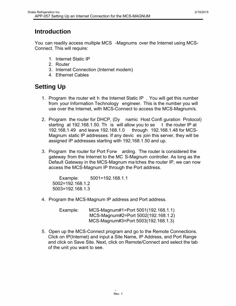
Introduction You can readily access multiple MCS -Magnums over the Internet using MCS-Connect. This will require:
1. Internet Static IP 2. Router 3. Internet Connection (Internet modem) 4. Ethernet Cables
Setting Up
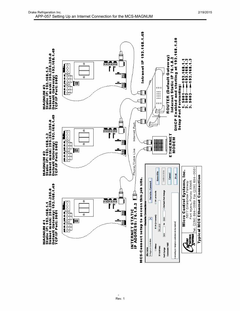
1. Program the router wit h the Internet Static IP . You will get this number from your Information Technology engineer. This is the number you will use over the Internet, with MCS-Connect to access the MCS-Magnum/s.
2. Program the router for DHCP, (Dy namic Host Confi guration Protocol)
starting at 192.168.1.50. Th is will allow you to se t the router IP at 192.168.1.49 and leave 192.168.1.0 through 192.168.1.48 for MCS-Magnum static IP addresses. If any devic es join this server, they will be assigned IP addresses starting with 192.168.1.50 and up.
3. Program the router for Port Forw arding. The router is considered the
gateway from the Internet to the MC S-Magnum controller. As long as the Default Gateway in the MCS-Magnum ma tches the router IP, we can now access the MCS-Magnum IP through the Port address.
Example: 5001=192.168.1.1 5002=192.168.1.2 5003=192.168.1.3
4. Program the MCS-Magnum IP address and Port address.
Example: MCS-Magnum#1=Port 5001(192.168.1.1) MCS-Magnum#2=Port 5002(192.168.1.2) MCS-Magnum#3=Port 5003(192.168.1.3)
5. Open up the MCS-Connect program and go to the Remote Connections. Click on IP(Internet) and input a Site Name, IP Address, and Port Range and click on Save Site. Next, click on Remote/Connect and select the tab of the unit you want to see.
Drake Refrigeration Inc. 2/19/2015
Rev. 1
APP-057 Setting Up an Internet Connection for the MCS-MAGNUM
-
Drake Refrigeration Inc. 2/19/2015
Rev. 1

Transmitting Config File with MCS-Connect
Drake Refrigeration Inc. 2/19/2015
Rev. 1

1. If you are connected utilizing a Null Modem Serial Cable
1. Connect to the MCS-MAGNUM by attaching a null modem serial cable (DB9 Male to DB9 Female) to the port on the front of the MCS-MAGNUM-KEYPAD.
2. On your computer start MCS-Connect. 3. Select Local Serial as method of connection. This will bring up the MCS-MAGNUM scanning screen. 4. Select the MCS-MAGNUM you would like to connect to and click the respective tab. Wait for the tables to
load.
5. Click the button and enter the correct authorization code (must be service level or higher). This
will enable the button.
6. Click the button and navigate to the configuration file you wish to transmit in the file-chooser that pops up. (Be sure the file type is .cfg)
7. Open the configuration file and wait until it has finished transmitting. 8. You may need to rescan to find the MCS-MAGNUM after the file has been loaded.
2. If you are connected utilizing a Crossover Ethernet Cable 1. Connect to the MCS-MAGNUM through the Ethernet port on the MCS-MAGNUM or through an Ethernet
switch already connected to the MCS-MAGNUM. Note your computer must be on the same network as the MCS-MAGNUM. (See app note 79).
2. On your computer start MCS-Connect 3. Select Local Ethernet as method of connection. This will bring up the MCS-MAGNUM scanning screen. 4. Select the MCS-MAGNUM you would like to connect to and click the respective tab. Wait for the tables to
load.
5. Click the button and enter the correct authorization code (must be service level or higher). This
will enable the button.
6. Click the button and navigate to the configuration file you wish to transmit in the file-chooser that pops up. (Be sure the file type is .cfg)
7. Open the configuration file and wait until it has finished transmitting. 8. You may need to rescan to find the MCS-MAGNUM after the file has been loaded.
Drake Refrigeration Inc. 2/19/2015
Rev. 1

Basic Start-up Procedure
Drake Refrigeration Inc. 2/19/2015
Rev. 1

MCS START UP
1. Equipment Installation Inspection
Inspect incoming voltage matches nameplate voltage, and chiller disconnect per
national and local codes.
Ensure chiller has power supplied for 24 hours and the disconnect switch is ON.
Inspect installation of equipment mounting, piping, and wiring for completion.
Inspect chiller location is free from overhangs and at least 3 feet from any wall
or fence.
Inspect chiller fluid level is full and free of air.
Check glycol freeze point and log into chart.
Tighten all Schrader valve cores and liquid line solenoid bodies.
Open receiver ball valves to release the refrigerant into the system and tighten
packing nut (If applicable).
Leak check the refrigerant circuit with an electronic leak detector.
Tighten all electrical connections in the control panel, microprocessor and other
controls.
***The Chiller can be started via Keypad or Laptop. If using Laptop, call Drake***
2. Chiller Operation (Via Keypad)
1. Refer to the Magnum chiller manuals for Sequence of Operation and Magnum
Keypad display.
Drake Refrigeration Inc. 2/19/2015
Rev. 1

2. Go to the Main Menu ---go to Passwords---tab and enter 2112 for Supervisor
level access
3. Go to the Inputs menu ---use ‘F3’ to page down to ‘Run/Stop’ (usually M-15)---
set to ‘MANOFF’
4. Use the down arrow to page down to ‘Emg/Stop’ (usually M-16)---set to
‘MANOFF’
Drake Refrigeration Inc. 2/19/2015
Rev. 1
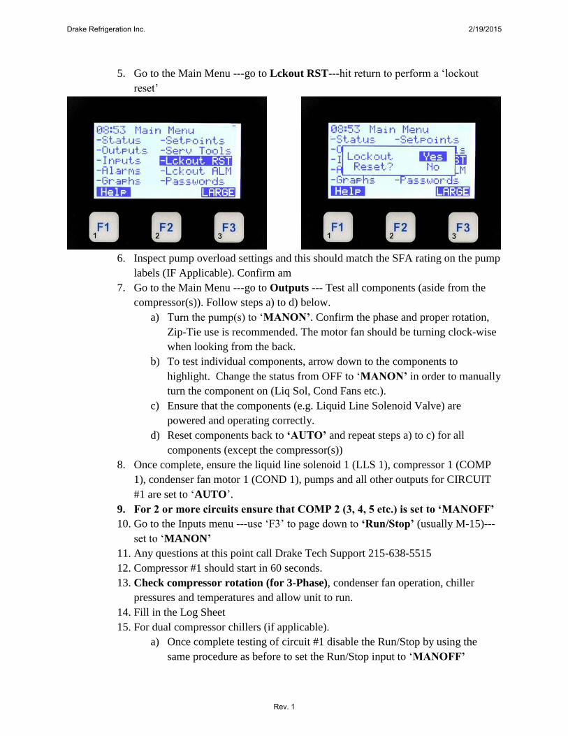
5. Go to the Main Menu ---go to Lckout RST---hit return to perform a ‘lockout
reset’
6. Inspect pump overload settings and this should match the SFA rating on the pump
labels (IF Applicable). Confirm am
7. Go to the Main Menu ---go to Outputs --- Test all components (aside from the
compressor(s)). Follow steps a) to d) below.
a) Turn the pump(s) to ‘MANON’. Confirm the phase and proper rotation,
Zip-Tie use is recommended. The motor fan should be turning clock-wise
when looking from the back.
b) To test individual components, arrow down to the components to
highlight. Change the status from OFF to ‘MANON’ in order to manually
turn the component on (Liq Sol, Cond Fans etc.).
c) Ensure that the components (e.g. Liquid Line Solenoid Valve) are
powered and operating correctly.
d) Reset components back to ‘AUTO’ and repeat steps a) to c) for all
components (except the compressor(s))
8. Once complete, ensure the liquid line solenoid 1 (LLS 1), compressor 1 (COMP
1), condenser fan motor 1 (COND 1), pumps and all other outputs for CIRCUIT
#1 are set to ‘AUTO’.
9. For 2 or more circuits ensure that COMP 2 (3, 4, 5 etc.) is set to ‘MANOFF’
10. Go to the Inputs menu ---use ‘F3’ to page down to ‘Run/Stop’ (usually M-15)---
set to ‘MANON’
11. Any questions at this point call Drake Tech Support 215-638-5515
12. Compressor #1 should start in 60 seconds.
13. Check compressor rotation (for 3-Phase), condenser fan operation, chiller
pressures and temperatures and allow unit to run.
14. Fill in the Log Sheet
15. For dual compressor chillers (if applicable).
a) Once complete testing of circuit #1 disable the Run/Stop by using the
same procedure as before to set the Run/Stop input to ‘MANOFF’
Drake Refrigeration Inc. 2/19/2015
Rev. 1

b) Wait for circuit #1 to pump-down and turn off
c) From the Outputs set COMP 1 to ‘MANOFF’
d) Ensure the liquid line solenoid 2 (LLS 2), compressor 2 (COMP 2),
condenser fan motor 2 (COND 2), pumps and all other outputs for
CIRCUIT #2 are set to ‘AUTO’
e) Enable the Run/Stop by using the same procedure as before to set the
Run/Stop input to ‘MANON’
f) Compressor #2 should start in 60 seconds
g) Repeat for more compressors
16. Complete Log Sheet.
17. Confirm to ‘Run/Stop’ is set to ‘MANON’ and ‘Emg/Stop’ is set to ‘MANOFF’
18. Confirm everything else is in ‘AUTO’ when done with the unit.
Log Sheet (Motors, Elements, etc.) ID Information Amp Readings Voltage Readings
Motor/Element Name L1 L2 L3 *NP L1-L2 L1-L3 L2-L3 *NP
Compressor 1
Compressor 2
Condenser Fan 1
Condenser Fan 2
Condenser Fan 3
Condenser Fan 4
Recirc. Pump
System Pump
Receiver Heater 1
Receiver Heater 2
Liquid Solenoid 1
Liquid Solenoid 2
*NP=Name Plate
Glycol Freeze Point :
Drake Refrigeration Inc. 2/19/2015
Rev. 1

Troubleshooting
Drake Refrigeration Inc. 2/19/2015
Rev. 1

MAGNUM VERSION 8 MANUAL REVISION 3.1
0
Troubleshooting Quick Reference (A more detailed troubleshooting guide is available on our website: www.MCScontrols.com) PROBLEM POTENTIAL SOLUTION No Sensor + 5 vdc or sensor +5 vdc output is less than 4.90 vdc.
Indicates a possible shorted input sensor Remove all sensor terminal blocks. Wait about 30 to 60 seconds. If + 5 vdc returns, replace one sensor wire at
a time until the + 5 vdc is lost again. This will be the shorted sensor. A Sensor Input reads -99.9 This indicates an open Sensor Input signal or 5 VDC problem.
Check sensor wiring for missing wire or poor connection. Check for faulty sensor. Check + 5 vdc on Sensor Input to ground. If less than 5 VDC is on the
sensor 5 VDC terminal block, the problem is with probably a shorted sensor. (A poly fuse protects the board)
Remove all Sensor Input terminals. Wait about 1 minute or until 5 VDC restored at Sensor Input. Connect terminals 1 at time until short reappears and fix bad sensor.
A Sensor Input reads +999.9 This indicates a shorted Sensor Input signal. Check sensor wiring for +5VDC shorted to signal etc. Check for faulty sensor.
A pressure sensor is reading more than 1 psi off (The temperature and humidity sensors do not require calibration.)
This indicates the transducer Sensor Input needs to be calibrated through the offset capability in the software. (Transducers by design need to be calibrated based on construction and altitude.) You must use the MCS-Connect with a valid Authorization code to change
sensor offsets See MCS-Connect Interactive section for instructions. (Change SI Status,
Manual Value and / or offset.) Invalid reading on one Sensor Input. This indicates an input problem with 1 sensor.
Verify jumper settings correct for that SI. Lost I/O Indicates communications problem.
Verify RS485 LED blinking. Verify termination jumper J6 only on at Magnum and last I/O. Verify Magnum and I/O address’s set correctly. Verify wiring from Magnum to each I/O correct. Check fuses/120 VAC on I/O units
MCS-Connect cannot make changes
This indicates you are not at a proper authorization level. Follow steps below for proper authorization From either the SITE INFO or STATUS screen in MCS-Connect, click the
‘View Only’ button at the top of the screen, or click on the ‘Passwords’ menu option on the lower right of your Keypad/LCD display.
Follow prompts and enter a valid 4-digit authorization number. The authorization level is displayed at the top of the display and is reflected
by the color of the Authorization button. Red = View Only Light Blue = User level Purple = Service level Dark Blue = Supervisor level Green = Factory level
Invalid authorization This indicates an invalid authorization number. Follow steps below for proper authorization Press Service Diagnostics key until the authorization option appears Press the Enter key From the “Display Status” press keys corresponding to your authorization
number. Press Enter
Drake Refrigeration Inc. 2/19/2015
Rev. 1
mike_courtney
Sticky Note
Unmarked set by mike_courtney

MAGNUM VERSION 8 MANUAL REVISION 3.1
0
PROBLEM POTENTIAL SOLUTION SI from AMPS board 10 A low. This indicates a problem with this SI only.
Jumper setting on this SI in wrong position. Incorrect sensor type used.
INVALID CONFIG VER Indicates layout of CFG wrong. CFG layout for different version than software
INVALID CONFIG TYPE Indicates CFG incompatible with software. INVALID CONFIG CHECKSUM Indicates Checksum invalid
Reload a valid CFG Sensor input believed invalid (Under Sensor Diagnostic Sub Menu)
Verify Berg jumpers using Quick Reference Sheets Check board version number Check wiring of sensor
Communications to MCS-485-GATEWAY from MCS-Connect not working.
Verify red LED on the gate way is blinking. This indicates that MCS-Connect is talking to the gateway.
Verify that the two wire shielded cable is properly wired from the RS-485 connector to the gateway.
Verify red LED (Located just to the left of the RS-485 connector on the Magnum board is blinking. This indicates that the Magnum is responding to the gateway.
If both of these LED are blinking, check the address of the Magnum and any other Magnums that are on the network. Each must have a unique address. This address can be changed from the Magnum. Proper authorization is required. Enter the UNIT INFORMATION screen by pressing the SERVICE DIAGNOSTIC key and scrolling to this item. Press the enter key and scroll to the NETWORK ADDRESS screen. Change address if needed.
Verify + 12 vdc to MCS-485-GATEWAY INVALID CONFIG Indicates Checksum invalid
Either set to factory defaults on reset settings.
Drake Refrigeration Inc. 2/19/2015
Rev. 1
MAGNUM VERSION 8 MANUAL REVISION 3.1
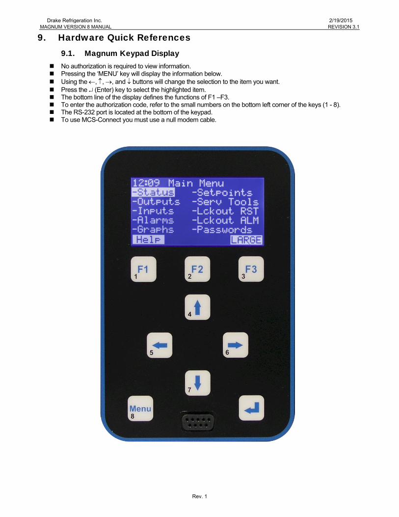
9. Hardware Quick References 9.1. Magnum Keypad Display
No authorization is required to view information. Pressing the ‘MENU’ key will display the information below. Using the , , , and buttons will change the selection to the item you want. Press the (Enter) key to select the highlighted item. The bottom line of the display defines the functions of F1 –F3. To enter the authorization code, refer to the small numbers on the bottom left corner of the keys (1 - 8). The RS-232 port is located at the bottom of the keypad. To use MCS-Connect you must use a null modem cable.
Drake Refrigeration Inc. 2/19/2015
Rev. 1
MAGNUM VERSION 8 MANUAL REVISION 3.1
0
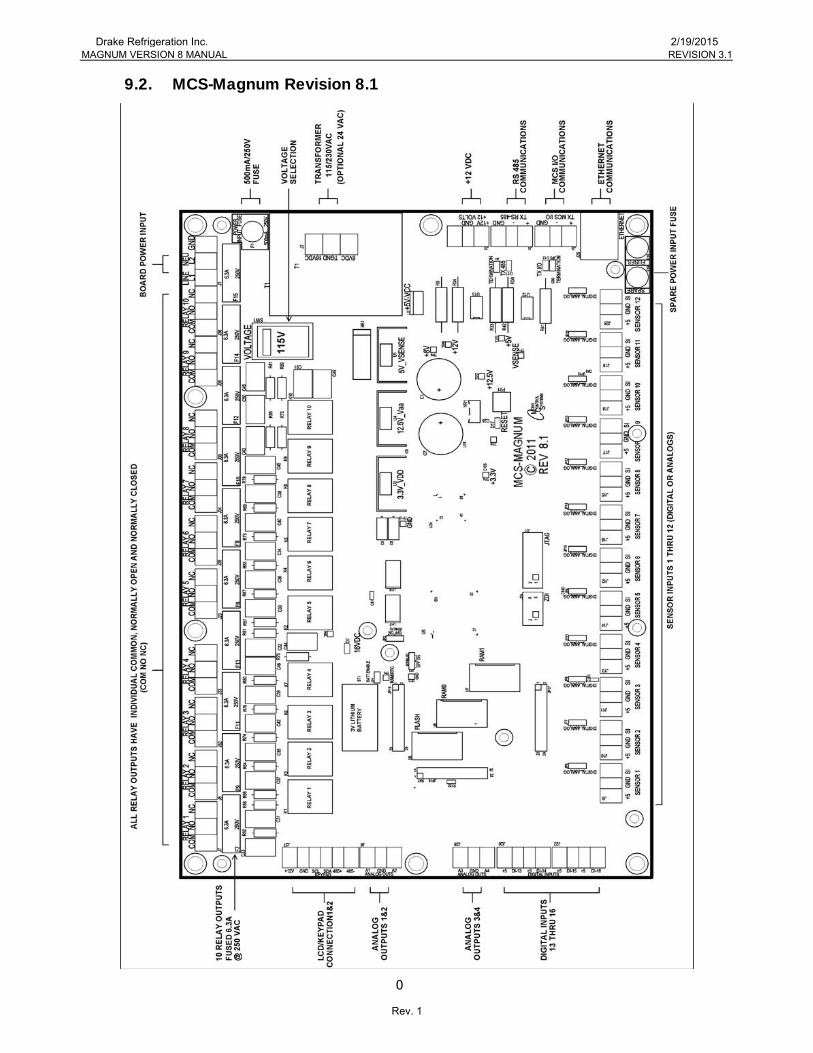
9.2. MCS-Magnum Revision 8.1
Drake Refrigeration Inc. 2/19/2015
Rev. 1
MAGNUM VERSION 8 MANUAL REVISION 3.1
0
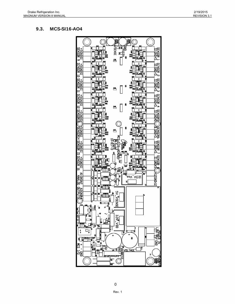
9.3. MCS-SI16-AO4
Drake Refrigeration Inc. 2/19/2015
Rev. 1

MAGNUM VERSION 8 MANUAL REVISION 3.1
0
9.4. MCS-RO10
Drake Refrigeration Inc. 2/19/2015
Rev. 1

Detailed Troubleshooting
Drake Refrigeration Inc. 2/19/2015
Rev. 1

Measure voltage at acinput connector block andverify that it is within 10percent of rated voltage
Troubleshooting General DeadBoard Symptoms
Voltageok?
Ac inputfuse blown?
Replace fuse. Iffuse blows again
replace board
Correct ac supplyto board
Start
Press RESETbutton on board
Is red RESETlight on all the
time?
Is green16VDC light
on?
Magnum Micro Controller Systems
If board has avoltage selectorswitch, is it set
correctly?
Turn power off, setswitch to correct
voltage, turn power on
Turn power off, wait10 seconds, turnpower back on
Board was locked updue to momentarypower dip or spike
Problemsolved?
Board was locked updue to momentarypower dip or spike
Replace board
Is board aMagnum?
Problemsolved?
Press RESETbutton on board
Turn power off, wait10 seconds, turnpower back on
Board was locked updue to momentarypower dip or spike
Problemsolved?
Board was locked updue to momentarypower dip or spike
Problemsolved? Replace board
Replace board
Is LCDbacklight on?
Try to reloadsoftware
Problemsolved?
Replace board
Software wascorrupted
YesYes
Yes
Yes Yes
Yes
Yes
Yes
Yes Yes
Yes
Replace board
Yes
No
No
No
NoNo
No
NoNo
No
No
No
Drake Refrigeration Inc. 2/19/2015
Rev. 1
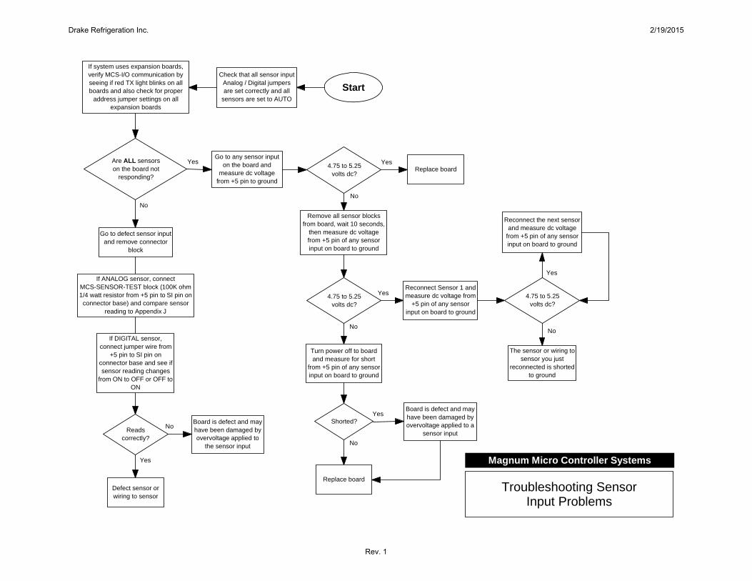
Start
Are ALL sensorson the board not
responding?
Go to any sensor inputon the board and
measure dc voltagefrom +5 pin to ground
4.75 to 5.25volts dc?
Yes
Remove all sensor blocksfrom board, wait 10 seconds,
then measure dc voltagefrom +5 pin of any sensorinput on board to ground
No
4.75 to 5.25volts dc?
Turn power off to boardand measure for short
from +5 pin of any sensorinput on board to ground
No
Shorted?
Replace board
No
Board is defect and mayhave been damaged byovervoltage applied to a
sensor input
Replace board
Yes
Go to defect sensor inputand remove connector
block
Readscorrectly?
No
Defect sensor orwiring to sensor
Yes
Yes
YesBoard is defect and mayhave been damaged byovervoltage applied to
the sensor input
If system uses expansion boards,verify MCS-I/O communication byseeing if red TX light blinks on allboards and also check for proper
address jumper settings on allexpansion boards
Check that all sensor inputAnalog / Digital jumpersare set correctly and all
sensors are set to AUTO
No
If ANALOG sensor, connectMCS-SENSOR-TEST block (100K ohm1/4 watt resistor from +5 pin to SI pin onconnector base) and compare sensor
reading to Appendix J
If DIGITAL sensor,connect jumper wire from
+5 pin to SI pin onconnector base and see ifsensor reading changes
from ON to OFF or OFF toON
Troubleshooting SensorInput Problems
Magnum Micro Controller Systems
Reconnect Sensor 1 andmeasure dc voltage from
+5 pin of any sensorinput on board to ground
4.75 to 5.25volts dc?
The sensor or wiring tosensor you just
reconnected is shortedto ground
Reconnect the next sensorand measure dc voltage
from +5 pin of any sensorinput on board to ground
Yes
No
Drake Refrigeration Inc. 2/19/2015
Rev. 1
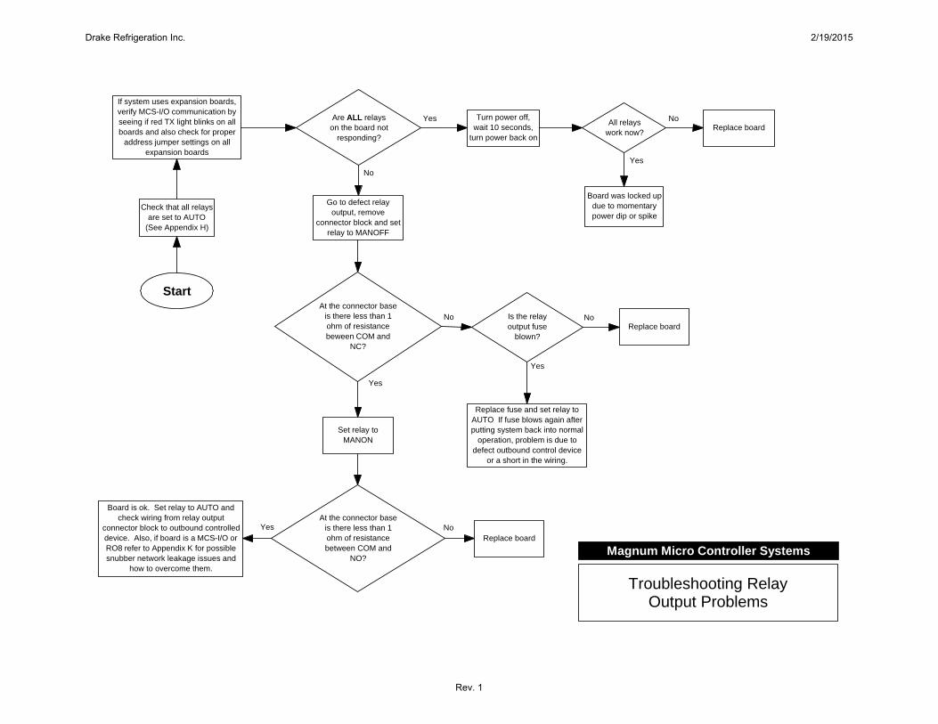
Start
Are ALL relayson the board not
responding?
Turn power off,wait 10 seconds,
turn power back on
All relayswork now?
YesReplace board
Go to defect relayoutput, remove
connector block and setrelay to MANOFF
At the connector baseis there less than 1ohm of resistancebeween COM and
NC?
No
Set relay toMANON
Yes
If system uses expansion boards,verify MCS-I/O communication byseeing if red TX light blinks on allboards and also check for proper
address jumper settings on allexpansion boards
Check that all relaysare set to AUTO
(See Appendix H)
No
No
Board was locked updue to momentarypower dip or spike
Yes
Is the relayoutput fuse
blown?Replace board
No
Replace fuse and set relay toAUTO If fuse blows again afterputting system back into normal
operation, problem is due todefect outbound control device
or a short in the wiring.
Yes
At the connector baseis there less than 1ohm of resistancebetween COM and
NO?
Replace boardNo
Board is ok. Set relay to AUTO andcheck wiring from relay output
connector block to outbound controlleddevice. Also, if board is a MCS-I/O orRO8 refer to Appendix K for possiblesnubber network leakage issues and
how to overcome them.
Yes
Troubleshooting RelayOutput Problems
Magnum Micro Controller Systems
Drake Refrigeration Inc. 2/19/2015
Rev. 1
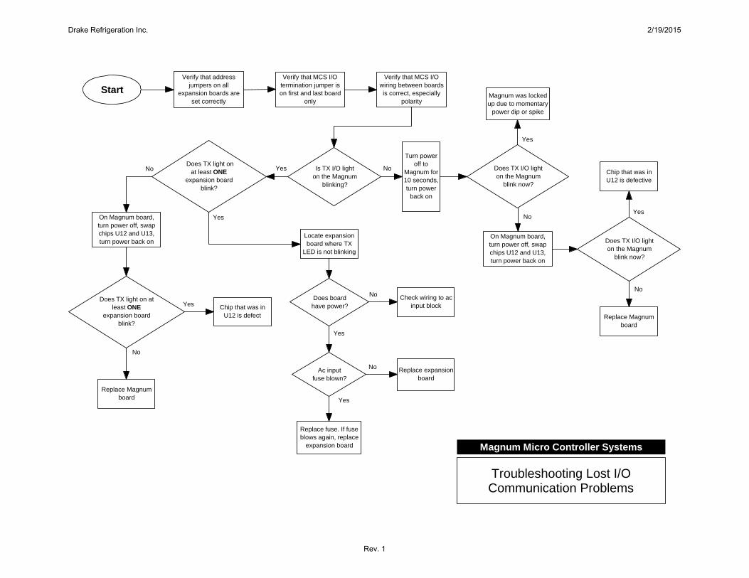
Start
Is TX I/O lighton the Magnum
blinking?
Locate expansionboard where TX
LED is not blinking
Does boardhave power?
Replace fuse. If fuseblows again, replace
expansion board
Ac inputfuse blown?
No
Yes
Replace expansionboard
Yes
Check wiring to acinput block
No
No
Verify that MCS I/Otermination jumper ison first and last board
only
On Magnum board,turn power off, swapchips U12 and U13,turn power back on
No
Yes
Does TX light onat least ONE
expansion boardblink?
Yes
YesOn Magnum board,turn power off, swapchips U12 and U13,turn power back on
Does TX light on atleast ONE
expansion boardblink?
No
Chip that was inU12 is defect
Yes
Replace Magnumboard
No
Verify that addressjumpers on all
expansion boards areset correctly
Turn poweroff to
Magnum for10 seconds,turn power
back on
Does TX I/O lighton the Magnum
blink now?
Magnum was lockedup due to momentary
power dip or spike
Troubleshooting Lost I/OCommunication Problems
Magnum Micro Controller Systems
Replace Magnumboard
No
Yes
Does TX I/O lighton the Magnum
blink now?
Chip that was inU12 is defective
Verify that MCS I/Owiring between boardsis correct, especially
polarity
Drake Refrigeration Inc. 2/19/2015
Rev. 1

Appendix G Entering Authorization Codes to Log In and Out of a Magnum
First, at the Main Menu use the arrow keys to navigate to Passwords:
Next, press the Enter key. You will see the following:
Now enter the proper four-digit authorization code. Each - is changed to a * as numbers are entered. After you have keyed in the numbers, press the
Enter key.
09:56 Main Menu -Status -Setpoints -Outputs -Serv Tools -Inputs -Lckout RST -Alarms -Lckout ALM -Graphs -Passwords Help,
09:56 Password
Enter Pin ----
Then Press ' ' Key . 1 , . 2 , . 3 .
09:56 Password
Enter Pin ****
Then Press ' ' Key . 1 , . 2 , . 3 .
Drake Refrigeration Inc. 2/19/2015
Rev. 1

Appendix G (continued) Entering Authorization Codes to Log In and Out of a Magnum
The Magnum will tell you if it accepted your code and the level of authorization. For example, if you entered a valid factory authorization code you will see the
following:
If you entered an invalid authorization code you will see the following:
Once you are logged in you can log out immediately by simply entering any invalid authorization code. If you are logged in and no keys are pressed for
more than 15 minutes the Magnum will automatically log you out, warning you shortly before with how many seconds remaining as shown here:
09:56 Password
Level – Factory
Press ' MENU ' Key . 1 , . 2 , . 3 .
09:56 Password
Level – VIEW ONLY Invalid Pin
Press ' MENU ' Key . 1 , . 2 , . 3 .
Press Any Key to Avoid
Auth Log Out 60
Drake Refrigeration Inc. 2/19/2015
Rev. 1

Appendix H Manually Turning On and Off a Magnum, MCS-I/O or RO8 Relay Output
Note: If a relay is in a Lockout state you cannot manually turn it on or off.
First, after logging into the Magnum with your authorization code (see Appendix G), use the arrow keys to navigate to Outputs:
Next, use the up and down arrow keys to highlight the relay you want to turn on or off:
Now press the Enter key. You should see something similar to the following:
09:56 Main Menu -Status -Setpoints -Outputs -Serv Tools -Inputs -Lckout RST -Alarms -Lckout ALM -Graphs -Passwords Help,
09:56 Outputs Relays Status M-1 COMP1-1 Off. M-2 LOAD1-1 Off M-3 UNLOD1-1 Off M-4 LLS1-1 Off Anlog .PG, PG.
09:56 Outputs Relays Status M-1 COMP1-1 Off. M-2 LOAD1-1 Off M-3 UNLOD1-1 Off M-4 LLS1-1 Off Anlog .PG, PG.
COMP1-1 Manual AUTO , Status
Drake Refrigeration Inc. 2/19/2015
Rev. 1

Appendix H (continued) Manually Turning On and Off a Magnum, MCS-I/O or RO8 Relay Output
Use the up and down arrow keys to cycle through the three modes for the relay output: AUTO, MANON or MANOFF
Stop when you reach the one you want:
Finally, press the Enter key to make the change. In our example the relay output is now manually turned on as shown here:
Remember to return the relay output to AUTO mode when you are done!
09:56 Outputs Relays Status M-1 COMP1-1 Off. M-2 LOAD1-1 Off M-3 UNLOD1-1 Off M-4 LLS1-1 Off Anlog .PG, PG.
COMP1-1 Manual MANON , Status
09:56 Outputs Relays Status M-1 COMP1-1 On . M-2 LOAD1-1 Off M-3 UNLOD1-1 Off M-4 LLS1-1 Off Anlog .PG, PG.
Change Made
Drake Refrigeration Inc. 2/19/2015
Rev. 1

Appendix I Determining and Changing the Network Address of a Magnum
First, at the Main Menu use the arrow keys to navigate to Serv Tools:
Next, press the Enter key. You will see the following:
Use the up and down arrow keys to highlight Address:
09:56 Main Menu -Status -Setpoints -Outputs -Serv Tools -Inputs -Lckout RST -Alarms -Lckout ALM -Graphs -Passwords Help,
09:56 Serv Tools -RS-485 Network 1. -Ethernet Network -System Info -Time / Date -Display .PG, PG.
09:56 RS-485 Setup Protocol MCS Address 1 . Baud Rate 19200 Back,
Drake Refrigeration Inc. 2/19/2015
Rev. 1

Appendix I (continued) Determining and Changing the Network Address of a Magnum
Now press the Enter key. You should see something similar to the following:
Use the up and down arrow keys to select the Address number:
Finally, press the Enter key to make the change. In our example the RS-485 network address has been changed from 1 to 2:
09:56 RS-485 Setup Protocol MCS Address 1 . Baud Rate 19200 Back,
Address 1,
09:56 RS-485 Setup Protocol MCS Address 1 . Baud Rate 19200 Back,
Address 2,
09:56 RS-485 Setup Protocol MCS Address 2 . Baud Rate 19200 Back,
Change Made
Drake Refrigeration Inc. 2/19/2015
Rev. 1

Appendix J Analog Sensor Input Reference Table
To troubleshoot analog sensor input problems and determine where the problem is, simply remove the sensor input connector block of the input you want to test and plug in a MCS-SENSOR-TEST block. If you do not have a MCS-SENSOR-TEST block you can connect a 100K ohm 1% ¼ watt resistor between the +5 and S1 pins of the suspect sensor input on the board with the original sensor connector block removed. After you have done this, compare the reading displayed by the Magnum with the table of the most common sensor types on the right. If the reading is close to what is found in the table for that particular sensor type you can safely assume that the board is functioning normally and that the problem lies with the sensor itself of the wiring from the sensor to the board.
Sensor Type Reading
CT100 57.0A
CT250 143.0A
CT500 287.0A
HUMD 54.0%
T100 77.0F
Ti150A 75.0P
Ti200 100.0P
Ti500 250.0P
Ti667A 334.0P
Drake Refrigeration Inc. 2/19/2015
Rev. 1

Appendix K Resolving MCS-I/O and RO8 Snubber
Network Leakage Issues
Each relay output on a MCS-I/O and RO8 board is protected by the use of on-board snubber networks. These networks consist of a resistor and capacitor in series connected from the common side of each relay to the normally open and normally closed sides. Its purpose is to suppress or “snub” the electrical arc that is produced when relay contacts open and close. Electrical arcs can shorten the useful life of a relay and can also cause the electronics on the controller board to malfunction. In some cases the use of these snubber networks can cause an outbound device, such as a relay, to stay on even when the controlling relay on the MCS-I/O or RO8 board is turned off. This can occur in situations where the outbound device requires very little ac current to keep it on once it is energized. Because snubber networks normally pass a small amount of current when the circuit it is protecting is switched off, enough current may pass through these networks to keep the outbound relay on, even though the controlling relay is turned off. An easy solution to this problem is to rewire the relay output as shown in the diagram to the right. As you can see, wiring the circuit in this way causes the outbound device to have the same voltage potential on both sides when it is not energized.
NO
NC
COM
LO
AD
LO
AD
LINE
NEUTRAL
Energized whenrelay is turned off
Energized whenrelay is turned on
Outbound sideMCS-I/O or RO8 side
Drake Refrigeration Inc. 2/19/2015
Rev. 1

END OF DOCUMENT
Drake Refrigeration Inc. 2/19/2015
Rev. 1