
AM Series Boiler & Water Heater User Manual - AERCO
170
Disclaimer The information contained in this manual is subject to change without notice from AERCO International, Inc. AERCO makes no warranty of any kind with respect to this material, including, but not limited to, implied warranties of merchantability and fitness for a particular application. AERCO International is not liable for errors appearing in this manual, not for incidental or consequential damages occurring in connection with the furnishing, performance, or use of these materials Operation & Maintenance Manual AM Series Natural Gas and Propane Gas Modulating Condensing Boilers and Water Heaters © 2019 AERCO Other documents for this product include: TAG-0072 GF-146-E Electrical Power Guide TAG-0073 GF-146-G Gas Supply Guide TAG-0074 GF-146-P Piping Application Guide TAG-0075 GF-146-V Venting Guide Applies to serial numbers: From 18170091 and up. OMM-0100_0F • GF-146 • 11/15/2019
-
Upload
khangminh22 -
Category
Documents
-
view
0 -
download
0
Transcript of AM Series Boiler & Water Heater User Manual - AERCO

Disclaimer
The information contained in this manual is subject to change without notice
from AERCO International, Inc. AERCO makes no warranty of any kind with
respect to this material, including, but not limited to, implied warranties of
merchantability and fitness for a particular application. AERCO International is
not liable for errors appearing in this manual, not for incidental or consequential
damages occurring in connection with the furnishing, performance, or use of
these materials
Operation & Maintenance Manual
AM Series Natural Gas and Propane Gas Modulating Condensing Boilers and Water Heaters
© 2019 AERCO
Other documents for this product include:
TAG-0072 GF-146-E Electrical Power Guide TAG-0073 GF-146-G Gas Supply Guide TAG-0074 GF-146-P Piping Application Guide TAG-0075 GF-146-V Venting Guide
Applies to serial numbers:
From 18170091 and up.
OMM-0100_0F • GF-146 • 11/15/2019

AM Series Boiler & Water Heater User Manual TABLE OF CONTENTS
OMM-0100_E • GF-146 • 11/15/2019 Technical Support • (800) 526-0288 • Mon-Fri, 8 am - 5 pm EST Page 2 of 170
Table of Contents FOREWORD .......................................................................................................................6
SECTION 1: GENERAL INFORMATION ..............................................................................7
1.1 WARNINGS & CAUTIONS ............................................................................................................................ 7 1.2 EMERGENCY SHUTDOWN ....................................................................................................................... 10
SECTION 2: FUNCTIONAL OVERVIEW ............................................................................ 11
2.1 INTRODUCTION ......................................................................................................................................... 11 2.1.1 AM Water Heaters and Boilers .............................................................................................................................. 11 2.1.2 AM Rapid Recovery (AMR) Skid Option ................................................................................................................. 11
2.2 INTENDED USE – BOILERS ...................................................................................................................... 12 2.3 INTENDED USE – WATER HEATERS ....................................................................................................... 12 2.4 INTENDED USE – WATER HEATERS AND BOILERS WITH AMR OPTION ........................................... 12 2.5 AM SERIES FUNCTIONAL SCHEMATICS ................................................................................................ 13
2.5.1 AM 399 / 500 Functional Schematic ...................................................................................................................... 13 2.5.2 AM 750 Functional Schematic ............................................................................................................................... 14 2.5.3 AM 1000 Functional Schematic ............................................................................................................................. 15 2.5.4 AMR Functional Schematic .................................................................................................................................... 16
2.6 MAIN COMPONENTS ................................................................................................................................. 17 2.6.1 Burner .................................................................................................................................................................... 17 2.6.2 AM Series 199 and 250 Main Components ........................................................................................................... 19 2.6.3 AM Series 399 and 500 Main Components ........................................................................................................... 22 2.6.4 AM Series 750 and 1000 Main Components ......................................................................................................... 25
SECTION 3: INSTALLATION – SITE ................................................................................. 29
3.1 CHOOSING THE INSTALLATION LOCATION ........................................................................................... 29 3.2 BOILER AND WATER HEATER INSTALLATION LOCATION FACTORS ................................................. 30 3.3 SAFETY CONCERNS ................................................................................................................................. 31 3.4 CLOSET AND ALCOVE INSTALLATION ................................................................................................... 31 3.5 CLEARANCES FOR INSTALLATION AND SERVICING ........................................................................... 31 3.6 CLEARANCES TO COMBUSTIBLE MATERIAL ........................................................................................ 32 3.7 VENT AND COMBUSTION AIR PIPING ..................................................................................................... 33 3.8 PREVENTION OF COMBUSTION AIR CONTAMINATION ....................................................................... 33 3.9 TRANSPORTING THE UNIT ...................................................................................................................... 33 3.10 UNPACKING AND TRANSPORTING ....................................................................................................... 33
3.10.1 Transporting a Standard AM Unit ........................................................................................................................ 34 3.10.2 Transporting an AMR Water Heater .................................................................................................................... 36
3.11 AMR BUFFER TANK INSTALLATION ...................................................................................................... 37 3.11.1 AMR Buffer Tank Installation Kits ........................................................................................................................ 37
3.12 AMR BUFFER TANK COMPONENTS ...................................................................................................... 38 3.13 BUFFER TANK INSTALLATION OVERVIEW .......................................................................................... 38 3.14 REMOVING THE AMR BRACING PLATE ................................................................................................ 39 3.15 AMR 80-GALLON BUFFER TANK INSTALLATION ................................................................................. 39 3.16 AMR 119-GALLON BUFFER TANK INSTALLATION ............................................................................... 41 3.17 AM SERIES SUPPLY AND RETURN PIPING DIMENSIONS .................................................................. 43
3.17.1 Standard AM Supply and Return Piping Dimensions ........................................................................................... 43 3.17.2 AMR Supply and Return Piping Dimensions ........................................................................................................ 44
SECTION 4: INSTALLATION – PIPING ............................................................................. 45
4.1 WATER INLET AND OUTLET PIPING ....................................................................................................... 45 4.2 WATER QUALITY ....................................................................................................................................... 45 4.3 SYSTEM PIPING METHODS - BOILERS ................................................................................................... 45

AM Series Boiler & Water Heater User Manual TABLE OF CONTENTS
OMM-0100_E • GF-146 • 11/15/2019 Technical Support • (800) 526-0288 • Mon-Fri, 8 am - 5 pm EST Page 3 of 170
4.4 FREEZE PROTECTION .............................................................................................................................. 46 4.5 FLOOR RADIANT HEATING SYSTEMS - BOILERS ................................................................................. 46 4.6 PIPING COMPONENTS - BOILERS ........................................................................................................... 46 4.7 PIPING COMPONENTS – WATER HEATERS ........................................................................................... 47 4.8 SAFETY RELIEF VALVE ............................................................................................................................ 48 4.9 LOW WATER CUTOFF (LWCO) ................................................................................................................. 49 4.10 EXPANSION TANK AND MAKEUP WATER ............................................................................................ 50 4.11 CIRCULATOR HEATING PUMP ............................................................................................................... 50 4.12 DOMESTIC HOT WATER SYSTEM PIPING WITH DIRECT WATER HEATER: WATER HEATERS .... 52 4.13 SCALDING – WATER HEATERS ............................................................................................................. 53 4.14 CONDENSATE DISPOSAL ....................................................................................................................... 55
SECTION 5: INSTALLATION – ELECTRICAL ................................................................... 57
5.1 ELECTRICAL CONNECTIONS – BOILERS AND WATER HEATERS ...................................................... 57 5.1.1 Power Supply Cable Connection - Boilers and Water Heaters .............................................................................. 57 5.1.2 Connecting Units in Cascade - Boilers and Water Heaters .................................................................................. 58 5.1.3 0-10 VDC Input Connections - Boilers and Water Heaters .................................................................................... 58 5.1.4 MODBUS Interface Connections – Boilers and Water Heaters ............................................................................. 59
5.2 ELECTRICAL CONNECTIONS – BOILERS ONLY .................................................................................... 60 5.2.1 Enable/Disable - Boilers ......................................................................................................................................... 60 5.2.2 Installing the Outdoor Temperature Sensor - Boilers............................................................................................ 60 5.2.3 Indirect Water Heater Connection - Boilers .......................................................................................................... 61 5.2.4 Indirect Water Heater Priority Selection - Boilers ................................................................................................. 61
5.3 ELECTRICAL CONNECTIONS – WATER HEATERS ONLY ..................................................................... 62 5.3.1 Storage Tank Connection - Water Heaters ............................................................................................................ 62
5.4 AMR RAPID RECOVERY OPTION WIRING .............................................................................................. 62
SECTION 6: INSTALLATION – VENTING AND COMBUSTION AIR PIPING ...................... 65
6.1 COMBUSTION AIR CONTAMINATION PREVENTION ............................................................................. 65 6.2 GENERAL VENTING AND AIR PIPING SYSTEMS ................................................................................... 66 6.3 MIN/MAX ALLOWABLE COMBUSTION AIR AND VENT PIPING LENGTHS ........................................... 68 6.4 GENERAL VENTING AND COMBUSTION AIR PIPING INSTALLATION ................................................. 68 6.5 SPECIFIC VENT INSTALLATIONS ............................................................................................................ 68
6.5.1 Installations Requiring High Temperature Venting ............................................................................................... 69 6.5.2 Sealing of PVC, CPVC or ABS .................................................................................................................................. 70 6.5.3 PVC/CPVC Vent Piping Materials ........................................................................................................................... 70 6.5.4 Air Intake and Vent Starter Pieces ......................................................................................................................... 71 6.5.5 Single Pipe Venting (Room Air Combustion) ......................................................................................................... 72 6.5.6 Determining Vent Termination Location ............................................................................................................... 73 6.5.7 Sidewall Termination - Two pipes ......................................................................................................................... 74 6.5.8 Combustion Air and Ventilation Openings ............................................................................................................ 75 6.5.9 Two Permanent Openings Method ....................................................................................................................... 75 6.5.10 One Permanent Opening Method ....................................................................................................................... 75 6.5.11 Installing Vent and Air Piping into Sidewall ......................................................................................................... 75 6.5.12 Sidewall Termination and Fittings ....................................................................................................................... 76 6.5.13 Multiple Vent and Air Terminations .................................................................................................................... 76 6.5.14 Sidewall Termination – Concentric Vent ............................................................................................................. 77 6.5.15 Sidewall Termination Installation ........................................................................................................................ 78 6.5.16 Multi-venting Sidewall Terminations .................................................................................................................. 79 6.5.17 Determining Location of Vertical Termination .................................................................................................... 80 6.5.18 Vertical Vent and Air Roof Termination Preparation .......................................................................................... 81 6.5.19 Installing Vertical Vent and Air Roof Terminations ............................................................................................. 81 6.5.20 Installing Multiple Vent and Air Vertical Terminations ..................................................................................... 82 6.5.21 Vertical Termination – Concentric Vent .............................................................................................................. 83 6.5.22 Determining Location of Vertical Concentric Vent Termination ......................................................................... 83

AM Series Boiler & Water Heater User Manual TABLE OF CONTENTS
OMM-0100_E • GF-146 • 11/15/2019 Technical Support • (800) 526-0288 • Mon-Fri, 8 am - 5 pm EST Page 4 of 170
6.5.23 Multi-Venting Vertical Terminations .................................................................................................................. 83
SECTION 7: INSTALLATION – NATURAL GAS ................................................................ 85
7.1 GAS SUPPLY PIPING ................................................................................................................................. 85 7.2 CONNECTION OF GAS SUPPLY PIPING ................................................................................................. 85 7.3 NATURAL GAS PIPE SIZING ..................................................................................................................... 87 7.4 NATURAL GAS SUPPLY PRESSURE REQUIREMENTS ......................................................................... 87 7.5 PROPANE GAS PIPE SIZING .................................................................................................................... 87 7.6 PROPANE GAS SUPPLY PRESSURE REQUIREMENTS ........................................................................ 87 7.7 CHECKING AND ADJUSTING THE UNIT INLET GAS SUPPLY PRESSURE .......................................... 88 7.8 HIGH ALTITUDE OPERATION ................................................................................................................... 88 7.9 CONVERSION FROM NATURAL GAS TO PROPANE GAS ..................................................................... 88
7.9.1 Gas Conversion Kit ................................................................................................................................................. 88 7.9.2 Gas Conversion Instructions .................................................................................................................................. 89
SECTION 8: UNIT START-UP ........................................................................................... 93
8.1 INITIAL START-UP REQUIREMENTS ....................................................................................................... 93 8.1.1 Filling the Condensate Neutralizer ........................................................................................................................ 93 8.1.2 Filling the Heating System ..................................................................................................................................... 94
8.2 GENERAL WARNINGS CONCERNING THE GAS SUPPLY ..................................................................... 94 8.2.1 Confirming the Unit’s Gas Type ............................................................................................................................. 95 8.2.2 Gas Type Conversion ............................................................................................................................................. 95
8.3 IDENTIFICATION OF CONTROLS ............................................................................................................. 96 8.4 BOILER STARTUP PROCEDURE.............................................................................................................. 96 8.5 WATER HEATER STARTUP PROCEDURE .............................................................................................. 97 8.6 GAS SUPPLY PRESSURE TEST ............................................................................................................... 98 8.7 COMBUSTION CALIBRATION ................................................................................................................. 100 8.8 LOST IGNITION PROCEDURE ................................................................................................................ 101 8.9 MINIMUM WATER FLOW ......................................................................................................................... 101 8.10 HEATING SYSTEM PRESSURE TEST .................................................................................................. 102
SECTION 9: OPERATION ............................................................................................... 103
9.1 GENERAL OPERATION ........................................................................................................................... 103 9.2 FREEZE PROTECTION ............................................................................................................................ 104 9.3 DISPLAY ENERGY SAVING MODE ......................................................................................................... 104 9.4 CONTROL PANEL DISPLAY .................................................................................................................... 104 9.5 STARTUP PROCEDURE - BOILERS ....................................................................................................... 105 9.6 BOILER SUMMER MODE ......................................................................................................................... 105 9.7 ADJUSTING THE DOMESTIC HOT WATER TEMPERATURE - BOILERS ............................................ 106 9.8 HEATING SYSTEM TEMPERATURE ADJUSTMENT - BOILERS .......................................................... 106 9.9 HEATING SYSTEM TYPE SELECTION - BOILERS ................................................................................ 106 9.10 OUTDOOR RESET ADJUSTMENT - BOILERS ..................................................................................... 106
9.10.1 Outdoor Reset: Setting Parameters .................................................................................................................. 107 9.10.2 Outdoor Reset Activation .................................................................................................................................. 107
9.11 BOILER DELAYS, ALARMS AND PROTECTIVE ACTIONS ................................................................. 108 9.12 BOILER CIRCULATOR PUMP PROTECTION ....................................................................................... 108 9.13 STARTUP PROCEDURE - WATER HEATERS ..................................................................................... 108 9.14 ADJUSTING THE STORAGE TANK TEMPERATURE (WATER HEATERS) ........................................ 109 9.15 USER MENU ........................................................................................................................................... 110 9.16 INSTALLER MENU ................................................................................................................................. 111 9.17 FACTORY MENU .................................................................................................................................... 113 9.18 DIAGNOSTICS – DISPLAY MESSAGES ............................................................................................... 117 9.19 DIAGNOSTICS – LOCKOUT (LOC) ERRORS ....................................................................................... 117

AM Series Boiler & Water Heater User Manual TABLE OF CONTENTS
OMM-0100_E • GF-146 • 11/15/2019 Technical Support • (800) 526-0288 • Mon-Fri, 8 am - 5 pm EST Page 5 of 170
9.20 DIAGNOSTICS – BLOCKING (ERR) ERRORS ...................................................................................... 119 9.21 BLOCKED FLUE PRESSURE SWITCH ................................................................................................. 121 9.22 UNIT SHUT-DOWN ................................................................................................................................. 122
SECTION 10: MAINTENANCE .......................................................................................... 124
10.1 CHECKING FOR GAS LEAKS ................................................................................................................ 125 10.2 FLUE AND AIR INLET PIPING INSPECTION ........................................................................................ 125 10.3 SYSTEM PIPING, PRESSURE, AND EXPANSION TANK INSPECTION ............................................. 125 10.4 IGNITION AND FLAME SENSOR INSPECTION .................................................................................... 125 10.5 WIRING AND CONNECTIONS INSPECTION ........................................................................................ 125 10.6 PERFORMANCE VERIFICATION INSPECTION ................................................................................... 125 10.7 FLAME INSPECTION .............................................................................................................................. 125 10.8 FLAME SIGNAL INSPECTION ............................................................................................................... 126 10.9 RELIEF VALVE INSPECTION ................................................................................................................ 126 10.10 UNIT VICINITY INSPECTION ............................................................................................................... 126 10.11 PRESSURE GAUGE INSPECTION ...................................................................................................... 126 10.12 CONDENSATE DRAIN SYSTEM INSPECTION .................................................................................. 127 10.13 LOW WATER CUTOFF TEST ............................................................................................................... 127 10.14 REMOVING THE UNIT COVERS ......................................................................................................... 128 10.15 CLEANING THE BURNER AND PRIMARY HEAT EXCHANGER (FLUE/GAS SIDE) ........................ 129 10.16 INSPECTING AND REPLACING THE HEAT EXCHANGER THERMAL INSULATION ....................... 133 10.17 INSPECTING AND REPLACING THE BURNER THERMAL INSULATION ......................................... 134 10.18 CHECKING FOR GAS LEAKS AFTER REASSEMBLY........................................................................ 136 10.19 IGNITION AND FLAME DETECTION SENSOR ELECTRODE POSITIONING ................................... 137 10.20 AIR FILTER CLEANING ........................................................................................................................ 138 10.21 CONDENSATE TRAP AND NEUTRALIZING RESERVOIR MAINTENANCE ..................................... 139 10.22 CONTROL BOARD REPLACEMENT ................................................................................................... 141 10.23 DRAINING THE WATER FROM THE UNIT ......................................................................................... 142 10.24 WATER AND FLUE TEMPERATURE SENSOR .................................................................................. 142 10.25 OUTDOOR TEMPERATURE SENSOR (BOILERS ONLY) .................................................................. 143 10.26 AM RAPID RECOVERY (AMR) OPTION MAINTENANCE .................................................................. 143
10.26.1 Components and Piping .................................................................................................................................. 144 10.26.2 Buffer Tank Anode Rods .................................................................................................................................. 144
10.27 MAINTENANCE KITS PART LISTS ...................................................................................................... 145 10.27.1 Wiring Diagram ................................................................................................................................................ 146
SECTION 11: TECHNICAL DATA ..................................................................................... 153
SECTION 12: SPARE PARTS DRAWINGS & LISTS .......................................................... 155
12.1 AM 399/500 SPARE PARTS DRAWINGS .............................................................................................. 155 12.2 AM 399/500 SPARE PARTS LIST .......................................................................................................... 158 12.3 AM 750/1000 SPARE PARTS DRAWINGS ............................................................................................ 161 12.4 AM 750/1000 SPARE PARTS LIST ........................................................................................................ 164 12.5 AMR OPTION SPARE PARTS DRAWING ............................................................................................. 167 12.6 AM RAPID RECOVERY (AMR) OPTION SPARE PARTS LIST ............................................................. 168
APPENDIX A: CONTROL PANEL OPERATION CHART ..................................................... 169

AM Series Boiler & Water Heater User Manual FORWARD
OMM-0100_E • GF-146 • 11/15/2019 Technical Support • (800) 526-0288 • Mon-Fri, 8 am - 5 pm EST Page 6 of 170
FOREWORD
The Advanced Modular (AM) Series represents the latest in high efficiency, condensing boiler and water heater technology. The AM Series has a unique modular design that provides exceptional reliability, serviceability, and fuel savings from 399 to 1000 MBTU. Each unit is comprised of between two and four independent thermal modules firing up to 250 MBTU each at 5:1 individual turndown. This allows for superior temperature control and low-cycling operation. This unique design provides the multiple boiler redundancy required in a boiler plant, but in a single unit installation with one set of water connections, one gas connection, and one vent connection. When needed, multiple units are easily co-located to provide a boiler plant with the highest efficiency, turndown, and redundancy in the smallest footprint. Multiple units are sequenced through the AERCO AM Cascade Manager. Each unit is equipped for Modbus communication to a BAS. High efficiencies and low vent temperatures mean the unit can be vented in PVC, CPVC, Polypropylene, and AL29-4C vent materials. The front-access design also means the unit is very simple to maintain and service.
Features:
• High Efficiency Condensing Boiler/Water Heater
• Natural Gas or Propane
• Superior Turndown 8:1 to 20:1 (depending on unit)
• Low NOx Emission <20ppm
• Direct or Conventional Vent with PVC, CPVC, Polypropylene, or AL29-4C materials
• Concentric Vent Capability
• Common Vent Capability
• Side wall common venting with no additional check valve
• Small, Doorway-Size Footprint
• Superior Reliability
• Minimal Maintenance
• Easy Front Access for Serviceability
• Zero Side Clearance
• Supports Integration to BAS System
• Modbus Communication Standard
• Integrated isolation valves, flow meters, and condensate neutralizer

AM Series Boiler & Water Heater User Manual CHAPTER 1: GENERAL INFORMATION
OMM-0100_E • GF-146 • 11/15/2019 Technical Support • (800) 526-0288 • Mon-Fri, 8 am - 5 pm EST Page 7 of 170
SECTION 1: GENERAL INFORMATION
1.1 Warnings & Cautions In addition to all the requirements included in this AERCO Instruction Manual, the installation of units MUST conform with local building codes, or, in the absence of local codes, ANSI Z223.1 (National Fuel Gas Code Publication No. NFPA-54) for gas-fired boilers and ANSI/NFPASB for LP gas-fired boilers. W here applicable, the equipment shall be installed in accordance with the current Installation Code for Gas Burning Appliances and Equipment, CSA B149.1, and applicable Provincial regulations for the class; which should be carefully followed in all cases. Authorities having jurisdiction should be consulted before installations are made.
IMPORTANT!
This Instruction Manual is an integral part of the product and must be maintained in legible condition. It must be given to the user by the installer and kept in a safe place for future reference.
WARNING!
Failure to comply with provisions, warnings, and cautions provided in this manual can lead to extensive property damage and/or personal injury or death.
In the event of a breakdown and/or malfunction of the boiler, turn off the unit and do not make any attempt to repair it. The boiler must be serviced exclusively by a Qualified installer using original spare parts. Failure to comply with this requirement may compromise the safety of the unit.
WARNING!
Installer: Read all instructions including this manual, before installing. Perform steps in the
order given.
User: The installation and maintenance sections of this manual are for use only by a
qualified heating installer. Refer to Chapter 9: Operation for user information.
Installation and Alterations: Only a Qualified installer must carry out the installation
and calibration of the boiler. Never modify the boiler or its components in any way.
Overheating: Should overheating occur or the gas supply fail; to shut off, do not turn off or
disconnect electrical supply to circulator. Instead, turn off the manual gas shut-off valve external to the appliance.
Water Contamination: Do not use this appliance if any part has been under water.
Immediately call a licensed authorized technician to inspect the appliance and to replace any part of the control system and any gas control, which has been under water.
Ensure the boiler and its controls are protected from dripping or spraying water during normal operation or service.
Spare Parts: Only use the boiler with the accessories and spares listed in this manual.
Failure to do so can cause equipment damage or dangerous conditions.

AM Series Boiler & Water Heater User Manual CHAPTER 1: GENERAL INFORMATION
OMM-0100_E • GF-146 • 11/15/2019 Technical Support • (800) 526-0288 • Mon-Fri, 8 am - 5 pm EST Page 8 of 170
NOTE:
When calling or writing about the boiler, have the unit model and serial number as seen on the unit rating plate.
CAUTION!
Do not use petroleum-based cleaning or sealing compounds in the boiler system. Gaskets and seals in the system may be damaged. This can result in substantial property damage.
The manufacturer declines all liability, contractual or otherwise (warranty included), for any damage to people, animals property or this same appliance, caused by:
• Incorrect installation or failure to comply with this or any other instruction provided by the manufacturer;
• Failure to comply with the applicable local and/or national regulations in force.
• Incorrect use of this appliance.
• Inadequate or incorrect service
• Inadequate or incorrect maintenance.

AM Series Boiler & Water Heater User Manual CHAPTER 1: GENERAL INFORMATION
OMM-0100_E • GF-146 • 11/15/2019 Technical Support • (800) 526-0288 • Mon-Fri, 8 am - 5 pm EST Page 9 of 170
OFF.
OFF.

AM Series Boiler & Water Heater User Manual CHAPTER 1: GENERAL INFORMATION
OMM-0100_E • GF-146 • 11/15/2019 Technical Support • (800) 526-0288 • Mon-Fri, 8 am - 5 pm EST Page 10 of 170
1.2 Emergency Shutdown If overheating occurs or the gas supply fails to shut off, close the manual gas shutoff valve (Figure 1-1) located external to the unit.
NOTE:
The Installer must identify and indicate the location of the emergency shutdown manual gas valve to operating personnel.
Figure 1-1: Manual Gas Shutoff Valve
IMPORTANT: FOR MASSACHUSETTS INSTALLATIONS:
Boiler Installations within the Commonwealth of Massachusetts must conform to the following requirements:
• Boiler must be installed by a plumber or a gas fitter who is licensed within the Commonwealth of Massachusetts.
• Prior to unit operation, the complete gas train and all connections must be leak tested using a non-corrosive soap.
• The vent termination must be located a minimum of 4 feet above grade level. If side-wall venting is used, the installation must conform to the requirements in 248 CMR 5.08 (2).
• Must be installed according to all local codes.

AM Series Boiler & Water Heater User Manual CHAPTER 2: FUNCTIONAL OVERVIEW
OMM-0100_E • GF-146 • 11/15/2019 Technical Support • (800) 526-0288 • Mon-Fri, 8 am - 5 pm EST Page 11 of 170
SECTION 2: FUNCTIONAL OVERVIEW
2.1 INTRODUCTION
2.1.1 AM Water Heaters and Boilers
Figure 2-1 shows the exterior appearance of the AM Series of boilers and water heaters. The AM Series comes in four functionally sized models; the 399, 500, 750, and 1000. Boilers are appended with a B (i.e. AM 1000B), and water heaters with a W (i.e. AM 1000W).
Figure 2-1: AM Boiler or Water Heater (AM 399/500 Left, AM 750/ AM 1000 Right)
2.1.2 AM Rapid Recovery (AMR) Skid Option
Figure 2-2 shows the AMR option, comprised of an AM water heater, thermal buffer tank, low water cutoff (LWCO), recirculation loop piping, and recirculation loop pump.
Figure 2-2: AM Water Heater with Rapid Recovery Option (AM 1000RS Shown)
AM SERIES WATER HEATER (AM750 OR AM1000)
RECIRCULATION LOOP PUMP
RECIRCULATION LOOP PIPING
HOT WATER OUTLET
AM 750 / 1000 AM 399 / AM 500
CONTROL PANEL
THERMAL BUFFER TANK
COLD WATER INLET
SAFETY RELIEF VALVE

AM Series Boiler & Water Heater User Manual CHAPTER 2: FUNCTIONAL OVERVIEW
OMM-0100_E • GF-146 • 11/15/2019 Technical Support • (800) 526-0288 • Mon-Fri, 8 am - 5 pm EST Page 12 of 170
2.2 Intended Use – Boilers The gas-fired condensing AM Series boilers are designed to be used in central heating systems. Any other use is prohibited.
Heat is always guaranteed for the production of domestic hot water since it is given priority over space heating demands. Follow the specific procedure in Section 9.7 for boiler adjustment for domestic hot water temperature. This boiler can be connected to an indirect storage tank for the production of domestic hot water (Section 4.10).
This unit can be installed with a direct venting system or with a one pipe vent system and draw combustion air from the room.
The quality of the system water is very important. Poor water quality can damage heating systems and boilers due to scale formation and corrosion.
A heating system can be configured to function at a temperature range of between 68°F (20°C) and 180°F (82°C).
The AM Series boiler can be connected to a room On/Off control (Section 5.2.1).
An outdoor air temperature sensor must also be connected to the boiler for an outdoor reset supply temperature control for maximum fuel efficiency and comfort. For further information on the outdoor-air reset, refer to Section 9.10.
2.3 Intended Use – Water Heaters The gas fired condensing AM Series water heaters are designed to be used for domestic hot water production. Any other use is prohibited.
The water heaters must be connected to a storage tank for the production of domestic hot water. When connecting the water heater to the storage water heater, the installer must consider the head loss of the water heater (see figure 4-4), the head loss of the piping system and the head loss of the storage water heater to size adequate pumps.
This unit can be installed with a direct venting system or with a one pipe vent system and draw combustion air from the room.
The quality of the system water is very important. Poor water quality can damage heating systems and boilers due to scale formation and corrosion.
2.4 Intended Use – Water Heaters and Boilers with AMR Option This option is available for AERCO AM Series water heaters and boilers. All functional descriptions that apply to AM water heaters and boilers apply to the AMR option, except where specifically noted.
The AMR option reduces thermal loss by using a pump to efficiently recirculate a mix of building recirculated water (if used on site), fresh potable water, and water in the lower portion of the tank for heating in the heat exchanger. A functional diagram may be found at the end of this chapter.

AM Series Boiler & Water Heater User Manual CHAPTER 2: FUNCTIONAL OVERVIEW
OMM-0100_E • GF-146 • 11/15/2019 Technical Support • (800) 526-0288 • Mon-Fri, 8 am - 5 pm EST Page 13 of 170
2.5 AM Series Functional Schematics
2.5.1 AM 399 / 500 Functional Schematic
Figure 2-3: 399 / 500 (Boiler & Water Heater) Functional Schematic

AM Series Boiler & Water Heater User Manual CHAPTER 2: FUNCTIONAL OVERVIEW
OMM-0100_E • GF-146 • 11/15/2019 Technical Support • (800) 526-0288 • Mon-Fri, 8 am - 5 pm EST Page 14 of 170
2.5.2 AM 750 Functional Schematic
Figure 2-4: 750 (Boiler & Water Heater) Functional Schematic

AM Series Boiler & Water Heater User Manual CHAPTER 2: FUNCTIONAL OVERVIEW
OMM-0100_E • GF-146 • 11/15/2019 Technical Support • (800) 526-0288 • Mon-Fri, 8 am - 5 pm EST Page 15 of 170
2.5.3 AM 1000 Functional Schematic
Figure 2-5: AM 1000 (Boiler & Water Heater) Functional Schematic

AM Series Boiler & Water Heater User Manual CHAPTER 2: FUNCTIONAL OVERVIEW
OMM-0100_E • GF-146 • 11/15/2019 Technical Support • (800) 526-0288 • Mon-Fri, 8 am - 5 pm EST Page 16 of 170
2.5.4 AMR Functional Schematic
Figure 2-6: AMR Function Diagram (Buffer Tank Transparent for Clarity
MIXED BUILDING RECIRCULATION
AND MAKEUP WATER RETURN
TANK OUTLET TO RECIRCULATION
LOOP
HOT WATER OUTLET
AM HEAT EXCHANGER INLET (FROM
WATER RETURN AND TANK)
GAS INLET
AMR RECIRCULATION LOOP PIPING
HOT WATER OUTLET (FROM AM HEAT EXCHANGER TO BUFFER TANK)
TANK INLET FROM HEAT EXCHANGER
AM SERIES WATER HEATER
BUFFER TANK
RECIRCULATION LOOP PUMP
= Warm Tank Water
= Cold Return Water
= Hot Water
LWCO (LOW WATER CUT-OFF)
= Tank and Cold Return Water

AM Series Boiler & Water Heater User Manual CHAPTER 2: FUNCTIONAL OVERVIEW
OMM-0100_E • GF-146 • 11/15/2019 Technical Support • (800) 526-0288 • Mon-Fri, 8 am - 5 pm EST Page 17 of 170
2.6 Main Components
2.6.1 Burner
Figure 2-7: Burner Main Components

AM Series Boiler & Water Heater User Manual CHAPTER 2: FUNCTIONAL OVERVIEW
OMM-0100_E • GF-146 • 11/15/2019 Technical Support • (800) 526-0288 • Mon-Fri, 8 am - 5 pm EST Page 18 of 170
Figure 2-8: Burner Main Components

AM Series Boiler & Water Heater User Manual CHAPTER 2: FUNCTIONAL OVERVIEW
OMM-0100_E • GF-146 • 11/15/2019 Technical Support • (800) 526-0288 • Mon-Fri, 8 am - 5 pm EST Page 19 of 170
2.6.2 AM Series 199 and 250 Main Components
Figure 2-9: AM Series 199 and 250 Main Components

AM Series Boiler & Water Heater User Manual CHAPTER 2: FUNCTIONAL OVERVIEW
OMM-0100_E • GF-146 • 11/15/2019 Technical Support • (800) 526-0288 • Mon-Fri, 8 am - 5 pm EST Page 20 of 170
Figure 2-10: AM Series 199 and 250 Main Components

AM Series Boiler & Water Heater User Manual CHAPTER 2: FUNCTIONAL OVERVIEW
OMM-0100_E • GF-146 • 11/15/2019 Technical Support • (800) 526-0288 • Mon-Fri, 8 am - 5 pm EST Page 21 of 170
Figure 2-11: AM Series 199 and 250 Main Components

AM Series Boiler & Water Heater User Manual CHAPTER 2: FUNCTIONAL OVERVIEW
OMM-0100_E • GF-146 • 11/15/2019 Technical Support • (800) 526-0288 • Mon-Fri, 8 am - 5 pm EST Page 22 of 170
2.6.3 AM Series 399 and 500 Main Components
Figure 2-12: AM Series 399 and 500 Main Components

AM Series Boiler & Water Heater User Manual CHAPTER 2: FUNCTIONAL OVERVIEW
OMM-0100_E • GF-146 • 11/15/2019 Technical Support • (800) 526-0288 • Mon-Fri, 8 am - 5 pm EST Page 23 of 170
Figure 2-13: AM Series 399 and 500 Main Components

AM Series Boiler & Water Heater User Manual CHAPTER 2: FUNCTIONAL OVERVIEW
OMM-0100_E • GF-146 • 11/15/2019 Technical Support • (800) 526-0288 • Mon-Fri, 8 am - 5 pm EST Page 24 of 170
Figure 2-14: AM Series 399 and 500 Main Components

AM Series Boiler & Water Heater User Manual CHAPTER 2: FUNCTIONAL OVERVIEW
OMM-0100_E • GF-146 • 11/15/2019 Technical Support • (800) 526-0288 • Mon-Fri, 8 am - 5 pm EST Page 25 of 170
2.6.4 AM Series 750 and 1000 Main Components
Figure 2-15: AM Series 750 and 1000 Main Components

AM Series Boiler & Water Heater User Manual CHAPTER 2: FUNCTIONAL OVERVIEW
OMM-0100_E • GF-146 • 11/15/2019 Technical Support • (800) 526-0288 • Mon-Fri, 8 am - 5 pm EST Page 26 of 170
Figure 2-16: AM Series 750 and 1000 Main Components

AM Series Boiler & Water Heater User Manual CHAPTER 2: FUNCTIONAL OVERVIEW
OMM-0100_E • GF-146 • 11/15/2019 Technical Support • (800) 526-0288 • Mon-Fri, 8 am - 5 pm EST Page 27 of 170
Figure 2-17: AM Series 750 and 1000 Main Components

AM Series Boiler & Water Heater User Manual CHAPTER 2: FUNCTIONAL OVERVIEW
OMM-0100_E • GF-146 • 11/15/2019 Technical Support • (800) 526-0288 • Mon-Fri, 8 am - 5 pm EST Page 28 of 170
(This page intentionally blank)

AM Series Boiler & Water Heater User Manual CHAPTER 3: INSTALLATION – SITE
OMM-0100_E • GF-146 • 11/15/2019 Technical Support • (800) 526-0288 • Mon-Fri, 8 am - 5 pm EST Page 29 of 170
SECTION 3: INSTALLATION – SITE
3.1 Choosing the Installation Location
This section describes the general installation considerations for the AM Series units.
WARNING!
Provisions for combustion air and ventilation of the boiler room are always required, regardless whether the combustion air is taken from the outside (Direct Vent, sealed combustion) or inside (room air for combustion). Insufficient ventilation of the boiler room can lead to high air temperatures. Make sure that intake and exhaust openings are sufficiently sized and no reduction or closure of openings takes place. If these are not provided, do not operate the boiler.
WARNING!
LIQUEFIED PETROLEUM (L.P.) PROPANE GAS-FIRED BOILER LOCATION REQUIRES SPECIAL ATTENTION: 1994 UNIFORM MECHANICAL CODE, section 304.6: “LPG Appliances. Liquefied petroleum gas-burning appliances shall not be installed in a pit, basement or similar location where heavier-than-air-gas might collect. Appliances so fueled shall not be installed in an above grade under-floor space or basement unless such location is provided with an approved means for removal of unburned gas.”
This appliance is not designed for direct outdoor installation. If installed outside of the structure, it must be sheltered so it is protected from rain, wind, sun and frost. NEVER place this appliance in a location that would subject it to temperatures at or near freezing or excessively high temperature. Failure to properly locate this unit can result in premature failure.
The boiler must NOT be installed on carpeting.
This appliance must be installed in a location so that any water leaking from the unit or piping connections or relief valve openings will not cause damage to the area surrounding the unit or any lower floors in the structure. When such locations cannot be avoided, it is recommended that a suitable drain pan, adequately drained, be installed under the boiler. The pan must not restrict combustion air flow.
When installed in a room with thin flooring, resonating noises may occur. Install noise reducing parts if required.
Do not allow excessive dust to collect on the appliance.

AM Series Boiler & Water Heater User Manual CHAPTER 3: INSTALLATION – SITE
OMM-0100_E • GF-146 • 11/15/2019 Technical Support • (800) 526-0288 • Mon-Fri, 8 am - 5 pm EST Page 30 of 170
WARNING! Do not store or use gasoline or other flammable vapors or liquids in the vicinity of this or any other appliance.
WHAT TO DO IF YOU SMELL GAS:
• Do not try to light any appliance.
• Do not touch any electrical switch.
• Do not use any phone in the building.
• Immediately call your gas supplier from a neighbor’s phone. Follow the gas
supplier’s instructions.
• If you cannot contact your gas supplier, call the fire department.
3.2 Boiler and Water Heater Installation Location Factors When locating the boiler or water heater, the following factors must be considered:
• location of vent/air intakes;
• connection to the gas supply;
• connection to the water supply;
• connection to the heating system;
• connection to the electrical supply;
• disposal of the condensation produced by the boiler;
• connection to the room thermostat, building automation system, or equivalent device;
• piping of the safety relief valve discharge;
• connection of the outdoor temperature sensor;
• possible connection of an indirect water heater;
• If flooding is possible, elevate the boiler sufficiently to prevent water from reaching the unit;
• The location of vent/air intakes;
• connection to the gas supply;
• connection to the water supply;
• connection to the electrical supply;
• disposal of the condensation produced by the boiler;
• piping of the safety relief valve discharge;
• connection of a storage tank;
• If flooding is possible, elevate the boiler sufficiently to prevent water from reaching the unit;

AM Series Boiler & Water Heater User Manual CHAPTER 3: INSTALLATION – SITE
OMM-0100_E • GF-146 • 11/15/2019 Technical Support • (800) 526-0288 • Mon-Fri, 8 am - 5 pm EST Page 31 of 170
3.3 Safety Concerns
WARNING!
Do not store any flammable materials or liquids in the immediate vicinity of the boiler.
3.4 Closet and Alcove Installation
AM boilers or water heaters are not approved for installation in a closet or in an alcove site.
3.5 Clearances for Installation and Servicing
Figures 3-1, 3-2 and 3-3 show the minimum clearances required for installation and servicing.
Figure 3-1: Recommended Minimum Clearance Distance, AM 199 – AM 500
Figure 3-2: Recommended Minimum Clearance Distance, AM 750 & AM 1000

AM Series Boiler & Water Heater User Manual CHAPTER 3: INSTALLATION – SITE
OMM-0100_E • GF-146 • 11/15/2019 Technical Support • (800) 526-0288 • Mon-Fri, 8 am - 5 pm EST Page 32 of 170
Figure 3-3: AMR Option - Recommended Minimum Service Clearances
NOTE:
Service clearances are minimum required clearances for ease of access, but larger service clearances are always preferred.
3.6 Clearances to Combustible Material
This unit may be installed directly onto a floor of combustible material with the following clearances:
Table 3-1: Unit Installation Clearance Dimensions
COMPONENT CLEARANCE DISTANCE
Ceiling 2 inches (51 mm)
Front 2 inches (51 mm)
Rear 2 inches (51 mm)
Sides 2 inches (51 mm)
Floor 0 inches (0 mm)
Concentric vent 0 inches (0 mm)
Split vent (two pipes) first 3 feet from the boiler 1 inch (25 mm)
Split vent (two pipes) after 3 feet from the boiler 0 inches (0 mm)
Boiler piping ¼ inch (7 mm)
AM Series Boiler & Water Heater User Manual CHAPTER 3: INSTALLATION – SITE
OMM-0100_E • GF-146 • 11/15/2019 Technical Support • (800) 526-0288 • Mon-Fri, 8 am - 5 pm EST Page 33 of 170
3.7 Vent and Combustion Air Piping
This boiler requires a special vent system, designed for pressurized venting.
The boiler is to be configured for either direct vent installation or for installation using room combustion air. When room combustion air is considered, see Chapter 6.
Vent and air may be vented vertically through the roof or out a side wall, unless otherwise specified. You may use any of the vent/air piping methods covered in Chapter 6.
Be sure to locate the unit such that the vent and air piping can be routed through the building and properly terminated.
The vent/air piping lengths, routing and termination method must all comply with the methods and limits given in Chapter 6.
3.8 Prevention of Combustion Air Contamination
Install air inlet piping for the appliance as described in Chapter 6. Do not terminate vent/air in locations that can allow contamination of combustion air.
WARNING!
Ensure that the combustion air will not contain any contaminants. Contaminated combustion air will damage the unit, resulting in possible personal injury, death or substantial property damage.
3.9 Transporting the Unit • Only transport the unit using the right transportation equipment, such as a hand truck with a
fastening belt or special equipment for maneuvering steps.
• During transportation, the unit must be secured on the transportation equipment to prevent it from falling off.
• Protect all parts against impacts during transport.
• Observe the transportation markings on the packaging.
• Leave the protective covers on the connections until ready to install.
• During transportation, cover the flue gas and air intake connections at the top of the unit with plastic or other material to avoid contamination.
3.10 Unpacking and Transporting
After removing the shipping carton from the unit, it may be moved according to its configuration as ether a standard AM unit, as described in section 3.10.1, or an AM water Heater configured with the Rapid Recovery option, as described in section 3.10.2.
CAUTION!
AM water heaters configured with the AERCO Rapid Recovery option must be moved ONLY with a forklift through the supporting skid. See section 3.10.2 for instructions.

AM Series Boiler & Water Heater User Manual CHAPTER 3: INSTALLATION – SITE
OMM-0100_E • GF-146 • 11/15/2019 Technical Support • (800) 526-0288 • Mon-Fri, 8 am - 5 pm EST Page 34 of 170
3.10.1 Transporting a Standard AM Unit
Transport a standard AM boiler or water heater to its installation location as follows.
Transporting a Standard AM Water Heater or Boiler
1. Remove the lower cover “A” at front of the AM unit by pulling it off.
2. Remove the screw & washer “B” (Figure 3-4), which fastens the pallet to the unit front.
Figure 3-4: Removing the Unit Front from Wood Pallet
3. Remove the screw and washer “C” (Figure 3-5), which fastens the pallet to the unit rear.
Figure 3-5: Removing the Unit rear from Wood Pallet
4. Install the two factory supplied eyebolts “D” on the upper side of the unit and attach chains or straps to lifting ring/hook “E” as shown in Figure 3-6.
Figure 3-6: Removing the Unit from Wood Pallet (Lifting)
A
E
C
D
B

AM Series Boiler & Water Heater User Manual CHAPTER 3: INSTALLATION – SITE
OMM-0100_E • GF-146 • 11/15/2019 Technical Support • (800) 526-0288 • Mon-Fri, 8 am - 5 pm EST Page 35 of 170
Transporting a Standard AM Water Heater or Boiler – Continued
5. Using the appropriate lifting equipment, hoist the unit from the wood pallet. The weight of each models are as follows:
Model Weight (lbs.)
AM399 300
AM500 325
AM750 500
AM1000 550
6. While unit is suspended, install the leveling feet “F” (Figure 3-7), to allow leveling the unit after installation.
Figure 3-7: Installing the Leveling Feet
WARNING!
The floor onto which the unit is installed must be capable of supporting the weight of the unit or the unit and/or building may be damaged.

AM Series Boiler & Water Heater User Manual CHAPTER 3: INSTALLATION – SITE
OMM-0100_E • GF-146 • 11/15/2019 Technical Support • (800) 526-0288 • Mon-Fri, 8 am - 5 pm EST Page 36 of 170
3.10.2 Transporting an AMR Water Heater
For an AM water heater with the rapid recovery option, the buffer tank is shipped separately from the main unit and must be assembled after main unit installation. The buffer tank should only be assembled to the unit after the water heater has been transported, located, positioned and installed in its final operating position. Transport the main unit (without buffer tank installed) as described below:
Transporting an AMR Water Heater
1. Remove the two (2) 3/8-16 hex cap screws, washers, and nuts attaching the front of the assembly skid to the pallet (Figure 3-8).
2. Remove the two (2) 3/8-16 hex cap screws, washers, and nuts attaching the rear of the assembly skid to the pallet (Figure 3-8.
3. Once the assembly is disconnected from the pallet, the unit may be transported using a fork lift inserted into the skid, front or rear, or at the sides, as indicated in Figure 3-8.
Figure 3-8: Transporting the AMR (Rapid Recovery) Water Heater
CAUTION!
DO NOT use the lifting lugs on the AM unit to lift the entire AMR assembly. They are to be used ONLY in the maintenance or replacement of the AM Series unit.
WARNING!
• Do not transport the AMR unit while the buffer tank is installed, or damage to equipment or property, or injury to persons might occur.
• The floor onto which the unit is installed must be capable of supporting the weight of the unit or the unit and/or building may be damaged.
STEP 1: REMOVE FRONT 3/8-16 HEX CAP SCREWS, WASHERS, & NUTS (x2)
STEP 2: REMOVE REAR 3/8-16 HEX CAP SCREWS, WASHERS,
& NUTS (x2)
Model Weight (lbs.)
AM 399 RS 600
AM 500RS 625
AM 750RS 800
AM 1000RS 850

AM Series Boiler & Water Heater User Manual CHAPTER 3: INSTALLATION – SITE
OMM-0100_E • GF-146 • 11/15/2019 Technical Support • (800) 526-0288 • Mon-Fri, 8 am - 5 pm EST Page 37 of 170
3.11 AMR Buffer Tank Installation
3.11.1 AMR Buffer Tank Installation Kits
If you are installing an AMR series unit (with rapid recovery option), the buffer tank is shipped as a separate item and installed only after the main water heater unit is in its final installation location and position. A kit is included with the necessary parts and components needed to install the buffer tank appropriate for your AMR model and tank size. Below are tables showing the part numbers for each model, and the parts included in the kits.
See Figure 3-9 for illustrations of the parts in the list.
AMR Buffer Tank Installation Kit P/Ns
AMR MODEL TANK SIZE
80 GAL. TANK 119 GAL. TANK
AMR 399/500 P/N 24484
P/N 24485
AMR 750/1000 P/N 24486
P/N 24484 Kit Part – 80 Gallon Tank for All AMR Models
QTY PART NO. DESCRIPTION
1 97084-18 FLEX HOSE, 18”
1 97084-24 FLEX HOSE, 24”
P/N 24485 Kit Parts – 119 Gallon Tank for AMR 399/500
QTY PART NO. DESCRIPTION
1 97084-18 FLEX HOSE, 18"
1 97084-24 FLEX HOSE, 24"
1 39209 EXTENSION ASSEMBLY, AMR BASE
2 56034 3/8-16 UNC-2B HEX LOCKNUT
2 121699 BOLT HEX 3/8-16
4 53050 FLAT WASHER, 3/8
2 90046-3 NIPPLE, 2" NPT x 3" LG
2 93499 REDUCING COUPLING, 2 1/2" FNPT x 2" FNPT
P/N 24486 Kit Parts – 119 Gallon Tank for AMR 750/1000
QTY PART NO. DESCRIPTION
2 97084-24 FLEX HOSE, 24"
1 39209 EXTENSION ASSEMBLY, AMR BASE
2 56034 3/8-16 UNC-2B HEX LOCKNUT
2 121699 BOLT HEX 3/8-16
4 53050 FLAT WASHER, 3/8
2 90046-3 NIPPLE, 2" NPT x 3" LG
2 93499 REDUCING COUPLING, 2 1/2" FNPT x 2" FNPT

AM Series Boiler & Water Heater User Manual CHAPTER 3: INSTALLATION – SITE
OMM-0100_E • GF-146 • 11/15/2019 Technical Support • (800) 526-0288 • Mon-Fri, 8 am - 5 pm EST Page 38 of 170
97084 - FLEX HOSE 39209 – BASE EXTENSION 56034 - 3/8-16 LOCKNUT
121699 - BOLT 3/8-16 53050 - FLAT WASHER, 3/8 90046-3 - NIPPLE, 2x3L
93499 - REDUCING COUPLING, 2-1/2 x 2
Figure 3-9: Buffer Tank Installation Parts Illustration
3.12 AMR Buffer Tank Components The following components are provided and must be installed on the buffer tank during installation of the buffer tank to the main unit (see Figure 3-10):
• P/N 92129 - T & P Valve
• P/N 62005 - Cord Grip
• P/N 49263 - Thermowell
• P/N 122848 - Conductive Compound (not shown)
P/N 92129 - T & P Valve P/N 62005 - Cord Grip P/N 49263 - Thermowell
Figure 3-10: Buffer Tank Components
3.13 Buffer Tank Installation Overview
80-Gallon Tank: Place tank, connect flex hoses, install tank components.
119-Gallon Tank: Attach base extender, place tank, install reducer couplings and 3” nipples to tank openings, connect flex hoses between tank and AMR unit, install tank components.

AM Series Boiler & Water Heater User Manual CHAPTER 3: INSTALLATION – SITE
OMM-0100_E • GF-146 • 11/15/2019 Technical Support • (800) 526-0288 • Mon-Fri, 8 am - 5 pm EST Page 39 of 170
3.14 Removing the AMR Bracing Plate The AMR bracing plate MUST be removed prior to tank installation while the remaining struts, required for shipping, may be left in place or removed.
After AMR unit is placed, remove the screws affixing the bracing plate covering the lower rear section of the AMR water heater, as shown in Figure 3-11. Remove all the screws, and then slide plate from the side of the unit.
Figure 3-11: Removing the AMR Bracing Plate
WARNING!
The buffer tank should only be installed to the main AMR unit AFTER the water heater has been transported and positioned in place. DO NOT attempt to move the entire unit after the buffer tank is installed.
3.15 AMR 80-Gallon Buffer Tank Installation To install the 80 gallon buffer tank to all AMR units, follow the procedures below:
Installing the AMR 80-Gallon Buffer Tank
1. Retract threaded tank clamps to allow maximum clearance for the tank (Figure 3-12).
Figure 3-12: 80 Gallon Tank Location and Tank Clamps on AMR Base
NOTE:
One or more of the tank clamps may be temporarily removed, to allow sliding the tank in from the side. Ensure any clamps removed are reinstalled after tank placement.
2. Center tank as indicated in Figure 3-12. Ensure that water connections are facing the rear of the AMR water heater as indicated in Figure 3-13.
3. When tank is in correct position, tighten tank clamps against tank (Figure 3-13).
STEP 1:
ADJUST TANK CLAMPS FOR CLEARANCE
STEP 2:
CENTER 80-GALLON TANK HERE
AMR BASE
REMOVE BRACING PLATE
REMOVE SCREWS

AM Series Boiler & Water Heater User Manual CHAPTER 3: INSTALLATION – SITE
OMM-0100_E • GF-146 • 11/15/2019 Technical Support • (800) 526-0288 • Mon-Fri, 8 am - 5 pm EST Page 40 of 170
Installing the 80-Gallon Tank for All AMR Models - Continued
4. Install the thermowell (P/N 49263) into the lower port on tank (see Figure 3-13) with pipe dope, then put heat conducting compound (P/N 122848) inside the thermowell.
5. Put the temperature sensor probe through the cord grip (P/N 62005) and then insert the sensor fully into the thermowell (see Figure 3-13). Screw the cord grip into the thermowell and then tighten cord grip to secure the temperature sensor probe in the thermowell.
6. Install pressure relief valve (P/N 92129) into upper port of tank using appropriate pipe dope, (such as Loctite 567). Valve outlet should point downwards (Figure 3-13).
Figure 3-13: AMR 80-Gallon Tank Installation and Components
7. Install the 18” Flex Hose (P/N 97084-18) between the AMR hot water OUTLET and the tank INLET. See Figure 3-13.
8. Install the 24” Flex Hose (P/N 97084-24) between the tank OUTLET and the AMR circulation loop INLET. See Figure 3-13.
9. Double-check that all water connections on the rear of the unit are tight and have not loosened during shipping.
STEP 3:
TIGHTEN TANK CLAMPS
STEP 5:
INSTALL CORD GRIP
STEP 4:
INSTALL THERMOWELL
STEP 6:
INSTALL P&T VALVE
STEP 8:
INSTALL 24” FLEX HOSE
TANK INLET
TANK OUTLET
AMR HOT WATER OUTLET
AMR RECIRCULATION
LOOP INLET
STEP 7:
INSTALL 18” FLEX HOSE
80 GALLON BUFFER TANK

AM Series Boiler & Water Heater User Manual CHAPTER 3: INSTALLATION – SITE
OMM-0100_E • GF-146 • 11/15/2019 Technical Support • (800) 526-0288 • Mon-Fri, 8 am - 5 pm EST Page 41 of 170
3.16 AMR 119-Gallon Buffer Tank Installation
Installing the AMR 119-Gallon Buffer Tank
WARNING!
Affixing the base extension to the base is required for 119-gallon tank installation.
1. Remove the two tank clamps from REAR of main base and relocate them to base extension (P/N 39209) using the existing hardware (Figure 3-14).
2. Remove the two tank clamps that are closer to the main unit and relocate both to next set of holes toward the rear using existing hardware (Figure 3-14).
NOTE:
One or more of the tank clamps may be temporarily removed, to allow sliding the tank in from the side. Ensure any clamps removed are reinstalled after tank placement as shown.
Figure 3-14: Adding the Extension to AMR Base for 119-Gallon Tank Installation
3. Affix extension (P/N 39209) to rear of AMR base by aligning tab holes of extension with holes on base sides (Figure 3-14). Use lock nuts (P/N 56034), hex bolts (P/N 1216990), and washers (P/N 53050) to secure both sides, with bolt/washer on outside, and nut on inside.
4. Adjust threaded tank clamps (Figure 3-14) to allow maximum clearance for tank.
5. Center the tank as shown in Figure 3-15. Ensure that the water connections are facing the rear of the AMR water heater as indicated in Figure 3-16.
6. Tighten all four tank clamps against the tank (Figure 3-16).
Figure 3-15: 119 Gallon Tank Location and Tank Clamps on AMR Base w/Extender
STEP 4:
ADJUST TANK CLAMPS FOR CLEARANCE
STEP 5: CENTER 119
GALLON TANK HERE
STEP 1:
MOVE TWO REAR TANK CLAMPS FROM MAIN BASE TO EXTENSION.
STEP 2:
MOVE TWO FORWARD TANK CLAMPS BACK TO NEXT SET OF HOLES TOWARD REAR.
STEP 3:
ATTACH EXTENSION BY LINING UP HOLES IN TAB AND BASE, USING BOLT, WASHER & NUT TO AFFIX.

AM Series Boiler & Water Heater User Manual CHAPTER 3: INSTALLATION – SITE
OMM-0100_E • GF-146 • 11/15/2019 Technical Support • (800) 526-0288 • Mon-Fri, 8 am - 5 pm EST Page 42 of 170
Installing the 119-Gallon Tank - Continued
7. Install the thermowell (P/N 49263) into the lower port on tank (see Figure 3-16) with pipe dope, then put heat conducting compound (P/N 122848) inside the thermowell.
8. Put the temperature sensor probe through the cord grip (P/N 62005) and then insert the sensor fully into the thermowell (see Figure 3-16). Screw the cord grip into the thermowell and then tighten cord grip to secure the temperature sensor probe in the thermowell.
9. Install pressure relief valve (P/N 92129) into upper port of tank using appropriate pipe dope (such as Loctite 567). Valve outlet should point downwards (Figure 3-16).
Figure 3-16: AMR 119-Gallon Tank Installation and Components
10. Install a reducing coupler (P/N 93499) into both the tank INLET and OUTLET to reduce both connections from 2-1/2” to 2”.
11. Install a 3” nipple (P/N 90046-3) into the reducing couplers installed in the tank’s INLET and OUTLET in Step 10.
12. Connect 24” flex hose (P/N 97084-24) between nipple in the tank INLET and AMR OUTLET.
13. Connect 18” or 24” (see NOTE) flex hose between nipple in the tank OUTLET and AMR recirculation loop INLET (Figure 3-16).
14. Double-check that all water connections on the rear of the unit are tight and have not loosened during shipping.
NOTE:
Use 18” hose (P/N 97084-18) for 399/500 units & 24” hose (P/N 97084-24) for 750/1000 units.
STEP 6:
TIGHTEN TANK
CLAMPS
STEP 7:
INSTALL THERMO-
WELL
STEP 9:
INSTALL P&T VALVE
STEP 12:
INSTALL 24” FLEX HOSE
119 GALLON BUFFER
TANK
AMR RECIRC.
LOOP INLET
TANK
OUTLET
AMR HOT WATER OUTLET
TANK INLET
STEP 13:
INSTALL 18” (399/500)
OR 24” (750/1000) FLEX HOSE
STEP 10:
INSTALL REDUCER
COUPLERS STEP 11:
INSTALL 3” NIPPLES
STEP 8:
INSTALL CORD GRIP

AM Series Boiler & Water Heater User Manual CHAPTER 3: INSTALLATION – SITE
OMM-0100_E • GF-146 • 11/15/2019 Technical Support • (800) 526-0288 • Mon-Fri, 8 am - 5 pm EST Page 43 of 170
3.17 AM Series Supply and Return Piping Dimensions
3.17.1 Standard AM Supply and Return Piping Dimensions
Standard connections and dimensions for all AM Series units are shown in Figure 3-17.
Figure 3-17: AM 399/500 & 750/1000 Installation Connection Dimensions
Models AM 750/1000
Models AM 399/500

AM Series Boiler & Water Heater User Manual CHAPTER 3: INSTALLATION – SITE
OMM-0100_E • GF-146 • 11/15/2019 Technical Support • (800) 526-0288 • Mon-Fri, 8 am - 5 pm EST Page 44 of 170
3.17.2 AMR Supply and Return Piping Dimensions
Connections and dimensions for AM Series water heaters with the Rapid Recovery option are shown in Figure 3-18.
Figure 3-18: AMR Installation Connection Dimensions
NOTE:
Installation considerations for AM units with the AMR option are identical as for standard AM water heaters, except where specifically noted.
COLD WATER INLET HOT WATER OUTLET
63.9 75.63
80 Gallon Tank
119 Gallon Tank 75.63
COLD WATER INLET
67.7
HOT WATER OUTLET
72.9
72.9
84.0
74.0
29.35
29.35

AM Series Boiler & Water Heater User Manual CHAPTER 4: INSTALLATION – PIPING
OMM-0100_E • GF-146 • 11/15/2019 Technical Support • (800) 526-0288 • Mon-Fri, 8 am - 5 pm EST Page 45 of 170
SECTION 4: INSTALLATION – PIPING
4.1 Water Inlet and Outlet Piping When connecting the hot water outlet and cold water inlet to building piping, first make sure the threads are thoroughly clean. AERCO recommends using Loctite ® 7649 to prime the threads and then Loctite 567 as pipe dope. Do NOT use Teflon tape.
4.2 Water Quality
• Before connecting the boiler to the heating system, the heating system must be thoroughly flushed to remove sediment, flux, filings and other foreign matter. The heat exchanger can be damaged by build-up of corrosion due to sediment.
• An approved inhibitor should be added to the heating system water to prevent limestone and magnetite deposits from forming and to protect the boiler from galvanic corrosion.
• The manufacturer cannot be held responsible for any damage caused by incorrect use of additives in the heating system.
• Continual fresh make-up water will reduce boiler life. Mineral buildup in the heat exchanger reduces heat transfer, overheats the stainless steel heat exchanger, and causes failure. Addition of oxygen carried in by makeup water can cause internal corrosion in system components. Leaks in boiler or piping must be repaired at once to prevent makeup water entering the boiler.
• Do not use the boiler to directly heat swimming pools or spa water.
• Hardness –Hardness substantially contributes to the formation of scaling, which is highly undesirable. The total hardness must be less than 200 ppm total dissolved solids (TDS).
• Artificial Softness – Do NOT use artificially softened water. Artificial softening agents generally use salt, which creates a chloride water chemistry, a major contributor to the corrosion of the types of metals used in hydronic systems. Elevated salt levels also contribute to higher conductivity levels, another undesirable characteristic in hydronic systems.
• Chloride – Chlorides are salts resulting from the combination of the gas chlorine with a metal and are instrumental in accelerating corrosion in the types of metals used in hydronic systems. Chlorides may be naturally occurring in the water. Concentrations of chlorides in system water should be less than 150 ppm.
• Conductivity – Dissolved metals and minerals increase the conductivity of water and indicate not only the presence of undesired corrosive agents, but also contribute to the transfer and migration of ions and charged particles in the water that contribute to fouling of sensors, valves, and other devices used in the system. Additionally, high conductivity contributes to galvanic corrosion, in which one metal will preferentially corrode when in when both are in contact with an electrolyte. conductivity should be less than 3000 μS.
• pH – The pH must always be between 6.5 and 8.5. Values out of this range are corrosive, causing damage to the heat exchanger and/or heating piping.
4.3 System Piping Methods - Boilers
This boiler is designed to function in a closed loop pressurized system not less than 15 psi (1 bar). A pressure gauge is included to monitor system pressure. Each boiler installation must have an air elimination device, which will remove air from the system. Install the boiler so the

AM Series Boiler & Water Heater User Manual CHAPTER 4: INSTALLATION – PIPING
OMM-0100_E • GF-146 • 11/15/2019 Technical Support • (800) 526-0288 • Mon-Fri, 8 am - 5 pm EST Page 46 of 170
gas ignition system components are protected from water (dripping, spraying, etc.), during appliance operation for basic service of circulator replacement, valves, and others.
4.3.1 Low water cutoff device
On a boiler installed above radiation level, some states and local codes require a low water cutoff device at the time of installation.
The low water cutoff terminals are present within the line voltage junction box.
4.4 Freeze Protection Freeze protection for new or existing systems must use glycol that is specially formulated for this purpose. This includes inhibitors, which prevent the glycol from attacking the metallic system components. Make certain to check that the system fluid is correct for the glycol concentration and inhibitor level. The system should be tested at least once a year and as recommended by the producer of the glycol solution. Allowance should be made for the expansion of the glycol solution in the system piping. Use only inhibited propylene glycol solutions. Ethylene glycol is toxic and can corrode gaskets and seals.
WARNING!
Never use non-approved additives or toxic boiler treatment chemicals in the heating system. Any additives introduced into the heating system must be recognized as safe. Use only inhibited propylene glycol solutions, which are specifically formulated for hydronic systems. Ethylene glycol is toxic and can attack gaskets and seals used in hydronic systems.
4.5 Floor Radiant Heating Systems - Boilers The setting of parameter 3015 in the Factory Menu (see Appendix B) determines the maximum supply temperature the boiler will maintain. No change to settings made from the control panel will cause the supply water temperature to exceed the maximum stated in this parameter.
• If glycol is used, it must be used in accordance with the instructions supplied with the product.
• Any additives added to the heating system must not be added directly inside the boiler but through the heating system piping to prevent damage to the boiler.
• This boiler is capable of servicing multiple temperature loop systems. It is the responsibility of the installer to protect the loops with lower temperature requirements from higher temperatures that may be required by other loops.
• To protect the radiant floor panel against over-heating you must install a safety device that shuts-off the boiler before it reaches the floor panel’s limit temperature.
• There is a risk of system damage due to unsuitable heating system water. If oxygen-permeable pipes are used, e.g. for under floor heating systems, the systems must be separated from one another by plate heat exchangers. Unsuitable heating system water promotes sludge and corrosion formation. This can result in boiler damage and malfunction.
4.6 Piping Components - Boilers
• Boiler system piping: boiler system piping MUST be properly sized. Reducing the pipe size can restrict the flow rate through the boiler, causing inadvertent high limit shutdowns and poor system performance.
• Boiler system pump: Field supplied. The system pump MUST be sized to meet the specified flow requirements.

AM Series Boiler & Water Heater User Manual CHAPTER 4: INSTALLATION – PIPING
OMM-0100_E • GF-146 • 11/15/2019 Technical Support • (800) 526-0288 • Mon-Fri, 8 am - 5 pm EST Page 47 of 170
• Indirect water heater circulating pump: Field supplied. The pump MUST be sized to meet the specified flow requirements. Consult the indirect water heater operating guide to determine flow characteristics for the selected product used.
• Isolation valves: Field supplied. Full port ball valves are required. Failure to use full port ball valves could result in a restricted flow rate through the boiler.
• Anti-scald mixing valve: Field supplied. If the boiler is connected to an indirect water heater for domestic hot water, this device MUST be installed.
• Unions: Field supplied. Recommended for unit serviceability.
• Safety relief valve. See Section 4.8.
• LWCO (Low Water Cut-Off): A LWCO comes with every unit and must be field installed. For more information, see Section 4.9.
• Indirect water heaters: Field supplied. This boiler may be piped to an indirect water heater to heat domestic hot water with the space heat transfer medium. The indirect water heater is connected to the system supply piping. A pump controlled by the boiler’s control will provide the flow of water through the indirect water heater. The indirect water heater’s temperature will be regulated by the boiler’s control. The boiler is pre-configured to control the operation of the DHW pump with Domestic Hot Water Prioritization programming.
• Temperature Sensor: For a single unit installation, the temperature sensor must be relocated to the system piping. For multiple unit installations using the AM Cascade Sequencer, the cascade header temperature sensor (included) must be installed in the system piping.
CAUTION!
It is up to the installer to ensure the minimum system flow is not at any time less than the values in the Minimum Water Flow row in Section 11: Technical Data. If the flow is lower, the unit automatically stops the burner.
WARNING!
The National Standard Plumbing Code, the National Plumbing Code of Canada and the Uniform Plumbing Code limit the pressure of the heat transfer fluid to less than the minimum working pressure of the potable water system up to 30 psi maximum. Also, the heat transfer fluid must be water or other non-toxic fluid having a toxicity of Class 1, as listed in Clinical Toxicology of Commercial Products, 5th Edition.
• Filter: Field supplied. A filter or equivalent multipurpose strainer is recommended at the return pipe of the boiler to remove system particles from older hydronic systems and protect newer systems.
4.7 Piping Components – Water Heaters
The separate storage vessel must have a temperature and pressure relief valve installed. This relief valve shall comply with the Standard for Relief Valves for Hot Water Supply Systems, ANSI Z21.22 • CSA 4.4.
Water heater system piping MUST be sized considering the pressure drops of the water heater (see figure 4-4), piping and storage tank.
Reducing the pipe size can restrict the flow rate through the water heater, causing poor system performance. Basic steps are listed below along with illustrations on Figures 4-6 and 4-8, which will guide you through the installation of the water heater piping.

AM Series Boiler & Water Heater User Manual CHAPTER 4: INSTALLATION – PIPING
OMM-0100_E • GF-146 • 11/15/2019 Technical Support • (800) 526-0288 • Mon-Fri, 8 am - 5 pm EST Page 48 of 170
• Connect the cold water supply to the inlet side of the water heater.
• Connect the hot water supply to the outlet side of the water heater.
• Install a backflow preventer (field supplied) on the cold feed make-up water line
• Install a field supplied pump as shown in Figures 4-6 and 4-8.
• Install a field supplied expansion tank on the cold water inlet. Consult the tank manufacturer’s instruction for specific information relating to tank installation. Size the expansion tank for the required system volume and capacity.
• Install a drain valve at the lowest point of the system.
• The temperature and pressure relief valve is sized to ASME specifications. Storage tanks may require additional valves depending on local codes.
• Water heater isolation valves: Field supplied. Install isolation valves as show on Figures 4-6 and 4-8. Full port ball valves are required. Failure to use full port ball valves could result in a restricted flow rate through the water heater.
• Anti-scald mixing valve: Field supplied. Install an anti-scald mixing valve as shown on Figures 4-6 and 4-8. An Anti-scald mixing valve is recommended when storing domestic hot water above 115°F. An anti-scald mixing valve MUST always be installed on an AMR system.
• Unions: Field supplied. Install Unions as shown on Figures 4-5 and 4-7, recommended for unit serviceability.
• Tank sensor: Factory supplied on water heater. The tank sensor MUST be installed in the lower 1/3 of the storage tank to achieve proper operation.
• Pump: Recirculation pump should be sized according to AERCO’s Primary Loop Design Guide, C400.3.
• Filter: Field supplied. Install a filter or equivalent multipurpose strainer at the cold water inlet connection of the water heater to remove system particles from older hydronic systems and protect newer systems.
• LWCO (Low Water Cut-Off): Factory Supplied. See Section 4.9.
Install the heater so the gas ignition system components are protected from water (dripping, spraying, etc.), during appliance operation for basic service of circulator replacement, valves, and others.
4.8 Safety Relief Valve
AM units come equipped with a safety relief valve on each factory installed module. Boilers are supplied with 50 PSI pressure relief valves. Water heaters are supplied with 125 PSI T&P relief valves. If a higher or lower rated PRV is required it must be field supplied and installed.
If an AM Series H-Stamped unit is being used directly in a domestic water heating application the relief valves must be replaced with appropriate temperature & pressure relief valves. These valves are supplied with the unit when configured in buy.aerco.com.
Pipe the discharge of the safety relief valve(s) (Figure 4-1) to a suitable drain to prevent injury in the event of pressure relief. Each relief valve must have its own discharge piping, be piped to within 18” of the ground, and not be combined with any other piping all the way to the point of discharge into a drain. Provide piping that is the same size as the safety relief valve outlet.

AM Series Boiler & Water Heater User Manual CHAPTER 4: INSTALLATION – PIPING
OMM-0100_E • GF-146 • 11/15/2019 Technical Support • (800) 526-0288 • Mon-Fri, 8 am - 5 pm EST Page 49 of 170
Figure 4-1: Piping the Relief Valve Discharge
4.9 Low Water Cutoff (LWCO) A low water cutoff (LWCO) (Figure 4-2) must be installed on the outlet piping of the boiler, and before any intervening valves (Figure 4-3). When installing such a device, you must consult and abide by all local codes and regulations in force.
Figure 4-2: Low Water Cutoff (LWCO)
NOTE:
In AM water heater systems configured with the AM Rapid Recovery Skid option, the LWCO is factory installed as shown in Figure 2-6 of Section 2.5.4.
NOTE:
Use Teflon tape or a suitable pipe joint compound for component and piping connections.
SAFETY RELIEF VALVE & T&P GAUGE
#1
HOT WATER SUPPLY OUTLET
RELIEF VALVE DISCHARGE PIPING (one for each valve and piped to within 18” (46 cm) of ground)
WATER RETURN INLET
SAFETY RELIEF VALVE & T&P GAUGE
#3
SAFETY RELIEF VALVE & T&P GAUGE
#2
SAFETY RELIEF VALVE & T&P GAUGE
#4

AM Series Boiler & Water Heater User Manual CHAPTER 4: INSTALLATION – PIPING
OMM-0100_E • GF-146 • 11/15/2019 Technical Support • (800) 526-0288 • Mon-Fri, 8 am - 5 pm EST Page 50 of 170
4.10 Expansion Tank and Makeup Water Install an expansion tank. Ensure the expansion tank is properly sized for the boiler volume and the system volume, temperature and pressure.
CAUTION!
Undersized expansion tanks will cause system water to be lost through the pressure relief valve and cause additional makeup water to be added to the system. Eventual boiler failure can result due to this excessive makeup water addition, compromising the functionality of the unit.
Refer to the expansion tank manufacturer instructions for additional installation details.
Connect the expansion tank to an air separator only if the air separator is located on the suction side (inlet) of the system circulator.
Always locate and install the system fill connection at the same location as the expansion tank connection to the system
4.11 Circulator Heating Pump AM Series boilers and water heaters must be fitted with a circulator pump. The water resistance to size the circulator pump to supply flow through the heating system at the unit’s connections is shown in graph form in Figure 4-3.
It is up to the installer to ensure the minimum system flow is not at any time less than the values in in the Minimum Water Flow in Section 11: Technical Data. If the flow is lower, the unit automatically stops the burner.
To connect a central heating pump on the secondary loop, see Figure 4-7, and t o electrically connect the pump to the boiler, see Figure 5-3.
Figure 4-3: AM Series Water Side Head Pressure Loss Graph
The water heater pressure losses (see Figure 4-4) are based on potable water with a hardness of 5 to 25 grains per gallon and a total dissolved solids not exceeding 200 ppm. Consult the manufacturer when heating potable water exceeding these specifications.
Heating of high hardness and/or high total dissolved solids water increases the pressure drops

AM Series Boiler & Water Heater User Manual CHAPTER 4: INSTALLATION – PIPING
OMM-0100_E • GF-146 • 11/15/2019 Technical Support • (800) 526-0288 • Mon-Fri, 8 am - 5 pm EST Page 51 of 170
and may require a larger circulating pump, and a revised temperature rise specification based on the water chemistry of the water to be heated.
Size your water system according to the following hardness guidelines to prevent scaling of the heat exchanger. See Figure 4-4 for corresponding water flow.
• If the water is 5 to 8 grain per gallon, this is SOFT water and you have to size the system for a 4 ft/sec minimum water velocity.
• If the water is 8 to 18 grain per gallon, this is NORMAL water and you have to size the system for a 4 to 8 ft/sec minimum water velocity.
• If the water is 18 to 23 grain per gallon, this is HARD water and you have to size the system for a 8 ft/sec minimum water velocity.
Figure 4-4: AM Series Water Velocity and Flow Graph

AM Series Boiler & Water Heater User Manual CHAPTER 4: INSTALLATION – PIPING
OMM-0100_E • GF-146 • 11/15/2019 Technical Support • (800) 526-0288 • Mon-Fri, 8 am - 5 pm EST Page 52 of 170
Figure 4-5: AM Boiler Piping Example (Models AM750/1000 Shown)
4.12 Domestic Hot Water System Piping with Direct Water Heater: Water Heaters
See Figure 4-5, for recommended piping for the AM Series water heater. Refer to Figure 5-3 to wire the water heater pump.
An anti-scald mixing valve is field supplied and is mandatory on the domestic hot water outlet of the water heater.

AM Series Boiler & Water Heater User Manual CHAPTER 4: INSTALLATION – PIPING
OMM-0100_E • GF-146 • 11/15/2019 Technical Support • (800) 526-0288 • Mon-Fri, 8 am - 5 pm EST Page 53 of 170
4.13 Scalding – Water Heaters
This water heater can deliver scalding temperature water at any faucet in the system. Be careful whenever using hot water to avoid scalding injury. Certain appliances such as dishwashers and automatic clothes washers may require increased temperature water. By setting the water temperature control on this water heater to obtain the increased temperature water required by these appliances, you may create the potential for scald injury. To protect against injury, you should install a mixing valve in the water system. This valve will reduce point of discharge temperature by mixing cold and hot water in branch supply lines.
Figure 4-6 details the relationship of water temperature and time with regard to scald injury and may be used as a guide in determining the safest water temperature for your applications.
Figure 4-6: Approximate Time / Temperature Relationships for Scalding

AM Series Boiler & Water Heater User Manual CHAPTER 4: INSTALLATION – PIPING
OMM-0100_E • GF-146 • 11/15/2019 Technical Support • (800) 526-0288 • Mon-Fri, 8 am - 5 pm EST Page 54 of 170
Figure 4-7: AM Water Heater Piping Example (Models AM 750W/1000W Shown)

AM Series Boiler & Water Heater User Manual CHAPTER 4: INSTALLATION – PIPING
OMM-0100_E • GF-146 • 11/15/2019 Technical Support • (800) 526-0288 • Mon-Fri, 8 am - 5 pm EST Page 55 of 170
4.14 Condensate Disposal
WARNING!
The condensate trap (Fig. 4-8, item “B”) MUST be filled with water or combustion gases will enter the room. The condensate neutralizer tank must be installed into the unit exactly as shown in Figure 4-8. Do NOT remove the condensate neutralizer tank from its position while the unit is in operation, as this will result in dangerous carbon monoxide escaping and creating a very dangerous situation.
The unit is equipped with a condensate neutralizer tank for the evacuation of condensate and to prevent the leakage of combustion products. The condensate drains from the flue exhaust outlet “A” through pipe to condensate neutralizer tank, drains through pipe “C” (Figure 4-8) and “E” (Figure 4-9, and empties into the floor drain or drain pan, “F” (Fig. 4-9).
NOTE:
In newer units, hose “A” (Fig. 4-8) attaches to a port at the bottom of flue, rather than the side.
The condensation disposal system must:
• slope the condensate tubing down and away from the boiler into a drain or drain pan (See Figure 4-9). Condensate from the boiler will be slightly acidic (around pH 4). The neutralizing tank (see Figure 4-8, item “B”) is built into the boiler and will neutralize the condensate products;
• be carried out with a pipe with an internal diameter equal to or greater than 3/4 inches (19 mm);
• be installed in such a way so as to avoid the freezing of the liquid;
• never discharge into gutters or rain collectors;
• be properly pitched towards the point of discharge avoiding high points, which could place the condensate system under pressure;
Figure 4-8: Condensate Neutralizer Tank (Unit Transparent for Clarity)
A = Connected to the Flue Exhaust B = Condensate Neutralizer Tank C = Condensate Drain Outlet D = Tank Cover
A
B C
D

AM Series Boiler & Water Heater User Manual CHAPTER 4: INSTALLATION – PIPING
OMM-0100_E • GF-146 • 11/15/2019 Technical Support • (800) 526-0288 • Mon-Fri, 8 am - 5 pm EST Page 56 of 170
Figure 4-9: Condensate Tank Draining
A condensate removal pump is required if the boiler is below the drain. When installing a condensate pump, select one approved for use with condensing boilers and furnaces. The pump should have an overflow switch to prevent property damage from condensate spillage.
E = Condensate Drain Pipe F = Floor Drain or Drain Pan
E
F

AM Series Boiler & Water Heater User Manual CHAPTER 5: INSTALLATION – ELECTRICAL
OMM-0100_E • GF-146 • 11/15/2019 Technical Support • (800) 526-0288 • Mon-Fri, 8 am - 5 pm EST Page 57 of 170
SECTION 5: INSTALLATION – ELECTRICAL
5.1 Electrical Connections – Boilers and Water Heaters
5.1.1 Power Supply Cable Connection - Boilers and Water Heaters
Provide and install a fused disconnect or service switch (15 amp recommended) as required by prevailing codes. To connect the electrical line voltage power supply cable, refer to Figure 5-1.
Figure 5-1: Line Voltage Connection
Figure 5-2: Boiler Electrical Junction Box Connections
(W/ Optional DHW through an Indirect Tank)
Ind
irec
t ta
nk s
en
so
r
Se
co
nd
ary
pu
mp
re
lay (
L1
)
120 VAC VOLTAGE TERMINALS 24 VDC VOLTAGE TERMINALS
Se
co
nd
ary
pu
mp
re
lay (
N)
(ma
x 3
A)
Ind
irec
t D
HW
pu
mp
(L
1)
(ma
x 3
A)
Ind
irec
t ta
nk s
en
so
r
Indirect tank sensor (Factory supplied)
Secondary pump
(Max 3A)
Indirect DHW pump (Max 3A)
En
ab
le / D
isa
ble
(d
ry c
on
tac
t)
En
ab
le / D
isa
ble
Ind
irec
t D
HW
pu
mp
(L
1)

AM Series Boiler & Water Heater User Manual CHAPTER 5: INSTALLATION – ELECTRICAL
OMM-0100_E • GF-146 • 11/15/2019 Technical Support • (800) 526-0288 • Mon-Fri, 8 am - 5 pm EST Page 58 of 170
Figure 5-3: Water Heater Electrical Junction Box Connections (with Direct Storage Tank)
5.1.2 Connecting Units in Cascade - Boilers and Water Heaters
Boilers or water heaters may be combined in a cascading system using the optional Cascade Sequencer (P/N 62110095). A maximum of eight heaters can be connected in a cascade. Refer to the AERCO Cascade Sequencer user manual (GF-146-CS) for information on how to set up and use a cascade system using AM water heaters or boilers.
5.1.3 0-10 VDC Input Connections - Boilers and Water Heaters
The AM Series models 500, 750 and 1000 are factory supplied with a Communications Module (the 399 model can be equipped with one as an option). This allows driving the appliance via a 0-10 VDC analog input. To do this, you must connect the 0-10 VDC supply between terminals 22 and 23 (see Figure 5-3) in the electrical junction box, and the CH mode (parameter 2003 in the Installer Menu per Section 9.16) must be set to 4 (four). When configured this way, the heater supply temperature is controlled by the analog input 0-10 VDC as shown in Figure 5-4 where:
• If the input voltage stays below 1.5V, the heater stays OFF.
• If the input voltage increases to between 1.5V and 2.0V, the heater start to operate and the supply temperature stays at the value set for the Minimum CH setpoint (parameter 3018 in the Factory menu per Appendix B).
• As the input voltage changes between 2V and 10V, the supply temperature will change proportionally between the Minimum CH setpoint (parameter 3018 in the Factory menu per Appendix B) and the Maximum CH setpoint (parameter 3017, in the Factory menu per Appendix B).
Sec
on
dar
y p
um
p (
max
3A
)
Jumper (Field supplied) or aquastat if used (Field supplied)
Ind
irec
t D
HW
pu
mp
Ind
irect
DH
W t
an
k s
en
so
r
Ind
irect
DH
W t
an
k s
en
so
r
Sec
on
dar
y p
um
p
Ind
irec
t D
HW
pu
mp
(m
ax 3
A)
120VAC VOLTAGE TERMINALS 24VDC VOLTAGE TERMINALS
Aq
ua
sta
t (d
ry c
on
tac
t (m
ax 3
A)
Aq
ua
sta
t (d
ry c
on
tac
t (m
ax 3
A)

AM Series Boiler & Water Heater User Manual CHAPTER 5: INSTALLATION – ELECTRICAL
OMM-0100_E • GF-146 • 11/15/2019 Technical Support • (800) 526-0288 • Mon-Fri, 8 am - 5 pm EST Page 59 of 170
Figure 5-4: 0-10 VDC Analog Input Algorithm
5.1.4 MODBUS Interface Connections – Boilers and Water Heaters
The AM Series models 500, 750 and 1000 are factory supplied with a Communications Module (the 399 model can be equipped with one as an option). This MODBUS interface can be connected to drive the unit from a building management device. Refer to the AM Series MODBUS User Manual (GF-146-MB), which is available from AERCO technical support and the AERCO website (www.aerco.com).
5.1.5 Connection to a LWCO Device
Use only LWCO sensor device. To use water flow switch, ask the manufacturer for an engineering wiring diagram.
Install LWCO device as per engineering method. Connect LWCO to heater terminals terminals 103 and 104.
WARNING!
Heater terminals 103 and 104 containing line voltage; an electrical shock hazard will exist.
5.1.6 Alarm contact
Alarm contact works only in presence of the 885 IF board (see Figures 2-9, 2-12 and 2-15, item 13).
Alarm contact does not react in case a dependent module (burner 2, 3 or 4) is in error.

AM Series Boiler & Water Heater User Manual CHAPTER 5: INSTALLATION – ELECTRICAL
OMM-0100_E • GF-146 • 11/15/2019 Technical Support • (800) 526-0288 • Mon-Fri, 8 am - 5 pm EST Page 60 of 170
5.2 Electrical Connections – Boilers Only
5.2.1 Enable/Disable - Boilers
For remote enabling/disabling of a boiler, follow the instructions below.
Wiring an ON/OFF Control to the Boiler
1. Remove the boiler front cover according to the instructions in Section 10.14.
2. Connect the leads of a two conductor cable (with a minimum cross section of #18 AWG) to your enable/disable controller and run the cable to the boiler electrical junction box.
3. Open the boiler electrical junction box cover and connect the leads of the cable to the “10” and “11” terminals as shown in Figure 5-5, below.
4. Enter the Installer Menu (Section 9.16) and ensure that parameter 2003 is set to 0 (zero).
NOTE:
The maximum cable length permitted is 32 feet (10 meters). For longer lengths, up to 300 feet (100 meters), a shielded cable with the shield connected to the ground must be used.
Figure 5-5: Enable/Disable Electrical Connection to Boiler (Terminals 10 and 11)
5.2.2 Installing the Outdoor Temperature Sensor - Boilers
The outdoor temperature sensor is supplied with the boiler. Install the outdoor temperature sensor on an exterior wall of the building facing NORTH or NORTH-EAST, at a height of between 4 feet and 6 feet from the ground level. On multi-story buildings, install the sensor near the upper half of the second floor. Do not install the sensor above doors, windows or ventilation outlets nor directly under balconies or gutter pipes. Do not shield the outdoor temperature sensor. Do not install the sensor on walls without overhangs, or that are not protected from rain. Connect the outdoor temperature sensor to the boiler to terminals “14” and “15” (see Figure 5-5, above).
Enable/disable

AM Series Boiler & Water Heater User Manual CHAPTER 5: INSTALLATION – ELECTRICAL
OMM-0100_E • GF-146 • 11/15/2019 Technical Support • (800) 526-0288 • Mon-Fri, 8 am - 5 pm EST Page 61 of 170
To connect an outdoor sensor to the boiler, perform the following:
Connecting the Outdoor Temperature Sensor to the Boiler
1. Remove the boiler front cover according to the instructions in Section 10.14.
2. Connect the leads of a two conductor cable (with a minimum cross section of #18 AWG) to the outdoor temperature sensor and run the cable to the boiler electrical junction box.
3. Open the boiler electrical junction box cover and connect the leads of the cable to the “14” and “15” terminals as shown in Figure 5-5, above.
4. Enter the Installer Menu (Section 9.16) and ensure that parameter 2003 is set to 1 (one).
NOTE:
The maximum outdoor temperature sensor cable length permitted is 32 feet (10 meters). For longer lengths, up to 300 feet (100 meters) a shielded cable, with the shield connected to the ground must be used.
WARNING!
Since the outdoor temperature sensor wires conduct 24 VAC, they must never be run through conduits containing 120 VAC power wires or an electrical shock hazard will exist.
5.2.3 Indirect Water Heater Connection - Boilers
To connect an indirect water heater to the boiler, perform the following steps:
Connecting the Boiler to an Indirect Water Heater
1. Ensure that water connections are first made per examples in Figures 4-6 or 4-8.
2. Open the boiler electrical junction box cover and connect the leads from the indirect water heater pump to terminals “107” and “108” (See Figure 5-3). The pump must not be higher than 2 amps current absorption.
3. Connect the indirect water heater temperature sensor to terminals “12” and “13” (See Figure 5-3). The sensor must be placed into the indirect water heater in a way that can detect its water temperature (follow the indirect water heater instructions).
4. Access the Factory Menu (Appendix B) and set parameter 3012 to 1 (one) to set the boiler to detect the indirect water heater sensor. Refer to Section 9.7 to set the desired indirect water heater temperature.
WARNING!
Since the indirect water heater temperature sensor wires conduct 24 VAC, they must never be run through conduits containing 120 VAC power wires or an electrical shock hazard will exist.
5.2.4 Indirect Water Heater Priority Selection - Boilers
The boiler is factory set for DHW priority. This means that the boiler will stay in DHW mode until the capacity of the indirect water heater reaches temperature. Once the indirect water heater is satisfied the boiler will automatically return to central heating.
Priority selection is a functionality that toggles between heating and DHW demand when they are both active at the same time. The priority selection is set with the 2067 (DHW Priority) parameter in the Installer Menu (see Section 9.16).

AM Series Boiler & Water Heater User Manual CHAPTER 5: INSTALLATION – ELECTRICAL
OMM-0100_E • GF-146 • 11/15/2019 Technical Support • (800) 526-0288 • Mon-Fri, 8 am - 5 pm EST Page 62 of 170
• If parameter 2067 is set to “0”, the boiler will load the indirect water heater for the time set in parameter 2063 and, after that, heating will take place for the same amount of time.
• If parameter 2067 is set to “1”, the boiler is prioritized for heating functionality.
• If parameter 2067 is set to “2”, the boiler is prioritized for indirect water heating.
5.3 Electrical Connections – Water Heaters Only
5.3.1 Storage Tank Connection - Water Heaters
This unit must be connected to a storage tank as follows:
Connecting the Water Heater to a Storage Tank
1. Connect the storage tank to the water heater as shown in Figure 4-7.
2. Remove the water heater front cover according to the instructions in Section 10.14.
3. If using an aquastat, connect the leads of a two conductor cable (with a minimum cross section of #18 AWG) to the aquastat and run the cable to the water heater electrical junction box.
4. Connect the aquastat cable leads to the “10” and “11” terminals as shown in Figure 5-5.
5. Access the Installer Menu (Section 9.16) and ensure that parameter 2003 is set to 0 (zero).
6. The storage tank pump must be connected to terminals “113” and “114” of the electrical junction box (See Figure 5-3) (a field supplied pump relay must be installed if the pump current draw is greater than 3 amps).
7. Remove the header sensor connections from terminals “8” and “9” (Figure 5-5).
8. Connect the leads of a two conductor cable (with a minimum cross section of #18 AWG) to the storage tank temperature sensor and run the cable to the water heater electrical junction box.
9. The storage tank temperature sensor must be connected to terminals “8” and “9” (See Figure 5-5). The sensor must be placed into the storage tank in a way that can detect the water temperature (Follow the storage tank manufacturer’s instructions).
10. Refer to Section 9.14 for how to set the desired storage tank temperature.
NOTE:
The maximum cable length permitted is 32 feet (10 meters). For longer lengths, up to 300 feet (100 meters), a shielded cable with the shield connected to the ground must be used.
5.4 AMR Rapid Recovery Option Wiring If installing an AM water heater with the AM Rapid Recovery (AMR) option, the following electrical connections should be confirmed in addition to all connections previously described. Refer to Section 2.4 for a description of the AMR option. The recirculation pump, pump relay, and LWCO are prewired into the AM water heater wiring terminals, as shown in Figure 5-6.

AM Series Boiler & Water Heater User Manual CHAPTER 5: INSTALLATION – ELECTRICAL
OMM-0100_E • GF-146 • 11/15/2019 Technical Support • (800) 526-0288 • Mon-Fri, 8 am - 5 pm EST Page 63 of 170
Figure 5-6: AMR Recirculation Pump, Pump Relay, and LWCO Wiring (Other Wiring Not Shown for Clarity)
AM
Wa
ter
He
ate
r W
irin
g
Te
rmin
als

AM Series Boiler & Water Heater User Manual CHAPTER 5: INSTALLATION – ELECTRICAL
OMM-0100_E • GF-146 • 11/15/2019 Technical Support • (800) 526-0288 • Mon-Fri, 8 am - 5 pm EST Page 64 of 170
(This page intentionally blank)

AM Series Boiler & Water Heater User Manual CHAPTER 6: INSTALL – VENT & COMBUSTION AIR PIPING
OMM-0100_E • GF-146 • 11/15/2019 Technical Support • (800) 526-0288 • Mon-Fri, 8 am - 5 pm EST Page 65 of 170
SECTION 6: INSTALLATION – VENTING AND COMBUSTION AIR PIPING
WARNING!
DO NOT connect this gas appliance, or any other appliance using a positive venting pressure, in a common vent system with other equipment! Failure to comply with this WARNING could result in the accumulation of carbon monoxide gas which can cause severe personal injury or death.
6.1 Combustion Air Contamination Prevention Install air inlet piping only as described in all of Chapter 6. Do not terminate vent/air in locations that can allow contamination of combustion air.
WARNING!
Contaminated combustion air will damage the unit possibly causing a dangerous condition.
Ensure that the combustion air will not contain any of the following contaminants:
• Permanent wave solutions;
• Chlorinated waxes/cleaners;
• Chlorine-based swimming pool chemicals;
• Calcium chloride used for thawing;
• Sodium chloride used for water softening;
• Refrigerant leaks;
• Paint or varnish removers;
• Hydrochloric acid/muriatic acid;
• Cements and glues;
• Antistatic fabric softeners used in clothes dryers;
• Chlorine-type bleaches, detergents, and cleaning solvents found in household laundry rooms;
• Adhesives used to fasten building products and other similar products.
Do not pipe combustion air near sources of products that may contaminate the air combustion, such as:
• Dry cleaning/laundry areas and establishments;
• Swimming pools;
• Metal fabrication plants;
• Beauty shops;
• Refrigeration repair shops;
• Photo processing plants;
• Auto body shops;
• Plastic manufacturing plants;
• Furniture refinishing areas and establishments;
• Remodeling areas;
• Garages with workshops.

AM Series Boiler & Water Heater User Manual CHAPTER 6: INSTALL – VENT & COMBUSTION AIR PIPING
OMM-0100_E • GF-146 • 11/15/2019 Technical Support • (800) 526-0288 • Mon-Fri, 8 am - 5 pm EST Page 66 of 170
6.2 General Venting and Air Piping Systems The AM Series of boilers and water heaters requires a special vent system, designed for pressurized venting.
The unit is to be used for either direct vent installation or for installation using room combustion air. When room air is considered, see example #6 in Figure 6-1 for an example of such a venting configuration.
Vent and air must terminate near one another and may be vented vertically through the roof or out a side wall, unless otherwise specified. You may use any of the vent/air piping methods from Figure 6-1.
Be sure to locate the unit such that the vent and air piping can be routed through the building and properly terminated. The vent/air piping lengths, routing and termination method must all comply with the methods and limits given in Chapter 6.
The vent installation must be in accordance with part Venting of Appliances, of the latest edition of the National Fuel Gas Code, ANSI Z223.1/NFPA 54 or section, Venting Systems and Air Supply for Appliances, of the CAN/CSA B149.1, Natural Gas and Propane Installation code or applicable provisions of the local building codes.
All vent pipes must be mechanically fixed.
The exhaust vent and the air inlet lines must be supported to prevent sagging. To do this, use a suitable pipe clamp to support the lines. Pipe clamps shall support the line every 3 feet (1 meter). Provide a support at each elbow. Pipe clamp shall be fixed with use of a wall stud.
DO NOT mix components from different systems. The vent system could fail, causing leakage of flue products into the living space. Use only approved materials listed on Tables 3-3 and 3-4.
Use of cellular core PVC and CPVC, or Radel, for venting system is NOT allowed.
Improper venting due to failure to comply with the warnings above can result in excessive levels of carbon monoxide!
The exhaust pipe must be pitched a minimum of a 1/4 inch per foot back to the boiler (to allow drainage of condensate).
The vent system shall be installed so as to prevent the accumulation of condensate.
Due to the high efficiency of the unit it may discharge what looks like white smoke especially when the outside air temperature is cold. This is a simply water vapor, a purely natural phenomenon and not a reason for concern.

AM Series Boiler & Water Heater User Manual CHAPTER 6: INSTALL – VENT & COMBUSTION AIR PIPING
OMM-0100_E • GF-146 • 11/15/2019 Technical Support • (800) 526-0288 • Mon-Fri, 8 am - 5 pm EST Page 67 of 170
Figure 6-1: Acceptable Vent/Air Piping Methods for AM Series Units

AM Series Boiler & Water Heater User Manual CHAPTER 6: INSTALL – VENT & COMBUSTION AIR PIPING
OMM-0100_E • GF-146 • 11/15/2019 Technical Support • (800) 526-0288 • Mon-Fri, 8 am - 5 pm EST Page 68 of 170
6.3 Min/Max Allowable Combustion Air and Vent Piping Lengths • The maximum length of the two pipes vent system is 120 equivalent feet (air intake plus
flue exhaust). However, each single pipe can’t be longer than 60 feet.
• Each 45° elbow inserted in the venting system has a loss of pressure equivalent to 3 feet of linear pipe.
• Each 90° elbow inserted in the venting system has a loss of pressure equivalent to 6 feet of linear pipe.
• The minimum length of the venting system is 1 foot (357 mm).
6.4 General Venting and Combustion Air Piping Installation The unit must be vented and supplied with combustion and ventilation air as described in this section. Ensure the vent and air piping and the combustion air supply comply with these instructions regarding vent system, air system, and combustion air quality. Inspect finished vent and air piping thoroughly to ensure all are airtight and comply with the instructions provided and with all requirements of all applicable codes.
WARNING!
Failure to provide a properly installed vent and air system will cause severe personal injury or death.
Using vent materials other than those listed in Table 6-1, failure to properly seal all seams and joints, mixing of venting materials, or failure to follow vent pipe and fittings manufacturer’s instructions can result in injury, death or property damage.
Table 6-1: Approved Venting Materials
6.5 Specific Vent Installations Choose acceptable combustion air inlet pipe materials from the following list:
• PVC, CPVC or ABS
• Polypropylene material to be sealed to specification of its manufacturer.
• AL29-4C, stainless steel material to be sealed to specification of its manufacturer. If using stainless steel, refer to section 6.5.1.

AM Series Boiler & Water Heater User Manual CHAPTER 6: INSTALL – VENT & COMBUSTION AIR PIPING
OMM-0100_E • GF-146 • 11/15/2019 Technical Support • (800) 526-0288 • Mon-Fri, 8 am - 5 pm EST Page 69 of 170
Polypropylene and stainless steel pipe may require an adaptor (not provided) to transition between the air inlet connection on the appliance and the air inlet pipe. Contact the vent manufacturer for a suitable adaptor.
6.5.1 Installations Requiring High Temperature Venting
The AM Series burners are factory set for plastic venting applications, and will the firing rate when flue gas temperatures reach 203°F. For installations with a delta T <35°F and return water temperatures higher than 145°F, a high temperature vent kit (69254-TAB) is required, and PVC venting is not allowable. These kits are automatically configured in buy.aerco.
Factory Menu Settings and Fuse Replacement for SST Venting
1. Refer to Appendix B for how to access, navigate, and choose settings in the Factory Menu.
2. Navigate to 3100 parameter and change to "SST" for stainless, "CPVC" for cPVC, and "PP" for polypropylene venting, which changes vent temperature threshold from 203°F to 215°F.
3. Refer to section 10.14 for instructions on opening the front panels to access the burners.
4. Locate the red Molex bayonet style fuse located to the right of each burner module, at the exhaust flue connection, as shown in 6-1a.
5. Remove each existing fuse rated for 203°F (P/N 62110042) and replace with the new one rated for 215°F (62110046).
6. Replace the front covers and proceed with venting installation procedures.
Figure 6-1a: Location of Flue Gas Temperature Limit Fuse
FLUE GAS TEMPERATURE LIMIT FUSE
BURNER
BLOWER
EXHAUST FLUE CONNECTION

AM Series Boiler & Water Heater User Manual CHAPTER 6: INSTALL – VENT & COMBUSTION AIR PIPING
OMM-0100_E • GF-146 • 11/15/2019 Technical Support • (800) 526-0288 • Mon-Fri, 8 am - 5 pm EST Page 70 of 170
6.5.2 Sealing of PVC or CPVC
The PVC or CPVC should be cleaned and sealed with the pipe manufacturer’s recommended solvents and standard commercial pipe cement for the material used. The PVC or CPVC should use a silicone sealant to ensure a proper seal at the appliance connection and the air inlet cap connection. Proper sealing of the air inlet pipe ensures that combustion air will be free of contaminants and supplied in proper volume.
When a sidewall or vertical rooftop combustion air supply system is disconnected for any reason, the air inlet pipe must be resealed to ensure that combustion air will be free of contaminants and supplied in proper volume.
6.5.3 PVC/CPVC Vent Piping Materials
Installation must comply with local requirements and with the National Fuel Gas Code, ANSI Z223.1 for U.S. installations or CSA B149.1 for Canadian installations.
For installation in Canada, vent pipe system must be certified to ULC-S636.
Installation of a PVC/CPVC vent system should adhere to the PVC/CPVC vent manufacturer’s installation instructions supplied with the vent system.
WARNING!
Do not insulate PVC/CPVC exhaust pipes nor install into an enclosure, closet, alcove or any other obstruction thereby preventing the cooling of the exhaust pipe.
WARNING!
PVC venting is only approved for installations with a difference of >35 degrees between supply and return temperature, and a return temperature less than 145°F. For lower ΔT systems, cPVC, polypropylene, or stainless steel venting is required. A high temperature kit will also be required. Contact your manufacturer's representative for further information.
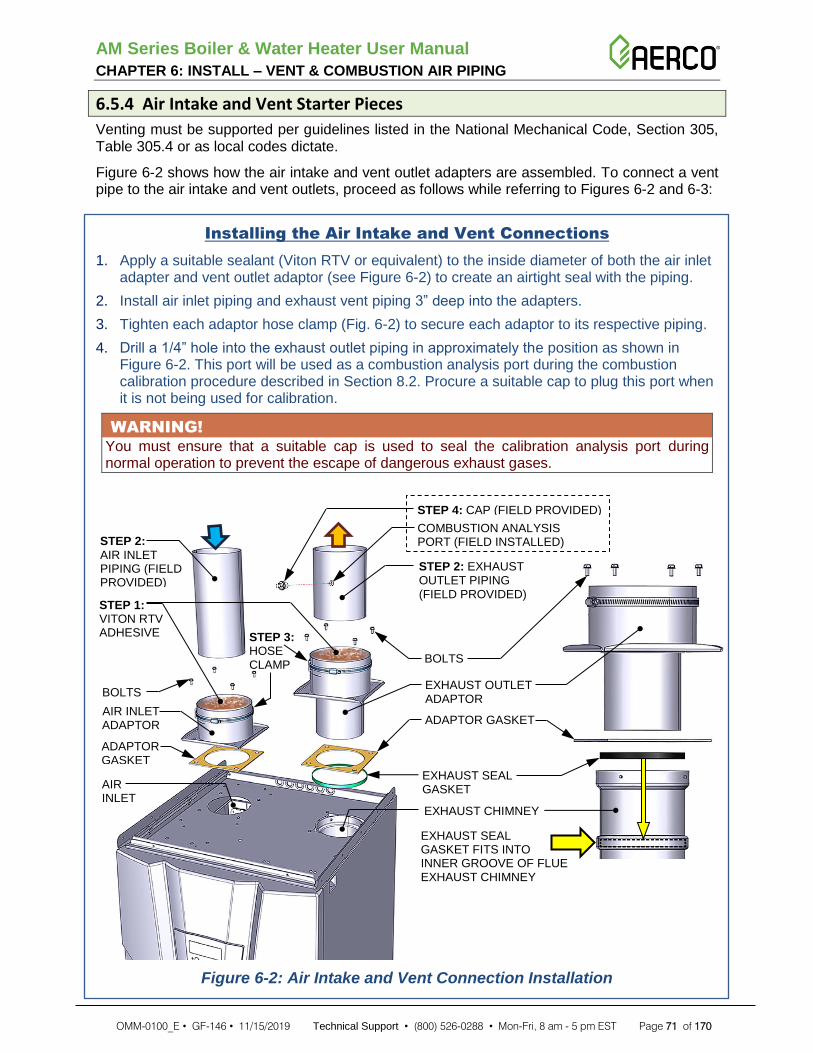
AM Series Boiler & Water Heater User Manual CHAPTER 6: INSTALL – VENT & COMBUSTION AIR PIPING
OMM-0100_E • GF-146 • 11/15/2019 Technical Support • (800) 526-0288 • Mon-Fri, 8 am - 5 pm EST Page 71 of 170
6.5.4 Air Intake and Vent Starter Pieces
Venting must be supported per guidelines listed in the National Mechanical Code, Section 305, Table 305.4 or as local codes dictate.
Figure 6-2 shows how the air intake and vent outlet adapters are assembled. To connect a vent pipe to the air intake and vent outlets, proceed as follows while referring to Figures 6-2 and 6-3:
Installing the Air Intake and Vent Connections
1. Apply a suitable sealant (Viton RTV or equivalent) to the inside diameter of both the air inlet adapter and vent outlet adaptor (see Figure 6-2) to create an airtight seal with the piping.
2. Install air inlet piping and exhaust vent piping 3” deep into the adapters.
3. Tighten each adaptor hose clamp (Fig. 6-2) to secure each adaptor to its respective piping.
4. Drill a 1/4” hole into the exhaust outlet piping in approximately the position as shown in Figure 6-2. This port will be used as a combustion analysis port during the combustion calibration procedure described in Section 8.2. Procure a suitable cap to plug this port when it is not being used for calibration.
WARNING!
You must ensure that a suitable cap is used to seal the calibration analysis port during normal operation to prevent the escape of dangerous exhaust gases.
Figure 6-2: Air Intake and Vent Connection Installation
BOLTS
EXHAUST OUTLET ADAPTOR
ADAPTOR GASKET
EXHAUST CHIMNEY
EXHAUST SEAL GASKET FITS INTO INNER GROOVE OF FLUE EXHAUST CHIMNEY
STEP 2: EXHAUST OUTLET PIPING (FIELD PROVIDED)
ADAPTOR GASKET
AIR INLET ADAPTOR
STEP 3: HOSE CLAMP
BOLTS
STEP 2: AIR INLET PIPING (FIELD PROVIDED)
COMBUSTION ANALYSIS PORT (FIELD INSTALLED)
STEP 4: CAP (FIELD PROVIDED)
AIR INLET
STEP 1: VITON RTV ADHESIVE
EXHAUST SEAL GASKET

AM Series Boiler & Water Heater User Manual CHAPTER 6: INSTALL – VENT & COMBUSTION AIR PIPING
OMM-0100_E • GF-146 • 11/15/2019 Technical Support • (800) 526-0288 • Mon-Fri, 8 am - 5 pm EST Page 72 of 170
Figure 6-3: Air Intake and Vent Connection Correctly Installed
Installation must comply with local requirements and with the National Fuel Gas Code, ANSI Z223.1 for U.S. installations or CSA B149.1 for Canadian installations. For installation in Canada, vent pipe system must be certified to ULC-S636 (see Table 6-1).
Installation of a stainless steel vent system should adhere to the stainless steel vent manufacturer’s installation instructions supplied with the vent system.
The installer must use a specific vent starter adaptor at the flue collar connection, supplied by the vent manufacturer to adapt to its vent system.
WARNING!
Do not insulate polypropylene exhaust pipes nor install into an enclosure, closet, alcove or any other obstruction thereby preventing the cooling of the exhaust pipe.
Do not use water-based lubricants on joints. Never use hydrocarbons-based lubricants because they would destroy gaskets.
6.5.5 Single Pipe Venting (Room Air Combustion)
Commercial applications utilizing this heater may be installed with a single pipe carrying the flue products to the outside while using combustion air from the equipment room. In this case the following conditions and considerations must be followed:
Utilizing the single pipe method, provisions for combustion and ventilation air must be in accordance with Air for Combustion and Ventilation, of the latest edition of the National Fuel Gas Code, ANSI Z223.1, in Canada, the latest edition of CGA Standard B149 Installation Code for Gas Burning Appliances and Equipment, or applicable provisions of the local building codes. For installation in Canada, vent pipe system must be certified to ULC-S636 (see Table 6-1).
There will be an increase in the noise level during normal operation from the inlet air opening.
Vent system and terminations must comply with all venting instructions found in Chapter 6.
All vent pipes connections must be secured following manufacturer instruction, properly supported, and the exhaust must be pitched a minimum of a 1/4 inch per foot back to the boiler (to allow drainage of condensate). Vent pipe system shall be installed in a way to prevent accumulation of condensate;
Where exhaust fans, clothes dryers, and kitchen ventilation systems interfere with the operation of appliances, makeup air shall be provided.

AM Series Boiler & Water Heater User Manual CHAPTER 6: INSTALL – VENT & COMBUSTION AIR PIPING
OMM-0100_E • GF-146 • 11/15/2019 Technical Support • (800) 526-0288 • Mon-Fri, 8 am - 5 pm EST Page 73 of 170
6.5.6 Determining Vent Termination Location
Locate the vent termination using the following guidelines:
1. The total length of piping for vent must not exceed the limits given in Section 6.3.
2. You must consider surrounding factors when terminating the vent, such as:
a) Position the vent termination where vapors will not damage nearby shrubs, plants or air conditioning equipment or be objectionable.
b) The flue products will form a noticeable plume as they condense in cold air. Avoid areas where the plume could obstruct window views.
c) Prevailing winds could cause freezing of condensate and water/ice buildup where flue products impinge on building surfaces or plants.
d) Avoid possibility of accidental contact of flue products with people or animals.
e) Do not locate the terminations where wind eddies could affect performance or cause recirculation, such as inside building corners, near adjacent buildings or surfaces, window wells, stairwells, alcoves, courtyards, or other recessed areas.
f) Do not terminate above any door or window. Condensate can freeze, causing ice formations.
g) Locate or guard vent to prevent condensate damage to exterior finishes.
3. The vent piping must terminate in an elbow pointed outward as shown in Figures 6-5, 6-6, or 6-7.
CAUTION!
Do not exceed the maximum lengths of the outside vent piping shown in Figure 3-31. Excessive length exposed to the outside could cause freezing of condensate in the vent pipe, resulting in potential heater shutdown.
4. Maintain clearances as shown in Figure 6-5. Vent must terminate as follows:
• At least 6 feet from adjacent walls.
• No closer than 12 inches below roof overhang.
• At least 7 feet above any public walkway.
• At least 3 feet above any forced air intake within 10 feet.
• No closer than 4 feet below or horizontally from any door or window or any other gravity air inlet.
• Do not terminate closer than 4 feet horizontally from any electric meter, gas meter, regulator, relief valve, or other equipment. Never terminate above or below any of these within 4 feet horizontally. Requirement unique to CANADA: vent system shall terminate at least 6 feet from electrical and gas meters.
5. Locate termination so it is not likely to be damaged by foreign objects, such as stones or balls, or subject to buildup of leaves or sediment.

AM Series Boiler & Water Heater User Manual CHAPTER 6: INSTALL – VENT & COMBUSTION AIR PIPING
OMM-0100_E • GF-146 • 11/15/2019 Technical Support • (800) 526-0288 • Mon-Fri, 8 am - 5 pm EST Page 74 of 170
Figure 6-4: Vent Locations and Clearances for Direct Venting
6.5.7 Sidewall Termination - Two pipes
Installation must comply with local requirements and with the National Fuel Gas Code, ANSI Z223.1 for U.S. installations or CSA B149.1 for Canadian installations.
CAUTION!
A gas vent extending through an exterior wall shall not terminate adjacent to a wall or below building extensions such as eaves, parapets, balconies, or decks.
Figure 6-5: Sidewall Termination of Air and Vent Pipes
NOTE
Minimum clearances to grade may be
higher depending on snow line.
If space permits:

AM Series Boiler & Water Heater User Manual CHAPTER 6: INSTALL – VENT & COMBUSTION AIR PIPING
OMM-0100_E • GF-146 • 11/15/2019 Technical Support • (800) 526-0288 • Mon-Fri, 8 am - 5 pm EST Page 75 of 170
6.5.8 Combustion Air and Ventilation Openings
Outdoor combustion air shall be provided through opening(s) to the outdoors.
WARNING!
Make sure that combustion air and ventilation openings are sufficiently sized and no reduction or closure of openings takes place.
6.5.9 Two Permanent Openings Method
Two permanent openings, one commencing within 12 inches (300 mm) of the top and one commencing within 12 inches (300 mm) of the bottom, of the room shall be provided. The openings shall communicate directly, or by ducts, with the outdoors or spaces that freely communicate with the outdoors, as follows:
• Where directly communicating with the outdoors or where communicating to the outdoors through vertical ducts, each opening shall have a minimum free area of 1 in2 each 4000 Btu/hr (550 mm2/kW) of total input rating of all appliances located in the room.
• Where communicating with the outdoors through horizontal ducts, each opening shall have a minimum free area of 1 in2 each 2000 Btu/hr (1100 mm2/kW) of total input rating of all appliances located in the room.
6.5.10 One Permanent Opening Method
One permanent opening, commencing within 12 inches (300 mm) of the top of the room, shall be provided. The appliances shall have clearances of at least 1 inch (25 mm) from the sides and back and 6 inches (150 mm) from the front of the appliance. The opening shall directly communicate with the outdoors or shall communicate through a vertical or horizontal duct to the outdoors or spaces that freely communicate with the outdoors and shall have a minimum free area of 1 in 2 each 3000 Btu/hr (700 mm2/kW) of the total input rating of all appliances located in the room.
6.5.11 Installing Vent and Air Piping into Sidewall
Install vent and air piping through sidewalls as follows:
Installing Vent and Air Piping into Sidewall
1. Install air pipe through wall: Cut a hole for the air pipe. Size the air pipe hole as close as desired to the air pipe outside diameter.
2. Install vent pipe through wall:
a) Cut a hole for the vent pipe. For either combustible or noncombustible construction, size the vent pipe hole with at least a 1/2 inch clearance around the vent pipe outer diameter;
b) Insert a galvanized metal thimble in the vent pipe hole as shown in Figure 6-6.
3. Use a sidewall termination plate as a template for correct location of hole centers.
4. Follow all local codes for isolation of vent pipe when passing through floors or walls.
5. Seal exterior openings thoroughly with exterior caulk.

AM Series Boiler & Water Heater User Manual CHAPTER 6: INSTALL – VENT & COMBUSTION AIR PIPING
OMM-0100_E • GF-146 • 11/15/2019 Technical Support • (800) 526-0288 • Mon-Fri, 8 am - 5 pm EST Page 76 of 170
Figure 6-6: Separate Air Intake and Vent Pipes Sidewall Termination
6.5.12 Sidewall Termination and Fittings
Ensure the following when installing through sidewalls:
• The air termination coupling must be oriented at least 12 inches above grade or snow line as shown in Figure 6-5.
• Maintain the required dimensions of the finished termination piping shown in Figure 6-5.
• Do not extend exposed vent pipe outside of the building more than what is shown in Figure 6-5. Condensate could freeze and block vent pipe.
6.5.13 Multiple Vent and Air Terminations
When installing multiple air and vent terminations, ensure the following:
• Terminate each vent/air connection as shown in Figure 6-7.
• All vent pipes and air inlets must terminate at the same height.
• Place wall penetrations to obtain minimum clearance of 12 inches between edge of air inlet and adjacent vent outlet, as shown in Figure 6-7 for U.S. installations. For Canadian installations, provide clearances required by CSA B149.1 Installation Code.
• The air inlet is part of a direct vent connection. It is not classified as a forced air intake with regard to spacing from adjacent appliance vents.

AM Series Boiler & Water Heater User Manual CHAPTER 6: INSTALL – VENT & COMBUSTION AIR PIPING
OMM-0100_E • GF-146 • 11/15/2019 Technical Support • (800) 526-0288 • Mon-Fri, 8 am - 5 pm EST Page 77 of 170
Figure 6-7: Two-Pipe Multi-Unit Air and Vent Sidewall Termination
6.5.14 Sidewall Termination – Concentric Vent
A concentric vent termination must terminate outside the structure and must be installed as shown in Figure 6-8. The termination opening must be protected from rain, as shown in Figure 6-9.
Figure 6-8: Concentric Sidewall Termination Clearances

AM Series Boiler & Water Heater User Manual CHAPTER 6: INSTALL – VENT & COMBUSTION AIR PIPING
OMM-0100_E • GF-146 • 11/15/2019 Technical Support • (800) 526-0288 • Mon-Fri, 8 am - 5 pm EST Page 78 of 170
Figure 6-9: Concentric Sidewall Termination Clearances (Side View)
6.5.15 Sidewall Termination Installation
Install a concentric vent termination into a sidewall as follows:
Installing Concentric Vent Termination into Sidewall
1. Determine the best location for the termination (see Figures 6-8 and 6-9).
2. The total length of piping for vent or air must not exceed the limits given in Section 6.3.
3. You must consider the surroundings when terminating the vent and air:
a) Position the vent termination where vapors will not damage nearby shrubs, plants or air conditioning equipment or be objectionable.
b) The flue products will form a noticeable plume as they condense in cold air. Avoid areas where the plume could obstruct window views.
c) Prevailing winds could cause freezing of condensate and water/ice buildup where flue products impinge on building surfaces or plants.
d) Avoid possibility of accidental contact of flue products with people or animals
e) Do not terminate above any door or window. Condensate can freeze, causing ice formations.
f) Locate or guard vent to prevent condensate damage to exterior finishes.
4. Cut one (1) hole 5 inches diameter into the structure to install the termination.
5. Install the concentric vent following the concentric kit manufacturer’s instruction. Ensure termination location clearance dimensions are as shown in Figures 6-8 and 6-9.
6. Operate the appliance one (1) heat cycle to ensure combustion air and vent pipes are properly connected to the concentric vent termination connections.

AM Series Boiler & Water Heater User Manual CHAPTER 6: INSTALL – VENT & COMBUSTION AIR PIPING
OMM-0100_E • GF-146 • 11/15/2019 Technical Support • (800) 526-0288 • Mon-Fri, 8 am - 5 pm EST Page 79 of 170
6.5.16 Multi-venting Sidewall Terminations
When two or more direct vent appliances are vented near each other, each appliance must be individually vented and vent terminations may be installed as shown in Figure 6-10. It is important that vent terminations be made as shown to avoid recirculation of flue gas.
Figure 6-10: Concentric Sidewall Multiple-Unit Termination Clearances

AM Series Boiler & Water Heater User Manual CHAPTER 6: INSTALL – VENT & COMBUSTION AIR PIPING
OMM-0100_E • GF-146 • 11/15/2019 Technical Support • (800) 526-0288 • Mon-Fri, 8 am - 5 pm EST Page 80 of 170
6.5.17 Determining Location of Vertical Termination
Locate the vertical vent/air terminations using the following guidelines:
1. The total length of piping for vent or air must not exceed the limits given in the Section 6.3.
2. The vent must terminate at least 3 feet above the highest place in which the vent penetrates the roof and at least 2 feet above any part of a building within 10 horizontal feet.
3. The vent must terminate in a tee or acceptable rain-cap.
4. The air piping must terminate in a down-turned 180° return pipe no further than 2 feet from the center of the vent pipe. This placement avoids recirculation of flue products into the combustion air stream
5. The vent piping must terminate at least 1 foot above the air intake. The air inlet pipe and vent pipe can be located in any desired position on the roof, but must always be no further than 2 feet apart and with the vent termination at least 1 foot above the air intake.
6. Locate terminations so they are not likely to be damaged by foreign objects, such as stones or balls, or subject to buildup of leaves or sediment.
Figure 6-11: Vertical Vent Termination

AM Series Boiler & Water Heater User Manual CHAPTER 6: INSTALL – VENT & COMBUSTION AIR PIPING
OMM-0100_E • GF-146 • 11/15/2019 Technical Support • (800) 526-0288 • Mon-Fri, 8 am - 5 pm EST Page 81 of 170
6.5.18 Vertical Vent and Air Roof Termination Preparation
Prepare for installation of vent and air termination into a roof as follows:
Vertical Vent and Air Roof Termination Preparation
1. Air pipe penetration: cut a hole for the air pipe, sizing the air pipe hole as close as desired to the air pipe outside diameter.
2. Vent pipe penetration:
3. Cut a hole for the vent pipe. For either combustible or noncombustible construction, size the vent pipe hole with at least a 1/2 inch clearance around the vent pipe outer diameter;
4. Insert a galvanized metal thimble in the vent pipe hole.
5. Space the air and vent holes to provide the minimum spacing shown in Figure 6-11 and listed in Section 6.5.16.
6. Follow all local codes for isolation of vent pipe when passing through floors, ceilings, and roofs.
7. Provide flashing and sealing boots sized for the vent pipe and air pipe.
6.5.19 Installing Vertical Vent and Air Roof Terminations
Install vent and air terminations into a roof as follows:
Installing Vertical Vent and Air Roof Terminations
1. Prepare the vent termination and the air termination elbow (Figure 6-11) by inserting bird screens.
2. The air piping must terminate in a down-turned 180° return bend as shown in Figure 6-11. Locate the air inlet pipe no further than 2 feet from the center of the vent pipe. This placement avoids recirculation of flue products into the combustion air stream.
3. Maintain the required dimensions of the finished termination piping as shown in Figure 6-11.
4. Do not extend exposed vent pipe outside of building more than shown in Figure 6-11. Condensate could freeze and block vent pipe.

AM Series Boiler & Water Heater User Manual CHAPTER 6: INSTALL – VENT & COMBUSTION AIR PIPING
OMM-0100_E • GF-146 • 11/15/2019 Technical Support • (800) 526-0288 • Mon-Fri, 8 am - 5 pm EST Page 82 of 170
6.5.20 Installing Multiple Vent and Air Vertical Terminations
Install multiple vent and air terminations in a roof as follows:
Installing Vertical Multiple Vent and Air Roof Terminations
1. When terminating multiple units, terminate each vent/air connection as shown in Figure 6-12.
2. Place roof penetrations to obtain minimum clearance of 12 inches between edge of air intake elbow and adjacent vent pipe of another appliance for U.S. installations
3. The air inlet is part of a direct vent connection. It is not classified as a forced air intake with regard to spacing from adjacent appliance vents.
Figure 6-12: Installing Multiple Vent and Air Vertical Terminations – Two Alternatives

AM Series Boiler & Water Heater User Manual CHAPTER 6: INSTALL – VENT & COMBUSTION AIR PIPING
OMM-0100_E • GF-146 • 11/15/2019 Technical Support • (800) 526-0288 • Mon-Fri, 8 am - 5 pm EST Page 83 of 170
6.5.21 Vertical Termination – Concentric Vent
Both combustion air and vent pipes must attach to the termination. The termination must terminate outside the structure and must be installed as shown in Figure 6-13.
6.5.22 Determining Location of Vertical Concentric Vent Termination
Locate the vertical concentric vent/air terminations using the following guidelines:
1. The total length of piping for vent or air must not exceed the limits given in the Section 6.3.
2. The concentric terminal must terminate at least 3 feet above the highest place in which the vent penetrates the roof and at least 2 feet above any part of a building within 10 horizontal feet.
3. Locate termination so it is not likely to be damaged by foreign objects, such as stones or balls, or subject to buildup of leaves or sediment.
Figure 6-13: Concentric Vertical Terminations
6.5.23 Multi-Venting Vertical Terminations
When two (2) or more direct vent appliances are vented near each other, each appliance must be individually vented.

AM Series Boiler & Water Heater User Manual CHAPTER 6: INSTALL – VENT & COMBUSTION AIR PIPING
OMM-0100_E • GF-146 • 11/15/2019 Technical Support • (800) 526-0288 • Mon-Fri, 8 am - 5 pm EST Page 84 of 170
(This page intentionally blank)

AM Series Boiler & Water Heater User Manual CHAPTER 7: INSTALLATION – NATURAL GAS
OMM-0100_E • GF-146 • 11/15/2019 Technical Support • (800) 526-0288 • Mon-Fri, 8 am - 5 pm EST Page 85 of 170
SECTION 7: INSTALLATION – NATURAL GAS
7.1 Gas Supply Piping Check that the type and the pressure of the gas supplied correspond with those required for the heater as stated on the rating plate. Never use a gas different than that stated on the heater rating plate.
A lockup style regulator is required on each unit any time the gas supply pressure may exceed 13” W.C. If gas supply pressure is between 3” and 13” individual regulators are recommended on every unit but not required.
NOTE:
For installation in Massachusetts an individual gas regulator is required on every unit regardless of incoming gas pressure.
7.2 Connection of Gas Supply Piping Connect the gas supply to the unit as follows:
Connecting the Gas Supply to the Unit
1. Refer to Figure 7-1 for connections necessary to pipe gas to the unit.
a) Install ground joint union for servicing, when required.
b) Install a manual shutoff valve in the gas supply piping.
c) Manual main shutoff valves must be identified as such by the installer.
2. Install a sediment trap / drip leg. (see Figure 7-1).
3. Support piping with hangers, and not from the unit or its accessories.
Figure 7-1: Gas Supply Piping Connections

AM Series Boiler & Water Heater User Manual CHAPTER 7: INSTALLATION – NATURAL GAS
OMM-0100_E • GF-146 • 11/15/2019 Technical Support • (800) 526-0288 • Mon-Fri, 8 am - 5 pm EST Page 86 of 170
Connecting the Gas Supply to the Unit - Continued
4. Purge all air from the gas supply piping.
5. Before placing the appliance in operation, check the appliance and its gas connection for leaks.
a) The appliance must be disconnected from the gas supply piping system during any pressure testing of that system at a test pressure in excess of 1/2 PSIG (3.5 kPa).
b) The appliance must be isolated from the gas supply piping system by closing a manual shutoff valve during any pressure testing of the gas supply piping system at test pressures equal to or less than 1/2 PSIG (3.5 kPa).
c) The appliance and its gas connection must be leak tested before placing it in operation.
6. Use pipe sealing compound compatible with propane gas. Apply sparingly only to male threads of the pipe joints so that pipe dope does not block gas flow.
WARNING!
• Do not attempt to support the weight of the piping with the water heater or its accessories.
• Never use an open flame to test for gas leaks. Always use an approved leak detection method.
• Failure to apply pipe sealing compound can result in severe personal injury, death, or substantial property damage.
The unit is shipped ready to fire on natural gas. Check appliance rating plate to determine which fuel the appliance is set for. If set to natural gas, it may be converted to propane gas following instructions in Section 7.9.

AM Series Boiler & Water Heater User Manual CHAPTER 7: INSTALLATION – NATURAL GAS
OMM-0100_E • GF-146 • 11/15/2019 Technical Support • (800) 526-0288 • Mon-Fri, 8 am - 5 pm EST Page 87 of 170
7.3 Natural Gas Pipe Sizing Refer to the table below for pipe lengths and diameters. For additional gas pipe sizing information, refer to ANSI Z223.1 (or B149.1 for Canadian installations).
TABLE 7-1: Gas Pipe Capacity for Natural Gas
Iron Pipe Size (in)
Nominal: 3/4 1 1 1/4 1 1/2 2 2 1/2 3 4
Actual ID: 0.824 1.049 1.380 1.610 2.067 2.469 3.068 4.026
Length (ft) Capacity in Cubic Feet of Gas per Hour
10 273 514 1060 1580 3050 4860 8580 17500
20 188 353 726 1090 2090 3340 5900 12000
30 151 284 583 873 1680 2680 4740 9660
40 N/A 243 499 747 1440 2290 4050 8270
50 N/A 215 442 662 1280 2030 3590 7330
60 N/A 195 400 600 1160 1840 3260 6640
70 N/A 179 368 552 1060 1690 3000 6110
80 N/A 167 343 514 989 1580 2790 5680
90 N/A 157 322 482 928 1480 2610 5330
100 N/A 148 304 455 877 1400 2470 5040
125 N/A 131 269 403 777 1240 2190 4460
150 N/A 119 244 366 704 1120 1980 4050
175 N/A N/A 224 336 648 1030 1820 3720
200 N/A N/A 209 313 602 960 1700 3460
250 N/A N/A 185 277 534 851 1500 3070
NOTE:
Maximum pipe capacity is based on a 0.60 specific gravity gas at a pressure of 0.5 PSIG and a 0.3” W.C. pressure drop.
7.4 Natural Gas Supply Pressure Requirements • Install 100% lockup gas pressure regulator in supply line if inlet pressure can exceed
13”W.C. at any time. Adjust lockup regulator for 13” W.C. maximum.
• Pressure required at the gas valve inlet pressure port:
o Maximum 13” W.C. with no flow (lockup) or with appliance off.
o Minimum 3” W.C. with gas flowing (verify during high fire).
7.5 Propane Gas Pipe Sizing Contact gas supplier to size pipes, tanks, and 100% lockup propane gas pressure regulator.
7.6 Propane Gas Supply Pressure Requirements • Adjust propane supply regulator provided by the gas supplier for 13”W.C. maximum
pressure.
• Pressure required at the gas valve inlet pressure port:
o Maximum 13” W.C. with no flow (lockup) or with appliance off.
o Minimum 3” W.C. with gas flowing (verify during high fire).

AM Series Boiler & Water Heater User Manual CHAPTER 7: INSTALLATION – NATURAL GAS
OMM-0100_E • GF-146 • 11/15/2019 Technical Support • (800) 526-0288 • Mon-Fri, 8 am - 5 pm EST Page 88 of 170
NOTE:
Ensure that the high gas pressure regulator is at least 6 to 10 feet upstream of the appliance.
7.7 Checking and Adjusting the Unit Inlet Gas Supply Pressure DO NOT adjust or attempt to measure gas valve outlet pressure. The gas valve is factory-set for the correct outlet pressure. This setting is suitable for natural gas and propane, requiring no field adjustment. Attempting to alter or measure the gas valve outlet pressure could result in damage to the valve, causing excessive levels of carbon monoxide.
The gas piping must be sized for the proper flow and length of pipe, to avoid excessive pressure drop. Both the gas meter and the gas regulator must be properly sized for the total gas load. If you experience a pressure drop greater than 1” W.C., the meter, regulator, or gas line is undersized or in need of servicing.
Refer to Section 8.6 and check the gas supply pressure.
7.8 High Altitude Operation Calibration at high altitudes follows the normal combustion calibration procedure and is subject to a de-rating according to C302.7. See aerco.com for further information.
For installations at higher altitudes in the United States, follow local codes or, in the absence of local codes, follow ANSI Z223.1/NFPA No. 54, The National Fuel Gas Code, and check and adjust the CO2 level following Section 8.7.
7.9 Conversion from Natural gas to Propane Gas The gas conversion must be performed on each burner present inside the unit.
The gas conversion shall be performed by a qualified service agency in accordance with these instructions and all applicable codes and requirements of the authority having jurisdiction. The information in these instructions must be followed to minimize the risk of danger. The qualified service agency is responsible for the proper conversion of the appliance. The installation is not proper and complete until the operation of the converted appliance is checked as specified in these instructions.
Conversion shall be carried out in accordance with the requirements of the provincial authorities having jurisdiction and in accordance with the requirements of the CAN-B149.1 and CAN1-B149.2 installation code.
7.9.1 Gas Conversion Kit
The conversion kit (supplied with the unit) is composed of the following parts, which are necessary for the gas change:
• A label stating the new gas rating and settings.
• Instructions for the change.
• An orifice for each burner present in the unit.

AM Series Boiler & Water Heater User Manual CHAPTER 7: INSTALLATION – NATURAL GAS
OMM-0100_E • GF-146 • 11/15/2019 Technical Support • (800) 526-0288 • Mon-Fri, 8 am - 5 pm EST Page 89 of 170
7.9.2 Gas Conversion Instructions
To change the gas type used by the unit, follow the instructions starting on the next page:
Gas Rating Conversion of Master Burner 1
You must convert Burner 1 (Master) first, and then convert each additional burner in the unit afterward. Refer to Figure 7-6 to locate Burner 1 (Master) and then perform the following steps:
1. Turn OFF power to the unit.
2. Gain access to the Factory Menu as follows: press and hold, at the same time, both the
RESET and buttons while turning ON unit power. Display will enter the Factory Menu (parameters 3000).
3. Using push buttons and select parameter 3002.
4. Press RESET button once to select displayed parameter. Parameter 3002 will begin to blink
in the display. Now the value can be changed using the and buttons.
5. Using Table 3-5, select the right parameter value for the unit you are converting to propane gas or to natural gas.
Table 7-2: Natural Gas and Propane Gas Settings
6. Press RESET button once to save the new value.
7. Turn the power OFF to the unit.
8. Close the manual gas shut off valve.
9. Remove the covers from the unit.
10. Unscrew nut “H” as per Figure 7-2.
11. Using a screwdriver, remove spring clip “A” (Figure 7-2);
12. Remove the gas valve from its site “C” as per Figure 7-3 (note O-ring “L”).
13. Replace orifice “G” per Figure 7-4, for the correct one for type of gas used. Verify that the stamping on the orifice matches Table 7-2.
14. Reinstall the gas valve, taking care to properly position O-ring “L” per Figure 7-3 and to place the gasket between the gas valve and nut “H” in Figure 7-2.
15. Open the manual gas shut off valve.

AM Series Boiler & Water Heater User Manual CHAPTER 7: INSTALLATION – NATURAL GAS
OMM-0100_E • GF-146 • 11/15/2019 Technical Support • (800) 526-0288 • Mon-Fri, 8 am - 5 pm EST Page 90 of 170
Gas Rating Conversion of Master Burner 1 - Continued
16. Check for any gas leaks on nut “H” as per Figure 7-2.
17. Turn the power ON to the unit.
18. Turn completely counter-clockwise screw “E” in Figure 7-5.
19. Check the gas supply pressure per Section 8.6. The minimum gas supply pressure must not be less than 3” W.C. (7.6 mbar) and the maximum gas supply pressure must not be higher than 13” W.C. (33 mbar).
20. Verify the CO2 rate and its adjustment per Section 8.7.
Figure 7-2: Dismantling the Gas Valve Figure 7-3: Lifting up the Gas Valve
Figure 7-4: Gas Valve Orifice Figure 7-5: Gas Valve Adjustments

AM Series Boiler & Water Heater User Manual CHAPTER 7: INSTALLATION – NATURAL GAS
OMM-0100_E • GF-146 • 11/15/2019 Technical Support • (800) 526-0288 • Mon-Fri, 8 am - 5 pm EST Page 91 of 170
Gas Rating Conversion of Burners 2, 3, and 4
After converting Burner 1 (Master), you must convert Burner 2, Burner 3 (if present), and Burner 4 (if present). Refer to Figure 7-6 and perform the following steps:
1. Turn the power OFF to the unit.
Burner 2:
2. Disconnect plug “B” from connector “A”.
3. Connect plug “B” to connector “C”.
4. Repeat Step 1 through Step 20 of the previous instructions “Gas Rating Conversion of Master Burner”.
5. Ensure power is still OFF to the unit.
Burner 3 (if present):
6. Disconnect plug “B” from connector “C”.
7. Connect plug “B” to connector “D”.
8. Repeat Step 1 through Step 20 of the previous instructions “Gas Rating Conversion of Master Burner”.
9. Ensure power is still OFF to the unit.
Burner 4 (if present):
10. Disconnect plug “B” from connector “D”.
11. Connect plug “B” to connector “E”.
12. Repeat Step 1 through Step 20 of the previous instructions “Gas Rating Conversion of Master Burner”.
After converting all burners:
13. Connect plug “B” to plug “A”.
14. Check the inlet gas pressure of the unit, per Section 8.6.
15. Attach to the front of the heater the appropriate conversion label, found in the conversion kit stating the new type of gas adjustment of the heater as follow:
a) Apply the label in Figure 7-7 if the heater has been converted to PROPANE GAS.
b) Apply the label in Figure 7-8 if the heater has been converted to NATURAL GAS.
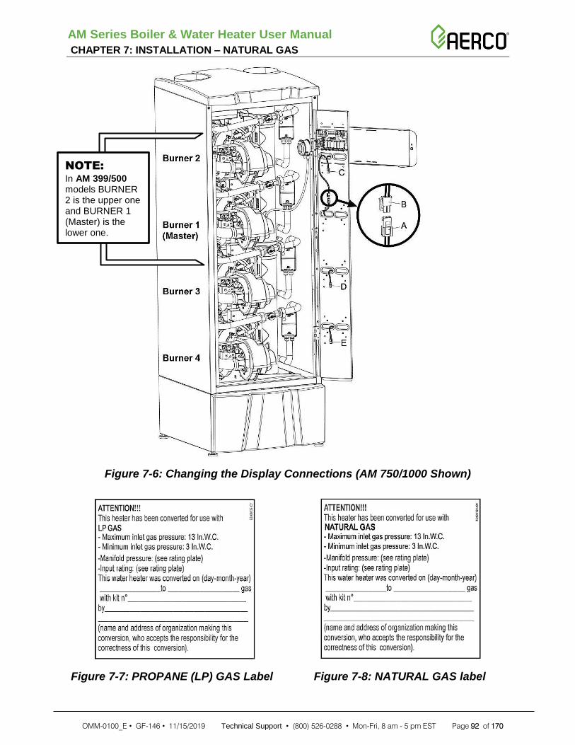
AM Series Boiler & Water Heater User Manual CHAPTER 7: INSTALLATION – NATURAL GAS
OMM-0100_E • GF-146 • 11/15/2019 Technical Support • (800) 526-0288 • Mon-Fri, 8 am - 5 pm EST Page 92 of 170
Figure 7-6: Changing the Display Connections (AM 750/1000 Shown)
Figure 7-7: PROPANE (LP) GAS Label Figure 7-8: NATURAL GAS label
NOTE:
In AM 399/500 models BURNER 2 is the upper one and BURNER 1 (Master) is the lower one.

AM Series Boiler & Water Heater User Manual CHAPTER 8 – UNIT START-UP
OMM-0100_E • GF-146 • 11/15/2019 Technical Support • (800) 526-0288 • Mon-Fri, 8 am - 5 pm EST Page 93 of 170
SECTION 8: UNIT START-UP
8.1 INITIAL START-UP REQUIREMENTS
Before starting the heater, the user must be correctly instructed by the installer, on how to operate the heater, in particular:
• Make sure that the user understands that combustion air and ventilation openings must not be restricted, closed, or modified in any way.
• Make sure that the user is informed of all the special measures to be taken for combustion air inlet and discharging flue gases, and that these must not be modified in any way.
• Make sure that the user keeps this manual and all other documentation included with the heater.
• Make sure that the user understands never to tamper with gas control settings and the risk of CO poisoning should an unauthorized individual do so
• Make sure that the user knows how to adjust temperatures and controls.
8.1.1 Filling the Condensate Neutralizer
The condensate neutralizer tank is positioned inside the heater as shown in Figure 4-8. It must be filled with water to prevent the leakage of flue gases from the condensate drainpipe, item “C” in Figure 4-8 and Item “E” in Figure 4-9. To fill and inspect the condensate neutralizer, refer to Section 10.12.
WARNING!
If the unit is turned OFF for more than 3 months, repeat the above operation to again fill the condensate trap. Failure to follow this warning could result in excessive levels of carbon monoxide.

AM Series Boiler & Water Heater User Manual CHAPTER 8 – UNIT START-UP
OMM-0100_E • GF-146 • 11/15/2019 Technical Support • (800) 526-0288 • Mon-Fri, 8 am - 5 pm EST Page 94 of 170
8.1.2 Filling the Heating System
To fill the heating system, proceed as follows:
CAUTION!
The water’s pH must fall within the following limit: 7.5<pH<9.5 and if the system contains aluminum parts, it must be less than 8.5. This pH value must be measured after steady condition and after air purging operations has been done. Water out of the above pH values can result in premature heat exchanger damage.
Filling the Boiler Heating System
1. Open any automatic air vents in the heating system.
2. Open the fill valve and proceed to fill the heating system and boiler until the pressure gauge, item “M” in Figure 8-1, reads the pressure for which the heating system is sized. To temporarily decrease the minimum water pressure, set parameter 3022 to the desired value (See Appendix B).
3. Check that there is no water leaking from the fittings. If there is, the leaks must be repaired.
4. Check the pressure gauge during the purging process. If the pressure has dropped, re-open the fill valve to bring the pressure back to the desired value. If it was changed, be sure ro set parameter 3022 back to its original value.
8.2 General Warnings Concerning the Gas Supply
When starting up the unit for the first time the following must be checked:
• That the unit is supplied with the type of fuel that it is configured to use (see Section 7.1).
• That the gas supply system is provided with all the safety devices and controls required under current national and local codes.
• That the vent and combustion air terminals are properly connected and free from any blockages.
• That the condensate drain tube is properly connected (see Section 4.14).
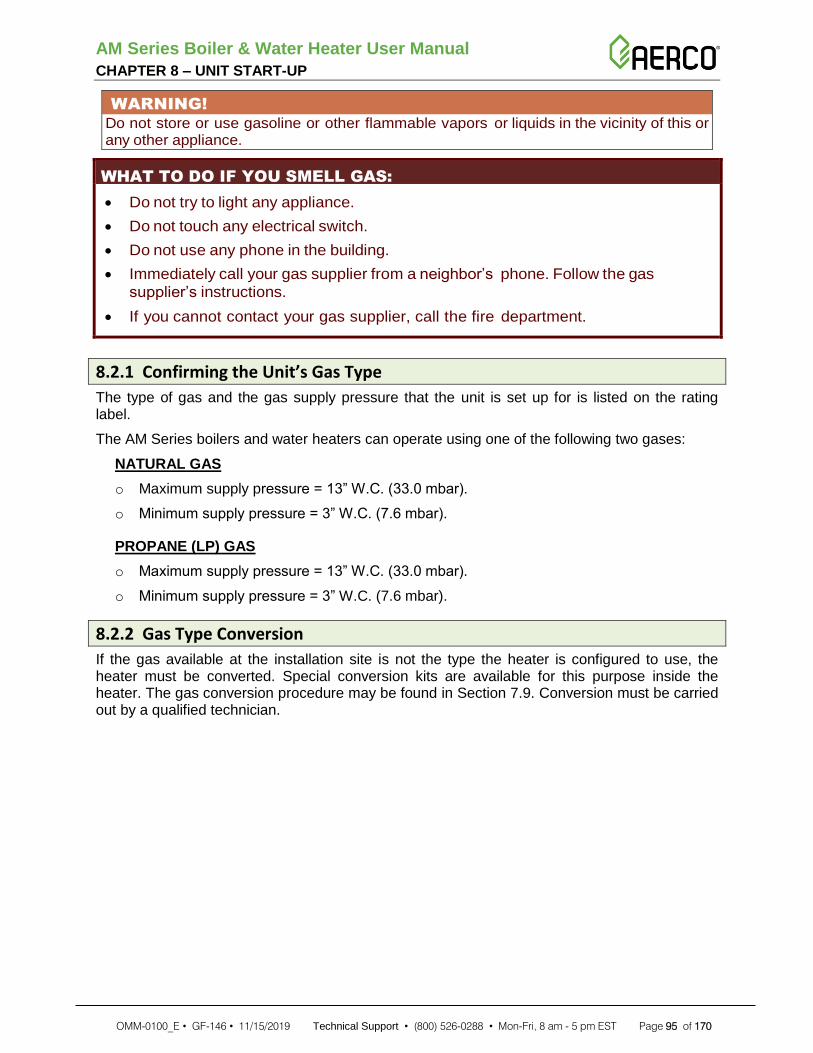
AM Series Boiler & Water Heater User Manual CHAPTER 8 – UNIT START-UP
OMM-0100_E • GF-146 • 11/15/2019 Technical Support • (800) 526-0288 • Mon-Fri, 8 am - 5 pm EST Page 95 of 170
WARNING! Do not store or use gasoline or other flammable vapors or liquids in the vicinity of this or any other appliance.
WHAT TO DO IF YOU SMELL GAS:
• Do not try to light any appliance.
• Do not touch any electrical switch.
• Do not use any phone in the building.
• Immediately call your gas supplier from a neighbor’s phone. Follow the gas
supplier’s instructions.
• If you cannot contact your gas supplier, call the fire department.
8.2.1 Confirming the Unit’s Gas Type
The type of gas and the gas supply pressure that the unit is set up for is listed on the rating label.
The AM Series boilers and water heaters can operate using one of the following two gases:
NATURAL GAS
o Maximum supply pressure = 13” W.C. (33.0 mbar).
o Minimum supply pressure = 3” W.C. (7.6 mbar).
PROPANE (LP) GAS
o Maximum supply pressure = 13” W.C. (33.0 mbar).
o Minimum supply pressure = 3” W.C. (7.6 mbar).
8.2.2 Gas Type Conversion
If the gas available at the installation site is not the type the heater is configured to use, the heater must be converted. Special conversion kits are available for this purpose inside the heater. The gas conversion procedure may be found in Section 7.9. Conversion must be carried out by a qualified technician.

AM Series Boiler & Water Heater User Manual CHAPTER 8 – UNIT START-UP
OMM-0100_E • GF-146 • 11/15/2019 Technical Support • (800) 526-0288 • Mon-Fri, 8 am - 5 pm EST Page 96 of 170
8.3 Identification of Controls
Figure 8-1: AM Series Control Panel Functions and Indicators
8.4 Boiler Startup Procedure
This section applies only to AM Series boilers. Refer to the next section for starting an AM Series water heater. To start the boiler, do the following:
Boiler Startup Procedure
NOTE:
Before operation it may be necessary to check the 2000 and 3000 level parameters on each control board. See Section 9.16 and Appendix B for further information.
1. Open the manual gas shut off valve (Figure 7-1),
2. Turn the unit power switch to ON (item “T” in Figure 8-1).
3. The boiler will fire only when there is a call for heat and the heating temperature setting is
higher than the actual supply temperature. Hold buttons or to select the desired heating temperature. If the external temperature sensor is connected (see Section 5.2.2), check that the calculated temperature (See User Menu, Section 9.15, parameter 1012 or parameter 1107) is higher than the actual boiler temperature and that the outdoor temperature (See User Menu, Section 9.15, parameter 1004) is lower than “warm weather shut down temperature” (See Section 9.16, parameter 2020 in Installer Menu).
4. If the boiler is connected to an indirect water heater, press buttons and to select the desired domestic hot water temperature.

AM Series Boiler & Water Heater User Manual CHAPTER 8 – UNIT START-UP
OMM-0100_E • GF-146 • 11/15/2019 Technical Support • (800) 526-0288 • Mon-Fri, 8 am - 5 pm EST Page 97 of 170
8.5 Water Heater Startup Procedure This section applies only to AM Series water heaters, as well as all water heaters configured with the AM Rapid Recovery (AMR) option. Refer to the previous section for starting an AM Series boiler. Refer to section 2.4 for a description of the AMR option for AM water heaters. To start the water heater, do the following:
Water Heater Startup Procedure
NOTE:
Before operation it may be necessary to check the 2000 and 3000 level parameters on each control board. See section 8.16 and Appendix B for further information.
1. Open the manual gas shut off valve (Figure 7-1).
2. Turn the unit power switch to ON (Figure 8-1).
NOTE:
The temperature setpoint is adjusted to its lowest temperature position when shipped from the factory.
3. The unit will fire only when the domestic hot water setting is higher than the storage tank
temperature (parameter 1002). Press buttons or to select the desired storage tank temperature.
4. If the display gives a Low Water Pressure error (Err 59, Section 9.19), repeat the air purging operations.

AM Series Boiler & Water Heater User Manual CHAPTER 8 – UNIT START-UP
OMM-0100_E • GF-146 • 11/15/2019 Technical Support • (800) 526-0288 • Mon-Fri, 8 am - 5 pm EST Page 98 of 170
8.6 Gas Supply Pressure Test DO NOT adjust or attempt to measure gas valve outlet pressure. The gas valve is factory-set for the correct outlet pressure. This setting is suitable for natural gas and propane, requiring no field adjustment. Attempting to alter or measure the gas valve outlet pressure could result in damage to the gas valve.
Check the gas supply pressure by following the steps below:
Gas Supply Pressure Test
1. Close the manual gas shut-off valve (Figure 7-1).
2. Remove the front cover (Figure 10-1).
3. Turn the screw in pressure port “D” shown in Figure 8-2 three turns counterclockwise.
Figure 8-2: Gas Valve
4. Connect a manometer with graduations of at least 0.1” W.C. (0.25 mbar) to the inlet gas port “D” shown in Figure 8-2 (on unit model 399 to 1000, choose the pressure port “D” from any gas valve present).
5. Open the manual gas shut off valve (Figure 7-1).
6. Check that the gas supply pressure does not exceed 13” W.C. If the gas supply pressure is higher than 13” W.C., adjust the upstream gas pressure regulator to bring the gas supply pressure between 12” W.C. and 13” W.C.
7. Turn the power switch to ON.
NOTE:
Never force the pressure connection screw or the gas valve will be damaged!

AM Series Boiler & Water Heater User Manual CHAPTER 8 – UNIT START-UP
OMM-0100_E • GF-146 • 11/15/2019 Technical Support • (800) 526-0288 • Mon-Fri, 8 am - 5 pm EST Page 99 of 170
Gas Supply Pressure Test - Continued
8. Generate a heat demand as follows, for appropriate type (boiler or water heater):
• BOILER or WATER HEATER: by pressing button to its maximum setting.
• INDIRECT WATER HEATER: by pressing button to its maximum setting.
9. Gain access to the installer menu (See Section 9.16) and set parameter 2200 to HIGH. Now the unit will run for 20 minutes at maximum input.
10. Check the manometer to make sure the gas supply pressure does not drop below 3” W.C. (7.6 mbar). If the gas supply pressure is lower than 3” W.C. it means that your inlet gas line or your gas pressure regulator is not correctly sized.
CAUTION!
DO NOT adjust the screw “F” (Figure 8-2). This screw is factory-set for the correct gas flow and outlet pressure. Attempting to alter the gas valve setting could result in damage to the valve, causing potential severe personal injury, death, or substantial property damage.
11. After verifying the correct gas pressures:
a) Return to parameter 2200 and set to OFF.
b) Close the manual gas shut-off valve (Figure 7-1).
c) Disconnect the manometer.
d) Turn the screw in pressure connection “D” in Figure 8-2, clockwise until snug.
e) Check pressure port “D” (Figure 8-2) for any gas leaks.

AM Series Boiler & Water Heater User Manual CHAPTER 8 – UNIT START-UP
OMM-0100_E • GF-146 • 11/15/2019 Technical Support • (800) 526-0288 • Mon-Fri, 8 am - 5 pm EST Page 100 of 170
8.7 Combustion Calibration Table 8-1 lists the correct CO2 and O2 ranges for a unit running at normal operating conditions. CO2 values outside of the ranges given in Table 8-1 may lead to malfunctioning of the unit and cause it to prematurely fail. To check the CO2 values, carry out a combustion analysis as described below:
WARNING!
During this procedure, compare CO (carbon monoxide) readings with the value given in Table 8-1. If this is higher, STOP the boiler and call the Factory service department (see phone number on the last cover page). Failure to comply with this requirement could result in severe personal injury, death or substantial property damage.
Combustion Calibration
1. If it is not already present, create a combustion analysis probe site 8” after the flue gas exhaust connection (see Figure 6-2). To do so, follow the vent pipe manufacturers’ instruction.
2. Keep the boiler or water heater in stand-by by pushing either button (for water
heaters) or (for boilers) until the word OFF is seen in the display.
3. Gain access to the Installer menu and set parameter 2201 to HIGH (see Section 9.16) so the “Burner 1 (Master) will run for 20 minutes at high fire input, then generate a demand for
heat by pressing the button.
4. Increase the setpoint to any valve above "OFF", such as 90°F.
5. Wait 2 to 3 minutes for the CO2 to stabilize;
6. Insert the probe of a calibrated combustion analyzer into the combustion analysis opening, as shown in Figure 6-2, and take a flue gas sample.
7. Compare the CO2 reading with the high fire range given in Table 8-1, making sure to use the range for the gas type in use. If the CO2 reading is outside the specified range, it must be adjusted using the “E” screw in Figure 8-2 of the gas valve closest to the burner unit in fire. Use a 2.5 mm Allen Wrench to turn the screw (clockwise to reduce the CO2 level, counter-clockwise to increase the CO2 level) in small increments and wait for the CO2 to stabilize to prevent overshooting the desired value.
Table 8-1: Combustion Calibration Values

AM Series Boiler & Water Heater User Manual CHAPTER 8 – UNIT START-UP
OMM-0100_E • GF-146 • 11/15/2019 Technical Support • (800) 526-0288 • Mon-Fri, 8 am - 5 pm EST Page 101 of 170
Combustion Calibration - Continued
8. Set value of parameter 2201 to LOW. The Burner 1 (Master) will now run for 20 minutes at low fire input.
9. Wait 2 to 3 minutes for the CO2 to stabilize.
10. Compare the CO2 reading with the low fire range given in Table 8-1, making sure to use the range for the gas type in use. The CO2 reading must be inside the specified range; if not, STOP the unit and call the Factory service department (see phone number on the last cover page).
11. Set Parameter 2201 in the Installer Menu (Section 9.16) to OFF.
12. Repeat this process for burners 2, 3, and 4 as applicable, using parameters 2202-2204 to calibrate each burner in turn.
13. Close the combustion analysis probe “H” in Figure 6-2 with a suitable cap in accordance with the vent pipe manufacturers’ instructions.
WARNING!
Once the analyzer probe cap in Figure 6-2 is correctly installed with the unit at high fire, check that there are no leaks and that the cap is mechanically secure.
8.8 Lost Ignition Procedure If the burner will not stay lit long enough to perform combustion calibration, perform the following steps:
Lost Ignition Procedure
1. Ensure the gas pressure to the unit is between 3"-13" W.C., ensure that parameter 3002 is set correctly on each burner, and that the gas valve has the appropriate gas orifice for either natural gas or propane.
2. Turn the setpoint to OFF.
3. For burner 1, turn parameter 2201 to IGN, for burner 2 use parameter 2202, etc.
4. Change the setpoint to 90°F.
5. Allow the unit to fire. Monitor parameter 1008 (flame strength). The minimum flame strength is 3.0. If the burner does not light, back the adjustment screw "E" fully out counterclockwise.
6. Repeat ignition trial. If the burner fails to stay lit, turn the adjustment screw one turn clockwise.
7. This procedure may be repeated for LOW and HIGH fire if necessary.
8.9 Minimum Water Flow This unit is self-protected against low water flow. A flow meter (Item 16 in Figure 2-7) continuously monitors the water flow to each burner. If the water flow decreases below the Minimum Water Flow in Section 11: Technical Data, the burner automatically shuts off.
This value is adjustable via parameter 3035.

AM Series Boiler & Water Heater User Manual CHAPTER 8 – UNIT START-UP
OMM-0100_E • GF-146 • 11/15/2019 Technical Support • (800) 526-0288 • Mon-Fri, 8 am - 5 pm EST Page 102 of 170
8.10 Heating System Pressure Test If the pressure inside the heating circuit falls below the minimum pressure for the system, the appliance switches off and the display shows Err 59 to indicate that it is necessary to restore the correct pressure. Open the filling valve and check the pressure on the pressure gauge “M” of Figure 8-1. Err 59 will disappear when the pressure is back at the right value. To prevent accidental relief valve openings, fill the heating circuit slowly.
This value is adjustable via parameter 3022.
CAUTION!
Continual fresh make-up water will reduce boiler life. Mineral buildup in the heat exchanger reduces heat transfer, overheats the stainless steel heat exchanger, and causes failure. Addition of oxygen carried in by makeup water can cause internal corrosion in system components. Leaks in boiler or piping must be repaired at once to prevent makeup water entering the boiler.

AM Series Boiler & Water Heater User Manual CHAPTER 9 – OPERATION
OMM-0100_E • GF-146 • 11/15/2019 Technical Support • (800) 526-0288 • Mon-Fri, 8 am - 5 pm EST Page 103 of 170
SECTION 9: OPERATION
9.1 General Operation
The unit is pre-set with standard parameters. However, it is possible to make a number of changes to the parameters by means of using the “User Menu” (see Section 9.15) and the “Installer Menu” (see Section 9.16).
During use, the part of the display labeled “N” (in Figure 9-1 shows the supply temperature (if the boiler is supplying heat) or the indirect water heater temperature (if boiler is supplying a tank load). The part of the display labeled “M” shows the pressure of the heating system. The o ther icons in t he d isp lay show the s ta tus o f t he various operating parameters per Figure 9-1.
Figure 9-1: Boiler Control Panel Functions and Indicators

AM Series Boiler & Water Heater User Manual CHAPTER 9 – OPERATION
OMM-0100_E • GF-146 • 11/15/2019 Technical Support • (800) 526-0288 • Mon-Fri, 8 am - 5 pm EST Page 104 of 170
9.2 Freeze Protection
For the freeze protection function to operate, the unit must remain connected to the electrical and gas supplies with DHW and central heating service switched to OFF
The freeze protection function is designed to protect the appliance only, not the heating system.
Because the water heater freeze protection function depends upon the electrical and gas supply, it is mandatory to install a safety device that alarms the user in case the unit room will reach a temperature near 35°F (2°C).
Once the boiler has reached a temperature of 50 °F (10 °C), the heating pump will automatically turn on. If the temperature falls below 41 °F (5 °C), the burner will light to prevent the boiler from freezing. If the boiler will not be used for long time it should be drained per Section 10.23.
9.3 Display Energy Saving Mode
The display, in Figure 9-1 is switched off each time no key is touched for at least 30 minutes, with the exception of when it displays errors or settings.
9.4 Control Panel Display
During normal operation, the display remains off, except if the unit goes into Lockout, or has a Blocking error. Pressing any button will activate the display, which will stay on for 30 minutes from the time of the last button press.

AM Series Boiler & Water Heater User Manual CHAPTER 9 – OPERATION
OMM-0100_E • GF-146 • 11/15/2019 Technical Support • (800) 526-0288 • Mon-Fri, 8 am - 5 pm EST Page 105 of 170
9.5 Startup Procedure - Boilers
This section applies only to AM Series boilers. For Water Heaters, refer to Section 9.13.
Boiler Startup Procedure
1. Open the manual gas shutoff valve.
2. Switch ON electric power to the boiler.
3. If the display shows code Err 65, it means that the polarity has not been observed between phase and neutral (Call service department to restore the situation, do not attempt to repair it).
4. Press button or to setup the heating temperature desired, then press RESET key to save the change.
5. Press button and to setup the domestic hot water temperature desired, then press RESET key to save the change.
If the burner fails to ignite within 60 seconds, the boiler will automatically attempt ignition another four times, after which if it fails to start-up, it will shut down and the display will show
Loc 01 together with icon .
If the boiler goes into any lockout or blocking error, the display will show icon and the
corresponding burner icon ( or ) will blink.
To restore the normal operating condition, press RESET key one time and the display will show the type of lockout. Press the RESET key again. To return to normal display mode, press and hold the RESET button for at least 5 seconds.
The boiler will automatically attempt another start-up.
Now the boiler will continue to operate in relation to the service requested and will show:
• The icon if the heating service is enabled.
• Blinking if heating service is active (boiler is warming the heating plant).
• The icon if a domestic hot water service is enabled;
• Blinking if a domestic hot water service is active (and boiler is loading an indirect water heater);
9.6 Boiler Summer Mode To disable the heating functions for a prolonged period, leaving only the domestic hot water
function, press the key until the word OFF is displayed. Then press RESET button to
save the change. Now the heating service is disabled, and is indicated by the icon disappearing from the display.

AM Series Boiler & Water Heater User Manual CHAPTER 9 – OPERATION
OMM-0100_E • GF-146 • 11/15/2019 Technical Support • (800) 526-0288 • Mon-Fri, 8 am - 5 pm EST Page 106 of 170
9.7 Adjusting the Domestic Hot Water Temperature - Boilers
The domestic hot water temperature for an indirect tank is adjusted by pressing buttons
and . When the buttons are pressed, the display, item “N” in Figure 9-1, shows the domestic hot water setpoint being selected. The range within which the domestic hot water can be set is 104°F (40°C) to 140°F (60°C).
9.8 Heating System Temperature Adjustment - Boilers The boiler provides hot water to the heating system at the temperature set by adjusting buttons
or as shown in Figure 9-1. To maximize the boilers’ performance, the heating temperature, should be set at a value that is just sufficient to maintain the desired temperature of the rooms.
9.9 Heating System Type Selection - Boilers The boiler is factory set for constant setpoint control.
The heating system type can be changed by accessing the Installer Menu per Section 9.16 and changing the 2003 parameter. One of the following heating modes can be selected:
• 2003 = 00 “Constant setpoint with remote enable” (see Section 9.16)
• 2003 = 01 “Outdoor reset with remote enable” (see Section 9.16). An outdoor temperature sensor is required for this setting.
• 2003 = 02 “Outdoor reset”
• 2003 = 03 “Constant setpoint”
• 2003 = 04 “0-10V control (remote setpoint)” (See Section 9.16). Settings 01 & 02 will wait for a closed circuit between terminals 10 and 11 before firing.
9.10 Outdoor Reset Adjustment - Boilers While in the “Installers’ Menu”, set the 2003 parameter to 01. In this mode the heating supply temperature, calculated temperature in Figure 9-2, will be adjusted automatically based on the input from the outdoor temperature sensor. The relationship between the outdoor temperature and the supply water temperature, corresponds with the graphs shown in Figure 9-2. In order to change the relationship between the supply water temperature and the outdoor temperature, all the parameters listed in the sections below must be set.

AM Series Boiler & Water Heater User Manual CHAPTER 9 – OPERATION
OMM-0100_E • GF-146 • 11/15/2019 Technical Support • (800) 526-0288 • Mon-Fri, 8 am - 5 pm EST Page 107 of 170
9.10.1 Outdoor Reset: Setting Parameters
The following are the parameter settings for Outdoor Reset (See Section 9.16):
• 2020 = “Warm weather shutdown temperature”. When the outdoor temperature drops this value the heating system is forced to shut-down. Suggested starting value is 72°F (22°C).
• 2021 = “Winter outdoor temperature”. Is the design winter temperature used for the basic heat load calculation.
• 2022 = “Winter supply temperature”. Is the supply temperature correspondent to the “Winter outdoor temperature” (parameter 2021). Suggested values are 104°F (40°C) for floor radiant panels or 158°F (70°C) for radiator heating systems.
• 2023 = “Spring outdoor temperature”. Is the typical spring outdoor temperature you want the heating service to the minimum capacity. Suggested value is 64°F (18°C).
• 2024 = “Spring supply temperature”. Is the supply temperature correspondent to the “Spring outdoor temperature” (parameter 2023). Suggested values are 86°F (30°C) for floor radiant panels or 108°F (42°C) for radiators heating systems.
9.10.2 Outdoor Reset Activation
Once selected, reset adjustment is completely automatic and will switch off at the end of the heating season and switch back on at the beginning of the heating season. When the outdoor temperature is higher than parameter 2020, (“Warm weather shutdown temperature”) the heating service switches off. When the outdoor temperature lowers below parameter 2020, (“Warm weather shutdown temperature”), the heating service switches back on. If, for some reason, the heating service doesn’t match the load, adjust parameters 2022 (during cold winter) and 2024 (during spring season) to raise or lower the calculated temperature and match the desired room temperature.
Figure 9-2: Outdoor Reset Settings Adjustment Graph
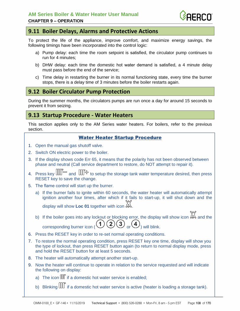
AM Series Boiler & Water Heater User Manual CHAPTER 9 – OPERATION
OMM-0100_E • GF-146 • 11/15/2019 Technical Support • (800) 526-0288 • Mon-Fri, 8 am - 5 pm EST Page 108 of 170
9.11 Boiler Delays, Alarms and Protective Actions
To protect the life of the appliance, improve comfort, and maximize energy savings, the following timings have been incorporated into the control logic:
a) Pump delay: each time the room setpoint is satisfied, the circulator pump continues to run for 4 minutes;
b) DHW delay: each time the domestic hot water demand is satisfied, a 4 minute delay must pass before the end of the service;
c) Time delay in restarting the burner in its normal functioning state, every time the burner stops, there is a delay time of 3 minutes before the boiler restarts again.
9.12 Boiler Circulator Pump Protection
During the summer months, the circulators pumps are run once a day for around 15 seconds to prevent it from seizing.
9.13 Startup Procedure - Water Heaters
This section applies only to the AM Series water heaters. For boilers, refer to the previous section.
Water Heater Startup Procedure
1. Open the manual gas shutoff valve.
2. Switch ON electric power to the boiler.
3. If the display shows code Err 65, it means that the polarity has not been observed between phase and neutral (Call service department to restore, do NOT attempt to repair it).
4. Press key and to setup the storage tank water temperature desired, then press RESET key to save the change.
5. The flame control will start up the burner.
a) If the burner fails to ignite within 60 seconds, the water heater will automatically attempt ignition another four times, after which if it fails to start-up, it will shut down and the
display will show Loc 01 together with icon .
b) If the boiler goes into any lockout or blocking error, the display will show icon and the
corresponding burner icon ( or ) will blink.
6. Press the RESET key in order to re-set normal operating conditions.
7. To restore the normal operating condition, press RESET key one time, display will show you the type of lockout, than press RESET button again (to return to normal display mode, press and hold the RESET button for at least 5 seconds.
8. The heater will automatically attempt another start-up.
9. Now the heater will continue to operate in relation to the service requested and will indicate the following on display:
a) The icon if a domestic hot water service is enabled;
b) Blinking if a domestic hot water service is active (heater is loading a storage tank).

AM Series Boiler & Water Heater User Manual CHAPTER 9 – OPERATION
OMM-0100_E • GF-146 • 11/15/2019 Technical Support • (800) 526-0288 • Mon-Fri, 8 am - 5 pm EST Page 109 of 170
9.14 Adjusting the Storage Tank Temperature (Water Heaters)
The storage tank temperature is adjusted by pressing keys and . When the keys are pressed, the display shows the domestic hot water setpoint being selected. The range within which the domestic hot water can be set is from 104°F (40°C) to 140°F (60°C).
The right temperature to keep storage and save energy, is the lowest possible temperature compatible with the amount of water you need. Start with a temperature of 120°F and check if this is sufficient. If not, gradually increase the temperature setpoint, checking each time if it is ok or not.
There is a hot water scald potential if the setpoint is set too high.

AM Series Boiler & Water Heater User Manual CHAPTER 9 – OPERATION
OMM-0100_E • GF-146 • 11/15/2019 Technical Support • (800) 526-0288 • Mon-Fri, 8 am - 5 pm EST Page 110 of 170
9.15 User Menu Press and hold the RESET button for 5 seconds to invoke the User Menu. When entering the User Menu, the 1000 series of parameters, shown in the chart below, are available for display, but cannot be edited.
Parameters for “Burner 1” are applicable for that burner only. If you want to see the same parameters for the other burners you must connect the display to the burner you want to see per the illustration in Figure 8-3. Parameters labeled “MULTIBURNER” apply to the entire unit. To navigate the Installer Menu, perform the following:
User Menu Navigation
Press the buttons and to scroll through each of the parameters. All parameters in the User Menu may be displayed, but cannot be edited.
User Menu
PAR# PARAMETER'S DESCRIPTION UNITS
1001 Burner 1 supply temperature °F
1002 Indirect water heater temperature °F
1004 Outdoor sensor temperature (Boilers Only) °F
1006 Burner 1 Flue gas temperature °F
1007 Burner 1 Return temperature °F
1008 Burner 1 Ionisation current µA
1009 State of the General pump (and of the Burner 1 check valve) ON/OFF
1010 State of the CH pump (Boilers Only) ON/OFF
1011 State of the DHW pump ON/OFF
1012 Calculated CH setpoint (when outdoor sensor s activated) (only for 199 and 250 mode) {Boilers Only)
°F
1040 Burner 1 Actual Fan speed rpm/min
1041 Burner 1 Ignition fan speed rpm/min
1042 Burner 1 Low power fan speed rpm/min
1043 Burner 1 High power fan speed
rpm/min
1051 Burner 1 Last lockout number \
1052 Burner 1 Last Blocking error \
1053 Burner 1 Number of flame failures #
1055 Burner 1 Number of failed ignitions #
1056 Burner 1 Total hours of operation tor boiler Hr x 10
1057 Burner 1 Total hours of operation for DHW Hr x 10
1059 *Burner 1 Interval between Lockouts. May be: 1MIN; 2:HRS; 3:0AY; 4:WK For parameters 1059 and 1060, the first digit displays the unit used, and
the second digit displays the number of those units. For example 1:34 would mean 34 minutes. A display of 4:3 would indicate 3 weeks. 1060
*Burner 1 Interval between Blocking errors. May be: 1:MIN; 2:HRS; 3:DAY; 4:WK
1062 Burner 1 Heating Water flow GPM
1101 MULTIBURNER: Number of burners ON n
1102 MULTIBURNER: System temperature · °F
1103 MULTIBURNER: My Burner Into Lockout /
1104 MULTIBURNER: Any Sumer into Stocking Error /
1106 MULTIBURNER: System is in emergency mode /
1107 MULTIBURNER: Current multi-burner setpoint °F
1120 MULTIBURNER: Burner 1 fire rate %
1121 MULTIBURNER: Burner 2 fire rate %
1122 MULTIBURNER: Burner 3 fire rate %
1123 MULTIBURNER: Burner 4 fire rate %
*Examples of displayed timer values and equivalent time lengths: 1:29 = 29 minutes 3:15 = 15 days 2:12 = 12 hours 4:26 = 26 weeks

AM Series Boiler & Water Heater User Manual CHAPTER 9 – OPERATION
OMM-0100_E • GF-146 • 11/15/2019 Technical Support • (800) 526-0288 • Mon-Fri, 8 am - 5 pm EST Page 111 of 170
9.16 Installer Menu This menu of parameters is available to qualified technicians for the purpose of analyzing the function of, and making adjustments to, the unit.
Parameters for “Burner 1” are applicable for that burner only. If you want to see the same parameters for the other burners you must connect the display to the burner you want to see per the illustration in Figure 8-3.
To enter and make changes in the Installer Menu, perform the following steps:
Installer Menu Navigation and Adjustment
1. To enter the Installer Menu, press and simultaneously hold down both the RESET and
buttons or 5 seconds until the icon is displayed. , then release the buttons. After entering the Installer Menu, the 2000 series of parameters, as shown in the menu table below, are available for display and editing.
2. To scroll through the list of parameters, press buttons and .
3. Once the desired parameter is displayed, it can be selected for editing by pressing the
RESET button once (the displayed value will start blinking) and then using the and
buttons to change the value, up or down.
4. To confirm the new value, press and release the RESET button before moving to the next parameter.
5. To exit the Installer Menu, press and hold RESET button for more than 5 seconds until the
icon is no longer shown in the display.
Installer Menu
Parameters PAR# DESCRIPTION UM RANGE BOILER FAC.SET
W.H. FAC.SET
USER
2001 Burner 1 minimum Power % 1 to 50 1 1
2002 Burner 1 maximum Power % 1 to 100 100 100
2003
CH mode nn
0: CH with thermostat; 1: CH with outdoor reset; RT opening will stops heating; 2: CH with outdoor reset; RT closure will reduce setpoint of par 2027; 3: CH with permanent heat demand; RT closure will reduce setpoint of par 2027 4: CH with 0-10Vcc input; 5: N/A
0
0
2004 Burner 1 Wait time after max differential sec 10 to 30 30 30
2005 Local post pump time (and of the Burner 1 Motorized valve)
sec 10 to 900 240 240
2010 System test: Burner 1 (Master) \ Off, Low, Ign, High (Set parameter to OFF to exit from this state)
OFF OFF

AM Series Boiler & Water Heater User Manual CHAPTER 9 – OPERATION
OMM-0100_E • GF-146 • 11/15/2019 Technical Support • (800) 526-0288 • Mon-Fri, 8 am - 5 pm EST Page 112 of 170
Installer Menu
Parameters PAR# DESCRIPTION UM RANGE BOILER FAC.SET
W.H. FAC.SET
USER
2011 System test: Local pump (and of the Burner 1 Motorized valve)
\ On or OFF OFF OFF
2012 System test: CH pump \ On or OFF OFF OFF
2013 System test: DHW pump \ On or OFF OFF OFF
2014 Display test (when RESET button is pushed all display icons will light-on. Next RESET buttons back in settings menu)
\ \ \ \
2020 Warm weather shutdown temperature °F 32 to 95 69 N/A
2021 Reset curve design: winter outdoor °F -4 to 41 24 N/A
2022 Reset curve design: winter supply temperature
°F 32 to 176 176 N/A
2023 Reset curve design: spring outdoor °F 32 to 86 69 N/A
2024 Reset curve design: spring supply temperature
°F 32 to 104 104 N/A
2027 Night setback temperature °F 2 to 90 18 N/A
2040 N/A N/A N/A N/A N/A
2041 N/A N/A N/A N/A N/A
2042 Burner 1 anti-cycling: time sec 10 to 900 180 180
2043 Burner 1 anti-cycling: differential temperature °F 0 to 36 28 28
2062 DHW post pump time sec 10 to 255 240 N/A
2063 DHW max priority time min 1 to 60 30 N/A
2067 DHW priority
0 = (TIME), DHW has priority to CH during
DHW max priority time (2063). 1 = (OFF), CH always has priority to DHW.
2 = (ON), DHW always has priority to CH.
2
N/A
2100 Display: delay to shut off min 0 to 30 5 5
2101 MULTIBURNER Emergency mode (If sensor 1102 fail)
\ no or yes Yes Yes
2102 MULTIBURNER Emergency setpoint °F 68 to 149 113 113
2103 MULTIBURNER start delay time sec 1 to 900 180 15
2104 MULTIBURNER stop delay time sec 1 to 900 180 15
2105 MULTIBURNER start burner diff. °F 0 to 36 9 9
2106 MULTIBURNER stop burner diff. °F 0 to 36 9 9
2107 MULTIBURNER calculated setpoint. Max offset up.
°F 1 to 36 18 7
2108 MULTIBURNER calculated setpoint. Max offset down.
°F 1 to 36 36 7
2109 MULTIBURNER next burner start rate % 1 to 100 70 70
2110 MULTIBURNER next burner stop rate % 1 to 100 10 10
2111 MULTIBURNER rotation interval Days 0 to 9 6 6
2113 MULTIBURNER start modulation delay factor min 0 to 60 5 0
2114 MULTIBURNER post local pump time sec 0 to 255 240 240
2200 System test: all burners together. \ Off, Low, Ign, High OFF OFF
2201 System test: Burner 1 (Master). \ Off, Low, Ign, High OFF OFF
2202 System test: Burner 2. \ Off, Low, Ign, High OFF OFF

AM Series Boiler & Water Heater User Manual CHAPTER 9 – OPERATION
OMM-0100_E • GF-146 • 11/15/2019 Technical Support • (800) 526-0288 • Mon-Fri, 8 am - 5 pm EST Page 113 of 170
Installer Menu
Parameters PAR# DESCRIPTION UM RANGE BOILER FAC.SET
W.H. FAC.SET
USER
2203 System test: Burner 3. \ Off, Low, Ign, High OFF OFF
2204 System test: Burner 4. \ Off, Low, Ign, High OFF OFF
9.17 Factory Menu Inappropriate changes to parameters in the Factory Menu could result in a unit or system malfunction. For this reason, only a qualified technician who has in-depth knowledge of the unit should make any changes to the parameters in this menu. The parameters available allow the unit to be configured and set for proper operation.
The Factory Menu for boilers and water heaters are different from one another, so there are separate columns showing the settings for each in the chart below.
To enter the Factory Menu, perform the following steps:
Factory Menu Navigation and Adjustment
1. Turn the electrical power switch to OFF.
2. Simultaneously press and hold the RESET and buttons.
3. While the RESET and buttons are both depressed, turn the power switch to ON.
4. Wait until the word “init” is displayed in the control panel display, or until the control panel display begins to show the 3000 parameters, then release the RESET button and then the
button.
5. Press the and buttons to scroll up or down through the parameters.
6. To change a displayed parameter, press the RESET button. The parameter value will blink.
7. Press the and buttons to cycle up or down through the parameter values.
8. To set a parameter value, press the RESET button while the desired value is displayed.
9. Wait at least 10 seconds after the last parameter change before exiting menu.
10. Exit the menu by turning the unit power switch to OFF.
11. The power switch may now be turned ON, and the Factory Menu will no longer be displayed.
Factory Menu
BOILER
PARAMETERS
WATER HEATER PARAMETERS
PARA# PARAMETER DESCRIPTION
RANGE FACTORY SETTINGS
BURNER 1
BURNER 2 TO 4
BURNER 1
BURNER 2 TO 4
3001
Burner logic address
NOTE: This is NOT the Modbus address
0 = No cascade 1 = Burner 1 (Master) 2 to 4 = Burner 2 to 4 (slave burners)
2 1 2 to 4 1 2 to 4

AM Series Boiler & Water Heater User Manual CHAPTER 9 – OPERATION
OMM-0100_E • GF-146 • 11/15/2019 Technical Support • (800) 526-0288 • Mon-Fri, 8 am - 5 pm EST Page 114 of 170
Factory Menu
BOILER
PARAMETERS
WATER HEATER PARAMETERS
PARA# PARAMETER DESCRIPTION
RANGE FACTORY SETTINGS
BURNER 1
BURNER 2 TO 4
BURNER 1
BURNER 2 TO 4
3002 Fan speed range 0 to 4 0 Refer to Table 8-1 in Chapter 8
3003 Display units C = °C and bar units F = °F and PSI units
F F F
F F
3004 Water pressure sensor
0 = Disabled 1 = Enabled 2 = N/A 3 = N/A
1 1 0
1 0
3005 Burner flapper valve
0 = Disabled 4 = Enabled 8 = N/A 12 = N/A
4 4 4
4 4
3006 Water flow sensor
0 = Disabled 16 = N/A 32 = N/A 48 = N/A
48 48 48
48 48
3007 Condensate blocked drain detector
EnAb = Enabled dISA = Disabled
Enab Enab dISA Enab dISA
3008 Flue gas detector SEnS = Sensor StCH = Switch
SEnS SEnS SEnS SEnS SEnS
3009 Outdoor thermistor type 10 = 10kohms 12 = 12kohms
10 10 10
10 10
3010 Other thermistor type 10 = 10kohms 12 = 12kohms
10 10 10
10 10
3011 Pump MODE
0 = Local pump 1 = N/A 2 = N/A 3 = N/A
0 0 0
0 0
3012 DHW mode
0 = no DHW 1 = DHW store with sensor 2 = DHW store with aquastat 3 = N/A 4 = N/A 5 = N/A
0
1 (if indirect
W.H. is present)
0
0 0
3013 Reset Err 115 EnAb = Enabled
dISA = Disabled Enab Enab Enab Enab Enab

AM Series Boiler & Water Heater User Manual CHAPTER 9 – OPERATION
OMM-0100_E • GF-146 • 11/15/2019 Technical Support • (800) 526-0288 • Mon-Fri, 8 am - 5 pm EST Page 115 of 170
Factory Menu
BOILER
PARAMETERS
WATER HEATER PARAMETERS
PARA# PARAMETER DESCRIPTION
RANGE FACTORY SETTINGS
BURNER 1
BURNER 2 TO 4
BURNER 1
BURNER 2 TO 4
3015
Reset curve design: Maximum heating supply temperature (This parameter is overruled by 3017 parameter)
68°F to 194°F 179°F 179°F 179°F N/A N/A
3016 Reset curve design: Minimum heating supply temperature
68°F to 194°F 68°F 68°F 68°F
N/A N/A
3017
Maximum supply temperature (This parameter overrules 3015 parameter)
68°F to 194°F 179°F 179°F 179°F
179°F 179°F
3018 Minimum supply 68°F to 194°F 89°F 89°F 89°F 89°F 89°F
3020 Type of water flow sensor
0 = N/A 1 = DN8 2 = DN 10 3 = DN 15 4 = DN 20 5 = DN 25
3 4 4 4 4
3022 Minimum water pressure
0 to 74 PSI 14 14 14 14 14
3035 Minimum water flow 0 to 26.4 GPM 3.9 3.9 3.9 3.9 3.9
3050 Number of slave burners
0 to 3
3
399 = 1 500 = 1 750 = 2
1000 = 3
3
399 = 1 500 = 1 750 = 2
1000 = 3
3
3085 Modbus Address 0 - 126 0 0 0 0 0
3086 Number of Modbus Stop Bits
1 or 2 2 2 2 2 2
3100 Venting Type PVC, CPVC, PP, or SST
PVC PVC PVC PVC PVC
3101 N/A N/A N/A N/A N/A
Switch “S4”
Position of Switch “S4” On or Off On On Off On Off

AM Series Boiler & Water Heater User Manual CHAPTER 9 – OPERATION
OMM-0100_E • GF-146 • 11/15/2019 Technical Support • (800) 526-0288 • Mon-Fri, 8 am - 5 pm EST Page 116 of 170
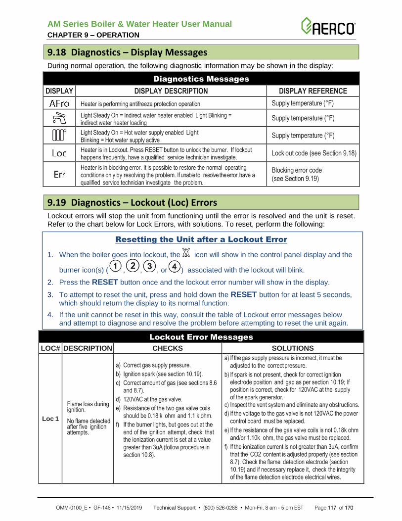
AM Series Boiler & Water Heater User Manual CHAPTER 9 – OPERATION
OMM-0100_E • GF-146 • 11/15/2019 Technical Support • (800) 526-0288 • Mon-Fri, 8 am - 5 pm EST Page 117 of 170
9.18 Diagnostics – Display Messages During normal operation, the following diagnostic information may be shown in the display:
Diagnostics Messages
DISPLAY DISPLAY DESCRIPTION DISPLAY REFERENCE
Heater is performing antifreeze protection operation. Supply temperature (°F)
Light Steady On = Indirect water heater enabled Light Blinking = indirect water heater loading
Supply temperature (°F)
Light Steady On = Hot water supply enabled Light Blinking = Hot water supply active
Supply temperature (°F)
Heater is in Lockout. Press RESET button to unlock the burner. If lockout happens frequently, have a qualified service technician investigate.
Lock out code (see Section 9.18)
Heater is in blocking error. It is possible to restore the normal operating conditions only by resolving the problem. If unable to resolve the error, have a qualified service technician investigate the problem.
Blocking error code (see Section 9.19)
9.19 Diagnostics – Lockout (Loc) Errors Lockout errors will stop the unit from functioning until the error is resolved and the unit is reset. Refer to the chart below for Lock Errors, with solutions. To reset, perform the following:
Resetting the Unit after a Lockout Error
1. When the boiler goes into lockout, the icon will show in the control panel display and the
burner icon(s) ( , , , or ) associated with the lockout will blink.
2. Press the RESET button once and the lockout error number will show in the display.
3. To attempt to reset the unit, press and hold down the RESET button for at least 5 seconds, which should return the display to its normal function.
4. If the unit cannot be reset in this way, consult the table of Lockout error messages below and attempt to diagnose and resolve the problem before attempting to reset the unit again.
Lockout Error Messages
LOC# DESCRIPTION CHECKS SOLUTIONS
Loc 1
Flame loss during ignition. No flame detected after five ignition attempts.
a) Correct gas supply pressure.
b) Ignition spark (see section 10.19).
c) Correct amount of gas (see sections 8.6 and 8.7).
d) 120VAC at the gas valve.
e) Resistance of the two gas valve coils should be 0.18 k ohm and 1.1 k ohm.
f) If the burner lights, but goes out at the end of the ignition attempt, check: that the ionization current is set at a value greater than 3uA (follow procedure in section 10.8).
a) If the gas supply pressure is incorrect, it must be adjusted to the correct pressure.
b) If spark is not present, check for correct ignition electrode position and gap as per section 10.19; If position is correct, check for 120VAC at the supply of the spark generator.
c) Inspect the vent system and eliminate any obstructions.
d) If the voltage to the gas valve is not 120VAC the power control board must be replaced.
e) If the resistance of the gas valve coils is not 0.18k ohm and/or 1.10k ohm, the gas valve must be replaced.
f) If the ionization current is not greater than 3uA, confirm that the CO2 content is adjusted properly (see section 8.7). Check the flame detection electrode (section 10.19) and if necessary replace it, check the integrity of the flame detection electrode electrical wires.

AM Series Boiler & Water Heater User Manual CHAPTER 9 – OPERATION
OMM-0100_E • GF-146 • 11/15/2019 Technical Support • (800) 526-0288 • Mon-Fri, 8 am - 5 pm EST Page 118 of 170
Lockout Error Messages
LOC# DESCRIPTION CHECKS SOLUTIONS
Loc 2
Gas valve not supplied before ignition attempt (When this error happens to burner 1 (MASTER), it stops all other burners)
a) - Check High limit temperature switch
b) - Check High limit flue temperature fuse
WARNING! If the high temperature fuse is
blown, before it is replaced it is mandatory to inform the manufacturer to prevent serious damage and a possible dangerous condition. Failure to comply with this requirement can result in excessive levels of carbon monoxide, which can result in severe personal injury or death!
Loc 3 Gas valve lost cable connection during fire
a) Check the integrity of the wires connections between gas valve and control board.
a) If wires are interrupted, replace the wires. b) If wires are ok try to replace the gas valve or the power
control board.
Loc 4 Gas valve relay not closing
a) Check the integrity of the wires connections between gas valve and control board.
a) If wires are interrupted, replace the wires. b) If wires are ok try to replace the gas valve or the power
control board.
Loc 5
Gas valve circuit (When this error happens to burner 1 (MASTER), it stops all other burners)
a) Check High limit temperature switch
b) Check High limit flue temperature fuse
WARNING! If the high temperature fuse is
blown, before it is replaced it is mandatory to inform the manufacturer to prevent serious damage and a possible dangerous condition. Failure to comply with this requirement can result in excessive levels of carbon monoxide, which can result in severe personal injury or death!
Loc 6 Safety relay open error
Replace the power control board
Loc 7 Safety relay closed error
Replace the power control board
Loc 11 Blocking error over 20 hr.
Press RESET button to see the Blocking error reference and proceed follow it.
Loc 12 Fan error
a) Check for 120VAC power connection of the fan
b) Check PWM connection of the fan
a) If no 120Vac is present replace the power control board b) If no PWM signal, replace power control board c) Try to replace the fan
Loc 13 to
24
Internal software error Replace the power control board
Loc 25
Gas valve circuit (When this error happens to burner 1 (MASTER), it stops all other burners)
a) Check High limit temperature switch.
b) Check High limit flue temperature fuse.
WARNING! If the high temperature fuse is
blown before it is replaced, it is mandatory to inform the manufacturer to prevent serious damage and a possible dangerous condition. Failure to comply with this requirement can result in excessive levels of carbon monoxide, which can result in severe personal injury or death!
Loc 26 Internal software error Replace the power control board
Loc 27 to
28
Flame present with closed gas valve Replace the gas valve
Loc 29
Interlock input (When this error happens to burner 1 (MASTER) stops all other burners)
a - Check LWCO connection b - Check flue blocked pressure switch
a - If LWCO intervenes, try to reset it b - Check if flue gas line is free from any blockage

AM Series Boiler & Water Heater User Manual CHAPTER 9 – OPERATION
OMM-0100_E • GF-146 • 11/15/2019 Technical Support • (800) 526-0288 • Mon-Fri, 8 am - 5 pm EST Page 119 of 170
Lockout Error Messages
LOC# DESCRIPTION CHECKS SOLUTIONS
Loc 30
Internal software error Replace the power control board
Loc 31
Five times flame lost during one demand
a) Check detection electrode.
b) Check for any obstruction on air inlet / flue exhaust system.
c) Check for any air inlet contamination from combustion gas (e.g. flue exhaust terminal too much near air inlet terminal).
a) Try to replace detection electrode.
b) Remove any obstruction.
c) Remove the cause of the air inlet contamination.
Loc 32 to
37 Internal software error Replace the power control board
Loc 38
Flue sensor does not increase temperature when burner on
a) Check if flue temperature sensor match section 10.24
b) Check if flue gas sensor reading (parameter 1006) increases its temperature when burner is on.
a) If temperature sensor does not match section 10.24, it must be replaced.
b) If temperature does not increase replace the flue gas sensor or the control board.
9.20 Diagnostics – Blocking (Err) Errors Blocking errors are generated by a permanent fault. There is no way to unlock the unit other than to resolve the cause of the fault.
To reset a lockout error, do the following:
Resetting the Unit after a Blocking (Err) Error
1. When the boiler goes into lockout, the icon will show in the control panel display and
the burner icon(s) ( , , , or ) associated with the lockout will blink.
2. Press the RESET button once and the lockout error number will show in the display.
3. To resolve the error, consult the table of Error (Err) messages in the chart below and attempt to diagnose and resolve the problem.
4. To return the display to normal function, press and hold down the RESET button for at least 5 seconds.
Blocking Error Messages
ERR# DESCRIPTION CHECKS SOLUTIONS
Err 0 Self Checking Not needed a) During startup, display shows “Err 0”
temporarily, because it’s doing its own self checking.
Err 45 to 53
Internal software error Replace the power control board.
Err 54 Flame detected, but not observed.
- Replace the power control board.
Err 55 to 58
Low water pressure error
Check pressure sensor. Replace the pressure sensor.
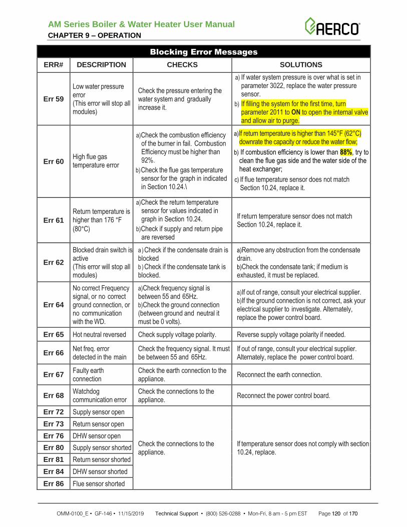
AM Series Boiler & Water Heater User Manual CHAPTER 9 – OPERATION
OMM-0100_E • GF-146 • 11/15/2019 Technical Support • (800) 526-0288 • Mon-Fri, 8 am - 5 pm EST Page 120 of 170
Blocking Error Messages
ERR# DESCRIPTION CHECKS SOLUTIONS
Err 59
Low water pressure error (This error will stop all modules)
Check the pressure entering the water system and gradually increase it.
a) If water system pressure is over what is set in parameter 3022, replace the water pressure sensor.
b) If filling the system for the first time, turn parameter 2011 to ON to open the internal valve and allow air to purge.
Err 60 High flue gas temperature error
a) Check the combustion efficiency of the burner in fail. Combustion Efficiency must be higher than 92%.
b) Check the flue gas temperature sensor for the graph in indicated in Section 10.24.\
a) If return temperature is higher than 145°F (62°C) downrate the capacity or reduce the water flow;
b) If combustion efficiency is lower than 88%, try to clean the flue gas side and the water side of the heat exchanger;
c) If flue temperature sensor does not match Section 10.24, replace it.
Err 61
Return temperature is higher than 176 °F
(80°C)
a) Check the return temperature sensor for values indicated in graph in Section 10.24.
b) Check if supply and return pipe are reversed
If return temperature sensor does not match Section 10.24, replace it.
Err 62
Blocked drain switch is active (This error will stop all modules)
a ) Check if the condensate drain is blocked b ) Check if the condensate tank is blocked.
a) Remove any obstruction from the condensate drain. b) Check the condensate tank; if medium is exhausted, it must be replaced.
Err 64
No correct Frequency signal, or no correct ground connection, or no communication with the WD.
a) Check frequency signal is between 55 and 65Hz. b) Check the ground connection (between ground and neutral it must be 0 volts).
a) If out of range, consult your electrical supplier. b) If the ground connection is not correct, ask your electrical supplier to investigate. Alternately, replace the power control board.
Err 65 Hot neutral reversed Check supply voltage polarity. Reverse supply voltage polarity if needed.
Err 66 Net freq. error detected in the main
Check the frequency signal. It must be between 55 and 65Hz.
If out of range, consult your electrical supplier. Alternately, replace the power control board.
Err 67 Faulty earth connection
Check the earth connection to the appliance.
Reconnect the earth connection.
Err 68 Watchdog communication error
Check the connections to the appliance.
Reconnect the power control board.
Err 72 Supply sensor open
Check the connections to the appliance.
If temperature sensor does not comply with section 10.24, replace.
Err 73 Return sensor open
Err 76 DHW sensor open
Err 80 Supply sensor shorted
Err 81 Return sensor shorted
Err 84 DHW sensor shorted
Err 86 Flue sensor shorted

AM Series Boiler & Water Heater User Manual CHAPTER 9 – OPERATION
OMM-0100_E • GF-146 • 11/15/2019 Technical Support • (800) 526-0288 • Mon-Fri, 8 am - 5 pm EST Page 121 of 170
Blocking Error Messages
ERR# DESCRIPTION CHECKS SOLUTIONS
Err 87 Reset button error Too many reset button pushes within 60 sec. period.
Err 93 Appliance selection error
Check the list of 3000 parameters (Appendix B).
Err 107 Internal software error - Replace the power control board.
Err 108
Err 109 Error happening to burners 2, 3 or 4
When burner 1 (MASTER) goes in a general error, it stops burners 2, 3 and 4 generating an “Err 109”
Resolve the error to burner 1 (MASTER)
Err 110 Flapper valve not open error
a) Check for any obstruction into the exhaust system.
b) Check if the fan is running.
c) Check the flapper valve and its control sensor.
a) Remove the obstruction from flue exhaust.
b) Replace the fan or the power control board.
c) Replace the flapper valve or its control sensor.
Err 111 Flapper valve not closed error
Check the flapper valve and its control sensor.
Replace the flapper valve or its control sensor.
Err 112 Internal software error - Replace the power control board.
Err 113
Err 114 Too low water flow Check water flow into the system (parameter 1062), it must be higher than parameter 3035.
Increase the water flow into the system. Check for any obstructions in the water system inlets.
Err 115 Multiple burner master failure
- Reset via 3013 parameter.
Err 116
Multiple burner communication failure. (This error will stop all modules.)
a) Bus communication interrupted.
b) Burner is not working.
a) Check for bus communication.
b) Restore the burner that has its light off.
NO CONN
Microprocessor in lockout
a) Check if water pressure sensor wires are in short circuit.
b) Check if water flow meter wires are in short circuit.
c) Check display wires are connected to burner 1 (MASTER).
a) If not in short circuit try to replace the water pressure sensor (or disconnect it via 3000 menu).
b) If not in short circuit try to replace the water flow meter (or disconnect it via 3000 menu).
c) If not any of the above try to replace the power control board or the display.
9.21 Blocked Flue Pressure Switch The AM Series units are equipped with a blocked flue pressure switch safety that shuts down the unit when the flue exhaust vent pipe is blocked. If this pressure switch shuts off the unit (Loc 25), do not attempt to place the boiler in operation but rather, contact a qualified service agency or technician able to reset the unit after checking for any potential dangerous situations.

AM Series Boiler & Water Heater User Manual CHAPTER 9 – OPERATION
OMM-0100_E • GF-146 • 11/15/2019 Technical Support • (800) 526-0288 • Mon-Fri, 8 am - 5 pm EST Page 122 of 170
WARNING!
If the high temperature fuse is blown before it is replaced, it is mandatory to inform the manufacturer to prevent serious damage and a possible dangerous condition. A blocked vent could cause high levels of CO to enter the mechanical room. Ensure vent is intact and free of any obstructions or restrictions.
9.22 Unit Shut-Down
To shut the unit down, perform the following:
Shutting Down the Unit
1. Turn the unit power switch to the OFF position.
2. Turn off all electrical power to the unit.
3. Close the manual shut-off valve (Figure 9-3) by turning the valve handle clock-wise. Do not force.
Figure 9-3: Gas Safety Shut-Off Valve
• Do not drain the system, unless exposure to freezing temperatures will occur.
• Do not drain the system, if it is filled with an antifreeze solution.

AM Series Boiler & Water Heater User Manual CHAPTER 9 – OPERATION
OMM-0100_E • GF-146 • 11/15/2019 Technical Support • (800) 526-0288 • Mon-Fri, 8 am - 5 pm EST Page 123 of 170
(This page intentionally blank)

AM Series Boilers and Water Heaters User Manual CHAPTER 10 – MAINTENANCE
OMM-0100_E • GF-146 • 11/15/2019 Technical Support • (800) 526-0288 • Mon-Fri, 8 am - 5 pm EST Page 124 of 170
SECTION 10: MAINTENANCE
This section must be brought to the attention of the user by the installer so that the user can make the necessary arrangements with a qualified service agency for the periodic care and maintenance of the boiler. Refer to Table 10-1 for a schedule of necessary maintenance procedures.
Lack of proper care and maintenance of this boiler and any fuel burning equipment may result in a hazardous condition.
A trained and qualified service technician should perform the inspection listed in these instructions before each heating season and at regular intervals.
CAUTION!
Servicing, inspection and adjustment must be done by a trained technician in accordance with all applicable local and national codes. Improper servicing or adjustment could damage the boiler and result in equipment damage or a dangerous condition!
Table 10-1: AM Series Maintenance Schedule
SERVICE TECHNICIAN
USER MAINTENANCE
Annual Startup and Maintenance:
• Address reported problems
• Check all piping for gas leaks
• Verify flue and air lines in good condition and sealed tight
• Check system water pressure/system piping/expansion tank
• Check control settings
• Check ignition and flame sense electrodes
• Check wiring and connections
• Perform start up checkout and performance verification
• Flame inspection
• Check flame signal
• Inspect combustion chamber. Clean and vacuum if necessary.
• Clean the heat exchanger if the flue temperature is 63°F (35°C)
above return water temperature
• Clean condensate reservoir and fill with fresh water
• Clean air filter
• Check the capacity input
• Check relief valve
• Check thermal Insulation inside every module
Daily Check: • Check boiler area
• Check pressure gauge
Monthly Check: • Check vent piping and vent termination screen
• Check air piping and air termination screen
• Check relief valve
• Check condensate drain system
• Check any air vents on the system that no leaks are present
Periodic Check: • Test low water cut-off (if used)
• Reset low water cut-off button (if used)
Six Month Check: • Check boiler piping (gas and water) for leaks
• Check and clean anodes in buffer tank (if installed)
End of Season Months Check: • Shut boiler down (unless boiler used for domestic
hot water)

AM Series Boilers and Water Heaters User Manual CHAPTER 10 – MAINTENANCE
OMM-0100_E • GF-146 • 11/15/2019 Technical Support • (800) 526-0288 • Mon-Fri, 8 am - 5 pm EST Page 125 of 170
10.1 Checking for Gas Leaks • Inspect all gas piping and verify to be leak free.
• Check for gas leaks: using soap solution, check for gas leaks from meter to appliance including all pipes and fittings and heater connection. Use liquid soap solution for all gas testing.
10.2 Flue and Air inlet Piping Inspection • Check for obstructions, condensation, corrosion and physical damage, water stains, any signs
of rust, other corrosions or separation of the vent and air intake piping.
• Check outside terminations. Screens and louvers should be free of any debris and must be cleaned as required.
10.3 System Piping, Pressure, and Expansion Tank Inspection • Check water piping and accessories for leaks. All leaks should be corrected.
• Check that the system is filled with water and the reading on the pressure gauge remains stable.
Eliminate all system and unit leaks. Continual fresh makeup water will reduce boiler life. Minerals can build up in sections, reducing heat transfer, overheating heat exchanger, and causing heat exchanger failure. Leaking water may also cause severe property damage.
10.4 Ignition and Flame Sensor Inspection
To inspect and maintain the ignition and flame sensor, perform the following:
Ignition and Flame Sensor Inspection
1. Remove the fan-burner assembly unit per Section 10.15.
2. Remove any deposits accumulated on the ignition/flame sensor electrode using sand paper.
3. Check the positioning of the electrodes per Section 10.19.
4. Reinstall the fan-burner assembly back into the unit.
10.5 Wiring and Connections Inspection
Inspect all heater wiring, making sure wires are in good condition and securely attached.
10.6 Performance Verification Inspection
• Start the unit and perform a combustion calibration test as per Section 8.7.
• Verify cold fill pressure is correct and that operating pressure does not go too high (if so, check for problems with the expansion tank).
10.7 Flame Inspection
• Inspect flame through the observation window on the burner.
• If the flame is unsatisfactory at either high fire or low fire, clean the burner per Section 10.15.

AM Series Boilers and Water Heaters User Manual CHAPTER 10 – MAINTENANCE
OMM-0100_E • GF-146 • 11/15/2019 Technical Support • (800) 526-0288 • Mon-Fri, 8 am - 5 pm EST Page 126 of 170
10.8 Flame Signal Inspection
• Start the unit and perform the combustion calibration procedure per section 8.7.
• At high fire and low fire the flame signal (parameter 1008) should be within values given in Appendix A, under header “ionization current”. A lower flame signal may indicate a fouled or damaged flame sense electrode. If cleaning the flame sense electrode does not improve the problem, ground wiring is in good condition, and ground continuity is satisfactory, replace the flame sensor electrode.
10.9 Relief Valve Inspection
• Inspect the relief valve and lift the lever to verify flow.
• Before operating any relief valve, ensure that it is piped with its discharge in a safe area to avoid severe scald potential.
• Relief valve should be re-inspected at least once every three years, by a licensed plumbing contractor or authorized inspection agency, to ensure that the product has not been affected by corrosive water conditions. Certain naturally occurring conditions may corrode the valve or its components over time, rendering the valve inoperative. Such conditions are not detectable unless the valve and its components are physically removed and inspected. This inspection must only be conducted by a plumbing contractor or authorized inspection agency – not by the user.
WARNING!
Failure to re-inspect the relief valve as directed could result in unsafe pressure buildup, and a dangerous condition.
10.10 Unit Vicinity Inspection
The following are NOT allowed to be in the vicinity of the unit or the flue exhaust system:
• Combustible/flammable materials: Do not store combustible materials, gasoline or any other flammable vapors or liquids near the unit or exhaust system. Remove immediately if found.
• Air contaminants: Products containing chlorine or fluorine, if allowed to contaminate the heater intake air, will cause acidic condensate in the heater. This will cause significant damage to the heater if allowed to continue. If any of these products are in the room from which the heater takes its combustion air, they must be removed immediately or the heater combustion air (and vent termination) must be relocated to another area.
All materials discussed above should be immediately removed from the heater vicinity and the vicinity of the heater combustion air inlet.
If these materials have been present for an extended period, call a qualified service technician to inspect the heater for possible damage from acid corrosion.
If products cannot be removed, immediately call a qualified service technician to re-pipe vent and air piping and locate vent termination/air intake away from contaminated areas.
10.11 Pressure Gauge Inspection
Make sure the pressure reading on the heater pressure gauge (item “M” in Figures 5-1 or 5-3) does not exceed the maximum working pressure. Higher pressures may indicate a problem with the expansion tank.

AM Series Boilers and Water Heaters User Manual CHAPTER 10 – MAINTENANCE
OMM-0100_E • GF-146 • 11/15/2019 Technical Support • (800) 526-0288 • Mon-Fri, 8 am - 5 pm EST Page 127 of 170
Contact a qualified service technician if problem persists.
10.12 Condensate Drain System Inspection
• Inspect the condensate drain line, condensate fittings, and condensate trap for signs of weeping or leakage.
• If you detect signs of leakage, immediately contact your qualified service technician to inspect the boiler and system.
• Ensure there is sufficient neutralizer media. It is recommended to replace this media annually.
WARNING!
Have leaks fixed at once by a qualified service technician.
10.13 Low Water Cutoff Test
If an LWCO is installed, it should be tested. Testing the low water cutoff shuts the unit off. Press the RESET button on the low water cutoff to turn the unit back on.

AM Series Boilers and Water Heaters User Manual CHAPTER 10 – MAINTENANCE
OMM-0100_E • GF-146 • 11/15/2019 Technical Support • (800) 526-0288 • Mon-Fri, 8 am - 5 pm EST Page 128 of 170
10.14 Removing the Unit Covers In order to remove the unit covers, refer to Figure 10-1 and follow the steps below:
Removing the Unit Covers
1. Lift up, by hand, the Top Cover “A”.
2. Remove two Front Cover screws “B”.
3. Pull back the upper part of Front Cover “C” for 2 inches, then pull it up for one inch and remove it from the unit.
4. Pull back upper part of Bottom Cover “D” for 2 inches, then pull it up for one inch and remove it from the unit.
5. To gain access to the junction box:
a) Remove the Junction Box Cover screw “E” at rear of cover.
b) Remove Junction Box cover “F”.
Figure 10-1: Removing the Top and Front Covers
(F) Junction
Box Cover
(A) Top Cover
(C) Front Cover
(D) Bottom Cover
(E) Junction Box Screw
(B) Front Cover
Screws (2 each)

AM Series Boilers and Water Heaters User Manual CHAPTER 10 – MAINTENANCE
OMM-0100_E • GF-146 • 11/15/2019 Technical Support • (800) 526-0288 • Mon-Fri, 8 am - 5 pm EST Page 129 of 170
10.15 Cleaning the Burner and Primary Heat Exchanger (Flue/Gas Side) The burner and primary heat exchanger must be checked every year and cleaned if required. To correctly clean the burner and the flue gas side of the heat exchanger follow the steps below:
Cleaning the Burner and Primary Heat Exchanger
WARNING!
Before proceeding to the next step, verify that the electrical supply to the heater, and any other electrical supply near the heater, is off. Verify that the manual gas shut off valve is closed.
1. Follow the steps in Section 10.14 to gain access to the internal components.
2. Prepare a suitable cover for the burner so that no dirt, water, or other foreign objects can fall into the burner unit from above.
3. Disconnect the two wires “D” (Figure 6-2) from the ignition electrodes and the wire “E” (Figure 10-3) from the flame detection electrode.
4. Loosen screws “F” (Figure 10-2) and move up the spark generator “A”.
Figure 10-2: Removing the Spark Generator
Cleaning the Burner and Primary Heat Exchanger - Continued
D
F
A
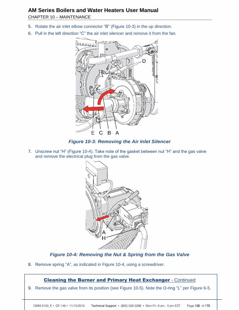
AM Series Boilers and Water Heaters User Manual CHAPTER 10 – MAINTENANCE
OMM-0100_E • GF-146 • 11/15/2019 Technical Support • (800) 526-0288 • Mon-Fri, 8 am - 5 pm EST Page 130 of 170
5. Rotate the air inlet elbow connector “B” (Figure 10-3) in the up direction.
6. Pull in the left direction “C” the air inlet silencer and remove it from the fan.
Figure 10-3: Removing the Air Inlet Silencer
7. Unscrew nut “H” (Figure 10-4). Take note of the gasket between nut “H” and the gas valve and remove the electrical plug from the gas valve.
Figure 10-4: Removing the Nut & Spring from the Gas Valve
8. Remove spring “A”, as indicated in Figure 10-4, using a screwdriver.
Cleaning the Burner and Primary Heat Exchanger - Continued
9. Remove the gas valve from its position (see Figure 10-5). Note the O-ring “L” per Figure 6-5.

AM Series Boilers and Water Heaters User Manual CHAPTER 10 – MAINTENANCE
OMM-0100_E • GF-146 • 11/15/2019 Technical Support • (800) 526-0288 • Mon-Fri, 8 am - 5 pm EST Page 131 of 170
Figure 10-5: Removing the Gas Valve
10. Unscrew the four nuts “B” in Figure 10-6;
11. Remove the entire fan and burner assembly, detail “C”, as shown in Figure 10-6
Figure 10-6: Removing the Fan and Burner Assembly
Cleaning the Burner and Primary Heat Exchanger - Continued
12. Use a cylindrical brush with plastic bristles to clean the inside of the combustion chamber, item “H” per Figure 10-6

AM Series Boilers and Water Heaters User Manual CHAPTER 10 – MAINTENANCE
OMM-0100_E • GF-146 • 11/15/2019 Technical Support • (800) 526-0288 • Mon-Fri, 8 am - 5 pm EST Page 132 of 170
13. Use a vacuum cleaner to remove any unburned residue from the combustion chamber.
14. Clean the surfaces of the burner and around the electrodes using the vacuum cleaner.
WARNING!
While performing the next step, carefully wash only the inside of the combustion chamber and do not get water on the outside of the combustion chamber opening. Failure to comply with this warning can cause extensive property damage or a dangerous condition.
15. Using only water, wash the inside of the combustion chamber. The water will drain into the condensate drain.
16. Reassemble the components by performing the disassembly steps in reverse order, taking care to reinstall the gasket at nut “H” of Figure 10-4 and the O-ring “L” as per Figure 10-5. These must be replaced with a new gasket and/or O-ring if not in good condition.
17. Open the manual gas shutoff valve.
18. Check that there are no gas leaks.
19. Restore electrical power to the unit.

AM Series Boilers and Water Heaters User Manual CHAPTER 10 – MAINTENANCE
OMM-0100_E • GF-146 • 11/15/2019 Technical Support • (800) 526-0288 • Mon-Fri, 8 am - 5 pm EST Page 133 of 170
10.16 Inspecting and Replacing the Heat Exchanger Thermal Insulation The thermal insulation in each heat exchanger module must be inspected every year for any damage, including cracks, chips, or other abnormalities. If any damage is found, the insulation must be replaced using the instructions below. The replacement procedure must be repeated on each heat exchanger module in the unit.
Replacing the HEAT EXCHANGER Thermal Insulation
1. Follow Steps 1 through 11 of the instructions in section 10.15 in order to remove the fan and burner assembly from the heat exchanger.
2. Unscrew nut from the thermal insulation (see Figure A).
3. Use a screwdriver to remove the thermal insulation.
4. Prepare the screw and the washer to fix the new thermal insulation (see Figure B).
Figure A: Screw & Thermal Insulation Figure B: Screw & Washer
5. Align the bolt holes in the heat exchanger (detail B in Figure 8) with the corresponding hole in the thermal insulation (detail A in Figure C).
6. Install the thermal insulation in the heat exchanger, holding it in place with the screw and washer included with the kit (see Figure D). ). It is recommended that you use a high temperature anti-seize compound when installing the screw to facilitate removal during subsequent maintenance.
Figure C: Replacing Thermal Insulation Figure D: Installing Thermal Insulation

AM Series Boilers and Water Heaters User Manual CHAPTER 10 – MAINTENANCE
OMM-0100_E • GF-146 • 11/15/2019 Technical Support • (800) 526-0288 • Mon-Fri, 8 am - 5 pm EST Page 134 of 170
10.17 Inspecting and Replacing the Burner Thermal Insulation The thermal insulation in each burner must be inspected every year for any damage, including cracks, chips, or other abnormalities. If any damage is found, the insulation must be replaced using the instructions below. The replacement procedure must be repeated on each burner module in the unit.
Replacing the BURNER Thermal Insulation
1. Follow Steps 1 through 11 of the instructions in section 6.1.16 in order to remove the fan and burner assembly from the heat exchanger.
2. Unscrew the screws holding the electrodes in place (see Figure E).
3. Remove both the ignition and flame detection electrodes (see Figure F).
Figure E: Removing Electrode’s Screws Figure F: Removing the Electrodes
4. Remove the burner’s thermal insulation (see Figure G).
5. Replace the O-Ring (see arrow in Figure H) with the new one included in the kit.
Figure G: Remove Thermal Insulation Figure H: Replace the O-Ring

AM Series Boilers and Water Heaters User Manual CHAPTER 10 – MAINTENANCE
OMM-0100_E • GF-146 • 11/15/2019 Technical Support • (800) 526-0288 • Mon-Fri, 8 am - 5 pm EST Page 135 of 170
Replacing the BURNER Thermal Insulation - Continued
6. Install the wool gasket in the back of the new burner thermal insulation (see Figure I).
7. Install the new burner thermal insulation on the burner (see Figure J).
Figure I: Wool Gasket w/ Thermal Insulation Figure J: Install Thermal Insulation
8. Assembly the ignition and detection electrodes, paying attention to the correct position of the red gasket (shown with arrows in Figure K).
9. Screw the electrodes in place (see Figure L).
Figure K: Reassemble the Electrodes Figure L: Tighten the Electrodes
10. Before reinstalling the burner, clean the surface on which the gasket will sit (shown with arrows in Figure M) to ensure a good seal.
11. Install the reassembled fan burner assembly (see Figure N) in the heat exchanger by performing the steps in section 10.15 – Removing the Burner in reverse order.
Figure M: Clean Gasket Surface Figure N: Burner Reassembly
12. Repeat the instructions above on the remaining burners in the unit.

AM Series Boilers and Water Heaters User Manual CHAPTER 10 – MAINTENANCE
OMM-0100_E • GF-146 • 11/15/2019 Technical Support • (800) 526-0288 • Mon-Fri, 8 am - 5 pm EST Page 136 of 170
10.18 Checking for Gas Leaks after Reassembly Once the unit is reassembled and the electrical connection restored, open the manual gas shut off valve and check the unit for gas leaks.
Checking for Gas Leaks After Reassembly
1. Use an approved leak detention method to check all junctions shown with arrows A through E in Figure O.
Figure O: Leak Check Locations

AM Series Boilers and Water Heaters User Manual CHAPTER 10 – MAINTENANCE
OMM-0100_E • GF-146 • 11/15/2019 Technical Support • (800) 526-0288 • Mon-Fri, 8 am - 5 pm EST Page 137 of 170
10.19 Ignition and Flame Detection Sensor Electrode Positioning For the heater to work properly the electrodes must be positioned as listed below and shown in Figure 10-7:
Ignition and Flame Detection Electrode Positioning
2. To insure correct functioning of the burner, the distances listed below should be carefully verified by hand using calipers.
• The distance between the ignition electrodes “A” and “B”, must be between 0.08 in (2 mm), and 0.10 in (2.5 mm);
• The distance of the ignition electrodes to the burner surface must be between 0.20 in (5.0 mm), and 0.22 in (5.5 mm);
• The distance of the flame detection electrode to the burner surface must be between 0.23 in (6.0 mm), and 0.27 in (7.0 mm).
Figure 10-7: Positioning the Ignition & Flame Detection Sensor Electrodes

AM Series Boilers and Water Heaters User Manual CHAPTER 10 – MAINTENANCE
OMM-0100_E • GF-146 • 11/15/2019 Technical Support • (800) 526-0288 • Mon-Fri, 8 am - 5 pm EST Page 138 of 170
10.20 Air Filter Cleaning For the heater to work properly the air filter must be clean. A dirty air filter can cause a power input reduction of the unit, resulting in system malfunctions. To clean the air filter, perform the following:
Cleaning the Air Filter
1. Follow the steps in Section 10.14 to gain access to the internal components.
2. Pull down with a rotating motion the air filter “B” as per Figure 10-8.
3. Pull out the air filter and remove it from the unit.
4. Clean the surface of the air filter using compressed air.
5. Reassemble the air filter, noting the orientation arrow on the front of the filter.
Figure 10-8: Removing the Air Filter for Cleaning

AM Series Boilers and Water Heaters User Manual CHAPTER 10 – MAINTENANCE
OMM-0100_E • GF-146 • 11/15/2019 Technical Support • (800) 526-0288 • Mon-Fri, 8 am - 5 pm EST Page 139 of 170
10.21 Condensate Trap and Neutralizing Reservoir Maintenance The condensate trap and neutralizing reservoir must be checked every year and cleaned if required. Follow the steps below to properly inspect, refill or replace the condensate neutralizing reservoir and media:
Monitor the level of the neutralization media in the reservoir periodically. The pH can be checked after the condensate has exited from pipe “A” of Figure 4-8. Check the pH level every three months for the first year. Use a suitable pH test strip paper or an electronic pH meter for precise measurement. The frequency of pH level inspection can be reduced to every six months or every year depending on the readings obtained compared to local water authority requirements. The neutralizing media should be replaced when the pH level drops below the minimum level of the local water authority. For replacement media contact AERCO.
To inspect and maintain the condensate system, perform the following:
Condensate System Inspection and Maintenance
1. Turn off electrical power to the unit.
2. Close the manual gas shut-off valve (Figure 7-1).
3. Follow the steps in Section 10.14 to remove the lower front cover.
4. Pull out the condensate collection tank assembly “A” (Figure 10-9).
Figure 10-9: Pull Out Tank Figure 10-10: Open Cover
5. Open the neutralizer tank cover “C” per Figure 10-10, and inspect the collection tank for wear or damage.
6. Examine the neutralizing media and replenish with fresh media if needed.
7. Fill the condensate collection tank with fresh water until the water begins to flow from the condensate drain piping.

AM Series Boilers and Water Heaters User Manual CHAPTER 10 – MAINTENANCE
OMM-0100_E • GF-146 • 11/15/2019 Technical Support • (800) 526-0288 • Mon-Fri, 8 am - 5 pm EST Page 140 of 170
Condensate System Inspection and Maintenance - Continued
8. Replace the condensate cover and reinsert the condensate collection tank assembly back into the unit.
WARNING!
The condensate collection tank must be filled with water to prevent flue gas emissions from escaping during unit operation. Failure to comply with this requirement can result in dangerous levels of carbon monoxide.
9. Open the manual gas shutoff valve.
10. Restore electrical power to the unit and return to service.
WARNING!
The condensate neutralizer tank MUST be installed correctly into the unit, as shown in Figure 4-8. If you do not install the condensate collection tank into its correct position, it will result in combustion gases will entering the room and creating a dangerous condition.

AM Series Boilers and Water Heaters User Manual CHAPTER 10 – MAINTENANCE
OMM-0100_E • GF-146 • 11/15/2019 Technical Support • (800) 526-0288 • Mon-Fri, 8 am - 5 pm EST Page 141 of 170
10.22 Control Board Replacement The AM Series multi-burner units are configured to be driven by one control board (named Burner 1 (Master)). On this board are connected all external devices such as: enable/disable, outdoor sensor, pump commands, LWCO, and some internal safety devices such as blocked drain magnetic switch, flue blocked pressure switch, etc. If the Burner 1 control board fails, the complete unit stops functioning. If installer does not have a spare replacement part, the burner control board from one of the other burners may be used to replace the Burner 1 (master) control board in order to resume the function of the unit. To do so, perform the following:
Replacing the Burner 1 (Master) Control Board
1. Turn off all electrical power to the unit.
2. Follow the steps in Section 10.14 to remove the front cover.
3. Refer to Figure 10-11 and disconnect plug “B” (plug coming from display) from plug “A” (plug coming from “Burner 1 (Master).
4. Disconnect all other plugs from the Burner 1 (Master) control board.
5. Loosen the four (4) screws “C” and remove the Burner 1 (Master) control board from the unit.
Burner 1 (Master)
Control Board
DETAIL: Setting S4 Switch to ON (Board Cover Removed For Clarity)
Figure 10-11: Replacing the Burner 1 (Master) Control Board
6. Repeat step 5 above to remove another control board from its location.
7. Install this control board to the location where the Burner 1 (Master) control board was installed, and reconnect all plugs to this board.
8. Locate S4 Switch per figure 10-11, and move from OFF (UP) to ON (DOWN) position.
Replacing the Burner 1 (Master) Control Board - Continued
ON
(C) Four
Screws
S4
SWITCH

AM Series Boilers and Water Heaters User Manual CHAPTER 10 – MAINTENANCE
OMM-0100_E • GF-146 • 11/15/2019 Technical Support • (800) 526-0288 • Mon-Fri, 8 am - 5 pm EST Page 142 of 170
9. Ensure that all connections that are now disconnected from the replacement board are secure from shorts or damage by electrically insulating each of the plugs.
10. Replace all covers.
11. Turn on electrical power to the unit.
12. Gain access to the Factory menu, per Appendix B, and set all parameters as shown in the column “Burner 1 (Master)”. Take special note of parameter 3050, as the unit has lost the function of a control board, and the 3050 value must be reduced by one unit to reflect this.
13. Shut off electrical power to the unit;
14. Turn on the power to the unit. Now the new Burner 1 control board should drive the unit correctly.
10.23 Draining the Water from the Unit To drain the water from the unit, follow the steps below:
Draining the Water from the Unit
1. Cool down the unit by setting the control temperature to the maximum (see Section 9.2 for boilers and Section 9.14 for water heaters) and wait the temperature gauge shows less than 104°F (40°C).
2. Turn OFF all electrical power off to the heater.
3. Close the manual gas shutoff valve, Figure 7-1.
4. Close the heater isolation valves in the heating system. If isolation valves haven’t been installed, the entire heating system will have to be drained.
5. Check that the heating system fill valve is closed.
6. Connect a hose to the drain valves and place the other end of the hose in a sink or some other suitable drain.
7. Open the drain valves and wait for all water drain.
8. If unit isolation valves have not been installed in the heating system open any bleed valves at the highest point of the system.
9. After draining out all the water, close the bleed valves and the unit drain valves.
10.24 Water and Flue Temperature Sensor The boiler has a number of sensors that measure temperature. For proper function, the electrical resistance between the sensor wires must correspond with the values shown in Figure 10-12 for both boilers and water heaters.

AM Series Boilers and Water Heaters User Manual CHAPTER 10 – MAINTENANCE
OMM-0100_E • GF-146 • 11/15/2019 Technical Support • (800) 526-0288 • Mon-Fri, 8 am - 5 pm EST Page 143 of 170
Figure 10-12: Water and Flue Temperature Sensor Curve
10.25 Outdoor Temperature Sensor (Boilers Only) An outdoor temperature sensor can be connected to the boiler (see Section 5.2.2). The electrical resistance existing between the sensor wires must correspond with the values shown in Figure 10-13.
Figure 10-13: Outdoor Temperature Sensor Curve (Boilers Only)
10.26 AM Rapid Recovery (AMR) Option Maintenance
Refer to Chapter 10 for all general maintenance procedures applicable to the AM Series of water heaters used in the AMR option.

AM Series Boilers and Water Heaters User Manual CHAPTER 10 – MAINTENANCE
OMM-0100_E • GF-146 • 11/15/2019 Technical Support • (800) 526-0288 • Mon-Fri, 8 am - 5 pm EST Page 144 of 170
10.26.1 Components and Piping
The external circulator pump, piping, parts, and low water cut-off specific to the AMR option are designed to provide years of trouble-free service. However, periodic inspection and routine maintenance are recommended for all hydronic systems and mechanical equipment. If any evidence of leakage or damage is present, take preventive measures and shut down the system immediately, then contact AERCO technical support for information about repair or replacement of any parts or components. See Chapter 12 for a diagram and parts list of all AMR option spare parts.
10.26.2 Buffer Tank Anode Rods
Anodes should be checked and cleaned every six months.
The AMR buffer tank supplies 25 grams of anode per square foot of tank area. Original anode rod diameter is 3/4” (0.75”), and should be replaced if diameter is reduced by 20% to 3/5” (0.60”) diameter or less. Figure 10-14 shows a comparison of an old anode needing replacement, and a new anode.
Figure 10-14: Buffer Tank New and Old Anode Comparison
Replacement anode rods (PN 93135-4) are available from AERCO Technical Support.
NEW ANODE ROD (3/4” DIAMETER)
OLD ANODE ROD NEEDING REPLACEMENT DUE TO EXCESSIVE DIAMETER REDUCTION

AM Series Boilers and Water Heaters User Manual CHAPTER 10 – MAINTENANCE
OMM-0100_E • GF-146 • 11/15/2019 Technical Support • (800) 526-0288 • Mon-Fri, 8 am - 5 pm EST Page 145 of 170
10.27 Maintenance Kits Part Lists The annual and 24-month maintenance kits for the various models of AM units are shown in the table below. The basic kit part number is 58109, with the suffix of -01 through -06 appended to it to indicate the specific kit required.
AM Series Maintenance Kit (P/N 58109) P/N Suffix and Part List
P/N SUFFIX
DESCRIPTION COMPONENTS
P/N DESCRIPTION Q’TY
-01
AM399/500 ANNUAL MAINTENANCE
KIT
60505029 DETECTION ELECTRODE 2
60701023 GASKET KERASIL 325R SQ 38X17X2 2
60505028 IGNITION ELECTRODE 2
60701022 GASKET KERASIL 325R SQ 56X22X2 2
-02
AM750 ANNUAL MAINTENANCE
KIT
60505029 DETECTION ELECTRODE 3
60701023 GASKET KERASIL 325R SQ 38X17X2 3
60505028 IGNITION ELECTRODE 3
60701022 GASKET KERASIL 325R SQ 56X22X2 3
-03
AM1000 ANNUAL MAINTENANCE
KIT
60505029 DETECTION ELECTRODE 4
60701023 GASKET KERASIL 325R SQ 38X17X2 4
60505028 IGNITION ELECTRODE 4
60701022 GASKET KERASIL 325R SQ 56X22X2 4
-04
AM399/500 24 MONTH FIRESIDE
INSPECTION KIT
60505029 DETECTION ELECTRODE 2
60701023 GASKET KERASIL 325R SQ 38X17X2 2
60505028 IGNITION ELECTRODE 2
60701022 GASKET KERASIL 325R SQ 56X22X2 2
60703047 SIL. GASKET D.200 F.188 H.7,2 2
62801021 SYNTHETIC PLATE FILTER 2
-05
AM750 24 MONTH FIRESIDE
INSPECTION KIT
60505029 DETECTION ELECTRODE 3
60701023 GASKET KERASIL 325R SQ 38X17X2 3
60505028 IGNITION ELECTRODE 3
60701022 GASKET KERASIL 325R SQ 56X22X2 3
60703047 SIL. GASKET D.200 F.188 H.7,2 3
62801021 SYNTHETIC PLATE FILTER 3
-06
AM1000 24 MONTH FIRESIDE
INSPECTION KIT
60505029 DETECTION ELECTRODE 4
60701023 GASKET KERASIL 325R SQ 38X17X2 4
60505028 IGNITION ELECTRODE 4
60701022 GASKET KERASIL 325R SQ 56X22X2 4
60703047 SIL. GASKET D.200 F.188 H.7,2 4
62801021 SYNTHETIC PLATE FILTER 4

AM Series Boilers and Water Heaters User Manual CHAPTER 10 – MAINTENANCE
OMM-0100_E • GF-146 • 11/15/2019 Technical Support • (800) 526-0288 • Mon-Fri, 8 am - 5 pm EST Page 146 of 170
10.27.1 AM Series 399 – 1000 Model Wiring Diagram
WARNING
Label all wires prior to disconnection when servicing controls. Wiring errors can cause improper and dangerous operation! Verify proper operation after servicing. Failure to comply with this warning can cause extensive property damage, severe personal injury or death!
See Legend at the end of this section.

AM Series Boilers and Water Heaters User Manual CHAPTER 10 – MAINTENANCE
OMM-0100_E • GF-146 • 11/15/2019 Technical Support • (800) 526-0288 • Mon-Fri, 8 am - 5 pm EST Page 147 of 170
WARNING
Label all wires prior to disconnection when servicing controls. Wiring errors can cause improper and dangerous operation! Verify proper operation after servicing. Failure to comply with this warning can cause extensive property damage, severe personal injury or death!

AM Series Boilers and Water Heaters User Manual CHAPTER 10 – MAINTENANCE
OMM-0100_E • GF-146 • 11/15/2019 Technical Support • (800) 526-0288 • Mon-Fri, 8 am - 5 pm EST Page 148 of 170
WARNING
Label all wires prior to disconnection when servicing controls. Wiring errors can cause improper and dangerous operation! Verify proper operation after servicing. Failure to comply with this warning can cause extensive property damage, severe personal injury or death!

AM Series Boilers and Water Heaters User Manual CHAPTER 10 – MAINTENANCE
OMM-0100_E • GF-146 • 11/15/2019 Technical Support • (800) 526-0288 • Mon-Fri, 8 am - 5 pm EST Page 149 of 170
WARNING
Label all wires prior to disconnection when servicing controls. Wiring errors can cause improper and dangerous operation! Verify proper operation after servicing. Failure to comply with this warning can cause extensive property damage, severe personal injury or death!
CONTINUED

AM Series Boilers and Water Heaters User Manual CHAPTER 10 – MAINTENANCE
OMM-0100_E • GF-146 • 11/15/2019 Technical Support • (800) 526-0288 • Mon-Fri, 8 am - 5 pm EST Page 150 of 170
WARNING
Label all wires prior to disconnection when servicing controls. Wiring errors can cause improper and dangerous operation! Verify proper operation after servicing. Failure to comply with this warning can cause extensive property damage, severe personal injury or death!

AM Series Boilers and Water Heaters User Manual CHAPTER 10 – MAINTENANCE
OMM-0100_E • GF-146 • 11/15/2019 Technical Support • (800) 526-0288 • Mon-Fri, 8 am - 5 pm EST Page 151 of 170
Legend for Electrical Scheme
6 – High limit supply temperature switch
7 – Supply temperature sensor
9 – Flue gas temperature sensor
10 – High limit Flue gas temperature fuse
11 – Control Board Fuse – F1 5x20 3A
13 – Ignition electrodes
14 – Spark generator
15 – Return temperature sensor
16 – Modulating PWM fan
17 – Back flue preventer switch (Flapper valve
switch)
19 – Water pressure sensor
20 – Gas valve
22 – Detection electrode
28 – Blocked flue pressure switch
29 – Condensate blocked drain switch
32 – Main electrical switch
34 – Display
35 – IF 885 board (optional on 199 & 250) Fuse–
F1 5x20 3A
47 – Water flow meter
48 – Motorized valve (optional)
51 – Connection board
Fuse – F1 5X20 10A
Fuse – F2 5X20 10A
Fuse – F3 5X20 3A
Fuse – F4 5X20 3A
Fuse – F6 5X20 3A
RGPR – CH pump relay
RGPS – DHW pump relay
RPP1 – Local pump relayfor Burner 1 (MASTER)
RPP2 – Local pump relayfor Burner 2
RPP3 – Local pump relayfor Burner 3
RPP4 – Local pump relayfor Burner 4
AM Series Boilers and Water Heaters User Manual CHAPTER 10 – MAINTENANCE
OMM-0100_E • GF-146 • 11/15/2019 Technical Support • (800) 526-0288 • Mon-Fri, 8 am - 5 pm EST Page 152 of 170
(This page intentionally blank)
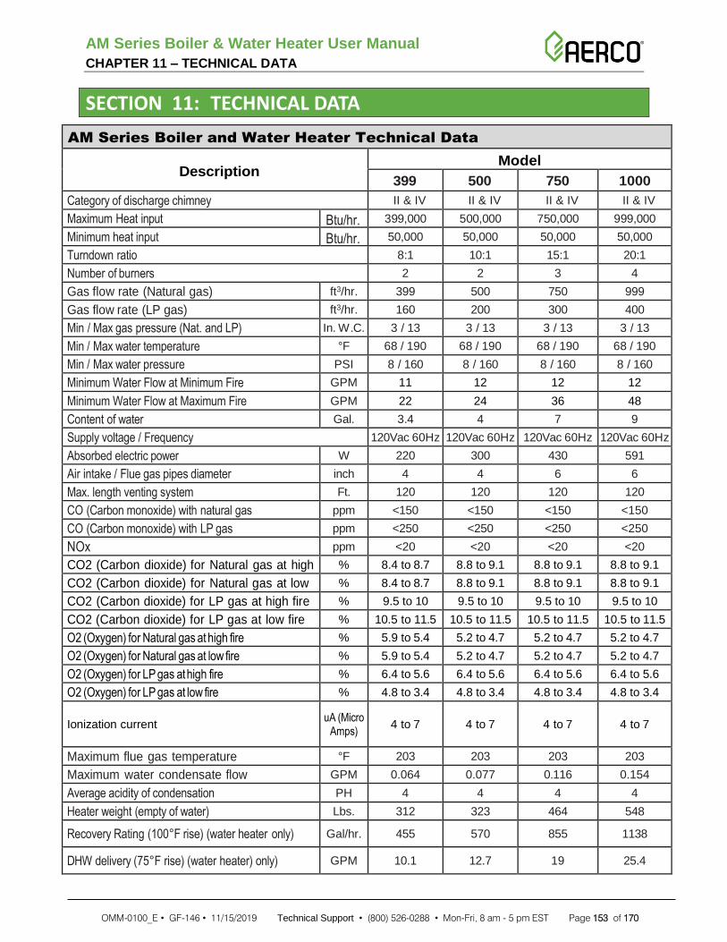
AM Series Boiler & Water Heater User Manual CHAPTER 11 – TECHNICAL DATA
OMM-0100_E • GF-146 • 11/15/2019 Technical Support • (800) 526-0288 • Mon-Fri, 8 am - 5 pm EST Page 153 of 170
SECTION 11: TECHNICAL DATA
AM Series Boiler and Water Heater Technical Data
Description Model
399 500 750 1000
Category of discharge chimney II & IV II & IV II & IV II & IV
Maximum Heat input Btu/hr. 399,000 500,000 750,000 999,000
Minimum heat input Btu/hr. 50,000 50,000 50,000 50,000
Turndown ratio 8:1 10:1 15:1 20:1
Number of burners 2 2 3 4
Gas flow rate (Natural gas) ft3/hr. 399 500 750 999
Gas flow rate (LP gas) ft3/hr. 160 200 300 400
Min / Max gas pressure (Nat. and LP) In. W.C. 3 / 13 3 / 13 3 / 13 3 / 13
Min / Max water temperature °F 68 / 190 68 / 190 68 / 190 68 / 190
Min / Max water pressure PSI 8 / 160 8 / 160 8 / 160 8 / 160
Minimum Water Flow at Minimum Fire GPM 11 12 12 12
Minimum Water Flow at Maximum Fire GPM 22 24 36 48
Content of water Gal. 3.4 4 7 9
Supply voltage / Frequency 120Vac 60Hz 120Vac 60Hz 120Vac 60Hz 120Vac 60Hz
Absorbed electric power W 220 300 430 591
Air intake / Flue gas pipes diameter inch 4 4 6 6
Max. length venting system Ft. 120 120 120 120
CO (Carbon monoxide) with natural gas ppm <150 <150 <150 <150
CO (Carbon monoxide) with LP gas ppm <250 <250 <250 <250
NOx ppm <20 <20 <20 <20
CO2 (Carbon dioxide) for Natural gas at high % 8.4 to 8.7 8.8 to 9.1 8.8 to 9.1 8.8 to 9.1
CO2 (Carbon dioxide) for Natural gas at low % 8.4 to 8.7 8.8 to 9.1 8.8 to 9.1 8.8 to 9.1
CO2 (Carbon dioxide) for LP gas at high fire % 9.5 to 10 9.5 to 10 9.5 to 10 9.5 to 10
CO2 (Carbon dioxide) for LP gas at low fire % 10.5 to 11.5 10.5 to 11.5 10.5 to 11.5 10.5 to 11.5
O2 (Oxygen) for Natural gas at high fire % 5.9 to 5.4 5.2 to 4.7 5.2 to 4.7 5.2 to 4.7
O2 (Oxygen) for Natural gas at low fire % 5.9 to 5.4 5.2 to 4.7 5.2 to 4.7 5.2 to 4.7
O2 (Oxygen) for LP gas at high fire % 6.4 to 5.6 6.4 to 5.6 6.4 to 5.6 6.4 to 5.6
O2 (Oxygen) for LP gas at low fire % 4.8 to 3.4 4.8 to 3.4 4.8 to 3.4 4.8 to 3.4
Ionization current uA (Micro
Amps) 4 to 7 4 to 7 4 to 7 4 to 7
Maximum flue gas temperature °F 203 203 203 203
Maximum water condensate flow GPM 0.064 0.077 0.116 0.154
Average acidity of condensation PH 4 4 4 4
Heater weight (empty of water) Lbs. 312 323 464 548
Recovery Rating (100°F rise) (water heater only) Gal/hr. 455 570 855 1138
DHW delivery (75°F rise) (water heater) only) GPM 10.1 12.7 19 25.4

AM Series Boiler & Water Heater User Manual CHAPTER 11 – TECHNICAL DATA
OMM-0100_E • GF-146 • 11/15/2019 Technical Support • (800) 526-0288 • Mon-Fri, 8 am - 5 pm EST Page 154 of 170
AM Rapid Recovery Buffer Tank Technical Data
Specifications 80 Gal. Tank 119 Gal. Tank
Code ASME Sec IV HLW ASME Sec IV HLW
Design Pressure 150 psi 150 psi
Test Pressure 150 psi 150 psi
Heads 10 Gauge 10 Gauge
Shell 10 Gauge 10 Gauge
Interior Ultonium Glass Lining Porcelain Enamel
Exterior Baked Enamel Steel Jacket Baked Enamel Steel Jacket
Insulation 2” R-12.5 Open Cell Foam 2” R-12.5 Open Cell Foam
Supports Sits on Shell Sits on Shell
Capacity 80 Gal. 119 Gal.
Weight 192 Lbs. 225 Lbs.
Material Specifications
Shell Carbon Steel Carbon Steel
Heads Carbon Steel Carbon Steel
Couplings Carbon Steel Carbon Steel
Jacket 24 Gauge Steel 24 Gauge Steel
AMR Storage Tank Dimensions
Mark 80 Gal. Tank 119 Gal. Tank
A – Overall height 59.75” 63.50”
B – Top of Jacket 58.75” 62.50”
C – Diameter 28” 28”
D – T&P to Floor 52.5” 55.75”
E – Circulation 9.25” 9.25”
F – Circulation 14.25” 14.25”

AM Series Boiler & Water Heater User Manual CHAPTER 12 – SPARE PARTS
OMM-0100_E • GF-146 • 11/15/2019 Technical Support • (800) 526-0288 • Mon-Fri, 8 am - 5 pm EST Page 155 of 170
SECTION 12: SPARE PARTS DRAWINGS & LISTS
12.1 AM 399/500 Spare Parts Drawings
Figure 12-1: AM 399/500 General Assembly Parts Drawing (1 of 2)
23a
24a
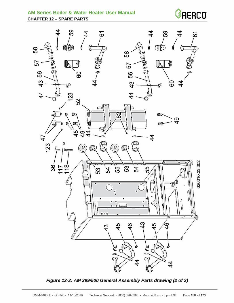
AM Series Boiler & Water Heater User Manual CHAPTER 12 – SPARE PARTS
OMM-0100_E • GF-146 • 11/15/2019 Technical Support • (800) 526-0288 • Mon-Fri, 8 am - 5 pm EST Page 156 of 170
Figure 12-2: AM 399/500 General Assembly Parts drawing (2 of 2)

AM Series Boiler & Water Heater User Manual CHAPTER 12 – SPARE PARTS
OMM-0100_E • GF-146 • 11/15/2019 Technical Support • (800) 526-0288 • Mon-Fri, 8 am - 5 pm EST Page 157 of 170
Figure 12-3: AM 399/500 Burner/Fan Assembly Parts Drawing

AM Series Boiler & Water Heater User Manual CHAPTER 12 – SPARE PARTS
OMM-0100_E • GF-146 • 11/15/2019 Technical Support • (800) 526-0288 • Mon-Fri, 8 am - 5 pm EST Page 158 of 170
12.2 AM 399/500 Spare Parts List
AM 399/500 Spare Parts List
Item# Part# Description
1 60801066 6X12 SCREW WITH WASHER
2a 62617327 4” CONNECTION – AIR INTAKE ADAPTER w/ GASKET (See Section 6.5.4)
2b 62617353 4” CONNECTION – VENT OUTLET ADAPTER w/ GASKETS (See Section 6.5.4)
3 62610091 BLACK UPPER COVER
3 62610098 GREY UPPER COVER
4 60404391 BENT BOX COVER
5 62118027 885IF BOARD INTERFACE
6 61103015 PVC CLAMPER INTERNAL DIAM. 22
7 60338034 GAS COLLECTOR 1P 1/4 NPT H=593
8 62626003 STAINLESS STEEL TUBE D.18 3/4P F-F INT.90
9 60701006 GASKET 3/4P 24X15X2 KLINSIL
10 62801023 CONDENSE ACIDITY NEUTRALIZER UNTIL 280 KW BOX
11 60322021 CORRUGATED TUBE DIAM 28 L 1250
12 60322020 CORRUGATED TUBE DIAM 28 L 800
13 60805006 ADJUSTABLE FOOT
14 60703034 GASKET EPDM D.125
15 61405316 D.125 H.809 COLLECTOR-2 EXCHANGERS
16 60702097 GASKET D.119 H.16 I.94
17 60702096 GASKET D.66 H.16 I.45
18 60502085 SINGLE GREY BOARD CLAMP
18 60502086 ON FLOOR YELLOW-GREEN BOARD CLAMP
18 60502101 SINGLE BLUE BOARD CLAMP
19 60506031 BLACK 2 POLES SWITCH
20 60507059 CONNECTION BOARD 160X100
21 62113046 PRESSURE SWITCH ON 3.2 IN W.C.
22 62801021 SYNTHETIC PLATE FILTER
23a 61405326 CAP WITH LATERAL DISCHARGE
24a 62111040 TILTING LEVEL SENSOR
23b 62651066 CAP WITH BOTTOM DISCHARGE
24b 62111051 TILTING LEVEL SENSOR
25 62110088 CONTROL BOARD 885MN10 110 V
26 60320001 SILICONE PIPE D.4X8
27 61405339 RIGHT REDUCED TAP 1/4'-3/8'
28 60702059 EPDM CLAMPER
29 62610094 COMPLETE BLACK FRONT COVER H80
29 62610097 COMPLETE GREY FRONT COVER H80
30 61405320 NO LOGO FRONT COVER
31 62610100 ABS 287X600 BASE BLACK
31 62610099 ABS 287X600 BASE GREY
32 61405264 DISPLAY GLASS
33 62110089 DISPLAY TYPE 885LB01
34 61405254 6 BUTTONS SWITCH
35 62110067 OUTDOOR SENSOR
36 62110071 SENSOR 10K D6X45 L=2500 T
37 62630185 LP TO NAT CONVERSION KIT (399 Models Only)
37 62630192 LP TO NAT CONVERSION KIT (500 Models Only)
38 62630212 NAT TO LP CONVERSION KIT
NOTE: Items 23a & 24a are used in AM 399/500 units before serial number 16060000.
NOTE: Items 23b & 24b are used in AM 399/500 units after serial number 16060000.

AM Series Boiler & Water Heater User Manual CHAPTER 12 – SPARE PARTS
OMM-0100_E • GF-146 • 11/15/2019 Technical Support • (800) 526-0288 • Mon-Fri, 8 am - 5 pm EST Page 159 of 170
AM 399/500 Spare Parts List
Item# Part# Description
39 OMM-0100_0C AM SERIES USER MANUAL REV-C
40 N/A N/A
41 61405347 WATER PROTECTION COVER FAN GROUP
42 62801022 NEUTRALISING LIMESTONE 10 KG
43 62111026 CLIP SENSOR NTC 10 KOHM D. 28
44 60701007 1"1/4 GASKET
45 62621151 COPPER TUBE D28 F/F 1'1/4 H=550
46 62101079 AUTOMATIC SAFETY THERMOSTAT 95°C
47 61206002 AIR VENT VALVE
48 60101072 BRASS REDUCTION 3/8 INCH
49 61204005 SCREWDRIVER 1/2" CHARGE FAUCET
52 60338033 STAINLESS STEEL 2 IN COLLECTOR 2" NPT
52 60338036 CARBON STEEL 2 IN COLLECTOR 2" NPT (Boilers Only)
53 62115004 THERMOMANOM. D.80 0-75 PSI 60-320°F (Boilers Only)
53 62115005 THERMOMANOM. D.80 0-200 PSI 60-320°F (Water Heaters Only)
54 61205023 SAFETY VALVE 3/4P M ASME NPT 50 PSI (Boilers Only)
54 61205024 SAFETY VALVE 3/4P M ASME NPT 125 PSI (Water Heaters Only)
55 60113009 BRASS CONNECTION 1P1/4 - 1P1/4
56 62621154 COPPER TUBE D28 F/F 1'1/4 1'1/4
57 61212014 VORTEX FLOW SENSOR
58 62621153 COPPER TUBE D28 F/F 1'1/4 1'1/4 RIT 2 (Models WITH Motorized Valve)
58 62621186 COPPER TUBE D28 F/F 1'1/4 1'1/4 (Models WITHOUT Motorized Valve)
59 61202043 SPHERE 2 WAY VALVE (Models WITH Motorized Valve)
60 61203024 2 WAY VALVE MOTOR (Models WITH Motorized Valve)
61 62621152 COPPER TUBE D28 F/F 1'1/4 1'1/4 RIT (Models WITH Motorized Valve)
62 60801065 6X12MM TC CR SCREW
63 62113045 PRESSURE GAUGE BAR
64 60107005 PLUG BRASS 1/4P M WITH O-RING
65 60801151 SCREW 4X10 GALVANIZED
66 61408014 BRASS CONNECTION 1' 1/4' IN EXIT
67 62616111 KIT FOR 6 OR AND 3 WASHERS
68 61408013 BRASS CONNECTION 1' 1/4' IN ENTRANCE
69 60510022 SPARK GENERATOR NO CABLE UL
70 60504206 CABLE UL IGNITOR CONN 90° L155
71 60701023 GASKET KERASIL 325R SQ 38X17X2
72 60505029 DETECTION ELECTRODE
73 60801081 SELFTAPPING SCREW 4X8 TC S-TT UNI-8112
74 60801108 SELFTAPPING SCREW 4X14 TCC-NP UNI-8112
75 61404123 AXIAL FAN COLLECTOR H.69
76 62651043 MAGNET CLAP GROUP
77 62111044 REED MAGNETIC POSITION SENSOR
78 60702078 GASKET SHAPED FOR FAN
79 60702077 OR RING 3325 SIL 2,62 X 82,22
80 60701013 GASKET FRIZITE D15,5 F11,5 SP1,5
81 60815013 PIREX GLASS D15,5 SP5
82 60404253 FLANGE L21,2 H34 SP1
83 60504266 MASTER GAS CABLE UL 885
83 60504267 SLAVE GAS CABLE UL 885
84 60101224 FLANGE GAS 32X32 3/4P

AM Series Boiler & Water Heater User Manual CHAPTER 12 – SPARE PARTS
OMM-0100_E • GF-146 • 11/15/2019 Technical Support • (800) 526-0288 • Mon-Fri, 8 am - 5 pm EST Page 160 of 170
AM 399/500 Spare Parts List
Item# Part# Description
85 60702029 O-RING 130 2,62 X 22,22
86 61201040 GAS VALVE SIGMA848 120V
87 61404121 90° INTERNAL ELBOW
88 60801136 SCREW SELFTAPPING 4X12 TC S-TT UNI-8112
89 60702052 O-RING 2050 EPDM 1,78 X 12,42
90 60114093 GAS DIAPHRAGM D.15,5 H8 HOLE D.7
91 60702065 O-RING 2,62 X 17,86
92 62651054 HIGH POWER SILENCER GROUP
93 61404120 COSMOMIX GAS MIXER
94 60702064 SHAPED GASKET DIAM. 71,2 H. 9,2
95 60406142 AIR MIXER DIAPHRAGM 7 D.10-1 D.17
96 62649090 CONDENSING HEAT EXCHANGER 58KW 12T ASME H (399 Models Only)
96 62649088 CONDENSING HEAT EXCHANGER 58KW 12T ASME HLW (399 W.H. Only)
96 62649086 CONDENSING HEAT EXCHANGER 70KW 15T ASME H (500 Models Only)
96 62649089 CONDENSING HEAT EXCHANGER 70KW 15T ASME HLW (500 W.H. Only)
97 60434036 EXCHANGERS BRACKET
98 60406137 SHAPED BRACKET 67X54X36
99 60802005 NUT ZINC COATED 6MA
100 61404122 FAN COLLECTOR BASE
101 60801093 SCREW 6X16 8.8 WITH WASHER UNI 6921
102 62111041 BAYONETTE SENSOR NTC 10K 2P MOLEX
103 62111042 BAYONETTE FUSE 203°F 2P MOLEX (NON-SST VENTING) SEE SECTION 6.5.1
62111046 BAYONETTE FUSE 215°F 2P MOLEX (SST VENTING) SEE SECTION 6.5.1
104 60702083 OR RING 3137 EPDM 2,62 X 34,60
105 61405300 CONDENSATION DISCHARGE PIPE D.46.7
106 60801138 SCREW 4X8 ZINC TC-CR DIN4042
107 60505028 IGNITION ELECTRODE
108 60701022 GASKET KERASIL 325R SQ 56X22X2
109 62632006 KIT THERMAL INSULATIONS
110 60701021 GASKET S.WOLL PLUS D.100 SP.2
111 62629045 FIBER BURNER D.70 H200
112 60701019 KERASIL GASKET 325R SQ Ø 80.5 MM
113 62651052 AXIAL BURNER GROUP 58-70KW
114 60504265 FAN CABLE UL 885
115 60801021 BOLT 5X12 CROSS HEAD
116 61901036 BOILER FAN 135 KW 115V
117 60807002 SPRING FOR 3/4" RING NUT
118 60108006 SENSOR TRAP
119 60703047 SIL. GASKET D.200 F.188 H.7,2
120 60503064 RELAY 115V 16A EXCHANGE
121 60503026 FUSE 3A DELAYED GLASS
122 60503065 FUSE 10A DELAYED GLASS
123 60101119 3/8G MALE TO 1/8NPT FEMALE BUSHING

AM Series Boiler & Water Heater User Manual CHAPTER 12 – SPARE PARTS
OMM-0100_E • GF-146 • 11/15/2019 Technical Support • (800) 526-0288 • Mon-Fri, 8 am - 5 pm EST Page 161 of 170
12.3 AM 750/1000 Spare Parts Drawings
Figure 12-4: AM 750/1000 General Assembly Parts Drawing (1 of 2)
23a
24a

AM Series Boiler & Water Heater User Manual CHAPTER 12 – SPARE PARTS
OMM-0100_E • GF-146 • 11/15/2019 Technical Support • (800) 526-0288 • Mon-Fri, 8 am - 5 pm EST Page 162 of 170
Figure 12-5: AM 750/1000 General Assembly Parts Drawing (2 of 2)

AM Series Boiler & Water Heater User Manual CHAPTER 12 – SPARE PARTS
OMM-0100_E • GF-146 • 11/15/2019 Technical Support • (800) 526-0288 • Mon-Fri, 8 am - 5 pm EST Page 163 of 170
Figure 12-6: AM 750/1000 Burner/Fan Assembly Parts Drawing

AM Series Boiler & Water Heater User Manual CHAPTER 12 – SPARE PARTS
OMM-0100_E • GF-146 • 11/15/2019 Technical Support • (800) 526-0288 • Mon-Fri, 8 am - 5 pm EST Page 164 of 170
12.4 AM 750/1000 Spare Parts List
AM 750/1000 Spare Parts List
Item# Part# Description
1 60801066 6X12 SCREW WITH WASHER
2a 62617326 6” CONNECTION – AIR INTAKE ADAPTER w/ GASKET (See Section 6.5.4)
2b 62617351 6” CONNECTION – VENT OUTLET ADAPTER w/GASKETS (See Section 6.5.4)
3 62610091 BLACK UPPER COVER
3 62610098 GREY UPPER COVER
4 60404391 BENT BOX COVER
5 62118027 885IF BOARD INTERFACE
6 61103015 PVC CLAMPER INTERNAL DIAM. 22
7 60338032 COLLECTOR PIPE 1P 1/4 M NPT H=1245
8 62626003 STAINLESS STEEL TUBE D.18 3/4P F-F INT.90
9 60701006 GASKET 3/4P 24X15X2 KLINSIL
10 62801023 CONDENSE ACIDITY NEUTRALIZER UNTIL 280 KW BOX
11 60322021 CORRUGATED TUBE DIAM 28 L 1250
12 60322020 CORRUGATED TUBE DIAM 28 L 800
13 60805006 ADJUSTABLE FOOT
14 60703034 GASKET EPDM D.125
15 61405317 D.125 H.809 COLLECTOR-1 EXCHANGER (750 Models Only)
. ~15
+ D.125 H.809 COLLECTOR-2 EXCHANGERS (1000 Models Only)
16 60702097 GASKET D.119 H.16 I.94
17 60702096 GASKET D.66 H.16 I.45
18 60502085 SINGLE GREY BOARD CLAMP
18 60502086 ON FLOOR YELLOW-GREEN BOARD CLAMP
18 60502101 SINGLE BLUE BOARD CLAMP
19 60506031 BLACK 2 POLES SWITCH
20 60507059 CONNECTION BOARD 160X100
21 62113046 PRESSURE SWITCH ON 3.2 IN W.C.
22 62801021 SYNTHETIC PLATE FILTER
23a 62651066 CAP WITH LATERAL DISCHARGE
24a 62111051 TILTING LEVEL SENSOR
23b 62651066 CAP WITH BOTTOM DISCHARGE
24b 62111051 TILTING LEVEL SENSOR
25 62110088 CONTROL BOARD 885MN10 110 V
26 60320001 SILICONE PIPE D.4X8
27 61405339 RIGHT REDUCED TAP 1/4'-3/8'
28 60702059 EPDM CLAMPER
29 62610093 COMPLETE PLASTIC FRONT COVER BLACK
29 62610096 COMPLETE PLASTIC FRONT COVER GREY
30 61405305 COLLECTOR D.125 H.718 - 2 EXCHANGERS
31 61405320 NO LOGO FRONT COVER
32 62610100 ABS 287X600 BASE BLACK
32 62610099 ABS 287X600 BASE GREY
33 61405264 DISPLAY GLASS
34 62110089 DISPLAY TYPE 885LB01
35 61405254 6 BUTTONS SWITCH
36 61405347 WATER PROTECTION COVER FAN GROUP
37 62111026 CLIP SENSOR NTC 10 KOHM D. 28
38 60701007 1"1/4 GASKET
NOTE: Items 23b & 24b are used in AM 1000 units (only) after serial number 16060000.
NOTE: Items 23a & 24a are used in all AM 750/1000 units before serial number 16060000.

AM Series Boiler & Water Heater User Manual CHAPTER 12 – SPARE PARTS
OMM-0100_E • GF-146 • 11/15/2019 Technical Support • (800) 526-0288 • Mon-Fri, 8 am - 5 pm EST Page 165 of 170
AM 750/1000 Spare Parts List
Item# Part# Description
39 62621151 COPPER TUBE D28 F/F 1'1/4 H=550
40 62101079 AUTOMATIC SAFETY THERMOSTAT 95°C
41 61206002 AIR VENT VALVE
42 60101072 BRASS REDUCTION 3/8 INCH
43 61204005 SCREWDRIVER 1/2" CHARGE FAUCET
46 60338028 STAINLESS STEEL 4 IN COLLECTOR 2"1/2 NPT
46 60338024 CARBON STEEL 4 IN COLLECTOR 2"1/2 NPT (Boilers Only)
47 62115004 THERMOMANOM. D.80 0-75 PSI 60-320°F (Boilers Only)
47 62115005 THERMOMANOM. D.80 0-200 PSI 60-320°F (Water Heaters Only)
48 61205023 SAFETY VALVE 3/4P M ASME NPT 50 PSI (Boilers Only)
48 61205024 SAFETY VALVE 3/4P M ASME NPT 125 PSI (Water Heaters Only)
49 60113009 BRASS CONNECTION 1P1/4 - 1P1/4
50 62621154 COPPER TUBE D28 F/F 1'1/4 1'1/4
51 61212014 VORTEX FLOW SENSOR
52 62621153 COPPER TUBE D28 F/F 1'1/4 1'1/4 RIT 2 (Models WITH Motorized Valve)
52 62621186 COPPER TUBE D28 F/F 1'1/4 1'1/4 NO (Models WITHOUT Motorized Valve)
53 61202043 SPHERE 2 WAY VALVE (Models WITH Motorized Valve)
54 61203024 2 WAY VALVE MOTOR (Models WITH Motorized Valve)
55 62621152 COPPER TUBE D28 F/F 1'1/4 1'1/4 RIT (Models WITH Motorized Valve)
56 60801065 6X12MM TC CR SCREW
57 62113045 PRESSURE GAUGE BAR
58 60107005 PLUG BRASS 1/4P M WITH O-RING
59 60801151 SCREW 4X10 GALVANIZED
60 61408014 BRASS CONNECTION 1' 1/4' IN EXIT
61 62616111 KIT FOR 6 OR AND 3 WASHERS
62 61408013 BRASS CONNECTION 1' 1/4' IN ENTRANCE
63 60510022 SPARK GENERATOR NO CABLE UL
64 60504206 CABLE UL IGNITOR CONN 90° L155
65 60701023 GASKET KERASIL 325R SQ 38X17X2
66 60505029 DETECTION ELECTRODE
67 60801081 SELFTAPPING SCREW 4X8 TC S-TT UNI-8112
68 60801108 SELFTAPPING SCREW 4X14 TCC-NP UNI-8112
69 61404123 AXIAL FAN COLLECTOR H.69
70 62651043 MAGNET CLAP GROUP
71 62111044 REED MAGNETIC POSITION SENSOR
72 60702078 GASKET SHAPED FOR FAN
73 60702077 OR RING 3325 SIL 2,62 X 82,22
74 60701013 GASKET FRIZITE D15,5 F11,5 SP1,5
75 60815013 PIREX GLASS D15,5 SP5
76 60404253 FLANGE L21,2 H34 SP1
77 60504266 MASTER GAS CABLE UL 885
77 60504267 SLAVE GAS CABLE UL 885
78 60101224 FLANGE GAS 32X32 3/4P
79 60702029 O-RING 130 2,62 X 22,22
80 61201040 GAS VALVE SIGMA848 120V
81 61404121 90° INTERNAL ELBOW
82 60801136 SCREW SELFTAPPING 4X12 TC S-TT UNI-8112
83 60702052 O-RING 2050 EPDM 1,78 X 12,42
84 60114093 GAS DIAPHRAGM D.15,5 H8 HOLE D.7

AM Series Boiler & Water Heater User Manual CHAPTER 12 – SPARE PARTS
OMM-0100_E • GF-146 • 11/15/2019 Technical Support • (800) 526-0288 • Mon-Fri, 8 am - 5 pm EST Page 166 of 170
AM 750/1000 Spare Parts List
Item# Part# Description
85 60702065 O-RING 2,62 X 17,86
86 62651054 HIGH POWER SILENCER GROUP
87 61404120 COSMOMIX GAS MIXER
88 60702064 SHAPED GASKET DIAM. 71,2 H. 9,2
89 60406142 AIR MIXER DIAPHRAGM 7 D.10-1 D.17
90 62649086 CONDENSING HEAT EXCHANGER 70KW 15T ASME H
90 62649089 CONDENSING HEAT EXCHANGER 70KW 15T ASME HLW (Water Heaters Only)
91 60434036 EXCHANGERS BRACKET
92 60406137 SHAPED BRACKET 67X54X36
93 60802005 NUT ZINC COATED 6MA
94 61404122 FAN COLLECTOR BASE
95 60801093 SCREW 6X16 8.8 WITH WASHER UNI 6921
96 62111041 BAYONETTE SENSOR NTC 10K 2P MOLEX
97
62111042 BAYONETTE FUSE 102°C 2P MOLEX
62111046 High temperature bayonet fuse NOTE: FOR UNITS WITH HIGH TEMPERATURE VENT KIT 69254 ONLY!
98 60702083 OR RING 3137 EPDM 2,62 X 34,60
99 61405300 CONDENSATION DISCHARGE PIPE D.46.7
100 60801138 SCREW 4X8 ZINC TC-CR DIN4042
101 60505028 IGNITION ELECTRODE
102 60701022 GASKET KERASIL 325R SQ 56X22X2
103 62632006 KIT THERMAL INSULATIONS
104 60701021 GASKET S.WOLL PLUS D.100 SP.2
105 62629045 FIBER BURNER D.70 H200
106 60701019 KERASIL GASKET 325R SQ Ø 80.5 MM
107 62651052 AXIAL BURNER GROUP 58-70KW
108 60504265 FAN CABLE UL 885
109 60801021 BOLT 5X12 CROSS HEAD
110 61901036 BOILER FAN 135 KW 115V
111 62110067 OUTDOOR SENSOR
112 62110071 SENSOR 10K D6X45 L=2500 T
113 62630192 LP TO NAT CONVERSION KIT
114 62630184 NAT TO LP CONVERSION KIT
115 OMM-0100_0C AM SERIES USER MANUAL REV-C
116 N/A N/A
117 62801022 NEUTRALISING LIMESTONE 10 KG
118 60703047 SIL. GASKET D.200 F.188 H.7,2
119 60107020 1”1/4G F BRASS PLUG (750 Models Only)
120 60503064 RELAY 115V 16A EXCHANGE
121 60503026 FUSE 3A DELAYED GLASS
122 60503065 FUSE 10A DELAYED GLASS
123 60101119 3/8G MALE TO 1/8NPT FEMALE BUSHING

AM Series Boiler & Water Heater User Manual CHAPTER 12 – SPARE PARTS
OMM-0100_E • GF-146 • 11/15/2019 Technical Support • (800) 526-0288 • Mon-Fri, 8 am - 5 pm EST Page 167 of 170
12.5 AMR Option Spare Parts Drawing The AMR spare parts and part numbers are shown below. Refer to the previous sections for water heater part drawings and part lists.
Figure 12-7: AMR Piping and Parts Identification (Partially Exploded)
121700 (1)
99232 (27)
97082 (25)
(26) 97085
(23) 93513
(17) 93503
93512 (22)
92128 (14)
93505 (19)
93506 (20)
93501 (16)
91044–5.10 (11)
(18) 93504
(30) 63174
(13) 91044-36.00
(28) 99233 (x3)
35044 (34)
(31)
97084-31
(25) 97082
(6) 56085 (x 6)
54028 (x5) (35)
93507 (21)
90046-3 (36)
90124 (33)
93563 (32)
93506 (20)
90124 (33)
93563 (32)
(29) 63173
93507 (21)
91044-24.00 (12)
9-234 (8)
(10) 91044-3.50
(9) 90046-15
50015 (4)
54121 (5)
(3) 34094
(2) 24424-2
(15) 92129
(10) 91044-3.50
93135-4 (38)

AM Series Boiler & Water Heater User Manual CHAPTER 12 – SPARE PARTS
OMM-0100_E • GF-146 • 11/15/2019 Technical Support • (800) 526-0288 • Mon-Fri, 8 am - 5 pm EST Page 168 of 170
12.6 AM Rapid Recovery (AMR) Option Spare Parts List The AM Rapid Release units contain the following parts in addition to the parts for the particular model of AM water heater used. Refer to Figure 12-7:
AM Rapid Recovery (AMR) Option Spare Parts List
ITEM# QTY. PART # DESCRIPTION
1 1 121700 LOW WATER CUT-OFF
2 1 24424-2 BUFFER TANK, 80 GAL
3 1 34094 BASE
4 2 50015 STEEL CLAMP W/MOUNTING HOLE
5 2 54121 DRILLING SCREW, #10-24 x 1/2 LG
6 6 56085 SERRATED FLANGE LOCKNUT, 5/16-18
7 - - -
8 1 9-234 CLOSE NIPPLE, 3/4" NPT SCH. 40 RED BRASS
9 1 90046-15 NIPPLE, 2" NPT 304 SS SCH 40, 15" LG
10 2 91044-3.50 COPPER TUBE, 2" x 3.50" LG
11 1 91044-5.10 COPPER TUBE, 2" x 5.10" LG
12 1 91044-24.00 COPPER TUBE, 2" x 24.00" LG
13 1 91044-36.00 COPPER TUBE, 2" x 36.00" LG
14 1 92128 FULL PORT BALL VALVE, 3/4" NPT
15 1 92129 T&P RELIEF VALVE, 1" MNPT x 1" FNPT
16 1 93501 ELBOW 90 DEG., SOCKET TO SOCKET, 2" TUBE
17 1 93503 TEE, SOCKET TO SOCKET, 2" TUBE
18 1 93504 WYE STAINER, 2" TUBE
19 1 93505 HEX REDUCING BUSHING, 1" MNPT x 3/4" FNPT
20 2 93506 ELBOW 90 DEG., 2 1/2" FNPT
21 2 93507 HEX REDUCING BUSHING, 2 1/2" MNPT x 2" FNPT
22 1 93512 ADAPTOR, 3/4" TUBE x 3/4" FNPT
23 1 93513 REDUCING INLINE TEE, 2" TUBE x 3/4" TUBE
24 2 97082 ADAPTOR, SOCKET END, 2" TUBE x 2" MNPT
25 2 97082 ADAPTOR, SOCKET END, 2" TUBE x 2" MNPT
26 1 97085 ADAPTOR, 2" MALE TUBE END x 2" MNPT
27 1 99232 CIRCULATOR PUMP
28 3 99233 CLAMP, 2" PIPE
29 1 63173 POWER WIRE ASSEMBLY, CIRCULATOR PUMP
30 1 63174 WIRE ASSEMBLY, PUMP RELAY
31 2 97084-24 CORRUGATED HOSE, 2" FIP x 2" FIP x 24" LG
32 2 93545 UNION, BRASS, 2 1/2" FNPT x 2 1/2" FNPT
33 1 90124 CLOSE NIPPLE, 2 1/2" NPT
34 1 35044 STRUT CHANNEL
35 5 54028 SCREW, HEX HD SERRATED 5/16-18
36 1 90046-3 NIPPLE, 2" NPT 304 SS SCH 40, 3" LG
37 1 AM 750W or
AM 1000W ADVANCED MODULAR (AM) WATER HEATER
38 2 93135-4 ANODE ROD, BUFFER TANK

AM Series Boiler & Water Heater User Manual APPENDIX A: CONTROL PANEL OPERATION. FLOW CHART
OMM-0100_E • GF-146 • 11/15/2019 Technical Support • (800) 526-0288 • Mon-Fri, 8 am - 5 pm EST Page 169 of 170
APPENDIX A: CONTROL PANEL OPERATION CHART
Figure A-1: Flow Chart of Control Panel Operation

AM Series Boilers and Water Heaters User Manual
OMM-0100_E • GF-146 • 11/15/2019 Technical Support • (800) 526-0288 • Mon-Fri, 8 am - 5 pm EST Page 170 of 170
© AERCO International, Inc., 2019
Change Log:
Date Description Changed By
03/28/2016
Rev D: Added SST venting down rate menu/fuse change instructions, changed number/function of electrical terminals in drawings, changed venting adapter configuration/BOM/part drawing/instructions, added Class II compliance, changed or added menu items 2200-2204, 3085, 3086, & 3101, misc. changes and improvements, fixed all tables. Added buffer tank installation instructions (section s 3.11 –
3.16), corrected AMR electrical diag., added new AMR images, removed drain pan from images/parts list, replaced item 32 coupling with brass version, P/N 93563. Added new section 4.1 Water Inlet and
Outlet Piping.
Curtis Harvey
5/10/2019
Rev E: PIR 1290: Removed De-Scaler option, replaced union 93563 with 93545. DIR 364: Modified model list on front cover DIR 376: Changed range of temperatures that can be set to 68°F
(20°C) to 176°F (80°C) in section 9.7 and 9.14.
DIR 407: Section 9.6 Installer Menu, changed parameter 2005 to “10
to 260” seconds (from 10 to 900).
11/15/2019 Rev F: DIR 19-70: Updated Parts Number
Linley Thobourne