
Catalogue - Frico
128
” air curtains radiant heaters fan heaters convectors controls Catalogue ceiling fans
-
Upload
khangminh22 -
Category
Documents
-
view
1 -
download
0
Transcript of Catalogue - Frico
” air curtainsradiant heaters
fan heaters
convectorscontrols
Catalogue
ceiling fans

Managing director Do not hesitate to contact us! Mo - Fr 8.00 - 17.00 CETT +46 31 336 86 [email protected]
Sales Support
Lena MajqvistSales SupportT: +46 31 336 86 38 [email protected]
Yvonne StenholmSales Support ManagerT: +46 31 336 86 16 [email protected]
Technical Support
International Sales
Johanna Fridén NilssonSales SupportT: +46 31 336 86 39 [email protected]
”Here you will find a lot of information about our products gathered in one single catalogue. We have products for both electrical and water heating, and without heat, providing a comfortable and energy efficient indoor climate. Our radiant heaters for open air restaurants also provide comfort outdoors. More information about us or our products can be found just a few clicks away - on our website. There we want to both inspire you and help you with useful tools to choose the right product, make heating calculations and obtain all the information you need for your projects!
www.frico.se
Karin JohanssonTechnical SupportT: +46 31 336 86 93 [email protected]
Susanne AnderssonTechnical SupportT: +46 31 336 86 93 [email protected]
Pontus GrimbergInternational Sales DirectorT: +46 31 336 86 35 [email protected]
Jan-Erik LundholmInternational Area ManagerT: +46 31 336 86 13 [email protected]
Jan SvallingsonBusiness Development DirectorT: +46 31 336 86 21 [email protected]
Ingvor Thomsson BjörklundMarketing and Sales CoordinatorT: +46 31 336 86 06 [email protected] Stephan Hansson
Quality ManagerT: +46 31 336 86 10 [email protected]
Martin EkmanTechnical Support ManagerT: +46 31 336 86 93 [email protected]
Jonas ValentinManaging Director T: +46 31 336 86 04 [email protected]
Jonas ElmnäsInternational Area ManagerT: +46 31 336 86 03 [email protected]
Gerlinde FussKey Account ManagerT: +49 7021 48 32 29 [email protected]
Ola Wallander Product Area Director T: +46 31 336 86 26 [email protected]
Product Area Director
4
48
78
104 113
102
Air curtains
Radiant heaters
Fan heaters
Convectors Controls
Ceiling fans
80 K21, 2 kW 3
81 Elektra C/F/V/H 3
84 Tiger, 2-9 kW, 15 kW, 20 and 30 kW 3
86 Cat, 3-9 kW 3
88 Panther, 6-15 kW 3
90 Panther, 20 and 30 kW 3
114 Control system SIRe
119 Other controls
120 Thermostats
122 Water controls
8 PA2200C 1 3 2
10 PA3200C 1 3 2
13 PA2500 1 3 2
16 Portier 1 3
18 AR200, recessed mounting 1 3 2
20 AR3500, recessed mounting 1 3 2
22 Corinte ADCS 1 3 2
22 Corinte ACCS 3 2
26 PA3500 1 3 2
28 PA4200 1 3 2
33 ADA 1
34 ADA Cool 1
36 RDS, for revolving doors 3 2
38 SFS, for revolving doors 3 2
40 AGS5500 1 2
42 AGI 1 2
44 UF600 1
46 PA1508, for small openings 3
47 Door heater PA1006 3
53 Thermoplus EC 3
56 Thermocassette HP 3
58 Elztrip EZ100 3
60 Elztrip EZ200 3
62 Elztrip EZ300 3
64 Infrared heater IR 3
66 Infrared heater IRCF 3
68 Infrared heater CIR 3
92 SWH, water heated 2
96 SWS, water heated 2
98 SWT, ceiling mounted, water heated 2
100 SWX, water heated 2
102 Industrial ceiling fan ICF
105 Frostguard FML 3
106 Ribbed pipe radiator 3
108 Thermowarm TWT, TWTC 3
110 Fan convector PF 3 2
112 Benchheater SH 3
70 Infrared heater ELIR 3
72 Infrared heater IH 3
74 Infrared heater IHC 3
76 Aquaztrip Basic, water heated 2
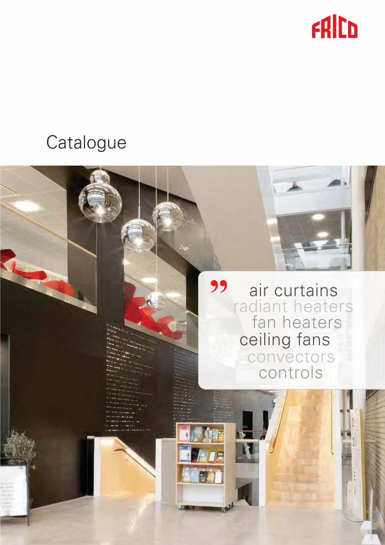
Comfort and energy saving
Design and specifications are subject to change without notice.
See www.frico.se for latest updated info.
The cover shows the library in Gothenburg, Sweden.
Photo: Sanna Lundberg.
Frico's PA3500 air curtains are installed in the entrance and provide both comfort and energy savings in
the library.

2
Frico saves energy Thanks to our broad product range and our many years of experience, Frico is able to help you save energy. By offering total solutions, including both complete heating systems and products for additional heating, we can generate a comfortable indoor climate at a low energy cost. Our regulation systems for different levels ensure that you never use more energy than is required. Through our parent company, Systemair, we also possess knowledge about ventilation and can provide appropriate solutions.
Climate-smartAt Frico, we are proud to be able to offer energy-efficient products for a better indoor climate. In our product development work, the focus is on achieving the greatest possible function with the least possible energy consumption – without compromising on our core values of trust, competence and design.
This means that our products not only manage the local climate in business complexes, industrial buildings, offices or summer cottages; with optimum energy efficiency, we ensure that our products are climate-smart.
Good reasons to choose Frico
Frico's headoffice is located outside Gothenburg in Sweden and we are a part of the Systemair Group. Today Frico is represented in 70 countries world wide either by subsidiaries or distributors. Updated information is always available on our website www.frico.se.
We manufacture at production units in Skinnskatteberg, Sweden and at other ISO-certified production units in Europe. Our warehouses are strategically placed in several places in Europe.
More than 80 years experience in developing products for the varied Nordic climate has provided us with a unique knowledge bank. This is our foundation when creating today's energy efficient solutions for a comfortable indoor climate.
Leading technology and design Today Frico is the leading supplier of air curtains, radiant heaters and fan heaters in Europe, and the products are designed according to good Scandinavian tradition. As market leaders we run development and offer both electrical and water heated products and also air curtains without heat. For our air curtains the Thermozone Technology guarantee efficient separation with minimum use of energy and a low sound level.
Keeping our promises Frico has access to one of Europe's most modern and advanced air and sound laboratories. It helps us to ensure that our products deliver what we promise. We regularly carry out tests and measurements during the development of new products, but also to improve existing products. The measurements are carried out according to the AMCA and ISO standards.
Frico AcademyFrico Academy is an important platform for networking and sharing inspiration and knowledge between us and our distributors around the world. Through the Frico Academy we share our knowledge on theory and technology, as well as product knowledge and experience in manufacturing and product development.

3
Air curtains It makes sound economic sense to create an efficient and invisible door that keeps the heat inside. Air curtains can be even more effective when used in air conditioned or cold storage buildings.
Thermozone technology with its precisely adjusted air velocity gives even protection throughout the opening. Frico air curtains provide the most efficient separation with the lowest possible energy consumption, regardless of whether it is the heat or the cold that you want to keep inside. Radiant heaters Frico radiant heaters imitate the sun, the most comfortable and efficient heat source available. The heat is emitted only when the rays hit a surface and the room temperature can thus be lowered while occupants experience a comfortable environment. This makes radiant heaters well suited not only for total heating but also for zone and spot heating, for example to avoid cold draughts from windows.
Radiant heaters are easy to install and require minimum maintenance. They heat directly when switched on and give no air movement.
Fan heaters We are proud of the worldwide fame Frico fan heaters have gained. They are reliable and are designed for long life. Our range covers all needs. The investment cost is low compared to other heating systems.
A great advantage of fan heaters is the option of combining heating and ventilation. Frico fan heaters are compact, silent and light weight. They are available for electrical heating as well as for water heating.
Convectors Convection is the term for the rotating air movement where the air is affected by a heat source. The air is heated - rises upwards - cools and comes back to then be reheated. This gives good comfort through good heat distribution and the warm air flow directed upwards can be used to counteract cold drafts from large glass surfaces.
Ceiling fansCeiling fans force over-heated air from the ceiling down to the occupation zone in premises with high ceilings so that the heat is maximally exploited. The ceiling fans can also be run in reverse, so that cold air can circulate through the room giving it a cooler feel.
Thermostats and controlsThe key to energy efficient heating and good comfort is the combination of heating products and good controls. Frico offers a wide range of thermostats and controls, read more under each product or in the Frico Catalogues.
Energy efficient products for a comfortable indoor climate
The product selection guide at www.frico.se helps you to find the right product and to easily collate all technical data, accessories and heating calculations to your documents.
4
R
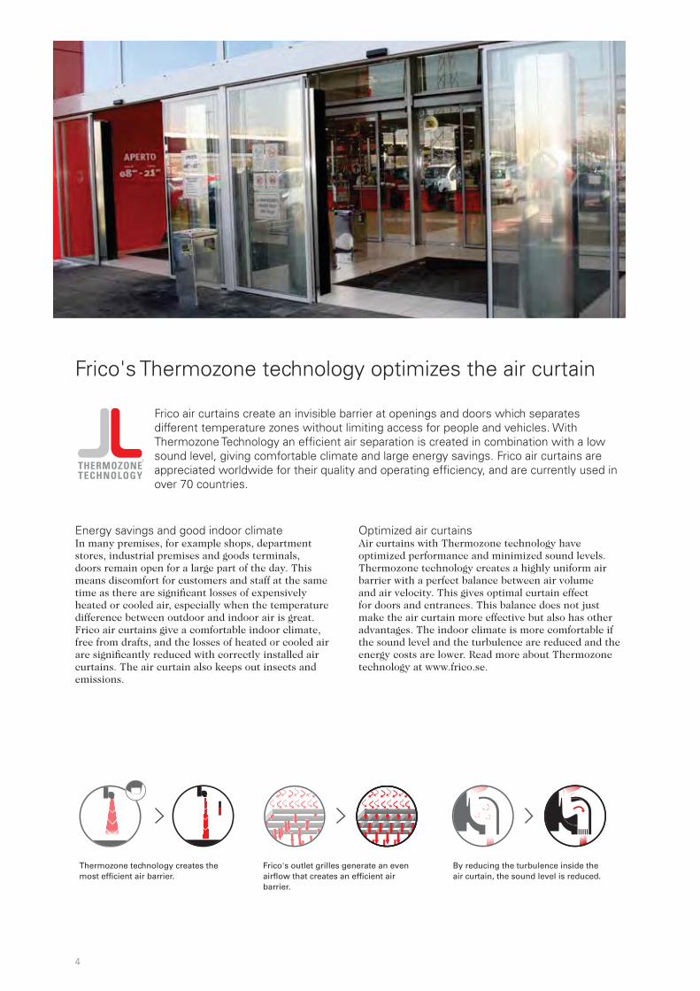
Frico air curtains create an invisible barrier at openings and doors which separates different temperature zones without limiting access for people and vehicles. With Thermozone Technology an efficient air separation is created in combination with a low sound level, giving comfortable climate and large energy savings. Frico air curtains are appreciated worldwide for their quality and operating efficiency, and are currently used in over 70 countries.
Frico's Thermozone technology optimizes the air curtain
Energy savings and good indoor climate In many premises, for example shops, department stores, industrial premises and goods terminals, doors remain open for a large part of the day. This means discomfort for customers and staff at the same time as there are significant losses of expensively heated or cooled air, especially when the temperature difference between outdoor and indoor air is great. Frico air curtains give a comfortable indoor climate, free from drafts, and the losses of heated or cooled air are significantly reduced with correctly installed air curtains. The air curtain also keeps out insects and emissions.
Frico's outlet grilles generate an even airflow that creates an efficient air barrier.
By reducing the turbulence inside the air curtain, the sound level is reduced.
Thermozone technology creates the most efficient air barrier.
Optimized air curtains Air curtains with Thermozone technology have optimized performance and minimized sound levels. Thermozone technology creates a highly uniform air barrier with a perfect balance between air volume and air velocity. This gives optimal curtain effect for doors and entrances. This balance does not just make the air curtain more effective but also has other advantages. The indoor climate is more comfortable if the sound level and the turbulence are reduced and the energy costs are lower. Read more about Thermozone technology at www.frico.se.
5
Air curtains
Correct air velocity Air velocity is too high
Air velocity is too low
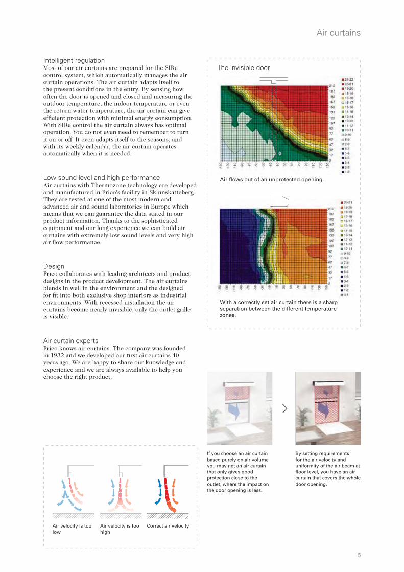
Air flows out of an unprotected opening.
With a correctly set air curtain there is a sharp separation between the different temperature zones.
The invisible door
By setting requirements for the air velocity and uniformity of the air beam at floor level, you have an air curtain that covers the whole door opening.
If you choose an air curtain based purely on air volume you may get an air curtain that only gives good protection close to the outlet, where the impact on the door opening is less.
Intelligent regulation Most of our air curtains are prepared for the SIRe control system, which automatically manages the air curtain operations. The air curtain adapts itself to the present conditions in the entry. By sensing how often the door is opened and closed and measuring the outdoor temperature, the indoor temperature or even the return water temperature, the air curtain can give efficient protection with minimal energy consumption. With SIRe control the air curtain always has optimal operation. You do not even need to remember to turn it on or off. It even adapts itself to the seasons, and with its weekly calendar, the air curtain operates automatically when it is needed.
Low sound level and high performance Air curtains with Thermozone technology are developed and manufactured in Frico's facility in Skinnskatteberg. They are tested at one of the most modern and advanced air and sound laboratories in Europe which means that we can guarantee the data stated in our product information. Thanks to the sophisticated equipment and our long experience we can build air curtains with extremely low sound levels and very high air flow performance.
DesignFrico collaborates with leading architects and product designs in the product development. The air curtains blends in well in the environment and the designed for fit into both exclusive shop interiors as industrial environments. With recessed installation the air curtains become nearly invisible, only the outlet grille is visible.
Air curtain experts Frico knows air curtains. The company was founded in 1932 and we developed our first air curtains 40 years ago. We are happy to share our knowledge and experience and we are always available to help you choose the right product.

6
Air curtains
Choose air curtain For optimal air curtain effect, it is important to choose the right air curtain. We have air curtains for all openings from small kiosk hatches to large industrial doors. They blow from above, from the side or from below. Choose between electrical, water heated or unheated versions.
To get the most out of the product, the following hints are important to bear in mind.
• To ensure that the air flow reaches the floor at the optimal air speed, the installation height (not the height of the opening) determines the choice of air curtain.
• The air curtain units should cover the whole width (or height) of the opening. The air curtains can be obtained in different lengths. For wide (high) openings, several units are mounted beside (on top) of each other.
• The units should be positioned as close to the opening as possible.
• For optimal performance it is important that the pressure difference between outside and inside is not too big.
Our air curtains
1 Ambient, no heat 3 Electrical heat 2 Water heat
Type Recommended Heat Mouting Extra Page
installation height
Entrances
PA2200C 2,2 m 3 2 1 Horizontal Remote control. 8
PA2500 2,5 m 3 2 1 Horizontal SIRe control system. 13
Portier 2,5 m 3 1 Horizontal Brushed stainless steel. 16
AR200 2,5 m 3 2 1 Horizontal Recessed mounting. 18
ADA 2,5 m 1 Horizontal Cable and plug. 33
Commercial
Corinte 3 m 3 2 1 Horizontal/Vertical SIRe control system. Polished, mirror polished or brushed stainless steel.
22
PA3200C 3,2 m 3 2 1 Horizontal Remote control. 10
AR3500 3,5 m 3 2 1 Horizontal Recessed mounting. SIRe control system. 20
PA3500 3,5 m 3 2 1 Horizontal/Vertical SIRe control system. 26
PA4200 4,2 m 3 2 1 Horizontal/Vertical SIRe control system. 28
Industry
AGS5500 5,5 m 2 1 Horizontal SIRe control system. Vertical unit is available as special order. 40
AGI Large doorways 2 1 Horizontal/Vertical 42
UF600 Large doorways 1 Vertical Air barrier blown from below. 44
Specific use
ADA Cool Cold storage 1 Horizontal Special terminales for easy connection of several units. Cable and plug.
34
RDS Revolving doors 3 2 Horizontal For revolving doors. SIRe control system. 36
SFS Revolving doors 3 2 Vertical For revolving doors. SIRe control system. 38
PA1508 Small openings 3 Horizontal Cable and plug. 46
PA1006 Door heater 3 Horizontal Cable and plug. 47
7
Air curtains
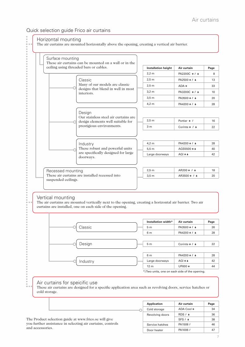
The Product selection guide at www.frico.se will give you further assistance in selecting air curtains, controls and accessories.
Recessed mounting These air curtains are installed recessed into suspended ceilings.
Design Our stainless steel air curtains are design elements well suitable for prestigious environments.
Classic Many of our models are classic designs that blend in well in most interiors.
Surface mounting These air curtains can be mounted on a wall or in the ceiling using threaded bars or cables.
Air curtains for speicific use These air curtains are designed for a specific application area such as revolving doors, service hatches or cold storage.
Industry These robust and powerful units are specifically designed for large doorways.
Quick selection guide Frico air curtains
Classic
Industry
Vertical mounting The air curtains are mounted vertically next to the opening, creating a horizontal air barrier. Two air curtains are installed, one on each side of the opening.
Horizontal mounting The air curtains are mounted horizontally above the opening, creating a vertical air barrier.
*) Two units, one on each side of the opening.
Design
Installation height Air curtain Page
2,2 m PA2200C 1 3 2 8
2,5 m PA2500 1 3 2 13
2,5 m ADA 1 33
3,2 m PA3200C 1 3 2 10
3,5 m PA3500 1 3 2 20
4,2 m PA4200 1 3 2 28
2,5 m Portier 1 3 16
3 m Corinte 1 3 2 22
4,2 m PA4200 1 3 2 28
5,5 m AGS5500 1 2 40
Large doorways AGI 1 2 42
2,5 m AR200 1 3 2 18
3,5 m AR3500 1 3 2 20
Installation width* Air curtain Page
5 m PA3500 1 3 2 26
6 m PA4200 1 3 2 28
5 m Corinte 1 3 2 22
6 m PA4200 1 3 2 28
Large doorways AGI 1 2 42
12 m UF600 1 44
Application Air curtain Page
Cold storage ADA Cool 1 34
Revolving doors RDS 3 2 36
SFS 3 2 38
Service hatches PA1508 3 46
Door heater PA1006 3 47
8
R
Air curtains
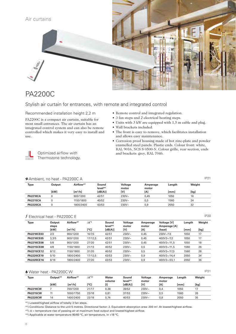
PA2200C
• Remote control and integrated regulation.• 3 fan steps and 2 electrical heating steps.• Units with 3 kW are equipped with 1,5 m cable and plug. • Wall brackets included. • The front is easy to remove, which facilitates installation
and allows easy maintenance. • Corrosion proof housing made of hot zinc-plate and powder
enamelled steel panels. Plastic ends. Colour front: white, RAL 9016, NCS S 0500-N. Colour grille, rear section, ends and brackets: grey, RAL 7046.
Stylish air curtain for entrances, with remote and integrated control
3 Electrical heat - PA2200C E
2 Water heat - PA2200C W
*1) Lowest/highest airflow of totally 3 fan steps. *2) Conditions: Distance to the unit 5 metres. Directional factor: 2. Equivalent absorption area: 200 m². At lowest/highest airflow. *3) t = temperature rise of passing air at maximum heat output and lowest/highest airflow.*4) Applicable at water temperature 80/60 °C, air temperature, in +18 °C.
1 Ambient, no heat - PA2200C A
Optimized airflow with Thermozone technology.
PA2200C is a compact air curtain, suitable for most small entrances. The air curtain has an integrated control system and can also be remote controlled which makes it very easy to install and use.
IP21
IP21
IP20
Recommended installation height 2,2 m
Type Output*4
[kW]
Airflow*1
[m3/h]
t*3,4
[°C]
Water
volume
[l]
Sound
level*2
[dB(A)]
Voltage
motor
[V]
Amperage
motor
[A]
Length
[mm]
Weight
[kg]
PA2210CW 7 700/1200 21/17 0,38 39/52 230V~ 0,4 1050 17
PA2215CW 11 1000/1750 23/18 0,81 37/53 230V~ 0,5 1560 26
PA2220CW 14 1400/2400 22/18 0,74 40/53 230V~ 0,8 2050 35
Type Output
steps
[kW]
Airflow*1
[m3/h]
t*3
[°C]
Sound
level*2
[dB(A)]
Voltage
motor
[V]
Amperage
motor
[A]
Voltage [V]
Amperage [A]
(heat)
Length
[mm]
Weight
[kg]
PA2210CE03 2/3 900/1200 10/7,5 42/51 230V~ 0,45 230V~/13 1050 17
PA2210CE05 3,3/5 900/1200 17/12,5 42/51 230V~ 0,45 400V3~/7,2 1050 17
PA2210CE08 5/8 900/1200 27/20 42/51 230V~ 0,45 400V3~/11,5 1050 18
PA2215CE08 4/8 1150/1800 21/13 40/52 230V~ 0,5 400V3~/11,5 1560 26
PA2215CE12 8/12 1150/1800 31/20 40/52 230V~ 0,5 400V3~/17,3 1560 28
PA2220CE10 5/10 1800/2400 17/12,5 43/53 230V~ 0,9 400V3~/14,4 2050 34
PA2220CE16 8/16 1800/2400 27/20 43/53 230V~ 0,9 400V3~/23,1 2050 36
Type Output
[kW]
Airflow*1
[m3/h]
Sound
level*2
[dB(A)]
Voltage
motor
[V]
Amperage
motor
[A]
Length
[mm]
Weight
[kg]
PA2210CA 0 900/1200 42/51 230V~ 0,45 1050 16
PA2215CA 0 1150/1800 40/52 230V~ 0,5 1560 24
PA2220CA 0 1800/2400 43/53 230V~ 0,9 2050 32

9
5,0
3,7
3,1
2,7
2,4
0,1
0,5
1,0
1,5
2,0
2,5
m6,7
345
min 500 15790,5
10
20
40
210
165
1026 / 1536 / 2026
1050 / 1560 / 2050
Cu ø1553
min 500 min 500157 157
2218
4
71 40
min 500 min 500 157157
Air
curt
ains
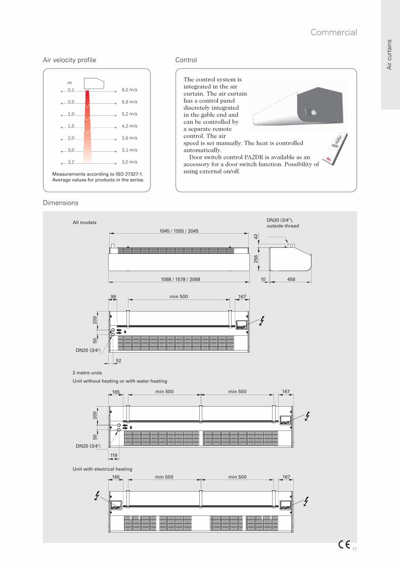
Air velocity profile Control
Dimensions
m/s
m/s
m/s
m/s
m/s
m/s
mThe control system is integrated in the air curtain. The air curtain has a control panel discretely integrated in the gable end and can be controlled by a separate remote control. The air speed is set manually. The heat is controlled automatically.
Door switch control PA2DR is available as an accessory for a door switch function. Possibility of using external on/off.
All models
Unit with electrical heating
Unit without heating or with water heating
2 metre units
Measurements according to ISO 27327-1. Average values for products in the series.
Accessories PA2200C - see PA3200C.
Entrances

10
R
Air curtains
• Remote control and integrated regulation.• 3 fan steps and 2 electrical heating steps.• Wall brackets included. • The front is easy to remove, which facilitates installation
and allows easy maintenance. • Corrosion proof housing made of hot zinc-plate and powder
enamelled steel panels. Plastic ends. Colour front: white, RAL 9016, NCS S 0500-N. Colour grille, rear section, ends and brackets: grey, RAL 7046.
Stylish air curtain for commercial premises, with remote and integrated control
3 Electrical heat - PA3200C E
2 Water heat - PA3200C W
PA3200C is a compact air curtain for commercial buildings and small industrial entrances. The air curtain has an integrated control system and can also be remote controlled which makes it very easy to install and use.
IP21
IP21
IP20
PA3200C
1 Ambient, no heat - PA3200C A
Optimized airflow with Thermozone technology.
Recommended installation height 3,2 m
*1) Lowest/highest airflow of totally 3 fan steps. *2) Conditions: Distance to the unit 5 metres. Directional factor: 2. Equivalent absorption area: 200 m². At lowest/highest airflow. *3) t = temperature rise of passing air at maximum heat output and lowest/highest airflow.*4) Applicable at water temperature 60/40 °C, air temperature, in +18 °C.
Type Output*4
[kW]
Airflow*1
[m3/h]
t*3,4
[°C]
Water
volume
[l]
Sound
level*2
[dB(A)]
Voltage
motor
[V]
Amperage
motor
[A]
Length
[mm]
Weight
[kg]
PA3210CW 8 1050/1700 16/14 1,3 45/55 230V~ 0,65 1068 26
PA3215CW 14 1850/2700 17/15 2,1 46/57 230V~ 0,7 1578 36
PA3220CW 18 2200/3300 18/16 2,7 49/58 230V~ 1,3 2068 48
Type Output
steps
[kW]
Airflow*1
[m3/h]
t*3
[°C]
Sound
level*2
[dB(A)]
Voltage
motor
[V]
Amperage
motor
[A]
Voltage [V]
Amperage [A]
(heat)
Length
[mm]
Weight
[kg]
PA3210CE08 5/8 1100/1750 22/13 46/57 230V~ 0,65 400V3~/11,5 1068 26
PA3215CE12 8/12 1700/2750 21/13 46/59 230V~ 1,0 400V3~/17,3 1578 37
PA3220CE16 10/16 2300/3500 22/13 50/60 230V~ 1,3 400V3~/23,1 2068 51
Type Output
[kW]
Airflow*1
[m3/h]
Sound
level*2
[dB(A)]
Voltage
motor
[V]
Amperage
motor
[A]
Length
[mm]
Weight
[kg]
PA3210CA 0 1100/1750 46/57 230V~ 0,7 1068 22
PA3215CA 0 1700/2750 46/59 230V~ 1,0 1578 32
PA3220CA 0 2300/3500 50/60 230V~ 1,3 2068 42
11
6,8
5,2
4,2
3,1
3,0
0,1
0,5
1,0
1,5
3,0
3,2
m8,0
3,6 2,0
1045 / 1555 / 2045
1068 / 1578 / 2068
4225
6
10 458
167min 50099
209
50
52
DN20 (3/4")
167min 500 min 500165
209
50
119
DN20 (3/4")
min 500 min 500 167165
Air
curt
ains
m/s
m/s
m/s
m/s
m/s
m/s
m/s
m
DN20 (3/4"), outside thread
Commercial
Air velocity profile
Dimensions
The control system is integrated in the air curtain. The air curtain has a control panel discretely integrated in the gable end and can be controlled by a separate remote control. The air speed is set manually. The heat is controlled automatically.
Door switch control PA2DR is available as an accessory for a door switch function. Possibility of using external on/off.
All models
2 metre units
Unit without heating or with water heating
Unit with electrical heating
Measurements according to ISO 27327-1. Average values for products in the series.
Control
12
PAWAK (PA2200C)
PA2DR
PA2PF
PA2PPA3PF PA34TR PAMLK FHDN20 (PA3200C)
PA2EF/PA3EF
Air curtains
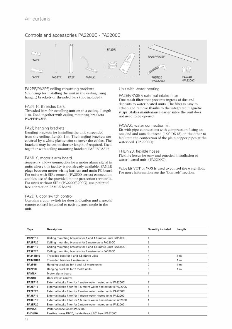
Controls and accessories PA2200C - PA3200C
Unit with water heating
PA2EF/PA3EF, external intake filterFine mesh filter that prevents ingress of dirt and deposits to water heated units. The filter is easy to attach and remove thanks to the integrated magnetic strips. Makes maintenance easier since the unit does not need to be opened. PAWAK, water connection kit Kit with pipe connections with compression fitting on one end and outside thread (1/2” DN15) on the other to facilitate the connection of the plain copper pipes at the water coil. (PA2200C).
FHDN20, flexible hoses Flexible hoses for easy and practical installation of water heated unit. (PA3200C).
Valve kit VOT or VOS is used to control the water flow. For more information see the "Controls" section.
PA2PF/PA3PF, ceiling mounting bracketsMountings for installing the unit in the ceiling using hanging brackets or threaded bars (not included). PA34TR, threaded barsThreaded bars for installing unit on to a ceiling. Length 1 m. Used together with ceiling mounting brackets PA2PF/PA3PF.
PA2P, hanging bracketsHanging brackets for installing the unit suspended from the ceiling. Length 1 m. The hanging brackets are covered by a white plastic trim to cover the cables. The brackets may be cut to shorter length, if required. Used together with ceiling mounting brackets PA2PF/PA3PF.
PAMLK, motor alarm board Accessory allows connection for a motor alarm signal in units where this facility is not already available. PAMLK plugs between motor wiring harness and main PC board. For units with SIRe control (PA2500 series) connection enables use of the provided motor protection terminals. For units without SIRe (PA2200/3200C), use potential free contact on PAMLK board.
PA2DR, door switch controlContains a door switch for door indication and a special remote control intended to activate auto mode in the unit.
Type Description Quantity included Length
PA2PF15 Ceiling mounting brackets for 1 and 1,5 metre units PA2200C 4
PA2PF20 Ceiling mounting brackets for 2 metre units PA2200C 6
PA3PF15 Ceiling mounting brackets for 1 and 1,5 metre units PA3200C 4
PA3PF20 Ceiling mounting brackets for 2 metre units PA3200C 6
PA34TR15 Threaded bars for 1 and 1,5 metre units 4 1 m
PA34TR20 Threaded bars for 2 metre units 6 1 m
PA2P15 Hanging brackets for 1 and 1,5 metre units 2 1 m
PA2P20 Hanging brackets for 2 metre units 3 1 m
PAMLK Motor alarm board 1
PA2DR Door switch control
PA2EF10 External intake filter for 1 metre water heated units PA2200C 1
PA2EF15 External intake filter for 1,5 metre water heated units PA2200C 1
PA2EF20 External intake filter for 2 metre water heated units PA2200C 1
PA3EF10 External intake filter for 1 metre water heated units PA3200C 1
PA3EF15 External intake filter for 1,5 metre water heated units PA3200C 1
PA3EF20 External intake filter for 2 metre water heated units PA3200C 1
PAWAK Water connection kit PA2200C
FHDN20 Flexible hoses DN20, inside thread, 90° bend PA3200C 2
13
R
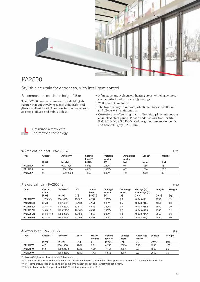
PA2500
• 3 fan steps and 3 electrical heating steps, which give more even comfort and extra energy savings.
• Wall brackets included. • The front is easy to remove, which facilitates installation
and allows easy maintenance. • Corrosion proof housing made of hot zinc-plate and powder
enamelled steel panels. Plastic ends. Colour front: white, RAL 9016, NCS S 0500-N. Colour grille, rear section, ends and brackets: grey, RAL 7046.
Stylish air curtain for entrances, with intelligent control
3 Electrical heat - PA2500 E
2 Water heat - PA2500 W
*1) Lowest/highest airflow of totally 3 fan steps. *2) Conditions: Distance to the unit 5 metres. Directional factor: 2. Equivalent absorption area: 200 m². At lowest/highest airflow. *3) t = temperature rise of passing air at maximum heat output and lowest/highest airflow.*4) Applicable at water temperature 60/40 °C, air temperature, in +18 °C.
1 Ambient, no heat - PA2500 A
Optimized airflow with Thermozone technology.
The PA2500 creates a temperature dividing air barrier that effectively prevents cold drafts and gives excellent heating comfort in door ways, such as shops, offices and public offices.
IP21
IP21
IP20
Recommended installation height 2,5 m
Type Output*4
[kW]
Airflow*1
[m3/h]
t*3,4
[°C]
Water
volume
[l]
Sound
level*2
[dB(A)]
Voltage
motor
[V]
Amperage
motor
[A]
Length
[mm]
Weight
[kg]
PA2510W 4,7 900/1300 12/11 0,71 42/53 230V~ 0,45 1050 17,5
PA2515W 9,2 1250/2100 16/13 1,09 41/54 230V~ 0,6 1560 26
PA2520W 11 1800/2600 15/13 1,42 43/55 230V~ 0,9 2050 35
Type Output
steps
[kW]
Airflow*1
[m3/h]
t*3
[°C]
Sound
level*2
[dB(A)]
Voltage
motor
[V]
Amperage
motor
[A]
Voltage [V]
Amperage [A]
(heat)
Length
[mm]
Weight
[kg]
PA2510E05 1,7/3,3/5 900/1450 17/10,5 42/51 230V~ 0,5 400V3~/7,2 1050 19
PA2510E08 3/5/8 900/1450 27/16,5 42/51 230V~ 0,5 400V3~/11,5 1050 20
PA2515E08 2,7/5,4/8 1400/2200 17,5/11 40/52 230V~ 0,7 400V3~/11,5 1560 30
PA2515E12 3,9/8/12 1400/2200 26/16,5 40/52 230V~ 0,7 400V3~/17,3 1560 32
PA2520E10 3,4/6,7/10 1800/2900 17/10,5 43/53 230V~ 1,0 400V3~/14,4 2050 36
PA2520E16 6/10/16 1800/2900 27/16,5 43/53 230V~ 1,0 400V3~/23,1 2050 40
Type Output
[kW]
Airflow*1
[m3/h]
Sound
level*2
[dB(A)]
Voltage
motor
[V]
Amperage
motor
[A]
Length
[mm]
Weight
[kg]
PA2510A 0 900/1300 43/53 230V~ 0,5 1050 16
PA2515A 0 1250/2100 44/54 230V~ 0,7 1560 23,5
PA2520A 0 1800/2600 44/55 230V~ 1,0 2050 32

14
6,0 m/s
4,5 m/s
3, m/s
3,3 m/s
3,0 m/s
0,1
0,5
1,0
1,5
2,0
2,5
m8,0 m/s
2500 2500 /
5,2 m/s
3,8 m/s
3,2 m/s
2,8 m/s
2,5 m/s
6, m/s
345
min 500 15790,5
1020
40
210
165
1026 / 1536 / 2026
1050 / 1560 / 2050
Cu ø1553
min 500 min 500157 157
2218
4
71 40
min 500 min 500 157157
Air curtains
Air velocity profile Control
SIRe Basic SIRe Competent SIRe Advanced
Dimensions
All models
Unit with electrical heating
Unit without heating or with water heating
2 metre units
Measurements according to ISO 27327-1. Average values for products in the series.
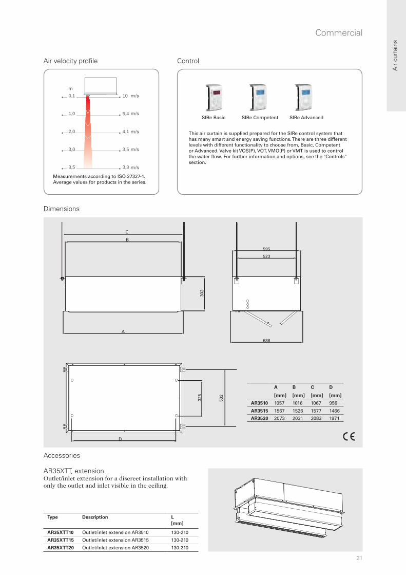
This air curtain is supplied prepared for the SIRe control system that has many smart and energy saving functions. There are three different levels with different functionality to choose from, Basic, Competent or Advanced. Valve kit VOS(P), VOT, VMO(P) or VMT is used to control the water flow. For further information and options, see the "Controls" section.

15
PA2PPA34TR PAMLKPA2PF PA2EF PAWAK
Air
curt
ains
Entrances
Accessories
Unit with water heating
PA2PF, ceiling mounting bracketsMountings for installing the unit in the ceiling using hanging brackets or threaded bars (not included). PA34TR, threaded barsThreaded bars for installing unit on to a ceiling. Length 1 m. Used together with ceiling mounting brackets PA2PF/PA3PF. PA2P, hanging bracketsHanging brackets for installing the unit suspended from the ceiling. Length 1 m. The hanging brackets are covered by a white plastic trim to cover the cables. The brackets may be cut to shorter length, if required. Used together with ceiling mounting brackets PA2PF/PA3PF.
PAMLK, motor alarm board Accessory allows connection for a motor alarm signal in units where this facility is not already available. PAMLK plugs between motor wiring harness and main PC board. For units with SIRe control (PA2500 series) connection enables use of the provided motor protection terminals. For units without SIRe (PA2200/3200C), use potential free contact on PAMLK board.
PA2EF, external intake filterFine mesh filter that prevents ingress of dirt and deposits to water heated units. The filter is easy to attach and remove thanks to the integrated magnetic strips. Makes maintenance easier since the unit does not need to be opened. PAWAK, water connection kit Kit with pipe connections with compression fitting on one end and outside thread (1/2” DN15) on the other to facilitate the connection of the plain copper pipes at the water coil.
Type Description Quantity included Length
PA2PF15 Ceiling mounting brackets for 1 and 1,5 metre units 4
PA2PF20 Ceiling mounting brackets for 2 metre units 6
PA34TR15 Threaded bars for 1 and 1,5 metre units 4 1 m
PA34TR20 Threaded bars for 2 metre units 6 1 m
PA2P15 Hanging brackets for 1 and 1,5 metre units 2 1 m
PA2P20 Hanging brackets for 2 metre units 3 1 m
PAMLK Motor alarm board 1
PA2EF10 External intake filter for 1 metre water heated units 1
PA2EF15 External intake filter for 1,5 metre water heated units 1
PA2EF20 External intake filter for 2 metre water heated units 1
PAWAK Water connection kit

16
R
Air curtains
Portier
• Low sound level.• Adjustable outlet grille makes it possible to direct the air
for optimum air curtain effect.• Simple suspension using fixing nuts on the upper side for
installation with wall brackets, suspension kit or wire/threaded rod.
• Housing in brushed stainless steel. Colour outlet grille and ends: black, RAL 9005.
Design air curtain for entrances
Portier is an exclusive air curtain in brushed stainless steel intended for entrance doors in e.g. shops, banks, hotels and restaurants. The elegant design of the air curtain makes it particularly suitable for environments where demands are made on a high standard of design.
IP211 Ambient, no heat - Portier A
3 Electrical heat - Portier E
*1) Conditions: Distance to the unit 5 metres. Directional factor: 2. Equivalent absorption area: 200 m². *2) t = temperature rise of passing air at maximum heat output and highest airflow. *3) Alternative 400 V3~ + 230 V~ (operating supply) if the current is greater than 16 A. Applies when connecting several units.
Approved for 220V/1ph/60Hz and 380V/3ph/60Hz. Product performance for 220V/1ph/60Hz and 380V/3ph/60Hz will differ from stated data.
IP21
Optimized airflow with Thermozone technology.
Recommended installation height 2,5 m
Type Output steps
[kW]
Airflow
[m3/h]
t*2
[°C]
Sound level
[dB(A)]*1
Voltage
[V]
Amperage
[A]
Length
[mm]
Weight
[kg]
PS210E03 1,5/3 1200 8 50 230V~/400V3N~*3 13,4/4,8 1020 17
PS210E06 3/6 1200 15 50 400V3N~*3 9,2 1020 17
PS210E09 4,5/9 1200 23 50 400V3N~*3 13,5 1020 17
PS215E09 4,5/9 1900 14 50 400V3N~*3 13,5 1530 24
PS215E14 6,7/13,5 1900 21 50 400V3~ + 230V~ 20,0 1530 24
Type Output
[kW]
Airflow
[m3/h]
Sound level
[dB(A)]*1
Voltage
[V]
Amperage
[A]
Length
[mm]
Weight
[kg]
PS210A 0 1300 54 230V~ 0,45 1020 14
PS215A 0 2000 56 230V~ 0,55 1530 20
17
6,6
4,2
3,8
3,2
2,8
2,6
0,1
0,5
1,0
1,5
2,0
2,5
m
PS210 1020, PS215 1530
PS210 816, PS215 1335
291
138
280
M6 (4x)
K-O ø29
K-O ø23
111
9610
0
P2WB ADPK1 ADPF1P2JK
RTI2 MDCCB20 CB22A
ir cu
rtai
ns
Entrances
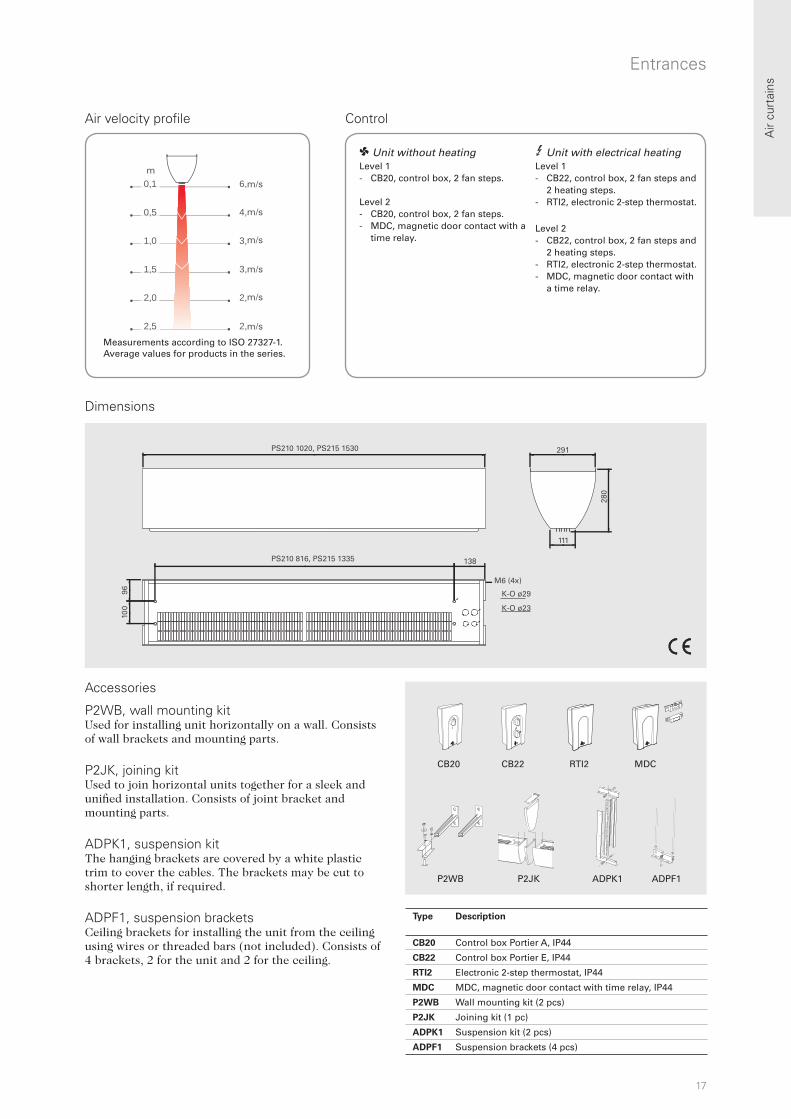
Air velocity profile Control
Dimensions
m/s
m/s
m/s
m/s
m/s
m/s
m
3 Unit with electrical heating Level 1 - CB22, control box, 2 fan steps and
2 heating steps. - RTI2, electronic 2-step thermostat.
Level 2 - CB22, control box, 2 fan steps and
2 heating steps. - RTI2, electronic 2-step thermostat. - MDC, magnetic door contact with
a time relay.
P2WB, wall mounting kitUsed for installing unit horizontally on a wall. Consists of wall brackets and mounting parts. P2JK, joining kitUsed to join horizontal units together for a sleek and unified installation. Consists of joint bracket and mounting parts. ADPK1, suspension kit The hanging brackets are covered by a white plastic trim to cover the cables. The brackets may be cut to shorter length, if required.
ADPF1, suspension bracketsCeiling brackets for installing the unit from the ceiling using wires or threaded bars (not included). Consists of 4 brackets, 2 for the unit and 2 for the ceiling.
Accessories
Measurements according to ISO 27327-1. Average values for products in the series.
1 Unit without heating Level 1 - CB20, control box, 2 fan steps.
Level 2 - CB20, control box, 2 fan steps. - MDC, magnetic door contact with a
time relay.
Type Description
CB20 Control box Portier A, IP44
CB22 Control box Portier E, IP44
RTI2 Electronic 2-step thermostat, IP44
MDC MDC, magnetic door contact with time relay, IP44
P2WB Wall mounting kit (2 pcs)
P2JK Joining kit (1 pc)
ADPK1 Suspension kit (2 pcs)
ADPF1 Suspension brackets (4 pcs)

18
Air curtains
AR200
• Just one model per length, but electrical units are convertible between several outputs and 230V~/400V3N~ making it simple and flexible to adapt the output to current need.
• Low unit height (200 mm). • Bottom plate in white lacquered aluminium.
Colour: RAL 9016, NCS S 0500-N. The bottom plate can easily be removed and painted in an optional colour. Non visible parts made of hot zinc plated steel panels.
Recessed air curtain for smaller entrances
3 Electrical heat - AR200 E
2 Water heat - AR200 W
*1) Lowest/highest airflow of totally 3 fan steps. *2) Conditions: Distance to the unit 5 metres. Directional factor: 2. Equivalent absorption area: 200 m². At lowest/highest airflow. *3) t = temperature rise of passing air at maximum heat output and lowest/highest airflow.*4) Applicable at water temperature 80/60 °C, air temperature, in +18 °C. Approved for 220V/1ph/60Hz and 380V/3ph/60Hz. Product performance for 220V/1ph/60Hz and 380V/3ph/60Hz will differ from stated data.
1 Ambient, no heat - AR200 A
AR200 is a compact air curtain, suitable for most small entrances. A low height makes it possible to install AR200 where ceiling space is limited. The recessed installation and low sound level makes AR200 very discreet.
IP20
IP20
IP20
Recommended installation height 2,5 m
Type Output
[kW]
Airflow*1
[m3/h]
Sound level*2
[dB(A)]
Voltage
[V]
Amperage
[A]
Length
[mm]
Weight
[kg]
AR210A 0 650/1200 34/50 230V~ 0,5 1042 18
AR215A 0 950/1750 34/50 230V~ 0,6 1552 25
AR220A 0 1300/2400 40/54 230V~ 1,0 2042 36
Type Output steps
400V3N~
[kW]
Output steps
230V~
[kW]
Airflow*1
[m3/h]
t*3
[°C]
Sound
level*2
[dB(A)]
Voltage
[V]
Amperage
400V3N~
[A]
Amperage
230V~
[A]
Length
[mm]
Weight
[kg]
AR210E09 3 - 650/1200 13/7 34/50 400V3N~ 4,3 - 1042 23
6/9 - 650/1200 41/22 34/50 400V3N~ 13 - 1042 23
- 3 650/1200 13/7 34/50 230V~ - 13 1042 23
- 3/5 650/1200 23/12 34/50 230V~ - 22 1042 23
AR215E11 4,5 - 950/1750 14/8 34/50 400V3N~ 6,5 - 1552 32
6,8/11,3 - 950/1750 35/20 34/50 400V3N~ 16 - 1552 32
- 4,5 950/1750 14/8 34/50 230V~ - 20 1552 32
- 4,5/6,8 950/1750 21/12 34/50 230V~ - 30 1552 32
AR220E18 6 - 1300/2400 13/7 40/54 400V3N~ 8,7 - 2042 44
12/18 - 1300/2400 41/22 40/54 400V3N~ 26 - 2042 44
- 6 1300/2400 13/7 40/54 230V~ - 26 2042 44
- 6/10 1300/2400 23/12 40/54 230V~ - 43 2042 44
Type Output*4
[kW]
Airflow*1
[m3/h]
t*3,4
[°C]
Water
volume
[l]
Sound level*2
[dB(A)]
Voltage
[V]
Amperage
[A]
Length
[mm]
Weight
[kg]
AR210W 6,6 700/1000 24/21 0,5 41/49 230V~ 0,4 1042 21
AR215W 10 1000/1600 24/20 0,9 37/50 230V~ 0,6 1552 39
AR220W 13 1400/2000 23/20 1,1 44/53 230V~ 1,0 2042 42

19
6,0 m
4,8 m
3,6 m
3,0 m
2,6 m
2,3 m
0,1
0,5
1,0
1,5
2,0
2,5
m
1002/1512
940/1450
1042/1552
494
449
392
432
210
M8
DN15 (1/2”)
2027
540
2092/96
AR210/215A/E
198
RTI2 MDCT10SCB30N CB32N TVVS20/25 SD20
VRS20/25
SD20AV20/25 TRVS20/25 BPV10JVF20/25
/2003
/2042
/1940
Air
curt
ains
Entrances
Air velocity profile Control
Dimensions
m/s
m/s
m/s
m/s
m/s
m/s
m
Controls
Valve kit VRS20/25 (option: valve TVVS20/25 with actuator SD20) is used to control the water flow.
Measurements according to ISO 27327-1. Average values for products in the series.
3 Unit with electrical heating Level 1 - CB32N, control box, 3 fan steps
and 2 heating steps. - RTI2, electronic 2-step thermostat. Level 2 - CB32N, control box, 3 fan steps
and 2 heating steps. - RTI2, electronic 2-step thermostat. - MDC, magnetic door contact with
a time relay.
1 Unit without heating Level 1 - CB30N, control box, 3 fan steps. 2 Unit with water heating Level 1 - CB30N, control box, 3 fan steps. - T10S, room thermostat IP30. Level 2 - CB30N, control box, 3 fan steps. - RTI2, electronic 2-step thermostat. - MDC, magnetic door contact with a
time relay.
Type Description HxWxD
[mm]
CK01E Control kit Electric level 1 (CB32N, RTI2)
CK02E Control kit Electric level 2 (CB32N, RTI2, MDC)
CK01W Control kit Water level 1 (CB30N, T10)
CK02W Control kit Water level 2 (CB30N, RTI2, MDC)
CB30N Control box AR200A/W, IP44 155x87x43
CB32N Control box AR200E, IP44 155x87x43
T10S Electronic thermostat, IP30 80x80x31
RTI2 Electronic 2-step room thermostat, IP44 155x87x43
MDC Magnetic door contact with time relay, IP44 155x87x43
MDCDC Magnetic door contact
Type Description
VRS20 Valve set DN20
VRS25 Valve set DN25
TVVS20 2-way control valve, DN20
TVVS25 2-way control valve, DN25
SD20 Actuator 230V~
20
R
Air curtains
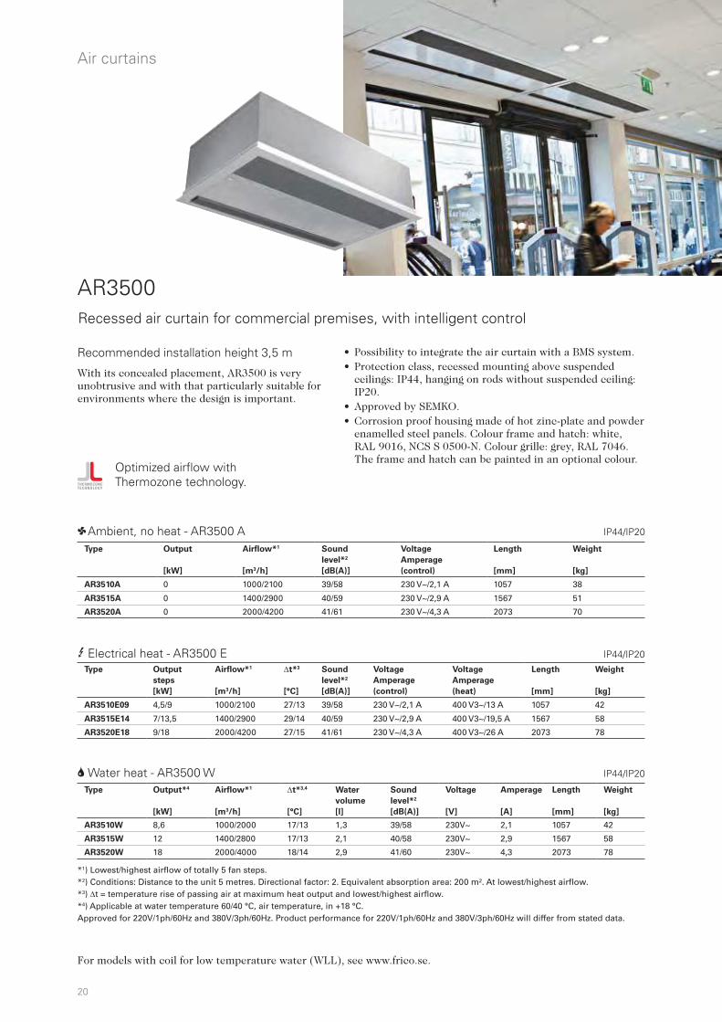
AR3500
• Possibility to integrate the air curtain with a BMS system.• Protection class, recessed mounting above suspended
ceilings: IP44, hanging on rods without suspended ceiling: IP20.
• Approved by SEMKO. • Corrosion proof housing made of hot zinc-plate and powder
enamelled steel panels. Colour frame and hatch: white, RAL 9016, NCS S 0500-N. Colour grille: grey, RAL 7046. The frame and hatch can be painted in an optional colour.
Recessed air curtain for commercial premises, with intelligent control
3 Electrical heat - AR3500 E
2 Water heat - AR3500 W
1 Ambient, no heat - AR3500 A
Optimized airflow with Thermozone technology.
With its concealed placement, AR3500 is very unobtrusive and with that particularly suitable for environments where the design is important.
IP44/IP20
Recommended installation height 3,5 m
*1) Lowest/highest airflow of totally 5 fan steps. *2) Conditions: Distance to the unit 5 metres. Directional factor: 2. Equivalent absorption area: 200 m². At lowest/highest airflow. *3) t = temperature rise of passing air at maximum heat output and lowest/highest airflow.*4) Applicable at water temperature 60/40 °C, air temperature, in +18 °C. Approved for 220V/1ph/60Hz and 380V/3ph/60Hz. Product performance for 220V/1ph/60Hz and 380V/3ph/60Hz will differ from stated data.
IP44/IP20
IP44/IP20
For models with coil for low temperature water (WLL), see www.frico.se.
Type Output*4
[kW]
Airflow*1
[m3/h]
t*3,4
[°C]
Water
volume
[l]
Sound
level*2
[dB(A)]
Voltage
[V]
Amperage
[A]
Length
[mm]
Weight
[kg]
AR3510W 8,6 1000/2000 17/13 1,3 39/58 230V~ 2,1 1057 42
AR3515W 12 1400/2800 17/13 2,1 40/58 230V~ 2,9 1567 58
AR3520W 18 2000/4000 18/14 2,9 41/60 230V~ 4,3 2073 78
Type Output
steps
[kW]
Airflow*1
[m3/h]
t*3
[°C]
Sound
level*2
[dB(A)]
Voltage
Amperage
(control)
Voltage
Amperage
(heat)
Length
[mm]
Weight
[kg]
AR3510E09 4,5/9 1000/2100 27/13 39/58 230 V~/2,1 A 400 V3~/13 A 1057 42
AR3515E14 7/13,5 1400/2900 29/14 40/59 230 V~/2,9 A 400 V3~/19,5 A 1567 58
AR3520E18 9/18 2000/4200 27/15 41/61 230 V~/4,3 A 400 V3~/26 A 2073 78
Type Output
[kW]
Airflow*1
[m3/h]
Sound
level*2
[dB(A)]
Voltage
Amperage
(control)
Length
[mm]
Weight
[kg]
AR3510A 0 1000/2100 39/58 230 V~/2,1 A 1057 38
AR3515A 0 1400/2900 40/59 230 V~/2,9 A 1567 51
AR3520A 0 2000/4200 41/61 230 V~/4,3 A 2073 70
21
10 m
5,4 m
4,1 m
3,5 m
3,3 m
0,1
1,0
2,0
3,0
3,5
m
A
302
B
C
638
523
595
325
532
D
Air
curt
ains
Commercial
Air velocity profile Control
SIRe Basic SIRe Competent SIRe Advanced
Dimensions
m/s
m/s
m/s
m/s
m/s
m
A
[mm]
B
[mm]
C
[mm]
D
[mm]
AR3510 1057 1016 1067 956
AR3515 1567 1526 1577 1466
AR3520 2073 2031 2083 1971
Accessories
AR35XTT, extensionOutlet/inlet extension for a discreet installation with only the outlet and inlet visible in the ceiling.
This air curtain is supplied prepared for the SIRe control system that has many smart and energy saving functions. There are three different levels with different functionality to choose from, Basic, Competent or Advanced. Valve kit VOS(P), VOT, VMO(P) or VMT is used to control the water flow. For further information and options, see the "Controls" section.
Measurements according to ISO 27327-1. Average values for products in the series.
Type Description L
[mm]
AR35XTT10 Outlet/inlet extension AR3510 130-210
AR35XTT15 Outlet/inlet extension AR3515 130-210
AR35XTT20 Outlet/inlet extension AR3520 130-210
22
R
,6 m/s
6,5 m/s
4,8 m/s
4,1 m/s
3, m/s
3,4 m/s
3,1 m/s
0,1
0,5
1,0
1,5
2,0
2,5
3,0
m11,0 m/s
6,1 m/s
4,6 m/s
3, m/s
3,6 m/s
3,3 m/s
3,0 m/s
HL HR
A A
B B
Air curtains
Product key
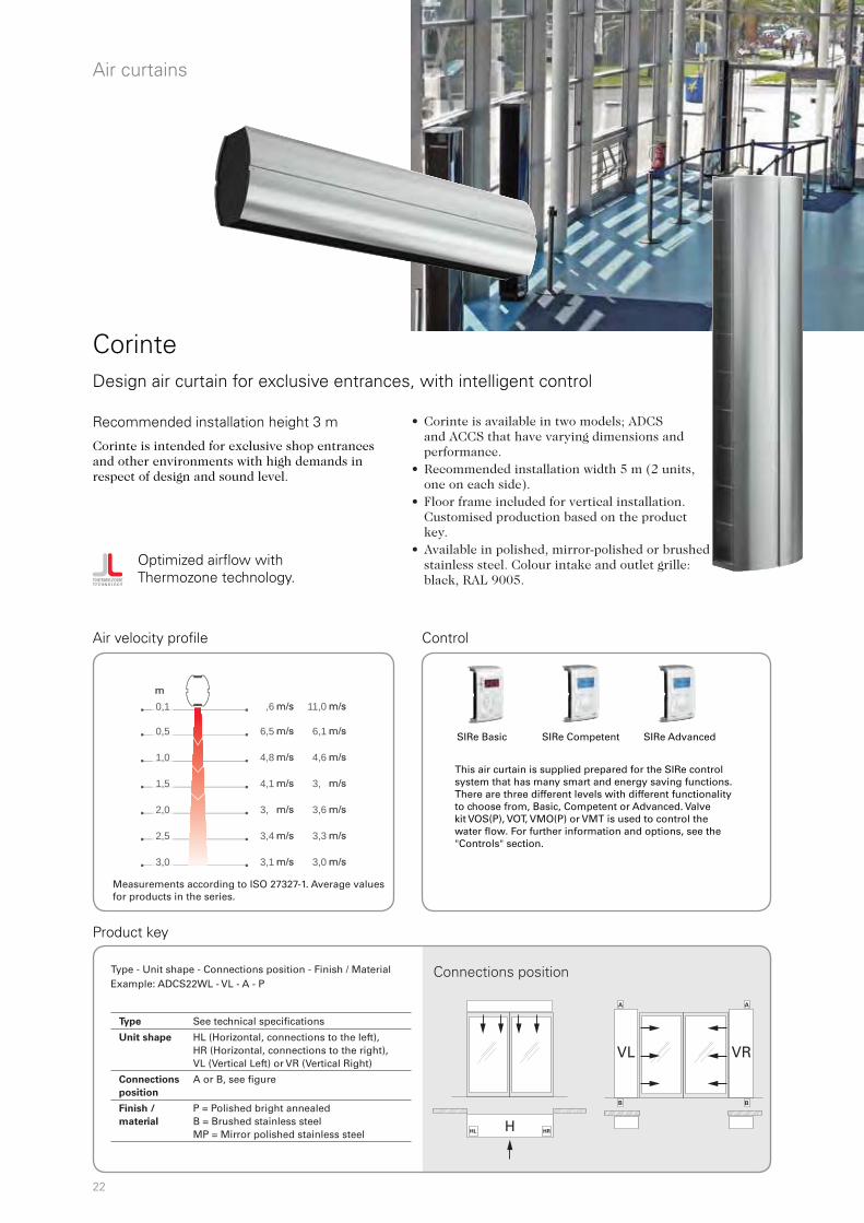
CorinteDesign air curtain for exclusive entrances, with intelligent control
Optimized airflow with Thermozone technology.
Corinte is intended for exclusive shop entrances and other environments with high demands in respect of design and sound level.
Recommended installation height 3 m
Air velocity profile Control
SIRe Basic SIRe Competent SIRe Advanced
This air curtain is supplied prepared for the SIRe control system that has many smart and energy saving functions. There are three different levels with different functionality to choose from, Basic, Competent or Advanced. Valve kit VOS(P), VOT, VMO(P) or VMT is used to control the water flow. For further information and options, see the "Controls" section.
m/s
m/s
m/s
m/s
m/s
m/s
m/s
m
m/s
m/s
m/s
m/s
m/s
m/s
m/s
m/s
m/s
m/s
m/s
m/s
m/s
m/s
m
m/s
m/s
m/s
m/s
m/s
m/s
m/s
Connections position
• Corinte is available in two models; ADCS and ACCS that have varying dimensions and performance.
• Recommended installation width 5 m (2 units, one on each side).
• Floor frame included for vertical installation. Customised production based on the product key.
• Available in polished, mirror-polished or brushed stainless steel. Colour intake and outlet grille: black, RAL 9005.
Measurements according to ISO 27327-1. Average values for products in the series.
Type - Unit shape - Connections position - Finish / MaterialExample: ADCS22WL - VL - A - P
Type See technical specifications
Unit shape HL (Horizontal, connections to the left), HR (Horizontal, connections to the right), VL (Vertical Left) or VR (Vertical Right)
Connections
position
A or B, see figure
Finish /
material
P = Polished bright annealed B = Brushed stainless steel MP = Mirror polished stainless steel

23
Air
curt
ains
3 Electrical heat - ADCS E
2 Water heat - ADCS WL, coil for low water temperature (480 °C)
1 Ambient, no heat - ADCS A IP20
IP20
IP20
Commercial
3 Electrical heat - ACCS E
2 Water heat - ACCS WL, coil for low water temperature (480 °C)
IP20
IP20
For models with coil for high temperature water (WH), see www.frico.se.
*1) Available only for horizontal mounting. *2) Available only for vertical mounting. *3) Lowest/highest airflow of totally 5 fan steps.*4) Conditions: Distance to the unit 5 metres. Directional factor: 2. Equivalent absorption area: 200 m². At lowest/highest airflow. *5) t = temperature rise of passing air at maximum heat output and lowest/highest airflow.*6) Applicable at water temperature 60/40 °C, air temperature, in +18 °C.
*1) Available only for horizontal mounting. *2) Lowest/highest airflow of totally 5 fan steps. *3) Conditions: Distance to the unit 5 metres. Directional factor: 2. Equivalent absorption area: 200 m². At lowest/highest airflow. *4) t = temperature rise of passing air at maximum heat output and lowest/highest airflow.*5) Applicable at water temperature 60/40 °C, air temperature, in +18 °C. *6) Horizontal mounting*7) Vertical mounting
Type Output*6
[kW]
Airflow*3
[m3/h]
t*5,6
[°C]
Water
volume
[l]
Sound
level*4
[dB(A)]
Output-
motor
[W]
Voltage
motor
[V]
Amperage
motor
[A]
Length
[mm]
Weight
[kg]
ADCS17WL*¹ 17 1400/3000 22/17 2,8 39/59 670 230V~ 2,9 1700 85
ADCS22WL 24 1800/4000 23/18 3,6 42/60 990 230V~ 4,3 2200 110
ADCS25WL*² 28 2050/4500 24/18 4,0 42/61 1150 230V~ 5,0 2450 125
Type Output
steps
[kW]
Airflow*3
[m3/h]
t*4
[°C]
Sound
level*4
[dB(A)]
Output-
motor
[W]
Voltage
motor
[V]
Amperage
motor
[A]
Voltage [V]
Amperage [A]
(heat)
Length
[mm]
Weight
[kg]
ADCS17E*¹ 7,5/15 1400/3000 32/15 40/60 670 230V~ 2,9 400V3~/21,7 1700 73
ADCS22E 10/20 1800/3600 33/15 42/61 830 230V~ 3,6 400V3~/28,9 2200 95
ADCS25E*² 11,2/22,5 2050/4100 33/15 43/63 990 230V~ 4,3 400V3~/32,5 2450 108
Type Output
[kW]
Airflow*3
[m3/h]
Sound
level*3
[dB(A)]
Output-
motor
[W]
Voltage
motor
[V]
Amperage
motor
[A]
Length
[mm]
Weight
[kg]
ADCS17A*¹ 0 1400/3000 40/60 670 230V~ 2,9 1700 73
ADCS22A 0 1800/4000 42/61 990 230V~ 4,3 2200 95
ADCS25A*² 0 2050/4500 43/63 1150 230V~ 5,0 2450 108
Type Output*5 Airflow*2 t*4,5 Water volume Sound Voltage Amperage Length Weight
H*6
[kW]
V*7
[kW]
[m3/h]
H*6
[°C]
V*7
[°C]
H*6
[l]
V*7
[l]
level*3
[dB(A)]
motor
[V]
motor
[A]
[mm]
[kg]
ACCS10WL*¹ 9 - 950/1900 18/14 - 1,1 - 44/61 230V~ 2,1 1000 50
ACCS15WL*¹ 17 - 1350/2600 24/19 - 1,9 - 45/62 230V~ 2,9 1500 65
ACCS20WL 23 23 1980/3800 23/18 22/18 2,5 4,4 47/64 230V~ 4,3 2000 95
ACCS25WL 29 26 2340/4500 24/19 21/17 3,3 4,4 48/65 230V~ 5,0 2500 110
ACCS30WL 34 31 2660/5100 25/20 22/18 3,9 5,6 48/65 230V~ 5,7 3000 130
Type Outout
steps
[kW]
Airflow*2
[m3/h]
t*4
[°C]
Sound
level*3
[dB(A)]
Voltage
motor
[V]
Amperage
motor
[A]
Voltage [V]
Amperage [A]
(heat)
Length
[mm]
Weight
[kg]
ACCS10E08*¹ 2,7/5,4/8,1 950/1900 25/13 44/61 230V~ 2,2 400V3~/11,7 1000 50
ACCS15E12*¹ 3,9/7,8/12 1350/2600 26/13 45/62 230V~ 2,9 400V3~/16,9 1500 65
ACCS20E16 5,4/11/16 1980/3800 24/13 47/64 230V~ 4,3 400V3~/23,4 2000 95
ACCS25E20 6,6/13/20 2340/4500 25/13 48/65 230V~ 5,1 400V3~/28,6 2500 110
ACCS30E23 7,8/15/23 2660/5100 26/14 48/65 230V~ 5,8 400V3~/33,8 3000 130
24
AXP300ADCSEH ADCM P/S
M8 M8
Cu ø22
VL - A
VL - B
VR - A
VR - B
Min 180
225 12
5
72116
Min 180
225125
72116
100
87
126
150
500
350
376
75
1700/2200
1666/2166
126
150
2200
/245
0
500 350
Air curtains
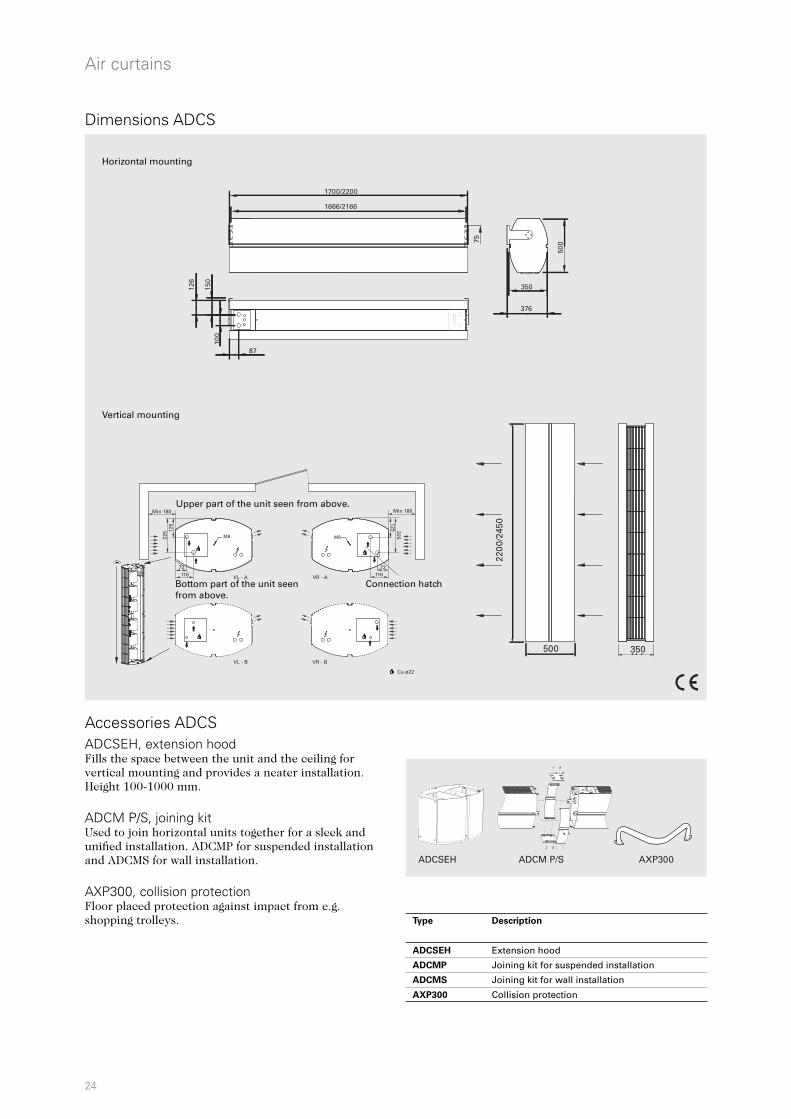
ADCSEH, extension hoodFills the space between the unit and the ceiling for vertical mounting and provides a neater installation. Height 100-1000 mm.
ADCM P/S, joining kitUsed to join horizontal units together for a sleek and unified installation. ADCMP for suspended installation and ADCMS for wall installation.
AXP300, collision protectionFloor placed protection against impact from e.g. shopping trolleys.
Accessories ADCS
Dimensions ADCS
Vertical mounting
Horizontal mounting
Upper part of the unit seen from above.
Bottom part of the unit seen from above.
Connection hatch
Type Description
ADCSEH Extension hood
ADCMP Joining kit for suspended installation
ADCMS Joining kit for wall installation
AXP300 Collision protection

25
L
400 314
50
206
148
103
220 93
L
[mm]
ACCS10* 1000
ACCS15* 1500
ACCS20 2000
ACCS25 2500
ACCS30 3000
L
400
314
105
207
78
115
M8 M8 105
207
78
115VL - A VR - A
VL - B VR - B
AXP300ACCSEHACCW
FH1025
Air
curt
ains
Commercial
Dimensions ACCS
ACCW, wall bracketBrackets for installing unit horizontally on a wall. Two are required for 1 and 1.5 metre units, while 2 and 2.5 metre units need three and 3 metre units need four.Available in three designs:- ACCWBB, brushed stainless steel- ACCWBP, polished stainless steel- ACCWBMP, mirror polished stainless steel ACCSEH, extension hoodFills the space between the unit and the ceiling for vertical mounting and provides a neater installation. Height 100-1000 mm. AXP300, collision protectionFloor placed protection against impact from e.g. shopping trolleys.
FH1025, flexible hoseFlexible hose (DN25, 1" inside/outside thread) for easy connection to the pipe system.
Accessories ACCS
Horizontal mounting
Vertical mounting
Upper part of the unit seen from above.
Bottom part of the unit seen from above.
Connection dimensions, inside thread: 1", DN25
Connection dimensions, inside thread: 3/4", DN20
*1) Available only for horizontal mounting.
Type Description
ACCWBB Wall bracket, brushed stainless steel
ACCWBP Wall bracket, polished stainless steel
ACCWBMP Wall bracket, mirror polished stainless steel
ACCSEH Extension hood 100-1000 mm
AXP300 Collision protection
FH1025 Flexible hose DN25, inside/outside thread, length 1 m
26
R
Air curtains
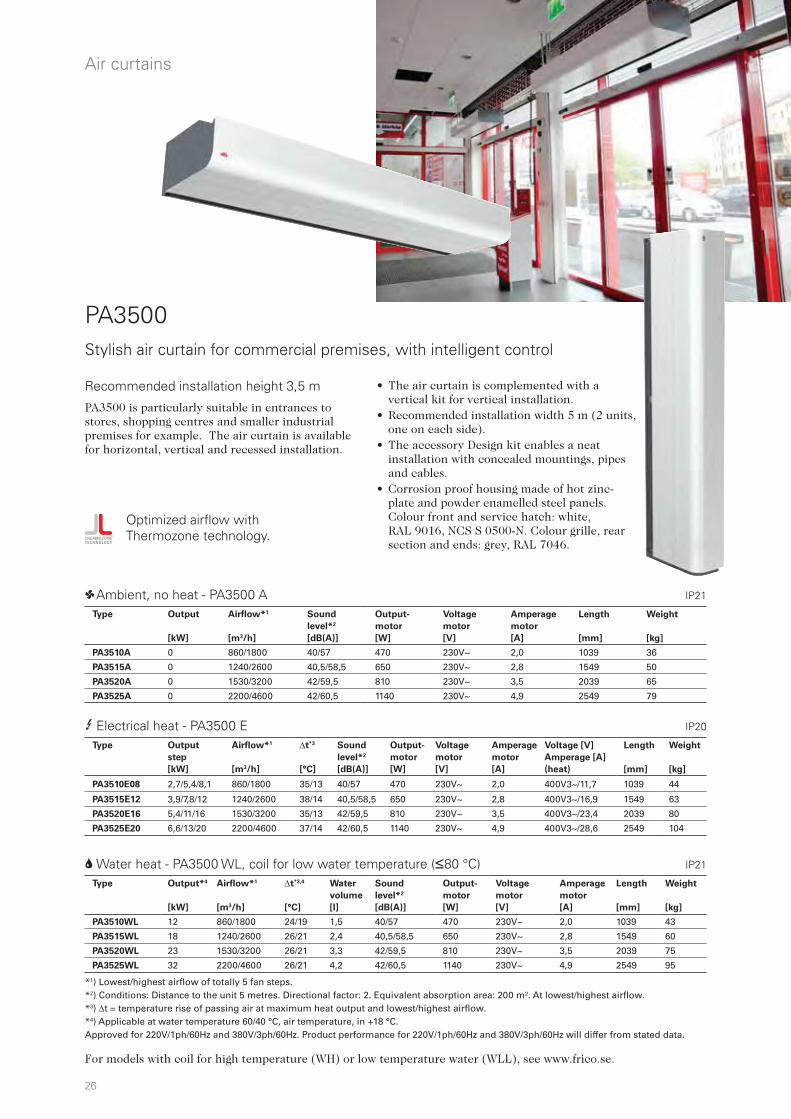
PA3500Stylish air curtain for commercial premises, with intelligent control
3 Electrical heat - PA3500 E
2 Water heat - PA3500 WL, coil for low water temperature (480 °C)
1 Ambient, no heat - PA3500 A
Optimized airflow with Thermozone technology.
PA3500 is particularly suitable in entrances to stores, shopping centres and smaller industrial premises for example. The air curtain is available for horizontal, vertical and recessed installation.
IP21
IP21
IP20
Recommended installation height 3,5 m
*1) Lowest/highest airflow of totally 5 fan steps. *2) Conditions: Distance to the unit 5 metres. Directional factor: 2. Equivalent absorption area: 200 m². At lowest/highest airflow. *3) t = temperature rise of passing air at maximum heat output and lowest/highest airflow.*4) Applicable at water temperature 60/40 °C, air temperature, in +18 °C. Approved for 220V/1ph/60Hz and 380V/3ph/60Hz. Product performance for 220V/1ph/60Hz and 380V/3ph/60Hz will differ from stated data.
• The air curtain is complemented with a vertical kit for vertical installation.
• Recommended installation width 5 m (2 units, one on each side).
• The accessory Design kit enables a neat installation with concealed mountings, pipes and cables.
• Corrosion proof housing made of hot zinc-plate and powder enamelled steel panels. Colour front and service hatch: white, RAL 9016, NCS S 0500-N. Colour grille, rear section and ends: grey, RAL 7046.
For models with coil for high temperature (WH) or low temperature water (WLL), see www.frico.se.
Type Output*4
[kW]
Airflow*1
[m3/h]
t*3,4
[°C]
Water
volume
[l]
Sound
level*2
[dB(A)]
Output-
motor
[W]
Voltage
motor
[V]
Amperage
motor
[A]
Length
[mm]
Weight
[kg]
PA3510WL 12 860/1800 24/19 1,5 40/57 470 230V~ 2,0 1039 43
PA3515WL 18 1240/2600 26/21 2,4 40,5/58,5 650 230V~ 2,8 1549 60
PA3520WL 23 1530/3200 26/21 3,3 42/59,5 810 230V~ 3,5 2039 75
PA3525WL 32 2200/4600 26/21 4,2 42/60,5 1140 230V~ 4,9 2549 95
Type Output
step
[kW]
Airflow*1
[m3/h]
t*3
[°C]
Sound
level*2
[dB(A)]
Output-
motor
[W]
Voltage
motor
[V]
Amperage
motor
[A]
Voltage [V]
Amperage [A]
(heat)
Length
[mm]
Weight
[kg]
PA3510E08 2,7/5,4/8,1 860/1800 35/13 40/57 470 230V~ 2,0 400V3~/11,7 1039 44
PA3515E12 3,9/7,8/12 1240/2600 38/14 40,5/58,5 650 230V~ 2,8 400V3~/16,9 1549 63
PA3520E16 5,4/11/16 1530/3200 35/13 42/59,5 810 230V~ 3,5 400V3~/23,4 2039 80
PA3525E20 6,6/13/20 2200/4600 37/14 42/60,5 1140 230V~ 4,9 400V3~/28,6 2549 104
Type Output
[kW]
Airflow*1
[m3/h]
Sound
level*2
[dB(A)]
Output-
motor
[W]
Voltage
motor
[V]
Amperage
motor
[A]
Length
[mm]
Weight
[kg]
PA3510A 0 860/1800 40/57 470 230V~ 2,0 1039 36
PA3515A 0 1240/2600 40,5/58,5 650 230V~ 2,8 1549 50
PA3520A 0 1530/3200 42/59,5 810 230V~ 3,5 2039 65
PA3525A 0 2200/4600 42/60,5 1140 230V~ 4,9 2549 79
27
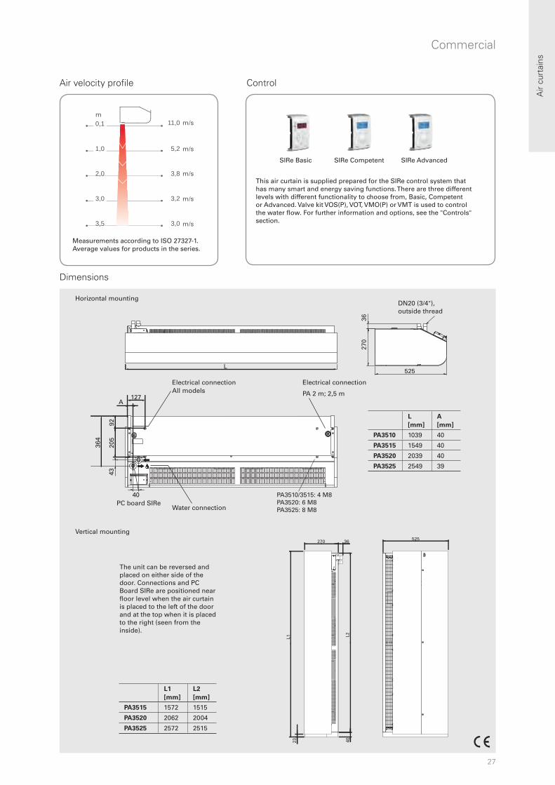
11,0 m
5,2 m
3,8 m
3,2 m
3,0 m
0,1
1,0
2,0
3,0
3,5
m
525L
270
36
43
40
127
PA3510/3515: 4 M8PA3520: 6 M8PA3525: 8 M8
205
92
364
A
270 36 525
L1 L2
23 40
Air
curt
ains
Horizontal mounting
Commercial
Air velocity profile Control
SIRe Basic SIRe Competent SIRe Advanced
Dimensions
m/s
m/s
m/s
m/s
m/s
m
L
[mm]
A
[mm]
PA3510 1039 40
PA3515 1549 40
PA3520 2039 40
PA3525 2549 39
DN20 (3/4"), outside thread
Electrical connection All models
Water connection PC board SIRe
PA 2 m; 2,5 m
L1
[mm]
L2
[mm]
PA3515 1572 1515
PA3520 2062 2004
PA3525 2572 2515
The unit can be reversed and placed on either side of the door. Connections and PC Board SIRe are positioned near floor level when the air curtain is placed to the left of the door and at the top when it is placed to the right (seen from the inside).
Measurements according to ISO 27327-1. Average values for products in the series.
This air curtain is supplied prepared for the SIRe control system that has many smart and energy saving functions. There are three different levels with different functionality to choose from, Basic, Competent or Advanced. Valve kit VOS(P), VOT, VMO(P) or VMT is used to control the water flow. For further information and options, see the "Controls" section.
Vertical mounting
Electrical connection
28
R
Air curtains
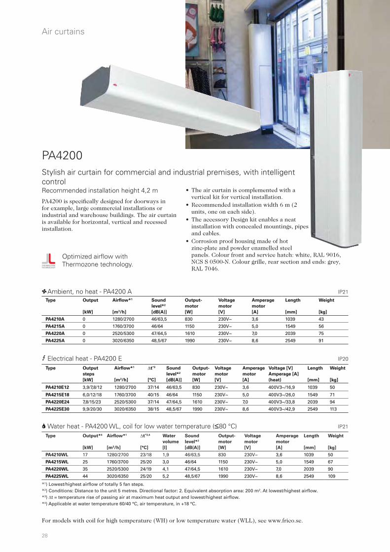
Stylish air curtain for commercial and industrial premises, with intelligent control
3 Electrical heat - PA4200 E
2 Water heat - PA4200 WL, coil for low water temperature (480 °C)
1 Ambient, no heat - PA4200 A
Optimized airflow with Thermozone technology.
PA4200 is specifically designed for doorways in for example, large commercial installations or industrial and warehouse buildings. The air curtain is available for horizontal, vertical and recessed installation.
IP21
IP21
IP20
Recommended installation height 4,2 m • The air curtain is complemented with a vertical kit for vertical installation.
• Recommended installation width 6 m (2 units, one on each side).
• The accessory Design kit enables a neat installation with concealed mountings, pipes and cables.
• Corrosion proof housing made of hot zinc-plate and powder enamelled steel panels. Colour front and service hatch: white, RAL 9016, NCS S 0500-N. Colour grille, rear section and ends: grey, RAL 7046.
PA4200
For models with coil for high temperature (WH) or low temperature water (WLL), see www.frico.se.
*1) Lowest/highest airflow of totally 5 fan steps. *2) Conditions: Distance to the unit 5 metres. Directional factor: 2. Equivalent absorption area: 200 m². At lowest/highest airflow. *3) t = temperature rise of passing air at maximum heat output and lowest/highest airflow.*4) Applicable at water temperature 60/40 °C, air temperature, in +18 °C.
Type Output*4
[kW]
Airflow*1
[m3/h]
t*3,4
[°C]
Water
volume
[l]
Sound
level*2
[dB(A)]
Output-
motor
[W]
Voltage
motor
[V]
Amperage
motor
[A]
Length
[mm]
Weight
[kg]
PA4210WL 17 1280/2700 23/18 1,9 46/63,5 830 230V~ 3,6 1039 50
PA4215WL 25 1760/3700 25/20 3,0 46/64 1150 230V~ 5,0 1549 67
PA4220WL 35 2520/5300 24/19 4,1 47/64,5 1610 230V~ 7,0 2039 90
PA4225WL 44 3020/6350 25/20 5,2 48,5/67 1990 230V~ 8,6 2549 109
Type Output
steps
[kW]
Airflow*1
[m3/h]
t*3
[°C]
Sound
level*2
[dB(A)]
Output-
motor
[W]
Voltage
motor
[V]
Amperage
motor
[A]
Voltage [V]
Amperage [A]
(heat)
Length
[mm]
Weight
[kg]
PA4210E12 3,9/7,8/12 1280/2700 37/14 46/63,5 830 230V~ 3,6 400V3~/16,9 1039 50
PA4215E18 6,0/12/18 1760/3700 40/15 46/64 1150 230V~ 5,0 400V3~/26,0 1549 71
PA4220E24 7,8/15/23 2520/5300 37/14 47/64,5 1610 230V~ 7,0 400V3~/33,8 2039 94
PA4225E30 9,9/20/30 3020/6350 38/15 48,5/67 1990 230V~ 8,6 400V3~/42,9 2549 113
Type Output
[kW]
Airflow*1
[m3/h]
Sound
level*2
[dB(A)]
Output-
motor
[W]
Voltage
motor
[V]
Amperage
motor
[A]
Length
[mm]
Weight
[kg]
PA4210A 0 1280/2700 46/63,5 830 230V~ 3,6 1039 43
PA4215A 0 1760/3700 46/64 1150 230V~ 5,0 1549 56
PA4220A 0 2520/5300 47/64,5 1610 230V~ 7,0 2039 75
PA4225A 0 3020/6350 48,5/67 1990 230V~ 8,6 2549 91
29
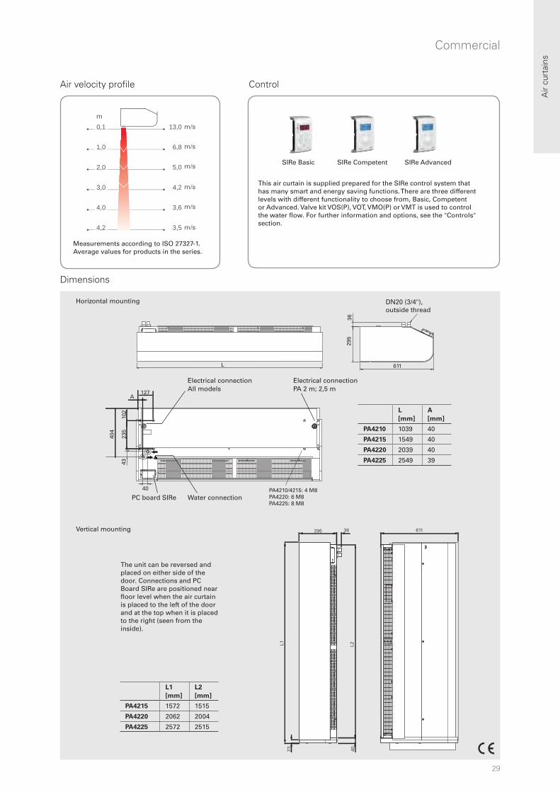
13,0 m
6,8 m
5,0 m
4,2 m
3,6 m
3,5 m
0,1
1,0
2,0
3,0
4,0
4,2
m
295 36 611
4023
L2L1
611L
295
36
40
127A
4323
510
2
404
PA4210/4215: 4 M8PA4220: 6 M8PA4225: 8 M8
L1
[mm]
L2
[mm]
PA4215 1572 1515
PA4220 2062 2004
PA4225 2572 2515
L
[mm]
A
[mm]
PA4210 1039 40
PA4215 1549 40
PA4220 2039 40
PA4225 2549 39
Air
curt
ains
Commercial
Air velocity profile Control
Dimensions
DN20 (3/4"), outside thread
Electrical connection All models
Water connection PC board SIRe
PA 2 m; 2,5 m Electrical connection
The unit can be reversed and placed on either side of the door. Connections and PC Board SIRe are positioned near floor level when the air curtain is placed to the left of the door and at the top when it is placed to the right (seen from the inside).
m/s
m/s
m/s
m/s
m/s
m/s
m
SIRe Basic SIRe Competent SIRe Advanced
This air curtain is supplied prepared for the SIRe control system that has many smart and energy saving functions. There are three different levels with different functionality to choose from, Basic, Competent or Advanced. Valve kit VOS(P), VOT, VMO(P) or VMT is used to control the water flow. For further information and options, see the "Controls" section.
Horizontal mounting
Vertical mounting
Measurements according to ISO 27327-1. Average values for products in the series.
30
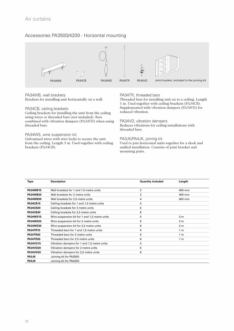
PA34WB PA34CB PA34WS PA34TR PA34VD
Air curtains
PA34WB, wall bracketsBrackets for installing unit horizontally on a wall. PA34CB, ceiling bracketsCeiling brackets for installing the unit from the ceiling using wires or threaded bars (not included). Best combined with vibration dampers (PA34VD) when using threaded bars. PA34WS, wire suspension kitGalvanized wires with wire locks to secure the unit from the ceiling. Length 3 m. Used together with ceiling brackets (PA34CB).
PA34TR, threaded barsThreaded bars for installing unit on to a ceiling. Length 1 m. Used together with ceiling brackets (PA34CB). Supplemented with vibration dampers (PA34VD) for reduced vibration. PA34VD, vibration dampersReduces vibrations for ceiling installations with threaded bars. PA3JK/PA4JK, joining kitUsed to join horizontal units together for a sleek and unified installation. Consists of joint bracket and mounting parts.
Accessories PA3500/4200 - Horizontal mounting
Joint bracket, included in the joining kit
Type Description Quantity included Length
PA34WB15 Wall brackets for 1 and 1,5 metre units 2 400 mm
PA34WB20 Wall brackets for 2 metre units 3 400 mm
PA34WB30 Wall brackets for 2,5 metre units 4 400 mm
PA34CB15 Ceiling brackets for 1 and 1,5 metre units 4
PA34CB20 Ceiling brackets for 2 metre units 6
PA34CB30 Ceiling brackets for 2,5 metre units 8
PA34WS15 Wire suspension kit for 1 and 1,5 metre units 4 3 m
PA34WS20 Wire suspension kit for 2 metre units 6 3 m
PA34WS30 Wire suspension kit for 2,5 metre units 8 3 m
PA34TR15 Threaded bars for 1 and 1,5 metre units 4 1 m
PA34TR20 Threaded bars for 2 metre units 6 1 m
PA34TR30 Threaded bars for 2,5 metre units 8 1 m
PA34VD15 Vibration dampers for 1 and 1,5 metre units 4
PA34VD20 Vibration dampers for 2 metre units 6
PA34VD30 Vibration dampers for 2,5 metre units 8
PA3JK Joining kit for PA3500
PA4JK Joining kit for PA4200

31
PA3DW PA4DW
PA3DC PA4DC
Air
curt
ains
Commercial
Recessed mounting in suspended ceilings
PA3DW/PA4DW, design kit for wall mountingUsed to conceal mountings, cables and pipes. Used together with ceiling brackets PA34WB.
PA3DC/PA4DC, design kit for ceiling mountingUsed to conceal mountings, cables and pipes. The design kit has a telescope function that can be adapted for the installation. It can also be extended with one or more extension parts.
Two design kits are required for 1 and 1.5 metre units, while 2 metre units need three kits and 2.5 metre units need four kits.
PA3XT/PA4XT, outlet extensionOutlet extension with telescopic function. Used for recessed installation of units in suspended ceilings.
Accessories PA3500/4200 - Horizontal mounting
Type Description LxHxW
[mm]
PA3DW10 Design kit for wall mounting PA3510 87x382x1006
PA3DW15 Design kit for wall mounting PA3515 87x382x1516
PA3DW20 Design kit for wall mounting PA3520 87x382x2006
PA3DW25 Design kit for wall mounting PA3525 87x382x2516
PA4DW10 Design kit for wall mounting PA4210 87x424x1006
PA4DW15 Design kit for wall mounting PA4215 87x424x1516
PA4DW20 Design kit for wall mounting PA4220 87x424x2006
PA4DW25 Design kit for wall mounting PA4225 87x424x2516
Type Description
PA3DCS Design kit for ceiling mounting PA3500, small, 200-300 mm (1 piece)
PA3DCM Design kit for ceiling mounting PA3500, medium, 300-500 mm (1 piece)
PA3DCL Design kit for ceiling mounting PA3500, large, 500-900 mm (1 piece)
PA3DXT Design kit for ceiling mounting PA3500, extension, 420 mm (1 piece)
PA4DCS Design kit for ceiling mounting PA4200, small, 200-300 mm (1 piece)
PA4DCM Design kit for ceiling mounting PA4200, medium, 300-500 mm (1 piece)
PA4DCL Design kit for ceiling mounting PA4200, large, 500-900 mm (1 piece)
PA4DXT Design kit for ceiling mounting PA4200, extension, 420 mm (1 piece)
Type Description
PA3XT10 Outlet extension for PA3510, 130-200 mm
PA3XT15 Outlet extension for PA3515, 130-200 mm
PA3XT20 Outlet extension for PA3520, 130-200 mm
PA3XT25 Outlet extension for PA3525, 130-200 mm
PA4XT10 Outlet extension for PA4210, 130-200 mm
PA4XT15 Outlet extension for PA4215, 130-200 mm
PA4XT20 Outlet extension for PA4220, 130-200 mm
PA4XT25 Outlet extension for PA4225, 130-200 mm
32
PA34EF
DTV200S
FHDN20
PA3VDW PA4VDW
AXP300PA3HE(VDW) PA4HE(VDW)
Air curtains
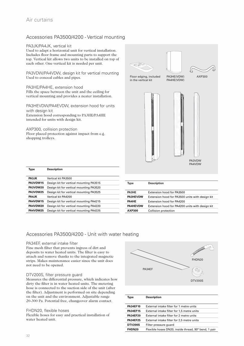
Accessories PA3500/4200 - Vertical mounting
PA34EF, external intake filterFine mesh filter that prevents ingress of dirt and deposits to water heated units. The filter is easy to attach and remove thanks to the integrated magnetic strips. Makes maintenance easier since the unit does not need to be opened. DTV200S, filter pressure guardMeasures the differential pressure, which indicates how dirty the filter is in water heated units. The metering hose is connected to the suction side of the unit (after the filter). Adjustment is performed on site depending on the unit and the environment. Adjustable range 20-300 Pa. Potential free, changeover alarm contact. FHDN20, flexible hoses Flexible hoses for easy and practical installation of water heated unit.
Accessories PA3500/4200 - Unit with water heating
PA3JK/PA4JK, vertical kit Used to adapt a horizontal unit for vertical installation. Includes floor frame and mounting parts to support the top. Vertical kit allows two units to be installed on top of each other. One vertical kit is needed per unit. PA3VDW/PA4VDW, design kit for vertical mountingUsed to conceal cables and pipes.
PA3HE/PA4HE, extension hoodFills the space between the unit and the ceiling for vertical mounting and provides a neater installation.
PA3HEVDW/PA4EVDW, extension hood for units with design kitExtension hood corresponding to PA3HE/PA4HE intended for units with design kit. AXP300, collision protectionFloor placed protection against impact from e.g. shopping trolleys.
Floor edging, included in the vertical kit
Type Description
PA3HE Extension hood for PA3500
PA3HEVDW Extension hood for PA3500 units with design kit
PA4HE Extension hood for PA4200
PA4HEVDW Extension hood for PA4200 units with design kit
AXP300 Collision protection
Type Description
PA3JK Vertical kit PA3500
PA3VDW15 Design kit for vertical mounting PA3515
PA3VDW20 Design kit for vertical mounting PA3520
PA3VDW25 Design kit for vertical mounting PA3525
PA4JK Vertical kit PA4200
PA4VDW15 Design kit for vertical mounting PA4215
PA4VDW20 Design kit for vertical mounting PA4220
PA4VDW25 Design kit for vertical mounting PA4225
Type Description
PA34EF10 External intake filter for 1 metre units
PA34EF15 External intake filter for 1,5 metre units
PA34EF20 External intake filter for 2 metre units
PA34EF25 External intake filter for 2,5 metre units
DTV200S Filter pressure guard
FHDN20 Flexible hoses DN20, inside thread, 90° bend, 1 pair
33
R
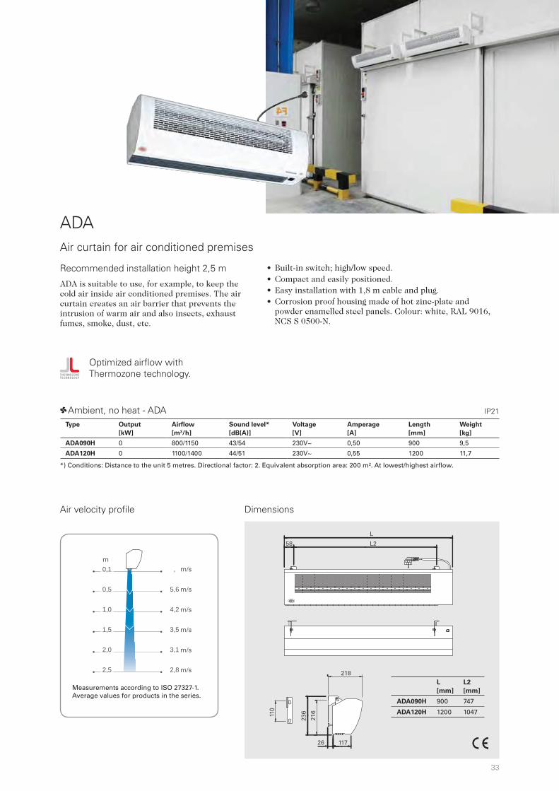
, m
5,6 m
4,2 m
3,5 m
3,1 m
2,8 m
0,1
0,5
1,0
1,5
2,0
2,5
m
L
L258
L
[mm]
L2
[mm]
ADA090H 900 747
ADA120H 1200 1047
218
11726
236110
216
ADA
• Built-in switch; high/low speed.• Compact and easily positioned.• Easy installation with 1,8 m cable and plug.• Corrosion proof housing made of hot zinc-plate and
powder enamelled steel panels. Colour: white, RAL 9016, NCS S 0500-N.
Air curtain for air conditioned premises
Air velocity profile Dimensions
IP211 Ambient, no heat - ADA
Optimized airflow with Thermozone technology.
*) Conditions: Distance to the unit 5 metres. Directional factor: 2. Equivalent absorption area: 200 m². At lowest/highest airflow.
m/s
m/s
m/s
m/s
m/s
m/s
m
Recommended installation height 2,5 m
ADA is suitable to use, for example, to keep the cold air inside air conditioned premises. The air curtain creates an air barrier that prevents the intrusion of warm air and also insects, exhaust fumes, smoke, dust, etc.
Measurements according to ISO 27327-1. Average values for products in the series.
Type Output
[kW]
Airflow
[m3/h]
Sound level*
[dB(A)]
Voltage
[V]
Amperage
[A]
Length
[mm]
Weight
[kg]
ADA090H 0 800/1150 43/54 230V~ 0,50 900 9,5
ADA120H 0 1100/1400 44/51 230V~ 0,55 1200 11,7
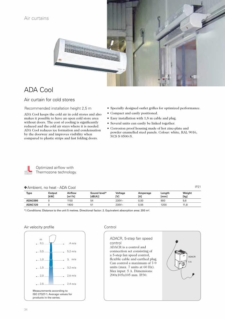
34
,4 m
5,2 m
3, m
3,2 m
2,6 m
2,4 m
0,1
0,5
1,0
1,5
2,0
2,5
m
R
ADACR
5 A
Air curtains
ADA Cool
• Specially designed outlet grilles for optimized performance.
• Compact and easily positioned.
• Easy installation with 1,8 m cable and plug.
• Several units can easily be linked together.
• Corrosion proof housing made of hot zinc-plate and powder enamelled steel panels. Colour: white, RAL 9016, NCS S 0500-N.
Air curtain for cold stores
1 Ambient, no heat - ADA Cool
Air velocity profile
IP21
*) Conditions: Distance to the unit 5 metres. Directional factor: 2. Equivalent absorption area: 200 m².
ADA Cool keeps the cold air in cold stores and also makes it possible to have an open cold store area without doors. The cost of cooling is significantly reduced and the cold air stays where it is needed. ADA Cool reduces ice formation and condensation by the doorway and improves visibility when compared to plastic strips and fast folding doors.
m/s
m/s
m/s
m/s
m/s
m/s
m
Optimized airflow with Thermozone technology.
Control
ADACR, 5-step fan speed controlADACR is a control and connection set consisting of a 5-step fan speed control, flexible cable and earthed plug. Can control a maximum of 7-9 units (max. 7 units at 60 Hz). Max input: 5 A. Dimensions: 200x105x105 mm. IP30.
Recommended installation height 2,5 m
Measurements according to ISO 27327-1. Average values for products in the series.
Type Output
[kW]
Airflow
[m3/h]
Sound level*
[dB(A)]
Voltage
[V]
Amperage
[A]
Length
[mm]
Weight
[kg]
ADAC090 0 1150 54 230V~ 0,50 900 9,6
ADAC120 0 1400 51 230V~ 0,55 1200 11,8

35
2,2
2,5
3,2
3,5
4,2
5,5
218
11726
L258
L
110
231
251
Air
curt
ains
Our cool models Frico offers several models without heat that are suitable for keeping the cold in cold storages. Choose the appropriate unit according to the dimensions of the opening. There are units for horizontal and vertical mounting and in different designs.
PA4200A
PA3500 / PA4200
Dimensions
L
[mm]
L2
[mm]
ADAC090 900 747
ADAC120 1200 1047
Cold storage
AGS5500A
PA3500A
PA3200CA
PA2500A
PA2200CA
ADA Cool
Recommended installation height

36
Air curtains
RDS
• Customised production based on the product key.
• The SIRe control system offers the possibility of frost protection for water heated units.
• The front of the duct is covered by a duct panel that is available in polished high gloss, polished or brushed stainless steel. It is also available in powder coated steel, in any RAL/NCS colour. Exhaust duct and air curtain in powder coated steel, white, RAL 9016. Aluminium louvres.
Discreet air curtain for revolving doors, with intelligent control
2 Water heat - RDS WL, coil for low water temperature (480 °C)
*1) Lowest/highest airflow of totally 5 fan steps.*2) Conditions: Distance to the unit 5 metres. Directional factor: 2. Equivalent absorption area: 200 m². *3) t = temperature rise of passing air at maximum heat output and lowest/highest airflow. *4) Applicable at water temperature 60/40 °C, air temperature, in +18 °C. *5) Applicable at water temperature 80/60 °C, air temperature, in +18 °C. *6) Approximate weight for air curtain and duct.
3 Electrical heat - RDS E IP23
IP23
RDS is an ideal air curtain solution for revolving doors. The air curtain is installed above the door and the exhaust duct is adapted to the diameter of the door, which gives a neat and discrete solution.
Typ Output*4
[kW]
Output*5
[kW]
Airflow*1
[m3/h]
t*3,4
[°C]
t*3,5
[°C]
Water
volume
[l]
Sound
level*1
[dB(A)]
Voltage
[V]
Amperage
[A]
Length
[mm]
Weight*6
[kg]
RDS23WL 10 18 1050/2300 18/13 31/23 2,2 60 230V~ 2,3 1000 80
RDS29WL 12 20 1300/2900 17/12 29/21 2,2 61 230V~ 3,6 1000 100
RDS38WL 17 30 1800/3800 18/13 31/23 3,4 62 230V~ 4,8 1500 150
RDS56WL 25 43 2700/5600 18/13 30/23 4,5 63 230V~ 7,0 2000 200
RDS65WL 32 54 3100/6500 19/15 32/25 5,7 64 230V~ 8,2 2500 220
Type Output
steps
[kW]
Airflow*1
[m3/h]
t*3
[°C]
Sound
level*2
[dB(A)]
Voltage [V]
Amperage [A]
(control)
Voltage [V]
Amperage [A]
(heat)
Length
[mm]
Weight*6
[kg]
RDS23E08 2,7/5,4/8,1 1050/2300 23/11 60 230V~/2,3 400V3~/11,7 1000 80
RDS29E12 3,9/7,8/12 1300/2900 27/12 61 230V~/3,6 400V3~/16,9 1000 100
RDS38E18 6,0/12/18 1800/3800 30/14 62 230V~/4,8 400V3~/26,0 1500 150
RDS56E23 7,8/15/23 2700/5600 26/12 63 230V~/7,0 400V3~/33,8 2000 200
RDS65E30 9,9/19/30 3100/6500 29/14 64 230V~/8,2 400V3~/42,9 2500 220
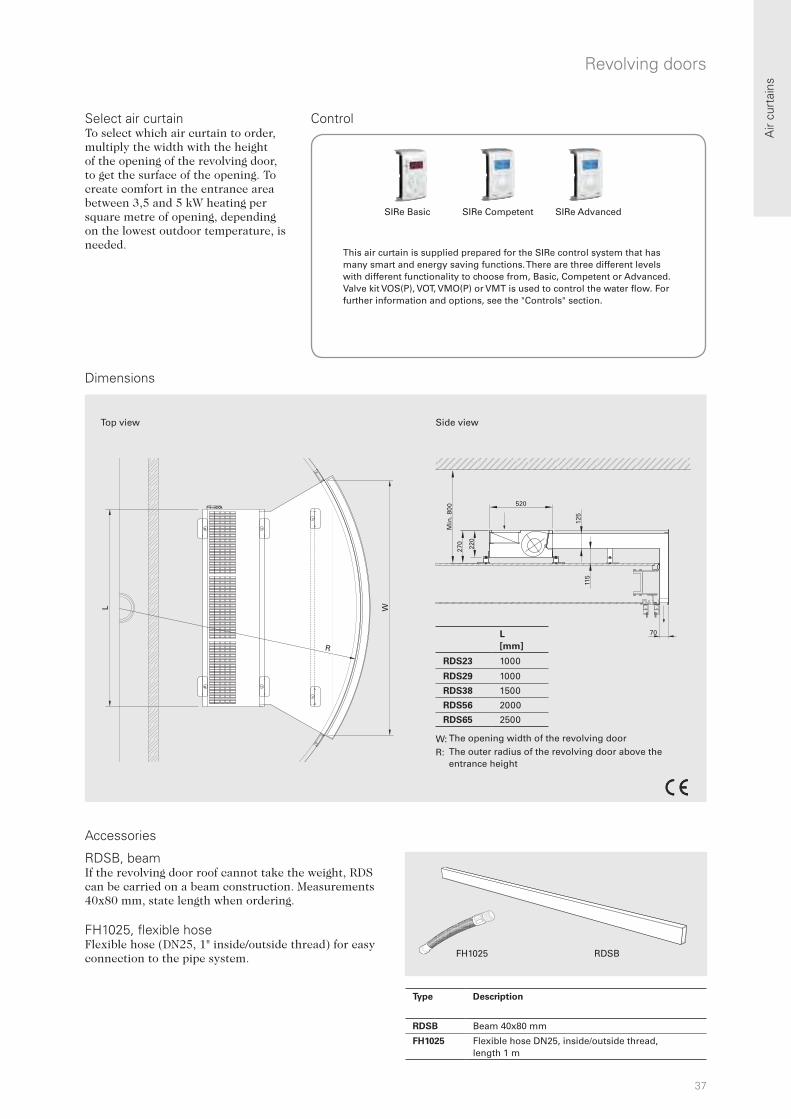
37
FH1025 RDSB
W
R
L
70
270
Min
. 800
520
115
125
220
L
[mm]
RDS23 1000
RDS29 1000
RDS38 1500
RDS56 2000
RDS65 2500
W: R:
Air
curt
ains
Revolving doors
Accessories
Dimensions
RDSB, beamIf the revolving door roof cannot take the weight, RDS can be carried on a beam construction. Measurements 40x80 mm, state length when ordering. FH1025, flexible hoseFlexible hose (DN25, 1" inside/outside thread) for easy connection to the pipe system.
Side viewTop view
Select air curtainTo select which air curtain to order, multiply the width with the height of the opening of the revolving door, to get the surface of the opening. To create comfort in the entrance area between 3,5 and 5 kW heating per square metre of opening, depending on the lowest outdoor temperature, is needed.
Control
This air curtain is supplied prepared for the SIRe control system that has many smart and energy saving functions. There are three different levels with different functionality to choose from, Basic, Competent or Advanced. Valve kit VOS(P), VOT, VMO(P) or VMT is used to control the water flow. For further information and options, see the "Controls" section.
SIRe Basic SIRe Competent SIRe Advanced
The opening width of the revolving door The outer radius of the revolving door above the entrance height
Type Description
RDSB Beam 40x80 mm
FH1025 Flexible hose DN25, inside/outside thread, length 1 m
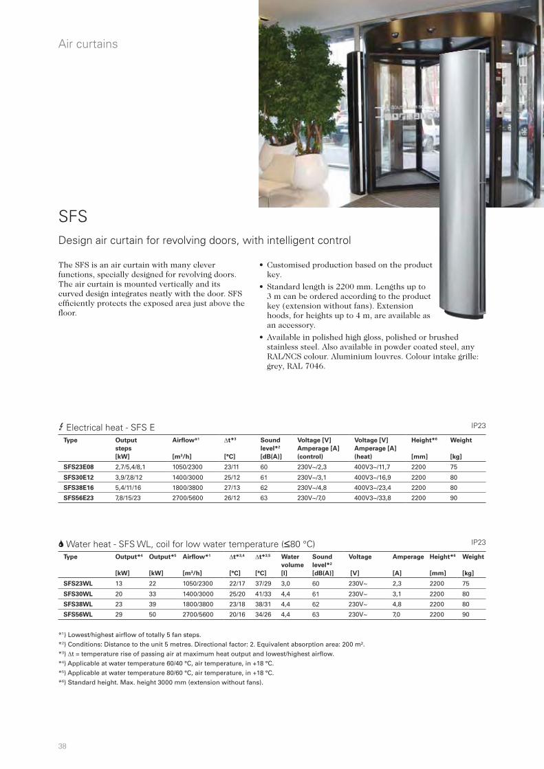
38
Air curtains
SFS
• Customised production based on the product key.
• Standard length is 2200 mm. Lengths up to 3 m can be ordered according to the product key (extension without fans). Extension hoods, for heights up to 4 m, are available as an accessory.
• Available in polished high gloss, polished or brushed stainless steel. Also available in powder coated steel, any RAL/NCS colour. Aluminium louvres. Colour intake grille: grey, RAL 7046.
Design air curtain for revolving doors, with intelligent control
2 Water heat - SFS WL, coil for low water temperature (480 °C)
*1) Lowest/highest airflow of totally 5 fan steps.*2) Conditions: Distance to the unit 5 metres. Directional factor: 2. Equivalent absorption area: 200 m². *3) t = temperature rise of passing air at maximum heat output and lowest/highest airflow. *4) Applicable at water temperature 60/40 °C, air temperature, in +18 °C. *5) Applicable at water temperature 80/60 °C, air temperature, in +18 °C. *6) Standard height. Max. height 3000 mm (extension without fans).
3 Electrical heat - SFS E IP23
IP23
The SFS is an air curtain with many clever functions, specially designed for revolving doors. The air curtain is mounted vertically and its curved design integrates neatly with the door. SFS efficiently protects the exposed area just above the floor.
Type Output*4
[kW]
Output*5
[kW]
Airflow*1
[m3/h]
t*3,4
[°C]
t*3,5
[°C]
Water
volume
[l]
Sound
level*2
[dB(A)]
Voltage
[V]
Amperage
[A]
Height*6
[mm]
Weight
[kg]
SFS23WL 13 22 1050/2300 22/17 37/29 3,0 60 230V~ 2,3 2200 75
SFS30WL 20 33 1400/3000 25/20 41/33 4,4 61 230V~ 3,1 2200 80
SFS38WL 23 39 1800/3800 23/18 38/31 4,4 62 230V~ 4,8 2200 80
SFS56WL 29 50 2700/5600 20/16 34/26 4,4 63 230V~ 7,0 2200 90
Type Output
steps
[kW]
Airflow*1
[m3/h]
t*3
[°C]
Sound
level*2
[dB(A)]
Voltage [V]
Amperage [A]
(control)
Voltage [V]
Amperage [A]
(heat)
Height*6
[mm]
Weight
[kg]
SFS23E08 2,7/5,4/8,1 1050/2300 23/11 60 230V~/2,3 400V3~/11,7 2200 75
SFS30E12 3,9/7,8/12 1400/3000 25/12 61 230V~/3,1 400V3~/16,9 2200 80
SFS38E16 5,4/11/16 1800/3800 27/13 62 230V~/4,8 400V3~/23,4 2200 80
SFS56E23 7,8/15/23 2700/5600 26/12 63 230V~/7,0 400V3~/33,8 2200 90
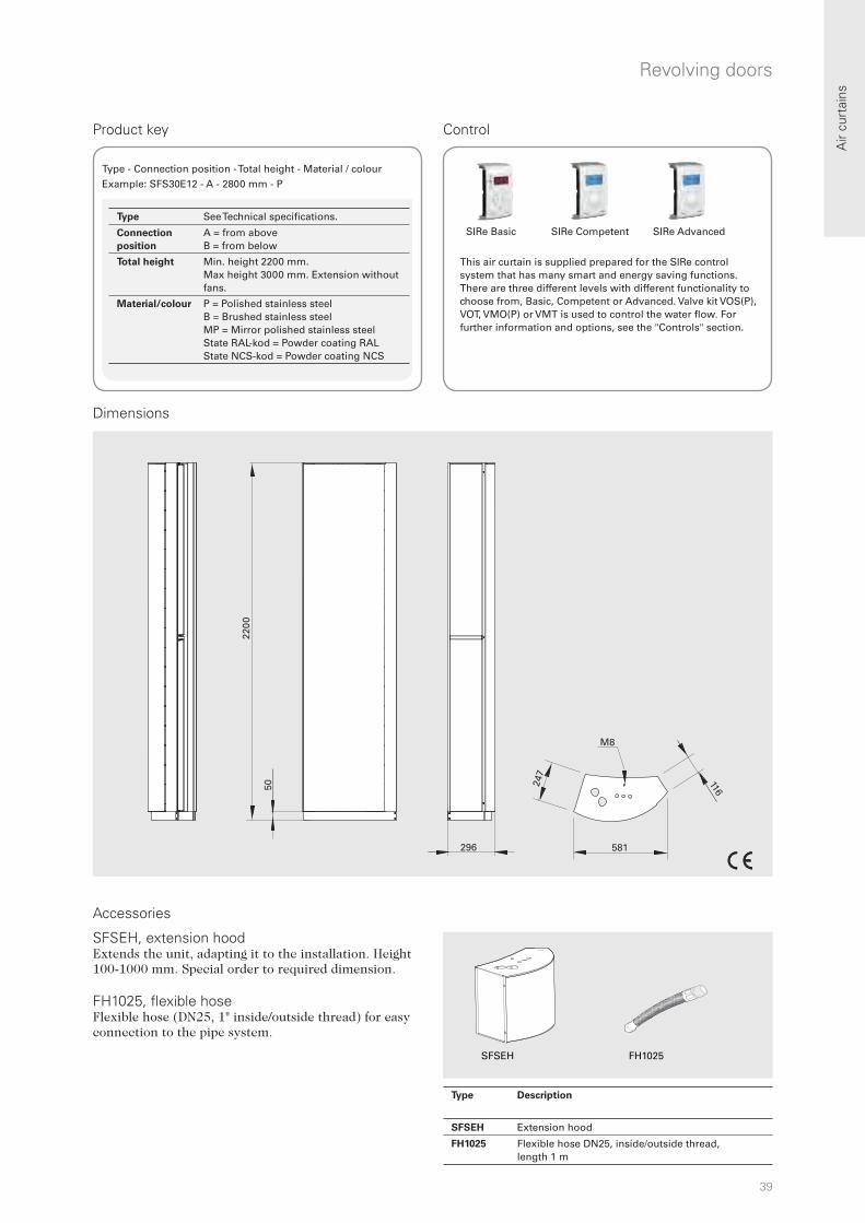
39
2200
50
296
247
581
M8
116
FH1025SFSEH
Air
curt
ains
Revolving doors
Control
SIRe Basic SIRe Competent SIRe Advanced
This air curtain is supplied prepared for the SIRe control system that has many smart and energy saving functions. There are three different levels with different functionality to choose from, Basic, Competent or Advanced. Valve kit VOS(P), VOT, VMO(P) or VMT is used to control the water flow. For further information and options, see the "Controls" section.
Accessories
SFSEH, extension hoodExtends the unit, adapting it to the installation. Height 100-1000 mm. Special order to required dimension. FH1025, flexible hoseFlexible hose (DN25, 1" inside/outside thread) for easy connection to the pipe system.
Product key
Type - Connection position - Total height - Material / colourExample: SFS30E12 - A - 2800 mm - P
Dimensions
Type Description
SFSEH Extension hood
FH1025 Flexible hose DN25, inside/outside thread, length 1 m
Type See Technical specifications.
Connection
position
A = from above B = from below
Total height Min. height 2200 mm.Max height 3000 mm. Extension without fans.
Material/colour P = Polished stainless steelB = Brushed stainless steelMP = Mirror polished stainless steel State RAL-kod = Powder coating RAL State NCS-kod = Powder coating NCS

40
R
Air curtains
• The following models are available for special order:
- with electrical heating
- with alternative water connections
- for vertical installation
- for recessed installation in suspended ceilings
• Intake grilles that can be opened make it easy to access the water coil. The grille is easy to clean from the outside.
• Adjustable outlet grille makes it possible to direct the air for optimum air curtain effect.
• Corrosion proof housing made of hot zinc-plate and powder enamelled steel panels. Colour: white, RAL 9016, NCS S 0500-N. Colour grille: grey, RAL 7046.
*1) Lowest/highest airflow of totally 5 fan steps. *2) Conditions: Distance to the unit 5 metres. Directional factor: 2. Equivalent absorption area: 200 m². At lowest/highest airflow. *3) t = temperature rise of passing air at maximum heat output and lowest/highest airflow.*4) Applicable at water temperature 60/40 °C, air temperature, in +18 °C. Models 1,5m – 2,5m approved for 220V/1ph/60Hz are available on request. Product performance for 220V/1ph/60Hz will differ from stated data.
Optimized airflow with Thermozone technology.
AGS5500 is a powerful air curtain intended for industrial doors but it can also be used for entryways in other large premises such as shopping malls.
IP23
IP23
AGS5500Air curtain for doors in industrial and large premises, with intelligent control
Recommended installation height 5,5 m
2 Water heat - AGS5500 WL, coil for low water temperature (480 °C)
1 Ambient, no heat - AGS5500 A
For models with coil for high temperature water (WH), see www.frico.se.
Type Output
[kW]
Airflow*1
[m3/h]
Sound
level*2
[dB(A)]
Voltage
motor
[V]
Amperage
motor
[A]
Length
[mm]
Weight
[kg]
AGS5515A 0 2500/5800 51/70 230V~ 8,1 1515 109
AGS5520A 0 3750/8700 52/72 230V~ 12,1 2010 144
AGS5525A 0 5000/11600 53/73 230V~ 16,2 2520 183
AGS5530A 0 6250/14500 55/74 230V~ 20,3 3030 218
Type Output*4
[kW]
Airflow*1
[m3/h]
t*3,4
[°C]
Water
volume
[l]
Sound
level*2
[dB(A)]
Voltage
motor
[V]
Amperage
motor
[A]
Length
[mm]
Weight
[kg]
AGS5515WL 26 2500/5500 19/14 4,0 50/70 230V~ 7,7 1515 129
AGS5520WL 45 3750/8250 22/16 8,1 51/71 230V~ 11,6 2010 169
AGS5525WL 59 5000/11000 21/16 9,2 52/72 230V~ 15,4 2520 213
AGS5530WL 71 6250/13750 20/15 11,0 54/74 230V~ 19,3 3030 258

41
0,1
1,0
2,0
3,0
4,0
5,0
6,0
m16,4 m
8, m
6,4 m
5,4 m
4, m
4,2 m
3, m
L
L/2
766
4087
147
500
450
30
AGS5515: 4 x M10 AGS5520/5525: 6 x M10AGS5530: 8 x M10
605
555
AGS5520/5525
GWB640 GP1010
L
[mm]
AGS5515 1515
AGS5520 2010
AGS5525 2520
AGS5530 3030
Air
curt
ains
Industry
Air velocity profile
Dimensions
Control
SIRe Basic SIRe Competent SIRe Advanced
This air curtain is supplied prepared for the SIRe control system that has many smart and energy saving functions. There are three different levels with different functionality to choose from, Basic, Competent or Advanced. Valve kit VOS(P), VOT, VMO(P) or VMT is used to control the water flow. For further information and options, see the "Controls" section.
Accessories
GWB640, wall bracketBrackets for installing unit horizontally on a wall. Two are required for 1 and 1.5 metre units, while 2 and 2.5 metre units need three and 3 metre units need four. GP1010, threaded barThreaded bar for mounting in ceilings. Length 1 m. M10. Four are required for 1 and 1.5 metre units, while 2 and 2.5 metre units need six and 3 metre units need eight.
m/s
m/s
m/s
m/s
m/s
m/s
m/s
m
Measurements according to ISO 27327-1. Average values for products in the series.
PC board (2 x for AGS5525/5530)Electrical connection
Water connection
Type Description
GWB640 Wall bracket, 1 pc
GP1010 Threaded bar, 1 m, 1 pc
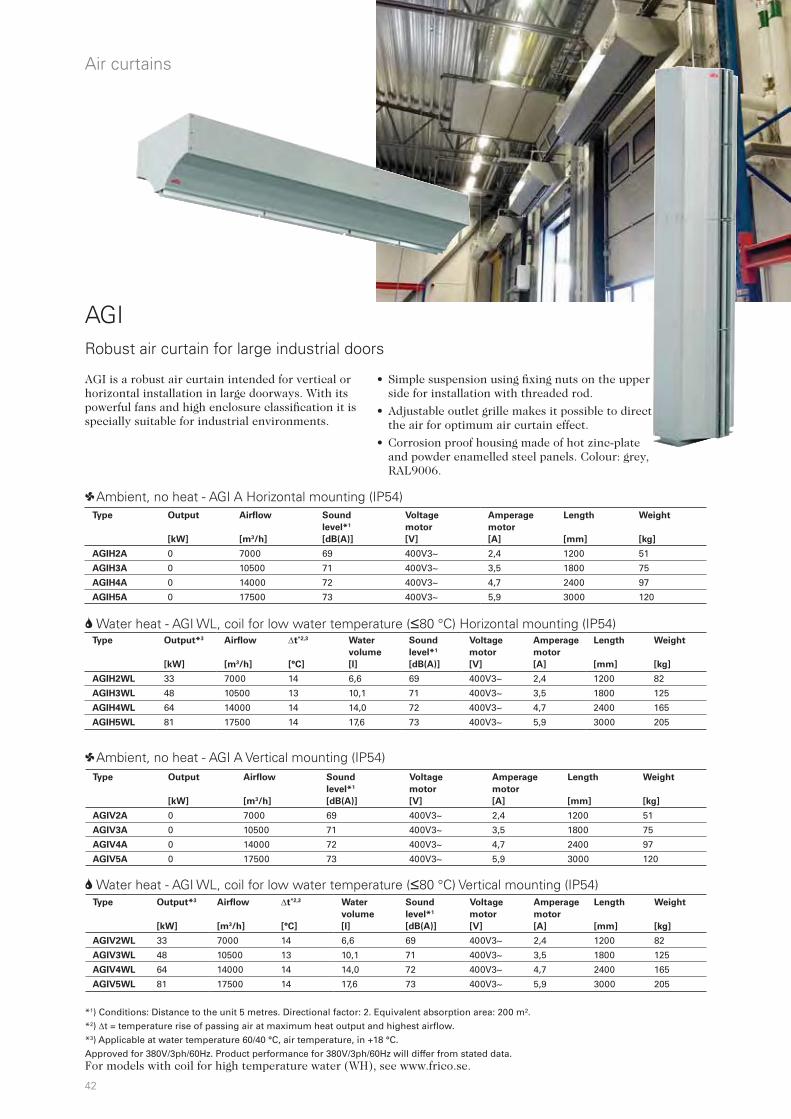
42
Air curtains
AGI
• Simple suspension using fixing nuts on the upper side for installation with threaded rod.
• Adjustable outlet grille makes it possible to direct the air for optimum air curtain effect.
• Corrosion proof housing made of hot zinc-plate and powder enamelled steel panels. Colour: grey, RAL9006.
Robust air curtain for large industrial doors
2 Water heat - AGI WL, coil for low water temperature (480 °C) Horizontal mounting (IP54)
1 Ambient, no heat - AGI A Horizontal mounting (IP54)
AGI is a robust air curtain intended for vertical or horizontal installation in large doorways. With its powerful fans and high enclosure classification it is specially suitable for industrial environments.
*1) Conditions: Distance to the unit 5 metres. Directional factor: 2. Equivalent absorption area: 200 m². *2) t = temperature rise of passing air at maximum heat output and highest airflow. *3) Applicable at water temperature 60/40 °C, air temperature, in +18 °C. Approved for 380V/3ph/60Hz. Product performance for 380V/3ph/60Hz will differ from stated data.
1 Ambient, no heat - AGI A Vertical mounting (IP54)
2 Water heat - AGI WL, coil for low water temperature (480 °C) Vertical mounting (IP54)
For models with coil for high temperature water (WH), see www.frico.se.
Type Output
[kW]
Airflow
[m3/h]
Sound
level*1
[dB(A)]
Voltage
motor
[V]
Amperage
motor
[A]
Length
[mm]
Weight
[kg]
AGIH2A 0 7000 69 400V3~ 2,4 1200 51
AGIH3A 0 10500 71 400V3~ 3,5 1800 75
AGIH4A 0 14000 72 400V3~ 4,7 2400 97
AGIH5A 0 17500 73 400V3~ 5,9 3000 120
Type Output*3
[kW]
Airflow
[m3/h]
t*2,3
[°C]
Water
volume
[l]
Sound
level*1
[dB(A)]
Voltage
motor
[V]
Amperage
motor
[A]
Length
[mm]
Weight
[kg]
AGIH2WL 33 7000 14 6,6 69 400V3~ 2,4 1200 82
AGIH3WL 48 10500 13 10,1 71 400V3~ 3,5 1800 125
AGIH4WL 64 14000 14 14,0 72 400V3~ 4,7 2400 165
AGIH5WL 81 17500 14 17,6 73 400V3~ 5,9 3000 205
Type Output
[kW]
Airflow
[m3/h]
Sound
level*1
[dB(A)]
Voltage
motor
[V]
Amperage
motor
[A]
Length
[mm]
Weight
[kg]
AGIV2A 0 7000 69 400V3~ 2,4 1200 51
AGIV3A 0 10500 71 400V3~ 3,5 1800 75
AGIV4A 0 14000 72 400V3~ 4,7 2400 97
AGIV5A 0 17500 73 400V3~ 5,9 3000 120
Type Output*3
[kW]
Airflow
[m3/h]
t*2,3
[°C]
Water
volume
[l]
Sound
level*1
[dB(A)]
Voltage
motor
[V]
Amperage
motor
[A]
Length
[mm]
Weight
[kg]
AGIV2WL 33 7000 14 6,6 69 400V3~ 2,4 1200 82
AGIV3WL 48 10500 13 10,1 71 400V3~ 3,5 1800 125
AGIV4WL 64 14000 14 14,0 72 400V3~ 4,7 2400 165
AGIV5WL 81 17500 14 17,6 73 400V3~ 5,9 3000 205
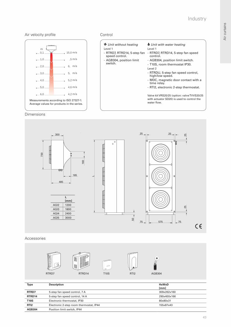
43
15,0 m
,5 m
6, m
5, m
5,2 m
4,6 m
4,2 m
0,1
1,0
2,0
3,0
4,0
5,0
6,0
m
RTI2T10SRTRD7 RTRD14 AGB304
L
[mm]
AGI2 1200
AGI3 1800
AGI4 2400
AGI5 3000
300
50
L
25
25 25
75 75575
25
300
485
185
730
160
Air
curt
ains
Industry
Air velocity profile Control
Accessories
Dimensions
m/s
m/s
m/s
m/s
m/s
m/s
m/s
m
2 Unit with water heating Level 1
- RTRD7, RTRD14, 5-step fan speed control.
- AGB304, position limit switch. - T10S, room thermostat IP30. Level 2
- RTRDU, 5-step fan speed control, high/low speed.
- MDC, magnetic door contact with a time relay.
- RTI2, electronic 2-step thermostat.
Valve kit VRS20/25 (option: valve TVVS20/25 with actuator SD20) is used to control the water flow.
Measurements according to ISO 27327-1. Average values for products in the series.
1 Unit without heating Level 1
- RTRD7, RTRD14, 5-step fan speed control.
- AGB304, position limit switch.
Type Description HxWxD
[mm]
RTRD7 5-step fan speed control, 7 A 309x262x160
RTRD14 5-step fan speed control, 14 A 290x400x166
T10S Electronic thermostat, IP30 80x80x31
RTI2 Electronic 2-step room thermostat, IP44 155x87x43
AGB304 Position limit switch, IP44

44
3 m 4 m 5 m 6 m 7 m 8 m 10 m
3 m UF601 UF601 UF601 UF601
4 m UF602 UF602 UF602
5 m UF603 UF603 UF604 UF605
6 m UF604 UF605 UF605
Air curtains
UF600Air curtain with floor outlet for large industrial doorways
1 Ambient, no heat - UF600 IP54
UF600 creates a very effective air barrier when air at high speed is pushed out through a narrow channel situated in the floor inside the door opening. An air barrier directed upwards from the floor gives the best possible protection against cold air flowing into the premises.
UF600 consists of a pillar with inlet hood, silencers and fans, as well as a floor channel with its slot at floor level. The pillar is placed outside (or inside) the door on either side of the opening. The floor channel is cast in the floor.
Dimensioning
Door width [m]
Do
or
hei
gh
t [m
]
Principle
Other door sizes on request. For larger openings, two pillars are required. Please contact Frico.
• Can be used for doors with rail traffic.
• Short payoff period.
• Very large doors (e.g. 8 x 10 m) require several pillars and separated floor ducts. The pillars can be positioned on each or the same side of the opening.
• Available in galvanised, hot zinc-plated steel panels for outdoor installation.
Type Output
[kW]
Air velocity
[m/s]
Voltage
[V]
Amperage
[A]
Dimensions
floor duct
[mm]
Diameter
fans
[mm]
Diameter
silencer
[mm]
UF601 2x4 30 400V3~ 2x8,4 600x600 500 750
UF602 2x7,5 35 400V3~ 2x14,6 750x750 630 900
UF603 2x11 38 400V3~ 2x20 750x750 630 900
UF604 2x15 38 400V3~ 2x31 750x750 630 900
UF605 2x18,5 40 400V3~ 2x37 750x750 630 900
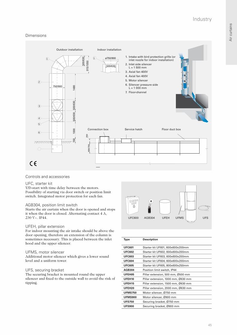
45
60
0/7
50
25
0
UFC600 AGB304 UFMSUFEH UFS
1
2
3
4
5
6
1 ø750/900
500/630500/
630
915/
1050
750/900
1480
500/
630
500/
630
1000
150
Air
curt
ains
Industry
Dimensions
Controls and accessories
UFC, starter kit Y/D-start with time delay between the motors. Possibility of starting via door switch or position limit switch. Integrated motor protection for each fan. AGB304, position limit switch Starts the air curtain when the door is opened and stops it when the door is closed. Alternating contact 4 A, 230 V~. IP44. UFEH, pillar extensionFor indoor mounting the air intake should be above the door opening, therefore an extension of the column is sometimes necessary. This is placed between the inlet hood and the upper silencer. UFMS, motor silencerAdditional motor silencer which gives a lower sound level and a uniform tower.
UFS, securing bracketThe securing bracket is mounted round the upper silencer and fixed to the outside wall to avoid the risk of tipping.
Outdoor installation Indoor installation
Connection box Service hatch Floor duct box
1. Intake with bird protection grille (or inlet nozzle for indoor installation)
2. Inlet side silencer L = 1 500 mm
3. Axial fan 400V
4. Axial fan 400V
5. Motor silencer
6. Silencer pressure side L = 1 000 mm
7. Floor-channel
Type Description
UFC601 Starter kit UF601, 600x600x200mm
UFC602 Starter kit UF602, 600x600x200mm
UFC603 Starter kit UF603, 600x600x200mm
UFC604 Starter kit UF604, 600x600x200mm
UFC605 Starter kit UF605, 800x600x250mm
AGB304 Position limit switch, IP44
UFEH05 Pillar extension, 500 mm, Ø500 mm
UFEH10 Pillar extension, 1000 mm, Ø630 mm
UFEH15 Pillar extension, 1500 mm, Ø630 mm
UFEH20 Pillar extension, 2000 mm, Ø630 mm
UFMS750 Motor silencer, Ø750 mm
UFMS900 Motor silencer, Ø900 mm
UFS750 Securing bracket, Ø750 mm
UFS900 Securing bracket, Ø900 mm

46
5,2 m/s
2, m/s
2,2 m/s
1, m/s
0,1
0,5
1,0
1,5
m
300 300
730
Ø 5.5 (3x)A
14.5
5
683
390
55
67
7025
25
154
167790
Air curtains
PA1508
• Built-in control.
• Compact and easily positioned.
• Low sound level.
• Units with 2-3 kW are supplied with a 1,8 m cable and plug. Units with 4,5 kW are supplied with a 1,3 m cable without plug.
• The unit is easily angled on the bracket, which is used for both wall and ceiling mounting.
• Corrosion proof housing made of hot zinc-plate and powder enamelled steel panels. Colour front: white, RAL 9016, NCS S 0500-N. Colour grille, rear section, ends and brackets: grey, RAL 7046.
Air curtain for small openings
3 Electrical heat - PA1508 IP20
Air velocity profile Dimensions
*1) Conditions: Distance to the unit 5 metres. Directional factor: 2. Equivalent absorption area: 200 m². At lowest/highest airflow. *2) t = temperature rise of passing air at maximum heat output and lowest/highest airflow.
PA1508 is primarily intended for small openings such as kiosk and service hatches and cashier benches where a long, narrow air flow is required. This creates a temperature separating air barrier that prevents cold air from pushing in and hot air from flowing out. PA1508 also gives additional heat and in this way also improves the working environment.
Measurements according to ISO 27327-1. Average values for products in the series.
Bracket
Type Output
[kW]
Airflow
[m3/h]
t*2
[°C]
Sound
level*1
[dB(A)]
Voltage
[V]
Amperage
(heat)
[A]
Length
[mm]
Weight
[kg]
PA1508E02 1/2 270/400 22/15 39/50 230V~ 9,3 790 7,5
PA1508E03 2/3 270/400 34/23 39/50 230V~ 13,6 790 7,5
PA1508E05 3/4,5 270/400 51/34 39/50 230V~ 20,2 790 7,5
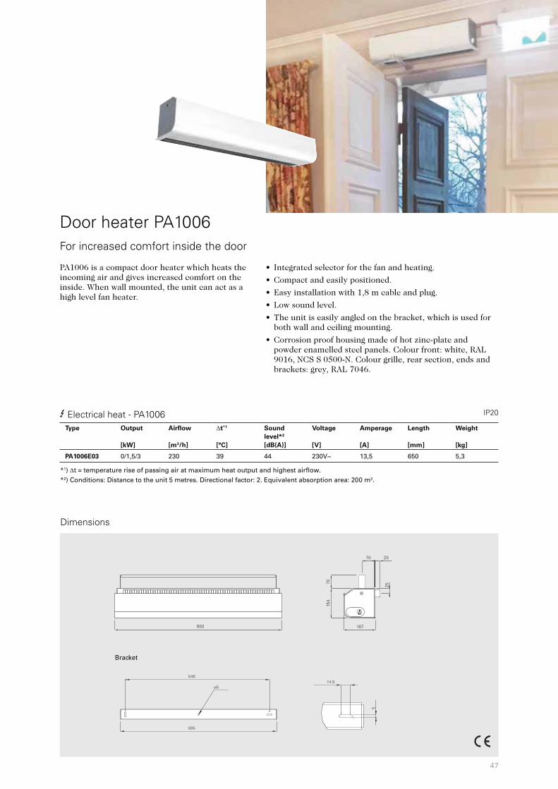
47
650
70
167
25
7015
4
25
548
ø5
595
14.5
5
Door heater PA1006
• Integrated selector for the fan and heating.
• Compact and easily positioned.
• Easy installation with 1,8 m cable and plug.
• Low sound level.
• The unit is easily angled on the bracket, which is used for both wall and ceiling mounting.
• Corrosion proof housing made of hot zinc-plate and powder enamelled steel panels. Colour front: white, RAL 9016, NCS S 0500-N. Colour grille, rear section, ends and brackets: grey, RAL 7046.
For increased comfort inside the door
3 Electrical heat - PA1006 IP20
Dimensions
PA1006 is a compact door heater which heats the incoming air and gives increased comfort on the inside. When wall mounted, the unit can act as a high level fan heater.
*1) t = temperature rise of passing air at maximum heat output and highest airflow. *2) Conditions: Distance to the unit 5 metres. Directional factor: 2. Equivalent absorption area: 200 m².
Bracket
Type Output
[kW]
Airflow
[m3/h]
t*1
[°C]
Sound
level*2
[dB(A)]
Voltage
[V]
Amperage
[A]
Length
[mm]
Weight
[kg]
PA1006E03 0/1,5/3 230 39 44 230V~ 13,5 650 5,3
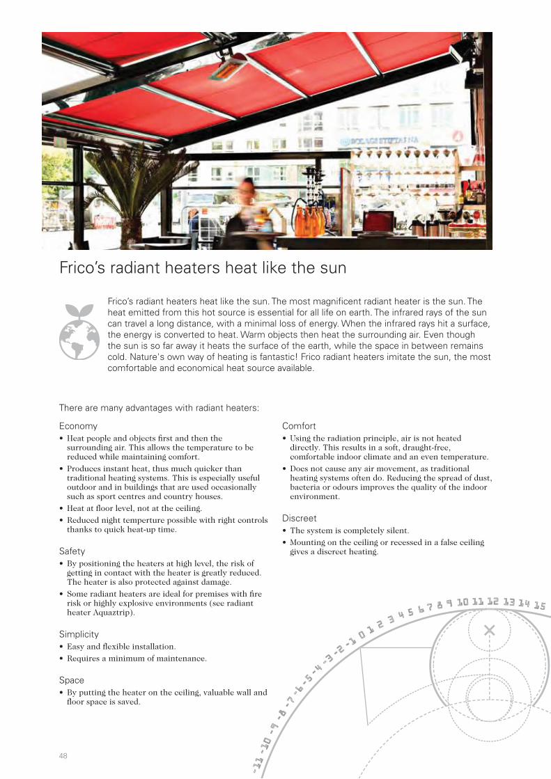
48
Radiant heaters
Frico’s radiant heaters heat like the sun. The most magnificent radiant heater is the sun. The heat emitted from this hot source is essential for all life on earth. The infrared rays of the sun can travel a long distance, with a minimal loss of energy. When the infrared rays hit a surface, the energy is converted to heat. Warm objects then heat the surrounding air. Even though the sun is so far away it heats the surface of the earth, while the space in between remains cold. Nature's own way of heating is fantastic! Frico radiant heaters imitate the sun, the most comfortable and economical heat source available.
Frico’s radiant heaters heat like the sun
There are many advantages with radiant heaters:
Economy• Heat people and objects first and then the
surrounding air. This allows the temperature to be reduced while maintaining comfort.
• Produces instant heat, thus much quicker than traditional heating systems. This is especially useful outdoor and in buildings that are used occasionally such as sport centres and country houses.
• Heat at floor level, not at the ceiling.
• Reduced night temperture possible with right controls thanks to quick heat-up time.
Safety• By positioning the heaters at high level, the risk of
getting in contact with the heater is greatly reduced. The heater is also protected against damage.
• Some radiant heaters are ideal for premises with fire risk or highly explosive environments (see radiant heater Aquaztrip).
Simplicity• Easy and flexible installation.
• Requires a minimum of maintenance.
Space• By putting the heater on the ceiling, valuable wall and
floor space is saved.
Comfort• Using the radiation principle, air is not heated
directly. This results in a soft, draught-free, comfortable indoor climate and an even temperature.
• Does not cause any air movement, as traditional heating systems often do. Reducing the spread of dust, bacteria or odours improves the quality of the indoor environment.
Discreet• The system is completely silent.
• Mounting on the ceiling or recessed in a false ceiling gives a discreet heating.
-11-10-9-8-7-6-5
-4-3-2-1
0123 4 5
6 7 8 9 10 11 12 13 14 15
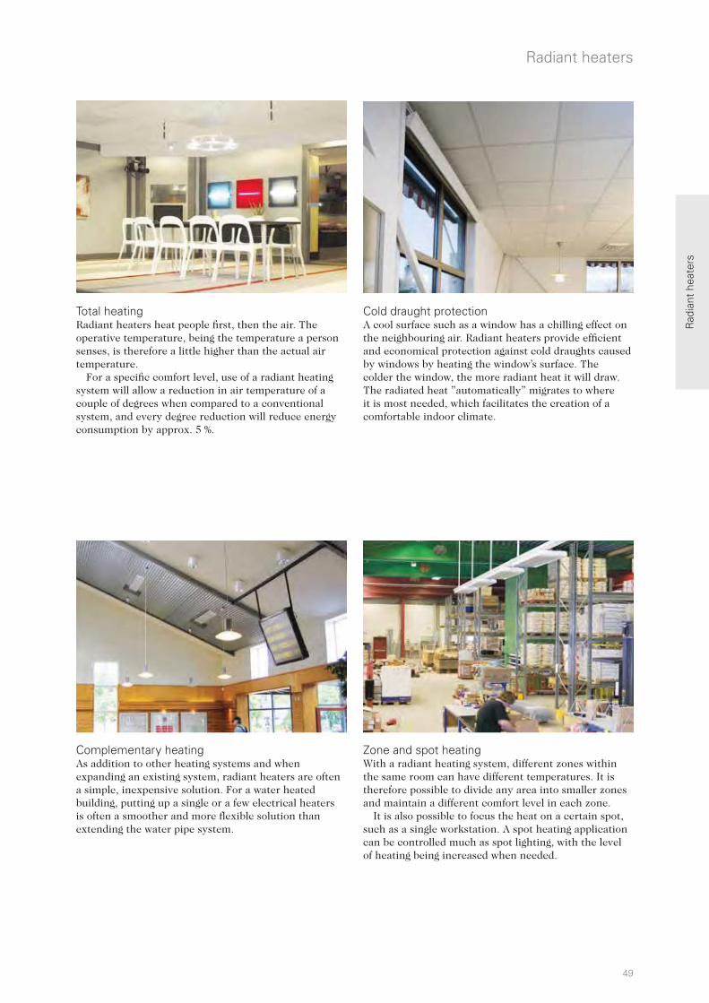
49
Radiant heaters
Rad
iant
hea
ters
Total heating Radiant heaters heat people first, then the air. The operative temperature, being the temperature a person senses, is therefore a little higher than the actual air temperature.
For a specific comfort level, use of a radiant heating system will allow a reduction in air temperature of a couple of degrees when compared to a conventional system, and every degree reduction will reduce energy consumption by approx. 5 %.
Zone and spot heating With a radiant heating system, different zones within the same room can have different temperatures. It is therefore possible to divide any area into smaller zones and maintain a different comfort level in each zone.
It is also possible to focus the heat on a certain spot, such as a single workstation. A spot heating application can be controlled much as spot lighting, with the level of heating being increased when needed.
Complementary heating As addition to other heating systems and when expanding an existing system, radiant heaters are often a simple, inexpensive solution. For a water heated building, putting up a single or a few electrical heaters is often a smoother and more flexible solution than extending the water pipe system.
Cold draught protectionA cool surface such as a window has a chilling effect on the neighbouring air. Radiant heaters provide efficient and economical protection against cold draughts caused by windows by heating the window’s surface. The colder the window, the more radiant heat it will draw. The radiated heat ”automatically” migrates to where it is most needed, which facilitates the creation of a comfortable indoor climate.

50
Thermoplus
Thermocassette
EZ100
Radiant heaters
Choose the right radiant heater Radiant heaters are available in various designs – it is primarily the installation height, the surrounding environment and the type of heating wanted (see previous page) that determine the choice of product.
Offices, shops and public premises Radiant heaters offer many advantages for applications where silent, discreet and efficient heating is required. They give a safe, hygienic and pleasant heat. Mounting on the ceiling or recessed in a false ceiling leaves the walls free and gives a discreet heating. Ceiling mounting also protects the heaters from damage, which ensures longer life. With zone and spot heating as well as protection against cold draughts it is possible to create a comfortable indoor climate with the best economy.
Type Heating Installation
height
Output Surface
temp.
Application area*1 Heating element Page
[m] [W] [°C] Offices Industry Outdoors
Thermoplus 3 2–3 300-900 180 ++ + Radiant aluminium panel 53
Thermocassette 3 < 3 300-600 100 ++ + Heating film 56
Elztrip EZ100 3 2,5–4 600-1500 280 ++ + Radiant aluminium panel 58
Elztrip EZ200 3 3–10 800-2200 340 ++ Radiant aluminium panel 60
Elztrip EZ300 3 4–15 3600-4500 350 ++ Radiant aluminium panel 62
Infrared IR 3 4,5–20 3000-6000 700 ++ + Infrared heating rod 64
Infrared IRCF 3 3–5 1500-4500 2200*3 ++ + Halogen lamp 66
Infrared CIR 3 2–2,5 500-2000 750 + ++ Infrared heating rod 68
Infrared ELIR 3 2–3 1200 2200*3 + ++ Halogen lamp 70
Infrared IH 3 1,8–3,5 1000-2000 2200*3 + ++ Halogen lamp 72
Infrared IHC 3 1,8–3 1150-1750 1200*3 + ++ Carbon lamp 74
Aquaztrip Basic 2 3–15 199*2 80–120*2 + ++ Radiant aluminium panel 76
*1) Our products are divided into three main application areas: "Offices, shops and public premises", "Industry and large premises" and "Outdoors" but most products can be used in several application areas. *2) Output per meter. Depending on water temperature. *3) Filament temperature
2–3 m
< 3 m
2,5–4 m

51
EZ200
EZ300
IR
IRCF
CIR
ELIR
IH
IHC
Radiant heaters
Rad
iant
hea
ters
Industry and large premises The principle of radiant heaters is well used in buildings with high ceilings such as industrial premises. There are no heat losses between heater and floor since radiant heaters only create the heat when they hit a surface. An industrial building often consists of zones that require different temperatures. With radiant heaters it is possible to direct the heat where it is needed and create different temperature zones.
Outdoors The summer season can be prolonged with the use of radiant heaters for outdoor use. There are different solutions depending on the environment. For open-air restaurants without protective walls a heater with a high surface temperature is required. The better the area is protected against the wind, the less output you need, which means you are not as dependent on heaters with a high surface temperature.
3–5 m
4–15 m
4,5–20 m
3–10 m
2–3 m
1,8 – 3,5 m
2–2,5 m
1,8 – 3 m

52
Basic criterias: 1. Type of premises – store, warehouse etc. 2. Type of heating - total heating, zone heating, cold draught
protection3. Height: installation height4. Mounting: wall or ceiling5. Connection: with electrical heat or water heat
Offices, shops and public premises
Frico radiant heaters are available for different kinds of heating and for different application areas. To facilitate your choice of product, you will find some typical cases on the following pages. More detailed information on important factors to consider when choosing a radiant heater is found on the previous pages.
Total heating, cafeteria
1. Type of premises: cafeteria 2. Type of heating: total heating3. Height: 2,80 metres4. Mounting: ceiling5. Connection: electrical
Recommendation: Thermocassette can be recessed into a false ceiling. When using Thermocassette for total heating, the units should be spread out through the ceiling for example as shown.
Total heating, workshop
1. Type of premises: workshop2. Type of heating: total heating3. Height: 5 metres4. Mounting: ceiling5. Connection: with electrical heat
Recommendation: A number of EZ300 evenly positioned over the area to be heated creates comfortable heat.
Zone heating, café
1. Type of premises: café2. Type of heating: zone heating3. Height: 3 metres4. Mounting: wall and ceiling5. Connection: with electrical heat
Recommendation: IH can be mounted on the wall or ceiling of the restaurant. Best comfort is given if the heaters heat from two directions.
Outdoors
Industry and large premises
Installation examples for radiant heaters

53
Rad
iant
hea
ters
Thermoplus EC
• Thermoplus is available in three versions:
- Type EC, for dry rooms. Controlled by a separate thermostat or output control. IP20.
- Type ECVT, for wet rooms. With a built-in cord switch, indicator lamp and thermostat (+5 – +40 °C). IP44.
- Type ECV, for wet rooms. Primarily designed for connection as slave device to ECVT, but can also be controlled separately using the same methods as for EC. IP44.
• Installed above windows and therefore also suitable for rooms where children are present.
• Wall brackets included. Ceiling mounting kit is available as an accessory.
• Front panel of white scratch-resistant enamelled aluminium. Colour: RAL 9010. Rear panel of hot zinc-plated steel panels.
Thermoplus is mounted above windows and gives an effecient protection against cold draught. The slim shape also makes it suitable for heating areas with limited space, like for example bathrooms. Thermoplus can furthermore be a cost-effective and flexible alternative to floor heating. Thermoplus is covered with white enamel which makes it discreet and scratch-resistant. The slim shape makes it practically invisible when mounted in the ceiling angle.
Slim radiant heater for protection against cold draughts
Thermoplus EC for dry rooms (IP20)
Thermoplus ECVT for wet rooms, with built-in switch and thermostat (IP44)
Thermoplus ECV slave unit to ECVT for wet rooms (IP44)
Type Heat output
[W]
Voltage
[V]
Amperage
[A]
Max. surface temp.
[°C]
LxHxD
[mm]
Weight
[kg]
EC45021 450 230V~ 2,0 180 1076x100x90 2,6
EC45031 450 400V~ 1,1 180 1076x100x90 2,6
EC60021 600 230V~ 2,6 180 1505x100x90 3,7
EC60031 600 400V~ 1,5 180 1505x100x90 3,7
EC75021 750 230V~ 3,3 180 1810x100x90 4,4
EC75031 750 400V~ 1,9 180 1810x100x90 4,4
EC90021 900 230V~ 3,9 180 2140x100x90 4,8
EC90031 900 400V~ 2,3 180 2140x100x90 4,8
Type Heat output
[W]
Voltage
[V]
Amperage
[A]
Max. surface temp.
[°C]
LxHxD
[mm]
Weight
[kg]
ECVT30021 300 230V~ 1,3 180 870x100x90 2,6
ECVT55021 550 230V~ 2,4 180 1505x100x90 4,3
ECVT55031 550 400V~ 1,4 180 1505x100x90 4,3
ECVT70021 700 230V~ 3,0 180 1810x100x90 5,0
ECVT70031 700 400V~ 1,8 180 1810x100x90 5,0
Type Heat output
[W]
Voltage
[V]
Amperage
[A]
Max. surface temp.
[°C]
LxHxD
[mm]
Weight
[kg]
ECV30021 300 230V~ 1,3 180 870x100x90 2,3
ECV55021 550 230V~ 2,4 180 1505x100x90 4,0
ECV55031 550 400V~ 1,4 180 1505x100x90 4,0
ECV70021 700 230V~ 3,0 180 1810x100x90 4,7
ECV70031 700 400V~ 1,8 180 1810x100x90 4,7

54
90
1800
6025
25
Dimensions
Type ECV, ECVT
Mounting on the wall Mounting on the ceiling
Type EC
A
[mm]
B
[mm]
EC450 1076 600
EC600 1505 900
EC750 1810 1200
EC900 2140 1800
A
[mm]
B
[mm]
ECV(T)300 870 400
ECV(T)550 1505 900
ECV(T)700 1810 1200
Ceiling fixture
Installation height Minimum distances
Flammable material
2 - 3 m
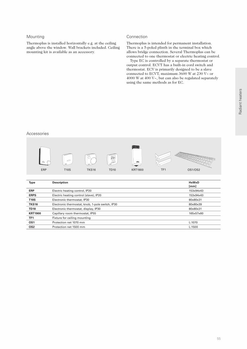
55
20
25
30
15
10
5
ERP TF1T10S TKS16 TD10 KRT1900 OS1/OS2
Rad
iant
hea
ters
Mounting Connection
Accessories
Thermoplus is intended for permanent installation. There is a 5-poled plinth in the terminal box which allows bridge connection. Several Thermoplus can be connected to one thermostat or electric heating control.
Type EC is controlled by a separate thermostat or output control. ECVT has a built-in cord switch and thermostat. ECV is primarily designed to be a slave connected to ECVT, maximum 3600 W at 230 V~ or 4000 W at 400 V~, but can also be regulated separately using the same methods as for EC.
Thermoplus is installed horizontally e.g. at the ceiling angle above the window. Wall brackets included. Ceiling mounting kit is available as an accessory.
Type Description HxWxD
[mm]
ERP Electric heating control, IP20 153x94x43
ERPS Electric heating control (slave), IP20 153x94x43
T10S Electronic thermostat, IP30 80x80x31
TKS16 Electronic thermostat, knob, 1-pole switch, IP30 80x80x39
TD10 Electronic thermostat, display, IP30 80x80x31
KRT1900 Capillary room thermostat, IP55 165x57x60
TF1 Fixture for ceiling mounting
OS1 Protection net 1070 mm L:1070
OS2 Protection net 1500 mm L:1500

56
80
1800
500
50
• The low surface temperature (max. 100 °C) makes Thermocassette well suited for low ceiling heights. There is no risk of burns to the person(s) in this vicinity.
• Easy installation with 1,8 m cable and plug.
• High protection class, IP55.
• Complies with requirements of flammable areas according to SEMKO 111FF.
• Corrosion proof casing of hot zinc-plated and powder lacquered steel panels. Colour: white, RAL 9016, NCS S 0500-N.
Thermocassette is intended for discreet heating in offices, bathrooms, schools etc. Designed for either surface or recessed mounting it is well suited for total heating as well as for spot heating of for example a reception desk. Mounted in a false ceiling it is well protected against damage. Recessed mounting make the heater an integral part of the ceiling.
Installation height
Thermocassette HP
Radiant heaters
Minimum distances
Flammable material
Discreet radiant heat cassette for recessed or surface mounting
Thermocassette HP (IP55) Type Heat output
[W]
Voltage
[V]
Amperage
[A]
Max. surface
temp.
[°C]
LxBxH
[mm]
Weight
[kg]
HP3 300 230V~ 1,3 100 593x593x80* 5,8
HP6 600 230V~ 2,6 100 593x1193x80* 10,7*) Height with brackets.
< 3 m
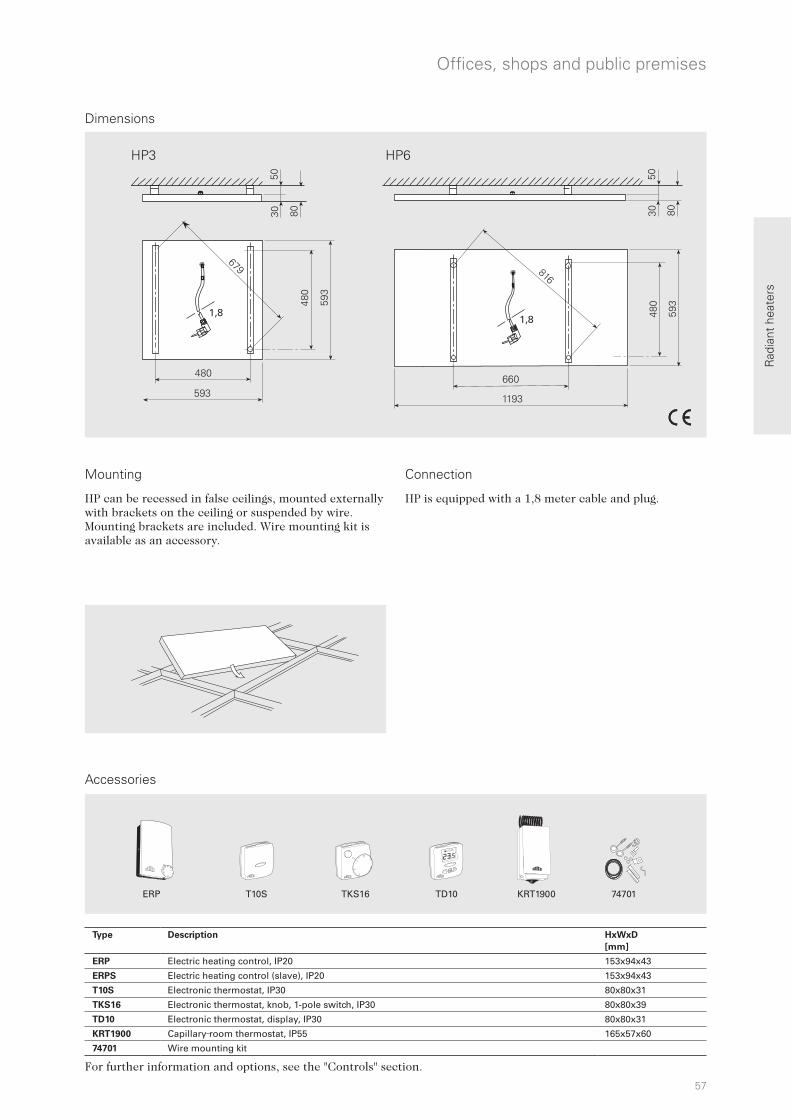
57
20
25
30
15
10
5
ERP T10S TKS16 TD10 KRT1900 74701
1,81,8
HP3 HP6
Rad
iant
hea
ters
HP is equipped with a 1,8 meter cable and plug.
Accessories
Offices, shops and public premises
Dimensions
Mounting Connection
For further information and options, see the "Controls" section.
HP can be recessed in false ceilings, mounted externally with brackets on the ceiling or suspended by wire. Mounting brackets are included. Wire mounting kit is available as an accessory.
Type Description HxWxD
[mm]
ERP Electric heating control, IP20 153x94x43
ERPS Electric heating control (slave), IP20 153x94x43
T10S Electronic thermostat, IP30 80x80x31
TKS16 Electronic thermostat, knob, 1-pole switch, IP30 80x80x39
TD10 Electronic thermostat, display, IP30 80x80x31
KRT1900 Capillary room thermostat, IP55 165x57x60
74701 Wire mounting kit

58
50
1800
50
500
50
Installation height
Elztrip EZ100
• Integrated elements and a surface structure for improved efficiency.
• The heaters are approved for serial connection.
• Fixtures for easy mounting on the ceiling are included.
• Bracket for wall mounting is available as an accessory.
• Corrosion proof casing of hot zinc-plated and powder lacquered steel panels. Colour: white, RAL 9016, NCS S 0500-N. Heating panel of naturally anodised aluminium.
EZ100 is intended for total and supplementary heating as well as protection against cold draughts from windows in environments such as offices, shops, restaurants etc. EZ100 is a single panel radiant heater with clean and simple design that blends well with electrical fittings.
Radiant heaters
Minimum distances
Flammable material
Single panel radiant heater for offices, shops etc.
Elztrip EZ100 (IP44)Type Heat output
[W]
Voltage
[V]
Amperage
[A]
Max. surface
temperature
[°C]
Dimensions
LxHxW
[mm]
Weight
[kg]
EZ106N 600 230V~ 2,6 280 870x50x150 3,2
EZ111N 1050 230V~ 4,6 280 1470x50x150 5,4
EZ115N 1500 230V~ 6,5 280 1950x50x150 7,0
2,5 - 4 m

59
CIRT
1/2 h
1 h
2h
4h
kW
20
25
30
15
10
5
ERP CIRTT10S TKS16 TD10 KRT1900
L
[mm]
A
[mm]
EZ106N 870 655
EZ111N 1470 1252
EZ115N 1950 1731
EZMVK
Rad
iant
hea
ters
Accessories
Offices, shops and public premises
Dimensions
Mounting Connection
For further information and options, see the "Controls" section.
Elztrip is installed horizontally on ceilings, in armature rails, on cables, suspended, etc. Fixtures for easy mounting on the ceiling are included. If the heater is suspended by wires, use the four mounting points on the heater. Bracket for wall mounting is available as an accessory.
Elztrip is intended for permanent installation. The heaters are approved for serial connection.
Type Description HxWxD
[mm]
ERP Electric heating control, IP20 153x94x43
ERPS Electric heating control (slave), IP20 153x94x43
T10S Electronic thermostat, IP30 80x80x31
TKS16 Electronic thermostat, knob, 1-pole switch, IP30 80x80x39
TD10 Electronic thermostat, display, IP30 80x80x31
KRT1900 Capillary room thermostat, IP55 165x57x60
CIRT Stepless output control with timer 155x87x43
EZMVK Mounting bracket

60
80
1800
150
600
150
Installation height
Elztrip EZ200
• Integrated elements and a surface structure for improved efficiency.
• The heaters are approved for serial connection.
• Standard mountings for installation included.
• Corrosion proof casing of hot zinc-plated and powder lacquered steel panels. Colour: RAL 9016, NCS S 0500-N. Heating panel of naturally anodised aluminium.
EZ200 is intended for total and supplementary heating as well as protection against cold draughts from windows in environments such as, department stores, assembly halls, industrial premises etc. EZ200 is a double panel radiant heater with clean and simple design that blends well with electrical fittings.
Radiant heaters
Minimum distances
Flammable material
Double panel radiant heater for department stores, industrial premises etc.
Elztrip EZ200 (IP44)Type Heat output
[W]
Voltage
[V]
Amperage
[A]
Max. element
temperature
[°C]
Dimensions
LxHxW
[mm]
Weight
[kg]
EZ208 800 230V~ 3,5 340 683x64x282 4,9
EZ212 1200 230V~ 5,2 340 923x64x282 6,8
EZ217 1700 230V~ 7,4 340 1221x64x282 8,8
EZ222 2200 230V~ 9,6 340 1520x64x282 10,7
EZ20831 800 400V2~ 2,0 340 683x64x282 4,9
EZ21231 1200 400V2~ 3,0 340 923x64x282 6,8
EZ21731 1700 400V2~ 4,3 340 1221x64x282 8,8
EZ22231 2200 400V2~ 5,5 340 1520x64x282 10,7
3 - 10 m
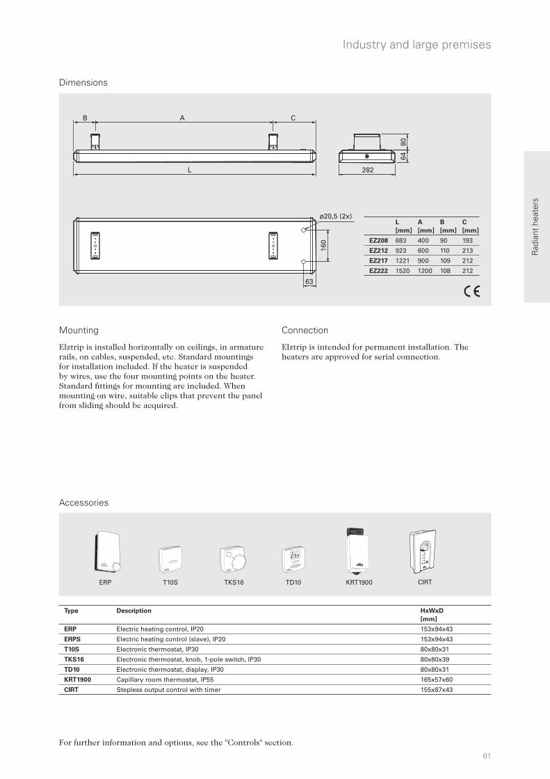
61
AB
L
63
282
C
ø20,5 (2x)
8064
160
L
[mm]
A
[mm]
B
[mm]
C
[mm]
EZ208 683 400 90 193
EZ212 923 600 110 213
EZ217 1221 900 109 212
EZ222 1520 1200 108 212
CIRT
1/2 h
1 h
2h
4h
kW
20
25
30
15
10
5
ERP CIRTT10S TKS16 TD10 KRT1900
Rad
iant
hea
ters
Accessories
Industry and large premises
Dimensions
Mounting Connection
For further information and options, see the "Controls" section.
Elztrip is intended for permanent installation. The heaters are approved for serial connection.
Elztrip is installed horizontally on ceilings, in armature rails, on cables, suspended, etc. Standard mountings for installation included. If the heater is suspended by wires, use the four mounting points on the heater. Standard fittings for mounting are included. When mounting on wire, suitable clips that prevent the panel from sliding should be acquired.
Type Description HxWxD
[mm]
ERP Electric heating control, IP20 153x94x43
ERPS Electric heating control (slave), IP20 153x94x43
T10S Electronic thermostat, IP30 80x80x31
TKS16 Electronic thermostat, knob, 1-pole switch, IP30 80x80x39
TD10 Electronic thermostat, display, IP30 80x80x31
KRT1900 Capillary room thermostat, IP55 165x57x60
CIRT Stepless output control with timer 155x87x43

62
115
1800
250
700
250
Installation height
Elztrip EZ300
• Integrated elements and a surface structure for improved efficiency.
• The heaters are approved for serial connection.
• Standard mountings for installation included.
• Casing of grey alu-zinc coated steel panels, very resistant against corrosion. Heating panel of naturally anodised aluminium.
EZ300 is intended for total and supplementary heating in industrial environments such as warehouses, workshops etc. EZ300 is a triple panel radiant heater with discreet and robust design that blends well with electrical fittings.
Radiant heaters
Minimum distances
Flammable material
Triple panel radiant heater for warehouses, workshops etc.
Elztrip EZ300 (IP44)Type Heat output
[W]
Voltage
[V]
Amperage
[A]
Max. element
temperature
[°C]
Dimensions
LxHxW
[mm]
Weight
[kg]
EZ336 3600 230V3~/400V3N~ 9,0/5,2 350 1670x63x420 19,8
EZ345 4500 230V3~/400V3N~ 11,3/6,5 350 2030x63x420 24,2
4 - 15 m

63
S123T10S TK10S KRT1900
B A
200
120
63
ø32,5 (2x)
L 420
40
L
[mm]
A
[mm]
B
[mm]
EZ336 1670 1200 235
EZ345 2030 1500 265
20
25
30
15
10
5
0
12
Rad
iant
hea
ters
Accessories
Industry and large premises
Dimensions
Mounting Connection
For further information and options, see the "Controls" section.
Elztrip is intended for permanent installation. The heaters are approved for serial connection.
Elztrip is installed horizontally on ceilings, in armature rails, on cables, suspended, etc. Standard mountings for installation included. If the heater is suspended by wires, use the four mounting points on the heater. Standard fittings for mounting are included. When mounting on wire, suitable clips that prevent the panel from sliding should be acquired.
Type Description HxWxD
[mm]
T10S Electronic thermostat, IP30 80x80x31
TK10S Electronic thermostat, knob, IP30 80x80x31
KRT1900 Capillary room thermostat, IP55 165x57x60
S123 Manual switch for 1-2-3 output steps, IP44 72x64x46

64
2300700
400 400
400
4,5 - 20 m 4 - 6 m
Installation height
Industrial infrared heater IR
• Reflectors of shiny anodised aluminium for optimal heat distribution.
• The mounting brackets allow the heater to be angled in five different positions.
• Connection plinth which allows for connection of a regulator or for serial connection of several heaters.
• Protection grille is available as an accessory.
• Casing of grey alu-zinc coated steel panels, very resistant against corrosion.
IR is suitabe for total or supplementary heating of premises with large volume and high ceilings. It can also be used outdoors for example on sport arena stands or to keep loading bays dry and frostless. IR has a robust industrial design.
Radiant heaters
Minimum distances
Flammable material
For premises with large volumes and high ceilings
Industrial infrared heater IR (IP44)Type Output steps
[kW]
Voltage
[V]
Amperage
[A]
Max. element
temperature
[°C]
Dimensions
LxHxW
[mm]
Weight
[kg]
IR3000 1/2/3 400V3N~* 4,3 700 1125x83x358 9,0
IR4500 1.5/3/4.5 400V3N~* 6,5 700 1500x83x358 11,1
IR6000 2/4/6 400V3N~* 8,7 700 1875x83x358 13,2*) Can also be connected 400V3~, but then without output steps. With neutral, one element tube at a time can be connected.

65
S123T10S TK10S KRT1900
20
25
30
15
10
5
0
12
L1
[mm]
L2
[mm]
IR3000 600 1125
IR4500 900 1500
IR6000 1200 1875
IRGCBT
CBT
1h
21
2h
4h
Rad
iant
hea
ters
Accessories
Industry and large premises
Industrial infrared heater IR is installed horizontally with mounting brackets that can be installed directly against the ceiling or wall. The mounting allows the radiation angle to be adjusted 30° in each direction. The heaters can also be suspended from wire (minimum Ø 3 mm). Protection grille is available as an accessory.
Dimensions
Mounting Connection
Industrial infrared heater IR is intended for permanent installation. There are double connection plinths in the connection box that make it possible to further connect from one heater to another.
For further information and options, see the "Controls" section.
Type Description HxWxD
[mm]
T10S Electronic thermostat with concealed knob, IP30 80x80x31
TK10S Electronic thermostat with visible knob, IP30 80x80x31
KRT1900 Capillary room thermostat, IP55 165x57x60
S123 Manual switch for 1-2-3 output steps, IP44 72x64x46
CBT Timer, IP44 155x87x43
IRG3000 Protection grille IR3000 869x362x40
IRG4500 Protection grille IR4500 1235x362x40
IRG6000 Protection grille IR6000 1615x362x40
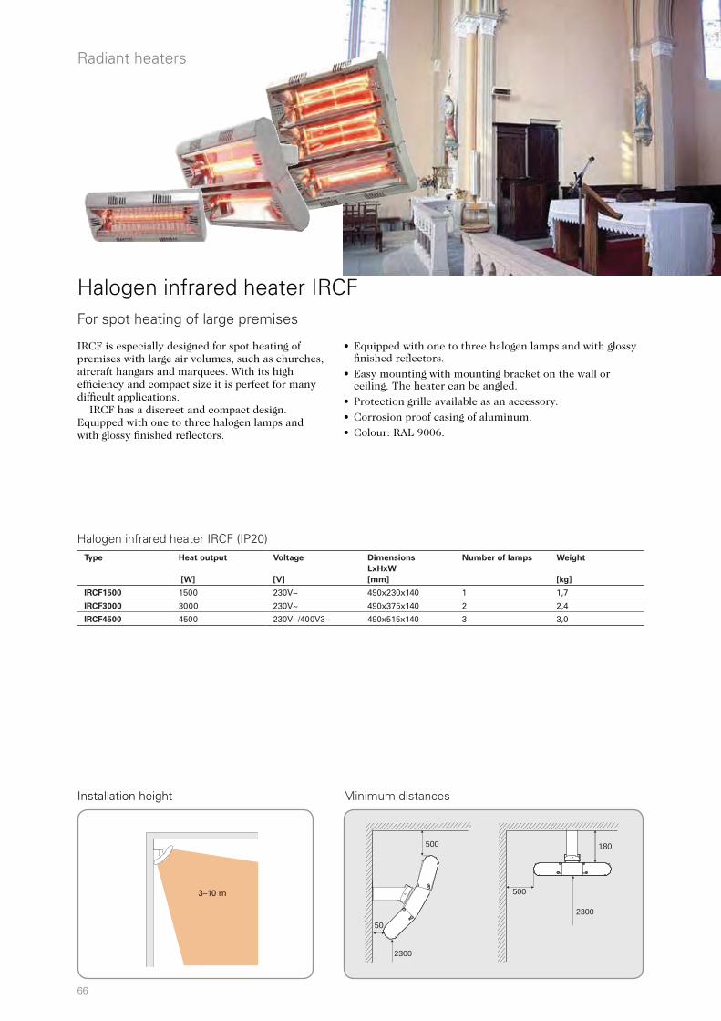
66
500
2300
50
180
500
2300
Installation height
Halogen infrared heater IRCF
• Equipped with one to three halogen lamps and with glossy finished reflectors.
• Easy mounting with mounting bracket on the wall or ceiling. The heater can be angled.
• Protection grille available as an accessory.
• Corrosion proof casing of aluminum.
• Colour: RAL 9006.
IRCF is especially designed for spot heating of premises with large air volumes, such as churches, aircraft hangars and marquees. With its high efficiency and compact size it is perfect for many difficult applications. IRCF has a discreet and compact design. Equipped with one to three halogen lamps and with glossy finished reflectors.
Radiant heaters
Minimum distances
For spot heating of large premises
Halogen infrared heater IRCF (IP20)Type Heat output
[W]
Voltage
[V]
Dimensions
LxHxW
[mm]
Number of lamps Weight
[kg]
IRCF1500 1500 230V~ 490x230x140 1 1,7
IRCF3000 3000 230V~ 490x375x140 2 2,4
IRCF4500 4500 230V~/400V3~ 490x515x140 3 3,0
3–10 m
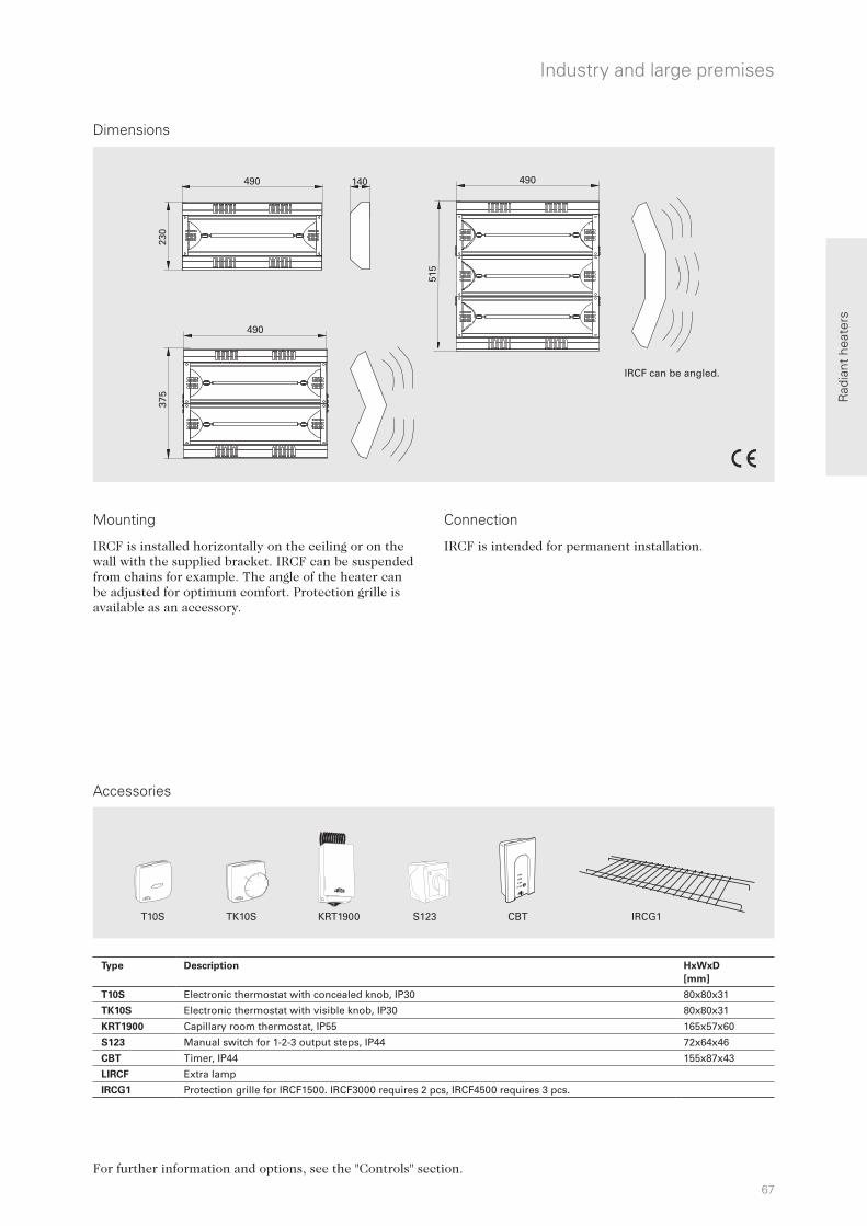
67
S123T10S TK10S KRT1900
20
25
30
15
10
5
0
12
IRCG1CBT
CBT
1h
21
2h
4h
230
490 140
490
375
490
515
Rad
iant
hea
ters
Accessories
Industry and large premises
IRCF is installed horizontally on the ceiling or on the wall with the supplied bracket. IRCF can be suspended from chains for example. The angle of the heater can be adjusted for optimum comfort. Protection grille is available as an accessory.
Dimensions
Mounting Connection
IRCF is intended for permanent installation.
For further information and options, see the "Controls" section.
IRCF can be angled.
Type Description HxWxD
[mm]
T10S Electronic thermostat with concealed knob, IP30 80x80x31
TK10S Electronic thermostat with visible knob, IP30 80x80x31
KRT1900 Capillary room thermostat, IP55 165x57x60
S123 Manual switch for 1-2-3 output steps, IP44 72x64x46
CBT Timer, IP44 155x87x43
LIRCF Extra lamp
IRCG1 Protection grille for IRCF1500. IRCF3000 requires 2 pcs, IRCF4500 requires 3 pcs.
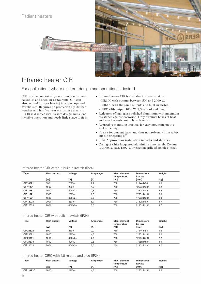
68
Infrared heater CIR
• Infrared heater CIR is available in three versions:
- CIR100 with outputs between 500 and 2000 W.
- CIR200 with the same outputs and built-in switch.
- CIRC with output 1000 W. 1,8 m cord and plug.
• Reflectors of high-gloss polished aluminium with maximum resistance against corrosion. Grey terminal boxes of heat and weather resistant polycarbonate.
• Adjustable mounting brackets for easy mounting on the wall or ceiling.
• No risk for current leaks and thus no problem with a safety cut-out triggering off.
• IP24. Approved for installation in baths and showers.
• Casing of white lacquered aluminium zinc panels. Colour: RAL 9002, NCS 1502-Y. Protection grille of stainless steel.
CIR provide comfort all year around on terraces, balconies and open-air restaurants. CIR can also be used for spot heating in workshops and warehouses. Requires no protection against bad weather and has five-year corrosion warranty. CIR is discreet with its slim design and silent, invisible operation and needs little space to fit in.
Radiant heaters
For applications where discreet design and operation is desired
Infrared heater CIR without built-in switch (IP24)
Infrared heater CIR with built-in switch (IP24)
Infrared heater CIRC with 1.8 m cord and plug (IP24)
Type Heat output
[W]
Voltage
[V]
Amperage
[A]
Max. element
temperature
[°C]
Dimensions
LxHxW
[mm]
Weight
[kg]
CIR20521 500 230V~ 2,2 750 710x44x94 1,5
CIR21021 1000 230V~ 4,3 750 1250x44x94 2,2
CIR21031 1000 400V2~ 2,5 750 1250x44x94 2,2
CIR21531 1500 400V2~ 3,8 750 1755x44x94 3,0
CIR22031 2000 400V2~ 5,0 750 2180x44x94 3,7
Type Heat output
[W]
Voltage
[V]
Amperage
[A]
Max. element
temperature
[°C]
Dimensions
LxHxW
[mm]
Weight
[kg]
CIR10521 500 230V~ 2,2 750 710x44x94 1,5
CIR11021 1000 230V~ 4,3 750 1250x44x94 2,2
CIR11031 1000 400V2~ 2,5 750 1250x44x94 2,2
CIR11521 1500 230V~ 6,5 750 1755x44x94 3,0
CIR11531 1500 400V2~ 3,8 750 1755x44x94 3,0
CIR12021 2000 230V~ 8,7 750 2180x44x94 3,7
CIR12031 2000 400V2~ 5,0 750 2180x44x94 3,7
Type Heat output
[W]
Voltage
[V]
Amperage
[A]
Max. element
temperature
[°C]
Dimensions
LxHxW
[mm]
Weight
[kg]
CIR11021C 1000 230V~ 4,3 750 1250x44x94 2,2

69
CIRT
1/2 h
1 h
2h
4h
kW
CIRT CBT
A
[mm]
B*¹
[mm]
BMIN
*²
[mm]
CIR105/205 710 500 300
CIR110/210 1250 900 600
CIR115/215 1755 1200 800
CIR120/220 2180 1500 1000
CBT
1h
21
2h
4h
150
700
150
300
1800
ERP
Rad
iant
hea
ters
Installation height Minimum distances
Accessories
Outdoors
CIR is installed horizontally on the ceiling or on the wall with the supplied adjustable mounting brackets. The angle of the heater can be adjusted for optimum comfort. The standard brackets cannot be used for angled installation on the ceiling, because the distance then becomes less than the minimum distance. CIR can also be suspended by wire.
Dimensions
Mounting Connection CIR11021C is equipped with 1.8 m cord and plug for connection to an earthed outlet socket. Other models are intended for fixed installation. The heaters are approved for serial connection.
Flammable material
*1) Recommendation *2) Minimum distances between brackets
For further information and options, see the "Controls" section.
Type Description HxWxD
[mm]
CIRT Stepless output control with timer 155x87x43
CBT Timer 155x87x43
ERP Electric heating control 157x93x40
2–2,5 m2–2,5 m
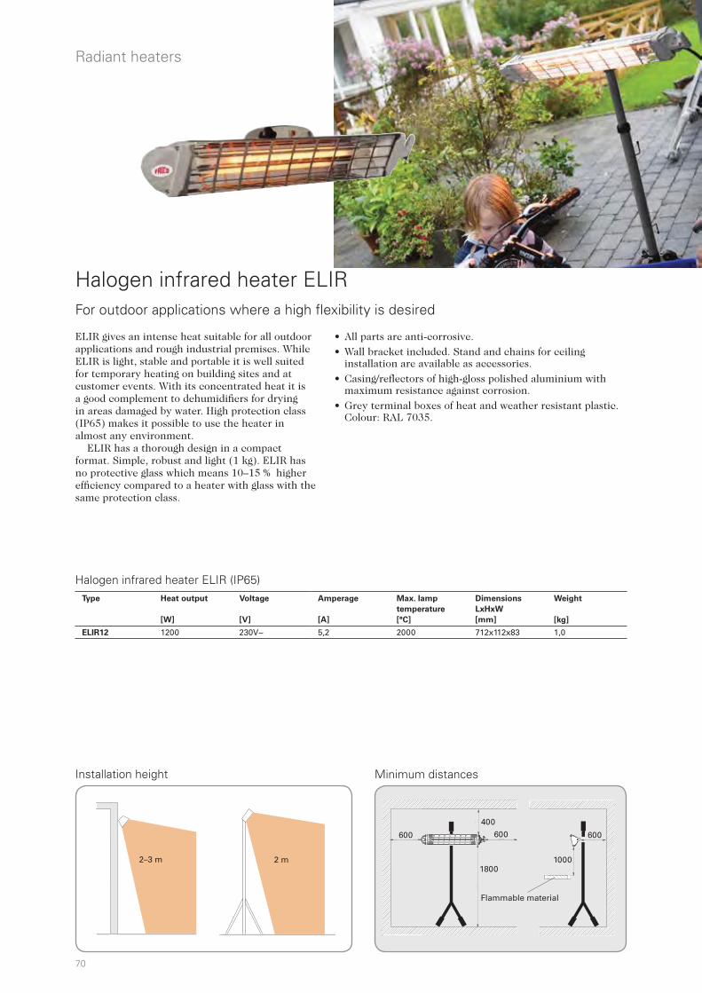
70
600 600
1800
400
600
10001000
1800
600
400
600 600
Installation height
Halogen infrared heater ELIR
ELIR gives an intense heat suitable for all outdoor applications and rough industrial premises. While ELIR is light, stable and portable it is well suited for temporary heating on building sites and at customer events. With its concentrated heat it is a good complement to dehumidifiers for drying in areas damaged by water. High protection class (IP65) makes it possible to use the heater in almost any environment. ELIR has a thorough design in a compact format. Simple, robust and light (1 kg). ELIR has no protective glass which means 10–15 % higher efficiency compared to a heater with glass with the same protection class.
Minimum distances
For outdoor applications where a high flexibility is desired
Halogen infrared heater ELIR (IP65)
Radiant heaters
Flammable material
• All parts are anti-corrosive.
• Wall bracket included. Stand and chains for ceiling installation are available as accessories.
• Casing/reflectors of high-gloss polished aluminium with maximum resistance against corrosion.
• Grey terminal boxes of heat and weather resistant plastic. Colour: RAL 7035.
Type Heat output
[W]
Voltage
[V]
Amperage
[A]
Max. lamp
temperature
[°C]
Dimensions
LxHxW
[mm]
Weight
[kg]
ELIR12 1200 230V~ 5,2 2000 712x112x83 1,0
2–3 m 2 m
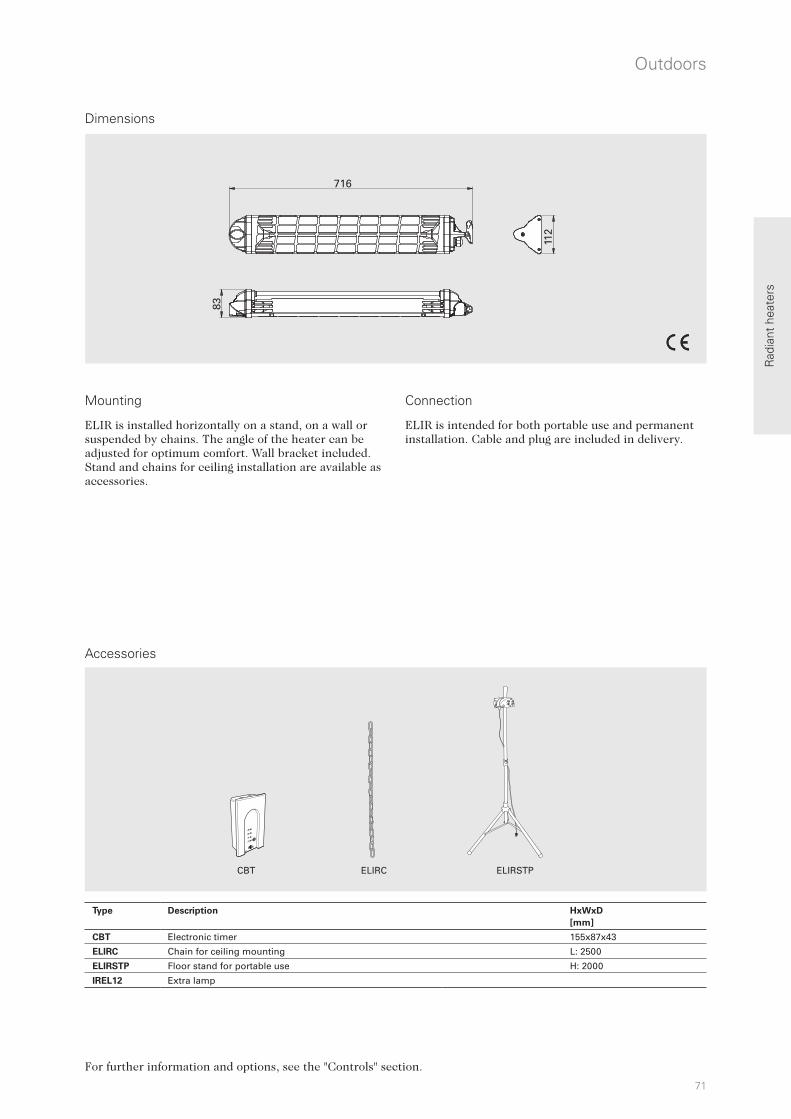
71
CBT ELIRC ELIRSTP
CBT
1h
21
2h
4h
716
83
112
Rad
iant
hea
ters
Accessories
Outdoors
Dimensions
Mounting Connection
ELIR is intended for both portable use and permanent installation. Cable and plug are included in delivery.
For further information and options, see the "Controls" section.
ELIR is installed horizontally on a stand, on a wall or suspended by chains. The angle of the heater can be adjusted for optimum comfort. Wall bracket included. Stand and chains for ceiling installation are available as accessories.
Type Description HxWxD
[mm]
CBT Electronic timer 155x87x43
ELIRC Chain for ceiling mounting L: 2500
ELIRSTP Floor stand for portable use H: 2000
IREL12 Extra lamp

72
Halogen infrared heater IH
Halogeninfra IH is powerful with a high filament temperature of 2200 °C and is the perfect choice for exposed outdoor environments where design is important. IH can also be used as local heating in large premises. IH is available in two different designs. IHW gives a comfortable heat in the occupied zone from close range and also wider heat distribution. IHF has more direct heat distribution and is designed to be installed higher up. IH is easy to position thanks to its compact design. The discreet and appealing look makes it suitable for outdoor environments with design demands.
Suitable for exposed outdoor environments with design demands
Infrared heater IHW with wide heat distribution (IP44)
Infrared heater IHF with directed heat distribution (IP44)
Radiant heaters
• IH is available in two versions:
- IHW provides wide heat distribution (60°), recommended installation height 1.8 – 2.5 m.
- IHF provides directed heat distribution (40°), recommended installation height 2.3 – 3.5 m.
• IH consists of a halogen lamp with a faint red glow and a very high intensity and a highly-polished reflector for optimum heat distribution.
• Bracket for wall mounting. Can also be suspended from the ceiling or mounted on a post. Other mounting alternatives are available as accessories.
• Equipped with a 0.9 metre cord with plug for connection to an earthed outlet socket.
• Casing in anodised aluminium, grille in Nickel/Chrome plating, end caps in powder-coated light-alloy metal. Colour: RAL 9006.
Type Heat output
[W]
Voltage
[V]
Amperage
[A]
Max. filament
temperature
[°C]
Dimensions
LxHxW
[mm]
Weight
[kg]
IHW10 1000 230V~ 4,3 2200 500x77x169 1,9
IHW15 1500 230V~ 6,5 2200 500x77x169 1,9
IHW20 2000 230V~ 8,7 2200 676x77x169 2,5
Type Heat output
[W]
Voltage
[V]
Amperage
[A]
Max. filament
temperature
[°C]
Dimensions
LxHxW
[mm]
Weight
[kg]
IHF10 1000 230V~ 4,3 2200 500x77x169 1,9
IHF15 1500 230V~ 6,5 2200 500x77x169 1,9
IHF20 2000 230V~ 8,7 2200 676x77x169 2,5

73
IHUB IHXH IHXL IHT IHPIHECBT
500/676 169
160
0,9
7714
7
300
A
160200 180
min 30°
B
500
1000
1800
Rad
iant
hea
ters
Accessories
Dimensions
Outdoors
For further information about the accessories, see carbon infrared heater IHC.
MountingIH installed horizontally on walls with supplied bracket. The heater can be angled up to 45°. The heater can also be mounted on e.g. a parasol or a post, a suitable U-bolt (not included) is used for this together with the supplied console. For ceiling installation use ceiling bracket IHE (accessory). For other mounting alternatives, see accessories. Connection IH is equipped with a 0.9 metre cord with plug for connection to an earthed outlet socket.
Installation height Minimum distances
Flammable material
Type Description HxWxD
[mm]
CBT Electronic timer, IP44 155x87x43
IHUB Universal bracket for IH
IHE Ceiling bracket
IHXH Extension bracket for high level mounting
IHXL Extension bracket for low level mounting
IHT Triple bracket
IHTW Wire kit (3 wires) for IHT
IHP Post for freestanding installation H: 2,3 m
2,3 – 3,5 m1,8 -2,5 m
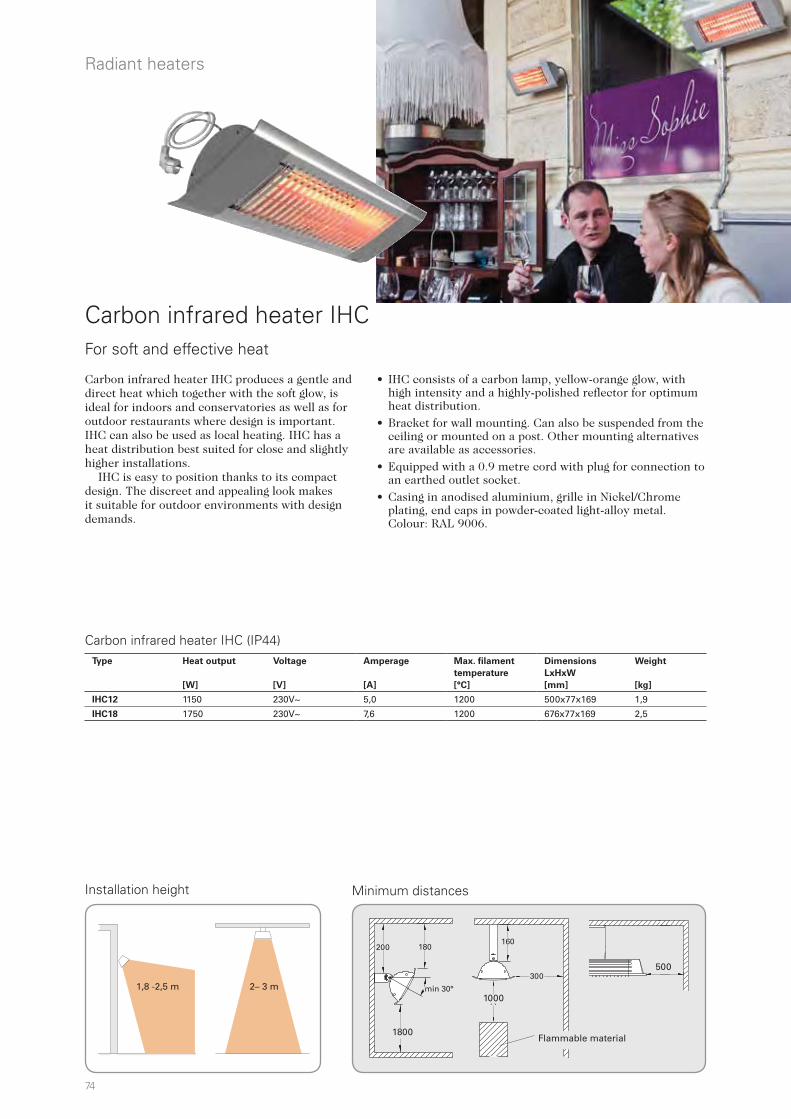
74
300
A
160200 180
min 30°
B
500
1000
1800
Installation height
Carbon infrared heater IHC produces a gentle and direct heat which together with the soft glow, is ideal for indoors and conservatories as well as for outdoor restaurants where design is important. IHC can also be used as local heating. IHC has a heat distribution best suited for close and slightly higher installations. IHC is easy to position thanks to its compact design. The discreet and appealing look makes it suitable for outdoor environments with design demands.
Minimum distances
Carbon infrared heater IHC (IP44)
Radiant heaters
• IHC consists of a carbon lamp, yellow-orange glow, with high intensity and a highly-polished reflector for optimum heat distribution.
• Bracket for wall mounting. Can also be suspended from the ceiling or mounted on a post. Other mounting alternatives are available as accessories.
• Equipped with a 0.9 metre cord with plug for connection to an earthed outlet socket.
• Casing in anodised aluminium, grille in Nickel/Chrome plating, end caps in powder-coated light-alloy metal. Colour: RAL 9006.
Flammable material
For soft and effective heat
Carbon infrared heater IHC
Type Heat output
[W]
Voltage
[V]
Amperage
[A]
Max. filament
temperature
[°C]
Dimensions
LxHxW
[mm]
Weight
[kg]
IHC12 1150 230V~ 5,0 1200 500x77x169 1,9
IHC18 1750 230V~ 7,6 1200 676x77x169 2,5
1,8 -2,5 m 2– 3 m

75
IHUB IHXH IHXL IHT IHPIHECBT
500/676 169
160
0,9
7714
7
Rad
iant
hea
ters
Accessories
Dimensions
Outdoors
MountingIHC installed horizontally on walls with supplied bracket. The heater can be angled up to 45°. The heater can also be mounted on e.g. a parasol or a post, a suitable U-bolt (not included) is used for this together with the supplied console. For ceiling installation use ceiling bracket IHE (accessory). For other mounting alternatives, see accessories. Connection IHC is equipped with a 0.9 metre cord with plug for connection to an earthed outlet socket.
IHUB, universal bracket A bracket that makes it easy to even angle IH/IHC sideways. The bracket also allows mounting on, for example, a windbreak when the clamping screw is used.
IHE, ceiling bracketUsed to secure the IH/IHC in the ceiling.
IHXH, drooping extension bracket for high level mounting Used to install IH/IHC at high level, such as above a window. Wall bracket included.
IHXL, arching extension bracket for low level mounting Used to install IH/IHC at low level, such as on a windbreak. Wall bracket included.
For further information and options, see the "Controls" section.
IHT, triple bracket Three IH/IHC units can be mounted on the IHT bracket to provide heat in all directions. Can be suspended from the ceiling by three wires or mounted on an IHP post. Used for IH10, IH15 and IHC12. IHTW, wire kitSet of three bright galvanized wires for easy hanging of IHT.
IHP, post for freestanding installation Post to stand IH/IHC on the floor. IHP has a fixed length of 2.3 m and can be cut to desired length. The IHT triple bracket can be attached to provide heat in all directions. IH/IHC can also be mounted directly on the post using a standard bracket and a U-bolt.
Type Description HxWxD
[mm]
CBT Electronic timer, IP44 155x87x43
IHUB Universal bracket for IH
IHE Ceiling bracket
IHXH Extension bracket for high level mounting
IHXL Extension bracket for low level mounting
IHT Triple bracket
IHTW Wire kit (3 wires) for IHT
IHP Post for freestanding installation H: 2,3 m
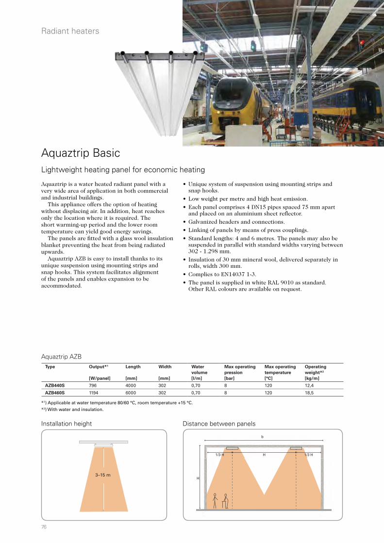
76
H
b
1/3 H1/3 H H
Aquaztrip is a water heated radiant panel with a very wide area of application in both commercial and industrial buildings. This appliance offers the option of heating without displacing air. In addition, heat reaches only the location where it is required. The short warming-up period and the lower room temperature can yield good energy savings. The panels are fitted with a glass wool insulation blanket preventing the heat from being radiated upwards. Aquaztrip AZB is easy to install thanks to its unique suspension using mounting strips and snap hooks. This system facilitates alignment of the panels and enables expansion to be accommodated.
• Unique system of suspension using mounting strips and snap hooks.
• Low weight per metre and high heat emission.
• Each panel comprises 4 DN15 pipes spaced 75 mm apart and placed on an aluminium sheet reflector.
• Galvanized headers and connections.
• Linking of panels by means of press couplings.
• Standard lengths: 4 and 6 metres. The panels may also be suspended in parallel with standard widths varying between 302 - 1.298 mm.
• Insulation of 30 mm mineral wool, delivered separately in rolls, width 300 mm.
• Complies to EN14037 1-3.
• The panel is supplied in white RAL 9010 as standard. Other RAL colours are available on request.
Distance between panels
Aquaztrip Basic Lightweight heating panel for economic heating
Installation height
*1) Applicable at water temperature 80/60 °C, room temperature +15 °C. *2) With water and insulation.
Radiant heaters
Aquaztrip AZBType Output*1
[W/panel]
Length
[mm]
Width
[mm]
Water
volume
[l/m]
Max operating
pression
[bar]
Max operating
temperature
[°C]
Operating
weight*2
[kg/m]
AZB440S 796 4000 302 0,70 8 120 12,4
AZB460S 1194 6000 302 0,70 8 120 18,5
3–15 m
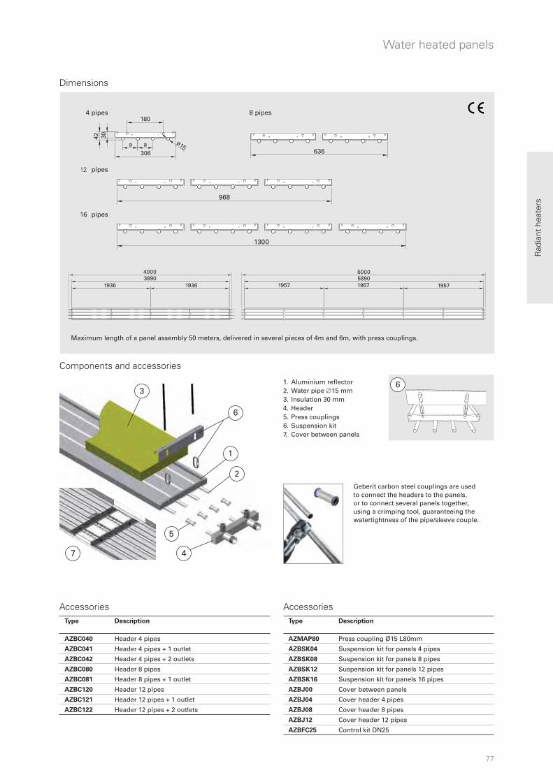
77
6
1
2
4
3
5
7
636
1300
968
306
ø15
180
a a
42 30
40003890
19361936 1957 1957
600058901957
6
Rad
iant
hea
ters
Geberit carbon steel couplings are used to connect the headers to the panels, or to connect several panels together, using a crimping tool, guaranteeing the watertightness of the pipe/sleeve couple.
1. Aluminium reflector 2. Water pipe 15 mm 3. Insulation 30 mm 4. Header 5. Press couplings6. Suspension kit7. Cover between panels
Dimensions
Water heated panels
4
12
16
pipes
pipes
pipes
8 pipes
Components and accessories
Accessories Accessories
Maximum length of a panel assembly 50 meters, delivered in several pieces of 4m and 6m, with press couplings.
Type Description
AZMAP80 Press coupling Ø15 L80mm
AZBSK04 Suspension kit for panels 4 pipes
AZBSK08 Suspension kit for panels 8 pipes
AZBSK12 Suspension kit for panels 12 pipes
AZBSK16 Suspension kit for panels 16 pipes
AZBJ00 Cover between panels
AZBJ04 Cover header 4 pipes
AZBJ08 Cover header 8 pipes
AZBJ12 Cover header 12 pipes
AZBFC25 Control kit DN25
Type Description
AZBC040 Header 4 pipes
AZBC041 Header 4 pipes + 1 outlet
AZBC042 Header 4 pipes + 2 outlets
AZBC080 Header 8 pipes
AZBC081 Header 8 pipes + 1 outlet
AZBC120 Header 12 pipes
AZBC121 Header 12 pipes + 1 outlet
AZBC122 Header 12 pipes + 2 outlets
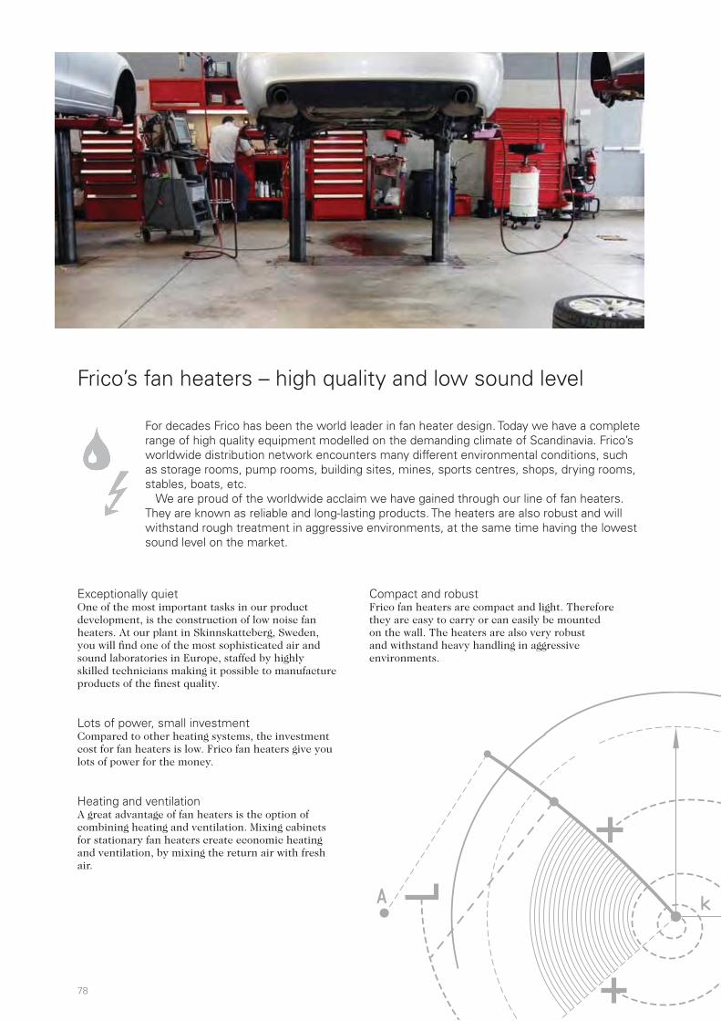
78
For decades Frico has been the world leader in fan heater design. Today we have a complete range of high quality equipment modelled on the demanding climate of Scandinavia. Frico’s worldwide distribution network encounters many different environmental conditions, such as storage rooms, pump rooms, building sites, mines, sports centres, shops, drying rooms, stables, boats, etc.
We are proud of the worldwide acclaim we have gained through our line of fan heaters. They are known as reliable and long-lasting products. The heaters are also robust and will withstand rough treatment in aggressive environments, at the same time having the lowest sound level on the market.
Exceptionally quiet One of the most important tasks in our product development, is the construction of low noise fan heaters. At our plant in Skinnskatteberg, Sweden, you will find one of the most sophisticated air and sound laboratories in Europe, staffed by highly skilled technicians making it possible to manufacture products of the finest quality.
Lots of power, small investment Compared to other heating systems, the investment cost for fan heaters is low. Frico fan heaters give you lots of power for the money.
Heating and ventilation A great advantage of fan heaters is the option of combining heating and ventilation. Mixing cabinets for stationary fan heaters create economic heating and ventilation, by mixing the return air with fresh air.
Compact and robust Frico fan heaters are compact and light. Therefore they are easy to carry or can easily be mounted on the wall. The heaters are also very robust and withstand heavy handling in aggressive environments.
Frico’s fan heaters – high quality and low sound level
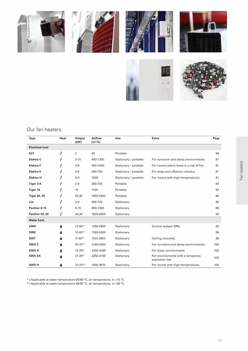
79
Fan
heat
ers
Our fan heaters
*1) Applicable at water temperature 80/60 °C, air temperature, in +15 °C. *2) Applicable at water temperature 80/60 °C, air temperature, in +40 °C.
Type Heat Output
[kW]
Airflow
[m3/h]
Use Extra Page
Electrical heat
K21 3 2 90 Portable 80
Elektra C 3 3-15 400-1300 Stationary / portable For corrosive and damp environments. 81
Elektra F 3 3-9 400-1000 Stationary / portable For rooms where there is a risk of fire. 81
Elektra V 3 3-6 400-700 Stationary / portable For ships and offshore industry. 81
Elektra H 3 6-9 1000 Stationary / portable For rooms with high temperatures. 81
Tiger 2-9 3 2-9 280-720 Portable 84
Tiger 15 3 15 1120 Portable 84
Tiger 20, 30 3 20,30 1900-2600 Portable 84
Cat 3 3-9 280-720 Stationary 86
Panther 6-15 3 6-15 900-1300 Stationary 88
Panther 20, 30 3 20,30 1900-2600 Stationary 90
Water heat
SWH 2 12-64*1 1260-5900 Stationary Control system SIRe. 92
SWS 2 12-65*1 1260-6300 Stationary 96
SWT 2 11-40*1 1100-3900 Stationary Ceiling mounted. 98
SWX C 2 20-37*1 2160-4300 Stationary For corrosive and damp environments. 100
SWX D 2 15-29*1 2200-4430 Stationary For dusty environments. 100
SWX EX 2 21-39*1 2250-4150 Stationary For environments with a temporary explosion risk.
100
SWX H 2 12-23*2 1830-3870 Stationary For rooms with high temperatures. 100

80
220
160
200
150
Fan heaters
Fan heater K21
• Self-regulating ceramic PTC element that can not be overheated.
• Intensive and concentrated heat emission. The air is heated to approx. 65 °C when it passes through K21.
• Equipped with 2 metre long cord with plug for connection to an earthed outlet socket.
• Thermostat (+5 – +35 °C) and output selector (0/1/2 kW).
• Approved by SEMKO.
• Outer casing in white enamelled sheet steel. Colour: RAL 9016, NCS S 0500-N (white).
Small and portable fan heater with high output temperature
K21 is a compact and safe fan heater designed for portable use. Ideal for heating small areas, for example, garages, caravans, awnings, weekend cottages, offices, patios, etc. K21 fan heater is small and compact in white metal finish and is equipped with a solid handle.
Fan heater K21 (IP21)
Dimensions
*1) Conditions: Distance to the unit 5 metres. *2) t = temperature rise of passing air at maximum heat output.
Type Output steps
[kW]
Airflow
[m³/h]
Sound level*1
[dB(A)]
t*2
[°C]
Voltage
[V]
Amperage
[A]
HxWxD
[mm]
Weight
[kg]
K21 0/1/2 90 43 62 230V~ 8,9 220x160x200 2,5
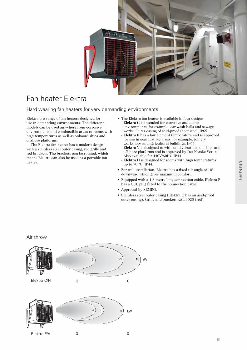
81
Elektra C/H
6/9 15 kW3
3 0
Elektra F/V
9 kW3 6
3 0
Fan
heat
ers
Air throw
Fan heater Elektra Hard wearing fan heaters for very demanding environments
Elektra is a range of fan heaters designed for use in demanding environments. The different models can be used anywhere from corrosive environments and combustible areas to rooms with high temperatures as well as onboard ships and offshore platforms. The Elektra fan heater has a modern design with a stainless steel outer casing, red grille and red brackets. The brackets can be rotated, which means Elektra can also be used as a portable fan heater.
• The Elektra fan heater is available in four designs:- Elektra C is intended for corrosive and damp
environments, for example, car-wash halls and sewage works. Outer casing of acid-proof sheet steel. IP65.
- Elektra F has a low element temperature and is approved for use in combustible areas, for example, joinery workshops and agricultural buildings. IP65.
- Elektra V is designed to withstand vibrations on ships and offshore platforms and is approved by Det Norske Veritas. Also available for 440V/60Hz. IP44.
- Elektra H is designed for rooms with high temperatures, up to 70 °C. IP44.
• For wall installation, Elektra has a fixed tilt angle of 10° downward which gives maximum comfort.
• Equipped with a 1.8 metre long connection cable. Elektra F has a CEE plug fitted to the connection cable.
• Approved by SEMKO.
• Stainless steel outer casing (Elektra C has an acid-proof outer casing). Grille and bracket: RAL 3020 (red).
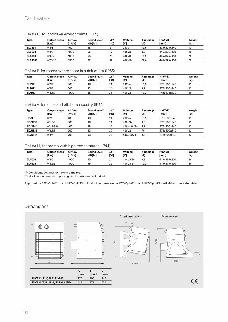
82
10°
405/
525
425/485
405/
465
390/545
3°
CB
A
Fan heaters
Elektra C, for corrosive environments (IP65)
Elektra F, for rooms where there is a risk of fire (IP65)
Elektra V, for ships and offshore industry (IP44)
Elektra H, for rooms with high temperatures (IP44)
*1) Conditions: Distance to the unit 5 metres. *2) t = temperature rise of passing air at maximum heat output.
Approved for 220V/1ph/60Hz and 380V/3ph/60Hz. Product performance for 220V/1ph/60Hz and 380V/3ph/60Hz will differ from stated data.
Dimensions
A
[mm]
B
[mm]
C
[mm]
ELC331, ELV, ELF331/633 375 300 340
ELC633/933/1533, ELF933, ELH 445 375 430
Fixed installation Portabel use
Type Output steps
[kW]
Airflow
[m³/h]
Sound level*1
[dB(A)]
t*2
[°C]
Voltage
[V]
Amperage
[A]
HxWxD
[mm]
Weight
[kg]
ELC331 0/2/3 400 48 21 230V~ 13,5 375x300x340 13
ELC633 0/3/6 1000 55 17 400V3~ 8,9 445x375x430 20
ELC933 0/4,5/9 1000 55 25 400V3~ 13,2 445x375x430 20
ELC1533 0/7,5/15 1300 62 32 400V3~ 22,0 445x375x430 20
Type Output steps
[kW]
Airflow
[m³/h]
Sound level*1
[dB(A)]
t*2
[°C]
Voltage
[V]
Amperage
[A]
HxWxD
[mm]
Weight
[kg]
ELF331 0/2/3 400 48 21 230V~ 13,5 375x300x340 13
ELF633 0/3/6 700 53 24 400V3~ 9,1 375x300x340 13
ELF933 0/4,5/9 1000 55 25 400V3~ 13,2 445x375x430 20
Type Output steps
[kW]
Airflow
[m³/h]
Sound level*1
[dB(A)]
t*2
[°C]
Voltage
[V]
Amperage
[A]
HxWxD
[mm]
Weight
[kg]
ELV331 0/2/3 400 48 21 230V~ 13,3 375x300x340 13
ELV3333 0/1,5/3 400 48 21 400V3~ 4,6 375x300x340 13
ELV3344 0/1,8/3,6 400 48 25 400/440V3~ 5,1 375x300x340 13
ELV5333 0/2,5/5 700 53 20 400V3~ 7,5 375x300x340 13
ELV6344 0/3/6 700 53 24 440/440V3~ 8,2 375x300x340 13
Type Output steps
[kW]
Airflow
[m³/h]
Sound level*1
[dB(A)]
t*2
[°C]
Voltage
[V]
Amperage
[A]
HxWxD
[mm]
Weight
[kg]
ELH633 0/3/6 1000 55 24 400V3N~ 8,9 445x375x430 20
ELH933 0/4,5/9 1000 55 25 400V3N~ 13,2 445x375x430 20

83
ELSRT / ELFSRT ELRTELSELSRT4
Fan
heat
ers
Accessories
Control options
Fan heater Elektra H features an integrated thermostat with the working range 0 – +70 °C, other models feature an integrated thermostat with the working range 0 – +35 °C. The output can be selected using the output selector on the unit or on the external control panel. Elektra F Can be controlled using an external control panel for remote control, for example, when installed high on a wall.
• ELS, control panel
• ELFSRT, control panel with integrated thermostat (0 – +35 °C), controls one unit
Elektra C / Elektra VCan be regulated using an external control panel with integrated thermostat (0 - +35 °C) for remote control, for example, when installed high on a wall.
• ELSRT, control panel, controls one unit
• ELSRT4, control panel, controls up to four units
Elektra HCan be regulated using an external thermostat.
• ELRT, room thermostat
Elektra
Type Description HxWxD
[mm]
ELSRT Control panel and thermostat, for ELC/ELV, controls one fan heater, IP65 175x150x100
ELSRT4 Control panel and thermostat, for ELC/ELV, controls 4 fan heaters, IP65 255x360x110
ELS Control panel, for ELF, start/stop, IP65 105x70x80
ELFSRT Control panel and thermostat, for ELF, controls one fan heater, IP65 175x150x100
ELRT Thermostat, for ELH, IP44 175x150x100
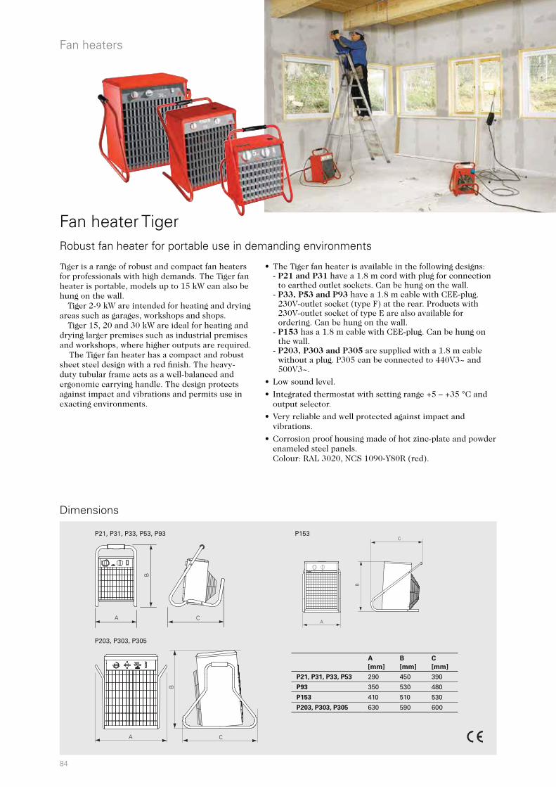
84
P203, P303, P305
P21, P31, P33, P53, P93 P153
A
B
C
Co kW
A
B
C
A C
B
Fan heaters
Dimensions
Fan heater Tiger
• The Tiger fan heater is available in the following designs:- P21 and P31 have a 1.8 m cord with plug for connection
to earthed outlet sockets. Can be hung on the wall.- P33, P53 and P93 have a 1.8 m cable with CEE-plug.
230V-outlet socket (type F) at the rear. Products with 230V-outlet socket of type E are also available for ordering. Can be hung on the wall.
- P153 has a 1.8 m cable with CEE-plug. Can be hung on the wall.
- P203, P303 and P305 are supplied with a 1.8 m cable without a plug. P305 can be connected to 440V3~ and 500V3~.
• Low sound level.
• Integrated thermostat with setting range +5 – +35 °C and output selector.
• Very reliable and well protected against impact and vibrations.
• Corrosion proof housing made of hot zinc-plate and powder enameled steel panels. Colour: RAL 3020, NCS 1090-Y80R (red).
Robust fan heater for portable use in demanding environments
Tiger is a range of robust and compact fan heaters for professionals with high demands. The Tiger fan heater is portable, models up to 15 kW can also be hung on the wall.
Tiger 2-9 kW are intended for heating and drying areas such as garages, workshops and shops.
Tiger 15, 20 and 30 kW are ideal for heating and drying larger premises such as industrial premises and workshops, where higher outputs are required. The Tiger fan heater has a compact and robust sheet steel design with a red finish. The heavy-duty tubular frame acts as a well-balanced and ergonomic carrying handle. The design protects against impact and vibrations and permits use in exacting environments.
A
[mm]
B
[mm]
C
[mm]
P21, P31, P33, P53 290 450 390
P93 350 530 480
P153 410 510 530
P203, P303, P305 630 590 600
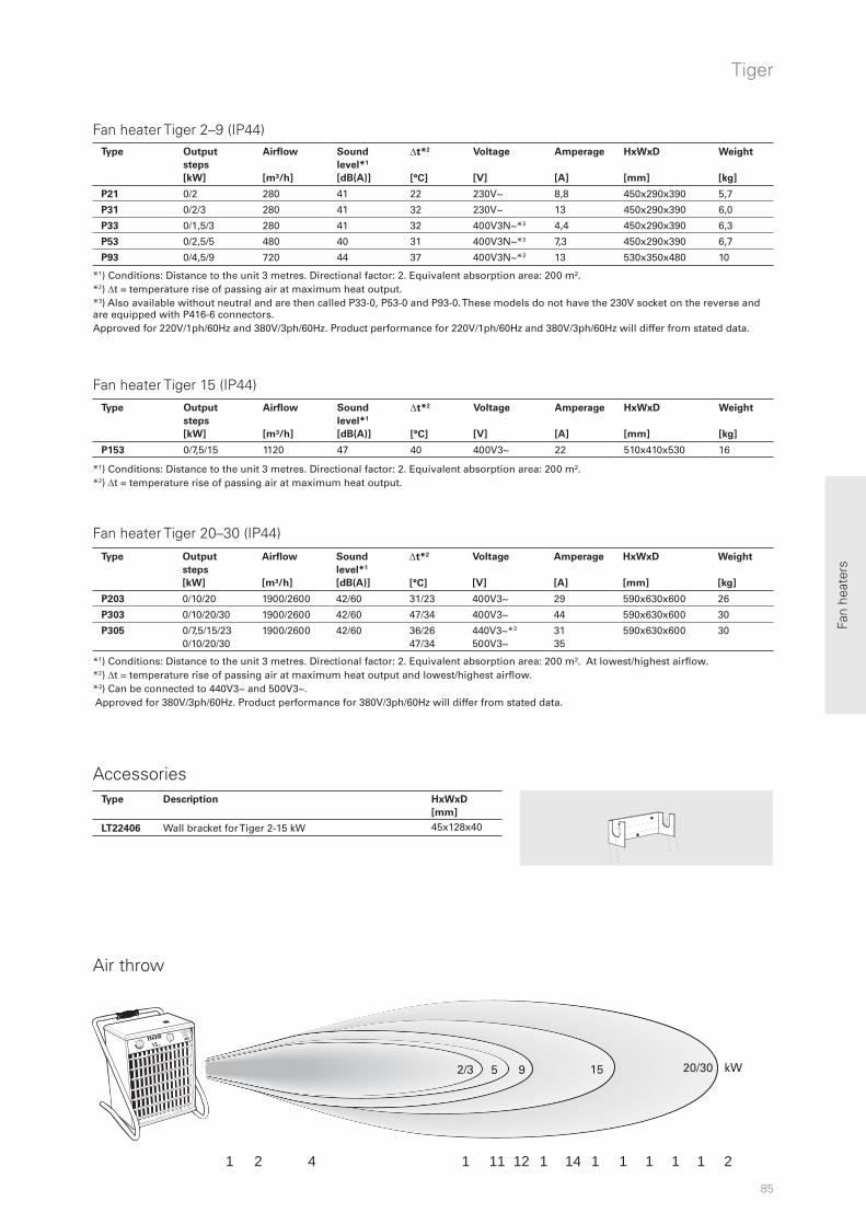
85
2/3 5 9 15 20/30 kW
2 1 4 1 11 12 1 14 1 1 1 1 1 2
Fan
heat
ers
Tiger
Accessories
Fan heater Tiger 2–9 (IP44)
Fan heater Tiger 15 (IP44)
Fan heater Tiger 20–30 (IP44)
Air throw
*1) Conditions: Distance to the unit 3 metres. Directional factor: 2. Equivalent absorption area: 200 m². At lowest/highest airflow. *2) t = temperature rise of passing air at maximum heat output and lowest/highest airflow. *3) Can be connected to 440V3~ and 500V3~. Approved for 380V/3ph/60Hz. Product performance for 380V/3ph/60Hz will differ from stated data.
*1) Conditions: Distance to the unit 3 metres. Directional factor: 2. Equivalent absorption area: 200 m². *2) t = temperature rise of passing air at maximum heat output.
*1) Conditions: Distance to the unit 3 metres. Directional factor: 2. Equivalent absorption area: 200 m². *2) t = temperature rise of passing air at maximum heat output. *3) Also available without neutral and are then called P33-0, P53-0 and P93-0. These models do not have the 230V socket on the reverse and are equipped with P416-6 connectors.Approved for 220V/1ph/60Hz and 380V/3ph/60Hz. Product performance for 220V/1ph/60Hz and 380V/3ph/60Hz will differ from stated data.
Type Output
steps
[kW]
Airflow
[m³/h]
Sound
level*1
[dB(A)]
t*2
[°C]
Voltage
[V]
Amperage
[A]
HxWxD
[mm]
Weight
[kg]
P21 0/2 280 41 22 230V~ 8,8 450x290x390 5,7
P31 0/2/3 280 41 32 230V~ 13 450x290x390 6,0
P33 0/1,5/3 280 41 32 400V3N~*3 4,4 450x290x390 6,3
P53 0/2,5/5 480 40 31 400V3N~*3 7,3 450x290x390 6,7
P93 0/4,5/9 720 44 37 400V3N~*3 13 530x350x480 10
Type Output
steps
[kW]
Airflow
[m³/h]
Sound
level*1
[dB(A)]
t*2
[°C]
Voltage
[V]
Amperage
[A]
HxWxD
[mm]
Weight
[kg]
P153 0/7,5/15 1120 47 40 400V3~ 22 510x410x530 16
Type Output
steps
[kW]
Airflow
[m³/h]
Sound
level*1
[dB(A)]
t*2
[°C]
Voltage
[V]
Amperage
[A]
HxWxD
[mm]
Weight
[kg]
P203 0/10/20 1900/2600 42/60 31/23 400V3~ 29 590x630x600 26
P303 0/10/20/30 1900/2600 42/60 47/34 400V3~ 44 590x630x600 30
P305 0/7,5/15/23 0/10/20/30
1900/2600 42/60 36/26 47/34
440V3~*3 500V3~
31 35
590x630x600 30
Type Description HxWxD
[mm]
LT22406 Wall bracket for Tiger 2-15 kW 45x128x40
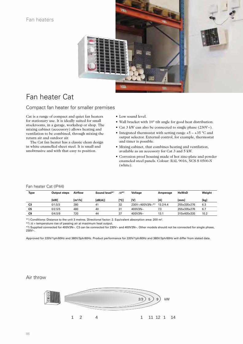
86
21 4 1 11 12 1 14
CC
kW
C kW2/3 5 9
Fan heaters
Fan heater Cat
• Low sound level.
• Wall bracket with 10° tilt angle for good heat distribution.
• Cat 3 kW can also be connected to single phase (230V~).
• Integrated thermostat with setting range +5 – +35 °C and output selector. External control, for example, thermostat and timer is possible.
• Mixing cabinet, that combines heating and ventilation, available as an accessory for Cat 3 and 5 kW.
• Corrosion proof housing made of hot zinc-plate and powder enameled steel panels. Colour: RAL 9016, NCS S 0500-N (white).
Compact fan heater for smaller premises
Fan heater Cat (IP44)
Air throw
Cat is a range of compact and quiet fan heaters for stationary use. It is ideally suited for small stockrooms, in a garage, workshop or shop. The mixing cabinet (accessory) allows heating and ventilation to be combined, through mixing the return air and outdoor air. The Cat fan heater has a classic clean design in white enamelled sheet steel. It is small and unobtrusive and with that easy to position.
*1) Conditions: Distance to the unit 3 metres. Directional factor: 2. Equivalent absorption area: 200 m². *2) t = temperature rise of passing air at maximum heat output. *3) Supplied connected for 400V3N~. C3 can be connected for 230V~ and 400V3N~. Other models should not be connected for single phase, 230V~.
Approved for 220V/1ph/60Hz and 380V/3ph/60Hz. Product performance for 220V/1ph/60Hz and 380V/3ph/60Hz will differ from stated data.
Type Output steps
[kW]
Airflow
[m³/h]
Sound level*1
[dB(A)]
t*2
[°C]
Voltage
[V]
Amperage
[A]
HxWxD
[mm]
Weight
[kg]
C3 0/1.5/3 280 41 32 230V~/400V3N~*3 13.2/4.4 255x335x276 6.3
C5 0/2.5/5 480 40 31 400V3N~ 7.3 255x335x276 6.7
C9 0/4.5/9 720 44 37 400V3N~ 13.1 315x405x335 10.2

87
CBTTK10ST10S EV300
CBT
1h
21
2h
4h20
25
30
15
10
5
C
10°
A
B
TP
Fan
heat
ers
Cat
Accessories
Dimensions
Control options
Integrated regulation The integrated thermostat controls both the fan and heating, alternatively only the heating. The selection is made using the function selector. In operations with only heating the fan blows continuously and the thermostat only controls the heating output. The thermostat’s working range is +5 – +35 °C. The output can be selected using the output selector.
External controlCat can also be controlled via external output selector, thermostat and timer.
• T10S/TK10S, electronic thermostat with concealed/visible knob
• EV300, output selector
• CBT, electronic timer
Mixing cabinet
Mixing cabinet PCMB35 with Cat.
A
[mm]
B
[mm]
C
[mm]
C3 335 255 276
C5 335 255 276
C9 405 315 335
Type Description HxWxD
[mm]
T10S Electronic thermostat with concealed knob 80x80x31
TK10S Electronic thermostat with visible knob 80x80x31
EV300 Output selector 100x80x90
CBT Electronic timer 155x87x43
CMB35 Mixing cabinet for C3 and C5 400x295x170
TP3/5 Cover panel for switches - for C3 and C5
TP9 Cover panel for switches - for C9
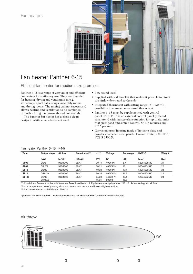
88
3 0 3
kW
Fan heaters
Fan heater Panther 6-15Efficient fan heater for medium size premises
Panther 6-15 is a range of very quiet and efficient fan heaters for stationary use. They are intended for heating, drying and ventilation in e.g. workshops, sport halls, shops, assembly rooms and drying rooms. The mixing cabinet (accessory) allows heating and ventilation to be combined, through mixing the return air and outdoor air. The Panther fan heater has a classic clean design in white enamelled sheet steel.
Fan heater Panther 6–15 (IP44)
Air throw
*1) Conditions: Distance to the unit 3 metres. Directional factor: 2. Equivalent absorption area: 200 m². At lowest/highest airflow. *2) t = temperature rise of passing air at maximum heat output and lowest/highest airflow. *3) Can be connected to 440V3~ and 500V3~. Approved for 380V/3ph/60Hz. Product performance for 380V/3ph/60Hz will differ from stated data.
• Low sound level.
• Supplied with wall bracket that makes it possible to direct the airflow down and to the side.
• Integrated thermostat with setting range +5 – +35 °C, possibility to connect an external thermostat.
• Panther 6–15 must be supplemented with control panel PP15. PP15 is an external control panel (ordered separately) with master-/slave function for up to six units that gives good and simple control. SE135 requires one PP15 per unit.
• Corrosion proof housing made of hot zinc-plate and powder enamelled steel panels. Colour: white, RAL 9016, NCS S 0500-N.
Type Output steps
[kW]
Airflow
[m³/h]
Sound level*1
[dB(A)]
t*2
[°C]
Voltage
[V]
Amperage
[A]
HxWxD
[mm]
Weight
[kg]
SE06 0/3/6 900/1300 39/47 20/14 400V3N~ 8.7 520x450x510 21
SE09 0/4.5/9 900/1300 39/47 30/21 400V3N~ 13 520x450x510 22
SE12 0/6/12 900/1300 39/47 40/28 400V3N~ 17.3 520x450x510 22
SE15 0/7.5/15 900/1300 39/47 50/35 400V3N~ 21.7 520x450x510 22
SE135 0/5/10 0/7/13.5
900/1300 39/47 34/23 45/31
440V3~*³ 500V3~
13.4 15.6
520x450x510 23
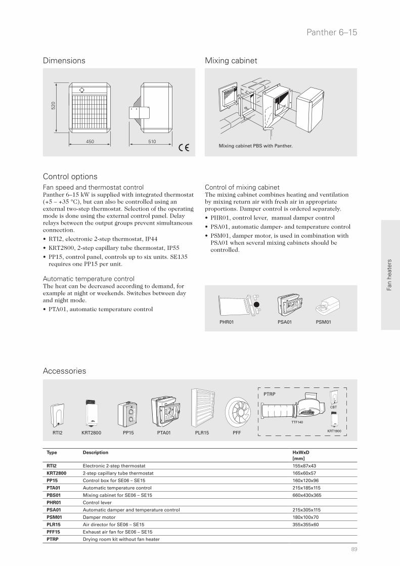
89
520
450 510
CBT
1h
21
2h
4h
CBT
KRT1900
PTRP
TTF140
PLR15 PFFPTA01KRT2800RTI2 PP15
PSM01PSA01PHR01
Fan
heat
ers
Control options
Panther 6–15
Accessories
Dimensions
Fan speed and thermostat controlPanther 6–15 kW is supplied with integrated thermostat (+5 – +35 °C), but can also be controlled using an external two-step thermostat. Selection of the operating mode is done using the external control panel. Delay relays between the output groups prevent simultaneous connection.
• RTI2, electronic 2-step thermostat, IP44
• KRT2800, 2-step capillary tube thermostat, IP55
• PP15, control panel, controls up to six units. SE135 requires one PP15 per unit.
Automatic temperature controlThe heat can be decreased according to demand, for example at night or weekends. Switches between day and night mode.
• PTA01, automatic temperature control
Control of mixing cabinetThe mixing cabinet combines heating and ventilation by mixing return air with fresh air in appropriate proportions. Damper control is ordered separately.
• PHR01, control lever, manual damper control
• PSA01, automatic damper- and temperature control
• PSM01, damper motor, is used in combination with PSA01 when several mixing cabinets should be controlled.
Mixing cabinet
Mixing cabinet PBS with Panther.
Type Description HxWxD
[mm]
RTI2 Electronic 2-step thermostat 155x87x43
KRT2800 2-step capillary tube thermostat 165x60x57
PP15 Control box for SE06 – SE15 160x120x96
PTA01 Automatic temperature control 215x185x115
PBS01 Mixing cabinet for SE06 – SE15 660x430x365
PHR01 Control lever
PSA01 Automatic damper and temperature control 215x305x115
PSM01 Damper motor 180x100x70
PLR15 Air director for SE06 – SE15 355x355x60
PFF15 Exhaust air fan for SE06 – SE15
PTRP Drying room kit without fan heater
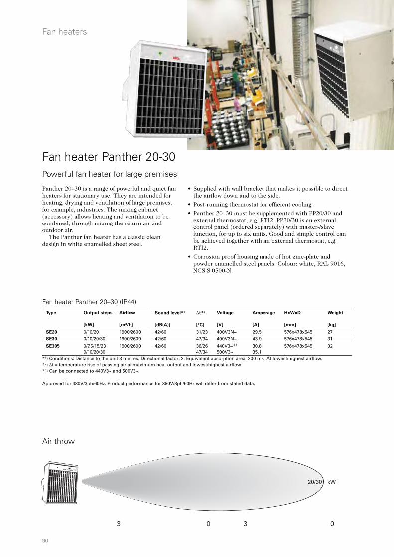
90
3 0 3 0
20/30 kW
Fan heaters
Fan heater Panther 20-30Powerful fan heater for large premises
Panther 20–30 is a range of powerful and quiet fan heaters for stationary use. They are intended for heating, drying and ventilation of large premises, for example, industries. The mixing cabinet (accessory) allows heating and ventilation to be combined, through mixing the return air and outdoor air. The Panther fan heater has a classic clean design in white enamelled sheet steel.
Fan heater Panther 20–30 (IP44)
Air throw
*1) Conditions: Distance to the unit 3 metres. Directional factor: 2. Equivalent absorption area: 200 m². At lowest/highest airflow. *2) t = temperature rise of passing air at maximum heat output and lowest/highest airflow. *3) Can be connected to 440V3~ and 500V3~. Approved for 380V/3ph/60Hz. Product performance for 380V/3ph/60Hz will differ from stated data.
• Supplied with wall bracket that makes it possible to direct the airflow down and to the side.
• Post-running thermostat for efficient cooling.
• Panther 20–30 must be supplemented with PP20/30 and external thermostat, e.g. RTI2. PP20/30 is an external control panel (ordered separately) with master-/slave function, for up to six units. Good and simple control can be achieved together with an external thermostat, e.g. RTI2.
• Corrosion proof housing made of hot zinc-plate and powder enamelled steel panels. Colour: white, RAL 9016, NCS S 0500-N.
Type Output steps
[kW]
Airflow
[m³/h]
Sound level*1
[dB(A)]
t*2
[°C]
Voltage
[V]
Amperage
[A]
HxWxD
[mm]
Weight
[kg]
SE20 0/10/20 1900/2600 42/60 31/23 400V3N~ 29.5 576x478x545 27
SE30 0/10/20/30 1900/2600 42/60 47/34 400V3N~ 43.9 576x478x545 31
SE305 0/7.5/15/23 0/10/20/30
1900/2600 42/60 36/26 47/34
440V3~*³ 500V3~
30.8 35.1
576x478x545 32

91
576
478
CBT
1h
21
2h
4h
CBT
KRT1900
PTRP
TTF140
PLR30 PFFPTA01KRT2800RTI2 PP20/PP30
PSM01PSA01PHR01
545
Fan
heat
ers
Panther 20–30
Accessories
Dimensions
Control of mixing cabinetThe mixing cabinet combines heating and ventilation by mixing return air with fresh air in appropriate proportions. Damper control is ordered separately.
• PHR01, control lever, manual damper control
• PSA01, automatic damper- and temperature control
• PSM01, damper motor, is used in combination with PSA01 when several mixing cabinets should be controlled.
Mixing cabinet
Mixing cabinet PBS with Panther.
Control options Fan speed and thermostat controlPanther 20–30 kW is controlled using an external thermostat. Selection of the operating mode is done using the external control panel. Delay relays between the output groups prevent simultaneous connection.
• RTI2, electronic 2-step thermostat, IP44
• KRT2800, 2-step capillary tube thermostat, IP55
• PP20/30, control panel, controls up to six units
Automatic temperature controlThe heat can be decreased according to demand, for example at night or weekends. Switches between day and night mode.
• PTA01, automatic temperature control
Type Description HxWxD
[mm]
RTI2 Electronic 2-step thermostat 155x87x43
KRT2800 2-step capillary tube thermostat 165x60x57
PP20 Control box for SE20 160x120x96
PP30 Control box for SE30 and SE305 160x120x96
PTA01 Automatic temperature control 215x185x115
PBS02 Mixing cabinet for SE20, SE30 and SE305 890x520x420
PSA01 Automatic damper and temperature control 215x305x115
PHR01 Control lever
PSM01 Damper motor 180x100x70
PLR30 Air director for SE20, SE30 and SE305 415x445x60
PFF30 Exhaust air fan for SE20, SE30 and SE305
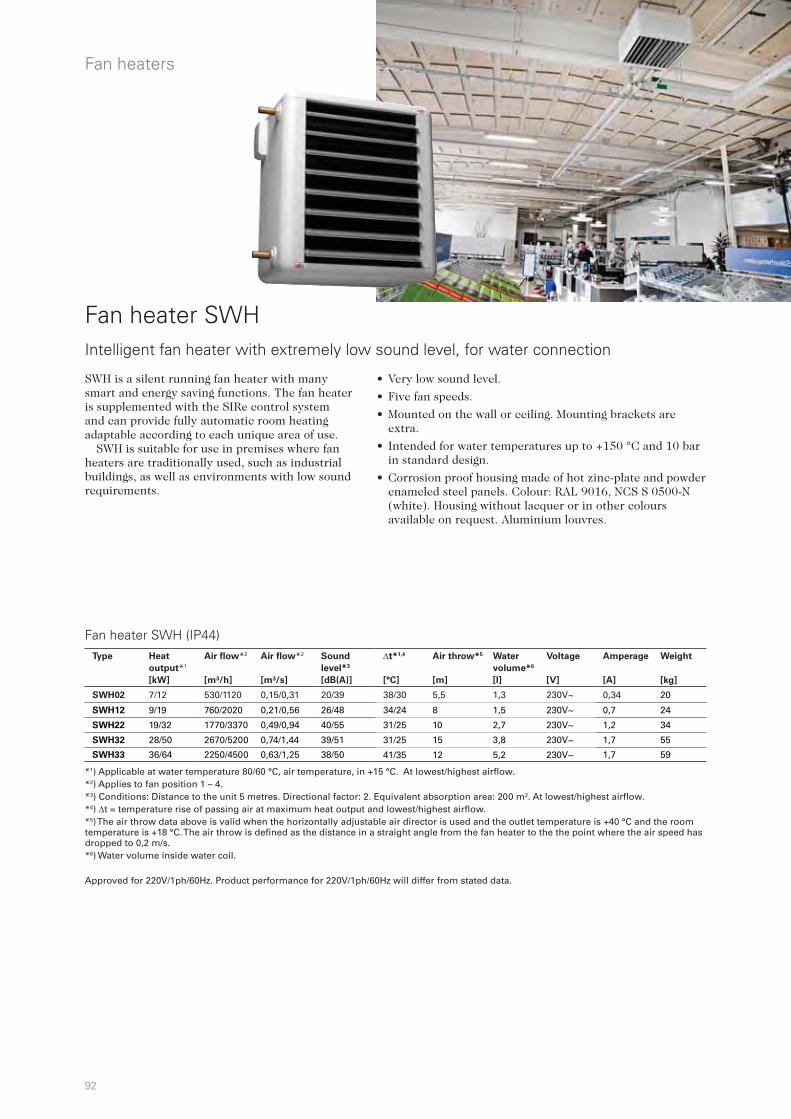
92
Fan heaters
Fan heater SWHIntelligent fan heater with extremely low sound level, for water connection
SWH is a silent running fan heater with many smart and energy saving functions. The fan heater is supplemented with the SIRe control system and can provide fully automatic room heating adaptable according to each unique area of use.
SWH is suitable for use in premises where fan heaters are traditionally used, such as industrial buildings, as well as environments with low sound requirements.
Fan heater SWH (IP44)
• Very low sound level.
• Five fan speeds.
• Mounted on the wall or ceiling. Mounting brackets are extra.
• Intended for water temperatures up to +150 °C and 10 bar in standard design.
• Corrosion proof housing made of hot zinc-plate and powder enameled steel panels. Colour: RAL 9016, NCS S 0500-N (white). Housing without lacquer or in other colours available on request. Aluminium louvres.
*1) Applicable at water temperature 80/60 °C, air temperature, in +15 °C. At lowest/highest airflow. *2) Applies to fan position 1 – 4. *3) Conditions: Distance to the unit 5 metres. Directional factor: 2. Equivalent absorption area: 200 m². At lowest/highest airflow. *4) t = temperature rise of passing air at maximum heat output and lowest/highest airflow.*5) The air throw data above is valid when the horizontally adjustable air director is used and the outlet temperature is +40 °C and the room temperature is +18 °C. The air throw is defined as the distance in a straight angle from the fan heater to the the point where the air speed has dropped to 0,2 m/s. *6) Water volume inside water coil.
Approved for 220V/1ph/60Hz. Product performance for 220V/1ph/60Hz will differ from stated data.
Type Heat
output*1
[kW]
Air flow*2
[m³/h]
Air flow*2
[m³/s]
Sound
level*3
[dB(A)]
t*1,4
[°C]
Air throw*5
[m]
Water
volume*6
[l]
Voltage
[V]
Amperage
[A]
Weight
[kg]
SWH02 7/12 530/1120 0,15/0,31 20/39 38/30 5,5 1,3 230V~ 0,34 20
SWH12 9/19 760/2020 0,21/0,56 26/48 34/24 8 1,5 230V~ 0,7 24
SWH22 19/32 1770/3370 0,49/0,94 40/55 31/25 10 2,7 230V~ 1,2 34
SWH32 28/50 2670/5200 0,74/1,44 39/51 31/25 15 3,8 230V~ 1,7 55
SWH33 36/64 2250/4500 0,63/1,25 38/50 41/35 12 5,2 230V~ 1,7 59
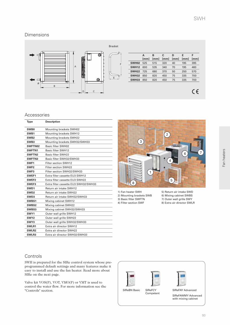
93
4
2
58
6 7
3
1
A
B
CD
ø
A
B
E
F
Fan
heat
ers
SWH
Accessories
Dimensions
1) Fan heater SWH2) Mounting brackets SWB 3) Basic filter SWFTN 4) Filter section SWF
5) Return air intake SWD 6) Mixing cabinet SWBS 7) Outer wall grille SWY 8) Extra air director SWLR
SIReBN Basic SIReFCY Competent
SIReFAY Advanced
SIReFAWMY Advanced with mixing cabinet
SWH is prepared for the SIRe control system whose pre-programmed default settings and many features make it easy to install and use the fan heater. Read more about SIRe on the next page. Valve kit VOS(P), VOT, VMO(P) or VMT is used to control the water flow. For more information see the "Controls" section.
Bracket
Controls
A
[mm]
B
[mm]
C
[mm]
D
[mm]
E
[mm]
F
[mm]
SWH02 525 515 320 40 195 395
SWH12 600 535 340 70 195 460
SWH22 725 680 370 50 250 570
SWH32 850 820 450 75 335 700
SWH33 850 820 450 75 335 700
Type Description
SWB0 Mounting brackets SWH02
SWB1 Mounting brackets SWH12
SWB2 Mounting brackets SWH22
SWB3 Mounting brackets SWH32/SWH33
SWFTN02 Basic filter SWH02
SWFTN1 Basic filter SWH12
SWFTN2 Basic filter SWH22
SWFTN3 Basic filter SWH32/SWH33
SWF1 Filter section SWH12
SWF2 Filter section SWH22
SWF3 Filter section SWH32/SWH33
SWEF1 Extra filter cassette EU3 SWH12
SWEF2 Extra filter cassette EU3 SWH22
SWEF3 Extra filter cassette EU3 SWH32/SWH33
SWD1 Return air intake SWH12
SWD2 Return air intake SWH22
SWD3 Return air intake SWH32/SWH33
SWBS1 Mixing cabinet SWH12
SWBS2 Mixing cabinet SWH22
SWBS3 Mixing cabinet SWH32/SWH33
SWY1 Outer wall grille SWH12
SWY2 Outer wall grille SWH22
SWY3 Outer wall grille SWH32/SWH33
SWLR1 Extra air director SWH12
SWLR2 Extra air director SWH22
SWLR3 Extra air director SWH32/SWH33
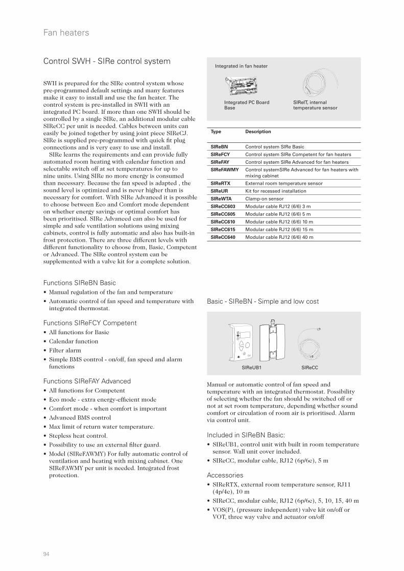
94
52
41
3
230
230
C
Fan heaters
Control SWH - SIRe control system
SIReUB1 SIReCC
Integrated PC Board Base
SIReIT, internal temperature sensor
Integrated in fan heater
Basic - SIReBN - Simple and low cost
SWH is prepared for the SIRe control system whose pre-programmed default settings and many features make it easy to install and use the fan heater. The control system is pre-installed in SWH with an integrated PC board. If more than one SWH should be controlled by a single SIRe, an additional modular cable SIReCC per unit is needed. Cables between units can easily be joined together by using joint piece SIReCJ. SIRe is supplied pre-programmed with quick fit plug connections and is very easy to use and install.
SIRe learns the requirements and can provide fully automated room heating with calendar function and selectable switch off at set temperatures for up to nine units. Using SIRe no more energy is consumed than necessary. Because the fan speed is adapted , the sound level is optimized and is never higher than is necessary for comfort. With SIRe Advanced it is possible to choose between Eco and Comfort mode dependent on whether energy savings or optimal comfort has been prioritised. SIRe Advanced can also be used for simple and safe ventilation solutions using mixing cabinets, control is fully automatic and also has built-in frost protection. There are three different levels with different functionality to choose from, Basic, Competent or Advanced. The SIRe control system can be supplemented with a valve kit for a complete solution.
Functions SIReBN Basic • Manual regulation of the fan and temperature
• Automatic control of fan speed and temperature with integrated thermostat.
Functions SIReFCY Competent • All functions for Basic
• Calendar function
• Filter alarm
• Simple BMS control - on/off, fan speed and alarm functions
Functions SIReFAY Advanced • All functions for Competent
• Eco mode - extra energy-efficient mode
• Comfort mode - when comfort is important
• Advanced BMS control
• Max limit of return water temperature.
• Stepless heat control.
• Possibility to use an external filter guard.
• Model (SIReFAWMY) For fully automatic control of ventilation and heating with mixing cabinet. One SIReFAWMY per unit is needed. Integrated frost protection.
Manual or automatic control of fan speed and temperature with an integrated thermostat. Possibility of selecting whether the fan should be switched off or not at set room temperature, depending whether sound comfort or circulation of room air is prioritised. Alarm via control unit. Included in SIReBN Basic:• SIReUB1, control unit with built in room temperature
sensor. Wall unit cover included.
• SIReCC, modular cable, RJ12 (6p/6c), 5 m Accessories • SIReRTX, external room temperature sensor, RJ11
(4p/4c), 10 m
• SIReCC, modular cable, RJ12 (6p/6c), 5, 10, 15, 40 m
• VOS(P), (pressure independent) valve kit on/off or VOT, three way valve and actuator on/off
Type Description
SIReBN Control system SIRe Basic
SIReFCY Control system SIRe Competent for fan heaters
SIReFAY Control system SIRe Advanced for fan heaters
SIReFAWMY Control systemSIRe Advanced for fan heaters with mixing cabinet
SIReRTX External room temperature sensor
SIReUR Kit for recessed installation
SIReWTA Clamp-on sensor
SIReCC603 Modular cable RJ12 (6/6) 3 m
SIReCC605 Modular cable RJ12 (6/6) 5 m
SIReCC610 Modular cable RJ12 (6/6) 10 m
SIReCC615 Modular cable RJ12 (6/6) 15 m
SIReCC640 Modular cable RJ12 (6/6) 40 m
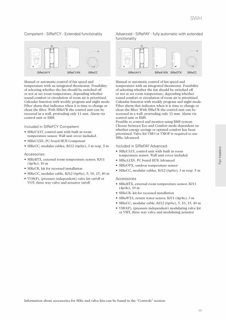
95
Fan
heat
ers
SIReOTXSIReC1XN SIReA1XN
SWH
Competent - SIReFCY - Extended functionality Advanced - SIReFAY - fully automatic with extended functionality
SIReCCSIReCC
Information about accessories for SIRe and valve kits can be found in the “Controls” section.
Manual or automatic control of fan speed and temperature with an integrated thermostat. Possibility of selecting whether the fan should be switched off or not at set room temperature, depending whether sound comfort or circulation of room air is prioritised. Calendar function with weekly program and night mode. Filter alarm that indicates when it is time to change or clean the filter. With SIReUR the control unit can be recessed in a wall, protruding only 11 mm. Alarm via control unit or BMS. Included in SIReFCY Competent:• SIReUA1Y, control unit with built in room
temperature sensor. Wall unit cover included.
• SIReC1XN, PC board HUB Competent
• SIReCC, modular cables, RJ12 (6p/6c), 3 m resp. 5 m
Accessories • SIReRTX, external room temperature sensor, RJ11
(4p/4c), 10 m
• SIReUR, kit for recessed installation
• SIReCC, modular cable, RJ12 (6p/6c), 5, 10, 15, 40 m
• VOS(P), (pressure independent) valve kit on/off or VOT, three way valve and actuator on/off
Manual or automatic control of fan speed and temperature with an integrated thermostat. Possibility of selecting whether the fan should be switched off or not at set room temperature, depending whether sound comfort or circulation of room air is prioritised. Calendar function with weekly program and night mode. Filter alarm that indicates when it is time to change or clean the filter. With SIReUR the control unit can be recessed in a wall, protruding only 11 mm. Alarm via control unit or BMS. Possible to control and monitor using BMS system. Choose between Eco and Comfort mode dependent on whether energy savings or optimal comfort has been prioritised. Valve kit VMO or VMOP is required to use SIRe Advanced. Included in SIReFAY Advanced:• SIReUA1Y, control unit with built in room
temperature sensor. Wall unit cover included.
• SIReA1XN, PC board HUB Advanced
• SIReOTX, outdoor temperature sensor
• SIReCC, modular cables, RJ12 (6p/6c), 3 m resp. 5 m
Accessories • SIReRTX, external room temperature sensor, RJ11
(4p/4c), 10 m
• SIReUR, kit for recessed installation
• SIReWTA, return water sensor, RJ11 (4p/4c), 3 m
• SIReCC, modular cable, RJ12 (6p/6c), 5, 10, 15, 40 m
• VMO(P), (pressure independent) modulating valve kit or VMT, three way valve and modulating actuator
SIReUA1Y SIReUA1Y

96
A
B
CD
ø
A
B
E
F
Fan heaters
Dimensions
Fan heater SWS
• Mounted on the wall. Mounting brackets are extra.
• Intended for water temperatures up to +150 °C and 10 bar in standard design.
• Casing of grey alu-zinc coated steel panels, very resistant against corrosion. Louvres in anodised aluminium.
Basic fan heater for water connection
Fan heater SWS is intended for water-heating or cooling. SWS is suitable for places where fan heaters are traditionally used, such as industrial premises, workshops and storage rooms. The fan heater is mounted on the wall. By turning the unit the water connections will be positioned on the left or right side.
Fan heater SWS (IP44)
*1) Applicable at water temperature 80/60 °C, air temperature, in +15 °C. At lowest/highest airflow. *2) Conditions: Distance to the unit 5 metres. Directional factor: 2. Equivalent absorption area: 200 m². At lowest/highest airflow. *3) t = temperature rise of passing air at maximum heat output and lowest/highest airflow.*4) The air throw data above is valid when the horizontally adjustable air director is used and the outlet temperature is +40 °C and the room temperature is +18 °C. The air throw is defined as the distance in a straight angle from the fan heater to the the point where the air speed has dropped to 0,2 m/s. *5) Water volume inside water coil.*6) Approved for 220V/1ph/60Hz. Product performance for 220V/1ph/60Hz will differ from stated data.
Bracket
A
[mm]
B
[mm]
C
[mm]
D
[mm]
Ø
[mm]
E
[mm]
F
[mm]
SWS02 470 520 210 50 22 195 395
SWS12 545 540 215 60 22 195 460
SWS22 675 690 215 60 28 250 570
SWS32(3)
SWS33(3)
800 830 315 35 28 335 700
Type Heat
output*1
[kW]
Airflow
[m3/h]
Air flow
[m3/s]
Sound
level*2
[dB(A)]
t*1,3
[°C]
Air throw*4
[m]
Water
volume*5
[l]
Voltage
[V]
Amperage
[A]
Weight
[kg]
SWS02*6 7/12 520/1260 0,14/0,35 27/50 37/28 5.5 1.3 230V~ 0.32 14
SWS12*6 8/19 620/2340 0,17/0,65 25/57 35/23 8 1.5 230V~ 0.67 18
SWS22 11/30 860/3560 0,24/0,99 33/58 38/25 10 2.7 230V~ 0.90 26
SWS32 19/50 1540/6300 0,43/1,75 39/64 36/23 15 3.8 230V~ 2.42 45
SWS33 24/65 1550/6090 0,43/1,69 39/64 44/31 13 5.2 230V~ 2.48 45
SWS323 40/48 4400/5890 1,22/1,64 56/62 26/24 12.5 3.8 400V3~ 0.82 45
SWS333 52/62 4300/5660 1,19/1,57 56/62 35/32 11 5.2 400V3~ 0.83 45
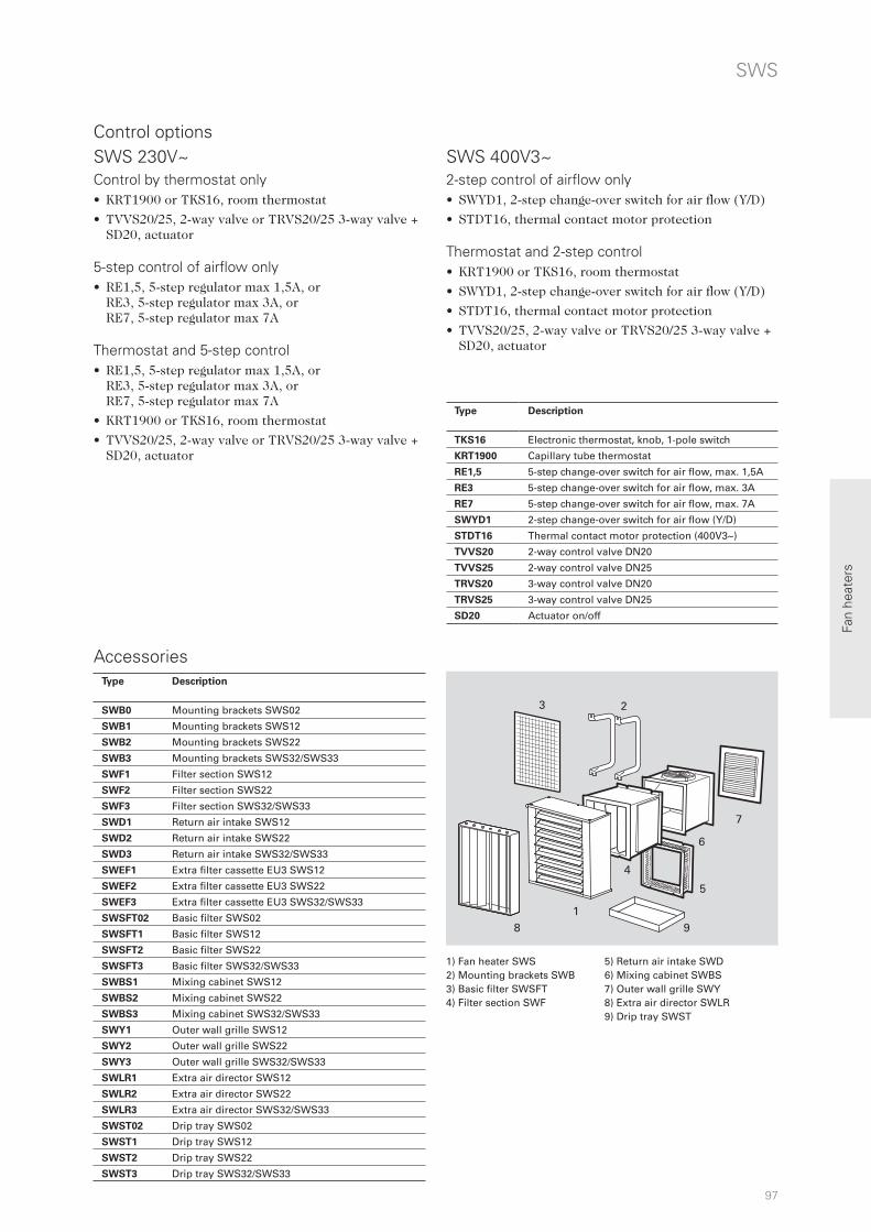
97
1
23
4
5
6
7
98
Fan
heat
ers
SWS
Accessories
Control options SWS 400V3~ SWS 230V~
1) Fan heater SWS2) Mounting brackets SWB 3) Basic filter SWSFT4) Filter section SWF
5) Return air intake SWD 6) Mixing cabinet SWBS 7) Outer wall grille SWY 8) Extra air director SWLR9) Drip tray SWST
Control by thermostat only• KRT1900 or TKS16, room thermostat
• TVVS20/25, 2-way valve or TRVS20/25 3-way valve + SD20, actuator
5-step control of airflow only• RE1,5, 5-step regulator max 1,5A, or
RE3, 5-step regulator max 3A, or RE7, 5-step regulator max 7A
Thermostat and 5-step control• RE1,5, 5-step regulator max 1,5A, or
RE3, 5-step regulator max 3A, or RE7, 5-step regulator max 7A
• KRT1900 or TKS16, room thermostat
• TVVS20/25, 2-way valve or TRVS20/25 3-way valve + SD20, actuator
2-step control of airflow only• SWYD1, 2-step change-over switch for air flow (Y/D)
• STDT16, thermal contact motor protection
Thermostat and 2-step control• KRT1900 or TKS16, room thermostat
• SWYD1, 2-step change-over switch for air flow (Y/D)
• STDT16, thermal contact motor protection
• TVVS20/25, 2-way valve or TRVS20/25 3-way valve + SD20, actuator
Type Description
SWB0 Mounting brackets SWS02
SWB1 Mounting brackets SWS12
SWB2 Mounting brackets SWS22
SWB3 Mounting brackets SWS32/SWS33
SWF1 Filter section SWS12
SWF2 Filter section SWS22
SWF3 Filter section SWS32/SWS33
SWD1 Return air intake SWS12
SWD2 Return air intake SWS22
SWD3 Return air intake SWS32/SWS33
SWEF1 Extra filter cassette EU3 SWS12
SWEF2 Extra filter cassette EU3 SWS22
SWEF3 Extra filter cassette EU3 SWS32/SWS33
SWSFT02 Basic filter SWS02
SWSFT1 Basic filter SWS12
SWSFT2 Basic filter SWS22
SWSFT3 Basic filter SWS32/SWS33
SWBS1 Mixing cabinet SWS12
SWBS2 Mixing cabinet SWS22
SWBS3 Mixing cabinet SWS32/SWS33
SWY1 Outer wall grille SWS12
SWY2 Outer wall grille SWS22
SWY3 Outer wall grille SWS32/SWS33
SWLR1 Extra air director SWS12
SWLR2 Extra air director SWS22
SWLR3 Extra air director SWS32/SWS33
SWST02 Drip tray SWS02
SWST1 Drip tray SWS12
SWST2 Drip tray SWS22
SWST3 Drip tray SWS32/SWS33
Type Description
TKS16 Electronic thermostat, knob, 1-pole switch
KRT1900 Capillary tube thermostat
RE1,5 5-step change-over switch for air flow, max. 1,5A
RE3 5-step change-over switch for air flow, max. 3A
RE7 5-step change-over switch for air flow, max. 7A
SWYD1 2-step change-over switch for air flow (Y/D)
STDT16 Thermal contact motor protection (400V3~)
TVVS20 2-way control valve DN20
TVVS25 2-way control valve DN25
TRVS20 3-way control valve DN20
TRVS25 3-way control valve DN25
SD20 Actuator on/off
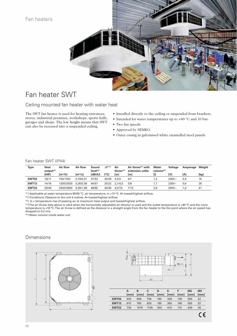
98
30
ØG
DF
E
ØH
BC
A
Fan heaters
Dimensions
Fan heater SWT
• Installed directly to the ceiling or suspended from brackets.
• Intended for water temperatures up to +80 °C and 10 bar.
• Two fan speeds.
• Approved by SEMKO.
• Outer casing in galvanised white enamelled steel panels.
Ceiling mounted fan heater with water heat
The SWT fan heater is used for heating entrances, stores, industrial premises, workshops, sports halls, garages and shops. The low height means that SWT can also be recessed into a suspended ceiling.
Fan heater SWT (IP44)
*1) Applicable at water temperature 80/60 °C, air temperature, in +15 °C. At lowest/highest airflow. *2) Conditions: Distance to the unit 5 metres. At lowest/highest airflow. *3) t = temperature rise of passing air at maximum heat output and lowest/highest airflow.*4) The air throw data above is valid when the horizontally adjustable air director is used and the outlet temperature is +40 °C and the room temperature is +18 °C. The air throw is defined as the distance in a straight angle from the fan heater to the the point where the air speed has dropped to 0,2 m/s. *5) Water volume inside water coil.
A
[mm]
B
[mm]
C
[mm]
D
[mm]
E
[mm]
F
[mm]
ØG
[mm]
ØH
[mm]
SWT02 535 640 705 195 330 135 305 22
SWT12 675 760 825 195 355 160 355 22
SWT22 735 1070 1135 300 415 115 430 28
Type Heat
output*1
[kW]
Air flow
[m3/h]
Air flow
[m3/s]
Sound
level*2
[dB(A)]
t*1,3
[°C]
Air
throw*4
[m]
Air throw*4 with
extension collar
[m]
Water
volume*5
[l]
Voltage
[V]
Amperage
[A]
Weight
[kg]
SWT02 7,8/11 700/1100 0,19/0,31 37/53 33/29 2,2/4 4/7 1,2 230V~ 0,4 19
SWT12 14/18 1300/2000 0,36/0,56 44/57 25/22 2,7/4,5 5/8 1,7 230V~ 0,6 26
SWT22 29/40 2500/3900 0,69/1,08 48/60 34/30 4,5/7,5 7/12 3,9 230V~ 1,0 41

99
1
3
4
2
KRT1900TKS16 RE3/RE7 SD20TVVS20/25 TRVS20/25
20
25
30
15
10
5
CB20
Fan
heat
ers
SWT
Accessories
Control options
1) Fan heater SWT 2) Filter SWTCF 3) Air director SWTCL 4) Extension collar SWTCE
Control by thermostat only• KRT1900 or TKS16, room thermostat
• TVVS20/25, 2-way valve or TRVS20/25 3-way valve + SD20, actuator
2-step control of airflow only• CB20, control panel
Thermostat and 2-step control• CB20, control panel
• KRT1900 or TKS16, room thermostat
• TVVS20/25, 2-way valve or TRVS20/25 3-way valve + SD20, actuator
5-step control of airflow only• RE1,5, 5-step regulator max 1,5A, or
RE3, 5-step regulator max 3A, or RE7, 5-step regulator max 7A
Thermostat and 5-step control• RE1,5, 5-step regulator max 1,5A, or
RE3, 5-step regulator max 3A, or RE7, 5-step regulator max 7A
• KRT1900 or TKS16, room thermostat
• TVVS20/25, 2-way valve or TRVS20/25 3-way valve + SD20, actuator
Type Description
SWTCE02 Extension collar 350 mm to SWT02, increases the throw pattern to 4-7 m
SWTCE12 Extension collar 350 mm to SWT12, increases the throw pattern to 5-8 m
SWTCE22 Extension collar 350 mm to SWT22, increases the throw pattern to 7-12 m
SWTCF02 Filter for SWT02
SWTCF12 Filter for SWT12
SWTCF22 Filter for SWT22
SWTCL02 Air director for SWT02
SWTCL12 Air director for SWT12
SWTCL22 Air director for SWT22
Type Description HxWxD
[mm]
TKS16 Electronic thermostat, knob, 1-pole switch 80x80x39
KRT1900 Capillary tube thermostat 165x57x60
CB20 Control box 155x87x43
RE1,5 5-step change-over switch for air flow 1,5 A 200x105x105
RE3 5-step change-over switch for air flow 3 A 200x105x105
RE7 5-step change-over switch for air flow 7 A 257x147x145
TVVS20 2-way valve DN20
TVVS25 2-way valve DN25
TRVS20 3-way valve DN20
TRVS25 3-way valve DN25
SD20 Actuator on/off 230V
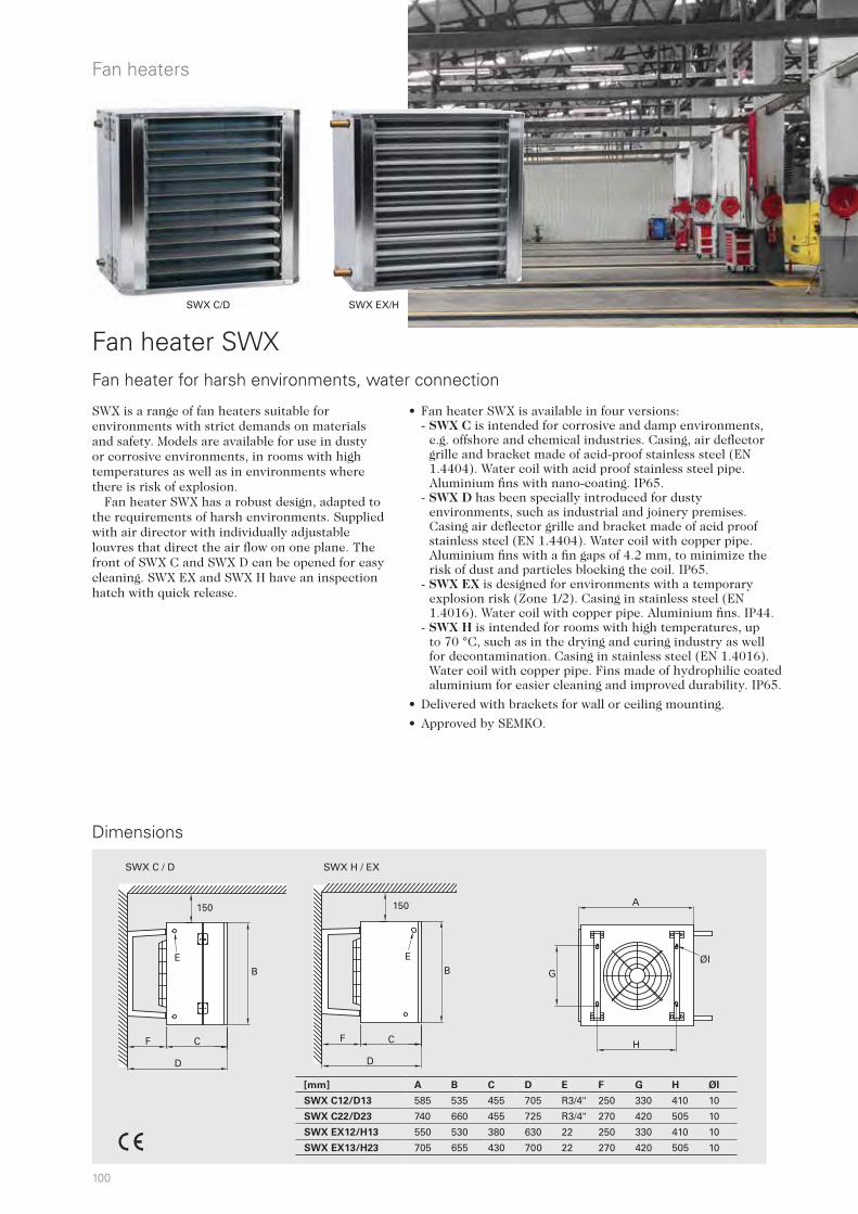
100
SWX C/D SWX EX/H
150
BE
F C
D
150
BE
F C
D
A
G
H
ØI
SWX C / D SWX H / EX
Fan heaters
Fan heater SWX
• Fan heater SWX is available in four versions:- SWX C is intended for corrosive and damp environments,
e.g. offshore and chemical industries. Casing, air deflector grille and bracket made of acid-proof stainless steel (EN 1.4404). Water coil with acid proof stainless steel pipe. Aluminium fins with nano-coating. IP65.
- SWX D has been specially introduced for dusty environments, such as industrial and joinery premises. Casing air deflector grille and bracket made of acid proof stainless steel (EN 1.4404). Water coil with copper pipe. Aluminium fins with a fin gaps of 4.2 mm, to minimize the risk of dust and particles blocking the coil. IP65.
- SWX EX is designed for environments with a temporary explosion risk (Zone 1/2). Casing in stainless steel (EN 1.4016). Water coil with copper pipe. Aluminium fins. IP44.
- SWX H is intended for rooms with high temperatures, up to 70 °C, such as in the drying and curing industry as well for decontamination. Casing in stainless steel (EN 1.4016). Water coil with copper pipe. Fins made of hydrophilic coated aluminium for easier cleaning and improved durability. IP65.
• Delivered with brackets for wall or ceiling mounting.
• Approved by SEMKO.
Fan heater for harsh environments, water connection
SWX is a range of fan heaters suitable for environments with strict demands on materials and safety. Models are available for use in dusty or corrosive environments, in rooms with high temperatures as well as in environments where there is risk of explosion.
Fan heater SWX has a robust design, adapted to the requirements of harsh environments. Supplied with air director with individually adjustable louvres that direct the air flow on one plane. The front of SWX C and SWX D can be opened for easy cleaning. SWX EX and SWX H have an inspection hatch with quick release.
[mm] A B C D E F G H ØI
SWX C12/D13 585 535 455 705 R3/4" 250 330 410 10
SWX C22/D23 740 660 455 725 R3/4" 270 420 505 10
SWX EX12/H13 550 530 380 630 22 250 330 410 10
SWX EX13/H23 705 655 430 700 22 270 420 505 10
Dimensions
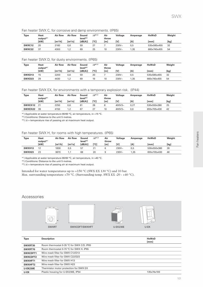
101
SWXRT SWXCDFT/SWXHFT U-EKU-EK230E
Fan
heat
ers
Fan heater SWX C, for corrosive and damp environments. (IP65)
*1) Applicable at water temperature 80/60 °C, air temperature, in +15 °C. *2) Conditions: Distance to the unit 5 metres. *3) t = temperature rise of passing air at maximum heat output.
SWX
Fan heater SWX D, for dusty environments. (IP65)
Fan heater SWX EX, for environments with a temporary explosion risk. (IP44)
Fan heater SWX H, for rooms with high temperatures. (IP65)
*1) Applicable at water temperature 80/60 °C, air temperature, in +40 °C. *2) Conditions: Distance to the unit 5 metres. *3) t = temperature rise of passing air at maximum heat output.
Intended for water temperatures up to +150 °C (SWX EX 130 °C) and 10 bar.Max. surrounding temperature +70 °C. (Surrounding temp. SWX EX -20 - +40 °C).
Accessories
Type Heat
output*1
[kW]
Air flow
[m³/h]
Air flow
[m³/s]
Sound
level*2
[dB(A)]
t*1,3
[°C]
Air
throw
[m]
Voltage
[V]
Amperage
[A]
HxWxD
[mm]
Weight
[kg]
SWXC12 20 2160 0,6 59 27 7 230V~ 0,5 535x585x455 32
SWXC22 37 4300 1,2 69 25 10 230V~ 1,35 660x740x455 54
Type Heat
output*1
[kW]
Air flow
[m³/h]
Air flow
[m³/s]
Sound
level*2
[dB(A)]
t*1,3
[°C]
Air
throw
[m]
Voltage
[V]
Amperage
[A]
HxWxD
[mm]
Weight
[kg]
SWXD13 15 2200 0,6 59 20 7 230V~ 0,5 535x585x455 32
SWXD23 29 4430 1,2 69 19 10 230V~ 1,35 660x740x455 54
Type Heat
output*1
[kW]
Air flow
[m³/h]
Air flow
[m³/s]
Sound
level*2
[dB(A)]
t*1,3
[°C]
Air
throw
[m]
Voltage
[V]
Amperage
[A]
HxWxD
[mm]
Weight
[kg]
SWXEX12 21 2250 0,6 61 28 8 400V3~ 0,27 530x550x380 25
SWXEX22 39 4150 1,2 67 27 10 400V3~ 0,6 655x705x430 42
Type Heat
output*1
[kW]
Air flow
[m³/h]
Air flow
[m³/s]
Sound
level*2
[dB(A)]
t*1,3
[°C]
Air
throw
[m]
Voltage
[V]
Amperage
[A]
HxWxD
[mm]
Weight
[kg]
SWXH13 12 1830 0,5 57 21 6 230V~ 0,5 530x550x380 28
SWXH23 23 3870 1,1 68 20 9 230V~ 1,35 655x705x430 46
Type Description HxWxD
[mm]
SWXRT35 Room thermostat 0-35 °C for SWX C/D. IP65
SWXRT70 Room thermostat 0-70 °C for SWX H. IP65
SWXCDFT1 Wire mesh filter for SWX C12/D13
SWXCDFT2 Wire mesh filter for SWX C22/D23
SWXHFT1 Wire mesh filter for SWX H13
SWXHFT2 Wire mesh filter for SWX H23
U-EK230E Thermistor motor protection for SWX EX
U-EK Plastic housing for U-EK230E, IP54 135x74x100

102
Ceiling fans
Dimensions
Industrial ceiling fan ICF
• The blades push down large volumes of air without causing excessive air speed.
• Can operate clockwise and anti-clockwise.
• Canopy with vibration absorption.
• Fan blades and downrod coated with zinc.
• The enclosed motor is equipped with permanently lubricated ball bearings for long life.
• Other fan blade diameters are available as an accessory (914, 1218 mm).
• Other downrods are available as an accessory (gives a total height of 395, 945 mm).
• High protection class, IP55 (ICF55).
• Colour: NCS S 0505-R90B
Equalizes the temperature in buildings with high ceilings
Industrial ceiling fan ICF (IP20 / IP55)
Protection class ICF20: IP20.Protection class ICF55: IP55.Approved by IMQ.
Ceiling fans are used primarily to equalize the temperature in rooms with high ceilings, such as industrial and warehouse buildings, gymnasiums, and shops. Several controls as well as downrods and blades of different sizes are available, making it possible to adapt ceiling fan ICF to almost all applications. Ceiling fan ICF pushes the warm air from the ceiling and thus lowers the temperature there, the heat losses through the roof and walls are reduced and in many cases, heating costs can be reduced by up to 30%.
Industrial ceiling fan ICF is of high quality and maintenance free with a long service life. Easy installation and low energy consumption gives a very short pay-off period, in many instances in less than a year.
Type Output
[W]
Airflow
[m³/h]
Voltage
[V]
Amperage
[A]
Height x Ø
[mm]
Weight
[kg]
ICF20 70 13500 230V~ 0.33 545x1422 6.2
ICF55 70 13500 230V~ 0.33 545x1422 6.2
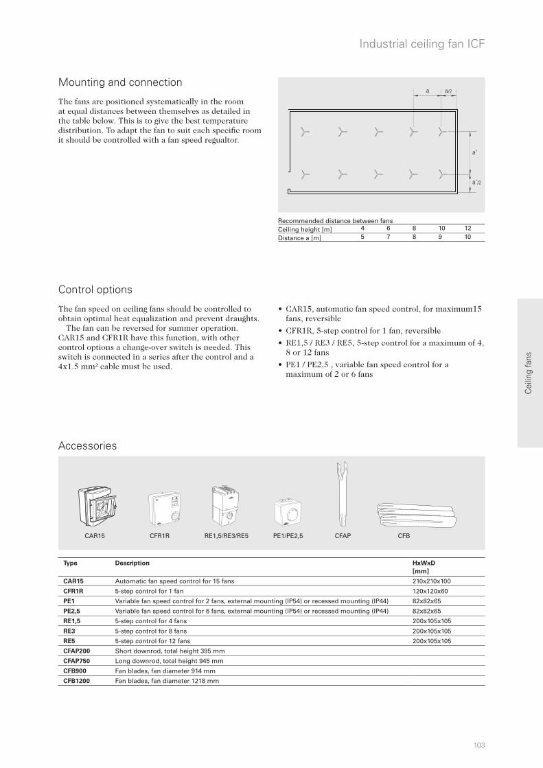
CAR15 CFR1R RE1,5/RE3/RE5 PE1/PE2,5 CFAP CFB
a a/2
a‘
a‘/2
4 6 8 10 125 7 8 9 10
103
Cei
ling
fans
Industrial ceiling fan ICF
Accessories
The fan speed on ceiling fans should be controlled to obtain optimal heat equalization and prevent draughts.
The fan can be reversed for summer operation. CAR15 and CFR1R have this function, with other control options a change-over switch is needed. This switch is connected in a series after the control and a 4x1.5 mm² cable must be used.
• CAR15, automatic fan speed control, for maximum15 fans, reversible
• CFR1R, 5-step control for 1 fan, reversible
• RE1,5 / RE3 / RE5, 5-step control for a maximum of 4, 8 or 12 fans
• PE1 / PE2,5 , variable fan speed control for a maximum of 2 or 6 fans
Control options
The fans are positioned systematically in the room at equal distances between themselves as detailed in the table below. This is to give the best temperature distribution. To adapt the fan to suit each specific room it should be controlled with a fan speed regualtor.
Mounting and connection
Recommended distance between fans Ceiling height [m]Distance a [m]
Type Description HxWxD
[mm]
CAR15 Automatic fan speed control for 15 fans 210x210x100
CFR1R 5-step control for 1 fan 120x120x60
PE1 Variable fan speed control for 2 fans, external mounting (IP54) or recessed mounting (IP44) 82x82x65
PE2,5 Variable fan speed control for 6 fans, external mounting (IP54) or recessed mounting (IP44) 82x82x65
RE1,5 5-step control for 4 fans 200x105x105
RE3 5-step control for 8 fans 200x105x105
RE5 5-step control for 12 fans 200x105x105
CFAP200 Short downrod, total height 395 mm
CFAP750 Long downrod, total height 945 mm
CFB900 Fan blades, fan diameter 914 mm
CFB1200 Fan blades, fan diameter 1218 mm
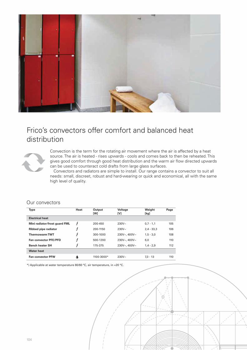
104
Convectors
Our convectors
Convection is the term for the rotating air movement where the air is affected by a heat source. The air is heated - rises upwards - cools and comes back to then be reheated. This gives good comfort through good heat distribution and the warm air flow directed upwards can be used to counteract cold drafts from large glass surfaces.
Convectors and radiators are simple to install. Our range contains a convector to suit all needs: small, discreet, robust and hard-wearing or quick and economical, all with the same high level of quality.
Frico’s convectors offer comfort and balanced heat distribution
Applicable at water temperature 80/60 °C, air temperature, in +20 °C.*)
Type Heat Output
[W]
Voltage
[V]
Weight
[kg]
Page
Electrical heat
Mini radiator/frost guard FML 3 200-450 230V~ 0,7 - 1,1 105
Ribbed pipe radiator 3 200-1150 230V~ 2,4 - 33,3 106
Thermowarm TWT 3 300-1000 230V~, 400V~ 1,5 - 3,0 108
Fan convector PFE/PFD 3 500-1200 230V~, 400V~ 6,0 110
Bench heater SH 3 175-375 230V~, 400V~ 1,4 - 2,9 112
Water heat
Fan convector PFW 2 1100-3000* 230V~ 7,3 - 13 110
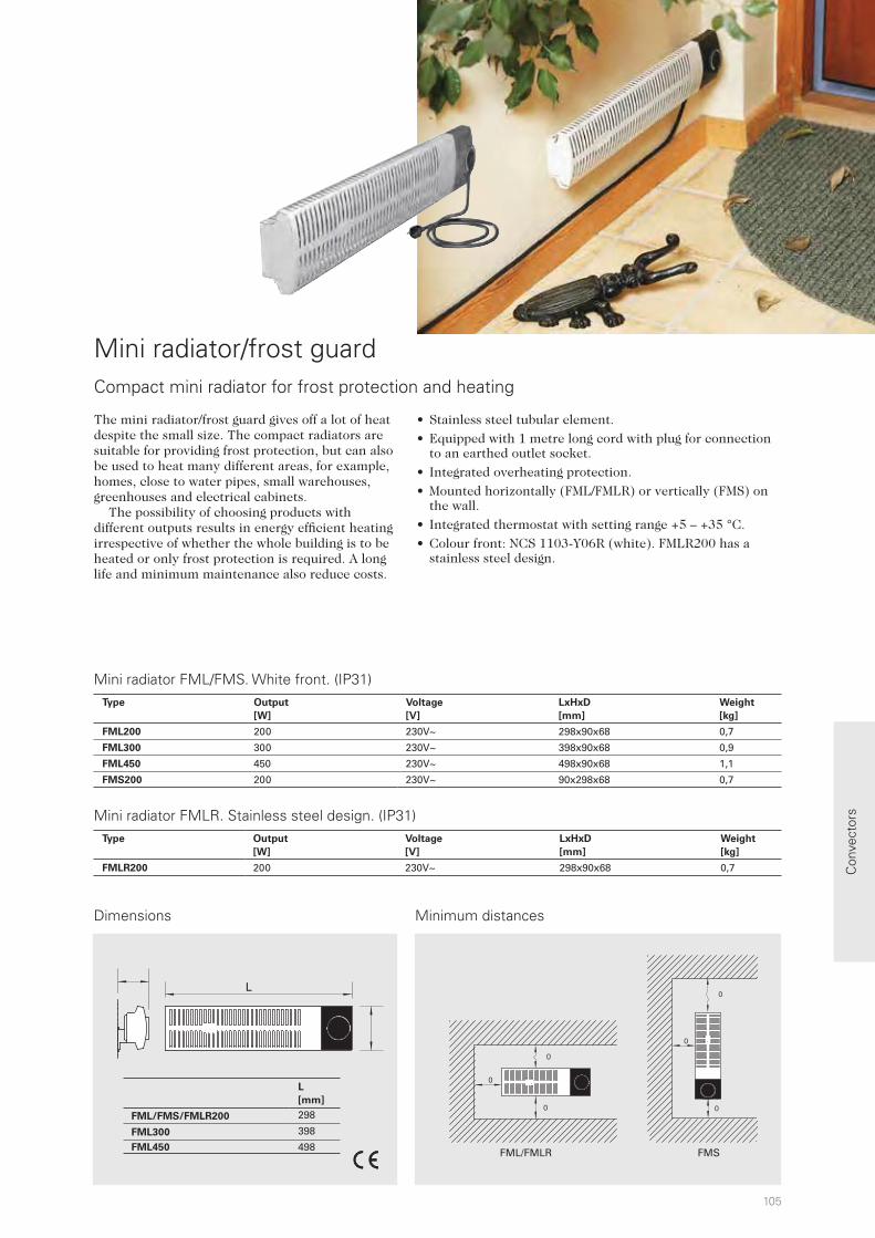
105
0
0
0
0
0
0
FML/FMLR FMS
L
L
[mm]
FML/FMS/FMLR200 298
FML300 398
FML450 498
Con
vect
ors
The mini radiator/frost guard gives off a lot of heat despite the small size. The compact radiators are suitable for providing frost protection, but can also be used to heat many different areas, for example, homes, close to water pipes, small warehouses, greenhouses and electrical cabinets. The possibility of choosing products with different outputs results in energy efficient heating irrespective of whether the whole building is to be heated or only frost protection is required. A long life and minimum maintenance also reduce costs.
Dimensions
• Stainless steel tubular element.
• Equipped with 1 metre long cord with plug for connection to an earthed outlet socket.
• Integrated overheating protection.
• Mounted horizontally (FML/FMLR) or vertically (FMS) on the wall.
• Integrated thermostat with setting range +5 – +35 °C.
• Colour front: NCS 1103-Y06R (white). FMLR200 has a stainless steel design.
Mini radiator/frost guard Compact mini radiator for frost protection and heating
Minimum distances
Mini radiator FML/FMS. White front. (IP31)
Mini radiator FMLR. Stainless steel design. (IP31)Type Output
[W]
Voltage
[V]
LxHxD
[mm]
Weight
[kg]
FMLR200 200 230V~ 298x90x68 0,7
Type Output
[W]
Voltage
[V]
LxHxD
[mm]
Weight
[kg]
FML200 200 230V~ 298x90x68 0,7
FML300 300 230V~ 398x90x68 0,9
FML450 450 230V~ 498x90x68 1,1
FMS200 200 230V~ 90x298x68 0,7

106
Convectors
• The ribbed pipe radiator is available in the following designs:
- Model 125, without output selector.
- Model 126, with output selector that regulates the heat in three steps.
- Model 127, without output selector, sand-filled and suitable for rooms at risk to fire.
• The ribbed flanges increase the heating surface and provide good heat transfer combined with a compact design.
• Resettable overheating protection along the full length of the ribbed pipe radiator.
• A protective steel case give a lower surface temperature and extra protection against impact (model 125 and 126).
• Approved for wet rooms (IP44).
• Can be regulated using an external thermostat.
• Colour: RAL 6005, NCS 7020-B90G (dark green).
Frico's ribbed pipe radiators are designed for harsh environments and are approved for wet rooms, but are also available in designs for rooms at risk of fire. The retro design has also created a new application area in modern housing. Convectors and radiators from Frico efficiently produce pleasant heat. Heat distribution in the room is good at the same time as the warm air flow directed upwards can be used to counteract cold draughts from the windows. Frico's ribbed pipe radiators have a hard wearing and robust design in dark green sheet steel. The compact format means the radiator has a small footprint, but gives a lot of heat.
Robust and hard wearing ribbed pipe radiator in a retro design
Ribbed pipe radiator 125. Without output selector. (IP44)
Ribbed pipe radiator 126, with output selector. (IP44)
Ribbed pipe radiator 127, without output selector, for use in combustible areas (sand filled). (IP44)
Type Output
[W]
Voltage
[V]
LxHxD
[mm]
Weight
[kg]
125-12B 200 230V~ 370x180x185 2,4
125-22B 375 230V~ 530x180x185 3,3
125-32B 575 230V~ 730x180x185 4,5
125-42B 775 230V~ 880x180x185 5,5
Type Output
[W]
Voltage
[V]
LxHxD
[mm]
Weight
[kg]
126-32B 575 230V~ 730x180x185 4,7
126-42B 775 230V~ 880x180x185 5,7
126-52B 1150 230V~ 1185x180x185 7,5
Type Output
[W]
Voltage
[V]
LxHxD
[mm]
Weight
[kg]
127-22B 500 230V~ 980x180x185 10,9
127-42B 800 230V~ 1925x180x185 33,3

107
121
1
A
[mm]
B
[mm]
125-12B 370 245125-22B 530 405125-32B 730 605125-42B 880 755126-32B 730 605126-42B 880 755126-52B 1185 1060127-22B 980 855127-42B 1925 1800
0
300
00
Con
vect
ors
Dimensions
Ribbed pipe radiator
Minimum distances
The origins of Frico's ribbed pipe radiators can be traced back to the 1930s, but they are just as suitable, hard wearing and functional today.
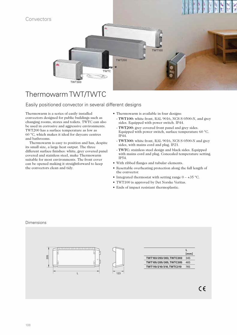
108
L
[mm]
TWT103/203/303, TWTC303 345
TWT105/205/305, TWTC305 465
TWT110/210/310, TWTC310 765
205
L 123
Convectors
Thermowarm is a series of easily installed convectors designed for public buildings such as changing rooms, stores and toilets. TWTC can also be used in corrosive and aggressive environments. TWT200 has a surface temperature as low as 60 °C, which makes it ideal for daycare centres and bathrooms. Thermowarm is easy to position and has, despite its small size, a large heat output. The three different surface finishes: white, grey covered panel covered and stainless steel, make Thermowarm suitable for most environments. The front cover can be opened making it straightforward to keep the convectors clean and tidy.
Dimensions
Thermowarm TWT/TWTCEasily positioned convector in several different designs
• Thermowarm is available in four designs:
- TWT100: white front, RAL 9016, NCS S 0500-N, and grey sides. Equipped with power switch. IP44.
- TWT200: grey covered front panel and grey sides. Equipped with power switch, surface temperature 60 °C. IP44.
- TWT300: white front, RAL 9016, NCS S 0500-N and grey sides, with mains cord and plug. IP21.
- TWTC: stainless steel design and black sides. Equipped with mains cord and plug. Concealed temperature setting. IP54.
• With ribbed flanges and tubular elements.
• Resettable overheating protection along the full length of the convector.
• Integrated thermostat with setting range 0 – +35 °C.
• TWT100 is approved by Det Norske Veritas.
• Ends of impact resistant thermoplastic.
TWTC
TWT300
TWT200
TWT100
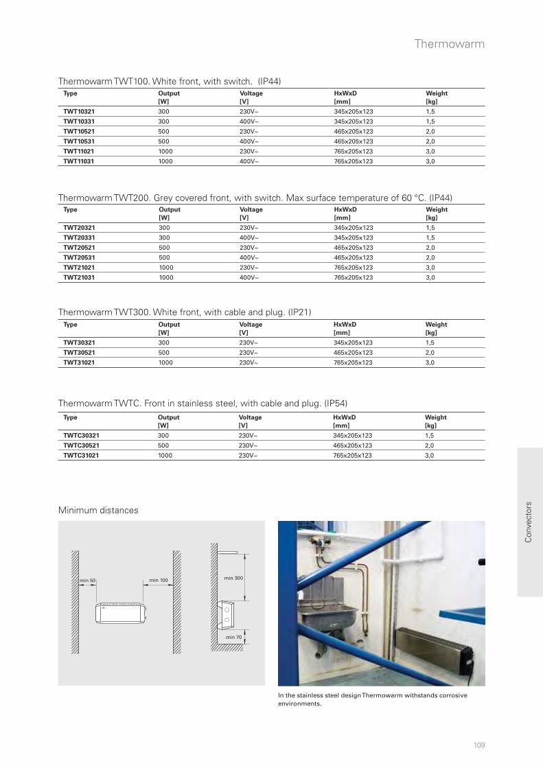
109
min 50 min 100 min 300
min 70
Con
vect
ors
Thermowarm
Minimum distances
In the stainless steel design Thermowarm withstands corrosive environments.
Thermowarm TWT100. White front, with switch. (IP44)
Thermowarm TWT200. Grey covered front, with switch. Max surface temperature of 60 °C. (IP44)
Thermowarm TWT300. White front, with cable and plug. (IP21)
Thermowarm TWTC. Front in stainless steel, with cable and plug. (IP54)
Type Output
[W]
Voltage
[V]
HxWxD
[mm]
Weight
[kg]
TWT10321 300 230V~ 345x205x123 1,5
TWT10331 300 400V~ 345x205x123 1,5
TWT10521 500 230V~ 465x205x123 2,0
TWT10531 500 400V~ 465x205x123 2,0
TWT11021 1000 230V~ 765x205x123 3,0
TWT11031 1000 400V~ 765x205x123 3,0
Type Output
[W]
Voltage
[V]
HxWxD
[mm]
Weight
[kg]
TWT20321 300 230V~ 345x205x123 1,5
TWT20331 300 400V~ 345x205x123 1,5
TWT20521 500 230V~ 465x205x123 2,0
TWT20531 500 400V~ 465x205x123 2,0
TWT21021 1000 230V~ 765x205x123 3,0
TWT21031 1000 400V~ 765x205x123 3,0
Type Output
[W]
Voltage
[V]
HxWxD
[mm]
Weight
[kg]
TWT30321 300 230V~ 345x205x123 1,5
TWT30521 500 230V~ 465x205x123 2,0
TWT31021 1000 230V~ 765x205x123 3,0
Type Output
[W]
Voltage
[V]
HxWxD
[mm]
Weight
[kg]
TWTC30321 300 230V~ 345x205x123 1,5
TWTC30521 500 230V~ 465x205x123 2,0
TWTC31021 1000 230V~ 765x205x123 3,0

110
598 / 1058
330
PFE/PFD 30PFW 45
90 9
Convectors
Fan convector PF is suitable for most environments, for example, homes and offices. It is also ideal for use in buildings that are rarely used, for example, weekend cottages, where quick heating is required. The fan convector also has very good drying properties. Models up to 800 W have a surface temperature of less than 60 °C which makes them extremely suitable for daycare centres and bathrooms. The fan convector consumes less energy than standard convectors. The air flow from the convector, which balances the temperature difference between the floor and ceiling, gives higher efficiency and lower energy consumption compared to convectors without a fan. Fan convector PF has an attractive and clean design in a white finish. A brushed aluminium front is available as an accessory. The low surface temperature makes it possible to finish the front panel in any colour or a film finish can be applied.
Dimensions
Fan convector PFEfficient fan convector for quick heating
• Fan convector PF is available in the following designs:
- PFE is equipped with a 1.2 metre long cord with plug for connection to an earthed outlet socket (230V~). Can be used as a portable unit, a floor stand is available as an accessory.
- PFD is designed for permanent installation (400V2~).
- PFW is for water based heating. Equipped with a 1.2 metre long cord with plug for connection to an earthed outlet socket. Supplied with two, 0.9 m PEX hoses for easy installation. Works with a heat pump.
• Low sound level.
• PFE/PFD has a master-/slave function and integrated thermostat with setting range 5 – +35 °C and is preset for night reduction via external signal.
• The fan speed (low/high) can be set on PFW.
• The air intake is protected by a metal filter which prevents e.g. dust from entering the radiator.
• Corrosion proof housing made of hot zinc-plate and powder enameled steel panels. Colour: RAL 9016, NCS S 0500-N (standard). A brushed aluminium front is available as an accessory.
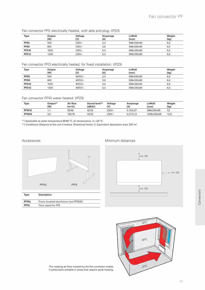
111
min 100
min 100
min 100
Con
vect
ors
Fan convector PF
Accessories
The rotating air flow created by the fan convector makes it particularly suitable in areas that require quick heating.
PFFAL PFFS
Minimum distances
*1) Applicable at water temperature 80/60 °C, air temperature, in +20 °C. *2) Conditions: Distance to the unit 3 metres. Directional factor: 2. Equivalent absorption area: 200 m².
Fan convector PFW water heated. (IP23)
Fan convector PFE electrically heated, with able and plug. (IP23)
Fan convector PFD electrically heated, for fixed installation. (IP23)
Type Output
[W]
Voltage
[V]
Amperage
[A]
LxWxD
[mm]
Weight
[kg]
PFE5 500 230V~ 2,3 598x330x90 6,0
PFE8 800 230V~ 3,6 598x330x90 6,0
PFE10 1000 230V~ 4,4 598x330x90 6,0
PFE12 1200 230V~ 5,3 598x330x90 6,0
Type Output
[W]
Voltage
[V]
Amperage
[A]
LxWxD
[mm]
Weight
[kg]
PFD5 500 400V2~ 2,3 598x330x90 6,0
PFD8 800 400V2~ 3,6 598x330x90 6,0
PFD10 1000 400V2~ 4,4 598x330x90 6,0
PFD12 1200 400V2~ 5,3 598x330x90 6,0
Type Output*1
[W]
Air flow
[m³/h]
Sound level*²
[dB(A)]
Voltage
[V]
Amperage
[A]
LxWxD
[mm]
Weight
[kg]
PFW10 1,1 59/48 42/32 230V~ 0,15/0,07 598x330x90 7,3
PFW20 3,0 165/78 44/33 230V~ 0,31/0,13 1058x330x90 12,8
Type Description
PFFAL Front, brushed aluminium (not PFW20)
PFFS Floor stand for PFE
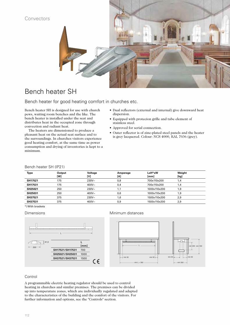
112
L
[mm]
SH17521/SH17531 700
SH25021/SH25031 1000
SH37521/SH37531 1500
L
41,5
200
Convectors
Bench heater SHBench heater for good heating comfort in churches etc.
• Dual reflectors (external and internal) give downward heat dispersion.
• Equipped with protecion grille and tube element of stainless steel.
• Approved for serial connection.
• Outer reflector is of zinc-plated steel panels and the heater is grey lacquered. Colour: NCS 4000, RAL 7036 (grey).
Bench heater SH is designed for use with church pews, waiting room benches and the like. The bench heater is installed under the seat and distributes heat in the occupied zone through convection and radiant heat. The heaters are dimensioned to produce a pleasant heat on the actual seat surface and to the surroundings. In churches visitors experience good heating comfort, at the same time as power consumption and drying of inventories is kept to a minimum.
Dimensions
A programmable electric heating regulator should be used to control heating in churches and similar premises. The premises can be divided up into temperature zones, which are individually regulated and adapted to the characteristics of the building and the comfort of the visitors. For further information and options, see the "Controls" section.
Control
Minimum distances
Bench heater SH (IP21)Type Output
[W]
Voltage
[V]
Amperage
[A]
LxH*xW
[mm]
Weight
[kg]
SH17521 175 230V~ 0,8 700x110x200 1,4
SH17531 175 400V~ 0,4 700x110x200 1,4
SH25021 250 230V~ 1,1 1000x110x200 1,9
SH25031 250 400V~ 0,6 1000x110x200 1,9
SH37521 375 230V~ 1,6 1500x110x200 2,9
SH37531 375 400V~ 0,9 1500x110x200 2,9
*) With brackets
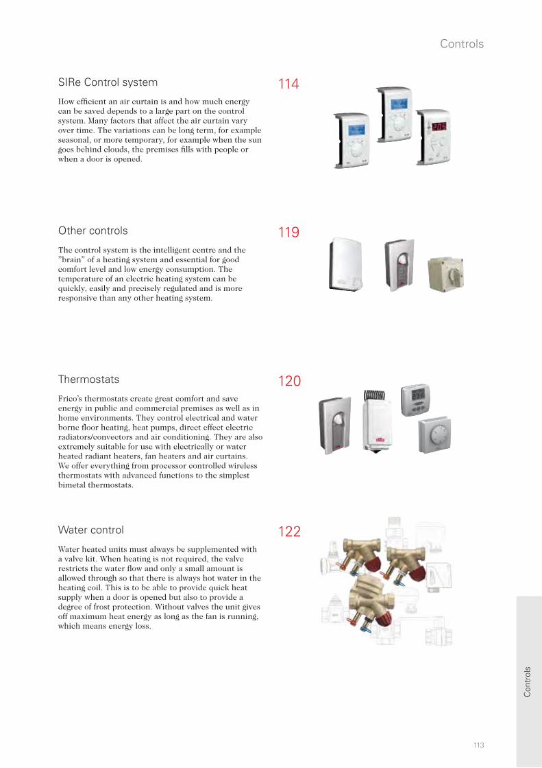
114
120
122
119
Controls
113
Con
trol
s
The control system is the intelligent centre and the ”brain” of a heating system and essential for good comfort level and low energy consumption. The temperature of an electric heating system can be quickly, easily and precisely regulated and is more responsive than any other heating system.
Other controls
Thermostats
Water control
Water heated units must always be supplemented with a valve kit. When heating is not required, the valve restricts the water flow and only a small amount is allowed through so that there is always hot water in the heating coil. This is to be able to provide quick heat supply when a door is opened but also to provide a degree of frost protection. Without valves the unit gives off maximum heat energy as long as the fan is running, which means energy loss.
SIRe Control system
Frico’s thermostats create great comfort and save energy in public and commercial premises as well as in home environments. They control electrical and water borne floor heating, heat pumps, direct effect electric radiators/convectors and air conditioning. They are also extremely suitable for use with electrically or water heated radiant heaters, fan heaters and air curtains. We offer everything from processor controlled wireless thermostats with advanced functions to the simplest bimetal thermostats.
How efficient an air curtain is and how much energy can be saved depends to a large part on the control system. Many factors that affect the air curtain vary over time. The variations can be long term, for example seasonal, or more temporary, for example when the sun goes behind clouds, the premises fills with people or when a door is opened.

114
Controls
114
SIRe Control system
IntelligentAutomatically adapts to your entrance The air curtain automatically adapts to your entrance conditions. Depending on how often the door is opened/closed, or if it is left open continually, the integrated SIRe controls the air curtain operation so that optimal comfort and energy efficiency is achieved.
ProactiveAnticipates for quicker reactions By measuring the outdoor temperature, the air curtain is always a step ahead. The integrated regulation ensures that the air curtain is prepared for changes in the outdoor temperature. For example, when a warm spring day turns into a chilly evening. The air speed is adjusted depending on the outdoor temperature change and stops the chill before it penetrates the premises.
AdaptiveExpert on your entrance SIRe has the capacity to learn precisely what happens at your entrance. The air curtain adapts so that it is always ready to operate fully as soon as the door is opened. It also considers the acoustic comfort by ensuring that the air curtain does not switch between high and low speeds too often.
Eco modeSave money and the environment at the same time With SIRe intelligent regulation integrated in your air curtain, you get comfort in your entrance without wasting energy. If you want to increase the energy efficiency further, set SIRe in Eco mode. The air curtain then uses as little energy as possible without compromising too much on comfort. Energy savings of up to 35 percent are possible.
Outdoor temperature
Regulation of airflow and heat output
Open/closed door
Room temperature
Most of our air curtains are prepared for the intelligent SIRe control system, which automatically manages the air curtain operations. The air curtain adapts itself to the present conditions in the entry. By sensing how often the door opens/closes, outdoor temperature, indoor temperature or even the return water temperature, the air curtain will give you the most effective protection with the highest energy efficiency. Install and forgetWith SIRe control system, the air curtain will always perform at its best. You’ll never have to think about switching it on or off. It even adapts to the season outside, and with calendar function the air curtain automatically runs during the hours it is needed.
th
e at
mae
allyve
l
ghest energ
ed

115
SIRe Control system
115
Con
trol
s
BMS solutionsEndless possibilities With our intelligent SIRe control system, the possibilities to control your air curtains via BMS are endless. You can either choose to control your air curtain by 0-10 V signals (controlling on/off, fan speed, heating and alarm) or completely control all functions and receive indications from your air curtain via gateway (two threaded) BUS communication.
Calendar functionPresets as required SIRe has a calendar function for all the days of the week. The air curtain starts in the morning to ensure that it’s always working to create a comfortable climate and save energy. Preset default setting may easily be adjusted by the user.
Simple installation”Plug and play” An air curtain with integrated SIRe control system is easy to install. The different components are supplied together and are easy to assemble. The system self-checks that everything is correct and that it functions. Thanks to the preset default settings it is easy to start air curtain operation as soon as the system is in place.
SIRe Basic SIRe Competent SIRe Advanced
The SIRe control system is also available for fan heaters, see product chapter SWH.
SIRe is an intelligent and well designed low voltage control system which can be customised for each unique application and environment. The PC board SIRe is built into the air curtain on delivery and is equipped with modular connectors for easy connection of external components. SIRe is supplied pre-programmed and is very easy to install and use. SIRe can control up to nine units. If more than one air curtain should be controlled by a single SIRe, an additional modular cable SIReCC RJ12 (6p/6c) per unit is needed. Cables between units can easily be joined together by using joint piece SIReCJ6.
There are three different levels with different functionality to choose from, Basic, Competent or Advanced.
SIRe can be set to 18 languages, divided into two product versions.
• SIRexxxY communicates in Swedish, Norwegian, English, German, French, Spanish, Dutch, Italian, Danish and Finnish.
• SIRexxxZ communicates in Russian, Ukrainian, Polish, Czech, Slovak, Romanian, Hungarian, Turkish, English and German.
oon
tos
s c
etys
fe
oon
stu
Type Description
SIReBN Control system SIRe Basic
SIReACY Control system SIRe Competent
SIReAAY Control system SIRe Advanced
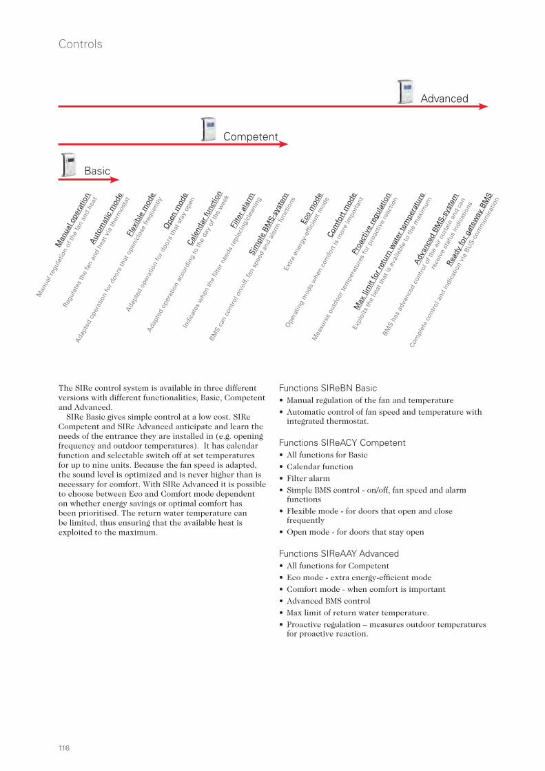
116
Controls
116
Functions SIReBN Basic • Manual regulation of the fan and temperature
• Automatic control of fan speed and temperature with integrated thermostat.
Functions SIReACY Competent • All functions for Basic
• Calendar function
• Filter alarm
• Simple BMS control - on/off, fan speed and alarm functions
• Flexible mode - for doors that open and close frequently
• Open mode - for doors that stay open
Functions SIReAAY Advanced • All functions for Competent
• Eco mode - extra energy-efficient mode
• Comfort mode - when comfort is important
• Advanced BMS control
• Max limit of return water temperature.
• Proactive regulation – measures outdoor temperatures for proactive reaction.
Adv
ance
d BM
S-sy
stem
BMS
has
adva
nced
con
trol
of t
he a
ir cu
rtai
n an
d ca
n
rece
ive
stat
us in
dica
tions
Com
fort
mod
e
Ope
ratin
g m
ode
whe
n co
mfo
rt is
mor
e im
port
ant
Filte
r ala
rm
Indi
cate
s w
hen
the
filte
r nee
ds re
plac
ing/
clea
ning
Flex
ible
mod
e
Ada
pted
ope
ratio
n fo
r doo
rs th
at o
pen/
clos
e fr
eque
ntly
Man
ual o
pera
tion
Man
ual r
egul
atio
n of
the
fan
and
heat
Ope
n m
ode
Ada
pted
ope
ratio
n fo
r doo
rs th
at s
tay
open
Aut
omat
ic m
ode
Regu
late
s th
e fa
n an
d he
at v
ia th
erm
osta
t
Cale
ndar
func
tion
Ada
pted
ope
ratio
n ac
cord
ing
to th
e da
y of
the
wee
k
Sim
ple
BMS-
syst
em
BMS
can
cont
rol o
n/of
f, fa
n sp
eed
and
alar
m fu
nctio
ns
Eco
mod
e
Extr
a en
ergy
-effi
cien
t mod
e
Proa
ctiv
e re
gula
tion
Mea
sure
s ou
tdoo
r tem
pera
ture
s fo
r pro
activ
e re
actio
n
Max
lim
it fo
r ret
urn
wat
er te
mpe
ratu
re
Expl
oits
the
heat
that
is a
vaila
ble
to th
e m
axim
um
Read
y fo
r gat
eway
BM
S
Com
plet
e co
ntro
l and
indi
catio
n vi
a BU
S-co
mm
unic
atio
n
Advanced
Competent
Basic
The SIRe control system is available in three different versions with different functionalities; Basic, Competent and Advanced.
SIRe Basic gives simple control at a low cost. SIRe Competent and SIRe Advanced anticipate and learn the needs of the entrance they are installed in (e.g. opening frequency and outdoor temperatures). It has calendar function and selectable switch off at set temperatures for up to nine units. Because the fan speed is adapted, the sound level is optimized and is never higher than is necessary for comfort. With SIRe Advanced it is possible to choose between Eco and Comfort mode dependent on whether energy savings or optimal comfort has been prioritised. The return water temperature can be limited, thus ensuring that the available heat is exploited to the maximum.

117
52
41
3
230
230
SIReUB1 SIReCC
52
41
3
230
230
52
41
3
230
230
SIReOTX SIReCCSIReA1XN SIReDC
SIReCCSIReC1XN SIReDC
SIRe Control system
117
Con
trol
s
Included in SIReBN Basic:• SIReUB1, control unit with built in room temperature
sensor. Wall unit cover included.
• SIReCC, modular cable, RJ12 (6p/6c), 5 m
Included in SIReACY Competent:• SIReUA1Y, control unit with built in room
temperature sensor. Wall unit cover included.
• SIReC1XN, PC board HUB Competent
• SIReDC, door contact
• SIReCC, modular cables, RJ12 (6p/6c), 3 m resp. 5 m
Included in SIReAAY Advanced:• SIReUA1Y, control unit with built in room
temperature sensor. Wall unit cover included.
• SIReA1XN, PC board HUB Advanced
• SIReOTX, outdoor temperature sensor
• SIReDC, door contact
• SIReCC, modular cables, RJ12 (6p/6c), 3 m resp. 5 m
Accessories • SIReRTX, external room temperature sensor, RJ11
(4p/4c), 10 m
• SIReUR, kit for recessed installation
• SIReWTA, return water sensor, RJ11 (4p/4c), 3 m
• SIReCC, modular cable, RJ12 (6p/6c), 5, 10, 15, 40 m
• VMO(P), (pressure independent) modulating valve kit or VMT, three way valve and modulating actuator
Accessories • SIReRTX, external room temperature sensor, RJ11
(4p/4c), 10 m
• SIReUR, kit for recessed installation
• SIReCC, modular cable, RJ12 (6p/6c), 5, 10, 15, 40 m
• VOS(P), (pressure independent) valve kit on/off or VOT, three way valve and actuator on/off
Accessories • SIReRTX, external room temperature sensor, RJ11
(4p/4c), 10 m
• SIReCC, modular cable, RJ12 (6p/6c), 5, 10, 15, 40 m
• VOS(P), (pressure independent) valve kit on/off or VOT, three way valve and actuator on/off
Integrated PC Board Base
SIReIT, internal temperature sensor
Integrated in the air curtain
Integrated PC Board Base
SIReIT, internal temperature sensor
Integrated in the air curtain
Integrated PC Board Base
SIReIT, internal temperature sensor
Integrated in the air curtain
Wall unit cover
Wall unit cover
SIReUA1Y IP30
SIReUB1 IP30
SIReA1XN IP10
SIReC1XN IP10
SIReOTX IP65
SIReIT IP65
SIReRTX IP30
SIReUR IP30
SIReWTA IP65
SIReUA1Y
SIReUA1Y

118
SIReRTX SIReUR
SIReWTA SIReCJ4
SIReCC
SIReCJ6
Controls
118
Integration of Frico air curtains in an overall control system (BMS)
BMS-control - level 1With SIRe Competent the air curtains can be integrated in an overall control system (BMS). The air curtain can be started/stopped and the fan speed regulated via the BMS system. A 5-30V control signal is required for starting/stopping. A 0-10V control signal is required to control the fan speed. Potential free contact for buzzer.
BMS-control - level 2With SIRe Advanced the air curtains can be integrated in an overall control system (BMS). The air curtain can be started/stopped, the fan speed and heating regulated smoothly via the BMS system. A 5-30V control signal is required for starting/stopping. A 0-10V control signal is required to control the fan speed and heating. Input for alarm and night reduction via external potential free contact. Potential free contact for buzzer and operation indication.
BMS-control - level 3With SIRe Advanced it is also possible to communicate via Modbus RTU (RS485). Contact Frico for more information.
SIRe control system - options
SIReRTX, external room temperature sensorUsed to obtain a better measuring point in the premises when the control unit is located so that the internal room temperature sensor does not show a relevant value. 10 m. cable with modular connector RJ11 (4p/4c).
SIReUR, kit for recessed installationKit for installing SIReUA1 recessed in a wall. Only protrudes 11 mm from the wall.
SIReWTA, return water sensorClamp-on sensor for return water temperature control. 3 m. cable with modular connector RJ11 (4p/4c). Should be mounted on the return pipe on the heating coil.
SIReCJ4/SIReCJ6, joint pieceUsed to join two RJ11 (4p/4c) respectively RJ12 (6p/6c).
SIReCC, modular cablesModular cables RJ11 (4p/4c) and RJ12 (6p/6c). Available in lengths of 3, 5, 10 and 15 m (RJ12 also in 40 m).
Elevator control
Fire alarm system
Air curtain control
Building Management System
Entrance control
Air conditioner control
Type Description
SIReRTX External room temperature sensor, IP30
SIReUR Kit for recessed installation, IP30
SIReWTA Return water sensor, IP65
SIReCJ4 Used to join two RJ11(4/4)
SIReCJ6 Used to join two RJ12(6/6)
SIReCC603 Modular cable RJ12(6/6) 3 m
SIReCC605 Modular cable RJ12(6/6) 5 m
SIReCC610 Modular cable RJ12(6/6) 10 m
SIReCC615 Modular cable RJ12(6/6) 15 m
SIReCC640 Modular cable RJ12(6/6) 40 m
SIReCC403 Modular cable RJ11(4/4) 3 m
SIReCC405 Modular cable RJ11(4/4) 5 m
SIReCC410 Modular cable RJ11(4/4) 10 m
SIReCC415 Modular cable RJ11(4/4) 15 m

Controls
119
Con
trol
s
ERP, electric heating controlStepless pulse control intended for single phase (3600W/230V) or two phase (6000W/400V2~) electric heaters. Cannot control 3 phase loads. Pulse time 60 secs. Triac control (quiet control). Integrated temperature sensor. External sensors available as an accessory. Save reduction function via external connection timer (1–10 degrees). For larger power outputs a slave unit (ERPS) can be connected. Each ERPS can handle the same power as ERP. IP20.
CIRT, stepless output control with timerStepless output control with timer, primarily intended for infrared heaters and other radiant heaters. Intended for single phase (3600W/230V~) or two phase (6000W/400V2~) electric heaters. Especially suited for spot amd zone heating. The heat contribution is regulated for best comfort (25-100 %). The built-in timer can be set for 0.5 to 4 or 4 to 24 hours. High protection class. IP44.
S123, manual switch for 1-2-3 stepsControls the output in three steps 0-1/3-2/3-3/3. IP44.
CBT, electronic timerElectronic timer with alternating contact. Setting range 1/2-1-2-4 or 4-8-16-24 hours respectively. The setting range can be limited down to a maximum time of 1/2 hours. IP44.
KUR, digital time switchDigital weekly timer with 8 different program steps (36 memory places) equipped with a changeover contact. Max. breaking current: 10 A. IP55.
Other controls
Type Voltage
[V]
Max input
[A]
HxWxD
[mm]
S123 230/400V3~ 20 72x64x46
Type Voltage
[V]
Max input
[A]
HxWxD
[mm]
ERP 230/400V~ 16 153x93x40
ERPS 230/400V~ 16 153x93x40
Accessories ERPType Description
ERPRG Room sensor ERP
ERPGG Floor/duct sensor ERP
Type Voltage
[V]
Max input
[A]
HxWxD
[mm]
CIRT 230/400V2~ 16 155x87x43
Type Voltage
[V]
Max input
[A]
HxWxD
[mm]
KUR 230V~ 10 175x85x105
Type Voltage
[V]
Max input
[A]
HxWxD
[mm]
CBT 230V~ 16 155x87x43

120120
Controls
RTS01, external sensor (accessory) External sensor of NTC-type 10 kOhm. 3 m cable included.
KRT1900/1 KRTV19 KRT2800
TBK10 TBKS10
TBK, bimetal thermostats Mechanical bimetal thermostats with acceleration resistance for room heating/cooling. TBKS10 also has a 1-pole switch. CE compliant.
KRT, capillary tube thermostatsCapillary tube thermostats for room heating/cooling. Available with concealed and visible knob, and control in 1 or 2 steps. KRT2800 controls in 2 steps and has adjustable temperature difference between the steps (1–4 degrees). KRT1901 has a temperature range of -35–+10 °C. High protection class (IP44 resp. IP55). CE compliant.
RTI2 RTI2VT10S TK10S TKS16(400) TD10
T, TK, TD, basic offer thermostatsProcessor controlled thermostats for room/floor heating. Available with concealed/visible knob or digital display. Model with visible knob also available with switch and in 400 V.
On/off control (for slow systems) or proportional control (for faster systems) in the same thermostat. TD10 has adjustable P-band and time of cycle.
Internal and/or external sensors (external sensor RTS01 available as an accessory) give the possibility of selecting the sensor function e.g limiting external sensors (min/max). Save reduction either by built-in manual switch or via external timer. CE compliant.
RTI2, electronic 2-step thermostatsProcessor controlled 2-step thermostats for room heating /cooling. Available with concealed or visible knob. Adjustable temperature difference between the steps (1–10 degrees). Save reduction via external connection timer (1–10 degrees). External sensor (RTS01) available as an accessory. High protection class (IP44). CE compliant.
Thermostats
Type Description
RTS01 External sensor
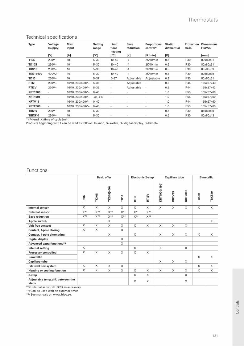
121121
Thermostats
Con
trol
s
Functions
Technical specifications
Basic offer Electronic 2-step Capillary tube Bimetallic
T10
S
TK
10
S
TK
S1
6(4
00
)
TD
10
RT
I2
RT
I2V
KR
T19
00
/19
01
KR
TV
19
KR
T2
80
0
TB
K10
TB
KS
10
Internal sensor X X X X X X X X X X X
External sensor X*¹ X*¹ X*¹ X*¹ X*¹ X*¹
Save reduction X*² X*² X*² X*² X*² X*²
1-pole switch X X
Volt free contact X X X X X X X X X
Contact, 1-pole closing X X X
Contact, 1-pole alternating X X X X X X X
Digital display X
Advanced extra functions*³ X
Internal setting X X X X
Processor controlled X X X X X X
Bimetallic X X
Capillary tube X X X
Fits wall box system X X X X X X
Heating or cooling function X X X X X X X X X X X
2-step X X X
Adjustable temp.diff. between the
stepsX X X
*¹) External sensor (RTS01) as accessory. *²) Can be used with an external timer. *³) See manuals on www.frico.se.
Type Voltage
(supply)
[V]
Max
input
[A]
Setting
range
[°C]
Limit
floor
heating
[°C]
Save
reduction
[K]
Proportional
control*
[K/min]
Static
differential
[K]
Protection
class
Dimensions
HxWxD
[mm]
T10S 230V~ 10 5–30 10–40 -4 2K/10min 0,5 IP30 80x80x31
TK10S 230V~ 10 5–30 10–40 -4 2K/10min 0,5 IP30 80x80x31
TKS16 230V~ 16 5–30 10–40 -4 2K/10min 0,5 IP30 80x80x39
TKS16400 400V2~ 16 5–30 10–40 -4 2K/10min 0,5 IP30 80x80x39
TD10 230V~ 10 5–37 5–37 Adjustable Adjustable 0,3 IP30 80x80x31
RTI2 230V~ 16/10, 230/400V~ 5–35 - Adjustable - 0,5 IP44 155x87x43
RTI2V 230V~ 16/10, 230/400V~ 5–35 - Adjustable - 0,5 IP44 155x87x43
KRT1900 - 16/10, 230/400V~ 0–40 - - - 1,0 IP55 165x57x60
KRT1901 - 16/10, 230/400V~ -35–+10 - - - 1,0 IP55 165x57x60
KRTV19 - 16/10, 230/400V~ 0–40 - - - 1,0 IP44 165x57x60
KRT2800 - 16/10, 230/400V~ 0–40 - - - 1,0 IP55 165x57x60
TBK10 230V~ 10 5–30 - - - 0,5 IP30 85x82x39
TBKS10 230V~ 10 5–30 - - - 0,5 IP30 80x80x43*) P-band [K]/time of cycle [min] Products beginning with T can be read as follows: K=knob, S=switch, D= digital display, B=bimetal.

122122
Controls
SIRe Basic, SIRe Competent
SIRe Advanced
Water control - Choose valve kit
Water heated units that are controlled by SIRe are supplemented with valve kits. It’s easy to choose the right valve kit. Look at the guide for the level of SIRe chosen - Basic, Competent or Advanced and select the valve kit which suits the system requirements and characteristics.
VOS, valve kit on/off• Complete kit with two way control and
adjustment valve, on/off-actuator, shut-off valve and bypass.
VOSP, pressure independent valve kit on/off• Complete kit with two way pressure
independent control and adjustment valve, on/off-actuator, shut-off valve and bypass.
• Two way pressure independent control and adjustment valve ensures that the flow always is constant.
VMO, modulating valve kit• Complete kit with two way control and
adjustment valve, modulating (stepless) actuator and shut-off valve.
VMOP, pressure independent and modulating valve kit• Complete kit with two way pressure
independent control and adjustment valve, modulating (stepless) actuator and shut-off valve.
• Two way pressure independent control and adjustment valve ensures that the flow always is constant.
VMOP15LF
• Flow range 0,004 - 0,035 l/s• DN15 VMOP15NF
• Flow range 0,021 - 0,088 l/s• DN15 VMOP20
• Flow range 0,035 - 0,175 l/s• DN20 VMOP25
• Flow range 0,071 - 0,353 l/s• DN25
VOS15LF
• Kvs 0,90 • Max flow at 10 kPa: 0,079 l/s • DN15 VOS15NF
• Kvs 1,8 • Max flow at 10 kPa: 0,158 l/s • DN15 VOS20
• Kvs 3,4 • Max flow at 10 kPa: 0,299 l/s • DN20 VOS25
• Kvs 7,2 • Max flow at 10 kPa: 0,630 l/s • DN25
VOSP15LF
• Flow range 0,004 - 0,035 l/s• DN15 VOSP15NF
• Flow range 0,021 - 0,088 l/s• DN15 VOSP20
• Flow range 0,035 - 0,175 l/s• DN20 VOSP25
• Flow range 0,071 - 0,353 l/s• DN25
VOT15
• Kvs 1,7 • Max flow at 10 kPa: 0,149 l/s • DN15 VOT20
• Kvs 2,5 • Max flow at 10 kPa: 0,220 l/s • DN20 VOT25
• Kvs 4,5 • Max flow at 10 kPa: 0,395 l/s • DN25
VMT15
• Kvs 1,7 • Max flow at 10 kPa: 0,149 l/s • DN15 VMT20
• Kvs 2,5 • Max flow at 10 kPa: 0,220 l/s • DN20 VMT25
• Kvs 4,5 • Max flow at 10 kPa: 0,395 l/s • DN25
VMO15LF • Kvs 0,40 • Max flow at 10 kPa: 0,035 l/s • DN15 VMO15NF
• Kvs 1,0 • Max flow at 10 kPa: 0,088 l/s • DN15 VMO20
• Kvs 2,1 • Max flow at 10 kPa: 0,185 l/s • DN20 VMO25
• Kvs 4,0 • Max flow at 10 kPa: 0,352 l/s • DN25
VOT, three way control valve and actuator on/off• Three way control valve and actuator on/
off.
VMT, three way control valve and modulating actuator• Three way control valve and modulating
actuator.
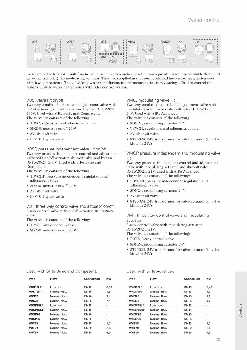
123
VMOPVOS
VAT
VOSP VMO VMTVOT
123
Water control
Con
trol
s
Complete valve kits with multifunctional terminal valves makes new functions possible and ensures stable flows and exact control using the modulating actuator. They are supplied at different levels and have a low installation cost with few components. The valve kit gives exact adjustment and means extra energy savings. Used to control the water supply to water heated units with SIRe control system.
VMO, modulating valve kitTwo way combined control and adjustment valve with modulating actuator and shut-off valve. DN15/20/25. 24V. Used with SIRe Advanced.The valve kit consists of the following:
• SDM24, modulating actuator 24V
• TBVCM, regulation and adjustment valve
• AV, shut off valve
• ST23024, 24V transformer for valve actuator (in valve kit with 24V)
VMOP, pressure independent and modulating valve kitTwo way pressure independent control and adjustment valve with modulating actuator and shut-off valve. DN15/20/25. 24V. Used with SIRe Advanced.The valve kit consists of the following:
• TBVCMP, pressure independent regulation and adjustment valve
• SDM24, modulating actuator 24V
• AV, shut off valve
• ST23024, 24V transformer for valve actuator (in valve kit with 24V)
VMT, three way control valve and modulating actuator3-way control valve with modulating actuator. DN15/20/25. 24V.The valve kit consists of the following:
• TRVS, 3-way control valve
• SDM24, modulating actuator 24V
• ST23024, 24V transformer for valve actuator (in valve kit with 24V)
VOS, valve kit on/offTwo way combined control and adjustment valve with on/off actuator, shut-off valve and bypass. DN15/20/25. 230V. Used with SIRe Basic and Competent. The valve kit consists of the following:
• TBVC, regulation and adjustment valve
• SD230, actuator on/off 230V
• AV, shut off valve
• BPV10, bypass valve VOSP, pressure independent valve kit on/offTwo way pressure independent control and adjustment valve with on/off actuator, shut-off valve and bypass. DN15/20/25. 230V. Used with SIRe Basic and Competent. The valve kit consists of the following:
• TBVCMP, pressure independent regulation and adjustment valve
• SD230, actuator on/off 230V
• AV, shut off valve
• BPV10, bypass valve VOT, three way control valve and actuator on/off3-way control valve with on/off actuator, DN15/20/25. 230V.The valve kit consists of the following:
• TRVS, 3-way control valve
• SD230, actuator on/off 230V
Used with SIRe Advanced.Used with SIRe Basic and Competent.
Type Flow Connection Kvs
VOS15LF Low flow DN15 0,90
VOS15NF Normal flow DN15 1,8
VOS20 Normal flow DN20 3,4
VOS25 Normal flow DN25 7,2
VOSP15LF Low flow DN15 -
VOSP15NF Normal flow DN15 -
VOSP20 Normal flow DN20 -
VOSP25 Normal flow DN25 -
VOT15 Normal flow DN15 1,7
VOT20 Normal flow DN20 2,5
VOT25 Normal flow DN25 4,5
Type Flow Connection Kvs
VMO15LF Low flow DN15 0,40
VMO15NF Normal flow DN15 1,0
VMO20 Normal flow DN20 2,0
VMO25 Normal flow DN25 4,0
VMOP15LF Low flow DN15 -
VMOP15NF Normal flow DN15 -
VMOP20 Normal flow DN20 -
VMOP25 Normal flow DN25 -
VMT15 Normal flow DN15 1,7
VMT20 Normal flow DN20 2,5
VMT25 Normal flow DN25 4,5

124
230V ~
C°
AV20/25
JVF20/25
TRVS20/25
BPV10
SD20
T10S/KRT
VR
S20
/25
230V ~
C°
TVVS20/25
SD20
T10S/KRT
SD20AV20/25 TRVS20/25 BPV10 TVVS20/25JVF20/25
VRS20/25
SD20 TRVS20/25
124
Controls
TVVS20/25, valves + SD20, actuator*TVVS20/25, 2-way regulation valve and SD20, actuator on/off provides a basic form of water regulation, without the possibility of adjusting or shutting the water flow off, e.g. when making maintenance. A suitable thermostat is chosen to regulate TVVS20/25 and SD20. DN20/25. TVVS20/25, 2-way control valve*TVVS20: maximum close-off pressure 150 kPa (1,5 bar), kvs 2,6, DN20 (3/4"). TVVS25: maximum close-off pressure 70 kPa (0,7 bar), kvs 4,5, DN25 (1").Pressure class PN16. TRVS20/25, 3-way control valveIf a 3-way valve is preferred, TRVS20/25 can be used instead of TVVS20/25. TRVS20: maximum close-off pressure 100 kPa (1,0 bar), kvs 2,5, DN20 (3/4").TRVS25: maximum close-off pressure 70 kPa (0,7 bar), kvs 4,5, DN25 (1").Pressure class PN16.
SD20, actuator on/off 230V~*SD20 regulates the heat supply. Works on/off. A 5 second closing of the valve prevents sudden pressure changes in the pipe system. In unpowered mode, the SD20 valve is opened via spring return.
TE3434Flexible hose, length 0,8 metres, for water heated units (2 is needed for a unit) with external thread 3/4” (DN20) at one end and coupling nut internal thread 3/4” (DN20), on the other.
VRS20/25, valve kit*For control of water flow to water heated air curtains.
The valve kit consists of the following:• AV20/25, stop valve• JVF20/25, adjustment valve• TRVS20/25, on/off 3-way control valve• BPV10, by-pass valve • SD20, actuator on/off 230V~
The stop valve (AV20/25) consists of a ball valve which is either open or closed. It is used to turn the water flow off and on. The water flow can be fine-tuned manually with the adjustment valve and can also be completely turned off. The water flow may be read off the valve. The kv value for JVF20 is 3,5 and for JVF25 it is 5,5.
If the 3-way valve (TRVS20/25) is closed, the flow through the by-pass valve (BPV10) is low to ensure presence of warm water in the heating coil. This leads to instant heat supply when needed and some degree of frost protection. The actuator (SD20) works on/off.
The valve kit is available with two different valve dimensions: VRS20 - DN20 (3/4”) and VRS25 - DN25 (1”). The by-pass valve dimension is DN10 (3/8”). To regulate VRS20/25, a suitable thermostat has to be added.
*) These products can not be used together with SIRe control system.

Symbols for model types
= normal design (no symbols), IPX0 = drip-proof design, IPX1 = splash-proof design, IPX4
= jet-proof design, IPX5
Protection classes for electrical material
IP, first figure Protection against solid objects
0 No protection
1 Protection against solid objects 50 mm
2 Protection against solid objects 12,5 mm
3 Protection against solid objects 2,5 mm
4 Protection against solid objects 1,0 mm
5 Protection against dust
6 Dust-tight
IP, second figure Protection against water
0 No protection
1 Protection against vertically dripping water
2 Protection against dripping water angled at max 15°
3 Protection against sprinkled water
4 Protection against spraying with water
5 Protection against water jets
6 Protection against heavy seas
7 Protection against short-term immersion in water
8 Protection against the effects of long-term immersion in water
How is sound measured?Sound level is measured in decibels (dB). The dB is a logarithmic unit used to describe a ratio. If the sound level is increased by 10 dB, the result is twice as loud (as perceived by human ear).
It is also useful to know that two equally strong sound sources give an added sound level of 3 dB. Assume you have two entrances with two air curtains in each entrance, all four units with a sound level of 50 dB. The total sound level will then be 56 dB. The first opening will have a total sound level of 53 dB plus an extra 3 dB from the other opening.
Points of reference – dB
0 The softest sound a person can hear
10 Normal breathing
30 Recommended max. level for bedrooms
40 Quiet office, library
50 Large office
60 Normal conversation
80 Ringing telephone
85 Noisy restaurant
110 Shouting in ear
120 The threshold of pain
Technical data
Heat insulation, U-value
U = thermal transmittance value [W/m²°C]U-values indicate the heat insulating capacity of a building section.
Material U-value [W/m² °C]
Walls
New building
Wooden fascia with 15 cm insulation and plaster 0,27
Wooden fascia with 20 cm insulation and plaster 0,25
Wooden fascia with 25 cm insulation and plaster 0,22
Brick fascia with 15 cm insulation and plaster 0,27
Brick fascia with 20 cm insulation and plaster 0,24
Light concrete with 15 cm insulation 0,25
Light concrete with 20 cm insulation 0,2
Sheet metal fascia with 5 cm insulation 0,8
Sheet metal fascia with 10 cm insulation 0,4
Sheet metal fascia with 15 cm insulation 0,3
New construction for low energy house 0,18
Warehouse 0,3
One layer PVC (900 g) 5,0
Insulated hall (Thermohall) 0,6
Older building
Single brick 12 cm 1,8
1 1/2 brick 18 cm 1,1
Light concrete block 20 cm 0,8
Light concrete block 30 cm 0,6
Concrete 15 cm 2,8
Concrete with 5 cm insulation 0,8
Concrete with 10 cm insulation 0,4
Frame wall with 5 cm insulation 0,8
Frame wall with 10 cm insulation 0,4
Frame wall with 15 cm insulation 0,3
New construction 0,3
Roof
New building
Sheet metal pitched roof, with 20 cm insulation 0,24
Brick pitched roof, with 20 cm insulation 0,23
Older building
Concrete beam frame 15 cm 2,8
Concrete beam frame with 5 cm insulation 0,8
Concrete beam frame with 10 cm insulation 0,4
Light concrete 20 cm 0,8
Light concrete 30 cm 0,6
Sheet metal roof, uninsulated 4,0
Sheet metal roof with 5 cm insulation 0,8
Sheet metal roof with 10 cm insulation 0,6
Sheet metal roof with 25 cm insulation 0,2
Windows
New building
1+1 pane window (1 outer pane and 1 insulated pane) 2,5
2 pane window (2 insulated panes) 2,7
2+1 pane window (1 outer pane and 2 insulated panes) 1,0
3 pane window (3 insulated panes) 1,2
Energy class A 0,9
Energy class B 1,0
Energy class C 1,1
Energy class D 1,2
Energy class E 1,3
Energy class F 1,4
Energy class G 1,5
Older building
1 pane window 5,0
2 pane window 3,0
3 pane window 2,0
3 pane window insulation pane 1,8