CATALOGUE - Salher
260
CATALOGUE
-
Upload
khangminh22 -
Category
Documents
-
view
3 -
download
0
Transcript of CATALOGUE - Salher
CATALOGUE

With almost 40 years of experience, Salher provides solutions for urban and industrial wastewater treatments, drinking water treatments, grey water reuse systems, hydrocarbon separators, as well as accessories for wastewater treatments, all around the world.
Solutions
“Our clients expect from our projects personalization and innovation, both are the values that drive us to the excellence and make the difference.”
We design and manufacture our own equipment to ensure effective solutions.
URBAN WATER& REUSE
DRINKINGWATER
INDUSTRIALWATER
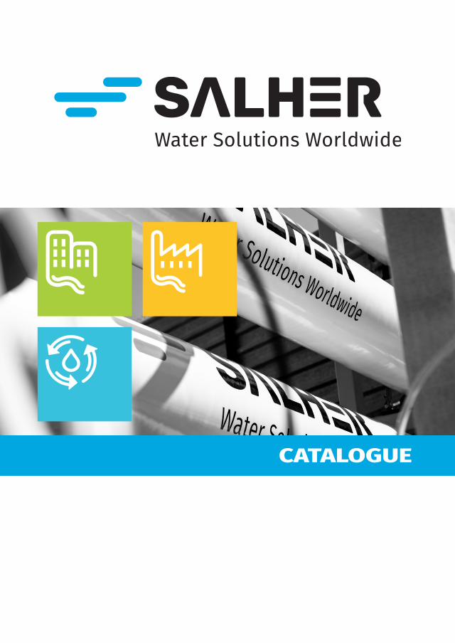
Our products cover the needs of a water treatment plant from start to finish by adding screening systems, such as endless screw sieves or rotary drum sieves, and other elements such as pumping stations, tertiary treatments for the water reuse and sludge dehydration systems.Optionally, the treatment lines can be installed above-ground.
Products
Services
Manufacturing SupplyProject and Design
Commissioning Maintenance Courses &documentary support

2
1
3
4
5
6
7
8
9
10
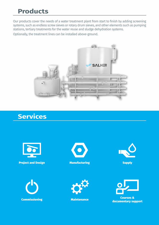
Pretreatment
Primary treatments
Tertiary treatments
Secondary treatments
Water purification
Oil/water separators
Pumping stations
Tanks
Sludge treatment and thickeners
Accessories


1Pretreatment


Table of contents
Other dimensions and configurations can be provided upon request. Internal dimensions. Dimensions in millimeters. Volumes in liters, the dimensions indicated may vary according to the needs.Due to its policy of continuous development, Salher Ibérica, S.L. reserves the right to modify the data that appear in this document without notice.This document is protected by the intellectual property law, so that the customer cannot claim, manipulate or duplicate this documentation, except copy for personal use.
Manual screensCoarse screen with manual cleaning REF: CVA-ARG AND ARF 10REF: CD-ARG AND ARF 10Coarse and fine screen with manual cleaning for installation in GFRP canalREF: CD-MA-D 11
Semi-automatic screensCoarse and fine screen, manual and automatic cleaning, for installation in GFRP canal REF: CD-MA-RAC 12Fine screen with automatic cleaning for civil engineering REF: RAC 13
Automatic screens Sieve for coarse solids for installation on pumping stations and manholesREF: TA-HEL-MINI 14Manhole for TA-HEL-MINIREF: CARCASA TA-HEL-MINI 15Helical screw sieve with automatic cleaning, waste dehydration and compaction, for installation in civil engineering canal REF: TA-HEL 16Helical screw sieve for fine solids with automatic cleaning, waste dehydration and compacting system, for aboveground installation REF: TA-HEL-S 17Helical screw sieve for fine solids with automatic cleaning for pumping stationsREF: TA-HEL-PB 20Rotary drum sieve for small flowsREF: TARO -MINI 22Rotary drum sieveREF: TA-RO 23Accessories for rotary drum sieveREF: COMPAC-TA–RO 24REF: TAPA-TARO 24REF: ES-TARO 25Compact pretreatment plant - helical screw sieve REF: PPC-TAHEL AND PPC-TAHEL-D 26Compact pretreatment plant - rotary drum sieveREF: PPC-TARO AND PPC-TARO-D 30
Grit chambers and grease trapsVertical grease separatorREF: CVC-CG 34Horizontal grease separatorREF: CHC-CG 35Horizontal sand removal and solids settling tankREF: CHC–DES 36Wastewater storage tankREF: CHC–E 37Manual grease separator for restaurants REF: CG-MAN 38
Automatic grease trapsAutomatic grease separator for aboveground installationREF: PSG 39Automatic grease separator for restaurantREF: CG-AUT 40
Accessories and spare partsPACKAGING FOR SIEVES 41SPARE PARTS FOR RAC 41SPARE PARTS FOR CG-AUT 41SPARE PARTS FOR TAHEL 42SPARE PARTS FOR TARO 43SPARE PARTS FOR PSG 44MISCELLANEOUS 45
10
1
Ø620
500
L
H
A
CE CS
CE CS
PretreatmentData and models of the table may vary.
Catalogue - 2020V2.3.1
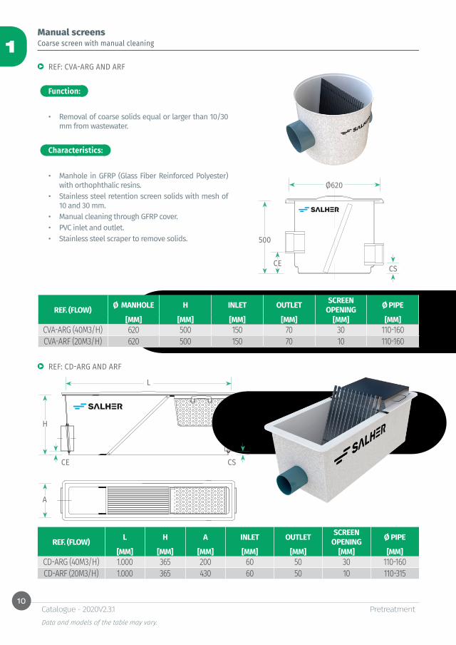
Coarse screen with manual cleaning Manual screens
Function:
Characteristics:
REF: CVA-ARG AND ARF
• Removal of coarse solids equal or larger than 10/30 mm from wastewater.
• Manhole in GFRP (Glass Fiber Reinforced Polyester) with orthophthalic resins.
• Stainless steel retention screen solids with mesh of 10 and 30 mm.
• Manual cleaning through GFRP cover.• PVC inlet and outlet.• Stainless steel scraper to remove solids.
REF: CD-ARG AND ARF
REF. (FLOW) Ø MANHOLE H INLET OUTLET SCREEN OPENING Ø PIPE
[MM] [MM] [MM] [MM] [MM] [MM]CVA-ARG (40M3/H) 620 500 150 70 30 110-160CVA-ARF (20M3/H) 620 500 150 70 10 110-160
REF. (FLOW) L H A INLET OUTLET SCREEN OPENING Ø PIPE
[MM] [MM] [MM] [MM] [MM] [MM] [MM]CD-ARG (40M3/H) 1.000 365 200 60 50 30 110-160CD-ARF (20M3/H) 1.000 365 430 60 50 10 110-315
11
1
A
H
L
PretreatmentData and models of the table may vary.
Catalogue - 2020V2.3.1
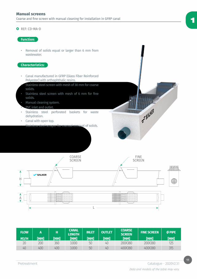
Manual screens
Function:
Characteristics:
Coarse and fine screen with manual cleaning for installation in GFRP canal
REF: CD-MA-D
• Removal of solids equal or larger than 6 mm from wastewater.
• Canal manufactured in GFRP (Glass Fiber Reinforced Polyester) with orthophthalic resins.
• Stainless steel screen with mesh of 30 mm for coarse solids.
• Stainless steel screen with mesh of 6 mm for fine solids.
• Manual cleaning system. • PVC inlet and outlet.• Stainless steel perforated baskets for waste
dehydration.• Canal with open top.• Stainless steel scraper for manual removal of solids.
COARSE SCREEN
FINE SCREEN
FLOW A H CANAL LENGTH INLET OUTLET COARSE
SCREEN FINE SCREEN Ø PIPE
M3/H [MM] [MM] [MM] [MM] [MM] [MM] [MM] [MM]20 200 360 3.000 50 40 200X380 200X380 12540 400 400 3.000 50 40 400X380 400X380 315
12
1
H
L
A
PretreatmentData and models of the table may vary.
Catalogue - 2020V2.3.1
Function:
Characteristics:
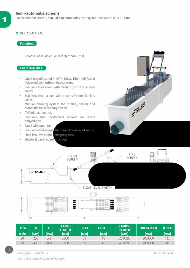
Semi-automatic screens
REF: CD-MA-RAC
• Removal of solids equal or larger than 6 mm.
Coarse and fine screen, manual and automatic cleaning, for installation in GFRP canal
• Canal manufactured in GFRP (Glass Fiber Reinforced Polyester) with orthophthalic resins.
• Stainless steel screen with mesh of 30 mm for coarse solids.
• Stainless steel screen with mesh of 6 mm for fine solids.
• Manual cleaning system for primary screen and automatic for secondary screen.
• PVC inlet and outlet.• Stainless steel perforated baskets for waste
dehydration.• Canal with open top.• Stainless steel scraper for manual removal of solids.• Float level switch for emergency start.• Electrical panel board in option.
COARSE SCREEN
FINE SCREEN
FLOAT LEVEL SWITCH
FLOW A H CANAL LENGTH INLET OUTLET COARSE
SCREEN FINE SCREEN Ø PIPE
M3/H [MM] [MM] [MM] [MM] [MM] [MM] [MM] [MM]20 200 360 3.000 50 40 200X380 200X380 12540 400 400 3.000 50 40 400X380 400X380 315

13
1
PretreatmentData and models of the table may vary.
Catalogue - 2020V2.3.1
Function:
Characteristics:
Semi-automatic screensFine screen with automatic cleaning for civil engineering
REF: RAC
• Removal of solids equal or larger than 6 mm.
• Stainless steel screen with perforated mesh of 6 mm.• Automatic cleaning system.• Stainless steel perforated basket for waste
dehydration.• Electrical panel board in option.• Float level switch for emergency start.
FLOAT LEVEL SWITCH
FINE SCREEN
FLOW SCREEN WIDTH SCREEN HEIGHT FINE SCREEN GEAR MOTORM3/H [MM] [MM] [MM] KW
20 200 360 200X380 0.18 KW40 400 400 400X380 0.18 KW
14
1
16672134 +5002622 +1000
PretreatmentData and models of the table may vary.
Catalogue - 2020V2.3.1
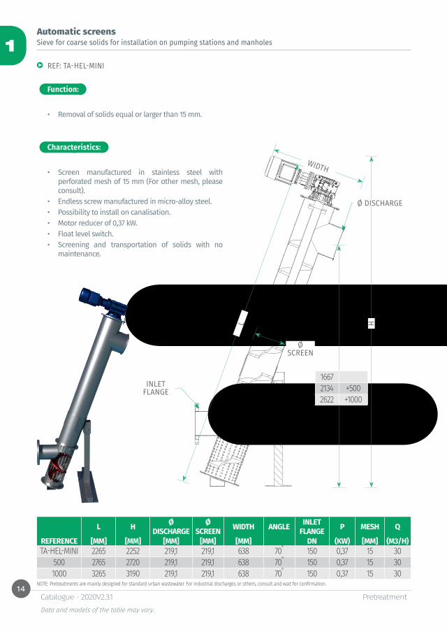
Automatic screens Sieve for coarse solids for installation on pumping stations and manholes
Function:
Characteristics:
REF: TA-HEL-MINI
• Removal of solids equal or larger than 15 mm.
• Screen manufactured in stainless steel with perforated mesh of 15 mm (For other mesh, please consult).
• Endless screw manufactured in micro-alloy steel. • Possibility to install on canalisation.• Motor reducer of 0,37 kW.• Float level switch. • Screening and transportation of solids with no
maintenance.
HL
WIDTH
Ø SCREEN
INLET FLANGE
Ø DISCHARGE
NOTE: Pretreatments are mainly designed for standard urban wastewater. For industrial discharges or others, consult and wait for confirmation.
L H Ø DISCHARGE
Ø SCREEN WIDTH ANGLE INLET
FLANGE P MESH Q
REFERENCE [MM] [MM] [MM] [MM] [MM] DN (KW) [MM] (M3/H)TA-HEL-MINI 2265 2252 219,1 219,1 638 70˚ 150 0,37 15 30
500 2765 2720 219,1 219,1 638 70˚ 150 0,37 15 301000 3265 3190 219,1 219,1 638 70˚ 150 0,37 15 30
15
1
7671234 +5001722 +1000
90018042
9
1200
PretreatmentData and models of the table may vary.
Catalogue - 2020V2.3.1
Automatic screens
Function:
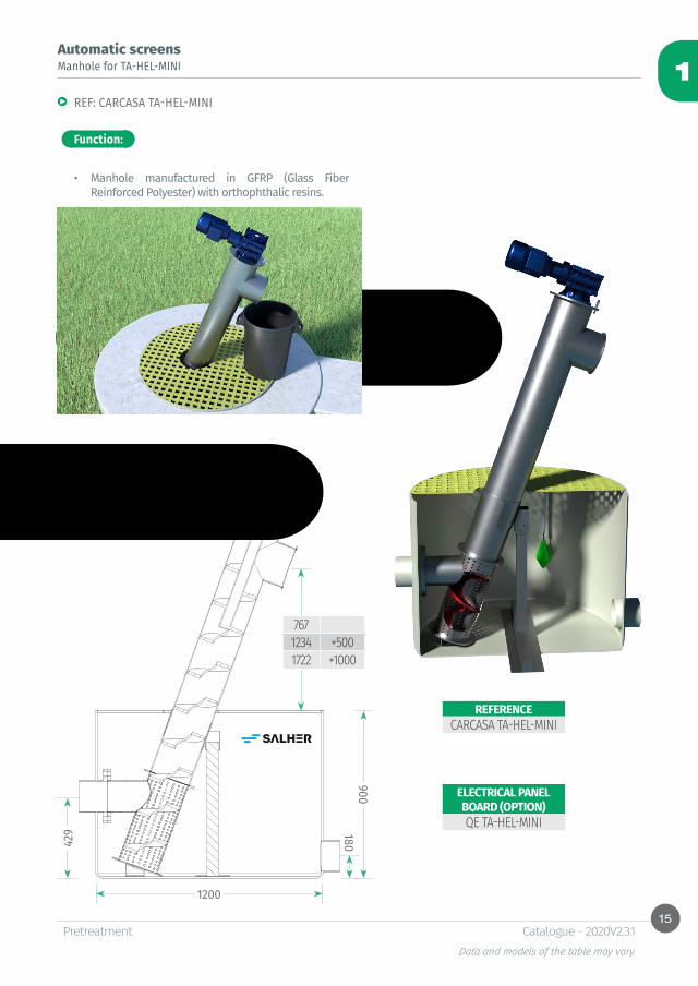
Manhole for TA-HEL-MINI
• Manhole manufactured in GFRP (Glass Fiber Reinforced Polyester) with orthophthalic resins.
REF: CARCASA TA-HEL-MINI
REFERENCECARCASA TA-HEL-MINI
ELECTRICAL PANEL BOARD (OPTION)QE TA-HEL-MINI

16
1
(A)
(B)
(C)
(E)(F)
(G)(H)
(J)
PretreatmentData and models of the table may vary.
Catalogue - 2020V2.3.1
Helical screw sieve with automatic cleaning, waste dehydration and compaction, for installation in civil engineering canal
Automatic screens
Function:
Characteristics:
Accessories:
REF: TA-HEL
• Removal of solids equal or larger than 3 mm, waste dehydration and compacting system.
• Totally dismountable stainless steel AISI 304 equipment.
• Fine screen in stainless steel with opening size from 3 to 10 mm.
• Endless screw manufactured in micro-alloy steel, no central shaft, working angle of 35°.
• Continuous cleaning system of mesh with brushes placed on the endless screw.
• Automatic cleaning system with brushes and pressurized water.
• Automatic waste dehydration system and compactor.• Neoprene bands for lateral water-tightness.• Adjustable supporting base height and rotation
system for maintenance operations.• Electrical panel board in option.
• Automatic cleaning system:* Cleaning electrovalve N/C 1/2”: cleaning system
automation.* Filter in Y 1/2”: protection and retention of
particles carried by the water. * Ball valve 1/2”: closure of the cleaning connection
if necessary.• Safety switch on top cover.• Emergency stop. • Conductive level sensor by rods for equipment
operation automation.
NOTE: Pretreatments are mainly designed for standard urban wastewater. For industrial discharges or others, consult and wait for confirmation.
(A) (B) (C) (E) (F) (G) (H) (J)
REF. LENGTH H CANAL H DISCHARGE
WIDTH CANAL
WIDTH SIEVE
Ø DISCHARGE TOTAL H 0 P. OPENING
SIZETA-HEL [MM] [MM] [MM] [MM] [MM] [MM] [MM] [MM] [KW] [MM]200-SP 2.849 500 530 ≥300 240 168 1.250 ≥2335 0.55 3-10
200 4.800 800 1.320 ≥300 230 168 2.050 ≥3712 0.55 3-10400 5.300 800 1.450 ≥450 400 273 2.440 ≥4328 1.1 3-10600 6.040 1.000 1.440 ≥750 670 406 2.650 ≥4800 1.5 3-10

17
1
(D)
(H)
(C)
(J)
(G)
(B)
(A)
E
SR
PretreatmentData and models of the table may vary.
Catalogue - 2020V2.3.1
Automatic screens
Function: Accessories:
Characteristics:
• Automatic cleaning system:* Cleaning electrovalve N/C 1/2”: cleaning system
automation.* Filter in Y 1/2”: protection and retention of
particles carried by the cleaning water. * Ball valve 1/2”: closure of the cleaning connection
if necessary.• Safety switch on top cover.• Emergency stop. • Conductive level sensor by rods for equipment
operation automation.
Helical screw sieve for fine solids with automatic cleaning, waste dehydration and compacting system, for aboveground installation
REF: TA-HEL-S
• Removal of solids equal or larger than 3 mm, waste dehydration and compacting system.
• Ideal for installation down the pumping stations.
• Totally dismountable stainless steel AISI 304 equipment.
• Fine solids screen in stainless steel with perforated mesh.
• Screen in stainless steel with opening size from 3 to 10 mm.
• Endless screw manufactured in micro-alloy steel, no central shalf, working angle of 35°.
• Continuous cleaning system of mesh with brushes placed on the endless screw.
• Automatic cleaning system with brushes and pressurized water.
• Automatic waste dehydration system and compactor.• Neoprene bands for lateral watertightness.• Adjustable supporting base height and rotation
system for maintenance operations.• Structure in stainless steel for aboveground
installation, with flanged connections in AISI 304.• Electrical panel board in option.
NOTE: Pretreatments are mainly designed for standard urban wastewater. For industrial discharges or others, consult and wait for confirmation.
REF. (A) (B) (C) (D) (G) (H) (J) P. OPENING SIZE
FLANGES (E/S/R)
TA-HEL-S [MM] [MM] [MM] [MM] [MM] [MM] [MM] KW [MM] DN200-SP 2.920 855 1.194 408 165 1910 2.435 0.55 3-10 100/125/100
200 4.900 1.100 2.280 558 165 2990 3.975 0.55 3-10 200/200/125400 5.400 1.350 2.410 658 269 3.390 4.390 1.1 3-10 250/250/150600 6.130 1.700 2.640 868 406 3.830 4.870 1.5 3-10 300/400/300

18
1
PretreatmentData and models of the table may vary.
Catalogue - 2020V2.3.1
Automatic screens
TABLE OF FLOWS
NOTE: Pretreatments are mainly designed for standard urban wastewater. For industrial discharges or others, consult and wait for confirmation.
REF. TA-HEL 200(S)-SP TA-HEL(S) 200 TA-HEL(S) 400 TA-HEL(S) 600OPENING SIZE [MM] MAXIMUM FLOW CLEAN WATER WITH PERFORATED MESH [M³/H]
3 20 40 90 3504 33 65 129 3855 45 80 155 4256 59 99 185 46010 90 115 215 540

19
1
PretreatmentData and models of the table may vary.
Catalogue - 2020V2.3.1

20
1
PretreatmentData and models of the table may vary.
Catalogue - 2020V2.3.1
Automatic screens Helical screw sieve for fine solids with automatic cleaning for pumping stations
Function:
Characteristics:
REF: TA-HEL-PB
• Removal of solids equal or larger than 20 mm, waste dehydration and compacting system.
• Designed to be installed in a pumping station.
• Totally dismountable stainless steel AISI 304 equipment.
• Screen manufactured in stainless steel with perforated mesh.
• Opening size of 20 mm.• Endless screw manufactured in micro-alloy steel, no
central shaft, working angle of 90°.• Automatic cleaning system with brushes and
pressurized water.• Automatic cleaning system with spray nozzles and
pressurized water.• Waste dehydration and compacting system.• Collection water tank for pipes diameter up to Ø 250
mm.
Accessories:
• Automatic cleaning system:* Cleaning electrovalve N/C 1/2”: cleaning system
automation.* Filter in Y 1/2”: protection and retention of
particles carried by the cleaning water. * Ball valve 1/2”: closure of the cleaning connection
if necessary.• Safety switch on top cover.• Emergency stop. • Conductive level sensor by rods for equipment
operation automation.
NOTE: Pretreatments are mainly designed for standard urban wastewater. For industrial discharges or others, consult and wait for confirmation.
REFERENCE A [MM] B [MM] C [MM] D [MM] E F [MM] G [MM] H J P [KW]TA-HEL-PB-1500 3300±500 2.300 640 273 DN 200 806 400 2” ½” 1,1TA-HEL-PB-2000 3800±500 2.800 640 273 DN 200 806 400 2” ½” 1,1TA-HEL-PB-2500 4300±500 3.300 640 273 DN 200 806 400 2” ½” 1,1
21
1
A
B
E
C
K
F
G
L
D
H J
PretreatmentData and models of the table may vary.
Catalogue - 2020V2.3.1
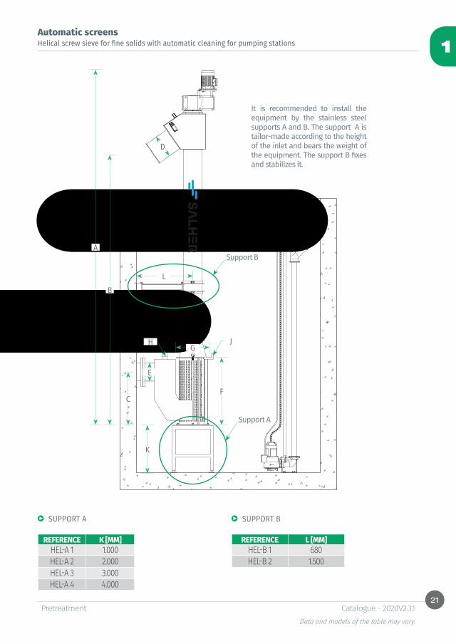
Automatic screens Helical screw sieve for fine solids with automatic cleaning for pumping stations
Support A
It is recommended to install the equipment by the stainless steel supports A and B. The support A is tailor-made according to the height of the inlet and bears the weight of the equipment. The support B fixes and stabilizes it.
Support B
SUPPORT A SUPPORT B
REFERENCE K [MM]HEL-A 1 1.000HEL-A 2 2.000HEL-A 3 3.000HEL-A 4 4.000
REFERENCE L [MM]HEL-B 1 680HEL-B 2 1.500

22
1
A
H
L
E S
R
PretreatmentData and models of the table may vary.
Catalogue - 2020V2.3.1
Automatic screens
Function:
Rotary drum sieve for small flows
REF: TARO -MINI
• Solids filtration or sieve (solid-liquid separation). Removal of fine solids from 0,5 to 3 mm.
• Equipment manufactured in GFRP (Glass Fiber Reinforced Polyester).
• Filtering cylinder manufactured in stainless steel AISI 316 by helical winding. Johnson type triangular profile.
• Opening sizes from 0,5 to 3 mm.• Automatic double cleaning system composed of
scraper and cleaning through spray nozzles with pressurized system water.
• Flanged inlet, outlet and overflow GFRP pipes.• Supports for aboveground installation.• GFRP protection cover for filtering drum.
Characteristics:
SIEVE WIDTH SIEVE HEIGHT SIEVE LENGTH MOTOR POWER FLANGES (E, S, R)MATERIAL [MM] [MM] [MM] [KW] DN
GFRP/AISI304 780 650 810 0,12 80
Accessories:
• Automatic cleaning system:* Cleaning electrovalve N/C 1/2”: cleaning system
automation.* Filter in Y 1/2”: protection and retention of
particles carried by the cleaning water. * Ball valve 1/2”: closure of the cleaning connection
if necessary.• Emergency stop button. • Butterfly valve installed on inlet.• Safety switch on top cover.• Electrical panel board in option.
NOTE: Pretreatments are mainly designed for standard urban wastewater. For industrial discharges or others, consult and wait for confirmation.
OPENING SIZE [MM] Q MAX CLEAN WATER [M3/H]0,50 10,81,00 17,52,00 24,93,00 28,1
23
1
A
H
L
R
E
S
P
PretreatmentData and models of the table may vary.
Catalogue - 2020V2.3.1
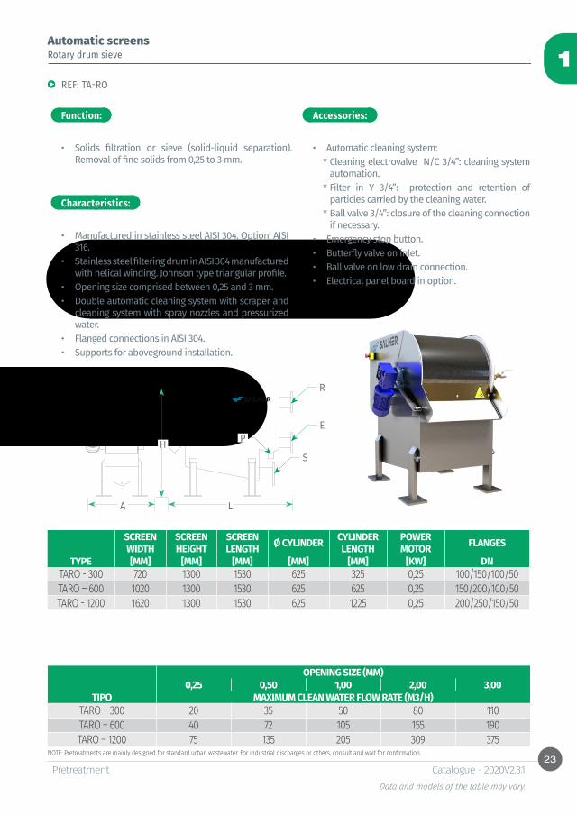
Rotary drum sieveAutomatic screens
Function:
Characteristics:
REF: TA-RO
• Solids filtration or sieve (solid-liquid separation). Removal of fine solids from 0,25 to 3 mm.
Accessories:
• Automatic cleaning system:* Cleaning electrovalve N/C 3/4”: cleaning system
automation.* Filter in Y 3/4”: protection and retention of
particles carried by the cleaning water. * Ball valve 3/4”: closure of the cleaning connection
if necessary.• Emergency stop button.• Butterfly valve on inlet.• Ball valve on low drain connection.• Electrical panel board in option.
• Manufactured in stainless steel AISI 304. Option: AISI 316.
• Stainless steel filtering drum in AISI 304 manufactured with helical winding. Johnson type triangular profile.
• Opening size comprised between 0,25 and 3 mm.• Double automatic cleaning system with scraper and
cleaning system with spray nozzles and pressurized water.
• Flanged connections in AISI 304.• Supports for aboveground installation.
NOTE: Pretreatments are mainly designed for standard urban wastewater. For industrial discharges or others, consult and wait for confirmation.
SCREEN WIDTH
SCREEN HEIGHT
SCREEN LENGTH Ø CYLINDER CYLINDER
LENGTHPOWER MOTOR FLANGES
TYPE [MM] [MM] [MM] [MM] [MM] [KW] DNTARO - 300 720 1300 1530 625 325 0,25 100/150/100/50TARO – 600 1020 1300 1530 625 625 0,25 150/200/100/50TARO - 1200 1620 1300 1530 625 1225 0,25 200/250/150/50
OPENING SIZE (MM)0,25 0,50 1,00 2,00 3,00
TIPO MAXIMUM CLEAN WATER FLOW RATE (M3/H)TARO – 300 20 35 50 80 110TARO – 600 40 72 105 155 190TARO – 1200 75 135 205 309 375
24
1
PretreatmentData and models of the table may vary.
Catalogue - 2020V2.3.1
Automatic screens
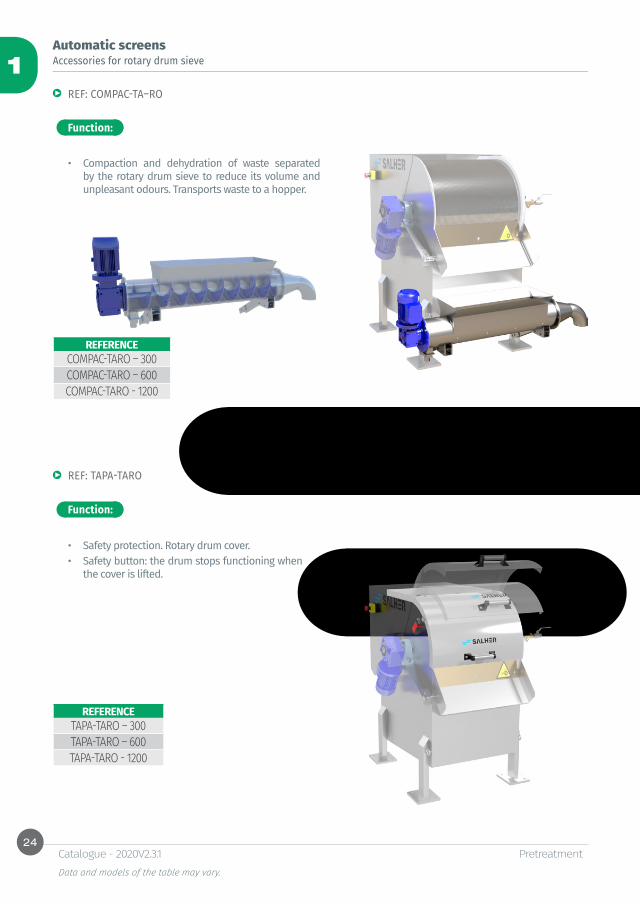
REF: COMPAC-TA–RO
Accessories for rotary drum sieve
Function:
Function:
• Compaction and dehydration of waste separated by the rotary drum sieve to reduce its volume and unpleasant odours. Transports waste to a hopper.
REF: TAPA-TARO
• Safety protection. Rotary drum cover. • Safety button: the drum stops functioning when
the cover is lifted.
REFERENCECOMPAC-TARO – 300COMPAC-TARO – 600COMPAC-TARO - 1200
REFERENCETAPA-TARO – 300TAPA-TARO – 600TAPA-TARO - 1200
25
1
PretreatmentData and models of the table may vary.
Catalogue - 2020V2.3.1
Automatic screens
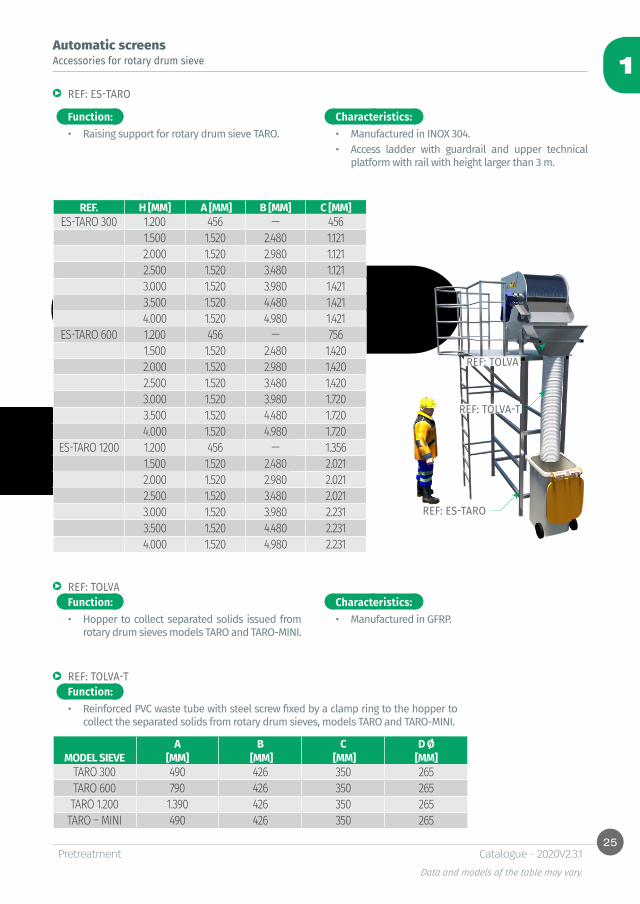
REF: ES-TARO
REF: TOLVA
REF: TOLVA-T
Accessories for rotary drum sieve
Function:
Function:
Function:
• Raising support for rotary drum sieve TARO.
• Hopper to collect separated solids issued from rotary drum sieves models TARO and TARO-MINI.
• Reinforced PVC waste tube with steel screw fixed by a clamp ring to the hopper to collect the separated solids from rotary drum sieves, models TARO and TARO-MINI.
• Manufactured in INOX 304.• Access ladder with guardrail and upper technical
platform with rail with height larger than 3 m.
• Manufactured in GFRP.
Characteristics:
Characteristics:
REF: TOLVA
REF: TOLVA-T
REF: ES-TARO
REF. H [MM] A [MM] B [MM] C [MM]ES-TARO 300 1.200 456 — 456
1.500 1.520 2.480 1.1212.000 1.520 2.980 1.1212.500 1.520 3.480 1.1213.000 1.520 3.980 1.4213.500 1.520 4.480 1.4214.000 1.520 4.980 1.421
ES-TARO 600 1.200 456 — 7561.500 1.520 2.480 1.4202.000 1.520 2.980 1.4202.500 1.520 3.480 1.4203.000 1.520 3.980 1.7203.500 1.520 4.480 1.7204.000 1.520 4.980 1.720
ES-TARO 1200 1.200 456 — 1.3561.500 1.520 2.480 2.0212.000 1.520 2.980 2.0212.500 1.520 3.480 2.0213.000 1.520 3.980 2.2313.500 1.520 4.480 2.2314.000 1.520 4.980 2.231
A B C D ØMODEL SIEVE [MM] [MM] [MM] [MM]
TARO 300 490 426 350 265TARO 600 790 426 350 265TARO 1.200 1.390 426 350 265
TARO – MINI 490 426 350 265
26
1
PretreatmentData and models of the table may vary.
Catalogue - 2020V2.3.1
Automatic screens
Function:
Characteristics:
Compact pretreatment plant - helical screw sieve
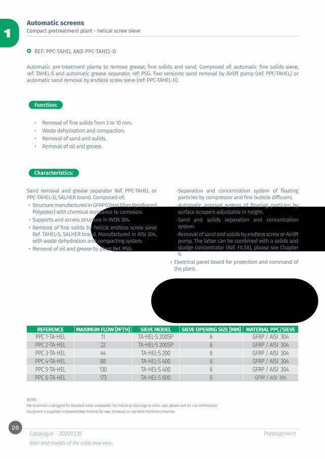
REF: PPC-TAHEL AND PPC-TAHEL-D
Automatic pre-treatment plants to remove grease, fine solids and sand. Composed of: automatic fine solids sieve, ref: TAHEL-S and automatic grease separator, ref: PSG. Two versions: sand removal by Airlift pump (ref: PPC-TAHEL) or automatic sand removal by endless screw sieve (ref: PPC-TAHEL-D).
• Removal of fine solids from 3 to 10 mm.• Waste dehydration and compaction. • Removal of sand and solids.• Removal of oil and grease.
Sand removal and grease separator Ref. PPC-TAHEL or PPC-TAHEL-D, SALHER brand. Composed of: • Structure manufactured in GFRP (Glass Fiber Reinforced
Polyester) with chemical resistance to corrosion.• Supports and access structure in INOX 304.• Removal of fine solids by helical endless screw sieve
Ref. TAHEL-S, SALHER brand. Manufactured in AISI 304, with waste dehydration and compacting system.
• Removal of oil and grease by plant Ref. PSG:
NOTES:Pre-treatment is designed for standard urban wastewater. For industrial discharge or other uses, please wait for use confirmation.Equipment is supplied in disassembled modules for easy transport on standard maritime containers.
-Separation and concentration system of floating particles by compressor and fine bubble diffusers. -Automatic removal system of floating particles by surface scrapers adjustable in height. -Sand and solids separation and concentration system. -Removal of sand and solids by endless screw or Airlift pump. The latter can be combined with a solids and sludge concentrator (Ref. FILSA), please see Chapter 9.
• Electrical panel board for protection and command of the plant.
REFERENCE MAXIMUM FLOW [M³/H] SIEVE MODEL SIEVE OPENING SIZE [MM] MATERIAL PPC/SIEVEPPC 1-TA-HEL 11 TA-HEL-S 200SP 6 GFRP / AISI 304PPC 2-TA-HEL 22 TA-HEL-S 200SP 6 GFRP / AISI 304PPC 3-TA-HEL 44 TA-HEL-S 200 6 GFRP / AISI 304PPC 4-TA-HEL 88 TA-HEL-S 400 6 GFRP / AISI 304PPC 5-TA-HEL 130 TA-HEL-S 400 6 GFRP / AISI 304PPC 6-TA-HEL 173 TA-HEL-S 600 6 GFRP / AISI 304
27
1
PretreatmentData and models of the table may vary.
Catalogue - 2020V2.3.1
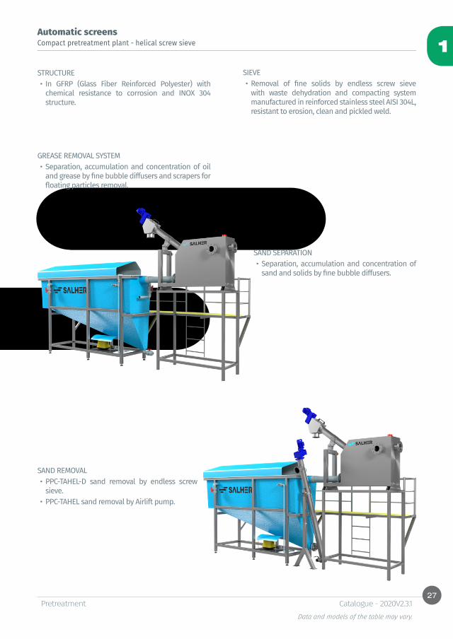
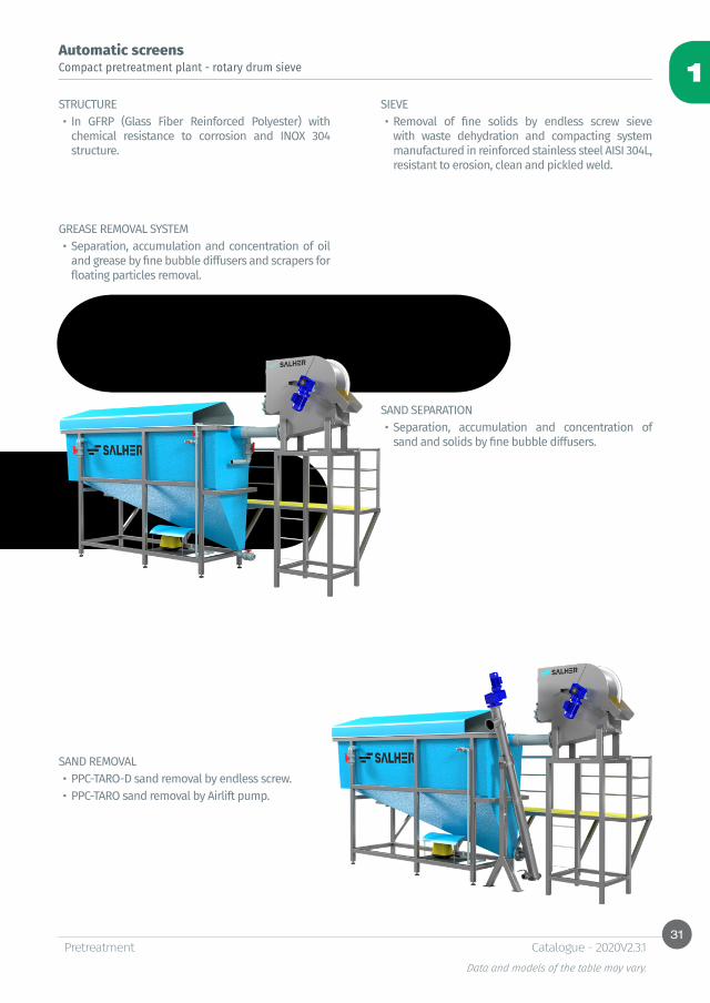
Automatic screens Compact pretreatment plant - helical screw sieve
STRUCTURE• In GFRP (Glass Fiber Reinforced Polyester) with
chemical resistance to corrosion and INOX 304 structure.
SIEVE• Removal of fine solids by endless screw sieve
with waste dehydration and compacting system manufactured in reinforced stainless steel AISI 304L, resistant to erosion, clean and pickled weld.
GREASE REMOVAL SYSTEM • Separation, accumulation and concentration of oil
and grease by fine bubble diffusers and scrapers for floating particles removal.
SAND SEPARATION • Separation, accumulation and concentration of
sand and solids by fine bubble diffusers.
SAND REMOVAL• PPC-TAHEL-D sand removal by endless screw
sieve.• PPC-TAHEL sand removal by Airlift pump.
28
1
C
F
D
ØE ØR
ØS
ØV
ØAØAI
A B
PretreatmentData and models of the table may vary.
Catalogue - 2020V2.3.1
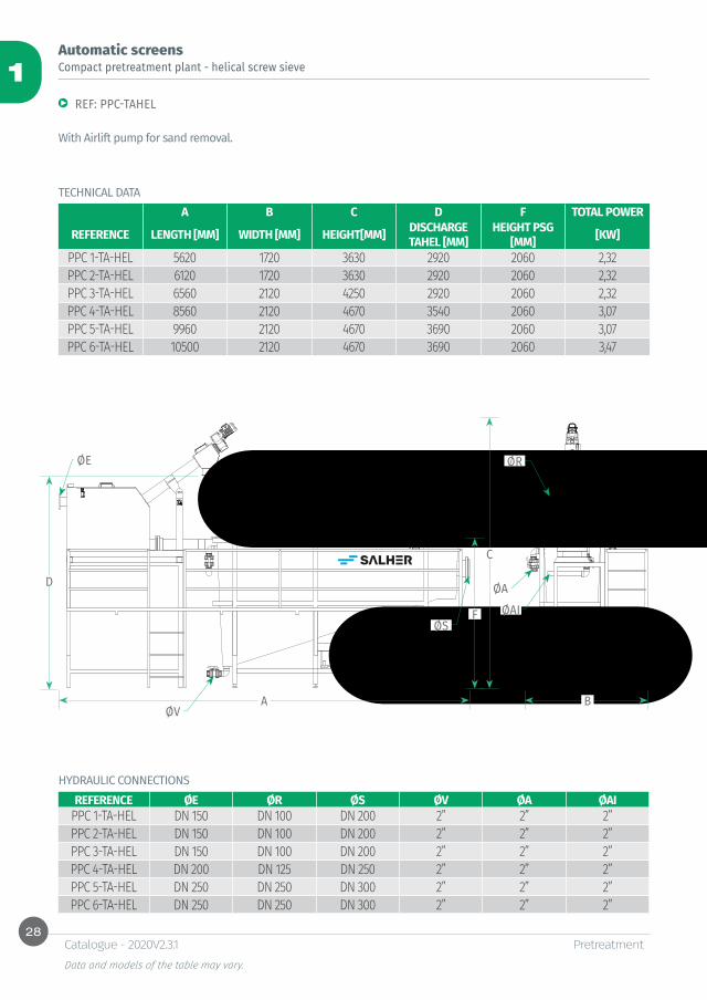
Automatic screens Compact pretreatment plant - helical screw sieve
REF: PPC-TAHEL
With Airlift pump for sand removal.
A B C D F TOTAL POWER
REFERENCE LENGTH [MM] WIDTH [MM] HEIGHT[MM] DISCHARGE TAHEL [MM]
HEIGHT PSG [MM] [KW]
PPC 1-TA-HEL 5620 1720 3630 2920 2060 2,32PPC 2-TA-HEL 6120 1720 3630 2920 2060 2,32PPC 3-TA-HEL 6560 2120 4250 2920 2060 2,32PPC 4-TA-HEL 8560 2120 4670 3540 2060 3,07PPC 5-TA-HEL 9960 2120 4670 3690 2060 3,07PPC 6-TA-HEL 10500 2120 4670 3690 2060 3,47
TECHNICAL DATA
REFERENCE ØE ØR ØS ØV ØA ØAIPPC 1-TA-HEL DN 150 DN 100 DN 200 2” 2” 2”PPC 2-TA-HEL DN 150 DN 100 DN 200 2” 2” 2”PPC 3-TA-HEL DN 150 DN 100 DN 200 2” 2” 2”PPC 4-TA-HEL DN 200 DN 125 DN 250 2” 2” 2”PPC 5-TA-HEL DN 250 DN 250 DN 300 2” 2” 2”PPC 6-TA-HEL DN 250 DN 250 DN 300 2” 2” 2”
HYDRAULIC CONNECTIONS
29
1
C
E
D
ØE ØR
ØS
ØV
ØA
A B
F
PretreatmentData and models of the table may vary.
Catalogue - 2020V2.3.1
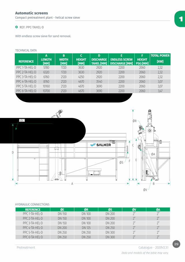
Automatic screens Compact pretreatment plant - helical screw sieve
REF: PPC-TAHEL-D
With endless screw sieve for sand removal.
A B C D E F TOTAL POWER
REFERENCE LENGTH [MM]
WIDTH [MM]
HEIGHT [MM]
DISCHARGE TAHEL [MM]
ENDLESS SCREW DISCHARGE [MM]
HEIGHT PSG [MM] [KW]
PPC 1-TA-HEL-D 5780 1720 3630 2920 2200 2060 2,32PPC 2-TA-HEL-D 6320 1720 3630 2920 2200 2060 2,32PPC 3-TA-HEL-D 6760 2120 4250 2920 2200 2060 2,32PPC 4-TA-HEL-D 8760 2120 4670 3540 2200 2060 3,07PPC 5-TA-HEL-D 10160 2120 4670 3690 2200 2060 3,07PPC 6-TA-HEL-D 10700 2120 4670 3690 2200 2060 3,47
TECHNICAL DATA
REFERENCE ØE ØR ØS ØV ØAPPC 1-TA-HEL-D DN 150 DN 100 DN 200 2” 2”PPC 2-TA-HEL-D DN 150 DN 100 DN 200 2” 2”PPC 3-TA-HEL-D DN 150 DN 100 DN 200 2” 2”PPC 4-TA-HEL-D DN 200 DN 125 DN 250 2” 2”PPC 5-TA-HEL-D DN 250 DN 250 DN 300 2” 2”PPC 6-TA-HEL-D DN 250 DN 250 DN 300 2” 2”
HYDRAULIC CONNECTIONS

30
1
PretreatmentData and models of the table may vary.
Catalogue - 2020V2.3.1
Automatic screens
Function:
Characteristics:
Compact pretreatment plant - rotary drum sieve
REF: PPC-TARO AND PPC-TARO-D
Automatic pre-treatment plants to remove grease, fine solids and sand. Composed of: automatic fine solids sieve Ref. TARO and automatic grease separator Ref. PSG. Two versions: sand removal by Airlift pump (Ref. PPC-TARO) or automatic sand removal by endless screw sieve (Ref. PPC-TARO-D).
• Removal of fine solids from 3 to 10 mm.• Waste dehydration and compaction. • Removal of sand and solids.• Removal of oil and grease.
Sand removal and grease separator Ref. PPC-TARO or PPC-TARO-D, SALHER brand, composed of:• Structure manufactured in GFRP (Glass Fiber Reinforced
Polyester) with chemical resistance to corrosion.• Supports and access structure in INOX 304.• Removal of fine solids by rotary drum sieve Ref. TARO,
SALHER brand. Manufactured in AISI 304.• Removal of oil and grease by plant Ref. PSG:
NOTES:Pre-treatment is designed for standard urban wastewater. For industrial discharge or other uses, please wait for use confirmation.Equipment is supplied in disassembled modules for easy transport on standard maritime containers.
-Separation and concentration system of floating particles by compressor and fine bubble diffusers. -Automatic removal system of floating particles by surface scrapers adjustable in height. -Sand and solids separation and concentration system. -Removal of sand and solids by endless screw or Airlift pump. The latter can be combined with a solids and sludge concentrator (Ref. FILSA), please see Chapter 9.
• Electrical panel board for protection and command of the plant.
REFERENCE MAXIMUM FLOW [M³/H] SIEVE MODEL SIEVE OPENING SIZE [MM] MATERIAL PPC/SIEVEPPC 1-TA-RO 11 TA-RO 300 3 GFRP / AISI 304PPC 2-TA-RO 22 TA-RO 300 3 GFRP / AISI 304PPC 3-TA-RO 44 TA-RO 300 3 GFRP / AISI 304PPC 4-TA-RO 88 TA-RO 600 3 GFRP / AISI 304PPC 5-TA-RO 130 TA-RO 600 3 GFRP / AISI 304PPC 6-TA-RO 173 TA-RO 1200 3 GFRP / AISI 304
31
1
PretreatmentData and models of the table may vary.
Catalogue - 2020V2.3.1
Automatic screens
STRUCTURE• In GFRP (Glass Fiber Reinforced Polyester) with
chemical resistance to corrosion and INOX 304 structure.
SIEVE• Removal of fine solids by endless screw sieve
with waste dehydration and compacting system manufactured in reinforced stainless steel AISI 304L, resistant to erosion, clean and pickled weld.
GREASE REMOVAL SYSTEM • Separation, accumulation and concentration of oil
and grease by fine bubble diffusers and scrapers for floating particles removal.
SAND SEPARATION • Separation, accumulation and concentration of
sand and solids by fine bubble diffusers.
SAND REMOVAL• PPC-TARO-D sand removal by endless screw.• PPC-TARO sand removal by Airlift pump.
Compact pretreatment plant - rotary drum sieve
32
1
ØR
ØP
ØS
ØL
ØAØAI
ØV
ØE
A B
C
D F
PretreatmentData and models of the table may vary.
Catalogue - 2020V2.3.1
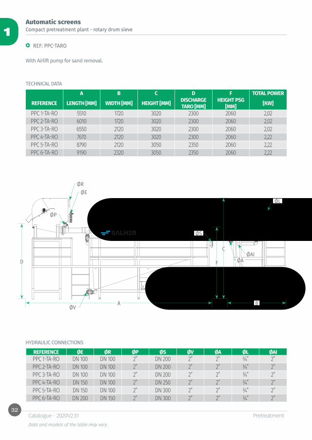
Automatic screens
REF: PPC-TARO
With Airlift pump for sand removal.
A B C D F TOTAL POWER
REFERENCE LENGTH [MM] WIDTH [MM] HEIGHT [MM] DISCHARGE TARO [MM]
HEIGHT PSG [MM] [KW]
PPC 1-TA-RO 5510 1720 3020 2300 2060 2,02PPC 2-TA-RO 6010 1720 3020 2300 2060 2,02PPC 3-TA-RO 6550 2120 3020 2300 2060 2,02PPC 4-TA-RO 7670 2120 3020 2300 2060 2,22PPC 5-TA-RO 8790 2120 3050 2350 2060 2,22PPC 6-TA-RO 9190 2320 3050 2350 2060 2,22
REFERENCE ØE ØR ØP ØS ØV ØA ØL ØAIPPC 1-TA-RO DN 100 DN 100 2” DN 200 2” 2” ¾” 2”PPC 2-TA-RO DN 100 DN 100 2” DN 200 2” 2” ¾” 2”PPC 3-TA-RO DN 100 DN 100 2” DN 200 2” 2” ¾” 2”PPC 4-TA-RO DN 150 DN 100 2” DN 250 2” 2” ¾” 2”PPC 5-TA-RO DN 150 DN 100 2” DN 300 2” 2” ¾” 2”PPC 6-TA-RO DN 200 DN 150 2” DN 300 2” 2” ¾” 2”
HYDRAULIC CONNECTIONS
TECHNICAL DATA
Compact pretreatment plant - rotary drum sieve
33
1
ØS
ØL
ØR
ØP
ØA
ØV
ØE
A B
C
ED F
PretreatmentData and models of the table may vary.
Catalogue - 2020V2.3.1
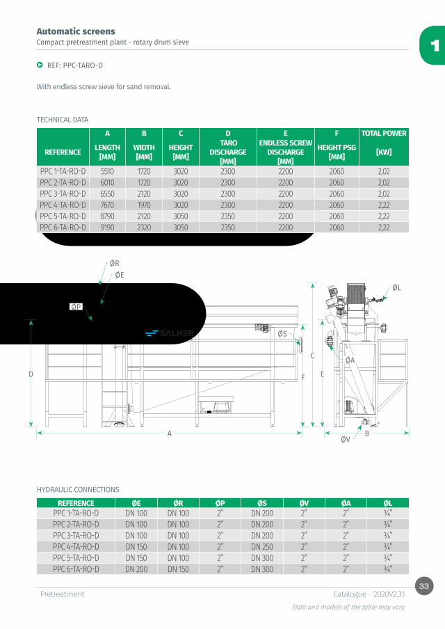
Automatic screens
REF: PPC-TARO-D
With endless screw sieve for sand removal.
A B C D E F TOTAL POWER
REFERENCE LENGTH [MM]
WIDTH [MM]
HEIGHT [MM]
TARO DISCHARGE
[MM]
ENDLESS SCREW DISCHARGE
[MM]
HEIGHT PSG [MM] [KW]
PPC 1-TA-RO-D 5510 1720 3020 2300 2200 2060 2,02PPC 2-TA-RO-D 6010 1720 3020 2300 2200 2060 2,02PPC 3-TA-RO-D 6550 2120 3020 2300 2200 2060 2,02PPC 4-TA-RO-D 7670 1970 3020 2300 2200 2060 2,22PPC 5-TA-RO-D 8790 2120 3050 2350 2200 2060 2,22PPC 6-TA-RO-D 9190 2320 3050 2350 2200 2060 2,22
REFERENCE ØE ØR ØP ØS ØV ØA ØLPPC 1-TA-RO-D DN 100 DN 100 2” DN 200 2” 2” ¾”PPC 2-TA-RO-D DN 100 DN 100 2” DN 200 2” 2” ¾”PPC 3-TA-RO-D DN 100 DN 100 2” DN 200 2” 2” ¾”PPC 4-TA-RO-D DN 150 DN 100 2” DN 250 2” 2” ¾”PPC 5-TA-RO-D DN 150 DN 100 2” DN 300 2” 2” ¾”PPC 6-TA-RO-D DN 200 DN 150 2” DN 300 2” 2” ¾”
Compact pretreatment plant - rotary drum sieve
HYDRAULIC CONNECTIONS
TECHNICAL DATA
34
1
Ø
H
ØB
CE CS
150
PretreatmentData and models of the table may vary.
Catalogue - 2020V2.3.1
Function:
Characteristics:
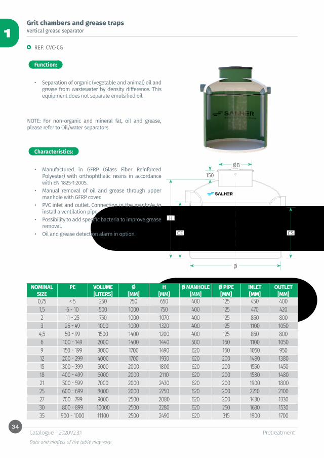
Vertical grease separatorGrit chambers and grease traps
REF: CVC-CG
• Separation of organic (vegetable and animal) oil and grease from wastewater by density difference. This equipment does not separate emulsified oil.
NOTE: For non-organic and mineral fat, oil and grease, please refer to Oil/water separators.
• Manufactured in GFRP (Glass Fiber Reinforced Polyester) with orthophthalic resins in accordance with EN 1825-1:2005.
• Manual removal of oil and grease through upper manhole with GFRP cover.
• PVC inlet and outlet. Connection in the manhole to install a ventilation pipe.
• Possibility to add specific bacteria to improve grease removal.
• Oil and grease detection alarm in option.
NOMINAL PE VOLUME Ø H Ø MANHOLE Ø PIPE INLET OUTLETSIZE [LITERS] [MM] [MM] [MM] [MM] [MM] [MM]0,75 < 5 250 750 650 400 125 450 4001,5 6 - 10 500 1000 750 400 125 470 4202 11 - 25 750 1000 1070 400 125 850 8003 26 - 49 1000 1000 1320 400 125 1100 1050
4,5 50 - 99 1500 1400 1200 400 125 850 8006 100 - 149 2000 1400 1440 500 160 1100 10509 150 - 199 3000 1700 1490 620 160 1050 95012 200 - 299 4000 1700 1930 620 200 1480 138015 300 - 399 5000 2000 1800 620 200 1550 145018 400 - 499 6000 2000 2110 620 200 1580 148021 500 - 599 7000 2000 2430 620 200 1900 180025 600 - 699 8000 2000 2750 620 200 2210 210027 700 - 799 9000 2500 2080 620 200 1430 133030 800 - 899 10000 2500 2280 620 250 1630 153035 900 - 1000 11100 2500 2490 620 315 1900 1700

35
1
150
Ø
L
ØB ØB
CE CS
PretreatmentData and models of the table may vary.
Catalogue - 2020V2.3.1
Function:
Characteristics:
Grit chambers and grease trapsHorizontal grease separator
REF: CHC-CG
• Separation of organic (vegetable and animal) oil and grease from wastewater by density difference. This equipment does not separate emulsified oil.
NOTE: For non-organic and mineral fat, oil and grease, please refer to Oil/water separators.
• Manufactured in GFRP (Glass Fiber Reinforced Polyester) with orthophthalic resins in accordance with EN 1825-1:2005.
• High performance of oil and grease removal due to large surface.
• Manual removal of oil and grease through manholes with GFRP covers.
• PVC inlet and outlet. Connection in the manhole to install a ventilation pipe.
• Possibility to add specific bacteria to improve grease removal.
• Oil and grease detection alarm in option.
Options
NOMINAL VOLUME Ø LENGTH Ø MANHOLE Ø PIPE INLET OUTLETSIZE [LITERS] [MM] [MM] [MM] [MM] [MM] [MM]
6 2.000 1.000 2.800 1 X 500 125 875 82512 4.000 1.200 3.800 2 X 500 200 1.000 95018 6.000 1.200 5.530 2 X 500 200 1.000 95024 8.000 1.400 5.500 2 X 500 200 1.200 1.15030 10.000 1.400 6.760 2 X 500 250 1.150 1.10045 15.000 1.700 6.930 2 X 500 315 1.385 1.335

36
1
ØBØB
ØCE CS
L
150
PretreatmentData and models of the table may vary.
Catalogue - 2020V2.3.1
Function:
Characteristics:
Grit chambers and grease trapsHorizontal sand removal and solids settling tank
REF: CHC–DES
• Removal of sand and solids by density difference.
• Manufactured in GFRP (Glass Fiber Reinforced Polyester) with orthophthalic resins.
• High performance of sand and solids removal due to large surface.
• Manual removal of sand and solids through manholes with GFRP covers.
• PVC inlet and outlet. Connection in the manhole to install a ventilation pipe.
• Oil and grease detection alarm in option.
Options
VOLUME Ø LENGTH Ø MANHOLE Ø PIPE CE CS[LITERS] [MM] [MM] [MM] [MM] [MM] [MM]
2.000 1.000 2.800 1X500 125 875 8254.000 1.200 3.800 2X500 160 1.040 9906.000 1.200 5.530 2X500 200 1.000 9508.000 1.400 5.500 2X500 200 1.200 1.15010.000 1.400 6.760 2X500 315 1.085 1.03515.000 1.700 6.930 2X500 315 1.385 1.335
37
1
PretreatmentData and models of the table may vary.
Catalogue - 2020V2.3.1
Function:
Characteristics:
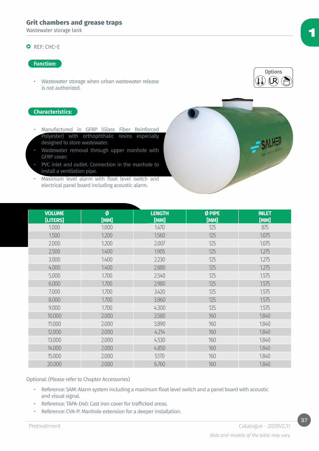
Grit chambers and grease trapsWastewater storage tank
REF: CHC–E
• Wastewater storage when urban wastewater release is not authorized.
• Manufactured in GFRP (Glass Fiber Reinforced Polyester) with orthophthalic resins especially designed to store wastewater.
• Wastewater removal through upper manhole with GFRP cover.
• PVC inlet and outlet. Connection in the manhole to install a ventilation pipe.
• Maximum level alarm with float level switch and electrical panel board including acoustic alarm.
Optional: (Please refer to Chapter Accessories)
• Reference: SAM: Alarm system including a maximum float level switch and a panel board with acoustic and visual signal.
• Reference: TAPA-D40: Cast iron cover for trafficked areas.• Reference: CVA-P: Manhole extension for a deeper installation.
Options
VOLUME Ø LENGTH Ø PIPE INLET[LITERS] [MM] [MM] [MM] [MM]
1.000 1.000 1.470 125 8751.500 1.200 1.560 125 1.0752.000 1.200 2.007 125 1.0752.500 1.400 1.905 125 1.2753.000 1.400 2.230 125 1.2754.000 1.400 2.880 125 1.2755.000 1.700 2.540 125 1.5756.000 1.700 2.980 125 1.5757.000 1.700 3.420 125 1.5758.000 1.700 3.860 125 1.5759.000 1.700 4.300 125 1.57510.000 2.000 3.580 160 1.84011.000 2.000 3.890 160 1.84012.000 2.000 4.214 160 1.84013.000 2.000 4.530 160 1.84014.000 2.000 4.850 160 1.84015.000 2.000 5.170 160 1.84020.000 2.000 6.760 160 1.840
38
1
A
H
PretreatmentData and models of the table may vary.
Catalogue - 2020V2.3.1
Function:
Characteristics:
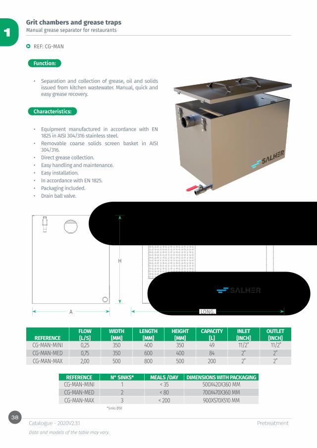
Grit chambers and grease trapsManual grease separator for restaurants
REF: CG-MAN
• Separation and collection of grease, oil and solids issued from kitchen wastewater. Manual, quick and easy grease recovery.
• Equipment manufactured in accordance with EN 1825 in AISI 304/316 stainless steel.
• Removable coarse solids screen basket in AISI 304/316.
• Direct grease collection.• Easy handling and maintenance. • Easy installation.• In accordance with EN 1825.• Packaging included.• Drain ball valve.
REFERENCE N° SINKS* MEALS /DAY DIMENSIONS WITH PACKAGING CG-MAN-MINI 1 < 35 500X420X360 MMCG-MAN-MED 2 < 80 700X470X360 MMCG-MAN-MAX 3 < 200 900X570X510 MM
*Sinks Ø50
LONG.
FLOW WIDTH LENGTH HEIGHT CAPACITY INLET OUTLETREFERENCE [L/S] [MM] [MM] [MM] [L] [INCH] [INCH]
CG-MAN-MINI 0,25 350 400 350 49 11/2” 11/2”CG-MAN-MED 0,75 350 600 400 84 2” 2”CG-MAN-MAX 2,00 500 800 500 200 2” 2”
39
1
L A
HF
PretreatmentData and models of the table may vary.
Catalogue - 2020V2.3.1
Function:
Characteristics:
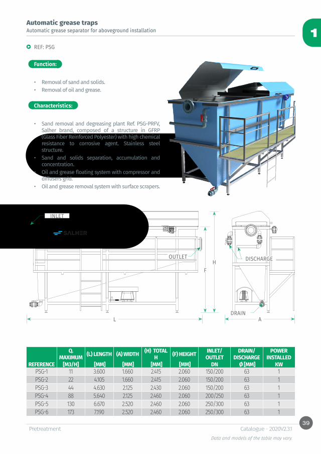
Automatic grease trapsAutomatic grease separator for aboveground installation
REF: PSG
• Removal of sand and solids.• Removal of oil and grease.
• Sand removal and degreasing plant Ref. PSG-PRFV, Salher brand, composed of a structure in GFRP (Glass Fiber Reinforced Polyester) with high chemical resistance to corrosive agent. Stainless steel structure.
• Sand and solids separation, accumulation and concentration.
• Oil and grease floating system with compressor and diffusers grid.
• Oil and grease removal system with surface scrapers.
INLET
OUTLET
DRAIN
DISCHARGE
Q. MAXIMUM (L) LENGTH (A) WIDTH (H) TOTAL
H (F) HEIGHT INLET/OUTLET
DRAIN/DISCHARGE
POWER INSTALLED
REFERENCE [M3/H] [MM] [MM] [MM] [MM] DN Ø [MM] KWPSG-1 11 3.600 1.660 2.415 2.060 150/200 63 1PSG-2 22 4.105 1.660 2.415 2.060 150/200 63 1PSG-3 44 4.630 2.125 2.430 2.060 150/200 63 1PSG-4 88 5.640 2.125 2.460 2.060 200/250 63 1PSG-5 130 6.670 2.520 2.460 2.060 250/300 63 1PSG-6 173 7.190 2.520 2.460 2.060 250/300 63 1
40
1
A
H
PretreatmentData and models of the table may vary.
Catalogue - 2020V2.3.1
Function:
Characteristics:
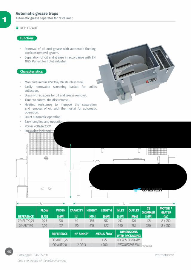
Automatic grease trapsAutomatic grease separator for restaurant
REF: CG-AUT
• Removal of oil and grease with automatic floating particles removal system.
• Separation of oil and grease in accordance with EN 1825. Perfect for hotel industry.
• Manufactured in AISI 304/316 stainless steel. • Easily removable screening basket for solids
collection.• Discs with scrapers for oil and grease removal.• Timer to control the disc removal.• Heating resistance to improve the separation
and removal of oil, with thermostat for automatic operation.
• Quiet automatic operation. • Easy handling and operation.• Power voltage 230V.• Packaging included.
REFERENCE N° SINKS* MEALS /DAY DIMENSIONS WITH PACKAGING
CG-AUT-0,25 1 < 25 600X350X380 MMCG-AUT-2,0 2 OR 3 < 200 972X485X597 MM *Sinks Ø50
L
FLOW WIDTH CAPACITY HEIGHT LENGTH INLET OUTLET CS SKIMMER
MOTOR /HEATER
REFERENCE [L/S] [MM] [L] [MM] [MM] [MM] [MM] [MM] (W)CG-AUT-0,25 0,25 270 40 365 512 210 170 195 8 / 750CG-AUT-2,0 2,00 437 170 610 862 360 284 330 8 / 750
41
1
PretreatmentData and models of the table may vary.
Catalogue - 2020V2.3.1
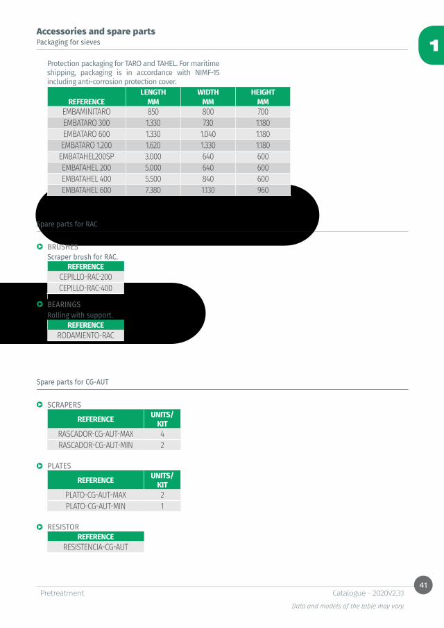
Packaging for sieves
Protection packaging for TARO and TAHEL. For maritime shipping, packaging is in accordance with NIMF-15 including anti-corrosion protection cover.
Accessories and spare parts
Spare parts for RAC
Spare parts for CG-AUT
LENGTH WIDTH HEIGHTREFERENCE MM MM MM
EMBAMINITARO 850 800 700EMBATARO 300 1.330 730 1.180EMBATARO 600 1.330 1.040 1.180EMBATARO 1.200 1.620 1.330 1.180
EMBATAHEL200SP 3.000 640 600EMBATAHEL 200 5.000 640 600EMBATAHEL 400 5.500 840 600EMBATAHEL 600 7.380 1.130 960
BRUSHESScraper brush for RAC.
REFERENCECEPILLO-RAC-200CEPILLO-RAC-400
BEARINGSRolling with support.
REFERENCERODAMIENTO-RAC
SCRAPERS
REFERENCE UNITS/KIT
RASCADOR-CG-AUT-MAX 4RASCADOR-CG-AUT-MIN 2
PLATES
REFERENCE UNITS/KIT
PLATO-CG-AUT-MAX 2PLATO-CG-AUT-MIN 1
RESISTORREFERENCE
RESISTENCIA-CG-AUT
42
1
PretreatmentData and models of the table may vary.
Catalogue - 2020V2.3.1
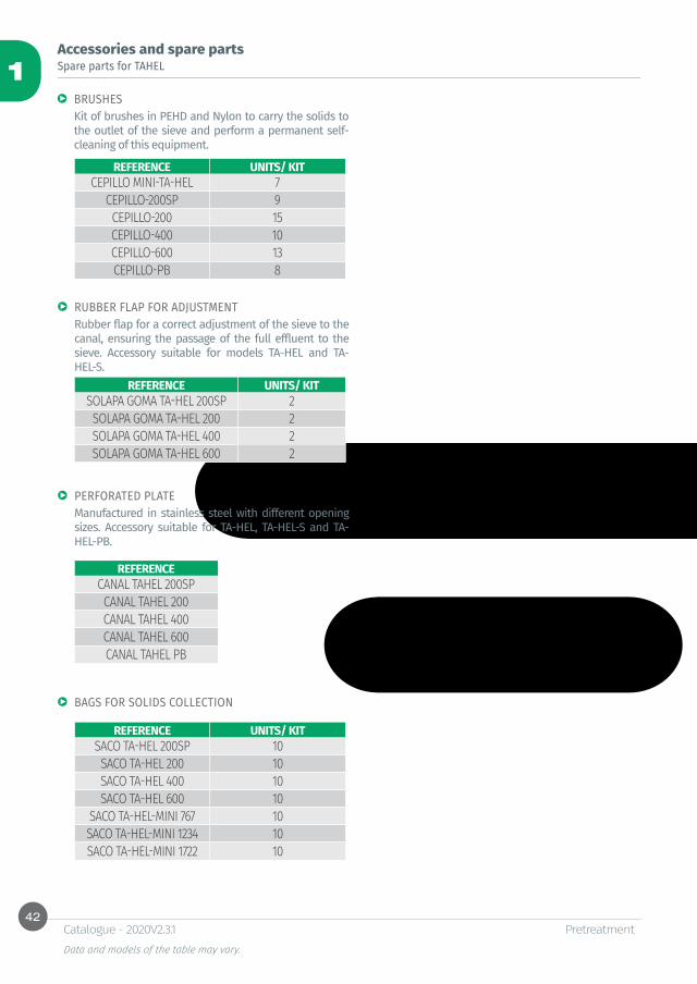
Accessories and spare partsSpare parts for TAHEL
BAGS FOR SOLIDS COLLECTION
RUBBER FLAP FOR ADJUSTMENT
PERFORATED PLATE
Kit of brushes in PEHD and Nylon to carry the solids to the outlet of the sieve and perform a permanent self-cleaning of this equipment.
Rubber flap for a correct adjustment of the sieve to the canal, ensuring the passage of the full effluent to the sieve. Accessory suitable for models TA-HEL and TA-HEL-S.
Manufactured in stainless steel with different opening sizes. Accessory suitable for TA-HEL, TA-HEL-S and TA-HEL-PB.
BRUSHES
REFERENCE UNITS/ KITCEPILLO MINI-TA-HEL 7
CEPILLO-200SP 9CEPILLO-200 15CEPILLO-400 10CEPILLO-600 13CEPILLO-PB 8
REFERENCE UNITS/ KITSACO TA-HEL 200SP 10SACO TA-HEL 200 10SACO TA-HEL 400 10SACO TA-HEL 600 10
SACO TA-HEL-MINI 767 10SACO TA-HEL-MINI 1234 10SACO TA-HEL-MINI 1722 10
REFERENCE UNITS/ KITSOLAPA GOMA TA-HEL 200SP 2SOLAPA GOMA TA-HEL 200 2SOLAPA GOMA TA-HEL 400 2SOLAPA GOMA TA-HEL 600 2
REFERENCECANAL TAHEL 200SPCANAL TAHEL 200CANAL TAHEL 400CANAL TAHEL 600CANAL TAHEL PB
43
1
PretreatmentData and models of the table may vary.
Catalogue - 2020V2.3.1
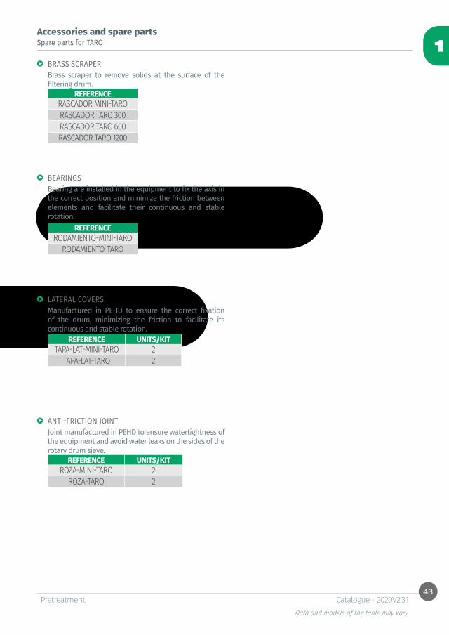
Accessories and spare partsSpare parts for TARO
BRASS SCRAPER
BEARINGS
LATERAL COVERS
ANTI-FRICTION JOINT
Brass scraper to remove solids at the surface of the filtering drum.
Bearing are installed in the equipment to fix the axis in the correct position and minimize the friction between elements and facilitate their continuous and stable rotation.
Manufactured in PEHD to ensure the correct fixation of the drum, minimizing the friction to facilitate its continuous and stable rotation.
Joint manufactured in PEHD to ensure watertightness of the equipment and avoid water leaks on the sides of the rotary drum sieve.
REFERENCERODAMIENTO-MINI-TARO
RODAMIENTO-TARO
REFERENCE UNITS/KITTAPA-LAT-MINI-TARO 2
TAPA-LAT-TARO 2
REFERENCE UNITS/KITROZA-MINI-TARO 2
ROZA-TARO 2
REFERENCERASCADOR MINI-TARORASCADOR TARO 300RASCADOR TARO 600RASCADOR TARO 1200
44
1
PretreatmentData and models of the table may vary.
Catalogue - 2020V2.3.1
Accessories and spare partsSpare parts for PSG
SCRAPERS
DIFFUSERS
BEARINGS
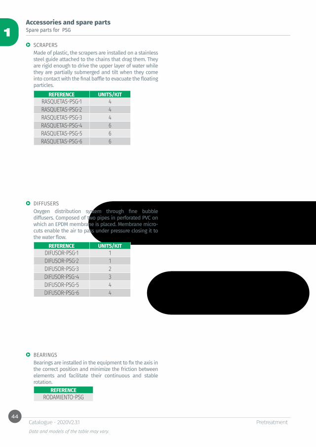
Made of plastic, the scrapers are installed on a stainless steel guide attached to the chains that drag them. They are rigid enough to drive the upper layer of water while they are partially submerged and tilt when they come into contact with the final baffle to evacuate the floating particles.
Oxygen distribution system through fine bubble diffusers. Composed of two pipes in perforated PVC on which an EPDM membrane is placed. Membrane micro-cuts enable the air to pass under pressure closing it to the water flow.
Bearings are installed in the equipment to fix the axis in the correct position and minimize the friction between elements and facilitate their continuous and stable rotation.
REFERENCE UNITS/KITRASQUETAS-PSG-1 4RASQUETAS-PSG-2 4RASQUETAS-PSG-3 4RASQUETAS-PSG-4 6RASQUETAS-PSG-5 6RASQUETAS-PSG-6 6
REFERENCE UNITS/KITDIFUSOR-PSG-1 1DIFUSOR-PSG-2 1DIFUSOR-PSG-3 2DIFUSOR-PSG-4 3DIFUSOR-PSG-5 4DIFUSOR-PSG-6 4
REFERENCERODAMIENTO-PSG

45
1
PretreatmentData and models of the table may vary.
Catalogue - 2020V2.3.1
Accessories and spare partsMiscellaneous
CLEANING ELECTROVALVE Electrovalve N/C for cleaning automation by nozzles. Accessory suitable for models TAHEL and TARO.
REFERENCEEV
CLEANING ELECTROVALVE COIL REFERENCEBOBINA EV
FILTER IN YAccessory for protection and extension of the useful life of the electrovalve, retaining the particles carried by the cleaning water.
REFERENCEFILTRO-Y
PROBE RODLevel probe with rods by conductivity. Automatic operation of the equipment through the rods of the probe to register the level inside to activate/stop the equipment.
REFERENCESONDA
REF: OIL SET 1000Oil and grease detection alarm to install in grease separators working between -20 and 40°C.
REFERENCEOIL-SET 1000
REF: SAND-SET 1000Sand and solids detection alarm to install in settling tanks working between -20 and 40°C.
REFERENCESAND SET 1000
REF: SAMMaximum level alarm system. Efficient for urban wastewater storage tanks.Includes: level float switch with 5 m cable especially manufactured for wastewater, control panel board with acoustic and visual alarm and switch, dimensions 284x222x122 mm.
REFERENCESAM


2Primary treatments

Table of contentsSettling - digestion
Small vertical septic tank REF: CVC-FS 50Horizontal septic tankREF: CHC-FS 51Imhoff tankREF: CHC-IMH 52
Truncated cone-shaped settling tanksClosed static settling tankREF: CVC-DC-TC 53Open static settling tank REF: CVA-DC-TC 54
Lamella clarifierREF: DE-LA 55
Dissolved air flotation unitDissolved air flotation unitREF: VESPA 56REF: FLC 61
Other dimensions and configurations can be provided upon request. Internal dimensions. Dimensions in millimeters. Volumes in liters, the dimensions indicated may vary according to the needs.Due to its policy of continuous development, Salher Ibérica, S.L. reserves the right to modify the data that appear in this document without notice.This document is protected by the intellectual property law, so that the customer cannot claim, manipulate or duplicate this documentation, except copy for personal use.
50
2
H
Ø
ØB150ØT
ØT
Primary treatmentsData and models of the table may vary.
Catalogue - 2020V2.3.1
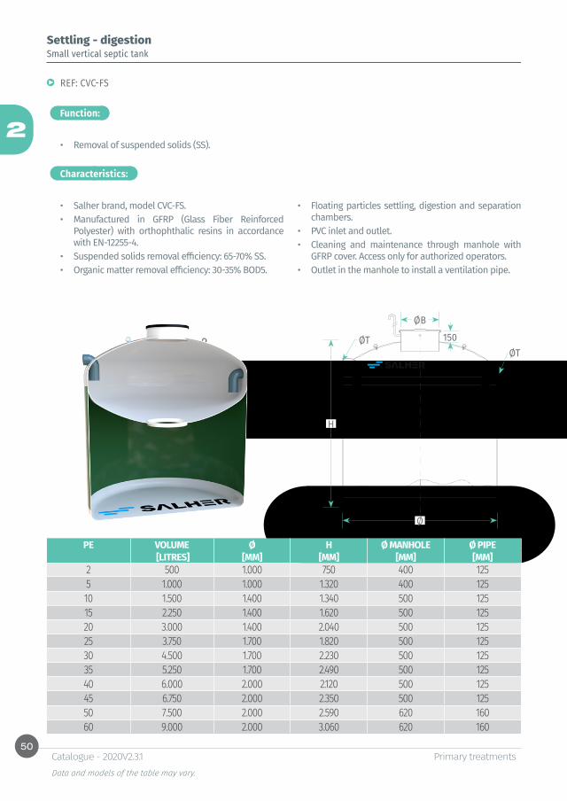
Settling - digestionSmall vertical septic tank
REF: CVC-FS
• Removal of suspended solids (SS).
Function:
Characteristics:
• Salher brand, model CVC-FS.• Manufactured in GFRP (Glass Fiber Reinforced
Polyester) with orthophthalic resins in accordance with EN-12255-4.
• Suspended solids removal efficiency: 65-70% SS.• Organic matter removal efficiency: 30-35% BOD5.
• Floating particles settling, digestion and separation chambers.
• PVC inlet and outlet.• Cleaning and maintenance through manhole with
GFRP cover. Access only for authorized operators. • Outlet in the manhole to install a ventilation pipe.
PE VOLUME Ø H Ø MANHOLE Ø PIPE [LITRES] [MM] [MM] [MM] [MM]
2 500 1.000 750 400 1255 1.000 1.000 1.320 400 12510 1.500 1.400 1.340 500 12515 2.250 1.400 1.620 500 12520 3.000 1.400 2.040 500 12525 3.750 1.700 1.820 500 12530 4.500 1.700 2.230 500 12535 5.250 1.700 2.490 500 12540 6.000 2.000 2.120 500 12545 6.750 2.000 2.350 500 12550 7.500 2.000 2.590 620 16060 9.000 2.000 3.060 620 160
51
2
Ø
ØB
CE CS
L
ØTØT
Primary treatmentsData and models of the table may vary.
Catalogue - 2020V2.3.1
Settling - digestion
Function:
Characteristics:
Horizontal septic tank
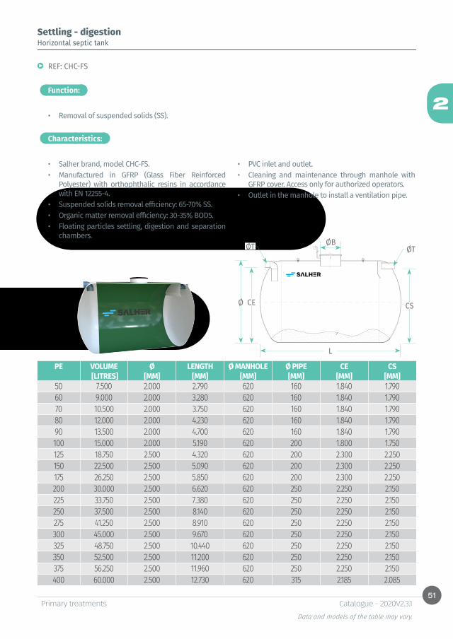
REF: CHC-FS
• Removal of suspended solids (SS).
• Salher brand, model CHC-FS.• Manufactured in GFRP (Glass Fiber Reinforced
Polyester) with orthophthalic resins in accordance with EN 12255-4.
• Suspended solids removal efficiency: 65-70% SS.• Organic matter removal efficiency: 30-35% BOD5.• Floating particles settling, digestion and separation
chambers.
• PVC inlet and outlet.• Cleaning and maintenance through manhole with
GFRP cover. Access only for authorized operators. • Outlet in the manhole to install a ventilation pipe.
PE VOLUME Ø LENGTH Ø MANHOLE Ø PIPE CE CS [LITRES] [MM] [MM] [MM] [MM] [MM] [MM]
50 7.500 2.000 2.790 620 160 1.840 1.79060 9.000 2.000 3.280 620 160 1.840 1.79070 10.500 2.000 3.750 620 160 1.840 1.79080 12.000 2.000 4.230 620 160 1.840 1.79090 13.500 2.000 4.700 620 160 1.840 1.790100 15.000 2.000 5.190 620 200 1.800 1.750125 18.750 2.500 4.320 620 200 2.300 2.250150 22.500 2.500 5.090 620 200 2.300 2.250175 26.250 2.500 5.850 620 200 2.300 2.250200 30.000 2.500 6.620 620 250 2.250 2.150225 33.750 2.500 7.380 620 250 2.250 2.150250 37.500 2.500 8.140 620 250 2.250 2.150275 41.250 2.500 8.910 620 250 2.250 2.150300 45.000 2.500 9.670 620 250 2.250 2.150325 48.750 2.500 10.440 620 250 2.250 2.150350 52.500 2.500 11.200 620 250 2.250 2.150375 56.250 2.500 11.960 620 250 2.250 2.150400 60.000 2.500 12.730 620 315 2.185 2.085

52
2
Ø
ØB
CE CS
L
ØTØT
Primary treatmentsData and models of the table may vary.
Catalogue - 2020V2.3.1
Settling - digestion
Function:
Characteristics:
Imhoff tank
REF: CHC-IMH
• Removal of suspended solids (SS).
• Salher brand, model CHC-IMH.• Manufactured in GFRP (Glass Fiber Reinforced
Polyester) with orthophthalic resins in accordance with EN 12255-4.
• Suspended solids removal efficiency: 70-75% SS.• Organic matter removal efficiency: 35-40% BOD5.• Horizontal separating baffle.• Floating particles settling, digestion and separation
chambers.
• PVC inlet and outlet.• Cleaning and maintenance through manhole with
GFRP cover. Access only for authorized operators. • Outlet in the manhole to install a ventilation pipe.
PE VOLUME Ø LENGTH Ø MANHOLE Ø PIPE CE CS [LITRES] [MM] [MM] [MM] [MM] [MM] [MM]
50 7.500 2.000 2.790 620 160 1.840 1.79060 9.000 2.000 3.280 620 160 1.840 1.79070 10.500 2.000 3.750 620 160 1.840 1.79080 12.000 2.000 4.230 620 160 1.840 1.79090 13.500 2.000 4.700 620 160 1.840 1.790100 15.000 2.000 5.190 620 200 1.800 1.750125 18.750 2.500 4.320 620 200 2.300 2.250150 22.500 2.500 5.090 620 200 2.300 2.250175 26.250 2.500 5.850 620 200 2.300 2.250200 30.000 2.500 6.620 620 250 2.250 2.200225 33.750 2.500 7.380 620 250 2.250 2.200250 37.500 2.500 8.140 620 250 2.250 2.200275 41.250 2.500 8.910 620 250 2.250 2.200300 45.000 2.500 9.670 620 250 2.250 2.200325 48.750 2.500 10.440 620 250 2.250 2.200350 52.500 2.500 11.200 620 250 2.250 2.200375 56.250 2.500 11.960 620 250 2.250 2.200400 60.000 2.500 12.730 620 315 2.185 2.135

53
2
H
H1
H2
E
Ø
C4
D2C2 C3
D3
ØB
150
Primary treatmentsData and models of the table may vary.
Catalogue - 2020V2.3.1
Truncated cone-shaped settling tanks
Function:
Characteristics:
Closed static settling tank
REF: CVC-DC-TC
• Removal of suspended solids (SS).
• Salher brand, model CVC-DC-TC.• Manufactured in GFRP (Glass Fiber Reinforced
Polyester) with orthophthalic resins. For underground installation.
• Shape: truncated-cone.• Center-feed chamber and Thompson V-notch weir.• PVC inlet and outlet.• Outlet in the manhole to install a ventilation pipe.
CENTRAL CYLINDER [MM] PARTIAL HEIGHTS [MM] VOLUMEØ D D1 D2 D3 E H1 H2 H C1 C2 C3 C4 LITRES
1.000 75 75 300 700 800 500 1.563 100 150 300 750 7501.200 75 75 300 700 800 600 1.720 100 150 300 1.000 1.1301.400 90 90 300 700 800 700 1.870 100 150 300 1.200 1.5901.700 90 90 400 900 1.000 850 2.300 150 200 300 1.400 2.9102.000 110 110 500 900 1.000 1.000 2.530 150 200 300 1.700 4.1902.500 160 160 620 1.000 1.200 1.250 3.110 250 250 350 2.000 7.9303.000 160 160 690 1.200 1.400 1.500 3.700 250 250 350 2.500 13.4203.500 200 200 750 1.400 1.600 1.750 4.265 250 300 400 3.000 21.0004.000 200 200 1.000 1.600 1.800 2.000 4.840 250 300 400 3.500 30.980
54
2
H
H1
H2
E
Ø
C4D2
C2C3
D3
Primary treatmentsData and models of the table may vary.
Catalogue - 2020V2.3.1
Truncated cone-shaped settling tanks
Function:
Characteristics:
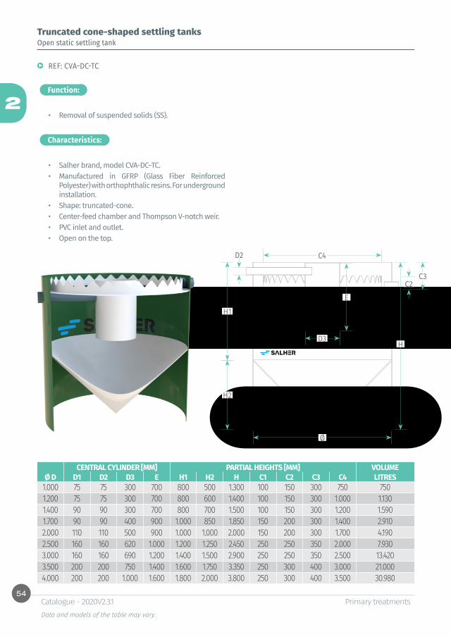
Open static settling tank
REF: CVA-DC-TC
• Removal of suspended solids (SS).
• Salher brand, model CVA-DC–TC.• Manufactured in GFRP (Glass Fiber Reinforced
Polyester) with orthophthalic resins. For underground installation.
• Shape: truncated-cone.• Center-feed chamber and Thompson V-notch weir.• PVC inlet and outlet.• Open on the top.
CENTRAL CYLINDER [MM] PARTIAL HEIGHTS [MM] VOLUMEØ D D1 D2 D3 E H1 H2 H C1 C2 C3 C4 LITRES
1.000 75 75 300 700 800 500 1.300 100 150 300 750 7501.200 75 75 300 700 800 600 1.400 100 150 300 1.000 1.1301.400 90 90 300 700 800 700 1.500 100 150 300 1.200 1.5901.700 90 90 400 900 1.000 850 1.850 150 200 300 1.400 2.9102.000 110 110 500 900 1.000 1.000 2.000 150 200 300 1.700 4.1902.500 160 160 620 1.000 1.200 1.250 2.450 250 250 350 2.000 7.9303.000 160 160 690 1.200 1.400 1.500 2.900 250 250 350 2.500 13.4203.500 200 200 750 1.400 1.600 1.750 3.350 250 300 400 3.000 21.0004.000 200 200 1.000 1.600 1.800 2.000 3.800 250 300 400 3.500 30.980

55
2
H
LA
ØE
ØR
ØS
ØV
Primary treatmentsData and models of the table may vary.
Catalogue - 2020V2.3.1
Function: Characteristics:
Lamella clarifier
REF: DE-LA
• Equipment designed to facilitate the continuous settling of suspended solids contained in water. The installation of lamellar modules in the settling compartment increases the effective surface of settling, improves the efficiency of the clarifier and reduces the tank surface. Equipment more compact and efficient.
• This system can be used in wastewater and water purification plants.
• Applications: * Potable water clarification.* Treatment of grey water.* Settling of surface and underground water.* Tertiary treatment.* Industrial wastewater.
• Salher brand, model DE-LA.• Tank manufactured in GFRP. • External support frame manufactured in carbon
steel with anti-corrosion protection. Optional: AISI 304 or AISI 316.
• Tube settler manufactured in PVC. Slope angle of 60°.
• Upper canal for clarified water collection.• Flanged inlet, outlet and overflow connections.• Ball valve installed on vacuum connection.• Tube settler is removable.• Options: flocculation pipe, maintenance footbridge
with access ladder and tramex.
Lamella clarifier
FLOW LENGTH WIDTH (A) HEIGHT (H)REFERENCE [M3/H] [MM] [MM] [MM] ØE ØS ØR ØV
DE-LA 5 5 2055 1255 2170 2’’ 2’’ 2’’ 1 1/4’’DE-LA 25 25 3680 2300 2164 4’’ 6’’ 6’’ 2’’DE-LA 50 50 6875 2285 2332 4’’ 6’’ 6’’ 3’’DE-LA 100 100 11493 2290 2473 4” 6” 6” 3”

56
2
Primary treatmentsData and models of the table may vary.
Catalogue - 2020V2.3.1
Fonction:
Characteristics:
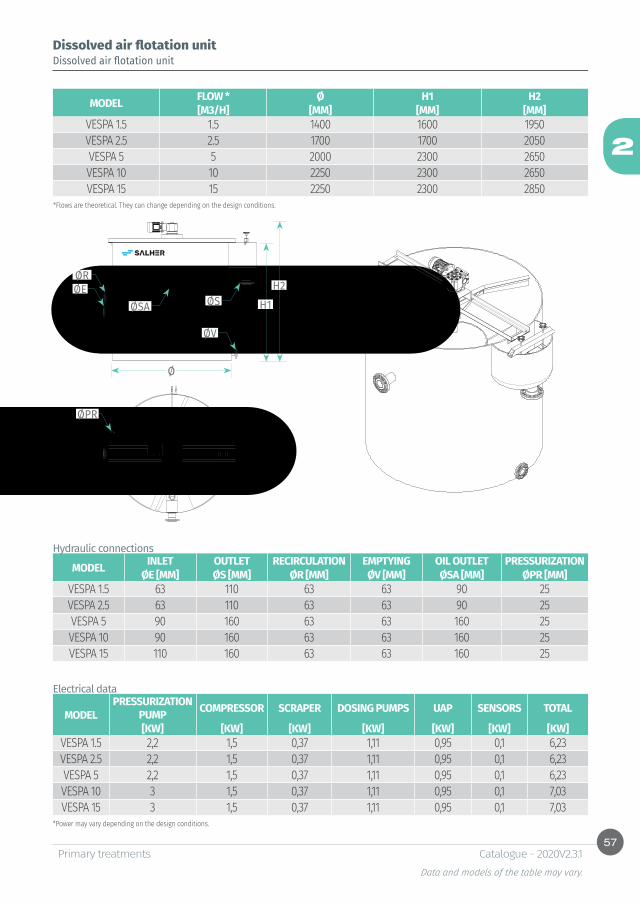
Dissolved air flotation unitDissolved air flotation unit
REF: VESPA
• The equipment, model VESPA, Salher brand, separates suspended solids, grease and oils in wastewater.
• The main structure is manufactured in GFRP with elements in stainless steel AISI 316L. The equipment is designed to facilitate the shipment in maritime containers.
• With an appropriate preparation of the water to treat, the equipment will reach this efficiency:
* Removal of BOD5: 40% - 80%* Removal of COD: 60% - 80%.* Removal of suspended solids, oils and grease: 90%
57
2
Ø
H1H2ØE
ØR
ØSA ØS
ØV
ØPR
Primary treatmentsData and models of the table may vary.
Catalogue - 2020V2.3.1
Dissolved air flotation unitDissolved air flotation unit
MODEL FLOW * Ø H1 H2[M3/H] [MM] [MM] [MM]
VESPA 1.5 1.5 1400 1600 1950VESPA 2.5 2.5 1700 1700 2050VESPA 5 5 2000 2300 2650VESPA 10 10 2250 2300 2650VESPA 15 15 2250 2300 2850
MODEL INLET OUTLET RECIRCULATION EMPTYING OIL OUTLET PRESSURIZATIONØE [MM] ØS [MM] ØR [MM] ØV [MM] ØSA [MM] ØPR [MM]
VESPA 1.5 63 110 63 63 90 25VESPA 2.5 63 110 63 63 90 25VESPA 5 90 160 63 63 160 25VESPA 10 90 160 63 63 160 25VESPA 15 110 160 63 63 160 25
MODELPRESSURIZATION
PUMP COMPRESSOR SCRAPER DOSING PUMPS UAP SENSORS TOTAL
[KW] [KW] [KW] [KW] [KW] [KW] [KW]VESPA 1.5 2,2 1,5 0,37 1,11 0,95 0,1 6,23VESPA 2.5 2,2 1,5 0,37 1,11 0,95 0,1 6,23VESPA 5 2,2 1,5 0,37 1,11 0,95 0,1 6,23VESPA 10 3 1,5 0,37 1,11 0,95 0,1 7,03VESPA 15 3 1,5 0,37 1,11 0,95 0,1 7,03
Hydraulic connections
Electrical data
*Flows are theoretical. They can change depending on the design conditions.
*Power may vary depending on the design conditions.
58
2
L
A
Primary treatmentsData and models of the table may vary.
Catalogue - 2020V2.3.1
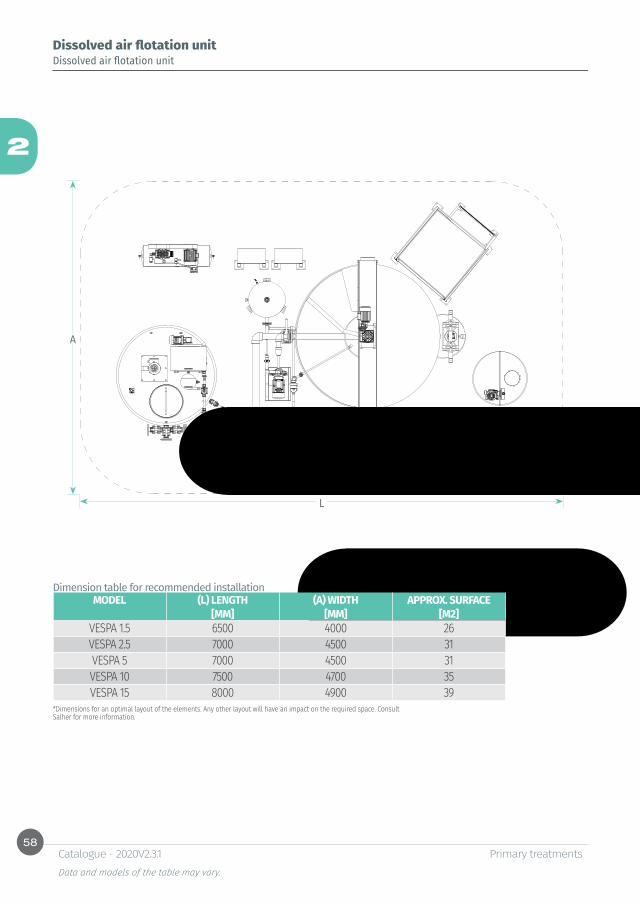
Dissolved air flotation unitDissolved air flotation unit
Dimension table for recommended installationMODEL (L) LENGTH (A) WIDTH APPROX. SURFACE
[MM] [MM] [M2]VESPA 1.5 6500 4000 26VESPA 2.5 7000 4500 31VESPA 5 7000 4500 31VESPA 10 7500 4700 35VESPA 15 8000 4900 39
*Dimensions for an optimal layout of the elements. Any other layout will have an impact on the required space. Consult Salher for more information.

59
2
Primary treatmentsData and models of the table may vary.
Catalogue - 2020V2.3.1
Dissolved air flotation unitDissolved air flotation unit
ELEMENTS INCLUDEDThe dissolved air flotation unit, model VESPA, Salher brand, is a fully automatized system, composed of the following elements:
1. Flotation unit:• Main structure and inner parts manufactured in GFRP
through Filament Winding.• Skimmer for floating particles collection manufactured
in stainless steel AISI 316L.• Adjustable scrapers system manufactured in AISI 304
actuated by a slow rotation motor reducer. Scapers in plastic material.
• Support and fixation of the scrapers system manufactured in AISI 316L through longitudinal profiles fixed to the main structure of the equipment.
• Height-adjustable clarified water collector manufactured in stainless steel AISI 316L to control the level of the water layer.
• Butterfly valve with pneumatic actuation for automatic drain of the equipment.
• Foldable covers manufactured in transparent methacrylate. Easy supervision of the inner part of the flotation unit, no need for opening the equipment and reduction of bad smells.
• Conductive probe with rods installed in clarified water chamber to control the level of operation.
• Pressurization system for recirculated water composed of:
-Centrifuge pressurization pump. -Pressure transmitter in the pump impulsion. -Venturi injectors for first water-air mixture. -Small air pressure tank with measurement system and pre-installed valves kit. -Pneumatic diaphragme valves for pressurization. -Pneumatic control panel composed of:
* Regulator filter (0-8.5 bar).* Pressure regulator (0-8.5 bar).* Flow switch.
* Set of control electrovalves.• Piston compressor for air needs of the whole system.• Skid for flocculant and pressurization pumps.• Safety elements for emergency shutdown.• The equipment includes all manual valves required for
the correct operation of the system.
60
2
Primary treatmentsData and models of the table may vary.
Catalogue - 2020V2.3.1
Dissolved air flotation unitDissolved air flotation unit
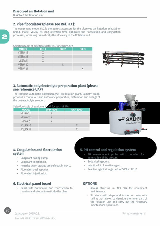
2. Pipe flocculator (please see Ref. FLC):The equipment, model FLC, is the perfect accessory for the dissolved air flotation unit, Salher brand, model VESPA. Its long retention time optimizes the flocculation and coagulation processes, increasing dramatically the efficiency of the flotation unit.
MODEL FLC-1 FLC-2 FLC-3VESPA 1,5 XVESPA 2,5 XVESPA 5 XVESPA 10 XVESPA 15 X
Selection table of pipe flocculator PLC for each VESPA
3. Automatic polyelectrolyte preparation plant (please see reference UAP) The compact automatic polyelectrolyte preparation plant, Salher® brand, provides a continuous and automatic preparation, maturation and dosage of the polyelectrolyte solution.
MODEL UAP 1000 UAP 2000VESPA 1.5 XVESPA 2.5 XVESPA 5 XVESPA 10 XVESPA 15 X
Selection table of equipment UAP for each VESPA
4. Coagulation and flocculation system
• Coagulant dosing pump.• Coagulant injection kit.• Reactive agent storage tank of 500L in PEHD.• Flocculant dosing pump.• Flocculant injection kit.
5. PH control and regulation system • PH measurement probe with controller for
automation of the process.• Soda dosing pump.• Injection kit of reactive agent.• Reactive agent storage tank of 500L in PEHD.
6. Electrical panel board • Panel with automaton and touchscreen to
monitor and pilot automatically the plant.
OPTIONS• Access structure in AISI 304 for equipment
maintenance.• Structure with steps and inspection area with
railing that allows to visualize the inner part of the flotation unit and carry out the necessary maintenance operations.

61
2
L A
H
Primary treatmentsData and models of the table may vary.
Catalogue - 2020V2.3.1
Pipe flocculator Pipe flocculator
Fonction: Characteristics:
REF: FLC
• The equipment, model FLC, Salher brand, is the perfect accessory for the dissolved air flotation unit, model VESPA, Salher brand, as well as for the lamellar settler, model DE-LA. Its long retention time optimizes the processes of coagulation and flocculation, increasing dramatically its efficiency.
• The system includes insertions in line for the preparation and control of the flocculation process.
The flocculator equipment, Salher brand, is a system formed by the following elements:• PEHD piping.• Skid in stainless steel with category C5-M anti-
corrosion painting.• Height and level regulation system. • Sample-taking taps.• Coagulant and soda injection points.• Flocculant injection points.
MODEL NOMINAL FLOW L H A Ø PIPE[M3/H] [MM] [MM] [MM] [MM]
FLC -1 5 3000 1200 600 D 90FLC -2 10 3500 1500 600 D 90FLC -3 15 4500 1600 800 D 110FLC -4 25 3500 1700 1000 D 160FLC -5 50 6000 2000 1000 D 160FLC -6 100 9500 2000 1000 D 160
MODEL FLC-1 FLC-2 FLC-3 FLC-4 FLC-5 FLC-6VESPA 1,5 XVESPA 2,5 XVESPA 5 XVESPA 10 XVESPA 15 XDE-LA 5 XDE-LA 10 XDE-LA 25 XDE-LA 50 XDE-LA 100 X
Selection table of pipe flocculator FLC for each VESPA and DE-LA


3Secondary treatments

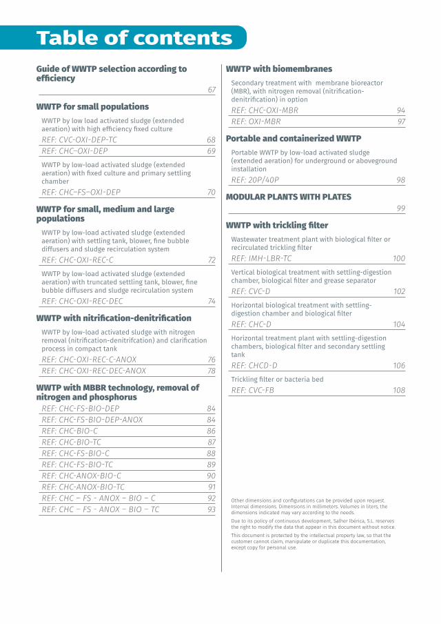
Table of contents
Other dimensions and configurations can be provided upon request. Internal dimensions. Dimensions in millimeters. Volumes in liters, the dimensions indicated may vary according to the needs.Due to its policy of continuous development, Salher Ibérica, S.L. reserves the right to modify the data that appear in this document without notice.This document is protected by the intellectual property law, so that the customer cannot claim, manipulate or duplicate this documentation, except copy for personal use.
Guide of WWTP selection according to efficiency
67
WWTP for small populationsWWTP by low load activated sludge (extended aeration) with high efficiency fixed culture REF: CVC-OXI-DEP-TC 68REF: CHC–OXI-DEP 69WWTP by low-load activated sludge (extended aeration) with fixed culture and primary settling chamberREF: CHC–FS–OXI-DEP 70
WWTP for small, medium and large populations
WWTP by low-load activated sludge (extended aeration) with settling tank, blower, fine bubble diffusers and sludge recirculation system REF: CHC-OXI-REC-C 72WWTP by low-load activated sludge (extended aeration) with truncated settling tank, blower, fine bubble diffusers and sludge recirculation system REF: CHC-OXI-REC-DEC 74
WWTP with nitrification-denitrificationWWTP by low-load activated sludge with nitrogen removal (nitrification-denitrifcation) and clarification process in compact tank REF: CHC-OXI-REC-C-ANOX 76REF: CHC-OXI-REC-DEC-ANOX 78
WWTP with MBBR technology, removal of nitrogen and phosphorus
REF: CHC-FS-BIO-DEP 84REF: CHC-FS-BIO-DEP-ANOX 84REF: CHC-BIO-C 86REF: CHC-BIO-TC 87REF: CHC-FS-BIO-C 88REF: CHC-FS-BIO-TC 89REF: CHC-ANOX-BIO-C 90REF: CHC-ANOX-BIO-TC 91REF: CHC – FS - ANOX – BIO – C 92REF: CHC – FS - ANOX – BIO – TC 93
WWTP with biomembranesSecondary treatment with membrane bioreactor (MBR), with nitrogen removal (nitrification-denitrification) in optionREF: CHC-OXI-MBR 94REF: OXI-MBR 97
Portable and containerized WWTPPortable WWTP by low-load activated sludge (extended aeration) for underground or aboveground installationREF: 20P/40P 98
MODULAR PLANTS WITH PLATES 99
WWTP with trickling filterWastewater treatment plant with biological filter or recirculated trickling filterREF: IMH-LBR-TC 100Vertical biological treatment with settling-digestion chamber, biological filter and grease separator REF: CVC-D 102Horizontal biological treatment with settling-digestion chamber and biological filter REF: CHC-D 104Horizontal treatment plant with settling-digestion chambers, biological filter and secondary settling tankREF: CHCD-D 106Trickling filter or bacteria bed REF: CVC-FB 108
66
3
Secondary treatments Data and models of the table may vary.
Catalogue - 2020V2.3.1
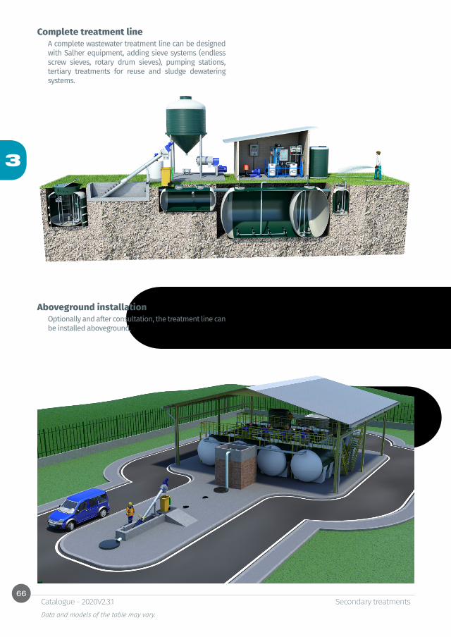
Complete treatment lineA complete wastewater treatment line can be designed with Salher equipment, adding sieve systems (endless screw sieves, rotary drum sieves), pumping stations, tertiary treatments for reuse and sludge dewatering systems.
Aboveground installation Optionally and after consultation, the treatment line can be installed aboveground.
67
3
Secondary treatments Data and models of the table may vary.
Catalogue - 2020V2.3.1
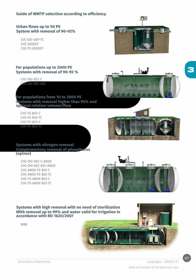
Guide of WWTP selection according to efficiency
Urban flows up to 50 PESystem with removal of 90-92%
For populations up to 2000 PESystems with removal of 90-92 %
For populations from 10 to 3000 PESystems with removal higher than 95% and optimal relation volume/flow
CHC-FS-BIO-CCHC-FS-BIO-TCCHC-FS-BIO-CCHC-FS-BIO-TC
Systems with high removal with no need of sterilizationWith removal up to 99% and water valid for irrigation in accordance with RD 1620/2007
MBR
Systems with nitrogen removalComplementary removal of phosphorus (option)
CVC-OXI-DEP-TCCHC-OXIDEPCHC-FS-OXIDEP
CHC-OXI-REC-C CHC-OXI-REC-DEC
CHC-OXI-REC-C-ANOXCHC-OXI-REC-DEC-ANOXCHC-ANOX-FS-BIO-C CHC-ANOX-FS-BIO-TCCHC-FS-ANOX-BIO-CCHC-FS-ANOX-BIO-TC

68
3
CE
Ø
CS
H
Secondary treatments Data and models of the table may vary.
Catalogue - 2020V2.3.1
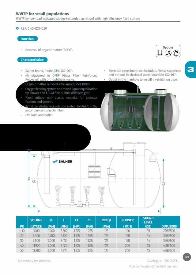
WWTP by low load activated sludge (extended aeration) with high efficiency fixed culture
REF: CVC-OXI-DEP-TC
• Removal of organic matter (BOD5).
• Salher brand, model CVC-OXI-DEP-TC.• Equipment manufactured in GFRP (Glass Fiber
Reinforced Polyester) with orthophthalic resins. • Organic matter removal efficiency: ≥ 95% BOD5.• Oxygen feeding system and mixed liquor equalization
by blower and EPDM fine bubble diffusers grid. • Fixed culture with plastic material for biomass
fixation and growth. • Activated sludge recirculation system by Airlift.
Function:
Characteristics:
WWTP for small populations
• Truncated settling tank with central feeding and Thompson canal.
• PVC inlet and outlet.• Access via manholes with PP cover.• Electrical panel board not included. Please see prices
and options in electrical panel board for OXI-DEP.• Outlet in the manhole to install a ventilation pipe.
Options
VOLUME Ø H CE CS Ø PIPE BLOWER SOUND LEVEL
PE [LITRES] [MM] [MM] [MM] [MM] [MM] ( W ) II (DB) DIFFUSERS≤ 10 3.100 1.400 2.175 1.800 1.700 125 100 39 2DBF50020 6.300 2.000 2.175 1.800 1.700 125 150 44 2DBF50030 9.600 2.250 2.575 2.200 2.100 125 150 44 3DBF50040 11.900 2.500 2.575 2.200 2.100 125 200 45 4DBF50050 13.800 2.500 2.975 2.600 2.500 125 200 45 4DBF500
69
3
CECEØØ
CSCS
LL
Secondary treatments Data and models of the table may vary.
Catalogue - 2020V2.3.1
WWTP by low-load activated sludge (extended aeration) with high efficiency fixed culture
REF: CHC–OXI-DEP
• Removal of organic matter (BOD5).
• Salher brand, model CHC-OXI-DEP.• Manufactured in GFRP (Glass Fiber Reinforced
Polyester) with orthophthalic resins.• Organic matter removal efficiency: ≥ 95% BOD5.• Oxygen feeding system and mixed liquor equalization
by blower and EPDM fine bubble diffusers grid. • Fixed culture with plastic material for biomass
fixation and growth. • Activated sludge recirculation system by Airlift in the
secondary settling chamber.• PVC inlet and outlet.
Function:
Characteristics:
WWTP for small populations
• Electrical panel board not included. Please see prices and options in electrical panel board for OXI-DEP.
• Outlet in the manhole to install a ventilation pipe.
Options
VOLUME Ø L CE CS PIPE Ø BLOWER SOUND LEVEL
PE [LITRES] [MM] [MM] [MM] [MM] [MM] ( W ) II (DB) DIFFUSERS≤ 10 3.100 1.400 2.300 1.275 1.225 125 100 39 2DBF50020 6.300 1.700 3.100 1.575 1.525 125 150 44 3DBF50030 9.600 2.000 3.430 1.875 1.825 125 150 44 3DBF50040 11.900 2.000 3.420 1.875 1.825 125 200 45 4DBF50050 13.800 2.000 4.770 1.875 1.825 125 200 45 4DBF500

70
3
CEØCS
L
Secondary treatments Data and models of the table may vary.
Catalogue - 2020V2.3.1
WWTP by low-load activated sludge (extended aeration) with fixed culture and primary settling chamber
REF: CHC–FS–OXI-DEP
• Settling of suspended solids (SS).• Removal of organic matter (BOD5).
• Salher brand, model CHC-FS-OXI-DEP.• Manufactured in GFRP (Glass Fiber Reinforced
Polyester) with orthophthalic resins.• Organic matter removal efficiency: ≥ 95% BOD5.• Primary settling chamber for the flow equalization
and coarse solids removal. • Oxygen feeding system and mixed liquor equalization
by blower and EPDM fine bubble diffusers grid. • Fixed culture with plastic material for biomass
fixation and growth.
Function:
Characteristics:
WWTP for small populations
• Activated sludge return system through Airlift in the secondary settling chamber.
• PVC inlet and outlet.• Electrical panel board not included. Please see prices
and options in electrical panel board for OXI-DEP.• Outlet in the manhole to install a ventilation pipe.
Options
PE TOTAL VOL. FS VOL. VOL. OXI DC VOL. Ø L CE CS Ø T BLOWER SOUND
LEVEL[LITRES] [LITRES] [LITRES] [LITRES] [MM] [MM] [MM] [MM] [MM] ( W ) II (DB) DIF.
≤ 5 2.500 1.000 1.000 500 1.200 2.440 1.075 1.000 125 80 35 210 4.000 1.000 2.000 1.000 1.400 2.860 1.275 1.200 125 80 35 215 6.500 1.500 3.000 2.000 1.700 3.000 1.575 1.500 125 150 43 320 8.500 2.000 4.000 2.500 1.700 4.000 1.575 1.500 125 150 43 330 12.000 3.000 6.000 3.000 2.000 4.200 1.875 1.800 125 200 44 440 16.000 4.000 8.000 4.000 2.000 5.460 1.875 1.800 125 200 44 450 20.000 5.000 10.000 5.000 2.250 5.450 2.125 2.050 125 240 48 560 24.000 6.000 12.000 6.000 2.250 6.450 2.125 2.050 125 240 48 5
71
3
Secondary treatments Data and models of the table may vary.
Catalogue - 2020V2.3.1
WWTP for small populations
Characteristics:
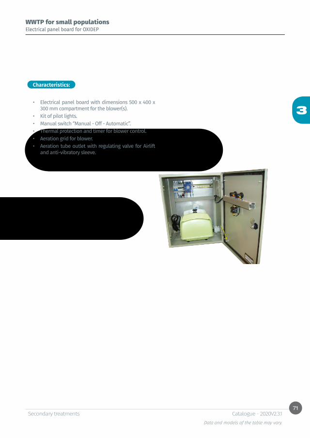
Electrical panel board for OXIDEP
• Electrical panel board with dimensions 500 x 400 x 300 mm compartment for the blower(s).
• Kit of pilot lights.• Manual switch “Manual - Off - Automatic”.• Thermal protection and timer for blower control.• Aeration grid for blower.• Aeration tube outlet with regulating valve for Airlift
and anti-vibratory sleeve.

72
3
Secondary treatments Data and models of the table may vary.
Catalogue - 2020V2.3.1
WWTP for small, medium and large populations
Function:
Characteristics:
WWTP by low-load activated sludge (extended aeration) with settling tank, blower, fine bubble diffusers and sludge recirculation system
REF: CHC-OXI-REC-C
• Removal of organic matter (BOD5).
• Salher brand, model CHC-OXI-REC-C.• Manufactured in GFRP (Glass Fiber Reinforced
Polyester) with orthophthalic resins.• Organic matter removal efficiency: 80-90% BOD5.• Oxygen feeding system and mixed liquor equalization
by blower and EPDM fine bubble diffusers grid.
Options
• Compact settling tank and activated sludge recirculation system by submerged pump.
• PVC inlet and outlet.• Access in the manhole through GFRP cover. • Outlet in the manhole to install a ventilation pipe.
73
3
CEØCS
L
Secondary treatments Data and models of the table may vary.
Catalogue - 2020V2.3.1
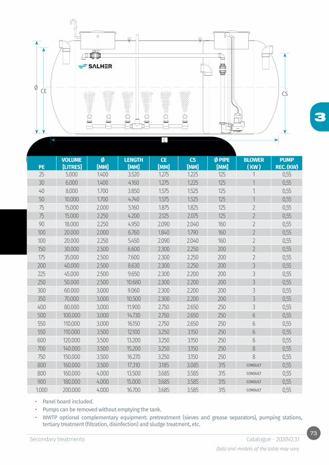
• Panel board included.• Pumps can be removed without emptying the tank.• WWTP optional complementary equipment: pretreatment (sieves and grease separators), pumping stations,
tertiary treatment (filtration, disinfection) and sludge treatment, etc.
VOLUME Ø LENGTH CE CS Ø PIPE BLOWER PUMPPE [LITRES] [MM] [MM] [MM] [MM] [MM] ( KW ) REC. (KW)25 5.000 1.400 3.520 1.275 1.225 125 1 0,5530 6.000 1.400 4.160 1.275 1.225 125 1 0,5540 8.000 1.700 3.850 1.575 1.525 125 1 0,5550 10.000 1.700 4.740 1.575 1.525 125 1 0,5575 15.000 2.000 5.160 1.875 1.825 125 2 0,5575 15.000 2.250 4.200 2.125 2.075 125 2 0,5590 18.000 2.250 4.950 2.090 2.040 160 2 0,55100 20.000 2.000 6.760 1.840 1.790 160 2 0,55100 20.000 2.250 5.450 2.090 2.040 160 2 0,55150 30.000 2.500 6.600 2.300 2.250 200 2 0,55175 35.000 2.500 7.600 2.300 2.250 200 2 0,55200 40.000 2.500 8.630 2.300 2.250 200 3 0,55225 45.000 2.500 9.650 2.300 2.200 200 3 0,55250 50.000 2.500 10.680 2.300 2.200 200 3 0,55300 60.000 3.000 9.060 2.300 2.200 200 3 0,55350 70.000 3.000 10.500 2.300 2.200 200 3 0,55400 80.000 3.000 11.900 2.750 2.650 250 3 0,55500 100.000 3.000 14.730 2.750 2.650 250 6 0,55550 110.000 3.000 16.150 2.750 2.650 250 6 0,55550 110.000 3.500 12.100 3.250 3.150 250 6 0,55600 120.000 3.500 13.200 3.250 3.150 250 6 0,55700 140.000 3.500 15.200 3.250 3.150 250 8 0,55750 150.000 3.500 16.270 3.250 3.150 250 8 0,55800 160.000 3.500 17.310 3.185 3.085 315 CONSULT 0,55800 160.000 4.000 13.500 3.685 3.585 315 CONSULT 0,55900 180.000 4.000 15.000 3.685 3.585 315 CONSULT 0,551.000 200.000 4.000 16.700 3.685 3.585 315 CONSULT 0,55

74
3
Secondary treatments Data and models of the table may vary.
Catalogue - 2020V2.3.1
WWTP for small, medium and large populations
Function:
Characteristics:
WWTP by low-load activated sludge (extended aeration) with truncated settling tank, blower, fine bubble diffusers and sludge recirculation system
REF: CHC-OXI-REC-DEC
• Removal of organic matter (BOD5).
• Salher brand, model CHC-OXI-REC-DEC.• Manufactured in GFRP (Glass Fiber Reinforced
Polyester) with orthophthalic resins.• Organic matter removal efficiency: ≥ 90 - 95 % BOD5.• Oxygen feeding system and mixed liquor equalization
by blower and EPDM fine bubble diffusers grid.• Truncated settling tank with central feeding and
Thompson canal.• Activated sludge recirculation system by submerged
pump.• PVC inlet and outlet.• Access in the manhole through GFRP cover. • Outlet in the manhole to install a ventilation pipe.
Options
75
3
CEØ
Ø
CS
L
H
Secondary treatments Data and models of the table may vary.
Catalogue - 2020V2.3.1
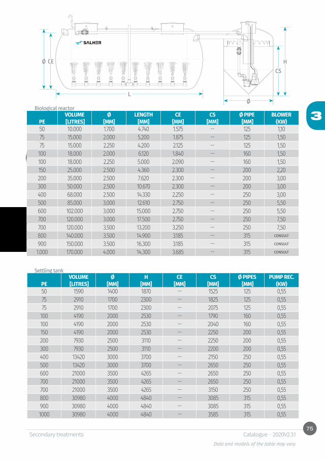
Biological reactor
Settling tankVOLUME Ø H CE CS Ø PIPES PUMP REC.
PE [LITRES] [MM] [MM] [MM] [MM] [MM] (KW)50 1590 1400 1870 -- 1525 125 0,5575 2910 1700 2300 -- 1825 125 0,5575 2910 1700 2300 -- 2075 125 0,55
100 4190 2000 2530 -- 1790 160 0,55100 4190 2000 2530 -- 2040 160 0,55150 4190 2000 2530 -- 2250 200 0,55200 7930 2500 3110 -- 2250 200 0,55300 7930 2500 3110 -- 2200 200 0,55400 13420 3000 3700 -- 2150 250 0,55500 13420 3000 3700 -- 2650 250 0,55600 21000 3500 4265 -- 2650 250 0,55700 21000 3500 4265 -- 2650 250 0,55700 21000 3500 4265 -- 3150 250 0,55800 30980 4000 4840 -- 3085 315 0,55900 30980 4000 4840 -- 3085 315 0,551000 30980 4000 4840 -- 3585 315 0,55
VOLUME Ø LENGTH CE CS Ø PIPE BLOWERPE [LITRES] [MM] [MM] [MM] [MM] [MM] (KW)50 10.000 1.700 4.740 1.575 -- 125 1,1075 15.000 2.000 5.200 1.875 -- 125 1,5075 15.000 2.250 4.200 2.125 -- 125 1,50
100 18.000 2.000 6.120 1.840 -- 160 1,50100 18.000 2.250 5.000 2.090 -- 160 1,50150 25.000 2.500 4.360 2.300 -- 200 2,20200 35.000 2.500 7.620 2.300 -- 200 3,00300 50.000 2.500 10.670 2.300 -- 200 3,00400 68.000 2.500 14.330 2.250 -- 250 3,00500 85.000 3.000 12.610 2.750 -- 250 5,50600 102.000 3.000 15.000 2.750 -- 250 5,50700 120.000 3.000 17.500 2.750 -- 250 7,50700 120.000 3.500 13.200 3.250 -- 250 7,50800 140.000 3.500 14.900 3.185 -- 315 CONSULT
900 150.000 3.500 16.300 3.185 -- 315 CONSULT
1.000 170.000 4.000 14.300 3.685 -- 315 CONSULT
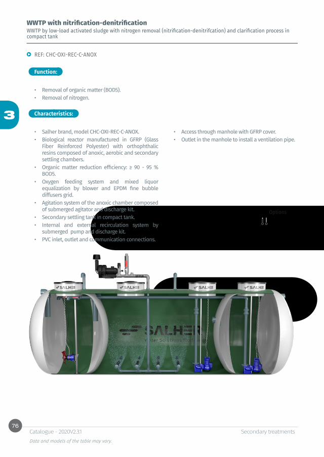
76
3
Secondary treatments Data and models of the table may vary.
Catalogue - 2020V2.3.1
Function:
Characteristics:
WWTP with nitrification-denitrificationWWTP by low-load activated sludge with nitrogen removal (nitrification-denitrifcation) and clarification process in compact tank
REF: CHC-OXI-REC-C-ANOX
• Removal of organic matter (BOD5).• Removal of nitrogen.
• Salher brand, model CHC-OXI-REC-C-ANOX.• Biological reactor manufactured in GFRP (Glass
Fiber Reinforced Polyester) with orthophthalic resins composed of anoxic, aerobic and secondary settling chambers.
• Organic matter reduction efficiency: ≥ 90 - 95 % BOD5.
• Oxygen feeding system and mixed liquor equalization by blower and EPDM fine bubble diffusers grid.
• Agitation system of the anoxic chamber composed of submerged agitator and discharge kit.
• Secondary settling tank in compact tank.• Internal and external recirculation system by
submerged pump and discharge kit.• PVC inlet, outlet and communication connections.
• Access through manhole with GFRP cover.• Outlet in the manhole to install a ventilation pipe.
Options

77
3
CEØCS
L
Secondary treatments Data and models of the table may vary.
Catalogue - 2020V2.3.1
• Panel board included.• Pumps can be removed without emptying the tank.• WWTP optional complementary equipment: pretreatment (sieves and grease separators), pumping stations,
tertiary treatment (filtration, disinfection) and sludge treatment, etc.
VOLUME Ø LENGTH CE CS PIPE BLOWER REC. PUMP AGITATORPE [LITRES] [MM] [MM] [MM] [MM] [MM] ( KW) (KW) (KW)25 8.000 1.400 5.500 1.275 1.225 125 0,55 0,55 0,6030 10.000 1.700 4.750 1.575 1.525 125 0,55 0,55 0,6040 12.000 1.700 5.650 1.575 1.525 125 0,55 0,55 0,6050 15.000 1.700 7.000 1.575 1.525 125 0,75 0,55 0,6075 24.000 2.000 8.050 1.840 1.790 160 1,1 0,55 0,6075 24.000 2.250 6.500 2.090 2.040 160 1,1 0,55 0,6090 30.000 2.250 8.000 2.050 2.000 200 1,1 0,55 0,60100 35.000 2.250 9.250 2.050 2.000 200 1,5 0,55 0,60100 35.000 2.500 7.600 2.300 2.250 200 1,5 0,55 0,60150 45.000 2.500 9.660 2.300 2.250 200 2,2 0,55 0,60175 50.000 2.500 10.680 2.300 2.250 200 2,2 0,55 0,60200 55.000 2.500 11.700 2.300 2.250 200 2,2 0,55 0,60225 65.000 3.000 9.800 2.800 2.750 200 2,2 0,55 0,60250 70.000 3.000 10.500 2.800 2.750 200 3 0,55 0,60300 85.000 3.000 12.600 2.800 2.750 250 3 0,55 0,60350 95.000 3.500 10.600 3.250 3.150 250 4 0,55 0,60400 110.000 3.500 12.120 3.250 3.150 250 5,5 0,55 0,60500 140.000 3.500 15.240 3.250 3.150 250 5,5 0,55 0,60550 150.000 4.000 13.890 3.750 3.650 250 5,5 0,55 0,60600 170.000 4.000 14.300 3.750 3.650 250 5,5 0,55 0,60700 190.000 4.000 15.900 3.750 3.650 250 7,5 0,55 0,60750 205.000 4.000 17.100 3.750 3.650 250 7,5 0,55 0,60800 220.000 4.000 18.500 3.750 3.650 250 7,5 0,55 0,60900 2 X 125.000 3.500 13.650 3.250 3.150 250 2 X 5,5 0,55 0,601.000 2 X 140.000 3.500 15.240 3.250 3.150 250 2 X 5,5 0,55 0,60

78
3
Secondary treatments Data and models of the table may vary.
Catalogue - 2020V2.3.1
Function:
Characteristics:
WWTP with nitrification-denitrificationWWTP by low-load activated sludge, with nitrogen removal (nitrification-denitrification) and clarification process in independent truncated tank
REF: CHC-OXI-REC-DEC-ANOX
• Removal of organic matter (BOD5).• Removal of nitrogen.
• Salher brand, model CHC-OXI-REC-DEC-ANOX.• Biological reactor manufactured in GFRP (Glass
Fiber Reinforced Polyester) with orthophthalic resins composed of anoxic, aerobic and secondary settling chambers.
• Organic matter reduction efficiency: ≥ 90 - 95 % BOD5.
• Oxygen feeding system and mixed liquor equalization by blower and EPDM fine bubble diffusers grid.
• Agitation system of the anoxic chamber composed of submerged agitator and discharge kit.
• Independent secondary settling tank manufactured in GFRP, with central feeding and Thompson canal.
• Internal and external recirculation system by submerged pump and discharge kit.
• PVC inlet, outlet and communication connections.• Access through manhole with GFRP cover.• Outlet in the manhole to install a ventilation pipe.
Options

79
3
CEØ
Ø
CS
L
H
Secondary treatments Data and models of the table may vary.
Catalogue - 2020V2.3.1
Biological reactor
Settling tank
• Panel board included.• WWTP optional complementary equipment: pretreatment (sieves and grease separators), pumping stations,
tertiary treatment (filtration, disinfection) and sludge treatment, etc.
VOLUME Ø H CS Ø PIPE REC. PUMPPE [LITRES] [MM] [MM] [MM] [MM] ( KW )25 1130 1200 1720 1225 125 0,5530 1130 1200 1720 1525 125 0,5540 1590 1400 1870 1825 125 0,5550 1590 1400 1870 1825 125 0,5575 2910 1700 2300 1790 160 0,5590 4190 2000 2530 2000 200 0,55100 4190 2000 2530 2000 200 0,55100 4190 2000 2530 2250 200 0,55150 4190 2000 2530 2250 200 0,55175 7930 2500 3110 2250 200 0,55200 7930 2500 3110 2250 200 0,55225 7930 2500 3110 2250 200 0,55
VOLUME Ø LENGTH CE Ø PIPE BLOWER REC. PUMP AGITATORPE [LITRES] [MM] [MM] [MM] [MM] ( KW ) (KW) (KW)25 7.000 1.400 4.850 1.275 125 0,55 0,55 0,630 8.000 1.400 5.460 1.575 125 0,55 0,55 0,640 10.000 1.700 4.750 1.875 125 0,55 0,55 0,650 13.000 1.700 6.450 1.875 125 0,75 0,55 0,675 21.000 2.000 7.060 1.840 160 1,1 0,55 0,675 21.000 2.250 5.750 2.090 160 1,1 0,55 0,690 26.000 2.250 7.000 2.050 200 1,1 0,55 0,6100 32.000 2.250 8.470 2.050 200 1,5 0,55 0,6100 32.000 2.500 7.000 2.300 200 1,5 0,55 0,6150 39.000 2.500 8.450 2.300 200 2,2 0,55 0,6175 43.000 2.500 9.250 2.300 200 2,2 0,55 0,6200 47.000 2.500 10.050 2.300 200 2,2 0,55 0,6225 56.000 2.500 11.900 2.300 200 2,2 0,55 0,6
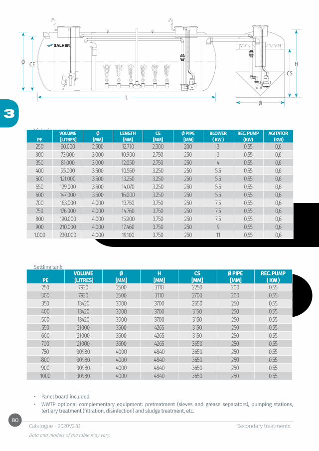
80
3
CEØ
Ø
CS
L
H
Secondary treatments Data and models of the table may vary.
Catalogue - 2020V2.3.1
• Panel board included.• WWTP optional complementary equipment: pretreatment (sieves and grease separators), pumping stations,
tertiary treatment (filtration, disinfection) and sludge treatment, etc.
Biological reactor
Settling tankVOLUME Ø H CS Ø PIPE REC. PUMP
PE [LITRES] [MM] [MM] [MM] [MM] ( KW )250 7930 2500 3110 2250 200 0,55300 7930 2500 3110 2700 200 0,55350 13420 3000 3700 2650 250 0,55400 13420 3000 3700 3150 250 0,55500 13420 3000 3700 3150 250 0,55550 21000 3500 4265 3150 250 0,55600 21000 3500 4265 3150 250 0,55700 21000 3500 4265 3650 250 0,55750 30980 4000 4840 3650 250 0,55800 30980 4000 4840 3650 250 0,55900 30980 4000 4840 3650 250 0,551000 30980 4000 4840 3650 250 0,55
VOLUME Ø LENGTH CE Ø PIPE BLOWER REC. PUMP AGITATORPE [LITRES] [MM] [MM] [MM] [MM] ( KW ) (KW) (KW)250 60.000 2.500 12.710 2.300 200 3 0,55 0,6300 73.000 3.000 10.900 2.750 250 3 0,55 0,6350 81.000 3.000 12.050 2.750 250 4 0,55 0,6400 95.000 3.500 10.550 3.250 250 5,5 0,55 0,6500 121.000 3.500 13.250 3.250 250 5,5 0,55 0,6550 129.000 3.500 14.070 3.250 250 5,5 0,55 0,6600 147.000 3.500 16.000 3.250 250 5,5 0,55 0,6700 163.000 4.000 13.750 3.750 250 7,5 0,55 0,6750 176.000 4.000 14.760 3.750 250 7,5 0,55 0,6800 190.000 4.000 15.900 3.750 250 7,5 0,55 0,6900 210.000 4.000 17.460 3.750 250 9 0,55 0,61.000 230.000 4.000 19.100 3.750 250 11 0,55 0,6

81
3
Secondary treatments Data and models of the table may vary.
Catalogue - 2020V2.3.1
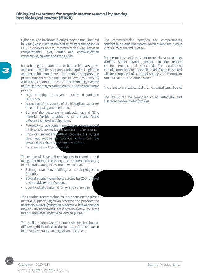
82
3
Secondary treatments Data and models of the table may vary.
Catalogue - 2020V2.3.1
Biological treatment for organic matter removal by moving bed biological reactor (MBRR)
Cylindrical and horizontal/vertical reactor manufactured in GFRP (Glass Fiber Reinforced Polyester) composed of GFRP manholes access, communication wall between compartments, inlet, outlet and communication connections, air vent and lifting rings.
It is a biological treatment in which the biomass grows adhered to mobile supports under optimal agitation and oxidation conditions. The mobile supports are plastic material with a high specific area (>500 m2/m3) with a density around 1g/cm³. This technology has the following advantages compared to the activated sludge process: • High stability of organic matter degradation
processes.• Reduction of the volume of the biological reactor for
an equal quality outlet effluent.• Sizing of the reactors with tank volumes and filling
material flexible to adapt to current and future efficiency removal requirements.
• Flexibillity to face contaminating load variations and inhibitors, to normalize the process in a few hours.
• Improves secondary settling because the system does not require recirculation to maintain the bacterial population, avoiding the bulking.
• Easy control and maintenance.
The reactor will have different layouts for chambers and fillings according to the required removal efficencies, inlet contaminating loads and flows to treat. • Settling chambers: settling or settling/digestion
(Imhoff).• Several aeration chambers: aerobic for COD removal
and aerobic for nitrification.• Specific plastic material for aeration chambers.
The aeration system maintains in suspension the plastic material supports (agitation process) and provides the necessary oxygen (oxidation process). A lateral channel blower with accessories: antivibratory sleeve, collector, filter, manometer, safety valve and air purge.
The air distribution system is composed of a fine bubble diffusers grid installed at the bottom of the reactor to improve the aeration and agitation processes.
The communication between the compartments consists in an efficient system which avoids the plastic material fixation and release.
The secondary settling is performed by a secondary clarifier, Salher brand, compact to the reactor or independent and truncated. The equipment manufactured in GFRP (Glass Fiber Reinforced Polyester) will be composed of a central supply and Thompson canal to collect the clarified water.
The plant control will consist of an electrical panel board.
The WWTP can be composed of an automatic and dissolved oxygen meter (option).
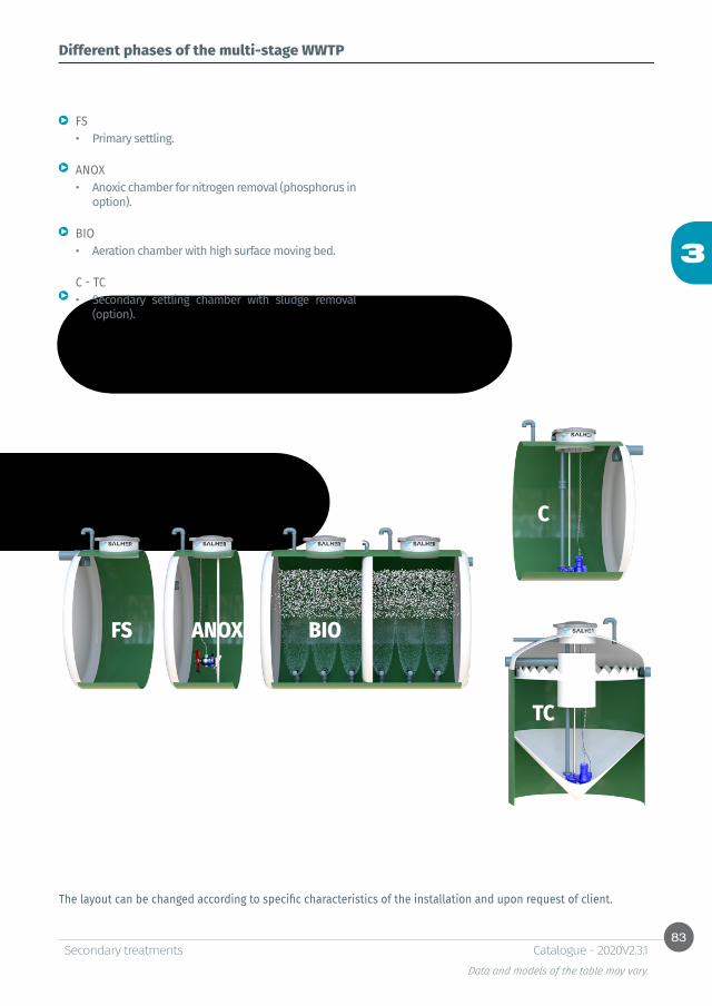
83
3
FS ANOX BIO
TC
C
Secondary treatments Data and models of the table may vary.
Catalogue - 2020V2.3.1
Different phases of the multi-stage WWTP
FS• Primary settling.
ANOX• Anoxic chamber for nitrogen removal (phosphorus in
option).
BIO• Aeration chamber with high surface moving bed.
C - TC• Secondary settling chamber with sludge removal
(option).
The layout can be changed according to specific characteristics of the installation and upon request of client.

84
3
CE
CE
Ø
Ø
CS
CS
L
L
Secondary treatments Data and models of the table may vary.
Catalogue - 2020V2.3.1
WWTP with MBBR technology, removal of nitrogen and phosphorus
REF: CHC-FS-BIO-DEPREF: CHC-FS-BIO-DEP-ANOX
• Option: panel board with automaton and control by GSM, dissolved oxygen probe.
Options
VOLUME Ø L Ø T CE CS BLOWER AGITATOR ANOX
PE [LITRES] [M] [MM] [MM] [MM] [MM] 220V 50HZ 220V 50HZ10 3.370 1,4 2.450 125 1.275 1.225 120 W 0,5 KW20 6.220 1,7 3.060 125 1.575 1.525 150 W 0,5 KW30 9.320 1,7 4.420 125 1.575 1.525 250 W 0,5 KW40 12.430 2 4.350 125 1.875 1.825 2X150 W 0,5 KW50 15.540 2 5.320 125 1.875 1.825 2X200 W 0,5 KW

85
3
Secondary treatments Data and models of the table may vary.
Catalogue - 2020V2.3.1
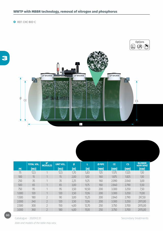
86
3
CEØ
CS
L
Secondary treatments Data and models of the table may vary.
Catalogue - 2020V2.3.1
WWTP with MBBR technology, removal of nitrogen and phosphorus
REF: CHC-BIO-C
Options
TOTAL VOL. N° MODULES UNIT VOL. Ø L Ø PIPE CE CS BLOWER
400V 50HZPE [M3] [M3] [M] [M] [MM] [MM] [MM] [KW]75 12,5 1 12,5 1,70 5,83 125 1.575 1.525 1,10
100 15 1 15 2,00 5,10 160 1.875 1.825 1,10250 35 1 35 2,25 9,25 160 2.090 2.040 3,00500 65 1 65 3,00 9,75 160 2.840 2.790 5,50750 95 1 95 3,50 10,50 200 3.300 3.250 7,50
1.000 120 1 120 3,50 13,16 200 3.300 3.250 11,001.500 180 2 90 3,00 13,25 200 2.840 2.790 2X7,502.000 240 2 120 3,50 13,16 200 3.300 3.250 2X11,002.500 300 2 150 4,00 12,70 250 3.750 3.700 2X15,003.000 360 2 180 4,00 15,10 250 3.750 3.700 2X15,00
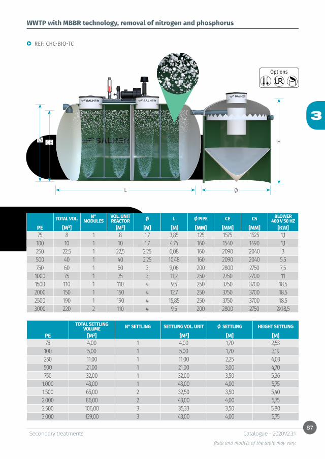
87
3
Ø
HCEØ
L
Secondary treatments Data and models of the table may vary.
Catalogue - 2020V2.3.1
REF: CHC-BIO-TC
WWTP with MBBR technology, removal of nitrogen and phosphorus
TOTAL VOL. N° MODULES
VOL. UNIT REACTOR Ø L Ø PIPE CE CS BLOWER
400 V 50 HZPE [M³] [M³] [M] [M] [MM] [MM] [MM] [KW]75 8 1 8 1,7 3,85 125 1575 1525 1,1
100 10 1 10 1,7 4,74 160 1540 1490 1,1250 22,5 1 22,5 2,25 6,08 160 2090 2040 3500 40 1 40 2,25 10,48 160 2090 2040 5,5750 60 1 60 3 9,06 200 2800 2750 7,5
1000 75 1 75 3 11,2 250 2750 2700 111500 110 1 110 4 9,5 250 3750 3700 18,52000 150 1 150 4 12,7 250 3750 3700 18,52500 190 1 190 4 15,85 250 3750 3700 18,53000 220 2 110 4 9,5 200 2800 2750 2X18,5
Options
TOTAL SETTLING VOLUME N° SETTLING SETTLING VOL. UNIT Ø SETTLING HEIGHT SETTLING
PE [M³] [M³] [M] [M]75 4,00 1 4,00 1,70 2,53
100 5,00 1 5,00 1,70 3,19250 11,00 1 11,00 2,25 4,03500 21,00 1 21,00 3,00 4,70750 32,00 1 32,00 3,50 5,36
1.000 43,00 1 43,00 4,00 5,751.500 65,00 2 32,50 3,50 5,402.000 86,00 2 43,00 4,00 5,752.500 106,00 3 35,33 3,50 5,803.000 129,00 3 43,00 4,00 5,75

88
3
CEØ CS
L
Secondary treatments Data and models of the table may vary.
Catalogue - 2020V2.3.1
WWTP with MBBR technology, removal of nitrogen and phosphorus
REF: CHC-FS-BIO-C
Options
TOTAL VOL. N° MODULES VOL. UNIT Ø L Ø PIPE CE CS BLOWER
400V 50HZPE [M³] [M³] [M] [M] [MM] [MM] [MM] [KW]75 15 1 15 1,70 6,93 125 1.875 1.825 1,1
100 20 1 20 2,00 6,70 160 1.840 1.790 1,1250 45 1 45 2,25 11,70 160 2.090 2.040 3500 90 1 90 3,00 13,25 160 2.840 2.790 5,5750 130 1 130 3,50 14,20 200 3.300 3.250 7,5
1.000 150 1 150 4,00 12,70 200 3.800 3.750 111.500 240 2 120 3,50 13,10 200 3.300 3.250 7,52.000 300 2 150 4,00 12,70 200 3.800 3.750 2X112.500 380 2 190 4,00 15,87 250 3.750 3.700 2X153.000 450 3 150 4,00 12,70 200 3.800 3.750 3X11,00
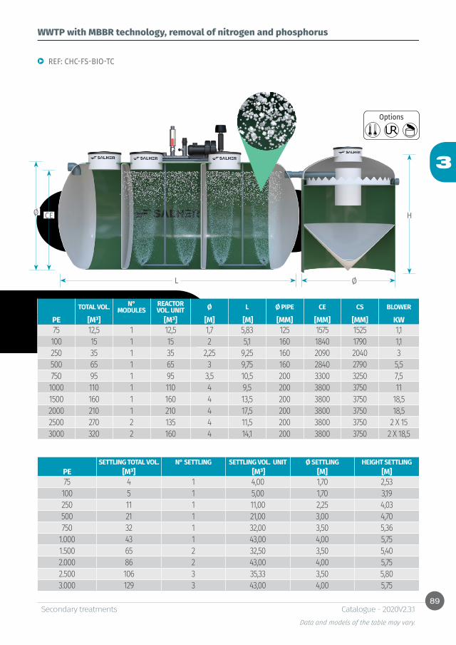
89
3
Ø
HCEØ
L
Secondary treatments Data and models of the table may vary.
Catalogue - 2020V2.3.1
WWTP with MBBR technology, removal of nitrogen and phosphorus
REF: CHC-FS-BIO-TC
TOTAL VOL. N° MODULES
REACTOR VOL. UNIT Ø L Ø PIPE CE CS BLOWER
PE [M³] [M³] [M] [M] [MM] [MM] [MM] KW75 12,5 1 12,5 1,7 5,83 125 1575 1525 1,1
100 15 1 15 2 5,1 160 1840 1790 1,1250 35 1 35 2,25 9,25 160 2090 2040 3500 65 1 65 3 9,75 160 2840 2790 5,5750 95 1 95 3,5 10,5 200 3300 3250 7,5
1000 110 1 110 4 9,5 200 3800 3750 111500 160 1 160 4 13,5 200 3800 3750 18,52000 210 1 210 4 17,5 200 3800 3750 18,52500 270 2 135 4 11,5 200 3800 3750 2 X 153000 320 2 160 4 14,1 200 3800 3750 2 X 18,5
Options
SETTLING TOTAL VOL. N° SETTLING SETTLING VOL. UNIT Ø SETTLING HEIGHT SETTLINGPE [M³] [M³] [M] [M]75 4 1 4,00 1,70 2,53
100 5 1 5,00 1,70 3,19250 11 1 11,00 2,25 4,03500 21 1 21,00 3,00 4,70750 32 1 32,00 3,50 5,36
1.000 43 1 43,00 4,00 5,751.500 65 2 32,50 3,50 5,402.000 86 2 43,00 4,00 5,752.500 106 3 35,33 3,50 5,803.000 129 3 43,00 4,00 5,75

90
3
CEØ CS
L
Secondary treatments Data and models of the table may vary.
Catalogue - 2020V2.3.1
WWTP with MBBR technology, removal of nitrogen and phosphorus
REF: CHC-ANOX-BIO-C
Options
REACTOR TOTAL VOL.
N° MODULES
VOL. UNIT Ø L Ø PIPE CE CS AGITATOR REC.
PUMP BLOWER
PE [M³] [M³] [M] [M] [MM] [MM] [MM] (KW) (KW) (KW)75 20 1 20 2,25 5,45 125 2.125 2.075 0,55 0,55 1,10
100 25 1 25 2,25 6,70 125 2.125 2.075 0,55 0,55 1,10250 55 1 55 2,50 11,68 160 2.840 2.790 0,55 0,55 3,00500 110 1 110 4,00 9,50 160 3.840 3.790 0,55 0,55 5,50750 160 1 160 4,00 13,50 200 3.800 3.750 0,55 0,55 7,50
1.000 210 1 210 4,00 17,50 200 3.800 3.750 0,55 0,55 7,501.500 310 2 155 4,00 13,09 200 3.800 3.750 2X0,55 2X0,55 2X11,002.000 420 2 210 4,00 17,50 200 3.800 3.750 2X0,55 2X0,55 2X15,002.500 510 3 170 4,00 14,30 200 3.800 3.750 3X0,55 3X0,55 3X15,003.000 630 3 210 4,00 17,50 200 3.800 3.750 3X0,55 3X0,55 3X15,00
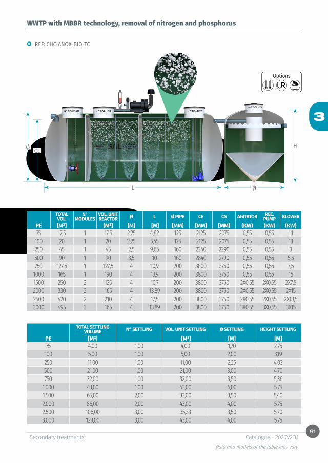
91
3
Ø
HCEØ
L
Secondary treatments Data and models of the table may vary.
Catalogue - 2020V2.3.1
WWTP with MBBR technology, removal of nitrogen and phosphorus
REF: CHC-ANOX-BIO-TC
TOTAL VOL.
N° MODULES
VOL. UNIT REACTOR Ø L Ø PIPE CE CS AGITATOR REC.
PUMP BLOWER
PE [M³] [M³] [M] [M] [MM] [MM] [MM] (KW) (KW) (KW)75 17,5 1 17,5 2,25 4,82 125 2125 2075 0,55 0,55 1,1
100 20 1 20 2,25 5,45 125 2125 2075 0,55 0,55 1,1250 45 1 45 2,5 9,65 160 2340 2290 0,55 0,55 3500 90 1 90 3,5 10 160 2840 2790 0,55 0,55 5,5750 127,5 1 127,5 4 10,9 200 3800 3750 0,55 0,55 7,5
1000 165 1 190 4 13,9 200 3800 3750 0,55 0,55 151500 250 2 125 4 10,7 200 3800 3750 2X0,55 2X0,55 2X7,52000 330 2 165 4 13,89 200 3800 3750 2X0,55 2X0,55 2X152500 420 2 210 4 17,5 200 3800 3750 2X0,55 2X0,55 2X18,53000 495 3 165 4 13,89 200 3800 3750 3X0,55 3X0,55 3X15
Options
TOTAL SETTLING VOLUME N° SETTLING VOL. UNIT SETTLING Ø SETTLING HEIGHT SETTLING
PE [M³] [M³] [M] [M]75 4,00 1,00 4,00 1,70 2,75
100 5,00 1,00 5,00 2,00 3,19250 11,00 1,00 11,00 2,25 4,03500 21,00 1,00 21,00 3,00 4,70750 32,00 1,00 32,00 3,50 5,36
1.000 43,00 1,00 43,00 4,00 5,751.500 65,00 2,00 33,00 3,50 5,402.000 86,00 2,00 43,00 4,00 5,752.500 106,00 3,00 35,33 3,50 5,703.000 129,00 3,00 43,00 4,00 5,75

92
3
CEØCS
L
Secondary treatments Data and models of the table may vary.
Catalogue - 2020V2.3.1
WWTP with MBBR technology, removal of nitrogen and phosphorus
REF: CHC – FS - ANOX – BIO – C
Options
TOTAL VOL.
N° MODULES
VOL. UNIT Ø L Ø PIPE CE CS AGITATOR REC. PUMP BLOWER
PE [M³] [M³] [M] [M] [MM] [MM] [MM] (KW) (KW) (KW)75 25 1 25 2,25 6,7 125 2.125 2.075 0,55 0,55 1,10
100 30 1 30 2,25 8 160 2.090 2.040 0,55 0,55 1,10250 70 1 70 3 10,5 160 2.840 2.790 0,55 0,55 3,00500 130 1 130 3,5 14,2 160 3.340 3.290 0,55 0,55 5,50750 195 1 195 4 16,27 200 3.800 3.750 0,55 0,55 7,50
1.000 230 2 115 4 9,5 200 3.800 3.750 2X0,55 2X0,55 2X7,501.500 340 2 170 4 14,3 200 3.800 3.750 2X0,55 2X0,55 2X11,002.000 450 3 150 4 12,7 200 3.800 3.750 3X0,55 3X0,55 2X11,002.500 570 3 190 4 15,87 200 3.800 3.750 3X0,55 3X0,55 3X15,003.000 680 4 170 4 14,3 200 3.800 3.750 4X0,55 4X0,55 4X15,00
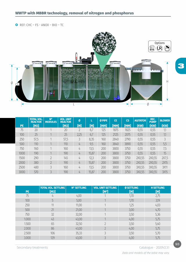
93
3
Ø
HCEØ
L
Secondary treatments Data and models of the table may vary.
Catalogue - 2020V2.3.1
WWTP with MBBR technology, removal of nitrogen and phosphorus
REF: CHC – FS - ANOX – BIO – TC
TOTAL VOL. REACTOR
N° MODULES
VOL. UNIT REACTOR Ø L Ø PIPE CE CS AGITATOR REC.
PUMP BLOWER
PE [M3] [M3] [M] [M] [MM] [MM] [MM] (KW) (KW) (KW)75 20 1 20 2 6,7 125 1875 1825 0,55 0,55 1,1
100 25 1 25 2,25 6,7 125 2125 2075 0,55 0,55 1,1250 57,5 1 57,5 3 8,35 160 2840 2790 0,55 0,55 3500 110 1 110 4 9,5 160 3840 3890 0,55 0,55 5,5750 160 1 160 4 13,5 200 3800 3750 0,55 0,55 7,5
1000 190 1 190 4 15,87 200 3800 3750 0,55 0,55 151500 290 2 145 4 12,3 200 3800 3750 2X0,55 2X0,55 2X7,52000 380 2 190 4 15,87 200 3800 3750 2X0,55 2X0,55 2X152500 480 3 160 4 13,5 200 3800 3750 3X0,55 3X0,55 3X113000 570 3 190 4 15,87 200 3800 3750 3X0,55 3X0,55 3X15
Options
TOTAL VOL. SETTLING N° SETTLING VOL. UNIT SETTLING Ø SETTLING H SETTLINGPE [M3] [M³] [M] [M]75 4 4,00 1 1,70 2,75
100 5 5,00 1 1,70 3,19250 11 11,00 1 1,25 4,03500 21 21,00 1 3,00 4,70750 32 32,00 1 3,50 5,36
1.000 43 43,00 1 4,00 5,751.500 65 32,50 2 3,50 5,402.000 86 43,00 2 4,00 5,752.500 106 35,33 3 3,50 5,703.000 129 43,00 3 4,00 5,75

94
3
Secondary treatments Data and models of the table may vary.
Catalogue - 2020V2.3.1
Function:
Characteristics:
WWTP with biomembranesSecondary treatment with membrane bioreactor (MBR), with nitrogen removal (nitrification-denitrification) in option
REF: CHC-OXI-MBR
• High efficiency removal of organic matter, suspended solids and ammonia.
• System suitable for reuse of treated wastewater.
• Technology: membrane bioreactor (MBR). Biological treatment with separation of biomass from clarified water by ultrafiltration membranes at atmospheric pressure.
• Equipment Salher brand, compact, modular, very efficient, easy installation and operation.
• Manufactured in GFRP (Glass Fiber Reinforced Polyester), certified.
• Ultrafiltration membrane with pore diameter < 0,1 µm.
• Effluent suitable for reuse in accordance with RD1620/2007.
• High quality effluent with separation solid/liquid.• High efficiency: BOD5: 99%; COD: 95%; N-NH4+ : 82%;
TSS: 99%; faecal coliforms: 99,9%.
Advantages:
• High quality of the effluent. Water suitable for reuse in accordance with RD1620/2007. Effluent 100% free of virus, bacteria and other pathogens.
• Reduction of the surface required compared with traditional technologies: 65-75%. Removal of secondary settling tank and reduction of biological reactor volume.
• Secondary settling tank replaced by ultrafiltration membranes. Technology with excellent separation clarified water/sludge. No problem linked to sludge settling.
• Flexibility increased to face peak flows and contaminating loads.
• No smell. No bulking problem.• Sludge quantity is lower and more stable. High
sludge age and less mass loads.• High level of automation.
Options

95
3
Secondary treatments Data and models of the table may vary.
Catalogue - 2020V2.3.1
WWTP with biomembranesSecondary treatment with membrane bioreactor (MBR), with nitrogen removal (nitrification-denitrification) in option
REF: CHC-OXI-MBR
Q VOL. MBR TANK
Ø MBR TANK H L MBR
TANKVOL.
BIOLOGICAL REACTOR
Ø MBR TANK
L MBR TANK
(M³/DAY) N° SKID N° MEMBRANES / SKID [M3] [MM] [MM] [MM] [M3] [MM] [MM]
25 1 5 5,00 1.400 3.000 13 2.000 4.37550 2 5 10,25 2.250 2.870 25 2.500 5.59050 1 10 5,00 1.400 3.000 25 2.500 5.59075 3 5 13,65 2.250 3.720 35 2.500 7.610
100 4 5 17,00 2.250 4.570 45 2.500 9.660100 2 10 10,25 2.250 2.870 45 2.500 9.660100 1 20 7,00 1.700 3.000 45 2.500 9.660125 5 5 20,40 2.250 5.420 55 2.500 11.700150 3 10 13,65 2.250 3.720 60 2.500 12.710150 6 5 23,75 2.250 6.270 60 2.500 12.710175 7 5 27,15 2.250 7.120 70 3.000 10.500200 1 40 10,00 2.000 3.000 75 3.000 11.200200 2 20 19,15 2.500 4.310 75 3.000 11.200200 4 10 17,00 2.250 4.570 75 3.000 11.200200 8 5 30,50 2.250 8.000 75 3.000 11.200225 9 5 34,00 2.250 8.820 85 3.000 12.550250 5 10 20,40 2.250 5.420 95 3.500 10.500250 10 5 37,25 2.250 9.670 95 3.500 10.500300 3 20 26,40 2.500 5.780 110 3.500 12.120300 6 10 23,75 2.250 6.270 110 3.500 12.120350 7 10 27,15 2.250 7.120 130 3.500 14.200400 2 40 28,70 3.000 4.570 140 3.500 15.240400 4 20 33,60 2.500 7.250 140 3.500 15.240400 8 10 30,53 2.250 8.000 140 3.500 15.240450 9 10 33,90 2.250 8.800 155 4.000 13.050500 5 20 40,80 2.500 8.720 170 4.000 14.250500 10 10 37,30 2.250 9.670 170 4.000 14.250600 3 40 39,00 3.000 6.040 200 4.000 16.600600 6 20 48,00 2.500 10.190 200 4.000 16.600700 7 20 55,00 2.500 11.660 2 X 120 3.500 13.160800 4 40 49,50 3.000 7.500 2 X 135 3.500 14.700800 8 20 62,50 2.500 13.130 2 X 135 3.500 14.700900 9 20 70,00 2.500 14.600 2 X 150 4.000 12.6501.000 5 40 60,00 3.000 9.000 2 X 165 4.000 13.8501.000 10 20 77,00 2.500 16.000 2 X 165 4.000 13.850
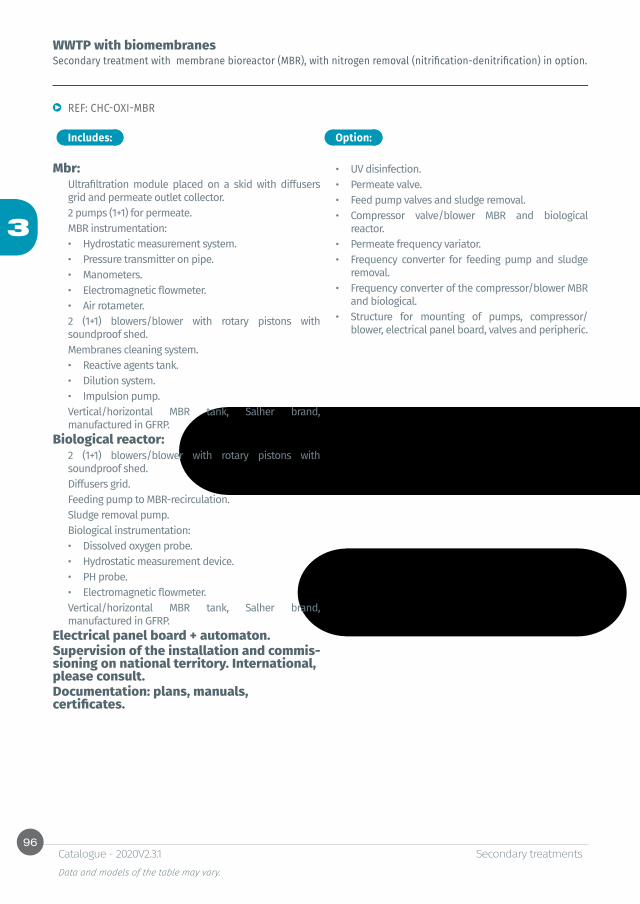
96
3
Secondary treatments Data and models of the table may vary.
Catalogue - 2020V2.3.1
WWTP with biomembranesSecondary treatment with membrane bioreactor (MBR), with nitrogen removal (nitrification-denitrification) in option.
REF: CHC-OXI-MBR
Includes:
Mbr:Ultrafiltration module placed on a skid with diffusers grid and permeate outlet collector. 2 pumps (1+1) for permeate.MBR instrumentation:• Hydrostatic measurement system.• Pressure transmitter on pipe.• Manometers.• Electromagnetic flowmeter.• Air rotameter.2 (1+1) blowers/blower with rotary pistons with soundproof shed.Membranes cleaning system.• Reactive agents tank.• Dilution system.• Impulsion pump.Vertical/horizontal MBR tank, Salher brand, manufactured in GFRP.
Biological reactor:2 (1+1) blowers/blower with rotary pistons with soundproof shed.Diffusers grid.Feeding pump to MBR-recirculation.Sludge removal pump.Biological instrumentation:• Dissolved oxygen probe.• Hydrostatic measurement device.• PH probe.• Electromagnetic flowmeter.Vertical/horizontal MBR tank, Salher brand, manufactured in GFRP.
Electrical panel board + automaton.Supervision of the installation and commis-sioning on national territory. International, please consult.Documentation: plans, manuals, certificates.
Option:
• UV disinfection.• Permeate valve.• Feed pump valves and sludge removal.• Compressor valve/blower MBR and biological
reactor.• Permeate frequency variator.• Frequency converter for feeding pump and sludge
removal.• Frequency converter of the compressor/blower MBR
and biological.• Structure for mounting of pumps, compressor/
blower, electrical panel board, valves and peripheric.
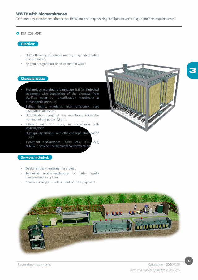
97
3
Secondary treatments Data and models of the table may vary.
Catalogue - 2020V2.3.1
WWTP with biomembranesTreatment by membranes bioreactors (MBR) for civil engineering. Equipment according to projects requirements.
REF: OXI-MBR
Function:
Characteristics:
• High efficiency of organic matter, suspended solids and ammonia.
• System designed for reuse of treated water.
• Technology membrane bioreactor (MBR). Biological treatment with separation of the biomass from clarified water by ultrafiltration membrane at atmospheric pressure.
• Salher brand, modular, high efficiency, easy installation and start.
• Ultrafiltration range of the membrane (diameter nominal of the pore < 0,1 µm).
• Effluent valid for reuse, in accordance with RD1620/2007.
• High quality effluent with efficient separation solid/liquid.
• Treatment performance: BOD5: 99%; COD: 95%; N-NH4+ : 82%; SST: 99%; faecal coliforms: 99.9%
Services included:
• Design and civil engineering project. • Technical recommendations on site. Works
management in option. • Commissioning and adjustment of the equipment.

98
3
Secondary treatments Data and models of the table may vary.
Catalogue - 2020V2.3.1
Function:
Characteristics:
Portable and containerized WWTPPortable WWTP by low-load activated sludge (extended aeration) for underground or aboveground installation
• Organic matter removal (BOD5).
• Salher brand, model 20P/40P.• Manufactured in GFRP (Glass Fiber Reinforced
Polyester) with orthophthalic resins and placed in containers.
• Water treatment plants can be placed in containers (activated sludge, moving bed biological reactor, bio-membranes).
• In standard containers (20 ‘or 40’).• Easy to transport and install.• Completely compact.• Possibility to place a technical compartment for
panel board and equipment.
REF: 20P/40P

99
3
Secondary treatments Data and models of the table may vary.
Catalogue - 2020V2.3.1
Function:
Characteristics:
MODULAR PLANTS WITH PLATES
• Urban and industrial wastewater treatment for large flows.
• The modularity of these elements facilitates shipment and installation worldwide.
• Mixed treatment systems.• Modular tanks composed of mechanical and
chemical resistant plates, easy to transport and install, for under and half underground installation.
• Technical design, engineering, installation or works management in option.

100
3
Secondary treatments Data and models of the table may vary.
Catalogue - 2020V2.3.1
Function:
Characteristics:
WWTP with trickling filterWastewater treatment plant with biological filter or recirculated trickling filter
REF: IMH-LBR-TC
• Organic matter removal (BOD5).• Removal of suspended solids (SS).
• Salher brand, model IMH-LBR-TC.• Manufactured in GFRP (Glass Fiber Reinforced
Polyester) with orthophthalic resins.• Organic matter removal efficiency: 85-90% BOD5.• Suspended solids removal efficiency: 90% SS.• Primary treatment by settling-digestion process
(Imhoff tank).• Secondary treatment by recirculated trickling
filter, fed by a rotary distributor (rotary arm), drain system and natural air vent.
• Plastic filling material with high porosity rate (95%) and large specific surface (140 m²/m³).
• Pumping station to feed the biological filter including pump with level regulation system. Option: 2 pumps in automatic alternate functioning.
• Secondary truncated settling tank with central feeding and Thompson canal.
• Sludge removal system to the digestion chamber of the Imhoff tank composed of a submerged pump with auto-coupling removal system.
• Partial or complete recirculation of the treated water to increase the treatment efficiency.
• PVC inlet and outlet.• Manholes with GFRP cover.• Outlet in the manhole to install a ventilation pipe.
Options
IMHOFF TANK SETTLINGMANHOLE
SLBR
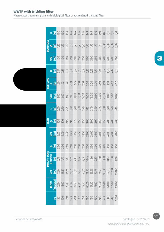
101
3
Secondary treatments Data and models of the table may vary.
Catalogue - 2020V2.3.1
WWTP with trickling filterWastewater treatment plant with biological filter or recirculated trickling filter
IMHO
FF TA
NKSL
BRSE
TTLI
NGM
ANHO
LEFL
OWVO
L.LE
NGTH
ØVO
LØ
H VO
LØ
H
VOL
Ø
H PE
[M3/
DAY]
[M3]
[M]
[M]
[M3]
[M]
[M]
[M3]
[M]
[M]
[M3]
[M]
[M]
507,5
07,5
02,7
92,0
03,0
01,2
02,6
02,0
01,2
02,1
71,0
01,2
01,0
010
015
,0013
,504,7
02,0
06,0
01,7
02,6
04,0
01,7
02,3
31,0
01,2
01,0
015
022
,5018
,754,3
22,5
09,0
02,0
02,7
56,0
01,7
03,2
11,5
01,2
01,4
520
030
,0026
,255,8
52,5
011,
002,0
03,4
08,0
02,0
03,2
11,5
01,2
01,4
525
037
,5033
,757,3
82,5
013
,502,2
53,4
010
,002,2
53,2
72,0
01,4
01,4
430
045
,0037
,508,1
42,5
016
,502,5
03,3
012
,002,5
03,2
82,5
01,4
01,7
635
052
,5045
,009,6
72,5
018
,502,5
03,7
014
,002,5
03,6
92,5
01,4
01,7
640
060
,0048
,7510
,442,5
022
,003,0
03,1
016
,003,0
03,2
63,0
01,7
01,4
945
067
,5056
,2511,
962,5
024
,003,0
03,4
018
,003,0
03,5
53,0
01,7
01,4
950
075
,0063
,759,6
03,0
026
,003,0
03,7
020
,003,0
03,8
33,5
01,7
01,7
060
090
,0075
,0011,
303,0
033
,003,5
03,3
523
,003,5
03,5
64,0
01,7
01,9
370
010
5,00
90,00
13,30
3,00
36,50
3,50
3,80
27,00
3,50
3,97
5,00
2,00
1,80
800
120,0
097
,5010
,803,5
043
,004,0
03,4
030
,003,5
04,2
86,0
02,0
02,1
190
013
5,00
112,50
11,30
3,50
47,00
4,00
3,70
35,00
4,00
4,12
6,00
2,00
2,11
1.000
150,0
012
0,00
13,16
3,50
51,00
4,00
4,10
40,00
4,00
4,52
7,00
2,00
2,41
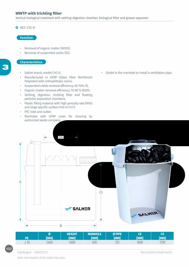
102
3
Ø
CS
H
ØB
Secondary treatments Data and models of the table may vary.
Catalogue - 2020V2.3.1
Function:
Characteristics:
WWTP with trickling filterVertical biological treatment with settling-digestion chamber, biological filter and grease separator
REF: CVC-D
• Removal of organic matter (BOD5).• Removal of suspended solids (SS).
• Salher brand, model CVC-D.• Manufactured in GFRP (Glass Fiber Reinforced
Polyester) with orthophthalic resins.• Suspended solids removal efficiency: 65-70% SS.• Organic matter removal efficiency: 70-80 % BOD5.• Settling, digestion, trickling filter and floating
particles separation chambers.• Plastic filling material with high porosity rate (95%)
and large specific surface (140 m²/m³).• PVC inlet and outlet.• Manholes with GFRP cover for cleaning by
authorized waste company.
• Outlet in the manhole to install a ventilation pipe.
Ø HEIGHT MANHOLE Ø PIPE CE CSPE [MM] [MM] [MM] [MM] [MM] [MM]
≤ 10 1.400 1.600 620 125 1600 1.150

103
3
Secondary treatments Data and models of the table may vary.
Catalogue - 2020V2.3.1

104
3
Secondary treatments Data and models of the table may vary.
Catalogue - 2020V2.3.1
Function:
Characteristics:
WWTP with trickling filterHorizontal biological treatment with settling-digestion chamber and biological filter
REF: CHC-D
• Removal of organic matter (BOD5).• Removal of suspended solids (SS).
• Salher brand, model CHC-D.• Manufactured in GFRP (Glass Fiber Reinforced
Polyester) with orthophthalic resins.• Suspended solids removal efficiency: 65-70% SS.• Organic matter removal efficiency: 70 - 80 % BOD5.• Primary treatment by settling-digestion.• Secondary treatment consisting in trickling filter
fed by fixed distributor, drain in the lower part and natural air vent.
• Plastic filling material with high porosity rate (95%) and large specific surface (140 m²/m³).
• PVC inlet and outlet.
• Manholes with GFRP cover for cleaning by authorized waste company.
• Outlet in the manhole to install a ventilation pipe.
Options
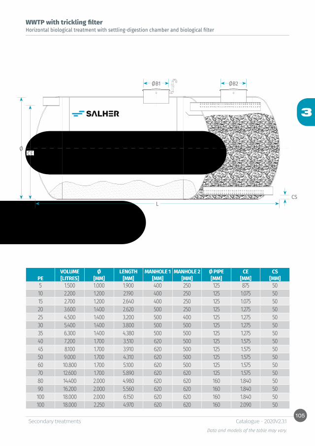
105
3
Ø
L
CE
CS
ØB1 ØB2
Secondary treatments Data and models of the table may vary.
Catalogue - 2020V2.3.1
WWTP with trickling filterHorizontal biological treatment with settling-digestion chamber and biological filter
VOLUME Ø LENGTH MANHOLE 1 MANHOLE 2 Ø PIPE CE CSPE [LITRES] [MM] [MM] [MM] [MM] [MM] [MM] [MM]5 1.500 1.000 1.900 400 250 125 875 5010 2.200 1.200 2.190 400 250 125 1.075 5015 2.700 1.200 2.640 400 250 125 1.075 5020 3.600 1.400 2.620 500 250 125 1.275 5025 4.500 1.400 3.200 500 400 125 1.275 5030 5.400 1.400 3.800 500 500 125 1.275 5035 6.300 1.400 4.380 500 500 125 1.275 5040 7.200 1.700 3.510 620 500 125 1.575 5045 8.100 1.700 3.910 620 500 125 1.575 5050 9.000 1.700 4.310 620 500 125 1.575 5060 10.800 1.700 5.100 620 500 125 1.575 5070 12.600 1.700 5.890 620 620 125 1.575 5080 14.400 2.000 4.980 620 620 160 1.840 5090 16.200 2.000 5.560 620 620 160 1.840 50100 18.000 2.000 6.150 620 620 160 1.840 50100 18.000 2.250 4.970 620 620 160 2.090 50
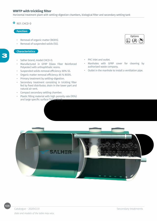
106
3
Secondary treatments Data and models of the table may vary.
Catalogue - 2020V2.3.1
Function:
Characteristics:
WWTP with trickling filterHorizontal treatment plant with settling-digestion chambers, biological filter and secondary settling tank
REF: CHCD-D
• Removal of organic matter (BOD5).• Removal of suspended solids (SS).
• Salher brand, model CHCD-D.• Manufactured in GFRP (Glass Fiber Reinforced
Polyester) with orthophthalic resins.• Suspended solids removal efficiency: 80% SS.• Organic matter removal efficiency: 85 % BOD5.• Primary treatment by settling-digestion. • Secondary treatment consisting in trickling filter
fed by fixed distributor, drain in the lower part and natural air vent.
• Compact secondary settling chamber. • Plastic filling material with high porosity rate (95%)
and large specific surface (140 m²/m³).
• PVC inlet and outlet.• Manholes with GFRP cover for cleaning by
authorized waste company.• Outlet in the manhole to install a ventilation pipe.
Options
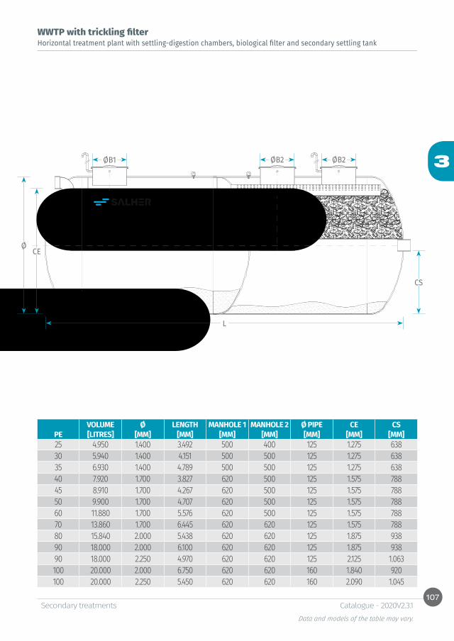
107
3
Ø
L
CE
CS
ØB1 ØB2 ØB2
Secondary treatments Data and models of the table may vary.
Catalogue - 2020V2.3.1
WWTP with trickling filterHorizontal treatment plant with settling-digestion chambers, biological filter and secondary settling tank
VOLUME Ø LENGTH MANHOLE 1 MANHOLE 2 Ø PIPE CE CSPE [LITRES] [MM] [MM] [MM] [MM] [MM] [MM] [MM]25 4.950 1.400 3.492 500 400 125 1.275 63830 5.940 1.400 4.151 500 500 125 1.275 63835 6.930 1.400 4.789 500 500 125 1.275 63840 7.920 1.700 3.827 620 500 125 1.575 78845 8.910 1.700 4.267 620 500 125 1.575 78850 9.900 1.700 4.707 620 500 125 1.575 78860 11.880 1.700 5.576 620 500 125 1.575 78870 13.860 1.700 6.445 620 620 125 1.575 78880 15.840 2.000 5.438 620 620 125 1.875 93890 18.000 2.000 6.100 620 620 125 1.875 93890 18.000 2.250 4.970 620 620 125 2.125 1.063100 20.000 2.000 6.750 620 620 160 1.840 920100 20.000 2.250 5.450 620 620 160 2.090 1.045

108
3
Ø
CS
H
ØB
CE
Secondary treatments Data and models of the table may vary.
Catalogue - 2020V2.3.1
Function:
Characteristics:
WWTP with trickling filterTrickling filter or bacteria bed
REF: CVC-FB
• Removal of organic matter (BOD5).
• Salher brand, model CVC-FB.• Manufactured in GFRP (Glass Fiber Reinforced
Polyester) with orthophthalic resins.• Organic matter removal efficiency: 80-90% BOD5.• Secondary treatment consisting in trickling filter
fed by fixed distributor, drain in the lower part and natural air vent.
• Plastic filling material with high porosity rate (95%) and large specific surface (140 m²/m³).
• PVC inlet and outlet.• Manholes with GFRP cover.• Outlet in the manhole to install a ventilation pipe.
Options
VOLUME Ø LENGTH MANHOLE Ø PIPE CE CSPE [LITRES] [MM] [MM] [MM] [MM] [MM] [MM]5-10 500 1.000 750 400 125 570 5015 750 1.000 1.070 400 125 890 5020 1.000 1.000 1.320 400 125 1.200 5025 1.250 1.400 950 400 125 680 5030 1.500 1.400 1.110 400 125 840 5035 1.750 1.400 1.270 400 125 1.000 5040 2.000 1.700 1.050 400 125 700 5045 2.250 1.700 1.160 400 125 810 5050 2.500 1.700 1.270 500 125 920 5060 3.000 1.700 1.490 500 125 1.104 5070 3.500 1.700 1.710 500 125 1.360 5080 4.000 2.000 1.480 620 160 1.040 5090 4.500 2.000 1.640 620 160 890 50

109
3
Secondary treatments Data and models of the table may vary.
Catalogue - 2020V2.3.1


4Tertiary treatments


Table of contentsIntroduction to reuse systems
114
Grey water and treated water reuseCompact plant for grey and treated water reuse for several applicationsREF: GRISAL-AUT 116
Reuse of treated industrial water for vehi-cles cleaning
2.2. Compact plant for reuse of industrial treated wastewater issued from vehicles washing automatic systemsREF: LAVA-E 118
Reuse of wastewater, rainwater and treated water by high efficiency membranes
2.3. Compact plant for water reuse by utrafiltration technologyREF: UF-AUT 121
Rainwater reuse 2.4 Rainwater treatment plantREF: SAL-PLU 122Rainwater recycling and treatmentREF: RAP 124
Other dimensions and configurations can be provided upon request. Internal dimensions. Dimensions in millimeters. Volumes in liters, the dimensions indicated may vary according to the needs.Due to its policy of continuous development, Salher Ibérica, S.L. reserves the right to modify the data that appear in this document without notice.This document is protected by the intellectual property law, so that the customer cannot claim, manipulate or duplicate this documentation, except copy for personal use.
114
4
Tertiary treatmentsData and models of the table may vary.
Catalogue - 2020V2.3.1
1. Water reuse systems
Salher provides tertiary treatment equipment for water reuse in accordance with the final quality and use required.
SALHER equipment is manufactured in accordance with “RD 1620/2007, December 7th”, establishing a legal system for treated water. Salher provides also a range of equipment for rainwater treatment.There are several treatment systems according to the final use: • Compliance with quality standards 1.1: RESIDENTIAL:
-Private garden watering. -Toilet flush refill.
• Compliance with quality standards 1.2: SERVICES: -Urban green area watering (parks, sport area, street cleaning, etc.), forests, fields.
• Compliance with quality standards 1.2: SERVICES: -Vehicles industrial cleaning.
• Compliance with quality standards 3.1: INDUSTRIAL: -Reuse of industrial and cleaning process, except food industry.
• Compliance with quality standards 4: ENTERTAINMENT: -Golf course watering.
Other reuse systems can be designed upon request.
This system can be placed on a structure, connected with all the components, or independent for a future installation.
The reuse station, SALHER brand, is a set of refining equipment (tertiary treatment) to treat: • Grey water (issued from showers, baths and sinks).• Treated wastewater (urban and industrial).
Obtaining high quality water for different final reuse in accordance with maximum values fixed by RD1620/2007.
Reuse systems are composed of the following elements:
• Ultrafiltration systems: -Function: removal of traces and micropollutants. Effluent 100% free of virus, bacteria and other pathogens. High quality water for reuse. -Equipment:
* Filtration modules composed of ultrafiltration membranes (nominal diameter of the pore < 0,1 µm).
* Structure in GFRP, with prefilter mounting, UF membranes, peripheric, instrumentation, cleaning system and electrical panel board.
• High efficiency filtration systems: -Function: removal of suspended solids. -Equipment:
* High efficiency filters with filling material depending on final use.
* Ring filters.* Cartridge filters.
• Activated carbon filtration systems:
Introduction to reuse systems
-Function: removal of organic matter, free chlorine, deodorization and water discolouration. -Equipment:
* High efficiency filters with filling material depending on final use.
• Disinfection systems: -Function: removal of pathogen germs, disinfection of treated wastewater with high turbidity or colour and maintenance of water quality in tank. -Equipment:
* Chlorination.* UV radiation.
115
4
Tertiary treatmentsData and models of the table may vary.
Catalogue - 2020V2.3.1
2. Compact water reuse plants
• Removal of suspended solids, organic matter, intestinal nematodes, turbidity and free chlorine, and water deodorization and discolouration.
• Application: water reuse for different purposes in accordance with RD1620/2007.
Function:
Characteristics:
Compact equipment for water reuse in accordance with RD1620/2007.Tertiary system, Salher brand, with possibility of mounting on carbon steel structure, composed of the following elements, depending on final use:• High productivity filters in Glass Fiber Reinforced
Polyester (GFRP), with manual or automatic cleaning and different filling material (selected grain) according to final use.
• Cartridge/ring filters with several filtration levels according to final use.
• Activated carbon filters in GFRP (Glass Fiber Reinforced Polyester) with manual or automatic cleaning, filling material depending on the needs and granule according to final use.
• Supply system to tertiary treatment composed of submerged or auto-suction pumps, with regulation system and flow control, level float regulators, etc.
• Pre-chlorination composed of dosing pumps with impulse frequency regulation, proportional to the flow controlled by a pulse meter transmitter.
• UV radiation generator with stainless steel radiation chamber, high technology UV lamps, electronic control module with acoustic and visual alarm in the event of lamp failure. Timer and alarm for lamp, UV intensity sensor.
• Plant for colorant dosing.• Disinfection system on tank composed of
submerged or self-priming recirculation pump, with regulation system and flow control.
• Panel board for control and command of the tertiary treatment.
• Set of accessories composed of connections, valves, sampling points, regulation and control system, etc.
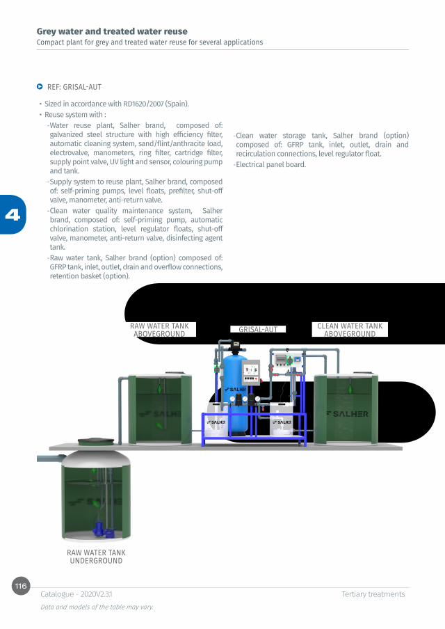
116
4
Tertiary treatmentsData and models of the table may vary.
Catalogue - 2020V2.3.1
Compact plant for grey and treated water reuse for several applicationsGrey water and treated water reuse
REF: GRISAL-AUT
• Sized in accordance with RD1620/2007 (Spain).• Reuse system with :
-Water reuse plant, Salher brand, composed of: galvanized steel structure with high efficiency filter, automatic cleaning system, sand/flint/anthracite load, electrovalve, manometers, ring filter, cartridge filter, supply point valve, UV light and sensor, colouring pump and tank. -Supply system to reuse plant, Salher brand, composed of: self-priming pumps, level floats, prefilter, shut-off valve, manometer, anti-return valve. -Clean water quality maintenance system, Salher brand, composed of: self-priming pump, automatic chlorination station, level regulator floats, shut-off valve, manometer, anti-return valve, disinfecting agent tank. -Raw water tank, Salher brand (option) composed of: GFRP tank, inlet, outlet, drain and overflow connections, retention basket (option).
-Clean water storage tank, Salher brand (option) composed of: GFRP tank, inlet, outlet, drain and recirculation connections, level regulator float. -Electrical panel board.
GRISAL-AUTRAW WATER TANK ABOVEGROUND
CLEAN WATER TANK ABOVEGROUND
RAW WATER TANK UNDERGROUND
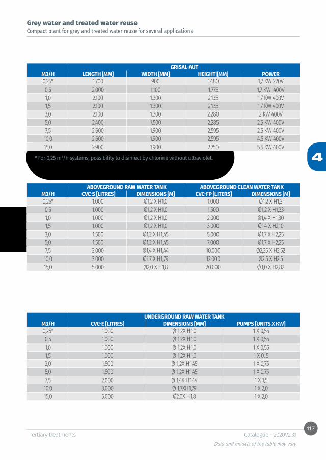
117
4
Tertiary treatmentsData and models of the table may vary.
Catalogue - 2020V2.3.1
* For 0,25 m3/h systems, possibility to disinfect by chlorine without ultraviolet.
Compact plant for grey and treated water reuse for several applicationsGrey water and treated water reuse
GRISAL-AUTM3/H LENGTH [MM] WIDTH [MM] HEIGHT [MM] POWER0,25* 1.700 900 1.480 1,7 KW 220V0,5 2.000 1.100 1.775 1,7 KW 400V1,0 2.100 1.300 2.135 1,7 KW 400V1,5 2.100 1.300 2.135 1,7 KW 400V3,0 2.100 1.300 2.280 2 KW 400V5,0 2.400 1.500 2.285 2,5 KW 400V7,5 2.600 1.900 2.595 2,5 KW 400V10,0 2.600 1.900 2.595 4,5 KW 400V15,0 2.900 1.900 2.750 5,5 KW 400V
ABOVEGROUND RAW WATER TANK ABOVEGROUND CLEAN WATER TANKM3/H CVC-S [LITRES] DIMENSIONS [M] CVC-FP [LITERS] DIMENSIONS [M]0,25* 1.000 Ø1,2 X H1,0 1.000 Ø1,2 X H1,30,5 1.000 Ø1,2 X H1,0 1.500 Ø1,2 X H1,331,0 1.000 Ø1,2 X H1,0 2.000 Ø1,4 X H1,301,5 1.000 Ø1,2 X H1,0 3.000 Ø1,4 X H2,103,0 1.500 Ø1,2 X H1,45 5.000 Ø1,7 X H2,255,0 1.500 Ø1,2 X H1,45 7.000 Ø1,7 X H2,257,5 2.000 Ø1,4 X H1,44 10.000 Ø2,25 X H2,5210,0 3.000 Ø1,7 X H1,79 12.000 Ø2,5 X H2,515,0 5.000 Ø2,0 X H1,8 20.000 Ø3,0 X H2,82
UNDERGROUND RAW WATER TANKM3/H CVC-E [LITRES] DIMENSIONS [MM] PUMPS [UNITS X KW]0,25* 1.000 Ø 1,2X H1,0 1 X 0,550,5 1.000 Ø 1,2X H1,0 1 X 0,551,0 1.000 Ø 1,2X H1,0 1 X 0,551,5 1.000 Ø 1,2X H1,0 1 X 0, 53,0 1.500 Ø 1,2X H1,45 1 X 0,755,0 1.500 Ø 1,2X H1,45 1 X 0,757,5 2.000 Ø 1,4X H1,44 1 X 1,510,0 3.000 Ø 1,7XH1,79 1 X 2,015,0 5.000 Ø2,0X H1,8 1 X 2,0
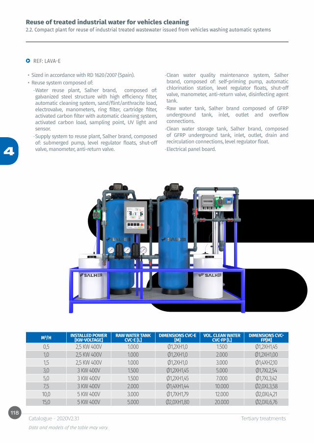
118
4
Tertiary treatmentsData and models of the table may vary.
Catalogue - 2020V2.3.1
2.2. Compact plant for reuse of industrial treated wastewater issued from vehicles washing automatic systemsReuse of treated industrial water for vehicles cleaning
• Sized in accordance with RD 1620/2007 (Spain).• Reuse system composed of:
-Water reuse plant, Salher brand, composed of: galvanized steel structure with high efficiency filter, automatic cleaning system, sand/flint/anthracite load, electrovalve, manometers, ring filter, cartridge filter, activated carbon filter with automatic cleaning system, activated carbon load, sampling point, UV light and sensor. -Supply system to reuse plant, Salher brand, composed of: submerged pump, level regulator floats, shut-off valve, manometer, anti-return valve.
-Clean water quality maintenance system, Salher brand, composed of: self-priming pump, automatic chlorination station, level regulator floats, shut-off valve, manometer, anti-return valve, disinfecting agent tank. -Raw water tank, Salher brand composed of GFRP underground tank, inlet, outlet and overflow connections. -Clean water storage tank, Salher brand, composed of GFRP underground tank, inlet, outlet, drain and recirculation connections, level regulator float. -Electrical panel board.
REF: LAVA-E
M³/H INSTALLED POWER [KW-VOLTAGE]
RAW WATER TANK CVC-E [L]
DIMENSIONS CVC-E [M]
VOL. CLEAN WATER CVC-FP [L]
DIMENSIONS CVC-FP[M]
0,5 2,5 KW 400V 1.000 Ø1,2XH1,0 1.500 Ø1,2XH1,451,0 2,5 KW 400V 1.000 Ø1,2XH1,0 2.000 Ø1,2XH1,001,5 2,5 KW 400V 1.000 Ø1,2XH1,0 3.000 Ø1,4XH2,103,0 3 KW 400V 1.500 Ø1,2XH1,45 5.000 Ø1,7XL2,545,0 3 KW 400V 1.500 Ø1,2XH1,45 7.000 Ø1,7XL3,427,5 3 KW 400V 2.000 Ø1,4XH1,44 10.000 Ø2,0XL3,5810,0 5 KW 400V 3.000 Ø1,7XH1,79 12.000 Ø2,0XL4,2115,0 5 KW 400V 5.000 Ø2,0XH1,80 20.000 Ø2,0XL6,76

119
4
Tertiary treatmentsData and models of the table may vary.
Catalogue - 2020V2.3.1
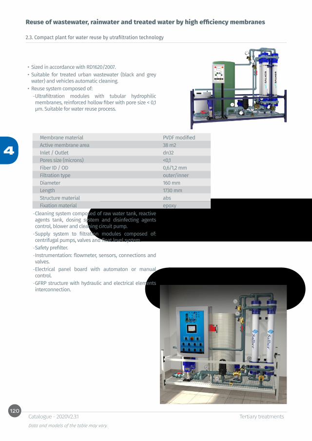
120
4
Tertiary treatmentsData and models of the table may vary.
Catalogue - 2020V2.3.1
Reuse of wastewater, rainwater and treated water by high efficiency membranes
2.3. Compact plant for water reuse by utrafiltration technology
• Sized in accordance with RD1620/2007.• Suitable for treated urban wastewater (black and grey
water) and vehicles automatic cleaning.• Reuse system composed of:
-Ultrafiltration modules with tubular hydrophilic membranes, reinforced hollow fiber with pore size < 0,1 μm. Suitable for water reuse process.
Membrane material PVDF modifiedActive membrane area 38 m2Inlet / Outlet dn32Pores size (microns) <0,1Fiber ID / OD 0,6/1,2 mmFiltration type outer/inner Diameter 160 mmLength 1730 mmStructure material absFixation material epoxy
-Cleaning system composed of raw water tank, reactive agents tank, dosing system and disinfecting agents control, blower and cleaning circuit pump. -Supply system to filtration modules composed of: centrifugal pumps, valves and float level system. -Safety prefilter. -Instrumentation: flowmeter, sensors, connections and valves. -Electrical panel board with automaton or manual control. -GFRP structure with hydraulic and electrical elements interconnection.

121
4
Tertiary treatmentsData and models of the table may vary.
Catalogue - 2020V2.3.1
REF: UF-AUT
UF-AUT
UNDERGROUND RAW WATER TANK
UNDERGROUND CLEAN WATER TANK
OPTION
ELECTROMAGNETIC FLOWMETER
WATER STORAGE TANK
UF-AUT
FLOW M³/H MIN./MAX. FLOW[M³/H]
N° CARTRIDGES
LENGTH [MM] WIDTH [MM] HEIGHT
[MM]POWER
INSTALLEDRAW WATER
TANK [LITRES]
RAW WATER TANK [MM]
2 (2,5) 1,9-3 1 2.275 1.040 2.075 1,95 KW 1.250 Ø1200 X H12554 (5) 3,8-8 2 2.445 1.040 2.075 2,25 KW 2.500 Ø1400 X H17608 (10) 7,6-18 4 2.615 1.130 2.075 3,00 KW 2.500 Ø1400 X H176012 (20) 11,4-28 6 2.790 1.250 2.075 4,00 KW 10.000 Ø2500 X H228016 (30) 15,2-38 8 2.980 1.450 2.075 4,75 KW 15.000 Ø2500 X H3300
UNDERGROUND RAW WATER TANK UNDERGROUND CLEAN WATER TANK CVC-E [LITRES] Ø X H [MM] CVC-E [LITRES] Ø X H [MM]
1.500 Ø 1200 X H1450 5.000 Ø2000 X H18001.500 Ø1200 X H1450 7.000 Ø2000 X H22503.000 Ø1700 X H1490 12.000 Ø2250 X H30505.000 Ø2000 X H1800 20.000 Ø2000 X L67608.000 Ø2250 X H2250 25.000 Ø2250 X L6700

122
4
Tertiary treatmentsData and models of the table may vary.
Catalogue - 2020V2.3.1
2.4 Rainwater treatment plantRainwater reuse
Equipment of treatment of rainwater, Salher brand, composed of:• Compact structure, Salher brand, with hydraulic and
electrical interconnection of the elements: -1 Filtration head with automatic and manual cleaning. -1 Disinfection system.
* Membranes dosing pump, electromagnetic actuation.
* Cylindrical storage tank in polyethylene to mix the product of 120 litres capacity.
* 1 level probe for tank.* Set of accessories composed of: double ball
retention valve, injection connection with check ball valve, 2 m suction pipe PVC-glass, 4 m de polypropylene impulsion pipe, ankle, screw and fuse.
* 1 equipment for manual test: chlorine – pH.* 1 flowmeter.
• Recirculation pump with floating suction (for submerged installation) and level regulator float.
• 1 Electrical panel board for protection and operation.
REF: SAL-PLU
* model SAL-PLU 2.0 ent filtration head with manual cleaning
Option: raw water collection tank and clean water storage tank (Ref: RAP 02).
DIMENSIONS STRUCTURE WEIGHT STRUCTURE FLOW REUSEREFERENCE (AXLXH) M (KG) (M³/H)
SAL-PLU -2.0- ENT * 1.0 X 1.0 X 1.80 80 2.5SAL-PLU – 5.0- ENT 1.0 X 1.4 X 1.80 300 5.0SAL-PLU -10.0- ENT 1.0 X 1.4 X 1.80 300 10.0SAL-PLU -20.0- ENT 1.0 X 1.4 X 1.80 300 20.0

123
4
Tertiary treatmentsData and models of the table may vary.
Catalogue - 2020V2.3.1
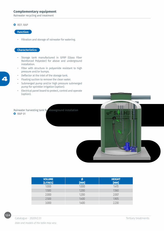
124
4
Tertiary treatmentsData and models of the table may vary.
Catalogue - 2020V2.3.1
Rainwater recycling and treatmentComplementary equipment
Function:
Characteristics:
REF: RAP
RAP 01
• Filtration and storage of rainwater for watering.
• Storage tank manufactured in GFRP (Glass Fiber Reinforced Polyester) for above and underground installation.
• Filter with structure in polyamide resistant to high pressure and/or bumps.
• Deflector at the inlet of the storage tank.• Floating suction to remove the clean water.• Submerged pump and/or high pressure submerged
pump for sprinkler irrigation (option).• Electrical panel board to protect, control and operate
(option).
Rainwater harvesting tank for aboveground installation
VOLUME Ø HEIGHT[LITRES] [MM] [MM]
1.000 1.000 1.4701.500 1.200 1.5602.000 1.200 2.0072.500 1.400 1.9053.000 1.400 2.230

125
4
Tertiary treatmentsData and models of the table may vary.
Catalogue - 2020V2.3.1
Rainwater recycling and treatmentComplementary equipment
Rainwater harvesting tank for underground installation RAP 02
VOLUME Ø LENGTH[LITRES] [MM] [MM]
4.000 1.400 2.8805.000 1.700 2.5406.000 1.700 2.9807.000 1.700 3.4208.000 1.700 3.8609.000 1.700 4.30010.000 2.000 3.58011.000 2.000 3.89012.000 2.000 4.21413.000 2.000 4.53014.000 2.000 4.85015.000 2.000 5.17020.000 2.000 6.76024.000 2.500 5.38025.000 2.500 5.59030.000 2.500 6.60035.000 2.500 7.61040.000 2.500 8.640


5Water purification

Table of contents
FILTRATION TREATMENTSCOMPACT PURIFICATION PLANTS FOR WATER WITH LOW POLLUTANT LOADREF: PUR-F 134COMPACT WATER PURIFICATION PLANT WITH ACTIVE CARBON REF: PUR-FF-CA 136COMPACT PURIFICATION PLANT FOR WATER WITH ORGANIC MATTER LOADREF: PUR-FQFF-CA 138COMPACT PURIFICATION PLANT FOR ABOVEGROUND WATER WITH HIGH TURBIDITYREF: PUR-FQLF 140ALTERNATIVES TO FILTRATION
DECALCIFICATIONREF: PUR-FF-S 142DENITRIFICATIONREF: PUR-FF-N 142WATER DEMINERALIZATION REF: PUR-FF-DM 142IRON REMOVALREF: PUR-FF-FE 142WATER REMINERALIZATION REF: PUR-FF-RM 142
ULTRAFILTRATION TREATMENTSCOMPACT ULTRAFILTRATION PLANTS REF: PUR-UF 144
REVERSE OSMOSIS TREATMENTS COMPACT REVERSE OSMOSIS PLANTS FOR SMALL FLOWSREF: PUR-MINIRO 146REVERSE OSMOSIS COMPACT PLANTS FOR LARGE FLOWSREF: PUR-MAXIRO-BW / PUR-MAXIRO-SW 148REF: PUR-MAXIRO-BW2 150
POLISHING TREATMENT: ULTRAPURE WATERCOMPACT PURIFICATION PLANTS BY DEMINERALIZATION / ELECTRODEIONIZATION REF: PUR-EDI 151COMPACT PURIFICATION PLANTS BY CONTINUOUS ELECTRODEIONIZATION REF: PUR-CEDI 152
COMPACT EMERGENCY PLANTSREF: PUR-EM 154
DISINFECTION SYSTEMSAUTOMATIC CHLORINATION SYSTEM WITH SODIUM HYPOCHLORITE AND PH ADJUSTMENTREF: SAL-CL; SAL-CLPH 156AUTOMATIC REDOX STATION REF: SAL-RX 157CHLORINATION CHAMBER WITH DOSING SYSTEMREF: CVC-CE 158AUTOMATIC OZONE GENERATION SYSTEMREF: SAL-OZ 159DISINFECTION BY ULTRAVIOLETREF: SAL-UV 160
Other dimensions and configurations can be provided upon request. Internal dimensions. Dimensions in millimeters. Volumes in liters, the dimensions indicated may vary according to the needs.Due to its policy of continuous development, Salher Ibérica, S.L. reserves the right to modify the data that appear in this document without notice.This document is protected by the intellectual property law, so that the customer cannot claim, manipulate or duplicate this documentation, except copy for personal use.

130
5
Water purification Data and models of the table may vary.
Catalogue - 2020V2.3.1
INTRODUCTION TO WATER PURIFICATION SYSTEMS
Salher offers innovative customized water purifications systems. Our plants are the best solution for undesirable contaminating situations of surface, underground and sea water.
Salher plants modularity flexibilizes the layouts to treat any type of water.
TURBIDITY REDUCTION SYSTEMS
LAMELLAR SETTLING Lamella clarifiers Salher brand with an advanced lamella technology for an efficient settling of flocs and solid particles suspended in water.• Larger effective area in settling surface• Mixing system and flocculation to facilitate the settling
process
FILTRATIONFiltration equipment mounted at Salher and adapted to the characteristics of each type of water, with optimal filling material for each case and fully automatic operation. • Filtration through silex-anthracite, zeolite or
activated glass• Filling material with high degree of selectivity
Introduction
Filtra�onLamellar se�ling
DAF
Ultrafiltra�on
Reverse osmosis brackish water
Reverse osmosis sea water
Demineraliza�onCEDI
-
TDS
TSS
-
+
+
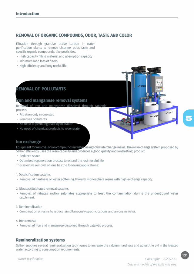
131
5
Water purification Data and models of the table may vary.
Catalogue - 2020V2.3.1
Filtration through granular active carbon in water purification plants to remove chlorine, odor, taste and specific organic compounds, like pesticides.• High capacity filling material and absorption capacity• Minimum load loss of filters• High efficiency and long useful life
REMOVAL OF ORGANIC COMPOUNDS, ODOR, TASTE AND COLOR
REMOVAL OF POLLUTANTS
Iron and manganese removal systemsRemoval of iron and manganese dissolved through catalytic process. • Filtration only in one step• Removes pollutants • No need of permanganate by oxidation• No need of chemical products to regenerate
Ion exchangeEquipment for removal of ion compounds in water, using solid interchange resins. The ion exchange system proposed by Salher efficiently uses the resin capacity and produces a good quality and longlasting product.• Reduced space• Optimized regeneration process to extend the resin useful life
This selective removal of ions has the following applications:
1. Decalcification systems• Removal of hardness or water softening, through monosphere resins with high exchange capacity.
2. Nitrates/Sulphates removal systems • Removal of nitrates and/or sulphates appropriate to treat the contamination during the underground water
catchment.
3. Demineralization• Combination of resins to reduce simultaneously specific cations and anions in water.
4. Iron removal • Removal of iron and manganese dissolved through catalytic process.
Remineralization systemsSalher supplies several remineralization techniques to increase the calcium hardness and adjust the pH in the treated water according to consumption requirements.
Introduction
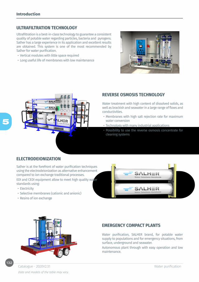
132
5
Water purification Data and models of the table may vary.
Catalogue - 2020V2.3.1
ULTRAFILTRATION TECHNOLOGY
REVERSE OSMOSIS TECHNOLOGY
Introduction
Ultrafiltration is a best-in-class technology to guarantee a consistent quality of potable water regarding particles, bacteria and pyrogens. Salher has a large experience in its application and excellent results are obtained. This system is one of the most recommended by Salher for water purification.• Vertical modules with little space required• Long useful life of membranes with low maintenance
Water treatment with high content of dissolved solids, as well as brackish and seawater in a large range of flows and conductivities. • Membranes with high salt rejection rate for maximum
water conversion • Technology with many industrial applications• Possibility to use the reverse osmosis concentrate for
cleaning systems
ELECTRODEIONIZATIONSalher is at the forefront of water purification techniques using the electrodeionization as alternative enhancement compared to ion exchange traditional processes.EDI and CEDI equipment allow to meet high quality water standards using:• Electricity• Selective membranes (cationic and anionic)• Resins of ion exchange
EMERGENCY COMPACT PLANTS
Water purification, SALHER brand, for potable water supply to populations and for emergency situations, from surface, underground and seawater.Autonomous plant through with easy operation and low maintenance.
133
5
Water purification Data and models of the table may vary.
Catalogue - 2020V2.3.1
Introduction
DISINFECTION SYSTEMSDisinfection of treated clean water and maintenance of the water quality in tanks before consumption.
Sodium hypochlorite (NaClO) treatment Efficient application for microorganisms removal from water and powerful action over time to avoid bacteria and algae proliferation through residual chlorine in water.• Treatment in line or on tank by automatic chlorination equipment
with measurement and control of free chlorine providing a water according to high quality standards
UV disinfection Salher offers the possibility to disinfect the water through UV light, avoiding chemical substances in the water.
Ozone treatment Ozone is an efficient disinfectant in very short contact period time. It has a disinfecting action and strong oxidizing power. Several options available. • Unlike other treatments, it has no impact (color, odor, taste) and no residual trace in water• In-line layout through by-pass or on tank
SALHER WATER PURIFICATION PLANTS VALUE CHAIN
• High quality water. Water purification plants, SALHER brand, produce a potable water in accordance with the international quality standards, in terms of physical, chemical and bacteriological characteristics.
• Compact pre-mounted plant on containerizable modular structures easy to ship and ready for use (“plug&play”).• Robustness and reliability. Factory Acceptance Test (FAT) in Salher premises and mechanical easiness of modules for
a reliable operation.• Possibility of assembling on carbon steel or GFRP structures.• Small space required and modular layout, easy expandable for future needs. • Low operation and production costs for potable water with design optimization and reduction of energy consumption.• Easy maintenance and plant automation, no qualified staff is required. • Long useful life.• Technical assessment adding value and integrity within the sales process of the equipment.

134
5
Water purification Data and models of the table may vary.
Catalogue - 2020V2.3.1
FILTRATION TREATMENTSCOMPACT PURIFICATION PLANTS FOR WATER WITH LOW POLLUTANT LOAD
Function: Characteristics:
Option:
REF: PUR-F
• Removal of suspended solids, turbidity and pathogen microorganisms.
• Medium quality treatment water, usually surface water issued from rivers, lakes and reservoirs. Inlet water characteristics:
* Concentration of suspended solids and turbidity: TSS < 200 mg/l ; Turbidity < 20 NTU.
* Concentration of dissolved solids: TDS < 1500 mg/l.* Concentration of pollutants below the acceptable
threshold level.
• Compact equipment for water purification, in accordance with RD 140/2003 and recommendations of the World Health Organization (WHO).
• Water purification system, Salher brand, with possibility to install on carbon steel structure, composed of the following elements, according to applications:
* High efficiency filters in GFRP (Glass Fiber Reinforced Polyester) with automatic cleaning system, provided with silex and anthracite filling material, with grain size selected according to final use.
* Ring filter with different filtration degrees, according to applications.
* Feeding systems to filtration systems composed of centrifugal pumps, provided with regulation system and flow control, level regulators, etc.
* Disinfection system and quality control of water in tank composed of a self-priming pump for recirculation, with automatic chlorination station.
* Electrical panel board for control and command of the plant.
* Set of accessories composed of interconnection pipes between equipment, valves, sampling intakes, regulation and control systems, etc.
• GFRP STRUCTURE-SKID with hydraulic and electrical interconnection of the elements.
• Alternatives to multilayer filter silex-anthracite:* Filtration with zeolite filter media. Ref. PUR-F-Z
(CONSULT).* Filtration with activated glass media. Ref. PUR-F-V
(CONSULT).• Dosage of oxidant in pretreatment for disinfection
and organic matter oxidation and reduction of Fe/Mn.
• Raw water tank. Operation of the plant independent from feed water.
• Treated water storage tank.• Automatic PH control and regulation of the treated
water.• Alternative disinfection system of water treated in
post-treatment.

135
5
Water purification Data and models of the table may vary.
Catalogue - 2020V2.3.1
FILTRATION TREATMENTSCOMPACT PURIFICATION PLANTS FOR WATER WITH LOW POLLUTANT LOAD
*Includes filling load for filters + GFRP structure.
M3/H LENGTH WIDTH HEIGHT INSTALLED POWER
WEIGHT*[MM] [MM] [MM] [KG]
0,5 2.000 1.000 1.500 2,4KW / 400V 1751 2.000 1.100 1.500 2,4KW / 400V 3073 2.100 1.320 1.700 2,4KW / 400V 4035 2.200 1.800 1.700 3,2KW / 400V 69310 2.300 2.100 1.900 5,3KW / 400V 1.31815 2.300 2.200 2.000 7,0KW / 400V 1.66820 2.500 2.500 2.000 8,5KW / 400V 2.21325 2.800 2.700 2.100 9,5KW / 400V 2.89330 2.800 2.700 2.100 11,5KW / 400V 2.91435 2.900 2.850 2.200 11,5KW / 400V 3.90740 3.300 3.200 2.300 14,5KW / 400V 5.34745 3.300 3.200 2.300 14,5KW / 400V 5.36350 4.200 2.600 1.600 16,5KW / 400V 5.54860 4.200 2.800 1.600 18,5KW / 400V 6.03570 4.200 3.100 1.700 22,5KW / 400V 7.69880 4.800 3.100 1.800 27,5KW / 400V 8.92190 4.800 3.300 2.000 29,5KW / 400V 10.699100 5.300 3.300 2.200 33,0KW / 400V 12.219

136
5
Water purification Data and models of the table may vary.
Catalogue - 2020V2.3.1
FILTRATION TREATMENTSCOMPACT WATER PURIFICATION PLANT WITH ACTIVE CARBON
Function: Characteristics:
Option:
REF: PUR-FF-CA
• Removal of suspended solids, organic matter, turbidity and pathogen microorganisms.
• Removal of free chlorine, odors, tastes and absorption of specific organic compounds.
• Treatment of medium quality water, usually surface water issued from rivers, lakes and reservoirs. Characteristics of the inlet water:
* Concentration of suspended solids and turbidity: TSS < 200 mg/l; Turbidity < 20 NTU.
* Concentration of dissolved solids: TDS < 1500 mg/l.* Concentration of pollutants below the acceptable
threshold level.
• Compact equipment for water purification in accordance with RD 140/2003 and recommendations of the World Health Organization (WHO).
• Water purification system, Salher brand, with possibility of installation on carbon steel structure, composed of the following elements, according to applications:
* High efficiency filters in GFRP (Glass Fiber Reinforced Polyester) with automatic cleaning system, provided with silex and anthracite filling material, with grain size selected according to final use.
* Activated carbon filter in GFRP (Glass Fiber Reinforced Polyester) with automatic cleaning system, filling material through activated carbon issued from coconut shell, for treatment of purification systems.
* Ring filter with different filtering degrees, according to final use.
* Feeding system to the filtration treatment composed of centrifugal pumps, with regulation system and flow control, level regulators, etc.
* Disinfection system and water quality control in tank composed of self-priming pump for recirculation, with automatic chlorination station.
* Panel board for control and command of the plant.* Set of accessories composed of interconnection
pipes between equipment, valves, sampling intakes, regulation and control systems, etc.
• GFRP STRUCTURE-SKID with hydraulic and electrical interconnection of the elements.
• Alternatives to silex-anthracite multilayer filter:* Filtration with zeolite media. Ref.: PUR-FF-ZCA
(CONSULT).* Filtration with activated glass media. Ref.: PUR-FF-
VCA (CONSULT).• Dosage of oxidant in pretreatment for disinfection
and oxidation of organic matter and Fe/Mn reduction.
• Raw water tank. Operation of the plant independent from feed water.
• Treated water storage tank.• Automatic control and regulation of pH of treated
water.• Alternative system of disinfection of the treated
water in post-treatment.
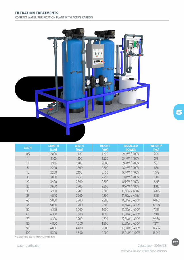
137
5
Water purification Data and models of the table may vary.
Catalogue - 2020V2.3.1
FILTRATION TREATMENTSCOMPACT WATER PURIFICATION PLANT WITH ACTIVE CARBON
*Includes filling load for filters + GFRP structure.
M3/H LENGTH WIDTH HEIGHT INSTALLED POWER
WEIGHT*[MM] [MM] [MM] [KG]
0,5 2.000 1.100 1.200 2,4KW / 400V 2041 2.100 1.100 1.500 2,4KW / 400V 3783 2.100 1.400 2.000 2,4KW / 400V 5075 2.200 1.800 2.300 3,2KW / 400V 83610 2.200 2.100 2.450 5,3KW / 400V 1.57315 3.000 2.250 2.450 7,0KW / 400V 1.98020 3.400 2.500 2.300 8,5KW / 400V 2.21325 3.600 2.700 2.300 9,5KW / 400V 3.31530 4.100 2.700 2.300 11,5KW / 400V 3.70835 4.500 2.900 2.300 11,5KW / 400V 5.15240 5.000 3.200 2.300 14,5KW / 400V 6.89245 5.000 3.200 2.300 14,5KW / 400V 6.90850 4.250 3.200 1.600 16,5KW / 400V 7.21260 4.300 3.500 1.600 18,5KW / 400V 7.91170 4.300 3.700 1.700 22,5KW / 400V 9.96680 4.800 4.000 1.800 27,5KW / 400V 12.11190 4.800 4.400 2.000 29,5KW / 400V 14.234100 5.300 4.500 2.200 33,0KW / 400V 16.244
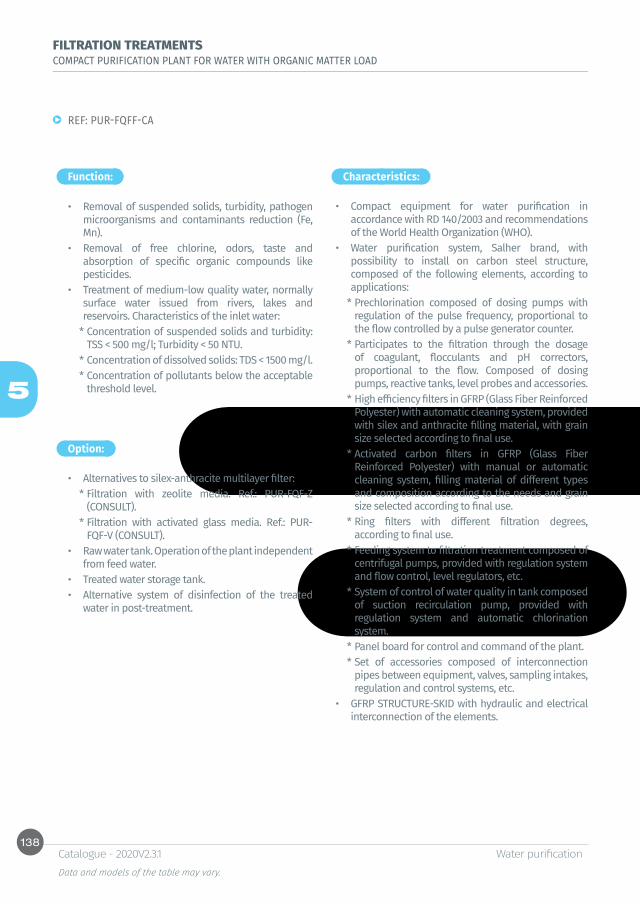
138
5
Water purification Data and models of the table may vary.
Catalogue - 2020V2.3.1
FILTRATION TREATMENTSCOMPACT PURIFICATION PLANT FOR WATER WITH ORGANIC MATTER LOAD
Function: Characteristics:
Option:
REF: PUR-FQFF-CA
• Removal of suspended solids, turbidity, pathogen microorganisms and contaminants reduction (Fe, Mn).
• Removal of free chlorine, odors, taste and absorption of specific organic compounds like pesticides.
• Treatment of medium-low quality water, normally surface water issued from rivers, lakes and reservoirs. Characteristics of the inlet water:
* Concentration of suspended solids and turbidity: TSS < 500 mg/l; Turbidity < 50 NTU.
* Concentration of dissolved solids: TDS < 1500 mg/l.* Concentration of pollutants below the acceptable
threshold level.
• Compact equipment for water purification in accordance with RD 140/2003 and recommendations of the World Health Organization (WHO).
• Water purification system, Salher brand, with possibility to install on carbon steel structure, composed of the following elements, according to applications:
* Prechlorination composed of dosing pumps with regulation of the pulse frequency, proportional to the flow controlled by a pulse generator counter.
* Participates to the filtration through the dosage of coagulant, flocculants and pH correctors, proportional to the flow. Composed of dosing pumps, reactive tanks, level probes and accessories.
* High efficiency filters in GFRP (Glass Fiber Reinforced Polyester) with automatic cleaning system, provided with silex and anthracite filling material, with grain size selected according to final use.
* Activated carbon filters in GFRP (Glass Fiber Reinforced Polyester) with manual or automatic cleaning system, filling material of different types and composition according to the needs and grain size selected according to final use.
* Ring filters with different filtration degrees, according to final use.
* Feeding system to filtration treatment composed of centrifugal pumps, provided with regulation system and flow control, level regulators, etc.
* System of control of water quality in tank composed of suction recirculation pump, provided with regulation system and automatic chlorination system.
* Panel board for control and command of the plant.* Set of accessories composed of interconnection
pipes between equipment, valves, sampling intakes, regulation and control systems, etc.
• GFRP STRUCTURE-SKID with hydraulic and electrical interconnection of the elements.
• Alternatives to silex-anthracite multilayer filter:* Filtration with zeolite media. Ref.: PUR-FQF-Z
(CONSULT).* Filtration with activated glass media. Ref.: PUR-
FQF-V (CONSULT).• Raw water tank. Operation of the plant independent
from feed water.• Treated water storage tank. • Alternative system of disinfection of the treated
water in post-treatment.
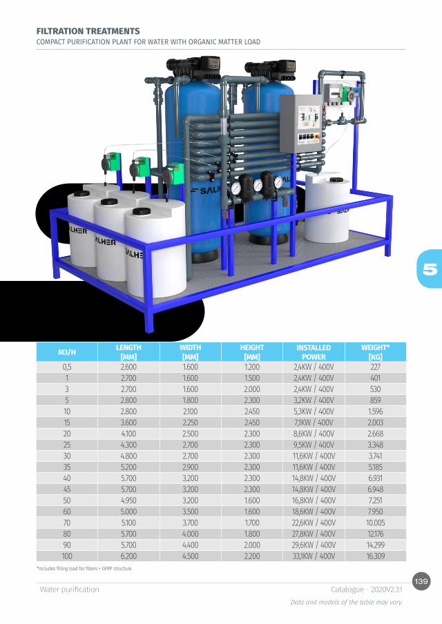
139
5
Water purification Data and models of the table may vary.
Catalogue - 2020V2.3.1
FILTRATION TREATMENTSCOMPACT PURIFICATION PLANT FOR WATER WITH ORGANIC MATTER LOAD
*Includes filling load for filters + GFRP structure.
M3/H LENGTH WIDTH HEIGHT INSTALLED POWER
WEIGHT*[MM] [MM] [MM] [KG]
0,5 2.600 1.600 1.200 2,4KW / 400V 2271 2.700 1.600 1.500 2,4KW / 400V 4013 2.700 1.600 2.000 2,4KW / 400V 5305 2.800 1.800 2.300 3,2KW / 400V 85910 2.800 2.100 2.450 5,3KW / 400V 1.59615 3.600 2.250 2.450 7,1KW / 400V 2.00320 4.100 2.500 2.300 8,6KW / 400V 2.66825 4.300 2.700 2.300 9,5KW / 400V 3.34830 4.800 2.700 2.300 11,6KW / 400V 3.74135 5.200 2.900 2.300 11,6KW / 400V 5.18540 5.700 3.200 2.300 14,8KW / 400V 6.93145 5.700 3.200 2.300 14,8KW / 400V 6.94850 4.950 3.200 1.600 16,8KW / 400V 7.25160 5.000 3.500 1.600 18,6KW / 400V 7.95070 5.100 3.700 1.700 22,6KW / 400V 10.00580 5.700 4.000 1.800 27,8KW / 400V 12.17690 5.700 4.400 2.000 29,6KW / 400V 14.299100 6.200 4.500 2.200 33,1KW / 400V 16.309

140
5
Water purification Data and models of the table may vary.
Catalogue - 2020V2.3.1
FILTRATION TREATMENTSCOMPACT PURIFICATION PLANT FOR ABOVEGROUND WATER WITH HIGH TURBIDITY
Function: Characteristics:
Option:
REF: PUR-FQLF
• Removal of suspended solids, organic matter, turbidity and pathogen microorganisms and reduction of pollutants (Fe, Mn,..).
• Treatment of low quality water, usually surface water issued from rivers, lakes and tanks. Characteristics of the inlet water:
* Concentration of suspended solids and turbidity: TSS < 1000 mg/l; Turbidity < 500 NTU.
* Concentration of dissolved solids: TDS < 1500 mg/l.* Concentration of pollutants below the acceptable
threshold level.
• Compact equipment for water purification in accordance with RD 140/2003 and recommendations of the World Health Organization (WHO).
• Water purification system, Salher brand, with possibility to install on carbon steel structure, composed of the following elements, according to applications:
* Prechlorination composed of dosing pumps regulated by the frequency of impulses, proportional to the flow controlled by a pulse generator counter.
* Participates to the filtration through the dosage of coagulant, flocculants and pH correctors, proportional to the flow. Composed of dosing pumps, reagent tanks, level probes and accessories.
* Lamellar settling tank composed of polypropylene rectangular tank and lamellar modules with slope of 60°, with adjustable canal, overflow and inlet, outlet and emptying intakes.
* High efficiency filter in GFRP (Glass Fiber Reinforced Polyester), with automatic cleaning system, provided with silex and anthracite filling material, with grain sizes selected according to final use.
* Ring filter with different filtering degrees, according to final use.
* Feeding system to filtration treatment composed of centrifugal pumps provided with regulation system and flow control, level regulators, etc.
* System of water quality control on tank composed of suction recirculation pump, with regulation system and automatic chlorination station.
* Electrical panel board for control and command of the plant.
* Set of accessories composed of interconnection pipes between equipment, valves, sampling intakes, regulation and control systems, etc.
• GFRP STRUCTURE-SKID with hydraulic and electrical interconnection of the elements.
• Alternatives to the silex-anthracite multilayer filter:* Filtration with zeolite media. Ref.: PUR-FQLF-Z
(CONSULT)* Filtration with activated glass media. Ref.: PUR-
FQLF-V (CONSULT)• Raw water tank. Operation of the plant independent
from feed water. • Treated water storage tank. • Alternative system of disinfection of the treated
water in post-treatment.
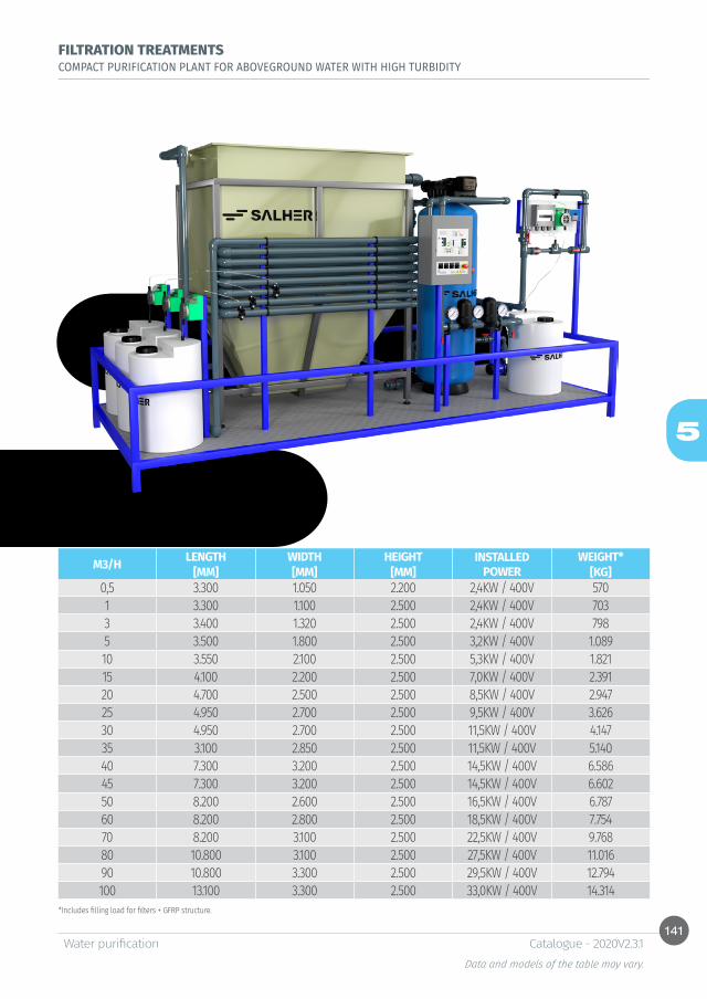
141
5
Water purification Data and models of the table may vary.
Catalogue - 2020V2.3.1
FILTRATION TREATMENTSCOMPACT PURIFICATION PLANT FOR ABOVEGROUND WATER WITH HIGH TURBIDITY
*Includes filling load for filters + GFRP structure.
M3/H LENGTH WIDTH HEIGHT INSTALLED POWER
WEIGHT*[MM] [MM] [MM] [KG]
0,5 3.300 1.050 2.200 2,4KW / 400V 5701 3.300 1.100 2.500 2,4KW / 400V 7033 3.400 1.320 2.500 2,4KW / 400V 7985 3.500 1.800 2.500 3,2KW / 400V 1.08910 3.550 2.100 2.500 5,3KW / 400V 1.82115 4.100 2.200 2.500 7,0KW / 400V 2.39120 4.700 2.500 2.500 8,5KW / 400V 2.94725 4.950 2.700 2.500 9,5KW / 400V 3.62630 4.950 2.700 2.500 11,5KW / 400V 4.14735 3.100 2.850 2.500 11,5KW / 400V 5.14040 7.300 3.200 2.500 14,5KW / 400V 6.58645 7.300 3.200 2.500 14,5KW / 400V 6.60250 8.200 2.600 2.500 16,5KW / 400V 6.78760 8.200 2.800 2.500 18,5KW / 400V 7.75470 8.200 3.100 2.500 22,5KW / 400V 9.76880 10.800 3.100 2.500 27,5KW / 400V 11.01690 10.800 3.300 2.500 29,5KW / 400V 12.794100 13.100 3.300 2.500 33,0KW / 400V 14.314

142
5
Water purification Data and models of the table may vary.
Catalogue - 2020V2.3.1
FILTRATION TREATMENTSALTERNATIVES TO FILTRATION
REF: PUR-FF-SDECALCIFICATION
Function:
• Removal of calcium, magnesium and bicarbonates in the water for softening avoiding scale in piping and equipment.
• Removal efficiency limited due to the concentration of sodium in water.
CONSULT FOR MORE INFORMATION
REF: PUR-FF-NDENITRIFICATION
Function:
• Removal of nitrates, sulphates and bicarbonates in water, preventing from health issues.• Efficiency of the removal limited due to the concentration of chloride in water.
CONSULT FOR MORE INFORMATION
REF: PUR-FF-DMWATER DEMINERALIZATION
Function:
• Reduction of specific ions to meet the standard requirements and improve water quality.
CONSULT FOR MORE INFORMATION
REF: PUR-FF-FEIRON REMOVAL
Function:
• Removal of iron and manganese preventing from oxide waste.• Characteristics of inlet water:
* Iron concentration < 5 mg/l.* Manganese concentration < 1 mg/l.* Free chlorine concentration < 0,5 mg/l.
CONSULT FOR MORE INFORMATION
REF: PUR-FF-RMWATER REMINERALIZATION
Function:
• Addition of minerals in water and pH adjustment for balanced water and avoidance of oxidations. • Permeate water conditioning after reverse osmosis treatment.
CONSULT FOR MORE INFORMATION

143
5
Water purification Data and models of the table may vary.
Catalogue - 2020V2.3.1
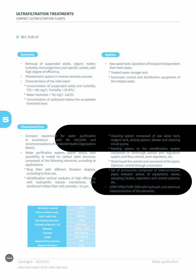
144
5
Water purification Data and models of the table may vary.
Catalogue - 2020V2.3.1
ULTRAFILTRATION TREATMENTSCOMPACT ULTRAFILTRATION PLANTS
Function:
Characteristics:
Option:
REF: PUR-UF
• Removal of suspended solids, organic matter, turbidity, microorganisms and specific metals, with high degree of efficiency.
• Pretreatment system in reverse osmosis process.• Characteristics of the inlet water:
* Concentration of suspended solids and turbidity: TSS < 100 mg/l ; Turbidity < 50 NTU.
* Water hardness < 150 mg/l CaCO3.* Concentration of pollutants below the acceptable
threshold level.
• Compact equipment for water purification in accordance with RD 140/2003 and recommendations of the World Health Organization (WHO).
• Water purification system, Salher brand, with possibility to install on carbon steel structure, composed of the following elements, according to applications:
* Ring filter with different filtration degrees, according to final use.
* Ultrafiltration vertical modules of high efficiency with hydrophilic tubular membranes, with reinforced hollow fiber with porosity < 0,1 μm.
• Raw water tank. Operation of the plant independent from feed water.
* Treated water storage tank. * Automatic control and disinfection equipment of
the treated water.
Membrane material PVDF Active membrane area 38 / 55 m²
Inlet / outlet size DN32/50Size of pores (microns) < 0,1μm
Diameter of fiber ID / OD 0,6/1,2 mm Filtration outside / inside Diameter 160 / 250 mm Length 1730/1160 mm
Material of the structure ABS Material of fixation Epoxy
* Cleaning system composed of raw water tank, reagent tank, dosing system, blower and cleaning circuit pump.
* Feeding system to the ultrafiltration system composed of centrifugal pumps with regulation system and flow control, level regulators, etc.
* Panel board for control and command of the plant. Optional: control through automaton.
* Set of accessories composed of interconnection pipes between pieces of equipment, valves, sampling intakes, regulation and control systems, etc.
• GFRP STRUCTURE-SKID with hydraulic and electrical interconnection of the elements.

145
5
Water purification Data and models of the table may vary.
Catalogue - 2020V2.3.1
ULTRAFILTRATION TREATMENTSCOMPACT ULTRAFILTRATION PLANTS
M3/H M²/UNIT LENGTH WIDTH HEIGHT INSTALLED POWER
VOL. CLEANING TANK[MM] [MM] [MM]
0,5 38 / 1 2.250 1.040 2.075 2,7KW / 400V 2001 38 / 1 2.250 1.040 2.075 2,7KW / 400V 2003 38 / 1 2.250 1.040 2.075 2,9KW / 400V 3005 38 / 2 2.450 1.040 2.075 2,9KW / 400V 50010 55 / 2 2.550 1.150 2.075 4,2KW / 400V 1.00015 38 / 4 2.615 1.150 2.075 6,5KW / 400V 1.00020 38 / 6 2.750 1.250 2.075 6,5KW / 400V 1.50025 55 / 6 3.040 1.450 2.075 7,5KW / 400V 2.00030 38 / 10 3.450 1.650 2.075 7,5KW / 400V 2.50035 55 / 8 3.750 1.650 2.075 7,5KW / 400V 2.50040 55 / 10 4.150 1.650 2.075 9,2KW / 400V 3.00045 55 / 10 4.150 1.650 2.075 9,2KW / 400V 3.00050 55 / 12 4.860 1.950 2.075 10,5KW / 400V 4.00060 55 / 12 4.860 1.950 2.075 12,2KW / 400V 4.00070 55 / 14 5.250 1.950 2.200 14,4KW / 400V 5.00080 55 / 16 5.650 1.950 2.200 14,4KW / 400V 5.00090 55 / 16 5.650 1.950 2.200 14,6KW / 400V 5.000100 55 / 18 6.050 2.250 2.075 17,6KW / 400V 6.000

146
5
Water purification Data and models of the table may vary.
Catalogue - 2020V2.3.1
REVERSE OSMOSIS TREATMENTS COMPACT REVERSE OSMOSIS PLANTS FOR SMALL FLOWS
Function:
Characteristics: Option:
REF: PUR-MINIRO
• Removal of inorganic matter, salinity, pollutants, concentration of ions in water, and pathogen microorganisms, achieving a high degree of efficiency.
• Characteristics of inlet water:* Turbidity < 1 NTU.* SDI < 5.
• Salt rejection: 99,4%.
• Compact equipment for water purification in accordance with RD 140/2003 and recommendations of the World Health Organization (WHO).
• Water purification system, Salher brand, with possibility to install on carbon steel structure, composed of the following elements, according to applications:
* Microfiltration of 5 microns.* Feeding system to reverse osmosis composed of
vertical centrifugal pump. Optional: frequency controller.
* Skid equipped with spiral wound membranes (PA/PS) with high salt rejection, available sizes of 2,5’’ and 4’’, for any salt concentration.
* Autocleaning system with dragging –flushing–.* Conductivimeter for control of permeate.* Panel board for control and command of the plant.* Set of accessories composed of interconnection
pipes between pieces of equipment, valves, sampling intakes, regulation and control systems, etc.
• GFRP STRUCTURE-SKID with hydraulic and electrical interconnection of the elements.
• Antifouling dosing equipment (recommended above 8°HF).
• Equipment to prevent from free chlorine.• Permeate recirculation system (used as safety
system).• Flushing with permeate water (requires
accumulation tank).• Chemical cleaning unit –CIP– (recommended for
long stops of the plant).• Raw water tank. Operation of the plant independent
from feed water. • Treated water storage tank. • Mixing system.• Treated water remineralization system.• Treated water disinfection system.

147
5
Water purification Data and models of the table may vary.
Catalogue - 2020V2.3.1
REVERSE OSMOSIS TREATMENTS COMPACT REVERSE OSMOSIS PLANTS FOR SMALL FLOWS
REF: PUR-MINIRO-BW
REF: PUR-MINIRO-SW
Inlet TDS < 2000 ppmConversion rate: 40-60%
Inlet TDS < 45000 ppmConversion rate: 30-40%
* Permeate flow.The layout may vary according to the water quality.
* Flow permeate.Conditions: 25 °C seawater 32000 mg/l TDS. The layout can vary according to the water quality.
All reverse osmosis purification systems are designed on a case-by-case basis.
CONSULT FOR MORE INFORMATION.
M3/D* MEMBRANE LENGTH WIDTH HEIGHT INSTALLED POWER[MM] [MM] [MM]
4 3X4021 1150 400 402 2,2KW / 400V9 3X4040 1300 600 427 3,0KW / 400V18 2X4040 1500 600 750 6,1KW / 400V
M3/D* MEMBRANE LENGTH WIDTH HEIGHT INSTALLED POWER[MM] [MM] [MM]
2 1X2540 650 300 650 1,3KW / 400V3 1X4021 650 350 650 1,3KW / 400V5 1X4040 650 600 1.600 1,6KW / 400V10 2X4040 700 650 1.600 2,1KW / 400V15 3X4040 750 650 1.600 4,0KW / 400V20 4X4040 750 700 1.600 4,0KW / 400V25 5X4040 800 750 1.600 4,5KW / 400V30 6X4040 850 750 2.300 4,5KW / 400V40 6X4040 850 750 2.300 5,1KW / 400V

148
5
Water purification Data and models of the table may vary.
Catalogue - 2020V2.3.1
REVERSE OSMOSIS TREATMENTS REVERSE OSMOSIS COMPACT PLANTS FOR LARGE FLOWS
Function:
Characteristics:
Option:
REF: PUR-MAXIRO-BW / PUR-MAXIRO-SW
• Removal of inorganic matter, salinity, pollutants, concentration of ions in water and pathogen microorganisms with high efficiency.
• Characteristics of inlet water:* Turbidity < 1 NTU* SDI < 5
• Compact equipment for water purification in accordance with RD 140/2003 and recommendations of the World Health Organization (WHO).
• Water purification system, Salher brand, with possibility to install on carbon steel structure, composed of the following elements, according to applications:
* Disc filters with different filtration degrees, depending on final use.
* Antifouling treatment in line to avoid incrustations in membranes and problems in the reverse osmosis process. System composed of: dosing pump, reagent tank, level probe and accessories.
* Microfiltration of 5 micron.* Feeding system to reverse osmosis composed of
multistage high pressure pumps, with fail-safe system to avoid overpressure. Optional: frequency converter.
* Skid equipped with spiral wound membranes (PA/PS) with high salt rejection, available in sizes of 2,5’’, 4’’ and 8’’, for any salt concentration.
* Automatic cleaning system through –flushing- with permeate water.
* Conductivimeter for permeate control.* Electrical panel board for control and command of
the plant.
• Permeate recirculation system.• Automatic or manual chemical cleaning unit –CIP–
(recommended for long stops of the plant).• Raw water tank. Operation of the plant independent
from feed water. • Treated water storage tank. • Mixing system.• Treated water remineralization system.• Treated water disinfection system.
* Set of accessories composed of interconnection pipes between pieces of equipment, conductivity meters, valves, sampling, regulation and control systems, etc.
• GFRP STRUCTURE-SKID with hydraulic and electrical interconnection of the elements.
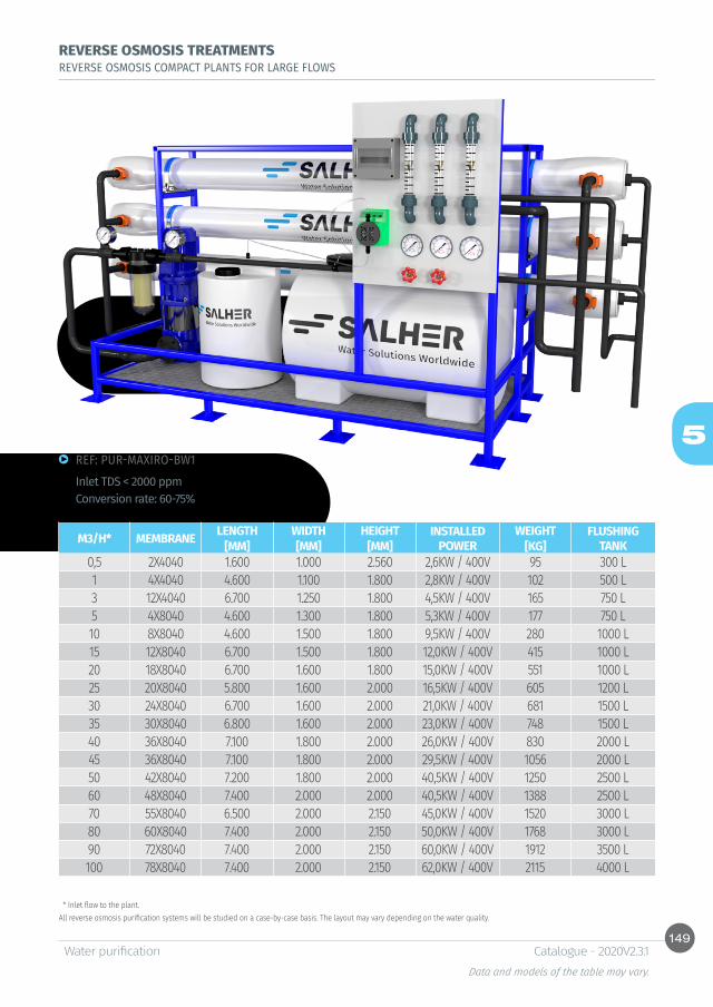
149
5
Water purification Data and models of the table may vary.
Catalogue - 2020V2.3.1
REVERSE OSMOSIS TREATMENTS REVERSE OSMOSIS COMPACT PLANTS FOR LARGE FLOWS
REF: PUR-MAXIRO-BW1Inlet TDS < 2000 ppmConversion rate: 60-75%
* Inlet flow to the plant. All reverse osmosis purification systems will be studied on a case-by-case basis. The layout may vary depending on the water quality.
M3/H* MEMBRANE LENGTH WIDTH HEIGHT INSTALLED POWER
WEIGHT FLUSHING TANK[MM] [MM] [MM] [KG]
0,5 2X4040 1.600 1.000 2.560 2,6KW / 400V 95 300 L1 4X4040 4.600 1.100 1.800 2,8KW / 400V 102 500 L3 12X4040 6.700 1.250 1.800 4,5KW / 400V 165 750 L5 4X8040 4.600 1.300 1.800 5,3KW / 400V 177 750 L10 8X8040 4.600 1.500 1.800 9,5KW / 400V 280 1000 L15 12X8040 6.700 1.500 1.800 12,0KW / 400V 415 1000 L20 18X8040 6.700 1.600 1.800 15,0KW / 400V 551 1000 L25 20X8040 5.800 1.600 2.000 16,5KW / 400V 605 1200 L30 24X8040 6.700 1.600 2.000 21,0KW / 400V 681 1500 L35 30X8040 6.800 1.600 2.000 23,0KW / 400V 748 1500 L40 36X8040 7.100 1.800 2.000 26,0KW / 400V 830 2000 L45 36X8040 7.100 1.800 2.000 29,5KW / 400V 1056 2000 L50 42X8040 7.200 1.800 2.000 40,5KW / 400V 1250 2500 L60 48X8040 7.400 2.000 2.000 40,5KW / 400V 1388 2500 L70 55X8040 6.500 2.000 2.150 45,0KW / 400V 1520 3000 L80 60X8040 7.400 2.000 2.150 50,0KW / 400V 1768 3000 L90 72X8040 7.400 2.000 2.150 60,0KW / 400V 1912 3500 L100 78X8040 7.400 2.000 2.150 62,0KW / 400V 2115 4000 L
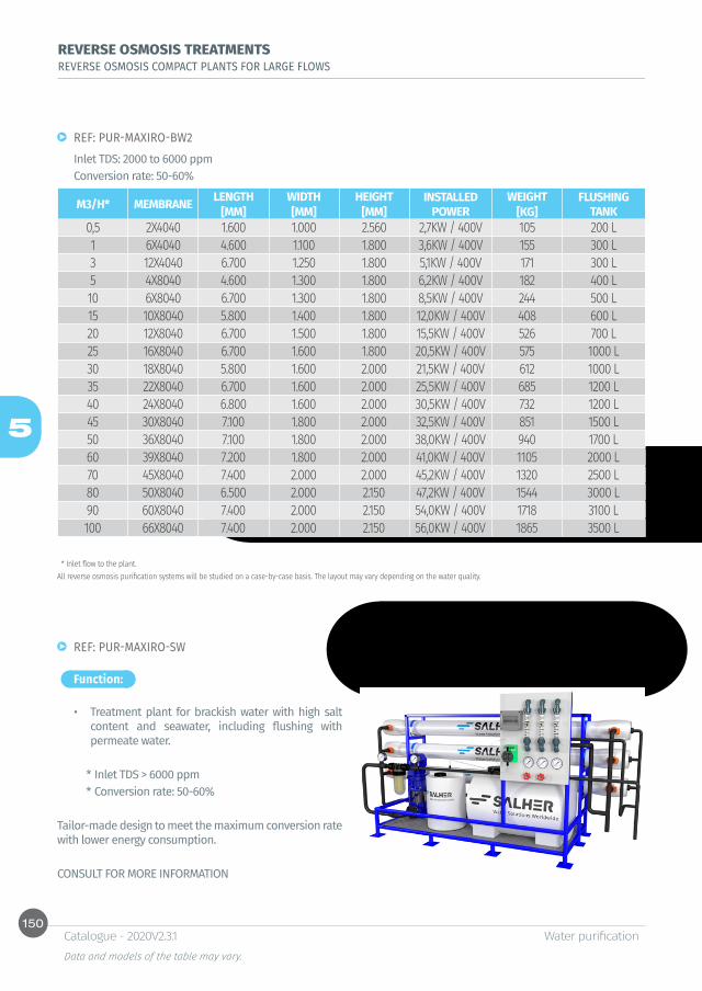
150
5
Water purification Data and models of the table may vary.
Catalogue - 2020V2.3.1
REF: PUR-MAXIRO-BW2Inlet TDS: 2000 to 6000 ppmConversion rate: 50-60%
* Inlet flow to the plant. All reverse osmosis purification systems will be studied on a case-by-case basis. The layout may vary depending on the water quality.
REVERSE OSMOSIS TREATMENTS REVERSE OSMOSIS COMPACT PLANTS FOR LARGE FLOWS
Function:
REF: PUR-MAXIRO-SW
• Treatment plant for brackish water with high salt content and seawater, including flushing with permeate water.
* Inlet TDS > 6000 ppm* Conversion rate: 50-60%
Tailor-made design to meet the maximum conversion rate with lower energy consumption.
CONSULT FOR MORE INFORMATION
M3/H* MEMBRANE LENGTH WIDTH HEIGHT INSTALLED POWER
WEIGHT FLUSHING TANK[MM] [MM] [MM] [KG]
0,5 2X4040 1.600 1.000 2.560 2,7KW / 400V 105 200 L1 6X4040 4.600 1.100 1.800 3,6KW / 400V 155 300 L3 12X4040 6.700 1.250 1.800 5,1KW / 400V 171 300 L5 4X8040 4.600 1.300 1.800 6,2KW / 400V 182 400 L10 6X8040 6.700 1.300 1.800 8,5KW / 400V 244 500 L15 10X8040 5.800 1.400 1.800 12,0KW / 400V 408 600 L20 12X8040 6.700 1.500 1.800 15,5KW / 400V 526 700 L25 16X8040 6.700 1.600 1.800 20,5KW / 400V 575 1000 L30 18X8040 5.800 1.600 2.000 21,5KW / 400V 612 1000 L35 22X8040 6.700 1.600 2.000 25,5KW / 400V 685 1200 L40 24X8040 6.800 1.600 2.000 30,5KW / 400V 732 1200 L45 30X8040 7.100 1.800 2.000 32,5KW / 400V 851 1500 L50 36X8040 7.100 1.800 2.000 38,0KW / 400V 940 1700 L60 39X8040 7.200 1.800 2.000 41,0KW / 400V 1105 2000 L70 45X8040 7.400 2.000 2.000 45,2KW / 400V 1320 2500 L80 50X8040 6.500 2.000 2.150 47,2KW / 400V 1544 3000 L90 60X8040 7.400 2.000 2.150 54,0KW / 400V 1718 3100 L100 66X8040 7.400 2.000 2.150 56,0KW / 400V 1865 3500 L

151
5
Water purification Data and models of the table may vary.
Catalogue - 2020V2.3.1
POLISHING TREATMENT: ULTRAPURE WATERCOMPACT PURIFICATION PLANTS BY DEMINERALIZATION / ELECTRODEIONIZATION
Function:
Characteristics:
Option:
REF: PUR-EDI
• Equipment of demineralization by ion exchange or electrodeionization module for ultrapure water production.
* Polishing system for silica removal from osmosis water. Excellent quality outlet water.
* Outlet water with less than 0,1 μs/cm conductivity. Maximum residual silica concentration < 1 g/l.
• Compact plant, SALHER brand, with electrical and hydraulic interconnection of the elements:
* High efficiency ion exchange filters, in GFRP (Glass Fiber Reinforced Polyester) with automatic cleaning system. Combination of strong acid cation and base anion resins through two independent columns or in mixed bed.
* Electrodeionization module, as an alternative or a complementary system of columns of ion exchange.
* Microfiltration of 5 and 1 microns.
• Treated water storage tank.• Recirculation system.
* Feeding system to demineralization treatment composed of centrifugal pumps with regulation systems, flow control, level regulators, etc.
* Conductivimeter for control of permeate.* Panel board for control and command of the
treatment.* Set of accessories composed of interconnection
pipes between elements of the equipment, conductivity meters, valves, sampling, regulation and control systems, etc.
M3/HFLOWS
MIN./MAX. [M³/H ]
D LM EDI
0,5 0,25 / 1 X X X1 1 / 1,5 X X X2 1,6 / 2,2 X X X4 3 / 5 X X X6 5 / 7,5 X X X10 4 / 15 X X X15 10 / 24 X X X25 20 / 30 X40 30 / 50 X
D: Cationic/anionic demineralizer filter (2 columns)LM: Mixed bed demineralizer filter (1 column)EDI: Electrodeionization module.
Tailor-made design according to the inlet and outlet water.
CONSULT FOR MORE INFORMATION
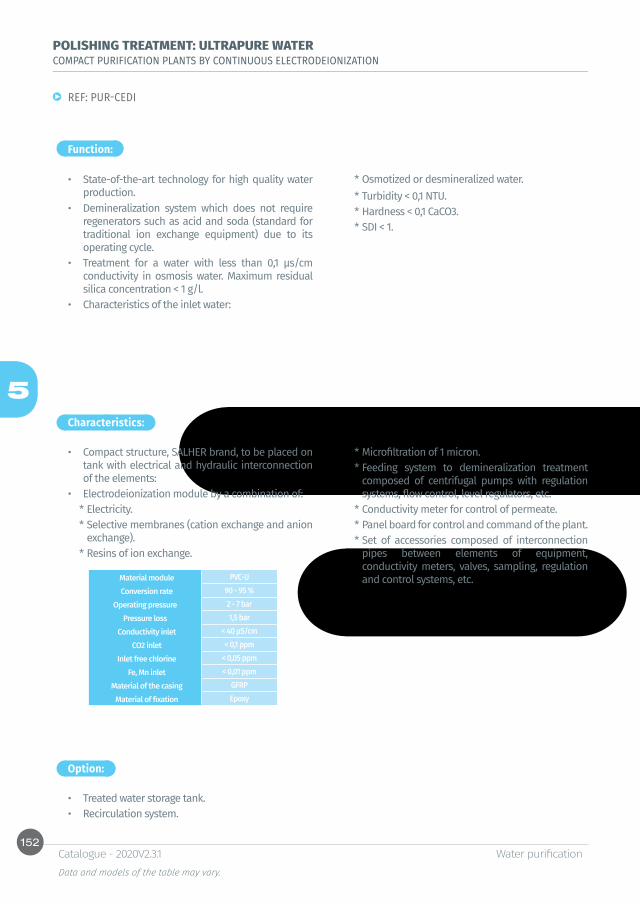
152
5
Water purification Data and models of the table may vary.
Catalogue - 2020V2.3.1
POLISHING TREATMENT: ULTRAPURE WATERCOMPACT PURIFICATION PLANTS BY CONTINUOUS ELECTRODEIONIZATION
Function:
Characteristics:
Option:
REF: PUR-CEDI
• State-of-the-art technology for high quality water production.
• Demineralization system which does not require regenerators such as acid and soda (standard for traditional ion exchange equipment) due to its operating cycle.
• Treatment for a water with less than 0,1 μs/cm conductivity in osmosis water. Maximum residual silica concentration < 1 g/l.
• Characteristics of the inlet water:
• Compact structure, SALHER brand, to be placed on tank with electrical and hydraulic interconnection of the elements:
• Electrodeionization module by a combination of:* Electricity.* Selective membranes (cation exchange and anion
exchange).* Resins of ion exchange.
* Microfiltration of 1 micron.* Feeding system to demineralization treatment
composed of centrifugal pumps with regulation systems, flow control, level regulators, etc.
* Conductivity meter for control of permeate.* Panel board for control and command of the plant. * Set of accessories composed of interconnection
pipes between elements of equipment, conductivity meters, valves, sampling, regulation and control systems, etc.
• Treated water storage tank. • Recirculation system.
* Osmotized or desmineralized water.* Turbidity < 0,1 NTU.* Hardness < 0,1 CaCO3.* SDI < 1.
Material module PVC-U Conversion rate 90 - 95 %
Operating pressure 2 - 7 barPressure loss 1,5 bar
Conductivity inlet < 40 μS/cm CO2 inlet < 0,1 ppm
Inlet free chlorine < 0,05 ppm Fe, Mn inlet < 0,01 ppm
Material of the casing GFRP Material of fixation Epoxy
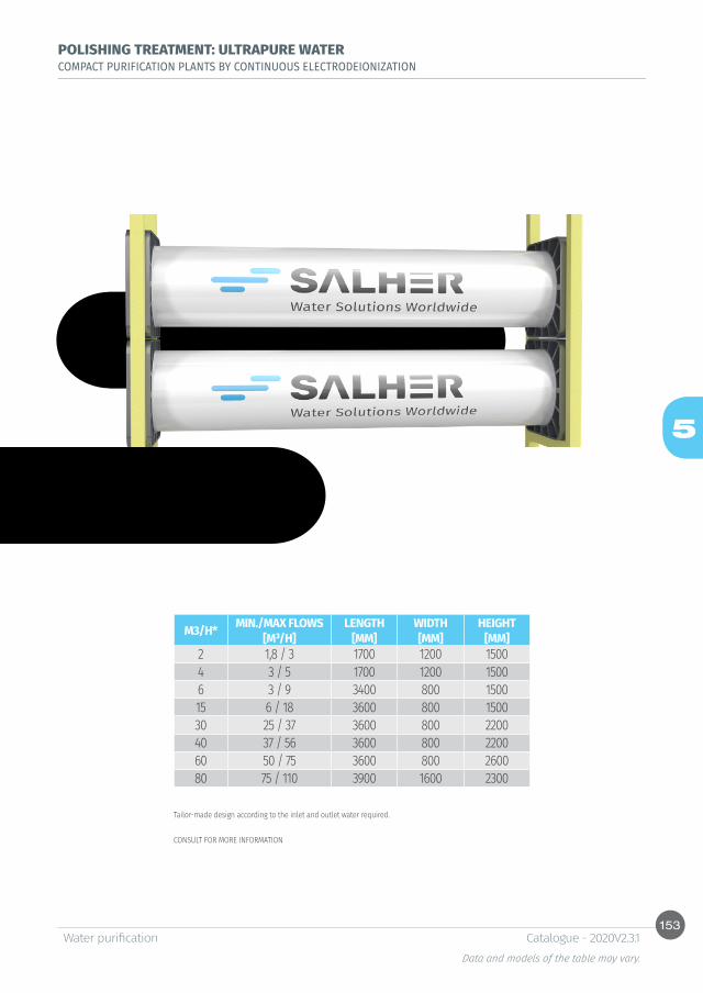
153
5
Water purification Data and models of the table may vary.
Catalogue - 2020V2.3.1
POLISHING TREATMENT: ULTRAPURE WATERCOMPACT PURIFICATION PLANTS BY CONTINUOUS ELECTRODEIONIZATION
Tailor-made design according to the inlet and outlet water required.
CONSULT FOR MORE INFORMATION
M3/H* MIN./MAX FLOWS LENGTH WIDTH HEIGHT[M³/H] [MM] [MM] [MM]
2 1,8 / 3 1700 1200 15004 3 / 5 1700 1200 15006 3 / 9 3400 800 150015 6 / 18 3600 800 150030 25 / 37 3600 800 220040 37 / 56 3600 800 220060 50 / 75 3600 800 260080 75 / 110 3900 1600 2300
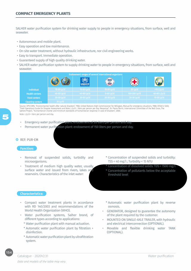
154
5
Water purification Data and models of the table may vary.
Catalogue - 2020V2.3.1
COMPACT EMERGENCY PLANTS
SALHER water purification system for drinking water supply to people in emergency situations, from surface, well and seawater.
• Autonomous and mobile plant.• Easy operation and low maintenance.• On-site water treatment, without hydraulic infrastructure, nor civil engineering works.• Easy to transport. Immediate operation.• Guaranteed supply of high quality drinking water.• SALHER water purification system to supply drinking water to people in emergency situations, from surface, well and
seawater.Endowment ranges of several international organisms
1 2 3 4 5
Individual 15-20 Lp/d 15-20 Lp/d 15-20 Lp/d 20 Lp/d >15 L/p/dHealth centers 40-60 Lp/d 40-60 Lp/d 0-60 Lp/d 100-200 Lp/d 40-60 L/p/dFood centers 20-30 Lp/d 20-30 Lp/d 20-30 Lp/d 20-30 Lp/d 15-30 Lp/d
Cleaning centers 35 Lp/d - - - -
Source: OPS/OMS, “Environmental health after natural disasters”, 1982; United Nations High Commissioner for Refugees, Manual for emergency situations, 1988; OFDA/U SAID, “Field Operations Guide for Disaster Assessment and Note: L/p/d = liters per person per day. Response”; Dr. Pierre Perrin, International Committee of the Red Cross; The Sphere Project, “Humanitarian Charter and minimum standards of humanitarian response in case of disasters”, 2000.Note: L/p/d = liters per person and day.
• Emergency water purification plant: endowment of 20 liters per person and day.• Permanent water purification plant: endowment of 150 liters per person and day.
Function:
Characteristics:
REF: PUR-EM
• Removal of suspended solids, turbidity and microorganisms.
• Treatment of medium high quality water, usually surface water and issued from rivers, lakes and reservoirs. Characteristics of the inlet water:
• Compact water treatment plants in accordance with RD 140/2003 and recommendations of the World Health Organization (WHO).
• Water purification systems, Salher brand, of different types according to applications:
* Water purification plant with manual actuation.* Automatic water purification plant by filtration +
disinfection.* Automatic water purification plant by ultrafiltration
system.
* Automatic water purification plant by reverse osmosis.
• GENERATOR, designed to guarantee the autonomy of the plant required by the customer.
• MOUNTED ON SINGLE-AXLE TRAILER, with hydraulic and electrical interconnection (OPTIONAL).
• Movable and flexible drinking water TANK (OPTIONAL).
* Concentration of suspended solids and turbidity: TSS < 40 mg/l ; Turbidity < 15 NTU
* Concentration of dissolved solids: TDS < 1500 mg/l* Concentration of pollutants below the acceptable
threshold level
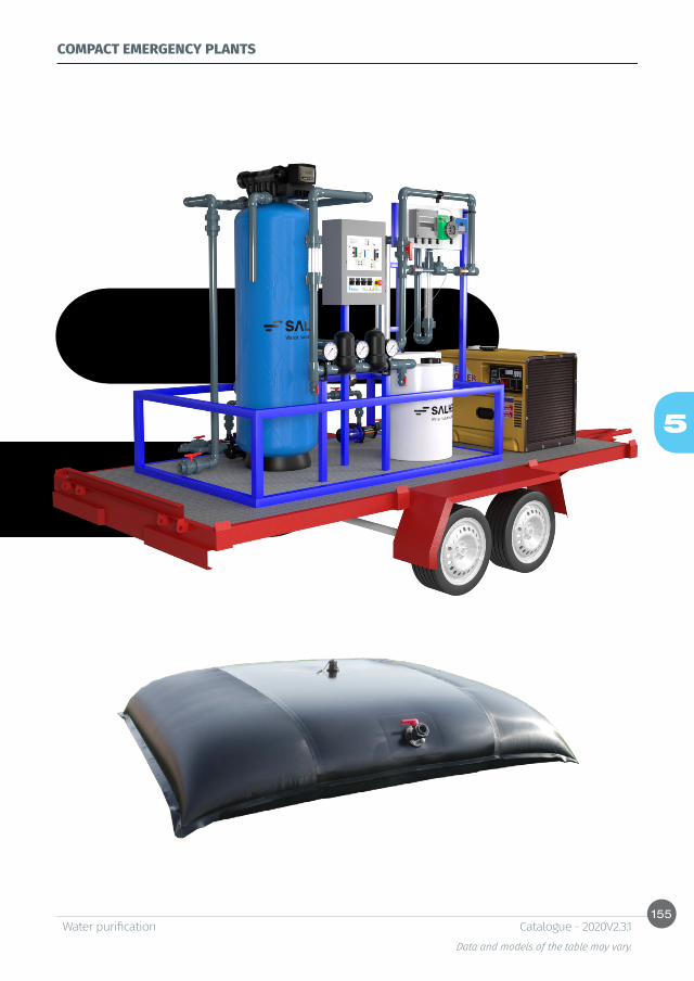
155
5
Water purification Data and models of the table may vary.
Catalogue - 2020V2.3.1
COMPACT EMERGENCY PLANTS
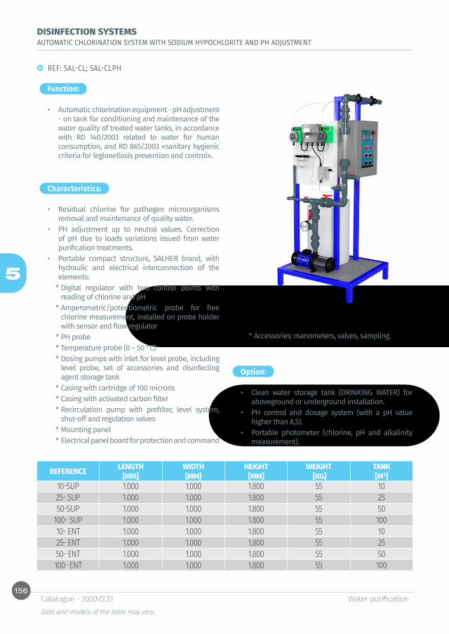
156
5
Water purification Data and models of the table may vary.
Catalogue - 2020V2.3.1
DISINFECTION SYSTEMSAUTOMATIC CHLORINATION SYSTEM WITH SODIUM HYPOCHLORITE AND PH ADJUSTMENT
Function:
Characteristics:
REF: SAL-CL; SAL-CLPH
• Automatic chlorination equipment - pH adjustment - on tank for conditioning and maintenance of the water quality of treated water tanks, in accordance with RD 140/2003 related to water for human consumption, and RD 865/2003 «sanitary hygienic criteria for legionellosis prevention and control».
• Residual chlorine for pathogen microorganisms removal and maintenance of quality water.
• PH adjustment up to neutral values. Correction of pH due to loads variations issued from water purification treatments.
• Portable compact structure, SALHER brand, with hydraulic and electrical interconnection of the elements:
* Digital regulator with two control points with reading of chlorine and pH
* Amperometric/potentiometric probe for free chlorine measurement, installed on probe holder with sensor and flow regulator
* PH probe* Temperature probe (0 – 50 °C)* Dosing pumps with inlet for level probe, including
level probe, set of accessories and disinfecting agent storage tank
* Casing with cartridge of 100 microns* Casing with activated carbon filter* Recirculation pump with prefilter, level system,
shut-off and regulation valves* Mounting panel * Electrical panel board for protection and command
Option:
• Clean water storage tank (DRINKING WATER) for aboveground or underground installation.
• PH control and dosage system (with a pH value higher than 8,5).
• Portable photometer (chlorine, pH and alkalinity measurement).
* Accessories: manometers, valves, sampling.
REFERENCE LENGTH WIDTH HEIGHT WEIGHT TANK[MM] [MM] [MM] [KG] [M³]
10-SUP 1.000 1.000 1.800 55 1025- SUP 1.000 1.000 1.800 55 2550-SUP 1.000 1.000 1.800 55 50
100- SUP 1.000 1.000 1.800 55 10010- ENT 1.000 1.000 1.800 55 1025- ENT 1.000 1.000 1.800 55 2550- ENT 1.000 1.000 1.800 55 50100- ENT 1.000 1.000 1.800 55 100

157
5
Water purification Data and models of the table may vary.
Catalogue - 2020V2.3.1
DISINFECTION SYSTEMSAUTOMATIC REDOX STATION
Function:
Characteristics:
REF: SAL-RX
• Chlorine-redox automatic equipment for water quality maintenance in fire protection water tanks and water reuse tanks, WWTP effluent pathogens removal, etc. in accordance with RD 865/2003 «hygienic sanitary criteria for legionellosis prevention and control».
• Compact mobile structure, Salher brand, with hydraulic and electrical interconnections of the elements:
* Digital regulator.* Redox probe for potential measurement in mV,
mounted on probe holder on pipe/casing.* Dosing pump with level probe inlet, including level
probe, kit of accessories and disinfectant agents storage tank.
* Casing with cartridge of 100 microns..* Recirculation pump (submerged or surface) with
level regulators, shut-off and regulation valves.* Mounting panel.* Electrical panel board for protection and
command.* Accessories: manometers, valves, sampling.
Option:
• Water tank for fire protection / tanks for reuse water storage, for aboveground and underground installation.
• Portable photometer (chlorine, pH and alkalinity measurement).
* Especially to keep water clean in water tanks for fire protection.Note: options for installation with underground or aboveground tank.
REFERENCE LENGTH WIDTH HEIGHT WEIGHT TANK[MM] [MM] [MM] [KG] [M³]
SAL-RX -10-SUP 1.000 1.000 1.800 55 10SAL-RX -25- SUP 1.000 1.000 1.800 55 25SAL-RX -50-SUP 1.000 1.000 1.800 55 50
SAL-RX -100- SUP 1.000 1.000 1.800 55 100SAL-RX -10- ENT 1.000 1.000 1.800 55 10SAL-RX -25- ENT 1.000 1.000 1.800 55 25SAL-RX -50- ENT 1.000 1.000 1.800 55 50SAL-RX -100- ENT 1.000 1.000 1.800 55 100

158
5
Water purification Data and models of the table may vary.
Catalogue - 2020V2.3.1
DISINFECTION SYSTEMSCHLORINATION CHAMBER WITH DOSING SYSTEM
Function:
Characteristics:
REF: CVC-CE
• Disinfection system for effluents issued from treatment plants, including pathogen germ removal.
• Contact-chlorination chamber, SALHER brand, manufactured in GFRP, cylindrical vertical layout with contact deflectors.
• Dosing system of hypochlorite composed of:* Dosing pump with membrane electromagnetically
operated, impulsions regulation and inlet for level probe, flow 5 – 10 l/h at maximum pressure of 10 bar, power supply 220V 50 – 60 Hz
* Polyethylene tank for product mix with a capacity of 120 liters
* Level probe for disconnection due to lack of product
* Kit of accessories. Filter with double ball check valve, injection pipe with ball anti-return valve, 2 m suction pipe of PVC-cristal, 4 m polyetylene impulsion pipe, fixation, screws and fuse
Two options are available:
• Type 1:* Disinfection chamber.
• Type 2:* Disinfection chamber.* Dosing pump.* Sodium hypochlorite tank.
DIMENSIONS ARE IN MM AND INTERIOR
PE CAPACITY Ø HEIGHT Ø MANHOLE Ø PIPE[L] [MM] [MM] [MM] [MM]
1 A 50 500 1.000 750 400 1255 A 75 750 1.000 1.070 500 125
76 A 100 1.000 1.200 1.000 500 160101 A 200 1.500 1.400 1.120 620 200201 A 300 2.000 1.400 1.440 620 200301 A 400 2.500 1.400 1.760 620 250401 A 500 3.000 1.700 1.490 620 250501 A 600 3.500 1.700 1.710 620 300601 A 700 4.000 2.000 1.470 620 300701 A 800 4.500 2.000 1.520 620 300801 A 900 5.000 2.000 1.790 620 300901 A 1.000 5.500 2.500 1.370 620 300
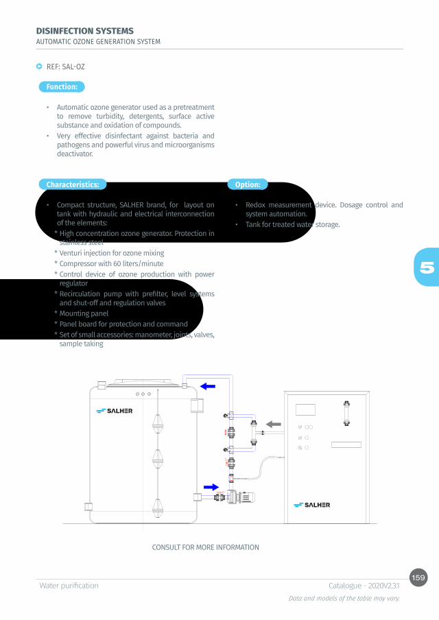
159
5
Water purification Data and models of the table may vary.
Catalogue - 2020V2.3.1
DISINFECTION SYSTEMSAUTOMATIC OZONE GENERATION SYSTEM
Function:
Characteristics:
REF: SAL-OZ
• Automatic ozone generator used as a pretreatment to remove turbidity, detergents, surface active substance and oxidation of compounds.
• Very effective disinfectant against bacteria and pathogens and powerful virus and microorganisms deactivator.
• Compact structure, SALHER brand, for layout on tank with hydraulic and electrical interconnection of the elements:
* High concentration ozone generator. Protection in stainless steel
* Venturi injection for ozone mixing* Compressor with 60 liters/minute* Control device of ozone production with power
regulator* Recirculation pump with prefilter, level systems
and shut-off and regulation valves * Mounting panel* Panel board for protection and command* Set of small accessories: manometer, joints, valves,
sample taking
Option:
• Redox measurement device. Dosage control and system automation.
• Tank for treated water storage.
CONSULT FOR MORE INFORMATION
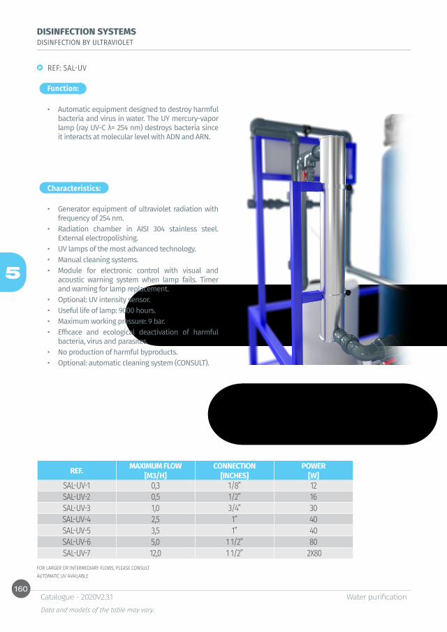
160
5
Water purification Data and models of the table may vary.
Catalogue - 2020V2.3.1
DISINFECTION SYSTEMSDISINFECTION BY ULTRAVIOLET
Function:
Characteristics:
REF: SAL-UV
• Automatic equipment designed to destroy harmful bacteria and virus in water. The UY mercury-vapor lamp (ray UV-C λ= 254 nm) destroys bacteria since it interacts at molecular level with ADN and ARN.
• Generator equipment of ultraviolet radiation with frequency of 254 nm.
• Radiation chamber in AISI 304 stainless steel. External electropolishing.
• UV lamps of the most advanced technology.• Manual cleaning systems.• Module for electronic control with visual and
acoustic warning system when lamp fails. Timer and warning for lamp replacement.
• Optional: UV intensity sensor.• Useful life of lamp: 9000 hours.• Maximum working pressure: 9 bar.• Efficace and ecological deactivation of harmful
bacteria, virus and parasites.• No production of harmful byproducts.• Optional: automatic cleaning system (CONSULT).
FOR LARGER OR INTERMEDIARY FLOWS, PLEASE CONSULTAUTOMATIC UV AVAILABLE
REF. MAXIMUM FLOW CONNECTION POWER[M3/H] [INCHES] [W]
SAL-UV-1 0,3 1/8” 12SAL-UV-2 0,5 1/2” 16SAL-UV-3 1,0 3/4” 30SAL-UV-4 2,5 1” 40SAL-UV-5 3,5 1” 40SAL-UV-6 5,0 1 1/2” 80SAL-UV-7 12,0 1 1/2” 2X80

161
5
Water purification Data and models of the table may vary.
Catalogue - 2020V2.3.1


6Oil/water separators


Table of contents
Class I Oil/water separators by coalescenceClass I Oil/water separator by coalescence, separation chamber, skimmer and compact storage tankREF: CHC-SH-L-X-K 166Class I Oil/water separator by coalescence, skimmer and independent storage tankREF: CHC-SH-L-K 167Class I Oil/water separator by coalescence, with mechanical skimmer and independent storage tankREF: CHC-SH-L-K-M 168Class I Oil/water separator by coalescence, with 2 separation chambers, automatic closure device and oil filterREF: CHC-SH-L-2 170REF: CHC-SH-L-2-O 170REF: CHC-SH-L-2-F 170REF: CHC-SH-L-2-F-O 170Class I Oil/water separator by coalescence, with 2 separation chambers, automatic closure device and oil filter
Class I Oil/water separator by coalescence with built-in settling, automatic closure device and by-pass systemREF: CHC-SH-L-O-BP 172Class I Oil/water separator, 1 separation chamber, automatic closure device and oil filterREF: CVC-SH-F-O; CVC-SH-F 174
Class II Oil/water separators standardClass II Oil/water separator, 1 separation chamber, standardREF: CVC-SH-C; CVC-SH-C-O 175
Accessories for oil/water separatorsIndependent oil storage tank REF: CVC-AC 176Vertical sand and solids settling tankREF: CVC-DC 177Vertical sand and solids settling tank REF: CHC-DES 178Mechanical skimmer REF: SK 180REF: SK-ATEX 180Storm spillway and flow regulator
REF: CVC-AARC 181Oil filters and automatic closure devices for oil/water separators Salher® 182Absorbent filter for oil/water separators Salher® 183Hydrocarbon level detection alarm REF: OMS-1 184Sand and solids detection alarmREF: IDOIL-S 184Oil, hydrocarbon, sand and solids detection alarmREF: IDOIL-OS 184Oil, hydrocarbon, sand, solids and maximum level alarmREF: IDOIL-LOS 185Oil, hydrocarbon, sand and solids detection alarm with solar panel charging and warning via mobileREF: IDOIL-SOLAR 185Floating hydrocarbon level alarmREF: SET-OSK2 185
Other dimensions and configurations can be provided upon request. Internal dimensions. Dimensions in millimeters. Volumes in liters, the dimensions indicated may vary according to the needs.Due to its policy of continuous development, Salher Ibérica, S.L. reserves the right to modify the data that appear in this document without notice.This document is protected by the intellectual property law, so that the customer cannot claim, manipulate or duplicate this documentation, except copy for personal use.

166
6
L
ØBØB ØB
Ø
Oil/water separatorsData and models of the table may vary.
Catalogue - 2020V2.3.1
Class I Oil/water separators by coalescence
Function: Characteristics:
Class I Oil/water separator by coalescence, separation chamber, skimmer and compact storage tank
REF: CHC-SH-L-X-K
• Separation of mineral oil, grease and hydrocarbon from water by density difference and coalescence. This unit does not separate emulsified oil and hydrocarbon.
Note: For organic oil and grease removal (animal and vegetal), please refer to Grease Separators.
• Salher brand, model CHC-SH-L-X-K. Class I: outlet parameters lower than 5 ppm.
• Designed in accordance with EN 858.• Equipment manufactured in GFRP (Glass Fiber
Reinforced Polyester) with orthophthalic resins.• Oil separation, solids settling and oil storage chambers.• Coalescing plates with large specific surface: 240m²/
m³.• Adjustable skimmer to collect separated oil and
hydrocarbon.• Built-in storage chamber for the separated oil. Removal
of oil through upper manhole.• PVC inlet and outlet. Outlet in the manhole to install a
ventilation pipe.• Oil and hydrocarbon detection alarm in option.
Options
Flow(l/s). Capacity (l). Dimensions (mm). For larger flows, please consult.
FLOW TOTAL CAPACITY CAPACITY K. CAPACITY S-B. CAPACITY A Ø L Ø PIPE Ø MANHOLE[L/S] [LITRES] [LITRES] [LITRES] [LITRES] [MM] [MM] [MM] [MM]
3 1.800 600 600 600 1.000 2.480 110-125 2X5005 3.200 1.900 600 700 1.200 3.340 125-160 6207 4.500 2.400 1.200 900 1.400 3.200 125-160 62010 7.000 3.000 2.250 1.750 1.400 4.900 160-200 62015 11.000 4.000 4.250 2.750 1.700 5.180 160-200 62020 14.500 6.000 5.000 3.500 2.000 5.000 200-250 62025 18.000 8.000 5.500 4.500 2.000 6.120 250 620
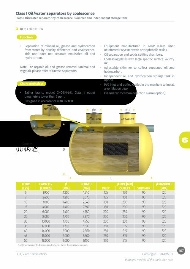
167
6
L
ØB ØB
Ø
Oil/water separatorsData and models of the table may vary.
Catalogue - 2020V2.3.1
Class I Oil/water separators by coalescence
Function:
Characteristics:
Class I Oil/water separator by coalescence, skimmer and independent storage tank
REF: CHC-SH-L-K
• Separation of mineral oil, grease and hydrocarbon from water by density difference and coalescence. This unit does not separate emulsified oil and hydrocarbon.
Note: For organic oil and grease removal (animal and vegetal), please refer to Grease Separators.
• Salher brand, model CHC-SH-L-K. Class I: outlet parameters lower than 5 ppm.
• Designed in accordance with EN 858.
• Equipment manufactured in GFRP (Glass Fiber Reinforced Polyester) with orthophthalic resins.
• Oil separation and solids settling chambers.• Coalescing plates with large specific surface: 240m2/
m3.• Adjustable skimmer to collect separated oil and
hydrocarbon.• Independent oil and hydrocarbon storage tank in
option. • PVC inlet and outlet. Outlet in the manhole to install
a ventilation pipe.• Oil and hydrocarbon detection alarm (option).
Options
Flow(l/s). Capacity (l). Dimensions (mm). For larger flows, please consult.
FLOW CAPACITY Ø LENGTH Ø PIPE [MM] Ø MANHOLE[L/S] [LITRES] [MM] [MM] INLET OUTLET SKIMMER [MM]
5 1.900 1.200 1.910 125 160 90 6207 2.400 1.200 2.370 125 160 90 62010 3.000 1.400 2.340 160 200 90 62015 4.000 1.400 2.890 160 200 90 62020 6.000 1.400 4.180 200 250 90 62025 8.000 1.700 3.870 200 250 90 62030 10.000 1.700 4.750 200 250 90 62035 12.000 1.700 5.630 250 315 90 62040 14.000 2.000 4.860 250 315 90 62045 16.000 2.000 5.500 250 315 90 62050 18.000 2.000 6.150 250 315 90 620

168
6
L
ØB ØB
Ø
Oil/water separatorsData and models of the table may vary.
Catalogue - 2020V2.3.1
Class I Oil/water separators by coalescence
Function:
Class I Oil/water separator by coalescence, with mechanical skimmer and independent storage tank
REF: CHC-SH-L-K-M
• Separation of mineral oil, grease and hydrocarbon from water by density difference and coalescence. This unit does not separate emulsified oil and hydrocarbon.
Note: For organic oil and grease removal (animal and vegetal), please refer to Grease Separators.
Characteristics:
• Salher brand, model CHC-SH-L-K-M. Class I: outlet parameters lower than 5 ppm.
Flow(l/s). Capacity (l). Dimensions (mm). For larger flows, please consult.
• Designed in accordance with EN 858.• Equipment manufactured in GFRP (Glass Fiber
Reinforced Polyester) with orthophthalic resins.• Oil separation and solids settling chambers.• Coalescing plates with large specific surface: 240m²/
m³.• Mechanical skimmer for oil collection.• Independent oil and hydrocarbon storage tank in
option. • PVC inlet and outlet. Outlet in the manhole to install
a ventilation pipe.• Oil and hydrocarbon detection alarm (option).
Options
FLOW CAPACITY Ø LENGTH Ø PIPES [MM] Ø MANHOLE N°[L/S] [LITRES] [MM] [MM] INLET OUTLET SKIMMER [MM] SUPPORTS
5 1.900 1.200 1.910 125 125 50 620 27 2.400 1.200 2.370 125 125 50 620 210 3.000 1.400 2.340 160 160 50 620 215 4.000 1.400 2.890 160 160 50 620 220 6.000 1.400 4.180 200 200 50 620 225 8.000 1.700 3.870 250 250 50 620 230 10.000 1.700 4.750 250 250 50 620 235 12.000 1.700 5.630 315 315 50 620 240 14.000 2.000 4.860 315 315 50 620 245 16.000 2.000 5.500 315 315 50 620 250 18.000 2.000 6.150 315 315 50 620 2

169
6
Oil/water separatorsData and models of the table may vary.
Catalogue - 2020V2.3.1

170
6
L
ØB
CSCE
ØB
Ø
Oil/water separatorsData and models of the table may vary.
Catalogue - 2020V2.3.1
Class I Oil/water separators by coalescence
Function:
Class I Oil/water separator by coalescence, with 2 separation chambers, automatic closure device and oil filter
REF: CHC-SH-L-2
• Mineral oil and grease, and hydrocarbon separation from water by density difference and coalescence. This unit does not separate emulsified oil and hydrocarbon.
NOTE: For organic oil and grease removal (vegetal and animal), please refer to Grease Separators.
Characteristics:
• Salher brand, model CHC-SH-L-2. Class I: outlet oil concentration lower than 5 ppm.
• Designed in accordance with EN 858 Standard.• Equipment manufactured in GFRP (Glass Fiber
Reinforced Polyester) with orthophthalic resins.• Oil and hydrocarbon separation and solids settling
chambers.• Accumulation of oil and hydrocarbon on water
surface.
• Coalescing plates with large specific surface: 240m2/m3.
• Oil filter and automatic closure device composed of float and closure system.
• Oil removal through manhole.• PVC inlet and outlet pipes. Manhole with air vent to
install a ventilation pipe.• Optional: oil and hydrocarbon detection alarm.
Options
REF: CHC-SH-L-2-OREF: CHC-SH-L-2-FREF: CHC-SH-L-2-F-O

171
6
Oil/water separatorsData and models of the table may vary.
Catalogue - 2020V2.3.1
Class I Oil/water separators by coalescenceClass I Oil/water separator by coalescence, with 2 separation chambers, automatic closure device and oil filter
Flow (l/s). Capacity (l). Dimensions (mm). For larger flows, please consult.
FLOW VOL. Ø LENGTH Ø PIPE Ø MANHOLE
OIL STORAGE CE CS OIL
LAYER
VOL. WITH OILS
USEFUL VOL.
N° PLATES
[L/S] [LITRES] [MM] [MM] [MM] [MM] [LITRES] MM] [MM] [MM] [LITRES] [LITRES] 3 1.200 1.000 1.900 110 500 45 890 840 45 1132 1087 15 2.200 1.200 2.000 125 500 45 1075 1025 45 1437 1392 27 2.550 1.200 2.260 160 500 109 1040 990 65 2160 2051 210 3.400 1.400 2.210 160 620 150 1240 1170 85 2857 2707 315 4.500 1.400 3.190 160 620 229 1240 1170 85 4283 4054 420 6.550 1.700 3.200 200 620 342 1500 1430 110 6268 5926 625 8.000 1.700 3.843 250 620 388 1450 1380 90 7401 7013 730 9.000 1.700 4.290 250 620 484 1450 1380 100 8379 7895 840 12.000 1.700 5.600 315 620 642 1385 1315 90 10652 10010 1050 15.000 2.000 5.150 315 620 795 1685 1585 110 13641 12846 1460 18.000 2.000 6.100 315 620 956 1685 1585 110 16338 15382 1670 22.000 2.250 6.000 315 620 1063 1935 1835 110 21008 19945 1880 25.000 2.250 6.700 315 620 1198 1935 1835 110 23631 22433 2090 28.000 2.250 7.470 315 620 1347 1935 1835 110 26517 25170 24100 30.000 2.250 7.970 315 620 1444 1935 1835 110 28391 26947 28

172
6
Oil/water separatorsData and models of the table may vary.
Catalogue - 2020V2.3.1
Class I Oil/water separators by coalescence
Function:
Class I Oil/water separator by coalescence with built-in settling, automatic closure device and by-pass system
REF: CHC-SH-L-O-BP
• Mineral oil and grease and hydrocarbon separation from water by density difference and coalescence. This unit does not separate emulsified oil.
• Regulation and by-pass system for flows excess, excellent for large surfaces. The excess water accumulated in the equipment is separated and carried directly outwards, and the oil/water separator will treat only the nominal flow.
Characteristics:
• Salher brand, model CHC-SH-L-O-BP. Class I: outlet parameters lower than 5 ppm.
• Includes sand and solids settling chamber. • Flow regulator system and by-pass with overflow
for water excess. • Designed in accordance with EN 858.• Equipment manufactured in GFRP (Glass Fiber
Reinforced Polyester) with orthophthalic resins.• Oil and hydrocarbon separation and solids settling
chambers.• Accumulation of oil and hydrocarbon on water
surface.• Coalescing plates with large specific surface:
240m2/m3.
• Oil filter and automatic closure device composed of float and closure system.
• Oil removal by upper manhole. • PVC inlet and outlet. Outlet in the manhole to
install a ventilation pipe.
OPTION: • Oil and hydrocarbon detection alarm.• Oil maximum level alarm.• Maximum level alarm to avoid clogging. • Mechanical skimmer for separated oil removal.• Please consult flow regulators for larger flows.
Options
For the run-off in excess a flow by-pass is incorporated. This unit is appropriate for large run-off collection surfaces. The excess run-off that enters the unit is separated and conveyed directly outwards ensuring that the unit only treats the nominal design flow.Note: For organic oil and grease removal (animal and vegetal), please refer to Grease Separators.

173
6
L
ØB ØB ØB
Ø
Oil/water separatorsData and models of the table may vary.
Catalogue - 2020V2.3.1
Class I Oil/water separators by coalescenceClass I Oil/water separator by coalescence with built-in settling, automatic closure device and by-pass system
Flow(l/s). Capacity (l). Dimensions (mm). For larger flows, please consult.
NOMINAL FLOW
MAXIMUM FLOW VOLUME Ø LENGTH Ø PIPE Ø MANHOLE
[L/S] [L/S] [LITRES] [MM] [MM] [MM] [MM]3 15 2.000 1.200 1.800 200 5005 30 3.000 1.400 2.000 250 62010 40 4.000 1.400 2.950 315 62015 50 5.000 1.700 2.250 315 62020 100 6.500 1.700 2.700 315 62040 200 15.000 2.000 4.800 500 75050 250 20.000 2.000 6.400 500 75080 300 25.000 2.250 6.300 500 750100 350 30.000 2.250 7.550 500 750150 500 45.000 2.500 9.200 600 750200 700 55.000 3.000 7.800 700 750250 825 70.000 3.000 10.000 800 750

174
6H
ØB
390
Ø
Oil/water separatorsData and models of the table may vary.
Catalogue - 2020V2.3.1
Class I Oil/water separators by coalescence
Function:
Class I Oil/water separator, 1 separation chamber, automatic closure device and oil filter
REF: CVC-SH-F-O; CVC-SH-F
• Mineral oil and grease and hydrocarbon separation from water by density difference. This unit does not separate emulsified oil.
Characteristics:
• Salher brand, model CVC-SH-F-O (with oil filter and automatic closure device); CVC-SH-F (with oil filter). Class I: outlet parameters lower than 5 ppm.
• Designed in accordance with EN 858.• Equipment manufactured in GFRP (Glass Fiber
Reinforced Polyester) with orthophthalic resins.• Oil and hydrocarbon separation and solids settling
chambers.• Accumulation of oil and hydrocarbon on water
surface.• Oil filter and automatic closure device composed of
float and closure system.
• Oil removal by upper manhole. • PVC inlet and outlet. Outlet in the manhole to install
a ventilation pipe.• Oil and hydrocarbon detection alarm (option).
Flow(l/s). Capacity (l). Dimensions (mm). For larger flows, please consult.
FLOW VOLUME Ø H Ø PIPE Ø MANHOLE[L/S] [LITRES] [MM] [MM] [MM] [MM]0,5 193 620 890 110 4001 380 750 980 110 4002 700 1.000 990 110 5003 1.000 1.000 1.360 110 5004 1.350 1.200 1.320 125 5005 1.800 1.400 1.310 125 5006 2.160 1.400 1.540 125 5007 2.520 1.400 1.770 160 5008 2.880 1.700 1.350 160 6209 3.240 1.700 1.600 160 62010 3.600 1.700 1.760 160 620
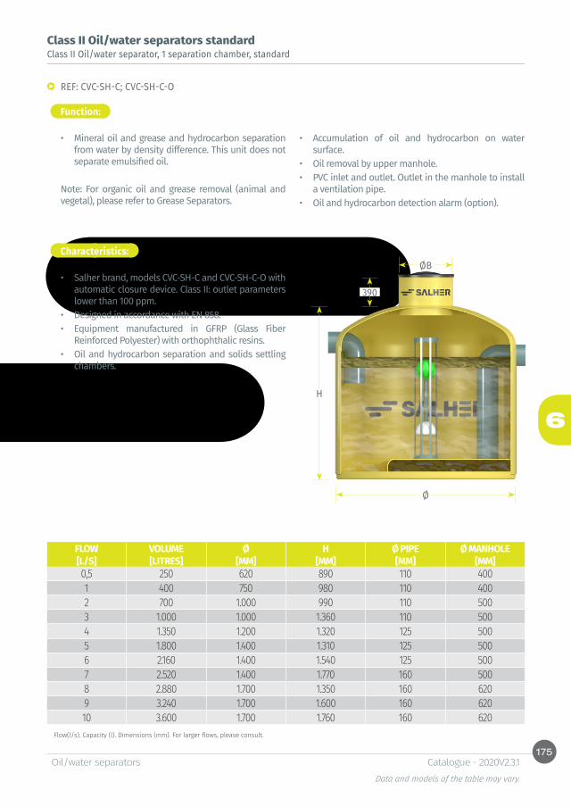
175
6H
ØB
390
Ø
Oil/water separatorsData and models of the table may vary.
Catalogue - 2020V2.3.1
Flow(l/s). Capacity (l). Dimensions (mm). For larger flows, please consult.
Class II Oil/water separators standard
Function:
Class II Oil/water separator, 1 separation chamber, standard
REF: CVC-SH-C; CVC-SH-C-O
• Mineral oil and grease and hydrocarbon separation from water by density difference. This unit does not separate emulsified oil.
Note: For organic oil and grease removal (animal and vegetal), please refer to Grease Separators.
Characteristics:
• Salher brand, models CVC-SH-C and CVC-SH-C-O with automatic closure device. Class II: outlet parameters lower than 100 ppm.
• Designed in accordance with EN 858.• Equipment manufactured in GFRP (Glass Fiber
Reinforced Polyester) with orthophthalic resins.• Oil and hydrocarbon separation and solids settling
chambers.
• Accumulation of oil and hydrocarbon on water surface.
• Oil removal by upper manhole. • PVC inlet and outlet. Outlet in the manhole to install
a ventilation pipe.• Oil and hydrocarbon detection alarm (option).
FLOW VOLUME Ø H Ø PIPE Ø MANHOLE[L/S] [LITRES] [MM] [MM] [MM] [MM]0,5 250 620 890 110 4001 400 750 980 110 4002 700 1.000 990 110 5003 1.000 1.000 1.360 110 5004 1.350 1.200 1.320 125 5005 1.800 1.400 1.310 125 5006 2.160 1.400 1.540 125 5007 2.520 1.400 1.770 160 5008 2.880 1.700 1.350 160 6209 3.240 1.700 1.600 160 62010 3.600 1.700 1.760 160 620
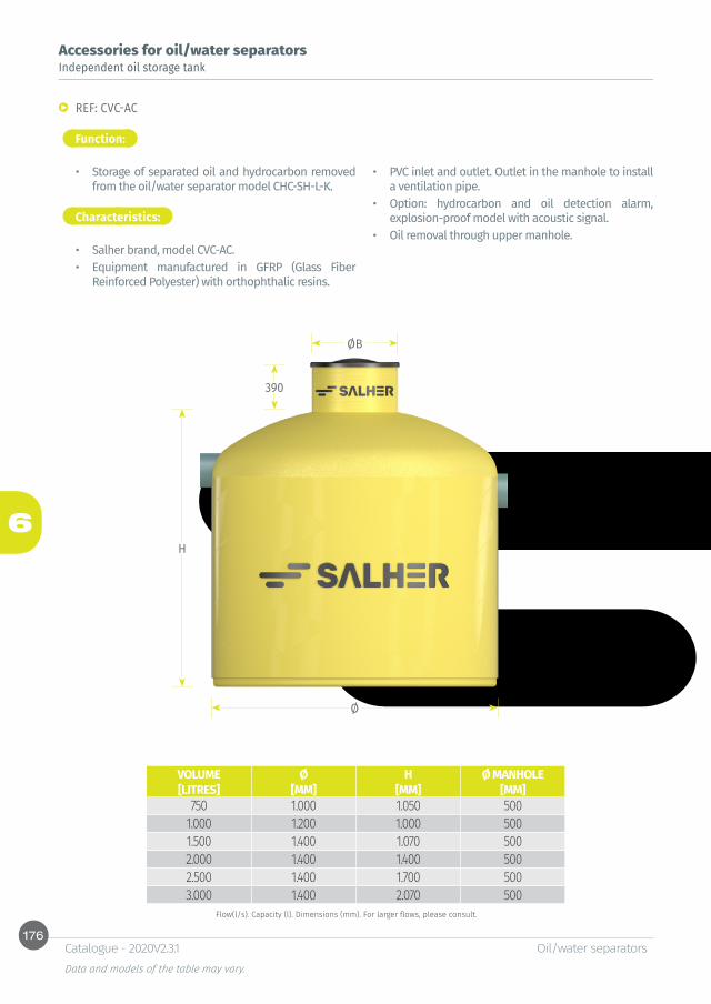
176
6H
ØB
390
Ø
Oil/water separatorsData and models of the table may vary.
Catalogue - 2020V2.3.1
Accessories for oil/water separators
Function:
Independent oil storage tank
REF: CVC-AC
• Storage of separated oil and hydrocarbon removed from the oil/water separator model CHC-SH-L-K.
Characteristics:
• Salher brand, model CVC-AC.• Equipment manufactured in GFRP (Glass Fiber
Reinforced Polyester) with orthophthalic resins.
Flow(l/s). Capacity (l). Dimensions (mm). For larger flows, please consult.
• PVC inlet and outlet. Outlet in the manhole to install a ventilation pipe.
• Option: hydrocarbon and oil detection alarm, explosion-proof model with acoustic signal.
• Oil removal through upper manhole.
VOLUME Ø H Ø MANHOLE[LITRES] [MM] [MM] [MM]
750 1.000 1.050 5001.000 1.200 1.000 5001.500 1.400 1.070 5002.000 1.400 1.400 5002.500 1.400 1.700 5003.000 1.400 2.070 500
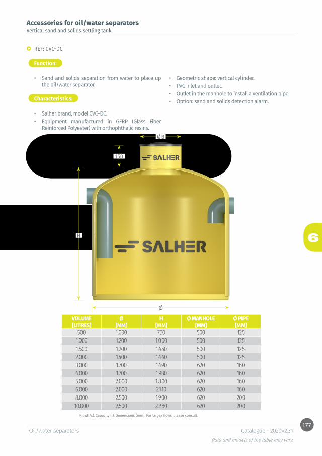
177
6H
ØB
150
Ø
Oil/water separatorsData and models of the table may vary.
Catalogue - 2020V2.3.1
Flow(l/s). Capacity (l). Dimensions (mm). For larger flows, please consult.
Accessories for oil/water separators
Function:
Vertical sand and solids settling tank
REF: CVC-DC
• Sand and solids separation from water to place up the oil/water separator.
Characteristics:
• Salher brand, model CVC–DC.• Equipment manufactured in GFRP (Glass Fiber
Reinforced Polyester) with orthophthalic resins.
Flow(l/s). Capacity (l). Dimensions (mm). For larger flows, please consult.
• Geometric shape: vertical cylinder. • PVC inlet and outlet.• Outlet in the manhole to install a ventilation pipe.• Option: sand and solids detection alarm.
VOLUME Ø H Ø MANHOLE Ø PIPE[LITRES] [MM] [MM] [MM] [MM]
500 1.000 750 500 1251.000 1.200 1.000 500 1251.500 1.200 1.450 500 1252.000 1.400 1.440 500 1253.000 1.700 1.490 620 1604.000 1.700 1.930 620 1605.000 2.000 1.800 620 1606.000 2.000 2.110 620 1608.000 2.500 1.900 620 20010.000 2.500 2.280 620 200
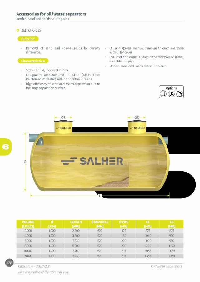
178
6
L
ØB ØB
Ø
Oil/water separatorsData and models of the table may vary.
Catalogue - 2020V2.3.1
Accessories for oil/water separators
Function:
Vertical sand and solids settling tank
REF: CHC-DES
• Removal of sand and coarse solids by density difference.
Characteristics:
• Salher brand, model CHC–DES.• Equipment manufactured in GFRP (Glass Fiber
Reinforced Polyester) with orthophthalic resins.• High efficiency of sand and solids separation due to
the large separation surface.
• Oil and grease manual removal through manhole with GFRP cover.
• PVC inlet and outlet. Outlet in the manhole to install a ventilation pipe.
• Option: sand and solids detection alarm.
Options
VOLUME Ø LENGTH Ø MANHOLE Ø PIPE CE CS[LITRES] [MM] [MM] [MM] [MM] [MM] [MM]
2.000 1.000 2.800 620 125 875 8254.000 1.200 3.800 620 160 1.040 9906.000 1.200 5.530 620 200 1.000 9508.000 1.400 5.500 620 200 1.200 1.15010.000 1.400 6.760 620 315 1.085 1.03515.000 1.700 6.930 620 315 1.385 1.335

179
6
Oil/water separatorsData and models of the table may vary.
Catalogue - 2020V2.3.1

180
6
A
E
B
C
D
Oil/water separatorsData and models of the table may vary.
Catalogue - 2020V2.3.1
* All dimensions are in mm.** Flows are indicative and depend on the product viscosity and working depth.
Accessories for oil/water separators
Function:
Mechanical skimmer
REF: SKREF: SK-ATEX
• Collection of mineral oil and hydrocarbon present in water or aqueous solutions.
Characteristics:
• Equipment manufactured in AISI 304 stainless steel.• Oil belt designed for extreme conditions.• Steel safety chain to prevent the loss of the skimmer
if the belt breaks.• Anti-splash protection in AISI 304 stainless steel.• Can be used as a pretreatment, before the filtration
or combined with a coalescing system.
• Compact, robust and handy.• Programmer and explosion protection in option. • Skimmer with explosion-proof protection ATEX in
option.
A B C D E FLOWREFERENCE [MM] [MM] [MM] [MM] [MM] [L/H]
SK - 100 176 320 -- 420 100 50SK - 150 176 320 -- 470 150 76SK - 200 176 320 -- 520 200 100
BELT SPARE PARTBANDA-SK - 100BANDA-SK - 150BANDA-SK - 200
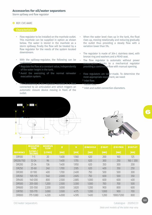
181
6
H
Ø
ØB150
Oil/water separatorsData and models of the table may vary.
Catalogue - 2020V2.3.1
Accessories for oil/water separatorsStorm spillway and flow regulator
REF: CVC-AARC
Characteristics:
• Flow regulator to be installed on the manhole outlet. This manhole can be supplied in option as shown below. The water is stored in the manhole as a storm spillway; finally the flow will be treated by a flow regulator for the needs of the system located downstream.
• With the spillway-regulator, the following can be performed:
* Regulate the flow at a constant value, independently of the water height in the tank.
* Avoid the oversizing of the normal rainwater evacuation system.
• The functioning of the regulator consists in a float connected to an articulated arm which triggers an automatic closure device moving in front of the outlet.
• When the water level rises up in the tank, the float rises up, moving rotationally and reducing gradually the outlet thus providing a steady flow with a variation lower than 5%.
• The regulator is made of 304-L stainless steel, with bronze ring and washers and a PEHD seat.
• The flow regulator is automatic without power consumption thanks to a mechanical regulator providing a continuous flow with manual opening.
• Flow regulators are tailor-made. To determine the most appropriate equipment, we need:
* Inlet flow.* Outlet flow. * Inlet and outlet connection diameters.
REGULATED FLOW
MAXIMUM FLOW Ø H Ø MANHOLE Ø INLET Ø BY-PASS Ø OUTLET
REFERENCE [LITRES /SECOND] [LITRES] [MM] [MM] [MM] [MM] [MM] [MM]
DR100 1-5 20 1.400 1.560 620 200 160 125DR200/150 5,1-24 96 1.400 1.755 620 300 250 160 / 200
DR200 25-34 136 1.400 1.950 620 350 300 200DR250 35-60 240 1.700 2.185 620 400 350 250DR300 61-100 400 1.700 2.400 750 500 500 300DR350 105-135 540 2.000 2.605 750 600 500 350DR400 140-200 800 2.500 2.885 1.000 600 600 400DR500 205-300 1.200 2.500 3.300 1.000 700 700 500DR600 335-550 2.200 3.000 3.820 1.200 900 800 600DR700 555-770 3.080 3.500 4.175 1.200 1.000 900 700DR800 775-1.080 4.320 4.000 4.595 1.400 1.200 1000/1200 800
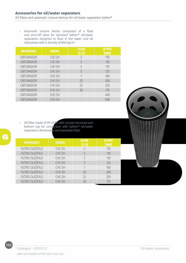
182
6
Oil/water separatorsData and models of the table may vary.
Catalogue - 2020V2.3.1
Accessories for oil/water separatorsOil filters and automatic closure devices for oil/water separators Salher®
• Automatic closure device composed of a float and shut-off valve for standard Salher® oil/water separators designed to float in the water and oil interphase with a density of 850 kg/m³.
• Oil filter made of PP-GFRP with circular structure and bottom cap for connection with Salher® oil/water separators. Removable and washable filter.
REFERENCE MODEL FLOW Ø PIPE [L/S] [MM]
OBTURADOR CVC-SH 2 110OBTURADOR CVC-SH 3 110OBTURADOR CHC-SH 3 110OBTURADOR CHC-SH 5 125OBTURADOR CHC-SH 7 160OBTURADOR CHC-SH 20 200OBTURADOR CHC-SH 25 250OBTURADOR CHC-SH 30 315OBTURADOR CHC-SH - 400OBTURADOR CHC-SH - 500
REFERENCE MODEL FLOW Ø PIPE [L/S] [MM]
FILTRO OLEÓFILO CVC-SH 2 110FILTRO OLEÓFILO CVC-SH 3 110FILTRO OLEÓFILO CHC-SH 3 110FILTRO OLEÓFILO CHC-SH 5 125FILTRO OLEÓFILO CHC-SH 7 160FILTRO OLEÓFILO CHC-SH 20 200FILTRO OLEÓFILO CHC-SH 25 250FILTRO OLEÓFILO CHC-SH 30 315
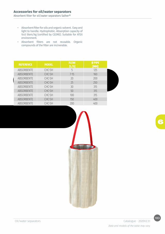
183
6
Oil/water separatorsData and models of the table may vary.
Catalogue - 2020V2.3.1
Accessories for oil/water separatorsAbsorbent filter for oil/water separators Salher®
• Absorbent filter for oils and organic solvent. Easy and light to handle. Hydrophobic. Absorption capacity of 9,43 liters/kg (certified by CEDRE). Suitable for ATEX environment.
• Absorbent filters are not reusable. Organic compounds of the filter are incinerable.
REFERENCE MODEL FLOW Ø PIPE [L/S] [MM]
ABSORBENTE CHC-SH 5 125ABSORBENTE CHC-SH 7-15 160ABSORBENTE CHC-SH 20 200ABSORBENTE CHC-SH 25 250ABSORBENTE CHC-SH 30 315ABSORBENTE CHC-SH 50 315ABSORBENTE CHC-SH 100 315ABSORBENTE CHC-SH 150 400ABSORBENTE CHC-SH 200 400

184
6
Oil/water separatorsData and models of the table may vary.
Catalogue - 2020V2.3.1
Hydrocarbon level detection alarm
Sand and solids detection alarm
Oil, hydrocarbon, sand and solids detection alarm
REF: OMS-1
REF: IDOIL-S
REF: IDOIL-OS
• Equipment of level detection of hydrocarbon, oil and grease to install in grease and oil/water separators with working temperatures (-20 to 50°C).
• Equipment of detection of level of sand and solids to install in grit chambers and solids settling tanks with working temperatures (-20 to 40°C).
• Combined alarm system for oil, hydrocarbon, sand and solids.
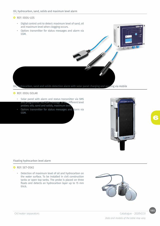
185
6
Oil/water separatorsData and models of the table may vary.
Catalogue - 2020V2.3.1
Oil, hydrocarbon, sand, solids and maximum level alarm
Oil, hydrocarbon, sand and solids detection alarm with solar panel charging and warning via mobile
Floating hydrocarbon level alarm
REF: IDOIL-LOS
REF: IDOIL-SOLAR
REF: SET-OSK2
• Digital control unit to detect: maximum level of sand, oil and maximum level when clogging occurs.
• Option: transmitter for status messages and alarm via GSM.
• Solar panel with alarm and status transmitter via SMS and programmer via MSM message of the different level probes: oils, sand and solids, maximum level.
• Option: transmitter for status messages and alarm via GSM.
• Detection of maximum level of oil and hydrocarbon on the water surface. To be installed in civil construction tanks or open top tanks. The probe is placed on three floats and detects an hydrocarbon layer up to 15 mm thick.

7Pumping stations


Table of contentsSelection of pumping stations. Summary of flows and performances.
PUMPING STATIONS SELECTION CHART
Standard pumping stationsRange miniREF: CVC-PB-A 194Range miniREF: CVA-PB-A 195Medium rangeREF: CVC-PB-B 196Maxi rangeREF: CVC-PB-C 197Maxi-Vortex rangeREF: CVC-PB-D 198Single-channel maxi rangeREF: CVC-PB-E 199Pumping station with 24 hours emergency storage capacityREF: CHC-PB-AC 200
Accessories for pumping stations Valve vaultREF: CVA-CV 201Manhole extension for pumping station REF: CVA-P-PB 201Access ladder to pumping stationREF: E-PB 202Pedestrian access coverREF: TAPA-PB 202Anti-fall platformREF: TRAMEX-PB 203Self-cleaning bottomREF: KORBBO 203Solids screen basketREF: RG-PB 204Fixing brackets REF: ES-PB 204Gallow and pulley for pumps extractionREF: P-PB 205
Other dimensions and configurations can be provided upon request. Internal dimensions. Dimensions in millimeters. Volumes in liters, the dimensions indicated may vary according to the needs.Due to its policy of continuous development, Salher Ibérica, S.L. reserves the right to modify the data that appear in this document without notice.This document is protected by the intellectual property law, so that the customer cannot claim, manipulate or duplicate this documentation, except copy for personal use.
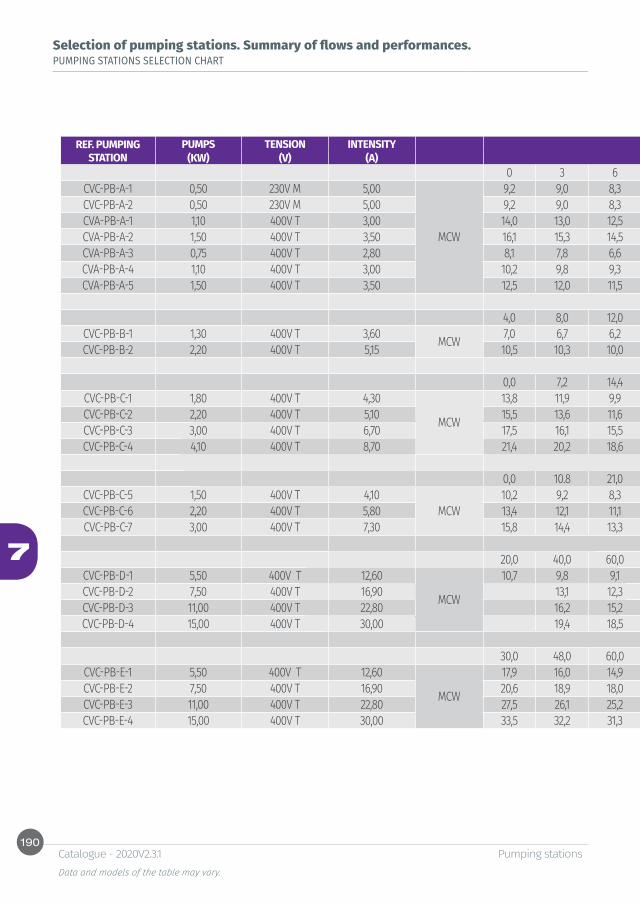
190
7
Pumping stationsData and models of the table may vary.
Catalogue - 2020V2.3.1
Selection of pumping stations. Summary of flows and performances.PUMPING STATIONS SELECTION CHART
REF. PUMPING STATION
PUMPS TENSION INTENSITY Ø(KW) (V) (A) FLOW M3/H SOLIDS PASSAGE
0 3 6 9 12 15 18 24 30 33 36 VÓRTEXCVC-PB-A-1 0,50 230V M 5,00
MCW
9,2 9,0 8,3 7,5 6,1 4,5 2,5 60CVC-PB-A-2 0,50 230V M 5,00 9,2 9,0 8,3 7,5 6,1 4,5 2,5 60CVA-PB-A-1 1,10 400V T 3,00 14,0 13,0 12,5 11,2 10,0 8,5 7,1 4,0 60CVA-PB-A-2 1,50 400V T 3,50 16,1 15,3 14,5 13,8 12,1 10,9 9,5 6,5 60CVA-PB-A-3 0,75 400V T 2,80 8,1 7,8 6,6 6,3 6,0 4,8 4,0 2,3 60CVA-PB-A-4 1,10 400V T 3,00 10,2 9,8 9,3 8,9 8,0 7,0 6,0 4,1 2,8 2,0 1,8 60CVA-PB-A-5 1,50 400V T 3,50 12,5 12,0 11,5 11,0 10,4 9,2 8,5 6,5 4,8 3,9 2,6 60
FLOW M3/H4,0 8,0 12,0 16,0 20,0 28,0 36,0 40,0 44,0 48,0 52,0 64,0 VÓRTEX
CVC-PB-B-1 1,30 400V T 3,60 MCW 7,0 6,7 6,2 5,8 5,3 4,6 3,8 3,4 3,0 2,6 2,3 60CVC-PB-B-2 2,20 400V T 5,15 10,5 10,3 10,0 9,5 9,0 8,5 7,8 7,2 6,8 6,5 6,0 4,8 60
FLOW M3/H0,0 7,2 14,4 21,6 28,8 36,0 43,2 50,4 57,6 64,8 72,0 VÓRTEX
CVC-PB-C-1 1,80 400V T 4,30
MCW
13,8 11,9 9,9 7,7 6,1 4,7 3,5 2,5 65CVC-PB-C-2 2,20 400V T 5,10 15,5 13,6 11,6 9,8 8,2 6,5 4,7 3,3 2,0 65CVC-PB-C-3 3,00 400V T 6,70 17,5 16,1 15,5 12,8 10,6 8,0 6,1 4,6 3,2 65CVC-PB-C-4 4,10 400V T 8,70 21,4 20,2 18,6 16,7 14,6 12,4 10,2 8,2 6,5 5,0 3,8 65
FLOW M3/H0,0 10.8 21,0 32,4 43,2 65,0 64,8 76,0 86,4 97,2 108,0 SINGLE CHANNEL
CVC-PB-C-5 1,50 400V T 4,10MCW
10,2 9,2 8,3 7,5 6,8 6,0 5,2 4,3 3,4 80CVC-PB-C-6 2,20 400V T 5,80 13,4 12,1 11,1 10,2 9,4 8,6 7,8 6,9 6,0 5,2 80CVC-PB-C-7 3,00 400V T 7,30 15,8 14,4 13,3 12,4 11,7 11,0 10,3 9,5 8,6 7,7 6,7 80
FLOW M3/H20,0 40,0 60,0 80,0 100,0 120,0 150,0 180,0 200,0 250,0 VÓRTEX
CVC-PB-D-1 5,50 400V T 12,60
MCW
10,7 9,8 9,1 8,4 7,6 6,5 98CVC-PB-D-2 7,50 400V T 16,90 13,1 12,3 11,5 10,6 9,8 98CVC-PB-D-3 11,00 400V T 22,80 16,2 15,2 14,2 13,4 12,5 11,1 9,8 100CVC-PB-D-4 15,00 400V T 30,00 19,4 18,5 17,7 16,8 15,8 14,4 13,0 12,1 100
FLOW M3/H30,0 48,0 60,0 72,0 78,0 96,0 114,0 132,0 144,0 150,0 SINGLE CHANNEL
CVC-PB-E-1 5,50 400V T 12,60
MCW
17,9 16,0 14,9 13,8 13,4 11,9 10,6 9,3 8,5 76CVC-PB-E-2 7,50 400V T 16,90 20,6 18,9 18,0 17,1 16,7 15,5 14,2 13,0 12,1 76CVC-PB-E-3 11,00 400V T 22,80 27,5 26,1 25,2 24,2 23,7 22,2 20,7 19,1 18,0 17,5 76CVC-PB-E-4 15,00 400V T 30,00 33,5 32,2 31,3 30,2 29,8 28,3 26,7 25,1 24,0 23,4 76
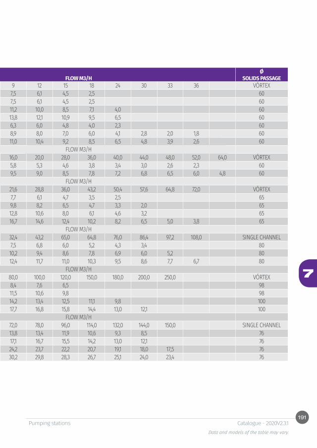
191
7
Pumping stationsData and models of the table may vary.
Catalogue - 2020V2.3.1
REF. PUMPING STATION
PUMPS TENSION INTENSITY Ø(KW) (V) (A) FLOW M3/H SOLIDS PASSAGE
0 3 6 9 12 15 18 24 30 33 36 VÓRTEXCVC-PB-A-1 0,50 230V M 5,00
MCW
9,2 9,0 8,3 7,5 6,1 4,5 2,5 60CVC-PB-A-2 0,50 230V M 5,00 9,2 9,0 8,3 7,5 6,1 4,5 2,5 60CVA-PB-A-1 1,10 400V T 3,00 14,0 13,0 12,5 11,2 10,0 8,5 7,1 4,0 60CVA-PB-A-2 1,50 400V T 3,50 16,1 15,3 14,5 13,8 12,1 10,9 9,5 6,5 60CVA-PB-A-3 0,75 400V T 2,80 8,1 7,8 6,6 6,3 6,0 4,8 4,0 2,3 60CVA-PB-A-4 1,10 400V T 3,00 10,2 9,8 9,3 8,9 8,0 7,0 6,0 4,1 2,8 2,0 1,8 60CVA-PB-A-5 1,50 400V T 3,50 12,5 12,0 11,5 11,0 10,4 9,2 8,5 6,5 4,8 3,9 2,6 60
FLOW M3/H4,0 8,0 12,0 16,0 20,0 28,0 36,0 40,0 44,0 48,0 52,0 64,0 VÓRTEX
CVC-PB-B-1 1,30 400V T 3,60 MCW 7,0 6,7 6,2 5,8 5,3 4,6 3,8 3,4 3,0 2,6 2,3 60CVC-PB-B-2 2,20 400V T 5,15 10,5 10,3 10,0 9,5 9,0 8,5 7,8 7,2 6,8 6,5 6,0 4,8 60
FLOW M3/H0,0 7,2 14,4 21,6 28,8 36,0 43,2 50,4 57,6 64,8 72,0 VÓRTEX
CVC-PB-C-1 1,80 400V T 4,30
MCW
13,8 11,9 9,9 7,7 6,1 4,7 3,5 2,5 65CVC-PB-C-2 2,20 400V T 5,10 15,5 13,6 11,6 9,8 8,2 6,5 4,7 3,3 2,0 65CVC-PB-C-3 3,00 400V T 6,70 17,5 16,1 15,5 12,8 10,6 8,0 6,1 4,6 3,2 65CVC-PB-C-4 4,10 400V T 8,70 21,4 20,2 18,6 16,7 14,6 12,4 10,2 8,2 6,5 5,0 3,8 65
FLOW M3/H0,0 10.8 21,0 32,4 43,2 65,0 64,8 76,0 86,4 97,2 108,0 SINGLE CHANNEL
CVC-PB-C-5 1,50 400V T 4,10MCW
10,2 9,2 8,3 7,5 6,8 6,0 5,2 4,3 3,4 80CVC-PB-C-6 2,20 400V T 5,80 13,4 12,1 11,1 10,2 9,4 8,6 7,8 6,9 6,0 5,2 80CVC-PB-C-7 3,00 400V T 7,30 15,8 14,4 13,3 12,4 11,7 11,0 10,3 9,5 8,6 7,7 6,7 80
FLOW M3/H20,0 40,0 60,0 80,0 100,0 120,0 150,0 180,0 200,0 250,0 VÓRTEX
CVC-PB-D-1 5,50 400V T 12,60
MCW
10,7 9,8 9,1 8,4 7,6 6,5 98CVC-PB-D-2 7,50 400V T 16,90 13,1 12,3 11,5 10,6 9,8 98CVC-PB-D-3 11,00 400V T 22,80 16,2 15,2 14,2 13,4 12,5 11,1 9,8 100CVC-PB-D-4 15,00 400V T 30,00 19,4 18,5 17,7 16,8 15,8 14,4 13,0 12,1 100
FLOW M3/H30,0 48,0 60,0 72,0 78,0 96,0 114,0 132,0 144,0 150,0 SINGLE CHANNEL
CVC-PB-E-1 5,50 400V T 12,60
MCW
17,9 16,0 14,9 13,8 13,4 11,9 10,6 9,3 8,5 76CVC-PB-E-2 7,50 400V T 16,90 20,6 18,9 18,0 17,1 16,7 15,5 14,2 13,0 12,1 76CVC-PB-E-3 11,00 400V T 22,80 27,5 26,1 25,2 24,2 23,7 22,2 20,7 19,1 18,0 17,5 76CVC-PB-E-4 15,00 400V T 30,00 33,5 32,2 31,3 30,2 29,8 28,3 26,7 25,1 24,0 23,4 76
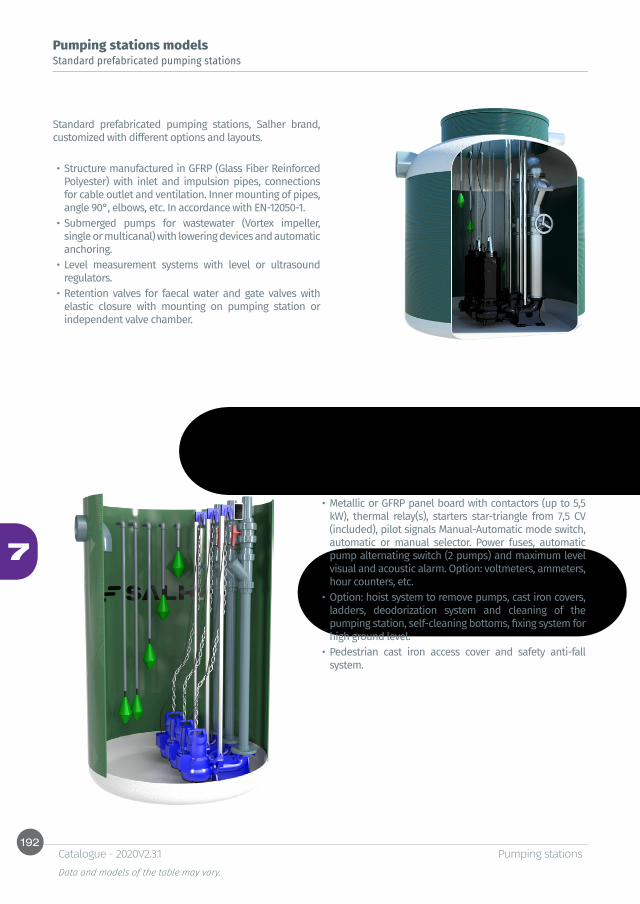
192
7
Pumping stationsData and models of the table may vary.
Catalogue - 2020V2.3.1
Pumping stations models Standard prefabricated pumping stations
Standard prefabricated pumping stations, Salher brand, customized with different options and layouts.
• Structure manufactured in GFRP (Glass Fiber Reinforced Polyester) with inlet and impulsion pipes, connections for cable outlet and ventilation. Inner mounting of pipes, angle 90°, elbows, etc. In accordance with EN-12050-1.
• Submerged pumps for wastewater (Vortex impeller, single or multicanal) with lowering devices and automatic anchoring.
• Level measurement systems with level or ultrasound regulators.
• Retention valves for faecal water and gate valves with elastic closure with mounting on pumping station or independent valve chamber.
• Metallic or GFRP panel board with contactors (up to 5,5 kW), thermal relay(s), starters star-triangle from 7,5 CV (included), pilot signals Manual-Automatic mode switch, automatic or manual selector. Power fuses, automatic pump alternating switch (2 pumps) and maximum level visual and acoustic alarm. Option: voltmeters, ammeters, hour counters, etc.
• Option: hoist system to remove pumps, cast iron covers, ladders, deodorization system and cleaning of the pumping station, self-cleaning bottoms, fixing system for high ground level.
• Pedestrian cast iron access cover and safety anti-fall system.
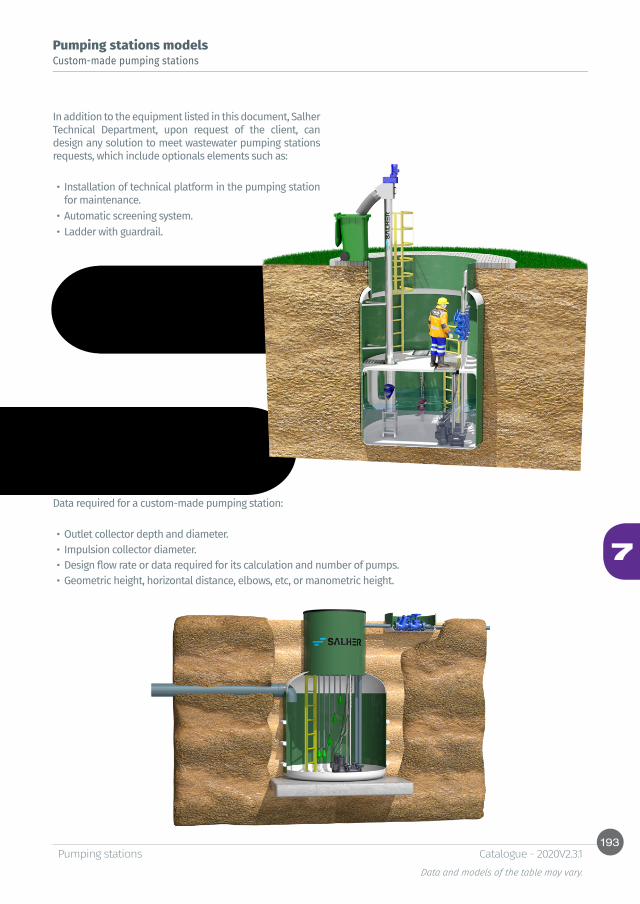
193
7
Pumping stationsData and models of the table may vary.
Catalogue - 2020V2.3.1
Pumping stations models Custom-made pumping stations
In addition to the equipment listed in this document, Salher Technical Department, upon request of the client, can design any solution to meet wastewater pumping stations requests, which include optionals elements such as:
• Installation of technical platform in the pumping station for maintenance.
• Automatic screening system.• Ladder with guardrail.
Data required for a custom-made pumping station:
• Outlet collector depth and diameter.• Impulsion collector diameter. • Design flow rate or data required for its calculation and number of pumps.• Geometric height, horizontal distance, elbows, etc, or manometric height.
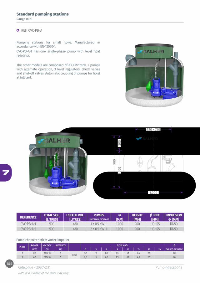
194
7
900
700
200
1.000
620 - 750
Pumping stationsData and models of the table may vary.
Catalogue - 2020V2.3.1
Standard pumping stationsRange mini
REF: CVC-PB-A
Pumping stations for small flows. Manufactured in accordance with EN-12050-1.CVC-PB-A-1 has one single-phase pump with level float regulator.
The other models are composed of a GFRP tank, 2 pumps with alternate operation, 3 level regulators, check valves and shut-off valves. Automatic coupling of pumps for hoist at full tank.
Pump characteristics: vortex impeller
PUMPPOWER VOLTAGE INTENSITY FLOW M3/H Ø
(KW) (V) (A) 0 3 6 9 12 15 18 24 SOLIDS PASSAGE1 0,5 230V M 5
MCW9,2 9 8,3 7,5 6,1 4,5 2,5 60
2 0,5 230V M 5 9,2 9 8,3 7,5 6,1 4,5 2,5 60
REFERENCE TOTAL VOL. USEFUL VOL. PUMPS Ø HEIGHT Ø PIPE IMPULSION[LITRES] [LITRES] UNITS/KW/VOLTAGE [MM] [MM] [MM] Ø [MM]
CVC-PB-A-1 500 470 1 X 0.5 KW II 1.000 900 110-125 DN50CVC-PB-A-2 500 470 2 X 0.5 KW II 1.000 900 110-125 DN50
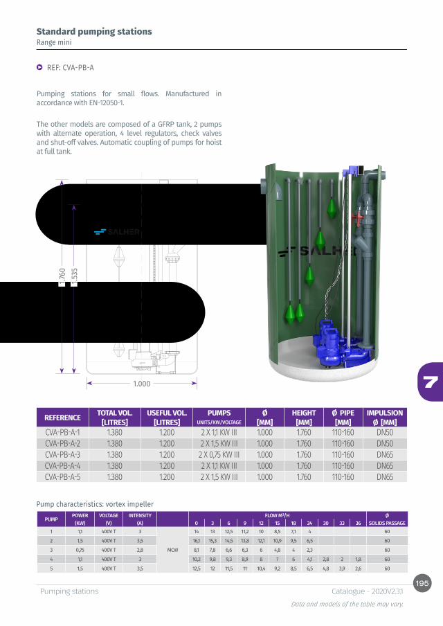
195
7
1.535
1.760
1.000
Pumping stationsData and models of the table may vary.
Catalogue - 2020V2.3.1
Standard pumping stationsRange mini
REF: CVA-PB-A
Pumping stations for small flows. Manufactured in accordance with EN-12050-1.
The other models are composed of a GFRP tank, 2 pumps with alternate operation, 4 level regulators, check valves and shut-off valves. Automatic coupling of pumps for hoist at full tank.
Pump characteristics: vortex impeller
PUMPPOWER VOLTAGE INTENSITY FLOW M³/H Ø
(KW) (V) (A) 0 3 6 9 12 15 18 24 30 33 36 SOLIDS PASSAGE1 1,1 400V T 3
MCW
14 13 12,5 11,2 10 8,5 7,1 4 60
2 1,5 400V T 3,5 16,1 15,3 14,5 13,8 12,1 10,9 9,5 6,5 60
3 0,75 400V T 2,8 8,1 7,8 6,6 6,3 6 4,8 4 2,3 60
4 1,1 400V T 3 10,2 9,8 9,3 8,9 8 7 6 4,1 2,8 2 1,8 60
5 1,5 400V T 3,5 12,5 12 11,5 11 10,4 9,2 8,5 6,5 4,8 3,9 2,6 60
REFERENCE TOTAL VOL. USEFUL VOL. PUMPS Ø HEIGHT Ø PIPE IMPULSION[LITRES] [LITRES] UNITS/KW/VOLTAGE [MM] [MM] [MM] Ø [MM]
CVA-PB-A-1 1.380 1.200 2 X 1,1 KW III 1.000 1.760 110-160 DN50CVA-PB-A-2 1.380 1.200 2 X 1,5 KW III 1.000 1.760 110-160 DN50CVA-PB-A-3 1.380 1.200 2 X 0,75 KW III 1.000 1.760 110-160 DN65CVA-PB-A-4 1.380 1.200 2 X 1,1 KW III 1.000 1.760 110-160 DN65CVA-PB-A-5 1.380 1.200 2 X 1,5 KW III 1.000 1.760 110-160 DN65

196
7
1.300
1.760
1.400
1.000
Pumping stationsData and models of the table may vary.
Catalogue - 2020V2.3.1
Standard pumping stationsMedium range
REF: CVC-PB-B
Pumping station for wastewater and rainwater. Manufactured in accordance with EN-12050-1.
The standard model is composed of a GFRP tank, 2 pumps with alternate operation, 5 level regulators, check valves and shut-off valves. Automatic coupling of pumps for hoist at full tank and electrical panel board. Optional accessories.
Pump characteristics: vortex impeller
PUMPPOWER VOLTAGE INTENSITY FLOW M³/H Ø
(KW) (V) (A) 4 8 12 16 20 28 36 40 44 48 52 64 SOLIDS PASSAGE1 1,3 400V T 3,6
MCW7 6,7 6,2 5,8 5,3 4,6 3,8 3,4 3 2,6 2,3 60
2 2,2 400V T 5,15 10,5 10,3 10 9,5 9 8,5 7,8 7,2 6,8 6,5 6 4,8 60
OPTIONS
REFERENCE TOTAL VOL. USEFUL VOL. PUMPS Ø HEIGHT Ø PIPE IMPULSION[LITRES] [LITRES] UNITS/KW/VOLTAGE [MM] [MM] [MM] Ø [MM]
CVC-PB-B-1 2.500 2.000 2X 1,3 KW III 1.400 1.760 110-300 DN65CVC-PB-B-2 2.500 2.000 2X 2,2 KW III 1.400 1.760 110-300 DN65
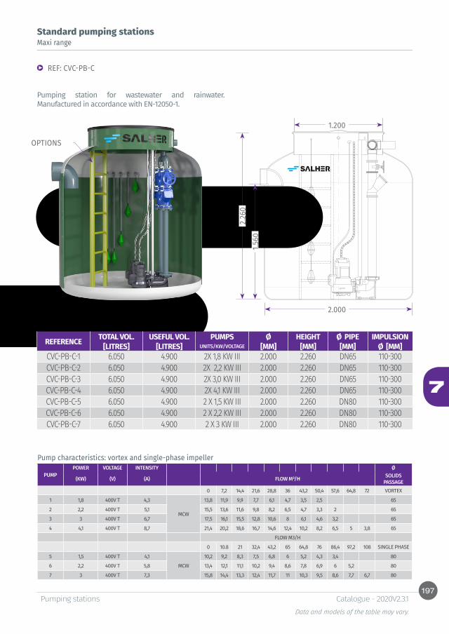
197
7
2.260
1.560
2.000
1.200
Pumping stationsData and models of the table may vary.
Catalogue - 2020V2.3.1
Standard pumping stationsMaxi range
REF: CVC-PB-C
Pumping station for wastewater and rainwater. Manufactured in accordance with EN-12050-1.
Pump characteristics: vortex and single-phase impeller
PUMPPOWER VOLTAGE INTENSITY Ø
(KW) (V) (A) FLOW M³/H SOLIDS PASSAGE
0 7,2 14,4 21,6 28,8 36 43,2 50,4 57,6 64,8 72 VORTEX
1 1,8 400V T 4,3
MCW
13,8 11,9 9,9 7,7 6,1 4,7 3,5 2,5 65
2 2,2 400V T 5,1 15,5 13,6 11,6 9,8 8,2 6,5 4,7 3,3 2 65
3 3 400V T 6,7 17,5 16,1 15,5 12,8 10,6 8 6,1 4,6 3,2 65
4 4,1 400V T 8,7 21,4 20,2 18,6 16,7 14,6 12,4 10,2 8,2 6,5 5 3,8 65
FLOW M3/H
0 10.8 21 32,4 43,2 65 64,8 76 86,4 97,2 108 SINGLE PHASE
5 1,5 400V T 4,1
MCW
10,2 9,2 8,3 7,5 6,8 6 5,2 4,3 3,4 80
6 2,2 400V T 5,8 13,4 12,1 11,1 10,2 9,4 8,6 7,8 6,9 6 5,2 80
7 3 400V T 7,3 15,8 14,4 13,3 12,4 11,7 11 10,3 9,5 8,6 7,7 6,7 80
OPTIONS
REFERENCE TOTAL VOL. USEFUL VOL. PUMPS Ø HEIGHT Ø PIPE IMPULSION[LITRES] [LITRES] UNITS/KW/VOLTAGE [MM] [MM] [MM] Ø [MM]
CVC-PB-C-1 6.050 4.900 2X 1,8 KW III 2.000 2.260 DN65 110-300CVC-PB-C-2 6.050 4.900 2X 2,2 KW III 2.000 2.260 DN65 110-300CVC-PB-C-3 6.050 4.900 2X 3,0 KW III 2.000 2.260 DN65 110-300CVC-PB-C-4 6.050 4.900 2X 4,1 KW III 2.000 2.260 DN65 110-300CVC-PB-C-5 6.050 4.900 2 X 1,5 KW III 2.000 2.260 DN80 110-300CVC-PB-C-6 6.050 4.900 2 X 2,2 KW III 2.000 2.260 DN80 110-300CVC-PB-C-7 6.050 4.900 2 X 3 KW III 2.000 2.260 DN80 110-300
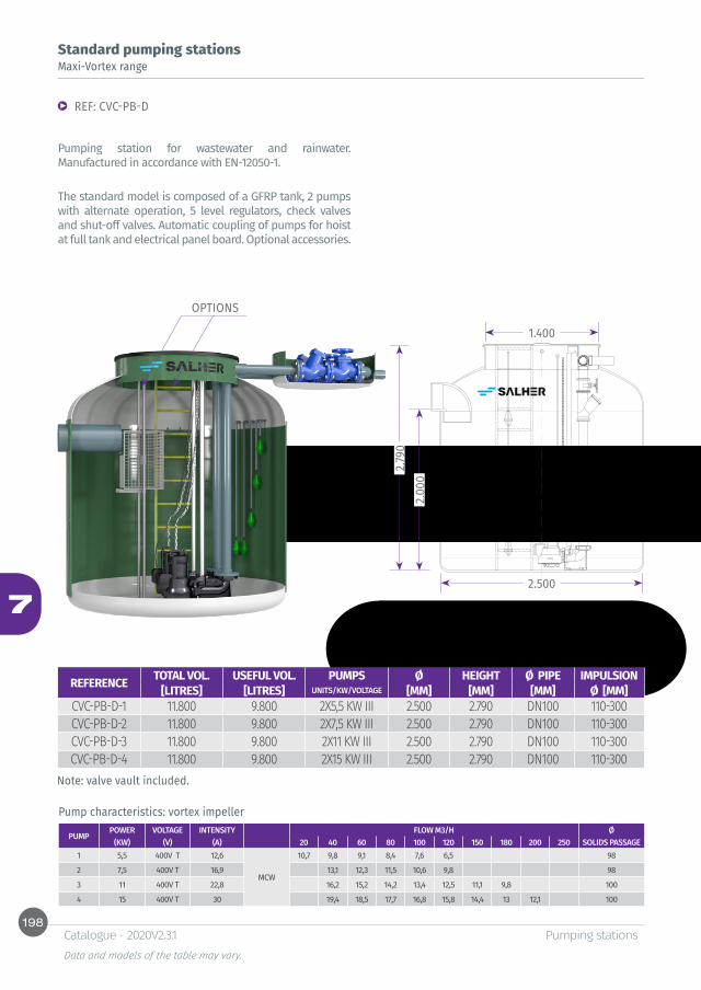
198
7
2.790
2.000
2.500
1.400
Pumping stationsData and models of the table may vary.
Catalogue - 2020V2.3.1
Standard pumping stationsMaxi-Vortex range
REF: CVC-PB-D
Pumping station for wastewater and rainwater. Manufactured in accordance with EN-12050-1.
The standard model is composed of a GFRP tank, 2 pumps with alternate operation, 5 level regulators, check valves and shut-off valves. Automatic coupling of pumps for hoist at full tank and electrical panel board. Optional accessories.
Pump characteristics: vortex impeller
PUMPPOWER VOLTAGE INTENSITY FLOW M3/H Ø
(KW) (V) (A) 20 40 60 80 100 120 150 180 200 250 SOLIDS PASSAGE1 5,5 400V T 12,6
MCW
10,7 9,8 9,1 8,4 7,6 6,5 98
2 7,5 400V T 16,9 13,1 12,3 11,5 10,6 9,8 98
3 11 400V T 22,8 16,2 15,2 14,2 13,4 12,5 11,1 9,8 100
4 15 400V T 30 19,4 18,5 17,7 16,8 15,8 14,4 13 12,1 100
OPTIONS
Note: valve vault included.
REFERENCE TOTAL VOL. USEFUL VOL. PUMPS Ø HEIGHT Ø PIPE IMPULSION[LITRES] [LITRES] UNITS/KW/VOLTAGE [MM] [MM] [MM] Ø [MM]
CVC-PB-D-1 11.800 9.800 2X5,5 KW III 2.500 2.790 DN100 110-300CVC-PB-D-2 11.800 9.800 2X7,5 KW III 2.500 2.790 DN100 110-300CVC-PB-D-3 11.800 9.800 2X11 KW III 2.500 2.790 DN100 110-300CVC-PB-D-4 11.800 9.800 2X15 KW III 2.500 2.790 DN100 110-300
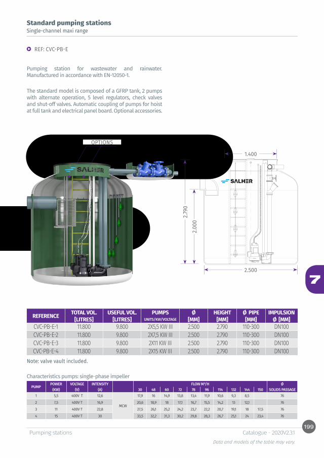
199
7
2.790
2.000
2.500
1.400
Pumping stationsData and models of the table may vary.
Catalogue - 2020V2.3.1
Standard pumping stationsSingle-channel maxi range
REF: CVC-PB-E
Pumping station for wastewater and rainwater. Manufactured in accordance with EN-12050-1.
The standard model is composed of a GFRP tank, 2 pumps with alternate operation, 5 level regulators, check valves and shut-off valves. Automatic coupling of pumps for hoist at full tank and electrical panel board. Optional accessories.
Characteristics pumps: single-phase impeller
PUMPPOWER VOLTAGE INTENSITY FLOW M³/H Ø
(KW) (V) (A) 30 48 60 72 78 96 114 132 144 150 SOLIDS PASSAGE 1 5,5 400V T 12,6
MCW
17,9 16 14,9 13,8 13,4 11,9 10,6 9,3 8,5 76
2 7,5 400V T 16,9 20,6 18,9 18 17,1 16,7 15,5 14,2 13 12,1 76
3 11 400V T 22,8 27,5 26,1 25,2 24,2 23,7 22,2 20,7 19,1 18 17,5 76
4 15 400V T 30 33,5 32,2 31,3 30,2 29,8 28,3 26,7 25,1 24 23,4 76
OPTIONS
Note: valve vault included.
REFERENCE TOTAL VOL. USEFUL VOL. PUMPS Ø HEIGHT Ø PIPE IMPULSION[LITRES] [LITRES] UNITS/KW/VOLTAGE [MM] [MM] [MM] Ø [MM]
CVC-PB-E-1 11.800 9.800 2X5,5 KW III 2.500 2.790 110-300 DN100CVC-PB-E-2 11.800 9.800 2X7,5 KW III 2.500 2.790 110-300 DN100CVC-PB-E-3 11.800 9.800 2X11 KW III 2.500 2.790 110-300 DN100CVC-PB-E-4 11.800 9.800 2X15 KW III 2.500 2.790 110-300 DN100
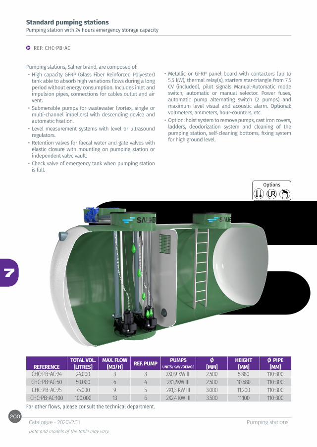
200
7
Pumping stationsData and models of the table may vary.
Catalogue - 2020V2.3.1
Standard pumping stationsPumping station with 24 hours emergency storage capacity
Pumping stations, Salher brand, are composed of:• High capacity GFRP (Glass Fiber Reinforced Polyester)
tank able to absorb high variations flows during a long period without energy consumption. Includes inlet and impulsion pipes, connections for cables outlet and air vent.
• Submersible pumps for wastewater (vortex, single or multi-channel impellers) with descending device and automatic fixation.
• Level measurement systems with level or ultrasound regulators.
• Retention valves for faecal water and gate valves with elastic closure with mounting on pumping station or independent valve vault.
• Check valve of emergency tank when pumping station is full.
• Metallic or GFRP panel board with contactors (up to 5,5 kW), thermal relay(s), starters star-triangle from 7,5 CV (included), pilot signals Manual-Automatic mode switch, automatic or manual selector. Power fuses, automatic pump alternating switch (2 pumps) and maximum level visual and acoustic alarm. Optional: voltmeters, ammeters, hour-counters, etc.
• Option: hoist system to remove pumps, cast iron covers, ladders, deodorization system and cleaning of the pumping station, self-cleaning bottoms, fixing system for high ground level.
For other flows, please consult the technical department.
Options
REF: CHC-PB-AC
TOTAL VOL. MAX. FLOW REF. PUMP PUMPS Ø HEIGHT Ø PIPEREFERENCE [LITRES] [M3/H] UNITS/KW/VOLTAGE [MM] [MM] [MM]
CHC-PB-AC-24 24.000 3 3 2X0,9 KW III 2.500 5.380 110-300CHC-PB-AC-50 50.000 6 4 2X1,2KW III 2.500 10.680 110-300CHC-PB-AC-75 75.000 9 5 2X1,3 KW III 3.000 11.200 110-300CHC-PB-AC-100 100.000 13 6 2X2,4 KW III 3.500 11.100 110-300
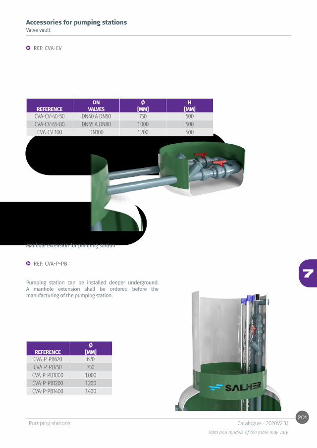
201
7
Pumping stationsData and models of the table may vary.
Catalogue - 2020V2.3.1
Accessories for pumping stations Valve vault
Manhole extension for pumping station
REF: CVA-CV
REF: CVA-P-PB
Pumping station can be installed deeper underground. A manhole extension shall be ordered before the manufacturing of the pumping station.
DN Ø HREFERENCE VALVES [MM] [MM]
CVA-CV-40-50 DN40 A DN50 750 500CVA-CV-65-80 DN65 A DN80 1.000 500CVA-CV-100 DN100 1.200 500
Ø REFERENCE [MM]CVA-P-PB620 620CVA-P-PB750 750CVA-P-PB1000 1.000CVA-P-PB1200 1.200CVA-P-PB1400 1.400

202
7
Pumping stationsData and models of the table may vary.
Catalogue - 2020V2.3.1
Accessories for pumping stations Access ladder to pumping station
Pedestrian access cover
REF: E-PB
REF: TAPA-PB
Manufactured in GFRP (Glass Fiber Reinforced Polyester) with isophthalic resins resistant to corrosion. It provides access inside down to the bottom of the pumping station. Option: additional proportional part of safety ladder.
Manufactured in GFRP or galvanized iron. Non-skid watermark, two retractable sides and closure system with square key.
H REFERENCE [MM]
TAPA-PB 1.000 1.000TAPA-PB 1.200 1.200TAPA-PB 1.400 1.400TAPA-PB 1.700 1.700TAPA-PB 2.000 2.000TAPA-PB 2.250 2.250TAPA-PB 2.500 2.500TAPA-PB 3.000 3.000TAPA-PB 3.500 3.500TAPA-PB 4.000 4.000
H REFERENCE [MM]E-PB 1.000 1.000E-PB 1.500 1.500E-PB 2.000 2.000E-PB 2.250 2.250E-PB 3.000 3.000E-PB 3.500 3.500E-PB 4.000 4.000E-PB 4.500 4.500E-PB 5.000 5.000

203
7
Pumping stationsData and models of the table may vary.
Catalogue - 2020V2.3.1
Accessories for pumping stations Anti-fall platform
Self-cleaning bottom
REF: TRAMEX-PB
REF: KORBBO
Manufactured in GFRP (Glass Fiber Reinforced Polyester) or stainless steel. Facilitates the opening of the pumping station and can be used as a safety platform to prevent falls inside the pumping station. The platform is foldable and can be divided.
H REFERENCE [MM]
TRAMEX-PB 1.000 1.000TRAMEX-PB 1.200 1.200TRAMEX-PB 1.400 1.400TRAMEX-PB 1.700 1.700TRAMEX-PB 2.000 2.000TRAMEX-PB 2.250 2.250TRAMEX-PB 2.500 2.500TRAMEX-PB 3.000 3.000TRAMEX-PB 3.500 3.500TRAMEX-PB 4.000 4.000
H REFERENCE [MM]
KORBBO 1.000 1.000KORBBO 1.200 1.200KORBBO 1.400 1.400KORBBO 1.700 1.700KORBBO 2.000 2.000KORBBO 2.250 2.250KORBBO 2.500 2.500KORBBO 3.000 3.000KORBBO 3.500 3.500KORBBO 4.000 4.000

204
7
Pumping stationsData and models of the table may vary.
Catalogue - 2020V2.3.1
Accessories for pumping stations Solids screen basket
Fixing brackets
REF: RG-PB
Manufactured in galvanized iron or stainless steel with opening size comprised between 50 and 100 mm, to avoid the passage of coarse solids which can damage the pumping station. Equipped with extraction system at full tank.
REF: ES-PB
Lateral fixing brackets installed in a helical pattern to avoid the pumping station flotation due to an important phreatic level. These brackets adhere to the ground or the surrounding filling. Set of 3 fixing brackets. Separation of 25 cm between supports.
Ø PIPESREFERENCE [MM]RG-PB 160 160RG-PB 250 250RG-PB 355 355RG-PB 400 400RG-PB 500 500
REFERENCIA UDSES-PB 1000 3ES-PB 1200 3ES-PB 1400 3ES-PB 1700 3ES-PB 2000 3ES-PB 2250 3ES-PB 2500 3ES-PB 3000 3ES-PB 3500 3ES-PB 4000 3
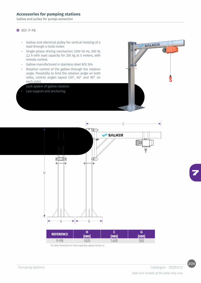
205
7H
G G
C
Pumping stationsData and models of the table may vary.
Catalogue - 2020V2.3.1
Accessories for pumping stations Gallow and pulley for pumps extraction
REF: P-PB
• Gallow and electrical pulley for vertical hoisting of a load through a hoist motor.
• Single-phase driving mechanism 230V 50 Hz, 500 W, 2,2 A with load capacity for 250 kg at 5 meters, with remote control.
• Gallow manufactured in stainless steel AISI 304.• Rotation control of the gallow through the rotation
angle. Possibility to limit the rotation angle on both sides, control angles layout (30°, 60° and 90° on each side).
• Lock system of gallow rotation. • Low support and anchoring.
For other dimensions or hoist capacities, please consult us.
REFERENCE H C G[MM] [MM] [MM]
P-PB 1.670 1.400 500


8Tanks

Table of contents
MANUFACTURING AND CHARACTERISTICS OF STANDARD, ULTRAREINFORCED AND ISOTHER-MAL GFRP TANKS
210
Tanks for aboveground and underground installation
Water storage tank, cylindrical and vertical, open with GFRP coverREF: CVA 212Water storage tank, cylindrical and vertical, close with GFRP coverREF: CVC-S 213Water storage tank, cylindrical and vertical, closed with screwed coverREF: CVC-FP 214Water storage tank, cylindrical and vertical, closed with manhole and GFRP coverREF: CVC-E 215Water storage tank, cylindrical and horizontal, closed with manhole and GFRP coverREF: CHC 216REF: CHC-S 217
Isothermal tanks for water storage, cylin-drical and vertical, closed with manhole and cover
Isothermal tanks for water storage REF: CVC-ISO 219REF: CHC - ISO 220Supports for horizontal tanks model CHCREF: SO-CU 222Water storage tank, cylindrical and vertical, closed with skid for agitator and screwed coverREF: CVC-B 223Diesel storage tank, cylindrical and vertical, double wall. CertifiedREF. CVC-DPH 224Oil storage tank, cylindrical and vertical, double wall. CertifiedREF. CVC-DPA 225
Accessories for tanksFerrule support extension 226Supplement for additional manholes 226Lateral manhole 226Connections for inlet, outlet and drain of GFRP tanksREF: MAN-HEM 227Pipe and union sleeve PVC-U for flanged connectionsREF: BRIDA 228
Other dimensions and configurations can be provided upon request. Internal dimensions. Dimensions in millimeters. Volumes in liters, the dimensions indicated may vary according to the needs.Due to its policy of continuous development, Salher Ibérica, S.L. reserves the right to modify the data that appear in this document without notice.This document is protected by the intellectual property law, so that the customer cannot claim, manipulate or duplicate this documentation, except copy for personal use.
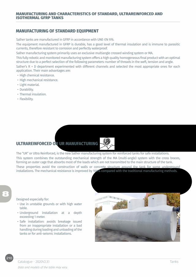
210
8
TanksData and models of the table may vary.
Catalogue - 2020V2.3.1
MANUFACTURING AND CHARACTERISTICS OF STANDARD, ULTRAREINFORCED AND ISOTHERMAL GFRP TANKS
MANUFACTURING OF STANDARD EQUIPMENT
ULTRAREINFORCED OR UR MANUFACTURING
Salher tanks are manufactured in GFRP in accordance with UNE-EN 976.The equipment manufactured in GFRP is durable, has a good level of thermal insulation and is immune to parasitic currents, therefore resistant to corrosion and perfectly waterproof.Salher manufacturing system primarily uses an exclusive multiangle crossed winding system or MA.This fully robotic and monitored manufacturing system offers a high quality homogeneous final product with an optimal structure due to a perfect selection of the following parameters: number of threads in the weft, tension and angle.Salher’s R + D department experimented with different channels and selected the most appropriate ones for each application. Their main advantages are:• High chemical resistance.• High mechanical resistance.• Light material.• Durability.• Thermal insulation.• Flexibility.
The “UR” or Ultra Reinforced, is the new Salher manufacturing system for reinforced tanks for safe installations.This system combines the outstanding mechanical strength of the MA (multi-angle) system with the cross braces, forming an outer cage that absorbs most of the loads which are not transmitted to the main structure of the tank.These properties avoid the construction of walls or concrete structure around the tank for some underground installations. The mechanical resistance is improved by 100% compared with the traditional manufacturing methods.
Designed especially for:• Use in unstable grounds or with high water
table. • Underground installation at a depth
exceeding 1 meter.• Safe installation: avoids breakage issued
from an inappropriate installation or a bad handling during loading and unloading of the tanks or for anti-seismic installations.

211
8
TanksData and models of the table may vary.
Catalogue - 2020V2.3.1
MANUFACTURING AND CHARACTERISTICS OF STANDARD, ULTRAREINFORCED AND ISOTHERMAL GFRP TANKS
CHARACTERISTICS
MA SYSTEM STANDARD UR OPTION
MAXIMUM DEPTH OF UNDERGROUND INSTALLATION 1000 MM 5000 MM
VARIABLE ANGLE INCLUDED INCLUDED
CAPS KORBBOGEN REINFORCED: DOUBLE WALL OR MESH, ACCORDING TO DESIGN
PROTECTION OF INLET AND OUTLET PIPING NOT INCLUDED INCLUDED
STABLE GROUND VALID VALIDUNSTABLE GROUND SPECIAL INSTALLATION REQUIRED VALID
ABOVEGROUND INSTALLATION WITH BAD WEATHER NOT VALID VALID
COVERS STANDARD FOLDABLE
COMPARISON CHART:
TRADITIONAL METHOD FILAMENT WINDING MA SYSTEM UR SYSTEM
TENSILE STRENGHT (MPA) 80 170% 260%ELASTICITY IN BENDING
MODULE (MPA) 8.600 50% 90%
RESISTANCE TO FLEXION (MPA) 202 60% 110%
Double wall isothermal system Double wall system and thermal surface coating to guarantee a thermal insulation under extreme weather conditions.

212
8
TanksData and models of the table may vary.
Catalogue - 2020V2.3.1
Tanks for aboveground and underground installation
Function:
Water storage tank, cylindrical and vertical, open with GFRP cover
REF: CVA
• Water storage.
Characteristics:
• Salher brand, model CVA.• Equipment manufactured in GFRP (Glass Fiber
Reinforced Polyester) with orthophthalic resins.• Cylindrical, flat bottom and open top.• GFRP cover in option.• PVC connections or flanges in option. Indicate
the number of connections, diameters and layout.
• Other tank diameters available.
Options
VOLUME Ø HEIGHT[LITRES] [MM] [MM]
5.000 1.700 2.2006.000 1.700 2.6406.000 2.000 1.9507.000 1.700 3.1007.000 2.000 2.2508.000 1.700 3.5508.000 2.000 2.6009.000 2.000 2.90010.000 2.000 3.200
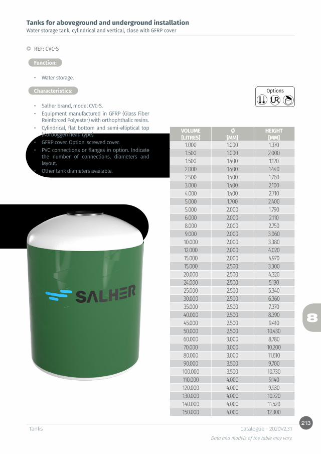
213
8
TanksData and models of the table may vary.
Catalogue - 2020V2.3.1
Tanks for aboveground and underground installation
Function:
Water storage tank, cylindrical and vertical, close with GFRP cover
REF: CVC-S
• Water storage.
Characteristics:
• Salher brand, model CVC-S.• Equipment manufactured in GFRP (Glass Fiber
Reinforced Polyester) with orthophthalic resins.• Cylindrical, flat bottom and semi-elliptical top
(Korboggen head type).• GFRP cover. Option: screwed cover.• PVC connections or flanges in option. Indicate
the number of connections, diameters and layout.
• Other tank diameters available.
Options
VOLUME Ø HEIGHT[LITRES] [MM] [MM]
1.000 1.000 1.3701.500 1.000 2.0001.500 1.400 1.1202.000 1.400 1.4402.500 1.400 1.7603.000 1.400 2.1004.000 1.400 2.7105.000 1.700 2.4005.000 2.000 1.7906.000 2.000 2.1108.000 2.000 2.7509.000 2.000 3.06010.000 2.000 3.38012.000 2.000 4.02015.000 2.000 4.97015.000 2.500 3.30020.000 2.500 4.32024.000 2.500 5.13025.000 2.500 5.34030.000 2.500 6.36035.000 2.500 7.37040.000 2.500 8.39045.000 2.500 9.41050.000 2.500 10.43060.000 3.000 8.78070.000 3.000 10.20080.000 3.000 11.61090.000 3.500 9.700100.000 3.500 10.730110.000 4.000 9.140120.000 4.000 9.930130.000 4.000 10.720140.000 4.000 11.520150.000 4.000 12.300

214
8
TanksData and models of the table may vary.
Catalogue - 2020V2.3.1
Tanks for aboveground and underground installation
Function:
Water storage tank, cylindrical and vertical, closed with screwed cover
REF: CVC-FP
• Water storage.
Characteristics:
• Salher brand, model CVC–FP. • Equipment manufactured in GFRP (Glass Fiber
Reinforced Polyester) with orthophthalic resins.• Cylindrical with flat bottom and top.• Screwed cover of 420 or 600 mm of diameter (to
confirm).• PVC connections or flanges in option. Indicate the
number of connections, diameters and layout.• Other tank diameters available.
VOLUME Ø HEIGHT[LITRES] [MM] [MM]
5.000 1.700 2.2505.000 2.000 1.6006.000 2.000 1.9106.000 2.250 1.5507.000 2.000 2.2507.000 2.250 1.8008.000 2.000 2.5508.000 2.250 2.0508.000 2.500 1.6509.000 2.000 2.9009.000 2.250 2.3009.000 2.500 1.8509.000 3.000 1.30010.000 2.250 2.52010.000 2.500 2.05010.000 3.000 1.45012.000 2.250 3.05012.000 2.500 2.50012.000 3.000 1.70015.000 2.500 3.10015.000 3.000 2.15015.000 3.500 1.600
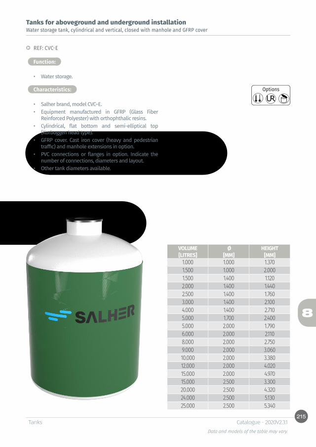
215
8
TanksData and models of the table may vary.
Catalogue - 2020V2.3.1
Tanks for aboveground and underground installation
Function:
Water storage tank, cylindrical and vertical, closed with manhole and GFRP cover
REF: CVC-E
• Water storage.
Characteristics:
• Salher brand, model CVC–E.• Equipment manufactured in GFRP (Glass Fiber
Reinforced Polyester) with orthophthalic resins.• Cylindrical, flat bottom and semi-elliptical top
(Korboggen head type).• GFRP cover. Cast iron cover (heavy and pedestrian
traffic) and manhole extensions in option.• PVC connections or flanges in option. Indicate the
number of connections, diameters and layout.• Other tank diameters available.
Options
VOLUME Ø HEIGHT[LITRES] [MM] [MM]
1.000 1.000 1.3701.500 1.000 2.0001.500 1.400 1.1202.000 1.400 1.4402.500 1.400 1.7603.000 1.400 2.1004.000 1.400 2.7105.000 1.700 2.4005.000 2.000 1.7906.000 2.000 2.1108.000 2.000 2.7509.000 2.000 3.06010.000 2.000 3.38012.000 2.000 4.02015.000 2.000 4.97015.000 2.500 3.30020.000 2.500 4.32024.000 2.500 5.13025.000 2.500 5.340
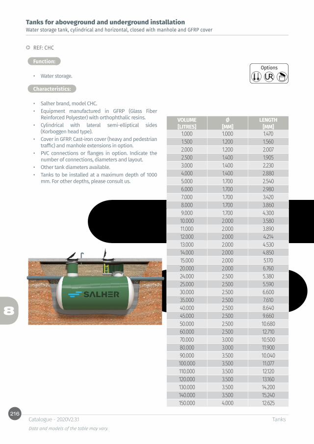
216
8
TanksData and models of the table may vary.
Catalogue - 2020V2.3.1
Tanks for aboveground and underground installation
Function:
Water storage tank, cylindrical and horizontal, closed with manhole and GFRP cover
REF: CHC
• Water storage.
Characteristics:
• Salher brand, model CHC.• Equipment manufactured in GFRP (Glass Fiber
Reinforced Polyester) with orthophthalic resins.• Cylindrical with lateral semi-elliptical sides
(Korboggen head type).• Cover in GFRP. Cast-iron cover (heavy and pedestrian
traffic) and manhole extensions in option.• PVC connections or flanges in option. Indicate the
number of connections, diameters and layout.• Other tank diameters available.• Tanks to be installed at a maximum depth of 1000
mm. For other depths, please consult us.
Options
VOLUME Ø LENGTH[LITRES] [MM] [MM]
1.000 1.000 1.4701.500 1.200 1.5602.000 1.200 2.0072.500 1.400 1.9053.000 1.400 2.2304.000 1.400 2.8805.000 1.700 2.5406.000 1.700 2.9807.000 1.700 3.4208.000 1.700 3.8609.000 1.700 4.30010.000 2.000 3.58011.000 2.000 3.89012.000 2.000 4.21413.000 2.000 4.53014.000 2.000 4.85015.000 2.000 5.17020.000 2.000 6.76024.000 2.500 5.38025.000 2.500 5.59030.000 2.500 6.60035.000 2.500 7.61040.000 2.500 8.64045.000 2.500 9.66050.000 2.500 10.68060.000 2.500 12.71070.000 3.000 10.50080.000 3.000 11.90090.000 3.500 10.040100.000 3.500 11.077110.000 3.500 12.120120.000 3.500 13.160130.000 3.500 14.200140.000 3.500 15.240150.000 4.000 12.625
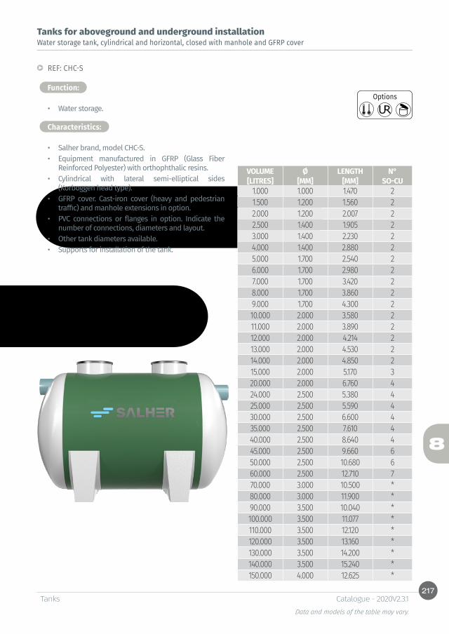
217
8
TanksData and models of the table may vary.
Catalogue - 2020V2.3.1
Tanks for aboveground and underground installation
Function:
Water storage tank, cylindrical and horizontal, closed with manhole and GFRP cover
REF: CHC-S
• Water storage.
Characteristics:
• Salher brand, model CHC-S.• Equipment manufactured in GFRP (Glass Fiber
Reinforced Polyester) with orthophthalic resins.• Cylindrical with lateral semi-elliptical sides
(Korboggen head type).• GFRP cover. Cast-iron cover (heavy and pedestrian
traffic) and manhole extensions in option. • PVC connections or flanges in option. Indicate the
number of connections, diameters and layout.• Other tank diameters available.• Supports for installation of the tank.
Options
*Consult
VOLUME Ø LENGTH N°[LITRES] [MM] [MM] SO-CU
1.000 1.000 1.470 21.500 1.200 1.560 22.000 1.200 2.007 22.500 1.400 1.905 23.000 1.400 2.230 24.000 1.400 2.880 25.000 1.700 2.540 26.000 1.700 2.980 27.000 1.700 3.420 28.000 1.700 3.860 29.000 1.700 4.300 210.000 2.000 3.580 211.000 2.000 3.890 212.000 2.000 4.214 213.000 2.000 4.530 214.000 2.000 4.850 215.000 2.000 5.170 320.000 2.000 6.760 424.000 2.500 5.380 425.000 2.500 5.590 430.000 2.500 6.600 435.000 2.500 7.610 440.000 2.500 8.640 445.000 2.500 9.660 650.000 2.500 10.680 660.000 2.500 12.710 770.000 3.000 10.500 *80.000 3.000 11.900 *90.000 3.500 10.040 *100.000 3.500 11.077 *110.000 3.500 12.120 *120.000 3.500 13.160 *130.000 3.500 14.200 *140.000 3.500 15.240 *150.000 4.000 12.625 *

218
8
TanksData and models of the table may vary.
Catalogue - 2020V2.3.1
Isothermal tanks for water storage, cylindrical and vertical, closed with manhole and coverIsothermal tanks for water storage
Isothermal tanks, Salher brand, keeps the water at a constant temperature in outdoor low temperatures conditions thanks to a structure formed with a double GFRP coat and an intermediary insulating coat of polyurethane monolithic foam.
The high density polyurethane foam is the best insulating material compared to other materials and requires less thickness. Polyurethane spraying is carried out uniformly over the entire tank to avoid thermal bridges and cracks. In addition, the sandwich-like structure greatly increases the structural strength of the equipment in comparison with conventional tanks.
Requires no additional maintenance as polyurethane foam is resistant to aging, retaining its thermal and mechanical properties.
Salher guarantees the maintenance of optimal water process temperatures, as well as the non-freezing during the winter with average temperatures up to -6°C for stored water and up to -25°C for water in continuous flow.

219
8
H
Ø1Ø2
TanksData and models of the table may vary.
Catalogue - 2020V2.3.1
Isothermal tanks for water storage, cylindrical and vertical, closed with manhole and coverIsothermal tanks for water storage
Function:
• Water storage.
Characteristics:
• Salher brand, model CVC-ISO.• Equipment manufactured in GFRP (Glass Fiber
Reinforced Polyester) with orthophthalic resins.• Cylindrical with flat bottom and semi-elliptical top
(Korboggen head type).• GFRP cover. Screwed cover in option.• PVC connections or flanges in option. Indicate the
number of connections, diameters and layout.• Other tank diameters available.
REF: CVC-ISO
VOLUME Ø1 Ø2 HEIGHT[LITRES] [MM] [MM] [MM]
5.000 1.700 1.900 2.6005.000 2.000 2.200 1.9906.000 2.000 2.200 2.3108.000 2.000 2.200 2.9509.000 2.000 2.200 3.26010.000 2.000 2.200 3.58012.000 2.000 2.200 4.22015.000 2.000 2.200 5.17015.000 2.500 2.700 3.50020.000 2.500 2.700 4.52024.000 2.500 2.700 5.33025.000 2.500 2.700 5.54030.000 2.500 2.700 6.56035.000 2.500 2.700 7.57040.000 2.500 2.700 8.59045.000 2.500 2.700 9.61050.000 2.500 2.700 10.63060.000 3.000 3.200 8.98070.000 3.000 3.200 10.40080.000 3.000 3.200 11.81090.000 3.500 3.700 9.900100.000 3.500 3.700 10.930110.000 4.000 4.200 9.340120.000 4.000 4.200 10.130130.000 4.000 4.200 10.920140.000 4.000 4.200 11.720150.000 4.000 4.200 12.500
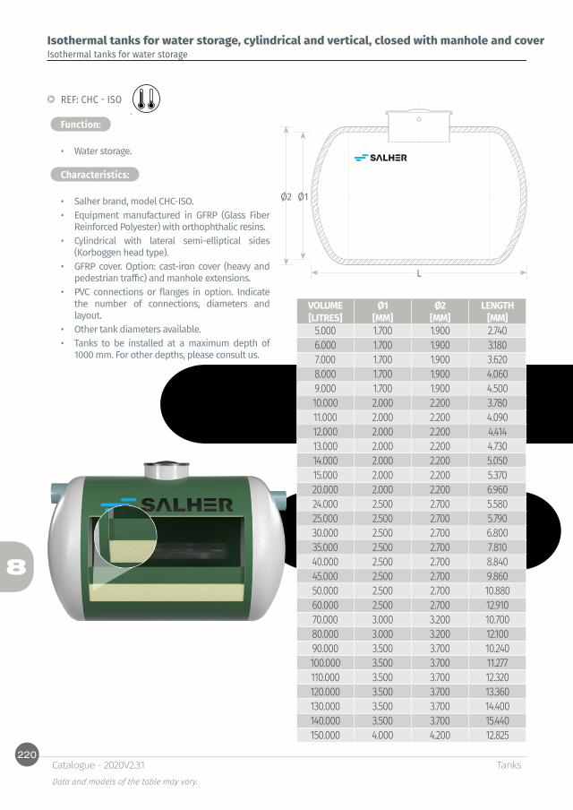
220
8
L
Ø1Ø2
TanksData and models of the table may vary.
Catalogue - 2020V2.3.1
Isothermal tanks for water storage, cylindrical and vertical, closed with manhole and coverIsothermal tanks for water storage
Function:
• Water storage.
Characteristics:
• Salher brand, model CHC-ISO.• Equipment manufactured in GFRP (Glass Fiber
Reinforced Polyester) with orthophthalic resins.• Cylindrical with lateral semi-elliptical sides
(Korboggen head type).• GFRP cover. Option: cast-iron cover (heavy and
pedestrian traffic) and manhole extensions.• PVC connections or flanges in option. Indicate
the number of connections, diameters and layout.
• Other tank diameters available.• Tanks to be installed at a maximum depth of
1000 mm. For other depths, please consult us.
REF: CHC - ISO
VOLUME Ø1 Ø2 LENGTH[LITRES] [MM] [MM] [MM]
5.000 1.700 1.900 2.7406.000 1.700 1.900 3.1807.000 1.700 1.900 3.6208.000 1.700 1.900 4.0609.000 1.700 1.900 4.50010.000 2.000 2.200 3.78011.000 2.000 2.200 4.09012.000 2.000 2.200 4.41413.000 2.000 2.200 4.73014.000 2.000 2.200 5.05015.000 2.000 2.200 5.37020.000 2.000 2.200 6.96024.000 2.500 2.700 5.58025.000 2.500 2.700 5.79030.000 2.500 2.700 6.80035.000 2.500 2.700 7.81040.000 2.500 2.700 8.84045.000 2.500 2.700 9.86050.000 2.500 2.700 10.88060.000 2.500 2.700 12.91070.000 3.000 3.200 10.70080.000 3.000 3.200 12.10090.000 3.500 3.700 10.240100.000 3.500 3.700 11.277110.000 3.500 3.700 12.320120.000 3.500 3.700 13.360130.000 3.500 3.700 14.400140.000 3.500 3.700 15.440150.000 4.000 4.200 12.825

221
8
TanksData and models of the table may vary.
Catalogue - 2020V2.3.1
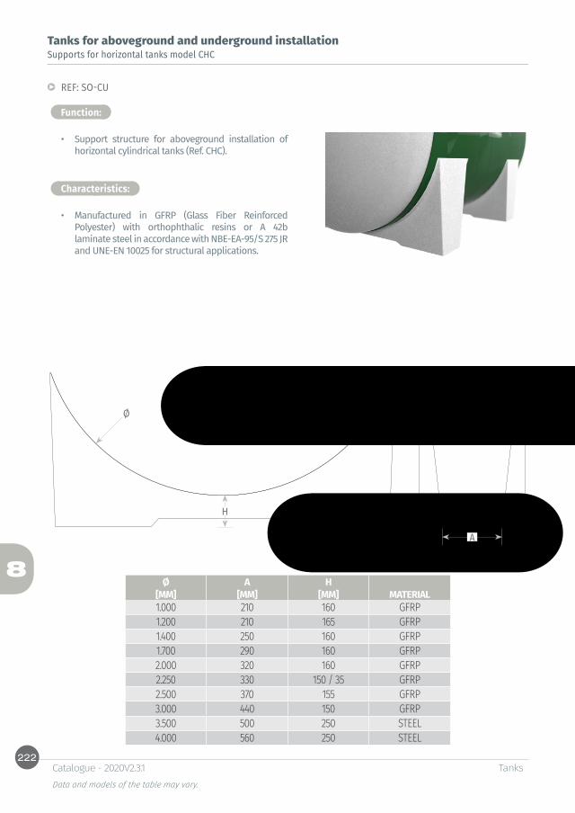
222
8
A
H
Ø
TanksData and models of the table may vary.
Catalogue - 2020V2.3.1
Tanks for aboveground and underground installation
Function:
Supports for horizontal tanks model CHC
REF: SO-CU
• Support structure for aboveground installation of horizontal cylindrical tanks (Ref. CHC).
Characteristics:
• Manufactured in GFRP (Glass Fiber Reinforced Polyester) with orthophthalic resins or A 42b laminate steel in accordance with NBE-EA-95/S 275 JR and UNE-EN 10025 for structural applications.
Ø A H [MM] [MM] [MM] MATERIAL1.000 210 160 GFRP1.200 210 165 GFRP1.400 250 160 GFRP1.700 290 160 GFRP2.000 320 160 GFRP2.250 330 150 / 35 GFRP2.500 370 155 GFRP3.000 440 150 GFRP3.500 500 250 STEEL4.000 560 250 STEEL
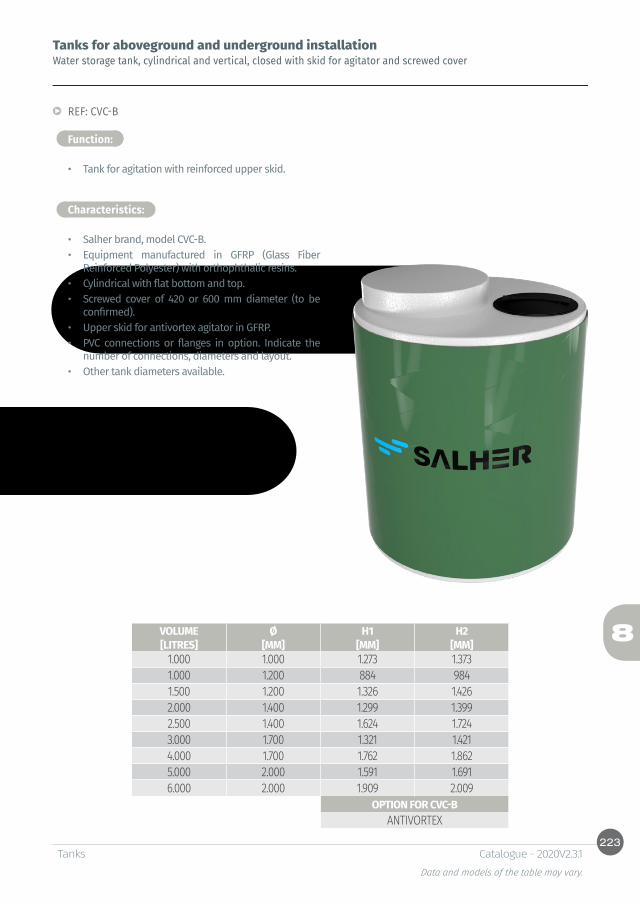
223
8
TanksData and models of the table may vary.
Catalogue - 2020V2.3.1
Tanks for aboveground and underground installation
Function:
Water storage tank, cylindrical and vertical, closed with skid for agitator and screwed cover
REF: CVC-B
• Tank for agitation with reinforced upper skid.
Characteristics:
• Salher brand, model CVC-B.• Equipment manufactured in GFRP (Glass Fiber
Reinforced Polyester) with orthophthalic resins.• Cylindrical with flat bottom and top. • Screwed cover of 420 or 600 mm diameter (to be
confirmed). • Upper skid for antivortex agitator in GFRP.• PVC connections or flanges in option. Indicate the
number of connections, diameters and layout.• Other tank diameters available.
VOLUME Ø H1 H2[LITRES] [MM] [MM] [MM]
1.000 1.000 1.273 1.3731.000 1.200 884 9841.500 1.200 1.326 1.4262.000 1.400 1.299 1.3992.500 1.400 1.624 1.7243.000 1.700 1.321 1.4214.000 1.700 1.762 1.8625.000 2.000 1.591 1.6916.000 2.000 1.909 2.009
OPTION FOR CVC-BANTIVORTEX

224
8
TanksData and models of the table may vary.
Catalogue - 2020V2.3.1
Double wall tanks for aboveground installation
Function:
Diesel storage tank, cylindrical and vertical, double wall. Certified
REF. CVC-DPH
• Diesel storage.• Indoor or protected installation.
Characteristics:
• Salher brand, model CVC–DPH.• Equipment manufactured in GFRP (Glass Fiber
Reinforced Polyester) with orthophthalic resins.• Double wall GFRP-GFRP composed of:
* Inner chemical protection coat (isophthalic resins).* Mechanical resistance coat, orthophtalic resins
(inner tank).* Separation screen and air chamber insulation (inner
tank).* Separating core with air chamber.* Separation screen and air chamber insulation
(outer tank).* Mechanical resistance coat orthophthalic resins
(outer tank).* Outdoor treatment (isophthalic resins).
• Peephole for leakage detection.• Safety valve pressure-expansion.• Flat upper part with inlet and drain connection of 2”.• Volumeter to control the capacity.
VOLUME Ø INNER Ø OUTER H[LITRES] [MM] [MM] [MM]
500 620 640 1.750500 750 770 1.240750 750 770 1.800
1.000 1.000 1.030 1.3801.500 1.000 1.030 2.0201.500 1.200 1.230 1.4302.000 1.200 1.230 1.8702.000 1.400 1.440 1.4002.500 1.400 1.440 1.7203.000 1.400 1.440 2.0204.000 1.700 1.760 1.8505.000 2.000 2.080 1.7006.000 2.000 2.080 2.000
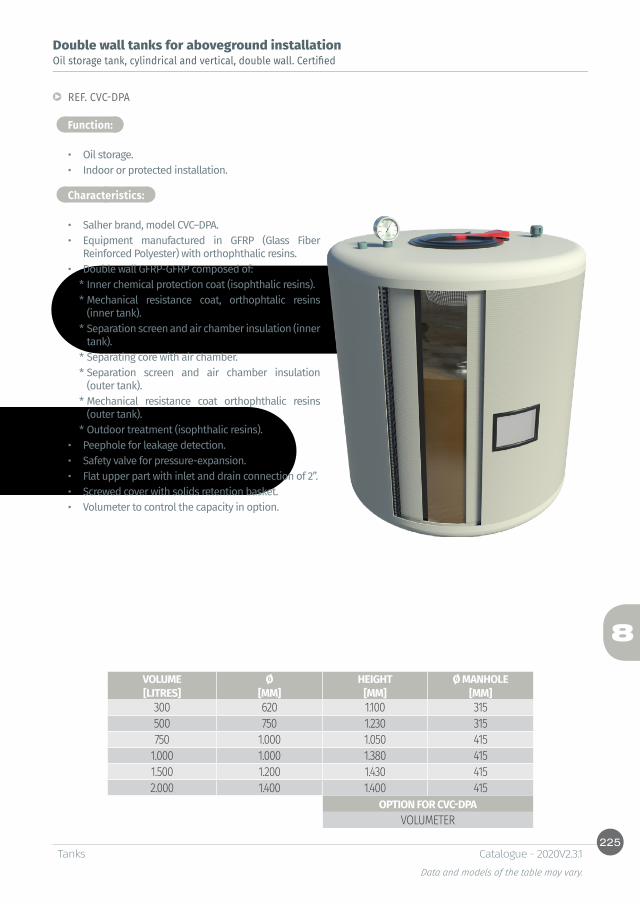
225
8
TanksData and models of the table may vary.
Catalogue - 2020V2.3.1
Double wall tanks for aboveground installation
Function:
Oil storage tank, cylindrical and vertical, double wall. Certified
REF. CVC-DPA
• Oil storage.• Indoor or protected installation.
Characteristics:
• Salher brand, model CVC–DPA.• Equipment manufactured in GFRP (Glass Fiber
Reinforced Polyester) with orthophthalic resins.• Double wall GFRP-GFRP composed of:
* Inner chemical protection coat (isophthalic resins).* Mechanical resistance coat, orthophtalic resins
(inner tank).* Separation screen and air chamber insulation (inner
tank).* Separating core with air chamber.* Separation screen and air chamber insulation
(outer tank).* Mechanical resistance coat orthophthalic resins
(outer tank).* Outdoor treatment (isophthalic resins).
• Peephole for leakage detection.• Safety valve for pressure-expansion.• Flat upper part with inlet and drain connection of 2”.• Screwed cover with solids retention basket.• Volumeter to control the capacity in option.
VOLUME Ø HEIGHT Ø MANHOLE[LITRES] [MM] [MM] [MM]
300 620 1.100 315500 750 1.230 315750 1.000 1.050 415
1.000 1.000 1.380 4151.500 1.200 1.430 4152.000 1.400 1.400 415
OPTION FOR CVC-DPAVOLUMETER
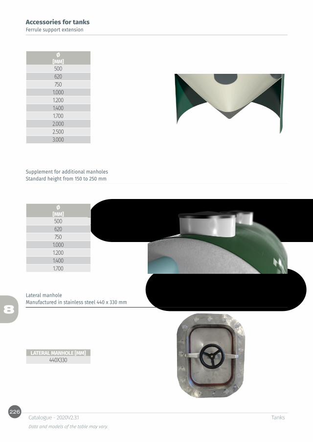
226
8
TanksData and models of the table may vary.
Catalogue - 2020V2.3.1
Accessories for tanksFerrule support extension
Standard height from 150 to 250 mm
Manufactured in stainless steel 440 x 330 mm
Supplement for additional manholes
Lateral manhole
Ø[MM]500620750
1.0001.2001.4001.7002.0002.5003.000
Ø[MM]500620750
1.0001.2001.4001.700
LATERAL MANHOLE [MM]440X330

227
8
D K F
G
TanksData and models of the table may vary.
Catalogue - 2020V2.3.1
Accessories for tanks
Function:
Connections for inlet, outlet and drain of GFRP tanks
• Kit composed of a straight connection, rubber seal, screws and flanges. The whole content is screwed in the steel to connect the tank to external pipes.
Characteristics:
• Dimensions in accordance with EN 1452-2 for standard pipe connections in accordance with EN 1452-3.
• Plastic material in PP and PVC-U.
REF: MAN-HEM
D PN E K F[MM] [MM] [MM] [MM]
20 16 27 65 14X425 16 33 75 14X432 16 41 85 14X440 16 50 100 18X450 16 61 110 18X463 16 76 125 18X475 16 90 145 18X490 16 108 160 18X8110 16 131 180 18X8125 16 148 210 18X8140 16 165 210 18X8160 10 188 240 22X8200 10 225 270 22X8225 10 248 295 22X8250 10 282 350 22X12315 10 342 400 22X12400 6 432 515 26X16
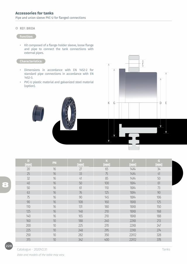
228
8
D EGK
F
TanksData and models of the table may vary.
Catalogue - 2020V2.3.1
Accessories for tanks
Function:
Pipe and union sleeve PVC-U for flanged connections
REF: BRIDA
• Kit composed of a flange-holder sleeve, loose flange and pipe to connect the tank connections with external pipes.
Characteristics:
• Dimensions in accordance with EN 1452-2 for standard pipe connections in accordance with EN 1452-3.
• PVC-U plastic material and galvanized steel material (option).
D PN E K F G[MM] [MM] [MM] [MM] [MM]
20 16 27 65 14X4 3425 16 33 75 14X4 4132 16 41 85 14X4 5040 16 50 100 18X4 6150 16 61 110 18X4 7363 16 76 125 18X4 9075 16 90 145 18X4 10690 16 108 160 18X8 125110 16 131 180 18X8 150125 16 148 210 18X8 168140 16 165 210 18X8 188160 10 188 240 22X8 213200 10 225 270 22X8 247225 10 248 295 22X8 274250 10 282 350 22X12 328315 10 342 400 22X12 378


9Sludge treatment and thickeners

Table of contentsSludge treatment
Closed static thickenerREF: CVC-DC-TC 234Open static thickenerREF: CVA-DC-TC 235Open static thickener with steel supportsREF: CVA-E-TC 236Sludge thickener by gravity, closed and open with ferrule-supportREF: CVC-E-TC-VS AND CVA-E-TC-VS 237Footbridge for sludge thickener REF: PASARELA 238Ladder with rail and exit systemREF: EQ-P 238Sludge dewatering by filter bagsREF: FILSA 239Filter press REF: FP 240Automatic unit for polyelectrolyte preparation REF: UAP 242Sludge storage tank, undergroundREF: CHC-F 243
Other dimensions and configurations can be provided upon request. Internal dimensions. Dimensions in millimeters. Volumes in liters, the dimensions indicated may vary according to the needs.Due to its policy of continuous development, Salher Ibérica, S.L. reserves the right to modify the data that appear in this document without notice.This document is protected by the intellectual property law, so that the customer cannot claim, manipulate or duplicate this documentation, except copy for personal use.
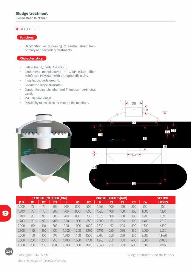
234
9
H
H1
H2
E
Ø
C4
D2C2 C3
D3
ØB
150
Sludge treatment and thickenersData and models of the table may vary.
Catalogue - 2020V2.3.1
Function:
Characteristics:
Sludge treatmentClosed static thickener
REF: CVC-DC-TC
• Dehydration or thickening of sludge issued from primary and secondary treatments.
• Salher brand, model CVC–DC–TC.• Equipment manufactured in GFRP (Glass Fiber
Reinforced Polyester) with orthophthalic resins.• Installation: underground. • Geometric shape: truncated.• Central feeding chamber and Thompson perimetral
canal. • PVC inlet and outlet.• Possibility to install an air vent on the manhole.
CENTRAL CYLINDER [MM] PARTIAL HEIGHTS [MM] VOLUMEØ D D1 D2 D3 E H1 H2 H C1 C2 C3 C4 LITRES
1.000 75 75 300 700 800 500 1.563 100 150 300 750 7501.200 75 75 300 700 800 600 1.720 100 150 300 1.000 1.1301.400 90 90 300 700 800 700 1.870 100 150 300 1.200 1.5901.700 90 90 400 900 1.000 850 2.300 150 200 300 1.400 2.9102.000 110 110 500 900 1.000 1.000 2.530 150 200 300 1.700 4.1902.500 160 160 620 1.000 1.200 1.250 3.110 250 250 350 2.000 7.9303.000 160 160 690 1.200 1.400 1.500 3.700 250 250 350 2.500 13.4203.500 200 200 750 1.400 1.600 1.750 4.265 250 300 400 3.000 21.0004.000 200 200 1.000 1.600 1.800 2.000 4.840 250 300 400 3.500 30.980

235
9
H
H1
H2
E
Ø
C4D2
C2C3
D3
Sludge treatment and thickenersData and models of the table may vary.
Catalogue - 2020V2.3.1
Function:
Characteristics:
Sludge treatmentOpen static thickener
REF: CVA-DC-TC
• Dehydration or thickening of sludge issued from primary and secondary treatments.
• Salher brand, model CVA–DC–TC.• Equipment manufactured in GFRP (Glass Fiber
Reinforced Polyester) with orthophthalic resins.• Installation: underground. • Geometric shape: truncated.• Central feeding chamber and Thompson perimetral
canal. • PVC inlet and outlet.• Open on the top.
CENTRAL CYLINDER [MM] PARTIAL HEIGHTS [MM] VOLUMEØ D D1 D2 D3 E H1 H2 H C1 C2 C3 C4 LITRES
1.000 75 75 300 700 800 500 1.300 100 150 300 750 7501.200 75 75 300 700 800 600 1.400 100 150 300 1.000 1.1301.400 90 90 300 700 800 700 1.500 100 150 300 1.200 1.5901.700 90 90 400 900 1.000 850 1.850 150 200 300 1.400 2.9102.000 110 110 500 900 1.000 1.000 2.000 150 200 300 1.700 4.1902.500 160 160 620 1.000 1.200 1.250 2.450 250 250 350 2.000 7.9303.000 160 160 690 1.200 1.400 1.500 2.900 250 250 350 2.500 13.4203.500 200 200 750 1.400 1.600 1.750 3.350 250 300 400 3.000 21.0004.000 200 200 1.000 1.600 1.800 2.000 3.800 250 300 400 3.500 30.980
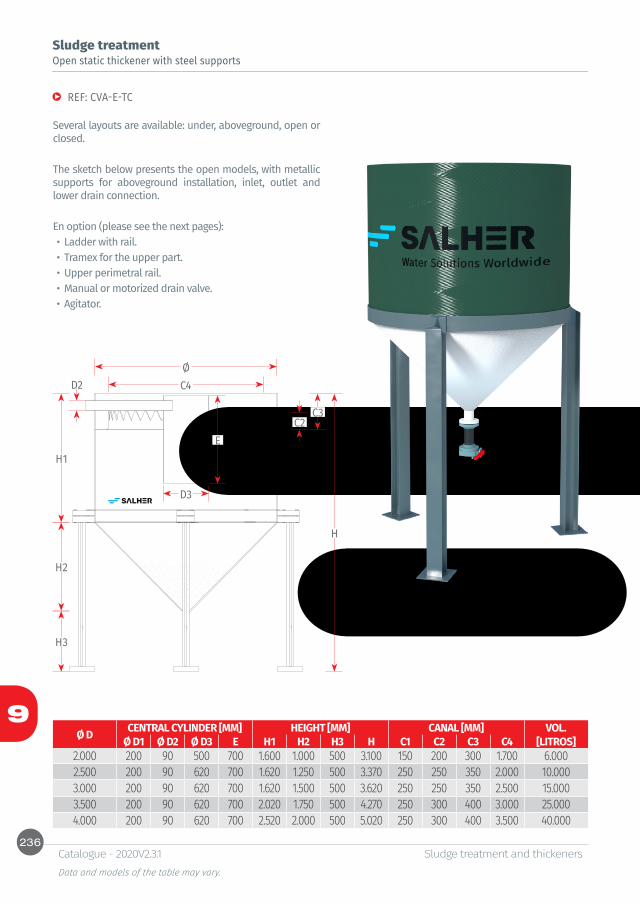
236
9
H
H1
H2
H3
E
ØC4D2
C2C3
D3
Sludge treatment and thickenersData and models of the table may vary.
Catalogue - 2020V2.3.1
Sludge treatmentOpen static thickener with steel supports
REF: CVA-E-TC
Several layouts are available: under, aboveground, open or closed.
The sketch below presents the open models, with metallic supports for aboveground installation, inlet, outlet and lower drain connection.
En option (please see the next pages):• Ladder with rail.• Tramex for the upper part.• Upper perimetral rail.• Manual or motorized drain valve.• Agitator.
Ø D CENTRAL CYLINDER [MM] HEIGHT [MM] CANAL [MM] VOL. Ø D1 Ø D2 Ø D3 E H1 H2 H3 H C1 C2 C3 C4 [LITROS]
2.000 200 90 500 700 1.600 1.000 500 3.100 150 200 300 1.700 6.0002.500 200 90 620 700 1.620 1.250 500 3.370 250 250 350 2.000 10.0003.000 200 90 620 700 1.620 1.500 500 3.620 250 250 350 2.500 15.0003.500 200 90 620 700 2.020 1.750 500 4.270 250 300 400 3.000 25.0004.000 200 90 620 700 2.520 2.000 500 5.020 250 300 400 3.500 40.000

237
9
H
H1
H2
E
Ø
C4
D2C2 C3
D3
ØB
150
250
H
H1
H2
E
Ø
C4D2
C2
250
C3
D3
Sludge treatment and thickenersData and models of the table may vary.
Catalogue - 2020V2.3.1
Sludge treatmentSludge thickener by gravity, closed and open with ferrule-support
REF: CVC-E-TC-VS AND CVA-E-TC-VS
Open or closed thickener, for aboveground installation. Support through extension of the ferrule-support.
En option (please see the next pages):• Ladder with rail.• Tramex for the upper part.• Upper perimetral rail.• Manual or motorized drain valve.• Agitator.
Ø D CENTRAL CYLINDER [MM] HEIGHT [MM] CANAL [MM] VOL. Ø D1 Ø D2 Ø D3 E H1 H2 H CVC H CVA C1 C2 C3 C4 [LITROS]
1.400 200 90 300 500 1.750 850 2.800 2.450 150 200 300 1.200 3.0001.700 200 90 400 500 1.500 850 2.785 2.350 150 200 300 1.400 4.0002.000 200 90 500 700 1.300 1.000 2.810 2.300 150 200 300 1.700 5.0002.000 200 90 500 700 1.600 1.000 3.610 3.100 150 200 300 1.700 6.0002.500 200 90 620 700 1.620 1.250 3.945 3.370 250 250 350 2.000 10.0002.500 200 90 620 700 2.650 1.250 4.475 3.900 250 250 350 2.000 15.0003.000 200 90 620 700 1.620 1.500 4.260 3.620 250 250 350 2.500 15.0003.000 200 90 620 700 2.350 1.500 4.490 3.850 250 250 350 2.500 20.0003.000 200 90 620 700 3.050 1.500 5.190 4.550 250 250 350 2.500 25.000
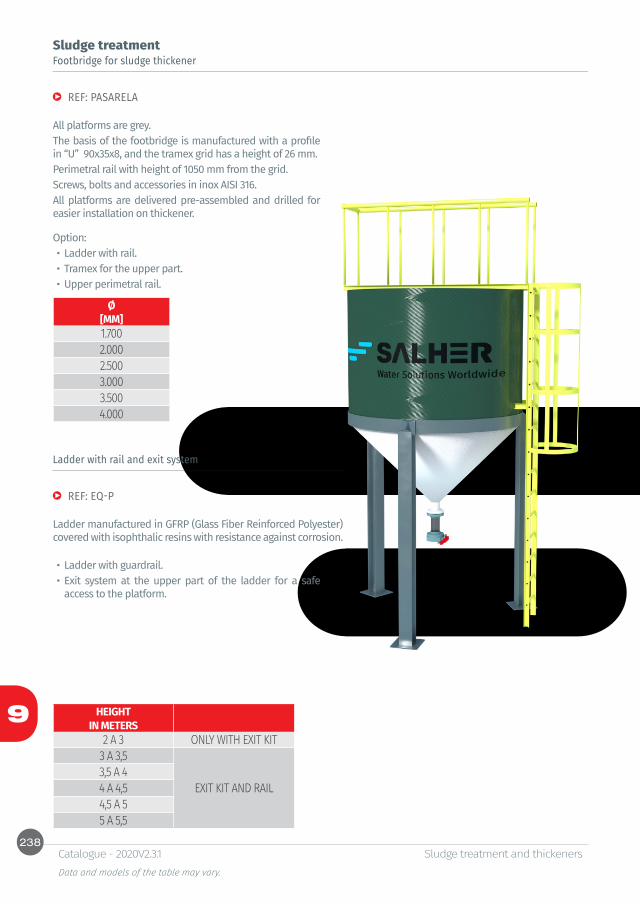
238
9
Sludge treatment and thickenersData and models of the table may vary.
Catalogue - 2020V2.3.1
Sludge treatmentFootbridge for sludge thickener
Ladder with rail and exit system
REF: PASARELA
REF: EQ-P
All platforms are grey.The basis of the footbridge is manufactured with a profile in “U” 90x35x8, and the tramex grid has a height of 26 mm. Perimetral rail with height of 1050 mm from the grid.Screws, bolts and accessories in inox AISI 316.All platforms are delivered pre-assembled and drilled for easier installation on thickener.
Ladder manufactured in GFRP (Glass Fiber Reinforced Polyester) covered with isophthalic resins with resistance against corrosion.
Option: • Ladder with rail.• Tramex for the upper part.• Upper perimetral rail.
• Ladder with guardrail.• Exit system at the upper part of the ladder for a safe
access to the platform.
Ø[MM]1.7002.0002.5003.0003.5004.000
HEIGHTIN METERS
2 A 3 ONLY WITH EXIT KIT3 A 3,5
EXIT KIT AND RAIL3,5 A 44 A 4,54,5 A 55 A 5,5

239
9
Sludge treatment and thickenersData and models of the table may vary.
Catalogue - 2020V2.3.1
Function:
Characteristics:
Sludge treatmentSludge dewatering by filter bags
REF: FILSA
• Sludge removal and dewatering from small and medium sized treatment plants.
• Bags made with a porous matter to allow the water and drying air passage, and prevent from the clogging of the retained solids.
• Equipment in polypropylene with inner structure in stainless steel AISI 304.
• Expanding baskets manufactured in AISI 304.• Wheelbarrow for bag transportation.• Number of bag heads available of 1, 2, 4 and 8.• Filter bags manufactured through drying with
fixing process.• Includes 10 bags per head.
• Motorized valve with safety box (option).• Level probe connected to the panel control. • Electrical panel board (option).• Butterfly valve at the inlet of the equipment. • Butterfly valves for bags connection. • Automatic filtration phase and filling by gravity. • Low maintenance and energy cost. • High efficiency for 10 to 20% dry matter after a
few hours, and 40 to 80% of dry matter after outdoor storage.
* For different flow and number of bags, please consult Salher
• After removing most part of water from sludge, bags are placed in the drying area for the final dehydration.
REF MAX. FLOW HEADS/ BAGS WIDTH HEIGHT LENGTH INLET OUTLET OVERFLOW
[M3/D] [UNITS] [MM] [MM] [MM] DN DN DNFILSA 01 1 1 / 10 660 1.690 951 1X80 1X80 1X100FILSA 02 2 2 / 20 770 1.750 1.300 1X100 1X100 1X100FILSA 04 4 4 / 40 1.100 1.750 1.350 2X100 1X100 1X100FILSA 08 8 8 / 80 1.145 1.750 2.250 2X100 1X100 1X100
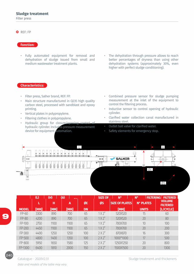
240
9
L A
HØE
ØS
Sludge treatment and thickenersData and models of the table may vary.
Catalogue - 2020V2.3.1
Sludge treatment
Fonction:
Characteristics:
Filter press
REF: FP
• Fully automated equipment for removal and dehydration of sludge issued from small and medium wastewater treatment plants.
• Filter press, Salher brand, REF: FP.• Main structure manufactured in Q235 high quality
carbon steel, processed with sandblast and epoxy printing.
• Vertical plates in polypropylene.• Filtering clothes in polypropylene.• Hydraulic group for closure/opening control of
hydraulic cylinder. Includes pressure measurement device for equipment automation.
REF(L)
LENGTH(H)
HEIGHT(A)
WIDTH ØE ØSSIZE OF PLATES
N° PLATES
N° CHAMBERS
FILTERING SURFACE
FILTERED VOLUME
[MM] [MM] [MM] DN [MM] UNIT UNIT [M2] [L/CYCLE]FP-60 3300 890 700 DN 65 1 X 2” 520X520 15 14 6 60FP-80 4200 890 700 DN 65 1 X 2” 520X520 20 19 8 80FP-100 2750 1100 1100 DN 65 1 X 2” 700X700 10 9 10 100FP-200 4450 1100 1100 DN 65 1 X 2” 700X700 20 19 20 200FP-300 4400 1250 1250 DN 100 2 X 2” 870X870 16 15 25 300FP-500 4800 1400 1350 DN 100 2 X 2” 1000*1000 17 16 40 500FP-800 5950 1650 1580 DN 125 2 X 2” 1250X1250 20 19 50 800FP-1300 6400 1810 2000 DN 150 2 X 2” 1500X1500 20 19 80 1300
For other filtering volumes, please consult Salher.
• Combined pressure sensor for sludge pumping measurement at the inlet of the equipment to control the filtering process.
• Inductive sensor to control opening of hydraulic cylinder.
• Clarified water collection canal manufactured in stainless steel.
• Outlet ball valve for clarified water. • Safety elements for emergency stop.
• The dehydration through pressure allows to reach better percentages of dryness than using other dehydration systems (approximately 30%, even higher with perfect sludge conditioning).
L H A ØE ØS SIZE OF PLATES N° PLATES VOLUME FILTERED
MODEL [MM] [MM] [MM] DN [MM] UNITS [L/CYCLE]FP-60 3300 890 700 65 1 X 2” 520X520 15 60FP-80 4200 890 700 65 1 X 2” 520X520 20 80FP-100 2750 1100 1100 65 1 X 2” 700X700 10 100FP-200 4450 1100 1100 65 1 X 2” 700X700 20 200FP-300 4400 1250 1250 100 2 X 2” 870X870 16 300FP-500 4800 1400 1350 100 2 X 2” 1000*1000 17 500FP-800 5950 1650 1580 125 2 X 2” 1250X1250 20 800FP-1300 6400 1810 2000 150 2 X 2” 1500X1500 20 1300
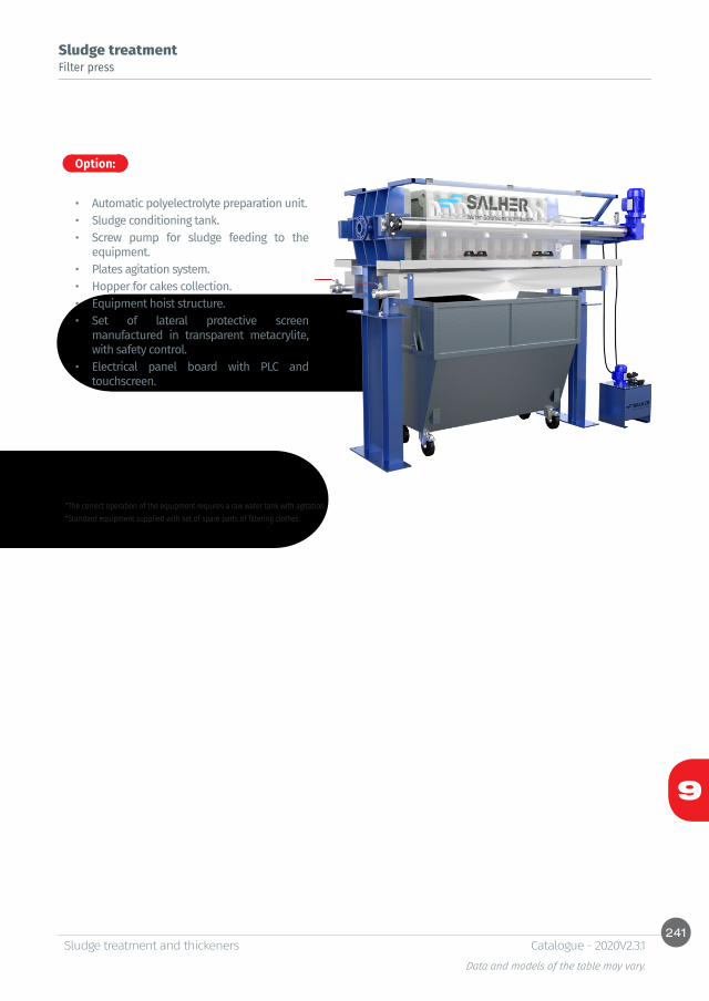
241
9
Sludge treatment and thickenersData and models of the table may vary.
Catalogue - 2020V2.3.1
Sludge treatmentFilter press
• Automatic polyelectrolyte preparation unit.• Sludge conditioning tank. • Screw pump for sludge feeding to the
equipment.• Plates agitation system. • Hopper for cakes collection.• Equipment hoist structure.• Set of lateral protective screen
manufactured in transparent metacrylite, with safety control.
• Electrical panel board with PLC and touchscreen.
Option:
*The correct operation of the equipment requires a raw water tank with agitation. *Standard equipment supplied with set of spare parts of filtering clothes.
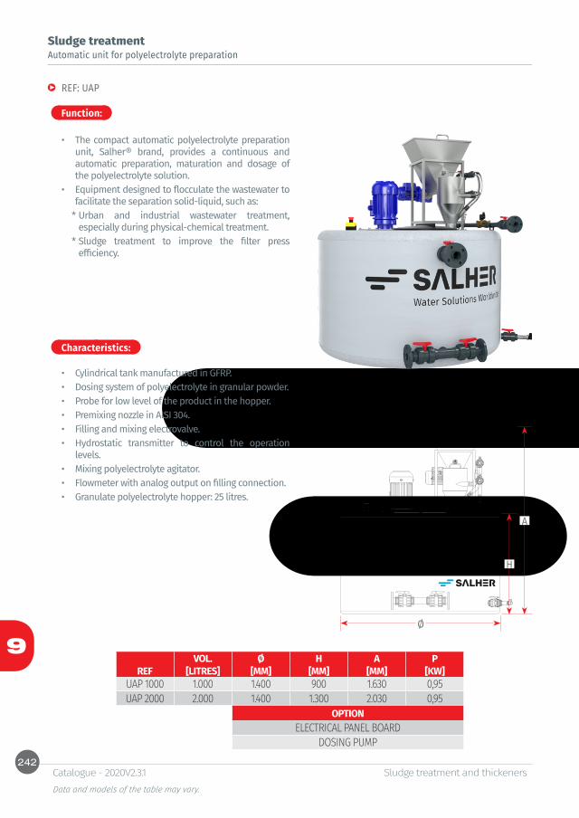
242
9
H
A
Ø
Sludge treatment and thickenersData and models of the table may vary.
Catalogue - 2020V2.3.1
Function:
Characteristics:
Automatic unit for polyelectrolyte preparation
REF: UAP
• The compact automatic polyelectrolyte preparation unit, Salher® brand, provides a continuous and automatic preparation, maturation and dosage of the polyelectrolyte solution.
• Equipment designed to flocculate the wastewater to facilitate the separation solid-liquid, such as:
* Urban and industrial wastewater treatment, especially during physical-chemical treatment.
* Sludge treatment to improve the filter press efficiency.
• Cylindrical tank manufactured in GFRP.• Dosing system of polyelectrolyte in granular powder. • Probe for low level of the product in the hopper.• Premixing nozzle in AISI 304.• Filling and mixing electrovalve. • Hydrostatic transmitter to control the operation
levels. • Mixing polyelectrolyte agitator.• Flowmeter with analog output on filling connection.• Granulate polyelectrolyte hopper: 25 litres.
Sludge treatment
VOL. Ø H A PREF [LITRES] [MM] [MM] [MM] [KW]
UAP 1000 1.000 1.400 900 1.630 0,95UAP 2000 2.000 1.400 1.300 2.030 0,95
OPTIONELECTRICAL PANEL BOARD
DOSING PUMP

243
9
Sludge treatment and thickenersData and models of the table may vary.
Catalogue - 2020V2.3.1
Function:
Characteristics:
Sludge treatmentSludge storage tank, underground
REF: CHC-F
• Storage and concentration of sludge issued from secondary settling tanks.
• GFRP tank for underground installation.• Set of inlet, air vent and overflow connections at the
head of the tank. • Includes pump to place in the secondary settling
tank, pump Vortex type 50 mm, 0,55 kW III 400 V 50 Hz, in INOX. With impulsion outlet in DN 40-50 mm.
VOLUME Ø LENGTH POWER OF SLUDGE PUMP[LITRES] [MM] [MM] [KW] III 400V 50 HZ
2.500 1.400 1.905 0.555.000 1.700 2.540 0.5510.000 2.000 3.580 0.5512.000 2.000 4.214 0.5515.000 2.000 5.170 0.55


10Accessories


Table of contentsSampling manhole
REF: CVA-ATM 248
Effluent control manhole REF: CVA-CAM 248
Manhole extensionREF: CVA-P 248
Foldable telescopic cover for pedestrian area
REF: TTAP 249
Cast iron cover class D400 - Breaking Load > 400 kn
REF: TAPA-D40 250
Fine bubble diffusersREF: DBF 250
Prefabricated flowmeterParshall flumeREF: MC-CP 251REF: MC-CP-C 251Flowmeter triangular V-notch REF: MC-VT 252REF: MC-CU 252
Accessories for oil/water separatorsStorm spillway and flow regulatorREF: CVC-AARC 253Maximum level alarm for wastewater tanks REF: SAM 254Dissolved oxygen meterREF: MED-OX 254Hydrocarbon level detection alarm REF: OMS-1 255Sand and solids detection alarmREF: IDOIL-S 255Oil, hydrocarbon, sand and solids detection alarmREF: IDOIL-OS 255
Oil, hydrocarbon, sand, solids and maximum level alarmREF: IDOIL-LOS 256Oil, hydrocarbon, sand and solids detection alarm with solar panel charging and warning via mobileREF: IDOIL-SOLAR 256Floating hydrocarbon level alarmREF: SET-OSK2 256
DeodorizationREF: CARBO-VENT 257REF: CARBO-SAC 258
Bacteria and enzymesBRICK - 900 - 450 259CRM DEPUR 259SEPT 259DOSEFOSS 259CLAIR 259
Other dimensions and configurations can be provided upon request. Internal dimensions. Dimensions in millimeters. Volumes in liters, the dimensions indicated may vary according to the needs.Due to its policy of continuous development, Salher Ibérica, S.L. reserves the right to modify the data that appear in this document without notice.This document is protected by the intellectual property law, so that the customer cannot claim, manipulate or duplicate this documentation, except copy for personal use.

248
10
Ø
Ø
H
H
CE CS
AccessoriesData and models of the table may vary.
Catalogue - 2020V2.3.1
Sampling manhole
Effluent control manhole
Manhole extension
REF: CVA-ATM
REF: CVA-CAM
REF: CVA-P
• For inspection and control of the water discharge at the outlet of the WWTP, oil/water separators, etc.
• For inspection and control of the discharge at the outlet of the WWTP, oil/water separators, etc.
• Sized in accordance with the Region of Madrid Standard for industrial activity, up the municipal network.
• Manhole extension, manufactured in GFRP, to facilitate the installation of the equipment deeper underground for a better protection to outdoors.
• Easy and quick installation. Extensions shall fit together up to the required height or possibility of custom-made extension.
* Dimensions manufactured upon request.
Ø MANHOLE Ø PIPE HEIGHT INLET OUTLET[MM] [MM] [MM] [MM] [MM]400 125 500 150 50500 160 500 150 50500 200 500 150 50620 250 500 150 50750 300 500 150 50
Ø MANHOLE Ø PIPE HEIGHT[MM] [MM] [MM]1.200 200-315 1.0001.200 200-315 1.5001.200 200-315 2.0001.200 200-315 2.2501.200 200-315 2.500
LENGTH[MM] Ø 250 Ø 400 Ø 500 Ø 620 Ø 750 * Ø 1000* 250 X X X X X X500 X X X X X X750 X X X X X X
1.000 X X X X X X

249
10
Ø
H
AccessoriesData and models of the table may vary.
Catalogue - 2020V2.3.1
Function:
Characteristics:
Foldable telescopic cover for pedestrian area
REF: TTAP
• Foldable cover for protection and closure of tank manholes.
• Resistant structure in GFRP by moulding.• Quick and safe access to underground equipment. • Easy closure by anchoring type ring carabiner to
install a safety lock.• Identification plate with equipment data. Facilitates
a quick check without access inside. • Customizable: possibility to mark with laser a logo/
text (example: symbol of company or other). • Includes a full kit of installation for on-site mounting
in 5 minutes.• Resistant to bad weather (corrosion and oxidation)
and chemical agents.
For manhole extension length over than h=0,5m, please consult Ref. CVA-PTo seal the union, consult the reference KIT, in Accessories.
Ø HREF [MM] [MM]
TTAP 620 620 110TTAP 750 750 110
TTAP 1000 1.000 110TTAP 1200 1.200 110

250
10
L
AO
CE
AccessoriesData and models of the table may vary.
Catalogue - 2020V2.3.1
Cast iron cover class D400 - Breaking Load > 400 kn
Fine bubble diffusers
REF: TAPA-D40
REF: DBF
• Cast iron cover manufactured in accordance with ISO 1083 (1987) according to the class D 400 of UNE-EN-124 (1995), with inscription "water treatment".
• Circular cover with safety locking system, by rotation and protected with plastic screw. Includes anti-noise and anti-slip polyethylene joint.
• The frame contains alveoles to optimize its installation and 4 holes to clamp it to the ground if necessary.
• For roads, including pedestrian streets, roadsides and parking areas for all type of vehicles (group 4 of the UNE-EN-124 of 1995).
• Diffusers are composed of two PVC pipes connected to a T-shape element. Pipes are covered with an EPDM membrane which distributes the air.
• Micro-openings of membrane operate like a valve which releases the air under pressure, then is closed during the water passage. An air bubble with reduced diameter, 0,5 to 1 mm, rises slowly to the surface. The equipment efficiency is improved by 2 factors:
* Oxygen transfer surface is increased.* The air bubble stays longer in water.
DIMENSIONS [MM] WEIGHT [KG]A C O H E FRAME COVER TOTAL
850 650 600 100 27 29 36 65
LENGTHREF [MM]
DBF100 1.140DBF500 640
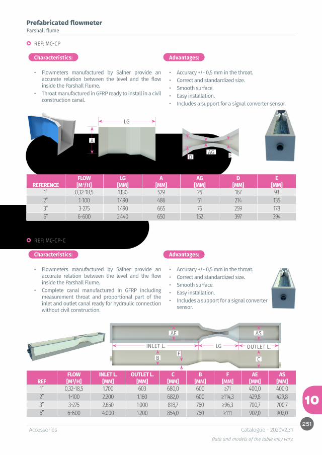
251
10
LG
LG
AE AS
CB
A
D EAG
F
AccessoriesData and models of the table may vary.
Catalogue - 2020V2.3.1
Characteristics:
Characteristics:
Advantages:
Advantages:
Parshall flumePrefabricated flowmeter
REF: MC-CP
REF: MC-CP-C
• Flowmeters manufactured by Salher provide an accurate relation between the level and the flow inside the Parshall Flume.
• Throat manufactured in GFRP ready to install in a civil construction canal.
• Flowmeters manufactured by Salher provide an accurate relation between the level and the flow inside the Parshall Flume.
• Complete canal manufactured in GFRP including measurement throat and proportional part of the inlet and outlet canal ready for hydraulic connection without civil construction.
• Accuracy +/- 0,5 mm in the throat.• Correct and standardized size.• Smooth surface.• Easy installation.• Includes a support for a signal converter sensor.
• Accuracy +/- 0,5 mm in the throat.• Correct and standardized size.• Smooth surface.• Easy installation.• Includes a support for a signal converter
sensor.
INLET L. OUTLET L.
FLOW LG A AG D EREFERENCE [M³/H] [MM] [MM] [MM] [MM] [MM]
1” 0,32-18,5 1.130 529 25 167 932” 1-100 1.490 486 51 214 1353” 3-275 1.490 665 76 259 1786” 6-600 2.440 650 152 397 394
FLOW INLET L. OUTLET L. C B F AE ASREF [M³/H] [MM] [MM] [MM] [MM] [MM] [MM] [MM]1” 0,32-18,5 1.700 603 680,0 600 ≥71 400,0 400,02” 1-100 2.200 1.160 682,0 600 ≥114,3 429,8 429,83” 3-275 2.650 1.000 818,7 760 ≥96,3 700,7 700,76” 6-600 4.000 1.200 854,0 760 ≥111 902,0 902,0

252
10
Ø
H
P
HV
L1 L2L2
AccessoriesData and models of the table may vary.
Catalogue - 2020V2.3.1
Ultrasound flowmeter for open canals
REF: MC-CU
• Principle: ultrasound. Flowmeter in open canals, range: 0-0,3m, 0-1m or 0-3 m with digital indicator. Dimensions 185 x 240 x 115 mm. Output 4-20 mA. Impulse output. Protection IP 65. 12 m cable length; built-in totalizer, indicates instantaneous flow, average flow in the last hour and last 24 hours.
• Option: connections box and extra cable up to 50 m.
Flowmeter triangular V-notch
REF: MC-VT
• Flow measurement device. Sampling possible.
• Salher brand, model MC-VT.• Triangular V-notch manufactured in PP and calibrated
in accordance with ISO 1438/1, with different angles and flows.
• Low friction coefficient, minimal water absorption and high chemical resistance.
• V-notch manhole composed of a cylindrical and vertical manhole, open on the top, in GFRP (Glass Fiber Reinforced Polyester).
• GFRP wall with box for triangular V-notch.• PVC inlet and outlet. GFRP upper cover.
Function:
Characteristics:
FLOW Ø H P HV L1 L2 CE CS[M3/H] ANGLE [MM] [MM] [MM] [MM] [MM] [MM] [MM] [MM]0 A 15 22,5° 1.000 1.250 300 200 700 300 50 50
1,8 A 30 45 ° 1.000 1.250 300 185 700 300 50 501,8 A 60 45 ° 1.000 1.250 350 245 700 300 50 50
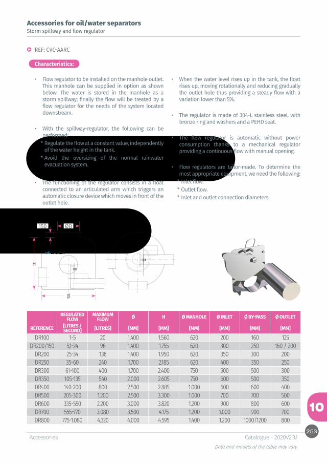
253
10
H
Ø
ØB150
AccessoriesData and models of the table may vary.
Catalogue - 2020V2.3.1
Accessories for oil/water separatorsStorm spillway and flow regulator
REF: CVC-AARC
Characteristics:
• Flow regulator to be installed on the manhole outlet. This manhole can be supplied in option as shown below. The water is stored in the manhole as a storm spillway; finally the flow will be treated by a flow regulator for the needs of the system located downstream.
• With the spillway-regulator, the following can be performed:
* Regulate the flow at a constant value, independently of the water height in the tank.
* Avoid the oversizing of the normal rainwater evacuation system.
• The functioning of the regulator consists in a float connected to an articulated arm which triggers an automatic closure device which moves in front of the outlet hole.
• When the water level rises up in the tank, the float rises up, moving rotationally and reducing gradually the outlet hole thus providing a steady flow with a variation lower than 5%.
• The regulator is made of 304-L stainless steel, with bronze ring and washers and a PEHD seat.
• The flow regulator is automatic without power consumption thanks to a mechanical regulator providing a continuous flow with manual opening.
• Flow regulators are tailor-made. To determine the most appropriate equipment, we need the following:
* Inlet flow.* Outlet flow. * Inlet and outlet connection diameters.
REGULATED FLOW
MAXIMUM FLOW Ø H Ø MANHOLE Ø INLET Ø BY-PASS Ø OUTLET
REFERENCE [LITRES /SECOND] [LITRES] [MM] [MM] [MM] [MM] [MM] [MM]
DR100 1-5 20 1.400 1.560 620 200 160 125DR200/150 5,1-24 96 1.400 1.755 620 300 250 160 / 200
DR200 25-34 136 1.400 1.950 620 350 300 200DR250 35-60 240 1.700 2.185 620 400 350 250DR300 61-100 400 1.700 2.400 750 500 500 300DR350 105-135 540 2.000 2.605 750 600 500 350DR400 140-200 800 2.500 2.885 1.000 600 600 400DR500 205-300 1.200 2.500 3.300 1.000 700 700 500DR600 335-550 2.200 3.000 3.820 1.200 900 800 600DR700 555-770 3.080 3.500 4.175 1.200 1.000 900 700DR800 775-1.080 4.320 4.000 4.595 1.400 1.200 1000/1200 800
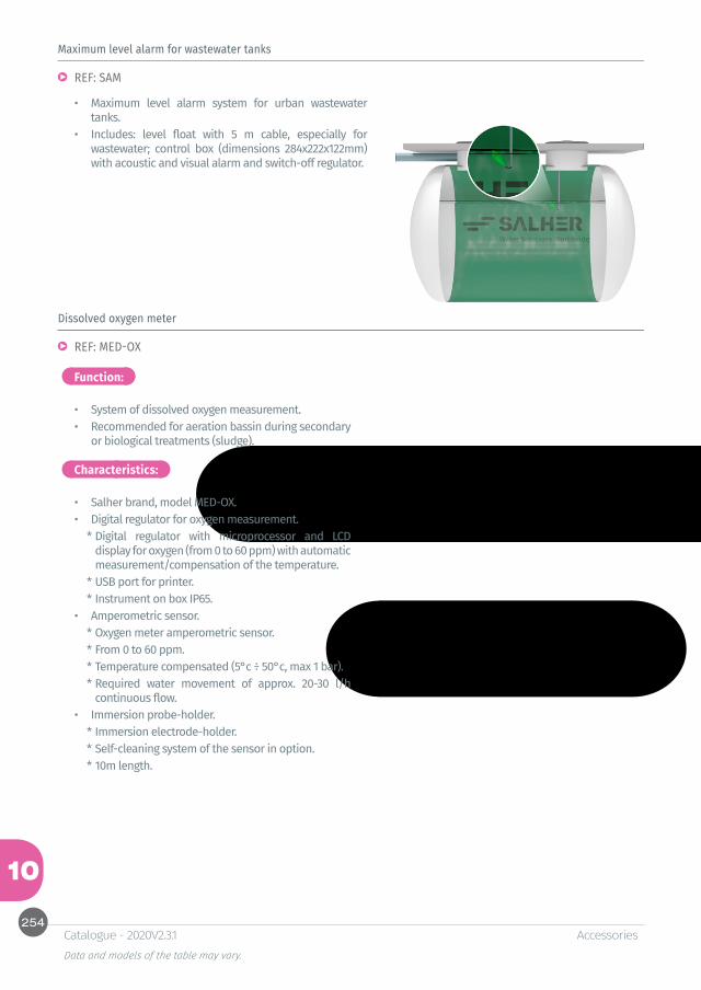
254
10
AccessoriesData and models of the table may vary.
Catalogue - 2020V2.3.1
Maximum level alarm for wastewater tanks
REF: SAM
• Maximum level alarm system for urban wastewater tanks.
• Includes: level float with 5 m cable, especially for wastewater; control box (dimensions 284x222x122mm) with acoustic and visual alarm and switch-off regulator.
Dissolved oxygen meter
REF: MED-OX
• System of dissolved oxygen measurement. • Recommended for aeration bassin during secondary
or biological treatments (sludge).
• Salher brand, model MED-OX.• Digital regulator for oxygen measurement.
* Digital regulator with microprocessor and LCD display for oxygen (from 0 to 60 ppm) with automatic measurement/compensation of the temperature.
* USB port for printer.* Instrument on box IP65.
• Amperometric sensor.* Oxygen meter amperometric sensor.* From 0 to 60 ppm.* Temperature compensated (5°c ÷ 50°c, max 1 bar).* Required water movement of approx. 20-30 l/h
continuous flow.• Immersion probe-holder.
* Immersion electrode-holder.* Self-cleaning system of the sensor in option. * 10m length.
Function:
Characteristics:

255
10
AccessoriesData and models of the table may vary.
Catalogue - 2020V2.3.1
Hydrocarbon level detection alarm
Sand and solids detection alarm
Oil, hydrocarbon, sand and solids detection alarm
REF: OMS-1
REF: IDOIL-S
REF: IDOIL-OS
• Equipment of level detection of hydrocarbon, oil and grease to install in grease and oil/water separators with working temperatures (-20 to 50°C).
• Equipment of detection of level of sand and solids to install in grit chambers and solids settling tanks with working temperatures (-20 to 40°C).
• Combined alarm system for oil, hydrocarbon, sand and solids.
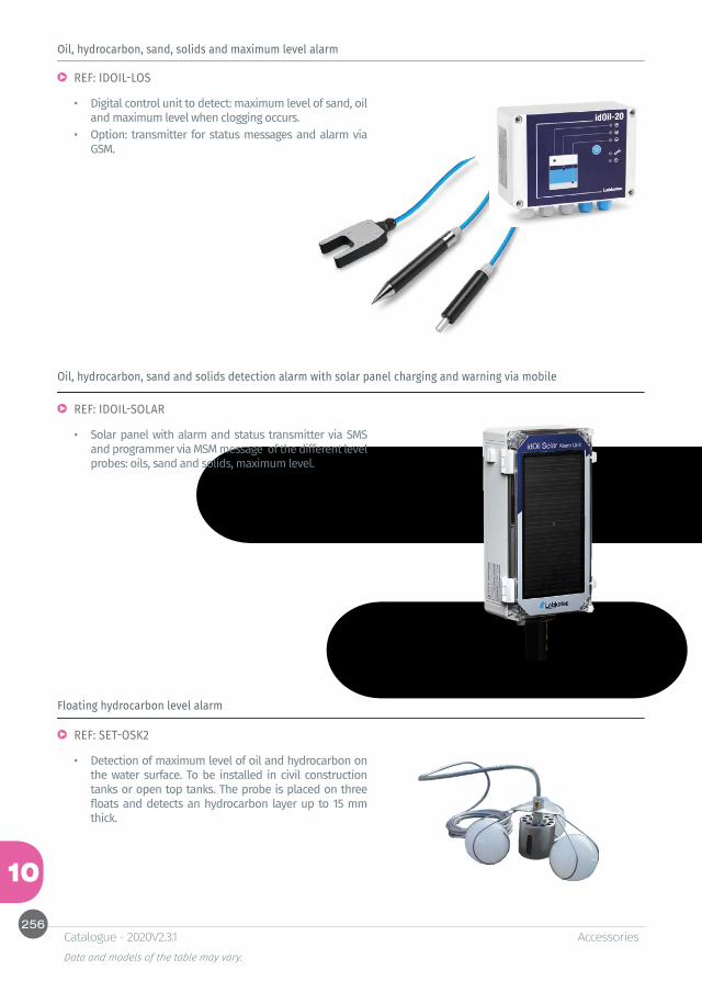
256
10
AccessoriesData and models of the table may vary.
Catalogue - 2020V2.3.1
Oil, hydrocarbon, sand, solids and maximum level alarm
Oil, hydrocarbon, sand and solids detection alarm with solar panel charging and warning via mobile
Floating hydrocarbon level alarm
REF: IDOIL-LOS
REF: IDOIL-SOLAR
REF: SET-OSK2
• Digital control unit to detect: maximum level of sand, oil and maximum level when clogging occurs.
• Option: transmitter for status messages and alarm via GSM.
• Solar panel with alarm and status transmitter via SMS and programmer via MSM message of the different level probes: oils, sand and solids, maximum level.
• Detection of maximum level of oil and hydrocarbon on the water surface. To be installed in civil construction tanks or open top tanks. The probe is placed on three floats and detects an hydrocarbon layer up to 15 mm thick.

257
10
AccessoriesData and models of the table may vary.
Catalogue - 2020V2.3.1
Function:
Characteristics:
Deodorization
REF: CARBO-VENT
• Treatment of gas issued from WWTP and septic tanks air vents.
• Salher brand, model CARBO-VENT.• Treatment of contaminants issued from WWTPs:
hydrogen sulphide, methan and other gas.• Different types of granules with specific functions for
more efficient deodorization. • Long useful life treatment of gas. • Granule with color change depending on the use
level.• Working temperature: -10 to 50°C• Installation at the outlet of the ventilation line.
Vertical, horizontal and corner layout.• Female connection PVC 1 ½” DN40.• Possibility to connect several equipment in parallel.
FULL LOAD SPARE FOR CARBO-VENT
REFERENCE Ø LENGTH INLET CONNECTION [MM] [MM]
CARBO-VENT 130 650 DN50
REFERENCECARGA-CARBO-VENT

258
10
AccessoriesData and models of the table may vary.
Catalogue - 2020V2.3.1
Function:
Characteristics:
Desodorisation
REF: CARBO-SAC
• Filter for treatment of gas issued from WWTP and pumping stations. To be installed in a technical room.
• Designed for continuous treatment flows from 328 to 768 m³/h.
• Treatment of a wide range of contaminating gas: hydrogen sulphide, mercaptans, volatile organic compounds and other gas.
• Composed of 3 differents types of granules with specific functions for better efficiency and longer useful life. These granules can be changed depending on the gas.
• Granule placed in different nets for an easy changing.• Electrical panel board for control and operation with
hour counter for load changing warning.
REF Ø TOTAL HEIGHT Ø INLET SUCTION FLOW Ø OUTLET POWER
CARBO-SAC [MM] [MM] [MM] [M3/H] [MM] [KW/VOLTAGE/HZ]
250 620 1.350 110 288 65 0,076/400/50750 1.000 1.350 125 328 95 0,12/400/50
1.000 1.000 1.650 160 384 95 0,75/400/501.500 1.200 1.650 200 576 115 1,1/400/502.000 1.400 1.650 200 768 115 1,5/400/50
REFERENCECARGA-CARBO-SAC
250750
1.0001.5002.000
259
10
AccessoriesData and models of the table may vary.
Catalogue - 2020V2.3.1
Bacteria and enzymes
BRICK - 900 - 450
• Treatment against grease and bad smell in grease separators with urban or industrial wastewater, septic tanks with high level of grease.
• 24 hours dosage without mechanism.• Presentation: box with 4/8 units of 900/450 g.
CRM DEPUR
• Biological products for foam removal in WWTP. • Presentation: container of 25 l.
SEPT
• Effervescent biological pastille which degrades organic matter, avoids clogging and bad smell in domestic and industrial pipes, septic tanks, pumping stations, etc.
• Presentation: container of 6 boxes of 24 individual tablets.
DOSEFOSS
• Biological treatment of pipes, grease separators and septic tanks.
• Presentation: box of 25 water-soluble bags of 200 g.
CLAIR
• Biological activator for WWTP by activated sludge to improve the sludge settling and remove bad smells.
• Presentation: container of 25 kg.
Salher Ibérica, S. L.Carrera Toledana,3328500 Arganda del ReyMadrid - EspañaTel. +34 918 700 015Fax: +34 918 757 [email protected]
Salher GuadalajaraC/ Guadalajara Jalisco nº 70Polígono Industrial Henares19180-MarchamaloGuadalajara - España
Salher PortugalZona Industrial de VAGOSlotes 44-463840 Vagos-Aveiro PortugalTel. +351 234 795 821Fax: +351 234 795 [email protected]
Salher PolskaŁubna 62, 05-532Baniocha - PolskaTel. +48 22 737 24 [email protected]
Salher France5, rue Isidore Valleix31500 Toulouse (France)Tel: +33 1 84 16 47 84Cell: +33 6 62 57 16 [email protected]
Salher MéxicoGonzález Camarena, 1600-4ASanta Fe - Ciudad de México01210Estados Unidos Mexicanos+52 55 5081 [email protected]
Salher Malasia SDN BHDD-6-5, Megan Avenue 1189 Jalan Tun RazakKuala Lumpur [email protected]
Salher PerúRío Perene, 114Urb. Santa Isolina15311 Comas - Lima - Perú(01) 620 0722(+51) 948 870 [email protected]
www.salher.com
With more than 35 years in the market, we have become one leading supplier for construction and engineering companies, government agencies and installation companies.
Salher equipment is supplied worldwide.