Electro Controls - Level - Watts UK & Ireland
7
Level - 2017 WattsIndustries.co.uk Electro Controls
-
Upload
khangminh22 -
Category
Documents
-
view
0 -
download
0
Transcript of Electro Controls - Level - Watts UK & Ireland

Level - 2017
WattsIndustries.co.uk
Electro Controls

[email protected] \ wattsindustries.co.uk
LEVELS SECTION 19
LIQUID LEVEL SWITCHES HOrIZOnTALELL.. EL..
To monitor liquid level in tanks and switchpumps or an alarm in the event of high or lowlevel. Two switches are required when usingboth high and low level or limit and alarmfunctions. EL-041 / 093 switches containmagnets, therefore ensure that no metalobjects are present in the liquid.
Volt free contacts
Max. ambient 70°C
Liquid sp. gravity > 0.75
Enclosure Flammability: ELL.. = UL94-V0 EL.. = Metal
Media : ELL.. Oil, Diesel, Water, Non aggressive fluids EL-041/ 093 Oil, Diesel, Water, Some aggressive fluids
Type Mounting Diff. mm Max. Media Max. Media 230VAC Media Contact Enclosure Cut-in Temp °C Press. Bar SPDT Materials
ELL-01 Horizontal 12 90 4 15(8)A Brass/Phosphor Bronze/Polypropylene IP54 ELL-02 Horizontal 12 90 4 15(8)A Brass/Phosphor Bronze/Polypropylene IP65
EL-041 Horizontal 12 330 25 10(5)A Stainless steel IP65 EL-093 Horizontal 125/550 adj. 330 25 10(5)A Stainless steel IP65
DIMENSIONS
DRILLING DETAIL:
WIRING:
EL-041 / 093
ELL-01 / 02
1" BSPT
70
20
100
65 200
28
278 - 561 adj
NOTE:LEVEL SWITCHES MUST BE MOUNTED
HORIZONTALLY WITH THE ELECTRICAL
ENTRY FACING DOWNWARDS.
73
120
M20
64
135
64
120
150 73
120
M20
64
135
64
ELL-01 / 02
EL-041 EL-093
EL-041 DIRECT MOUNTING EL-MF.. WELDED MATING FLANGE
M12
Use M12 studs to project 30mm
6592 65 CTRS
76 65
1337
ACCESSORIES: WELDED MATING FLANGE for EL-041, 093 EL-MF Carbon Steel EL-MF/ST Stainless Steel
ELL.. EL..
+L
11
12
On level rise contacts 11-14 close 11-12 open.
On level fall contacts 11-12 close 11-14 open.
1
4
2+L
141
4
2
On level rise contacts 1-4 close 1-2 open.
On level fall contacts 1-2 close 1-4 open.
102 T: +44 (0) 1480 407074 \ F: +44 (0) 1480 407076
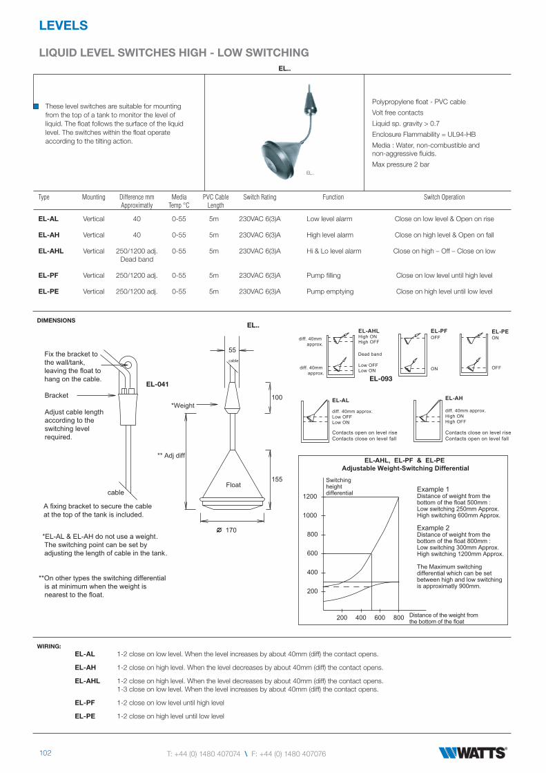
LIQUID LEVEL SWITCHES HIGH - LOW SWITCHInG
LEVELS
EL..
These level switches are suitable for mountingfrom the top of a tank to monitor the level ofliquid. The float follows the surface of the liquidlevel. The switches within the float operateaccording to the tilting action.
Polypropylene float - PVC cable
Volt free contacts
Liquid sp. gravity > 0.7
Enclosure Flammability = UL94-HB
Media : Water, non-combustible and non-aggressive fluids.
Max pressure 2 bar
Type Mounting Difference mm Media PVC Cable Switch Rating Function Switch Operation Approximatly Temp °C Length
EL-AL Vertical 40 0-55 5m 230VAC 6(3)A Low level alarm Close on low level & Open on rise
EL-AH Vertical 40 0-55 5m 230VAC 6(3)A High level alarm Close on high level & Open on fall
EL-AHL Vertical 250/1200 adj. 0-55 5m 230VAC 6(3)A Hi & Lo level alarm Close on high – Off – Close on low Dead band
EL-PF Vertical 250/1200 adj. 0-55 5m 230VAC 6(3)A Pump filling Close on low level until high level
EL-PE Vertical 250/1200 adj. 0-55 5m 230VAC 6(3)A Pump emptying Close on high level until low level
DIMENSIONS
WIRING:
EL..
EL..
EL-041EL-093
A fixing bracket to secure the cable
at the top of the tank is included.
**On other types the switching differential
is at minimum when the weight is
nearest to the float.
*EL-AL & EL-AH do not use a weight.
The switching point can be set by
adjusting the length of cable in the tank.
*Weight
Float
Bracket 100
155
170
55
cable
cable
Adjust cable length
according to the
switching level
required.
Fix the bracket to
the wall/tank,
leaving the float to
hang on the cable.
** Adj diff
EL-AL
diff. 40mm approx.
Low OFF
Low ON
EL-AH
diff. 40mm approx.High ON
High OFF
EL-AHLHigh ONHigh OFF
Low OFFLow ON
EL-PEON
OFF
EL-PFOFF
ON
diff. 40mm
approx.
diff. 40mm
approx.
Dead band
EL-AHL, EL-PF & EL-PE Adjustable Weight-Switching Differential
400
600
800
1000
1200
200
200 400 600 800
Switching height differential
Distance of the weight from the bottom of the float
Example 1Distance of weight from the bottom of the float 500mm :Low switching 250mm Approx.High switching 600mm Approx.
Example 2Distance of weight from the bottom of the float 800mm :Low switching 300mm Approx.High switching 1200mm Approx.
The Maximum switching differential which can be set between high and low switching is approximatly 900mm.
Contacts open on level rise
Contacts close on level fall
Contacts close on level rise
Contacts open on level fall
EL-AL 1-2 close on low level. When the level increases by about 40mm (diff) the contact opens.
EL-AH 1-2 close on high level. When the level decreases by about 40mm (diff) the contact opens.
EL-AHL 1-2 close on high level. When the level decreases by about 40mm (diff) the contact opens. 1-3 close on low level. When the level increases by about 40mm (diff) the contact opens.
EL-PF 1-2 close on low level until high level
EL-PE 1-2 close on high level until low level

[email protected] \ wattsindustries.co.uk
LEVELS SECTION 19
EL-AL 1-2 close on low level. When the level increases by about 40mm (diff) the contact opens.
EL-AH 1-2 close on high level. When the level decreases by about 40mm (diff) the contact opens.
EL-AHL 1-2 close on high level. When the level decreases by about 40mm (diff) the contact opens. 1-3 close on low level. When the level increases by about 40mm (diff) the contact opens.
EL-PF 1-2 close on low level until high level
EL-PE 1-2 close on high level until low level
LIQUID LEVEL SWITCHES VErTICAL
SP
EC
IAL
OR
DE
RO
NLY
EL-140 / 141, ETF-1
To monitor liquid level in tanks and switchpumps or an alarm in the event of high or lowlevel. Two switches are required when usingboth high and low level or limit and alarmfunctions. EL-140 / 141 switches containmagnets, therefore ensure that no metalobjects are present in the liquid.
Volt free contacts
Max. ambient 70°C
Liquid sp. gravity > 0.75
Enclosure Flammability: EL.. = Metal ETF.. = UL94-HB
Media : ETF.. Oil, Diesel, Water, Non-aggressive fluids
EL-140 / 141 Oil, Diesel, Water, Some aggressive fluids
Type Mounting Diff. mm Max. Media Max. Media 230VAC Media Contact Enclosure Cut-in Temp °C Press. Bar SPDT Materials
EL-140 Vertical 30/1340 adj. 330 25 10(5)A Stainless steel IP65
EL-141 Vertical 30/2340 adj. 330 25 10(5)A Stainless steel IP65
ETF-1 Vertical 30/900 adj. 65 5 10(5)A Nylon/Plastic IP54
DIMENSIONS
DRILLING DETAIL:
WIRING:
ETF-1
EL-MF..
EL-140 / 141 ETF-1
EL-041 DIRECT MOUNTING EL-MF.. WELDED MATING FLANGE
ACCESSORIES: WELDED MATING FLANGE for EL-041, 141 EL-MF Carbon Steel EL-MF/ST Stainless Steel
EL.. ETF..
EL-140 / 141
114
65
weight
adjustable stops
weight
110
55
20
77
73
120
M20
64
135
150
EL -
140
= 1
582
E
L-14
1=
308
2
90
123
Switc
h po
int a
dj.
AdjustableCounterweight
Adjustable stops
50
When float reaches upper adj stop C-NC close : When float reaches lower adj stop C-NO closeEL-140/141 - The counter balance/weight on the arm/lever should be adjusted for correct operation.
ETF-1
34
84
M12
Use M12 studs to project 30mm
6592 65 CTRS76 65
13 37
1
2
3
+L
+L
11
1214
On level rise contacts 11-14 close 11-12 open.On level fall contacts 11-12 close 11-14 open.
On level rise contacts 1-3 close 1-2 open.On level fall contacts 1- 2 close 1-3 open.

104 T: +44 (0) 1480 407074 \ F: +44 (0) 1480 407076
LEVELS
LIQUID LEVEL TrAnSMITTEr 4-20MA ULTrASOnICELU-8
Used to measure fluid depth or targetdistance in tanks or sumps / slurries. Theunit produces a 4-20mA output signal linearacross the desired measuring range.Suitable for use with BMS systems. The uniteliminates spurious echoes and ensures asteady output.
Accuracy 0.25% of measuring range.
Pressure -0.25 / +2 bar
Programmable display : 4 digit concealed
Flange mounting : DN80 PN16, BS10 TABLE D 3î, ANSI 3î.
Load at 24VDC 250Ω
Ultrasonic cone angle 12°
Materials : UPVC, Polypropylene
The unit is not suitable for use with any media that has visible fumes.
Type Measuring Operating Span Resolution Supply Output Max Protection Range Temp °C Min ± 15% 2 wire Power
ELU-8 0.5 / 8m -10/+60 100mm 1mm 24VDC 4-20mA loop 0.5W IP68
DIMENSIONS
ELU-8
SIDE VIEW
O : Origin of measurement. All measurements (distances / depths) are taken from O.D : Dead band 500mm.A : Max media height for signal range. If measurement is required to the top of the tank, mount the transmitter 500mm higher.P : Protect the unit from sunlight.B : Beam width 0.21 x Range (R)X : Beam must not touch any obstacles. Ensure that the beam path is uninterrupted.
Mounting :
OPEN TANK ñ Mount at least 0.5m above the highest media level and 105mm away from walls for every 1m of media depth.CLOSED TANK ñ Mount at least 0.5m above the highest media level. Do not mount the unit in the centre of the tank to monitor powder or granules etc. which can form into a cone shape and give inaccurate readings - in this case the unit should be mounted close to the edge as shown.Use plastic mounting bolts. Do not over-tighten as this may cause acoustic coupling to the mounting and give false readings.The transmitter must be mounted on the gasket supplied.
PLAN VIEW
11
60
192
M20
124
84
12
93
C
192
C
4 slots on 153 PCD 45 to C
25
INSTALLATION:
OPEN TANK / SUMP CLOSED TANK
X
B
P
D
R
A
O
X
B
O
X
D
A

[email protected] \ wattsindustries.co.uk
LEVELS SECTION 19
LIQUID LEVEL TrAnSMITTEr 4-20MA ULTrASOnIC
The unit can be set to read in either Distance or Depth mode. M : minimum distance between set points must be > 100mm D : 500mm Dead band O : Start of measurement
Distance Mode : The 4mA point is required to be closer to ‘O’ than the 20mA point ie O-T = 1m = 4mA O-B = 5m = 20mA At 2m the unit will give an output of 8mA
Depth Mode : The 20mA point is required to be closer to ‘O’ than the 4mA point ie O-T = 1m = 20mA O-B = 5m = 4mA At 2m the unit will give an output of 16mA
MEASUREMENT :
WIRING:
INSTALLATION: Press the following keys in sequence M . The display now shows ‘Ent’1. Scaling Choose either Manual or Automatic scaling.Manual Achieved by taking measurement from O to target distance for the 4mA & 20mA points. Press E to display current setting. To change, press E again & use the keys to set the distance (m) for the 4mA setting. Press E to confirm setting - unit displays ‘donE’ & then the new setting. Press . Unit now displays current 20mA setting. To change, press E & use the keys to set the distance (m) for the 20mA setting. Press E to confirm the setting. The unit displays ‘donE’ and then the new setting. Press M twice to enter run mode.Automatic : Achieved by adjusting physical tank contents to the the 4mA & 20mA points Press . The unit displays ‘Auto’. Press E once and the display will show the 4mA distance of media from the sensor. Press E to store the value. Press E to confirm. Unit displays ‘donE’ and then displays the current setting. Press . Unit displays the 20mA distance of media from the sensor. Press E to store the value. Press E to confirm. Unit displays ‘donE’ and then displays the current setting. Press M twice to enter run mode.
2. Display Selection:Press keys in sequence M . Unit displays ‘Ent’ Press . The unit now displays ‘disP’. Press E.To display depth/distance in metres : Use the keys to display depth above 4mA point or distance above 20mA point in metres.Press E to confirm the setting. Unit displays ‘donE’. Press M twice to enter run mode.To display depth/distance as % of range. Use the keys to display depth above 4mA point or distance above 20mA point inmetres. Press . The unit now displays ‘PerC’. Press E to confirm the setting The unit displays ‘donE’ Press M twice to enter runmode.
3. Lost Echo Response: This occurs if the unit fails to receive ‘good’ echoes. When normal conditions resume, so do output & display.Press keys in sequence M . Unit displays ‘LE’. Press E. then keys to select the ‘lost echo’ output required :-Select ‘20mA’ : drive to 20mA OR ‘4mA’ : drive to 4mA OR ‘21mA’ : drive to 21mA OR ‘hold’ : holds last ’good’ reading.Press E to confirm setting. The unit displays ‘donE’ Press M twice to enter run mode.
T
B
mA
20
4
4
20
M
DIS
TA
NC
E M
OD
E
DE
PT
H M
OD
E
O
Detail showing keypad and display located under the transmitter cover
Terminals 0.5-1.5mm² Sensor / control signal cable size 7/0.2mm Max length 300mScreened cable is recommended The screen should be earthed at controller end onlyKeep sensor/control signal wires away from power cables/units which may cause interference.
EM
EM
4 - 20mA
RED
BLUE
+_
+-
TROUBL E SHOOTING :
1. Unit gives ‘Lost Echo’ reading ‘LE’ Target is out of range or media is too dusty/steamy or excessive foam on liquid surface. Check tank conditions and/or re-site transmitter.
2. Reading not changing with level. Obstruction interfering with echo ie agitator blade or tank wall. Re-site transmitter away from obstructions.
3. Reading erratic. Media unsteady or within dead band. Electrical noise interference. Re-site transmitter ensuring media is 500mm away. Check wiring.
4. Reading occasionally high when tank not full. Close range echo being detected. Acoustic coupling to mounting bracket. Re-site transmitter. Fit foam gasket and loosen mounting bolts.
5. No Display / Loop current. Power failure. Check power supply.
6. Display reads “ ¯ ¯ ¯ ¯” or “_ _ _ _ “ Media over or under range ie outside the 4-20mA setpoints. Reset the unit.
7. Display reads “Err” 4mA & 20mA setpoints are within 100mm of each other. Reset the unit.

© 2017 WattsELECTRO CATALOGUE-UK-W-UK UK-W-UK-05-2017-Rev0
Watts Industries UK LtdColmworth Business Park, Eaton Socon, St. Neots, PE19 8YX, UK
T: +44 (0) 1480 407074 • F: +44 (0) 1480 [email protected] • wattsindustries.co.uk