ULTRAMIX® TX91 to TX96 - Watts
16
wattswater.eu ULTRAMIX ® TX91 to TX96 High productivity thermostatic mixing valve Technical data sheet
-
Upload
khangminh22 -
Category
Documents
-
view
0 -
download
0
Transcript of ULTRAMIX® TX91 to TX96 - Watts

wattswater.eu
ULTRAMIX® TX91 to TX96High productivity thermostatic mixing valve
Technical data sheet

Watts Water Technologies, Inc.
Thermostatic mixing valves ULTRAMIX®
Thermostatic mixing valves with a double regulation functioning according to a principle of servo-motor.
Water mixing is obtained by two independent valves, one for hot water, one for cold water – which operate like two hydraulic relays.
These two valves are controlled by a bimetallic strip that records output water temperature and can be adjustable also with the calibrated control knob.
The device may be supply by any hot water production system, even by instantaneous production ; if the generator is able to produce very low hot water flows.
Recommended device for all applications where the mixed water temperature must be kept exact and constant, and adjusted at any time.
2
Technical features
Maximum static pressure 10 bar
Maximum dynamic pressure 6 bar
Operating pressure 2 - 4 bar
Minimum operating pressure 1 bar
Maxi. hot temperature supply 85°C
Flow mini. 5 l/min (8 l/min models 1”1/2 and 2”)
Flow max. 56, 80, 120, 175, 260, 400 l/min, depending model
Minimum temperature variation between inlets
5°C
Maximum pressure variation 1,5 bar
* minimum differential hot/mix temperature must be > 10°C.
Technical features
Nomenclature and materials
N° Designation Materials EURO
1 Body Brass CB770S
2Cartridge 10/50°C or 30/70°C
Brass + stainless steel + EPDM + covered steel
3 Cover M2 Plastic PP
4 Knob Plastic ABS
5 Screw Stainless steel 1.4310 (AISI 301/302)
1
2
34
5
Accès au logiciel de calcul : cliquez ici
• CONTINUOUS PROTECTION AGAINST LEGIONELLA
• ANTI-SCALD PROTECTIONThe hot water shuts off automatically if there is not enough cold water(Δ Hot water/Mixed water > 10°C).
• MAXIMUM LIMITATION OF ADJUSTABLE AND LOCKABLE TEMPERATURE
• LIMITED MAINTENANCENo friction from moving metal parts, therefore excellent resistance to scaling and remarkable longevity.
• BIMETALLIC STRIP TECHNOLOGY Exceptional qualities of regulation and resistance to the scale (determining factor for safety).
• SIMPLE AND FAST MAINTENANCE Removal cartridge without dismantling the thermostatic mixing valve, filters and non-return valves accessible directly on the cartridge.
• ADJUSTMENT PRECISION and CONFORT Stability of temperature with low and high flow rates.
• GUARANTEE Thermostatic mixing valve and cartridge guaranteed 5 years.
• Calculation software access: Click here
www.ultramix.fr/watts_en/

Watts Water Technologies, Inc.
3
Bimetallic strip technology
The TRUBERT Eurotherm technique uses the principle of double control through indirect action of a bimetallic strip.
This receives temperature information corresponding to the set point and will react instantaneously (+/- 1 sec.).
The double control will take place as follows : the bimetallic strip acts on a pre-mixing valve with a very small flowrate, also called the distributor, this will regulate the flow of water in two slave valves with membranes, causing an amplification of the signal, but ensuring the same mixture proportion and thus the same temperature.
The slightest variation in use conditions will be passed along to the same operating chain: first the distributor and then the large water passages.
This technology combines substantial regulation and scale-resistance qualities (a decisive element for safety and the correct operation of the thermostatic mixing valve).
Water mixing is obtained by two independent valves, which operate like two hydraulic relays: - One for hot water - One for cold water
These two valves are controlled by a bimetallic strip that records output water temperature. Its position can also be adjusted by means of the thermostatic mixing valve's control knob.
The water runs at exactly the desired temperature. If it goes off by just one degree, the bimetallic strip instantly adjusts water mixing.
This operational principle provides many advantages:
• No load from water pressure is exerted on the bimetallic strip. Due to the bimetallic strip’s high sensitivity and nearly non-existent inertia, it is not subject to any load and the mixing valve reacts instantly.
• Nearly non-existent hysteresis and improved durability over time with the bimetallic strip.
• No friction from moving metal parts means excellent resistance to scale and remarkable longevity.
• Thanks to the relay operational principle, low and high flow rates receive the same adjustment quality (which is not true of all solutions available on the market).
• Anti-scalding feature: The hot water shuts off automatically if there is not enough cold water (∆ Hot water/Mixed water > 10°C), avoiding the scalding.
Bimetallic strip concept
Cold water Hot water
Mixed water output
Bimetallic strip
Adjustment knob
Hot waterinput
Anti-returnvalve
Hot valve hot water
Cold valvecold water
Anti-returnvalve
Cold membrane cold water closed position(2nd control)
Hot membrane hot water(2nd control)
Compression chamber
Distributor controlled by end of thermal switch
(1st control)
Jet Jet
Compression chamber
Cold water input
Dual piloting principle
ULTRAMIX® Video

Watts Water Technologies, Inc.
4
Against legionella answer
The thermostatic mixing valve (with cartridge 30/70°C) allows:
• Adjust the temperature up to 55/60°C in the primary loop (recommended temperature).
• Adjust the temperature to 39°C (until 50°C – according to uses) in the secondary loop.
• Proceed to a thermal shock: simply by freeing the control knob and position it a 70°C (without dismantling the thermostatic mixing valve, cartridge or control knob).
You may also put the cartridge in position “RINSING” i.e. turn over cartridge, fix it at back, (rinsing kit and simple procedure delivered with each ULTRAMIX®):
• Rinse the thermostatic mixing valve and the drains (important before activation).
• Inject a disinfectant into the water supply system without danger of damaging the thermostatic mechanism, because it is not anymore in contact with water.
• Proceed to a thermal “shock” with more than 70°C, without risk to damage the thermostatic mechanism prematurely, because it is not anymore in contact with water.
There are only 2 methods recommended to fight the legionella bacteria:
- Raise the temperature up to 70°C to cause a thermal shock
- Disinfect to cause a chemical shock
Development of legionella according to temperature:
< 20°C : lethargic state20-46°C : growth (no multiplication from 47°C on) 50°C : 90 % of bacteria will die in a period of 2 hours60°C : 90 % of bacteria will die in 2 minutes80°C : 90 % of bacteria will die in less than 1 minute
Right or left connections ?
All our thermostatic mixing valves for public installations (ULTRAMIX®, T9107, T9715, and flanged models) are designed for being supplied with HOT water at the LEFT and the COLD water supply at the RIGHT.
On special request, when this arrangement is impossible, some mixing valves can be fitted the other way round with a special cartridge of “IN” (inverse) type.

Watts Water Technologies, Inc.
5
The multi-levels approach: the right temperature for each application
Key points of the regulation: - Increased hot temperature from the heater (use water heaters with minimal or no storage).
- Avoid stagnation and ensure good water circulation.
- Use of recirculation systems: circulating loop and balancing valves.
- Circulating loop should be designed to return the mixed water to the storage at a minimum temperature of 55°C.
- Thermostatic mixing valves must be as close as possible to the point of use.
- Thermostatic mixing valve must have integrated check-valves.
- Thermostatic mixing valve must allow easy cleaning and disinfection operation.
- Dismantle and clean hoses, taps, showerheads and thermostatic mixing valves minimum once a year.
- Hot and cold water ditribution pipes must be insulated sufficiently (never together).
- To maintain cool water under 20°C.
SYMBOLS Hot water Water hammer arrestor Safety valve Drain Thermometer
Cold water Stop valve Pump
Pressure reducing valve
Mixed water Non return valve Isolating valve
Flow direction Water drain cock Thermostatic Adjustment valve Manometer mixing valve
Sanitaryhot water
production
A
B
C
D
E
F
F
F
G
E
G
+
+
G
Volume inferior or equal to 3 liters
between the distribution point
and the most distant point
of use (shower).
A
B
C
D
E
F
G
Flow diagram for a « multi-levels » complete mixed water circuit
VM : micrometer valves to stabilize circuit temperature
VM1 A : Opening from 70 to 90 %.
VM1 B : Opening from 30 to 10 %.
Remark: if there is a connection point on the boiler (R), the return circuit should be connected here (A).
Recycling of the loop: with a minimum of six times the mixed water’s volume per hour.
Delivery of the pump: total manometric height, minimum 4 meters + head loss of the loop.
Watts Water Technologies, Inc.
6
Sanitaryhot water
production
85°C
Cold water
Hot water
+85°Ckitchens
and landries
cold water collector or feeder
valve
ULTRAMIX30/70°C
ULTRAMIX10/50°C
rooms fitted with MINIMIXingthermostatic mixing valves
temperature lower than 50°C
drawing points at risk shower typevolume 3 liters
+55°C +38°C
hot water collector or feeder
VM1 A
VM1 AVM1 B
VM1 B
65°C
Sanitaryhot water
production
min. temp. 55°C
38°C
ULTRAMIX10/50°C
ULTRAMIX30/70°C
Mixed water
Mixed water
Return temp 33°C min. temp. 50°C
no drawing off
Showers
Showers
Drawing pointsat risk shower typevolume 3 liters
Cold water
Hot water
Return frommixed water
VM : small diameter micrometric valve (TA or similar)
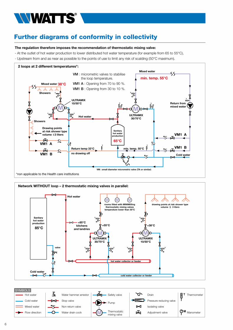
The regulation therefore imposes the recommendation of thermostatic mixing valve:
- At the outlet of hot water production to lower distributed hot water temperature (for example from 65 to 55°C),
- Upstream from and as near as possible to the points of use to limit any risk of scalding (50°C maximum).
2 loops at 2 different temperatures*:
*non applicable to the Health care institutions
Network WITHOUT loop – 2 thermostatic mixing valves in parallel:
VM : micrometric valves to stabilise the loop temperature.
VM1 A : Opening from 70 to 90 %.
VM1 B : Opening from 30 to 10 %.
SYMBOLS Hot water Water hammer arrestor Safety valve Drain Thermometer
Cold water Stop valve Pump
Pressure reducing valve
Mixed water Non return valve Isolating valve
Flow direction Water drain cock Thermostatic Adjustment valve Manometer mixing valve
Further diagrams of conformity in collectivity

Watts Water Technologies, Inc.
7
Calculation of the loop’s pump flow capacity:
Statutory calculation - Calculation of the loop’s pump flow capacity
The flow is calculated according to calorific losses on the surface of the whole piping, it depends on the thickness of the isolation.
Loss “P” :P = L.k. (te - ta) P in w, L in m,
K : coef k (insulating) (this coefficient varies according to the diameter and the nature of the pipe).
te : temperature of sanitary hot water.
ta : room temperature (for example: +10°C in the basement, +20°C upstairs).
This discharge is usually determined according to a ∆T° near 5°C.
tr : temperature of the return, will never be less than 50°C.
td : starting temperature.
P (kW)
1,163 (td - tr)Q (m3/h) = _____________
Table 1 - Development of legionella according to water temperature
<20°C / 69°F _______________________________________________________________________ lethargic state
20-46°C / 68-115°F __________________________________________________________ growth (no multiplication from 47°C on)
50°C / 122°F _______________________________________________________________________ 90% of bacteria will die in a period of 2 hours
60°C / 140°F _______________________________________________________________________ 90% of bacteria will die in 2 minutes
80°C / 178°F _______________________________________________________________________ 90% of bacteria will die in less of 1 minute
Table 2 - Relation between the canalization’s capacity and its length *
Material Dimensions of the pipe Length in meters leading to a capacity of 3 liters
Copper 15 x 1 22 m 18 x 1 15 m 22 x 1 9 m
Galvanized steel DN 15 15 m DN 20 8 m
Plastic pipe PEX/PER 15 x 2,5 39 m 18 x 2,5 23 m
Plastic PP 20 x 1,9 14 m 25 x 1,9 9 m
* Source: CSTC Belgium Nov. 2002. The canalization’s capacity is the inner section multiplied by the length.
How is a capacity of 3 liters ensured?
To respect the volume of 3 liters between the distribution point and the furthest drawing point, you must calculate the length of the pipe that contains a capacity of 3 liters.
This length varies considerably depending on the inside diameter of the tube used.
As a practical rule, you can use the formula opposite to calculate the length of the pipe L in millimetres (mm) according to the inside diameter of the tube.
= L in mm
inside diameter of the tube in square
3,14 x Dint2
12.000.000= 19 498,25 mm
= 19,49 m
=
14 x 14 = 196
3,14 x 196
12.000.000
615,44
Example for a 14x16 copper tube:
12.000.000= 22 613,35 mm
= 22,61 m
=
13 x 13 = 169
3,14 x 169
12.000.000
530,66
Example for a 13x16 PEX tube:
12.000.000

Dimensioning of mixing valves in group mixing
CASE A B C D E FTemperature displayed on the mixing valve 38°C 38°C 45°C 45°C 50°C 50°CType of tap on the sanitary appliances outlet flow control mixing valve tap flow control mixing valve tap flow control
Wash basin 12 L 6 L 10 L 6 L 8,4 L 6 L
Shower 12 L 8,4 L 10 L 7 L 8,4 L 6 L
Kitchen sink 12 L 8,4 L 10 L 7 L 8,4 L 6 L
Bathtub 20 L - 16 L - 14 L -
Bidet 12 L 8,4 L 10 L 7 L 8,4 L 6 L
Sink for washing up/pot and other applications 20 L 14 L 16 L 11 L 14 L 10 L
1 - Usual bathroom appliance unit flow rates (needs of mixed water)
2 - Calculating the total instant flow rate to be supplied by the mixing valve. Depending in the nature of the work, choose the decrease ratio of the flow rates corresponding with the quantity of appliances to be supplied (table below). Multiply this ratio by the cumulated flow rate to obtain the instant flow rate.
CASE OF ULTRAMIX® THERMOSTATIC MIXING VALVES
Calculation method:
Quantity of appliances 1 or 2 3 4 5 10 15 20 25 30 35 40 50 60 70
Residences 1 0,70 0,60 0,50 0,33 0,27 0,23 0,21 0,19 0,17 0,16 0,14 0,13 0,12
Guest houses, campsites, hospitals, spa installations 1 1 1 1 0,82 0,67 0,57 0,52 0,47 0,42 0,40 0,35 0,32 0,30
Stadiums and gymns, factories, schools, swimming pools, barracks 1 1 1 1 1 1 1 1 0,86 0,76 0,68 0,57 0,49 0,42 Quantity of appliances 80 90 100 110 120 130 140 150 160 170 180 190 200 > 200
Residences 0,11 0,105 0,10 0,097 0,093 0,087 0,083 0,08 0,078 0,076 0,074 0,072 0,07 0,07
Guest houses, campsites, hospitals, spa installations 0,27 0,26 0,25 0,242 0,232 0,217 0,207 0,20 0,195 0,19 0,185 0,18 0,175 0,175
Stadiums and gymns, factories, schools, swimming pools, barracks 0,38 0,35 0,32 0,30 0,28 0,26 0,24 0,22 — — — — — —
2 - Decrease coefficients of flow rates K (simultaneity coefficients)
The precision, sensitivity, flow rate and durability of the mixing valve can be ensured only insofar as it is looked after, and before all else, correctly chosen.
To define the size of the most suitable mixing valve for a determined use, the following elements must be known: the total instant flow rate (see paragraph below) and dynamic pressure available at the outflow for the hot water, and for the cold water, the mixing valve’s supply pipes. It can be measured or calculated, by using the DARIES abacus.This abacus can also be used to make sure the water speed is not excessive.Never admit a static pressure of more than 10 bar.
1 - Define the Cumulated Flow rate of mixed water by multiplying the quantity of appliances to be supplied by the usual unit flow rates (table below). (Consult us for any other application as necessary).
Watts Water Technologies, Inc.
8

3 - Table of maximum working flow rates
Watts Water Technologies, Inc.
9
SIMULTANEITYCOEFFICIENT
(K)
Numberof pointsof use
SIMULTANEITY COEFFICIENT (K) depends on the type of work and the number of taps to be supplied.
We consider 3 types of work:
• stadiums – gymnasiums – factories – schools – swimming pools – army barracks
• guest houses – campsites – hospitals – spa installations
• accomodations
3 - Choose the thermostatic mixing valve that will ensure regulation at this instant flow rate, under the available dynamic pressure (b. = bar) for its operation (table below).
Model TX91 TX92 TX93 TX94 TX95 TX96
Max. working flow rate: in l/min. under 3 bar 56 80 120 175 260 400in l/sec. under 3 bar 0,93 1,33 2,00 2,91 4,33 6,66
Pipe diameter corresponding with the size of the mixing valve:in mm 20 20 26 33 40 50in inches 3/4” 3/4” 1” 1”1/4 1”1/2 2”
Number of points of use for example (see simultaneity coefficient):from 1 1 1 1 1 1to 7 10 15 21 32 50
Minimum flow rate:in l/min. 5 5 5 5 8 8in l/sec. 0,08 0,08 0,08 0,08 0,13 0,13

Watts Water Technologies, Inc.
10
SettingWATTS recommends the installation of a thermometer of control of the temperature on the mixed water piping and one on the return of the loop. Moreover, this temperature must be checked at least once a month under the normal conditions of operation.
This thermometer must be installed at a distance of at least 1 meter from the thermostatic mixing valve.
Step 1
Mixed water temperature adjustment (this adjustment is done autonomously without the loop circulation pump):
1. Stop the loop circulation pump.
2. Close the pump isolation valves.
3. Open sufficient points of use on the mixed water circuit to obtain the minimum flow of the thermostatic mixing valve.
4. Turn the thermostatic mixing valve axis control shaft to reduce or increase the mixed water temperature.
5. Once the required temperature is obtained, replace the control knob (according to the model).
Step 2
Mixed water loop temperature adjustment:
1. Open the pump isolation valves.
2. Start the circulation pump.
3. Now proceed with the balancing: the ∆T° difference between the mixed water outlet and the return should be 5°C. To achieve this, manually adjust the VM1A balance valve (between 70 and 90 % of its total opening) and the VM1B valve (between 30 and 10 % of its total opening).
NOTE: Leave the circuit sufficient time to stabilise before making another adjustment. Check the stability of the mixed water temperature on the monitoring thermometer. If necessary, re-index the temperature knob so that its graduation is in phase with the mixed water temperature (operation referred to as “calibration” in the installation instructions).
Principle diagram of a mixed water loop return
VM : Micrometric valves to stabilise the loop temperature.
VM1 A : Opening from 70 to 90 %.VM1 B : Opening from 30 to 10 %.
Remarks:1. If there is a connection point on the
boiler (R), the return circuit should be connected here (A).
2. Possibly, it can be interesting to envisage two micrometric valves VM2, in particular in the case of a restoration of installation: the pump will not have to take into account the additional headloss due to the thermostatic mixing valve. In this case VM1A and VM1B are useless, the adjustment being done then on valves VM2.
VM2 C - Opening from 70 to 90 %.VM2 D - Opening from 30 to 10 %.
Possibility
Return frommixed waterloop
Main water supply with backflow protection
VM: small diametermicrometer valve
Hot waterproduction
N.B : Other variations are possible.Consult our Technical Assistance Department who can send you the corresponding diagrams.
Flow diagram for a complete mixed water circuit
SYMBOLS Hot water Water hammer arrestor Safety valve Drain Thermometer
Cold water Stop valve Pump
Pressure reducing valve
Mixed water Non return valve Isolating valve
Flow direction Water drain cock Thermostatic Adjustment valve Manometer mixing valve

Watts Water Technologies, Inc.
11
Maintenance
Range
Rinsing kit is an exclusive advantage for preventive or curative treatment and is delivered with the device.
Adjustment range 10/50°C: to supply from 1 to 50 sanitary points of use
Adjustment range 30/70°C : to supply sanitary hot water loop at 55°C or more
Take off knob, cover, and screws. Remove the cover/cartridge from its casing.
Place the flat washer (included in package) on the device's neck.
Place the cover/cartridge unit upside down on the device and flat washers.
Tighten the temporary screws (included the package). The valves act now as a “by-pass”.
Diameter Flow (l/min) Finish Points of use* Part number Weight (kg)
M 3/4” 20x27 Min. 5 – Max. 56 Grey epoxy 1 to 7 22TX91E 1,8
M 3/4” 20x27 Min. 5 – Max. 56 Chrome plated 1 to 7 22TX91C 1,8
M 3/4” 20x27 Min. 5 – Max. 80 Grey epoxy 1 to 7 22TX92E 1,8
M 3/4” 20x27 Min. 5 – Max. 80 Chrome plated 1 to 7 22TX92C 1,8
M 1” 26x34 Min. 5 – Max. 120 Grey epoxy 1 to 15 22TX93E 2,8
M 1” 26x34 Min. 5 – Max. 120 Chrome plated 1 to 15 22TX93C 2,8
M 1”1/4 33x42 Min. 5 – Max. 175 Grey epoxy 1 to 21 22TX94E 4,6
M 1”1/4 33x42 Min. 5 – Max. 175 Chrome plated 1 to 21 22TX94C 4,6
M 1”1/2 40x49 Min. 8 – Max. 260 Grey epoxy 1 to 32 22TX95E 7,8
M 1”1/2 40x49 Min. 8 – Max. 260 Chrome plated 1 to 32 22TX95C 7,8
M 2” 50x60 Min. 8 – Max. 400 Grey epoxy 1 to 50 22TX96E 10
M 2” 50x60 Min. 8 – Max. 400 Chrome plated 1 to 50 22TX96C 10
Diameter Flow (l/min) Finish Points of use* Part number Weight (kg)
M 3/4” 20x27 Min. 5 – Max. 56 Grey epoxy 1 to 7 22TX91E37 1,8
M 3/4” 20x27 Min. 5 – Max. 56 Chrome plated 1 to 7 22TX91C37 1,8
M 3/4” 20x27 Min. 5 – Max. 80 Grey epoxy 1 to 7 22TX92E37 1,8
M 3/4” 20x27 Min. 5 – Max. 80 Chrome plated 1 to 7 22TX92C37 1,8
M 1” 26x34 Min. 5 – Max. 120 Grey epoxy 1 to 15 22TX93E37 2,8
M 1” 26x34 Min. 5 – Max. 120 Chrome plated 1 to 15 22TX93C37 2,8
M 1”1/4 33x42 Min. 5 – Max. 175 Grey epoxy 1 to 21 22TX94E37 4,6
M 1”1/4 33x42 Min. 5 – Max. 175 Chrome plated 1 to 21 22TX94C37 4,6
M 1”1/2 40x49 Min. 8 – Max. 260 Grey epoxy 1 to 32 22TX95E37 7,8
M 1”1/2 40x49 Min. 8 – Max. 260 Chrome plated 1 to 32 22TX95C37 7,8
M 2” 50x60 Min. 8 – Max. 400 Grey epoxy 1 to 50 22TX96E37 10
M 2” 50x60 Min. 8 – Max. 400 Chrome plated 1 to 50 22TX96C37 10
* For information only. Take the coefficient of combined flow into consideration.

Watts Water Technologies, Inc.
12
ULTRAMIX® TX91 from 5 to 56 l/min
Diameter Flow (l/min) Setting range Finish Points
of use* Part number Weight(kg)
M 3/4” Min. 5 – Max. 56 10/50°C Grey epoxy 1 to 7 22TX91E 1,8
M 3/4” Min. 5 – Max. 56 10/50°C Chrome plated 1 to 7 22TX91C 1,8
M 3/4” Min. 5 – Max. 56 30/70°C Grey epoxy 1 to 7 22TX91E37 1,8
M 3/4” Min. 5 – Max. 56 30/70°C Chrome plated 1 to 7 22TX91C37 1,8
Flow rates dynamic pressure at inlets
1 bar 2 bar 3 bar
Flow rate in l/min 24 41 56
Flow rate in l/s 0,40 0,68 0,93
ULTRAMIX® TX92 from 5 to 80 l/min
Diameter Flow (l/min) Setting range Finish Points
of use* Part number Weight(kg)
M 3/4” Min. 5 – Max. 80 10/50°C Grey epoxy 1 to 10 22TX92E 1,8
M 3/4” Min. 5 – Max. 80 10/50°C Chrome plated 1 to 10 22TX92C 1,8
M 3/4” Min. 5 – Max. 80 30/70°C Grey epoxy 1 to 10 22TX92E37 1,8
M 3/4” Min. 5 – Max. 80 30/70°C Chrome plated 1 to 10 22TX92C37 1,8
Flow rates dynamic pressure at inlets
1 bar 2 bar 3 bar
Flow rate in l/min 31 56 80
Flow rate in l/s 0,51 0,93 1,33
ULTRAMIX® TX93 from 5 to 120 l/min
Diameter Flow (l/min) Setting range Finish Points
of use* Part number Weight(kg)
M 1” Min. 5 – Max. 120 10/50°C Grey epoxy 1 to 15 22TX93E 2,8
M 1” Min. 5 – Max. 120 10/50°C Chrome plated 1 to 15 22TX93C 2,8
M 1” Min. 5 – Max. 120 30/70°C Grey epoxy 1 to 15 22TX93E37 2,8
M 1” Min. 5 – Max. 120 30/70°C Chrome plated 1 to 15 22TX93C37 2,8
Flow rates dynamic pressure at inlets
1 bar 2 bar 3 bar
Flow rate in l/min 56 91 120
Flow rate in l/s 0,93 1,51 2,00
* For information only. Take the coefficient of combined flow into consideration.
117
120
81
93
19
98
Ø 3/4”
Ø 66Hotwater
Coldwater
Mixed water
117
120
81
93
19
98
Ø 3/4”
Ø 66Hotwater
Coldwater
Mixed water
117
120
81
93
19
98
Ø 3/4”
Ø 66Hotwater
Coldwater
Mixed water
117
120
81
93
19
98
Ø 3/4”
Ø 66Hotwater
Coldwater
Mixed water
144
142
96
108
23
116
Ø 1”
Ø 66Hotwater
Coldwater
Mixed water
144
142
96
108
23
116
Ø 1”
Ø 66Hotwater
Coldwater
Mixed water
Watts Water Technologies, Inc.
13
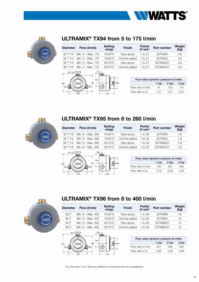
ULTRAMIX® TX94 from 5 to 175 l/min
Diameter Flow (l/min) Setting range Finish Points
of use* Part number Weight(kg)
M 1”1/4 Min. 5 – Max. 175 10/50°C Grey epoxy 1 to 21 22TX94E 4,6
M 1”1/4 Min. 5 – Max. 175 10/50°C Chrome plated 1 to 21 22TX94C 4,6
M 1”1/4 Min. 5 – Max. 175 30/70°C Grey epoxy 1 to 21 22TX94E37 4,6
M 1”1/4 Min. 5 – Max. 175 30/70°C Chrome plated 1 to 21 22TX94C37 4,6
Flow rates dynamic pressure at inlets
1 bar 2 bar 3 bar
Flow rate in l/min 91 133 175
Flow rate in l/s 1,51 2,21 2,91
ULTRAMIX® TX95 from 8 to 260 l/min
Diameter Flow (l/min) Setting range Finish Points
of use* Part number Weight(kg)
M 1”1/2 Min. 8 – Max. 260 10/50°C Grey epoxy 1 to 32 22TX95E 7,8
M 1”1/2 Min. 8 – Max. 260 10/50°C Chrome plated 1 to 32 22TX95C 7,8
M 1”1/2 Min. 8 – Max. 260 30/70°C Grey epoxy 1 to 32 22TX95E37 7,8
M 1”1/2 Min. 8 – Max. 260 30/70°C Chrome plated 1 to 32 22TX95C37 7,8
Flow rates dynamic pressure at inlets
1 bar 2 bar 3 bar
Flow rate in l/min 130 201 260
Flow rate in l/s 2,16 3,35 4,33
* For information only. Take the coefficient of combined flow into consideration.
ULTRAMIX® TX96 from 8 to 400 l/min
Diameter Flow (l/min) Setting range Finish Points
of use* Part number Weight(kg)
M 2” Min. 8 – Max. 400 10/50°C Grey epoxy 1 to 50 22TX96E 10
M 2” Min. 8 – Max. 400 10/50°C Chrome plated 1 to 50 22TX96C 10
M 2” Min. 8 – Max. 400 30/70°C Grey epoxy 1 to 50 22TX96E37 10
M 2” Min. 8 – Max. 400 30/70°C Chrome plated 1 to 50 22TX96C37 10
Flow rates dynamic pressure at inlets
1 bar 2 bar 3 bar
Flow rate in l/min 231 328 400
Flow rate in l/s 3,85 5,46 6,66
182
160
108
116
24
145
Ø 1”1/4
Ø 66Hotwater
Coldwater
Mixed water
182
160
108
116
24
145
Ø 1”1/4
Ø 66Hotwater
Coldwater
Mixed water
218
200
129
128
36
175
Ø 1”1/2
Ø 66Hotwater
Coldwater
Mixed water
218
200
129
128
36
175
Ø 1”1/2
Ø 66Hotwater
Coldwater
Mixed water
242
217
144
140
36
198
Ø 2”
Ø 66Hotwater
Coldwater
Mixed water
242
217
144
140
36
198
Ø 2”
Ø 66Hotwater
Coldwater
Mixed water
Watts Water Technologies, Inc.
14
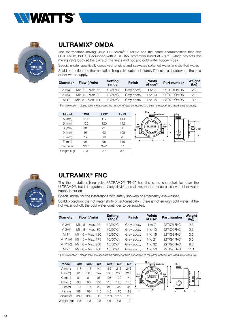
ULTRAMIX® OMDAThe thermostatic mixing valve ULTRAMIX® "OMDA" has the same characteristics than the ULTRAMIX®, but it is equipped with a RILSAN protection kilned at 250°C which protects the mixing valve body at the place of the seats and hot and cold water supply pipes.
Special model specifically conceived to withstand seawater, softened water and distilled water.
Scald protection: the thermostatic mixing valve cuts off instantly if there is a shutdown of the cold or hot water supply.
Diameter Flow (l/min) Setting range Finish Points
of use* Part number Weight(kg)
M 3/4” Min. 5 – Max. 56 10/50°C Grey epoxy 1 to 7 22TX91OMDA 2,3
M 3/4” Min. 5 – Max. 80 10/50°C Grey epoxy 1 to 10 22TX92OMDA 2,3
M 1” Min. 5 – Max. 120 10/50°C Grey epoxy 1 to 15 22TX93OMDA 3,5
* For information - please take into account the number of taps connected to the same network and used simultaneously.
Model TX91 TX92 TX93
A (mm) 117 117 144
B (mm) 120 120 142
C (mm) 81 81 96
D (mm) 93 93 108
E (mm) 19 19 23
F (mm) 98 98 116
diameter 3/4” 3/4” 1”
Weight (kg) 2,3 2,3 3,5
Model TX91 TX92 TX93 TX94 TX95 TX96
A (mm) 117 117 144 182 218 242
B (mm) 120 120 142 160 200 217
C (mm) 81 81 96 108 129 144
D (mm) 93 93 108 116 128 140
E (mm) 19 19 23 24 36 36
F (mm) 98 98 116 145 175 198
diameter 3/4” 3/4” 1” 1”1/4 1”1/2 2”
Weight (kg) 1,8 1,8 2,8 4,6 7,8 10
ULTRAMIX® FNCThe thermostatic mixing valve ULTRAMIX® "FNC" has the same characteristics than the ULTRAMIX®, but it integrates a safety device and allows the tap to be used even if hot water supply is cut off.
Special model for the installations with safety showers or emergency eye-washer.
Scald protection: the hot water shuts off automatically if there is not enough cold water ; if the hot water cut off, the cold water continues to be supplied.
Diameter Flow (l/min) Setting range Finish Points
of use* Part number Weight(kg)
M 3/4” Min. 5 – Max. 56 10/50°C Grey epoxy 1 to 7 22TX91FNC 2,3
M 3/4” Min. 5 – Max. 80 10/50°C Grey epoxy 1 to 10 22TX92FNC 2,3
M 1” Min. 5 – Max. 120 10/50°C Grey epoxy 1 to 15 22TX93FNC 3,5
M 1”1/4 Min. 5 – Max. 175 10/50°C Grey epoxy 1 to 21 22TX94FNC 5,0
M 1”1/2 Min. 8 – Max. 260 10/50°C Grey epoxy 1 to 32 22TX95FNC 8,6
M 2” Min. 8 – Max. 400 10/50°C Grey epoxy 1 to 50 22TX96FNC 11,1
* For information - please take into account the number of taps connected to the same network and used simultaneously.
Hotwater
Coldwater
Mixed water
Hotwater
Coldwater
Mixed water
Hotwater
Coldwater
Mixed water
Hotwater
Coldwater
Mixed water

Watts Water Technologies, Inc.
15
ULTRAMIX® HP haute protectionThe thermostatic mixing valve ULTRAMIX® "HP" has the same characteristics than the ULTRAMIX®, but it is equipped with anti-vandalism safety device.
Thermostatic mixing valve specifically conceived for the collective applications where the risks of deterioration are high. The mechanism and its adjustment are protected by a metal frontage made inviolable by a specific high protection lock.
Scald protection: the thermostatic mixing valve cuts off instantly if there is a shutdown of the cold or hot water supply.
Finish chrome plated.
Diameter Flow (l/min) Setting range Finish Points
of use* Part number Weight(kg)
M 3/4” Min. 5 – Max. 56 10/50°C Chrome plated 1 to 7 22T/X91CHP 2,6
M 3/4” Min. 5 – Max. 80 10/50°C Chrome plated 1 to 10 22T/X92CHP 2,6
M 1” Min. 5 – Max. 120 10/50°C Chrome plated 1 to 15 22T/X93CHP 3,7
M 1”1/4 Min. 5 – Max. 175 10/50°C Chrome plated 1 to 21 22T/X94CHP 5,3
M 1”1/2 Min. 8 – Max. 260 10/50°C Chrome plated 1 to 32 22T/X95CHP 8,7
M 2” Min. 8 – Max. 400 10/50°C Chrome plated 1 to 50 22T/X96CHP 10,8
Standard gradations: 10/50°C, on request 30/70°C.* For information - please take into account the number of taps connected to the same network and used simultaneously.
Model TX91 TX92 TX93 TX94 TX95 TX96
A (mm) 117 117 144 176 218 242
B (mm) 124,5 124,5 147,5 170 196,5 220
C (mm) 81 81 94.5 111,5 129 144
D (mm) 91,2 91,2 97 114 129 138,5
E (mm) 19 19 23,2 24 32 35,5
F (mm) 97,5 97,5 115 145 175 196
diameter 3/4” 3/4” 1” 1”1/4 1”1/2 2”
Weight (kg) 2,6 2,6 3,7 5,3 8,7 10,8
High Protection KitAllows to transform the ULTRAMIX® thermostatic mixing valves (all temperature setting, chrome plated, epoxy) and old range series 9000 into a high protection thermostatic mixing valve. The kit includes: chrome platted metal frontage, high protection lock and key for dito.
For thermostatic mixing valve type Part number
TX91, TX92, old range 9200 22TB120007
TX93, old range 9300 22TB120008
TX94, old range 9400 22TB120009
TX95, old range 9500 22TB120010
TX96, old range 9600 22TB120011
Maintenance kit for ULTRAMIX® cartridgesThis kit includes all the usual wearing parts: the cover-cartridge gasket ➊, 2 filter-support (elastomer) ➋, gaskets for cover screws ➌, 2 stainless steel strainers ➍, the check valve units and assembled check valve carriers ➎ and the cover screws ➏.
For cartridge type Part number complete kit Part number simplified kit
TX1, TX2, TX137, TX237 22TB120002 22TB120022 (without cover screws)
TX3, TX337 22TB120003 22TB120023 (without cover screws)
TX4, TX437 22TB120004 22TB120024 (without cover screws)
TX5, TX537 22TB120005 22TB120025 (without cover screws)
TX6, TX637 22TB120006 22TB120026 (without cover screws)
➎➏
➊➋➌
➍
Mixed water
Coldwater
Hotwater
Mixed water
Coldwater
Hotwater

TX91aTX96-TS-FR-W-EN-10-21
WATTS INDUSTRIES France1590 avenue d’Orange • CS 10101 Sorgues 84275 VEDENE CEDEX • FRANCE
Tél. +33 (0)4 90 33 28 28 • Fax +33 (0)4 90 33 28 29/[email protected] • www.wattswater.fr
© 2021 Watts
The descriptions and photographs contained in this product specification sheet are supplied by way of information only and are not binding.Watts reserves the right to carry out any technical and design improvements to its products without prior notice. Warranty : All sales and contracts for sale are expressly conditioned onthe buyer’s assent to Watts terms and conditions found on its website at www.watts.com. Watts hereby objects to any term, different from or additional to Watts terms, contained in any
buyer communication in any form, unless agreed to in a writing signed by an officer of Watts.
Follow us Watts Water Technologies
Replacement cartridges ULTRAMIX®
The thermostatic mechanisms are independent from the other parts of the thermostatic mixing valves.
This modular system, facilitates the first start-up and the maintenance (possibility of cartridge exchange).
Any installation defect is immediately detected and allows a quick compliance.
All Eurotherm "cartridges" of ULTRAMIX®, high productivity thermostatic mixing valve, have stainless steel filters and check valves NF approved.
The WATTS INDUSTRIES software is designed to validate the calculation carried out manually in order to choose the right thermostatic mixing valve (according to pressures, pipe diameters, desired flowrate and number of points of use).
For mixing valve type Flow (l/min) Setting range Part number
TX91E, TX91C, T/X91CHP 5 to 56 10/50°C 22TX1*
TX92E, TX92C, T/X92CHP 5 to 80 10/50°C 22TX2*
TX93E, TX93C, T/X93CHP 5 to 120 10/50°C 22TX3
TX94E, TX94C, T/X94CHP 5 to 175 10/50°C 22TX4
TX95E, TX95C, T/X95CHP 8 to 260 10/50°C 22TX5
TX96E, TX96C, T/X96CHP 8 to 400 10/50°C 22TX6
TX91E37, TX91C37, T/X91CHP 5 to 56 30/70°C 22TX137*
TX92E37, TX92C37, T/X92CHP 5 to 80 30/70°C 22TX237*
TX93E37, TX93C37, T/X93CHP 5 to 120 30/70°C 22TX337
TX94E37, TX94C37, T/X94CHP 5 to 175 30/70°C 22TX437
TX95E37, TX95C37, T/X95CHP 8 to 260 30/70°C 22TX537
TX96E37, TX96C37, T/X96CHP 8 to 400 30/70°C 22TX637
TX91FNC 5 to 56 10/50°C 22TX1FNC
TX92FNC 5 to 80 10/50°C 22TX2FNC
TX93FNC 5 to 120 10/50°C 22TX3FNC
TX94FNC 5 to 175 10/50°C 22TX4FNC
TX95FNC 8 to 260 10/50°C 22TX5FNC
TX96FNC 8 to 400 10/50°C 22TX6FNC
TX91OMDA 5 to 56 10/50°C 22TX1OMDA
TX92OMDA 5 to 80 10/50°C 22TX2OMDA
TX93OMDA 5 to 120 10/50°C 22TX3OMDA
For reversed cartridges add ”IN” to the article code. * For reversed cartridges add ”IN” to the article code, for installations requiring a higher flow rate, the 22TX1 and 22TX2
cartridges as well as 22TX137 and 22TX237 are compatible and interchangeable.
OperatingOnline selection tool Ultramix®
Delta P in bar
Flo
w in
L/m
in
Access to the calculation software: click here
www.ultramix.en/watts_fr/index.html